JP7207202B2 - vehicle - Google Patents
vehicle Download PDFInfo
- Publication number
- JP7207202B2 JP7207202B2 JP2019121186A JP2019121186A JP7207202B2 JP 7207202 B2 JP7207202 B2 JP 7207202B2 JP 2019121186 A JP2019121186 A JP 2019121186A JP 2019121186 A JP2019121186 A JP 2019121186A JP 7207202 B2 JP7207202 B2 JP 7207202B2
- Authority
- JP
- Japan
- Prior art keywords
- vehicle
- condenser
- air
- air conditioning
- ceiling
- Prior art date
- Legal status (The legal status is an assumption and is not a legal conclusion. Google has not performed a legal analysis and makes no representation as to the accuracy of the status listed.)
- Active
Links
Images


Classifications
-
- B—PERFORMING OPERATIONS; TRANSPORTING
- B60—VEHICLES IN GENERAL
- B60H—ARRANGEMENTS OF HEATING, COOLING, VENTILATING OR OTHER AIR-TREATING DEVICES SPECIALLY ADAPTED FOR PASSENGER OR GOODS SPACES OF VEHICLES
- B60H1/00—Heating, cooling or ventilating [HVAC] devices
- B60H1/32—Cooling devices
- B60H1/3204—Cooling devices using compression
- B60H1/3228—Cooling devices using compression characterised by refrigerant circuit configurations
-
- B—PERFORMING OPERATIONS; TRANSPORTING
- B60—VEHICLES IN GENERAL
- B60H—ARRANGEMENTS OF HEATING, COOLING, VENTILATING OR OTHER AIR-TREATING DEVICES SPECIALLY ADAPTED FOR PASSENGER OR GOODS SPACES OF VEHICLES
- B60H1/00—Heating, cooling or ventilating [HVAC] devices
- B60H1/00642—Control systems or circuits; Control members or indication devices for heating, cooling or ventilating devices
- B60H1/00735—Control systems or circuits characterised by their input, i.e. by the detection, measurement or calculation of particular conditions, e.g. signal treatment, dynamic models
- B60H1/00764—Control systems or circuits characterised by their input, i.e. by the detection, measurement or calculation of particular conditions, e.g. signal treatment, dynamic models the input being a vehicle driving condition, e.g. speed
-
- B—PERFORMING OPERATIONS; TRANSPORTING
- B60—VEHICLES IN GENERAL
- B60H—ARRANGEMENTS OF HEATING, COOLING, VENTILATING OR OTHER AIR-TREATING DEVICES SPECIALLY ADAPTED FOR PASSENGER OR GOODS SPACES OF VEHICLES
- B60H1/00—Heating, cooling or ventilating [HVAC] devices
- B60H1/32—Cooling devices
- B60H1/3204—Cooling devices using compression
- B60H1/3223—Cooling devices using compression characterised by the arrangement or type of the compressor
-
- B—PERFORMING OPERATIONS; TRANSPORTING
- B60—VEHICLES IN GENERAL
- B60H—ARRANGEMENTS OF HEATING, COOLING, VENTILATING OR OTHER AIR-TREATING DEVICES SPECIALLY ADAPTED FOR PASSENGER OR GOODS SPACES OF VEHICLES
- B60H1/00—Heating, cooling or ventilating [HVAC] devices
- B60H1/32—Cooling devices
- B60H1/3204—Cooling devices using compression
- B60H1/3227—Cooling devices using compression characterised by the arrangement or the type of heat exchanger, e.g. condenser, evaporator
-
- B—PERFORMING OPERATIONS; TRANSPORTING
- B60—VEHICLES IN GENERAL
- B60H—ARRANGEMENTS OF HEATING, COOLING, VENTILATING OR OTHER AIR-TREATING DEVICES SPECIALLY ADAPTED FOR PASSENGER OR GOODS SPACES OF VEHICLES
- B60H1/00—Heating, cooling or ventilating [HVAC] devices
- B60H1/32—Cooling devices
- B60H1/3233—Cooling devices characterised by condensed liquid drainage means
- B60H1/32331—Cooling devices characterised by condensed liquid drainage means comprising means for the use of condensed liquid, e.g. for humidification or for improving condenser performance
-
- B—PERFORMING OPERATIONS; TRANSPORTING
- B60—VEHICLES IN GENERAL
- B60K—ARRANGEMENT OR MOUNTING OF PROPULSION UNITS OR OF TRANSMISSIONS IN VEHICLES; ARRANGEMENT OR MOUNTING OF PLURAL DIVERSE PRIME-MOVERS IN VEHICLES; AUXILIARY DRIVES FOR VEHICLES; INSTRUMENTATION OR DASHBOARDS FOR VEHICLES; ARRANGEMENTS IN CONNECTION WITH COOLING, AIR INTAKE, GAS EXHAUST OR FUEL SUPPLY OF PROPULSION UNITS IN VEHICLES
- B60K1/00—Arrangement or mounting of electrical propulsion units
- B60K1/04—Arrangement or mounting of electrical propulsion units of the electric storage means for propulsion
- B60K2001/0405—Arrangement or mounting of electrical propulsion units of the electric storage means for propulsion characterised by their position
- B60K2001/0438—Arrangement under the floor
Description
本明細書では、車両に搭載される車載空調装置、および車載空調装置を搭載した車両を開示する。 This specification discloses an in-vehicle air conditioner mounted in a vehicle and a vehicle equipped with the in-vehicle air conditioner.
従来から空調装置を搭載した車両が広く知られている。車載の空調装置は、当然ながら、車両に搭載された車載バッテリの電力で駆動する。車載バッテリの電力には、限りがあるため、車載空調装置の消費電力の低減が従来から強く求められている。 BACKGROUND ART Conventionally, vehicles equipped with air conditioners are widely known. An in-vehicle air conditioner is, of course, driven by electric power of an in-vehicle battery mounted in the vehicle. Since the power of an on-vehicle battery is limited, there has been a strong demand to reduce the power consumption of an on-vehicle air conditioner.
そこで、一部では、冷房時における消費電力を低減するために、冷媒と外気との熱交換を行うコンプレッサの近傍に、ミスト(水)を噴霧し、当該ミストの気化熱により、冷媒の冷却効率、ひいては、空調装置の冷房効率を高める空調装置が提案されている。 Therefore, in some cases, in order to reduce power consumption during cooling, mist (water) is sprayed near the compressor that exchanges heat between the refrigerant and the outside air, and the heat of vaporization of the mist increases the cooling efficiency of the refrigerant. Air conditioners have been proposed that improve the cooling efficiency of air conditioners.
例えば、特許文献1には、エバポレータで発生した凝縮水を、コンデンサに噴霧する噴霧ノズルを備えた車両用一体型空調装置が開示されている。この特許文献1では、コンプレッサ、コンデンサ、絞り弁、エバポレータ、噴霧ノズル等は、全て同一のケース内に収容され、ユニット化されている。そして、このユニット化された空調装置は、車両の室外天井部分に配置されている。特許文献1のように、コンプレッサにミストを噴霧する構成とすることで、冷房効率をより向上できる。
For example,
ここで、車室の床下にバッテリを配置しつつ、車室の低床化を実現するためには、特許文献1のように空調装置を天井に配置することが有効である。しかし、天井にコンデンサを含む空調装置を配置すると天井が大型化してしまう。特に、特許文献1では、空調装置の構成要素をほぼ全て、一つのケース内に収容している。この場合、当然ながら、当該ケースのサイズは大きくなるが、かかるケースを車室の外側の天井部分に配置した場合、車両の天井部分の意匠の自由度が大幅に制限される。また、重量物であるコンプレッサが天井にあると、車両の重心が上がり、車両の安定性が損なわれる。さらに、動的運転タスクの一部または全てを車両側で実行する運転支援車両および自動運転車両の場合、当該車両の周辺情報を検知する周辺情報センサを車両の天井等に設置する。このとき、空調装置に起因して車両の天井部が上方に部分的に突出していると、周辺情報センサの取付位置が制限されることになる。また、こうした車両天井の部分的な突出を抑制するために、空調装置を、車室外側ではなく車室内に突出させることも考えられる。しかし、この場合、車室の天井が低くなり、乗員に圧迫感を与えるおそれもあった。
Here, in order to lower the floor of the passenger compartment while arranging the battery under the floor of the passenger compartment, it is effective to arrange the air conditioner on the ceiling as in
そこで、本明細書では、車両の意匠の自由度をより向上できる車載空調装置、および、車両を開示する。 Therefore, the present specification discloses an in-vehicle air conditioner and a vehicle that can further improve the degree of freedom in designing the vehicle.
本明細書で開示する車載空調装置は、車両に搭載される車載空調装置であって、前記車載空調装置は、1以上の空調ユニットを有しており、前記空調ユニットは、車室内空気と冷媒とを熱交換させるエバポレータと、前記車室内から前記エバポレータを通過して再度、車室内に向かう空気流れを生成するブロアファンと、前記冷媒を圧縮するコンプレッサと、前記冷媒と外気とを熱交換させるコンデンサと、前記冷媒を前記エバポレータ、前記コンプレッサ、および前記コンデンサを通るように循環させる冷媒配管と、水をミスト状にして前記コンデンサに向かう外気に噴霧する噴霧ノズルと、を備えており、前記エバポレータおよび前記ブロアファンは、前記車両の天井部に配置され、前記コンデンサおよび前記噴霧ノズルは、車両下部に配置される、ことを特徴とする。 The in-vehicle air conditioner disclosed in this specification is an in-vehicle air conditioner mounted in a vehicle, the in-vehicle air conditioner has one or more air conditioning units, and the air conditioning unit includes air in the vehicle interior and a refrigerant an evaporator that exchanges heat between the refrigerant and the outside air, a blower fan that generates an air flow that flows from the vehicle interior through the evaporator and back into the vehicle interior, a compressor that compresses the refrigerant, and heat exchange between the refrigerant and the outside air. a condenser; a refrigerant pipe for circulating the refrigerant through the evaporator, the compressor, and the condenser; and a spray nozzle for spraying water into a mist into the outside air toward the condenser, the evaporator and the blower fan is arranged on the ceiling of the vehicle, and the condenser and the spray nozzle are arranged on the lower part of the vehicle.
コンデンサに向かう外気に水を噴霧することで、冷房時における冷却効率をより向上できる。また、空調装置の構成要素を、天井部と車両下部とに分割配置することで、車両天井部の意匠の自由度をより向上できる。 By spraying water toward the outside air toward the condenser, the cooling efficiency during cooling can be further improved. Further, by disposing the components of the air conditioner separately in the ceiling portion and the vehicle lower portion, it is possible to further improve the degree of freedom in the design of the vehicle ceiling portion.
この場合、前記空調ユニットは、さらに、車室の床下に配置され、水を貯留する水タンクと、前記水タンクの水を前記噴霧ノズルに供給するウォーターポンプと、を備えてもよい。 In this case, the air conditioning unit may further include a water tank that is arranged under the floor of the passenger compartment and stores water, and a water pump that supplies water from the water tank to the spray nozzles.
重量の大きい水タンクを床下に配置することで、車両の重心を下に下げることができ、車両の安定性を向上できる。 By placing the heavy water tank under the floor, the vehicle's center of gravity can be lowered, improving vehicle stability.
この場合、前記空調ユニットは、さらに、前記エバポレータで凝縮された水を前記水タンクに導くドレンホースを備えてもよい。 In this case, the air conditioning unit may further include a drain hose that guides water condensed by the evaporator to the water tank.
エバポレータで発生した凝縮水を水タンクに導くことで、水タンクへの給水の頻度を低減できる。 By guiding the condensed water generated in the evaporator to the water tank, the frequency of supplying water to the water tank can be reduced.
また、前記車載空調装置は、車室前側を空調する前側空調ユニットと、車室後側を空調する後側空調ユニットと、を有しており、前記前側空調ユニットの前記コンデンサおよび前記噴霧ノズルは、前記車両の前下角部に位置する前側収容空間に配置され、前記後側空調ユニットの前記コンデンサおよび前記噴霧ノズルは、前記車両の後下角部に位置する後側収容空間に配置されてもよい。 The in-vehicle air-conditioning system includes a front air-conditioning unit for air-conditioning a front side of the passenger compartment and a rear air-conditioning unit for air-conditioning a rear side of the passenger compartment, and the condenser and the spray nozzle of the front-side air-conditioning unit are , and the condenser and the spray nozzle of the rear air conditioning unit may be arranged in a rear accommodation space located at a lower rear corner of the vehicle. .
車両の前後それぞれに、空調ユニットを配置することで、車室全体を効率的に冷却できる。 By arranging air-conditioning units at the front and rear of the vehicle, the entire passenger compartment can be efficiently cooled.
本明細書で開示する車両は、車両を走行させる駆動モータを含むパワーユニットと、前記駆動モータを駆動する電力を蓄電したバッテリと、を有した電気自動車であり、前記車載空調装置は、1以上の空調ユニットを有しており、前記空調ユニットは、車室内空気と冷媒とを熱交換させるエバポレータと、前記車室内から前記エバポレータを通過して再度、車室内に向かう空気流れを生成するブロアファンと、前記冷媒を圧縮するコンプレッサと、前記冷媒と外気とを熱交換させるコンデンサと、前記冷媒を前記エバポレータ、前記コンプレッサ、および前記コンデンサを通るように循環させる冷媒配管と、水をミスト状にして前記コンデンサに向かう外気に噴霧する噴霧ノズルと、を備えており、前記エバポレータおよび前記ブロアファンは、車両の天井部に配置され、前記コンデンサおよび前記噴霧ノズルは、車両下部に配置されてもよい。 A vehicle disclosed in this specification is an electric vehicle having a power unit including a drive motor that drives the vehicle, and a battery that stores electric power for driving the drive motor. An air conditioning unit includes an evaporator that exchanges heat between the air in the vehicle and the refrigerant, and a blower fan that generates an air flow from the vehicle interior to the vehicle interior after passing through the evaporator. a compressor for compressing the refrigerant; a condenser for exchanging heat between the refrigerant and outside air; refrigerant piping for circulating the refrigerant so as to pass through the evaporator, the compressor, and the condenser; and a spray nozzle for spraying outside air toward a condenser, wherein the evaporator and the blower fan may be located in the vehicle ceiling, and the condenser and the spray nozzle may be located in the vehicle underside.
コンデンサに向かう外気に水を噴霧することで、冷房時における冷却効率をより向上できる。また、空調装置の構成要素を、天井部と車両下部とに分割配置することで、車両天井部の意匠の自由度をより向上できる。 By spraying water toward the outside air toward the condenser, the cooling efficiency during cooling can be further improved. Further, by disposing the components of the air conditioner separately in the ceiling portion and the vehicle lower portion, it is possible to further improve the degree of freedom in the design of the vehicle ceiling portion.
この場合、前記車両は、その前端および後端が、当該車両の底部から天井まで略鉛直方向に延びる略箱形状であり、前記車両は、自動運転可能であってもよい。 In this case, the vehicle may have a substantially box-shaped front end and a rear end extending substantially vertically from the bottom of the vehicle to the ceiling, and the vehicle may be capable of self-driving.
箱形かつ自動運転可能な車両の場合、ボンネットやトランク、運転席などが存在しないため、空調装置の要素を収容する空間が限られる。しかし、本明細書で開示する車両によれば、これら要素が分割して収容されるため、略箱形状の自動運転車両であっても、意匠性を損なうことなく、空調装置を搭載できる。 In the case of a box-shaped, self-driving vehicle, there is no bonnet, no trunk, no driver's seat, etc., so there is limited space to accommodate the elements of the air conditioning system. However, according to the vehicle disclosed in the present specification, since these elements are divided and accommodated, even an approximately box-shaped automatic driving vehicle can be equipped with an air conditioner without impairing the design.
この場合、前記車載空調装置は、車室前側を空調する前側空調ユニットと、車室後側を空調する後側空調ユニットと、を有しており、前記前側空調ユニットの前記コンデンサおよび前記噴霧ノズルは、前記車両の一対の前輪の間に位置する前側収容空間に配置され、前記後側空調ユニットの前記コンデンサおよび前記噴霧ノズルは、前記車両の一対の後輪の間に位置する後側収容空間に配置され、前記後側収容空間には、さらに、前記パワーユニットと、前記パワーユニットを冷却するためのモータ用冷媒を冷却するラジエータが配置されており、前記ラジエータは、前記後側空調ユニットの前記コンデンサと上下に並んで配置されていてもよい。 In this case, the in-vehicle air-conditioning system includes a front air-conditioning unit for air-conditioning the front side of the passenger compartment and a rear air-conditioning unit for air-conditioning the rear side of the passenger compartment. is disposed in a front accommodation space located between a pair of front wheels of the vehicle, and the condenser and the spray nozzle of the rear air conditioning unit are arranged in a rear accommodation space located between a pair of rear wheels of the vehicle. Further, the power unit and a radiator for cooling motor coolant for cooling the power unit are arranged in the rear accommodation space, and the radiator is arranged in the condenser of the rear air conditioning unit. may be arranged vertically.
車両の前後それぞれに、空調ユニットを配置することで、車室全体を効率的に冷却できる。また、ラジエータとコンデンサを上下に並べて配置することで、パワーユニット冷却用の他の冷媒も効果的に冷却でき、パワーユニットも良好に冷却できる。 By arranging air-conditioning units at the front and rear of the vehicle, the entire passenger compartment can be efficiently cooled. In addition, by arranging the radiator and the condenser vertically, other refrigerants for cooling the power unit can be effectively cooled, and the power unit can be cooled well.
また、前記車両の前端面の下端および後端面の下端の少なくとも一方には、外気の通過を許容するグリルが設けられており、前記コンデンサは、前記グリルと前後方向に対向して配置されており、前記グリルの上端は、前記コンデンサの中央高さより下方にあってもよい。 At least one of the lower end of the front end surface and the lower end of the rear end surface of the vehicle is provided with a grill that allows the passage of outside air, and the condenser is arranged to face the grill in the front-rear direction. , the upper edge of the grill may be below the central height of the condenser.
かかる構成とすることで、グリルを下方に位置させることができ、車両の前端面および後端面の面積を十分に確保でき、前端面および後端面の意匠の自由度を向上できる。 With such a configuration, the grille can be positioned at a lower position, sufficient areas of the front end surface and the rear end surface of the vehicle can be secured, and the degree of freedom in designing the front end surface and the rear end surface can be improved.
また、本明細書で開示する車両は、車室中央の床下に配置されたメインバッテリと、前記車室を空調する1以上の空調ユニットと、を備え、前記空調ユニットは、前記車室内空気と冷媒とを熱交換させるエバポレータと、前記車室内から前記エバポレータを通過して再度、車室内に向かう空気流れを生成するブロアファンと、前記冷媒を圧縮するコンプレッサと、前記冷媒と外気とを熱交換させるコンデンサと、前記冷媒を前記エバポレータ、前記コンプレッサ、および前記コンデンサを通るように循環させる冷媒配管と、を備えており、前記エバポレータおよび前記ブロアファンは、前記車両の天井部に配置され、前記コンデンサおよび前記コンプレッサは、前記車両の前下角部に位置する前側収容空間および前記車両の後下角部に位置する後側収容空間の少なくとも一方に配置される、ことを特徴とする。 Further, the vehicle disclosed in this specification includes a main battery arranged under the floor in the center of the passenger compartment, and one or more air conditioning units for air-conditioning the passenger compartment. An evaporator that exchanges heat with a refrigerant, a blower fan that generates an air flow from the vehicle interior through the evaporator and back into the vehicle interior, a compressor that compresses the refrigerant, and heat exchange between the refrigerant and outside air. and a refrigerant pipe for circulating the refrigerant through the evaporator, the compressor, and the condenser, wherein the evaporator and the blower fan are arranged on the ceiling of the vehicle, and the condenser and the compressor is arranged in at least one of a front accommodation space located at a lower front corner of the vehicle and a rear accommodation space located at a lower rear corner of the vehicle.
上記のように、空調ユニットの構成要素を天井部と車両下部の収容空間とに分割して配置することで、車両天井部の意匠の自由度をより向上できる。特に、天井部の上側への突出を抑制できる。 As described above, by arranging the components of the air-conditioning unit separately into the ceiling portion and the accommodation space in the lower portion of the vehicle, it is possible to further improve the degree of freedom in designing the vehicle ceiling portion. In particular, upward protrusion of the ceiling can be suppressed.
この場合、さらに、車両天井の外表面に搭載され、当該車両の周辺情報を検知する周辺情報センサを備え、前記車両は、少なくとも前記周辺情報センサで検知された情報に基づいて、自車の走行をコントロールする自動運転機能または運転支援機能を有してもよい。 In this case, a peripheral information sensor mounted on the outer surface of the ceiling of the vehicle for detecting peripheral information of the vehicle is further provided, and the vehicle detects at least the information detected by the peripheral information sensor. It may have an automatic driving function or a driving support function that controls the
上記の車両は、周辺情報センサの検知の邪魔になりやすい突出部が抑制されているため、天井外表面に周辺情報センサを搭載することで周辺情報を効率的に検知できる。 In the vehicle described above, since protrusions that tend to interfere with the detection of the surrounding information sensor are suppressed, the surrounding information can be detected efficiently by mounting the surrounding information sensor on the outer surface of the ceiling.
本明細書で開示する車載空調装置および車両によれば、コンデンサに向かう外気に水を噴霧することで、冷房時における冷却効率をより向上できる。また、空調装置の構成要素を、天井部と車両下部とに分割配置することで、車両天井部の意匠の自由度をより向上できる。 According to the in-vehicle air conditioner and vehicle disclosed in this specification, the cooling efficiency during cooling can be further improved by spraying water into the outside air directed toward the condenser. Further, by disposing the components of the air conditioner separately in the ceiling portion and the vehicle lower portion, it is possible to further improve the degree of freedom in the design of the vehicle ceiling portion.
以下、図面を参照して空調装置50を搭載した車両10の構成について説明する。なお、以下で参照する各図面において、「Fr」、「Up」、「L」は、それぞれ、車両前方、車両上方、車幅方向左側を示している。
Hereinafter, the configuration of the
<全体構成>
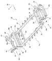
はじめに、図1~図5を参照して、車両10の全体構成について簡単に説明する。図1は、車両10を外側から見た斜視図である。また、図2は、車両中央から車両前方を見た車室内の斜視図であり、図3は、車両前部から車両後方を見た車室内の斜視図である。さらに、図4、図5は、車両10のメインフレーム12の斜視図である。
<Overall composition>
First, the general configuration of the
この車両10は、特定の敷地内において、規定のルートに沿って自動運転で走行しながら、乗客を輸送するバスとして利用される。したがって、当該車両10は、比較的、高頻度で、停車と発進を繰り返し、また、比較的、高頻度で、乗客の乗降のためにドア22を開閉する。また、この車両10は、比較的、低速(例えば30km/h以下)で走行する。
This
ただし、本明細書で開示する車両10の利用形態は、適宜、変更可能であり、例えば、当該車両10を、移動可能なビジネススペースとして利用してもよい。例えば、車両10は、各種商品を陳列販売する小売店や、飲食物を調理して提供する飲食店などの店舗として用いられてもよい。また、別の形態として、車両10は、事務作業や顧客との打ち合わせ等を行うためのオフィスとして用いられてもよい。また、車両10は、顧客や荷物を輸送するタクシーやバス、運送用車両として用いられてもよい。また、車両10の利用シーンは、ビジネスに限らず、例えば、車両10は、個人の移動手段として用いられてもよい。また、車両10の走行パターンや走行速度も、適宜変更されてもよい。
However, the usage form of the
この車両10は、駆動モータを原動機として有した電気自動車である。車両10には、この駆動モータに電力を供給するためのメインバッテリ106(図15参照)が搭載されている。後述する空調装置50は、このメインバッテリ106からの電力で駆動する。メインバッテリ106は、充放電可能な二次電池であり、定期的に外部電力により充電される。なお、空調装置50に電力供給するバッテリを有するのであれば、車両10は、電気自動車に限らず、他の形式の自動車でもよい。例えば、車両10は、エンジンを原動機として搭載したエンジン自動車でもよいし、エンジンおよび駆動モータを原動機として搭載したハイブリッド自動車でもよい。さらに、車両10は、燃料電池で発電した電力で駆動モータを駆動する燃料電池自動車でもよい。
This
また、この車両10は、上述した通り自動運転で走行可能である。ここで、「自動運転」とは、動的運転タスクのほぼ全てを車両10が行うことを意味しており、例えば、米国の自動車技術会(SAE)で定められたレベル3からレベル5のいずれかを意味する。レベル3は、高速道路等、特定の場所において、全ての動的運転タスクが自動化されているものの、緊急時には、ドライバーの操作が必要となる運転形態である。また、レベル4は、特定の場所に限り、全ての動的運転タスクが自動化されており、緊急時の対応も自動的に処理される運転形態である。レベル5は、場所等の制限なく、ほぼ全ての条件で自動運転が可能な運転形態であり、いわゆる、「完全自動運転」を意味する。なお、車両10は、自動運転機能ではなく、動的運転タスクの一部を車両10が行う運転支援機能を有するものでもよい。「運転支援」とは、例えば、SAEで定められたレベル1またはレベル2を意味する。レベル1において、車両10は、ステアリング操作および加減速のいずれか一方をサポートする。レベル2において、車両10は、ステアリング操作と加減速の両方を、連携させながら運転をサポートする。
In addition, the
こうした自動運転または運転支援を可能にするために、車両10には、当該車両10の周辺の情報検知するための1以上の周辺情報センサ130が搭載されている。周辺情報センサ130は、周辺情報を検知できるセンサであれば、特に限定されない。したがって、周辺情報センサ130は、例えば、周辺の像を撮像するカメラ(可視光カメラや赤外線カメラ等)でもよい。また、周辺情報センサ130は、電波を使用して物体を検知するレーザセンサ、例えば、ミリ波レーダなどでもよい。さらに、周辺情報センサ130は、光を使用して物体を検知する光センサ、例えば、赤外線センサやライダー(Lidar)等でもよい。本例では、周辺情報センサ130のうち、少なくとも一つを、車両10の天井の外表面に搭載している。
In order to enable such automatic driving or driving assistance, the
車両10は、図1に示すとおり、ボンネットおよびトランクを有しておらず、前端面および後端面が略鉛直に立ち上がる略箱状(直方体状)の外形を有している。この車両10の前端近傍には、一対の前輪18が、後端近傍には、一対の後輪20が、それぞれ設けられている。車両10の側面には、大きな窓13が設けられている。また、車両10の左側面中央には、車両の前後方向にスライドして開閉する両開きスライドタイプのドア22が設けられている。つまり、本例では、車幅方向両側面のうち、一方の側面にドア22が形成され、他方の側面にはドア22は、形成されていない。
As shown in FIG. 1, the
車両10の前端面には、ウィンドシールドとして機能する窓13と、当該窓13の下側に配されたランプ配置部14と、が設けられている。ランプ配置部14には、車両の存在および挙動を光によって車外者に知らせるための信号用ランプ15が配置されている。このランプ配置部14の下端には、車両内に外気を導くためのフロントグリル24fが設けられている。車両10の後端面は、車両の前端面とほぼ同じ構成となっており、窓13とランプ配置部14が上下に並ぶとともに、ランプ配置部14の下端にリアグリル24r(図1では見えず)が配置されている。したがって、本例の車両10は、ほぼ前後対称の外観を有している。
A
図2に示すように、車両10の車室前部には、オペレーターからの支持を受け付ける操作パネル26が設けられている。また、フロアパネル100の前端近傍は、乗員が車両後方に向かって座ることができる座席28を構成するように、盛り上がっている。同様に、図3に示すように、フロアパネル100の後端近傍は、乗員が車両前方に向かって座ることができる座席28を構成するように、盛り上がっている。車室のうちドア22の周辺には、シート等の大型の内装品は、固定設置されておらず、広めの空間が確保されている。
As shown in FIG. 2, an
本例の車両10は、梯状のメインフレーム12の上に、箱形のボディ16が組み付けられるボディ・オン・フレーム構造となっている。メインフレーム12は、図4、図5に示す通り、一対の前輪18の間に位置するフロントパートPfと、一対の後輪20の間に位置するリアパートPrと、フロントパートPfおよびリアパートPrの間に位置するセンターパートPcと、に大別される。フロントパートPfには、車両前後方向に延びる一対のフロントサイドメンバ30と、当該一対のフロントサイドメンバ30を連結するクロスメンバ36a,36b,36cと、が設けられている。クロスメンバ36cは、二つのフロントサイドメンバ30の後端同士を連結する。フロントサイドメンバ30の上面からは、エアサスペンション(図示せず)を取り付けるためのサスペンションタワー40が立脚している。
The
リアパートPrも、フロントパートPfと同様に、車両前後方向に延びる一対のリアサイドメンバ34と、当該一対のリアサイドメンバ34を連結するクロスメンバ36i,36j,36kと、が設けられている。クロスメンバ36iは、二つのリアサイドメンバ34の前端同士を連結する。リアサイドメンバ34の上面からは、エアサスペンション(図示せず)を取り付けるためのサスペンションタワー40が立脚している。
Similarly to the front part Pf, the rear part Pr is also provided with a pair of
センターパートPcには、車両前後方向に延びる一対のセンターサイドメンバ32と、当該一対のセンターサイドメンバ32を連結するクロスメンバ36d,36e,36f,36g,36hと、が設けられている。クロスメンバ36dは、一対のセンターサイドメンバ32の前端同士を連結しており、クロスメンバ36hは、一対のセンターサイドメンバ32の後端同士を連結している。また、クロスメンバ36eは、クロスメンバ36dの後方に隣接して設けられており、クロスメンバ36gは、クロスメンバ36hの前方に隣接して設けられている。換言すれば、センターパートPcの前端および後端には、車幅方向に延びる二本のクロスメンバ36が前後方向に積層して配置されている。これにより、センターパートPcの歪みがより効果的に防止される。
The center part Pc is provided with a pair of
ここで、図4、図5から明らかな通り、センターパートPcは、フロントパートPfおよびリアパートPrよりも下方に位置している。そのため、センターパートPcとフロントパートPfの境界には、上下に延びてクロスメンバ36cとクロスメンバ36dを接続するキック部材38が設けられている。同様に、センターパートPcとリアパートPrとの境界にも、上下に延びてクロスメンバ36iとクロスメンバ36hを接続するキック部材38が設けられている。
Here, as is clear from FIGS. 4 and 5, the center part Pc is located below the front part Pf and the rear part Pr. Therefore, a
以上のようなメインフレーム12に、原動機、動力伝達装置、ブレーキ装置、走行装置、懸架装置、かじ取り装置、電気装置等が組み付けられ、シャシを構成する。ここで、上述した通り、フロアパネル100の前部(フロントパートPfに対応する部分)および後部(リアパートPrに対応する部分)は、上方に盛り上がっている。上述した原動機および各種装置の大部分は、このフロアパネル100の盛り上がり部分の下側空間に配置される。以下では、フロアパネル100の前部盛り上がり部分の下側(車両10の前下角部であり、一対の前輪18の間部分)の空間を「前側収容空間94f」と呼ぶ。同様に、フロアパネル100の後部盛り上がり部分の下側(車両10の後下角部であり、一対の後輪20の間部分)の空間を「後側収容空間94r」と呼ぶ。さらに、前側、後側を区別しない場合には、添字f,rを省略し、単に、「収容空間94」と呼ぶ。
A prime mover, a power transmission device, a brake device, a traveling device, a suspension device, a steering device, an electric device, and the like are assembled to the
箱型のボディ16は、このメインフレーム12の上に組み付けられる。図1に示すように、ボディ16は、例えば、車両上下方向に延びるピラー42,44や、車両10の側面および天面の境界において前後方向に延びるレール46、フロアパネル100の車幅方向端部を下側から支えるべく前後方向に延びるロッカ48(図16参照、図1では、ロッカモール110で隠れて見えず)等を有している。なお、以下では、車両10の側面と、前面または後面と、の境界に設けられるピラーを「第一ピラー42」と呼び、車両10の側面中間部分に設けられ、第一ピラー42よりも車両前後方向中心寄りに位置するピラーを「第二ピラー44」と呼ぶ。
A box-shaped
<空調装置50の全体構成>
次に、この車両10に搭載される空調装置50の全体構成について説明する。図6は、空調装置50の構成を示すブロック図である。図6に示す通り、本例の空調装置50は、車室の前部を空調する前側空調ユニット52fと、車両の後部を空調する後側空調ユニット52rと、これら二つのユニットの駆動を制御する制御部51と、を有している。この二つの空調ユニット52f,52rの構成は、ほぼ同じである。また、両者を区別しない場合には、添字f,rを省略して「空調ユニット52」呼ぶ。
<Overall Configuration of
Next, the overall configuration of the
制御部51は、例えば、プロセッサとメモリとを有したコンピュータでもよいし、マイコンやアナログ回路、パワー・トランジスタ等を配線基板に搭載した電子制御ユニット(ECU)などでもよい。制御部51には、各空調ユニットに搭載されたセンサでの検知結果や、操作パネル26を介して入力されたオペレーターからの指示等が入力される。制御部51は、これらの入力された信号に基づいて、必要な制御量を算出し、当該制御量が得られるように、空調ユニット52を構成する各機器に駆動信号を出力する。
The
二つの空調ユニット52は、互いに独立して駆動可能となっている。このように互いに独立した空調ユニット52を二つ設けることで、一方の空調ユニット52に不備が生じた場合でも、他方の空調ユニット52で空調できるため、空調装置50の信頼性を向上できる。
The two
次に、各空調ユニット52の構成について説明する。図7は、一つの空調ユニット52の構成を示す模式図である。この空調ユニット52は、冷媒が循環して流れる冷媒配管74と、当該冷媒配管74の途中に設けられたコンプレッサ60、コンデンサ62、膨張弁58、および、エバポレータ54を有している。コンプレッサ60は、気体状態の冷媒を圧縮し、高温高圧の液体状態にする。コンデンサ62は、冷媒と外気とを熱交換させる熱交換器である。コンデンサ62の背後には、外気をコンデンサ62に導く電動ファン64が設けられている。また、膨張弁58は、冷媒を急速に膨張させてエバポレータ54またはコンデンサ62に送る。エバポレータ54は、車室内の空気と熱交換する熱交換器である。エバポレータ54の背後には、車室内空気をエバポレータ54に送るとともに、熱交換後の空気を車室内に吹き出すブロアファン56が設けられている。
Next, the configuration of each
冷房サイクルでは、コンプレッサ60から高温高圧で半液状の冷媒がコンデンサ62に出力される。コンデンサ62は、この冷媒を外気で冷却し、液状に変化させる。膨張弁58は、コンデンサ62から送られた液状の冷媒を微細なノズル穴からエバポレータ54内に噴射し、一気に気化させる。この冷媒の気化に伴い、エバポレータ54の周辺の熱が奪われていき、エバポレータ54が冷却される。このエバポレータ54にブロアファン56の風を通過させることで、車室内に冷気が送られる。エバポレータ54を出た冷媒は、コンプレッサ60に戻り再び圧縮される。なお、図7において、冷媒配管74のうち、薄墨ハッチング部分は、冷房時において冷媒が気体状態となる範囲を、濃墨ハッチング部分は、冷房時において冷媒が液体または半液体状態となる範囲を示している。また、暖房サイクルでは、冷媒の流れが冷房サイクルと逆になる。
In the cooling cycle, the
ここで、本例は、上述した通り、低速で走行し、停車とドア22の開閉を頻繁に行う車両10を想定している。かかる車両では、走行風が乏しく、コンプレッサ60での冷媒の冷却効率が低くなりがちであった。また、頻繁にドア22が開閉されることで、車室内の冷気が外部に逃げやすく、冷房効率が低下しやすかった。そのため、本例で想定するような車両10では、冷房に際して多量の電力が必要になるという問題があった。
Here, in this example, as described above, it is assumed that the
そこで、本例では、冷房時における消費電力を低減するために、コンプレッサ60の前方に、水をミスト状にして噴霧する噴霧ノズル66を設けている。このミスト水は、コンプレッサ60を挟んで電動ファン64の反対側、すなわち、コンプレッサ60を通過する外気の流路途中であって、コンプレッサ60より上流側位置に噴霧される。噴霧されたミスト水は、コンプレッサ60の直前で気化し、周辺から熱を奪う。これにより、コンプレッサ60には、当該噴霧ノズル66が無い場合と比べて、冷たい空気が吹き込む。その結果、より効率的に冷媒を冷却でき、冷房効率を向上できる。そして、結果として、消費電力を大幅に低減できる。これは、メインバッテリ106に蓄電された電力を走行用のエネルギー源とする電気自動車では、連続走行時間の増加、充電頻度の低下に繋がるため、非常に大きなメリットとなる。
Therefore, in this example, in order to reduce power consumption during cooling, a
空調装置50は、この噴霧ノズル66に供給する水を貯留する水タンク68も備えている。水タンク68と噴霧ノズル66は、出力ホース76aで連結されており、当該出力ホース76aの途中には、貯留水を噴霧ノズル66に圧送するウォーターポンプ69が設けられている。また、水タンク68には、ドレンホース76bおよび給水ホース76dも接続されている。ドレンホース76bは、冷房時にエバポレータ54で発生した凝縮水を水タンク68に導くホースである。このように、冷房時に発生する凝縮水を廃棄することなく、ミスト噴霧に利用することで、水タンク68への給水の頻度を低減でき、空調装置50の管理の手間を軽減できる。
The
ドレンホース76bの途中には、雨水ホース76cが合流している。雨水ホース76cは、雨水回収口78に接続されたホースである。雨水回収口78は、車両10の天面に設けられており、雨水を雨水ホース76cに導く開口である。このように、凝縮水に加えて、雨水も回収して蒸留することで、水タンク68への給水の頻度をより低減でき、空調装置50の管理の手間を軽減できる。
A
さらに、給水ホース76dは、水タンク68と給水口72とを連通するホースである。給水口72は、後に詳説する通り、車両10の下部に設けられ、外部の水道ホースと連結可能な部位である。凝縮水および雨水だけでは、水が不足する場合には、当該給水口72から給水ホース76dを介して水タンク68に給水される。水タンク68には、貯留量を検知するセンサ、例えば、液面レベルを検知するレベルセンサ70や、貯留水の重量を検知する重量センサ等が設けられている。制御部51は、このセンサでの検知結果に基づいて、貯留量が一定以下になれば、オペレーターにアラームを出力する。また、制御部51は、空調装置50の駆動に連動してウォーターポンプ69を駆動し、ミスト水をコンプレッサ60近傍に噴霧させる。このように、凝縮水および雨水を溜めるだけでなく、外部からも給水可能とすることで、より長期間、水の噴霧が可能となり、空調装置50の冷房効率をより長期間、向上させることができる。
Furthermore, the
<空調装置の配置の概要>
次に、こうした空調ユニット52を構成する各部材の配置について図7、図8を参照して説明する。図8は、空調装置50の主な構成要素の配置を示す斜視図である。上述した通り、本例の空調装置50は、前側空調ユニット52fと後側空調ユニット52rと、に大別される。各空調ユニット52は、さらに、その配置に基づいて、天井パートPt、下部パートPb、給水パートPwに大別できる。
<Outline of Air Conditioner Layout>
Next, the arrangement of each member constituting the
天井パートPtは、車両の天井部分に配置されるもので、エバポレータ54、ブロアファン56、膨張弁58、および雨水回収口78等が含まれる。このうち、エバポレータ54、ブロアファン56、および、膨張弁58は、一つのケースに収容され、一部品化されている。以下では、この一部品化されたものを、「天井アセンブリ79」と呼ぶ。
The ceiling part Pt is arranged in the ceiling part of the vehicle, and includes the
車両10の天井部分には、天井外装パネル84と天井内装パネル86(図8では図示せず、図9参照)が設けられており、両者の間には、天井空間88が存在している。本例では、この天井空間88に、天井アセンブリ79を配置している。なお、図8から明らかな通り、前側空調ユニット52fの天井アセンブリ79は、天井空間88の前端近傍に、後側空調ユニット52rの天井アセンブリ79は、天井空間88の後端近傍に、配置されている。また、雨水回収口78として機能する開口は、車両10の天井部の略中央に設けられている。
A
下部パートPbを構成するコンプレッサ60、コンデンサ62、および噴霧ノズル66は、前側収容空間94fまたは後側収容空間94rに配置される。具体的には、前側収容空間94f内には、前側から順に、前側空調ユニット52fの噴霧ノズル66、コンデンサ62、およびコンプレッサ60が配置されている。また、後側収容空間94r内には、前側から順に、後側空調ユニット52rのコンプレッサ60、噴霧ノズル66、およびコンデンサ62が配置されている。なお、後側空調ユニット52rのコンデンサ62の上側には、モータユニット112の冷却に利用されるラジエータ80が配置されている。
The
給水パートPwを構成する水タンク68は、車両10の床下に配置される。本例では、車両の床下のうち、前側収容空間94fと隣接する箇所に、前側空調ユニット52fの水タンク68を、後側収容空間94rと隣接する箇所に、後側空調ユニット52rの水タンク68を、それぞれ配置している。また、車両10の側面下端(ロッカ48の下側)には、給水口72が設けられている。この給水口72は、給水ホース76dを介して、二つの水タンク68に連結されている。したがって、本例では、前側空調ユニット52fおよび後側空調ユニット52rで、一つの給水口72を共用している。
A
冷媒配管74のうち、天井アセンブリ79と下部パートPbとを接続する部分は、第一ピラー42内を通っている。すなわち、第一ピラー42は、インナパネルおよびアウターパネル(いずれも図示せず)を接合して構成されるが、両者の間には、空間が形成される。本例では、この空間内に、冷媒配管74を通している。
A portion of the
また、天井アセンブリ79および水タンク68を接続するドレンホース76bは、第二ピラー44内を通っている。本例では、天井アセンブリ79の車幅方向両端からドレンホース76bを引き出し、車両の両サイドに設けられた第二ピラー44に通している。したがって、車両全体では、4本のドレンホース76bが4本の第二ピラー44を通っている。
Also, a
つまり、本例では、上下に延びる冷媒配管74およびドレンホース76bを、いずれも、ピラー42,44に通している。かかる構成とすることで、冷媒配管74およびドレンホース76bを隠すための専用の部材を別途設ける必要がなく、車両の構成をより簡易化できる。また、コンプレッサ60は、車両10の前部または後部に配置され、水タンク68は、当該コンプレッサ60よりも車両前後方向中心寄りに配置される。かかるコンプレッサ60に連結される冷媒配管74を第一ピラー42に、コンプレッサ60に連結されるドレンホース76bを第一ピラー42より中心寄りに位置する第二ピラー44に、それぞれ通すことで、冷媒配管74およびドレンホース76bの距離を短くできる。その結果、材料費を低減できる。また、冷媒配管74の距離が短くなれば、その分、冷媒の熱損失が低減されるため、空調効率の更なる向上が図れる。
In other words, in this example, the vertically extending
雨水ホース76cは、車両10の天井近傍で、このドレンホース76bに、合流している。給水口72に接続された給水ホース76dは、ロッカ48の側部において前後方向に延び、二つの水タンク68に連結されている。
The
<天井アセンブリ>
次に、天井アセンブリ79の構成について説明する。図9は、天井アセンブリ79周辺での概略断面図である。天井アセンブリ79は、既述した通り、天井外装パネル84と天井内装パネル86との間に形成される天井空間88に配置されている。天井内装パネル86のうち、天井アセンブリ79との対向部分には、車室内と天井空間88とを連通する通気口90が形成されている。また、通気口90と天井アセンブリ79との間には、空気流れをガイドするダクト82が配置されている。この通気口90およびダクト82を介して、車室内の空気が天井アセンブリ79に導かれるとともに、天井アセンブリ79から出力される調温後の空気が車室内に放出される。したがって、空調空気は、車室の天面から噴き出される。
<Ceiling assembly>
Next, the configuration of the
ここで、空調吹き出し口を車室の天面に設けた車両は、従来からいくつか知られている。しかしながら、従来の車両では、車両の天井空間に、エバポレータ、ブロアファン、および、膨張弁に加えて、さらに、コンプレッサやコンデンサも設けていた。この場合、これら全ての部品を収容するために、天井空間の厚みを増加させる必要がある。天井空間の厚みを増加させるために、空調ユニットの配置箇所において、天井外装パネルを外側(上側)に突出させることも考えられるが、この場合、車両の意匠の自由度が低下し、また、車高が増加するという問題があった。また、天井外装パネルではなく、天井内装パネルを内側(下側)に突出させれば、車高の増加を抑えつつ天井空間の厚みを確保できるが、この場合には、車室の天井が低くなり、車室空間の開放感が損なわれる。 Here, conventionally, there are several known vehicles in which an air conditioning outlet is provided on the top surface of the passenger compartment. However, in conventional vehicles, in addition to the evaporator, blower fan, and expansion valve, a compressor and a condenser are also provided in the ceiling space of the vehicle. In this case, the thickness of the ceiling space needs to be increased to accommodate all these parts. In order to increase the thickness of the ceiling space, it is conceivable to make the ceiling exterior panel protrude outward (upward) at the location where the air conditioning unit is arranged. There was a problem of height increase. In addition, if the ceiling interior panel instead of the ceiling exterior panel protrudes inward (downward), it is possible to secure the thickness of the ceiling space while suppressing the increase in vehicle height, but in this case, the ceiling of the passenger compartment is low. As a result, the sense of openness of the passenger compartment space is spoiled.
本例では、天井空間88に、天井アセンブリ79(エバポレータ54、ブロアファン56、膨張弁58)のみを配置しているため、天井空間88の厚みを小さく抑えることができる。その結果、車高を抑えつつも、車室の天井を高くすることができる。また、天井空間88を薄くできるため、車両の意匠の自由度を向上できる。
In this example, since only the ceiling assembly 79 (the
ここで、上述した通り、本例では、少なくとも一つの周辺情報センサ130が、車両10の天井の外表面に搭載されている。周辺情報センサ130は、光または電波を送受して周辺情報を検知するため、周辺情報センサ130の近傍に光や電波を遮る突出部が存在すると、周辺情報を十分に検知できない。したがって、車両10の天井外表面に突出部等がある場合、周辺情報センサ130の設置位置が制限される。本例では、上述した通り、天井に、天井アセンブリ79のみを配置しており、車両10の天井外表面に大きな突出部が存在していない。その結果、周辺情報センサ130の搭載位置の自由度が向上する。
Here, as described above, in this example, at least one
ところで、車両10の天井には、直射日光が当たりやすく、夏場には、天井空間88の温度が上がりやすい。かかる天井空間88に、エバポレータ54等を配置した場合、冷却効率が低下するおそれがある。そこで、本例では、天井外装パネル84の裏面(天井内装パネル86との対向面)に、断熱シート92を貼り付けている。断熱シート92は、適度な断熱性を有するのであれば、その材質は特に限定されない。したがって、断熱シート92は、例えば、グラスウールやロックウール等の繊維系断熱材で形成されてもよいし、ウレタンフォームやフェノールフォーム等の発泡系断熱材で形成されてもよい。いずれにしても、天井外装パネル84の裏面に断熱シート92を貼り付けることで、天井空間88の温度上昇を抑制でき、空調装置50の冷房効率を向上できる。
By the way, the ceiling of the
<前側空調ユニットの下部パート>
次に、前側空調ユニット52fの下部パートPbについて説明する。図10は、前側収容空間94fに収容される下部パートPbの配置を示す模式図である。また、図11は、前側空調ユニット52fのコンデンサ62周辺の斜視図である。また、図12は、前側空調ユニット52fのコンプレッサ60の配置を示す概略斜視図である。
<Lower part of the front air conditioning unit>
Next, the lower part Pb of the front
図10に示すとおり、前側収容空間94f内には、前側から順に、噴霧ノズル66、コンデンサ62、電動ファン64、コンプレッサ60が配置されている。また、コンデンサ62の前方には、前側収容空間94fと外部とを連通するフロントグリル24fが配置されている。このフロントグリル24fは、車両10の前端面の下端に設けられている。
As shown in FIG. 10, a
フロントグリル24fを、前端面下端に配置するのは、ランプ配置部14を大きく確保するためである。ここで、フロントグリル24fを前端面下端に配置した場合、図10に示す通り、フロントグリル24fの上端は、コンデンサ62の高さ中心より下側に位置しており、フロントグリル24fが、コンデンサ62に比べて下側にオフセットしている。そのため、外気は、図10において、二点鎖線で示すように、フロントグリル24fから前側収容空間94f内に進入した後、電動ファン64により吸い込まれて上方に進む。そして、この外気は、コンデンサ62および電動ファン64を通過した後は、下方へと進み、前側収容空間94fの底部から外部へと流れていく。
The reason why the
つまり、本例において、コンデンサ62に流れ込む外気は、当該コンデンサ62周辺を頂部とする山なりの経路を流れる。フロントグリル24fとコンデンサ62との間には、こうした外気の流れをガイドするダクト83が設けられている。なお、前側収容空間94fには、空調ユニット52を構成する部品だけでなく、ブレーキ装置や操舵装置、エアサスペンションのポンプやエアタンク等が配置されている。コンデンサ62および電動ファン64を通過した外気は、これらブレーキ装置や操舵装置等の隙間を通って外部に放出される。
That is, in this example, the outside air flowing into the
前側空調ユニット52fのコンデンサ62は、図11に示すように、扁平な直方体であり、正面視で横長の長方形となっている。このコンデンサ62は、支持枠99で支持されている。この支持枠99の後部は、電動ファン64を支持するファンシュラウド(図示せず)と連結されている。その結果、コンデンサ62のすぐ背後には、電動ファン64が位置している。
As shown in FIG. 11, the
コンデンサ62の前方には、複数の噴霧ノズル66が配置されている。本例では、この噴霧ノズル66を、コンデンサ62の車幅方向両端近傍に二つずつ、合計四つ設けている。また、噴霧ノズル66は、その噴霧軸方向が、コンデンサ62の表面と平行になるような姿勢、具体的には、噴霧軸が車幅方向と平行になる姿勢で配置されている。かかる構成とすることで、ミストが、コンデンサ62に当たりにくくなるため、コンデンサ62の前方空間に広がりやすくなる。その結果、ミストをより均等に噴霧できる。各噴霧ノズル66は、ノズルブラケット120で支持されており、当該ノズルブラケット120は、支持枠99に取り付けられている。噴霧ノズル66から噴霧されたミストが、コンデンサ62の直前位置において、気化することでコンデンサ62に流れ込む外気温度を低下させることができる。そして、これにより、コンデンサ62での冷媒の冷却効率、ひいては、空調装置50の冷房効率を向上できる。
A plurality of
ここで、図10から明らかな通り、噴霧ノズル66は、いずれも、水タンク68よりも上方に配置されている。かかる構成とすることで、ウォーターポンプ69から圧力が付与されない限り、噴霧ノズル66から水が出力されない。その結果、出力ホース76aの途中に、水の漏出防止のためのバルブ等を設ける必要がなく、構成を簡易化できる。
Here, as is clear from FIG. 10 , all of the
前側空調ユニット52fのコンプレッサ60は、電動ファン64の背後に配置されている。このコンプレッサ60の配置を可能にするために、本例では、フロントパートPfに設けられた一対のクロスメンバ36a,36b(図5、図12参照)の間に支持プレート108を架け渡している。支持プレート108は、金属からなる略平板であり、その一端は、クロスメンバ36aに、その他端は、クロスメンバ36bに溶接されている。コンプレッサ60は、この支持プレート108の上に固定される。
The
なお、図12から明らかな通り、二つのクロスメンバ36a,36bは、いずれも、その車幅方向両端が、フロントサイドメンバ30に向かって立ち上がったような形状となっている。したがって、クロスメンバ36a,36bの車幅方向中間部分は、フロントサイドメンバ30よりも下側に位置している。これにより、コンプレッサ60の配置高さを低く抑えることができ、前側収容空間94fの空間効率を向上できる。
As is clear from FIG. 12 , the two
ここで、繰り返し述べる通り、前側空調ユニット52fのうち、コンデンサ62、コンプレッサ60、および噴霧ノズル66は、前側収容空間94fに配置している。かかる配置とするのは、上述した通り、天井アセンブリ79のサイズを低減し、車両10の天井周りの意匠の自由度を高めるためである。また、前側空調ユニット52fのうち、比較的重量の大きいコンプレッサ60を、車両10の下部に配置することで、車両10の安定性を向上できる。さらに、コンデンサ62をフロントグリル24fの背後に配置することで、当該コンデンサ62を天井に配置した場合と比べて、走行風がコンデンサ62に当たりやすくなり、冷却効率が向上する。
Here, as described repeatedly, the
なお、本例では、車両10前面のデザインの自由度を向上するために、コンデンサ62に対してフロントグリル24fが下方にオフセットした配置となっている。この場合でも、走行風が円滑にコンデンサ62に到達するように、本例では、フロントグリル24fの背後にダクト83を設けている。また、十分な流量の外気がコンデンサ62に流れるように、電動ファン64の回転速度を制御している。
In this example, the
<後側空調ユニットの下部パート>
次に、後側空調ユニット52rの下部パートPbについて説明する。図13は、後側空調ユニット52rに収容される下部パートPbの配置を示す模式図である。また、図14は、後側空調ユニット52rのコンデンサ62周辺の斜視図である。図13に示すとおり、後側収容空間94r内には、前側から順に、コンプレッサ60、噴霧ノズル66、コンデンサ62、電動ファン64が配置されている。また、電動ファン64の後方には、後側収容空間94rと外部とを連通するリアグリル24rが配置されている。このリアグリル24rは、フロントグリル24fと同様に、車両10の後端面の下端に設けられている。これにより、後側のランプ配置部14も大きく確保できる。
<Lower part of the rear air conditioning unit>
Next, the lower part Pb of the rear
したがって、後側空調ユニット52rにおいても、リアグリル24rの上端は、コンデンサ62の高さ中心より下側に位置しており、リアグリル24rが、コンデンサ62に比べて下側にオフセットしている。そのため、外気は、図13において、二点鎖線で示すように、後側収容空間94rの下側から後側収容空間94r内に進入した後、電動ファン64により吸い込まれて上方に進む。そして、この外気は、コンデンサ62および電動ファン64を通過した後は、下方へと進み、リアグリル24rから外部へと流れていく。つまり、本例においても、外気は、コンデンサ62周辺を頂部とする山なりの経路を流れる。このとき、電動ファン64から出力される外気(排気)の逆流を防止するために、本例では、電動ファン64とリアグリル24rとの間に、排気の流れをガイドするダクト83を設けている。
Therefore, in the rear
後側収容空間94rには、空調ユニット52を構成する部品に加え、駆動モータと伝達機構とを組み合わせたパワーユニット114や、当該パワーユニット114の駆動を制御するパワーコントロールユニット(PCU)116等が配置されている。コンデンサ62は、パワーユニット114のケースの側部に取り付けられている。
A
図14に示すように、後側空調ユニット52rのコンデンサ62も、扁平な直方体であり、正面視で横長の長方形となっている。また、後側空調ユニット52rのコンデンサ62の上側には、扁平な直方体形状のラジエータ80が配置されている。ラジエータ80は、パワーユニット114の冷却用の冷媒を冷却するためのものである。支持枠99は、このラジエータ80およびコンデンサ62を上下に並んだ状態で保持している。支持枠99の後部には、電動ファン64を支持するファンシュラウド(図示せず)と連結されており、コンデンサ62およびラジエータ80のすぐ背後には、電動ファン64が位置している。
As shown in FIG. 14, the
コンデンサ62の前方には、複数(図示例では四つ)の噴霧ノズル66が配置されている。この複数の噴霧ノズル66は、いずれも、その噴霧軸方向が、コンデンサ62の表面と平行になるような姿勢で配置されている。なお、後側空調ユニット52rでは、前側空調ユニット52fに比べて、複数の噴霧ノズル66の配置がばらついている。これは、後側空調ユニット52rのコンデンサ62周辺に、配置された様々な部材と噴霧ノズル66との干渉を避けるためである。すなわち、後側空調ユニット52rのコンデンサ62周辺には、空調に用いられる冷媒および水が流れる配管に加え、パワーユニット114の冷却用冷媒が流れる配管も設けられており、前側空調ユニット52fに比べてコンデンサ62周辺で利用できるスペースが限られている。その結果、後側空調ユニット52rでは、前側空調ユニット52fに比べて、複数の噴霧ノズル66の配置がばらついている。
A plurality of (four in the illustrated example)
以上の通り、後側空調ユニット52rにおいても、前側空調ユニット52fと同様に、コンプレッサ60、および噴霧ノズル66を、車両10の下部に配置することで、車両10の天井周りの意匠の自由度が向上し、車両10の安定性を向上できる。
As described above, in the rear air-
ところで、これまでの説明で明らかな通り、本例では、コンデンサ62および噴霧ノズル66を含む下部パートPbを二つ用意し、この二つの下部パートPbを車両10の前後に分割して配置している。かかる構成とすることで、コンデンサ62を大型化することなく、コンデンサ62をバランスよく配置できる。すなわち、コンデンサ62での熱交換の効率を高めるためには、コンデンサ62の表面積を広くすることが望ましい。しかし、車両10内、特に本例のようにボンネットやトランクを有さない箱状の車両10の場合、広い収容空間94を確保することは難しく、表面積の大きいコンデンサ62を搭載することは難しい。本例では、収容空間94に収まる程度のコンデンサ62を二つ用意し、これらを前後に分割して配置することで、一つ一つのコンデンサ62のサイズは抑えつつ、十分な冷却能力を得ることができる。
By the way, as is clear from the description so far, in this example, two lower parts Pb including the
<給水パート>
次に、給水パートPwの構成について説明する。図15は、センターパートPc周辺の概略斜視図である。給水パートPwは、ミスト水を貯留する水タンク68を有する。この水タンク68は、車室の床下に配置されている。より具体的には、前側空調ユニット52fの水タンク68は、センターサイドメンバ32とクロスメンバ36eとが交差する角部に配置されている。当該角部には、1辺がセンターサイドメンバ32の底面に、他の1辺がクロスメンバ36eの底面に溶接された、略三角形状の三角ブラケット104が設けられている。前側空調ユニット52fの水タンク68は、この三角ブラケット104の上に載置され、固定される。同様に、後側空調ユニット52rの水タンク68は、センターサイドメンバ32とクロスメンバ36gとが交差する角部に配置されている。当該角部にも、三角ブラケット104が設けられており、水タンク68は、この三角ブラケット104の上に載置され、固定される。
<Water supply part>
Next, the configuration of the water supply part Pw will be described. FIG. 15 is a schematic perspective view around the center part Pc. The water supply part Pw has a
車両の床下には、さらに、パワーユニット114に電力を供給するメインバッテリ106も配置されている。このメインバッテリ106は、車両前後方向に長尺な扁平形状である。このメインバッテリ106の厚み(高さ方向寸法)は、センターサイドメンバ32の高さ方向寸法とほぼ同じとなっている。このメインバッテリ106は、クロスメンバ36eおよびクロスメンバ36gとの間に、適度な隙間が生じるように配置される。水タンク68は、このメインバッテリ106と、クロスメンバ36eおよびクロスメンバ36gと、の間の隙間に配置されている。つまり、本例において水タンク68は、メインバッテリ106の前後に生じるデッドスペースを利用して配置されている。なお、かかる配置を可能にするために、水タンク68の厚み(高さ方向寸法)は、メインバッテリ106の厚み(高さ方向寸法)とほぼ同じになっている。
A
ここで、図15から明らかな通り、二つの水タンク68は、いずれも、車幅方向片側(本例では右側)に配置している。また、本例では、給水口72も、二つの水タンク68と同様に、車幅方向片側(本例では右側)に配置している。かかる構成とすることで、一つの給水口72と、二つの水タンク68を連通する給水ホース76dの経路をほぼ直線状にでき(図8参照)、給水ホース76dの取り回しを簡易化できる。また、本例では、車両10のドア22は、左側に設けられているが、二つの水タンク68を、この反対側である右側に設けている。換言すれば、比較的、重量の大きい水タンク68を、ドア22の反対側に配置することで、乗客の乗降に伴う車両の揺れを効果的に低減できる。また、そもそも、重量の大きい水タンク68を、床下に配置することで、車両10の重心を下げることができ、車両10の安定性をより向上できる。さらに、給水口72もドア22の反対側に配置することで、乗降時に、乗客の足等と給水口72との接触が効果的に防止される。
Here, as is clear from FIG. 15, both of the two
次に、給水口72の配置について図16を参照して説明する。図16は、給水口72周辺を正面から見た模式図である。車両10の側面下端には、車両前後方向に延びて、フロアパネル100の車幅方向両端を下側から支えるロッカ48が設けられている。給水口72と水タンク68を連結する給水ホース76dは、当該ロッカ48のすぐ外側を通っている。給水口72は、例えば、略円筒形の流体継手で構成されており、ロッカ48の斜め下方向に付き出るような姿勢で配置されている。
Next, the arrangement of the
このロッカ48の車幅方向外側には、当該ロッカ48を隠して意匠性を保つための樹脂部材であるロッカモール110が設けられている。ロッカモール110は、図16に示すように、水平方向外側に進んだ後、下方に垂れ下がる断面略L字形状のパネル部材である。給水口72の下端は、このロッカモール110の下端とほぼ同じか、僅かに高い位置にあり、給水口72は、車両10の外部から見ても、ロッカモール110の裏側に隠れて見えないようになっている。その一方で、ロッカモール110の下側には、外部の水道ホースが十分に通過できる程度のスペースが確保されているため、当該水道ホースと給水口72の接続は問題なく行える。
A
<その他の構成>
以上の説明から明らかな通り、本明細書で開示する空調装置50では、コンプレッサ60の直前で水を噴霧しているため、冷房効率をより向上できる。また、空調ユニット52を、天井パートPt、下部パートPb、給水パートPwに分けて配置することで、車両の意匠の自由度を向上することができる。ただし、これまで説明した構成は一例であり、エバポレータ54およびブロアファン56が天井部分に、コンデンサ62が車両下部に配置されるのであれば、その他の構成は、適宜、変更されてもよい。例えば、本例では、低速自動運転される略箱形の車両を例に挙げて説明したが、本例に開示の空調装置50は、他の形態の車両に搭載されてもよい。また、コンプレッサ60は、車両下部の収容空間94ではなく、天井空間88に配置されてもよい。同様に、膨張弁58は、天井空間88ではなく、収容空間94や、第一ピラー42内に設けられてもよい。
<Other configurations>
As is clear from the above description, in the
10 車両、12 メインフレーム、13 窓、14 ランプ配置部、15 信号用ランプ、16 ボディ、18 前輪、20 後輪、22 ドア、24f フロントグリル、24r リアグリル、26 操作パネル、28 座席、30 フロントサイドメンバ、32 センターサイドメンバ、34 リアサイドメンバ、36a~36k クロスメンバ、38 キック部材、40 サスペンションタワー、42 第一ピラー、44 第二ピラー、46 レール、48 ロッカ、50 空調装置、51 制御部、52f 前側空調ユニット、52r 後側空調ユニット、54 エバポレータ、56 ブロアファン、58 膨張弁、60 コンプレッサ、62 コンデンサ、64 電動ファン、66 噴霧ノズル、68 水タンク、69 ウォーターポンプ、70 レベルセンサ、72 給水口、74 冷媒配管、76a 出力ホース、76b ドレンホース、76c 雨水ホース、76d 給水ホース、78 雨水回収口、79 天井アセンブリ、80 ラジエータ、82,83 ダクト、84 天井外装パネル、86 天井内装パネル、88 天井空間、90 通気口、92 断熱シート、94f 前側収容空間、94r 後側収容空間、99 支持枠、100 フロアパネル、104 三角ブラケット、106 メインバッテリ、108 支持プレート、110 ロッカモール、112 モータユニット、114 パワーユニット、120 ノズルブラケット、130 周辺情報センサ、Pb 下部パート、Pc センターパート、Pf フロントパート、Pr リアパート、Pt 天井パート、Pw 給水パート。
10 vehicle, 12 main frame, 13 window, 14 lamp placement part, 15 signal lamp, 16 body, 18 front wheel, 20 rear wheel, 22 door, 24f front grill, 24r rear grill, 26 operation panel, 28 seat, 30 front side Member 32 Center side member 34 Rear side member 36a to 36k Cross member 38 Kick member 40 Suspension tower 42 First pillar 44 Second pillar 46 Rail 48 Rocker 50 Air conditioner 51 Control unit 52f Front air conditioning unit, 52r Rear air conditioning unit, 54 Evaporator, 56 Blower fan, 58 Expansion valve, 60 Compressor, 62 Condenser, 64 Electric fan, 66 Spray nozzle, 68 Water tank, 69 Water pump, 70 Level sensor, 72 Water inlet , 74 refrigerant pipe, 76a output hose, 76b drain hose, 76c rainwater hose, 76d water supply hose, 78 rainwater collection port, 79 ceiling assembly, 80 radiator, 82, 83 duct, 84 ceiling exterior panel, 86 ceiling interior panel, 88 ceiling Space 90 Vent 92 Thermal insulation sheet 94f Front storage space 94r Rear storage space 99 Support frame 100 Floor panel 104 Triangular bracket 106 Main battery 108 Support plate 110 Rocker molding 112 Motor unit 114 Power unit, 120 nozzle bracket, 130 peripheral information sensor, Pb lower part, Pc center part, Pf front part, Pr rear part, Pt ceiling part, Pw water supply part.
Claims (3)
前記車両は、車両を走行させる駆動モータを含むパワーユニットと、前記駆動モータを駆動する電力を蓄電したバッテリと、を有した電気自動車であり、
前記車載空調装置は、1以上の空調ユニットを有しており、
前記空調ユニットは、
車室内空気と冷媒とを熱交換させるエバポレータと、
前記車室内から前記エバポレータを通過して再度、車室内に向かう空気流れを生成するブロアファンと、
前記冷媒を圧縮するコンプレッサと、
前記冷媒と外気とを熱交換させるコンデンサと、
前記冷媒を前記エバポレータ、前記コンプレッサ、および前記コンデンサを通るように循環させる冷媒配管と、
水をミスト状にして前記コンデンサに向かう外気に噴霧する噴霧ノズルと、
を備えており、
前記エバポレータおよび前記ブロアファンは、前記車両の天井部に配置され、
前記コンデンサおよび前記噴霧ノズルは、車両下部に配置され、
前記車載空調装置は、車室前側を空調する前側空調ユニットと、車室後側を空調する後側空調ユニットと、を有しており、
前記前側空調ユニットの前記コンデンサおよび前記噴霧ノズルは、前記車両の一対の前輪の間に位置する前側収容空間に配置され、
前記後側空調ユニットの前記コンデンサおよび前記噴霧ノズルは、前記車両の一対の後輪の間に位置する後側収容空間に配置され、
前記後側収容空間には、さらに、前記パワーユニットと、前記パワーユニットを冷却するためのモータ用冷媒を冷却するラジエータが配置されており、
前記ラジエータは、前記後側空調ユニットの前記コンデンサと上下に並んで配置されている、
ことを特徴とする車両。 A vehicle equipped with an in-vehicle air conditioner,
The vehicle is an electric vehicle having a power unit including a drive motor for running the vehicle, and a battery storing electric power for driving the drive motor,
The in-vehicle air conditioner has one or more air conditioning units,
The air conditioning unit is
an evaporator for exchanging heat between the air inside the vehicle and the refrigerant;
a blower fan that generates an air flow from the vehicle interior through the evaporator and toward the vehicle interior again;
a compressor for compressing the refrigerant;
a condenser for exchanging heat between the refrigerant and outside air;
refrigerant piping for circulating the refrigerant through the evaporator, the compressor, and the condenser;
a spray nozzle for spraying water in the form of a mist into the outside air toward the condenser;
and
The evaporator and the blower fan are arranged on the ceiling of the vehicle,
The condenser and the spray nozzle are arranged at the bottom of the vehicle ,
The in-vehicle air conditioner has a front air conditioning unit for air conditioning the front side of the passenger compartment and a rear air conditioning unit for air conditioning the rear side of the passenger compartment,
the condenser and the spray nozzle of the front air conditioning unit are arranged in a front accommodation space located between a pair of front wheels of the vehicle;
the condenser and the spray nozzle of the rear air conditioning unit are disposed in a rear accommodation space located between a pair of rear wheels of the vehicle;
The power unit and a radiator for cooling a motor coolant for cooling the power unit are further disposed in the rear housing space,
The radiator is arranged vertically with the condenser of the rear air conditioning unit,
A vehicle characterized by:
前記車両は、その前端および後端が、当該車両の底部から天井まで略鉛直方向に延びる略箱形状であり、
前記車両は、自動運転可能である、
ことを特徴とする車両。 A vehicle according to claim 1 ,
The vehicle has a substantially box-shaped front end and a rear end extending substantially vertically from the bottom of the vehicle to the ceiling,
the vehicle is capable of autonomous driving;
A vehicle characterized by:
前記車両の前端面の下端および後端面の下端の少なくとも一方には、外気の通過を許容するグリルが設けられており、
前記コンデンサは、前記グリルと前後方向に対向して配置されており、
前記グリルの上端は、前記コンデンサの中央高さより下方にある、
ことを特徴とする車両。 A vehicle according to claim 1 or 2 ,
At least one of the lower end of the front end surface and the lower end of the rear end surface of the vehicle is provided with a grill that allows passage of outside air,
The condenser is arranged to face the grill in the front-rear direction,
the upper edge of the grill is below the center height of the condenser;
A vehicle characterized by:
Priority Applications (3)
| Application Number | Priority Date | Filing Date | Title |
|---|---|---|---|
| JP2019121186A JP7207202B2 (en) | 2019-06-28 | 2019-06-28 | vehicle |
| CN202010586173.1A CN112140838B (en) | 2019-06-28 | 2020-06-24 | Vehicle-mounted air conditioner and vehicle |
| US16/912,713 US11602978B2 (en) | 2019-06-28 | 2020-06-26 | Vehicle air conditioner and vehicle |
Applications Claiming Priority (1)
| Application Number | Priority Date | Filing Date | Title |
|---|---|---|---|
| JP2019121186A JP7207202B2 (en) | 2019-06-28 | 2019-06-28 | vehicle |
Publications (2)
| Publication Number | Publication Date |
|---|---|
| JP2021006434A JP2021006434A (en) | 2021-01-21 |
| JP7207202B2 true JP7207202B2 (en) | 2023-01-18 |
Family
ID=73887520
Family Applications (1)
| Application Number | Title | Priority Date | Filing Date |
|---|---|---|---|
| JP2019121186A Active JP7207202B2 (en) | 2019-06-28 | 2019-06-28 | vehicle |
Country Status (3)
| Country | Link |
|---|---|
| US (1) | US11602978B2 (en) |
| JP (1) | JP7207202B2 (en) |
| CN (1) | CN112140838B (en) |
Families Citing this family (4)
| Publication number | Priority date | Publication date | Assignee | Title |
|---|---|---|---|---|
| JP2021006441A (en) | 2019-06-28 | 2021-01-21 | トヨタ自動車株式会社 | On-vehicle air conditioner |
| JP7211289B2 (en) * | 2019-06-28 | 2023-01-24 | トヨタ自動車株式会社 | In-vehicle air conditioner |
| JP7211290B2 (en) * | 2019-06-28 | 2023-01-24 | トヨタ自動車株式会社 | In-vehicle air conditioner |
| DE102019213860A1 (en) * | 2019-09-11 | 2021-03-11 | Mahle International Gmbh | Air conditioning system for a motor vehicle |
Citations (2)
| Publication number | Priority date | Publication date | Assignee | Title |
|---|---|---|---|---|
| JP2008273261A (en) | 2007-04-25 | 2008-11-13 | Mitsubishi Heavy Ind Ltd | Air conditioner for vehicle |
| JP2010173357A (en) | 2009-01-27 | 2010-08-12 | Calsonic Kansei Corp | Vehicle cooling apparatus |
Family Cites Families (29)
| Publication number | Priority date | Publication date | Assignee | Title |
|---|---|---|---|---|
| US2481135A (en) | 1948-02-19 | 1949-09-06 | Jr Sterling E Maness | Vehicle cooling system |
| US3926000A (en) | 1974-06-24 | 1975-12-16 | Carlie D Scofield | Automotive air conditioner and method of operating the same |
| US4516406A (en) | 1983-02-22 | 1985-05-14 | Gentry And Green Enterprises | Cooling system for motor vehicles |
| JPS6058418U (en) | 1983-09-29 | 1985-04-23 | 株式会社東芝 | Vehicle air conditioner drain pipe structure |
| US5081912A (en) | 1991-02-05 | 1992-01-21 | Asha Corporation | Vehicle vent |
| US5211136A (en) | 1992-04-15 | 1993-05-18 | Dacus Gary T | Engine cooling apparatus |
| JPH0664029U (en) * | 1993-02-09 | 1994-09-09 | サンデン株式会社 | Vehicle air conditioner |
| US5456089A (en) | 1993-03-24 | 1995-10-10 | Tripac, Inc. | Universal condenser for an air conditioning system |
| JPH09207542A (en) * | 1996-02-08 | 1997-08-12 | Nippon Climate Syst:Kk | Integrated air-conditioner for automobile |
| KR100255336B1 (en) | 1996-12-31 | 2000-05-01 | 정몽규 | Air treating device for bus |
| JP3581065B2 (en) * | 1999-11-22 | 2004-10-27 | アルプス電気株式会社 | Dual air conditioning system for vehicles |
| US6658872B1 (en) | 2002-05-16 | 2003-12-09 | Dennis James | Air conditioner mist applicator |
| US6718787B1 (en) * | 2003-05-05 | 2004-04-13 | Carrier Corporation | Supply air blower design in bus air conditioning units |
| US7669557B2 (en) * | 2006-02-08 | 2010-03-02 | Toyota Jidosha Kabushiki Kaisha | Cooling device for vehicle |
| US20090199582A1 (en) | 2006-07-04 | 2009-08-13 | Renault Trucks | Air Conditioning System Operating On A Supercritical Cycle For Use In Motor Vehicles |
| JP2009035206A (en) | 2007-08-03 | 2009-02-19 | Masaru Kitano | Operation energy-saving device for bus vehicle |
| US20100307176A1 (en) * | 2009-06-03 | 2010-12-09 | Gm Global Technology Operations, Inc. | Water Cooled Condenser in a Vehicle HVAC System |
| JP6320071B2 (en) * | 2014-02-18 | 2018-05-09 | 大阪瓦斯株式会社 | Air conditioning system and heat exchange device |
| CN205001052U (en) * | 2015-09-30 | 2016-01-27 | 赵智强 | Heat abstractor is assisted to car waste water reclamation |
| EP3275706B1 (en) * | 2016-07-28 | 2020-04-08 | Carrosserie Hess AG | Installation for air conditioning a passenger compartment of a passenger bus |
| KR102474364B1 (en) * | 2017-12-04 | 2022-12-05 | 현대자동차 주식회사 | Thermal management system for vehicle |
| US10913414B2 (en) | 2018-03-02 | 2021-02-09 | Ford Global Technologies, Llc | Method and system for water usage on-board a vehicle |
| CN208704134U (en) | 2018-03-05 | 2019-04-05 | 中山大学 | Air-conditioning is sprayed cooling system |
| US10844774B2 (en) | 2018-03-26 | 2020-11-24 | Ford Global Technologies, Llc | Method and system for water collection and usage on-board a vehicle |
| US20200376924A1 (en) * | 2019-06-01 | 2020-12-03 | Webtez, Inc. | Vehicle Under Mounted HVAC Container |
| JP2021006441A (en) | 2019-06-28 | 2021-01-21 | トヨタ自動車株式会社 | On-vehicle air conditioner |
| JP7211290B2 (en) | 2019-06-28 | 2023-01-24 | トヨタ自動車株式会社 | In-vehicle air conditioner |
| JP2021006757A (en) | 2019-06-28 | 2021-01-21 | トヨタ自動車株式会社 | On-vehicle air conditioner |
| JP7211289B2 (en) | 2019-06-28 | 2023-01-24 | トヨタ自動車株式会社 | In-vehicle air conditioner |
-
2019
- 2019-06-28 JP JP2019121186A patent/JP7207202B2/en active Active
-
2020
- 2020-06-24 CN CN202010586173.1A patent/CN112140838B/en active Active
- 2020-06-26 US US16/912,713 patent/US11602978B2/en active Active
Patent Citations (2)
| Publication number | Priority date | Publication date | Assignee | Title |
|---|---|---|---|---|
| JP2008273261A (en) | 2007-04-25 | 2008-11-13 | Mitsubishi Heavy Ind Ltd | Air conditioner for vehicle |
| JP2010173357A (en) | 2009-01-27 | 2010-08-12 | Calsonic Kansei Corp | Vehicle cooling apparatus |
Also Published As
| Publication number | Publication date |
|---|---|
| CN112140838B (en) | 2023-08-08 |
| US11602978B2 (en) | 2023-03-14 |
| US20200406720A1 (en) | 2020-12-31 |
| CN112140838A (en) | 2020-12-29 |
| JP2021006434A (en) | 2021-01-21 |
Similar Documents
| Publication | Publication Date | Title |
|---|---|---|
| JP7211289B2 (en) | In-vehicle air conditioner | |
| JP7207202B2 (en) | vehicle | |
| US11529840B2 (en) | Vehicle air conditioner | |
| US20200406707A1 (en) | Vehicle air conditioner | |
| JP7211290B2 (en) | In-vehicle air conditioner | |
| CN112140841B (en) | Vehicle-mounted air conditioning device and vehicle | |
| EP3628519B1 (en) | Methods and systems for autonomous climate control optimization of a transport vehicle | |
| EP2212135B1 (en) | A vehicle-cabin air-conditioning system and a module containing the system | |
| US20110061414A1 (en) | Rooftop mounted air conditioner | |
| US6931884B2 (en) | Undermount transport temperature control unit | |
| EP2588333A1 (en) | Agricultural vehicle cab fitted with an hvac system | |
| JP6306276B1 (en) | Air-conditioning structure for mobile facilities | |
| KR20220169664A (en) | Mounting structure of thermal management module for vehicle | |
| CN202448813U (en) | Refrigerating device for transportation of common refrigerator truck | |
| CN215793494U (en) | Storage system | |
| CN212827788U (en) | Take chassis subassembly and freight train of refrigeration function | |
| KR20120057150A (en) | Air conditioning system for vehicle with three wheels | |
| JP2010030408A (en) | Arrangement structure of air conditioning device for vehicle | |
| JPH1178544A (en) | Cooling system for electric vehicle | |
| JP2010052560A (en) | Arrangement structure of air conditioning device for vehicle |
Legal Events
| Date | Code | Title | Description |
|---|---|---|---|
| A621 | Written request for application examination |
Free format text: JAPANESE INTERMEDIATE CODE: A621 Effective date: 20210827 |
|
| A977 | Report on retrieval |
Free format text: JAPANESE INTERMEDIATE CODE: A971007 Effective date: 20220727 |
|
| A131 | Notification of reasons for refusal |
Free format text: JAPANESE INTERMEDIATE CODE: A131 Effective date: 20220802 |
|
| A521 | Request for written amendment filed |
Free format text: JAPANESE INTERMEDIATE CODE: A523 Effective date: 20220830 |
|
| TRDD | Decision of grant or rejection written | ||
| A01 | Written decision to grant a patent or to grant a registration (utility model) |
Free format text: JAPANESE INTERMEDIATE CODE: A01 Effective date: 20221206 |
|
| A61 | First payment of annual fees (during grant procedure) |
Free format text: JAPANESE INTERMEDIATE CODE: A61 Effective date: 20221219 |
|
| R151 | Written notification of patent or utility model registration |
Ref document number: 7207202 Country of ref document: JP Free format text: JAPANESE INTERMEDIATE CODE: R151 |