JP7207156B2 - Vehicle opening/closing body stopping device - Google Patents
Vehicle opening/closing body stopping device Download PDFInfo
- Publication number
- JP7207156B2 JP7207156B2 JP2019093633A JP2019093633A JP7207156B2 JP 7207156 B2 JP7207156 B2 JP 7207156B2 JP 2019093633 A JP2019093633 A JP 2019093633A JP 2019093633 A JP2019093633 A JP 2019093633A JP 7207156 B2 JP7207156 B2 JP 7207156B2
- Authority
- JP
- Japan
- Prior art keywords
- opening
- back door
- drum
- worm
- rotating body
- Prior art date
- Legal status (The legal status is an assumption and is not a legal conclusion. Google has not performed a legal analysis and makes no representation as to the accuracy of the status listed.)
- Active
Links
Images


Description
本発明は、車両用開閉体停止装置に関する。 TECHNICAL FIELD The present invention relates to an opening/closing body stopping device for a vehicle.
特許文献1には、車両後部に開口部が形成される車体と、開口部を全開する全開位置及び開口部を全閉する全閉位置の間で変位するバックドアと、バックドアを全閉位置及び全開位置の間の任意の中間位置で停止させる開閉調節装置と、を備える車両が開示されている。開閉調節装置は、停止操作及び停止解除操作を行うための操作部材と、バックドアを開閉可能に保持する調節部と、を有する。調節部は、操作部材の停止操作に伴って任意の中間位置からバックドアが開方向に変位しないようにロックしたり、操作部材の停止解除操作に伴ってバックドアのロックを解除したりする。
こうして、車両の後方に障害物が存在するなどの理由により、バックドアを全開位置まで開動作できない状況下において、ユーザは、障害物の手前の位置でバックドアを停止させることが可能となる。 In this way, the user can stop the back door in front of the obstacle in a situation where the back door cannot be opened to the fully open position due to the presence of an obstacle behind the vehicle.
上記のような開閉調節装置は、バックドアの車両幅方向における一端部と車体の車両幅方向における一端部とを連結するように設置される。このため、開閉調節装置の操作部材は、バックドアを開操作するユーザにとって、必ずしも操作しやすい位置にあるとはいえない。本発明の目的は、ユーザが開閉体を任意の位置で停止させるための操作を行いやすい車両用開閉体停止装置を提供することである。 The opening/closing adjustment device as described above is installed so as to connect one end of the back door in the vehicle width direction and one end of the vehicle body in the vehicle width direction. For this reason, the operation member of the opening/closing adjustment device is not necessarily located at a position that is easy for the user who opens the back door to operate. SUMMARY OF THE INVENTION An object of the present invention is to provide a vehicle opening/closing body stopping device that allows a user to easily perform an operation for stopping an opening/closing body at an arbitrary position.
以下、上記課題を解決するための手段及びその作用効果について記載する。
上記課題を解決する車両用開閉体停止装置は、車体に形成される開口部を閉塞する全閉位置及び前記開口部を開放する全開位置の間で開閉動作する開閉体を、前記全閉位置及び前記全開位置の間の任意の位置で停止させる車両用開閉体停止装置であって、前記開閉体が開方向及び閉方向の一方の方向に動作するときに第1回転方向に回転し、前記開閉体が開方向及び閉方向の他方の方向に動作するときに前記第1回転方向の逆方向となる第2回転方向に回転するドラムと、前記ドラムの前記第1回転方向の回転を制限するロック位置及び前記ドラムの前記第1回転方向の回転を許容するアンロック位置を含む移動範囲内を移動するロック部材と、前記ドラムが前記第2回転方向に回転した後に前記第1回転方向に回転することでノック動作するノック機構と、を備え、前記ノック機構は、前記ノック動作の度に、前記ロック部材を前記ロック位置に位置する状態及び前記ロック部材を前記アンロック位置に位置する状態の一方の状態から他方の状態に切り替わる。
Means for solving the above problems and their effects will be described below.
A vehicular opening/closing body stopping device that solves the above-described problems provides an opening/closing body that opens and closes between a fully closed position that closes an opening formed in a vehicle body and a fully open position that opens the opening. A vehicular opening/closing body stopping device for stopping at an arbitrary position between the fully open positions, wherein the opening/closing body rotates in a first rotation direction when operated in one of the opening direction and the closing direction, and a drum that rotates in a second rotational direction opposite to the first rotational direction when the body moves in the other of the opening direction and the closing direction; and a lock that restricts rotation of the drum in the first rotational direction. a locking member that moves within a range of movement including a position and an unlocked position that allows rotation of the drum in the first rotational direction; and a locking member that rotates in the first rotational direction after the drum rotates in the second rotational direction. a knocking mechanism that performs a knocking operation with each knocking operation, wherein the knocking mechanism moves the lock member to one of the state of positioning the lock member at the lock position and the state of positioning the lock member at the unlock position. state to the other state.
上記構成において、ノック機構は、開閉体が開方向及び閉方向の一方の方向に動作した後に他方の方向に動作することでノック動作する。つまり、ノック機構は、ユーザが開閉体を開閉操作することでノック動作する。したがって、車両用開閉体停止装置は、ユーザの開閉体の開閉操作により、開閉体を開方向又は閉方向に動作不能な状態としたり、開方向又は閉方向に動作不能な状態を解消したりできる。こうして、ユーザは、所望の位置で開閉体を停止させるための操作を行いやすくなる。 In the above configuration, the knock mechanism knocks by operating the opening/closing body in one of the opening and closing directions and then in the other direction. That is, the knock mechanism knocks when the user opens and closes the opening/closing body. Therefore, the vehicular opening/closing body stopping device can set the opening/closing body inoperable in the opening direction or the closing direction or eliminate the state in which the opening/closing body cannot operate in the opening direction or the closing direction, according to the user's opening/closing operation of the opening/closing body. . Thus, the user can easily perform an operation for stopping the opening/closing body at a desired position.
上記車両用開閉体停止装置は、前記ドラムから伝達される動力に基づいて回転するウォームホイールと、前記ウォームホイールから伝達される動力に基づいて軸方向に移動可能且つ周方向に回転可能に構成されるウォームと、前記ウォームを回転可能に支持するとともに前記ウォームの軸方向における移動量を規定する規制壁を有するケースと、を備え、前記ウォームは、前記ウォームホイールから動力が伝達されるとき、前記規制壁に接触するまでは、前記ウォームの周方向の回転よりも、前記ウォームの軸方向への移動を優先するように構成され、前記ノック機構は、前記ウォームが前記ウォームの軸方向における第1方向に移動する後に、前記ウォームが前記ウォームの軸方向における第2方向に移動することにより、前記ノック動作することが好ましい。 The vehicular opening/closing body stopping device includes a worm wheel that rotates based on power transmitted from the drum, and a worm wheel that is axially movable and circumferentially rotatable based on the power transmitted from the worm wheel. and a case having a regulating wall that rotatably supports the worm and regulates the amount of movement of the worm in the axial direction. The knock mechanism is configured to give priority to axial movement of the worm over circumferential rotation of the worm until the worm comes into contact with the regulating wall. It is preferable that the knocking action is performed by moving the worm in the second direction in the axial direction of the worm after moving in the direction.
上記構成の車両用開閉体停止装置は、ドラムの回転運動をウォームの軸方向の運動に変化させることで、ノック機構にノック動作させる。また、ウォームが規制壁に接触することでウォームが軸方向に移動できなくなる場合には、ウォームがウォームホイールから伝達される動力に基づいて周方向に回転する。したがって、車両用開閉体停止装置は、開閉体の開動作又は閉動作が継続される場合において、ウォームが第1方向又は第2方向に移動し続けることを抑制できる。 The vehicular opening/closing body stopping device configured as described above changes the rotational motion of the drum to the axial motion of the worm to cause the knock mechanism to perform a knocking operation. Further, when the worm cannot move in the axial direction due to contact with the regulating wall, the worm rotates in the circumferential direction based on the power transmitted from the worm wheel. Therefore, the vehicular opening/closing body stopping device can suppress the worm from continuing to move in the first direction or the second direction when the opening operation or the closing operation of the opening/closing body continues.
上記車両用開閉体停止装置において、前記ノック機構は、軸方向が前記第1方向及び前記第2方向となるように固定配置される筒体と、前記ウォームに押されることで、前記筒体に対して前記第1方向に移動するノック体と、前記筒体に対して前記筒体の周方向に回転することで、前記筒体との係合関係が変化する回転体と、前記回転体を前記第2方向に付勢する付勢部材と、を有し、前記筒体は、前記回転体と係合する第1係合面及び第2係合面が前記筒体の周方向に並ぶように形成され、前記ノック体は、前記ノック動作において、前記回転体が前記筒体の前記第1係合面又は前記第2係合面と係合しなくなるまで前記回転体を前記第1方向に押すことで前記回転体を前記筒体の周方向に回転させた後に、前記第2方向に移動するものであり、前記回転体は、前記第1係合面と係合する場合には、前記ロック部材を前記アンロック位置に位置させる前進位置に位置し、前記第2係合面と係合する場合には、前記前進位置よりも前記第2方向に移動することで前記ロック部材を前記ロック位置に位置させる後退位置に位置し、前記ノック動作の度に、前記筒体の周方向に回転することで、前記第1係合面と係合する状態及び前記第2係合面と係合する状態の一方の状態から他方の状態に切り替わることが好ましい。 In the above-described vehicular opening/closing body stopping device, the knock mechanism includes a cylindrical body that is fixedly disposed so that axial directions are aligned with the first direction and the second direction, and a cylinder that is pushed by the worm to move the knock mechanism to the cylindrical body. a knock body that moves in the first direction; a rotating body that rotates in the circumferential direction of the cylindrical body with respect to the cylindrical body to change the engagement relationship with the cylindrical body; and a biasing member that biases in the second direction, wherein the cylindrical body has a first engaging surface and a second engaging surface that engage with the rotating body arranged in the circumferential direction of the cylindrical body. and the knock body rotates the rotating body in the first direction until the rotating body disengages from the first engaging surface or the second engaging surface of the cylindrical body in the knocking operation. After rotating the rotating body in the circumferential direction of the cylindrical body by pushing, the rotating body moves in the second direction, and when the rotating body engages with the first engagement surface, the When the lock member is positioned at the advanced position where the lock member is positioned at the unlocked position and engages with the second engagement surface, the lock member is moved from the advanced position in the second direction to the locked position. By rotating in the circumferential direction of the cylindrical body each time the knocking operation is performed, the state of engagement with the first engagement surface and the engagement with the second engagement surface are achieved. It is preferable to switch from one state to the other state.
上記構成の車両用開閉体停止装置は、ウォームの軸方向における移動に基づく筒体と回転体との係合状態の切り替わりによって、開閉体を開方向又は閉方向に動作不能な状態としたり、当該動作不能な状態を解消したりできる。 In the vehicle opening/closing body stopping device having the above-described configuration, the opening/closing body is put into a state inoperable in the opening direction or in the closing direction by switching the engagement state between the cylindrical body and the rotating body based on the movement of the worm in the axial direction. You can remove the inoperable state.
上記車両用開閉体停止装置において、車両は、前記開閉体としてのバックドアと、前記バックドアを開動作させるモーメントを前記バックドアに付与するガススプリングと、を備え、前記ドラムは、前記バックドアが開動作するときに前記第1回転方向に回転し、前記開閉体が閉動作するときに前記第2回転方向に回転し、前記バックドアの自重に応じたモーメント及び前記ガススプリングの反力に応じたモーメントが釣り合うときの前記バックドアの位置を中立位置としたとき、前記ノック機構は、前記バックドアが前記中立位置よりも前記全閉位置寄りに位置する場合に、前記回転体が前記後退位置よりも前記第1方向に移動するように、前記回転体を前記第1方向に押すプッシュ体を有することが好ましい。 In the vehicle opening/closing body stopping device described above, the vehicle includes a back door as the opening/closing body, and a gas spring for applying a moment for opening the back door to the back door. rotates in the first rotation direction when the opening operation is performed, and rotates in the second rotation direction when the opening/closing body performs the closing operation, and the moment according to the weight of the back door and the reaction force of the gas spring When the position of the back door when the corresponding moments are balanced is assumed to be a neutral position, the knock mechanism is arranged so that the rotating body moves backward when the back door is positioned closer to the fully closed position than the neutral position. It is preferable to have a push body that pushes the rotating body in the first direction so as to move in the first direction rather than position.
開閉体が中立位置及び全閉位置の間に位置する場合、言い換えれば、開閉体の開度が小さい場合には、ユーザが開閉体を停止させる必要性が低い。この点、上記構成の車両用開閉体停止装置は、開閉体が中立位置よりも全閉位置寄りに位置する場合に、プッシュ体が回転体を後退位置よりも第1方向に移動させる。この場合には、ユーザが開閉体を開閉操作しても、回転体が後退位置に移動できなくなる点で、車両用開閉体停止装置が開閉体を停止できなくなる。こうして、車両用開閉体停止装置は、バックドアが全閉位置の近くに位置する場合に不用意にバックドアを停止させない点で、ユーザの利便性を高めることができる。 When the opening/closing body is positioned between the neutral position and the fully closed position, in other words, when the opening degree of the opening/closing body is small, the need for the user to stop the opening/closing body is low. In this regard, in the above-configured vehicular opening/closing body stopping device, the pushing body moves the rotating body in the first direction from the retracted position when the opening/closing body is located closer to the fully closed position than the neutral position. In this case, even if the user opens and closes the opening/closing body, the rotator cannot move to the retracted position, and the vehicle opening/closing body stopping device cannot stop the opening/closing body. Thus, the vehicular opening/closing body stopping device can improve the user's convenience in that the back door is not inadvertently stopped when the back door is positioned near the fully closed position.
上記車両用開閉体停止装置において、前記ノック機構は、前記ドラムから前記ウォームホイールに動力を伝達する中継ギヤを有し、前記中継ギヤには、前記中継ギヤの軸線と交差する方向に延びるカム溝が形成され、前記プッシュ体は、前記カム溝に係合するカム軸を有し、前記カム溝は、前記ドラムが前記第2回転方向に回転するに連れて、前記プッシュ体が前記第1方向に移動するように形成されることが好ましい。 In the vehicle opening/closing body stopping device, the knock mechanism has a relay gear for transmitting power from the drum to the worm wheel, and the relay gear has a cam groove extending in a direction intersecting the axis of the relay gear. is formed, and the push body has a cam shaft that engages the cam groove, and the cam groove is adapted to move the push body in the first direction as the drum rotates in the second direction of rotation. It is preferably configured to move to
上記構成によれば、バックドアが閉動作する場合には、プッシュ体が第1方向に移動し、バックドアが開動作する場合には、プッシュ体が第2方向に移動する。つまり、車両用開閉体停止装置は、バックドアが閉位置に近付く程、プッシュ体を第1方向に移動できる。 According to the above configuration, the push body moves in the first direction when the back door is closed, and the push body moves in the second direction when the back door is opened. That is, the vehicle opening/closing body stopping device can move the push body in the first direction as the back door approaches the closed position.
前記ノック動作において、前記ノック体が前記第1係合面に係合する前記回転体を前記第1方向に押したときの前記回転体の回転後の位置を第1の位置とし、前記ノック体が前記第2係合面に係合する前記回転体を前記第1方向に押したときの前記回転体の回転後の位置を第2の位置とし、前記プッシュ体は、前記バックドアが前記中立位置よりも前記全閉位置寄りに位置する場合に、前記回転体を前記第1方向に押すことで前記回転体を前記第2の位置まで回転させることが好ましい。 In the knocking operation, the position after rotation of the rotating body when the knocking body pushes the rotating body engaged with the first engaging surface in the first direction is defined as a first position. pushes the rotating body engaging with the second engaging surface in the first direction, the post-rotation position of the rotating body is defined as a second position; It is preferable to rotate the rotating body to the second position by pushing the rotating body in the first direction when the rotating body is positioned closer to the fully closed position than the fully closed position.
全閉位置からバックドアを開動作する際に、回転体が第1の位置に位置していると、バックドアの開動作中に、回転体が筒体の第2係合面と係合するおそれがある。この場合、ロック部材がドラムの第1回転方向の回転をロックするため、バックドアの開動作が意図せず停止されるおそれがある。この点、上記構成の車両用開閉体停止装置によれば、全閉位置からバックドアを開動作する際に、回転体が必ず第2の位置に位置する。このため、車両用開閉体停止装置は、全閉位置からバックドアを開動作させる際に、バックドアの開動作を意図せず停止させることを防止できる。 When the back door is opened from the fully closed position, if the rotating body is positioned at the first position, the rotating body engages the second engaging surface of the cylinder during the opening operation of the back door. There is a risk. In this case, since the lock member locks the rotation of the drum in the first rotation direction, there is a possibility that the opening operation of the back door is unintentionally stopped. In this respect, according to the vehicular opening/closing body stopping device having the above configuration, the rotating body is always positioned at the second position when the back door is opened from the fully closed position. Therefore, the vehicular opening/closing body stopping device can prevent the opening operation of the back door from being unintentionally stopped when the back door is opened from the fully closed position.
上記車両用開閉体停止装置において、前記ドラムには、前記ドラムの軸方向に凹み形成される収容凹部と、前記収容凹部から前記ドラムの径方向に凹み形成される係合凹部と、が設けられ、前記収容凹部には、前記ロック部材が収容され、前記ロック部材は、前記ノック動作の度に、前記係合凹部に係合する前記ロック位置及び前記係合凹部に係合しない前記アンロック位置を含む移動範囲内を移動することが好ましい。 In the vehicular opening/closing body stopping device described above, the drum is provided with a housing recess that is recessed in the axial direction of the drum, and an engagement recess that is recessed from the housing recess in the radial direction of the drum. , the lock member is accommodated in the accommodation recess, and the lock member is moved to the lock position where it engages with the engagement recess and the unlock position where it does not engage with the engagement recess each time the knocking operation is performed. It is preferable to move within a movement range that includes .
上記構成によれば、車両用開閉体停止装置は、ロック部材をドラムの収容凹部に収容できる。この点で、車両用開閉体停止装置は、ロック部材をドラムの収容凹部の外方に配置する場合に比較して、装置の大型化を抑制できる。 According to the above configuration, in the vehicle opening/closing body stopping device, the lock member can be accommodated in the accommodation recess of the drum. In this respect, the vehicular opening/closing body stopping device can suppress an increase in the size of the device compared to the case where the locking member is arranged outside the housing recess of the drum.
上記車両用開閉体停止装置は、前記開閉体が開動作する場合に前記ドラムから繰り出される一方、前記開閉体が閉動作する場合に前記ドラムに巻き取られるケーブルと、前記ドラムを付勢し、前記ドラムの回転に伴い弾性変形する渦巻ばねと、を備えることが好ましい。 The vehicular opening/closing body stopping device urges the drum and a cable that is let out from the drum when the opening/closing body is opened, and is wound around the drum when the opening/closing body is closed, and a spiral spring that elastically deforms as the drum rotates.
上記構成によれば、車両用開閉体停止装置は、簡易な構成で、開閉体が開動作するときにドラムを第1回転方向に回転させ、開閉体が閉動作するときにドラムを第2回転方向に回転させることができる。 According to the above configuration, the vehicular opening/closing body stopping device rotates the drum in the first rotation direction when the opening/closing body is opened, and rotates the drum in the second rotation direction when the opening/closing body is closed. direction can be rotated.
上記構成の車両用開閉体停止装置は、ユーザが開閉体を任意の位置で停止させるための操作を行いやすくできる。 The vehicular opening/closing body stopping device having the above-described configuration enables a user to easily perform an operation for stopping the opening/closing body at an arbitrary position.
以下、車両用開閉体停止装置(以下、「停止装置」とも言う。)を備える車両の一実施形態について図面を参照しつつ説明する。
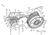
図1に示すように、車両10は、後部に開口部11が形成される車体12と、開口部11を開閉する開閉体の一例としてのバックドア20と、車体12とバックドア20との間に配置されるガススプリング30と、バックドア20を任意の位置で停止させる停止装置40と、を備える。
An embodiment of a vehicle provided with a vehicle opening/closing body stopping device (hereinafter also referred to as a "stopping device") will be described below with reference to the drawings.
As shown in FIG. 1, a
開口部11は、略矩形状をなし、車両後方に開口する。開口部11は、ユーザが車両10の荷室から荷物を取り出したり、ユーザが車両10の荷室に荷物を積み込んだりするための開口部である。
The
バックドア20は、開口部11に対応する形状をなす。バックドア20は、回動軸21を介して、開口部11の上部に回動可能に支持される。バックドア20は、車両幅方向に延びる回動軸線回りに回動することで、開口部11を開放する「全開位置」及び開口部11を閉塞する「全閉位置」の間で変位する。また、バックドア20は、ユーザがバックドア20を開こうとする際にユーザに操作されるドアハンドル22を有する。
The
ガススプリング30は、筒状のシリンダ31と、棒状のピストンロッド32と、を有する。ガススプリング30は、シリンダ31とピストンロッド32との間に封入された高圧ガスの反力でバックドア20を付勢する。ガススプリング30は、バックドア20が全閉位置に位置するときも、バックドア20が全開位置に位置するときも、バックドア20を開方向に付勢する。ガススプリング30の第1端は、車体12に対して、車両幅方向に延びる軸線回りに回動可能に連結され、ガススプリング30の第2端は、バックドア20に対して、車両幅方向に延びる軸線回りに回動可能に連結される。
The
バックドア20には、バックドア20の重量と、ガススプリング30の反力と、ユーザによるドアハンドル22の操作力と、が作用する。つまり、バックドア20には、バックドア20の重量に応じた第1のモーメントと、ガススプリング30の反力に応じた第2のモーメントと、ユーザの操作力に応じた第3のモーメントと、が作用する。ここで、第1のモーメントは、バックドア20の重量と、バックドア20の回動軸21からバックドア20の重心までの距離と、の積で表現されるモーメントである。第2のモーメントは、ガススプリング30の反力と、バックドア20の回動軸21からバックドア20とガススプリング30との連結位置までの距離と、の積で表現されるモーメントである。第3のモーメントは、ユーザの操作力と、バックドア20の回動軸21からドアハンドル22までの距離と、の積で表現されるモーメントである。なお、ドアハンドル22の操作力は、バックドア20の開方向に作用する場合に正の値になり、バックドア20の閉方向に作用する場合に負の値になるとする。また、以降の説明では、第1のモーメントを「M1」で表現し、第2のモーメントを「M2」で表現し、第3のモーメントを「M3」で表現する。
The weight of the
バックドア20において、「M1>M2+M3」が成立する場合、言い換えれば、バックドア20の閉方向に作用するモーメントがバックドア20の開方向に作用するモーメントよりも大きい場合、バックドア20は閉動作する。また、「M1<M2+M3」が成立する場合、言い換えれば、バックドア20の開方向に作用するモーメントがバックドア20の閉方向に作用するモーメントよりも大きい場合、バックドア20は開動作する。さらに、「M1=M2+M3」が成立する場合、言い換えれば、バックドア20の閉方向に作用するモーメントとバックドア20の開方向に作用するモーメントとが釣り合う場合、バックドア20は停止する。
When "M1>M2+M3" is established in the
以降の説明では、ユーザがバックドア20を操作しない場合に、「M1=M2」が成立するときのバックドア20の位置を「中立位置」という。つまり、バックドア20が中立位置よりも全閉位置寄りに位置する場合、言い換えれば、バックドア20が中立位置及び全閉位置の間に位置する場合、バックドア20が閉動作しようとする。一方、バックドア20が中立位置よりも全開位置寄りに位置する場合、言い換えれば、バックドア20が中立位置及び全開位置の間に位置する場合、バックドア20が開動作しようとする。
In the following description, the position of the
次に、停止装置40について詳しく説明する。
停止装置40は、ユーザのバックドア20の開閉操作に基づいて、全開位置及び全閉位置の間の任意の位置でバックドア20を停止させる装置である。
Next, the
The stopping
図2~図5に示すように、停止装置40は、停止装置40の構成部品を収容するケース50と、ケース50とともに停止装置40の外装を構成するカバー70と、バックドア20の開閉動作に連動して回転するドラム80と、ドラム80に巻き掛けられるケーブル90と、ドラム80を付勢する渦巻ばね100と、を備える。また、停止装置40は、ドラム80から伝達される動力で駆動する中継ギヤ110と、中継ギヤ110から伝達される動力で駆動するウォームホイール120と、ウォームホイール120から伝達される動力で駆動するウォーム130と、を備える。また、停止装置40は、ドラム80の回転をロックするロック部材140と、ロック部材140の作動状況を切り替えるノック機構200と、を備える。
As shown in FIGS. 2 to 5, the stopping
図6に示すように、ケース50は、平板状をなす主壁51と、主壁51から延びる周壁52と、ドラム80を支持する第1支軸53と、中継ギヤ110を支持する第2支軸54を含むブラケット55と、ウォームホイール120を支持する第3支軸56と、を備える。また、ケース50は、ウォーム130を支持する第1規制壁57及び第2規制壁58と、ノック機構200を収容する収容壁59と、第1支軸53の周囲を囲うように主壁51から突出する台座61と、を有する。
As shown in FIG. 6, the
図1に示すように、ケース50は、車体12の開口部11の車両幅方向における端部に固定される。図4及び図6に示すように、周壁52は、主壁51の大部分を縁取るように主壁51から延びる。周壁52には、ケース50の内部から外部にケーブル90を引き出すための通用孔62が形成される。通用孔62は、ケース50において、ドラム80を収容する領域と対応する位置に形成される。
As shown in FIG. 1 , the
第1支軸53、第2支軸54及び第3支軸56は、略円柱状をなす。第1支軸53、第2支軸54及び第3支軸56は、主壁51から同じ方向に延びる。第1支軸53の先端には、渦巻ばね100を固定するための固定溝63が径方向に形成される。第2支軸54を含むブラケット55は、第2支軸54が第2規制壁58と収容壁59とに干渉することを避けるために、主壁51とは別体に形成される。ブラケット55は、第2規制壁58と収容壁59とを跨ぐように、主壁51に固定される。
The
第1規制壁57及び第2規制壁58は、周壁52と同じ方向に主壁51から延びる。第1規制壁57及び第2規制壁58は、互いに対向する位置に形成される。第1規制壁57及び第2規制壁58には、ウォーム130の端部を支持する軸受64が形成される。
A first restricting
収容壁59は、台座61から第1支軸53の突出方向と同じ方向に延びる。収容壁59は、第1規制壁57とともに、ノック機構200の構成部品を収容するための第1凹部65を区画する。台座61は、第1支軸53の軸方向からの正面視において略円柱状をなす。台座61には、第1支軸53の軸方向に第2凹部66及び第3凹部67が凹み形成される。第2凹部66は、ノック機構200の構成部品を配置するための空間であり、第3凹部67は、ロック部材140を配置するための空間である。
The
図2に示すように、カバー70は、ケース50の周壁52の先端を縁取るような形状をなす。カバー70は、ねじなどの締結部材でケース50に固定する構成でもよいし、スナップフィット構造でケース50に固定する構成でもよい。
As shown in FIG. 2 , the
図2に示すように、ドラム80は、略円柱状をなす。図7及び図8に示すように、ドラム80には、渦巻ばね100を収容する第1収容凹部81と、ロック部材140を収容する「収容凹部」の一例としての第2収容凹部82と、ロック部材140の先端が係合する係合凹部83と、が形成される。また、ドラム80には、ケーブル90の巻き取りを案内する周溝84と、ケーブル90の第1端が挿入される挿入孔85と、周溝84の基端と挿入孔85とを接続する接続溝86と、が形成される。
As shown in FIG. 2, the
第1収容凹部81及び第2収容凹部82は、略円柱状をなす空間である。第1収容凹部81は、ドラム80の軸方向における第1面に凹み形成され、第2収容凹部82は、ドラム80の軸方向における第2面に凹み形成される。係合凹部83は、第2収容凹部82からドラム80の径方向における外方に凹み形成される。本実施形態において、係合凹部83は、ドラム80の周方向に連続するように、複数形成される。周溝84は、ドラム80の外周面に螺旋状に形成される。挿入孔85は、第1収容凹部81からドラム80の軸方向に形成される。接続溝86は、周溝84の基端と挿入孔85とを接続するように、ドラム80の第1収容凹部81に形成される。
The first accommodating recessed
また、ドラム80は、ドラム80の外周面に周方向に亘って形成される第1ギヤ部87と、渦巻ばね100の先端が係止する係止部88と、を有する。第1ギヤ部87は、周溝84とドラム80の軸方向に隣り合うように形成される。図7に示すように、係止部88は、第1収容凹部81から、ドラム80の軸方向に突出する。
Further, the
図2に示すように、ケーブル90の第1端は、ドラム80の挿入孔85に挿入された状態で固定される。挿入孔85から延びるケーブル90は、ドラム80の周溝84に巻き取られる。図3及び図4に示すように、ドラム80は、第2収容凹部82をケース50の台座61に向けた状態で、ケース50の第1支軸53に回転可能に支持される。渦巻ばね100の基端はケース50の第1支軸53の固定溝63に固定され、渦巻ばね100の先端はドラム80の係止部88に固定される。このとき、渦巻ばね100は、ケーブル90を巻き取る回転方向にドラム80に初期荷重を付与する。また、図1に示すように、ドラム80から延びるケーブル90の第2端は、バックドア20に固定される。
As shown in FIG. 2, the first end of the
こうして、バックドア20が開動作する場合、開動作するバックドア20がケーブル90を牽引するため、ドラム80からケーブル90が繰り出される。このとき、渦巻ばね100は、ドラム80の回転量に応じて弾性変形する。一方、バックドア20が閉動作する場合、渦巻ばね100に付勢されるドラム80が回転するため、ドラム80がケーブル90を巻き取る。つまり、バックドア20が閉動作する場合であっても、ケーブル90に緩みが発生しない。
In this way, when the
以降の説明では、バックドア20が開動作する場合にドラム80が回転する方向を「第1回転方向R11」とし、バックドア20が閉動作する場合にドラム80が回転する方向を「第2回転方向R12」とする。第1回転方向R11は、第2回転方向R12の逆方向である。
In the following description, the direction in which the
図7及び図8に示すように、中継ギヤ110は、第2ギヤ部111を有する。第2ギヤ部111の歯数は、ドラム80の第1ギヤ部87の歯数よりも少ない。図8に示すように、中継ギヤ110の片面には、中継ギヤ110の軸方向と交差する方向に延びるカム溝112が形成される。カム溝112は、中継ギヤ110の軸方向からの正面視において、渦巻き状をなす。カム溝112において、中継ギヤ110の中心から近い端部を第1端とし、中継ギヤ110の中心から遠い端部を第2端としたとき、中継ギヤ110の中心からカム溝112までの距離は、カム溝112の第1端から第2端に進むに連れて次第に長くなる。
As shown in FIGS. 7 and 8 , the
図3に示すように、中継ギヤ110は、第2ギヤ部111がドラム80の第1ギヤ部87と噛み合うように、ケース50の第2支軸54に回転可能に支持される。また、中継ギヤ110は、第2支軸54に支持される状態では、カム溝112がケース50の主壁51を向く。
As shown in FIG. 3 , the
図7及び図8に示すように、ウォームホイール120は、第3ギヤ部121及び第4ギヤ部122を有する。第3ギヤ部121の歯数は、中継ギヤ110の第2ギヤ部111の歯数よりも少なく、第4ギヤ部122の歯数は、第3ギヤ部121の歯数よりも多い。図3に示すように、ウォームホイール120は、第3ギヤ部121が中継ギヤ110の第2ギヤ部111と噛み合うように、ケース50の第3支軸56に回転可能に支持される。
As shown in FIGS. 7 and 8, the
図7及び図8に示すように、ウォーム130は、第5ギヤ部131と、第5ギヤ部131の軸方向における第1端から延びる第1軸部132と、第5ギヤ部131の軸方向における第2端から延びる第2軸部133と、を有する。第5ギヤ部131の軸方向における長さは、ケース50の第1規制壁57及び第2規制壁58の間の長さよりも短い。
As shown in FIGS. 7 and 8, the
本実施形態では、一般的なウォームギヤ機構と異なり、ウォームホイール120が駆動ギヤに相当し、ウォーム130が従動ギヤに相当する。このため、ウォームギヤ機構におけるセルフロック機能が働かないように、第5ギヤ部131の進み角は比較的大きな値に設定される。
In this embodiment, unlike a general worm gear mechanism, the
図4に示すように、ウォーム130は、第5ギヤ部131がウォームホイール120の第4ギヤ部122と噛み合うように、ケース50の第1規制壁57及び第2規制壁58に支持される。詳しくは、ウォーム130の第1軸部132が第1規制壁57の軸受64に支持され、ウォーム130の第2軸部133が第2規制壁58の軸受64に支持される。
As shown in FIG. 4 , the
ここで、ウォーム130の第5ギヤ部131はねじ状の歯部を有するため、ウォームホイール120が回転する場合、ウォーム130には、ウォーム130の軸方向、周方向及び径方向に力が作用する。
Here, since the
この点、本実施形態において、ウォーム130の第5ギヤ部131の軸方向における長さは、ケース50の第1規制壁57及び第2規制壁58の間の長さよりも短いため、ウォーム130は軸方向に移動可能となる。また、第1規制壁57及び第2規制壁58は、ウォーム130の周方向の回転を妨げないため、ウォーム130はウォーム130の周方向に回転可能となる。ただし、ウォーム130は、第1規制壁57及び第2規制壁58に支持されることで、ウォーム130の径方向に移動不能となる。なお、ウォームホイール120の第4ギヤ部122及びウォーム130の第5ギヤ部131は、ウォームホイール120が回転する場合に、ウォーム130の周方向の回転よりも、ウォーム130の軸方向への移動が優先されるように構成される。
In this regard, in this embodiment, the length of the
このため、図4に示すように、ケース50の正面視において、ウォームホイール120が時計方向に回転する場合、ウォーム130の第5ギヤ部131の第1端がケース50の第1規制壁57に接触するまで、ウォーム130が移動する。ウォーム130の第5ギヤ部131の第1端がケース50の第1規制壁57に接触した後は、ウォーム130がウォームホイール120の回転方向に対応する回転方向に回転する。一方、ケース50の正面視において、ウォームホイール120が反時計方向に回転する場合、ウォーム130の第5ギヤ部131の第2端がケース50の第2規制壁58に接触するまで、ウォーム130が移動する。ウォーム130の第5ギヤ部131の第2端がケース50の第2規制壁58に接触した後は、ウォーム130がウォームホイール120の回転方向に対応する回転方向に回転する。こうして、ウォーム130は、第1規制壁57及び第2規制壁58により軸方向の移動量が規定される。
Therefore, as shown in FIG. 4 , when the
以上説明したように、本実施形態のウォームホイール120とウォーム130とは、「回転部材」としてのウォームホイール120の回転運動を「直動部材」としてのウォーム130の直線運動に変換する機構である。さらに、本機構は、直動部材が所定量だけ直線運動した後は、回転部材が回転しても直動部材が直線運動することを制限する機構でもある。
As described above, the
図2に示すように、ロック部材140は、板状をなす。ロック部材140は、基端から先端に向かうに連れて先細りする。ロック部材140の基端には、ロック部材140の厚さ方向に連結孔141が貫通形成される。
As shown in FIG. 2, the locking
図4に示すように、ロック部材140は、ケース50の第3凹部67に収容される。また、第3凹部67が形成される台座61は、ドラム80の第2収容凹部82に収容されるため、図5に示すように、ロック部材140は、先端をドラム80の係合凹部83に向けた状態で、ドラム80の第2収容凹部82に収容される。
As shown in FIG. 4 , the
そして、ロック部材140は、ノック機構200の動作により、ドラム80の係合凹部83に係合する「ロック位置」と、ドラム80との係合凹部83に係合しない「アンロック位置」と、を含む移動範囲内を移動する。ロック部材140は、ロック位置に位置する場合、ドラム80の回転を制限し、アンロック位置に位置する場合、ドラム80の回転を許容する。
The
次に、ノック機構200について説明する。
以降の説明では、図9及び図10に示すように、ノック機構200の構成部品が連結される方向を「軸方向DA」とし、ノック機構200の軸方向DAにおける一方向を「第1方向DA1」とし、第1方向DA1の逆方向を「第2方向DA2」とする。また、ノック機構200の周方向DCにおける一方向を「第1周方向DC1」とし、第1周方向DC1の逆方向を「第2周方向DC2」とする。
Next, the
In the following description, as shown in FIGS. 9 and 10, the direction in which the components of the
図9及び図10に示すように、ノック機構200は、筒状をなす筒体210と、筒体210に対して軸方向DAに移動するノック体220と、筒体210に対して軸方向DAに移動するプッシュ体230と、筒体210に対して周方向DCに回転する回転体240と、を有する。また、ノック機構200は、回転体240を第2方向DA2に付勢する付勢部材250と、回転体240とロック部材140とを連結する連結軸260と、を有する。
As shown in FIGS. 9 and 10, the
筒体210には、ノック体220の軸方向DAの移動をガイドする第1ガイド溝211と、プッシュ体230の軸方向DAの移動をガイドする第2ガイド溝212と、が形成される。第1ガイド溝211及び第2ガイド溝212は、筒体210の第2方向DA2の端部から第1方向DA1に向かって延びる。
A
筒体210は、第1周方向DC1に進むに連れて第2方向DA2に向かうように傾斜する第1カム面213及び第2カム面214と、軸方向DAに延びる第1規制面215及び第2規制面216と、を内部に有する。第1カム面213及び第2カム面214の各々は、周方向DCに交互に並ぶように複数形成される。第2カム面214の第1周方向DC1における端部と第1カム面213の第2周方向DC2における端部との間には、第2方向DA2に延びる退避溝217が形成される。第1規制面215は、第1カム面213の第1周方向DC1における端部と第2カム面214の第2周方向DC2における端部とを軸方向DAに接続する。第2規制面216は、第1カム面213の第2周方向DC2における端部から第2方向DA2に延びる面であって且つ退避溝217の内面である。
The
ノック体220は、略棒状をなす。ノック体220には、第2方向DA2における端部から第1方向DA1に向かう第1軸孔221と、第1方向DA1における端部から第2方向DA2に向かう第2軸孔222と、が形成される。ノック体220は、第2方向DA2における端部から径方向における外方に延びる第1ガイド軸223と、第1軸孔221及び第2軸孔222の間の中間壁224と、ノック体220の第1方向DA1における端部に形成される第3カム面225及び第4カム面226と、を有する。第3カム面225は、第1周方向DC1に進むに連れて第2方向DA2に向かうように傾斜し、第4カム面226は、第1周方向DC1に進むに連れて第1方向DA1に向かうように傾斜する。第3カム面225及び第4カム面226の各々は、周方向DCに交互に並ぶように複数形成される。
Knock
プッシュ体230は、略筒状をなす。プッシュ体230には、プッシュ体230の第2方向DA2における端部から第1方向DA1に延びる第3ガイド溝231が形成される。プッシュ体230は、軸方向DAにおける中間部から径方向における外方に延びる第2ガイド軸232と、第2ガイド軸232の先端から延びるカム軸233と、プッシュ体230の第2方向DA2における端部に形成される第5カム面234及び第6カム面235と、を有する。
The
第2ガイド軸232は略角柱状をなし、カム軸233は略円柱状をなす。第5カム面234は、第1周方向DC1に進むに連れて第1方向DA1に向かうように傾斜し、第6カム面235は、第1周方向DC1に進むに連れて第2方向DA2に向かうように傾斜する。周方向DCにおいて、第5カム面234は第6カム面235よりも長い。第5カム面234及び第6カム面235の各々は、周方向DCに交互に並ぶように複数形成される。プッシュ体230における第5カム面234の形成数は、ノック体220における第3カム面225の形成数の半数であり、プッシュ体230における第6カム面235の形成数は、ノック体220における第4カム面226の形成数の半数である。
The
回転体240は、軸方向DAに延びる軸体241と、軸体241から軸体241の径方向に放射状に延びる複数のリブ242と、を有する。軸体241には、第1方向DA1における端部から第2方向DA2に向かって係合孔243が形成される。リブ242の第2方向DA2における先端には、第1周方向DC1に進むに連れて第2方向DA2に向かう第7カム面244が設けられる。
The
付勢部材250は、いわゆるコイルスプリングである。連結軸260は、円板状をなすフランジ261と、フランジ261から第1方向DA1に延びる屈曲軸262と、フランジ261から第2方向DA2に延びる係合軸263と、を有する。フランジ261は、付勢部材250の端部を支持する部位となる。屈曲軸262は、略L字状に屈曲する。
The biasing
そして、ノック体220とプッシュ体230とが筒体210に対して第1方向DA1に挿入され、回転体240と付勢部材250と連結軸260とが筒体210に対して第2方向DA2に挿入されることで、ノック機構200が構成される。
Knocking
ノック体220とプッシュ体230とが筒体210に挿入される状態では、ノック体220の第1ガイド軸223が筒体210の第1ガイド溝211及びプッシュ体230の第3ガイド溝231に収まり、プッシュ体230の第2ガイド軸232が筒体210の第2ガイド溝212に収まる。こうして、ノック体220は、筒体210とプッシュ体230とに対し、周方向DCに回転不能且つ軸方向DAに移動可能となる。同様に、プッシュ体230は、筒体210に対し、周方向DCに回転不能且つ軸方向DAに移動可能となる。
When the
回転体240が筒体210に挿入される状態では、回転体240の第7カム面244が筒体210の第1カム面213又は筒体210の退避溝217の底面218に接触する。つまり、回転体240が筒体210に係合する。回転体240が筒体210に係合する状態では、回転体240の周方向DCの回転が制限される。一方、回転体240が筒体210と係合しない状態、言い換えれば、回転体240が筒体210に対して第1方向DA1に変位した状態では、回転体240の第1周方向DC1の回転が可能となる。
When the
連結軸260が筒体210に挿入される状態では、連結軸260の係合軸263が回転体240の係合孔243に挿入される。連結軸260は、付勢部材250により第2方向DA2に付勢されることになるため、連結軸260は回転体240を常時に第2方向DA2に押す状態となる。このため、回転体240が第1方向DA1及び第2方向DA2に移動する場合には、連結軸260は回転体240に接したまま回転体240とともに移動する。
When the connecting
図4及び図6に示すように、ノック機構200は、ケース50の第1凹部65及び第2凹部66に跨って収容される。このとき、付勢部材250は、連結軸260のフランジ261とケース50の第1凹部65及び第2凹部66を区画する壁部との間で圧縮される。こうして、付勢部材250は、回転体240と連結軸260とを第2方向DA2に付勢する。また、連結軸260の屈曲軸262は、ロック部材140の連結孔141に挿入される。
As shown in FIGS. 4 and 6 , the
図5及び図9に示すように、ノック体220の第2軸孔222には、ウォーム130の第1軸部132が挿入される。このため、ウォーム130が第1方向DA1に移動する場合には、ウォーム130の第1軸部132の先端がノック体220の中間壁224を第1方向DA1に押し、ウォーム130が第2方向DA2に移動する場合には、ウォーム130の第1軸部132の先端がノック体220の中間壁224から離れる。
As shown in FIGS. 5 and 9 , the
図5に示すように、ノック機構200のプッシュ体230のカム軸233は、中継ギヤ110のカム溝112に係合する。プッシュ体230のカム軸233は、中継ギヤ110が回転する場合には、カム軸233に沿って移動する。詳しくは、中継ギヤ110に噛み合うドラム80が第1回転方向R11に回転する場合、言い換えれば、バックドア20が開動作する場合、プッシュ体230が第2方向DA2に移動する。一方、中継ギヤ110に噛み合うドラム80が第2回転方向R12に回転する場合、言い換えれば、バックドア20が閉動作する場合、プッシュ体230が第1方向DA1に移動する。
As shown in FIG. 5 ,
次に、図11~図15を参照して、ノック機構200の作用について説明する。
図11~図15は、筒体210の第1カム面213及び第2カム面214に関する構成と、ノック体220の第3カム面225及び第4カム面226に関する構成と、回転体240の第7カム面244に関する構成と、を模式的に図示している。
Next, operation of the
11 to 15 show the configuration of the
図11は、ノック体220が第1方向DA1に付勢されていないときの筒体210とノック体220と回転体240との位置関係を示している。図11に示すように、回転体240は、付勢部材250によって第2方向DA2に付勢されるため、回転体240の第7カム面244は、筒体210の第1カム面213を第2方向DA2に押す。筒体210の第1カム面213及び回転体240の第7カム面244は、ともに第1周方向DC1に進むに連れて第2方向DA2に向かうように傾斜するため、第2方向DA2に付勢される回転体240は、筒体210の第1カム面213に沿って移動しようとする。その結果、回転体240は、筒体210の第1カム面213及び第1規制面215に接触する。
FIG. 11 shows the positional relationship among
以降の説明では、図11に示す回転体240の位置を「前進位置」という。前進位置は、回転体240が筒体210の「第1係合面」の一例としての第1カム面213及び第1規制面215と係合することで、回転体240の姿勢が安定する位置である。回転体240が前進位置に位置する場合、ロック部材140はアンロック位置に位置する。なお、回転体240が前進位置に位置する状態は、ノック式ボールペンにおいて、軸筒からペン先が突出した状態に相当する。
In the following description, the position of the
図12に実線で示すように、図11に示す状態からノック体220が第1方向DA1に移動すると、ノック体220の第3カム面225が回転体240の第7カム面244を第1方向DA1に押す。ノック体220の第3カム面225が筒体210の第1カム面213よりも第1方向DA1に移動すると、回転体240が筒体210の第1カム面213及び第1規制面215に係合しなくなる。ノック体220の第3カム面225及び回転体240の第7カム面244は、ともに第1周方向DC1に進むに連れて第2方向DA2に向かうように傾斜するため、回転体240は、ノック体220の第3カム面225に沿って移動しようとする。詳しくは、図12に二点鎖線で示すように、回転体240がノック体220に対して第1周方向DC1に回転するように、回転体240の第7カム面244がノック体220の第3カム面225と摺動する。
12, when knock
一方、ノック体220の第3カム面225と第1周方向DC1に隣り合う第4カム面226は、第1周方向DC1に進むに連れて第1方向DA1に向かうように傾斜するため、回転体240の第7カム面244はノック体220の第4カム面226と摺動しない。その結果、回転体240は、先端が、ノック体220の第3カム面225及び当該第3カム面225と第1周方向DC1に隣り合う第4カム面226の境界に留まる。
On the other hand, the
以降の説明では、図12に二点鎖線で示す回転体240の周方向DCにおける位置を「第1の位置」という。回転体240が第1の位置に位置する場合、軸方向DAにおいて、回転体240の第7カム面244の少なくとも一部が筒体210の第2カム面214と対向する。
In the following description, the position of the
図13に実線で示すように、図12に示す状態からノック体220が第2方向DA2に移動すると、回転体240の第7カム面244がノック体220の第3カム面225に接触しなくなる。つまり、ノック体220の第3カム面225が回転体240の第7カム面244を第1方向DA1に押す状態が解消され、回転体240の第7カム面244が筒体210の第2カム面214を押す状態となる。筒体210の第2カム面214及び回転体240の第7カム面244は、ともに第1周方向DC1に進むに連れて第2方向DA2に向かうように傾斜するため、回転体240は、筒体210の第2カム面214に沿って移動しようとする。詳しくは、回転体240がノック体220に対して第1周方向DC1に回転するように、回転体240の第7カム面244が筒体210の第2カム面214と摺動する。
13, when the
筒体210の第2カム面214と当該第2カム面214の第1周方向DC1に隣り合う第1カム面213との間には、第2方向DA2に退避溝217が延びる。このため、回転体240の第7カム面244が筒体210の第2カム面214と摺動し続けると、図13に二点鎖線で示すように、回転体240のリブ242が筒体210の退避溝217に収まる。つまり、回転体240が筒体210の第2規制面216及び筒体210の退避溝217の底面218に接触する。
A
以降の説明では、図13に示す回転体240の位置、すなわち、回転体240が前進位置よりも第2方向DA2に移動した位置を「後退位置」という。後退位置は、回転体240が筒体210と「第2係合面」としての第2規制面216及び退避溝217の底面218に係合することで、回転体240の姿勢が安定する位置である。回転体240が後退位置に位置する場合、ロック部材140はロック位置に位置する。なお、回転体240が前進位置に位置する状態は、ノック式ボールペンにおいて、軸筒にペン先が収容される状態に相当する。
In the following description, the position of the
図14に実線で示すように、図13に示す状態からノック体220が第1方向DA1に移動すると、ノック体220の第3カム面225が回転体240の第7カム面244を第1方向DA1に押す。ノック体220の第3カム面225が筒体210の第1カム面213よりも第1方向DA1に移動すると、回転体240が筒体210の第2規制面216及び退避溝217の底面218に係合しなくなる。このため、図14に二点鎖線で示すように、回転体240がノック体220に対して第1周方向DC1に回転するように、回転体240の第7カム面244がノック体220の第3カム面225と摺動する。こうして、回転体240は、先端がノック体220の第3カム面225及び当該第3カム面225と周方向DCに隣り合う第4カム面226の境界に留まる。
14, when knock
以降の説明では、図14に二点鎖線で示す回転体240の周方向DCにおける位置を「第2の位置」という。回転体240が第2の位置に位置する場合、軸方向DAにおいて、回転体240の第7カム面244の少なくとも一部が筒体210の第1カム面213と対向する。
In the following description, the position of the
図15に実線で示すように、図14に示す状態からノック体220が第2方向DA2に移動すると、回転体240の第7カム面244がノック体220の第3カム面225に係合しなくなる。つまり、ノック体220の第3カム面225が回転体240の第7カム面244を第1方向DA1に押す状態が解消され、回転体240の第7カム面244が筒体210の第1カム面213を押す状態となる。このため、図15に二点鎖線で示すように、回転体240がノック体220に対して周方向DCに回転するように、回転体240の第7カム面244が筒体210の第1カム面213と摺動する。その結果、図13と同様に、回転体240が筒体210の第1カム面213及び第1規制面215に接触する。つまり、回転体240が「前進位置」に位置する。
15, when knock
以降の説明では、図11~図13又は図13~図15に示すように、ノック機構200において、ノック体220が第1方向DA1に移動した後に第2方向DA2に移動する動作を「ノック動作」という。そして、ノック機構200は、ノック動作の度に、回転体240を後退位置から前進位置に移動させたり、回転体240を前進位置から後退位置に移動させたりする。つまり、ノック機構200は、ノック動作の度に、ロック部材140をロック位置からアンロック位置に移動させたり、ロック部材140をアンロック位置からロック位置に移動させたりする。
In the following description, as shown in FIGS. 11 to 13 or 13 to 15, in the
なお、ノック機構200は、ウォーム130がノック体220を第1方向DA1に押した後に、ウォーム130が第2方向DA2に移動することでノック動作する。言い換えれば、ノック機構200は、ドラム80が第2回転方向R12に回転した後に、ドラム80が第1回転方向R11に回転することでノック動作する。さらに言い換えれば、ノック機構200は、バックドア20が閉動作した後にバックドア20が開動作することでノック動作する。ノック機構200にノック動作させるために必要なバックドア20の変位量は適宜に設定すればよい。
Note that the
次に、図16~図29を参照して、停止装置40の作用について説明する。
図16~図29では、停止装置40の作用の説明の容易のために、一部構成の図示を省略したり簡略したりしている。
Next, operation of the
In FIGS. 16 to 29, for ease of explanation of the action of the
まず、任意の位置まで開動作させたバックドア20に対し、ユーザが停止操作及び停止解除操作を行うときの停止装置40の作用について説明する。ここで、停止操作とは、開動作可能なバックドア20を開作動不能とするための操作であり、停止解除操作とは、開動作不能なバックドア20を開動作可能とするための操作である。停止操作及び停止解除操作は、上述した通り、ともに、バックドア20を僅かに閉動作させた後にバックドア20を僅かに開動作させる操作である。
First, the operation of the stopping
図16及び図17は、バックドア20が全閉位置に位置するときの停止装置40の状態を示している。バックドア20が全閉位置に位置する場合、ドラム80は最も第2回転方向R12に回転した状態であり、中継ギヤ110は最も第1回転方向R21に回転した状態である。つまり、ドラム80はケーブル90を最も巻き取った状態であり、中継ギヤ110はプッシュ体230を最も第2方向DA2に移動させる状態である。
16 and 17 show the state of the
そして、ユーザがバックドア20を中立位置及び全開位置の間の中間位置まで開動作させると、停止装置40が図18及び図19に示す状態となる。
図18及び図19に示すように、バックドア20が全閉位置から開動作すると、開動作するバックドア20がケーブル90を牽引するため、ドラム80からケーブル90が繰り出される。つまり、ドラム80が第1回転方向R11に回転するため、中継ギヤ110が第2回転方向R22に回転し、ウォームホイール120が第1回転方向R31に回転する。
When the user opens the
As shown in FIGS. 18 and 19 , when the
中継ギヤ110が第2回転方向R22に回転すると、中継ギヤ110のカム溝112の内面とノック機構200のプッシュ体230のカム軸233とが摺動する。このため、ノック機構200のプッシュ体230が第2方向DA2に移動する。プッシュ体230の第2方向DA2への移動量は、中継ギヤ110の第2回転方向R22への回転量に比例する。
When
ウォームホイール120が第1回転方向R31に回転すると、ウォーム130は、ケース50の第2規制壁58に接触するまで第2方向DA2に移動し、第2規制壁58に接触する後は周方向DCに回転する。図19に示すように、ウォーム130の第1軸部132は、ノック機構200のノック体220の中間壁224から離れる。このため、図11及び図19に示すように、回転体240は前進位置に位置し、図18に示すように、ロック部材140はアンロック位置に位置する。
When the
その後、ユーザが停止操作を行う場合、ユーザはバックドア20を中間位置から僅かに閉動作させる。
図20及び図21に示すように、バックドア20が僅かに閉動作すると、ケーブル90に弛みが発生するため、ドラム80がケーブル90を巻き取る。つまり、ドラム80が第2回転方向R12に回転するため、中継ギヤ110が第1回転方向R21に回転し、ウォームホイール120が第2回転方向R32に回転する。
After that, when the user performs a stop operation, the user slightly closes the
As shown in FIGS. 20 and 21 , when the
ウォームホイール120が第2回転方向R32に回転すると、ウォーム130は、ケース50の第1規制壁57に接触するまで第1方向DA1に移動する。すると、図12及び図21に示すように、ウォーム130がノック体220を第1方向DA1に押すため、回転体240が前進位置よりも第1方向DA1に移動する。その結果、図20に示すように、ロック部材140がアンロック位置よりも第1方向DA1に移動する。
When the
続いて、ユーザは、停止操作を完了させるべく、バックドア20を僅かに開動作させる。このとき、ユーザは、バックドア20を開方向に操作してもよいし、バックドア20から手を離すだけでもよい。バックドア20から手を離すだけでバックドア20が開動作するのは、バックドア20が中立位置よりも全開位置寄りに位置するためである。
Subsequently, the user slightly opens the
図22及び図23に示すように、バックドア20が僅かに開動作すると、バックドア20がケーブル90を牽引するため、ドラム80からケーブル90が繰り出される。つまり、ドラム80が第1回転方向R11に回転するため、中継ギヤ110が第2回転方向R22に回転し、ウォームホイール120が第1回転方向R31に回転する。ウォームホイール120が第1回転方向R31に回転すると、ウォーム130は、第2方向DA2に移動する。すると、図13及び図23に示すように、ウォーム130がノック体220を第1方向DA1に押さなくなるため、回転体240が後退位置まで移動する。その結果、図22に示すように、ロック部材140がロック位置に移動する。
As shown in FIGS. 22 and 23 , when the
図22に示すように、ロック部材140がロック位置に位置すると、ドラム80が第1回転方向R11に回転不能となる。すると、バックドア20がドラム80からケーブル90を引き出すことができなくなり、バックドア20が開動作不能となる。こうして、停止装置40は、バックドア20を停止状態とする。
As shown in FIG. 22, when the
その後、ユーザが停止解除操作を行う場合、ユーザはバックドア20を中間位置から僅かに閉動作させる。
図24に示すように、バックドア20が僅かに閉動作すると、ケーブル90に緩みが発生するため、ドラム80がケーブル90を巻き取る。つまり、ドラム80が第2回転方向R12に回転するため、中継ギヤ110が第1回転方向R21に回転し、ウォームホイール120が第2回転方向R32に回転する。
Thereafter, when the user performs the stop release operation, the user slightly closes the
As shown in FIG. 24 , when the
ウォームホイール120が第2回転方向R32に回転すると、ウォーム130は、ケース50の第1規制壁57に接触するまで第1方向DA1に移動する。すると、図14に示すように、ウォーム130がノック体220を第1方向DA1に押すため、回転体240が前進位置よりも第1方向DA1に移動する。その結果、図24に示すように、ロック部材140がアンロック位置よりも第1方向DA1に移動する。
When the
続いて、ユーザは、停止解除操作を完了させるべく、バックドア20を開動作させる。このとき、ユーザは、バックドア20を開方向に操作してもよいし、バックドア20から手を離すだけでもよい。
Subsequently, the user opens the
図25に示すように、バックドア20が開動作すると、バックドア20がケーブル90を牽引するため、ドラム80からケーブル90が繰り出される。つまり、ドラム80が第1回転方向R11に回転するため、中継ギヤ110が第2回転方向R22に回転し、ウォームホイール120が第1回転方向R31に回転する。
As shown in FIG. 25 , when the
ウォームホイール120が第1回転方向R31に回転すると、ウォーム130は、第2方向DA2に移動する。すると、図15に示すように、ウォーム130がノック体220を第1方向DA1に押さなくなるため、回転体240が前進位置まで移動する。その結果、図25に示すように、ロック部材140がアンロック位置に移動する。
When the
図25に示すように、ロック部材140がアンロック位置に位置すると、ドラム80が第1回転方向R11に回転可能となる。すると、バックドア20がドラム80からケーブル90を引き出すことが可能となり、バックドア20が開動作可能となる。こうして、停止装置40は、バックドア20の停止状態を解除する。
As shown in FIG. 25, when the
次に、バックドア20が閉動作するときの停止装置40の作用について説明する。
図20及び図24に示すように、バックドア20の閉動作中には、ドラム80が第2回転方向R12に回転するため、中継ギヤ110が第1回転方向R21に回転し、ウォームホイール120が第2回転方向R32に回転する。中継ギヤ110が第1回転方向R21に回転すると、中継ギヤ110のカム溝112の内面とノック機構200のプッシュ体230のカム軸233とが摺動する。このため、ノック機構200のプッシュ体230が第1方向DA1に移動する。プッシュ体230の第1方向DA1への移動量は、中継ギヤ110の第1回転方向R21への回転量に比例する。また、ウォームホイール120が第2回転方向R32に回転すると、ウォーム130は、ケース50の第1規制壁57に接触した状態で周方向DCに回転する。
Next, the action of the
As shown in FIGS. 20 and 24, during the closing operation of the
図26に示すように、バックドア20が中立位置よりも全閉位置寄りの位置まで閉動作すると、プッシュ体230が回転体240に接触する。このため、バックドア20が上記位置よりもさらに閉動作すると、プッシュ体230が回転体240を第1方向DA1に押す。
As shown in FIG. 26 , when the
ここで、停止装置40は、ロック部材140の位置に応じて、バックドア20の開動作を制限したり許容したりする。一方、停止装置40は、ロック部材140の位置に関わらず、バックドア20の閉動作を許容する。このため、ユーザがバックドア20の閉動作を開始するときには、バックドア20の開動作がロックされている場合と、バックドア20の開動作がロックされていない場合と、がある。言い換えれば、停止装置40が図18及び図19に示すように回転体240が前進位置に位置するときにユーザがバックドア20の閉動作を開始する場合もあれば、停止装置40が図22及び図23に示すように回転体が後退位置に位置するときにユーザがバックドア20の閉動作を開始する場合もある。
Here, the stopping
図27は、停止装置40がバックドア20の開動作をロックしていない状況下で、バックドア20の閉動作が開始される場合のプッシュ体230の動作を示している。つまり、図27に実線で示す回転体240の位置は、図12に二点鎖線で示す回転体240の位置と対応している。
FIG. 27 shows the operation of the
図27に二点鎖線で示すように、バックドア20が全閉位置の付近まで閉動作されることで、プッシュ体230の第5カム面234がノック体220の第3カム面225よりも第1方向DA1に移動すると、プッシュ体230の第5カム面234が回転体240の第7カム面244を第1方向DA1に押す。すると、図27に二点鎖線で示すように、回転体240がプッシュ体230に対して第1周方向DC1に回転するように、回転体240の第7カム面244がプッシュ体230の第5カム面234と摺動する。
As indicated by the two-dot chain line in FIG. 27 , when the
その結果、回転体240は、周方向DCにおいて、図27に実線で示す第1の位置から図27に二点鎖線で示す第2の位置に移動する。詳しくは、回転体240は、軸方向DAにおいて、回転体240の第7カム面244の少なくとも一部が、筒体210の第2カム面214と対向する第1の位置から、軸方向DAにおいて、回転体240の第7カム面244の少なくとも一部が、筒体210の第1カム面213と対向する第2の位置に移動する。
As a result, the
一方、図28は、停止装置40がバックドア20の開動作をロックする状況下で、バックドア20の閉動作が開始される場合のプッシュ体230の動作を示している。つまり、図28に実線で示す回転体240の位置は、図14に二点鎖線で示す回転体240の位置と対応している。
On the other hand, FIG. 28 shows the operation of the
図28に二点鎖線で示すように、バックドア20が全閉位置の付近まで閉動作されることで、プッシュ体230の第5カム面234がノック体220の第3カム面225よりも第1方向DA1に移動すると、プッシュ体230の第5カム面234が回転体240の第7カム面244を第1方向DA1に押す。すると、図28に二点鎖線で示すように、回転体240がプッシュ体230に対して第1周方向DC1に回転するように、回転体240の第7カム面244がプッシュ体230の第5カム面234と摺動する。
As indicated by a two-dot chain line in FIG. 28 , when the
その結果、回転体240は、周方向DCにおいて、図27に実線で示す第2の位置から図27に二点鎖線で示す第2の位置に僅かに移動する。詳しくは、回転体240は、軸方向DAにおいて、回転体240の第7カム面244の少なくとも一部が筒体210の第1カム面213と対向する第2の位置から、軸方向DAにおいて、回転体240の第7カム面244の少なくとも一部が筒体210の第1カム面213と対向する第2の位置に僅かに移動する。つまり、プッシュ体230の移動前後における回転体240の位置は、ともに第2の位置である。
As a result, the
こうして、図27及び図28に示すように、バックドア20の閉動作の開始時点における回転体240が前進位置に位置しているか後退位置に位置しているかに関わらず、バックドア20が全閉位置の付近まで閉動作する場合、回転体240が常に第2の位置に位置する。
Thus, as shown in FIGS. 27 and 28, the
このため、図27及び図28に二点鎖線で示すように回転体240が第2の位置に位置する状態で、バックドア20が開動作する場合には、図29に示すように、回転体240が筒体210に対して第1周方向DC1に回転するように、回転体240の第7カム面244が筒体210の第1カム面213と摺動する。このため、回転体240は、図29に二点鎖線で示す前進位置に移動する。言い換えれば、回転体240が後退位置に移動しない点で、停止装置40がバックドア20の開動作を停止しない。
Therefore, when the
こうして、プッシュ体230は、バックドア20が全閉位置の付近まで閉動作される場合に、回転体240を第2の位置に移動させることで、回転体240の位置を初期化する。以降の説明では、プッシュ体230が回転体240の位置を初期化する機能を「初期化機能」ともいう。
In this way, the
また、図27及び図28に実線で示すように、プッシュ体230が回転体240を後退位置よりも第1方向DA1に移動させる場合、すなわち、プッシュ体230の第5カム面234が筒体210の退避溝217の底面218よりも第1方向DA1に位置する場合には、回転体240が後退位置に移動できなくなる。つまり、この場合には、停止装置40がバックドア20の開動作を停止できなくなる。
27 and 28, when the pushing
こうして、プッシュ体230には、バックドア20が全閉位置の付近に位置する場合に、回転体240を退避位置に移動できなくすることで、ロック部材140によるドラム80の回転のロックを無効化する。以降の説明では、プッシュ体230がドラム80の回転のロックを無効化する機能を「無効化機能」ともいう。
In this way, the
ここで、バックドア20が閉動作する状況下において、プッシュ体230がドラム80の回転のロックを無効化し始めるときのバックドア20の位置を「無効化位置」とし、プッシュ体230がノック機構200の回転体240の位置を初期化するときのバックドア20の位置を「初期化位置」とする。この場合、無効化位置は、中立位置及び全閉位置の間の位置とすることが好ましく、初期化位置は、無効化位置及び全閉位置の間の位置とすることが好ましい。
Here, the position of the
本実施形態の効果について説明する。
(1)ノック機構200は、バックドア20が閉動作した後に開動作することでノック動作する。つまり、ノック機構200は、ユーザがバックドア20を開閉操作することでノック動作する。したがって、停止装置40は、ユーザのバックドア20の開閉操作により、バックドア20が開動作不能な状態及びバックドア20が開動作可能な状態を切り替えることができる。こうして、ユーザは、所望の位置でバックドア20を停止させるための操作を行いやすくなる。
Effects of the present embodiment will be described.
(1) The
(2)停止装置40は、ドラム80の回転運動をウォーム130の直線運動に変化させることで、ノック機構200にノック動作させる。また、停止装置40は、ウォーム130が第1規制壁57及び第2規制壁58に接触することで、ウォーム130が軸方向DAに移動できなくなる場合には、ウォーム130がウォームホイール120から伝達される動力に基づいて周方向DCに回転する。したがって、停止装置40は、バックドア20の開動作又は閉動作が継続される場合において、ウォーム130が第1方向DA1又は第2方向DA2に移動し続けることを抑制できる。例えば、ウォーム130が際限なく第1方向DA1又は第2方向DA2に移動することを許容する構成とする場合に比較して、停止装置40の大型化を抑制できる。
(2) The
(3)バックドア20が無効化位置及び全閉位置の間に位置する場合には、バックドア20の開度が小さく、ユーザがバックドア20を停止させる必要性が低い。この点、停止装置40は、バックドア20が無効化位置及び全閉位置の間に位置する場合には、プッシュ体230が回転体240を後退位置よりも第1方向DA1に移動させる。つまり、この場合には、バックドア20が開閉動作されても、回転体240が後退位置に向かって移動できなくなる点で、バックドア20が停止しなくなる。こうして、停止装置40は、バックドア20が全閉位置の近くに位置する場合に不用意にバックドア20を停止しない点で、ユーザの利便性を高めることができる。
(3) When the
(4)プッシュ体230は、中継ギヤ110のカム溝112に係合するカム軸233を有する。カム溝112は、中継ギヤ110が第1回転方向R21に回転するに連れて、プッシュ体230が第1方向DA1に移動するように形成される。このため、バックドア20が閉動作する場合には、プッシュ体230が第1方向DA1に移動し、バックドア20が開動作する場合には、プッシュ体230が第2方向DA2に移動する。つまり、停止装置40は、バックドア20が全閉位置に近付く程、プッシュ体230を第1方向DA1に移動させることができる。
(4) The
(5)全閉位置又は全閉位置の付近からバックドア20を開動作させる際に、回転体240が第1の位置に位置していると、バックドア20の開動作中に、回転体240が筒体210の第2規制面216及び退避溝217の底面218と係合するおそれがある。つまり、全閉位置又は全閉位置の付近からバックドア20を開動作する際に、回転体240が第1の位置に位置していると、バックドア20の開動作中に、回転体240が後退位置に移動するおそれがある。この場合、ロック部材140がドラム80の第1回転方向R11の回転をロックするため、バックドア20の開動作が停止される。
(5) When the
この点、停止装置40において、プッシュ体230は、バックドア20が初期化位置及び全閉位置の間に位置する場合に、回転体240を第1方向DA1に押すことで回転体240を第2の位置まで回転させる。つまり、全閉位置又は全閉位置の付近からバックドア20を開動作させる場合には、回転体240が必ず第2の位置に位置する。このため、停止装置40は、全閉位置からバックドア20を開動作する際に、バックドア20を停止することを防止できる。
In this regard, in the stopping
(6)停止装置40は、ロック部材140をドラム80の第2収容凹部82に収容する。この点で、停止装置40は、ロック部材140をドラム80の第2収容凹部82の外方に配置する場合に比較して、装置の大型化を抑制できる。
(6) The stopping
(7)停止装置40は、バックドア20が開動作する場合にドラム80から繰り出される一方、バックドア20が閉動作する場合にドラム80に巻き取られるケーブル90と、ドラム80の回転に伴い弾性変形する渦巻ばね100と、を備える。このため、停止装置40は、簡易な構成で、バックドア20が開動作するときにドラム80を第1回転方向R11に回転させ、バックドア20が閉動作するときにドラム80を第2回転方向R12に回転させることができる。
(7) The stopping
本実施形態は、以下のように変更して実施することができる。本実施形態及び以下の変更例は、技術的に矛盾しない範囲で互いに組み合わせて実施することができる。
・停止装置40は、開口部11の車両幅方向における片端に1つだけ設けてもよいし、開口部11の車両幅方向における両端に1つずつ設けてもよい。
This embodiment can be implemented with the following modifications. This embodiment and the following modified examples can be implemented in combination with each other within a technically consistent range.
One stopping
・停止装置40のケース50はバックドア20に取り付けてもよい。この場合、停止装置40から延びるケーブル90の端部は車体12に取り付けることが好ましい。
・停止装置40は、バックドア20の開閉動作に応じてドラム80が回転可能であれば、ケーブル90と渦巻ばね100とを有しなくてもよい。例えば、停止装置40は、バックドア20の回動軸21の回動によりドラム80が回転する構成を採用してもよいし、ガススプリング30のシリンダ31に対するピストンロッド32の進退移動によりドラム80が回転する構成を採用してもよい。
- The
- The stopping
・停止装置40において、ドラム80の第1ギヤ部87、中継ギヤ110の第2ギヤ部111、ウォームホイール120の第3ギヤ部121及び第4ギヤ部122並びにウォームの第5ギヤ部131におけるギヤ比は、適宜に変更すればよい。また、ドラム80の外径と、中継ギヤ110のカム溝112の形状とについても、適宜に変更すればよい。つまり、バックドア20の開閉動作量に対するウォーム130の軸方向DAの移動量及びプッシュ体230の軸方向DAの移動量は、車両10の仕様に応じて適宜に設定されることが好ましい。
In the stopping
・ロック部材140の先端が係合するドラム80の係合凹部83は、ドラム80の第2収容凹部82に形成する必要はない。例えば、ドラム80には、ドラム80の外周面又は側面に係合凹部83に相当する構成を形成してもよい。
- The
・ロック部材140は、ドラム80との摺動抵抗により、ドラム80の回転を制限する構成であってもよい。例えば、ロック部材140は、ブレーキパッド及びブレーキシューなどとしてもよい。
- The
・停止装置40は、中継ギヤ110とウォームホイール120とウォーム130との代わりに、ドラム80の回転運動をノック体220の進退運動に変換する機構を有してもよい。例えば、停止装置40は、ウォームホイール120とウォーム130との代わりにラックアンドピニオン機構を有してもよい。この場合、停止装置40は、ラックが第1方向DA1又は第2方向DA2に対してノック動作に必要な量だけ移動した後に、ピニオンからラックに対する動力の伝達を遮断する構成を採用することが好ましい。
- Instead of the
・プッシュ体230の駆動源は、中継ギヤ110でなくてもよい。例えば、停止装置40は、ドラム80の回転運動をプッシュ体230の軸方向DAにおける進退運動に直接変換する機構を採用してもよい。この場合、ドラム80の動力をウォームホイール120に伝達可能であれば、停止装置40は中継ギヤ110を有しなくてもよい。
- The driving source of the
・ケース50の第2規制壁58は、ウォーム130の第2軸部133の先端に接することで、ウォーム130の第2方向DA2の移動量を規定する構成としてもよい。つまり、第2規制壁58は、ウォーム130の一部に接触することで、ウォーム130の第2方向DA2における移動量を規定すればよい。
The
・停止装置40において、プッシュ体230の無効化機能及び初期化機能は、必須の構成ではない。例えば、停止装置40は、プッシュ体230の無効化機能だけを有してもよいし、プッシュ体230の初期化機能だけを有してもよい。
- In the
・停止装置40は、バックドア20が閉動作する際にプッシュ体230の無効化機能が機能し始める無効化位置は、中立位置よりも全開位置寄りの位置に設定してもよい。同様に、バックドア20が閉動作する際にプッシュ体230の初期化機能が機能し始める初期化位置は、中立位置よりも全開位置寄りの位置に設定してもよい。
- The stopping
・停止装置40は、車両10の開閉体の一例としての車両10のボンネット及び車両10のサイドドアに適用してもよい。車両10のサイドドアは、スイングドアでもよいし、ガルウイングでもよい。なお、停止装置40は、開方向又は閉方向に動作しようとする動作範囲が設定される開閉体に適用することが好ましい。上記実施形態では、中立位置から全開位置までの範囲が、開閉体が開動作しようとする動作範囲に相当する。
- The stopping
・例えば、車両10のボンネットなど、開閉体が閉動作するように付勢される場合、停止装置40は、開閉体が開動作した後に閉動作する場合に、ノック機構200がノック動作するように構成されることが好ましい。この場合、ボンネットが閉動作するときのドラム80の回転方向が第1回転方向R11となり、ボンネットが開動作するときのドラム80の回転方向が第2回転方向R12となることが好ましい。これによれば、停止装置40は、自重により閉動作しようとするボンネットを任意の位置で停止できる。つまり、車両は、ボンネットを任意の位置で支えるための支持部材を備えなくてもよくなる。
For example, when an opening/closing body such as the bonnet of the
10…車両、11…開口部、12…車体、20…バックドア(開閉体の一例)、21…回動軸、22…ドアハンドル、30…ガススプリング、31…シリンダ、32…ピストンロッド、40…停止装置、50…ケース、51…主壁、52…周壁、53…第1支軸、54…第2支軸、55…ブラケット、56…第3支軸、57…第1規制壁(規制壁の一例)、58…第2規制壁(規制壁の一例)、59…収容壁、61…台座、62…通用孔、63…固定溝、64…軸受、65…第1凹部、66…第2凹部、67…第3凹部、70…カバー、80…ドラム、81…第1収容凹部、82…第2収容凹部(収容凹部の一例)、83…係合凹部、84…周溝、85…挿入孔、86…接続溝、87…第1ギヤ部、88…係止部、90…ケーブル、100…渦巻ばね、110…中継ギヤ、111…第2ギヤ部、112…カム溝、120…ウォームホイール、121…第3ギヤ部、122…第4ギヤ部、130…ウォーム、131…第5ギヤ部、132…第1軸部、133…第2軸部、140…ロック部材、141…連結孔、200…ノック機構、210…筒体、211…第1ガイド溝、212…第2ガイド溝、213…第1カム面(第1係合面の一例)、214…第2カム面、215…第1規制面(第1係合面の一例)、216…第2規制面(第2係合面の一例)、217…退避溝、218…底面(第2係合面の一例)、220…ノック体、221…第1軸孔、222…第2軸孔、223…第1ガイド軸、224…中間壁、225…第3カム面、226…第4カム面、230…プッシュ体、231…第3ガイド溝、232…第2ガイド軸、233…カム軸、234…第5カム面、235…第6カム面、240…回転体、241…軸体、242…リブ、243…係合孔、244…第7カム面、250…付勢部材、260…連結軸、261…フランジ、262…屈曲軸、263…係合軸、DA…軸方向、DA1…第1方向、DA2…第2方向、DC…周方向、DC1…第1周方向、DC2…第2周方向、R11~R31…第1回転方向、R12~R32…第2回転方向。
DESCRIPTION OF
Claims (8)
前記開閉体が開方向及び閉方向の一方の方向に動作するときに第1回転方向に回転し、前記開閉体が開方向及び閉方向の他方の方向に動作するときに前記第1回転方向の逆方向となる第2回転方向に回転するドラムと、
前記ドラムの前記第1回転方向の回転を制限するロック位置及び前記ドラムの前記第1回転方向の回転を許容するアンロック位置を含む移動範囲内を移動するロック部材と、
前記ドラムが前記第2回転方向に回転した後に前記第1回転方向に回転することでノック動作するノック機構と、を備え、
前記ノック機構は、前記ノック動作の度に、前記ロック部材を前記ロック位置に位置する状態及び前記ロック部材を前記アンロック位置に位置する状態の一方の状態から他方の状態に切り替わる
車両用開閉体停止装置。 A vehicle that stops an opening/closing body that opens and closes between a fully closed position that closes an opening formed in the vehicle body and a fully open position that opens the opening at an arbitrary position between the fully closed position and the fully opened position. An opening/closing body stopping device for
When the opening/closing body operates in one of the opening direction and the closing direction, it rotates in the first rotation direction, and when the opening/closing body operates in the other of the opening direction and the closing direction, it rotates in the first rotation direction. a drum that rotates in a second opposite direction of rotation;
a lock member that moves within a movement range including a lock position that restricts rotation of the drum in the first rotation direction and an unlock position that allows rotation of the drum in the first rotation direction;
a knock mechanism that performs a knocking operation by rotating the drum in the first rotation direction after rotating in the second rotation direction;
The knock mechanism switches from one of a state in which the lock member is positioned at the lock position and a state in which the lock member is positioned at the unlock position to the other state each time the knock operation is performed. stop device.
前記ウォームは、前記ウォームホイールから動力が伝達されるとき、前記規制壁に接触するまでは、前記ウォームの周方向の回転よりも、前記ウォームの軸方向への移動を優先するように構成され、
前記ノック機構は、前記ウォームが前記ウォームの軸方向における第1方向に移動する後に、前記ウォームが前記ウォームの軸方向における第2方向に移動することにより、前記ノック動作する
請求項1に記載の車両用開閉体停止装置。 a worm wheel that rotates based on the power transmitted from the drum; a worm that is axially movable and circumferentially rotatable based on the power transmitted from the worm wheel; and the worm is rotatable. a case having a regulating wall that supports the worm and defines the amount of movement of the worm in the axial direction,
the worm is configured to give priority to axial movement of the worm over circumferential rotation of the worm until contact with the restricting wall when power is transmitted from the worm wheel;
2. The knocking mechanism according to claim 1, wherein the worm moves in the first direction in the axial direction of the worm, and then the worm moves in the second direction in the axial direction of the worm to perform the knocking operation. Vehicle opening/closing body stopping device.
軸方向が前記第1方向及び前記第2方向となるように固定配置される筒体と、
前記ウォームに押されることで、前記筒体に対して前記第1方向に移動するノック体と、
前記筒体に対して前記筒体の周方向に回転することで、前記筒体との係合関係が変化する回転体と、
前記回転体を前記第2方向に付勢する付勢部材と、を有し、
前記筒体は、前記回転体と係合する第1係合面及び第2係合面が前記筒体の周方向に並ぶように形成され、
前記ノック体は、前記ノック動作において、前記回転体が前記筒体の前記第1係合面又は前記第2係合面と係合しなくなるまで前記回転体を前記第1方向に押すことで前記回転体を前記筒体の周方向に回転させた後に、前記第2方向に移動するものであり、
前記回転体は、
前記第1係合面と係合する場合には、前記ロック部材を前記アンロック位置に位置させる前進位置に位置し、前記第2係合面と係合する場合には、前記前進位置よりも前記第2方向に移動することで前記ロック部材を前記ロック位置に位置させる後退位置に位置し、
前記ノック動作の度に、前記筒体の周方向に回転することで、前記第1係合面と係合する状態及び前記第2係合面と係合する状態の一方の状態から他方の状態に切り替わる
請求項2に記載の車両用開閉体停止装置。 The knock mechanism is
a cylindrical body fixedly arranged such that axial directions are in the first direction and the second direction;
a knock body that is pushed by the worm and moves in the first direction with respect to the cylindrical body;
a rotating body whose engagement relationship with the cylinder changes by rotating in the circumferential direction of the cylinder with respect to the cylinder;
a biasing member that biases the rotating body in the second direction;
The cylindrical body is formed so that a first engaging surface and a second engaging surface that engage with the rotating body are arranged in a circumferential direction of the cylindrical body,
In the knocking operation, the knocking body pushes the rotating body in the first direction until the rotating body is no longer engaged with the first engaging surface or the second engaging surface of the cylindrical body. After rotating the rotating body in the circumferential direction of the cylindrical body, it moves in the second direction,
The rotating body is
When engaged with the first engagement surface, the lock member is positioned at the advanced position to position the lock member at the unlocked position. located at a retracted position where the lock member is positioned at the lock position by moving in the second direction;
Each time the knocking operation is performed, the cylindrical body rotates in the circumferential direction to switch from one of the state of engaging with the first engaging surface and the state of engaging with the second engaging surface to the other state. 3. The vehicle opening/closing body stopping device according to claim 2.
前記ドラムは、前記バックドアが開動作するときに前記第1回転方向に回転し、前記開閉体が閉動作するときに前記第2回転方向に回転し、
前記バックドアの自重に応じたモーメント及び前記ガススプリングの反力に応じたモーメントが釣り合うときの前記バックドアの位置を中立位置としたとき、
前記ノック機構は、前記バックドアが前記中立位置よりも前記全閉位置寄りに位置する場合に、前記回転体が前記後退位置よりも前記第1方向に移動するように、前記回転体を前記第1方向に押すプッシュ体を有する
請求項3に記載の車両用開閉体停止装置。 The vehicle includes a back door as the opening/closing body, and a gas spring that imparts a moment to the back door to open the back door,
the drum rotates in the first rotation direction when the back door is opened, and rotates in the second rotation direction when the opening/closing body is closed;
When the position of the back door when the moment corresponding to the self weight of the back door and the moment corresponding to the reaction force of the gas spring are balanced is defined as a neutral position,
The knock mechanism moves the rotator so that the rotator moves in the first direction from the retracted position when the back door is positioned closer to the fully closed position than to the neutral position. The vehicle opening/closing body stopping device according to claim 3, further comprising a push body that pushes in one direction.
前記中継ギヤには、前記中継ギヤの軸線と交差する方向に延びるカム溝が形成され、
前記プッシュ体は、前記カム溝に係合するカム軸を有し、
前記カム溝は、前記ドラムが前記第2回転方向に回転するに連れて、前記プッシュ体が前記第1方向に移動するように形成される
請求項4に記載の車両用開閉体停止装置。 The knock mechanism has a relay gear that transmits power from the drum to the worm wheel,
A cam groove extending in a direction intersecting the axis of the intermediate gear is formed in the intermediate gear,
The push body has a cam shaft that engages with the cam groove,
5. The vehicle opening/closing body stopping device according to claim 4, wherein the cam groove is formed such that the push body moves in the first direction as the drum rotates in the second rotation direction.
前記プッシュ体は、前記バックドアが前記中立位置よりも前記全閉位置寄りに位置する場合に、前記回転体を前記第1方向に押すことで前記回転体を前記第2の位置まで回転させる
請求項4又は請求項5に記載の車両用開閉体停止装置。 In the knocking operation, the position after rotation of the rotating body when the knocking body pushes the rotating body engaged with the first engaging surface in the first direction is defined as a first position. pushes the rotating body engaging with the second engaging surface in the first direction, the post-rotation position of the rotating body being a second position;
The push body pushes the rotating body in the first direction to rotate the rotating body to the second position when the back door is positioned closer to the fully closed position than the neutral position. The vehicle opening/closing body stopping device according to claim 4 or 5.
前記収容凹部には、前記ロック部材が収容され、
前記ロック部材は、前記ノック動作の度に、前記係合凹部に係合する前記ロック位置及び前記係合凹部に係合しない前記アンロック位置を含む移動範囲内を移動する
請求項1~請求項6の何れか一項に記載の車両用開閉体停止装置。 The drum is provided with a housing recess recessed in the axial direction of the drum and an engagement recess recessedly formed from the housing recess in the radial direction of the drum,
The lock member is accommodated in the accommodation recess,
Each time the locking member is knocked, the locking member moves within a movement range including the locking position where it engages with the engaging recess and the unlocking position where it does not engage with the engaging recess. 7. The vehicle opening/closing body stopping device according to any one of 6.
前記ドラムを付勢し、前記ドラムの回転に伴い弾性変形する渦巻ばねと、を備える
請求項1~請求項7の何れか一項に記載の車両用開閉体停止装置。 a cable that is unwound from the drum when the opening/closing body performs an opening operation and is wound around the drum when the opening/closing body performs a closing operation;
The vehicular opening/closing body stopping device according to any one of claims 1 to 7, further comprising: a spiral spring that biases the drum and elastically deforms as the drum rotates.
Priority Applications (1)
| Application Number | Priority Date | Filing Date | Title |
|---|---|---|---|
| JP2019093633A JP7207156B2 (en) | 2019-05-17 | 2019-05-17 | Vehicle opening/closing body stopping device |
Applications Claiming Priority (1)
| Application Number | Priority Date | Filing Date | Title |
|---|---|---|---|
| JP2019093633A JP7207156B2 (en) | 2019-05-17 | 2019-05-17 | Vehicle opening/closing body stopping device |
Publications (2)
| Publication Number | Publication Date |
|---|---|
| JP2020186623A JP2020186623A (en) | 2020-11-19 |
| JP7207156B2 true JP7207156B2 (en) | 2023-01-18 |
Family
ID=73221569
Family Applications (1)
| Application Number | Title | Priority Date | Filing Date |
|---|---|---|---|
| JP2019093633A Active JP7207156B2 (en) | 2019-05-17 | 2019-05-17 | Vehicle opening/closing body stopping device |
Country Status (1)
| Country | Link |
|---|---|
| JP (1) | JP7207156B2 (en) |
Families Citing this family (2)
| Publication number | Priority date | Publication date | Assignee | Title |
|---|---|---|---|---|
| JP7255524B2 (en) * | 2020-03-06 | 2023-04-11 | トヨタ車体株式会社 | Retaining device for vehicle door |
| JP7312519B2 (en) | 2020-03-25 | 2023-07-21 | トヨタ車体株式会社 | vehicle door stop |
Citations (3)
| Publication number | Priority date | Publication date | Assignee | Title |
|---|---|---|---|---|
| JP2003325310A (en) | 2002-05-14 | 2003-11-18 | Mitsuyoshi Kanbara | Curtain opening and closing device |
| JP2007009684A (en) | 2005-06-27 | 2007-01-18 | Stabilus Gmbh | Opening device for flap |
| JP2018172902A (en) | 2017-03-31 | 2018-11-08 | トヨタ車体株式会社 | Vehicle door open/close adjusting device |
Family Cites Families (1)
| Publication number | Priority date | Publication date | Assignee | Title |
|---|---|---|---|---|
| JPH0517296Y2 (en) * | 1986-06-28 | 1993-05-10 |
-
2019
- 2019-05-17 JP JP2019093633A patent/JP7207156B2/en active Active
Patent Citations (3)
| Publication number | Priority date | Publication date | Assignee | Title |
|---|---|---|---|---|
| JP2003325310A (en) | 2002-05-14 | 2003-11-18 | Mitsuyoshi Kanbara | Curtain opening and closing device |
| JP2007009684A (en) | 2005-06-27 | 2007-01-18 | Stabilus Gmbh | Opening device for flap |
| JP2018172902A (en) | 2017-03-31 | 2018-11-08 | トヨタ車体株式会社 | Vehicle door open/close adjusting device |
Also Published As
| Publication number | Publication date |
|---|---|
| JP2020186623A (en) | 2020-11-19 |
Similar Documents
| Publication | Publication Date | Title |
|---|---|---|
| US10691160B2 (en) | Forward/backward movement device | |
| US11459804B2 (en) | Forward/backward movement device | |
| JP5663719B2 (en) | Adjusting device with spindle drive | |
| JP7207156B2 (en) | Vehicle opening/closing body stopping device | |
| JP2010036671A (en) | Opening/closing mechanism of storage box | |
| TW201438632A (en) | Accelerating device for moveable furniture or domestic-appliance parts | |
| JP7135814B2 (en) | roller unit | |
| WO2017078121A1 (en) | Locking apparatus | |
| JP2020122335A (en) | Advance/retract movement device | |
| CN112922486B (en) | Vehicle door stop device | |
| WO2020090855A1 (en) | Object moving mechanism | |
| WO2021215368A1 (en) | Car door stopping device | |
| JP7141900B2 (en) | Locking device and door drive unit with locking device | |
| JP5026171B2 (en) | Rotating mechanism and storage device using the same | |
| JP7312519B2 (en) | vehicle door stop | |
| JP2010126099A (en) | Lid body opening/closing mechanism structure | |
| JP4845789B2 (en) | Sliding assist device and drawer / retraction unit | |
| JP6328069B2 (en) | Rope-driven advance / retreat unit | |
| WO2007116572A1 (en) | Slide assisting device | |
| JP7440386B2 (en) | Advance/retreat movement device | |
| JP7466180B2 (en) | Rotary and reciprocating actuator, stopper operating device, stopper, and door with stopper | |
| JP2024000328A (en) | Extend-retract motion device | |
| JP5503452B2 (en) | Unlocking actuator | |
| JP4777752B2 (en) | Control cable | |
| JP6357021B2 (en) | Control lever structure for vehicle seat |
Legal Events
| Date | Code | Title | Description |
|---|---|---|---|
| A621 | Written request for application examination |
Free format text: JAPANESE INTERMEDIATE CODE: A621 Effective date: 20220309 |
|
| A977 | Report on retrieval |
Free format text: JAPANESE INTERMEDIATE CODE: A971007 Effective date: 20221129 |
|
| TRDD | Decision of grant or rejection written | ||
| A01 | Written decision to grant a patent or to grant a registration (utility model) |
Free format text: JAPANESE INTERMEDIATE CODE: A01 Effective date: 20221206 |
|
| A61 | First payment of annual fees (during grant procedure) |
Free format text: JAPANESE INTERMEDIATE CODE: A61 Effective date: 20221219 |
|
| R150 | Certificate of patent or registration of utility model |
Ref document number: 7207156 Country of ref document: JP Free format text: JAPANESE INTERMEDIATE CODE: R150 |