JP7207049B2 - Method for manufacturing fuel cell - Google Patents
Method for manufacturing fuel cell Download PDFInfo
- Publication number
- JP7207049B2 JP7207049B2 JP2019050775A JP2019050775A JP7207049B2 JP 7207049 B2 JP7207049 B2 JP 7207049B2 JP 2019050775 A JP2019050775 A JP 2019050775A JP 2019050775 A JP2019050775 A JP 2019050775A JP 7207049 B2 JP7207049 B2 JP 7207049B2
- Authority
- JP
- Japan
- Prior art keywords
- separator
- lubricant
- fuel cell
- electrode assembly
- membrane electrode
- Prior art date
- Legal status (The legal status is an assumption and is not a legal conclusion. Google has not performed a legal analysis and makes no representation as to the accuracy of the status listed.)
- Active
Links
Images


Classifications
-
- Y—GENERAL TAGGING OF NEW TECHNOLOGICAL DEVELOPMENTS; GENERAL TAGGING OF CROSS-SECTIONAL TECHNOLOGIES SPANNING OVER SEVERAL SECTIONS OF THE IPC; TECHNICAL SUBJECTS COVERED BY FORMER USPC CROSS-REFERENCE ART COLLECTIONS [XRACs] AND DIGESTS
- Y02—TECHNOLOGIES OR APPLICATIONS FOR MITIGATION OR ADAPTATION AGAINST CLIMATE CHANGE
- Y02E—REDUCTION OF GREENHOUSE GAS [GHG] EMISSIONS, RELATED TO ENERGY GENERATION, TRANSMISSION OR DISTRIBUTION
- Y02E60/00—Enabling technologies; Technologies with a potential or indirect contribution to GHG emissions mitigation
- Y02E60/30—Hydrogen technology
- Y02E60/50—Fuel cells
-
- Y—GENERAL TAGGING OF NEW TECHNOLOGICAL DEVELOPMENTS; GENERAL TAGGING OF CROSS-SECTIONAL TECHNOLOGIES SPANNING OVER SEVERAL SECTIONS OF THE IPC; TECHNICAL SUBJECTS COVERED BY FORMER USPC CROSS-REFERENCE ART COLLECTIONS [XRACs] AND DIGESTS
- Y02—TECHNOLOGIES OR APPLICATIONS FOR MITIGATION OR ADAPTATION AGAINST CLIMATE CHANGE
- Y02P—CLIMATE CHANGE MITIGATION TECHNOLOGIES IN THE PRODUCTION OR PROCESSING OF GOODS
- Y02P70/00—Climate change mitigation technologies in the production process for final industrial or consumer products
- Y02P70/50—Manufacturing or production processes characterised by the final manufactured product
Description
本発明は、膜電極接合体の周縁部が固定される枠状の樹脂フレームと、膜電極接合体および樹脂フレームを挟み込む一対のセパレータと、を含む燃料電池セルの製造方法に関する。 TECHNICAL FIELD The present invention relates to a method for manufacturing a fuel cell including a frame-shaped resin frame to which a peripheral portion of a membrane electrode assembly is fixed, and a pair of separators sandwiching the membrane electrode assembly and the resin frame.
燃料電池は、複数の燃料電池セルが積層された燃料電池スタックを有している。各燃料電池セルは、膜電極接合体(MEA)と、膜電極接合体の周縁部が固定される枠状の樹脂フレームと、膜電極接合体および樹脂フレームを両側から挟持する一対のセパレータと、によって構成される。 A fuel cell has a fuel cell stack in which a plurality of fuel cells are stacked. Each fuel cell includes a membrane electrode assembly (MEA), a frame-shaped resin frame to which the peripheral edge of the membrane electrode assembly is fixed, a pair of separators that sandwich the membrane electrode assembly and the resin frame from both sides, Consists of
セパレータには、膜電極接合体に反応ガスを供給するためのガス流路が形成されている。金型を用いてシート状の基材にプレス加工を施すことによって、ガス流路を有するセパレータが形成される。 A gas flow path is formed in the separator for supplying reaction gas to the membrane electrode assembly. A separator having gas channels is formed by pressing a sheet-like base material using a mold.
ところで、プレス加工によるセパレータの成形では、金型に対するセパレータの離型性を向上させるためにシート状の基材の両面に潤滑剤を塗布する場合がある。この場合、セパレータの離型性は向上するが、セパレータの表面に潤滑剤が付着した状態となる。 By the way, in forming the separator by press working, there is a case where a lubricant is applied to both surfaces of the sheet-like base material in order to improve the releasability of the separator from the mold. In this case, the releasability of the separator is improved, but the lubricant adheres to the surface of the separator.
なお、セパレータの金型に対する離型性を向上させるために潤滑剤を用いる燃料電池セルの製造方法は、例えば特許文献1に開示されている。 A method of manufacturing a fuel cell using a lubricant to improve the releasability of the separator from the mold is disclosed in Patent Document 1, for example.
しかしながら、セパレータの表面に潤滑剤が残っていると、樹脂フレームとセパレータとを接着する際に、樹脂フレームの表面に設けられた接着層とセパレータとの界面に存在する潤滑剤が、接着層とセパレータとの結合を阻害する。 However, if the lubricant remains on the surface of the separator, the lubricant present at the interface between the adhesive layer provided on the surface of the resin frame and the separator will interfere with the adhesive layer when the resin frame and the separator are adhered. Inhibits binding with the separator.
このため、潤滑剤を用いてセパレータを成形する場合、セパレータの成形後に潤滑剤残渣を除去する必要があるので、燃料電池セルの製造に時間がかかる。なお、潤滑剤残渣が完全に除去されたことを検査する場合、ngオーダーで潤滑剤を検量する必要があるとともに、1週間程度時間がかかる。 For this reason, when the separator is molded using a lubricant, it is necessary to remove the lubricant residue after the separator is molded, so it takes a long time to manufacture the fuel cell. In addition, when inspecting that the lubricant residue has been completely removed, it is necessary to calibrate the lubricant on the order of ng and it takes about one week.
本発明は、このような点を鑑みてなされたものであり、セパレータ成形後の潤滑剤除去工程を設けることなく、潤滑剤残渣による接着性の低下を抑制することが可能な燃料電池セルの製造方法を提供することを課題とする。 The present invention has been made in view of these points, and manufactures a fuel cell capable of suppressing deterioration in adhesiveness due to lubricant residue without providing a lubricant removal step after separator molding. The object is to provide a method.
このような点を鑑みて、本発明に係る燃料電池セルの製造方法は、膜電極接合体と、前記膜電極接合体の周縁部が固定される枠状の樹脂フレームと、前記膜電極接合体および前記樹脂フレームを挟み込む一対のセパレータと、を含む燃料電池セルの製造方法であって、前記セパレータとなるシート状の基材の両面に所定の融点を有する潤滑剤を供給するとともに、前記基材にプレス加工を施すことにより、前記膜電極接合体に反応ガスを供給するためのガス流路を有するセパレータを形成する工程と、前記膜電極接合体が固定されるとともに両面に熱可塑性樹脂からなる接着層が設けられた前記樹脂フレームを前記一対のセパレータで挟み込んだ状態で、前記潤滑剤の融点よりも高い温度で前記一対のセパレータを熱圧することによって、前記潤滑剤を前記接着層中に分散させるとともに、前記セパレータを前記樹脂フレームに接着する工程と、を含むことを特徴とする。 In view of these points, the method for manufacturing a fuel cell according to the present invention includes a membrane electrode assembly, a frame-shaped resin frame to which the peripheral edge of the membrane electrode assembly is fixed, and the membrane electrode assembly. and a pair of separators sandwiching the resin frame, wherein a lubricant having a predetermined melting point is supplied to both surfaces of a sheet-like base material that serves as the separator, and the base material forming a separator having a gas flow path for supplying reaction gas to the membrane electrode assembly by press working on the membrane electrode assembly; The lubricant is dispersed in the adhesive layers by hot-pressing the pair of separators at a temperature higher than the melting point of the lubricant in a state in which the resin frame provided with the adhesive layer is sandwiched between the pair of separators. and bonding the separator to the resin frame.
本発明によれば、両面に接着層が設けられた前記樹脂フレームを前記一対のセパレータで挟み込んだ状態で、前記潤滑剤の融点よりも高い温度で前記一対のセパレータを熱圧することによって、前記潤滑剤を前記接着層中に分散させるとともに、前記セパレータを前記樹脂フレームに接着する。これにより、熱圧着時に潤滑剤を接着層中に分散させることができるので、樹脂フレームの表面に設けられた接着層とセパレータとの界面の潤滑剤が無くなる。このため、潤滑剤により接着層とセパレータとの結合が阻害されるのを抑制することができるので、樹脂フレームとセパレータとの接着強度が低下するのを抑制することができる。 According to the present invention, in a state in which the resin frame provided with adhesive layers on both sides is sandwiched between the pair of separators, the lubricating agent is heated and pressed at a temperature higher than the melting point of the lubricant. An agent is dispersed in the adhesive layer and the separator is adhered to the resin frame. As a result, the lubricant can be dispersed in the adhesive layer during thermocompression bonding, so that there is no lubricant at the interface between the adhesive layer provided on the surface of the resin frame and the separator. Therefore, it is possible to prevent the lubricant from interfering with the bonding between the adhesive layer and the separator, thereby suppressing a decrease in the adhesive strength between the resin frame and the separator.
また、セパレータの成形後に潤滑剤を除去する必要がないので、燃料電池セルの製造に時間がかかるのを抑制することができる。また、潤滑剤残渣が完全に除去されたことを検査する必要もない。 In addition, since it is not necessary to remove the lubricant after molding the separator, it is possible to reduce the amount of time required to manufacture the fuel cell. Also, there is no need to check that the lubricant residue has been completely removed.
以上のように、セパレータ成形後の潤滑剤除去工程を設けることなく、潤滑剤残渣による接着性の低下を抑制することができる。 As described above, it is possible to suppress deterioration in adhesiveness due to lubricant residue without providing a lubricant removal step after separator molding.
以下、本発明の構成を図面に示す実施形態の一例に基づいて詳細に説明する。以下では、一例として、燃料電池車両に搭載される燃料電池またはこれを含む燃料電池システムに本発明を適用した場合を例示して説明するが、適用範囲がこのような例に限られることはない。 BEST MODE FOR CARRYING OUT THE INVENTION Hereinafter, the configuration of the present invention will be described in detail based on an example of an embodiment shown in the drawings. In the following, as an example, a case where the present invention is applied to a fuel cell mounted on a fuel cell vehicle or a fuel cell system including the same will be described, but the scope of application is not limited to such an example. .
[セパレータを備えた燃料電池セルの構成]
図1は、燃料電池セル1(以下、セル1という)の要部を断面視した図である。図1に示すように、セル1は、酸化剤ガス(例えば空気)と、燃料ガス(例えば水素)と、の電気化学反応により起電力を発生する固体高分子型燃料電池である。セル1は、MEGA2と、MEGA2を区画するように、MEGA2に接触するセパレータ(燃料電池用セパレータ)3とを備えている。なお、本実施形態では、MEGA2は、一対のセパレータ3、3により、挟持されている。
[Structure of Fuel Cell Equipped with Separator]
FIG. 1 is a sectional view of a main part of a fuel cell 1 (hereinafter referred to as cell 1). As shown in FIG. 1, the cell 1 is a polymer electrolyte fuel cell that generates an electromotive force through an electrochemical reaction between an oxidant gas (eg, air) and a fuel gas (eg, hydrogen). The cell 1 includes a
MEGA2は、膜電極接合体(MEA)4と、この両面に配置されたガス拡散層7、7とが、一体化されたものである。膜電極接合体4は、電解質膜5と、電解質膜5を挟むように接合された一対の電極6、6と、からなる。電解質膜5は、固体高分子材料で形成されたプロトン伝導性のイオン交換膜からなり、電極6は、たとえば、白金などの触媒を担持した例えばカーボン素材が分散した多孔質層である。電解質膜5の一方側に配置された電極6がアノードとなり、他方側の電極6がカソードとなる。ガス拡散層7は、例えばカーボンペーパー若しくはカーボンクロス等のカーボン多孔質体、または、金属メッシュ若しくは発泡金属等の金属多孔質体などのガス透過性を有する導電性部材によって形成される。
The
本実施形態では、MEGA2が、セル1の発電部であり、セパレータ3は、MEGA2のガス拡散層7に接触している。また、ガス拡散層7が省略されている場合には、膜電極接合体4が発電部であり、この場合には、セパレータ3は、膜電極接合体4に接触している。したがって、セル1の発電部は、膜電極接合体4を含むものであり、セパレータ3に接触する。
In this embodiment, the MEGA 2 is the power generation part of the cell 1, and the
セパレータ3は、導電性やガス不透過性などに優れた金属(例えば、SUS、チタン、アルミニウム、ニッケル等の金属)を基材とする板状の部材であって、その一面側がMEGA2のガス拡散層7と当接している。
The
本実施形態では、各セパレータ3は、断面形状が波形状ないし凹凸状に形成されている。セパレータ3の形状は、波の形状が等脚台形をなし、かつ波の頂部が平坦で、この頂部の両端が等しい角度をなして角張っている。つまり、各セパレータ3は、表側から見ても裏側から見ても、ほぼ同じ形状である。MEGA2の一方のガス拡散層7には、セパレータ3の頂部が面接触し、MEGA2の他方のガス拡散層7には、セパレータ3の頂部が面接触している。
In this embodiment, each
前記セパレータ3は、上述した金属(例えば、SUS、チタン、アルミニウム、ニッケル等の金属)からなるシート状の基材3aを金型を用いてプレス成形することにより、前記の形状を呈するように成形(塑性変形)される(後で詳述)。
The
一方の電極(すなわちアノード)6側のガス拡散層7とセパレータ3との間に画成されるガス流路21は、燃料ガスが流通する流路であり、他方の電極(すなわちカソード)6側のガス拡散層7とセパレータ3との間に画成されるガス流路22は、酸化剤ガスが流通する流路である。セル1を介して対向する一方のガス流路21に燃料ガスが供給され、ガス流路22に酸化剤ガスが供給されると、セル1内で電気化学反応が生じて起電力が生じる。
A
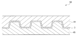
図2に示すように、MEGA2は、平面視矩形状に形成されており、MEGA2の周縁部は、枠状の樹脂フレーム30に接着剤層35(図3参照)を介して接着固定されている。MEGA2および樹脂フレーム30によって、膜電極接合体アセンブリ40が構成されている。
As shown in FIG. 2, the MEGA 2 is formed in a rectangular shape in plan view, and the periphery of the MEGA 2 is adhesively fixed to a frame-
樹脂フレーム30は、セパレータ3を流れる燃料ガス、酸化剤ガス、および後述する冷却水をシールする部材である。樹脂フレーム30は、熱可塑性樹脂または熱硬化性樹脂からなるとともに、可撓性を有する。樹脂フレーム30の周縁部には図3に示すように、セパレータ3に熱圧着するための熱可塑性樹脂シートからなる接着層31が設けられている。膜電極接合体アセンブリ40の樹脂フレーム30に対してセパレータ3が接着固定されることによって、セル1が構成されている。なお、接着層31に用いる樹脂として、例えばポリプロピレン等のポリオレフィン系樹脂が挙げられるが、他の樹脂を用いてもよい。
The
[燃料電池スタックの構成]
図4は、燃料電池スタック(燃料電池)10の要部を断面視した図である。図4に示すように、燃料電池スタック10には、基本単位であるセル1が複数積層されている。各セル1のセパレータ3の一面側は上述したようにMEGA2のガス拡散層7と当接し、他面側が隣接する他のセパレータ3の他面側と当接している。
[Configuration of fuel cell stack]
FIG. 4 is a cross-sectional view of a main part of the fuel cell stack (fuel cell) 10. As shown in FIG. As shown in FIG. 4, the
あるセル1と、それに隣接するもうひとつのセル1とは、アノードとなる電極6とカソードとなる電極6とを向き合わせて配置されている。また、あるセル1のアノードとなる電極6に沿って配置されたセパレータ3の背面側の頂部と、もうひとつのセル1のカソードとなる電極6に沿って配置されたセパレータ3の背面側の頂部とが、面接触している。隣接する2つのセル1間で面接触するセパレータ3、3の間に画成される空間23には、セル1を冷却する冷媒としての水(冷却水)が流通する。
A certain cell 1 and another adjacent cell 1 are arranged with an
[セパレータの製造工程]
図5は、セパレータの製造に用いる金型の構造を示す断面図であり、図6は、セパレータの製造工程の概略フローを示した図である。図7は、セパレータの製造途中の様子を示す断面図である。なお、図7では、後述する潤滑剤60を省略している。
[Manufacturing process of separator]
FIG. 5 is a cross-sectional view showing the structure of a mold used for manufacturing the separator, and FIG. 6 is a diagram showing a schematic flow of the manufacturing process of the separator. FIG. 7 is a cross-sectional view showing a state in the middle of manufacturing the separator. 7, the
本実施形態では、図5に示すように、前述したセパレータ3は、金型50を用いて成形される。金型50は、所定方向(ガス流路の流れ方向)に延びる凹状面(上側に窪んだ面)43と凸状面(下側に膨出した面)44とが交互に設けられた凹凸面からなるプレス面42を有する上型41と、上型の凹凸面(プレス面42)と相補的な形状を有する凹凸面からなるプレス面46を有する下型45と、からなる。セパレータ3は、金型50を用いて、セパレータ3の素材となる基材3aを上型41のプレス面42と下型45のプレス面46とで上下方向でプレスすることで、波形状ないし凹凸状を呈するように形成される。
In this embodiment, as shown in FIG. 5, the
ここで、本実施形態では、成形後のセパレータ3の金型50に対する離型性を確保するために、基材3aの両面(図3の上面および下面)に所定の融点を有する潤滑剤60を塗布(供給)する(図6の供給工程S1参照)。潤滑剤60としては、例えばアクリルポリマー系樹脂を用いることができる。また、アクリルポリマー系樹脂は、例えばアクリル酸メチル、アクリル酸エチル、アクリル酸ブチル、アクリル酸n-ブチル、アクリル酸2-エチルヘキシル、アクリル酸2-ジメチルアミノエチル、アクリル酸2-ヒドロキシエチルのうちの1種以上を、所定の温度以下の融点になるように重合させることにより得られる。なお、基材3aの両面(上面および下面)への潤滑剤60の供給は、上型41のプレス面42と下型45のプレス面46とに潤滑剤60を塗布(供給)することによって行ってもよい。
Here, in the present embodiment, in order to ensure releasability of the molded
その後、基材3aを上型41と下型45とによって上下方向から所定圧で挟んでプレス加工を施す(図6のプレス工程S2参照)。これにより、図7に示すように波状または凹凸状(すなわち、ガス流路21、22および空間23を形成する構造)を有するセパレータ3が形成される。
After that, the
そして、金型50を型開きして、セパレータ3を金型50から取り出す(図6の離型工程S3参照)。このようにして、セパレータ3が製造される。なお、成形後のセパレータ3の表面には、潤滑剤60が残留している。
Then, the
[燃料電池セルの製造方法]
図8は、セル1の製造途中の様子を示す断面図であり、図9は、セル1の製造工程の概略フローを示した図である。図10は、セル1の製造途中における接着層31周辺の拡大断面図である。なお、図8では、潤滑剤60を省略している。
[Manufacturing method of fuel cell]
FIG. 8 is a cross-sectional view showing a state during the manufacture of the cell 1, and FIG. 9 is a diagram showing a schematic flow of the manufacturing process of the cell 1. FIG. 10 is an enlarged cross-sectional view of the
セル1は図8に示すように、樹脂フレーム30を一対のセパレータ3で挟み込んだ状態で金型70を用いて熱圧着することにより成形される。金型70は、セパレータ3の周縁部を上方から押圧する枠状の押圧部71aとセパレータ3の凹凸面を避ける凹部71bとを有する上型71と、セパレータ3の周縁部を下方から押圧する枠状の押圧部72aとセパレータ3の凹凸面を避ける凹部72bとを有する下型72と、を含んでいる。押圧部71aおよび72aは、樹脂フレーム30の接着層31に対向する位置に設けられている。
As shown in FIG. 8, the cell 1 is molded by thermocompression bonding using a
また、上型71および下型72の各々には、樹脂フレーム30とセパレータ3とを接合するための加熱装置(図示せず)が内蔵されている。加熱装置は、上型71および下型72を加熱するものであれば、通電式、蒸気式等のいずれの形態であってもよい。加熱装置は、セパレータ3を介して樹脂フレーム30の接着層31を溶融可能な温度に設定されている。
Each of the
セル1を製造する場合、MEGA2の周縁部に樹脂フレーム30が固定された膜電極接合体アセンブリ40と、波状または凹凸状を有する一対のセパレータ3と、を準備する(図9の準備工程S11参照)。
When manufacturing the cell 1, a
そして、膜電極接合体アセンブリ40を一対のセパレータ3で挟み込んだ状態で金型70を用いて一対のセパレータ3を樹脂フレーム30に熱圧着する(図9のプレス工程S12参照)。このとき、潤滑剤60および接着層31の融点よりも高い温度で熱圧着を行う。これにより、図10に示すようにセパレータ3の表面と接着層31との境界に存在していた潤滑剤60が、金型70からの熱により溶融し、図11に示すように接着層31中に分散する。このため、セパレータ3と接着層31とが直接接触するので、セパレータ3と接着層31との間の接着が阻害されない。なお、本実施形態では、接着層31の融点は潤滑剤60の融点よりも低い。このため、潤滑剤60が溶融する前に接着層31が溶融しているので、接着層31中に潤滑剤60がより分散しやすい。
Then, with the
その後、金型70を型開きして、セル1を金型70から取り出す。そして、セル1に冷却風を当てることによって、セル1を常温まで冷却する(図9の冷却工程S13参照)。このようにして、セル1が製造される。
After that, the
なお、上記セル1の製造工程において、セル1をコンベア等(図示せず)により間欠的に移動させて各工程(準備工程、プレス工程、冷却工程)で処理を施す場合、例えば、セル1を加熱処理する工程(プレス工程S12)および冷却工程S13の各々を、2つのステーションに分けて2回行ってもよい。この場合、各ステーションにおける処理時間(滞在時間)を約半分に短縮することができるので、タクトタイムを短縮することができる。 In the manufacturing process of the cell 1, when the cell 1 is intermittently moved by a conveyor or the like (not shown) and processed in each process (preparation process, pressing process, cooling process), for example, the cell 1 is Each of the heat treatment step (pressing step S12) and the cooling step S13 may be performed twice in two stations. In this case, the processing time (residence time) at each station can be shortened by about half, so the takt time can be shortened.
本実施形態では、上記のように、両面に接着層31が設けられた樹脂フレーム30を一対のセパレータ3で挟み込んだ状態で、潤滑剤60の融点よりも高い温度で一対のセパレータ3を熱圧着する。これにより、熱圧時に潤滑剤60を接着層31中に分散させることができるので、樹脂フレーム30の表面に設けられた接着層31とセパレータ3との界面の潤滑剤60が無くなる。このため、潤滑剤60により接着層31とセパレータ3との結合が阻害されるのを抑制することができるので、樹脂フレーム30とセパレータ3との接着強度が低下するのを抑制することができる。
In this embodiment, as described above, the
また、セパレータ3の成形後に潤滑剤60を除去する必要がないので、セル1の製造に時間がかかるのを抑制することができる。また、潤滑剤60が完全に除去されたことを検査する必要もない。
In addition, since it is not necessary to remove the
以上のように、セパレータ成形後の潤滑剤除去工程を設けることなく、潤滑剤残渣による接着性の低下を抑制することができる。 As described above, it is possible to suppress deterioration in adhesiveness due to lubricant residue without providing a lubricant removal step after separator molding.
なお、今回開示された実施形態は、すべての点で例示であって制限的なものではないと考えられるべきである。本発明の範囲は、上記した実施形態の説明ではなく特許請求の範囲によって示され、さらに特許請求の範囲と均等の意味および範囲内でのすべての変更が含まれる。 It should be noted that the embodiments disclosed this time should be considered as examples and not restrictive in all respects. The scope of the present invention is indicated by the scope of the claims rather than the description of the above-described embodiments, and includes all modifications within the meaning and scope equivalent to the scope of the claims.
例えば、上記実施形態では、潤滑剤60としてアクリルポリマー系樹脂を用いる例について示したが、本発明はこれに限らない。プレス工程S12において融点よりも高い温度になった際に接着層31中に分散する樹脂であれば、アクリルポリマー系以外の樹脂を用いてもよい。
For example, in the above embodiment, an example using an acrylic polymer resin as the
1:セル(燃料電池セル)、2:MEGA(発電部)、3:セパレータ、3a:基材、4:膜電極接合体、21、22:ガス流路、30:樹脂フレーム、31:接着層、60:潤滑剤 1: cell (fuel cell), 2: MEGA (power generation unit), 3: separator, 3a: base material, 4: membrane electrode assembly, 21, 22: gas flow path, 30: resin frame, 31: adhesive layer , 60: lubricant
Claims (1)
前記セパレータとなるシート状の基材の両面に所定の融点を有する潤滑剤を供給するとともに、前記基材にプレス加工を施すことにより、前記膜電極接合体に反応ガスを供給するためのガス流路を有するセパレータを形成する工程と、
前記膜電極接合体が固定されるとともに両面に熱可塑性樹脂からなる接着層が設けられた前記樹脂フレームを前記一対のセパレータで挟み込んだ状態で、前記潤滑剤の融点よりも高い温度で前記一対のセパレータを熱圧することによって、前記潤滑剤を溶融させ、前記潤滑剤を前記接着層中に分散させるとともに、前記セパレータを前記樹脂フレームに接着する工程と、
を含むことを特徴とする燃料電池セルの製造方法。 A method for manufacturing a fuel cell comprising: a membrane electrode assembly; a frame-shaped resin frame to which a peripheral edge of the membrane electrode assembly is fixed; and a pair of separators sandwiching the membrane electrode assembly and the resin frame. There is
A gas flow for supplying a reaction gas to the membrane electrode assembly by supplying a lubricant having a predetermined melting point to both sides of the sheet-like base material that will be the separator, and pressing the base material. forming a separator having channels;
In a state in which the resin frame to which the membrane electrode assembly is fixed and which is provided with adhesive layers made of a thermoplastic resin on both sides thereof is sandwiched between the pair of separators, the pair of separators is heated to a temperature higher than the melting point of the lubricant. a step of hot-pressing the separator to melt the lubricant, disperse the lubricant in the adhesive layer, and adhere the separator to the resin frame;
A method of manufacturing a fuel cell, comprising:
Priority Applications (1)
| Application Number | Priority Date | Filing Date | Title |
|---|---|---|---|
| JP2019050775A JP7207049B2 (en) | 2019-03-19 | 2019-03-19 | Method for manufacturing fuel cell |
Applications Claiming Priority (1)
| Application Number | Priority Date | Filing Date | Title |
|---|---|---|---|
| JP2019050775A JP7207049B2 (en) | 2019-03-19 | 2019-03-19 | Method for manufacturing fuel cell |
Publications (2)
| Publication Number | Publication Date |
|---|---|
| JP2020155247A JP2020155247A (en) | 2020-09-24 |
| JP7207049B2 true JP7207049B2 (en) | 2023-01-18 |
Family
ID=72559572
Family Applications (1)
| Application Number | Title | Priority Date | Filing Date |
|---|---|---|---|
| JP2019050775A Active JP7207049B2 (en) | 2019-03-19 | 2019-03-19 | Method for manufacturing fuel cell |
Country Status (1)
| Country | Link |
|---|---|
| JP (1) | JP7207049B2 (en) |
Citations (5)
| Publication number | Priority date | Publication date | Assignee | Title |
|---|---|---|---|---|
| JP2003142119A (en) | 2001-11-07 | 2003-05-16 | Honda Motor Co Ltd | Method of manufacturing metallic separator for fuel cell |
| JP2007207644A (en) | 2006-02-03 | 2007-08-16 | Nissan Motor Co Ltd | Fuel cell, and method of manufacturing same |
| JP2018170291A (en) | 2014-05-28 | 2018-11-01 | 株式会社神戸製鋼所 | Separator material for fuel cell and method for producing the same |
| JP2018185977A (en) | 2017-04-26 | 2018-11-22 | 株式会社Soken | Fuel cell |
| JP2020145130A (en) | 2019-03-08 | 2020-09-10 | トヨタ自動車株式会社 | Manufacturing method of fuel battery cell |
-
2019
- 2019-03-19 JP JP2019050775A patent/JP7207049B2/en active Active
Patent Citations (5)
| Publication number | Priority date | Publication date | Assignee | Title |
|---|---|---|---|---|
| JP2003142119A (en) | 2001-11-07 | 2003-05-16 | Honda Motor Co Ltd | Method of manufacturing metallic separator for fuel cell |
| JP2007207644A (en) | 2006-02-03 | 2007-08-16 | Nissan Motor Co Ltd | Fuel cell, and method of manufacturing same |
| JP2018170291A (en) | 2014-05-28 | 2018-11-01 | 株式会社神戸製鋼所 | Separator material for fuel cell and method for producing the same |
| JP2018185977A (en) | 2017-04-26 | 2018-11-22 | 株式会社Soken | Fuel cell |
| JP2020145130A (en) | 2019-03-08 | 2020-09-10 | トヨタ自動車株式会社 | Manufacturing method of fuel battery cell |
Also Published As
| Publication number | Publication date |
|---|---|
| JP2020155247A (en) | 2020-09-24 |
Similar Documents
| Publication | Publication Date | Title |
|---|---|---|
| US9831504B2 (en) | Single fuel cell and method of manufacturing single fuel cell | |
| US11133514B2 (en) | Resin frame equipped membrane electrode assembly and method of producing the same | |
| US11283094B2 (en) | Fuel cell and method for manufacturing the fuel cell | |
| JP6848799B2 (en) | How to manufacture a single cell of a fuel cell | |
| CN109659581B (en) | Method for manufacturing single cell of fuel cell | |
| US10763530B2 (en) | Manufacturing method for fuel cell | |
| CN110739473A (en) | Method for manufacturing fuel cell unit and fuel cell unit | |
| JP7207049B2 (en) | Method for manufacturing fuel cell | |
| JP2020145130A (en) | Manufacturing method of fuel battery cell | |
| JP7257851B2 (en) | Elastic cell frame for fuel cell, manufacturing method thereof, and unit cell using same | |
| JP5141281B2 (en) | Method for producing fuel cell electrode assembly | |
| EP2999040B1 (en) | Apparatus and method for producing fuel cell separator assembly | |
| JP2007179815A (en) | Fuel cell module, fuel cell stack, and fabricating method of fuel cell module | |
| JP2017068908A (en) | Manufacturing method for resin frame-attached electrolyte membrane-electrode structure | |
| KR20200072198A (en) | Elastomer cell frame for fuel cell and manufacturing method thereof and unit cell comprising thereof | |
| CN116368648A (en) | Membrane electrode unit for an electrochemical cell and method for producing a membrane electrode unit | |
| JP2019096389A (en) | Method of manufacturing fuel battery cell | |
| JP2022067828A (en) | Manufacturing method for fuel cell separator | |
| US20190109342A1 (en) | Fuel cell | |
| JP2016170961A (en) | Method of manufacturing fuel battery single cell | |
| JP5817547B2 (en) | Manufacturing method of fuel cell | |
| JP7184057B2 (en) | Method for manufacturing fuel cell | |
| JP7031526B2 (en) | Fuel cell cell manufacturing equipment | |
| JP2021136205A (en) | Manufacturing method of fuel cell | |
| JP2017010704A (en) | Method for manufacturing electrolyte membrane/electrode structure with resin frame |
Legal Events
| Date | Code | Title | Description |
|---|---|---|---|
| A621 | Written request for application examination |
Free format text: JAPANESE INTERMEDIATE CODE: A621 Effective date: 20211119 |
|
| A977 | Report on retrieval |
Free format text: JAPANESE INTERMEDIATE CODE: A971007 Effective date: 20220824 |
|
| A131 | Notification of reasons for refusal |
Free format text: JAPANESE INTERMEDIATE CODE: A131 Effective date: 20220906 |
|
| A521 | Request for written amendment filed |
Free format text: JAPANESE INTERMEDIATE CODE: A523 Effective date: 20221011 |
|
| TRDD | Decision of grant or rejection written | ||
| A01 | Written decision to grant a patent or to grant a registration (utility model) |
Free format text: JAPANESE INTERMEDIATE CODE: A01 Effective date: 20221206 |
|
| A61 | First payment of annual fees (during grant procedure) |
Free format text: JAPANESE INTERMEDIATE CODE: A61 Effective date: 20221219 |
|
| R151 | Written notification of patent or utility model registration |
Ref document number: 7207049 Country of ref document: JP Free format text: JAPANESE INTERMEDIATE CODE: R151 |