JP7206509B2 - BASE STATION DEVICE, TERMINAL DEVICE, AND COMMUNICATION METHOD - Google Patents
BASE STATION DEVICE, TERMINAL DEVICE, AND COMMUNICATION METHOD Download PDFInfo
- Publication number
- JP7206509B2 JP7206509B2 JP2020518839A JP2020518839A JP7206509B2 JP 7206509 B2 JP7206509 B2 JP 7206509B2 JP 2020518839 A JP2020518839 A JP 2020518839A JP 2020518839 A JP2020518839 A JP 2020518839A JP 7206509 B2 JP7206509 B2 JP 7206509B2
- Authority
- JP
- Japan
- Prior art keywords
- terminal device
- base station
- ack
- scheme
- acks
- Prior art date
- Legal status (The legal status is an assumption and is not a legal conclusion. Google has not performed a legal analysis and makes no representation as to the accuracy of the status listed.)
- Active
Links
- 238000000034 method Methods 0.000 title claims description 59
- 238000004891 communication Methods 0.000 title claims description 56
- 230000005540 biological transmission Effects 0.000 claims description 111
- 238000009825 accumulation Methods 0.000 claims description 74
- 230000035508 accumulation Effects 0.000 claims description 74
- 238000012790 confirmation Methods 0.000 claims description 10
- 238000010586 diagram Methods 0.000 description 36
- 101100465000 Mus musculus Prag1 gene Proteins 0.000 description 7
- 238000004088 simulation Methods 0.000 description 7
- 238000004364 calculation method Methods 0.000 description 6
- 238000005516 engineering process Methods 0.000 description 4
- 238000010295 mobile communication Methods 0.000 description 4
- 230000014509 gene expression Effects 0.000 description 3
- 230000011664 signaling Effects 0.000 description 3
- 230000004044 response Effects 0.000 description 2
- 230000000052 comparative effect Effects 0.000 description 1
- 230000003111 delayed effect Effects 0.000 description 1
- 230000007774 longterm Effects 0.000 description 1
- 239000007787 solid Substances 0.000 description 1
Images


Classifications
-
- H—ELECTRICITY
- H04—ELECTRIC COMMUNICATION TECHNIQUE
- H04W—WIRELESS COMMUNICATION NETWORKS
- H04W28/00—Network traffic management; Network resource management
- H04W28/02—Traffic management, e.g. flow control or congestion control
- H04W28/0284—Traffic management, e.g. flow control or congestion control detecting congestion or overload during communication
-
- H—ELECTRICITY
- H04—ELECTRIC COMMUNICATION TECHNIQUE
- H04L—TRANSMISSION OF DIGITAL INFORMATION, e.g. TELEGRAPHIC COMMUNICATION
- H04L1/00—Arrangements for detecting or preventing errors in the information received
- H04L1/12—Arrangements for detecting or preventing errors in the information received by using return channel
- H04L1/16—Arrangements for detecting or preventing errors in the information received by using return channel in which the return channel carries supervisory signals, e.g. repetition request signals
- H04L1/18—Automatic repetition systems, e.g. Van Duuren systems
- H04L1/1829—Arrangements specially adapted for the receiver end
- H04L1/1835—Buffer management
-
- H—ELECTRICITY
- H04—ELECTRIC COMMUNICATION TECHNIQUE
- H04L—TRANSMISSION OF DIGITAL INFORMATION, e.g. TELEGRAPHIC COMMUNICATION
- H04L1/00—Arrangements for detecting or preventing errors in the information received
- H04L1/12—Arrangements for detecting or preventing errors in the information received by using return channel
- H04L1/16—Arrangements for detecting or preventing errors in the information received by using return channel in which the return channel carries supervisory signals, e.g. repetition request signals
- H04L1/1607—Details of the supervisory signal
- H04L1/1635—Cumulative acknowledgement, i.e. the acknowledgement message applying to all previous messages
-
- H—ELECTRICITY
- H04—ELECTRIC COMMUNICATION TECHNIQUE
- H04L—TRANSMISSION OF DIGITAL INFORMATION, e.g. TELEGRAPHIC COMMUNICATION
- H04L1/00—Arrangements for detecting or preventing errors in the information received
- H04L1/12—Arrangements for detecting or preventing errors in the information received by using return channel
- H04L1/16—Arrangements for detecting or preventing errors in the information received by using return channel in which the return channel carries supervisory signals, e.g. repetition request signals
- H04L1/18—Automatic repetition systems, e.g. Van Duuren systems
- H04L1/1829—Arrangements specially adapted for the receiver end
- H04L1/1864—ARQ related signaling
-
- H—ELECTRICITY
- H04—ELECTRIC COMMUNICATION TECHNIQUE
- H04L—TRANSMISSION OF DIGITAL INFORMATION, e.g. TELEGRAPHIC COMMUNICATION
- H04L69/00—Network arrangements, protocols or services independent of the application payload and not provided for in the other groups of this subclass
- H04L69/16—Implementation or adaptation of Internet protocol [IP], of transmission control protocol [TCP] or of user datagram protocol [UDP]
- H04L69/163—In-band adaptation of TCP data exchange; In-band control procedures
-
- H—ELECTRICITY
- H04—ELECTRIC COMMUNICATION TECHNIQUE
- H04W—WIRELESS COMMUNICATION NETWORKS
- H04W28/00—Network traffic management; Network resource management
- H04W28/02—Traffic management, e.g. flow control or congestion control
- H04W28/0273—Traffic management, e.g. flow control or congestion control adapting protocols for flow control or congestion control to wireless environment, e.g. adapting transmission control protocol [TCP]
-
- H—ELECTRICITY
- H04—ELECTRIC COMMUNICATION TECHNIQUE
- H04W—WIRELESS COMMUNICATION NETWORKS
- H04W72/00—Local resource management
- H04W72/20—Control channels or signalling for resource management
- H04W72/23—Control channels or signalling for resource management in the downlink direction of a wireless link, i.e. towards a terminal
-
- H—ELECTRICITY
- H04—ELECTRIC COMMUNICATION TECHNIQUE
- H04W—WIRELESS COMMUNICATION NETWORKS
- H04W72/00—Local resource management
- H04W72/50—Allocation or scheduling criteria for wireless resources
- H04W72/51—Allocation or scheduling criteria for wireless resources based on terminal or device properties
Description
本発明は、基地局装置、端末装置、及び通信方法に関する。 The present invention relates to base station apparatuses, terminal apparatuses, and communication methods.
現在のネットワークは、モバイル端末(スマートフォンやフューチャーホン)のトラフィックがネットワークのリソースの大半を占めている。また、モバイル端末が使うトラフィックは、今後も拡大していく傾向にある。 In current networks, the traffic of mobile terminals (smartphones and feature phones) occupies the majority of network resources. In addition, the traffic used by mobile terminals will continue to expand in the future.
第5世代移動体通信(5Gまたは、NR(New Radio))の通信規格では、4G(第4世代移動体通信)の標準技術に加えて、さらなる高データレート化、大容量化、低遅延化を実現する技術が求められている。なお、第5世代通信規格については、3GPPの作業部会(例えば、TSG-RAN WG1、TSG-RAN WG2等)で技術検討が進められている。 In the 5th generation mobile communication (5G or NR (New Radio)) communication standard, in addition to the standard technology of 4G (4th generation mobile communication), further high data rate, large capacity, low delay There is a need for a technology that realizes As for the 5th generation communication standard, technical studies are underway in 3GPP working groups (eg, TSG-RAN WG1, TSG-RAN WG2, etc.).
データ通信においては、TCP/IP(Transmission Control Protocol/Internet Protocol)と呼ばれる通信プロトコルが用いられる場合がある。TCP/IPは、TCPとIPとを組み合わせたプロトコルであり、インターネットなどで標準的に用いられている。 In data communication, a communication protocol called TCP/IP (Transmission Control Protocol/Internet Protocol) may be used. TCP/IP is a protocol that combines TCP and IP, and is standardly used in the Internet and the like.
TCPにおける通信は、送信側の通信装置がデータパケットを送信し、受信側の通信装置はデータパケットを正常に受信できたとき、受信したデータパケットに対する確認応答であるACK(Acknowledgement)を返信する。送信側の通信装置はACKを受信し、次のデータパケットを送信する。このように、TCPにおける通信では、ACKを受信することで、データパケットが到達したことを確認することができ、信頼性のある通信を実現している。 In TCP communication, a transmission-side communication device transmits a data packet, and when the reception-side communication device successfully receives the data packet, it returns an acknowledgment (ACK) for the received data packet. The transmitting communication device receives the ACK and transmits the next data packet. Thus, in TCP communication, it is possible to confirm that a data packet has arrived by receiving an ACK, thereby realizing reliable communication.
TCPの通信においては、ACKの送信が多くなると、ACKの送信で通信リソースが使用され、通信速度が低下する場合がある。そこで、ACKの送信数を減少させる方式として、例えば、割当られたリソースを超えるACKを破棄する方式がある。また、ACKの送信数を減少させる方式として、送信バッファに所定数までACKが滞留することを許容し、所定数を超えたACKを破棄する方式がある。 In TCP communication, when the number of ACK transmissions increases, communication resources are used for ACK transmission, which may reduce the communication speed. Therefore, as a method of reducing the number of ACK transmissions, for example, there is a method of discarding ACKs exceeding the allocated resources. Further, as a method for reducing the number of ACK transmissions, there is a method of allowing ACKs to stay in a transmission buffer up to a predetermined number and discarding ACKs exceeding the predetermined number.
LTE及びTCP/IPに関する技術については、以下の先行技術文献に記載されている。 Technologies related to LTE and TCP/IP are described in the following prior art documents.
しかし、一部のACKを破棄する方式を用いた通信装置は、複数のパケットを受信するまでACKを返信しない。例えば、パケットの送信側の通信装置が、ACKを受信するか、送信するデータの合計が所定のサイズ以上になるか、もしくはパケットの送信待ちタイマがタイムアウトするまで、次のパケットを送信しないような制御を行っている場合がある。送信側の通信装置は、このような制御を行っている場合、送信するデータが小さいため送信データの合計が所定のサイズ以上にならない場合、パケットの送信待ちタイマがタイムアウトするまで次のパケットを送信することができない。この場合、次のデータパケットを待っている受信側の通信装置において、データの受信が遅延してしまう。 However, a communication device using a method of discarding some ACKs does not return ACKs until it receives a plurality of packets. For example, the communication device on the transmission side of the packet does not transmit the next packet until it receives an ACK, the total amount of data to be transmitted reaches or exceeds a predetermined size, or the packet transmission waiting timer times out. You may have control. Under such control, the communication device on the transmitting side transmits the next packet until the packet transmission wait timer times out if the total amount of transmission data does not exceed a predetermined size because the amount of data to be transmitted is small. Can not do it. In this case, the reception of data is delayed in the communication device on the receiving side waiting for the next data packet.
そこで、一開示は、一部のACKを破棄する方式を適用しても、データ送受信の遅延を抑制する基地局装置、端末装置、及び通信方法を提供することにある。 Therefore, one disclosure is to provide a base station apparatus, a terminal apparatus, and a communication method that suppress the delay in data transmission/reception even if a method of discarding some ACKs is applied.
端末装置と無線通信を行う基地局装置であって、前記基地局装置から受信したパケットに対応する受信確認パケットを、前記端末装置において蓄積することができる蓄積数を、前記端末装置が送信するデータ量に応じて決定する制御部と、前記決定した蓄積数を含む制御信号を、前記端末装置に送信できる送信部と、を有する。 A base station device that performs wireless communication with a terminal device, wherein data transmitted by the terminal device indicates the number of reception confirmation packets that can be stored in the terminal device, corresponding to packets received from the base station device. and a transmission unit capable of transmitting a control signal including the determined accumulation number to the terminal device.
一開示は、一部のACKを破棄する方式を適用しても、データ送受信の遅延を抑制することにある。 One disclosure is to suppress the delay in data transmission/reception even if a method of discarding some ACKs is applied.
以下、本実施の形態について図面を参照して詳細に説明する。本明細書における課題及び実施例は一例であり、本願の権利範囲を限定するものではない。特に、記載の表現が異なっていたとしても技術的に同等であれば、異なる表現であっても本願の技術を適用可能であり、権利範囲を限定するものではない。 Hereinafter, this embodiment will be described in detail with reference to the drawings. The problems and examples in this specification are examples, and do not limit the scope of rights of the present application. In particular, even if the expressions in the description are different, as long as they are technically equivalent, the technology of the present application can be applied even if the expressions are different, and the scope of rights is not limited.
[第1の実施の形態]
最初に第1の実施の形態について説明する。[First embodiment]
First, the first embodiment will be explained.
通信システム10は、端末装置と、端末装置と無線通信する基地局装置とを有する。基地局装置は、基地局装置から受信したパケットに対応する受信確認パケットの、端末装置において蓄積することができる蓄積数(蓄積閾値)を、端末装置が送信するデータ量に応じて決定する制御部を有する。また、基地局装置は、決定した蓄積数を含む制御信号を、端末装置に送信できる送信部を有する。
The
図1は、第1の実施の形態における、通信システム10の構成例を示す図である。通信システム10は、端末装置100と基地局装置200を有する。端末装置100と基地局装置200は、無線通信をしており(S1)、例えば、パケットを使用してデータの送受信を行う。端末装置100は、例えば、携帯電話などのモバイル通信端末である。また、基地局装置200は、例えば、5GにおけるgNodeBである。
FIG. 1 is a diagram showing a configuration example of a
端末装置100と基地局装置200は、例えば、互いにTCP/IPに基づき通信を行う。基地局装置200は、例えば、図示しないネットワークから端末装置100が送信先であるデータを受信すると、端末装置100にデータを含むTCPパケットを送信する。端末装置100は、TCPパケットを受信すると、受信したTCPパケットに対応する(受信したことを送信元装置に通知するための)受信確認パケット(例えば、ACK)を送信する。以降、単にパケットと称する場合、TCPパケット、又は受信確認パケット、又はその両方を示す。
The
基地局装置200は、図示しないプロセッサ、ストレージ、メモリを有し、ストレージに記憶されたプログラムをメモリにロードし、プロセッサがロードしたプログラムを実行することで、制御部201及び送信部202を構築し、各処理を実行する。
The
基地局装置200は、制御部201、送信部202、及びデータ203を有する。データ203は、例えば、端末装置100が所定時間において送信するACK送信数(又はACK送信数の平均値)が記憶される。
制御部201は、データ203に含まれる端末装置100が送信するデータ量に基づいて(応じて)(S2)、蓄積数を決定する(S3)。蓄積数は、端末装置100が蓄積することができるACKの最大数であり、蓄積数を超えるACKについては、端末装置100にて破棄される。
The
送信部202は、制御部201が決定した蓄積数を制御信号に含め(S4)、端末装置100に送信する(S5)。
The
端末装置100は、蓄積数を含む制御信号を受信し、蓄積数を取得する。端末装置100は、取得した蓄積数に従い、受信確認を蓄積し、蓄積数を超える受信確認については破棄する。
The
第1の実施の形態では、基地局装置200は、端末装置100が送信するデータ量に応じて、蓄積数を決定する。これにより、端末装置100は、過剰なACKの送信を抑制することができる。
In the first embodiment, the
なお、端末装置100において蓄積することができる蓄積数(蓄積閾値)は,下りのデータ送信量に応じて決定してもよい。端末装置100は、TCPパケットの受信数に応じた数のACKを送信する場合がある。そこで、基地局装置200は、端末装置100が下りのデータ送信量に応じた数のACKを送信するとみなし、下りのデータ送信量に応じて蓄積数を決定してもよい。
Note that the number of accumulations (accumulation threshold) that can be accumulated in the
[第2の実施の形態]
次に、第2の実施の形態について説明する。[Second embodiment]
Next, a second embodiment will be described.
<通信システムの構成例>
図2は、通信システム10の構成例を示す図である。通信システム10は、端末装置100-1,2、基地局装置200、及びネットワーク300を有する。通信システム10は、例えば、LTE(Long Term Evolution)の通信規格や、5Gに対応した通信システムである。<Configuration example of communication system>
FIG. 2 is a diagram showing a configuration example of the
端末装置100-1,2(以下、端末装置100と呼ぶ場合がある)は、例えば、スマートフォンやタブレット端末などのモバイル通信端末(通信装置)である。端末装置100は、例えば、基地局装置200と無線接続し、基地局装置200を介してネットワーク300と通信を行う。端末装置100は、基地局装置200やネットワーク300からデータをダウンロードしたり、サービスの提供を受けたりする。また、端末装置100は、例えば、TCP/IPに基づいて、基地局装置200やネットワーク300と通信を行う。
The terminal devices 100-1 and 100-2 (hereinafter sometimes referred to as terminal device 100) are mobile communication terminals (communication devices) such as smartphones and tablet terminals, for example. The
基地局装置200は、端末装置100が送受信するパケットを中継する通信装置である。基地局装置200は、例えば、LTEにけるeNodeB(evolved Node B)や、5GにおけるgNodeBである。また、基地局装置200は、スイッチやルータなどのネットワーク機器であってもよい。
The
ネットワーク300は、例えば、インターネットであってもよいし、専用線で構成されているイントラネットであってもよい。
The
<端末装置の構成例>
図3は、端末装置100の構成例を示す図である。端末装置100は、CPU(Central Processing Unit)110、ストレージ120、メモリ130、及びRF(Radio Frequency)回路150を有する。<Configuration example of terminal device>
FIG. 3 is a diagram showing a configuration example of the
ストレージ120は、プログラムやデータを記憶する、フラッシュメモリ、HDD(Hard Disk Drive)、又はSSD(Solid State Drive)などの補助記憶装置である。ストレージ120は、通信プログラム121及びACK送信プログラム122を記憶する。
The
メモリ130は、ストレージ120に記憶されているプログラムをロードする領域である。また、メモリ130、プログラムがデータを記憶する領域としても使用される。
RF回路150は、基地局装置200と無線接続する装置である。RF回路150は、例えば、アンテナを有し、アンテナを介して基地局装置200と電波(パケット)の送受信を行う。
The
CPU110は、ストレージ120に記憶されているプログラムを、メモリ130にロードし、ロードしたプログラムを実行し、各処理を実現するプロセッサである。
The
CPU110は、通信プログラム121を実行することで、通信処理を行う。通信処理は、基地局装置200やネットワーク300などと、通信を行う処理である。端末装置100は、例えば、端末装置100のユーザや、端末装置100において実行するプログラムの要求に応じて通信を行うとき、通信処理を行う。
The
また、CPU110は、ACK送信プログラム122を実行することで、送信制御部を構築し、ACK送信処理を行う。ACK送信処理は、基地局装置200から受信したTCPパケットに対応するACK(応答確認)を生成し、送信バッファに格納し、ACKの送信方式に応じてACKを基地局装置200に送信する処理である。
Further, the
CPU110は、ACK送信プログラム122の有するHD(Hybrid Discard)方式モジュール1221を実行することで、送信制御部を構築し、HD方式によるACK送信処理を行う。HD方式は、AD(Active Discard)方式及びPD(Passive Discard)方式の両方式を同時に実行するACK送信方式である。
The
PD方式は、割当リソース量に応じた数のACKを送信し、送信しなかったACKのうち、破棄率に応じた数のACKを破棄し、それ以外のACKは送信するACK送信方式である。すなわち、PD方式では、端末装置100は、割当リソース量に応じたACK数と、破棄率に応じて破棄しないACK数の合計が、送信するACK数となる。なお、PD方式は、割当リソース量に応じた数のACKを送信し、送信しなかったACKを破棄するACK送信方式であってもよい。
The PD scheme is an ACK transmission scheme in which the number of ACKs corresponding to the allocated resource amount is transmitted, the number of ACKs not transmitted is discarded according to the discard rate, and the other ACKs are transmitted. That is, in the PD scheme, the number of ACKs to be transmitted by the
AD方式は、蓄積閾値(ACKを蓄積できる最大数)までACKを送信バッファに蓄積し、蓄積閾値を超えるACKは破棄率に応じて破棄するACK送信方式である。すなわち、AD破棄率方式では、端末装置100は、蓄積閾値のACK数と、破棄率に応じて破棄しないACK数の合計が、送信するACK数となる。なお、AD方式は、蓄積閾値までACKを送信バッファに蓄積し、蓄積閾値を超えるACKは破棄するACK送信方式であってもよい。
The AD method is an ACK transmission method in which ACKs are accumulated in a transmission buffer up to an accumulation threshold (maximum number of ACKs that can be accumulated), and ACKs exceeding the accumulation threshold are discarded according to the discard rate. That is, in the AD discard rate method, the number of ACKs to be transmitted by the
HD方式は、AD方式及びPD方式の2段階でACKを破棄するACK送信方式である。HD方式は、蓄積閾値内のACKでも割当リソース量を超えるACKは、破棄率に応じて破棄するACK送信方式である。なお、HD方式は、蓄積閾値内のACKでも割当リソース量を超えるACKは破棄するACK送信方式であってもよい。 The HD scheme is an ACK transmission scheme that discards ACKs in two stages, the AD scheme and the PD scheme. The HD scheme is an ACK transmission scheme in which even ACKs within the accumulation threshold but exceeding the allocated resource amount are discarded according to the discard rate. Note that the HD scheme may be an ACK transmission scheme that discards ACKs exceeding the allocated resource amount even if the ACKs are within the accumulation threshold.
CPU110は、ACK送信プログラム122の有する蓄積閾値取得モジュール1222を実行することで、受信部を構築し、蓄積閾値取得処理を行う。蓄積閾値取得処理は、HD方式で使用する蓄積閾値を、基地局装置200から取得する処理である。蓄積閾値取得処理は、制御信号を受信し、受信した制御信号に含まれる蓄積閾値を取得する。制御信号は、例えば、RRC(Radio Resource Control)シグナリングである。
The
<基地局装置の構成例>
図4は、基地局装置200の構成例を示す図である。基地局装置200は、CPU210、ストレージ220、メモリ230、NIC(Network Interface Card)240及びRF回路250を有する。<Configuration example of base station device>
FIG. 4 is a diagram showing a configuration example of the
ストレージ220は、プログラムやデータを記憶する、フラッシュメモリ、HDD、又はSSDなどの補助記憶装置である。ストレージ220は、通信制御プログラム221及びACK受信プログラム222を記憶する。
The
メモリ230は、ストレージ220に記憶されているプログラムをロードする領域である。また、メモリ230は、プログラムがデータを記憶する領域としても使用される。
NIC240は、ネットワーク300と接続するインターフェースである。基地局装置200は、NIC240を介して、ネットワーク300内の通信装置と通信を行う。
The
RF回路250は、端末装置100と無線接続する装置である。RF回路250は、例えば、アンテナを有し、アンテナを介して端末装置100と電波(パケット)の送受信を行う。
The
CPU210は、ストレージ220に記憶されているプログラムを、メモリ230にロードし、ロードしたプログラムを実行し、各処理を実現するプロセッサである。
The
CPU210は、通信制御プログラム221を実行することで、割当部を構築し、通信制御処理を行う。通信制御処理は、端末装置100の通信を制御する処理である。通信制御処理は、例えば、端末装置100に対して無線リソースを割り当てる処理である。
By executing the
また、CPU210は、ACK受信プログラム222を実行することで、制御部を構築し、ACK受信処理を行う。ACK受信処理は、端末装置100からACK(応答確認)を受信する処理である。また、ACK受信処理は、端末装置100における蓄積閾値を決定(算出)する処理である。
Further, the
CPU210は、ACK受信プログラム222の有するHD方式制御モジュール2221を実行することで、制御部及び送信部を構築し、HD方式制御処理を行う。HD方式制御処理は、端末装置100によるHD方式の通信を制御する処理である。
The
また、CPU210は、ACK受信プログラム222の有する蓄積閾値算出モジュール2222を実行することで、制御部を構築し、蓄積閾値算出処理を行う。蓄積閾値算出処理は、無線通信する端末装置100の蓄積閾値を算出する処理である。なお、基地局装置200は、無線通信する端末装置100が複数存在する場合、複数の端末装置100それぞれについて、蓄積閾値を算出する。
Further, the
さらに、CPU210は、ACK受信プログラム222の有するACK送信関連情報通知モジュール2223を実行することで、送信部を構築し、ACK送信関連情報通知処理を行う。ACK送信関連情報通知処理は、算出した蓄積閾値を含むACK送信関連情報を、制御信号(例えば、RRCシグナリング)に含め、端末装置100に通知(送信)する処理である。
Furthermore, the
<HD方式によるACK送信処理>
図5は、HD方式によるACK送信処理のシーケンスの例を示す図である。TCP(x)(xは整数)におけるxは、TCPパケットの識別子であり、例えば、シーケンス番号を示すものとする。また、ACK(y)(yは整数)におけるyは、対応するTCPパケットの識別子(上述したxに対応)を示すものとする。<ACK transmission processing by HD method>
FIG. 5 is a diagram showing an example of a sequence of ACK transmission processing according to the HD method. x in TCP(x) (where x is an integer) is a TCP packet identifier, for example, a sequence number. Also, y in ACK(y) (y is an integer) indicates the identifier of the corresponding TCP packet (corresponding to x described above).
端末装置100は、基地局装置200からTCPパケット(1)~(5)を受信する(S301~S305)。
The
端末装置100は、ACKの送信契機が発生すると、BSR(Buffer Status Report)を送信する(S105)。
The
図6は、各タイミングにおける送信バッファの例を示す図である。図6(A)は、図5のシーケンスのタイミングT31における送信バッファの例を示す図である。タイミングT31においては、送信バッファには、受信したTCPパケット(1)~(5)に対するACK(1)~(5)が蓄積されている。 FIG. 6 is a diagram showing an example of a transmission buffer at each timing. FIG. 6A is a diagram showing an example of a transmission buffer at timing T31 in the sequence of FIG. At timing T31, ACKs (1) to (5) for received TCP packets (1) to (5) are accumulated in the transmission buffer.
ここで、端末装置100は、AD方式により、蓄積閾値(例えば4)を超えるACKを、破棄率に応じて破棄する。端末装置100は、図5(A)において、例えば、破棄率に応じてACK(1)を破棄する。
Here, the
図5のシーケンスに戻り、端末装置100は、ACKの送信契機が発生すると、BSR(Buffer Status Report)を送信し(S306)、UL_Grant(Uplink Grant)を基地局装置200から受信する(S307)。
Returning to the sequence of FIG. 5, when an ACK transmission trigger occurs, the
BSRは、例えば、端末装置100が基地局装置200に対して、パケット(ACK及びTCPパケットを含む)を送信するための無線リソースの割り当てを要求するメッセージである。また、UL_Grantは、例えば、端末装置100に対して割り当てる無線リソース量を含むメッセージである。
The BSR is, for example, a message in which the
図6(B)は、図5のシーケンスのタイミングT32における送信バッファの例を示す図である。タイミングT32においては、送信バッファには、ACK(2)~(5)が蓄積されている。 FIG. 6B is a diagram showing an example of the transmission buffer at timing T32 in the sequence of FIG. At timing T32, ACKs (2) to (5) are accumulated in the transmission buffer.
端末装置100は、PD方式により、割当リソース量に応じた数のACK(図5におけるACK(4)及び(5))を送信対象とする。そして、端末装置100は、送信対象以外のACK(図5におけるACK(3)及び(2))のうち、破棄率に応じた数のACK(図5におけるACK(2))を破棄し、破棄しないACK(図5におけるACK(3))を送信対象とする。
The
上述したように、HD方式では、端末装置100は、蓄積閾値や割当リソース量によって送信対象とされるACK以外の破棄候補となるACKを、破棄率に応じて破棄する。また、HD方式では、蓄積閾値や割当リソース量によって送信対象とされるACK以外のACKを破棄してもよい。この場合、蓄積閾値や割当リソース量によって送信対象とされるACKの数の、全体のACKの数(蓄積閾値や割当リソース量によって送信対象とされるACK+破棄されるACK)に対する割合を破棄率とみなしてもよい。
As described above, in the HD scheme, the
なお、HD方式では、端末装置100は、例えば、蓄積閾値に応じた数のACKを送信バッファに蓄積し、ACKの送信タイミングで蓄積されたACKを送信する。例えば、HD方式の蓄積閾値を用いた以下の式(1)で、破棄率の近似値を算出することができる。
Note that, in the HD scheme, the
DR = 1-T/100 ・・・式(1) DR = 1-T/100 Formula (1)
DRは、破棄率であり、Tは蓄積閾値である。以降の説明におけるHD方式の破棄率と蓄積閾値との関係は、式(1)に基づくものとする。 DR is the discard rate and T is the accumulation threshold. The relationship between the HD format discard rate and the accumulation threshold in the following description is based on equation (1).
<蓄積閾値決定処理>
図7は、端末装置100におけるTCPパケット受信とACK送信のシーケンスの例を示す図である。なお、図7の右方には、通信における電波状態の例を示す。電波状態は、例えば、下り方向の電波における干渉度合いを示し、電波状態が良好であるほど、干渉度合いが少ないことを示す。また、図7において、TCPはTCPパケット(データを含む)を示し、ACKはTCPパケットを受信したことに対するACKを示す。さらに、図7における端末装置100は、例えば、N(Nは整数)個のTCPパケット受信に対して、N/2個のACKを送信する制御を行うものとする。<Accumulation threshold determination processing>
FIG. 7 is a diagram showing an example of a sequence of TCP packet reception and ACK transmission in
基地局装置200は、電波状態が平均値(例えば、処理S11~S16の実行時間における平均値)であるとき、TCPパケットを所定時間内に4パケット送信する(S11)。そして、端末装置100は、TCPパケットを4パケット受信すると、2パケットのACKを送信する(S12)。
The
また、基地局装置200は、電波状態が良好であるとき、TCPパケットを所定時間内に6パケット送信する(S13)。そして、端末装置100は、TCPパケットを6パケット受信すると、3パケットのACKを送信する(S14)。
Also, when the radio wave condition is good, the
また、基地局装置200は、電波状態が劣悪であるとき、TCPパケットを所定時間内に2パケット送信する(S15)。そして、端末装置100は、TCPパケットを2パケット受信すると、1パケットのACKを送信する(S16)。上述したように、基地局装置200は、電波状態が良好であるほど、多数のTCPパケットを送信する。
Also, when the radio wave condition is poor, the
端末装置100は、処理S11~S16において、TCPパケットを合計12パケット受信し、合計6パケットのACKを送信している。処理S11及び処理S12、処理S13及び処理S14、及び処理S15及び処理S16のそれぞれが所定時間で行われている場合、所定時間におけるTCPパケットの送信数の平均は4パケットとなり(S17)、ACKの送信数の平均は2パケットとなる(S18)。
In processes S11 to S16, the
以下、第2の実施の形態において、基地局装置200は、各端末装置100における所定時間におけるACKの送信数の平均値に基づいて、蓄積閾値を決定する。
Hereinafter, in the second embodiment, the
式(1)で示すように、破棄率は、蓄積閾値に基づいて決定される場合がある。そこで、端末装置100は、蓄積閾値を算出し、算出した蓄積閾値に基づいて破棄率を決定する。なお、第2の実施の形態において、端末装置100は、端末装置100に無線接続する端末装置ごとに、蓄積閾値を算出する。以下に、蓄積閾値の算出方法について説明する。
The discard rate may be determined based on an accumulation threshold, as shown in equation (1). Therefore, the
例えば、基地局装置200は、以下の式(2)及び式(3)を用いて蓄積閾値(T)を算出する。
For example, the
Nack = STBS / (STCP_Segment × 2) ・・・式(2)
T = max(Nack , 1) ・・・式(3) Nack=STBS/(STCP_Segment × 2 ) Equation (2)
T=max( Nack , 1) Expression (3)
STBSは、ダウンリンクのデータ量の平均値である。STCP_Segmentは、TCPセグメントのデータサイズである。すなわち、Nackは、例えば端末装置100が2回のTCPデータ(パケット)受信に対して1回のACKを送信する場合における、端末装置100のACKの送信数の平均値を示す。式(2)は、STBSを、STCP_Segment×2で除した商が、Nackとなることを示す式である。S TBS is the average amount of downlink data. S TCP_Segment is the data size of a TCP segment. That is, Nack indicates the average value of the number of ACK transmissions of the
また、Tは、式(3)より、少なくとも1以上とする。これにより、端末装置100がACKを返信しないことを防止する。また、第2の実施の形態において、Nackは、小数点以下は破棄されるものとする。なお、Nackは、小数点以下を繰り上げされてもよいし、小数点第1位で四捨五入されてもよい。式(3)は、Nackまたは1の、どちらか大きいほうの整数部分が、Tとなることを示す式である。Also, T is set to be at least 1 or more according to the formula (3). This prevents the
上述したように、基地局装置200は、蓄積閾値を、端末装置100におけるACK送信数の平均値とする。例えば、通信システムにおいて、ACK送信数以上のACKを返信することは、スループットの維持において、過剰なACK送信となる場合がある。そこで、基地局装置200は、ACK送信数の平均のACKを送信できれば、所定以上のスループットを維持するのに十分であると仮定し、ACK送信数の平均値を蓄積閾値とすることで、平均値を超えるACKの送信を抑制する。
As described above, the
図8は、蓄積閾値算出処理S500のフローチャートの例を示す図である。基地局装置200は、蓄積閾値を算出する契機が発生すると、蓄積閾値算出処理S500を行う。
FIG. 8 is a diagram showing an example of a flowchart of the accumulation threshold calculation process S500. The
基地局装置200は、無線接続する各端末装置100の蓄積閾値を算出する(S500-1)。基地局装置200は、例えば、上述した式(2)及び式(3)を用いて、端末装置100ごとに、蓄積閾値を算出する。
The
そして、基地局装置200は、各端末装置100に、蓄積閾値を含むACK送信関連情報を通知し(S500-2)、処理を終了する。基地局装置200は、制御信号(例えばRRCシグナリング)を用いて、端末装置100にACK送信関連情報を通知する。
Then, the
<シミュレーション1>
以下に、上述した式(2)及び式(3)を用いて蓄積閾値を算出した場合の、シミュレーション結果を示す。<
Simulation results when the accumulation threshold is calculated using the formulas (2) and (3) described above are shown below.
図9は、各端末装置100の蓄積閾値の例を示す図である。図9は、10台の端末装置100(図9におけるUE1~UE10)のNackの計算値、及び蓄積閾値(T)を示す。例えば、UE8における蓄積閾値は2となる。FIG. 9 is a diagram showing an example of the accumulation threshold of each
図10は、UE1~UE10のACK送信数及びスループットの例を示す図である。図10(A)は、スループットの平均値の例を示す図である。図10(B)は、ACK送信数の例を示す図である。なお、他の方式と比較するため、図10は、UEごとに、左からBasic方式、Granted ACK方式、Hibrid Discard方式、及びHibrid Discard(Opt)方式におけるシミュレーション結果を示す。 FIG. 10 is a diagram showing an example of the number of ACK transmissions and throughput of UE1 to UE10. FIG. 10A is a diagram showing an example of average values of throughput. FIG. 10B is a diagram showing an example of the number of ACK transmissions. For comparison with other schemes, FIG. 10 shows simulation results for the Basic scheme, the Granted ACK scheme, the Hybrid Discard scheme, and the Hybrid Discard (Opt) scheme from the left for each UE.
Basic方式(以下、第1方式と呼ぶ場合がある)は、全てのTCPパケットに対してACKを返信する方式であって、ACKの破棄を行わない。Granted ACK方式(以下、第2方式と呼ぶ場合がある)は、下りに割り当てられた無線リソースに応じてACKを返信し、それ以上のACKは破棄する方式である。Hibrid Discard方式(以下、第3方式と呼ぶ場合がある)は、蓄積閾値のACKを返信し、それ以上のACKを下りの割り当て無線リソースに応じて返信する方式であり、破棄率は端末装置によらず、0.96に固定されている。Hibrid Discard(Opt)方式(以下、提案方式と呼ぶ場合がある)は、第2の実施の形態における方式であり、UE1~UE10の蓄積閾値は、図9の値を用いる。 The Basic method (hereinafter sometimes referred to as the first method) is a method of returning ACKs to all TCP packets, and does not discard ACKs. The Granted ACK scheme (hereinafter sometimes referred to as the second scheme) is a scheme in which ACKs are returned according to the radio resources allocated to the downlink, and any more ACKs are discarded. The hybrid discard method (hereinafter sometimes referred to as the third method) is a method of returning ACKs equal to the accumulation threshold and returning more ACKs according to the allocated downlink radio resources, and the discard rate depends on the terminal device. is fixed at 0.96. The Hybrid Discard (Opt) scheme (hereinafter sometimes referred to as the proposed scheme) is the scheme in the second embodiment, and the values in FIG. 9 are used for the accumulation thresholds of UE1 to UE10.
例えば、UE4は、図10(A)より、提案方式のほうが、第2及び第3方式よりスループットが向上している。また、UE4は、図10(A)より、提案方式において第1方式と同等のスループットである。また、UE4は、図10(B)より、提案方式のほうが、第1~第3方式よりACK送信数を抑制している。 For example, as shown in FIG. 10A, UE4 has better throughput with the proposed scheme than with the second and third schemes. Also, from FIG. 10A, UE4 has the same throughput in the proposed scheme as in the first scheme. Also, as shown in FIG. 10(B), the proposed scheme suppresses the number of ACK transmissions by UE4 more than the first to third schemes.
また、他のUEについても、提案方式は、第1~第3方式より少ないあるいは同等のACK送信数で、比較対象方式と同等又は良好なスループットを維持していることがわかる。 It can also be seen that for other UEs, the proposed scheme maintains the same or better throughput than the comparative scheme with a smaller or equal number of ACK transmissions than the first to third schemes.
<シミュレーション2>
シミュレーション1より端末装置100の数を増やしてシミュレーションを行う。<
A simulation is performed by increasing the number of
図11は、端末装置100の台数ごとの総スループットの例を示す図である。総スループットは、例えば、各端末装置100の平均スループットの合計値である。図11によると、提案方式は、第1及び第2方式と比較し、総スループットが良好である。例えば、提案方式は、端末装置100が40台の場合に、最も総スループットが良好となる。
FIG. 11 is a diagram showing an example of total throughput for each number of
図12は、端末装置100の台数ごとのACK送信数の例を示す図である。例えば、総スループットが最も良好となる端末装置100の台数が40台の場合、提案方式は、第1及び第2方式よりもACK送信数が少ない。以下、端末装置100の台数が40台の場合の、各端末装置100のスループット及びACK送信数について、シミュレーション結果を示す。
FIG. 12 is a diagram showing an example of the number of ACK transmissions for each number of
図13は、第1方式及び提案方式の端末装置100ごとのスループットの例を示す図である。また、図14は、第2方式及び提案方式の端末装置100ごとのスループットの例を示す図である。
FIG. 13 is a diagram showing an example of throughput for each
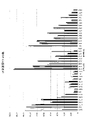
例えば、図13より、第1方式では、UE14、UE8、UE19、及びUE1が、突出してスループットが良好である。一方、第1方式では、UE38、UE11、UE35、UE39、UE3、UE22、UE7、UE21、UE23、UE26、及びUE13が、スループットが0に近い、劣悪な数値となっている。 For example, from FIG. 13, in the first method, UE14, UE8, UE19, and UE1 have outstandingly good throughput. On the other hand, in the first scheme, UE38, UE11, UE35, UE39, UE3, UE22, UE7, UE21, UE23, UE26, and UE13 have poor throughput values close to zero.
対して、提案方式では、UE14、UE8、UE19、及びUE1のスループットが、他のUEと比較すると良好ではあるものの、第1方式ほど突出してはいない。また、提案方式では、UE38、UE11、UE35、UE39、UE3、UE22、UE7、UE21、UE23、UE26、及びUE13のスループットが、第1方式ほど低い値ではない。図11で示したように、端末装置100の台数が40台の総スループットは、提案方式より第1方式の方が高い。すなわち、提案方式は、第1方式と比較して、端末装置間のスループットの差異が小さく、より公平な方式であることがわかる。
On the other hand, in the proposed scheme, the throughputs of UE14, UE8, UE19, and UE1 are better than those of other UEs, but not as outstanding as in the first scheme. Also, in the proposed scheme, the throughputs of UE38, UE11, UE35, UE39, UE3, UE22, UE7, UE21, UE23, UE26, and UE13 are not as low as in the first scheme. As shown in FIG. 11, the total throughput of 40
また、図14に示すように、提案方式は、第2方式と比較して、端末装置間のスループットの差異が同等あるいは小さく、より公平な方式であることがわかる。 In addition, as shown in FIG. 14, the proposed scheme has the same or smaller difference in throughput between terminal apparatuses than the second scheme, and is a fairer scheme.
図15は、第1方式及び提案方式の端末装置100ごとのACK送信数の例を示す図である。また、図16は、第2方式及び提案方式の端末装置100ごとのACK送信数の例を示す図である。
FIG. 15 is a diagram showing an example of the number of ACK transmissions for each
例えば、図15より、第1方式では、UE14、UE8、UE19、及びUE1が、突出してACK送信数が多い。一方、第1方式では、UE38、UE11、UE35、UE39、UE3、UE22、UE7、UE21、UE23、UE26、及びUE13が、ACK送信が0に近い小さい数値となっている。 For example, from FIG. 15, in the first scheme, UE14, UE8, UE19, and UE1 have a significantly large number of ACK transmissions. On the other hand, in the first scheme, the ACK transmissions of UE38, UE11, UE35, UE39, UE3, UE22, UE7, UE21, UE23, UE26, and UE13 are small values close to zero.
対して、提案方式では、UE14、UE8、UE19、及びUE1のACK送信数が、他のUEと比較すると多いが、第1方式ほど突出してはいない。また、提案方式では、UE38、UE11、UE35、UE39、UE3、UE22、UE7、UE21、UE23、UE26、及びUE13のACK送信数が、第1方式ほど低い値ではない。図12で示したように、端末装置100の台数が40台のACK送信数は、提案方式より第1方式の方が少ない。すなわち、提案方式は、第1方式と比較して、ACK送信数の合計が少ないことに加え、端末装置間のACK送信数の差異が小さく、ACK送信においても公平な方式であることがわかる。
On the other hand, in the proposed scheme, the number of ACK transmissions of UE14, UE8, UE19, and UE1 is larger than that of other UEs, but not as prominent as in the first scheme. Also, in the proposed scheme, the number of ACK transmissions of UE38, UE11, UE35, UE39, UE3, UE22, UE7, UE21, UE23, UE26, and UE13 is not as low as in the first scheme. As shown in FIG. 12, the number of ACK transmissions with 40
また、図16に示すように、提案方式は、第2方式と比較して、ACK送信数の合計が少ないことに加え、端末装置間のACK送信数の差異が同等あるいは小さく、ACK送信においても公平な方式であることがわかる。 In addition, as shown in FIG. 16, the proposed scheme has a smaller total number of ACK transmissions than the second scheme, and the difference in the number of ACK transmissions between terminal devices is the same or small. It turns out to be a fair system.
第2の実施の形態において、端末装置100は2段階でACKを破棄する。第1段階は、平均伝送レートに基づき決定される蓄積閾値によるACKの破棄である。第1段階によって、端末装置100に対する無線リソースの過剰な割り当てを抑制することができる。
In the second embodiment, the
第2段階は、無線リソースの割り当て量に応じたACKを送信し、残りのACKの破棄である。第2段階によって、無線リソースの割り当て量に応じたACKを送信することで、過剰なACKの送信を抑制することができる。 The second step is to transmit ACKs according to the allocated amount of radio resources and discard the remaining ACKs. By transmitting ACKs according to the allocated amount of radio resources in the second stage, it is possible to suppress transmission of excessive ACKs.
[その他の実施の形態]
各実施の形態における処理は、それぞれ組み合わせてもよい。例えば、第2の実施の形態における式(1)~(3)は、第1の実施の形態における蓄積数(蓄積閾値)の算出に使用されてもよい。[Other embodiments]
The processing in each embodiment may be combined. For example, equations (1) to (3) in the second embodiment may be used to calculate the accumulation number (accumulation threshold) in the first embodiment.
10 :通信システム
100 :端末装置
110 :CPU
120 :ストレージ
121 :通信プログラム
122 :ACK送信プログラム
130 :メモリ
150 :RF回路
200 :基地局装置
201 :制御部
202 :送信部
203 :データ
210 :CPU
220 :ストレージ
221 :通信制御プログラム
222 :ACK受信プログラム
230 :メモリ
250 :RF回路
300 :ネットワーク10: Communication system 100: Terminal device 110: CPU
120: Storage 121: Communication program 122: ACK transmission program 130: Memory 150: RF circuit 200: Base station device 201: Control unit 202: Transmission unit 203: Data 210: CPU
220: storage 221: communication control program 222: ACK reception program 230: memory 250: RF circuit 300: network
Claims (5)
前記基地局装置から受信したパケットに対応する受信確認パケットを、前記端末装置において蓄積することができる蓄積数を、前記端末装置が送信するデータ量に応じて決定する制御部と、
前記決定した蓄積数を含む制御信号を、前記端末装置に送信できる送信部と、
を有し、
前記制御部は、所定時間における前記端末装置の受信確認パケットの送信数の平均を、前記蓄積数と決定する
基地局装置。 A base station device that performs wireless communication with a terminal device,
a control unit that determines the number of reception confirmation packets that can be stored in the terminal device according to the amount of data transmitted by the terminal device;
a transmission unit capable of transmitting a control signal including the determined accumulation number to the terminal device;
has
The control unit determines an average number of transmissions of acknowledgment packets from the terminal device in a predetermined period of time as the accumulated number.
Base station equipment.
前記送信部は、前記複数の端末装置ごとに前記制御信号を送信できる
請求項1記載の基地局装置。 When there are a plurality of terminal devices, the control unit determines the number of accumulations for each of the plurality of terminal devices,
The base station apparatus according to claim 1, wherein the transmission section can transmit the control signal for each of the plurality of terminal apparatuses.
前記端末装置は、前記蓄積数の前記受信確認パケットのうち、前記基地局装置に割り当てられた無線リソースの量に応じた数の受信確認パケットを、前記基地局装置に送信する
請求項1記載の基地局装置。 Furthermore, having an allocation unit that allocates radio resources to the terminal device,
2. The terminal device according to claim 1, wherein said terminal device transmits to said base station device, among said accumulated number of said reception confirmation packets, a number of reception confirmation packets corresponding to an amount of radio resources allocated to said base station device. Base station equipment.
前記基地局装置が前記端末装置の送信するデータ量に応じて決定する、前記基地局装置から受信したパケットに対応する受信確認パケットを蓄積することができる蓄積数を含む制御信号を受信する受信部と、
前記受信した制御信号に含まれる前記蓄積数の受信確認パケットを蓄積し、前記蓄積数を超える受信確認パケットを破棄する送信制御部と
を有し、
前記蓄積数は、所定時間における前記端末装置の受信確認パケットの送信数の平均である
端末装置。 A terminal device that performs wireless communication with a base station device,
a receiving unit for receiving a control signal including a storage number of acknowledgment packets corresponding to packets received from the base station device, which is determined by the base station device according to the amount of data transmitted by the terminal device; When,
a transmission control unit that accumulates the number of reception confirmation packets included in the received control signal and discards reception confirmation packets that exceed the number of accumulations;
The accumulated number is an average number of transmissions of reception confirmation packets of the terminal device in a predetermined period of time .
前記基地局装置から受信したパケットに対応する受信確認パケットを、前記端末装置において蓄積することができる蓄積数を、前記端末装置が送信するデータ量に応じて決定し、
前記決定した蓄積数を含む制御信号を、前記端末装置に送信し、
前記蓄積数の決定において、所定時間における前記端末装置の受信確認パケットの送信数の平均を、前記蓄積数と決定する
通信方法。 A communication method in a base station device that performs wireless communication with a terminal device,
determining, according to the amount of data transmitted by the terminal device, the number of reception confirmation packets that can be stored in the terminal device, corresponding to the packet received from the base station device;
transmitting a control signal including the determined accumulation number to the terminal device;
In determining the number of accumulations , an average number of transmissions of acknowledgment packets from the terminal device in a predetermined period of time is determined as the number of accumulations.
Communication method.
Applications Claiming Priority (1)
| Application Number | Priority Date | Filing Date | Title |
|---|---|---|---|
| PCT/JP2018/018615 WO2019220517A1 (en) | 2018-05-14 | 2018-05-14 | Base station device, terminal device, and communication method |
Publications (2)
| Publication Number | Publication Date |
|---|---|
| JPWO2019220517A1 JPWO2019220517A1 (en) | 2021-05-27 |
| JP7206509B2 true JP7206509B2 (en) | 2023-01-18 |
Family
ID=68539716
Family Applications (1)
| Application Number | Title | Priority Date | Filing Date |
|---|---|---|---|
| JP2020518839A Active JP7206509B2 (en) | 2018-05-14 | 2018-05-14 | BASE STATION DEVICE, TERMINAL DEVICE, AND COMMUNICATION METHOD |
Country Status (4)
| Country | Link |
|---|---|
| US (1) | US20210058200A1 (en) |
| JP (1) | JP7206509B2 (en) |
| CN (1) | CN112119621A (en) |
| WO (1) | WO2019220517A1 (en) |
Citations (4)
| Publication number | Priority date | Publication date | Assignee | Title |
|---|---|---|---|---|
| JP2007524262A (en) | 2003-12-23 | 2007-08-23 | テレフオンアクチーボラゲット エル エム エリクソン(パブル) | Method and apparatus for controlling queue buffer |
| US20090190604A1 (en) | 2008-01-28 | 2009-07-30 | Broadcom Corporation | Method and System for Dynamically Adjusting Acknowledgement Filtering for High-Latency Environments |
| US20130250765A1 (en) | 2012-03-23 | 2013-09-26 | Qualcomm Incorporated | Delay based active queue management for uplink traffic in user equipment |
| US20160302197A1 (en) | 2013-06-07 | 2016-10-13 | Apple Inc. | Managing pending acknowledgement packets in a communication device |
Family Cites Families (7)
| Publication number | Priority date | Publication date | Assignee | Title |
|---|---|---|---|---|
| ATE448617T1 (en) * | 2003-09-11 | 2009-11-15 | Ericsson Telefon Ab L M | METHOD FOR DISCARDING ALL SEGMENTS RESPONSIBLE TO THE SAME PACKET IN A BUFFER |
| US8184561B2 (en) * | 2004-12-22 | 2012-05-22 | Nokia Corporation | Terminal based packet loss due to mobility detection |
| CN102143078B (en) * | 2011-03-29 | 2013-10-02 | 华为技术有限公司 | Forwarding equipment as well as method and system for processing message |
| WO2015196393A1 (en) * | 2014-06-25 | 2015-12-30 | 华为技术有限公司 | Data transmission method and device |
| US10128987B2 (en) * | 2016-09-15 | 2018-11-13 | Microsoft Technology Licensing, Llc | Scalable receive window auto-tuning |
| US10498867B2 (en) * | 2016-11-02 | 2019-12-03 | Solarflare Communications, Inc. | Network interface device and host processing device field |
| US10419542B2 (en) * | 2017-07-26 | 2019-09-17 | Verizon Patent And Licensing Inc. | Transmission control protocol (TCP) synchronize (SYN) signaling passthrough for TCP proxy servers |
-
2018
- 2018-05-14 CN CN201880093402.7A patent/CN112119621A/en active Pending
- 2018-05-14 WO PCT/JP2018/018615 patent/WO2019220517A1/en active Application Filing
- 2018-05-14 JP JP2020518839A patent/JP7206509B2/en active Active
-
2020
- 2020-11-03 US US17/088,524 patent/US20210058200A1/en active Pending
Patent Citations (4)
| Publication number | Priority date | Publication date | Assignee | Title |
|---|---|---|---|---|
| JP2007524262A (en) | 2003-12-23 | 2007-08-23 | テレフオンアクチーボラゲット エル エム エリクソン(パブル) | Method and apparatus for controlling queue buffer |
| US20090190604A1 (en) | 2008-01-28 | 2009-07-30 | Broadcom Corporation | Method and System for Dynamically Adjusting Acknowledgement Filtering for High-Latency Environments |
| US20130250765A1 (en) | 2012-03-23 | 2013-09-26 | Qualcomm Incorporated | Delay based active queue management for uplink traffic in user equipment |
| US20160302197A1 (en) | 2013-06-07 | 2016-10-13 | Apple Inc. | Managing pending acknowledgement packets in a communication device |
Non-Patent Citations (2)
| Title |
|---|
| OHTA,Yoshiaki, et al.,Controlling TCP ACK Transmission: Impact of Discard Ratio on Perfromance in LTE-Advanced Pro,2017 IEEE Conference on Standards for Communications and Networking(CSCN),2017年09月,p.227-232 |
| 太田 好明 他,LTE-Advanced上り無線アクセス方式を考慮したTCPスループットの特性改善:TCP ACK送信制御手法の評価と検討,電子情報通信学会技術研究報告,2016年07月13日,第116巻,第147号,p.65~70 |
Also Published As
| Publication number | Publication date |
|---|---|
| JPWO2019220517A1 (en) | 2021-05-27 |
| CN112119621A (en) | 2020-12-22 |
| US20210058200A1 (en) | 2021-02-25 |
| WO2019220517A1 (en) | 2019-11-21 |
Similar Documents
| Publication | Publication Date | Title |
|---|---|---|
| JP6992090B2 (en) | Data transmission method and its device | |
| US10178676B2 (en) | Data transmission method, device, and system | |
| US9622132B2 (en) | Switching between cellular and license-exempt (shared) bands | |
| JP6262359B2 (en) | Data transmission method, data transmission system, and data transmission apparatus | |
| US20120163205A1 (en) | System and method for flow control in a multi-point hsdpa communication network | |
| US10263895B2 (en) | Data transmission method, central processing node, gateway, and base station | |
| US20170208615A1 (en) | Method for transmitting uplink grant and base station | |
| JP2014529219A (en) | Data transfer within a communication network | |
| US10075264B2 (en) | Data transmission method, device, and system | |
| US10154416B2 (en) | Data processing method, and communications device and system | |
| JP2022516899A (en) | Wireless communication method and equipment | |
| JPWO2018127985A1 (en) | Wireless communication apparatus, wireless communication system, and wireless communication method | |
| WO2018233552A1 (en) | Data transmission method and device | |
| US11184860B2 (en) | Data sending method and apparatus | |
| US11677669B2 (en) | Communication device, relay device, and communication system for controlling generation of a TCP acknowledgement (ACK) | |
| JP2022554261A (en) | Power allocation method and apparatus | |
| US9106381B2 (en) | Method and system configuring a base station to trigger HS-DPCCH generation | |
| JP7206509B2 (en) | BASE STATION DEVICE, TERMINAL DEVICE, AND COMMUNICATION METHOD | |
| EP4104357A1 (en) | Handling overlapping of multiple physical uplink shared channels (puschs) | |
| TW202131740A (en) | Device and method for handling physical uplink control channel collision | |
| JP6845448B2 (en) | Communication equipment, communication methods, and communication systems | |
| TWI784764B (en) | Device of handling a harq retransmission | |
| JP2018526925A (en) | Method for operating user equipment and method for operating baseband unit | |
| KR20210020738A (en) | Method and apparatus for controlling packet transmission and reception in a wireless communication system |
Legal Events
| Date | Code | Title | Description |
|---|---|---|---|
| A621 | Written request for application examination |
Free format text: JAPANESE INTERMEDIATE CODE Effective date: 20201026 Free format text: JAPANESE INTERMEDIATE CODE: A621 Effective date: 20201026 |
|
| A131 | Notification of reasons for refusal |
Free format text: JAPANESE INTERMEDIATE CODE: A131 Effective date: 20211109 |
|
| A521 | Request for written amendment filed |
Free format text: JAPANESE INTERMEDIATE CODE: A523 Effective date: 20220107 |
|
| A131 | Notification of reasons for refusal |
Free format text: JAPANESE INTERMEDIATE CODE: A131 Effective date: 20220607 |
|
| A521 | Request for written amendment filed |
Free format text: JAPANESE INTERMEDIATE CODE: A523 Effective date: 20220804 |
|
| TRDD | Decision of grant or rejection written | ||
| A01 | Written decision to grant a patent or to grant a registration (utility model) |
Free format text: JAPANESE INTERMEDIATE CODE: A01 Effective date: 20221129 |
|
| A61 | First payment of annual fees (during grant procedure) |
Free format text: JAPANESE INTERMEDIATE CODE: A61 Effective date: 20221212 |
|
| R150 | Certificate of patent or registration of utility model |
Ref document number: 7206509 Country of ref document: JP Free format text: JAPANESE INTERMEDIATE CODE: R150 |