JP7205802B2 - Electron beam irradiation device and electron beam irradiation method - Google Patents
Electron beam irradiation device and electron beam irradiation method Download PDFInfo
- Publication number
- JP7205802B2 JP7205802B2 JP2019147245A JP2019147245A JP7205802B2 JP 7205802 B2 JP7205802 B2 JP 7205802B2 JP 2019147245 A JP2019147245 A JP 2019147245A JP 2019147245 A JP2019147245 A JP 2019147245A JP 7205802 B2 JP7205802 B2 JP 7205802B2
- Authority
- JP
- Japan
- Prior art keywords
- electron beam
- container
- beam irradiation
- roller
- conveying
- Prior art date
- Legal status (The legal status is an assumption and is not a legal conclusion. Google has not performed a legal analysis and makes no representation as to the accuracy of the status listed.)
- Active
Links
Images


Landscapes
- Apparatus For Disinfection Or Sterilisation (AREA)
Description
本発明は、電子線照射装置および電子線照射方法に関し、詳しくは、回転搬送機構を伴う電子線照射装置および電子線照射方法に関する。 TECHNICAL FIELD The present invention relates to an electron beam irradiation apparatus and an electron beam irradiation method, and more particularly to an electron beam irradiation apparatus and an electron beam irradiation method involving a rotary transport mechanism.
医薬品、化粧品および飲料などの包装容器に対しては、内容物を充填する前に容器を滅菌して無菌状態にし、その後、無菌室内で内容物を充填して密封するように義務付けられている。 For packaging containers such as pharmaceuticals, cosmetics and beverages, it is obligatory to sterilize the container to aseptic conditions before filling the contents, and then fill and seal the contents in an aseptic room.
具体的な滅菌方法としては、高温高圧水蒸気を用いる高圧蒸気滅菌、エチレンオキシドガス(EOG)を用いるEOG滅菌、γ線や電子線等の放射線を用いる放射線照射滅菌等が知られている。 As specific sterilization methods, high-pressure steam sterilization using high-temperature, high-pressure steam, EOG sterilization using ethylene oxide gas (EOG), radiation irradiation sterilization using radiation such as gamma rays and electron beams, and the like are known.
これらの内、高圧蒸気滅菌は、高温高圧水蒸気を用いるため、高圧のチャンバーを必要とし、また、対象物が高温高圧に耐える必要がある。このため、高圧蒸気滅菌は、近年広く用いられているプラスチック製の容器に適した滅菌方法とは言えない。 Among these methods, high-pressure steam sterilization uses high-temperature, high-pressure steam, and therefore requires a high-pressure chamber, and the object to be sterilized must withstand high temperature and high pressure. For this reason, high-pressure steam sterilization cannot be said to be a sterilization method suitable for plastic containers that have been widely used in recent years.
また、EOG滅菌は、低温での滅菌が可能であるが、滅菌処理および残留ガス除去に要する時間が比較的大きい。また、EOGが発がん性を有することから、規制の強化が求められている。 In addition, EOG sterilization allows sterilization at low temperatures, but the time required for sterilization and residual gas removal is relatively long. In addition, since EOG is carcinogenic, stricter regulations are required.
このため、近年は、放射線照射滅菌が広く採用されるようになっているが、その内でも、放射性物質を使用する必要がない電子線照射滅菌の採用が増えてきている。そして、このような電子線照射滅菌では、容器の外面を滅菌するだけでなく、容器の材質、肉厚の大きさによっては容器の内面を滅菌することもできる。 For this reason, radiation irradiation sterilization has been widely adopted in recent years, and among them, the adoption of electron beam irradiation sterilization, which does not require the use of radioactive substances, is increasing. Such electron beam irradiation sterilization can sterilize not only the outer surface of the container, but also the inner surface of the container depending on the material and thickness of the container.
従来の電子線照射滅菌は、容器を梱包した状態で、梱包の外側から透過力の高い高エネルギーの電子線を照射して電子線を梱包及び容器肉厚等を透過させることにより容器全面を滅菌している(特許文献1、2参照)。この方法は、容器を梱包しているため、滅菌した後、ユーザーの下に搬送することが可能である。
Conventional electron beam irradiation sterilization involves sterilizing the entire surface of a container by irradiating a high-energy electron beam with high penetrating power from the outside of the package while the container is packed, and allowing the electron beam to penetrate the package and the thickness of the container. (See
しかし、上記の方法を採用した場合には、梱包を開封したときから内容物を充填するまでの間に、容器の外面が汚染されるリスクがある。このため、内容物の充填ラインにおいて、滅菌と内容物の充填とを連続して行うことができるインラインタイプの電子線照射技術が求められている。また、高エネルギー電子線で梱包した状態で滅菌した後に梱包を開放する際の再汚染を防ぐために、2重包装にすることや、内容物を充填するまでの間に容器の外面を滅菌する技術も求められている。 However, when the above method is employed, there is a risk of contamination of the outer surface of the container between the time the package is opened and the time the content is filled. For this reason, an in-line type electron beam irradiation technology capable of continuously performing sterilization and filling of contents in a contents filling line is desired. In addition, in order to prevent recontamination when opening the package after sterilizing it with a high-energy electron beam, double packaging is used, and the outer surface of the container is sterilized before the contents are filled. is also required.
このようなインラインでの電子線照射を行うためには、装置が小型であることが求められるが、上記した従来の高エネルギー電子線照射装置では装置規模が大きく、また、発生するX線を遮蔽するためには、コンクリートシールドなどの大型のシールド設備を必要とする。このため、高エネルギー電子線照射装置は、インラインでの電子線照射に適した設備とは言えない。 In order to perform such in-line electron beam irradiation, it is required that the device be small. In order to do so, a large shield facility such as a concrete shield is required. Therefore, the high-energy electron beam irradiation apparatus cannot be said to be equipment suitable for in-line electron beam irradiation.
一方、低エネルギーおよび中エネルギーの電子線照射装置は、装置規模が小さく、シールド設備としても、鉛シールドを用いた小型の自己シールドでよいため(特許文献3参照)、インラインでの電子線照射に適した設備と言うことができる。 On the other hand, the low-energy and medium-energy electron beam irradiation apparatuses are small in scale, and the shield equipment may be a small self-shield using a lead shield (see Patent Document 3). It can be said that it is suitable equipment.
しかしながら、滅菌の対象となる容器は、一般的に有底筒状の形状を有している。このため、透過力の小さい低エネルギーおよび中エネルギーの電子線を、容器の一方向、例えば、側面側から照射したのでは、背面側や底面には電子線を照射することができず、照射のムラを生じてしまう。 However, containers to be sterilized generally have a cylindrical shape with a bottom. For this reason, if low-energy and medium-energy electron beams with low penetrating power are irradiated from one direction, for example, the side surface of the container, the electron beam cannot be irradiated to the back side or the bottom surface of the container. It causes unevenness.
そこで、このような照射ムラの発生をなくす方法として、例えば、筒状の容器の側面を支持して搬送しながら底面部側から電子線を照射する第1電子線加速器と、筒状の容器を底面部側から支持して自転させながら側面部側から電子線を照射する第2電子線加速器とを配置して、第1電子線加速器による照射と第2電子線加速器による照射とを連続して行う連続滅菌装置が提案されている(特許文献4参照)。 Therefore, as a method for eliminating the occurrence of such irradiation unevenness, for example, a first electron beam accelerator that irradiates an electron beam from the bottom side while supporting the side surface of the cylindrical container and transporting it, and a cylindrical container. A second electron beam accelerator that irradiates an electron beam from the side portion side while being supported from the bottom portion side and rotated on its axis is arranged, and the irradiation by the first electron beam accelerator and the irradiation by the second electron beam accelerator are continuously performed. A continuous sterilization apparatus has been proposed (see Patent Document 4).
しかしながら、このような連続滅菌装置は、容器の底面および側面の全周に亘って電子線を照射することはできるものの、容器の搬送手段および電子線加速器をそれぞれ2台必要とするため、設備の大型化が避けられない。また、電子線の照射を2回に分けて行う必要があるため、効率的な処理とは言えず、生産性の向上を図る上で問題がある。 However, although such a continuous sterilization apparatus can irradiate the entire circumference of the bottom surface and side surfaces of the container with electron beams, it requires two container transport means and two electron beam accelerators, respectively. An increase in size is inevitable. In addition, since the electron beam irradiation must be performed in two steps, it cannot be said to be an efficient treatment, which poses a problem in terms of improving productivity.
本発明は、上記した従来の電子線照射滅菌における諸問題に鑑みて、低エネルギーまたは中エネルギーの電子線を用いながらも、1台の電子線照射装置で、さらに、1回の照射で、有底筒状の容器の外面全体に電子線を照射することができる電子線照射技術を提供することを課題とする。 In view of the various problems in the conventional electron beam irradiation sterilization described above, the present invention uses a single electron beam irradiation apparatus while using a low-energy or medium-energy electron beam. An object of the present invention is to provide an electron beam irradiation technique capable of irradiating the entire outer surface of a cylindrical bottom container with an electron beam.
本発明者は、上記課題の解決について鋭意検討を行い、以下に記載する発明により上記課題が解決できることを見出し、本発明を完成させるに至った。 The present inventors have earnestly studied how to solve the above problems, found that the above problems can be solved by the invention described below, and completed the present invention.
請求項1に記載の発明は、
有底筒状の容器に向けて電子線を照射する電子線照射装置であって、
前記容器を側面が前記電子線の照射方向と相対するように保持して、上流側から下流側に向けて搬送する搬送路を備える搬送手段と、
前記搬送路を搬送される前記容器に向けて電子を加速して照射する電子線照射部を備える電子線照射手段とが備えられており、
前記搬送手段は、回転しながら搬送方向に移動する複数のローラーが、搬送方向に対して傾斜して、一定間隔をおいて配置されて、隣接する2つの前記ローラー間に配置された前記容器を回転させながら搬送するように構成されており、
前記ローラーには、長手方向の一方の端部に側面の全周に亘って前記側面から径方向に突出する鍔部が設けられていると共に、前記ローラーの回転軸の鉛直方向に対する傾斜角度を変更することができる角度可変機構が備えられており、
前記傾斜角度を調節することにより、前記容器に対する前記電子線の照射角度を調節するように構成されていることを特徴とする電子線照射装置である。
The invention according to
An electron beam irradiation device that irradiates an electron beam toward a bottomed cylindrical container,
a conveying means having a conveying path that holds the container so that the side faces face the irradiation direction of the electron beam and conveys the container from the upstream side to the downstream side;
an electron beam irradiation means including an electron beam irradiation unit that accelerates and irradiates electrons toward the container transported on the transport path,
In the conveying means, a plurality of rollers that move in the conveying direction while rotating are arranged at regular intervals with an inclination with respect to the conveying direction, and the containers are arranged between the two adjacent rollers. It is configured to be conveyed while being rotated,
The roller is provided with a collar portion that protrudes radially from the side surface over the entire circumference of the side surface at one end in the longitudinal direction, and changes the inclination angle of the rotation axis of the roller with respect to the vertical direction. It is equipped with a variable angle mechanism that can
The electron beam irradiation apparatus is characterized in that an irradiation angle of the electron beam to the container is adjusted by adjusting the inclination angle.
請求項2に記載の発明は、
前記鍔部の突出幅が、前記容器の側面と前記容器の回転中心との間の距離より小さいことを特徴とする請求項1に記載の電子線照射装置である。
The invention according to claim 2,
2. The electron beam irradiation apparatus according to
請求項3に記載の発明は、
前記鍔部の前記容器と接触する面が、鏡面加工されていることを特徴とする請求項1または請求項2に記載の電子線照射装置である。
The invention according to claim 3,
3. The electron beam irradiation apparatus according to
請求項4に記載の発明は、
前記鍔部の前記容器と接触する面が、金属を用いて形成されていることを特徴とする請求項1ないし請求項3のいずれか1項に記載の電子線照射装置である。
The invention according to claim 4,
4. The electron beam irradiation apparatus according to any one of
請求項5に記載の発明は、
請求項1ないし請求項4のいずれか1項に記載の電子線照射装置を用いて、有底筒状の容器に向けて電子線を照射する電子線照射方法であって、
前記ローラーの傾斜角度を調節して載置した前記容器を、側面が前記電子線の照射方向と所定の角度で相対するように保持して、上流側から下流側に向けて搬送する搬送工程と、
前記搬送路を搬送される前記容器の側面に向けて電子を加速して照射する電子線照射工程とを備えており、
前記搬送工程において、隣接する2つの前記ローラー間に配置された前記容器を回転させながら搬送することを特徴とする電子線照射方法である。
The invention according to claim 5,
An electron beam irradiation method for irradiating a bottomed cylindrical container with an electron beam using the electron beam irradiation apparatus according to any one of
a conveying step of conveying the container placed by adjusting the inclination angle of the roller from the upstream side to the downstream side while holding the container so that the side faces face the irradiation direction of the electron beam at a predetermined angle; ,
and an electron beam irradiation step of accelerating and irradiating electrons toward the side surface of the container conveyed on the conveying path,
In the transporting step, the electron beam irradiation method is characterized in that the container placed between the two adjacent rollers is transported while being rotated.
本発明によれば、低エネルギーまたは中エネルギーの電子線を用いながら、1台の電子線照射装置で、1回の照射で筒状の容器の外面全体に電子線を照射することができる電子線照射技術を提供することができる。 According to the present invention, an electron beam that can irradiate the entire outer surface of a cylindrical container with a single electron beam irradiation apparatus while using a low-energy or medium-energy electron beam. Irradiation technology can be provided.
以下、本発明を実施の形態に基づいて説明する。 BEST MODE FOR CARRYING OUT THE INVENTION The present invention will be described below based on embodiments.
[1]電子線照射装置
1.基本的な態様
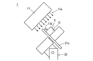
はじめに、本実施の形態の電子線照射装置の基本的な態様について説明する。図1Aは、本実施の形態に係る電子線照射装置の基本的な態様を示す模式図であって、容器の搬送方向における矢視図である。図1Bは、図1AのA-A矢視図である。
[1] Electron
図1A、図1Bにおいて、1はインラインに設けられた電子線照射装置であり、電子線を容器Cに向けて放射して照射する電子線照射部11が、傾斜して支持された容器Cと相対するように、搬送路12の上方に傾斜して配置されている。なお、本実施の形態において、電子線照射部11は、例えば、加速電圧1MV以下の低エネルギーまたは中エネルギーで電子を加速する。
In FIGS. 1A and 1B,
搬送路12は、回転軸が傾斜した状態でローラー支持装置22に支持された複数のローラー21から構成されており、ローラー21の端部に設けられた鍔部21cで容器Cを支持して、回転する複数のローラー21の隣接する2つのローラー間に容器Cを載置して回転させながら、下流側に搬送するように構成されている。
The conveying
そして、本実施の形態においては、ローラー21の回転軸の鉛直方向に対する傾斜角度を変更することができる角度可変機構を備えている。なお、図1Aにおいて、CLはローラー21の回転軸の中心線であり、θは回転軸の鉛直方向に対する傾斜角度である。
In this embodiment, an angle variable mechanism is provided that can change the tilt angle of the rotation shaft of the
以上のような構成とすることにより、傾斜した状態で容器Cを搬送しても、容器Cは鍔部21cにより支えられるため、装置より落下させずに搬送することができる。そして、傾斜した状態で容器を搬送することにより、容器を完全に直立していない状態、あるいは完全に水平にしていない状態で搬送することができ、前後の工程、特に容器への内容物の充填などの工程と組み合わせることが容易となる。また、装置の高さや幅を抑制することができ、装置を小型化することが可能である。
With the configuration as described above, even if the container C is transported in an inclined state, the container C can be transported without being dropped from the apparatus because the container C is supported by the
そして、ローラー21上に傾斜して載置され、回転しながら輸送される容器Cの側面に向けて、傾斜して配置された電子線照射部11から放射電子線11aを照射することにより、容器の側面全周に電子線を照射することができる。また、放射電子線11aの一部は容器Cの底面Bや頂部Tに向けても回り込むため、低エネルギーまたは中エネルギーの電子線照射装置を用いながらも、1台の電子線照射装置で、しかも、1回の照射で、有底筒状の容器の外面全体に電子線を照射して十分な滅菌を行うことができる。
Then, the radiated
そして、低エネルギーまたは中エネルギーの電子を加速して照射する電子線照射部11は小型であるため、電子線照射装置1全体も小型化でき、インラインに設ける滅菌設備として好ましい。
Since the electron
また、本実施の形態では、容器Cを、ガイドとローラーで挟持したり、チャック等で把持したりすることなく、ローラー21上で回転させながら搬送することができるため、電子線照射に際して容器Cに電子線が照射されない陰の部分が生じない。また、電子線照射時の回り込み電子線に対する鍔部21cによる陰の部分についても、ローラー21の回転により容器の陰の部分が移動するため、底面Bや頂部Tの全面に電子線を照射することができる。
Further, in the present embodiment, the container C can be conveyed while being rotated on the
さらに、本実施の形態においては、前記の通り、角度可変機構が設けられているため、傾斜角度θを調節することにより、容器Cに対する放射電子線11aの角度を変更させることができるため、容器Cの形状によって電子線が照射され難く、陰になる部分が生じる恐れがある場合でも、傾斜角度θを変更することで、容器の姿勢を自在に調節し、電子線の照射箇所を調整して陰の部分に照射することが可能となる。なお、具体的な傾斜角度θとしては15~90°が好ましい。
Furthermore, in this embodiment, as described above, since the angle variable mechanism is provided, the angle of the emitted
また、本実施の形態においては、必要に応じて、低エネルギーの電子線を用いて、電子線照射前に予め内容物が充填された容器に対して、内容物に電子線を照射せずに容器の外面だけを照射することもできる。 Further, in the present embodiment, if necessary, a low-energy electron beam is used to irradiate a container filled with contents in advance before electron beam irradiation, without irradiating the contents with an electron beam. It is also possible to irradiate only the outer surface of the container.
2.電子線照射装置の特徴部
次に、本実施の形態の電子線照射装置の特徴部について説明する。
2. Characteristic Part of Electron Beam Irradiation Apparatus Next, the characteristic part of the electron beam irradiation apparatus of the present embodiment will be described.
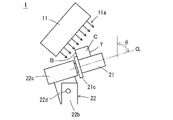
(1)ローラー
図1Aに示すように、本実施の形態においては、電子線の照射方向と相対するように配置された搬送路12に、回転しながら搬送方向に移動する複数のローラー21が、回転軸が傾斜した状態、即ち、回転軸の鉛直方向に対して鋭角が形成される傾斜角度θでローラー支持装置22に支持されて、一定間隔をおいて配置されている。そして、前記したように、ローラー21の端部には鍔部21cが設けられて、傾斜した容器Cを底面B側から支持している。
(1) Roller As shown in FIG. 1A, in the present embodiment, a plurality of
この結果、容器Cを、ガイドとローラーで挟持したり、チャック等で把持したりすることなく、ローラー21上で回転させながら搬送することができるため、電子線照射に際して容器Cに陰の部分が生じない。このため、1台の電子線照射装置で、1回の照射であっても、底面B、頂部T等に対して放射電子線11aの回り込みを利用して、容器Cの外面全体に電子線を照射することができる。
As a result, the container C can be conveyed while being rotated on the
しかし、容器に対する電子線の照射方向および容器の姿勢が固定されている場合、容器Cの形状によっては電子線が照射され難く、陰になる部分が生じる恐れがある。このような陰の発生は、電子線の照射方向、または容器の姿勢のいずれかを調節することで抑制することができるが、電子線の照射方向を調節する方法は、電子線照射部11の位置を変えなければならないため、大きなスペースや複雑な機構を必要とし好ましいことではない。 However, when the irradiation direction of the electron beam to the container and the attitude of the container are fixed, the electron beam is difficult to irradiate depending on the shape of the container C, and there is a possibility that a shaded portion may occur. The occurrence of such shadows can be suppressed by adjusting either the irradiation direction of the electron beam or the attitude of the container. Since the position must be changed, it requires a large space and a complicated mechanism, which is not preferable.
これに対して、本実施の形態のように、複雑な機構を必要としない角度可変機構を設けてローラー21の傾斜角度θを可変にした場合には、傾斜角度θを簡易な機構により自在に変更することができるため、容器の姿勢を容易に自在に調節することが可能となり、大きなスペースも必要としない。
On the other hand, when the tilt angle θ of the
本実施の形態において、ローラー21の容器Cと接触する部分21aの少なくとも一部の側面では、全周に亘って、ローレット加工または梨地加工が施されていることが好ましい。このような加工を施すことにより、容器Cとローラー21の側面との間の摩擦力が高められるため、容器Cがローラー21に対して滑りにくくなり、回転するローラー21に合わせて、確実に、容器Cを回転させることができる。
In the present embodiment, at least a part of the side surface of the
なお、具体的なローレット加工の形態としては、アヤ目加工やローラー21の軸方向に沿って目が形成されたヒラ目加工を挙げることができる。また、梨地加工の形態としては、エッチング、サンドブラスト、ホーニングなど公知の表面処理加工を挙げることができる。ローレット加工の目の大きさおよび梨地における粗度は、容器の材質、側面の曲率の大きさ、表面粗度等に応じて適宜決定される。
In addition, as a specific form of knurling processing, crochet processing and flattening processing in which a mesh is formed along the axial direction of the
また、ローラー21の容器Cと接触しない部分21bの少なくとも一部の側面では、全周に亘って、鏡面加工が施されていることが好ましい。具体的には、図1Aに示すように、ローラー21の長さを容器Cの高さより大きくし、容器Cと接触しない部分21bの一部の側面に鏡面加工が施されていることが好ましい。
In addition, it is preferable that at least a part of the side surface of the
これにより、鏡面加工が施されている部分では、放射電子線11aが反射されて、容器Cに向けて後方散乱するため、放射電子線11aの照射線量が少ない容器Cの頂部Tの蓋部などについても、ローラー21の鏡面加工された側面から後方散乱された電子線を照射して、滅菌することができる。
As a result, the
そして、このような効果を得るためには、ローラー21の少なくとも側面部分は、電子線に対する後方散乱の機能に優れる金属を用いて形成されていることが好ましい。
In order to obtain such an effect, it is preferable that at least the side surface portion of the
好ましい金属としては、例えば、タングステン(W)や金(Au)などの重金属が挙げられる。これらの金属は、ローラー21の内部まで、所謂バルク状態で使用してもよいが、表面被覆して薄膜を形成させる等、後方散乱に関与する表面部分のみに使用してもよい。
Preferred metals include, for example, heavy metals such as tungsten (W) and gold (Au). These metals may be used in a so-called bulk state up to the inside of the
(2)鍔部
本実施の形態においては、上記したように、ローラー21の端部には鍔部21cが設けられており、傾斜した状態で搬送される容器Cを支えている。
(2) Flange In the present embodiment, as described above, the
(a)鍔部の突出幅
このため、鍔部21cの突出幅は、ローラー21を傾斜させた状態において容器Cを鍔部21cで支持できる幅であることを基本とするが、容器Cの側面と容器Cの回転中心との間の距離より小さいことが好ましい。具体的には、例えば、容器Cが円筒形である場合には、容器Cの半径より小さくすることが好ましく、また、非円筒形、例えば横断面が楕円形の筒状容器のように距離が一定でない容器の場合には、最小の距離より小さいことが好ましい。
(a) Projection Width of Collar Portion For this reason, the projecting width of the
容器Cの底面Bの一部では、鍔部21cによって一時的に陰が形成されるが、鍔部21cの突出幅を上記のように設定した場合、容器Cの回転に合わせて、陰となる部分が移動していくため、底面Bの全体に対して、十分に放射電子線を照射することができる。
A part of the bottom surface B of the container C is temporarily shaded by the
(b)鍔部の表面状態及び材質
鍔部21cの容器Cと接触する面は鏡面加工されていることが好ましい。これによりローラー21および容器Cを回転させたときの鍔部21cと容器Cとの間の摩擦力が低減されるため、容器Cをスムーズに回転させることができる。また、このような鏡面加工は、鍔部21cの電子線の後方散乱機能を向上させることができる。
(b) Surface state and material of collar portion It is preferable that the surface of the
また、少なくとも、容器Cと接触する面は、電子線に対する後方散乱の機能に優れる、例えば、タングステン(W)や金(Au)等の重金属を用いて形成されていることが好ましい。 Moreover, at least the surface that comes into contact with the container C is preferably made of a heavy metal such as tungsten (W) or gold (Au), which has an excellent backscattering function for electron beams.
(3)ローラー支持装置
図3はローラー支持装置22の構成を示す斜視図であり、図4は角度可変機構を説明する図である。
(3) Roller support device FIG. 3 is a perspective view showing the structure of the
図3に示すように、ローラー支持装置22は、金属製の固定部材22a、支持部材22b、およびローラー保持部材22cを有している。支持部材22bは、2枚の板材からなり、2枚の板材が所定の間隔で平行に且つ鉛直に配置され、固定部材22aの外側の面に垂直に立設されている。ローラー保持部材22cは、ローラー21の回転軸を保持する軸受け部と、軸受け部の固定部材22aとの対向面に垂直に且つローラー21の回転軸と同じ向きに立設された板材とを有している。
As shown in FIG. 3, the
そして、ローラー保持部材22cの板材は、支持部材22bの2枚の板材の間に挿入され、支持部材22bの2枚の板材と共に、支点22dを中心として旋回可能に支持されている。これにより、図4に示すように、ローラー21を、支点22dを中心として鉛直な面に沿って旋回可能として、傾斜角度θを変更することができる角度可変機構を構成させることができる。
The plate member of the
そして、このような角度可変機構を設けて、ローラー21の傾斜角度θを可変とすることにより、放射電子線11aの放射方向と容器Cの軸とのなす角度、即ち容器Cに対する照射角度を好ましい角度に合わせて調節することができる。
By providing such an angle variable mechanism and varying the inclination angle θ of the
なお、ローラー支持装置22の上下には突出部が設けられており、上側の突出部にローラー21が取り付けられ、下側の突出部にピニオン24aが取り付けられている。
Protrusions are provided on the upper and lower sides of the
(4)ローラー回転機構
図5は、ローラーの回転機構を説明する模式図である。図5において、24bはラックであり、搬送路に沿って平行に配置されている。図5に示すように、ローラー支持装置22が搬送路に搬入されたときピニオン24aがラック24bと噛み合い、ローラー支持装置22が搬送方向に移動することでローラー21が回転する。これにより、容器Cを回転させながら電子線を照射することができる。
(4) Roller Rotation Mechanism FIG. 5 is a schematic diagram illustrating a roller rotation mechanism. In FIG. 5, 24b is a rack, which is arranged in parallel along the transport path. As shown in FIG. 5, when the
このように、ピニオン24aとラック24bを組み合わせることにより、回転機構を簡素な構成にすることができ、また故障のリスクが低減される。また、ローラー21の回転数は、ピニオン24aとラック24bの歯数の比によって決まるため、搬送スピードが変動してもローラー21の回転数が変動することがない。このため、例えば照射線量を調整するため、搬送スピードを変えた場合でも回転数を一定に保つことができる。
By combining the
3.より好ましい態様
次に、本実施の形態において、より好ましい態様について説明する。
3. More Preferred Aspects Next, more preferred aspects of the present embodiment will be described.
(1)反射板
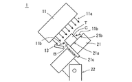
図6は、ローラーの好ましい態様および後方散乱電子線の利用を説明する図である。図6において、21aはローラーの容器Cと接触する部分であり、21bは接触しない部分である。また13は反射板である。
(1) Reflector FIG. 6 is a diagram illustrating a preferred embodiment of rollers and utilization of backscattered electron beams. In FIG. 6, 21a is the portion of the roller that contacts the container C, and 21b is the portion that does not contact. 13 is a reflector.
図6に示すように、本実施の形態においては、必要に応じて、反射板13を配置し、反射板13で後方散乱させた後方散乱電子線11bを容器Cに照射してもよい。反射板13は、設置位置および散乱方向の自由度が高い。このため、ローラーの後方散乱では照射しにくい箇所に対しても照射することができ好ましい。
As shown in FIG. 6, in this embodiment, if necessary, a
(2)電子線照射部
電子線照射部11は、長手方向が搬送路に対して垂直な面と平行に設置される。このとき、図1Aに示すように、長手方向を鉛直方向に対して例えば15~90°の角度でローラー21の回転軸と同じ向きに傾斜させることにより、電子線照射部11の高さ方向、および幅方向における設置スペースを小さくすることができる。
(2) Electron Beam Irradiation Unit The electron
また、電子線照射部11は、搬送路に対して垂直な面上における高さ方向および水平方向の位置を調節する位置調節機構および電子線の放射方向を調節する放射方向調節機構を備える支持装置によって支持されていることが好ましい。角度可変機構と位置調節機構および放射方向調節機構を用いることで、照射条件に対して高い自由度が得られるため、多様な形状およびサイズの容器に対してより好適な条件の下で電子線を照射することができる。
In addition, the electron
(3)搬送手段
電子線を照射する際には、前記のように容器Cは、鉛直方向に対して傾斜角度θ傾斜した傾斜状態で保持される。一方、電子線を照射する前後には、容器Cに内容物を充填するなど、容器Cを直立状態で保持することが好ましい工程が設けられる。このため、搬送手段は、電子線照射領域の上流側で直立状態で保持されている容器を傾斜状態に変え、一方、電子線照射領域の下流側に傾斜状態から直立状態に戻すように構成されていることが好ましい。
(3) Conveying Means When irradiating the electron beam, the container C is held in an inclined state at an inclination angle θ with respect to the vertical direction as described above. On the other hand, before and after the irradiation with the electron beam, a process such as filling the container C with the content is preferably performed to hold the container C in an upright state. For this reason, the conveying means is configured to change the container, which is held in an upright state on the upstream side of the electron beam irradiation area, to an inclined state, and on the downstream side of the electron beam irradiation area, to return the container from the inclined state to the upright state. preferably.
具体的には例えば、搬送手段の上流側端部に搬入される容器Cを上工程の搬送手段からローラー21に移し換える公知の機構を設置し、一方、搬送手段の下流側端部に搬出される容器Cをローラー21から下工程の搬送手段に移し換える機構を設置するなどの構成が用いられる。
Specifically, for example, a known mechanism is installed to transfer the container C carried in to the upstream end of the transport means from the upstream transport means to the
[2]電子線照射方法
次に、上記した電子線照射装置を用いて、有底筒状の容器に向けて電子線を照射する電子線照射方法について説明する。
[2] Electron Beam Irradiation Method Next, an electron beam irradiation method for irradiating a bottomed cylindrical container with an electron beam using the electron beam irradiation apparatus described above will be described.
本実施の形態においては、上記した電子線照射装置を用いて、以下の2つの工程を経ることにより、容器に電子線を照射して滅菌を行うことができる。 In the present embodiment, the container can be sterilized by irradiating electron beams through the following two processes using the electron beam irradiation apparatus described above.
即ち、傾斜状態にある容器を、側面が電子線の照射方向と相対するように保持して、上流側から下流側に向けて搬送する搬送工程と、搬送路を搬送される容器に向けて電子線を放射して照射する電子線照射工程との2つの工程である。 That is, a conveying step in which a container in an inclined state is held so that its side surface faces the irradiation direction of the electron beam and is conveyed from the upstream side to the downstream side; There are two processes, one is an electron beam irradiation process in which rays are emitted and irradiated.
そして、このような工程を経て、有底筒状の容器に向けて電子線を照射することにより、上記した電子線照射装置の説明において記載したように、容器の側面だけでなく、底面や頂部に対しても十分に電子線を照射することができる。この結果、加速電圧1MV以下で低エネルギーまたは中エネルギーの電子線を照射する小型の電子線照射部を用いながらも、1回の照射で筒状の容器の外面全体に電子線を効率良く照射することができる。 Then, through such steps, by irradiating an electron beam toward the cylindrical container with a bottom, as described in the above description of the electron beam irradiation apparatus, not only the side surface of the container but also the bottom surface and top portion can be exposed. can be sufficiently irradiated with an electron beam. As a result, the entire outer surface of the cylindrical container can be efficiently irradiated with an electron beam in a single irradiation, while using a small-sized electron beam irradiation unit that irradiates a low-energy or medium-energy electron beam at an acceleration voltage of 1 MV or less. be able to.
以上、本発明を実施の形態に基づき説明したが、本発明は上記の実施の形態に限定されるものではない。本発明と同一および均等の範囲内において、上記の実施の形態に対して種々の変更を加えることが可能である。 Although the present invention has been described above based on the embodiments, the present invention is not limited to the above embodiments. Various modifications can be made to the above embodiment within the same and equivalent scope of the present invention.
1 電子線照射装置
11 電子線照射部
11a 放射電子線
11b 後方散乱電子線
12 搬送路
13 反射板
21 ローラー
21a 容器と接触する部分
21b 容器と接触しない部分
21c 鍔部
22 ローラー支持装置
22a 固定部材
22b 支持部材
22c ローラー保持部材
22d 支点
24 回転機構
24a ピニオン
24b ラック
C 容器
B 底面
T 頂部
θ 傾斜角度
CL 回転軸の中心線
1 electron
Claims (5)
前記容器を側面が前記電子線の照射方向と相対するように保持して、上流側から下流側に向けて搬送する搬送路を備える搬送手段と、
前記搬送路を搬送される前記容器に向けて電子を加速して照射する電子線照射部を備える電子線照射手段とが備えられており、
前記搬送手段は、回転しながら搬送方向に移動する複数のローラーが、搬送方向に対して傾斜して、一定間隔をおいて配置されて、隣接する2つの前記ローラー間に配置された前記容器を回転させながら搬送するように構成されており、
前記ローラーには、長手方向の一方の端部に側面の全周に亘って前記側面から径方向に突出する鍔部が設けられていると共に、前記ローラーの回転軸の鉛直方向に対する傾斜角度を変更することができる角度可変機構が備えられており、
前記傾斜角度を調節することにより、前記容器に対する前記電子線の照射角度を調節するように構成されていることを特徴とする電子線照射装置。 An electron beam irradiation device that irradiates an electron beam toward a bottomed cylindrical container,
a conveying means having a conveying path that holds the container so that the side faces face the irradiation direction of the electron beam and conveys the container from the upstream side to the downstream side;
an electron beam irradiation means including an electron beam irradiation unit that accelerates and irradiates electrons toward the container transported on the transport path,
In the conveying means, a plurality of rollers that move in the conveying direction while rotating are arranged at regular intervals with an inclination with respect to the conveying direction, and the containers are arranged between the two adjacent rollers. It is configured to be conveyed while being rotated,
The roller is provided with a collar portion that protrudes radially from the side surface over the entire circumference of the side surface at one end in the longitudinal direction, and changes the inclination angle of the rotation axis of the roller with respect to the vertical direction. It is equipped with a variable angle mechanism that can
An electron beam irradiation apparatus, wherein an irradiation angle of the electron beam to the container is adjusted by adjusting the inclination angle.
前記ローラーの傾斜角度を調節して載置した前記容器を、側面が前記電子線の照射方向と所定の角度で相対するように保持して、上流側から下流側に向けて搬送する搬送工程と、
前記搬送路を搬送される前記容器の側面に向けて電子を加速して照射する電子線照射工程とを備えており、
前記搬送工程において、隣接する2つの前記ローラー間に配置された前記容器を回転させながら搬送することを特徴とする電子線照射方法。 An electron beam irradiation method for irradiating a bottomed cylindrical container with an electron beam using the electron beam irradiation apparatus according to any one of claims 1 to 4,
a conveying step of conveying the container placed by adjusting the inclination angle of the roller from the upstream side to the downstream side while holding the container so that the side faces face the irradiation direction of the electron beam at a predetermined angle; ,
and an electron beam irradiation step of accelerating and irradiating electrons toward the side surface of the container conveyed on the conveying path,
The electron beam irradiation method, wherein in the transporting step, the container placed between the two adjacent rollers is transported while being rotated.
Priority Applications (1)
| Application Number | Priority Date | Filing Date | Title |
|---|---|---|---|
| JP2019147245A JP7205802B2 (en) | 2019-08-09 | 2019-08-09 | Electron beam irradiation device and electron beam irradiation method |
Applications Claiming Priority (1)
| Application Number | Priority Date | Filing Date | Title |
|---|---|---|---|
| JP2019147245A JP7205802B2 (en) | 2019-08-09 | 2019-08-09 | Electron beam irradiation device and electron beam irradiation method |
Publications (2)
| Publication Number | Publication Date |
|---|---|
| JP2021028228A JP2021028228A (en) | 2021-02-25 |
| JP7205802B2 true JP7205802B2 (en) | 2023-01-17 |
Family
ID=74667174
Family Applications (1)
| Application Number | Title | Priority Date | Filing Date |
|---|---|---|---|
| JP2019147245A Active JP7205802B2 (en) | 2019-08-09 | 2019-08-09 | Electron beam irradiation device and electron beam irradiation method |
Country Status (1)
| Country | Link |
|---|---|
| JP (1) | JP7205802B2 (en) |
Citations (5)
| Publication number | Priority date | Publication date | Assignee | Title |
|---|---|---|---|---|
| WO2001023007A1 (en) | 1999-09-24 | 2001-04-05 | Iotron Industries Canada Inc. | Electron beam sterilization of contained liquids |
| JP2002211520A (en) | 2001-01-15 | 2002-07-31 | Toyo Seikan Kaisha Ltd | Device and method for electron beam sterilization of vessel |
| JP2012247378A (en) | 2011-05-31 | 2012-12-13 | Ihi Corp | Electron beam irradiation apparatus and electron beam irradiation system |
| JP2013215579A (en) | 2012-04-11 | 2013-10-24 | Krones Ag | Apparatus and method for radiation-based disinfection for container lid |
| JP2016129677A (en) | 2016-01-22 | 2016-07-21 | 株式会社エアレックス | Electron beam sterilization method |
Family Cites Families (2)
| Publication number | Priority date | Publication date | Assignee | Title |
|---|---|---|---|---|
| JP2002078780A (en) * | 2000-06-26 | 2002-03-19 | Mitsubishi Heavy Ind Ltd | Electron beam irradiation method and apparatus therefor |
| JP4889012B2 (en) * | 2006-07-27 | 2012-02-29 | 三菱重工食品包装機械株式会社 | Sterilizer |
-
2019
- 2019-08-09 JP JP2019147245A patent/JP7205802B2/en active Active
Patent Citations (6)
| Publication number | Priority date | Publication date | Assignee | Title |
|---|---|---|---|---|
| WO2001023007A1 (en) | 1999-09-24 | 2001-04-05 | Iotron Industries Canada Inc. | Electron beam sterilization of contained liquids |
| JP2002211520A (en) | 2001-01-15 | 2002-07-31 | Toyo Seikan Kaisha Ltd | Device and method for electron beam sterilization of vessel |
| JP2012247378A (en) | 2011-05-31 | 2012-12-13 | Ihi Corp | Electron beam irradiation apparatus and electron beam irradiation system |
| JP2013215579A (en) | 2012-04-11 | 2013-10-24 | Krones Ag | Apparatus and method for radiation-based disinfection for container lid |
| JP6313544B2 (en) | 2012-04-11 | 2018-04-18 | クロネス アーゲー | Apparatus and method for radiation-based disinfection of container lids |
| JP2016129677A (en) | 2016-01-22 | 2016-07-21 | 株式会社エアレックス | Electron beam sterilization method |
Also Published As
| Publication number | Publication date |
|---|---|
| JP2021028228A (en) | 2021-02-25 |
Similar Documents
| Publication | Publication Date | Title |
|---|---|---|
| JP6313544B2 (en) | Apparatus and method for radiation-based disinfection of container lids | |
| CN103770981B (en) | For the equipment of the outside sterilization of plastic parison | |
| JP5558209B2 (en) | Electron beam sterilizer | |
| EP1956608B1 (en) | Electron beam vacuum apparatus for sterilising containers | |
| JP5176503B2 (en) | Container sterilizer | |
| US20130129566A1 (en) | Device for internal and external sterilisation of plastic containers by means of charge carrier beams | |
| CN108283010A (en) | A kind of non-destructive X-ray detection machine, is used for the device and operating method of this machine | |
| EP2292515A1 (en) | Electron beam irradiation device for aperture vessel | |
| JP7205802B2 (en) | Electron beam irradiation device and electron beam irradiation method | |
| JP5176502B2 (en) | Container sterilizer | |
| JP5209050B2 (en) | Sterilization using β-ray radiation | |
| JP4365835B2 (en) | Electron beam irradiation device for open containers | |
| JP7246619B2 (en) | Electron beam irradiation device and electron beam irradiation method | |
| JP2010105702A (en) | Electron rays sterilizer | |
| JP6932115B2 (en) | Equipment and methods for sterilizing containers, equipped with X-ray shielding devices | |
| JP4889013B2 (en) | Sterilizer | |
| JP2007113936A (en) | Method and device for radiating electron beam | |
| CN101297376A (en) | Electron beam irradiation method, electron beam irradiation apparatus, and electron beam irradiation apparatus for open container | |
| JP2012247378A (en) | Electron beam irradiation apparatus and electron beam irradiation system | |
| JP6821882B1 (en) | Base material processing equipment | |
| JPH1045116A (en) | Equipment for sterilization/disinfection | |
| JP2004191307A (en) | Electron beam irradiation device | |
| JP4910819B2 (en) | Electron beam sterilizer | |
| JP7274403B2 (en) | Electron beam sterilization device and method | |
| JP5082050B2 (en) | Electron beam irradiation device |
Legal Events
| Date | Code | Title | Description |
|---|---|---|---|
| A621 | Written request for application examination |
Free format text: JAPANESE INTERMEDIATE CODE: A621 Effective date: 20220722 |
|
| A871 | Explanation of circumstances concerning accelerated examination |
Free format text: JAPANESE INTERMEDIATE CODE: A871 Effective date: 20220831 |
|
| TRDD | Decision of grant or rejection written | ||
| A01 | Written decision to grant a patent or to grant a registration (utility model) |
Free format text: JAPANESE INTERMEDIATE CODE: A01 Effective date: 20221205 |
|
| A61 | First payment of annual fees (during grant procedure) |
Free format text: JAPANESE INTERMEDIATE CODE: A61 Effective date: 20221218 |
|
| R150 | Certificate of patent or registration of utility model |
Ref document number: 7205802 Country of ref document: JP Free format text: JAPANESE INTERMEDIATE CODE: R150 |
|
| R250 | Receipt of annual fees |
Free format text: JAPANESE INTERMEDIATE CODE: R250 |