JP7205183B2 - Door locking systems and vehicle door handles - Google Patents
Door locking systems and vehicle door handles Download PDFInfo
- Publication number
- JP7205183B2 JP7205183B2 JP2018216817A JP2018216817A JP7205183B2 JP 7205183 B2 JP7205183 B2 JP 7205183B2 JP 2018216817 A JP2018216817 A JP 2018216817A JP 2018216817 A JP2018216817 A JP 2018216817A JP 7205183 B2 JP7205183 B2 JP 7205183B2
- Authority
- JP
- Japan
- Prior art keywords
- circuit
- communication
- door
- control circuit
- antenna
- Prior art date
- Legal status (The legal status is an assumption and is not a legal conclusion. Google has not performed a legal analysis and makes no representation as to the accuracy of the status listed.)
- Active
Links
Images


Description
本発明は、ドアの開錠又は施錠、および開錠および施錠が可能なドア錠システムおよび車両用ドアのハンドルに関する。 BACKGROUND OF THE INVENTION 1. Field of the Invention The present invention relates to a door locking system and a vehicle door handle capable of unlocking or locking a door, and unlocking and locking the door.
車両などのドア(扉)を、ドアから離れた場所で解錠施錠を行う携帯型の無線鍵装置(以下、キーデバイスと記載する)が利用されている。このようなキーデバイスの内、ポケットやバッグにキーデバイスを収容した状態で、ドアハンドルに手を近接や接触、離間などすることで、解錠施錠ができるキーは、スマートキーなどと呼ばれる。 2. Description of the Related Art A portable wireless key device (hereinafter referred to as a key device) is used to unlock and lock a door of a vehicle or the like at a location away from the door. Among such key devices, a key that can be unlocked and locked by bringing a hand close to, contacting, or separating from a door handle while the key device is stored in a pocket or bag is called a smart key.
特許文献1には、スマートキーシステムを採用した車両用ドアハンドル装置に係る発明が記載されている。この車両用ドアハンドル装置は、ドアハンドルの内部に車載機器(ドア錠システム)が搭載されている。車載機器は、車両のECU(エレクトロニックコントロールユニット)と第一ラインおよび第二ラインとで電気的に接続されている。車載機器は、携帯機(キーデバイスの一例)への返答リクエスト信号を外部に送信するアンテナ機能を有するアンテナ用コイル、ロックセンサおよびアンロックセンサを有する人検知ICを備えている。 Patent Document 1 describes an invention relating to a vehicle door handle device employing a smart key system. This vehicle door handle device has an in-vehicle device (door lock system) mounted inside the door handle. The in-vehicle device is electrically connected to the ECU (Electronic Control Unit) of the vehicle through the first line and the second line. The in-vehicle device includes an antenna coil having an antenna function for externally transmitting a response request signal to a portable device (an example of a key device), and a human detection IC having a lock sensor and an unlock sensor.
特許文献1に記載されているような従来のスマートキーシステムでは、これに用いるキーデバイスは、車両(ドア)に対してあらかじめ定められたキーデバイスが用いられていた。しかし近年の、いわゆるスマートフォンなどの携帯端末の普及や一台の車両を複数人で共有するいわゆるカーシェアリング文化の醸成により、あらかじめ定められたキーデバイスとは別に、種々のキーデバイスが使用可能であることが要請される。この場合、ドアハンドルに、複数種のキーデバイスに対応したドア開錠装置を搭載することが考えられる。しかしこの場合、各々の複数種のキーデバイスに対応すべく設けた回路やアンテナ、およびこれらの電波通信や信号の伝送などの干渉が問題となる。干渉が生じると、適切な開錠施錠が行えないため問題である。また、回路等の増加により、車両との接続インタフェースが複雑になるおそれもあるため、インタフェースの単純化が要請される。 A conventional smart key system such as that described in Patent Document 1 uses a key device that is predetermined for a vehicle (door). However, with the recent spread of mobile terminals such as smartphones and the development of a so-called car-sharing culture in which multiple people share one vehicle, various key devices can be used in addition to the predetermined key devices. is required. In this case, it is conceivable to mount a door unlocking device corresponding to a plurality of types of key devices on the door handle. However, in this case, there is a problem of interference between the circuits and antennas provided for each of the multiple types of key devices, and their radio wave communication and signal transmission. If interference occurs, it is a problem because appropriate unlocking and locking cannot be performed. In addition, since the increase in the number of circuits and the like may complicate the connection interface with the vehicle, simplification of the interface is required.
本発明は、かかる実状に鑑みて為されたものであって、その目的は、複数種のキーデバイスに対応しつつインタフェースが単純化されたドア錠システムおよび車両用ドアのハンドルを提供することにある。 SUMMARY OF THE INVENTION The present invention has been made in view of such circumstances, and an object thereof is to provide a door lock system and a vehicle door handle which are compatible with a plurality of types of key devices and have a simplified interface. be.
上記目的を達成するための本発明に係るドア錠システムの特徴構成は、扉の開錠可否を判定するための応答を要求する第一通信を実行する第一回路と、前記扉の開錠可否を判定
するための第二通信を実行し、当該第二通信の受信結果を外部へ送出する第二回路と、前記第一回路および前記第二回路の動作を制御する制御回路と、を備え、前記制御回路は、前記第一通信もしくは前記第二通信の一方が実行される際に、他方を実行停止させ、前記第一回路は、コイルとコンデンサとを含み、前記コイルと前記コンデンサとは、LC並列回路を構成又は前記LC並列回路の構成を解除可能であり、前記第一回路は、前記LC並列回路が構成されると通信不能になり、前記LC並列回路の構成が解除されると、通信可能になる点にある。
A door locking system according to the present invention for achieving the above object is characterized by: a first circuit for executing a first communication requesting a response for determining whether or not a door can be unlocked; A second circuit that executes a second communication for determining the second communication and outputs the reception result of the second communication to the outside, and a control circuit that controls the operation of the first circuit and the second circuit, The control circuit stops execution of one of the first communication and the second communication when the other is executed , the first circuit includes a coil and a capacitor, and the coil and the capacitor are: An LC parallel circuit can be configured or the configuration of the LC parallel circuit can be canceled, the first circuit becomes incapable of communication when the LC parallel circuit is configured, and when the configuration of the LC parallel circuit is released, It is at the point where communication becomes possible .
上記構成によれば、第一回路は、第一のキーデバイスに対して、扉の開錠可否を判定するための応答を要求する第一通信を実行可能である。第一通信は、第一回路から第一のキーデバイスに対して一方向で行われる通信としての送信である。第一通信には、ブロードキャスト通信が含まれる。第二回路は、第二の(他の)キーデバイスと第二通信を実行できる。第二通信は、扉の開錠可否を判定するための応答を要求する通信と、当該応答の受信とを含む相方向通信である。第二回路は、扉の開錠可否を判定するための情報を含む受信結果を外部(たとえば、車両のECU)へ送出する。これにより、ドア錠システムは、複数の(2以上の)キーデバイスに対応する。 According to the above configuration, the first circuit can execute the first communication requesting a response for determining whether the door can be unlocked from the first key device. The first communication is a one-way transmission from the first circuit to the first key device. The first communication includes broadcast communication. A second circuit is capable of performing a second communication with a second (other) key device. The second communication is two-way communication including communication requesting a response for determining whether the door can be unlocked and reception of the response. The second circuit sends a reception result including information for determining whether or not the door can be unlocked to the outside (for example, the ECU of the vehicle). This allows the door lock system to accommodate multiple (two or more) key devices.
上記構成によれば、制御回路が、第一通信もしくは第二通信の一方が実行される際に、他方を実行停止させる。これにより、第一回路もしくは第二回路は、一方の回路が通信を実行している場合に、他方の回路の通信による干渉(ノイズ)を受けない。その結果、第一通信および第二通信は適切に実行可能となり、ドア錠システムは、複数のキーデバイスに適切に対応できる。このように干渉を回避できるため、ドア錠システムと外部(例えば、車両のECU)とのインタフェースも単純化可能となる。たとえば、第一回路と第二回路とで信号線を別々にしたりすることを要しない。 According to the above configuration, the control circuit suspends the execution of one of the first communication and the second communication when the other is executed. As a result, the first circuit or the second circuit is not subject to interference (noise) due to communication of the other circuit when one circuit is executing communication. As a result, the first communication and the second communication can be performed properly, and the door locking system can properly handle multiple key devices. Since interference can be avoided in this way, the interface between the door locking system and the outside (for example, the ECU of the vehicle) can also be simplified. For example, it is not necessary to use separate signal lines for the first circuit and the second circuit.
本発明に係るドア錠システムの更なる特徴構成は、前記第一回路は、無線通信により前記第一通信を実行可能であり、前記第二回路は、無線通信により前記第二通信を実行可能であり、前記第一回路は、前記第二回路に対して相対的に遠距離の無線通信を実行する点にある。 A further characteristic configuration of the door lock system according to the present invention is that the first circuit is capable of executing the first communication by wireless communication, and the second circuit is capable of executing the second communication by wireless communication. and wherein the first circuit performs relatively long-distance wireless communication with the second circuit.
上記構成によれば、第一回路は、第二回路に対して相対的に遠距離の無線通信を実行可能である。たとえば、遠距離のキーデバイスとの通信は、第一回路が第一通信として実行する。近距離のキーデバイスとの通信は、第二回路が第二通信として実行する。近距離のキーデバイスと第二通信を実行する際は、第一通信の実行は停止されるため、搭乗者がドアハンドルなどのキーデバイスに近づいた際には、適切に第二通信を実行して開錠施錠を行える。 According to the above configuration, the first circuit can perform relatively long-distance wireless communication with the second circuit. For example, communication with a remote key device is performed by the first circuit as the first communication. Communication with the short-range key device is performed by the second circuit as second communication. Since the execution of the first communication is suspended when executing the second communication with a key device at a short distance, the second communication is properly executed when the passenger approaches a key device such as a door handle. can be unlocked and locked.
本発明に係るドア錠システムの更なる特徴構成は、前記制御回路は、前記第二通信が実行可能である場合、前記第一通信を実行停止させる点にある。 A further characteristic configuration of the door locking system according to the present invention is that the control circuit stops execution of the first communication when the second communication is executable.
上記構成によれば、第一通信に対応するキーデバイスおよび第二通信に対応するキーデバイスが、それぞれ第一通信および第二通信で通信可能である場合、第一通信の実行が停止されることで、第二通信が優先して実行される。また、第二通信が実行されている場合に、第二通信の実行中に第一通信の実行が開始されて第二通信が阻害されることを防止できる。 According to the above configuration, when the key device corresponding to the first communication and the key device corresponding to the second communication can communicate with the first communication and the second communication, respectively, the execution of the first communication is stopped. , the second communication is preferentially executed. Moreover, when the second communication is being executed, it is possible to prevent the second communication from being hindered by starting the execution of the first communication while the second communication is being executed.
本発明に係るドア錠システムの更なる特徴構成は、前記制御回路は、前記第二通信が実行される際に、前記第一回路を動作不能にする点にある。 A further feature of the door locking system according to the present invention is that the control circuit disables the first circuit when the second communication is performed.
上記構成によれば、第一通信に対応するキーデバイスおよび第二通信に対応するキーデバイスが、それぞれ第一通信および第二通信で通信可能である場合、第一回路を動作不能に設定されることで第一通信の実行が停止される。これにより、第二通信が優先して実行される。また、第二通信が実行されている際に、第一回路を動作不能に設定して第一通信の実行を阻止しておくことで、第二通信の実行中に第一通信の実行が開始されて第二通信が阻害されることを防止できる。 According to the above configuration, when the key device corresponding to the first communication and the key device corresponding to the second communication can communicate by the first communication and the second communication, respectively, the first circuit is disabled. This stops execution of the first communication. Thereby, the second communication is preferentially executed. Also, when the second communication is being executed, by setting the first circuit to be inoperable and preventing the execution of the first communication, the execution of the first communication is started while the second communication is being executed. It is possible to prevent the second communication from being blocked by the
本発明に係るドア錠システムの更なる特徴構成は、前記第一回路は、無線通信用の第一アンテナ回路を有し、前記制御回路は、前記第二通信が実行される際に、前記第一アンテナ回路を遮断する点にある。 A further characteristic configuration of the door locking system according to the present invention is that the first circuit has a first antenna circuit for wireless communication, and the control circuit controls, when the second communication is performed, the first One is to cut off the antenna circuit.
上記構成によれば、第一アンテナ回路が遮断されることで、第一回路が第一通信を実行不能になる。これにより、第二通信が優先して実行される。また、第二通信が阻害されることを防止できる。 According to the above configuration, the first circuit becomes incapable of executing the first communication by disconnecting the first antenna circuit. Thereby, the second communication is preferentially executed. Also, it is possible to prevent the second communication from being blocked.
本発明に係るドア錠システムの更なる特徴構成は、前記第一アンテナ回路は、前記コイルを有する第一アンテナと、前記コンデンサおよび当該コンデンサに直列接続されたスイッチとを有し、前記コイルと前記コンデンサおよび前記スイッチとは、前記制御回路と並列接続されており、前記制御回路は、前記第二通信が実行される際に前記スイッチを短絡させて、前記LC並列回路を構成する点にある。 A further characteristic configuration of the door locking system according to the present invention is that the first antenna circuit has a first antenna having the coil, the capacitor and a switch connected in series to the capacitor, and the coil and the The capacitor and the switch are connected in parallel with the control circuit, and the control circuit short-circuits the switch when the second communication is performed to form the LC parallel circuit. be.
上記構成によれば、スイッチの短絡により、第一アンテナ回路にLC並列回路を構成可能である。制御回路が当該スイッチを短絡させることにより、第一回路は第一通信を実行不能になる。 According to the above configuration, an LC parallel circuit can be configured in the first antenna circuit by short-circuiting the switch. The control circuit shorts the switch, thereby disabling the first circuit from performing the first communication.
上記目的を達成するための本発明に係るドア錠システムの他の特徴構成は、扉の開錠可否を判定するための応答を要求する第一通信を実行する第一回路と、前記扉の開錠可否を判定するための第二通信を実行し、当該第二通信の受信結果を外部へ送出する第二回路と、前記第一回路および前記第二回路の動作を制御する制御回路と、前記扉の開錠指示又は施錠指示を入力するための近接センサと、を備え、前記制御回路は、前記第一通信もしくは前記第二通信の一方が実行される際に、他方を実行停止させ、前記第二回路は、無線通信用の第二アンテナを有し、前記近接センサは、前記開錠指示又は前記施錠指示を検出するための電極を有し、前記第二アンテナは、前記電極の外周に隣接して設けられている点にある。 Another characteristic configuration of the door locking system according to the present invention for achieving the above object is a first circuit for executing a first communication requesting a response for determining whether the door can be unlocked; a second circuit for executing a second communication for determining whether or not the lock can be locked, and transmitting the reception result of the second communication to the outside; a control circuit for controlling the operations of the first circuit and the second circuit; a proximity sensor for inputting a door unlocking instruction or door locking instruction, wherein the control circuit stops execution of one of the first communication and the second communication when the other is executed, The second circuit has a second antenna for wireless communication, the proximity sensor has an electrode for detecting the unlocking instruction or the locking instruction, and the second antenna is an outer circumference of the electrode. It's located next to it.
上記構成によれば、第一回路は、第一のキーデバイスに対して、扉の開錠可否を判定するための応答を要求する第一通信を実行可能である。第一通信は、第一回路から第一のキーデバイスに対して一方向で行われる通信としての送信である。第一通信には、ブロードキャスト通信が含まれる。第二回路は、第二の(他の)キーデバイスと第二通信を実行できる。第二通信は、扉の開錠可否を判定するための応答を要求する通信と、当該応答の受信とを含む相方向通信である。第二回路は、扉の開錠可否を判定するための情報を含む受信結果を外部(たとえば、車両のECU)へ送出する。これにより、ドア錠システムは、複数の(2以上の)キーデバイスに対応する。
また、上記構成によれば、制御回路が、第一通信もしくは第二通信の一方が実行される際に、他方を実行停止させる。これにより、第一回路もしくは第二回路は、一方の回路が通信を実行している場合に、他方の回路の通信による干渉(ノイズ)を受けない。その結果、第一通信および第二通信は適切に実行可能となり、ドア錠システムは、複数のキーデバイスに適切に対応できる。このように干渉を回避できるため、ドア錠システムと外部(例えば、車両のECU)とのインタフェースも単純化可能となる。たとえば、第一回路と第二回路とで信号線を別々にしたりすることを要しない。
また、上記構成によれば、乗員が所持しているキーデバイスとの通信によりあらかじめ扉の開錠が可と判定されている場合、キーデバイスを所持した乗員が近接センサの電極を介して扉の開錠指示を行える。同様に、乗員が所持しているキーデバイスとの通信によりあらかじめ扉の施錠が可と判定されている場合、キーデバイスを所持した乗員が近接センサの電極を介して扉の施錠指示を行える。なお、近接センサとは、乗員の身体(たとえば、手)の近接離間を検出するセンサである。以下の説明において、近接には接触を含む。
According to the above configuration, the first circuit can execute the first communication requesting a response for determining whether the door can be unlocked from the first key device. The first communication is a one-way transmission from the first circuit to the first key device. The first communication includes broadcast communication. A second circuit is capable of performing a second communication with a second (other) key device. The second communication is two-way communication including communication requesting a response for determining whether the door can be unlocked and reception of the response. The second circuit sends a reception result including information for determining whether or not the door can be unlocked to the outside (for example, the ECU of the vehicle). This allows the door lock system to accommodate multiple (two or more) key devices.
Moreover, according to the above configuration, when one of the first communication and the second communication is executed, the control circuit stops the other. As a result, the first circuit or the second circuit is not subject to interference (noise) due to communication of the other circuit when one circuit is executing communication. As a result, the first communication and the second communication can be performed properly, and the door locking system can properly handle multiple key devices. Since interference can be avoided in this way, the interface between the door locking system and the outside (for example, the ECU of the vehicle) can also be simplified. For example, it is not necessary to use separate signal lines for the first circuit and the second circuit.
Further, according to the above configuration, when it is determined in advance that the door can be unlocked by communicating with the key device possessed by the passenger, the passenger holding the key device can open the door via the electrode of the proximity sensor. You can issue an unlock command. Similarly, when it is determined in advance that the door can be locked by communication with the key device held by the passenger, the passenger holding the key device can issue a door locking instruction via the electrodes of the proximity sensor. Note that the proximity sensor is a sensor that detects the proximity and separation of the passenger's body (for example, hand). In the following description, proximity includes contact.
上記構成によれば、第二アンテナを近接センサの外周に隣接して設けることで、第二アンテナおよび近接センサの電極をコンパクトに配置可能である。特に、第一回路が第二回路に対して相対的に遠距離の無線通信を実行する場合、第二アンテナを有する第二回路は相対的に近距離の無線通信を実行するが、第二アンテナおよび近接センサの電極が隣接して設けられることで、近距離におけるキーデバイスによる開錠可もしくは施錠可の判定と同時もしくは直後に近接センサの電極により開錠指示又は施錠指示が行える。これにより、乗員の使用感の向上とセキュリティの向上とを実現できる。 According to the above configuration, by providing the second antenna adjacent to the outer periphery of the proximity sensor, the electrodes of the second antenna and the proximity sensor can be arranged compactly. In particular, if the first circuit performs relatively long-range wireless communication with respect to the second circuit, the second circuit with the second antenna performs relatively short-range wireless communication, but the second antenna And, the electrodes of the proximity sensor are provided adjacent to each other, so that the electrodes of the proximity sensor can issue an unlocking instruction or a locking instruction at the same time or immediately after the key device determines whether the door can be unlocked or locked at a short distance. As a result, it is possible to improve the usability of the passenger and improve security.
本発明に係るドア錠システムの更なる特徴構成は、前記近接センサは、第一近接距離と、前記第一近接距離よりも近い第二近接距離とを識別可能であり、前記制御回路は、前記第一近接距離での近接を検出した場合、前記第二通信の実行を可能とし、前記第二近接距離での近接を検出した場合、前記第二通信の実行を停止する点にある。 A further characteristic configuration of the door locking system according to the present invention is that the proximity sensor is capable of distinguishing between a first proximity distance and a second proximity distance that is closer than the first proximity distance, and the control circuit is configured to: Execution of the second communication is enabled when proximity at the first proximity distance is detected, and execution of the second communication is stopped when proximity at the second proximity distance is detected.
上記構成によれば、たとえば、接触などの第二近接距離と、近接センサで検知可能な程度の近い距離、かつ、第二近接距離よりも遠い第一近接距離とを区別して、近接センサで検出される程度近くであるが接触するほど近くない第一近接距離にキーデバイスを所持する乗員が存在することを確認しつつ第二通信を実行できる。この場合乗員は、近接センサへの接触により開錠指示又は施錠指示を入力してもよい。 According to the above configuration, for example, the second proximity distance such as contact is distinguished from the first proximity distance that is close enough to be detected by the proximity sensor and is farther than the second proximity distance, and detected by the proximity sensor. The second communication can be performed while confirming that there is an occupant holding the key device at a first proximity distance close enough to be touched but not close enough to touch. In this case, the passenger may input an unlocking instruction or a locking instruction by touching the proximity sensor.
本発明に係るドア錠システムの更なる特徴構成は、前記制御回路は、前記第二通信が実行される際に、前記近接センサの動作を停止させる点にある。 A further characteristic configuration of the door locking system according to the present invention is that the control circuit stops the operation of the proximity sensor when the second communication is performed.
上記構成によれば、第二通信の実行中に、近接センサの電極からの干渉(ノイズ)を受けない。その結果、第二通信を適切に実行可能となる。 According to the above configuration, interference (noise) from the electrodes of the proximity sensor is not received during execution of the second communication. As a result, the second communication can be properly executed.
上記目的を達成するための本発明に係る車両用ドアのハンドルの特徴構成は、車両用扉の開錠可否を判定するための応答を要求する第一通信を実行する第一回路と、前記車両用扉の開錠可否を判定するための第二通信を実行し、当該第二通信の受信結果を送出する第二回路と、前記第一回路および前記第二回路の動作を制御する制御回路と、前記第一回路と前記制御回路とが並列接続された一対の電線と、前記第一回路、前記第二回路、および前記制御回路を収容するケーシングと、を備え、一対の前記電線は、前記第二通信の受信結果を外部へ送出すると共に、前記外部から供給された電力を前記第一回路、前記第二回路、および前記制御回路へ供給し、前記制御回路は、前記第一通信もしくは前記第二通信の一方が実行される際に、他方を実行停止させる点にある。 A vehicle door handle according to the present invention for achieving the above object is characterized by: a first circuit for executing a first communication requesting a response for determining whether or not the vehicle door can be unlocked; a second circuit for executing a second communication for determining whether or not the door can be unlocked and transmitting the reception result of the second communication; and a control circuit for controlling the operations of the first circuit and the second circuit. , a pair of electric wires in which the first circuit and the control circuit are connected in parallel, and a casing housing the first circuit, the second circuit, and the control circuit, wherein the pair of electric wires are connected to the A reception result of the second communication is sent to the outside, and the power supplied from the outside is supplied to the first circuit, the second circuit, and the control circuit, and the control circuit receives the first communication or the The point is that when one of the second communications is executed, the other is stopped.
上記構成によれば、上述のドア錠システムをケーシング内に収容した車両用ドアのハンドルにおいて、上述のドア錠システムと同様の効果を奏することができる。また、上述のドア錠システムは、ケーシング内に収容された状態において、一対の電線により電力供給を受け、また、外部出力が可能であるため、ケーシング内に収容された状態のドア錠システムと外部(例えば、車両のECU)とのインタフェースが単純化される。 According to the above configuration, in the handle of the vehicle door in which the above-described door locking system is accommodated in the casing, the same effects as those of the above-described door locking system can be obtained. In addition, the door lock system described above receives power from a pair of electric wires when housed in the casing, and is capable of outputting power to the outside. The interface with (eg, the vehicle's ECU) is simplified.
複数種のキーデバイスに対応しつつインタフェースが単純化されたドア錠システムおよび車両用ドアのハンドルを提供することができる。 It is possible to provide a door locking system and a vehicle door handle with a simplified interface while supporting multiple types of key devices.
図1から図4に基づいて、本発明の実施形態に係るドア錠システムおよび車両用ドアのハンドルについて説明する。 A door locking system and a vehicle door handle according to an embodiment of the present invention will be described with reference to FIGS. 1 to 4. FIG.
〔概略構成〕
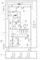
図1および図2に示すように、ドア錠システム100は、車両用ドア(扉の一例)のハンドル200に内蔵されている。ドア錠システム100は、図1に示すように、車両(図示せず)のエレクトロニックコントロールユニット(以下ではECU9と記載する)と一対の電線9s、9gで接続されている。
[Outline configuration]
As shown in FIGS. 1 and 2, the
ドア錠システム100は、アンテナ機能を有するコイル40(第一アンテナの一例)やコイル30(第二アンテナの一例)などを有し、車両の乗員が所持しているキーデバイスや、キーデバイスとして機能することが可能な携帯型電子機器(たとえば、スマートフォン)と通信して開錠可否や施錠可否を判定するための情報(たとえば、車両への搭乗を許可された乗員のID、受信結果の一例)を要求し、もしくは取得し、また、乗員からのドアの開閉指令の入力を受け付ける装置である。ドア錠システム100は、コイル40により、開錠可否や施錠可否を判定するための応答を要求する第一通信を実行する。ドア錠システム100は、コイル30により、開錠可否や施錠可否を判定するための第二通信を実行する。以下では、開錠可否や施錠可否を判定するための情報を、単に判定情報と記載する場合がある。また、以下では、上述のキーデバイスと、キーデバイスとして機能することが可能な携帯型電子機器とを包括して、単にキーデバイスと記載する場合がある。以下の説明では、主としてドア錠システム100が開錠する場合の第一通信および第二通信を例示して説明するが、施錠する場合についても同様である。
The
第二通信は、キーデバイスが第一通信を実行可能な領域よりも、ドア錠システム100とより近い領域内において実行可能である。
The second communication can be performed within an area closer to the
〔ECUの説明〕
ECU9は、ドア錠システム100を搭載したハンドル200を使用した車両の中央制御装置もしくはその一部である。ECU9は、電源回路90、開錠回路91、および第一アンテナ駆動回路92を有する。なお、本実施形態における回路とは、一つの基板上に複数の電子部品が搭載されたものや、複数の電子部品の機能がワンチップ化されたいわゆる集積回路(IC)である場合などを包含する一般的な形態を意味するに過ぎず、具体的な形態を特定するものではない。
[Explanation of ECU]
The
電源回路90は、ドア錠システム100に駆動用の電力を供給する電源装置である。電源回路90は、電線9sを通じて直流電流で電力を供給する。なお、電線9gはグランドである。
The
開錠回路91はドア錠システム100から車両用ドアの開錠可否の判定を行うための情報や扉の開錠指示の入力に係る情報を、電線9sの電流値の振幅などで取得する。開錠回路91は、これら情報に基づいて、車両用ドアの開錠可否の判定や、扉の開錠装置(図示せず)に対して開錠の指示を送出する。
The unlocking
第一アンテナ駆動回路92は、アンテナとしてのコイル40の駆動回路である。第一アンテナ駆動回路92は、電線9gに符号化した交流電流を供給し、コイル40に所定の信号(たとえば、キーデバイスへの通信要求信号)を送信させる。
The first
〔ドア錠システムの説明〕
ドア錠システム100は、図1に示すように、コイル40を有し、遠距離通信に適した第一回路4、コイル30を有し、第一回路4の場合とは相対的に近距離通信に適した第二回路3、乗員からのドアの開錠指示の入力を受け付けるアンロックセンサ部16(近接センサの一例)、第一回路4、第二回路3、乗員からのドアの施錠指示の入力を受け付けるロックセンサ部15の動作に基づいてドア錠システム100の動作を制御する制御部2を有する制御回路1、および、一対の電線9s、9gと接続された一対の電線5(電線51、52)を備えている。
[Description of the door lock system]
The
第一回路4は、乗員が携帯(所持)しているキーデバイス(たとえば、あらかじめ車両に添付して販売された無線鍵装置)と電波による無線通信(送信)を行うための回路である。第一回路4は、本実施形態では、遠距離通信に適した通信方式で通信を実行する。第一回路4は、本実施形態では、いわゆるLF帯域(周波数が30kHzから300kHz)を用い、例えば、AM変調で符号化した応答要求信号をブロードキャスト送信する無線通信(いわゆるLF通信)を実行する(第一通信の一例)。以下では、第一回路4などがドア錠システム100として行う応答要求信号の送信を、単に通信と記載する場合がある。ここではLF通信を例示したが、他の遠距離通信、例えば、Bluetooth(登録商標)での通信の場合は通信を送受信するようにしても良い。
The
第一回路4は、アンテナ機能を有するコイル40、コイル40と直列接続された第一コンデンサ41、コイル40と並列接続された第二コンデンサ42、第二コンデンサ42と直列接続されたスイッチ43を有する。
The
第一コンデンサ41は、電線51に設けられている。第一コンデンサ41は、DCカット(いわゆるカップリング)回路である。第一コンデンサ41は、ECU9の第一アンテナ駆動回路92から送出される交流電流をコイル40に供給(バイパス)可能とし、電線51から供給される電流の直流成分がコイル40に供給されないようにカットする。また、第一コンデンサ41は、コイル40と共に、LC直列共振回路を構成する。このLC直列共振回路は、第一コンデンサ41の静電容量の調整により、ECU9の第一アンテナ駆動回路92から送出される交流電流の周波数と共振する。これにより、コイル40は無線通信において適切な送信を行える。
The
コイル40は、LF帯域でのアンテナ機能を有する巻電線である。コイル40は、一端が電線51に接続され、他端が電線52に接続されている。コイル40と第一コンデンサ41との間の電線51を、以下では電線51bと記載し、他の電線51の部分を電線51aと記載する。
The
第二コンデンサ42およびスイッチ43は、電線51bと電線52とに接続された電線42aに設けられている。本実施形態では、第二コンデンサ42は、スイッチ43に対して電線51b側に設けられている。第二コンデンサ42は、スイッチ43が短絡している場合、コイル40と共にLC並列回路(第一アンテナ回路、LC回路の一例)を構成する。第二コンデンサ42は、スイッチ43が短絡(いわゆる閉)された場合、コイル40とのLC並列回路を構成される。スイッチ43が開放(導通を遮断、いわゆる開)された場合、コイル40とのLC並列回路の構成を解除される。スイッチ43の開閉(遮断および短絡)は、制御回路1の指令に基づいて行われる。なお、スイッチ43は、電界効果トランジスタや絶縁ゲートバイポーラトランジスタ、ないし、その他のスイッチ機能を有するデバイスや接点構造であればよい。
A
スイッチ43が短絡されてLC並列回路が構成された場合、第一回路4は、通信不能になる。スイッチ43が開放されて第二コンデンサ42がコイル40から遮断された場合、LC並列回路が解除される。これにより第一回路4は通信可能になる。
When the
第一回路4の通信を受信したキーデバイスは、第一の固有のIDを含む情報を車両に送信する(以下では第一応答通信と記載する)。本実施形態では、車両には、コイル40やコイル30とは別のアンテナ(図示せず)が設けられ、当該アンテナが、キーデバイスの第一応答通信を受信する。開錠回路91は、当該第一応答通信から第一の固有のIDを含む情報を取得し、開錠可と判定すれば、アンロックセンサ部16からの開錠指令の受信を待機する。開錠回路91は、開錠不可と判定すればそのまま待機する。
The key device that receives the communication of the
第二回路3は、乗員が携帯している別のキーデバイス(たとえば、あらかじめ車両に登録されたID情報を記録されたスマートフォン)と電波による無線通信を行うための回路である。第二回路3は、本実施形態では、近距離通信に適した通信方式で通信を実行する。第二回路3は、いわゆるRFID(Radio Frequency IDentification)と呼ばれる無線通信による個体識別機能を実現する通信方式などで通信する。第二回路3は、本実施形態では、いわゆるNFC(Near Field Communication)とよばれる近距離無線通信を実行し、第一回路4の場合と同様に、キーデバイスからの応答信号(IDなどを含む信号)を受信することで、判定情報を取得する(第二通信の一例)。第二回路3は、制御部2の動作指令に基づいて通信を実行する。近距離無線通信についての詳細説明は省略する。
The
第二回路3は、コイル30、コイル30を駆動する第二アンテナ駆動回路31、およびコイル30で受信した電波信号に含まれる信号を制御回路1へ送信し、制御回路1から第二回路3の動作に係る指令を受信する通信部32を有する。第二回路3は、その電源端子39sと電線51aとを、ダイオード3dを有する電線3sで接続されて電力供給を受けている。ダイオード3dは、アノード側が電線51a側に接続されている。第二回路3は、そのグランド端子39gと電線52とを、電線3gで接続されてグランドに接続されている。つまり、制御回路1は、一対の電線5に対して第一回路4や第一回路4のコイル40と並列接続されている。
The
コイル30は、NFCアンテナ機能を有する巻電線である。本実施形態では、NFCアンテナ機能を実現する例として、コイル30が巻電線であるコイルを例示しているが、巻電線に代えて、基板にプリントされた導電パターンによってNFCアンテナ機能を実現しても良い。
The
第二アンテナ駆動回路31は、NFC通信用の回路である。第二アンテナ駆動回路31は、コイル30を駆動してNFC通信を実行する。また、第二アンテナ駆動回路31は、コイル30のインピーダンスの変化に基づいてNFC通信可能な他の機器(本実施形態では、NFC通信可能なキーデバイス)が、第二回路3の通信可能エリアに存在することを検知し、当該検知が行われた場合に第二回路3としてNFC通信を実行する。
The second
通信部32は、信号線12aを通じて制御回路1と通信可能に接続されている。通信部32は、制御回路1と通信して受信した動作指令に基づいて第二アンテナ駆動回路31に通信を実行させる。通信部32は、第二アンテナ駆動回路31の通信の実行によりコイル30で受信した電波信号に含まれる信号を取得する。通信部32は、制御回路1から取得した動作指令に基づいて第二アンテナ駆動回路31を駆動し、コイル30を介して所定の信号を送信させる。なお、本実施形態では、第二アンテナ駆動回路31は、コイル30で受信した電波信号に含まれる信号を復調した後、復調した信号を通信部32へ送出している。
The
制御回路1は、制御部2を有し、第一回路4や第二回路3などの動作を制御する回路である。制御回路1は、第二回路3と通信して第二回路3を制御し、第二回路3からの信号を取得する第二回路制御部12、第一回路4の動作状態を監視する第一回路検知部13、スイッチ43の開閉を制御する第一回路制御部14、ロックセンサ電極15aを有し、乗員からの施錠指令の入力を検出するロックセンサ電極15aから施錠指令を取得してECU9に施錠指令を送出するロックセンサ部15、アンロックセンサ電極16a(電極の一例)を有し、乗員からの開錠指令の入力を検出するアンロックセンサ電極16aからの開錠指令を取得してECU9に開錠指令を送出するアンロックセンサ部16、および出力部11を備えている。
The control circuit 1 is a circuit that has a
制御回路1は、その電源端子19sと電線51aとを、ダイオード1dおよび抵抗1rを有する電線1sで接続されて電力供給を受けている。ダイオード1dは、アノード側が電線51a側に接続されている。制御回路1は、そのグランド端子19gと電線52とを電線1gで接続されてグランドに接続されている。制御回路1は、出力部11とダイオード1dよりも電線51a側の電線1sとを、ダイオード11dおよび抵抗11rを有する電線11aで接続されている。ダイオード11dは、アノード側が電線1s側に接続されている。
The control circuit 1 is supplied with power by connecting its
出力部11は、制御回路1の第二回路制御部12、ロックセンサ部15、およびアンロックセンサ部16などから出力される信号を電流の振幅に変換(符号化)してECU9に送出する回路である。制御回路1の各部からECU9へ出力される信号は、出力部11を介してECU9に出力される。以下では出力部11の動作については記載を省略する。
The
第一回路検知部13は、電線51bと、抵抗13rを有する電線13aにより接続されている。第一回路検知部13は電線51bの電圧(ピーク電圧の大小)を検知し、検知結果を制御部2に送出する。制御部2は第一回路検知部13の検知結果により、第一回路4がECU9に駆動されて送信中であるかどうかを判定する。本実施形態では、ピーク電圧が所定の値よりも高ければ、送信中であると判定する。
The first
第二回路制御部12は、通信部32から判定情報を含む信号を受信し、制御部2の動作指令に基づいて第二回路3の動作に係る指令(通信の許可や禁止など)を第二回路3に送信する。第二回路制御部12は、判定情報を含む信号を更に開錠回路91へ送出する。開錠回路91は、判定情報を含む信号を受信して開錠可と判定すれば、アンロックセンサ16からの開錠指令の受信を待つことなく開錠する。開錠回路91は、開錠不可と判定すればそのまま待機する。
The second
ロックセンサ電極15aおよびアンロックセンサ電極16aは、静電容量型の近接センサ等である。ロックセンサ部15およびアンロックセンサ部16は、ロックセンサ電極15aやアンロックセンサ電極16aが乗員の近接を検知すると、それぞれ、ECU9に施錠指令や開錠指令を送出する。なお、本実施形態における近接には接触が含まれる。
The
第一回路制御部14は、制御部2の指令に基づいて、スイッチ43を開閉する。第一回路制御部14とスイッチ43とは、信号線14aで通信可能に接続されている。
The first
制御部2は、制御回路1のCPUなどであり、制御回路1の各部の制御、および、第一回路4および第二回路3の動作を制御する中央制御部である。
The
制御部2は、第一回路4もしくは第二回路3の一方が通信する際に、他方の通信を停止させることができる。
When one of the
〔ドア錠システムの動作の説明〕
本実施形態におけるドア錠システムの動作の一例を説明する。以下では、図1に示すドア錠システム100について説明する。
[Description of the operation of the door lock system]
An example of the operation of the door locking system according to this embodiment will be described. The
制御部2は、第一回路検知部13の検知結果に基づいて、ECU9が第一回路4で通信していないタイミングで(期間内に)第二回路3に通信させる。制御部2は、第二回路3に通信させる際に、第一回路4の通信を停止させる。つまり、第二回路3の通信を優先する。
Based on the detection result of the first
制御部2は、第一回路4の通信を停止させる場合、第一回路制御部14に指令して、スイッチ43を短絡させてLC並列回路を構成し、第一回路4を送信不能とする。
When stopping the communication of the
ECU9は所定のタイミングで第一回路4の送信と送信停止とを交互に繰り返す。
The
制御部2は、第一回路4の送信期間中はスイッチ43を開放させる。なお、制御部2は、スイッチ43を開放している旨をECU9にあらかじめ通知し、当該通知に基づいてECU9が第一回路4に送信させてもよい。
The
制御部2は、ECU9が第一回路4からの送信を停止している際(期間中)に、スイッチ43を短絡させる。これにより、第一回路4にLC並列回路が形成されて、第一回路4が通信不能になる。制御部2は、第一回路4に通信不能な状態を一定期間維持させ、その後、スイッチ43を開放させて第一回路4を送信可能にする。
The
制御部2は、ECU9が第一回路4からの通信を停止している際であって、かつ、第一回路4が通信不能とされている際(期間中)に、第二回路3に通信を許可する。第二回路3は、通信可能なキーデバイスが第二回路3の通信可能エリアに存在するかどうかを検知し、存在することが検知された場合に通信を実行し、判定情報を取得してECU9に送信する。第二回路3は制御部2に通信を禁止されると、通信の実行を停止する。制御部2は、第二回路3に通信を許可もしくは禁止した場合、その旨をECU9に通知してもよい。当該通知により、ECU9はECU9が第一回路4からの通信を待機し、また、再開することができる。
The
〔ハンドルの説明〕
図2には、ドア錠システム100を搭載した車両用のハンドル200の分解斜視図を示している。
[Description of handle]
FIG. 2 shows an exploded perspective view of a
ハンドル200は、車両のドア(図示せず)に搭載される。図2に示すように、ハンドル200は、ドア錠システム100が搭載される第一座部81と、第一座部81に嵌めこまれて固定され、ドア錠システム100の基板の一部を支持する第二座部82と、第二座部82およびドア錠システム100を収容して外側を覆うケーシング83とを有する。
The
ドア錠システム100は、本実施形態では、ハンドル200の長手方向の一端側にコイル30およびロックセンサ電極15aを配置し、他端側にコイル40およびアンロックセンサ電極16aを配置している。ドア錠システム100の一対の電線5は、ハンドル200の一端側に設けられた一対の接続端子5aを有し、接続端子5aを介して車両のECU9と接続される。
In this embodiment, the
図3は、図2に示したドア錠システム100におけるコイル30およびロックセンサ電極15aを配置した部分の部分拡大図である。平面状に形成されたロックセンサ電極15aの電極板の外周に沿いこれを囲むように、コイル30が配置されている。コイル30は、ロックセンサ電極15aに隣接して設けられている。コイル30は、ロックセンサ電極15aの支持基盤の上に、電極パターンとして形成されている。
FIG. 3 is a partial enlarged view of the portion where the
以上のようにして、複数種のキーデバイスに対応しつつインタフェースが単純化されたドア錠システムおよび車両用ドアのハンドルを提供できる。 As described above, it is possible to provide a door locking system and a vehicle door handle that are compatible with a plurality of types of key devices and have a simplified interface.
〔別実施形態〕
(1)上記実施形態では、制御部2は、第一回路4もしくは第二回路3の一方が通信する際に、他方の通信を停止させることができる旨を説明した。しかし、制御部2は更に、第二回路3が通信する際に、ロックセンサ部15やアンロックセンサ部16の、ロックセンサ電極15aやアンロックセンサ電極16aによる検出を停止させることもできる。
[Another embodiment]
(1) In the above embodiment, it has been explained that when one of the
たとえば、制御部2が第二回路3に通信を許可している際に、ロックセンサ部15のロックセンサ電極15aによる検出を停止させるとよい。この場合、特に、第二アンテナ駆動回路31が第二回路3の通信可能エリアに通信可能なキーデバイス存在することを検知した場合にロックセンサ部15のロックセンサ電極15aによる検出を停止させるとよい。このようにすることで、第二回路3とキーデバイスとの通信の確実性が高まる。なお、ロックセンサ部15のロックセンサ電極15aによる検出の停止は、例えばロックセンサ部15とロックセンサ電極15aとの接続を遮断してもよいし、ロックセンサ電極15aをグランドに接続してもよい。アンロックセンサ部16およびアンロックセンサ電極16aの場合も同様である。
For example, it is preferable to stop the detection by the
(2)上記実施形態では、第二回路3がNFC通信を行う場合を説明したが、NFC通信以外のその他の近距離無線通信を行える。
(2) In the above embodiment, the case where the
(3)上記実施形態では、ロックセンサ電極15aおよびアンロックセンサ電極16aは、静電容量型の近接センサ等であり、ロックセンサ部15およびアンロックセンサ部16は、ロックセンサ電極15aやアンロックセンサ電極16aが乗員の近接を検知すると、それぞれ、ECU9に施錠指令や開錠指令を送出する場合を説明した。このように乗員の近接を検知する場合、ロックセンサ部15およびアンロックセンサ部16はたとえば、接触(第二近接距離)と、接触を除く近接(第一近接距離)とを区別(識別の一例)して、接触と、接触を除く近接とをそれぞれ異なる動作指令として認識することもできる。
(3) In the above embodiment, the
たとえば、制御部2は、アンロックセンサ部16による接触を除く近接が検出された場合、第二回路3の通信を禁止し、接触が検知されている状態において、第二回路3の通信を許可してもよい。この場合、たとえば、キーデバイスを所持している乗員が偶然車両の近くに存在し、第二回路3が当該キーデバイスと通信し、開錠回路91がアンロックセンサ部16からの開錠指令の受信を待機している場合に、キーデバイスを所持していないその他の人がアンロックセンサ電極16aに近接して、キーデバイスを所持している乗員の開錠意思とは無関係にドアが開錠されるような不都合を回避できる。
For example, the
また、制御部2は、ロックセンサ部15による接触を除く近接が検出された場合、第二回路3の通信を許可(第二通信の実行を可能とする一例)し、接触が検知されている状態において、第二回路3の通信を禁止(第二通信の実行を停止する一例)することもできる。この場合、ロックセンサ部15で近接が検出される程度近くにキーデバイスが存在することを確認しつつ第二回路3で通信を実行できる。なお、ロックセンサ部15ではなく、アンロックセンサ部16としてもよい。
Further, when proximity other than contact is detected by the
(4)上記実施形態では、第一回路4がスイッチ43を有する場合を説明したが、制御回路1がスイッチ43を内蔵してもよい。
(4) Although the
(5)上記実施形態では、第二回路3は、その電源端子39sと電線51aとを、ダイオード3dを有する電線3sで接続されて電力供給を受けている場合を説明したが、第二回路3は、図4に示すように制御回路1から電力供給を受けてもよい。この場合、制御回路1にレギュレータなどで電圧調整等された電流を出力する出力端子19aを設ける。そして、第二回路3は、その電源端子39sと出力端子19aとを電線で接続されて電力供給を受ける。
(5) In the above embodiment, the
(6)上記実施形態では、第一回路4の第一コンデンサ41は、コイル40と共に、LC直列共振回路を構成する場合を説明した。これに加えて、第一回路4は、第一コンデンサ41およびコイル40と直列に接続されるダンピング抵抗を有してもよい。このダンピング抵抗により、第一回路4が送信する際に、そのLC直列共振回路に蓄えられる電荷を早期に減衰させて、LC直列共振回路の共振をシャープにすることができる。
(6) In the above embodiment, the case where the
(7)上記実施形態では、ドア錠システム100がLF通信を実行する第一回路4と、NFCなどの近距離無線通信を実行する第二回路3とを有する場合を説明した。ドア錠システム100は、これらに加えて、更に他の通信方式(たとえば、Bluetoothなどの通信)を実行する通信回路を有してもよい。ドア錠システム100は、第一回路4、第二回路3、および他の通信回路を含む3つ以上の通信回路を有してよい。
(7) In the above embodiment, the
(8)上記実施形態では、第一回路4は、アンテナ機能を有するコイル40、コイル40と直列接続された第一コンデンサ41、コイル40と並列接続された第二コンデンサ42、第二コンデンサ42と直列接続されたスイッチ43を有する場合を説明した。そして、制御部2が、第一回路4の通信を停止させる場合、第一回路制御部14に指令して、スイッチ43を短絡させてLC並列回路を構成し、第一回路4を送信不能とする場合を説明した。しかし、第二コンデンサ42およびスイッチ43に代えて、コイル40に直列接続された第二スイッチを有してもよい。この場合、制御部2が、第一回路4の通信を停止させる場合、第二スイッチを開放させて第一回路4を送信不能とすることができる。
(8) In the above embodiment, the
なお、上記実施形態(別実施形態を含む、以下同じ)で開示される構成は、矛盾が生じない限り、他の実施形態で開示される構成と組み合わせて適用することが可能であり、また、本明細書において開示された実施形態は例示であって、本発明の実施形態はこれに限定されず、本発明の目的を逸脱しない範囲内で適宜改変することが可能である。 It should be noted that the configurations disclosed in the above embodiments (including other embodiments, the same shall apply hereinafter) can be applied in combination with configurations disclosed in other embodiments as long as there is no contradiction. The embodiments disclosed in this specification are exemplifications, and the embodiments of the present invention are not limited thereto, and can be modified as appropriate without departing from the object of the present invention.
1 :制御回路
2 :制御部
3 :第二回路
4 :第一回路
9g :電線
9s :電線
16 :アンロックセンサ部(近接センサ)
16a :アンロックセンサ電極(電極)
30 :第二アンテナ
40 :コイル(第一アンテナ、第一アンテナ回路、LC回路)
42 :第二コンデンサ(第一アンテナ回路、LC回路)
83 :ケーシング
100 :ドア錠システム
200 :ハンドル
1: control circuit 2: control unit 3: second circuit 4:
16a: unlock sensor electrode (electrode)
30: Second antenna 40: Coil (first antenna, first antenna circuit, LC circuit)
42: second capacitor (first antenna circuit, LC circuit)
83: Casing 100: Door lock system 200: Handle
Claims (10)
前記扉の開錠可否を判定するための第二通信を実行し、当該第二通信の受信結果を外部へ送出する第二回路と、
前記第一回路および前記第二回路の動作を制御する制御回路と、を備え、
前記制御回路は、前記第一通信もしくは前記第二通信の一方が実行される際に、他方を実行停止させ、
前記第一回路は、コイルとコンデンサとを含み、
前記コイルと前記コンデンサとは、LC並列回路を構成又は前記LC並列回路の構成を解除可能であり、
前記第一回路は、前記LC並列回路が構成されると通信不能になり、前記LC並列回路の構成が解除されると、通信可能になるドア錠システム。 a first circuit that performs a first communication requesting a response for determining whether the door can be unlocked;
a second circuit that executes a second communication for determining whether or not the door can be unlocked, and outputs a reception result of the second communication to the outside;
a control circuit that controls operations of the first circuit and the second circuit;
the control circuit suspends execution of one of the first communication and the second communication when the other is executed ;
the first circuit includes a coil and a capacitor;
The coil and the capacitor can form an LC parallel circuit or cancel the LC parallel circuit,
A door lock system in which the first circuit becomes incapable of communication when the LC parallel circuit is configured, and becomes communicable when the configuration of the LC parallel circuit is released .
前記第二回路は、無線通信により前記第二通信を実行可能であり、
前記第一回路は、前記第二回路に対して相対的に遠距離の無線通信を実行する請求項1に記載のドア錠システム。 The first circuit is capable of executing the first communication by wireless communication,
The second circuit is capable of executing the second communication by wireless communication,
2. The door locking system of claim 1, wherein said first circuit performs relatively long-range wireless communication with said second circuit.
前記制御回路は、前記第二通信が実行される際に、前記第一アンテナ回路を遮断する請求項1から4のいずれか一項に記載のドア錠システム。 The first circuit has a first antenna circuit for wireless communication,
5. The door locking system according to any one of claims 1 to 4, wherein said control circuit cuts off said first antenna circuit when said second communication is performed.
前記コイルと前記コンデンサおよび前記スイッチとは、前記制御回路と並列接続されており、
前記制御回路は、前記第二通信が実行される際に前記スイッチを短絡させて、前記LC並列回路を構成する請求項5に記載のドア錠システム。 The first antenna circuit has a first antenna having the coil, the capacitor and a switch connected in series with the capacitor,
The coil, the capacitor and the switch are connected in parallel with the control circuit,
6. The door lock system according to claim 5, wherein the control circuit short-circuits the switch when the second communication is performed to configure the LC parallel circuit.
前記扉の開錠可否を判定するための第二通信を実行し、当該第二通信の受信結果を外部へ送出する第二回路と、
前記第一回路および前記第二回路の動作を制御する制御回路と、
前記扉の開錠指示又は施錠指示を入力するための近接センサと、を備え、
前記制御回路は、前記第一通信もしくは前記第二通信の一方が実行される際に、他方を実行停止させ、
前記第二回路は、無線通信用の第二アンテナを有し、
前記近接センサは、前記開錠指示又は前記施錠指示を検出するための電極を有し、
前記第二アンテナは、前記電極の外周に隣接して設けられているドア錠システム。 a first circuit that performs a first communication requesting a response for determining whether the door can be unlocked;
a second circuit that executes a second communication for determining whether or not the door can be unlocked, and outputs a reception result of the second communication to the outside;
a control circuit that controls operations of the first circuit and the second circuit;
a proximity sensor for inputting an unlocking instruction or a locking instruction for the door,
the control circuit suspends execution of one of the first communication and the second communication when the other is executed;
The second circuit has a second antenna for wireless communication,
The proximity sensor has an electrode for detecting the unlocking instruction or the locking instruction,
The door locking system, wherein the second antenna is located adjacent to the perimeter of the electrode.
前記制御回路は、前記第一近接距離での近接を検出した場合、前記第二通信の実行を可能とし、前記第二近接距離での近接を検出した場合、前記第二通信の実行を停止する請求項7に記載のドア錠システム。 The proximity sensor is capable of distinguishing between a first proximity distance and a second proximity distance that is closer than the first proximity distance,
The control circuit enables execution of the second communication when proximity is detected at the first proximity distance, and stops execution of the second communication when proximity is detected at the second proximity distance. A door locking system according to claim 7.
前記車両用扉の開錠可否を判定するための第二通信を実行し、当該第二通信の受信結果を送出する第二回路と、
前記第一回路および前記第二回路の動作を制御する制御回路と、
前記第一回路と前記制御回路とが並列接続された一対の電線と、
前記第一回路、前記第二回路、および前記制御回路を収容するケーシングと、を備え、
一対の前記電線は、前記第二通信の受信結果を外部へ送出すると共に、前記外部から供給された電力を前記第一回路、前記第二回路、および前記制御回路へ供給し、
前記制御回路は、前記第一通信もしくは前記第二通信の一方が実行される際に、他方を実行停止させる車両用ドアのハンドル。 a first circuit that performs a first communication requesting a response for determining whether the vehicle door can be unlocked;
a second circuit that executes a second communication for determining whether or not the vehicle door can be unlocked, and transmits a reception result of the second communication;
a control circuit that controls operations of the first circuit and the second circuit;
a pair of electric wires in which the first circuit and the control circuit are connected in parallel;
a casing housing the first circuit, the second circuit, and the control circuit;
The pair of wires transmit the reception result of the second communication to the outside and supply the power supplied from the outside to the first circuit, the second circuit, and the control circuit,
A vehicle door handle in which the control circuit stops execution of one of the first communication and the second communication when the other is executed.
Priority Applications (4)
| Application Number | Priority Date | Filing Date | Title |
|---|---|---|---|
| JP2018216817A JP7205183B2 (en) | 2018-11-19 | 2018-11-19 | Door locking systems and vehicle door handles |
| US16/674,175 US11030836B2 (en) | 2018-11-19 | 2019-11-05 | Door lock system and handle of door for vehicle |
| DE102019131065.2A DE102019131065A1 (en) | 2018-11-19 | 2019-11-18 | Door locking system and handle of a door for a vehicle |
| CN201911133461.5A CN111197440B (en) | 2018-11-19 | 2019-11-19 | Door lock system and handle for vehicle door |
Applications Claiming Priority (1)
| Application Number | Priority Date | Filing Date | Title |
|---|---|---|---|
| JP2018216817A JP7205183B2 (en) | 2018-11-19 | 2018-11-19 | Door locking systems and vehicle door handles |
Publications (2)
| Publication Number | Publication Date |
|---|---|
| JP2020084469A JP2020084469A (en) | 2020-06-04 |
| JP7205183B2 true JP7205183B2 (en) | 2023-01-17 |
Family
ID=70906798
Family Applications (1)
| Application Number | Title | Priority Date | Filing Date |
|---|---|---|---|
| JP2018216817A Active JP7205183B2 (en) | 2018-11-19 | 2018-11-19 | Door locking systems and vehicle door handles |
Country Status (1)
| Country | Link |
|---|---|
| JP (1) | JP7205183B2 (en) |
Citations (6)
| Publication number | Priority date | Publication date | Assignee | Title |
|---|---|---|---|---|
| US20060165039A1 (en) | 2003-01-30 | 2006-07-27 | Geoff Lyon | RFID reader device having closely packed antennas |
| JP2007231588A (en) | 2006-02-28 | 2007-09-13 | Tokai Rika Co Ltd | Electronic key communication device and electronic key communication system |
| JP2007332547A (en) | 2006-06-12 | 2007-12-27 | Nissan Motor Co Ltd | Controller for door lock mechanism, and control method for door lock mechanism |
| JP2007332546A (en) | 2006-06-12 | 2007-12-27 | Nissan Motor Co Ltd | Controller for door lock mechanism, and control method for door lock mechanism |
| US20170263066A1 (en) | 2016-03-10 | 2017-09-14 | Hyundai Mobis Co., Ltd. | Vehicle door control system and operating method thereof |
| JP2019133327A (en) | 2018-01-30 | 2019-08-08 | 株式会社デンソー | Vehicle authentication system and in-vehicle device |
Family Cites Families (2)
| Publication number | Priority date | Publication date | Assignee | Title |
|---|---|---|---|---|
| JP5461956B2 (en) * | 2009-10-29 | 2014-04-02 | 株式会社東海理化電機製作所 | Vehicle wireless communication system |
| JP6503913B2 (en) * | 2015-06-19 | 2019-04-24 | アイシン精機株式会社 | Vehicle door handle drive device and vehicle communication device |
-
2018
- 2018-11-19 JP JP2018216817A patent/JP7205183B2/en active Active
Patent Citations (6)
| Publication number | Priority date | Publication date | Assignee | Title |
|---|---|---|---|---|
| US20060165039A1 (en) | 2003-01-30 | 2006-07-27 | Geoff Lyon | RFID reader device having closely packed antennas |
| JP2007231588A (en) | 2006-02-28 | 2007-09-13 | Tokai Rika Co Ltd | Electronic key communication device and electronic key communication system |
| JP2007332547A (en) | 2006-06-12 | 2007-12-27 | Nissan Motor Co Ltd | Controller for door lock mechanism, and control method for door lock mechanism |
| JP2007332546A (en) | 2006-06-12 | 2007-12-27 | Nissan Motor Co Ltd | Controller for door lock mechanism, and control method for door lock mechanism |
| US20170263066A1 (en) | 2016-03-10 | 2017-09-14 | Hyundai Mobis Co., Ltd. | Vehicle door control system and operating method thereof |
| JP2019133327A (en) | 2018-01-30 | 2019-08-08 | 株式会社デンソー | Vehicle authentication system and in-vehicle device |
Also Published As
| Publication number | Publication date |
|---|---|
| JP2020084469A (en) | 2020-06-04 |
Similar Documents
| Publication | Publication Date | Title |
|---|---|---|
| CN111197440B (en) | Door lock system and handle for vehicle door | |
| US9842444B2 (en) | Phone sleeve vehicle fob | |
| JP5720501B2 (en) | In-vehicle mobile terminal charger | |
| JP5975525B2 (en) | In-vehicle system, vehicle control apparatus, communication control method, and vehicle control method | |
| US11491953B2 (en) | Mobile device and electronic key system for wireless communication with vehicle device | |
| WO2016092766A1 (en) | Communication system | |
| JP6856488B2 (en) | Switch device | |
| JP6453587B2 (en) | Electronic key system | |
| JP5152011B2 (en) | Electronic key system and portable device for vehicle control | |
| JP2013126301A (en) | Non-contact charger | |
| JP7205183B2 (en) | Door locking systems and vehicle door handles | |
| JP6036348B2 (en) | In-vehicle system, communication device, and program | |
| JP6597538B2 (en) | Vehicle portable device | |
| JP5755356B1 (en) | Keyless system and portable device | |
| JP2019016840A (en) | Portable device, and control method of portable device | |
| JP2013231327A (en) | Communication system, control device, mobile unit, and communication method | |
| US20220145674A1 (en) | Door handle device | |
| JP7206897B2 (en) | Door locking systems and vehicle door handles | |
| JP2013146138A (en) | Non contact charger | |
| JP2023031535A (en) | Authentication system, and user interface device | |
| KR20140082209A (en) | Wireless charging system in vehicle and method thereof | |
| JP6964976B2 (en) | Vehicle communication device | |
| TWI597193B (en) | Control system, control apparatus, and mobile device for vehicle | |
| JP2013216147A (en) | On-vehicle noncontact charge system | |
| WO2018216460A1 (en) | Vehicular communication system and user-accompanying communication device |
Legal Events
| Date | Code | Title | Description |
|---|---|---|---|
| A621 | Written request for application examination |
Free format text: JAPANESE INTERMEDIATE CODE: A621 Effective date: 20210921 |
|
| A977 | Report on retrieval |
Free format text: JAPANESE INTERMEDIATE CODE: A971007 Effective date: 20220628 |
|
| A131 | Notification of reasons for refusal |
Free format text: JAPANESE INTERMEDIATE CODE: A131 Effective date: 20220705 |
|
| A521 | Request for written amendment filed |
Free format text: JAPANESE INTERMEDIATE CODE: A523 Effective date: 20220825 |
|
| TRDD | Decision of grant or rejection written | ||
| A01 | Written decision to grant a patent or to grant a registration (utility model) |
Free format text: JAPANESE INTERMEDIATE CODE: A01 Effective date: 20221129 |
|
| A61 | First payment of annual fees (during grant procedure) |
Free format text: JAPANESE INTERMEDIATE CODE: A61 Effective date: 20221212 |
|
| R150 | Certificate of patent or registration of utility model |
Ref document number: 7205183 Country of ref document: JP Free format text: JAPANESE INTERMEDIATE CODE: R150 |