JP7205073B2 - electronic clock - Google Patents
electronic clock Download PDFInfo
- Publication number
- JP7205073B2 JP7205073B2 JP2018082327A JP2018082327A JP7205073B2 JP 7205073 B2 JP7205073 B2 JP 7205073B2 JP 2018082327 A JP2018082327 A JP 2018082327A JP 2018082327 A JP2018082327 A JP 2018082327A JP 7205073 B2 JP7205073 B2 JP 7205073B2
- Authority
- JP
- Japan
- Prior art keywords
- wheel
- position detection
- needle
- hand
- date
- Prior art date
- Legal status (The legal status is an assumption and is not a legal conclusion. Google has not performed a legal analysis and makes no representation as to the accuracy of the status listed.)
- Active
Links
Images


Classifications
-
- G—PHYSICS
- G04—HOROLOGY
- G04C—ELECTROMECHANICAL CLOCKS OR WATCHES
- G04C3/00—Electromechanical clocks or watches independent of other time-pieces and in which the movement is maintained by electric means
- G04C3/14—Electromechanical clocks or watches independent of other time-pieces and in which the movement is maintained by electric means incorporating a stepping motor
- G04C3/146—Electromechanical clocks or watches independent of other time-pieces and in which the movement is maintained by electric means incorporating a stepping motor incorporating two or more stepping motors or rotors
-
- G—PHYSICS
- G04—HOROLOGY
- G04C—ELECTROMECHANICAL CLOCKS OR WATCHES
- G04C17/00—Indicating the time optically by electric means
- G04C17/005—Indicating the time optically by electric means by discs
- G04C17/0058—Indicating the time optically by electric means by discs with date indication
- G04C17/0066—Indicating the time optically by electric means by discs with date indication electromagnetically driven, e.g. intermittently
-
- G—PHYSICS
- G04—HOROLOGY
- G04C—ELECTROMECHANICAL CLOCKS OR WATCHES
- G04C3/00—Electromechanical clocks or watches independent of other time-pieces and in which the movement is maintained by electric means
- G04C3/16—Electromechanical clocks or watches independent of other time-pieces and in which the movement is maintained by electric means incorporating an electro-dynamic continuously rotating motor
-
- G—PHYSICS
- G04—HOROLOGY
- G04C—ELECTROMECHANICAL CLOCKS OR WATCHES
- G04C9/00—Electrically-actuated devices for setting the time-indicating means
- G04C9/08—Electrically-actuated devices for setting the time-indicating means by electric drive
-
- G—PHYSICS
- G04—HOROLOGY
- G04D—APPARATUS OR TOOLS SPECIALLY DESIGNED FOR MAKING OR MAINTAINING CLOCKS OR WATCHES
- G04D7/00—Measuring, counting, calibrating, testing or regulating apparatus
-
- G—PHYSICS
- G04—HOROLOGY
- G04R—RADIO-CONTROLLED TIME-PIECES
- G04R20/00—Setting the time according to the time information carried or implied by the radio signal
-
- G—PHYSICS
- G04—HOROLOGY
- G04R—RADIO-CONTROLLED TIME-PIECES
- G04R20/00—Setting the time according to the time information carried or implied by the radio signal
- G04R20/02—Setting the time according to the time information carried or implied by the radio signal the radio signal being sent by a satellite, e.g. GPS
-
- G—PHYSICS
- G04—HOROLOGY
- G04R—RADIO-CONTROLLED TIME-PIECES
- G04R60/00—Constructional details
- G04R60/14—Constructional details specific to electromechanical timepieces, e.g. moving parts thereof
Description
本発明は、電子時計に関する。 The present invention relates to electronic timepieces.
多機能時計を省スペースで実現するために、複数の指針を1つのモーターで駆動するものが知られている(特許文献1)。特許文献1は、機能針(モード針)および日板(日車)を1つのステップモーターで駆動し、ゼネバ機構により、機能針が5周するごとに、日車が指す位置が1日変わるように構成している。
In order to realize a space-saving multi-function timepiece, there is known one in which a plurality of hands are driven by a single motor (Patent Document 1). In
モーターで指針を駆動する電子時計では、強い磁界や時計の落下などの外乱の影響により機能針の位置がずれた場合、機能針と日車の位置関係もずれてしまい、日車を移動させた後に、機能針を本来の基準位置に戻せないという課題がある。 In an electronic watch whose hands are driven by a motor, if the position of the function hand is displaced due to disturbances such as a strong magnetic field or the clock being dropped, the positional relationship between the function hand and the date wheel will also be displaced, causing the date wheel to move. Later, there is the problem that the function hand cannot be returned to its original reference position.
本発明の目的は、機能針と日車等の時刻に基づく表示を行う表示部材とを1つのモーターで駆動する場合に、機能針の位置が外乱の影響でずれた場合でも、機能針を基準位置に戻すことができる電子時計を提供することにある。 SUMMARY OF THE INVENTION It is an object of the present invention to drive a function hand and a display member, such as a date wheel, that displays time based on a single motor, and to prevent the position of the function hand from deviating due to disturbance. To provide an electronic timepiece which can be returned to its original position.
本発明の電子時計は、時刻以外の情報を指示する機能針と、前記機能針を駆動する駆動装置と、前記機能針に連動して駆動され、前記時刻に基づく表示を行う表示部材と、前記機能針が針位置検出位置にあることを検出する針位置検出装置と、前記駆動装置および前記針位置検出装置を制御して前記機能針の針位置検出処理を行う制御装置と、を備えることを特徴とする。 An electronic timepiece according to the present invention comprises: a function hand indicating information other than time; a driving device for driving the function hand; a display member driven in conjunction with the function hand to display information based on the time; a needle position detection device that detects that the functional needle is at the needle position detection position; and a control device that controls the drive device and the needle position detection device to perform needle position detection processing of the functional needle. Characterized by
本発明によれば、外乱の影響により機能針の位置がずれた場合でも、針位置検出装置によって機能針の針位置を検出できる。したがって、外乱の影響を受けた場合でも、検出した針位置を基準にして、機能針を基準位置に戻すことができ、機能針によって正しい情報を指示することができる。また、制御装置は、機能針と日車等の時刻に基づく表示を行う表示部材との位置関係を正しく把握できるので、表示部材の移動も正しく行うことができる。 According to the present invention, the needle position of the functional needle can be detected by the needle position detection device even when the position of the functional needle is displaced due to the influence of disturbance. Therefore, even when affected by disturbance, the function needle can be returned to the reference position with reference to the detected needle position, and correct information can be indicated by the function needle. In addition, since the control device can accurately grasp the positional relationship between the function hand and the display member such as the date indicator that displays the time based on the time, the display member can be moved correctly.
本発明の電子時計において、前記制御装置は、システムリセット直後に前記針位置検出処理を行うことが好ましい。 In the electronic timepiece of the present invention, it is preferable that the control device performs the hand position detection processing immediately after system reset.
電子時計のシステムリセット直後の初期状態では、機能針の針位置は不定であり、そのままでは正しい情報を指示できない。一方、本発明によれば、システムリセット直後に、制御装置が自動的に針位置検出処理を行うため、機能針の針位置を検出できる。このため、機能針を正常な位置に移動でき、機能針に連動して駆動する表示部材との関係も正常に保たれる。 In the initial state immediately after system reset of the electronic timepiece, the position of the function hand is indeterminate, and correct information cannot be indicated as it is. On the other hand, according to the present invention, the control device automatically performs needle position detection processing immediately after system reset, so the needle position of the functional needle can be detected. Therefore, the function hand can be moved to a normal position, and a normal relationship with the display member driven in conjunction with the function hand can be maintained.
本発明の電子時計において、前記制御装置は、基準位置合わせを指示する入力があった場合に、前記針位置検出処理を行うことが好ましい。 In the electronic timepiece according to the aspect of the invention, it is preferable that the control device performs the hand position detection processing when there is an input instructing reference alignment.
本発明によれば、ユーザーが、電子時計のボタン等の操作部材を用いて基準位置合わせを指示する操作を行った場合に、制御装置は、針位置検出処理を行うことができる。このため、ユーザーは、磁気や外乱による影響により、機能針の位置がずれていることに気がついたときに、制御装置に針位置検出処理を実行させ、機能針を正常な位置に移動でき、表示部材との関係も正常に保たれる。 According to the present invention, the control device can perform hand position detection processing when a user performs an operation of instructing reference alignment using an operation member such as a button of an electronic timepiece. Therefore, when the user notices that the position of the function needle is shifted due to the influence of magnetism or disturbance, the user can cause the control device to execute the needle position detection process, move the function needle to the correct position, and display the The relationship with the member is also maintained normally.
本発明の電子時計において、前記制御装置は、定期的に前記針位置検出処理を行うことが好ましい。 In the electronic timepiece of the present invention, it is preferable that the control device periodically performs the hand position detection process.
本発明によれば、制御装置は、定期的に針位置検出処理を行うため、機能針の針位置を自動的に修正できる。このため、磁気や外乱による影響により機能針の位置がずれていることをユーザーが気がつかない場合でも、機能針を常に正常な位置に移動でき、表示部材との関係も正常に保たれる。したがって、機能針は、常に正しい情報を指示できる。 According to the present invention, the control device periodically performs needle position detection processing, so that the needle position of the functional needle can be automatically corrected. Therefore, even if the user does not notice that the position of the function hand is displaced due to the influence of magnetism or disturbance, the function hand can always be moved to the normal position, and the normal relationship with the display member can be maintained. Therefore, the functional hand can always point to the correct information.
本発明の電子時計において、前記表示部材はカレンダー車であって、前記制御装置は、前記カレンダー車を駆動させる制御を行う場合に、前記針位置検出処理を実行することが好ましい。 In the electronic timepiece of the present invention, it is preferable that the display member is a calendar wheel, and the control device executes the hand position detection process when performing control to drive the calendar wheel.
機能針と、カレンダー車とを駆動装置で連動して駆動する場合、ゼネバ機構等を用いることで、機能針が複数周(例えば6周)回転した場合に、カレンダー車を駆動するように構成すればよい。この場合、機能針の針位置検出は、機能針を6周回転する間の1箇所であるため、針位置検出を行う場合も機能針は最大で6周回転することになる。日付が変更される日替わり時(日送り時)に針位置検出を行えば、もともとカレンダー車の移動のために機能針が回転するタイミングで針位置検出を行うことができる。
すなわち、日替わり時以外のタイミングで針位置検出処理を行う場合は、例えば、ユーザーが時計を装着している日中に機能針が複数周回転し、利便性が低下する。また、針位置検出処理時と、日替わり時とで、別々に機能針を回転させなければならず、1日あたりの消費電力が増大する。
これに対し、日替わり時に針位置検出処理を行えば、一般的なユーザーであれば、時計を外して利用していない可能性が高い深夜に機能針を複数周回転させるため、ユーザーの利便性低下を防止できる。また、機能針を複数周回転させる処理を、1日に1回にでき、1日あたりの消費電力も低減できる。
When the function hand and the calendar wheel are driven in conjunction with a drive device, a Geneva mechanism or the like should be used so that the calendar wheel is driven when the function hand rotates a plurality of times (for example, six times). Just do it. In this case, since the needle position of the function needle is detected at one point while the function needle rotates 6 times, the function needle rotates 6 times at maximum even when the needle position is detected. If the hand position is detected when the date changes (when the date is changed), the hand position can be detected at the timing when the function hand rotates to move the calendar wheel.
In other words, if the hand position detection process is performed at a timing other than when the day changes, for example, the function hand rotates multiple times during the daytime when the user is wearing the watch, which reduces convenience. In addition, the function hand must be rotated separately for the hand position detection process and for the daily change, which increases power consumption per day.
On the other hand, if the hand position detection process is performed at the time of the day's change, the user's convenience will be reduced because the function hand will rotate multiple times late at night, when a general user is likely to take off the watch and not use it. can be prevented. In addition, the process of rotating the function hand a plurality of times can be performed once a day, and power consumption per day can be reduced.
本発明の電子時計において、前記機能針の基準位置と、前記針位置検出位置とは異なる位置に設定され、前記制御装置は、前記機能針を前記針位置検出位置から前記基準位置に移動させる移動制御量を記憶していることが好ましい。 In the electronic timepiece of the present invention, the reference position of the function hand and the hand position detection position are set to different positions, and the control device moves the function hand from the hand position detection position to the reference position. Preferably, the controlled variable is stored.
本発明によれば、機能針の基準位置と、針位置検出位置とを異なる位置に設定し、制御装置は移動制御量を記憶している。したがって、移動制御量の設定値を変更するだけで、針位置検出位置に対する基準位置を自由に設定できる。すなわち、針位置検出位置は、針位置検出装置を配置しやすい位置や、表示部材を回転する輪列の歯車を組み込みしやすい位置などに自由に設定できる。また、機能針の基準位置は、機能針が所定範囲で移動しても表示部材が移動しない位置等に自由に設定できる。
これらにより、省スペースで組み立てやすいレイアウトを実現でき、かつ、機能針の基準位置を、時計デザインや、表示する情報に応じて適切な位置に設定でき、小型でかつ利便性の高い電子時計を提供できる。
According to the present invention, the reference position of the functional needle and the needle position detection position are set to different positions, and the control device stores the movement control amount. Therefore, the reference position relative to the needle position detection position can be freely set simply by changing the set value of the movement control amount. That is, the needle position detection position can be freely set to a position where the needle position detection device can be easily arranged, or a position where the gear train for rotating the display member can be easily incorporated. Further, the reference position of the function hand can be freely set to a position where the display member does not move even if the function hand moves within a predetermined range.
As a result, a space-saving and easy-to-assemble layout can be realized, and the reference position of the function hand can be set to an appropriate position according to the watch design and the information to be displayed, providing a compact and highly convenient electronic watch. can.
[電子時計]
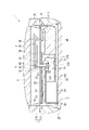
本実施形態の電子時計1は、図1に示すように、3つの小窓(サブダイヤル)770、780、790を備える多機能時計である。この電子時計1の構造について、図1~3を用いて説明する。
なお、以降の説明において、電子時計1を、文字板に垂直な方向であってカバーガラス側または裏蓋側から見ることを平面視という。
[Electronic clock]
The
In the following description, viewing the
本実施形態の電子時計1は、地球の上空を所定の軌道で周回している複数のGPS衛星や準天頂衛星などの位置情報衛星からの衛星信号を受信して衛星時刻情報を取得し、内部時刻情報を修正できるように構成されている。さらに、電子時計1は、衛星信号の受信処理として、ユーザーがボタンを操作することで受信を開始する手動受信に加えて、所定の条件に該当した際に自動的に受信を開始する自動受信を備えている。
The
電子時計1は、図1~3に示すように、文字板50、ムーブメント20、平面アンテナ40、二次電池24等を収容する外装ケース10を備える。また、電子時計1は、外部操作用のりゅうず6と、4つのボタン7A、7B、7C、7Dと、外装ケース10に接続されるバンドとを備える。バンドは、外装ケース10の12時側に接続される第1バンド15と、6時側に接続される第2バンド16と、図示略の中留とを備える。第1バンド15、第2バンド16は、外装ケース10に取り付けられるチタン等の金属製のエンドピースと、複数の駒とを備えるメタルバンドである。なお、バンドとしては、メタルバンドに限らず、レザーバンドや樹脂バンドなどでもよい。
As shown in FIGS. 1 to 3, the
文字板50は、ポリカーボネートなどの非導電性部材にて円板状に形成されている。文字板50の平面中心O(図3)には、文字板50を貫通して設けられる指針軸4(秒針軸4B、分針軸4C、時針軸4D)が配置され、この指針軸4には指針3(秒針3B、分針3C、時針3D)が取り付けられている。
文字板50は、3つの小窓(サブダイヤル)を有する。すなわち、図1に示すように、文字板50の指針軸4が設けられた平面中心Oに対して、3時方向に円形の第1小窓770と指針771が設けられ、9時方向に円形の第2小窓780と指針781が設けられ、6時方向に円形の第3小窓790と指針791、792が設けられている。
また、文字板50の平面中心Oに対して、4時と5時との間の方向(4.5時方向)に矩形の日窓51が設けられている。図2にも示すように、文字板50の裏面側には日車55が配置され、日車55は日窓51から視認可能となっている。さらに、文字板50には、指針軸4が挿通される貫通孔53と、指針771、781、791、792の指針軸5B、5C、5Dが挿通される貫通孔(図示略)も形成されている。
The
The
A
本実施形態では、第1小窓770の指針771は曜日を指示する曜日針であり、第2小窓780の指針781は各種情報を指示するモード針(機能針)である。第3小窓790の指針791、792は、ホームタイムやローカルタイムを指示する小時計用の時針および分針である。
これらの秒針3B、分針3C、時針3D、指針771、781、791、792および日車55は、後述するモーターおよび輪列を介して駆動される。
In this embodiment, the
These
モード針である指針781で指示される第2小窓780には、二次電池24の残量を示すパワーインジケーターと、夏時間の設定モードと、機内モードと、GPS衛星信号の受信モードとの各モードの設定を指示する目盛が表示されている。
パワーインジケーターは、第2小窓780の9時位置から7時位置に渡って帯状に表示され、9時位置がF(Full)、7時位置がE(Empty)を意味する。すなわち、二次電池24の電池電圧が第一閾値以上の場合に指針781がFを指示して充電量が十分であることを示し、電池電圧が第一閾値より低い第二閾値未満の場合に指針781がEを指示して充電量が不足していることを示す。電池電圧が第二閾値以上、第一閾値未満の所定値の場合、指針781がFとEの間(例えば8時位置)を指示して充電量が下がっていることを示す。そして、このFの位置(9時位置)が、後述するように指針781の基準位置とされている。
夏時間の設定モードを表示する記号として、6時位置に「A」、略5時位置に「S」、略4時位置に「D」が表示されている。
「A」は、夏時間を自動設定するAUTOモードを意味する。AUTOモードは、衛星信号から位置情報を取得した際に、電子時計1の記憶装置に記憶されたデータを用いて自動的に夏時間に変更するモードである。このため、電子時計1の記憶装置には、位置情報と、その位置情報に対応するタイムゾーンと、夏時間設定データとが対応付けられたデータベースが記憶されている。
「S」は、STDモード(スタンダードモード)を意味し、手動設定によって、常にスタンダードタイムを表示するモードを意味する。「D」は、DSTモードを意味し、手動設定によって、常にサマータイムを表示するモードを意味する。
機内モードを示す飛行機マークは、第2小窓780の10時位置に表示され、受信モードの測時モードを示す「1」は略11時位置に表示され、測位モードを示す「4+」は略12時位置に表示されている。うるう秒情報を取得する受信モードを示す「L」は略1時位置に表示されている。
A second
The power indicator is displayed in a belt shape from the 9 o'clock position to the 7 o'clock position in the second
As symbols indicating the daylight saving time setting mode, "A" is displayed at the 6 o'clock position, "S" is displayed at the approximately 5 o'clock position, and "D" is displayed at the approximately 4 o'clock position.
"A" means AUTO mode that automatically sets daylight saving time. The AUTO mode is a mode for automatically changing to daylight saving time using data stored in the storage device of the
"S" stands for STD mode (standard mode), which means a mode in which the standard time is always displayed by manual setting. "D" means DST mode, which means a mode that always displays daylight saving time by manual setting.
An airplane mark indicating the in-flight mode is displayed at the 10 o'clock position of the second
[電子時計の外装構造]
図1~図3に示すように、電子時計1は、後述するムーブメント20等を収容する外装ケース10を備える。なお、図2は、文字板50の7時位置、文字板50の平面中心O、12時位置を結ぶ図1のII-II線に沿った断面図である。図3は、ムーブメント20の要部を裏蓋側から見た平面図である。
外装ケース10は、図2に示すように、ケース本体11と、裏蓋12と、カバーガラス31を備える。ケース本体11は、円筒状の胴13と、胴13の表面側に設けられたベゼル14とを備える。
ケース本体11の裏面側には、ケース本体11の裏面側の開口を塞ぐ円板状の裏蓋12が設けられている。裏蓋12は、ケース本体11の胴13にねじ構造により接続される。なお、本実施形態では、胴13と裏蓋12とは、別体で構成されているが、これに限らず、胴13および裏蓋12が一体化されたワンピースケースでもよい。
胴13、ベゼル14、裏蓋12には、SUS(ステンレス鋼)、チタン合金、アルミ、BS(真鍮)などの金属材料が利用される。
[Exterior structure of electronic watch]
As shown in FIGS. 1 to 3, the
The
A disk-shaped
Metal materials such as SUS (stainless steel), titanium alloy, aluminum, and BS (brass) are used for the
[電子時計の内部構造]
次に、電子時計1の外装ケース10に内蔵される内部構造について説明する。
図2に示すように、外装ケース10内には、文字板50の他、ムーブメント20、平面アンテナ(パッチアンテナ)40、日車55、ダイヤルリング32等が収容される。
なお、以下のムーブメント20の説明において、地板21の裏蓋側を表側とし、地板21の文字板側を裏側として説明する。
[Internal structure of electronic clock]
Next, the internal structure incorporated in the
As shown in FIG. 2, the
In the following description of the
ムーブメント20は、地板21、輪列受け(図示略)、地板21および輪列受けに支持される駆動体22、回路基板23、二次電池24、太陽電池パネル25、光センサー用回路基板26を備える。
地板21は、プラスチック等の非導電性部材にて形成されている。地板21は、駆動体22を収容する駆動体収容部21Aと、日車55が配置される日車配置部21Bと、平面アンテナ40を収容するアンテナ収容部21Cとを備える。日車配置部21Bは、地板21の裏側に形成されたリング状の凹溝部で構成されている。
駆動体収容部21Aおよびアンテナ収容部21Cは、地板21の表側に設けられている。アンテナ収容部21Cは、平面位置が文字板50の12時位置であるため、図1、3に示すように、平面アンテナ40は12時位置に配置されている。具体的には、平面アンテナ40は、指針3の指針軸4とケース本体11との間であり、かつ、文字板50の略11時位置から略1時位置の範囲に配置されている。したがって、図3に示すように、文字板50の平面中心Oから12時方向に向かう12時仮想線L0を設定した場合、平面アンテナ40の少なくとも一部は12時仮想線L0に平面視で重なっている。具体的には、平面アンテナ40の平面中心が12時仮想線L0に平面視で重なっている。なお、図3の説明における平面視とは、ムーブメント20を表側(裏蓋12側)から見た状態を意味する。
なお、以下の説明では、平面視において、指針軸4(文字板50の平面中心O)と文字板50の12時位置とを結ぶ線を前述した12時仮想線L0とし、以下、指針軸4(平面中心O)と、1~11時位置とを結ぶ各線を1時仮想線L1、2時仮想線L2、3時仮想線L3、4時仮想線L4、5時仮想線L5、6時仮想線L6、7時仮想線L7、8時仮想線L8、9時仮想線L9、10時仮想線L10、11時仮想線L11とする。
The
The
In the following description, the line connecting the pointer shaft 4 (plane center O of the dial 50) and the 12 o'clock position of the
二次電池24は、文字板50と平面視で重なる領域を、3時仮想線L3および9時仮想線L9で2つの領域に区画した際に、文字板50の6時位置を含む領域に配置される。具体的には、二次電池24は、平面視において、6時仮想線L6および8時仮想線L8間の領域、すなわち7時仮想線L7に重なる位置に配置されている。
The
駆動体22は、地板21の駆動体収容部21Aに収容され、秒針3B、分針3C、時針3D、指針771、781、791、792および日車55を駆動する。
駆動体22は、図3に示すように、秒針3Bを駆動する第1モーター101および第1輪列110と、分針3Cを駆動する第2モーター102および第2輪列120と、時針3Dを駆動する第3モーター103および第3輪列130とを有する。
さらに、駆動体22は、指針791、792を駆動する第4モーター104および第4輪列140と、指針771を駆動する第5モーター105および第5輪列150と、指針781を駆動する第6モーター106および第6輪列160とを有する。したがって、第6モーター106および第6輪列160によって、機能針である指針781を駆動する駆動装置が構成される。
なお、日車55は、別途、専用のモーターを組み込んで駆動してもよいが、本実施形態では、指針781を駆動する第6モーター106および第6輪列160に加えて後述するゼネバ機構を有する日車輪列170を設けることで、指針781を所定周(例えば6周)回転すると日車55を1日分移動できるように構成している。さらに、指針781の針位置検出用として、第6輪列160に連動する針位置検出輪列180も設けられている。
各モーター101~106は、時計用のステップモーターであり、第4モーター104のみ2つのコイルを有する2コイルのステップモーターである。
The driving
As shown in FIG. 3, the driving
Further, the driving
Note that the
Each of the
回路基板23は、前記モーター101~106や制御装置60を構成するIC等が取り付けられ、地板21の裏蓋側に配置されて、地板21にネジなどで取り付けられている。
太陽電池パネル25は、文字板50の裏面に配置され、文字板50を通して入射した光を受光して発電する一般的なものである。なお、昇圧回路を設けずに発電電圧を確保するため、複数(例えば6~8個)のセルに分割し、各セルを直列に接続することが好ましい。この太陽電池パネル25で発電された電力は、回路基板23を介して二次電池24に充電される。
光センサー用回路基板26は、太陽電池パネル25と地板21との間に配置されている。光センサー用回路基板26は、後述する針位置検出装置210、220、230、240の発光素子211、221、231、241が取り付けられている。
The
The
The optical
[モーターの配置]
第1モーター101は、平面視において、4時仮想線L4に重なる位置に配置され、切換装置700の巻真701と、指針軸4(平面中心O)との間に配置されている。
第2モーター102は、平面視において、8時仮想線L8に重なる位置に配置され、二次電池24と、平面アンテナ40との間に配置されている。
第3モーター103は、平面視において、切換装置700の巻真701と平面アンテナ40との間、より具体的には2時仮想線L2と平面アンテナ40との間に配置されている。この第3モーター103は、平面視において、一部が1時仮想線L1に重なって配置されている。
第4モーター104は、平面視において、二次電池24および切換装置700の巻真701の間に配置され、5時仮想線L5および6時仮想線L6に重なる位置に配置されている。
第5モーター105は、平面視において、一部が2時仮想線L2に重なる位置に配置され、切換装置700の巻真701と、第3モーター103との間に配置されている。
第6モーター106は、平面視において、一部が10時仮想線L10に重なる位置に配置され、第6モーター106のローターやコイルは、9時仮想線L9および10時仮想線L10の間に配置されている。
[Motor placement]
The
The
The
The
The
The
このため、モーター101~106は、平面視において、平面アンテナ40、二次電池24、巻真701と重ならない位置に配置されている。
また、指針771が取り付けられる指針軸5Bと、指針781が取り付けられる指針軸5Cと、指針791、792が取り付けられる指針軸5Dとは、それぞれ日車55の内周側に配置されている。
Therefore, the
Further, the
第1輪列110は、第1モーター101のローターカナに噛み合う秒中間車111と、秒中間車111のカナに噛み合う秒車112と、秒中間車111のカナに噛み合う秒検出車113とを備えている。秒車112の秒針軸4Bには、秒針3Bが取り付けられている。
秒中間車111および秒検出車113には、後述する針位置検出装置210によって検出される針位置検出用の孔が形成されている。なお、第2輪列120、第3輪列130、針位置検出輪列180においても、位置検出用の孔を有する歯車が設けられ、その孔の位置に応じて針位置検出装置220、230、240が設けられている。
The
The intermediate
第2輪列120は、第2モーター102のローターカナに噛み合う五番車121と、五番車121のカナに噛み合う三番車122と、三番車122のカナに噛み合う二番車123とを備えている。二番車123は、秒車112と平面的に重なって配置されている。二番車123の分針軸4Cには、分針3Cが取り付けられている。
The
第3輪列130は、第3モーター103のローターカナに噛み合う時第1中間車131と、時第1中間車131に噛み合う時第2中間車132と、時第2中間車132に噛み合う時第3中間車133と、時第3中間車133のカナに噛み合う時第4中間車134と、時第4中間車134のカナに噛み合う時第5中間車135と、時第5中間車135のカナに噛み合う筒車136とを備えている。筒車136は、秒車112、二番車123と平面的に重なって配置されている。筒車136の時針軸4Dには、時針3Dが取り付けられている。
また、時第5中間車135のカナには、図4に示すように、地板21の裏側に配置された時検出車137が噛み合っている。
The
The pinion of the fifth
第4輪列140は、ホームタイム(HT)用の指針791、792を駆動する輪列であり、第4モーター104のローターカナに噛み合うHT中間車141と、HT中間車141のカナに噛み合うHT分車142と、HT日の裏車143と、図4に示すように、HT日の裏車143のカナ143Aに噛み合うHT筒車144とを備えている。HT筒車144は、平面視において、HT分車142と重なっており、地板21の裏側に配置されている。
HT分車142には、HT用の分針である指針791が取り付けられ、HT筒車144にはHT用の時針である指針792が取り付けられている。
すなわち、第4モーター104は、指針軸4(文字板50の平面中心O)に対して6時方向に設けられた指針軸5Dに取り付けられた指針791、792を駆動する。
The
The
That is, the
第5輪列150は、3時位置に設けられて曜日を指示する曜針である指針771を駆動する輪列であり、図3に示すように、第5モーター105のローターカナに噛み合う小曜第一中間車151と、小曜第一中間車151のカナに噛み合う小曜第二中間車152と、小曜第二中間車152のカナに噛み合う小曜車153とを備えている。小曜車153は、地板21の裏側に配置され、小曜車153の指針軸5Bには指針771が取り付けられている。
電子時計1では、小曜車153は、平面視において、3時仮想線L3に重なる位置に配置されている。具体的には、小曜車153の指針軸5Bの軸位置と指針軸4(平面中心O)とを結ぶ線と、3時仮想線L3との交差角度が約4~8度、例えば約6度となる位置に配置されている。
The
In the
第6輪列160は、9時位置に設けられてモード情報などを指示するモード針(機能針MI)である指針781を駆動する輪列であり、図6にも示すように、第6モーター106のローターカナ106Aに噛み合うMI第一中間車161と、MI第一中間車161に噛み合うMI第二中間車162と、MI第二中間車162のカナに噛み合うMI車163とを備えている。MI車163の指針軸5Cには、指針781が取り付けられている。
電子時計1では、MI第二中間車162およびMI車163は、平面視において、9時仮想線L9に重なる位置に配置されている。具体的には、MI車163の指針軸5Cの軸位置と指針軸4(平面中心O)とを結ぶ線と、9時仮想線L9との交差角度が約4~8度、例えば約6度となる位置に配置されている。
The
In the
[日車輪列]
次に、指針781に連動して、より具体的には指針781を駆動する第6輪列160に連動して日車55を駆動する日車輪列170について図3~図7を用いて説明する。図3は、前述の通りムーブメント20の要部を裏蓋側から見た平面図である。図4は、ムーブメント20を文字板側から見た平面図である。なお、図4は、後述する指針781が基準位置である「F」位置を指示している場合の状態を示している。図5は、ムーブメント20の要部を示す分解斜視図である。図6は、電子時計1の指針(モード針)781を駆動する第6輪列160および針位置検出輪列180を示す平面図である。図7は、電子時計1の日車輪列170および日ジャンパー57を示す平面図である。
日車輪列170は、図3~図7に示すように、日回し第一中間車171と、日回し第二中間車172と、日回し第三中間車173と、日回し車174とを備える。日回し第一中間車171は、MI車163にかみ合い、その回転軸は地板21を貫通して設けられている。日回し第一中間車171の回転軸に設けられたカナ171Aは、地板21の文字板側に露出している。
日回し第二中間車172および日回し第三中間車173は、地板21と文字板50間に配置されている。日回し第二中間車172は、日回し第一中間車171のカナ171Aに噛み合い、日回し第三中間車173は、日回し第二中間車172のカナに噛み合っている。
[Day wheel train]
Next, the
3 to 7, the
The second
日回し第三中間車173は、図7に示すように、回転軸173Dを挟んで一対の駆動歯173Aが形成されている。各駆動歯173Aの基端部分は、一対の溝部173Bが形成されている。日回し第三中間車173の外周面において、各溝部173B間は、円弧状の規制面173Cとされている。
日回し車174は、周方向に沿って均等間隔に複数本の歯174Aを備える。本実施形態の日回し車174は、7本の歯174Aを備える。歯174Aは、前記駆動歯173Aに噛み合う。また、歯174Aは、日車55の内歯車551に噛み合っている。したがって、日回し第三中間車173は、180°回転する毎に日回し車174を2歯分(360°×2/7)回転し、日車55を回転する。また、駆動歯173Aが日回し車174の歯174Aに噛み合っていない場合、日回し車174の2つの歯174Aが日回し第三中間車173の規制面173Cに当接し、日回し車174すなわち日車55の回転が規制される。したがって、日車輪列170において、日回し第三中間車173と日回し車174とで、いわゆるゼネバ機構が構成されている。
As shown in FIG. 7, the date driving third
The
[針位置検出輪列]
次に、第6輪列160に連動して回転する針位置検出輪列180について説明する。
針位置検出輪列180は、図3,5,6に示すように、MI第一中間車161に噛み合う第一検出車181と、第一検出車181のカナに噛み合う第二検出車182と、第二検出車182のカナに噛み合う第三検出車183との3つの歯車を備える。したがって、MI第一中間車161が第6モーター106で回転されると、第一検出車181、第二検出車182、第三検出車183は順次減速されて回転する。これらの各検出車181、182、183は、貫通孔181A、182A、183Aがそれぞれ形成され、第三検出車183が一回転する間の一箇所で各貫通孔181A、182A、183Aが平面視で重なるように配置されている。
[Needle position detection train wheel]
Next, the needle position
As shown in FIGS. 3, 5, and 6, the needle position
[日ジャンパー]
日車55は、日ジャンパー57で規制されている。日ジャンパー57は、図7に示すように、地板21に形成された軸201に回転自在に取り付けられたベース部571と、ベース部571から延出されたアーム部572と、アーム部572の先端に設けられて内歯車551に係合する係合部573と、ベース部571から日回し第三中間車173の外周にそって延長されたガイド部574とを備える。
アーム部572は、バネ性を有し、係合部573が内歯車551に係合することで撓み、その撓みに応じたバネ力で係合部573を内歯車551に押し付けることができるように構成されている。
ガイド部574は、日回し第三中間車173に対向する円弧面574Aを備える。この円弧面574Aは、図4に示すように、日回し第三中間車173の駆動歯173Aをガイド可能に構成されている。
[Sun Jumper]
The
The
The
ここで、指針781がモード表示を行う範囲(インジケーター表示範囲)では、日回し第三中間車173の駆動歯173Aは、円弧面574Aに当接し続ける範囲で移動する。このため、日ジャンパー57は、ガイド部574の位置が駆動歯173Aで規制されるため、係合部573が内歯車551に係合する状態に維持される。
一方、図7に示すように、駆動歯173Aが円弧面574Aに当接する範囲(日ジャンパー有効範囲)から外れている場合、ガイド部574と、日回し第三中間車173の規制面173Cとは離れている。このため、日ジャンパー57は、図7に一点鎖線で示すように、ガイド部574が規制面173Cに近づく方向に回転できる。このため、日ジャンパー57の係合部573は、内歯車551から外れる状態になる。したがって、日回し車174が日車55を回転する際には、日ジャンパー57による日車55の規制が外れ、日車55を回転するトルクを低減できる。
Here, in the range in which the
On the other hand, as shown in FIG. 7, when the driving
[針位置検出装置]
電子時計1には、前述したように、4つの針位置検出装置210、220、230、240が設けられている。図4および図5に示すように、針位置検出装置210は、光センサー用回路基板26に設けられた発光素子211と、回路基板23に設けられた受光素子212とを備える。針位置検出装置220は、光センサー用回路基板26に設けられた発光素子221と、回路基板23に設けられた受光素子222とを備える。針位置検出装置230は、光センサー用回路基板26に設けられた発光素子231と、回路基板23に設けられた受光素子232とを備える。針位置検出装置240は、光センサー用回路基板26に設けられた発光素子241と、回路基板23に設けられた受光素子242とを備える。
[Needle position detector]
The
[切換装置]
切換装置700は、りゅうず6の操作に連動して動作する装置であり、図3に示すように、りゅうず6が取り付けられる巻真701に加えて、おしどり、かんぬき、クリックバネ、スイッチレバー、おしどり押さえ、スイッチ接点ばね体、スイッチ接点ばね、スイッチ車等を備えた一般的な切換機構である。
巻真701は、図3、4に示すように、ムーブメント20において、平面視で文字板50の3時位置に設けられている。また、巻真701に加えておしどり等を含む切換装置700は、文字板50の外周に沿って、3時仮想線L3から4時仮想線L4に跨がって配置されている。
[Switching device]
The
As shown in FIGS. 3 and 4, the winding
地板21の表側には、図示を略すが、前述した構成に加えて、回路押さえ、耐磁板、アンテナ押さえ、輪列受け等が配置されている。
地板21の裏側には、図示を略すが、前述した構成に加えて、筒車押さえ、耐磁板、日車押さえなどが配置されている。これらの構成は、従来から用いられているため、説明を省略する。
Although not shown, on the front side of the
Although not shown, on the back side of the
[制御装置]
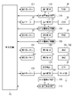
次に、電子時計1の制御装置60について説明する。図8は、電子時計の制御装置、モーター、輪列、針位置検出装置の組み合わせを示すブロック図である。
制御装置60は、回路基板23に取り付けられたIC等で構成され、電子時計1の各種制御を行う。制御装置60は、図8に示すように、第1モーター101から第6モーター106の駆動を制御する。また、制御装置60は、針位置検出装置210、220、230、240の駆動を制御して針位置検出処理を実行する。
[Control device]
Next, the
The
[機能針の針位置検出装置]
次に、モード針である指針781の針位置を検出する針位置検出装置240の詳細について図6、図7、図9を用いて説明する。図9は、モード針位置、モーターステップ数、インジケーター表示範囲、日ジャンパー有効範囲、日送り範囲の関係を示す図である。
針位置検出装置240は、図6に示すように、指針781を駆動する第6輪列160に連動して回転する針位置検出輪列180の貫通孔181A、182A、183Aを通して、光センサー用回路基板26に設けられた発光素子241からの光を、回路基板23に設けられた受光素子242で受光することで、針位置検出輪列180つまりは第6輪列160で駆動される指針781の位置を検出する。
本実施形態では、日回し第三中間車173が図7に示す位置、つまり、駆動歯173Aがガイド部574と日回し車174との間に配置された位置が針位置検出位置とされている。具体的には、後述するように、基準位置を0としたモーターステップ数で+120の位置に設定されている。
[Needle position detection device for functional needle]
Next, the details of the needle
As shown in FIG. 6, the needle
In this embodiment, the position where the date driving third
本実施形態では、第6モーター106および第6輪列160は、第6モーター106を1ステップ駆動すると、指針781が6°移動するように設定されている。このため、第6モーター106を60ステップ駆動すると、指針781は360°(1周)回転する。
また、針位置検出輪列180は、第6モーター106が360ステップ駆動すると、第三検出車183が一回転(360°移動)するように設定されている。したがって、各検出車181、182、183の各貫通孔181A、182A、183Aが重なるのは、第6モーター106を360ステップ駆動する間の1ステップである。なお、第6モーター106を360ステップ駆動すると、指針781は6回転する。
また、第6モーター106を360ステップ駆動すると、日回し第三中間車173は180°回転する。この際、日回し車174は、日回し第三中間車173の駆動歯173Aによって2歯分(360°×2/7)回転する。日車55の内歯車は、62個の歯を備えており、日回し車174が2歯分回転すると、日車55も2歯分つまり1日分移動する。
In this embodiment, the
Further, the needle position
Further, when the
本実施形態では、指針781の基準位置は、指針781がパワーインジケーターの「F」の位置を指示する位置、すなわち、図1に示すように、第2小窓780において9時方向を指示する位置に設定されている。
第6モーター106を正転方向に駆動した場合、指針781は逆転し、日車55は正転する。なお、指針781は、逆転する場合、パワーインジケーターの「F」から「E」、「A」、「S」、「D」の目盛の方向(反時計回り)に移動する。日車55は、正転する場合、日が進む方向(時計回り)に移動する。
第6モーター106を逆転方向に駆動した場合、指針781は正転し、日車55は逆転する。この場合、指針781は、パワーインジケーターの「F」から「飛行機マーク」、「1」、「4+」、「L」の目盛の方向(時計回り)に移動する。日車55は、逆転する場合、日が戻る方向(反時計回り)に移動する。
In this embodiment, the reference position of the
When the
When the
本実施形態では、図9に示すように、指針781が各モードの情報を表示するインジケーター表示範囲は、基準位置を0としてモーターステップ数で表すと、ほぼ-30~+30の範囲、つまり指針781が-180°~+180°の約1周(360°)回転する範囲である。この際、日回し第三中間車173が回転する角度は約30°であり、図4に示すように、駆動歯173Aは円弧面574Aに当接してガイドされる範囲で移動する。このため、日ジャンパー57は、ガイド部574が駆動歯173Aに当接することによって、図7の実線位置に維持され、係合部573が内歯車551に係合して日ジャンパー57が有効となっている。
日ジャンパー57が有効に機能する範囲(日ジャンパー有効範囲)は、モーターステップ数で表すと、約-60~+60の範囲であり、日回し第三中間車173が回転する角度は約60°である。すなわち、日回し第三中間車173が約60°回転する範囲で駆動歯173Aが円弧面574Aに当接するように設定されている。
さらに、駆動歯173Aが日回し車174を回転して日車55を送る日送り範囲は、モーターステップ数で表すと、約+150~+240の範囲である。なお、指針781や輪列の状態では、+180と-180は同じであるため、+180から-180に連続させた範囲で示せば、+180~-120の範囲である。
針位置検出位置は、日ジャンパー57の有効範囲外であり、かつ、日送り範囲外となる位置に設定され、本実施形態では、モーターステップ数が+120の位置に設定されている。
なお、図9に示す具体例は一例であり、設計によって適宜変更できる。
In this embodiment, as shown in FIG. 9, the indicator display range in which the
The range in which the
Furthermore, the range in which the
The hand position detection position is set outside the effective range of the
It should be noted that the specific example shown in FIG. 9 is an example, and can be changed as appropriate depending on the design.
[指針(機能針)の針位置検出処理]
次に、図10を用いて、定期的な針位置検出処理、具体的には、日送り時(日替わり時)での針位置検出処理を説明する。
制御装置60は、日付が変更される日送り時には、まず、日送り開始前準備として、現在の指針781の指示位置(開始位置)を確認し、基準位置(Fの位置)に対する開始位置を確認する(S1)。
制御装置60は、開始位置が基準位置に対して第6モーター106の正転側にあるか否かを判断する(S2)。ここで、指針781が、パワーインジケーターの範囲を指示している場合と、夏時間の「A,S,D」を指示している場合、制御装置60は、開始位置が基準位置に対して第6モーター106の正転側であると判定する。また、指針781が、機内モード、測時モード、測位モード、うるう秒受信モードを指示している場合、制御装置60は、開始位置が基準位置に対して第6モーター106の逆転側であると判定する。
[Needle position detection processing of needle (function needle)]
Next, with reference to FIG. 10, periodic hand position detection processing, specifically, hand position detection processing at the time of changing the date (when the day changes) will be described.
When the date is to be changed, the
The
制御装置60は、S2でYESと判定した場合、指針781を基準位置に移動するために必要なステップ数である指定発数mを、開始位置に応じたステップ数Xに設定する(S3)。なお、開始位置が正転側である場合、基準位置に戻すには、第6モーター106のローターを逆転する必要があり、逆転方向へのステップ数はマイナス値で表す。例えば、指針781がパワーインジケーターのミドルの位置(8時位置)を指示しており、基準位置(9時位置)に戻すためのステップ数が「5」の場合、S3では、「m=-5」を設定する。
一方、S2でNOと判定した場合も、指針781を基準位置に移動するためのステップ数mを開始位置に応じたステップ数Xとして設定する(S4)。開始位置が逆転側である場合、ローターを正転させることになる。例えば、指針781が機内モードの位置(10時位置)を指示しており、基準位置(9時位置)に戻すためのステップ数が「5」の場合、S4では、「m=5」を設定する。
なお、開始位置が基準位置である場合は、正転側と逆転側のいずれかに判定するように設定すればよく、S3またはS4では「m=0」が設定される。
If the determination in S2 is YES, the
On the other hand, even if the determination in S2 is NO, the number of steps m for moving the
If the start position is the reference position, it may be set to determine either the forward rotation side or the reverse rotation side, and "m=0" is set in S3 or S4.
次に、制御装置60は、第6モーター106の駆動を制御し、指針781を針位置検出位置に移動する(S5)。すなわち、基準位置から針位置検出位置まで移動するために必要な移動制御量であるステップ数Iは、予め設定される。本実施形態では、針位置検出位置は基準位置の正転側に設けられており、具体的には+120ステップとされている。なお、本実施形態の制御装置60は、前記移動制御量を、針位置検出位置から基準位置まで移動するために必要なステップ数(-120ステップ)として記憶している。このため、基準位置から針位置検出位置までの移動制御量は、記憶したステップ数の符号(+または-)を切り替えて用いればよい。
そして、開始位置から基準位置まで移動するために必要なステップ数は前記mであるため、開始位置から針位置検出位置まで移動するためのステップ数Aは、I+mである。例えば、開始位置が基準位置の正転側にあり、m=-5の場合、ステップ数A=+120+(-5)=+115である。一方、開始位置が基準位置の逆転側にあり、m=5の場合、ステップ数A=+120+(5)=+125である。図9に示すように、開始位置が逆転側のほうが、正転側よりも針位置検出位置に移動するために必要なステップ数は多くなる。
また、制御装置60は、針位置検出時の検出回数を示す変数nを初期値0に設定する(S6)。
Next, the
Since the number of steps required to move from the start position to the reference position is m, the number of steps A to move from the start position to the needle position detection position is I+m. For example, if the start position is on the forward rotation side of the reference position and m=-5, the number of steps A=+120+(-5)=+115. On the other hand, when the starting position is on the reverse side of the reference position and m=5, the number of steps A=+120+(5)=+125. As shown in FIG. 9, the number of steps required to move to the needle position detection position is greater when the start position is on the reverse rotation side than on the forward rotation side.
In addition, the
次に、制御装置60は、針位置検出装置240を制御して、針位置検出を実行する(S7)。具体的には、制御装置60は、発光素子241を発光させ、受光素子242で受光できたか否かを確認して針位置検出処理を実行する。この結果により、制御装置60は、モード針の位置検出に成功したか否かを判定する(S8)。
Next, the
制御装置60は、S8でYESと判定した場合は、後述するように、S13以降の処理を行う。なお、指針781の位置ずれが生じていない場合は、S5で、指針781が針位置検出位置に移動する。このため、針位置検出輪列180の各検出車181~183の貫通孔181A~183Aが、発光素子241および受光素子242間に重なって位置し、1回目の針位置検出で成功することになる。
一方、S8でNOと判定した場合は、制御装置60は、nが180であるかを判定する(S9)。検出回数nが180ではない場合(S9でNO)、制御装置60は、nに1を加算し、第6モーター106を正転方向に1ステップ駆動する信号を出力する(S10)。このため、指針781は、逆転方向に1ステップ分移動する。
そして、S7に戻り、制御装置60は、針位置検出処理(S7)、成功判定処理(S8)を順次実行する。
If the determination in S8 is YES, the
On the other hand, if the determination in S8 is NO, the
Then, returning to S7, the
制御装置60は、S8でNOと判定し続けて、検出回数nが180となった場合は(S9でYES)、S9でYESと判定された回数が1回目であるかを判定する(S11)。S11で1回目と判定した場合、制御装置60は、n=0に初期化し、-360ステップを出力する(S12)。これにより、第6モーター106は、逆転方向に360ステップ分駆動され、指針781は時計回りに6周回転する。この逆転方向の駆動中は針位置検出を行わないため、制御装置60は、第6モーター106を逆転方向に早送りで駆動する。
その後、S7に戻り、制御装置60は、針位置検出処理(S7)、成功判定処理(S8)を順次実行する。
例えば、図9において、外乱によって指針781の位置がずれ、実際の針位置検出位置がモーターステップ数+118の位置であったとする。この場合、モーターステップ数が+120の位置から+300の位置まで、180回実行しても針位置検出に成功しない。この場合、制御装置60は、+300から-60の位置まで、逆転方向に早送りで360ステップ駆動する。その後、-60から+120の位置まで、1ステップずつ駆動しながら針位置検出処理を実行する。そして、モーターステップ数が+118の位置で針位置検出に成功した場合は、その位置が正しくはモーターステップ数+120の位置であり、その位置から-120ステップ移動した位置が基準位置となることを検出できる。
なお、第6モーター106を-360ステップ駆動してから、正転方向に1ステップずつ動かして針位置検出処理を実行するのは、第6輪列160や針位置検出輪列180の各歯車のバックラッシュの影響を排除するためである。すなわち、第6モーター106を逆転した場合、各歯車のバックラッシュにより、貫通孔181A、182A、183Aの重なりがずれてしまう可能性がある。そこで、常に、第6モーター106を正転方向に駆動しながら、発光素子241、受光素子242で針位置検出処理を行うため、-360ステップ駆動した後、+1ステップずつ、針位置検出処理を実行している。
If the
After that, returning to S7, the
For example, in FIG. 9, it is assumed that the
The reason why the
制御装置60は、n=180となるまで、S7およびS8の処理を繰り返し、第6モーター106の正転方向に180ステップ移動するまで針位置検出処理を行う。そして、針位置検出に成功すると(S8でYES)、制御装置60は、針位置検出処理を終了する(S13)。
The
次に、制御装置60は、日送りを実施して指針781を開始位置に復帰させる(S14)。針位置検出に成功した時点では、基準位置から+120ステップの針位置検出位置に位置するため、第6モーター106を正転方向に120ステップ移動して+240ステップの位置(図9の-120ステップの位置と同じ)まで移動すれば日送りを行うことができる。さらに、開始位置に戻すために第6モーター106を正転方向に必要なステップ分移動すればよい。
例えば、開始位置が基準位置であった場合は、針位置検出位置(+120ステップ位置)から1日分の日送りを行って基準位置に戻すには、第6モーター106を正転方向に+240ステップ移動すればよい。
また、開始位置が基準位置と異なる位置であり、mステップ移動させることで基準位置に移動する位置である場合、基準位置から-mステップ移動すれば開始位置に戻すことができる。このため、針位置検出位置から1日分の日送りを行って開始位置に戻すには、第6モーター106を正転方向に(+240-m)ステップ移動すればよい。例えば、開始位置が基準位置に対して第6モーター106の逆転側に位置し、m=5であった場合、制御装置60は、S14で第6モーター106を+240-5=+235ステップ分移動する。一方、開始位置が基準位置に対して第6モーター106の正転側に位置し、m=-5であった場合、制御装置60は、S14で第6モーター106を+240-(-5)=+245ステップ分移動する。
なお、小の月から翌月1日に日送りする場合のように、2日分以上の日送りを行う場合は、さらに1日あたり、+360ステップ分、第6モーター106を駆動すればよい。
以上により、日替わり時におけるモード針位置検出と日送り処理が終了する。
Next, the
For example, if the starting position is the reference position, the
Also, if the start position is different from the reference position and is a position that can be moved to the reference position by moving by m steps, it can be returned to the start position by moving from the reference position by -m steps. Therefore, in order to return to the start position after advancing one day from the hand position detection position, the
When the date is advanced for two days or more, such as when the date is advanced from the first month to the first day of the following month, the
Thus, the mode hand position detection and date advance processing at the time of the day change are completed.
また、制御装置60がS11でNOと判定した場合、つまりS9でYESと判断したのが2回目の場合、針位置検出輪列180を一周期分動かして針位置検出を行っているため、例えば、針位置検出装置240の故障や他の理由から針位置検出に成功しないと推測される。このため、制御装置60は、S11でNOと判定した場合は、針位置検出に失敗したと判定する。ただし、針位置検出に失敗した場合でも、S11でNOと判定した時点の位置は、S5で移動した位置から、+180ステップ、-360ステップ、+180ステップ移動した時点であり、元の位置(S5で移動した位置、つまり針位置検出位置と推定した位置)である。このため、開始位置との相対的な関係は、針位置検出に成功した場合と同じであるため、(+240-m)ステップ分、第6モーター106を駆動することで、1日分の日送り処理と開始位置への復帰とを行うことができる。
ただし、S14の処理を行うと、ユーザーが針位置検出に失敗していることを確認できず、その後、指針781が指示する情報が正しいと誤解する可能性があるため、S11でNOと判定された場合に、指針781を針位置検出に失敗したことを指示する位置、例えば、パワーインジケーターの「E」と、サマータイムの「A」との間を指示するように制御してもよい。
以上により、日送り処理とモード針位置検出の処理が終了する。
If the
However, if the process of S14 is performed, the user cannot confirm that the needle position detection has failed, and there is a possibility that the user may misunderstand that the information indicated by the
Thus, the date advance process and the mode hand position detection process are completed.
[秒針、分針、時針の定時の針位置検出]
秒針3B、分針3C、時針3Dの定時の針位置検出処理は、各指針が針位置検出位置である12時位置に移動する0時0分0秒または12時0分0秒のタイミングに行う。なお、秒針3B、分針3C、時針3Dの定時の針位置検出処理は、1日に2回行うものに限定されず、1日に1回(0時0分0秒または12時0分0秒のいずれか)に行うものでもよい。
秒針3B、分針3C、時針3Dの針位置検出処理は、従来と同様に行えばよい。例えば、制御装置60は、最初に針位置検出装置210を制御して秒針3Bの針位置検出を行い、次に、針位置検出装置220を制御して分針3Cの針位置検出を行い、最後に、針位置検出装置230を制御して時針3Dの針位置検出を行う。
また、制御装置60は、秒針3B、分針3C、時針3Dに加えてモード針である指針781の針位置検出を行う場合は、秒針3B、分針3C、時針3Dの針位置検出を行った後に、針位置検出装置240を制御して前述した指針781の針位置検出を行えばよい。このように、各針位置検出を順次行うことで、消費電流の一時的な増加を抑制できる。
[Second hand, minute hand, and hour hand position detection at fixed time]
The regular hand position detection processing for the
Hand position detection processing for the
Further, when the
[システムリセット時の針位置検出]
システムリセット時には、各指針の位置を記憶する針位置カウンターの値もリセットされ、制御装置60が現在の指針の位置を把握できないため、秒針3B、分針3C、時針3D、指針781の各針位置検出処理を順次実行する。
秒針3B、分針3C、時針3Dの針位置検出処理は、従来から行われているように、各指針を駆動するモーター101~103を1ステップずつ動かし、針位置検出装置210~230を制御して行えばよい。
[Needle position detection at system reset]
When the system is reset, the value of the hand position counter that stores the position of each hand is also reset, and the
Hand position detection processing for the
指針781の針位置検出処理は、現在の指針781の開始位置が不明であり、針位置検出位置に移動してから針位置検出処理を開始できないため、現在位置から針位置検出処理を開始する。
このため、制御装置60は、図11のフローチャートに示す処理を実行する。なお、図11のフローチャートにおいて、S21~S28は、図10のフローチャートのS6~S13と同じであるため、簡略して説明する。
制御装置60は、図11の処理を開始すると、検出回数の変数nを0に初期化し(S21)、針位置検出装置240を制御して針位置検出処理を実行し(S22)、モード針位置検出に成功したか否かを判定する(S23)。制御装置60は、S23でNOの場合、n=180かを判定し(S24)、S24でNOと判定した場合は、nに1を加算し、第6モーター106を1ステップ分駆動し(S25)、S22に戻って針位置検出を実行する。
以下、S22からS25の処理を繰り返し、S23でNOのまま、n=180となり、S24でYESと判定した場合は、1回目であるかを判定し(S26)、1回目であれば(S26でYES)、n=0とし、第6モーター106を-360ステップ分、逆転駆動し(S27)、S22からS25を再度繰り返す。
Since the current starting position of the
Therefore, the
11, the
After that, the processing from S22 to S25 is repeated, and n=180 remains as NO in S23. YES), n=0, the
制御装置60は、S23でYESと判定した場合、針位置検出を終了し(S28)、この針位置から-120ステップの位置を基準位置に設定する(S29)。
制御装置60は、S29で設定した基準位置に対し、指定されたモードに応じて指針781を移動する(S30)。システムリセット直後は、指針781は標準の表示モードであるパワーインジケーターを指示する。このため、制御装置60は、二次電池24の電圧を測定し、その測定値に応じた位置に指針781を移動する。また、他のモードの設定、選択操作が行われた場合など、パワーインジケーター以外の情報を表示する場合には、対応する目盛位置に指針781を移動する。以上により、システムリセット時のモード針位置検出処理が終了する。
また、制御装置60はS26でNOの場合、指針781を現在位置に停止させ、処理を終了する。
If the determination in S23 is YES, the
The
If S26 is NO, the
[基準位置合わせ時の針位置検出]
電子時計1は、ユーザーが指針781の指示位置のずれを確認した場合に、りゅうずやボタン7Aを操作することで、指針781の基準位置合わせを指示する入力があった場合に、針位置検出処理を実行する機能も備えている。この際の、針位置検出処理は、図11に示すシステムリセット時と同じ処理であるため、説明を省略する。
[Needle position detection when adjusting the reference position]
The
[実施形態の効果]
電子時計1は、第6モーター106によって、モード針である指針781と、日車55とを駆動できるため、省スペース化が図られ、小型の多機能時計を実現できる。
また、外乱の影響により指針781の位置がずれた場合でも、針位置検出装置240によって指針781の針位置を検出できる。したがって、検出した針位置を基準にして、指針781を基準位置に戻すこともでき、指針781によって正しい情報を指示することができる。また、制御装置60は、指針781と日車55の位置関係を正しく把握できるので、日車55の移動も正しく行うことができる。
[Effects of Embodiment]
Since the
Further, even if the position of the
指針781の針位置検出を、同じ第6モーター106によって駆動される日車55を移動する日送り時に行うようにしているので、ユーザーの利便性低下を防止でき、1日あたりの消費電力も低減できる。すなわち、指針781の針位置検出時に、指針781は最大で6周回転し、ユーザーが電子時計1を利用している可能性が高い日中に動作すると、ユーザーは指針781による情報を把握できず利便性が低下する。これに対し、日送り時であれば、ユーザーは電子時計1を利用していない可能性が高いので、利便性低下を防止できる。
さらに、日送り時にも指針781を6周回転するため、日送り時に針位置検出も行えば、指針781を6周回転する動作を1日に1回に制限でき、1日あたりの消費電力を低減できる。
また、制御装置60は、定期的に針位置検出処理を行うため、指針781の針位置を自動的に修正できる。このため、指針781の位置がずれていることをユーザーが気がつかない場合でも、指針781を常に正常な位置に移動でき、日車55との関係も正常に保たれる。したがって、指針781は、常に正しい情報を指示できる。
Since the pointer position of the
Furthermore, since the
Further, since the
制御装置60は、日送り時の針位置検出処理では、S5によって、針位置検出位置に移動してから、S7の針位置検出を実行するため、指針781の位置ずれが発生していない場合には、検出回数n=0つまり1回目で針位置を検出できる。したがって、定期的に行う針位置検出処理を短時間で終了できる確率を向上でき、針位置検出処理での消費電力も低減できる。
In the hand position detection process when feeding the date, the
指針781の基準位置をモーターステップ数で0とした場合、針位置検出位置を+120と異なる位置に設定し、制御装置60は針位置検出位置から基準位置への移動制御量(-120)を記憶している。
したがって、移動制御量の設定値を変更するだけで、針位置検出位置に対する基準位置を自由に設定できる。このため、第2小窓780の目盛位置が変更となり、基準位置を12時方向に設定する場合でも、前記移動制御量を変更すればよく、簡単に設定できる。このため、時計デザインや、表示する情報に応じて、指針781の基準位置を設定でき、利便性の高い電子時計1を提供できる。
さらに、針位置検出位置を基準位置と関係無く、自由に設定できるため、針位置検出装置240を配置しやすい位置や、日回し第三中間車173を組み込みやすい位置などに自由に設定できる。図7に示すように、針位置検出位置を日ジャンパー57の有効範囲外であり、日送り範囲外に設定すれば、日回し第三中間車173を組み込む際に、駆動歯173Aが日ジャンパー57や日回し車174と干渉しない位置に配置できるため、日回し第三中間車173を容易に組み込むことができる。さらに、日回し第三中間車173を組み込んだ直後に針位置検出を行うことができるので、第6輪列160、日車輪列170、針位置検出輪列180が針位置検出位置に位置することを、組み込み直後に容易に確認できる。したがって、第6輪列160が針位置検出位置に位置することを確認してから、指針軸5Cに指針781を取り付けるまでの時間を短縮でき、組立作業も効率化できる。
If the reference position of the
Therefore, the reference position relative to the needle position detection position can be freely set simply by changing the set value of the movement control amount. Therefore, even when the position of the scale of the second
Furthermore, since the needle position detection position can be freely set regardless of the reference position, it is possible to freely set a position where the needle
針位置検出装置240で針位置を検出するために、第6輪列160に連動する専用の針位置検出輪列180を設けたので、針位置検出装置240の配置位置の自由度を向上でき、ムーブメント20における各部品のレイアウトの自由度も向上できる。また、針位置検出輪列180の検出車181~183の枚数や減速比なども自由に設定できる。このため、針位置検出を行う場合の指針781の最大の回転数を、前記実施形態の6周ではなく、5周以下や7周以上に設定することも、針位置検出輪列180の構成を変更することで容易に対応できる。
Since the dedicated needle position
指針781がインジケーター表示範囲に位置する場合、駆動歯173Aが円弧面574Aに当接するため、日ジャンパー57の係合部573が内歯車551に係合する状態を維持できる。また、日送り時には、駆動歯173Aが円弧面574Aに当接する範囲から外れるため、日ジャンパー57による日車55の回転規制を解除でき、日車55を回転するためのトルクを低減できる。したがって、日回し第三中間車173を、日ジャンパー57の有効、解除の切替にも利用できる。
When the
制御装置60は、電子時計1のシステムリセット直後に、秒針3B、分針3C、時針3D、指針781の各針位置検出処理を自動的に実行するため、各指針を正常な位置に移動でき、指針781に連動して駆動する日車55の関係も正常に保たれる。
さらに、制御装置60は、ユーザーが、ボタン7A~7D等を用いて基準位置合わせを指示する操作を行った場合に、システムリセット時と同様の針位置検出処理を行うため、ユーザーは、指針781の位置ずれに気がついたときに、針位置検出処理を実行できる。このため、指針781を正常な位置に移動でき、日車55との関係も正常に保たれる。
Immediately after the system reset of the
Furthermore, when the user operates the
[他の実施形態]
なお、本発明は前述の実施形態に限定されるものではなく、本発明の目的を達成できる範囲での変形、改良等は本発明に含まれるものである。
例えば、前記実施形態では、基準位置と針位置検出位置とを異なる位置に設定していたが、同じ位置に設定してもよい。例えば、前記実施形態の基準位置を針位置検出位置としてもよく、針位置検出位置をインジケーター表示範囲内に設定してもよい。この場合は、針位置検出処理を行う場合に、インジケーター表示を行っている指針781を針位置検出位置に移動するステップ数が少なく、指針781は1周未満で針位置検出位置に移動できるので、外乱等による位置ずれ量が小さい場合に針位置検出処理を短時間で行うことができる。
[Other embodiments]
It should be noted that the present invention is not limited to the above-described embodiments, and includes modifications, improvements, etc. within the scope of achieving the object of the present invention.
For example, in the above embodiment, the reference position and the needle position detection position are set at different positions, but they may be set at the same position. For example, the reference position in the above embodiment may be the needle position detection position, or the needle position detection position may be set within the indicator display range. In this case, when performing the needle position detection process, the number of steps for moving the
前記実施形態では、指針781の定期的な針位置検出処理を、日送り時に実行していたが、例えば、午前7時や午前12時等、日送り時以外のタイミングで実行してもよい。
また、ユーザーがボタン7A~7Dやりゅうず6を操作して日送りを手動で行った場合や、時刻情報の受信によって日車55を修正する際に、指針781の針位置検出処理を実行してもよい。この際、バックラッシュの影響を考慮し、日車55が逆転される場合は針位置検出処理を行わず、日車55が正転される場合のみ針位置検出処理を行ってもよい。
In the above-described embodiment, the periodical needle position detection processing of the
Further, when the user manually advances the date by operating the
前記実施形態では、図10,11に示すように、針位置検出を行う際に、+180ステップ駆動して検出できなかった場合、-360ステップ早送りで逆転してから、再度+180ステップ駆動していたが、0ステップから+360ステップまで正転方向のみに駆動して針位置検出を行ってもよい。この場合、日送り時には、1日分の日送りも同時に行うことができる。
さらに、前記実施形態では、S5で針位置検出位置に移動してから、S7の針位置検出を実行していたが、S5で基準位置に移動し、この基準位置から1ステップずつ第6モーター106を駆動して針位置検出を実行してもよい。この場合、実際の針位置検出位置が図9のモーターステップ数の+0~+119の範囲にある場合に、前記実施形態よりも少ない回数で針位置検出に成功できる。
In the above-described embodiment, as shown in FIGS. 10 and 11, when detecting the needle position, if the needle position cannot be detected by +180 step driving, it is reversed by -360 step fast forward, and then +180 step driving is performed again. However, the needle position may be detected by driving only in the normal direction from 0 step to +360 steps. In this case, when the date is advanced, it is also possible to advance the date for one day at the same time.
Furthermore, in the above-described embodiment, the needle position is detected in S7 after moving to the needle position detection position in S5. may be driven to perform needle position detection. In this case, when the actual needle position detection position is in the range of +0 to +119 of the number of motor steps in FIG. 9, the needle position can be successfully detected with a smaller number of times than in the above embodiment.
指針781と同じ第6モーター106で駆動される表示部材として日車55を例に挙げて説明したが、表示部材は、時刻に基づく表示を行うものであれば、他のものであってもよい。例えば、ホームタイム(ローカルタイム)を表示する小時計、24時間で表示領域を1周する24時針、または日車以外のカレンダー車等が例示できる。
日車以外のカレンダー車としては、曜日を表示する曜車や、月を表示する月車、月齢を表示する月齢車でもよい。すなわち、表示部材としては、時刻に基づく表示を行うものであればよく、通常は、定期的に駆動されるものである。
Although the
The calendar wheel other than the date wheel may be a day wheel that displays the day of the week, a month wheel that displays the month, or a month wheel that displays the age of the moon. That is, any display member may be used as long as it performs display based on the time, and is normally driven periodically.
1…電子時計、3…指針、3B…秒針、3C…分針、3D…時針、10…外装ケース、20…ムーブメント、23…回路基板、26…光センサー用回路基板、50…文字板、51…日窓、55…日車、57…日ジャンパー、60…制御装置、101…第1モーター、102…第2モーター、103…第3モーター、104…第4モーター、105…第5モーター、106…第6モーター、106A…ローターカナ、110…第1輪列、120…第2輪列、130…第3輪列、140…第4輪列、150…第5輪列、160…第6輪列、161…MI第一中間車、162…MI第二中間車、163…MI車、170…日車輪列、171…第一中間車、171A…カナ、172…第二中間車、173…第三中間車、173A…駆動歯、173B…溝部、173C…規制面、173D…回転軸、174…日回し車、174A…歯、180…針位置検出輪列、181…第一検出車、181A…貫通孔、182…第二検出車、182A…貫通孔、183…第三検出車、183A…貫通孔、210…針位置検出装置、211…発光素子、212…受光素子、220…針位置検出装置、221…発光素子、222…受光素子、230…針位置検出装置、231…発光素子、232…受光素子、240…針位置検出装置、241…発光素子、242…受光素子、571…ベース部、572…アーム部、573…係合部、574…ガイド部、574A…円弧面、770…第1小窓、771…指針、780…第2小窓、781…指針、790…第3小窓、791…指針、792…指針。
DESCRIPTION OF
Claims (7)
前記機能針を駆動する駆動装置と、
前記機能針に連動して駆動され、前記時刻に基づく表示を行う表示部材と、
前記機能針が針位置検出位置にあることを検出する針位置検出装置と、
前記駆動装置および前記針位置検出装置を制御して前記機能針の針位置検出処理を行う制御装置と、を備え、
前記機能針の基準位置と、前記針位置検出位置とは異なる位置に設定され、
前記制御装置は、前記機能針を前記針位置検出位置から前記基準位置に移動させる移動制御量を記憶している
ことを特徴とする電子時計。 a function hand that indicates information other than the time;
a driving device for driving the function needle;
a display member that is driven in conjunction with the function hand and performs display based on the time;
a needle position detection device for detecting that the functional needle is at the needle position detection position;
a control device that controls the drive device and the needle position detection device to perform needle position detection processing of the functional needle ;
The reference position of the functional needle is set to a position different from the needle position detection position,
The control device stores a movement control amount for moving the functional needle from the needle position detection position to the reference position.
An electronic clock characterized by :
前記制御装置は、システムリセット直後に前記針位置検出処理を行う
ことを特徴とする電子時計。 The electronic timepiece according to claim 1,
The electronic timepiece, wherein the control device performs the hand position detection processing immediately after a system reset.
ボタンまたはりゅうずを有する操作部材を備え、
前記制御装置は、前記操作部材の操作に基づく基準位置合わせを指示する入力があった場合に、前記針位置検出処理を行う
ことを特徴とする電子時計。 In the electronic timepiece according to claim 1 or claim 2,
An operating member having a button or crown,
The electronic timepiece according to claim 1, wherein the control device performs the hand position detection processing when there is an input instructing reference position alignment based on the operation of the operation member.
前記制御装置は、定期的に前記針位置検出処理を行う
ことを特徴とする電子時計。 In the electronic timepiece according to any one of claims 1 to 3,
The electronic timepiece, wherein the control device periodically performs the hand position detection process.
前記表示部材はカレンダー車であって、
前記制御装置は、前記カレンダー車を駆動させる制御を行う場合に、前記針位置検出処理を実行する
ことを特徴とする電子時計。 The electronic timepiece according to any one of claims 1 to 4,
The display member is a calendar wheel,
The electronic timepiece according to claim 1, wherein the control device executes the hand position detection process when performing control to drive the calendar wheel.
前記カレンダー車は日車であって、
前記制御装置は、1日に1回、日付が変更される場合に、前記針位置検出処理を実行する
ことを特徴とする電子時計。 The electronic timepiece according to claim 5,
the calendar wheel is a date wheel,
The electronic timepiece, wherein the control device executes the hand position detection process once a day when the date is changed.
時刻情報を受信する受信部を備え、
前記制御装置は、前記受信部による受信の結果、前記カレンダー車が修正される場合に、前記針位置検出処理を実行する
ことを特徴とする電子時計。 In the electronic timepiece according to claim 5 or claim 6,
A receiving unit for receiving time information,
The electronic timepiece, wherein the control device executes the hand position detection process when the calendar wheel is corrected as a result of the reception by the reception unit.
Priority Applications (3)
| Application Number | Priority Date | Filing Date | Title |
|---|---|---|---|
| JP2018082327A JP7205073B2 (en) | 2018-04-23 | 2018-04-23 | electronic clock |
| CN201910313408.7A CN110389523B (en) | 2018-04-23 | 2019-04-18 | Electronic clock |
| US16/390,059 US20190324406A1 (en) | 2018-04-23 | 2019-04-22 | Electronic timepiece |
Applications Claiming Priority (1)
| Application Number | Priority Date | Filing Date | Title |
|---|---|---|---|
| JP2018082327A JP7205073B2 (en) | 2018-04-23 | 2018-04-23 | electronic clock |
Publications (3)
| Publication Number | Publication Date |
|---|---|
| JP2019190938A JP2019190938A (en) | 2019-10-31 |
| JP2019190938A5 JP2019190938A5 (en) | 2021-04-30 |
| JP7205073B2 true JP7205073B2 (en) | 2023-01-17 |
Family
ID=68236345
Family Applications (1)
| Application Number | Title | Priority Date | Filing Date |
|---|---|---|---|
| JP2018082327A Active JP7205073B2 (en) | 2018-04-23 | 2018-04-23 | electronic clock |
Country Status (3)
| Country | Link |
|---|---|
| US (1) | US20190324406A1 (en) |
| JP (1) | JP7205073B2 (en) |
| CN (1) | CN110389523B (en) |
Families Citing this family (3)
| Publication number | Priority date | Publication date | Assignee | Title |
|---|---|---|---|---|
| JP7102778B2 (en) * | 2018-02-27 | 2022-07-20 | セイコーエプソン株式会社 | Watch movements and watches |
| JP2021113782A (en) * | 2020-01-21 | 2021-08-05 | セイコーエプソン株式会社 | Electronic timepiece and method for controlling electronic timepiece |
| JP7127658B2 (en) * | 2020-02-04 | 2022-08-30 | カシオ計算機株式会社 | Electronic clock, pointer display control method and program |
Citations (3)
| Publication number | Priority date | Publication date | Assignee | Title |
|---|---|---|---|---|
| US4253173A (en) | 1979-10-15 | 1981-02-24 | Societe Suisse Pour L'industrie Horlogere Management Services S.A. | Dual display synchronization system for a timepiece |
| US20140286138A1 (en) | 2013-03-21 | 2014-09-25 | Casio Computer Co., Ltd. | Analog electronic timepiece |
| JP2016191603A (en) | 2015-03-31 | 2016-11-10 | シチズンホールディングス株式会社 | Analog electronic clock and control method of analog electronic clock |
Family Cites Families (28)
| Publication number | Priority date | Publication date | Assignee | Title |
|---|---|---|---|---|
| DD277540A1 (en) * | 1988-11-30 | 1990-04-04 | Ruhla Uhren Veb K | WHEELS FACTORY |
| JP3363235B2 (en) * | 1994-02-17 | 2003-01-08 | コニカ株式会社 | Light beam shift detecting device of image forming apparatus |
| JP3357209B2 (en) * | 1994-11-30 | 2002-12-16 | アマノ株式会社 | Home position detection device for analog clock movement |
| WO1997021153A1 (en) * | 1995-12-06 | 1997-06-12 | Citizen Watch Co., Ltd. | Radio-calibrated timepiece |
| CN1132079C (en) * | 1997-04-25 | 2003-12-24 | 精工电子有限公司 | Electronic timepiece |
| US6868046B2 (en) * | 2000-11-17 | 2005-03-15 | Asulab S.A. | Electronic watch including capacitive keys on its crystal |
| CN1111767C (en) * | 2000-12-22 | 2003-06-18 | 彭光中 | Wireless method for calibrating time of clock |
| TW558676B (en) * | 2002-08-02 | 2003-10-21 | Chih-Hao Yiu | Device for detecting angular position |
| JP4185779B2 (en) * | 2003-01-20 | 2008-11-26 | リズム時計工業株式会社 | Radio correction clock |
| EP1553469A4 (en) * | 2003-07-04 | 2005-08-10 | Seiko Epson Corp | Time correction system, time correction designating unit, pointer type clock, and method for correcting time |
| JP4715176B2 (en) * | 2004-11-29 | 2011-07-06 | セイコーエプソン株式会社 | Electronic clock |
| JP4488049B2 (en) * | 2007-09-28 | 2010-06-23 | カシオ計算機株式会社 | Needle position detector |
| JP4650472B2 (en) * | 2007-09-28 | 2011-03-16 | カシオ計算機株式会社 | Needle position detector |
| CN201159838Y (en) * | 2007-10-08 | 2008-12-03 | 福建省昇邦电子科技有限公司 | Radio controlled clock movement |
| JP4468997B2 (en) * | 2008-02-05 | 2010-05-26 | セイコークロック株式会社 | Pointer position detection device, clock, and pointer position detection method |
| JP2010203828A (en) * | 2009-03-02 | 2010-09-16 | Casio Computer Co Ltd | Pointer type timepiece |
| JP2010281773A (en) * | 2009-06-08 | 2010-12-16 | Casio Computer Co Ltd | Rotational position detection device and pointer clock |
| JP4985752B2 (en) * | 2009-12-10 | 2012-07-25 | カシオ計算機株式会社 | Hand position detection device and electronic timepiece |
| JP5099181B2 (en) * | 2010-06-24 | 2012-12-12 | カシオ計算機株式会社 | Electronic device with multiple needles |
| JP5170172B2 (en) * | 2010-06-24 | 2013-03-27 | カシオ計算機株式会社 | Electronic device with multiple needles |
| EP2869140B1 (en) * | 2013-10-30 | 2016-04-06 | The Swatch Group Research and Development Ltd. | Device for the detection of the position of timepiece hands |
| JP6370882B2 (en) * | 2014-04-01 | 2018-08-08 | シチズン時計株式会社 | clock |
| DE102014207118A1 (en) * | 2014-04-14 | 2015-10-15 | Prüftechnik Dieter Busch AG | Method and measuring system for determining the alignment of a first belt pulley of a belt drive with respect to a second belt pulley of the belt drive |
| JP2015004684A (en) * | 2014-09-03 | 2015-01-08 | カシオ計算機株式会社 | Electronic equipment with multi-hand |
| CN105607457B (en) * | 2014-11-20 | 2019-09-13 | 南京中兴新软件有限责任公司 | A kind of method, apparatus and smartwatch of smartwatch unlocking screen |
| JP6546037B2 (en) * | 2015-08-21 | 2019-07-17 | セイコーインスツル株式会社 | Movement and electronic watch |
| JP6047223B1 (en) * | 2015-12-22 | 2016-12-21 | セイコークロック株式会社 | Pointer position detection structure and clock |
| CN107703728B (en) * | 2017-10-18 | 2020-05-19 | 广东乐芯智能科技有限公司 | Method for enabling watch pointer to reach preset position |
-
2018
- 2018-04-23 JP JP2018082327A patent/JP7205073B2/en active Active
-
2019
- 2019-04-18 CN CN201910313408.7A patent/CN110389523B/en active Active
- 2019-04-22 US US16/390,059 patent/US20190324406A1/en not_active Abandoned
Patent Citations (4)
| Publication number | Priority date | Publication date | Assignee | Title |
|---|---|---|---|---|
| US4253173A (en) | 1979-10-15 | 1981-02-24 | Societe Suisse Pour L'industrie Horlogere Management Services S.A. | Dual display synchronization system for a timepiece |
| US20140286138A1 (en) | 2013-03-21 | 2014-09-25 | Casio Computer Co., Ltd. | Analog electronic timepiece |
| JP2014182074A (en) | 2013-03-21 | 2014-09-29 | Casio Comput Co Ltd | Analog electronic timepiece |
| JP2016191603A (en) | 2015-03-31 | 2016-11-10 | シチズンホールディングス株式会社 | Analog electronic clock and control method of analog electronic clock |
Also Published As
| Publication number | Publication date |
|---|---|
| CN110389523B (en) | 2022-08-16 |
| US20190324406A1 (en) | 2019-10-24 |
| CN110389523A (en) | 2019-10-29 |
| JP2019190938A (en) | 2019-10-31 |
Similar Documents
| Publication | Publication Date | Title |
|---|---|---|
| US8295128B2 (en) | Radio-controlled timepiece | |
| JP7205073B2 (en) | electronic clock | |
| JP6310283B2 (en) | Electronics | |
| EP2141557B1 (en) | Timepiece | |
| US20180217557A1 (en) | Electronic timepiece | |
| JP5447613B2 (en) | Analog electronic clock | |
| JP5176671B2 (en) | Electronic clock | |
| CN110941173B (en) | Movement and electronic timepiece | |
| US7027361B2 (en) | Perpetual calendar for a timepiece | |
| JP6517971B2 (en) | Electronics | |
| CN110187632B (en) | Electronic clock | |
| JP2010014569A (en) | Timepiece | |
| JP3956966B2 (en) | Electronic timepiece with calendar display function and control method thereof | |
| JP7396050B2 (en) | electronic clock | |
| JP4572549B2 (en) | Electronic clock | |
| JP6269225B2 (en) | Pointer type display device | |
| US20190332060A1 (en) | Electronic timepiece | |
| JP4670396B2 (en) | clock | |
| JP4759975B2 (en) | Electronic clock | |
| JP2021113782A (en) | Electronic timepiece and method for controlling electronic timepiece |
Legal Events
| Date | Code | Title | Description |
|---|---|---|---|
| A521 | Request for written amendment filed |
Free format text: JAPANESE INTERMEDIATE CODE: A523 Effective date: 20210319 |
|
| A621 | Written request for application examination |
Free format text: JAPANESE INTERMEDIATE CODE: A621 Effective date: 20210319 |
|
| A977 | Report on retrieval |
Free format text: JAPANESE INTERMEDIATE CODE: A971007 Effective date: 20220131 |
|
| A131 | Notification of reasons for refusal |
Free format text: JAPANESE INTERMEDIATE CODE: A131 Effective date: 20220201 |
|
| A131 | Notification of reasons for refusal |
Free format text: JAPANESE INTERMEDIATE CODE: A131 Effective date: 20220802 |
|
| A521 | Request for written amendment filed |
Free format text: JAPANESE INTERMEDIATE CODE: A523 Effective date: 20220906 |
|
| TRDD | Decision of grant or rejection written | ||
| A01 | Written decision to grant a patent or to grant a registration (utility model) |
Free format text: JAPANESE INTERMEDIATE CODE: A01 Effective date: 20221129 |
|
| A61 | First payment of annual fees (during grant procedure) |
Free format text: JAPANESE INTERMEDIATE CODE: A61 Effective date: 20221212 |
|
| R150 | Certificate of patent or registration of utility model |
Ref document number: 7205073 Country of ref document: JP Free format text: JAPANESE INTERMEDIATE CODE: R150 |