JP7205032B2 - Battery degradation diagnosis device and method - Google Patents
Battery degradation diagnosis device and method Download PDFInfo
- Publication number
- JP7205032B2 JP7205032B2 JP2021571999A JP2021571999A JP7205032B2 JP 7205032 B2 JP7205032 B2 JP 7205032B2 JP 2021571999 A JP2021571999 A JP 2021571999A JP 2021571999 A JP2021571999 A JP 2021571999A JP 7205032 B2 JP7205032 B2 JP 7205032B2
- Authority
- JP
- Japan
- Prior art keywords
- voltage
- battery
- cycle
- unit
- battery cells
- Prior art date
- Legal status (The legal status is an assumption and is not a legal conclusion. Google has not performed a legal analysis and makes no representation as to the accuracy of the status listed.)
- Active
Links
Images


Classifications
-
- G—PHYSICS
- G01—MEASURING; TESTING
- G01R—MEASURING ELECTRIC VARIABLES; MEASURING MAGNETIC VARIABLES
- G01R31/00—Arrangements for testing electric properties; Arrangements for locating electric faults; Arrangements for electrical testing characterised by what is being tested not provided for elsewhere
- G01R31/36—Arrangements for testing, measuring or monitoring the electrical condition of accumulators or electric batteries, e.g. capacity or state of charge [SoC]
- G01R31/378—Arrangements for testing, measuring or monitoring the electrical condition of accumulators or electric batteries, e.g. capacity or state of charge [SoC] specially adapted for the type of battery or accumulator
-
- G—PHYSICS
- G01—MEASURING; TESTING
- G01R—MEASURING ELECTRIC VARIABLES; MEASURING MAGNETIC VARIABLES
- G01R31/00—Arrangements for testing electric properties; Arrangements for locating electric faults; Arrangements for electrical testing characterised by what is being tested not provided for elsewhere
- G01R31/36—Arrangements for testing, measuring or monitoring the electrical condition of accumulators or electric batteries, e.g. capacity or state of charge [SoC]
- G01R31/392—Determining battery ageing or deterioration, e.g. state of health
-
- G—PHYSICS
- G01—MEASURING; TESTING
- G01R—MEASURING ELECTRIC VARIABLES; MEASURING MAGNETIC VARIABLES
- G01R31/00—Arrangements for testing electric properties; Arrangements for locating electric faults; Arrangements for electrical testing characterised by what is being tested not provided for elsewhere
- G01R31/36—Arrangements for testing, measuring or monitoring the electrical condition of accumulators or electric batteries, e.g. capacity or state of charge [SoC]
- G01R31/382—Arrangements for monitoring battery or accumulator variables, e.g. SoC
- G01R31/3835—Arrangements for monitoring battery or accumulator variables, e.g. SoC involving only voltage measurements
-
- G—PHYSICS
- G01—MEASURING; TESTING
- G01R—MEASURING ELECTRIC VARIABLES; MEASURING MAGNETIC VARIABLES
- G01R31/00—Arrangements for testing electric properties; Arrangements for locating electric faults; Arrangements for electrical testing characterised by what is being tested not provided for elsewhere
- G01R31/36—Arrangements for testing, measuring or monitoring the electrical condition of accumulators or electric batteries, e.g. capacity or state of charge [SoC]
- G01R31/385—Arrangements for measuring battery or accumulator variables
- G01R31/387—Determining ampere-hour charge capacity or SoC
- G01R31/388—Determining ampere-hour charge capacity or SoC involving voltage measurements
-
- G—PHYSICS
- G01—MEASURING; TESTING
- G01R—MEASURING ELECTRIC VARIABLES; MEASURING MAGNETIC VARIABLES
- G01R31/00—Arrangements for testing electric properties; Arrangements for locating electric faults; Arrangements for electrical testing characterised by what is being tested not provided for elsewhere
- G01R31/36—Arrangements for testing, measuring or monitoring the electrical condition of accumulators or electric batteries, e.g. capacity or state of charge [SoC]
- G01R31/396—Acquisition or processing of data for testing or for monitoring individual cells or groups of cells within a battery
-
- H—ELECTRICITY
- H01—ELECTRIC ELEMENTS
- H01M—PROCESSES OR MEANS, e.g. BATTERIES, FOR THE DIRECT CONVERSION OF CHEMICAL ENERGY INTO ELECTRICAL ENERGY
- H01M10/00—Secondary cells; Manufacture thereof
- H01M10/42—Methods or arrangements for servicing or maintenance of secondary cells or secondary half-cells
- H01M10/425—Structural combination with electronic components, e.g. electronic circuits integrated to the outside of the casing
-
- H—ELECTRICITY
- H01—ELECTRIC ELEMENTS
- H01M—PROCESSES OR MEANS, e.g. BATTERIES, FOR THE DIRECT CONVERSION OF CHEMICAL ENERGY INTO ELECTRICAL ENERGY
- H01M10/00—Secondary cells; Manufacture thereof
- H01M10/42—Methods or arrangements for servicing or maintenance of secondary cells or secondary half-cells
- H01M10/44—Methods for charging or discharging
- H01M10/441—Methods for charging or discharging for several batteries or cells simultaneously or sequentially
-
- H—ELECTRICITY
- H01—ELECTRIC ELEMENTS
- H01M—PROCESSES OR MEANS, e.g. BATTERIES, FOR THE DIRECT CONVERSION OF CHEMICAL ENERGY INTO ELECTRICAL ENERGY
- H01M10/00—Secondary cells; Manufacture thereof
- H01M10/42—Methods or arrangements for servicing or maintenance of secondary cells or secondary half-cells
- H01M10/48—Accumulators combined with arrangements for measuring, testing or indicating the condition of cells, e.g. the level or density of the electrolyte
- H01M10/482—Accumulators combined with arrangements for measuring, testing or indicating the condition of cells, e.g. the level or density of the electrolyte for several batteries or cells simultaneously or sequentially
-
- H—ELECTRICITY
- H01—ELECTRIC ELEMENTS
- H01M—PROCESSES OR MEANS, e.g. BATTERIES, FOR THE DIRECT CONVERSION OF CHEMICAL ENERGY INTO ELECTRICAL ENERGY
- H01M10/00—Secondary cells; Manufacture thereof
- H01M10/42—Methods or arrangements for servicing or maintenance of secondary cells or secondary half-cells
- H01M10/425—Structural combination with electronic components, e.g. electronic circuits integrated to the outside of the casing
- H01M2010/4271—Battery management systems including electronic circuits, e.g. control of current or voltage to keep battery in healthy state, cell balancing
-
- Y—GENERAL TAGGING OF NEW TECHNOLOGICAL DEVELOPMENTS; GENERAL TAGGING OF CROSS-SECTIONAL TECHNOLOGIES SPANNING OVER SEVERAL SECTIONS OF THE IPC; TECHNICAL SUBJECTS COVERED BY FORMER USPC CROSS-REFERENCE ART COLLECTIONS [XRACs] AND DIGESTS
- Y02—TECHNOLOGIES OR APPLICATIONS FOR MITIGATION OR ADAPTATION AGAINST CLIMATE CHANGE
- Y02E—REDUCTION OF GREENHOUSE GAS [GHG] EMISSIONS, RELATED TO ENERGY GENERATION, TRANSMISSION OR DISTRIBUTION
- Y02E60/00—Enabling technologies; Technologies with a potential or indirect contribution to GHG emissions mitigation
- Y02E60/10—Energy storage using batteries
Landscapes
- Physics & Mathematics (AREA)
- General Physics & Mathematics (AREA)
- Engineering & Computer Science (AREA)
- Manufacturing & Machinery (AREA)
- Chemical & Material Sciences (AREA)
- Chemical Kinetics & Catalysis (AREA)
- Electrochemistry (AREA)
- General Chemical & Material Sciences (AREA)
- Microelectronics & Electronic Packaging (AREA)
- Secondary Cells (AREA)
- Charge And Discharge Circuits For Batteries Or The Like (AREA)
- Tests Of Electric Status Of Batteries (AREA)
Description
本発明は、バッテリー退化度診断装置及び方法に関し、より詳しくは、複数のバッテリーセルの退化度を正確且つ迅速に診断することができるバッテリー退化度診断装置及び方法に関する。
BACKGROUND OF THE
本出願は、2019年10月24日付け出願の韓国特許出願第10-2019-0132946号に基づく優先権を主張し、当該出願の明細書及び図面に開示された内容は、すべて本出願に組み込まれる。 This application claims priority based on Korean Patent Application No. 10-2019-0132946 filed on October 24, 2019, and all contents disclosed in the specification and drawings of the application are incorporated into this application. be
近年、ノートパソコン、ビデオカメラ、携帯電話などのような携帯用電子製品の需要が急激に伸び、電気自動車、エネルギー貯蔵用蓄電池、ロボット、衛星などの開発が本格化するにつれて、繰り返して充放電可能な高性能バッテリーに対する研究が活発に行われている。 In recent years, the demand for portable electronic products such as laptops, video cameras, mobile phones, etc. has increased rapidly, and the development of electric vehicles, energy storage batteries, robots, satellites, etc. has been in full swing. Research into high-performance batteries with high performance is being actively carried out.
現在、ニッケルカドミウム電池、ニッケル水素電池、ニッケル亜鉛電池、リチウムバッテリーなどのバッテリーが商用化しているが、中でもリチウムバッテリーはニッケル系列のバッテリーに比べてメモリ効果が殆ど起きず充放電が自在であって、自己放電率が非常に低くてエネルギー密度が高いという長所から脚光を浴びている。 Currently, nickel-cadmium batteries, nickel-metal hydride batteries, nickel-zinc batteries, lithium batteries, etc. are commercially available. Among them, lithium batteries have almost no memory effect and can be charged and discharged freely compared to nickel-based batteries. , has been spotlighted due to its very low self-discharge rate and high energy density.
一方、このようなバッテリーは、充電及び放電が繰り返されるにつれて容量が徐々に低下するため、バッテリーの容量低下によって予期せぬ事故が発生するおそれがある。したがって、バッテリーの寿命または退化度を推定するための多様な研究が行われている。 On the other hand, since the capacity of such a battery gradually decreases as charging and discharging are repeated, an unexpected accident may occur due to the decrease in battery capacity. Therefore, various researches have been conducted to estimate battery life or degradation.
従来、バッテリーの健康状態(State of Charge、SOH)を推定し、バッテリーの残余寿命を推定するバッテリー寿命推定方法または装置が開示されている(特許文献1)。 Conventionally, a battery life estimation method or device for estimating the state of charge (SOH) of a battery and estimating the remaining life of the battery has been disclosed (Patent Document 1).
ただし、特許文献1では、バッテリーが充電されるときの電圧上昇量を測定してバッテリーの健康状態を推定し、統計的技法(例えば、パーティクルフィルタ)を用いて推定された健康状態からバッテリーの残余寿命を算定するため、バッテリーの残余寿命または退化度を診断するのに相当な時間がかかるという問題がある。
However, in
本発明は、上記問題点に鑑みてなされたものであり、バッテリーセルの測定電圧に基づいて、バッテリーセルの退化度を迅速且つ正確に診断することができるバッテリー退化度診断装置及び方法を提供することを目的とする。 SUMMARY OF THE INVENTION The present invention has been made in view of the above problems, and provides an apparatus and method for diagnosing the degree of deterioration of a battery cell, which can quickly and accurately diagnose the degree of deterioration of a battery cell based on the measured voltage of the battery cell. for the purpose.
本発明の他の目的及び長所は、下記の説明によって理解でき、本発明の実施形態によってより明らかに分かるであろう。また、本発明の目的及び長所は、特許請求の範囲に示される手段及びその組合せによって実現することができる。 Other objects and advantages of the present invention can be understood from the following description and will be more clearly understood from the embodiments of the present invention. Also, the objects and advantages of the present invention can be achieved by means and combinations thereof shown in the claims.
本発明の一態様によるバッテリー退化度診断装置は、放電及び充電が行われる複数のサイクル毎に、複数のバッテリーセルのそれぞれの電圧を測定し、測定された複数の電圧に対する複数の電圧情報を出力するように構成された測定部と、複数の電圧情報を受信し、複数のバッテリーセルのそれぞれの最初サイクルで測定された基準電圧を基準にしてそれぞれのバッテリーセルのサイクル毎の電圧偏差を算出し、複数のバッテリーセルのそれぞれに対して算出された複数の電圧偏差による電圧合算値に基づいて、複数のバッテリーセルの相対的退化度を診断するように構成された制御部と、を含む。 A battery degradation diagnosis device according to an aspect of the present invention measures the voltage of each of a plurality of battery cells for each of a plurality of cycles of discharging and charging, and outputs a plurality of voltage information for the plurality of measured voltages. a measuring unit configured to receive a plurality of voltage information and calculate a voltage deviation for each cycle of each battery cell based on a reference voltage measured at the first cycle of each of the plurality of battery cells; and a control unit configured to diagnose the relative deterioration degree of the plurality of battery cells based on the voltage sum value according to the plurality of voltage deviations calculated for each of the plurality of battery cells.
測定部は、複数のバッテリーセルの放電が終了してから所定の時間が経過した測定時点における電圧を測定するように構成され得る。 The measurement unit may be configured to measure the voltage at a measurement point after a predetermined time has passed since the discharge of the plurality of battery cells is completed.
制御部は、それぞれのバッテリーセルの最初サイクルで測定された電圧を基準電圧に設定し、それぞれのバッテリーセルの各サイクル毎に測定されたセル電圧と基準電圧との差を算出して電圧偏差を算出するように構成され得る。 The controller sets the voltage measured in the first cycle of each battery cell as the reference voltage, calculates the difference between the cell voltage measured in each cycle of each battery cell and the reference voltage, and calculates the voltage deviation. It can be configured to calculate
制御部は、複数のバッテリーセルのそれぞれに対して算出された電圧合算値を互いに比較し、複数のバッテリーセルの相対的退化度を診断するように構成され得る。 The control unit may be configured to compare the voltage sum values calculated for each of the plurality of battery cells and diagnose the relative degree of deterioration of the plurality of battery cells.
制御部は、電圧合算値が大きいほどバッテリー退化度が大きいと診断するように構成され得る。 The control unit may be configured to diagnose that the greater the voltage sum value, the greater the battery degradation.
制御部は、複数のサイクルを複数の単位区間に区画し、区画された複数の単位区間のそれぞれに属したサイクルに対応して算出された少なくとも一つの電圧偏差に基づいて、区画された複数の単位区間のそれぞれに対する単位合算値を算出し、同一単位区間に対応して算出された単位合算値同士を比較した結果に基づいて複数のバッテリーセルの複数の単位区間それぞれにおける相対的退化度を診断するように構成され得る。 The control unit partitions the plurality of cycles into a plurality of unit intervals, and based on at least one voltage deviation calculated for each cycle belonging to each of the plurality of partitioned unit intervals, the plurality of partitioned Calculate the unit total value for each unit interval, and diagnose the relative degradation of multiple battery cells in each of the multiple unit intervals based on the result of comparing the unit total values calculated for the same unit interval. can be configured to
制御部は、複数のバッテリーセルのうちターゲットセルを選定し、複数の単位区間のそれぞれにおいてターゲットセルに対応する単位合算値を算出し、ターゲットセルに対応するように算出された複数の単位合算値を互いに比較し、ターゲットセルの退化加速を診断するように構成され得る。 The controller selects a target cell from among the plurality of battery cells, calculates a unit total value corresponding to the target cell in each of the plurality of unit intervals, and calculates the plurality of unit total values calculated to correspond to the target cell. to each other to diagnose accelerated degeneration of the target cell.
制御部は、サイクルが進行するほど単位合算値が大きくなれば、ターゲットセルの退化が加速していると診断するように構成され得る。 The controller may be configured to diagnose that the target cell is degenerating at an accelerated rate when the unit sum value increases as the cycle progresses.
本発明の他の態様によるバッテリーパックは、本発明の一態様によるバッテリー退化度診断装置を含む。 A battery pack according to another aspect of the present invention includes a battery degradation diagnostic device according to one aspect of the present invention.
本発明のさらに他の態様によるバッテリー退化度診断方法は、放電及び充電が行われる複数のサイクル毎に、複数のバッテリーセルのそれぞれの電圧を測定する電圧測定段階と、複数のバッテリーセルのそれぞれの最初サイクルで測定された基準電圧を基準にしてそれぞれのバッテリーセルのサイクル毎の電圧偏差を算出する電圧偏差算出段階と、複数のバッテリーセルのそれぞれに対して算出された複数の電圧偏差による電圧合算値を算出する電圧合算値算出段階と、電圧合算値算出段階で算出された電圧合算値に基づいて、複数のバッテリーセルの相対的退化度を診断する退化度診断段階と、を含む。 A method for diagnosing the degree of deterioration of a battery according to still another aspect of the present invention includes a voltage measurement step of measuring voltages of each of a plurality of battery cells for each of a plurality of cycles of discharging and charging; A voltage deviation calculation step of calculating the voltage deviation of each battery cell for each cycle based on the reference voltage measured in the first cycle; and a degradation degree diagnosis step of diagnosing the relative degradation of the plurality of battery cells based on the voltage sum value calculated in the voltage sum value calculation step.
本発明の一態様によれば、測定された電圧値に基づいて複数のバッテリーセルの相対的退化度を診断できるため、複数のバッテリーセルの相対的退化度を正確且つ迅速に診断することができる。 According to one aspect of the present invention, since the relative deterioration degree of the plurality of battery cells can be diagnosed based on the measured voltage value, the relative deterioration degree of the plurality of battery cells can be accurately and quickly diagnosed. .
また、本発明の一態様によれば、バッテリーの健康状態を推定しなくても、短時間で複数のバッテリーセルに対する性能優位を比較診断することができる。 Further, according to one aspect of the present invention, it is possible to comparatively diagnose the performance advantage of a plurality of battery cells in a short time without estimating the health condition of the battery.
また、本発明の一態様によれば、バッテリーセルの退化原因の推定に必要な情報が提供されるため、ユーザがバッテリーセルの交換時期またはバッテリーセルの充放電条件などを決定するのに役立つことができる。 In addition, according to one aspect of the present invention, the information necessary for estimating the cause of deterioration of the battery cell is provided, so that it is useful for the user to decide when to replace the battery cell or the charging/discharging conditions of the battery cell. can be done.
本発明の効果は上記の効果に制限されず、他の効果は特許請求の範囲の記載から当業者に明確に理解できるであろう。 The effects of the present invention are not limited to the above effects, and other effects will be clearly understood by those skilled in the art from the description of the claims.
本明細書に添付される次の図面は、発明の詳細な説明ともに本発明の技術的な思想をさらに理解させる役割をするものであるため、本発明は図面に記載された事項だけに限定されて解釈されてはならない。 The following drawings attached to this specification serve to further understand the technical idea of the present invention together with the detailed description of the invention, so the present invention is limited only to the matters described in the drawings. should not be construed as
本明細書及び特許請求の範囲に使われた用語や単語は通常的や辞書的な意味に限定して解釈されてはならず、発明者自らは発明を最善の方法で説明するために用語の概念を適切に定義できるという原則に則して本発明の技術的な思想に応ずる意味及び概念で解釈されねばならない。 The terms and words used in the specification and claims should not be construed as being limited to their ordinary or dictionary meanings, and the inventors themselves have used terms in order to best describe their invention. It should be interpreted with the meaning and concept according to the technical idea of the present invention according to the principle that the concept can be properly defined.
したがって、本明細書に記載された実施形態及び図面に示された構成は、本発明のもっとも望ましい一実施形態に過ぎず、本発明の技術的な思想のすべてを代弁するものではないため、本出願の時点においてこれらに代替できる多様な均等物及び変形例があり得ることを理解せねばならない。 Therefore, the embodiments described in this specification and the configurations shown in the drawings are only the most desirable embodiments of the present invention, and do not represent all the technical ideas of the present invention. It should be understood that there may be various equivalents and modifications that could be substituted for them at the time of filing.
また、本発明の説明において、関連公知構成または機能についての具体的な説明が本発明の要旨を不明瞭にし得ると判断される場合、その詳細な説明は省略する。 In addition, in the description of the present invention, when it is determined that a detailed description of related known structures or functions may obscure the gist of the present invention, the detailed description thereof will be omitted.
第1、第2などのように序数を含む用語は、多様な構成要素のうちある一つをその他の要素と区別するために使われたものであり、これら用語によって構成要素が限定されることはない。 Terms including ordinal numbers such as first, second, etc. are used to distinguish one of the various components from other components, and the components are defined by these terms. no.
明細書の全体において、ある部分がある構成要素を「含む」とするとき、これは特に言及されない限り、他の構成要素を除外するものではなく、他の構成要素をさらに含み得ることを意味する。 Throughout the specification, when a part "includes" a certain component, this does not exclude other components, but means that it can further include other components unless otherwise specified. .
また、明細書に記載された制御部のような用語は少なくとも一つの機能や動作を処理する単位を意味し、ハードウェア、ソフトウェア、またはハードウェアとソフトウェアとの組合せで具現され得る。 Also, a term such as a control unit described in the specification means a unit that processes at least one function or operation, and can be embodied in hardware, software, or a combination of hardware and software.
さらに、明細書の全体において、ある部分が他の部分と「連結(接続)」されるとするとき、これは「直接的な連結(接続)」だけではなく、他の素子を介在した「間接的な連結(接続)」も含む。 Furthermore, throughout the specification, when a part is "coupled (connected)" to another part, this means not only "direct coupling (connection)" but also "indirect coupling" via other elements. Also includes "connection (connection)".
以下、添付された図面を参照して本発明の望ましい実施形態を詳しく説明する。 Hereinafter, preferred embodiments of the present invention will be described in detail with reference to the accompanying drawings.
図1は、本発明の一実施形態によるバッテリー退化度診断装置100を概略的に示した図である。図2は、本発明の一実施形態によるバッテリー退化度診断装置100を含むバッテリーパック1を概略的に示した図である。図3は、本発明の一実施形態によるバッテリー退化度診断装置100を含むバッテリーパック1の例示的構成を示した図である。
FIG. 1 is a schematic diagram of a battery degradation
図2及び図3を参照すると、バッテリーパック1は、バッテリーモジュール10及びバッテリー退化度診断装置100を含むことができる。
2 and 3, the
ここで、バッテリーモジュール10には、一つ以上のバッテリーセルが直列及び/または並列で接続されて備えられ得る。そして、バッテリーセルは、負極端子及び正極端子を備え、物理的に分離可能な一つの独立したセルを意味する。一例として、一つのパウチ型リチウムポリマーセルをバッテリーセルとして見なし得る。
Here, the
以下では、図2及び図3に示されたように、バッテリーモジュール10に第1バッテリーセルB1、第2バッテリーセルB2、第3バッテリーセルB3及び第4バッテリーセルB4が含まれたとして説明する。ただし、バッテリーモジュール10には一つ以上のバッテリーセルが備えられればよく、備えられるバッテリーセルの個数には特に制限がない。
Hereinafter, as shown in FIGS. 2 and 3, the
図1を参照すると、バッテリー退化度診断装置100は、測定部110及び制御部120を含むことができる。
Referring to FIG. 1 , the battery degradation
測定部110は、放電及び充電が行われる複数のサイクル毎に、複数のバッテリーセルB1~B4それぞれの電圧を測定するように構成され得る。
The
具体的には、測定部110は、複数のバッテリーセルB1~B4のうち少なくとも一つの電圧を測定することができる。
Specifically, the
例えば、図3の実施形態において、測定部110は、第1センシングラインSL1、第2センシングラインSL2、第3センシングラインSL3、第4センシングラインSL4及び第5センシングラインSL5を通じてバッテリーモジュール10と接続され得る。そして、測定部110は、第1センシングラインSL1及び第2センシングラインSL2を通じて第1バッテリーセルB1の電圧を測定し得る。また、測定部110は、第2センシングラインSL2及び第3センシングラインSL3を通じて第2バッテリーセルB2の電圧を測定し得る。また、測定部110は、第3センシングラインSL3及び第4センシングラインSL4を通じて第3バッテリーセルB3の電圧を測定し得る。また、測定部110は、第4センシングラインSL4及び第5センシングラインSL5を通じて第4バッテリーセルB4の電圧を測定し得る。
For example, in the embodiment of FIG. 3, the
また、測定部110は、一サイクル毎に複数のバッテリーセルB1~B4それぞれの電圧を測定し得る。
Also, the
例えば、複数のバッテリーセルB1~B4の充電及び放電が総200サイクル行われたと仮定する。測定部110は、第1サイクル~第200サイクルのそれぞれにおいて複数のバッテリーセルB1~B4の電圧を測定し得る。
For example, it is assumed that a total of 200 cycles of charging and discharging of the plurality of battery cells B1-B4 are performed. The measuring
また、測定部110は、測定された複数の電圧に対する複数の電圧情報を出力するように構成され得る。
Also, the measuring
測定部110は、複数のセンシングラインSL1~SL5を用いて測定した複数のバッテリーセルB1~B4の電圧をデジタル信号の形態に変換し得る。そして、測定部110は、変換したデジタル信号を出力することで、測定した電圧情報を出力し得る。
The
制御部120は、複数の電圧情報を受信するように構成され得る。
すなわち、制御部120は、測定部110から受信したデジタル信号を読み取り、測定部110によって測定された複数のバッテリーセルB1~B4に対する電圧情報を取得することができる。
That is, the
図3を参照すると、測定部110と制御部120とは有線で互いに接続され得る。すなわち、測定部110と制御部120とは有線で互いに信号を送受信するように構成され得る。
Referring to FIG. 3, the
例えば、測定部110が第1サイクル~第200サイクルのそれぞれにおいて測定した複数のバッテリーセルB1~B4それぞれの電圧情報を制御部120に送信したと仮定する。この場合、制御部120は、複数のバッテリーセルB1~B4のそれぞれに対し、第1サイクルにおける電圧情報から第200サイクルにおける電圧情報をすべて取得することができる。
For example, it is assumed that the
制御部120は、複数のバッテリーセルB1~B4それぞれの最初サイクルで測定された基準電圧を基準にしてそれぞれのバッテリーセルのサイクル毎の電圧偏差を算出するように構成され得る。
The
具体的には、制御部120は、下記の数式1を用いてそれぞれのバッテリーセルのサイクル毎の電圧偏差を算出し得る。
Specifically, the
[数式1]
△V = Vn - Vref
[Formula 1]
ΔV = Vn - Vref
ここで、△Vは算出された電圧偏差[mV]であり、Vnは第nサイクルで測定された電圧[mV]であり、Vrefは基準サイクルで測定された基準電圧[mV]であり、nは正の整数である。 where ΔV is the calculated voltage deviation [mV], Vn is the voltage [mV] measured in the nth cycle, Vref is the reference voltage [mV] measured in the reference cycle, n is a positive integer.
例えば、基準サイクルが第1サイクルである場合、Vrefは第1サイクルで測定された電圧であり得る。すなわち、制御部120は、第1サイクルで測定された電圧を基準にして、第1サイクルで測定された基準電圧(Vref)と第nサイクルで測定された電圧(Vn)との間の電圧偏差(△V)を算出することができる。この場合、制御部120は、第1サイクル~第nサイクルにおける複数のバッテリーセルB1~B4の退化度を診断することができる。
For example, if the reference cycle is the first cycle, Vref can be the voltage measured in the first cycle. That is, the
他の例として、基準サイクルが第101サイクルである場合、Vrefは第101サイクルで測定された電圧であり得る。すなわち、制御部120は、第101サイクルで測定された電圧を基準にして、第101サイクルで測定された基準電圧(Vref)と第nサイクルで測定された電圧(Vn)との間の電圧偏差(△V)を算出することができる。この場合、制御部120は、第101サイクル~第nサイクルにおける複数のバッテリーセルB1~B4の退化度を診断することができる。
As another example, if the reference cycle is the 101st cycle, Vref may be the voltage measured at the 101st cycle. That is, the
以下、図3の実施形態において、制御部120が複数のバッテリーセルB1~B4のそれぞれに対して算出した電圧偏差の例を図4~図7を参照して説明する。
Hereinafter, examples of voltage deviations calculated for each of the plurality of battery cells B1 to B4 by the
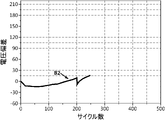
図4は、本発明の一実施形態によるバッテリー退化度診断装置100が第1バッテリーセルB1に対して算出した電圧偏差[mV]を示した図である。図5は、本発明の一実施形態によるバッテリー退化度診断装置100が第2バッテリーセルB2に対して算出した電圧偏差[mV]を示した図である。図6は、本発明の一実施形態によるバッテリー退化度診断装置100が第3バッテリーセルB3に対して算出した電圧偏差[mV]を示した図である。図7は、本発明の一実施形態によるバッテリー退化度診断装置100が第4バッテリーセルB4に対して算出した電圧偏差[mV]を示した図である。
FIG. 4 is a graph showing voltage deviation [mV] calculated for the first battery cell B1 by the battery degradation
具体的には、図4は、第1サイクル~第400サイクルで算出された第1バッテリーセルB1の電圧偏差を示した図である。図5は、第1サイクル~第250サイクルで算出された第2バッテリーセルB2の電圧偏差を示した図である。図6は、第1サイクル~第250サイクルで算出された第3バッテリーセルB3の電圧偏差を示した図である。図7は、第1サイクル~第320サイクルで算出された第4バッテリーセルB4の電圧偏差を示した図である。 Specifically, FIG. 4 is a diagram showing the voltage deviation of the first battery cell B1 calculated from the 1st cycle to the 400th cycle. FIG. 5 is a diagram showing the voltage deviation of the second battery cell B2 calculated from the 1st cycle to the 250th cycle. FIG. 6 is a diagram showing the voltage deviation of the third battery cell B3 calculated from the 1st cycle to the 250th cycle. FIG. 7 is a diagram showing the voltage deviation of the fourth battery cell B4 calculated from the 1st cycle to the 320th cycle.
図4~図7を参照すると、第nサイクルで測定されたバッテリーセルの電圧によって、電圧偏差は0、正数または負数で算出され得る。望ましくは、図4~図7の実施形態において、基準サイクルは第1サイクルであり得る。すなわち、電圧偏差を算出するとき、基準サイクルで測定されたバッテリーセルの電圧が基準になるため、図4~図7において、第1サイクルにおける電圧偏差はいずれも0と同一である。 4 to 7, the voltage deviation can be calculated as 0, a positive number, or a negative number according to the voltage of the battery cell measured in the nth cycle. Desirably, in the embodiments of FIGS. 4-7, the reference cycle may be the first cycle. That is, when calculating the voltage deviation, the voltage of the battery cell measured in the reference cycle is used as the reference, so the voltage deviation in the first cycle is the same as 0 in FIGS.
また、基準になる基準電圧(例えば、第1サイクルで測定されたバッテリーセルの電圧)は、複数のバッテリーセルB1~B4毎に異なるように測定され得る。すなわち、複数のバッテリーセルB1~B4の退化度に応じて基準電圧が相異なるように設定され得る。 Also, the reference voltage (for example, the battery cell voltage measured in the first cycle) can be measured differently for each of the plurality of battery cells B1 to B4. That is, different reference voltages can be set according to the degree of deterioration of the plurality of battery cells B1 to B4.
制御部120は、複数のバッテリーセルB1~B4のそれぞれに対して算出された複数の電圧偏差による電圧合算値に基づいて、複数のバッテリーセルB1~B4の相対的退化度を診断するように構成され得る。
The
まず、制御部120は、複数のバッテリーセルB1~B4のそれぞれに対して算出された複数の電圧偏差を合算し得る。すなわち、電圧合算値とは、複数のバッテリーセルB1~B4毎に算出された複数の電圧偏差を足した値であり得る。
First, the
例えば、図4~図7の実施形態において、制御部120が複数のバッテリーセルB1~B4のそれぞれに対して、第1サイクルから第200サイクルまでの電圧偏差を合算したと仮定する。第1バッテリーセルB1の電圧合算値は2575[mV]であり、第2バッテリーセルB2の電圧合算値は-1187[mV]であり、第3バッテリーセルB3の電圧合算値は-3272[mV]であり、第4バッテリーセルB4の電圧合算値は-7404[mV]であり得る。
For example, in the embodiments of FIGS. 4-7, it is assumed that the
制御部120は、複数のバッテリーセルB1~B4のそれぞれに対して算出された電圧合算値を比較し、複数のバッテリーセルB1~B4の相対的退化度を診断し得る。
The
具体的には、制御部120は、電圧合算値が小さいほど退化の進行が遅いと診断し、電圧合算値が大きいほど退化がより進行したと診断することができる。
Specifically, the
例えば、上述した実施形態のように、第1バッテリーセルB1の電圧合算値が2575[mV]であり、第2バッテリーセルB2の電圧合算値が-1187[mV]であり、第3バッテリーセルB3の電圧合算値が-3272[mV]であり、第4バッテリーセルB4の電圧合算値が-7404[mV]であると仮定する。制御部120は、電圧合算値が最も大きい第1バッテリーセルB1の相対的退化度が最も高いと診断し、電圧合算値が最も小さい第4バッテリーセルB4の相対的退化度が最も低いと診断し得る。望ましくは、制御部120は、第1サイクル~第200サイクルにおいて、第1バッテリーセルB1が第2バッテリーセルB2、第3バッテリーセルB3及び第4バッテリーセルB4に比べてさらに退化したと診断することができる。
For example, as in the above-described embodiment, the total voltage value of the first battery cell B1 is 2575 [mV], the total voltage value of the second battery cell B2 is -1187 [mV], and the third battery cell B3 is -3272 [mV], and the voltage sum of the fourth battery cell B4 is -7404 [mV]. The
図8は、複数のバッテリーセルB1~B4に対するサイクル容量維持率を示した図である。具体的には、図8は、充放電サイクルの進行に伴う、複数のバッテリーセルB1~B4それぞれの容量変化を示した図である。ここで、サイクル容量維持率は、複数のバッテリーセルB1~B4のそれぞれに対して推定された健康状態(SOH)に対応し得る。 FIG. 8 is a diagram showing cycle capacity retention rates for a plurality of battery cells B1 to B4. Specifically, FIG. 8 is a diagram showing changes in capacity of each of the plurality of battery cells B1 to B4 as charge/discharge cycles progress. Here, the cycle capacity maintenance rate may correspond to the state of health (SOH) estimated for each of the plurality of battery cells B1-B4.
図8を参照すると、第1サイクルから第200サイクルに進行するほど、第1バッテリーセルB1の容量が最も多く減ることが確認できる。また、第4バッテリーセルB4の容量が最も少し減ることが確認できる。ただし、図8に示されたバッテリーセルの健康状態は、直接測定することはできず、バッテリーセルの電流及び/または電圧などのバッテリー状態情報に基づいて推定される値である。すなわち、バッテリーセルの健康状態は、バッテリーセルの充電及び/または放電電流を積算するか又はバッテリーセルの内部抵抗の変化を考慮して推定されるため、推定に多くの時間とシステム資源が必要であるという問題がある。 Referring to FIG. 8, it can be seen that the capacity of the first battery cell B1 decreases the most from the 1st cycle to the 200th cycle. Also, it can be seen that the capacity of the fourth battery cell B4 decreases the most. However, the health status of the battery cells shown in FIG. 8 cannot be measured directly, but is an estimated value based on battery status information such as current and/or voltage of the battery cells. That is, the health state of the battery cell is estimated by integrating the charge and/or discharge current of the battery cell or by considering the change in the internal resistance of the battery cell, so estimation requires a lot of time and system resources. There is a problem that there is
一方、本発明の一実施形態によるバッテリー退化度診断装置100は、測定された電圧値に基づいて複数のバッテリーセルB1~B4の相対的退化度を診断できるため、複数のバッテリーセルB1~B4の相対的退化度を正確且つ迅速に診断することができる。
On the other hand, the battery degradation
すなわち、バッテリー退化度診断装置100は、複数のバッテリーセルB1~B4の健康状態を推定しなくても、複数のバッテリーセルB1~B4間の相対的退化度を診断できるため、短時間で複数のバッテリーセルB1~B4の相対的退化度を診断しなければならない状況でも、複数のバッテリーセルB1~B4の相対的退化度を正確且つ迅速に診断することができる。
That is, the battery degradation degree
一方、バッテリー退化度診断装置100に備えられた制御部120は、本発明で実行される多様な制御ロジックを実行するため、当業界に知られたプロセッサ、ASIC(application-specific integrated circuit)、他のチップセット、論理回路、レジスタ、通信モデム、データ処理装置などを選択的に含み得る。また、制御ロジックがソフトウェアとして具現されるとき、制御部120はプログラムモジュールの集合として具現され得る。このとき、プログラムモジュールはメモリに保存され、制御部120によって実行され得る。メモリは制御部120の内部または外部に備えられ得、周知の多様な手段で制御部120と接続され得る。
On the other hand, the
また、図1~図3を参照すると、バッテリー退化度診断装置100は保存部130をさらに含み得る。保存部130は、制御部120が複数のバッテリーセルB1~B4の退化度を診断するのに必要なプログラム及びデータなどを保存することができる。すなわち、保存部130は、バッテリー退化度診断装置100の各構成要素が動作及び機能を実行するのに必要なデータやプログラム、または、動作及び機能の実行過程で生成されるデータなどを保存し得る。
In addition, referring to FIGS. 1 to 3, the battery degradation
例えば、保存部130は、各サイクルで測定された複数のバッテリーセルB1~B4それぞれの電圧情報を保存し得る。
For example, the
また、保存部130は、データを記録、消去、更新及び読出できると知られた公知の情報記憶手段であればその種類に特に制限がない。一例として、情報記憶手段には、RAM(random access memory)、フラッシュメモリ、ROM(read only memory)、EEPROM(electrically erasable programmable ROM)、レジスタなどが含まれ得る。また、保存部130は、制御部120によって実行可能なプロセスが定義されたプログラムコードを保存し得る。
Also, the
測定部110は、複数のバッテリーセルB1~B4の放電が終了してから所定の時間が経過した測定時点における電圧を測定するように構成され得る。
The measuring
望ましくは、測定部110は、バッテリーセルの開放回路電圧(Open Circuit Voltage、OCV)を測定することができる。すなわち、測定部110は、バッテリーセルの充電または放電が終了した後、所定の時間が経過したとき、バッテリーセルの開放回路電圧を測定し得る。例えば、測定部110は、バッテリーセルの放電が終了した後、バッテリーセルが無負荷状態であるときの開放回路電圧を測定し得る。
Preferably, the measuring
すなわち、測定部110は、複数のバッテリーセルB1~B4の電圧を測定するとき、電流による影響を最小化するために、複数のバッテリーセルB1~B4の開放回路電圧を測定するように構成され得る。例えば、測定部110は、バッテリーセルの正確な開放回路電圧を測定するため、バッテリーセルの放電が終了し、化学的弛緩(chemical relaxation)状態に到達したときにバッテリーセルの開放回路電圧を測定し得る。
That is, the
図3の実施形態において、測定部110は、複数のバッテリーセルB1~B4の放電が終了した後、複数のバッテリーセルB1~B4それぞれの開放回路電圧を測定するように構成され得る。したがって、測定部110は、開放回路電圧を測定するため、複数のバッテリーセルB1~B4の放電が終了してから所定の時間が経過した時点で、複数のバッテリーセルB1~B4それぞれの電圧を測定することができる。
In the embodiment of FIG. 3, the measuring
すなわち、測定部110は、複数のバッテリーセルB1~B4の放電が終了した放電終了時点から同じ時間が経過した時点で、複数のバッテリーセルB1~B4それぞれの電圧を測定することができる。例えば、測定部110は、複数のバッテリーセルB1~B4の放電が終了した後、300秒が経過したとき、複数のバッテリーセルB1~B4それぞれの電圧を測定し得る。
That is, the
制御部120は、それぞれのバッテリーセルの最初サイクルで測定された電圧を基準電圧に設定するように構成され得る。
The
例えば、数式1を参照すると、制御部120は、複数のバッテリーセルB1~B4のそれぞれに対して、測定部110によって第1サイクルで測定された電圧を基準電圧に設定し得る。
For example, referring to
また、制御部120は、それぞれのバッテリーセルの各サイクル毎に測定されたセル電圧と基準電圧との差を算出して電圧偏差を算出するように構成され得る。
Also, the
上述した実施形態のように、基準サイクルが第1サイクルに設定された場合、電圧偏差は第nサイクルで測定された電圧と第1サイクルで測定された電圧との差として算出され得る。すなわち、制御部120は、複数のバッテリーセルB1~B4に対し、第1サイクルから第nサイクルが進行するまでの相対的退化度を診断し得る。
If the reference cycle is set to the first cycle as in the above embodiment, the voltage deviation can be calculated as the difference between the voltage measured at the nth cycle and the voltage measured at the first cycle. That is, the
したがって、本発明の一実施形態によるバッテリー退化度診断装置100は、複数のサイクルが進行する間に複数のバッテリーセルB1~B4が退化した程度を容易に比較することができる。すなわち、バッテリー退化度診断装置100は、複数のバッテリーセルB1~B4に対する性能優位を短時間で比較しなければならない状況でより効果的に用いることができる。
Therefore, the battery degradation
制御部120は、複数のバッテリーセルB1~B4のそれぞれに対して算出された電圧合算値を互いに比較し、複数のバッテリーセルB1~B4の相対的退化度を診断するように構成され得る。
The
ここで、電圧合算値は、複数のバッテリーセルB1~B4間の性能優位を比較可能な指標であり得る。例えば、算出された複数の電圧偏差を合算して電圧合算値を算出し得る。 Here, the voltage sum value may be an index capable of comparing performance superiority among the plurality of battery cells B1 to B4. For example, a voltage total value can be calculated by summing a plurality of calculated voltage deviations.
一般に、内部ガスの発生、リチウムメッキの生成、電解液の分解及び/または副産物の蓄積などの理由で、バッテリーセルのサイクルが進行するほど測定される開放電圧は増加し得る。例えば、バッテリーセル内部の正極容量の減少によってバッテリーセルが退化する場合、初期バッテリーセルよりも、正極の開放回路電圧は増加し、負極の開放回路電圧は減少し得る。すなわち、EOL(end of life)状態のバッテリーセルの開放回路電圧は、BOL(beginning of life)状態のバッテリーセルの開放回路電圧よりも大きくなり得る。したがって、バッテリーセルが退化するほど、バッテリーセルの開放電圧が増加し得る。 In general, the measured open-circuit voltage may increase as the cycle of the battery cell progresses due to the generation of internal gas, the generation of lithium plating, the decomposition of the electrolyte and/or the accumulation of byproducts. For example, when a battery cell ages due to a decrease in positive electrode capacity inside the battery cell, the open circuit voltage of the positive electrode may increase and the open circuit voltage of the negative electrode may decrease relative to the initial battery cell. That is, an open circuit voltage of a battery cell in an EOL (end of life) state may be higher than an open circuit voltage of a battery cell in a BOL (begining of life) state. Therefore, as the battery cell degrades, the open circuit voltage of the battery cell may increase.
例えば、数式1を参照すると、バッテリーセルのサイクルが進行するほど、第nサイクルで測定された電圧(Vn)が増加し得るため、バッテリーセルが退化するほど電圧合算値が増加し得る。望ましくは、制御部120は、電圧合算値が大きいほどバッテリー退化度が大きいと診断するように構成され得る。逆に、制御部120は、電圧合算値が小さいほどバッテリー退化度が小さいと診断するように構成され得る。
For example, referring to
したがって、本発明の一実施形態によるバッテリー退化度診断装置100は、バッテリーセルの退化による開放電圧の変化を考慮して、複数のバッテリーセルB1~B4間の相対的退化度を正確且つ迅速に診断することができる。
Therefore, the battery deterioration
以下、本発明の一実施形態によるバッテリー退化度診断装置100が所定のサイクル区間で複数のバッテリーセルB1~B4間の相対的退化度を比較する実施形態を説明する。
Hereinafter, an embodiment will be described in which the battery degradation
まず、制御部120は、複数のサイクルを複数の単位区間に区画するように構成され得る。
First, the
例えば、図4~図7の実施形態において、制御部120は、50サイクル毎に単位区間を区画し得る。すなわち、制御部120は、第1サイクル~第50サイクルを第1単位区間に区画し、第51サイクル~第100サイクルを第2単位区間に区画し得る。そして、制御部120は、第101サイクル~第150サイクルを第3単位区間に区画し、第151サイクル~第200サイクルを第4単位区間に区画し、第201サイクル~第250サイクルを第5単位区間に区画し得る。
For example, in the embodiments of FIGS. 4 to 7, the
そして、制御部120は、区画された複数の単位区間のそれぞれに属したサイクルに対応して算出された少なくとも一つの電圧偏差に基づいて、区画された複数の単位区間のそれぞれに対する単位合算値を算出するように構成され得る。
Then, the
ここで、単位合算値とは、単位区間毎に算出された電圧合算値を意味し得る。すなわち、制御部120は、区画した複数の単位区間毎に電圧合算値を算出することができる。
Here, the unit sum value may mean a voltage sum value calculated for each unit section. That is, the
具体的には、制御部120は、区画した複数の単位区間に属したサイクル毎に電圧偏差を算出することができる。例えば、第1単位区間を挙げれば、制御部120は、第1サイクル~第50サイクルのそれぞれに対して電圧偏差を算出し得る。そして、制御部120は、第1サイクル~第50サイクルのそれぞれで算出した電圧偏差を合算して、第1単位区間の単位合算値を算出し得る。
Specifically, the
同様に、第2単位区間を挙げれば、制御部120は、第51サイクル~第100サイクルのそれぞれに対して電圧偏差を算出し得る。そして、制御部120は、第51サイクル~第100サイクルのそれぞれで算出した電圧偏差を合算して、第2単位区間の単位合算値を算出し得る。
Similarly, taking the second unit interval, the
制御部120は、第1単位区間の電圧合算値及び第2単位区間の単位合算値を算出した方式と同様に、第3単位区間、第4単位区間及び第5単位区間の単位合算値を算出し得る。
The
最後に、制御部120は、同一単位区間に対応して算出された単位合算値同士を比較した結果に基づいて複数のバッテリーセルB1~B4の複数の単位区間それぞれにおける相対的退化度を診断するように構成され得る。
Finally, the
すなわち、制御部120は、複数の単位区間毎に複数のバッテリーセルB1~B4間の相対的退化度を診断することができる。
That is, the
例えば、制御部120は、第1単位区間、第2単位区間、第3単位区間、第4単位区間及び第5単位区間のそれぞれにおける複数のバッテリーセルB1~B4間の相対的退化度をそれぞれ診断し得る。
For example, the
したがって、本発明の一実施形態によるバッテリー退化度診断装置100は、全期間にわたる複数のバッテリーセルB1~B4の相対的退化度を診断できるだけでなく、単位区間毎に複数のバッテリーセルB1~B4の退化度を診断することができる。
Therefore, the battery degradation degree
また、制御部120は、複数の単位区間のそれぞれに対するサイクル所要時間(一サイクルの進行にかかった時間)、充電電流の強度、放電電流の強度またはバッテリーセルの温度などのサイクル情報を取得して保存部130に保存し得る。そして、制御部120は、複数の単位区間のそれぞれにおいて診断された複数のバッテリーセルの退化度とともに、保存部130に保存されたサイクル情報を提供し得る。
In addition, the
したがって、バッテリー退化度診断装置100は、サイクル情報をユーザに提供することで、バッテリーセルの退化原因の推定に必要な情報を提供することができる。
Therefore, the battery degradation degree
また、バッテリー退化度診断装置100は、バッテリーセルの退化原因の推定に必要な情報を提供することで、ユーザがバッテリーセルの交換時期またはバッテリーセルの充放電条件などを決定するのに役立つことができる。
In addition, the battery degradation
以下、本発明の一実施形態によるバッテリー退化度診断装置100がそれぞれのバッテリーセルの退化加速を診断する実施形態について説明する。
Hereinafter, an embodiment of diagnosing accelerated deterioration of each battery cell by the battery deterioration
制御部120は、複数のバッテリーセルB1~B4のうちターゲットセルを選定するように構成され得る。
The
すなわち、制御部120は、複数のバッテリーセルB1~B4のうち退化加速を診断するターゲットセルを選定することができる。例えば、制御部120は、第1バッテリーセルB1をターゲットセルとして選定し得る。
That is, the
そして、制御部120は、複数の単位区間のそれぞれでターゲットセルに対応する単位合算値を算出するように構成され得る。
Also, the
まず、制御部120は、複数のサイクルを複数の単位区間に区画し得る。
First, the
例えば、図4の実施形態において、制御部120は、第1サイクル~第400サイクルを50サイクル毎に区画し得る。すなわち、制御部120は、第1サイクル~第400サイクルを第1単位区間~第8単位区間に区画し得る。
For example, in the embodiment of FIG. 4, the
そして、制御部120は、区画された複数の単位区間のそれぞれに属したサイクルに対応して算出された少なくとも一つの電圧偏差に基づいて、区画された複数の単位区間のそれぞれに対する単位合算値を算出するように構成され得る。
Then, the
ここで、制御部120は、ターゲットセルの退化加速程度を診断するため、複数のサイクルのうち最初サイクルで測定された電圧を上記の数式1の基準電圧(Vref)に設定し得る。
Here, the
例えば、制御部120がターゲットセルの第1単位区間~第8単位区間の単位合算値を算出しようとするとき、制御部120は、第1単位区間の最初サイクル(第1サイクル)で測定された電圧を基準電圧(Vref)に設定し得る。すなわち、ターゲットセルの退化加速程度を診断する場合、複数の単位区間のそれぞれの単位合算値を算出するための基準電圧が同一でなければならない。したがって、制御部120は、ターゲットセルの退化加速程度を診断するため、第1サイクルで測定された電圧を基準にして、第1単位区間~第8単位区間に対する単位合算値を算出し得る。
For example, when the
他の例として、制御部120がターゲットセルの第3単位区間~第8単位区間の単位合算値を算出しようとするとき、制御部120は、第3単位区間の最初サイクル(第101サイクル)で測定された電圧を基準電圧(Vref)に設定し得る。この場合、制御部120は、第3単位区間~第8単位区間におけるターゲットセルの退化加速程度を診断することができる。
As another example, when the
最後に、制御部120は、ターゲットセルに対応するように算出された複数の単位合算値同士を比較して、ターゲットセルの退化加速を診断するように構成され得る。
Finally, the
もし、サイクルが進行するほど単位合算値が大きくなれば、制御部120は、ターゲットセルの退化が加速していると診断することができる。逆に、サイクルが進行するほど単位合算値が小さくなれば、ターゲットセルの退化が減速していると診断することができる。
If the unit sum value increases as the cycle progresses, the
以下、図4を参照して、制御部120が第1バッテリーセルB1の退化加速を診断する実施形態を説明する。
Hereinafter, an embodiment in which the
制御部120は、第1バッテリーセルB1をターゲットセルに選定し、第1サイクル~第400サイクルを第1単位区間~第8単位区間に区画し得る。
The
そして、制御部120は、第1サイクルで測定されたターゲットセルの電圧を基準にして、第1サイクル~第400サイクルのそれぞれに対応する電圧偏差を算出し得る。
Then, the
そして、制御部120は、算出したサイクル毎の電圧偏差に基づいて、第1単位区間~第8単位区間のそれぞれの単位合算値を算出し得る。
Then, based on the calculated voltage deviation for each cycle, the
図4を参照すると、第1単位区間~第8単位区間のそれぞれの単位合算値は、サイクルが進行するほど増加することが分かる。すなわち、図4のグラフにおいて、電圧偏差「0」を基準にして、第1バッテリーセルB1の電圧偏差グラフを積分した面積がそれぞれの単位区間における単位合算値に対応し得る。 Referring to FIG. 4, it can be seen that the unit sum values of the first to eighth unit intervals increase as the cycle progresses. That is, in the graph of FIG. 4, the area obtained by integrating the voltage deviation graph of the first battery cell B1 with respect to the voltage deviation '0' may correspond to the unit total value in each unit section.
具体的には、図4の実施形態において、第1単位区間及び第2単位区間の単位合算値は負数で算出され、第3単位区間~第8単位区間の単位合算値は正数で算出され得る。そして、第1単位区間から第8単位区間へとサイクルが進行するとともに、単位合算値が徐々に増加するパターンを見せ得る。 Specifically, in the embodiment of FIG. 4, the unit total values of the first and second unit intervals are calculated as negative numbers, and the unit total values of the third to eighth unit intervals are calculated as positive numbers. obtain. Then, as the cycle progresses from the first unit interval to the eighth unit interval, a pattern in which the unit total value gradually increases can be seen.
したがって、制御部120は、ターゲットセルである第1バッテリーセルB1の退化が加速していると診断することができる。
Therefore, the
すなわち、本発明の一実施形態によるバッテリー退化度診断装置100は、複数のバッテリーセルB1~B4を相互に比較してセル間の相対的退化度を診断できるだけでなく、一つのバッテリーセルの退化加速程度を診断することもできる。
That is, the battery deterioration
したがって、バッテリー退化度診断装置100は、個別バッテリーセルの退化加速程度及び複数のバッテリーセルB1~B4の相対的退化度に基づいて、より正確に且つ信頼度高くバッテリー退化情報を提供することができる。
Therefore, the battery degradation
また、本発明によるバッテリー退化度診断装置100は、バッテリーパック1に備えられ得る。すなわち、図2及び図3を参照すると、本発明によるバッテリーパック1は、上述したバッテリー退化度診断装置100及び一つ以上のバッテリーセルを含むことができる。また、バッテリーパック1は、電装品(リレー、ヒューズなど)及びケースなどをさらに含むことができる。
Also, the battery degradation
図9は、本発明の他の実施形態によるバッテリー退化度診断方法を概略的に示した図である。ここで、バッテリー退化度診断方法に含まれた各段階は、本発明の一実施形態によるバッテリー退化度診断装置100によって実行できる。
FIG. 9 is a diagram schematically illustrating a method for diagnosing battery deterioration according to another embodiment of the present invention. Here, each step included in the method for diagnosing battery deterioration can be performed by the
図9を参照すると、バッテリー退化度診断方法は、電圧測定段階、電圧偏差算出段階、電圧合算値算出段階及び退化度診断段階を含むことができる。 Referring to FIG. 9, the battery deterioration degree diagnosing method may include a voltage measurement step, a voltage deviation calculation step, a voltage sum value calculation step, and a deterioration degree diagnosis step.
電圧測定段階は、放電及び充電が行われる複数のサイクル毎に、複数のバッテリーセルB1~B4それぞれの電圧を測定する段階であって、測定部110によって実行できる。
The voltage measurement step is a step of measuring the voltage of each of the plurality of battery cells B1 to B4 for each of a plurality of cycles of discharging and charging, and can be performed by the measuring
望ましくは、測定部110は、それぞれのサイクルで複数のバッテリーセルB1~B4の開放回路電圧を測定することができる。例えば、図3の実施形態において、測定部110は、複数のセンシングラインSL1~SL5を通じてバッテリーモジュール10に備えられた複数のバッテリーセルB1~B4の開放回路電圧を測定し得る。
Preferably, the measuring
電圧偏差算出段階は、複数のバッテリーセルB1~B4それぞれの最初サイクルで測定された基準電圧を基準にしてそれぞれのバッテリーセルのサイクル毎の電圧偏差を算出する段階であって、制御部120によって実行できる。
The voltage deviation calculation step is a step of calculating a voltage deviation for each cycle of each battery cell based on the reference voltage measured in the first cycle of each of the plurality of battery cells B1 to B4, and is executed by the
例えば、制御部120は、上記の数式1を参照して複数のバッテリーセルB1~B4それぞれのサイクル毎の電圧偏差を算出し得る。
For example, the
ここで、制御部120は、退化度を診断しようとするバッテリーセルの最初サイクルで測定された電圧を基準電圧に設定することができる。
Here, the
例えば、第1サイクル~第250サイクルで複数のバッテリーセルB1~B4の退化度を診断しようとするとき、制御部120は、第1サイクルで測定された複数のバッテリーセルB1~B4それぞれの電圧を該当バッテリーセルの電圧偏差算出の基準電圧として設定し得る。
For example, when diagnosing the degree of deterioration of the plurality of battery cells B1 to B4 in the 1st to 250th cycles, the
他の例として、第101サイクル~第250サイクルで複数のバッテリーセルB1~B4の退化度を診断しようとするとき、制御部120は、第101サイクルで測定された複数のバッテリーセルB1~B4それぞれの電圧を該当バッテリーセルの電圧偏差算出の基準電圧として設定し得る。
As another example, when diagnosing the degree of deterioration of the plurality of battery cells B1 to B4 in the 101st to 250th cycles, the
電圧合算値算出段階は、複数のバッテリーセルB1~B4のそれぞれに対して算出された複数の電圧偏差による電圧合算値を算出する段階であって、制御部120によって実行できる。
The voltage sum value calculation step is a step of calculating a voltage sum value according to a plurality of voltage deviations calculated for each of the plurality of battery cells B1 to B4, and can be performed by the
制御部120は、複数のバッテリーセルB1~B4のそれぞれに対して算出したサイクル毎の電圧偏差を足して電圧合算値を算出し得る。
The
具体的には、制御部120は、退化度を診断しようとするサイクル区間に対する電圧合算値を算出し得る。
Specifically, the
例えば、制御部120は、第1サイクル~第250サイクルのそれぞれで算出された複数の電圧偏差をすべて足して、第1サイクル~第250サイクル区間に対する電圧合算値を算出し得る。
For example, the
他の例として、制御部120は、第1サイクル~第250サイクルを50サイクルずつ単位区間に区画し、区画された単位区間のそれぞれに対する電圧合算値を算出し得る。この場合、制御部120は、単位区間毎に複数のバッテリーセルB1~B4の相対的退化度を診断するか、または、ターゲットセルの退化加速程度を診断することができる。
As another example, the
退化度診断段階は、電圧合算値算出段階で算出された電圧合算値に基づいて、複数のバッテリーセルB1~B4の相対的退化度を診断する段階であって、制御部120によって実行できる。 The step of diagnosing the degree of deterioration is a step of diagnosing the degree of relative deterioration of the plurality of battery cells B1 to B4 based on the sum of voltages calculated in the step of calculating the sum of voltages.
望ましくは、制御部120は、算出した電圧合算値が大きいほど退化がより進行したと診断することができる。逆に、制御部120は、算出した電圧合算値が小さいほど退化の進行が遅いと診断することができる。
Preferably, the
したがって、本発明の他の実施形態によるバッテリー退化度診断方法は、複数のバッテリーセルB1~B4それぞれの健康状態を推定しなくても、測定された電圧に基づいて退化度を迅速且つ正確に診断することができる。 Therefore, the method for diagnosing the degree of deterioration of a battery according to another embodiment of the present invention quickly and accurately diagnoses the degree of deterioration based on the measured voltage without estimating the health status of each of the plurality of battery cells B1 to B4. can do.
したがって、バッテリー退化度診断方法は、複数のバッテリーの退化度を短時間で診断または推定しなければならない環境において非常に効果的に適用することができる。 Therefore, the method for diagnosing the degree of deterioration of a battery can be very effectively applied in an environment where the degree of deterioration of a plurality of batteries must be diagnosed or estimated in a short time.
上述した本発明の実施形態は、装置及び方法のみによって具現されるものではなく、本発明の実施形態の構成に対応する機能を実現するプログラムまたはそのプログラムが記録された記録媒体を通じても具現され得、このような具現は上述した実施形態の記載から当業者であれば容易に具現できるであろう。 The above-described embodiments of the present invention can be embodied not only by devices and methods, but also through programs that implement functions corresponding to the configurations of the embodiments of the present invention or recording media in which the programs are recorded. , such implementation can be easily implemented by those skilled in the art from the description of the above-described embodiments.
以上のように、本発明を限定された実施形態と図面によって説明したが、本発明はこれに限定されるものではなく、本発明の属する技術分野で通常の知識を持つ者によって本発明の技術思想と特許請求の範囲の均等範囲内で多様な修正及び変形が可能であることは言うまでもない。 As described above, the present invention has been described with the limited embodiments and drawings, but the present invention is not limited to this, and a person having ordinary knowledge in the technical field to which the present invention belongs may understand the techniques of the present invention. It goes without saying that various modifications and variations are possible within the equivalent scope of the concept and claims.
また、上述した本発明は、本発明が属する技術分野で通常の知識を持つ者により、本発明の技術的思想を逸脱しない範囲内で様々な置換、変形及び変更が可能であって、上述した実施形態及び添付の図面によって限定されるものではなく、多様な変形のため各実施形態の全部または一部が選択的に組み合わせられて構成され得る。 In addition, the above-described present invention can be variously replaced, modified, and changed within the scope of the technical idea of the present invention by those who have ordinary knowledge in the technical field to which the present invention belongs. It is not limited by the embodiments and attached drawings, and all or part of each embodiment can be selectively combined for various modifications.
1:バッテリーパック
10:バッテリーモジュール 100:バッテリー退化度診断装置
110:測定部
120:制御部
130:保存部
B1~B4:第1バッテリーセル~第4バッテリーセル
SL1~SL5:第1センシングライン~第5センシングライン
1: Battery pack 10: Battery module 100: Battery degradation diagnostic device 110: Measurement unit 120: Control unit 130: Storage unit B1 to B4: First battery cell to fourth battery cell SL1 to SL5: First sensing line to fourth 5 sensing lines
Claims (10)
前記複数の電圧情報を受信し、前記複数のバッテリーセルのそれぞれの最初サイクルで測定された基準電圧を基準にしてそれぞれのバッテリーセルのサイクル毎の電圧偏差を算出し、前記複数のバッテリーセルのそれぞれに対して算出された複数の電圧偏差による電圧合算値に基づいて、前記複数のバッテリーセルの退化度を診断するように構成された制御部と、を含む、バッテリー退化度診断装置。 a measurement unit configured to measure the voltage of each of the plurality of battery cells and output a plurality of voltage information for the plurality of measured voltages for each cycle of discharging and charging;
receiving the plurality of voltage information, calculating a cycle-by-cycle voltage deviation of each battery cell based on a reference voltage measured in the first cycle of each of the plurality of battery cells, and calculating a voltage deviation of each of the plurality of battery cells; and a control unit configured to diagnose the deterioration degree of the plurality of battery cells based on the voltage sum value of the plurality of voltage deviations calculated for each of the battery cells.
前記複数のバッテリーセルの放電が終了してから所定の時間が経過した測定時点における電圧を測定するように構成された、請求項1に記載のバッテリー退化度診断装置。 The measurement unit
2. The battery degradation diagnostic apparatus according to claim 1, configured to measure voltage at a point of time when a predetermined period of time has passed since discharge of said plurality of battery cells is completed.
それぞれのバッテリーセルの前記最初サイクルで測定された電圧を前記基準電圧に設定し、それぞれのバッテリーセルの各サイクル毎に測定されたセル電圧と前記基準電圧との差を算出して前記電圧偏差を算出するように構成された、請求項2に記載のバッテリー退化度診断装置。 The control unit
The voltage measured in the first cycle of each battery cell is set as the reference voltage, the difference between the cell voltage measured in each cycle of each battery cell and the reference voltage is calculated, and the voltage deviation is calculated. 3. The battery degradation diagnostic device according to claim 2, configured to calculate.
前記複数のバッテリーセルのそれぞれに対して算出された電圧合算値を互いに比較し、前記複数のバッテリーセルの退化度を診断するように構成された、請求項1から3のいずれか一項に記載のバッテリー退化度診断装置。 The control unit
4. The system according to any one of claims 1 to 3, configured to diagnose the degree of deterioration of the plurality of battery cells by comparing the voltage sum values calculated for each of the plurality of battery cells. battery degradation diagnosis device.
前記電圧合算値が大きいほどバッテリー退化度が大きいと診断するように構成された、請求項4に記載のバッテリー退化度診断装置。 The control unit
5. The apparatus for diagnosing a degree of battery deterioration according to claim 4, configured to diagnose that the degree of battery deterioration increases as the voltage sum value increases.
前記サイクルを複数の単位区間に区画し、区画された複数の単位区間のそれぞれに属したサイクルに対応して算出された少なくとも一つの電圧偏差に基づいて、区画された前記複数の単位区間のそれぞれに対する単位合算値を算出し、同一単位区間に対応して算出された単位合算値同士を比較した結果に基づいて前記複数のバッテリーセルの前記複数の単位区間それぞれにおける退化度を診断するように構成された、請求項4または5に記載のバッテリー退化度診断装置。 The control unit
The cycle is divided into a plurality of unit intervals, and each of the plurality of divided unit intervals is calculated based on at least one voltage deviation calculated corresponding to the cycle belonging to each of the plurality of partitioned unit intervals. and diagnosing the degree of degradation of the plurality of battery cells in each of the plurality of unit sections based on the result of comparing the unit sum values calculated corresponding to the same unit section. 6. The battery deterioration degree diagnostic device according to claim 4 or 5, wherein the battery deterioration level diagnostic device is a battery.
前記複数のバッテリーセルのうちターゲットセルを選定し、前記複数の単位区間のそれぞれにおいて前記ターゲットセルに対応する単位合算値を算出し、前記ターゲットセルに対応するように算出された複数の単位合算値を互いに比較し、前記ターゲットセルの退化加速を診断するように構成された、請求項6に記載のバッテリー退化度診断装置。 The control unit
Selecting a target cell from among the plurality of battery cells, calculating a unit total value corresponding to the target cell in each of the plurality of unit intervals, and calculating a plurality of unit total values corresponding to the target cell are compared with each other to diagnose accelerated degradation of the target cell.
前記サイクルが進行するほど前記単位合算値が大きくなれば、前記ターゲットセルの退化が加速していると診断するように構成された、請求項7に記載のバッテリー退化度診断装置。 The control unit
The apparatus for diagnosing the degree of battery deterioration according to claim 7, configured to diagnose that deterioration of the target cell is accelerating when the unit sum value increases as the cycle progresses.
前記複数のバッテリーセルのそれぞれの最初サイクルで測定された基準電圧を基準にしてそれぞれのバッテリーセルのサイクル毎の電圧偏差を算出する電圧偏差算出段階と、
前記複数のバッテリーセルのそれぞれに対して算出された複数の電圧偏差による電圧合算値を算出する電圧合算値算出段階と、
前記電圧合算値算出段階で算出された電圧合算値に基づいて、前記複数のバッテリーセルの退化度を診断する退化度診断段階と、を含む、バッテリー退化度診断方法。 a voltage measurement step of measuring the voltage of each of the plurality of battery cells for each cycle of discharge and charge;
a voltage deviation calculating step of calculating a voltage deviation for each cycle of each battery cell based on a reference voltage measured at the first cycle of each of the plurality of battery cells;
a voltage sum value calculating step of calculating a voltage sum value according to a plurality of voltage deviations calculated for each of the plurality of battery cells;
and a deterioration degree diagnosis step of diagnosing the degree of deterioration of the plurality of battery cells based on the voltage sum value calculated in the voltage sum value calculation step.
Applications Claiming Priority (3)
| Application Number | Priority Date | Filing Date | Title |
|---|---|---|---|
| KR1020190132946A KR20210048810A (en) | 2019-10-24 | 2019-10-24 | Apparatus and method for diagnosing degeneracy of battery |
| KR10-2019-0132946 | 2019-10-24 | ||
| PCT/KR2020/013690 WO2021080219A1 (en) | 2019-10-24 | 2020-10-07 | Device and method for diagnosing degree of battery deterioration |
Publications (2)
| Publication Number | Publication Date |
|---|---|
| JP2022534442A JP2022534442A (en) | 2022-07-29 |
| JP7205032B2 true JP7205032B2 (en) | 2023-01-17 |
Family
ID=75620760
Family Applications (1)
| Application Number | Title | Priority Date | Filing Date |
|---|---|---|---|
| JP2021571999A Active JP7205032B2 (en) | 2019-10-24 | 2020-10-07 | Battery degradation diagnosis device and method |
Country Status (6)
| Country | Link |
|---|---|
| US (1) | US20220317197A1 (en) |
| EP (1) | EP3998489A4 (en) |
| JP (1) | JP7205032B2 (en) |
| KR (1) | KR20210048810A (en) |
| CN (1) | CN114207454B (en) |
| WO (1) | WO2021080219A1 (en) |
Families Citing this family (1)
| Publication number | Priority date | Publication date | Assignee | Title |
|---|---|---|---|---|
| KR20240040991A (en) * | 2022-09-22 | 2024-03-29 | 주식회사 엘지에너지솔루션 | Apparatus and method for analysing test of battery's long time characteristics |
Citations (5)
| Publication number | Priority date | Publication date | Assignee | Title |
|---|---|---|---|---|
| JP2004132899A (en) | 2002-10-11 | 2004-04-30 | Furukawa Electric Co Ltd:The | Method and device for determining deterioration of storage battery |
| JP2009162750A (en) | 2007-12-13 | 2009-07-23 | Panasonic Corp | Methods and apparatuses of estimating service life and inhibiting deterioration of lithium secondary battery, battery pack using the same, and charger |
| US20120274281A1 (en) | 2010-12-29 | 2012-11-01 | Lg Chem, Ltd. | Apparatus and method for managing battery pack by reflecting degradation degree of secondary cells and battery pack having the same |
| JP2013247773A (en) | 2012-05-25 | 2013-12-09 | Toyota Motor Corp | Power storage system and disconnection determination method |
| JP2018120758A (en) | 2017-01-25 | 2018-08-02 | 三菱自動車工業株式会社 | Lithium ion battery and lithium ion battery system |
Family Cites Families (20)
| Publication number | Priority date | Publication date | Assignee | Title |
|---|---|---|---|---|
| JP3430600B2 (en) * | 1993-12-24 | 2003-07-28 | 新神戸電機株式会社 | Method and apparatus for estimating deterioration state of storage battery |
| JP3539412B2 (en) * | 2001-08-09 | 2004-07-07 | 日産自動車株式会社 | Battery battery abnormality detection device |
| KR101187766B1 (en) * | 2008-08-08 | 2012-10-05 | 주식회사 엘지화학 | Apparatus and Method for cell balancing based on battery's voltage variation pattern |
| JP5586219B2 (en) * | 2009-12-25 | 2014-09-10 | 株式会社東芝 | Diagnostic device, battery pack, and battery value index manufacturing method |
| WO2011125213A1 (en) * | 2010-04-09 | 2011-10-13 | トヨタ自動車株式会社 | Secondary battery degradation determination device and degradation determination method |
| US9246337B2 (en) * | 2010-04-23 | 2016-01-26 | Hitachi, Ltd. | Battery pack and battery pack controller |
| JP5395006B2 (en) * | 2010-07-22 | 2014-01-22 | 株式会社日立製作所 | Battery control system, control method therefor, and battery system |
| CN103492893B (en) * | 2011-04-25 | 2015-09-09 | 株式会社Lg化学 | For estimating equipment and the method for the deterioration of battery capacity |
| JP2013096752A (en) * | 2011-10-28 | 2013-05-20 | Sanyo Electric Co Ltd | Abnormality determination method for battery pack and battery pack |
| US20140278169A1 (en) * | 2013-03-12 | 2014-09-18 | Samsung Sdi Co., Ltd. | Apparatus for predicting state of health of battery pack by using discrete wavelet transform |
| FR3009093B1 (en) * | 2013-07-29 | 2017-01-13 | Renault Sa | ESTIMATING THE AGING CONDITION OF AN ELECTRIC BATTERY |
| US9411019B2 (en) * | 2013-12-16 | 2016-08-09 | Automotive Research & Testing Center | Method and system for estimating state of health of battery set |
| KR101572494B1 (en) * | 2014-01-14 | 2015-11-27 | (주)아이비티 | Apparatus of Estimating SOH for Battery |
| JP6161133B2 (en) * | 2015-07-02 | 2017-07-12 | 学校法人同志社 | Data extraction apparatus, data extraction method, and data extraction program |
| KR101882287B1 (en) | 2016-12-09 | 2018-07-26 | 주식회사 효성 | Battery life estimation method and device of it |
| KR102055850B1 (en) * | 2017-12-21 | 2019-12-13 | 주식회사 엘지화학 | Apparatus and method for diagnosing fault of current sensor |
| US11703547B2 (en) * | 2018-04-03 | 2023-07-18 | Maxim Integrated Products, Inc. | Software-configurable battery management systems and methods |
| CN108226809A (en) * | 2018-04-13 | 2018-06-29 | 淮阴工学院 | A kind of multi-model and battery SOC evaluation method |
| US10676137B2 (en) | 2018-05-21 | 2020-06-09 | Bollinger Motors, LLC | Automotive vehicle body |
| KR20210074003A (en) * | 2019-12-11 | 2021-06-21 | 주식회사 엘지에너지솔루션 | Apparatus and method for diagnosing degeneracy of battery |
-
2019
- 2019-10-24 KR KR1020190132946A patent/KR20210048810A/en active Search and Examination
-
2020
- 2020-10-07 WO PCT/KR2020/013690 patent/WO2021080219A1/en unknown
- 2020-10-07 JP JP2021571999A patent/JP7205032B2/en active Active
- 2020-10-07 US US17/626,603 patent/US20220317197A1/en active Pending
- 2020-10-07 CN CN202080053060.3A patent/CN114207454B/en active Active
- 2020-10-07 EP EP20878781.2A patent/EP3998489A4/en active Pending
Patent Citations (5)
| Publication number | Priority date | Publication date | Assignee | Title |
|---|---|---|---|---|
| JP2004132899A (en) | 2002-10-11 | 2004-04-30 | Furukawa Electric Co Ltd:The | Method and device for determining deterioration of storage battery |
| JP2009162750A (en) | 2007-12-13 | 2009-07-23 | Panasonic Corp | Methods and apparatuses of estimating service life and inhibiting deterioration of lithium secondary battery, battery pack using the same, and charger |
| US20120274281A1 (en) | 2010-12-29 | 2012-11-01 | Lg Chem, Ltd. | Apparatus and method for managing battery pack by reflecting degradation degree of secondary cells and battery pack having the same |
| JP2013247773A (en) | 2012-05-25 | 2013-12-09 | Toyota Motor Corp | Power storage system and disconnection determination method |
| JP2018120758A (en) | 2017-01-25 | 2018-08-02 | 三菱自動車工業株式会社 | Lithium ion battery and lithium ion battery system |
Also Published As
| Publication number | Publication date |
|---|---|
| EP3998489A4 (en) | 2022-08-10 |
| CN114207454B (en) | 2023-06-20 |
| US20220317197A1 (en) | 2022-10-06 |
| EP3998489A1 (en) | 2022-05-18 |
| CN114207454A (en) | 2022-03-18 |
| JP2022534442A (en) | 2022-07-29 |
| KR20210048810A (en) | 2021-05-04 |
| WO2021080219A1 (en) | 2021-04-29 |
Similar Documents
| Publication | Publication Date | Title |
|---|---|---|
| JP7293566B2 (en) | Battery degradation diagnosis device and method | |
| KR102630222B1 (en) | Apparatus and method for diagnosing battery | |
| JP2022532544A (en) | Battery condition diagnostic device and method | |
| JP7205032B2 (en) | Battery degradation diagnosis device and method | |
| JP2023517587A (en) | Battery diagnostic device and method | |
| US20240027531A1 (en) | Battery diagnosing system and method | |
| JP7419647B2 (en) | Battery diagnostic device and method | |
| JP7443648B2 (en) | Battery management device and method | |
| KR102657496B1 (en) | Apparatus and method for managing battery | |
| JP2023516477A (en) | Battery diagnostic device and method | |
| JP7467820B2 (en) | Battery diagnostic device and method | |
| JP7452780B2 (en) | Battery diagnostic device and method | |
| EP4198536A1 (en) | Battery management apparatus and method | |
| JP2023533238A (en) | Battery diagnostic device and method | |
| JP2023539583A (en) | Battery condition diagnosis device and method | |
| JP2023527184A (en) | Battery condition diagnosis device and method | |
| KR20240002211A (en) | Battery diagnostic device and method | |
| KR20220054105A (en) | Apparatus and method for managing battery | |
| JP2023547133A (en) | Battery management device and method | |
| JP2023515595A (en) | Battery management device and method | |
| KR20210118669A (en) | Apparatus and method for setting battery parameter |
Legal Events
| Date | Code | Title | Description |
|---|---|---|---|
| A621 | Written request for application examination |
Free format text: JAPANESE INTERMEDIATE CODE: A621 Effective date: 20211207 |
|
| A977 | Report on retrieval |
Free format text: JAPANESE INTERMEDIATE CODE: A971007 Effective date: 20221121 |
|
| TRDD | Decision of grant or rejection written | ||
| A01 | Written decision to grant a patent or to grant a registration (utility model) |
Free format text: JAPANESE INTERMEDIATE CODE: A01 Effective date: 20221129 |
|
| A61 | First payment of annual fees (during grant procedure) |
Free format text: JAPANESE INTERMEDIATE CODE: A61 Effective date: 20221206 |
|
| R150 | Certificate of patent or registration of utility model |
Ref document number: 7205032 Country of ref document: JP Free format text: JAPANESE INTERMEDIATE CODE: R150 |