JP7204994B2 - Passenger conveyor and its skirt guard switch device - Google Patents
Passenger conveyor and its skirt guard switch device Download PDFInfo
- Publication number
- JP7204994B2 JP7204994B2 JP2022514873A JP2022514873A JP7204994B2 JP 7204994 B2 JP7204994 B2 JP 7204994B2 JP 2022514873 A JP2022514873 A JP 2022514873A JP 2022514873 A JP2022514873 A JP 2022514873A JP 7204994 B2 JP7204994 B2 JP 7204994B2
- Authority
- JP
- Japan
- Prior art keywords
- facing portion
- skirt guard
- fixed
- facing
- bracket
- Prior art date
- Legal status (The legal status is an assumption and is not a legal conclusion. Google has not performed a legal analysis and makes no representation as to the accuracy of the status listed.)
- Active
Links
Images


Classifications
-
- B—PERFORMING OPERATIONS; TRANSPORTING
- B66—HOISTING; LIFTING; HAULING
- B66B—ELEVATORS; ESCALATORS OR MOVING WALKWAYS
- B66B29/00—Safety devices of escalators or moving walkways
- B66B29/02—Safety devices of escalators or moving walkways responsive to, or preventing, jamming by foreign objects
Description
本開示は、乗客コンベア及びそのスカートガードスイッチ装置に関するものである。 The present disclosure relates to a passenger conveyor and its skirt guard switch device.
従来のエスカレータの安全装置では、スカートガードに切欠が設けられている。切欠には、ベースが嵌め込まれている。ベースは、一対のボルトによってスカートガードに固定されている。ベースには、穴が設けられている。穴には、可動片が挿入されている。ベースには、支持片が固定されている。支持片には、スイッチが固定されている。 In a conventional escalator safety device, a notch is provided in the skirt guard. A base is fitted in the notch. The base is fixed to the skirt guard by a pair of bolts. A hole is provided in the base. A movable piece is inserted into the hole. A support piece is fixed to the base. A switch is fixed to the support piece.
スカートガードと踏段との間の隙間に異物が挟まれると、可動片が押され、可動片によってスイッチが操作される(例えば、特許文献1参照)。
When a foreign object is caught in the gap between the skirt guard and the step, the movable piece is pushed and the switch is operated by the movable piece (see
上記のような従来のエスカレータでは、可動片がスカートガードを貫通しているため、スカートガードに切欠を設ける必要がある。このため、スカートガードの構成が複雑になり、製造に手間がかかる。 In the conventional escalator as described above, since the movable piece penetrates the skirt guard, it is necessary to provide a notch in the skirt guard. For this reason, the structure of the skirt guard is complicated, and it takes time and effort to manufacture it.
本開示は、上記のような課題を解決するためになされたものであり、スカートガードの構成が複雑になることを抑制することができる乗客コンベア及びそのスカートガードスイッチ装置を得ることを目的とする。 The present disclosure has been made to solve the problems described above, and an object of the present disclosure is to provide a passenger conveyor and a skirt guard switch device for the same that can prevent the configuration of the skirt guard from becoming complicated. .
本開示に係る乗客コンベアは、トラス、トラス内に設けられており、循環することにより利用者を搬送する無端状の搬送体、搬送体の側方に隙間をおいて配置されているスカートガード、トラスに対して固定されているブラケット、及びブラケットに支持されており、搬送体から離れる方向へのスカートガードの変形を検出する検出スイッチを備え、ブラケットは、スカートガードに重ねて固定されており、スカートガードと一体に変形可能な第1対向部と、第1対向部に対向している第2対向部と、第1対向部と第2対向部とを繋いでおり、トラスに対して固定されている繋ぎ部とを有しており、検出スイッチは、第1対向部及び第2対向部のいずれか一方に設けられており、スカートガードの変形により第1対向部及び第2対向部の他方によって操作される。
また、本開示に係る乗客コンベアのスカートガードスイッチ装置は、ブラケット、及びブラケットに支持されており、スカートガードの変形を検出する検出スイッチを備え、ブラケットは、スカートガードに重ねて固定され、スカートガードと一体に変形可能な第1対向部と、第1対向部に対向している第2対向部と、第1対向部と第2対向部とを繋いでおり、トラスに対して固定される繋ぎ部とを有しており、検出スイッチは、第1対向部及び第2対向部のいずれか一方に設けられており、スカートガードの変形により第1対向部及び第2対向部の他方によって操作される。The passenger conveyor according to the present disclosure includes a truss, an endless carrier that is provided in the truss and carries a user by circulation, a skirt guard that is arranged on the side of the carrier with a gap, A bracket fixed to the truss and a detection switch supported by the bracket for detecting deformation of the skirt guard in a direction away from the carrier, the bracket being overlapped and fixed to the skirt guard, A first facing portion that can be deformed integrally with the skirt guard, a second facing portion facing the first facing portion, and the first facing portion and the second facing portion are connected and fixed to the truss. The detection switch is provided on either one of the first facing portion and the second facing portion, and the other of the first facing portion and the second facing portion is detected by deformation of the skirt guard. operated by
Further, the skirt guard switch device for a passenger conveyor according to the present disclosure includes a bracket and a detection switch that is supported by the bracket and detects deformation of the skirt guard. A first facing part that can be deformed integrally with the truss, a second facing part that faces the first facing part, and a connecting part that connects the first facing part and the second facing part, and is fixed to the truss The detection switch is provided on either one of the first facing portion and the second facing portion, and is operated by the other of the first facing portion and the second facing portion due to deformation of the skirt guard. be.
本開示の乗客コンベア及びそのスカートガードスイッチ装置によれば、スカートガードの構成が複雑になることを抑制することができる。 According to the passenger conveyor and the skirt guard switch device of the present disclosure, it is possible to prevent the configuration of the skirt guard from becoming complicated.
以下、実施の形態について、図面を参照して説明する。
実施の形態1.
図1は、実施の形態1によるエスカレータの要部を示す斜視図である。図において、無端状の搬送体1は、循環することにより利用者を搬送する。また、搬送体1は、複数の踏段2を有している。複数の踏段2は、無端状に連結されている。Embodiments will be described below with reference to the drawings.
1 is a perspective view showing a main part of an escalator according to
搬送体1の循環経路は、往路区間と、復路区間と、上階折り返し区間と、下階折り返し区間とを有している。往路区間は、利用者を乗せる区間である。復路区間は、往路区間の下方に位置している区間である。上階折り返し区間は、上階において往路区間と復路区間とを繋ぐ区間である。下階折り返し区間は、下階において往路区間と復路区間とを繋ぐ区間である。
The circulation route of the conveying
往路区間は、下水平部と、下曲部と、中間傾斜部と、上曲部と、上水平部とを有している。下曲部は、下水平部と中間傾斜部との間の部分である。上曲部は、上水平部と中間傾斜部との間の部分である。 The forward section has a lower horizontal portion, a lower curved portion, an intermediate inclined portion, an upper curved portion, and an upper horizontal portion. The lower curved portion is the portion between the lower horizontal portion and the intermediate inclined portion. The upper curved portion is the portion between the upper horizontal portion and the intermediate inclined portion.
往路区間における搬送体1の幅方向両側には、一対の欄干3が設けられている。図1では、一対の欄干3のうちの一方のみが示されている。各欄干3には、無端状の移動手摺4が設けられている。移動手摺4は、搬送体1に同期して循環する。
A pair of
図2は、図1のII-II線に沿う断面図である。建物の上階と下階との間には、トラス5が架設されている。搬送体1は、トラス5内に設けられている。また、搬送体1は、トラス5によって支持されている。一対の欄干3は、トラス5上に立てられている。
FIG. 2 is a cross-sectional view along line II-II of FIG. A
トラス5は、複数の上弦材6、図示しない複数の下弦材、複数の縦部材7、図示しない複数の傾斜部材、図示しない複数の上横部材、及び図示しない複数の下横部材を有している。
The
各下弦材は、対応する上弦材6の下方に配置されている。各縦部材7は、対応する上弦材6と、対応する下弦材との間に固定されている。各傾斜部材は、対応する上弦材6と、対応する下弦材との間に固定されている。また、各傾斜部材は、隣り合う縦部材に対して傾斜している。
Each lower chord is arranged below the corresponding
各上横部材は、トラス5の幅方向に隣り合う上弦材6間に固定されている。各下横部材は、トラス5の幅方向に隣り合う下弦材間に固定されている。トラス5の幅方向は、図2の左右方向である。
Each upper horizontal member is fixed between
各欄干3は、欄干パネル8、内デッキカバー9、外デッキカバー10、及びスカートガード11を有している。
Each
各欄干3において、内デッキカバー9及び外デッキカバー10は、欄干パネル8の下部に配置されている。各欄干3において、内デッキカバー9は、欄干パネル8に対して、搬送体1側に配置されている。各欄干3において、外デッキカバー10は、欄干パネル8に対して、搬送体1とは反対側に配置されている。
In each
各欄干3において、スカートガード11は、内デッキカバー9の下部に設けられている。また、各欄干3において、スカートガード11は、搬送体1の側方に隙間30をおいて配置されている。即ち、各スカートガード11は、搬送体1の往路区間に位置する複数の踏段2の側面に対向している。
In each
各欄干3において、内デッキカバー9は、欄干パネル8の下端部とスカートガード11の上端部との間の開口を塞いでいる。
In each
各スカートガード11は、複数の分割板によって構成されている。複数の分割板は、搬送体1の往路区間に沿って連続して並べられている。また、各スカートガード11は、金属、例えばステンレス鋼により構成されている。
Each
エスカレータには、複数のスカートガードスイッチ装置12が設けられている。各スカートガードスイッチ装置12は、縦部材7とスカートガード11との間に設けられている。また、実施の形態1では、複数のスカートガードスイッチ装置12は、搬送体1の循環経路の往路区間における下曲部と上曲部とにそれぞれ設けられている。
The escalator is provided with a plurality of skirt
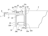
図3は、図2のIII-III線に沿う断面図である。スカートガードスイッチ装置12は、平板状の連結部材21、ブラケット22、複数の固定ボルト23、検出スイッチ24、固定片25、可動片26、調整ボルト27、及びナット28を有している。
3 is a cross-sectional view taken along line III-III in FIG. 2. FIG. The skirt
連結部材21は、例えば溶接により、縦部材7に固定されている。また、連結部材21は、縦部材7から搬送体1へ向けて水平に突出している。
The connecting
ブラケット22は、複数の固定ボルト23により、連結部材21に固定されている。即ち、ブラケット22は、連結部材21を介してトラス5に対して固定されている。また、ブラケット22は、搬送体1と縦部材7との間に配置されている。
連結部材21に固定された状態におけるブラケット22の平面形状は、U字形である。ブラケット22は、第1対向部22a、第2対向部22b、及び繋ぎ部22cを有している。第1対向部22a、第2対向部22b、及び繋ぎ部22cは、長方形の平板を折り曲げることにより形成されている。ブラケット22は、スカートガード11と同様の金属、例えばステンレス鋼により構成されている。
The planar shape of the
第1対向部22aの形状、第2対向部22bの形状、及び繋ぎ部22cの形状は、それぞれ矩形の平板状である。第1対向部22a及び第2対向部22bは、繋ぎ部22cから同方向へ水平に突出している。これにより、第1対向部22a及び第2対向部22bは、互いに対向している。また、第1対向部22a及び第2対向部22bは、互いに平行、かつ繋ぎ部22cに対して直角である。
The shape of the first facing
第1対向部22aは、対向面22dと、外側面22eとを有している。対向面22dは、第2対向部22bに対向する面である。外側面22eは、対向面22dとは反対側の面である。
The first facing
外側面22eは、スカートガード11に接している。外側面22eには、例えば接着又は溶接により、スカートガード11が固定されている。即ち、第1対向部22aは、スカートガード11に重ねて固定されている。また、第1対向部22aは、スカートガード11と一体に変形可能である。
The
繋ぎ部22cは、第1対向部22aと第2対向部22bとを繋いでいる。また、繋ぎ部22cは、複数の固定ボルト23により、連結部材21に固定されている。これにより、繋ぎ部22cは、トラス5に対して固定されている。
The connecting
連結部材21又は繋ぎ部22cには、図示しない長孔が設けられている。長孔には、複数の固定ボルト23が通されている。このため、連結部材21に対する繋ぎ部22cの位置は、複数の固定ボルト23を緩めることによって、搬送体1の幅方向へ調整可能となっている。
A long hole (not shown) is provided in the connecting
検出スイッチ24は、ブラケット22に支持されている。また、検出スイッチ24は、搬送体1から離れる方向へのスカートガード11の変形を検出する。
A
また、検出スイッチ24は、スイッチ本体24aと、操作部24bとを有している。スイッチ本体24aの基端部は、第1対向部22aに固定されている。操作部24bは、スイッチ本体24aの先端部に設けられている。また、操作部24bは、第2対向部22bに対向している。
Further, the
検出スイッチ24は、スカートガード11の変形により第2対向部22bによって操作される。
The
例えば、図4に示すように、踏段2とスカートガード11との間に異物31が挟まれると、スカートガード11が搬送体1から離れる方向へ撓む。このとき、第1対向部22aは、スカートガード11と一体に撓む。
For example, as shown in FIG. 4 , when a
これに対して、繋ぎ部22cが連結部材21に固定されているため、第2対向部22bは移動したり変形したりしない。このため、第1対向部22aが撓むと、第1対向部22aに固定されている検出スイッチ24が第2対向部22bに近付く。そして、第1対向部22aの撓み量が設定値を超えると、第2対向部22bによって操作部24bが操作される。
On the other hand, since the connecting
固定片25は、連結部材21に固定されている。可動片26は、繋ぎ部22cに固定されている。また、可動片26は、固定片25に対向している。
The fixed
調整ボルト27は、可動片26とは反対側から、固定片25を貫通して、可動片26にねじ込まれている。即ち、調整ボルト27は、固定片25及び可動片26を介して、連結部材21とブラケット22との間に設けられている。
The
固定片25には、調整ボルト27を通す貫通孔25aが設けられている。可動片26には、調整ボルト27がねじ込まれるねじ孔26aが設けられている。ナット28は、固定片25の端面であって、可動片26とは反対側の端面に接している。ナット28には、調整ボルト27がねじ込まれている。
The fixed
複数の固定ボルト23が緩められた状態で、調整ボルト27を回転させることによって、搬送体1の幅方向への連結部材21に対する繋ぎ部22cの位置が調整される。
By rotating the adjusting
このようなエスカレータ及びスカートガードスイッチ装置12では、第1対向部22aがスカートガード11に重ねて固定されており、スカートガード11と一体に変形可能となっている。第2対向部22bは、第1対向部22aに対向している。また、繋ぎ部22cは、トラス5に対して固定されている。そして、検出スイッチ24は、第1対向部22aに設けられており、スカートガード11の変形により第2対向部22bによって操作される。
In such an escalator and skirt
このため、可動片を貫通させるための孔加工をスカートガード11に施す必要がなく、スカートガード11の構成が複雑になることを抑制することができる。
Therefore, the
また、工場においてスカートガード11にブラケット22を予め固定しておくことができ、エスカレータの据付作業における作業性を向上させることができる。
In addition, the
また、検出スイッチ24と第2対向部22bとの間の隙間寸法を現地で調整する必要がなく、現地での調整作業を容易にすることができる。
In addition, it is not necessary to adjust the size of the gap between the
また、ねじの頭がスカートガード11から搬送体1側へ突出していないため、ねじの頭に異物が引っ掛かることがない。
Moreover, since the head of the screw does not protrude from the
また、連結部材21に対する繋ぎ部22cの位置は、複数の固定ボルト23を緩めることによって、搬送体1の幅方向へ調整可能になっている。このため、スカートガード11と搬送体1との間の隙間の調整を容易にすることができる。
Further, the position of the connecting
また、連結部材21とブラケット22との間に調整ボルト27が設けられているため、スカートガード11と搬送体1との間の隙間の調整をさらに容易にすることができる。
Further, since the adjusting
なお、検出スイッチ24は、第2対向部22bに設けられていてもよい。この場合、検出スイッチ24は、第1対向部22aによって操作される。
Note that the
また、スカートガードスイッチ装置12を設ける位置は、下曲部及び上曲部に限定されず、例えば中間傾斜部であってもよい。
Further, the position where the skirt
また、スカートガードスイッチ装置12の数は、特に限定されない。
Also, the number of skirt
また、乗客コンベアは、動く歩道であってもよい。 The passenger conveyor may also be a moving walkway.
1 搬送体、5 トラス、11 スカートガード、12 スカートガードスイッチ装置、21 連結部材、22 ブラケット、22a 第1対向部、22b 第2対向部、22c 繋ぎ部、23 固定ボルト、24 検出スイッチ、27 調整ボルト。
Claims (4)
前記トラス内に設けられており、循環することにより利用者を搬送する無端状の搬送体、
前記搬送体の側方に隙間をおいて配置されているスカートガード、
前記トラスに対して固定されているブラケット、及び
前記ブラケットに支持されており、前記搬送体から離れる方向への前記スカートガードの変形を検出する検出スイッチ
を備え、
前記ブラケットは、
前記スカートガードに重ねて固定されており、前記スカートガードと一体に変形可能な第1対向部と、
前記第1対向部に対向している第2対向部と、
前記第1対向部と前記第2対向部とを繋いでおり、前記トラスに対して固定されている繋ぎ部と
を有しており、
前記検出スイッチは、前記第1対向部及び前記第2対向部のいずれか一方に設けられており、前記スカートガードの変形により前記第1対向部及び前記第2対向部の他方によって操作される乗客コンベア。truss,
an endless transport body provided in the truss for transporting a user by circulating;
A skirt guard arranged with a gap on the side of the conveying body;
a bracket fixed to the truss; and a detection switch supported by the bracket for detecting deformation of the skirt guard in a direction away from the carrier,
The bracket is
a first facing portion fixed to the skirt guard and deformable integrally with the skirt guard;
a second facing portion facing the first facing portion;
a connecting portion that connects the first facing portion and the second facing portion and is fixed to the truss;
The detection switch is provided on either one of the first facing portion and the second facing portion, and is operated by the other of the first facing portion and the second facing portion due to deformation of the skirt guard. Conveyor.
をさらに備えており、
前記連結部材に対する前記繋ぎ部の位置は、前記固定ボルトを緩めることによって、前記搬送体の幅方向へ調整可能になっている請求項1記載の乗客コンベア。a connecting member fixed to the truss and having the connecting portion fixed by a fixing bolt;
2. The passenger conveyor according to claim 1, wherein the position of said connecting portion with respect to said connecting member can be adjusted in the width direction of said carrier by loosening said fixing bolt.
をさらに備えている請求項2記載の乗客コンベア。The passenger conveyor according to claim 2, further comprising an adjustment bolt provided between the connecting member and the bracket for adjusting the position of the connecting portion with respect to the connecting member in the width direction of the carrier.
前記ブラケットに支持されており、スカートガードの変形を検出する検出スイッチ
を備え、
前記ブラケットは、
前記スカートガードに重ねて固定され、前記スカートガードと一体に変形可能な第1対向部と、
前記第1対向部に対向している第2対向部と、
前記第1対向部と前記第2対向部とを繋いでおり、トラスに対して固定される繋ぎ部と
を有しており、
前記検出スイッチは、前記第1対向部及び前記第2対向部のいずれか一方に設けられており、前記スカートガードの変形により前記第1対向部及び前記第2対向部の他方によって操作される乗客コンベアのスカートガードスイッチ装置。a bracket, and a detection switch supported by the bracket for detecting deformation of the skirt guard,
The bracket is
a first facing portion fixed to the skirt guard and deformable integrally with the skirt guard;
a second facing portion facing the first facing portion;
a connecting portion that connects the first facing portion and the second facing portion and is fixed to the truss;
The detection switch is provided on either one of the first facing portion and the second facing portion, and is operated by the other of the first facing portion and the second facing portion due to deformation of the skirt guard. Conveyor skirt guard switch device.
Applications Claiming Priority (1)
| Application Number | Priority Date | Filing Date | Title |
|---|---|---|---|
| PCT/JP2020/016239 WO2021210036A1 (en) | 2020-04-13 | 2020-04-13 | Passenger conveyor and skirt guard switch device therefor |
Publications (2)
| Publication Number | Publication Date |
|---|---|
| JPWO2021210036A1 JPWO2021210036A1 (en) | 2021-10-21 |
| JP7204994B2 true JP7204994B2 (en) | 2023-01-16 |
Family
ID=78084387
Family Applications (1)
| Application Number | Title | Priority Date | Filing Date |
|---|---|---|---|
| JP2022514873A Active JP7204994B2 (en) | 2020-04-13 | 2020-04-13 | Passenger conveyor and its skirt guard switch device |
Country Status (3)
| Country | Link |
|---|---|
| JP (1) | JP7204994B2 (en) |
| CN (1) | CN115315405A (en) |
| WO (1) | WO2021210036A1 (en) |
Families Citing this family (1)
| Publication number | Priority date | Publication date | Assignee | Title |
|---|---|---|---|---|
| WO2023203050A1 (en) * | 2022-04-21 | 2023-10-26 | Inventio Ag | Position sensor for escalators and moving walkways |
Citations (2)
| Publication number | Priority date | Publication date | Assignee | Title |
|---|---|---|---|---|
| JP5997970B2 (en) | 2012-08-09 | 2016-09-28 | 花王株式会社 | Method for producing rice bran with a high content of free triterpene alcohol |
| JP2016216148A (en) | 2015-05-15 | 2016-12-22 | 三菱電機株式会社 | Passenger conveyor |
Family Cites Families (2)
| Publication number | Priority date | Publication date | Assignee | Title |
|---|---|---|---|---|
| JPS5997970U (en) * | 1982-12-23 | 1984-07-03 | 株式会社東芝 | Escalator skirt guard safety switch |
| JPH0597373A (en) * | 1991-10-04 | 1993-04-20 | Mitsubishi Electric Corp | Safety device for man conveyor |
-
2020
- 2020-04-13 WO PCT/JP2020/016239 patent/WO2021210036A1/en active Application Filing
- 2020-04-13 JP JP2022514873A patent/JP7204994B2/en active Active
- 2020-04-13 CN CN202080079998.2A patent/CN115315405A/en active Pending
Patent Citations (2)
| Publication number | Priority date | Publication date | Assignee | Title |
|---|---|---|---|---|
| JP5997970B2 (en) | 2012-08-09 | 2016-09-28 | 花王株式会社 | Method for producing rice bran with a high content of free triterpene alcohol |
| JP2016216148A (en) | 2015-05-15 | 2016-12-22 | 三菱電機株式会社 | Passenger conveyor |
Also Published As
| Publication number | Publication date |
|---|---|
| WO2021210036A1 (en) | 2021-10-21 |
| CN115315405A (en) | 2022-11-08 |
| JPWO2021210036A1 (en) | 2021-10-21 |
Similar Documents
| Publication | Publication Date | Title |
|---|---|---|
| EP3231761B1 (en) | Pallet conveyor | |
| JP2013508243A (en) | Passenger conveyor truss structure | |
| JP2012171725A (en) | Safety device of passenger conveyor | |
| JP7204994B2 (en) | Passenger conveyor and its skirt guard switch device | |
| US20120073934A1 (en) | Conveying equipment for persons | |
| JP4835146B2 (en) | Skirt guard device for passenger conveyor | |
| JP5114062B2 (en) | Passage conveyor handrail guide device | |
| JP2007518650A (en) | Moving walkway, moving slope, or escalator | |
| US9950903B2 (en) | Truss construction for a passenger conveyor comprising a single wall profile | |
| US10046951B2 (en) | Fixing modules and pallets for a pallet conveyor | |
| JP2008222354A (en) | Driving roller falling detector for escalator, and escalator | |
| JP7167836B2 (en) | Working step of passenger conveyor and working method using the working step | |
| JP2018108867A (en) | Abnormality detection device for passenger conveyor | |
| JP2016166061A (en) | Extension member and passenger conveyor using the same | |
| JP6329877B2 (en) | Passenger conveyor | |
| US10065838B2 (en) | Truss construction for a passenger conveyor comprising a drawer mechanism | |
| JP6367403B1 (en) | Passenger conveyor | |
| JP5085672B2 (en) | Passenger conveyor | |
| JP2010202362A (en) | Passenger conveyor | |
| WO2021205544A1 (en) | Truss structure for passenger conveyor | |
| US9457996B2 (en) | Balustrade support for an escalator or a moving walkway | |
| WO2020235086A1 (en) | Passenger conveyor | |
| JP7118252B2 (en) | passenger conveyor truss | |
| JP2007176692A (en) | Handrail structure of passenger conveyor | |
| JP3583046B2 (en) | Passenger conveyor |
Legal Events
| Date | Code | Title | Description |
|---|---|---|---|
| A621 | Written request for application examination |
Free format text: JAPANESE INTERMEDIATE CODE: A621 Effective date: 20220311 |
|
| TRDD | Decision of grant or rejection written | ||
| A01 | Written decision to grant a patent or to grant a registration (utility model) |
Free format text: JAPANESE INTERMEDIATE CODE: A01 Effective date: 20221206 |
|
| A61 | First payment of annual fees (during grant procedure) |
Free format text: JAPANESE INTERMEDIATE CODE: A61 Effective date: 20221228 |
|
| R150 | Certificate of patent or registration of utility model |
Ref document number: 7204994 Country of ref document: JP Free format text: JAPANESE INTERMEDIATE CODE: R150 |