JP7204485B2 - Heat dissipation device and method for UV-LED photoreactor - Google Patents
Heat dissipation device and method for UV-LED photoreactor Download PDFInfo
- Publication number
- JP7204485B2 JP7204485B2 JP2018555798A JP2018555798A JP7204485B2 JP 7204485 B2 JP7204485 B2 JP 7204485B2 JP 2018555798 A JP2018555798 A JP 2018555798A JP 2018555798 A JP2018555798 A JP 2018555798A JP 7204485 B2 JP7204485 B2 JP 7204485B2
- Authority
- JP
- Japan
- Prior art keywords
- thermally conductive
- reactor
- fluid
- thermal contact
- led
- Prior art date
- Legal status (The legal status is an assumption and is not a legal conclusion. Google has not performed a legal analysis and makes no representation as to the accuracy of the status listed.)
- Active
Links
- 238000000034 method Methods 0.000 title description 19
- 230000017525 heat dissipation Effects 0.000 title description 7
- 239000012530 fluid Substances 0.000 claims description 256
- 239000000758 substrate Substances 0.000 claims description 88
- 230000005855 radiation Effects 0.000 claims description 60
- 238000012546 transfer Methods 0.000 claims description 26
- 239000004020 conductor Substances 0.000 claims description 22
- 229910000679 solder Inorganic materials 0.000 claims description 20
- 239000011248 coating agent Substances 0.000 claims description 12
- 238000000576 coating method Methods 0.000 claims description 12
- 230000003287 optical effect Effects 0.000 claims description 11
- 230000008878 coupling Effects 0.000 claims description 9
- 238000010168 coupling process Methods 0.000 claims description 9
- 238000005859 coupling reaction Methods 0.000 claims description 9
- 230000002708 enhancing effect Effects 0.000 claims description 6
- 230000001678 irradiating effect Effects 0.000 claims description 5
- 238000004891 communication Methods 0.000 claims description 3
- XLYOFNOQVPJJNP-UHFFFAOYSA-N water Substances O XLYOFNOQVPJJNP-UHFFFAOYSA-N 0.000 description 67
- VTLYHLREPCPDKX-UHFFFAOYSA-N 1,2-dichloro-3-(2,3-dichlorophenyl)benzene Chemical compound ClC1=CC=CC(C=2C(=C(Cl)C=CC=2)Cl)=C1Cl VTLYHLREPCPDKX-UHFFFAOYSA-N 0.000 description 17
- 238000007726 management method Methods 0.000 description 16
- 239000000463 material Substances 0.000 description 16
- 239000011941 photocatalyst Substances 0.000 description 14
- 239000000126 substance Substances 0.000 description 10
- 230000001699 photocatalysis Effects 0.000 description 7
- XBBRGUHRZBZMPP-UHFFFAOYSA-N 1,2,3-trichloro-4-(2,4,6-trichlorophenyl)benzene Chemical compound ClC1=CC(Cl)=CC(Cl)=C1C1=CC=C(Cl)C(Cl)=C1Cl XBBRGUHRZBZMPP-UHFFFAOYSA-N 0.000 description 6
- VYPSYNLAJGMNEJ-UHFFFAOYSA-N silicon dioxide Inorganic materials O=[Si]=O VYPSYNLAJGMNEJ-UHFFFAOYSA-N 0.000 description 6
- 230000008901 benefit Effects 0.000 description 5
- 229910052751 metal Inorganic materials 0.000 description 5
- 239000002184 metal Substances 0.000 description 5
- 244000005700 microbiome Species 0.000 description 5
- 239000007800 oxidant agent Substances 0.000 description 5
- 239000007787 solid Substances 0.000 description 5
- 241000894006 Bacteria Species 0.000 description 4
- MHAJPDPJQMAIIY-UHFFFAOYSA-N Hydrogen peroxide Chemical compound OO MHAJPDPJQMAIIY-UHFFFAOYSA-N 0.000 description 4
- GWEVSGVZZGPLCZ-UHFFFAOYSA-N Titan oxide Chemical compound O=[Ti]=O GWEVSGVZZGPLCZ-UHFFFAOYSA-N 0.000 description 4
- 230000032770 biofilm formation Effects 0.000 description 4
- 238000013461 design Methods 0.000 description 4
- 238000005516 engineering process Methods 0.000 description 4
- QSHDDOUJBYECFT-UHFFFAOYSA-N mercury Chemical compound [Hg] QSHDDOUJBYECFT-UHFFFAOYSA-N 0.000 description 4
- 229910052753 mercury Inorganic materials 0.000 description 4
- 150000002739 metals Chemical class 0.000 description 4
- 230000000813 microbial effect Effects 0.000 description 4
- 238000000746 purification Methods 0.000 description 4
- 229910001220 stainless steel Inorganic materials 0.000 description 4
- 239000000356 contaminant Substances 0.000 description 3
- 238000011109 contamination Methods 0.000 description 3
- 239000000499 gel Substances 0.000 description 3
- 230000000670 limiting effect Effects 0.000 description 3
- 238000013032 photocatalytic reaction Methods 0.000 description 3
- 239000010935 stainless steel Substances 0.000 description 3
- 230000003068 static effect Effects 0.000 description 3
- CBENFWSGALASAD-UHFFFAOYSA-N Ozone Chemical compound [O-][O+]=O CBENFWSGALASAD-UHFFFAOYSA-N 0.000 description 2
- 241000700605 Viruses Species 0.000 description 2
- 235000013361 beverage Nutrition 0.000 description 2
- -1 but not limited to Substances 0.000 description 2
- 239000003054 catalyst Substances 0.000 description 2
- 238000006243 chemical reaction Methods 0.000 description 2
- 238000004140 cleaning Methods 0.000 description 2
- 239000003426 co-catalyst Substances 0.000 description 2
- 238000009826 distribution Methods 0.000 description 2
- 239000003651 drinking water Substances 0.000 description 2
- 230000005670 electromagnetic radiation Effects 0.000 description 2
- 230000006870 function Effects 0.000 description 2
- 239000005350 fused silica glass Substances 0.000 description 2
- 230000036541 health Effects 0.000 description 2
- 238000005286 illumination Methods 0.000 description 2
- 238000002156 mixing Methods 0.000 description 2
- 150000002894 organic compounds Chemical class 0.000 description 2
- 238000007254 oxidation reaction Methods 0.000 description 2
- 239000010453 quartz Substances 0.000 description 2
- 230000004044 response Effects 0.000 description 2
- 238000001356 surgical procedure Methods 0.000 description 2
- 230000002195 synergetic effect Effects 0.000 description 2
- 239000004408 titanium dioxide Substances 0.000 description 2
- 208000034309 Bacterial disease carrier Diseases 0.000 description 1
- 238000010521 absorption reaction Methods 0.000 description 1
- 230000009471 action Effects 0.000 description 1
- 230000004913 activation Effects 0.000 description 1
- 238000007792 addition Methods 0.000 description 1
- 230000002411 adverse Effects 0.000 description 1
- 239000000443 aerosol Substances 0.000 description 1
- 238000004887 air purification Methods 0.000 description 1
- 229910045601 alloy Inorganic materials 0.000 description 1
- 239000000956 alloy Substances 0.000 description 1
- 229910052782 aluminium Inorganic materials 0.000 description 1
- XAGFODPZIPBFFR-UHFFFAOYSA-N aluminium Chemical compound [Al] XAGFODPZIPBFFR-UHFFFAOYSA-N 0.000 description 1
- 238000003491 array Methods 0.000 description 1
- 230000001580 bacterial effect Effects 0.000 description 1
- 230000005540 biological transmission Effects 0.000 description 1
- 235000012206 bottled water Nutrition 0.000 description 1
- 230000015556 catabolic process Effects 0.000 description 1
- 239000003638 chemical reducing agent Substances 0.000 description 1
- 210000001072 colon Anatomy 0.000 description 1
- 238000010276 construction Methods 0.000 description 1
- 238000006731 degradation reaction Methods 0.000 description 1
- 238000011161 development Methods 0.000 description 1
- 235000020188 drinking water Nutrition 0.000 description 1
- 238000005530 etching Methods 0.000 description 1
- 239000004744 fabric Substances 0.000 description 1
- 238000001914 filtration Methods 0.000 description 1
- 239000007789 gas Substances 0.000 description 1
- 238000010438 heat treatment Methods 0.000 description 1
- 239000005457 ice water Substances 0.000 description 1
- 230000008676 import Effects 0.000 description 1
- 230000006872 improvement Effects 0.000 description 1
- 238000011065 in-situ storage Methods 0.000 description 1
- 230000002779 inactivation Effects 0.000 description 1
- 208000015181 infectious disease Diseases 0.000 description 1
- 238000007689 inspection Methods 0.000 description 1
- 238000003698 laser cutting Methods 0.000 description 1
- 239000007788 liquid Substances 0.000 description 1
- 239000004973 liquid crystal related substance Substances 0.000 description 1
- 238000004519 manufacturing process Methods 0.000 description 1
- 239000006262 metallic foam Substances 0.000 description 1
- 238000012986 modification Methods 0.000 description 1
- 230000004048 modification Effects 0.000 description 1
- 238000005457 optimization Methods 0.000 description 1
- 230000001590 oxidative effect Effects 0.000 description 1
- 239000012188 paraffin wax Substances 0.000 description 1
- 230000036961 partial effect Effects 0.000 description 1
- 244000052769 pathogen Species 0.000 description 1
- 238000007146 photocatalysis Methods 0.000 description 1
- 239000004033 plastic Substances 0.000 description 1
- 229920003023 plastic Polymers 0.000 description 1
- 229920000642 polymer Polymers 0.000 description 1
- 239000011148 porous material Substances 0.000 description 1
- 239000000376 reactant Substances 0.000 description 1
- 230000006798 recombination Effects 0.000 description 1
- 238000005215 recombination Methods 0.000 description 1
- 230000002829 reductive effect Effects 0.000 description 1
- 238000002310 reflectometry Methods 0.000 description 1
- 239000002210 silicon-based material Substances 0.000 description 1
- 239000007921 spray Substances 0.000 description 1
- 238000004659 sterilization and disinfection Methods 0.000 description 1
- 238000006467 substitution reaction Methods 0.000 description 1
- 239000010409 thin film Substances 0.000 description 1
- 231100000331 toxic Toxicity 0.000 description 1
- 230000002588 toxic effect Effects 0.000 description 1
- 238000002834 transmittance Methods 0.000 description 1
- 238000011144 upstream manufacturing Methods 0.000 description 1
- 238000001429 visible spectrum Methods 0.000 description 1
- 230000000007 visual effect Effects 0.000 description 1
Images


Classifications
-
- C—CHEMISTRY; METALLURGY
- C02—TREATMENT OF WATER, WASTE WATER, SEWAGE, OR SLUDGE
- C02F—TREATMENT OF WATER, WASTE WATER, SEWAGE, OR SLUDGE
- C02F1/00—Treatment of water, waste water, or sewage
- C02F1/30—Treatment of water, waste water, or sewage by irradiation
- C02F1/32—Treatment of water, waste water, or sewage by irradiation with ultraviolet light
- C02F1/325—Irradiation devices or lamp constructions
-
- H—ELECTRICITY
- H05—ELECTRIC TECHNIQUES NOT OTHERWISE PROVIDED FOR
- H05K—PRINTED CIRCUITS; CASINGS OR CONSTRUCTIONAL DETAILS OF ELECTRIC APPARATUS; MANUFACTURE OF ASSEMBLAGES OF ELECTRICAL COMPONENTS
- H05K1/00—Printed circuits
- H05K1/02—Details
- H05K1/0201—Thermal arrangements, e.g. for cooling, heating or preventing overheating
- H05K1/0203—Cooling of mounted components
- H05K1/0204—Cooling of mounted components using means for thermal conduction connection in the thickness direction of the substrate
-
- H—ELECTRICITY
- H05—ELECTRIC TECHNIQUES NOT OTHERWISE PROVIDED FOR
- H05K—PRINTED CIRCUITS; CASINGS OR CONSTRUCTIONAL DETAILS OF ELECTRIC APPARATUS; MANUFACTURE OF ASSEMBLAGES OF ELECTRICAL COMPONENTS
- H05K1/00—Printed circuits
- H05K1/18—Printed circuits structurally associated with non-printed electric components
- H05K1/181—Printed circuits structurally associated with non-printed electric components associated with surface mounted components
-
- H—ELECTRICITY
- H05—ELECTRIC TECHNIQUES NOT OTHERWISE PROVIDED FOR
- H05K—PRINTED CIRCUITS; CASINGS OR CONSTRUCTIONAL DETAILS OF ELECTRIC APPARATUS; MANUFACTURE OF ASSEMBLAGES OF ELECTRICAL COMPONENTS
- H05K7/00—Constructional details common to different types of electric apparatus
- H05K7/20—Modifications to facilitate cooling, ventilating, or heating
- H05K7/20218—Modifications to facilitate cooling, ventilating, or heating using a liquid coolant without phase change in electronic enclosures
- H05K7/20272—Accessories for moving fluid, for expanding fluid, for connecting fluid conduits, for distributing fluid, for removing gas or for preventing leakage, e.g. pumps, tanks or manifolds
-
- C—CHEMISTRY; METALLURGY
- C02—TREATMENT OF WATER, WASTE WATER, SEWAGE, OR SLUDGE
- C02F—TREATMENT OF WATER, WASTE WATER, SEWAGE, OR SLUDGE
- C02F2103/00—Nature of the water, waste water, sewage or sludge to be treated
- C02F2103/02—Non-contaminated water, e.g. for industrial water supply
- C02F2103/026—Treating water for medical or cosmetic purposes
-
- C—CHEMISTRY; METALLURGY
- C02—TREATMENT OF WATER, WASTE WATER, SEWAGE, OR SLUDGE
- C02F—TREATMENT OF WATER, WASTE WATER, SEWAGE, OR SLUDGE
- C02F2201/00—Apparatus for treatment of water, waste water or sewage
- C02F2201/32—Details relating to UV-irradiation devices
- C02F2201/322—Lamp arrangement
- C02F2201/3222—Units using UV-light emitting diodes [LED]
-
- C—CHEMISTRY; METALLURGY
- C02—TREATMENT OF WATER, WASTE WATER, SEWAGE, OR SLUDGE
- C02F—TREATMENT OF WATER, WASTE WATER, SEWAGE, OR SLUDGE
- C02F2201/00—Apparatus for treatment of water, waste water or sewage
- C02F2201/32—Details relating to UV-irradiation devices
- C02F2201/322—Lamp arrangement
- C02F2201/3227—Units with two or more lamps
-
- C—CHEMISTRY; METALLURGY
- C02—TREATMENT OF WATER, WASTE WATER, SEWAGE, OR SLUDGE
- C02F—TREATMENT OF WATER, WASTE WATER, SEWAGE, OR SLUDGE
- C02F2201/00—Apparatus for treatment of water, waste water or sewage
- C02F2201/32—Details relating to UV-irradiation devices
- C02F2201/326—Lamp control systems
-
- C—CHEMISTRY; METALLURGY
- C02—TREATMENT OF WATER, WASTE WATER, SEWAGE, OR SLUDGE
- C02F—TREATMENT OF WATER, WASTE WATER, SEWAGE, OR SLUDGE
- C02F2201/00—Apparatus for treatment of water, waste water or sewage
- C02F2201/32—Details relating to UV-irradiation devices
- C02F2201/328—Having flow diverters (baffles)
-
- C—CHEMISTRY; METALLURGY
- C02—TREATMENT OF WATER, WASTE WATER, SEWAGE, OR SLUDGE
- C02F—TREATMENT OF WATER, WASTE WATER, SEWAGE, OR SLUDGE
- C02F2301/00—General aspects of water treatment
- C02F2301/02—Fluid flow conditions
- C02F2301/028—Tortuous
-
- C—CHEMISTRY; METALLURGY
- C02—TREATMENT OF WATER, WASTE WATER, SEWAGE, OR SLUDGE
- C02F—TREATMENT OF WATER, WASTE WATER, SEWAGE, OR SLUDGE
- C02F2303/00—Specific treatment goals
- C02F2303/04—Disinfection
-
- C—CHEMISTRY; METALLURGY
- C02—TREATMENT OF WATER, WASTE WATER, SEWAGE, OR SLUDGE
- C02F—TREATMENT OF WATER, WASTE WATER, SEWAGE, OR SLUDGE
- C02F2307/00—Location of water treatment or water treatment device
- C02F2307/10—Location of water treatment or water treatment device as part of a potable water dispenser, e.g. for use in homes or offices
-
- H—ELECTRICITY
- H05—ELECTRIC TECHNIQUES NOT OTHERWISE PROVIDED FOR
- H05K—PRINTED CIRCUITS; CASINGS OR CONSTRUCTIONAL DETAILS OF ELECTRIC APPARATUS; MANUFACTURE OF ASSEMBLAGES OF ELECTRICAL COMPONENTS
- H05K2201/00—Indexing scheme relating to printed circuits covered by H05K1/00
- H05K2201/10—Details of components or other objects attached to or integrated in a printed circuit board
- H05K2201/10007—Types of components
- H05K2201/10106—Light emitting diode [LED]
Description
関連出願の参照
本出願は、2016年1月19日に出願された「HEAT DISSIPATION APPARATUS AND METHODS FOR UV-LED PHOTOREACTORS」と題する米国特許出願第62/280,630号の優先権を主張する。米国のために、本出願は、2016年1月19日に出願された「HEAT DISSIPATION APPARATUS AND METHODS FOR UV-LED PHOTOREACTORS」と題する米国特許出願第62/280,630号の、米国特許法第119条に基づく利益を主張する。米国特許出願第62/280,630号は、あらゆる目的のために、参照により本明細書に組み込まれる。
REFERENCE TO RELATED APPLICATIONS This application claims priority to U.S. patent application Ser. For the purposes of the United States, this application is subject to 35 U.S.C. §119 of U.S. patent application Ser. Claim the benefits under the Article. US Patent Application No. 62/280,630 is incorporated herein by reference for all purposes.
本発明は、流体を照射するために使用される紫外光(放射線)発光ダイオード(UV-LED)リアクタの熱管理に関する。特定の実施形態は、UV-LEDおよび/またはUV-LEDフォトリアクタに使用される他の発熱する電子デバイスに放熱を提供するための装置および方法を提供する。 The present invention relates to thermal management of ultraviolet light (radiation) light emitting diode (UV-LED) reactors used to illuminate fluids. Certain embodiments provide apparatus and methods for providing heat dissipation to UV-LEDs and/or other heat-generating electronic devices used in UV-LED photoreactors.
紫外線(UV)リアクタ、UV放射線を投射するリアクタ、は、多くの光反応、光触媒反応、および光開始反応に適用される。UVリアクタの用途の1つは、水および空気の浄化である。特に、近年、UVリアクタは、水処理の最も有望な技術の1つとして台頭している。従来技術のUVリアクタシステムは、典型的には、UV放射線を発生させるために低および中圧水銀ランプを使用する。 Ultraviolet (UV) reactors, reactors that project UV radiation, are applied to many photoreactions, photocatalytic reactions, and photoinitiation reactions. One application of UV reactors is water and air purification. In particular, UV reactors have emerged as one of the most promising technologies for water treatment in recent years. Prior art UV reactor systems typically use low and medium pressure mercury lamps to generate UV radiation.
発光(放射線放出)ダイオード(LED)は、典型的には、LEDによって放出される放射線が(多くの用途のために)単色(すなわち単一波長)であると考えられるような狭い帯域幅の放射線を放出する。LED技術の最近の進歩により、LEDは、DNA吸収のための波長および光触媒活性化のために使用することができる波長を含む種々の波長のUV放射線を生成するように設計することができる。UV-LEDは、限定ではなく、コンパクトで堅牢な設計、より低い電圧および電力要件、ならびに高い周波数によってオンおよびオフする能力を含む、従来の水銀UVランプと比較して利点を有する。UV-LEDのこれらの利点によって、UV-LEDは、UVリアクタシステムにおいてUVランプに取って代わるための魅力的な代替物となっている。この置換はまた、新しい用途の新規のUVリアクタの開発を可能にする。 Light emitting (radiation emitting) diodes (LEDs) typically emit narrow bandwidth radiation such that the radiation emitted by the LED is (for many applications) considered monochromatic (i.e. single wavelength) emits With recent advances in LED technology, LEDs can be designed to produce UV radiation of various wavelengths, including wavelengths for DNA absorption and wavelengths that can be used for photocatalytic activation. UV-LEDs have advantages over conventional mercury UV lamps, including, but not limited to, a compact and robust design, lower voltage and power requirements, and the ability to be turned on and off by high frequencies. These advantages of UV-LEDs make them an attractive alternative to replace UV lamps in UV reactor systems. This replacement also enables the development of new UV reactors for new applications.
UV-LEDリアクタは、一般に、水の殺菌などの用途で流体を照射するために使用され得る。しかし、典型的なUV-LEDリアクタでは、リアクタ内で使用されるUV-LED(または他の電子デバイス)が相当に加熱される。UV-LEDフォトリアクタに使用されるUV-LEDの過度の加熱は、放射出力を減少させ、UV-LEDの有効寿命を減少させ、かつ/または放出される放射線のピーク波長をシフトさせる可能性がある。UV-LEDの放射出力および/またはその寿命性能は、適切な熱管理(例えば、放熱)によって大幅に向上し得る。UV-LEDによって生成される熱は、UV-LEDに電子的に接続された(例えば、同じプリント回路基板(PCB)に搭載された)他の電子構成要素の性能に悪影響を及ぼし得、かつ/または、その逆をあり得る。 UV-LED reactors can generally be used to irradiate fluids in applications such as water disinfection. However, in a typical UV-LED reactor, the UV-LEDs (or other electronic devices) used within the reactor heat up considerably. Excessive heating of UV-LEDs used in UV-LED photoreactors can reduce radiant output, reduce the useful life of UV-LEDs, and/or shift the peak wavelength of emitted radiation. be. The radiant output of a UV-LED and/or its longevity performance can be greatly enhanced by proper thermal management (eg heat dissipation). The heat generated by UV-LEDs can adversely affect the performance of other electronic components electronically connected to the UV-LEDs (e.g., mounted on the same printed circuit board (PCB)) and/or Or it could be vice versa.
関連技術の前述の例およびこれに関連する制限は、例示的であり排他的ではないことを意図している。関連技術の他の制限は、明細書の読解および図面の検討を受けて当業者に明らかになるであろう。 The foregoing examples of related art and limitations associated therewith are intended to be illustrative and not exclusive. Other limitations of the related art will become apparent to those skilled in the art upon inspection of the specification and drawings.
以下の実施形態およびその態様は、例示的かつ説明的なものであり、範囲を限定するものではないことが意図されたシステム、ツールおよび方法と関連して説明および図示されている。様々な実施形態において、上記の問題の1つまたは複数が低減または排除されており、一方で、他の実施形態は他の改善に関する。 The following embodiments and aspects thereof are described and illustrated in conjunction with systems, tools and methods that are intended to be exemplary and explanatory, and not limiting in scope. In various embodiments, one or more of the above problems have been reduced or eliminated, while other embodiments relate to other improvements.
本発明の態様は、UV-LEDによって生成される熱を放散することを含む、UV-LEDによって生成される熱の熱管理のための装置および方法を提供する。熱管理は、UV-LED放射出力および/またはUV-LEDの動作寿命を向上させることができる。特定の実施形態は、流体流を照射するためのUV-LEDおよび/またはUV-LEDフォトリアクタに使用される他の電子デバイスに放熱を提供するための装置および方法を提供する。非限定的な例として、UV-LEDリアクタは、水処理リアクタなどの流体処理リアクタであってもよい。 Aspects of the present invention provide apparatus and methods for thermal management of heat generated by UV-LEDs, including dissipating heat generated by UV-LEDs. Thermal management can improve the UV-LED radiant output and/or the operational life of the UV-LED. Certain embodiments provide apparatus and methods for providing heat dissipation to UV-LEDs and/or other electronic devices used in UV-LED photoreactors for illuminating fluid streams. As a non-limiting example, the UV-LED reactor may be a fluid treatment reactor, such as a water treatment reactor.
本発明のいくつかの態様によれば、UV-LEDフォトリアクタの流体流路を通って流れる流体は、UV-LEDおよび/またはフォトリアクタの他の電子デバイスによって生成される熱を放散させるために使用される。UVリアクタは、照射される流体の一部がUV-LEDまたはUV-LED回路基板の近傍で循環するように、および/または、流体導管の壁に熱伝導材料を組み込むことによって構成される。放熱は、1つまたは複数のUV-LEDがフォトリアクタの少なくとも1つの流体導管限定壁に動作可能に接続されているLEDプリント回路基板(PCB)の高熱伝導材料を熱的に結合することによって達成され得る。フォトリアクタのこのような流体導管を画定する壁(複数可)もまた、高熱伝導材料から作成されてもよい。この熱結合によって、UV-LEDによって生成される熱は、高熱伝導PCBおよびフォトリアクタの少なくとも1つの高熱伝導管画定壁(複数可)を通って拡散し、結果、流体は、フォトリアクタの導管内を流れるときに、UV-LED(複数可)によって生成される熱を、UV-LED(複数可)からフォトリアクタの導管画定壁(複数可)を介して放散させる。この構成では、UV-LEDが接続されているPCBを、直接的に、または、リアクタの他の熱伝導部品を介して、もしくは、UV-LED(複数可)が接続されているPCBの側面から他の熱伝導材料を通じて、流体導管に接続することができる。いくつかの実施形態では、典型的なはんだマスクコーティングを有しない(またはこのはんだマスクコーティングを除去した)金属コアPCBの領域(例えば、縁部)を介して、熱結合が達成され得、これは結果として熱伝導性が高い。この構成は、熱管理、ひいてはUV-LED(複数可)および対応するUV-LEDフォトリアクタの放射出力および寿命を改善することができる。 According to some aspects of the present invention, the fluid flowing through the fluid flow path of the UV-LED photoreactor is used to dissipate heat generated by the UV-LED and/or other electronic devices of the photoreactor. used. UV reactors are configured such that a portion of the irradiated fluid circulates in the vicinity of the UV-LEDs or UV-LED circuit board and/or by incorporating thermally conductive material into the walls of the fluid conduits. Heat dissipation is achieved by thermally coupling the high thermal conductivity material of the LED printed circuit board (PCB) in which one or more UV-LEDs are operably connected to at least one fluid conduit defining wall of the photoreactor. can be The wall(s) defining such fluid conduits of the photoreactor may also be made of a high thermal conductivity material. This thermal coupling causes the heat generated by the UV-LEDs to diffuse through the high thermal conductivity PCB and at least one high thermal conductivity tube-defining wall(s) of the photoreactor, resulting in fluid flow into the conduits of the photoreactor. The heat generated by the UV-LED(s) is dissipated from the UV-LED(s) through the conduit-defining wall(s) of the photoreactor. In this configuration, the PCB to which the UV-LED(s) are connected can be directly or via other heat-conducting components of the reactor or from the side of the PCB to which the UV-LED(s) are connected. Connections to the fluid conduits can be made through other thermally conductive materials. In some embodiments, thermal coupling can be achieved through areas (eg, edges) of a metal core PCB that do not have a typical solder mask coating (or have the solder mask coating removed), which is As a result, the thermal conductivity is high. This configuration can improve thermal management and thus radiant output and lifetime of the UV-LED(s) and corresponding UV-LED photoreactor.
本発明の一態様は、流体流にUV放射線を照射するための紫外線(UV)リアクタを提供する。リアクタは、流体が流れることを可能にするための1つまたは複数の熱伝導壁を備える熱伝導管本体によって画定される流体導管と、プリント回路基板(PCB)に動作可能に接続されたUV発光ダイオード(UV-LED)とを備え、UV-LEDは放射線を流体導管に導くように配向されている。PCBは、第1の表面を有する熱伝導基板を含む。熱伝導管本体は、PCBの熱伝導基板の第1の表面と熱的に接触している。熱は、UV-LEDから熱伝導基板、熱伝導基板の第1の表面と熱伝導管本体との間の熱接触を介して、熱伝導管本体の1つまたは複数の熱伝導壁から流体導管を通って流れる流体へと放散される。 One aspect of the present invention provides an ultraviolet (UV) reactor for irradiating a fluid stream with UV radiation. The reactor comprises a fluid conduit defined by a thermally conductive tube body with one or more thermally conductive walls for allowing fluid to flow, and a UV emitter operably connected to a printed circuit board (PCB). a diode (UV-LED), which is oriented to direct radiation into the fluid conduit. The PCB includes a thermally conductive substrate having a first surface. The heat conducting tube body is in thermal contact with the first surface of the heat conducting substrate of the PCB. Heat is transferred from the UV-LED to the thermally conductive substrate, through thermal contact between the first surface of the thermally conductive substrate and the thermally conductive tube body, from one or more thermally conductive walls of the thermally conductive tube body to the fluid conduit. dissipated into the fluid flowing through.
UV-LEDは、UV-LEDから流体導管へと第1の方向に延伸する主光軸を有するように放射線を方向付ける配向されてもよい。熱伝導基板の第1の表面は、実質的に第1の方向に配向された法線ベクトルを有する平面であってもよい。いくつかの実施形態では、第1の面の法線ベクトルの向きが、実質的に第1の方向にあることは、法線ベクトルと第1の方向との間の角度差が任意の面において25°未満であることを意味する。いくつかの実施形態では、この角度差は15°未満である。いくつかの実施形態では、この角度差は5°未満である。 The UV-LED may be oriented to direct radiation with a primary optic axis extending in a first direction from the UV-LED to the fluid conduit. The first surface of the thermally conductive substrate may be planar with a normal vector oriented substantially in the first direction. In some embodiments, the orientation of the normal vector of the first surface being substantially in the first direction means that the angular difference between the normal vector and the first direction is less than 25°. In some embodiments, this angular difference is less than 15°. In some embodiments, this angular difference is less than 5°.
熱伝導管本体とPCBの熱伝導基板の第1の表面との間の熱接触は、熱伝導管本体と熱伝導基板の第1の表面との間に介在する熱接触強化構成要素を含むことができる。熱接触強化構成要素は、熱伝導管本体とPCBの熱伝導基板との間の熱接触抵抗を減少させる(熱接触伝導率を増加させる)ことができる。熱接触強化構成要素は、熱伝導性かつ変形可能な熱パッドを含むことができる。熱接触強化構成要素は、熱伝導性ゲルまたはペーストを含むことができる。熱伝導管本体とPCBの熱伝導基板の第1の表面との間の熱接触は、熱伝導管本体と熱伝導基板の第1の表面との間に介在する熱伝導中間構成要素を含むことができる。 The thermal contact between the thermally conductive tube body and the first surface of the thermally conductive substrate of the PCB includes a thermal contact enhancing component interposed between the thermally conductive tube body and the first surface of the thermally conductive substrate. can be done. The thermal contact enhancement component can reduce thermal contact resistance (increase thermal contact conductivity) between the thermally conductive tube body and the thermally conductive substrate of the PCB. The thermal contact enhancement component can include a thermally conductive and deformable thermal pad. The thermal contact enhancement component can include a thermally conductive gel or paste. The thermal contact between the heat conducting tube body and the first surface of the heat conducting substrate of the PCB includes a heat conducting intermediate component interposed between the heat conducting tube body and the first surface of the heat conducting substrate. can be done.
PCBは、熱伝導基板の第1の表面が露出している熱接触領域を含むことができる。熱伝導管本体と熱伝導基板の第1の表面との間の熱接触は、熱接触領域内で行うことができる。PCBのはんだマスクコーティングが、PCBの熱接触領域から除去される。PCBは、熱接触領域に隣接する回路領域内の熱伝導基板の第1の表面を覆うはんだマスクを含むことができ、UV-LEDは回路領域内に位置する。 The PCB can include a thermal contact area where the first surface of the thermally conductive substrate is exposed. Thermal contact between the thermally conductive tube body and the first surface of the thermally conductive substrate can be made within the thermal contact area. The solder mask coating of the PCB is removed from the thermal contact areas of the PCB. The PCB may include a solder mask covering the first surface of the thermally conductive substrate in the circuit area adjacent to the thermal contact area, the UV-LED being located in the circuit area.
流体導管を通って流れる流体は、流体導管の1つまたは複数の熱伝導壁と接触して、流体導管の1つまたは複数の熱伝導壁から流体に熱を放散することができる。流体導管を通って流れる流体と流体導管の1つまたは複数の熱伝導壁との間の接触は、少なくとも部分的に、リアクタのUV活性領域内で生じ得る。 Fluid flowing through the fluid conduit can contact one or more heat-conducting walls of the fluid conduit to dissipate heat from the one or more heat-conducting walls of the fluid conduit to the fluid. Contact between the fluid flowing through the fluid conduit and one or more heat conducting walls of the fluid conduit may occur, at least partially, within the UV active region of the reactor.
熱伝導管本体は、複数の流体流路であって、各流体流路は、1つまたは複数の熱伝導壁によって画定される、複数の流体流路と、複数の流体流路のうちの少なくとも2つの端部に配置され、少なくとも2つの流体流路の間に流体連通をもたらすように成形されたマニホルドとを備えることができる。熱伝導管本体と熱伝導基板の第1の表面との間の熱接触はマニホルドと熱伝導基板の第1の表面との間の熱接触を含んでもよい。マニホルドは、複数の流体流路と一体的に形成されてもよい。マニホルドは、複数の流体流路に接合され、熱的に接触してもよい。 The heat transfer tube body comprises a plurality of fluid flow channels, each fluid flow channel defined by one or more heat transfer walls, and at least one of the plurality of fluid flow channels. and manifolds positioned at the two ends and shaped to provide fluid communication between the at least two fluid flow paths. Thermal contact between the thermally conductive tube body and the first surface of the thermally conductive substrate may include thermal contact between the manifold and the first surface of the thermally conductive substrate. The manifold may be integrally formed with the plurality of fluid channels. A manifold may be joined to and in thermal contact with the plurality of fluid flow paths.
主光軸は、流体導管を通る流体流の方向とほぼ平行であってもよい。熱伝導管本体が複数の長手方向に延伸する流体流路を含む場合、主光軸は、複数の長手方向に延伸する流体チャネルを通る流体流の長手方向とほぼ平行であり得る。光軸がUV-LEDから流体導管まで延伸する第1の方向は、複数の流体流路のうちの少なくとも1つの流体流の長手方向に対向し得る。光軸がUV-LEDから流体導管まで延伸する第1の方向は、付加的にまたは代替的に、複数の流体流路のうちの少なくとも1つの流体流の長手方向と同じであってもよい。 The primary optical axis may be substantially parallel to the direction of fluid flow through the fluid conduit. Where the heat transfer tube body includes a plurality of longitudinally extending fluid flow passages, the primary optical axis may be substantially parallel to the longitudinal direction of fluid flow through the plurality of longitudinally extending fluid channels. A first direction in which the optical axis extends from the UV-LED to the fluid conduit may be opposite the longitudinal direction of the fluid stream of at least one of the plurality of fluid channels. A first direction in which the optical axis extends from the UV-LED to the fluid conduit may additionally or alternatively be the same as the longitudinal direction of the fluid stream of at least one of the plurality of fluid channels.
本発明の別の態様は、流体流にUV放射線を照射するための紫外線(UV)リアクタにおける熱管理の方法を提供する。この方法は、1つまたは複数の熱伝導壁を備える熱伝導管本体によって画定される流体導管を通じて流体が流れることを可能にすることと、UV発光ダイオード(UV-LED)をプリント回路基板(PCB)に動作可能に接続することであって、PCBは、第1の表面を有する熱伝導基板を含む、接続することと、放射線を流体導管内に導くためにUV-LEDを配向させることと、熱伝導管本体とPCBの熱伝導基板の第1の表面との間に熱接触を形成することとを含み、熱は、UV-LEDから熱伝導基板、熱伝導基板の第1の表面と熱伝導管本体との間の熱接触を介して、熱伝導管本体の1つまたは複数の熱伝導壁から、流体導管を通って流れる流体へと放散される。 Another aspect of the invention provides a method of thermal management in an ultraviolet (UV) reactor for irradiating a fluid stream with UV radiation. The method comprises allowing fluid to flow through a fluid conduit defined by a heat conducting tube body with one or more heat conducting walls, and mounting a UV light emitting diode (UV-LED) on a printed circuit board (PCB). ), the PCB including a thermally conductive substrate having a first surface; orienting the UV-LED to direct radiation into the fluid conduit; forming thermal contact between the heat conducting tube body and a first surface of a heat conducting substrate of the PCB, wherein heat is transferred from the UV-LED to the heat conducting substrate, the first surface of the heat conducting substrate and the heat conducting substrate. Heat is dissipated from the heat transfer wall or walls of the heat transfer tube body to the fluid flowing through the fluid conduits via thermal contact with the heat transfer tube body.
この方法は、本明細書に記載されたリアクタ、ならびに、これを作製、組み立て、および/または使用する方法の特徴と同様の特徴を含むことができる。 The method can include features similar to those of the reactors and methods of making, assembling, and/or using the same described herein.
上述の例示的な態様および実施形態に加えて、さらなる態様および実施形態が、図面を参照し、以下の詳細な説明を検討することによって明らかになるであろう。 In addition to the exemplary aspects and embodiments described above, further aspects and embodiments will become apparent by reference to the drawings and study of the following detailed descriptions.
例示的な実施形態が、図面の参照される図に示されている。本明細書に開示される実施形態および図は、限定的ではなく例示的なものと考えられることが意図される。 Exemplary embodiments are illustrated in referenced figures of the drawings. It is intended that the embodiments and figures disclosed herein be considered illustrative rather than restrictive.
以下の説明全体を通して、特定の詳細が、当業者により完全な理解を提供するために記載される。しかしながら、周知の要素は、本開示を不必要に不明瞭にすることを避けるために詳細に図示または説明されていないことがある。したがって、説明および図面は、限定的な意味ではなく例示的な意味で考慮されるべきである。 Throughout the following description, specific details are set forth to provide a thorough understanding by those skilled in the art. However, well-known elements may not have been shown or described in detail to avoid unnecessarily obscuring the present disclosure. Accordingly, the description and drawings are to be regarded in an illustrative rather than a restrictive sense.
文脈が他に指示しない限り、「流体」(本明細書で使用する場合)は、液体(限定されないが水を含む)および/または気体(限定されないが空気を含む)を指す。 Unless the context dictates otherwise, "fluid" (as used herein) refers to liquids (including but not limited to water) and/or gases (including but not limited to air).
文脈がそうでないと指示しない限り、「紫外線」(本明細書で使用される場合)は、可視スペクトルの紫端の波長より短いがX線の波長よりも長い波長を有する電磁放射線を指す。典型的には、紫外線は、約10nmから約400nmの波長を有する電磁放射線を指す。 Unless the context dictates otherwise, "ultraviolet" (as used herein) refers to electromagnetic radiation having wavelengths shorter than those in the violet end of the visible spectrum but longer than those of X-rays. Typically, ultraviolet radiation refers to electromagnetic radiation having wavelengths from about 10 nm to about 400 nm.
本出願では、「熱接触」という語句を使用している。文脈がそうでないと指示しない限り、熱接触は、金属間または金属程度の熱伝導率を有する構成要素間の物理的接触のような2つ以上の熱伝導性構成要素間の物理的接触を含むと理解されるべきである。例えば、いくつかの実施形態では、金属程度の熱伝導率を有し、「熱接触」を行うことができる材料は、室内の温度および圧力における典型的なステンレス鋼の熱伝導率の少なくとも60%の熱伝導率を有する材料を含むことができる。いくつかの実施形態では、このような材料は、室内の温度および圧力において10W/(mK)より大きい熱伝導率を有する。いくつかの実施形態では、このような材料は、室内の温度および圧力において12W/(mK)より大きい熱伝導率を有する。いくつかの状況において、構成要素間の熱接触は、熱接触強化構成要素によって強化され得る。そのような熱接触強化構成要素は、熱接触している2つ以上の構成要素の間の熱伝導率を高めるペースト、ゲル、変形可能な固体などを含むことができる。 In this application, the term "thermal contact" is used. Unless the context dictates otherwise, thermal contact includes physical contact between two or more thermally conductive components, such as physical contact between metals or components having metallic-like thermal conductivity. should be understood. For example, in some embodiments, materials that have metallic-like thermal conductivities and are capable of making "thermal contacts" are at least 60% the thermal conductivities of typical stainless steels at room temperature and pressure. can include a material having a thermal conductivity of In some embodiments, such materials have a thermal conductivity greater than 10 W/(mK) at room temperature and pressure. In some embodiments, such materials have a thermal conductivity greater than 12 W/(mK) at room temperature and pressure. In some situations, thermal contact between components may be enhanced by thermal contact enhancing components. Such thermal contact enhancing components can include pastes, gels, deformable solids, etc. that enhance thermal conductivity between two or more components in thermal contact.
本出願は、材料および構成要素を「熱伝導性」または「熱伝導」として説明している。文脈上他に指示がない限り、これらの語句は、金属程度の熱伝導率を有する材料および構成要素を指すと理解すべきである。例えば、いくつかの実施形態では、金属程度の熱伝導率を有し、「熱伝導性」または「熱伝導」であるとして説明されている材料および/または構成要素は、室内の温度および圧力における典型的なステンレス鋼の熱伝導率の少なくとも60%の熱伝導率を有する材料を含むことができる。いくつかの実施形態では、このような材料は、室内の温度および圧力において10W/(mK)より大きい熱伝導率を有する。いくつかの実施形態では、このような材料は、室内の温度および圧力において12W/(mK)より大きい熱伝導率を有する。 This application describes materials and components as "thermally conductive" or "thermally conductive." Unless the context dictates otherwise, these terms should be understood to refer to materials and components having thermal conductivity comparable to that of metals. For example, in some embodiments, materials and/or components described as being “thermally conductive” or “thermally conductive,” having thermal conductivity comparable to that of metals, are Materials can be included that have a thermal conductivity that is at least 60% that of typical stainless steel. In some embodiments, such materials have a thermal conductivity greater than 10 W/(mK) at room temperature and pressure. In some embodiments, such materials have a thermal conductivity greater than 12 W/(mK) at room temperature and pressure.
本技術は、流体中の光反応を引き起こすために、1つまたは複数のソリッドステート紫外線(UV)エミッタ(例えば、UV発光(放射線放出)ダイオード(UV-LED)、UVを放出する誘電体薄膜など)によって動作するリアクタ(フォトリアクタ)を対象とする。UVによって活性化される1つまたは複数の光触媒構造を、光触媒反応のためにフォトリアクタに使用することができる。UV放射線と反応させて、光開始酸化反応のためのヒドロキシルラジカルなどの高活性ラジカルを生成するために、化学酸化剤をリアクタに添加することもできる。本明細書に記載のUV-LEDリアクタの実施形態は、構成要素を一体化することによって、効率的かつコンパクトであり得、それらの流体環境および光学環境の両方を正確に制御することができる。UV-LEDリアクタは、1つまたは複数の特別に設計された流路と、流路を流れる流体を照射するように構成された少なくとも1つのUV-LEDとを備える。 The technology uses one or more solid-state ultraviolet (UV) emitters (e.g., UV-emitting (radiation-emitting) diodes (UV-LEDs), UV-emitting dielectric thin films, etc.) to trigger photoreactions in fluids. ) for reactors (photoreactors). One or more photocatalytic structures activated by UV can be used in the photoreactor for photocatalytic reactions. Chemical oxidants can also be added to the reactor to react with the UV radiation to produce highly active radicals such as hydroxyl radicals for photo-initiated oxidation reactions. By integrating components, embodiments of UV-LED reactors described herein can be efficient and compact, and both their fluidic and optical environments can be precisely controlled. A UV-LED reactor comprises one or more specially designed channels and at least one UV-LED configured to illuminate a fluid flowing through the channels.
UV-LEDリアクタの実施形態は、直接光反応、および/または光触媒反応、および/または光開始酸化によって微生物(例えば、細菌およびウイルス)を不活性化し、および/または化学汚染物質(例えば、有害な有機化合物)などの微小汚染物質を分解することによって、水を浄化するために使用することができる。流体(例えば、水)は、例えば、電気ポンプを使用して強制対流によってUV-LEDリアクタを流れる。UV-LED(複数可)は、壁プラグ、太陽電池または電池によって給電することができる。UV-LED(複数可)は、水が流れるかまたは流れるのを止めると、自動的にオンおよびオフにすることができる。二酸化チタンまたは他の適切な光触媒のような光触媒を、中実基板(流体が基板上を通過する)または穿孔基板(流体が基板を通過する)上に固定することができる。いくつかの実施形態では、光触媒、触媒担体、および/または共触媒の組み合わせを、流体流路内の基板に配置することができる。妥当な場合、化学酸化剤をリアクタに注入することができる。化学酸化剤は、過酸化水素、またはオゾン、または他の化学物質であってもよい。妥当な場合、化学還元剤をリアクタに注入することができる。 Embodiments of UV-LED reactors inactivate microorganisms (e.g., bacteria and viruses) and/or remove chemical contaminants (e.g., harmful It can be used to purify water by breaking down micropollutants such as organic compounds). A fluid (eg, water) flows through the UV-LED reactor by forced convection using, for example, an electric pump. The UV-LED(s) can be powered by wall plugs, solar cells or batteries. The UV-LED(s) can turn on and off automatically when water flows or stops flowing. A photocatalyst, such as titanium dioxide or other suitable photocatalyst, can be immobilized on a solid substrate (fluid passes over the substrate) or perforated substrate (fluid passes through the substrate). In some embodiments, a combination of photocatalyst, catalyst support, and/or co-catalyst can be disposed on the substrate within the fluid flow path. If applicable, chemical oxidants can be injected into the reactor. The chemical oxidant may be hydrogen peroxide, or ozone, or other chemicals. If applicable, chemical reducing agents can be injected into the reactor.
UV放射線源として1つまたは複数のUV-LEDを用いて動作するリアクタは、限定ではなく、コンパクトで堅牢な設計、より低い電圧および電力要件、ならびに高い周波数によってオンおよびオフする能力を含む、従来の水銀UVランプに優る利点を有する。UVランプとは異なり、UV-LEDは個々の小さなサイズの放射線源である。それらは、従来の水銀UVランプの配置と比較して、より高い自由度でリアクタ内に位置決めすることができる。さらに、UV-LEDリアクタの性能は、本明細書に記載のリアクタ幾何形状に対する最適化によって改善され得る。特に、本明細書に記載のUV-LEDリアクタの実施形態は、1つまたは複数のUV-LED(および/またはUV-LEDリアクタの電子デバイス)から熱を放散するように最適化され得、それにより、UV-LEDの放射出力および有効寿命の向上が促進される。 Reactors operating with one or more UV-LEDs as the UV radiation source are traditionally of mercury UV lamps. Unlike UV lamps, UV-LEDs are individual small-sized radiation sources. They can be positioned within the reactor with greater freedom compared to conventional mercury UV lamp arrangements. Furthermore, the performance of UV-LED reactors can be improved by optimizations to the reactor geometry described herein. In particular, embodiments of the UV-LED reactors described herein can be optimized to dissipate heat from one or more UV-LEDs (and/or the electronic devices of the UV-LED reactor), which helps improve the radiant output and useful life of UV-LEDs.
UV-LEDの寿命を延長または維持するために、UV-LEDリアクタを通じて流れ、UV-LEDリアクタによって照射される流体が、UV-LEDによって生成される熱を、照射される流体に伝達することによって、処理されている流体を介してUV-LEDから熱を放散することによって、UV-LEDの熱管理に使用され得る。UV-LEDリアクタは、照射される流体の一部がUV-LEDまたはUV-LED回路基板の近傍で循環するように、および/または、リアクタの流体導管の壁に熱伝導材料を組み込むことによって構成され得る。 In order to extend or maintain the life of UV-LEDs, a fluid that flows through and is illuminated by the UV-LED reactor transfers heat generated by the UV-LEDs to the fluid that is illuminated. , can be used for thermal management of UV-LEDs by dissipating heat from the UV-LEDs through the fluid being treated. UV-LED reactors are configured such that a portion of the irradiated fluid circulates in the vicinity of the UV-LED or UV-LED circuit board and/or by incorporating thermally conductive material into the walls of the fluid conduits of the reactor. can be
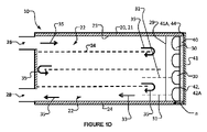
図1A~図1Eは、本発明の例示的な実施形態によるUV-LEDリアクタ10を示す。UV-LEDリアクタ10は、熱伝導管本体21によって画定される流体導管20と、プリント回路基板(PCB)40に動作可能に接続され、放射線を流体導管20に導くように配向された少なくとも1つのUV-LED30とを備える。より具体的には、UV-LED30は、第1の方向33に沿ってUV LED30から導管20内の流体に向かって延伸する主光軸31を有することによって、放射線を流体導管20に向けるように配向される。熱伝導管本体21は、1つまたは複数の熱伝導チャネル壁24を備え、熱伝導チャネル壁はリアクタ10内に流体流路22を画定する。流体導管20に入るおよび流体導管20から出る流体(例えば水)のための入口26および出口28がそれぞれ設けられている。流体流が入口26からリアクタ10に入り、長手方向に延伸する流路22を通って流れ、隣接する内側流路22の端部において旋回し、出口28から出ることを示す矢印35によって、主な流体流方向が図1Aおよび図1Dに示されている。UV LED30と流路22との間の熱伝導本体21に、石英または石英ガラス窓のようなUV透過窓29を埋め込むことができる。当業者には理解されるように、UV-LEDリアクタ10は、UV-LED30のためのドライバ回路(例えば、図2に示すLEDドライバ32)、マイクロコントローラ、電源ポート、オン/オフスイッチなどを含むことができる。図面を不明瞭にすることを避けるために、これらの一般的な構成要素はいずれも、図1A~図1Eには示されていない。コリメートレンズ、収束レンズ、および/もしくは他のレンズ(図示せず)、またはそれらの組み合わせを含む1つまたは複数のレンズを、UV-LEDリアクタ10内でUV-LED30と流体流路22との間に配置して、UV-LED放射パターンを、各UV-LED30に対応する主光軸31に沿って、長手方向に延伸する流体流路22へと集束させることができる。
1A-1E show a UV-
PCB40は、第1の表面41Aを有する熱伝導基板41を含む。熱伝導基板41の第1の表面41Aは、ほぼ平面であり、法線ベクトルnを有する。図1Bに示すように、法線ベクトルnは、実質的に第1の方向33(すなわち、放射線がUV-LED30から流体導管20に向けられる方向)に向けられてもよい。いくつかの実施形態では、第1の表面41Aの法線ベクトルnの向きが、実質的に第1の方向33にあることは、法線ベクトルnと第1の方向33との間の角度差が任意の面において25°未満であることを意味する。いくつかの実施形態では、この角度差は15°未満である。いくつかの実施形態では、この角度差は5°未満である。熱伝導管本体21は、PCB40の熱伝導基板41の第1の表面41Aと熱接触している。このようにして、熱は、UV-LED30から熱伝導基板41、熱伝導基板41の第1の表面41Aと熱伝導管本体21との間の熱接触を介して、熱伝導管本体21の1つまたは複数の熱伝導壁24から流体導管20を流れる流体へと放散される。
図1A~図1EのUV-LEDリアクタを参照すると、リアクタ10は、長手方向に延伸する流体流路22のアレイを備え、そのような各流路22は、任意選択的に対応する放射線集束素子(図示せず)を通じて、および、例示の実施形態では、UV透過窓29を通じて、1つの対応するUV-LED30によって照射される。他の実施形態では、各流路22は、2つ以上の対応するUV-LEDによって照射されてもよく、各UV-LED30からの放射を集束させるために、複数の放射線集束素子が組み込まれてもよい(各UV-LED30のための1つまたは複数の集光要素および/またはUV LED30の間で共有される1つまたは複数の放射線集束素子)を含む。対応するUV-LED30および/または対応する放射線集束素子は、それらの対応する長手方向に延伸する流路22の長手方向端部に位置決めされてもよい。リアクタ10は、放射線を1つの対応する流路22に向けるように配向されたいくつかのUV-LED30を含むことができる(すなわち、多対1のLEDおよび流路の比率)。リアクタ10は、異なるUV波長を放出するいくつかのUV-LED30を含むことができる。これは、相乗効果をもたらし、光反応および光触媒反応の速度を増加させることができる。流体が一方の長手方向に延伸するチャネル22から別の長手方向に延伸するチャネル22へと蛇行経路内で流れることを可能にするために、隣接する一対の流体流路22が、例えば、マニホルド(図2に示すマニホルド160など)または他の何らかの適切なポートを介して一端で接続され得る。図1A~図1Eに示される例示的な実施形態から分かるように、流体は複数の長手方向に延伸するチャネル22を通って進み、流体がUV-LEDリアクタ10を入口26と出口28との間で移動するときに複数回通過する。
Referring to the UV-LED reactor of FIGS. 1A-1E, the
図1A~図1EのUV-LEDリアクタ10を参照すると、流体は、UV-LEDリアクタ10を出入りして流れ、長手方向に延伸する流路22を通過し、UV-LED30からのUV放射線によって照射される。例示の実施形態では、UV-LED30は、流体導管20および長手方向に延伸する各流体流路22の各々の一端に位置決めされる。UV-LED30からの放射線の主光軸31(任意選択的に上述したレンズによって任意に集束された後)は、第1の方向33に延伸する。これらの第1の方向33は、長手方向に延伸するチャネル22における流体流の長手方向とほぼ平行であり得、長手方向に延伸する流路22の長手方向延伸にほぼ平行であり得る。図1A~図1Eは、リアクタ10の一端から照射されている流体導管20の例示の流路22を示す。一般に、UV-LEDリアクタの流体導管流路は、流路の長手方向の一方または両方の端部から照射されてもよい。いくつかの実施形態では、UV-LEDは、長手方向に対向するUV-LEDからの放射線の主光軸が、対向するが平行な長手方向になり得るように、UV-LEDリアクタの対向する長手方向端部に配置することができる。
Referring to UV-
UV-LED30および/またはリアクタ10の他の発熱する電子デバイス(図示せず)によって生成される熱を、UV-LED30(および/または他の電子デバイス)から放散させるために、UV-LED30を通じて流れ、UV-LED30によって照射されている流体を使用することができる。図1A~図1Eに示す例示的な実施形態では、照射される流体がUV-LED30およびPCB40の近傍で循環するように、リアクタ10が構成される。リアクタ10はまた、UV-LEDおよびPCB40から熱を放散させるための熱伝導チャネル壁24を備える熱伝導材料(熱伝導)導管本体21を組み込んでいる。具体的には、熱伝導管本体21は、PCB40の熱伝導基板41の第1の表面41Aと熱接触している。このようにして、熱は、UV-LED30から熱伝導基板41、熱伝導基板41の第1の表面41Aと熱伝導管本体21との間の熱接触を介して、熱伝導管本体21の1つまたは複数の熱伝導壁24から流体導管20を流れる流体へと放散される。UV-LEDリアクタ10のUV活性領域内(すなわち、UV-LED(複数可)30からのUV放射線によって照射されるリアクタ10の領域内)で熱交換が起こる。
Heat generated by the UV-
いくつかの実施形態では、リアクタ10は、任意選択的に、熱伝導管本体21とPCB40の熱伝導基板41の第1の表面41Aとの間の熱接触に介在し得る熱接触強化構成要素50(図1Eに示す)を含んでもよい。熱接触強化構成要素50は、パラフィンろうおよび/またはシリコーンベースの材料を含むがこれに限定されない熱伝導性材料を含む。いくつかの実施形態では、熱接触強化構成要素50は、熱伝導管本体21と第1の表面41Aとの間の物理的接触における小さな凹凸を充填するために変形可能である(例えば、変形可能なパッドまたは変形可能なゲルもしくはペースト)。熱伝導管本体21と第1の表面41Aとの間に介在するとき、熱接触強化構成要素50は、熱伝導管本体21と第1の表面41Aとの間の熱接触抵抗を減少させる(熱接触伝導率を増加させる)ことができる。熱接触強化構成要素50は任意選択であり、すべての実施形態において必須ではない。
In some embodiments, the
UV-LED30は、回路領域42においてPCB40に動作可能に接続されている。回路領域42において、PCBは、回路領域42内のはんだマスクコーティング42Aによって覆われてもよい(少なくとも大部分にわたって)。いくつかの実施形態では、熱伝導管本体21とPCB40の熱伝導基板41の第1の表面41Aとの間の熱接触を容易にするために、露出した熱接触領域44が第1の表面41Aに設けられる。熱接触領域44は、熱伝導管本体21と熱接触している第1の表面41Aの部分であってもよい。はんだマスクコーティング42Aは、熱接触領域44内でヘッド伝導PCB基板41の第1の表面41Aから除去することができる。例えば、図1Cに最もよく見られるように、熱接触領域44(例えば、はんだマスク42を欠いている)は、PCB40の縁部の周りに配置することができ、ただし、熱接触領域44は、電子部品が取り付けられておらず、電気的に接続されていない、PCB40の他の適切な領域に配置されてもよい)。PCB40のはんだマスクコーティング42は、非限定的な例として、レーザ切断、エッチングなどによって除去されて、熱伝導管本体21とPCB40の熱伝導基板41の第1の表面41Aとの間に熱接触を提供して、LED30、PCB40、チャネル壁(複数可)24、およびリアクタ10を流れる流体の間の熱伝達を容易にすることができる。いくつかの実施形態では、PCB40の縁部における熱接触領域44の幅は数ミリメートルであってもよい。一般に、熱接触領域44の寸法が大きくなればなるほど、熱伝達率は高くなる。しかし、熱接触領域44の寸法を大きくすると、リアクタ10全体のサイズが大きくなり得るため、トレードオフが存在する。PCB40の熱伝導基板層41を露出させるために外側層(例えばはんだマスク42)を除去することにより、PCB40と流体導管20の熱伝導性チャネル壁24との間の熱接触/結合が著しく改善され、そのため、UV-LED30からの熱を、チャネル22を通じて移動する流体に伝達することができる(例えば、流体流路22を画定するチャネル壁(複数可)24の表面積が大きいため、チャネル22内の移動する流体の性質のため、および、一般的にPCB40の温度よりも低い、流路22の内部の流体の温度のため)。
UV-
図2は、本発明の例示的な実施形態によるUV-LEDリアクタ100の部分斜視図を示す。リアクタ100の多くの特徴および構成要素は、リアクタ10の特徴および構成要素と同様であり、数字「1」が先頭に付された同じ参照番号が、リアクタ10のものと同様であるリアクタ100の特徴および構成要素を示すために使用されている。しかしながら、UV-LEDリアクタ100は、UV-LEDリアクタ10とは異なり、UV-LEDリアクタ100の熱伝導管本体121が熱伝導マニホルド160を備え、マニホルドは、図1A~図1Eに関連して上述したように、1つの長手方向に延伸する流路122から別の長手方向に延伸する流路122に流体が流れることを可能にするために、長手方向の一端において流路122間で流体流を誘導する。図2には示されていないが、リアクタ100は、その反対側の長手方向端部に別のマニホルド160を有することができる。熱伝導マニホルド160は、導管本体121の熱伝導チャネル壁124と一体的に形成されてもよく、または導管本体121の熱伝導壁124と熱的に接触して接合されてもよい。
FIG. 2 shows a partial perspective view of UV-
上述したリアクタ10のように、UV-LEDリアクタ100は、熱伝導管本体121によって画定される流体導管120と、プリント回路基板(PCB)140に動作可能に接続され、放射線を流体導管120に導くように配向された少なくとも1つのUV-LED130とを備える。より具体的には、UV-LED130は、第1の方向133に沿ってUV LED130から導管120内の流体に向かって延伸する主光軸131を有することによって、放射線を流体導管120に向けるように配向される。熱伝導管本体121は、1つまたは複数の熱伝導チャネル壁124を備え、熱伝導チャネル壁はリアクタ110内に流体流路122を画定する。PCB140は、第1の表面141Aを有する熱伝導基板141を含む。熱伝導基板141の第1の表面141Aは、ほぼ平面であり、法線ベクトルnを有する。図2に示すように、法線ベクトルnは、実質的に第1の方向133(すなわち、放射線がUV-LED130から流体導管120に向けられる方向)に向けられてもよい。いくつかの実施形態では、第1の表面141Aの法線ベクトルnの向きが、実質的に第1の方向133にあることは、法線ベクトルnと第1の方向133との間の角度差が任意の面において25°未満であることを意味する。いくつかの実施形態では、この角度差は15°未満である。いくつかの実施形態では、この角度差は5°未満である。熱伝導管本体121は、PCB140の熱伝導基板141の第1の表面141Aと熱接触している。このようにして、熱は、UV-LED130から熱伝導基板141、熱伝導基板141の第1の表面141Aと熱伝導管本体121との間の熱接触(マニホルド160を介する)を介して、熱伝導管本体121の1つまたは複数の熱伝導壁124から流体導管120を流れる流体へと放散される。
Like the
上述したリアクタ10と同様に、リアクタ100は、熱接触強化構成要素150がマニホルド160とPCB140の熱伝導基板141の第1の表面141Aとの間に(熱接触領域144において)介在することを除いて、上述の熱接触強化構成要素150と同様の特徴を有する熱接触強化構成要素150を含むことができる。例示の図2の実施形態のリアクタ100はまた、熱伝導本体121のマニホルド160とPCB140の第1の表面141とを互いに熱的に接触したままにし、それによって、空隙を最小化し、熱伝導率を高めるために、適切な締結具(図示せず)によってマニホルド160に結合され得る(例えば、ステンレス鋼を含むがこれに限定されない剛性材料から作製される)圧力板118をも備える。
Similar to
上述したリアクタ10と同様に、PCB140は、LED130が配置される回路領域142を含み、回路領域142ははんだマスク142Aで覆われてもよい。上述したリアクタ10と同様に、はんだマスク142Aは、熱接触領域144において熱伝導基板141の表面141Aから除去されてもよく、または熱接触領域144ははんだマスク142Aを欠いてもよい。図2は、例示の実施形態では、LED130と同じPCB140上に配置されたUV-LEDドライバ回路132を示す。これは必須ではなく、UV-LEDドライバ回路132は、空間が設計上の制約となる場合、他の場所に配置されてもよい。
Similar to
リアクタ100の長手方向の一方の端部のみが図2に示されているが、同じ概念が流路122の長手方向の他方の端部に適用されてもよい。すなわち、流路122内の流体は、長手方向の他方の端部からUV-LEDによって照射されてもよく、このようなUV-LED(および/またはリアクタ100の他の電子構成要素)によって生成される熱は、長手方向の一方の端部について本明細書において説明されているのと同じように除去することができる。
Although only one longitudinal end of
図1A~図1Eおよび図2に示す例示的な実施形態において、UV-LEDリアクタは、1つのUV-LEDまたはUV-LEDのアレイのいずれかによって照射される流体が対応する長手方向に流れる一連の長手方向に延伸する流路を備える。図1A~図1Eおよび図2の実施形態のようなマルチチャネルリアクタでは、流体流は、チャネルを並列または直列(流路がそれらの端部において流体連通している場合、流体流は一方の流路から他方の流路へ進む)に進むことができる。図3A~3Bに示す例示的な実施形態では、UV-LEDリアクタ200は、1つまたは複数のUV-LED230で照射される流体が対応する長手方向に流れる単一の長手方向に延伸する流体流路222を備える熱伝導管本体221によって画定される流体導管220を備える。主な流体流方向は図3A~図3Bにおいて矢印235で示され、入口226からUV-LEDリアクタ200に入り、長手方向に延伸する流路222を通って流れ、出口228から出る流体を示す。UV-LED放射線は、1つまたは複数の収束レンズおよびコリメートレンズのような集束素子(ここには図示せず)を介して集束される。リアクタチャネル222内の長手方向に流れる流体は、チャネル222の長手方向においてUV-LED(複数可)230からの集束放射によって照射される。UV-LED(複数可)230は、流路122の一端または両端に位置決めすることができる。流体に供給される全UV線量(UVフルエンス)は、流体流量を調整すること、および/または、UV-LED放射強度を調節すること、および/または、UV-LEDの数をオン/オフすることによって制御することができる。リアクタ200の多くの特徴および構成要素は、リアクタ10の特徴および構成要素と同様であり、数字「2」が先頭に付された同じ参照番号が、リアクタ10のものと同様であるリアクタ200の特徴および構成要素を示すために使用されている。
In the exemplary embodiment shown in FIGS. 1A-1E and 2, the UV-LED reactor comprises a corresponding longitudinal series of fluid illuminated by either a single UV-LED or an array of UV-LEDs. with a channel extending in the longitudinal direction of the In multi-channel reactors, such as the embodiments of FIGS. 1A-1E and 2, fluid flow is directed through the channels in parallel or in series (where the flow paths are in fluid communication at their ends, the fluid flow is in one direction). from one channel to the other channel). In the exemplary embodiment shown in FIGS. 3A-3B, UV-
図1A~図1Eおよび図2に示す例示的な実施形態において、UV-LEDリアクタは、一方の端部において1つのUV-LEDまたはUV-LEDのアレイによって照射される流体が対応する長手方向に流れる一連の長手方向に延伸する流路を備える。図1A~図1Eおよび図2の実施形態のようなマルチチャネルリアクタでは、UV-LED30からの放射線(任意選択的に上述のレンズによって集束された後)および長手方向に延伸するチャネル22内の流体流の主な方向は、長手方向に延伸する流路22の長手方向延伸にほぼ平行な長手方向に沿っている。いくつかの実施形態では、UV-LEDからの放射線が長手方向に延伸する流路の長手方向延伸および流路内の流体の主な流体流方向にほぼ直交するように、UV-LEDは、付加的または代替的に流路に沿って位置決めされてもよい。例えば、図4は、本発明の例示的な実施形態によるUV-LEDリアクタ300の上面断面図を示す。リアクタ300の多くの特徴および構成要素は、リアクタ10の特徴および構成要素と同様であり、数字「3」が先頭に付された同じ参照番号が、リアクタ10のものと同様であるリアクタ300の特徴および構成要素を示すために使用されている。
In the exemplary embodiment shown in FIGS. 1A-1E and 2, the UV-LED reactor has a longitudinal direction corresponding to the fluid illuminated by one UV-LED or array of UV-LEDs at one end. A series of longitudinally extending channels for flow are provided. In a multi-channel reactor such as the embodiment of FIGS. 1A-1E and 2, the radiation from the UV-LEDs 30 (optionally after being focused by a lens as described above) and the fluid in the
図4に示される例示的な実施形態から分かるように、流体は複数の長手方向に延伸するチャネル322(熱伝導管本体321およびその熱伝導壁324によって画定される)を通って進み、流体がUV-LEDリアクタ300を通って入口と出口(ここでは示さず)との間で移動するときに複数回通過する。UV-LED330および/またはリアクタ300の他の発熱する電子デバイス(図示せず)によって生成される熱を、UV-LED330(および/または他の電子デバイス)から放散させるために、チャネル322を通って流れ、UV-LED330によって照射されている流体を使用することができる。図4に示す例示的な実施形態では、照射される流体がUV-LED330のUV活性領域内で循環するように、リアクタ300が構成される。より具体的には、UV-LED330は、第1の方向に沿ってUV LED330から導管320内の流体に向かって延伸する主光軸を有することによって、放射線を流体導管320に向けるように配向される。熱伝導管本体321は、1つまたは複数の熱伝導チャネル壁324を備え、熱伝導チャネル壁はリアクタ310内に流体流路322を画定する。PCB340は、第1の表面を有する熱伝導基板を含む。熱伝導基板の第1の表面は、概して平面であり、実質的に第1の方向(すなわち、放射線がUV-LED330から流体導管320に向けられる第1の方向)に配向され得る法線ベクトルnを有する。実質的に第1の方向の意味は、本明細書の他の箇所に記載された意味を有することができる。熱伝導管本体321は、PCB340の熱伝導基板の第1の表面と熱接触している。このようにして、熱は、UV-LED330から熱伝導基板、熱伝導基板の第1の表面と熱伝導管本体321との間の熱接触を介して、熱伝導管本体321の1つまたは複数の熱伝導壁324から流体導管320を流れる流体へと放散される。図4に示すリアクタ300は、上述したリアクタ10,110と同様の他の特性および構成要素を含むことができる。
As can be seen from the exemplary embodiment shown in FIG. 4, the fluid travels through a plurality of longitudinally extending channels 322 (defined by the heat transfer tube body 321 and its heat transfer walls 324) such that the fluid Multiple passes are made as it moves through the UV-
図5は、本発明の例示的な実施形態によるUV-LEDリアクタ400の上面断面図を示す。UV-LEDリアクタ400は、一連の長手方向に積み重ねられたリアクタ300を含む。流体は、図4に関連して上述したように、入口および出口(ここには図示せず)の間でUV-LEDリアクタ400を通って進む。リアクタ400によって利用される熱管理技法は、図4に関連して上述した熱管理技法と同様である。リアクタ400の多くの特徴および構成要素は、リアクタ10の特徴および構成要素と同様であり、数字「4」が先頭に付された同じ参照番号が、リアクタ10のものと同様であるリアクタ400の特徴および構成要素を示すために使用されている。
FIG. 5 shows a top cross-sectional view of a UV-
本明細書に記載の長手方向に延伸する流体流路は、円形、半円形、正方形、矩形、三角形、台形、六角形などを含むが、これらに限定されない任意の適切な形状をとることができる断面を有する。これらの断面は、熱管理を改善することによってリアクタの性能を向上させることができる。例えば、円形断面を有する流体流路は、リアクタのUV-LED(および/または他の電子デバイス)に最適な熱管理を提供することができる。図6に示す例示的な実施形態では、UV-LEDリアクタ500は、三角形断面を有する長手方向に延伸する流体流路522を含む。流体は、図4に関連して上述したように、入口および出口(ここには図示せず)の間でUV-LEDリアクタ500を通って進む。リアクタ500によって利用される熱管理技法は、図4に関連して上述した熱管理技法と同様である。リアクタ500の多くの特徴および構成要素は、リアクタ10の特徴および構成要素と同様であり、数字「5」が先頭に付された同じ参照番号が、リアクタ10のものと同様であるリアクタ500の特徴および構成要素を示すために使用されている。
The longitudinally extending fluid flow channels described herein can take any suitable shape including, but not limited to, circular, semi-circular, square, rectangular, triangular, trapezoidal, hexagonal, and the like. have a cross section. These cross-sections can improve reactor performance by improving thermal management. For example, fluid flow channels with circular cross-sections can provide optimal thermal management for UV-LEDs (and/or other electronic devices) in the reactor. In the exemplary embodiment shown in FIG. 6, UV-
本明細書で説明する熱管理技法は、PCB上に接続されたUV-LEDを含む電子機器から熱を放散するために流体(典型的には水)を利用する。これは、PCBの熱伝導基板と、流路(および/またはマニホルド)内を移動する流体で連続的に冷却される流体導管熱伝導壁との間の熱接触を最大限にすることによって達成される。熱伝導管本体とPCBの熱伝導基板との間の熱接触の熱接触抵抗は、本明細書の他の箇所に記載されているように、熱間隙を埋めるために、変形可能で熱伝導性の熱接触強化構成要素(例えば熱接触構成要素50,150)を、熱伝導管本体とPCBの熱伝導基板の第1の表面との間に介在させること、および/または、PCBの縁部(または他の領域(複数可))からはんだマスクコーティングを除去することによって、大幅に低減することができる。そのような熱接触強化構成要素は任意選択である。
The thermal management techniques described herein utilize a fluid (typically water) to dissipate heat from electronics including UV-LEDs connected on a PCB. This is achieved by maximizing thermal contact between the thermally conductive substrate of the PCB and the fluid conduit thermally conductive walls that are continuously cooled by fluid moving within the channels (and/or manifolds). be. The thermal contact resistance of the thermal contact between the thermally conductive tube body and the thermally conductive substrate of the PCB is determined by a deformable and thermally conductive material to fill the thermal gap, as described elsewhere herein. of the thermal contact enhancement component (e.g.,
ヒートシンク(複数可)を使用すること、または、またはPCBの背部(すなわち、UV-LEDが接続されている側の反対側)において流体流を通過させることなど、能動的または受動的な熱除去および熱管理の他の技法を、本明細書に記載の放熱装置および方法と組み合わせて使用することもできる。 Active or passive heat removal and Other techniques of thermal management can also be used in combination with the heat dissipation devices and methods described herein.
UV-LEDリアクタ(図示せず)のいくつかの実施形態は、長手方向に延伸する流体流路を通る流体を照射する複数のUV-LEDを備える。いくつかの実施形態(ここには図示せず)では、複数の放射線集束素子が組み込まれており(各UV-LEDに対して1つ)、各UV-LEDからの放射線は、対応する集束素子によって集束される。いくつかの実施形態では、1つまたは複数のLEDから成るグループが、任意の適切な内容で、1つまたは複数の対応する集束素子(または1つまたは複数の対応する集束素子内からの1つまたは複数の対応するレンズ)から成るグループを共有することができる。例えば、合計9個のLEDおよび3個のレンズがあってもよく、LEDは3つのLEDから成る3つのグループにグループ化され、3つのLEDから成る各グループからの放射が、LEDグループに対応する単一のレンズを通過する。複数のUV-LEDを組み込んだUV-LEDリアクタが、相対的に大きな断面を有する空孔を有する流体流路に特に適し得る。複数のUV-LEDは、流体流路を照射するために単一のUV-LEDによって操作される実施形態と比較して、そのような流体流路における放射照度を増加させることによって照射範囲を最大にするのを助けることができる。 Some embodiments of the UV-LED reactor (not shown) include multiple UV-LEDs that illuminate the fluid through longitudinally extending fluid channels. In some embodiments (not shown here), multiple radiation-focusing elements are incorporated (one for each UV-LED), and radiation from each UV-LED is directed to a corresponding focusing element. is focused by In some embodiments, a group of one or more LEDs is associated with one or more corresponding focusing elements (or one from within one or more corresponding focusing elements) in any suitable manner. or multiple corresponding lenses) can be shared. For example, there may be a total of 9 LEDs and 3 lenses, the LEDs grouped into 3 groups of 3 LEDs, and the emission from each group of 3 LEDs corresponds to an LED group. Pass through a single lens. A UV-LED reactor incorporating multiple UV-LEDs may be particularly suitable for fluid flow paths having pores with relatively large cross-sections. Multiple UV-LEDs maximize illumination coverage by increasing the irradiance in such fluid flow paths compared to embodiments operated by a single UV-LED to illuminate such fluid flow paths. can help you to
本発明のUV-LEDリアクタは、多くの光反応、光触媒リアクタおよび光開始反応に使用することができる。1つの特定の用途は、水の浄化または他のUV透過性流体の浄化である。水処理は、直接光反応、光触媒反応および/または光開始酸化反応による、微生物(例えば細菌およびウイルス)の不活性化および化学汚染物質(例えば毒性有機化合物)などの微小汚染物質の分解によって達成され得る。水は、電気ポンプなどの流体移動デバイスの使用によってUV-LEDリアクタを通って流れることができる。UV-LEDは、壁プラグ、太陽電池または電池によって給電することができる。妥当な場合、光触媒は、流体が通過する中実基板、および/または例えばメッシュ、スクリーン、金属フォーム、布もしくはそれらの組み合わせを含む、流体が通過する有孔基板上に固定化され得る。固体および/または有孔基板上に支持された光触媒は、長手方向に延伸する流体流路内に位置決めすることができる。光触媒はまた、断面を部分的または全体的に覆うように、流体流路の断面内に位置決めすることもできる。光触媒が流路の断面全体を覆う場合、流体が光触媒基板を通過することを可能にするために有孔基板を使用することができる。光触媒はUV-LEDからの集束UV放射線を照射され、UV-LED光触媒リアクタが提供される。光触媒は、二酸化チタン、または任意の他の光触媒を含んでもよい。特定の実施形態では、1つまたは複数の光触媒、触媒担体および共触媒の組み合わせが、固体および/または有孔基板(複数可)上に設けられる。妥当な場合、化学酸化剤のような化学反応剤をUVリアクタに注入することができる。化学酸化剤は、過酸化水素、オゾン、または他の化学物質を含んでもよい。UV-LEDは、外部信号によって自動的にオン/オフすることができる。リアクタは、静的ミキサ、ボーテックスジェネレータ、バッフル等のような、導管内の流体流を抑制するための1つまたは複数の構成要素を含むことができる。 The UV-LED reactor of the present invention can be used for many photoreactions, photocatalytic reactors and photoinitiation reactions. One particular application is the purification of water or other UV transparent fluids. Water treatment is achieved by inactivation of microorganisms (e.g. bacteria and viruses) and degradation of micropollutants such as chemical contaminants (e.g. toxic organic compounds) by direct photoreaction, photocatalysis and/or photoinitiated oxidation reactions. obtain. Water can be flowed through the UV-LED reactor by use of a fluid movement device such as an electric pump. UV-LEDs can be powered by wall plugs, solar cells or batteries. Where applicable, the photocatalyst may be immobilized on a fluid-passing solid substrate and/or a fluid-passing perforated substrate including, for example, mesh, screen, metal foam, cloth, or combinations thereof. A photocatalyst supported on a solid and/or perforated substrate can be positioned within the longitudinally extending fluid flow channel. The photocatalyst can also be positioned within the cross-section of the fluid flow channel so as to partially or wholly cover the cross-section. If the photocatalyst covers the entire cross section of the channel, a perforated substrate can be used to allow the fluid to pass through the photocatalytic substrate. The photocatalyst is irradiated with focused UV radiation from a UV-LED to provide a UV-LED photocatalytic reactor. The photocatalyst may include titanium dioxide, or any other photocatalyst. In certain embodiments, a combination of one or more photocatalysts, catalyst supports and co-catalysts is provided on a solid and/or perforated substrate(s). If applicable, chemical reactants such as chemical oxidants can be injected into the UV reactor. Chemical oxidants may include hydrogen peroxide, ozone, or other chemicals. The UV-LED can be turned on/off automatically by an external signal. The reactor may include one or more components for restricting fluid flow within the conduit, such as static mixers, vortex generators, baffles, and the like.
いくつかの実施形態では、静的ミキサ、ボーテックスジェネレータ、バッフルなどを長手方向に延伸する流体流路に配備して、流体流路を通過する際に混合を増加させ、かつ/または流体流を回転させることができる。これは、より均一なUV線量を送達することによって、またはリアクタ内で光触媒が存在する光触媒表面付近の物質移動を改善することによって、UV-LEDリアクタの性能を向上させることができる。静的ミキサ、ボーテックスジェネレータ、バッフルなどはまた、流体流路内のUV放射線フルエンス率プロファイルに合致するように、様々な入来する流動様式に適応するように動的に調整することができる流れ制約要素としての役割を果たすこともできる。 In some embodiments, static mixers, vortex generators, baffles, etc. are deployed in the longitudinally extending fluid flow path to increase mixing and/or rotate the fluid flow as it passes through the fluid flow path. can be made This can improve the performance of the UV-LED reactor by delivering a more uniform UV dose or by improving mass transport near the photocatalyst surface where the photocatalyst resides within the reactor. Static mixers, vortex generators, baffles, etc. can also be dynamically adjusted to accommodate various incoming flow regimes to match the UV radiation fluence rate profile within the fluid flow path. It can also serve as an element.
本明細書に記載のUV-LEDリアクタの実施形態の熱伝導管本体は、アルミニウム、ステンレス鋼、または金属、合金、高強度プラスチックなどのような他の十分に強固な材料から作成されていてもよい。流体流路を画定する流体導管の内壁は、内壁に入射する放射線の任意の部分を流体に反射するために、高いUV反射率を有する材料から作成されるか、または、当該材料によってコーティングされる(必ずしも必要ではない)ことが可能である。 The heat-conducting tube bodies of the UV-LED reactor embodiments described herein may be made from aluminum, stainless steel, or other sufficiently robust materials such as metals, alloys, high-strength plastics, and the like. good. The inner wall of the fluid conduit defining the fluid flow path is made of or coated with a material with high UV reflectivity to reflect any portion of the radiation incident on the inner wall to the fluid. (but not necessarily) possible.
本明細書に記載された実施形態は、特定の特徴および流体流路構成またはレンズ構成などを有して提示されているが、本明細書に記載の特徴または構成の任意の他の適切な組み合わせがUV-LEDリアクタに存在し得ることを理解されたい。 Although the embodiments described herein are presented with particular features and fluid flow channel configurations or lens configurations, etc., any other suitable combination of features or configurations described herein may be used. can be present in the UV-LED reactor.
さらに、UV-LEDリアクタは、異なるピーク波長のUV-LEDを組み込んで、相乗効果を引き起こして光反応効率を高めることができる。 In addition, UV-LED reactors can incorporate UV-LEDs with different peak wavelengths to cause synergistic effects and increase photoreaction efficiency.
いくつかの実施形態では、UV-LEDリアクタは、UV-LEDのアレイによって照射される、石英または石英ガラス窓で覆われた平坦な流路を含む。この構成には、2つの別個の形式を有し得る。
a.チャネル(複数可)(平行チャネルを含む)を流れる流体が、主に流路長(または主流方向)の軸に垂直な方向においてUV-LEDによって照射される。この場合、LED(複数可)は流路の長さに沿って位置決めされる。流れは主にUV-LEDの下/上を移動し、照射される。
b.チャネル(複数可)を流れる流体が、主に流路長(または主流方向)の軸に平行な方向においてUV-LEDによって照射される。この場合、LED(複数可)は流路(複数可)の一端または両端に位置決めされる。流れは主にUV-LEDに向かってまたはUV-LEDから外方に移動し、照射される。
In some embodiments, the UV-LED reactor comprises a flat channel covered with a quartz or fused silica window that is illuminated by an array of UV-LEDs. This configuration can have two distinct forms.
a. A fluid flowing through the channel(s) (including parallel channels) is illuminated by a UV-LED primarily in a direction perpendicular to the axis of the channel length (or mainstream direction). In this case, the LED(s) are positioned along the length of the channel. The stream mainly travels under/over the UV-LEDs and is illuminated.
b. A fluid flowing through the channel(s) is illuminated by the UV-LED primarily in a direction parallel to the axis of the channel length (or mainstream direction). In this case, the LED(s) are positioned at one or both ends of the channel(s). The flow mainly moves towards or away from the UV-LEDs and is irradiated.
これらの構成のいずれにおいても、UV放射線への流体の曝露を制御することができる。流路およびUV-LEDアレイは、流れが所望の数のLEDに曝露されるように配置され得る。設計は、単一流路、一連の平行な流路、または複数の流路からなるスタックであってもよい。流体に供給される全UV線量は、流量を調整すること、および/または、UV-LED強度を調節すること、および/または、UV-LEDの数をオン/オフすることによって制御することができる。この設計は、薄い平らなUV-LEDリアクタの製造を可能にする。例えば、いくつかの実施形態では、UV-LDリアクタは、流体のための入口ポートおよび出口ポートを有し、形状および寸法の点で、スマートフォンのサイズとほぼ同じであってもよい。 In any of these configurations, the exposure of the fluid to UV radiation can be controlled. The channels and UV-LED arrays can be arranged such that the flow is exposed to the desired number of LEDs. The design may be a single channel, a series of parallel channels, or a stack of multiple channels. The total UV dose delivered to the fluid can be controlled by adjusting the flow rate and/or adjusting the UV-LED intensity and/or turning on/off the number of UV-LEDs. . This design allows the fabrication of thin flat UV-LED reactors. For example, in some embodiments, the UV-LD reactor has inlet and outlet ports for the fluid and can be approximately the size of a smart phone in shape and dimensions.
いくつかの実施形態では、主な照射方向が流れの主方向に対して垂直になるように、複数のLEDが、長手方向に延伸する流体流路の長さに沿って位置決めされる。LED(複数可)は、長手方向に延伸する流体流路の一方の側に沿って、または対向する両側に沿って位置決めされてもよい。この流れは主にUV-LEDの下(または上)に移動し得、長手方向に延伸する流体流路を通って長手方向に進むときに照射され得る。チャネルの内壁は、流体への放射線伝達を促進するために、高いUV反射率を有する材料から作成されるか、またはそれによってコーティングされ得る。流体が1つのチャネルから別のチャネルに移動するために、2つの隣接する流体流路が一端において接続されていてもよい(流体はリアクタを多段に通過する)。UV-LED放射パターンを調整するために、コリメートレンズ、発散レンズ、収束レンズ、および他のレンズを含む種々のレンズをUV-LEDリアクタに設置することができる。 In some embodiments, multiple LEDs are positioned along the length of the longitudinally extending fluid flow channel such that the primary illumination direction is perpendicular to the primary direction of flow. The LED(s) may be positioned along one side or along opposite sides of the longitudinally extending fluid flow path. This stream may move primarily under (or over) the UV-LEDs and may be illuminated as it travels longitudinally through the longitudinally extending fluid flow channel. The inner walls of the channel may be made of or coated with a material with high UV reflectance to facilitate radiation transmission into the fluid. Two adjacent fluid flow paths may be connected at one end (fluid passes through the reactor in multiple stages) for fluid movement from one channel to another. Various lenses, including collimating lenses, diverging lenses, converging lenses, and other lenses, can be installed in the UV-LED reactor to adjust the UV-LED radiation pattern.
UV-LEDリアクタの特定の用途は、例えば、使用場所の用途における、低~中程度の流量の水の処理および処置を含む。さらに、本明細書に記載の実施形態によるUV-LEDリアクタは、そのコンパクトな構成および高い効率に起因して、器具(例えば、冷蔵庫、冷凍庫、水冷器、コーヒーマシン、給水器、製氷機など)、健康管理または医療デバイスまたは設備、歯科用機器、および清潔な水の使用を必要とする任意の他のデバイスに組み込むことができる。UV-LEDリアクタは、デバイスに組み込まれてもよく、既存のデバイスに追加物として適用されてもよい。例えば、UV-LEDリアクタは、UV-LEDリアクタがデバイス内で使用される(例えば、デバイスの送水管を通過する)水を処理するように、送水管のいずこかに位置決めされてもよい。これは、パイプを通過する間に流体が照射/処理される必要がある場合、またはパイプの内部に潜在的な微生物バイオフィルムの形成を防止する必要がある場合、または使用前にパイプラインの端部において流れが処理される必要がある場合に、特に興味深いものであり得る。UV-LEDリアクタは、1つまたは複数の他の形態の水浄化方法(ろ過など)と共にデバイスに組み込まれてもよい。次に、UV-LEDリアクタの例示的な使用場所の流体処理応用形態を、図7~図9を参照して説明する。 Particular applications of UV-LED reactors include low to moderate flow water treatment and treatment, for example, in point-of-use applications. Furthermore, due to its compact configuration and high efficiency, UV-LED reactors according to embodiments described herein can be used in appliances (eg, refrigerators, freezers, water coolers, coffee machines, waterers, ice machines, etc.). , healthcare or medical devices or equipment, dental equipment, and any other device that requires the use of clean water. UV-LED reactors may be incorporated into devices or applied as an add-on to existing devices. For example, a UV-LED reactor may be positioned anywhere in the water pipe such that the UV-LED reactor treats water used within the device (eg, passing through the water pipe of the device). . This may be useful if the fluid needs to be irradiated/treated while passing through the pipe, or if potential microbial biofilm formation inside the pipe needs to be prevented, or if the end of the pipeline needs to be cleaned prior to use. It can be of particular interest if the flow needs to be processed in the section. UV-LED reactors may be incorporated into devices along with one or more other forms of water purification methods (such as filtration). Exemplary in-situ fluid treatment applications for UV-LED reactors will now be described with reference to FIGS. 7-9.
図7は、入口パイプ626、出口パイプ628、および給水栓605を備え、水の処理のためにUV-LED630によって操作されるUV-LEDリアクタ610を組み込んだ水処理システム600を示す。水は、入口626を介してリアクタ610に入り、UV-LEDリアクタ610を通過し、一般的な使用のために出口パイプ638から出て給水栓605に進む前にUV-LED630から放出されるUV放射線によって照射される。概略的な流体流方向が矢印で示されている。リアクタ610の多くの特徴および構成要素は、リアクタ10の特徴および構成要素と同様であり、数字「6」が先頭に付された同じ参照番号が、リアクタ10のものと同様であるリアクタ600の特徴および構成要素を示すために使用されている。
FIG. 7 shows a
いくつかの実施形態では、UV-LEDリアクタは、冷凍庫、水冷器、コーヒーメーカ、自動販売機などのような、人間による消費のために水(または水ベースの流体)を分配または使用する器具に組み込まれてもよい。人間による消費に使用される水は高度の浄化が必要である。例えば、冷蔵庫、冷凍庫、および水冷器の主な給水設備は、有害な病原体を含む可能性がある。これは、水道網に分配される前に水が適切に処理されない可能性のある途上国および遠隔地において特に懸念される。さらに、その特定の構造に起因して、冷蔵庫/冷凍庫の送水管は、バイオフィルムおよび微生物汚染を起こしやすいものであり得る。一般的に、ポリマーチューブが、屋外の氷および飲料水において使用されるために、水を主給水設備から冷蔵庫に移送する。特に水が使用されていないとき、細菌性バイオフィルムが送水管内に形成する可能性がある(例えば、バイオフィルムは8時間以内に形成する可能性がある)。間欠的な水使用パターンは、水柱全体が、日中長時間にわたって送水管内に停滞する原因となる。給水管が、表面上の細菌のコロニー形成およびバイオフィルムの形成を受けやすいことは、よく認識されている問題である。 In some embodiments, UV-LED reactors are applied to appliances that dispense or use water (or water-based fluids) for human consumption, such as freezers, water coolers, coffee makers, vending machines, etc. may be incorporated. Water used for human consumption requires a high degree of purification. For example, the main water supply for refrigerators, freezers, and water coolers can contain harmful pathogens. This is of particular concern in developing countries and remote areas where water may not be properly treated before distribution to the water network. Additionally, due to their particular construction, refrigerator/freezer water lines can be prone to biofilm and microbial contamination. Typically, polymer tubing transfers water from the main water supply to the refrigerator for use in outdoor ice and potable water. Bacterial biofilms can form in water pipes, especially when water is not being used (eg, biofilms can form within 8 hours). Intermittent water usage patterns cause the entire water column to remain in the water pipe for long periods of the day. The susceptibility of water pipes to bacterial colonization and biofilm formation on surfaces is a well-recognized problem.
水の流れの開始および停止に応答して、リアクタのUV-LEDを自動的にオンおよびオフにすることができる。センサは、流体流を検出し、UV-LEDをオンまたはオフにするためにリアクタに信号を送信するために使用することができる。UV-LEDリアクタは、(消費のための)送水管から出る水の中の微生物汚染を減少させ、感染リスクを低下させることができる。これは、UV-LEDの動作条件によって容易になる。例えば、UV-LEDは様々な温度で動作することができ、高い頻度でオンとオフとを切り替えることができ、これは特に冷蔵庫および水冷器用途にとって重要である。 Reactor UV-LEDs can be turned on and off automatically in response to starting and stopping water flow. Sensors can be used to detect fluid flow and send signals to the reactor to turn the UV-LEDs on or off. UV-LED reactors can reduce microbial contamination in water exiting water pipes (for consumption), lowering the risk of infection. This is facilitated by the UV-LED operating conditions. For example, UV-LEDs can operate at different temperatures and can be switched on and off frequently, which is especially important for refrigerator and water cooler applications.
人間による消費を意図した水または水ベースの流体(例えば、コーヒーまたは他の飲料)を分配または使用する任意の器具は、水を処理するために本明細書に記載の実施形態によるUV-LEDリアクタを組み込むことができる。例えば、図8は、本体711と、水/氷ディスペンサ714に水を送るためのパイプ713とを備える冷蔵庫700を示す。冷蔵庫700には、UV-LEDリアクタ710が組み込まれている。リアクタ710の多くの特徴および構成要素は、リアクタ10の特徴および構成要素と同様であり、数字「7」が先頭に付された同じ参照番号が、リアクタ10のものと同様であるリアクタ710の特徴および構成要素を示すために使用されている。パイプ713内を流れる水はUV-LEDリアクタ710を通過し、水/氷ディスペンサ714に入る前にUV放射線によって照射される。概略的な流体流方向が矢印で示されている。同様に、UV-LEDリアクタを組み込むことから利益を得ることができる他の器具には、冷凍庫、製氷機、冷凍飲料機、水冷器、コーヒーメーカ、自動販売機などが含まれるが、これらに限定されない。
Any appliance that dispenses or uses water or water-based fluids intended for human consumption (e.g., coffee or other beverages) may use a UV-LED reactor according to embodiments described herein to treat the water. can be incorporated. For example, FIG. 8 shows a
本明細書に記載された実施形態によるUV-LEDリアクタの他の用途には、手術、洗浄または清浄な水を必要とする別の目的のために、健康管理または歯科関連または医療用デバイスまたは設備内でまたはそれによって使用される水または他の流体の処理が含まれる。特に、多くの健康管理用途では、水質が飲料水よりも高い水準であることが要求される。本明細書に記載されるUV-LEDリアクタの効率およびコンパクト性は、それらのリアクタを、医療機器における実施のための従来のUVランプリアクタよりも魅力的にすることができる。 Other uses of UV-LED reactors according to embodiments described herein include health care or dental related or medical devices or equipment for surgery, cleaning or other purposes requiring clean water. treatment of water or other fluids used in or by it. In particular, many health care applications require water quality to be of a higher standard than drinking water. The efficiency and compactness of the UV-LED reactors described herein can make them more attractive than conventional UV lamp reactors for implementation in medical devices.
例えば、図9は、本体821と、UV-LEDリアクタ810を収容するパイプ823とを含む血液透析器800を示す。パイプ823を流れる水は、血液透析器での使用に先立ち、処理のためにUV-LEDリアクタ810を通過する。リアクタ810の多くの特徴および構成要素は、リアクタ10の特徴および構成要素と同様であり、数字「8」が先頭に付された同じ参照番号が、リアクタ10のものと同様であるリアクタ810の特徴および構成要素を示すために使用されている。同様に、UV-LEDリアクタを組み込むことから利益を得ることができる他の器具には、限定されるものではないが、結腸洗浄治療機器、および洗浄または手術のために水を供給する歯科機器などが含まれる。
For example, FIG. 9 shows a
歯科機器の用途に関して、歯科ユニットウォーターライン(DUWL)の調査は、バイオフィルムの形成が問題であり、DUWLにおいて同定された細菌の大部分が遍在するものであることを示している。このような細菌は家庭の水分配システムでは少ない数しか存在しないかもしれないが、歯科ユニットの、空孔の狭い送水管の内腔表面にバイオフィルムとして繁栄する可能性がある。汚染されたDUWLからの微生物は、作業ユニットハンドピースによって生成されるエアロゾルおよび跳ねによって転移する。様々な研究は、DUWLにおける微生物汚染の低減の必要性を強調している。 With respect to dental instrumentation applications, a survey of dental unit waterlines (DUWL) indicates that biofilm formation is a problem and that most of the bacteria identified in DUWL are ubiquitous. Although such bacteria may be present in low numbers in domestic water distribution systems, they can thrive as biofilms on the luminal surfaces of narrow-bore water pipes in dental units. Microorganisms from contaminated DUWL are transferred by aerosols and splashes produced by the work unit handpiece. Various studies highlight the need to reduce microbial contamination in DUWL.
いくつかの実施形態では、ユニットに使用される水を処理するためにUV-LEDリアクタを歯科ユニットに組み込むことができる。UV-LEDリアクタは、歯科ユニット(歯科用椅子など)に一体化されてもよく、またはUV-LEDリアクタは、使用前に水を処理するために、水スプレーを保持する歯科用椅子のトレイ(アシスタントトレイ)内、もしくは、水スプレーハンドル内、もしくは、送水管を通じた他のいずこかに配置されてもよい。インスタントオンおよびオフを含む機能が、歯科ユニットに組み込まれたUV-LEDリアクタに含まれてもよい。 In some embodiments, a UV-LED reactor can be incorporated into the dental unit to treat water used in the unit. The UV-LED reactor may be integrated into a dental unit (such as a dental chair) or the UV-LED reactor may be placed in a dental chair tray ( assistant tray), or in the water spray handle, or anywhere else through the water line. Features including instant on and off may be included in the UV-LED reactor built into the dental unit.
いくつかの実施形態は、パルスモードで動作するUV-LEDを含む。例えば、LEDは高周波でパルスされてもよい。この動作モードは、光触媒効率を高めるために光反応速度および光触媒の電子-正孔再結合に影響を及ぼし得る。 Some embodiments include UV-LEDs operating in pulsed mode. For example, an LED may be pulsed at a high frequency. This mode of operation can influence the photoreaction rate and electron-hole recombination of the photocatalyst to enhance photocatalytic efficiency.
いくつかの実施形態では、UV-LEDは自動的にオンおよびオフするようにプログラムすることができる。例えば、流体流がリアクタ内での移動を開始または停止するとき(使用場所での適用における水浄化に有用であり得る)、または特定の時間間隔をおいてUV-LEDをオン/オフすることが望ましい場合がある。UV-LEDのオン/オフ状態を制御するために、流体流路内の流体の動きを検出するためにセンサを使用することができる。代替的に、ユーザは、直接的に(例えば、スイッチをオンまたはオフにすることによって)、または間接的な動作として(例えば、タップをオンおよびオフにすることによって)、センサを物理的に起動することができる。この特徴は、有利にはリアクタによって使用されるエネルギーを節約することができる。別の例として、微生物の可能性のある成長、未処理の上流の流体からの微生物の拡散を防止するために、および/または、任意のバイオフィルム形成を防止するために、UVリアクタチャンバがある時間作動していないときにUVリアクタチャンバを洗浄するために、特定の時間間隔をおいてUV-LEDをオン/オフすることが望ましい場合がある。UV-LEDのオン/オフ状態を制御するために、マイクロコントローラを適用して、特定の時間間隔をおいて(例えば数時間に一度)、UV-LEDを一定時間(例えば数秒間)にわたってオンにするように、プログラムすることができる。 In some embodiments, UV-LEDs can be programmed to turn on and off automatically. For example, when the fluid flow starts or stops moving in the reactor (which can be useful for water purification in point-of-use applications), or at specific time intervals the UV-LED can be turned on/off. may be desirable. A sensor can be used to detect fluid movement in the fluid flow path to control the on/off state of the UV-LED. Alternatively, the user physically activates the sensor either directly (e.g. by turning a switch on or off) or as an indirect action (e.g. by turning a tap on and off). can do. This feature can advantageously save energy used by the reactor. Another example is a UV reactor chamber to prevent potential growth of microorganisms, spread of microorganisms from untreated upstream fluids, and/or to prevent any biofilm formation. It may be desirable to turn the UV-LEDs on and off at specific time intervals to clean the UV reactor chamber during periods of inactivity. To control the on/off state of the UV-LEDs, a microcontroller is applied to turn on the UV-LEDs for a certain period of time (eg, seconds) at specific time intervals (eg, once every few hours). can be programmed to
いくつかの実施形態では、UV-LEDの少なくともいくつかは、信号を受信することに応答して、その出力を調整するように、または自動的にオンもしくはオフにするようにプログラムすることができる。この信号は、例えば、UV-LEDリアクタを通過する流体の流量(または他の測定可能な特性)が変化するときに生成されてもよい。流体が水である実施形態では、測定可能な特性は、水質または汚染物質の濃度を示すものであり得る。水質指標の例には、UV透過率および濁度が含まれる。この構成は、特定の動作条件に基づいて適切な放射線エネルギーが流体に向けられることを促進することができる。 In some embodiments, at least some of the UV-LEDs can be programmed to adjust their output or automatically turn on or off in response to receiving a signal. . This signal may be generated, for example, when the flow rate (or other measurable property) of the fluid passing through the UV-LED reactor changes. In embodiments where the fluid is water, the measurable property may be indicative of water quality or contaminant concentration. Examples of water quality indicators include UV transmittance and turbidity. This configuration can facilitate directing the appropriate radiation energy to the fluid based on the particular operating conditions.
いくつかの実施形態では、例えば液晶ディスプレイ(LCD)または放射線信号(有色LEDなど)などの視覚インジケータをUV-LEDリアクタ上に、または別の目に見える場所(例えば、用途が水処理の場合はタップ)に設けて、リアクタおよびUV-LEDの状態をユーザに通知することができる。一例として、UV-LEDがオンであるときに、LCD上の標識を表示することができ、または、UV-LEDの「オン」状態をユーザに示す有色LEDをオンにすることができる。 In some embodiments, a visual indicator, such as a liquid crystal display (LCD) or radiation signal (such as a colored LED), is placed on the UV-LED reactor, or another visible location (e.g., if the application is water treatment). tap) to notify the user of the status of the reactor and UV-LEDs. As an example, an indicator on the LCD can be displayed when the UV-LED is on, or a colored LED can be turned on to indicate to the user the "on" state of the UV-LED.
本明細書に記載された放熱および熱管理方法および装置を組み込むことができるUV-LEDベースのフォトリアクタのさらなる例示的な実施形態は、参照により本明細書に組み込まれる、2016年1月19日に出願された「HEAT DISSIPATION APPARATUS AND METHODS FOR UV-LED PHOTOREACTORS」と題する米国特許出願第62/280,630号に記載されている。 Further exemplary embodiments of UV-LED-based photoreactors that can incorporate the heat dissipation and thermal management methods and apparatus described herein are incorporated herein by reference, Jan. 19, 2016. US patent application Ser.
用語の解釈
文脈が明確に別途必要としない限り、明細書および特許請求の範囲全体を通して、
・「備える(comprise)」、「備えている(comprising)」などは、排他的または網羅的な意味とは対照的に包括的な意味で解釈されるべきであり、言い換えれば、「含むが、これに限定されない」という意味である。
・「接続されている」、「結合されている」、またはその任意の変形は、2つ以上の要素間の直接的または間接的な任意の接続または結合を意味する。要素間の結合または接続は、物理的、論理的、またはそれらの組み合わせとすることができる。
・「本明細書における」、「上記(above)」、「下記(below)」および類似の意味の単語は、本明細書を記述するために使用される場合、本明細書の任意の特定の部分ではなく、本明細書全体を参照するものとする。
・「または」は、2つ以上の項目のリストを参照して、その単語の以下の解釈すべてをカバーする、すなわち、リスト内の項目のいずれか、リスト内のすべての項目、および、リスト内の項目の任意の組み合わせ。
・単数形「a」、「an」および「the」には、適切な複数形の意味も含まれる。
Interpretation of Terms Throughout the specification and claims, unless the context clearly requires otherwise:
- "comprise", "comprising" etc. are to be interpreted in an inclusive sense as opposed to an exclusive or exhaustive sense, in other words "including but not It is not limited to this.
- "Connected", "Coupled" or any variation thereof means any direct or indirect connection or coupling between two or more elements. Couplings or connections between elements may be physical, logical, or a combination thereof.
- the terms "herein,""above,""below," and words of similar import, when used to describe this specification, refer to any particular Reference should be made to the specification as a whole and not to any part thereof.
"or" refers to a list of two or more items and covers all of the following interpretations of the word: any of the items in the list, all items in the list, and any combination of the items in
- The singular forms "a", "an" and "the" include the appropriate plural meanings.
本明細書および任意の添付の特許請求の範囲(存在する場合)に使用される、「長手方向」、「横方向」、「水平」、「前」、「後」、「上部」、「下部」、「下方」、「上方」、「下」などの方向を示す語は、説明および図示された装置の特定の方向に依存する。本明細書に記載される主題は、様々な代替的な向きを想定することができる。したがって、これらの方向の用語は厳密に定義されておらず、狭義に解釈されるべきではない。 "longitudinal", "lateral", "horizontal", "front", "back", "upper", "lower" as used in this specification and any appended claims (if any) , "downward," "upward," "downward," etc., will depend on the particular orientation of the device being described and illustrated. The subject matter described herein can assume various alternative orientations. Therefore, these directional terms are not strictly defined and should not be interpreted narrowly.
構成要素(例えば、基板、アセンブリ、デバイス、マニホルドなど)が上記で言及されている場合、他に示されない限り、その構成要素への言及(「手段」への言及を含む)は、その構成要素の均等物として、本明細書で説明した図解されている例示的な実施形態における機能を実行する開示された構造と構造的に同等ではない構成要素を含む、記載された構成要素の機能を実行する(すなわち、機能的に同等である)任意の構成要素を含むものとして解釈されるべきである。 Where a component (e.g., substrate, assembly, device, manifold, etc.) is referred to above, unless otherwise indicated, references to that component (including references to "means") refer to that component perform the functions of the described components, including components that are not structurally equivalent to the disclosed structures that perform the functions in the illustrated exemplary embodiments described herein as equivalents of (ie, functionally equivalent).
システム、方法、および装置の特定の例は、説明のために本明細書に記載されている。これらは例にすぎない。本明細書で提供される技術は、上記の例示的なシステム以外のシステムに適用することができる。本発明の実施において、多くの変更、修正、追加、省略、および置換が可能である。本発明は、特徴、要素および/もしくは動作を同等の特徴、要素および/もしくは動作に置き換えること、異なる実施形態からの特徴、要素および/もしくは動作を混合およびマッチングすること、本明細書に記載の実施形態からの特徴、要素および/もしくは動作を、他の技術の特徴、要素、および/もしくは動作と組み合わせること、ならびに/または、記載された実施形態から特徴、要素および/もしくは動作の組み合わせを省略することによって得られる変形を含む、当業者には明らかである記載された実施形態に対する変形を含む。 Specific examples of systems, methods, and apparatus are described herein for purposes of illustration. These are just examples. The techniques provided herein can be applied to systems other than the exemplary systems described above. Many changes, modifications, additions, omissions, and substitutions are possible in the practice of the invention. The present invention allows the replacement of features, elements and/or acts with equivalent features, elements and/or acts, the mixing and matching of features, elements and/or acts from different embodiments, the features, elements and/or acts described herein. combining features, elements and/or acts from the embodiments with features, elements and/or acts of other technologies and/or omitting combinations of features, elements and/or acts from the described embodiments; It includes variations to the described embodiments that would be apparent to those skilled in the art, including variations obtained by doing so.
Claims (31)
熱伝導性材料を含む流体導管と、
回路領域を含む第1の表面を有する熱伝導基板を備えるプリント回路基板(PCB)と、
前記熱伝導基板の前記第1の表面の前記回路領域を覆うはんだマスクと、
前記PCBに動作可能に接続されているUV発光ダイオード(UV-LED)であり、放射線を前記流体導管へと方向付けるように配向されている、UV-LEDと、
を備え、
前記PCBの前記熱伝導基板の前記第1の表面の熱接触領域は、はんだマスクコーティングがなく、前記熱伝導性材料は、前記熱伝導基板の前記第1の表面の前記熱接触領域に熱結合されている、紫外線(UV)リアクタ。 An ultraviolet (UV) reactor for applying ultraviolet (UV) radiation to a fluid stream, comprising:
a fluid conduit comprising a thermally conductive material;
a printed circuit board (PCB) comprising a thermally conductive substrate having a first surface containing a circuit area;
a solder mask covering the circuit area on the first surface of the thermally conductive substrate;
a UV light emitting diode (UV-LED) operably connected to the PCB and oriented to direct radiation into the fluid conduit;
with
A thermal contact area of the first surface of the thermally conductive substrate of the PCB is free of a solder mask coating, and the thermally conductive material thermally couples to the thermal contact area of the first surface of the thermally conductive substrate. An ultraviolet (UV) reactor.
前記主光軸は、流体が前記流体導管を通って流れるときに、前記流体導管を通る前記流体が流れる方向とほぼ平行である、請求項1に記載のリアクタ。 the UV-LED is oriented to direct radiation so as to have a principal optic axis extending in a first direction from the UV-LED to the fluid conduit;
2. The reactor of claim 1, wherein said primary optical axis is substantially parallel to the direction of fluid flow through said fluid conduit when fluid flows through said fluid conduit.
前記熱伝導性材料の前記熱伝導基板の前記第1の表面への前記熱結合は、前記マニホルドの前記熱伝導基板の前記第1の表面への熱結合を含む、請求項1から17のいずれか一項に記載のリアクタ。 The fluid conduit is a plurality of fluid flow paths, each fluid flow path of the plurality of fluid flow paths comprising a thermally conductive material, and at least one of the plurality of fluid flow paths. manifolds positioned at two ends and shaped to provide fluid communication between the at least two fluid flow paths;
18. Any of claims 1-17, wherein the thermal coupling of the thermally conductive material to the first surface of the thermally conductive substrate comprises thermal coupling of the manifold to the first surface of the thermally conductive substrate. or the reactor according to claim 1.
前記熱伝導性材料の前記PCBの前記熱伝導基板の前記第1の表面への前記熱結合は、前記複数の流体流路と前記熱伝導基板の前記第1の表面との間に介在する熱伝導マニホルドを含む、請求項1から17のいずれか一項に記載のリアクタ。 the fluid conduit comprises a plurality of fluid channels, each fluid channel of the plurality of fluid channels comprising a thermally conductive material;
The thermal coupling of the thermally conductive material to the first surface of the thermally conductive substrate of the PCB causes heat interposed between the plurality of fluid channels and the first surface of the thermally conductive substrate. 18. The reactor of any one of claims 1-17, comprising a conducting manifold.
流体が流れることを可能にするための1つまたは複数の熱伝導壁によって画定される流体導管と、
熱伝導性プリント回路基板上に動作可能に取り付けられた少なくとも1つのUV発光ダイオード(UV-LED)であって、前記UV-LEDは、放射線を前記流体導管に導くように配向されている、UV-LEDと
を備え、
前記UV-LEDは、前記UV-LEDから前記流体導管へと第1の方向において延伸する主光軸を有するように、放射線を方向付けるように配向され、
前記プリント回路基板ははんだマスクコーティングがない熱接触領域を含む平面の第1の表面を有し、
熱伝導基板の前記第1の表面の法線ベクトルは、実質的に前記第1の方向と平行に配向されており、
前記プリント回路基板の前記熱接触領域は、前記流体導管の前記1つまたは複数の熱伝導壁に熱接触する、紫外線(UV)リアクタ。 An ultraviolet (UV) reactor for irradiating a fluid stream with ultraviolet (UV) radiation, comprising:
a fluid conduit defined by one or more heat-conducting walls for allowing fluid to flow;
at least one UV light emitting diode (UV-LED) operably mounted on a thermally conductive printed circuit board, said UV-LED oriented to direct radiation into said fluid conduit; - comprising an LED and
the UV-LED is oriented to direct radiation so as to have a principal optic axis extending in a first direction from the UV-LED to the fluid conduit;
the printed circuit board having a planar first surface including a thermal contact area free of a solder mask coating;
a normal vector to the first surface of the thermally conductive substrate is oriented substantially parallel to the first direction;
An ultraviolet (UV) reactor, wherein the thermal contact area of the printed circuit board is in thermal contact with the one or more thermally conductive walls of the fluid conduit.
流体が流れることを可能にするための1つまたは複数の熱伝導壁によって画定される流体導管と、
熱伝導性プリント回路基板上に動作可能に取り付けられた少なくとも1つのUV発光ダイオード(UV-LED)であって、前記UV-LEDは、放射線を前記流体導管に導くように配向されている、UV-LEDと
を備え、
前記プリント回路基板ははんだマスクコーティングがない熱接触領域を含み、
前記プリント回路基板の前記熱接触領域は、前記流体導管の前記1つまたは複数の熱伝導壁に熱接触し、
前記UV-LEDは、前記プリント回路基板の第1の側にあり、前記プリント回路基板の前記熱接触領域は、前記プリント回路基板の第1の側の裏側の前記プリント回路基板の第2の側にある、リアクタ。 An ultraviolet (UV) reactor for irradiating a fluid stream with ultraviolet (UV) radiation, comprising:
a fluid conduit defined by one or more heat-conducting walls for allowing fluid to flow;
at least one UV light emitting diode (UV-LED) operably mounted on a thermally conductive printed circuit board, said UV-LED oriented to direct radiation into said fluid conduit; - with LEDs
with
the printed circuit board includes a thermal contact area free of solder mask coating;
the thermal contact area of the printed circuit board is in thermal contact with the one or more thermally conductive walls of the fluid conduit;
The UV-LEDs are on a first side of the printed circuit board and the thermal contact area of the printed circuit board is on a second side of the printed circuit board behind the first side of the printed circuit board. in the reactor .
入口および出口を有する流体導管と、a fluid conduit having an inlet and an outlet;
第1の側および前記第1の側と反対の第2の側を有する熱伝導基板を備えるプリント回路基板(PCB)であって、前記PCBの前記熱伝導基板の前記第2の側が、前記流体導管の入口と前記流体導管の出口との間の前記流体導管内の流体流路の一部に面している、PCBと、A printed circuit board (PCB) comprising a thermally conductive substrate having a first side and a second side opposite said first side, said second side of said thermally conductive substrate of said PCB being in contact with said fluid. a PCB facing a portion of a fluid flow path within the fluid conduit between an inlet of the conduit and an outlet of the fluid conduit;
前記熱伝導基板の前記第1の側において前記PCB上に動作可能に接続されているUV発光ダイオード(UV-LED)であって、放射線を前記流体導管内に導くように配向されている、UV-LEDとa UV light emitting diode (UV-LED) operatively connected onto the PCB on the first side of the thermally conductive substrate and oriented to direct radiation into the fluid conduit; - with LEDs
を備える、紫外線(UV)リアクタ。An ultraviolet (UV) reactor comprising:
Priority Applications (1)
| Application Number | Priority Date | Filing Date | Title |
|---|---|---|---|
| JP2022211952A JP2023052169A (en) | 2016-01-19 | 2022-12-28 | Heat release device and method for uv-led photoreactor |
Applications Claiming Priority (3)
| Application Number | Priority Date | Filing Date | Title |
|---|---|---|---|
| US201662280630P | 2016-01-19 | 2016-01-19 | |
| US62/280,630 | 2016-01-19 | ||
| PCT/CA2017/050061 WO2017124191A1 (en) | 2016-01-19 | 2017-01-19 | Heat dissipation apparatus and methods for uv-led photoreactors |
Related Child Applications (1)
| Application Number | Title | Priority Date | Filing Date |
|---|---|---|---|
| JP2022211952A Division JP2023052169A (en) | 2016-01-19 | 2022-12-28 | Heat release device and method for uv-led photoreactor |
Publications (3)
| Publication Number | Publication Date |
|---|---|
| JP2019505350A JP2019505350A (en) | 2019-02-28 |
| JP2019505350A5 JP2019505350A5 (en) | 2020-02-27 |
| JP7204485B2 true JP7204485B2 (en) | 2023-01-16 |
Family
ID=59361228
Family Applications (2)
| Application Number | Title | Priority Date | Filing Date |
|---|---|---|---|
| JP2018555798A Active JP7204485B2 (en) | 2016-01-19 | 2017-01-19 | Heat dissipation device and method for UV-LED photoreactor |
| JP2022211952A Pending JP2023052169A (en) | 2016-01-19 | 2022-12-28 | Heat release device and method for uv-led photoreactor |
Family Applications After (1)
| Application Number | Title | Priority Date | Filing Date |
|---|---|---|---|
| JP2022211952A Pending JP2023052169A (en) | 2016-01-19 | 2022-12-28 | Heat release device and method for uv-led photoreactor |
Country Status (12)
| Country | Link |
|---|---|
| US (3) | US10829394B2 (en) |
| EP (1) | EP3405284A4 (en) |
| JP (2) | JP7204485B2 (en) |
| KR (1) | KR20180104039A (en) |
| CN (1) | CN108778485A (en) |
| BR (1) | BR112018014694A2 (en) |
| CA (1) | CA3011890C (en) |
| MX (1) | MX2018008881A (en) |
| PH (1) | PH12018501544A1 (en) |
| SG (1) | SG11201805817VA (en) |
| WO (1) | WO2017124191A1 (en) |
| ZA (1) | ZA201804602B (en) |
Families Citing this family (28)
| Publication number | Priority date | Publication date | Assignee | Title |
|---|---|---|---|---|
| JP7090030B2 (en) | 2016-01-19 | 2022-06-23 | ザ ユニバーシティ オブ ブリティッシュ コロンビア | Methods and devices for controlling the radiation dose to fluids in UV-LED photoreactors |
| BR112018014694A2 (en) * | 2016-01-19 | 2018-12-26 | Univ British Columbia | heat dissipating apparatus and methods for uv-led photoreactors |
| JP6891537B2 (en) * | 2017-02-28 | 2021-06-18 | 東芝ライテック株式会社 | Fluid sterilizer |
| CN108686249A (en) * | 2017-03-31 | 2018-10-23 | 财团法人工业技术研究院 | Fluid sterilizing device and water purifying equipment using same |
| US11312642B2 (en) | 2017-03-31 | 2022-04-26 | Industrial Technology Research Institute | Fluid sterilizing device |
| CA3069755A1 (en) * | 2017-07-19 | 2019-01-24 | The University Of British Columbia | Uv-led photoreactors with controlled radiation and hydrodynamics and methods for fabrication and use of same |
| US11857924B2 (en) * | 2017-09-28 | 2024-01-02 | Sonata Scientific LLC | Photocatalytic fluidized bed reactor systems |
| JP6897602B2 (en) * | 2018-02-27 | 2021-06-30 | 豊田合成株式会社 | Fluid sterilizer |
| CN109956517A (en) * | 2017-12-14 | 2019-07-02 | 丰田合成株式会社 | Ultraviolet light sterilizing unit and fluid sterilizing unit |
| KR101986305B1 (en) * | 2017-12-22 | 2019-06-07 | 엘지전자 주식회사 | water purifier |
| US10993579B2 (en) | 2018-03-22 | 2021-05-04 | Bedford Systems Llc | Low power liquid purifier |
| GB2575086B (en) | 2018-06-28 | 2021-11-03 | Subsea 7 Us Llc | Sanitising seawater at subsea locations |
| CN109647312A (en) * | 2019-01-24 | 2019-04-19 | 王冠宇 | A kind of novel photocatalysis reactor |
| US11952293B2 (en) | 2019-03-07 | 2024-04-09 | International Water-Guard Industries Inc. | Apparatus for disinfecting a fluid |
| JP2021016715A (en) * | 2019-07-23 | 2021-02-15 | 株式会社エンプラス | Uv sterilization apparatus |
| TW202128567A (en) | 2019-07-31 | 2021-08-01 | 美商通路實業集團國際公司 | Water treatment system |
| WO2021041410A1 (en) * | 2019-08-26 | 2021-03-04 | Crystal Is, Inc. | Periodic uvc dosing |
| CN114746277B (en) * | 2019-10-11 | 2024-04-09 | 多哈科技大学 | Rapid mercury-free photochemical micro/nano encapsulation under ambient conditions |
| DE102019218722A1 (en) * | 2019-12-02 | 2021-06-02 | Wmf Group Gmbh | Coffee machine with module for inactivating microorganisms |
| CN112191203A (en) * | 2020-03-13 | 2021-01-08 | 上海合全药业股份有限公司 | LED light source photocatalysis tubular reactor and application thereof |
| IT202000011890A1 (en) * | 2020-05-21 | 2021-11-21 | Lelantos S R L | DEVICE AND PROCEDURE FOR SANITIZING AIR AND/OR SURFACES |
| JP7257368B2 (en) * | 2020-09-23 | 2023-04-13 | サンスター技研株式会社 | Air cleaner |
| US20230054238A1 (en) * | 2020-11-12 | 2023-02-23 | Charles E. Rigby | Germicidal duct assembly |
| WO2022108833A1 (en) * | 2020-11-17 | 2022-05-27 | Teva Czech Industries S.R.O | Uv-leds photoreactor apparatus and associated methods |
| US20220249727A1 (en) * | 2021-02-11 | 2022-08-11 | Ammi Llc. | Ultraviolet lamp |
| EP4353799A1 (en) * | 2021-07-08 | 2024-04-17 | Nichia Corporation | Apparatus for treating fluid with ultraviolet light |
| JP7397366B2 (en) * | 2021-07-08 | 2023-12-13 | 日亜化学工業株式会社 | Fluid ultraviolet light treatment equipment |
| US20230212038A1 (en) * | 2022-01-05 | 2023-07-06 | Access Business Group International Llc | Water treatment system |
Citations (7)
| Publication number | Priority date | Publication date | Assignee | Title |
|---|---|---|---|---|
| JP2010264238A (en) | 2009-05-18 | 2010-11-25 | Dental Equipment Llc Dba Pelton & Crane | Dental hand tool with disinfection reactor |
| US20100294726A1 (en) | 2009-05-21 | 2010-11-25 | Butters Brian E | Uv reactor design having pressure equalizing manifold for increasing uv flux efficiency |
| US20120228236A1 (en) | 2009-11-04 | 2012-09-13 | Hawkins Ii R Thomas | Photochemical purification of fluids |
| JP2014161767A (en) | 2013-02-22 | 2014-09-08 | Saitama Univ | Ultraviolet irradiating water treatment apparatus |
| US20150114912A1 (en) | 2013-10-28 | 2015-04-30 | Fariborz Taghipour | UV-LED Collimated Radiation Photoreactor |
| US20150129776A1 (en) | 2013-11-08 | 2015-05-14 | Mag Aerospace Industries, Llc | Point of use water treatment device |
| JP2017060668A (en) | 2015-09-25 | 2017-03-30 | 日機装株式会社 | Fluid sterilization apparatus |
Family Cites Families (11)
| Publication number | Priority date | Publication date | Assignee | Title |
|---|---|---|---|---|
| US5288461A (en) | 1992-08-31 | 1994-02-22 | Teledyne Industries, Inc. | Fluid treatment system |
| US7520978B2 (en) * | 2005-06-17 | 2009-04-21 | Philips Lumileds Lighting Co., Llc | Fluid purification system with ultra violet light emitters |
| US20080085224A1 (en) * | 2006-10-10 | 2008-04-10 | Chun-Cheng Cheng | Air purifier |
| KR100908572B1 (en) * | 2008-01-21 | 2009-07-22 | 주식회사 엘 앤 에프 | Reflector of back light for liquid crystal display and back light unit using thereof |
| TWI438375B (en) * | 2011-11-25 | 2014-05-21 | Lextar Electronics Corp | Light module and light component thereof |
| JPWO2014058011A1 (en) * | 2012-10-10 | 2016-09-05 | イーグル工業株式会社 | Sterilizer |
| DE102013105221A1 (en) | 2013-05-22 | 2014-11-27 | Khs Gmbh | Container treatment machine and method for operating a container treatment machine |
| JP6625522B2 (en) * | 2013-05-22 | 2019-12-25 | メルク パテント ゲゼルシャフト ミット ベシュレンクテル ハフツングMerck Patent Gesellschaft mit beschraenkter Haftung | Biocidal purification reactor |
| US10040699B2 (en) * | 2013-07-08 | 2018-08-07 | Sensor Electronics Technology, Inc. | Ultraviolet water disinfection system |
| JP7090030B2 (en) | 2016-01-19 | 2022-06-23 | ザ ユニバーシティ オブ ブリティッシュ コロンビア | Methods and devices for controlling the radiation dose to fluids in UV-LED photoreactors |
| BR112018014694A2 (en) * | 2016-01-19 | 2018-12-26 | Univ British Columbia | heat dissipating apparatus and methods for uv-led photoreactors |
-
2017
- 2017-01-19 BR BR112018014694A patent/BR112018014694A2/en not_active Application Discontinuation
- 2017-01-19 MX MX2018008881A patent/MX2018008881A/en unknown
- 2017-01-19 CA CA3011890A patent/CA3011890C/en active Active
- 2017-01-19 JP JP2018555798A patent/JP7204485B2/en active Active
- 2017-01-19 US US16/071,466 patent/US10829394B2/en active Active
- 2017-01-19 SG SG11201805817VA patent/SG11201805817VA/en unknown
- 2017-01-19 WO PCT/CA2017/050061 patent/WO2017124191A1/en active Application Filing
- 2017-01-19 KR KR1020187023734A patent/KR20180104039A/en not_active Application Discontinuation
- 2017-01-19 EP EP17740938.0A patent/EP3405284A4/en active Pending
- 2017-01-19 CN CN201780018242.5A patent/CN108778485A/en active Pending
-
2018
- 2018-07-10 ZA ZA2018/04602A patent/ZA201804602B/en unknown
- 2018-07-19 PH PH12018501544A patent/PH12018501544A1/en unknown
-
2020
- 2020-11-09 US US17/093,092 patent/US11649175B2/en active Active
-
2022
- 2022-12-28 JP JP2022211952A patent/JP2023052169A/en active Pending
-
2023
- 2023-05-15 US US18/317,660 patent/US20240018019A1/en active Pending
Patent Citations (7)
| Publication number | Priority date | Publication date | Assignee | Title |
|---|---|---|---|---|
| JP2010264238A (en) | 2009-05-18 | 2010-11-25 | Dental Equipment Llc Dba Pelton & Crane | Dental hand tool with disinfection reactor |
| US20100294726A1 (en) | 2009-05-21 | 2010-11-25 | Butters Brian E | Uv reactor design having pressure equalizing manifold for increasing uv flux efficiency |
| US20120228236A1 (en) | 2009-11-04 | 2012-09-13 | Hawkins Ii R Thomas | Photochemical purification of fluids |
| JP2014161767A (en) | 2013-02-22 | 2014-09-08 | Saitama Univ | Ultraviolet irradiating water treatment apparatus |
| US20150114912A1 (en) | 2013-10-28 | 2015-04-30 | Fariborz Taghipour | UV-LED Collimated Radiation Photoreactor |
| US20150129776A1 (en) | 2013-11-08 | 2015-05-14 | Mag Aerospace Industries, Llc | Point of use water treatment device |
| JP2017060668A (en) | 2015-09-25 | 2017-03-30 | 日機装株式会社 | Fluid sterilization apparatus |
Also Published As
| Publication number | Publication date |
|---|---|
| US20190062180A1 (en) | 2019-02-28 |
| EP3405284A4 (en) | 2019-08-28 |
| MX2018008881A (en) | 2019-02-21 |
| CA3011890A1 (en) | 2017-07-27 |
| PH12018501544A1 (en) | 2019-05-27 |
| KR20180104039A (en) | 2018-09-19 |
| US20210122650A1 (en) | 2021-04-29 |
| US10829394B2 (en) | 2020-11-10 |
| WO2017124191A1 (en) | 2017-07-27 |
| JP2023052169A (en) | 2023-04-11 |
| CA3011890C (en) | 2024-02-20 |
| EP3405284A1 (en) | 2018-11-28 |
| US11649175B2 (en) | 2023-05-16 |
| SG11201805817VA (en) | 2018-08-30 |
| US20240018019A1 (en) | 2024-01-18 |
| CN108778485A (en) | 2018-11-09 |
| BR112018014694A2 (en) | 2018-12-26 |
| JP2019505350A (en) | 2019-02-28 |
| ZA201804602B (en) | 2020-07-29 |
Similar Documents
| Publication | Publication Date | Title |
|---|---|---|
| JP7204485B2 (en) | Heat dissipation device and method for UV-LED photoreactor | |
| US20230202880A1 (en) | Uv-led radiation photo reactor | |
| EP3405283B1 (en) | Apparatus for controlling radiation dose to fluids in uv-led photoreactors | |
| EP2915546B1 (en) | Ultraviolet sterilizer and sterilization method | |
| US9260323B2 (en) | Point of use water treatment device | |
| GB2567342B (en) | A method, system and apparatus for treatment of fluids | |
| US7520978B2 (en) | Fluid purification system with ultra violet light emitters | |
| JP2020530384A (en) | Equipment and methods for irradiation | |
| JP2023100246A (en) | water treatment system | |
| KR20060102808A (en) | Water-purifier preventing a rise in temperature of water | |
| CA3229283A1 (en) | Apparatus and method for irradiation |
Legal Events
| Date | Code | Title | Description |
|---|---|---|---|
| A529 | Written submission of copy of amendment under article 34 pct |
Free format text: JAPANESE INTERMEDIATE CODE: A529 Effective date: 20180829 |
|
| A521 | Request for written amendment filed |
Free format text: JAPANESE INTERMEDIATE CODE: A523 Effective date: 20200116 |
|
| A621 | Written request for application examination |
Free format text: JAPANESE INTERMEDIATE CODE: A621 Effective date: 20200116 |
|
| A977 | Report on retrieval |
Free format text: JAPANESE INTERMEDIATE CODE: A971007 Effective date: 20201030 |
|
| A131 | Notification of reasons for refusal |
Free format text: JAPANESE INTERMEDIATE CODE: A131 Effective date: 20201106 |
|
| A601 | Written request for extension of time |
Free format text: JAPANESE INTERMEDIATE CODE: A601 Effective date: 20210208 |
|
| A521 | Request for written amendment filed |
Free format text: JAPANESE INTERMEDIATE CODE: A523 Effective date: 20210405 |
|
| A131 | Notification of reasons for refusal |
Free format text: JAPANESE INTERMEDIATE CODE: A131 Effective date: 20211005 |
|
| A521 | Request for written amendment filed |
Free format text: JAPANESE INTERMEDIATE CODE: A523 Effective date: 20220105 |
|
| A131 | Notification of reasons for refusal |
Free format text: JAPANESE INTERMEDIATE CODE: A131 Effective date: 20220527 |
|
| TRDD | Decision of grant or rejection written | ||
| A01 | Written decision to grant a patent or to grant a registration (utility model) |
Free format text: JAPANESE INTERMEDIATE CODE: A01 Effective date: 20221202 |
|
| A61 | First payment of annual fees (during grant procedure) |
Free format text: JAPANESE INTERMEDIATE CODE: A61 Effective date: 20221228 |
|
| R150 | Certificate of patent or registration of utility model |
Ref document number: 7204485 Country of ref document: JP Free format text: JAPANESE INTERMEDIATE CODE: R150 |