JP7202059B2 - SHEET PROCESSING APPARATUS AND IMAGE FORMING APPARATUS INCLUDING THE SAME - Google Patents

SHEET PROCESSING APPARATUS AND IMAGE FORMING APPARATUS INCLUDING THE SAME Download PDF

Info

Publication number
JP7202059B2
JP7202059B2 JP2016015717A JP2016015717A JP7202059B2 JP 7202059 B2 JP7202059 B2 JP 7202059B2 JP 2016015717 A JP2016015717 A JP 2016015717A JP 2016015717 A JP2016015717 A JP 2016015717A JP 7202059 B2 JP7202059 B2 JP 7202059B2
Authority
JP
Japan
Prior art keywords
sheet
support unit
pressing roller
folding
folded
Prior art date
Legal status (The legal status is an assumption and is not a legal conclusion. Google has not performed a legal analysis and makes no representation as to the accuracy of the status listed.)
Active
Application number
JP2016015717A
Other languages
Japanese (ja)
Other versions
JP2017132616A (en
Inventor
聡 堀口
Current Assignee (The listed assignees may be inaccurate. Google has not performed a legal analysis and makes no representation or warranty as to the accuracy of the list.)
Canon Finetech Nisca Inc
Original Assignee
Canon Finetech Nisca Inc
Priority date (The priority date is an assumption and is not a legal conclusion. Google has not performed a legal analysis and makes no representation as to the accuracy of the date listed.)
Filing date
Publication date
Application filed by Canon Finetech Nisca Inc filed Critical Canon Finetech Nisca Inc
Priority to JP2016015717A priority Critical patent/JP7202059B2/en
Priority to CN201710056873.8A priority patent/CN107021378B/en
Priority to US15/416,650 priority patent/US10625971B2/en
Publication of JP2017132616A publication Critical patent/JP2017132616A/en
Application granted granted Critical
Publication of JP7202059B2 publication Critical patent/JP7202059B2/en
Active legal-status Critical Current
Anticipated expiration legal-status Critical

Links

Images

Description

本発明は、複写機、プリンタなどの画像形成装置から順次搬出され集積し束としたシートに対して折りを行う装置であり、より詳しくは折り曲げられたシート束の折りループを押圧して、排出後に折りシートが開かないような処理を行うシート処理装置及びこれを備える画像形成装置に関する。 The present invention relates to an apparatus for folding a stack of sheets that are sequentially conveyed from an image forming apparatus such as a copier or a printer. BACKGROUND OF THE INVENTION 1. Field of the Invention The present invention relates to a sheet processing apparatus that performs processing such that a folded sheet is not opened later, and an image forming apparatus having the same.

一般に、画像形成装置から搬出されるシートを部揃えしてステープル綴じ、或いは冊子状に折り合わせる処理装置は広く知られている。これらの処理装置はシートの中ほどをステープルあるいは接着剤で中綴じして冊子状に折り合わせるものがある。このような装置にあっては、2、3枚から30枚程度のシート束を二つに折り曲げ処理するが、排出後にこの折り曲げ処理をした折りループ部分が開いてしまい折りシート束の集積量が少なくなってしまっていた。
この為、一旦折り曲げ処理をした二つ折りシートの折りループ部分に対して再びシート束をそのループ表裏から押圧する処理が知られている。
2. Description of the Related Art In general, a processing apparatus that collates and staples sheets delivered from an image forming apparatus or folds them into a booklet is widely known. Some of these processing apparatuses saddle-stitch sheets with staples or adhesives in the middle and fold them into a booklet. In such an apparatus, a bundle of 2, 3 to 30 sheets is folded in two. It was running low.
For this reason, there is known a process of pressing the sheet bundle again from the front and back sides of the loop portion of the double-folded sheet that has been folded once.

本出願人によって出願された特許文献1は、二つ折りシートの折りループに沿ってこの折りループの上下方向から段階的に狭くなる対の押えローラにより挟圧しながら移動する装置が示されている。これによれば、従来のように押えローラにシートの折り目だけを押圧するのではなく、段階的に押圧する押えローラにより内側に向く折り目が付けられて、シートの折り目に内側に向く折り目が生じて折られた折りシートが開きにくくなって、集積量の向上が図れている。 Patent Document 1 filed by the applicant of the present invention discloses a device that moves along a folding loop of a double-folded sheet while being pressed by a pair of pressing rollers that narrow in steps from the top and bottom of the folding loop. According to this, instead of pressing only the fold line of the sheet against the presser roller as in the conventional art, the presser roller presses the sheet in stages to form an inwardly directed crease, so that an inwardly directed crease is formed in the fold of the sheet. Folded sheets that have been folded by hand become difficult to open, and the amount of stacking can be improved.

特開2016-11191号公報JP 2016-11191 A

しかしながら特許文献1のものにもさらに改善の余地があることが本発明者の確認よりわかった。すなわち、確かに相互に対向する間隔が異なる複数列押えローラにより内側に折り筋が付けられ従前のものより開くにくくなったが、折り枚数が増えると折りシートの幅方向の中央部は折り筋が付くが、端部付近は折り筋が余りつかず確り折ることができないこと解った。これを解明したところ折りシートの折りループのし幅方向中央はシートのコシが強く、端部に従って弱くなることから生じていた。また、特に複数の間隔の異なる押えローラの進入側よりも搬出側で折り筋が付きにくいことも解った。これは、進入側は進行方向にシートが続き、搬出側はシートの続きが少なく折りシートのコシが弱いことから生じると推測される。 However, the present inventor has confirmed that there is room for further improvement in the technique disclosed in Patent Document 1 as well. In other words, it is true that multiple rows of pressing rollers facing each other at different intervals create creases on the inside, making it more difficult to open than the conventional one. However, it was found that there were not many creases near the edges and it was not possible to fold the paper securely. As a result of clarification, it was found that the stiffness of the sheet was strong at the center in the width direction of the fold loop of the folded sheet, and it was caused by weakening toward the edges. In addition, it has been found that creases are less likely to form on the carry-out side than on the entrance side of a plurality of pressing rollers having different intervals. This is presumed to be caused by the fact that the sheet continues in the direction of travel on the entrance side and the sheet continues less on the discharge side, resulting in a weaker stiffness of the folded sheet.

本発明は上記のさらなる改善のためにされたものであって、折りシートの折りループの幅方向全域を抑えるとともに、幅方向の端部を複数回押えることによって折りシートの幅方向端部も確実に折り込み、また必要に応じてこれを実行することをその主な課題としている。 The present invention has been devised to further improve the above, and in addition to suppressing the entire widthwise fold loop of the folded sheet, the widthwise end portion of the folded sheet is also secured by pressing the widthwise end portion a plurality of times. Its main task is to fold it into and execute it as needed.

本発明は、上記課題を解決するために以下の構成を採用する。すなわち、複数枚のシートからなる折りシートの折りループを押圧すべく前記折りループを挟んで対向して配置され、前記折りループに沿った幅方向において複数列に構成される一対の円柱形状の押え部材と、前記幅方向に移動するとともに、前記複数列の一対の押え部材の全てが前記幅方向における前記折りループの一端から離間した初期位置から前記複数列の一対の押え部材の全てが前記幅方向における前記折りループの他端から離間した終端位置に向かう移動方向において、前記複数列の一対の押え部材の対向する相互の間隔が下流から上流に向かって段階的に狭くなるように前記複数列の一対の押え部材を支持する支持ユニットと、前記支持ユニットを制御する制御部と、を備え、前記制御部は、前記初期位置から前記終端位置に前記支持ユニットの複数列の一対の押え部材が移動する全領域移動と、前記折りシートの厚さが所定厚さを越える場合に、前記支持ユニットの複数列の一対の押え部材の全てが前記折りループを挟む前記折りシートの所定の端部領域と前記初期位置及び前記終端位置の何れか一方との間で、前記支持ユニットの複数列の一対の押え部材が往復移動する端部領域移動と、を行うように前記支持ユニットを制御することを特徴とする。 The present invention employs the following configurations to solve the above problems. That is, a pair of cylindrical pressers arranged in a plurality of rows in the width direction along the fold loop are arranged facing each other across the fold loop to press the fold loop of the folded sheet consisting of a plurality of sheets. While moving in the width direction , all of the plurality of rows of the pair of pressing members move from an initial position where all of the plurality of rows of the pair of pressing members are separated from one end of the folding loop in the width direction. In the moving direction toward the end position spaced apart from the other end of the fold loop in the width direction, the plurality of fold loops are arranged such that the distance between the pair of pressing members facing each other in the plurality of rows narrows stepwise from downstream to upstream. A support unit for supporting a pair of pressing members in a row; and a control section for controlling the supporting unit, wherein the control section moves the pair of pressing members in a plurality of rows of the support unit from the initial position to the terminal position. and when the thickness of the folded sheet exceeds a predetermined thickness , all of the plurality of rows of the pair of pressing members of the support unit move to a predetermined end portion of the folded sheet sandwiching the folded loop. and controlling the support unit to perform end region movement in which a pair of pressing members in a plurality of rows of the support unit reciprocate between the region and either one of the initial position and the terminal position. characterized by

本発明は上記の解決手段を有することにより、シートの幅方向の中央部の折りがなされるとともに、枚数が多いときなど必要に応じて選択的に幅方向端部を繰り返して押えるので端部の折りが、より確実になされ、より折りシートが開きにくくなって見栄えも良くなり、折りシート束をスタックする際には集積性が向上する。 According to the present invention, by having the above solution, the central portion of the sheet in the width direction is folded, and when the number of sheets is large, the width direction end portion is selectively pressed repeatedly as necessary, so that the end portion can be folded. Folding is performed more reliably, the folded sheets are less likely to open, the appearance is improved, and stackability is improved when stacking the bundle of folded sheets.

画像形成装置と本発明に係わる折りユニットを内装してシート処理装置として組み合わせた全体構成を示した説明図である。1 is an explanatory diagram showing an overall configuration in which an image forming apparatus and a folding unit according to the present invention are incorporated and combined as a sheet processing apparatus; FIG. 本発明に係わる折りユニットを内装したシート処理装置の全体説明図である。1 is an overall explanatory diagram of a sheet processing apparatus incorporating a folding unit according to the present invention; FIG. シート処理装置における折りローラの折り処理の説明図である。FIG. 5 is an explanatory diagram of folding processing of folding rollers in the sheet processing apparatus; 押えローラを支持する支持ユニットの移動機構を束排出口側から見た斜視図である。FIG. 4 is a perspective view of a movement mechanism of a support unit that supports a pressing roller, viewed from the bundle outlet side; 図4における折りユニットを矢視dとして折りローラ側から見た折りユニットの斜視図である。FIG. 5 is a perspective view of the folding unit in FIG. 4 as viewed from the side of the folding roller as viewed from arrow d; 図4の折りユニット内を移動する押えローラユニットを支持する支持ユニットの折りローラ側からの斜視図である。FIG. 5 is a perspective view from the folding roller side of a supporting unit that supports a pressing roller unit that moves in the folding unit of FIG. 4 ; 図6の支持ユニットのフロント上ベース板を外した状態の折りローラ側からの正面図である。FIG. 7 is a front view from the folding roller side of the support unit of FIG. 6 with the front upper base plate removed; 図7の押えローラ及びガイドプレート付近の拡大図である。FIG. 8 is an enlarged view of the vicinity of a pressing roller and a guide plate in FIG. 7; 図6図7で示した支持ユニットに支持される押えローラユニットとこれに取り付けられるガイドプレートとを説明するための図で、図9(a)は第2上押えローラユニットにガイドプレートが位置決めされた斜視図である。図9(b)はこの斜視図の断面説明図である。6 is a view for explaining the presser roller unit supported by the support unit shown in FIG. 7 and the guide plate attached thereto, FIG. 9(a) shows the guide plate positioned at the second upper presser roller unit. is a perspective view. FIG. 9(b) is a cross-sectional explanatory view of this perspective view. 押えローラユニットとガイドプレートの位置決めを示す他の実施例を示し、図10(a)は第1上押えローラユニットらガイドプレートが位置決めされる支持図である。図10(b)はこの斜視図の断面説明図である。Another embodiment showing the positioning of the pressing roller unit and the guide plate is shown. FIG. 10(a) is a support diagram showing the positioning of the first upper pressing roller unit and the guide plate. FIG. 10(b) is a cross-sectional explanatory view of this perspective view. 図4から図10に示した押えローラを支持する支持ユニットの初期位置にある状態の正面図である。FIG. 11 is a front view of a support unit that supports the pressing rollers shown in FIGS. 4 to 10 and is in an initial position; 図4から図10に示した支持ユニットの幅方向中程に移動している状態の正面図である。FIG. 11 is a front view of the support unit shown in FIGS. 4 to 10 in a state of being moved to the middle in the width direction; 図4から図10に示した支持ユニットの幅方向の終了状態の正面図である。Fig. 11 is a front view of the support unit shown in Figs. 4 to 10 in the end state in the width direction; 図11から図13により段階折りされ複数の折り線が形成されたシート折り冊子の説明図で、図14(a)は第1上押えローラと第1下押えローラにより押圧された状態を示す図である。図14(b)は第2上押えローラと第2下押えローラによる押圧された状態を示す図である。図14(c)は最終の第3上押えローラと第3下押えローラによって押圧された状態を示す図である。FIG. 11 to FIG. 13 are explanatory diagrams of a folded sheet booklet in which a plurality of folding lines are formed by folding in stages, and FIG. is. FIG. 14(b) is a diagram showing a pressed state by the second upper pressing roller and the second lower pressing roller. FIG. 14(c) is a diagram showing a state pressed by the final third upper pressing roller and third lower pressing roller. 図14で押えローラで押圧された冊子を示す図で、図15(a)は図11から図13までの支持ユニットによって押圧された折りシート束を示し幅方向端部の折りが甘い状態を示している。図15(b)は、支持ユニットの進入側のシート幅方向端部の折り状態の説明図で、図15(c)は、支持ユニットの搬出側のシート幅方向端部の折り時状態の説明図である。FIGS. 14A and 14B show the booklet pressed by the pressing roller, and FIG. 15A shows the bundle of folded sheets pressed by the support unit shown in FIGS. ing. FIG. 15(b) is an explanatory view of the folding state of the sheet width direction end on the entry side of the support unit, and FIG. 15(c) is an illustration of the folding state of the sheet width direction end on the carry-out side of the support unit. It is a diagram. 図15のシート端部の折りが不十分であることの原因を調査するための説明図である。FIG. 16 is an explanatory diagram for investigating the cause of insufficient folding of the sheet end portion of FIG. 15; 図11から図14までの支持ユニットの移動状態を説明する図で、図17(a)は支持ユニットの幅方向移動毎にシート束を排出する動作を示し、図17(b)は支持ユニットが進入後搬出側に往復後にシート束を排出する図15までの改善の余地のある支持ユニットの動作状態の説明図である。11 to 14 for explaining the movement state of the support unit, FIG. 17(a) shows the operation of discharging a sheet bundle each time the support unit moves in the width direction, and FIG. 17(b) shows the movement of the support unit FIG. 16 is an explanatory diagram of an operation state of the support unit having room for improvement up to FIG. 15 that discharges the sheet bundle after reciprocating to the carry-out side after entering; 本発明に係わる支持ユニットの動作を示し、図18(a)は支持ユニット搬出側端部でシートループの一部を往復して押圧する状態を示し、図18(b)は支持ユニットが搬出側端部でシートループの一部も往復して押圧した後、進入側に復帰した状態を示す説明図である。Fig. 18(a) shows a state in which a portion of the sheet loop is reciprocated and pressed by the end of the support unit on the unloading side, and Fig. 18(b) shows the state where the support unit is on the unloading side. FIG. 10 is an explanatory view showing a state in which a portion of the seat loop is also reciprocated and pressed at the end and then returned to the entry side; 本発明に係わる支持ユニットの他の実施形態を示す図で、図19(a)は折シートの幅方向の進入側端部と搬出側の端部夫々で支持ユニットが往復動をした後、シート束を排出する状態を示す図であり、図19(b)はシートの幅方向の進入側端部と搬出側の端部夫々で支持ユニットが往復動をした後、支持ユニットが進入側に戻ってからシート束を排出する状態を示す図である。FIG. 19A is a view showing another embodiment of the support unit according to the present invention. FIG. 19A shows the sheet after the support unit reciprocates at the entrance side end and the discharge side end in the width direction of the folded sheet. FIG. 19B is a diagram showing a state in which a bundle is discharged, and FIG. 19B shows the support unit returning to the entrance side after the support unit reciprocates at both the entrance side end and the carry-out side end in the width direction of the sheet. FIG. 10 is a diagram showing a state in which a sheet bundle is discharged after being discharged; 支持ユニットのシートループの幅方向端部の往復動により、折り目がより明確なった折りシートを示す図で、図20(a)は支持ユニットによって押圧された折りシート束を示し幅方向端部の折り図15(a)に比べよりしっかりとなされた冊子の状態を示している。図20(b)は、支持ユニットの進入側のシート幅方向端部を往復して押圧した折り状態の冊子説明図で、図20(c)は、支持ユニットの搬出側のシート幅方向端部を往復して押圧した状態の冊子説明図である。FIG. 20A shows a bundle of folded sheets pressed by the support unit, and shows a folded sheet bundle whose creases are clarified by the reciprocating motion of the width direction end portions of the sheet loops of the support unit. It shows the condition of the booklet folded more tightly than in FIG. 15(a). FIG. 20(b) is an explanatory view of a booklet in a folded state in which the sheet width direction end on the entrance side of the support unit is reciprocatingly pressed, and FIG. 20(c) is a sheet width direction end on the discharge side of the support unit. It is a booklet explanatory view in a state in which the is pressed back and forth. 図20の冊子を仕上げるために図18及び図19に示す支持ユニットの移動状態を説明するための図である。21 is a diagram for explaining the moving state of the support unit shown in FIGS. 18 and 19 for finishing the booklet of FIG. 20; FIG. 折りシートの折り枚数に応じて、支持ユニットの幅方向全域移動と端部往復動を行うフローチャート図である。FIG. 10 is a flow chart showing the movement of the support unit across the entire width direction and the reciprocation of the end portion according to the number of folded sheets. 本発明に係わるシート処理装置を含む制御構成説明図である。FIG. 2 is an explanatory diagram of a control configuration including a sheet processing apparatus according to the present invention;

以下図示の実施の態様に基づいて本発明を詳述する。図1に示す画像形成システムは画像形成装置Aとシート処理装置Bで構成され、シート処理装置Bには折りユニット50が組み込まれている。 The present invention will be described in detail below based on the illustrated embodiments. The image forming system shown in FIG. 1 includes an image forming apparatus A and a sheet processing apparatus B, and the sheet processing apparatus B incorporates a folding unit 50 .

[画像形成装置の構成]
図1に示す画像形成装置Aは、給紙部1からシートを画像形成部2に送り、画像形成部2でシートに印刷した後、本体排出口3からシートを搬出する。給紙部1は複数のサイズのシートが給紙カセット1a、1bに収納してあり、指定されたシートを1枚ずつ分離して画像形成部2に給送する。画像形成部2は例えば静電ドラム4と、その周囲に配置された印字ヘッド(レーザ発光器)5と現像器6と、転写チャージャ7と定着器8が配置され、静電ドラム4上にレーザ発光器5で静電潜像を形成し、これに現像器6でトナーを付着し、転写チャージャ7でシート上に画像を転写し、定着器8で加熱定着する。このように画像形成されたシートは本体排出口3から順次搬出される。図示9は循環経路であり、定着器8から表面側に印刷したシートを、本体スイッチバック経路10を介して表裏反転した後、再び画像形成部2に給送してシートの裏面側に印刷する両面印刷の経路である。このように両面印刷されたシートは本体スイッチバック経路10で表裏反転された後、本体排出口3から搬出される。
[Configuration of Image Forming Apparatus]
The image forming apparatus A shown in FIG. 1 feeds a sheet from a paper feeding section 1 to an image forming section 2 , prints the sheet in the image forming section 2 , and then carries out the sheet from a body outlet 3 . Sheets of a plurality of sizes are stored in sheet feeding cassettes 1 a and 1 b , and sheet feeding section 1 separates designated sheets one by one and feeds them to image forming section 2 . The image forming unit 2 includes, for example, an electrostatic drum 4 , a print head (laser emitter) 5 and a developing device 6 , a transfer charger 7 and a fixing device 8 arranged around the electrostatic drum 4 . A light emitting device 5 forms an electrostatic latent image, a developing device 6 applies toner to the image, a transfer charger 7 transfers the image onto a sheet, and a fixing device 8 heats and fixes the image. Sheets on which images have been formed in this way are sequentially carried out from the body outlet 3 . FIG. 9 shows a circulation path, in which the sheet printed on the front side from the fixing device 8 is reversed through the main body switchback path 10 and then fed again to the image forming section 2 to print on the back side of the sheet. This is the path for double-sided printing. The sheet printed on both sides in this way is turned upside down in the main body switchback path 10 and then discharged from the main body outlet 3 .

図示11は画像読取装置であり、プラテン12上にセットした原稿シートをスキャンユニット13で走査し、反射ミラー、集光レンズを経て光電変換素子14で電気的に読み取る。この画像データは画像処理部で例えばデジタル処理された後、データ貯蔵部17に転送され、前記レーザ発光器5に画像信号を送る。また、図示15は原稿送り装置であり、原稿スタッカ16に収容した原稿シートをプラテン12に給送するフィーダ装置である。 FIG. 11 is an image reading device, in which a document sheet set on a platen 12 is scanned by a scanning unit 13 and electrically read by a photoelectric conversion element 14 via a reflecting mirror and a condensing lens. This image data is, for example, digitally processed by the image processing section, transferred to the data storage section 17, and sent to the laser emitter 5 as an image signal. 15 in the drawing is a document feeding device, which is a feeder device for feeding the document sheets accommodated in the document stacker 16 to the platen 12 .

上記構成の画像形成装置Aには制御部(コントローラ)が設けられ、コントロールパネル18から画像形成条件、例えばシートサイズ指定、カラー・モノクロ印刷指定、プリント部数指定、片面・両面印刷指定、拡大・縮小印刷指定などのプリントアウト条件が設定される。一方、画像形成装置Aには上記スキャンユニット13で読み取った画像データ或いは外部のネットワークから転送された画像データがデータ貯蔵部17に蓄積され、このデータ貯蔵部から画像データはバッファメモリに転送され、このバッファメモリ19から順次、レーザ発光器5にデータ信号が移送されるように構成されている。 A control unit (controller) is provided in the image forming apparatus A configured as described above, and image forming conditions such as sheet size designation, color/monochrome printing designation, number of print copies designation, single-sided/double-sided printing designation, enlargement/reduction can be selected from the control panel 18 . Printout conditions such as print designation are set. On the other hand, in the image forming apparatus A, the image data read by the scanning unit 13 or the image data transferred from the external network is stored in the data storage unit 17, and the image data is transferred from the data storage unit to the buffer memory. Data signals are sequentially transferred from the buffer memory 19 to the laser emitter 5 .

[シート処理装置の構成]
上述の画像形成装置Aに連結されたシート処理装置Bは、図2に示すようにケーシング20に上記第1排紙トレイ21と第2排紙トレイ22を備え、本体排出口3に連なる搬入口23を有するシート搬入経路P1が設けられている。搬入ローラ24の下流側にはシートの搬入を検出する搬入センサSenが配置されている。
[Structure of Sheet Processing Apparatus]
The sheet processing apparatus B connected to the above-described image forming apparatus A includes the first discharge tray 21 and the second discharge tray 22 in the casing 20 as shown in FIG. 23 is provided. A carry-in sensor Sen for detecting the carry-in of the sheet is arranged downstream of the carry-in roller 24 .

このシート搬入経路P1はケーシング20に略々水平方向の直線経路で構成されている。そしてこのシート搬入経路P1から分岐しシートを反転方向に移送する第1スイッチバック搬送路SP1と第2スイッチバック搬送路SP2が配置されている。そして第1スイッチバック搬送路SP1が経路下流側で、第2スイッチバック搬送路SP2が経路上流側でそれぞれシート搬入経路P1から分岐され、両搬送路は互いに距離を隔て配置されている。 The sheet carry-in path P1 is formed in the casing 20 as a substantially horizontal linear path. A first switchback conveying path SP1 and a second switchback conveying path SP2 branch from the sheet carry-in path P1 and transport the sheet in the reverse direction. The first switchback transport path SP1 and the second switchback transport path SP2 are branched from the sheet carry-in path P1 on the downstream side of the path and on the upstream side of the path, respectively, and the two transport paths are arranged at a distance from each other.

このような経路構成でシート搬入経路P1には搬入ローラ24と排紙ローラ25が配置されている。排紙ローラ25は正逆転可能となっている。またシート搬入経路P1には第2スイッチバック搬送路SP2にシートを案内する経路切換片(図示せず)が配置されソレノイドなどの作動手段に連結されている。またシート搬入経路P1には、搬入口23からのシートに、例えば1枚ずつ穿孔処理する1枚穿孔ユニット28が搬入ローラ24と搬入センサSen1の下流側に設けられている。 With such a route configuration, the carry-in roller 24 and the paper discharge roller 25 are arranged in the sheet carry-in route P1. The discharge roller 25 is reversible. A path switching piece (not shown) for guiding the sheet to the second switchback transport path SP2 is arranged on the sheet carry-in path P1 and connected to an operating means such as a solenoid. Further, in the sheet carry-in path P1, a single-sheet punching unit 28 for punching the sheets from the carry-in port 23 one by one is provided downstream of the carry-in roller 24 and the carry-in sensor Sen1.

[第1スイッチバック搬送路SP1の構成]
図2に示されるように第1スイッチバック搬送路SP1は次のように構成されている。シート搬入経路P1の出口端に排紙ローラ25が設けられ、この排紙ローラ25のシートを積載支持する処理トレイ29が設けられている。この処理トレイ29の上方には正逆転ローラ30がトレイ上のシートと接する位置と離間した待機位置との間で昇降自在に配置されている。この正逆転ローラ30が連結され処理トレイ29上にシートが進入する際は同図時計方向に回転し、シート後端が排紙ローラ25から排紙されトレイ上に進入した後は反時計方向に回転するように制御される。従って処理トレイ29上に第1スイッチバック搬送路SP1が構成されている。この処理トレイ29の排紙方向後端部には、端面綴じステープル装置33が配置されている。このステープル装置33は処理トレイ29上に集積されたシート束の後端縁の1個所若しくは複数個所にステープル綴じする。綴じ処理されたシート束は第1排紙トレイ21排出される。
[Configuration of first switchback transport path SP1]
As shown in FIG. 2, the first switchback transport path SP1 is constructed as follows. A discharge roller 25 is provided at the exit end of the sheet carry-in path P1, and a processing tray 29 for supporting the sheet on the discharge roller 25 is provided. A reversible roller 30 is arranged above the processing tray 29 so as to be vertically movable between a position in contact with the sheet on the tray and a standby position away from the tray. When the forward/reverse roller 30 is connected and the sheet enters the processing tray 29, it rotates clockwise in FIG. controlled to rotate. Therefore, the first switchback transport path SP1 is formed on the processing tray 29. As shown in FIG. An end-face binding stapling device 33 is arranged at the rear end of the processing tray 29 in the sheet ejection direction. The stapling device 33 staples the trailing edge of the sheet bundle stacked on the processing tray 29 at one or more locations. The bound sheet bundle is discharged to the first discharge tray 21 .

[第2スイッチバック搬送路の構成]
前記シート搬入経路P1から分岐された第2スイッチバック搬送路SP2の構成について説明する。この第2スイッチバック搬送路SP2は、図2に示すようにシートが排紙ローラ25にニップされた状態で正転から逆転してスイッチバック搬送されてくるシートを案内する搬送路である。この搬送路は、図2に示すようにケーシング20に略々鉛直方向に配置され、経路入口に搬送ローラ36が、経路出口に出口搬送ローラ37が配置されている。また第2スイッチバック搬送路SP2の下流側にはこの搬送路から送られたシートを部揃えし一時集積する第2の処理トレイを構成するスタッカ部35が設けられている。図示のスタッカ部35はシートを移送する搬送ガイドで構成されている。このスタッカ部35には中綴じステープラ40と折りローラ45が配置されている。以下順次これらの構成について説明する。
[Configuration of second switchback transport path]
The configuration of the second switchback transport path SP2 branched from the sheet carry-in path P1 will be described. As shown in FIG. 2, the second switchback transport path SP2 is a transport path that guides the sheet that is nipped by the discharge roller 25 and is switchback-transported from the forward rotation to the reverse rotation. As shown in FIG. 2, the conveying path is arranged substantially vertically in the casing 20, with conveying rollers 36 at the entrance of the path and exit conveying rollers 37 at the exit of the path. A stacker section 35 constituting a second processing tray for sorting and temporarily stacking the sheets fed from the second switchback conveying path SP2 is provided downstream of the second switchback conveying path SP2. The illustrated stacker section 35 is composed of a transport guide for transporting sheets. A saddle stitching stapler 40 and folding rollers 45 are arranged in the stacker section 35 . These configurations will be described in order below.

[スタッカ部の構成]
スタッカ部35は、シートの搬送をガイドするガイド部材で形成され、このガイド上にシートを積載収納するように構成されている。図示のスタッカ部35は第2スイッチバック搬送路SP2に連なり、ケーシング20の中央部に略々鉛直方向に配置されている。これによって装置を小型コンパクトに構成している。このスタッカ部35は内部に最大サイズシートを収納する長さ形状に形成され、特に図示のものは後述する中綴じステープラ40と折りローラ45(45a、45b)を配置する側に突出するように湾曲又は屈曲した形状に構成されている。
[Structure of Stacker]
The stacker section 35 is formed of a guide member that guides sheet conveyance, and is configured to stack and store sheets on this guide. The illustrated stacker section 35 continues to the second switchback transport path SP2 and is arranged substantially vertically in the central portion of the casing 20 . As a result, the device is made small and compact. The stacker portion 35 is formed in a lengthwise shape to accommodate the maximum size sheets inside, and the illustrated one is curved so as to protrude toward the side on which the saddle stitching stapler 40 and the folding rollers 45 (45a, 45b), which will be described later, are arranged. Or it is configured in a bent shape.

上記スタッカ部35の搬送方向後端側には前述の第2スイッチバック搬送路SP2の出口端とオーバラップするスイッチバック進入路35aが連設されている。これは第2スイッチバック搬送路SP2の出口搬送ローラ37から送られる搬入(後続)シートの先端とこのスタッカ部35に支持されている積載済(先行)シートの後端をオーバラップさせることによって集積するシートのページ順位を確保するためである。また、スタッカ部35にはシートの搬入方向先端を規制するストッパ手段としての先端規制部材(以下、ストッパ38という)がガイド下流側に配置してあり、このストッパ38はスタッカ部35に沿って移動可能にガイドレールなどに支持され、図示しないシフト手段でシートをスタッカ部35に搬入する位置、集積方向の中程で綴じる位置及び折りローラ45で折る位置に移動するように構成されている。また、スタッカ部35の搬送方向中ほどには、シートを整合する整合部材39が設けられシートの搬入の都度に側縁を押圧して整合を行う。 A switchback entry path 35a is connected to the rear end of the stacker section 35 in the transport direction so as to overlap the exit end of the second switchback transport path SP2. This stacking is performed by overlapping the leading edge of the incoming (following) sheet sent from the exit conveying roller 37 of the second switchback conveying path SP2 and the trailing edge of the loaded (preceding) sheet supported by the stacker section 35. This is to ensure the page order of the sheet to be printed. In the stacker section 35 , a leading edge regulating member (hereinafter referred to as a stopper 38 ) as stopper means for regulating the leading edge of the sheet in the carry-in direction is arranged downstream of the guide. The sheet is supported by a guide rail or the like so as to be moved by shift means (not shown) to a position where the sheet is carried into the stacker section 35, a position where the sheet is bound in the middle of the stacking direction, and a position where the folding roller 45 folds the sheet. Further, an aligning member 39 for aligning the sheets is provided in the middle of the stacker section 35 in the conveying direction, and aligns the sheets by pressing the side edges each time the sheets are carried.

[中綴じステープラの説明]
次に、このスタッカ部35の上方に位置する中綴じステープラ40は、ステープル針をシート束に打ち込むドライバーユニット41と打ち込まれたステープル針の脚部を互いに向き合う方向に折り曲げるクリンチャユニット42で構成され、それぞれのユニットはスタッカ部35を挟んで対向する位置に構成され、通常シート長さの2分の1となる図示Xの綴じ位置でシートを綴じる。
尚、この中綴じステープラ40はシート束の綴じるスープル針として金属の針を用いるほか紙製からなる紙製針や針を使用しない圧着や切り込みをシートに入れて綴じてもよい。
[Description of saddle stitching stapler]
Next, the saddle stitching stapler 40 positioned above the stacker unit 35 is composed of a driver unit 41 for driving staples into the sheet bundle and a clincher unit 42 for bending the legs of the driven staples in directions facing each other. The respective units are arranged at positions facing each other with the stacker section 35 interposed therebetween, and the sheets are usually bound at the binding position indicated by X in the figure, which is 1/2 of the sheet length.
The saddle stitching stapler 40 may use a metal needle as a staple for binding a bundle of sheets, or may bind the sheets by applying pressure or notching without using paper needles or needles.

[折りローラの説明]
次に、折りローラ45の構成について説明する。上述の中綴じステープラ40の下流側に配置された折位置Yには、図2に示すようにシート束を折り合わせる折りローラ45とこの折りローラ45のニップ位置にシート束を挿入する折りブレード46が備えられている。図3を参照すると、折りローラ45は互いに圧接した上圧接ローラ45aと下圧接ローラ45bで構成され、この上圧接ローラ45a下圧接ローラ45bは略々最大シートの幅長さより多少長く形成されている。この折りローラ45は、図示されていない圧縮スプリングで互いに圧接方向に付勢されている。上記一対の折りローラ45はゴムローラなどの比較的摩擦係数の大きい材料で形成されている。
[Description of Folding Roller]
Next, the configuration of the folding roller 45 will be described. At the folding position Y arranged downstream of the saddle stitching stapler 40, as shown in FIG. is provided. Referring to FIG. 3, the folding roller 45 is composed of an upper pressing roller 45a and a lower pressing roller 45b which are pressed against each other, and the upper pressing roller 45a and the lower pressing roller 45b are formed slightly longer than the width of the maximum sheet. . The folding rollers 45 are biased against each other by a compression spring (not shown). The pair of folding rollers 45 are made of a material having a relatively large coefficient of friction, such as rubber rollers.

上記の折りローラ45の圧接位置には、この位置に向かって侵入する折りブレード46が進退可能に配置されている。この折りブレード46は、シート束が中綴じステープラ40で中綴じされた後、この綴じ位置を折りローラ45に押し込むように移動し、この動作に連動して折りローラ45が圧接回転することにより中綴じシートを折り曲げて二つ折りにしていく。この途中で折りブレード46は元の位置に復帰して次のシート束の搬入に備える。折りブレード46の移動位置は、折り位置Yとして図2に示されており、この位置はシートが束として綴じ針で綴じられた位置Xに一致している。 At the pressing position of the folding roller 45, a folding blade 46 is arranged so as to move forward and backward. After the sheet bundle is saddle-stitched by the saddle-stitch stapler 40, the folding blade 46 moves so as to push the binding position into the folding roller 45, and the folding roller 45 rotates under pressure in conjunction with this operation. Fold the binding sheet and fold it in half. During this process, the folding blade 46 returns to its original position to prepare for the next sheet bundle. The position of movement of the folding blade 46 is shown in FIG. 2 as the folding position Y, which corresponds to the position X where the sheets are stapled together as a stack.

ここで、スタックされあるいはスタック中綴じされたシート束の折り処理手順を図3により説明する。シートがストッパ38により係止され束となり、このストッパ38が上昇してシートの搬送方向中程の位置を中綴じステープラ40で綴じ処理を行う。綴じ処理後、今度は綴じられたシート束を下降してシート綴じ位置を折り位置になるようにストッパ38を停止する。この状態が図3(a)に示されている。この位置は、折りローラ45の上圧接ローラ45aと下圧接ローラ45bの圧接位置に一致するように停止している。その後図示しない駆動モータにより上圧接ローラ45aと下圧接ローラが同じ方向に回転し、折りブレード46が圧接位置に押し込むように移動する。この状態は図3(b)に示されている。 Here, the procedure for folding a bundle of sheets stacked or saddle-stitched will be described with reference to FIG. The sheets are stopped by the stopper 38 to form a bundle, and the stopper 38 rises to perform the binding process by the saddle stitching stapler 40 at the middle position of the sheets in the conveying direction. After the binding process, the bound sheet bundle is lowered and the stopper 38 is stopped so that the sheet binding position becomes the folding position. This state is shown in FIG. 3(a). This position is stopped so as to coincide with the pressing position of the upper pressing roller 45 a and the lower pressing roller 45 b of the folding roller 45 . After that, the upper pressure roller 45a and the lower pressure roller 45a are rotated in the same direction by a driving motor (not shown), and the folding blade 46 is pushed into the pressure contact position. This state is shown in FIG. 3(b).

次に、図3(c)に示す様に、引き続き上圧接ローラ45aと下圧接ローラ45bが同じ方向に回転が継続され、折りブレード46が圧接位置手前で一旦停止する。今度は折りブレード46は、元の戻り方向に移動して退避する。その後さらに上圧接ローラ45aと下圧接ローラ45bが同じ方向に回転継続すると、図3(d)に示す様に、折りシート束BSは一定のループBLを描いて折り処理される。このシート束は、折りブレード46で突いた折り目となる折りループ先端BL1、これを中心に上方に膨らんだ上方ループBL2、下方に膨らんだ下方ループBL3、ループを維持するようにシートを押圧するループ基端部BL4が形成され、この状態で一旦停止する。 Next, as shown in FIG. 3C, the upper pressure roller 45a and the lower pressure roller 45b continue to rotate in the same direction, and the folding blade 46 temporarily stops before the pressure contact position. The folding blade 46 is now retracted by moving in the original return direction. Thereafter, when the upper pressure roller 45a and the lower pressure roller 45b continue to rotate in the same direction, the folded sheet bundle BS is folded along a constant loop BL as shown in FIG. 3(d). This sheet bundle consists of a folding loop leading edge BL1 that serves as a fold line pierced by the folding blade 46, an upper loop BL2 that bulges upward around this point, a lower loop BL3 that bulges downward, and a loop that presses the sheets so as to maintain the loop. A base end portion BL4 is formed, and the process is temporarily stopped in this state.

ところで、折り目でループが発生するのは、シート束自らが折り目位置で外側に開こうする力が働くためである。従って、折りシート束BSの枚数が多ければ多いほど開いて広がろうとする力が強く、このまま排出するとシート束が開いてしまうことになるので、本願のものは以下に述べるような順次にループ部分を、押えローラ70で段階的に押圧して折り込む段階折りを行っている。 By the way, the reason why a loop is generated at the fold line is that the sheet bundle itself exerts a force to open outward at the fold line position. Therefore, the greater the number of sheets in the folded sheet bundle BS, the stronger the force to open and spread. are pushed step by step by the presser roller 70 to perform step folding.

[折りユニットの説明]
ここから、上述の折り処理をおこなった折りシート束BSが開いてしまうのを防止するための本発明に係わるシート処理装置の一部となる折りユニット50を説明する。図4はこのユニットを排出側から見た斜視図である。図5は図4の矢視dとして示した折りローラ45側から見た斜視図である。また、この折りユニット50内で折りシート幅方向に折りループに沿って移動する支持ユニット56について折りローラ45側からの斜視図である図6と正面図である図7を参照して説明する。その後に、図8から図10までで押えローラ70間に位置するガイドプレート201及び押えローラ70との関係を説明し、図11から図14により段階折りの動作について説明する。
[Description of folding unit]
Now, the folding unit 50 which is a part of the sheet processing apparatus according to the present invention for preventing the folded sheet bundle BS which has undergone the folding process from being opened will be described. FIG. 4 is a perspective view of this unit viewed from the discharge side. FIG. 5 is a perspective view seen from the side of the folding roller 45 indicated by arrow d in FIG. Further, the support unit 56 that moves along the folding loop in the width direction of the folded sheet in the folding unit 50 will be described with reference to FIG. 6, which is a perspective view from the side of the folding roller 45, and FIG. After that, the relationship between the guide plate 201 positioned between the pressing rollers 70 and the pressing rollers 70 will be described with reference to FIGS. 8 to 10, and the step folding operation will be described with reference to FIGS. 11 to 14. FIG.

まず、図2に戻って折りユニット50は、折りローラ45の下流側の折りシート搬送パスBPを横断するように配置されている。より詳しくは、この折りユニット50は、折りローラ45が折りシート束BSを折り曲げて折り状態したシート束を間隔の異なる押えローラとなる押えローラ70で押圧して折り処理する。この折りユニット50は、シート幅方向に折り目を有し一定のループを有する折りシート束BSの折り目に対峙している。 First, returning to FIG. 2, the folding unit 50 is arranged so as to traverse the folded sheet conveying path BP on the downstream side of the folding roller 45 . More specifically, in the folding unit 50, the folding roller 45 folds the folded sheet bundle BS and folds the folded sheet bundle by pressing the sheet bundle with the pressing rollers 70 having different intervals. The folding unit 50 faces the crease of the folded sheet bundle BS having a constant loop and having a crease in the sheet width direction.

また、図2の折りユニット50の前後には折りローラ45で折り込まれて搬送される折りシートの背及び小口を検出する束搬入検出センサ(SEN3)129と束排出ローラ49からの排出を検出する束排出センサ(SEN4)131がそれぞれ配置してある。
なお、図2の折りユニット50は折りローラ45と機外に排出する排出部材としての束排出ローラ49との間に設置されているが、折りシート搬送パスBPを横切るようにすれば、束排出ローラ49の下流側に装置することもできる。
Before and after the folding unit 50 in FIG. 2, a bundle carry-in detection sensor (SEN3) 129 for detecting the spine and fore edge of the folded sheet folded and conveyed by the folding roller 45 and discharge from the bundle discharge roller 49 are detected. Bundle discharge sensors (SEN4) 131 are arranged respectively.
The folding unit 50 shown in FIG. 2 is installed between the folding roller 45 and the bundle discharge roller 49 as a discharge member for discharging to the outside of the machine. It can also be installed downstream of roller 49 .

この折りユニット50は、図4に示すように装置の一方に配置された右側板53とこれに対向する左側板54と、これらをその上方で連結する連結アングル55で装置全体のフレームを構成している。この右側板53と左側板54との間には、この側板間を往復移動する複数列の押えローラ70を支持して移動するユニットである支持ユニット56が配置してある。この支持ユニット56の側板間の往復移動は、右側板53と左側板54との間で上方に位置する上ガイドレール57と下ガイドレール58に沿ってスライドしてなされる。すなわち、上ガイドレール57に支持ユニット56の上方に取り付けられた上スライドブロック60が摺動し、下ガイドレール58に支持ユニット56の下方に取り付けられた下スライドブロック61が摺動するように移動可能に支持されている。 As shown in FIG. 4, the folding unit 50 comprises a right side plate 53 arranged on one side of the device, a left side plate 54 opposite to the right side plate 53, and a connecting angle 55 connecting these above the right side plate 53 to form the frame of the entire device. ing. A support unit 56 is arranged between the right side plate 53 and the left side plate 54 to support and move a plurality of rows of pressing rollers 70 that reciprocate between the side plates. The reciprocating movement between the side plates of the support unit 56 is performed by sliding along an upper guide rail 57 and a lower guide rail 58 positioned above between the right side plate 53 and the left side plate 54 . That is, the upper slide block 60 attached above the support unit 56 slides on the upper guide rail 57, and the lower slide block 61 attached below the support unit 56 slides on the lower guide rail 58. supported as possible.

また、上記支持ユニット56の上方には、この装置の右側板53と左側板54との間に移動ベルト65が張設されている。図4に示されるように右側板53側に右プーリ63が、左側板54側に左プーリ64が夫々位置して移動ベルト65を巻回している。そして、この移動ベルト65の一端が支持ユニット56の上端にベルト固定部65bで固定されている。従って、移動ベルト65を移動してベルト固定部65bを装置手前(左側)から奥側側(右側)に移動すると、支持ユニット56も上ガイドレール57及び下ガイドレール58に沿って図4の装置手前(左側)から奥側(右側)に移動することになる。移動ベルト65を逆方向に移動するとベルト固定部65bも逆方向に移動し、支持ユニット56も逆方向に移動する。 Above the support unit 56, a moving belt 65 is stretched between the right side plate 53 and the left side plate 54 of the device. As shown in FIG. 4, a right pulley 63 and a left pulley 64 are positioned on the right side plate 53 side and the left side plate 54 side, respectively, and a moving belt 65 is wound therearound. One end of the moving belt 65 is fixed to the upper end of the support unit 56 by a belt fixing portion 65b. Therefore, when the moving belt 65 is moved to move the belt fixing portion 65b from the front side (left side) of the apparatus to the back side (right side), the support unit 56 also moves along the upper guide rail 57 and the lower guide rail 58 to move the apparatus shown in FIG. It moves from the near side (left side) to the far side (right side). When the moving belt 65 moves in the opposite direction, the belt fixing portion 65b also moves in the opposite direction, and the support unit 56 also moves in the opposite direction.

なお、この機構にあっては、追って説明する複数列の押えローラ70対が広い方から狭くなる方向に移動して折りループを段階的に押圧する方向でこれから移動する方を下流側、移動してきた側を上流側としている。言い換えると図4の左から右が移動方向(矢印UB方向)で右側が下流側、左側を上流側としている。 In this mechanism, a plurality of pairs of presser rollers 70, which will be described later, move from the wider side to the narrower side to press the folding loop step by step. upstream side. In other words, the movement direction (arrow UB direction) is from left to right in FIG. 4, the right side is the downstream side, and the left side is the upstream side.

ところで、移動ベルト65を巻回する左プーリ64には、正逆転可能なユニット駆動モータ69左側板54に設けられたモータギアユニット68に取り付けてある。このユニット駆動モータ69の回転駆動は、モータ出力ギア67からモータギアユニット68に設けられた伝達ギア66を介して移動ベルト65の左プーリ64に連結してある。 On the left pulley 64 around which the moving belt 65 is wound, a reversible unit drive motor 69 is attached to a motor gear unit 68 provided on the left side plate 54 . The rotational drive of this unit drive motor 69 is connected to the left pulley 64 of the moving belt 65 via the transmission gear 66 provided in the motor gear unit 68 from the motor output gear 67 .

したがって、ユニット駆動モータ69の駆動回転方向の選択により、支持ユニット56も装置手前側(左側)から奥側(右側)にして折りループを押圧し、逆に奥側(右側)から手前側(左側)に復帰するように選択的に移動することができる。なお、図5で示されるように、支持ユニット56の左側板54側(図5では右側)の上方端部付近には、左側板54寄りに位置するホームポジション(HP)位置にあることを示すユニットフラグ107が設けてある。このユニットフラグ107をホームポジションセンサ108で検出すると支持ユニット56はホームポジション(HP)に位置していることになる。この位置から図5の白抜き矢印UBにユニット移動して折りループを段階的に押圧していく。 Therefore, by selecting the driving rotation direction of the unit drive motor 69, the support unit 56 also presses the folding loop from the front side (left side) to the back side (right side) of the apparatus, and conversely, from the back side (right side) to the front side (left side). ) can be selectively moved back to As shown in FIG. 5, near the upper end of the support unit 56 on the side of the left side plate 54 (the right side in FIG. 5), there is a home position (HP) positioned near the left side plate 54. A unit flag 107 is provided. When the unit flag 107 is detected by the home position sensor 108, the support unit 56 is positioned at the home position (HP). From this position, the unit moves to the outline arrow UB in FIG. 5 to press the folding loop step by step.

そして、このホームポジション(HP)位置から矢印UB方向に支持ユニット56が移動するとユニット駆動モータ69に内蔵された図示しないパルス発生機よりその位置が判別され、右側板53寄りの折り返しポジションに位置していることが判別される。この折り返しポジションではユニット駆動モータ69を逆回転させて、今度はホームポジション(HP)に向かって支持ユニット56が移動するように制御する。従って、支持ユニット56は、移動ベルト65等によって移動されるユニット移動部材となっている。 When the support unit 56 moves from this home position (HP) in the direction of the arrow UB, the position is determined by a pulse generator (not shown) incorporated in the unit drive motor 69, and the position is positioned at the folding position near the right side plate 53. It is determined that At this folded position, the unit drive motor 69 is rotated in the reverse direction, and the support unit 56 is controlled to move toward the home position (HP) this time. Therefore, the support unit 56 is a unit moving member that is moved by the moving belt 65 or the like.

[支持ユニットの構成]
次に、図示左右に移動する支持ユニット56の構成について説明する。図5は折りローラ45側から見たものであるが、支持ユニット56はこのユニットの背面側を構成するユニットベース板62a(図4)と上下に分割されたフロント上ベース板62bとフロント下ベース板62cと、この側方を先行ユニット側板95と後行ユニット側板96と、その上下をユニット天板59aと、ユニット底板59bで囲われている。
[Configuration of support unit]
Next, the configuration of the support unit 56 that moves left and right in the drawing will be described. 5 is a view from the folding roller 45 side, the support unit 56 consists of a unit base plate 62a (FIG. 4) constituting the rear side of this unit, a front upper base plate 62b divided into upper and lower parts, and a front lower base plate 62b. It is surrounded by the plate 62c, the preceding unit side plate 95 and the succeeding unit side plate 96 on the side thereof, and the unit top plate 59a and the unit bottom plate 59b on the upper and lower sides thereof.

図6に示されているように、先行ユニット側板95には比較的大きく開口した先行側板開口97と後行ユニット側板には先行側板開口97より狭く設定した後行側板開口98が設けられている。これらの開口はシートの折り目を支持ユニット56が挟んで移動するために設けられ、先行側板開口97側から折りループBLの押圧を開始する。 As shown in FIG. 6, the leading unit side plate 95 is provided with a leading side plate opening 97 that is relatively large, and the trailing unit side plate is provided with a trailing side plate opening 98 that is narrower than the leading side plate opening 97. . These openings are provided for the support unit 56 to move across the folding line of the sheet, and start pressing the folding loop BL from the leading side plate opening 97 side.

この支持ユニット56の内部について図6及び図8により説明するが、説明のためフロント上ベース板62bを省いている。まず、先行ユニット側板95側から後行ユニット側板96に向かって、複数列この実施例にあっては3列からなる押えローラ(この押えローラを総称して符号70で示している)対が設けられている。これらの押えローラ70はその列ごとに対のローラ間(折りループ厚さ方向)の間隔が異なっている。すなわち、一列目のローラは第1上押えローラ71とシート折り目位置を中央としてほぼ等しい対向位置で所定間隔離れた位置に第1下押えローラ72が配置されている。これらの押えローラ70は、後述するように押えローラユニット81として構成され、この押えローラユニットは押えローラ70を支持している。 The inside of the support unit 56 will be explained with reference to FIGS. 6 and 8, but the front upper base plate 62b is omitted for explanation. First, from the side of the side plate 95 of the preceding unit toward the side plate 96 of the following unit, a pair of pressing rollers (the pressing rollers are collectively indicated by reference numeral 70) consisting of a plurality of rows and three rows in this embodiment are provided. It is These pressing rollers 70 have different intervals between pairs of rollers (folding loop thickness direction) for each row. That is, the rollers in the first row are arranged such that the first upper pressing roller 71 and the first lower pressing roller 72 are arranged at positions substantially equal to each other with the sheet crease position as the center and at a position separated by a predetermined distance. These pressing rollers 70 are configured as a pressing roller unit 81 as will be described later, and this pressing roller unit supports the pressing rollers 70 .

図示のものは、第1上押えローラ71の軸である第1上押えローラ軸78aがこれを支持する第1上押えローラ支持アーム91aに取り付けられ、この第1上押えローラ支持アーム91aはモールド部材からなり板金で中空に折り曲げ加工された第1上押えローラフレーム86aに取り付けられてユニット化されている。 In the illustrated one, a first upper pressing roller shaft 78a, which is the shaft of the first upper pressing roller 71, is attached to a first upper pressing roller supporting arm 91a that supports the first pressing roller supporting arm 91a. It is attached to a first upper pressing roller frame 86a which is made of a member and is formed by bending a sheet metal into a hollow shape to form a unit.

さらに、上記第1上押えローラ71と第1上押えローラフレーム86aの天板との間には、この第1上押えローラ71を常時折りループを押圧する方向(図8の下方向)に付勢する第1上押えローラ押圧バネ147aが配置されている。また、上記第1上押えローラ支持アーム91aには支持アーム長穴94が設けられている。従って、第1上押えローラ軸78aはこの範囲で移動可能となっており、支持ユニット56に取り付けられたときは、この支持アーム長穴94が第1上押えローラ71の移動を規制することになる。 Further, between the first upper pressing roller 71 and the top plate of the first upper pressing roller frame 86a, the first upper pressing roller 71 is always attached in a direction (downward direction in FIG. 8) to press the folding loop. A biasing first upper pressing roller pressing spring 147a is arranged. A support arm elongated hole 94 is provided in the first upper pressing roller support arm 91a. Therefore, the first upper pressing roller shaft 78a is movable within this range, and when attached to the support unit 56, the support arm elongated hole 94 regulates the movement of the first upper pressing roller 71. Become.

また、折りシートの折りループBLを挟んで対向する位置ある第1下押えローラ72も、上記同様に第1下押えローラ72の軸である第1下押えローラ軸78bはこれを支持する第1下押えローラ支持アーム91bに取り付けられている。この第1下押えローラ支持アーム91bもモールド部材からなり板金で中空に折り曲げ加工された第1下押えローラフレーム86bに取り付けられてユニット化されている。また、同様に上記第1下押えローラ72と第1下押えローラフレーム86bの天板との間には、この第1押えローラ72を常時折りループを押圧する方向(図8の上方向)に付勢する第1下押えローラ押圧バネ147bが配置されている。 Similarly, the first lower pressing roller shaft 78b, which is the shaft of the first lower pressing roller 72, faces the first lower pressing roller 72 across the folding loop BL of the folded sheet. It is attached to the lower pressing roller support arm 91b. The first lower pressing roller support arm 91b is also made of a molded member and is attached to a first lower pressing roller frame 86b formed by bending a sheet metal into a hollow shape to form a unit. Similarly, between the first pressing roller 72 and the top plate of the first pressing roller frame 86b, the first pressing roller 72 is always placed in the direction of pressing the folding loop (upward direction in FIG. 8). A biasing first lower pressing roller pressing spring 147b is arranged.

さらに、上記第1下押えローラ支持アーム91bは支持アーム長穴94が設けられている。従って、第1下押えローラ軸78bはこの範囲で移動可能となっており、支持ユニット56に取り付けられたときは、この支持アーム長穴94が第1下押えローラ72の上方への移動を規制する。 Further, a support arm elongated hole 94 is provided in the first lower pressing roller support arm 91b. Therefore, the first lower pressing roller shaft 78b is movable within this range, and when attached to the support unit 56, the support arm elongated hole 94 regulates the upward movement of the first lower pressing roller 72. do.

また、2列目の第2上押えローラ73を支持する第2上押えローラユニット83a及びと第2下押えローラ74を支持する第2下押えローラユニット83b、さらに3列目の第3上押えローラ75を支持する第3上押えローラユニット84a及びと第3下押えローラ76を支持する第3下押えローラユニット84bも1列目と同様にユニット相互が対向するような構成となっている。 A second upper pressing roller unit 83a supporting the second upper pressing roller 73 in the second row, a second lower pressing roller unit 83b supporting the second lower pressing roller 74, and a third upper pressing roller in the third row. A third upper pressing roller unit 84a that supports the roller 75 and a third lower pressing roller unit 84b that supports the third lower pressing roller 76 are also configured to face each other as in the first row.

従って、各々の押えローラ70は押えローラ支持アーム90に支持されて押えローラ押圧バネ146とともに押えローラユニット81として予め組み立てられてユニット化され、この押えローラユニット81の支持ユニット56への組み込みが容易に行える。尚、この押えローラ70のユニット構成については図9により再度説明する。 Therefore, each of the pressing rollers 70 is supported by the pressing roller support arm 90 and pre-assembled as a pressing roller unit 81 together with the pressing roller pressing spring 146 to form a unit. can be done The unit structure of the pressing roller 70 will be explained again with reference to FIG.

[支持ユニットにおける各押えローラの関係]
次に、支持ユニットにおける各押えローラ70の関係について説明する。図7によく示されているように、第1上押えローラ71と第1下押えローラ72とのローラ相互の間隔L1は常時一定に保たれている。本実施例においては、このL1は、略14ミリメートルに設定してある。また、図8に示される第1上押えローラ押圧バネ147a及び第1下押えローラ押圧バネ147bは両ローラが接触した状態で各略4.0キログラムの荷重が与えられるように設定されている。
[Relationship between Presser Rollers in Support Unit]
Next, the relationship between the pressing rollers 70 in the support unit will be described. As shown in FIG. 7, the interval L1 between the first upper pressing roller 71 and the first lower pressing roller 72 is always kept constant. In this embodiment, this L1 is set to approximately 14 millimeters. Also, the first upper pressing roller pressing spring 147a and the first lower pressing roller pressing spring 147b shown in FIG. 8 are set so that a load of approximately 4.0 kg is applied to each roller when the two rollers are in contact with each other.

また、図7に示されているように、第2上押えローラ73と第2下押えローラ74とのローラ相互の間隔L2も常時一定に保たれている。本実施例においては、このL2は、略7ミリメートルに設定してある。また、図8に示される第2上押えローラ押圧バネ148a及び第2下押えローラ押圧バネ148bは両ローラの接触時相当で、各略4.0キログラムの荷重が与えられるように設定されている。 Further, as shown in FIG. 7, the interval L2 between the second upper pressing roller 73 and the second lower pressing roller 74 is always kept constant. In this embodiment, this L2 is set to approximately 7 millimeters. Also, the second upper pressing roller pressing spring 148a and the second lower pressing roller pressing spring 148b shown in FIG. 8 are set so as to apply a load of approximately 4.0 kilograms each when the two rollers are in contact with each other. .

以上のように、1列目の第1上押えローラ71と第1下押えローラ72とは図7に示す様に所定各間隔L1(本実施例では略14ミリメートル)、2列目の第2上押えローラ73と第2下押えローラ74とは同様に所定間隔L2(本実施例では略7ミリメートル)離間をしている。これは、各押えローラ70を支持する押えローラ支持アーム90の支持アーム長穴によってその移動範囲を規制するとともに1列目2列目の押えローラユニット81の支持ユニットへの取り付け位置を設定している。従って、これにより1列目2列目の押えローラ70相互は所定以上狭くならないように位置規制されていることになる。 As described above, the first upper pressing roller 71 and the first lower pressing roller 72 in the first row are spaced apart by a predetermined distance L1 (approximately 14 mm in this embodiment) as shown in FIG. The upper pressing roller 73 and the second lower pressing roller 74 are similarly separated by a predetermined distance L2 (approximately 7 mm in this embodiment). The movement range of the pressing roller support arm 90 for supporting each pressing roller 70 is regulated by the long hole of the pressing roller support arm 90, and the attachment position of the pressing roller units 81 of the first and second rows to the supporting unit is set. there is Accordingly, the pressing rollers 70 in the first and second rows are positioned so as not to become narrower than a predetermined width.

しかし、この実施例における最終列としての3列目の第3上押えローラ75と第3下押えローラ76とは図6から図6から図9に示されるように、常時圧接可能に弾性付勢されている。これは、ローラ間隔L3=0になるように、3列目の押えローラユニット81の位置を規定している。なお、この実施例にあっては、図8の第3上押えローラ押圧バネ149a及び第3下押えローラ押圧バネ149bもローラ接触位置で各略4.0キログラムの荷重が与えられるように設定されている。これより、折りシート束BSの折りループ(ループ先端の折り目BL1)には両側に4キログラムを超える荷重が与えられながら、押えローラ70が順次折りループを押圧する段階折りを行うことになる。従って、各押えローラ70はシートを押圧する方向に付勢されている。この段階折りの動作については図11から図13によって後述する。 However, the third upper pressing roller 75 and the third lower pressing roller 76 in the third row as the final row in this embodiment are elastically biased so as to always be in pressure contact as shown in FIGS. It is This defines the position of the pressing roller unit 81 in the third row so that the roller interval L3=0. In this embodiment, the third upper pressing roller pressing spring 149a and the third lower pressing roller pressing spring 149b shown in FIG. 8 are also set so that a load of approximately 4.0 kg is applied at the roller contact position. ing. As a result, while a load exceeding 4 kg is applied to both sides of the folding loop (folding line BL1 at the leading edge of the loop) of the folded sheet bundle BS, the pressing roller 70 sequentially presses the folding loops to perform step folding. Therefore, each pressing roller 70 is biased in the direction of pressing the sheet. This step-folding operation will be described later with reference to FIGS. 11 to 13. FIG.

[ガイドプレートの説明]
ここで、各々の押えローラ70の間に配置されて折りループを案内するガイドプレート201について図6から図8により説明する。図示の様に、第1列目の第1上押えローラ71と2列目の第2上押えローラ72の間に第1上ガイドプレート201aが配置され、第2上押えローラ72と3列目の第3上押えローラ75との間には第2上ガイドプレート202aが配置されている。また、これらと折りループを挟んで対向する位置である第1列目の第1下押えローラ72と2列目の第2下押えローラ74の間に第1下ガイドプレート201bが配置され、この第2下押えローラ74と3列目の第3下押えローラ76との間には第2下ガイドプレート202bが配置されている。
[Explanation of the guide plate]
Here, the guide plate 201 arranged between the pressing rollers 70 and guiding the folding loop will be described with reference to FIGS. 6 to 8. FIG. As shown in the figure, a first upper guide plate 201a is arranged between the first upper pressing roller 71 of the first row and the second upper pressing roller 72 of the second row. A second upper guide plate 202a is arranged between the third upper pressing roller 75 and the second upper guide plate 202a. A first lower guide plate 201b is arranged between the first lower pressing roller 72 in the first row and the second lower pressing roller 74 in the second row, which are opposed to these with the folding loop interposed therebetween. A second lower guide plate 202b is arranged between the second lower pressing roller 74 and the third lower pressing roller 76 in the third row.

この各ガイドプレート201は先端が各押えローラ70の周面に延設したガイド部203と有し、基端部側は押えローラユニット81に取り付けられている。この取り付けの構造については図9で説明を加えるが、このガイド部203は支持ユニット56の移動(図8図中の矢印UB方向への移動)で押えローラ70が移動する際に、この押えローラ70の対向する間隔に応じ位置決めされ、この押えローラ70とガイドプレート201のガイド部203でロート断面(3列目ローラを頂点とする二等辺三角形)形状に構成することによって折りループ端部が各押えローラ70の間に巻き込まれることを付勢でいる。 Each guide plate 201 has a guide portion 203 extending from the peripheral surface of each pressing roller 70 at its tip, and is attached to the pressing roller unit 81 at its base end. The structure of this attachment will be explained in FIG. 9, but the guide portion 203 is designed to support the pressing roller 70 when the pressing roller 70 is moved by the movement of the support unit 56 (movement in the direction of arrow UB in FIG. 8). The pressing roller 70 and the guide portion 203 of the guide plate 201 form a cross section of the funnel (an isosceles triangle with the third row roller as the apex) so that the folding loop ends can be positioned at the respective intervals. It is biased to be caught between the pressing rollers 70 .

次に、押えローラ70とガイドプレート201の先端側に形成されたガイド部203との位置関係について特に図8により説明する。ガイドプレート201は図示の様に上下2組ずつ4つ配列されているが、このうち第1上押えローラ71と第2上押えローラ73との間に配置たされた第1上ガイドプレート201aについて説明する。この第1上ガイドプレート201aの先端が膨出して第1上押えローラ71と第2上押えローラ73とローラ間に位置する第1上ガイド突出部(凸部)211a側より延設されて膨出した第1上ガイド部203aを形成してある。この第1上ガイド部203aは、第1上押えローラ71(下流)側の第1上ガイド下流部209aから第2上押えローラ73(上流)側に向かって図示下方に傾斜した第1上ガイド傾斜部205aを有している。この延設と傾斜は、折りループBLの端部が第1上押えローラ71と第2上押えローラ73の間に巻き込まれたり、引っ掛かりを生じたりすることを防ぐために設けられている。 Next, the positional relationship between the pressing roller 70 and the guide portion 203 formed on the tip side of the guide plate 201 will be described with particular reference to FIG. As shown in the figure, four guide plates 201 are arranged in two pairs each on the upper and lower sides. explain. The tip of the first upper guide plate 201a bulges out to extend from the first upper pressing roller 71, the second upper pressing roller 73, and the first upper guide projection (projection) 211a located between the rollers. A protruding first upper guide portion 203a is formed. The first upper guide portion 203a is inclined downward in the drawing from a first upper guide downstream portion 209a on the first upper pressing roller 71 (downstream) side toward the second upper pressing roller 73 (upstream) side. It has an inclined portion 205a. This extension and inclination are provided to prevent the end of the folding loop BL from being caught or caught between the first upper pressing roller 71 and the second upper pressing roller 73 .

第1上押えローラ71、第2上押えローラ73と第1上ガイド部の関係は、前記第1上ガイド傾斜部205aに対して下流側の第1上押えローラ71の支持ユニット56移動方向と略直交する方向で下流側の第1上押えローラ71の中心軸である第1上押えローラ軸78aを通る垂線nに、この下流側の 第1上押えローラ71の周面で略直角を成す接線Tが上記第1ガイド傾斜部205aに交差する関係(Tの矢印が当接する関係)に配置してある。なお、この場合の接線Tは、折りループBL端部をガイドする範囲内にあればよい。 The relationship between the first upper pressing roller 71, the second upper pressing roller 73, and the first upper guide portion is the moving direction of the support unit 56 of the first upper pressing roller 71 on the downstream side with respect to the first upper guide inclined portion 205a. The circumferential surface of the first upper pressing roller 71 on the downstream side forms a substantially right angle with a perpendicular line n passing through the first upper pressing roller shaft 78a, which is the central axis of the first upper pressing roller 71 on the downstream side in a substantially orthogonal direction. The tangential line T is arranged so as to intersect the first guide inclined portion 205a (relationship in which the arrow of T abuts). In this case, the tangent line T may be within the range that guides the end of the folded loop BL.

また、前記第1上ガイド傾斜部205aとこの上流側に位置する第2上押えローラ73との関係は、この第2上押えローラ73の中心軸である第2上押えローラ軸79aを通る上記支持ユニット56の移動方向に沿う直線mと、この直線mと略直角を成す垂線nで囲まれる第1上ガイド傾斜部205aの上流側の第2上押えローラ73の周面の範囲に第1上ガイド上流部207aが対応する関係(PT矢印が当接する関係であり、実質的に第2上押えローラ73の図8左下の1/4の周面の範囲に位置する関係)に夫々配置してある。 Further, the relationship between the first upper guide inclined portion 205a and the second upper pressing roller 73 located upstream is the above-described position passing through the second upper pressing roller shaft 79a, which is the central axis of the second upper pressing roller 73. In the range of the peripheral surface of the second upper pressing roller 73 on the upstream side of the first upper guide inclined portion 205a surrounded by a straight line m along the moving direction of the support unit 56 and a perpendicular line n forming a substantially right angle with the straight line m. The upper guide upstream portion 207a is arranged in a corresponding relationship (a relationship in which the PT arrow abuts, and a relationship in which the second upper pressing roller 73 is substantially positioned within a quarter of the peripheral surface of the lower left part of FIG. 8). There is.

上述の関係にすることによって、これにより、このガイド部203は支持ユニット56の移動方向に延びて前後の押えローラ70周面を露出するようになって全体としてロート断面状(下流側を底辺とし上流側を頂点としたた略二等辺三角形状)に折りループを案内することとになり、段階的な折り込みが比較的スムーズに行える。 By establishing the above-described relationship, the guide portion 203 extends in the moving direction of the support unit 56 and exposes the front and rear pressing rollers 70 to expose the front and rear pressing rollers 70. The folding loop is guided in a substantially isosceles triangle shape with the upstream side as the apex, and stepwise folding can be performed relatively smoothly.

[押えローラユニットへのガイドプレートの取り付け]
本実施例にあっては、ガイドプレート201のガイド部が各押えローラ70と上述の関係に設定してあるので、相互の正確な位置出しが必要となる。そこで図9に示すような取り付け構成を有している。図9(a)は第2上押えローラユニットにガイドプレートが位置決めされた斜視図である。図9(b)はこの斜視図の断面説明図である。図10は図9取り付け構成の変形例である。以下、説明する。
[Attaching the guide plate to the presser roller unit]
In this embodiment, since the guide portion of the guide plate 201 and the pressing rollers 70 are set in the relationship described above, it is necessary to perform mutual accurate positioning. Therefore, a mounting configuration as shown in FIG. 9 is provided. FIG. 9(a) is a perspective view of the guide plate positioned on the second upper pressing roller unit. FIG. 9(b) is a cross-sectional explanatory view of this perspective view. FIG. 10 is a modification of the mounting arrangement of FIG. This will be explained below.

ここで先に多少触れたが、第2上押えローラユニット83aについて先に説明を追加しておく。図9(a)に示すように、第2上押えローラユニット83aは、折りループBLを押圧する回転可能な第2上押えローラ73と、この第2上押えローラ73を支持する第2上押えローラブラケット142aをその内壁で摺動可能に保持する第2上押えローラフレーム87a(フレーム)を有している。
この第2上押えローラフレーム87aと上記第2上押えローラブラケット142aの間には、図示様に第2上押えローラ73をシート押圧方向に付勢する第2上押えローラ押圧バネ148a(弾性スプリング)が左右に2本第2上押えローラバネ受け162aを介して取り付けられている。
Although a little touched on here, a description of the second upper pressing roller unit 83a will be added first. As shown in FIG. 9A, the second upper pressing roller unit 83a includes a rotatable second upper pressing roller 73 that presses the fold loop BL, and a second upper pressing roller that supports the second upper pressing roller 73. It has a second upper pressing roller frame 87a (frame) that slidably holds the roller bracket 142a on its inner wall.
Between the second upper pressing roller frame 87a and the second upper pressing roller bracket 142a, a second upper pressing roller pressing spring 148a (elastic spring) for biasing the second upper pressing roller 73 in the sheet pressing direction is provided as shown in the figure. ) are attached to the left and right via second upper pressing roller spring bearings 162a.

さらに、図示の第2上押えローラフレーム87aの左右その面には、上記の第2上押えローラ73の第2上押えローラ軸79aを支持アーム長穴94で移動可能に支持する第2上押えローラ支持アーム92aが取り付けられている。この第2上押えローラ支持アーム92aの取り付けは、第2上押えローラフレーム87aの側部に設けられた開口に、これに嵌合するアームフック92afによって係止されている。一方、第2上押えローラ支持アーム92aの支持アーム長穴94は第2上押えローラブラケットに個設したローラブラケット軸157もEリング158によって移動可能に取り付けられている。これらによって、ユニット化されて第2上押えローラユニット83aが構成されている。 Further, on the left and right surfaces of the second upper pressing roller frame 87a shown in the figure, there are provided second upper pressing roller shafts 79a of the second upper pressing roller 73 which are movably supported by support arm elongated holes 94. A roller support arm 92a is attached. The attachment of the second upper pressing roller support arm 92a is stopped by an arm hook 92af fitted in an opening provided in the side portion of the second upper pressing roller frame 87a. On the other hand, the supporting arm slot 94 of the second upper pressing roller supporting arm 92a is also movably attached by an E-ring 158 to a roller bracket shaft 157 separately provided on the second upper pressing roller bracket. These are combined into a second upper pressing roller unit 83a.

したがって、図9(a)に示に示す様に、第2上押えローラ支持アーム92aがアームフック92afで係止されてユニット化されているので、この状態で支持ユニット56に組み付けてネジ89で容易に取り付けることができる。この構成は図6から図8のすべての押えローラユニット81が同様になっている。また、第2上押えローラユニット83aは支持ユニット56に対して位置調整が可能なようにその頂部に第2上押えローラユニット調整ネジ182aが取り付けられている。 Therefore, as shown in FIG. 9(a), the second upper pressing roller support arm 92a is engaged with the arm hook 92af to form a unit. Easy to install. This configuration is the same for all the pressing roller units 81 shown in FIGS. A second upper pressing roller unit adjustment screw 182a is attached to the top of the second upper pressing roller unit 83a so that the position of the second upper pressing roller unit 83a can be adjusted with respect to the support unit 56. As shown in FIG.

以上により、第2上押えローラ73やこれを付勢する第2上押えローラ押圧バネ148aなどをユニット化した第2上押えローラユニット83aを支持ユニット56に取り付け可能としたので、組み付けが容易となる。また、第2上押えローラユニット83aは支持ユニット56に対して上下に調整可能な第2上押えローラユニット調整ネジ182を設けている。これにより折りループBLに対して最も適切な押圧する位置が設定できる。 As described above, the second upper pressing roller unit 83a, in which the second upper pressing roller 73, the second upper pressing roller pressing spring 148a for urging the second upper pressing roller 73, and the like are unitized, can be attached to the support unit 56, so that it is easy to assemble. Become. Further, the second upper pressing roller unit 83a is provided with a second upper pressing roller unit adjustment screw 182 that can be vertically adjusted with respect to the support unit 56. As shown in FIG. This makes it possible to set the most appropriate pressing position for the folding loop BL.

次に、上記の第2上押えローラユニット83aに対して、支持ユニット56移動方向の下流側に位置する第1上ガイドプレート201aの取り付け構成について説明する。
図9(a)の斜視図にあるように、第2上押えローラユニット83aの第2上押えローラフレーム87aの上流側の外壁には、フレームの一部を図示の様に切り欠いたフレーム切り欠き部右145aとフレーム切り欠き部左145bが設けられている。この切り込みに対して、第1上ガイドプレート201aの第2上押えローラユニット83a側面(下流側面/裏面)には、その第1上ガイド部203aの上方の取り付け部側に第2上押えローラユニット83aに向かって突出した第1上ガイド突出部(凸部)211aが形成してある。また、図9(b)の断面説明図によく示されるように、第1上ガイドプレート201aの第1上ガイド部203aの反対側の上端部には、第2上押えローラユニット83aの上端部に嵌合するガイド係止部213aが設けてある。
Next, the mounting structure of the first upper guide plate 201a located downstream in the movement direction of the support unit 56 with respect to the second upper pressing roller unit 83a will be described.
As shown in the perspective view of FIG. 9(a), on the outer wall on the upstream side of the second upper pressing roller frame 87a of the second upper pressing roller unit 83a, a frame cutout is provided by notching a portion of the frame as shown. A right cutout portion 145a and a left frame cutout portion 145b are provided. With respect to this notch, the second upper pressing roller unit 83a side surface (downstream side surface/rear surface) of the first upper guide plate 201a has a second upper pressing roller unit 83a on the mounting portion side above the first upper guide portion 203a. A first upper guide protrusion (projection) 211a is formed to protrude toward 83a. Further, as well shown in the cross-sectional view of FIG. 9B, a second upper pressing roller unit 83a is provided at the upper end of the first upper guide plate 201a opposite to the first upper guide portion 203a. There is provided a guide locking portion 213a that fits into.

この第1上ガイド突出部(凸部)211aが上述のフレームの一部を図示の様に切り欠いたフレーム切り欠き部右145aとフレーム切り欠き部左145b及び第2上押えローラユニット83aの上端部に嵌合するガイド係止部213a夫々勘合して第2上押えローラ73とこの第1上ガイドプレート201aとの位置関係がユニット組み立て時に設定できるようになっている。これによれば上ガイドプレート201aの第1上ガイド部203aと第2上押えローラ73との位置関係が制度よく設定できる。 The first upper guide protrusion (projection) 211a is formed by cutting out a part of the frame as shown in the drawing. The positional relationship between the second upper pressing roller 73 and the first upper guide plate 201a can be set when the unit is assembled. According to this, the positional relationship between the first upper guide portion 203a of the upper guide plate 201a and the second upper pressing roller 73 can be set with good accuracy.

なお、図示のものは上ガイドプレート201aの取り付けはこの凹凸関係でなされおり、第2上押えローラユニット83aと第1上押えローラユニット82aとで挟み込むようになっていて、特に取り付けネジなどがなくとも容易に取り付けることができる。
以上の構成によれば、第1上ガイドプレート201aの第1ガイド部203aと第2上押えローラ73との位置合わせが制度よくできる。
In the illustrated one, the upper guide plate 201a is attached in this concave-convex relationship, and is sandwiched between the second upper pressing roller unit 83a and the first upper pressing roller unit 82a, and there are no attachment screws or the like. Both can be easily installed.
According to the above configuration, the first guide portion 203a of the first upper guide plate 201a and the second upper pressing roller 73 can be accurately aligned.

これらの構成は、他の各ガイドプレート201とこのガイドプレート201の上流側の押えローラユニット81も同様に構成されている。
これにより、折りループの押えローラ70対を列として配置する際に、この前後の押えローラ70間にシート端部が巻き込まれてしまうこと防ぐガイドプレート201を凹凸部相互の嵌合により、容易かつ位置精度を保ちながら取り付けることができる。
Each of the other guide plates 201 and the pressing roller unit 81 on the upstream side of this guide plate 201 are also configured similarly.
As a result, when the pair of presser rollers 70 for the folding loop are arranged in a row, the guide plate 201 which prevents the sheet edge from being caught between the front and rear presser rollers 70 can be easily and easily fitted by the uneven portions. It can be installed while maintaining positional accuracy.

次に、図9の変形例を図10により説明する。図9では、第1上ガイドプレート201aをその上流側に位置する第2上押えローラユニット83aに取り付けたが、図10のものはこの上ガイドプレート201aを下流側に位置する第1上押えローラユニット82aで位置決めして取り付けてある。
なお、この変形例も第1上押えローラ71を保持する第1上押えローラ支持アーム91aは第1上押えローラフレーム86aの側部切り欠き係合するアームフック91afによりユニット化されている点など図9のものと同じ構成となっている。
Next, a modification of FIG. 9 will be described with reference to FIG. In FIG. 9, the first upper guide plate 201a is attached to the upstream second upper pressing roller unit 83a. It is positioned and attached by the unit 82a.
Also in this modified example, the first upper pressing roller support arm 91a for holding the first upper pressing roller 71 is unitized by an arm hook 91af engaged with the side notch of the first upper pressing roller frame 86a. It has the same configuration as that of FIG.

図10に示される第1上押えローラユニット82aの第1上押えローラフレーム86aには、フレーム上流側面300に長方形形状に切り欠いた上流側切り欠き部302が設けられている。この上流側切り欠き部302に第1上押えローラユニット82aの下流側面に設けた下流側突出部(凸部)306が嵌合するようにもうけてある。これによれば上ガイドプレート201aの第1上ガイド部203aと第1上押えローラ71との位置関係が制度よく設定できる。 The first upper pressing roller frame 86a of the first upper pressing roller unit 82a shown in FIG. A downstream projecting portion (convex portion) 306 provided on the downstream side surface of the first upper pressing roller unit 82a is fitted into the upstream notch portion 302. As shown in FIG. According to this, the positional relationship between the first upper guide portion 203a of the upper guide plate 201a and the first upper pressing roller 71 can be set with good accuracy.

[支持ユニットの動作説明]
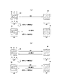
ここからは、図11から図13により折りユニット50内の支持ユニット56の折りシート束BSへの搬入、段階的な押圧動作について説明する。これらの図11から図13は、束排出口側からの見た支持ユニット56で、説明の都合上この支持ユニット56のユニットベース板62aを省略したものである。図11は支持ユニット56がホームポジション(HP)に位置し折りシート束BSの搬入に備え待機している状態を示している。図12は支持ユニット56が折りシート束BSの幅方向中程まで移動し3列のローラによる折りループBLのシート束幅BWを段階的な折りを行っている状態を示している。図13は、3列のローラによる段階的な段階折りが完了し支持ユニット56が折り返しポジションである終端位置(EP)に位置している状態を示している。以下、各状態について説明する。
[Description of the operation of the support unit]
11 to 13, the carrying-in of the support unit 56 in the folding unit 50 to the folded sheet bundle BS and the stepwise pressing operation will be described. 11 to 13 show the support unit 56 viewed from the bundle outlet side, and the unit base plate 62a of the support unit 56 is omitted for convenience of explanation. FIG. 11 shows a state in which the support unit 56 is positioned at the home position (HP) and is waiting for the loading of the bundle of folded sheets BS. FIG. 12 shows a state in which the support unit 56 moves to the middle of the folded sheet bundle BS in the width direction, and folds stepwise across the sheet bundle width BW of the folding loop BL by three rows of rollers. FIG. 13 shows a state in which stepwise folding by three rows of rollers is completed and the support unit 56 is positioned at the end position (EP), which is the folding position. Each state will be described below.

まず図11では、3列の押えローラを有する支持ユニット56のユニットフラグ107が右側板53に取り付けられたホームポジションセンサ108に検出され、支持ユニット56はホームポジション(HP)に位置している。この位置で、後述する「段階折りモード」が設定されている場合は、折りローラ45で折り曲げ処理され、折りシート搬送パスBPを搬送されてくる折りシート束BSの搬入を待つ。 First, in FIG. 11, the unit flag 107 of the support unit 56 having three rows of pressing rollers is detected by the home position sensor 108 attached to the right side plate 53, and the support unit 56 is positioned at the home position (HP). At this position, if the later-described "staged folding mode" is set, it waits for the folded sheet bundle BS that has been folded by the folding rollers 45 and is conveyed along the folded sheet conveying path BP.

ところで、このホームポジション(HP)に位置する支持ユニット56は、移動方向から順に相互の間隔が狭くなり、最終列は圧接する押えローラ70が設けられている。既に説明しているように本実施例にあっては1列目の第1上押えローラ71と第1下押えローラ72が略14ミリメートルの間隔を持って配置されている。また、2列目の第2上押えローラ73と第2下押えローラ74が略7ミリメートルの間隔を有している。さらに3列目の第3上押えローラ75と第3下押えローラ76は領域R1で相互に圧接している。さらにこれらのローラ相互の離間及び圧接の中心は折りシート束BSの中心である折りシートの折りループ先端(折り目)BL1に略一致するように配置されている。 By the way, the support units 56 positioned at the home position (HP) are arranged with a pressure roller 70 which is pressed against the support unit 56 in order from the direction of movement, and the last row is provided with a pressure roller 70 . As already explained, in the present embodiment, the first upper pressing roller 71 and the first lower pressing roller 72 in the first row are arranged with an interval of approximately 14 mm. Also, the second upper pressing roller 73 and the second lower pressing roller 74 in the second row have an interval of approximately 7 mm. Furthermore, the third upper pressing roller 75 and the third lower pressing roller 76 in the third row are in pressure contact with each other in the region R1. Further, the center of separation and pressure contact between these rollers is arranged so as to substantially coincide with the folding loop leading edge (folding line) BL1 of the folded sheet, which is the center of the bundle of folded sheets BS.

この折りシート束BSの折りループが所定の大きさ(本実施例にあってはループの上下方向が、例えば22ミリメートル)になると、折りローラ45を停止させて支持ユニット56を図11右側にユニット駆動モータ69の駆動で移動させる。この移動が開始すると折りシート束の図示左側(一方)の端部(シート端部)を一列目の第1上押えローラ71と第1下押えローラ72が乗り越え、折りシート先端ループBL1からやや上方の位置に折り目をつけながら左側に移動する。先ほど述べたように本実施例におけるループの大きさは略22ミリメートル程度であり、第1上押えローラ71と第1下押えローラ72との間隔は略14ミリ程度とされているので、上下に略4ミリメートル弱オーバラップし、これが図14(a)に示す第1の折り線100を付与することになる。 When the folding loop of the folded sheet bundle BS reaches a predetermined size (in this embodiment, the vertical direction of the loop is, for example, 22 mm), the folding roller 45 is stopped and the support unit 56 is moved to the right side of FIG. It is moved by driving the drive motor 69 . When this movement starts, the first upper pressing roller 71 and the first lower pressing roller 72 ride over the left (one) edge (sheet edge) of the folded sheet bundle in the drawing, and the folded sheet bundle is slightly above the leading end loop BL1 of the folded sheet. Move to the left while making a crease at the position of . As mentioned earlier, the size of the loop in this embodiment is approximately 22 mm, and the distance between the first upper pressing roller 71 and the first lower pressing roller 72 is approximately 14 mm. They overlap by approximately 4 millimeters, which gives the first fold line 100 shown in FIG. 14(a).

また、第1上押えローラ71と第1下押えローラ72との間隔が開いているので、折りシート束BS端部をそれほど損傷することなくこれらのローラが乗り越えることになる。また、第1上押えローラ71と第1下押えローラ72を含む押えローラ70はシート搬送方向と同方向に軸支され、この軸上で回転自在に支持されている。この回転によっても折りシート束端部の乗り越えが容易となる。 Further, since the gap between the first upper pressing roller 71 and the first lower pressing roller 72 is large, these rollers can ride over the edge of the folded sheet bundle BS without much damage. A pressing roller 70 including a first upper pressing roller 71 and a first lower pressing roller 72 is axially supported in the same direction as the sheet conveying direction, and is rotatably supported on this shaft. This rotation also facilitates getting over the edge of the bundle of folded sheets.

さらに、第1上押えローラ71、第2上押えローラ73、第3上押えローラ75の移動方向の間には第1上ガイドプレート201a、第2上ガイドプレート202aが配置されている。一方、折りループBLを挟んでこれらと対向する第1下押えローラ72、第2下押えローラ74、第3下押えローラ76の移動方向の間には第1下ガイドプレート201b、第2下ガイドプレート202bが配置されている。これらにより、折りシート束BSの折りループBLはローラ間に侵入することなく上流側の押えローラ70間にスムーズに案内される。 Further, a first upper guide plate 201a and a second upper guide plate 202a are arranged between the first upper pressing roller 71, the second upper pressing roller 73 and the third upper pressing roller 75 in the moving direction. On the other hand, a first lower guide plate 201b, a second lower guide plate 201b, and a second lower guide plate 201b are provided between the first lower pressing roller 72, the second lower pressing roller 74, and the third lower pressing roller 76 facing each other across the folding loop BL in the moving direction. A plate 202b is arranged. As a result, the folding loop BL of the bundle of folded sheets BS is smoothly guided between the pressing rollers 70 on the upstream side without entering between the rollers.

支持ユニット56が引き続き移動すると、第1上押えローラ71と第1下押えローラ72とのとの間隔で押圧されたループは、さらに第2上押えローラ73と第2下押えローラ74とのやや狭められた間隔で折りシート束BSのループを押え付けて第2の折り目をつけることになる。本実施例におけるさらに第2上押えローラ73と第2下押えローラ74との間隔は略7ミリメートルに設定され、第1上押えローラ71と第1下押えローラ72とのとの間隔よりも上下にそれぞれ略3.5ミリメートル程度オーバラップし、これが図14(b)に示す第2折り線101を付与することになる。 As the support unit 56 continues to move, the loop pressed by the gap between the first upper pressing roller 71 and the first lower pressing roller 72 is further moved slightly between the second upper pressing roller 73 and the second lower pressing roller 74. The loop of the bundle of folded sheets BS is pressed at the narrowed interval to form the second crease. Further, in this embodiment, the distance between the second upper pressing roller 73 and the second lower pressing roller 74 is set to approximately 7 millimeters, which is higher or lower than the distance between the first upper pressing roller 71 and the first lower pressing roller 72. , respectively, by approximately 3.5 mm, which gives the second fold line 101 shown in FIG. 14(b).

これに引き続き、3列目のローラである第3上押えローラ75と第3下押えローラ76にその折り目BL1が段階折りされる。すなわち、第3上押えローラ75と第3下押えローラ76は、その間隔は0として略圧接状態となっているので、折り目のシート厚さ方向の分シートを第3上押えローラ押圧バネ149aと第3下押えローラ押圧バネ149bに押圧されながら段階折りされることになり、これが図14(c)に示す最終折り線102を付与することになる。 Following this, the folding line BL1 is step-folded by the third upper pressing roller 75 and the third lower pressing roller 76, which are rollers in the third row. In other words, the third upper pressing roller 75 and the third lower pressing roller 76 are in a substantially press-contact state with the distance therebetween being 0, so that the third upper pressing roller pressing spring 149a pushes the sheet in the thickness direction of the crease. The sheet is folded in stages while being pressed by the third lower pressing roller pressing spring 149b, thereby giving the final folding line 102 shown in FIG. 14(c).

上記の内容で折りシート束BSを1ユニット内で段階的に押圧して支持ユニット56が折りシート束BSのシート幅方向略中央に位置した状態が図12に示されている。この状態からさらに支持ユニット56は図示右側に向かってシートの折り目厚さ方向から相互の間隔が狭くなる押えローラ70により段階的にシートに折り線を付与しながら移動する。この移動により、折りシート束の図示右左(一方)端部(シート端部)を3列目の第3上押えローラ75と第3下押えローラ76が通過して押えローラにより順次押圧して段階折りを行う。 FIG. 12 shows a state in which the folded sheet bundle BS is pressed stepwise within one unit and the support unit 56 is positioned substantially at the center of the folded sheet bundle BS in the sheet width direction. From this state, the support unit 56 further moves toward the right side of the drawing while giving a folding line to the sheet step by step by the pressing rollers 70 whose mutual interval is narrowed in the thickness direction of the folding line of the sheet. As a result of this movement, the right and left (one) ends (sheet ends) of the folded sheet bundle are passed by the third upper pressing roller 75 and the third lower pressing roller 76 in the third row, and the pressing rollers sequentially press and step fold.

この通過後、支持ユニット56が図示の左側板54側の折り返しポジションである終端位置(EP)に到達する。この状態が図13に示されている。この折り返しポジションに到達するとユニット駆動モータ69の駆動を停止する。その後、段階折りを施した(押えローラ70での押圧完了した)折りシート束BSが折りローラ45及び束排出ローラ49の排出方向への回転により排出されるのを待つ。段階折りされた折りシート束BSの排出完了が図2に示した束排出センサ(SEN4)131で検出されると、支持ユニット56を折り返しポジションからホームポジション(HP)に復帰させ、図11の位置で次の折りシート束BSの搬入に備える。 After this passage, the support unit 56 reaches an end position (EP), which is a folding position on the side of the left side plate 54 shown in the figure. This state is shown in FIG. When the turn-back position is reached, the drive of the unit drive motor 69 is stopped. After that, it waits for the folded sheet bundle BS that has been step-folded (completely pressed by the pressing roller 70) to be discharged by the rotation of the folding roller 45 and the bundle discharging roller 49 in the discharging direction. When the completion of discharge of the folded sheet bundle BS that has been step-folded is detected by the bundle discharge sensor (SEN4) 131 shown in FIG. to prepare for carrying in the next bundle of folded sheets BS.

なお、上記においては図13の段階折りした折りシートBSを一旦排出してから支持ユニット56を終端位置(EP)からホームポジション位置(HP)に復帰するようにしたが、折りシート束BSを排出することなく、再度支持ユニット56を図13の右側から左側に移動して、第3上押えローラ75と第3下押えローラ76により、折りシート束BSの折り目を再度押圧させながら、ホームポジション(HP)に復帰させれば、最終列の段階折りをより確実にすることもできる。 In the above description, after the folded sheet BS that has been folded in stages as shown in FIG. 13 again, and the third upper pressing roller 75 and the third lower pressing roller 76 press the crease of the folded sheet bundle BS again to the home position ( HP), the stage folding of the last row can be made more reliable.

以上のように、本実施例にあっては、折り曲げられた折りシート束BSに対して支持ユニット56により、3段階の折りを実行している。この折り動作を行って排出した折りシート束BSについて図14により説明する。これまで説明してきたように、本発明のシート束の押圧部材としての第1上押えローラ71と第1下押えローラ72で折りシート束BSの折り目厚さ方向(折り目で折りシート束BS搬送方向と交差する上下方向)から、折りローラ45で折り目がつけられ折りループBLが生じた箇所を折り目方向に移動して複数の折り目を付けている。 As described above, in this embodiment, the folded sheet bundle BS is folded in three steps by the support unit 56 . The folded sheet bundle BS discharged after performing this folding operation will be described with reference to FIG. As described above, the first upper pressing roller 71 and the first lower pressing roller 72 serving as sheet bundle pressing members according to the present invention are used to fold the folded sheet bundle BS in the crease thickness direction (folded sheet bundle BS conveying direction at the crease). ), a plurality of creases are formed by moving in the crease direction the locations where creases are formed by the folding rollers 45 and the fold loops BL are generated.

既に説明したように、第1段階の第1上押えローラ71と第1下押えローラ72の間隔を折りループよりもやや狭い間隔 (本実施例にあってはループ高さ22ミリメートルに対して略14ミリメートル) に規定して、折りローラ45によって付けられた折り目に沿って移動して第1段階の折り目をつける。これが、図14(a)の実線矢印が示す第1折り線100であり、図15(a)では折りシート束BSに薄いラインで第1折り線100として表れている。これは、図14(a)の様にループとなった部分に第1上押えローラ71と第1下押えローラ72で押えられた部分が集中荷重を受けシート束が座屈し折り生じ、第1上押えローラ71と第1下押えローラ72の幅方向への移動により第1折り線100となって現れるからである。 As already explained, the interval between the first upper pressing roller 71 and the first lower pressing roller 72 in the first stage is slightly narrower than the fold loop (in this embodiment, the interval is approximately 22 mm for the loop height of 22 mm). 14 mm) and moves along the crease made by the folding rollers 45 to create the first stage crease. This is the first folding line 100 indicated by the solid arrow in FIG. 14(a), and in FIG. 15(a) it appears as the first folding line 100 as a thin line on the folded sheet bundle BS. This is because, as shown in FIG. 14(a), the looped portion pressed by the first upper pressing roller 71 and the first lower pressing roller 72 receives a concentrated load, and the sheet bundle is buckled and folded. This is because the first folding line 100 appears due to the movement of the upper pressing roller 71 and the first lower pressing roller 72 in the width direction.

次に、第2段階はシート束の押圧部材としての第2上押えローラ73と第2下押えローラ74の間隔は、第1段階で押圧形成したループよりもやや狭い間隔 (本実施例にあっては略7ミリメートル) で規定してあり、折りローラ45によって付けられた折り目に沿って移動して第2段階の折り目をつける。これが、これが、図14(b)に示す第1折り線100よりも背側に位置する実線矢印が示す第2折り線101であり、図15では折りシート束BSに薄いラインで第2折り線101としてあらわれている。これも、図14(b)の様にループとなった部分に第2上押えローラ73と第2下押えローラ74で押えられた部分が集中荷重を受けシート束に座屈し折り生じ、第2上押えローラ73と第2下押えローラ74の幅方向への移動により第1折り線101となって現れるからである。 Next, in the second step, the interval between the second upper pressing roller 73 and the second lower pressing roller 74 as pressing members for the sheet bundle is slightly narrower than the loop formed by pressing in the first step (in the present embodiment). (approximately 7 millimeters in diameter) and moves along the crease made by the folding rollers 45 to form the second stage crease. This is the second folding line 101 indicated by the solid arrow located on the dorsal side of the first folding line 100 shown in FIG. 14(b), and in FIG. It appears as 101. In this case, as shown in FIG. 14(b), the looped portion pressed by the second upper pressing roller 73 and the second lower pressing roller 74 receives a concentrated load, and the sheet bundle buckles and folds. This is because the first folding line 101 appears due to the movement of the upper pressing roller 73 and the second lower pressing roller 74 in the width direction.

最終の段階としてシート束の押圧部材としての第3上押えローラ75と第3下押えローラ76は、第3上押えローラ押圧バネ149aと第3下押えローラ押圧バネ149bとの弾性力で押圧している。この最終列階では、第1段階、第2段階のように第3上押えローラ75と第3下押えローラ76の間隔をあけていない。(本実施例にあっての規制間隔は0ミリメートル)。 In the final stage, the third upper pressing roller 75 and the third lower pressing roller 76 as pressing members for the sheet bundle are pressed by the elastic force of the third upper pressing roller pressing spring 149a and the third lower pressing roller pressing spring 149b. ing. In this final row, there is no space between the third upper pressing roller 75 and the third lower pressing roller 76 as in the first stage and the second stage. (The regulation interval in this embodiment is 0 mm).

従って、最終列階での押圧は折りシート束BSの押圧した厚さの位置を、第3上押えローラ75と第3下押えローラ76で押圧しながら折り目方向に移動する。この最終列の押えローラ70の折り目は折りシート束BSに、図14(c)の実線矢印が示す最終折り線102であり、図15(a)では折りシート束BSに比較的濃いラインで最終折り線102として表れている。 Therefore, in the last row, the pressed thickness position of the folded sheet bundle BS is pressed by the third upper pressing roller 75 and the third lower pressing roller 76 and moved in the crease direction. The folding line of the pressing roller 70 in the last row is the final folding line 102 indicated by the solid arrow in FIG. 14(c) on the folded sheet bundle BS, and in FIG. It appears as fold line 102 .

なお、折りシート束BSの幅方向端部には、折りローラ45及び押えローラ70の圧接状態からシートに乗り上げる際の端部折り目103が形成されている。これは略圧接状態の第3上押えローラ75と第3下押えローラ76で押えられる部分は折り目を強化された最終折り線102として現れている。 At the widthwise end of the folded sheet bundle BS, an end crease 103 is formed when the folded sheet bundle BS is pushed onto the sheet from the state of pressure contact between the folding roller 45 and the pressing roller 70 . The portion pressed by the third upper pressing roller 75 and the third lower pressing roller 76 which are in substantially pressure contact state appears as a final folding line 102 in which the crease is reinforced.

以上のように、各押えローラ70を異なる間隔で座屈させて折り目が形成されるようにし、これにより第1段階の薄いラインである第1折り線100、第2段階の薄いラインである第2折り線101、及び最終列階の折りシート束BS厚さに応じて生じた比較的濃いラインである最終折り線102の各ライン位置で、折りシート束BSの閉じ方向(折り目を通過する搬送方向の線)側への折り方向が向くことにより、これまでの折り目押えローラで端に押圧するものに比べ、排出後も折りシート束BSが開いてしまい、整列性や集積性が低下することを防止できる。 As described above, the pressure rollers 70 are buckled at different intervals to form creases, thereby forming the first fold line 100, which is the first thin line, and the second fold line, which is the second thin line. At each line position of the second folding line 101 and the final folding line 102, which is a relatively dark line generated according to the thickness of the folded sheet bundle BS on the last row, the closing direction of the folded sheet bundle BS (conveyance passing through the folding line) Since the folding direction is directed to the direction line ) side, the folded sheet bundle BS is opened even after discharge compared to the conventional crease pressing roller that presses the edge, resulting in lower alignment and accumulation. can be prevented.

[段階折りを実行した折りシート]
以上述べた通り、これまでの折り目のみを押圧するものに比べ、折りシートが開くことが少なくなったが、さらに改善の余地があることが分かった。すなわち、図15はこれまでにも説明したが、図14で押えローラで押圧された冊子を示す図で、図15(a)は図11から図13までの支持ユニットによって押圧された折りシート束は、折りシートの幅方向端部の折りが甘くしっかりと折れていない状態となった。図15(b)に示す様に、支持ユニット56のホームポジション(HP)側の第1段階の薄いラインである第1折り線100の端部100HT、第2段階の薄いラインである第2折り線101の端部101HTには明確な折り線が現れていなかった。また、特に折り返しポジションである終端位置(EP)側の第1段階の薄いラインである第1折り線100の端部100ET、第2段階の薄いラインである第2折り線101の端部101ETは折り線があまり付与されていないことが判明した。
[Folded sheet with step folding]
As described above, the folded sheet is less likely to be opened than the conventional method that presses only the crease, but it has been found that there is room for further improvement. 15 shows the booklet pressed by the pressing roller in FIG. 14, and FIG. 15(a) shows the bundle of folded sheets pressed by the supporting unit shown in FIGS. In the case of the folded sheet, the edges in the width direction of the folded sheet were loosely folded and not firmly folded. As shown in FIG. 15(b), the end portion 100HT of the first folding line 100, which is the first stage thin line on the home position (HP) side of the support unit 56, and the second folding line 100HT, which is the second stage thin line. A clear fold line did not appear at the end 101HT of the line 101 . In particular, the end portion 100ET of the first fold line 100, which is the first thin line on the end position (EP) side, which is the folding position, and the end portion 101ET of the second fold line 101, which is the second thin line, are It was found that the crease line was not provided so much.

この折りシートの幅方向の両端部、言い換えると支持ユニット56のホームポジション(HP)側と終端位置(EP)側の端部の折りがしっかりとなされない原因を探求し、本発明者は折りシートの折りループのコシである反力が異なる目であることを解明した。図16はこれを確認するために行った実験であり、用いたシートはA4サイズ、坪量81.4g/mで幅240mmを折りローラ45で位置と折った折りシートの支持ユニット56ホームポジション側の折りシート束端部から30mm位置Pr1と60mm位置Pr2と、折りシートの幅方向中央位置Pr3をプッシュゲージで、15mmまで押し込んで測定した。その測定結果は下記の表の様になった。尚、図16のBW表記は束シートの幅の幅を示し、半分の幅は2/BWで表わしている。 The present inventor investigated the reason why both ends of the folded sheet in the width direction, in other words, the ends on the home position (HP) side and the end position (EP) side of the support unit 56 are not securely folded. It was clarified that the reaction force, which is the stiffness of the folded loop, is different. FIG. 16 shows an experiment conducted to confirm this. The sheets used were A4 size, grammage 81.4 g/m 2 and width 240 mm. 30 mm position Pr1 and 60 mm position Pr2 from the edge of the bundle of folded sheets on the side and the center position Pr3 in the width direction of the folded sheet were measured by pushing the push gauge up to 15 mm. The measurement results are shown in the table below. Note that the BW notation in FIG. 16 indicates the width of the bundle of sheets, and the half width is expressed by 2/BW.

Figure 0007202059000001

上記の表からわかるように、折りシートの折りループのコシ(反力)は中央が最も高く、端部側が低くなることが分かった。また、実際に支持ユニット56を移動して、折りシートの折りループ部分を観察するとホームポジション(HP)側の端部Pr1までの折り線と端部からは同じ30mmの位置にある終端位置(EP)側のPr4とシート束終端までの折り線は、Pr4から終端までの折り線がより付きにくいことも解った。これは実際に、支持ユニット56を移動する場合には、移動方向にシート連続の有無に関係すると思われる。したがって折り枚数の程度によっては、終端位置側のみに折り線を付与するように支持ユニットを一部で往復動しても良い。 As can be seen from the above table, the stiffness (reaction force) of the folding loops of the folded sheet is highest at the center and lowest at the edges. Further, when the support unit 56 is actually moved and the folding loop portion of the folded sheet is observed, the folding line to the end Pr1 on the home position (HP) side and the end position (EP It was also found that the folding line from Pr4 to the end of the sheet bundle on the ) side is more difficult to attach. Actually, when the support unit 56 is moved, it seems to be related to the presence or absence of sheet continuation in the movement direction. Therefore, depending on the number of sheets to be folded, the support unit may be partially reciprocated so that the folding line is provided only on the terminal position side.

[支持ユニットの移動]
次に、支持ユニット56の折りループに対するシート幅BW方向での支持ユニット移動について説明する。尚、矢印UBは支持ユニット56の移動方向を示し、図17は、既に説明した図11から図13までの支持ユニットの移動を説明し、図18と図19はこの図17の支持ユニット56の移動を改善した本発明に係わるものを示している。以下、順次説明する。
[Movement of support unit]
Next, the movement of the support unit in the sheet width BW direction with respect to the folding loop of the support unit 56 will be described. An arrow UB indicates the moving direction of the support unit 56, FIG. 17 illustrates the movement of the support unit 56 shown in FIGS. 11 to 13 already described, and FIGS. Fig. 3 shows an improved movement according to the invention; A description will be given below.

[これまでの支持ユニットの移動]
図17は既に図11から図13で説明したのでここでの詳細な説明は省略するが、図17(a)では支持ユニット56がホームポジション位置(HP)から終端位置(EP)に向かって移動して折りシートの折りループに対して第1上押えローラ71と第1下押えローラ72から順次互いに圧接する第3上押えローラ75と第3下押えローラ76とまでで順次押圧して折りシートを排出する。図17(b)では、支持ユニット56がシート束幅BWの方向に往復して折りループを押圧する。ここでは特に、互いに圧接する第3上押えローラ75と第3下押えローラ76が折りループを2回押圧するので上記の図17(a)の押えに比べてより折りができる。しかしながら、特に終端位置(EP)側の折りループ端部は折り目が付きにくく、図14及び図15に示す様に折り目が弱く改善の余地があった。
[Previous support unit movement]
Since FIG. 17 has already been described with reference to FIGS. 11 to 13, detailed description thereof will be omitted here. In FIG. Then, the folding loop of the folded sheet is sequentially pressed by the first upper pressing roller 71 and the first lower pressing roller 72 to the third upper pressing roller 75 and the third lower pressing roller 76 which are in sequential pressure contact with each other to form the folded sheet. to discharge. In FIG. 17B, the support unit 56 reciprocates in the direction of the sheet bundle width BW to press the folding loop. Here, in particular, the third upper pressing roller 75 and the third lower pressing roller 76, which are in pressure contact with each other, press the folding loop twice, so that folding can be performed more than the pressing shown in FIG. 17(a). However, it is particularly difficult to crease the edge of the folding loop on the end position (EP) side, and as shown in FIGS. 14 and 15, the crease is weak and there is room for improvement.

[本発明に係わる支持ユニットの移動]
そこで、端部、特に終端位置(EP)側の端部の一部領域を複数回押圧することによって折り目を明確にしたものが、図18と図19に示すものである。
[Movement of support unit according to the present invention]
FIG. 18 and FIG. 19 show creasing lines made by pressing the end portion, especially a partial region of the end portion on the end position (EP) side, a plurality of times.

(第1実施例)
図18は上記の図17(a)の終端位置(EP)側で支持ユニット56を一部往復して折りシート端部を押えたものである。支持ユニット56は終端位置(EP)で図示の様に終端位置(EP)側の折りシート終端に達すると今度はホームポジション位置(HP)側に戻り復帰する。この復帰移動は、シートの束幅の約1/4から約1/5に設定されている。この約1/4から約1/5を支持ユニット56が移動すると、再び終端位置(EP)側に向かって移動し折りシートの折りループを抜けて終端位置(EP)に移動し、押圧した折りシート束を排出し、次の折りシートの搬入を待つ。これによれば、終端位置(EP)側の折りシート端部を複数回押えローラ70で押圧するので、図17の支持ユニット56で押圧された折りシートに比べ、終端位置(EP)側の端部側が確り折られる。
(First embodiment)
FIG. 18 shows a state in which the support unit 56 is partly reciprocated on the end position (EP) side of FIG. When the support unit 56 reaches the end position (EP) side of the folded sheet as shown in the figure, it returns to the home position (HP) side. This return movement is set to about 1/4 to about 1/5 of the sheet bundle width. When the support unit 56 moves about 1/4 to about 1/5 of this, it moves again toward the end position (EP) side, passes through the folding loop of the folded sheet, moves to the end position (EP), and presses the folded sheet. Discharge the sheet bundle and wait for the next folded sheet to be brought in. According to this, the edge of the folded sheet on the end position (EP) side is pressed a plurality of times by the pressing roller 70. Therefore, compared to the folded sheet pressed by the support unit 56 in FIG. Part side is definitely folded.

(第2実施例)
図18(b)は、図18(a)の支持ユニット56が終端位置(EP)側端部で支持ユニット端部移動端部移動UBT1、UBT2の往復移動の後、ホームポジション位置(HP)に復帰する。その後、最初の折りシート束を排出し、このホームポジション位置(HP)で、次の折りシート束の搬入を待つ。この実施例2によれば、支持ユニット56の終端位置(EP)からホームポジション位置(HP)への復帰の過程でも折りシートの折りループを重ねて押圧するので、終端位置(EP)側端部の折りが確りなされるとともに、実施例1のものよりも折り目が付きやすくなる。尚、支持ユニット端部移動端部移動UBT1、UBT2の往復移動の範囲は、シートの束幅の約1/4から約1/5に設定されていることは実施例1と同様となっている。
(Second embodiment)
FIG. 18(b) shows that the support unit 56 of FIG. 18(a) is at the end position (EP) side end, and after the reciprocating movement of the support unit end movement end movement UBT1, UBT2, it returns to the home position position (HP). return. After that, the first folded sheet bundle is discharged, and the next folded sheet bundle is awaited at this home position (HP). According to the second embodiment, the folding loops of the folded sheet are overlapped and pressed even in the process of returning the supporting unit 56 from the end position (EP) to the home position (HP). The fold is made more securely, and creases are easier to form than in the case of the first embodiment. The reciprocating range of the support unit end movement end movement UBT1 and UBT2 is set to about 1/4 to about 1/5 of the sheet bundle width, which is the same as in the first embodiment. .

(第3実施例)
次に、図19(a)で第3実施例を説明する。ここでは、支持ユニット56が折りシート幅方向のホームポジション位置(HP)側と終端位置(EP)側の両端部付近で往復動を行う。すなわち、支持ユニット56は、ホームポジション位置(HP)から折りシートの折りループに移動し、この付近で支持ユニット端部移動端部移動UBT1、UBT2の往復移動の後を行い、その後終端位置(EP)に向かって移動する。この移動が完了すると、折りシートを排出し次の折りシートの搬入を待つ。これによれば、図18で示したものに比べ、ホームポジション位置(HP)側でもシートの束幅の約1/4から約1/5に範囲の端部付近を支持ユニット56が往復動するので、折りループの両端部がよりしっかりと折り込まれる。
(Third embodiment)
Next, a third embodiment will be described with reference to FIG. 19(a). Here, the support unit 56 reciprocates in the vicinity of both ends on the home position (HP) side and the end position (EP) side in the width direction of the folded sheet. That is, the support unit 56 moves from the home position (HP) to the folding loop of the folded sheet, performs the reciprocating movement of the support unit end movement end movement UBT1, UBT2 in the vicinity of this position, and then the end position (EP ). When this movement is completed, the folded sheet is discharged and the next folded sheet is waited for. 18, the support unit 56 reciprocates in the vicinity of the ends of the range of about 1/4 to about 1/5 of the width of the bundle of sheets even on the home position (HP) side. Therefore, both ends of the fold loop are folded more firmly.

(第4実施例)
次に、図19(b)により、支持ユニット56の移動につき第4実施例を説明する。この実施例では、支持ユニット56が折りシート幅方向のホームポジション位置(HP)側と終端位置(EP)側の両端部付近で往復動を夫々行い、その後に支持ユニット56を終端位置(EP)からホームポジション位置(HP)に移動するのである。その後折りシート束を排出して、次の折りシート束の搬入を待つもので、一部のシート束を処理する時間はかかるが、もっと折り精度が向上する。ここにおいても、シートの束幅の約1/4から約1/5に範囲の端部付近を支持ユニット56が往復動する。なお、先に終端位置(EP)側の往復を行い、その後折り返して初期位置であるホームポジション位置(HP)側で往復動を行っていも良いことは言うまでもない。
(Fourth embodiment)
Next, a fourth embodiment of movement of the support unit 56 will be described with reference to FIG. 19(b). In this embodiment, the support unit 56 reciprocates in the vicinity of both the home position (HP) side and the end position (EP) side in the width direction of the folded sheet, and then moves the support unit 56 to the end position (EP). to the home position (HP). After that, the folded sheet bundle is discharged and the next folded sheet bundle is brought in. Although it takes time to process a part of the sheet bundle, the folding accuracy is further improved. Also in this case, the support unit 56 reciprocates in the vicinity of the end of the range of about 1/4 to about 1/5 of the width of the sheet bundle. Needless to say, the reciprocating motion may be performed on the end position (EP) side first, and then turned back to perform the reciprocating motion on the home position (HP) side, which is the initial position.

[支持ユニットの両端部一部往復動した折りシート]
上記の図19における実施例3及び実施例4の折りシートに対する支持ユニット端部移動端部移動UBT1、UBT2の往復移動を行った後の折りシート
が図20に示してある。この図はシート端部を支持ユニット56で往復動を行っていない図15と対比してみると、図20(a)に示されるように折りシート(冊子)両端部に第1折り線100と第2折り線101が明白に付与され、確実に端部まで折りがなされている。
[Folded sheet partially reciprocating at both ends of support unit]
FIG. 20 shows the folded sheet after the reciprocating movement of the support unit end movement end movement UBT1 and UBT2 for the folded sheet of the third and fourth embodiments in FIG. 19 described above. This figure is compared with FIG. 15 in which the sheet end portion is not reciprocated by the support unit 56. As shown in FIG. A second folding line 101 is clearly provided to ensure that the edge is folded.

図20(b)は、支持ユニットの進入側であるホームポジション(HP)側の第1段階の薄いラインである第1折り線100の端部100HT、第2段階の薄いラインである第2折り線101の端部101HTには明確な折り線が現れた状態を示している。また、図20(c)に示す様に、折り返しポジションである終端位置(EP)側の第1段階の薄いラインである第1折り線100の端部100ET、第2段階の薄いラインである第2折り線101の端部101ETにも折り線が付与されるようになった。これにより、折りシートの幅方向端部に支持ユニット56の一部往復動を施すことで、折り目が確りと付与され第2排紙トレイ22に排出後も折り部が開くことが少なくなり、集積性も向上し、また、見栄えも良い折り冊子を提供できるようになった。 FIG. 20(b) shows an end portion 100HT of the first folding line 100, which is the first stage thin line on the home position (HP) side, which is the entrance side of the support unit, and the second folding line 100HT, which is the second stage thin line. The edge 101HT of the line 101 shows a state in which a distinct folding line appears. Also, as shown in FIG. 20(c), the end portion 100ET of the first fold line 100, which is the first-step thin line on the end position (EP) side, which is the folding position, and the second-step thin line, the second fold line 100ET. A folding line is also added to the end portion 101ET of the two-folding line 101 . As a result, by partially reciprocating the support unit 56 at the width direction end portion of the folded sheet, the crease is surely provided, and the folded portion is less likely to open even after the sheet is discharged to the second discharge tray 22, thereby stacking the folded sheet. It is now possible to provide a folded booklet that is also more attractive and has a better appearance.

なお、図20では、図18に対応する終端位置(EP)側でのみ支持ユニット56を一部往復して折りシート端部を押えたものではないが、折り枚数があまり多くない場合には、比較的腰の弱い終端位置(EP)のみを行えば、排出後の冊子が折り目で開くことが少ないので、場合によっては一方のみの支持ユニット56の往復動で足りる。 In FIG. 20, the support unit 56 is partially reciprocated only on the end position (EP) side corresponding to FIG. If only the end position (EP), which is relatively weak, is performed, the booklet after ejection is less likely to be opened at the crease, so reciprocation of only one support unit 56 is sufficient in some cases.

(実施例5)
ここで、これまでの図17から図19までの折りシートの折りループ(折り目)に対する支持ユニット56で押圧移動についても、図21の流れ図で整理して説明する。折り目押圧の指示をオペレータがコントロールパネル18(図1、図23)からしておくと、折りローラ45で折られた折りシートが折りユニット50に搬入して予め定められた位置で停止する(F1)。折りシートの搬入が完了すると段階的に折り目を押圧する押えローラを支持する支持ユニット56をホームポジション位置(HP)から移動を開始する(F2)。
(Example 5)
Here, the pressing movement of the support unit 56 with respect to the folding loops (folding lines) of the folded sheets shown in FIGS. When the operator gives an instruction to press the fold from the control panel 18 (FIGS. 1 and 23), the folded sheet folded by the folding roller 45 is carried into the folding unit 50 and stopped at a predetermined position (F1 ). When the folded sheet is completely carried in, the support unit 56 that supports the pressing roller that presses the fold in stages starts to move from the home position (HP) (F2).

次に、先ほどのオペレータの指示により、支持ユニット56の折りシート幅の全域移動のみで端部の往復動をしない場合(F3)、支持ユニット56の折りシート幅の全域移動に加え、終端位置(EP)のみで端部の往復動を行う場合(F4)、そして支持ユニット56の折りシート幅の全域移動に加え、初期位置であるホームポジション位置(HP)と終端位置(EP)の折シート両端で一部往復動を行う場合(F5)が選択される。さらに支持ユニット56がホームポジション位置(HP)から終端位置(EP)までの往路で待機して折りシートを排出するか、あるいはホームポジション位置(HP)から終端位置(EP)に移動してさらに初期位置であるホームポジション位置(HP)復帰してから折りシートを排出して、2部目の折りシートを折りユニットに搬入する(F12)かも選択可能(F6からF11までの6通り)となっている。 Next, when the support unit 56 is moved only over the entire width of the folded sheet and the end portion is not reciprocated (F3) according to the previous instruction from the operator, in addition to the movement of the support unit 56 over the entire width of the folded sheet, EP) alone (F4), and in addition to the movement of the support unit 56 over the entire width of the folded sheet, both ends of the folded sheet at the home position (HP), which is the initial position, and the end position (EP). (F5) is selected when partial reciprocating motion is performed at . Further, the support unit 56 waits in the outward path from the home position (HP) to the end position (EP) and discharges the folded sheet, or moves from the home position (HP) to the end position (EP) and further initializes. It is also possible to select (F12) to discharge the folded sheets after returning to the home position (HP), which is the position, and carry in the folded sheets for the second copy to the folding unit (six ways from F6 to F11). there is

つまり、先に説明した図17(a)が図21(F6)に、図17(b)が図21(F7)に対応している。また、図18(a)が図21(F8)に、図18(b)が図21(F9)に対応している。さらに、図19(a)が図21(F10)に、図19(b)が図21(F11)に夫々対応していることになる。したがって、図21の際下段の矢印で示す様に、折りループの段階的な折りに要する時間が増えると折り精度を向上させることになる。もちろん、折りローラ45で折り処理された折りシートを支持ユニット56の押えローラで折り処理することなしに束排出することも選択できる。ここまでは、オペレータ―がコントロールパネル18から手動で支持ユニット56の移動を入力した例を示したが、以下に示す様に折りシートの枚数や厚さによって移動を変えても良い。 17A corresponds to FIG. 21F6, and FIG. 17B corresponds to FIG. 21F7. 18(a) corresponds to FIG. 21(F8), and FIG. 18(b) corresponds to FIG. 21(F9). Furthermore, FIG. 19(a) corresponds to FIG. 21(F10), and FIG. 19(b) corresponds to FIG. 21(F11). Therefore, as indicated by the lower arrow in FIG. 21, if the time required for stepwise folding of the folding loop increases, the folding accuracy is improved. Of course, it is also possible to select to discharge the folded sheet folded by the folding roller 45 without folding it by the pressing roller of the support unit 56 . So far, an example has been shown in which the operator manually inputs the movement of the support unit 56 from the control panel 18, but the movement may be changed according to the number and thickness of the folded sheets as described below.

(実施例6)
これまでは、オペレータが入力して支持ユニット56の移動を選択するようにしたが、図22のフローチャートに示すように折りシートの枚数あるいは厚さの程度によって、支持ユニット56の移動をしても良く、以下これに説明する。コントロールパネル18から「折りループ段階折り」の実行を指示して置く。するとまず、折り枚数の枚数をカウントする。このカウントは搬入ローラ24の下流側の搬入センサSEN1で行うが、画像形成装置本体からのカウント情報を受信して設定しても良い。また、厚さ測定の場合は、折りローラローラの軸間を測定すればよい。以下は、枚数を例にする。
(Example 6)
Up until now, the operator has input and selected the movement of the support unit 56. However, as shown in the flow chart of FIG. OK, I'll explain this below. Execution of "folding loop step-folding" is instructed from the control panel 18. - 特許庁Then, first, the number of sheets to be folded is counted. This count is performed by the carry-in sensor SEN1 on the downstream side of the carry-in roller 24, but it may be set by receiving count information from the main body of the image forming apparatus. In the case of thickness measurement, the distance between the axes of the folding rollers may be measured. Below is an example of the number of sheets.

折りシート枚数が10枚を越えるか否かを、後に説明する折りシート段階折り制御部124(制御部)で判断する(S1)。この判断で折りシート枚数が10枚を超えない(Noの)場合は、図示右に進み支持ユニット56は折りシート束の全域移動のみを行い、終端位置(EP)で待機(図17(a))して、折りシート束を排出するとともに次シートがある場合は束の搬入を待つ(S6)。 A folding sheet stage folding control section 124 (control section), which will be described later, determines whether or not the number of folding sheets exceeds 10 (S1). If the number of folded sheets does not exceed 10 (No) in this judgment, the support unit 56 moves to the right in the drawing and only moves the entire bundle of folded sheets, waiting at the end position (EP) (FIG. 17(a)). ), the folded sheet bundle is discharged, and if there is a next sheet, the bundle is waited for (S6).

一方、10枚を越えると判断された場合は、さらに15枚を越えるか否かを判断する(S3)。この判断で越えない場合は、図示左側に進み支持ユニット56での折りシート幅の全域移動と終端位置(EP)の終端部の往復動を行い、終端位置(EP)で待機(図18(a))して、折りシート束を排出するとともに次シートがある場合は束の搬入を待つ(S6)。ここで15枚を超える場合には、支持ユニット56での折りシート幅の全域移動とホームポジション位置(HP)との終端位置(EP)の両端部の往復動後にシート束を排出し、次シートがある場合は束の搬入を待つ(S6)。 On the other hand, if it is determined that the number of sheets exceeds 10, it is further determined whether or not the number of sheets exceeds 15 (S3). If it does not exceed this determination, it proceeds to the left side of the drawing, moves the entire width of the folded sheet by the support unit 56 and reciprocates the end portion of the end position (EP), and waits at the end position (EP) (FIG. 18(a)). )), the folded sheet bundle is discharged, and if there is a next sheet, the bundle is waited for (S6). Here, if the number of sheets exceeds 15, after the support unit 56 moves the entire width of the folding sheet and reciprocates both ends of the end position (EP) to the home position (HP), the sheet bundle is discharged, and the next sheet is discharged. If there is, wait for the delivery of the bundle (S6).

以上の様に、折りシート束の枚数により、幅方向端部の往復動を行うか、行う場合は、終端位置(EP)側のみか、両端を行うかを自動的に判断する。この様に設定することで、押えローラ70の押圧の時間を短縮しかつ折り精度を向上することができる。尚、折り枚数が1から3枚程度の場合は,この支持ユニット56を移動することなく、折りローラ45のみの折りで束排出を行い、処理速度を上げることもできることは言うまでもない。 As described above, depending on the number of folded sheet bundles, it is automatically determined whether reciprocation is to be performed at the ends in the width direction, and if so, whether to perform only the end position (EP) side or both ends. By setting in this manner, the pressing time of the pressing roller 70 can be shortened and the folding accuracy can be improved. It goes without saying that when the number of folded sheets is about 1 to 3, the bundle can be discharged by folding only the folding roller 45 without moving the support unit 56, thereby increasing the processing speed.

[制御構成の説明]
これまで、説明した折りユニット50を備えるシート処理装置B及びこのシート処理装置Bを含む画像形装置Aの制御構成を図23のブロック図により説明する。画像形成手段を備える画像形成装置制御部110は、コントロールパネル18に設けられた入力手段111から所望の処理を入力する。この入力はモード設定手段によって、シート処理装置Bのシート処理装置制御部115を制御する。また、画像形成装置制御部110は、給紙部1の給紙制御部110bを制御するとともにシート処理装置制御部115に対して折り枚数または折りシート厚さ情報を出力する。
[Description of control configuration]
The control configuration of the sheet processing apparatus B including the folding unit 50 described above and the image forming apparatus A including the sheet processing apparatus B will be described with reference to the block diagram of FIG. An image forming apparatus control unit 110 having image forming means inputs desired processing from an input means 111 provided on the control panel 18 . This input controls the sheet processing apparatus control section 115 of the sheet processing apparatus B by the mode setting means. Further, the image forming apparatus control section 110 controls the sheet feeding control section 110 b of the sheet feeding section 1 and outputs information on the number of folded sheets or the thickness of the folded sheets to the sheet processing apparatus control section 115 .

本実施例のシート処理装置Bの処理モードは、次のモードを備えている。
すなわち、(1)画像形成がされたシートを第1排紙トレイ21に収容する「プリントアウトモード」。(2)本体排出口3からのシートを束状に部揃ええしてー端面綴じステープル装置33で綴じ後第1排紙トレイ21に収納する「ステープル綴じモード」(3)本体排出口3からのシートを第2の処理トレイであるスタッカ部35で束状に部揃えしてこのシート束の中程を中綴じステープラ40で綴じ後、冊子状に折り畳んで第2排紙トレイ22に収納する「束中綴じ束折りモード」。(4)中綴じして冊子状に折り畳んだシート束の折り目のループに支持ユニット56を移動して押えローラで折りループを段階的に押えて段階折りして、第2排紙トレイに22に収納する「段階折りモード」。これらのモードが指定可能なように構成されている。また、この「段階折りモード」では折り枚数に応じて、終端位置(EP)側やホームポジション位置(HP)側と終端位置(EP)側の折りシートの折りループ両端を一部往復動してより折り精度を上げるようになっている。なお、図21に記載の様に、折り精度は手動入力によって選択しても良い。
The processing modes of the sheet processing apparatus B of this embodiment include the following modes.
(1) A “printout mode” in which sheets on which images have been formed are accommodated in the first paper discharge tray 21 . (2) A "stapling mode" in which the sheets from the main body discharge port 3 are aligned into a bundle and stored in the first paper discharge tray 21 after being stapled by the end-face binding stapling device 33 (3) From the main body discharge port 3 The sheets are sorted into a bundle by a stacker unit 35 which is a second processing tray, and after the middle of the bundle of sheets is bound by a saddle-stitching stapler 40, the sheets are folded into a booklet and stored in a second discharge tray 22. "Bunch saddle stitch bundle folding mode". (4) The support unit 56 is moved to the fold loop of the sheet bundle folded into a booklet by saddle-stitching, and the press roller gradually presses the fold loop to fold the sheet bundle step by step, and the sheet bundle is placed on the second sheet discharge tray 22 . "Step-by-step folding mode" for storage. These modes are configured so that they can be specified. In this "step folding mode", depending on the number of sheets to be folded, part of the folding loop ends of the folded sheet on the end position (EP) side or the home position position (HP) side and the end position (EP) side are reciprocated. It is designed to increase folding accuracy. Incidentally, as shown in FIG. 21, the folding accuracy may be selected by manual input.

シート処理装置Bは、上記の指定されたモードによって動作可能とされるシート処理装置制御部115と、動作プログラムを格納したROM113と、制御データを記憶したRAM114を備えている。そして、このシート処理装置制御部115は、この装置内のシート搬送を制御するシート搬送制御部116と、1枚ごとにシートに1枚穿孔ユニット28で押圧処理を行う1枚穿孔制御部117と、処理トレイ29でシートの集積制御を行う処理トレイ制御部118と、この処理トレイ29にシート束として集積されたシートの端面側を綴じ、綴じ後排出する端面綴じ制御部119と、この処理トレイ29で綴じ処理されたシート束を集積するため集積量に応じて第1排紙トレイ21の昇降等を制御する第1排紙トレイ昇降制御部120とを備えている。 The sheet processing apparatus B includes a sheet processing apparatus control section 115 which is operable in the specified mode, a ROM 113 storing an operation program, and a RAM 114 storing control data. The sheet processing apparatus control section 115 includes a sheet conveyance control section 116 for controlling sheet conveyance within the apparatus, and a single sheet perforation control section 117 for performing pressing processing by the one sheet perforation unit 28 for each sheet. , a processing tray control unit 118 that controls stacking of sheets on the processing tray 29, an end surface binding control unit 119 that binds the end surfaces of the sheets stacked as a sheet bundle on the processing tray 29, and discharges the sheets after binding, and this processing tray. A first discharge tray lift control unit 120 is provided for controlling elevating and the like of the first discharge tray 21 in accordance with the amount of stacking in order to stack the sheet bundles that have been bound in step 29 .

また、シート束のシート搬送方向の1/2付近を綴じる中綴じたり中折りしたりする場合、シートのスタッカ部35にシート束を集積するスタッカ部制御部121で制御される。このスタッカ部制御部121は、1枚ずつスタッカ部35に搬入してくるシートの先端を規制するストッパ38や整合部材39で整列してシート束を生成する。さらに、シート束の中程にステープル針等を打ち込むように中綴じステープラを制御する中綴じ制御部122と中綴じされたシート束を折りブレード46で折りローラ45に押し込んで中折りを施すように制御するシート中折り制御部123を備える。このシート中折り制御部123は束搬入検出センサ(SEN3)129、特に図示していないがエンコーダセンサに結線されその出力信号により、折りローラ45を駆動する折りモータを制御する。 When saddle-stitching or folding the sheet bundle in the vicinity of 1/2 in the sheet conveying direction, the stacker unit control unit 121 stacks the sheet bundle in the sheet stacker unit 35 . The stacker section control section 121 aligns the leading edge of the sheets brought into the stacker section 35 one by one by a stopper 38 and an aligning member 39 to generate a sheet bundle. Further, a saddle stitching controller 122 controls a saddle stitching stapler so as to drive a staple or the like into the middle of the sheet bundle, and a folding blade 46 pushes the saddle stitched sheet bundle into folding rollers 45 for center folding. A sheet center folding control unit 123 for controlling is provided. The sheet center folding control unit 123 is connected to a bundle introduction detection sensor (SEN3) 129, which is an encoder sensor (not shown), and controls a folding motor for driving the folding roller 45 based on its output signal.

この折りシート束BSに対して、これまで説明した「段階折りモード」に従って複数列の押えローラ70を支持する支持ユニット56を移動するユニット駆動モータ69に結線されこれを制御する折りシート段階折り制御部124(制御部)を備える。このシート折りシート段階折り制御部124(制御部)は、折りユニットがホームポジション(HP)にあることを確認するホームポジションセンサ108にも結線されている。また、特にこの発明に関係する、搬入ローラ24下流側に位置してシートの装置搬入を検出する搬入センサS1、折りローラ45下流で折りシート束BSの搬入を検出する束搬入センサ(SEN3)129にも連結されている。 For this folded sheet bundle BS, according to the "staged folding mode" described above, a unit driving motor 69 for moving the support unit 56 that supports a plurality of rows of pressing rollers 70 is connected to the folded sheet staged folding control for controlling this. A unit 124 (control unit) is provided. This sheet folding sheet stage folding control section 124 (control section) is also connected to a home position sensor 108 for confirming that the folding unit is at the home position (HP). Further, particularly related to the present invention, a carry-in sensor S1 positioned downstream of the carry-in roller 24 to detect the sheet being carried into the apparatus, and a bundle carry-in sensor (SEN3) 129 downstream of the folding roller 45 to detect the carry-in of the folded sheet bundle BS. is also connected to

そして、段階折りが終了した折りシート束BSは、束排出ローラ49を駆動する束排出ローラ駆動モータに結線された中折りシート排出制御部125により制御されて第2排紙トレイに排出集積される。この中折りシート排出制御部は、束排出センサ(SEN4)131に結線されて折りシート束BSの排出動作を確認する。 Then, the folded sheet bundle BS for which the step folding has been completed is discharged and stacked on the second paper discharge tray under the control of the center-folded sheet discharge control section 125 connected to the bundle discharge roller drive motor for driving the bundle discharge roller 49 . . This center-folded sheet discharge controller is connected to a bundle discharge sensor (SEN4) 131 to check the discharge operation of the folded sheet bundle BS.

本発明に特に関連する、折りシートの端部の一部往復移動を含む段階折り制御については、これまで各機構の説明及び図18から図22までの各動作状態説明図で説明したので、ここでの説明は省略するが、その内容で段階折りを実行するように折りユニット50内の支持ユニット56の移動を制御する。 The step-folding control including the partial reciprocating movement of the end portion of the folded sheet, which is particularly relevant to the present invention, has been described above with reference to the description of each mechanism and the operation state diagrams of FIGS. 18 to 22. Although the description is omitted, the movement of the support unit 56 in the folding unit 50 is controlled so as to execute the step folding according to the contents.

以上のように、この発明を実施するための形態によれば、下記のような効果を奏する。
1.折りシートBSの折りループBLを押圧する一対の押え部材(押えローラ70)と、前記折シートの幅方向に移動するとともに前記押え部材相互の間隔が移動方向に段階的に狭くして複数列を支持する支持ユニット56と、上記支持ユニットの幅方向への移動を制御する制御部(折りシート段階折り制御部124)とを備え、上記制御部は、上記支持ユニットが前記折りループのシート幅全領域を押え部材によって押圧する全領域移動と、この全領域移動に加えシート端部領域で往復動を行って折りループの幅端部を押圧する端部領圧移動とを選択的に行うシート処理装置である。
As described above, according to the embodiment of the present invention, the following effects are obtained.
1. A pair of presser members (presser rollers 70) for pressing the folded loop BL of the folded sheet BS, and a plurality of presser members that move in the width direction of the folded sheet and are gradually narrowed in the moving direction. A support unit 56 for supporting the rows, and a control section (folded sheet step-folding control section 124) for controlling the movement of the support unit in the width direction. All-area movement in which the entire width area is pressed by the pressing member, and edge-pressing movement in which, in addition to this all-area movement, a reciprocating motion is performed in the sheet edge area to press the width edge of the fold loop. It is a sheet processing device.

これによれば、シートの幅方向の中央部の折りがなされるとともに、枚数が多いときなど必要に応じて選択的に幅方向端部を繰り返して押えるので端部の折りが、より確実になされ、より折りシートが開きにくくなって見栄えも良くなり、折りシート束をスタックする際には集積性が向上する。 According to this, the central portion in the width direction of the sheet is folded, and the end portions in the width direction are selectively pressed repeatedly as necessary, such as when the number of sheets is large, so that the end portions can be folded more reliably. , the folded sheets are more difficult to open, the appearance is improved, and stackability is improved when stacking the bundle of folded sheets.

2.上記制御部は、折りシートの厚さ所定厚さを越えるときは支持ユニットの端部領域移動を実行する上記1に記載のシート処理装置である。 2. The sheet processing apparatus according to 1 above, wherein the control unit moves the end region of the support unit when the thickness of the folded sheet exceeds a predetermined thickness.

これによれば、折りシートの厚さが所定厚さを越えるときに端部押圧を実行するので、必要のない折りシートの処理に時間を要しない。 According to this, since the edge pressing is performed when the thickness of the folded sheet exceeds the predetermined thickness, it does not take time to process unnecessary folded sheets.

3.上記制御部は、折りシートの枚数が所定枚数を越えるときは支持ユニットの端部押圧移動を実行することを特徴とする請求項1に記載のシート処理装置。 3. The sheet processing apparatus according to claim 1, wherein the control section carries out the end pressing movement of the support unit when the number of folded sheets exceeds a predetermined number.

これによれば、折りシートの枚数が所定枚数を越えるときに端部押圧を実行するので、必要のない折りシートの処理に時間を要しない。 According to this, since the edge pressing is executed when the number of folded sheets exceeds the predetermined number, it does not take time to process unnecessary folded sheets.

4.折りシートBSの折りループBLを押圧する対の押えローラ70と、前記折シートの幅方向に初期位置(ホームポジション位置(HP))から終端位置(EP)に移動するとともに前記対の押えローラ70相互の間隔が移動方向に段階的に狭くして複数列を支持する支持ユニット56と、上記支持ユニットの幅方向への移動を制御する制御部(折りシート段階折り制御部124)とを備え、上記支持ユニット56は、上記複数列の対の押圧ローラ70のうち移動方向の最終列の押圧ローラ(第3上押えローラ75、第3下押えローラ76)が互いに圧接し、最終列手前の押圧ローラ(第2上押えローラ73、第2下押えローラ74)を所定間隔(L2)で維持するように位置規制し、上記制御部は、上記支持ユニットが前記折りループのシート幅全領域を前記押えローラ70によって折りループを押圧する全領域移動と、この全領域移動に加えシート端部領域で往復動を行って折りループの幅端部を前記押えローラ70で押圧する端部領圧移動とを選択的に行うシート処理装置である。 4. A pair of presser rollers 70 for pressing the folding loop BL of the folded sheet BS, and a pair of presser rollers 70 that move from the initial position (home position (HP)) to the end position (EP) in the width direction of the folded sheet. A support unit 56 that supports a plurality of rows by gradually narrowing the interval between the rollers 70 in the moving direction, and a control unit (folded sheet step-folding control unit 124) that controls the movement of the support unit in the width direction. In the support unit 56, the pressing rollers (the third upper pressing roller 75 and the third lower pressing roller 76) in the last row in the movement direction of the plurality of rows of the pair of pressing rollers 70 are pressed against each other, The pressure rollers (second upper pressing roller 73, second lower pressing roller 74) are positionally regulated so as to be maintained at a predetermined interval (L2), and the control section controls the support unit to cover the entire sheet width area of the folding loop. to press the fold loop by the pressing roller 70, and in addition to this full-area movement, reciprocating motion is performed in the sheet end region to press the width end of the fold loop by the pressing roller 70. It is a sheet processing apparatus that selectively performs movement.

これによれば、これによれば、シートの幅方向の中央部の折りがなされるとともに、枚数が多いときなど必要に応じて選択的に幅方向端部を繰り返して押えるので端部の折りが、より確実になされ、より折りシートが開きにくくなって見栄えも良くなり、折りシート束をスタックする際には集積性が向上する。 According to this, the central portion in the width direction of the sheet is folded, and the end portions in the width direction are selectively pressed repeatedly as necessary, such as when the number of sheets is large, so that the end portions can be folded. , the folded sheets are more difficult to open, the appearance is improved, and stackability is improved when stacking the bundle of folded sheets.

5.上記制御部(折りシート段階折り制御部124)は、折りシートの厚さ所定厚さを越えるとき、あるいは折りシートの枚数が所定枚数を越えるときに支持ユニットの端部領域移動を実行する上記1に記載のシート処理装置。 5. The control section (folded sheet stage folding control section 124) executes end area movement of the support unit when the thickness of the folded sheet exceeds a predetermined thickness or when the number of folded sheets exceeds a predetermined number. 2. The sheet processing apparatus according to 1 above.

これによれば、これによれば、シートの幅方向の中央部の折りがなされるとともに、枚数が多いときや枚数の多いときなど必要に応じて選択的に幅方向端部を繰り返して押えるので薄い場合や枚数の少ないときの処理時間が多くなることが無い。 According to this, according to this, the central portion in the width direction of the sheet is folded, and the end portion in the width direction is selectively pressed repeatedly as necessary, such as when the number of sheets is large or when the number of sheets is large. The processing time does not increase when the sheets are thin or when the number of sheets is small.

6.上記制御部(折りシート段階折り制御部124)はさらに、折りシートの厚さ所定厚さあるいは折りシートの枚数が所定枚数を越えるとき、越えた状態に応じて支持ユニットの端部領域移動を折りループの終端に実行するか両端部に端部領域移動を実行するかを選択した上記5に記載のシート処理装置である。 6. When the thickness of the folded sheet or the number of folded sheets exceeds a predetermined number, the control section (folded sheet stage folding control section 124) further moves the end region of the support unit according to the exceeded state. 6. The sheet processing apparatus according to 5 above, in which it is selected whether to execute at the terminal end of the folding loop or to execute the edge region movement at both ends.

これによれば、折りシートの枚数や厚さに応じて折りループの端部の押圧を終端位置か両端かを選択したので、折り精度と処理時間のバランスが取れる。 According to this method, the terminal position or both ends of the folded loop are selected according to the number and thickness of the folded sheets, so that the folding accuracy and the processing time are well balanced.

7.上記制御部(折りシート段階折り制御部124)は、折りシートの厚さ所定厚さを越えるとき、あるいは折りシートの枚数が所定枚数を越えるときに支持ユニットの端部領域移動を上記終端位置付近で実行する請求項5に記載のシート処理装置。 7. The control section (folded sheet stage folding control section 124) stops the end area movement of the support unit when the thickness of the folded sheet exceeds a predetermined thickness or when the number of folded sheets exceeds a predetermined number. 6. A sheet processing apparatus according to claim 5, wherein the processing is performed near the position.

これによれば、ある範囲の枚数厚さのときは、比較的折りが十分でない終端位置(EP)側のみを押圧するので、折りシートに応じた処理ができる。 According to this, when the thickness of the number of sheets is within a certain range, only the end position (EP) side where the folding is relatively insufficient is pressed, so that the processing corresponding to the folded sheet can be performed.

8.上記制御部(折りシート段階折り制御部124)は、支持ユニットの端部領域移動を上記終端位置付近で実行後さらに初期位置付近でも端部領域移動を実行する上記7に記載のシート処理装置である。 8. The sheet processing according to 7 above, wherein the control section (folded sheet stage folding control section 124) moves the end region of the support unit near the terminal position and then further moves the end region near the initial position. It is a device.

これによれば、終端位置(EP)側と初期位置側のホームポジション位置(HP)側で押圧するので、折りシートをよりしっかりと折り込むことができる。 According to this, since the pressure is applied on the home position (HP) side of the end position (EP) side and the initial position side, the folded sheet can be folded more securely.

9.上記制御部(折りシート段階折り制御部124)は、前記支持ユニットによる初期位置付近で端部領域移動を実行し、その後全領域移動を実行し、この全領域移動に引き続き終端付近で端部領域移動を実行する上記5に記載のシート処理装置である。
これによれば、端部押圧を選択するっともに、必要時には両端部を押圧するので、端部の折りが、より確実になされ、より折りシートが開きにくくなって見栄えも良くなり、折りシート束をスタックする際には集積性が向上する。
9. The control section (folded sheet step-folding control section 124) moves the edge area near the initial position by the support unit, then moves the entire area, and subsequently moves the edge area near the end after moving the entire area. 6. The sheet processing apparatus according to 5 above, which executes movement.
According to this, since both end pressing is selected and both ends are pressed when necessary, the end is folded more reliably, the folded sheets are less likely to open, and the appearance is improved, resulting in a bundle of folded sheets. stacking improves integration.

10.シート上に画像形成する画像形成部2と、この画像形成部からのシートに所定のシート処理を施すシート処理装置Bとを備え、このシート処理装置Bは上記請求項1ないし請求項9の何れかに記載のシート処理装置を備えている画像形成装置である。 10. An image forming section 2 for forming an image on a sheet, and a sheet processing apparatus B for performing predetermined sheet processing on the sheet from the image forming section. An image forming apparatus comprising the sheet processing apparatus according to any one of .

これによれば、 According to this,

これによれば、上記1ないし9に記載の効果を奏する画像形成装置が提供できる。 According to this, it is possible to provide an image forming apparatus having the effects described in 1 to 9 above.

これによれば、シートの幅方向の中央部の折りがなされるとともに、幅方向端部を繰り返して押えるので端部の折りが、より確実になされ、より折りシートが開きにくくなって見栄えも良くなり、折りシート束をスタックする際には集積性が向上する。 According to this, the central portion in the width direction of the sheet is folded, and the end portions in the width direction are repeatedly pressed, so that the end portions are folded more reliably, and the folded sheet is more difficult to open, and the appearance is improved. As a result, when stacking the bundle of folded sheets, stackability is improved.

なお、前記の実施の形態における効果の説明では、本実施の形態の各部について、特許請求の範囲における各構成要素をかっこ書で示し、もしくは参照符号を付して両者の関係を明確にした。また、上記制御部(折りシート段階折り制御部124)は、シート処理装置B内でなく画像形成装置Aに設けても良く、あるいは別のコントール内に納めても良いことはもちろんである。 In the description of the effects of the above embodiment, each constituent element in the scope of claims of each part of the present embodiment is shown in parentheses or denoted by reference numerals to clarify the relationship between the two. The control section (folded sheet stage folding control section 124) may be provided in the image forming apparatus A instead of the sheet processing apparatus B, or may be included in a separate controller.

さらに、本発明は前述した実施の形態に限定されず、本発明を逸脱しない範囲で種々の変形が可能であり、特許請求の範囲に記載された技術思想に含まれる技術的事項のすべてが本発明の対象となる。これまでの実施の形態は、好適な例を示したものであるが、当業者ならば、本明細書に開示の内容から、各種の代替例、修正例、変形例あるいは改良例を実現することができ、これらは添付の特許請求の範囲に記載された技術的範囲に含まれる。 Furthermore, the present invention is not limited to the above-described embodiments, and various modifications are possible without departing from the scope of the present invention. Subject to invention. Although the preferred embodiments have been described so far, those skilled in the art can realize various alternatives, modifications, variations or improvements from the contents disclosed in this specification. are possible and fall within the scope of the appended claims.

A 画像形成装置
B シート処理装置
X 綴じ位置
Y 折り位置
BS 折りシート束
BL 折りループ
BL1 折りループ先端(折り目)
PA シート束移動方向
UB 支持ユニット移動(初期押圧)方向
35 スタッカ部
40 中綴じステープラ
45 折りローラ
49 束排出ローラ
50 折りユニット
53 右側板
54 左側板
55 連結アングル
56 支持ユニット
57 上ガイドレール
58 下ガイドレール
60 上スライドブロック
61 下スライドブロック
62 段階折りベース板
63 右プーリ
64 左プーリ
65 移動ベルト
66 伝達ギア
67 モータ出力ギア
68 モータギアユニット
69 ユニット駆動モータ
70 押えローラ(押圧部材)
71 第1上押えローラ
72 第1下押えローラ
73 第2上押えローラ
74 第2下押えローラ
75 第3上押えローラ
76 第3下押えローラ
77 押えローラ軸
78a 第1上押えローラ軸
78b 第1下押えローラ軸
79a 第2上押えローラ軸
79b 第2下押えローラ軸
80a 第3上押えローラ軸
80b 第3下押えローラ軸
81 押えローラユニット
82a 第1上押えローラユニット
82b 第1下押えローラユニット
83a 第2上押えローラユニット
83b 第2下押えローラユニット
84a 第3上押えローラユニット
84b 第3下押えローラユニット
85 押えローラフレーム
86a 第1上押えローラフレーム
86b 第1下押えローラフレーム
87a 第2上押えローラフレーム
87b 第2下押えローラフレーム
88a 第3上押えローラフレーム
88b 第3下押えローラフレーム
90 押えローラ支持アーム
91a 第1上押えローラ支持アーム
91af アームフック
91b 第1下押えローラ支持アーム
92a 第2上押えローラ支持アーム
92af アームフック
92b 第2下押えローラ支持アーム
93a 第3上押えローラ支持アーム
93b 第3下押えローラ支持アーム
94 支持アーム長穴
95 先行ユニット側板
96 後行ユニット側板
97 先行側板開口
98 後行側板開口
100 第1折り線
100HT ホームポジション位置(HP)側端部
100ET 終端位置(EP)側端部
101 第2折り線
101HT ホームポジション位置(HP)側端部
101ET 終端位置(EP)側端部
102 最終折り線
103 端部折り目
115 シート処理装置制御部
124 折りシート段階折り制御部(制御部)
140 押えローラブラッケト
141a 第1上押えローラブラケット
141b 第1下押えローラブラケット
142a 第2上押えローラブラケット
142b 第2下押えローラブラケット
143a 第3上押えローラブラケット
143b 第3下押えローラブラケット
144 ブラケット長穴
145a フレーム切り欠き部右
145b フレーム切り欠き部左
146 押えローラ押圧バネ
147a 第1上押えローラ押圧バネ
147b 第1下押えローラ押圧バネ
148a 第2上押えローラ押圧バネ
148b 第2下押えローラ押圧バネ
149a 第3上押えローラ押圧バネ
149b 第3下押えローラ押圧バネ
157 ローラブラケット軸
158 Eリング
160 押えローラバネ受け
161a 第1上押えローラバネ受け
161b 第1下押えローラバネ受け
162a 第2上押えローラバネ受け
162b 第2下押えローラバネ受け
163a 第3上押えローラバネ受け
163b 第3下押えローラバネ受け
180 ユニット調整ネジ
181a 第1上押えローラユニット調整ネジ
181b 第1下押えローラユニット調整ネジ
182a 第2上押えローラユニット調整ネジ
182b 第2下押えローラユニット調整ネジ
183a 第3上押えローラユニット調整ネジ
183b 第3下押えローラユニット調整ネジ
185 ベース板調整孔
186b 第1下フレーム調整孔
187b 第2下フレーム調整孔
188b 第3下フレーム調整孔
201 ガイドプレート
201a 第1上ガイドプレート
201b 第1下ガイドプレート
202a 第2上ガイドプレート
202b 第2下ガイドプレート
203 ガイド部
203a 第1上ガイド部
203b 第1下ガイド部
204a 第2上ガイド部
204b 第2下ガイド部
205 ガイド傾斜部
205a 第1上ガイド傾斜部
205b 第1下ガイド傾斜部
206a 第2上ガイド傾斜部
206b 第2下ガイド傾斜部
207 ガイド上流部
207a 第1上ガイド上流部
207b 第1下ガイド上流部
208a 第2上ガイド上流部
208b 第2下ガイド上流部
209 ガイド下流部
209a 第1上ガイド下流部
209b 第1下ガイド下流部
210a 第2上ガイド下流部
210b 第2下ガイド下流部
211 ガイド突出部
211a 第1上ガイド突出部 (凸部)
213 ガイド係止部
213a 第1上ガイド係止部
300 フレーム上流側面
302 上流側切り欠き部
304 第1上ガイドプレート下流側面
306 下流側突出部(凸部)
BW シート束幅
UBT1 支持ユニット端部移動
UBT2 支持ユニット端部移動
A Image forming apparatus B Sheet processing apparatus X Binding position Y Folding position BS Folded sheet bundle BL Folding loop BL1 Tip of folding loop (folding line)
PA Sheet bundle movement direction UB Support unit movement (initial pressing) direction 35 Stacker section 40 Saddle stitch stapler 45 Folding roller 49 Bundle discharge roller 50 Folding unit 53 Right side plate 54 Left side plate 55 Connection angle 56 Support unit 57 Upper guide rail 58 Lower guide Rail 60 Upper slide block 61 Lower slide block 62 Stage folding base plate 63 Right pulley 64 Left pulley 65 Moving belt 66 Transmission gear 67 Motor output gear 68 Motor gear unit 69 Unit drive motor 70 Pressing roller (pressing member)
71 First upper pressing roller 72 First lower pressing roller 73 Second upper pressing roller 74 Second lower pressing roller 75 Third upper pressing roller 76 Third lower pressing roller 77 Pressing roller shaft 78a First upper pressing roller shaft 78b First Lower pressing roller shaft 79a Second upper pressing roller shaft 79b Second lower pressing roller shaft 80a Third upper pressing roller shaft 80b Third lower pressing roller shaft 81 Pressing roller unit 82a First upper pressing roller unit 82b First lower pressing roller unit 83a Second upper pressing roller unit 83b Second upper pressing roller unit 84a Third upper pressing roller unit 84b Third lower pressing roller unit 85 Pressing roller frame 86a First upper pressing roller frame 86b First lower pressing roller frame 87a Second upper Presser roller frame 87b Second lower presser roller frame 88a Third upper presser roller frame 88b Third lower presser roller frame 90 Presser roller support arm 91a First upper presser roller support arm 91af Arm hook 91b First lower presser roller support arm 92a 2 Upper presser roller support arm 92af Arm hook 92b Second lower presser roller support arm 93a Third upper presser roller support arm 93b Third lower presser roller support arm 94 Support arm oblong hole 95 Leading unit side plate 96 Trailing unit side plate 97 Leading side plate Opening 98 Trailing side plate opening 100 First folding line 100HT Home position (HP) side end 100ET End position (EP) side end 101 Second folding line 101HT Home position (HP) side end 101ET End position (EP ) side edge portion 102 final folding line 103 edge folding line 115 sheet processing device control section 124 folded sheet stage folding control section (control section)
140 Pressing roller bracket 141a First upper pressing roller bracket 141b First lower pressing roller bracket 142a Second upper pressing roller bracket 142b Second lower pressing roller bracket 143a Third upper pressing roller bracket 143b Third lower pressing roller bracket 144 Bracket long hole 145a Frame cutout right 145b Frame cutout left 146 Pressing roller pressing spring 147a First upper pressing roller pressing spring 147b First lower pressing roller pressing spring 148a Second upper pressing roller pressing spring 148b Second lower pressing roller pressing spring 149a Third upper pressing roller pressing spring 149b Third lower pressing roller pressing spring 157 Roller bracket shaft 158 E-ring 160 Pressing roller spring receiver 161a First upper pressing roller spring receiver 161b First lower pressing roller spring receiver 162a Second upper pressing roller spring receiver 162b Second Lower pressing roller spring receiver 163a Third upper pressing roller spring receiver 163b Third lower pressing roller spring receiver 180 Unit adjusting screw 181a First upper pressing roller unit adjusting screw 181b First lower pressing roller unit adjusting screw 182a Second upper pressing roller unit adjusting screw 182b Second lower pressing roller unit adjusting screw 183a Third upper pressing roller unit adjusting screw 183b Third lower pressing roller unit adjusting screw 185 Base plate adjusting hole 186b First lower frame adjusting hole 187b Second lower frame adjusting hole 188b Third lower frame Adjustment hole 201 Guide plate 201a First upper guide plate 201b First lower guide plate 202a Second upper guide plate 202b Second lower guide plate 203 Guide portion 203a First upper guide portion 203b First lower guide portion 204a Second upper guide portion 204b Second lower guide portion 205 Guide inclined portion 205a First upper guide inclined portion 205b First lower guide inclined portion 206a Second upper guide inclined portion 206b Second lower guide inclined portion 207 Guide upstream portion 207a First upper guide upstream portion 207b First lower guide upstream portion 208a Second upper guide upstream portion 208b Second lower guide upstream portion 209 Guide downstream portion 209a First upper guide downstream portion 209b First lower guide downstream portion 210a Second upper guide downstream portion 210b Second lower guide Downstream portion 211 Guide projecting portion 211a First upper guide projecting portion (convex portion)
213 Guide locking portion 213a First upper guide locking portion 300 Frame upstream side surface 302 Upstream side notch portion 304 First upper guide plate downstream side surface 306 Downstream side projecting portion (convex portion)
BW Sheet bundle width UBT1 Support unit end movement UBT2 Support unit end movement

Claims (8)

複数枚のシートからなる折りシートの折りループを押圧すべく前記折りループを挟んで対向して配置され、前記折りループに沿った幅方向において複数列に構成される一対の円柱形状の押え部材と、
前記幅方向に移動するとともに、前記複数列の一対の押え部材の全てが前記幅方向における前記折りループの一端から離間した初期位置から前記複数列の一対の押え部材の全てが前記幅方向における前記折りループの他端から離間した終端位置に向かう移動方向において、前記複数列の一対の押え部材の対向する相互の間隔が下流から上流に向かって段階的に狭くなるように前記複数列の一対の押え部材を支持する支持ユニットと、
前記支持ユニットを制御する制御部と、を備え、
前記制御部は、
前記初期位置から前記終端位置に前記支持ユニットの複数列の一対の押え部材が移動する全領域移動と、
前記折りシートの厚さが所定厚さを越える場合に、前記支持ユニットの複数列の一対の押え部材の全てが前記折りループを挟む前記折りシートの所定の端部領域と前記初期位置及び前記終端位置の何れか一方との間で、前記支持ユニットの複数列の一対の押え部材が往復移動する端部領域移動と、
を行うように前記支持ユニットを制御することを特徴とするシート処理装置。
and a pair of cylindrical presser members arranged in a plurality of rows in the width direction along the fold loop so as to press the fold loop of the folded sheet made up of a plurality of sheets. ,
While moving in the width direction, all of the plurality of rows of the pair of pressing members move from the initial position where all of the plurality of rows of the pair of pressing members are separated from one end of the fold loop in the width direction. In the movement direction toward the end position spaced apart from the other end of the folded loop, the plurality of rows of the pair of pressing members are arranged so that the spacing between the plurality of rows of pressing members facing each other gradually narrows from downstream to upstream. a support unit that supports the pressing member;
A control unit that controls the support unit,
The control unit
full-area movement in which a plurality of rows of a pair of pressing members of the support unit move from the initial position to the terminal position;
When the thickness of the folded sheet exceeds a predetermined thickness, all of the plurality of rows of the pair of pressing members of the support unit are positioned at a predetermined edge region of the folded sheet sandwiching the folded loop, the initial position, and the terminal end. an end region movement in which a pair of pressing members in a plurality of rows of the support unit reciprocates between one of the positions;
A sheet processing apparatus, wherein the support unit is controlled to perform
複数枚のシートからなる折りシートの折りループを押圧すべく前記折りループを挟んで対向して配置され、前記折りループに沿った幅方向において複数列に構成される一対の円柱形状の押え部材と、
前記幅方向に移動するとともに、前記複数列の一対の押え部材の全てが前記幅方向における前記折りループの一端から離間した初期位置から前記複数列の一対の押え部材の全てが前記幅方向における前記折りループの他端から離間した終端位置に向かう移動方向において、前記複数列の一対の押え部材の対向する相互の間隔が下流から上流に向かって段階的に狭くなるように前記複数列の一対の押え部材を支持する支持ユニットと、
前記支持ユニットを制御する制御部と、を備え、
前記制御部は、
前記初期位置から前記終端位置に前記支持ユニットの複数列の一対の押え部材が移動する全領域移動と、
前記折りシートの枚数が所定枚数を越える場合に、前記支持ユニットの複数列の一対の押え部材の全てが前記折りループを挟む前記折りシートの所定の端部領域と前記初期位置及び前記終端位置の何れか一方との間で前記支持ユニットの複数列の一対の押え部材が往復移動を行う端部領域移動と、
を行うように前記支持ユニットを制御することを特徴とするシート処理装置。
and a pair of cylindrical presser members arranged in a plurality of rows in the width direction along the fold loop so as to press the fold loop of the folded sheet made up of a plurality of sheets. ,
While moving in the width direction, all of the plurality of rows of the pair of pressing members move from the initial position where all of the plurality of rows of the pair of pressing members are separated from one end of the fold loop in the width direction. In the movement direction toward the end position spaced apart from the other end of the folded loop, the plurality of rows of the pair of pressing members are arranged so that the spacing between the plurality of rows of pressing members facing each other gradually narrows from downstream to upstream. a support unit that supports the pressing member;
A control unit that controls the support unit,
The control unit
full-area movement in which a plurality of rows of a pair of pressing members of the support unit move from the initial position to the terminal position;
When the number of folded sheets exceeds a predetermined number, all of the plurality of rows of the pair of pressing members of the support unit are positioned between a predetermined edge region of the folded sheet sandwiching the folding loop, the initial position, and the terminal position. an end region movement in which a pair of pressing members in a plurality of rows of the support unit reciprocates between one of them;
A sheet processing apparatus, wherein the support unit is controlled to perform
前記複数列の一対の押え部材のうち前記移動方向の最終列の一対の押え部材が互いに圧接し、最終列手前の一対の押え部材を所定間隔となるように位置規制される請求項1又は請求項2に記載のシート処理装置。 1 or claim 1, wherein a pair of pressing members in a last row in said movement direction of said pair of pressing members in said plurality of rows are in pressure contact with each other, and a pair of pressing members in front of said last row are positionally regulated so as to maintain a predetermined distance. Item 3. The sheet processing apparatus according to item 2. 前記制御部は、
前記支持ユニットの複数列の一対の押え部材が前記初期位置から前記終端位置に向かって前記折りループを押圧して移動し、
前記初期位置よりも前記終端位置に近い前記折りループが形成された前記折りシートの所定の端部領域と前記終端位置との間で前記支持ユニットの複数列の一対の押え部材を前記往復移動させて前記折りループの前記端部領域を複数回押圧する、
ように前記支持ユニットを制御する請求項1乃至請求項3の何れかに記載のシート処理装置。
The control unit
a plurality of rows of a pair of pressing members of the support unit move from the initial position toward the terminal position by pressing the folding loop;
A pair of pressing members in a plurality of rows of the support unit are reciprocally moved between a predetermined end region of the folded sheet in which the folding loop is formed closer to the terminal position than the initial position and the terminal position. pressing the end region of the fold loop multiple times;
4. The sheet processing apparatus according to any one of claims 1 to 3, wherein the support unit is controlled so as to
前記制御部は、
前記支持ユニットの複数列の一対の押え部材が前記初期位置から前記終端位置に向かって前記折りループを押圧して移動し、
前記初期位置よりも前記終端位置に近い前記折りループが形成された前記折りシートの所定の端部領域と前記終端位置との間で前記支持ユニットの複数列の一対の押え部材が前記往復移動して前記端部領域を複数回押圧し、
その後、前記支持ユニットの複数列の一対の押え部材が前記初期位置に移動しながら前記折りループを押圧する、
ように前記支持ユニットを制御する請求項1乃至請求項3の何れかに記載のシート処理装置。
The control unit
a plurality of rows of a pair of pressing members of the support unit move from the initial position toward the terminal position by pressing the folding loop;
A pair of pressing members in a plurality of rows of the support unit reciprocate between a predetermined end region of the folded sheet formed with the folded loop closer to the terminal position than the initial position and the terminal position. pressing the end region multiple times with
Thereafter, a pair of pressing members in a plurality of rows of the support unit presses the folding loop while moving to the initial position.
4. The sheet processing apparatus according to any one of claims 1 to 3, wherein the support unit is controlled so as to
前記制御部は、前記複数列の一対の押え部材が、前記初期位置から前記終端位置に向かって前記折りループを押圧して移動する際に、前記終端位置よりも前記初期位置に近い前記折りループの端部領域と前記初期位置との間で前記往復移動して前記折りループが形成された前記折りシートの所定の端部領域を複数回押圧した後、前記初期位置よりも前記終端位置に近い前記端部領域と前記終端位置との間で前記往復移動して前記端部領域を複数回押圧するように、前記支持ユニットを制御する請求項1乃至請求項3の何れかに記載のシート処理装置。 The controller controls the folding loop closer to the initial position than the terminal position when the pair of pressing members in the plurality of rows moves from the initial position toward the terminal position by pressing the folding loop. and the initial position, and after pressing a predetermined end region of the folded sheet on which the folded loop is formed by the reciprocating motion a plurality of times, the 4. The sheet processing according to any one of claims 1 to 3, wherein the support unit is controlled so as to reciprocate between the end region and the end position and press the end region a plurality of times. Device. 前記制御部は、前記複数列の一対の押え部材が、前記初期位置から前記終端位置に向かって前記折りループを押圧して移動する際に、前記終端位置よりも前記初期位置に近い前記折りループが形成された前記折りシートの所定の端部領域と前記初期位置との間で前記往復移動して前記端部領域を複数回押圧した後、前記初期位置よりも前記終端位置に近い前記端部領域と前記終端位置との間で前記往復移動して前記端部領域を複数回押圧し、その後、前記初期位置に移動しながら前記折りループを押圧するように、前記支持ユニットを制御する請求項1乃至請求項3の何れかに記載のシート処理装置。 The controller controls the folding loop closer to the initial position than the terminal position when the pair of pressing members in the plurality of rows moves from the initial position toward the terminal position by pressing the folding loop. After the reciprocating movement between the predetermined end region of the folded sheet on which the is formed and the initial position to press the end region a plurality of times, controlling said supporting unit to press said end region multiple times by said reciprocating movement between said region and said end position, and then pressing said fold loop while moving to said initial position. The sheet processing apparatus according to any one of claims 1 to 3. シート上に画像形成する画像形成部と、
前記画像形成部からのシートに所定のシート処理を施すシート処理装置と、
を備え、
前記シート処理装置は、請求項1乃至請求項7の何れかに記載のシート処理装置である画像形成装置。
an image forming unit that forms an image on a sheet;
a sheet processing device for performing predetermined sheet processing on the sheet from the image forming unit;
with
An image forming apparatus, wherein the sheet processing apparatus is the sheet processing apparatus according to any one of claims 1 to 7.
JP2016015717A 2016-01-29 2016-01-29 SHEET PROCESSING APPARATUS AND IMAGE FORMING APPARATUS INCLUDING THE SAME Active JP7202059B2 (en)

Priority Applications (3)

Application Number Priority Date Filing Date Title
JP2016015717A JP7202059B2 (en) 2016-01-29 2016-01-29 SHEET PROCESSING APPARATUS AND IMAGE FORMING APPARATUS INCLUDING THE SAME
CN201710056873.8A CN107021378B (en) 2016-01-29 2017-01-26 Sheet processing apparatus, image forming apparatus, and method of pressing fold of sheet
US15/416,650 US10625971B2 (en) 2016-01-29 2017-01-26 Apparatus for processing sheets, apparatus for forming images and method of pressing folds of sheets

Applications Claiming Priority (1)

Application Number Priority Date Filing Date Title
JP2016015717A JP7202059B2 (en) 2016-01-29 2016-01-29 SHEET PROCESSING APPARATUS AND IMAGE FORMING APPARATUS INCLUDING THE SAME

Publications (2)

Publication Number Publication Date
JP2017132616A JP2017132616A (en) 2017-08-03
JP7202059B2 true JP7202059B2 (en) 2023-01-11

Family

ID=59502079

Family Applications (1)

Application Number Title Priority Date Filing Date
JP2016015717A Active JP7202059B2 (en) 2016-01-29 2016-01-29 SHEET PROCESSING APPARATUS AND IMAGE FORMING APPARATUS INCLUDING THE SAME

Country Status (1)

Country Link
JP (1) JP7202059B2 (en)

Citations (1)

* Cited by examiner, † Cited by third party
Publication number Priority date Publication date Assignee Title
JP2009149435A (en) 2007-11-27 2009-07-09 Ricoh Co Ltd Sheet processing device, sheet carrying device, image forming device and sheet processing method

Family Cites Families (1)

* Cited by examiner, † Cited by third party
Publication number Priority date Publication date Assignee Title
JP6410018B2 (en) * 2014-06-30 2018-10-24 キヤノンファインテックニスカ株式会社 Sheet processing apparatus and image forming apparatus having the same

Patent Citations (1)

* Cited by examiner, † Cited by third party
Publication number Priority date Publication date Assignee Title
JP2009149435A (en) 2007-11-27 2009-07-09 Ricoh Co Ltd Sheet processing device, sheet carrying device, image forming device and sheet processing method

Also Published As

Publication number Publication date
JP2017132616A (en) 2017-08-03

Similar Documents

Publication Publication Date Title
US7802779B2 (en) Sheet processing apparatus and image forming device having the same
JP5455671B2 (en) Sheet processing apparatus and image forming apparatus
US6908078B2 (en) Sheet processing with sheet inserting device
JP6360368B2 (en) Sheet processing apparatus, image forming apparatus including the same, and sheet additional folding method
US8774702B2 (en) Sheet post-processing apparatus and image forming apparatus having the same
JP4871551B2 (en) Sheet processing apparatus, image forming apparatus, and image forming system
CN107021378B (en) Sheet processing apparatus, image forming apparatus, and method of pressing fold of sheet
US8087655B2 (en) Sheet processing apparatus and image forming apparatus with movable receiving member
JP2013086881A (en) Sheet processing device, image formation system, and sheet processing method
JP6410018B2 (en) Sheet processing apparatus and image forming apparatus having the same
JP7202059B2 (en) SHEET PROCESSING APPARATUS AND IMAGE FORMING APPARATUS INCLUDING THE SAME
JP6571338B2 (en) Sheet processing apparatus and image forming apparatus having the same
JP6553334B2 (en) Sheet processing apparatus and image forming apparatus having the same
JP6537303B2 (en) Sheet processing apparatus and image forming system provided with the same
JP6537305B2 (en) Sheet processing apparatus and image forming system provided with the same
JP6537304B2 (en) Sheet processing apparatus and image forming system provided with the same
JP2017132615A (en) Sheet processing apparatus, image forming apparatus, and method of pressing folds of sheets
JP6571337B2 (en) Sheet processing apparatus and image forming apparatus having the same
JP5165036B2 (en) Sheet processing apparatus, image forming apparatus, and image forming system
JP2016102009A (en) Sheet processing device and image formation apparatus having the same
JP6408360B2 (en) Sheet processing apparatus and image forming apparatus having the same
JP2005059517A (en) Sheet processor, image forming system, sheet processing method, computer program and recording medium
JP2016135702A (en) Sheet processing device and image formation device equipped with the same
JP2013114197A (en) Paper processing device, image forming system and paper processing method

Legal Events

Date Code Title Description
A711 Notification of change in applicant

Free format text: JAPANESE INTERMEDIATE CODE: A711

Effective date: 20170724

A711 Notification of change in applicant

Free format text: JAPANESE INTERMEDIATE CODE: A712

Effective date: 20170724

A621 Written request for application examination

Free format text: JAPANESE INTERMEDIATE CODE: A621

Effective date: 20181207

A131 Notification of reasons for refusal

Free format text: JAPANESE INTERMEDIATE CODE: A131

Effective date: 20191129

RD02 Notification of acceptance of power of attorney

Free format text: JAPANESE INTERMEDIATE CODE: A7422

Effective date: 20200116

A521 Request for written amendment filed

Free format text: JAPANESE INTERMEDIATE CODE: A523

Effective date: 20200122

A131 Notification of reasons for refusal

Free format text: JAPANESE INTERMEDIATE CODE: A131

Effective date: 20200608

A521 Request for written amendment filed

Free format text: JAPANESE INTERMEDIATE CODE: A523

Effective date: 20200807

A02 Decision of refusal

Free format text: JAPANESE INTERMEDIATE CODE: A02

Effective date: 20201225

A521 Request for written amendment filed

Free format text: JAPANESE INTERMEDIATE CODE: A523

Effective date: 20210325

C60 Trial request (containing other claim documents, opposition documents)

Free format text: JAPANESE INTERMEDIATE CODE: C60

Effective date: 20210325

C11 Written invitation by the commissioner to file amendments

Free format text: JAPANESE INTERMEDIATE CODE: C11

Effective date: 20210406

A521 Request for written amendment filed

Free format text: JAPANESE INTERMEDIATE CODE: A523

Effective date: 20210422

A911 Transfer to examiner for re-examination before appeal (zenchi)

Free format text: JAPANESE INTERMEDIATE CODE: A911

Effective date: 20210430

C21 Notice of transfer of a case for reconsideration by examiners before appeal proceedings

Free format text: JAPANESE INTERMEDIATE CODE: C21

Effective date: 20210506

A912 Re-examination (zenchi) completed and case transferred to appeal board

Free format text: JAPANESE INTERMEDIATE CODE: A912

Effective date: 20210702

C211 Notice of termination of reconsideration by examiners before appeal proceedings

Free format text: JAPANESE INTERMEDIATE CODE: C211

Effective date: 20210706

C22 Notice of designation (change) of administrative judge

Free format text: JAPANESE INTERMEDIATE CODE: C22

Effective date: 20220210

C22 Notice of designation (change) of administrative judge

Free format text: JAPANESE INTERMEDIATE CODE: C22

Effective date: 20220412

C13 Notice of reasons for refusal

Free format text: JAPANESE INTERMEDIATE CODE: C13

Effective date: 20220427

A521 Request for written amendment filed

Free format text: JAPANESE INTERMEDIATE CODE: A523

Effective date: 20220622

C22 Notice of designation (change) of administrative judge

Free format text: JAPANESE INTERMEDIATE CODE: C22

Effective date: 20220701

C302 Record of communication

Free format text: JAPANESE INTERMEDIATE CODE: C302

Effective date: 20220823

C13 Notice of reasons for refusal

Free format text: JAPANESE INTERMEDIATE CODE: C13

Effective date: 20220824

A521 Request for written amendment filed

Free format text: JAPANESE INTERMEDIATE CODE: A523

Effective date: 20221021

C23 Notice of termination of proceedings

Free format text: JAPANESE INTERMEDIATE CODE: C23

Effective date: 20221116

C03 Trial/appeal decision taken

Free format text: JAPANESE INTERMEDIATE CODE: C03

Effective date: 20221209

C30A Notification sent

Free format text: JAPANESE INTERMEDIATE CODE: C3012

Effective date: 20221209

A61 First payment of annual fees (during grant procedure)

Free format text: JAPANESE INTERMEDIATE CODE: A61

Effective date: 20221223

R150 Certificate of patent or registration of utility model

Ref document number: 7202059

Country of ref document: JP

Free format text: JAPANESE INTERMEDIATE CODE: R150