JP7201914B2 - game machine - Google Patents
game machine Download PDFInfo
- Publication number
- JP7201914B2 JP7201914B2 JP2019188184A JP2019188184A JP7201914B2 JP 7201914 B2 JP7201914 B2 JP 7201914B2 JP 2019188184 A JP2019188184 A JP 2019188184A JP 2019188184 A JP2019188184 A JP 2019188184A JP 7201914 B2 JP7201914 B2 JP 7201914B2
- Authority
- JP
- Japan
- Prior art keywords
- game
- control board
- state
- reel
- main control
- Prior art date
- Legal status (The legal status is an assumption and is not a legal conclusion. Google has not performed a legal analysis and makes no representation as to the accuracy of the status listed.)
- Active
Links
Images


Description
遊技機に関する。 Regarding gaming machines.
回胴式遊技機(スロットマシン)は、所定数の遊技メダルを投入後に遊技開始指示装置(スタートレバー)が操作されたことを契機として1ゲームが開始されて、複数の図柄が外周上に配置された複数列の回胴(リール)が回転動作し、当該回転動作を停止させるための回胴停止装置(ストップボタン)を駆使して回胴を停止させた結果、有効ライン上に所定の図柄の組合せ(例えば「777」等の入賞役)が並んだ場合には、通常遊技状態よりも遊技者にとって利益状態の高い特別遊技状態(通常時よりも小役等の抽選確率が上昇する遊技状態)に移行するタイプのものが一般的である。ここで、回胴式遊技機においては、遊技の興趣性を高めるための演出用の画像等が、リールの回転動作及び停止動作とシンクロした形で、液晶等のディスプレイ上にて表示される場合があり、回胴停止装置等を操作した際に、回胴上に表示された図柄とディスプレイ上に表示された演出用の画像等とを見比べながら、遊技の結果を予測して楽しむよう構成されているものが多い。また、遊技機に何らかの異常が発生した場合には遊技の進行が停止するエラーとなり得るよう構成されているものも多い。また、近年のぱちんこ遊技機としては、遊技盤面(遊技領域)上の始動口に遊技球が入球したことを契機として所定確率の大当り抽選がなされ、当該大当り抽選に当選した場合には大当り(特別遊技)状態へと移行し、遊技盤面に備えられた大入賞口が開放して大量の賞球を獲得できるぱちんこ遊技機が主流である。このように構成されたぱちんこ遊技機の内には、当該大当り抽選における当選確率を上昇させる確率変動遊技状態や当該大当り抽選における抽選結果を報知するための図柄変動の効率を上昇させる時間短縮遊技状態等を備え、これら遊技状態によって遊技者にとって有利な遊技進行状態を創り出すことで遊技の興趣性を高める遊技機も存在している。このような遊技機においては、多様な遊技性が求められていた。 In a reel-type game machine (slot machine), one game is started when a game start instruction device (start lever) is operated after a predetermined number of game medals are inserted, and a plurality of symbols are arranged on the outer circumference. As a result of stopping the reel by making full use of a reel stop device (stop button) to stop the rotation, a predetermined pattern is displayed on the effective line. (for example, a winning combination such as "777") is lined up, a special game state in which the profit state for the player is higher than in the normal game state (a game state in which the lottery probability of a small winning combination is higher than in the normal game state) ) is common. Here, in a reel-type gaming machine, when an image for presentation to increase the interest of the game is displayed on a display such as a liquid crystal in a manner synchronized with the spinning and stopping operations of the reels. , and when operating the spinning drum stopping device, etc., it is configured to enjoy predicting the result of the game while comparing the pattern displayed on the spinning drum and the image for production displayed on the display. There are many things. Also, many of them are configured so that an error that stops the progress of the game can occur when some kind of abnormality occurs in the gaming machine. In addition, as a recent pachinko game machine, a jackpot lottery with a predetermined probability is performed when a game ball enters the start hole on the game board (game area). Pachinko game machines that shift to a special game) state and can win a large amount of prize balls by opening the large winning opening provided on the game board are mainstream. Among the pachinko gaming machines constructed in this way, there are a probability variable game state for increasing the probability of winning in the big win lottery and a time shortening game state for increasing the efficiency of pattern variation for notifying the lottery result in the big win lottery. There is also a gaming machine that enhances the interest of the game by creating a game progress state that is advantageous to the player by these game states. Such gaming machines are required to have a variety of playability.
多様な遊技性を有する遊技機を提供することを目的とする。 It is an object of the present invention to provide a game machine with a variety of playability.
本態様に係る遊技機は、
前扉と、
筐体と、
投入口から投入された遊技媒体が通過する通路中に設けられ、遊技媒体を検知し得る検知手段A、検知手段B、及び検知手段C(検知手段Bは、検知手段Aより下流側に位置し、検知手段Cは検知手段Bより下流側に位置する)と
を備え、
ベット数が「3」であり、クレジット数が所定値(所定値はクレジット数の上限値未満の値)である状況にて、投入口から遊技媒体が投入される場合において、当該遊技媒体に対する検知手段Aと検知手段Bの検知結果が所定条件を満たすと、クレジット数に「1」を加算し得るよう構成されており、
ベット数が「3」であり、クレジット数が所定値(所定値はクレジット数の上限値未満の値)である状況にて、電源の供給が遮断される事象が発生した時から、当該電源の供給が遮断される事象を検知し、電源断処理を実行する時までの期間の設計値をT1とし、
ベット数が「3」であり、クレジット数が所定値(所定値はクレジット数の上限値未満の値)である状況にて、投入口から遊技媒体が投入される場合において、当該遊技媒体を検知手段Bが検知した後に当該遊技媒体を検知手段Bが検知しなくなった時から、当該遊技媒体を検知手段Cが検知した時までの期間の設計値をT2としたとき、
T1<T2となっており、
前扉と筐体とが施錠可能であり、
筐体の背面部材には、第1の開口部と第2の開口部とが少なくとも形成されており、
第1の開口部から解錠部に対して所定の解錠操作が行われることにより前扉と筐体とを解錠可能となっており、
遊技媒体の差数に関する値が特定条件を満たすと遊技の進行を停止可能とし、
遊技媒体の差数に関する値が特定条件を満たして遊技の進行を停止した場合であっても、メニュー画面の表示条件を満たすとメニュー画面を表示可能とする
ことを特徴とする遊技機である。
<付記>
尚、本態様とは異なる別態様について以下に列記しておくが、これらには何ら限定されることなく実施することが可能である。
本別態様に係る遊技機は、
第1特別遊技状態及び第2特別遊技状態を有する特別遊技状態、通常遊技状態を少なくとも含む複数の遊技状態と、
第1特別遊技状態に移行可能な第1特別役と、第2特別遊技状態に移行可能な第2特別役とを含む役抽選を行う抽選手段と、を備え、
通常遊技状態では、X枚賭けの遊技とY枚賭けの遊技とが可能であり、X及びYは整数であって、XはYよりも大きく、
第1特別役は、通常遊技状態においてX枚掛けのときに当選可能に構成されており、
第2特別役は、通常遊技状態においてY枚掛けのときに当選可能に構成されており、
第1特別役が当選している状況下にてY枚掛けで任意の操作手順でストップスイッチを操作する遊技を行った場合の出玉率をAとし、
第2特別役が当選している状況下にてX枚掛けで任意の操作手順でストップスイッチを操作する遊技を行った場合の出玉率をBとし、
第2特別役が当選している状況下にてY枚掛けで任意の操作手順でストップスイッチを操作する遊技を行った場合の出玉率をCとしたとき、
A<B、A<C、B<Cが成立する
ことを特徴とする遊技機である。
The gaming machine according to this aspect is
front door and
a housing;
Detecting means A, detecting means B, and detecting means C (detecting means B is located downstream from detecting means A) are provided in a passage through which game media inserted from an insertion port pass, and are capable of detecting game media. , the detection means C is located downstream from the detection means B),
Detection of the game medium when the game medium is inserted from the insertion slot in a situation where the number of bets is "3" and the number of credits is a predetermined value (the predetermined value is a value less than the upper limit of the number of credits). When the detection result of means A and detection means B satisfies a predetermined condition, it is configured to add "1" to the number of credits,
In a situation where the number of bets is "3" and the number of credits is a predetermined value (the predetermined value is a value less than the upper limit of the number of credits), from the time an event occurs in which the supply of power is interrupted, the power supply Let T1 be the design value of the period from the detection of an event in which the supply is cut off to the time when the power cutoff process is executed,
In a situation where the number of bets is "3" and the number of credits is a predetermined value (the predetermined value is a value less than the upper limit of the number of credits), when game media are inserted from the slot, the game media are detected. When the design value of the period from when the detection means B stops detecting the game medium after the means B detects it to when the detection means C detects the game medium is T2,
T1<T2, and
The front door and the housing are lockable,
At least a first opening and a second opening are formed in the back member of the housing,
The front door and the housing can be unlocked by performing a predetermined unlocking operation on the unlocking unit through the first opening,
When a value related to the difference number of game media satisfies a specific condition, progress of the game can be stopped;
This gaming machine is characterized in that even when a value relating to the difference number of game media satisfies a specific condition and progress of the game is stopped, the menu screen can be displayed when the display condition for the menu screen is satisfied.
<Appendix>
Other aspects different from this aspect will be listed below, but the present invention can be implemented without being limited to these.
The game machine according to this alternative aspect is
A plurality of game states including at least a special game state having a first special game state and a second special game state, and a normal game state;
A lottery means for performing a role lottery including a first special role capable of shifting to a first special game state and a second special role capable of shifting to a second special game state,
In the normal gaming state, a game with an X bet and a game with a Y bet are possible, where X and Y are integers, X is greater than Y,
The first special combination is configured to be able to be won when X coins are placed in the normal game state,
The second special combination is configured so that it can be won when Y pieces are placed in the normal game state,
Let A be the ball output rate when a game is performed in which the stop switch is operated in an arbitrary operation procedure with Y pieces under the condition that the first special role is won,
Let B be the ball output rate when a game is performed in which the stop switch is operated in an arbitrary operation procedure with X pieces under the condition that the second special role is won,
When a game is performed in which the stop switch is operated in an arbitrary operation procedure with Y pieces under the condition that the second special role is won, the ball output rate is C,
This gaming machine is characterized in that A<B, A<C, and B<C are established.
本態様に係る遊技機によれば、多様な遊技性を有する遊技機を提供することができるという効果を奏する。 According to the gaming machine according to this aspect, there is an effect that it is possible to provide a gaming machine having a variety of playability.
はじめに、本明細書における各用語の意義について説明する。「乱数」とは、回胴式遊技機において何らかの遊技内容を決定するための抽選(電子計算機によるくじであり、抽せんとも称することがある)に使用される乱数であり、狭義の乱数の他に擬似乱数も含む(例えば、乱数としてはハード乱数、CPUを含む主制御チップによって生成された内蔵乱数、擬似乱数としてはソフト乱数)。例えば、遊技の結果に影響を与えるいわゆる「基本乱数」、具体的には、特別遊技に移行するための特別役や入賞役(小役、再遊技役)と関連した「当選乱数」、等を挙げることができる。「CPU」とは、当業界において周知であるものと同義であり、使用されているアーキテクチャ(CISC、RISC、ビット数等)や処理性能等には何ら限定されない。「電断(電源断)」とは、遊技機に設けられた電源スイッチの操作実行有無に係らず、遊技機に供給される電源電圧が一定レベル以下となったことを指し、例えば、電源供給ユニットの破損や停電等による不測の事態による電源供給の遮断をも包含する。「ROM」とは、当業界において周知であるものと同義であり、情報を物理的に保持する(例えば、データ読み出し用の電流を与えた場合、導通する素子構成であれば「1」、導通しない素子構成であれば「0」となる)。RAMとは、当業界において周知であるものと同義であり、情報を電気的に保持する(例えば、データ読み出し用の電流を与えた場合、蓄電されていれば「1」、蓄電されていなければ「0」となる。尚、RAM内で保持されているデータの一部又はすべてに対して、電断時にはバックアップ電源が供給されるよう構成されていることが一般的である)。「遊技状態」とは、例えば、遊技メダルが獲得容易であり遊技者にとって有利な特別遊技状態(いわゆる大当り遊技であり、ボーナス遊技や第1種BB・第2種BB等と呼ばれるものが該当する)、再遊技役の当選率があらかじめ定められた値である通常遊技状態よりも再遊技役の当選率が高い(又は低い)状態である再遊技確率変動遊技状態(RT状態)、当選した役を入賞させるためのリールの停止順、停止位置を報知し得るAT(アシストタイム)中状態、前記RT状態とAT中状態とが複合したART(アシストリプレイタイム)状態、等が挙げられる。また、通常遊技状態においても、RT状態、AT中状態、ART中状態への移行抽選確率が異なる、高確率通常遊技状態、低確率通常遊技状態、等(本例では、抽選状態と称している)が挙げられる。また、遊技状態は複合しても問題ない{更に、これらの遊技状態や機能(例えば、AT中状態への移行抽選や、リールの停止順に係る報知指示の出力等)は、遊技進行を制御する主制御基板側ですべて実装してしまっても問題ない}。また、本例においては、ATに関する状態とRT状態とを個別に記載し、RT状態が「RT1」且つATに関する状態が「通常遊技状態」等と称しているが、RT状態とATに関する状態とを纏めてARTに関する状態としてARTに関する状態が「通常遊技状態」等と称してもよい。「当選役」とは、内部抽選(内部注抽せんと称することがある)により当選した条件装置の種類(又は、条件装置番号)である。「報知状態」とは、後述する押し順ナビを実行可能なATに関する状態であり、リール停止順によって入賞する役が相違しないために押し順ナビが実行されない条件装置が当選したゲームであっても、ATに関する状態が押し順ナビを実行可能な状態であれば「報知状態」とするよう構成している。「カウンタ値」とは「報知遊技実行可能数」とも称し、後述する、AT残りゲーム数もしくはATカウンタM60のカウンタ値である。例えば、「報知遊技実行可能数」が1以上(「0」となった当該遊技も含めても良い)である場合には後述する押し順ナビが実行され得る。また、「報知遊技実行可能数」として、小役(主に、押し順ベル役)が当選したことに基づいて得られる遊技媒体の差枚数(払出し枚数から投入枚数を引いた枚数)や、押し順ベル役の当選回数、を採用しても良い。また、「特殊報知状態」とは、ATに関する状態のうち遊技者に最も有利となる状態であり、本例では、「上乗せ特化状態」と称している。なお、「所定の遊技状態」とは、本例に記載する遊技状態や報知状態などの全ての状態の1又は複数の組み合わせのいずれとしてもよい。また、「特定条件」とは、ATカウンタ値を減算し得る条件であり、例えば、1ゲームが終了した、所定役(例えば、押し順ベル役)が当選した、等が特定条件となる。「第1種特別役物」とは、規定数ごとの入賞に係る図柄の組合せの数を増加させ、又は規定数ごとの入賞に係る条件装置が作動する確率を上昇させる役物で、あらかじめ定められた場合に作動し12回を超えない回数の遊技の結果が得られるまで作動を継続することができるものであり、RB(レギュラーボーナス)と称することがある。「第1種特別役物連続作動装置」とは、第1種特別役物を連続して作動させることができる装置で、特定の図柄の組合せが表示された場合に作動しあらかじめ定められた場合に作動を終了するものであり、BB(ビッグボーナス)や第1種BBと称することがある。「第2種特別役物」とは、役抽選の結果に拘らず入賞に係る条件装置を作動させることとなる役物で、あらかじめ定められた場合に作動し1回の遊技の結果が得られた場合に作動を終了するものであり、CB(チャレンジボーナス)と称することがある。「第2種特別役物連続作動装置」とは、第2種特別役物を連続して作動させることができる装置で、特定の図柄の組合せが表示された場合に作動しあらかじめ定められた場合に作動を終了するものであり、MB(ミドルボーナス)や第2種BBと称することがある。「普通役物」とは、規定数毎の入賞に係る図柄の組合せの数を増加させ、又は、規定数毎の入賞に係る条件装置が作動する確率を上昇させる役物で、特定の図柄の組合せが表示された場合に作動し1回の遊技の結果が得られた場合に作動を終了することとされているものであり、SB(シングルボーナス)と称することがある。「オールJACINタイプ」とは、第1種BB役が入賞した場合にJACINしたものとみなし、第1種BBの実行中においては常にRB中とする構成である。また、「JACIN抽選タイプ」とは、第1種BBの実行時にて非RB中とRB中とを繰り返し実行する構成である。また、「無制御リール」とは、停止操作を行った後に実行され得る引込み制御が実行されない状態のリールであり、停止操作を受け付けたリール位置から停止し得る最も近いリール位置にて停止する状態のリールである。「オールCBタイプ」とは、第2種BBの実行時にて常にCB中となる構成である。「CB移行抽選タイプ」とは、第2種BBの実行時にて非CB中とCB中とを繰り返し実行する構成である。
First, the meaning of each term used in this specification will be explained. "Random numbers" are random numbers used in lotteries (computer-based lotteries, sometimes referred to as lotteries) to determine certain game content in reel-type gaming machines, and are used in addition to narrowly defined random numbers. It also includes pseudo-random numbers (for example, hard random numbers as random numbers, built-in random numbers generated by a main control chip including a CPU, soft random numbers as pseudo-random numbers). For example, the so-called "basic random number" that affects the result of the game, specifically, the "winning random number" related to the special role for transitioning to the special game and the winning role (small role, replay role), etc. can be mentioned. "CPU" has the same meaning as that well known in the industry, and is not limited to the architecture (CISC, RISC, number of bits, etc.), processing performance, etc. used. “Electrical interruption (power supply interruption)” refers to the fact that the power supply voltage supplied to the gaming machine has fallen below a certain level, regardless of whether or not the power switch provided on the gaming machine is operated. It also includes interruption of power supply due to unforeseen circumstances such as unit damage or power failure. "ROM" is synonymous with what is well known in the industry, and physically retains information (for example, when a current for reading data is applied, it is "1" if the element configuration is conductive, "0" if the element configuration does not RAM is synonymous with what is well known in the industry, and holds information electrically (for example, when a current for reading data is applied, it is "1" if it is charged, and "1" if it is not charged). It becomes "0."It is generally configured so that backup power is supplied to part or all of the data held in the RAM when power is cut off.). The "game state" is, for example, a special game state in which game medals can be easily acquired and is advantageous to the player (so-called jackpot game, bonus game,
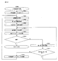
尚、本実施形態は、あくまで一例であり、各手段が存在する場所や機能等、各種処理に関しての各ステップの順序、フラグのオン・オフのタイミング、各ステップの処理を担う手段名等に関し、以下の態様に限定されるものではない。また、上記した実施形態や変更例は、特定のものに対して適用されると限定的に解すべきでなく、どのような組み合わせであってもよい。例えば、ある実施形態についての変更例は、別の実施形態の変更例であると理解すべきであり、また、ある変更例と別の変更例が独立して記載されていたとしても、当該ある変更例と当該別の変更例を組み合わせたものも記載されていると理解すべきである。 Note that this embodiment is only an example, and regarding the location and function of each means, the order of each step regarding various processes, the timing of turning on and off the flag, the name of the means responsible for the processing of each step, etc. It is not limited to the following aspects. Moreover, the above-described embodiments and modifications should not be construed as being limited to being applied to a specific one, and may be combined in any way. For example, a modification of one embodiment should be understood as a modification of another embodiment, and even if one modification is described independently of another, the It should be understood that combinations of modifications and other such modifications are also described.
(本実施形態)
ここで、各構成要素について説明する前に、本実施形態に係る回胴式遊技機Pの特徴(概略)を説明する。以下、図面を参照しながら、各要素について詳述する。
(this embodiment)
Here, before describing each component, the features (outline) of the reel-type game machine P according to the present embodiment will be described. Each element will be described in detail below with reference to the drawings.
まず、図1(一部の構成については図2)を参照しながら、本実施形態に係る回胴式遊技機Pの前面側の基本構造を説明する。回胴式遊技機Pは、主に前扉(フロントドアとも称す)と、裏箱(キャビネット、基体とも称す)と裏箱内に設置されたリールユニット、ホッパ装置、電源供給ユニットE、主制御基板M(CPUMCを含む主制御チップCが搭載されている基板)、副制御基板S(CPUSCを含む副制御チップSCが搭載されている基板)で構成される。以下、これらを順に説明する。 First, the basic structure of the front side of the reel-type game machine P according to the present embodiment will be described with reference to FIG. 1 (part of the structure is shown in FIG. 2). The reel-type gaming machine P mainly includes a front door (also referred to as a front door), a back box (also referred to as a cabinet or base), reel units installed in the back box, a hopper device, a power supply unit E, and a main control unit. It consists of a substrate M (a substrate on which a main control chip C including a CPUMC is mounted) and a sub-control substrate S (a substrate on which a sub-control chip SC including a CPUSC is mounted). These will be described in order below.
<前扉DU>
前扉DUは、遊技状態を視認可能にするための機構、遊技媒体の入力を可能にするための機構、リールユニットを操作するための機構、その他の機構等を含む。具体的には、遊技状態を視認可能にするための機構として、リール窓D160、投入数表示灯D210、スタートランプD180、再遊技ランプD290、投入可能ランプD300、特別遊技状態表示装置D250、クレジット数表示装置D200、払出数表示装置(押し順表示装置)D270(押し順表示装置D270と称することもある)、ATカウンタ値表示装置D280、有利区間表示器YH等が取り付けられている。また、遊技媒体の投入や賭け数(ベット数)の入力を可能にするための機構として、メダル投入口D170、ベットボタンD220、投入された遊技媒体の払い出しを可能にするための機構として、精算ボタンD60が取り付けられている。そして、リールを操作するための機構として、スタートレバーD50、停止ボタンD40が取り付けられている。なお、本実施形態における回胴式遊技機は、スタートレバーD50、停止ボタンD40、メダル投入口D170、ベットボタンD220、精算ボタンD60、サブ入力ボタンSB、十字キーSB2等が取り付けられている遊技者側にせり出した形状の操作卓を備えている。以下、各要素について詳述する。
<Front door DU>
The front door DU includes a mechanism for making the game state visible, a mechanism for allowing input of game media, a mechanism for operating the reel units, other mechanisms, and the like. Specifically, as a mechanism for visually recognizing the game state, reel window D160, insertion number display lamp D210, start lamp D180, replay lamp D290, insertion possible lamp D300, special game state display device D250, credit number A display device D200, a payout number display device (push order display device) D270 (also referred to as a push order display device D270), an AT counter value display device D280, an advantageous interval display device YH, and the like are attached. In addition, as a mechanism for enabling the insertion of game media and inputting the number of bets (number of bets), a medal insertion slot D170, a bet button D220, and a mechanism for enabling the payment of the inserted game media are settling. A button D60 is attached. A start lever D50 and a stop button D40 are attached as mechanisms for operating the reels. It should be noted that the reel-type gaming machine in this embodiment is equipped with a start lever D50, a stop button D40, a medal slot D170, a bet button D220, a checkout button D60, a sub-input button SB, a cross key SB2, and the like. It is equipped with an operation console that protrudes to the side. Each element will be described in detail below.
<遊技状態を視認可能にするための機構>
次に、遊技状態を視認可能にするための機構の要部について説明する。リール窓D160は、前扉DUの一部を構成する合成樹脂等によって形成された透明な部材であり、リール窓D160を通して遊技機枠内に設置されたリールユニットを視認可能に構成されている。また、投入数表示灯D210は、3つのLEDによって構成されており、現在ベット(一の遊技を開始するために必要な遊技メダルを投入すること)されているメダル数と同数のLEDが点灯するよう構成されている。具体的には、投入数表示灯D210は、1ベットランプD211、2ベットランプD212、3ベットランプD213の3つのLED(ランプ)によって構成されており、ベットされている遊技メダルが1枚である場合には1ベットランプD211:点灯、2ベットランプD212:消灯、3ベットランプD213:消灯となり、ベットされている遊技メダルが2枚である場合には1ベットランプD211:点灯、2ベットランプD212:点灯、3ベットランプD213:消灯となり、ベットされている遊技メダルが3枚である場合には1ベットランプD211:点灯、2ベットランプD212:点灯、3ベットランプD213:点灯となる(再遊技が停止表示した次ゲームにおいてはその限りではなく、詳細は後述する)。また、スタートランプD180は、LEDによって構成されており、スタートレバーD50の操作が有効(操作を受け付けている)である場合に点灯し、スタートレバーD50の操作が無効(操作を受け付けていない)である場合に消灯するよう構成されている。また、再遊技ランプD290は、LEDによって構成されており、再遊技が停止表示したことを契機として点灯し、再遊技が停止表示した次回の遊技が終了したことによって消灯するよう構成されている。また、投入可能ランプD300は、メダル投入口D170への遊技メダルの投入が有効である、又は、ベットボタンD220の操作が有効である場合に点灯(点滅としてもよい)し、遊技メダルの投入が無効である、又は、ベットボタンD220の操作が無効である場合に消灯するよう構成されている。また、特別遊技状態表示装置D250は、7セグメントディスプレイによって構成されており、特別遊技中に払い出された払出数の総数が表示されるよう構成されている。尚、特別遊技状態表示装置D250を設けない構成としてもよく、そのように構成した場合には、後述する演出表示装置S40(第二情報表示部とも称することがある)にて当該払出数の総数を表示するよう構成することで遊技者は特別遊技中に払い出された払出数の総数を認識することができユーザーフレンドリーな遊技機とすることができる。また、クレジット数表示装置D200は、7セグメントディスプレイによって構成されており、遊技者の持ちメダルとして遊技機内に貯留されているメダル数の総数(クレジット数)が表示されるよう構成されている。また、払出数表示装置(押し順表示装置)D270は、7セグメントディスプレイによって構成されており、現在払出されている遊技メダル数及びリール停止順(左停止ボタンD41、中停止ボタンD42、右停止ボタンD43の停止順)によって入賞する役が相違し得る条件装置{いわゆる押し順役(押し順あり役とも称することがある)であるが、入賞する役や停止表示される図柄組合せが相違した場合には、遊技者に付される利益率(払出枚数、その後のRT状態等)が異なり得るよう構成されているものが一般的である}が成立したゲームにて、遊技者に最も有利となるリール停止順を報知し得るよう構成されている(当該報知を押し順ナビと称することがある)。このように、払出数表示装置(押し順表示装置)D270は、現在払出されている遊技メダル数と遊技者に最も高利益となるリール停止順との2つの表示を実行し得るよう構成されており、実行されている表示が2つの表示のうちいずれであるかを遊技者が誤認しないような表示態様となっており、当該表示態様の詳細は後述することとする。また、ATカウンタ値表示装置D280は、ATに関する状態(詳細は後述する)のうち、押し順表示装置D270(第一情報表示部とも称することがある)に表示された押し順ナビ表示に従って遊技を進行した場合に保障されることとなる遊技者にとって有利なATに関する状態(本例では、押し順ナビ状態、報知遊技とも称することがあり詳細は後述する)に滞在し得るゲーム数を表示し得るよう構成されている。尚、ATカウンタ値表示装置D280を設けない構成としてもよく、そのように構成した場合には、AT中状態に滞在し得るゲーム数を演出表示装置S40にて表示するよう構成することで遊技者は当該有利なATに関する状態が保障されているゲーム数を認識することができユーザーフレンドリーな遊技機とすることができる。尚、払出数表示装置(押し順表示装置)D270は、払出数表示装置と押し順表示装置との2つの装置に分けるよう構成してもよい。
<Mechanism for making game state visible>
Next, the main part of the mechanism for making the game state visible will be described. The reel window D160 is a transparent member made of synthetic resin or the like that constitutes a part of the front door DU, and is configured so that the reel unit installed within the gaming machine frame can be visually recognized through the reel window D160. In addition, the input number display lamp D210 is composed of three LEDs, and the same number of LEDs as the number of medals currently bet (insert game medals required to start one game) are lit. is configured as follows. Specifically, the inserted number display lamp D210 is composed of three LEDs (lamps) of a 1-bet lamp D211, a 2-bet lamp D212, and a 3-bet lamp D213, and one game medal is bet. In this case, the 1-bet lamp D211: lights up, the 2-bet lamp D212: goes out, and the 3-bet lamp D213: goes out. : lights up, 3 bet lamp D213: lights off, and when the number of bets is 3, 1 bet lamp D211: lights up, 2 bet lamp D212: lights up, 3 bet lamp D213: lights up (replay This is not the case in the next game where is stopped and displayed, details will be described later). The start lamp D180 is composed of an LED, and lights up when the operation of the start lever D50 is valid (operation is accepted), and is turned on when the operation of the start lever D50 is invalid (operation is not accepted). It is configured to turn off in certain cases. Further, the replay lamp D290 is composed of an LED, and is configured to be lit when the replay stop display is triggered and turn off when the next game after the replay stop display is completed. In addition, the insertable lamp D300 lights up (may blink) when the inserting of game medals into the medal inserting slot D170 is effective, or when the operation of the bet button D220 is effective, and the inserting of game medals is enabled. It is configured to be turned off when the bet button D220 is invalid or the operation of the bet button D220 is invalid. Also, the special game state display device D250 is composed of a 7-segment display, and is configured to display the total number of payouts paid out during the special game. In addition, the special game state display device D250 may not be provided. is displayed, the player can recognize the total number of payouts paid out during the special game, and a user-friendly gaming machine can be provided. The credit amount display device D200 is composed of a 7-segment display, and is configured to display the total number of medals (credit amount) stored in the gaming machine as the player's own medals. In addition, the payout number display device (press order display device) D270 is composed of a 7-segment display, and displays the number of game medals currently paid out and the reel stop order (left stop button D41, middle stop button D42, right stop button). D43 (stopping order of D43) can make a difference in the winning hand. is generally configured so that the profit rate (the number of payouts, the RT state after that, etc.) given to the player can be different} is established, the reel that is most advantageous to the player The stop order is configured to be notified (this notification is sometimes referred to as push order navigation). In this way, the number-of-payouts display device (push-order display device) D270 is configured to be able to display two types of display: the number of game medals currently being paid out and the order in which the reels are stopped in order to maximize the profit for the player. The display mode is such that the player does not misunderstand which of the two displays is being executed, and the details of the display mode will be described later. In addition, the AT counter value display device D280 performs the game according to the pressing order navigation display displayed on the pressing order display device D270 (also referred to as the first information display unit) among the AT related states (details will be described later). It is possible to display the number of games in which the player can stay in an AT-related state (in this example, also referred to as push-order navigation state or information game, details of which will be described later) that is guaranteed to the player when progressing. is configured as follows. It should be noted that the AT counter value display device D280 may not be provided. In such a configuration, the effect display device S40 displays the number of games in which the AT counter value display device D280 can be maintained. can recognize the number of games in which the state regarding the advantageous AT is guaranteed, and can be a user-friendly gaming machine. The payout number display device (pressing order display device) D270 may be configured to be divided into two devices, a payout number display device and a push order display device.
また、有利区間表示器YHは、LEDによって構成されており、「有利区間」である場合には点灯し、「有利区間」でない場合には消灯するよう構成されている(点灯及び消灯タイミングについては後述する)。ここで、本例に係る回胴式遊技機においては、従来の回胴式遊技機と同様に、遊技メダルが獲得容易であり遊技者にとって有利な特別遊技状態(いわゆる大当り遊技であり、ボーナス遊技や第1種BB・第2種BB等と呼ばれるものが該当する)、再遊技役の当選率があらかじめ定められた値である通常遊技状態よりも再遊技役の当選率が高い(又は低い)状態である再遊技確率変動遊技状態(RT状態)、当選した役を入賞させるためのリールの停止順、停止位置を報知し得るAT(アシストタイム)中状態、前記RT状態とAT中状態とが複合したART(アシストリプレイタイム)状態、等を採り得るが、これらの「遊技状態」とは別に、「通常区間」、「待機区間」及び「有利区間」という3つの「遊技区間」のいずれかを設定可能となっている。尚、本例においては「待機区間」は設定しておらず、「通常区間」と「有利区間」とのいずれかの遊技区間を設定している。このうち、「有利区間」が他の「遊技区間」よりも、遊技者にとって相対的に有利となるものとして位置付けられており、例えば、「遊技状態」がAT中状態やART状態であることと「有利区間」とが対応付けされている。即ち、「遊技状態」がAT中状態やART状態であると、有利区間表示器YHが点灯するのであるが、後述するように、「遊技区間」の設定制御も「遊技状態」の設定制御と同様に、遊技進行を制御する主制御基板側で行われるため、有利区間表示器YHの点灯/消灯状況によって、遊技進行状況が遊技者にとって相対的に有利なものとなっているか否かが、嘘偽りなく遊技者に対して伝達可能となっている。尚、後述するように、「有利区間」が所定の上限ゲーム数(例えば、1500ゲーム)に達するまで継続すると「通常区間」が強制的に設定されるのであるが、その際には、残存するATに関する状態も強制的に終了させられる(AT中状態を維持するための情報がクリア・初期化される)ため、設定される「遊技区間」の変更が「遊技状態」の移行にも影響を与え得るものとなっており、それにより比較的設計自由度の高いAT中状態やART状態等の「遊技状態」によって、著しく射幸性が高まってしまうことを自動的に抑制できるものとなっているのである。尚、上述したように、「有利区間」が所定の上限ゲーム数(例えば、1500ゲーム)に達するまで継続すると「通常区間」が強制的に設定される、即ち、「有利区間」が終了することとなるが、「有利区間」の終了条件はこれには限定されない。本例に係る回胴式遊技機における「有利区間」の終了条件は、「押し順役(押し順あり役)を構成する小役の中で、払出し枚数が最も多い小役を獲得可能な押し順ナビ1回の実行(例えば、押し順役を構成する小役として、7枚、3枚、1枚の小役がある場合、払出し枚数が最も多い7枚が獲得可能な押し順ナビであって、押し順により7枚、又は1枚が獲得可能な押し順役と、押し順により3枚が獲得可能な押し順役があれば、3枚が獲得可能な押し順ナビは、ここでいう押し順ナビには該当しない)」、又は、「BB、RB、MB、のいずれかに当選」を満たし、且つ、「任意の終了条件(40G1セットのループ抽選に非当選(AT)、固定32G経過(ガセ前兆)等)」、又は、「有利区間1500G」を満たすことが終了条件となっている。尚、押し順ベル役が存在しないような仕様(例:RT状態を移行するためのリプレイの押し順は存在するが、押し順によって払出し枚数が異なる小役が存在しない仕様)の場合には、「払出し枚数が最も多い小役を獲得可能な押し順ナビ1回」という有利区間を終了するための条件は除外される。また、本実施形態では、押し順役を構成する小役として11枚役に対応する小役と1枚役に対応する小役を含む小役により構成されているため、「払出し枚数が最も多い小役を獲得可能な押し順ナビ1回の実行」とは、11枚のメダルが獲得可能(11枚役が入賞可能)な押し順を報知することを指す。 In addition, the advantageous section indicator YH is composed of an LED, and is configured to be lit in the case of the "advantageous section" and to be extinguished in the case of not being the "advantageous section" (the lighting and extinguishing timings are described later). Here, in the reel-type gaming machine according to the present example, as in the conventional reel-type gaming machine, game medals can be easily acquired, and a special game state (so-called jackpot game, bonus game, etc.) is advantageous for the player. , 1st type BB, 2nd type BB, etc.), the winning rate of the replay role is higher (or lower) than the normal game state where the winning rate of the replay role is a predetermined value The replay probability variable gaming state (RT state), the stopping order of the reels for winning the winning combination, the AT (assist time) state that can notify the stopping position, and the RT state and the AT state. Composite ART (assist replay time) state, etc. can be taken, but apart from these "game states", one of three "game sections", "normal section", "waiting section" and "advantage section" can be set. In this example, the "waiting section" is not set, and either the "normal section" or the "advantageous section" is set. Among these, the "advantageous section" is positioned as being relatively more advantageous for the player than other "game sections". "advantageous section" is associated. That is, when the "game state" is the AT state or the ART state, the advantageous interval indicator YH lights up. Similarly, since this is done on the side of the main control board that controls the progress of the game, whether or not the progress of the game is relatively advantageous to the player can be determined by the lighting/light-out status of the advantageous zone indicator YH. It is possible to truthfully transmit to the player. As will be described later, if the "advantageous section" continues until it reaches a predetermined upper limit number of games (for example, 1500 games), the "normal section" is forcibly set. The state related to AT is also forcibly terminated (information to maintain the state during AT is cleared and initialized), so changing the set "game section" does not affect the transition of "game state". As a result, it is possible to automatically suppress the remarkably increased gambling nature due to the "game state" such as the AT state and the ART state, which have a relatively high degree of design freedom. of. As described above, if the "advantageous section" continues until it reaches a predetermined upper limit number of games (for example, 1500 games), the "normal section" is forcibly set, that is, the "advantageous section" ends. However, the end condition of the "advantageous section" is not limited to this. The end condition of the "advantageous section" in the reel-type gaming machine according to the present example is "a push that can win a small win with the largest number of payouts among the small wins that constitute the push order (play with push order). Execution of forward navigation once (for example, if there are small wins of 7, 3, and 1 as small wins that make up the push order navigator, the 7 wins with the highest number of payouts can be acquired. Then, if there is a pushing order combination in which 7 cards or 1 card can be obtained depending on the pushing order and a pushing order combination in which 3 cards can be obtained depending on the pushing order, the pushing order navigation that can obtain 3 cards is referred to here. (does not apply to push order navigation)" or "won any of BB, RB, or MB", and "arbitrary termination conditions (not won in 40G1 set loop lottery (AT), fixed 32G The end condition is that the progress (fake omen, etc.)” or the “advantageous section 1500G” is satisfied. In addition, in the case of specifications where there is no push order bell combination (eg, there is a replay push order for transitioning to the RT state, but there is no small combination with a different payout number depending on the push order), The condition for ending the advantageous section, ie, “one press-order navigator capable of acquiring the small winning combination with the largest number of payouts”, is excluded. In addition, in the present embodiment, the small winning combination that constitutes the winning combination is composed of a small combination corresponding to an 11-card combination and a small combination corresponding to a 1-card combination. Execution of push order navigator that can win a small win once" means notification of a push order in which 11 medals can be won (11 wins can be won).
<遊技媒体の入力を可能にするための機構>
次に、遊技媒体の入力を可能にするための機構の要部について説明する。メダル投入口D170は、遊技メダルの投入口であり、メダル受付可能状態である状況下において当該投入口に投入された遊技メダルは遊技機内部へと誘導される。また、遊技機内部にはメダルの投入を検出するセンサとして、投入受付センサD10sと、第1投入センサD20sと、第2投入センサD30sと、が設けられており、遊技機内部へと誘導された遊技メダルが正常に投入されたと判断した場合に、投入されたメダルをベットされたメダルとして検出し得るよう構成されている。また、ベットボタンD220は、遊技者によって操作可能に構成されており、操作によって、貯留されているメダル(クレジットのメダル)をベットすることができるよう構成されている。また、精算ボタンD60は、遊技者によって操作可能に構成されており、操作によって、貯留されているメダル(クレジットのメダル)及び/又はベットされているメダルを遊技者に払い戻すことが可能となっている。尚、精算ボタンD60の操作によって払い戻された遊技メダルは、放出口D240に払い出されるよう構成されている。
<Mechanism for enabling input of game media>
Next, the main part of the mechanism for enabling the input of game media will be described. The medal slot D170 is a slot for inserting game medals, and the game medals inserted into the slot are guided into the gaming machine in a state where medals can be accepted. In addition, an insertion receiving sensor D10s, a first insertion sensor D20s, and a second insertion sensor D30s are provided as sensors for detecting the insertion of medals inside the gaming machine, and the medals are guided into the gaming machine. When it is determined that game medals have been inserted normally, the inserted medals can be detected as bet medals. Also, the bet button D220 is configured to be operable by the player, and configured to bet accumulated medals (credit medals) by operation. The settlement button D60 is configured to be operable by the player, and can be operated to refund the accumulated medals (credit medals) and/or bet medals to the player. there is The game medals paid out by operating the settlement button D60 are arranged to be paid out to the ejection port D240.
<リールユニットを操作するための機構>
次に、スタートレバーD50は、遊技者によって操作可能に構成されており、操作によってリールの動作を開始可能に構成されている。また、停止ボタンD40は、遊技者によって操作可能な左停止ボタンD41、中停止ボタンD42、右停止ボタンD43を備えており、夫々の停止ボタンを操作することによってリールの動作を順次停止可能に構成されている。
<Mechanism for operating the reel unit>
Next, the start lever D50 is configured so as to be operable by the player, and is configured to be capable of starting the movement of the reels by operation. In addition, the stop button D40 includes a left stop button D41, a middle stop button D42, and a right stop button D43 that can be operated by the player. By operating each stop button, the operation of the reels can be sequentially stopped. It is
<前扉DUに設けられたその他の機構>
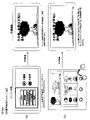
次に前扉DUに設けられたその他の機構の要部について図2の前扉DUを開いて回胴式遊技機Pの内部の構成を示した斜視図も参照しつつ説明する。前扉DUには、遊技の興趣性を高めるための機構として、予告演出や背景演出等の演出を表示するための演出表示装置S40、様々な点灯態様にて点灯し得る遊技効果ランプD26(不図示)、信号中継用の扉基板D、投入されたメダルの検出等を行なうメダルセレクタDS、サウンドを出力し得るスピーカS20、合成樹脂等によって形成された部材である、中パネル(中装飾パネル)、上パネルD130及び下パネルD140、等が設けられている。演出表示装置S40は、上パネルに形成された透視領域を介して演出等を表示する表示部が視認可能となるように前扉DUの裏面側上部に取り付けられている。また、装飾ランプユニットD150及びLEDランプユニットS10は、回胴式遊技機Pの遊技の進行に応じて発光する発光源を有しており、下パネルD140を挟んで右側及び左側の各々に装飾ランプユニットD150が設けられ、上パネルD130を挟んで右側及び左側の各々にLEDランプユニットS10が設けられている(装飾ランプユニットD150とLEDランプユニットS10とを総称して、ランプユニットと称することがある)。また、前扉DUの背面におけるリール窓D160の下方には、扉基板Dが取り付けられており、この扉基板Dには、前述した停止ボタンD40や、スタートレバーD50、精算ボタンD60等の入力信号が入力され、入力された信号を直接或いは加工して後述する主制御基板Mに出力する中継基板の機能を有している。また、メダル投入口D170に対応し、前扉DUの背面における扉基板Dの付近には、詳細後述するメダルセレクタDSが設けられており、メダル投入口D170から投入されたメダルの検出並びに簡易的な真贋を行ない、適正なメダルを後述するホッパH40に案内し、不適正なメダルを後述するメダル受け皿D230に返却する機能を有している。更に、扉基板Dの下方の左右にスピーカS20が夫々1つずつ設けられている。中パネルは、操作卓の上側、上パネルD130の下側の部分であり、前述したリール窓を含むパネル部分である。また、前述した操作卓D190に取り付けられているサブ入力ボタンSB及び十字キーSB2とは、後述するメニュー画面における操作や副制御基板S側でのボタン連打演出(サブ入力ボタンSBを連打操作することによって、ボーナスに当選しているか否かに関する演出を実行する)やミニゲーム(例えば、「AT中状態」への突入の成否の演出)等の進行等に用いる部材である。なお、回胴式遊技機Pの前扉DUには、放出口D240から放出された遊技メダル(或いは単にメダルと呼ぶことがある)を受けるメダル受け皿D230、前扉DUの開閉状態を検出可能な扉スイッチD80が設けられている。また、前扉DUには鍵穴D260が設けられており、鍵穴D260の形状と整合するキー(ドアキー)を鍵穴D260に差し込む{加えて、所定の方向(例えば、時計回り)に捻る}ことで、前扉DUを開放し得るよう構成されている。更に、本実施形態においては、ドアキーを鍵穴D260に差し込む{加えて、所定の方向(例えば、反時計回り)に捻る}ことで、エラー状態(ドア開放エラー等)を解除し得るよう構成されている。また、ベットボタンD220の内部にはベットボタンランプS50が設けられており、ベットボタンランプS50は、副制御基板Sにて制御されるLEDで構成されており、ベットボタンランプS50が点灯(又は点滅)することにより、ベットボタンD220の操作が有効であることを遊技者に知覚させることができる。また、停止ボタンD40の内部には停止ボタンランプS60が設けられており(左停止ボタンD41、中停止ボタンD42、右停止ボタンD43の3つの停止ボタンに夫々設けられている)、停止ボタンランプS60は、副制御基板Sにて制御されるLEDで構成されており、停止ボタンランプS60の点灯(又は点滅)の有無及び/又は点灯色により、停止ボタンD40の操作が有効であることを遊技者に知覚させることができる。尚、有効である停止ボタンD40に対応した点灯色にて点灯するのは有効である停止ボタンD40に対応した停止ボタンランプS60のみとなるよう構成されているため、例えば、左停止ボタンD41が無効、中停止ボタンD42が有効、右停止ボタンD43が有効である場合には、左停止ボタンD41に対応した停止ボタンランプS60が消灯、中停止ボタンD42に対応した停止ボタンランプS60が点灯、右停止ボタンD43に対応した停止ボタンランプS60が点灯のように、3つの停止ボタンランプS60の点灯態様が夫々相違し得るよう構成されている。また、停止ボタンランプS60の点灯色や点灯態様を相違させることにより(点灯・点滅のように相違させたり、低速点滅・高速点滅のように相違させてもよい)、押し順ナビが実行されるゲームにて、現在停止操作するべき停止ボタンを遊技者が判別し易くなるよう構成してもよく、例えば、すべてのリールが回転中であり、「左→中→右」の押し順が正解(最大の払出枚数)となる押し順ベルに当選している場合に、左停止ボタンに対応する停止ボタンランプを白色で点滅させ、中停止ボタンに対応する停止ボタンランプと右停止ボタンに対応する停止ボタンランプとを青色に点灯させ、その後、遊技者が左停止ボタンを操作して左リールを停止させた場合には、左停止ボタンに対応する停止ボタンランプを消灯させ、中停止ボタンに対応する停止ボタンランプを白色で点滅させ、右停止ボタンに対応する停止ボタンランプとを青色に点灯させるよう構成してもよい。
<Other mechanisms provided in the front door DU>
Next, the essential parts of other mechanisms provided on the front door DU will be described with reference to the perspective view of FIG. On the front door DU, as a mechanism for increasing the interest of the game, there is an effect display device S40 for displaying effects such as an advance notice effect and a background effect, and a game effect lamp D26 that can be lit in various lighting modes (not shown), a door substrate D for relaying signals, a medal selector DS for detecting inserted medals, a speaker S20 capable of outputting sound, and a middle panel (middle decorative panel) made of synthetic resin or the like. , an upper panel D130 and a lower panel D140, and the like. The effect display device S40 is attached to the upper part of the back side of the front door DU so that the display section for displaying effects and the like can be visually recognized through the see-through area formed on the upper panel. Also, the decorative lamp unit D150 and the LED lamp unit S10 have light emitting sources that emit light according to the progress of the game of the reel-type game machine P, and decorative lamps are provided on the right and left sides of the lower panel D140, respectively. A unit D150 is provided, and an LED lamp unit S10 is provided on each of the right and left sides of the upper panel D130 (the decorative lamp unit D150 and the LED lamp unit S10 may be collectively referred to as lamp units). ). Further, a door substrate D is attached below the reel window D160 on the back surface of the front door DU, and this door substrate D receives input signals from the aforementioned stop button D40, start lever D50, checkout button D60, and the like. is input, and has the function of a relay board that directly or processes the input signal and outputs it to the main control board M, which will be described later. Corresponding to the medal insertion slot D170, a medal selector DS, which will be described later in detail, is provided near the door substrate D on the back of the front door DU, and detects medals inserted from the medal insertion slot D170. It has a function of carrying out an authenticity check, guiding proper medals to a hopper H40, which will be described later, and returning improper medals to a medal receiving tray D230, which will be described later. Furthermore, one speaker S20 is provided on each of the right and left sides below the door substrate D. As shown in FIG. The middle panel is the upper side of the operator console and the lower side of the upper panel D130, and is the panel part including the aforementioned reel window. Further, the sub-input button SB and the cross key SB2 attached to the console D190 described above are used for operations on the menu screen, which will be described later, and button repeated hitting effects on the sub-control board S side. This is a member used for the progress of mini-games (for example, the success or failure of entering the "AT state") and the like. The front door DU of the reel-type game machine P has a medal receiving tray D230 for receiving game medals (or simply called medals) discharged from the discharge port D240, and the opening/closing state of the front door DU can be detected. A door switch D80 is provided. In addition, a keyhole D260 is provided in the front door DU, and a key (door key) that matches the shape of the keyhole D260 is inserted into the keyhole D260 {and twisted in a predetermined direction (for example, clockwise)}. It is configured so that the front door DU can be opened. Furthermore, in this embodiment, an error state (door open error, etc.) can be canceled by inserting the door key into the keyhole D260 {in addition, twisting it in a predetermined direction (for example, counterclockwise)}. there is A bet button lamp S50 is provided inside the bet button D220. The bet button lamp S50 is composed of an LED controlled by the sub-control board S. The bet button lamp S50 lights up (or blinks). ), the player can perceive that the operation of the bet button D220 is effective. A stop button lamp S60 is provided inside the stop button D40 (provided for each of the three stop buttons: the left stop button D41, the middle stop button D42, and the right stop button D43). is composed of LEDs controlled by the sub-control board S, and the presence or absence and/or lighting color of the stop button lamp S60 indicates to the player that the operation of the stop button D40 is valid. can be perceived by It should be noted that only the stop button lamp S60 corresponding to the active stop button D40 is lit in the lighting color corresponding to the active stop button D40. For example, the left stop button D41 is disabled. , when the middle stop button D42 is effective and the right stop button D43 is effective, the stop button lamp S60 corresponding to the left stop button D41 is turned off, the stop button lamp S60 corresponding to the middle stop button D42 is turned on, and the right stop button is turned on. Like the lighting of the stop button lamp S60 corresponding to the button D43, the lighting modes of the three stop button lamps S60 are configured to be different from each other. Further, by changing the lighting color and lighting mode of the stop button lamp S60 (they may be different such as lighting/blinking or low speed/high speed flashing), push order navigation is executed. In the game, it may be configured so that the player can easily identify the stop button that should be stopped at present. When winning the push order bell that will be the maximum payout number), the stop button lamp corresponding to the left stop button flashes in white, the stop button lamp corresponding to the middle stop button and the stop corresponding to the right stop button After that, when the player operates the left stop button to stop the left reel, the stop button lamp corresponding to the left stop button is turned off, and the stop button lamp corresponding to the middle stop button is turned off. The stop button lamp may be flashed in white, and the stop button lamp corresponding to the right stop button may be illuminated in blue.
次に裏箱(キャビネット、基体とも称す)並びに、裏箱内に設置される各装置について説明する。裏箱の略中央には、リール窓D160を介してその一部が視認可能となるようにリールユニットが取付られている。リールユニットは、リールM50とリールM50の駆動源(ステッピングモータ等)とを備えている。また、リールM50は、左リールM51、中リールM52、右リールM53を備えている。ここで、夫々のリール部は合成樹脂等により形成され、リール部の外周上(リール帯MO上)には複数の図柄が描かれている。そして、スタートレバーD50及び停止ボタンD40における各停止ボタンの操作に基づき、夫々のリール部の回転動作及び停止動作を可能とするよう構成されている。また、図示しないが、左リールM51、中リールM52及び右リールM53の内部にはLED(以下、リールバックライトと呼ぶことがある)が設けられており、LEDが点灯した際にはリール部外周を透過した光によって、リール部外周が点灯したように視認できるよう構成されている。また、リールM50の上方には、各リール(左リールM51、中リールM52、右リールM53)を駆動するための後述する回胴基板Kが格納されている。 Next, the back box (also called cabinet or base) and each device installed in the back box will be described. A reel unit is attached to substantially the center of the back box so that a part thereof can be visually recognized through the reel window D160. The reel unit includes a reel M50 and a drive source (stepping motor, etc.) for the reel M50. The reel M50 also includes a left reel M51, a middle reel M52, and a right reel M53. Here, each reel portion is formed of synthetic resin or the like, and a plurality of patterns are drawn on the outer circumference of the reel portion (on the reel band MO). Further, it is configured to allow the respective reel portions to be rotated and stopped based on the operation of each stop button in the start lever D50 and the stop button D40. Although not shown, LEDs (hereinafter sometimes referred to as reel backlights) are provided inside the left reel M51, the middle reel M52, and the right reel M53. The outer circumference of the reel can be visually recognized as if it were illuminated by the light transmitted through. Above the reel M50, a reel board K, which will be described later, for driving each reel (left reel M51, middle reel M52, and right reel M53) is stored.
また、リールM50の上方には、遊技全体の制御を司る後述する主制御基板Mが格納され、リールM50の左方には、図1に示した演出表示装置S40、LEDランプユニットS10、スピーカS20等を用いて行われる各種演出の制御を司る後述する副制御基板Sが格納されている。なお、主制御基板Mには、後述する設定変更装置制御処理を実行するため(設定変更を行うため)に使用する設定キースイッチM20、設定値の変更やエラー解除等を実行し得る設定/リセットボタンM30が接続されている。図2において、設定キースイッチM20、設定/リセットボタンM30については何れも不図示としているが、主制御基板Mの基板上等の適宜位置に設けられていればよい(即ち、前扉DUを開かなければ人為的なアクセスが困難な位置に設けられていればよい)。 In addition, above the reel M50, a main control board M, which will be described later and controls the entire game, is stored. A sub-control board S, which will be described later, is stored for controlling various effects that are performed using, for example. The main control board M includes a setting key switch M20 used to execute a setting change device control process (to change settings), and a setting/reset key switch M20 for changing setting values and canceling errors. A button M30 is connected. Although neither the setting key switch M20 nor the setting/reset button M30 are shown in FIG. If not, it may be provided in a position where human access is difficult).
リールM50の下方には、投入された遊技メダルが集められるホッパH40や、遊技メダルを払い出すメダル払出装置Hが設けられており、回胴式遊技機P全体に電源を供給するための電源基板Eが格納されている。メダル払出装置Hから払い出された遊技メダルは、コインシュータD90を通って、放出口D240から払い出されるようになっている。また、電源基板E(電源供給ユニットEとも称することがある)の前面には、回胴式遊技機Pの電源を投入するための電源スイッチE10も設けられている。なお、メダル払出装置Hの詳細については後述する。 A hopper H40 for collecting inserted game medals and a medal payout device H for paying out game medals are provided below the reel M50, and a power supply board for supplying power to the entire reel-type game machine P. E is stored. The game medals paid out from the medal payout device H pass through the coin shooter D90 and are paid out from the outlet D240. A power switch E10 for turning on the power of the reel-type game machine P is also provided on the front surface of the power board E (sometimes referred to as a power supply unit E). Details of the medal payout device H will be described later.
<メダルセレクタDS>
次に、メダルセレクタDSについて、図3を交えつつ詳細に説明する。図3は、回胴式遊技機P内部における、メダル投入口D170に投入された遊技メダルの経路(セレクタ)を示した斜視図である。メダルセレクタDSは、扉基板Dの付近にメダル投入口D170から投入された遊技メダルの通路となる投入受付センサD10sが設けられており、投入受付センサD10sの下方には、遊技メダルを放出口D240に導くためのコインシュータD90などが設けられている。投入受付センサD10sは、メダル投入口D170から投入された遊技メダルを主に寸法に基づいて選別し、規格寸法に適合した遊技メダルだけを受け入れる機能を有しており、この機能により適合しないと判断されたメダル(又は、その他の異物)は、ブロッカD100により放出口D240に払い戻されるよう構成されている。遊技者がスタートレバーD50を操作する前に(遊技メダルの投入が有効である状態にて)遊技メダルを投入すると、遊技メダルは投入受付センサD10sによって選別され、規格を満足しているものだけがホッパH40内に投入され、規格を満たしていないメダルは、コインシュータD90を通って、放出口D240に返却されるようになっている。これに対して、スタートレバーD50が操作された後に(遊技メダルの投入が有効でない状態にて)遊技メダルが投入された場合は、規格を満たしているか否かに拘らず、投入された遊技メダルはコインシュータD90を通って、放出口D240に返却される。また、投入受付センサD10sの内部(流路の奥)には、詳細後述するメダル投入に係るセンサが設けられており、寸法規格を満たして受け入れられた遊技メダルが通過すると、第1投入センサD20s及び第2投入センサD30sによって検出されて、その信号が後述する主制御基板Mに供給されるようになっている。
<Medal Selector DS>
Next, the medal selector DS will be described in detail with reference to FIG. FIG. 3 is a perspective view showing a path (selector) of game medals inserted into the medal slot D170 inside the reel-type game machine P. As shown in FIG. The medal selector DS is provided with an insertion reception sensor D10s serving as a path for game medals inserted from the medal insertion opening D170 near the door substrate D, and below the insertion reception sensor D10s is an ejection opening D240 for game medals. A coin shooter D90 or the like is provided for leading to. The insertion reception sensor D10s has a function of selecting game medals inserted from the medal insertion slot D170 mainly based on the size and accepting only the game medals conforming to the standard dimensions. The medals (or other foreign objects) that have been dropped are configured to be paid back to the ejection port D240 by the blocker D100. When the player inserts game medals before operating the start lever D50 (in a state in which the insertion of game medals is valid), the game medals are sorted by the insertion reception sensor D10s, and only those satisfying the standards are selected. Tokens that are thrown into the hopper H40 and do not meet the standards are returned to the outlet D240 through the coin shooter D90. On the other hand, when game medals are inserted after the start lever D50 is operated (in a state in which the insertion of game medals is not valid), regardless of whether the standard is met, the inserted game medals is returned to the outlet D240 through the coin shooter D90. Further, inside the insertion receiving sensor D10s (at the back of the flow path), there is provided a sensor related to medal insertion, which will be described later in detail. and the second insertion sensor D30s, and the signal thereof is supplied to the main control board M, which will be described later.
次に、メダル投入に係るセンサについて詳述する。メダル投入口D170に投入された遊技メダルは、まず投入受付センサD10sを通過する。投入受付センサD10sは機械式のダブルセンサになっており、遊技メダルが通過することによって、2つの突起した機構が押下されることによりオンとなり遊技メダルが正常に通路を通過することができることとなる。また、このような構成により、遊技メダルではない異物(規格を満足していない異物であり、例えば、遊技メダルよりも径が小さいもの)が投入された場合には、2つの突起した機構が押下されない。このようなメダルは、起立した状態をメダルが維持できないため、通路を通過できず(メダルが倒れこむ)、前述したようにコインシュータD90を通って放出口D240に払い戻されることとなる。そのほかにも、投入受付センサD10sは、オンとなっている時間が所定時間以上連続した場合等にも、エラーであると判定し得る(その結果、ブロッカD100がオフとなり得る)よう構成されている。 Next, the sensor for inserting medals will be described in detail. Game medals inserted into the medal slot D170 first pass through the insertion acceptance sensor D10s. The insertion acceptance sensor D10s is a mechanical double sensor, and when the game medals pass, the two protruding mechanisms are pushed down to turn on and allow the game medals to pass normally through the path. . Also, with such a configuration, when a foreign object that is not a game medal (a foreign object that does not satisfy the standard, for example, a diameter smaller than that of a game medal) is thrown in, the two protruding mechanisms are pushed down. not. Since such medals cannot be maintained in an upright state, they cannot pass through the path (the medals fall down) and are returned to the ejection port D240 through the coin shooter D90 as described above. In addition, the input reception sensor D10s is configured to be able to determine that an error has occurred (as a result, the blocker D100 can be turned off) even when the ON time continues for a predetermined time or longer. .
遊技メダルがブロッカD100を正常に通過した場合に、通過直後に第1投入センサD20s及び第2投入センサD30sを通過することとなる。この投入センサ(第1投入センサD20s及び第2投入センサD30s)は2つのセンサで構成されており(遊技メダルの規格上の直径よりも小さい間隔で隣接配置されており)、夫々のセンサのオン・オフ状況(第1投入センサD20s及び第2投入センサD30sのオン・オフの組み合わせの遷移していく順序、等)及びオン・オフとなっている時間を監視することにより様々なエラーを検出可能に構成されている。 When the game medal normally passes through the blocker D100, it passes through the first insertion sensor D20s and the second insertion sensor D30s immediately after passing. This insertion sensor (first insertion sensor D20s and second insertion sensor D30s) is composed of two sensors (arranged adjacently with an interval smaller than the standard diameter of game medals), and each sensor is turned on・Various errors can be detected by monitoring the off state (the order of transition of the combination of on/off of the first insertion sensor D20s and the second insertion sensor D30s, etc.) and the ON/OFF time. is configured to
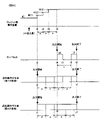
<メダル払出装置H>
次に、図4のメダル払出装置Hの正面図及び上面図を用いてメダル払出装置Hを詳細に説明する。メダル払出装置Hは、クレジット(遊技機内部に電子的に貯留されている遊技メダル)又はベットされているメダル(遊技を開始するために投入されたメダル)が存在する状態で、精算ボタンが操作された、又は、入賞により遊技メダルが払い出される場合に作動することとなる。作動する場合には、まず、ホッパモータH80が駆動することにより、ディスク回転軸H50aを中心にディスクH50が回転する。回転によりメダル払出装置H内の遊技メダルは放出付勢手段H70を変位させて遊技メダル出口H60から放出口D240に向かって流下していくこととなる。尚、払出センサ(第1払出センサH10s及び第2払出センサH20s)は2つのセンサで構成されており、夫々のセンサのオン・オフ状況(第1払出センサH10s及び第2払出センサH20sのオン・オフの組み合わせの遷移していく順序、等)及びオン・オフとなっている時間を監視することにより様々なエラーを検出可能に構成されている。より具体的には、例えば、遊技メダル出口H60を正常に通過する際には、放出付勢手段H70の変位により、第1払出センサH10s=オフ・第2払出センサH20s=オフの状態から、第1払出センサH10s=オフ・第2払出センサH20s=オフ→第1払出センサH10s=オン・第2払出センサH20s=オフ→第1払出センサH10s=オン・第2払出センサH20s=オン→第1払出センサH10s=オフ・第2払出センサH20s=オン→第1払出センサH10s=オフ・第2払出センサH20s=オフ、というセンサ状態遷移となるため、このセンサ状態遷移と反する動きを検出した場合には、エラーとするよう構成することを例示することができる。
<Medal Dispensing Device H>
Next, the medal payout device H will be described in detail with reference to the front view and top view of the medal payout device H in FIG. The medal payout device H operates the checkout button in a state where credits (game medals electronically stored inside the game machine) or bet medals (medals inserted to start a game) are present. or when game medals are paid out as a result of winning a prize. When operating, the hopper motor H80 is first driven to rotate the disk H50 around the disk rotation axis H50a. The rotation causes the game medals in the medal payout device H to displace the release urging means H70 and flow down from the game medal outlet H60 toward the release port D240. The payout sensor (the first payout sensor H10s and the second payout sensor H20s) is composed of two sensors. Various errors can be detected by monitoring the transition order of off combinations, etc.) and the time of on/off. More specifically, for example, when passing through the game medal exit H60 normally, due to the displacement of the release urging means H70, the first payout sensor H10s = off and the second payout sensor H20s = off to the second payout sensor H20s. 1st payout sensor H10s = off · 2nd payout sensor H20s = off → 1st payout sensor H10s = on · 2nd payout sensor H20s = off → 1st payout sensor H10s = on · 2nd payout sensor H20s = on → 1st payout Sensor H10s = off, second payout sensor H20s = on → first payout sensor H10s = off, second payout sensor H20s = off. , to be an error.
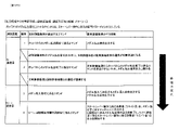
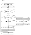
次に、図5は、本実施形態における、回胴式遊技機の基本仕様一覧である。本実施形態に係る回胴式遊技機は、規定数(1ゲームにてベットできる遊技メダルの最大枚数)が3枚、左リールM51、中リールM52及び右リールM53のコマ数はいずれも20コマ、入賞判定される有効ラインは「左リールM51上段、中リールM52中段、右リールM53下段」の1ラインとなっている。尚、最大払出枚数は11枚、最小払出枚数は1枚(入賞役と払出枚数との対応付けは後述)である。また、優先入賞順(引き込み優先順)は、「再遊技役→小役(ベル、スイカ、等)→ボーナス」となっており、例えば、再遊技役とボーナスが同時に成立している場合には、再遊技役となる図柄組み合わせが停止表示し且つボーナスは入賞不能である。また、ベルとスイカが成立している場合には、どちらも引き込める位置(入賞する停止位置まで4コマ以内の位置)で停止ボタンを押した場合には払出枚数が多い小役を優先して引きこむよう構成されている。尚、同図に示した構成はあくまで一例であり、各リールのコマ数を変更(例えば、21コマに変更)したり、有効ラインの構成を変更(例えば、横3ライン、斜め2ラインの5ラインに変更、左リールM51下段、中リールM52中段、右リールM53上段の1ラインに変更)しても何ら問題ない。また、特に押し順によって遊技者にとって異なる利益が付与される押し順小役が当選したときの引き込み制御としては、予め定められた正解の押し順で操作された場合には払出し枚数の多い小役を優先して引き込むように制御(枚数優先制御)しており、正解の押し順とは異なる不正解の押し順で操作された場合には停止表示可能な(停止操作から4コマ以内の位置に配置されている)図柄のうち入賞可能性を高める(入賞可能な複数図柄組合せのうち入賞する可能性が最も多くなる)図柄を引き込む制御(個数優先制御)を行っている。 Next, FIG. 5 is a list of basic specifications of the reel-type game machine in this embodiment. In the reel-type gaming machine according to the present embodiment, the specified number (the maximum number of game medals that can be bet in one game) is 3, and the number of frames on the left reel M51, middle reel M52, and right reel M53 is 20 frames. , the effective line for which a prize is determined is one line of "left reel M51 upper stage, middle reel M52 middle stage, right reel M53 lower stage". The maximum number of payouts is 11, and the minimum number of payouts is 1 (association between the winning combination and the number of payouts will be described later). In addition, the priority winning order (pull-in priority order) is "replay role → small win (bell, watermelon, etc.) → bonus", for example, when the replay role and bonus are established at the same time , the symbol combination for the replaying combination is stopped and displayed, and the bonus cannot be won. Also, if the bell and watermelon are established, if you press the stop button at a position where you can draw both (a position within 4 frames to the stop position where you win a prize), give priority to a small combination with a large number of payouts. It is designed to pull. The configuration shown in the figure is only an example, and the number of frames on each reel can be changed (for example, changed to 21 frames), or the configuration of effective lines can be changed (for example, 3 horizontal lines, 2 diagonal lines, 5 lines). There is no problem even if the line is changed to 1 line of the left reel M51 lower stage, the middle reel M52 middle stage, and the right reel M53 upper stage). In addition, as a pull-in control when a small winning combination in which different benefits are given to the player depending on the pressing order is won, a small winning combination with a large number of payouts is provided when the operation is performed in a predetermined correct pressing order. (number of sheets priority control), and if the incorrect pressing order is different from the correct pressing order, it is possible to stop display (in a position within 4 frames from the stop operation A control (quantity priority control) is performed to draw in the symbols that increase the possibility of winning (among the combinations of multiple symbols that can be won, the possibility of winning is the highest) among the symbols that are arranged.
次に、図6は、本実施形態における、回胴式遊技機のリール配列一覧である。同図に示されるように、左リールM51、中リールM52及び右リールM53のコマ数はいずれも20コマ(0番~19番)であり、図柄は「黒セブン」、「白セブン」、「羊」、「ブランク」、「ベル」、「リプレイA」、「リプレイB」、「スイカA」、「スイカB」、「チェリー」の10種類となっている。ここで、「ブランク」は、その他の図柄と同様に当選役を構成する図柄組み合わせに含まれる図柄であり、当選役を構成しない図柄という意味ではなく、「ブランク」を含む当選役を構成する図柄組み合わせとしては、例えば、「スイカB・リプレイA・ブランク」で再遊技02となっている。尚、同図に示した構成はあくまで一例であり、図柄の種類を増減・変更しても何ら問題ない。
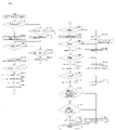
Next, FIG. 6 is a reel arrangement list of the reel-type game machine in this embodiment. As shown in the figure, the left reel M51, the middle reel M52, and the right reel M53 each have 20 frames (
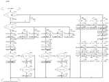
次に、図7~図9は、本実施形態における図柄組み合わせ一覧1~3である。本実施形態においては、夫々の条件装置に対して複数の図柄組み合わせが存在しており、後述するように、左リールM51、中リールM52及び右リールM53の停止順番や停止位置に応じて、いずれか一の図柄組み合わせが有効ライン(前述した1ライン)上に停止表示されるよう構成されている。尚、有効ライン上に同一種類の図柄が揃っていない場合にも遊技者から見ると有効ライン以外のライン上にて一列に同一の図柄が揃いやすく構成されている(スイカの場合には中段に横一直線に揃う等、リール上のいずれかに一直線にスイカ図柄が3つ揃うよう構成されている)。また、本実施形態においては、第1種BB役(いわゆる第1種特別役物に係る役物連続作動装置であるが、以下、単にBB役と呼ぶことがある)となる図柄組み合わせして、1種BB‐A(RB-Aを連続作動させ、264枚を超える払出で終了)となる「羊・羊・羊」と、1種BB‐B(RB-Bを連続作動させ、132枚を超える払出で終了)となる「黒セブン・黒セブン・黒セブン」と、1種BB‐C(RB-Bを連続作動させ、132枚を超える払出で終了)となる「白セブン・白セブン・白セブン」との3つの図柄組み合わせを有している。尚、本実施形態においては、第1種BB役が入賞し、BBが実行された(役物が作動した)場合には、当該BB実行中においては、BB中のすべてのゲームにおいて、1つの抽選テーブルを参照して、役物以外の当選役(小役、再遊技役)を抽選するよう構成されている(1回のBBの実行中において役抽選の際に参照するテーブルを切り替えない方式であり、以下、オールJACINタイプと呼ぶことがある)。尚、第1種BB役の形式に関しては、これには限定されず、1回のBBの実行中において役抽選の際に参照するテーブルを切り替え得るよう構成してもよい。また、RT状態が「RT1」である場合に14番~16番に対応する再遊技04となる図柄組み合わせが停止表示されると、RT0に移行するよう構成されている(RT状態の詳細については後述する)。尚、「RT1」よりも「RT0」の方が遊技者に不利なRT状態であるため、「RT1」から「RT0」に移行することを転落すると称することがある。また、17番に対応する再遊技05となる図柄組み合わせが停止表示されると、左リールM51、中リールM52及び右リールM53の下段に「黒セブン」が停止表示され得ることとなり、18番に対応する再遊技05となる図柄組み合わせが停止表示されると、左リールM51、中リールM52及び右リールM53の下段に「白セブン」が停止表示され得ることとなる(詳細は後述することとする)。また、後述する「入賞‐A1」~「入賞‐A6」の条件装置である押し順ベルが当選した場合には、遊技者にとって最も有利な押し順にてリールを停止させると、21番~27番に対応する「入賞01」~「入賞03」となる図柄組み合わせが停止表示され、11枚の遊技メダルが払い出される一方、遊技者にとって最も有利な押し順とは異なる押し順にてリールを停止させると、39番~56番に対応する「入賞08」~「入賞11」となる図柄組み合わせが停止表示され、1枚の遊技メダルが払い出されることとなる。尚、同図における「‐」はいずれの図柄が停止表示されてもよい旨を示しており、例えば、23番に対応する「ベル・‐・ベル」は左リールM51及び右リールM53の有効ライン上にベルが停止表示されれば中リールM52の有効ライン上にはどの図柄が停止表示されても11枚の遊技メダルが獲得できる。
7 to 9 are symbol combination lists 1 to 3 in this embodiment. In this embodiment, there are a plurality of symbol combinations for each conditional device, and as will be described later, any Either one of the symbol combinations is configured to be stopped and displayed on the effective line (one line described above). Even if the symbols of the same kind are not aligned on the activated lines, the same symbols are arranged in a row on lines other than the activated lines from the player's point of view (in the case of watermelon, the symbols are arranged in the middle row). It is configured so that three watermelon patterns are aligned in a straight line on any one of the reels, such as horizontally aligned. In addition, in the present embodiment, the combination of symbols for a
次に、図10は、本実施形態における条件装置一覧である。尚、同図においては、条件装置番号を当選番号と称しており、以降においても条件装置番号を当選番号と称することがある。本実施形態においては、再遊技役は再遊技‐A~再遊技‐D3(当選番号1~6)まで設けられており、左リールM51、中リールM52及び右リールM53の停止順番や停止位置に応じて、停止表示する再遊技役が相違し得るよう構成されている。ここで、本実施形態においては、最も右の列である「条件装置」の項目に図示されているように、左リールM51、中リールM52及び右リールM53の停止順番や停止位置に応じて複数種類の条件装置が停止表示され得るよう構成されており、当該複数種類の条件装置のうち同一の当選番号となる条件装置を纏めて、右から3番目の列である「条件装置(名称)」の項目にて図示している。具体的には、例えば、当選番号1に対応する条件装置である「再遊技‐A」においては、左リールM51、中リールM52及び右リールM53の停止順番や停止位置に応じて、「再遊技01」、「再遊技02」、「再遊技03」の3種類の条件装置が停止表示され得るよう構成されている。尚、「条件装置(名称)」を単に条件装置と称することがある。また、「再遊技01」等の再遊技に関する条件装置を再遊技役と称することがあり、「入賞01」等の入賞することで遊技メダルが払い出される条件装置を小役と称することがあり、「1種BB‐A」等の停止表示されることによりBBが開始することとなる条件装置をBB役と称することがある。また、当選番号21~23及び25~27に当選した場合には、BB役と小役とが重複して当選することとなり、そのような場合には、当選した小役に対応する図柄が停止表示し得る位置にて左停止ボタンD41、中停止ボタンD42及び右停止ボタンD43を操作するとBB役に対応する図柄が停止表示せずに小役に対応する図柄が停止表示する一方、小役に対応する図柄が停止表示しない(引き込めない)位置にて左停止ボタンD41、中停止ボタンD42及び右停止ボタンD43を操作すると小役に対応する図柄が停止表示せずにBB役に対応する図柄が停止表示するよう構成されている。具体的には、例えば、当選番号21の条件装置である「1種BB‐B+入賞‐C」に当選した場合には、「入賞12」又は「入賞13」であるチェリーと、「1種BB‐B」である黒セブンとのいずれかが停止表示し得ることとなる。より具体的には、左リールM51→中リールM52→右リールM53の順番にリールを停止させる場合において、(1)第1停止にて左リールM51の上段に図柄番号0~4番(図6のリール配列を参照)が位置している操作タイミングにて左停止ボタンD41を操作した場合には、左リールM51の上段に「入賞12」に対応する図柄番号4番が停止し、中リールM52及び右リールM53の停止位置に拘らず、「入賞12」が停止表示される。(2)第1停止にて左リールM51の上段に図柄番号5~12番が位置している操作タイミングにて左停止ボタンD41を操作した場合には、左リールM51の上段に「入賞13」に対応する図柄番号6番、11番、又は16番が停止し、中リールM52及び右リールM53の停止位置に拘らず、「入賞13」が停止表示される。(3‐1)第1停止にて左リールM51の上段に図柄番号13~19番が位置している操作タイミングにて左停止ボタンD41を操作した場合には、左リールM51の上段に「1種BB‐B」に対応する図柄番号17番又は19番が停止する。(3‐2)第2停止にて中リールM52の中段に図柄番号14~18番が位置している操作タイミングにて中停止ボタンD42を操作した場合には、中リールM52の中段に「1種BB‐B」に対応する図柄番号18番が停止し、その後、第3停止にて右リールM53の下段に図柄番号13~17番が位置している操作タイミングにて右停止ボタンD43を操作した場合には、右リールM53の下段に「1種BB‐B」に対応する図柄番号17番が停止し、BB役が停止表示されることとなる。(3‐3)第2停止にて中リールM52の中段に図柄番号19~13番が位置している操作タイミングにて中停止ボタンD42を操作した場合には、中リールM52の中段に「1種BB‐B」に対応する図柄番号18番が停止できず、いずれの条件装置も停止表示されないこととなる。
Next, FIG. 10 is a condition device list in this embodiment. In addition, in the same figure, the condition device number is called the winning number, and the condition device number may be called the winning number hereinafter. In this embodiment, the replay combination is provided from replay-A to replay-D3 (winning
次に、「役割」の項目には、「条件装置(名称)」がどのような役割となっているかを図示しており、当選番号1に対応する「通常リプレイ」は、停止ボタンの押し順に拘らず、RT状態が移行しない再遊技役が停止表示される再遊技に係る条件装置であり、当選番号2に対応する「逆押し白7揃いリプレイ」は、停止ボタンの押し順に拘らず、RT状態が移行しない再遊技役が停止表示される再遊技に係る条件装置であるが、逆押し(右リールM53→中リールM52→左リールM51の順にリールを停止させること)にて、右リールM53の図柄番号18~2番の範囲、中リールM52の図柄番号9~13番の範囲、左リールM51の図柄番号5~10番の範囲が各リールの下段に位置している操作タイミングにて停止ボタンを操作することにより、右リールM53、中リールM52及び左リールM51の下段に「白セブン」が停止表示され、遊技者から見ると白セブンが下段に揃っているように見えるよう構成されている。尚、再遊技‐Bに当選し、AT上乗せ抽選に当選したゲームにおいて、逆押しで「白セブン」を狙うよう指示する演出(詳細は後述する)を実行することにより、AT上乗せ抽選に当選した旨を遊技者に報知し得るよう構成されている。当選番号3に対応する「順押し黒7揃いリプレイ」は、停止ボタンの押し順に拘らず、RT状態が移行しない再遊技役が停止表示される再遊技に係る条件装置であるが、順押し(左リールM51→中リールM52→右リールM53の順にリールを停止させること)にて、左リールM51の図柄番号13~19番の範囲、中リールM52の図柄番号14~18番の範囲、右リールM53の図柄番号13~17番の範囲が各リールの下段に位置している操作タイミングにて停止ボタンを操作することにより、左リールM51、中リールM52及び右リールM53の下段に「黒セブン」が停止表示され、遊技者から見ると黒セブンが下段に揃っているように見えるよう構成されている。尚、再遊技‐Cに当選し、AT上乗せ抽選に当選したゲームにおいて、順押しで「黒セブン」を狙うよう指示する演出(詳細は後述する)を実行することにより、AT上乗せ抽選に当選した旨を遊技者に報知し得るよう構成されている。
Next, the "role" item shows what kind of role the "condition device (name)" has, and the "normal replay" corresponding to the winning
また、当選番号4に対応する「RT維持RP1**(3択)」は第1停止リールを左リールM51と中リールM52と右リールM53とのいずれにするか(いずれの停止ボタンを操作するか)によって、停止表示される再遊技役が相違し得る条件装置であり、第1停止リールを左リールM51とした場合には、RT状態が移行しない再遊技01、再遊技02又は再遊技03が停止表示され、第1停止リールを中リールM52又は右リールM53とした場合には、RT状態が「RT1」から「RT0」に移行し得る再遊技04が停止表示される。また、当選番号5に対応する「RT維持RP*1*(3択)」は第1停止リールを左リールM51と中リールM52と右リールM53とのいずれにするか(いずれの停止ボタンを操作するか)によって、停止表示される再遊技役が相違し得る条件装置であり、第1停止リールを中リールM52とした場合には、RT状態が移行しない再遊技03が停止表示され、第1停止リールを左リールM51又は右リールM53とした場合には、RT状態が「RT1」から「RT0」に移行し得る再遊技04が停止表示される。また、当選番号6に対応する「RT維持RP**1(3択)」は第1停止リールを左リールM51と中リールM52と右リールM53とのいずれにするか(いずれの停止ボタンを操作するか)によって、停止表示される再遊技役が相違し得る条件装置であり、第1停止リールを右リールM53とした場合には、RT状態が移行しない再遊技01又は再遊技03が停止表示され、第1停止リールを左リールM51又は中リールM52とした場合には、RT状態が「RT1」から「RT0」に移行し得る再遊技04が停止表示される。
In addition, "RT maintenance RP1** (three options)" corresponding to the winning
また、当選番号7~12に対応する、「押し順ベル123」~「押し順ベル321」は、リール停止順を6択のいずれとするかによって入賞する小役が相違し得る条件装置であり、例えば、「左リールM51:1、中リールM52:2、右リールM53:3」となっており「123」の場合「左リールM51→中リールM52→右リールM53」の押し順で停止させるという意味であり、例えば、「入賞A‐1」(当選番号7)の場合には、「123」=「左→中→右」の順に停止させる(押し順に正解する)と最大獲得枚数である11枚の遊技メダルが獲得できる「入賞01」となる図柄組み合わせが停止表示することとなる。尚、「押し順ベル123」の「123」等はその当選番号における最大獲得枚数を獲得可能な押し順(リール停止順)を示している。尚、最大獲得枚数を獲得可能な押し順以外の押し順にてリールを停止させた場合には、即ち、押し順に正解できないと1枚の払出となるよう構成されており、このように構成することで、「AT中状態」等のATに関する状態にて再遊技役の押し順やベルの押し順をナビ(押し順表示装置D270にて最高利益となる押し順を表示)し、「通常遊技状態」等のATに関する状態には押し順をナビしないという遊技者の利益率が異なる複数の遊技状態を創出することができる。尚、ATに関する状態については後述する。
In addition, "push
また、当選番号13に対応する、「共通ベル」は、入賞04~入賞07のいずれが停止しても最大獲得枚数である11枚の遊技メダルが獲得できる、即ち、押し順に拘らず最大利益が獲得できる条件装置であり、押し順不問ベルと称することがある。また、当選番号15に対応する、「スイカA」は、平行ラインにスイカ(スイカAとスイカBのいずれか)が3つ揃いし易いよう構成されており、例えば、図9における60番の入賞14は各リール中段にスイカAが3つ揃いすることとなる。また、当選番号16に対応する、「スイカB」は、斜めラインにスイカ(スイカAとスイカBのいずれか)が3つ揃いし易いよう構成されており、例えば、図9における66番の入賞16は左リールM51上段にスイカB、中リールM52中段にスイカB、右リールM53下段にスイカAのように、斜め右下がりにスイカが3つ揃いすることとなる。また、当選番号17に対応する、「BB中弱レア小役(斜めベル揃い)」は、有効ライン上にベルが3つ揃いし得る条件装置であり、詳細は後述するが、BB中に当選することによってAT上乗せ抽選が実行される条件装置である。また、当選番号18に対応する、「BB中強レア小役(V字ベル揃い)」は、左リールM51上段、中リールM52中段、右リールM53上段にベルが停止表示され得る条件装置であり、詳細は後述するが、BB中に当選することによってAT上乗せ抽選が実行される条件装置である。
In addition, the "common bell" corresponding to the winning
次に、「ボーナス当選情報」の項目には、0~3までの数値が当選番号毎に振り分けられている。本実施形態においては、ボーナス(BB役)が含まれない当選番号はボーナス当選情報を0とし、ボーナス(BB役)が含まれる当選番号として、1種BB‐Aが含まれる当選番号(19)のボーナス当選情報を1、1種BB‐Bが含まれる当選番号(20~23)のボーナス当選情報を2、1種BB‐Cが含まれる当選番号(24~27)のボーナス当選情報を3としている。ボーナス当選情報を主制御基板Mが記憶することによっていずれのBB成立の有無やいずれのBB役に当選したかに係る情報を記憶することができる。尚、ボーナス当選情報の詳細については後述する。 Next, in the item of "bonus winning information", numerical values from 0 to 3 are assigned to each winning number. In this embodiment, the bonus winning information is set to 0 for winning numbers that do not include a bonus (BB role), and the winning number that includes a bonus (BB role) is a winning number (19) that includes one type of BB-A. 1 for bonus winning information, 2 for winning numbers (20 to 23) including one type BB-B, 3 for bonus winning information for winning numbers (24 to 27) including one type BB-C and By storing the bonus winning information in the main control board M, it is possible to store information relating to the presence or absence of which BB has been established and which BB combination has been won. The details of the bonus winning information will be described later.
次に、「入賞・再遊技当選情報」の項目には、0~18までの数値が当選番号毎に振り分けられている。本実施形態においては、再遊技役と小役とが含まれない当選番号(ハズレに対応する当選番号0とボーナスに対応する当選番号19・20・24)は入賞・再遊技当選情報を0とし、再遊技役又は小役が含まれる当選番号に対して1~18入賞・再遊技当選情報を条件装置毎に振り分けている。入賞・再遊技当選情報を主制御基板Mが記憶することによっていずれの再遊技役又は小役に当選したかに係る情報を記憶することができる。尚、入賞・再遊技当選情報の詳細については後述する。
Next, in the item of "winning/replay winning information", numerical values from 0 to 18 are distributed for each winning number. In this embodiment, the winning/replay winning information is set to 0 for the winning numbers (winning
次に、「演出グループ番号」の項目には、0~11までの数値が当選番号毎に振り分けられている。演出グループ番号を主制御基板M側から副制御基板S側に送信することによって、副制御基板S側が実行する演出を決定することができるよう構成されている。尚、演出グループ番号の詳細については後述する。 Next, in the item of "effect group number", numerical values from 0 to 11 are distributed for each winning number. By transmitting the effect group number from the main control board M side to the sub control board S side, the effect to be executed by the sub control board S side can be determined. Details of the effect group number will be described later.
次に、「出玉グループ番号」の項目には、0~13までの数値が当選番号毎に振り分けられている。出玉グループ番号を主制御基板Mが記憶し、当該記憶した出玉グループ番号をATに関する抽選(例えば、AT抽選、AT上乗せ抽選)を実行する際に使用することにより、ATに関する抽選処理を実行するためのプログラム、データ容量を削減することができる。尚、出玉グループ番号が0となる条件装置が当選してもAT抽選及びAT上乗せ抽選は実行されない。一方、出玉グループ番号が0でない条件装置が当選した場合には、AT抽選又はAT上乗せ抽選が実行され得ることとなる。尚、出玉グループ番号の詳細については後述する。また、出玉グループ番号が0となる条件装置が当選した場合にも、AT抽選又はAT上乗せ抽選が実行され得るよう構成してもよく、そのように構成した場合には、出玉グループ番号が0となる条件装置が当選してAT抽選又はAT上乗せ抽選が実行された場合には、当該抽選結果がかならずハズレ(非当選)となるよう構成することが好適である。 Next, in the item of "ball-out group number", numerical values from 0 to 13 are assigned to each winning number. A main control board M stores a payout ball group number, and the stored payout ball group number is used when executing a lottery (for example, an AT lottery, an AT additional lottery) for an AT, thereby executing a lottery process for an AT. It is possible to reduce the amount of programs and data to be used. Incidentally, even if the conditional device with the payout ball group number of 0 is won, the AT lottery and the AT additional lottery are not executed. On the other hand, when a conditional device whose payout ball group number is not 0 is won, an AT lottery or an AT additional lottery can be executed. Details of the payout ball group number will be described later. In addition, even when a conditional device with a payout group number of 0 is won, the AT lottery or AT additional lottery may be executed. It is preferable to configure the lottery result to always be a loss (non-win) when the AT lottery or the AT extra lottery is executed by winning the conditional device that becomes 0.
次に、図11は、本実施形態における小役、再遊技役に関する当選番号(条件装置番号、当選役とも称す)及びボーナス(BB、BB役とも称す)が役抽選手段により決定される抽選確率(当選率とも称する)を示す一覧である。同図においては、当選番号の当選率を図示している。 Next, FIG. 11 shows the lottery probability that the winning numbers (also referred to as conditional device numbers and winning hands) and bonuses (also referred to as BB and BB hands) related to the minor winning combination and the replaying combination in this embodiment are determined by the winning combination lottery means. (also referred to as winning rate). In the figure, the winning rate of winning numbers is illustrated.
まず、BB未作動時である「RT0」、「RT1」及び「RT2」における抽選確率について詳述する。本実施形態においては、RT状態によって当選役(特に、再遊技役)の出現率(抽選確率)が相違し得るよう構成されており、「再遊技役」(すべての再遊技役を合計した出現率)は「RT1」の場合においてその他のRT状態よりも出現率が高くなっている。また、当選番号4~6にて停止表示し得る「再遊技04」(いわゆる転落再遊技役であり、「RT1」であり且つボーナスが当選していない状況下において当該再遊技役に対応する図柄組合せが停止表示されると、以降「RT0」に移行することとなる)は「RT1」にて主に当選し、「RT0」においてはほぼ出現しないようになっている。尚、「RT2」においては、当選番号4~6にて停止表示し得る「再遊技04」が出現し得ることとなるが、「再遊技04」が停止表示されてもRT状態は移行しない。尚、「RT1」において「再遊技04」が停止表示された場合には、「RT0」に移行した、即ち、RT状態が転落した旨を報知する演出である転落演出(例えば、演出表示装置S40に「残念」と表示)を実行し、「RT0」において「再遊技04」が停止表示された場合には、転落演出を実行しないよう構成してもよい。そのように構成することにより、「再遊技04」が停止表示されたにも拘らず、転落演出が実行されなかったことにより、BBに当選していることを認識することができ、遊技の興趣性を高めることができる。尚、そのように構成した場合には、「再遊技04」が停止表示されたことにより出力される効果音と「再遊技04」以外の再遊技役(例えば、RT状態が移行しない「再遊技01」)が停止表示されたことにより出力される効果音とが相違するよう構成してもよく、そのように構成することにより、「再遊技04」が停止表示されたことを遊技者が認識し易く構成することができる。また、押し順ナビが発生しないATに関する状態(例えば、「通常遊技状態」であり、非AT遊技状態と称することがある)である場合と押し順ナビが発生し得るATに関する状態(例えば、「AT中状態」であり、AT遊技状態と称することがある)である場合との両方の場合において「RT1」に滞在することがある。このとき、「RT1」から「RT0」へ移行(転落)する可能性がある当選番号が当選したとき、非AT遊技状態のときにはRT状態が転落する可能性があることを示す特殊な効果音をスタートレバーD50の操作に基づいて出力しないように構成されていても良い。これにより、非AT遊技状態においては「RT0」に転落する可能性があることを遊技者に悟らせることなく、遊技状態を移行させることが可能となる。一方、AT遊技状態のときにはRT状態が転落する可能性があることを示す特殊な効果音をスタートレバーの操作に基づいて出力する(且つ、RT状態が転落しない再遊技役が停止表示される押し順ナビを報知する)ように構成されていても良い。これにより、RT状態が転落しないよう遊技者は気を付けて、特殊な効果音が報知された以降の停止ボタンD40の操作を行なうことが可能となる。また、当選番号2又は3にて停止表示し得る「再遊技05」(AT状態にて停止表示された場合にAT上乗せ抽選に当選した旨を報知し得る再遊技役)は主に「RT1」で出現し、その他のRT状態ではほぼ出現しないようになっている。尚、これら再遊技役となる図柄組み合わせの停止表示に伴うRT状態に関する状態の遷移については後述する。また、後述するように、本実施形態においては、遊技者に最も有利となるリール停止順を報知する押し順ナビを押し順表示装置D270及び演出表示装置S40にて実行し得るよう構成されている。尚、当該抽選確率を適宜変更しても何ら問題ない。また、本実施形態においては、ボーナスは小役と重複し得るよう構成されており、スイカA、スイカB、チェリーの一部と重複している。具体的には、当選番号21~23及び当選番号25~27がボーナスと小役とが重複している条件装置となっている。
First, the lottery probabilities at "RT0", "RT1" and "RT2" when the BB is not activated will be described in detail. In this embodiment, the appearance rate (lottery probability) of the winning combination (particularly, the replay combination) may differ depending on the RT state. rate) is higher in the case of "RT1" than in other RT states. In addition, "replay 04" (so-called fall replay role) that can be stopped and displayed at winning
また、「RT2」である状況においては、BBに当選しており、且つ、BBが未作動である状況であるため、当選番号20及び24のBB役(小役とは重複していない単独のBB役であり、単独BB役、単独BBと称することがある)に当選した場合には、BB役の新たな当選は無効となり、小役の当選のみが有効となる。具体的には、例えば、「RT2」であり、且つ、1種BB‐Aに当選している(持ち越している)状況下、当選番号24の「1種BB‐C」に当選した場合には、当該当選番号24に係る1種BB‐Cは無効となる。即ち、当選番号0の「ハズレ」に当選した場合と同様の状況となる。尚、持ち越している1種BB‐Aは当選している状態が継続される。また、「RT2」である状況においては、BBに当選しており、且つ、BBが未作動である状況であるため、当選番号21~23及び当選番号25~27の小役とBB役とが重複している条件装置に当選した場合には、BB役の新たな当選は無効となり、小役の当選のみが有効となる。具体的には、例えば、「RT2」であり、且つ、1種BB‐Aに当選している(持ち越している)状況下、当選番号21の「1種BB‐B+入賞‐C」に当選した場合には、当該当選番号21に係る1種BB‐Bは無効となり、入賞‐Cのみが有効となる。即ち、当選番号14の「入賞‐C」に当選した場合と同様の状況となる。尚、持ち越している1種BB‐Aは当選している状態が継続される。尚、ボーナスとの重複は小役に限られるものでなく、再遊技役の一部とで重複していても良い。例えば、当選番号4~6の再遊技役の一部でボーナス役と重複しても良い。このように、ボーナスがRT移行リプレイ(RT状態が移行し得る再遊技役)を含む条件装置とも重複するようにすることで、RT移行リプレイを含む条件装置が当選したときにもボーナスが当選する可能性があり、RT移行リプレイが停止表示されても、ボーナスの否定をしないこととなるため、遊技者に期待を持たせることが可能となる。なお、このように構成した場合には、RT移行リプレイが停止表示されてもRT状態は移行しないように制御する。これにより、遊技者はRT状態が移行(リプレイ確率が相対的に低いRT状態に移行)しているはずであるのにリプレイ確率が低確率になっていない(頻繁にリプレイに当選する)こと等から、ボーナスに当選している可能性が高いかもしれないといった遊技に関する興趣を高めることが可能となる。
In addition, in the situation of "RT2", since the BB is won and the BB is not activated, the BB wins of the winning
次に、BB作動時である「1種BB‐A,B,C」における抽選確率について詳述する。本実施形態においては、BB作動中においては、当選番号13の「共通ベル」と当選番号17の「BB中弱レア小役(斜めベル揃い)」と当選番号18の「BB中強レア小役(V字ベル揃い)」との3つの小役が当選し得るよう構成されており、「AT中状態」にて当選したBBの作動中において「BB中弱レア小役(斜めベル揃い)」又は「BB中強レア小役(V字ベル揃い)」に当選した場合にはAT上乗せ抽選が実行されるよう構成されている(詳細は後述することとする)。
Next, the lottery probability in "one kind of BB-A, B, and C" when the BB is activated will be described in detail. In this embodiment, during the BB operation, the winning
また、同図上段においては、設定値が1である場合の小役出現率を例示しており、共通ベル(当選番号13)においては、RT状態に拘らず出現率が一律となっているが、同図下段に示すように、共通ベルの出現率は設定値(本例では、6段階)によって相違するよう構成されている。具体的には、設定1における置数が3204、設定2における置数が3404、設定3における置数が3604、設定4における置数が3904、設定5における置数が4204、設定6における置数が4504、となっており、設定値が高くなる程出現率が高くなるよう構成されている。このように構成することにより、例えば、遊技者が共通ベルの出現回数(当選回数)を計測しながら遊技を進行した場合、共通ベルに頻繁に当選することにより、遊技している遊技機に係る設定値が相対的に高い設定値であることに期待を抱きながら遊技を進行することができる。また、設定値が高くなるほど1遊技当たりにおける期待値が高くなり、設定値が高くなるほど出玉率が高くなるように構成されている。なお、共通ベルの出現率は設定値によって相違するよう構成されているが、当該共通ベルの当選によっては、後述するAT抽選、AT上乗せ抽選、及び、高確率状態移行抽選は実行されないので、ATに関する状態の移行抽選(ATに関する抽選とも称する。)には影響を及ぼさないよう構成されている。 In addition, the upper part of the figure shows an example of the appearance rate of a minor combination when the set value is 1, and in the common bell (winning number 13), the appearance rate is uniform regardless of the RT state. , and as shown in the lower part of the figure, the appearance rate of the common bell is configured to differ depending on the set value (6 levels in this example). Specifically, the number of entries in setting 1 is 3204, the number of entries in setting 2 is 3404, the number of entries in setting 3 is 3604, the number of entries in setting 4 is 3904, the number of entries in setting 5 is 4204, the number of entries in setting 6 is 4504, and the higher the set value, the higher the appearance rate. With this configuration, for example, when a player progresses a game while counting the number of appearances of common bells (the number of wins), the common bells are frequently won, thereby increasing The game can be played while expecting that the set value is a relatively high set value. Also, the higher the set value, the higher the expected value per game, and the higher the set value, the higher the payout rate. In addition, although the appearance rate of the common bell is configured to differ depending on the set value, the AT lottery, the AT additional lottery, and the high-probability state transition lottery, which will be described later, are not executed depending on the winning of the common bell. It is configured so as not to affect the status transition lottery (also referred to as AT lottery).
また、同図中段は、押し順ナビあり時における期待値一覧である。同図においては、「AT中状態」等の押し順表示装置D270及び演出表示装置S40にて押し順ナビが実行され得る状態において押し順ナビが実行された場合に、当該ナビに従ってリールを停止させた場合の1遊技あたりの平均払出数(入賞した小役によって払い出される平均のメダルの枚数であり、1ゲームで得られる遊技媒体の期待数とも称する)と、1遊技あたりのメダル増減期待値(3枚ベットにて遊技した場合のメダル投入枚数に対するメダル払出枚数の比率であり、1より大きい場合には期待値がプラスとなりメダルが増加していくこととなる一方、1より小さい場合には期待値がマイナスとなりメダルが減少していくこととなる)とを図示している。尚、1遊技あたりの平均払出数は、「再遊技役の置数の総和(当選番号1~6についての置数の総和)×再遊技役における払出枚数(3枚)+小役(11枚役)の置数(小役出現率)の総和(当選番号7~16についての置数の総和)×小役(11枚役)における払出枚数(11枚)/すべての置数の総和(65536)」のようにして算出することができる。また、1遊技あたりのメダル増減期待値は、「1遊技あたりの平均払出数/1遊技あたりのメダル投入枚数(3枚)」のようにして算出することができる。尚、1ゲームあたりのメダル投入数(1ゲームを行う際の遊技媒体の投入数)は3枚となっており、1遊技あたりの平均払出数が3より大きい場合に1遊技あたりのメダル増減期待値が1より大きくなるよう構成されている。同図に示されるように、本実施形態においては、「RT1」が1遊技あたりのメダル増減期待値が相対的に最も大きくなっている。尚、同図における数値はボーナスによるメダルの増減は考慮していない。即ち、押し順ナビが発生する状況において遊技を進行した場合(最適操作態様で操作された場合、有利操作態様で操作された場合とも称す)、「RT1」ではメダルが増えていくこととなる。尚、「RT0」及び「RT2」においては、不図示であるが、押し順ナビが発生していない状況下においては、1遊技あたりのメダル増減期待値は1より小さい値となっており、メダルが減少していくこととなる。尚、本実施形態においては、「RT0」又は「RT2」においても押し順ナビあり時においては1遊技あたりのメダル増減期待値が1より大きくなっているが、これには限定されず、「RT0」又は「RT2」における押し順ナビあり時の1遊技あたりのメダル増減期待値が1より小さくなるよう構成してもよい。尚、再遊技役となる図柄組み合わせが停止表示した場合には実際には前回遊技における賭け枚数(3枚)が自動ベットされるが、本実施形態におけるメダル増減期待値を算出するにあたっては、メダル3枚の払出しと仮定して算出している。尚、1遊技を1ゲームと称することがある。
In addition, the middle part of the figure is a list of expected values when there is push order navigation. In the figure, when the push order navigation is executed in a state where the push order navigation can be executed by the push order display device D270 and the effect display device S40 such as "AT state", the reels are stopped according to the navigation. The average number of payouts per game in the case of It is the ratio of the number of paid out medals to the number of inserted medals when the game is played with three bets. The value becomes negative and the number of medals decreases). In addition, the average number of payouts per game is "the sum of the number of re-playing positions (the sum of the number of positions for the winning
また、各RT状態における、1遊技あたりの平均払出数は、RT状態が「RT0」の場合には3.511291504であり、RT状態が「RT1」の場合には4.737915039であり、RT状態が「RT2」の場合には3.67137146となっている。また、各RT状態における、1遊技あたりのメダル増減期待値は、RT状態が「RT0」の場合には1.170430501であり、RT状態が「RT1」の場合には1.579305013でありRT状態が「RT2」の場合には1.223790487となっており、押し順ナビあり時においては、RT状態が「RT1」の場合が遊技者にとって最も有利なRT状態となっている。尚、当該数値は設定1である場合の値となっている。尚、上記小役、再遊技役に関する当選番号及びボーナスの抽選確率はあくまで一例であり、例えば、BBが内部成立中となる「RT2」における1遊技あたりのメダル増減期待値(押し順ナビあり時のメダル増減期待値)が1未満となるよう構成してもよい。そのように構成することにより、押し順ナビが発生する状況且つ「RT2」である場合(BBが内部成立中である場合)に、ボーナスを揃えることができるゲームにてボーナスを揃えなかった場合にも、徐々に持ちメダルが減少していくこととなり、押し順ナビが発生する状況且つ「RT2」である場合(BBが内部成立中である場合)に、ボーナスを揃えることができるゲームにて故意にボーナスを揃えないことにより持ちメダルを増加させていくような攻略を防止することができる。具体的には、「RT2」においてハズレとなる確率を、「RT2」において当選する全ての小役(入賞-A1~入賞-I)の当選確率よりも高くなるように設計することが好ましく、そのように設計されるように再遊技役の当選確率を定めることが好ましい(再遊技役の当選確率を高く設計するとその分ハズレとなる確率が低くなってしまうため、再遊技役の当選確率が高くなり過ぎないように設計することが好ましい)。尚、本例の「RT2」においては、すべての小役を合算した当選確率は18784/65536であり、すべての再遊技の合算した当選確率は、12501/65536であり、ハズレとなる確率は、34251/65536となっており(図11参照)、ハズレとなる確率の方がすべての小役を合算した当選確率よりも高くなるように設計されている。 In addition, the average number of payouts per game in each RT state is 3.511291504 when the RT state is "RT0", and is 4.737915039 when the RT state is "RT1". is "RT2", it is 3.67137146. In addition, the expected medal increase/decrease value per game in each RT state is 1.170430501 when the RT state is "RT0", and is 1.579305013 when the RT state is "RT1". is 1.223790487 when is "RT2", and when there is push order navigation, the RT state of "RT1" is the most advantageous RT state for the player. Note that the numerical value is a value when the setting is 1. It should be noted that the winning number and bonus lottery probability for the above-mentioned small winning combination and replaying combination are only examples, and for example, the expected medal increase/decrease value per game in "RT2" where BB is internally established (when there is push order navigation (expected medal increase/decrease value) may be configured to be less than one. With such a configuration, in the case where the push order navigation occurs and when it is "RT2" (when the BB is internally established), when the bonus is not arranged in the game in which the bonus can be arranged However, the number of medals you have will gradually decrease, and if you are in a situation where push order navigation occurs and it is "RT2" (when BB is internally established), you can intentionally It is possible to prevent a strategy that increases the number of medals possessed by not arranging the bonuses in the game. Specifically, it is preferable to design the probability of losing in “RT2” to be higher than the winning probability of all small winnings (winning-A1 to winning-I) that win in “RT2”. It is preferable to set the winning probability of the replay role so that it is designed to It is preferable to design so that it does not become too much). In addition, in "RT2" of this example, the total winning probability of all small winnings is 18784/65536, the total winning probability of all replays is 12501/65536, and the probability of losing is It is 34251/65536 (see FIG. 11), and is designed so that the probability of losing is higher than the total winning probability of all small wins.
また、図11に示すように、本実施形態においては、1種BB‐Aの出現率は、設定1~設定6の全てについて同一の置数である40が割り当てられている。また、1種BB‐Cの出現率は、設定1~設定6の全てについて同一の置数である160が割り当てられている。これに対して、1種BB‐Bの出現率は、設定1に対して160が割り当てられ、設定2に対して180が割り当てられ、設定3に対して200が割り当てられ、設定4に対して220が割り当てられ、設定5に対して240が割り当てられ、設定6に対して270が割り当てられている。即ち、1種BB‐Bの出現率は、設定値によって割り当てられている置数が異なっている。このように、1種BB‐A及び1種BB‐Cは、設定差のないBB(1種BB‐A、1種BB‐Cを設定差なしBB、設定差なしボーナスと称することがある)として機能し、1種BB‐Bは、設定差のあるBB(1種BB‐Bを設定差ありBB、設定差ありボーナスと称することがある)として機能する。また、1種BB‐A、1種BB‐Bと1種BB‐CのいずれもRT状態に拘らず(「RT0」と「RT1」とで)出現率は一律である。尚、1種BB‐A及び1種BB‐C(合算)の出現率は設定値に拘らず同一であるが、1種BB‐B(合算)の出現率は設定値によって相違する。尚、1種BB‐Bの出現率として合算した出現率は設定値が相違しても同一であるが、当選番号毎の出現率が設定値によって相違するよう構成してもよく、そのように構成した場合にも1種BB‐Bを設定差ありBBと称してもよい。
Also, as shown in FIG. 11, in this embodiment, the appearance rate of
次に、図12のブロック図を参照しながら、本実施形態に係る回胴式遊技機Pの電気的な概略構成を説明する。はじめに、本実施形態に係る回胴式遊技機は、遊技の進行を制御する主制御基板Mを中心として、副制御基板S、扉基板D、回胴基板K、電源基板E、中継基板IN、設定キースイッチM20、設定/リセットボタンM30等がデータをやり取り可能に接続されて構成されている。尚、図中の実線部がデータのやり取りに関する動きを示したものであり、図中の破線部が電源供給ルートを示したものである。尚、電源供給ルートはこれに限られたものではなく、例えば電源基板Eから主制御基板を介さずに中継基板INや扉基板Dに電源を供給しても良い。 Next, a schematic electrical configuration of the reel-type game machine P according to the present embodiment will be described with reference to the block diagram of FIG. First, the reel-type game machine according to the present embodiment has a main control board M for controlling the progress of the game, a sub-control board S, a door board D, a reel board K, a power supply board E, a relay board IN, A setting key switch M20, a setting/reset button M30, etc. are connected so as to be able to exchange data. The solid line portion in the figure indicates the movement related to data exchange, and the dashed line portion in the figure indicates the power supply route. The power supply route is not limited to this. For example, power may be supplied from the power supply board E to the relay board IN or the door board D without passing through the main control board.
主制御基板(主制御手段、主基板、メイン制御手段、メイン基板、主遊技部と称することがある)Mは、回胴式遊技機Pで行われる遊技全体の進行を司る基板である。主制御基板Mには、主制御チップCが搭載されており、主制御チップCには、CPUC100(CPUMCとも称することがある)、内蔵ROMC110、内蔵RAMC120等がバスによって互いにデータをやり取り可能に接続されて搭載されている。そして、主制御基板Mは、前扉DUに搭載された扉基板Dから、スタートレバーD50等が操作されたことを示す信号等を受け取って、副制御基板Sや、扉基板D、回胴基板K等に向かって制御コマンド(あるいは制御信号)を出力することにより、これら各種基板の動作を制御している{例えば、副制御基板Sに向かって指示番号(押し順番号、指示情報、操作情報とも称する)を出力することにより、副制御基板Sは演出表示装置S40上で押し順ナビを実行することが可能となっている}。
A main control board (also referred to as main control means, main board, main control means, main board, or main game section) M is a board that governs the progress of the entire game performed in the reel-type game machine P. A main control chip C is mounted on the main control board M, and a CPUC 100 (also referred to as CPUMC), a built-in
また、副制御基板(副制御手段、副基板、サブ制御手段、サブ基板、副遊技部と称することがある)Sにも、前述した主制御基板Mと同様に、副制御チップSCが搭載されており、副制御チップSCには、CPUSC100や、ROM、RAM等が設けられていて、バスによって互いにデータをやり取り可能に接続されて構成されている。また、副制御基板Sには、各種LEDランプS10(ベットボタンランプS50や停止ボタンランプS60が含まれている)、スピーカS20、演出表示装置S40、回胴バックライト(バックランプとも称する)S30等が接続されている。ここで回胴バックライトS30とは、左リールM51、中リールM52、右リールM53夫々の内部に設けられ、リールの表面に描かれた図柄を裏側から照らすライトである。副制御基板Sは、主制御基板Mから受け取った制御コマンドを解析して、各種LEDランプS10、スピーカS20、演出表示装置S40、回胴バックライトS30等にそれぞれ駆動信号を出力することにより、各種の演出を行っている。尚、本例に係る回胴式遊技機においては、左リールの上段、中段、下段、中リールの上段、中段、下段、右リールの上段、中段、下段、の9個の範囲を遊技者が個別に識別できるよう、回胴バックライトS30として複数のLEDが設けられている。一例としては、左リールの上段に対応するLEDが点灯し、その他のLEDがすべて消灯することによって、遊技者は左リール上段が点灯していると識別することができる。また、本例に係る回胴式遊技機は、所定の図柄組み合わせが停止表示した際に、回胴バックライトS30の点灯態様を変化させることによって当該所定の図柄組み合わせが停止表示した旨を遊技者に示唆するバックランプ演出(バックライト演出と称することがある)を実行可能に構成されている。
Also, the sub-control board (sometimes referred to as sub-control means, sub-board, sub-control means, sub-board, sub-game part) S also has a sub-control chip SC mounted thereon, like the main control board M described above. The sub control chip SC is provided with a
扉基板Dには、前述した投入受付センサD10s、第1投入センサD20s、第2投入センサD30s、回転しているリールM50を停止するための停止ボタンD40、リールM50の回転を開始するためのスタートレバーD50、貯留されている遊技メダル(クレジット)や投入された遊技メダルを払い出して遊技を終了するための精算ボタンD60、遊技の状態を表示する各種の表示パネルD70{不図示であるが、前述した、投入数表示灯D210、スタートランプD180、再遊技ランプD290、投入可能ランプD300、特別遊技状態表示装置D250、払出数表示装置(押し順表示装置)D270は、クレジット数表示装置D200、有利区間表示器YH、等の表示装置の集合体}、前扉の開閉判定やエラーの解除や設定値の変更を実行するための扉スイッチD80、投入された後に適合しないと判断された遊技メダル(又は、その他の異物)を放出口D240に払い戻すためのブロッカD100等が接続されている。また、この扉基板Dは、前述した主制御基板Mとデータをやり取り可能に接続されている。このため、前扉DUに設けられたスタートレバーD50や、停止ボタンD40、精算ボタンD60等を操作すると、扉基板Dを介して、操作に係る信号が主制御基板Mに供給されるようになっている。また、投入受付センサD10sが遊技メダルの通過を検出した信号も、扉基板Dを介して主制御基板Mに供給される。 On the door substrate D, there are the aforementioned insertion reception sensor D10s, first insertion sensor D20s, second insertion sensor D30s, a stop button D40 for stopping the rotating reel M50, and a start button for starting rotation of the reel M50. A lever D50, a checkout button D60 for paying out stored game medals (credits) or inserted game medals to end the game, various display panels D70 for displaying the game status {not shown, but the above-mentioned The input number display lamp D210, the start lamp D180, the replay lamp D290, the input possible lamp D300, the special game state display device D250, the payout number display device (push order display device) D270, the credit amount display device D200, the advantageous section A group of display devices such as the display YH}, a door switch D80 for judging whether the front door is open or closed, canceling errors, and changing set values, game medals judged to be unsuitable after being inserted (or , and other foreign matter) to the outlet D240. Further, the door board D is connected to the main control board M described above so that data can be exchanged. Therefore, when the start lever D50, the stop button D40, the checkout button D60, etc., provided on the front door DU are operated, a signal relating to the operation is supplied to the main control board M via the door board D. ing. In addition, a signal that the insertion reception sensor D10s detects the passage of game medals is also supplied to the main control board M through the door board D.
また、回胴基板Kには、リールM50を回転させるための回胴モータK10と、リールM50の回転位置を検出するための回胴センサK20等が接続されている。回胴基板Kは、当該回胴センサK20によって、リールM50の回転位置を検出しながら回胴モータK10を駆動することにより、リールM50を、決定された停止位置で停止させることが可能となっている。また、本実施形態の回胴式遊技機においては、回胴モータK10には、所謂ステップモータ(ステッピングモータと称することがある)が使用されている。尚、ステップモータは、リールM50が1回転するステップ数として、480ステップが設定されている。また、各リール(左リールM51、中リールM52、右リールM53)には略均一の大きさで所定数(例えば、20個)の図柄が設定されており、1図柄分に相当するステップ数としては、24ステップ(=480/20)が設定されている。尚、ステップ数、リール1周あたりの図柄の数は変更しても何ら問題ない。 Further, to the reel board K, a reel motor K10 for rotating the reel M50, a reel sensor K20 for detecting the rotational position of the reel M50, and the like are connected. The spinning drum substrate K can stop the reel M50 at the determined stop position by driving the spinning drum motor K10 while detecting the rotational position of the reel M50 by the spinning drum sensor K20. there is Further, in the reel-type gaming machine of the present embodiment, a so-called step motor (sometimes referred to as a stepping motor) is used as the reel motor K10. The step motor is set to 480 steps as the number of steps for one rotation of the reel M50. In addition, a predetermined number (for example, 20) of symbols of approximately uniform size are set on each reel (left reel M51, middle reel M52, right reel M53). is set to 24 steps (=480/20). There is no problem even if the number of steps and the number of symbols per reel are changed.
また、メダル払出装置Hは、中継基板INを介して、主制御基板Mに接続されており、主制御基板Mからの制御信号に基づいて、所定枚数(例えば、10枚)の遊技メダルを払い出す動作を行う。尚、メダル払出装置Hにはメダルが正常に払い出されたか否かの判定や払い出された遊技メダルの数の計測を実行する第1払出センサH10s及び第2払出センサH20sと、ディスクH50を回転させるためのホッパモータH80と、が接続されている。 Also, the medal payout device H is connected to the main control board M via the relay board IN, and based on the control signal from the main control board M, pays out a predetermined number of game medals (for example, 10). perform the action to release. The medal payout device H includes a first payout sensor H10s and a second payout sensor H20s for judging whether or not medals have been paid out normally and for measuring the number of game medals paid out, and a disk H50. A hopper motor H80 for rotating is connected.
これら各種制御基板、及び基板で消費される電力は、電源基板E(電源スイッチE10により電源供給の有無を制御する基板)から供給されている。図12では、電源基板Eから電力が供給される様子を破線の矢印で表している。図示されているように、主制御基板Mおよび副制御基板Sには、電源基板Eから電力が直接供給されており、各種基板(扉基板D、回胴基板K、中継基板IN)には、主制御基板Mを介して電力が供給されている。電源基板Eには所定量(例えば、100V)の交流電圧が供給されており、この電力を規定電圧の直流電圧に変換した後、夫々の制御基板及び基板に供給している。 These various control boards and the power consumed by the boards are supplied from a power supply board E (a board that controls the presence or absence of power supply by means of a power switch E10). In FIG. 12, the dashed arrow indicates how power is supplied from the power supply board E. As shown in FIG. As shown in the figure, the main control board M and the sub control board S are directly supplied with power from the power supply board E, and the various boards (door board D, reel board K, relay board IN) are Power is supplied through the main control board M. A predetermined amount of AC voltage (for example, 100 V) is supplied to the power supply board E, and after this power is converted into a specified DC voltage, it is supplied to each control board and board.
また、主制御基板Mには、後述する設定変更装置制御処理を実行するため(設定変更を行うため)に使用する設定キースイッチM20、設定値の変更やエラー解除等を実行し得る設定/リセットボタンM30、が接続されている。また、主制御基板Mは、リールM50(左リールM51、中リールM52、右リールM53)の回転や停止を制御するリール制御手段と、遊技者にとって有利なATに関する状態である「AT中状態」に移行するためのAT移行抽選を実行するAT抽選手段と、「AT中状態」に滞在可能なゲーム数であるAT残りゲーム数(又は、ATカウンタM60のカウンタ値)を増加させるAT上乗せ抽選を実行するAT上乗せ抽選手段と、を有している。 The main control board M also includes a setting key switch M20 used to execute a setting change device control process (to change settings), and a setting/reset key switch M20 for changing setting values and canceling errors. Button M30, is connected. The main control board M also includes reel control means for controlling rotation and stopping of the reels M50 (left reel M51, middle reel M52, and right reel M53), and an "AT in progress state" which is a state related to AT advantageous to the player. AT lottery means for executing an AT transition lottery for shifting to , and an AT add-on lottery for increasing the number of AT remaining games (or the counter value of the AT counter M60), which is the number of games that can be stayed in the "AT state". and an AT addition lottery means to be executed.
次に、図13~36は、本実施形態における、主制御基板Mが行う一般的な処理の流れを示したフローチャートである。 13 to 36 are flow charts showing the flow of general processing performed by the main control board M in this embodiment.
尚、フローチャートは主に、処理ステップ(長方形にて図示)、判断(ひし形にて図示)、流れ線(矢印)、開始・終了・復帰等を示す端子(角丸長方形にて図示)によって構成されている。また、処理ステップの内、別のフローチャートにて詳細を図示している場合、当該別のフローチャートを参照するものをサブルーチン(左右の線が二重線である長方形にて図示)として図示している。ここで、遊技機の開発段階においては、スペック違いの遊技機を同時に開発することも行われているが、本例においては、メイン側の処理内に、スペック違いの遊技機で実行するサブルーチン(通常は使用しないサブルーチン)を残さないよう構成しており、ノイズや不正行為によって、通常時には実行されない未使用サブルーチンに係る処理が実行されることを防止している。 The flowchart mainly consists of processing steps (indicated by rectangles), judgments (indicated by diamonds), flow lines (arrows), and terminals (indicated by rounded rectangles) indicating start, end, return, etc. ing. Further, when the details of the processing steps are shown in a separate flowchart, those referring to the separate flowchart are shown as subroutines (indicated by rectangles with double lines on the left and right sides). . Here, in the development stage of a game machine, game machines with different specifications are sometimes developed at the same time, but in this example, a subroutine ( (subroutines that are not normally used) are configured not to be left behind, thereby preventing execution of processing related to unused subroutines that are not normally executed due to noise or fraud.
まず、図13は、回胴式遊技機Pの電源を投入した後(或いはシステムリセットやユーザリセット時において)、主制御基板MのCPUC100にて初めて実行される処理の流れを示したフローチャートである。まず、ステップ1000で、回胴式遊技機Pの電源を投入した後、ステップ1002で、主制御基板MのCPUC100は、タイマ割り込みの初期設定を実行する(ここでは、タイマ割り込みが開始されるのではなくタイマ割り込みの種類をセットするのみであり、以降の処理において、タイマ割り込みが開始されると定期的に後述するタイマ割り込み時処理に係るフローチャートが実行される)。次に、ステップ1004で、主制御基板MのCPUC100は、主制御チップCの機能設定としてシリアル通信の設定(速度、データの長さ、データ送信方法の設定)等を実行する。次に、ステップ1006で、主制御基板MのCPUC100は、RAM領域の先頭アドレスからチェックサム領域直前のアドレスまでのチェックサムを算出する。次に、ステップ1008で、主制御基板MのCPUC100は、RAM領域をチェックし(例えば、当該算出したチェックサムとチェックサム領域に保持されているチェックサムデータとに基づき、電源断・電源断復帰により内蔵RAMC120に格納されているデータが正しく保持されているか否かをチェックし)、電源断復帰データを生成する。次に、ステップ1010で、主制御基板MのCPUC100は、設定キースイッチM20のスイッチ状態を確認する。次に、ステップ1014で、主制御基板MのCPUC100は、設定キースイッチM20がオフであるか否かを判定する。
First, FIG. 13 is a flow chart showing the flow of processing executed for the first time by the
ステップ1014でYesの場合、ステップ1016で、主制御基板MのCPUC100は、RAM内の電源断処理済みフラグのオン・オフ(ステップ1904でオンとなる)及び全RAMのチェックサム状態(ステップ1006でのチェック結果)を参照し、RAM内の電源断復帰データは正常であるか否かを判定する。ステップ1016でYesの場合、ステップ1020で、主制御基板MのCPUC100は、決定された初期化範囲で、RAM領域の初期化を実行する。次に、ステップ1022で、主制御基板MのCPUC100は、電源断時の処理(ステップ1902)にて保存したスタックポインタに係るデータに基づき、スタックポインタを復帰する。次に、ステップ1036で、主制御基板MのCPUC100は、RAM領域内を参照し、RAM領域内の設定値に係るデータは正常範囲内(本例では、0~5)であるか否かを判定する。ステップ1036でYesの場合、ステップ1038で、主制御基板MのCPUC100は、入力ポートの読み込みを実行する。次に、ステップ1040で、主制御基板MのCPUC100は、ステップ1002にてセットしたタイマ割り込みを開始する。次に、ステップ1042で、主制御基板MのCPUC100は、電源断処理済みフラグをオフにし、復帰したスタックポインタに従い電源断時の処理に復帰する。
If Yes at step 1014, at step 1016, the
また、ステップ1016でNoの場合、ステップ1024で、主制御基板MのCPUC100は、バックアップエラー表示をセットする(例えば、レジスタ領域内にエラー番号をセットする)。次に、ステップ1300で、主制御基板MのCPUC100は、後述する、復帰不可能エラー処理を実行する。
If No at step 1016, at
また、ステップ1036でNoの場合、ステップ1046で、主制御基板MのCPUC100は、設定値エラー表示(例えば、払出数表示装置D270に表示されることとなる)をセットする(例えば、レジスタ領域内にセットする)。次に、ステップ1300で、主制御基板MのCPUC100は、後述する復帰不可能エラー処理を実行する。
Further, if No in step 1036, in step 1046, the
また、ステップ1014でNoの場合、ステップ1028で、主制御基板MのCPUC100は、RAM内の電源断処理済みフラグのオン・オフ(ステップ1904でオンとなる)及び全RAMのチェックサム状態(ステップ1006でのチェック結果)を参照し、RAM内の電源断復帰データは正常であるか否かを判定する。ステップ1028でYesの場合、ステップ1030で、主制御基板MのCPUC100は、RAMの初期化範囲をRAM内の設定値(設定値データ)を記憶する記憶領域を除く所定範囲に決定してセット(例えば、レジスタ領域内にセット)し、ステップ1034に移行する。RAMの初期化範囲に含まれない範囲は、設定値(設定値データ)を記憶する記憶領域のみには限定されず、「有利区間」の総累計ゲーム数、遊技区間の総累計(有利区間+通常区間)ゲーム数、「有利区間」の滞在割合を算出した結果、等もRAMの初期化範囲に含まれない範囲となっている。このように構成することにより、遊技における「有利区間」に滞在している比率(有利区間比率)を算出及び表示することができることとなる。また、有利区間比率の算出処理は、単位遊技が終了するタイミングで算出するよう構成されている。また、有利区間比率は、遊技機の電源が投入されると表示される(例えば、4桁の7セグメントディスプレイに表示される)。具体的な表示態様としては、「有利区間比率→6000ゲームあたりの連続役物比率→6000ゲームあたりの役物比率→累積の連続役物比率→累積の役物比率」の順に5秒間隔で繰り返し表示される。尚、連続役物比率とは「RBが作動している状態での払出し数/総払出し数」であり、役物比率とは「RB、CB、又はSBが作動している状態での払出し数/総払出し数」である。他方、ステップ1028でNoの場合、ステップ1032で、主制御基板MのCPUC100は、RAMの初期化範囲をRAM内の設定値(設定値データ)を記憶する記憶領域を含む特定範囲に決定してセット(例えば、レジスタ領域内にセット)し、ステップ1034に移行する。次に、ステップ1034で、主制御基板MのCPUC100は、ステップ1030又はステップ1032にて決定された初期化範囲で、RAM領域の初期化を実行する。次に、ステップ1100で、主制御基板MのCPUC100は、後述する、設定変更装置制御処理を実行する。
If No at step 1014, at step 1028, the
尚、不図示ではあるが、主制御基板Mが搭載する一時記憶領域(RAM領域等)の初期値(処理開始時の値)は、特別遊技が実行される値とならないよう構成することが好適である(プログラムの処理開始直後に、ノイズや不正行為により、特別遊技の実行判定を行う処理を実行してしまった場合に特別遊技が誤って実行されることを防止するため)。また、不図示ではあるが、主制御基板MのRAM領域内に当選乱数等の乱数を記憶する場合には、専用の記憶領域を確保し、乱数に係る情報を記憶しているバイト内には当該乱数に係る情報のみを記憶する(各種タイマ値等、その他の情報を記憶しない)よう構成することが好適である(同じ1バイト内に記憶した別のデータを操作する際に、ノイズ等によって乱数に係る情報が書き換わってしまうことを防止するため)。 Although not shown, the initial value (value at the start of processing) of the temporary storage area (RAM area, etc.) mounted on the main control board M is preferably configured so as not to be the value at which the special game is executed. (In order to prevent the special game from being erroneously executed when the special game execution determination process is executed due to noise or fraud immediately after the start of the program processing). Also, although not shown, when storing random numbers such as winning random numbers in the RAM area of the main control board M, a dedicated storage area is secured, and the bytes storing the information related to the random numbers have It is preferable to store only information related to the random number (other information such as various timer values is not stored) (when operating other data stored in the same byte, noise etc. (to prevent information related to random numbers from being rewritten).
次に、図14は、図13におけるステップ1100のサブルーチンに係る、設定変更装置制御処理のフローチャートであり、設定変更モードとも称する。まず、ステップ1102で、主制御基板MのCPUC100は、スタックポインタをセットする(当該処理の先頭アドレスで初期化する)。次に、ステップ1104で、主制御基板MのCPUC100は、タイマ割り込みを起動する。次に、ステップ1106で、主制御基板MのCPUC100は、RAM領域内の設定値(設定値データ)は正常範囲内(本例では、0~5)ではないか否かを判定する。尚、設定値(設定値データ)を1~6で管理していた場合、RAMの初期化を実行し設定値が「0」となったときに「1」に戻す処理が必要となる。そこで、本例においては、設定値(設定値データ)の正常範囲を0~5として管理することにより、RAMの初期化を実行した後の設定値(設定値データ)の補正処理(ステップ1106及びステップ1108の処理)を不要とすることができ、処理時間を短縮することや処理の容量を削減することが可能となる。ステップ1106でYesの場合、ステップ1108で、主制御基板MのCPUC100は、設定値(設定値データ)に所定値(例えば、0=遊技者にとって最も不利となる値)をセットし、ステップ1110に移行する。他方、ステップ1106でNoの場合にもステップ1110に移行する。次に、ステップ1110で、主制御基板MのCPUC100は、エラー表示LED(例えば、払出数表示装置D270)に設定変更装置作動中である旨(例えば、全セグメントを点灯させる「88」)を表示し、設定表示LED(不図示)に設定値を表示(設定値に係る表示はRAM内で保持している設定値(設定値データ)に1を加算した数値となっている)し、ステップ1112に移行する。尚、前述したように、払出数表示装置D270は押し順を報知する際にも使用される。そのように構成されているため、例えば、7セグLEDの一部に故障が発生している(点灯できないセグがある)ような場合において押し順を報知する際、誤った情報を報知することがあり得る。このような事態を防止するため、設定変更装置作動中において払出数表示装置D270に7セグメントを全点灯「88」させることにより、7セグメントが故障しているか否かが確認でき、遊技者に不利益等を与えることを防止できる。また、設定値(設定値データ)の表示に係る構成として、設定値を記憶する記憶領域における設定値(設定値データ)に1を加算したデータを記憶しておく設定値表示用のRAMの記憶領域を有し、当該記憶領域を参照して設定値を表示するよう構成しても良い。尚、不図示であるが、ステップ1110の処理を実行した後、副制御基板S側に設定変更モードに移行していることを示すコマンドを送信するための処理を実行している。
Next, FIG. 14 is a flow chart of the setting change device control process related to the subroutine of
次に、ステップ1112で、主制御基板MのCPUC100は、設定/リセットボタンM30がオフからオンに切り替わったか否かを判定する。ステップ1112でYesの場合、ステップ1114で、主制御基板MのCPUC100は、現在の設定値(設定値データ)に1を加算し(加算した結果設定値(設定値データ)が5を超過した場合には、設定値(設定値データ)は0となる)、ステップ1116に移行する。尚、ステップ1112でNoの場合にも、ステップ1116に移行する。次に、ステップ1116で、主制御基板MのCPUC100は、スタートレバーD50がオフからオンに切り替わったか否かを判定する。ステップ1116でNoの場合には、ステップ1112に移行し、ステップ1112~ステップ1116の処理をループする。ステップ1116でYesの場合、ステップ1118で、主制御基板MのCPUC100は、設定キースイッチM20がオンからオフに切り替わったか否かを判定する。ステップ1118でNoの場合には、ステップ1118の処理をループする。他方、ステップ1118でYesの場合、ステップ1120で、主制御基板MのCPUC100は、エラー表示LED(不図示)に設定変更装置の作動が終了した旨を表示し、設定表示LED(不図示)の設定値(設定値データ)の表示を消去し、ステップ1200の遊技進行制御処理に移行する。尚、不図示であるが、ステップ1120の処理を実行した後、副制御基板S側に設定変更モードを終了することを示すコマンドを送信するための処理を実行している。
Next, at step 1112, the
次に、図15は、図13におけるステップ1300の(及び他のフローチャートにおいて呼び出された)サブルーチンに係る、復帰不可能エラー処理のフローチャートである。まず、ステップ1302で、主制御基板MのCPUC100は、割り込みを禁止する(以降は、後述するタイマ割り込み時処理に係るフローチャートが実行されない)。次に、ステップ1304で、主制御基板MのCPUC100は、出力ポートアドレス及び出力ポート数をセットする。次に、ステップ1306で、主制御基板MのCPUC100は、出力ポート(本例では、0~6であり、各種LEDへの表示出力や各種モータへの駆動出力)をオフにする。次に、ステップ1308で、主制御基板MのCPUC100は、次のポート出力アドレスをセットする(この繰り返しにより、各種LEDへの表示出力や各種モータへの駆動出力が順次停止される)。次に、ステップ1310で、主制御基板MのCPUC100は、各出力ポートへの出力が終了したか否かを判定する。ステップ1310でYesの場合には、ステップ1312で、主制御基板MのCPUC100は、セットされているエラー表示を実行し(本処理を実行する際には何らかのエラーが発生している)、当該処理の実行を繰り返し、電源電圧が低下することでリセット信号が入力されて終了する。(即ち、無限ループに突入するので、復帰を促す一切の操作を受け付けない)。尚、ステップ1310でNoの場合には、ステップ1306に移行する。尚、ステップ1306~ステップ1310の処理は、LED・モータへの出力をクリアする処理である(但し、外部出力信号はクリアしないので、エラーに関する情報やエラー発生時における遊技進行状況等をホールコンピュータ側へ出力することは可能である)。
Next, FIG. 15 is a flowchart of unrecoverable error handling according to the subroutine of
次に、図16は、図14におけるステップ1200のサブルーチンに係る、遊技進行制御処理(1枚目)のフローチャートである。まず、ステップ1202で、主制御基板MのCPUC100は、スタックポインタをセットする(当該処理の先頭アドレスで初期化する)。次に、ステップ1203で、主制御基板MのCPUC100は、当該ゲームに必要なRAM領域内のデータ(例えば、ベット上限数、入賞の有効ライン、等)をセットする。尚、ステップ1203は、前回の遊技で使用したデータ{例えば、条件装置番号(当選番号)、演出グループ番号、指示情報}をクリアするためのデータ(RAMのアドレスをクリアするための「0」のデータ)をRAMにセットする処理も含まれる。尚、条件装置番号、演出グループ番号、指示情報等はクリアせずに、次遊技が実行された際に選択された番号を上書きするように構成するようにしても良い。次に、ステップ1204で、主制御基板MのCPUC100は、当該ゲームにおけるRT状態(例えば、「RT0」等)をセットする(図27のステップ1704で決定したRT状態をセットする)。次に、ステップ1205で、主制御基板MのCPUC100は、ステップ1204でセットしたRT状態に関するコマンド(サブ側へのコマンド)をセットする。尚、RT状態をセットする処理は、図27のステップ1704にて実行してもよい。また、ステップ1704にてRT状態に関するコマンド(サブ側へのコマンド)をセットしても良い。また、RT状態をサブ側に送信する場合には常時送信する必要はなく、遊技区間が「有利区間」である場合にのみRT状態をサブ側に送信するよう構成してもよい。次に、ステップ1206で、主制御基板MのCPUC100は、当該ゲームにおけるATに関する状態(例えば、「AT中状態」等)をセットする(図21のステップ1420、ステップ1429、図22のステップ1435、ステップ1439、ステップ1443、図23のステップ1444‐3、ステップ1444‐4で決定したATに関する状態をセットする)。次に、ステップ1207で、主制御基板MのCPUC100は、ステップ1206でセットしたATに関する状態に関するコマンド(サブ側へのコマンド)をセットする。また、ATに関する状態をセットする処理は、図21のステップ1416、ステップ1428、図22のステップ1438、図23のステップ1444‐1にて実行してもよい。また、ATに関する状態をサブ側に送信する場合には常時送信する必要はなく、遊技区間が「有利区間」である場合にのみATに関する状態をサブ側に送信するよう構成してもよい。次に、ステップ1208で、主制御基板MのCPUC100は、当該ゲームにおける遊技区間(例えば、「有利区間」等)をセットする(図31のステップ3510、ステップ3516、ステップ3520で決定した遊技区間をセットする)。次に、ステップ1208‐1で、主制御基板MのCPUC100は、ステップ1208でセットした遊技区間に関するコマンド(サブ側へのコマンド)をセットする。次に、ステップ1209で、主制御基板MのCPUC100は、メダル払出装置Hが遊技メダルで満杯ではないか否かを判定する。具体的には、メダル払出装置Hから溢れ出たメダルを格納するメダル補助タンクHS(詳細は後述する)を備え、メダル補助タンクHSの内部に侵入可能な2つの満杯検知電極DE(詳細は後述する)による電流の導通/非導通にて判定する(メダルを介して電流が導通した場合には、満杯と判定する)。ステップ1209でYesの場合、ステップ1218に移行する。
Next, FIG. 16 is a flowchart of the game progress control process (first game) according to the subroutine of
他方、ステップ1209でNoの場合、ステップ1210で、主制御基板MのCPUC100は、メダル満杯エラーフラグをオンにする(例えば、RAM領域のメダル満杯エラーフラグ領域内をオンに相当する値で更新する)。次に、ステップ1212で、主制御基板MのCPUC100は、メダル満杯エラーに対応したエラー番号の表示を7セグLED(例えば、貯留表示LED又は獲得枚数LED)で実行する。次に、ステップ1214で、主制御基板MのCPUC100は、メダル満杯エラーが解除されたか否か(例えば、メダル補助タンクHSに設けられた2つの満杯検知電極による電流が非導通、且つ、設定/リセットボタンM30が押下されたか否か)を判定する。ステップ1214でYesの場合、ステップ1216で、主制御基板MのCPUC100は、メダル満杯エラーフラグをオフにし(例えば、RAM領域のメダル満杯エラーフラグ領域内をオフに相当する値で更新し)、ステップ1218に移行する。他方、ステップ1214でNoの場合には、ステップ1212に移行する。次に、ステップ1218で、主制御基板MのCPUC100は、メダル投入受付を許可し(再遊技役の次ゲームにおいては自動にて投入動作が実行されることとなる)、次の処理(ステップ1220の処理)に移行する。ここで、ステップ1218では、ブロッカD100のオン処理(メダル流路が形成する処理)を行う。具体的には、前回遊技で再遊技役が成立した場合には、現在の貯留数(クレジット)が所定値(本例では、50枚)未満であることを条件として、ブロッカD100のオン処理を実行する。換言すると、現在の貯留数(クレジット)が所定値である場合には、ブロッカD100のオン処理を実行しない。一方、前回遊技で再遊技役が成立しなかった場合には、一律にブロッカD100のオン処理を実行するようにしている。このように構成することにより、再遊技役が成立した場合であっても貯留数(クレジット)が所定値に達していない場合には、遊技メダルが投入できるように構成され、「RT1」等のRT状態よりも再遊技役の当選確率の高いRT状態(例えば、「RT1」)に滞在しているときや、見た目では再遊技役とは分かり辛い再遊技役(小役に見せかけた再遊技:無効ライン上にベル-ベル-ベルや、左リールにチェリーが停止した図柄組合せ)が停止した場合であっても、遊技者はリズム良く(違和感なく)遊技を行うことができる。
On the other hand, if No in step 1209, in step 1210, the
次に、図17は、図16におけるステップ1200のサブルーチンに係る、遊技進行制御処理(2枚目)のフローチャートである。まず、ステップ1220で、主制御基板MのCPUC100は、遊技メダルがベットされていない、又は貯蓄されていない(クレジットが存在していない)か否かを判定する。ステップ1220でYesの場合、ステップ1221で、主制御基板MのCPUC100は、設定値表示条件を充足している(例えば、扉スイッチD80、設定キースイッチM20がすべてオンとなると当該条件を充足する)か否かを判定する。ステップ1221でYesの場合、ステップ1222で、主制御基板MのCPUC100は、設定表示LED(不図示だが、払出数表示装置D270、クレジット数表示装置D200、投入数表示灯D210としてもよい)に設定値を表示し(設定確認モードに移行し)、設定キースイッチM20がオフとなったことを条件にステップ1221に移行する。尚、設定変更モードの移行条件を満たしたときには、副制御基板S側に設定変更モードを開始することを示すコマンドを送信するための処理、設定変更モードの終了条件を満たしたときに設定変更モードを終了することを示すコマンドを送信するための処理を実行している。ステップ1220又はステップ1221でNoの場合、ステップ1224で、主制御基板MのCPUC100は、遊技メダルの投入及び精算に係る管理を実行する。次に、ステップ1225で、主制御基板MのCPUC100は、遊技メダルの受付可能枚数を確認する。次に、ステップ1226で、主制御基板MのCPUC100は、ブロッカD100がオンか否かを判定する。ステップ1226でYesの場合、ステップ1227で、主制御基板MのCPUC100は、第1投入センサD20s又は第2投入センサD30sがオンであるか否かを判定する(本実施形態においてはメダルの投入を検出するための投入センサを2つ有しており、第1投入センサD20s又は第2投入センサD30sがオンとなると、遊技メダルを1枚受け付けたと判定する)。ステップ1227でYesの場合、ステップ1230で、主制御基板MのCPUC100は、第1投入センサD20s及び第2投入センサD30sがオフであるか否かを判定する(第1投入センサD20s又は第2投入センサD30sがオンとなった後、第1投入センサD20s及び第2投入センサD30sがオフとなると、受け付けた1枚の遊技メダルが第1投入センサD20s及び第2投入センサD30sを通過したと判定する)。ステップ1230でYesの場合、ステップ1231で、主制御基板MのCPUC100は、1枚の正常な遊技メダルの投入を受け付けたと判定する。不図示であるが、ステップ1231の後、主制御基板MのCPUC100は、クレジットが上限数(本例では、50)、且つ、ベット数が最大数(本例では、3)であるか否かを判定し、Yesと判定した場合にはブロッカD100をオフ(メダル流路を形成しない状態)に制御する。尚、ステップ1230でNoの場合には、ステップ1230の処理を繰り返し、ステップ1226またはステップ1227でNoの場合には、ステップ1232に移行する。
Next, FIG. 17 is a flow chart of the game progress control process (second game) relating to the subroutine of
次に、ステップ1232で、主制御基板MのCPUC100は、精算ボタンD60の操作があったか否かを判定する。ステップ1232でYesの場合、ステップ1233で、主制御基板MのCPUC100は、クレジットの残り枚数又はベットされている遊技メダルが存在するか否かを判定する。ステップ1233でYesの場合、ステップ1234で、主制御基板MのCPUC100は、ホッパ駆動フラグ(RAM領域内のフラグであり、ホッパモータH80を駆動している際にオンとするフラグ)をオンにし、遊技メダル1枚の払出を実行する。次に、ステップ1236で、主制御基板MのCPUC100は、第1払出センサH10s又は第2払出センサH20sがオンであるか否かを判定する(本実施形態においてはメダルの払出を検出するための払出センサを2つ有しており、第1払出センサH10s又は第2払出センサH20sがオンとなると、遊技メダル1枚の払出動作が行われていると判定する)。ステップ1236でYesの場合、ステップ1247に移行する。ここで、フローチャート上には明記してはいないが、前回遊技が再遊技役であった場合にはクレジットの残り枚数のみが精算の対象となる。
Next, at
他方、ステップ1236でNoの場合、ステップ1241で、主制御基板MのCPUC100は、ホッパ駆動後(ステップ1234の処理のタイミング後)から所定時間(例えば、5秒)経過したか否かを判定する。具体的には、ホッパ駆動信号をホッパモータH80に送信している(ホッパモータH80が回転している)のにもかかわらず、メダルが払い出されていないと判定している状況が所定時間継続したか否かを判定する。ステップ1241でYesの場合、ステップ1242で、主制御基板MのCPUC100は、メダル空エラーフラグをオンにする(例えば、メダル空エラーフラグ領域内をオンに相当する値で更新する)。次に、ステップ1244で、主制御基板MのCPUC100は、メダル空エラー表示を実行する。次に、ステップ1245で、主制御基板MのCPUC100は、メダル空エラーが解除されたか否か(例えば、設定/リセットボタンM30が押下されたか否か)を判定する。ステップ1245でYesの場合、ステップ1246で、主制御基板MのCPUC100は、メダル空エラーフラグをオフにし(例えば、RAM領域のメダル空エラーフラグ領域内をオフに相当する値で更新し)、ステップ1247に移行する。他方、ステップ1245でNoの場合、ステップ1244に移行する。
On the other hand, if No at
次に、ステップ1247で、主制御基板MのCPUC100は、第1払出センサH10s及び第2払出センサH20sがオフであるか否かを判定する(第1払出センサH10s又は第2払出センサH20sがオンとなった後、第1払出センサH10s及び第2払出センサH20sがオフとなると、払出動作が行われていた1枚の遊技メダルの払出動作が完了したと判定する)。ステップ1247でYesの場合、ステップ1248で、主制御基板MのCPUC100は、ホッパ駆動フラグをオフにし、ステップ1233に移行する。尚、ステップ1241又はステップ1247でNoの場合には、ステップ1236に移行する。
Next, at step 1247, the
他方、ステップ1232又はステップ1233でNoの場合、ステップ1251で、主制御基板MのCPUC100は、スタートレバーD50が有効であり(例えば、ゲームを開始するための規定枚数の遊技メダルが投入された等)、且つ、当該スタートレバーD50の操作があったか否かを判定する。ステップ1251でYesの場合、ステップ1253で、主制御基板MのCPUC100は、RAM領域内の設定値は正常範囲内(本例では、0~5)であるか否かを判定する。ステップ1253でYesの場合、ステップ1254で、主制御基板MのCPUC100は、乱数の取得、ブロッカD100をオフにする処理を実行した後に、次の処理(ステップ3600の処理)に移行する。他方、ステップ1253でNoの場合、ステップ1256で、主制御基板MのCPUC100は、設定値エラー表示をセットする(例えば、レジスタ領域内にエラー番号をセットする)。次に、ステップ1300で、主制御基板MのCPUC100は、復帰不可能エラー処理を実行する。尚、ステップ1251でNoの場合には、ステップ1220に移行する。
On the other hand, if No at
次に、図18は、図16におけるステップ1200のサブルーチンに係る、遊技進行制御処理(3枚目)のフローチャートである。まず、ステップ3600で、主制御基板MのCPUC100は、後述する、内部抽選実行処理を実行する。次に、ステップ1259で、主制御基板MのCPUC100は、現在のATに関する状態はAT上乗せ抽選可能な状態であるか否かを判定する。ここで、本例においては、AT上乗せ抽選を実行可能なATに関する状態は、「AT中状態」、「上乗せ特化状態」、「特化前兆状態」、「有利BB状態」となっており、「有利BB内部中遊技」においては、ATカウンタ値が0より大きい状態となり得るがAT上乗せ抽選は実行しないよう構成されている。これは、「有利BB内部中遊技」において、遊技者が敢えてBBの図柄組合せを揃えさせないことの方が、遊技者にとって有利となってしまうことを防止するためである。尚、「有利BB内部中遊技」にてAT上乗せ抽選を実行し得るよう構成してもよく、そのように構成した場合には、「有利BB内部中遊技」にてAT上乗せ抽選に当選してもすぐには報知せずに、その後BBが終了したタイミングでAT上乗せ抽選に当選した旨、又は、ATゲーム数が上乗せされた後のAT残りゲーム数を報知するよう構成してもよい。
Next, FIG. 18 is a flowchart of the game progress control process (third sheet) according to the subroutine of
ステップ1259でYesの場合、ステップ1500で、主制御基板MのCPUC100は、後述する、ゲーム数上乗せ実行処理を実行し、ステップ1400に移行する。他方、ステップ1259でNoの場合にもステップ1400に移行する。このゲーム数上乗せ実行処理は、ATに関する状態に応じて異なる抽選テーブルを用いて抽選を実行することも可能であるが、設定値に応じては抽選確率が異ならない(同一の抽選テーブルを用いて抽選を実行する)ことが好適である。次に、ステップ1400で、主制御基板MのCPUC100は、後述する、AT状態移行制御処理を実行する。次に、ステップ1450で、主制御基板MのCPUC100は、後述する、条件装置番号管理処理を実行する。
If Yes at
ここで、本例におけるATに関する状態を列挙し詳述する(図30のAT状態遷移図でも示されている)。(1)「低確率状態」とは、ATに当選していない(「AT中状態」に移行する権利を獲得していない)状態であり、且つ、ボーナス役に当選していない状態である。尚、「低確率状態」とは、所謂「通常状態」であるため、「通常状態」と称することもある。(2)「通常BB内部中遊技」とは、「低確率状態」においてBB役に当選した、且つ、BB役が入賞していない、且つ、AT抽選に当選していない状態である。(3)「通常BB状態」とは、「低確率状態」においてBB役に当選し、且つ、AT抽選に当選していない状況にて、BB役に対応する図柄組合せが停止表示されたとき、又は、「通常BB内部中遊技」においてBB役に対応する図柄組合せが停止表示されたときに実行される状態である。(4)「高確率状態」とは、AT抽選に当選していない(「AT中状態」に移行する権利を獲得していない)状態であり、且つ、ボーナス役に当選していない状態であり、前述した「低確率状態」よりもATに当選し易い状態である。尚、後述するように、新たに「高確率状態」に移行した場合には高確保障ゲーム数が経過するまでは「低確率状態」に移行しないよう構成されている(5)「AT中状態」とは、AT(押し順ナビ)を行い、且つ、AT残りゲーム数(ATカウンタ値)の減算を行う状態である。尚、ATカウンタ値が0となっても、後述する継続抽選に当選した場合には、ATカウンタに所定値がセットされ、「AT中状態」が継続する(6)「特化前兆状態」とは、「AT中状態」よりもATゲーム数が相対的に上乗せされ易い状態である「上乗せ特化状態」に移行する権利を獲得している状態である。(7)「上乗せ特化状態」とは、「AT中状態」よりもATゲーム数が相対的に上乗せされ易い状態である。(8)「有利BB内部中遊技」とは、「高確率状態」、「AT中状態」、「特化前兆状態」又は「上乗せ特化状態」においてBB役に当選し、且つ、BB役が入賞していない状態である。(9)「待機BB内部中遊技」とは、「低確率状態」においてBB役に当選し、且つ、BB役によってAT抽選に当選しており、且つ、BB役が入賞していない状態である。(10)「有利BB状態」とは、「高確率状態」、「AT中状態」、「特化前兆状態」又は「上乗せ特化状態」においてBB役に当選しBB役に対応する図柄組合せが停止表示されたとき、又は、「有利BB内部中遊技」においてBB役に対応する図柄組合せが停止表示されたときに実行される状態、又は、「低確率状態」においてBB役に当選し、且つ、BB役によってAT抽選に当選しており、且つ、BB役に対応する図柄組合せが停止表示されたとき、又は、「待機BB内部中遊技」においてBB役に対応する図柄組み合わせが停止表示された時に実行される状態である。(12)「復活可否演出用状態」とは、ATカウンタ値が0となり、かつ、後述する継続抽選に非当選となった場合に移行するATに関する状態であり。「復活可否演出用状態」においては、後述する復活抽選が実行され、復活抽選に当選した場合には「AT中状態」に移行(ATカウンタに所定値がセットされる)し、復活抽選に非当選となった場合には「低確率状態」に移行することとなる。 Here, the states for the AT in this example are listed and detailed (also shown in the AT state transition diagram of FIG. 30). (1) A "low probability state" is a state in which an AT has not been won (the right to shift to an "AT state" has not been acquired) and a bonus combination has not been won. Note that the "low-probability state" is a so-called "normal state", so it may also be referred to as a "normal state." (2) “Normal BB internal game” is a state in which a BB role is won in a “low-probability state”, the BB role is not won, and the AT lottery is not won. (3) "Normal BB state" means that when the symbol combination corresponding to the BB role is stopped and displayed in a situation where the BB role is won in the "low probability state" and the AT lottery is not won, Alternatively, it is a state executed when the symbol combination corresponding to the BB combination is stop-displayed in the "normal BB internal game". (4) "High probability state" is a state in which the AT lottery has not been won (the right to shift to "AT state" has not been acquired) and a bonus combination has not been won. , is a state in which it is easier to win an AT than in the above-described “low probability state”. In addition, as will be described later, in the case of a new transition to the "high probability state", it is configured not to transition to the "low probability state" until the number of high securing obstacle games has passed (5) "AT state ' is a state in which AT (push order navigation) is performed and the number of remaining AT games (AT counter value) is subtracted. Even if the AT counter value becomes 0, if a continuation lottery (to be described later) is won, a predetermined value is set in the AT counter, and the "AT state" continues. is a state in which the player has acquired the right to shift to the "additional specialized state", which is a state in which the number of AT games is relatively more likely to be added than in the "AT in progress state". (7) "Additional specialization state" is a state in which the number of AT games is relatively more likely to be added than in the "AT in progress state". (8) “advantageous BB internal game” means winning the BB role in the “high probability state”, “AT state”, “specialization precursor state” or “additional specialization state”, and the BB role is It is in a state of not winning a prize. (9) "Standby BB internal game" is a state in which the BB role is won in the "low probability state", the AT lottery is won with the BB role, and the BB role is not won. . (10) "advantageous BB state" means that a symbol combination corresponding to the BB role is won in the "high probability state", "AT state", "specialization precursor state" or "additional specialization state". A state executed when the symbol combination corresponding to the BB role is stopped and displayed in the ``advantageous BB internal game'', or winning the BB role in the ``low probability state'', and , when the AT lottery is won with the BB role and the symbol combination corresponding to the BB role is stop-displayed, or the symbol combination corresponding to the BB role is stop-displayed in the ``waiting BB internal game''. It is a state that is executed when (12) "Restoration possible/impossible effect state" is a state related to the AT that is shifted when the AT counter value becomes 0 and the subsequent lottery, which will be described later, is not won. In the "state for effecting whether or not to revive", a revival lottery, which will be described later, is executed, and if the revival lottery is won, the state shifts to "AT state" (a predetermined value is set in the AT counter), and the revival lottery is not performed. If you win, you will be moved to the "low probability state".
次に、ステップ1550で、主制御基板MのCPUC100は、後述する、全リールの回転を開始し、ステップ1261‐1に移行する。次に、ステップ1261‐1で、主制御基板MのCPUC100は、引き込みポイント作成要求(回転している左リールM51、中リールM52、右リールM53の停止位置を決定するために要求され、停止順番や他のリールの停止位置に応じて適宜要求される)があったか否かを判定する。ステップ1261‐1でYesの場合、ステップ1262で、主制御基板MのCPUC100は、引き込みポイントを作成し、ステップ1263に移行する。他方、ステップ1261‐1でNoの場合にも、ステップ1263に移行する。このように、「BB内部中遊技」においては、押し順ベルに当選したゲームにおいて、停止ボタンを11枚の払出となる正解の押し順にて停止させなかった(例えば、入賞‐A1の場合には停止ボタンを「左→中→右」の順で停止させなかった)場合(不正解の押し順にてリールを停止させた場合)にも、リールの停止制御によって11枚の払出となる図柄組み合わせが入賞するよう構成されている。次に、ステップ1263で、主制御基板MのCPUC100は、リール停止受付可否チェックを実行する。次に、ステップ1264で、主制御基板MのCPUC100は、いずれかの停止ボタン(左停止ボタンD41、中停止ボタンD42、右停止ボタンD43)の操作があったか否かを判定する。ステップ1264でYesの場合、ステップ1265で、主制御基板MのCPUC100は、操作があった停止ボタンに対応したリール(例えば、左停止ボタンD41には左リールM51が対応)の停止位置を決定する。他方、ステップ1264でNoの場合にも、ステップ1266に移行する。次に、ステップ1266で、主制御基板MのCPUC100は、全リール停止チェック処理を実行する。次に、ステップ1267で、主制御基板MのCPUC100は、すべてのリール(左リールM51、中リールM52、右リールM53)が停止したか否かを判定する。ステップ1267でYesの場合、ステップ1268で、主制御基板MのCPUC100は、RAM内の図柄停止位置データと、内部当選役停止可能位置データとを比較する。次に、ステップ1269で、主制御基板MのCPUC100は、表示された図柄の組み合わせが正常であるか否かを判定する(内部抽選によって決定された入賞可能となる役と一致していなければ異常であると判定される)。尚、ステップ1269における表示された図柄の組み合わせが正常であるか否かの判定は、停止ボタンの操作に基づくリールの停止制御が正常に完了したか否かを判定しており、入賞役に当選しているゲームにて、当該入賞役が入賞可能な操作態様で停止ボタンの操作が実行された場合において、実際に停止したリール位置が正常でなかった(内部抽選によって決定された入賞可能となる役が遊技者からの見た目上では停止表示なかった)場合であっても、遊技機内部の処理によってリールの停止制御が正常に実行完了した場合には、当該入賞役の入賞に基づく遊技メダルの払い出しが実行されるよう構成されている。ステップ1269でYesの場合にはステップ1274に移行する。他方、ステップ1269でNoの場合、ステップ1270で、主制御基板MのCPUC100は、表示判定エラー表示をセットする(例えば、レジスタ領域内にセットする)。次に、ステップ1300で、主制御基板MのCPUC100は、復帰不可能エラー処理を実行する。他方、ステップ1267でNoの場合、ステップ1261‐1に移行する。
Next, at
次に、ステップ1274で、主制御基板MのCPUC100は、入賞による遊技メダルの払出処理を実行する。次に、ステップ1275で、主制御基板MのCPUC100は、遊技メダルを払い出す入賞があったか否かを判定する{入賞によって獲得した遊技メダルが、クレジットの最大数(本例では、50)を超過した場合に、遊技メダルの払出が実行される}。ステップ1275でYesの場合、ステップ1276で、主制御基板MのCPUC100は、ホッパ駆動フラグ(ホッパモータH80を駆動している際にオンとするフラグ)をオンにし、遊技メダル1枚の払出を実行する。次に、ステップ1277で、主制御基板MのCPUC100は、第1払出センサH10s又は第2払出センサH20sがオンであるか否かを判定する(第1払出センサH10s又は第2払出センサH20sがオンとなると、遊技メダル1枚の払出動作が行われていると判定する)。ステップ1277でYesの場合にはステップ1286に移行する。
Next, at step 1274, the
他方、ステップ1277でNoの場合、ステップ1279で、主制御基板MのCPUC100は、ホッパ駆動後(ステップ1276の処理のタイミング後)から所定時間(例えば、5秒)経過したか否かを判定する。ステップ1279でYesの場合、ステップ1280で、主制御基板MのCPUC100は、メダル空エラーフラグをオンにする(例えば、RAM領域のメダル空エラーフラグ領域内をオンに相当する値で更新する)。次に、ステップ1281で、主制御基板MのCPUC100は、メダル空エラー表示を7セグLEDで実行する。次に、ステップ1282で、主制御基板MのCPUC100は、メダル空エラーが解除されたか否か(例えば、設定/リセットボタンM30が押下されたか否か)を判定する。ステップ1282でYesの場合、ステップ1283で、主制御基板MのCPUC100は、メダル空エラーフラグをオフにし(例えば、RAM領域のメダル空エラーフラグ領域内をオフに相当する値で更新し)、ステップ1286に移行する。他方、ステップ1282でNoの場合、ステップ1281に移行する。
On the other hand, if No at
次に、ステップ1286で、主制御基板MのCPUC100は、第1払出センサH10s及び第2払出センサH20sがオフであるか否かを判定する(第1払出センサH10s又は第2払出センサH20sがオンとなった後、第1払出センサH10s及び第2払出センサH20sがオフとなると、払出動作が行われていた1枚の遊技メダルの払出動作が完了したと判定する)。ステップ1286でYesの場合、ステップ1288で、主制御基板MのCPUC100は、ホッパ駆動フラグをオフにし、ステップ1290に移行する。尚、ステップ1279又はステップ1286でNoの場合には、ステップ1277に移行する。次に、ステップ1290で、主制御基板MのCPUC100は、当該入賞(ステップ1275でYesとなった入賞)に対応した払出が完了したか否かを判定する。ステップ1290でYesの場合にはステップ3400に移行する。尚、ステップ1286でNoの場合には、ステップ1277に移行し、ステップ1275でNoの場合には、ステップ3400に移行し、ステップ1290でNoの場合には、ステップ1276に移行する。
Next, at
次に、ステップ3400で、主制御基板MのCPUC100は、後述する、残りゲーム数管理処理を実行する。次に、ステップ1700で、主制御基板MのCPUC100は、後述する、RT状態移行制御処理を実行する。次に、ステップ1750で、主制御基板MのCPUC100は、後述する、AT状態開始制御処理を実行する。次に、ステップ3500で、主制御基板MのCPUC100は、後述する、遊技区間移行制御処理を実行する。次に、ステップ1293で、主制御基板MのCPUC100は、遊技終了処理(例えば、ベット数のクリア、遊技状態の移行処理等)を実行し、次の処理(ステップ1202の処理)に移行する。
Next, at step 3400, the
次に、図19は、本実施形態における、図18のステップ3600のサブルーチンに係る、内部抽選実行処理のフローチャートである。まず、ステップ3602で、主制御基板MのCPUC100は、内部抽選テーブル(当選番号や取得した乱数と比較するための置数等が記憶されている、内部抽選を実行する際に用いるテーブル)をセットし、ステップ3604に移行する。次に、ステップ3604で、主制御基板MのCPUC100は、セットされている内部抽選テーブルアドレスに係る当選番号を取得する。尚、当選番号から入賞・再遊技当選情報を生成することができる。また、ボーナスと小役とが重複して当選したり、ボーナスと再遊技役とが重複して当選したりした場合には、当選番号から入賞・再遊技当選情報とボーナス当選情報との双方の当選情報を生成することができる。具体的な生成の処理については、後述する。次に、ステップ3606で、主制御基板MのCPUC100は、セットされている内部抽選テーブルアドレスに係る繰り返し回数を取得する。ここで、繰り返し回数とは、出玉グループ番号が同一であり、且つ、取得した乱数と比較するための置数が同一である連続した当選番号の数であり、主制御基板MのROMに予め記憶されている。例えば、出玉グループ番号2は、当選番号4~12の9個の当選番号が含まれており、押し順再遊技役である当選番号4~6の連続する3個については前記置数が同一となっており、押し順ベル役である当選番号7~12の連続する6個については前記置数が同一となっているため、押し順再遊技役に係る繰り返し回数は3となり、押し順ベル役に係る繰り返し回数は6となる。尚、押し順再遊技役である当選番号4~6を取得した際に用いる抽選テーブルと押し順ベル役である当選番号7~12を取得した際に用いる抽選テーブルとは単一の抽選テーブルとして構成されている。次に、ステップ3608で、主制御基板MのCPUC100は、セットされている内部抽選テーブルアドレスに係る出玉グループ番号を取得し、ステップ3610に移行する。
Next, FIG. 19 is a flow chart of internal lottery execution processing related to the subroutine of
次に、ステップ3610で、主制御基板MのCPUC100は、設定値データを取得する。次に、ステップ3612で、主制御基板MのCPUC100は、指定アドレスデータを取得する。次に、ステップ3614で、主制御基板MのCPUC100は、内部抽選に当選したか否か(取得した乱数が今回検索した内部抽選テーブル内に存在したか否か)を判定する。ステップ3614でYesの場合には、内部抽選に当選したと判定したため、その後の内部抽選テーブルアドレスに関しては判定(抽選)を実行せずに、次の処理(ステップ1259の処理)に移行する。他方、ステップ3614でNoの場合、ステップ3616で、主制御基板MのCPUC100は、繰り返し回数を更新する。次に、ステップ3618で、主制御基板MのCPUC100は、残っている繰り返し回数があるか否かを判定する。ステップ3618でYesの場合、ステップ3610に移行し、残っている繰り返し回数がなくなる又は内部抽選に当選するまで、ステップ3610~ステップ3618の処理を繰り返し実行する。尚、ステップ3618でNoの場合、ステップ3620で、主制御基板MのCPUC100は、内部抽選テーブルアドレスを更新(次の出玉グループ番号に係るアドレスに更新)し、ステップ3604に移行してステップ3604以降の処理を実行する。尚、内部抽選の具体的な処理については後述することとなる。
Next, at step 3610, the
次に、図20は、本実施形態における、図18のステップ1500のサブルーチンに係る、ゲーム数上乗せ実行処理のフローチャートである。まず、ステップ1502で、主制御基板MのCPUC100は、ATに関する状態は「AT中状態」、「特化前兆状態」又は「上乗せ特化状態」であるか否かを判定する。ステップ1502でYesの場合、ステップ1504で、主制御基板MのCPUC100は、当該ゲームに係る出玉グループ番号はAT中上乗せ役(「AT中状態」において、残りATゲーム数を上乗せし得る当選番号であり、本例では、再遊技‐B、再遊技‐C、入賞‐Dとなっている)に関する出玉グループ番号(本例では、1、3)であるか否かを判定する。ステップ1504でYesの場合にはステップ1514に移行する。また、ステップ1502でNoの場合、換言すると、ATに関する状態が有利BB状態であった場合、ステップ1512で、主制御基板MのCPUC100は、当該ゲームに関する出玉グループ番号はBB中上乗せ役(「有利BB状態」において、残りATゲーム数を上乗せし得る当選番号であり、本例では、入賞‐H、入賞‐I)に関する出玉グループ番号(本例では、5、6)であるか否かを判定する。ステップ1512でYesの場合には、ステップ1514に移行し、ステップ1512でNoの場合には、ステップ1518に移行する。また、ステップ1504でNoの場合、ステップ1506で、主制御基板MのCPUC100は、ATに関する状態は「上乗せ特化状態」であるか否かを判定する。ステップ1506でYesの場合、ステップ1508で、主制御基板MのCPUC100は、当該ゲームに関する出玉グループ番号は特化中上乗せ役(「上乗せ特化状態」において、残りATゲーム数を上乗せし得る且つ「AT中状態」においては残りATゲーム数を上乗せしない当選番号であり、本例では、再遊技‐A、再遊技‐D1~D3、入賞‐A1~A6となっている)に関する出玉グループ番号(本例では、2、13)であるか否かを判定する。ステップ1508でYesの場合、ステップ1514に移行する。尚、ステップ1506又はステップ1508でNoの場合にはステップ1518に移行する。
Next, FIG. 20 is a flowchart of the number-of-games addition execution process according to the subroutine of
次に、ステップ1514で、主制御基板MのCPUC100は、当選時上乗せゲーム数抽選テーブルを参照し、当該ゲームに係る出玉グループ番号に基づいてAT上乗せゲーム数を決定する(例えば、欄外にて示す抽選テーブルにおいて、ラッチした乱数値がいずれの範囲内に収まっているか否かで判定する)。尚、AT上乗せゲーム数を決定することを、AT上乗せ抽選を実行するとも称する。次に、ステップ1516で、主制御基板MのCPUC100は、当該決定したAT上乗せゲーム数をATカウンタM60のカウンタ値に加算し、当該加算後のATカウンタ値をATカウンタM60にセットする。次に、ステップ1517で、主制御基板MのCPUC100は、当該決定したAT上乗せゲーム数に係るコマンド(副制御基板S側へのコマンドであり、副制御基板Sは当該コマンドを受信することにより、ATゲーム数上乗せが実行されたか否かと上乗せゲーム数が何ゲームであるかを認識することができる)をセットし、ステップ1518に移行する。尚、ボーナスが含まれる当選番号(当選番号19~27)に係る出玉グループ番号である、出玉グループ番号7~11の場合にもATに関する抽選(AT抽選、AT上乗せ抽選)が実行され得る。
Next, at
ここで、同図欄外にて示す抽選テーブルは、当選時上乗せゲーム数抽選テーブルの一例であり、本実施形態においては、押し順ナビが実行されるATに関する状態の一部(本例では、「AT中状態」、「特化前兆状態」、「上乗せ特化状態」、「有利BB状態」)にて当選時上乗せ役が当選した場合には、当該ゲームに係る出玉グループ番号に基づいて、AT上乗せゲーム数は「0」~「300」が抽選によって決定され、当該決定された値がATカウンタM60のカウンタ値に加算されることとなる。尚、「0」が決定された場合にはAT残りゲーム数は増加しないこととなる(「0」が決定された場合には、AT上乗せ抽選に非当選と称することがある)。 Here, the lottery table shown in the margin of the figure is an example of the lottery table for the number of additional games when winning. AT state", "specialization precursor state", "additional specialization state", and "advantageous BB state"). The number of AT additional games is determined by lottery from "0" to "300", and the determined value is added to the counter value of the AT counter M60. Incidentally, when "0" is determined, the number of AT remaining games does not increase (when "0" is determined, it may be referred to as non-winning in the AT additional lottery).
また、当選時上乗せ役に当選した場合のAT上乗せゲーム数の平均値(期待値)は、図示されるような値となっており、具体的な算出方法としては、当選役がスイカAである場合には、{置数(600)×AT上乗せゲーム数(0)+置数(100)×AT上乗せゲーム数(10)+置数(300)×AT上乗せゲーム数(30)+置数(24)×AT上乗せゲーム数(100)}/置数の総数(1024)=12.1(ゲーム)、のようにして算出することができる。 In addition, the average value (expected value) of the number of AT-additional games in the case of winning an additional role at the time of winning is a value as shown in the figure. In the case, {Number of games (600) x Number of AT games (0) + Number of games (100) x Number of games (10) + Number of games (300) x Number of games (30) + Number of games ( 24) x number of AT-added games (100)}/total number of entries (1024) = 12.1 (games).
次に、当選役が再遊技‐B又は再遊技‐Cである場合には、{置数(500)×AT上乗せゲーム数(0)+置数(200)×AT上乗せゲーム数(50)+置数(300)×AT上乗せゲーム数(100)+置数(24)×AT上乗せゲーム数(300)}/置数の総数(1024)=46.1(ゲーム)、のようにして算出することができる。 Next, when the winning combination is Replay-B or Replay-C, {Set number (500)*AT additional game number (0)+Set number (200)*AT additional game number (50)+ Number of entries (300) x Number of AT games added (100) + Number of entries (24) x Number of AT games added (300)}/Total number of entries (1024) = 46.1 (games) be able to.
次に、当選役が再遊技‐A又は再遊技‐D1~D3、入賞‐A1~A6である場合には、{置数(300)×AT上乗せゲーム数(10)+置数(600)×AT上乗せゲーム数(30)+置数(124)×AT上乗せゲーム数(50)}/置数の総数(1024)=26.61(ゲーム)、のようにして算出することができる。尚、当選役が再遊技‐A又は再遊技‐D1~D3、入賞‐A1~A6である場合にATゲーム数が上乗せされるのはATに関する状態が「上乗せ特化状態」である場合のみとなっている。 Next, when the winning combination is Replay-A or Replay-D1 to D3, and Winning-A1 to A6, {number of games (300) x number of AT-added games (10) + number of games (600) x AT additional game number (30) + number of AT addition (124) x AT additional game number (50)}/total number of entries (1024) = 26.61 (games). In addition, when the winning combination is Replay-A or Replay-D1~D3, Winning-A1~A6, the number of AT games will be added only when the state regarding AT is "Additional specialized state". It's becoming
次に、当選役がBB中弱レア役である場合には、{置数(800)×AT上乗せゲーム数(0)+置数(100)×AT上乗せゲーム数(10)+置数(100)×AT上乗せゲーム数(30)+置数(24)×AT上乗せゲーム数(100)}/置数の総数(1024)=6.3(ゲーム)、のようにして算出することができる。 Next, when the winning combination is a BB medium-low rare combination, {set number (800) x AT additional game number (0) + set number (100) x AT additional game number (10) + set number (100 )*number of AT-added games (30)+number of entries (24)*number of AT-added games (100)}/total number of entries (1024)=6.3 (games).
次に、当選役がBB中強レア役である場合には、{置数(300)×AT上乗せゲーム数(0)+置数(300)×AT上乗せゲーム数(30)+置数(400)×AT上乗せゲーム数(50)+置数(24)×AT上乗せゲーム数(300)}/置数の総数(1024)=35.4(ゲーム)、のようにして算出することができる。 Next, when the winning combination is the BB medium-strong rare combination, {set number (300)*AT additional game number (0)+set number (300)*AT additional game number (30)+set number (400 )*number of AT-added games (50)+number of entries (24)*number of AT-added games (300)}/total number of entries (1024)=35.4 (games).
尚、本実施形態においては、AT上乗せ抽選を実行した場合には、当選役の種類によってAT上乗せゲーム数の平均値が相違し得るよう構成されているが、設定値によってはAT上乗せゲーム数の平均値は相違しないよう構成されている。ここで、当選番号に基づいてAT上乗せ抽選を実行するよう構成する場合には、例えば、当選番号7と当選番号8とでAT上乗せ抽選として同一の処理を実行する場合、当選番号が7であるか8であるかを判断する処理を実行しなければならないが、本実施形態のように、出玉グループ番号に基づいてAT上乗せ抽選を実行するよう構成することにより、当選番号7と当選番号8とでAT上乗せ抽選として同一の処理を実行する場合には、出玉グループ番号が2であるかを判断するのみで当選番号7と当選番号8とのいずれのAT上乗せ抽選に関する処理も実行することができることとなる。
In this embodiment, when the AT extra lottery is executed, the average value of the AT extra game count may vary depending on the type of winning combination. Mean values are configured not to differ. Here, when the configuration is such that the AT additional lottery is executed based on the winning number, for example, when the winning
フローチャートの説明に戻ると、次に、ステップ1518で、主制御基板MのCPUC100は、当該ゲームに係る当選番号(又は入賞・再遊技当選情報、又は出玉グループ番号、等で判断してもよい)は再遊技‐B(逆押しで停止させることによって無効ラインに白セブンが一直線になり得る再遊技である逆押し白7リプレイ)に関する当選番号であるか否かを判定する。ステップ1518でYesの場合、ステップ1520で、主制御基板MのCPUC100は、再遊技‐BによるATゲーム数上乗せがあったか否か、換言すると、再遊技‐Bに当選したことによるAT上乗せゲーム数は0ではなかったか否かを判定する。ステップ1520でYesの場合、ステップ1522で、主制御基板MのCPUC100は、逆押し指示コマンド(副制御基板S側へのコマンドであり、逆押し(「右→中→左」)にて無効ラインに白セブンを揃えるよう指示する演出を実行することとなる)をセットし、ステップ1526に移行する。他方、ステップ1520でNoの場合、ステップ1524で、主制御基板MのCPUC100は、逆押し回避コマンド(副制御基板S側へのコマンドであり、逆押し(「右→中→左」)以外の押し順を指示し、無効ラインに白セブンを揃えないようにする演出を実行することとなる)をセットし、ステップ1526に移行する。尚、ステップ1518でNoの場合にも、ステップ1526に移行する。次に、ステップ1526で、主制御基板MのCPUC100は、当該ゲームに係る当選番号(又は入賞・再遊技当選情報、又は出玉グループ番号、等で判断してもよい)は再遊技‐C(順押しで停止させることによって無効ラインに黒セブンが一直線になり得る再遊技である順押し黒7リプレイ)であるか否かを判定する。ステップ1526でYesの場合、ステップ1528で、主制御基板MのCPUC100は、再遊技‐CによるATゲーム数上乗せがあったか否か、換言すると、再遊技‐Cに当選したことによるAT上乗せゲーム数は0ではなかったか否かを判定する。ステップ1528でYesの場合、ステップ1530で、主制御基板MのCPUC100は、順押し指示コマンド(副制御基板S側へのコマンドであり、順押し(「左→中→右」)にて無効ラインに黒セブンを揃えるよう指示する演出を実行することとなる)をセットし、次の処理(ステップ1400の処理)に移行する。他方、ステップ1528でNoの場合、ステップ1532で、主制御基板MのCPUC100は、順押し回避コマンド(副制御基板S側へのコマンドであり、順押し(「左→中→右」)以外の押し順を指示し、無効ラインに黒セブンを揃えないようにする演出を実行することとなる)をセットし、次の処理(ステップ1400の処理)に移行する。尚、ステップ1526でNoの場合にも、次の処理(ステップ1400の処理)に移行する。尚、本実施形態においては、逆押し指示コマンド、逆押し回避コマンド、順押し指示コマンド、順押し回避コマンドを副制御基板Sに送信し、副制御基板Sがこれらコマンドを受信することによって、副制御基板S側にて押し順ナビに関する演出を実行し得るよう構成したが、これには限定されず、AT上乗せ抽選に当選した場合に、AT上乗せ抽選に当選した旨及びAT上乗せゲーム数に係るコマンド(例えば、ステップ1517の処理に係るAT上乗せゲーム数に係るコマンド)を副制御基板S側に送信し、副制御基板S側が当該コマンドを受信した場合に、副制御基板S側で押し順ナビに関する演出の実行タイミングや演出態様を決定するよう構成してもよい。一例としては、再遊技‐Bが当選した遊技であって、副制御基板S側で前記コマンドを受信したゲーム(ATゲーム数上乗せがあるゲーム)にて逆押しを指示する演出態様を選択して実行するよう構成してもよいし、副制御基板S側で前記コマンドを受信したゲームでは逆押しを指示する演出を実行せず、その後の所定条件(例えば、特定の再遊技役(例えば、再遊技‐B又はC)に当選した)を充足したゲームにて無効ラインにて7揃いが可能な押し順を指示する演出を実行するよう構成してもよい。又は、再遊技‐Bが当選した遊技であって、副制御基板S側で前記コマンドを受信したゲーム(ATゲーム数の上乗せがあるゲーム)では、逆押しを指示する演出を実行せず、その後の所定条件(例えば、所定ゲーム数後(同時に連続演出を実行しても良く、その場合には連続演出の最終ゲーム)を充足したゲームにてATゲーム数上乗せ演出(演出表示装置S40にて表示されるAT残りゲーム数に係る表示が増加する演出であり、例えば、「+30G」と表示)を実行しても良い。尚、本例においては、演出表示装置S40においても、AT残りゲーム数に係る表示を表示し得るよう構成されており、当該表示と主制御基板側で記憶しているAT残りゲーム数とは同一であってもよいし、相違していてもよい。尚、再遊技‐Bが当選した遊技であって、副制御基板S側で前記コマンドを受信したゲーム(ATゲーム数の上乗せがあるゲーム)で、逆押しを指示する演出を実行せず、その後の所定条件を充足したゲームにてATゲーム数上乗せ演出を実行する場合の例としては、副制御基板S側でボーナスの当選を煽る特別な演出(例えば、所定の連続演出)を実行しているとき(ボーナス内部中では再遊技‐Bの当選確率が低い(0%も含む)ため、7揃いが可能な押し順を報知してしまうとボーナス当選していないことが遊技者に認識されてしまう)等、副制御基板S側が特別な演出を実行しているときが挙げられる。尚、主制御基板M側にてAT上乗せ抽選に当選し、AT残りゲーム数の上乗せがあったことを副制御基板S側が判断する情報としては、(1)AT残りゲーム数に関する情報をAT上乗せ抽選後に主制御基板M側から副制御基板S側に送信する。その後、副制御基板S側で、前回送信されたAT残りゲーム数に関する情報と今回送信されたAT残りゲーム数に関する情報との差分を算出し、AT上乗せ抽選で当選したAT上乗せゲーム数を把握する、(2)主制御基板M側のAT上乗せ抽選の結果として得られたAT上乗せゲーム数に関するコマンドを副制御基板S側に送信する。また、AT上乗せ抽選に当選しなかった場合には、AT上乗せ抽選に当選しなかった旨に係るコマンドを副制御基板S側に送信し、副制御基板S側が当該コマンドを受信した場合に、副制御基板S側で押し順ナビに関する演出の演出態様を決定するよう構成してもよい。一例としては、再遊技‐Bが当選した遊技であって、副制御基板S側で前記コマンドを受信したゲーム(ATゲーム数上乗せがなかったゲーム)にて中押し(第1停止として中停止ボタンを操作することであり、7揃いを回避する押し順)を指示する演出態様を選択して実行するよう構成してもよい。尚、主制御基板M側にてAT上乗せ抽選が実行されたが、AT残りゲーム数の上乗せがなかったことを副制御基板S側が判断する情報としては、(1)AT残りゲーム数に関する情報をAT上乗せ抽選後に主制御基板M側から副制御基板S側に送信する。その後、副制御基板S側で、前回送信されたAT残りゲーム数に関する情報と今回送信されたAT残りゲーム数に関する情報との差分を算出し、AT上乗せ抽選で当選したAT上乗せゲーム数を把握する(前回送信されたAT残りゲーム数に関する情報から今回送信されたAT残りゲーム数に関する情報を減算した値が1である場合にAT上乗せ抽選に当選しなかったと判断する)、(2)主制御基板M側のAT上乗せ抽選の結果としてAT上乗せゲーム数が0ゲームである旨に関するコマンドを副制御基板S側に送信する。
Returning to the explanation of the flow chart, next, in step 1518, the
次に、図21は、本実施形態における、図18のステップ1400のサブルーチンに係る、AT状態移行制御処理のフローチャート(1枚目)である。まず、ステップ1402で、主制御基板MのCPUC100は、現在のATに関する状態は、AT抽選を実行可能なATに関する状態であるか否かを判定する。尚、本実施形態においては、AT抽選を実行可能なATに関する状態は、「高確率状態」のみとなっており、「高確率状態」にてBBに当選することにより「有利BB内部中遊技」に移行し、その後BB役が入賞することにより、「有利BB状態」に移行し、実行されたBBが終了することにより、「AT中状態」に移行すると共に、ATカウンタにATゲーム数の初期値である50回がセットされることとなる。尚、「低確率状態」にてBBに当選しても、「通常BB内部中遊技」に移行して、その後「AT中状態」には移行しない。尚、これには限定されず、「通常遊技状態」にてBBに当選した場合にBB役を契機としてAT抽選に当選し得るよう構成してもよい。そのように構成した場合には、「通常遊技状態」にてBBに当選した場合にBB役を契機としてAT抽選に当選した場合には、「有利BB内部中遊技」に移行し、その後BBを揃えることで「有利BB状態」に移行することとなる。尚、「通常遊技状態」にてBBに当選し、且つ、BBを揃えていない内部中の状態においては、遊技区間を「有利区間」としてもよいし、「待機区間」としてもよい。ステップ1402でYesの場合、ステップ1404で、主制御基板MのCPUC100は、当該ゲームに係る条件装置はAT抽選役(本例では、設定差なしBB役である第1種BB‐A又は第1種BB‐C)であるか否かを判定する。尚、本実施形態においては、設定差なしBB単独の当選番号(当選番号19、24)と設定差なしBBと小役が重複している当選番号(当選番号、25、26、27)とのいずれもがAT抽選役となっている。ステップ1404でYesの場合、ステップ1406で、主制御基板MのCPUC100は、次ゲーム以降のATに関する状態を「有利BB内部中遊技」に決定し、ステップ1410に移行する。また、ステップ1402又はステップ1404でNoの場合にも、ステップ1410に移行する。尚、本実施形態においてはATに関する状態が相違した場合にAT抽選に係るAT当選率(当選し得るか当選しないか)が相違するよう構成されているが、ATに関する状態が同一である場合には、設定値が相違してもAT抽選に係るAT当選率は同一となっている(「高確率状態」にてBBに当選した場合には設定値に拘らず必ずATに当選する=その後「AT中状態」に移行する)。
Next, FIG. 21 is a flowchart (first sheet) of the AT state transition control process according to the subroutine of
次に、ステップ1410で、主制御基板MのCPUC100は、次ゲーム以降のATに関する状態が決定されていないか否かを判定する。ステップ1410でYesの場合、ステップ1412で、主制御基板MのCPUC100は、現在のATに関する状態は「低確率状態」であるか否かを判定する。ステップ1412でYesの場合、ステップ1414で、主制御基板MのCPUC100は、当該ゲームに係る条件装置は状態昇格役(当選することによって「低確率状態」から「高確率状態」に移行し得る小役であり、本例では、チェリー)であるか否かを判定する。ステップ1414でYesの場合、ステップ1416で、主制御基板MのCPUC100は、所定確率(本例では、1/2であり、設定値によって相違していなければ変更しても問題ない)にて当選する高確率状態移行抽選を実行する。次に、ステップ1418で、主制御基板MのCPUC100は、当該実行した高確率状態移行抽選に当選したか否かを判定する。ステップ1418でYesの場合、ステップ1420で、主制御基板MのCPUC100は、次ゲーム以降のATに関する状態を「高確率状態」に決定し、ステップ1430に移行する。
Next, at step 1410, the
また、ステップ1412でNoの場合、ステップ1424で、主制御基板MのCPUC100は、現在のATに関する状態は「高確率状態」であるか否かを判定する。ステップ1424でYesの場合、ステップ1426で、主制御基板MのCPUC100は、高確保障カウンタKHcのカウンタ値が1(高確保障最終ゲームであり、「高確率状態」となってから10ゲーム目)であるか否かを判定する。ステップ1426でYesの場合、ステップ1428で、主制御基板MのCPUC100は、低確率移行条件を充足しているか否かを判定する。ここで、本実施形態においては、ATに関する状態が「高確率状態」である場合には遊技区間が「有利区間」となっており、遊技区間が「有利区間」である場合には、押し順ナビが1回以上実行される、又は、所定ゲーム数(本例では、1500ゲーム)「有利区間」が継続することを充足しなければ「有利区間」が終了しないよう構成されている(即ち、低確率状態移行抽選に当選したとしても、押し順ナビが1回以上実行されていない等により低確率移行条件を充足していない場合には、「高確率状態」が終了しないよう構成されている)。尚、「有利区間」中にBB役が当選し、BBを実行した場合には、「有利区間」にて押し順ナビを1回も実行していなくても「有利区間」を任意のタイミングで終了し得るように構成されていてもよい。ステップ1428でYesの場合、ステップ1429で、主制御基板MのCPUC100は、次ゲーム以降のATに関する状態を「低確率状態」に決定し、ステップ1430に移行する。ここで、低確率移行条件は、押し順ナビが1回実行されたことで充足する。尚、押し順役(リール停止順によって入賞する役が相違し、遊技者の利益率が相違する当選番号)として、最大払出枚数が8枚の役と最大払出枚数が11枚の役とを設けた場合には、最大払出枚数が多い最大払出枚数が11枚の役の押し順ナビが1回実行されたことを低確率移行条件としてもよい。尚、ステップ1410、ステップ1414、ステップ1418、ステップ1424、ステップ1426又はステップ1428でNoの場合にもステップ1430に移行する。このように、本実施形態においては、新たに「高確率状態」に移行した場合には、高確保障カウンタKHcに高確保障ゲームである10ゲームをセットし、当該カウンタ値が0となるまでは「低確率状態」に移行しないよう構成されている。尚、このような抽選方式はあくまで一例であり、例えば、「高確率状態」に移行してから10ゲーム間は低確率状態移行抽選を実行せず(「高確率状態」の滞在が保障される)、当該10ゲーム経過後から毎ゲームで所定の確率(例えば、1/20)で「高確率状態」から「低確率状態」に移行する抽選を実行するよう構成してもよい。尚、AT抽選役(低確AT抽選役、高確AT抽選役)、状態昇格役は、全設定値において同一の当選確率となっている。
If No at
次に、図22は、本実施形態における、図18のステップ1400のサブルーチンに係る、AT状態移行制御処理のフローチャート(2枚目)である。まず、ステップ1430で、主制御基板MのCPUC100は、現在のATに関する状態は「AT中状態」であるか否かを判定する。ステップ1430でYesの場合、ステップ1431で、主制御基板MのCPUC100は、ATカウンタM60のカウンタ値は所定値(本例では、4)以上であるか否か判定する。ここで、本実施形態においては、ATに関する状態が「AT中状態」である場合において、ATカウンタ値が4以上である、換言するとAT残りゲーム数が4ゲーム以上である場合においては、スイカBに当選した際の1/2の確率で「上乗せ特化状態」への移行権利を獲得し、「特化前兆状態」に移行し得る一方、ATに関する状態が「AT中状態」である場合において、ATカウンタ値が3以下である、換言するとAT残りゲーム数が3ゲーム以下である場合においては、スイカBに当選しても「上乗せ特化状態」への移行権利を獲得する抽選(特化状態移行抽選とも称することがある)を実行せず、「特化前兆状態」及び「上乗せ特化状態」に移行しないよう構成されている。尚、これには限定されず、ATカウンタ値が3以下である場合であっても、スイカBに当選して「上乗せ特化状態」への移行権利を獲得する抽選(特化状態移行抽選とも称することがある)を実行し得るよう構成してもよく、そのように構成し、ATカウンタ値が3以下である状況にてスイカBに当選して「上乗せ特化状態」への移行権利を獲得する抽選に当選した場合には、当該抽選に当選した次ゲームから「特化前兆状態」又は「上乗せ特化状態」となり得る(に移行し得る)よう構成してもよいし、ATカウンタ値が所定値(例えば、1又は0)となったときに「特化前兆状態」又は「上乗せ特化状態」となり得る(に移行し得る)よう構成してもよいし、当該抽選に当選した遊技から所定数の遊技の実行後に「特化前兆状態」又は「上乗せ特化状態」となり得る(に移行し得る)よう構成してもよい。また、「上乗せ特化状態」に移行する場合には、必ずしも「特化前兆状態」を経由する必要はなく、例えば、「AT中状態」から「上乗せ特化状態」に直接移行し得るよう構成してもよい。ステップ1431でYesの場合、ステップ1432で、主制御基板MのCPUC100は、当該ゲームに係る条件装置は特化移行役(「上乗せ特化状態」への移行権利を獲得する抽選を実行し得る小役であり、本例では、スイカB)であるか否かを判定する。ステップ1432でYesの場合、ステップ1433で、主制御基板MのCPUC100は、所定確率(本例では、1/2)で当選する特化状態移行抽選を実行する。次に、ステップ1434で、主制御基板MのCPUC100は、当該実行した特化状態移行抽選に当選したか否かを判定する。ステップ1434でYesの場合、ステップ1435で、主制御基板MのCPUC100は、次ゲーム以降のATに関する状態を「特化前兆状態」に決定し、ステップ1444‐1に移行する。他方、ステップ1431でNoの場合、ステップ1436で、主制御基板MのCPUC100は、ATカウンタM60のカウンタ値が1(ATカウンタ値が1の場合はAT最終ゲームとなる)であるか否かを判定する。ステップ1436でYesの場合、ステップ1437で、主制御基板MのCPUC100は、所定確率(本例では、2/3)で当選する継続抽選を実行する。次に、ステップ1438で、主制御基板MのCPUC100は、当該実行した継続抽選に当選したか否かを判定する。ステップ1438でYesの場合、ステップ1439で、主制御基板MのCPUC100は、次ゲーム以降のATに関する状態を「AT中状態」に決定し、ステップ1444‐1に移行する(AT状態移行可能条件を充足するためATカウンタにAT初期ゲーム数(本例では、50)がセットされることになる)。他方、ステップ1438でNoの場合、ステップ1443で、主制御基板MのCPUC100は、次ゲーム以降のATに関する状態を「復活可否演出用状態」に決定し、ステップ1444‐1に移行する。尚、ステップ1430、ステップ1432、ステップ1434又はステップ1436でNoの場合にも、ステップ1444‐1に移行する。このように、本実施形態においては、AT最終ゲームにて継続抽選を実行し、継続抽選に当選した場合には、再度ATカウンタM60に初期値である50ゲームがセットされる。即ち、ATゲーム数上乗せを考慮しない場合、1セットあたり50ゲームのATが2/3でループし続ける遊技性となっている。尚、継続抽選の実行タイミングはAT最終ゲームには限定されず、例えば、ATの最初のゲーム(新たに「AT中状態」となった最初のゲームやATカウンタM60に初期値がセットされてから最初のゲーム)に継続抽選を実行するよう構成してもよい。そのように構成することにより、「AT中状態」にてすでに次回のセット(継続抽選の当選に係るAT)が実行されるか否か(ATが継続するか否か)が決定されているため、継続抽選に当選している場合と継続抽選に当選しなかった場合とでAT中の演出を相違させることができ、例えば、継続抽選に当選している場合には、ATカウンタM60のカウンタ値が1以上の状況(ATの実行途中)にてBGMを変更(歌が流れる、等)したり、継続抽選に当選していることが確定的となる演出を実行することができる。
Next, FIG. 22 is a flowchart (second sheet) of the AT state transition control process according to the subroutine of
次に、図23は、本実施形態における、図18のステップ1400のサブルーチンに係る、AT状態移行制御処理のフローチャート(3枚目)である。まず、ステップ1444‐1で、主制御基板MのCPUC100は、現在のATに関する状態は復活可否演出用状態であるか否かを判定する。ステップ1444‐1でYesの場合、ステップ1444‐2で、主制御基板MのCPUC100は、当該ゲームに関する条件装置は復活役(「復活可否演出用状態」にて当選することにより次回のゲームにて「AT中状態」に移行可能となる役、換言すると、ATを引き戻せる役)であるか否かを判定する。ここで、本実施形態においては復活役は、スイカA、スイカB、チェリー、ボーナス役(設定差なしBB役のみであり、設定差ありBB役は含まない)のいずれかが含まれている役となっており、当該ゲームに関する条件装置が復活役となった場合を、復活抽選に当選すると称している。ステップ1444‐2でYesの場合、ステップ1444‐3で、主制御基板MのCPUC100は、次ゲーム以降のATに関する状態を「AT中状態」に決定し、ステップ1445に移行する。ここで、AT状態移行可能条件を充足するためATカウンタにAT初期ゲーム数(本例では、50)がセットされることとなる。他方、ステップ1444‐2でNoの場合、ステップ1444‐4で、主制御基板MのCPUC100は、次ゲーム以降のATに関する状態を「低確率状態」に決定し、ステップ1445に移行する。尚、ステップ1441‐1でNoの場合にも、ステップ1445に移行する。このように、本実施形態においては、AT最終ゲームとなり、かつ、継続抽選に非当選となった場合においても「復活可否演出用状態」に移行し、当該「復活可否演出用状態」にて復活抽選に当選することができれば、次回のゲームから「AT中状態」に移行するよう構成されている。尚、「復活可否演出用状態」は「有利区間」となっているが、「AT中状態」におけるATに関する抽選(AT上乗せ抽選、継続抽選、等)は実行されず、復活抽選を実行可能に構成されており、「AT中状態」と「復活可否演出用状態」とではATに関する抽選の実行態様が相違している。
Next, FIG. 23 is a flowchart (third sheet) of the AT state transition control process according to the subroutine of
次に、ステップ1445で、主制御基板MのCPUC100は、次ゲーム以降のATに関する状態が決定されていないか否かを判定する。ステップ1445でYesの場合、ステップ1446で、主制御基板MのCPUC100は、ATに関する状態の移行条件を充足したか否かを判定する(例えば、図30にて示されるように、「特化前兆状態」にて前兆ゲーム数である10ゲームを消化した場合に充足する)。ステップ1446でYesの場合、ステップ1447で、主制御基板MのCPUC100は、次ゲーム以降のATに関する状態を決定し、ステップ1448に移行する(例えば、図30にて示されるように、「特化前兆状態」にて前兆ゲーム数を消化した場合には「上乗せ特化状態」に決定)。尚、ステップ1445又はステップ1446でNoの場合にも、ステップ1448に移行する。次に、ステップ1448で、主制御基板MのCPUC100は、高確保障カウンタ値コマンド(本例では、サブ側へのコマンドであり、現在の高確保障カウンタ値、換言すると、高確率状態が保障されている残りのゲーム数に係るコマンド)をセットし、ステップ1449‐1に移行する。次に、ステップ1449‐1で、主制御基板MのCPUC100は、次ゲーム以降のATに関する状態は「有利BB内部中遊技」に決定するか否かを判定する。ステップ1449‐1でYesの場合、ステップ1449‐2で、主制御基板MのCPUC100は、高確保障カウンタKHcのカウンタ値をゼロクリアし、次の処理(ステップ1450の処理)に移行する。尚、ステップ1499‐1でNoの場合にも、次の処理(ステップ1450の処理)に移行する。
Next, at step 1445, the
尚、本実施形態においては、抽選状態によってAT当選率が相違するよう構成されており、「低確率状態」にてBB役(設定差なしBB役)に当選した場合にはAT移行抽選に当選しない(その後「AT中状態」に移行しない)一方、「高確率状態」にてBB役(設定差なしBB役)に当選した場合にはAT移行抽選に当選する(その後「AT中状態」に移行する)よう構成したが、これには限定されず、所定の条件装置である条件装置AをAT抽選役とし、「有利区間」であるATに関する状態として「高確率状態A」と「高確率状態B」とを有するよう構成した場合に、「高確率状態A」にて条件装置Aに当選した場合には1/10でAT移行抽選に当選し、「高確率状態B」にて条件装置Aに当選した場合には1/2でAT移行抽選に当選するよう構成してもよい。尚、AT移行抽選に当選した場合には、ATに関する状態として「AT中状態」へ移行するまでの準備状態である「AT準備状態」に移行し、その後所定の終了条件(例えば、「AT準備状態」に移行してから10ゲーム経過)を充足した場合に「AT中状態」に移行するよう構成してもよい。 In addition, in this embodiment, the AT winning rate is configured to differ depending on the lottery state, and if the BB role (BB role with no set difference) is won in the "low probability state", the AT transition lottery is won. On the other hand, if you win the BB role (no set difference BB role) in the "high probability state", you will win the AT transition lottery (then you will be in the "AT state" However, it is not limited to this, and the condition device A, which is a predetermined condition device, is used as an AT lottery role, and the states related to the AT that are the “advantageous section” are “high probability state A” and “high probability state B", if you win the condition device A in the "high probability state A", you win the AT transition lottery at 1/10, and the condition device in the "high probability state B" It may be constructed such that when A is won, the AT transfer lottery is won at 1/2. In addition, when the AT transition lottery is won, the state related to AT is shifted to "AT ready state" which is a preparation state until shifting to "AT in progress state". 10 games have passed since the transition to the "state"), the transition to the "AT state" may be made.
次に、図24は、本実施形態における、図18のステップ1450のサブルーチンに係る、条件装置番号管理処理のフローチャートである。まず、ステップ1451で、主制御基板MのCPUC100は、現在の遊技区間は「有利区間」であるか否かを判定する。ステップ1451でYesの場合、ステップ1452で、主制御基板MのCPUC100は、入賞・再遊技当選情報に係るコマンド(副制御基板S側のコマンドであり、例えば、当該ゲームに係る入賞・再遊技当選情報に係るコマンド)をセットする。次に、ステップ1454で、主制御基板MのCPUC100は、当該ゲームに係る条件装置は押し順あり役(押し順によって入賞する役が相違する条件装置であり、例えば、入賞‐A1等)であるか否かを判定する。ステップ1454でYesの場合、ステップ1458で、主制御基板MのCPUC100は、当該ゲームに係る入賞・再遊技当選情報に基づき、当該ゲーム中における指示番号(押し順番号とも称す)を決定し、指示番号を記憶するためのRAMアドレス(押し順ナビを表示するためRAMアドレスとは異なるアドレス)に記憶する。尚、指示番号とは押し順に係る情報であり、本例においては、主制御基板Mが決定し、副制御基板Sに送信されることとなる(詳細は後述する)。また、副制御基板Sは当該指示番号を受信することにより演出表示装置S40上で押し順ナビを表示することができることとなる。尚、押し順ナビを実行しない場合にも指示番号が決定(不図示であるが指示番号をクリアすることに基づいて指示番号が初期値となる)されるよう構成されている。尚、押し順当てゲームを実行する場合には、押し順当てゲーム専用の所定の指示番号(例えば、AX)を決定するよう構成してもよい。次に、ステップ1460で、主制御基板MのCPUC100は、当該ゲームに係る指示番号に基づいて押し順表示装置D270にて押し順ナビ表示を実行する(主制御基板側の押し順ナビ表示の表示イメージは図34を参照)。次に、ステップ1466で、主制御基板MのCPUC100は、ステップ1458で決定した指示番号に係るコマンド(サブ側へのコマンド)をセット(例えば、レジスタ領域内にセット)し、ステップ1472に移行する(副制御基板側の押し順ナビ表示の表示イメージは図34を参照)。尚、本例では、押し順表示装置D270及び演出表示装置S40にて遊技者に最も高利益となるリールの停止順を表示することを押し順ナビ、押し順ナビ表示を表示する、等と称している。尚、本実施形態においては指示番号に基づいて押し順ナビを表示しており、例えば、「左→中→右」の押し順は押し順表示装置D270にて「=1」で表示するよう構成されており、押し順ベルの場合も押し順再遊技の場合もいずれも「=1」で表示するよう構成している。尚、これには限定されず、押し順ベルに係るゲームにて「左→中→右」の押し順ナビを押し順表示装置D270に表示する場合と、押し順再遊技に係るゲームにて「左→中→右」の押し順ナビを押し順表示装置D270に表示する場合とで異なる表示態様となるよう構成してもよい。即ち、押し順表示装置D270に表示される押し順ナビの表示態様の種類数は入賞・再遊技当選情報の種類数と同数となるよう構成してもよい。
Next, FIG. 24 is a flow chart of conditional device number management processing according to the subroutine of
また、ステップ1451又はステップ1454でNoの場合、ステップ1468で、主制御基板MのCPUC100は、当該ゲームの入賞・再遊技当選情報にマスク処理を実行し、マスク処理をした情報をRAMの所定アドレスに記憶する。ここで、当該ゲームに係る入賞・再遊技当選情報を副制御基板S側に送信した場合に、不正な行為により当該入賞・再遊技当選情報が認識されてしまうと、当該ゲームに係る高利益となる押し順(リール停止順)が認識されてしまうこととなる。そこで、本例においては、当該ゲームに係る入賞・再遊技当選情報にマスク処理{入賞・再遊技当選情報(特に押し順に係る情報)を秘匿的にする処理}を実行してから副制御基板Sに送信するよう構成することにより、高利益な押し順が認識できないよう構成している。尚、本実施形態における、マスク処理の方法としては、複数の入賞・再遊技当選情報(同様の役割を持った入賞・再遊技当選情報が好適であり、例えば、押し順によってRT状態が移行する再遊技役となる図柄組み合わせが停止表示し得る複数の入賞・再遊技当選情報)を1つの演出グループ番号(例えば、入賞・再遊技当選情報4~6を演出グループ4とする等)として、演出グループ番号を副制御基板S側に送信するよう構成している。尚、マスク処理の方法としては、これには限定されず、例えば、設けられている入賞・再遊技当選情報(本例では、0~18)の後に、新たにマスク処理後の入賞・再遊技当選情報を設けるよう構成してもよい。また、そのような場合にも、演出グループ番号のように既存の入賞・再遊技当選情報のうち複数の入賞・再遊技当選情報を1つの入賞・再遊技当選情報としてマスク処理後の入賞・再遊技当選情報を設けるよう構成することが望ましい(例えば、入賞・再遊技当選情報4~6を、マスク処理後の入賞・再遊技当選情報である入賞・再遊技当選情報19(新たに設けた入賞・再遊技当選情報)とする等)。尚、主制御基板MにおけるATに関する状態等に基づき、操作情報(押し順ナビ)を報知する遊技であると判断した場合には、副制御基板S側に入賞・再遊技当選情報を送信し、操作情報を報知しない遊技では副制御基板S側に演出グループ番号を送信するようにしても良い。このように構成した場合、指示番号に係るコマンドを副制御基板S側に送信しても良いし、送信しないように構成しても良い。
If No at step 1451 or
次に、ステップ1470で、主制御基板MのCPUC100は、当該マスク処理を実行した後の演出グループ番号に係るコマンド(サブ側へのコマンド)をセット(例えば、レジスタ領域内にセット)し、ステップ1472に移行する。次に、ステップ1472で、主制御基板MのCPUC100は、ボーナス当選情報(ボーナスに当選したか否かがサブ側で認識できることとなる)に係るコマンド(サブ側へのコマンド)をセット(例えば、レジスタ領域内にセット)し、次の処理(ステップ1550の処理)に移行する。尚、本実施形態においては、当選番号から入賞・再遊技当選情報とボーナス当選情報とを導出するよう構成されているが、当該導出方法については後述することとする。また、同図下段に示すように、押し順ナビの表示例としては、「AT中状態」の場合には、(1)転落再遊技役が含まれる場合→転落再遊技役が停止表示されない押し順をナビ、(2)ベル(1枚役・11枚役)の場合→最も払出枚数が多くなる押し順をナビ、等のように構成されている。このように、本実施形態においては、遊技区間が「有利区間」である場合には、副制御基板S側に入賞・再遊技当選情報(当選役の種類と遊技者にとって最も有利な押し順とを特定できる番号)や指示番号(遊技者にとって最も有利な押し順を特定できる番号)を送信し得るよう構成されている一方、遊技区間が「通常区間」である場合には、副制御基板S側に演出グループ番号(当選役の概要のみ特定できる番号)を送信し得るよう構成されている。即ち、「有利区間」においては、押し順によって遊技の結果及び遊技者の利益が相違する入賞・再遊技当選情報を含めた、当該ゲームに係る入賞・再遊技当選情報をそのまま副制御基板S側に送信し得る一方、「有利区間」でない遊技区間においては、当該ゲームに係る入賞・再遊技当選情報は送信せずに、押し順によって遊技の結果及び遊技者の利益が相違する入賞・再遊技当選情報の場合には押し順に係る情報を秘匿した演出グループ番号を副制御基板S側に送信するよう構成されている。
Next, in
尚、遊技区間が「有利区間」でない場合等においては、主制御基板Mで決定された入賞・再遊技当選情報を副制御基板Sに送信する際にマスク処理を実行して演出グループ番号を決定し、当該演出グループ番号を副制御基板Sに送信するよう構成している。尚、演出グループ番号とは入賞・再遊技当選情報を、同様の役割となる当選役(例えば、転落再遊技役が含まれる再遊技役、押し順ベル、等)に係る入賞・再遊技当選情報をグループ化して、番号を振り分けたものである。当該ゲームに係る入賞・再遊技当選情報にマスク処理{入賞・再遊技当選情報(特に押し順に係る情報)を秘匿的にする処理}を実行してから副制御基板Sに送信するよう構成することにより、不正な行為により当該入賞・再遊技当選情報に係る情報が認識され、当該ゲームに係る高利益となる押し順(リール停止順)が認識されてしまう事態を防止している。 In addition, when the game section is not the "advantageous section", etc., when transmitting the winning/re-game winning information determined by the main control board M to the sub control board S, mask processing is executed to determine the effect group number. , and the effect group number is transmitted to the sub-control board S. Note that the performance group number is the winning/replay winning information, and the winning/replay winning information related to a winning combination that has a similar role (for example, a replay combination including a falling replay combination, a bell in order of pushing, etc.). are grouped and numbered. The prize winning/replay winning information related to the game is masked {processing to make the winning/replay winning information (especially information related to the order of pushing) confidential} before being transmitted to the sub-control board S. Therefore, it is possible to prevent the information related to the winning/replay winning information from being recognized by an illegal act, and to prevent the recognition of the pressing order (reel stop order) that is highly profitable for the game.
次に、図25は、本実施形態における、図18のステップ1550のサブルーチンに係る、リール回転開始準備処理のフローチャートである。まず、ステップ1552で、主制御基板MのCPUC100は、遊技間隔最小時間タイマM70(減算タイマ)のタイマ値が0であるか否かを判定する。ここで、遊技間隔最小時間タイマM70は、あるゲーム開始タイミング(リール回転開始タイミング)から次のゲーム開始タイミング(リール回転開始タイミング)までに担保されるべき時間(本例では、4.1秒)を計測するタイマである。ステップ1552でYesの場合、ステップ1554で、主制御基板MのCPUC100は、遊技間隔最小時間タイマM70のタイマ値に新たに最小時間(本例では、4.1秒)をセットしてスタートする。他方、ステップ1552でNoの場合、主制御基板MのCPUC100は、無限ループ処理を実行する。次に、ステップ1556で、主制御基板MのCPUC100は、終了したゲームに係るリール停止順に係る情報及び押し順に係る情報をクリアする。次に、ステップ1558で、主制御基板MのCPUC100は、終了したゲームに係るリール停止中に係る情報及び引き込みポイント作成要求をクリアする。次に、ステップ1560で、主制御基板MのCPUC100は、終了したゲームに係る図柄停止位置データを初期化する。次に、ステップ1562で、主制御基板MのCPUC100は、当該ゲームに係るリール回転開始待機時の出力要求をセットする。次に、ステップ1564で、主制御基板MのCPUC100は、当該ゲームに係るリール制御コマンドをセットし、次の処理(ステップ1260の処理)に移行する。換言すると、ステップ1562及びステップ1564の処理によって、副制御基板Sにリールが回転開始することを示すためのコマンドが送信可能となる。
Next, FIG. 25 is a flow chart of reel rotation start preparation processing according to the subroutine of
次に、図26は、本実施形態における、図18のステップ3400のサブルーチンに係る、残りゲーム数管理処理のフローチャートである。まず、ステップ3402で、主制御基板MのCPUC100は、現在の遊技区間は「有利区間」であるか否かを判定する。尚、詳細は後述することとなるが、「有利区間」とは遊技区間のうちの1つであり、ATに関する状態が「AT中状態」である場合などの遊技者にとって有利である遊技の状況にてセットされ易い遊技区間となっている。ステップ3402でYesの場合、ステップ3404で、主制御基板MのCPUC100は、有利区間残りゲーム数カウンタYKc‐1(デクリメントカウンタであり、「有利区間」に滞在し得る最大ゲーム数である1500が初期値としてセットされ、「有利区間」である期間にて毎ゲーム減算され得るカウンタ)のカウンタ値を1減算する。
Next, FIG. 26 is a flow chart of the number-of-remaining-games management process according to the subroutine of step 3400 of FIG. 18 in this embodiment. First, at step 3402, the
次に、ステップ3408で、主制御基板MのCPUC100は、現在のATに関する状態は「AT中状態」であるか否かを判定する。ステップ3408でYesの場合、ステップ3410で、主制御基板MのCPUC100は、ATカウンタ値を1減算する。次に、ステップ3412で、主制御基板MのCPUC100は、ATに関する状態が高確率状態であるか否かを判定する。ステップ3412でYesの場合、ステップ3414で、主制御基板MのCPUC100は、高確保障カウンタKHcのカウンタ値を1減算し、次の処理(ステップ1700の処理)に移行する。尚、ステップ3402、ステップ3408又はステップ3412でNoの場合にも、次の処理(ステップ1700の処理)に移行する。このように、本実施形態においては、押し順ナビが表示し得るATに関する状態として「AT中状態」である場合には、毎ゲームATカウンタ値が減算されるが、「有利BB状態」、「有利BB内部中遊技」、「特化前兆状態」又は「上乗せ特化状態」である場合には、ゲームが実行されてもATカウンタ値は減算されないよう構成されている。即ち、ATカウンタ値が残存している(1以上残っている)状況にて「AT中状態」から「特化前兆状態」に移行した場合には、ATカウンタ値を維持したまま、「AT中状態」→「特化前兆状態」→「上乗せ特化状態」と遷移(移行)することができるよう構成されている。尚、ATに関する状態が「AT中状態」であっても、その遊技でボーナス役を含む当選番号が決定された場合に、ATカウンタ値を1減算しないようにすることができる。このとき、例えば、主制御基板MのRAMに記憶されるATカウンタ値は減算しないが、副制御基板Sによって制御される演出表示装置S40に表示される残りATゲーム数は減算するように表示を制御しても良い。例えば、ATカウンタ値が「30」で、演出表示装置S40に表示されている残りAT残りゲーム数が「30」のときに遊技が実行され且つボーナスが当選した場合、ATカウンタ値は「30」を維持、又は当該遊技に係るAT上乗せ抽選により得られた値「α」を加算した値である「30+α」を記憶するが、スタートレバーD50の操作を契機に、演出表示装置S40に表示されているAT残りゲーム数として「29」、又はAT上乗せ抽選により得られた値「α」を加算した値である「29+α」を表示しても良い(尚、上乗せ抽選により得られた「α」は、当該遊技で報知せずに、当該遊技以降の特定の遊技(ボーナス遊技開始時、ボーナス遊技中、ボーナス遊技終了時、又はボーナス遊技終了後から所定の条件を満たした遊技)において「α」を報知しても良い)。そして、演出表示装置S40に表示されているAT残りゲーム数は、「有利BB内部中遊技」においても遊技毎に1ずつ減算し、ボーナス確定を示唆する演出(例えば、ボーナス確定画面)を出力するまでAT残りゲーム数が遊技毎に減算されるように構成することができる。このように構成することによって、「AT中状態」等の押し順ナビが実行され得る状態にてボーナスに当選した場合において、ボーナス当選を遊技者に直ぐに把握されないようにすることができる。つまり、ボーナス役を含む当選番号が決定された後に、ボーナスに当選したか否かを煽る複数遊技に亘る連続演出を演出表示装置S40等を用いて実行し、遊技の興趣を高めることができる。尚、ボーナス遊技が終了した後に演出表示装置S40に表示されるATの残りゲーム数は「30」又はAT上乗せ抽選の結果上乗せに当選し上乗せした結果を報知する場合は、「30」以上の値を表示するように制御するようにすることができる。尚、ATカウンタ値が「1」で、且つ演出表示装置S40に表示されている残りATゲーム数が「1」のときに遊技が実行されボーナスが当選した場合、演出表示装置S40に表示されているAT残りゲーム数に係る表示は「0」となるが、この状態を維持したまま、ボーナスに当選したか否かを煽る複数遊技に亘る連続演出を実行し、ATカウンタ値が「1」で、演出表示装置S40に表示されているAT残りゲーム数が「1」のときに遊技が実行され且つAT上乗せ抽選が実行され得る当選番号(又は入賞・再遊技当選情報、又は出玉グループ番号)が当選し、且つ、AT上乗せ抽選に当選しなかった場合には、ATゲーム数が「0」となるとともに演出表示装置S40に表示されているATゲーム数は「0」となる。また、AT残りゲーム数が少ない場合には、AT残りゲーム数が多い場合よりも連続演出を実行する確率を低く(0%も含む)設定するように構成しても良い。
Next, in step 3408, the
次に、図27は、本実施形態における、図18のステップ1700のサブルーチンに係る、RT状態移行制御処理のフローチャートである。まず、ステップ1702で、主制御基板MのCPUC100は、当該ゲームにてRT状態移行可能条件が充足したか否かを判定する。ここで、本実施形態においては、RT状態移行可能条件は、RAMクリアの実行(RAMの初期化)、再遊技の停止表示(本例では、再遊技04の停止表示)、BBの当選・開始・終了にて充足し得るよう構成されている。ステップ1702でYesの場合、ステップ1704で、主制御基板MのCPUC100は、当該充足したRT状態移行可能条件に基づきRT状態移行可否及び次ゲーム以降のRT状態を決定し(図28のRT状態遷移図を参照)、次の処理(ステップ1750の処理)に移行する。尚、ステップ1702でNoの場合にも次の処理(ステップ1750の処理)に移行する。尚、本実施形態においては、全リールの停止後にRT状態移行制御処理を実行しているが、「RT1」に移行する場合には当該移行タイミングはレバーオン時に移行しても良い。RT状態を移行する(RT番号をRAMに記憶する)タイミングは、適宜定めることができる。
Next, FIG. 27 is a flow chart of RT state transition control processing according to the subroutine of step 1700 of FIG. 18 in this embodiment. First, at step 1702, the
次に、図28は、本実施形態における、RT状態遷移図である。本実施形態においては、「RT0」~「RT2」及び「1種BB‐A,B,C」の4つのRT状態が存在しており、図中の矢印に示される条件を満たすことによってRT状態が移行することとなる。RT状態の具体的な移行例としては、RT状態が「RT1」である場合に、RAM初期化が実行される、又は、再遊技04が停止表示された場合に「RT0」に移行する。再遊技04が停止表示とは、具体的には、RT状態が「RT1」である状況にて「再遊技‐D1」に当選した場合に、第一停止として左停止ボタンを操作した場合には、再遊技01~03が停止表示し、RT状態として「RT1」が維持される。一方、RT状態が「RT1」である状況にて「再遊技‐D1」に当選した場合に、第一停止として中停止ボタン又は右停止ボタンを操作した場合には、再遊技04が停止表示し、RT状態は「RT1」から「RT0」に移行する。 Next, FIG. 28 is an RT state transition diagram in this embodiment. In this embodiment, there are four RT states, "RT0" to "RT2" and "1 type BB-A, B, C", and the RT states are fulfilled by satisfying the conditions indicated by the arrows in the figure. will be transferred. As a specific example of transition to the RT state, when the RT state is "RT1", RAM initialization is executed, or when replay 04 is stopped and displayed, the state shifts to "RT0". Replay 04 is displayed as being stopped, specifically, when "Replay-D1" is won in a situation where the RT state is "RT1", and the left stop button is operated as the first stop. , replays 01 to 03 are stopped and displayed, and "RT1" is maintained as the RT state. On the other hand, when "replay-D1" is won in a situation where the RT state is "RT1", if the middle stop button or right stop button is operated as the first stop, replay 04 is stopped and displayed. , the RT state transitions from "RT1" to "RT0".
また、RT状態が「RT0」又は「RT1」の場合に、BB役に当選し、当該当選したゲームにてBB役を入賞させない(1種BB‐A,B,Cに係る条件装置が作動する)とRT状態が「RT2」に移行する。また、「RT2」にてBB役を入賞させる(1種BB‐A,B,Cが作動する)と「1種BB‐A,B,C」に移行する。また、「1種BB‐A,B,C」にてBBが終了(1種BB‐A,B,Cの作動が終了)すると「RT1」に移行する。尚、ATに関する状態が「低確率状態」である場合にBBに当選し、BBが終了した場合には、RT状態は遊技者にとって高利益な「RT1」に移行することとなるが、ATに関する状態は押し順ナビが発生しない状態であるため、「再遊技‐D1~D3」に当選した際に不正解の押し順(第1停止が左ボタン、中ボタン、右ボタンの3択であり、3択のうち1つが正解の押し順であり再遊技04以外の再遊技が停止表示され、3択のうち2つが不正解の押し順であり再遊技04が停止表示される)にてリールを停止させることにより再遊技04が停止表示してしまい、「RT1」から「RT0」に移行することとなる。また、ATに関する状態が「高確率状態」、「AT中状態」、「特化前兆状態」又は「上乗せ特化状態」である場合にBBに当選し、BBが終了した場合には、RT状態は遊技者にとって高利益な「RT1」に移行することとなると共に、ATに関する状態は押し順ナビが発生する状態であり、「再遊技‐D1~D3」に当選した際にも、再遊技04が停止表示しない正解の押し順をナビしてくれるため、「RT1」を維持することができることとなる。 Also, when the RT state is "RT0" or "RT1", the BB role is won, and the BB role is not won in the winning game (the conditional device related to 1 type BB-A, B, C is activated ) and the RT state shifts to "RT2". Also, when the BB role is won in "RT2" (1 types BB-A, B, C are activated), the game shifts to "1 types BB-A, B, C". Also, when BB ends in "1 type BB-A, B, C" (operation of 1 type BB-A, B, C ends), it shifts to "RT1". It should be noted that when the state regarding AT is "low probability state", the BB is won, and when the BB ends, the RT state will shift to "RT1", which is highly profitable for the player. Since the state is a state where the push order navigation does not occur, when winning "Replay-D1 to D3", the wrong push order (the first stop is the left button, the middle button, and the right button, One of the three options is the correct pressing order and the replays other than the replay 04 are stopped and displayed, and two of the three options are the incorrect pressing order and the replay 04 is stopped and displayed). By stopping the replay 04, the replay 04 is stopped and displayed, and the game shifts from "RT1" to "RT0". Also, if the state related to AT is "high probability state", "AT state", "specialization precursor state" or "additional specialization state", BB is elected, and when BB ends, RT state will shift to "RT1", which is highly profitable for the player, and the state related to AT is a state where push order navigation occurs, and even when "replay-D1 to D3" is won, replay 04 can navigate the order of pressing correct answers that are not displayed stop, so that "RT1" can be maintained.
次に、図29は、本実施形態における、図18のステップ1750のサブルーチンに係る、AT状態開始制御処理のフローチャートである。まず、ステップ1752で、主制御基板MのCPUC100は、当該ゲームにてAT状態移行可能条件が充足したか否かを判定する。尚、AT状態移行可能条件とは、例えば、(1)「高確率状態」にて当選した設定差なしBBが終了した場合、(2)継続抽選に当選した場合、(3)復活抽選に当選した場合に充足する。ステップ1752でYesの場合、ステップ1754で、主制御基板MのCPUC100は、新たに「AT前兆状態」に移行したことを契機として、AT初期ゲーム数(本例では、50であり、「AT中状態」に移行した後から減算が開始されるゲーム数)をATカウンタM60にセットし、ステップ1756に移行する。尚、ステップ1752でNoの場合にも、ステップ1756に移行する。次にステップ1756で、主制御基板MのCPUC100は、現在のATに関する状態は高確率状態ではないか否かを判定する。ステップ1756でYesの場合、ステップ1758で、主制御基板MのCPUC100は、次のゲームのATに関する状態は高確率状態であるか否かを判定する。ステップ1758でYesの場合、ステップ1760で、主制御基板MのCPUC100は、高確保障ゲーム数(本例では、10)を高確保障カウンタにセットし、次の処理(ステップ3500の処理)に移行する。尚、ステップ1756又はステップ1758でNoの場合にも、次の処理(ステップ3500の処理)に移行する。尚、「高確率状態」にてBBに当選し「有利BB内部中遊技」に移行した後、BBを入賞させることにより「有利BB状態」に移行し、当該「有利BB状態」にてATゲーム数が上乗せされた場合には、BBが終了し「有利BB状態」から「AT中状態」に移行した時点で、ATカウンタにセットされる初期値は50を超過していることとなる。具体的には、「有利BB状態」でATゲーム数が30ゲーム上乗せされた後、「AT中状態」に移行した場合には、ATカウンタに80(初期値50+上乗せ30)がセットされることになる。このとき、「有利BB状態」において30ゲーム上乗せされたことを遊技者に報知する演出を行った場合、「AT中状態」の開始時に、AT初期ゲーム数として80ゲームである旨を遊技者に報知するのが望ましいが、別の報知方法として、あえて、「有利BB状態」において30ゲーム上乗せされたことを遊技者に報知する演出を行わずに、「AT中状態」の開始時に初期値である50ゲームを遊技者に提示した後、AT中(例えば、「AT中状態」の開始直後や、演出表示装置S40におけるAT残りゲーム数が少ない状態)に30ゲーム上乗せされたことを遊技者に報知する演出を行う報知方法も考えられる。このようにすることで、遊技者は「有利BB状態」でATゲーム数上乗せが行われたのか、または、何ゲームのゲーム数上乗せが行われたのか、を明確に把握することができないため、AT中(押し順ナビが発生し得る状態)にて原因不明で突如発生する上乗せ演出に対する興趣を高めることができる。尚、本例においては、ステップ1754にてAT初期ゲーム数をATカウンタM60にセットするよう構成しているが、AT初期ゲーム数をセットする処理の実行タイミングは本例のものには限定されず、前述したステップ1400のAT状態移行制御処理を実行するタイミングにAT初期ゲーム数をATカウンタM60にセットするよう構成してもよい。また、ATカウンタM60にセットされたゲーム数(AT初期ゲーム数)は、BBが終了した後の遊技(ATに関する状態が「AT中状態」)になったときから減算されるよう構成されている(BB中には減算開始しない)。また、ATカウンタM60のカウンタ値は主制御基板MのRAMの記憶領域に記憶されるよう構成されている。
Next, FIG. 29 is a flowchart of the AT state start control process according to the subroutine of step 1750 of FIG. 18 in this embodiment. First, at
次に、図30は、本実施形態における、AT状態遷移図である。本実施形態においては、「低確率状態」、「通常BB内部中遊技」、「通常BB状態」、「高確率状態」、「AT中状態」、「特化前兆状態」、「上乗せ特化状態」、「有利BB内部中遊技」、「有利BB状態」、「復活可否演出用状態」の10個のATに関する状態が存在しており、図中の矢印に示される条件を満たすことによってATに関する状態が移行することとなる。例えば、「AT中状態」にてスイカBに当選し、1/2で当選する特化状態移行抽選に当選した場合には「特化前兆状態」に移行する。また、「特化前兆状態」に移行してから10ゲームが経過(消化)した場合には「上乗せ特化状態」に移行するよう構成されている。尚、遊技区間としては、「低確率状態」、「通常BB内部中遊技」、「通常BB状態」の3つのATに関する状態が「通常区間」に設定され、「高確率状態」、「AT中状態」、「特化前兆状態」、「上乗せ特化状態」、「有利BB内部中遊技」、「有利BB状態」、「復活可否演出用状態」の7つのATに関する状態が「有利区間」に設定される。即ち、「有利区間」となる7つのATに関する状態を遷移(移行)していても、「通常区間」に設定せずに1500ゲーム経過した場合には「有利区間」は強制的に終了して「通常区間」に設定される。また、押し順ナビが表示される報知遊技状態である「AT中状態」、「特化前兆状態」又は「上乗せ特化状態」である場合に、再遊技04が停止表示された場合であっても、遊技状態は維持される。 Next, FIG. 30 is an AT state transition diagram in this embodiment. In the present embodiment, "low probability state", "normal BB internal game", "normal BB state", "high probability state", "AT state", "specialization precursor state", "additional specialization state" , ``advantageous BB internal game'', ``advantageous BB state'', and ``restoration possibility state''. The state will change. For example, when watermelon B is won in the "at-during state" and the special state transition lottery that wins in 1/2 is won, the state shifts to the "special precursor state". Further, when 10 games have passed (completed) after shifting to the "predictive state of specialization", the state is shifted to the "additional specialization state". In addition, as the game section, three AT-related states of "low probability state", "normal BB internal game", and "normal BB state" are set in the "normal section", and "high probability state", "AT during State", "specialization precursor state", "additional specialization state", "advantageous BB internal game", "advantageous BB state", "recovery possibility state" 7 AT related states are in "advantageous section" set. That is, even if the state of the seven ATs that are the "advantageous section" is transitioned (transitioned), if 1500 games have passed without setting the "normal section", the "advantageous section" is forcibly terminated. It is set to "Normal section". Further, in the case of the information game state in which the push order navigation is displayed, that is, the "AT state", the "predictive state of specialization", or the state of "additional specialization", even if the replay 04 is stopped and displayed. Also, the game state is maintained.
尚、前述したように、「AT中状態」である場合に、ATカウンタM60のカウンタ値が0であり且つ継続抽選非当選の場合には、「復活可否演出用状態」となる。「復活可否演出用状態」で復活抽選に当選した場合には、再び「AT中状態」に戻ることができる。一方、「復活可否演出用状態」で復活抽選に当選しなかった場合には、「低確率状態」に移行し、「有利区間」から「通常区間」になる。 As described above, if the AT counter M60 has a counter value of 0 in the "AT in progress state" and the continuous lottery is not won, the "restoration possible/impossible effect state" is entered. When winning the resurrection lottery in the "resurrection possible/impossible effect state", the player can return to the "AT in progress state" again. On the other hand, if the revival lottery is not won in the ``restoration availability effect state'', the state shifts to a ``low probability state'', and the ``advantageous section'' becomes a ``normal section''.
「高確率状態」にて設定差なしBB(1種BB‐A又は1種BB‐C)に当選し、設定差なしBBが作動し、「有利BB状態」が終了したときには、「AT中状態」に移行する。また、「AT中状態」に設定差なしBB(1種BB‐A又は1種BB‐C)に当選し、設定差なしBBが作動し、「有利BB状態」が終了したときにも、「AT中状態」に移行する。尚、「復活可否演出用状態」にて設定差なしBB(1種BB‐A又は1種BB‐C)に当選し、設定差なしBBが作動し、「有利BB状態」が終了したときにも「AT中状態」に移行する(復活抽選に当選するため)。尚、「復活可否演出用状態」にて設定差ありBB(1種BB‐B)に当選し、設定差ありBBが作動し、「有利BB状態」が終了したときには、設定差ありBBが単独のBB役に係る当選番号(当選番号20)であった場合にはBB終了後に「低確率状態」となり(設定差ありBB役を契機として復活抽選に当選しないため)、設定差ありBBがレア役と重複している当選番号(当選番号21~23)であった場合にはBB終了後に「AT中状態」となる(レア役を契機として復活抽選に当選するため)。
In the "high probability state", when the BB without set difference (1 type BB-A or 1 type BB-C) is elected, the BB without set difference is activated, and when the "advantageous BB state" ends, "AT state ”. Also, when you win BB without set difference (1 type BB-A or 1 type BB-C) in "AT state", BB without set difference is activated, and "advantageous BB state" ends, " "In AT state". In addition, when winning BB with no set difference (1 type BB-A or 1 type BB-C) in the "recovery possibility state", BB with no set difference is activated, and "advantageous BB state" ends also shifts to "state during AT" (to win the revival lottery). In addition, when the BB with a set difference (1 type BB-B) is elected in the ``state for revival possibility/refusal effect'', the BB with a set difference is activated, and when the ``advantageous BB state'' ends, the BB with a set difference is alone. If it is a winning number (winning number 20) related to the BB role of , it will be in a "low probability state" after the BB is over (because the BB role with the setting difference will not win the revival lottery), and the BB with the setting difference is rare. If the winning number (winning
また、「有利区間」で且つ「高確率状態」である場合に設定差ありBB(1種BB‐B)に当選し、設定差ありBBが作動し、「有利BB状態」が終了したときには、「高確率状態」に移行する。 Also, in the case of "advantageous section" and "high probability state", BB with set difference (1 type BB-B) is elected, BB with set difference is activated, and when "advantageous BB state" ends, Move to "high probability state".
また、「有利BB状態」の終了後に移行するATに関する状態は、AT中(「AT中状態」、「特化前兆状態」、「上乗せ特化状態」)にて当選したBB終了後(設定差ありBBと設定差なしBBとのいずれも)には「AT中状態」、「特化前兆状態」又は「上乗せ特化状態」のうちBB当選時のATに関する状態に移行し、非AT中(「高確率状態」)にて当選した設定差なしBB終了後には、「AT中状態」に移行する。また、非AT中(「高確率状態」)にて当選した設定差ありBB終了後には、「高確率状態」に移行する。 In addition, the state related to AT that transitions after the end of the “advantageous BB state” is after the BB that was elected during AT (“AT state”, “specialization precursor state”, “additional specialization state”) (setting difference For both BB with BB and BB with no set difference), transition to the state related to AT at the time of BB winning among "AT state", "specialization precursor state" or "additional specialization state", and non-AT during ( After finishing the BB with no set difference won in the "high probability state"), the state shifts to the "AT state". In addition, after the BB with a setting difference that is won during non-AT (“high probability state”), the game shifts to the “high probability state”.
尚、ATに関する状態は本実施形態のものには限定されず、例えば、「低確率状態」又は「高確率状態」にて所定の当選番号に当選することによってAT抽選が実行され、当該AT抽選に当選することにより「前兆状態」に移行し、16~32ゲーム経過後に「AT中状態」に移行するよう構成してもよいし、そのように構成した場合には、前記所定の条件装置に当選することによってAT抽選が実行され、当該AT抽選に当選しなかった場合には、「ガセ前兆状態」に移行し、16~32ゲーム経過後に「低確率状態」又は「高確率状態」に移行するよう構成してもよい。また、遊技区間として「有利区間」とも「通常区間」とも異なる「待機区間」を設けてもよく、例えば、「チェリー」に当選することによってAT抽選が実行される遊技性とした場合に、BBとチェリーが重複した「BB+チェリー」に当選し、AT抽選に当選した場合には、「BB+チェリー」の「BB」が入賞するまでのBB内部中の状態を「待機区間」とするよう構成してもよい。このように、「待機区間」を設けることにより、「低確率状態」にてBBに当選、且つ、AT抽選に非当選である場合と、「低確率状態」にてBBに当選、且つ、AT抽選に当選している場合とで、BBの図柄組合せが揃うまで(有利区間表示器が点灯するまで)の期間においては、有利区間表示器YHが消灯しているため、AT抽選に当選しているか否かを遊技者に対して煽ることができる。また、「上乗せ特化状態」においてBBが当選した場合には、当該BB終了後に「上乗せ特化状態」が再開するよう構成してもよく、そのように構成した場合には、当該BB中は「上乗せ特化状態」において当選したBBとして「AT中状態」にて当選したBBとは異なるAT上乗せ抽選を実行する(例えば、「AT中状態」にて当選したBBよりもAT上乗せ抽選に当選し易い、ATゲーム数上乗せ1回あたりのゲーム数が相対的に多い)よう構成してもよい。また、「特化前兆状態」においてBBが当選した場合には、当該BB終了後に「上乗せ特化状態」に移行するよう構成してもよく、そのように構成した場合には、当該BB中は「上乗せ特化状態」において当選したBBと同様にAT上乗せ抽選が実行されるよう構成してもよい。 In addition, the state regarding AT is not limited to that of this embodiment, for example, AT lottery is executed by winning a predetermined winning number in "low probability state" or "high probability state". It may be configured to shift to the "precursive state" by winning , and shift to the "AT state" after 16 to 32 games have elapsed. An AT lottery is executed by winning the lottery, and if the AT lottery is not won, the game shifts to a "fake omen state", and after 16 to 32 games, shifts to a "low probability state" or "high probability state". may be configured to Also, as the game section, a "waiting section" different from the "advantageous section" and the "normal section" may be provided. If you win "BB + Cherry" overlapping with Cherry and win the AT lottery, the state inside BB until "BB" of "BB + Cherry" wins is configured to be a "waiting interval". may In this way, by providing a "waiting interval", if the BB is won in the "low probability state" and the AT lottery is not won, and if the BB is won in the "low probability state" and the AT During the period until the BB symbol combination is complete (until the advantageous section indicator lights up), the advantageous section indicator YH is off, so you won't win the AT lottery. It is possible to incite the player whether or not there is. Also, if BB wins in the "additional specialization state", it may be configured so that the "additional specialization state" is restarted after the BB ends. Execute an AT add-on lottery that is different from the BB that won in the "AT state" as a BB that won in the "add-on specialized state" The number of AT games is added, and the number of games per game is relatively large). In addition, when BB is elected in the "specialized precursor state", it may be configured to shift to the "additional specialized state" after the end of the BB. It may be configured such that the AT addition lottery is executed in the same manner as the winning BB in the "addition specialization state".
次に、図31は、本実施形態における、図18のステップ3500のサブルーチンに係る、遊技区間移行制御処理のフローチャートである。はじめに、本実施形態においては、遊技の状態に係る区間として遊技区間を有しており、遊技区間としては、相対的に遊技者にとって低利益な「通常区間」と、相対的に遊技者にとって高利益な区間である「有利区間」と、の2つの遊技区間を有している。フローチャートの説明としては、まず、ステップ3508で、主制御基板MのCPUC100は、当該ゲームに係る遊技区間は「通常区間」であるか否かを判定する。ステップ3508でYesの場合、ステップ3510で、主制御基板MのCPUC100は、次ゲーム以降の遊技区間を現在のATに関する状態及び現在の遊技の状況に対応する遊技区間に決定し、ステップ3528に移行する。他方、ステップ3508でNoの場合、換言すると遊技区間が「有利区間」である場合、ステップ3514で、主制御基板MのCPUC100は、有利区間残りゲーム数カウンタYKc‐1のカウンタ値が0であるか否か、換言すると、「有利区間」が継続可能な最大ゲーム数に到達したか否かを判定する。ステップ3514でYesの場合、ステップ3515で、主制御基板MのCPUC100は、ATに関連する情報をすべてクリアする(それにより、ATカウンタ値が0となり、「特化前兆状態」の滞在ゲーム数といったものも0となる)。他方、ステップ3514でNoの場合、ステップ3518で、主制御基板MのCPUC100は、任意の有利区間終了条件を充足していないか否かを判定する。ここで、任意の有利区間終了条件とは、有利区間残りゲーム数カウンタYKc‐1のカウンタ値が0となった場合以外の「有利区間」の終了条件であり、例えば、ATカウンタ値が0となった場合や、押し順ナビが所定回数実行された場合等となっている。ステップ3518でNoの場合、即ち、任意の有利区間終了条件を充足した場合にはステップ3515に移行する。このように、本実施形態においては、「有利区間」が終了して次ゲーム以降に「通常区間」に設定する場合には、ATに関連する情報(AT継続ゲーム数、AT残りゲーム数、等に係る情報)をすべてクリアするので、以降の「通常区間」において再度「有利区間」となる際の条件が緩和されることがなくなる。尚、ステップ3515の処理(有利区間終了時の処理)によりクリアするATに関連する情報としては、有利区間残りゲーム数カウンタYKc‐1のカウンタ値、遊技状態を示すフラグ等がある。また、これらの情報は設定変更時のRAMクリアによってもクリアされることとなるが、設定変更時のRAMクリアによっては、「役物連続作動装置(BB)に係る条件装置」や「RT状態」、「貯留枚数」等に係る情報もクリアするのに対し、ステップ3515の処理(有利区間終了時の処理)によっては、「役物連続作動装置(BB)に係る条件装置」や「RT状態」、「貯留枚数」等に係る情報はクリアされない。このように、設定変更時のRAMクリア範囲と「有利区間」終了時(例えば、ステップ3515の処理実行時)のクリア範囲は相違している。尚、設定変更時のRAMクリアによって、「役物連続作動装置(BB)に係る条件装置」や「RT状態」を保持するように構成していても良い。また、「有利区間」終了時にクリアする範囲のアドレスは連続している。このように「有利区間」終了時にクリアする範囲のアドレスを連続させることにより、クリア処理時にクリアする先頭アドレスと、クリアするアドレスの範囲を指定するという簡易的な処理でクリアすることができる。また、「有利区間」が終了した場合には、「有利区間」が終了した旨に係るコマンドを主制御基板Mから副制御基板Sに送信する。但し、副制御基板S側は当該コマンドを受信しても、「有利区間」であった旨や、「AT中状態」を何ゲーム実行したかに係る情報等の遊技履歴は消去しないよう構成されている。但し、設定変更時のRAMクリアを実行した場合には、副制御基板S側における、「有利区間」であった旨や、「AT中状態」を何ゲーム実行したかに係る情報等の遊技履歴も消去されることとなる。
Next, FIG. 31 is a flow chart of the game interval transition control process according to the subroutine of
尚、有利区間残りゲーム数カウンタYKc‐1のカウンタ値が0となったために「有利区間」が終了した場合には、(1)現在のATに関する状態が「高確率状態」であった場合には、次ゲームにてATに関する状態が「低確率状態」となる、(2)現在のATに関する状態が「有利BB内部中遊技」であった場合には、次ゲームにてATに関する状態が「通常BB内部中遊技」となる、(3)現在のATに関する状態が「有利BB状態」であった場合には、次ゲームにてATに関する状態が「通常BB状態」となる、(4)現在のATに関する状態が「AT中状態」、「特化前兆状態」、「上乗せ特化状態」又は「復活可否演出用状態」であった場合には、次ゲームにてATに関する状態が「低確率状態」となるよう構成されている(ATに関連する情報がクリアされるため)。 In addition, when the "advantageous section" ends because the counter value of the advantageous section remaining game number counter YKc-1 becomes 0, (1) when the state regarding the current AT is "high probability state" (2) If the current AT state is "advantageous BB internal game" in the next game, the AT state will be "low probability state" in the next game. (3) If the current state of AT is "advantageous BB state", the state of AT in the next game will be "normal BB state" (4) Currently If the state related to the AT is "AT state", "specialization precursor state", "additional specialization state" or "state for resurrection possibility state", the state related to AT in the next game will be "low probability state” (because the AT related information is cleared).
次に、ステップ3516で、主制御基板MのCPUC100は、次ゲーム以降の遊技区間を「通常区間」に設定する。次に、ステップ3517で、主制御基板MのCPUC100は、「有利区間」が終了したため有利区間表示器YHを消灯し、ステップ3528に移行する。尚、「有利区間」が終了して「通常区間」に設定する際に有利区間表示器YHを消灯するよう構成されているが、詳細な消灯のタイミングは本実施形態のタイミングには限定されず、例えば、「有利区間」が終了して「通常区間」となるゲームに係る遊技メダル投入時に有利区間表示器YHを消灯するよう構成してもよい。換言すると、次遊技が開始可能となるスタートレバーD50が操作される前に有利区間表示器YHを消灯するように構成していれば良い。他方、ステップ3518でYesの場合、ステップ3520で、主制御基板MのCPUC100は、次ゲーム以降の遊技区間を「有利区間」に決定し、ステップ3528に移行する。
Next, at step 3516, the
次に、ステップ3528で、主制御基板MのCPUC100は、次ゲームにて新たに「有利区間」に設定することが決定した(「通常区間」から「有利区間」に設定することが決定した)か否かを判定する。ステップ3528でYesの場合、ステップ3530で、主制御基板MのCPUC100は、有利区間残りゲーム数カウンタYKc‐1に所定値をセットする。尚、当該有利区間残りゲーム数カウンタYKc‐1にセットする所定値は、すべての設定値において共通する固定の数値(本例では、1500)となっている。次に、ステップ3534で、主制御基板MのCPUC100は、有利区間表示器YHを点灯し、次の処理(ステップ1293の処理)に移行する。尚、ステップ3528でNoの場合にも、次の処理(ステップ1293の処理)に移行する。尚、本実施形態においては、ステップ3534のタイミングにて有利区間表示器YHの点灯処理を実行したが、有利区間表示器YHの点灯タイミングはこれには限定されず、有利区間表示器YHの点灯タイミングは新たに「有利区間」となる前のゲーム(「通常区間」のゲーム)におけるスタートレバーの操作タイミングから新たに「有利区間」となるゲームにおける遊技メダル投入可能となるタイミングまで(新たに「有利区間」となる前のゲームが再遊技に係るゲームであった場合には、新たに「有利区間」となるゲームにおけるスタートレバーの操作が有効となるタイミングまで)の期間にて適宜設定してもよい。
Next, at step 3528, the
次に、図32は、本実施形態におけるステップ1600のサブルーチンに係る、タイマ割り込み時処理のフローチャートである。当該サブルーチンの処理は、ステップ1040又はステップ1104の処理にて、タイマ割り込みが開始された場合に実行開始され、以降、所定時間(本例では、Tとしているが、例えば、2ms程度の時間が設定される)を周期として定期的に実行されるよう構成されている。
Next, FIG. 32 is a flow chart of timer interrupt processing according to the subroutine of
まず、ステップ1602で、主制御基板MのCPUC100は、割り込み開始時の処理(例えば、CPUC100内のレジスタで保持されているデータの退避、電源断検知信号の入力ポートチェック等)を実行する。次に、ステップ1604で、主制御基板MのCPUC100は、現在(今回の割り込み処理にて)電源断を検知していないか否かを判定する。ステップ1604でNoの場合、ステップ1900で、主制御基板MのCPUC100は、後述する、電源断時処理を実行する。他方、ステップ1604でYesの場合、ステップ1606で、主制御基板MのCPUC100は、タイマ計測(ソフトウエアで管理する各種タイマの更新処理)を開始する。次に、ステップ1608で、主制御基板MのCPUC100は、入力ポートデータを生成して、当該データを記憶する(RAM領域内の各入力ポートデータの格納領域を更新する)。ここで、入力ポートデータとは、精算ボタンD60、スタートレバーD50、停止ボタンD40、扉スイッチD80、設定キースイッチM20、設定/リセットボタンM30、電源断検知信号、投入受付センサD10s、第1投入センサD20s、第2投入センサD30s、第1払出センサH10s、第2払出センサH20s、等の検出に係る情報である(即ち、これらの操作部材での操作有無やセンサ検知状態が、割り込み間隔Tでサンプリングされる)。
First, in
次に、ステップ1610で、主制御基板MのCPUC100は、RAM領域内の入力ポートデータを参照し、各入力ポートデータのサンプリング結果に応じて、扉スイッチフラグ、設定キースイッチフラグのオン・オフを切り替える(例えば、扉スイッチD80のスイッチ状態が複数回のサンプリングに亘って連続してオンである場合に、扉スイッチフラグをオンとすることで、ノイズの影響を受けることなく前扉DUが開状態であることを検出することもできる)。次に、ステップ6100で、主制御基板MのCPUC100は、全リール(左リールM51、中リールM52、右リールM53)の回胴駆動制御処理(リールM50の駆動の制御に係る処理であり、詳細は後述する)を実行する。次に、ステップ1612で、主制御基板MのCPUC100は、ATカウンタM60を参照し、当該カウンタ値が0より大きいか否かを判定する。ステップ1612でYesの場合、ステップ1613で、主制御基板MのCPUC100は、ATカウンタ値表示装置D280にてAT残りゲーム数(ATゲーム数)を表示し、ステップ1614に移行する。尚、ステップ1612でNoの場合にもステップ1614に移行する。尚、主制御基板Mで制御されるATカウンタ値表示装置D280を備えていない場合には、ステップ1612及びステップ1613の処理は不要である。次に、ステップ1614で、主制御基板MのCPUC100は、出力データを出力ポートに出力する。ここで、出力データとは、リールM50、ブロッカD100、等を駆動するためのデータである。次に、ステップ1616で、主制御基板MのCPUC100は、すべてのエラーフラグがオフ(不図示であるが、投入メダル逆流エラーフラグ、投入枚数エラーフラグ、投入メダル滞留エラーフラグ、投入異常エラーフラグ、払出異常エラーフラグ、払出メダル滞留エラーフラグ、扉スイッチフラグ、等のエラーに係るフラグが全てオフ)であるか否かを判定する。ステップ1616でYesの場合、ステップ1618で、主制御基板MのCPUC100は、エラー未検出コマンド(サブ側へのコマンドであり、エラーが検出されていない旨に係るコマンド)をセットし(例えば、レジスタ領域内にセットし)、ステップ1622に移行する。他方、ステップ1616でNoの場合、ステップ1620で、主制御基板MのCPUC100は、エラー検出コマンド(サブ側へのコマンドであり、エラーが検出されている旨に係るコマンド)をセットし(例えば、レジスタ領域内にセットし)、ステップ1622に移行する。尚、ステップ1620においては、オンとなっているエラーフラグに対応したエラー(現在発生しているエラー)に係る情報がサブ側に送信されるよう構成されている。また、エラー未検出コマンドはエラーが発生していた状態からエラーが解除された場合にのみ(フラグがオフになったと判定された場合にのみ)セットしても良いし、エラー未検出のときには当該情報のセット処理を実行しなくても良い(ステップ1618が無くても良い)。更に、エラー検出コマンドはエラーが発生していない状態からエラーが発生した場合にのみセット処理を実行しても良いし、第1のエラー(例えば、投入メダル滞留エラー)が発生している状態から第2のエラー(例えば、払出メダル滞留エラー)のようにエラーの種類が変わった場合にセット処理を実行してもよい。
Next, at step 1610, the
次に、ステップ1622で、主制御基板MのCPUC100は、制御コマンド(サブ側のコマンド)を送信する(例えば、ステップ1618やステップ1620でレジスタ領域内にセットされている場合には、そのセットされた制御コマンドを送信することとなる)。ここで、副制御基板Sに送信するコマンドとして、スタートレバー操作タイミングに係るコマンド(スタートレバー操作直後に送信される)、第1リール停止受付タイミングに係るコマンド(第1停止として停止ボタンを操作した直後に送信される)、第2リール停止受付タイミングに係るコマンド(第2停止として停止ボタンを操作した直後に送信される)、第3リール停止受付タイミングに係るコマンド(第3停止として停止ボタンを操作した直後に送信される)、全リールが停止した直後に送信される)、停止表示図柄の停止タイミングに係るコマンド(表示図柄停止として停止ボタンを操作した直後に送信される)、入賞・再遊技当選情報に係るコマンド(スタートレバー操作直後に送信される(有利区間中に限る))、ボーナス当選情報に係るコマンド(スタートレバー操作直後に送信される)、RT状態に係るコマンド(全リールが停止してから次のゲームが開始されるまでの間に送信される)、ATに関する状態に係るコマンド(全リールが停止してから次のゲームが開始されるまでの間に送信される)、高確保障カウンタ値コマンド(スタートレバー操作直後に送信される)、AT残りゲーム数に係るコマンド(全リールが停止してから次のゲームが開始されるまでの間、又は、スタートレバー操作直後に送信される)、遊技区間に関するコマンド(全リールが停止してから次のゲームが開始されるまでの間に送信される)、等がある。次に、ステップ1624で、主制御基板MのCPUC100は、外部端子信号(回胴式遊技機Pから外部のホールコンピュータ等へ情報伝達するための信号)を出力する。尚、当該外部信号にて出力されるエラーに係る情報としては、不図示であるが、ドア開放エラー、投入異常エラー、払出異常エラー、投入受付センサ滞留エラー、等が出力される。尚、ドア開放エラーは、前扉DUが開放されドアスイッチフラグがオンとなった場合にエラーとなるよう構成されており、投入受付センサ滞留エラーは投入受付センサが遊技メダルの滞留を検出した場合にエラーとなるよう構成されている。次に、ステップ1626で、主制御基板MのCPUC100は、LED(7セグLEDランプ、等)の出力データ(例えば、複数の7セグLEDユニットのうち、所定の7セグLEDユニットを点灯させ、7セグの所定のセグメントを点灯させる)を出力する(所謂、ダイナミック点灯)。次に、ステップ1628で、主制御基板MのCPUC100は、LEDの点灯態様(例えば、LEDの点灯色を変更)を実行する。尚、ステップ1628は実行されなくてもよい。次に、ステップ1630で、主制御基板MのCPUC100は、ソフト乱数管理処理(ソフトウエアで管理する乱数値の更新処理等)を実行する。次に、ステップ1632で、主制御基板MのCPUC100は、内部情報レジスタデータを取得する(内部情報レジスタには、乱数発生回路に異常が出ると異常フラグ用ビットが立つ領域が存在している)。次に、ステップ1634で、主制御基板MのCPUC100は、乱数更新用クロックの周波数は正常であるか否か(当該周波数異常を示す異常フラグ用ビットが立っていないか否か)を判定する。具体的には、乱数更新用クロックの周波数が所定値を下回った場合に異常用フラグビットが立つ。ステップ1634でYesの場合、ステップ1636で、主制御基板MのCPUC100は、内蔵乱数の更新状態は正常であるか否か(当該更新状態異常を示す異常フラグ用ビットが立っていないか否か)を判定する。ステップ1636でYesの場合、ステップ1638で、主制御基板MのCPUC100は、割り込み終了処理を実行し、次の処理(ステップ1602の処理)に移行する。他方、ステップ1634又はステップ1636でNoの場合には、ステップ1640で、主制御基板MのCPUC100は、内蔵乱数エラー表示をセットする(例えば、レジスタ領域内にエラー番号をセットする)。次に、ステップ1300で、主制御基板MのCPUC100は、前述した、復帰不可能エラー処理を実行する。
Next, at step 1622, the
次に、図33は、本実施形態における、図32のステップ6100のサブルーチンに係る、回胴駆動制御処理のフローチャートである。尚、本処理においては、1つのリールについての処理を例示しているが、左リールM51、中リールM52、右リールM53のそれぞれに対応する処理を実行することを補足しておく。まず、ステップ6102で、主制御基板MのCPUMCは、リール回転開始待機状態開始タイミング(例えば、図25のステップ1564の処理の実行後のタイミング)に到達したか否かを判定する。ステップ6102でYesの場合、ステップ6104で、主制御基板MのCPUMCは、リール駆動状態を、リール回転開始待機状態に更新し、ステップ6106に移行する。他方、ステップ6102でNoの場合にもステップ6106に移行する。 Next, FIG. 33 is a flow chart of the reel driving control process according to the subroutine of step 6100 of FIG. 32 in this embodiment. In this processing, the processing for one reel is exemplified, but it should be supplemented that the processing corresponding to each of the left reel M51, the middle reel M52, and the right reel M53 is executed. First, at step 6102, the CPUMC of the main control board M determines whether or not the reel rotation start standby state start timing (for example, the timing after execution of the process of step 1564 in FIG. 25) has been reached. If Yes at step 6102 , at step 6104 , the CPUMC of the main control board M updates the reel drive state to the reel rotation start standby state, and proceeds to step 6106 . On the other hand, if No in step 6102, the process proceeds to step 6106 as well.
次に、ステップ6106で、主制御基板MのCPUMCは、リール加速状態開始タイミング(リール回転開始待機状態が終了し、リールの加速処理を実行開始するタイミングであり、例えば、図18のステップ1260の処理の実行タイミング)に到達したか否かを判定する。ステップ6106でYesの場合、ステップ6108で、主制御基板MのCPUMCは、リール駆動状態を、リール加速状態に更新する。次に、ステップ6110で、主制御基板MのCPUMCは、リール加速処理を実行し、ステップ6112に移行する。尚、リールが停止している場合には、本処理によってリールの回転が開始することとなる。他方、ステップ6106でNoの場合にも、ステップ6112に移行する。 Next, at step 6106, the CPUMC of the main control board M determines the reel acceleration state start timing (the timing at which the reel rotation start waiting state ends and the reel acceleration processing starts. It is determined whether or not the processing execution timing) has been reached. If Yes at step 6106, at step 6108, the CPUMC of the main control board M updates the reel drive state to the reel acceleration state. Next, at step 6110 , the CPUMC of the main control board M executes reel acceleration processing, and proceeds to step 6112 . Incidentally, when the reel is stopped, the rotation of the reel is started by this process. On the other hand, if the result in step 6106 is No, the process proceeds to step 6112 as well.
次に、ステップ6112で、主制御基板MのCPUMCは、現在のリール駆動状態はリール加速状態であるか否かを判定する。ステップ6112でYesの場合、ステップ6114で、主制御基板MのCPUMCは、リール加速状態の終了タイミング(例えば、後述する図35におけるリール加速状態における「割り込み実行回数」分の割り込み処理をすべて実行したタイミング)に到達したか否かを判定する。ステップ6114でYesの場合、ステップ6116で、主制御基板MのCPUMCは、リール駆動状態を、リール定速状態に更新する。次に、ステップ6118で、主制御基板MのCPUMCは、リール定速維持処理を実行し、ステップ6120に移行する。尚、ステップ6112又はステップ6114でNoの場合にも、ステップ6120に移行する。 Next, at step 6112, the CPUMC of the main control board M determines whether or not the current reel drive state is the reel acceleration state. In the case of Yes in step 6112, in step 6114, the CPUMC of the main control board M executes all the interrupt processes corresponding to the end timing of the reel acceleration state (for example, the "interruption execution count" in the reel acceleration state in FIG. 35 to be described later). timing) is reached. In the case of Yes at step 6114, at step 6116, the CPUMC of the main control board M updates the reel drive state to the reel constant speed state. Next, at step 6118, the CPUMC of the main control board M executes reel constant speed maintenance processing, and proceeds to step 6120. FIG. It should be noted that even if No in step 6112 or step 6114 , the process proceeds to step 6120 .
次に、ステップ6120で、主制御基板MのCPUMCは、現在のリール駆動状態はリール定速状態であるか否かを判定する。ステップ6120でYesの場合、ステップ6122で、主制御基板MのCPUMCは、リール定速状態となってから(ステップ6116の処理を実行してから)、リールセンサがリール(本サブルーチンの処理に対応するリール)に設けられたインデックスを検出したか否かを判定する。ここで、不図示であるが、各リールには、1個(2個以上であってもよい)のインデックスが設けられている。インデックスは、リールの例えば周側面に凸状に設けられており、リールが所定位置を通過したか否かや、1回転したか否か等を検出するときに用いられる。そして、各インデックスは、リールセンサにより検知される。リールセンサの信号は、主制御基板Mに電気的に接続されている。そして、リールセンサがインデックスを検出する(切る)と、その入力信号が主制御基板Mに入力され、そのリールが所定位置を通過したことが検知されるよう構成されている。ステップ6122でYesの場合、リールの回転速度が定速になったと判定し、ステップ6130の処理に移行する。他方、ステップ6122でNoの場合、ステップ6124で、主制御基板MのCPUMCは、リール駆動状態がリール定速状態となってから所定時間(例えば、割り込み処理を400回実行する時間値)が経過したか否かを判定する。ステップ6124でNoの場合には、リールの回転速度が定速になったと判定し、ステップ6130の処理に移行する。このように、本例においては、リール駆動状態がリール定速状態になってから所定時間以内にリールセンサがインデックスを検出することでリール回転速度が正常に定速になっているかを判定可能に構成されている。尚、前記所定時間は、本例では割り込み処理400回を実行する時間値となっており(割り込み処理400回で400ステップ回転できるよう構成されている)、リール回転速度が定速である場合にリールが1回転(1周)する時間(例えば、リール1回転分は336ステップであり、割り込み処理を336回実行する時間値)よりも長時間となっている。このように構成することにより、リール駆動状態が定速状態となったタイミングにおけるインデックスとリールセンサとの距離(リールが回転してインデックスがリールセンサに検出されるまでの距離)がどれだけ離れていても、リール回転速度が定速であった場合には、リール駆動状態がリール定速状態となってから前記所定時間以内(割り込み処理を400回実行する時間値)にインデックスをリールセンサが検出することができるよう構成されている。 Next, at step 6120, the CPUMC of the main control board M determines whether or not the current reel drive state is the reel constant speed state. In the case of Yes in step 6120, in step 6122, after the CPUMC of the main control board M reaches the reel constant speed state (after executing the processing of step 6116), the reel sensor detects the reel (corresponding to the processing of this subroutine). It is determined whether or not the index provided on the reel to be played has been detected. Here, although not shown, each reel is provided with one (or two or more) index. The index is provided, for example, in a convex shape on the peripheral side surface of the reel, and is used when detecting whether or not the reel has passed a predetermined position, whether or not it has made one revolution, and the like. Each index is detected by a reel sensor. Signals from the reel sensors are electrically connected to the main control board M. When the reel sensor detects (turns off) the index, the input signal is input to the main control board M to detect that the reel has passed a predetermined position. If Yes at step 6122 , it is determined that the rotation speed of the reel has become constant, and the process proceeds to step 6130 . On the other hand, in the case of No in step 6122, in step 6124, the CPUMC of the main control board M detects that a predetermined time (for example, a time value for executing interrupt processing 400 times) has elapsed since the reel drive state changed to the reel constant speed state. determine whether or not If No in step 6124 , it is determined that the rotation speed of the reel has become constant, and the process proceeds to step 6130 . Thus, in this example, it is possible to determine whether the reel rotational speed is normally constant by detecting the index within a predetermined time after the reel driving state becomes the reel constant speed state. It is configured. In this example, the predetermined time is a time value for executing interrupt processing 400 times (configured so that 400 steps of rotation can be performed by interrupt processing 400 times), and when the reel rotation speed is constant, It is longer than the time required for one rotation (one round) of the reel (for example, one rotation of the reel is 336 steps and the time value for executing the interrupt process 336 times). With this configuration, it is possible to determine how far the distance between the index and the reel sensor (the distance until the reel is rotated and the index is detected by the reel sensor) at the timing when the reel driving state becomes the constant speed state. However, if the reel rotation speed is constant, the reel sensor detects the index within the predetermined time (time value for executing interrupt processing 400 times) after the reel driving state becomes the reel constant speed state. It is configured so that it can
フローチャートの説明に戻ると、ステップ6124でYesの場合、ステップ6126で、主制御基板MのCPUMCは、リール駆動状態を、リール加速状態に更新する。次に、ステップ6128で、主制御基板MのCPUMCは、リール再加速処理を実行し、ステップ6130の処理に移行する。このように、本例においては、リール駆動状態がリール定速状態になってから所定時間(例えば、割り込み処理を400回実行する時間値)以内にリールセンサがインデックスを検出しなかった場合には、リール駆動状態をリール加速状態に再度更新し、リール再加速処理(ステッピングモータの励磁態様はリール加速処理と同様となっている)を実行するよう構成されている。尚、ステップ6120でNoの場合にも、ステップ6130の処理に移行することとなる。尚、リール再加速処理は前述したリール加速処理と同一の処理としなくともよく、リール再加速処理とリール加速処理とで、ステッピングモータの励磁する相の組み合わせや励磁する相の組み合わせ毎の割り込み処理の実行回数を相違させてもよい。 Returning to the description of the flowchart, if Yes at step 6124, at step 6126, the CPUMC of the main control board M updates the reel drive state to the reel acceleration state. Next, at step 6128, the CPUMC of the main control board M executes the reel re-acceleration process, and proceeds to the process of step 6130. Thus, in this example, if the reel sensor does not detect the index within a predetermined time (for example, a time value for executing interrupt processing 400 times) after the reel driving state becomes the reel constant speed state, , the reel drive state is renewed to the reel acceleration state, and reel re-acceleration processing (the stepping motor excitation mode is the same as the reel acceleration processing) is executed. It should be noted that even if the result in step 6120 is No, the process proceeds to step 6130 . Note that the reel re-acceleration process does not have to be the same process as the reel acceleration process described above. may be executed differently.
次に、図34は、本実施形態における、図32のステップ6200のサブルーチンに係る、リール回転停止処理のフローチャートである。まず、ステップ6106で、主制御基板MのCPUMCは、リール減速待機状態開始タイミング(リール定速状態が終了するタイミングであり、例えば、停止ボタンが操作されることによってリール減速待機状態開始タイミングとなったと判定する)に到達したか否かを判定する。ステップ6130でYesの場合、ステップ6132で、主制御基板MのCPUMCは、リール駆動状態を、リール減速待機状態に更新し、ステップ6134に移行する。他方、ステップ6130でNoの場合にも、ステップ6134に移行する。 Next, FIG. 34 is a flow chart of reel rotation stop processing according to the subroutine of step 6200 of FIG. 32 in this embodiment. First, at step 6106, the CPUMC of the main control board M determines the start timing of the reel deceleration standby state (the timing at which the reel constant speed state ends). It is determined whether or not it has reached If Yes at step 6130 , at step 6132 , the CPUMC of the main control board M updates the reel driving state to the reel deceleration standby state, and proceeds to step 6134 . On the other hand, if step 6130 is No, the process also proceeds to step 6134 .
次に、ステップ6134で、主制御基板MのCPUMCは、現在のリール駆動状態は、リール減速待機状態であるか否かを判定する。ステップ6136でYesの場合、主制御基板MのCPUMCは、リール減速待機状態終了タイミング(リール減速処理を実行開始するタイミング)に到達したか否かを判定する。ステップ6136でYesの場合、ステップ6138で、主制御基板MのCPUMCは、リールの減速(リール減速処理)を開始する。次に、ステップ6140で、主制御基板MのCPUMCは、リール駆動状態を、リール減速状態に更新し、ステップ6142の処理に移行する。尚、ステップ6134又はステップ6136でNoの場合にも、ステップ6142の処理に移行する。 Next, at step 6134, the CPUMC of the main control board M determines whether or not the current reel drive state is the reel deceleration standby state. In the case of Yes in step 6136, the CPUMC of the main control board M determines whether or not the reel deceleration standby state end timing (timing to start executing reel deceleration processing) has been reached. If Yes at step 6136, at step 6138, the CPUMC of the main control board M starts decelerating the reel (reel deceleration processing). Next, at step 6140, the CPUMC of the main control board M updates the reel drive state to the reel deceleration state, and proceeds to the process of step 6142. It should be noted that even if No in step 6134 or step 6136 , the process proceeds to step 6142 .
次に、ステップ6142で、主制御基板MのCPUMCは、現在のリール駆動状態はリール減速状態であるか否かを判定する。ステップ6142でYesの場合、ステップ6144で、主制御基板MのCPUMCは、リール減速状態終了タイミング(リール減速処理を実行終了するタイミング)に到達したか否かを判定する。ステップ6144でYesの場合、ステップ6146で、主制御基板MのCPUMCは、リール駆動状態を、リール停止状態に更新し、次の処理(ステップ1612の処理)に移行する。尚、ステップ6142又はステップ6144でNoの場合にも、次の処理(ステップ1612の処理)に移行する。 Next, at step 6142, the CPUMC of the main control board M determines whether or not the current reel drive state is the reel deceleration state. In the case of Yes in step 6142, in step 6144, the CPUMC of the main control board M determines whether or not the reel deceleration state end timing (timing to end execution of reel deceleration processing) has been reached. In the case of Yes at step 6144, at step 6146, the CPUMC of the main control board M updates the reel drive state to the reel stop state, and proceeds to the next process (process of step 1612). Note that even if No in step 6142 or step 6144, the process proceeds to the next process (process of step 1612).
次に、図35を用いて、本例に係る回胴式遊技機のリールM50の回転動作について詳述する。本例に係る回胴式遊技機は、スタートレバーD50が操作されたことに基づいてステッピングモータの回転を開始し、リールの回転速度が定速に達すると、以下、定速を維持する(リール駆動状態がリール定速状態となるとリール定速維持処理を実行するが、実際に回転速度が定速に達していない場合もある)。そして、いずれかの停止ボタンが操作されると、操作された停止ボタンに対応するリール(ステッピングモータ)について停止制御を行う。ここで、ステッピングモータは、Φ0,Φ1,Φ2,Φ3という4つの相を有する4相ステッピングモータ(4相ステッピングモータでなくとも問題ない)であり、励磁する相を切り替え、ステッピングモータを1-2相励磁することで回転制御を行う。すなわち、駆動パルスデータ(励磁する相の組み合わせ)を循環的に変化させていくことで、ステッピングモータを正方向に回転させることができる。同図においては、Φ0~Φ3のうち、どの相を励磁するのかを指定している様を表すものを「励磁する相」の列に示している(詳細は後述する)。 Next, with reference to FIG. 35, the rotation operation of the reel M50 of the reel-type gaming machine according to this example will be described in detail. In the reel-type gaming machine according to this example, the rotation of the stepping motor is started based on the operation of the start lever D50, and when the rotation speed of the reel reaches a constant speed, the constant speed is maintained thereafter (reel When the drive state becomes the reel constant speed state, the reel constant speed maintenance process is executed, but the rotational speed may not actually reach the constant speed). When one of the stop buttons is operated, stop control is performed on the reel (stepping motor) corresponding to the operated stop button. Here, the stepping motor is a four-phase stepping motor having four phases Φ0, Φ1, Φ2, and Φ3 (there is no problem if it is not a four-phase stepping motor). Rotation is controlled by phase excitation. That is, by cyclically changing the drive pulse data (combination of phases to be excited), the stepping motor can be rotated in the forward direction. In the same figure, the column of "Phase to be excited" shows how to designate which phase among Φ0 to Φ3 is to be excited (details will be described later).
また、同図上段の「リール回転速度イメージ」に示すように、ステッピングモータが回転開始してから停止するまでの駆動状態を6つに分け、各駆動状態に応じた駆動パターンに従って、ステッピングモータを駆動制御している。ここで駆動状態には、「リール停止状態」、「リール回転開始待機状態」、「リール加速状態」、「リール定速状態」、「リール減速待機状態」、「リール減速状態」がある。尚、「リール回転速度イメージ」においては、縦軸はリール回転速度であり上方向に速度が速くなってゆき、横軸は時間であり時間が右方向に時間が経過してゆくよう図示している。また、同図に示す一例は、リールの回転不良が発生しなかった場合を例示しており、リールを手で押さえる、脱調が発生する等の要因でリール回転不良が発生した場合はこの限りではない(リール回転不良が発生した場合については後述することとする)。 In addition, as shown in the "reel rotation speed image" in the upper part of the same figure, the driving state from the start of rotation of the stepping motor until it stops is divided into six, and the stepping motor is rotated according to the driving pattern corresponding to each driving state. Drive controlled. Here, the driving states include "reel stop state", "reel rotation start standby state", "reel acceleration state", "reel constant speed state", "reel deceleration standby state", and "reel deceleration state". In the "reel rotation speed image", the vertical axis is the reel rotation speed, which increases upward, and the horizontal axis is time, which is illustrated so that time elapses in the right direction. there is In addition, the example shown in the same figure illustrates the case where the reel rotation failure does not occur. Not (cases where reel rotation failure occurs will be described later).
「リール停止状態」は、リールが停止している状態を示すものであり、「リール停止状態」になっているときは、リールは静止した状態になっており、ステッピングモータの4相すべての相が励磁されていない状態になっている。 The "reel stop state" indicates a state in which the reel is stopped. In the "reel stop state", the reel is in a stationary state, and all four phases of the stepping motor are is not energized.
次に、「リール停止状態」である状況にて、図中(1)のタイミングで、スタートレバーD50が操作されたことに基づいて、リール駆動状態が「リール回転開始待機状態」に更新される。ここで、「リール回転開始待機状態」は、スタートレバーD50が操作されてからステッピングモータの加速処理(リール加速処理)を開始するまで待機している状態を示すものである。この待機期間は、リール駆動状態が「リール停止状態」から「リール加速状態」へ移行するまでの期間になっている。例えば、前回の遊技でリールの駆動状態が「リール加速状態」になった時点からの時間を計時し、最小遊技時間(約4.1秒)経過前に今回の遊技に係るスタートレバーD50が操作された場合は、「リール回転開始待機状態」となる。 Next, when the start lever D50 is operated in the "reel stop state", the reel driving state is updated to the "reel rotation start waiting state" at the timing (1) in the drawing. . Here, the "reel rotation start standby state" indicates a state of waiting from the operation of the start lever D50 to the start of acceleration processing of the stepping motor (reel acceleration processing). This waiting period is a period until the reel driving state shifts from the "reel stop state" to the "reel acceleration state". For example, the time is counted from the time when the reel drive state became the "reel acceleration state" in the previous game, and the start lever D50 related to the current game is operated before the minimum game time (about 4.1 seconds) elapses. If it is done, it will be "reel rotation start waiting state".
次に、図中(2)のタイミングで、リール駆動状態が「リール回転開始待機状態」から「リール加速状態」に更新される。ここで、「リール加速状態」は、リールが静止している状態から定速に到達するためにリールを加速している状態である。本例では、タイマ割り込み処理を220回(「100+60+30+15+8+4+2+1=220」であり、同図左下段のリール加速状態における割り込み実行回数を参照)実行すると加速状態が終了する(リール駆動状態を「リール定速状態」に更新する)よう構成されている。次に、図中(3)のタイミング、換言すると、「リール加速状態」があと1回のタイマ割り込み処理の実行により終了するタイミングで、リール回転速度が定速に到達する。尚、本タイミングでは、リール駆動状態は「リール加速状態」のままとなっている。次に、図中(4)のタイミングにて、リール駆動状態が「リール回転開始待機状態」から「リール加速状態」に更新されてから、タイマ割り込み処理が220回実行されたことにより、リール駆動状態が「リール定速状態」に更新される。このように、本例においては、リール回転速度が定速に到達した後に、タイマ割り込み処理1回分はリール駆動状態が「リール加速状態」のままになる、換言すると、「リール加速状態」における最終の励磁する相の組み合わせである「φ3、φ0」では割り込み処理を1回のみ実行するよう構成されており、励磁する相の組み合わせ毎に割り込み処理を1回実行する「リール定速状態」と同様の励磁態様となっている(リールの回転異常が発生しなかった場合)。このように構成することによって、リール回転速度が定速に到達するまでの加速処理を安定して実行することができる。 Next, at the timing (2) in the figure, the reel drive state is updated from the "reel rotation start waiting state" to the "reel acceleration state". Here, the "reel acceleration state" is a state in which the reel is accelerated from a stationary state to reach a constant speed. In this example, when the timer interrupt processing is executed 220 times ("100+60+30+15+8+4+2+1=220", refer to the number of interrupt executions in the reel acceleration state in the lower left of the figure), the acceleration state ends (reel driving state is changed to "reel constant speed status”). Next, at the timing (3) in the figure, in other words, at the timing when the "reel acceleration state" is terminated by the execution of the timer interrupt process one more time, the reel rotational speed reaches a constant speed. At this timing, the reel drive state remains in the "reel acceleration state". Next, at the timing of (4) in the figure, after the reel drive state is updated from the "reel rotation start waiting state" to the "reel acceleration state", the timer interrupt process is executed 220 times, whereby the reel is driven. The state is updated to "reel constant speed state". Thus, in this example, after the reel rotation speed reaches a constant speed, the reel drive state remains in the "reel acceleration state" for one timer interrupt process. In the combination of phases to be excited "φ3, φ0", the interrupt processing is configured to be executed only once. is in the excitation mode (when reel rotation abnormality does not occur). With this configuration, it is possible to stably execute the acceleration process until the reel rotational speed reaches a constant speed.
ここで、同図下段は「ステップモータ励磁イメージ」である。同図においては、リール駆動状態が「リール加速状態」である場合におけるステップモータ励磁イメージと、リール駆動状態が「リール定速状態」である場合におけるステップモータ励磁イメージとを例示する。まず、リール駆動状態が「リール加速状態」である場合におけるステップモータ励磁イメージを、同図左下段を参照して詳述する。尚、「励磁する相」は励磁する相の組み合わせであり、「割り込み実行回数」は、その励磁する相の組み合わせで励磁することとなる割り込み処理を実行する回数を示している。本例においては、リール加速処理を実行する際には、ステップモータ(ステッピングモータ)をタイマ割り込み処理220回分励磁するよう構成されており、(KA)「φ0」にて割り込み処理を100回→(KB)「φ0、φ1」にて割り込み処理を60回→(KC)「φ1」にて割り込み処理を30回→(KD)「φ1、φ2」にて割り込み処理を15回→(KE)「φ2」にて割り込み処理を8回→(KF)「φ2、φ3」にて割り込み処理を4回→(KG)「φ3」にて割り込み処理を2回→(KH)「φ3、φ0」にて割り込み処理を1回、のように割り込み処理を実行してステップモータ(ステッピングモータ)を励磁するよう構成されている(割り込み処理の実行回数はあくまで一例であり変更しても問題ない)。このように、本例においては、リール加速処理の実行時においては、1の励磁する相の組み合わせにて割り込み処理を実行する回数を徐々に減少させていくよう構成されている。 Here, the lower part of the figure is the "step motor excitation image". In the figure, an image of step motor excitation when the reel driving state is the "reel acceleration state" and an image of the step motor excitation when the reel driving state is the "reel constant speed state" are illustrated. First, the step motor excitation image when the reel drive state is the "reel acceleration state" will be described in detail with reference to the lower left part of the figure. The "phase to be excited" is the combination of the phases to be excited, and the "interrupt execution count" indicates the number of times the interrupt process is executed to excite the combination of the phases to be excited. In this example, when the reel acceleration process is executed, the stepping motor is excited for 220 times of timer interrupt processing. KB) 60 interrupt processes at "φ0, φ1" → (KC) 30 interrupt processes at "φ1" → (KD) 15 interrupt processes at "φ1, φ2" → (KE) "φ2 → (KF) 4 interrupts at "φ2, φ3" → (KG) 2 interrupts at "φ3" → (KH) Interrupt at "φ3, φ0" It is configured to excite the step motor (stepping motor) by executing interrupt processing such as processing once (the number of times interrupt processing is executed is just an example, and there is no problem if it is changed). In this way, in this example, when the reel acceleration process is executed, the number of interrupt processes executed in one combination of phases to be excited is gradually reduced.
次に、リール駆動状態が「リール定速状態」である場合におけるステップモータ励磁イメージを、同図右下段を参照して詳述する。本例においては、リール定速状態である場合(リール定速維持処理を実行する際)には、(TA)「φ0」にて割り込み処理を1回→(TB)「φ0、φ1」にて割り込み処理を1回→(TC)「φ1」にて割り込み処理を1回→(TD)「φ1、φ2」にて割り込み処理を1回→(TE)「φ2」にて割り込み処理を1回→(TF)「φ2、φ3」にて割り込み処理を1回→(TG)「φ3」にて割り込み処理を1回→(TH)「φ3、φ0」にて割り込み処理を1回→(TA)「φ0」にて割り込み処理を1回→(TB)「φ0、φ1」にて割り込み処理を1回→・・・、のように(TA)~(TG)を割り込み処理1回ずつ繰り返して実行してステップモータ(ステッピングモータ)を励磁するよう構成されている。このように、本例においては、リール定速維持処理の実行時においては、1の励磁する相の組み合わせにて割り込み処理を実行する回数がすべて1回となるよう構成されている。 Next, the step motor excitation image when the reel drive state is the "reel constant speed state" will be described in detail with reference to the lower right part of the figure. In this example, when the reel is in the constant speed state (when the reel constant speed maintenance process is executed), the interrupt processing is performed once at (TA) ``φ0'' → (TB) at ``φ0, φ1'' 1 interrupt processing → (TC) 1 interrupt processing at “φ1” → (TD) 1 interrupt processing at “φ1, φ2” → (TE) 1 interrupt processing at “φ2” → (TF) 1 interrupt process at "φ2, φ3" → (TG) 1 interrupt process at "φ3" → (TH) 1 interrupt process at "φ3, φ0" → (TA) " φ0” interrupt processing once → (TB) ”φ0, φ1” interrupt processing once → . . . is configured to excite a step motor (stepping motor). In this way, in this example, when the reel constant speed maintenance process is executed, the number of times the interrupt process is executed for each combination of phases to be excited is one.
次に、リール駆動状態が「リール定速状態」である状況にて、図中(5)のタイミングで、いずれかのリールに対応した停止ボタンが操作され、リール駆動状態が「リール減速待機状態」に更新される。ここで、「リール定速状態」は、リールの回転速度が定速になっている状態(励磁する相の組み合わせを1回の割り込み処理毎に切り替えている状態)であり、「リール減速待機状態」は、遊技者によって停止ボタンが操作されてから、停止制御を開始するまでの状態(リール減速待機状態においては、すべりコマ数に対応したリールのすべりが発生している)を示すものである。この駆動状態の期間は、停止ボタンの操作タイミングに基づいて定まる。 Next, in the situation where the reel drive state is the "reel constant speed state", at the timing of (5) in the figure, the stop button corresponding to one of the reels is operated, and the reel drive state is changed to the "reel deceleration standby state". ” is updated. Here, the "reel constant speed state" is a state in which the rotational speed of the reel is constant (a state in which the combination of phases to be excited is switched for each interrupt processing), and the "reel deceleration standby state ” indicates the state from when the stop button is operated by the player to when the stop control is started (in the reel deceleration waiting state, the reels are slipping corresponding to the number of slipping frames). . The period of this driving state is determined based on the operation timing of the stop button.
次に、図中(6)のタイミングで、リール駆動状態が「リール減速待機状態」から「リール減速状態」に更新され、リールの減速が開始される。リール駆動状態が「リール減速待機状態」から「リール減速状態」に更新されると、リールの回転を停止すべくステッピングモータの特定の相を所定時間励磁し続けることとなり、一例としては、4相全てを励磁する4相励磁を行う。そして、所定時間励磁を行うと、図中(7)のタイミングにて、リール駆動状態が「リール減速状態」から「リール停止状態」に更新され、リールが停止することとなる。 Next, at timing (6) in the figure, the reel drive state is updated from the "reel deceleration standby state" to the "reel deceleration state", and deceleration of the reels is started. When the reel driving state is updated from the "reel deceleration standby state" to the "reel deceleration state", a specific phase of the stepping motor is continuously excited for a predetermined period of time to stop the rotation of the reel. A four-phase excitation that excites all is performed. Then, when excitation is performed for a predetermined time, the reel drive state is updated from the "reel deceleration state" to the "reel stop state" at the timing (7) in the figure, and the reel stops.
上述したように、本例に係る回胴遊技機は、リール駆動状態がリール定速状態になってから所定時間(例えば、割り込み処理を400回実行する時間値)以内にリールセンサがインデックスを検出しなかった場合には、リール駆動状態をリール加速状態に再度更新し、リール再加速処理(ステッピングモータの励磁態様はリール加速処理と同様となっている)を実行するよう構成されているため、リール駆動状態がリール加速状態である場合、換言すると、リール加速処理の実行中にはリールの加速が正常に実行されたか否かを判定していない。また、リールの加速が正常に行われたか、換言すると、リールが定速になっているか(リール回転不良が発生していないか)は、ステップ6124の処理(リール駆動状態がリール定速状態に更新されてから所定時間経過後に判定される)で判定することとなるが、ステップ6124の処理で、リールセンサがインデックスを検出しなかったことからリールが定速になっていない(リール回転不良が発生している)と判定した場合には、リール再加速処理を実行する、即ち、再度リール加速処理を初めから実行するよう構成されている。このように、リール加速処理の実行中にはリールの加速が正常に実行されたか否かを判定しないよう構成することにより、リール加速処理の実行中にリール回転不良が発生した場合においても、その後、リール回転不良が解消し、リール加速処理を実行終了するまでの残りのリール加速処理によって、リールの回転速度を定速に到達させることができた場合には、リール駆動状態がリール定速状態に更新されてから所定時間経過するまでにリールセンサがインデックスを検出することにより、再加速処理を実行せずにリール定速維持処理を実行することとなり、リール再加速処理の実行によって、遊技者が遊技を進行できない(停止ボタンを操作できない)事態を発生し難くすることができる。また、リール加速処理の実行中において、リールの加速が正常に実行されたか否かを判定する処理を実行しないよう構成することにより、リールの回転に関する処理に要するデータ量を少なくすることができる。尚、このように構成されていることから、本例に係る回胴式遊技機がリール加速処理を実行している途中にてリール回転不良が発生した場合には、以下のように作用することとなる。 As described above, in the reel game machine according to the present example, the reel sensor detects the index within a predetermined time (for example, a time value for executing interrupt processing 400 times) after the reel driving state becomes the reel constant speed state. If not, the reel drive state is updated to the reel acceleration state again, and the reel re-acceleration process (the excitation mode of the stepping motor is the same as the reel acceleration process) is executed. If the reel drive state is the reel acceleration state, in other words, it is not determined whether or not the reels have been normally accelerated during the reel acceleration process. In addition, whether the reels are normally accelerated, in other words, whether the reels are at a constant speed (whether reel rotation failure has occurred) is determined by the processing of step 6124 (reel drive state changes to reel constant speed state). However, in the process of step 6124, since the reel sensor did not detect the index, the reel has not reached a constant speed (reel rotation failure has occurred). has occurred), the reel re-acceleration process is executed, that is, the reel acceleration process is executed again from the beginning. In this way, by not determining whether or not the reel acceleration has been normally performed during the execution of the reel acceleration process, even if the reel rotation failure occurs during the execution of the reel acceleration process, the , when the reel rotation failure is resolved and the reel rotation speed can be brought to a constant speed by the remaining reel acceleration processing until the reel acceleration processing is completed, the reel driving state is the reel constant speed state. When the reel sensor detects the index within a predetermined period of time after being updated to , the reel constant speed maintenance process is executed without executing the re-acceleration process, and by executing the reel re-acceleration process, It is possible to make it difficult to cause a situation in which the player cannot proceed with the game (the stop button cannot be operated). Further, by not executing the process of determining whether or not the acceleration of the reels has been normally executed during the execution of the reel acceleration process, it is possible to reduce the amount of data required for the process relating to the rotation of the reels. In addition, since it is configured in this way, when reel rotation failure occurs while the reel acceleration processing is being executed by the reel-type gaming machine according to the present example, the following actions are taken. becomes.
<作用1>
リールの回転が開始→リール駆動状態をリール加速状態に更新→リール加速処理を実行→リール加速処理の実行終了→リール駆動状態をリール定速状態に更新→リール定速維持処理を実行→リール定速維持処理の実行中にリール回転不良が発生→リール回転不良を検知→リール再加速処理を実行
上記のように作用し得るよう構成されている。
尚、リール回転不良とは、リール窓D160等のリール近傍に設けられた部材によってリールの回転が阻害される(リール窓D160にリールが擦れる等)、脱調が発生する等によって、リールの加速が正常に実行されなかった場合を称している。このように、リール定速維持処理の実行中にリール回転不良が発生した場合にもリール再加速処理を実行するよう構成することにより、円滑に遊技を進行することができることとなる。
<
Reel rotation starts → Reel driving state is updated to reel acceleration state → Reel acceleration processing is executed → Reel acceleration processing is completed → Reel driving state is updated to reel constant speed state → Reel constant speed maintenance processing is executed → Reel constant speed Reel rotation failure occurs during execution of the speed maintenance process→Detection of reel rotation failure→Execution of reel re-acceleration process.
It should be noted that the reel rotation failure means that the rotation of the reel is hindered by a member provided near the reel such as the reel window D160 (the reel rubs against the reel window D160, etc.), or the reel is accelerated due to the occurrence of step-out. is not executed normally. In this manner, the game can be smoothly progressed by executing the reel re-acceleration process even when the reel rotation failure occurs during execution of the reel constant speed maintenance process.
<作用2>
リールの回転が開始→リール駆動状態をリール加速状態に更新→リール加速処理を実行→リール加速処理の実行途中にリール回転不良が発生→リール加速処理を継続して実行→リール加速処理の実行終了→リール駆動状態をリール定速状態に更新→リール定速維持処理を実行→リール回転不良を検知→リール再加速処理を実行
上記のように作用し得るよう構成されている。このように、リール加速処理の実行中にリール回転不良が発生した場合にも、その後リール回転不良を検知した場合にリール再加速処理を実行するよう構成することにより、円滑に遊技を進行することができることとなる。また、上記のように、リール加速処理の実行途中にて回胴回転不良が発生した場合にも、リール加速処理を継続して実行し、回胴回転不良が発生していない場合と同様の割り込み回数分リール加速処理を実行した場合にリール加速処理の実行を終了することとなる。このように構成することにより、リール加速処理の実行開始直後にリール回転不良が発生した場合等にリール再加速処理を実行せずにリールの回転速度が定速に到達し易いよう構成することができる。
<
Reel rotation starts → Reel driving status is updated to reel acceleration → Reel acceleration processing is executed → Reel rotation failure occurs during reel acceleration processing → Reel acceleration processing is continued → Reel acceleration processing is completed →Renewal of reel drive state to reel constant speed state→Execution of reel constant speed maintenance processing→Detection of reel rotation failure→Execution of reel re-acceleration processing. In this way, even if reel rotation failure occurs during execution of the reel acceleration processing, the reel re-acceleration processing is executed when the reel rotation failure is detected after that, so that the game can be smoothly progressed. can be done. In addition, as described above, even if a reel rotation failure occurs during the execution of the reel acceleration processing, the reel acceleration processing is continued to be executed, and the same interrupt as in the case where the reel rotation failure does not occur When the reel acceleration process has been executed for the number of times, the execution of the reel acceleration process is terminated. By configuring in this way, it is possible to configure so that the rotation speed of the reel can easily reach a constant speed without executing the reel re-acceleration processing when reel rotation failure occurs immediately after the start of execution of the reel acceleration processing. can.
<作用3>
リールの回転が開始→リール駆動状態をリール加速状態に更新→リール加速処理を実行→リール加速処理の実行途中に電源断処理を実行→電源断から復帰→リール加速処理を継続して実行(未処理のリール加速処理を実行)→リール加速処理の実行途中にリール回転不良が発生→リール加速処理を継続して実行(未処理のリール加速処理を実行)→リール加速処理の実行終了→リール駆動状態をリール定速状態に更新→リール定速維持処理を実行→リール回転不良を検知→リール再加速処理を実行
上記のように作用し得るよう構成されている。このように、リール加速処理の実行中に電源断処理を実行した場合にも、電源復帰後に継続してリール加速処理を実行し、その後リール駆動状態をリール定速状態に更新した後から所定時間以内にリールセンサがインデックスを検出しなかった場合にリール再加速処理を実行することにより、円滑に遊技を進行することができることとなる。また、リール加速処理の実行中に電源断処理を実行した場合に、電源復帰後に継続してリール加速処理を実行し、その後リール駆動状態をリール定速状態に更新した後から所定時間以内にリールセンサがインデックスを検出した場合にはリール再加速処理を実行しないよう構成されており、そのように構成することにより、リール再加速処理によって遊技者が遊技を進行できない(停止ボタンを操作できない)事態を発生し難くすることができる。なお、電源断処理を電源断時処理と称することがある。
<
Reel rotation starts → Reel drive status is updated to reel acceleration → Reel acceleration process is executed → Power is turned off during reel acceleration process → Power is restored → Reel acceleration process continues (until process) → Reel rotation failure occurs during execution of reel acceleration processing → Continue reel acceleration processing (execute unprocessed reel acceleration processing) → End reel acceleration processing → Reel drive The state is updated to the reel constant speed state→the reel constant speed maintenance process is executed→the reel rotation failure is detected→the reel reacceleration process is executed. In this way, even when the power-off process is executed while the reel acceleration process is being executed, the reel acceleration process is continuously executed after the power is restored, and then the reel drive state is updated to the reel constant speed state for a predetermined time. By executing the reel re-acceleration process when the reel sensor does not detect the index within the time limit, the game can proceed smoothly. Further, when the power-off process is executed while the reel acceleration process is being executed, the reel acceleration process is continuously executed after the power is restored, and then the reel driving state is updated to the reel constant speed state within a predetermined time. The reel re-acceleration process is not executed when the sensor detects the index, and with such a configuration, the player cannot proceed with the game (cannot operate the stop button) due to the reel re-acceleration process. can be made less likely to occur. Note that power-off processing may be referred to as power-off processing.
<<最終停止ボタン操作後の作用>>
本例に係る回胴式遊技機は、最終停止ボタン(第3停止ボタン)の操作後に最終のリール(最後まで回転しているリールであり、第3リールとも称する)が停止し、入賞役となる図柄組み合わせが停止表示した場合には遊技メダルの払出が実行され得るよう構成されているが、遊技メダルの払出に関する作用として、以下のように構成してもよい。
<<Action after final stop button operation>>
In the reel-type gaming machine according to this example, after the final stop button (third stop button) is operated, the final reel (the reel that rotates to the end, also referred to as the third reel) stops, and a winning combination is achieved. Although the system is configured such that game medals can be paid out when a symbol combination is stopped and displayed, the action related to the game medals payout may be configured as follows.
<作用1>
入賞役に当選したゲームとしてリールの回転が開始→リール駆動状態を定速状態に更新→定速状態維持処理を実行→停止ボタンの受付が有効になる→第1リールの停止操作として第1停止ボタンを操作→第1リールが停止表示→第2リールの停止操作として第2停止ボタンを操作→第2リールが停止表示→第3リールの停止操作として第3停止ボタンを操作(第3停止ボタンの操作を受け付ける)→リール駆動状態をリール減速状態に更新→電源断が発生→第3リールが停止表示位置まで移動(回転)→電源断を検出→電源断時処理を実行→電源復帰→リールに入賞役に対応する図柄組み合わせが停止表示→遊技メダルの払出に関する処理を実行
上記のように作用するよう構成してもよい。このように構成することで、前述した共通ベル等の、当選した場合には停止ボタンの操作タイミングに拘わらず入賞させることができる小役に当選したゲームにおいて、第3停止ボタンの停止操作を受け付けた直後に遊技場の停電などにより電源断が発生した場合にも、第3リールの停止予定位置に拘らず(すべりコマ数が最大であった場合にも)、電源断を検出する前に当該停止予定位置までの移動(回転)が完了するよう構成することができる。また、電源復帰後に入賞役を構成する図柄組み合わせ(例えば、共通ベル)が停止表示されている場合には、正常に遊技メダルの払出を実行することができ、遊技者に不利益が生じ難いよう構成することができる。
<
Reel rotation starts as a game in which a winning combination is won → Reel drive state is updated to constant speed state → Constant speed state maintenance processing is executed → Acceptance of stop button becomes effective → 1st stop as stop operation of 1st reel Operate the button → 1st reel is stop display → Operate the 2nd stop button to stop the 2nd reel → 2nd reel is stop display → Operate the 3rd stop button to stop the 3rd reel (3rd stop button) operation is received) → Renew reel drive status to reel deceleration → Power failure occurs → 3rd reel moves (rotates) to the stop display position → Power failure is detected → Power failure processing is executed → Power is restored → Reel The symbol combination corresponding to the winning combination may be stopped and displayed, and then the processing relating to the payout of the game medals may be executed as described above. By configuring in this way, in a game in which a small winning combination such as the above-described common bell is won regardless of the operation timing of the stop button, the stop operation of the third stop button is accepted. Even if a power outage occurs immediately after the power outage due to a power outage in the amusement center, regardless of the planned stop position of the third reel (even if the number of sliding frames is the maximum), the relevant power outage is detected before the power outage is detected. It can be configured so that the movement (rotation) to the planned stop position is completed. Further, when the symbol combination (for example, a common bell) that constitutes the winning combination is stopped and displayed after the power is restored, the payout of the game medals can be executed normally, so that the player is unlikely to be disadvantaged. Can be configured.
<作用2>
入賞役に当選したゲームとしてリールの回転が開始→リール駆動状態を定速状態に更新→定速状態維持処理を実行→停止ボタンの受付が有効になる→第1リールの停止操作として第1停止ボタンを操作→第1リールが停止表示→第2リールの停止操作として第2停止ボタンを操作→第2リールが停止表示→第3リールの停止操作として第3停止ボタンを操作(第3停止ボタンの操作を受け付ける)→リール駆動状態をリール減速状態に更新→リール回転不良が発生→第3リールが遊技者から見て停止予定位置まで移動(回転)できない→遊技者から見てリールに入賞役に対応する図柄組み合わせが停止表示していないが、ステップ1269の判定処理では図柄組み合わせは正常であると判定(停止ボタンの操作に基づくリールの停止制御が正常に完了したと判定した場合であり、例えば、ベル役が当選しているゲームにおいて、遊技者から見てリールに入賞役であるベル役に対応する図柄組み合わせが停止表示しなかったが、遊技者の停止ボタンの操作に対応した遊技機内部の処理によってベル役に対応する図柄組み合わせを停止表示させるための停止制御を正常に実行した場合)→遊技メダルの払出に関する処理を実行
上記のように作用するよう構成してもよい。このように構成することで、第3停止ボタンの停止操作を受け付けた直後にリール回転不良が発生し、遊技者から見てリールに入賞役に対応する図柄組み合わせが停止表示していない場合にも、遊技機の内部処理にて入賞役に当選し、且つ当該入賞役に対応する図柄組み合わせを停止表示できるタイミングで各リール(左リール、中リール、右リール)に対応する停止ボタンの操作を受け付けており、当該入賞役に対応する図柄組み合わせを停止表示させるための停止制御が正常に実行された場合には、遊技メダルの払出を実行することができ、遊技者に不利益が生じ難いよう構成することができる。尚、リール回転不良が発生するタイミングは上記の例には限定されず、第2リールが停止表示してから遊技メダルの払出に関する処理を実行までの期間にリール回転不良が発生し、結果として第3停止に対応するリールが停止予定位置に停止できなかった場合にはすべて適用可能である(以下に例示するリール回転不良に関する作用にも適用可能である)。尚、上記作用2においては、入賞役に当選したゲームにおける作用を例示している。即ち、リール回転不良が発生しなかった場合には、以下のような作用となる(他の作用においても回転不良及び電源断が発生しなかった場合には、同様の作用となるよう構成してもよい)。
入賞役に当選したゲームとしてリールの回転が開始→リール駆動状態を定速状態に更新→定速状態維持処理を実行→停止ボタンの受付が有効になる→第1リールの停止操作として第1停止ボタンを操作→第1リールが停止表示→第2リールの停止操作として第2停止ボタンを操作→第2リールが停止表示→第3リールの停止操作として第3停止ボタンを操作(第3停止ボタンの操作を受け付ける)→リール駆動状態をリール減速状態に更新→第3リールが遊技者から見て停止予定位置まで移動する→遊技者から見てリールに入賞役に対応する図柄組み合わせが停止表示しており、ステップ1269の判定処理で図柄組み合わせは正常であると判定→遊技メダルの払出に関する処理を実行
尚、前述又は後述する作用における入賞役としては、当選したゲームにて停止ボタンの操作タイミングに拘わらず入賞可能な入賞役(例えば、共通ベル)としてもよいし、当選したゲームにて停止ボタンの操作タイミングによって入賞する場合と入賞しない場合とがある入賞役(例えば、スイカA、スイカB、チェリー)としてもよい。また、所定の遊技状態にて所定の入賞役に当選したゲームにおいて、リール回転不良や電源断が発生せず、当該所定の入賞役に対応する図柄組み合わせが停止表示した場合に、リールバックライト(バックランプと称することがある)が点滅する演出(バックランプ演出と称することがある)として当該所定の入賞役に対応するバックランプ演出を実行するよう構成した場合には、前記所定の遊技状態にて前記所定の入賞役に当選したゲームにて、リール回転不良が発生して、前記所定の入賞役に対応する図柄組み合わせが停止表示しなかった場合にも、前記所定の入賞役に対応するバックランプ演出を実行するよう構成してもよい。また、本作用においては、第3停止に対応するリールが停止予定位置に停止できなかった場合について例示したが、これには限定されず、第1停止に対応するリールがリール回転不良によって停止予定位置に停止できなかった場合に適用してもよいし、第2停止に対応するリールがリール回転不良によって停止予定位置に停止できなかった場合に適用してもよい(他の作用についても同様に適用可能である)。
<
Reel rotation starts as a game in which a winning combination is won → Reel drive state is updated to constant speed state → Constant speed state maintenance processing is executed → Acceptance of stop button becomes effective → 1st stop as stop operation of 1st reel Operate the button → 1st reel is stop display → Operate the 2nd stop button to stop the 2nd reel → 2nd reel is stop display → Operate the 3rd stop button to stop the 3rd reel (3rd stop button) operation is accepted)→The reel drive state is updated to the reel deceleration state→Reel rotation failure occurs→The third reel cannot move (rotate) to the expected stop position from the player's point of view→The reel winning combination from the player's point of view Although the symbol combination corresponding to is not stopped and displayed, it is determined that the symbol combination is normal in the determination process of step 1269 (this is the case where it is determined that the reel stop control based on the operation of the stop button has been completed normally, For example, in a game in which the bell role is won, the symbol combination corresponding to the bell role, which is the winning role on the reels from the player's point of view, did not stop and display, but the gaming machine responded to the player's operation of the stop button. When the stop control for stop-displaying the symbol combination corresponding to the bell combination is normally executed by the internal processing → Execution of the processing related to the payout of the game medals. With this configuration, even if the reel rotation failure occurs immediately after receiving the stop operation of the third stop button and the symbol combination corresponding to the winning combination of the reels is not stopped and displayed from the player's point of view. Receives the operation of the stop button corresponding to each reel (left reel, middle reel, right reel) at the timing when the winning combination is won by the internal processing of the gaming machine and the symbol combination corresponding to the winning combination can be stopped and displayed. When the stop control for stop-displaying the symbol combination corresponding to the winning combination is normally executed, the game medals can be paid out, and the player is unlikely to be disadvantaged. can do. The timing at which the reel rotation failure occurs is not limited to the above example. This is applicable to all the cases where the reel corresponding to the 3 stops could not be stopped at the expected stop position (also applicable to the actions related to the reel rotation failures exemplified below). Note that, in the
Reel rotation starts as a game in which a winning combination is won → Reel drive state is updated to constant speed state → Constant speed state maintenance processing is executed → Acceptance of stop button becomes effective → 1st stop as stop operation of 1st reel Operate the button → 1st reel is stop display → Operate the 2nd stop button to stop the 2nd reel → 2nd reel is stop display → Operate the 3rd stop button to stop the 3rd reel (3rd stop button) operation is accepted)→The reel drive state is updated to the reel deceleration state→The 3rd reel moves to the expected stop position as seen from the player→The symbol combination corresponding to the winning combination is stopped and displayed on the reels as seen from the player In
<作用3>
入賞役に当選したゲームとしてリールの回転が開始→リール駆動状態を定速状態に更新→定速状態維持処理を実行→停止ボタンの受付が有効になる→第1リールの停止操作として第1停止ボタンを操作→第1リールが停止表示→第2リールの停止操作として第2停止ボタンを操作→第2リールが停止表示→電源断が発生して遊技機への電力の安定供給が停止→第3リールの停止操作として第3停止ボタンを操作(第3停止ボタンの操作を受け付ける)→リール駆動状態をリール減速状態に更新→電源断を検出→電源断時処理を実行→第3リールが遊技者から見て停止予定位置まで移動(回転)できない→遊技者から見てリールに入賞役に対応する図柄組み合わせが停止表示していないが、ステップ1269の判定処理では図柄組み合わせは正常であると判定(停止ボタンの操作に基づくリールの停止制御が正常に完了したと判定した場合であり、例えば、ベル役が当選しているゲームにおいて、遊技者から見てリールに入賞役であるベル役に対応する図柄組み合わせが停止表示しなかったが、遊技者の停止ボタンの操作に対応した遊技機内部の処理によってベル役に対応する図柄組み合わせを停止表示させるための停止制御を正常に実行した場合)→遊技メダルの払出に関する処理を実行
上記のように作用するよう構成してもよい。尚、電源断を検出するタイミング、電源断が発生して遊技機への電力の供給が停止するタイミング、ステップ1269の判定処理で図柄組み合わせは正常であると判定するタイミング、及び電源復帰するタイミングは、上記のタイミングには限定されず、第2リールが停止表示してから遊技メダルの払出に関する処理を実行までの期間に、電源断を検出するタイミング、電源断が発生して遊技機への電力の供給が停止するタイミング、ステップ1269の判定処理で図柄組み合わせは正常であると判定するタイミング、及び電源復帰するタイミングが存在していればよく、電源断の発生によって第3停止ボタンに対応するリールが停止予定位置に停止できなかった場合にはすべて適用可能である(以下に例示する電源断を含む作用についても同様である)。このように構成することで、第3停止ボタンの停止操作を受け付けた直前(又は直後)に電源断が発生し、遊技者から見てリールに入賞役に対応する図柄組み合わせが停止表示できなかった場合にも、遊技機の内部処理にて入賞役に当選し、且つ当該入賞役に対応する図柄組み合わせを停止表示できるタイミングで各リール(左リール、中リール、右リール)に対応する停止ボタンの操作を受け付けており、当該入賞役に対応する図柄組み合わせを停止表示させるための停止制御が正常に実行された場合には、電源復帰後に遊技メダルの払出(遊技メダルの払出には、ホッパの駆動による放出口からの払出のみではなく、クレジット数表示装置の表示(クレジット数)が増加することも含まれることとする)を実行することができ、遊技者に不利益が生じ難いよう構成することができる。尚、電源断が発生して遊技機への電力の供給が停止するタイミングを電源断が発生するタイミングと称することがある。また、所定の遊技状態にて所定の入賞役に当選したゲームにおいて、リール回転不良や電源断が発生せず、当該所定の入賞役に対応する図柄組み合わせが停止表示した場合に、リールバックライト(バックランプと称することがある)が点滅する演出(バックランプ演出と称することがある)として当該所定の入賞役に対応するバックランプ演出を実行するよう構成した場合には、前記所定の遊技状態にて前記所定の入賞役に当選したゲームにて、電源断が発生して、前記所定の入賞役に対応する図柄組み合わせが停止表示しなかった場合にも、前記所定の入賞役に対応するバックランプ演出を実行するよう構成してもよい。また、本作用においては、第3停止に対応するリールが停止予定位置に停止できなかった場合について例示したが、これには限定されず、第1停止に対応するリールが電源断によって停止予定位置に停止できなかった場合に適用してもよいし、第2停止に対応するリールが電源断によって停止予定位置に停止できなかった場合に適用してもよい(他の作用についても同様に適用可能である)。なお、本例における、「遊技機への電力の供給が停止」、「遊技機への電力の安定供給が停止」とは、遊技機に供給される電力が0であるということではなく、電源断の発生などにより、遊技機へ供給される電力が、遊技機稼働時に供給される電力未満となった場合、遊技機への電力の供給が遮断された場合などであってもよい。
<
Reel rotation starts as a game in which a winning combination is won → Reel drive state is updated to constant speed state → Constant speed state maintenance processing is executed → Acceptance of stop button becomes effective → 1st stop as stop operation of 1st reel button operation → 1st reel is stopped display → 2nd stop button is operated to stop the 2nd reel → 2nd reel is stopped display → Power interruption occurs and the stable supply of power to the gaming machine is stopped → 2nd Operate the 3rd stop button as a stop operation of the 3rd reel (accept the operation of the 3rd stop button) → update the reel driving state to the reel deceleration state → detect the power interruption → execute the processing at the time of power interruption → the 3rd reel is in the game Unable to move (rotate) to the expected stop position from the player's point of view.→The symbol combination corresponding to the winning combination is not stopped and displayed on the reels from the player's point of view. (This is the case when it is determined that the stop control of the reels based on the operation of the stop button has been completed normally. For example, in a game in which the bell role is won, the bell role corresponds to the winning role of the reel from the player's point of view. The symbol combination corresponding to the bell combination was not stopped and displayed, but the stop control for stopping and displaying the symbol combination corresponding to the bell combination was normally executed by the processing inside the gaming machine corresponding to the operation of the stop button by the player) → Execution of processing relating to payout of game medals It may be configured to operate as described above. The timing for detecting power interruption, the timing for stopping power supply to the game machine due to power interruption, the timing for judging that the symbol combination is normal in the judgment processing of
<作用4>
ハズレとなったゲームとしてリールの回転が開始→リール駆動状態を定速状態に更新→定速状態維持処理を実行→停止ボタンの受付が有効になる→第1リールの停止操作として第1停止ボタンを操作→第1リールが停止表示→第2リールの停止操作として第2停止ボタンを操作→第2リールが停止表示→第3リールの停止操作として第3停止ボタンを操作(第3停止ボタンの操作を受け付ける)→リール駆動状態をリール減速状態に更新→リール回転不良が発生→第3リールが遊技者から見て停止予定位置まで移動(回転)できない→遊技者から見てリールに入賞役に対応する図柄組み合わせが停止表示しているが、ステップ1269の判定処理では図柄組み合わせは正常であると判定(停止ボタンの操作に基づくリールの停止制御が正常に完了したと判定した場合であり、例えば、ハズレとなったゲームにおいて、遊技者から見てリールにハズレに対応する図柄組み合わせが停止表示しなかったが、遊技者の停止ボタンの操作に対応した遊技機内部の処理によってハズレに対応する図柄組み合わせを停止表示させるための停止制御を正常に実行した場合)→遊技メダルの払出が実行されない
上記のように作用するよう構成してもよい。このように構成することで、役抽選の結果がハズレとなったゲームにおいて、第3停止ボタンの停止操作を受け付けた直後にリール回転不良が発生し、遊技者から見てリールに入賞役に対応する図柄組み合わせが停止表示している場合にも、遊技機の内部処理にてハズレとなり、且つハズレに対応する図柄組み合わせを停止表示できるタイミングで各リール(左リール、中リール、右リール)に対応する停止ボタンの操作を受け付けており、ハズレに対応する図柄組み合わせを停止表示させるための停止制御が正常に実行された場合には、入賞役に対応する図柄組み合わせが停止表示されていても遊技メダルの払出を実行しないよう構成することができ、公正な遊技機とすることができると共に、遊技場に意図しない不利益を生じさせない遊技機とすることができる。尚、上記作用4はハズレのみには限定されず、例えば、ベルに当選していないゲーム(再遊技役に当選しているゲーム、スイカに当選しているゲーム、等)において、リール回転不良が発生してベルに対応する図柄組み合わせが停止表示した場合にも適用することができることを補足しておく。また、このような場合においては、遊技者から見た停止表示されている図柄組み合わせは、回転不良により内部抽選結果と整合性のとれていない図柄組み合わせとなっているが、ステップ1269の判定処理では図柄組み合わせは正常であると判定しているため、表示判定エラー(復帰不可能エラー)は発生しない(表示判定エラーが発生したと判定しない)よう構成されている。
<
Reel rotation starts as a lost game→Reel driving state is updated to constant speed state→Constant speed state maintenance processing is executed→Stop button reception becomes effective→1st stop button as stop operation of the 1st reel → 1st reel is stop display → 2nd stop button is operated to stop the 2nd reel → 2nd reel is stop display → 3rd stop button is operated to stop the 3rd reel (3rd stop button operation is accepted)→Release driving state is updated to reel deceleration state→Reel rotation failure occurs→The third reel cannot move (rotate) to the expected stop position from the player's point of view→The reel becomes a winning combination from the player's point of view Although the corresponding symbol combination is stopped and displayed, it is determined in the determination process of
<作用5>
ハズレとなったゲームとしてリールの回転が開始→リール駆動状態を定速状態に更新→定速状態維持処理を実行→停止ボタンの受付が有効になる→第1リールの停止操作として第1停止ボタンを操作→第1リールが停止表示→第2リールの停止操作として第2停止ボタンを操作→第2リールが停止表示→電源断が発生して遊技機への電力の供給が停止→第3リールの停止操作として第3停止ボタンを操作(第3停止ボタンの操作を受け付ける)→リール駆動状態をリール減速状態に更新→電源断を検出→電源断時処理を実行→第3リールが遊技者から見て停止予定位置まで移動(回転)できない→遊技者から見てリールに入賞役に対応する図柄組み合わせが停止表示しているが、ステップ1269の判定処理では図柄組み合わせは正常であると判定(停止ボタンの操作に基づくリールの停止制御が正常に完了したと判定した場合であり、例えば、ハズレとなったゲームにおいて、遊技者から見てリールにハズレに対応する図柄組み合わせが停止表示しなかったが、遊技者の停止ボタンの操作に対応した遊技機内部の処理によってハズレに対応する図柄組み合わせを停止表示させるための停止制御を正常に実行した場合)→電源復帰→遊技メダルの払出が実行されない
上記のように作用するよう構成してもよい。このように構成することで、役抽選の結果ハズレとなったゲームにおいて、第3停止ボタンの停止操作を受け付けた直後に電源断時処理を実行し、遊技者から見てリールに入賞役に対応する図柄組み合わせが停止表示している場合にも、遊技機の内部処理にてハズレとなり、且つハズレに対応する図柄組み合わせを停止表示できるタイミングで各リール(左リール、中リール、右リール)に対応する停止ボタンの操作を受け付けており、ハズレに対応する図柄組み合わせを停止表示させるための停止制御が正常に実行された場合には、入賞役に対応する図柄組み合わせが停止表示されていても遊技メダルの払出を実行しないよう構成することができ、公正な遊技機とすることができると共に、遊技場に意図しない不利益を生じさせない遊技機とすることができる。尚、上記作用5はハズレのみには限定されず、例えば、ベルに当選していないゲーム(再遊技役に当選しているゲーム、スイカに当選しているゲーム、等)において、リール回転不良が発生してベルに対応する図柄組み合わせが停止表示した場合にも適用することができることを補足しておく。また、このような場合においては、遊技者から見た停止表示されている図柄組み合わせは、回転不良により内部抽選結果と整合性のとれていない図柄組み合わせとなっているが、ステップ1269の判定処理では図柄組み合わせは正常であると判定しているため、表示判定エラー(復帰不可能エラー)は発生しない(表示判定エラーが発生したと判定しない)よう構成されている。
<
Reel rotation starts as a lost game→Reel driving state is updated to constant speed state→Constant speed state maintenance processing is executed→Stop button reception becomes effective→1st stop button as stop operation of the 1st reel → The 1st reel is displayed as a stop → The 2nd stop button is operated to stop the 2nd reel → The 2nd reel is displayed as a stop → The power supply to the gaming machine is stopped due to a power failure → The 3rd reel Operation of the third stop button as a stop operation (accepts the operation of the third stop button)→renewal of the reel driving state to the reel deceleration state→detection of power failure→execution of power failure processing→
<作用6>
ハズレとなったゲームとしてリールの回転が開始→リール駆動状態を定速状態に更新→定速状態維持処理を実行→停止ボタンの受付が有効になる→第1リールの停止操作として第1停止ボタンを操作→第1リールが停止表示→第2リールの停止操作として第2停止ボタンを操作→第2リールが停止表示→第3リールの停止操作として第3停止ボタンを操作(第3停止ボタンの操作を受け付ける)→リール駆動状態をリール減速状態に更新→リール回転不良が発生→第3リールが遊技者から見て停止予定位置まで移動(回転)できない→遊技者から見てリールにボーナス役(例えば、BB役)に対応する図柄組み合わせが停止表示しているが、ステップ1269の判定処理では図柄組み合わせは正常であると判定(停止ボタンの操作に基づくリールの停止制御が正常に完了したと判定した場合であり、例えば、ボーナス役に当選しておらず、且つ、ハズレとなったゲームにおいて、遊技者から見てリールにボーナス役に対応する図柄組み合わせが停止表示したが、遊技者の停止ボタンの操作に対応した遊技機内部の処理によってハズレに対応する図柄組み合わせを停止表示させるための停止制御を正常に実行した場合)→ボーナスが開始せず、且つ、ボーナス開始時のフリーズが実行されない
上記のように作用するよう構成してもよい。このように構成することで、役抽選の結果がハズレとなったゲームにおいて、第3停止ボタンの停止操作を受け付けた直後にリール回転不良が発生し、遊技者から見てリールにボーナス役に対応する図柄組み合わせが停止表示している場合にも、遊技機の内部処理にてハズレとなり、且つハズレに対応する図柄組み合わせを停止表示できるタイミングで各リール(左リール、中リール、右リール)に対応する停止ボタンの操作を受け付けており、ハズレに対応する図柄組み合わせを停止表示させるための停止制御が正常に実行された場合には、ボーナス役に対応する図柄組み合わせが停止表示されていてもボーナスが開始しないよう構成することができ、公正な遊技機とすることができると共に、遊技場に意図しない不利益を生じさせない遊技機とすることができる。尚、上記作用6はハズレのみには限定されず、例えば、ボーナス役に当選しておらず(ボーナス内部中でなく)、且つボーナス役に当選しなかったゲーム(再遊技役に当選しているゲーム、スイカに当選しているゲーム、等)において、リール回転不良が発生してボーナス役に対応する図柄組み合わせが停止表示した場合にも適用することができることを補足しておく。尚、上記作用6においては、ボーナス役に当選しなかったゲームにおける作用を例示している。即ち、リール回転不良が発生しなかった場合には、以下のような作用となる(他の作用においても回転不良及び電源断が発生しなかった場合には、適用可能である)。
リールの回転が開始→リール駆動状態を定速状態に更新→定速状態維持処理を実行→停止ボタンの受付が有効になる→第1リールの停止操作として第1停止ボタンを操作→第1リールが停止表示→第2リールの停止操作として第2停止ボタンを操作→第2リールが停止表示→第3リールの停止操作として第3停止ボタンを操作(第3停止ボタンの操作を受け付ける)→リール駆動状態をリール減速状態に更新→第3リールが遊技者から見て停止予定位置まで移動する→遊技者から見てリールにボーナス役に対応する図柄組み合わせが停止表示しておらず、ステップ1269の判定処理で図柄組み合わせは正常であると判定→ボーナスが実行開始されない、且つボーナス開始時のフリーズが実行されない
のような作用となる。一方、ボーナス役に当選したゲーム又はボーナス内部中にて、リール回転不良が発生していなかった場合としては以下の作用となる。
リールの回転が開始→リール駆動状態を定速状態に更新→定速状態維持処理を実行→停止ボタンの受付が有効になる→第1リールの停止操作として第1停止ボタンを操作→第1リールが停止表示→第2リールの停止操作として第2停止ボタンを操作→第2リールが停止表示→第3リールの停止操作として第3停止ボタンを操作(第3停止ボタンの操作を受け付ける)→リール駆動状態をリール減速状態に更新→第3リールが遊技者から見て停止予定位置まで移動する→遊技者から見てリールにボーナス役に対応する図柄組み合わせが停止表示し、ステップ1269の判定処理で図柄組み合わせは正常であると判定→ボーナスが実行開始される、且つボーナス開始時のフリーズが実行される
のような作用を例示することができる。尚、上記では、ボーナスの開始時にフリーズを実行する場合を例示したが、ボーナスの種類(ボーナス役の種類)によって、フリーズが実行されるボーナスとフリーズが実行されないボーナスを有していてもよいし、ボーナス役に当選する遊技状態によってもフリーズの実行有無を相違させてもよい。
<
Reel rotation starts as a lost game→Reel driving state is updated to constant speed state→Constant speed state maintenance processing is executed→Stop button reception becomes effective→1st stop button as stop operation of the 1st reel → 1st reel is stop display → 2nd stop button is operated to stop the 2nd reel → 2nd reel is stop display → 3rd stop button is operated to stop the 3rd reel (3rd stop button operation is accepted)→renewal of the reel drive state to reel deceleration state→reel rotation failure occurs→the third reel cannot move (rotate) to the expected stop position from the player's point of view→reel bonus role from the player's point of view ( For example, the symbol combination corresponding to the BB hand) is stopped and displayed, but in the determination process of
Reel rotation starts→Reel driving state is updated to constant speed state→Constant speed state maintenance processing is executed→Stop button acceptance becomes effective→First stop button is operated to stop the first reel→First reel is displayed as stopped → the second stop button is operated to stop the second reel → the second reel is displayed as stopped → the third stop button is operated as the stop operation for the third reel (accepts the operation of the third stop button) → reel The drive state is updated to the reel deceleration state→the third reel moves to the expected stop position as seen from the player→the symbol combination corresponding to the bonus combination is not stopped and displayed on the reels as seen from the player, and
Reel rotation starts→Reel driving state is updated to constant speed state→Constant speed state maintenance processing is executed→Stop button acceptance becomes effective→First stop button is operated to stop the first reel→First reel is displayed as stopped → the second stop button is operated to stop the second reel → the second reel is displayed as stopped → the third stop button is operated as the stop operation for the third reel (accepts the operation of the third stop button) → reel The drive state is updated to the reel deceleration state→The third reel moves to the expected stop position as seen from the player→The symbol combination corresponding to the bonus combination is stopped and displayed on the reels as seen from the player. It is determined that the symbol combination is normal→execution of the bonus is started, and a freeze at the start of the bonus is executed. In the above, the case where the freeze is executed at the start of the bonus has been exemplified, but depending on the type of bonus (type of bonus combination), there may be bonuses where freeze is executed and bonuses where freeze is not executed. Whether or not the freeze is executed may be varied depending on the game state in which the bonus combination is won.
<作用7>
ハズレとなったゲームとしてリールの回転が開始→リール駆動状態を定速状態に更新→定速状態維持処理を実行→停止ボタンの受付が有効になる→第1リールの停止操作として第1停止ボタンを操作→第1リールが停止表示→第2リールの停止操作として第2停止ボタンを操作→第2リールが停止表示→電源断が発生して遊技機への電力の供給が停止→第3リールの停止操作として第3停止ボタンを操作(第3停止ボタンの操作を受け付ける)→リール駆動状態をリール減速状態に更新→電源断を検出→電源断時処理を実行→第3リールが遊技者から見て停止予定位置まで移動(回転)できない→遊技者から見てリールにボーナス役(例えば、BB役)に対応する図柄組み合わせが停止表示しているが、ステップ1269の判定処理では図柄組み合わせは正常であると判定(停止ボタンの操作に基づくリールの停止制御が正常に完了したと判定した場合であり、例えば、ボーナス役に当選しておらず、且つ、ハズレとなったゲームにおいて、遊技者から見てリールにボーナス役に対応する図柄組み合わせが停止表示したが、遊技者の停止ボタンの操作に対応した遊技機内部の処理によってハズレに対応する図柄組み合わせを停止表示させるための停止制御を正常に実行した場合)→電源復帰→ボーナスが開始せず、且つ、ボーナス開始時のフリーズが実行されない
上記のように作用するよう構成してもよい。このように構成することで、役抽選の結果がハズレとなったゲームにおいて、第3停止ボタンの停止操作を受け付けた直後に電源断時処理を実行し、遊技者から見てリールにボーナス役に対応する図柄組み合わせが停止表示している場合にも、遊技機の内部処理にてハズレとなり、且つハズレに対応する図柄組み合わせを停止表示できるタイミングで各リール(左リール、中リール、右リール)に対応する停止ボタンの操作を受け付けており、ハズレに対応する図柄組み合わせを停止表示させるための停止制御が正常に実行された場合には、ボーナス役に対応する図柄組み合わせが停止表示されていても遊技メダルのボーナスを開始しないよう構成することができ、公正な遊技機とすることができると共に、遊技場に意図しない不利益を生じさせない遊技機とすることができる。尚、上記作用6はハズレのみには限定されず、例えば、ボーナス役に当選しておらず(ボーナス内部中でなく)、且つボーナス役に当選しなかったゲーム(再遊技役に当選しているゲーム、スイカに当選しているゲーム、等)において、リール回転不良が発生してボーナス役に対応する図柄組み合わせが停止表示した場合にも適用することができることを補足しておく。尚、上記作用6においては、ボーナス役に当選しなかったゲームにおける作用を例示している。即ち、電源断が発生しなかった場合には、以下のような作用となる(他の作用においても回転不良及び電源断が発生しなかった場合には、適用可能である)。
リールの回転が開始→リール駆動状態を定速状態に更新→定速状態維持処理を実行→停止ボタンの受付が有効になる→第1リールの停止操作として第1停止ボタンを操作→第1リールが停止表示→第2リールの停止操作として第2停止ボタンを操作→第2リールが停止表示→第3リールの停止操作として第3停止ボタンを操作(第3停止ボタンの操作を受け付ける)→リール駆動状態をリール減速状態に更新→第3リールが遊技者から見て停止予定位置まで移動する→遊技者から見てリールにボーナス役に対応する図柄組み合わせが停止表示しておらず、ステップ1269の判定処理で図柄組み合わせは正常であると判定→ボーナスが実行開始されない、且つボーナス開始時のフリーズが実行されない
のような作用となる。一方、ボーナス役に当選したゲーム又はボーナス内部中にて、リール電源断が発生していなかった場合としては以下の作用となる。
リールの回転が開始→リール駆動状態を定速状態に更新→定速状態維持処理を実行→停止ボタンの受付が有効になる→第1リールの停止操作として第1停止ボタンを操作→第1リールが停止表示→第2リールの停止操作として第2停止ボタンを操作→第2リールが停止表示→第3リールの停止操作として第3停止ボタンを操作(第3停止ボタンの操作を受け付ける)→リール駆動状態をリール減速状態に更新→第3リールが遊技者から見て停止予定位置まで移動する→遊技者から見てリールにボーナス役に対応する図柄組み合わせが停止表示し、ステップ1269の判定処理で図柄組み合わせは正常であると判定→ボーナスが実行開始される、且つボーナス開始時のフリーズが実行される
のような作用を例示することができる。尚、上記では、ボーナスの開始時にフリーズを実行する場合を例示したが、ボーナスの種類(ボーナス役の種類)によって、フリーズが実行されるボーナスとフリーズが実行されないボーナスを有していてもよいし、ボーナス役に当選する遊技状態によってもフリーズの実行有無を相違させてもよい。
<
Reel rotation starts as a lost game→Reel driving state is updated to constant speed state→Constant speed state maintenance processing is executed→Stop button reception becomes effective→1st stop button as stop operation of the 1st reel → The 1st reel is displayed as a stop → The 2nd stop button is operated to stop the 2nd reel → The 2nd reel is displayed as a stop → The power supply to the gaming machine is stopped due to a power failure → The 3rd reel Operation of the third stop button as a stop operation (accepts the operation of the third stop button)→renewal of the reel driving state to the reel deceleration state→detection of power failure→execution of power failure processing→
Reel rotation starts→Reel driving state is updated to constant speed state→Constant speed state maintenance processing is executed→Stop button acceptance becomes effective→First stop button is operated to stop the first reel→First reel is displayed as stopped → the second stop button is operated to stop the second reel → the second reel is displayed as stopped → the third stop button is operated as the stop operation for the third reel (accepts the operation of the third stop button) → reel The drive state is updated to the reel deceleration state→the third reel moves to the expected stop position as seen from the player→the symbol combination corresponding to the bonus combination is not stopped and displayed on the reels as seen from the player, and
Reel rotation starts→Reel driving state is updated to constant speed state→Constant speed state maintenance processing is executed→Stop button acceptance becomes effective→First stop button is operated to stop the first reel→First reel is displayed as stopped → the second stop button is operated to stop the second reel → the second reel is displayed as stopped → the third stop button is operated as the stop operation for the third reel (accepts the operation of the third stop button) → reel The drive state is updated to the reel deceleration state→The third reel moves to the expected stop position as seen from the player→The symbol combination corresponding to the bonus combination is stopped and displayed on the reels as seen from the player. It is determined that the symbol combination is normal→execution of the bonus is started, and a freeze at the start of the bonus is executed. In the above, the case where the freeze is executed at the start of the bonus has been exemplified, but depending on the type of bonus (type of bonus combination), there may be bonuses where freeze is executed and bonuses where freeze is not executed. Whether or not the freeze is executed may be varied depending on the game state in which the bonus combination is won.
<作用8>
ボーナス内部中に実行されたゲームとして、又はボーナス役に当選したゲームとしてリールの回転が開始→リール駆動状態を定速状態に更新→定速状態維持処理を実行→停止ボタンの受付が有効になる→第1リールの停止操作として第1停止ボタンを操作→第1リールが停止表示→第2リールの停止操作として第2停止ボタンを操作→第2リールが停止表示→第3リールの停止操作として第3停止ボタンを操作(第3停止ボタンの操作を受け付ける)→リール駆動状態をリール減速状態に更新→リール回転不良が発生→第3リールが遊技者から見て停止予定位置まで移動(回転)できない→遊技者から見てリールにボーナス役(例えば、BB役)に対応する図柄組み合わせが停止表示していないが、ステップ1269の判定処理では図柄組み合わせは正常であると判定→ボーナスが開始し、且つ、ボーナス開始時のフリーズが実行される
上記のように作用するよう構成してもよい。このように構成することで、ボーナスに当選している状況にて実行されたゲーム、又はボーナス役に当選したゲームにおいて、第3停止ボタンの停止操作を受け付けた直後にリール回転不良が発生し、遊技者から見てリールにボーナス役に対応する図柄組み合わせが停止表示していない場合にも、ボーナス役に対応する図柄組み合わせを停止表示できるタイミングで各リール(左リール、中リール、右リール)に対応する停止ボタンの操作を受け付けており、ボーナス役に対応する図柄組み合わせを停止表示させるための停止制御が正常に実行された場合には、ボーナス役に対応する図柄組み合わせが停止表示されていなくても、ボーナスを開始し且つボーナス開始時に実行されるフリーズを実行するよう構成することができ、ボーナスが開始されるべき状況でリール回転不良によってボーナスが開始されなくなってしまうような遊技者にとっての著しい不利益を生じさせないよう構成することができると共に、リール回転不良が発生しなかった場合と同様に、ボーナス開始時のフリーズを実行することによって、遊技者は違和感なく遊技を進行することができることとなる。
<
As a game executed during the bonus or as a game in which a bonus combination is won, the reels start rotating → update the reel drive state to the constant speed state → execute the constant speed state maintenance process → enable reception of the stop button. → Operate the 1st stop button as the stop operation of the 1st reel → Stop display of the 1st reel → Operate the 2nd stop button as the stop operation of the 2nd reel → Stop display of the 2nd reel → Stop operation of the 3rd reel Operate the third stop button (accept the operation of the third stop button) → update the reel drive state to the reel deceleration state → cause reel rotation failure → move (rotate) the third reel to the expected stop position as seen from the player Impossible→The symbol combination corresponding to the bonus combination (for example, the BB combination) is not stopped and displayed on the reels from the player's point of view, but the symbol combination is determined to be normal in the determination processing of
<作用9>
ボーナス内部中に実行されたゲームとして、又はボーナス役に当選したゲームとしてリールの回転が開始→リール駆動状態を定速状態に更新→定速状態維持処理を実行→停止ボタンの受付が有効になる→第1リールの停止操作として第1停止ボタンを操作→第1リールが停止表示→第2リールの停止操作として第2停止ボタンを操作→第2リールが停止表示→電源断が発生して遊技機への電力の供給が停止→第3リールの停止操作として第3停止ボタンを操作(第3停止ボタンの操作を受け付ける)→リール駆動状態をリール減速状態に更新→電源断を検出→電源断時処理を実行→第3リールが遊技者から見て停止予定位置まで移動(回転)できない→遊技者から見てリールにボーナス役(例えば、BB役)に対応する図柄組み合わせが停止表示していないが、ステップ1269の判定処理では図柄組み合わせは正常であると判定→電源復帰→ボーナスが開始し、且つ、ボーナス開始時のフリーズが実行される
上記のように作用するよう構成してもよい。このように構成することで、ボーナスに当選している状況にて実行されたゲーム、又はボーナス役に当選したゲームにおいて、第3停止ボタンの停止操作を受け付けた直後に電源断時処理を実行し、遊技者から見てリールにボーナス役に対応する図柄組み合わせが停止表示していない場合にも、ボーナス役に対応する図柄組み合わせを停止表示できるタイミングで各リール(左リール、中リール、右リール)に対応する停止ボタンの操作を受け付けており、ボーナス役に対応する図柄組み合わせを停止表示させるための停止制御が正常に実行された場合には、ボーナス役に対応する図柄組み合わせが停止表示されていなくても、ボーナスを開始し且つボーナス開始時に実行されるフリーズを実行するよう構成することができ、ボーナスが開始されるべき状況で電源断によってボーナスが開始されなくなってしまうような遊技者にとっての著しい不利益を生じさせないよう構成することができると共に、リール回転不良が発生しなかった場合と同様に、ボーナス開始時のフリーズを実行することによって、遊技者は違和感なく遊技を進行することができることとなる。
<
As a game executed during the bonus or as a game in which a bonus combination is won, the reels start rotating → update the reel drive state to the constant speed state → execute the constant speed state maintenance process → enable reception of the stop button. → Operate the first stop button to stop the first reel → Stop display on the first reel → Operate the second stop button to stop the second reel → Stop display on the second reel → Power off occurs and the game is played Power supply to the machine is stopped → 3rd stop button is operated to stop the 3rd reel (accepts operation of the 3rd stop button) → Reel driving state is updated to reel deceleration state → Power interruption is detected → Power interruption Time processing is executed→The third reel cannot be moved (rotated) to the expected stop position from the player's point of view→The symbol combination corresponding to the bonus combination (for example, BB combination) is not stopped and displayed on the reels from the player's point of view However, in the determination process of
<作用10>
ハズレとなったゲームとしてリールの回転が開始→リール駆動状態を定速状態に更新→定速状態維持処理を実行→停止ボタンの受付が有効になる→第1リールの停止操作として第1停止ボタンを操作→第1リールが停止表示→第2リールの停止操作として第2停止ボタンを操作→第2リールが停止表示→第3リールの停止操作として第3停止ボタンを操作(第3停止ボタンの操作を受け付ける)→リール駆動状態をリール減速状態に更新→リール回転不良が発生→第3リールが遊技者から見て停止予定位置まで移動(回転)できない→遊技者から見てリールに再遊技役に対応する図柄組み合わせが停止表示しているが、ステップ1269の判定処理では図柄組み合わせは正常であると判定(停止ボタンの操作に基づくリールの停止制御が正常に完了したと判定した場合であり、例えば、ハズレとなったゲームにおいて、遊技者から見てリールに再遊技役に対応する図柄組み合わせが停止表示したが、遊技者の停止ボタンの操作に対応した遊技機内部の処理によってハズレに対応する図柄組み合わせを停止表示させるための停止制御を正常に実行した場合)→再遊技役の停止表示に対応する自動ベットが行われず、且つ再遊技ランプD290が新たに点灯しない
上記のように作用するよう構成してもよい。このように構成することで、役抽選の結果がハズレとなったゲームにおいて、第3停止ボタンの停止操作を受け付けた直後にリール回転不良が発生し、遊技者から見てリールに再遊技役に対応する図柄組み合わせが停止表示している場合にも、遊技機の内部処理にてハズレとなり、且つハズレに対応する図柄組み合わせを停止表示できるタイミングで各リール(左リール、中リール、右リール)に対応する停止ボタンの操作を受け付けており、ハズレに対応する図柄組み合わせを停止表示させるための停止制御が正常に実行された場合には、再遊技役に対応する図柄組み合わせが停止表示されていても自動ベットが行われず、且つ再遊技ランプD290が新たに点灯しないこととなる。また、作用10において、現在のRT状態にて停止表示した場合にRT状態が移行することとなる再遊技役に対応する図柄組み合わせが遊技者から見て停止表示していたとしても、遊技機の内部処理にてハズレとなり、且つハズレに対応する図柄組み合わせを停止表示できるタイミングで各リール(左リール、中リール、右リール)に対応する停止ボタンの操作を受け付けており、ハズレに対応する図柄組み合わせを停止表示させるための停止制御が正常に実行された場合には、RT状態は移行しないこととなる(再遊技役以外のRT状態が移行することとなる役に対応する図柄組み合わせが停止表示した場合にも同様に適用可能である)。このように構成することにより、遊技場に意図しない不利益を生じさせない遊技機とすることができる。尚、上記作用10はハズレのみには限定されず、例えば、再遊技役に当選していないゲームにおいて、リール回転不良が発生して再遊技役に対応する図柄組み合わせが停止表示した場合に適用することができることを補足しておく。即ち、リール回転不良が発生しなかった場合には、以下のような作用となる(他の作用においても回転不良及び電源断が発生しなかった場合には、適用可能である)。
リールの回転が開始→リール駆動状態を定速状態に更新→定速状態維持処理を実行→停止ボタンの受付が有効になる→第1リールの停止操作として第1停止ボタンを操作→第1リールが停止表示→第2リールの停止操作として第2停止ボタンを操作→第2リールが停止表示→第3リールの停止操作として第3停止ボタンを操作(第3停止ボタンの操作を受け付ける)→リール駆動状態をリール減速状態に更新→第3リールが遊技者から見て停止予定位置まで移動する→遊技者から見てリールにハズレに対応する図柄組み合わせが停止表示し、ステップ1269の判定処理で図柄組み合わせは正常であると判定→自動ベットが行われず、且つ再遊技ランプD290が新たに点灯しない
のような作用となる。
尚、自動ベットとは、再遊技役に当選したゲームにてベットしていた規定数(例えば、3枚)の遊技メダルが、再遊技役が停止表示したことにより、ベットボタン(マックスベットボタン)の操作やメダル投入口からの遊技メダルの投入がなくとも自動でベットされることとなっている。
一方、再遊技役に当選したゲームにてリール回転不良が発生しなかった場合としては以下の作用となる。
リールの回転が開始→リール駆動状態を定速状態に更新→定速状態維持処理を実行→停止ボタンの受付が有効になる→第1リールの停止操作として第1停止ボタンを操作→第1リールが停止表示→第2リールの停止操作として第2停止ボタンを操作→第2リールが停止表示→第3リールの停止操作として第3停止ボタンを操作(第3停止ボタンの操作を受け付ける)→リール駆動状態をリール減速状態に更新→第3リールが遊技者から見て停止予定位置まで移動する→遊技者から見てリールに再遊技役に対応する図柄組み合わせが停止表示し、ステップ1269の判定処理で図柄組み合わせは正常であると判定→自動ベットが実行される、且つ再遊技ランプD290が新たに点灯する(前回のゲームにて再遊技役に当選していた場合には再遊技ランプD290は点灯を継続する)
のような作用を例示することができる。
<
Reel rotation starts as a lost game→Reel driving state is updated to constant speed state→Constant speed state maintenance processing is executed→Stop button reception becomes effective→1st stop button as stop operation of the 1st reel → 1st reel is stop display → 2nd stop button is operated to stop the 2nd reel → 2nd reel is stop display → 3rd stop button is operated to stop the 3rd reel (3rd stop button operation is accepted)→renewal of the reel drive state to reel deceleration state→reel rotation failure occurs→the third reel cannot move (rotate) to the expected stop position from the player's point of view→replay role on the reel from the player's point of view The symbol combination corresponding to is stopped and displayed, but in the determination process of
Reel rotation starts→Reel driving state is updated to constant speed state→Constant speed state maintenance processing is executed→Stop button acceptance becomes effective→First stop button is operated to stop the first reel→First reel is displayed as stopped → the second stop button is operated to stop the second reel → the second reel is displayed as stopped → the third stop button is operated as the stop operation for the third reel (accepts the operation of the third stop button) → reel The drive state is updated to the reel deceleration state→the third reel moves to the expected stop position as seen from the player→the symbol combination corresponding to the losing reel is stopped and displayed as seen from the player, and the symbols are displayed in the determination process of
In addition, the automatic bet means that the specified number (for example, 3) of game medals betted in the game in which the replay role is won is displayed by the bet button (max bet button) when the replay role is stopped and displayed. The bet is automatically placed without the operation of or insertion of game medals from the medal slot.
On the other hand, when the reel rotation failure does not occur in the game in which the replay role is won, the following operations are performed.
Reel rotation starts→Reel driving state is updated to constant speed state→Constant speed state maintenance processing is executed→Stop button acceptance becomes effective→First stop button is operated to stop the first reel→First reel is displayed as stopped → the second stop button is operated to stop the second reel → the second reel is displayed as stopped → the third stop button is operated as the stop operation for the third reel (accepts the operation of the third stop button) → reel The drive state is updated to the reel deceleration state→the third reel moves to the expected stop position as seen from the player→the symbol combination corresponding to the replay combination is displayed stopped on the reels as seen from the player, and the determination process of
Such action can be exemplified.
<作用11>
ハズレとなったゲームとしてリールの回転が開始→リール駆動状態を定速状態に更新→定速状態維持処理を実行→停止ボタンの受付が有効になる→第1リールの停止操作として第1停止ボタンを操作→第1リールが停止表示→第2リールの停止操作として第2停止ボタンを操作→第2リールが停止表示→電源断が発生して遊技機への電力の供給が停止→第3リールの停止操作として第3停止ボタンを操作(第3停止ボタンの操作を受け付ける)→リール駆動状態をリール減速状態に更新→電源断を検出→電源断時処理を実行→第3リールが遊技者から見て停止予定位置まで移動(回転)できない→遊技者から見てリールに再遊技役に対応する図柄組み合わせが停止表示しているが、ステップ1269の判定処理では図柄組み合わせは正常であると判定(停止ボタンの操作に基づくリールの停止制御が正常に完了したと判定した場合であり、例えば、ハズレとなったゲームにおいて、遊技者から見てリールに再遊技役に対応する図柄組み合わせが停止表示したが、遊技者の停止ボタンの操作に対応した遊技機内部の処理によってハズレに対応する図柄組み合わせを停止表示させるための停止制御を正常に実行した場合)→電源復帰→再遊技役の停止表示に対応する自動ベットが行われず、且つ再遊技ランプD290が新たに点灯しない
上記のように作用するよう構成してもよい。このように構成することで、役抽選の結果がハズレとなったゲームにおいて、第3停止ボタンの停止操作を受け付けた直後に電源断時処理を実行し、遊技者から見てリールに再遊技役に対応する図柄組み合わせが停止表示している場合にも、遊技機の内部処理にてハズレとなり、且つハズレに対応する図柄組み合わせを停止表示できるタイミングで各リール(左リール、中リール、右リール)に対応する停止ボタンの操作を受け付けており、ハズレに対応する図柄組み合わせを停止表示させるための停止制御が正常に実行された場合には、再遊技役に対応する図柄組み合わせが停止表示されていても自動ベットが行われず、且つ再遊技ランプD290が新たに点灯しないこととなる。また、作用10において、現在のRT状態にて停止表示した場合にRT状態が移行することとなる再遊技役に対応する図柄組み合わせが遊技者から見て停止表示していたとしても、遊技機の内部処理にてハズレとなり、且つハズレに対応する図柄組み合わせを停止表示できるタイミングで各リール(左リール、中リール、右リール)に対応する停止ボタンの操作を受け付けており、ハズレに対応する図柄組み合わせを停止表示させるための停止制御が正常に実行された場合には、RT状態は移行しないこととなる(再遊技役以外のRT状態が移行することとなる役に対応する図柄組み合わせが停止表示した場合にも同様に適用可能である)。このように構成することにより、遊技場に意図しない不利益を生じさせない遊技機とすることができる。尚、上記作用11はハズレのみには限定されず、例えば、再遊技役に当選していないゲームにおいて、電源断が発生して再遊技役に対応する図柄組み合わせが停止表示した場合に適用することができることを補足しておく。即ち、電源断が発生しなかった場合には、以下のような作用となる(他の作用においても回転不良及び電源断が発生しなかった場合には、適用可能である)。
リールの回転が開始→リール駆動状態を定速状態に更新→定速状態維持処理を実行→停止ボタンの受付が有効になる→第1リールの停止操作として第1停止ボタンを操作→第1リールが停止表示→第2リールの停止操作として第2停止ボタンを操作→第2リールが停止表示→第3リールの停止操作として第3停止ボタンを操作(第3停止ボタンの操作を受け付ける)→リール駆動状態をリール減速状態に更新→第3リールが遊技者から見て停止予定位置まで移動する→遊技者から見てリールにハズレに対応する図柄組み合わせが停止表示し、ステップ1269の判定処理で図柄組み合わせは正常であると判定→自動ベットが行われず、且つ再遊技ランプD290が新たに点灯しない
のような作用となる。一方、再遊技役に当選したゲームにて電源断が発生しなかった場合としては以下の作用となる。
リールの回転が開始→リール駆動状態を定速状態に更新→定速状態維持処理を実行→停止ボタンの受付が有効になる→第1リールの停止操作として第1停止ボタンを操作→第1リールが停止表示→第2リールの停止操作として第2停止ボタンを操作→第2リールが停止表示→第3リールの停止操作として第3停止ボタンを操作(第3停止ボタンの操作を受け付ける)→リール駆動状態をリール減速状態に更新→第3リールが遊技者から見て停止予定位置まで移動する→遊技者から見てリールに再遊技役に対応する図柄組み合わせが停止表示し、ステップ1269の判定処理で図柄組み合わせは正常であると判定→自動ベットが実行される、且つ再遊技ランプD290が新たに点灯する(前回のゲームにて再遊技役に当選していた場合には再遊技ランプD290は点灯を継続する)
のような作用を例示することができる。
<
Reel rotation starts as a lost game→Reel driving state is updated to constant speed state→Constant speed state maintenance processing is executed→Stop button reception becomes effective→1st stop button as stop operation of the 1st reel → The 1st reel is displayed as a stop → The 2nd stop button is operated to stop the 2nd reel → The 2nd reel is displayed as a stop → The power supply to the gaming machine is stopped due to a power failure → The 3rd reel Operation of the third stop button as a stop operation (accepts the operation of the third stop button)→renewal of the reel driving state to the reel deceleration state→detection of power failure→execution of power failure processing→
Reel rotation starts→Reel driving state is updated to constant speed state→Constant speed state maintenance processing is executed→Stop button acceptance becomes effective→First stop button is operated to stop the first reel→First reel is displayed as stopped → the second stop button is operated to stop the second reel → the second reel is displayed as stopped → the third stop button is operated as the stop operation for the third reel (accepts the operation of the third stop button) → reel The drive state is updated to the reel deceleration state→the third reel moves to the expected stop position as seen from the player→the symbol combination corresponding to the loss is stopped and displayed on the reels as seen from the player, and the symbols are determined in
Reel rotation starts→Reel driving state is updated to constant speed state→Constant speed state maintenance processing is executed→Stop button acceptance becomes effective→First stop button is operated to stop the first reel→First reel is displayed as stopped → the second stop button is operated to stop the second reel → the second reel is displayed as stopped → the third stop button is operated as the stop operation for the third reel (accepts the operation of the third stop button) → reel The drive state is updated to the reel deceleration state→the third reel moves to the expected stop position as seen from the player→the symbol combination corresponding to the replay combination is displayed stopped on the reels as seen from the player, and the determination process of
Such action can be exemplified.
<作用12>
再遊技に当選したゲームとしてリールの回転が開始→リール駆動状態を定速状態に更新→定速状態維持処理を実行→停止ボタンの受付が有効になる→第1リールの停止操作として第1停止ボタンを操作→第1リールが停止表示→第2リールの停止操作として第2停止ボタンを操作→第2リールが停止表示→第3リールの停止操作として第3停止ボタンを操作(第3停止ボタンの操作を受け付ける)→リール駆動状態をリール減速状態に更新→リール回転不良が発生→第3リールが遊技者から見て停止予定位置まで移動(回転)できない→遊技者から見てリールに再遊技役に対応する図柄組み合わせが停止表示していないが、ステップ1269の判定処理では図柄組み合わせは正常であると判定→再遊技役の停止表示に対応する自動ベットが行われ、且つ再遊技ランプD290が新たに点灯する
上記のように作用するよう構成してもよい。このように構成することで、役抽選の結果が再遊技となったゲームにおいて、第3停止ボタンの停止操作を受け付けた直後にリール回転不良が発生し、遊技者から見てリールに再遊技役に対応する図柄組み合わせが停止表示していない場合にも、遊技機の内部処理にて再遊技に当選しており、且つ再遊技役に対応する図柄組み合わせを停止表示できるタイミングで各リール(左リール、中リール、右リール)に対応する停止ボタンの操作を受け付けており、再遊技役に対応する図柄組み合わせを停止表示させるための停止制御が正常に実行された場合には、再遊技役に対応する図柄組み合わせが停止表示されていなくても自動ベットが行われ、且つ再遊技ランプD290が新たに点灯することとなる。このように構成することにより、遊技者に意図しない不利益を生じさせない遊技機とすることができると共に、再遊技役に対応する図柄組み合わせが停止表示しないことにより、リールを視認しても再遊技役に当選したのか否かが判断できなくても、自動ベットの実行有無や再遊技ランプD290の点灯を視認することにより、遊技の状況を誤認し難くすることができる。また、作用12において、現在のRT状態にて停止表示した場合にRT状態が移行することとなる再遊技役に当選していた場合には、当該再遊技役に対応する図柄組み合わせが停止表示していなくとも、RT状態は移行することとなる。このように構成することにより、遊技の進行に不具合が生じ難い遊技機とすることができ、ユーザーフレンドリーな遊技機を構成することができる。
<
Reel rotation starts as a game won for replay → Reel drive state is updated to constant speed state → Constant speed state maintenance processing is executed → Acceptance of stop button becomes effective → 1st stop as stop operation of 1st reel Operate the button → 1st reel is stop display → Operate the 2nd stop button to stop the 2nd reel → 2nd reel is stop display → Operate the 3rd stop button to stop the 3rd reel (3rd stop button) operation is received)→renewal of reel drive state to reel deceleration state→reel rotation failure occurs→3rd reel cannot move (rotate) to the expected stop position from the player's point of view→replay on the reel from the player's point of view Although the symbol combination corresponding to the winning combination is not stopped and displayed, the symbol combination is determined to be normal in the determination processing of step 1269.→Automatic betting corresponding to the stopped display of the replaying combination is made, and the replaying lamp D290 is turned on. It may be configured to operate as described above for newly lighting. With this configuration, in a game in which the result of the winning combination lottery is a replay, the reel rotation failure occurs immediately after receiving the stop operation of the third stop button, and the replaying combination of the reels appears from the player's point of view. Even if the symbol combination corresponding to is not stopped and displayed, the replay has been won by the internal processing of the gaming machine, and each reel (left reel , middle reel, and right reel), and when the stop control for stopping and displaying the symbol combination corresponding to the replay role is normally executed, it corresponds to the replay role. An automatic bet is made even if the symbol combination to be played is not stopped and displayed, and the replay lamp D290 is newly lit. By constructing in this way, it is possible to provide a gaming machine that does not cause an unintended disadvantage to the player, and since the symbol combination corresponding to the replay combination is not stopped and displayed, the replay can be performed even if the reels are visually recognized. Even if it is not possible to determine whether or not the winning combination has been won, it is possible to make it difficult to misunderstand the game situation by visually confirming whether or not the automatic bet is executed and the lighting of the re-game lamp D290. Further, in the
<作用13>
再遊技に当選したゲームとしてリールの回転が開始→リール駆動状態を定速状態に更新→定速状態維持処理を実行→停止ボタンの受付が有効になる→第1リールの停止操作として第1停止ボタンを操作→第1リールが停止表示→第2リールの停止操作として第2停止ボタンを操作→第2リールが停止表示→電源断が発生して遊技機への電力の供給が停止→第3リールの停止操作として第3停止ボタンを操作(第3停止ボタンの操作を受け付ける)→リール駆動状態をリール減速状態に更新→電源断を検出→電源断時処理を実行→第3リールが遊技者から見て停止予定位置まで移動(回転)できない→遊技者から見てリールに再遊技役に対応する図柄組み合わせが停止表示していないが、ステップ1269の判定処理では図柄組み合わせは正常であると判定→電源復帰→再遊技役の停止表示に対応する自動ベットが行われ、且つ再遊技ランプD290が新たに点灯する
上記のように作用するよう構成してもよい。このように構成することで、役抽選の結果が再遊技となったゲームにおいて、第3停止ボタンの停止操作を受け付けた直後に電源断時処理を実行し、遊技者から見てリールに再遊技役に対応する図柄組み合わせが停止表示していない場合にも、遊技機の内部処理にて再遊技に当選しており、且つ再遊技役に対応する図柄組み合わせを停止表示できるタイミングで各リール(左リール、中リール、右リール)に対応する停止ボタンの操作を受け付けており、再遊技役に対応する図柄組み合わせを停止表示させるための停止制御が正常に実行された場合には、再遊技役に対応する図柄組み合わせが停止表示されていなくても自動ベットが行われ、且つ再遊技ランプD290が新たに点灯することとなる。このように構成することにより、遊技者に意図しない不利益を生じさせない遊技機とすることができると共に、再遊技役に対応する図柄組み合わせが停止表示しないことにより、リールを視認しても再遊技役に当選したのか否かが判断できなくても、自動ベットの実行有無や再遊技ランプD290の点灯を視認することにより、遊技の状況を誤認し難くすることができる。また、作用13において、現在のRT状態にて停止表示した場合にRT状態が移行することとなる再遊技役に当選していた場合には、当該再遊技役に対応する図柄組み合わせが停止表示していなくとも、RT状態は移行することとなる。このように構成することにより、遊技の進行に不具合が生じ難い遊技機とすることができ、ユーザーフレンドリーな遊技機を構成することができる。
<
Reel rotation starts as a game won for replay → Reel drive state is updated to constant speed state → Constant speed state maintenance processing is executed → Acceptance of stop button becomes effective → 1st stop as stop operation of 1st reel Operation of the button → 1st reel is stopped display → 2nd stop button is operated to stop the 2nd reel → 2nd reel is stopped display → Power interruption occurs and power supply to the game machine is stopped → 3rd Operate the third stop button as a reel stop operation (accept the operation of the third stop button) → Update the reel drive state to the reel deceleration state → Detect power interruption → Execute power interruption processing → 3rd reel is the player Not able to move (rotate) to the expected stop position as seen from the player's point of view → Although the symbol combination corresponding to the replaying combination is not stopped and displayed on the reels from the player's point of view, it is determined that the symbol combination is normal in the determination process of
<作用14>
RT状態が移行する役(RT移行役と称することがある)に当選したゲームとしてリールの回転が開始→リール駆動状態を定速状態に更新→定速状態維持処理を実行→停止ボタンの受付が有効になる→第1リールの停止操作として第1停止ボタンを操作→第1リールが停止表示→第2リールの停止操作として第2停止ボタンを操作→第2リールが停止表示→第3リールの停止操作として第3停止ボタンを操作(第3停止ボタンの操作を受け付ける)→リール駆動状態をリール減速状態に更新→リール回転不良が発生→第3リールが遊技者から見て停止予定位置まで移動(回転)できない→遊技者から見てRT移行役に対応する図柄組み合わせが停止表示していないが、ステップ1269の判定処理では図柄組み合わせは正常であると判定→RT状態が移行する
上記のように作用するよう構成してもよい。このように構成することで、RT移行役に当選したゲームにおいて、第3停止ボタンの停止操作を受け付けた直後にリール回転不良が発生し、遊技者から見てリールにRT移行役に対応する図柄組み合わせが停止表示していない場合にも、遊技機の内部処理にてRT移行役に当選しており、且つRT移行役に対応する図柄組み合わせを停止表示できるタイミングで各リール(左リール、中リール、右リール)に対応する停止ボタンの操作を受け付けており、RT移行役に対応する図柄組み合わせを停止表示させるための停止制御が正常に実行された場合には、RT移行役に対応する図柄組み合わせが停止表示されていなくてもRT状態が移行することとなる。このように構成することにより、遊技者に意図しない不利益を生じさせない遊技機とすることができると共に、遊技機が本来有する遊技状態の遷移に沿って遊技を進行させることができ、遊技場の管理者も安心して遊技機を稼働させることができる。尚、RT移行役とは、所定のRT状態にて図柄組み合わせが停止表示することにより、当該所定のRT状態とは異なるRT状態に移行する役であり、滞在しているRT状態によってRT移行役となるか否かが相違し得ることとなる。即ち、RT状態Aでは所定役AはRT移行役であるが、RT状態Bでは所定役AはRT移行役とならない場合があってもよいし、RT状態Aでは所定役AはRT移行役であるが、RT状態Bでは所定役Aに当選しない場合があってもよい。
<
Reel rotation starts as a game in which the RT state transition (sometimes referred to as RT transition) is won → Reel driving state is updated to constant speed state → Constant speed state maintenance processing is executed → Stop button is accepted Enabled → Operate the 1st stop button to stop the 1st reel → Stop display on the 1st reel → Operate the 2nd stop button to stop the 2nd reel → Stop display on the 2nd reel → 3rd reel Operation of the third stop button as a stop operation (accepts the operation of the third stop button)→renewal of the reel drive state to reel deceleration state→reel rotation failure→the third reel moves to the expected stop position as seen from the player. (Rotation) is not possible→From the player's point of view, the symbol combination corresponding to the RT transition combination is not stopped and displayed, but the determination processing in
<作用15>
RT状態が移行する役(RT移行役と称することがある)に当選したゲームとしてリールの回転が開始→リール駆動状態を定速状態に更新→定速状態維持処理を実行→停止ボタンの受付が有効になる→第1リールの停止操作として第1停止ボタンを操作→第1リールが停止表示→第2リールの停止操作として第2停止ボタンを操作→第2リールが停止表示→電源断が発生して遊技機への電力の供給が停止→第3リールの停止操作として第3停止ボタンを操作(第3停止ボタンの操作を受け付ける)→リール駆動状態をリール減速状態に更新→電源断を検出→電源断時処理を実行→第3リールが遊技者から見て停止予定位置まで移動(回転)できない→遊技者から見てRT移行役に対応する図柄組み合わせが停止表示していないが、ステップ1269の判定処理では図柄組み合わせは正常であると判定→RT状態が移行する(電源復帰後にRT状態が移行してもよいし、電源復帰前にRT状態が移行してもよい)
上記のように作用するよう構成してもよい。このように構成することで、RT移行役に当選したゲームにおいて、第3停止ボタンの停止操作を受け付けた直後に電源断時処理を実行し、遊技者から見てリールにRT移行役に対応する図柄組み合わせが停止表示していない場合にも、遊技機の内部処理にてRT移行役に当選しており、且つRT移行役に対応する図柄組み合わせを停止表示できるタイミングで各リール(左リール、中リール、右リール)に対応する停止ボタンの操作を受け付けており、RT移行役に対応する図柄組み合わせを停止表示させるための停止制御が正常に実行された場合には、RT移行役に対応する図柄組み合わせが停止表示されていなくてもRT状態が移行することとなる。このように構成することにより、遊技者に意図しない不利益を生じさせない遊技機とすることができると共に、遊技機が本来有する遊技状態の遷移に沿って遊技を進行させることができ、遊技場の管理者も安心して遊技機を稼働させることができる。
<
Reel rotation starts as a game in which the RT state transition (sometimes referred to as RT transition) is won → Reel driving state is updated to constant speed state → Constant speed state maintenance processing is executed → Stop button is accepted Becomes effective → Operate the 1st stop button to stop the 1st reel → Display stop on the 1st reel → Operate the 2nd stop button to stop the 2nd reel → Display stop on the 2nd reel → Power off occurs Then the power supply to the game machine is stopped → The third stop button is operated to stop the third reel (accepts the operation of the third stop button) → The reel drive state is updated to the reel deceleration state → Power interruption is detected →execution of power-off processing →cannot move (rotate) the third reel to the expected stop position from the player's point of
It may be configured to operate as described above. With this configuration, in the game in which the RT transition combination is won, the power-off process is executed immediately after receiving the stop operation of the third stop button, and the RT transition combination is matched to the reels from the player's point of view. Even if the symbol combination is not stopped and displayed, each reel (left reel, middle If the operation of the stop button corresponding to the reel, right reel) is received, and the stop control for stopping and displaying the symbol combination corresponding to the RT transition combination is normally executed, the symbol corresponding to the RT transition combination is executed. Even if the combination is not stopped and displayed, the RT state will be changed. By constructing in this way, it is possible to provide a gaming machine that does not cause unintended disadvantages to the player, and it is possible to progress the game along the transition of the game state inherent in the gaming machine, thereby improving the performance of the gaming facility. The administrator can also operate the game machine with peace of mind.
<作用16>
RT状態が移行する役(RT移行役と称することがある)に当選していないゲームとしてリールの回転が開始→リール駆動状態を定速状態に更新→定速状態維持処理を実行→停止ボタンの受付が有効になる→第1リールの停止操作として第1停止ボタンを操作→第1リールが停止表示→第2リールの停止操作として第2停止ボタンを操作→第2リールが停止表示→第3リールの停止操作として第3停止ボタンを操作(第3停止ボタンの操作を受け付ける)→リール駆動状態をリール減速状態に更新→リール回転不良が発生→第3リールが遊技者から見て停止予定位置まで移動(回転)できない→遊技者から見てRT移行役に対応する図柄組み合わせが停止表示しているが、ステップ1269の判定処理では図柄組み合わせは正常であると判定→RT状態が移行しない
上記のように作用するよう構成してもよい。このように構成することで、RT移行役に当選していないゲームにおいて、第3停止ボタンの停止操作を受け付けた直後にリール回転不良が発生し、遊技者から見てリールにRT移行役に対応する図柄組み合わせが停止表示してしまった場合にも、RT状態が移行しないこととなる。このように構成することにより、例えば、AT中状態にて遊技者にとって不利なRT状態に移行させないための押し順ナビが実行された場合に、遊技者が押し順ナビに従って停止ボタンを操作下にも拘わらず、リール回転不良によりRT状態が移行してしまう(転落してしまう)図柄組み合わせが見た目上停止表示してしまった場合にも、RT状態が移行しないこととなり、遊技者に意図しない不利益を生じさせない遊技機とすることができると共に、遊技機が本来有する遊技状態の遷移に沿って遊技を進行させることができ、遊技場の管理者も安心して遊技機を稼働させることができる。
<
The rotation of the reels starts as a game in which the RT state transition role (sometimes referred to as an RT transition role) is not won → Update the reel drive state to the constant speed state → Execute the constant speed state maintenance process → Press the stop button. Acceptance becomes effective → 1st stop button is operated to stop the 1st reel → 1st reel is displayed to stop → 2nd stop button is operated to stop the 2nd reel → 2nd reel is displayed to be stopped → 3rd Operation of the third stop button as a reel stop operation (accepting the operation of the third stop button)→renewal of the reel drive state to reel deceleration state→reel rotation failure→position of the third reel to be stopped as viewed by the player →The symbol combination corresponding to the RT transition combination is stopped and displayed from the player's point of view. It may be configured to act as With this configuration, in a game in which the RT transition combination is not won, the reel rotation failure occurs immediately after receiving the stop operation of the third stop button, and the reel corresponds to the RT transition combination from the player's point of view. Even if the symbol combination to be played is stopped and displayed, the RT state does not shift. With this configuration, for example, when push order navigation is executed to prevent the player from transitioning to the RT state, which is disadvantageous to the player, in the AT state, the player can operate the stop button according to the push order navigation. In spite of this, even if the RT state shifts (falls down) due to reel rotation failure and the symbol combination is visually stopped, the RT state does not shift, and unintended consequences for the player. To provide a game machine that does not generate profits, to advance a game along the transition of a game state originally possessed by the game machine, and to enable a manager of a game parlor to operate the game machine without anxiety.
<作用17>
RT状態が移行する役(RT移行役と称することがある)に当選していないゲームとしてリールの回転が開始→リール駆動状態を定速状態に更新→定速状態維持処理を実行→停止ボタンの受付が有効になる→第1リールの停止操作として第1停止ボタンを操作→第1リールが停止表示→第2リールの停止操作として第2停止ボタンを操作→第2リールが停止表示→電源断が発生して遊技機への電力の供給が停止→第3リールの停止操作として第3停止ボタンを操作(第3停止ボタンの操作を受け付ける)→リール駆動状態をリール減速状態に更新→電源断を検出→電源断時処理を実行→第3リールが遊技者から見て停止予定位置まで移動(回転)できない→遊技者から見てRT移行役に対応する図柄組み合わせが停止表示しているが、ステップ1269の判定処理では図柄組み合わせは正常であると判定→RT状態が移行しない
上記のように作用するよう構成してもよい。このように構成することで、RT移行役に当選していないゲームにおいて、第3停止ボタンの停止操作を受け付けた直後に電源断時処理を実行し、遊技者から見てリールにRT移行役に対応する図柄組み合わせが停止表示してしまった場合にも、RT状態が移行しないこととなる。このように構成することにより、例えば、AT中状態にて遊技者にとって不利なRT状態に移行させないための押し順ナビが実行された場合に、遊技者が押し順ナビに従って停止ボタンを操作下にも拘わらず、リール回転不良によりRT状態が移行してしまう(転落してしまう)図柄組み合わせが見た目上停止表示してしまった場合にも、RT状態が移行しないこととなり、遊技者に意図しない不利益を生じさせない遊技機とすることができると共に、遊技機が本来有する遊技状態の遷移に沿って遊技を進行させることができ、遊技場の管理者も安心して遊技機を稼働させることができる。
<
The rotation of the reels starts as a game in which the RT state transition role (sometimes referred to as an RT transition role) has not been won → the reel drive state is updated to the constant speed state → the constant speed state maintenance process is executed → the stop button is pressed. Reception becomes effective → 1st stop button is operated to stop the 1st reel → 1st reel is displayed to stop → 2nd stop button is operated to stop the 2nd reel → 2nd reel is displayed to stop → power is turned off occurs and the power supply to the game machine is stopped → The third stop button is operated to stop the third reel (accepts the operation of the third stop button) → The reel drive state is updated to the reel deceleration state → Power is cut off is detected→execution of power failure processing→the third reel cannot move (rotate) to the expected stop position from the player's point of view→the symbol combination corresponding to the RT transition combination is stopped and displayed from the player's point of view, In the determination process of
<作用18>
ハズレとなったゲームとしてリールの回転が開始→リール駆動状態を定速状態に更新→定速状態維持処理を実行→停止ボタンの受付が有効になる→第1リールの停止操作として第1停止ボタンを操作→第1リールが停止表示→第2リールの停止操作として第2停止ボタンを操作→リール回転不良が発生→第2リールが遊技者から見て停止予定位置まで移動(回転)できない→遊技者から見て第1リール及び第2リールにおける有効ライン上にボーナス役に対応する図柄組み合わせが停止表示→スピーカからテンパイ音が出力されない
また、
ハズレとなったゲームとしてリールの回転が開始→リール駆動状態を定速状態に更新→定速状態維持処理を実行→停止ボタンの受付が有効になる→第1リールの停止操作として第1停止ボタンを操作→第1リールが停止表示→第2リールの停止操作として第2停止ボタンを操作→リール回転不良が発生→第2リールが遊技者から見て停止予定位置まで移動(回転)できない→遊技者から見て第1リール及び第2リールにおける有効ライン上にボーナス役に対応する図柄組み合わせが停止表示しない(第2リールが停止予定位置まで移動した場合には、第1リール及び第2リールにおける有効ライン上にボーナス役に対応する図柄組み合わせが停止表示する)→スピーカからテンパイ音が出力される
上記のように作用するよう構成してもよい。また、リール回転不良が発生しなかった場合の作用としては、
ハズレとなったゲームとしてリールの回転が開始→リール駆動状態を定速状態に更新→定速状態維持処理を実行→停止ボタンの受付が有効になる→第1リールの停止操作として第1停止ボタンを操作→第1リールが停止表示→第2リールの停止操作として第2停止ボタンを操作→第2リールが遊技者から見て停止予定位置まで移動(回転)→遊技者から見て第1リール及び第2リールにおける有効ライン上にボーナス役に対応する図柄組み合わせが停止表示→スピーカからテンパイ音が出力される
また、
ハズレとなったゲームとしてリールの回転が開始→リール駆動状態を定速状態に更新→定速状態維持処理を実行→停止ボタンの受付が有効になる→第1リールの停止操作として第1停止ボタンを操作→第1リールが停止表示→第2リールの停止操作として第2停止ボタンを操作→第2リールが遊技者から見て停止予定位置まで移動(回転)→遊技者から見て第1リール及び第2リールにおける有効ライン上にボーナス役に対応する図柄組み合わせが停止表示しない→スピーカからテンパイ音が出力されない
上記のように作用するよう構成してもよい。
このように構成することで、役抽選の結果がハズレとなったゲームにおいて、第2停止ボタンの停止操作を受け付けた直後にリール回転不良が発生し、ボーナス図柄を構成する図柄組み合わせが第1停止及び第2停止に停止した、換言すると、ボーナス図柄がテンパイした場合にも、本例の停止予定位置にて停止した場合にはボーナス図柄がテンパイしない予定であった場合にはテンパイ音を出力しないこととなり、リール回転不良の発生によりリールにおける見た目上の停止位置が正常でない場合にも、スピーカからの出力によって遊技者はリール回転不良が発生していることをいち早く察知することができる。また、同様に、役抽選の結果がハズレとなったゲームにおいて、第2停止ボタンの停止操作を受け付けた直後にリール回転不良が発生し、ボーナス図柄を構成する図柄組み合わせが第1停止及び第2停止に停止しなかった、換言すると、ボーナス図柄がテンパイしなかった場合にも、本例の停止予定位置にて停止した場合にはボーナス図柄がテンパイする予定であった場合にはテンパイ音を出力することとなり、リール回転不良の発生によりリールにおける見た目上の停止位置が正常でない場合にも、スピーカからの出力によって遊技者はリール回転不良が発生していることをいち早く察知することができる。
<
Reel rotation starts as a lost game→Reel driving state is updated to constant speed state→Constant speed state maintenance processing is executed→Stop button reception becomes effective→1st stop button as stop operation of the 1st reel → The 1st reel is displayed to be stopped → The 2nd stop button is operated to stop the 2nd reel → Malrotation of the reel occurs → The 2nd reel cannot move (rotate) to the expected stop position as seen from the player → Play Symbol combinations corresponding to the bonus combination are displayed stationary on the effective lines of the first reel and the second reel from the perspective of the player → no tenpai sound is output from the speaker.
Reel rotation starts as a lost game→Reel driving state is updated to constant speed state→Constant speed state maintenance processing is executed→Stop button reception becomes effective→1st stop button as stop operation of the 1st reel → The 1st reel is displayed to be stopped → The 2nd stop button is operated to stop the 2nd reel → Malrotation of the reel occurs → The 2nd reel cannot move (rotate) to the expected stop position as seen from the player → Play The symbol combination corresponding to the bonus combination is not stopped and displayed on the effective lines of the first reel and the second reel from the perspective of the person (when the second reel moves to the planned stop position, the A combination of symbols corresponding to the bonus combination is stopped and displayed on the activated line.) → A tenpai sound is output from the speaker. Also, as an action when reel rotation failure does not occur,
Reel rotation starts as a lost game→Reel driving state is updated to constant speed state→Constant speed state maintenance processing is executed→Stop button reception becomes effective→1st stop button as stop operation of the 1st reel → 1st reel is stopped and displayed → 2nd stop button is operated to stop the 2nd reel → 2nd reel moves (rotates) to the expected stop position as seen from the player → 1st reel as seen from the player And the symbol combination corresponding to the bonus combination is displayed stopped on the activated line on the second reel → A tenpai sound is output from the speaker.
Reel rotation starts as a lost game→Reel driving state is updated to constant speed state→Constant speed state maintenance processing is executed→Stop button reception becomes effective→1st stop button as stop operation of the 1st reel → 1st reel is stopped and displayed → 2nd stop button is operated to stop the 2nd reel → 2nd reel moves (rotates) to the expected stop position as seen from the player → 1st reel as seen from the player Also, the symbol combination corresponding to the bonus combination is not stopped and displayed on the activated line of the second reel→the tenpai sound is not output from the speaker.
With this configuration, in a game in which the result of the winning combination lottery is a loss, the reel rotation failure occurs immediately after receiving the stop operation of the second stop button, and the symbol combination constituting the bonus symbols is the first stop. And when the bonus symbols are stopped at the second stop, in other words, even if the bonus symbols are ten-up, if the bonus symbols are scheduled not to be ten-up when stopped at the planned stop position in this example, the ten-pai sound is not output. As a result, even when the apparent stop positions of the reels are not normal due to the occurrence of reel rotation failure, the player can quickly perceive that the reel rotation failure has occurred by the output from the speaker. Similarly, in a game in which the result of the winning combination lottery is a loss, the reel rotation failure occurs immediately after receiving the stop operation of the second stop button, and the symbol combination constituting the bonus symbols is the first stop and the second stop button. Even when the bonus symbols did not stop, in other words, when the bonus symbols did not become tenpai, when the bonus symbols were scheduled to become tenpai when stopped at the planned stop position in this example, a tenpai sound is output. As a result, even when the apparent stop position of the reel is not normal due to the occurrence of the reel rotation failure, the player can quickly perceive the occurrence of the reel rotation failure by the output from the speaker.
<作用19>
ハズレとなったゲームとしてリールの回転が開始→リール駆動状態を定速状態に更新→定速状態維持処理を実行→停止ボタンの受付が有効になる→第1リールの停止操作として第1停止ボタンを操作→第1リールが停止表示→電源断が発生して遊技機への電力の供給が停止→第2リールの停止操作として第2停止ボタンを操作→電源断を検出→電源断時処理を実行→第2リールが遊技者から見て停止予定位置まで移動(回転)できない→遊技者から見て第1リール及び第2リールにおける有効ライン上にボーナス役に対応する図柄組み合わせが停止表示→電源復帰→スピーカからテンパイ音が出力されない
また、
ハズレとなったゲームとしてリールの回転が開始→リール駆動状態を定速状態に更新→定速状態維持処理を実行→停止ボタンの受付が有効になる→第1リールの停止操作として第1停止ボタンを操作→第1リールが停止表示→電源断が発生して遊技機への電力の供給が停止→第2リールの停止操作として第2停止ボタンを操作→電源断を検出→電源断時処理を実行→第2リールが遊技者から見て停止予定位置まで移動(回転)できない→遊技者から見て第1リール及び第2リールにおける有効ライン上にボーナス役に対応する図柄組み合わせが停止表示しない(第2リールが停止予定位置まで移動した場合には、第1リール及び第2リールにおける有効ライン上にボーナス役に対応する図柄組み合わせが停止表示する)→電源復帰→スピーカからテンパイ音が出力される
上記のように作用するよう構成してもよい。また、電源断が発生しなかった場合の作用としては、
ハズレとなったゲームとしてリールの回転が開始→リール駆動状態を定速状態に更新→定速状態維持処理を実行→停止ボタンの受付が有効になる→第1リールの停止操作として第1停止ボタンを操作→第1リールが停止表示→第2リールの停止操作として第2停止ボタンを操作→第2リールが遊技者から見て停止予定位置まで移動(回転)→遊技者から見て第1リール及び第2リールにおける有効ライン上にボーナス役に対応する図柄組み合わせが停止表示→スピーカからテンパイ音が出力される
また、
ハズレとなったゲームとしてリールの回転が開始→リール駆動状態を定速状態に更新→定速状態維持処理を実行→停止ボタンの受付が有効になる→第1リールの停止操作として第1停止ボタンを操作→第1リールが停止表示→第2リールの停止操作として第2停止ボタンを操作→第2リールが遊技者から見て停止予定位置まで移動(回転)→遊技者から見て第1リール及び第2リールにおける有効ライン上にボーナス役に対応する図柄組み合わせが停止表示しない→スピーカからテンパイ音が出力されない
上記のように作用するよう構成してもよい。尚、スピーカからテンパイ音を出力するタイミングは、電源断時処理の実行終了前であってもよいし、電源断発生後の電源復帰後としてもよい。
このように構成することで、役抽選の結果がハズレとなったゲームにおいて、第2停止ボタンの停止操作を受け付けた直後に電源断時処理を実行し、ボーナス図柄を構成する図柄組み合わせが第1停止及び第2停止として停止した、換言すると、ボーナス図柄がテンパイした場合にも、本例の停止予定位置にて停止した場合にはボーナス図柄がテンパイしない予定であった場合にはテンパイ音を出力しないこととなり、リール回転不良の発生によりリールにおける見た目上の停止位置が正常でない場合にも、スピーカからの出力によって遊技者はリール回転不良が発生していることをいち早く察知することができる。また、同様に、役抽選の結果がハズレとなったゲームにおいて、第2停止ボタンの停止操作を受け付けた直後にリール回転不良が発生し、ボーナス図柄を構成する図柄組み合わせが第1停止及び第2停止として停止しなかった、換言すると、ボーナス図柄がテンパイしなかった場合にも、本例の停止予定位置にて停止した場合にはボーナス図柄がテンパイする予定であった場合にはテンパイ音を出力することとなり、リール回転不良の発生によりリールにおける見た目上の停止位置が正常でない場合にも、スピーカからの出力によって遊技者はリール回転不良が発生していることをいち早く察知することができる。尚、本作用では第2停止に対応するリールが停止予定位置に停止しなかった場合を例示したが、第1停止に対応するリールが停止予定位置に停止しなかった(第1停止操作を実行した直後にリール回転不良が発生した)場合としてもよい。
<
Reel rotation starts as a lost game→Reel driving state is updated to constant speed state→Constant speed state maintenance processing is executed→Stop button reception becomes effective→1st stop button as stop operation of the 1st reel → The 1st reel is stopped and displayed → A power cut occurs and power supply to the gaming machine is stopped → The 2nd stop button is operated to stop the 2nd reel → Power cut is detected → Power cut processing is executed. Execution → The second reel cannot be moved (rotated) to the expected stop position as seen from the player → Symbol combinations corresponding to the bonus combinations are stopped and displayed on the effective lines of the first and second reels as seen from the player → Power supply Return → Tenpai sound is not output from the speaker.
Reel rotation starts as a lost game→Reel driving state is updated to constant speed state→Constant speed state maintenance processing is executed→Stop button reception becomes effective→1st stop button as stop operation of the 1st reel → The 1st reel is stopped and displayed → A power cut occurs and power supply to the gaming machine is stopped → The 2nd stop button is operated to stop the 2nd reel → Power cut is detected → Power cut processing is executed. Execution → The second reel cannot be moved (rotated) to the expected stop position as viewed from the player → The symbol combination corresponding to the bonus combination is not stopped and displayed on the activated lines of the first and second reels as viewed from the player ( When the second reel moves to the expected stop position, the symbol combination corresponding to the bonus combination is stopped and displayed on the effective lines of the first and second reels.)→Power is restored→A tenpai sound is output from the speaker. It may be configured to operate as described above. In addition, as an action when power failure does not occur,
Reel rotation starts as a lost game→Reel driving state is updated to constant speed state→Constant speed state maintenance processing is executed→Stop button reception becomes effective→1st stop button as stop operation of the 1st reel → 1st reel is stopped and displayed → 2nd stop button is operated to stop the 2nd reel → 2nd reel moves (rotates) to the expected stop position as seen from the player → 1st reel as seen from the player And the symbol combination corresponding to the bonus combination is displayed stopped on the activated line on the second reel → A tenpai sound is output from the speaker.
Reel rotation starts as a lost game→Reel driving state is updated to constant speed state→Constant speed state maintenance processing is executed→Stop button reception becomes effective→1st stop button as stop operation of the 1st reel → 1st reel is stopped and displayed → 2nd stop button is operated to stop the 2nd reel → 2nd reel moves (rotates) to the expected stop position as seen from the player → 1st reel as seen from the player Also, the symbol combination corresponding to the bonus combination is not stopped and displayed on the activated line of the second reel→the tenpai sound is not output from the speaker. The timing for outputting the tenpai sound from the speaker may be before the execution of the power-off processing is completed, or after the power is restored after the occurrence of the power-off.
With this configuration, in a game in which the result of the winning combination lottery is a loss, the power failure processing is executed immediately after receiving the stop operation of the second stop button, and the symbol combination constituting the bonus symbols is the first symbol combination. In other words, even if the bonus symbols are stopped as the stop and the second stop, the tenpai sound is output when the bonus symbols are scheduled not to be tenup if the bonus symbols are stopped at the planned stop position of this example. Therefore, even when the apparent stop position of the reel is not normal due to the occurrence of the reel rotation failure, the player can quickly perceive the occurrence of the reel rotation failure by the output from the speaker. Similarly, in a game in which the result of the winning combination lottery is a loss, the reel rotation failure occurs immediately after receiving the stop operation of the second stop button, and the symbol combination constituting the bonus symbols is the first stop and the second stop button. Even if the game does not stop as a stop, in other words, if the bonus symbols do not tense, if the bonus symbols are scheduled to tense when stopped at the planned stop position in this example, the tenpai sound is output. As a result, even when the apparent stop position of the reel is not normal due to the occurrence of the reel rotation failure, the player can quickly perceive the occurrence of the reel rotation failure by the output from the speaker. In this operation, the case where the reel corresponding to the second stop did not stop at the planned stop position was illustrated, but the reel corresponding to the first stop did not stop at the planned stop position (when the first stop operation was executed). It may be the case that the reel rotation failure occurred immediately after the start.
<作用20>
ボーナス内部中でなく、且つハズレとなったゲームとしてリールの回転が開始→リール駆動状態を定速状態に更新→定速状態維持処理を実行→停止ボタンの受付が有効になる→第1リールの停止操作として第1停止ボタンを操作→第1リールが停止表示→第2リールの停止操作として第2停止ボタンを操作→リール回転不良が発生→第2リールが遊技者から見て停止予定位置まで移動(回転)できない→遊技者から見て第1リール及び第2リールにおける有効ライン上にボーナス役に対応する図柄組み合わせが停止表示→スピーカからボーナス確定テンパイ音が出力されない
また、
ボーナス内部中である、又はボーナスに当選したゲームとしてリールの回転が開始→リール駆動状態を定速状態に更新→定速状態維持処理を実行→停止ボタンの受付が有効になる→第1リールの停止操作として第1停止ボタンを操作→第1リールが停止表示→第2リールの停止操作として第2停止ボタンを操作→リール回転不良が発生→第2リールが遊技者から見て停止予定位置まで移動(回転)できない→遊技者から見て第1リール及び第2リールにおける有効ライン上にボーナス役に対応する図柄組み合わせが停止表示しない(第2リールが停止予定位置まで移動した場合には、第1リール及び第2リールにおける有効ライン上にボーナス役に対応する図柄組み合わせが停止表示する)→スピーカからボーナス確定テンパイ音が出力される
上記のように作用するよう構成してもよい。また、リール回転不良が発生しなかった場合の作用としては、
ボーナス内部中である、又はボーナスに当選したゲームとしてリールの回転が開始→リール駆動状態を定速状態に更新→定速状態維持処理を実行→停止ボタンの受付が有効になる→第1リールの停止操作として第1停止ボタンを操作→第1リールが停止表示→第2リールの停止操作として第2停止ボタンを操作→第2リールが遊技者から見て停止予定位置まで移動(回転)→遊技者から見て第1リール及び第2リールにおける有効ライン上にボーナス役に対応する図柄組み合わせが停止表示→スピーカからボーナス確定テンパイ音が出力される
また、
ボーナス内部中でなく、且つハズレとなったゲームとしてリールの回転が開始→リール駆動状態を定速状態に更新→定速状態維持処理を実行→停止ボタンの受付が有効になる→第1リールの停止操作として第1停止ボタンを操作→第1リールが停止表示→第2リールの停止操作として第2停止ボタンを操作→第2リールが遊技者から見て停止予定位置まで移動(回転)→遊技者から見て第1リール及び第2リールにおける有効ライン上にボーナス役に対応する図柄組み合わせが停止表示しない→スピーカからボーナス確定テンパイ音が出力されない
上記のように作用するよう構成してもよい。尚、ボーナス確定テンパイ音とは、所定のボーナス図柄を構成する図柄が有効ラインに停止表示(テンパイ)し、且つ当該所定のボーナス図柄が停止表示可能な状況である場合にスピーカから出力され得るテンパイ音である。
このように構成することで、役抽選の結果がハズレであり、且つボーナス内部中でないゲームにおいて、第2停止ボタンの停止操作を受け付けた直後にリール回転不良が発生し、ボーナス図柄を構成する図柄組み合わせが第1停止及び第2停止として停止した、換言すると、ボーナス図柄がテンパイした場合にも、本例の停止予定位置にて停止した場合にはボーナス図柄がテンパイしない予定であった場合にはボーナス確定テンパイ音を出力しないこととなり、リール回転不良の発生によりリールにおける見た目上の停止位置が正常でない場合にも、スピーカからの出力によって遊技者はリール回転不良が発生していることをいち早く察知することができる。
また、同様に、役抽選の結果がボーナス役となったゲーム又はボーナス内部中に実行されたゲームにおいて、第2停止ボタンの停止操作を受け付けた直後にリール回転不良が発生し、ボーナス図柄を構成する図柄組み合わせが第1停止及び第2停止として停止しなかった、換言すると、ボーナス図柄がテンパイしなかった場合にも、本例の停止予定位置にて停止した場合にはボーナス図柄がテンパイする予定であった場合にはボーナス確定テンパイ音を出力することとなり、リール回転不良の発生によりリールにおける見た目上の停止位置が正常でない場合にも、スピーカからの出力によって遊技者はリール回転不良が発生していることをいち早く察知することができる。尚、本作用では第2停止に対応するリールが停止予定位置に停止しなかった場合を例示したが、第1停止に対応するリールが停止予定位置に停止しなかった(第1停止操作を実行した直後にリール回転不良が発生した)場合としてもよい。
<
Reel rotation starts as a game that is not in the bonus and has been lost → Reel driving state is updated to constant speed → Constant speed state maintenance processing is executed → Acceptance of the stop button becomes effective → First reel starts Operation of the first stop button as a stop operation → Stop display of the first reel → Operation of the second stop button as a stop operation of the second reel → Occurrence of reel rotation failure → The second reel reaches the expected stop position as seen from the player. Unable to move (rotate)→A symbol combination corresponding to a bonus combination is statically displayed on the activated lines of the first and second reels from the player's point of view→No bonus confirmation tenpai sound is output from the speaker.
Reel rotation starts as a game in which the bonus is in progress or the bonus is won → Reel drive state is updated to constant speed → Constant speed state maintenance processing is executed → Acceptance of the stop button becomes effective → First reel starts. Operation of the first stop button as a stop operation → Stop display of the first reel → Operation of the second stop button as a stop operation of the second reel → Occurrence of reel rotation failure → The second reel reaches the expected stop position as seen from the player. Unable to move (rotate) → From the player's point of view, the symbol combination corresponding to the bonus combination does not stop and display on the activated lines of the first and second reels (when the second reel moves to the expected stop position, the symbol combination does not stop). The symbol combination corresponding to the bonus combination is stopped and displayed on the activated lines of the 1st and 2nd reels.)→The sound of the tenpai confirming the bonus is output from the speaker. Also, as an action when reel rotation failure does not occur,
Reel rotation starts as a game in which the bonus is in progress or the bonus is won → Reel drive state is updated to constant speed → Constant speed state maintenance processing is executed → Acceptance of the stop button becomes effective → First reel starts. The first stop button is operated as a stop operation → the first reel is stopped and displayed → the second stop button is operated as a stop operation for the second reel → the second reel moves (rotates) to the expected stop position as seen from the player → the game A combination of symbols corresponding to the bonus combination is displayed stationary on the effective lines of the first reel and the second reel as viewed from the player.
Reel rotation starts as a game that is not in the bonus and has been lost → Reel driving state is updated to constant speed → Constant speed state maintenance processing is executed → Acceptance of the stop button becomes effective → First reel starts The first stop button is operated as a stop operation → the first reel is stopped and displayed → the second stop button is operated as a stop operation for the second reel → the second reel moves (rotates) to the expected stop position as seen from the player → the game From the player's point of view, the symbol combination corresponding to the bonus combination is not stopped and displayed on the effective lines of the first reel and the second reel.→Bonus confirmation tenpai sound is not output from the speaker. Note that the bonus confirmation tenpai sound is the tenpai sound that can be output from the speaker when the symbols that make up the predetermined bonus symbols are stopped and displayed (tenpai) on the active line and the predetermined bonus symbols can be stopped and displayed. is the sound.
With this configuration, in a game in which the result of the winning combination lottery is a loss and the bonus is not in progress, the reel rotation failure occurs immediately after receiving the stop operation of the second stop button, and the symbols forming the bonus symbols. In other words, even if the combination is stopped as the first stop and the second stop, even if the bonus symbols are tense, if the bonus symbols are scheduled not to be tense if the combination is stopped at the planned stop position of this example. Even if the sound of the bonus confirmation tenpai is not output and the apparent stop position of the reel is not normal due to the occurrence of the reel rotation failure, the player can quickly perceive that the reel rotation failure has occurred by the output from the speaker. can do.
Similarly, in a game in which the result of the lottery is a bonus or a game executed during the bonus, the reel rotation failure occurs immediately after receiving the stop operation of the second stop button, forming a bonus symbol. Even if the combination of symbols to be played did not stop at the first stop and the second stop, in other words, even if the bonus symbols did not tense, if the bonus symbols stopped at the planned stop position in this example, the bonus symbols will be tense. If it is, the sound of bonus determination tenpai is output, and even if the apparent stop position of the reel is not normal due to the occurrence of reel rotation failure, the player will not be able to detect the reel rotation failure due to the output from the speaker. You can quickly detect that In this action, the case where the reel corresponding to the second stop did not stop at the planned stop position was exemplified, but the reel corresponding to the first stop did not stop at the planned stop position (when the first stop operation was executed). It may be the case that the reel rotation failure occurred immediately after the start.
<作用21>
ハズレとなったゲームとしてリールの回転が開始→リール駆動状態を定速状態に更新→定速状態維持処理を実行→停止ボタンの受付が有効になる→第1リールの停止操作として第1停止ボタンを操作→第1リールが停止表示→電源断が発生して遊技機への電力の供給が停止→第2リールの停止操作として第2停止ボタンを操作→電源断を検出→電源断時処理を実行→第2リールが遊技者から見て停止予定位置まで移動(回転)できない→遊技者から見て第1リール及び第2リールにおける有効ライン上にボーナス役に対応する図柄組み合わせが停止表示→電源復帰→スピーカからテンパイ音が出力されない
また、
ハズレとなったゲームとしてリールの回転が開始→リール駆動状態を定速状態に更新→定速状態維持処理を実行→停止ボタンの受付が有効になる→第1リールの停止操作として第1停止ボタンを操作→第1リールが停止表示→電源断が発生して遊技機への電力の供給が停止→第2リールの停止操作として第2停止ボタンを操作→電源断を検出→電源断時処理を実行→第2リールが遊技者から見て停止予定位置まで移動(回転)できない→遊技者から見て第1リール及び第2リールにおける有効ライン上にボーナス役に対応する図柄組み合わせが停止表示しない(第2リールが停止予定位置まで移動した場合には、第1リール及び第2リールにおける有効ライン上にボーナス役に対応する図柄組み合わせが停止表示する)→電源復帰→スピーカからテンパイ音が出力される
上記のように作用するよう構成してもよい。また、電源断が発生しなかった場合の作用としては、
ハズレとなったゲームとしてリールの回転が開始→リール駆動状態を定速状態に更新→定速状態維持処理を実行→停止ボタンの受付が有効になる→第1リールの停止操作として第1停止ボタンを操作→第1リールが停止表示→第2リールの停止操作として第2停止ボタンを操作→第2リールが遊技者から見て停止予定位置まで移動(回転)→遊技者から見て第1リール及び第2リールにおける有効ライン上にボーナス役に対応する図柄組み合わせが停止表示→スピーカからテンパイ音が出力される
また、
ハズレとなったゲームとしてリールの回転が開始→リール駆動状態を定速状態に更新→定速状態維持処理を実行→停止ボタンの受付が有効になる→第1リールの停止操作として第1停止ボタンを操作→第1リールが停止表示→第2リールの停止操作として第2停止ボタンを操作→第2リールが遊技者から見て停止予定位置まで移動(回転)→遊技者から見て第1リール及び第2リールにおける有効ライン上にボーナス役に対応する図柄組み合わせが停止表示しない→スピーカからテンパイ音が出力されない
上記のように作用するよう構成してもよい。尚、スピーカからテンパイ音を出力するタイミングは、電源断時処理の実行終了前であってもよいし、電源断発生後の電源復帰後としてもよい。
このように構成することで、役抽選の結果がハズレとなったゲームにおいて、第2停止ボタンの停止操作を受け付けた直後に電源断時処理を実行し、ボーナス図柄を構成する図柄組み合わせが第1停止及び第2停止として停止した、換言すると、ボーナス図柄がテンパイした場合にも、本例の停止予定位置にて停止した場合にはボーナス図柄がテンパイしない予定であった場合にはテンパイ音を出力しないこととなり、電源断の発生によりリールにおける見た目上の停止位置が正常でない場合にも、スピーカからの出力によって遊技者は電源断の発生によってリールに異常が発生していることをいち早く察知することができる。また、同様に、役抽選の結果がハズレとなったゲームにおいて、第2停止ボタンの停止操作を受け付けた直後に電源断が発生し、ボーナス図柄を構成する図柄組み合わせが第1停止及び第2停止として停止しなかった、換言すると、ボーナス図柄がテンパイしなかった場合にも、本例の停止予定位置にて停止した場合にはボーナス図柄がテンパイする予定であった場合にはテンパイ音を出力することとなり、電源断の発生によりリールにおける見た目上の停止位置が正常でない場合にも、スピーカからの出力によって遊技者は電源断の発生によってリールに異常が発生していることをいち早く察知することができる。尚、本作用では第2停止に対応するリールが停止予定位置に停止しなかった場合を例示したが、第1停止に対応するリールが停止予定位置に停止しなかった(第1停止操作を実行した直後に電源断時処理を実行した)場合としてもよい。
<
Reel rotation starts as a lost game→Reel driving state is updated to constant speed state→Constant speed state maintenance processing is executed→Stop button reception becomes effective→1st stop button as stop operation of the 1st reel → The 1st reel is stopped and displayed → A power cut occurs and power supply to the gaming machine is stopped → The 2nd stop button is operated to stop the 2nd reel → Power cut is detected → Power cut processing is executed. Execution → The second reel cannot be moved (rotated) to the expected stop position as seen from the player → Symbol combinations corresponding to the bonus combinations are stopped and displayed on the effective lines of the first and second reels as seen from the player → Power supply Return → Tenpai sound is not output from the speaker.
Reel rotation starts as a lost game→Reel driving state is updated to constant speed state→Constant speed state maintenance processing is executed→Stop button reception becomes effective→1st stop button as stop operation of the 1st reel → The 1st reel is stopped and displayed → A power cut occurs and power supply to the gaming machine is stopped → The 2nd stop button is operated to stop the 2nd reel → Power cut is detected → Power cut processing is executed. Execution → The second reel cannot be moved (rotated) to the expected stop position as viewed from the player → The symbol combination corresponding to the bonus combination is not stopped and displayed on the activated lines of the first and second reels as viewed from the player ( When the second reel moves to the expected stop position, the symbol combination corresponding to the bonus combination is stopped and displayed on the effective lines of the first and second reels.)→Power is restored→A tenpai sound is output from the speaker. It may be configured to operate as described above. In addition, as an action when power failure does not occur,
Reel rotation starts as a lost game→Reel driving state is updated to constant speed state→Constant speed state maintenance processing is executed→Stop button reception becomes effective→1st stop button as stop operation of the 1st reel → 1st reel is stopped and displayed → 2nd stop button is operated to stop the 2nd reel → 2nd reel moves (rotates) to the expected stop position as seen from the player → 1st reel as seen from the player And the symbol combination corresponding to the bonus combination is displayed stopped on the activated line on the second reel → A tenpai sound is output from the speaker.
Reel rotation starts as a lost game→Reel driving state is updated to constant speed state→Constant speed state maintenance processing is executed→Stop button reception becomes effective→1st stop button as stop operation of the 1st reel → 1st reel is stopped and displayed → 2nd stop button is operated to stop the 2nd reel → 2nd reel moves (rotates) to the expected stop position as seen from the player → 1st reel as seen from the player Also, the symbol combination corresponding to the bonus combination is not stopped and displayed on the activated line of the second reel→the tenpai sound is not output from the speaker. The timing for outputting the tenpai sound from the speaker may be before the execution of the power-off processing is completed, or after the power is restored after the occurrence of the power-off.
With this configuration, in a game in which the result of the winning combination lottery is a loss, the power failure processing is executed immediately after receiving the stop operation of the second stop button, and the symbol combination constituting the bonus symbols is the first symbol combination. In other words, even if the bonus symbols are stopped as the stop and the second stop, the tenpai sound is output when the bonus symbols are scheduled not to be tenup if the bonus symbols are stopped at the planned stop position of this example. Therefore, even if the apparent stop position of the reel is not normal due to the occurrence of power failure, the player can quickly perceive that the reel is abnormal due to the power failure due to the output from the speaker. can be done. Similarly, in a game in which the result of the winning lottery is a loss, the power supply is cut off immediately after receiving the stop operation of the second stop button, and the combination of symbols constituting the bonus symbols is the first stop and the second stop. In other words, even if the bonus symbols do not tense, if the bonus symbols are scheduled to tenup if the bonus symbols stop at the planned stop position in this example, a tenpai sound is output. As a result, even if the apparent stop position of the reel is not normal due to the occurrence of power failure, the player can quickly perceive that the reel is abnormal due to the power failure due to the output from the speaker. can. In this operation, the case where the reel corresponding to the second stop did not stop at the planned stop position was illustrated, but the reel corresponding to the first stop did not stop at the planned stop position (when the first stop operation was executed). It is also possible to execute the power-off process immediately after the power-off).
<作用22>
ボーナス内部中でなく、且つハズレとなったゲームとしてリールの回転が開始→リール駆動状態を定速状態に更新→定速状態維持処理を実行→停止ボタンの受付が有効になる→第1リールの停止操作として第1停止ボタンを操作→第1リールが停止表示→電源断が発生して遊技機への電力の供給が停止→第2リールの停止操作として第2停止ボタンを操作→電源断を検出→電源断時処理を実行→第2リールが遊技者から見て停止予定位置まで移動(回転)できない→遊技者から見て第1リール及び第2リールにおける有効ライン上にボーナス役に対応する図柄組み合わせが停止表示→スピーカからボーナス確定テンパイ音が出力されない
また、
ボーナス内部中である、又はボーナスに当選したゲームとしてリールの回転が開始→リール駆動状態を定速状態に更新→定速状態維持処理を実行→停止ボタンの受付が有効になる→第1リールの停止操作として第1停止ボタンを操作→第1リールが停止表示→電源断が発生して遊技機への電力の供給が停止→第2リールの停止操作として第2停止ボタンを操作→電源断を検出→電源断時処理を実行→第2リールが遊技者から見て停止予定位置まで移動(回転)できない→遊技者から見て第1リール及び第2リールにおける有効ライン上にボーナス役に対応する図柄組み合わせが停止表示しない(第2リールが停止予定位置まで移動した場合には、第1リール及び第2リールにおける有効ライン上にボーナス役に対応する図柄組み合わせが停止表示する)→スピーカからボーナス確定テンパイ音が出力される
上記のように作用するよう構成してもよい。また、電源断が発生しなかった場合の作用としては、
ボーナス内部中である、又はボーナスに当選したゲームとしてリールの回転が開始→リール駆動状態を定速状態に更新→定速状態維持処理を実行→停止ボタンの受付が有効になる→第1リールの停止操作として第1停止ボタンを操作→第1リールが停止表示→第2リールの停止操作として第2停止ボタンを操作→第2リールが遊技者から見て停止予定位置まで移動(回転)→遊技者から見て第1リール及び第2リールにおける有効ライン上にボーナス役に対応する図柄組み合わせが停止表示→スピーカからボーナス確定テンパイ音が出力される
また、
ボーナス内部中でなく、且つハズレとなったゲームとしてリールの回転が開始→リール駆動状態を定速状態に更新→定速状態維持処理を実行→停止ボタンの受付が有効になる→第1リールの停止操作として第1停止ボタンを操作→第1リールが停止表示→第2リールの停止操作として第2停止ボタンを操作→第2リールが遊技者から見て停止予定位置まで移動(回転)→遊技者から見て第1リール及び第2リールにおける有効ライン上にボーナス役に対応する図柄組み合わせが停止表示しない→スピーカからボーナス確定テンパイ音が出力されない
上記のように作用するよう構成してもよい。尚、ボーナス確定テンパイ音とは、所定のボーナス図柄を構成する図柄が有効ラインに停止表示(テンパイ)し、且つ当該所定のボーナス図柄が停止表示可能な状況である場合にスピーカから出力され得るテンパイ音である。
このように構成することで、役抽選の結果がハズレであり、且つボーナス内部中でないゲームにおいて、第2停止ボタンの停止操作を受け付けた直後に電源断時処理を実行し、ボーナス図柄を構成する図柄組み合わせが第1停止及び第2停止として停止した、換言すると、ボーナス図柄がテンパイした場合にも、本例の停止予定位置にて停止した場合にはボーナス図柄がテンパイしない予定であった場合にはボーナス確定テンパイ音を出力しないこととなり、電源断の発生によりリールにおける見た目上の停止位置が正常でない場合にも、スピーカからの出力によって遊技者は電源断によってリールに異常が発生していることをいち早く察知することができる。
また、同様に、役抽選の結果がボーナス役となったゲーム又はボーナス内部中に実行されたゲームにおいて、第2停止ボタンの停止操作を受け付けた直後に電源断時処理が発生し、ボーナス図柄を構成する図柄組み合わせが第1停止及び第2停止として停止しなかった、換言すると、ボーナス図柄がテンパイしなかった場合にも、本例の停止予定位置にて停止した場合にはボーナス図柄がテンパイする予定であった場合にはボーナス確定テンパイ音を出力することとなり、電源断の発生によりリールにおける見た目上の停止位置が正常でない場合にも、スピーカからの出力によって遊技者は電源断によってリールに異常が発生していることをいち早く察知することができる。尚、本作用では第2停止に対応するリールが停止予定位置に停止しなかった場合を例示したが、第1停止に対応するリールが停止予定位置に停止しなかった(第1停止操作を実行した直後に電源断時処理を実行した)場合としてもよい。
<
Reel rotation starts as a game that is not in the bonus and has been lost → Reel driving state is updated to constant speed → Constant speed state maintenance processing is executed → Acceptance of the stop button becomes effective → First reel starts Operate the 1st stop button as a stop operation → Stop display on the 1st reel → A power failure occurs and power supply to the gaming machine is stopped → Operate the 2nd stop button as a stop operation for the 2nd reel → Power off Detection→execution of power failure processing→cannot move (rotate) the second reel to the expected stop position from the player's point of view→corresponds to the bonus combination on the activated lines of the first and second reels from the player's point of view The pattern combination is displayed stopped → The sound of the bonus confirmed tenpai is not output from the speaker.
Reel rotation starts as a game in which the bonus is in progress or the bonus is won → Reel drive state is updated to constant speed → Constant speed state maintenance processing is executed → Acceptance of the stop button becomes effective → First reel starts. Operate the 1st stop button as a stop operation → Stop display on the 1st reel → A power failure occurs and power supply to the gaming machine is stopped → Operate the 2nd stop button as a stop operation for the 2nd reel → Power off Detection→execution of power failure processing→cannot move (rotate) the second reel to the expected stop position from the player's point of view→corresponds to the bonus combination on the activated lines of the first and second reels from the player's point of view The symbol combination is not stopped and displayed (when the second reel moves to the expected stop position, the symbol combination corresponding to the bonus combination is stopped and displayed on the activated lines of the first reel and the second reel)→Bonus is confirmed from the speaker. It may be configured to operate as described above in which a tenpai sound is output. In addition, as an action when power failure does not occur,
Reel rotation starts as a game in which the bonus is in progress or the bonus is won → Reel drive state is updated to constant speed → Constant speed state maintenance processing is executed → Acceptance of the stop button becomes effective → First reel starts. The first stop button is operated as a stop operation → the first reel is stopped and displayed → the second stop button is operated as a stop operation for the second reel → the second reel moves (rotates) to the expected stop position as seen from the player → the game A combination of symbols corresponding to the bonus combination is displayed stationary on the effective lines of the first reel and the second reel as viewed from the player.
Reel rotation starts as a game that is not in the bonus and has been lost → Reel driving state is updated to constant speed → Constant speed state maintenance processing is executed → Acceptance of the stop button becomes effective → First reel starts The first stop button is operated as a stop operation → the first reel is stopped and displayed → the second stop button is operated as a stop operation for the second reel → the second reel moves (rotates) to the expected stop position as seen from the player → the game From the player's point of view, the symbol combination corresponding to the bonus combination is not stopped and displayed on the effective lines of the first reel and the second reel.→Bonus confirmation tenpai sound is not output from the speaker. Note that the bonus confirmation tenpai sound is the tenpai sound that can be output from the speaker when the symbols that make up the predetermined bonus symbols are stopped and displayed (tenpai) on the active line and the predetermined bonus symbols can be stopped and displayed. is the sound.
With this configuration, in a game where the result of the lottery is a loss and the bonus is not in progress, the power-off processing is executed immediately after receiving the stop operation of the second stop button, and the bonus pattern is formed. When the symbol combination is stopped as the first stop and the second stop, in other words, even if the bonus symbols are tense, if the bonus symbols are stopped at the planned stop position in this example, the bonus symbols are scheduled not to be tense. will not output the bonus confirmation tenpai sound, and even if the apparent stop position of the reel is not normal due to the power failure, the output from the speaker will inform the player that there is an abnormality in the reel due to the power failure. can be detected quickly.
Similarly, in a game in which the result of the lottery is a bonus hand or a game executed during the bonus, the power-off process occurs immediately after receiving the stop operation of the second stop button, and the bonus symbols are displayed. Even if the constituent symbol combination did not stop at the first stop and the second stop, in other words, even if the bonus symbols did not reappear, the bonus symbols would reappear if they stopped at the expected stop position of this example. If it was planned, a bonus confirmation tenpai sound will be output, and even if the apparent stop position of the reel is not normal due to the power failure, the output from the speaker will notify the player that the reel is abnormal due to the power failure. It is possible to quickly perceive that is occurring. In this operation, the case where the reel corresponding to the second stop did not stop at the planned stop position was illustrated, but the reel corresponding to the first stop did not stop at the planned stop position (when the first stop operation was executed). It is also possible to execute the power-off process immediately after the power-off).
<作用23>
クレジット数が1以上であり、所定の再遊技役に当選したゲームとしてリールの回転が開始→リール駆動状態を定速状態に更新→定速状態維持処理を実行→停止ボタンの受付が有効になる→第1リールの停止操作として第1停止ボタンを操作→第1リールが停止表示→第2リールの停止操作として第2停止ボタンを操作→第2リールが停止表示→第3リールの停止操作として第3停止ボタンを操作(第3停止ボタンの操作を受け付ける)→リール駆動状態をリール減速状態に更新→リール回転不良が発生→第3リールが遊技者から見て停止予定位置まで移動(回転)できない→前記所定の再遊技役に対応する図柄組み合わせが停止表示しない→マックスベットランプが点灯しない
また、
クレジット数が1以上であり、再遊技役に当選していないゲームとしてリールの回転が開始→リール駆動状態を定速状態に更新→定速状態維持処理を実行→停止ボタンの受付が有効になる→第1リールの停止操作として第1停止ボタンを操作→第1リールが停止表示→第2リールの停止操作として第2停止ボタンを操作→第2リールが停止表示→第3リールの停止操作として第3停止ボタンを操作(第3停止ボタンの操作を受け付ける)→リール駆動状態をリール減速状態に更新→リール回転不良が発生→第3リールが遊技者から見て停止予定位置まで移動(回転)できない→前記所定の再遊技役に対応する図柄組み合わせが停止表示→マックスベットランプが点灯する
上記のように作用するよう構成してもよい。また、リール回転不良が発生しなかった場合の作用としては、
クレジット数が1以上であり、所定の再遊技役に当選したゲームとしてリールの回転が開始→リール駆動状態を定速状態に更新→定速状態維持処理を実行→停止ボタンの受付が有効になる→第1リールの停止操作として第1停止ボタンを操作→第1リールが停止表示→第2リールの停止操作として第2停止ボタンを操作→第2リールが停止表示→第3リールの停止操作として第3停止ボタンを操作(第3停止ボタンの操作を受け付ける)→リール駆動状態をリール減速状態に更新→第3リールが遊技者から見て停止予定位置まで移動(回転)→前記所定の再遊技役に対応する図柄組み合わせが停止表示→マックスベットランプが点灯しない
また、
クレジット数が1以上であり、再遊技役に当選していないゲームとしてリールの回転が開始→リール駆動状態を定速状態に更新→定速状態維持処理を実行→停止ボタンの受付が有効になる→第1リールの停止操作として第1停止ボタンを操作→第1リールが停止表示→第2リールの停止操作として第2停止ボタンを操作→第2リールが停止表示→第3リールの停止操作として第3停止ボタンを操作(第3停止ボタンの操作を受け付ける)→リール駆動状態をリール減速状態に更新→第3リールが遊技者から見て停止予定位置まで移動(回転)→前記所定の再遊技役に対応する図柄組み合わせが停止表示しない→マックスベットランプが点灯する
上記のように作用するよう構成してもよい。
このように構成することで、再遊技に当選したゲームにおいて、第3停止ボタンの停止操作を受け付けた直後にリール回転不良が発生し、再遊技に対応する図柄組み合わせが停止表示しなかった場合にも、再遊技に対応する図柄組み合わせが停止表示した場合と同様に、マックスベットランプが点灯しないことにより、遊技者はマックスベットボタンの操作が有効でないことをいち早く察知することができる。また、再遊技に当選していないゲームにおいて、第3停止ボタンの停止操作を受け付けた直後にリール回転不良が発生し、再遊技に対応する図柄組み合わせが停止表示してしまった場合にも、再遊技に対応する図柄組み合わせが停止表示していない場合と同様に、マックスベットランプが点灯することにより、遊技者はマックスベットボタンの操作が有効であることをいち早く察知することができる。
<
The number of credits is 1 or more, and the rotation of the reels is started as a game in which a predetermined replay combination is won.→The reel driving state is updated to the constant speed state.→The constant speed state maintenance process is executed.→The acceptance of the stop button becomes valid. → Operate the 1st stop button as the stop operation of the 1st reel → Stop display of the 1st reel → Operate the 2nd stop button as the stop operation of the 2nd reel → Stop display of the 2nd reel → Stop operation of the 3rd reel Operate the third stop button (accept the operation of the third stop button) → update the reel drive state to the reel deceleration state → cause reel rotation failure → move (rotate) the third reel to the expected stop position as seen from the player Impossible → the symbol combination corresponding to the predetermined replay combination does not stop and display → the max bet lamp does not light up.
The number of credits is 1 or more, and the reel rotation is started as a game in which the replay role is not won → Reel drive state is updated to constant speed state → Constant speed state maintenance processing is executed → Acceptance of stop button becomes effective → Operate the 1st stop button as the stop operation of the 1st reel → Stop display of the 1st reel → Operate the 2nd stop button as the stop operation of the 2nd reel → Stop display of the 2nd reel → Stop operation of the 3rd reel Operate the third stop button (accept the operation of the third stop button) → update the reel drive state to the reel deceleration state → cause reel rotation failure → move (rotate) the third reel to the expected stop position as seen from the player Impossible→symbol combination corresponding to the predetermined replay combination is stopped and displayed→maximum bet lamp lights up. Also, as an action when reel rotation failure does not occur,
The number of credits is 1 or more, and the rotation of the reels is started as a game in which a predetermined replay combination is won.→The reel driving state is updated to the constant speed state.→The constant speed state maintenance process is executed.→The acceptance of the stop button becomes effective. → Operate the 1st stop button as the stop operation of the 1st reel → Stop display of the 1st reel → Operate the 2nd stop button as the stop operation of the 2nd reel → Stop display of the 2nd reel → Stop operation of the 3rd reel Operate the third stop button (accept the operation of the third stop button) → update the reel drive state to the reel deceleration state → move (rotate) the third reel to the expected stop position as seen from the player → the predetermined replay The symbol combination corresponding to the role is displayed stopped → Max bet lamp does not light up
The number of credits is 1 or more, and the reel rotation is started as a game in which the replay role is not won → Reel drive state is updated to constant speed state → Constant speed state maintenance processing is executed → Acceptance of stop button becomes effective → Operate the 1st stop button as the stop operation of the 1st reel → Stop display of the 1st reel → Operate the 2nd stop button as the stop operation of the 2nd reel → Stop display of the 2nd reel → Stop operation of the 3rd reel Operate the third stop button (accept the operation of the third stop button) → update the reel drive state to the reel deceleration state → move (rotate) the third reel to the expected stop position as seen from the player → the predetermined replay The combination of symbols corresponding to the winning combination is not stopped and displayed →the max bet lamp lights up.
With this configuration, in a game in which a replay is won, a reel rotation failure occurs immediately after accepting the stop operation of the third stop button, and the symbol combination corresponding to the replay is not stop-displayed. Similarly to the case where the symbol combination corresponding to the replay is stopped and displayed, since the max bet lamp does not light up, the player can quickly perceive that the operation of the max bet button is not effective. In addition, in a game in which the replay is not won, if the reel rotation failure occurs immediately after accepting the stop operation of the third stop button, and the symbol combination corresponding to the replay is stopped and displayed, the replay is not possible. Similar to the case where the symbol combination corresponding to the game is not stopped and displayed, the lighting of the max bet lamp allows the player to quickly perceive that the operation of the max bet button is effective.
<作用24>
クレジット数が1以上であり、所定の再遊技役に当選したゲームとしてリールの回転が開始→リール駆動状態を定速状態に更新→定速状態維持処理を実行→停止ボタンの受付が有効になる→第1リールの停止操作として第1停止ボタンを操作→第1リールが停止表示→第2リールの停止操作として第2停止ボタンを操作→第2リールが停止表示→電源断が発生して遊技機への電力の供給が停止→第3リールの停止操作として第3停止ボタンを操作(第3停止ボタンの操作を受け付ける)→リール駆動状態をリール減速状態に更新→電源断を検出→電源断時処理を実行→第3リールが遊技者から見て停止予定位置まで移動(回転)できない→前記所定の再遊技役に対応する図柄組み合わせが停止表示しない→マックスベットランプが点灯しない
また、
クレジット数が1以上であり、再遊技役に当選していないゲームとしてリールの回転が開始→リール駆動状態を定速状態に更新→定速状態維持処理を実行→停止ボタンの受付が有効になる→第1リールの停止操作として第1停止ボタンを操作→第1リールが停止表示→第2リールの停止操作として第2停止ボタンを操作→第2リールが停止表示→電源断が発生して遊技機への電力の供給が停止→第3リールの停止操作として第3停止ボタンを操作(第3停止ボタンの操作を受け付ける)→リール駆動状態をリール減速状態に更新→電源断を検出→電源断時処理を実行→第3リールが遊技者から見て停止予定位置まで移動(回転)できない→前記所定の再遊技役に対応する図柄組み合わせが停止表示→マックスベットランプが点灯する
上記のように作用するよう構成してもよい。また、電源断が発生しなかった場合の作用としては、
クレジット数が1以上であり、所定の再遊技役に当選したゲームとしてリールの回転が開始→リール駆動状態を定速状態に更新→定速状態維持処理を実行→停止ボタンの受付が有効になる→第1リールの停止操作として第1停止ボタンを操作→第1リールが停止表示→第2リールの停止操作として第2停止ボタンを操作→第2リールが停止表示→第3リールの停止操作として第3停止ボタンを操作(第3停止ボタンの操作を受け付ける)→リール駆動状態をリール減速状態に更新→第3リールが遊技者から見て停止予定位置まで移動(回転)→前記所定の再遊技役に対応する図柄組み合わせが停止表示→マックスベットランプが点灯しない
また、
クレジット数が1以上であり、再遊技役に当選していないゲームとしてリールの回転が開始→リール駆動状態を定速状態に更新→定速状態維持処理を実行→停止ボタンの受付が有効になる→第1リールの停止操作として第1停止ボタンを操作→第1リールが停止表示→第2リールの停止操作として第2停止ボタンを操作→第2リールが停止表示→第3リールの停止操作として第3停止ボタンを操作(第3停止ボタンの操作を受け付ける)→リール駆動状態をリール減速状態に更新→第3リールが遊技者から見て停止予定位置まで移動(回転)→前記所定の再遊技役に対応する図柄組み合わせが停止表示しない→マックスベットランプが点灯する
上記のように作用するよう構成してもよい。
このように構成することで、再遊技に当選したゲームにおいて、第3停止ボタンの停止操作を受け付けた直後に電源断時処理を実行し、再遊技に対応する図柄組み合わせが停止表示しなかった場合にも、再遊技に対応する図柄組み合わせが停止表示した場合と同様に、マックスベットランプが点灯しないことにより、遊技者はマックスベットボタンの操作が有効でないことをいち早く察知することができる。また、再遊技に当選していないゲームにおいて、第3停止ボタンの停止操作を受け付けた直後に電源断時処理を実行し、再遊技に対応する図柄組み合わせが停止表示してしまった場合にも、再遊技に対応する図柄組み合わせが停止表示していない場合と同様に、マックスベットランプが点灯することにより、遊技者はマックスベットボタンの操作が有効であることをいち早く察知することができる。
<
The number of credits is 1 or more, and the rotation of the reels is started as a game in which a predetermined replay combination is won.→The reel driving state is updated to the constant speed state.→The constant speed state maintenance process is executed.→The acceptance of the stop button becomes valid. → Operate the first stop button to stop the first reel → Stop display on the first reel → Operate the second stop button to stop the second reel → Stop display on the second reel → Power off occurs and the game is played Power supply to the machine is stopped → 3rd stop button is operated to stop the 3rd reel (accepts operation of the 3rd stop button) → Reel driving state is updated to reel deceleration state → Power interruption is detected → Power interruption Time processing is executed→The third reel cannot be moved (rotated) to the expected stop position from the player's point of view→The symbol combination corresponding to the predetermined replay combination is not stopped and displayed→The max bet lamp is not lit.
The number of credits is 1 or more, and the reel rotation is started as a game in which the replay role is not won → Reel drive state is updated to constant speed state → Constant speed state maintenance processing is executed → Acceptance of stop button becomes effective → Operate the first stop button to stop the first reel → Stop display on the first reel → Operate the second stop button to stop the second reel → Stop display on the second reel → Power off occurs and the game is played Power supply to the machine is stopped → 3rd stop button is operated to stop the 3rd reel (accepts operation of the 3rd stop button) → Reel driving state is updated to reel deceleration state → Power interruption is detected → Power interruption Time processing is executed→The third reel cannot be moved (rotated) to the expected stop position from the player's point of view→The symbol combination corresponding to the predetermined replay combination is displayed in a stopped state→The max bet lamp lights up. may be configured to In addition, as an action when power failure does not occur,
The number of credits is 1 or more, and the rotation of the reels is started as a game in which a predetermined replay combination is won.→The reel driving state is updated to the constant speed state.→The constant speed state maintenance process is executed.→The acceptance of the stop button becomes effective. → Operate the 1st stop button as the stop operation of the 1st reel → Stop display of the 1st reel → Operate the 2nd stop button as the stop operation of the 2nd reel → Stop display of the 2nd reel → Stop operation of the 3rd reel Operate the third stop button (accept the operation of the third stop button) → update the reel drive state to the reel deceleration state → move (rotate) the third reel to the expected stop position as seen from the player → the predetermined replay The symbol combination corresponding to the role is displayed stopped → Max bet lamp does not light up
The number of credits is 1 or more, and the reel rotation is started as a game in which the replay role is not won → Reel drive state is updated to constant speed state → Constant speed state maintenance processing is executed → Acceptance of stop button becomes effective → Operate the 1st stop button as the stop operation of the 1st reel → Stop display of the 1st reel → Operate the 2nd stop button as the stop operation of the 2nd reel → Stop display of the 2nd reel → Stop operation of the 3rd reel Operate the third stop button (accept the operation of the third stop button) → update the reel drive state to the reel deceleration state → move (rotate) the third reel to the expected stop position as seen from the player → the predetermined replay The combination of symbols corresponding to the winning combination is not stopped and displayed →the max bet lamp lights up.
With this configuration, in a game in which a replay is won, when the power-off process is executed immediately after accepting the stop operation of the third stop button, and the symbol combination corresponding to the replay is not stopped and displayed. In addition, the player can quickly perceive that the operation of the max bet button is not effective because the max bet lamp does not light up, similarly to the case where the symbol combination corresponding to the replay is stopped and displayed. Also, in a game in which the replay is not won, even if the power-off processing is executed immediately after accepting the stop operation of the third stop button, and the symbol combination corresponding to the replay is stopped and displayed. As in the case where the symbol combination corresponding to the replay is not stopped and displayed, the lighting of the max bet lamp allows the player to quickly perceive that the operation of the max bet button is effective.
<作用25>
ボーナス実行中におけるゲームであり、且つ入賞役に当選しており、当該入賞役の入賞に対応する遊技メダルが遊技者に付与されることでボーナスの終了条件を充足することとなるゲームとしてリールの回転が開始→リール駆動状態を定速状態に更新→定速状態維持処理を実行→停止ボタンの受付が有効になる→第1リールの停止操作として第1停止ボタンを操作→第1リールが停止表示→第2リールの停止操作として第2停止ボタンを操作→第2リールが停止表示→第3リールの停止操作として第3停止ボタンを操作(第3停止ボタンの操作を受け付ける)→リール駆動状態をリール減速状態に更新→リール回転不良が発生→第3リールが遊技者から見て停止予定位置まで移動(回転)できない→前記入賞役に対応する図柄組み合わせが停止表示しない→ボーナスが終了し、ボーナス終了時フリーズが実行される
上記のように作用するよう構成してもよい。また、リール回転不良が発生しなかった場合の作用としては、
ボーナス実行中におけるゲームであり、且つ入賞役に当選しており、当該入賞役の入賞に対応する遊技メダルが遊技者に付与されることでボーナスの終了条件を充足することとなるゲームとしてリールの回転が開始→リール駆動状態を定速状態に更新→定速状態維持処理を実行→停止ボタンの受付が有効になる→第1リールの停止操作として第1停止ボタンを操作→第1リールが停止表示→第2リールの停止操作として第2停止ボタンを操作→第2リールが停止表示→第3リールの停止操作として第3停止ボタンを操作(第3停止ボタンの操作を受け付ける)→リール駆動状態をリール減速状態に更新→第3リールが遊技者から見て停止予定位置まで移動(回転)→前記入賞役に対応する図柄組み合わせが停止表示→ボーナスが終了し、ボーナス終了時フリーズが実行される
上記のように作用するよう構成してもよい。
このように構成することで、ボーナス最終ゲームにて入賞役に当選し、第3停止ボタンの停止操作を受け付けた直後にリール回転不良が発生し、入賞役に対応する図柄組み合わせが停止表示しなかった場合にも、入賞役に対応する図柄組み合わせが停止表示した場合と同様に、ボーナスが終了すると共に、ボーナス終了時フリーズが実行されることにより、遊技者はボーナスが正常に終了したことをいち早く察知することができ、遊技の進行に対する違和感を抱かせることのない遊技機を提供することができる。
<
A game in which a bonus is being executed, a winning combination has been won, and game medals corresponding to the winning of the winning combination are awarded to the player to satisfy the conditions for ending the bonus. Rotation starts→reel drive state updated to constant speed state→execution of constant speed state maintenance processing→acceptance of stop button becomes effective→operate first stop button to stop
A game in which a bonus is being executed, a winning combination has been won, and game medals corresponding to the winning of the winning combination are awarded to the player to satisfy the conditions for ending the bonus. Rotation starts→reel drive state updated to constant speed state→execution of constant speed state maintenance processing→acceptance of stop button becomes effective→operate first stop button to stop
With this configuration, the winning combination is won in the final bonus game, and the reel rotation failure occurs immediately after receiving the stop operation of the third stop button, and the symbol combination corresponding to the winning combination is not displayed. Also in this case, as in the case where the symbol combination corresponding to the winning combination is stopped and displayed, the bonus is ended and the freeze at the end of the bonus is executed, so that the player can immediately know that the bonus has ended normally. To provide a game machine which can be perceived and which does not cause a sense of incongruity in the progress of a game.
<作用26>
ボーナス実行中におけるゲームであり、且つ入賞役に当選しており、当該入賞役の入賞に対応する遊技メダルが遊技者に付与されることでボーナスの終了条件を充足することとなるゲームとしてリールの回転が開始→リール駆動状態を定速状態に更新→定速状態維持処理を実行→停止ボタンの受付が有効になる→第1リールの停止操作として第1停止ボタンを操作→第1リールが停止表示→第2リールの停止操作として第2停止ボタンを操作→第2リールが停止表示→電源断が発生して遊技機への電力の供給が停止→第3リールの停止操作として第3停止ボタンを操作(第3停止ボタンの操作を受け付ける)→リール駆動状態をリール減速状態に更新→電源断を検出→電源断時処理を実行→第3リールが遊技者から見て停止予定位置まで移動(回転)できない→前記入賞役に対応する図柄組み合わせが停止表示しない→ボーナスが終了し、ボーナス終了時フリーズが実行される
上記のように作用するよう構成してもよい。また、電源断が発生しなかった場合の作用としては、
ボーナス実行中におけるゲームであり、且つ入賞役に当選しており、当該入賞役の入賞に対応する遊技メダルが遊技者に付与されることでボーナスの終了条件を充足することとなるゲームとしてリールの回転が開始→リール駆動状態を定速状態に更新→定速状態維持処理を実行→停止ボタンの受付が有効になる→第1リールの停止操作として第1停止ボタンを操作→第1リールが停止表示→第2リールの停止操作として第2停止ボタンを操作→第2リールが停止表示→第3リールの停止操作として第3停止ボタンを操作(第3停止ボタンの操作を受け付ける)→リール駆動状態をリール減速状態に更新→第3リールが遊技者から見て停止予定位置まで移動(回転)→前記入賞役に対応する図柄組み合わせが停止表示→ボーナスが終了し、ボーナス終了時フリーズが実行される
上記のように作用するよう構成してもよい。
このように構成することで、ボーナス最終ゲームにて入賞役に当選し、第3停止ボタンの停止操作を受け付けた直後に電源断時処理を実行し、入賞役に対応する図柄組み合わせが停止表示しなかった場合にも、入賞役に対応する図柄組み合わせが停止表示した場合と同様に、ボーナスが終了すると共に、ボーナス終了時フリーズが実行されることにより、遊技者はボーナスが正常に終了したことをいち早く察知することができ、遊技の進行に対する違和感を抱かせることのない遊技機を提供することができる。
<
A game in which a bonus is being executed, a winning combination has been won, and game medals corresponding to the winning of the winning combination are awarded to the player to satisfy the conditions for ending the bonus. Rotation starts→reel drive state updated to constant speed state→execution of constant speed state maintenance processing→acceptance of stop button becomes effective→operate first stop button to stop
A game in which a bonus is being executed, a winning combination has been won, and game medals corresponding to the winning of the winning combination are awarded to the player to satisfy the conditions for ending the bonus. Rotation starts→reel drive state updated to constant speed state→execution of constant speed state maintenance processing→acceptance of stop button becomes effective→operate first stop button to stop
With this configuration, the winning combination is won in the final bonus game, and immediately after the stop operation of the third stop button is accepted, the power-off process is executed, and the symbol combination corresponding to the winning combination is stopped and displayed. Even if the symbol combination corresponding to the winning combination is not displayed, the bonus is terminated and the freeze at the end of the bonus is executed, so that the player can recognize that the bonus has been normally terminated. To provide a game machine which can be detected quickly and which does not cause a sense of incongruity in the progress of a game.
尚、上述した本例に係る回胴式遊技機におけるリール加速処理に関する構成から、
リール加速処理の実行中に回胴回転不良が発生しなかった場合のリール加速処理の実行期間=A
リール加速処理の実行中に回胴回転不良が発生した場合の、回胴回転不良が発生するまでのリール加速処理の実行期間=B
リール加速処理の実行中に回胴回転不良が発生した場合の、回胴回転不良が発生した後のリール加速処理の実行期間=C
とした場合、
A=B+C
となるよう構成されている。
また、
リール加速処理の実行中に回胴回転不良が発生しなかった場合のリール加速処理の割り込み処理実行回数=D
リール加速処理の実行中に回胴回転不良が発生した場合の、回胴回転不良が発生するまでのリール加速処理の割り込み処理実行回数=E
リール加速処理の実行中に回胴回転不良が発生した場合の、回胴回転不良が発生した後のリール加速処理の割り込み処理実行回数=F
とした場合、
D=E+F
となるよう構成されている。
In addition, from the configuration related to the reel acceleration process in the reel-type gaming machine according to the present example described above,
Execution period of reel acceleration processing when reel rotation failure does not occur during execution of reel acceleration processing = A
Execution period of the reel acceleration process until the reel rotation failure occurs when the reel rotation failure occurs during execution of the reel acceleration processing = B
Execution period of the reel acceleration process after the reel rotation failure occurs when the reel rotation failure occurs during execution of the reel acceleration process = C
and
A=B+C
is configured to be
again,
The number of times reel acceleration processing interrupt processing is executed when reel rotation failure does not occur during execution of reel acceleration processing = D
Number of interrupt processing executions of reel acceleration processing until reel rotation failure occurs when reel rotation failure occurs during execution of reel acceleration processing = E
In the case where reel rotation failure occurs during execution of reel acceleration processing, the number of interrupt processing execution times for reel acceleration processing after occurrence of reel rotation failure = F
and
D=E+F
is configured to be
次に、図36は、図35におけるステップ1900のサブルーチンに係る、電源断時処理のフローチャートである。まず、ステップ1902で、主制御基板MのCPUC100は、スタックポインタを保存する。次に、ステップ1904で、主制御基板MのCPUC100は、電源断処理済みフラグをオンにする(例えば、RAM領域の電源断処理済みフラグ領域内をオンに相当する値で更新する)。次に、ステップ1906で、主制御基板MのCPUC100は、RAM領域の先頭アドレスからチェックサム領域直前アドレスまでのチェックサムを算出し、当該算出したチェックサムに基づく誤り検出用情報(例えば、当該算出したチェックサムにおける下位1バイト、或いは、その補数となるもの)をチェックサム領域にてセットする。次に、ステップ1912で、主制御基板MのCPUC100は、RAMの書き込みを禁止し、ステップ1914に移行する。次に、ステップ1914で、主制御基板MのCPUC100は、リセットを待機するための無限ループ処理を実行する。
Next, FIG. 36 is a flow chart of power-off processing according to the subroutine of
次に、図37は、本例に係る回胴式遊技機の押し順表示のイメージ図の一例を示したものである。図上の表は、実行される押し順ナビが示すリール停止順と指示番号(押し順に係る情報であり、本例においては、主制御基板Mが決定し、副制御基板Sに送信される)との対応を示す表である。例えば、押し順として、「中→右→左」を報知する場合の指示番号は、「A5」であることを示している。次に、図中左側は、押し順が「左→中→右」である場合(対応する指示番号は、「A1」)の押し順表示装置D270、有利区間表示器YH、及び演出表示装置S40に表示されるイメージを図示している。ここで、本例の押し順表示装置D270は、7セグメントの表示方式であり、払出数表示装置を兼ねている。また、メダルの払出が実行された場合に、当該払い出されたメダルの枚数は押し順表示装置D270にて2桁の数字で表示される。ここで、押し順ナビを実行する際にも、押し順表示装置D270の表示を2桁の数値で表示してしまうと、押し順表示装置D270における表示が、メダルの払出枚数であるか押し順ナビ表示であるかが判別困難になってしまう。そのため、メダルの払出枚数であるか押し順ナビ表示であるかの区別がつくように、押し順表示装置D270には、「=1」のように左側の桁には「=」を表示するよう構成することにより、押し順表示装置D270の表示が2桁の数値であった場合にはメダルの払出枚数の表示であり、押し順表示装置D270の表示として左側が「=」、右側が数字であった場合には押し順ナビの表示であると判別可能に構成し、遊技者の誤認を防ぐことができるように構成している。更に、押し順表示装置D270の右下部に備えられた、有利区間表示器YHにおいて、現在の遊技区間が、「有利区間」であることを示すランプが点灯している。同時に当該「有利区間」(又は、「AT中状態」)の残りゲーム数を示す「残り40ゲーム」の表示が演出表示装置S40上にて表示されている。また、図中右側が、押し順が「中→左→右」である場合(対応する指示番号は「A3」)の押し順表示装置D270及び演出表示装置S40に表示されるイメージを図示している。加えて、現在の遊技区間が「有利区間」であるため、有利区間表示器YHが点灯し、当該「有利区間」の残りゲーム数を示す「残り25ゲーム」の表示が演出表示装置S40上にて表示されている。尚、押し順あり役(リール停止順によって停止表示される役が相違する条件装置のうち、メダルの払出を伴う条件装置であり、例えば、ベル)と押し順あり再遊技役(リール停止順によって停止表示される役が相違する条件装置のうち、再遊技役に係る条件装置)の指示番号のセグメント表示を異なるものとしてもよいし、押し順表示装置D270の表示方式は7セグメントに限定されるものではなく、例えば、LED表示器を用いて、指示番号に対応する点灯パターンに従い、複数のLEDを点灯させることで、指示を行うように構成してもよい。尚、クレジット数表示装置D200の右下部に、有利区間表示器YHを備える構成としてもよい。この場合の有利区間表示器YHを点灯させるタイミングは、精算ボタンD60の操作が有効となるまで、であることが好ましい。遊技者が遊技をやめる際は、クレジット数表示装置D200を視認してメダルが残っていないかを確認することになる。そして、メダルが残っていれば、精算ボタンD60が操作される。即ち、精算ボタンD60が有効となるまでに点灯させることで、次遊技から「有利区間」であるのに、誤って遊技をやめてしまうことを防止することができる、というユーザフレンドリーな遊技機とすることができる。 Next, FIG. 37 shows an example of an image diagram of the pushing order display of the reel-type game machine according to this example. The table on the figure shows the reel stop order and the instruction number indicated by the push order navigation to be executed (information related to the push order, in this example, determined by the main control board M and transmitted to the sub control board S). It is a table showing correspondence with. For example, it indicates that the instruction number is "A5" when "middle→right→left" is notified as the pressing order. Next, the left side of the drawing shows the pressing order display device D270, the advantageous interval display YH, and the effect display device S40 when the pressing order is "left→middle→right" (the corresponding instruction number is "A1"). The image displayed in the Here, the pressing order display device D270 of this example is of a 7-segment display type, and also serves as a payout number display device. Also, when medals are paid out, the number of medals paid out is displayed in a two-digit number on the push order display device D270. Here, when the push order navigation is executed, if the display of the push order display device D270 is displayed with a two-digit numerical value, the display on the push order display device D270 will not be the number of medals to be paid out or the push order. It becomes difficult to distinguish whether it is a navigation display. Therefore, in order to distinguish between the number of medals to be paid out and the push order navigation display, the push order display device D270 should display "=" in the left digit like "=1". By configuring, when the display of the push order display device D270 is a two-digit numerical value, it is the display of the number of payout medals, and as the display of the push order display device D270, the left side is "=" and the right side is a number. If there is, it is configured to be able to determine that it is the display of the push order navigation, so as to prevent misrecognition by the player. Furthermore, in the advantageous section indicator YH provided in the lower right portion of the push order display device D270, a lamp is lit to indicate that the current game section is the "advantageous section". At the same time, a display of "40 remaining games" indicating the number of remaining games in the "advantageous section" (or "AT state") is displayed on the effect display device S40. Also, the right side of the drawing shows an image displayed on the pressing order display device D270 and the effect display device S40 when the pressing order is "middle → left → right" (the corresponding instruction number is "A3"). there is In addition, since the current game section is the "advantageous section", the advantageous section indicator YH lights up, and the display of "remaining 25 games" indicating the number of remaining games in the "advantageous section" is displayed on the effect display device S40. are displayed. In addition, a combination with a pressing order (among the conditional devices that differ in the combination that is stopped and displayed depending on the order of reel stop, a conditional device that accompanies the payout of medals, for example, a bell) and a replay combination with a pressing order (depending on the order of reel stop) Of the conditional devices with different stop-displayed hands, the segment display of the instruction number of the conditional device related to the replayed hand may be different, and the display method of the push order display device D270 is limited to 7 segments. Instead, for example, an LED indicator may be used to light a plurality of LEDs according to a lighting pattern corresponding to the instruction number, thereby giving an instruction. It should be noted that an advantageous section display YH may be provided in the lower right portion of the credit amount display device D200. In this case, it is preferable that the advantageous interval indicator YH is turned on until the operation of the settlement button D60 becomes valid. When the player quits the game, he/she will confirm whether or not there are any remaining medals by visually recognizing the credit number display device D200. Then, if medals remain, the settlement button D60 is operated. In other words, by turning on the light before the settlement button D60 becomes effective, it is possible to prevent the game from being erroneously stopped even though it is in the "advantageous section" from the next game, thereby providing a user-friendly gaming machine. be able to.
また、有利区間表示器YHにおける遊技区間の報知態様は、本例には限定されず、2つの7セグメント両方の右下に有利区間表示器YHと同様の区間表示器を備える(区間表示器を2つ備える)構成としてもよく、そのように構成した場合には、左側の区間表示器が点灯した場合には、現在の遊技区間が「通常区間」である旨を報知し、他方、右側の区間表示器が点灯した場合には、現在の遊技区間が「有利区間」である旨を報知するよう構成してもよい。更に、区間表示器の点灯時における色彩や点灯態様によって、「通常区間」と「有利区間」を区別する(例えば、「通常区間」においては「緑」、「有利区間」においては「赤」としたり、「通常区間」においては点灯、「有利区間」においては「点滅」とする)よう構成してもよい。更には、「有利区間」における「AT中BB内部中遊技」、「AT中BB状態」、「AT前兆状態」、「AT中状態」等によって、区間表示器の表示態様を変更するよう構成してもよい。更に、現在の遊技区間が「待機区間」であることを、「通常区間」及び、「有利区間」と区別して認識できるよう構成してもよい。但し、「通常区間」と「有利区間」の区別については使用する区間表示器を異ならせる等、区別し易い態様とし、遊技者が現在の遊技区間が「有利区間」であるか否かを認識し易くすることが好ましい。 In addition, the notification mode of the game section in the advantageous section display YH is not limited to this example, and a section display similar to the advantageous section display YH is provided at the lower right of both of the two seven segments (the section display is It may be a configuration with two), and in the case of such a configuration, when the left section indicator lights up, it notifies that the current game section is a "normal section", and on the other hand, the right side It may be configured to notify that the current game section is the "advantageous section" when the section indicator lights up. In addition, the “normal section” and the “advantageous section” are distinguished by the color and lighting mode when the section indicator is lit (for example, “normal section” is set to “green” and “advantageous section” is set to “red”). Alternatively, it may be configured such that it lights up in the "normal section" and "blinks" in the "advantageous section"). Furthermore, it is configured to change the display mode of the section indicator according to the "game during BB during AT", "BB state during AT", "AT precursor state", "state during AT", etc. in the "advantageous section". may Furthermore, it may be configured such that the current game section being the "waiting section" can be recognized separately from the "normal section" and the "advantageous section". However, regarding the distinction between the "normal section" and the "advantageous section", use different section indicators to make it easier to distinguish, so that the player can recognize whether the current game section is the "advantageous section". It is preferable to make it easy to
また、「有利区間」の残りゲーム数を示す演出表示装置S40上の表示については、例えば、「AT前兆状態」や「AT準備中」においては、当該「有利区間」の残りゲーム数を表示しない構成(遊技者にとって相対的に低利益な状態において、「有利区間」の残りゲーム数が減算されていくという、遊技者にとっての不利益を報知しない)としてもよい。但し、このように構成した場合であっても、区間表示器は点灯させ、遊技者に「有利区間」中である旨を報知することが好適である。同時に、区間表示器は、主制御基板M側が制御するよう構成すると共に、当該表示が、遊技者にとって視認容易な位置に区間表示器を設置するよう構成することが好ましい。 In addition, regarding the display on the effect display device S40 indicating the number of remaining games in the "advantageous section", for example, the number of remaining games in the "advantageous section" is not displayed in the "AT precursor state" or "AT preparation". A configuration (not informing the player of the disadvantage that the number of remaining games in the "advantageous section" is reduced when the profit is relatively low for the player) may be adopted. However, even in the case of such a configuration, it is preferable to turn on the section indicator to inform the player that the "advantageous section" is in progress. At the same time, it is preferable that the section display is configured to be controlled by the main control board M side, and that the section display is installed at a position where the display can be easily viewed by the player.
次に、図38~図57を参照して、副制御基板S側で実行される制御処理を説明する。 Next, referring to FIGS. 38 to 57, the control processing executed on the sub control board S side will be described.
<サブ側プログラム開始処理>
はじめに、図38は、サブ側プログラム開始処理を示すサブルーチンである。このサブ側プログラム開始処理は、電源が投入されたことにより呼び出されて実行される。
<Sub-side program start processing>
First, FIG. 38 is a subroutine showing sub-side program start processing. This sub-side program start processing is called and executed when the power is turned on.
まず、ステップ2002で、副制御基板SのCPUSCは、割り込みを禁止する。次に、ステップ2004で、副制御基板SのCPUSCは、CPUやRAMの初期化、チェックサムの算出等の各種の初期化処理を実行する。 First, in step 2002, the CPUSC of the sub control board S prohibits interrupts. Next, in step 2004, the CPUSC of the sub-control board S executes various initialization processes such as initialization of the CPU and RAM and calculation of checksum.
次に、ステップ2008で、副制御基板SのCPUSCは、電源投入時に算出したチェックサム値と、電源断時に算出して記憶しているチェックサム値とが一致するか否かを判断する。ステップ2008でYesの場合、換言すると、ステップ2008の判断処理で、双方のチェックサム値が一致すると判別した場合には、ステップ2010で、副制御基板SのCPUSCは、後述する1コマンド処理の実行中に電源断が発生した状態から復帰した状態であるか否か、すなわち、完全復帰した状態であるか否かを判断する。 Next, in step 2008, the CPUSC of the sub-control board S determines whether or not the checksum value calculated when the power is turned on matches the checksum value calculated and stored when the power is turned off. If Yes in step 2008, in other words, if it is determined in step 2008 that both checksum values match, in step 2010, the CPUSC of the sub-control board S executes 1-command processing, which will be described later. It is determined whether or not the state has been restored from the state in which the power supply was cut off during operation, that is, whether or not the state has been completely restored.
ステップ2010でYesの場合、換言すると、完全復帰であると判別した場合には、ステップ2012で、副制御基板SのCPUSCは、割り込みを許可し、電源断が発生したときに実行をしていた1コマンド処理に処理を戻す。 In the case of Yes in step 2010, in other words, when it is determined that the recovery is complete, in step 2012, the CPUSC of the sub-control board S permits an interrupt, and was executed when the power was cut off. Return to 1 command processing.
一方、ステップ2008でNoの場合、換言すると、前述したステップ2008の判断処理で、双方のチェックサム値が一致しないと判別した場合には、ステップ2014で、副制御基板SのCPUSCは、RAMクリアを実行する。尚、ステップ2014の処理を実行した後、又は、ステップ2010でNoの場合には、処理をサブメインループ処理に移行させる。 On the other hand, if No in step 2008, in other words, if it is determined that both checksum values do not match in the determination process of step 2008, in step 2014, the CPUSC of the sub control board S clears the RAM. to run. After executing the process of step 2014, or in the case of No in step 2010, the process is shifted to the sub-main loop process.
<サブメインループ処理>
次に、図39は、サブメインループ処理を示すサブルーチンである。サブメインループ処理は、図38に示すサブ側プログラム開始処理が実行された後に、呼び出されて実行される。
<Sub-main loop processing>
Next, FIG. 39 is a subroutine showing sub-main loop processing. The sub-main loop process is called and executed after the sub-side program start process shown in FIG. 38 is executed.
まず、ステップ2102で、副制御基板SのCPUSCは、ウォッチドッグタイマをクリアする。次に、ステップ2104で、副制御基板SのCPUSCは、ウォッチドッグタイマの作動を開始する。次に、ステップ2106で、副制御基板SのCPUSCは、割り込みを許可する。次に、ステップ2108で、副制御基板SのCPUSCは、コマンド受信処理を実行する。このコマンド受信処理は、主制御基板Mから送信された各種のコマンドを受信する処理である。 First, at step 2102, the CPUSC of the sub control board S clears the watchdog timer. Next, at step 2104, the CPUSC of the sub-control board S starts operating the watchdog timer. Next, at step 2106, the CPUSC of the sub control board S permits interrupts. Next, at step 2108, the CPUSC of the sub control board S executes command reception processing. This command reception process is a process of receiving various commands transmitted from the main control board M. FIG.
次に、ステップ2250で、副制御基板SのCPUSCは、後述する、1コマンド処理を実行する。この1コマンド処理は、主制御手段100からの制御コマンドに基づいて実行される処理である。具体的な処理は後述する。ステップ2110で、副制御基板SのCPUSCは、所定時間、例えば16msが経過したか否かを判断し、経過していないと判別したときには、ステップ2108に処理を戻す。一方、所定時間が経過していると判別したときには、ステップ2102に処理を戻す。なお、所定時間は、16msに限られず、処理に応じて適宜に変更することができる。 Next, at step 2250, the CPUSC of the sub control board S executes 1-command processing, which will be described later. This one-command process is a process executed based on a control command from the main control means 100 . Specific processing will be described later. At step 2110, the CPUSC of the sub control board S determines whether or not a predetermined period of time, for example 16 ms, has elapsed. On the other hand, when it is determined that the predetermined time has passed, the process returns to step 2102 . Note that the predetermined time is not limited to 16 ms, and can be appropriately changed according to the processing.
<サブ側電源断処理>
次に、図40は、副制御基板S側で実行されるサブ側電源断処理を示すサブルーチンである。サブ側電源断処理は、副制御基板Sが電源断を検知したことにより開始される処理である。
<Sub-side power-off processing>
Next, FIG. 40 is a subroutine showing sub-side power-off processing executed on the sub-control board S side. The sub-side power-off process is a process started when the sub-control board S detects power-off.
まず、ステップ2202で、副制御基板SのCPUSCは、ウォッチドッグタイマを停止する。ステップ2204で、副制御基板SのCPUSCは、サブ側プログラム開始処理の実行中であるか否かを判定する。ステップ2204でYesの場合にはステップ2210に移行する。他方、ステップ2204でNoの場合、ステップ2206で、副制御基板SのCPUSCは、チェックサムを算出する。次に、ステップ2208で、副制御基板SのCPUSCは、各種データ(チェックサムの算出結果や、実行していたプログラムの番地等)を退避させ、ステップ2210に移行する。 First, at step 2202, the CPUSC of the sub control board S stops the watchdog timer. At step 2204, the CPUSC of the sub-control board S determines whether or not the sub-side program start processing is being executed. If Yes in step 2204 , the process proceeds to step 2210 . On the other hand, if No at step 2204, at step 2206, the CPUSC of the sub control board S calculates the checksum. Next, in step 2208, the CPUSC of the sub-control board S saves various data (checksum calculation result, address of the program being executed, etc.), and proceeds to step 2210. FIG.
次に、ステップ2210で、副制御基板SのCPUSCは、500msが経過したか否かを判定する。ここで、500msが経過していると判別したときには、電源断処理を終了する。他方、ステップ2210でNoの場合、ステップ2212で、副制御基板SのCPUSCは、電源が復帰したか否かを判定する。ステップ2212でYesの場合、ステップ2214で、副制御基板SのCPUSCは、瞬断発生回数を更新する。次に、ステップ2216で、副制御基板SのCPUSCは、ウォッチドッグタイマの作動を開始し、電源断時に実行していた処理に戻す。尚、ステップ2212の判断処理で、電源が復帰していないと判別した場合には、前述したステップ2210に処理を戻す。 Next, at step 2210, the CPUSC of the sub control board S determines whether 500 ms has passed. Here, when it is determined that 500 ms has passed, the power-off process is terminated. On the other hand, if No at step 2210, at step 2212, the CPUSC of the sub control board S determines whether or not the power has been restored. In the case of Yes in step 2212, in step 2214, the CPUSC of the sub control board S updates the number of occurrences of momentary interruption. Next, in step 2216, the CPUSC of the sub-control board S starts the watchdog timer operation and returns to the process that was being executed when the power was turned off. If it is determined in step 2212 that the power has not been restored, the process returns to step 2210 described above.
<1コマンド処理>
次に、図41は、図39のステップ2250の処理で呼び出されて実行される1コマンド処理を示すサブルーチンである。
<1 command processing>
Next, FIG. 41 is a subroutine showing one-command processing called and executed in the processing of step 2250 in FIG.
次に、ステップ2252で、副制御基板SのCPUSCは、スタートレバーの操作タイミングではないか否かを判定する。ステップ2252でNoの場合、換言すると、スタートレバーの操作タイミングであると判別したときには、ステップ3000で、副制御基板SのCPUSCは、後述するスタートレバー操作時演出関連決定処理のサブルーチンを呼び出して実行する。次に、ステップ2300で、副制御基板SのCPUSCは、後述するスタートレバー操作時処理を実行し、ステップ7100に移行する。
Next, at step 2252, the CPUSC of the sub control board S determines whether or not it is time to operate the start lever. In the case of No in step 2252, in other words, when it is determined that it is time to operate the start lever, in
次に、ステップ2252でYesの場合、換言すると、スタートレバーの操作タイミングでない場合には、副制御基板SのCPUSCは、ステップ2254で、第1リール停止受付タイミングではないか否かを判定する。ステップ2254でNoの場合、換言すると、第1リール停止受付タイミングである場合には、ステップ2500で、副制御基板SのCPUSCは、後述する第1回胴停止受付時処理のサブルーチンを呼び出して実行し、ステップ7100に移行する。
Next, if Yes in step 2252, in other words, if it is not the start lever operation timing, the CPUSC of the sub control board S determines in step 2254 whether it is not the first reel stop acceptance timing. If No in step 2254, in other words, if it is time to accept the first reel stoppage, then in
次に、ステップ2254でYesの場合、換言すると、第1リール停止受付タイミングでない場合には、ステップ2258で、副制御基板SのCPUSCは、第2リール停止受付タイミングではないか否かを判定する。ステップ2258でNoの場合、換言すると、第2リール停止受付タイミングである場合には、ステップ2550で、副制御基板SのCPUSCは、後述する第2回胴停止受付時処理のサブルーチンを呼び出して実行し、ステップ7100に移行する。 Next, if Yes at step 2254, in other words, if it is not the first reel stop reception timing, at step 2258, the CPUSC of the sub control board S determines whether or not it is not the second reel stop reception timing. . If No at step 2258, in other words, if it is time to accept the second reel stop, at step 2550, the CPUSC of the sub-control board S calls and executes a subroutine for accepting the second reel stop, which will be described later. and go to step 7100 .
次に、ステップ2258でYesの場合、換言すると、第2リール停止受付タイミングでない場合には、ステップ2262で、副制御基板SのCPUSCは、第3リール停止受付タイミングではないか否かを判定する。ステップ2262でNoの場合、換言すると、第3リール停止受付タイミングである場合には、ステップ3200で、副制御基板SのCPUSCは、後述する第3回胴停止時演出関連決定処理のサブルーチンを呼び出して実行する。次に、ステップ2600で、副制御基板SのCPUSCは、後述する第3回胴停止受付時処理を実行し、ステップ7100に移行する。
Next, if Yes in step 2258, in other words, if it is not the second reel stop reception timing, in step 2262, the CPUSC of the sub control board S determines whether or not it is not the third reel stop reception timing. . In the case of No in step 2262, in other words, when it is the third reel stop acceptance timing, in
次に、ステップ2262でYesの場合、換言すると、第3リール停止受付タイミングでない場合には、ステップ2266で、副制御基板SのCPUSCは、停止表示図柄の停止タイミングであるか否かを判定する。ステップ2266でYesの場合、換言すると、停止表示図柄の停止タイミングである場合には、ステップ2268で、副制御基板SのCPUSCは、停止表示図柄時処理(図示せず)を実行し、ステップ7100に移行する。他方、ステップ2266でNoの場合、換言すると、停止表示図柄の停止タイミングでない場合には、副制御基板SのCPUSCは、直ちに、ステップ7100に移行する。 Next, if Yes in step 2262, in other words, if it is not the third reel stop acceptance timing, in step 2266, the CPUSC of the sub control board S determines whether or not it is the stop timing of the stop display pattern. . In the case of Yes in step 2266, in other words, when it is the stop timing of the stop display pattern, in step 2268, the CPUSC of the sub control board S executes stop display pattern time processing (not shown), and step 7100 is executed. transition to On the other hand, if No in step 2266 , in other words, if it is not the stop timing of the stop display pattern, the CPUSC of the sub control board S immediately proceeds to step 7100 .
次に、ステップ7100で、副制御基板SのCPUSCは、後述するメニュー画面表示制御処理を実行する。次にステップ7200で、副制御基板SのCPUSCは、後述する待機画面表示制御処理を実行し、次の処理(ステップ2110の処理)に移行する。
Next, at step 7100, the CPUSC of the sub-control board S executes menu screen display control processing, which will be described later. Next, at
次に、図42は、図41のステップ3000の処理で呼び出されて実行されるスタートレバー操作時演出関連決定処理を示すサブルーチンである。まず、ステップ3002で、副制御基板SのCPUSCは、当該ゲームのATに関する状態は「高確率状態」であるか否かを判定する。ステップ3002でYesの場合、ステップ3004で、副制御基板SのCPUSCは、主制御基板M側から受信した高確保障カウンタ値コマンドに基づき、現時点で残っている高確保障ゲーム数(高確率状態があと何ゲーム保障されているか)を確認する。次に、ステップ3050で、副制御基板SのCPUSCは、後述するバトル演出実行可否決定処理のサブルーチンを呼び出して実行し、ステップ3006に移行する。次に、ステップ3006で、副制御基板SのCPUSCは、当該ゲームにおいてはバトル演出が実行されことが決定されているか否かを判定する。ステップ3006でYesの場合、ステップ3008で、副制御基板SのCPUSCは、現在の滞在ステージと、当該ゲームのATに関する状態と、次ゲームのATに関する状態と、現在の高確保障ゲーム数とに基づき、滞在ステージ決定テーブル(図44参照)を参照して、滞在ステージ移行抽選(滞在ステージを変更するか否かの抽選)を実行し、次の処理(ステップ2300の処理)に移行する。尚、ステップ3006でNoの場合にも、次の処理(ステップ2300の処理)に移行する。他方、ステップ3002でNoの場合、ステップ3010で、副制御基板SのCPUSCは、当該ゲームのATに関する状態は「低確率状態」であるか否かを判定する。ステップ3010でYesの場合、ステップ3012で、副制御基板SのCPUSCは、現在の滞在ステージと、当該ゲームのATに関する状態と、次ゲームのATに関する状態とに基づき、滞在ステージ決定テーブル(図44参照)を参照して、滞在ステージ移行抽選を実行し、次の処理(ステップ2300の処理)に移行する。他方、ステップ3010でNoの場合、ステップ3014で、副制御基板SのCPUSCは、当該ゲームのATに関する状態は「AT中状態」であるか否かを判定する。ステップ3014でYesの場合、ステップ3100で、副制御基板SのCPUSCは、後述するAT中演出決定処理のサブルーチンを呼び出して実行し、次の処理(ステップ2300の処理)に移行する。他方、ステップ3014でNoの場合、ステップ3016で、副制御基板SのCPUSCは、当該ゲームのATに関する状態は「復活可否演出用状態」であるか否かを判定する。ステップ3016でYesの場合、ステップ3150で、副制御基板SのCPUSCは、後述する復活可否演出決定処理のサブルーチンを呼び出して実行し、次の処理(ステップ2300の処理)に移行する。他方、ステップ3016でNoの場合、ステップ3018で、副制御基板SのCPUSCは、現在の滞在ステージと当該ゲームのATに関する状態と、次ゲームのATに関する状態とに基づき、予告演出及び滞在ステージを決定し、次の処理(ステップ2300の処理)に移行する。尚、滞在ステージとは演出表示装置S40にて表示される背景演出を主とした演出のことであり、常にいずれかの滞在ステージが設定されるよう構成されている。尚、滞在ステージが異なると、背景演出、予告演出、等の各種演出の傾向が相違することとなる。
Next, FIG. 42 is a subroutine showing the effect related determination process at the time of start lever operation called and executed in the process of
次に、図43は、図42のステップ3050の処理で呼び出されて実行されるバトル演出実行可否決定処理を示すサブルーチンである。まず、ステップ3052で、副制御基板SのCPUSCは、高確保障ゲーム数は4以上であるか否かを判定する。ステップ3052でYesの場合、ステップ3054で、副制御基板SのCPUSCは、当該ゲームに係る条件装置はBB役であるか否かを判定する。ステップ3054でYesの場合、ステップ3056で、副制御基板SのCPUSCは、所定確率(本例では、1/2)で当選するバトル演出実行可否抽選(バトル演出(勝利)を実行するか否かの抽選)を実行する。次に、ステップ3058で、副制御基板SのCPUSCは、ステップ3056で実行したバトル演出実行可否抽選に当選したか否かを判定する。ステップ3058でYesの場合、ステップ3060で、副制御基板SのCPUSCは、当該ゲームに係る演出をバトル演出(勝利)に決定し、次の処理(ステップ3006の処理)に移行する。他方、ステップ3058でNoの場合、ステップ3062で、副制御基板SのCPUSCは、当該ゲームに係る演出をバトル演出以外の演出に決定し、次の処理(ステップ3006の処理)に移行する。ここで、バトル演出とは、複数ゲームに亘って実行される連続演出であり、バトル演出に勝利する、即ち、バトル演出(勝利)が実行されることにより、BB役に当選した且つAT抽選に当選したことが確定的となるよう構成されている。尚、バトル演出に関する構成はこれには限定されず、AT抽選には当選していなくともBB役に当選している場合(BB終了後には「低確率状態」又は「高確率状態」に移行する)にバトル演出(勝利)を実行し得るよう構成してもよい。
Next, FIG. 43 is a subroutine showing the battle effect execution enable/disable determination process called and executed in the process of
また、ステップ3054でNoの場合、副制御基板SのCPUSCは、当該ゲームに係る条件装置はレア役であるか否かを判定する。ここで、本例においては、レア役は、入賞-C(チェリー)、入賞-D(スイカA)及び入賞-E(スイカB)となっており、BB役と重複して当選し得る役となっている。即ち、遊技者はレア役が停止表示されることにより、BB役と同時当選していることに期待感を抱くこととなるステップ3064でYesの場合、ステップ3066で、副制御基板SのCPUSCは、所定確率(本例では、1/3であり、ステップ3056における所定確率よりも低い確率となっている)で当選するガセバトル演出実行可否抽選(バトル演出(敗北)を実行するか否かの抽選)を実行する。次に、ステップ3068で、副制御基板SのCPUSCは、ステップ3066で実行したガセバトル演出実行可否抽選に当選したか否かを判定する。ステップ3068でYesの場合、ステップ3070で、副制御基板SのCPUSCは、当該ゲームに係る演出をバトル演出(敗北)に決定し、次の処理(ステップ3006の処理)に移行する。また、ステップ3052、ステップ3064又はステップ3068でNoの場合、ステップ3072で、副制御基板SのCPUSCは、当該ゲームに係る演出をバトル演出以外の演出に決定し、次の処理(ステップ3006の処理)に移行する。ここで、バトル演出(敗北)は「通常区間」であっても実行し得るよう構成してもよい。
If No in step 3054, the CPUSC of the sub-control board S determines whether or not the conditional device for the game is a rare combination. Here, in this example, the rare roles are Winning-C (Cherry), Winning-D (Watermelon A) and Winning-E (Watermelon B). It's becoming That is, the player has a sense of anticipation that the rare combination is stopped and displayed, and that the BB combination is simultaneously won. , a lottery for whether or not to execute a guess battle effect (lottery for whether or not to execute a battle effect (defeat)) that wins with a predetermined probability (in this example, it is 1/3, which is a probability lower than the predetermined probability in step 3056). ). Next, at step 3068, the CPUSC of the sub control board S determines whether or not the lottery for execution of the gacha battle effect executed at
このように、高確保障ゲーム数が所定数以上である場合、例えば4以上である場合に、複数ゲームに亘ってバトル演出のような連続演出を実行し得る一方、高確保障ゲーム数が所定数未満である場合、例えば、4未満である場合に、バトル演出のような連続演出を実行しないよう構成されているため、連続演出の実行途中であるにもかかわらず、「低確率状態」への移行(「通常区間」が設定されること)によって有利区間表示器YHが消灯することを防止でき、バトル演出が終了するまでの有利区間表示器YHの点灯を確保できる場合にのみバトル演出を実行することにより、遊技者のBB当選への期待感を損なうことがなく、ユーザーフレンドリーな遊技機とすることができる。 Thus, when the number of high-retention obstacle games is a predetermined number or more, for example, 4 or more, a continuous effect such as a battle effect can be executed over a plurality of games, while the number of high-retention obstacle games is a predetermined number. If it is less than the number, for example, if it is less than 4, it is configured not to execute a continuous effect such as a battle effect, so even though the continuous effect is being executed, the "low probability state" is entered. The transition (setting of the "normal section") prevents the advantageous section indicator YH from turning off, and the battle production is performed only when the advantageous section indicator YH can be kept lit until the battle production ends. By executing this, a user-friendly gaming machine can be provided without impairing the player's expectation for BB winning.
また、レア役に当選しているときには、バトル演出(敗北)などの連続演出を実行し得るよう構成されているので、バトル演出の実行頻度を担保でき常に期待感を持って遊技を進行することができる。 Further, when a rare role is won, a continuous effect such as a battle effect (defeat) can be executed, so that the execution frequency of the battle effect can be ensured and the game can be progressed with a sense of anticipation at all times. can be done.
次に、図44は、滞在ステージ決定テーブルの一例である。尚、図44に示す滞在ステージ決定テーブルは、一部のみを抜粋したものである。図44に示す滞在ステージ決定テーブルは、当該ゲームが「低確率状態」であるときに使用するテーブルと、当該ゲームが「高確率状態」且つ高確保障ゲーム数が4以上であるときに使用するテーブルと、当該ゲームが「高確率状態」且つ高確保障ゲーム数が3以下であるときに使用するテーブルとの3種類からなる。 Next, FIG. 44 is an example of a stay stage determination table. It should be noted that the stay stage determination table shown in FIG. 44 is only an excerpt. The stay stage determination table shown in FIG. 44 is used when the game is in a "low probability state" and when the game is in a "high probability state" and the number of high securing obstacle games is 4 or more. There are three types of tables: a table and a table used when the game is in a "high probability state" and the number of high securing obstacle games is 3 or less.
当該ゲームが「低確率状態」であるときに使用する滞在ステージ決定テーブルでは、現在の滞在ステージと、次ゲームのATに関する状態と、当骸ゲームの滞在ステージと、対応する置数との関係が規定されている。「低確率状態」である場合には、現在の滞在ステージとして、砂漠ステージと街ステージとの2種類の演出ステージからなり、移行するステージとしては、砂漠ステージと街ステージと会議室ステージと洞窟ステージとの4種類の演出ステージからなる。次ゲームのATに関する状態として、「低確率状態」、「通常BB内部中遊技」と、「高確率状態」との3つの状態がある。 In the stay stage determination table used when the game is in the "low probability state", the relationship between the current stay stage, the AT-related state of the next game, the stay stage of the corpse game, and the corresponding set number is stipulated. In the case of the "low probability state", the current stay stage consists of two types of production stages, the desert stage and the city stage, and the transition stages are the desert stage, the city stage, the conference room stage, and the cave stage. It consists of four types of production stages. There are three states regarding the AT of the next game: "low probability state", "normal BB inside game", and "high probability state".
現在の滞在ステージが砂漠ステージであり次ゲームで「低確率状態」又は「通常BB内部中遊技」に移行する場合に当該ゲームで砂漠ステージが維持される場合の置数として0~979が割り当てられている。また、現在の滞在ステージが砂漠ステージであり次ゲームで「低確率状態」又は「通常BB内部中遊技」に移行する場合に当該ゲームで砂漠ステージから街ステージに移行する場合の置数として980~999が割り当てられている。
If the current stay stage is the desert stage and the next game shifts to "low probability state" or "normal BB internal game", 0 to 979 are assigned as a setting number when the desert stage is maintained in the game. ing. Also, if the current stay stage is the desert stage and the next game shifts to the "low probability state" or "normal BB internal game", the
さらに、現在の滞在ステージが街ステージであり次ゲームで「低確率状態」又は「通常BB内部中遊技」に移行する場合に当該ゲームで街ステージから砂漠ステージに移行する場合の置数として0~19が割り当てられている。現在の滞在ステージが街ステージであり次ゲームで「低確率状態」又は「通常BB内部中遊技」に移行する場合に当該ゲームで街ステージが維持される場合の置数として20~999が割り当てられている。 Furthermore, if the current stay stage is the town stage and the next game shifts to the "low probability state" or "normal BB inside game", the setting number in the case of shifting from the town stage to the desert stage in the game is from 0 to 19 are assigned. If the current stay stage is the town stage and the next game shifts to the "low probability state" or "normal BB inside game", 20 to 999 are assigned as the number when the town stage is maintained in the game. ing.
また、現在の滞在ステージが砂漠ステージであり次ゲームで「高確率状態」に移行する場合に当該ゲームで砂漠ステージが維持される場合の置数として0~249が割り当てられている。現在の滞在ステージが砂漠ステージであり次ゲームで「高確率状態」に移行する場合に当該ゲームで砂漠ステージから街ステージに移行する場合の置数として250~499が割り当てられている。現在の滞在ステージが砂漠ステージであり次ゲームで「高確率状態」に移行する場合に当該ゲームで砂漠ステージから会議室ステージに移行する場合の置数として500~749が割り当てられている。現在の滞在ステージが砂漠ステージであり次ゲームで「高確率状態」に移行する場合に当該ゲームで砂漠ステージから洞窟ステージに移行する場合の置数として750~999が割り当てられている。 In addition, 0 to 249 are assigned as input numbers when the desert stage is maintained in the current game when the current stay stage is the desert stage and the transition to the "high-probability state" occurs in the next game. 250 to 499 are assigned as input numbers in the case of transition from the desert stage to the city stage in the current game when the current stay stage is the desert stage and the transition to the "high probability state" occurs in the next game. If the current stay stage is the desert stage and the next game is to transition to the "high probability state", 500 to 749 are assigned as the set numbers when transitioning from the desert stage to the conference room stage in the game. 750 to 999 are assigned as input numbers in the case of transition from the desert stage to the cave stage in the game when the current stay stage is the desert stage and the transition to the "high probability state" occurs in the next game.
現在の滞在ステージが街ステージであり次ゲームで「高確率状態」に移行する場合に当該ゲームで街ステージから砂漠ステージに移行する場合の置数として0~249が割り当てられている。現在の滞在ステージが街ステージであり次ゲームで「高確率状態」に移行する場合に当該ゲームで街ステージが維持される場合の置数として250~499が割り当てられている。現在の滞在ステージが街ステージであり次ゲームで「高確率状態」に移行する場合に当該ゲームで街ステージから会議室ステージに移行する場合の置数として500~749が割り当てられている。現在の滞在ステージが街ステージであり次ゲームで「高確率状態」に移行する場合に当該ゲームで街ステージから洞窟ステージに移行する場合の置数として750~999が割り当てられている。 If the current stay stage is the town stage and the player moves to the "high probability state" in the next game, 0 to 249 are assigned as input numbers in the case of the transition from the town stage to the desert stage in the current game. 250 to 499 are assigned as input numbers when the town stage is maintained in the game when the current stay stage is the town stage and the transition to the "high probability state" occurs in the next game. 500 to 749 are assigned as a set number when the current stay stage is the town stage and the transition to the "high probability state" is made in the next game, and the transition from the town stage to the conference room stage is made in the game. 750 to 999 are assigned as a set number when the current stay stage is the town stage and the transition to the "high probability state" is made in the next game, and the transition from the town stage to the cave stage is made in the game.
当該ゲームが「高確率状態」且つ高確保障ゲーム数が4以上であるときに使用する滞在ステージ決定テーブルでは、現在の滞在ステージと、当骸ゲームの滞在ステージと、置数との関係が規定されている。現在の滞在ステージ及び移行するステージとして、砂漠ステージと街ステージと会議室ステージと洞窟ステージとの4種類の演出ステージからなる。 The stay stage determination table used when the game is in a "high probability state" and the number of high secured obstacle games is 4 or more defines the relationship between the current stay stage, the stay stage of the corpse game, and the set number. It is As the current stay stage and transition stage, there are four types of production stages: a desert stage, a town stage, a conference room stage, and a cave stage.
現在の滞在ステージが砂漠ステージであり当該ゲームで砂漠ステージが維持される場合の置数として0~879が割り当てられている。現在の滞在ステージが砂漠ステージであり当該ゲームで砂漠ステージから街ステージに移行する場合の置数として880~929が割り当てられている。現在の滞在ステージが砂漠ステージであり当該ゲームで砂漠ステージから会議室ステージに移行する場合の置数として930~959が割り当てられている。現在の滞在ステージが砂漠ステージであり当該ゲームで砂漠ステージから洞窟ステージに移行する場合の置数として960~999が割り当てられている。 0 to 879 are assigned as input numbers when the current stay stage is the desert stage and the desert stage is maintained in the game. 880 to 929 are assigned as input numbers when the current stay stage is the desert stage and the game transitions from the desert stage to the town stage. 930 to 959 are assigned as input numbers when the current stay stage is the desert stage and the game transitions from the desert stage to the meeting room stage. 960 to 999 are assigned as input numbers when the current stay stage is the desert stage and the game transitions from the desert stage to the cave stage.
現在の滞在ステージが街ステージであり当該ゲームで街ステージから砂漠ステージに移行する場合の置数として0~879が割り当てられている。現在の滞在ステージが街ステージであり当該ゲームで街ステージが維持される場合の置数として880~929が割り当てられている。現在の滞在ステージが街ステージであり当該ゲームで街ステージから会議室ステージに移行する場合の置数として930~959が割り当てられている。現在の滞在ステージが街ステージであり当該ゲームで街ステージから洞窟ステージに移行する場合の置数として960~999が割り当てられている。 0 to 879 are assigned as input numbers when the current stay stage is the town stage and the game shifts from the town stage to the desert stage. 880 to 929 are assigned as the set numbers when the current stay stage is the town stage and the town stage is maintained in the game. 930 to 959 are assigned as the set numbers when the current stay stage is the city stage and the transition from the city stage to the conference room stage in the game. 960 to 999 are assigned as the set numbers when the current stay stage is the town stage and the game shifts from the town stage to the cave stage.
現在の滞在ステージが会議室ステージであり当該ゲームで会議室ステージから砂漠ステージに移行する場合の置数として0~49が割り当てられている。現在の滞在ステージが会議室ステージであり当該ゲームで会議室ステージから街ステージに移行する場合の置数として50~99が割り当てられている。現在の滞在ステージが会議室ステージであり当該ゲームで会議室ステージが維持される場合の置数として100~949が割り当てられている。現在の滞在ステージが会議室ステージであり当該ゲームで会議室ステージから洞窟ステージに移行する場合の置数として950~999が割り当てられている。 0 to 49 are assigned as set numbers when the current stay stage is the conference room stage and the game transitions from the conference room stage to the desert stage. If the current stay stage is the meeting room stage and the game moves from the meeting room stage to the city stage, 50 to 99 are assigned as the set numbers. 100 to 949 are assigned as set numbers when the current stay stage is the meeting room stage and the meeting room stage is maintained in the game. 950 to 999 are assigned as set numbers when the current stay stage is the meeting room stage and the game moves from the meeting room stage to the cave stage.
現在の滞在ステージが洞窟ステージであり当該ゲームで洞窟ステージから砂漠ステージに移行する場合の置数として0~49が割り当てられている。現在の滞在ステージが洞窟ステージであり当該ゲームで洞窟ステージから街ステージに移行する場合の置数として50~99が割り当てられている。現在の滞在ステージが洞窟ステージであり当該ゲームで洞窟ステージから会議室ステージに移行する場合の置数として100~199が割り当てられている。現在の滞在ステージが洞窟ステージであり当該ゲームで洞窟ステージが維持される場合の置数として200~999が割り当てられている。 0 to 49 are assigned as input numbers when the current stay stage is the cave stage and the game shifts from the cave stage to the desert stage. If the current stay stage is the cave stage and the game shifts from the cave stage to the town stage, 50 to 99 are assigned as input numbers. 100 to 199 are assigned as the set numbers when the current stay stage is the cave stage and the game shifts from the cave stage to the conference room stage. 200 to 999 are assigned as the set numbers when the current stay stage is the cave stage and the cave stage is maintained in the game.
当該ゲームが「高確率状態」且つ高確保障ゲーム数が3以下であるときに使用する滞在ステージ決定テーブルでは、現在の滞在ステージと、次ゲームのATに関する状態と、当骸ゲームの滞在ステージと、置数との関係が規定されている。現在の滞在ステージ及び移行するステージとして、砂漠ステージと街ステージと会議室ステージと洞窟ステージとの4種類の演出ステージからなる。次ゲームのATに関する状態として、「高確率状態」、「有利BB内部中遊技」と、「低確率状態」との3つの状態がある。 The stay stage determination table used when the game is a "high probability state" and the number of high secured obstacle games is 3 or less includes the current stay stage, the state related to AT in the next game, and the stay stage of the corpse game. , and the relationship with the set number is specified. As the current stay stage and transition stage, there are four types of production stages: a desert stage, a town stage, a conference room stage, and a cave stage. There are three states, "high probability state", "advantageous BB internal game", and "low probability state", as the state regarding the AT of the next game.
現在の滞在ステージが砂漠ステージであり次ゲームで「高確率状態」又は「有利BB内部中遊技」に移行する場合に当該ゲームで砂漠ステージが維持される場合の置数として0~979が割り当てられている。現在の滞在ステージが砂漠ステージであり次ゲームで「高確率状態」又は「有利BB内部中遊技」に移行する場合に当該ゲームで砂漠ステージから街ステージに移行する場合の置数として980~999が割り当てられている。 If the current stay stage is the desert stage and the next game shifts to "high probability state" or "advantageous BB internal game", 0 to 979 are assigned as a setting number when the desert stage is maintained in the game. ing. If the current stay stage is the desert stage and the next game shifts to a "high probability state" or "advantageous BB internal game", 980 to 999 will be set as the setting number when shifting from the desert stage to the town stage in the game. assigned.
現在の滞在ステージが街ステージであり次ゲームで「高確率状態」又は「有利BB内部中遊技」に移行する場合に当該ゲームで街ステージから砂漠ステージに移行する場合の置数として0~19が割り当てられている。現在の滞在ステージが街ステージであり次ゲームで「高確率状態」又は「有利BB内部中遊技」に移行する場合に当該ゲームで街ステージが維持される場合の置数として20~999が割り当てられている。 If the current stay stage is the city stage and the next game shifts to a "high probability state" or "advantageous BB internal game", 0 to 19 are set as the number to shift from the city stage to the desert stage in that game. assigned. If the current stay stage is the city stage and the next game shifts to a "high probability state" or "advantageous BB internal game", 20 to 999 are assigned as the number when the city stage is maintained in the game. ing.
現在の滞在ステージが会議室ステージであり次ゲームで「高確率状態」又は「有利BB内部中遊技」に移行する場合に当該ゲームで会議室ステージから砂漠ステージに移行する場合の置数として0~29が割り当てられている。現在の滞在ステージが会議室ステージであり次ゲームで「高確率状態」又は「有利BB内部中遊技」に移行する場合に当該ゲームで会議室ステージから街ステージに移行する場合の置数として30~59が割り当てられている。現在の滞在ステージが会議室ステージであり次ゲームで「高確率状態」又は「有利BB内部中遊技」に移行する場合に当該ゲームで会議室ステージが維持される場合の置数として60~999が割り当てられている。 If the current stay stage is the conference room stage and the next game shifts to "high probability state" or "advantageous BB inside game", the setting number in the case of shifting from the conference room stage to the desert stage in the game is 0 ~ 29 have been assigned. If the current stay stage is the conference room stage and the next game shifts to a "high probability state" or "advantageous BB internal game", the set number when shifting from the conference room stage to the town stage in the game is 30 or more. 59 have been assigned. If the current stay stage is the conference room stage and the next game shifts to the "high probability state" or "advantageous BB inside game", the setting number when the conference room stage is maintained in the game is 60 to 999. assigned.
現在の滞在ステージが洞窟ステージであり次ゲームで「高確率状態」又は「有利BB内部中遊技」に移行する場合に当該ゲームで洞窟ステージから砂漠ステージに移行する場合の置数として0~29が割り当てられている。現在の滞在ステージが洞窟ステージであり次ゲームで「高確率状態」又は「有利BB内部中遊技」に移行する場合に当該ゲームで洞窟ステージから街ステージに移行する場合の置数として30~59が割り当てられている。現在の滞在ステージが洞窟ステージであり次ゲームで「高確率状態」又は「有利BB内部中遊技」に移行する場合に当該ゲームで洞窟ステージから会議室ステージに移行する場合の置数として60~99が割り当てられている。現在の滞在ステージが洞窟ステージであり次ゲームで「高確率状態」又は「有利BB内部中遊技」に移行する場合に当該ゲームで洞窟ステージが維持される場合の置数として100~999が割り当てられている。 If the current stay stage is the cave stage and the next game shifts to "high probability state" or "advantageous BB internal game", 0 to 29 are set as the number to shift from the cave stage to the desert stage in the game. assigned. If the current stay stage is the cave stage and the next game shifts to "high probability state" or "advantageous BB inside game", 30 to 59 are set as the number when shifting from the cave stage to the town stage in the game. assigned. If the current stay stage is the cave stage and the next game shifts to "high probability state" or "advantageous BB inside game", the setting number when shifting from the cave stage to the conference room stage in the game is 60 to 99. is assigned. If the current stay stage is a cave stage and the next game shifts to a "high probability state" or "advantageous BB inside game", 100 to 999 are assigned as a setting number when the cave stage is maintained in the game. ing.
現在の滞在ステージが砂漠ステージであり次ゲームで「低確率状態」に移行する場合に当該ゲームで砂漠ステージが維持される場合の置数として0~499が割り当てられている。現在の滞在ステージが砂漠ステージであり次ゲームで「低確率状態」に移行する場合に当該ゲームで砂漠ステージから街ステージに移行する場合の置数として500~999が割り当てられている。 If the current stay stage is the desert stage and the transition to the "low probability state" is made in the next game, 0 to 499 are assigned as the input numbers when the desert stage is maintained in the game. 500 to 999 are assigned as input numbers in the case of transition from the desert stage to the city stage in the game when the current stay stage is the desert stage and the transition to the "low probability state" is made in the next game.
現在の滞在ステージが街ステージであり次ゲームで「低確率状態」に移行する場合に当該ゲームで街ステージから砂漠ステージに移行する場合の置数として0~499が割り当てられている。現在の滞在ステージが街ステージであり次ゲームで「低確率状態」に移行する場合に当該ゲームで街ステージが維持される場合の置数として500~999が割り当てられている。 If the current stay stage is the town stage and the player moves to the "low probability state" in the next game, 0 to 499 are assigned as an input number in the case of the transition from the town stage to the desert stage in the current game. 500 to 999 are assigned as a setting number when the town stage is maintained in the game when the current stay stage is the town stage and the transition to the "low probability state" is made in the next game.
現在の滞在ステージが会議室ステージであり次ゲームで「低確率状態」に移行する場合に当該ゲームで会議室ステージから砂漠ステージに移行する場合の置数として0~499が割り当てられている。現在の滞在ステージが会議室ステージであり次ゲームで「低確率状態」に移行する場合に当該ゲームで会議室ステージから街ステージに移行する場合の置数として500~999が割り当てられている。 If the current stay stage is the conference room stage and the transition to the "low probability state" is made in the next game, 0 to 499 are assigned as a set number in the case of transition from the conference room stage to the desert stage in the current game. If the current stay stage is the conference room stage and the next game shifts to the "low probability state", 500 to 999 are assigned as the set numbers for the transition from the conference room stage to the town stage in the game.
現在の滞在ステージが洞窟ステージであり次ゲームで「低確率状態」に移行する場合に当該ゲームで洞窟ステージから砂漠ステージに移行する場合の置数として0~499が割り当てられている。現在の滞在ステージが洞窟ステージであり次ゲームで低確率状態に移行する場合に当該ゲームで洞窟ステージから街ステージに移行する場合の置数として500~999が割り当てられている。 If the current stay stage is the cave stage and the player moves to the "low probability state" in the next game, 0 to 499 are assigned as the input numbers in the case of transition from the cave stage to the desert stage in the game. 500 to 999 are assigned as a set number in the case of transition from the cave stage to the city stage in the current game when the current stay stage is the cave stage and the transition to the low probability state is made in the next game.
このように、「低確率状態」であるときには、砂漠ステージ又は街ステージの2つのステージが選択され得る(図42のステップ3012)。一方、「高確率状態」であるときには、砂漠ステージ、街ステージ、会議室ステージ、洞窟ステージの4つのステージが選択され得る(図42のステップ3008)。換言すると、「有利区間」である場合には4つの滞在ステージが選択され得る一方、「通常区間」においては2つの滞在ステージが選択され得るよう構成されており、「通常区間」において選択され得る2の滞在ステージは、「有利区間」においても選択され得る。このように構成することで、AT抽選の当選に期待が持てない「通常区間」においても、「有利区間」における滞在ステージとなり得る滞在ステージを選択することにより、「通常区間」においても飽きることなく遊技機を進行することができる。また、「高確率状態」から「低確率状態」に移行する場合、即ち、「有利区間」から「通常区間」となる場合に、「有利区間」の段階で、「通常区間」で選択される演出ステージを選択しておくことで、「有利区間」から「通常区間」に移行することを遊技者に判別しにくくし、期待感を保って遊技を継続させることができる。
Thus, when it is in the "low probability state", two stages, the desert stage or the city stage, can be selected (
尚、「通常区間」で選択される演出ステージの一部が、「有利区間」で選択される演出ステージと重複する(「通常区間」において選択され得るが「有利区間」では選択されない演出ステージを有する)ようにしてもよい。 In addition, some of the production stages selected in the "normal section" overlap with the production stages selected in the "advantageous section" (a production stage that can be selected in the "normal section" but not have).
また、高確保障ゲーム数が4以上であるときに使用する滞在ステージ決定テーブルと、高確保障ゲーム数が3以下であるときに使用する滞在ステージ決定テーブルとを相違させ、高確保障ゲーム数が少なくなった(3ゲーム以下になった)場合には、現在の滞在ステージよりも「有利区間」である期待度の高い滞在ステージへの移行(例えば、砂漠ステージ→会議室ステージ)をしないよう構成することにより、より期待度の高い滞在ステージに移行したにもかかわらず、少ないゲーム数にて「通常区間」なってしまい遊技者を落胆させることを防止することができる。尚、滞在ステージは「有利区間」である期待度が低い(「有利区間」にて選択され難い)ものから「砂漠ステージ、街ステージ、洞窟ステージ、会議室ステージ」の順になっている。 Further, the stay stage determination table used when the number of high-security obstacle games is 4 or more and the stay stage determination table used when the number of high-security obstacle games is 3 or less are differentiated, and the number of high-security obstacle games If there are fewer (below 3 games), do not move to a stay stage with a high degree of expectation (for example, desert stage → conference room stage), which is an "advantageous section" than the current stay stage. By constructing the stage, it is possible to prevent the player from being disappointed with the "normal section" after a small number of games even though the stage has shifted to a stay stage with a higher degree of expectation. The stay stages are arranged in the order of "desert stage, town stage, cave stage, conference room stage" from the lowest expected "advantageous section" (difficult to select in the "advantageous section").
尚、滞在ステージの構成は本例のものには限定されず、滞在ステージによって示唆され得るものを、「有利区間」である期待度とAT抽選に当選している期待度とBBに当選している期待度を示唆し得るよう構成してもよい。一例としては、BB役やレア役に当選したゲームにて滞在ステージが移行し得るよう構成し(BB役によってAT抽選に当選した場合と単独レア役に当選してAT抽選が実行されていない場合とを含む)、移行した滞在ステージによってAT抽選に当選している期待度が相違するよう構成し、期待度が低い順に「砂漠ステージ、街ステージ、洞窟ステージ、会議室ステージ」の順に構成してもよいし、移行した滞在ステージによってBB役に当選している期待度が相違するよう構成し、期待度が低い順に「砂漠ステージ、街ステージ、洞窟ステージ、会議室ステージ」の順に構成してもよい(例えば、会議室ステージに移行した場合には、BB内部当選中又はAT抽選に当選していることが確定的となる、等)。 In addition, the configuration of the stay stage is not limited to this example. It may be configured so as to suggest the degree of expectation. As an example, it is configured so that the stay stage can be shifted in the game in which the BB role or rare role is won (when the BB role wins the AT lottery and when the single rare role is won and the AT lottery is not executed ), configured so that the level of expectation for winning the AT lottery differs depending on the stage of stay, and in order of low level of expectation, "desert stage, town stage, cave stage, conference room stage". Alternatively, it may be configured so that the degree of expectation for winning the role of BB is different depending on the transitioned stay stage, and configured in the order of "desert stage, town stage, cave stage, conference room stage" in descending order of expectation. Good (for example, when moving to the conference room stage, it becomes certain that the BB internal lottery or the AT lottery has been won, etc.).
次に、図45は、図42のステップ3100の処理で呼び出されて実行されるAT中演出決定処理を示すサブルーチンである。まず、ステップ3102で、副制御基板SのCPUSCは、AT残りゲーム数は3ゲーム以下であるか否かを判定する。ステップ3102でYesの場合、ステップ3104で、副制御基板SのCPUSCは、AT最終ゲームであるか否かを判定する。ステップ3104でYesの場合、ステップ3106で、副制御基板SのCPUSCは、継続抽選に当選しているか否かを判定する。ステップ3106でYesの場合、ステップ3108で、副制御基板SのCPUSCは、当該ゲームに係る演出をAT継続煽り演出(成功)(ATが継続してATカウンタM60に初期値がセットされる、換言すると、次ゲームのATに関する状態が「AT中状態」となることを報知する演出)又はAT継続煽り演出(失敗)(ATが継続してATカウンタM60に初期値がセットされることが確定的とならず、次ゲームのATに関する状態が「AT中状態」又は「復活可否演出用状態」となることを報知する演出)に決定し、ステップ3126に移行する。ここで、継続抽選に当選している場合には、AT継続煽り演出(成功)対AT継続煽り演出(失敗)は、4対1の割合で決定する。即ち、本実施形態においては、継続抽選に当選している場合においても、AT継続煽り演出(失敗)が実行される場合があり、そのような場合には、次回のセットの最初のゲームに該当する次ゲームにおいて、復活演出(成功)が実行されることとなり、遊技者は恰も復活抽選に当選したかのように感じるよう構成されている(実際は継続抽選に当選しており、主制御基板M側の制御としてはAT継続煽り演出(成功)が実行された場合と同様)。このように構成することにより、「復活可否演出用状態」において復活抽選に当選することは稀であるが{1ゲームで2320/65536(設定1の場合)の抽選に当選}、継続演出に当選した場合にも復活演出(成功)を実行し得るよう構成することにより、復活演出が実行された場合に復活演出(成功)が実行される割合を高めることができ、遊技者は復活演出に期待感を高めることができる。
Next, FIG. 45 is a subroutine showing the effect determination process during AT called and executed in the process of
また、ステップ3106でNoの場合、ステップ3110で、副制御基板SのCPUSCは、当該ゲームに係る演出をAT継続煽り演出(失敗)に決定し、ステップ3126に移行する。また、ステップ3104でNoの場合、ステップ3112で、副制御基板SのCPUSCは、当該ゲームに係る演出をAT終盤演出に決定し、ステップ3126に移行する。また、ステップ3102でNoの場合、ステップ3114で、副制御基板SのCPUSCは、AT継続煽り演出(失敗)が実行された次ゲームであるか否かを判定する。ステップ3114でYesの場合、ステップ3116で、副制御基板SのCPUSCは、当該ゲームに係る演出を復活演出(成功)(「復活可否演出用状態」にて実行される復活演出(成功)と同様の演出態様であり、本処理では「AT中状態」が継続していた旨に係る演出)に決定し、ステップ3126に移行する。他方、ステップ3114でNoの場合にも、ステップ3126に移行する。
Further, if No in
次に、ステップ3126で、副制御基板SのCPUSCは、当該ゲームにてATゲーム数上乗せがあったか否かを判定する。ステップ3126でYesの場合、ステップ3028で、副制御基板SのCPUSCは、当該ゲームに係る演出を上乗せ演出(AT残りゲーム数が上乗せされた旨を報知する演出であり、例えば、「+50GET」等)に決定し、次の処理(ステップ2300の処理)に移行する。他方、ステップ3126でNoの場合、副制御基板SのCPUSCは、当該ゲームに係る演出をAT中演出(「AT中状態」等のAT中に実行される演出)に決定し、次の処理(ステップ2300の処理)に移行する。 Next, at step 3126, the CPUSC of the sub-control board S determines whether or not the number of AT games has been increased in the game. In the case of Yes in step 3126, in step 3028, the CPUSC of the sub control board S adds an effect related to the game (an effect to notify that the number of AT remaining games has been added, for example, "+50 GET" etc.). ), and proceeds to the next process (process of step 2300). On the other hand, in the case of No in step 3126, the CPUSC of the sub control board S determines the effect related to the game to be an effect during AT (an effect executed during AT such as "AT state"), and performs the next process ( processing of step 2300).
次に、図46は、図42のステップ3150の処理で呼び出されて実行される復活可否演出決定処理を示すサブルーチンである。まず、ステップ3152で、副制御基板SのCPUSCは、復活抽選に当選したか否かを判定する。ステップ3152でYesの場合、ステップ3154で、副制御基板SのCPUSCは、当該ゲームに係る演出を復活演出(成功)(前述した、ステップ3116にて実行される演出と同様の演出態様であり、「復活可否演出用状態」にて復活抽選に当選した旨を報知する演出であり、次ゲームにて「AT中状態」に移行し、ATカウンタM60に初期値がセットされることとなる)に決定し、次の処理(ステップ2300の処理)に移行する。他方、ステップ3152でNoの場合、ステップ3156で、副制御基板SのCPUSCは、当該ゲームに係る演出を復活演出(失敗)(「復活可否演出用状態」にて復活抽選に非当選であった旨を報知する演出であり、次ゲームにて「低確率状態」に移行することとなる)に決定し、次の処理(ステップ2300の処理)に移行する。 Next, FIG. 46 is a subroutine showing the restoration availability effect determination process called and executed in the process of step 3150 in FIG. First, at step 3152, the CPUSC of the sub control board S determines whether or not the revival lottery has been won. In the case of Yes in step 3152, in step 3154, the CPUSC of the sub control board S changes the effect related to the game to a revival effect (success) (a effect mode similar to the effect executed in step 3116 described above, It is an effect that informs that you have won the revival lottery in the "resurrection possibility state", and in the next game, it will shift to the "AT state" and the initial value will be set in the AT counter M60). It decides and shifts to the next process (process of step 2300). On the other hand, in the case of No in step 3152, in step 3156, the CPUSC of the sub-control board S changes the effect related to the game to the revival effect (failure) It is an effect to notify that effect, and the state will be shifted to the "low probability state" in the next game), and the process shifts to the next process (process of step 2300).
尚、前述したように、「復活可否演出用状態」も有利区間となっている、即ち、「有利区間」であるAT最終ゲーム(「AT中状態」の最終ゲーム)にて継続抽選に当選しなかった場合にも、次ゲームである「復活可否演出用状態」においても「有利区間」を延長するよう構成されているため、遊技者は有利区間表示器YHが点灯しているか否かを確認しただけでは、復活演出が成功するか否かを判別することが困難となり、復活演出の結果に注目することとなる。また、前述したように「AT中状態」と「復活可否演出用状態」とではATに関する抽選の実行態様が相違している。即ち、復活演出(成功)が実行される継続抽選に当選した次ゲームと、復活演出(成功)が実行される復活抽選に当選したゲームと、ではATに関する抽選の実行態様が相違することとなる。 In addition, as described above, the "resurrection possible or not effect state" is also an advantageous section, that is, if you win the continuous lottery in the AT final game (the final game of "AT state") which is the "advantageous section" Even if there is not, the ``advantageous interval'' is extended in the next game, ie, the ``resurrection permission/inhibition effect state'', so the player confirms whether or not the advantageous interval indicator YH is illuminated. It becomes difficult to determine whether or not the resurrection effect will be successful only by doing so, and attention is paid to the result of the resurrection effect. In addition, as described above, the execution mode of lottery relating to AT is different between the "AT in progress state" and the "restoration possible/impossible effect state". That is, the next game in which the continuation lottery in which the resurrection effect (successful) is executed is won and the game in which the resurrection lottery in which the resurrection effect (success) is executed are different in the execution mode of the lottery relating to AT. .
尚、本実施形態においては、AT中状態が終了した次のゲームにて1ゲームの「復活可否演出用状態」に移行し、当該「復活可否演出用状態」にて復活抽選を実行するよう構成することで、復活演出(成功)の実行ゲームと復活演出(失敗)の実行ゲームとのいずれも「有利区間」とする、即ち、有利区間表示器YHを点灯するよう構成することで、演出の結果を確認せずともATが終了するか否かを判別できてしまうことを防止したが、このような構成としては、以下のように構成してもよい。
(1)復活抽選を実行する1ゲームにおいてもATに関する状態を「AT中状態」とし、復活抽選を実行する1ゲームにおいては復活フラグをオンにし、復活抽選を実行するゲーム以前のゲームにおいては復活フラグをオフにすることにより、ATに関する異なる抽選態様とする。
(2)復活抽選を実行しないよう構成し、主制御基板M側の制御ではあくまで継続抽選に当選するか否かで「AT中状態」が終了するか否かが決定するよう構成し、かつ、継続抽選の実行タイミングをAT最終ゲームよりも前のゲーム(AT最終ゲームの1ゲーム前、実行中のセットの最初のゲーム、等)とする。そのように構成し、AT最終ゲームにて副制御基板S側の演出として復活演出(成功)と復活演出(失敗)とが実行され得る。演出の一例としては、「AT最終ゲームの前ゲーム:AT継続煽り演出(成功)→AT最終ゲーム:次セットのATが開始される旨の演出」、「AT最終ゲームの前ゲーム:AT継続煽り演出(次ゲームに継続)→AT最終ゲーム:AT継続煽り演出(成功)」、「AT最終ゲームの前ゲーム:AT継続煽り演出(失敗)→AT最終ゲーム:復活演出(成功)」、「AT最終ゲームの前ゲーム:AT継続煽り演出(失敗)→AT最終ゲーム:復活演出(失敗)」、等が実行するよう構成してもよい。即ち、主制御基板M側では継続抽選に当選するか否かによって「AT中状態」が継続する(次セットが実行される)か否かを決定しており、副制御基板S側の演出にてAT継続煽り演出や復活演出を実行するよう構成してもよい。
(3)復活演出(成功)が実行されるゲームにて、所定のタイミングまで復活演出(失敗)と同様の演出態様にて演出を実行し、当該所定のタイミングから復活演出(成功)である旨を報知する、即ち、当該所定のタイミングにて遊技者にATが継続する旨を報知するよう構成してもよい。そのように構成した場合における、前記所定のタイミングとしては、
(1)復活演出(成功)が実行されるゲームに係るベットボタン操作タイミング(遊技メダル投入タイミング)であり、継続抽選に当選している場合に実行可能となる、
(2)復活演出(成功)が実行されるゲームに係るスタートレバー操作タイミングであり、スタートレバー操作タイミングとなった場合には復活演出(敗北)と同様の演出態様となる演出は実行されない、
(3)復活演出(成功)が実行されるゲームに係る第1停止となる停止ボタンを押下したタイミング(第1停止オンとなったタイミング)、
(4)復活演出(成功)が実行されるゲームに係る第1停止となる停止ボタンを押下した後停止ボタンを離したタイミング(第1停止オン→オフとなったタイミング)、
(5)復活演出(成功)が実行されるゲームに係る第2停止となる停止ボタンを押下したタイミング(第2停止オンとなったタイミング)、
(6)復活演出(成功)が実行されるゲームに係る第2停止となる停止ボタンを押下した後停止ボタンを離したタイミング(第2停止オン→オフとなったタイミング)、
(7)復活演出(成功)が実行されるゲームに係る第3停止となる停止ボタンを押下したタイミング(第3停止オンとなったタイミング)、
(8)復活演出(成功)が実行されるゲームに係る第3停止となる停止ボタンを押下した後停止ボタンを離したタイミング(第3停止オン→オフとなったタイミング)、
等としてもよいし、
(9)復活演出(成功)が実行されるゲームの次ゲームに係るベットボタン操作タイミング(遊技メダル投入タイミング)、
(10)復活演出(成功)が実行されるゲームの次ゲームに係るスタートレバー操作タイミング、
等としてもよい。また、上記の(1)~(10)のような様々なタイミングのうちいずれのタイミングとするかを抽選によって決定するよう構成した場合には、第1停止となる停止ボタンを押下したタイミング以降において、継続抽選と復活抽選とのいずれにも当選していない場合にも有利区間表示器YHが継続して点灯しているため、遊技者は、第3停止となる停止ボタンを押下した後停止ボタンを離したタイミング、又は、復活演出が実行されるゲームの次ゲームに係るスタートレバー操作タイミングまで、ATが継続することに期待感を抱きながら遊技をすることができる。
In addition, in this embodiment, in the next game after the AT state is finished, the game is shifted to the ``resurrection possibility state'' of one game, and the revival lottery is executed in the ``resurrection possibility state''. By doing so, both the execution game of the resurrection effect (success) and the execution game of the resurrection effect (failure) are set as the "advantageous section", that is, the advantageous section indicator YH is lit. Although it is possible to prevent the determination of whether or not the AT is to end without checking the result, such a configuration may be configured as follows.
(1) In one game in which the resurrection lottery is executed, the AT-related state is set to "AT state", in one game in which the resurrection lottery is executed, the resurrection flag is turned on, and in the game before the resurrection lottery is executed, the resurrection is performed. By turning off the flag, a different lottery mode for AT is provided.
(2) It is configured not to execute the resurrection lottery, and the control on the main control board M side is configured to determine whether or not the "AT state" ends depending on whether or not the continuation lottery is won, and The execution timing of the continuation lottery is set to a game before the AT final game (one game before the AT final game, the first game of the set being executed, etc.). With such a configuration, a resurrection effect (success) and a resurrection effect (failure) can be executed as effects on the sub-control board S side in the AT final game. As an example of production, "previous game of AT final game: AT continuation agitation production (success) → AT final game: production to the effect that AT of the next set is started", "previous game of AT final game: AT continuation agitation Production (continue to the next game) → AT final game: AT continuation agitation production (success)”, “AT previous game: AT continuation agitation production (failure) → AT final game: resurrection production (success)”, “AT The game before the final game: AT continuation provocation effect (failure)→AT final game: resurrection effect (failure)”, etc. may be executed. That is, the main control board M side determines whether or not the "AT state" continues (the next set is executed) depending on whether or not the continuation lottery is won. It may be configured to execute an AT continuation agitation effect or a resurrection effect.
(3) In a game in which a resurrection effect (success) is executed, the resurrection effect (success) is executed until a predetermined timing in the same effect mode as the resurrection effect (failure), and the resurrection effect (success) is executed from the predetermined timing. , that is, to notify the player that the AT will continue at the predetermined timing. In the case of such a configuration, the predetermined timing is
(1) It is the bet button operation timing (game medal insertion timing) related to the game in which the resurrection effect (success) is executed, and can be executed when the continuation lottery is won.
(2) It is the start lever operation timing related to the game in which the resurrection effect (success) is executed, and when the start lever operation timing comes, the effect in the same effect mode as the resurrection effect (defeat) is not executed.
(3) Timing of pressing the stop button that is the first stop related to the game in which the resurrection effect (success) is executed (timing of turning on the first stop),
(4) Timing of releasing the stop button after pressing the stop button that is the first stop related to the game in which the resurrection effect (success) is executed (timing of turning the first stop ON→OFF),
(5) Timing of pressing the stop button that is the second stop related to the game in which the resurrection effect (success) is executed (timing of turning on the second stop),
(6) Timing of releasing the stop button after pressing the stop button, which is the second stop related to the game in which the resurrection effect (success) is executed (second stop on→off timing),
(7) Timing of pressing the stop button that is the third stop related to the game in which the resurrection effect (success) is executed (timing of turning on the third stop),
(8) Timing of releasing the stop button after pressing the stop button that is the third stop related to the game in which the resurrection effect (success) is executed (timing of turning the third stop ON→OFF),
etc.,
(9) bet button operation timing (game medal insertion timing) relating to the next game after the game in which the resurrection effect (success) is executed;
(10) start lever operation timing for the next game after the game in which the resurrection effect (success) is executed;
etc. In addition, in the case where it is configured to determine which timing among various timings such as the above (1) to (10) by lottery, after the timing when the stop button that is the first stop is pressed. Since the advantageous section indicator YH is continuously illuminated even when neither the continuation lottery nor the revival lottery is won, the player presses the stop button, which is the third stop, and then the stop button. It is possible to play the game with a sense of anticipation that the AT will continue until the timing when is released or the start lever operation timing for the next game after the game in which the resurrection effect is executed.
<スタートレバー操作時処理>
次に、図47は、図41のステップ2300の処理で呼び出されて実行されるスタートレバー操作時処理を示すサブルーチンである。
<Processing when operating the start lever>
Next, FIG. 47 is a subroutine showing the start lever operation processing that is called and executed in the processing of
次に、ステップ2302で、副制御基板SのCPUSCは、ATに関する状態がAT中状態であるか否かを判定する。ステップ2302でYesの場合、換言すれば、ATに関する状態がAT中状態である場合には、ステップ2350で、副制御基板SのCPUSCは、後述するスタートレバー操作時AT中処理を読み出して実行し、次の処理(ステップ2110の処理)に移行させる。
Next, in
次に、ステップ2302でNoの場合、換言すれば、ATに関する状態がAT中状態でない場合には、ステップ2304で、副制御基板SのCPUSCは、ATに関する状態が特化前兆状態であるか否かを判定する。ステップ2304でYesの場合、換言すれば、ATに関する状態が特化前兆状態である場合には、ステップ2400で、副制御基板SのCPUSCは、後述するスタートレバー操作時特化前兆処理を読み出して実行し、次の処理(ステップ2110の処理)に移行させる。
Next, if No in
次に、ステップ2304でNoの場合、換言すれば、ATに関する状態が「特化前兆状態」でない場合には、ステップ2306で、副制御基板SのCPUSCは、ATに関する状態が「上乗せ特化状態」であるか否かを判定する。ステップ2306でYesの場合、換言すれば、ATに関する状態が「上乗せ特化状態」である場合には、ステップ2450で、副制御基板SのCPUSCは、後述するスタートレバー操作時上乗せ特化処理を読み出して実行し、次の処理(ステップ2110の処理)に移行させる。 Next, if No in step 2304, in other words, if the state regarding the AT is not the "predictive state of specialization", in step 2306, the CPUSC of the sub control board S determines that the state regarding the AT is the "additional specialization state". ” is determined. In the case of Yes in step 2306, in other words, when the state regarding AT is the "addition specialization state", in step 2450, the CPUSC of the sub-control board S performs the addition specialization processing when the start lever is operated, which will be described later. Read and execute, and move to the next process (process of step 2110).
次に、ステップ2306でNoの場合、換言すれば、ATに関する状態が「上乗せ特化状態」でない場合には、ステップ2307で、副制御基板SのCPUSCは、ATに関する状態は「有利BB内部中遊技」であるか否かを判定する。ステップ2307でYesの場合、換言すると、ATに関する状態は「有利BB内部中遊技」である場合には、ステップ2700で、副制御基板SのCPUSCは、スタートレバー操作時有利BB内部中処理のサブルーチンを呼び出して実行し、次の処理(ステップ2110の処理)に移行させる。
Next, if No in step 2306, in other words, if the state regarding AT is not the "additional specialized state", in
ステップ2307でNoの場合、換言すると、ATに関する状態は「有利BB内部中遊技」でない場合には、ステップ2308で、副制御基板SのCPUSCは、RT状態は、「RT1」であるか否かを判定する。ステップ2308でYesの場合、換言すれば、RT状態は、「RT1」である場合には、ステップ2310で、副制御基板SのCPUSCは、ATに関する状態は、押し順ナビなし(押し順ナビが発生しないATに関する状態であり、「低確率状態」、「通常BB内部中遊技」、「通常BB状態」等となっている)であるか否かを判定する。ステップ2310でYesの場合、換言すれば、ATに関する状態が押し順ナビなしである場合には、ステップ2312で、副制御基板SのCPUSCは、回避コマンドを受信したか否かを判定する。尚、前述したように、逆押し指示コマンド、逆押し回避コマンド、順押し指示コマンド、順押し回避コマンドを副制御基板S側が受信したことにより、押し順ナビに関する演出を実行し得る構成ではなく、AT上乗せ抽選に当選した場合に、主制御基板M側がAT上乗せ抽選に当選した旨及びAT上乗せゲーム数に係るコマンドを副制御基板S側に送信し、副制御基板S側が当該コマンドを受信した場合に、副制御基板S側で押し順ナビに関する演出の実行タイミングや演出態様を決定するよう構成してもよい。
If No in
ステップ2312でYesの場合、換言すれば、回避コマンドを受信した場合には、ステップ2314で、副制御基板SのCPUSCは、押し順ナビ表示として成立を回避する画像を第1の数字表示態様グループで演出表示装置S40に表示し、次の処理(ステップ2110の処理)に移行させる。このように、本実施形態においては、「RT1」且つ「AT中状態」である状況からゲーム数が経過してATカウンタ値が0となることにより「RT1」且つ「低確率状態」に移行した場合に(再遊技04が停止表示される前に)、逆押し白7揃いリプレイ又は順押し黒7揃いリプレイに当選した場合には、ATゲーム数上乗せが発生しないため、白セブン又は黒セブンが一直線とならない押し順がナビされるよう構成されている。また、「RT1」且つ「AT中状態」である状況からゲーム数が経過してATカウンタ値が0となることにより「RT1」且つ「低確率状態」に移行した場合には、まだ「有利区間」とし、押し順ベルに当選したゲームにおいては押し順ナビが発生可能であるが、押し順再遊技に当選したゲームにおいては押し順ナビが発生しないよう構成してもよい。
In the case of Yes in
副制御基板SのCPUSCは、ステップ2308でNoの場合、ステップ2310でNoの場合、ステップ2312でNoの場合には、ステップ2316で、ATに関する状態に基づき演出画像及び背景画像を表示し、次の処理(ステップ2110の処理)に移行させる。
If No in
<スタートレバー操作時AT中処理>
次に、図48は、図47のステップ2350の処理で呼び出されて実行されるスタートレバー操作時AT中処理を示すサブルーチンである。
<Processing during AT when the start lever is operated>
Next, FIG. 48 is a subroutine showing a process during AT at the time of start lever operation called and executed in the process of
次に、副制御基板SのCPUSCは、ステップ2352で、当該ゲームに係る条件装置に関する情報を読出し、ステップ2354で、当該ゲームに係る入賞・再遊技当選情報を確認し、ステップ2356で、指示番号に係るコマンドを確認する。このように、「AT中状態」等の押し順ナビが実行され得るATに関する状態においては、主制御基板Mが入賞・再遊技当選情報に係るコマンドを副制御基板S側に送信し、「低確率状態」等の押し順ナビが実行されないATに関する状態(遊技区間が「通常区間」の場合も該当する)において演出グループ番号を送信する場合には、指示番号に係るコマンドを送信しなくても良い。さらにまた、主制御基板Mは、押し順ナビが実行され得るATに関する状態であっても押し順ナビが実行されないATに関する状態と同様に演出グループ番号を送信し、演出グループ番号と、指示番号に係るコマンドとに基づいて、押し順ベル(又は、押し順再遊技)が当選したこと、及び正解の押し順が把握できるように構成されていても良い。例えば、押し順ベル実行時の押し順ナビ表示と押し順再遊技の押し順ナビ表示とを同一の表示態様グループ(例えば、数字にて押し順を報知し、且つ、数字に係る表示色が同一)にて表示するように構成した場合に適用することができる。また、そのように構成した場合には、演出表示装置S40にて押し順ナビ実行時に、押し順ナビ表示とは異なる演出用画像(例えば、キャラクタ画像)を表示するよう構成し、押し順ベルに係る押し順ナビ実行時と押し順再遊技に係る押し順ナビ実行時とで異なる演出用画像を表示するよう構成してもよい。 Next, at step 2352, the CPUSC of the sub-control board S reads out the information regarding the condition device related to the game, at step 2354, confirms the winning/replay winning information related to the game, and at step 2356, the instruction number Check the commands related to In this way, in a state related to AT in which push order navigation can be executed, such as the "AT in progress state", the main control board M transmits a command related to the winning/replay winning information to the sub control board S side, When sending the effect group number in a state related to AT where the push order navigation is not executed such as "probability state" (this also applies when the game section is a "normal section"), even if you do not send a command related to the instruction number good. Furthermore, the main control board M transmits the effect group number in the same manner as the state related to the AT in which the push order navigation is not executed even in the state related to the AT in which the push order navigation can be executed, and the effect group number and the instruction number are transmitted. Based on such a command, it may be possible to comprehend that the pressing order bell (or pressing order replay) has been won and the correct pressing order. For example, the same display mode group is used for the push order navigation display when the push order bell is executed and the push order navigation display for the push order replay (for example, the push order is indicated by numbers and the display colors related to the numbers are the same). ) can be applied when configured to be displayed. Further, in the case of such a configuration, when the effect display device S40 executes the push order navigation, an effect image (for example, a character image) different from the push order navigation display is displayed. A configuration may be adopted in which a different performance image is displayed when the push order navigation is executed and when the push order navigation is executed according to the push order replay.
次に、ステップ2358で、副制御基板SのCPUSCは、当該ゲームの条件装置は押し順ベルであるか否かを判定する。ここで、押し順ベルは、前述した入賞‐A1~入賞‐A6のいずれかとなっている。
Next, at
ステップ2358でYesの場合、換言すれば、当該ゲームの条件装置は押し順ベルである場合には、ステップ2360で、副制御基板SのCPUSCは、押し順ナビ表示として、押し順ベルの6択の押し順のうちの正解の押し順を示唆する画像を第1の数字表示態様グループで演出表示装置S40に表示する。押し順は、第一停止ボタン、第二停止ボタン及び第三停止ボタンの各々を、左停止ボタンD41、中停止ボタンD42及び右停止ボタンD43に対応させた情報である。例えば、押し順ベルである入賞‐A1に当選した場合には、最大払出枚数を獲得可能な押し順である「左→中→右」に対応する押し順を示唆する数字を、円で囲った表示態様で表示する。
If Yes at
次に、ステップ2358でNoの場合、換言すれば、当該ゲームの条件装置は押し順ベルでない場合には、ステップ2362で、副制御基板SのCPUSCは、当該ゲームの条件装置は押し順再遊技であるか否かを判定する。ここで、押し順再遊技は、再遊技‐D1~D3のいずれかとなっている。
Next, if No in
ステップ2362でYesの場合、換言すれば、当該ゲームの条件装置は押し順再遊技である場合には、ステップ2364で、副制御基板SのCPUSCは、押し順ナビ表示として、押し順再遊技の3択の押し順のうちの正解の押し順を示唆する画像を演出表示装置S40に表示する。ここで、押し順は、3択であるので、第一停止ボタンを、左停止ボタンD41、中停止ボタンD42又は右停止ボタンD43のいずれかに対応させる情報である。例えば、第一停止ボタンが左停止ボタンD41である場合には、数字の1のみが、押し順ナビ表示として表示される。
If Yes at step 2362, in other words, if the condition device of the game is push order replay, at step 2364, the CPUSC of the sub control board S displays push order replay as push order navigation display. An image suggesting the correct pressing order of the three alternative pressing orders is displayed on the effect display device S40. Here, since there are three options for the pressing order, the information is such that the first stop button corresponds to either the left stop button D41, the middle stop button D42, or the right stop button D43. For example, when the first stop button is the left stop button D41, only the
ステップ2362でNoの場合、換言すれば、当該ゲームの条件装置は押し順再遊技である場合には、ステップ2366で、副制御基板SのCPUSCは、回避コマンドを受信したか否かを判定する。ここで、順押し回避コマンドと逆押し回避コマンドとを総称して回避コマンドと称している。ステップ2366でYesの場合、換言すれば、回避コマンドを受信した場合には、ステップ2368で、副制御基板SのCPUSCは、押し順ナビ表示として、成立を回避する画像を第1の数字表示態様グループで演出表示装置S40に表示する。 If No at step 2362, in other words, if the condition device of the game is push order replay, at step 2366, the CPUSC of the sub-control board S determines whether or not an avoidance command has been received. . Here, the forward-press avoidance command and the reverse-press avoidance command are collectively referred to as avoidance commands. In the case of Yes in step 2366, in other words, when the avoidance command is received, in step 2368, the CPUSC of the sub control board S displays the image for avoiding establishment in the first numerical display mode as the push order navigation display. The group is displayed on the effect display device S40.
次に、副制御基板SのCPUSCは、ステップ2366でNoの場合、前述したステップ2360、2364又は2368の処理を実行した後、ステップ2370で、AT中背景画像を演出表示装置S40に表示する。 Next, in the case of No in step 2366, the CPUSC of the sub control board S executes the processing of steps 2360, 2364 or 2368 described above, and then, in step 2370, displays the background image during AT on the effect display device S40.
次に、ステップ2372で、副制御基板SのCPUSCは、AT残りゲーム数が3ゲーム以下であるか否かを判定する。ステップ2372でYesの場合、換言すれば、AT残りゲーム数が3ゲーム以下である場合には、ステップS2374で、副制御基板SのCPUSCは、AT残りゲーム数を表示態様B(後述する表示態様Aよりも目立たない表示態様)で演出表示装置S40に表示する。 Next, at step 2372, the CPUSC of the sub control board S determines whether or not the number of AT remaining games is 3 games or less. If Yes in step 2372, in other words, if the number of AT remaining games is 3 or less, in step S2374, the CPUSC of the sub control board S displays the number of AT remaining games in display mode B (display mode described later). A) is displayed on the effect display device S40 in a less conspicuous display mode than A).
次に、ステップ2376で、副制御基板SのCPUSCは、順押し指示コマンドを受信したか否かを判定する。ステップ2376で、Yesの場合、換言すれば、順押し指示コマンドを受信した場合には、ステップ2378で、副制御基板SのCPUSCは、押し順ナビ表示として、成立を回避する画像を第1の数字表示態様グループで演出表示装置S40に表示する。 Next, at step 2376, the CPUSC of the sub control board S determines whether or not a forward push instruction command has been received. In the case of Yes in step 2376, in other words, when the forward pressing instruction command is received, in step 2378, the CPUSC of the sub control board S displays the image for avoiding establishment as the pressing order navigation display in step 2378. Displayed on the effect display device S40 in the number display mode group.
ステップ2376で、Noの場合、又はステップ2378の処理を実行した場合には、ステップ2380で、副制御基板SのCPUSCは、逆押し指示コマンドを受信したか否かを判定する。ステップ2380で、Yesの場合、換言すれば、逆押し指示コマンドを受信した場合には、ステップ2382で、副制御基板SのCPUSCは、押し順ナビ表示として、成立を回避する画像を第1の数字表示態様グループで演出表示装置S40に表示する。 If No in step 2376 or if the process of step 2378 has been executed, in step 2380 the CPUSC of the sub control board S determines whether or not a reverse push instruction command has been received. In the case of Yes in step 2380, in other words, when the reverse push instruction command is received, in step 2382, the CPUSC of the sub control board S displays the image for avoiding establishment as the push order navigation display in step 2382. Displayed on the effect display device S40 in the number display mode group.
副制御基板SのCPUSCは、ステップ2380で、Noの場合、又はステップ2382の処理実行した場合には、次の処理(ステップ2110の処理)に移行させる。 If the result of step 2380 is No, or if the process of step 2382 is executed, the CPUSC of the sub control board S moves to the next process (process of step 2110).
ステップ2372でNoの場合、換言すれば、AT残りゲーム数が4ゲーム以上である場合には、ステップS2384で、副制御基板SのCPUSCは、AT残りゲーム数を表示態様A(前述した表示態様Bよりも目立つ表示態様)で演出表示装置S40に表示する。ここで、4ゲーム以上である場合には、表示態様Aで表示し、3ゲーム以下である場合には、表示態様Bで表示する。 If No in step 2372, in other words, if the number of AT remaining games is four or more, in step S2384, the CPUSC of the sub control board S displays the number of AT remaining games in the display mode A (the display mode described above). B) is displayed on the effect display device S40 in a more conspicuous display mode than B). Here, when the number of games is 4 or more, display mode A is used, and when the number of games is 3 or less, display mode B is used.
次に、ステップ2386で、副制御基板SのCPUSCは、順押し指示コマンドを受信したか否かを判定する。ステップ2386で、Yesの場合、換言すれば、順押し指示コマンドを受信した場合には、ステップ2388で、副制御基板SのCPUSCは、押し順ナビ表示として、「左→中→右」に対応する押し順を示唆する画像を矢印の画像で演出表示装置S40に表示する。 Next, at step 2386, the CPUSC of the sub control board S determines whether or not a forward push instruction command has been received. In the case of Yes in step 2386, in other words, when the forward pressing instruction command is received, in step 2388, the CPUSC of the sub control board S corresponds to "left→middle→right" as the pressing order navigation display. An image suggesting the pressing order to be performed is displayed as an arrow image on the effect display device S40.
ステップ2386で、Noの場合、又はステップ2388の処理実行した場合には、ステップ2390で、副制御基板SのCPUSCは、逆押し指示コマンドを受信したか否かを判定する。ステップ2390で、Yesの場合、換言すれば、逆押し指示コマンドを受信した場合には、ステップ2392で、副制御基板SのCPUSCは、押し順ナビ表示として、「右→中→左」に対応する押し順を示唆する画像を矢印の画像で演出表示装置S40に表示する。 If No in step 2386, or if the process of step 2388 is executed, in step 2390, the CPUSC of the sub control board S determines whether or not a reverse push instruction command has been received. In the case of Yes in step 2390, in other words, when the reverse push instruction command is received, in step 2392, the CPUSC of the sub control board S corresponds to "right→middle→left" as the push order navigation display. An image suggesting the pressing order to be performed is displayed as an arrow image on the effect display device S40.
副制御基板SのCPUSCは、ステップ2390で、Noの場合、又はステップ2392の処理実行した場合には、次の処理(ステップ2110の処理)に移行させる。このように、AT残りゲーム数が少ない場合、換言するとAT残りゲーム数の表示を表示態様Aよりも目立つ表示態様である表示態様Bにて表示している場合には、順押し指示コマンド又は逆押し指示コマンドを受信しても矢印の画像と共に「7を狙え!」と表示する演出を実行せず、白セブン及び黒セブンが無効ラインに停止表示しない押し順である中リールを第1停止リールとする押し順ナビを実行するよう構成した。このように構成することにより、AT残りゲーム数が少ない状況において、AT残りゲーム数が少ないことを遊技者に対して煽る表示態様である表示態様BにてAT残りゲーム数を表示している場合には、矢印の画像や「7を狙え!」の表示によって当該表示態様BのAT残りゲーム数の表示の視認性を妨げないよう構成することができる。同様に、演出表示装置S40に表示されているAT残りゲーム数が少ない状況にて「AT中状態」(押し順ナビが実行され得るATに関する状態)が継続するか否かを煽る連続演出(例えば、バトル演出)を実行するよう構成した場合にも、バトル演出の実行中は矢印の画像や「7を狙え!」が表示されないよう構成することで、バトル演出の視認性を妨げないよう構成することができる。また、このように構成することにより、演出表示装置S40におけるAT残りゲーム数が0となり且つバトル演出に敗北して「AT中状態」が終了する旨が表示された場合にも、当該バトル演出中に順押し指示コマンド又は逆押し指示コマンドを受信していた場合には、「AT中状態」が終了する旨が表示された以降のベットボタンD220の操作タイミング等にて順押し指示コマンド又は逆押し指示コマンドに基づく(順押し黒7リプレイ又は逆押し白7リプレイの当選に基づく)AT上乗せゲーム数を報知する、即ち、AT上乗せ抽選に当選したゲームではATゲーム数が上乗せされたことを報知せず、以降のタイミングにて当該ATゲーム数が上乗せされたことを報知するよう構成することができ、遊技の興趣性が高まることとなる。 In step 2390, the CPUSC of the sub control board S shifts to the next process (process of step 2110) if No or if the process of step 2392 is executed. Thus, when the AT remaining game number is small, in other words, when the AT remaining game number is displayed in the display mode B that is more conspicuous than the display mode A, the forward press instruction command or the reverse Even if the push instruction command is received, the effect of displaying "Aim for 7!" along with the image of the arrow is not executed, and white 7 and black 7 are not stopped and displayed on the invalid line. It was configured to execute the push order navigation. With this configuration, when the number of AT remaining games is small, the number of AT remaining games is displayed in the display mode B, which is a display mode that encourages the player that the number of AT remaining games is small. In this case, the visibility of the display of the number of AT remaining games in the display mode B can be configured so as not to hinder the visibility of the display of the number of remaining AT games by the display of the arrow image or "Aim for 7!". Similarly, a continuous effect (for example, , battle production), the visibility of the battle production is not hindered by configuring so that the image of the arrow and "Aim for 7!" are not displayed during the execution of the battle production. be able to. Further, with such a configuration, even when the number of remaining AT games on the effect display device S40 becomes 0 and the effect of losing the battle effect and ending the "AT state" is displayed, the battle effect is still in progress. If a forward press instruction command or a reverse press instruction command is received in , the forward press instruction command or reverse press instruction command will be issued at the operation timing of the bet button D220 after the end of the "AT state" is displayed. Inform the number of AT games added based on the instruction command (based on winning of forward push black 7 replay or reverse push white 7 replay). Instead, it can be configured to notify that the number of AT games has been added at a later timing, thereby enhancing the interest of the game.
<スタートレバー操作時特化前兆処理>
次に、図49は、図47のステップ2400の処理で呼び出されて実行されるスタートレバー操作時特化前兆処理を示すサブルーチンである。
<Specialized precursor processing when operating the start lever>
Next, FIG. 49 is a subroutine showing a start lever operation special precursor process that is called and executed in the process of
次に、副制御基板SのCPUSCは、ステップ2402で、当該ゲームに係る条件装置に関する情報を読出し、ステップ2404で、当該ゲームに係る入賞・再遊技当選情報を確認し、ステップ2406で、指示番号に係るコマンドを確認する。このように、「AT中状態」等の押し順ナビが実行され得るATに関する状態においては、主制御基板Mが入賞・再遊技当選情報に係るコマンドを副制御基板S側に送信し、「低確率状態」等の押し順ナビが実行されないATに関する状態(遊技区間が「通常区間」の場合も該当する)において演出グループ番号を送信する場合には、指示番号に係るコマンドを送信しなくても良い。さらにまた、主制御基板Mは、押し順ナビが実行され得るATに関する状態であっても押し順ナビが実行されないATに関する状態と同様に演出グループ番号を送信し、演出グループ番号と、指示番号に係るコマンドとに基づいて、押し順ベル(又は、押し順再遊技)が当選したこと、及び正解の押し順が把握できるように構成されていても良い。 Next, at step 2402, the CPUSC of the sub-control board S reads out the information regarding the condition device related to the game, at step 2404, confirms the winning/replay winning information related to the game, and at step 2406, the instruction number Check the commands related to In this way, in a state related to AT in which push order navigation can be executed, such as the "AT in progress state", the main control board M transmits a command related to the winning/replay winning information to the sub control board S side, When sending the effect group number in a state related to AT where the push order navigation is not executed such as "probability state" (this also applies when the game section is a "normal section"), even if you do not send a command related to the instruction number good. Furthermore, the main control board M transmits the effect group number in the same manner as the state related to the AT in which the push order navigation is not executed even in the state related to the AT in which the push order navigation can be executed, and the effect group number and the instruction number are transmitted. Based on such a command, it may be possible to comprehend that the pressing order bell (or pressing order replay) has been won and the correct pressing order.
次に、ステップ2408で、副制御基板SのCPUSCは、当該ゲームの条件装置は押し順ベルであるか否かを判定する。ここで、押し順ベルは、前述した入賞‐A1~入賞‐A6のいずれかとなっている。 Next, at step 2408, the CPUSC of the sub control board S determines whether or not the condition device of the game is the pushing order bell. Here, the pushing order bell is one of the above-mentioned win-A1 to win-A6.
ステップ2408でYesの場合、換言すれば、当該ゲームの条件装置は押し順ベルである場合には、ステップ2410で、副制御基板SのCPUSCは、押し順ナビ表示として、押し順ベルの6択の押し順のうちの正解の押し順を示唆する画像を第2の数字表示態様グループで演出表示装置S40に表示する。押し順は、第一停止ボタン、第二停止ボタン及び第三停止ボタンの各々を、左停止ボタンD41、中停止ボタンD42及び右停止ボタンD43に対応させた情報である。例えば、押し順ベルである入賞‐A2に当選した場合には、最大払出枚数を獲得可能な押し順である「左→右→中」に対応する押し順を示唆する数字を星印で囲った表示態様で表示する。前述した第1の数字表示態様グループ及び第2の数字表示態様グループは、押し順を示唆する数値を、互いに異なる表示態様グループで表示すればよく、例えば、第1の数字表示態様グループは、数字を青色で表示し、第2の数字表示態様グループは、数字を赤色で表示するなどにすることができる。 If Yes in step 2408, in other words, if the conditional device of the game is the push order bell, in step 2410 the CPUSC of the sub control board S displays six push order bells as the push order navigation display. An image suggesting the correct pressing order among the pressing orders of 1 is displayed on the effect display device S40 in the second number display mode group. The pressing order is information in which the first stop button, the second stop button and the third stop button correspond to the left stop button D41, the middle stop button D42 and the right stop button D43. For example, if you win prize-A2, which is the order of pressing the bell, the numbers suggesting the order of pressing "left → right → middle" that can obtain the maximum payout number are enclosed with a star. Display in display mode. The above-described first number display mode group and second number display mode group may display numerical values suggesting the pressing order in different display mode groups. may be displayed in blue, a second group of numerical representations may display the numbers in red, and so on.
次に、ステップ2408でNoの場合、換言すれば、当該ゲームの条件装置は押し順ベルでない場合には、副制御基板SのCPUSCは、ステップ2412で、当該ゲームの条件装置は押し順再遊技であるか否かを判定する。ここで、押し順再遊技は、再遊技‐D1~D3のいずれかとなっている。
Next, if No in step 2408, in other words, if the condition device of the game is not the push order bell, the CPUSC of the sub control board S, in
ステップ2412でYesの場合、換言すれば、当該ゲームの条件装置は押し順再遊技である場合には、ステップ2414で、副制御基板SのCPUSCは、押し順ナビ表示として、押し順再遊技の3択の押し順のうちの正解の押し順を示唆する画像を第2の数字表示態様グループで演出表示装置S40に表示する。ここで、押し順は、3択であるので、第一停止ボタンを、左停止ボタンD41、中停止ボタンD42又は右停止ボタンD43のいずれかに対応させる情報である。例えば、正解の押し順として第一停止ボタンが左停止ボタンD41である場合には、演出表示装置S40の中央より左下側に数字の「1」が表示され、第一停止ボタンが中停止ボタンD42である場合には、演出表示装置S40の中央下側に数字の「1」が表示され、第一停止ボタンが右停止ボタンD43である場合には、演出表示装置S40の中央より右下側に数字の「1」が、押し順ナビ表示として表示される。換言すると、演出表示装置S40における停止すべきリールに対応する停止ボタンD40に近い位置に押し順の情報が表示される。
If Yes at
次に、ステップ2412でNoの場合、換言すれば、当該ゲームの条件装置は押し順再遊技でない場合には、ステップ2416で、副制御基板SのCPUSCは、順押し指示コマンドを受信したか否かを判断する。ステップ2416でYesの場合、換言すれば、順押し指示コマンドを受信した場合には、ステップ2418で、副制御基板SのCPUSCは、押し順ナビ表示として、「左→中→右」に対応する押し順を示唆する画像を矢印の画像で演出表示装置S40に表示する。
Next, if No in
次に、ステップ2416でNoの場合、換言すれば、順押し指示コマンドを受信していない場合には、ステップ2420で、副制御基板SのCPUSCは、逆押し指示コマンドを受信したか否かを判断する。ステップ2420でYesの場合、換言すれば、逆押し指示コマンドを受信した場合には、ステップ2422で、副制御基板SのCPUSCは、押し順ナビ表示として、「右→中→左」に対応する押し順を示唆する画像を矢印の画像で演出表示装置S40に表示する。
Next, if No in step 2416, in other words, if the forward push instruction command has not been received, in
次に、ステップ2420でNoの場合、換言すれば、逆押し指示コマンドを受信していない場合には、ステップ2424で、副制御基板SのCPUSCは、回避コマンドを受信したか否かを判断する。ここで、順押し回避コマンドと、逆押し回避コマンドとを総称して回避コマンドを称している。ステップ2424でYesの場合、換言すれば、回避コマンドを受信した場合には、ステップ2426で、副制御基板SのCPUSCは、押し順ナビ表示として、成立を回避する画像を第2の数字表示態様グループで演出表示装置S40に表示する。
Next, if No in
次に、副制御基板SのCPUSCは、ステップ2410、2414、2418、2422、2426の処理を実行した場合、又は、ステップ2424でNoの場合には、ステップ2428で、AT中背景画像を演出表示装置S40に表示し、ステップS2430で、AT残りゲーム数を表示態様Aで演出表示装置S40に表示し、次の処理(ステップ2110の処理)に移行させる。
Next, the CPUSC of the sub control board S executes the processing of
<スタートレバー操作時上乗せ特化処理>
次に、図50は、図47のステップ2450の処理で呼び出されて実行されるスタートレバー操作時上乗せ特化処理を示すサブルーチンである。
<Additional special processing when operating the start lever>
Next, FIG. 50 is a subroutine showing the special processing for adding when the start lever is operated which is called and executed in the processing of step 2450 in FIG.
次に、副制御基板SのCPUSCは、ステップ2452で、当該ゲームに係る条件装置に関する情報を読出し、ステップ2454で、当該ゲームに係る入賞・再遊技当選情報を確認し、ステップ2456で、指示番号に係るコマンドを確認する。このように、「AT中状態」等の押し順ナビが実行され得るATに関する状態においては、主制御基板Mが入賞・再遊技当選情報に係るコマンドを副制御基板S側に送信し、「低確率状態」等の押し順ナビが実行されないATに関する状態(遊技区間が「通常区間」の場合も該当する)において演出グループ番号を送信する場合には、指示番号に係るコマンドを送信しなくても良い。さらにまた、主制御基板Mは、押し順ナビが実行され得るATに関する状態であっても押し順ナビが実行されないATに関する状態と同様に演出グループ番号を送信し、演出グループ番号と、指示番号に係るコマンドとに基づいて、押し順ベル(又は、押し順再遊技)が当選したこと、及び正解の押し順が把握できるように構成されていても良い。 Next, at step 2452, the CPUSC of the sub-control board S reads out the information regarding the condition device related to the game, at step 2454, confirms the winning/replay winning information related to the game, and at step 2456, the instruction number Check the commands related to In this way, in a state related to AT in which push order navigation can be executed, such as the "AT in progress state", the main control board M transmits a command related to the winning/replay winning information to the sub control board S side, When sending the effect group number in a state related to AT where the push order navigation is not executed such as "probability state" (this also applies when the game section is a "normal section"), even if you do not send a command related to the instruction number good. Furthermore, the main control board M transmits the effect group number in the same manner as the state related to the AT in which the push order navigation is not executed even in the state related to the AT in which the push order navigation can be executed, and the effect group number and the instruction number are transmitted. Based on such a command, it may be possible to comprehend that the pressing order bell (or pressing order replay) has been won and the correct pressing order.
次に、ステップ2458で、副制御基板SのCPUSCは、当該ゲームの条件装置は押し順ベル又は共通ベルであるか否かを判定する。ここで、押し順ベルは、前述した入賞‐A1~入賞‐A6、入賞‐Bのいずれかとなっている。 Next, at step 2458, the CPUSC of the sub-control board S determines whether or not the condition device of the game is the pushing order bell or common bell. Here, the pushing order bell is one of the above-mentioned winning-A1 to winning-A6 and winning-B.
ステップ2458でYesの場合、換言すれば、当該ゲームの条件装置は押し順ベル又は共通ベルである場合には、ステップ2460で、副制御基板SのCPUSCは、押し順ナビ表示として、押し順ベルの6択の押し順のうちの正解の押し順を示唆する画像を第1の数字表示態様グループで演出表示装置S40に表示する。押し順は、第一停止ボタン、第二停止ボタン及び第三停止ボタンの各々を、左停止ボタンD41、中停止ボタンD42及び右停止ボタンD43に対応させた情報である。例えば、押し順ベルである入賞‐A4に当選した場合には、最大払出枚数を獲得可能な押し順である「右→左→中」に対応する押し順を示唆する数字を、星印で囲った表示態様で表示する。前述した第1の数字表示態様グループ及び第2の数字表示態様グループは、押し順を示唆する数値を、互いに異なる表示態様グループで表示すればよく、例えば、第1の数字表示態様グループは、数字を青色で表示し、第2の数字表示態様グループは、数字を赤色で表示するなどにすることができる。
If Yes at step 2458, in other words, if the game condition device is the push order bell or common bell, at
次に、前述したステップ2458でNoの場合、換言すれば、当該ゲームの条件装置は押し順ベルでも共通ベルでもない場合には、ステップ2462で、副制御基板SのCPUSCは、当該ゲームの条件装置は押し順再遊技であるか否かを判定する。ここで、押し順再遊技は、再遊技‐D1~D3のいずれかとなっている。 Next, if No in step 2458 described above, in other words, if the condition device for the game is neither the pressing order bell nor the common bell, then in step 2462, the CPUSC of the sub-control board S determines the conditions for the game. The device determines whether or not it is a push order replay. Here, the push order replay is any one of replay-D1 to D3.
ステップ2462でYesの場合、換言すれば、当該ゲームの条件装置は押し順再遊技である場合には、ステップ2464で、副制御基板SのCPUSCは、押し順ナビ表示として、押し順再遊技の3択の押し順のうちの正解の押し順を示唆する画像を第1の数字表示態様グループで演出表示装置S40に表示する。ここで、押し順は、3択であるので、第一停止ボタンを、左停止ボタンD41、中停止ボタンD42又は右停止ボタンD43のいずれかに対応させた情報である。例えば、正解の押し順として第一停止ボタンが左停止ボタンD41である場合には、演出表示装置S40の中央より左下側に数字の「1」が表示され、第一停止ボタンが中停止ボタンD42である場合には、演出表示装置S40の中央下側に数字の「1」が表示され、第一停止ボタンが右停止ボタンD43である場合には、演出表示装置S40の中央より右下側に数字の「1」が、押し順ナビ表示として表示される。換言すると、停止すべきリールに対応するストップスイッチに近い位置に押し順の情報が表示される。 If Yes at step 2462, in other words, if the condition device of the game is push order replay, at step 2464, the CPUSC of the sub control board S displays push order replay as push order navigation display. An image suggesting the correct pressing order among the three alternative pressing orders is displayed on the effect display device S40 in the first number display mode group. Here, since there are three options for the pressing order, the information is such that the first stop button corresponds to either the left stop button D41, the middle stop button D42, or the right stop button D43. For example, when the first stop button is the left stop button D41 as the pressing order of the correct answer, the number "1" is displayed on the lower left side of the center of the effect display device S40, and the first stop button is the middle stop button D42. , the number "1" is displayed at the bottom center of the effect display device S40, and when the first stop button is the right stop button D43, it is displayed at the lower right side from the center of the effect display device S40. The number "1" is displayed as a push order navigation display. In other words, the push order information is displayed at a position near the stop switch corresponding to the reel to be stopped.
次に、前述したステップ2462でNoの場合、換言すれば、当該ゲームの条件装置は押し順再遊技でない場合には、ステップ2466で、副制御基板SのCPUSCは、順押し指示コマンドを受信したか否かを判定する。ステップ2466でYesの場合、換言すれば、順押し指示コマンドを受信した場合には、ステップ2468で、副制御基板SのCPUSCは、押し順ナビ表示として、「左→中→右」に対応する押し順を示唆する画像を矢印の画像で演出表示装置S40に表示する。すなわち、押し順は、順押しであるので、第一停止ボタン、第二停止ボタン及び第三停止ボタンは、順に、左停止ボタンD41、中停止ボタンD42及び右停止ボタンD43であり、左から右に向く矢印の画像によって押し順を示唆することができる。
Next, in the case of No at step 2462 described above, in other words, if the condition device of the game is not the push order replay, at step 2466, the CPUSC of the sub-control board S receives the order push instruction command. Determine whether or not In the case of Yes in step 2466, in other words, when the forward pressing instruction command is received, in
次に、前述したステップ2466でNoの場合、換言すれば、順押し指示コマンドを受信していない場合には、ステップ2470で、副制御基板SのCPUSCは、逆押し指示コマンドを受信したか否かを判定する。ステップ2470でYesの場合、換言すれば、逆押し指示コマンドを受信した場合には、ステップ2472で、副制御基板SのCPUSCは、押し順ナビ表示として、「右→中→左」に対応する押し順を示唆する画像を矢印の画像で演出表示装置S40に表示する。すなわち、押し順は、逆押しであるので、第一停止ボタン、第二停止ボタン及び第三停止ボタンは、順に、右停止ボタンD43、中停止ボタンD42及び左停止ボタンD41であり、右から左に向く矢印の画像によって押し順を示唆することができる。 Next, if No in step 2466 described above, in other words, if the forward push instruction command has not been received, in step 2470, the CPUSC of the sub control board S determines whether or not the reverse push instruction command has been received. determine whether In the case of Yes in step 2470, in other words, when the reverse push instruction command is received, in step 2472, the CPUSC of the sub control board S corresponds to "right→middle→left" as the push order navigation display. An image suggesting the pressing order is displayed on the effect display device S40 in the form of an arrow image. That is, since the pressing order is reverse pressing, the first stop button, the second stop button and the third stop button are the right stop button D43, the middle stop button D42 and the left stop button D41 in order, from right to left. The pressing order can be suggested by an image of an arrow pointing to.
次に、前述したステップ2470でNoの場合、換言すれば、逆押し指示コマンドを受信していない場合には、ステップ2474で、副制御基板SのCPUSCは、回避コマンドを受信したか否かを判定する。ステップ2474でYesの場合、換言すれば、回避コマンドを受信した場合には、ステップ2476で、副制御基板SのCPUSCは、押し順ナビ表示として、成立を回避する画像を第1の数字表示態様グループで演出表示装置S40に表示する。ここで、回避コマンドは、順押し回避コマンドと逆押し回避コマンドとの双方のコマンドを総称する。したがって、順押し回避コマンドを受信した場合でも、逆押し回避コマンドを受信した場合でも、ステップ2476の処理が実行される。例えば、順押し回避コマンドを受信した場合には、順押し「左→中→右」を回避するために、演出表示装置S40の中央より右下側に数字の「1」を表示して、第一停止ボタンが右停止ボタンD43であるかのような情報を、押し順ナビ表示として表示する。
Next, if No in step 2470 described above, in other words, if the reverse push instruction command has not been received, in
次に、副制御基板SのCPUSCは、前述したステップ2460、2464、2468、2472、2476の処理を実行した場合、又は2474でNoの場合には、ステップ2480で、AT中背景画像を演出表示装置S40に表示し、ステップ2482で、AT残りゲーム数を表示態様Aで演出表示装置S40に表示し、次の処理(ステップ2110の処理)に移行させる。
Next, the CPUSC of the sub control board S executes the processing of
<スタートレバー操作時有利BB内部中処理>
次に、図51は、図47のステップ2700の処理で呼び出されて実行されるスタートレバー操作時有利BB内部中処理を示すサブルーチンである。
<Advantageous BB internal processing when operating the start lever>
Next, FIG. 51 is a subroutine showing the advantageous BB internal processing when the start lever is operated which is called and executed in the processing of
次に、副制御基板SのCPUSCは、ステップ2702で、当該ゲームに係る条件装置に関する情報を読出し、ステップ2704で、当該ゲームに係る入賞・再遊技当選情報を確認し、ステップ2706で、指示番号に係るコマンドを確認する。このように、「AT中状態」等の押し順ナビが実行され得るATに関する状態においては、主制御基板Mが入賞・再遊技当選情報に係るコマンドを副制御基板S側に送信し、「低確率状態」等の押し順ナビが実行されないATに関する状態(遊技区間が「通常区間」の場合も該当する)において演出グループ番号を送信する場合には、指示番号に係るコマンドを送信しなくても良い。さらにまた、主制御基板Mは、押し順ナビが実行され得るATに関する状態であっても押し順ナビが実行されないATに関する状態と同様に演出グループ番号を送信し、演出グループ番号と、指示番号に係るコマンドとに基づいて、押し順ベル(又は、押し順再遊技)が当選したこと、及び正解の押し順が把握できるように構成されていても良い。 Next, at step 2702, the CPUSC of the sub-control board S reads out the information regarding the condition device related to the game, at step 2704, confirms the winning/replay winning information related to the game, and at step 2706, the instruction number Check the commands related to In this way, in a state related to AT in which push order navigation can be executed, such as the "AT in progress state", the main control board M transmits a command related to the winning/replay winning information to the sub control board S side, When sending the effect group number in a state related to AT where the push order navigation is not executed such as "probability state" (this also applies when the game section is a "normal section"), even if you do not send a command related to the instruction number good. Furthermore, the main control board M transmits the effect group number in the same manner as the state related to the AT in which the push order navigation is not executed even in the state related to the AT in which the push order navigation can be executed, and the effect group number and the instruction number are transmitted. Based on such a command, it may be possible to comprehend that the pressing order bell (or pressing order replay) has been won and the correct pressing order.
次に、ステップ2708で、副制御基板SのCPUSCは、有利BB内部中遊技に移行してから所定ゲーム(5ゲーム)が経過していないか否かを判定する。ステップ2708でYesの場合、換言すれば、有利BB内部中遊技に移行してから所定ゲーム(5ゲーム)が経過していない場合には、ステップ2710で、副制御基板SのCPUSCは、当該ゲームの条件装置は押し順ベル又は共通ベルであるか否かを判定する。ここで、押し順ベルは、前述した入賞‐A1~入賞‐A6、入賞‐Bのいずれかとなっている。 Next, at step 2708, the CPUSC of the sub-control board S determines whether or not a predetermined number of games (five games) have elapsed after shifting to the advantage BB inside game. In the case of Yes in step 2708, in other words, when the predetermined game (five games) has not passed since the transition to the game during the advantage BB, in step 2710, the CPUSC of the sub control board S The condition device determines whether it is a pushing order bell or a common bell. Here, the pushing order bell is one of the above-mentioned winning-A1 to winning-A6 and winning-B.
ステップ2710でYesの場合、換言すれば、当該ゲームの条件装置は押し順ベル又は共通ベルである場合には、ステップ2712で、副制御基板SのCPUSCは、押し順ナビ表示として、押し順ベルの6択の押し順のうちの正解の押し順を示唆する画像を第1の数字表示態様グループで演出表示装置S40に表示する。押し順は、第一停止ボタン、第二停止ボタン及び第三停止ボタンの各々を、左停止ボタンD41、中停止ボタンD42及び右停止ボタンD43に対応させた情報である。例えば、押し順ベルである入賞‐A4に当選した場合には、最大払出枚数を獲得可能な押し順である「右→左→中」に対応する押し順を示唆する数字を、星印で囲った表示態様で表示する。前述した第1の数字表示態様グループ及び第2の数字表示態様グループは、押し順を示唆する数値を、互いに異なる表示態様グループで表示すればよく、例えば、第1の数字表示態様グループは、数字を青色で表示し、第2の数字表示態様グループは、数字を赤色で表示するなどにすることができる。 If Yes at step 2710, in other words, if the game condition device is the push order bell or common bell, at step 2712, the CPUSC of the sub control board S displays the push order bell as the push order navigation display. An image suggesting the correct pressing order among the six alternative pressing orders is displayed on the effect display device S40 in the first number display mode group. The pressing order is information in which the first stop button, the second stop button and the third stop button correspond to the left stop button D41, the middle stop button D42 and the right stop button D43. For example, if you win the winning prize-A4, which is the pressing order bell, the numbers suggesting the pressing order corresponding to "right → left → middle", which is the pressing order that can obtain the maximum number of payouts, are enclosed with asterisks. display mode. The above-described first number display mode group and second number display mode group may display numerical values suggesting the pressing order in different display mode groups. may be displayed in blue, a second group of numerical representations may display the numbers in red, and so on.
次に、前述したステップ2710でNoの場合、換言すれば、当該ゲームの条件装置は押し順ベルでも共通ベルでもない場合には、ステップ2714で、副制御基板SのCPUSCは、当該ゲームの条件装置は押し順再遊技であるか否かを判定する。ここで、押し順再遊技は、再遊技‐D1~D3のいずれかとなっている。 Next, if No in step 2710 described above, in other words, if the condition device of the game is neither the push order bell nor the common bell, in step 2714, the CPUSC of the sub control board S determines the condition of the game. The device determines whether or not it is a push order replay. Here, the push order replay is any one of replay-D1 to D3.
ステップ2714でYesの場合、換言すれば、当該ゲームの条件装置は押し順再遊技である場合には、ステップ2716で、副制御基板SのCPUSCは、押し順ナビ表示として、押し順再遊技の3択の押し順のうちの正解の押し順を示唆する画像を第1の数字表示態様グループで演出表示装置S40に表示する。ここで、押し順は、3択であるので、第一停止ボタンを、左停止ボタンD41、中停止ボタンD42又は右停止ボタンD43のいずれかに対応させた情報である。例えば、正解の押し順として第一停止ボタンが左停止ボタンD41である場合には、演出表示装置S40の中央より左下側に数字の「1」が表示され、第一停止ボタンが中停止ボタンD42である場合には、演出表示装置S40の中央下側に数字の「1」が表示され、第一停止ボタンが右停止ボタンD43である場合には、演出表示装置S40の中央より右下側に数字の「1」が、押し順ナビ表示として表示される。換言すると、停止すべきリールに対応するストップスイッチに近い位置に押し順の情報が表示される。
If Yes at step 2714, in other words, if the condition device of the game is push order replay, at
次に、前述したステップ2714でNoの場合、換言すれば、当該ゲームの条件装置は押し順再遊技でない場合には、ステップ2718で、副制御基板SのCPUSCは、7リプレイに関するコマンドを受信したか否かを判定する。ここで、順押し指示コマンドと逆押し指示コマンドと順押し回避コマンドと逆押し回避コマンドとを総称して7リプレイコマンドと称する。ステップ2718でYesの場合、換言すれば、7リプレイに関するコマンドを受信した場合には、ステップ2720で、副制御基板SのCPUSCは、押し順ナビ表示として、成立を回避する画像を第1の数字表示態様グループで演出表示装置S40に表示する。 Next, if No in step 2714 described above, in other words, if the condition device of the game is not push-order replay, in step 2718, the CPUSC of the sub-control board S receives a command regarding 7 replays. Determine whether or not Here, the forward-press instruction command, the reverse-press instruction command, the forward-press avoidance command, and the reverse-press avoidance command are collectively referred to as 7 replay commands. In the case of Yes in step 2718, in other words, when the command regarding 7 replays is received, in step 2720, the CPUSC of the sub control board S displays the image for avoiding establishment as the push order navigation display by the first number. Displayed on the effect display device S40 in the display mode group.
次に、副制御基板SのCPUSCは、前述したステップ2712、2716、2720の処理を実行した場合、又はステップ2718でNoの場合には、ステップ2722で、AT中背景画像を演出表示装置S40に表示し、ステップS2724で、AT残りゲーム数を表示態様Aで演出表示装置S40に表示し、次の処理(ステップ2110の処理)に移行させる。
Next, when the CPUSC of the sub control board S executes the processes of
ステップ2708でNoの場合、換言すれば、有利BB内部中遊技に移行してから所定ゲーム(5ゲーム)が経過した場合には、ステップ2726で、副制御基板SのCPUSCは、演出表示装置S40にて、BBに当選していることを報知し(この処理では、押し順ナビは表示しない)、次の処理(ステップ2110の処理)に移行させる。 In the case of No in step 2708, in other words, when the predetermined game (five games) has passed since the shift to the advantage BB internal game, in step 2726, the CPUSC of the sub control board S controls the effect display device S40. , it is notified that BB has been won (in this process, the push order navigation is not displayed), and the process proceeds to the next process (process of step 2110).
<第1回胴停止受付時処理>
次に、図52は、図41のステップ2500の処理で呼び出されて実行される第1回胴停止受付時処理を示すサブルーチンである。
<Processing when accepting the first stoppage of the cylinder>
Next, FIG. 52 is a subroutine showing the first reel stop accepting process that is called and executed in the process of
次に、ステップ2502で、副制御基板SのCPUSCは、当該ゲームにおいて押し順ナビが表示中であるか否かを判定する。ステップ2502でYesの場合、換言すれば、押し順ナビが表示中である場合には、ステップ2504で、副制御基板SのCPUSCは、第1停止として正解の押し順に基づく停止ボタンの操作があるか否かを判定する。 Next, at step 2502, the CPUSC of the sub control board S determines whether or not the push order navigation is being displayed in the game. In the case of Yes in step 2502, in other words, when the push order navigation is being displayed, in step 2504, the CPUSC of the sub control board S operates the stop button based on the correct push order as the first stop. Determine whether or not
次に、ステップ2504でYesの場合、換言すれば、第1停止として正解の押し順に基づく停止ボタンの操作がある場合には、ステップ2506で、副制御基板SのCPUSCは、押し順ナビ表示における第1停止に係る表示を消去し、次の処理(ステップ2110の処理)に移行させる。 Next, if Yes in step 2504, in other words, if there is a stop button operation based on the correct pressing order as the first stop, in step 2506, the CPUSC of the sub control board S displays the pressing order navigation display. The display related to the first stop is erased, and the next process (process of step 2110) is performed.
次に、ステップ2504でNoの場合、換言すれば、第1停止として正解の押し順に基づく停止ボタンの操作がない場合には、ステップ2508で、副制御基板SのCPUSCは、順押しナビ又は逆押しナビに係る押し順ナビの表示中であるか否かを判定する。ここで、7リプレイとは、順押し黒7揃いリプレイと逆押し白7揃いリプレイとの総称である。ステップ2508で、Yesの場合には、ステップ2510で、副制御基板SのCPUSCは、押し順ナビを暗転表示し(当該ゲーム中では暗転表示され続ける)、次の処理(ステップ2110の処理)に移行させる。
Next, if No in step 2504, in other words, if there is no operation of the stop button based on the correct pressing order as the first stop, in
ステップ2508でNoの場合、換言すれば、7リプレイに係る押し順ナビの表示中でない場合には、ステップ2512で、副制御基板SのCPUSCは、押し順ナビ表示を全て消去し、押し順失敗演出を実行し、次の処理(ステップ2110の処理)に移行させる。
In the case of No in
<第2回胴停止受付時処理>
次に、図53は、図41のステップ2550の処理で呼び出されて実行される第2回胴停止受付時処理を示すサブルーチンである。
<Processing when accepting second reel stop>
Next, FIG. 53 is a subroutine showing the second reel stop accepting process that is called and executed in the process of step 2550 in FIG.
次に、ステップ2552で、副制御基板SのCPUSCは、当該ゲームにおいて押し順ナビが表示中であるか否かを判定する。ステップ2552でYesの場合、換言すると、押し順ナビが表示中である場合には、ステップ2554で、副制御基板SのCPUSCは、当該ゲームに係る条件装置は押し順ベルであるか否かを判定する。ステップ2554でYesの場合、換言すると、当該ゲームに係る条件装置は押し順ベルである場合には、ステップ2556で、副制御基板SのCPUSCは、第2停止として正解の押し順に基づく停止ボタンの操作があるか否かを判定する。 Next, at step 2552, the CPUSC of the sub control board S determines whether or not the push order navigation is being displayed in the game. If Yes in step 2552, in other words, if push order navigation is being displayed, in step 2554, the CPUSC of the sub control board S determines whether the conditional device for the game is the push order bell. judge. If Yes in step 2554, in other words, if the conditional device related to the game is the pressing order bell, in step 2556, the CPUSC of the sub control board S selects the stop button based on the correct pressing order as the second stop. Determine whether or not there is an operation.
次に、ステップ2556でYesの場合、換言すると、第2停止として正解の押し順に基づく停止ボタンの操作がある場合には、ステップ2558で、副制御基板SのCPUSCは、押し順ナビ表示における第2停止に係る表示を消去し、次の処理(ステップ2110の処理)に移行させる。 Next, if Yes in step 2556, in other words, if there is an operation of the stop button based on the correct pressing order as the second stop, in step 2558, the CPUSC of the sub control board S displays the first button in the pressing order navigation display. 2 Deletes the display related to the stop, and shifts to the next process (process of step 2110).
次に、ステップ2556でNoの場合、換言すると、第2停止として正解の押し順に基づく停止ボタンの操作がない場合には、ステップ2560で、副制御基板SのCPUSCは、押し順ナビ表示をすべて消去し、押し順失敗演出を実行し、次の処理(ステップ2110の処理)に移行させる。 Next, if No in step 2556, in other words, if there is no stop button operation based on the correct pressing order as the second stop, in step 2560, the CPUSC of the sub control board S displays all the pressing order navigation displays. It is erased, the pressing order failure effect is executed, and the next process (process of step 2110) is performed.
次に、ステップ2552でNoの場合、換言すると、押し順ナビが表示中でない場合、又は、ステップ2554でNoの場合、換言すると、当該ゲームに係る条件装置は押し順ベルでない場合には、直ちに、次の処理(ステップ2110の処理)に移行させる。 Next, if No in step 2552, in other words, if the push order navigation is not being displayed, or if No in step 2554, in other words, if the condition device related to the game is not the push order bell, immediately , to the next process (process of step 2110).
<第3回胴停止時演出関連決定処理>
次に、図54は、図41のステップ3200の処理で呼び出されて実行される第3回胴停止時演出関連決定処理を示すサブルーチンである。
<Determination processing related to effect at the time of third drum stop>
Next, FIG. 54 is a subroutine showing the effect related determination process at the time of the third reel stop which is called and executed in the process of
次に、ステップ3202で、副制御基板SのCPUSCは、BB役が入賞したか否かを判定する。ステップ3202でYesの場合、換言すると、BB役が入賞した場合には、ステップ3204で、副制御基板SのCPUSCは、非AT中(「低確率状態」又は「高確率状態」)に当選したBB役であるか否かを判定する。ステップ3204でYesの場合、換言すると、非AT中に当選したBB役である場合、ステップ3206で、副制御基板SのCPUSCは、非AT中BB開始演出決定テーブルを参照し、当該ゲームのATに関する状態及びBB役に基づき、BB開始演出(BB役を入賞させると実行される演出)を決定して実行し、次の処理(ステップ2600の処理)に移行する。
Next, at step 3202, the CPUSC of the sub control board S determines whether or not the BB combination has been won. In the case of Yes in step 3202, in other words, when the BB combination is won, in
次に、ステップ3204でNoの場合、換言すると、AT中(「AT中状態」、「上乗せ特化状態」、「特化準備状態」又は「復活可否演出用状態」)に当選したBB役である場合、ステップ3208で、副制御基板SのCPUSCは、AT中BB開始演出決定テーブルを参照し、当該ゲームのATに関する状態及びBB役に基づき、BB開始演出を決定して実行し、次の処理(ステップ2600の処理)に移行させる。
Next, in the case of No in
次に、ステップ3202でNoの場合、換言すると、BB役が入賞しない場合、ステップ3210で、副制御基板SのCPUSCは、当該ゲームにて実行された演出に基づき演出を決定して実行し、次の処理(ステップ2600の処理)に移行させる。 Next, if No in step 3202, in other words, if the BB combination does not win, in step 3210, the CPUSC of the sub control board S determines and executes an effect based on the effect executed in the game, The process is shifted to the next process (process of step 2600).
図54の下左に示す非AT中BB開始演出決定テーブルは、非AT状態におけるBBの開始時点の演出を決定するためのテーブルである。非AT中BB開始演出決定テーブルは、BB役の種類とATに関する状態とBB開始演出の種類と確率(振分)との関係を規定するためのテーブルである。BB役の種類は、設定差ありBB(1種BB‐B)と、設定差なしBB(1種BB‐A及び1種BB‐C)との2種類である。ATに関する状態は、「通常BB内部中遊技」と、「有利BB内部中遊技」との2種類である。BB開始演出は、通常演出と高期待度演出とプレミア演出との3種類である。尚、非AT中にて当選したBBにおける、BB開始演出の種類によって、BB終了後に「AT中状態」に移行する期待度が相違するよう構成されており、期待度の低いものから「通常演出→高期待度演出→プレミア演出」の順になっている。 The non-AT BB start effect determination table shown in the lower left of FIG. 54 is a table for determining the effect at the start time of the BB in the non-AT state. The non-AT BB start effect determination table is a table for defining the relationship between the type of BB combination, the state regarding AT, the type of BB start effect, and the probability (distribution). There are two types of BB wins: BB with setting difference (1 type BB-B) and BB without setting difference (1 type BB-A and 1 type BB-C). There are two types of AT-related states: "ordinary BB inside game" and "advantageous BB inside game". There are three types of BB start effects: normal effects, high expectation effects, and premium effects. In addition, depending on the type of BB start effect in the BB won during non-AT, it is configured so that the degree of expectation to shift to the "AT state" after the BB ends is different. → High expectations production → Premier production”.
BB役が設定差ありBB(1種BB-B)であり、当該ゲームのATに関する状態が通常BB内部中遊技である場合に、BB開始演出が通常演出となる確率は、179/256である。BB役が設定差ありBB(1種BB-B)であり、当該ゲームのATに関する状態が「通常BB内部中遊技」である場合に、BB開始演出が高期待度演出となる確率は、77/256である。BB役が設定差ありBB(1種BB-B)であり、当該ゲームのATに関する状態が「通常BB内部中遊技」である場合に、BB開始演出がプレミア演出となる確率は、0/256である。 When the BB role is BB with setting difference (1 type BB-B) and the state regarding AT of the game is normal BB inside game, the probability that BB start effect is normal effect is 179/256. . When the BB role is BB with setting difference (1 type BB-B), and the state regarding AT of the game is "normal BB internal game", the probability that the BB start effect is a high expectation effect is 77. /256. When the BB role is BB with setting difference (1 type BB-B) and the state regarding AT of the game is "normal BB internal game", the probability that the BB start effect is a premium effect is 0/256. is.
BB役が設定差ありBB(1種BB‐B)であり、当該ゲームのATに関する状態が「有利BB内部中遊技」である場合に、BB開始演出が通常演出となる確率は、179/256である。BB役が設定差ありBB(1種BB‐B)であり、当該ゲームのATに関する状態が「有利BB内部中遊技」である場合に、BB開始演出が高期待度演出となる確率は、77/256である。BB役が設定差ありBB(1種BB‐B)であり、当該ゲームのATに関する状態が「有利BB内部中遊技」である場合に、BB開始演出がプレミア演出となる確率は、0/256である。 When the BB role is BB with setting difference (1 type BB-B), and the state regarding AT of the game is "advantageous BB internal game", the probability that the BB start effect is normal effect is 179/256. is. When the BB role is a BB with setting difference (1 type BB-B) and the state regarding AT of the game is "advantageous BB inside medium game", the probability that the BB start effect is a high expectation effect is 77. /256. When the BB role is BB with setting difference (1 type BB-B), and the state regarding AT of the game is "advantageous BB internal game", the probability that the BB start effect is a premium effect is 0/256. is.
BB役が設定差なしBB(1種BB‐A及び1種BB‐C)であり、当該ゲームのATに関する状態が「通常BB内部中遊技」である場合に、BB開始演出が通常演出となる確率は、179/256である。BB役が設定差なしBB(1種BB‐A及び1種BB‐C)であり、当該ゲームのATに関する状態が「通常BB内部中遊技」である場合に、BB開始演出が高期待度演出となる確率は、77/256である。BB役が設定差なしBB(1種BB‐A及び1種BB‐C)であり、当該ゲームのATに関する状態が「通常BB内部中遊技」である場合に、BB開始演出がプレミア演出となる確率は、0/256である。 When the BB role is BB with no setting difference (1 type BB-A and 1 type BB-C) and the state regarding AT of the game is "normal BB internal game", the BB start effect is normal effect. The probability is 179/256. When the BB role is BB with no setting difference (1 type BB-A and 1 type BB-C) and the state regarding AT of the game is "normal BB internal medium game", BB start production is high expectation production is 77/256. When the BB role is BB with no setting difference (1 type BB-A and 1 type BB-C) and the state regarding AT of the game is ``normal BB internal medium game'', the BB start presentation is a premium presentation. The probability is 0/256.
BB役が設定差なしBB(1種BB-A及び1種BB‐C)であり、当該ゲームのATに関する状態が「有利BB内部中遊技」である場合に、BB開始演出が通常演出となる確率は、67/256である。BB役が設定差なしBB(1種BB‐A及び1種BB‐C)であり、当該ゲームのATに関する状態が「有利BB内部中遊技」である場合に、BB開始演出が高期待度演出となる確率は、157/256である。BB役が設定差なしBB(1種BB‐A及び1種BB‐C)であり、当該ゲームのATに関する状態が「有利BB内部中遊技」である場合に、BB開始演出がプレミア演出となる確率は、32/256である。 When the BB role is BB with no setting difference (1 type BB-A and 1 type BB-C) and the state regarding AT of the game is "advantageous BB inside medium game", the BB start effect is normal effect. The probability is 67/256. When the BB role is a BB with no set difference (1 type BB-A and 1 type BB-C) and the AT state of the game is "advantageous BB internal medium game", the BB start effect is a high expectation effect. is 157/256. When the BB role is BB with no setting difference (1 type BB-A and 1 type BB-C) and the state regarding AT of the game is "advantageous BB internal medium game", the BB start presentation is a premium presentation. The probability is 32/256.
「通常区間」であるときには、設定差なしBB(1種BB‐A及び1種BB‐C)に当選した場合でも、設定差ありBB(1種BB‐B)に当選した場合でも、プレミア演出が選択されることはなく、高期待度演出よりも通常演出が選択される可能性が高くなるように定められている。 When it is a "normal section", even if you win BB without set difference (1 type BB-A and 1 type BB-C), even if you win BB with set difference (1 type BB-B), premium performance is not selected, and it is determined that the normal effect is more likely to be selected than the high-expectation effect.
有利区間であっても、設定差ありBB(1種BB‐B)に当選した場合には、プレミア演出が選択されることはなく、高期待度演出よりも通常演出が選択される可能性が高くなるように定められている。 Even if it is an advantageous section, if you win BB with a setting difference (1 type BB-B), the premium effect will not be selected, and there is a possibility that the normal effect will be selected rather than the high expectation effect. determined to be higher.
「有利区間」であり、設定差なしBB(1種BB‐A及び1種BB‐C)に当選した場合には、プレミア演出が選択される可能性がある。このように構成したことにより、プレミア演出が選択されることで、設定差なしBBに当選したことで、設定差なしBBが終了した後に「AT中状態」に移行することが確定していることを遊技者に示すことができる。また、「有利区間」であり、設定差なしBB(1種BB‐A及び1種BB‐C)に当選した場合には、通常演出よりも高期待度演出が選択される可能性が高くなる(通常演出が選択される可能性が低くなる)ように定められている。このようにすることで、遊技者は、BB開始演出を確認することによって、BB終了後にATが開始されるのか否かを推測することができ、ATの当選に期待感を抱くことができる。尚、「通常BB内部中遊技」にて入賞した設定差ありBB(1種BB‐B)に係るBB開始演出の振分と、「通常BB内部中遊技」にて入賞した設定差なしBB(1種BB‐A及び1種BB‐C)に係るBB開始演出の振分とは同一の振分となっている。尚、これには限定されず、「通常BB内部中遊技」にて入賞した設定差ありBB(1種BB‐B)に係るBB開始演出の振分と、「通常BB内部中遊技」にて入賞した設定差なしBB(1種BB‐A及び1種BB‐C)に係るBB開始演出の振分とを相違させてもよく、そのように構成することにより、設定差ありBBに関するBB開始演出であるか設定差なしBBに関するBB開始演出であるかによって振分が相違するよう構成することができる。 In the case of the "advantageous section" and winning the BB with no setting difference (1 type BB-A and 1 type BB-C), there is a possibility that the premium effect will be selected. With such a configuration, it is confirmed that the player wins the BB with no set difference by selecting the premium performance, and shifts to the 'state during AT' after the BB with no set difference ends. can be shown to the player. In addition, if it is an "advantageous section" and you win a BB with no set difference (1st type BB-A and 1st type BB-C), the possibility that the high-expectation effect will be selected over the normal effect will be higher. (The possibility that the normal effect will be selected becomes low). By doing so, the player can guess whether or not the AT will be started after the BB ends by confirming the BB start performance, and can have expectations for winning the AT. In addition, the distribution of the BB start effect related to the BB with a setting difference (1 type BB-B) won in the "normal BB internal game" and the BB without the setting difference won in the "normal BB internal game" ( The distribution is the same as the distribution of the BB start effect related to 1 type BB-A and 1 type BB-C). In addition, it is not limited to this, and the distribution of the BB start effect related to the BB with a setting difference (1 type BB-B) won in the "normal BB internal game", and the "normal BB internal game" The allocation of the BB start effect for the winning BBs without setting difference (1 type BB-A and 1 type BB-C) may be different, and by configuring in such a way, the BB start for BBs with setting difference It is possible to configure such that distribution differs depending on whether it is an effect or a BB start effect related to BB with no setting difference.
図54の下右に示すAT中BB開始演出決定テーブルは、AT中におけるBBの開始時点の演出を決定するためのテーブルである。AT中BB開始演出決定テーブルも、BB役の種類とATに関する状態とBB開始演出の種類と確率(振分)との関係を規定するためのテーブルである。BB役の種類は、設定差ありBB(1種BB‐B)と、設定差なしBB(1種BB‐A及び1種BB‐C)との2種類である。ATに関する状態は、「有利BB内部中遊技」との1種類である。BB開始演出は、上乗せ可能演出と上乗せ不可演出との2種類である。上乗せ可能演出はBBの実行中にAT上乗せ抽選が実行され得ることを示唆する演出であり、上乗せ不可演出はBBの実行中にAT上乗せ抽選が実行されないことを示唆する演出である。AT中に当選したBBについては、AT抽選に当選するか否かという要素がなく、BBの種類によってはAT上乗せ抽選が実行されるか否かが相違し得ることとなる。また、AT中においては、AT上乗せ抽選が実行されない設定差ありBBにおいても、遊技メダルが獲得できることとBB終了後には遊技者に有利なAT中となることにより、実行されるBBがAT上乗せ抽選が実行されるか否かを明確に報知するよう構成されている。以下、具体例を詳述する。 The BB start effect determination table during AT shown in the lower right of FIG. 54 is a table for determining the effect at the start time of BB during AT. The BB start effect determination table during AT is also a table for defining the relationship between the type of BB win, the state regarding AT, the type of BB start effect, and the probability (distribution). There are two types of BB wins: BB with setting difference (1 type BB-B) and BB without setting difference (1 type BB-A and 1 type BB-C). The state related to AT is one type of "advantageous BB internal game". There are two types of BB start effects, ie, an addable effect and an unaddable effect. The add-on possible performance is a performance suggesting that the AT add-on lottery can be executed during the execution of the BB, and the add-on impossible performance is a performance suggesting that the AT add-on lottery is not executed during the execution of the BB. As for the BB that wins during the AT, there is no factor as to whether or not it wins the AT lottery, and whether or not the AT extra lottery is executed depends on the type of BB. In addition, during AT, even in BB with a setting difference in which AT addition lottery is not executed, game medals can be obtained and after BB ends, AT is advantageous to the player, so that BB to be executed is AT addition lottery. is configured to clearly notify whether or not is executed. A specific example will be described in detail below.
BB役が設定差ありBB(1種BB‐B)であり、当該ゲームのATに関する状態が「有利BB内部中遊技」である場合に、BB開始演出が上乗せ可能演出となる確率は、0/256であり、上乗せ可能演出が実行されることはない。BB役が設定差ありBB(1種BB‐B)であり、当該ゲームのATに関する状態が「有利BB内部中遊技」である場合に、BB開始演出が上乗せ不可演出となる確率は、256/256であり、必ず上乗せ不可演出が実行される。BB役が設定差なしBB(1種BB‐A及び1種BB‐C)であり、当該ゲームのATに関する状態が「有利BB内部中遊技」である場合に、BB開始演出が上乗せ可能演出となる確率は、256/256であり、必ず上乗せ可能演出が実行される。BB役が設定差なしBB(1種BB‐A及び1種BB‐C)であり、当該ゲームのATに関する状態が「有利BB内部中遊技」である場合に、BB開始演出が上乗せ不可演出となる確率は、0/256であり、上乗せ不可演出が実行されることはない。 When the BB role is BB with setting difference (1 type BB-B), and the state regarding AT of the game is "advantageous BB internal game", the probability that the BB start effect will be an additional effect is 0/ 256, and the add-on effect is never executed. When the BB role is BB with setting difference (1 type BB-B), and the state regarding AT of the game is "advantageous BB internal game", the probability that the BB start effect will not be added is 256/ 256, and the non-additional effect is always executed. When the BB role is a BB with no setting difference (1 type BB-A and 1 type BB-C) and the AT state of the game is "advantageous BB inside medium game", the BB start effect is an effect that can be added. The probability of becoming is 256/256, and the extra possible effect is always executed. When the BB role is a BB with no setting difference (1 type BB-A and 1 type BB-C) and the AT state of the game is "advantageous BB internal game", the BB start effect is a non-additional effect. The probability is 0/256, and the non-additional effect is never executed.
<第3回胴停止受付時処理>
次に、図55は、図41のステップ2600の処理で呼び出されて実行される第3回胴停止受付時処理を示すサブルーチンである。
<Processing at the time of reception of the 3rd cylinder stop>
Next, FIG. 55 is a subroutine showing the processing at reception of the third reel stop which is called and executed in the processing of step 2600 in FIG.
次に、ステップ2602で、副制御基板SのCPUSCは、当該ゲームにおいて押し順ナビが表示中であるか否かを判定する。ステップ2602でYesの場合、換言すると、押し順ナビが表示中である場合には、ステップ2604で、副制御基板SのCPUSCは、当該ゲームに係る条件装置は押し順ベルであるか否かを判定する。ステップ2604でYesの場合、換言すると、当該ゲームに係る条件装置は押し順ベルである場合には、ステップ2606で、副制御基板SのCPUSCは、第3停止として正解の押し順に基づく停止ボタンの操作があるか否かを判定する。 Next, at step 2602, the CPUSC of the sub control board S determines whether or not the push order navigation is being displayed in the game. If Yes in step 2602, in other words, if push order navigation is being displayed, in step 2604, the CPUSC of the sub-control board S checks whether the conditional device for the game is the push order bell. judge. If Yes in step 2604, in other words, if the conditional device for the game is the pressing order bell, in step 2606, the CPUSC of the sub control board S selects the stop button based on the correct pressing order as the third stop. Determine whether or not there is an operation.
次に、ステップ2606でYesの場合、換言すると、第3停止として正解の押し順に基づく停止ボタンの操作がある場合には、ステップ2608で、副制御基板SのCPUSCは、押し順成功演出として演出表示装置S40にて「GET!」を表示する。他方、ステップ2606でNoの場合、換言すると、第3停止として正解の押し順に基づく停止ボタンの操作がない場合には、ステップ2610で、副制御基板SのCPUSCは、押し順成功演出の「GET!」を表示しない。 Next, if Yes in step 2606, in other words, if there is a stop button operation based on the correct pressing order as the third stop, in step 2608, the CPUSC of the sub-control board S produces a successful pressing order presentation. "GET!" is displayed on the display device S40. On the other hand, if No in step 2606, in other words, if there is no operation of the stop button based on the correct pressing order as the third stop, in step 2610, the CPUSC of the sub control board S outputs the "GET" of the pressing order successful presentation. !" is not displayed.
前述したステップ2602でNoの場合、換言すると、押し順ナビが表示中でない場合、ステップ2604でNoの場合、換言すると、当該ゲームに係る条件装置は押し順ベルでない場合、又は、ステップ2608若しくは2610の処理を実行した場合には、ステップ2612で、副制御基板SのCPUSCは、メイン側からAT上乗せゲーム数に係るコマンド(ステップ1517にてセットしたコマンド)を受信したか否かを判定する。尚、前述したように、主制御基板MがAT残りゲーム数を示すコマンドを副制御基板Sに送信し、副制御基板Sは前回受信したAT残りゲーム数を示すコマンドとの差分を算出することによりATゲーム数の上乗せが実行されたか否か及びAT上乗せゲーム数を判断し、AT上乗せゲーム数を表示可能に構成してもよい。 If No at step 2602 described above, in other words, if the push order navigation is not being displayed, if No at step 2604, in other words, if the condition device related to the game is not the push order bell, or step 2608 or 2610 is executed, at step 2612, the CPUSC of the sub control board S determines whether or not a command (command set at step 1517) relating to the number of AT-added games has been received from the main side. As described above, the main control board M transmits a command indicating the number of remaining AT games to the sub-control board S, and the sub-control board S calculates the difference from the previously received command indicating the number of remaining AT games. It is also possible to determine whether or not the number of AT games has been added and the number of games to be added to the AT, and display the number of games to be added to the AT.
次に、ステップ2612でYesの場合、換言すると、メイン側からATゲーム数に係るコマンドを受信した場合には、ステップ2614で、副制御基板SのCPUSCは、演出表示装置S40にてAT上乗せゲーム数を表示し、次の処理(ステップ2110の処理)に移行させる。他方、ステップ2612でNoの場合、換言すると、メイン側からATゲーム数に係るコマンドを受信していない場合には、ステップ2616で、副制御基板SのCPUSCは、演出表示装置S40にてAT上乗せゲーム数を表示せずに、次の処理(ステップ2110の処理)に移行させる。また、AT上乗せゲーム数の報知方法として、(1)上乗せゲーム数の全てを当該遊技で報知する、(2)上乗せゲーム数の一部を当該遊技で報知し、残りの遊技数を当該遊技以降の遊技で報知する、(3)当該遊技では上乗せゲーム数を報知せず、当該遊技以降の遊技(例えば、7リプレイ当選時や、共通ベル当選時(本来上乗せされない役の当選時)や、複数遊技(連続演出)を実行した後や、演出表示装置S40の残り遊技数が「0」となった遊技、又は「0」となった遊技の次遊技のベットボタンD220操作、スタートレバーD50の操作)で報知したりすることができる。 Next, in the case of Yes in step 2612, in other words, when a command relating to the number of AT games is received from the main side, in step 2614, the CPUSC of the sub control board S causes the effect display device S40 to display an AT additional game. The number is displayed, and the process proceeds to the next process (process of step 2110). On the other hand, in the case of No in step 2612, in other words, when the command relating to the number of AT games has not been received from the main side, in step 2616, the CPUSC of the sub control board S causes the effect display device S40 to add AT. Without displaying the number of games, the process proceeds to the next process (process of step 2110). In addition, as a method of reporting the number of AT added games, (1) all the number of added games is reported in the game, (2) part of the number of added games is reported in the game, and the remaining number of games is reported after the game. (3) The game does not notify the number of additional games, and the game after the game (for example, when winning 7 replays, when winning a common bell (when winning a role that is not originally added), or when multiple After the game (continuous effect) is executed, the game in which the number of remaining games in the effect display device S40 becomes "0", or the next game after the game becomes "0", the bet button D220 is operated, and the start lever D50 is operated. ) can be notified.
なお、「上乗せ特化状態」にて共通ベルに当選した場合には、押し順ナビに従って停止させた場合であっても、AT上乗せゲーム数に関する表示をしない(共通ベルではAT上乗せ抽選をしていない)。 In addition, if you win a common bell in the "additional specialization state", even if you stop according to the push order navigation, the number of AT addition games will not be displayed (common bells do not have an AT addition lottery. Absent).
以上のように構成することにより、本実施形態に係る回胴式遊技機によれば、「有利区間」において有利区間表示器YHが点灯するよう構成した遊技機において、遊技者にとって有利である期間を適切に報知可能に構成することができる。また、「復活可否演出用状態」を設けることにより、継続演出に当選し、その後復活演出(成功)が実行される場合においては、当該復活演出(成功)が実行されるゲームのATに関する状態は「AT中状態」であるため有利区間表示器YHが点灯しており、一方、継続演出に非当選となり、その後復活演出(失敗)が実行される場合においても、当該復活演出(失敗)が実行されるゲームのATに関する状態を「復活可否演出用状態」とし、当該ATに関する状態を「有利区間」とすることにより、有利区間表示器YHは点灯することとなる。このように構成することにより、復活演出を実行するゲームにて有利区間表示器YHを視認することにより、復活演出が成功するのか失敗するのかを認識し難いよう構成することができることとなり、遊技者にとって有利である期間を適切に報知可能に構成された遊技機において、興趣性の高い遊技機を担保することができる。 With the configuration as described above, according to the reel-type gaming machine according to the present embodiment, in the gaming machine configured so that the advantageous interval indicator YH lights up in the "advantageous interval", the period that is advantageous to the player can be configured to be appropriately notified. In addition, by providing the "resurrection possible/impossible effect state", in the case where the continuous effect is won and the resurrection effect (success) is executed after that, the state related to the AT of the game in which the resurrection effect (success) is executed is Even if the advantage section indicator YH is lit because of the "AT state" and the continuation effect is not won and the resurrection effect (failure) is executed after that, the resurrection effect (failure) is executed. By setting the state regarding the AT of the game to be played as the "recovery permission/prohibition effect state" and the state regarding the AT as the "advantageous section", the advantageous section indicator YH lights up. With this configuration, it is possible to make it difficult for the player to recognize whether the resurrection effect succeeds or fails by visually recognizing the advantageous interval indicator YH in the game in which the resurrection effect is executed. A gaming machine configured to be able to appropriately notify a period that is advantageous to the player can ensure a highly entertaining gaming machine.
尚、本例においては「高確率状態」にてBB役に当選した場合にAT抽選に当選し得るよう構成し、当該BB終了後には「AT中状態」に移行し得るよう構成したが、ATに関する構成は本例のものには限定されず、例えば、チェリー等のレア役にてAT抽選に当選し得る(BB役でなくとも当選し得る)よう構成し、AT抽選に当選した場合にはATに関する状態として「AT前兆状態」に移行し、「AT前兆状態」にて所定ゲーム数(例えば、10ゲーム)遊技をすることで「AT中状態」に移行するよう構成してもよい。 In addition, in this example, when the BB role is won in the "high probability state", it is configured to be able to win the AT lottery, and after the end of the BB, it is configured to be able to shift to the "AT state", but the AT The configuration regarding is not limited to this example, for example, it is configured so that a rare role such as cherry can win the AT lottery (can be won even if it is not a BB role), and if the AT lottery is won It may be configured such that the state related to AT is shifted to "AT precursory state", and a predetermined number of games (for example, 10 games) are played in "AT precursory state" to shift to "AT in progress state".
次に、図56は、本実施形態における、図41のステップ7100のサブルーチンに係る、メニュー画面表示制御処理のフローチャートである。まず、ステップ7102で、副制御基板SのCPUSCは、演出表示装置S40上にてメニュー画面が非表示であるか否かを判定する。ここで、メニュー画面とは、サブ入力ボタンSBを押下する等して演出表示装置S40に表示され得る画面であり、複数の項目から遊技者が選択して各種設定や遊技機に関する情報を確認することができる画面となっている。尚、項目の選択及び決定方法の一例としては、十字キーSB2(上ボタン、下ボタン、左ボタン、右ボタンの4つのボタンを有している)を操作して所望する項目にカーソルを合わせ、サブ入力ボタンSBを操作することにより、現在選択されている(カーソルがあっている)項目を決定し、当該項目に対応した画面が表示されることとなる。尚、本例では、項目を選択する画面と選択した項目を決定して表示される項目に対応する画面とのいずれもメニュー画面であるとしている。また、メニュー画面の表示態様は複数有していてもよく、例えば、遊技状態によってメニュー画面にて選択できる項目を相違させたり、背景画像のデザインを相違させたりしてもよく、換言すると、それらの相違点があったとしてもすべてメニュー画面と称することとしている。 Next, FIG. 56 is a flowchart of the menu screen display control process related to the subroutine of step 7100 of FIG. 41 in this embodiment. First, at step 7102, the CPUSC of the sub control board S determines whether or not the menu screen is not displayed on the effect display device S40. Here, the menu screen is a screen that can be displayed on the effect display device S40 by pressing the sub-input button SB or the like, and the player selects from a plurality of items to confirm various settings and information about the gaming machine. It is a screen that can be used. As an example of a method for selecting and determining an item, the cross key SB2 (having four buttons of up, down, left and right buttons) is operated to move the cursor to the desired item, By operating the sub-input button SB, the currently selected item (on which the cursor is placed) is determined, and the screen corresponding to the item is displayed. In this example, both the screen for selecting an item and the screen corresponding to the item displayed after determining the selected item are menu screens. In addition, the menu screen may have a plurality of display modes. For example, the items that can be selected on the menu screen may differ depending on the game state, or the design of the background image may differ. Even if there are differences, they are all referred to as menu screens.
<メニュー画面で選択できる項目>
メニュー画面にて選択可能な項目の一例を以下に列挙する。
(1)音量調整:遊技機から出力する音量を遊技者が調整できるように構成してもよく、例えば、音量調整に対応する画面を表示させてから、十字キーSB2の右ボタンを操作すると出力音量が大きくなり、十字キーSB2の左ボタンを操作すると出力音量が小さくなるよう構成してもよい。
(2)光量調整:LEDランプS10(停止ボタンランプS60、ベットボタンランプS50)等の副制御基板Sにて制御する各種ランプの光量(輝度)を遊技者が調整できるように構成してもよく、例えば、光量調整に対応する画面を表示させてから、十字キーSB2の上ボタンを操作すると光量(輝度)が強く(明るく)なり、十字キーSB2の下ボタンを操作すると光量(輝度)が弱く(暗く)なるよう構成してもよい。
(3)キャラクタカスタマイズ:遊技中に登場するキャラクタ(主人公キャラ、押し順ナビの声、対戦キャラ、演出表示装置S40に常時表示される遊技進行をサポートするキャラ、等)を選択・変更できるように構成してもよく、キャラクタカスタマイズに対応する画面を表示させた後、十字キーSB2で選択したいキャラクタにカーソルを合わせ、サブ入力ボタンSBを操作することで決定する。
(4)リール配列表:リール配列表に対応する画面にリール配列を表示可能に構成してもよい。
(5)配当表:配当表に対応する画面に配当表(停止表示することで再遊技や入賞役を構成する図柄組み合わせの一覧表)を表示可能に構成してもよい。尚、配当表を複数画面に分割して表示する場合には、例えば、十字キーSB2の左ボタンと右ボタンとで配当表の画面を切り替えられるよう構成してもよい。
<Items that can be selected on the menu screen>
Examples of selectable items on the menu screen are listed below.
(1) Volume adjustment: It may be configured so that the player can adjust the volume output from the gaming machine. For example, after displaying a screen corresponding to volume adjustment, the right button of the cross key SB2 is operated to output It may be configured such that the volume increases and the output volume decreases when the left button of the cross key SB2 is operated.
(2) Light amount adjustment: The light amount (brightness) of various lamps controlled by the sub-control board S such as the LED lamp S10 (stop button lamp S60, bet button lamp S50) may be adjusted by the player. For example, after displaying a screen corresponding to light amount adjustment, operating the upper button of the cross key SB2 increases the light amount (brightness), and operating the lower button of the cross key SB2 decreases the light amount (brightness). It may be configured to be (dark).
(3) Character customization: Characters that appear during the game (main character, push-order navigation voice, opponent character, character that supports the progress of the game that is always displayed on the effect display device S40, etc.) can be selected and changed. After displaying a screen corresponding to character customization, move the cursor to the character to be selected with the cross key SB2, and select by operating the sub-input button SB.
(4) Reel array table: The reel array may be displayed on a screen corresponding to the reel array table.
(5) Payout table: A payout table (a list of symbol combinations that constitute a replay or a winning combination by stopping display) may be displayed on a screen corresponding to the payout table. When the payout table is divided and displayed on a plurality of screens, for example, the screen of the payout table may be switched with the left button and the right button of the cross key SB2.
フローチャートの説明に戻ると、ステップ7102でYesの場合、ステップ7104で、副制御基板SのCPUSCは、メニュー画面表示可能状態であるか否かを判定する。ここで、メニュー画面表示可能状態とは、サブ入力ボタンSBの操作等、メニュー画面を表示し得る操作(時間経過で表示し得るよう構成してもよい)を実行した場合にメニュー画面が表示される状態であり、具体例としては、以下のように構成してもよい。
(1)遊技終了タイミング(第3停止ボタンをオン→オフとしたタイミング、表示判定タイミング、入賞に基づく払出完了タイミング、遊技終了処理として副制御基板S側に遊技終了に係るコマンドをセット又は送信したタイミング、遊技終了に係るコマンドを副制御基板S側が受信したタイミング等)から、遊技を進行しない(新たにベット操作がない、新たに再遊技の停止表示に基づく自動ベット動作がない、新たにスタートレバーの操作がない、新たにリールの回転開始がない、等)まま、所定時間(例えば、5秒)が経過した場合にメニュー画面表示可能状態としてもよい(それまではサブ入力ボタンSBを操作してもメニュー画面が表示されない)。尚、ベット操作とは、ベットボタンD220を操作してベットした場合と、メダル投入口D170に遊技メダルを投入してベットした場合のいずれをも含んでいる(再遊技の停止表示に基づく自動ベットもベット操作に含めてもよい)。
(2-1)遊技の実行中(遊技メダルがベットされている、リール回転開始までのウエイト期間中、リール回転中)にメニュー画面表示可能状態としないよう構成してもよい。
(2-2)遊技の実行中(遊技メダルがベットされている等)にメニュー画面表示可能状態とするよう構成してもよい。
(3)所定の演出実行中(ボーナスに当選しているか否かを報知する演出実行中、複数ゲームに亘って実行する連続演出実行中、ATゲーム数上乗せ抽選に当選しているかを報知する演出、等)は、メニュー画面表示可能状態としないよう構成してもよい。
(4)再遊技役の停止表示中にてメニュー画面表示可能状態としないよう構成してもよい。
尚、メニュー画面表示可能状態であることを遊技者に認識し易くするために、メニュー画面表示可能状態である場合には、サブ入力ボタンSB(サブ入力ボタンSBの内部に設けられたLED)を点滅表示するよう構成してもよい。
Returning to the description of the flowchart, if Yes at step 7102, at step 7104, the CPUSC of the sub-control board S determines whether or not the menu screen can be displayed. Here, the state in which the menu screen can be displayed means that the menu screen is displayed when an operation capable of displaying the menu screen, such as the operation of the sub-input button SB, is executed (the menu screen may be displayed after the passage of time). As a specific example, it may be configured as follows.
(1) Game end timing (timing to turn the third stop button from ON to OFF, display judgment timing, payout completion timing based on winning, set or transmit a command related to game end to the sub control board S side as game end processing timing, the timing at which the sub control board S side receives a command related to the end of the game, etc.), the game does not progress (no new betting operation, no new automatic betting operation based on the replay stop display, new start When a predetermined period of time (for example, 5 seconds) elapses while the lever is not operated, the reels are not newly rotated, etc., the menu screen may be displayed (until then, the sub-input button SB is operated. menu screen does not appear). Note that the betting operation includes both betting by operating the bet button D220 and betting by inserting game medals into the medal slot D170 (automatic betting based on replay stop display). may also be included in betting operations).
(2-1) It may be configured such that the menu screen display is not enabled during execution of the game (during the wait period until the start of reel rotation, during which game medals are betted, and during reel rotation).
(2-2) The menu screen may be displayed while the game is being played (game medals are bet, etc.).
(3) During the execution of a predetermined effect (during the execution of the effect to notify whether or not a bonus has been won, during the execution of a continuous effect that is executed over multiple games, and to notify whether the AT game number addition lottery has been won) , etc.) may be configured not to be in the menu screen displayable state.
(4) It may be configured such that the menu screen display is not enabled during the stop display of the replay combination.
In order to make it easier for the player to recognize that the menu screen can be displayed, the sub-input button SB (the LED provided inside the sub-input button SB) is turned on when the menu screen can be displayed. It may be configured to display blinking.
フローチャートの説明に戻ると、ステップ7104でYesの場合、ステップ7106で、副制御基板SのCPUSCは、サブ入力ボタンSBの操作があったか否かを判定する。尚、本例においてはメニュー画面を表示する操作をサブ入力ボタンSBの操作としているが、メニュー画面を表示する操作を変更しても、メニュー画面を表示する操作を複数有するよう構成してもよい。ステップ7106でYesの場合、ステップ7108で、副制御基板SのCPUSCは、演出表示装置S40にメニュー画面を表示する。次に、ステップ7109で、副制御基板SのCPUSCは、待機タイマ(遊技終了タイミングから後述する待機画面に移行する時間を計測するためのタイマ)を停止して当該タイマ値をゼロクリアする。次に、ステップ7110で、副制御基板SのCPUSCは、待機タイマ計時中フラグ(待機タイマが計時しているときにオンとなるフラグ)をオフにする。次に、ステップ7111で、副制御基板SのCPUSCは、メニュー待機タイマ(メニュー画面から後述する待機画面に移行する時間を計測するためのタイマであり、メニュー画面が表示開始されたタイミングで初期値がセットされる)に所定時間B(本例では、300秒であり、後述する所定時間Aよりも長時間となっている)をセットして、当該タイマをスタートする。次に、ステップ7112で、副制御基板SのCPUSCは、メニュー待機タイマ計時中フラグ(メニュー待機タイマが計時しているときにオンとなるフラグ)をオンにし、次の処理(ステップ7200の処理)に移行する。 Returning to the description of the flowchart, if Yes at step 7104, at step 7106, the CPUSC of the sub-control board S determines whether or not the sub-input button SB has been operated. In this example, the operation of displaying the menu screen is the operation of the sub-input button SB, but the operation of displaying the menu screen may be changed, or a plurality of operations of displaying the menu screen may be provided. . In the case of Yes at step 7106, at step 7108, the CPUSC of the sub control board S displays the menu screen on the effect display device S40. Next, at step 7109, the CPUSC of the sub-control board S stops the standby timer (timer for measuring the time from the game end timing to the standby screen to be described later) and clears the timer value to zero. Next, at step 7110, the CPUSC of the sub control board S turns off the standby timer clocking flag (flag that turns on when the standby timer is clocking). Next, in step 7111, the CPUSC of the sub-control board S sets the menu standby timer (a timer for measuring the time to shift from the menu screen to the standby screen described later), and the initial value is set at the timing when the menu screen starts to be displayed. is set) is set to a predetermined time B (in this example, it is 300 seconds, which is longer than the predetermined time A described later), and the timer is started. Next, at step 7112, the CPUSC of the sub control board S turns on the menu standby timer clocking flag (flag that turns on when the menu standby timer is clocking), and the next process (process of step 7200). transition to
また、ステップ7114で、副制御基板SのCPUSCは、メニュー画面終了条件を充足した否かを判定する。メニュー画面終了条件とは、メニュー画面の表示を終了する、換言すると、演出表示装置S40にて表示する画面(画像)をメニュー画面から他の画面(画像)に切り替える条件であり、充足する具体例としては、以下のように構成してもよい。
(1)新たにベット操作があった、新たにスタートレバーの操作があった、新たにリールの回転開始した場合に充足するよう構成してもよい。
(2)メニュー画面が表示され続けている状況下、メニュー画面の表示開始から所定時間(本例では、所定時間Bである300秒)が経過した場合に充足するよう構成してもよい。
(3)メニュー画面の所定の項目を選択及び決定し、当該所定の項目に対応する画面にて所定の操作を実行することで充足するよう構成してもよく、例えば、音量調整の項目にカーソルを合わせ、サブ入力ボタンSBを操作することによって、音量調整に対応した画面が表示され、十字キーSB2を操作して所望の音量に調整した後に、再度サブ入力ボタンSBを操作することで、選択中の大きさに音量が設定されると共に、メニュー画面の表示が終了し、メニュー画面が表示される前の画面(通常画面と称することがある)が表示される。
Also, in step 7114, the CPUSC of the sub control board S determines whether or not the menu screen termination condition is satisfied. The menu screen end condition is a condition for ending display of the menu screen, in other words, a condition for switching the screen (image) displayed by the effect display device S40 from the menu screen to another screen (image). may be configured as follows.
(1) It may be configured to be satisfied when there is a new bet operation, a new start lever operation, or a new start of rotation of the reels.
(2) In a situation where the menu screen continues to be displayed, the condition may be satisfied when a predetermined time (in this example, 300 seconds, which is the predetermined time B) has passed since the menu screen started to be displayed.
(3) Selecting and determining a predetermined item on the menu screen and executing a predetermined operation on the screen corresponding to the predetermined item may be sufficient. and operating the sub-input button SB, a screen corresponding to volume adjustment is displayed. The volume is set to medium volume, the display of the menu screen ends, and the screen before the menu screen is displayed (sometimes referred to as a normal screen) is displayed.
フローチャートの説明に戻ると、ステップ7114でYesの場合、ステップ7116で、副制御基板SのCPUSCは、演出表示装置S40にメニュー画面表示前に表示されていた画像を表示する。一例としては、主人公が森を歩いている画面が表示されている状況にて、サブ入力ボタンSBが操作されたことによりメニュー画面が表示された場合には、メニュー画面の表示が終了すると、再度主人公が森を歩いている画面が表示されることとなる。次に、ステップ7118で、副制御基板SのCPUSCは、メニュー待機タイマを停止してゼロクリアする。次に、ステップ7120で、副制御基板SのCPUSCは、メニュー待機タイマ計時中フラグをオフにし、次の処理(ステップ7200の処理)に移行する。
Returning to the description of the flowchart, if Yes at step 7114, at step 7116, the CPUSC of the sub control board S displays the image displayed before the menu screen display on the effect display device S40. As an example, if the menu screen is displayed by operating the sub-input button SB while the main character is walking in the forest, the menu screen is displayed again. A screen in which the hero is walking in the forest is displayed. Next, at
また、ステップ7114でNoの場合、ステップ7122で、副制御基板SのCPUSCは、サブ入力ボタンSB又は十字キーSB2の操作があったか否かを判定する。ステップ7122でYesの場合、ステップ7124で、副制御基板SのCPUSCは、メニュー待機タイマに所定時間B(本例では、300秒)を再セットし、次の処理(ステップ7200の処理)に移行する。尚、ステップ7104、ステップ7106又はステップ7122でNoの場合にも、次の処理(ステップ7200の処理)に移行する。このように、本実施形態においては、メニュー画面が表示されている状況にてサブ入力ボタンSB又は十字キーSB2の操作があった場合には、メニュー待機タイマに所定時間B(本例では、300秒)を再セットする、換言すると、待機画面が表示されるまでの時間の計測を初めからやり直すよう構成されている。尚、本例では、待機画面の表示に関するタイマとして、待機タイマとメニュー待機タイマとの2つのタイマを使用するよう構成したが、これには限定されず、待機画面の表示に関するタイマを1つのみ使用するよう構成してもよい。具体的には、待機画面の表示に関するタイマとして待機タイマのみを使用し、上述した待機タイマにセットする所定時間A(180秒)とメニュー待機タイマにセットする所定時間B(300秒)とを待機タイマにセットするよう構成してもよい。具体例としては、第3停止ボタンがオン→オフとなって待機タイマに所定時間A(180秒)がセットされ、その後、待機タイマのタイマ値が100秒の状況下、サブ入力ボタンSBが操作されてメニュー画面が表示開始されると、待機タイマに所定時間B(300秒が)セットされるよう構成してもよい。 If No at step 7114, at step 7122, the CPUSC of the sub-control board S determines whether or not the sub-input button SB or cross key SB2 has been operated. If Yes at step 7122, at step 7124, the CPUSC of the sub control board S resets the menu standby timer to the predetermined time B (300 seconds in this example), and proceeds to the next process (process of step 7200). do. Note that even if No in step 7104, step 7106, or step 7122, the process proceeds to the next process (process of step 7200). As described above, in this embodiment, when the sub-input button SB or the cross key SB2 is operated while the menu screen is displayed, the menu standby timer is set to the predetermined time B (300 in this example). seconds), in other words, the measurement of the time until the standby screen is displayed is restarted from the beginning. In this example, two timers, a standby timer and a menu standby timer, are used as timers for displaying the standby screen. may be configured to use Specifically, only the standby timer is used as a timer for displaying the standby screen, and the predetermined time A (180 seconds) set in the standby timer and the predetermined time B (300 seconds) set in the menu standby timer are waited. It may be configured to set a timer. As a specific example, the third stop button is switched from ON to OFF, and a predetermined time A (180 seconds) is set in the standby timer. When the menu screen is started to be displayed, a predetermined time B (300 seconds) is set in the standby timer.
次に、図57は、本実施形態における、図41のステップ7200のサブルーチンに係る、待機画面表示制御処理のフローチャートである。まず、ステップ7202で、副制御基板SのCPUSCは、待機画面は非表示であるか否かを判定する。ここで、待機画面とは、所定時間遊技が実行されていない(遊技が進行していない)と判定した場合に演出表示装置S40に表示され得る画面であり、遊技機にて実行される演出のストーリーに関する動画像が繰り返し再生されたり、「節電中」との表示が表示されたり、遊技機製造メーカーに関するロゴマークが表示されたりする。尚、本例においては、前述したメニュー画面を表示させる条件として遊技者による操作を必要としている一方、待機画面を表示させる条件としては遊技者による操作を必要としないよう構成されている。
Next, FIG. 57 is a flowchart of the standby screen display control process according to the subroutine of
ステップ7202でYesの場合、ステップ7204で、副制御基板SのCPUSCは、待機タイマ計時中フラグ(後述する待機タイマが計時しているときにオンとなるフラグ)がオフであるか否かを判定する。ステップ7204でYesの場合、ステップ7206で、副制御基板SのCPUSCは、遊技終了タイミングに到達したか否かを判定する。尚、本処理においては、第3停止ボタンがオン→オフとなったタイミングを遊技終了タイミングとしている。ステップ7206でYesの場合、ステップ7208で、副制御基板SのCPUSCは、待機タイマ(遊技終了時から待機画面に移行する時間を計測するためのタイマであり、遊技終了したタイミングで初期値がセットされる)に所定時間A(本例では、180秒であり、前述した所定時間Bよりも短時間となっている)をセットして、当該タイマをスタートする。次に、ステップ7210で、副制御基板SのCPUSCは、待機タイマ計時中フラグをオンにし、ステップ7212に移行する。尚、本実施形態においては、ステップ7208及びステップ7210の処理を実行する条件として、遊技終了タイミングに到達したことを条件としたが、これに加え、メニュー画面にてサブ入力ボタンSBを操作することにより、メニュー画面の表示前に表示されていた画像を表示した(メニュー画面の表示が終了した)ことを条件としてもよい。
If Yes at step 7202, at
次に、ステップ7212で、副制御基板SのCPUSCは、待機タイマのタイマ値が0となったか否かを判定する。ステップ7212でYesの場合、ステップ7214で、副制御基板SのCPUSCは、演出表示装置S40に待機画面を表示し、ステップ7216に移行する。次に、ステップ7216で、副制御基板SのCPUSCは、メニュー待機タイマを停止してゼロクリアする。次に、ステップ7218で、副制御基板SのCPUSCは、メニュー待機タイマ計時中フラグをオフにする。次に、ステップ7220で、副制御基板SのCPUSCは、待機タイマを停止してゼロクリアする。次に、ステップ7222で、副制御基板SのCPUSCは、待機タイマ計時中フラグをオフにし、ステップ7224に移行する。尚、ステップ7206でNoの場合にもステップ7224に移行する。 Next, at step 7212, the CPUSC of the sub control board S determines whether or not the timer value of the standby timer has reached zero. In the case of Yes at step 7212, at step 7214, the CPUSC of the sub control board S displays a standby screen on the effect display device S40, and proceeds to step 7216. Next, at step 7216, the CPUSC of the sub control board S stops the menu standby timer and clears it to zero. Next, at step 7218, the CPUSC of the sub control board S turns off the menu standby timer timing flag. Next, at step 7220, the CPUSC of the sub control board S stops the standby timer and clears it to zero. Next, in step 7222, the CPUSC of the sub control board S turns off the standby timer counting flag, and proceeds to step 7224. FIG. It should be noted that the process proceeds to step 7224 also in the case of No in step 7206 .
次に、ステップ7224で、副制御基板SのCPUSCは、メニュー待機タイマ計時中フラグがオンであるか否かを判定する。ステップ7224でYesの場合、ステップ7226で、副制御基板SのCPUSCは、メニュー待機タイマのタイマ値が0となったか否かを判定する。ステップ7226でYesの場合、ステップ7228で、副制御基板SのCPUSCは、演出表示装置S40に待機画面を表示する。次に、ステップ7230で、副制御基板SのCPUSCは、メニュー待機タイマを停止してゼロクリアする。次に、ステップ7232で、副制御基板SのCPUSCは、メニュー待機タイマ計時中フラグをオフにする。次に、ステップ7234で、副制御基板SのCPUSCは、待機タイマを停止してゼロクリアする。次に、ステップ7236で、副制御基板SのCPUSCは、待機タイマ計時中フラグをオフにし、次の処理(ステップ2110の処理)に移行する。尚、ステップ7224又はステップ7226でNoの場合にも、次の処理(ステップ2110の処理)に移行する。
Next, at step 7224, the CPUSC of the sub control board S determines whether or not the menu standby timer timing flag is ON. If Yes at step 7224, at
また、ステップ7204でNoの場合、換言すると、待機タイマ計時中フラグがオンである場合、ステップ7238で、副制御基板SのCPUSCは、待機タイマ計時終了条件を充足していないか否かを判定する。ここで、待機タイマ計時終了条件とは、待機タイマの計時を終了し、待機タイマのタイマ値をゼロクリアすることとなる条件であり、新たにベット操作があった、新たにスタートレバーの操作があった、新たにリールの回転が開始した、等が待機タイマ計時終了条件となっている。ステップ7238でYesの場合には、ステップ7212に移行し、他方、ステップ7238でNoの場合には、ステップ7216に移行する。
If No in
また、ステップ7202でNoの場合、ステップ7240で、副制御基板SのCPUSCは、待機画面終了条件を充足したか否かを判定する。ここで、待機画面終了条件とは、待機画面の表示を終了する条件であり、本例においては、新たにベット操作があった、新たにスタートレバーの操作があった、新たにリールの回転が開始した、等が待機画面終了条件となっている。尚、待機画面からメニュー画面に移行(メニュー画面を表示)可能に構成してもよく、例えば、待機画面が表示されている状況にてサブ入力ボタンSBを操作することによってメニュー画面が表示され得るよう構成してもよい。次に、ステップ7242で、副制御基板SのCPUSCは、演出表示装置S40に待機画面の表示前に表示されていた画像を表示し、次の処理(ステップ2110の処理)に移行する。一例としては、主人公が森を歩いている画面が表示されている状況にて、所定時間A遊技を進行しなかったことにより待機画面が表示された場合に、ベット操作を実行することによって再度主人公が森を歩いている画面が表示されることとなる。 If No at step 7202, at step 7240, the CPUSC of the sub control board S determines whether or not the waiting screen end condition is satisfied. Here, the standby screen termination condition is a condition for terminating the display of the standby screen. In this example, a new bet operation, a new start lever operation, and a new reel rotation are "Started" and the like are conditions for ending the standby screen. It should be noted that the standby screen may be changed to the menu screen (the menu screen may be displayed). For example, the menu screen may be displayed by operating the sub-input button SB while the standby screen is being displayed. may be configured as follows. Next, at step 7242, the CPUSC of the sub control board S displays the image displayed before the standby screen is displayed on the effect display device S40, and proceeds to the next process (process of step 2110). As an example, in a situation where a screen in which the hero is walking in the forest is displayed, if the standby screen is displayed because the game A has not progressed for a predetermined period of time, the bet operation can be executed to restart the main character. is walking in the forest.
次に、図58は、本実施形態に係る待機画面移行イメージ図である。まず(a)の場合、メニュー画面表示可能状態にてサブ入力ボタンSBの操作があったことによりメニュー画面が表示される。その後、メニュー画面が表示されている状況下、サブ入力ボタンSBやベットボタンD220の操作がないまま5分(所定時間Bであり300秒)経過し、待機画面が表示される。次に、(b)の場合、ゲームが実行され、遊技者がリールを停止させてゆき、第3停止ボタンの停止操作をすることですべてのリールが停止し、遊技者が第3停止ボタンを離したタイミングから3分(所定時間Aであり180秒)経過し、その間サブ入力ボタンSBやベットボタンD220の操作がなかったため、待機画面が表示される。このように、本例では、メニュー画面が表示されてから所定時間B経過した場合と、遊技を終了してから(第3停止ボタンがオン→オフとなってから)所定時間A経過した場合とで待機画面を表示し得るよう構成されており、所定時間Aよりも所定時間Bの方が長時間となっている。 Next, FIG. 58 is an image diagram of transition to the standby screen according to this embodiment. First, in the case of (a), the menu screen is displayed when the sub-input button SB is operated in the menu screen displayable state. Thereafter, while the menu screen is displayed, 5 minutes (predetermined time B, 300 seconds) pass without any operation of the sub-input button SB or bet button D220, and the standby screen is displayed. Next, in the case of (b), the game is executed, the reels are stopped by the player, all the reels are stopped by the stop operation of the third stop button, and the player presses the third stop button. Three minutes (predetermined time A is 180 seconds) have passed since the release timing, and since the sub-input button SB and bet button D220 were not operated during that time, the standby screen is displayed. Thus, in this example, the predetermined time B has elapsed since the menu screen was displayed, and the predetermined time A has elapsed since the game was terminated (after the third stop button was switched from ON to OFF). , and the predetermined time B is longer than the predetermined time A.
<<本例に適用可能なメニュー画面と待機画面の構成>>
ここで、本例に係る回胴式遊技機に適用可能なメニュー画面と待機画面に関する構成を、本実施形態の構成も含めて以下に詳述する。尚、以下に列挙する構成については、上述したすべての実施形態に適用可能であり、1又は複数を適宜組み合わせて問題ないことを補足しておく。
<<Structure of menu screen and standby screen applicable to this example>>
Here, the configuration of the menu screen and standby screen applicable to the reel-type gaming machine according to this example will be described in detail below, including the configuration of this embodiment. It should be noted that the configurations enumerated below are applicable to all the embodiments described above, and it is supplemented that there is no problem in combining one or a plurality of them as appropriate.
<待機タイマの計時開始タイミング>
待機画面を表示するまでの時間を計測する待機タイマに初期値をセットして計時を開始するタイミングとして、(1)最終停止操作として第3停止ボタン(最後まで回転しているリールに対応した停止ボタン)をオンにした後オフにしたタイミングから計時を開始する、(2)表示判定の実行タイミングから計時を開始する、(3)入賞に基づく払出完了タイミングから計時を開始する、(4)遊技終了処理として副制御基板S側に遊技終了に係るコマンドをセット又は送信したタイミングから計時を開始する、(5)遊技終了に係るコマンドを副制御基板S側が受信したタイミングから計時を開始するよう構成してもよい。また、初期値として所定時間A(待機タイマにセットするタイマ値であり、例えば、180秒)をセットしてもよい。
<Time measurement start timing of standby timer>
As the timing to set the initial value to the standby timer that measures the time until the standby screen is displayed and start timing, (1) the third stop button (stop corresponding to the reel that is spinning to the end) as the final stop operation button) is turned on and then turned off, (2) time is started from the execution timing of the display judgment, (3) time is started from the payout completion timing based on the winning, (4) game As end processing, timing is started at the timing when a command relating to the end of the game is set or transmitted to the sub control board S side. You may Also, a predetermined time A (a timer value to be set in the standby timer, for example, 180 seconds) may be set as the initial value.
<メニュー待機タイマの計時開始タイミング>
メニュー画面を表示するまでの時間を計測するメニュー待機タイマに初期値をセットして計時を開始するタイミングとして、サブ入力ボタンSBを操作してメニュー画面を表示させたタイミングから計時を開始するよう構成してもよい。また、初期値として所定時間B(メニュー待機タイマにセットするタイマ値であり、例えば、300秒)をセットしてもよい。尚、メニュー待機タイマにセットする所定時間Bは、前述した待機タイマにセットする所定時間A(待機タイマにセットするタイマ値であり、例えば、180秒)よりも長時間となっている。
<Menu standby timer start timing>
As the timing for setting the initial value to the menu waiting timer for measuring the time until the menu screen is displayed and starting time measurement, the time measurement is started from the timing when the menu screen is displayed by operating the sub-input button SB. You may Also, a predetermined time B (a timer value set in the menu standby timer, eg, 300 seconds) may be set as an initial value. The predetermined time B set in the menu standby timer is longer than the predetermined time A set in the standby timer (a timer value set in the standby timer, eg, 180 seconds).
<サブ入力ボタンに関する構成>
メニュー待機タイマが計時している状況にて、メニュー待機タイマに初期値を再セットし得るよう構成してもよく、例えば、メニュー画面の表示中にサブ入力ボタンSB又は十字キーSB2を操作することによりメニュー待機タイマに初期値である所定時間B(メニュー待機タイマにセットするタイマ値であり、例えば、300秒)をセットするよう構成してもよい。一例としては、メニュー画面が表示開始されたことにより、メニュー待機タイマに300秒をセットして計時を開始し、100秒後にメニュー待機タイマのタイマ値が200秒である状況下、十字キーSB2を操作したことにより、メニュー待機タイマに300秒が再セットされるよう構成してもよい。また、サブ入力ボタンSBを操作することによりメニュー画面を表示開始し得るよう構成し、メニュー画面の表示中(メニュー画面を表示開始してからサブ入力ボタンSBや十字キーSB2を操作することにより画面が遷移した遷移先の画面もメニュー画面としてもよい)に十字キーSB2を操作することにより、メニュー待機タイマに初期値を再セットし得るよう構成してもよいし、メニュー画面の表示中(メニュー画面を表示開始してからサブ入力ボタンSBや十字キーSB2を操作することにより画面が遷移した遷移先の画面もメニュー画面としてもよい)にサブ入力ボタンSB又は十字キーSB2を操作することにより、メニュー待機タイマに初期値を再セットし得るよう構成してもよい。
<Configuration related to sub-input button>
The initial value of the menu standby timer may be reset while the menu standby timer is counting. For example, operating the sub-input button SB or cross key SB2 while the menu screen is displayed may may be configured to set a predetermined time B (a timer value to be set in the menu standby timer, for example, 300 seconds) as an initial value to the menu standby timer. As an example, when the menu screen starts to be displayed, the menu standby timer is set to 300 seconds to start timing. After 100 seconds, the timer value of the menu standby timer is 200 seconds. The operation may be configured to reset the menu waiting timer to 300 seconds. Also, the menu screen can be displayed by operating the sub-input button SB. The transition destination screen may also be the menu screen). By operating the sub-input button SB or the cross key SB2, the screen to which the screen transitioned by operating the sub-input button SB or the cross key SB2 after the start of displaying the screen may also be the menu screen. The menu waiting timer may be configured to reset the initial value.
<停止ボタンに関する構成>
待機タイマが計時している状況にて、最終停止操作として第3停止ボタン(最後まで回転しているリールに対応した停止ボタン)をオンにした後オフにし、その後、ベット操作を実行していない状況にて停止ボタン(左停止ボタン、中停止ボタン及び右停止ボタン)を操作しても、待機タイマに初期値を再セットしないよう構成してもよい。一例としては、最終停止操作として第3停止ボタン(最後まで回転しているリールに対応した停止ボタン)をオンにした後オフにし、待機タイマに180秒がセットされてタイマの計時を開始し、その後、ベット操作を実行していない、且つ待機タイマのタイマ値が100秒である状況にて、停止ボタンを操作しても待機タイマのタイマ値を新たに再セットせず、タイマ値は100秒のままとなっているよう構成してもよい。
<Configuration related to the stop button>
While the standby timer is counting, as the final stop operation, the third stop button (the stop button corresponding to the reel that is spinning to the end) is turned on and then turned off, and no betting operation is performed after that. The initial value of the standby timer may not be reset even if the stop buttons (left stop button, middle stop button, and right stop button) are operated under certain circumstances. As an example, as the final stop operation, the third stop button (the stop button corresponding to the reel that is spinning to the end) is turned on and then turned off, 180 seconds are set in the standby timer, and the timer starts counting, After that, in a situation where no betting operation is executed and the timer value of the standby timer is 100 seconds, even if the stop button is operated, the timer value of the standby timer is not reset and the timer value is 100 seconds. may be configured to remain as they are.
<ベット操作に関する構成>
待機タイマが計時している状況にて、最終停止操作として第3停止ボタン(最後まで回転しているリールに対応した停止ボタン)をオンにした後オフにし、その後、ベット操作を実行した場合(ベットボタンD220を操作してベットした場合、又はメダル投入口D170に遊技メダルを投入してベットした場合)には、待機タイマの計時を停止し、タイマ値をゼロクリアする。即ち、待機タイマが計時している状況にて、最終停止操作として第3停止ボタン(最後まで回転しているリールに対応した停止ボタン)をオンにした後オフにし、その後、ベット操作を実行し、その他の操作を実行しないままであった場合には、時間経過によって待機画面が表示されることがないよう構成してもよい。尚、そのように構成した場合に、ベット操作からの時間経過によって待機画面が表示されることはないが、当該ベット操作から特定時間(例えば、100秒)経過した場合に出力中のサウンドの音量を0にする又は小さくするよう構成してもよい。このように構成することにより、残りの遊技メダルが規定数(例えば、3枚)未満となり(例えば、1枚)、残りの1枚の遊技メダルをベット(例えば、ベットボタンを操作)した状態で遊技を終了した場合や、遊技者がクレジットに規定数未満の遊技メダルを残存させて遊技を終了した(ベットはされていない)状態で、遊技場の店員が遊技機を清掃する際にベットボタンを操作してしまいベットされた場合等においても、意図しない音量でサウンドが出力されなくなる。また、最終停止操作として第3停止ボタンをオンにした後オフにし、その後ベット操作が実行されなかった場合にも、当該第3停止ボタンのオフのタイミング(リールが停止したタイミングとしてもよい)から前記特定時間(100秒)や前記所定時間A(180秒)経過した場合に、出力中のサウンドの音量を0にする又は小さくするよう構成してもよい。
<Configuration related to bet operation>
When the standby timer is counting, the third stop button (the stop button corresponding to the reel spinning to the end) is turned on and then turned off as the final stop operation, and then the betting operation is executed ( When a bet is placed by operating the bet button D220, or when a game medal is placed by inserting game medals into the medal slot D170), the standby timer is stopped and the timer value is cleared to zero. That is, while the standby timer is counting, the third stop button (stop button corresponding to the reel spinning to the end) is turned on and then turned off as the final stop operation, and then the betting operation is executed. , and other operations are not performed, the standby screen may not be displayed due to the passage of time. In such a configuration, the standby screen will not be displayed due to the passage of time from the bet operation, but the volume of the sound being output when a specific time (for example, 100 seconds) has passed since the bet operation. may be configured to be 0 or smaller. By configuring in this way, the number of remaining game medals is less than the specified number (for example, 3) (for example, 1), and the remaining 1 game medal is bet (for example, the bet button is operated). When the game is finished, or when the player has finished the game with less than the specified number of game medals left in the credit (no bet is placed), the bet button is pressed when the game hall clerk cleans the game machine. Even if a bet is made by operating the , the sound will not be output at an unintended volume. Further, even when the third stop button is turned on and then turned off as the final stop operation, and no betting operation is performed after that, from the timing when the third stop button is turned off (it may be the timing when the reels stop). The volume of the sound being output may be set to 0 or reduced when the specific time (100 seconds) or the predetermined time A (180 seconds) has elapsed.
<待機画面の表示条件>
待機画面の表示に関するデクリメントタイマ(本例では、待機タイマ、メニュー待機タイマ)のタイマ値が「1→0」になったことを条件にして待機画面を表示するよう構成してもよい。このように構成することにより、ベット操作が実行された場合やタイマ計測になんらかの異常が発生した場合に、タイマ値が「20→0」のように「1」を経由しないで「0」に到達した場合(ゼロクリアされた場合)にも、待機画面が表示されることはなく、意図しない待機画面の表示を防止することができる(その後、タイマ値が再セットされ、「1→0」になった場合に待機画面を表示するよう構成してもよい)。待機画面を表示するためのフラグを設けて、当該フラグがオンになった場合に待機画面を表示するよう構成してもよい。
<Display conditions for the standby screen>
The standby screen may be displayed on condition that the timer value of the decrement timer (standby timer, menu standby timer in this example) regarding the display of the standby screen has changed from "1 to 0". With this configuration, when a bet operation is executed or when some abnormality occurs in timer measurement, the timer value reaches "0" without going through "1" like "20→0". (when zero cleared), the standby screen will not be displayed, and it is possible to prevent unintended display of the standby screen. (It may be configured to display the standby screen when A flag for displaying the standby screen may be provided, and the standby screen may be displayed when the flag is turned on.
<精算ボタンに関する構成>
待機タイマが計時している状況にて、最終停止操作として第3停止ボタン(最後まで回転しているリールに対応した停止ボタン)をオンにした後オフにし、その後クレジットが1以上存在している状況にて、精算ボタンを操作してクレジットの精算を実行した場合、当該精算ボタンの操作タイミングから所定時間A(例えば、180秒)経過後又はクレジットの精算が終了したタイミング(最後の遊技メダルが放出口D240に返却されるタイミング)にて待機画面を表示するよう構成してもよい。
<Configuration related to payment button>
While the standby timer is counting, the third stop button (stop button corresponding to the reel spinning to the end) is turned on and then turned off as the final stop operation, and then 1 or more credits exist. In this situation, if the credits are settled by operating the settlement button, a predetermined time A (for example, 180 seconds) has passed since the timing of operating the settlement button, or the timing at which the credits have been settled (the last game medal is The standby screen may be displayed at the timing of returning to the ejection port D240.
<設定キースイッチに関する構成>
最終停止操作として第3停止ボタン(最後まで回転しているリールに対応した停止ボタン)をオンにした後オフにし、その後、電源が投入されている状況にて設定キースイッチをオフ→オンとしたタイミングから所定時間A(例えば、180秒)経過した場合に待機画面を表示するよう構成してもよい。また、最終停止操作として第3停止ボタン(最後まで回転しているリールに対応した停止ボタン)をオンにした後オフにし、その後、電源が投入されている状況にて、前扉を開放して設定キースイッチをオフ→オンとし、その後前扉を閉鎖したタイミングから所定時間A(例えば、180秒)経過した場合に待機画面を表示するよう構成してもよい。
<Configuration related to setting key switch>
As the final stop operation, the third stop button (the stop button corresponding to the reel that is spinning to the end) is turned on and then turned off, and then the setting key switch is turned off → on while the power is on. The standby screen may be displayed when a predetermined time A (for example, 180 seconds) has elapsed from the timing. In addition, as a final stop operation, turn on and turn off the third stop button (stop button corresponding to the reel that is spinning to the end), and then open the front door while the power is on. The setting key switch may be turned from off to on, and the standby screen may be displayed when a predetermined time A (for example, 180 seconds) elapses after the front door is closed.
また、最終停止操作として第3停止ボタン(最後まで回転しているリールに対応した停止ボタン)をオンにした後オフにし、その後、電源が投入されている状況にて設定キースイッチをオフ→オンとした場合においては、その後、設定キースイッチをオン→オフとしたタイミングから所定時間A(例えば、180秒)経過した場合に待機画面を表示するよう構成してもよい。また、最終停止操作として第3停止ボタン(最後まで回転しているリールに対応した停止ボタン)をオンにした後オフにし、その後、電源が投入されている状況にて、前扉を開放して設定キースイッチをオフ→オンとした場合においては、その後、設定キースイッチをオン→オフとした後に前扉を閉鎖したタイミングから所定時間A(例えば、180秒)経過した場合に待機画面を表示するよう構成してもよい。なお、本例における「停止ボタンをオンにする」とは、停止ボタンの操作が有効である状況にて停止ボタンの操作を受け付けることである。 Also, as the final stop operation, turn on the third stop button (the stop button corresponding to the reel that is spinning to the end) and then turn it off, and then turn the setting key switch off → on while the power is on. In this case, the standby screen may be displayed after a predetermined time A (for example, 180 seconds) has passed since the setting key switch was turned from on to off. Also, as a final stop operation, turn on and turn off the third stop button (stop button corresponding to the reel that is spinning to the end), and then open the front door while the power is on. When the setting key switch is turned from off to on, the standby screen is displayed when a predetermined time A (for example, 180 seconds) elapses after the front door is closed after the setting key switch is turned from on to off. may be configured as follows. Note that "turning on the stop button" in this example means accepting the operation of the stop button in a situation where the operation of the stop button is valid.
<所定のエラー発生時に関する構成>
最終停止操作として第3停止ボタン(最後まで回転しているリールに対応した停止ボタン)をオンにした後オフにし、その後、主制御基板M側に関する所定のエラー(例えば、遊技メダルがメダルセレクタDS内に滞留した場合に発生するエラー)が発生し、当該所定のエラーを解除したタイミングから所定時間A(例えば、180秒)経過した場合に待機画面を表示するよう構成してもよい。
<Structure for When a Predetermined Error Occurs>
As a final stop operation, the third stop button (the stop button corresponding to the reel that is spinning to the end) is turned on and then turned off, and then a predetermined error on the main control board M side (for example, the game medal is the medal selector DS The standby screen may be displayed when a predetermined time A (for example, 180 seconds) elapses from the timing at which the predetermined error is canceled.
<前扉に関する構成>
最終停止操作として第3停止ボタン(最後まで回転しているリールに対応した停止ボタン)をオンにした後オフにすることで待機タイマが計時を開始し、その後、前扉を開放し、開放状態を維持している場合にも待機タイマの計時を継続するよう構成してもよい。また、最終停止操作として第3停止ボタン(最後まで回転しているリールに対応した停止ボタン)をオンにした後オフにすることで待機タイマが計時を開始し、その後、前扉を開放し、その後、前扉を閉鎖した場合にも待機タイマの計時を継続するよう構成してもよい。
<Configuration related to the front door>
As the final stop operation, the third stop button (the stop button corresponding to the reel that is spinning to the end) is turned on and then turned off, so that the standby timer starts timing, and then the front door is opened to open it. may be configured to continue the time measurement of the standby timer even when the is maintained. In addition, as a final stop operation, the standby timer starts timing by turning on and then turning off the third stop button (stop button corresponding to the reel that is rotating to the end), and then the front door is opened, After that, even when the front door is closed, the standby timer may continue to count.
<AT中に関する構成1>
非AT中(例えば、ATに関する状態が「通常遊技状態」)である状況にて、最終停止操作として第3停止ボタン(最後まで回転しているリールに対応した停止ボタン)をオンにした後オフにしたタイミングから所定時間A(例えば、180秒)経過した場合には待機画面を表示し得る一方、AT中(例えば、ATに関する状態が「AT中状態」)である状況にて、最終停止操作として第3停止ボタン(最後まで回転しているリールに対応した停止ボタン)をオンにした後オフにしたタイミングから所定時間A(例えば、180秒)経過した場合には待機画面を表示しないよう構成してもよい。また、同様に、連続演出の実行中、ボーナスの実行中、ART中においても、最終停止操作の終了後から所定時間A経過しても待機画面を表示しないよう構成してもよい。また、AT中(例えば、ATに関する状態が「AT中状態」)である状況にて、押し順ナビが実行されたゲームにおける最終停止操作として第3停止ボタン(最後まで回転しているリールに対応した停止ボタン)をオンにした後オフにしたタイミングから所定時間A(例えば、180秒)経過した場合には待機画面を表示しない一方、AT中(例えば、ATに関する状態が「AT中状態」)である状況にて、押し順ナビが実行されなかったゲームにおける最終停止操作として第3停止ボタン(最後まで回転しているリールに対応した停止ボタン)をオンにした後オフにしたタイミングから所定時間A(例えば、180秒)経過した場合には待機画面を表示し得るよう構成してもよい。
<
In a non-AT state (for example, the state related to AT is "normal game state"), as the final stop operation, the third stop button (stop button corresponding to the reel spinning to the end) is turned on and then turned off. When a predetermined time A (e.g., 180 seconds) has passed since the timing was set, the standby screen can be displayed, and in a situation where AT is in progress (e.g., the state related to AT is "AT state"), the final stop operation , when a predetermined time A (for example, 180 seconds) has passed from the timing when the third stop button (stop button corresponding to the reel that is spinning to the end) is turned on and then turned off, the standby screen is not displayed. You may Similarly, during execution of the continuous effect, during execution of the bonus, and during ART, the standby screen may not be displayed even after the predetermined time A has elapsed after the end of the final stop operation. In addition, in a situation where AT is in progress (for example, the state related to AT is "AT state"), the third stop button (corresponding to the reel that is spinning to the end) is used as the final stop operation in the game in which push order navigation is executed. If a predetermined time A (e.g., 180 seconds) elapses from the timing when the stop button) is turned on and then turned off, the standby screen is not displayed, while the AT is in progress (e.g., the state related to AT is "AT state") In this situation, the third stop button (the stop button corresponding to the reel spinning to the end) as the final stop operation in the game where the push order navigation was not executed is turned on and then turned off for a predetermined time. The standby screen may be displayed when A (for example, 180 seconds) has elapsed.
<AT中に関する構成2>
AT中(例えば、ATに関する状態が「AT中状態」)である状況にて、サブ入力ボタン操作等によりメニュー画面を表示させた場合、(1)所定時間B(例えば、300秒)経過することにより待機画面を表示可能、(2)所定時間B(例えば、300秒)経過することによりAT中の通常画面(メニュー画面の表示前に表示されていた画面)に復帰する、となるよう構成してもよい。
<
When the menu screen is displayed by operating the sub-input button or the like in a situation where the AT is in progress (for example, the state regarding AT is "AT state"), (1) a predetermined time B (for example, 300 seconds) has passed. (2) After a predetermined time B (for example, 300 seconds) elapses, the normal screen during AT (the screen displayed before the menu screen is displayed) is restored. may
<AT中に関する構成3>
非AT中(例えば、ATに関する状態が「通常遊技状態」)である状況にて、最終停止操作として第3停止ボタン(最後まで回転しているリールに対応した停止ボタン)をオンにした後オフにしたタイミングから所定時間A(例えば、60秒)経過した場合には待機画面を表示し得るよう構成し、非AT中(例えば、ATに関する状態が「通常遊技状態」)である状況にて、メニュー画面が表示され、メニュー画面の表示開始から所定時間B(例えば、60秒)経過した場合には待機画面を表示し得るよう構成し、AT中(例えば、ATに関する状態が「AT中状態」)である状況にて、メニュー画面が表示され、メニュー画面の表示開始から所定時間C(例えば、180秒)経過した場合にはAT中の通常画面(メニュー画面の表示前に表示されていた画面)に復帰するよう構成してもよい。即ち、時間値を比較した場合、「所定時間A=所定時間B<所定時間C」となるように構成してもよい。尚、所定時間Aと所定時間Bとの時間値を同一としなくてもよく、所定時間Cが最も長時間となっていればよい。
<
In a non-AT state (for example, the state related to AT is "normal game state"), as the final stop operation, the third stop button (stop button corresponding to the reel spinning to the end) is turned on and then turned off. When a predetermined time A (e.g., 60 seconds) has passed from the timing set, the standby screen is configured to be displayed, and in a situation where the AT is not in progress (e.g., the state related to AT is "normal game state"), A menu screen is displayed, and when a predetermined time B (for example, 60 seconds) has elapsed from the start of the display of the menu screen, the standby screen is configured to be displayed, and during AT (for example, the state related to AT is "AT state") ), the menu screen is displayed, and when a predetermined time C (for example, 180 seconds) has passed since the start of the menu screen display, the normal screen during AT (the screen that was displayed before the menu screen was displayed) ) may be configured to return to That is, when the time values are compared, it may be configured such that "predetermined time A=predetermined time B<predetermined time C". Note that the time values of the predetermined time A and the predetermined time B may not be the same, and the predetermined time C may be the longest.
<その他の構成1>
待機画面の表示中にメダル投入口D170から遊技メダルを投入することによってメニュー画面を表示し得るよう構成してもよい。尚、待機画面の表示中にメダル投入口D170から遊技メダルを投入することによって表示されるメニュー画面は、(1)サブ入力ボタンを操作することによって表示されるメニュー画面と同一の画面、(2)サブ入力ボタンを操作することによって表示されるメニュー画面から所定の操作を実行する(所定の項目を選択して決定する)ことで表示される画面、(3)サブ入力ボタンを操作することによって表示されるメニュー画面と異なる画面、のように構成してもよい。また、待機画面の表示中にメダル投入口D170から遊技メダルを投入することによって表示されるメニュー画面の表示中にメダル投入口D170から遊技メダルを投入してもメニュー画面が表示され続ける一方、サブ入力ボタンを操作することによって表示されるメニュー画面の表示中にメダル投入口D170から遊技メダルを投入すると、メニュー画面の表示前に表示されていた画面に復帰するよう構成してもよい。また、待機画面の表示中にメダル投入口D170から遊技メダルを投入してベットするとメニュー画面が表示され、待機画面の表示中にベットボタンを操作してベットするとメニュー画面の表示前に表示されていた画面(電源投入直後に待機画面が表示された場合には、遊技中に表示される通常画面)が表示されるよう構成してもよい。また、待機画面の表示中にメダル投入口D170から遊技メダルを投入してベットするとメニュー画面が表示され、待機画面の表示中であり、クレジットに貯留されている遊技メダルが規定数である3枚以上の状況にてベットボタン(例えば、1回の操作によって3枚ベット可能なマックスベットボタン)を操作してベットするとメニュー画面の表示前に表示されていた画面(電源投入直後に待機画面が表示された場合には、遊技中に表示される通常画面)が表示され、待機画面の表示中であり、クレジットに貯留されている遊技メダルが規定数である3枚未満である状況にてベットボタン(例えば、1回の操作によって3枚ベット可能なマックスベットボタン)を操作してベットするとメニュー画面が表示されるよう構成してもよい。
<
The menu screen may be displayed by inserting game medals from the medal insertion slot D170 while the standby screen is displayed. The menu screen displayed by inserting game medals from the medal insertion slot D170 while the standby screen is displayed is (1) the same screen as the menu screen displayed by operating the sub-input button; ) A screen displayed by executing a predetermined operation (selecting and determining a predetermined item) from the menu screen displayed by operating the sub-input button, (3) By operating the sub-input button A screen different from the displayed menu screen may be configured. Further, even if game medals are inserted from the medal slot D170 while the menu screen is displayed by inserting game medals from the medal slot D170 while the standby screen is displayed, the menu screen continues to be displayed, while the sub screen is displayed. When game medals are inserted from the medal slot D170 while the menu screen displayed by operating the input button is displayed, the screen displayed before the menu screen is displayed may be returned. If game medals are inserted from the medal insertion slot D170 and bet while the standby screen is displayed, a menu screen will be displayed. It may also be configured such that a normal screen displayed during a game is displayed when the standby screen is displayed immediately after the power is turned on. Further, when game medals are inserted from the medal slot D170 and bet while the standby screen is displayed, the menu screen is displayed, the standby screen is being displayed, and the number of game medals accumulated in the credit is three, which is the specified number. In the above situation, if you operate the bet button (for example, the max bet button that allows you to bet 3 cards with one operation) and make a bet, the screen that was displayed before the menu screen was displayed (the standby screen is displayed immediately after the power is turned on). If it is, the normal screen that is displayed during the game) is displayed, the standby screen is being displayed, and the bet button is pressed when the number of game medals accumulated in the credit is less than 3, which is the prescribed number. (For example, a maximum bet button that allows three bets to be made by one operation) may be operated to display a menu screen when a bet is made.
<その他の構成2>
待機画面の表示態様を複数有しており、所定条件(例えば、メニュー画面にてパスワードを入力することにより、前回までの遊技履歴を引き継いで遊技していることを所定条件としてもよい)を充足していない場合にはストーリー紹介を行う動画像が待機画面として表示されるが、所定条件を充足している場合にはキャラクタ紹介を行う動画像が待機画面として表示されるよう構成してもよい。また、前記所定条件を充足していない場合と前記所定条件を充足している場合とのいずれにおいても、ストーリー紹介とキャラクタ紹介とが待機画面として表示され得るが、前記所定条件を充足しているか否かによって、ストーリー紹介とキャラクタ紹介とのいずれを表示するかの頻度が相違するよう構成してもよい。
<
It has a plurality of display modes of the standby screen, and satisfies a predetermined condition (for example, the predetermined condition may be that the game history is inherited up to the previous time by entering a password on the menu screen and the game is played). If not, a moving image introducing a story is displayed as a standby screen, but if a predetermined condition is satisfied, a moving image introducing a character may be displayed as a standby screen. . In addition, both when the predetermined condition is not satisfied and when the predetermined condition is satisfied, the story introduction and the character introduction can be displayed as a standby screen. Depending on whether or not, the frequency of displaying either the story introduction or the character introduction may be configured to differ.
<その他の変更例>
尚、本例においては、入賞することによって第1BBが実行される第1BB役と、入賞することによって遊技者にとって第1BBよりも低利益な第2BBが実行される第2BB役と、を有するよう構成してもよく、さらに、第1BB役と第2BB役とが重複当選し得るよう構成してもよい(「第1BB+第2BB」の役を設ける)。そのように構成し、「第1BB+第2BB」に当選した場合、高利益な第1BBの実行に対応する図柄組合せ(第1BB役)を停止表示可能とし、第1BBの実行が終了した後に、第2BBに対応する図柄組合せ(第2BB役)を停止表示可能としてもよい(第1BBの実行中においても第2BBに当選していることを持ち越す)。尚、「第1BB+第2BB」に当選した場合に、高利益な第1BBを先に実行することによって、例えば、遊技場の閉店時間が迫っている状況にて、「第1BB+第2BB」に当選した場合に、低利益な第2BBが先に実行され、当該第2BBの実行中に遊技場の閉店時間となってしまい、高利益な第1BBを実行できずに遊技を終了しなければならない事態を防止することができる。
<Other modification examples>
In this example, there are a first BB combination in which the first BB is executed by winning a prize, and a second BB combination in which the second BB, which is lower in profit for the player than the first BB, is executed by winning a prize. Further, it may be configured so that the 1st BB hand and the 2nd BB hand can be won simultaneously (providing the hand of "1st BB + 2nd BB"). In such a configuration, when "1st BB + 2nd BB" is won, the symbol combination (1st BB combination) corresponding to the execution of the high-profit 1BB can be stopped and displayed, and after the execution of the 1st BB is completed, the 1st The symbol combination (second BB combination) corresponding to 2BB may be stop-displayed (even during the execution of 1BB, the winning of 2BB is carried over). In addition, when the "1st BB + 2nd BB" is won, by executing the highly profitable 1st BB first, for example, in a situation where the closing time of the game hall is approaching, the "1st BB + 2nd BB" is won. In this case, the low-profit 2nd BB is executed first, and the game hall closes during the execution of the 2nd BB, and the game must be finished without being able to execute the high-profit 1st BB. can be prevented.
第1BBの作動が終了した後は、即時、第2BBの当選を報知してもよいし、潜伏させてから(報知しないまま所定ゲーム経過した後に)報知してもよい、当該潜伏させる構成を採用した場合には、第1BBの作動が終了した後の潜伏期間においては、再遊技の当選確率を高くするよう構成してもよい。また、潜伏させている時は、第2BBの当選可能性を示唆する演出を実行するよう構成してもよい(例えば、演出表示装置S40にて「BB連荘チャンスタイム!!」と表示する)。そのように構成した場合には、第1BBの終了後に第2BBが当選しない場合も設けなければ、演出発生=第2BBが当選していることが確定的となってしまうため、第1BBのみに当選し、その第1BBの作動が終了した後も、第2BBの当選可能性を示唆する演出を実行するよう構成することが好適である(第1BB終了後の演出態様は、上述したものと同様に、例えば、演出表示装置S40にて「BB連荘チャンスタイム!!」と表示する)。また、第1BBのみに当選し、その第1BBの作動が終了した後に、再度第1BBに当選した時であっても、第2BBの当選可能性を示唆する演出の実行を中止しないように構成してもよい。また、一旦、第2BBの当選をガセ報知した後、第1BBの当選を報知するよう構成してもよい(例えば、「BB連荘チャンスタイム!!」の表示→「残念」の表示→「第1BB当選中!!」等のように表示)。更に、AT中に重複当選し、第1BBの作動が終了した後に、第2BBを潜伏させている時は、演出表示装置S40では、AT準備中等を経てATに復帰させる(復帰後は演出上の残り遊技数の減少等を行う)が、内部的な残り遊技数の減少等は引き続き、中断しておくよう構成してもよい。尚、第1BBと第2BBとが重複当選した場合、第1BBの作動開始から第2BBの作動終了するまでの払出枚数を累計して演出表示装置S40等にて表示するよう構成してもよい。 After the operation of the 1st BB is completed, the winning of the 2nd BB may be notified immediately, or may be notified after hiding (after a predetermined game has passed without notification). In this case, the probability of winning the replay may be increased during the latent period after the operation of the first BB is completed. Also, when hidden, it may be configured to execute an effect suggesting the possibility of winning the second BB (for example, display "BB Renso Chance Time!!" on the effect display device S40). . In the case of such a configuration, if the 2nd BB is not won after the 1st BB ends, it will be definite that the effect occurs = the 2nd BB is won, so only the 1st BB is won. However, even after the operation of the first BB is completed, it is preferable to construct an effect suggesting the possibility of winning the second BB (the effect mode after the end of the first BB is the same as that described above) , for example, "BB Renso Chance Time!!" is displayed on the effect display device S40). Also, even if only the 1st BB is won and the 1st BB is won again after the operation of the 1st BB is completed, the execution of the performance suggesting the possibility of winning the 2nd BB is not stopped. may Alternatively, once the winning of the second BB is falsely announced, the winning of the first BB may be notified (for example, display of "BB Renso chance time!!" → display of "sorry" → display of "first 1BB winning!!”, etc.). Furthermore, when the second BB is hidden after the second BB is hidden after the operation of the first BB is completed, the effect display device S40 returns to the AT after preparing for the AT (after returning, the effect However, the internal reduction of the remaining number of games may be continued and interrupted. When the 1st BB and the 2nd BB are repeatedly won, the number of payouts from the start of the operation of the 1st BB to the end of the operation of the 2nd BB may be accumulated and displayed on the performance display device S40 or the like.
尚、本例においては、
(1)第1BBと小役Aが重複当選した場合には、第1BBを優先して停止制御する。
(2)第1BBと小役Bが重複当選した場合には、小役Bを優先して停止制御する。
即ち、BB役よりも優先して停止制御する小役と、BB役の方が優先して停止制御する小役とを設けてもよい。
(3)第1BBと小役Aが重複当選した場合には、小役Aが入賞したとき、又は、小役Aに対応する図柄組合せのうち一部の図柄(例えば、第1停止時、第2停止時)が停止した場合には小役Aに対応する報知(小役Aが入賞できるような報知)を行う。
即ち、本来であれば小役Aよりも優先して停止制御する第1BB役を報知するものを、第1停止や第2停止の結果(第1停止や第2停止の実行後の停止態様)によって、第3停止をどの位置で停止させるかに拘らず第1BB役が入賞不可能である場合(小役Aは入賞可能である)には、小役Aに対応する報知を行う。また、遊技の結果として小役Aが入賞した場合には小役Aに対応する報知を行う。このように構成することによって、ゲームの途中で変化する様々な遊技の状況に応じて遊技者に最も有利な報知を実行することができると共に、演出表示装置S40等によって報知された内容と実際に入賞する役が矛盾してしまうことを防止することができる。
(4)第1BBと小役Bが重複当選した場合には、全リール回転中に小役Bに対応する報知を行う。
In addition, in this example,
(1) When the 1st BB and the minor combination A are won in duplicate, the 1st BB is preferentially controlled to be stopped.
(2) When the 1st BB and the small winning combination B are won in duplicate, the small winning combination B is preferentially controlled to be stopped.
That is, there may be provided a small winning combination that is controlled to be stopped with priority over the BB combination and a small combination that is controlled to be stopped with priority given to the BB combination.
(3) If the 1st BB and the minor winning combination A are won in duplicate, when the minor winning combination A wins, or some of the symbols in the combination of symbols corresponding to the minor winning combination A (for example, during the first stop, the 2 stop) is stopped, the notification corresponding to the minor winning combination A (notifying that the minor winning combination A can be won) is performed.
That is, the result of the first stop or the second stop (the stop mode after the execution of the first stop or the second stop) is to be notified of the first BB win, which is originally controlled to be stopped with priority over the minor win A. Therefore, when the first BB win cannot be won regardless of the position where the third stop is stopped (small win A can win), notification corresponding to minor win A is made. Further, when the minor winning combination A is won as a result of the game, the notification corresponding to the minor winning combination A is performed. By constructing in this way, it is possible to execute the notification that is most advantageous to the player according to various game situations that change during the game, and to match the content notified by the effect display device S40 and the like to the actual result. It is possible to prevent a contradiction in winning roles.
(4) When the 1st BB and the minor combination B are won in duplicate, a notification corresponding to the minor combination B is made during rotation of all the reels.
また、主制御基板Mにて制御する、停止表示された図柄(又は図柄組合せ)の番号を表示する表示器(7セグ等)を有するよう構成してもよい。そのように構成した場合に、演出表示装置S40では、停止表示された図柄(又は図柄組合せ)とは対応していない矛盾演出を行う。例えば、有効ライン上にリプレイ-リプレイ-リプレイの図柄組合せが停止しているときに、スイカが当選したときに出力される可能性が高い演出(例えば、ランプを緑色に光らせる)を実行する。 In addition, it may be configured to have a display device (such as 7 segments) for displaying the numbers of symbols (or combination of symbols) stopped and displayed, which is controlled by the main control board M. FIG. In such a configuration, the effect display device S40 performs a contradictory effect that does not correspond to the symbols (or combination of symbols) stopped and displayed. For example, when the replay-replay-replay symbol combination is stopped on the active line, an effect (for example, lighting a lamp green) that is highly likely to be output when a watermelon is won is executed.
尚、本例においては、副制御基板S側から出力が可能な(入力はできない)イヤホンジャックを設け、以下のような特徴を有する構成としてもよい。
(1)遊技機のサブ入力ボタンによって、イヤホンジャックから出力される音量を複数段階から選択できる。
(2)イヤホンジャックを使用して遊技をしている場合においても、エラー発生時には、遊技機から予め定めた音量でエラー報知音が出力される(例えば、遊技機に設けたスピーカから出力される)。
(3)イヤホンジャックを使用して遊技をしている場合において、最大音量を選択しているときにおいても、イヤホンジャックから最大音量ではない所定の音量でエラー報知音が出力される。
In this example, an earphone jack capable of outputting (not inputting) from the sub-control board S side may be provided to have the following features.
(1) The volume output from the earphone jack can be selected from a plurality of levels by using the sub-input button of the gaming machine.
(2) Even when playing a game using an earphone jack, when an error occurs, an error notification sound is output from the game machine at a predetermined volume (for example, output from a speaker provided in the game machine). ).
(3) When playing a game using the earphone jack, even when the maximum volume is selected, the error notification sound is output from the earphone jack at a predetermined volume other than the maximum volume.
また、AT中状態やBB実行中は、イヤホンジャックを使用して遊技をしている場合においても、遊技機から演出音が出力されるよう構成してもよい。また、イヤホンジャックを使用していない時用の音量と、イヤホンジャックを使用していない時用の音量を個別に記憶しておくよう構成してもよい。イヤホンが抜かれた場合であっても、すぐにはイヤホンジャックを使用している時用の音量はクリア(初期値に)しない構成としてもよい。例えば、10分間無操作であった時は、いずれの音量もクリア(初期値に)することとしてもよい。但し、イヤホンが挿されたままである時は、イヤホンジャックを使用している時用の音量はクリア(初期値に)しなくても良い。イヤホンジャックは、遊技の邪魔にならない箇所に設けられることが好ましい(例えば、イヤホンジャックにイヤホンを挿入している場合に、スタートレバーを操作しようとしてイヤホンコードが遊技者の腕に絡まないような箇所)。 Also, during the AT state or during the BB execution, the game machine may be configured to output an effect sound even when playing a game using an earphone jack. Alternatively, the volume for when the earphone jack is not used and the volume for when the earphone jack is not used may be stored separately. Even if the earphone is pulled out, the volume for using the earphone jack may not be cleared (to the initial value) immediately. For example, when there is no operation for 10 minutes, all volumes may be cleared (to the initial value). However, when the earphone is still inserted, the volume for using the earphone jack does not need to be cleared (to the initial value). It is preferable that the earphone jack be provided in a place that does not interfere with the game (for example, if an earphone is inserted into the earphone jack, the earphone cord will not get entangled in the player's arm when trying to operate the start lever). ).
尚、本例においては、
(1)BB実行時において特定の枚数以上の獲得であった場合のBB終了後と、特定の枚数以下の獲得であった場合のBB終了後とで、再遊技役の当選確率が変動できるよう構成してもよい。
(2)再遊技役の当選確率が相対的に高いRT状態(例えば、RT1)が終了した場合に移行するRT状態を複数有していてもよい。例えば、「RT1」終了後に「RT0」に移行するよう構成してもよいし「RT3」(新たに設けたRT状態)に移行するよう構成してもよい。
(3)所定の役が入賞した場合にRT状態を移行する。即ちRT状態の移行を入賞との1対1対応とせずに、条件装置や入賞に拘らず一定確率で移行する(例えば、毎ゲーム一定確率でRT移行抽選を実行する)。
(4)0枚のRT移行目の搭載、0枚役の重複当選、0枚役の重複入賞を可能にする。即ち、どの押し順にて停止したとしても、どの位置で停止操作をおこなったとしても1枚以上の役が入賞しない役である0枚役を設け、当該0枚役の入賞によりRT状態が移行し得る、0枚役と7枚役との重複当選や0枚役Aと0枚役Bとの重複当選を可能に構成してもよい。尚、0枚役の重複当選時は、押し順により、RT移行する0枚役とRT移行しない0枚役のいずれかを入賞させるように構成してもよい。0枚役とBB役とを重複当選させ、0枚役を優先させて入賞させることも可能である。
In addition, in this example,
(1) The winning probability of the replay role can be changed after the BB ends when the number of wins equals or exceeds a specific number during the BB execution, and after the BB ends when the wins of the specified number or less. may be configured.
(2) There may be a plurality of RT states to be shifted to when the RT state (for example, RT1) in which the winning probability of the replay combination is relatively high ends. For example, it may be configured to shift to "RT0" after "RT1" ends, or to shift to "RT3" (a newly provided RT state).
(3) When a predetermined winning combination is won, the RT state is shifted. That is, without making the transition of the RT state a one-to-one correspondence with the prize, it transitions with a certain probability regardless of the condition device or the prize (for example, the RT transition lottery is executed with a certain probability every game).
(4) It is possible to install 0-coin RT transition, duplicate wins with 0-coin, and duplicate wins with 0-coin. That is, a 0-coin combination is provided, which is a combination in which no more than 1 combination is won no matter what position the player stops in any pressing order, and the winning of the 0-coin combination shifts the RT state. It is also possible to make possible the double winning of the 0-card hand and the 7-card hand and the double winning of the 0-card hand A and the 0-card hand B. It should be noted that, when a 0-piece winning combination is won, either a 0-card combination with a RT shift or a 0-couple combination without a RT shift may be awarded depending on the pressing order. It is also possible to win the 0-card hand and the BB hand more than once, and give priority to the 0-card hand.
尚、本例のように、押し順ベルの押し順が6択(「左→中→右」、「左→右→中」、「中→左→右」、「中→右→左」、「右→左→中」、「右→中→左」の6択)であり、押し順再遊技の押し順が3択(第1停止が左、中、右の3択)であるよう構成した場合には、押し順表示装置D270における押し順表示として、押し順ベルに係る押し順ナビ表示と押し順再遊技に係る押し順ナビ表示とが相違する、換言すると、6択の押し順ナビ表示と3択の押し順ナビ表示とが相違するよう構成してもよい。一例としては、6択に係る押し順表示として、「左→中→右」の場合には「=1」、「左→右→中」の場合には「=2」、「中→左→右」の場合には「=3」、「中→右→左」の場合には「=4」、「右→左→中」の場合には「=5」、「右→中→左」の場合には「=6」のように表示し、3択に係る押し順表示として、第1停止が左の場合には「=7」、第1停止が中の場合には「=8」、第1停止が右の場合には「=9」、のように表示するよう構成してもよい。 In addition, as in this example, the pressing order of the pressing order bell is 6 options ("left → middle → right", "left → right → middle", "middle → left → right", "middle → right → left", 6 choices of ``Right→Left→Center'' and ``Right→Center→Left''), and the push order of the push order replay is configured to have 3 choices (first stop is 3 choices of Left, Center, and Right). In this case, as the push order display on the push order display device D270, the push order navigation display related to the push order bell and the push order navigation display related to the push order replay are different. The display may be configured to be different from the three-option pressing order navigation display. As an example, as the pressing order display for the six options, "=1" in the case of "left→middle→right", "=2" in the case of "left→right→middle", and "middle→left→ "=3" for "right", "=4" for "middle→right→left", "=5" for "right→left→middle", "right→middle→left" In the case of , it is displayed as "=6", and as a push order display related to the three options, "=7" when the first stop is left, and "=8" when the first stop is middle. , and "=9" if the first stop is right.
尚、本例においては以下のように構成してもよい。
(1)「AT中状態」、「特化前兆状態」又は「上乗せ特化状態」にて連続して消化したゲーム数であるAT消化ゲーム数を演出表示装置にて表示可能に構成し、AT残りゲーム数が0となったことにより「AT中状態」から「通常遊技状態」に移行した後特定ゲーム以内に再度AT抽選に当選し「AT中状態」に移行した場合には、前回のAT消化ゲーム数を引き継いで加算していく一方、「有利区間」が所定ゲーム数(例えば、1500ゲーム)連続したことにより「AT中状態」から「通常遊技状態」に移行した後特定ゲーム以内に再度AT抽選に当選し「AT中状態」に移行した場合には、前回のAT消化ゲーム数を引き継がず、あらたに0ゲームからAT消化ゲーム数をカウントする。
(2)リールが回転を開始してから所定時間(例えば、30秒)停止ボタンを操作しなかった場合には、演出表示装置S40にてリールを停止することを促す表示(例えば、「リールを止めてください」と表示)するよう構成し、押し順ナビが発生しているゲームにてリールが回転を開始してから所定時間停止ボタンを操作しなかった場合には、(2‐1)演出表示装置S40における押し順ナビ表示とリールを停止することを促す表示との表示領域が重ならない、(2‐2)リールを停止することを促す表示が表示されない。
(3)押し順ナビが発生しているゲームにて電源を「オン→オフ→オン」とした場合には、リールの回転速度が定速となって停止ボタンの操作が有効となるよりも前のタイミングにて押し順ナビ(押し順表示装置D270における表示及び/又は演出表示装置S40における表示)が再表示される。
(4)或るATに関する状態と別のATに関する状態とでは、共通ベルが当選したゲームにて押し順ナビが発生する頻度が相違する、又は、押し順ナビが発生し得るATに関する状態である或るATに関する状態と、押し順ナビが発生し得るATに関する状態である別のATに関する状態とでは、共通ベルが当選したゲームにて押し順ナビが発生する頻度が相違する。
(5)最も再遊技の当選確率が高いRT状態(本例では「RT1」)である場合には、押し順ナビが発生するゲームの割合の方が押し順ナビが発生しないゲームの割合よりも高い。例えば、ベル役と再遊技役との合算当選率が1/2以上となっている。このように構成することにより、AT中に遊技者が飽きることなく遊技を進行することができる。
以上のように構成してもよい。
Note that the present example may be configured as follows.
(1) The number of AT completed games, which is the number of games played consecutively in the "AT in progress state", "specialization precursor state" or "additional specialization state", can be displayed on the effect display device, and the AT When the AT lottery is won again within a specific game after the transition from the "AT state" to the "normal game state" due to the number of remaining games becoming 0, and the state shifts to the "AT state", the previous AT While the number of games played is taken over and added, the "advantageous section" continues for a predetermined number of games (for example, 1500 games), and after the transition from the "AT state" to the "normal game state" occurs again within a specific game. When the AT lottery is won and the state shifts to the "state during AT", the number of AT games played in the previous time is not taken over, and the number of AT games played is newly counted from 0 game.
(2) If the stop button is not operated for a predetermined time (for example, 30 seconds) after the reel starts spinning, a display urging to stop the reel is displayed on the effect display device S40 (for example, "Stop the reel." Please stop."), and if the stop button is not operated for a predetermined time after the reels start spinning in a game in which push-order navigation is occurring, (2-1) effect (2-2) The display prompting to stop the reels is not displayed.
(3) If the power supply is turned "ON→OFF→ON" in a game in which push order navigation occurs, the rotation speed of the reel becomes constant and the operation of the stop button becomes effective. The push order navigation (the display on the push order display device D270 and/or the display on the effect display device S40) is redisplayed at the timing of .
(4) A state related to a certain AT and a state related to another AT differ in frequency of occurrence of push order navigation in a game in which a common bell is won, or a state related to an AT in which push order navigation may occur. The frequency of occurrence of push-order navigation in a game in which a common bell is won differs between the state of a certain AT and the state of another AT in which push-order navigation can occur.
(5) In the case of the RT state (“RT1” in this example) where the winning probability of replay is the highest, the ratio of games in which push order navigation occurs is higher than the ratio of games in which push order navigation does not occur. high. For example, the combined winning rate of the bell combination and the replay combination is 1/2 or more. With such a configuration, the player can progress the game without getting bored during the AT.
It may be configured as described above.
ここで、上述した遊技区間についての特徴点を以下に詳述することとする。 Here, the characteristic points of the above-described game section will be described in detail below.
≪通常区間≫
(1)押し順ナビが押し順表示装置D270にて表示されない。
(2)押し順ナビが演出表示装置S40にて表示されない。
(3)押し順によって遊技者の利益率に差異が生じる条件装置に係るコマンド(信号)を主制御基板M側から副制御基板S側に送信しない。
(4)BBの内部当選中とBBの実行中を除いて「有利区間」への移行抽選を実行可能である。
≪Normal section≫
(1) Push order navigation is not displayed on the push order display device D270.
(2) The push order navigation is not displayed on the effect display device S40.
(3) Do not transmit commands (signals) from the main control board M side to the sub control board S side for conditional devices that cause a difference in the player's profit rate depending on the pressing order.
(4) It is possible to execute a lottery for transition to the "advantageous section" except during the internal winning of the BB and during the execution of the BB.
≪待機区間≫
(1)押し順ナビが押し順表示装置D270にて表示されない。
(2)押し順ナビが演出表示装置S40にて表示されない。
(3)押し順によって遊技者の利益率に差異が生じる条件装置に係るコマンド(信号)を主制御基板M側から副制御基板S側に送信しない。
(4)「有利区間」への移行抽選が実行されない。
(5)「待機状態」にてBBが入賞した後は、次ゲームから「有利区間」となる。
≪Waiting section≫
(1) Push order navigation is not displayed on the push order display device D270.
(2) The push order navigation is not displayed on the effect display device S40.
(3) Do not transmit commands (signals) from the main control board M side to the sub control board S side for conditional devices that cause a difference in the player's profit rate depending on the pressing order.
(4) A lottery for transition to the "advantageous section" is not executed.
(5) After the BB wins in the "waiting state", the next game is the "advantageous section".
≪有利区間≫
(1)押し順ナビが押し順表示装置D270にて表示され得る。
(2)押し順ナビが演出表示装置S40にて表示され得る。
(3)押し順によって遊技者の利益率に差異が生じる条件装置に係るコマンド(信号)を主制御基板M側から副制御基板S側に送信され得る。
(4)「有利区間」の性能を変更する(例えば、ATに関する状態として「高確率状態」から「AT中状態」に移行する)抽選や、ATゲーム数上乗せ抽選等が実行され得る。
(5)「有利区間」中においては、有利区間表示器YHが常時点灯している。
(6)有利区間残りゲーム数カウンタYKc‐1のカウンタ値が0となった場合には、「有利区間」にてBB又は押し順ナビが1回以上実行されないと当該「有利区間」が基本的に終了しないよう構成されているが、例外として、「有利区間」が連続して所定ゲーム数(本例では、1500)継続した場合には「有利区間」にてBB及び押し順ナビが1回も実行されていなくとも当該「有利区間」が終了し得るよう構成されている。
(7)有利区間残りゲーム数カウンタYKc‐1の計測は「有利区間」におけるすべてのゲームにて実行される(例えば、BB実行中においても毎ゲームカウンタ値が加算されてゆく)。
≪Advantageous section≫
(1) Push order navigation can be displayed on the push order display device D270.
(2) Push order navigation can be displayed on the effect display device S40.
(3) A command (signal) relating to a conditional device that causes a difference in the player's profit rate depending on the pressing order can be transmitted from the main control board M side to the sub control board S side.
(4) A lottery that changes the performance of the "advantageous section" (for example, shifts from a "high probability state" to an "AT in progress state" as a state related to AT), a lottery that adds the number of AT games, etc. can be executed.
(5) During the "advantageous section", the advantageous section indicator YH is always lit.
(6) If the counter value of the advantageous section remaining game number counter YKc-1 becomes 0, the "advantageous section" is basically executed unless BB or push order navigation is executed one or more times in the "advantageous section". However, as an exception, if the "advantageous section" continues for a predetermined number of games (1500 in this example), BB and push order navigation are performed once in the "advantageous section". The "advantageous interval" is configured to end even if neither is executed.
(7) The counting of the advantageous interval remaining game number counter YKc-1 is executed in all games in the "advantageous interval" (for example, the counter value of each game is incremented even during BB execution).
ここで、「有利区間」への設定抽選に係る特徴点を以下に詳述する。
(1)役抽選の結果に基づいて「有利区間」への設定の有無が決定され、ゲーム数の経過等では「有利区間」への設定の有無は決定されない。
(2)設定値によって抽選確率の異なる条件装置が成立した場合には、当該条件装置の成立では「有利区間」への設定抽選が実行されない。
(3)ある条件装置が成立して「有利区間」への設定抽選が実行される場合においては、設定値が相違しても当該抽選確率は同一となっている。
(4)設定値によって「有利区間」の性能が相違しない(例えば、強チェリーが成立した場合において、設定1では「高確率状態」に移行し、設定6では「AT中状態」に移行する、等、設定値によって相違することはない)。
(5)「有利区間」への設定抽選に当選した場合には、基本的に次ゲームから「有利区間」となる(「通常区間」にて成立したBB役にて「有利区間」への設定抽選に当選した場合には、次ゲームでは「待機区間」とすることができる)。
Here, the characteristic points related to the setting lottery for the "advantageous section" will be described in detail below.
(1) Whether or not the "advantageous section" is set is determined based on the result of the combination lottery, and whether or not the "advantageous section" is set is not determined by the number of games played.
(2) If a conditional device with different lottery probabilities is established depending on the set value, the setting lottery for the "advantageous section" is not executed when the conditional device is established.
(3) When a certain conditional device is established and a setting lottery for the "advantageous section" is executed, the lottery probability is the same even if the set values are different.
(4) The performance of the "advantageous section" does not differ depending on the setting value (for example, when a strong cherry is established, setting 1 shifts to "high probability state", setting 6 shifts to "AT state", etc., which does not differ depending on the set value).
(5) Setting to "advantageous section" If you win the lottery, basically it will be "advantageous section" from the next game If you win the lottery, it can be used as a "waiting section" in the next game).
ここで、「有利区間」の性能の変更に係る特徴点を以下に詳述する。
(1)設定値を参照して「有利区間」の性能を変更する抽選が実行されない(全設定値共通の条件として、所定ゲーム数が経過、所定の条件装置が成立、を条件としてもよい)。
(2)設定値によって抽選確率の異なる条件装置が成立した場合には、当該条件装置の成立では「有利区間」の性能を変更する抽選が実行されない。ATゲーム数上乗せ抽選等も実行されない。
(3)BBが内部当選している場合には「有利区間」の性能を変更する抽選が実行されない。ATゲーム数上乗せ抽選等も実行されない。
(4)BB実行中において、当該実行されているBBの契機となったBB役の抽選確率が設定値によって相違する場合には、当該BB実行中においては「有利区間」の性能を変更する抽選が実行されない。ATゲーム数上乗せ抽選等も実行されない。
(5)BB実行中において、当該実行されているBBの契機となったBB役の抽選確率が設定値によって相違しない場合には、当該BB実行中においては「有利区間」の性能を変更する抽選が実行され得る。ATゲーム数上乗せ抽選等も実行され得る。
Here, the characteristic points related to the change of the performance of the "advantageous section" will be described in detail below.
(1) A lottery to change the performance of the "advantageous section" by referring to the setting value is not executed (as a condition common to all setting values, a predetermined number of games has elapsed and a predetermined condition device is established). .
(2) If a conditional device with different lottery probabilities is established depending on the set value, the lottery for changing the performance of the "advantageous section" is not executed when the conditional device is satisfied. The AT game number addition lottery and the like are not executed.
(3) If the BB is internally elected, the lottery for changing the performance of the "advantageous section" is not executed. The AT game number addition lottery and the like are not executed.
(4) During execution of BB, if the lottery probability of the BB role that triggered the BB that is being executed differs depending on the set value, a lottery that changes the performance of the "advantageous section" during the execution of BB is not executed. The AT game number addition lottery and the like are not executed.
(5) During execution of BB, if the lottery probability of the BB role that triggered the BB being executed does not differ depending on the set value, a lottery that changes the performance of the "advantageous section" during execution of the BB can be performed. A lottery for adding the number of AT games and the like can also be executed.
また、本例に係る回胴式遊技機は以下の構成を適用してもよい。また、以下の構成を単独で適用してもよいし、複数の構成を組み合わせてもよい。 Further, the following configuration may be applied to the reel-type gaming machine according to this example. Moreover, the following configurations may be applied independently, or a plurality of configurations may be combined.
<<ポイント1>>
(1)「有利区間」であるが「高確率状態」よりもAT抽選に当選し難いATに関する状態として「ガセ高確率状態」を有するよう構成する。
(2)連続演出は、少なくとも、所定G数以上の連続した遊技回数で構成する。
(3)AT抽選に100%で当選しない通常役とAT抽選に100%で当選する特殊役とを有しており、通常役を契機に連続演出を実行した場合且つAT抽選に当選していない場合に、当該連続演出中に特殊役に当選すると、連続演出途中であってもAT抽選に当選している旨を報知する演出を実行する(連続演出を差し替える)。
(4)高確保障ゲーム数の残りゲームが多い程、期待度(ボーナス当選の期待度、AT抽選当選の期待度)が高い連続演出を選択する確率が高く、高確保障ゲーム数の残りゲームが少ない程、期待度が低い連続演出を選択する確率が高い。
(5)高確保障ゲーム数の残りゲーム数が少ない程期待度(ボーナス当選の期待度、AT抽選当選の期待度)が高い1ゲーム完結の演出を選択する確率が高い。
(6)高確保障ゲーム数の残りゲーム数が所定値(例えば、4ゲーム)以下である場合、ハズレとなる連続演出は実行されないが、当りとなる連続演出(ボーナス当選、AT抽選当選)は実行され得る。換言すると、高確保障ゲーム数の残りゲーム数が所定値(例えば、4ゲーム)以下である場合、1ゲーム完結の演出はハズレの場合も当りの場合も実行され得るが、連続演出は当りの場合のみ実行され得る。
(7)有利区間の天井G数(1500ゲーム)まで所定値(4ゲーム)以下である場合、連続演出は実行されない。
(8)有利区間の天井G数まで所定値以下である場合と所定値より多い場合とで演出の選択傾向が相違する(連続演出の発生頻度、所定の演出の大当り期待度等)。
(9)「通常区間」におけるハズレの連続演出(例えば、敗北する演出)の途中で「有利区間」に新たに移行した場合、
(9‐1)連続演出を書き換える(「有利区間」移行ゲームにてステージチェンジ演出「振り向くとキャラがいてステチェン示唆セリフ」等)。連続演出(敗北)の途中にて演出が書き換えられる割合は、連続演出(勝利)の途中にて演出が書き換えられる割合よりも高い。
(9‐2)連続演出を最後まで実行した後に滞在ステージを変更する。連続演出の実行中に「有利区間」に移行した場合における、当該ゲームにて副制御基板S側で移行した旨を報知する割合と、連続演出を実行していない場合における、当該ゲームにて副制御基板S側で移行した旨を報知する割合とが相違する。
<<
(1) It is configured to have a "fake high probability state" as a state related to an AT that is in the "advantageous section" but is less likely to win the AT lottery than the "high probability state".
(2) The continuous effect is composed of at least the number of consecutive games equal to or greater than a predetermined number of Gs.
(3) It has a normal role that does not win the AT lottery with 100% and a special role that wins the AT lottery with 100%, and when the continuous performance is executed with the normal role as a trigger and the AT lottery is not won. In this case, if a special role is won during the continuous performance, a performance for informing that the AT lottery is won is executed even during the continuous performance (replaces the continuous performance).
(4) The higher the number of remaining high-securing obstacle games, the higher the probability of selecting a continuous effect with a high degree of expectation (expectation for bonus winning, expectation for AT lottery winning), and the remaining number of high-security obstacle games. The smaller the number, the higher the probability of selecting the continuous performance with the lower expectation.
(5) The probability of selecting the one-game complete effect with high expectations (expectations for winning a bonus, expectations for winning an AT lottery) is high as the number of remaining games is small.
(6) If the number of high-security obstacle games remaining is less than a predetermined value (for example, 4 games), the continuous performance that will be a loss is not executed, but the continuous performance that will be a hit (bonus winning, AT lottery winning) can be performed. In other words, when the number of remaining games in the number of high-retention obstacle games is equal to or less than a predetermined value (for example, 4 games), the effect of completing one game can be executed both in the case of a loss and in the case of a hit, but in the continuous effect, the effect is a win. can only be executed if
(7) When the ceiling G number (1500 games) in the advantageous section is equal to or less than a predetermined value (4 games), the continuous effect is not executed.
(8) The selection tendency of effects differs depending on whether the ceiling G number in the advantageous section is equal to or less than a predetermined value and when it is greater than the predetermined value (occurrence frequency of continuous effects, degree of expectation for a big hit in a predetermined effect, etc.).
(9) In the case of a new shift to the “advantageous section” in the middle of the continuous production of losing (for example, the production of defeat) in the “normal section”,
(9-1) Rewrite the continuous effect (such as a stage change effect in the "advantageous section" transition game, such as "when you turn around, there is a character and you have a line that suggests Sutechen"). The rate of rewriting the presentation during the continuous presentation (defeat) is higher than the rate of rewriting the presentation during the continuous presentation (winning).
(9-2) Change the stay stage after executing the continuous effect to the end. In the case of shifting to the "advantageous section" during the execution of continuous production, the ratio of notifying the fact that it has shifted on the sub control board S side in the game, and when the continuous production is not being executed, the secondary in the game It differs from the rate at which the control board S side notifies that the shift has occurred.
<<ポイント2>>
(1)「通常区間」にて設定され得る滞在ステージ(ステージA群とする)を遊技者が選択可能に構成する。例えば、サブ入力ボタンの操作によって選択可能とする。
(2)滞在ステージA群の1:「有利区間」となるか否かの抽選結果を、当該ゲームでのスタートレバーON時に先告知、
滞在ステージA群の2:「有利区間」となるか否かの抽選結果を、当該ゲームの終了時(又は次ゲームベット時(再遊技停止表示時はスタートレバー操作時))に後告知。
(3)「有利区間」且つ滞在ステージA群以外に滞在ステージである状態から、「通常区間」となった場合には、滞在ステージA群から滞在ステージを選択する。「有利区間」且つ演出A群以外に滞在ステージである状態から、「通常区間」となった場合には、滞在ステージを維持する。
(4)有利区間表示器が消灯且つ滞在ステージA群のときのAT期待度と、有利区間表示器が消灯且つ滞在ステージA群以外のときのAT期待度とが相違する。例えば、AT期待度の低いものから「有利区間表示器が消灯且つ滞在ステージA群→有利区間表示器が点灯且つ滞在ステージA群→有利区間表示器が点灯且つ滞在ステージA群以外」
(5)「通常区間」から「有利区間」となったゲームでの演出(1G完結の演出と連続演出とを含む)を契機として滞在ステージの移行(滞在ステージA群→滞在ステージB群)が発生する割合と、「有利区間」から「通常区間」となったゲームでの演出を契機として滞在ステージの移行が発生する割合とが相違する。
<<
(1) Configure so that the player can select a stay stage (stage A group) that can be set in the "normal section". For example, it can be selected by operating a sub-input button.
(2) Stay stage group A 1: The lottery result of whether or not it will be an “advantageous section” will be announced in advance when the start lever is turned on in the game,
Stay stage A group 2: The lottery result of whether or not it will be an “advantageous section” is notified after the end of the game (or when betting the next game (when the replay stop is displayed, when the start lever is operated)).
(3) When the state of "advantageous section" and stay stage other than stay stage group A becomes "normal section", a stay stage is selected from stay stage group A. When the state of the "advantageous section" and the staying stage other than the production group A changes to the "normal section", the staying stage is maintained.
(4) The AT expectation level when the advantageous interval display is unlit and stay stage group A is different from the AT expectation level when the advantageous interval indicator is unlit and stay stage other than stay stage A group. For example, from low AT expectations, "advantageous interval indicator is off and stay stage A group → advantageous interval indicator is on and stay stage A group → advantageous interval indicator is on and stay stage other than A group"
(5) A change in stay stage (stay stage group A → stay stage group B) triggered by the production in the game that changed from the “normal section” to the “advantageous section” (including the production of 1G completion and continuous production) There is a difference between the rate of occurrence and the rate of transition to the stay stage triggered by the production in the game from the "advantageous section" to the "normal section".
<<ポイント3>>
(1)「有利区間」の保障ゲーム数(高確保障ゲーム数の残りゲーム数)が多い程、期待度(AT抽選に当選している期待度、ボーナスに当選している期待度)が高い滞在ステージを選択する確率が高く、「有利区間」の保障ゲーム数(高確保障ゲーム数の残りゲーム数)が少ない程、期待度(AT抽選に当選している期待度、ボーナスに当選している期待度)が高い滞在ステージを選択する確率が高い。
(2)「有利区間」の残り保障ゲームが所定値以下(4ゲーム以下)である場合、残り保障ゲーム数が少ない程、滞在ステージが移行する演出を選択する確率が低い。
(3)期待度(AT抽選に当選している期待度、ボーナスに当選している期待度)の高い滞在ステージに滞在していない状況で期待度の高い演出が選択された場合は、期待度(AT抽選に当選している期待度、ボーナスに当選している期待度)の高い滞在ステージに滞在している状況で期待度の高い演出が選択された場合よりも期待度(AT抽選に当選している期待度、ボーナスに当選している期待度)が高い。
<<
(1) The higher the number of guaranteed games in the “advantageous section” (the remaining number of games with high secured obstacles), the higher the degree of expectation (expectation of winning the AT lottery, expectation of winning the bonus). The higher the probability of choosing the stay stage, the lower the number of guaranteed games in the "advantageous section" (remaining number of games with high secured obstacles), the higher the level of expectation (expectation of winning the AT lottery, winning the bonus probability of choosing a stay stage with a high degree of expectation).
(2) When the number of guaranteed remaining games in the “advantageous section” is equal to or less than a predetermined value (four games or less), the smaller the number of guaranteed remaining games, the lower the probability of selecting an effect that transitions to the stay stage.
(3) Stay with high expectations (expectation for winning AT lottery, expectation for winning bonus) (expectation for winning the AT lottery, expectation for winning the bonus) (expectation of winning a bonus) is high.
<<ポイント4>>
(1)「復活可否演出用状態」にてBBに当選した場合には、
(1‐1)BB中にAT上乗せ抽選を実行してもよいし、実行しないようにしてもよい。
(1‐2)BB終了後に「AT中状態」に移行してもよいし、移行しないようにしてもよい。
(1‐3)BB中にAT上乗せ抽選を実行してもよいし、実行しないようにしてもよい。
(1‐4)BB終了後に「AT中状態」に移行した場合には、AT残りゲーム数を「復活可否演出用状態」における1ゲーム分減算してもよいし、減算しなくともよい。
(2)「復活可否演出用状態」にてAT上乗せ抽選を実行してもよいし、実行しないようにしてもよい。AT上乗せ抽選を実行した場合、
(3)「復活可否演出用状態」にて逆押し白7揃いリプレイ又は順押し黒7揃いリプレイに当選した場合には回避ナビが発生し、復活演出(成功)を実行した後のタイミングにて上乗せゲーム数を報知する。
(4)「復活可否演出用状態」にて「有利区間」に移行し得る役に当選した場合には、次ゲームの開始タイミングで有利区間表示器が消灯する一方、「復活可否演出用状態」にて復活抽選に当選しなかった場合の次ゲームで「有利区間」に移行し得る役に当選した場合には、次ゲームの開始タイミングで有利区間表示器が点灯し得る。
(5)「復活可否演出用状態」では有利区間ではあるがAT上乗せ抽選が行われない仕様の場合、
(5‐1)「復活可否演出用状態」にてAT上乗せ抽選を実行し得る役(例えば、スイカA)に当選してもATゲーム数は上乗せされないが、復活演出(成功)を実行する1G(「AT中状態」)で上乗せし得る役(例えば、スイカA)に当選した場合ATゲーム数は上乗せされ得る。
(6)AT終盤の演出として「バトル演出3G+復活演出(失敗)1G」を実行する予定の場合において、復活演出実行ゲームにてボーナスに当選して復活演出(成功)が実行された場合のボーナス中においてはATゲーム数上乗せが発生しないが、バトル演出実行ゲーム(3Gのいずれか)にてボーナスに当選して復活演出(成功)が実行された場合のボーナス中においてはATゲーム数上乗せが発生し得る。また、ボーナス中の演出傾向が相違していてもよい。
<<
(1) If you win BB in the "resurrection state",
(1-1) AT addition lottery may be executed during BB, or may not be executed.
(1-2) After completing the BB, the state may be changed to the "AT state", or may not be changed.
(1-3) AT addition lottery may be executed during BB, or may not be executed.
(1-4) When the state shifts to the "AT state" after the BB ends, the number of remaining AT games may or may not be subtracted by one game in the "resurrection possible/impossible effect state".
(2) The AT addition lottery may be executed in the "resurrection possible/impossible effect state", or may not be executed. If you run an AT extra lottery,
(3) If you win a reverse push white 7 matching replay or a forward push black 7 matching replay in the "state for resurrection possibility production", avoidance navigation will occur, and at the timing after the revival production (success) is executed. The number of additional games is notified.
(4) In the case of winning a combination that can move to the "advantageous zone" in the "state for revival possibility", the advantageous zone indicator will be extinguished at the start of the next game, while the "state for revival possibility" will be displayed. In the case where the revival lottery is not won in the next game, the advantageous zone indicator can be lit at the start timing of the next game when winning a role that can shift to the "advantageous zone" in the next game.
(5) In the case of the "state for revival possibility production state", although it is an advantageous section, if the AT addition lottery is not performed,
(5-1) Even if you win a role (for example, watermelon A) that can execute an AT extra lottery in the "state for revival possibility/impossibility effect", the number of AT games will not be added, but the revival effect (success) will be executed 1G ("AT in state") When winning a role that can be added (for example, watermelon A), the number of AT games can be added.
(6) A bonus in the event that a bonus is won in the resurrection effect execution game and the resurrection effect (success) is executed in the case where "battle effect 3G + resurrection effect (failure) 1G" is scheduled to be executed as the effect at the end of the AT. During the bonus, the number of AT games is not added, but when the bonus is won in the battle effect execution game (any of 3G) and the revival effect (success) is executed, the number of AT games is added during the bonus. can. Also, the production tendencies during the bonus may be different.
<<ポイント5>>
(1)「有利区間」であるATに関する状態として遊技状態Aと遊技状態Bとを有する場合、
(1‐1)AT上乗せ抽選の当選期待度は「遊技状態A>有利状態B」となる(遊技状態Aの方が遊技状態Bよりも相対的にATゲーム数が上乗せされ易い又はAT上乗せゲーム数が多い)。
(1‐2)遊技状態Aで役Xに当選したときに上乗せ可能な上乗せ数と、遊技状態Aで役Yに当選したときの上乗せ可能な上乗せ数は異なる。
(1‐3)遊技状態Bで役Xに当選したときに上乗せ可能な上乗せ数と、遊技状態Bで役Yに当選したときに上乗せ可能な上乗せ数は同じ。
<<
(1) If there is a game state A and a game state B as the state related to the AT that is the "advantageous section",
(1-1) The degree of expectation for winning the AT extra lottery is "game state A>advantageous state B" a lot).
(1-2) The number of additions that can be added when winning the role X in the gaming state A and the number of additions that can be added when winning the combination Y in the gaming state A are different.
(1-3) The number of additions that can be added when winning the combination X in the gaming state B and the number of additions that can be added when winning the combination Y in the gaming state B are the same.
<<ポイント6>>
(1)転落回避示唆表示の表示態様を、スタートレバー操作時(A)と、第1停止後~第2停止する前(B)と、第2停止後~第3停止する前(C)とで相違させる。
(1‐1)転落回避示唆表示の表示態様は遊技者にとって目立たないものから「A<B<C」の順になっている。
(2)「AT中状態」且つ「RT1」の状態からATが終了した「低確率状態」且つ「RT1」となった場合において、押し順役に当選した場合に、押し順表示装置にて押し順ナビを表示するが、演出表示装置においては押し順ナビを表示しない(「???」と表示する)。
(3)転落回避示唆表示が表示されるゲームにて第3停止にて入賞18(転落役)が入賞した場合には、第2停止後の表示態様と同一の表示態様にて表示を維持する。
(4)電源断から復帰した場合であり演出表示装置の表示に係る初期処理が完了していない状況にてスタートレバーを操作した場合には、演出表示装置の表示に係る初期処理の完了よりも前のタイミングにてスピーカからの音声(例えば、「左だっ!」)にて押し順ナビを実行する。
(5)「上乗せ特化状態」等の遊技者にとって高利益なATに関する状態であっても、転落役に当選した場合には、転落回避示唆演出が優先して表示される。
(6)「有利区間」にて転落役が入賞しても「有利区間」は維持される。
(7)転落役が押し順役(押し順によって停止表示するか否かが決定する)であるよう構成した場合において、転落役ではない押し順役(押し順ベル等)に当選し、押し順ナビが実行され、押し順ナビとは異なる押し順にて停止させた場合には、演出表示装置の表示が暗転し得る一方、転落役に当選した場合に押し順ナビとは異なる押し順にて停止させた場合には、演出表示装置の表示は暗転しない(もしくは、転落回避示唆演出の表示には暗転しない)。
<<
(1) The display mode of the fall avoidance display is changed to when the start lever is operated (A), after the first stop to before the second stop (B), and after the second stop to before the third stop (C). to differ.
(1-1) The display mode of the fall avoidance suggestive display is arranged in the order of "A<B<C" from the least conspicuous to the player.
(2) When the state of "AT in progress" and "RT1" changes to "low probability state" and "RT1" where the AT is finished, when winning the push order, press on the push order display device. The order navigation is displayed, but the push order navigation is not displayed on the effect display device (displayed as "???").
(3) In a game in which a fall avoidance suggestion display is displayed, if winning 18 (falling combination) wins at the 3rd stop, the display is maintained in the same display mode as after the 2nd stop. .
(4) If the start lever is operated in a situation where the power is restored from a power failure and the initial processing related to the display of the effect display device has not been completed, the initial processing related to the display of the effect display device is completed. At the previous timing, the push order navigation is executed by the voice from the speaker (for example, "It's left!").
(5) Even in a state related to an AT that is highly profitable for the player, such as an "additional specialized state", if the fall combination is won, the fall avoidance suggestive effect is preferentially displayed.
(6) The "advantageous section" is maintained even if the fallen combination wins in the "advantageous section".
(7) In the case where the falling hand is configured to be a pushing hand (whether or not to display a stop display is determined by the pushing order), a pushing hand that is not a falling hand (push order bell, etc.) is won, and the pushing order is selected. When navigation is executed and stopped in a pressing order different from the pressing order navigation, the display of the effect display device may be darkened, while when the falling role is won, the pressing order different from the pressing order navigation is stopped. In this case, the display of the effect display device does not darken (or the display of the fall avoidance suggesting effect does not darken).
<<ポイント7>>
(1)設定差ありBBに係るBB終了後に「RT3」且つ「AT準備状態」に移行するよう構成した場合(本実施形態からの変更例1と同様)。
(1‐1)「RT3」にて高確率で当選する役に当選することによりAT上乗せ抽選に当選する(100%当選してもよいし、所定確率で当選してもよい)。
(1‐2)BB役の種類によってBB終了後に移行するRT状態を相違させ、いずれかのRT状態にて出現し易い役に応じてAT上乗せ抽選の実行態様(上乗せ抽選を実行する役、上乗せ抽選当選確率、AT上乗せゲーム数)を相違させる。
(1‐3)ボーナスA→RT1→昇格リプレイA→RT3(リプレイ確率高)、ボーナスB→RT2→昇格リプレイB→RT3、となるように構成し、昇格リプレイAと昇格リプレイBとで上乗せの当選率もしくは平均上乗せゲーム数が相違する。
(1‐4)ボーナスA→RT1、ボーナスB→RT2とし、且つ、昇格リプレイAと昇格リプレイBとを有している場合、RT1とRT2とで昇格リプレイAと昇格リプレイBとの当選確率が相違する。
(1‐5)ボーナスA→RT1、ボーナスB→RT2とし、夫々昇格リプレイと転落リプレイが当選し得るよう構成し、RT1とRT2で昇格リプレイと転落リプレイの当選確率が相違する。
(1‐6)設定差ありBB終了後に専用のRT状態に移行し(「RT3」且つ「AT準備状態」)、その後昇格リプレイを契機として「上乗せ特化状態」に移行する。
<<
(1) When the BB associated with the BB with the setting difference is configured to shift to "RT3" and "AT ready state" after the end of the BB (similar to
(1-1) By winning a role with a high probability of winning in "RT3", the AT addition lottery is won (100% may be won, or a predetermined probability may be won).
(1-2) Depending on the type of BB hand, the RT state to be shifted after the BB ends is different, and the execution mode of the AT additional lottery according to the hand that is likely to appear in any RT state (the hand that executes the additional lottery, the additional The lottery winning probability, the number of AT-added games) are made different.
(1-3) Bonus A → RT1 → promotion replay A → RT3 (high replay probability), bonus B → RT2 → promotion replay B → RT3, and promotion replay A and promotion replay B are added. The winning rate or the average number of additional games is different.
(1-4) When bonus A → RT1, bonus B → RT2, and promotion replay A and promotion replay B are provided, the winning probability of promotion replay A and promotion replay B in RT1 and RT2 is differ.
(1-5) Bonus A→RT1 and bonus B→RT2 are configured so that promotion replays and drop replays can be won respectively, and RT1 and RT2 have different winning probabilities for promotion replays and drop replays.
(1-6) After the BB with setting difference ends, it shifts to a dedicated RT state (“RT3” and “AT preparation state”), and then shifts to “additional specialization state” with promotion replay as a trigger.
<<ポイント8>>
(1)1種BB‐B1と1種BB‐B2とを有しており、1種BB‐B1終了後には「RT3」に移行し、1種BB‐B2終了後には「RT4」に移行するよう構成した場合。
(1‐1)「RT3」と「RT4」とではAT上乗せ抽選の実行態様(上乗せ抽選を実行する役、上乗せ抽選当選確率、AT上乗せゲーム数)が相違する。
(1‐2)1種BB‐B1に係るBB開始演出と1種BB‐B2に係るBB開始演出とでは、演出傾向が異なる(期待度の高いBB開始演出の選択率が異なる)。
(2)「AT準備状態」且つ「RT3」にて再遊技06よりも先に再遊技04が停止表示した場合に「RT4」に移行し、宝箱紛失演出を実行しない。「RT4」においては「RT3」に昇格する再遊技役が当選する。また、「RT4」から「RT3」となった場合には、その後再遊技‐E1~E3に当選しても宝箱開放上乗せ演出を実行しない。
(3)BB役を複数種類有しており、BB役を入賞させても遊技者からはどのBB役が入賞したかを見た目上判別し難いよう構成し、且つ、BBの種類によってBB終了後のRT状態を相違させ、昇格再遊技役に当選した際のAT上乗せ抽選の実行態様がRT状態によって相違する。そのように構成した場合には、BB中に実行される宝箱獲得演出の選択傾向をBBの種類によって相違させる(金の宝箱を獲得、銀の宝箱を獲得、銅の宝箱を獲得、等の置数振分が相違する)。
<<
(1) It has 1 type BB-B1 and 1 type BB-B2, and after finishing 1 type BB-B1, it shifts to "RT3", and after finishing 1 type BB-B2, it shifts to "RT4". If configured as
(1-1) "RT3" and "RT4" are different in the execution mode of the AT additional lottery (the combination for executing the additional lottery, the probability of winning the additional lottery, the number of AT additional games).
(1-2) The BB start effect associated with
(2) When the replay 04 is stop-displayed before the replay 06 in the "AT ready state" and "RT3", the process shifts to "RT4", and the treasure box loss presentation is not executed. In "RT4", a replaying role promoted to "RT3" is won. Further, when "RT4" becomes "RT3", even if re-game-E1 to E3 are won after that, the treasure box opening additional effect is not executed.
(3) There are a plurality of types of BB roles, and even if a player wins a BB role, it is difficult for the player to visually determine which BB role has been won, and after the BB has ended, depending on the type of BB. are made different, and the execution mode of the AT extra lottery when winning the promotion replay role is different depending on the RT state. In such a configuration, the selection tendency of the treasure chest acquisition effect to be executed during the BB is differentiated according to the type of BB (such as acquisition of a gold treasure box, acquisition of a silver treasure box, acquisition of a copper treasure box, etc.). different numbers).
<<ポイント9>>
(1)AT中に当選した設定差ありBBに係るBB開始演出とAT中に当選した設定差なしBBに係る開始演出で同一の演出態様となる割合と、非AT中に当選した設定差ありBBに係るBB開始演出と非AT中に当選した設定差なしBBに係る開始演出で同一の演出態様となる割合とが相違する。
<<
(1) There is a setting difference between the BB start effect for the BB that is won during AT and the setting difference that is not set for the BB that is won during AT, and the ratio of the same effect mode for the start effect for BB that is won during AT, and there is a setting difference for winning during non-AT. The ratio of the BB start effect related to BB and the start effect related to BB with no setting difference won during non-AT is different.
<<ポイント10>>
(1)「有利区間」で設定差ありBBに当選したときに設定値を示唆する演出が選択される確率よりも、「通常区間」で設定差なしBBに当選したときに設定値を示唆する演出が選択される確率の方が高い。
(2)非AT中に当選したBBでは、設定差に応じて異なるBB開始演出を選択するが、AT中に当選したBBでは、設定差に拘らず同じBB開始演出を選択する。
(3)AT中に当選した設定差ありBBとAT中に当選した設定差なしBBとでBB開始演出が同一の演出態様となる割合と、非AT中に当選した設定差ありBBと非AT中に当選した設定差なしBBとでBB開始演出が同一の演出態様となる割合が相違する。
<<Point 10>>
(1) Suggest a set value when winning a BB without a set difference in a “normal section” rather than the probability of selecting an effect that suggests a set value when winning a BB with a set difference in an “advantageous section” The probability that the production will be selected is higher.
(2) A BB won during non-AT selects a different BB start performance according to the set difference, but a BB won during AT selects the same BB start performance regardless of the set difference.
(3) The ratio of the BB start effects that are the same between the BB with set difference won during AT and the BB without set difference won during AT, and the BB with set difference won during non-AT and BB with set difference and non-AT The ratio of the BB start performance to be the same performance mode is different between the BB with no setting difference won in the middle.
<<ポイント11>>
(1)「設定差なし役(設定値によって当選率が相違しない役)+BB」当選時は、「設定差なし役」の当選時に実行可能な、「有利区間表示器点灯+演出B」を選択する確率よりも、「設定差あり役(設定値によって当選率が相違する役)」の当選時に実行可能な、「有利区間表示器消灯+演出A」を選択する確率の方が高い{「レア役+BB時」は、高確率状態への移行を煽る演出(例えば、高確率状態にて滞在し得る滞在ステージに移行する演出)よりも、BBの当選を煽う演出(例えば、バトル演出)の方が実行されやすい}。
(2)所定役(例えば、チェリー)に当選した場合に100%で高確率状態に移行するよう構成し、高確保障ゲーム数の振分を「50%→3G、40%→20G、10%→50G」のように振り分けて、3Gが選択された場合にはバトル敗北、その他の場合にはバトル勝利とする。また、バトル勝利した相手によって高確ゲーム数の長さ(20ゲームであるか50ゲームであるか)の期待度が異なる。また、上記の例の場合、高確20G目で継続可否を煽る演出(20ゲームであるか50ゲームであるかを煽る演出であり成功すると50ゲームであることが確定的となる)を実行する。
<<Point 11>>
(1) When winning the "no set difference (the win rate does not differ depending on the set value) + BB", select "advantage zone indicator lighting + effect B" that can be executed when the "no set difference" is won. The probability of selecting "advantage zone display extinguished + effect A" that can be executed when winning the "set difference hand (the winning rate is different depending on the set value)" is higher than the probability of choosing {"rare Role + BB time” is a production that arouses the winning of BB (for example, a battle production) rather than a production that agitates the transition to a high probability state (for example, a production that shifts to a stay stage where you can stay in a high probability state). easier to execute}.
(2) When a predetermined combination (for example, cherry) is won, it is configured to shift to a high probability state at 100%, and the number of high security obstacle games is distributed as follows: 50% → 3G, 40% → 20G, 10% → 50G", and if 3G is selected, the battle is defeated, and in other cases, the battle is won. Also, the degree of expectation for the number of high-probability games (20 games or 50 games) differs depending on the opponent who won the battle. Also, in the case of the above example, at the 20th game, a highly accurate 20th game is executed to agitate whether or not the game can be continued (a production to agitate whether the game is 20 or 50, and if successful, it will be definite that it will be the 50th game). .
<<ポイント12>>
(1)「通常区間」において実行され得る所定のフリーズ演出を有しており、当該フリーズ演出は設定値によって発生確率が相違する。
(1‐1)「有利区間」においては、所定のフリーズ演出が実行されない。
(1‐2)「有利区間」よりも「通常区間」の方が所定のフリーズ演出が実行され易い。
(1‐3)所定のフリーズ演出は設定差ありBB当選ゲームにて実行され得る。
(1‐4)所定のフリーズ演出は設定差ありBB入賞ゲームにて実行され得る。
(1‐5)所定のフリーズ演出はハズレ時に実行され得る。
<<Point 12>>
(1) It has a predetermined freeze effect that can be executed in the "normal section", and the probability of occurrence of the freeze effect differs depending on the set value.
(1-1) In the "advantageous section", the predetermined freeze effect is not executed.
(1-2) A predetermined freeze effect is more likely to be executed in the "normal section" than in the "advantageous section".
(1-3) A predetermined freeze effect can be executed in a BB winning game with a setting difference.
(1-4) A predetermined freeze effect can be executed in a BB winning game with a setting difference.
(1-5) A predetermined freeze effect can be executed at the time of failure.
<<<本例に適用可能な構成>>>
本例に係る回胴式遊技機に適用可能な構成を以下に詳述する。尚、以下に詳述するいずれの構成も、前述したすべての実施形態に適用可能であり、以下に詳述する1の構成を適用してもよいし、以下に詳述する複数の構成を適用してもよいことを補足しておく。
<<<Configuration applicable to this example>>>
A configuration applicable to the reel-type game machine according to this example will be described in detail below. Any of the configurations described in detail below can be applied to all the embodiments described above, and one configuration described in detail below may be applied, or a plurality of configurations described in detail below can be applied. Add what you can do.
<<メモリマップの構成>>
まず、図59を参照して、本例に係る回胴式遊技機に適用可能な主制御基板MのRAM(第1RAMと称することがある)におけるメモリマップの一部の構成について詳述する。同図に示す領域には、上位アドレスから、(1)「設定値データ」:設定の段階を管理する番号に係るデータのための領域、(2)「外部信号系データ」:外部信号出力に関係する情報を格納するための領域、(3)「RAMチェックサムデータ」:電源投入時に実行するチェックサム算出処理にて使用するデータであって、電源断時にRAMに記憶されているデータから算出されたデータを記憶し、電源投入時に実行するチェックサム算出処理にて特定の値(例えば「0」)を算出させる為の情報を格納するための領域、(4)「制御コマンドバッファ」:副制御基板側に送信するためのコマンド情報を格納するための領域、(5)「スタックポインタ一時保存バッファ」:電源断復帰時に使用する情報であって、電源断時に現在のスタックポインタに記憶されているデータを記憶し、電源断復帰時にスタックポインタに記憶する情報を格納するための領域、(6)「未使用領域」:遊技に使用されない領域を格納するための領域、(7)「退避データ1~退避データ8」:CALL命令、PUSH命令などにより、退避されるデータが設計上最大に書き込まれる可能性があるRAM、の順に領域が使用されている。このように構成した場合において、設計上スタックポインタが示す最上位アドレスは「7FF8H」となっているが、想定しない不具合(予期しない電断など)が発生した場合には、「7FF8H」よりも上位のアドレスをスタックポインタが示してしまう事態が生じる可能性がある。その場合、予め退避されるデータの領域として確保していた「退避データ1~退避データ8」の領域を超えて、退避データが記憶されてしまう可能性がある。そのような事態を考慮して、前記想定しない不具合が発生した場合にスタックポインタが示してしまう恐れのあるアドレス(「7FF8H」に近いアドレス)には遊技の進行に影響がないデータ(影響が少ないデータ)を格納するよう構成することが好適である。具体的には、予め退避されるデータの領域として確保していた「退避データ1~退避データ8」から少なくとも1アドレス空けたアドレスに、「設定値データ」を記憶するアドレスを設けることにより、遊技者だけでなく遊技場に対しても不利益を与えない遊技機を提供することができる。尚、同図においては、(5)「スタックポインタ一時保存バッファ」は、電源断復帰後に遊技が進行している状況においては使用することのないデータであり、(4)「制御コマンドバッファ」においては、副制御基板S側にコマンドを送信できなくなっても遊技の進行には影響が生じにくく、(3)「RAMチェックサムデータ」は、電源断復帰後に遊技が進行している状況においては使用することのないデータであり、(2)「外部信号系データ」は、ホールコンピュータに送信するためのデータであるため、遊技の進行には影響の少ないデータである。一方、(1)「設定値データ」は遊技の結果に影響を及ぼす設定値に関するデータであるため、例えば、低い設定値に変更されてしまった場合には遊技者に著しい不利益が生じてしまう可能性がある。さらにまた、例えば、高い設定値に変更されてしまった場合には遊技場に著しい不利益が生じてしまう可能性がある。以上の通り、(1)「設定値データ」は、遊技の正常な進行にとって重要なデータとなっている。このような理由から、同図における(1)~(7)では、(1)「設定値データ」が最も上位のデータ(上位アドレスに記憶されるデータ)となっている。換言すると、(1)「設定値データ」と(7)「退避データ1~退避データ8」との間のアドレスには、(2)「外部信号系データ」、(3)「RAMチェックサムデータ」、(4)「制御コマンドバッファ」、(5)「スタックポインタ一時保存バッファ」、(6)「未使用領域」、が格納されている。このように構成することにより、遊技機に不具合が発生して、スタックポインタからRAMに退避されるデータ数が設計を超えてしまった場合においても、遊技に使用していないRAMを備えていることにより遊技機に異常状態が発生し難いよう構成することができる。尚、(2)「外部信号系データ」、(3)「RAMチェックサムデータ」、(4)「制御コマンドバッファ」、(5)「スタックポインタ一時保存バッファ」、(6)「未使用領域」の5つのデータを格納するアドレスの順序は変更しても問題なく、例えば、上位アドレスから「(3)→(2)→(4)→(5)→(6)」の順に格納してもよいし、上位アドレスから「(6)→(5)→(3)→(2)→(4)」の順に格納してもよい。また、(6)「未使用領域」を設けないよう構成してもよい。尚、上記(2)~(5)のRAM領域に格納されているデータは、RAM領域に格納されているデータが変更されてしまった場合においても、遊技メダルを投入不可能とならない(遊技メダルを投入不可能となるエラーが発生しない)データとなっている。
<<Configuration of memory map>>
First, referring to FIG. 59, the configuration of part of the memory map in the RAM (sometimes referred to as first RAM) of the main control board M applicable to the reel-type game machine according to this example will be described in detail. The areas shown in FIG. Area for storing related information, (3) "RAM checksum data": Data used in checksum calculation processing executed when power is turned on, calculated from data stored in RAM when power is turned off. (4) "control command buffer": sub Area for storing command information to be sent to the control board side, (5) "stack pointer temporary storage buffer": Information used when power is restored, and is stored in the current stack pointer when power is turned off. (6) "unused area": an area for storing an area that is not used for games; (7) "saving
尚、図59に示す「設定値データ」を格納するための領域、換言すると、図59における(1)の領域には、以下のデータを格納し得るよう構成してもよい。
(A)総得点データ:実態的な遊技メダルを使用しない封入式の回胴式遊技機において投入可能な遊技メダルの総数と同様の役割を担う遊技価値数に関するデータを格納するための領域(総得点データを図59における(1)の領域に記憶する場合には、図59における(1)の領域として2バイトを有するよう構成してもよい)
(B)最小遊技時間:1回の最小遊技時間をカウントする(割り込み処理ごとにカウンタ値を減算していく)ためのデータ(1回の最小遊技時間は4.1秒)
(C)BB作動時の獲得枚数カウンタ:BBが終了することとなる条件(払出枚数)を充足したか否かを判定するためのカウンタ(遊技者に遊技価値を付与した値に対応してカウンタ値を減算していく)
(D)MB作動時の獲得枚数カウンタ:MBが終了することとなる条件(払出枚数)を充足したか否かを判定するためのカウンタ(遊技者に遊技価値を付与した値に対応してカウンタ値を減算していく)
尚、上記(A)~(D)と「設定値データ」とを複数格納し得る(異なるアドレスに格納する)よう構成してもよいし、いずれか1つのみ格納し得るよう構成してもよい。また、複数格納し得るよう構成する場合には、当該複数のデータのいずれもが、図59における(2)~(7)の領域よりも上位のアドレスに格納(格納するための領域を設ける)するよう構成することが好適である。そのように構成することにより、遊技者や遊技場に対して不利益を与えない遊技機を提供することができる。さらにまた、少なくとも(6)の領域よりも上位のアドレスであれば、設計上スタックポインタが示す最上位アドレスは「7FF8H」となっているが、想定しない不具合(予期しない電断など)が発生した場合に「7FF8H」よりも上位のアドレスをスタックポインタが示してしまう事態が生じる可能性があるが、遊技者や遊技場に対して不利益を与えない遊技機を提供することができる。
The area for storing the "set value data" shown in FIG. 59, in other words, the area (1) in FIG. 59 may be configured to store the following data.
(A) Total score data: An area for storing data related to the number of game values, which plays the same role as the total number of game medals that can be inserted in an enclosed reel-type gaming machine that does not use actual game medals (total When the score data is stored in area (1) in FIG. 59, the area (1) in FIG. 59 may be configured to have 2 bytes.)
(B) Minimum game time: Data for counting the minimum game time for one game (decrementing the counter value for each interrupt processing) (minimum game time for one game is 4.1 seconds)
(C) Acquired number counter at the time of BB operation: A counter for determining whether or not the condition for ending BB (number of payouts) is satisfied (counter corresponding to the value given to the player) value is subtracted)
(D) Acquisition number counter at the time of MB operation: A counter for determining whether or not the condition (number of payouts) for ending MB is satisfied (counter corresponding to the value given to the player) value is subtracted)
A plurality of (A) to (D) and "set value data" may be stored (stored at different addresses), or only one of them may be stored. good. In addition, when a plurality of data can be stored, each of the plurality of data is stored at an address higher than the areas (2) to (7) in FIG. 59 (an area for storing is provided). It is preferable to configure so as to With such a configuration, it is possible to provide a gaming machine that does not disadvantage the players or the gaming facility. Furthermore, if the address is at least higher than the area (6), the highest address indicated by the stack pointer is "7FF8H" by design, but an unexpected problem (such as an unexpected power failure) occurred. Although there is a possibility that the stack pointer indicates an address higher than "7FF8H" in some cases, it is possible to provide a gaming machine that does not disadvantage players and gaming facilities.
<<再遊技停止表示時に関する作用>>
次に、図60を参照して、本例に係る回胴式遊技機に適用可能な再遊技の当選したゲームにおける作用を詳述する。尚、以下に例示する構成は、再遊技の停止表示中においても遊技メダルを投入可能である構成を例示している。
<<Action related to replay stop display>>
Next, with reference to FIG. 60, the action in a winning game for replay applicable to the reel-type gaming machine according to this example will be described in detail. The configuration illustrated below illustrates a configuration in which game medals can be inserted even during the replay stop display.
まず、再遊技に当選したゲームにおいて(前回のゲームはハズレとする)、2つのリールが停止、1つのリール(最終リールとも称する)が回転しており、1ベットランプD211、2ベットランプD212、3ベットランプD213が点灯している状況下、最終リールに対応する停止ボタンが操作され(停止ボタンはオンのままとなる)、図中(1)のタイミングにて、再遊技図柄が停止表示する。その後、図中(2)のタイミングにて、停止ボタンを離し(オン→オフ)、その後、図中(3)のタイミングにて、再遊技ランプD290が点灯する。その後、図中(4)のタイミングにて、2ベットランプD212と3ベットランプD213とが略同時に消灯する。その後、図中(5)のタイミングにて、停止表示した再遊技に係る自動ベット動作(再遊技が停止表示すると遊技メダルの投入やベットボタンの操作がなくともベットされる)として、2ベットランプD212が点灯する。その後、図中(6)のタイミングにて、スタートレバーD50の操作が有効になり、停止表示した再遊技に係る自動ベット動作として、3ベットランプD213が点灯すると共に、3ベットランプD213の点灯タイミングと略同時に、スタートランプD180及び投入可能ランプD300が点灯する(投入可能ランプD300は点滅するよう構成してもよい)。 First, in a game in which a replay was won (previous game is assumed to be a loss), two reels are stopped, one reel (also called the final reel) is spinning, 1-bet lamp D211, 2-bet lamp D212, While the 3-bet lamp D213 is lit, the stop button corresponding to the final reel is operated (the stop button remains ON), and the replay symbols are stopped and displayed at the timing of (1) in the figure. . After that, at the timing (2) in the figure, the stop button is released (on→off), and after that, at the timing (3) in the figure, the replay lamp D290 lights up. After that, at the timing of (4) in the drawing, the 2 bed lamp D212 and the 3 bed lamp D213 are turned off substantially simultaneously. After that, at the timing of (5) in the figure, a 2 bet ramp is performed as an automatic betting operation related to the replay that has been stopped (when the replay is displayed to be stopped, a bet is made without inserting game medals or operating the bet button). D212 lights up. After that, at the timing of (6) in the figure, the operation of the start lever D50 becomes effective, and the 3-bet lamp D213 lights up as an automatic bet operation related to the replay that is stopped and displayed, and the lighting timing of the 3-bet lamp D213. Substantially at the same time, the start lamp D180 and the ready-to-start lamp D300 are turned on (the ready-to-start lamp D300 may be configured to blink).
ここで、同図における作用の特徴点について、以下に詳述する。 Here, the feature points of the action in the figure will be described in detail below.
<構成1>
再遊技が停止表示した次ゲームに係るスタートランプD180と3ベットランプD213とは略同時タイミングで点灯するよう構成されている。投入可能ランプD300をスタートランプD180よりも後に点灯させると、遊技者が遊技メダルを投入したい場合において、スタートランプD180が先に点灯したことを視認することで遊技メダルの投入ができないと認識してしまう場合があり、他方、スタートランプD180を投入可能ランプD300よりも後に点灯させると、遊技をスタートできないと認識してしまう場合がある。そこで、上記のように投入可能ランプD300とスタートランプD180とを略同時に点灯させることにより、遊技者の遊技メダル投入やスタートレバーD50の操作に関する判断を円滑にすることができ、誤った遊技メダルの投入やスタートレバーD50の操作を防ぐことができる。
<
The start lamp D180 and the 3-bet lamp D213 relating to the next game for which the replay is stopped and displayed are configured to light up at substantially the same timing. When the insertable lamp D300 is turned on after the start lamp D180, when the player wants to insert the game medals, he/she recognizes that the game medals cannot be inserted by visually confirming that the start lamp D180 has been turned on first. On the other hand, if the start lamp D180 is turned on after the start lamp D300 is turned on, the player may recognize that the game cannot be started. Therefore, by turning on the insertable lamp D300 and the start lamp D180 substantially simultaneously as described above, it is possible to facilitate the player's judgment regarding the insertion of game medals and the operation of the start lever D50, and thus the wrong game medals. It is possible to prevent the injection and the operation of the start lever D50.
<構成2>
再遊技が停止表示するゲームに係るベット操作タイミングから、再遊技が停止表示した次ゲームの遊技終了まで、1ベットランプD211は常に点灯している。このように構成することにより、遊技者にとって再遊技当選による自動ベット動作が行われたということが認識し易くなると共に、いち早く再遊技が当選したことを告知することができるため、遊技の進行を円滑にすることができる。
<
The 1-bet lamp D211 is always lit from the bet operation timing of the game in which the replay is stopped and displayed to the end of the next game in which the replay is stopped and displayed. With this configuration, it becomes easier for the player to recognize that the automatic betting operation has been performed due to the winning of the replay, and the fact that the winning of the replay has been won can be quickly notified, so that the progress of the game can be accelerated. can be smoothed out.
<構成3>
再遊技が停止表示したことに基づく再遊技ランプD290の点灯は、スタートランプD180の点灯よりも前のタイミングとなっている。このように、再遊技ランプD290を先に点灯することで、再遊技が当選したことを先に告知し、その後、スタートランプD180を点灯させて再遊技当選によるスタートレバーD50の操作が可能になったことを遊技者に告知することで、遊技者は遊技状況の把握を円滑にすることができる。
<
Lighting of the replay lamp D290 based on the stop display of the replay is before lighting of the start lamp D180. Thus, by lighting the re-game lamp D290 first, it is notified that the re-game has been won first, and then the start lamp D180 is lit to enable the operation of the start lever D50 due to the re-game winning. By informing the player of the fact, the player can smoothly grasp the game situation.
<構成4>
再遊技が停止表示したことに基づく再遊技ランプD290の点灯は、投入可能ランプD300の点灯よりも前のタイミングとなっている。このように、再遊技ランプD290を先に点灯することで、再遊技が当選したことを先に告知し、その後、投入可能ランプD300を点灯させて遊技メダルの投入が可能であることを告知することで遊技状況の把握を円滑にすることができる。
<
The lighting of the replay lamp D290 based on the stop display of the replay is before the lighting of the input possible lamp D300. In this way, by first lighting the re-game lamp D290, it is first notified that the re-game has been won, and then the insertable lamp D300 is lit to notify that the game medals can be inserted. This makes it possible to smoothly grasp the game situation.
<構成5>
再遊技が停止表示したことに基づく再遊技ランプD290の点灯は、3ベットランプD213の点灯よりも前のタイミングとなっている。このように、再遊技ランプD290を先に点灯することで、再遊技が当選したことを先に告知し、遊技者にとって再遊技当選による自動ベット動作が行われたということが認識し易くなると共に、いち早く再遊技が当選したことを告知することができるため、遊技の進行を円滑にすることができる。
<
The lighting of the replay lamp D290 based on the stop display of the replay is before the lighting of the 3-bet lamp D213. In this way, by lighting the replay lamp D290 first, the fact that the replay win is announced first, and the player can easily recognize that the automatic betting operation has been performed due to the replay win. , since it is possible to quickly notify that the replay has been won, the progress of the game can be made smooth.
<構成6>
再遊技が停止表示したことに基づく再遊技ランプD290の点灯は、2ベットランプD212の点灯よりも前のタイミングとなっている。このように、再遊技ランプD290を先に点灯することで、再遊技が当選したことを先に告知し、遊技者にとって再遊技当選による自動ベット動作が行われたということが認識し易くなると共に、いち早く再遊技が当選したことを告知することができるため、遊技の進行を円滑にすることができる。
<
Lighting of the replay lamp D290 based on the stop display of the replay is before lighting of the 2 bet lamp D212. In this way, by lighting the replay lamp D290 first, the fact that the replay win is announced first, and the player can easily recognize that the automatic betting operation has been performed due to the replay win. , since it is possible to quickly notify that the replay has been won, the progress of the game can be made smooth.
<構成7>
再遊技が停止表示した次ゲームに係る2ベットランプD212と3ベットランプD213の点灯は、2ベットランプD212が点灯した後に3ベットランプD213が点灯する(2ベットランプD212と3ベットランプD213とは略同時に点灯しない)。このように構成することにより、遊技者にとって再遊技当選による自動ベット動作が行われたということが認識し易くなり、遊技の進行を円滑にすることができる。
<
The lighting of the 2-bed lamp D212 and the 3-bed lamp D213 pertaining to the next game for which the replay is stopped and displayed is such that the 3-bed lamp D213 is lit after the 2-bed lamp D212 is lit (the 2-bed lamp D212 and the 3-bed lamp D213 are do not light up at approximately the same time). With this configuration, it becomes easier for the player to recognize that an automatic betting operation has been performed as a result of winning a replay, and the progress of the game can be facilitated.
<構成8>
再遊技が停止表示した後の2ベットランプD212と3ベットランプD213の消灯タイミングは略同時となっている。複数のランプ(2ベットランプD212と3ベットランプD213)が点灯していると遊技状態の把握が困難になるため、2ベットランプD212と3ベットランプD213を略同時に消灯させることで、遊技者が遊技状態を素早く把握できるようになる。
<
The 2-bet lamp D212 and the 3-bet lamp D213 are turned off at substantially the same time after the stop display of the replay. When a plurality of lamps (2-bed lamp D212 and 3-bed lamp D213) are lit, it becomes difficult to grasp the game state. You can quickly grasp the game state.
<構成9>
再遊技が停止表示したことに基づく再遊技ランプD290の点灯タイミングは、再遊技が停止表示した後の2ベットランプD212の消灯タイミングよりも前になっている。このように、再遊技ランプD290を先に点灯することで、再遊技が当選したことを先に告知し、遊技者にとって再遊技当選による自動ベット動作が行われたということが認識し易くなると共に、いち早く再遊技が当選したことを告知することができるため、遊技の進行を円滑にすることができる。
<
The turn-on timing of the re-game lamp D290 based on the stop display of the re-game is earlier than the turn-off timing of the 2-bet lamp D212 after the stop display of the re-game. In this way, by lighting the replay lamp D290 first, the fact that the replay win is announced first, and the player can easily recognize that the automatic betting operation has been performed due to the replay win. , since it is possible to quickly notify that the replay has been won, the progress of the game can be made smooth.
<構成10>
再遊技が停止表示したことに基づく再遊技ランプD290の点灯タイミングは、再遊技が停止表示した後の3ベットランプD213の消灯タイミングよりも前になっている。このように、再遊技ランプD290を先に点灯することで、再遊技が当選したことを先に告知し、遊技者にとって再遊技当選による自動ベット動作が行われたということが認識し易くなると共に、いち早く再遊技が当選したことを告知することができるため、遊技の進行を円滑にすることができる。
<
The turn-on timing of the re-game lamp D290 based on the stop display of the re-game is earlier than the turn-off timing of the 3-bet lamp D213 after the stop display of the re-game. In this way, by lighting the replay lamp D290 first, the fact that the replay win is announced first, and the player can easily recognize that the automatic betting operation has been performed due to the replay win. , since it is possible to quickly notify that the replay has been won, the progress of the game can be made smooth.
<構成11>
再遊技が停止表示した次ゲームに係るスタートランプD180と3ベットランプD213との点灯タイミングは略同時となっている。このように構成することにより、遊技者にスタートレバーD50の操作が有効であることをいち早く告知することができるため、遊技の進行を円滑にすることができる。
<
The lighting timings of the start lamp D180 and the 3-bet lamp D213 relating to the next game for which the replay is stopped and displayed are substantially the same. With this configuration, it is possible to promptly notify the player that the operation of the start lever D50 is effective, so that the game progresses smoothly.
<<その他の作用1>>
ここで、本例に係る回胴式遊技機に適用可能な再遊技の当選したゲームにおける図60の構成とは異なる作用を、その他の作用1として以下に詳述する。
<<
Here, an effect different from the configuration of FIG. 60 in a replay winning game applicable to the reel-type gaming machine according to this example will be described in detail as
<構成12>
再遊技が停止表示するゲームに係るベット操作タイミングから、再遊技が停止表示した次ゲームの遊技終了まで、2ベットランプD212及び3ベットランプD213は常に点灯しているよう構成してもよい。このように構成することにより、遊技者にとって、再遊技当選による自動ベット動作が行われたということが認識し易くなると共に、いち早く再遊技が当選したことを告知することができるため、遊技の進行を円滑にすることができる。
<
The 2-bet lamp D212 and the 3-bet lamp D213 may be always lit from the bet operation timing of the game in which the replay is stopped and displayed to the end of the next game in which the replay is stopped and displayed. With this configuration, it becomes easier for the player to recognize that the automatic betting operation has been performed by winning the replay, and the fact that the replay has been won can be notified as soon as possible, thereby progressing the game. can be facilitated.
<構成13>
再遊技が停止表示したことに基づく再遊技ランプD290の点灯タイミングと、再遊技が停止表示した後の2ベットランプD212の消灯タイミングとを略同時に構成してもよい。遊技者に自動ベット動作が行われていることを報知したいが、ベットランプ(2ベットランプD212)を点灯し続けていると遊技状態の把握が困難になることから、一旦2ベットランプD212を消灯することで遊技状態の把握を円滑にすることができ、さらに再遊技ランプD290を再遊技が停止表示した次ゲームに係る2ベットランプD212の点灯タイミング(投入可能ランプD300の点灯タイミングとしてもよい)よりも先に点灯することで遊技メダルを投入しなくてもよいことを予め告知しておくことができる。
<
The turn-on timing of the replay lamp D290 based on the stop display of the replay and the turn-off timing of the 2-bet lamp D212 after the stop display of the replay may be configured substantially simultaneously. It is desired to notify the player that an automatic bet operation is being performed, but if the bet lamp (2 bet lamp D212) is kept lit, it becomes difficult to grasp the gaming state, so the 2 bet lamp D212 is turned off once. By doing so, it is possible to smoothly grasp the gaming state, and furthermore, the lighting timing of the 2-bet lamp D212 related to the next game after the replay lamp D290 has been stopped and displayed (it may be the lighting timing of the input possible lamp D300). It is possible to notify in advance that game medals do not have to be inserted by lighting the indicator before the indicator.
<構成14>
再遊技が停止表示したことに基づく再遊技ランプD290の点灯タイミングと、再遊技が停止表示した後の3ベットランプD213の消灯タイミングとを略同時に構成してもよい。遊技者に自動ベット動作が行われていることを報知したいが、ベットランプ(3ベットランプD213)を点灯し続けていると遊技状態の把握が困難になることから、一旦2ベットランプD212を消灯することで遊技状態の把握を円滑にすることができ、さらに再遊技ランプD290を再遊技が停止表示した次ゲームに係る3ベットランプD213の点灯タイミング(投入可能ランプD300の点灯タイミングとしてもよい)よりも先に点灯することで遊技メダルを投入しなくてもよいことを予め告知しておくことができる。
<
The turn-on timing of the replay lamp D290 based on the stop display of the replay and the turn-off timing of the 3-bet lamp D213 after the stop display of the replay may be configured substantially simultaneously. It is desired to inform the player that an automatic betting operation is being performed, but if the bet lamp (3-bet lamp D213) continues to be lit, it becomes difficult to grasp the gaming state, so the 2-bet lamp D212 is turned off once. By doing so, it is possible to smoothly grasp the gaming state, and furthermore, the lighting timing of the 3-bet lamp D213 related to the next game after the replay lamp D290 is displayed as being stopped (it may also be the lighting timing of the input possible lamp D300). It is possible to notify in advance that game medals do not have to be inserted by lighting the indicator before the indicator.
<構成15>
あるゲームにて再遊技に当選し、当該あるゲームの次ゲームにおいても再遊技に当選した場合には、当該あるゲームに係る再遊技が停止表示したことに基づいて再遊技ランプD290が点灯してから、当該あるゲームの次々ゲームの遊技終了まで再遊技ランプD290が点灯し続けるよう構成してもよい。このように、再遊技ランプD290を継続して点灯させることで、遊技者にいち早く再遊技の当選を告知でき、遊技の進行を円滑にすることができる。
<
When a player wins a replay in a certain game and also wins a replay in the next game of the certain game, the replay lamp D290 lights up based on the stop display of the replay of the certain game. The replay lamp D290 may continue to light up until the end of the next game of the certain game. In this way, by continuously lighting the replay lamp D290, the player can be quickly notified of the winning of the replay, and the progress of the game can be facilitated.
<構成16>
第3停止操作(又は、再遊技図柄停止表示)を契機として、再遊技ランプD290、3ベットランプD213、2ベットランプD212、1ベットランプD211、スタートランプD180、投入可能ランプD300、等の各種ランプの制御を実行してもよい。このように構成することで、遊技の進行タイミングに応じたランプによる告知を実行することができ、遊技者が遊技の進行状況を把握することが容易となる。
<
Triggered by the third stop operation (or replay pattern stop display), various lamps such as a replay lamp D290, a 3-bet lamp D213, a 2-bet lamp D212, a 1-bet lamp D211, a start lamp D180, and an input possible lamp D300. control may be performed. By configuring in this way, it is possible to execute the notification by the lamp according to the progress timing of the game, and it becomes easy for the player to grasp the progress of the game.
<構成17>
再遊技ランプD290とスタートランプD180と投入可能ランプD300との点灯タイミングが略同時となるよう構成してもよい。このように構成することで、再遊技の停止表示に基づくランプの点灯であることを明確に報知することができる。
<
The lighting timings of the replay lamp D290, the start lamp D180, and the input possible lamp D300 may be substantially the same. By configuring in this way, it is possible to clearly notify that the lamp is turned on based on the replay stop display.
<構成18>
再遊技が停止表示したことに基づいて、3ベットランプD213と2ベットランプD212と1ベットランプD211とが略同時に消灯し、その後、3ベットランプD213と2ベットランプD212と1ベットランプD211とが略同時に点灯するよう構成してもよい。このように構成することで、再遊技に当選した場合の自動ベットされる遊技メダル数が3枚であることを明確に報知できる。
<
Based on the stop display of the replay, the 3-bet lamp D213, the 2-bet lamp D212 and the 1-bet lamp D211 are turned off substantially at the same time. It may be configured to turn on substantially simultaneously. By configuring in this way, it is possible to clearly notify that the number of game medals to be automatically bet when winning the replay is three.
<構成19>
再遊技が停止表示したことに基づいて、3ベットランプD213と2ベットランプD212と1ベットランプD211とが略同時に消灯し、その後、3ベットランプD213と2ベットランプD212と1ベットランプD211と再遊技ランプD290とスタートランプD180と投入可能ランプD300とが略同時に点灯するよう構成してもよい。このように構成することで、再遊技に当選した場合の自動ベットされる遊技メダル数が3枚であることを明確に報知できると共に、再遊技の停止表示に基づくランプの点灯であることを明確に報知することができる。
<
Based on the stop display of the replay, the 3-bet lamp D213, the 2-bet lamp D212, and the 1-bet lamp D211 are turned off substantially simultaneously, and then the 3-bet lamp D213, the 2-bet lamp D212, and the 1-bet lamp D211 are restarted. The game lamp D290, the start lamp D180, and the input possible lamp D300 may be configured to light substantially simultaneously. With this configuration, it is possible to clearly notify that the number of game medals to be automatically bet when winning the replay is 3, and to clearly indicate that the lamp is turned on based on the stop display of the replay. can be notified to
<<その他の作用2>>
ここで更に、本例に係る回胴式遊技機に適用可能な再遊技の当選したゲームにおける図60の構成とは異なる作用を、図61~図63を用いてその他の作用2として以下に詳述する。
<<
Here, further action different from the configuration of FIG. 60 in a replay winning game applicable to the reel-type gaming machine according to this embodiment will be described in detail below as
<再遊技停止表示時に関する作用図2>
次に、図61を参照して、本例の回胴式遊技機に適用可能な作用を詳述する。
<Action Diagram 2 Regarding Replay Stop Display>
Next, with reference to FIG. 61, the action applicable to the reel-type game machine of this example will be described in detail.
まず、再遊技に当選したゲームにおいて(前回のゲームはハズレとする)、2つのリールが停止、1つのリール(最終リールとも称する)が回転しており、1ベットランプD211、2ベットランプD212、3ベットランプD213が点灯している状況下、最終リールに対応する停止ボタンが操作され(停止ボタンはオンのままとなる)、図中(1)のタイミングにて、再遊技図柄が停止表示するのと略同時に、再遊技ランプD290が点灯し、略同時のタイミングにて2ベットランプD212と3ベットランプD213とが消灯する。その後、図中(2)のタイミングにて、2ベットランプD212が点灯する。その後、図中(3)のタイミングにて、3ベットランプD213が点灯する。その後、図中(4)のタイミングにて、停止ボタンが離され(オン→オフ)、その後、図中(5)のタイミングにて、スタートレバーD50の操作が有効になり、スタートランプD180及び投入可能ランプD300が略同時に点灯する。尚、1ベットランプD211は点灯したままとなっている。 First, in a game in which a replay was won (previous game is assumed to be a loss), two reels are stopped, one reel (also referred to as the final reel) is spinning, 1-bet lamp D211, 2-bet lamp D212, While the 3-bet lamp D213 is on, the stop button corresponding to the final reel is operated (the stop button remains on), and the replay symbols are stopped and displayed at the timing of (1) in the figure. Substantially at the same time, the regame lamp D290 is turned on, and at substantially the same timing, the 2-bet lamp D212 and the 3-bet lamp D213 are turned off. After that, at the timing (2) in the figure, the 2 bed lamp D212 lights up. After that, at the timing (3) in the figure, the 3 bed lamp D213 lights up. After that, at the timing of (4) in the figure, the stop button is released (ON→OFF), and then at the timing of (5) in the figure, the operation of the start lever D50 becomes effective, and the start lamp D180 is turned on. The possible lamp D300 lights almost simultaneously. Incidentally, the 1-bed lamp D211 remains on.
<再遊技停止表示時に関する作用図3>
まず、再遊技に当選したゲームにおいて(前回のゲームはハズレとする)、2つのリールが停止、1つのリール(最終リールとも称する)が回転しており、1ベットランプD211、2ベットランプD212、3ベットランプD213が点灯している状況下、最終リールに対応する停止ボタンが操作され(停止ボタンはオンのままとなる)、図中(1)のタイミングにて、再遊技図柄が停止表示する。その後、図中(2)のタイミングにて、停止ボタンが離され(オン→オフ)、その後、図中(3)のタイミングにて、再遊技ランプD290が点灯する。その後、図中(4)のタイミングにて、スタートレバーD50の操作が有効になり、スタートランプD180及び投入可能ランプD300が略同時に点灯する。尚、1ベットランプD211と2ベットランプD212と3ベットランプD213とは点灯したままとなっている。
<Action Diagram 3 Regarding Replay Stop Display>
First, in a game in which a replay was won (previous game is assumed to be a loss), two reels are stopped, one reel (also referred to as the final reel) is spinning, 1-bet lamp D211, 2-bet lamp D212, While the 3-bet lamp D213 is on, the stop button corresponding to the final reel is operated (the stop button remains on), and the replay symbols are stopped and displayed at the timing of (1) in the figure. . After that, at the timing (2) in the figure, the stop button is released (on→off), and after that, at the timing (3) in the figure, the replay lamp D290 lights up. After that, at the timing of (4) in the figure, the operation of the start lever D50 becomes valid, and the start lamp D180 and the ready-to-start lamp D300 are turned on substantially simultaneously. The 1-bed lamp D211, the 2-bed lamp D212, and the 3-bed lamp D213 remain lit.
<再遊技停止表示時に関する作用図4>
まず、再遊技に当選したゲームにおいて(前回のゲームはハズレとする)、2つのリールが停止、1つのリール(最終リールとも称する)が回転しており、1ベットランプD211、2ベットランプD212、3ベットランプD213が点灯している状況下、最終リールに対応する停止ボタンが操作され(停止ボタンはオンのままとなる)、図中(1)のタイミングにて、再遊技図柄が停止表示する。その後、図中(2)のタイミングにて、停止ボタンが離され(オン→オフ)、その後、図中(3)のタイミングにて、再遊技ランプD290が点灯するのと略同時にスタートランプD180及び投入可能ランプD300が点灯する。その後、図中(4)のタイミングにて、スタートレバーD50の操作が有効になる。尚、1ベットランプD211と2ベットランプD212と3ベットランプD213とは点灯したままとなっている。
<Action Diagram 4 Regarding Replay Stop Display>
First, in a game in which a replay was won (previous game is assumed to be a loss), two reels are stopped, one reel (also referred to as the final reel) is spinning, 1-bet lamp D211, 2-bet lamp D212, While the 3-bet lamp D213 is on, the stop button corresponding to the final reel is operated (the stop button remains on), and the replay symbols are stopped and displayed at the timing of (1) in the figure. . After that, at the timing of (2) in the figure, the stop button is released (on→off). The input ready lamp D300 lights up. After that, at the timing (4) in the figure, the operation of the start lever D50 becomes effective. The 1-bed lamp D211, the 2-bed lamp D212, and the 3-bed lamp D213 remain lit.
<再遊技停止表示時に関する作用図5>
まず、再遊技に当選したゲームにおいて(前回のゲームはハズレとする)、2つのリールが停止、1つのリール(最終リールとも称する)が回転しており、1ベットランプD211、2ベットランプD212、3ベットランプD213が点灯している状況下、最終リールに対応する停止ボタンが操作され(停止ボタンはオンのままとなる)、図中(1)のタイミングにて、再遊技図柄が停止表示する。その後、図中(2)のタイミングにて、停止ボタンが離され(オン→オフ)、その後、図中(3)のタイミングにて、1ベットランプD211と2ベットランプD212と3ベットランプD213とが略同時に消灯する。その後、図中(4)のタイミングにて、1ベットランプD211と2ベットランプD212と再遊技ランプD290とが略同時に点灯する。その後、図中(5)のタイミングにて、スタートレバーD50の操作が有効になり、3ベットランプD213とスタートランプD180と投入可能ランプD300とが略同時に点灯する。
<Action Diagram 5 Regarding Replay Stop Display>
First, in a game in which a replay was won (previous game is assumed to be a loss), two reels are stopped, one reel (also referred to as the final reel) is spinning, 1-bet lamp D211, 2-bet lamp D212, While the 3-bet lamp D213 is on, the stop button corresponding to the final reel is operated (the stop button remains on), and the replay symbols are stopped and displayed at the timing of (1) in the figure. . After that, at the timing of (2) in the figure, the stop button is released (on→off), and then at the timing of (3) in the figure, the 1-bed ramp D211, the 2-bed ramp D212, and the 3-bed ramp D213. turn off at about the same time. After that, at the timing of (4) in the figure, the 1-bet lamp D211, the 2-bet lamp D212 and the re-game lamp D290 are lit substantially simultaneously. After that, at the timing (5) in the figure, the operation of the start lever D50 becomes valid, and the 3 bed lamp D213, the start lamp D180, and the turn-on lamp D300 are turned on substantially simultaneously.
<再遊技停止表示時に関する作用図6>
まず、再遊技に当選したゲームにおいて(前回のゲームはハズレとする)、2つのリールが停止、1つのリール(最終リールとも称する)が回転しており、1ベットランプD211、2ベットランプD212、3ベットランプD213が点灯している状況下、最終リールに対応する停止ボタンが操作され(停止ボタンはオンのままとなる)、図中(1)のタイミングにて、再遊技図柄が停止表示する。その後、図中(2)のタイミングにて、停止ボタンが離され(オン→オフ)、その後、図中(3)のタイミングにて、再遊技ランプD290が点灯するのと略同時に、2ベットランプD212と3ベットランプD213とが消灯する。その後、図中(4)のタイミングにて、2ベットランプD212が点灯する。その後、図中(5)のタイミングにて、3ベットランプD213が点灯する。その後、図中(6)のタイミングにて、スタートレバーD50の操作が有効になり、スタートランプD180と投入可能ランプD300とが略同時に点灯する。尚、1ベットランプD211は点灯したままとなっている。
<Action Diagram 6 Regarding Replay Stop Display>
First, in a game in which a replay was won (previous game is assumed to be a loss), two reels are stopped, one reel (also called the final reel) is spinning, 1-bet lamp D211, 2-bet lamp D212, While the 3-bet lamp D213 is lit, the stop button corresponding to the final reel is operated (the stop button remains ON), and the replay symbols are stopped and displayed at the timing of (1) in the figure. . After that, at the timing of (2) in the figure, the stop button is released (on→off), and after that, at the timing of (3) in the figure, the 2 bet lamp lights up substantially simultaneously with the replay lamp D290. D212 and 3 bed lamp D213 are turned off. After that, at the timing of (4) in the figure, the 2 bed lamp D212 lights up. After that, at the timing (5) in the figure, the 3 bed lamp D213 lights up. After that, at the timing (6) in the figure, the operation of the start lever D50 becomes effective, and the start lamp D180 and the turn-on lamp D300 are turned on substantially at the same time. Incidentally, the 1-bed lamp D211 remains on.
<再遊技停止表示時に関する作用図7>
まず、再遊技に当選したゲームにおいて(前回のゲームはハズレとする)、2つのリールが停止、1つのリール(最終リールとも称する)が回転しており、1ベットランプD211、2ベットランプD212、3ベットランプD213が点灯している状況下、最終リールに対応する停止ボタンが操作され(停止ボタンはオンのままとなる)、図中(1)のタイミングにて、再遊技図柄が停止表示する。その後、図中(2)のタイミングにて、停止ボタンが離され(オン→オフ)、その後、図中(3)のタイミングにて、スタートレバーD50の操作が有効になり、再遊技ランプD290とスタートランプD180と投入可能ランプD300とが略同時に点灯する。尚、1ベットランプD211と2ベットランプD212と3ベットランプD213とは点灯したままとなっている。
<Action Diagram 7 Regarding Replay Stop Display>
First, in a game in which a replay was won (previous game is assumed to be a loss), two reels are stopped, one reel (also called the final reel) is spinning, 1-bet lamp D211, 2-bet lamp D212, While the 3-bet lamp D213 is lit, the stop button corresponding to the final reel is operated (the stop button remains ON), and the replay symbols are stopped and displayed at the timing of (1) in the figure. . After that, at the timing of (2) in the figure, the stop button is released (ON→OFF), and then at the timing of (3) in the figure, the operation of the start lever D50 becomes effective, and the replay lamp D290 is activated. The start lamp D180 and the ready-to-start lamp D300 are turned on substantially at the same time. The 1-bed lamp D211, the 2-bed lamp D212, and the 3-bed lamp D213 remain lit.
<再遊技停止表示時に関する作用図8>
まず、再遊技に当選したゲームにおいて(前回のゲームはハズレとする)、2つのリールが停止、1つのリール(最終リールとも称する)が回転しており、1ベットランプD211、2ベットランプD212、3ベットランプD213が点灯している状況下、最終リールに対応する停止ボタンが操作され(停止ボタンはオンのままとなる)、図中(1)のタイミングにて、再遊技図柄が停止表示する。その後、図中(2)のタイミングにて、停止ボタンが離され(オン→オフ)、その後、図中(3)のタイミングにて、1ベットランプD211と2ベットランプD212と3ベットランプD213とが略同時に消灯する。その後、図中(4)のタイミングにて、スタートレバーD50の操作が有効になり、再遊技ランプD290と1ベットランプD211と2ベットランプD212と3ベットランプD213とスタートランプD180と投入可能ランプD300とが略同時に点灯する。
<Action Diagram 8 Regarding Replay Stop Display>
First, in a game in which a replay was won (previous game is assumed to be a loss), two reels are stopped, one reel (also referred to as the final reel) is spinning, 1-bet lamp D211, 2-bet lamp D212, While the 3-bet lamp D213 is on, the stop button corresponding to the final reel is operated (the stop button remains on), and the replay symbols are stopped and displayed at the timing of (1) in the figure. . After that, at the timing of (2) in the figure, the stop button is released (on→off), and then at the timing of (3) in the figure, the 1-bed ramp D211, the 2-bed ramp D212, and the 3-bed ramp D213. turn off at about the same time. After that, at the timing of (4) in the figure, the operation of the start lever D50 becomes valid, and the replay lamp D290, the 1-bet lamp D211, the 2-bet lamp D212, the 3-bet lamp D213, the start lamp D180, and the entry possible lamp D300. and light up at approximately the same time.
<再遊技停止表示時に関する作用図9>
まず、再遊技に当選したゲームにおいて(前回のゲームはハズレとする)、2つのリールが停止、1つのリール(最終リールとも称する)が回転しており、1ベットランプD211、2ベットランプD212、3ベットランプD213が点灯している状況下、最終リールに対応する停止ボタンが操作され(停止ボタンはオンのままとなる)、図中(1)のタイミングにて、再遊技図柄が停止表示する。その後、図中(2)のタイミングにて、停止ボタンが離され(オン→オフ)、その後、図中(3)のタイミングにて、再遊技ランプD290が点灯する。その後、図中(4)のタイミングにて、2ベットランプD212と3ベットランプD213とが略同時に消灯する。その後、図中(5)のタイミングにて、2ベットランプD212が点灯する。その後、図中(6)のタイミングにて、3ベットランプD213が点灯する。その後、図中(7)のタイミングにて、スタートレバーD50の操作が有効になり、スタートランプD180と投入可能ランプD300とが略同時に点灯する。尚、1ベットランプD211は点灯したままとなっている。
<Action Diagram 9 Regarding Replay Stop Display>
First, in a game in which a replay was won (previous game is assumed to be a loss), two reels are stopped, one reel (also referred to as the final reel) is spinning, 1-bet lamp D211, 2-bet lamp D212, While the 3-bet lamp D213 is on, the stop button corresponding to the final reel is operated (the stop button remains on), and the replay symbols are stopped and displayed at the timing of (1) in the figure. . After that, at the timing (2) in the figure, the stop button is released (on→off), and after that, at the timing (3) in the figure, the replay lamp D290 lights up. After that, at the timing of (4) in the drawing, the 2-bed lamp D212 and the 3-bed lamp D213 are turned off substantially simultaneously. After that, at the timing of (5) in the figure, the 2 bed lamp D212 lights up. After that, at the timing (6) in the figure, the 3 bed lamp D213 lights up. After that, at the timing (7) in the figure, the operation of the start lever D50 becomes valid, and the start lamp D180 and the turn-on lamp D300 are turned on substantially at the same time. Incidentally, the 1-bed lamp D211 remains on.
<再遊技停止表示時に関する作用図10>
まず、再遊技に当選したゲームにおいて(前回のゲームはハズレとする)、2つのリールが停止、1つのリール(最終リールとも称する)が回転しており、1ベットランプD211、2ベットランプD212、3ベットランプD213が点灯している状況下、最終リールに対応する停止ボタンが操作され(停止ボタンはオンのままとなる)、図中(1)のタイミングにて、再遊技図柄が停止表示する。その後、図中(2)のタイミングにて、停止ボタンが離され(オン→オフ)、その後、図中(3)のタイミングにて、再遊技ランプD290が点灯する。その後、図中(4)のタイミングにて、スタートレバーD50の操作が有効になり、スタートランプD180と投入可能ランプD300とが略同時に点灯する。尚、1ベットランプD211と2ベットランプD212と3ベットランプD213とは点灯したままとなっている。
<Action Diagram 10 Regarding Replay Stop Display>
First, in a game in which a replay was won (previous game is assumed to be a loss), two reels are stopped, one reel (also called the final reel) is spinning, 1-bet lamp D211, 2-bet lamp D212, While the 3-bet lamp D213 is lit, the stop button corresponding to the final reel is operated (the stop button remains ON), and the replay symbols are stopped and displayed at the timing of (1) in the figure. . After that, at the timing (2) in the figure, the stop button is released (on→off), and after that, at the timing (3) in the figure, the replay lamp D290 lights up. After that, at the timing of (4) in the figure, the operation of the start lever D50 becomes valid, and the start lamp D180 and the ready-to-start lamp D300 are turned on substantially at the same time. The 1-bed lamp D211, the 2-bed lamp D212, and the 3-bed lamp D213 remain lit.
尚、図61~図63に例示した構成のうち、上述した構成1~構成19と同様の構成となっているものに関しては、上述した構成1~構成19同様の効果を創出することができる。
Among the configurations illustrated in FIGS. 61 to 63, configurations similar to
尚、上述した、再遊技図柄の停止表示タイミング、停止ボタンの操作タイミング、再遊技ランプD290の点灯・消灯タイミング、3ベットランプD213の点灯・消灯タイミング、2ベットランプD212の点灯・消灯タイミング、1ベットランプD211の点灯・消灯タイミング、スタートランプD180の点灯タイミング、投入可能ランプD300の点灯タイミングに関する構成は、いずれの構成(タイミング)を組み合わせても問題ないことを補足しておく。 In addition, the above-described stop display timing of the re-game pattern, operation timing of the stop button, lighting/extinguishing timing of the re-game lamp D290, lighting/extinguishing timing of the 3-bet lamp D213, lighting/extinguishing timing of the 2-bet lamp D212, 1 It is supplemented that any configuration (timing) can be combined with respect to the lighting/lighting-off timing of the bed lamp D211, the lighting timing of the start lamp D180, and the lighting timing of the turn-on lamp D300.
尚、上記においては、再遊技の停止表示中においても遊技メダルを投入可能である構成を例示したが、これには限定されず、再遊技の停止表示中においては、遊技メダルを投入不可能に構成してもよい(上述したすべての構成に適用可能である)。そのように構成した場合には、再遊技が停止表示している期間は投入可能ランプD300が消灯したままとなる。 In the above description, the game medals can be inserted even during the stop display of the replay, but the configuration is not limited to this. configuration (applicable to all configurations described above). In such a configuration, the input possible lamp D300 remains extinguished while the replay is stopped and displayed.
また、上述した略同時とは、遊技者が視認した際に見た目上同時であると認識できればよく、例えば、割り込み処理を10回実行する期間以内に実行される処理(点灯・消灯タイミング)であれば、略同時であるとしても問題ない。 In addition, the above-mentioned "substantially at the same time" means that when the player visually recognizes it as being at the same time, for example, it may be a process (lighting/lighting-out timing) that is executed within a period in which the interrupt process is executed 10 times. For example, there is no problem even if it is almost simultaneous.
<<ベットボタンランプに関する構成>>
本例に係る回胴式遊技機におけるベットボタンランプS50に関する構成として、以下のように構成してもよい。
<<Configuration related to bed button lamp>>
The bet button lamp S50 in the reel-type gaming machine according to this example may be configured as follows.
主制御基板Mの処理によってベットボタンD220を無効から有効にする処理が実行され、その後、主制御基板Mは副制御基板S側にベットボタンランプS50を点灯させるためのコマンドを送信し(主制御基板Mは副制御基板S側にベットボタンD220が有効になった旨のコマンドを送信するよう構成してもよい)、その後、副制御基板Sは、主制御基板Mから送信したベットボタンランプS50を点灯させるためのコマンドを受信したことにより、ベットボタンランプS50を点灯させるための処理を実行するよう構成してもよい。このように構成することにより、ベットボタンランプS50は副制御基板S側で点灯・消灯を管理しているが、主制御基板M側の遊技の状況に応じてベットボタンD220が有効である状況にて確実にベットボタンランプS50を点灯させることができ、遊技者がベットボタンランプS50の点灯を視認してベット(ベットボタンD220)が有効であるかを判断しても、主制御基板M側の遊技の状況との齟齬が生じないよう構成することができる。 The main control board M performs processing to enable the bet button D220 from disabled, after which the main control board M transmits a command to turn on the bet button lamp S50 to the sub control board S side (main control board M The board M may be configured to transmit a command indicating that the bet button D220 is activated to the sub-control board S side), after which the sub-control board S transmits the bet button lamp S50 transmitted from the main control board M. may be configured to execute processing for lighting the bet button lamp S50 upon receiving a command for lighting the bet button lamp S50. With this configuration, the bet button lamp S50 is controlled to be turned on/off on the sub-control board S side, but the bet button D220 is activated according to the game status on the main control board M side. can reliably light up the bet button lamp S50, and even if the player visually recognizes the lighting of the bet button lamp S50 and determines whether the bet (bet button D220) is valid, the main control board M side It can be configured so as not to cause inconsistency with the game situation.
<<停止ボタンランプに関する構成>>
本例に係る回胴式遊技機における停止ボタンランプS60に関する構成として、以下のように構成してもよい。
<<Configuration regarding the stop button lamp>>
The configuration regarding the stop button lamp S60 in the reel-type game machine according to this example may be configured as follows.
主制御基板Mの処理によって停止ボタンD40(左停止ボタンD41、中停止ボタンD42、右停止ボタンD43のいずれか)を無効から有効にする処理が実行され、その後、主制御基板Mは副制御基板S側に停止ボタンランプS60(前記有効にする処理が実行された停止ボタンに対応する停止ボタンランプS60)を点灯させるためのコマンドを送信し{主制御基板Mは副制御基板S側に停止ボタンD40(左停止ボタンD41、中停止ボタンD42、右停止ボタンD43のいずれか)が有効になった旨のコマンドを送信するよう構成してもよい}、その後、副制御基板Sは、主制御基板Mから送信した停止ボタンランプS60を点灯させるためのコマンドを受信したことにより、停止ボタンランプS60を点灯させるための処理を実行するよう構成してもよい。このように構成することにより、停止ボタンランプS60は副制御基板S側で点灯・消灯を管理しているが、主制御基板M側の遊技の状況に応じて停止ボタンランプS60が有効である状況にて確実に停止ボタンランプS60を点灯させることができ、遊技者が停止ボタンランプS60の点灯を視認して停止ボタンD40(左停止ボタンD41、中停止ボタンD42、右停止ボタンD43のいずれか)が有効であるかを判断しても、主制御基板M側の遊技の状況と齟齬が生じないよう構成することができる。 A process of enabling the stop button D40 (one of the left stop button D41, the middle stop button D42, and the right stop button D43) is executed by the processing of the main control board M. A command for turning on the stop button lamp S60 (the stop button lamp S60 corresponding to the stop button on which the above-mentioned enabling process has been executed) is sent to the S side {the main control board M transmits the stop button to the sub control board S side D40 (either left stop button D41, middle stop button D42, or right stop button D43) may be configured to transmit a command to the effect that it is activated}. It may be configured such that upon receiving the command for lighting the stop button lamp S60 transmitted from M, the processing for lighting the stop button lamp S60 is executed. With this configuration, the stop button lamp S60 is controlled to be turned on and off on the sub-control board S side, but the stop button lamp S60 is activated according to the game status on the main control board M side. The stop button lamp S60 can be reliably lit by the player, and when the player visually recognizes the lighting of the stop button lamp S60, the stop button D40 (either the left stop button D41, the middle stop button D42, or the right stop button D43). is valid, it can be configured so as not to cause any discrepancies with the game situation on the main control board M side.
<<本例に適用可能なリールユニットRUに関する構成>>
図64及び図65に示すように、本例に係る回胴式遊技機は、リールM50(M51、M52及びM53)の各々を、リールユニットRUを介して回転可能に備える。尚、図64は、リールユニットRU及びホッパH40の配置を示す正面図である。図65は、リールユニットRU及びホッパH40の配置を示す断面図である。本例に係る回胴式遊技機のリールユニットRUは、3つのリールM51、M52及びM53の全てを回転可能に収納する一体型ユニットとなっている。リールユニットRUは、略半円筒状の形状を有し、開口部RU10が形成されている。3つのリールM51、M52及びM53の図柄が開口部RU10を介して視認できるように、3つのリールM51、M52及びM53は、リールユニットRUに設けられている。尚、詳細は後述することとなるが、3つのリールは夫々、リール枠MWにリール帯MOが取り付けられることにより形成されている。
<<Structure Regarding Reel Unit RU Applicable to this Example>>
As shown in FIGS. 64 and 65, the reel-type gaming machine according to this example includes reels M50 (M51, M52 and M53) rotatably via reel units RU. Incidentally, FIG. 64 is a front view showing the arrangement of the reel unit RU and the hopper H40. FIG. 65 is a sectional view showing the arrangement of the reel unit RU and the hopper H40. The reel unit RU of the reel-type gaming machine according to this example is an integrated unit that rotatably accommodates all three reels M51, M52 and M53. The reel unit RU has a substantially semi-cylindrical shape, and is provided with an opening RU10. The three reels M51, M52 and M53 are provided in the reel unit RU so that the patterns of the three reels M51, M52 and M53 can be visually recognized through the opening RU10. Although details will be described later, each of the three reels is formed by attaching a reel band MO to a reel frame MW.
図65に示すように、リールユニットRUは、開口部RU10を挟んで天部RU20及び底部RU30を有する。リールユニットRUの底部RU30を、後述する台座部BUの上面に載せることで、リールユニットRUを台座部BUに設けることができる。 As shown in FIG. 65, the reel unit RU has a top portion RU20 and a bottom portion RU30 with an opening RU10 interposed therebetween. By placing the bottom portion RU30 of the reel unit RU on the upper surface of the base portion BU, which will be described later, the reel unit RU can be provided on the base portion BU.
<貫通孔RU40>
図64及び図65に示すように、リールユニットRUの底部RU30の前側端部には、複数の、例えば、3つの貫通孔RU40が前側端部の長手方向(水平方向)に沿って形成されている。3つの貫通孔RU40は、例えば、左リールM51、中リールM52、右リールM53に対応するように形成されている。
<Through hole RU40>
As shown in FIGS. 64 and 65, a plurality of, for example, three through holes RU40 are formed along the longitudinal direction (horizontal direction) of the front end of the bottom portion RU30 of the reel unit RU. there is The three through holes RU40 are formed to correspond to, for example, the left reel M51, the middle reel M52, and the right reel M53.
<<台座部BU>>
台座部BUは、金属板などで構成され、略板状の形状を有する。台座部BUの端部は、裏箱の左側側面、右側側面、背面などにビスなど(図示せず)で取り付けられ、台座部BUは、裏箱に固定されている。台座部BUは、水平方向に延在するように裏箱に取り付けられる。前述したように、台座部BUには、リールユニットRUが載置される。
<<Pedestal BU>>
The base portion BU is made of a metal plate or the like and has a substantially plate-like shape. The ends of the pedestal BU are attached to the left side, the right side, and the back of the back box with screws (not shown), and the pedestal BU is fixed to the back box. The pedestal BU is attached to the back box so as to extend horizontally. As described above, the reel unit RU is mounted on the base portion BU.
<ネジ穴BU10>
台座部BUの前面端部には、複数の、例えば、3つのネジ穴BU10が前面端部の長手方向(水平方向)に沿って形成されている。前述したリールユニットRUの底部RU30に形成されている複数の貫通孔RU40は、台座部BUの複数のネジ穴BU10の各々に対応するように形成されている。3つのネジ穴BU10は、例えば、左リールM51、中リールM52、右リールM53に対応するように形成されている。
<Screw hole BU10>
A plurality of, for example, three screw holes BU10 are formed along the longitudinal direction (horizontal direction) of the front end portion of the base portion BU. A plurality of through holes RU40 formed in the bottom portion RU30 of the reel unit RU described above are formed to correspond to the plurality of screw holes BU10 of the base portion BU. The three screw holes BU10 are formed to correspond to, for example, the left reel M51, the middle reel M52, and the right reel M53.
なお、貫通孔RU40及びネジ穴BU10の数や位置は、互いに対応し水平方向に沿って配置されていればよく、安定してリールユニットRUを台座部BUに載置できればよい。また、台座部BUのネジ穴BU10(及びビスBS)によって、リールユニットRUのみを台座部BUに取り付けるよう構成してもよいし、台座部BUのネジ穴BU10(及びビスBS)によって、リールユニットRUと1つのリール(左リールM51、中リールM52、又は右リールM53)との双方を台座部BUに取り付けるよう構成してもよい。 The numbers and positions of the through-holes RU40 and the screw holes BU10 need only correspond to each other and be arranged along the horizontal direction so that the reel unit RU can be stably mounted on the base portion BU. Further, the screw hole BU10 (and the screw BS) of the base portion BU may be used to attach only the reel unit RU to the base portion BU, or the screw hole BU10 (and the screw BS) of the base portion BU may be used to attach the reel unit RU to the base portion BU. Both the RU and one reel (the left reel M51, the middle reel M52, or the right reel M53) may be attached to the base portion BU.
<<リールユニットRUの固定方法>>
図64及び図65に示すように、リールユニットRUを台座部BUに載置するとともに、リールユニットRUの貫通孔RU40の各々が、対応する台座部BUのネジ穴BU10と連通するように、リールユニットRUを位置づけ、リールユニットRUの貫通孔RU40を介して、ビスBSをネジ穴BU10に螺合することで、リールユニットRUを台座部BUの一定の位置に取り付けて保持することができる。このようにすることで、リールユニットRUを、台座部BUに着脱可能に取り付けることができる。
<<How to fix the reel unit RU>>
As shown in FIGS. 64 and 65, the reel unit RU is mounted on the pedestal portion BU, and the reel unit RU is mounted so that each of the through holes RU40 of the reel unit RU communicates with the screw hole BU10 of the corresponding pedestal portion BU. By positioning the unit RU and screwing the screw BS into the threaded hole BU10 via the through hole RU40 of the reel unit RU, the reel unit RU can be attached and held at a fixed position on the base portion BU. By doing so, the reel unit RU can be detachably attached to the base portion BU.
ビスBSの他にネジやボルトなどの螺合部材によって取り付ける場合のほか、着脱可能なリベット、例えば、プッシュリベットなどの部材を用いてリールユニットRUを着脱可能に取り付けてもよい。係合部材や係止部材などによってリールユニットRUを着脱可能に台座部BUに取り付けることができればよい。 The reel unit RU may be detachably attached using a member such as a detachable rivet, for example, a push rivet, in addition to the screw BS. It is sufficient that the reel unit RU can be detachably attached to the base portion BU by means of an engaging member, a locking member, or the like.
なお、本例においては、リールユニットRUを台座部BUに載置する構成を例示したが、これには限定されず、リールユニットRUの上部に貫通孔RU40を設けてビスBSによって筐体内部に固定する(ぶらさげるように固定する)よう構成してもよいし、リールユニットRUの両側側面部に貫通孔RU40を設けてビスBSによって筐体内部に固定するよう構成してもよい。また、そのように構成した場合にも、以下に詳述するビスBSの位置やビスBSの落下位置に関する構成(例えば、前扉DUが開閉する箇所に最も近い位置に配置されたビスBSに関する構成)を適用可能であることを補足しておく。 In this example, the configuration in which the reel unit RU is placed on the pedestal portion BU was exemplified, but the configuration is not limited to this. It may be configured to be fixed (fixed so as to hang), or through holes RU40 may be provided in both side surfaces of the reel unit RU and fixed to the inside of the housing by screws BS. In addition, even if such a configuration is used, the configuration regarding the position of the screw BS and the drop position of the screw BS, which will be described in detail below (for example, the configuration regarding the screw BS located at the position closest to the opening/closing position of the front door DU) ) can be applied.
<<ホッパH40及びメダル補助タンクHS>>
図66(a)は、ホッパH40の背面右側からの斜視図であり、図66(b)は、ホッパH40の背面左側からの斜視図である。尚、図66(a)及び(b)には、後述するビスBSの移動を示す矢印も記載している。このビスBSの移動を示す矢印は、ビスBSとホッパH40の位置(1)及び(2)の双方について、図66(a)及び(b)に記載している。
<<Hopper H40 and medal auxiliary tank HS>>
FIG. 66(a) is a perspective view of the hopper H40 from the right side of the back surface, and FIG. 66(b) is a perspective view of the hopper H40 from the left side of the back surface. 66(a) and 66(b) also show arrows indicating movement of the screw BS, which will be described later. The arrows indicating the movement of the screw BS are shown in FIGS. 66(a) and (b) for both the positions (1) and (2) of the screw BS and the hopper H40.
ホッパH40(主タンク部材と称することがある)は、ABS(アクリロニトリルブタジエンスチレン)樹脂などにより成型された漏斗型のタンクである。図66に示すように、ホッパH40は、前側側壁H42と、左側側壁H44と、後側側壁H46と、右側側壁H48とを有する。前側側壁H42と左側側壁H44と後側側壁H46と右側側壁H48とは、周回するように配置され、前側側壁H42と左側側壁H44と後側側壁H46と右側側壁H48とによって開口部H30が形成される。開口部H30は、上方に向かって開口するように形成されている。前述したメダル投入口D170から投入されたメダルは、開口部H30を介してホッパH40の内部に導入される。なお、ホッパH40は、複数の部材から構成されていてもよく、当該複数の部材を総称して、ホッパH40、主タンク部材、主タンクユニット、等と称してもよい。 The hopper H40 (sometimes referred to as a main tank member) is a funnel-shaped tank made of ABS (acrylonitrile-butadiene-styrene) resin or the like. As shown in FIG. 66, the hopper H40 has a front sidewall H42, a left sidewall H44, a rear sidewall H46, and a right sidewall H48. The front side wall H42, the left side wall H44, the rear side wall H46, and the right side wall H48 are arranged so as to circle, and the front side wall H42, the left side wall H44, the rear side wall H46, and the right side wall H48 form an opening H30. be. The opening H30 is formed to open upward. The medals inserted from the medal insertion slot D170 are introduced into the hopper H40 through the opening H30. The hopper H40 may be composed of a plurality of members, and the plurality of members may be collectively referred to as the hopper H40, the main tank member, the main tank unit, or the like.
さらに、ホッパH40は、ホッパ底部H52と右側傾斜部H54及び左側傾斜部H56とを有する。右側傾斜部H54は、ホッパH40の右側に配置され、ホッパH40の右側に導入された遊技メダルは、自重で、後述するホッパ底部H52に向かって案内される。左側傾斜部H56は、ホッパH40の左側に配置され、ホッパH40の左側に導入されたメダルを自重でホッパ底部H52に向かって案内する。さらに、左側傾斜部H56は、被覆部H57を有する。被覆部H57は、左側傾斜部H56から延出し、後述するディスクH50の略左半分の上方を覆うように配置される。被覆部H57を設けたことにより、ホッパ底部H52で複数の遊技メダルが連架して落下できない状態となることを防止し、遊技メダルを円滑にホッパ底部H52に向かって案内することができる。 Further, the hopper H40 has a hopper bottom portion H52, a right slope portion H54 and a left slope portion H56. The right inclined portion H54 is arranged on the right side of the hopper H40, and the game medals introduced to the right side of the hopper H40 are guided by their own weight toward the hopper bottom portion H52, which will be described later. The left inclined portion H56 is arranged on the left side of the hopper H40, and guides medals introduced to the left side of the hopper H40 toward the hopper bottom portion H52 by its own weight. Further, the left inclined portion H56 has a covering portion H57. The covering portion H57 extends from the left inclined portion H56 and is arranged so as to cover an upper portion of substantially the left half of the disk H50, which will be described later. By providing the covering portion H57, it is possible to prevent a plurality of game medals from being continuously suspended in the hopper bottom portion H52 and unable to fall, and smoothly guide the game medals toward the hopper bottom portion H52.
右側傾斜部H54、左側傾斜部H56及び被覆部H57を設けたことにより、開口部H30を介してホッパH40の内部に導入された遊技メダルはいずれもホッパ底部H52に案内することができる。右側傾斜部H54、左側傾斜部H56及び被覆部H57によって案内されたメダルは、ホッパ底部H52に貯留されていく。このように、右側傾斜部H54、左側傾斜部H56及び被覆部H57は、遊技メダルをホッパH40の内部に収納する収納用傾斜部として機能する。 By providing the right inclined portion H54, the left inclined portion H56 and the covering portion H57, all game medals introduced into the hopper H40 through the opening portion H30 can be guided to the hopper bottom portion H52. The tokens guided by the right inclined portion H54, the left inclined portion H56 and the covering portion H57 are stored in the hopper bottom portion H52. In this manner, the right inclined portion H54, the left inclined portion H56 and the covering portion H57 function as a storage inclined portion for storing game medals inside the hopper H40.
ホッパ底部H52には、回転体としてのディスクH50が配置されている。ディスクH50は、前述したホッパモータH80によって回転駆動され、ディスクH50の回転動作により、遊技メダルは、遊技メダル出口H60から排出される。このようにして、ホッパH40に貯留されているメダルを、1枚ずつ遊技メダル出口H60から排出することができる。 A disk H50 as a rotating body is arranged in the hopper bottom H52. The disk H50 is rotationally driven by the hopper motor H80 described above, and game medals are ejected from the game medal outlet H60 by the rotational movement of the disk H50. In this manner, the medals stored in the hopper H40 can be discharged from the game medal outlet H60 one by one.
<排出案内部H62>
前側側壁H42の内側には、前側側壁H42に沿って排出案内部H62が形成されている。排出案内部H62は、長尺な形状を有し、かつ、傾斜して形成された傾斜面H64を有する。ホッパH40が裏箱に配置されたときには、傾斜面H64の左側よりも傾斜面H64の右側が下方に位置する。傾斜面H64の幅は、略一定に形成されているが、下方に向かうに(左側から右側に向かう)従って若干広がるように形成されている。
<Ejection guide part H62>
Inside the front side wall H42, a discharge guide portion H62 is formed along the front side wall H42. The discharge guide portion H62 has an elongated shape and an inclined surface H64 formed to be inclined. When the hopper H40 is arranged in the back box, the right side of the inclined surface H64 is positioned lower than the left side of the inclined surface H64. The width of the inclined surface H64 is formed substantially constant, but is formed so as to widen slightly as it goes downward (going from left to right).
排出案内部H62は、遊技メダルがホッパH40に貯留されていき、遊技メダルがホッパH40から溢れるよりも前に、ホッパH40の上部にある遊技メダルをメダル補助タンクHSに案内し、ホッパH40に貯留されているメダルを減らすための部材である。傾斜面H64の右側には、排出口H66が形成されており、傾斜面H64によって案内された遊技メダルは、排出口H66を介して、メダル補助タンクHSに排出される。このように、排出案内部H62は、遊技メダルをホッパH40の外部に排出する排出用傾斜部として機能する。前述したように、右側傾斜部H54、左側傾斜部H56及び被覆部H57は、遊技メダルをホッパH40の内部に収納する収納用傾斜部として機能するのに対し、排出案内部H62は、遊技メダルをホッパH40の外部に排出する排出用傾斜部として機能し、右側傾斜部H54及び左側傾斜部H56とは逆の機能を有する。 The ejection guide part H62 guides the game medals above the hopper H40 to the medal auxiliary tank HS and stores them in the hopper H40 before the game medals are accumulated in the hopper H40 and overflow from the hopper H40. It is a member for reducing the number of medals. A discharge port H66 is formed on the right side of the inclined surface H64, and the game medals guided by the inclined surface H64 are discharged to the medal auxiliary tank HS through the discharge port H66. In this manner, the discharge guide portion H62 functions as a discharge inclined portion for discharging the game medals to the outside of the hopper H40. As described above, the right inclined portion H54, the left inclined portion H56, and the cover portion H57 function as a storage inclined portion for storing the game medals inside the hopper H40, while the ejection guide portion H62 serves to remove the game medals. It functions as a discharging inclined portion for discharging to the outside of the hopper H40, and has a function opposite to that of the right inclined portion H54 and the left inclined portion H56.
また、左側傾斜部H56及び被覆部H57並びに排出案内部H62は、いずれも左側から右側に向かって遊技メダルを移動させる。すなわち、左側傾斜部H56及び被覆部H57並びに排出案内部H62は、いずれも右下がりの傾斜を有している。左側傾斜部H56及び被覆部H57の最終目標は、ホッパ底部H52であり、排出案内部H62の最終目標は、メダル補助タンクHSであるが、傾きを同じにすることで、ホッパH40の全体的な遊技メダルの移動を左側から右側に揃えることができる。 Also, the left inclined portion H56, the covering portion H57, and the ejection guide portion H62 all move the game medals from the left side to the right side. In other words, the left inclined portion H56, the covering portion H57, and the discharge guide portion H62 all slope downward to the right. The final target of the left inclined portion H56 and the cover portion H57 is the hopper bottom portion H52, and the final target of the discharge guide portion H62 is the medal auxiliary tank HS. Movement of game medals can be aligned from the left side to the right side.
排出案内部H62の傾斜面H64の奥行き側の排出口H66の近傍には、傾斜面H64の長手方向に沿って、上方向に向かって突出する突出壁H58が立設されている。突出壁H58によって傾斜面H64に載ったメダルがホッパ底部H52に落下することを防止することができる。 In the vicinity of the discharge port H66 on the depth side of the inclined surface H64 of the discharge guide portion H62, a projecting wall H58 projecting upward along the longitudinal direction of the inclined surface H64 is erected. The projecting wall H58 can prevent the medals placed on the inclined surface H64 from falling to the hopper bottom H52.
<メダル補助タンクHS>
メダル補助タンクHSは、略四角柱状の形状を有し、底面と4つの側面とを有する。メダル補助タンクHSは、上部に開口部HS10を有し、ホッパH40から排出されたメダルは、開口部HS10を介して導入されメダル補助タンクHSの内部に貯留される。なお、メダル補助タンクHSの詳細な構造及び機能については、後述する。
<Medal auxiliary tank HS>
The medal auxiliary tank HS has a substantially quadrangular prism shape and has a bottom surface and four side surfaces. The medal auxiliary tank HS has an opening HS10 at the top, and the medals discharged from the hopper H40 are introduced through the opening HS10 and stored inside the medal auxiliary tank HS. The detailed structure and function of the medal auxiliary tank HS will be described later.
<<リールユニットRUのビスBSの脱落>>
回胴式遊技機には、前扉DUが、裏箱に対して開閉可能に取り付けられている(前扉DUと裏箱とを合わせて筐体と称することがある)。前扉DUは、前扉DUの左側(遊技者から見て左側)を回転中心にして裏箱に回転可能に取り付けられている。このため、前扉DUの右側(遊技者から見て右側)が最も移動距離が大きく、前扉DUが閉じられるときには、裏箱との接触や衝突による衝撃が発生し裏箱に伝播する。回胴式遊技機の右側で衝撃は発生するために、回胴式遊技機の右側の衝撃が最も大きく、回胴式遊技機の左側では、徐々に衝撃が弱くなりやすい。
<<Drop off of screw BS of reel unit RU>>
A front door DU is attached to the back box of the reel-type game machine so that it can be opened and closed (the front door DU and the back box are sometimes collectively referred to as a housing). The front door DU is rotatably attached to the back box with the left side of the front door DU (the left side as seen from the player) as the center of rotation. Therefore, the right side of the front door DU (the right side from the player's point of view) has the longest moving distance, and when the front door DU is closed, impact due to contact or collision with the back box is generated and propagated to the back box. Since the impact occurs on the right side of the reel-type game machine, the impact on the right side of the reel-type game machine is the greatest, and the impact tends to gradually weaken on the left side of the reel-type game machine.
前述したように、リールユニットRUは、ビスBSによって台座部BUに着脱可能に取り付けられている。ビスBSは、左側、中央、右側の3箇所で台座部BUのネジ穴BU10に螺合されており、右側のネジ穴BU10に螺合されている右側ビスBSは、最も大きい衝撃が加えられる。このため、右側のネジ穴BU10に螺合されている右側ビスBSは衝撃によって最も緩み易く、螺合が解除されたときには、右側ビスBSは脱落して落下することになる。また、中央のネジ穴BU10に螺合されている中央ビスBSも、衝撃が加えられ、衝撃によって緩んで脱落する可能性がある。なお、左側のネジ穴BU10に螺合されている左ビスBSは、ある程度、衝撃が小さくなると想定されるが、衝撃の伝播の程度や使用時間などによって緩んで脱落する可能性は当然にある。 As described above, the reel unit RU is detachably attached to the base portion BU with screws BS. The screw BS is screwed into the screw hole BU10 of the pedestal BU at three locations, left, center and right, and the right screw BS screwed into the right screw hole BU10 receives the greatest impact. For this reason, the right screw BS screwed into the right screw hole BU10 is most likely to be loosened by an impact, and when the screwing is released, the right screw BS will come off and fall. Also, the central screw BS screwed into the central screw hole BU10 may be loosened by the impact and dropped. It is assumed that the left screw BS screwed into the left screw hole BU10 will receive less impact to some extent, but it is of course possible that the left screw BS may loosen and fall off depending on the degree of impact propagation and usage time.
<<ビスBSとホッパH40の位置(1)>>
図64及び図65に示すように、ホッパH40(メダル払出装置H)及びメダル補助タンクHSは、リールユニットRUの下部に配置されている。図64に示す例では、前述した3つのビスBSのうち、少なくとも右側ビスBSの下方に、ホッパH40の傾斜面H64が位置する。
<<Position of screw BS and hopper H40 (1)>>
As shown in FIGS. 64 and 65, the hopper H40 (the medal payout device H) and the medal auxiliary tank HS are arranged below the reel unit RU. In the example shown in FIG. 64, the inclined surface H64 of the hopper H40 is positioned below at least the right screw BS among the three screws BS described above.
右側ビスBSが衝撃によって脱落した場合には、まず、下方に向かって自由落下する(矢印1A)。落下した右側ビスBSは、傾斜面H64に達し、右側ビスBSの自重によって、傾斜面H64に案内されながら傾斜面H64を転動し傾斜面H64に沿って移動する(矢印1B)。右側ビスBSが、排出口H66に達すると、メダル補助タンクHSに向かって自由落下し(矢印1C)、メダル補助タンクHSに収納される。
When the right screw BS falls off due to impact, it first freely falls downward (
このように、右側ビスBSが衝撃によって脱落した場合であっても、ホッパH40から排出することができ、脱落したビスBSが、ホッパH40に進入することを未然に防止し、脱落したビスBSによってディスクH50の回転動作を妨げたりディスクH50を破損させたりすることを防ぎ、ホッパH40を安定的に動作させることができる。 In this way, even if the right screw BS falls off due to an impact, it can be discharged from the hopper H40, and the dropped screw BS is prevented from entering the hopper H40. It is possible to stably operate the hopper H40 by preventing the rotation of the disk H50 from being hindered and the disk H50 from being damaged.
なお、前述した例では、右側ビスBSのみを対象にしたが、3つの左側ビスBS、中央ビスBS、右側ビスBSの全てが、ホッパH40の傾斜面H64の上方に位置するように、ホッパH40及びリールユニットRUを位置づけるようにしてもよい。いずれのビスBSが脱落した場合でも、脱落したビスBSをメダル補助タンクHSに案内することができる。また、本例においては、リールユニットRUを台座部BUに載置するためのビスBSを例示したが、これには限定されず、裏箱との接触や衝突による衝撃が発生し易い前扉DUの右側(遊技者から見て右側)に取り付けられたビスなどの部材に関しても、脱落した際にメダル補助タンクHSに収納されるよう構成してもよい。 In the above example, only the right screw BS was targeted. and the reel unit RU may be positioned. Even if any screw BS is dropped, the dropped screw BS can be guided to the medal auxiliary tank HS. In this example, the screw BS for mounting the reel unit RU on the pedestal portion BU was exemplified, but the present invention is not limited to this. A member such as a screw attached to the right side (right side as seen from the player) may also be configured to be stored in the medal auxiliary tank HS when dropped.
<<ビスBSとホッパH40の位置(2)>>
図67は、リールユニットRU及びホッパH40の配置を示す正面図である。図67に示す例では、前述した3つのビスBSのうち、中央ビスBSの下方に、ホッパH40の傾斜面H64が位置し、右側ビスBSの下方には、メダル補助タンクHSが位置する。なお、図67において、図64と同様の構成については、同一の符号を付して示した。
<<Position of screw BS and hopper H40 (2)>>
FIG. 67 is a front view showing the arrangement of the reel unit RU and the hopper H40. In the example shown in FIG. 67, the inclined surface H64 of the hopper H40 is positioned below the center screw BS among the three screws BS described above, and the medal auxiliary tank HS is positioned below the right screw BS. In FIG. 67, the same components as in FIG. 64 are denoted by the same reference numerals.
右側ビスBSが衝撃によって脱落した場合には、そのまま下方に向かって自由落下し(矢印2A)、そのまま(傾斜面H64に接触せずに)、メダル補助タンクHSに収納される。
When the right screw BS falls off due to the impact, it freely falls downward (
中央ビスBSが衝撃によって脱落した場合には、まず、下方に向かって自由落下する(矢印3A)。落下した中央ビスBSは、傾斜面H64に達し、中央ビスBSの自重によって、傾斜面H64に案内されながら傾斜面H64を転動し傾斜面H64に沿って移動する(矢印3B)。中央ビスBSが、排出口H66に達すると、メダル補助タンクHSに向かって自由落下し(矢印3C)、メダル補助タンクHSに収納される。
When the central screw BS falls off due to impact, it first freely falls downward (
脱落した右側ビスBSや中央ビスBSが、ホッパH40に進入することを未然に防止し、脱落したビスBSによってディスクH50の回転動作を妨げたりディスクH50を破損させたりすることを防ぎ、ホッパH40を安定的に動作させることができる。 The dropped right side screw BS and the central screw BS are prevented from entering the hopper H40, and the dropped screw BS prevents the disc H50 from interfering with the rotating operation or damaging the disc H50, thereby preventing the hopper H40 from being damaged. It can operate stably.
なお、前述した例では、右側ビスBS及び中央ビスBSを対象にしたが、左側ビスBSも、ホッパH40の傾斜面H64の上方に位置するように、ホッパH40及びリールユニットRUを位置づけるようにしてもよい。いずれのビスBSが脱落した場合でも、脱落したビスBSをメダル補助タンクHSに案内することができる。 In the above example, the right screw BS and the central screw BS were targeted, but the hopper H40 and the reel unit RU are positioned so that the left screw BS is also positioned above the inclined surface H64 of the hopper H40. good too. Even if any screw BS is dropped, the dropped screw BS can be guided to the medal auxiliary tank HS.
前述したように、排出案内部H62の傾斜面H64の奥行き側に、傾斜面H64の長手方向に沿って、上方向に向かって突出する突出壁H58を形成するのが好ましい。突出壁H58を設けたことにより、脱落して傾斜面H64に載ったビスBSもホッパ底部H52に落下することを防止することができる。突出壁H58の高さは、ビスBSが傾斜面H64に落下したときに跳ね返る高さ以上である。ビスBSが、ホッパ底部H52に落下しないようにし、ビスBSがディスクH50の動作を妨げたり故障させたりすることを防止することができる。 As described above, it is preferable to form the projecting wall H58 projecting upward along the longitudinal direction of the inclined surface H64 on the depth side of the inclined surface H64 of the discharge guide portion H62. By providing the protruding wall H58, it is possible to prevent the screw BS that has dropped and rested on the inclined surface H64 from falling to the hopper bottom portion H52. The height of the projecting wall H58 is greater than or equal to the height at which the screw BS rebounds when dropped onto the inclined surface H64. The screws BS are prevented from falling into the hopper bottom portion H52, and the screws BS can be prevented from interfering with the operation of the disk H50 or causing failure.
このように、前扉DUの開閉による振動等により、リールユニットRUを取り付けるためのビスBSが脱着してしまった場合にも、当該脱着したビスBSがホッパH40内に侵入せずに、メダル補助タンクHSに落下するよう構成することによって、遊技場の管理者は脱着したビスBSを容易に回収することができる。 In this way, even if the screw BS for attaching the reel unit RU is detached due to vibration or the like due to the opening and closing of the front door DU, the detached screw BS does not enter the hopper H40 and medal assistance is provided. By configuring the screw BS to drop into the tank HS, the manager of the game arcade can easily collect the detached screw BS.
<<ホッパH400>>
図67に示す例では、右側ビスBSが落下したときには、ホッパH40の外側(遊技者から見て右側側壁H48の右側)を通過して(矢印2A)メダル補助タンクHSに収納される。落下した右側ビスBSを、ホッパH40の内側を通過させずに、メダル補助タンクHSに収納させる構成とすることで、図64に示したホッパH40と共用することができる。
<<Hopper H400>>
In the example shown in FIG. 67, when the right screw BS falls, it passes outside the hopper H40 (on the right side of the right side wall H48 as seen from the player) (
一方、図67の破線で示すように、右側側壁H48を右側に延伸させた構造(右側側壁H480)のホッパH400を用いてもよい。ホッパH400には、右側側壁H480の近くの底部に、底部開口H410が形成されており、右側ビスBSが落下したときには、ホッパH400の内部を通過し、さらに底部開口H410を介して、メダル補助タンクHSに収納される。このように、底部開口H410を介することで、落下した右側ビスBSをホッパH40内に侵入させずに、的確にメダル補助タンクHSに案内することができる。 On the other hand, as indicated by the dashed line in FIG. 67, a hopper H400 having a structure (right side wall H480) in which the right side wall H48 is extended to the right side may be used. The hopper H400 has a bottom opening H410 formed at the bottom near the right side wall H480. When the right screw BS falls, it passes through the inside of the hopper H400 and further through the bottom opening H410 into the medal auxiliary tank. Stored in HS. In this manner, by passing through the bottom opening H410, the dropped right screw BS can be accurately guided to the medal auxiliary tank HS without entering the hopper H40.
<<延出部RU50>>
前述した例では、ビスBSが、脱落した場合には、そのまま下方のメダル補助タンクHSに向かって自由落下するものであった。これに対して、図65の破線で示すように、リールユニットRUや台座部BUの下部に延出部ENを設けてもよい。延出部ENを設けることで、ビスBSが、脱落した場合でも、直ちに落下せず、一旦、延出部ENによって案内した後に、メダル補助タンクHSに落下させることができる。このように、延出部ENによって、ビスBSが取り付けられる位置と、メダル補助タンクHSの位置との整合を図ることができ、メダル補助タンクHSを配置する位置の自由度を高めることができる。
<<Extension RU50>>
In the above example, when the screw BS falls off, it freely falls toward the medal auxiliary tank HS below. On the other hand, as indicated by the dashed line in FIG. 65, an extension EN may be provided below the reel unit RU and the base BU. By providing the extending portion EN, even if the screw BS falls off, it does not fall immediately, but can be dropped into the medal auxiliary tank HS after being guided by the extending portion EN. In this way, the extending portion EN can match the position where the screw BS is attached and the position of the medal auxiliary tank HS, thereby increasing the flexibility of the position of the medal auxiliary tank HS.
<<メダル補助タンクHSの構成>>
<満杯検知電極用貫通孔HS20>
図68に示すように、メダル補助タンクHSには、奥側の面に少なくとも2つの満杯検知電極用貫通孔HS20が形成されている。また、裏箱の背面の下部には、2本の満杯検知電極DEと、導通検出基板CC(図65参照)とが設けられている。2本の満杯検知電極DEは、長尺な形状を有し、互いに平行にかつ水平に延在し、前方に向かって突出するように配置されている。メダル補助タンクHSの2つの満杯検知電極用貫通孔HS20は、2本の満杯検知電極DEに対応して形成されている。メダル補助タンクHSを裏箱の底部に配置すると、2本の満杯検知電極DEは、対応する満杯検知電極用貫通孔HS20を通過して、メダル補助タンクHSの内側に向かって突出する。
<<Structure of Medal Auxiliary Tank HS>>
<Through hole HS20 for full detection electrode>
As shown in FIG. 68, at least two fullness detection electrode through holes HS20 are formed in the back surface of the medal auxiliary tank HS. In addition, two fullness detection electrodes DE and a continuity detection substrate CC (see FIG. 65) are provided at the lower part of the rear surface of the back box. The two fullness detection electrodes DE have an elongated shape, extend horizontally and parallel to each other, and are arranged to protrude forward. The two fullness detection electrode through holes HS20 of the medal auxiliary tank HS are formed corresponding to the two fullness detection electrodes DE. When the medal auxiliary tank HS is arranged at the bottom of the back box, the two full detection electrodes DE pass through the corresponding full detection electrode through-holes HS20 and protrude toward the inside of the medal auxiliary tank HS.
メダル補助タンクHSにメダルが貯留されていくに従って、貯留されている遊技メダルの最上部分UL(図69(c)参照)は、徐々に上昇して2本の満杯検知電極DEに近づいていく。なお、図69(c)は、メダル補助タンクHSに遊技メダルが貯留されている状態を示す断面図である。図69(c)に示した最上部分ULの線は、メダル補助タンクHSに貯留された遊技メダルのうち最上部分ULに位置する遊技メダルの輪郭を結んだ線(例えば、包絡線など)である(簡便のため、最上部分ULを滑らかな曲線にて図示している)。メダル補助タンクHSに貯留されている遊技メダルが2本の満杯検知電極DEに接触し、複数のメダルを介して2本の満杯検知電極DEが導通すると、2本の満杯検知電極DEの間に電気回路が形成される。電気回路の形成により、導通検出基板CCは、2本の満杯検知電極DEの間で導通したことを示す信号を出力する。このようにすることで、2本の満杯検知電極DEの位置まで遊技メダルが貯留された場合に、メダル満杯エラーを検出することができるよう構成されている。 As medals are stored in the medal auxiliary tank HS, the uppermost portion UL (see FIG. 69(c)) of the stored game medals gradually rises and approaches the two full detection electrodes DE. Incidentally, FIG. 69(c) is a sectional view showing a state in which game medals are stored in the medal auxiliary tank HS. The line of the uppermost portion UL shown in FIG. 69(c) is a line (for example, an envelope line) connecting the contours of the game medals positioned in the uppermost portion UL among the game medals stored in the medal auxiliary tank HS. (For convenience, the uppermost portion UL is shown as a smooth curve). When the game medals stored in the medal auxiliary tank HS come into contact with the two fullness detection electrodes DE and the two fullness detection electrodes DE become conductive through the plurality of medals, the contact between the two fullness detection electrodes DE is detected. An electrical circuit is formed. By forming an electric circuit, the continuity detection board CC outputs a signal indicating that there is continuity between the two fullness detection electrodes DE. By doing so, when the game medals are stored up to the position of the two full detection electrodes DE, the medal full error can be detected.
なお、満杯検知電極DEの数は、2本だけでなく、3本以上設けてもよい。例えば、3本設ける場合には、前述した2本の満杯検知電極に加えて、当該2本の満杯検知電極の下方に1本の満杯検知電極を新たに設け、当該新たに設けた1本の満杯検知電極と、前述した2本の満杯検知電極のいずれか1本とが導通することによりメダル満杯エラーを検出することができるよう構成することができ、そのように構成することにより、メダル補助タンクHSに遊技メダルが均等に貯留されていない場合(例えば、メダル補助タンクHSの右側に偏って遊技メダルが貯留されている場合)においても、メダル満杯エラーを検出することができることとなる。 Note that the number of the full detection electrodes DE is not limited to two, and may be three or more. For example, when three are provided, in addition to the two fullness detection electrodes described above, one fullness detection electrode is newly provided below the two fullness detection electrodes, and the newly provided one It is possible to configure such that a medal full error can be detected by connecting the full detection electrode and any one of the two full detection electrodes described above. Even when the game medals are not evenly stored in the tank HS (for example, when the game medals are stored on the right side of the medal auxiliary tank HS), the full medal error can be detected.
<<ビスBSの素材及びメダルの素材>>
ビスBSの素材は、磁着可能で、かつ、導通可能なものである。例えば、鉄鋼材によって形成されている。また、メダルの素材は、磁着不可で、かつ、導通可能なものである。例えば、真鍮にメッキをしたものや、ステンレスによって形成されている。このように構成することにより、メダル補助タンクHSにビスBSが落下した場合においても、磁石等を用いることにより、簡便にメダル補助タンクHSからビスBSを取り出せることとなる。
<<Material of screw BS and medal>>
The material of the screw BS is magnetizable and electrically conductive. For example, it is made of steel. Also, the material of the medal is non-magnetizable and conductive. For example, it is made of plated brass or stainless steel. With this configuration, even if the screw BS falls into the medal auxiliary tank HS, the screw BS can be easily removed from the medal auxiliary tank HS by using a magnet or the like.
<<ビスBSの全長BLと2本の満杯検知電極DEの間の距離ELとの関係>>
前述した左側ビスBS、中央ビスBS及び右側ビスBSは、リールユニットRUを台座部BUに取り付けるために用いられる。図69(b)は、ビスBSの全体を示す正面図である。このビスBSは、長手方向の全長BL(図69(b)参照)が、2本の満杯検知電極DEの間の距離EL(図69(a)参照)よりも短いものを用いる(ビスBSの全長BL<2本の満杯検知電極DEの間の距離EL)。このようにすることで、ビスBS(例えば、右側ビスBS)が脱落して、メダル補助タンクHSに入り込んだ場合であっても満杯検知電極DEの間よりも短いため、ビスBS単独で2本の満杯検知電極DEと導通することはない(ビスBSが2本の満杯検知電極DEに引っかかることがない)。なお、ビスBSの全長BLは、頭部の厚み(長さ)と呼び長さとの和である。また、図69(a)は、メダル補助タンクHSの内部に満杯検知電極DEが突出した状態を示すメダル補助タンクHSの奥側部分の平面図である。
<<Relationship Between Overall Length BL of Screw BS and Distance EL Between Two Full Detection Electrodes DE>>
The left screw BS, center screw BS, and right screw BS described above are used to attach the reel unit RU to the base BU. FIG. 69(b) is a front view showing the entire screw BS. This screw BS has a total longitudinal length BL (see FIG. 69(b)) shorter than the distance EL (see FIG. 69(a)) between the two full detection electrodes DE (see FIG. 69(a)). Overall length BL<distance EL between two full detection electrodes DE). By doing so, even if the screw BS (for example, the right screw BS) falls off and enters the medal auxiliary tank HS, it is shorter than the space between the full detection electrodes DE, so there are two screws BS alone. (The screw BS is not caught by two fullness detection electrodes DE). The total length BL of the screw BS is the sum of the head thickness (length) and the nominal length. Also, FIG. 69(a) is a plan view of the back side portion of the medal auxiliary tank HS showing a state in which the full detection electrode DE protrudes inside the medal auxiliary tank HS.
<<ビスBSの座面の長さHRと満杯検知電極DEの直径EDとの関係>>
ビスBSの座面の径方向の長さHR(図69(b)参照)は、満杯検知電極DEの直径ED(図69(a)参照)よりも短い(ビスBSの座面の径方向の長さHR<満杯検知電極DEの直径ED)。このようにすることで、ビスBSが脱落して、メダル補助タンクHSに入り込んだ場合であっても、ビスBSの頭部が、一方の満杯検知電極DEに掛止されることがなく、ビスBSが満杯検知電極DEと接触した場合であっても直ちに離脱することができ、ビスBS単独で偶然に導通することはない。
<<Relationship Between Length HR of Bearing Surface of Screw BS and Diameter ED of Full Detection Electrode DE>>
The radial length HR (see FIG. 69(b)) of the bearing surface of the screw BS is shorter than the diameter ED (see FIG. 69(a)) of the full detection electrode DE (see FIG. 69(a)). length HR<diameter ED of full sensing electrode DE). By doing so, even if the screw BS falls off and enters the medal auxiliary tank HS, the head of the screw BS will not be hooked on one of the full detection electrodes DE. Even if the BS comes into contact with the full detection electrode DE, it can be immediately detached, and the screw BS alone will not accidentally conduct.
特に、図69(c)に示すように、2本の満杯検知電極DEのうちの一方の満杯検知電極DE(例えば、図69(c)の右側の満杯検知電極DE)が既に貯留されているメダルと接触している状態(最上部分UL)となっているときに、他方の満杯検知電極DE(例えば、図69(c)の左側の満杯検知電極DE)とビスBSが一時的に接触するような場合が生じたとしても、ビスBSが満杯検知電極DEに掛止されることはなく、直ちにビスBSは満杯検知電極DEから離脱することができ(図69(c)の矢印F参照)、ビスBSを介して導通回路が形成されることはなく、メダル補助タンクHSの満杯状態を誤判断されることはない。 In particular, as shown in FIG. 69(c), one of the two fullness detection electrodes DE (for example, the fullness detection electrode DE on the right side in FIG. 69(c)) is already stored. When in contact with the medal (uppermost portion UL), the other full detection electrode DE (for example, the left full detection electrode DE in FIG. 69(c)) and the screw BS temporarily contact. Even if such a case occurs, the screw BS will not be hooked to the fullness detection electrode DE, and the screw BS can be immediately detached from the fullness detection electrode DE (see arrow F in FIG. 69(c)). , a conductive circuit is not formed via the screws BS, and the full state of the medal auxiliary tank HS is not erroneously determined.
なお、本例として、リールユニットRUとして、3つのリールの全てを収納する一体型ユニットである場合について説明したが、3つのリールの各々を別個に収納する別体型ユニットである場合でも、ビスBSによって台座部BUに着脱可能に取り付けられ、ビスBSが外れる可能性は同様に生ずる。このため、メダル補助タンクHSやビスBSなどの構成を同様に採用することができる。 In this example, the case where the reel unit RU is an integrated unit that stores all three reels has been described, but even if it is a separate unit that stores each of the three reels separately, the screw BS is detachably attached to the pedestal portion BU by the screw BS. Therefore, the configuration of the medal auxiliary tank HS, screws BS, etc. can be similarly adopted.
<<リール帯の構成>>
図70(a)は、リール帯MOの全体を示す正面図である。図70(b)は、リール帯MOを湾曲させた状態を示す斜視図である。図70(c)は、リール帯MOの切れ目M59の近くを拡大して示した拡大正面図である。図70(d)は、「白セブン」図柄の近くを拡大して示した拡大正面図である。なお、「白セブン」図柄はボーナス図柄であり、有効ライン上に「白セブン・白セブン・白セブン」が停止表示することによりBBが開始されることとなる。リール帯MOは、薄い板状の長尺な形状(帯状)を有する。前述したように、リール帯MOには、長手方向に沿って、複数の図柄が描かれている。リール帯MOは、可撓性を有し、湾曲させることができる。また、透光性を有し、回胴バックライトから発せられた光によって背面から図柄を照明することができる。
<<Configuration of Reel Band>>
FIG. 70(a) is a front view showing the entire reel band MO. FIG. 70(b) is a perspective view showing a state in which the reel band MO is curved. FIG. 70(c) is an enlarged front view showing the vicinity of the break M59 of the reel strip MO. FIG. 70(d) is an enlarged front view showing the vicinity of the "white seven" design. The "white seven" symbol is a bonus symbol, and the BB is started by stop-displaying "white seven, white seven, white seven" on the active line. The reel strip MO has a thin plate-like elongated shape (strip shape). As described above, a plurality of patterns are drawn along the longitudinal direction on the reel band MO. The reel band MO is flexible and can be curved. In addition, it has translucency, and the pattern can be illuminated from the back by the light emitted from the spinning cylinder backlight.
リール帯MOの長手方向において第1の端部M55と第2の端部M57とを有する。第1の端部M55と第2の端部M57とが互いに向かい合うように湾曲させて、リール枠MWに取り付けることで環状(円筒状)のリールM50を形成する。リール枠MWは、主に、2本の同じ大きさの環状のフレームからなり、2本のフレームは、プラスチックなどの樹脂によって形成されて軽量化が図られている。2本のフレームは、互いに平行に、かつ双方の中心が同一の回転軸に位置するように配置されている。また、2本のフレームの間隔は、リール帯MOの幅と略同じになるように配置されている。2本のフレームの外周に沿って、2本のフレームの間にリール帯MOを貼付することで、リールM50を形成することができる。 It has a first end M55 and a second end M57 in the longitudinal direction of the reel band MO. A ring-shaped (cylindrical) reel M50 is formed by bending the first end M55 and the second end M57 so as to face each other and attaching it to the reel frame MW. The reel frame MW is mainly composed of two annular frames of the same size, and the two frames are made of resin such as plastic to reduce weight. The two frames are arranged parallel to each other and centered on the same rotation axis. Also, the interval between the two frames is arranged so as to be substantially the same as the width of the reel band MO. The reel M50 can be formed by attaching the reel strip MO between the two frames along the outer periphery of the two frames.
<重畳部分M58及び切れ目M59>
リール帯MOは、リール帯MOの長手方向の長さがリール枠MWの全周の長さよりも若干長く形成されている。このため、リール帯MOをリール枠MWに取り付けたときには、第1の端部M55及び第2の端部M57の近くでリール帯MOの一部が重なる部分(重畳部分M58)が生ずる。このようにすることで、周方向(リール帯MOの長手方向)に沿って間隙が生ずることなく、リール枠MWの全周に亘ってリール帯MOを取り付けることができる。また、リール帯MOをリール枠MWに取り付けたときには、リール帯MOの一部が重なり、第1の端部M55によって切れ目M59が形成される。
<Overlapping portion M58 and cut M59>
The length of the reel band MO in the longitudinal direction is slightly longer than the length of the entire circumference of the reel frame MW. Therefore, when the reel band MO is attached to the reel frame MW, a portion (overlapping portion M58) where the reel band MO partially overlaps occurs near the first end M55 and the second end M57. By doing so, the reel strip MO can be mounted over the entire circumference of the reel frame MW without creating a gap along the circumferential direction (longitudinal direction of the reel strip MO). Further, when the reel band MO is attached to the reel frame MW, the reel band MO partially overlaps, and the first end portion M55 forms a cut M59.
図70(c)に示すように、第2の端部M57の上側にリール帯MOが貼り付けられて、第1の端部M55によって切れ目M59が形成される。尚、このようにリール帯MOをリール枠MWに取り付ける場合には、まず、リール帯MOを貼り始める際に、第2の端部M57からリール枠MWに貼り始め、その後、リール枠MWをリールM50の回転方向と同じ向きに徐々に回転させながら、リール帯MOを第2の端部M57から第1の端部M55に向かってリール枠MWの一周に沿って貼っていき、最後に、第2の端部M57の上側にリール帯MOを貼って、第1の端部M55まで貼り終わる。このような順序でリール帯MOを貼った場合には、第1の端部M55は、リールM50の回転方向とは逆向きに向かって貼り終わることとなり、リール帯MOの上に第1の端部M55が重なった状態となる。 As shown in FIG. 70(c), the reel strip MO is attached to the upper side of the second end M57, and a cut M59 is formed by the first end M55. When attaching the reel strip MO to the reel frame MW in this way, first, when starting to stick the reel strip MO, sticking to the reel frame MW is started from the second end M57, and then the reel frame MW is attached to the reel. While gradually rotating in the same direction as the rotation direction of M50, the reel band MO is attached along the circumference of the reel frame MW from the second end M57 toward the first end M55, and finally, the first end M55. The reel band MO is pasted on the upper side of the end M57 of No. 2, and the pasting ends up to the first end M55. When the reel strip MO is stuck in this order, the first end M55 ends in the direction opposite to the rotation direction of the reel M50, and the first end is placed on the reel strip MO. A state in which the portions M55 are overlapped is obtained.
一方、リール帯MOを第1の端部M55からリール枠MWに貼り始め、その後、リール枠MWをリールM50の回転方向と逆向きに徐々に回転させながら、リール帯MOを第1の端部M55から第2の端部M57に向かってリール枠MWの一周に沿って貼っていき、最後に、第1の端部M55の上側にリール帯MOを貼って、第2の端部M57まで貼り終わる。このような順序でリール帯MOを貼った場合には、第2の端部M57は、リールM50の回転方向と同じ向きに向かって貼り終わることとなり、リール帯MOの上に第2の端部M57が重なった状態となる。 On the other hand, the reel strip MO is started to be attached to the reel frame MW from the first end M55, and then the reel frame MW is gradually rotated in the direction opposite to the rotation direction of the reel M50 while the reel strip MO is attached to the first end. Stick along one circumference of the reel frame MW from M55 toward the second end M57, and finally stick the reel band MO on the upper side of the first end M55 and stick it up to the second end M57. end. When the reel strip MO is pasted in this order, the second end M57 ends in the same direction as the rotation direction of the reel M50, and the second end is placed on the reel strip MO. It will be in a state where M57 overlaps.
ここで、リール帯MOを第1の端部M55からリール枠MWに貼り始め、その後第2の端部M57をリールM50の回転方向と同じ向きに向かって貼り終わり、リール帯MOの上に第2の端部M57が重なった状態となった場合においては、遊技を実行してリールM50が回転したときに、第2の端部M57の断面に空気が接触することで(空気抵抗が大きく)、第2の端部M57とその下側のリール帯MOとの間に空気が入り込みやすくなり、第2の端部M57近傍のリール帯MOが徐々に剥がれやすい状態となる。 Here, the reel band MO is started to be attached to the reel frame MW from the first end M55, and thereafter the second end M57 is attached in the same direction as the reel M50, and the second end is attached on the reel band MO. 2 ends M57 overlap each other, when the reel M50 is rotated by executing a game, air contacts the cross section of the second end M57 (air resistance is large). , air tends to enter between the second end M57 and the reel strip MO below it, and the reel strip MO in the vicinity of the second end M57 is gradually peeled off.
これに対して、リール帯MOを第2の端部M57からリール枠MWに貼り始め、その後第1の端部M55をリールM50の回転方向とは逆向きに向かって貼り終わり、リール帯MOの上に第1の端部M55が重なった状態となった場合においては、遊技を実行してリールM50が回転したときに、前述したリール帯MOの上に第2の端部M57が重なった状態と比較して、第1の端部M55の断面に空気が接触しにくく(空気抵抗が小さく)、第1の端部M55とその下側のリール帯MOとの間には空気が入り込みにくく、第1の端部M55近傍のリール帯MOが剥がれにくい状態となる。 On the other hand, the reel band MO starts to be attached to the reel frame MW from the second end M57, and then the first end M55 is attached in the direction opposite to the rotation direction of the reel M50. In the case where the first end M55 is superimposed on the reel M50, the second end M57 is superimposed on the reel band MO. , air is less likely to contact the cross section of the first end M55 (air resistance is smaller), and air is less likely to enter between the first end M55 and the reel strip MO below it, The reel band MO in the vicinity of the first end M55 becomes difficult to peel off.
以上から、リール帯MOをリール枠MWに貼る際には、リール帯MOを第2の端部M57からリール枠MWに貼り始め、その後第1の端部M55をリールM50の回転方向とは逆向きに向かって貼り終わり、リール帯MOの上に第1の端部M55が重なった状態とすることが好適である。 As described above, when attaching the reel strip MO to the reel frame MW, the reel strip MO is attached to the reel frame MW from the second end M57, and then the first end M55 is attached in the direction opposite to the rotation direction of the reel M50. It is preferable that the first end portion M55 overlaps the reel strip MO after the tape is stuck in the direction.
<各種の誤差>
このように、リール帯MOをリール枠MWに取り付けたときには、第1の端部M55と第2の端部M57との間に重畳部分M58が形成され、第1の端部M55又は第2の端部M57のいずれかの端部によって切れ目M59が形成される。前述したリール枠MWは、プラスチックなどの樹脂で形成されているため、成形の際に誤差が生ずる場合がある。また、リール枠MWを組み立てる際に変形して誤差が生ずる場合もある。さらに、リール帯MOは、可撓性を有するため、リール帯MOをリール枠MWに取り付ける際に、リール帯MOに歪みなどが生じたままの状態で取り付けられたり、リール枠MWの大きさ(外周)が設計値とは若干異なる状態で取り付けられる場合もある。重畳部分M58の下側のリール帯MOに大きい図柄(例えば、「白セブン」)が位置するよう構成した場合には、これらの各種の誤差のために、リール帯MOの取り付け位置が、所望している位置からずれた場合に、当該大きい図柄に、重畳部分M58の上側のリール帯MOが重なることで、上側のリール帯MOによって、当該大きい図柄が覆われてしまうことも想定される。
<Various errors>
Thus, when the reel band MO is attached to the reel frame MW, the overlapped portion M58 is formed between the first end M55 and the second end M57, and the first end M55 or the second end M57 A cut M59 is formed by one of the ends M57. Since the aforementioned reel frame MW is made of resin such as plastic, errors may occur during molding. In addition, when assembling the reel frame MW, deformation may occur and an error may occur. Furthermore, since the reel strip MO is flexible, when the reel strip MO is attached to the reel frame MW, the reel strip MO may be attached while being distorted or the like, or the size of the reel frame MW ( outer circumference) may be installed in a state slightly different from the design value. If a large pattern (for example, "white seven") is positioned on the reel strip MO below the overlapping portion M58, the mounting position of the reel strip MO may not be as desired due to these various errors. If the reel strip MO on the upper side of the superimposed portion M58 overlaps the large symbol, it is assumed that the large symbol is covered by the reel strip MO on the upper side.
また、遊技者は、遊技状態に応じて、ボーナス図柄を狙って目押しをすることがあり、ボーナス図柄を切れ目M59の近くに配置した場合には、ボーナス図柄を狙って目押しをするときや、ボーナス図柄を停止させたときなどには、ボーナス図柄を視認する際に切れ目M59も視認させてしまう可能がある。前述したような各種の誤差が生じていた場合には、図柄だけでなく、切れ目M59のずれや図柄の位置のずれなども遊技者に視認させてしまうことも想定される。ボーナス図柄が図柄組み合わせとして停止表示した場合には、遊技者にとって高利益となる図柄組み合わせであるため、遊技者は喜びと共にボーナス図柄に注目することとなるが、その場合に切れ目M59のずれや図柄の位置のずれなどを視認してしまうと、ボーナス図柄となる図柄組み合わせが停止表示された喜びが減少してしまう可能性がある。 In addition, depending on the game state, the player may aim at the bonus symbols when aiming at the bonus symbols. , when the bonus symbols are stopped, etc., there is a possibility that the break M59 is also visually recognized when visually recognizing the bonus symbols. In the event that various errors as described above have occurred, it is conceivable that the player may visually recognize not only the pattern, but also the misalignment of the cut line M59 and the positional misalignment of the symbol. When the bonus symbols are stop-displayed as a symbol combination, the symbol combination is highly profitable for the player, and the player is delighted and pays attention to the bonus symbols. Visually recognizing the deviation of the position of , there is a possibility that the joy of stopping and displaying the bonus symbol combination may decrease.
<ボーナス図柄の場合>
このようなことを防止するために、切れ目M59に最も近い位置には、ボーナス図柄などの最も大きい図柄よりも小さい図柄が配置される。具体的には、図柄の長手方向(リール帯MOの長手方向)の長さが最も長い図柄(ボーナス図柄など)の長手方向の長さをLLとした場合に、長手方向の長さがLLよりも短い図柄(長手方向の長さSL)を、第1の端部M55と第2の端部M57との双方に最も近い位置に配置する。
<For bonus designs>
In order to prevent such a situation, a symbol smaller than the largest symbol, such as a bonus symbol, is arranged at the position closest to the break M59. Specifically, when the length in the longitudinal direction of the symbol (bonus symbol, etc.) having the longest length in the longitudinal direction (longitudinal direction of the reel band MO) is LL, the length in the longitudinal direction is greater than LL. The shortest pattern (longitudinal length SL) is positioned closest to both the first end M55 and the second end M57.
このように、長手方向の長さが短い図柄を第1の端部M55及び第2の端部M57に最も近い位置に配置することで、各種の誤差が生じた場合であっても、これらの図柄は、重畳部分M58(切れ目M59)から離隔した位置に配置することができ、リール帯MOによって図柄が覆われることを防止することができる。さらに、前述した各種の誤差が生じていた場合であっても、切れ目M59のずれや図柄の位置のずれなどを遊技者に視認させることも防止することができる。尚、同図においては、ベル図柄(ベルに対応する図柄組み合わせを構成し得る図柄)の長手方向の長さとチェリー図柄(チェリーに対応する図柄組み合わせを構成し得る図柄)の長手方向の長さとを同一のSLとして図示しているが、ボーナス図柄(白セブン)の長手方向の長さであるLLよりも短ければ、ベル図柄の長手方向の長さとチェリー図柄の長手方向の長さとを相違させても問題ない。また、切れ目M59の近傍に配置する図柄は、ベル図柄とチェリー図柄のみには限定されず、ボーナス図柄でなければよく、例えば、再遊技図柄(再遊技に対応する図柄組み合わせを構成し得る図柄)やスイカ図柄(スイカに対応する図柄組み合わせを構成し得る図柄)を切れ目M59の近傍に配置するよう構成してもよい。また、本例においては、ボーナス図柄(白セブン)の長手方向の長さと、切れ目M59近傍に位置する図柄(例えば、ベル図柄)の長手方向の長さとを比較したが、これには限定されず、ボーナス図柄(白セブン)の短手方向の長さが、切れ目M59近傍に位置する図柄(例えば、ベル図柄)の短手方向の長さよりも長くなるよう構成してもよい。 In this way, by arranging the pattern having the shortest length in the longitudinal direction at the position closest to the first end M55 and the second end M57, even if various errors occur, these The symbols can be arranged at a position separated from the superimposed portion M58 (cut M59), and the symbols can be prevented from being covered by the reel band MO. Furthermore, even if the above-described various errors occur, it is possible to prevent the player from visually recognizing the misalignment of the cut line M59 and the misalignment of the symbol position. In the figure, the longitudinal length of the bell pattern (symbols that can form a pattern combination corresponding to the bell) and the longitudinal direction of the cherry pattern (symbols that can form a pattern combination corresponding to the cherry) are shown. Although shown as the same SL, if it is shorter than LL, which is the longitudinal length of the bonus symbol (white seven), the longitudinal length of the bell symbol and the longitudinal length of the cherry symbol are made different. is no problem. Also, the symbols to be arranged in the vicinity of the break M59 are not limited to only the bell symbol and the cherry symbol, and may be any non-bonus symbol. or a watermelon pattern (a pattern that can constitute a pattern combination corresponding to a watermelon) may be arranged near the break M59. Also, in this example, the longitudinal length of the bonus pattern (white seven) and the longitudinal length of the pattern (for example, the bell pattern) located near the break M59 were compared, but the present invention is not limited to this. , The length of the bonus symbol (white seven) in the short direction may be longer than the length of the short direction of the symbol (for example, the bell symbol) located near the break M59.
前述した例では、図柄の長手方向の長さが最も長い図柄(ボーナス図柄など)の長手方向の長さをLLと、長手方向の長さがLLよりも短い図柄の長手方向の長さSLとの比較で図柄の配置を決定したが、短手方向(リール帯MOの長手方向に対して垂直な方向)の長さをLTと、短手方向の長さがLTよりも短い図柄の短手方向の長さSTとの比較で図柄の配置を決定してもよい。 In the above example, the longitudinal length of the symbol with the longest longitudinal length (bonus symbol, etc.) is LL, and the longitudinal length of the symbol whose longitudinal length is shorter than LL is SL. The layout of the symbols was determined by comparing the length of the short direction (the direction perpendicular to the longitudinal direction of the reel band MO) to LT, and the length of the short direction of the symbol to be shorter than LT. The placement of the symbols may be determined by comparison with the direction length ST.
前述した長手方向の長さLL及びSLは、長手方向に沿って上側に最も突出した図柄の部分と下側に最も突出した図柄の部分との差の長さである。同様に、短手方向の長さLT及びSTは、短手方向に沿って上側に最も突出した図柄の部分と下側に最も突出した図柄の部分との差の長さである。 The lengths LL and SL in the longitudinal direction described above are the lengths of difference between the part of the pattern that protrudes most upward and the part of the pattern that protrudes most downward along the longitudinal direction. Similarly, the lengths LT and ST in the short direction are the lengths of the difference between the portion of the pattern that protrudes most upward and the portion of the pattern that protrudes most downward along the short direction.
<小役図柄の場合>
さらに、ボーナス図柄のほかに、スイカ図柄やチェリー図柄等、当選していても停止ボタンの操作タイミングによっては有効ラインに停止表示しない図柄、換言すると、最大すべりコマ数以上に離れて配置されている箇所が少なくとも1か所以上存在する図柄(レア役に対応する図柄、取りこぼしが発生し得る図柄、等と称することがある)も目押しの対象になる図柄となり、遊技者が視認しようとする図柄である。また、レア役に当選したゲームにて、停止ボタンを操作する前に当該レア役への当選を報知しない場合があり、そのような場合においても遊技者はレア役を入賞させたいため、最もレア役を取得しやすい(最も遊技者にとって高利益となる)停止ボタンの操作タイミング(操作態様)にて停止ボタンを操作することが多い。尚、入賞した場合に1枚等少ない払出枚数となる入賞役を多数有している遊技機も存在し、そのような場合には、最も遊技者にとって高利益となる停止ボタンの操作タイミング(操作態様)にて停止ボタンを操作することが多い。尚、最も遊技者にとって高利益となる停止ボタンの操作タイミング(操作態様)にて停止ボタンを操作することを、最適遊技方法と称することがある。
<In the case of a small role pattern>
Furthermore, in addition to bonus symbols, symbols such as watermelon symbols and cherry symbols, which are not stopped and displayed on the active line depending on the operation timing of the stop button even if they are won, in other words, are arranged apart from the maximum number of sliding frames or more. A symbol that has at least one position (sometimes referred to as a symbol corresponding to a rare role, a symbol that can be missed, etc.) is also a symbol that is the target of the spotting, and is a symbol that the player tries to see. is. In addition, in a game in which a rare role is won, there are cases where the winning of the rare role is not notified before the stop button is operated. The stop button is often operated at the operation timing (operation mode) of the stop button at which it is easy to acquire a winning combination (which is the most profitable for the player). There are also gaming machines that have a large number of winning combinations in which the number of payouts is small, such as one coin, when a prize is won. mode), the stop button is often operated. It should be noted that operating the stop button at the operating timing (operating mode) of the stop button that is most profitable for the player may be referred to as an optimal game method.
ここで、図71を参照して、最適遊技方法にて遊技を実行する際の切れ目M59との関係の一例を以下に詳述する。尚、図71に例示する遊技機においては、有効ラインは、左リール上段・中リール上段・右リール上段(上段一直線)と、左リール中段・中リール中段・右リール中段(中段一直線)と、左リール下段・中リール下段・右リール下段(下段一直線)と、左リール上段・中リール中段・右リール下段(右下がり一直線)と、左リール下段・中リール中段・右リール上段(右上がり一直線)と、の5ラインであり、規定数を3枚として構成している。また、レア役として、スイカ役とチェリー役とを有しており、スイカ役が入賞する場合には有効ライン上に「スイカ・スイカ・スイカ」が一直線に停止表示し、チェリー役が入賞する場合には有効ライン上に「チェリー・any・any」(anyはいずれの図柄でもよい旨を示している)が一直線に停止表示するよう構成されている。また、スイカ図柄とチェリー図柄とはいずれもレア役であるので、最大すべりコマ数以上に離れて配置されている箇所が少なくとも1か所以上存在する図柄となっている。 Here, with reference to FIG. 71, an example of the relationship with the break M59 when executing the game in the optimum game method will be described in detail below. In the gaming machine shown in FIG. 71, the effective lines are the upper left reel, the upper middle reel, and the upper right reel (straight upper line), the middle left reel, the middle middle reel, and the middle right reel (straight middle line), Lower left reel, lower middle reel, lower right reel (straight line at bottom), upper left reel, middle middle reel, lower right reel (straight downward to the right), lower left reel, middle middle reel, upper right reel (straight upward right) ) and , and the prescribed number is three. In addition, as rare roles, there are a watermelon role and a cherry role, and when the watermelon role wins, "watermelon, watermelon, and watermelon" are linearly stopped and displayed on the activated line, and when the cherry role wins. , "cherry, any, any" ("any" indicates that any pattern is acceptable) is stopped and displayed in a straight line on the effective line. Moreover, since both the watermelon symbol and the cherry symbol are rare combinations, the symbols have at least one or more places that are arranged apart from each other by the maximum number of sliding frames or more.
図71は、リール帯MOの一部を拡大して示した拡大正面図である。尚、同図においては、左リールについてのみ例示している。図71に示す例では、リール帯MOに、スイカ、ベル、リプレイ、BAR、チェリーの順に配置され、かつ、これらの図柄は、第1の端部M55や第2の端部M57から離れた位置に配置されている。遊技者は、レア役が当選した場合に、当該レア役の当選を察知し易く、且つ、当該レア役を入賞させ易いリール上の位置を狙って停止ボタンを操作する場合が多く、レア役であるスイカ役又はチェリー役に当選した場合に、前述した最適遊技方法にて遊技することで当該レア役を入賞させることができることとなる。具体的には、当該レア役を入賞させることができる停止ボタンの操作タイミングとして、チェリー図柄が上段に位置しているタイミングからチェリー図柄が下段に位置しているタイミングまでの3コマの間に停止ボタンを操作することによって、スイカ役とチェリー役のいずれに当選した場合も入賞させることができる。このような操作タイミング(最適遊技方法)で停止ボタンを操作した場合には、チェリー図柄が上段~スイカ図柄が下段までの9コマの範囲が停止表示され得る範囲となっており、同図に示すように、当該9コマのいずれの範囲が停止表示された場合においても(9通りの停止表示態様のいずれとなっても)、第1の端部M55や第2の端部M57から離れた位置に配置されており(スイカの2コマ上に配置されている図柄の近傍に切れ目M59はなく、チェリーの2コマ下に配置されている図柄の近傍にも切れ目M59はない)、切れ目M59のずれや図柄の位置のずれなどを遊技者に視認させることを防止することができる。 FIG. 71 is an enlarged front view showing an enlarged part of the reel band MO. In addition, only the left reel is illustrated in FIG. In the example shown in FIG. 71, a watermelon, a bell, a replay, a BAR, and a cherry are arranged in this order on the reel band MO, and these symbols are positioned away from the first end M55 and the second end M57. are placed in When a player wins a rare role, the player often operates the stop button aiming at a position on the reels where it is easy to sense that the rare role has been won and where it is easy for the player to win the rare role. When a certain watermelon combination or cherry combination is won, the rare combination can be won by playing the game with the above-described optimum game method. Specifically, as the operation timing of the stop button that can win the rare combination, the player stops during three frames from the timing when the cherry symbol is positioned on the upper row to the timing when the cherry symbol is positioned on the lower row. By operating the button, it is possible to win a prize regardless of whether the watermelon role or the cherry role is won. When the stop button is operated at such an operation timing (optimal game method), the range of 9 frames from the upper row of cherry symbols to the lower row of watermelon symbols can be stop-displayed, as shown in FIG. , regardless of which range of the nine frames is statically displayed (in any of the nine modes of static display), the position distant from the first end M55 or the second end M57 (there is no cut M59 near the pattern placed two frames above the watermelon, and there is no cut M59 near the pattern placed two frames below the cherry), and the gap of the cut M59 It is possible to prevent the player from visually recognizing the deviation of the position of the symbol or the position of the symbol.
同図に示すように、前記レア役を入賞させ易いリール上の位置を狙って停止ボタンを操作した場合に停止表示し得る図柄を、第1の端部M55や第2の端部M57の近傍に設けないよう構成することにより、リールにおける頻繁に停止表示される位置に第1の端部M55や第2の端部M57が位置しないよう構成することができ、切れ目M59のずれや図柄の位置のずれなどが生じている場合にも、切れ目M59のずれや図柄の位置のずれが遊技者に視認され難くなるよう構成することができる。 As shown in the figure, symbols that can be stopped and displayed when the stop button is operated aiming at a position on the reels where it is easy to win the rare combination are placed near the first end M55 and the second end M57. It is possible to configure so that the first end M55 and the second end M57 are not positioned at the position where the reel is frequently stopped and displayed, and the deviation of the break M59 and the position of the pattern Even if there is a deviation of the cut line M59 or a positional deviation of the symbol, it is difficult for the player to visually recognize the deviation of the cut line M59.
尚、本例におけるリールの1周分のステップ数は336ステップとなっており、1つのリールに配置されている図柄数は20図柄(20コマ)となっている。ここで、336÷20=16余り16となっているため、20コマ(図柄)の振り分けとして、17ステップのコマ(図柄)が16個と16ステップのコマ(図柄)が4個とで1つのリールは構成されている。また、切れ目M59はできるだけ遊技者に視認されないよう構成した方が、見栄えが良く好適であるため、切れ目M59と隣接しているコマ(図柄)は、相対的にステップ数の少ない16ステップとすることが好適である。 In this example, the number of steps for one round of the reel is 336 steps, and the number of symbols arranged on one reel is 20 symbols (20 frames). Here, since 336/20 = 16 with a remainder of 16, the 20 frames (symbols) are divided into 16 frames (symbols) of 17 steps and 4 frames (symbols) of 16 steps. The reel is configured. In addition, since it is preferable to make the break M59 invisible to the player as much as possible because it looks good, the pieces (symbols) adjacent to the break M59 are set to 16 steps, which is a relatively small number of steps. is preferred.
尚、本例における回胴式遊技機の構成として、一般的な回胴式遊技機で用いられる実体的な遊技メダルを投入・払出する必要がなく、データ化された擬似的な遊技媒体を用いて遊技進行が可能とするよう構成してもよい。また、そのように構成した場合、実体的な遊技メダルを投入・払出する必要がない分だけ、回胴式遊技機内部への不正アクセスの防止効果を上げたり(例えば、遊技メダルの投入開口部や払出開口部を有さない、前面扉と裏箱とが一体化されている等により、異物が挿入される間隙を封鎖する)、不正な遊技メダルが使用される危険性を低下させたり、といった不正行為(いわゆるゴト行為)に対するセキュリティ性も向上させるよう構成することができる(封入式の回胴式遊技機と称することがある)。尚、封入式の回胴式遊技機の構成は、前述したいずれの実施形態(又は構成)にも適用可能であることを補足しておく。尚、前記クレジット及びクレジット数表示装置D200を有していないよう構成してもよく、例えば、前記クレジット及び総得点(合計の得点)を1つの総得点として纏めて、主制御基板M、払出制御基板H(遊技価値制御基板、遊技価値制御手段とも称することがある)、又はその他の基板にて、当該総得点の増減処理や表示処理を実行してもよい。 It should be noted that, as the configuration of the reel-type gaming machine in this example, it is not necessary to insert and pay out actual game medals used in general reel-type gaming machines. It may be configured to allow the game to progress by pressing the button. In addition, in the case of such a configuration, the effect of preventing unauthorized access to the inside of the reel-type gaming machine is increased by the amount of no need to insert and pay out actual game medals (for example, the opening for inserting game medals or a payout opening, and the front door and the back box are integrated, etc., to block the gap where foreign objects are inserted), reduce the risk of illegal game tokens being used, (Sometimes referred to as an enclosed reel-type game machine). It should be noted that the configuration of the enclosed reel-type game machine is applicable to any of the above-described embodiments (or configurations). It should be noted that the credits and the number of credits display device D200 may not be provided. The increase/decrease processing and display processing of the total score may be executed on the board H (which may also be referred to as a game value control board or game value control means) or another board.
また、一般的な回胴式遊技機で用いられる実体的な遊技メダルに相当し、封入式の回胴式遊技機で遊技を行うために用いられる擬似的な遊技媒体として「得点」を有するよう構成してもよい。なお、「得点」を「得点情報」、「持ち点」、「持ち点情報」、「遊技価値」、「遊技価値情報」と称することもある。物理的に実在する実体的な遊技メダルは、遊技者が直接に手にして取り扱うことができる。これに対して、封入式の回胴式遊技機では、遊技者が実体的な遊技メダルを直接に扱うことなく遊技を進めることができる。得点は、実体的な遊技メダルではなく、主制御基板等のCPUが演算処理できるようにデータ化された擬似的な遊技媒体である。また、「クレジット」とは、得点のうち、ベット可能な状態又は精算可能な状態に一時的に貯留するための得点であり、主に主制御基板Mで管理されるデータである。また、「総得点」とは、封入式の回胴式遊技機に投入し得るすべての得点であり、主制御基板や払出制御基板にて管理されるデータとしてもよい。「総得点」は、実体的な遊技メダルを用いる一般的な回胴式遊技機のメダル受け皿に載せられている遊技メダルの数に相当する。尚、封入式の回胴式遊技機の構成を前述した実施形態に適用する場合には、本明細書内において「遊技メダル」と称しているものを、「得点」、「得点情報」、「持ち点」、「持ち点情報」、「遊技価値」、「遊技価値情報」等として扱うことは何等問題なく、適宜、「得点」、「得点情報」、「持ち点」、「持ち点情報」、「遊技価値」、「遊技価値情報」として称することに何ら問題無い。尚、「クレジット」を有していなくてもよい。また、クレジット数表示装置を、総得点表示装置として置き換えることも問題ない。 In addition, it corresponds to a physical game medal used in a general reel-type game machine, and has a "score" as a pseudo game medium used for playing a game in an enclosed reel-type game machine. may be configured. The "score" may also be referred to as "score information", "score", "score information", "game value", or "game value information". The game medals that are physically present can be directly handled by the player. On the other hand, in an enclosed reel type game machine, the player can proceed with the game without directly handling actual game medals. The score is not an actual game medal, but a pseudo-game medium converted into data so that a CPU such as a main control board can perform arithmetic processing. "Credits" are points that are temporarily stored in a bet-enabled state or a settlement-enabled state, and are mainly data managed by the main control board M. FIG. Further, the "total score" means all the scores that can be put into the enclosed reel-type game machine, and may be data managed by the main control board or payout control board. The "total score" corresponds to the number of game medals placed on the medal tray of a general reel-type gaming machine that uses physical game medals. In addition, when the configuration of the enclosed reel-type game machine is applied to the above-described embodiment, what is called "game medals" in this specification will be replaced with "scores", "score information", and "scores". There is no problem in handling it as "score", "score information", "game value", "game value information", etc., as appropriate, "score", "score information", "score", "score information" , “game value”, and “game value information”. In addition, it is not necessary to have "credit". Also, there is no problem in replacing the credit amount display device with a total score display device.
(第2実施形態)
尚、本実施形態においては、遊技者に有利なATに関する状態としてAT中状態等を有するよう構成し、AT中状態(いわゆるAT)では押し順ナビを実行することにより、遊技者に有利な状態を設けると共に、遊技の興趣性を向上したが、ATを実行可能な遊技機の構成としては、本実施形態の構成には限定されない。そこで、本実施形態の構成とは異なるATを実行可能な回胴式遊技機の構成を第2実施形態として、以下、本実施形態との相違点についてのみ詳述する。
(Second embodiment)
In this embodiment, it is configured to have an AT-in-progress state or the like as an AT-related state that is advantageous to the player, and in the AT-in-progress state (so-called AT), push-order navigation is executed, thereby providing a state that is advantageous to the player. is provided to improve the interest of the game, but the configuration of the gaming machine capable of executing AT is not limited to the configuration of the present embodiment. Therefore, the configuration of a reel-type game machine capable of executing AT, which is different from the configuration of the present embodiment, will be described as a second embodiment, and only the differences from the present embodiment will be described in detail below.
はじめに、図72は、第2実施形態における、図16のステップ1200のサブルーチンに係る、遊技進行制御処理(3枚目)のフローチャートである。同図における本実施形態との相違点は、ステップ4100(第2)及びステップ4200(第2)であり、即ち、ステップ1450で、前述した条件装置番号管理処理を実行した後、ステップ4100(第2)で、主制御基板MのCPUMCは、後述する、回転開始時フリーズ実行判定処理を実行し、ステップ1550に移行する。
First, FIG. 72 is a flowchart of the game progress control process (third card) according to the subroutine of
また、ステップ1750で、前述したAT中状態開始制御処理を実行した後、ステップ4200(第2)で、主制御基板MのCPUMCは、後述する停止時フリーズ実行判定処理を実行し、ステップ3500に移行する。詳細は後述することとなるが、第2実施形態においては、リールの回転開始時(スタートレバーD50操作時)と、リールの停止時(最終リールの停止時、第3リールの停止時)にフリーズ(所定時間リールが回転開始しない、所定時間次回の遊技に係るベット操作が実行できない)が発生し得るよう構成されている。 In step 1750, after executing the above-described AT state start control processing, in step 4200 (second), the CPUMC of the main control board M executes freeze execution determination processing at stop time, which will be described later, and the process proceeds to step 3500. Transition. Details will be described later, but in the second embodiment, when the reel starts rotating (when the start lever D50 is operated) and when the reel stops (when the last reel stops, when the third reel stops) (the reel does not start rotating for a predetermined time, and the betting operation for the next game cannot be executed for a predetermined time) can occur.
次に、図73は、第2実施形態における、図72のステップ4100(第2)のサブルーチンに係る、回転開始時フリーズ実行判定処理のフローチャートである。まず、ステップ4102で、主制御基板MのCPUMCは、当該ゲームからATに関する状態が新たに「AT中状態」となったか否かを判定する。ここで、「新たにAT中状態となった」とは、AT抽選に当選した後、初めてATに関する状態が「AT中状態」となった場合(AT初当りとも称することがある)であり、一例としては、(1)「高確率状態」にてBBに当選する→「有利BB内部中状態」に移行→BB図柄(ボーナス図柄)が停止表示し、「有利BB状態」に移行→BBが終了し、新たに「AT中状態」に移行、(2)「高確率状態」にてチェリーに当選した場合に1/2でAT抽選に当選する、且つAT抽選に当選した後は前兆状態{AT抽選に当選しているか否かに係る期待感を遊技者に抱かせるためのATに関する状態であり、チェリーの当選に係るAT抽選に当選しなかった場合においても、「前兆状態」と同様の演出態様(背景演出等)である「ガセ前兆状態」を有するよう構成してもよい}に移行するよう構成した場合においては、「高確率状態」にてチェリーに当選し、チェリーの当選に基づくAT抽選に当選したため、「前兆状態」に移行する→「前兆状態」の終了条件となる所定ゲーム数が実行されたため、新たに「AT中状態」に移行する、等の遊技状態遷移が「新たにAT中状態となった」に該当することとなる。一方、「新たにAT中状態となった」に該当しない場合の一例としては、(1)「AT中状態」に滞在している→ATカウンタ値が0となったため「AT継続バトル状態」{「AT中状態」に再度移行する(連荘する)可能性がある状態}に移行する→再度「AT中状態」に移行する、(2)「AT中状態」にてBBに当選する→「有利BB内部中状態」に移行→BB図柄(ボーナス図柄)が停止表示し、「有利BB状態」に移行→BBが終了し、再度「AT中状態」に移行、等の遊技状態遷移は「新たにAT中状態となった」に該当しないこととなる。 Next, FIG. 73 is a flow chart of freeze execution determination processing at rotation start according to the subroutine of step 4100 (second) in FIG. 72 in the second embodiment. First, in step 4102, the CPUMC of the main control board M determines whether or not the state regarding AT from the game has newly changed to "state during AT". Here, "newly in AT state" means that the state regarding AT becomes "AT in state" for the first time after winning the AT lottery (sometimes referred to as AT first hit), As an example, (1) winning BB in "high probability state" → transition to "advantageous BB internal medium state" → BB symbol (bonus symbol) is stopped and displayed, transition to "advantageous BB state" → BB is Finished, newly moved to "AT state", (2) If cherry is won in "high probability state", AT lottery will be won at 1/2, and after winning AT lottery, precursor state { This is an AT-related state for making the player feel a sense of anticipation as to whether or not the AT lottery has been won. may be configured to have a "fake omen state" which is a production mode (background production, etc.)}, the cherry is won in the "high probability state", and based on the winning of the cherry. Since the AT lottery was won, the game state transitions such as shifting to the “precursor state” → the predetermined number of games that are the conditions for ending the “precursor state” have been executed, and the game state transitions to the “AT state”. It will be in the state of AT during". On the other hand, as an example of a case that does not correspond to "newly in AT state", (1) staying in "AT in state" → "AT continuous battle state" because the AT counter value has become 0 { Transition to state in which there is a possibility of shifting to "AT state" again (consecutive)} → Shift to "AT state" again, (2) Win BB in "AT state" → " Advantageous BB internal state” → BB symbols (bonus symbols) are stopped and displayed, transition to “advantageous BB state” → BB ends, and transition to “AT state” again. It does not correspond to "became in an AT state during".
フローチャートの説明に戻ると、ステップ4102でYesの場合、ステップ4104で、主制御基板MのCPUMCは、AT開始フリーズ実行フラグ(オンとなることでリール回転開始時にフリーズが実行されることとなるフラグ)をオンにする。次に、ステップ4106で、主制御基板MのCPUMCは、AT開始フリーズ実行コマンド(副制御基板S側へのコマンドであり、当該コマンドを副制御基板S側が受信することにより、副制御基板S側にて、AT開始演出が実行されることとなる)をセットし、次の処理(ステップ1550の処理)に移行する。尚、ステップ4102でNoの場合にも、次の処理(ステップ1550の処理)に移行する。尚、同図にて例示しているフリーズはあくまで一例であり、様々な種類(実行条件や実行時間)のフリーズを有するよう構成しても問題ない。 Returning to the description of the flowchart, if Yes in step 4102, in step 4104, the CPUMC of the main control board M sets the AT start freeze execution flag (a flag that freezes are executed at the start of reel rotation when turned on). ) is turned on. Next, in step 4106, the CPUMC of the main control board M issues an AT start freeze execution command (a command to the sub control board S side). , the AT start effect is executed), and the process proceeds to the next process (step 1550). Note that even if No in step 4102, the process proceeds to the next process (process of step 1550). It should be noted that the freeze illustrated in the figure is merely an example, and there is no problem even if it is configured to have various types of freezes (execution conditions and execution times).
次に、図74は、第2実施形態における、図72のステップ1550のサブルーチンに係る、リール回転開始準備処理のフローチャートである。本実施形態との相違点は、ステップ1568(第2)~ステップ1574(第2)であり、即ち、ステップ1568(第2)で、主制御基板MのCPUMCは、AT開始フリーズ実行フラグがオンであるか否かを判定する。ステップ1568(第2)でYesの場合、ステップ1570(第2)で、主制御基板MのCPUMCは、AT開始フリーズ実行フラグをオフにする。次に、ステップ1572(第2)で、主制御基板MのCPUMCは、フリーズ実行タイマ(デクリメントタイマであり、新たに「AT中状態」となった場合に実行されるフリーズの実行時間と「AT中状態」が終了する際に実行されるフリーズの実行時間とを計測するためのタイマ)に、開始時フリーズ実行時間(本例では、5秒であり、新たに「AT中状態」となった場合に実行されるフリーズの実行時間)をセットして当該タイマをスタートし、ステップ1574(第2)に移行する。次に、ステップ1574(第2)で、主制御基板MのCPUMCは、フリーズ実行タイマのタイマ値が0となったか否かを判定する。ステップ1574(第2)でYesの場合には、ステップ1552に移行する。他方、ステップ1574(第2)でNoの場合、「AT中状態」開始時のフリーズの実行時間が経過するまで、ステップ1574(第2)の処理を繰り返し実行する。尚、ステップ1568(第2)でNoの場合にも、ステップ1552に移行する。
Next, FIG. 74 is a flow chart of reel rotation start preparation processing according to the subroutine of
このように、第2実施形態においては、新たに「AT中状態」が開始された場合にフリーズ(AT開始時のフリーズと称することがある)が実行されるよう構成されており、詳細は後述することとなるが、フリーズ実行中においては、副制御基板S側にてAT開始演出が実行されることとなる。本例においては、AT開始時のフリーズの実行時間を5秒としたが、当該実行時間は変更しても問題なく、AT開始演出の実行時間に合わせて設定することが好適である。尚、本例においては、後述宇するAT終了時のフリーズ実行時間は3秒となっており、AT終了時のフリーズ実行時間よりもAT開始時のフリーズ実行時間の方が長時間となるよう構成されている。このように、今後遊技者に有利な状況となるAT開始時のフリーズ実行時間をAT終了時のフリーズ実行時間よりも相対的に長時間とすることにより、遊技者の遊技意欲を高める興趣性の高い遊技機とすることができる。 Thus, in the second embodiment, the freeze (sometimes referred to as the freeze at the start of AT) is executed when the "state during AT" is newly started, and the details will be described later. However, during execution of the freeze, the AT start effect is executed on the sub-control board S side. In this example, the execution time of the freeze at the start of the AT is set to 5 seconds, but there is no problem even if the execution time is changed, and it is preferable to set it in accordance with the execution time of the AT start effect. In this example, the freeze execution time at the end of AT, which will be described later, is 3 seconds, and the freeze execution time at the start of AT is longer than the freeze execution time at the end of AT. It is In this way, by setting the freeze execution time at the start of AT, which will be advantageous to the player in the future, to be relatively longer than the freeze execution time at the end of AT, the player's desire to play the game is enhanced. It can be an expensive gaming machine.
次に、図75は、第2実施形態における、図75のステップ4200(第2)のサブルーチンに係る、停止時フリーズ実行判定処理のフローチャートである。まず、ステップ4202で、主制御基板MのCPUMCは、当該ゲームにてATカウンタ値が新たに0となったか否かを判定する。「ATカウンタ値が新たに0となった」とは、「AT中状態」などのATカウンタ値が減算していく状況にて、ATカウンタ値が「1→0」となった場合であり、ATに関する状態が「通常遊技状態」である状況等の、ATカウンタ値が常に0である場合は含んでいない。 Next, FIG. 75 is a flow chart of the stop-time freeze execution determination process according to the subroutine of step 4200 (second) in FIG. 75 in the second embodiment. First, at step 4202, the CPUMC of the main control board M determines whether or not the AT counter value has newly become 0 in the game. "The AT counter value has become 0" means that the AT counter value has changed from "1 to 0" in a situation where the AT counter value is decrementing, such as in an "AT in-progress state." It does not include the case where the AT counter value is always 0, such as when the AT-related state is "normal game state".
フローチャートの説明に戻ると、ステップ4202でYesの場合、ステップ4206に移行する。他方、ステップ4202でNoの場合、ステップ4204で、主制御基板MのCPUMCは、当該ゲームにて、有利区間残りゲーム数カウンタ値が新たに0となったか否かを判定する。「有利区間残りゲーム数カウンタ値が新たに0となった」とは、「AT中状態」などの有利区間残りゲーム数カウンタ値が減算していく状況にて、有利区間残りゲーム数カウンタ値が「1→0」となった場合であり、ATに関する状態が「通常遊技状態」である状況等の、有利区間残りゲーム数カウンタ値が常に0である場合は含んでいない。ステップ4204でYesの場合、ステップ4206に移行することとなる。次に、ステップ4206で、主制御基板MのCPUMCは、フリーズ実行タイマ(デクリメントタイマであり、新たに「AT中状態」となった場合に実行されるフリーズの実行時間と「AT中状態」が終了する際に実行されるフリーズの実行時間とを計測するためのタイマ)に、終了時フリーズ実行時間(本例では、3秒であり、「AT中状態」が終了する場合に実行されるフリーズの実行時間)をセットして当該タイマをスタートする。次に、ステップ4208で、主制御基板MのCPUMCは、AT終了フリーズ実行コマンド(副制御基板S側へのコマンドであり、当該コマンドを副制御基板S側が受信することにより、副制御基板S側にて、AT終了演出が実行されることとなる)をセットし、ステップ4210に移行する。次に、ステップ4210で、主制御基板MのCPUMCは、フリーズ実行タイマのタイマ値が0であるか否かを判定する。ステップ4210でYesの場合には、次の処理(ステップ3500の処理)に移行する。他方、ステップ4210でNoの場合、「AT中状態」終了時のフリーズの実行時間が経過するまで、ステップ4210の処理を繰り返し実行する。尚、ステップ4204でNoの場合には、次の処理(ステップ3500の処理)に移行する。
Returning to the description of the flowchart, if Yes in step 4202 , the process proceeds to step 4206 . On the other hand, if No at step 4202, at
次に、図76は、第2実施形態における、AT開始演出実行イメージ図である。同図においては、AT開始演出を実行途中で電源断が発生しなかった場合と電源断が発生した場合との一例を詳述することとする。 Next, FIG. 76 is an image diagram of AT start effect execution in the second embodiment. In the same figure, an example of a case where power failure does not occur and a case where power failure occurs during execution of the AT start presentation will be described in detail.
まず、同図における(a)にて、AT開始演出の実行途中で電源断が発生しなかった場合について詳述する。まず、ATに関する状態が新たに「AT中状態」となるゲームに係るスタートレバーD50が操作された(ゲームの開始条件を充足した)ことにより、AT開始演出が実行開始されると共に、フリーズが実行される。また、AT開始演出の演出態様として、演出表示装置S40に「ワープ実行!」と1秒間表示される(AT開始演出の実行中は、常時AT開始演出実行時専用の背景演出が実行される)。尚、本例においては、AT開始演出及びフリーズの実行時間は5秒となっている。その後、フリーズ開始から1秒が経過し、演出表示装置S40にて「ワープ実行!」との表示が消去される。尚、AT開始演出実行時専用の背景演出のみが演出表示装置S40に表示されている状態は3秒間維持することとなる。その後、フリーズの実行開始から4秒経過すると、AT開始演出の演出態様として、演出表示装置S40に「AT50G START!!」と1秒間表示される。その後、フリーズの実行開始から5秒が経過すると、フリーズの実行が終了すると共に、AT開始演出の実行が終了し、リールの回転が開始されることとなる。尚、AT開始演出の実行が終了した場合には、演出表示装置S40の「AT50G START!!」の表示が消去されると共に、AT開始演出実行時専用の背景演出から、AT中状態にて表示可能な背景演出に切り替わることとなる。また、AT中状態の1ゲーム目にて、前述した押し順ナビが実行される場合には、(1)フリーズが実行開始→5秒経過したことによりフリーズが終了→リールが回転開始すると共に演出表示装置S40にて押し順ナビを表示、(2)フリーズが実行開始→5秒経過したことによりフリーズが終了→リールが回転開始→リール駆動状態がリール定速状態になると共に演出表示装置S40にて押し順ナビを表示、のように構成してもよい。このように構成することにより、フリーズの実行によってリールの回転開始タイミングが従来よりも遅いタイミングとなった場合においても、遊技者が誤って正解の押し順と異なる押し順に対応した停止ボタンを操作してしまう事態を防止することができる。 First, in (a) of the figure, a detailed description will be given of a case where the power is not cut off during execution of the AT start effect. First, when the start lever D50 related to the game in which the AT-related state is newly set to "AT-in-progress state" is operated (the game start condition is satisfied), the AT start effect is started to be executed, and the freeze is executed. be done. Also, as an effect mode of the AT start effect, the effect display device S40 displays "Warp execution!" . In this example, the execution time of AT start effect and freeze is 5 seconds. After that, one second has passed since the start of freezing, and the display of "warp execution!" is erased from the effect display device S40. The state in which only the background effect dedicated to the execution of the AT start effect is displayed on the effect display device S40 is maintained for 3 seconds. After that, when 4 seconds have passed since the start of execution of the freeze, "AT50G START!!" After that, when 5 seconds have passed since the execution of the freeze is started, the execution of the freeze is finished, the execution of the AT start effect is finished, and the rotation of the reels is started. When the execution of the AT start effect is completed, the display of "AT50G START!!" It will switch to a possible background effect. In addition, when the above-described push order navigation is executed in the first game in the AT state, (1) Freeze starts execution → Freeze ends after 5 seconds have passed → Reel starts spinning and production The display device S40 displays the pressing order navigation. (2) Freeze starts → Freeze ends after 5 seconds have passed → Reel starts rotating → Reel drive state becomes reel constant speed state, and effect display device S40 is displayed. may be configured to display the pressing order navigation. With this configuration, even when the reel rotation start timing is later than before due to the execution of freezing, the player may mistakenly operate the stop button corresponding to the pressing order different from the correct pressing order. It is possible to prevent a situation where
次に、同図における(b)にて、AT開始演出の実行途中で電源断が発生した場合について詳述する。まず、ATに関する状態が新たに「AT中状態」となるゲームに係るスタートレバーD50が操作された(ゲームの開始条件を充足した)ことにより、AT開始演出が実行開始されると共に、フリーズが実行される。また、AT開始演出の演出態様として、演出表示装置S40に「ワープ実行!」と1秒間表示される(AT開始演出の実行中は、常時AT開始演出実行時専用の背景演出が実行される)。尚、本例においては、AT開始演出及びフリーズの実行時間は5秒となっている(電源断中の時間は除く)。その後、フリーズ開始から1秒が経過し、演出表示装置S40にて「ワープ実行!」との表示が消去される。尚、AT開始演出実行時専用の背景演出のみが演出表示装置S40に表示されている状態は3秒間維持することとなる。その後、フリーズの実行開始から2秒経過した時点で、電源断が発生する(例えば、遊技場が停電する)。その後、電源が復帰すると、演出表示装置S40に「AT50G START!!」と3秒間表示されると共に、フリーズが実行されたままとなる。その後、電源断中をのぞいたフリーズの実行開始からの合計の時間が5秒となった場合に、フリーズの実行が終了すると共に、AT開始演出の実行が終了し、リールの回転が開始されることとなる。このように、本例においては、フリーズの実行中(AT開始演出の実行中)に電源断が発生し、その後電源断から復帰した場合においては、フリーズの実行時間は電源断発生前の状態から継続して実行することとなる。一例としては、フリーズの実行時間が5秒である場合において、フリーズの実行開始から1秒後に電源断が発生した場合には、電源復帰後から4秒間フリーズが実行されることとなり、フリーズの実行開始から3秒後に電源断が発生した場合には、電源復帰後から2秒間フリーズが実行されることとなる。 Next, with reference to (b) in FIG. 10, a detailed description will be given of a case where the power supply is interrupted during execution of the AT start effect. First, when the start lever D50 related to the game in which the AT-related state is newly set to "AT-in-progress state" is operated (the game start condition is satisfied), the AT start effect is started to be executed, and the freeze is executed. be done. Also, as an effect mode of the AT start effect, the effect display device S40 displays "Warp execution!" . In this example, the execution time of the AT start effect and freeze is 5 seconds (excluding the time during power off). After that, one second has passed since the start of freezing, and the display of "warp execution!" is erased from the effect display device S40. The state in which only the background effect dedicated to the execution of the AT start effect is displayed on the effect display device S40 is maintained for 3 seconds. After that, when 2 seconds have passed since the start of freezing, a power failure occurs (for example, a power outage occurs in the game arcade). After that, when the power is restored, the effect display device S40 displays "AT50G START!!" After that, when the total time from the start of the freeze, excluding the time when the power is off, reaches 5 seconds, the execution of the freeze ends, the execution of the AT start effect ends, and the reels start spinning. It will happen. Thus, in this example, when the power failure occurs during execution of the freeze (during the execution of the AT start effect), and then the power is restored, the execution time of the freeze is changed from the state before the power failure. It will continue to run. As an example, if the freeze execution time is 5 seconds and the power is cut off 1 second after the start of the freeze, the freeze will be executed for 4 seconds after the power is restored, and the freeze will be executed. If a power failure occurs 3 seconds after the start, the freeze will be executed for 2 seconds after the power is restored.
また、AT開始演出の実行時間もフリーズの実行時間と同様に、AT開始演出の実行中に電源断が発生し、その後、電源断から復帰した場合においては、AT開始演出の実行時間は電源断発生前の状態から継続して実行することとなる。一方、AT開始演出の演出態様はAT開始演出の実行中に電源断が発生した場合と電源断が発生しなかった場合とで相違することとなり、具体的には、AT開始演出の実行中に電源断が発生しなかった場合においては、AT開始演出の実行開始から4秒が経過したタイミングにて、「AT50G START!!」と演出表示装置S40に表示される一方、AT開始演出の実行中に電源断が発生した場合においては、電源断の発生タイミングに拘わらず、電源断からの復帰後に、「AT50G START!!」と演出表示装置S40に表示されることとなる。尚、「AT50G START!!」との表示を、AT開始時ゲーム数表示と称することがある。また、同図においては、AT開始時ゲーム数表示として、AT開始時の(AT中状態開始時の)AT残りゲーム数が50ゲームである旨を報知するよう図示しているが、表示態様はこれには限定されず、例えば、AT中状態に移行する直前に実行された「有利BB状態」にてATゲーム数上乗せ抽選を実行可能に構成した場合においては、当該「有利BB状態」におけるATゲーム数上乗せ抽選の当選にて獲得したAT残りゲーム数をAT初期ゲーム数である50ゲームに上乗せしたAT残りゲーム数を、AT開始時ゲーム数表示として演出表示装置S40に表示するよう構成してもよい。一例としては、「有利BB状態」におけるATゲーム数上乗せ抽選によって30ゲームのAT残りゲーム数を獲得した場合には、AT開始時ゲーム数表示として、「AT80G START!!」と表示するよう構成してもよい。尚、同図においては、AT開始演出についてのみ例示したが、AT終了演出についても同様に、AT終了演出の演出態様はAT終了演出の実行中に電源断が発生した場合と電源断が発生しなかった場合とで相違するよう構成されている(例えば、AT終了演出の実行中に電源断が発生しなかった場合においては、AT終了演出の開始から2秒後に「AT終了 GET〇〇」と表示される一方、AT終了演出の実行中に電源断が発生した場合においては、電源断の発生タイミングに拘わらず、電源断からの復帰後に「AT終了 GET〇〇」と表示される)。また、AT開始演出又はAT終了演出の実行中に表示される演出であり、且つAT開始演出又はAT終了演出の実行中に電源断が発生した場合に、電源断復帰後には即時表示される演出であれば、AT開始時ゲーム数表示には限定されず、遊技者が視認できることで遊技をスムーズに進行できる表示であれば問題ない。 Also, the execution time of the AT start effect is the same as the execution time of the freeze, and in the case where the power is cut off during the execution of the AT start effect and then the power is restored from the power cut, the execution time of the AT start effect is the same as the execution time of the freeze. Execution continues from the state before the occurrence. On the other hand, the effect mode of the AT start effect is different between the case where the power failure occurs during execution of the AT start effect and the case where the power failure does not occur. Specifically, during the execution of the AT start effect, When the power failure does not occur, at the timing when 4 seconds have passed since the start of the AT start effect, "AT50G START!!" is displayed on the effect display device S40, while the AT start effect is being executed. , "AT50G START!" The display of "AT50G START!!" may be referred to as the number of games displayed at the start of AT. In addition, in the figure, as the display of the number of games at the start of AT, it is shown that the number of remaining AT games at the start of AT (at the start of the AT state) is 50 games, but the display mode is It is not limited to this, for example, in the case where the AT game number addition lottery is configured to be executable in the "advantageous BB state" executed immediately before shifting to the AT state, the AT in the "advantageous BB state" The number of remaining AT games obtained by winning the lottery for adding the number of games is added to the initial number of AT games of 50 games, and the number of remaining AT games is displayed on the performance display device S40 as the number of games displayed at the start of AT. good too. As an example, when the number of remaining AT games is 30 games in the AT game number addition lottery in the "advantageous BB state", it is configured to display "AT80G START !!" as the game number display at the start of AT. may In the same figure, only the AT start effect is illustrated, but the AT end effect is similarly performed. (For example, if there is no power failure during the execution of the AT end effect, "AT end GET 〇〇" will be displayed 2 seconds after the start of the AT end effect. On the other hand, when the power is cut off during execution of the AT end effect, ``AT end GET OO'' is displayed after the power is restored regardless of the timing of the power cut. Further, the effect is displayed during the execution of the AT start effect or the AT end effect, and if the power is cut off during the execution of the AT start effect or the AT end effect, the effect is displayed immediately after the power is restored. If so, the display is not limited to the display of the number of games at the start of the AT, and any display that allows the player to visually recognize and smoothly progress the game is acceptable.
以上のように構成することにより、第2実施形態に係る遊技機によれば、新たにAT中状態に移行した場合と、AT中状態が終了する場合とで、フリーズを実行可能に構成すると共に、新たにAT中状態に移行した場合におけるフリーズ実行中にはAT開始演出を実行し、AT中状態が終了する場合におけるフリーズ実行中にはAT終了演出を実行するよう構成した。このように構成した場合において、AT開始演出又はAT終了演出の実行中に電源断が発生した場合、電源断の復帰後には、AT開始演出又はAT終了演出における所定のタイミングから表示される予定の表示を、電源断復帰後に即時に表示するよう構成することによって、フリーズの実行中に意図しない電源断(例えば、遊技場の停電等)が発生した場合においても、AT残りゲーム数等の、遊技者が遊技の状況を把握するために必要な情報を即座に表示するよう構成することにより、遊技者が遊技の状況を把握できなくなる事態を防止することができる。 By configuring as described above, according to the gaming machine according to the second embodiment, when the state is newly shifted to the state during AT and when the state during AT ends, freeze can be executed. The AT start performance is executed during freeze execution when the state is newly shifted to the AT state, and the AT end performance is executed during freeze execution when the AT state ends. In the case of such a configuration, when a power failure occurs during the execution of the AT start effect or the AT end effect, after the power is restored, the AT start effect or the AT end effect is scheduled to be displayed from a predetermined timing. By configuring the display to be displayed immediately after power failure recovery, even if an unintended power failure (for example, a power failure in a game hall, etc.) occurs during execution of a freeze, the number of AT remaining games, etc. It is possible to prevent the player from being unable to grasp the game situation by immediately displaying the information necessary for the player to grasp the game situation.
尚、第2実施形態においては、新たにAT中状態に移行した場合と、AT中状態が終了する場合とで、フリーズを実行可能に構成したが、フリーズの実行態様はこれには限定されず、BB開始時やBB終了時等に実行し得るよう構成してもよいし、当選した条件装置や滞在している遊技状態に基づいて実行し得るよう構成してもよい。 In the second embodiment, the freeze can be executed when the AT state is newly entered and when the AT state ends, but the execution mode of the freeze is not limited to this. , at the start of the BB, or at the end of the BB, etc., or may be constructed so as to be executed based on the winning condition device or the staying game state.
尚、上述した本例に係る回胴式遊技機におけるフリーズに関する構成から、
フリーズの実行中に電源断が発生しなかった場合のフリーズの実行期間=A
フリーズの実行中に電源断が発生した場合の、電源断が発生するまでのフリーズの実行期間=B
フリーズの実行中に電源断が発生した場合の、電源断が発生した後のフリーズの実行期間=C
とした場合、
A=B+C
となるよう構成されている。
In addition, from the configuration related to freezing in the reel-type gaming machine according to the above-described example,
Freeze execution period when power failure does not occur during freeze execution = A
Freeze execution period until power failure when power failure occurs during freeze execution = B
If power failure occurs during freeze execution, freeze execution period after power failure = C
and
A=B+C
is configured to be
尚、AT開始演出に係るフリーズが実行終了すると、前述したリール加速処理が実行されることとなる。 Incidentally, when the execution of the freeze relating to the AT start effect is completed, the aforementioned reel acceleration processing is executed.
<<<<本例に適用可能な構成2>>>>
本例に係る回胴式遊技機に適用可能な構成を以下に詳述する。尚、以下に詳述するいずれの構成も、前述したすべての実施形態に適用可能であり、以下に詳述する1の構成を適用してもよいし、以下に詳述する複数の構成を適用してもよいことを補足しておく。
<<<<
A configuration applicable to the reel-type game machine according to this example will be described in detail below. Any of the configurations described in detail below can be applied to all the embodiments described above, and one configuration described in detail below may be applied, or a plurality of configurations described in detail below can be applied. Add what you can do.
<<<ランプユニットの構成>>>
まず、図77及び図78を用いて、本例に係る遊技機に適用可能なランプユニット(装飾ランプユニットD150とLEDランプユニットS10との総称)の点灯に関する構成を詳述する。
<<<Lamp unit configuration>>>
First, with reference to FIGS. 77 and 78, a detailed description will be given of a lighting configuration of a lamp unit (generic name for the decorative lamp unit D150 and the LED lamp unit S10) applicable to the gaming machine according to this example.
なお、本例におけるランプユニットのLEDは、フルカラーLED(複数の点灯色にて点灯可能)であり、副制御基板Sによる点灯制御によって1つのLED毎に点灯色を設定できるよう構成されている。また、ランプユニットは、遊技機が有する点灯パターン(詳細は後述する)に基づいて点灯するよう構成されており、点灯パターンはLED1つずつに対して設定してもよいし、複数のLEDを1つのグループとして当該1つのグループに対して設定してもよい。 The LEDs of the lamp unit in this example are full-color LEDs (capable of lighting in a plurality of lighting colors), and are configured so that lighting control by the sub-control board S can set the lighting color for each LED. In addition, the lamp unit is configured to be lit based on a lighting pattern (details will be described later) of the gaming machine. You may set with respect to the said one group as one group.
また、ランプユニット(LED)の点灯制御にはI2C(Inter‐Integrated Circult)通信を用いてもよい。I2C通信とは、マスタICから複数のスレーブICに対して、各スレーブICに対応する点灯パターンを送信し、各スレーブICはデータを受け取ったときにACK信号(アクノリッジ信号)を返送する方式であり、各スレーブIC同士が接続されているため、マスタICを起点として順番にデータ(点灯パターン)を送信し、各スレーブICは、各スレーブICに対応するデータを取得してACK信号を返送する。このように構成することによって、高速通信を実行することが可能となる。 Further, I2C (Inter-Integrated Circuit) communication may be used for lighting control of the lamp unit (LED). I2C communication is a method in which a master IC transmits a lighting pattern corresponding to each slave IC to a plurality of slave ICs, and each slave IC returns an ACK signal (acknowledge signal) when it receives data. Since the slave ICs are connected to each other, data (lighting patterns) are transmitted in order starting from the master IC, and each slave IC acquires data corresponding to each slave IC and returns an ACK signal. By configuring in this way, high-speed communication can be performed.
図77は、ランプユニット点灯構成イメージである。同図においては、本例に係る遊技機に適用可能なランプユニットの点灯に関する構成を詳述する。尚、同図に図示する各項目はあくまで一部の抜粋であり、例えば、要素1の欄に図示されている項目は、「赤色」~「色なし」の8個のみには限定されない。まず、図77に示すように、ランプユニットの点灯に関する要素として、要素1~要素6の6種類の要素を有している。
FIG. 77 is an image of a lamp unit lighting configuration. In the same figure, the configuration regarding the lighting of the lamp unit applicable to the game machine according to this embodiment will be described in detail. It should be noted that each item illustrated in the figure is only a partial excerpt, and for example, the items illustrated in the column of
<要素1>
要素1は点灯色となっており、「赤色」、「青色」、「緑色」、「白色」、「赤色+緑色」、「青色+緑色」、「青色+白色」、「色なし」の8種類の点灯色を要素1として有している。尚、本例に係るランプユニットは複数のLEDから構成されており、点灯色が「赤色」の場合は、すべてのLEDが赤色にて点灯することを示しており、点灯色が「赤色+青色」の場合は、合計のLEDの個数であるN個のLEDのうち、M個のLEDが赤色にて点灯し、L個のLEDが青色にて点灯することを示している(N=M+L)。尚、赤色にて点灯するLEDと青色にて点灯するLEDの順序の組み合わせは1通りのみであってもよいし、複数通りであってもよい(複数通り設ける場合には、点灯色として、「赤色+青色1」、「赤色+青色2」のように点灯色を複数設けてもよい)。また、「色なし」は消灯(非点灯)を示しており、常時消灯となる場合に選択される点灯色となっている。尚、前述したように、同図における要素1~要素6を構成する項目の数はあくまで一部の抜粋であり、要素1においては、「赤色+青色+緑色」等、3つ以上の色を組み合わせた点灯色を有するよう構成しても問題ない。
<
<要素2>
要素2は点灯時間となっており、「0.1秒」、「0.2秒」、「0.3秒」、「1秒」、「3秒」、「常時」、「点灯なし」の7種類の点灯時間を要素2として有している。尚、「常時」は、常時点灯となる場合に選択される点灯時間となっており、「点灯なし」は、常時消灯となる場合に選択される点灯時間となっている。
<
<要素3>
要素3は消灯時間となっており、「0.1秒」、「0.2秒」、「0.3秒」、「1秒」、「3秒」、「常時」、「消灯なし」の7種類の消灯時間を要素3として有している。尚、「常時」は、常時消灯となる場合に選択される点灯時間となっており、「消灯なし」は、常時点灯となる場合に選択される消灯時間となっている。
<
<要素4>
要素4は、点灯時間パターンとなっており、点灯時間パターンは、要素2である点灯時間と要素3である消灯時間とを組み合わせて構成されており、「0.1秒点灯→0.1秒消灯」、「0.1秒点灯→0.3秒消灯」、「0.2秒点灯→0.3秒消灯」、「1秒点灯→0.1秒消灯」、「3秒点灯→0.3秒消灯」、「常時点灯」、「常時消灯」の7種類の点灯時間パターンを要素4として有している。点灯時間パターンの一例としては、「0.1秒点灯→0.1秒消灯」の場合、要素2である「0.1秒」の点灯時間と要素3である「0.1秒」の消灯時間とを組み合わせて構成されている。尚、「常時点灯」は、常時点灯となる場合に選択される点灯時間パターンであり、要素2である「常時」の点灯時間と要素3である「消灯なし」の消灯時間とを組み合わせて構成されている。また、「常時消灯」は、常時消灯となる場合に選択される点灯時間パターンであり、要素2である「点灯なし」の点灯時間と要素3である「常時」の消灯時間とを組み合わせて構成されている。
<
The
<要素5>
要素5は、点灯要素となっており、点灯要素は、要素1である点灯色と要素4である点灯時間パターンとを組み合わせて構成されている。換言すると、点灯要素は、要素1である点灯色と要素2である点灯時間と要素3である消灯時間とを組み合わせて構成されている。尚、同図においては、説明の都合上、点灯要素の具体的な内容を点灯要素内容とし、点灯要素内容毎に振り分けた識別要素を点灯要素種別として図示している。点灯要素としては、
点灯要素種別a:「0.1秒赤色点灯→0.1秒消灯」
点灯要素種別b:「0.1秒青色点灯→0.1秒消灯」
点灯要素種別c:「0.1秒赤色点灯→0.3秒消灯」
点灯要素種別d:「0.1秒赤色+青色点灯→0.3秒消灯」
点灯要素種別e:「0.2秒赤色+青色点灯→0.3秒消灯」
点灯要素種別f:「0.2秒青色+緑色点灯→0.3秒消灯」
点灯要素種別g:「1秒白色点灯→0.1秒消灯」
点灯要素種別h:「1秒青色+白色点灯→0.1秒消灯」
点灯要素種別i:「3秒緑色点灯→0.3秒消灯」
点灯要素種別j:「3秒青色+緑色点灯→0.3秒消灯」
点灯要素種別k:「常時赤色点灯」
点灯要素種別l:「常時青色点灯」
点灯要素種別m:「常時緑色点灯」
点灯要素種別n:「常時白色点灯」
点灯要素種別o:「常時赤色+緑色点灯」
点灯要素種別p:「常時青色+緑色点灯」
点灯要素種別q:「常時青色+白色点灯」
点灯要素種別r:「常時消灯(色なし)」
の18種類の点灯要素を要素5として有している。点灯要素の一例としては、「0.1秒赤色点灯→0.1秒消灯」の場合、要素1である「赤色」と要素4である「0.1秒点灯→0.1秒消灯」の点灯時間パターン(上述したように点灯時間パターンは点灯時間と消灯時間との組み合わせである)とを組み合わせて構成されている。また、「常時赤色+緑色点灯」は、要素1である「赤色+緑色」と要素4である「常時点灯」とを組み合わせて構成されている。また、「常時消灯(色なし)」は、要素1である「色なし」と要素4である「常時消灯」とを組み合わせて構成されている。
<
The
Lighting element type a: "Lights red for 0.1 seconds → turns off for 0.1 seconds"
Lighting element type b: “0.1 second blue light → 0.1 second light off”
Lighting element type c: "Lights red for 0.1 seconds → turns off for 0.3 seconds"
Lighting element type d: "0.1 seconds red + blue lighting → 0.3 seconds off"
Lighting element type e: "0.2 seconds red + blue lighting → 0.3 seconds off"
Lighting element type f: “0.2 seconds blue + green light → 0.3 seconds light off”
Lighting element type g: "1 second white lighting → 0.1 second off"
Lighting element type h: "1 second blue + white lighting → 0.1 second off"
Lighting element type i: "Lights green for 3 seconds → turns off for 0.3 seconds"
Lighting element type j: "Lights blue + green for 3 seconds → turns off for 0.3 seconds"
Lighting element type k: "always red light"
Lighting element type l: "always blue lighting"
Lighting element type m: "always green lighting"
Lighting element type n: "Always white lighting"
Lighting element type o: "always red + green lighting"
Lighting element type p: "always blue + green lighting"
Lighting element type q: "always blue + white lighting"
Lighting element type r: "always off (no color)"
has 18 types of lighting elements as
<要素6>
要素6は、点灯パターンとなっており、要素5である点灯要素を1又は複数組み合わせて構成されている。尚、同図においては、説明の都合上、点灯パターンの具体的な内容を点灯パターン内容とし、点灯パターン内容毎に振り分けた識別要素を点灯パターン種別として図示している。点灯パターンとしては、
パターン1:「a→a→a→a」
パターン2:「b→b→b→b」
パターン3:「a→b→a→b」
パターン4:「a→a→g→g」
パターン5:「g→f→j」
パターン6:「i→h→b」
パターン7:「g→f→b」
パターン8:「i→j→g」
パターン9:「g→g→g」
パターン10:「k」
パターン11:「l」
パターン12:「m」
パターン13:「n」
パターン14:「o」
パターン15:「p」
パターン16:「q」
パターン17:「r」
の17種類の点灯パターンを要素6として有している。点灯パターンの一例としては、パターン1:「a→a→a→a」の場合、要素5である「0.1秒赤色点灯→0.1秒消灯」を4回繰り返すよう構成されている。また、パターン8「i→j→g」の場合、点灯要素種別i:「3秒緑色点灯→0.3秒消灯」と実行した後、点灯要素種別j:「3秒青色+緑色点灯→0.3秒消灯」を実行し、点灯要素種別g:「1秒白色点灯→0.1秒消灯」を実行するよう構成されている。尚、点灯パターンをさらに組み合わせて、パターン1→パターン4のようにランプユニットを点灯させてもよいし、パターン1→パターン4→パターン1→パターン4→パターン1→・・・のように、「パターン1→パターン4」を、点灯終了条件を充足するまで繰り返し点灯させてもよい。尚、点灯終了条件は、所定のエラー解除等の遊技の状況が変化した場合に充足するよう構成してもよいし、所定時間が経過した場合に充足するよう構成してもよい。
<
The
Pattern 1: "a→a→a→a"
Pattern 2: "b→b→b→b"
Pattern 3: "a→b→a→b"
Pattern 4: "a→a→g→g"
Pattern 5: "g→f→j"
Pattern 6: "i→h→b"
Pattern 7: "g→f→b"
Pattern 8: "i→j→g"
Pattern 9: "g→g→g"
Pattern 10: "k"
Pattern 11: "l"
Pattern 12: "m"
Pattern 13: "n"
Pattern 14: "o"
Pattern 15: "p"
Pattern 16: "q"
Pattern 17: "r"
17 types of lighting patterns are provided as
上記のように、本例に係る遊技機におけるランプユニットは点灯パターンの組み合わせによって点灯するよう構成されており、要素6の点灯パターンは、要素5の点灯要素の組み合わせによって構成されており、要素5の点灯要素は、要素1の点灯色と要素4の点灯時間パターンとの組み合わせによって構成されており、要素4の点灯時間パターンは、要素2の点灯時間と要素3の消灯時間との組み合わせによって構成されている。
As described above, the lamp unit in the gaming machine according to this example is configured to be lit by a combination of lighting patterns, and the lighting pattern of
尚、ランプユニットの点灯に係る構成として、要素1~要素6から構成されているよう詳述したが、これには限定されず、要素の数を増減してもよいし、要素1~要素6の内容を変更してもよい(例えば、要素1を点灯輝度にする等)。
It should be noted that although the configuration related to the lighting of the lamp unit is described in detail as being composed of
次に、図78は、状況別報知態様の一例である。同図においては、本例に係る遊技機に適用可能な、ランプユニットの点灯パターン(ランプユニット点灯パターンとも称することがある)、回胴バックライトS30の点灯態様(バックランプ点灯態様とも称することがある)、及びスピーカS20から出力されるサウンド(スピーカのサウンドとも称することがある)に関する遊技の状況毎の構成の一例を詳述する。尚、同図に図示する各項目はあくまで一部の抜粋であり、例えば、BB実行中に実行される点灯パターンはパターン7の1種類のみには限定されず、BBの種類(BBに係る条件装置の種類)やBBに当選した遊技状態によって点灯パターンを相違させてもよいし、1回のBBにおいて、複数の点灯パターンを組み合わせた点灯態様(点灯の周期)をBBが終了するまで繰り返し実行するよう構成してもよいことを補足しておく。また、エラーについても、一例として、メダル空エラーを例示しているが、エラーの種類によってランプユニットの点灯パターンを相違させてもよい。尚、構成1~構成6のすべてにおいて、通常遊技中(エラー発生中でない、且つ、電源投入直後でない、且つ、待機画面の表示中でない、且つ、設定確認モードでない、且つ、設定変更モードでない、且つボーナス実行中でない状況)において選択させ得るランプユニットの点灯パターンは、パターン2、パターン5、パターン6、パターン7、パターン8、パターン9、パターン11、パターン15、パターン16、パターン17、のいずれか1つ又は複数の組み合わせとなるよう構成されている。尚、通常遊技中として、低確率状態やAT中状態などさまざまな遊技状態を有するよう構成しているため、遊技状態によって選択され得るランプユニットの点灯パターンを相違させてもよい。換言すると、特定の遊技状態では選択されない点灯パターンや特定の遊技状態でのみ選択され得る点灯パターンを有するよう構成してもよい。尚、電源投入時とは、電源投入から所定時間(例えば、1秒)経過まで(電源投入直後)の状況となっている。
Next, FIG. 78 is an example of a state-based notification mode. In the figure, the lighting pattern of the lamp unit (also referred to as the lamp unit lighting pattern) and the lighting mode of the reel backlight S30 (also referred to as the back lamp lighting mode) that are applicable to the gaming machine according to the present embodiment are shown. There is), and an example of the configuration for each game situation regarding the sound output from the speaker S20 (sometimes referred to as the sound of the speaker) will be described in detail. It should be noted that each item shown in the figure is only a partial excerpt. The lighting pattern may be changed according to the type of device) or the game state in which the BB was won, or in one BB, the lighting mode (lighting cycle) combining a plurality of lighting patterns is repeatedly executed until the BB is completed. Note that it may be configured to As for the error, an empty medal error is exemplified as an example, but the lighting pattern of the lamp unit may be changed according to the type of error. In addition, in all of
<<構成1>>
<メダル空エラー発生中>
ランプユニット点灯パターン:パターン10(常時赤色点灯)
バックランプ点灯態様:相対的に小さい光量(通常の光量よりも小さい光量)で点灯
スピーカのサウンド:エラー解除までメダル空エラー発生中専用のサウンドをループ(繰り返し再生)
<電源投入時>
ランプユニット点灯パターン:パターン13(常時白色点灯)
バックランプ点灯態様:消灯
スピーカのサウンド:電源投入時専用のサウンドを所定時間出力
<待機画面表示中>
ランプユニット点灯パターン:パターン11(常時青色点灯)
バックランプ点灯態様:通常の光量で点灯
スピーカのサウンド:出力なし
<設定確認モード中>
ランプユニット点灯パターン:パターン12(常時緑色点灯)
バックランプ点灯態様:消灯
スピーカのサウンド:設定確認モード中専用のサウンド
<設定変更モード中>
ランプユニット点灯パターン:パターン9(「1秒白色点灯→0.1秒消灯」を3回繰り返す)
バックランプ点灯態様:消灯
スピーカのサウンド:設定変更モード中専用のサウンド
<BB実行中>
ランプユニット点灯パターン:パターン7(「1秒白色点灯→0.1秒消灯」→「0.2秒青色+緑色点灯→0.3秒消灯」→「0.1秒青色点灯→0.1秒消灯」)
バックランプ点灯態様:通常の光量で点灯
スピーカのサウンド:BB実行中専用のサウンドをループ(繰り返し再生)
上記のように構成されている。尚、電源投入時に実行される演出は、電源断が発生する前に実行されていた演出や電源断発生前の遊技状態によって相違し得るよう構成してもよい。
<<
<Empty Medal Error Occurred>
Lamp unit lighting pattern: Pattern 10 (constant red lighting)
Back lamp lighting mode: Lights with a relatively small amount of light (smaller than normal light amount) Speaker sound: Loops (repeatedly plays) a special sound for when a medal empty error occurs until the error is cleared
<When power is turned on>
Lamp unit lighting pattern: Pattern 13 (always white lighting)
Back lamp lighting mode: Off Speaker sound: Outputs a sound dedicated to powering on for a predetermined time <during standby screen display>
Lamp unit lighting pattern: Pattern 11 (always blue lighting)
Back lamp lighting mode: Lights with normal light intensity Speaker sound: No output <During setting confirmation mode>
Lamp unit lighting pattern: Pattern 12 (always green lighting)
Back lamp lighting mode: Off Speaker sound: Dedicated sound during setting confirmation mode <During setting change mode>
Lamp unit lighting pattern: Pattern 9 (“White lighting for 1 second → Turning off for 0.1 second” is repeated three times)
Back lamp lighting mode: Off Speaker sound: Special sound during setting change mode <BB execution>
Lamp unit lighting pattern: Pattern 7 (“1 second white lighting → 0.1 seconds off” → “0.2 seconds blue + green lighting → 0.3 seconds off” → “0.1 seconds blue lighting → 0.1 seconds lights out”)
Back lamp lighting mode: Lights up with normal amount of light Speaker sound: Loops (repeatedly plays) a special sound during BB execution
It is configured as described above. It should be noted that the effect executed when the power is turned on may be configured so as to be different depending on the effect executed before the power failure occurred and the game state before the power failure occurred.
構成1のように、メダル空エラー発生時等のエラー発生中と通常遊技中とで、ランプユニットの点灯パターンとして異なる点灯パターンのみを選択するよう構成し、且つ、点灯パターンを構成する点灯色として、メダル空エラー発生時には赤色が使用される一方、通常遊技中には赤色が使用されないよう構成する(所定の点灯色がエラー発生時にしか選択されないよう構成する)ことにより、遊技者や管理者が、エラーが発生している場合とエラーが発生していない場合とを容易に判別することができ、遊技場の営業や遊技の進行をスムーズにすることができる。また、電源投入直後と通常遊技中とで、ランプユニットの点灯パターンとして異なる点灯パターンを選択するよう構成することにより、遊技者や管理者が、電源投入直後と通常遊技中とを容易に判別することができ、遊技場の営業や遊技の進行をスムーズにすることができる。また、通常遊技中にも拘わらずエラーが発生したと誤認することがなく、遊技者はストレスなく遊技を進行できると共に、管理者はエラーが発生している遊技機を明確に判別することができることとなる。また、待機画面表示中と通常遊技中とで、ランプユニットの点灯パターンとして異なる点灯パターンを選択するよう構成することにより、遊技者や管理者が、待機画面表示中と通常遊技中とを容易に判別することができ、遊技場の営業や遊技の進行をスムーズにすることができる。また、待機画面の表示中において、遊技者が遊技を進行していないにも拘わらず、派手な点灯パターンを使用することによる消費電力を抑制することができる。また、設定確認モード中と通常遊技中とで、ランプユニットの点灯パターンとして異なる点灯パターンを選択するよう構成することにより、遊技者や管理者が、設定確認モード中と通常遊技中とを容易に判別することができ、遊技場の営業や遊技の進行をスムーズにすることができる。また、管理者が意図しない設定確認モードを即座に判別することができ、意図しない設定確認モードを迅速に判別することができると共に、設定キースイッチをオフにすることを失念してしまっても察知することができる。また、設定変更モード中と通常遊技中とで、ランプユニットの点灯パターンとして異なる点灯パターンを選択するよう構成することにより、遊技者や管理者が、設定変更モード中と通常遊技中とを容易に判別することができ、遊技場の営業や遊技の進行をスムーズにすることができる。また、管理者が意図しない設定変更モードを即座に判別することができ、意図しない設定変更モードを迅速に判別することができる。また、BB実行中と通常遊技中(BB実行中でない状態)とで、ランプユニットの点灯パターンとして異なる点灯パターンを選択するよう構成することにより、遊技者や管理者が、BB実行中と通常遊技中(BB実行中でない状態)とを容易に判別することができ、遊技者や管理者が遊技の状況を明確に判別することができる。
As in
尚、上述したような、ランプユニットに係るエラー発生時と通常遊技中との相違点、電源投入直後と通常遊技中との相違点、待機画面の表示中と通常遊技中との相違点、設定確認モード中と通常遊技中との相違点、設定変更モード中と通常遊技中との相違点、BB実行中と通常遊技中との相違点、としては、通常遊技中において使用されない点灯色(要素1)を有するよう構成してもよいし、通常遊技中において使用されない点灯時間(要素2)を有するよう構成してもよいし、通常遊技中において使用されない消灯時間(要素3)を有するよう構成してもよいし、通常遊技中において使用されない点灯時間パターン(要素4)を有するよう構成してもよいし、通常遊技中において使用されない点灯要素(要素5)を有するよう構成してもよいし、通常遊技中において使用されない点灯パターン(要素6)を有するよう構成してもよい。 In addition, as described above, the differences between when an error related to the lamp unit occurs and during the normal game, the differences between immediately after the power is turned on and during the normal game, the differences between when the standby screen is displayed and during the normal game, and the settings Differences between confirmation mode and normal game, difference between setting change mode and normal game, difference between BB execution and normal game are the lighting colors that are not used during normal game (element 1), may be configured to have a lighting time (element 2) that is not used during the normal game, or configured to have a lighting time (element 3) that is not used during the normal game It may be configured to have a lighting time pattern (element 4) that is not used during the normal game, or it may be configured to have a lighting element (element 5) that is not used during the normal game. , It may be configured to have a lighting pattern (element 6) that is not used during the normal game.
<<構成2>>
<メダル空エラー発生中>
ランプユニット点灯パターン:パターン10(常時赤色点灯)
バックランプ点灯態様:通常の光量で点灯
スピーカのサウンド:エラー解除までメダル空エラー発生中専用のサウンドをループ(繰り返し再生)
<電源投入時>
ランプユニット点灯パターン:パターン17(常時消灯(色なし))
バックランプ点灯態様:消灯
スピーカのサウンド:出力なし
<待機画面表示中>
ランプユニット点灯パターン:パターン11(常時青色点灯)
バックランプ点灯態様:待機画面表示中専用のパターンで点灯(点滅)
スピーカのサウンド:出力なし
<設定確認モード中>
ランプユニット点灯パターン:パターン10(常時赤色点灯)
バックランプ点灯態様:通常の光量で点灯
スピーカのサウンド:出力なし
<設定変更モード中>
ランプユニット点灯パターン:パターン10(常時赤色点灯)
バックランプ点灯態様:通常の光量で点灯
スピーカのサウンド:出力なし
<BB実行中>
ランプユニット点灯パターン:パターン7(「1秒白色点灯→0.1秒消灯」→「0.2秒青色+緑色点灯→0.3秒消灯」→「0.1秒青色点灯→0.1秒消灯」)
バックランプ点灯態様:通常の光量で点灯
スピーカのサウンド:BB実行中専用のサウンドをループ(繰り返し再生)
上記のように構成されている。
<<
<Medal Empty Error Occurring>
Lamp unit lighting pattern: Pattern 10 (constant red lighting)
Back lamp lighting mode: Lights up with normal amount of light Speaker sound: Loops (repeatedly plays) special sound during medal empty error occurrence until the error is cleared
<When power is turned on>
Lamp unit lighting pattern: Pattern 17 (always off (no color))
Back lamp lighting mode: Off Speaker sound: No output <During standby screen display>
Lamp unit lighting pattern: Pattern 11 (always blue lighting)
Back lamp lighting mode: Lights (blinks) in a dedicated pattern while the standby screen is displayed
Speaker sound: No output <during setting confirmation mode>
Lamp unit lighting pattern: Pattern 10 (constant red lighting)
Back lamp lighting mode: Lights with normal light intensity Speaker sound: No output <During setting change mode>
Lamp unit lighting pattern: Pattern 10 (constant red lighting)
Back lamp lighting mode: Lights with normal light intensity Speaker sound: No output <BB in progress>
Lamp unit lighting pattern: Pattern 7 (“1 second white lighting → 0.1 seconds off” → “0.2 seconds blue + green lighting → 0.3 seconds off” → “0.1 seconds blue lighting → 0.1 seconds lights out”)
Back lamp lighting mode: Lights up with normal amount of light Speaker sound: Loops (repeatedly plays) a special sound during BB execution
It is configured as described above.
<<構成3>>
<メダル空エラー発生中>
ランプユニット点灯パターン:パターン1(「0.1秒赤色点灯→0.1秒消灯」を4回繰り返す)
バックランプ点灯態様:通常の光量で点灯
スピーカのサウンド:エラー解除までメダル空エラー発生中専用のサウンドをループ(繰り返し再生)
<電源投入時>
ランプユニット点灯パターン:パターン13(常時白色点灯)
バックランプ点灯態様:通常の光量で点灯
スピーカのサウンド:出力なし
<待機画面表示中>
ランプユニット点灯パターン:パターン5(「1秒白色点灯→0.1秒消灯」→「0.2秒青色+緑色点灯→0.3秒消灯」→「3秒緑色点灯→0.3秒消灯」)
バックランプ点灯態様:通常の光量で点灯
スピーカのサウンド:出力なし
<設定確認モード中>
ランプユニット点灯パターン:パターン10(常時赤色点灯)
バックランプ点灯態様:通常の光量で点灯
スピーカのサウンド:出力なし
<設定変更モード中>
ランプユニット点灯パターン:パターン10(常時赤色点灯)
バックランプ点灯態様:通常の光量で点灯
スピーカのサウンド:出力なし
<BB実行中>
ランプユニット点灯パターン:パターン6(「3秒緑色点灯→0.3秒消灯」→「1秒青色+白色点灯→0.1秒消灯」→「0.1秒青色点灯→0.1秒消灯」)
バックランプ点灯態様:通常の光量で点灯
スピーカのサウンド:BB実行中専用のサウンドをループ(繰り返し再生)
上記のように構成されている。
<<
<Medal Empty Error Occurred>
Lamp unit lighting pattern: Pattern 1 (“0.1 seconds red lighting → 0.1 seconds lighting off” is repeated 4 times)
Back lamp lighting mode: Lights up with normal amount of light Speaker sound: Loops (repeatedly plays) special sound during medal empty error occurrence until the error is cleared
<When power is turned on>
Lamp unit lighting pattern: Pattern 13 (always white lighting)
Back lamp lighting mode: Lights with normal light intensity Speaker sound: No output <during standby screen display>
Lamp unit lighting pattern: Pattern 5 (“1 second white lighting → 0.1 seconds off” → “0.2 seconds blue + green lighting → 0.3 seconds off” → “3 seconds green lighting → 0.3 seconds off”) )
Back lamp lighting mode: Lights with normal light intensity Speaker sound: No output <During setting confirmation mode>
Lamp unit lighting pattern: Pattern 10 (constant red lighting)
Back lamp lighting mode: Lights with normal light intensity Speaker sound: No output <During setting change mode>
Lamp unit lighting pattern: Pattern 10 (constant red lighting)
Back lamp lighting mode: Lights with normal light intensity Speaker sound: No output <BB in progress>
Lamp unit lighting pattern: Pattern 6 (“3 seconds green lighting → 0.3 seconds off” → “1 second blue + white lighting → 0.1 seconds off” → “0.1 seconds blue lighting → 0.1 seconds off” )
Back lamp lighting mode: Lights up with normal amount of light Speaker sound: Loops (repeatedly plays) a special sound during BB execution
It is configured as described above.
<<構成4>>
<メダル空エラー発生中>
ランプユニット点灯パターン:パターン14(常時赤色+緑色点灯)
バックランプ点灯態様:通常の光量で点灯
スピーカのサウンド:エラー解除までメダル空エラー発生中専用のサウンドをループ(繰り返し再生)
<電源投入時>
ランプユニット点灯パターン:パターン13(常時白色点灯)
バックランプ点灯態様:消灯
スピーカのサウンド:出力なし
<待機画面表示中>
ランプユニット点灯パターン:パターン11(常時青色点灯)
バックランプ点灯態様:消灯
スピーカのサウンド:出力なし
<設定確認モード中>
ランプユニット点灯パターン:パターン3(「0.1秒赤色点灯→0.1秒消灯」→「0.1秒青色点灯→0.1秒消灯」→「0.1秒赤色点灯→0.1秒消灯」→「0.1秒青色点灯→0.1秒消灯」)
バックランプ点灯態様:消灯
スピーカのサウンド:出力なし
<設定変更モード中>
ランプユニット点灯パターン:パターン3(「0.1秒赤色点灯→0.1秒消灯」→「0.1秒青色点灯→0.1秒消灯」→「0.1秒赤色点灯→0.1秒消灯」→「0.1秒青色点灯→0.1秒消灯」)
バックランプ点灯態様:消灯
スピーカのサウンド:出力なし
<BB実行中>
ランプユニット点灯パターン:パターン6(「3秒緑色点灯→0.3秒消灯」→「1秒青色+白色点灯→0.1秒消灯」→「0.1秒青色点灯→0.1秒消灯」)
バックランプ点灯態様:通常の光量で点灯
スピーカのサウンド:BB実行中専用のサウンドをループ(繰り返し再生)
上記のように構成されている。尚、メダル空エラー発生中にスピーカから出力する警告音と、設定確認モード中及び設定変更モード中にスピーカから出力する警告音とを同一の警告音とし、警告音とは別に、メダル空エラー発生中には「メダル空エラー発生中です」との音声をスピーカから出力し、設定確認モード中には「設定確認モード中です」とスピーカから出力し、設定変更モード中には「設定変更モード中です」とスピーカから出力するよう構成してもよい。尚、メダル空エラーとは異なるエラーに関しても同様に、警告音と「〇〇エラー中です」の音声とをスピーカから出力するよう構成してもよい。
<<
<Medal Empty Error Occurring>
Lamp unit lighting pattern: Pattern 14 (always red + green lighting)
Back lamp lighting mode: Lights up with normal amount of light Speaker sound: Loops (repeatedly plays) special sound during medal empty error occurrence until the error is cleared
<When power is turned on>
Lamp unit lighting pattern: Pattern 13 (always white lighting)
Back lamp lighting mode: Off Speaker sound: No output <During standby screen display>
Lamp unit lighting pattern: Pattern 11 (always blue lighting)
Back lamp lighting mode: Off Speaker sound: No output <During setting confirmation mode>
Lamp unit lighting pattern: Pattern 3 (“0.1 second red light → 0.1 second off” → “0.1 second blue light → 0.1 second off” → “0.1 second red light → 0.1 second off" → "lights in blue for 0.1 seconds → lights out for 0.1 seconds")
Back lamp lighting mode: Off Speaker sound: No output <During setting change mode>
Lamp unit lighting pattern: Pattern 3 (“0.1 second red light → 0.1 second off” → “0.1 second blue light → 0.1 second off” → “0.1 second red light → 0.1 second off" → "lights in blue for 0.1 seconds → lights out for 0.1 seconds")
Back lamp lighting mode: Off Speaker sound: No output <BB in progress>
Lamp unit lighting pattern: Pattern 6 (“3 seconds green lighting → 0.3 seconds off” → “1 second blue + white lighting → 0.1 seconds off” → “0.1 seconds blue lighting → 0.1 seconds off” )
Back lamp lighting mode: Lights up with normal amount of light Speaker sound: Loops (repeatedly plays) a special sound during BB execution
It is configured as described above. In addition, the warning sound output from the speaker when the medal empty error occurs and the warning sound output from the speaker during the setting confirmation mode and the setting change mode are set to the same warning sound, and the medal empty error is generated separately from the warning sound. While in the setting confirmation mode, the speaker will output the voice "Medal empty error is occurring", "Setting confirmation mode is in progress" will be output from the speaker, and during the setting change mode, "Setting change mode in progress" will be output from the speaker. It may be configured to output from the speaker. It should be noted that errors other than the medal empty error may also be configured to output a warning sound and a voice saying "There is a XX error" from the speaker.
<<構成5>>
<メダル空エラー発生中>
ランプユニット点灯パターン:パターン13(常時白色点灯)
バックランプ点灯態様:通常の光量で点灯
スピーカのサウンド:エラー解除までメダル空エラー発生中専用のサウンドをループ(繰り返し再生)
<電源投入時>
ランプユニット点灯パターン:パターン17(常時消灯(点灯なし))
バックランプ点灯態様:点灯→消灯(通常遊技中となった場合に点灯)
スピーカのサウンド:出力なし
<待機画面表示中>
ランプユニット点灯パターン:パターン17(常時消灯(点灯なし))
バックランプ点灯態様:消灯
スピーカのサウンド:出力なし
<設定確認モード中>
ランプユニット点灯パターン:パターン13(常時白色点灯)
バックランプ点灯態様:通常の光量で点灯
スピーカのサウンド:設定確認モード中専用のサウンド
<設定変更モード中>
ランプユニット点灯パターン:パターン13(常時白色点灯)
バックランプ点灯態様:通常の光量で点灯
スピーカのサウンド:設定変更モード中専用のサウンド
<BB実行中>
ランプユニット点灯パターン:パターン5(「1秒白色点灯→0.1秒消灯」→「0.2秒青色+緑色点灯→0.3秒消灯」→「3秒青色+緑色点灯→0.3秒消灯」)
バックランプ点灯態様:通常の光量で点灯
スピーカのサウンド:BB実行中専用のサウンドをループ(繰り返し再生)
上記のように構成されている。
<<
<Medal Empty Error Occurred>
Lamp unit lighting pattern: Pattern 13 (always white lighting)
Back lamp lighting mode: Lights up with normal light volume Speaker sound: Loop (repeatedly played) special sound during medal empty error occurrence until the error is cleared
<When power is turned on>
Lamp unit lighting pattern: pattern 17 (always off (no lighting))
Back lamp lighting mode: lit → extinguished (lit when normal game is in progress)
Speaker sound: No output <Standby screen displayed>
Lamp unit lighting pattern: pattern 17 (always off (no lighting))
Back lamp lighting mode: Off Speaker sound: No output <During setting confirmation mode>
Lamp unit lighting pattern: Pattern 13 (always white lighting)
Back lamp lighting mode: Lights up with normal light intensity Speaker sound: Dedicated sound during setting confirmation mode <During setting change mode>
Lamp unit lighting pattern: Pattern 13 (always white lighting)
Back lamp lighting mode: Lights up with normal light volume Speaker sound: Special sound during setting change mode <during BB execution>
Lamp unit lighting pattern: Pattern 5 (“1 second white lighting → 0.1 seconds off” → “0.2 seconds blue + green lighting → 0.3 seconds off” → “3 seconds blue + green lighting → 0.3 seconds lights out”)
Back lamp lighting mode: Lights up with normal amount of light Speaker sound: Loops (repeatedly plays) a special sound during BB execution
It is configured as described above.
<<構成6>>
<メダル空エラー発生中>
ランプユニット点灯パターン:パターン1(「0.1秒赤色点灯→0.1秒消灯」を4回繰り返す)
バックランプ点灯態様:通常の光量で点灯
スピーカのサウンド:エラー解除までメダル空エラー発生中専用のサウンドをループ(繰り返し再生)
<電源投入時>
ランプユニット点灯パターン:パターン17(常時消灯(点灯なし))
バックランプ点灯態様:消灯
スピーカのサウンド:出力なし
<待機画面表示中>
ランプユニット点灯パターン:パターン11(常時青色点灯)
バックランプ点灯態様:消灯
スピーカのサウンド:出力なし
<設定確認モード中>
ランプユニット点灯パターン:パターン4(「0.1秒赤色点灯→0.1秒消灯」→「0.1秒赤色点灯→0.1秒消灯」→「1秒白色点灯→0.1秒消灯」→「1秒白色点灯→0.1秒消灯」)
バックランプ点灯態様:通常の光量で点灯
スピーカのサウンド:設定確認モード中専用のサウンド
<設定変更モード中>
ランプユニット点灯パターン:パターン4(「0.1秒赤色点灯→0.1秒消灯」→「0.1秒赤色点灯→0.1秒消灯」→「1秒白色点灯→0.1秒消灯」→「1秒白色点灯→0.1秒消灯」)
バックランプ点灯態様:通常の光量で点灯
スピーカのサウンド:設定変更モード中専用のサウンド
<BB実行中>
ランプユニット点灯パターン:パターン5(「1秒白色点灯→0.1秒消灯」→「0.2秒青色+緑色点灯→0.3秒消灯」→「3秒青色+緑色点灯→0.3秒消灯」)
バックランプ点灯態様:通常の光量で点灯
スピーカのサウンド:BB実行中専用のサウンドをループ(繰り返し再生)
上記のように構成されている。
<<
<Medal Empty Error Occurring>
Lamp unit lighting pattern: Pattern 1 (“0.1 seconds red lighting → 0.1 seconds lighting off” is repeated 4 times)
Back lamp lighting mode: Lights up with normal amount of light Speaker sound: Loops (repeatedly plays) special sound during medal empty error occurrence until the error is cleared
<When power is turned on>
Lamp unit lighting pattern: pattern 17 (always off (no lighting))
Back lamp lighting mode: Off Speaker sound: No output <During standby screen display>
Lamp unit lighting pattern: Pattern 11 (always blue lighting)
Back lamp lighting mode: Off Speaker sound: No output <During setting confirmation mode>
Lamp unit lighting pattern: Pattern 4 (“0.1 second red lighting → 0.1 second off” → “0.1 second red lighting → 0.1 second off” → “1 second white lighting → 0.1 second off”) → ``Lights white for 1 second → Turns off for 0.1 seconds'')
Back lamp lighting mode: Lights up with normal light intensity Speaker sound: Dedicated sound during setting confirmation mode <During setting change mode>
Lamp unit lighting pattern: Pattern 4 (“0.1 second red lighting → 0.1 second off” → “0.1 second red lighting → 0.1 second off” → “1 second white lighting → 0.1 second off”) → ``Lights white for 1 second → Turns off for 0.1 seconds'')
Back lamp lighting mode: Lights up with normal light volume Speaker sound: Special sound during setting change mode <during BB execution>
Lamp unit lighting pattern: Pattern 5 (“1 second white lighting → 0.1 seconds off” → “0.2 seconds blue + green lighting → 0.3 seconds off” → “3 seconds blue + green lighting → 0.3 seconds lights out")
Back lamp lighting mode: Lights up with normal amount of light Speaker sound: Loops (repeatedly plays) a special sound during BB execution
It is configured as described above.
尚、同図においては、構成1~構成6の6種類の構成を例示したが、当該構成はあくまで一例であり、遊技の状況毎のランプユニット点灯パターンやバックランプ点灯態様やスピーカから出力するサウンドを各構成から組み合わせてもよいし、どのように変更してもよい。また、ランプユニットの点灯パターンについては、ランプユニットに係る、エラー発生時と通常遊技中との相違点、電源投入直後と通常遊技中との相違点、待機画面の表示中と通常遊技中との相違点、設定確認モード中と通常遊技中との相違点、設定変更モード中と通常遊技中との相違点、BB実行中と通常遊技中との相違点、として、前述した要素1~要素6(図77参照)のいずれかを、通常遊技中には選択されないものが選択されるよう構成することが好適である。
In the figure, six types of
また、同図においては、エラーとしてメダル空エラーのみを例示しているが、これには限定されず、表示判定エラーやドア開放エラーについても、ランプユニットに係る、エラー発生時と通常遊技中との相違点、電源投入直後と通常遊技中との相違点、待機画面の表示中と通常遊技中との相違点、設定確認モード中と通常遊技中との相違点、設定変更モード中と通常遊技中との相違点、BB実行中と通常遊技中との相違点、として、前述した要素1~要素6(図77参照)のいずれかを、通常遊技中には選択されないものが選択されるよう構成してもよいし、メダル空エラーと表示判定エラーとで、ランプユニットに係る前述した要素1~要素6(図77参照)のいずれかを相違させる等、発生しているエラーの種類によって、ランプユニットに係る前述した要素1~要素6(図77参照)のいずれかを相違させてもよい。
In addition, in the figure, only an empty medal error is illustrated as an error, but it is not limited to this, and a display determination error and a door open error can also occur when an error occurs and during a normal game related to the lamp unit. Differences between immediately after turning on the power and during normal game Differences between displaying the standby screen and normal game Differences between setting confirmation mode and normal game Differences between setting change mode and normal game As the difference between during BB execution and during normal game, any of the above-mentioned
また、再遊技役が停止表示した際には、ランプユニットの点灯態様によって遊技者に再遊技役に係る図柄組み合わせが停止表示したことを報知するよう構成してもよく、具体的には、所定の遊技状態にて実行されたゲームにおいて、再遊技役に当選して再遊技役に係る図柄組み合わせが停止表示した場合にランプユニットが点灯するよう構成し、且つ、要素1~要素6のいずれかを当該ランプユニットの点灯態様には含まれており、再遊技役に当選せずに再遊技役に係る図柄組み合わせとは異なる図柄組み合わせが停止表示した場合におけるランプユニットの点灯態様には含まれないよう構成してもよい。このように構成することにより、遊技者は再遊技役に当選したことを明確に認識することができる。
Further, when the replay combination is stopped and displayed, it may be configured to inform the player that the symbol combination related to the replay combination has been stopped and displayed by the lighting mode of the lamp unit. In the game executed in the game state of , the lamp unit is configured to light up when the replay role is won and the symbol combination related to the replay role is stopped and displayed, and any one of the
<<<前扉開放と払出に関する構成>>>
次に、図79を用いて、本例に係る遊技機に適用可能な遊技メダルの払出に関する構成を詳述する。尚、同図に示す、「通常」とは、例えば、「低確率状態」にて入賞‐B(共通ベル)に当選し、共通ベルに対応する図柄組み合わせ(例えば、入賞04)が停止表示して11枚の遊技メダルを払い出すような場合を示している。また、「扉開放前に払出発生」や「扉開放後に払出発生」についても、入賞‐B(共通ベル)に当選し、共通ベルに対応する図柄組み合わせ(例えば、入賞04)が停止表示する場合を例示している。尚、同図においては、クレジット(クレジット数表示装置D200に表示されているクレジット数)が上限値(本例では、50)である場合について詳述している。
<<<Configuration related to front door opening and dispensing>>>
Next, with reference to FIG. 79, a configuration relating to payout of game medals applicable to the gaming machine according to this example will be described in detail. In addition, "normal" shown in FIG. This shows a case where 11 game medals are paid out. Also, regarding "payout occurs before door is opened" and "payout occurs after door is opened", if Winning-B (common bell) is won and the symbol combination corresponding to the common bell (for example, winning 04) is stopped and displayed. is exemplified. In addition, in the figure, the case where the credit (the number of credits displayed on the credit number display device D200) is the upper limit (50 in this example) is described in detail.
<<構成1>>
<通常の払出の場合>
構成1における通常の払出が実行される場合について詳述する。まず、3つのリールのうち2つのリールが停止し、他の1つのリールが回転している状況下、第3停止ボタンが押下され(第3停止ボタンが押下されることを第3停止ボタンがオンになると称することがある)、入賞04が停止表示する。その後、第3停止ボタンが非押下中となり(遊技者が第3停止ボタンから指を離すこと等によって第3停止ボタンが押下中から非押下中となる。尚、第3停止ボタンが押下中から非押下中となることを、第3停止ボタンがオンからオフとなると称することがある)、入賞04に対応する遊技メダルが払い出されると共に、スピーカS20から遊技メダルの払出に対応した払出音(同図における音B)が所定時間出力される。
<<
<In case of normal payment>
A case where a normal payout is executed in
<扉開放前に払出が実行される場合>
次に、構成1における扉開放前に払出が実行される場合について詳述する。まず、3つのリールのうち2つのリールが停止し、他の1つのリールが回転している状況下、第3停止ボタンがオンとなり、入賞04が停止表示する。その後、第3停止ボタンがオンからオフとなり、入賞04に対応する遊技メダルが払い出されると共に、スピーカS20から遊技メダルの払出に対応した払出音が出力開始される。その後、遊技メダルの払出に対応した払出音が出力されている状況下、前扉DUが開放され、スピーカS20から前扉DUが開放していることを報知する前扉開放報知音(同図における音A)が出力される。即ち、払出音と前扉開放報知音とが同時に出力される。その後、払出音の出力開始から所定時間が経過して払出音の出力が終了すると共に、前扉開放報知音の出力が終了する。尚、前扉DUは開放されたままとなっており、即ち、前扉開放報知音は、前扉DUが開放された場合に出力開始され、その後前扉DUが開放されたままであっても出力開放から特定時間経過することによって出力が終了するよう構成されている。このように構成することによって、管理者が設定確認や設定変更を行うために前扉DUを開放した場合等において、設定確認又は設定変更が終了するまで前扉開放報知音が出力され続けることを防止することがなく、ストレスなく設定確認及び設定変更を行うことができることとなる。尚、同図においては、払出音の出力終了と同時に前扉開放音の出力が終了するよう図示しているが、これには限定されず、払出音の出力終了タイミングと前扉開放音の出力終了タイミングとが異なるタイミングとなっていても何ら問題ない。
<When payment is executed before the door is opened>
Next, the case where the payout is executed before the door is opened in
<扉開放後に払出が実行される場合>
次に、構成1における扉開放後に払出が実行される場合について詳述する。まず、3つのリールのうち2つのリールが停止し、他の1つのリールが回転している状況下、第3停止ボタンがオンとなり、入賞04が停止表示する。その後、第3停止ボタンがオンである状況下、前扉DUが開放され、スピーカS20から前扉DUが開放していることを報知する前扉開放報知音(同図における音A)が出力される。即ち、第3停止ボタンのオン・オフに拘らず、前扉DUが開放されることによって前扉開放報知音が出力されるよう構成されている。その後、前扉DUが開放されており、且つ前扉開放報知音が出力されている状況下、第3停止ボタンがオンからオフとなり、入賞04に対応する遊技メダルが払い出されると共に、スピーカS20から遊技メダルの払出に対応した払出音が出力開始される。即ち、払出音と前扉開放報知音とが同時に出力される。その後、前扉DUの開放から特定時間が経過し、前扉開放報知音の出力が終了する。その後、払出音の出力開始から所定時間が経過して払出音の出力が終了する。
<When payout is executed after the door is opened>
Next, the case where the payout is executed after the door is opened in
構成1のように、前扉DUの開放に拘らず遊技メダルの払出を実行可能に構成することにより、遊技場の管理者が遊技機に遊技メダルを補給する場合などに前扉DUを閉め忘れてしまった(しっかりと閉まってしない)場合等においても、遊技メダルを正常に払い出すことができ、遊技者に不利益が生じないよう構成することができる。また、前扉開放報知音と払出音とを同時に出力可能に構成することにより、遊技機の状況がリアルタイムで把握できることとなる。尚、上記構成1のように構成する場合には、前扉開放報知音と払出音とを区別し易いような出力態様(音色、音程、テンポ、等)にすることが好適である。
As in
<<構成2>>
<通常の払出の場合>
構成2における通常の払出が実行される場合について詳述する。まず、3つのリールのうち2つのリールが停止し、他の1つのリールが回転している状況下、第3停止ボタンが押下され(第3停止ボタンが押下されることを第3停止ボタンがオンになると称することがある)、入賞04が停止表示する。その後、第3停止ボタンが非押下中となり(遊技者が第3停止ボタンから指を離すこと等によって第3停止ボタンが押下中から非押下中となる。尚、第3停止ボタンが押下中から非押下中となることを、第3停止ボタンがオンからオフとなると称することがある)、入賞04に対応する遊技メダルが払い出されると共に、スピーカS20から遊技メダルの払出に対応した払出音(同図における音B)が所定時間出力される。
<<
<In case of normal payment>
A case where a normal payout is executed in
<扉開放前に払出が実行される場合>
次に、構成2における扉開放前に払出が実行される場合について詳述する。まず、3つのリールのうち2つのリールが停止し、他の1つのリールが回転している状況下、第3停止ボタンがオンとなり、入賞04が停止表示する。その後、第3停止ボタンがオンからオフとなり、入賞04に対応する遊技メダルが払い出されると共に、スピーカS20から遊技メダルの払出に対応した払出音が出力開始される。その後、遊技メダルの払出に対応した払出音が出力されている状況下、前扉DUが開放され、スピーカS20から前扉DUが開放していることを報知する前扉開放報知音(同図における音A)が出力されると共に、払出音の出力が終了する。その後、前扉DUの開放から特定時間経過し、前扉開放報知音の出力が終了する。尚、払出音の出力期間である所定時間は、前扉開放報知音の出力中に終了することとなる。
<When payment is executed before the door is opened>
Next, the case where the payout is executed before the door is opened in
<扉開放後に払出が実行される場合>
次に、構成2における扉開放後に払出が実行される場合について詳述する。まず、3つのリールのうち2つのリールが停止し、他の1つのリールが回転している状況下、第3停止ボタンがオンとなり、入賞04が停止表示する。その後、第3停止ボタンがオンである状況下、前扉DUが開放され、スピーカS20から前扉DUが開放していることを報知する前扉開放報知音(同図における音A)が出力される。即ち、第3停止ボタンのオン・オフに拘らず、前扉DUが開放されることによって前扉開放報知音が出力されるよう構成されている。その後、前扉DUが開放されており、且つ前扉開放報知音が出力されている状況下、第3停止ボタンがオンからオフとなり、入賞04に対応する遊技メダルが払い出されるが、当該払出に対応した払出音は出力されない。その後、遊技メダルの払出が実行されている状況下、前扉DUの開放から特定時間経過し、前扉開放報知音の出力が終了すると共に、入賞04に対応する払出音が出力される。その後、入賞04に対応する遊技メダルの払出開始から所定時間経過し、払出音の出力が終了する。
<When payout is executed after the door is opened>
Next, the case where the payout is executed after the door is opened in
構成2のように、前扉DUの開放に拘らず遊技メダルの払出を実行可能に構成することにより、遊技場の管理者が遊技機に遊技メダルを補給する場合などに前扉DUを閉め忘れてしまった(しっかりと閉まってしない)場合等においても、遊技メダルを正常に払い出すことができ、遊技者に不利益が生じないよう構成することができる。また、前扉開放報知音と払出音とを同時に出力しないよう構成することにより、前扉開放報知音と払出音との音色が混在することにより、遊技機の状況が判断し難くなる事態を防止することができる。尚、構成2において、前扉開放報知音の出力中においても、払出音を出力するよう構成し、払出音の音量を前扉開放報知音の音量と比較して相対的に小さく(音量0も含む)するよう構成してもよい。
As in
<<その他の構成>>
図79に例示した構成を適用した場合、前扉DUの開放中においても、遊技メダルの投入、マックスベットボタン(本例では、ベットボタンD220)の操作、及びベットボタンランプS50(マックスベットランプとも称することがある)や投入可能ランプやベットランプ(1ベットランプ、2ベットランプ、3ベットランプ)の点灯が有効となるよう構成してもよい。即ち、前扉DUの開放中に遊技メダルを投入した場合には、遊技メダルの投入を検出可能であり(ブロッカがオンであり)、且つ当該投入が有効(クレジットが増加する、又は遊技メダルがベットされる)となるよう構成してもよい。そのように構成した場合には、遊技メダルの投入又はベットボタン(マックスベットボタン)の操作に対応したベット音(又はメダル投入音)をスピーカS20から出力するよう構成してもよい(前扉DUが開放していない場合においても、遊技メダルの投入又はベットボタン(マックスベットボタン)の操作に対応したベット音は出力可能)し、遊技メダルの投入又はベットボタン(マックスベットボタン)の操作に対応したベット音を出力しないよう構成してもよい。
<<Other configurations>>
When the configuration illustrated in FIG. 79 is applied, even while the front door DU is open, the insertion of game medals, the operation of the max bet button (in this example, the bet button D220), and the bet button lamp S50 (also called the max bet lamp) It may be configured so that lighting of lamps that can be turned on and bed lamps (1-bed lamp, 2-bed lamp, 3-bed lamp) are enabled. That is, when game medals are inserted while the front door DU is open, the insertion of game medals can be detected (the blocker is on) and the insertion is effective (credits increase or game medals are bet). In such a configuration, the bet sound (or medal insertion sound) corresponding to the insertion of game medals or the operation of the bet button (max bet button) may be output from the speaker S20 (front door DU Even when is not open, the bet sound corresponding to the insertion of game medals or the operation of the bet button (max bet button) can be output), corresponding to the insertion of game medals or the operation of the bet button (max bet button) The betting sound may be configured not to be output.
<<<電源断と払出に関する構成>>>
本例に係る遊技機に適用可能な、小役入賞時に第3停止を押下したまま電源断した場合の作用を以下に例示する。尚、以下に例示するいずれの構成も、本例に係るすべての実施形態に適用可能であることを補足しておく。尚、以下に詳述する構成は、クレジットが上限値(例えば、50)である場合、換言すると、小役の入賞により遊技メダルがメダル受け皿D230に払い出される場合を例示している。また、回胴バックライトS30の点滅による演出をバックランプ演出と称することがある。
<<<Configuration related to power off and payout>>>
An example of the action when the power is turned off while the third stop button is pressed when winning a minor winning combination, which is applicable to the gaming machine according to the present example, will be exemplified below. It should be added that any of the configurations illustrated below are applicable to all the embodiments according to this example. The configuration described in detail below exemplifies the case where the credit is the upper limit value (for example, 50), in other words, the case where game medals are paid out to the medal receiving tray D230 by winning a small winning combination. Also, the performance by blinking the reel backlight S30 may be referred to as a back lamp performance.
<構成1>
小役(例えば、入賞04の共通ベル)に当選したゲームにて、第3停止ボタンを押下して(オンにして)小役を入賞させる→第3停止ボタンを押下したまま電源断が発生する(遊技場に停電が発生する等)→第3停止ボタンを押下したまま電源復帰する→電源復帰すると共に前記小役に対応する遊技メダルの払出が実行される
上記の作用となるように構成してもよい。
<
In a game in which a small winning combination (for example, the common bell of winning 04) is won, the third stop button is pressed (turned on) to win a small winning combination → Power failure occurs while the third stop button is pressed. (A power outage occurs in the game arcade, etc.)→The power supply is restored while the third stop button is pressed.→The power supply is restored and the game medals corresponding to the small combination are paid out. may
また、電源断が発生していない状況にて遊技が進行し、小役の入賞に基づく遊技メダルの払出が実行された場合には、小役の入賞に基づくバックランプ演出が実行可能であり、且つ小役の入賞に基づく払出音が出力可能となる一方、上述した構成1のように、第3停止ボタンを押下したまま電源復帰して、小役の入賞に基づく遊技メダルの払出が実行された場合には、小役の入賞に基づくバックランプ演出が実行されない、且つ小役の入賞に基づく払出音が出力されないよう構成してもよい。このように構成することにより、電源断復帰後にバックランプ演出と払出音の出力とが突然実行されることにより、遊技者を驚かすことがないよう構成することができる。
In addition, when the game progresses in a state where the power is not cut off and game medals are paid out based on the winning of the minor winning combination, it is possible to execute the back lamp effect based on the winning of the minor winning combination. In addition, while the payout sound based on the winning of the minor winning combination can be output, the power is restored while the third stop button is held down as in the
このように構成することにより、遊技者が第3停止を押下している場合に電源断が発生し、即座に電源復帰した場合等においても、小役の入賞に基づく遊技メダルの払出を実行することができ、遊技者に不利益を生じないようにすることができる。尚、主制御基板M側が制御する所定の操作部材(例えば、スタートレバー、すべての停止ボタン、ベットボタン(マックスベットボタン)、精算ボタン、等)のいずれかが操作されていても、他の所定の操作部材が操作されていなければ、入賞に基づく遊技メダルの払出を実行可能に構成してもよい。例えば、電源断から復帰する場合に、第3停止ボタンとスタートレバーとの双方が操作されている(オンとなっている)場合には、入賞に基づく遊技メダルの払出を実行しないよう構成してもよい。また、そのように構成した場合には、(1)その後、第3停止ボタンを離すかスタートレバーを離すことによって(主制御基板M側が制御する操作部材のうちオンとなっている操作部材が1つのみとなることによって)、入賞に基づく遊技メダルの払出が実行されるよう構成してもよいし、(2)その後、第3停止ボタンとスタートレバーとを離すことによって(主制御基板M側が制御する操作部材がすべてオフとなることによって)、入賞に基づく遊技メダルの払出が実行されるよう構成してもよい。 With this configuration, game medals are paid out based on the winning of a small winning combination even when the power is cut off while the player is pressing the third stop button and the power is immediately restored. It is possible to prevent the player from being disadvantaged. In addition, even if any of the predetermined operation members controlled by the main control board M side (for example, the start lever, all the stop buttons, the bet button (max bet button), the checkout button, etc.) is operated, other predetermined If the operation member is not operated, the payout of game medals based on winning may be executed. For example, if both the third stop button and the start lever are operated (turned on) when the power is restored from a power failure, the payout of game medals based on winnings is not executed. good too. Also, in the case of such a configuration, (1) after that, by releasing the third stop button or releasing the start lever (one of the operating members controlled by the main control board M side is ON) (2) After that, by releasing the third stop button and the start lever (main control board M side (By turning off all of the controlling operation members), game medals may be paid out based on the winning.
尚、上記電源断が発生する状況を例示すると、電源スイッチがオンからオフになる、電源を供給するケーブルが断線する、遊技場に停電が発生する、電源を供給するケーブルが差し込み口から抜ける、等が考えられ、いずれの場合にも、上述した構成に適用可能である。 Examples of situations in which the above-mentioned power interruption occurs include: the power switch turning from on to off; the cable supplying power being disconnected; the power outage occurring in the game arcade; etc. are conceivable, and in any case, it is applicable to the configuration described above.
<構成2>
小役(例えば、入賞04の共通ベル)に当選したゲームにて、第3停止ボタンを押下して(オンにして)小役を入賞させる→第3停止ボタンを押下したまま前扉DUを開放(前扉DUを開放することでドア開放エラーが発生する)し、電源断が発生する(電源スイッチをオフにする等)→第3停止ボタンを押下したまま電源復帰する(電源スイッチをオンにする等)→第3停止ボタンを押下したまま前扉DUを閉鎖してドア開放エラーを解除する(例えば、ドアキーを鍵穴D260に差し込んで所定の方向に捻る)→ドア開放エラーが解除されると共に、前記小役に対応する遊技メダルの払出が実行される
上記の作用となるように構成してもよい。
<
In a game in which a small win (for example, the common bell of prize 04) is won, the third stop button is pressed (turned on) to win a small win → Open the front door DU while pressing the third stop button (A door open error occurs when the front door DU is opened), and a power failure occurs (turn off the power switch, etc.) → Restore the power while pressing the third stop button (turn the power switch on). etc.) → Close the front door DU while pressing the third stop button to cancel the door open error (for example, insert the door key into the keyhole D260 and twist it in a predetermined direction) → Release the door open error , the game medals corresponding to the small combination may be paid out as described above.
また、電源断が発生していない状況にて遊技が進行し、小役の入賞に基づく遊技メダルの払出が実行された場合には、小役の入賞に基づくバックランプ演出が実行可能であり、且つ小役の入賞に基づく払出音が出力可能となる一方、上述した構成2のように、第3停止ボタンを押下したままドア開放エラーが解除されて、小役の入賞に基づく遊技メダルの払出が実行された場合には、小役の入賞に基づくバックランプ演出が実行されない、且つ小役の入賞に基づく払出音が出力されないよう構成してもよい。このように構成することにより、ドア開放エラー解除後にバックランプ演出と払出音の出力とが突然実行されることにより、遊技者を驚かすことがないよう構成することができる。
In addition, when the game progresses in a state where the power is not cut off and game medals are paid out based on the winning of the minor winning combination, it is possible to execute the back lamp effect based on the winning of the minor winning combination. In addition, while the payout sound based on the winning of the minor combination can be output, the door opening error is canceled while the third stop button is pressed as in the
<構成3>
小役(例えば、入賞04の共通ベル)に当選したゲームにて、第3停止ボタンを押下して(オンにして)小役を入賞させる→第3停止ボタンを押下したまま電源断が発生する(遊技場に停電が発生する等)→第3停止ボタンから指を離す(第3停止ボタンをオンからオフにする)→電源復帰する→電源復帰すると共に前記小役に対応する遊技メダルの払出が実行される
上記のように構成してもよい。
<
In a game in which a small winning combination (for example, the common bell of winning 04) is won, the third stop button is pressed (turned on) to win a small winning combination → Power failure occurs while the third stop button is pressed. (For example, a power outage occurs in the game arcade) → Release the finger from the third stop button (Turn the third stop button from ON to OFF) → Restore the power → Restore the power and pay out the game medals corresponding to the minor winning combination may be configured as described above.
また、電源断が発生していない状況にて遊技が進行し、小役の入賞に基づく遊技メダルの払出が実行された場合には、小役の入賞に基づくバックランプ演出が実行可能であり、且つ小役の入賞に基づく払出音が出力可能となる一方、上述した構成3のように、第3停止ボタンを押下したまま電源断が発生して、第3停止ボタンを離した後に電源復帰して、小役の入賞に基づく遊技メダルの払出が実行された場合には、小役の入賞に基づくバックランプ演出が実行されない、且つ小役の入賞に基づく払出音が出力されないよう構成してもよい。このように構成することにより、電源断復帰後にバックランプ演出と払出音の出力とが突然実行されることにより、遊技者を驚かせてしまうことがないよう構成することができる。
In addition, when the game progresses in a state where the power is not cut off and game medals are paid out based on the winning of the minor winning combination, it is possible to execute the back lamp effect based on the winning of the minor winning combination. In addition, while it is possible to output a payout sound based on the winning of a small winning combination, as in the above-described
尚、上記構成1、構成2又は構成3のように構成した場合には、電源断復帰後の処理として、第3停止ボタンが押下されているか否か(オンであるか否か)を判定する処理(遊技進行制御処理にて実行される処理)を実行する前に、入賞に基づく遊技メダルの払出処理(遊技進行制御処理にて実行される処理)を実行するよう構成してもよい。また、前述したように、小役が入賞となる図柄組み合わせが停止表示した状況にて第3停止ボタンを押したまま電源断が発生し、その後第3停止ボタンを押下したまま電源断から復帰し、その後第3停止ボタンを離すことにより入賞に基づく遊技メダルの払出が実行されるよう構成してもよく、そのように構成した場合においては、当該払出に対応する払出音の出力とバックランプ演出は実行されないよう構成してもよい(電源断を介せずに入賞に基づく遊技メダルの払出が実行された場合には、払出音の出力とバックランプ演出とを実行する)。
In addition, when configured as in the
<<<設定確認モードと払出に関する構成>>>
本例に係る遊技機に適用可能な、小役入賞時に第3停止を押下したまま設定キースイッチをオンにした場合の作用を以下に例示する。尚、以下に例示するいずれの構成も、本例に係るすべての実施形態に適用可能であることを補足しておく。尚、以下に詳述する構成は、クレジットが上限値(例えば、50)である場合、換言すると、小役の入賞により遊技メダルがメダル受け皿D230に払い出される場合を例示している。また、以下に詳述する構成は、リール停止中であり、且つ電源投入されており、且つ、スタートレバー、すべての停止ボタン、ベットボタン(マックスベットボタン)、精算ボタン、等の主制御基板側にて制御される各種操作部材が操作されていない(オンではない)状況にて、前扉DUを開放して設定キースイッチをオフからオンにした場合には、設定確認モードに移行可能に構成されている場合を例示している。尚、設定確認モード中においては、演出表示装置S40にて設定確認モード中である旨を報知するよう構成してもよいし、報知しないよう構成してもよい。
<<<Setting confirmation mode and configuration related to payout>>>
An example of the action when the setting key switch is turned on while the third stop button is pressed when winning a minor winning combination, which is applicable to the gaming machine according to this example, will be described below. It should be added that any of the configurations illustrated below are applicable to all the embodiments according to this example. The configuration described in detail below exemplifies the case where the credit is the upper limit value (for example, 50), in other words, the case where game medals are paid out to the medal receiving tray D230 by winning a small winning combination. In addition, the configuration described in detail below is that the reel is stopped, the power is turned on, and the main control board side of the start lever, all stop buttons, bet button (max bet button), settlement button, etc. When the front door DU is opened and the setting key switch is turned on from off when the various operation members controlled by are not operated (not on), the setting confirmation mode can be entered. This is an example of a case where It should be noted that during the setting confirmation mode, the effect display device S40 may be configured to notify that the setting confirmation mode is in progress, or may be configured not to notify.
<構成1>
小役(例えば、入賞04の共通ベル)に当選したゲームにて、第3停止ボタンを押下して(オンにして)小役を入賞させる→第3停止ボタンを押下したまま前扉DUを開放(前扉DUを開放することでドア開放エラーが発生する)して設定キースイッチをオンにする(設定確認モードには移行しない)→第3停止ボタンを押下したまま前扉DUを閉鎖してドア開放エラーを解除する(例えば、ドアキーを鍵穴D260に差し込んで所定の方向に捻る)→第3停止ボタンを離しても設定確認モードに移行しない
上記のように構成してもよい。
<
In a game in which a small win (for example, the common bell of prize 04) is won, the third stop button is pressed (turned on) to win a small win → Open the front door DU while pressing the third stop button (A door open error occurs by opening the front door DU) and turn on the setting key switch (does not shift to setting confirmation mode) → Close the front door DU while pressing the 3rd stop button. Canceling the door open error (for example, inserting the door key into the keyhole D260 and twisting it in a predetermined direction)→Do not shift to the setting confirmation mode even when the third stop button is released may be configured as described above.
また、そのように構成した場合には、その後設定キースイッチがオンのまま、ベットが可能であり、ベットされている状況にてスタートレバーを操作することでリールが回転開始可能であり、停止ボタンを操作することによりリールを停止することが可能であるよう(遊技を進行可能に)構成してもよい。また、その後設定キースイッチがオンのままでは、ベットが不可能(遊技メダルの投入も不可能)としてもよいし、ベットは可能であるがスタートレバーを操作してもリールが回転開始しないよう構成してもよい。換言すると、設定キースイッチがオンのままでは、遊技の実行ができないよう構成してもよい。そのように構成した場合には、演出表示装置S40には設定確認モード中である旨の表示は表示されないことを補足しておく。また、設定キースイッチがオンのまま(上記構成1のような作用となった後)、再遊技図柄が停止表示していない状況にて前扉DUを開放した場合に、設定確認モードに移行し得るよう構成してもよいし、再遊技図柄が停止表示している状況にて前扉DUを開放した場合に、設定確認モードに移行しないよう構成してもよい。また、前記前扉DUを開放して設定確認モードに移行した場合においては、設定確認モードである旨を演出表示装置S40にて表示するよう構成してもよい。
Further, in the case of such a configuration, it is possible to place a bet while the setting key switch is on, and the reels can be started to rotate by operating the start lever while the bet is being placed, and the stop button can be used. It may be configured such that the reels can be stopped (the game can be progressed) by operating . Further, after that, if the setting key switch remains on, betting may be disabled (game medals cannot be inserted), or betting may be enabled, but the reels will not start rotating even if the start lever is operated. You may In other words, the game may not be executed while the setting key switch is on. It is supplemented that, in such a configuration, the effect display device S40 does not display a display indicating that the setting confirmation mode is in progress. In addition, when the front door DU is opened while the setting key switch is on (after the operation as in the
<<<マックスベットランプの点灯に関する構成>>>
次に、図80~図83を参照して、本例に係る回胴式遊技機に適用可能なマックスベットランプ(ベットボタンランプS50とも称することがある)の点灯に関する作用を詳述する。尚、以下に例示する構成は、再遊技の停止表示中においても遊技メダルを投入可能である構成を例示している。尚、マックスベットランプとは、マックスベットボタン内部又は近傍に設けられている、マックスベットボタンの操作が有効である旨を報知する、副制御基板S側又は主制御基板M側にて制御されるランプである。尚、同図においては、マックスベットランプが点灯(又は点滅)していることをON、マックスベットランプが消灯していることをOFF、1ベットランプD211が点灯していることをON、1ベットランプD211が消灯していることをOFF、2ベットランプD212が点灯していることをON、2ベットランプD212が消灯していることをOFF、3ベットランプD213が点灯していることをON、3ベットランプD213が消灯していることをOFF、スタートランプD180が点灯(又は点滅)していることをON、スタートランプD180が消灯していることをOFF、と図示している。また、図中では遊技メダルを1枚ずつメダル投入口D170から投入する場合(投入受付センサD10s、第1投入センサD20s、第2投入センサD30s等のメダル投入口D170に投入された遊技メダルを検出するセンサが遊技メダルを1枚ずつ検出する場合)を例示しているが、ベットボタンとして、マックスベットボタンとは異なる、1回の操作(オフ→オン)によって1枚の遊技メダルをベット可能な1ベットボタンや、1回の操作(オフ→オン)によって2枚の遊技メダルをベット可能な2ベットボタンを設けてもよく、そのように構成した場合に、メダル投入口D170への1枚の遊技メダル投入(投入受付センサD10s、第1投入センサD20s、又は第2投入センサD30sによる1枚の遊技メダルの検出)と同様の作用を、1ベットボタンの1回の押下に適用しても問題ない。
<<<Configuration related to lighting of max bed lamp>>>
Next, with reference to FIGS. 80 to 83, the operation of lighting the max bet lamp (also referred to as bet button lamp S50) applicable to the reel-type gaming machine according to this example will be described in detail. The configuration illustrated below illustrates a configuration in which game medals can be inserted even during the replay stop display. The max bet lamp is provided inside or near the max bet button, and is controlled by the sub control board S side or the main control board M side to notify that the operation of the max bet button is effective. is a lamp. In the figure, ON means that the max bed lamp is lit (or blinking), OFF means that the max bed lamp is turned off, ON means that the 1 bed lamp D211 is lit, and 1 bed is turned on. OFF when the lamp D211 is off, ON when the 2 bed lamp D212 is on, OFF when the 2 bed lamp D212 is off, ON when the 3 bed lamp D213 is on, OFF indicates that the 3 bed lamp D213 is off, ON indicates that the start lamp D180 is on (or blinks), and OFF indicates that the start lamp D180 is off. In addition, in the figure, when game medals are inserted one by one from the medal insertion slot D170 (the game medals inserted into the medal insertion slot D170 are detected by the insertion reception sensor D10s, the first insertion sensor D20s, the second insertion sensor D30s, etc.) The sensor detects game medals one by one) as an example, but unlike the max bet button, the bet button can bet one game medal with one operation (off → on). A 1-bet button or a 2-bet button that enables betting of two game medals by one operation (off→on) may be provided. Applying the same action as game medal insertion (detection of one game medal by insertion reception sensor D10s, first insertion sensor D20s, or second insertion sensor D30s) to pressing the 1-bet button once is problematic. Absent.
<<構成1>>
まず、図80における構成1について詳述する。回胴式遊技機に遊技メダルがベットされておらず、且つベットが有効である状況下において、マックスベットランプが点灯しており、1ベットランプD211が消灯しており、2ベットランプD212が消灯しており、3ベットランプD213が消灯しており、スタートランプD180が消灯している。その後、1枚目の遊技メダルが投入され、マックスベットランプが消灯する。その後、マックスベットランプが点灯すると共に、1ベットランプD211が点灯する。その後、2枚目の遊技メダルが投入され、マックスベットランプが消灯する。その後、マックスベットランプが点灯すると共に、2ベットランプD212が点灯する。その後、3枚目の遊技メダルが投入され、マックスベットランプが消灯、3ベットランプD213が点灯すると共に、スタートランプD180が点灯する。
<<
First,
構成1のように、マックスベットランプが遊技メダル1枚投入する毎に「消灯→点灯」するよう構成することにより、遊技メダルがメダル投入口D170から遊技機内部に誘導されている期間は、マックスベットボタンの操作が無効となっているため、当該誘導されている期間にてマックスベットランプを消灯させることにより、マックスベットボタンが有効となっている期間を正確に報知することができる。また、マックスベットボタンが有効となっている期間を正確に報知することにより、遊技者は、マックスベットボタンが無効、換言すると、遊技メダルの投入が無効である期間を把握することができるため、当該無効の期間にて遊技メダルを投入してしまい、遊技メダルが正常に投入されない事態を防止することができ、テンポのよい遊技進行が実現可能となる。
As in
また、構成1のように、3枚目の遊技メダルが投入されて、マックスベットランプが消灯した後に、3ベットランプD213が点灯するよう構成することにより、3ベットランプD213が点灯しているときにはマックスベットランプが消灯しているため、遊技者は規定数である3枚の遊技メダルがベットされたことを明確に認識することができる。
Further, as in
<<構成2>>
次に、図80における構成2について詳述する。回胴式遊技機に遊技メダルがベットされておらず、且つベットが有効である状況下において、マックスベットランプが点灯しており、1ベットランプD211が消灯しており、2ベットランプD212が消灯しており、3ベットランプD213が消灯しており、スタートランプD180が消灯している。その後、1枚目の遊技メダルが投入され、マックスベットランプが点灯したままであると共に、1ベットランプD211が点灯する。その後、2枚目の遊技メダルが投入され、マックスベットランプが点灯したままであると共に、2ベットランプD212が点灯する。その後、3枚目の遊技メダルが投入され、3ベットランプD213が点灯すると共に、スタートランプD180が点灯する。その後、マックスベットランプが消灯する。
<<
Next,
構成2のように、3枚目の遊技メダルが投入されて、3ベットランプD213が点灯した後にマックスベットランプが消灯するよう構成する、換言すると、3ベットランプD213を遊技者がマックスベットボタンを操作してからできるだけ早く点灯するよう構成することにより、遊技者の操作に合わせてシームレスに3ベットランプD213を点灯させることができ、遊技の進行をスムーズにすることができると共に、遊技者が余分に遊技メダルを投入したり、動作の遅さによる遊技機の性能や挙動に不信感を抱く事態を防止することができる。
Like
<<構成3>>
次に、図81における構成3について詳述する。回胴式遊技機に遊技メダルがベットされておらず、且つベットが有効である状況下において、マックスベットランプが点灯しており、1ベットランプD211が消灯しており、2ベットランプD212が消灯しており、3ベットランプD213が消灯しており、スタートランプD180が消灯している。その後、1枚目の遊技メダルが投入され、マックスベットランプが点灯したままであると共に、1ベットランプD211が点灯する。その後、2枚目の遊技メダルが投入され、マックスベットランプが点灯したままであると共に、2ベットランプD212が点灯する。その後、3枚目の遊技メダルが投入され、マックスベットランプが消灯すると共に、スタートランプD180が点灯する。その後、3ベットランプD213が点灯する。
<<
Next,
構成3のように、3枚目の遊技メダルが投入されて、3ベットランプD213が点灯する前のマックスベットランプが消灯すると略同時にスタートランプD180が点灯するよう構成することにより、次回の遊技が開始可能である旨を遊技者にいち早く報知することができ、遊技の進行をスムーズにすることができると共に、遊技者が余分に遊技メダルを投入したり、動作の遅さによる遊技機の性能や挙動に不信感を抱く事態を防止することができる。
As in
<<構成4>>
次に、図81における構成4について詳述する。回胴式遊技機に遊技メダルがベットされておらず、且つベットが有効である状況下において、マックスベットランプが点灯しており、1ベットランプD211が消灯しており、2ベットランプD212が消灯しており、3ベットランプD213が消灯しており、スタートランプD180が消灯している。その後、1枚目の遊技メダルが投入され、マックスベットランプが消灯する。その後、マックスベットランプが点灯すると共に、1ベットランプD211が点灯する。その後、2枚目の遊技メダルが投入され、マックスベットランプが消灯する。その後、マックスベットランプが点灯すると共に、2ベットランプD212が点灯する。その後、3枚目の遊技メダルが投入され、マックスベットランプが消灯する。その後、3ベットランプD213が点灯すると共に、スタートランプD180が点灯する。
<<
Next,
<<構成5>>
次に、図82における構成5について詳述する。回胴式遊技機に遊技メダルがベットされておらず、且つベットが有効である状況下において、マックスベットランプが点滅しており、1ベットランプD211が点灯しており、2ベットランプD212が点灯しており、3ベットランプD213が点灯しており、スタートランプD180が消灯している。その後、1枚目の遊技メダルが投入され、2ベットランプD212及び3ベットランプD213が消灯する。その後、2枚目の遊技メダルが投入され、2ベットランプD212が点灯する。その後、3枚目の遊技メダルが投入され、3ベットランプD213が点灯すると共に、スタートランプD180が点灯する。その後、マックスベットランプが点滅する際の、点灯→消灯となるタイミングよりも前に(点灯の途中で)、マックスベットランプが消灯する。尚、同図においては、マックスベットランプが点灯→消灯を繰り返すこととなる点滅における、点灯している状況にて、3枚目の遊技メダルが投入された場合を例示しているため、3枚目の遊技メダルが投入されたタイミングにてマックスベットランプが点灯→消灯となっているが、マックスベットランプの点滅における、消灯している状況にて、3枚目の遊技メダルが投入された場合には、3枚目の遊技メダルが投入されたタイミング以降はマックスベットランプが消灯したままとなる。
<<
Next,
構成5のように、ベットしていない状況にて、1ベットランプD211、2ベットランプD212、及び3ベットランプD213をすべて点灯させるよう構成した場合においても、遊技メダルの投入枚数(1枚目、2枚目、3枚目)によって、スタートランプD180、2ベットランプD212、及び3ベットランプD213の点灯・消灯の組み合わせを相違させることによって、遊技者は現在の遊技の状況(何枚の遊技メダルがベットされているか)を把握できることとなる。
As in
<<構成6>>
次に、図82における構成6について詳述する。回胴式遊技機に遊技メダルがベットされておらず、且つベットが有効である状況下において、マックスベットランプが点灯しており、1ベットランプD211が消灯しており、2ベットランプD212が消灯しており、3ベットランプD213が消灯しており、スタートランプD180が消灯している。その後、1枚目の遊技メダルが投入され、マックスベットランプが点灯したままであると共に、1ベットランプD211が点灯する。その後、2枚目の遊技メダルが投入され、マックスベットランプが点灯したままであると共に、2ベットランプD212が点灯する。その後、3枚目の遊技メダルが投入され、当該遊技メダルの投入を検知したタイミング(構成2におけるスタートランプD180及び3ベットランプD213の点灯タイミングよりも早いタイミング)でスタートランプD180が点灯すると共に、3ベットランプD213が点灯する。その後、マックスベットランプが消灯する。
<<
Next,
構成6のように、3枚目の遊技メダルが投入されて、3ベットランプD213が点灯した後にマックスベットランプが消灯するよう構成する、換言すると、3ベットランプD213を遊技者がマックスベットボタンを操作してからできるだけ早く点灯するよう構成することにより、遊技者の操作に合わせてシームレスに3ベットランプD213を点灯させることができ、遊技の進行をスムーズにすることができると共に、遊技者が余分に遊技メダルを投入したり、動作の遅さによる遊技機の性能や挙動に不信感を抱く事態を防止することができる。
As in
<<構成7>>
次に、図83における構成7について詳述する。回胴式遊技機に遊技メダルがベットされておらず、且つベットが有効である状況下において、マックスベットランプが点灯しており、1ベットランプD211が消灯しており、2ベットランプD212が消灯しており、3ベットランプD213が消灯しており、スタートランプD180が消灯している。その後、1枚目の遊技メダルが投入され、マックスベットランプが点灯したままであると共に、1ベットランプD211が点灯する。その後、スタートランプD180が点灯する(点滅を開始する)。その後、2枚目の遊技メダルが投入され、マックスベットランプが点灯したままであると共に、2ベットランプD212が点灯する。その後、3枚目の遊技メダルが投入され、マックスベットランプが消灯すると共に、3ベットランプD213が点灯する。
<<
Next,
構成6のように、3枚目の遊技メダルを投入した後に、マックスベットランプの消灯と3ベットランプD213の点灯が略同時となるよう構成する、換言すると、3ベットランプD213を遊技者がマックスベットボタンを操作してからできるだけ早く点灯するよう構成することにより、遊技者の操作に合わせてシームレスに3ベットランプD213を点灯させることができ、遊技の進行をスムーズにすることができると共に、遊技者が余分に遊技メダルを投入したり、動作の遅さによる遊技機の性能や挙動に不信感を抱く事態を防止することができる。
As in
尚、上述した構成1~構成4、構成6及び構成7において、マックスベットランプがオン=マックスベットランプが点灯としたが、マックスベットボタンが有効であることを遊技者が認識できる点灯態様であればよく、構成5と同様に、マックスベットランプがオン=マックスベットランプが点滅となるよう構成してもよい。また、構成5においても、マックスベットランプがオン=マックスベットランプが点灯となるように構成してもよい。また、同様に、構成1~構成6については、スタートランプD180がオン=スタートランプD180が点灯としたが、スタートレバーD50の操作が有効であることを遊技者が認識できる点灯態様であればよく、構成7と同様に、スタートランプD180がオン=スタートランプD180が点滅となるよう構成してもよい。また、構成7においても、スタートランプD180がオン=スタートランプD180が点灯となるように構成してもよい。また、マックスベットランプは、副制御基板S側で制御するよう構成してもよいし、主制御基板M側で制御するよう構成してもよい。
In the
<<<精算ボタン操作時に関する構成>>>
次に、図84~図87を参照して、本例に係る回胴式遊技機に適用可能な精算ボタンD60操作時の作用を詳述する。尚、以下の構成は、遊技機に3枚の遊技メダルがベットされており、クレジット数表示装置D200に表示されているクレジット数が4である場合を例示している。尚、同図においては、マックスベットランプが点灯(又は点滅)していることをON、マックスベットランプが消灯していることをOFF、精算ボタンの操作を新たに検出したことをON、精算ボタンの操作を検出していない、又は精算ボタンの操作を新たに検出していないことをOFF、1ベットランプD211が点灯していることをON、1ベットランプD211が消灯していることをOFF、2ベットランプD212が点灯していることをON、2ベットランプD212が消灯していることをOFF、3ベットランプD213が点灯していることをON、3ベットランプD213が消灯していることをOFF、スタートランプD180が点灯(又は点滅)していることをON、スタートランプD180が消灯していることをOFF、投入可能ランプD300が点灯(又は点滅)していることをON、投入可能ランプD300が消灯していることをOFF、クレジット数表示装置D200が1減算されることを、OFF→ON→OFFで1減算、と図示している。また、図中では遊技メダルを1枚ずつメダル投入口D170から投入する場合を例示しているが、ベットボタンとして、マックスベットボタンとは異なる、1回の操作(オフ→オン)によって1枚の遊技メダルをベット可能な1ベットボタンや、1回の操作(オフ→オン)によって2枚の遊技メダルをベット可能な2ベットボタンを設けてもよく、そのように構成した場合に、メダル投入口D170への1枚の遊技メダル投入と同様の作用を、1ベットボタンの1回の押下に適用しても問題ない。尚、以下に例示する構成は、再遊技の停止表示中においても遊技機に貯留されている遊技メダルを精算可能に構成してもよいし、再遊技の停止表示中においては遊技機に貯留されている遊技メダルを精算できないように構成してもよい。また、精算ボタンD60を操作して、ベットされている遊技メダルが放出口D240から払い出される条件として(精算ボタンが操作されたと判定する条件として)、精算ボタンが「オン→オフ」となったこととしてもよいし、「オン」となったこととしてもよいし、「0・5秒以上オン」となったこととしてもよい。
<<<Configuration when operating the payment button>>>
Next, with reference to FIGS. 84 to 87, the action when the settlement button D60 is operated which is applicable to the reel-type game machine according to this example will be described in detail. In the following configuration, three game medals have been bet on the gaming machine and the number of credits displayed on the credit number display device D200 is four. In the same figure, it is ON when the max bed lamp is lit (or blinking), OFF when the max bed lamp is off, ON when a new operation of the checkout button is detected, and the checkout button. or no new operation of the checkout button is detected, ON when the 1 bed lamp D211 is lit, OFF when the 1 bed lamp D211 is off, ON when the 2 bed lamp D212 is on, OFF when the 2 bed lamp D212 is off, ON when the 3 bed lamp D213 is on, and when the 3 bed lamp D213 is off OFF, ON when the start lamp D180 is lit (or blinking), OFF when the start lamp D180 is extinguished, ON when the ready-to-start lamp D300 is lit (or blinking), Ready-to-start lamp When the D300 is turned off, it is indicated as OFF, and when the credit amount display device D200 is decremented by 1, it is illustrated as decremented by 1 in the order of OFF→ON→OFF. Also, in the figure, the case of inserting game medals one by one from the medal slot D170 is exemplified. A 1-bet button for betting game medals and a 2-bet button for betting two game medals with one operation (off→on) may be provided. There is no problem in applying the same effect as inserting one game medal to D170 to pressing the 1-bet button once. The configuration illustrated below may be configured so that the game medals accumulated in the gaming machine can be settled even during the stop display of the replay, or the game medals accumulated in the gaming machine during the stop display of the replay can be set. It may be configured such that the game medals that are stored cannot be settled. In addition, as a condition for operating the settlement button D60 to pay out the bet game medals from the ejection port D240 (as a condition for determining that the settlement button has been operated), the settlement button has changed from "on to off". It may be "on", or "on for 0.5 seconds or more".
<<構成1>>
まず、図84における構成1について詳述する。回胴式遊技機に遊技メダルが3枚ベットされており、且つベットが有効でない状況下において、マックスベットランプが消灯しており、1ベットランプD211が点灯しており、2ベットランプD212が点灯しており、3ベットランプD213が点灯しており、スタートランプD180が点灯しており、投入可能ランプD300が点灯している。その後、精算ボタンD60が1回操作され(オフ→オンとなり)、精算処理が開始したタイミングで、1ベットランプD211、2ベットランプD212、3ベットランプD213、スタートランプD180、及び投入可能ランプD300が消灯すると共に、ベットされている3枚の遊技メダルが放出口D240から払い出され(払出が開始される)、その後、クレジット数表示装置D200に表示されている遊技機に貯留されているクレジットである4枚の遊技メダルが放出口D240から払い出される。また、最後に払い出される遊技メダル(クレジット数表示装置D200の表示が1→0となる遊技メダル)が払い出されたタイミングで、投入可能ランプD300が点灯する。なお、同図においては、精算ボタンD60の操作が有効な状況(有効期間中)にて、精算ボタンD60がオフ→オンとなることで精算処理が実行され得る場合を例示したが、精算処理の実行態様はこれには限定されず、例えば、精算ボタンD60の操作が有効な状況(有効期間中)にて、精算ボタンD60がオフ→オンとなり、オンが所定時間以上継続した場合(精算ボタンD60を長押しした場合)に精算処理を実行し得るよう構成してもよい(図85乃至図87についても同様である)。
<<
First,
構成1のように、ベットされている遊技メダルをクレジットよりも先に精算する(払い出す)よう構成することによって、遊技者が遊技を終了する際に、クレジットが0になったことを確認してすぐに離席したとしても、ベットされている遊技メダルの精算を忘れてしまうことが起こらないようにすることができる。特に、クレジット数が1~2枚等の少量である状況にて遊技を終了する場合は、遊技者が十分な遊技メダルを獲得できずに遊技を終了する可能性が相対的に高いため、遊技者の注意力も散漫になっている可能性がある。そのような場合にも、遊技者に意図しない不利益を生じないようにするために、ベットされている遊技メダルをクレジットよりも先に精算する(払い出す)よう構成しており、そのように構成されていることから、構成1においては、クレジット数表示装置D200に表示されているクレジット数が減算するよりも前に、1ベットランプD211、2ベットランプD212、3ベットランプD213、スタートランプD180、及び投入可能ランプD300が消灯するよう構成されている。
As in
<<構成2>>
次に、図84における構成2について詳述する。回胴式遊技機に遊技メダルが3枚ベットされており、且つベットが有効でない状況下において、マックスベットランプが消灯しており、1ベットランプD211が点灯しており、2ベットランプD212が点灯しており、3ベットランプD213が点灯しており、スタートランプD180が点灯しており、投入可能ランプD300が点灯している。その後、精算ボタンD60が1回操作され(オフ→オンとなり)、精算処理が開始したタイミングで、マックスベットランプが点灯すると共に、ベットされている3枚の遊技メダルが放出口D240から払い出される(払出が開始される)。その後、スタートランプD180が消灯すると共に、投入可能ランプD300が消灯する。その後、3ベットランプD213が消灯する。その後、2ベットランプD212が消灯する。その後、1ベットランプD211が消灯すると共に投入可能ランプD300が点灯する。尚、構成2においては、精算ボタンD60が1回操作されたと判定した場合、ベットされている遊技メダルを払い出すが、クレジットは払い出さないよう構成されており、ベットされている遊技メダルが0である状況にて精算ボタンD60が1回操作されたと判定した場合にクレジットを払い出すよう構成されている。
<<
Next,
構成2のように、精算ボタンD60が1回操作されたと判定した場合、ベットされている遊技メダルを払い出すが、クレジットは払い出さないよう構成し、且つ、精算ボタンD60が操作された場合において、1ベットランプD211、2ベットランプD212、3ベットランプD213、スタートランプD180及び投入可能ランプD300の消灯よりも前のタイミングでマックスベットランプを点灯するよう構成することにより、遊技者が誤って精算ボタンを操作してしまった場合に、ベットされている遊技メダルのみが払い出されることとなり、遊技者はマックスベットボタンを再度操作してクレジットをベットしたいため、マックスベットボタンが操作可能である旨をいち早く報知するよう構成することにより、遊技の進行をスムーズにすることができる。
As in
<<構成3>>
次に、図85における構成3について詳述する。回胴式遊技機に遊技メダルが3枚ベットされており、且つベットが有効でない状況下において、マックスベットランプが消灯しており、1ベットランプD211が点灯しており、2ベットランプD212が点灯しており、3ベットランプD213が点灯しており、スタートランプD180が点灯しており、投入可能ランプD300が点灯している。その後、精算ボタンD60が1回操作され(オフ→オンとなり)、精算処理が開始したタイミングで、スタートランプD180及び投入可能ランプD300が消灯する。ベットされている3枚の遊技メダルが放出口D240から払い出され(払出が開始される)、その後、クレジット数表示装置D200に表示されている遊技機に貯留されているクレジットである4枚の遊技メダルが放出口D240から払い出されることとなる。また、精算ボタンD60から指を離したタイミングの後、3ベットランプD213→2ベットランプD212→1ベットランプD211の順に消灯していく。また、最後に払い出される遊技メダル(クレジット数表示装置D200の表示が1→0となる遊技メダル)が払い出されたタイミングで、投入可能ランプD300が点灯する。
<<
Next,
<<構成4>>
次に、図85における構成4について詳述する。回胴式遊技機に遊技メダルが3枚ベットされており、且つベットが有効でない状況下において、マックスベットランプが消灯しており、1ベットランプD211が点灯しており、2ベットランプD212が点灯しており、3ベットランプD213が点灯しており、スタートランプD180が点灯しており、投入可能ランプD300が点灯している。その後、精算ボタンD60が1回操作され(オフ→オンとなり)、精算処理が開始したタイミングで、スタートランプD180及び投入可能ランプD300が消灯すると共に、ベットされている3枚の遊技メダルが放出口D240から払い出される(払出が開始される)。その後、3ベットランプD213が消灯する。その後、2ベットランプD212が消灯する。その後、1ベットランプD211が消灯すると共に投入可能ランプD300が点灯する。その後、マックスベットランプが点灯する。尚、構成4においては、精算ボタンD60が1回操作されたと判定した場合、ベットされている遊技メダルを払い出すが、クレジットは払い出さないよう構成されており、ベットされている遊技メダルが0である状況にて精算ボタンD60が1回操作されたと判定した場合にクレジットを払い出すよう構成されている。
<<
Next,
構成4のように、ベットされている遊技メダルを払い出すが、クレジットは払い出さないよう構成し、且つ、投入可能ランプD300の点灯よりも後のタイミングでマックスベットランプを点灯するよう構成することにより、遊技者が3枚ベットした後に1枚ベットへの変更を所望した場合においては、精算ボタンD60を1回操作してベットされている3枚の遊技メダルを精算した後に、遊技メダルを1枚投入する又は1ベットボタンを操作することとなるため、そのような場合において、マックスベットランプよりも投入可能ランプD300を先に点灯させることで、遊技の進行をスムーズにすることができる。
As in the
<<構成5>>
次に、図86における構成5について詳述する。回胴式遊技機に遊技メダルが3枚ベットされており、且つベットが有効でない状況下において、マックスベットランプが消灯しており、1ベットランプD211が点灯しており、2ベットランプD212が点灯しており、3ベットランプD213が点灯しており、スタートランプD180が点灯しており、投入可能ランプD300が点灯している。その後、精算ボタンD60が1回操作され(オフ→オンとなり)、精算処理が開始したタイミングで、1ベットランプD211、2ベットランプD212、3ベットランプD213、スタートランプD180、及び投入可能ランプD300が消灯すると共に、ベットされている3枚の遊技メダルが放出口D240から払い出される(払出が開始される)。その後、投入可能ランプD300が点灯する。その後、マックスベットランプが点灯する。尚、構成5においては、精算ボタンD60が1回操作されたと判定した場合、ベットされている遊技メダルを払い出すが、クレジットは払い出さないよう構成されており、ベットされている遊技メダルが0である状況にて精算ボタンD60が1回操作されたと判定した場合にクレジットを払い出すよう構成されている。
<<
Next,
<<構成6>>
次に、図86における構成6について詳述する。回胴式遊技機に遊技メダルが3枚ベットされており、且つベットが有効でない状況下において、マックスベットランプが消灯しており、1ベットランプD211が点灯しており、2ベットランプD212が点灯しており、3ベットランプD213が点灯しており、スタートランプD180が点灯しており、投入可能ランプD300が点灯している。その後、精算ボタンD60が押下されて精算処理が開始したタイミングで、投入可能ランプD300が消灯する。その後、スタートランプD180が消灯する。ベットされている3枚の遊技メダルが放出口D240から払い出され(払出が開始される)、その後、クレジット数表示装置D200に表示されている遊技機に貯留されているクレジットである4枚の遊技メダルが放出口D240から払い出されることとなる。また、精算ボタンD60が操作されたタイミングの後、3ベットランプD213→2ベットランプD212→1ベットランプD211の順に消灯していく。また、最後に払い出される遊技メダル(クレジット数表示装置D200の表示が1→0となる遊技メダル)が払い出された後、投入可能ランプD300が点灯する。尚、マックスベットランプは消灯したままとなっている。
<<
Next,
<<構成7>>
次に、図87における構成7について詳述する。回胴式遊技機に遊技メダルが3枚ベットされており、且つベットが有効でない状況下において、マックスベットランプが消灯しており、1ベットランプD211が点灯しており、2ベットランプD212が点灯しており、3ベットランプD213が点灯しており、スタートランプD180が点灯しており、投入可能ランプD300が点灯している。その後、精算ボタンD60が押下されて精算処理が開始したタイミングで、マックスベットランプの点滅が開始し、スタートランプD180が消灯する。その後、投入可能ランプD300が消灯すると共に、ベットされている3枚の遊技メダルが放出口D240から払い出される(払出が開始される)。その後、3ベットランプD213が消灯する。その後、2ベットランプD212が消灯する。その後、1ベットランプD211が消灯する。その後、投入可能ランプD300が点灯する。尚、マックスベットランプは消灯したままとなっている。尚、構成7においては、精算ボタンD60が1回操作されたと判定した場合、ベットされている遊技メダルを払い出すが、クレジットは払い出さないよう構成されており、ベットされている遊技メダルが0である状況にて精算ボタンD60が1回操作されたと判定した場合にクレジットを払い出すよう構成されている。
<<
Next,
<<<<電源断のタイミングによる動作の相違>>>>
図88は、遊技機への給電と電源断とのタイミングによる主制御基板M及び副制御基板Sの動作を説明するタイミングチャートである。図88(a)は、遊技機への給電と電源断とのタイミングの第1の態様を示すタイミングチャートであり、図88(b)は、遊技機への給電と電源断とのタイミングの第2の態様を示すタイミングチャートである。
<<<<Differences in operation due to power off timing>>>>>
FIG. 88 is a timing chart for explaining the operation of the main control board M and the sub control board S according to the timing of power supply to the game machine and power cutoff. FIG. 88(a) is a timing chart showing a first mode of the timing of power supply to the game machine and power cutoff, and FIG. 2 is a timing
第1の態様は、主制御基板Mのメインプログラムや、副制御基板Sのサブプログラムの実行が開始された後に、電源断が発生する態様である。一方、第2の態様は、主制御基板のメインプログラムや、副制御基板のサブプログラムの実行が開始されるよりも前に、電源断が発生する態様である。 The first mode is a mode in which the power is turned off after the main program of the main control board M or the sub-program of the sub-control board S is started to be executed. On the other hand, the second mode is a mode in which the power is turned off before the main program of the main control board or the subprogram of the sub-control board starts to be executed.
本例では、電源断は、遊技機への給電が停止した状態であり、遊技機の電源スイッチがオフになった状態や、電源ケーブルが抜けた状態や、電源ケーブルが断線した状態や、停電でもよい。遊技場において意図せずに給電が停止した場合なども含む。尚、電源断が発生したタイミングとは、遊技機への給電が停止したタイミングであり、遊技機の電源スイッチがオフになったタイミングであり、電源ケーブルが抜けたタイミングであり、電源ケーブルが断線したタイミングであり、停電が発生したタイミングである。また、本例における、「電源断の発生」とは、遊技機への電源供給(給電)が遮断されることであり、「電源断を検出する」とは、遊技機が電源断の発生を検出することである。 In this example, a power failure is a state in which the power supply to the game machine is stopped. It's okay. This also includes unintentional power supply interruptions at playgrounds. The timing at which the power supply is interrupted is the timing at which the power supply to the game machine is stopped, the timing at which the power switch of the game machine is turned off, the timing at which the power cable is disconnected, and the power cable is disconnected. It is the timing when the power failure occurred. In this example, "occurrence of power interruption" means interruption of power supply (power supply) to the gaming machine, and "detection of power interruption" means that the gaming machine detects the occurrence of power interruption. to detect.
図88(a)及び図88(b)において、ΔT1は、給電の開始から電源断が発生した後に主制御基板Mへの供給電圧がローレベル(オフレベルと称することがある)に到達するまでの時間であり、ΔT2は、給電の開始から主制御基板Mへの供給電圧が供給レベルに達するまでの時間であり、ΔT3は、電源断が発生したタイミングから主制御基板Mへの供給電圧がローレベルになるまでの時間であり、ΔT4は、主制御基板Mへの供給電圧が供給レベルに達してから副制御基板Sのサブプログラムが起動するまでの時間であり、ΔT5は、主制御基板Mへの供給電圧が供給レベルに達してから主制御基板Mのメインプログラムが起動するまでの時間である。ここで、ΔT5<ΔT1、ΔT2<ΔT3、ΔT5>ΔT3、ΔT4<ΔT5という関係が成立する。 In FIGS. 88(a) and 88(b), ΔT1 is from the start of power supply until the supply voltage to the main control board M reaches low level (sometimes referred to as off-level) after power failure. ΔT2 is the time from the start of power supply until the supply voltage to the main control board M reaches the supply level, and ΔT3 is the time when the supply voltage to the main control board M rises from the timing when the power supply is cut off. ΔT4 is the time from when the supply voltage to the main control board M reaches the supply level to when the sub-program of the sub-control board S starts up, and ΔT5 is the main control board It is the time from when the supply voltage to M reaches the supply level to when the main program of the main control board M starts up. Here, the relationships ΔT5<ΔT1, ΔT2<ΔT3, ΔT5>ΔT3, and ΔT4<ΔT5 are established.
<<<第1の態様>>>
<<電源の状態の変化>>
時刻t1で遊技機の給電が開始され、時刻t3で電源断が発生し遊技機への給電が停止する。
<<<first aspect>>>
<<change in power status>>
At time t1, power supply to the game machine is started, and at time t3, the power supply is interrupted and the power supply to the game machine is stopped.
<<主制御基板の動作>>
<電源供給ユニットEから主制御基板に供給される電源電圧>
前述したように、時刻t1から遊技機への給電が開始される。遊技機への給電により、電源供給ユニットEは、時刻t1から主制御基板に給電を開始する。電源供給ユニットEから主制御基板Mに供給される電源電圧は、オフレベル(時刻t1)から供給レベル(時刻t2)まで増加し、時刻t2から供給レベルで一定となる。尚、同図においては、主制御基板に給電を開始してから電源電圧が供給レベルに到達するまでの時間が一定である場合を例示しているが、これには限定されず、主制御基板に給電を開始してから電源電圧が供給レベルに到達するまでの時間にばらつきが生じ得るよう(ランダムとなるよう)構成してもよい。また、副制御基板に給電を開始してから電源電圧が供給レベルに到達するまでの時間が一定である場合を例示しているが、これには限定されず、副制御基板に給電を開始してから電源電圧が供給レベルに到達するまでの時間にはばらつきが生じるよう(ランダムとなるよう)構成してもよい。尚、そのように構成した場合においても、主制御基板に給電を開始してから電源電圧が供給レベルに到達するまでの時間の最小値(最小時間)は、副制御基板に給電を開始してから電源電圧が供給レベルに到達するまでの時間の最大値(最大時間)よりも長時間となるよう構成することが好適である。
<<Operation of main control board>>
<Power supply voltage supplied from power supply unit E to main control board>
As described above, power supply to the game machine starts at time t1. By supplying power to the game machine, the power supply unit E starts supplying power to the main control board from time t1. The power supply voltage supplied from the power supply unit E to the main control board M increases from the off level (time t1) to the supply level (time t2), and becomes constant at the supply level from time t2. In addition, in the same figure, the case where the time from the start of power supply to the main control board until the power supply voltage reaches the supply level is exemplified, but it is not limited to this, and the main control board It may be configured so that the time from when the power supply is started to when the power supply voltage reaches the supply level may vary (randomly). In addition, although the case where the time from the start of power supply to the sub-control board until the power supply voltage reaches the supply level is constant, this is not a limitation, and the power supply is started to the sub-control board. The time from when the power supply voltage reaches the supply level may vary (randomly). Even in such a configuration, the minimum value (minimum time) from the start of power supply to the main control board until the power supply voltage reaches the supply level is It is preferable to configure the power supply voltage to reach the supply level longer than the maximum value (maximum time).
その後、時刻t3で電源断が発生する。この電源断の発生により、電源供給ユニットEから主制御基板Mに供給される電源電圧は、供給レベル(時刻t3)から維持レベル(時刻t4)まで徐々に低下し、時刻t4から維持レベルで略一定となる。電源供給ユニットEには、コンデンサから構成されるバックアップ電源を有し、電源断が生じた場合でも、電源供給ユニットEは、一定の時間(時刻t4~時刻t5)に亘って略一定の電源電圧(維持レベル)を出力することができる(維持レベルの電圧が供給されている状況にて電源断時処理が実行されることとなる)。本例では、電源断時処理の実行開始(電源断を検出して)から維持レベルを保つ時間(時刻t4から時刻t5までの時間)は、最低でもタイマ割り込み処理を20回実行できる分の時間(タイマ割り込み時処理(図32)を20回呼び出して実行できる時間)担保できるよう構成されている。なお、同図においては、時刻t4から時刻t5までの時間を、最低でもタイマ割り込み処理を20回実行できる分の時間としているが、時刻t3から時刻t5までの時間、換言すると、遊技機への電源供給が遮断(電源断が発生)してから電源断時処理を実行できなくなるまでの時間が、最低でもタイマ割り込み処理を20回実行できる分の時間となるよう構成してもよい。
After that, a power failure occurs at time t3. Due to the occurrence of this power failure, the power supply voltage supplied from the power supply unit E to the main control board M gradually decreases from the supply level (time t3) to the maintenance level (time t4), and from time t4, it is almost at the maintenance level. becomes constant. The power supply unit E has a backup power supply composed of a capacitor, and even if the power supply is cut off, the power supply unit E maintains a substantially constant power supply voltage for a certain period of time (time t4 to time t5). (maintenance level) can be output (power-off processing is executed in a state where the voltage of the maintenance level is supplied). In this example, the time period (from time t4 to time t5) for maintaining the maintenance level after the start of execution of the power-off process (power-off detection) is at least the time required to execute the timer interrupt
その後、電源供給ユニットEから主制御基板Mに供給される電源電圧は、時刻t5から徐々に低下し、時刻t6でオフレベルとなる。 After that, the power supply voltage supplied from the power supply unit E to the main control board M gradually decreases from time t5, and becomes off level at time t6.
<メインプログラムの起動>
主制御基板で実行されるメインプログラムは、電源電圧が一定になった時刻t2からΔT5まで経過した時刻taから起動する。このメインプログラムの実行により、前述した図13に示した主制御基板START(電源投入)の処理が実行される。
<Starting the main program>
The main program executed by the main control board starts at time ta when ΔT5 has elapsed from time t2 when the power supply voltage becomes constant. By executing this main program, the main control board START (power-on) process shown in FIG. 13 is executed.
前述したように、図13のステップ1014の判断処理で、設定キースイッチがオフである場合には、ステップ1016~1022、1036~1046及び1300の処理が実行され、ステップ1040の処理によって、タイマ割り込みが起動される。 As described above, when the setting key switch is off in the determination process of step 1014 in FIG. is activated.
また、図13のステップ1014の判断処理で、設定キースイッチがオンである場合には、ステップ1028~1034及び1100の処理が実行される。 Further, when the setting key switch is turned on in the determination process of step 1014 in FIG. 13, the processes of steps 1028 to 1034 and 1100 are executed.
<タイマ割り込みの起動>
設定キースイッチがオフである場合には、図13のステップ1040の処理によってタイマ割り込みが起動され、設定キースイッチがオンである場合には、図14のステップ1104の処理によってタイマ割り込みが起動される。タイマ割り込みが起動された後には、所定の周期T毎に、図32に示すタイマ割り込み処理が呼び出されて実行される。タイマ割り込みが実行される周期Tは、1.8msecである。
<Activation of timer interrupt>
If the setting key switch is off, the timer interrupt is activated by the processing of step 1040 in FIG. 13, and if the setting key switch is on, the timer interrupt is activated by the processing of step 1104 in FIG. . After the timer interrupt is activated, the timer interrupt process shown in FIG. 32 is called and executed every predetermined cycle T. FIG. A cycle T for executing the timer interrupt is 1.8 msec.
<電源断の発生の検知>
電源断が発生し、電圧の低下が進行して一定の電圧まで低下した場合は電源供給ユニットEから電源断検知信号が出力される。主制御基板Mは、電源断検知信号が入力される入力ポートを有する。電源断検知信号は、電源断が発生していない場合には、ハイレベルの信号であり、電源断が発生している場合には、ローレベルの信号である。主制御基板Mは、入力ポートから読み出したデータが、ハイレベルの信号であるか又はローレベルの信号であるかによって、電源断の発生の有無を判断することができる。
<Detection of occurrence of power failure>
When a power failure occurs and the voltage drops to a certain level, the power supply unit E outputs a power failure detection signal. The main control board M has an input port to which a power-off detection signal is input. The power-off detection signal is a high-level signal when power-off has not occurred, and is a low-level signal when power-off has occurred. The main control board M can determine whether or not power failure has occurred depending on whether the data read from the input port is a high-level signal or a low-level signal.
本例では、主制御基板Mは、図32のステップ1604の判断処理で電源断を検知する。具体的には、主制御基板Mは、連続する2回のタイマ割り込み処理において、2回とも入力ポートから読み出したデータがローレベルの信号である場合に電源断が発生したと判断する。
In this example, the main control board M detects power interruption in the judgment process of
このように、本例では、連続する2回のタイマ割り込み処理によって電源断の発生を検知する。したがって、図13のステップ1040の処理や、図14のステップ1104の処理によってタイマ割り込みが起動された後に電源断が発生した場合には、電源断の発生を検知することができる。一方、タイマ割り込みが起動されるよりも前に電源断が発生した場合には、電源断の発生を検知することができない可能性がある。 Thus, in this example, the occurrence of power failure is detected by two consecutive timer interrupt processes. Therefore, when a power failure occurs after the timer interrupt is activated by the process of step 1040 in FIG. 13 or the process of step 1104 in FIG. 14, the power failure can be detected. On the other hand, if the power failure occurs before the timer interrupt is activated, there is a possibility that the occurrence of the power failure cannot be detected.
このように、メインプログラムの実行が開始された後に電源断が発生し、図13のステップ1040の処理や図14のステップ1104の処理によってタイマ割り込みが起動された後に電源断が発生した場合には、割り込み処理によって電源断が発生したことを検出することができる。電源断が発生したことを検出したときには、図36に示す電源断時処理を実行することができる。 In this way, when the power is turned off after the main program starts executing, and after the timer interrupt is activated by the processing of step 1040 in FIG. 13 or the processing of step 1104 in FIG. , it is possible to detect that the power supply has been interrupted by interrupt processing. When it is detected that a power failure has occurred, the power failure processing shown in FIG. 36 can be executed.
<<副制御基板の動作>>
<サブプログラムの起動>
副制御基板Sで実行されるサブプログラムは、電源電圧が一定になった時刻t2からΔT4が経過した時刻tbから起動する。このサブプログラムの実行により、前述した図38に示したサブ側プログラム開始処理が実行される。なお、ΔT4は、前述したΔT5よりも短く、副制御基板Sを主制御基板Mよりも先に起動させることで、副制御基板Sは、主制御基板Mから送信されるコマンドを取りこぼすことなく受信することができる。尚、同図においては、主制御基板Mに給電を開始してから電源電圧が供給レベルに到達するタイミングと、副制御基板Sに給電を開始してから電源電圧が供給レベルに到達するタイミングとを、同一の時刻tbとして図示しているが、主制御基板Mに給電を開始してから電源電圧が供給レベルに到達するまでの時間と副制御基板Sに給電を開始してから電源電圧が供給レベルに到達するまでの時間とが相違するよう構成してもよく、そのように構成した場合にも、主制御基板Mに給電を開始してから主制御基板Mのメインプログラムが起動するまでの時間を、副制御基板Sに給電を開始してから副制御基板Sのサブプログラムが起動するまでの時間よりも長時間に構成することが好適であり、主制御基板M側の電源電圧が供給レベルに到達してから主制御基板Mのメインプログラムが起動するまでの時間を、副制御基板S側の電源電圧が供給レベルに到達してから副制御基板Sのサブプログラムが起動するまでの時間よりも長時間に構成することが好適である。
<<Operation of sub control board>>
<Start subprogram>
The sub-program executed by the sub-control board S starts at time tb when ΔT4 has passed from time t2 when the power supply voltage becomes constant. By executing this subprogram, the above-described sub-side program start processing shown in FIG. 38 is executed. ΔT4 is shorter than ΔT5 described above, and by activating the sub-control board S before the main control board M, the sub-control board S does not miss commands transmitted from the main control board M. can receive. In the figure, the timing at which the power supply voltage reaches the supply level after starting power supply to the main control board M and the timing at which the power supply voltage reaches the supply level after starting power supply to the sub-control board S are shown. are shown as the same time tb. It may be configured so that the time until reaching the supply level is different, and even in such a configuration, from the start of power supply to the main control board M to the start of the main program of the main control board M is longer than the time from the start of power supply to the sub-control board S to the activation of the sub-program of the sub-control board S, and the power supply voltage on the main control board M side is The time from reaching the supply level to starting the main program of the main control board M is defined as the time from reaching the supply level of the power supply voltage on the sub-control board S side to starting the sub-program on the sub-control board S. It is preferred to configure it to be longer than hours.
<<<第2の態様>>>
図88(b)は、遊技機への給電と電源断とのタイミングの第2の態様を示すタイミングチャートである。第2の態様は、主制御基板Mで実行されるメインプログラムの実行が開始される前に電源断が発生する態様である。すなわち、電源供給ユニットEから副制御基板Sに供給される電源電圧が供給レベルになった時刻t2からΔT5まで経過するよりも前の時点で電源断が発生する態様である。
<<<Second Aspect>>>
FIG. 88(b) is a timing chart showing a second aspect of the timing of power supply to the game machine and power cutoff. A second mode is a mode in which the power is turned off before the main program executed by the main control board M is started. In other words, the power supply is interrupted before ΔT5 elapses from time t2 when the power supply voltage supplied from the power supply unit E to the sub-control board S reaches the supply level.
このように、第2の態様では、メインプログラムの実行が開始されるよりも前の時点で(タイマ割り込みが起動する前の時点で)電源断が発生するため、メインプログラムによって電源断が発生したことを検出することができず、図36に示す電源断時処理が実行されることなく、電源断により遊技機は停止する(供給電圧がローレベルに到達する)。 As described above, in the second mode, since the power failure occurs before the execution of the main program is started (before the timer interrupt is activated), the power failure is caused by the main program. 36 is not executed, and the game machine stops due to power failure (supply voltage reaches low level).
<<主制御基板の動作>>
<電源供給ユニットEから主制御基板に供給される電源電圧>
時刻t1から遊技機への給電が開始される。遊技機への給電により、電源供給ユニットEは、時刻t1から主制御基板Mに給電を開始する。電源供給ユニットEから主制御基板Mに供給される電源電圧は、オフレベル(時刻t1)から供給レベル(時刻t2)まで増加し、時刻t2から供給レベルで一定となる。
<<Operation of main control board>>
<Power supply voltage supplied from power supply unit E to main control board>
Power supply to the game machine starts at time t1. By supplying power to the gaming machine, the power supply unit E starts supplying power to the main control board M from time t1. The power supply voltage supplied from the power supply unit E to the main control board M increases from the off level (time t1) to the supply level (time t2), and becomes constant at the supply level from time t2.
その後、時刻t13で電源断が発生する。この電源断の発生により、電源供給ユニットEから主制御基板Mに供給される電源電圧は、供給レベル(時刻t13)から維持レベル(時刻t14)まで徐々に低下し、時刻t14から維持レベルで略一定となる。その後、電源供給ユニットEから主制御基板Mに供給される電源電圧は、時刻t15から徐々に低下し時刻t16でオフレベルとなる。なお、説明の都合上、維持レベルで略一定としているが、実際は電源断の発生から電圧レベルは徐々に低下し続けており、動作が保証可能な電圧レベル(動作保証電圧レベル)を下回り、その後電圧レベルが0となる。つまり実際は、電源断を検知してから動作保証電圧レベルを下回るまでが20割り込み以上となるように設計している。なお、電源断が発生してから動作保証電圧レベルを下回るまでが20割り込み以上となるように設計してもよい。 After that, a power failure occurs at time t13. Due to the occurrence of this power failure, the power supply voltage supplied from the power supply unit E to the main control board M gradually decreases from the supply level (time t13) to the maintenance level (time t14), and from time t14, it is almost at the maintenance level. becomes constant. Thereafter, the power supply voltage supplied from the power supply unit E to the main control board M gradually decreases from time t15 and becomes off level at time t16. For convenience of explanation, the maintenance level is assumed to be substantially constant, but in reality, the voltage level continues to gradually decrease after the occurrence of the power failure, falling below the voltage level at which operation can be guaranteed (operating guaranteed voltage level), and then The voltage level becomes 0. In other words, in practice, it is designed so that 20 or more interrupts are required from the detection of power failure until the voltage drops below the guaranteed operating voltage level. It should be noted that the design may be such that 20 interrupts or more are required from the occurrence of power failure until the voltage falls below the guaranteed operating voltage level.
このように、第2の態様では、電源断が発生した後にメインプログラムの実行が開始されることとなるが、図13のステップ1040の処理や図14のステップ1104の処理によってタイマ割り込みが起動されるよりも前に、電源供給ユニットEから主制御基板Mに供給される電源電圧がオフレベルとなるよう構成されている。なお、メインプログラムが起動する直前のタイミング(例えば、タイマ割り込み処理1回分の時間が経過するとメインプログラムが起動するタイミング)で電源断が発生した場合は、タイマ割り込み処理を起動可能であり、電源断処理を問題なく実行できる。 As described above, in the second mode, the execution of the main program is started after the power is turned off. The power supply voltage supplied from the power supply unit E to the main control board M is set to the off level before the power supply unit E is turned on. Note that if a power failure occurs just before the main program starts (for example, when the main program starts when the time for one timer interrupt process has elapsed), the timer interrupt process can be started, and the power is turned off. Processing can be performed without problems.
尚、同図においては、第1の態様と第2の態様とを例示したが、本例に係る遊技機に適用可能な構成としては、
(1)主制御基板Mに給電を開始した直後(例えば、主制御基板Mに給電を開始してからタイマ割り込み処理を1回実行する時間経過後)に電源断が発生
→メインプログラムの実行が開始される前に電源供給ユニットEから主制御基板Mに供給される電源電圧がオフレベルとなる(メインプログラムの実行が開始されないこととなる)
(2)主制御基板Mに給電を開始
→電源供給ユニットEから主制御基板Mに供給される電源電圧が供給レベルに到達した直後(例えば、主制御基板Mに供給される電源電圧が供給レベルに到達してからタイマ割り込み処理を1回実行する時間経過後)に電源断が発生
→メインプログラムの実行が開始される前に電源供給ユニットEから主制御基板Mに供給される電源電圧がオフレベルとなる(メインプログラムの実行が開始されないこととなる)
上記のように構成してもよい。
In addition, although the first mode and the second mode are illustrated in FIG.
(1) Immediately after power supply to the main control board M is started (for example, after a period of time from the start of power supply to the main control board M to execution of timer interrupt processing once), a power failure occurs → the execution of the main program is interrupted. Before starting, the power supply voltage supplied from the power supply unit E to the main control board M becomes off level (the execution of the main program does not start).
(2) Starting power supply to the main control board M → Immediately after the power supply voltage supplied from the power supply unit E to the main control board M reaches the supply level (for example, the power supply voltage supplied to the main control board M reaches the supply level After the timer interrupt processing is executed once after reaching , a power failure occurs → The power supply voltage supplied from the power supply unit E to the main control board M is turned off before the execution of the main program is started. level (main program execution will not start)
It may be configured as described above.
<<<設定キースイッチの状態と給電状態との関係>>>
図89(a)は、第1の態様での設定キースイッチの状態と給電状態と状況との関係を示す表であり、図89(b)は、第2の態様での設定キースイッチの状態と給電状態と状況との関係を示す表である。
<<<Relationship between setting key switch status and power supply status>>>
FIG. 89(a) is a table showing the relationship between the state of the setting key switch, the power supply state, and the situation in the first mode, and FIG. 89(b) is the state of the setting key switch in the second mode. 4 is a table showing the relationship between , power supply state, and situation.
<<第1の態様での設定キースイッチの状態と給電状態との関係>>
<状態1>
まず、図89(a)の状態1では、遊技機は、通常状態、すなわち、遊技が実行されている状態、又は遊技が実行可能な状態になっており、設定キースイッチは「オフ」となっており、「給電状態」は「オン」になっている。
<<Relationship between the state of the setting key switch and the power supply state in the first mode>>
<
First, in
<状態2>
状態2では、設定キースイッチが「オフ」となったままで電源断が生じ、「給電状態」は「オフ」となる。このとき、図36の電源断時処理が実行されて、通常状態で次に実行すべき処理の番地が、戻り番地として記憶領域に保存される。
<
In
<状態3>
状態3では、「給電状態」が「オフ」のままの状態で、設定キースイッチが操作されて「オン」に切り替えられる。
<
In
<状態4>
次に、状態4では、設定キースイッチが「オン」となった状態で、電源が供給されることで、「給電状態」は「オン」に切り替わる。「給電状態」が「オン」となることで、図13の主制御基板START(電源投入)処理が実行される。前述したように、第1の態様では、メインプログラムの実行が開始された後に、電源断が発生する態様であり、電源断が発生する(次の状態5)よりも前に、図13の主制御基板START(電源投入)処理を実行することができる。
<
Next, in
前述した図13のステップ1014の判断処理では、設定キースイッチは、オンであると判断されて、ステップ1028~1034の処理が実行されて、ステップ1100で設定変更装置制御処理が呼び出されて実行され、通常状態から設定変更モードに移行する。なお、この設定変更装置制御処理で、図14に示すステップ1102の処理によって、記憶領域が初期化される。このように、設定キースイッチが「オン」である状態で、「給電状態」が「オン」となった場合には、設定変更モードに移行することとなり、その後設定変更スイッチやスタートレバーを操作することにより設定値の変更が可能となっている。また、図32のステップ1622の処理によって、設定変更開始コマンドが副制御基板Sに送信されることにより、副制御基板S側にて設定変更モード中である旨の報知が可能となっている。
In the determination process of step 1014 in FIG. 13 described above, it is determined that the setting key switch is on, the processes of steps 1028 to 1034 are executed, and the setting change device control process is called and executed in
<状態5>
次に、設定変更モードであるときであり、設定変更装置制御処理が実行されている状態で、電源断が生じると、「給電状態」は「オフ」に変化する。電源断が生じたことで、図36の電源断時処理が呼び出され実行され、ステップ1902の処理によって、設定変更装置制御処理(設定変更モード)で次に実行すべき処理の番地が、戻り番地として記憶領域に保存される。
<
Next, when the device is in the setting change mode and the setting change device control process is being executed, if the power is turned off, the 'power supply state' changes to 'off'. 36 is called and executed when the power is turned off, and the process of step 1902 changes the address of the process to be executed next in the setting change device control process (setting change mode) to the return address. stored in the storage area as
<状態6>
状態6では、「給電状態」が「オフ」のままの状態で、設定キースイッチが操作されて、設定キースイッチが「オフ」に切り替えられる。
<
In
<状態7>
状態7では、設定キースイッチが「オフ」となった状態で、電源が供給されて、「給電状態」は「オン」に切り替わる。「給電状態」が「オン」となることで、図13の主制御基板START(電源投入)処理が実行される。図13のステップ1014の判断処理では、設定キースイッチは、「オフ」であると判断されて、ステップ1022の処理が実行される。このステップ1022の処理によって、状態5で記憶領域に保存された戻り番地に復帰し、戻り番地の処理から実行が開始される。前述したように、状態5で記憶領域に保存された戻り番地は、設定変更装置制御処理における次に実行すべき処理の番地であり、復帰することによって、設定変更装置制御処理の処理が直ちに実行される。このように、第1の態様では、通常状態にて電源供給がオフとなり、電源供給がオフである状況にて設定キースイッチをオンにして電源供給をオンにすることで設定変更モードに移行することが設定変更モードに移行する場合の基本的な作用となっているが、設定変更モード中にて電源供給をオフにし、設定キースイッチをオフにしてから電源供給をオンにした場合にも、戻り番地として設定変更モードが記憶されているため設定変更モード中となるよう構成されている。このように構成することにより、設定変更モード中に電源断が発生した(例えば、遊技場が停電になった等)場合にも、電源断発生前の状態に戻ることができ、遊技機の異常な動作を発生し難くすることができる。
<
In
<<第2の態様での設定キースイッチの状態と給電状態との関係>>
<状態1>
図89(b)の状態1は、第1の態様と同様に、遊技機は、通常状態、すなわち、遊技が実行されている状態や、遊技が実行可能な状態であり、設定キースイッチは「オフ」となっており、「給電状態」は「オン」になっている。
<<Relationship between the state of the setting key switch and the power supply state in the second mode>>
<
<状態2>
状態2も、第1の態様と同様に、設定キースイッチが「オフ」となったままで電源断が生じ、「給電状態」は「オフ」となる。このとき、図36の電源断時処理が実行されて、通常状態で次に実行すべき処理の番地が、戻り番地として記憶領域に保存される。
<
In
<状態3>
状態3では、「給電状態」が「オフ」のままの状態で、設定キースイッチが操作されて「オン」に切り替えられる。
<
In
<状態4>
状態4では、設定キースイッチが「オン」となった状態で、電源が供給されて、「給電状態」は「オン」に切り替わる。
<
In
<状態5>
状態5では、設定キースイッチが「オン」となった状態で、電源断が発生して、「給電状態」は「オフ」に切り替わる。前述したように、第2の態様では、主制御基板Mで実行されるメインプログラムの実行が開始される前に電源断が発生する。したがって、第2の態様では、「給電状態」は、一旦、「オン」になるが(状態4)、状態4に係る「給電状態」が「オン」となった直後(例えば、タイマ割り込み処理を1回実行する時間の経過後)に「給電状態」は「オフ」に切り替わる。換言すると、図13の主制御基板START(電源投入)処理が実行される前(又は、タイマ割り込みを起動する前)に、電源供給ユニットEから主制御基板Mに供給される電源電圧がオフレベルとなる(状態5)。このため、設定変更装置制御処理が実行されることはなく、記憶領域に記憶されている戻り番地は変更されず、状態2で保存された戻り番地がそのまま記憶領域に保存されている。
<
In
<状態6>
次に、状態6では、「給電状態」が「オフ」のままの状態で、設定キースイッチが操作されて、設定キースイッチが「オフ」に切り替えられる。
<
Next, in
<状態7>
状態7では、設定キースイッチが「オフ」となった状態で、電源が供給されて、「給電状態」は「オン」に切り替わる。「給電状態」が「オン」となることで、図13の主制御基板START(電源投入)処理が実行される。図13のステップ1014の判断処理では、設定キースイッチは、オフであると判断されて、ステップ1022の処理が実行される。このステップ1022の処理によって、状態2で記憶領域に保存された戻り番地に復帰し、戻り番地から実行が開始される。前述したように、状態2で記憶領域に保存された戻り番地は、通常状態で次に実行すべき処理の番地であり、通常状態で次に実行すべき処理が実行される。このように、第2の態様では、設定キースイッチが「オン」となった状態で、「給電状態」が「オン」となった場合においても、主制御基板Mのメインプログラムが実行される前に電源供給が「オフ」となった場合には、その後、設定キースイッチが「オフ」となってから電源供給が「オン」となっても、設定変更モードには移行しないよう構成されている。第2の態様のように構成することにより、遊技機の電源投入直後に電源断が発生した場合に、設定変更モードに移行させてしまうと遊技機に意図しない不具合が発生しまう可能性があるため、設定キースイッチがオンであっても設定変更モードに移行しないよう構成することができ、より不具合が生じ難い遊技機を構成することができる。
<
In
<<<メダルの付与の制御及び払出音の出力制御>>
前述したように、小役に入賞した場合(小役に対応する図柄組み合わせが停止表示した場合)には、入賞した小役に対応する払出し枚数のメダルが遊技者に付与される。
<<<Control of giving medals and output control of payout sound>>
As described above, when a minor winning combination is won (when the symbol combination corresponding to the minor winning combination is stopped and displayed), the player is provided with the number of medals to be paid out corresponding to the winning minor winning combination.
<<メダル付与の処理>>
メダルを付与する処理には、クレジット数として加算して付与する処理と、実際に遊技メダルを遊技機外に払い出して付与する処理とがある。
<<Medal granting process>>
The process of awarding medals includes the process of awarding the medals by adding them as the number of credits and the process of awarding the game medals by actually paying them out of the gaming machine.
<クレジット数の加算処理>
主制御基板MのCPUC100は、現在のクレジット数が最大貯留数未満(例えば、50未満)であるときには、クレジット数が最大貯留数に達するまで払出し枚数に応じてクレジット数を加算する。このクレジット数の加算処理は、主制御基板MのCPUC100の演算処理により実行される。
<Credit addition process>
The
<遊技メダルの払い出し処理>
主制御基板MのCPUC100は、現在のクレジット数が最大貯留数を超えたときには、ホッパH40を駆動してメダル払出装置Hからメダルを払い出することでメダルを付与する。メダル払出装置Hからの払出し処理は、主制御基板MからホッパH40に駆動信号を出力することで実行される。
<Payout processing of game medals>
The
<<メダル付与の態様>>
現在のクレジット数と付与するメダルの数とに応じて、クレジット数の加算処理のみの態様と、遊技メダルの払い出し処理のみの態様と、クレジット数の加算処理から遊技メダルの払い出し処理に移行する(クレジット数の加算処理とメダルの払い出し処理とのいずれも実行する)態様との3種類の態様がある。
<<Aspect of awarding medals>>
Depending on the current number of credits and the number of medals to be given, the mode of only adding credits, the mode of only paying out game medals, or shifting from the adding of credits to the paying out of game medals ( There are three modes, namely, a mode in which both the credit amount addition process and the medal payout process are executed.
<クレジット数の加算処理のみの態様>
現在のクレジット数が最大貯留数以下である場合には、主制御基板MのCPUC100は、クレジット数が最大貯留数に達するまで払出し枚数に応じてクレジット数を加算する。払出し枚数を加算しても最大貯留数に達しない場合には、クレジット数の加算処理のみで、メダル付与の処理は終了する。
<Aspect of credit addition processing only>
If the current number of credits is equal to or less than the maximum accumulated number, the
<クレジット数の加算処理から遊技メダルの払い出し処理に移行する態様>
現在のクレジット数が最大貯留数以下である場合に、主制御基板MのCPUC100は、クレジット数が最大貯留数に達するまで払い出し枚数に応じてクレジット数を加算する。主制御基板MのCPUC100は、クレジット数が最大貯留数に達した場合には、クレジット数の加算処理から遊技メダルの払い出し処理に切り替える。主制御基板MのCPUC100は、払い出し枚数からクレジットの加算分を減じた残りの枚数の遊技メダルを、ホッパH40を駆動してメダル払出装置Hから払い出す。クレジットの加算分と、メダル払出装置Hから払い出した遊技メダルの数との総和が、入賞した小役に対応する払出枚数である。
<Aspect of Shifting from Credit Number Addition Processing to Game Medal Payout Processing>
When the current number of credits is equal to or less than the maximum accumulated number, the
このように、クレジット数の加算処理から遊技メダルの払い出し処理に移行する場合には、主制御基板MのCPUC100は、クレジットの加算処理から遊技メダルの払い出し処理に切り替える。
In this way, when shifting from the credit addition process to the game medal payout process, the
<遊技メダルの払い出し処理のみの態様>
現在のクレジット数が既に最大貯留数となっている場合には、主制御基板MのCPUC100は、ホッパH40に駆動信号を出力してメダル払出装置Hから払出枚数分の遊技メダルを払い出す。
<Aspect of Payout Processing Only for Game Medals>
When the current number of credits has already reached the maximum number, the
<<具体例>>
例えば、図90に示すように、現在のクレジット数が47であるときに、払出枚数5枚のメダルを遊技者に付与する場合には、まず、主制御基板MのCPUC100は、クレジット数を1つずつ加算する。具体的には、主制御基板MのCPUC100は、クレジット数を48、49、50と増やす。図90に示す例では、クレジット表示装置に表示されているクレジット数が、47→48(1枚目(時刻t1))→49(2枚目(時刻t2))→50(3枚目(時刻t3))と変化する。クレジット数が50となることで、最大貯留数(50枚)に達し、これ以上は、クレジットを増やすことができない。
<<Specific example>>
For example, as shown in FIG. 90, when the current number of credits is 47 and five medals are to be paid out to the player, first, the
次に、主制御基板MのCPUC100は、クレジットの加算処理から遊技メダルの払い出し処理に切り替え、ホッパH40に駆動信号を出力し、払出し枚数5枚から、クレジットの加算分の3枚を減じた残りの2枚をメダル払出装置Hから払い出す。
Next, the
図90に示す例では、主制御基板MのCPUC100は、時刻t4でホッパH40に駆動信号を出力して払出処理を開始する。時刻t4~時刻t5で4枚目の遊技メダルが払い出され、時刻t6~時刻t7で5枚目の遊技メダルが払い出される。主制御基板MのCPUC100は、メダル払出装置Hから払い出されたメダルの数を計数しており、時刻t7で5枚目の遊技メダルが払い出されたことを検出して払い出し処理を終了する。
In the example shown in FIG. 90, the
<<各種時間>>
<クレジット数の加算処理の単位処理時間及び遊技メダルの払い出し処理の単位処理時間>
主制御基板MのCPUC100によるクレジットの加算処理では、クレジット数mからクレジット数m+1に増やすのに単位処理時間aを要する。例えば、図90に示すように、クレジット数48(1枚目)からクレジット数49(2枚目)に増やすのに、時刻t2-時刻t1=aを要し、クレジット数49(2枚目)からクレジット数50(3枚目)に増やすのに、時刻t3-時刻t2=aを要する。クレジットの加算処理において、単位処理時間aは略一定である。
<<Various times>>
<Unit processing time for credit addition processing and unit processing time for game medal payout processing>
In the credit addition process by the
また、メダル払出装置Hから遊技メダルを払い出す処理では、n枚目の遊技メダルの払い出しからn+1枚目の遊技メダルの払い出しまでに単位処理時間cを要する。例えば、図90に示すように、4枚目の遊技メダルの払い出しから5枚目の遊技メダルの払い出しまでに、時刻t6-時刻t4=cを要する。遊技メダルの払い出し処理において、単位処理時間cは略一定である。 In addition, in the process of paying out game medals from the medal payout device H, unit processing time c is required from the nth game medal payout to the (n+1)th game medal payout. For example, as shown in FIG. 90, time t6−time t4=c is required from the payout of the fourth game medal to the payout of the fifth game medal. In the game medal payout process, the unit processing time c is substantially constant.
1つの単位処理時間aは、連続する2つの加算処理のタイミングの差で規定できる。例えば、単位処理時間aは、47から48への(1枚目の)加算処理のタイミング(時刻t1)と48から49への(2枚目の)加算処理のタイミング(時刻t2)との差や、48から49への(2枚目の)加算処理のタイミング(時刻t2)と49から50への(3枚目の)加算処理のタイミング(時刻t3)との差である。 One unit processing time a can be defined by the timing difference between two consecutive addition processes. For example, the unit processing time a is the difference between the timing (time t1) of addition processing from 47 to 48 (first sheet) and the timing (time t2) of addition processing from 48 to 49 (second sheet). Also, it is the difference between the timing (time t2) of addition processing from 48 to 49 (second sheet) and the timing (time t3) of addition processing from 49 to 50 (third sheet).
また、1つの単位処理時間cは、連続する2つの払出処理の開始のタイミングの差で規定できる。例えば、単位処理時間cは、5枚目の処理の開始のタイミング(時刻t6)と4枚目の加算処理の開始のタイミング(時刻t4)との差である。このように、単位処理時間a及びcは一定の周期となるように規定すればよい。なお、以下の規定内容及び図90にて図示した構成はすべて、メダル払出装置H内に遊技メダルが十分貯留されており、ディスクD50のすべての溝に遊技メダルが載置されている状況にて遊技メダルを払い出す場合を例示している。 Also, one unit processing time c can be defined by the difference between the start timings of two consecutive payout processes. For example, the unit processing time c is the difference between the start timing (time t6) of processing for the fifth image and the start timing (time t4) of addition processing for the fourth image. In this way, the unit processing times a and c may be defined so as to have a constant period. The contents of the following regulations and the configuration illustrated in FIG. 90 are all based on the situation where game medals are sufficiently stored in the medal dispensing device H and game medals are placed in all the grooves of the disc D50. A case of paying out game medals is illustrated.
なお、t4やt6などの払出処理の開始のタイミングとしては、
(1)t4を4枚目の遊技メダルの払い出しによって、第1払出センサH1がオン→オフとなるタイミング、t6を5枚目の遊技メダルの払い出しによって、第1払出センサH1がオン→オフとなるタイミングとする、
(2)t4を4枚目の遊技メダルの払い出しによって、第2払出センサH2がオフ→オンとなるタイミング、t6を5枚目の遊技メダルの払い出しによって、第2払出センサH2がオフ→オンとなるタイミングとする、
(3)t4を4枚目の遊技メダルの払い出しによって、第2払出センサH2がオン→オフとなるタイミング、t6を5枚目の遊技メダルの払い出しによって、第2払出センサH2がオン→オフとなるタイミングとする、
(4)t4を4枚目の遊技メダルの払い出しによって、第1払出センサH1がオフ→オンとなるタイミング、t6を5枚目の遊技メダルの払い出しによって、第1払出センサH1がオフ→オンとなるタイミングとする、
(5)t4を4枚目の払い出しとなる遊技メダルの一部がディスクH50の外部に払い出されたタイミング、t5を5枚目の払い出しとなる遊技メダルの一部がディスクH50の外部に払い出されたタイミングとする、
(6)t4を4枚目の払い出しとなる遊技メダルの全部がディスクH50の外部に払い出されたタイミング、t5を5枚目の払い出しとなる遊技メダルの全部がディスクH50の外部に払い出されたタイミングとする、
(7)遊技メダル1枚の払い出し毎に払出処理を実行するよう構成した場合において、t4を4枚目の払出処理の開始タイミング、t6を5枚目の払出処理の開始タイミングとする、
上記のように構成してもよい。なお、第1払出センサH1及び第2払出センサH2の詳細については後述することとする。また、上述したような各種時間値やタイミングはあくまで設計値であるため、実際に遊技機が稼働している状況においては、多少のブレが生じる場合があり、そのような場合においても、本例に詳述している時間値の比較、タイミングの比較などは設計値を比較したものであることを補足しておく。また、上述したいずれの構成を採用したとしても、後述する時間値の比較は成立するよう構成できることを補足しておく。
In addition, as the timing of the start of the payout process such as t4 and t6,
(1) t4 is the timing at which the first payout sensor H1 turns from ON to OFF as the fourth game medal is paid out, and t6 is the timing at which the first payout sensor H1 turns from ON to OFF as the fifth game medal is paid out. at a time when
(2) t4 is the timing at which the second payout sensor H2 turns from OFF to ON as the fourth game medal is paid out, and t6 is the timing at which the second payout sensor H2 turns from OFF to ON as the fifth game medal is paid out. at a time when
(3) t4 is the timing at which the second payout sensor H2 turns from ON to OFF as the fourth game medal is paid out, and t6 is the timing at which the second payout sensor H2 turns from ON to OFF as the fifth game medal is paid out. at a time when
(4) t4 is the timing at which the first payout sensor H1 turns from OFF to ON as the fourth game medal is paid out, and t6 is the timing at which the first payout sensor H1 turns from OFF to ON as the fifth game medal is paid out. at a time when
(5) t4 is the timing when part of the game medals that will be the fourth payout is paid out to the outside of the disc H50, and t5 is the timing when part of the game medals that will be the fifth payout is paid out to the outside of the disc H50. at the time it was issued,
(6) t4 is the timing when all the fourth game medals are paid out outside the disk H50, and t5 is the timing when all the fifth game medals are paid out outside the disk H50. at the right time,
(7) In the case where the payout process is executed each time one game medal is paid out, t4 is the start timing of the payout process for the fourth coin, and t6 is the start timing of the payout process for the fifth coin.
It may be configured as described above. Details of the first payout sensor H1 and the second payout sensor H2 will be described later. In addition, since the various time values and timings as described above are only design values, there may be some blurring when the gaming machine is actually in operation. It should be added that the comparison of time values and the comparison of timings described in detail above are comparisons of design values. Further, it should be supplemented that the comparison of time values, which will be described later, can be established even if any of the configurations described above are adopted.
<クレジット数の加算処理から遊技メダルの払い出し処理への切り替え時間e>
前述したように、クレジット数が最大貯留数に達するまでクレジット数を加算し、払出枚数の全てを付与していない場合には、遊技メダルの払い出し処理に切り替える。主制御基板MのCPUC100が、クレジット数の加算処理から遊技メダルの払い出し処理に切り替えるのに切り替え時間eを要する。
<Switching time e from credit amount addition processing to game medal payout processing>
As described above, the number of credits is added until the number of credits reaches the maximum accumulated number, and if the total number of payouts has not been given, the process is switched to payout processing of game medals. It takes a switching time e for the
<<時間の比較>> <<Comparison of time>>
<単位処理時間aと単位処理時間c>
前述した単位処理時間aは、単位処理時間cと相違する。単位処理時間aは、主制御基板MのCPUC100の演算処理によって定まる時間であり、単位処理時間cは、主制御基板MのCPUC100の演算処理に要する時間と、メダル払出装置Hの駆動に要する時間との双方からなる。単位処理時間cを単位処理時間aよりも長くすることができる。このようにすることで、メダル払出装置Hの駆動時間も含めて的確に払出の制御をすることができる。
<Unit processing time a and unit processing time c>
The unit processing time a described above is different from the unit processing time c. The unit processing time a is the time determined by the arithmetic processing of the
尚、前述したように、メダル払出装置Hの駆動に要する時間を調整することで、単位処理時間cを単位処理時間aと等しくすることもできる。このようにすることで、払出処理を迅速にすることができる。 Incidentally, as described above, by adjusting the time required for driving the token payout device H, the unit processing time c can be made equal to the unit processing time a. By doing so, the payout process can be expedited.
<切り替え時間e>
切り替え時間eは、単位処理時間aと相違する。切り替え時間eを単位処理時間aよりも長くすることができる。切り替え時間eを長くすることで、クレジット数の加算処理から遊技メダルの払い出し処理に安定して切り替えることができ、主制御基板MのCPUC100の演算処理からホッパH40の駆動に円滑に切り替えることができる。
<Switching time e>
The switching time e is different from the unit processing time a. The switching time e can be made longer than the unit processing time a. By lengthening the switching time e, it is possible to stably switch from the credit addition process to the game medal payout process, and to smoothly switch from the arithmetic processing of the
また、切り替え時間eを単位処理時間aよりも短くすることもできる。切り替え時間eを短くすることで、クレジット数の加算処理から遊技メダルの払い出し処理に迅速に切り替えることができ、遊技メダルの払い出し処理を早めに終了することで、次の遊技を直ちに開始することで、遊技メダルの消費を増し、遊技場の利益を高めることができると共に、遊技機の稼働効率を高めることができる。 Also, the switching time e can be made shorter than the unit processing time a. By shortening the switching time e, it is possible to quickly switch from the credit addition process to the game medal payout process, and by ending the game medal payout process early, the next game can be immediately started. , the consumption of game medals can be increased, the profit of the game hall can be increased, and the operating efficiency of the game machine can be improved.
このように、切り替え時間eを単位処理時間aと相違させることで、遊技メダルの払い出し処理に切り替えるときに、払出しが一定の周期とは異なり、遊技メダルのメダル受け皿への払い出しが始まる高揚感や期待感を遊技に与えることができる。 In this way, by making the switching time e different from the unit processing time a, when switching to the game medal payout process, the payout process is different from the fixed period, and the payout of the game medals to the medal receiving tray starts to give an exhilarating feeling. It is possible to give a sense of expectation to the game.
切り替え時間eを単位処理時間aと一致させることもできる。切り替え時間eを単位処理時間aと一致させた場合には、一定の周期でメダルを遊技者に付与することができ、クレジット数の加算処理も遊技メダルの払い出し処理も同等のメダルの付与であることを遊技者に示すことで安心感を与えることができる。 It is also possible to match the switching time e with the unit processing time a. When the switching time e is matched with the unit processing time a, medals can be given to the player at a constant cycle, and the process of adding the number of credits and the process of paying out the game medals are equivalent to the giving of medals. A sense of security can be given to the player by showing this fact to the player.
<<遊技媒体付与音の出力>>
主制御基板MのCPUC100は、クレジットの加算処理を開始するときに(時刻t1)、払い出し開始コマンドを副制御基板Sに出力する。副制御基板Sは、この払い出し開始コマンドを受信したことを契機にして、スピーカS20からの遊技媒体付与音の出力を開始する。
<< Output of sound given to game media >>
The
また、主制御基板MのCPUC100は、遊技メダルの払い出しが終了するときに(時刻t7)、払い出し終了コマンドを副制御基板Sに出力する。副制御基板Sは、この払い出し終了コマンドを受信したことを契機にして、スピーカS20からの遊技媒体付与音の出力を終了する。前述したように、主制御基板MのCPUC100は、メダル払出装置Hから払い出された遊技メダルの数を計数しており、入賞した小役に対応する払い出し枚数の遊技メダルの全てを遊技者に付与したか否かを判断する。主制御基板MのCPUC100は、入賞した小役に対応する払い出し枚数の遊技メダルの全てを付与したと判断したときには、払い出し終了コマンドの副制御基板Sへの出力を終了して、スピーカS20からの遊技媒体付与音の出力を終了する。尚、遊技媒体付与音を一定の周期のサウンドを繰り返し再生する(出力する)ような態様とした場合には、払い出し終了コマンドを副制御基板S側が受信したタイミングにて即座に遊技媒体付与音の出力を終了するよう構成してもよいし、払い出し終了コマンドを副制御基板S側が受信したタイミングにて出力している遊技媒体付与音の周期が終了したタイミングにて遊技媒体付与音の出力を終了するよう構成してもよい。
Further, the
遊技媒体付与音は、単位付与音データを少なくとも1回再生することでスピーカS20から出力される音である。単位付与音データは、副制御基板SのRAMに予め記憶されている。図90に示すように、単位付与音データの1回分の再生時間はdであり、副制御基板SのCPUSCは、単位付与音データをRAMから読み出し、払い出し開始コマンドを受信したときから払い出し終了コマンドを受信するまでの間に亘って、単位付与音データを複数回繰り返し再生することで、遊技媒体付与音をスピーカS20から出力する。 The game medium imparted sound is a sound output from the speaker S20 by reproducing the unit imparted sound data at least once. The unit-applied sound data is stored in the RAM of the sub-control board S in advance. As shown in FIG. 90, the playback time for one unit given sound data is d, and the CPUSC of the sub control board S reads out the unit given sound data from the RAM, and receives the payout end command from the time when the payout start command is received. is received, the unit imparted sound data is repeatedly reproduced a plurality of times, thereby outputting the game medium imparted sound from the speaker S20.
<第1の態様>
図90に示す遊技媒体付与音の第1の態様は、払い出し開始コマンドを受信したときから単位付与音データを再生時間d毎に繰り返し再生する態様である。このように再生することで、一定の周期で遊技媒体付与音が出力される。前述したように、クレジット数の加算処理から遊技メダルの払い出し処理に切り替える場合であっても、遊技媒体付与音が一定の周期で出力されるため、払出について遊技者に違和感を感じさせず、クレジット数の加算処理も遊技メダルの払い出し処理も同等の価値を付与していることを遊技者に示すことで安心感を与えることができる。
<First Aspect>
A first mode of the game medium imparted sound shown in FIG. 90 is a mode in which the unit imparted sound data is repeatedly reproduced for each reproduction time d from when the payout start command is received. By reproducing in this way, the game medium applied sound is output at a constant cycle. As described above, even when the processing for adding the credits is switched to the processing for paying out the game medals, the game medium imparting sound is output at a constant cycle. It is possible to give the player a sense of security by showing the player that the process of adding the number and the process of paying out the game medals give the same value.
<第2の態様>
また、図90に示す遊技媒体付与音の第2の態様は、払い出し開始コマンドを受信したときから単位付与音データを再生時間d毎に再生し、クレジット数の加算処理が終了した後に時間fだけ単位付与音データを再生し、その後、時刻t4で遊技メダルの払い出し処理の開始とともに、改めて単位付与音データの再生を開始する態様である。遊技メダルの払い出し処理に切り替えるときに、遊技媒体付与音が一定の周期とは異なるタイミングで出力されるため、遊技メダルのメダル受け皿への払出しが始まる高揚感や期待感を遊技に与えることができる。
<Second Aspect>
In addition, in the second mode of the game medium imparted sound shown in FIG. 90, the unit imparted sound data is reproduced every playback time d from the time the payout start command is received, and after the credit number addition process is completed, the unit imparted sound data is reproduced for the time f. In this mode, the unit-applied sound data is reproduced, and then, at time t4, the game medal payout process is started, and the reproduction of the unit-applied sound data is started again. When switching to the game medal payout process, the game medium imparting sound is output at a timing different from the fixed period, so that the game can be given a sense of excitement and anticipation when the game medals start to be paid out to the medal receiving tray. .
なお、メダル払出装置Hから遊技メダルを払い出している最中に、ホッパH40の遊技メダルがなくなり、ホッパエラーが発生した場合(例えば、ステップ1279の処理にてYesと判定した場合)には、副制御基板Sは、遊技媒体付与音の出力を停止し、ホッパエラーが発生したことを示す音声を出力する。ホッパH40に遊技メダルが供給され、払出可能な状態になると、主制御基板Mは、改めて払い出し開始コマンドを副制御基板Sに送信し、副制御基板Sは、遊技媒体付与音の出力を開始する。尚、これには限定されず、ホッパエラーが発生した場合にも遊技媒体付与音は継続して出力されることとなるが、遊技媒体付与音の音量をホッパエラーが発生したことを示す音声の音量と比較して小さい音量にて出力(音量=0としてもよい)し、ホッパエラーが解除されることにより、ホッパエラーが発生したことを示す音声の出力を終了すると共に、遊技媒体付与音の音量を元に戻すよう構成してもよい。 It should be noted that, while the game medals are being paid out from the medal payout device H, if the hopper H40 runs out of game medals and a hopper error occurs (for example, if it is determined as Yes in the processing of step 1279), the secondary The control board S stops outputting the game medium imparted sound and outputs a sound indicating that a hopper error has occurred. When game medals are supplied to the hopper H40 and ready to be paid out, the main control board M again transmits a payout start command to the sub control board S, and the sub control board S starts outputting a game medium imparting sound. . It should be noted that the present invention is not limited to this, and even if a hopper error occurs, the sound given to the game medium is continuously output. By outputting at a volume smaller than the volume (volume may be set to 0) and canceling the hopper error, the output of the sound indicating that the hopper error has occurred is terminated, and the sound given to the game medium is output. It may be configured to restore the volume.
<<<基板における集積回路の配置>>
図91は、主制御基板Mに実装されている各種の電子部品の配置を示す正面図である。図92は、主制御基板Mに実装されている電子部品の配置を示す側面図である。
<<<Arrangement of Integrated Circuit on Substrate>>
91 is a front view showing the arrangement of various electronic components mounted on the main control board M. FIG. 92 is a side view showing the arrangement of electronic components mounted on the main control board M. FIG.
主制御基板Mは、略板状で長方形状のプリント基板MPを有する。プリント基板MPの表側には、主に、CPUC100、IC、抵抗、コネクタなどが実装され、プリント基板MPの裏側には、主に、導体による回路パターンが形成されている。主制御基板M(プリント基板MP)は、互いに平行で長手方向に沿った2つの長手端部ML1及びML2と、互いに平行で短手方向に沿った2つの短手端部MS1及びMS2とからなる長方形状を有する。
The main control board M has a substantially plate-shaped rectangular printed board MP. A
本例では、主制御基板Mは、遊技機の筐体内で立設するように取り付けられる。主制御基板Mが、立設して取り付けられたときには、長手端部ML1及びML2が水平方向に沿って配置され、短手端部MS1及びMS2が鉛直方向に沿って配置される。長手端部ML1は上側に位置し、長手端部ML2は下側に位置する。また、プリント基板MPの表側から見て、短手端部MS1は、短手端部MS2よりも左側に位置し、短手端部MS2は、短手端部MS1よりも右側に位置する。 In this example, the main control board M is attached so as to stand upright within the housing of the gaming machine. When the main control board M is installed in an upright position, the long ends ML1 and ML2 are arranged in the horizontal direction, and the short ends MS1 and MS2 are arranged in the vertical direction. Longitudinal end ML1 is positioned on the upper side, and longitudinal end ML2 is positioned on the lower side. In addition, when viewed from the front side of the printed circuit board MP, the short end MS1 is positioned to the left of the short end MS2, and the short end MS2 is positioned to the right of the short end MS1.
以下では、長手端部ML1側を上側と称し、長手端部ML2側を下側と称し、短手端部MS1側を左側と称し、短手端部MS2側を右側と称する。 Hereinafter, the side of the longitudinal end ML1 is called the upper side, the side of the longitudinal end ML2 is called the lower side, the side of the short end MS1 is called the left side, and the side of the short end MS2 is called the right side.
<CPUC100>
CPUC100は、長尺な形状を有し、長手方向の長さはCLLであり、短手方向の長さはCSLである。CPUC100は複数のピンを有し(図示せず)、複数のピンは、本体部から突出して形成されている。CPUC100がプリント基板MPに取り付けられたときには、複数のピンによって電気的接続が形成され、複数のピンには互いに異なる電気信号が流れる。このため、CPUC100をプリント基板MPに取り付ける作業では、CPUC100に所望の動作をさせるべく、CPUC100を適正な向きに取り付ける必要がある。CPUC100の第1番目のピン(図91に示す1P)をCPUC100を配置するための基準ピンとしている。CPUC100の本体部には、第1番目のピン(1P)を視認するためのマークが形成されたり、CPUC100の向きを視認するための切り欠き(図示せず)が形成されたりしている。
<CPUC100>
The
本例では、CPUC100の長手方向が、主制御基板Mの長手方向と一致するように(平行となるように)、CPUC100はプリント基板MPに取り付けられる。本例では、図91に示すように、CPUC100の第1番目のピンが左下側に位置するようにCPUC100を配置することで、CPUC100を、後述するICの向きと揃えて配置することになり、CPUC100をプリント基板MPに取り付ける作業の際に、CPUC100の向きを間違えて取り付けるミスを低減することができる。
In this example, the
さらに、一般的に、CPUC100の本体部には、型番やメーカ名などの各種の文字情報(図示せず)が、印字されている。文字情報は、CPUC100の長手方向に沿って第1番目のピン側から離隔するように印字されている。CPUC100がプリント基板MPに取り付けられた状態で、型番やメーカ名などの文字情報を容易に視認できるようにするのが好ましい。上述したように、CPUC100の第1番目のピンが左下側に位置するようにCPUC100を配置することで、印字されている型番やメーカ名などを視認しやすい向きでCPUC100を配置することができる。
Furthermore, generally, on the body of the
なお、CPUC100がプリント基板MPに取り付けられたときには、CPUC100のピンの番号は、プリント基板MPの表側から見て、第1番目のピン(1P)を始点にして反時計回りに沿って順に大きくなる。
When the
<IC>
プリント基板MPの表側には、各種のIC(集積回路)も取り付けられている。ICは、長尺な形状を有し、長手方向の長さはILLであり、短手方向の長さはISLである。CPUC100と同様に、ICも複数のピンを有し(図示せず)、複数のピンは、本体部から突出して形成されている。ICがプリント基板MPに取り付けられたときには、複数のピンによって電気的接続が形成され、複数のピンには互いに異なる電気信号が流れる。このため、ICをプリント基板MPに取り付ける作業においても、ICに所望する動作をさせるべく、ICを適正な向きに取り付ける必要がある。このため、ICの第1番目のピン(図91に示す1P)もICを配置するための基準ピンとしている。ICの本体部には、第1番目のピン(1P)を視認するためのマークが形成されたり、ICの向きを視認するための切り欠き(図示せず)が形成されたりしている。
<IC>
Various ICs (integrated circuits) are also attached to the front side of the printed circuit board MP. The IC has an elongated shape with a longitudinal length of ILL and a lateral length of ISL. Similar to the
本例では、ICの長手方向が、CPUC100の長手方向や主制御基板Mの長手方向と一致するように(平行となるように)、ICはプリント基板MPに取り付けられる。さらに、ICの第1番目のピンが左下側に位置するようにICをプリント基板MPに配置している。このように、ICの第1番目のピンが、常に左下側に位置するようにICを配置することで、全てのICの向きを揃えて配置することになり、ICをプリント基板MPに取り付ける作業の際に、ICの向きを間違えて取り付けるようなミスを低減することができる。
In this example, the IC is attached to the printed circuit board MP such that the longitudinal direction of the IC is aligned with (parallel to) the longitudinal direction of the
さらに、一般的に、ICの本体部には、型番やメーカ名などの各種の文字情報(図示せず)が、印字されている。文字情報は、第1番目のピン側からICの長手方向に沿って離隔するように印字されている。ICがプリント基板MPに取り付けられている状態で、ICの型番やメーカ名などの文字情報を容易に視認できるようにするのが好ましい。上述したように、ICの第1番目のピンが左下側に位置するようにICを配置することで、印字されている型番やメーカ名などを視認しやすい向きになるようにICを配置することもできる。 Furthermore, generally, various character information (not shown) such as a model number and a manufacturer's name is printed on the main body of the IC. Character information is printed so as to be separated from the first pin side along the longitudinal direction of the IC. It is preferable to make the character information such as the IC model number and the manufacturer's name easily visible while the IC is attached to the printed circuit board MP. As described above, by arranging the IC so that the first pin of the IC is located on the lower left side, the IC is arranged so that the printed model number, manufacturer name, etc. are easily visible. can also
なお、ICがプリント基板MPに取り付けられたときには、ICのピンの番号は、プリント基板MPの表側から見て、第1番目のピン(1P)を始点にして反時計回りに沿って順に大きくなる。 When the IC is attached to the printed circuit board MP, the pin numbers of the IC increase in order starting from the first pin (1P) as viewed from the front side of the printed circuit board MP in the counterclockwise direction. .
<抵抗>
プリント基板MPの表側には、各種の抵抗も取り付けられており、他の電子部品と電気的接続が形成されている。ICは、長尺な形状を有し、長手方向の長さはRLLであり、短手方向の長さはRSLである。
<Resistance>
Various resistors are also attached to the front side of the printed circuit board MP, and are electrically connected to other electronic components. The IC has an elongated shape with a longitudinal length RLL and a lateral length RSL.
<コネクタ>
プリント基板MPの表側には、コネクタも取り付けられており、他の電子部品と電気的接続が形成されている。主制御基板Mは、コネクタを介して副制御基板Sなどに接続され、各種の信号を送受信することができる。
<Connector>
A connector is also attached to the front side of the printed circuit board MP to form an electrical connection with other electronic components. The main control board M is connected to the sub-control board S and the like via a connector, and can transmit and receive various signals.
<CPUC100とICとの間隔>
図91の破線で示すように、CPUC100の周囲の所定の範囲CSR1の内側には、抵抗のみが配置され、ICは配置されていない。所定の範囲CSR1は、CPUC100の外周CORからの長さが所定の長さ以下となる範囲である。ここで、所定の長さは、例えば、少なくともCPUC100の短手方向の長さCSLにすることができる。ICには、各種の電流(時間的に変化する電流などであり、例えば、高周波信号)が流れ、ICがノイズの発生源となり得るため、CPUC100の動作に影響を与える可能性がある。このように、CPUC100の周囲の所定の範囲CSR1の内側にICを配置しないことで、ICをCPUC100からある程度の距離(例えば、長さCSL)だけ離隔した位置に配置し、ICから発せられるノイズを、CPUC100の動作に影響させないようにできる。
<Space between
As indicated by the dashed line in FIG. 91, only resistors and no ICs are arranged inside a predetermined range CSR1 around CPUC100. The predetermined range CSR1 is a range in which the length from the outer circumference COR of the
また、CPUC100の外周CORからの所定の長さを、少なくとも抵抗の長手方向の長さRLLにしてもよい。抵抗には電流が流れるため、抵抗が熱源となり得るため、CPUC100の動作に影響を与える可能性がある。このため、CPUC100の周囲の所定の範囲CSR1の内側に、抵抗を配置しないようにすることで、抵抗をCPUC100からある程度の距離(例えば、長さRLL)だけ離隔した位置に配置し、抵抗から発せられる熱を、CPUC100の動作に影響させないようにできる。
Also, the predetermined length from the outer circumference COR of the
<CPUC100の高さとICの高さと他の部品の高さとの関係>
図92は、図91に示した各種の電子部品の高さを示す側面図である。この図92に示すように、CPUC100の高さCHTが最も高く、次に、ICの高さIHTが高く、抵抗の高さRHTが最も低い。図91に示すように、CPUC100の周囲の所定の範囲CSR2の内側には、CPUC100の高さCHT未満の部品のみが配置される。所定の範囲CSR2は、CPUC100の外周CORからの長さが所定の長さ以下となる範囲である。ここで、所定の長さは、例えば、抵抗の長手方向の長さRLLにすることができる。
<Relationship between height of
92 is a side view showing the height of various electronic components shown in FIG. 91. FIG. As shown in FIG. 92, the height CHT of the
CPUC100をプリント基板MPに取り付ける作業では、取り付け用具(図示せず)が用いられる。取り付け用具は、取り付け用具の先端部でCPUC100を挟持してプリント基板MPに近づけて取り付ける用具である。取り付け用具の先端部でCPUC100を挟持する構造であるため、CPUC100が挟持されているときには、CPUC100の周囲に取り付け用具の先端部が配置される。このため、CPUC100を取り付けるときには、取り付け用具の先端部もプリント基板MPに近づけざるを得ず、取り付け用具の先端部が他の電子部品と干渉しないように、取り付け用具の先端部のための空間を確保する必要がある。
An attachment tool (not shown) is used in the work of attaching the
このため、CPUC100がプリント基板MPに取り付けられる位置の周辺の領域CSR2には、CPUC100の高さCHT未満の部品のみを配置する。このようにすることで、取り付け用具の先端部がプリント基板MPに最も近づいた状態であっても、取り付け用具の先端部が他の部品と干渉することはない。領域CSR2は、CPUC100の外周CORからの長さが所定の長さ以下となる範囲である。ここで、所定の長さは、例えば、少なくとも抵抗の長手方向の長さRLLにすることができる。
Therefore, in the area CSR2 around the position where the
尚、CPUC100の高さCHT未満の部品のみを配置するのは、CPUC100がプリント基板MPに取り付けられる位置の周辺の領域のみとし、プリント基板MPにおけるCPUC100がプリント基板MPに取り付けられる位置の周辺の領域外には、CPUC100の高さCHT以上の部品が取り付けられるよう構成してもよいし、プリント基板MPに取り付けられるすべての部品がCPUC100の高さCHT未満の部品となるよう構成してもよい。
It should be noted that only the parts below the height CHT of the
このように、CPUC100の周囲の所定の範囲CSR2の内側には、CPUC100の高さCHTよりも低い電子部品のみを配置することで、取り付け用具の先端部を近づけられる空間を確保することができ、取り付け用具を用いても、他の電子部品に損傷を与えることなく、CPUC100をプリント基板MPに取り付けることができる。
In this way, by arranging only the electronic components that are lower than the height CHT of the
なお、前述した例では主制御基板Mを一例として説明したが、副制御基板Sや扉基板Dや回胴基板Kや電源基板Eなど、CPUやICなどの電子部品が搭載される基板の全てに適用することができる。 In the above example, the main control board M was explained as an example. can be applied to
<<<AT抽選に関する構成>>>
次に、図93を参照して、本例に係る回胴式遊技機に適用可能なAT状態移行制御処理の構成について詳述する。尚、同図に例示する構成は、ATを有するよう構成した場合においては、上述したすべての構成に適用可能であることを補足しておく。
<<<Configuration related to AT lottery>>>
Next, with reference to FIG. 93, the configuration of AT state transition control processing applicable to the reel-type gaming machine according to this example will be described in detail. It should be noted that the configuration illustrated in the figure can be applied to all of the above-described configurations when an AT is included.
はじめに、図93は、本実施形態における、図18のステップ1400のサブルーチンに係る、AT状態移行制御処理のフローチャートである。まず、ステップ1401‐1で、主制御基板MのCPUMCは、現在のATに関する状態はAT抽選可能な状態であるか否かを判定する。尚、同図においては、低確率状態や高確率状態等のAT抽選に当選する確率の異なる複数の遊技状態は有しておらず、例えば、本実施形態における高確率状態等の1の遊技状態においてのみAT抽選を実行し得るよう構成されている。また、本実施形態との相違点として、BBの当選に基づいてAT抽選は実行しないよう構成されている。
First, FIG. 93 is a flow chart of AT state transition control processing according to the subroutine of
ステップ1401‐1でYesの場合、ステップ1401‐2で、主制御基板MのCPUMCは、AT抽選種別として「2」をセットし、所定のRAM領域に一時記憶する。ここで、AT抽選種別とは、AT抽選を実行するために要するデータ容量を削減するために設けている、AT抽選を実行する際に当選確率を識別するための種別である。次に、ステップ1401‐3で、主制御基板MのCPUMCは、当該ゲームに係る条件装置は設定差なし(抽選確率に設定差がない条件装置)であるか否かを判定する。同図に示す変更例においては、設定差なしとなる条件装置は、スイカB、チェリー、スイカA、再遊技(すべての再遊技役としてもよいし、一部の再遊技役としてもよい)、押し順ベルとなっており、本処理においては、設定差なしとなる条件装置に当選しているかどうかを判定している。尚、ハズレと共通ベルの抽選確率には設定差が設けられている(設定差ありとなっている)が、本処理においては、ハズレ又は共通ベルに当選したか否かを判定しないよう構成されている。尚、AT抽選種別を記憶する前記所定のRAM領域と、前述した当選番号や演出グループ番号を記憶するRAM領域とは異なる領域とすることが好適である。そのように構成することにより、当選確率に設定差のある条件装置に関する情報と当選確率に設定差のない条件装置に関する情報とが区別して記憶される領域である当選番号を記憶する領域と演出グループ番号を記憶する領域と、当選確率に設定差のある条件装置に関する情報と当選確率に設定差のない条件装置に関する情報とが区別せずに記憶される領域であるAT抽選種別を記憶する領域とを、混同しないよう構成することができる。 If Yes at step 1401-1, at step 1401-2, the CPUMC of the main control board M sets "2" as the AT lottery type and temporarily stores it in a predetermined RAM area. Here, the AT lottery type is a type for identifying the winning probability when executing the AT lottery, which is provided to reduce the data capacity required for executing the AT lottery. Next, in step 1401-3, the CPUMC of the main control board M determines whether or not the condition device related to the game has no set difference (condition device with no set difference in lottery probability). In the modified example shown in the figure, the conditional devices for no setting difference are watermelon B, cherry, watermelon A, replay (all replay hands or part of replay hands may be used), The pressing order is the bell, and in this process, it is determined whether or not the conditional device with no setting difference is won. There is a set difference between the lottery probabilities of the lost and common bells (there is a set difference), but in this processing, it is configured not to determine whether or not the lost or common bell is won. ing. It should be noted that it is preferable that the predetermined RAM area for storing the AT lottery type and the RAM area for storing the winning number and effect group number described above are different areas. With such a configuration, an area for storing winning numbers, which is an area in which information on a condition device with a setting difference in winning probability and information on a condition device with no setting difference in winning probability are stored separately, and a performance group. A region for storing numbers, and a region for storing AT lottery types, which is a region in which information on conditional devices with set differences in winning probabilities and information on conditional devices with no set differences in winning probabilities are stored without distinction. can be constructed so as not to confuse
ステップ1401‐3でYesの場合、ステップ1401‐4で、主制御基板MのCPUMCは、AT抽選種別テーブルを参照して、AT抽選種別をセットして前記所定のRAM領域(ステップ1401‐2に係る所定のRAM領域と同一のRAM領域)に一時記憶し(上書きされることとなる)、ステップ1401‐5に移行する。尚、ステップ1401‐3でNoの場合にも、ステップ1401‐5に移行する。ここで、同図右中段のAT抽選テーブルについて詳述する。本変更例においては、AT抽選を実行可能な状況にて設定差なしとなる条件装置に当選した場合には、スイカBに当選した場合はAT抽選種別として「0」を、チェリーに当選した場合はAT抽選種別として「0」を、スイカAに当選した場合はAT抽選種別として「1」を、再遊技に当選した場合はAT抽選種別として「2」を、押し順ベルに当選した場合はAT抽選種別として「2」を、セットするよう構成されている。 If Yes at step 1401-3, at step 1401-4, the CPUMC of the main control board M refers to the AT lottery type table, sets the AT lottery type, and stores the AT lottery type in the predetermined RAM area (step 1401-2). (the same RAM area as the predetermined RAM area) is temporarily stored (overwritten), and the process proceeds to step 1401-5. Note that even if No in step 1401-3, the process proceeds to step 1401-5. Here, the AT lottery table in the middle right part of the figure will be described in detail. In this modified example, if the AT lottery is executable and the conditional device with no set difference is won, if the watermelon B is won, the AT lottery type is set to "0", and if the cherry is won. If you win the AT lottery type "0", if you win the watermelon A, "1" as the AT lottery type, if you win the replay, "2" as the AT lottery type, if you win the push order bell It is configured to set "2" as the AT lottery type.
次に、ステップ1401‐5で、主制御基板MのCPUMCは、セットされているAT抽選種別に基づき、AT抽選を実行する。ここで、同図右下段に示すように、AT抽選に当選する確率は、AT抽選種別が「0」の場合には56/256であり、AT抽選種別が「1」の場合には18/256であり、AT抽選種別が「2」の場合には1/256であり、AT抽選に当選し易いものから順に、「0→1→2」となっている。次に、ステップ1401‐6で、主制御基板MのCPUMCは、ステップ1401‐5で実行したAT抽選に当選したか否かを判定する。ステップ1401‐6でYesの場合、ステップ1401‐7で、主制御基板MのCPUMCは、ATカウンタにAT初期ゲーム数として所定値(例えば、50)をセットする。尚、本変更例においては、本実施形態とは異なり、AT状態移行制御処理にてATカウンタにAT初期ゲーム数をセットするよう構成しており、AT状態開始制御処理ではAT初期ゲーム数はセットしないよう構成されている(ATゲーム数上乗せに当選した場合には、ATゲーム数が加算される場合がある)。次に、ステップ1401‐8で、主制御基板MのCPUMCは、次ゲーム以降のATに関する状態を「AT中状態」に決定し、次の処理(ステップ1430の処理)に移行する。尚、ステップ1401‐1又はステップ1401‐6でNoの場合にも、次の処理(ステップ1430の処理)に移行する。 Next, at step 1401-5, the CPUMC of the main control board M executes an AT lottery based on the set AT lottery type. Here, as shown in the lower right part of the figure, the probability of winning the AT lottery is 56/256 when the AT lottery type is "0" and 18/256 when the AT lottery type is "1". It is 256, and when the AT lottery type is "2", it is 1/256, and the AT lottery type is "0→1→2" in descending order. Next, at step 1401-6, the CPUMC of the main control board M determines whether or not the AT lottery executed at step 1401-5 has been won. If Yes at step 1401-6, at step 1401-7, the CPUMC of the main control board M sets the AT counter to a predetermined value (eg, 50) as the number of AT initial games. In this modified example, unlike the present embodiment, the AT state transition control process sets the AT initial game number in the AT counter, and the AT state start control process sets the AT initial game number. It is configured so that it does not (the number of AT games may be added when winning the addition of the number of AT games). Next, in step 1401-8, the CPUMC of the main control board M determines the state regarding AT after the next game to be "state during AT", and proceeds to the next process (process of step 1430). Note that even if No in step 1401-1 or step 1401-6, the process proceeds to the next process (process of step 1430).
従来の遊技機においては、AT抽選として、当選役を参照しない共通の抽選処理と、設定差なしとなる条件装置に当選した場合に実行される抽選処理(当選役を参照する抽選処理)とを有するよう構成した場合には、AT抽選を少なくとも2回実行する必要があったが、同図のようにAT抽選種別を設けることにより、当選役を参照しない共通の抽選処理(同図においては、ステップ1401‐2の処理が対応している)と、設定差なしとなる条件装置に当選した場合に実行される抽選処理(同図においては、ステップ1401‐4の処理が対応している)とを1回の抽選処理(同図においては、ステップ1401‐6の処理が対応している)にて実行することができることとなる。 In a conventional game machine, as an AT lottery, a common lottery process that does not refer to a winning combination, and a lottery process that is executed when a conditional device with no set difference is won (a lottery process that refers to a winning combination) is performed. However, by providing the AT lottery type as shown in the figure, a common lottery process (in the figure, The process of step 1401-2 corresponds), and the lottery process executed when the conditional device with no set difference is won (in the figure, the process of step 1401-4 corresponds). can be executed in one lottery process (corresponding to the process of step 1401-6 in the figure).
以上、遊技機として、回胴式遊技機の構成を例示したが、上述した構成は、ぱちんこ遊技機やじゃん球遊技機やアレンジボールやゲーム機やカジノマシン等の様々な遊技用の機種に適用できる。 As described above, the configuration of a reel-type gaming machine has been exemplified as a gaming machine, but the above-described configuration can be applied to various gaming machines such as pachinko gaming machines, rock-paper-scissors gaming machines, arrange-ball gaming machines, gaming machines, and casino machines. can.
尚、上述した構成のうち、設定変更モード、設定確認モード、設定キースイッチ、設定/リセットボタン等の設定に関する構成(例えば、図59に例示した構成)は、設定値を有するぱちんこ遊技機にも適用可能である。 Among the above-described configurations, the configuration related to settings such as the setting change mode, the setting confirmation mode, the setting key switch, and the setting/reset button (for example, the configuration illustrated in FIG. 59) can also be applied to pachinko game machines having set values. Applicable.
<<<本例に係る遊技機に適用可能な押し順ナビに係る構成>>>
本例に係る遊技機においては、押し順ナビを実行可能に構成されている。ここで、本例に適用可能な押し順ナビの実行態様を以下に詳述する。なお、以下に詳述する構成は、すべての実施形態に適用可能であることを補足しておく。
<<<Configuration Related to Push Order Navigation Applicable to Gaming Machine According to this Example>>>
The gaming machine according to this example is configured to be able to execute push order navigation. Here, the manner in which the push order navigation that can be applied to this example is executed will be described in detail below. It should be noted that the configuration described in detail below is applicable to all embodiments.
また、本例における押し順ナビに関しては、以下の構成を押し順ナビと称している。
(1)主制御基板Mにて制御される押し順表示装置D270に遊技者に有利な停止ボタンの操作態様が表示されることを押し順ナビと称する。具体例としては、「=3」と表示することで、「中→左→右」の押し順を指示可能である。また、押し順表示装置D270に表示される押し順ナビを指示、指示表示と称することがあり、押し順表示装置D270にて押し順ナビを実行する遊技を指示遊技と称することがある。
(2)副制御基板Sにて制御される演出表示装置S40に遊技者に有利な停止ボタンの操作態様(を示唆する画像)が表示されることを押し順ナビと称する。具体例としては、「123」と表示することで、「左→中→右」の押し順を指示(示唆)可能である。
(3)副制御基板Sにて制御されるスピーカS20から遊技者に有利な停止ボタンの操作態様を示唆する音声を出力することを押し順ナビと称する。具体例としては、スタートレバーを操作した際に「左です」と出力することで、第1停止ボタンとして左停止ボタンを操作すべき旨を指示(示唆)可能である。
(4)副制御基板Sにて制御されるリール窓枠ランプD310が遊技者に有利な停止ボタンの操作態様を示唆するよう点灯(点滅)することを押し順ナビと称する。具体例としては、スタートレバーを操作した際に左リール及び左停止ボタンに対応したリール窓枠ランプD310が点灯することで、第1停止ボタンとして左停止ボタンを操作すべき旨を指示(示唆)可能である。
(5)主制御基板M、又は副制御基板Sにて制御される停止ボタンD40(左停止ボタンD41、中停止ボタンD42、右停止ボタンD43)の内部に設けられた停止ボタンランプS60が遊技者に有利な停止ボタンの操作態様を示唆するよう点灯(点滅)することを押し順ナビと称する。具体例としては、スタートレバーを操作した際に左リールに対応した左停止ボタンD41が点灯することで、第1停止ボタンとして左停止ボタンを操作すべき旨を指示(示唆)可能である。
Further, regarding the push order navigation in this example, the following configuration is called push order navigation.
(1) Displaying a stop button operation mode advantageous to the player on the push order display device D270 controlled by the main control board M is called push order navigation. As a specific example, by displaying "=3", it is possible to indicate the pressing order of "middle→left→right". Also, the push order navigation displayed on the push order display device D270 may be referred to as an instruction or instruction display, and a game in which the push order navigation is executed on the push order display device D270 may be referred to as an instruction game.
(2) Displaying (an image suggesting an operation mode of) the stop button advantageous to the player on the effect display device S40 controlled by the sub-control board S is referred to as push-order navigation. As a specific example, by displaying "123", it is possible to instruct (suggest) the pressing order of "left→middle→right".
(3) Outputting a sound from the speaker S20 controlled by the sub-control board S to suggest an operation mode of the stop button that is advantageous to the player is called push-order navigation. As a specific example, it is possible to instruct (suggest) that the left stop button should be operated as the first stop button by outputting "left" when the start lever is operated.
(4) Lighting (blinking) of the reel window frame lamp D310 controlled by the sub-control board S to suggest the operation mode of the stop button advantageous to the player is called push-order navigation. As a specific example, when the start lever is operated, the reel window frame lamp D310 corresponding to the left reel and the left stop button lights up, thereby instructing (suggesting) that the left stop button should be operated as the first stop button. It is possible.
(5) The stop button lamp S60 provided inside the stop button D40 (left stop button D41, middle stop button D42, right stop button D43) controlled by the main control board M or the sub control board S Lighting (blinking) so as to suggest an operation mode of the stop button that is advantageous to the user is called push-order navigation. As a specific example, it is possible to instruct (suggest) that the left stop button D41 should be operated as the first stop button by lighting the left stop button D41 corresponding to the left reel when the start lever is operated.
以下では、押し順役(押し順ベル、押し順再遊技役などの押し順によって払出枚数やRT状態の移行態様が相違し得る役)が当選役として決定された遊技に、押し順ナビの表示が開始されるタイミング、及び押し順ナビが終了するタイミングについて説明する。AT中状態において押し順役が当選役として決定されることで、遊技者に最も有利となる停止ボタンの操作態様(リール停止順や停止ボタンの操作タイミング)を報知する押し順ナビを実行し得るよう構成されている。 In the following, push order navigation is displayed in a game in which a push order role (a role that can change the payout number and RT state transition mode depending on the push order, such as a push order bell, a push order replay role, etc.) is determined as a winning role. The timing at which is started and the timing at which the push order navigation ends will be described. By determining the winning combination as the winning combination in the AT state, it is possible to execute the pressing order navigation for notifying the player of the operation mode of the stop button (reel stop order and stop button operation timing) that is most advantageous to the player. is configured as follows.
<<押し順ナビの表示開始に係る構成>>
<ウエイトがない場合における押し順ナビの実行態様>
はじめに、ウエイトがない場合、換言すると、最小遊技時間が経過している(遊技間隔最小時間タイマM70のタイマ値が0である)場合にスタートレバーを操作して遊技が実行される場合の押し順ナビの実行態様について以下に説明する。
<<Configuration related to display start of push order navigation>>
<Mode of execution of push order navigation when there is no wait>
First, when there is no wait, in other words, when the minimum game time has passed (the timer value of the game interval minimum time timer M70 is 0), the pressing order when the game is executed by operating the start lever. The manner in which navigation is performed will be described below.
<構成1>
まず、図94の構成について説明する。ATに関する状態がAT中状態(押し順役に当選した場合に押し順ナビを実行する遊技状態)であり、最小遊技時間が経過している状況にて、スタートレバーが操作され、回胴回転開始処理を実行してリールが回転開始する(図18のステップ1260にて実行する)。なお、当該遊技においては、所定の押し順ベルに当選しており、「中→左→右」の順で停止操作することで遊技者に最も有利となる(払出枚数が多い)場合(例えば、「入賞‐A3」に当選した場合)について例示している。
<
First, the configuration of FIG. 94 will be described. The AT-related state is the AT-in-progress state (game state in which push-order navigation is executed when winning the push order role), and in a situation where the minimum game time has elapsed, the start lever is operated to start spinning the drum. Processing is executed and the reels start rotating (executed at step 1260 in FIG. 18). It should be noted that, in the game, if the predetermined pressing order of the bell is won, and the stop operation in the order of "middle → left → right" is most advantageous to the player (the number of payouts is large) (for example, The case of winning "winning - A3") is exemplified.
その後、回胴回転処理を実行した直後に、押し順表示装置D270にて押し順ナビとして「=3」が表示される。ここで、押し順表示装置D270における押し順ナビの一例として、
「=1」:「左→中→右」の押し順を指示
「=2」:「左→右→中」の押し順を指示
「=3」:「中→左→右」の押し順を指示
「=4」:「中→右→左」の押し順を指示
「=5」:「右→左→中」の押し順を指示
「=6」:「右→中→左」の押し順を指示
のように構成されている。
Then, immediately after the drum rotation process is executed, "=3" is displayed as the push order navigation on the push order display device D270. Here, as an example of the push order navigation in the push order display device D270,
"=1": Indicate the pressing order of "left → middle → right""=2": Indicate the pressing order of "left → right → middle""=3": Indicate the pressing order of "middle → left → right" Instruction "=4": Indicate the order of pressing "middle → right → left""=5": Indicate the order of pressing "right → left → middle""=6": Indicate the order of pressing "right → middle → left" The instructions are configured as follows.
なお、押し順表示装置D270にて押し順ナビを実行する場合の表示態様としては、上述した表示態様には限定されず、例えば、「=」を表示せずに、右側の桁(下位桁)のみに数字を表示してもよいし、右側の桁(下位桁)のみに停止ボタン(又はリール)に対応した数字ではない表示態様を表示するよう構成してもよい。また、右側の桁(下位桁)は次回停止操作すべき停止ボタン(又はリール)に対応した表示とし、左側の桁(上位桁)は当該遊技全体の押し順を示す表示とするよう構成してもよい。そのように構成した場合には、右側の桁(下位桁)は停止ボタンの停止操作毎に表示態様が変化し得る一方、左側の桁(上位桁)は停止ボタンの停止操作に拘らず同一の表示態様となる。 It should be noted that the display mode when executing the push order navigation on the push order display device D270 is not limited to the display mode described above. Only the numbers may be displayed, or only the right digits (lower digits) may be configured to display a display mode other than the numbers corresponding to the stop button (or reel). In addition, the digits on the right (lower digits) are displayed corresponding to the stop button (or reel) to be stopped next time, and the digits on the left (upper digits) are configured to display the pressing order of the entire game. good too. In such a configuration, the display mode of the right digit (lower digit) can change for each stop operation of the stop button, while the left digit (higher digit) remains the same regardless of the stop operation of the stop button. display mode.
押し順表示装置D270にて押し順ナビとして「=3」が表示された後、演出表示装置S40にて押し順ナビとして「123」が表示されることとなる。ここで、演出表示装置S40における押し順ナビの一例として、
「123」:「左→中→右」の押し順を指示
「132」:「左→右→中」の押し順を指示
「213」:「中→左→右」の押し順を指示
「312」:「中→右→左」の押し順を指示
「231」:「右→左→中」の押し順を指示
「321」:「右→中→左」の押し順を指示
のように構成されている。
After "=3" is displayed as the push order navigation on the push order display device D270, "123" is displayed as the push order navigation on the effect display device S40. Here, as an example of the push order navigation in the effect display device S40,
"123": Indicate the pressing order of "left → middle → right""132": Instruct the pressing order of "left → right → middle""213": Indicate the pressing order of "middle → left → right""312" ”: Indicate the pressing order of “middle → right → left” “231”: Instruct the pressing order of “right → left → middle” “321”: Configure as instructing the pressing order of “right → middle → left” It is
なお、演出表示装置S40にて押し順ナビを実行する場合の表示態様としては、上述した表示態様には限定されず、算用数字以外の表示態様としてもよく、例えば、漢数字としてもよいし、数字ではないキャラクタの画像やシンボルの画像等としてもよい。また、すべての停止ボタンに対応した表示態様以外にも、例えば、第1停止のみを指示する「1- -」(第1停止として左停止ボタンを操作すべき旨を報知する押し順ナビ)のような押し順ナビを実行してもよい。 It should be noted that the display mode for executing the push order navigation on the effect display device S40 is not limited to the display mode described above, and may be a display mode other than Arabic numerals, for example, Chinese numerals. , an image of characters other than numbers, an image of a symbol, or the like may be used. In addition to the display mode corresponding to all the stop buttons, for example, "1--" (push sequence navigation for notifying that the left stop button should be operated as the first stop) to instruct only the first stop. Such push order navigation may be executed.
なお、「表示」とは、表示するべき要素がすべて表示完了することとしてもよいし、表示するべき要素が表示を開始したこととしてもよい。例えば、演出表示装置S40に「123」を表示するとは、演出表示装置S40に「123」がすべて表示完了することとしてもよいし、演出表示装置S40にて「123」の表示が開始された(表示開始時のエフェクトが発生したなど)こととしてもよい。同様に、「表示終了」とは、表示を終了するべき要素がすべて表示されなくなることとしてもよいし、表示を終了するべき要素を表示されなくするための表示遷移を開始したこととしてもよい。例えば、演出表示装置S40にて「123」の表示を終了するとは、演出表示装置S40に「123」がすべて表示されなくなることとしてもよいし、演出表示装置S40にて「123」の表示の一部が消去され始めた(表示終了時のエフェクトが発生したなど)こととしてもよい。同様に、「表示を消去」とは、表示を消去するべき要素がすべて表示されなくなることとしてもよいし、表示を消去するべき要素を表示されなくするための表示遷移を開始したこととしてもよい。例えば、演出表示装置S40にて「123」の表示を消去するとは、演出表示装置S40に「123」がすべて表示されなくなることとしてもよいし、演出表示装置S40にて「123」の表示の一部が消去され始めた(表示消去時のエフェクトが発生したなど)こととしてもよい。また、同様に、演出表示装置S40にて「1」の表示を消去するとは、演出表示装置S40に「123」がすべて表示されている状況にて左停止ボタンが操作された後、演出表示装置S40に「1」が表示されなくなることとしてもよいし、演出表示装置S40にて「1」の表示の一部が消去され始めた(表示消去時のエフェクトが発生したなど)こととしてもよい。 Note that "display" may be the completion of displaying all the elements to be displayed, or the start of display of the elements to be displayed. For example, displaying "123" on the effect display device S40 may mean that all "123" is displayed on the effect display device S40, or display of "123" has started on the effect display device S40 ( It may be assumed that an effect occurs at the time of display start, etc.). Similarly, "end of display" may mean that all the elements whose display should end are not displayed, or that a display transition has started so that the elements whose display should end should not be displayed. For example, ending the display of "123" on the effect display device S40 may mean that all "123" is not displayed on the effect display device S40, or one of "123" is displayed on the effect display device S40. It may be that the part has started to be erased (eg, an effect at the end of display has occurred). Similarly, "clear display" may mean that all elements whose display should be cleared are no longer displayed, or that a display transition has been started so that the elements whose display should be cleared are no longer displayed. . For example, erasing the display of "123" on the effect display device S40 may mean that all "123" is not displayed on the effect display device S40, or one of the displays of "123" on the effect display device S40. It may be that the part has started to be erased (eg, an effect has occurred when the display is erased). Likewise, erasing the display of "1" on the effect display device S40 means that after the left stop button is operated in a situation where all "123" are displayed on the effect display device S40, the effect display device It may be that "1" is no longer displayed in S40, or part of the display of "1" has started to be erased in the effect display device S40 (such as an effect occurring when the display is erased).
演出表示装置S40にて押し順ナビが表示された後、停止ボタンの操作が有効になる。なお、リールの回転が開始した後、リール駆動状態がリール加速状態からリール定速状態となることで、停止ボタンの操作が有効となる。指示遊技においては、遊技者は押し順表示装置D270又は演出表示装置S40に表示される押し順ナビを確認して停止ボタンを操作するため、同図のように、停止ボタンが有効になるよりも前に押し順ナビを表示可能とすることで、遊技者が押し順を確認する前に停止ボタンを操作してしまう事態(押し順を間違えてしまう事態)を防止することができる。 After the push order navigation is displayed on the effect display device S40, the operation of the stop button becomes valid. After the reel starts to rotate, the operation of the stop button becomes effective when the reel drive state changes from the reel acceleration state to the reel constant speed state. In the instruction game, the player confirms the push order navigation displayed on the push order display device D270 or the effect display device S40 and operates the stop button. By enabling the push order navigation to be displayed in front, it is possible to prevent a situation in which the player operates the stop button before confirming the push order (a situation in which the push order is mistaken).
また、図94においては、押し順表示装置D270における押し順ナビの方が、演出表示装置S40における押し順ナビよりも先に表示される(表示開始される)こととなる。ここで、押し順表示装置D270の押し順ナビの表示について説明する。「入賞‐A3」が当選役として決定された場合に、主制御基板MのCPUC100は、タイマ割り込み時処理として、ステップ1622にて、制御コマンドとして入賞・再遊技当選情報に係るコマンドを副制御基板S側へ送信する。副制御基板SのCPUSCは、主制御基板MのCPUC100より受信した入賞・再遊技当選情報に係るコマンドに基づいて、ステップ2250のコマンド処理を実行する(コマンド処理としてステップ2360等の押し順ナビを表示するための押し順ナビ表示処理を実行する)。
Also, in FIG. 94, the push order navigation on the push order display device D270 is displayed (started to be displayed) before the push order navigation on the effect display device S40. Here, the display of the push order navigation of the push order display device D270 will be described. When "Winning-A3" is determined as a winning combination, the
ここで、副制御基板S側で制御する演出表示装置S40にて押し順ナビを表示する場合の処理について詳述する。まず、副制御基板SのCPUSCが主制御基板MのCPUC100からの入賞・再遊技当選情報に係るコマンドを受信した後、コマンドデータの保存、コマンド解析処理、サブメイン基板(副制御基板S内の基板)から演出制御基板(副制御基板S内の基板)に押し順ナビの表示態様に係るコマンドを送信する処理を順次行い、入賞・再遊技当選情報に係るコマンドの受信から押し順ナビの表示態様に係るコマンドの送信までは約16msを要する。また、演出制御基板は押し順ナビの表示態様に係るコマンドを受信し、コマンドの内容に問題がない場合には描画処理を実行し、当該描画処理には約32msを要する。なお、一例として、主制御基板Mが副制御基板S側に送信するコマンドを入賞・再遊技当選情報に係るコマンドとしたが、あくまで一例であり、演出グループ番号に係るコマンドなど他のコマンドとしてもよく、所望する演出の実行タイミングによって適宜設計すればよい。
Here, a detailed description will be given of the process of displaying the push order navigation on the effect display device S40 controlled by the sub control board S side. First, after the CPUSC of the sub-control board S receives a command related to the winning/re-game winning information from the
また、主制御基板M側で制御する押し順表示装置D270にて押し順ナビを表示する場合については、押し順表示装置D270はダイナミック点灯にて点灯するよう構成されているため、タイマ割り込み処理の周期を2msとすると、5つの7セグLEDユニットをタイマ割り込み処理毎に順次点灯させるため、点灯が完了するまでは最大で10ms程度の時間を要する。このように構成されているため、主制御基板M側で制御する押し順表示装置D270にて押し順ナビを表示する契機(例えば、スタートレバーの操作)が発生してから押し順ナビの表示が完了するまでの時間よりも、副制御基板S側で制御する演出表示装置S40にて押し順ナビを表示する契機(例えば、主制御基板M側からの入賞・再遊技当選情報に係るコマンドの受信)が発生してから押し順ナビの表示が完了するまでの時間の方が長時間となるよう構成されている。 Further, in the case where the push order display device D270 controlled by the main control board M side displays the push order navigation, the push order display device D270 is configured to be illuminated dynamically. If the period is 2 ms, the five 7-segment LED units are sequentially lit for each timer interrupt process, so it takes about 10 ms at maximum until the lighting is completed. Because of this configuration, the push order navigation is displayed after an opportunity (for example, operation of the start lever) for displaying the push order navigation in the push order display device D270 controlled by the main control board M side occurs. Rather than the time until completion, the opportunity to display the push order navigation on the effect display device S40 controlled by the sub control board S side (for example, reception of a command related to winning/replay winning information from the main control board M side ) is generated and the display of the push order navigation is completed is longer.
ここで、本例における押し順ナビの表示を開始可能な期間として、主制御基板MのCPUC100が実行する処理を用いて詳しく説明することにする。遊技機は、主制御基板MのCPUC100が周辺機器等の制御を行うことで遊技を進行させていくよう設計されている。尚、本例における主制御基板MのCPUC100が実行する処理については、説明を簡素化するために特定のステップに限って説明するが、この限りではないことを補足しておく。例えば、ステップ1251の判断処理で主制御基板MのCPUC100が、スタートレバーD50の操作が行われたと判定すると、ステップ1550でリール回転開始準備処理を実行する。そして、ステップ6102のリール回転開始待機状態開始タイミングに到達したと判定することで、ステップ6106のリール加速状態開始タイミングに到達しているかを判定する。そして、ステップ6108、およびステップ6110によりリール駆動状態をリール加速状態に更新し、リールの回転が開始する。ここで、ステップ6102からステップ6108までの期間は、リール回転開始までのウエイト期間に相当する期間であり、例えば所定の条件としての遊技間隔最小時間タイマM70によるゲーム開始タイミング(リール回転開始タイミング)から次のゲーム開始タイミング(リール回転開始タイミング)までに担保されるべき時間(本例では、4.1秒)を満たしていないために発生する期間であり、最小遊技時間とも称することがある。次にステップ6114で主制御基板MのCPUC100は、ステップ6114のリール加速状態終了タイミングに到達したかを判定する。そして、主制御基板MのCPUC100は、ステップ6116、およびステップ6118でリール駆動状態をリール定速状態に更新し、リールの定速状態を維持するよう処理を行った後、停止ボタンの操作を有効にする処理が実行される。本例では、主制御基板MのCPUC100が上記の処理を実行する期間内のいずれかのタイミング、換言すると、スタートレバーの操作が実行されたときから停止ボタンの操作が有効になるまでのいずれかのタイミングにて、押し順ナビが表示(表示開始)されるよう構成されていればよい。
Here, the processing executed by the
このように、スタートレバーD50の操作を行ったタイミングから停止ボタンの操作が有効になるまでの期間を、主制御基板MのCPUC100が実行する処理に従って説明したが、本例では、主制御基板MのCPUC100が実行する処理に従って、スタートレバー操作→最小遊技時間が経過→リール回転開始→リール加速状態→リール定速状態→停止ボタンの操作が有効(リール停止ボタンの操作が有効とも称する)、と期間を分けて規定することにする。例えば、図94では、押し順表示装置D270による押し順ナビは回胴回転開始処理を実行した直後のタイミング、演出表示装置S40による押し順ナビはリール加速状態中に実行される場合を例示している。
In this way, the period from the timing when the start lever D50 is operated until the operation of the stop button becomes effective has been described according to the processing executed by the CPUC100 of the main control board M, but in this example, the main control board M According to the processing executed by the
なお、図94においては、演出表示装置S40による押し順ナビがリール加速状態にて実行される場合を例示したが、主制御基板Mが副制御基板S側にコマンドを送信し、その後副制御基板Sが描画処理を実行して押し順ナビがリール加速状態の期間中に表示されるということであり、副制御基板S側の押し順ナビの表示に関する構成としては、以下のように構成してもよい。
(1)スタートレバー操作→最小遊技時間が経過→主制御基板Mが回胴回転開始処理を実行してリール回転開始→リール駆動状態を加速状態に更新→主制御基板Mが押し順表示装置D270にて押し順ナビをダイナミック点灯で表示→主制御基板Mが副制御基板S側に入賞・再遊技当選情報に係るコマンドを送信→副制御基板S側が入賞・再遊技当選情報に係るコマンドを受信→当該コマンドを契機として副制御基板S側が描画処理を実行し演出表示装置S40にて押し順ナビを表示→リール駆動状態を定速状態に更新
(2)スタートレバー操作→最小遊技時間が経過→主制御基板Mが回胴回転開始処理を実行してリール回転開始→リール駆動状態を加速状態に更新→主制御基板Mが押し順表示装置D270にて押し順ナビをダイナミック点灯で表示→主制御基板Mが副制御基板S側に入賞・再遊技当選情報に係るコマンドを送信→副制御基板S側が入賞・再遊技当選情報に係るコマンドを受信→主制御基板Mが副制御基板S側に所定のコマンドを送信→副制御基板S側が当該所定のコマンドを受信→当該所定のコマンドを契機として副制御基板S側が描画処理を実行し演出表示装置S40にて押し順ナビを表示→リール駆動状態を定速状態に更新
(3)スタートレバー操作→最小遊技時間が経過→主制御基板Mが回胴回転開始処理を実行してリール回転開始→リール駆動状態を加速状態に更新→主制御基板Mが押し順表示装置D270にて押し順ナビをダイナミック点灯で表示→主制御基板Mが副制御基板S側に入賞・再遊技当選情報に係るコマンドを送信→副制御基板S側が入賞・再遊技当選情報に係るコマンドを受信→リール駆動状態を定速状態に更新→当該コマンドを契機として副制御基板S側が描画処理を実行し演出表示装置S40にて押し順ナビを表示
(4)スタートレバー操作→最小遊技時間が経過→主制御基板Mが回胴回転開始処理を実行してリール回転開始→リール駆動状態を加速状態に更新→主制御基板Mが押し順表示装置D270にて押し順ナビをダイナミック点灯で表示→主制御基板Mが副制御基板S側に入賞・再遊技当選情報に係るコマンドを送信→副制御基板S側が入賞・再遊技当選情報に係るコマンドを受信→主制御基板Mが副制御基板S側に所定のコマンドを送信→副制御基板S側が当該所定のコマンドを受信→リール駆動状態を定速状態に更新→当該所定のコマンドを契機として副制御基板S側が描画処理を実行し演出表示装置S40にて押し順ナビを表示
上記のように構成してもよい。即ち、副制御基板S側が主制御基板M側から所定のコマンドを受信してから描画処理を実行するまでの時間値を設計して副制御基板S側の押し順ナビの表示タイミングを決定してもよいし、主制御基板M側が副制御基板S側に所定のコマンドを送信するタイミングを設計して副制御基板S側の押し順ナビの表示タイミングを決定してもよい。
Note that FIG. 94 illustrates the case where the push order navigation by the effect display device S40 is executed in the reel acceleration state, but the main control board M transmits a command to the sub control board S side, and then the sub control board. S executes the drawing process and the push order navigation is displayed during the period when the reel is in the accelerated state. good too.
(1) Start lever operation→Minimum game time elapsed→Main control board M executes reel rotation start processing to start reel rotation→Renew reel drive state to acceleration state→Main control board M push order display device D270 The push order navigation is displayed by dynamic lighting → The main control board M transmits a command related to the winning/replay winning information to the sub control board S side → The sub control board S receives the command related to winning/replay winning information →The sub-control board S side executes the drawing process with the command as a trigger, and the push order navigation is displayed on the effect display device S40 →The reel driving state is updated to the constant speed state (2) Start lever operation →The minimum game time has passed → The main control board M executes reel rotation start processing to start reel rotation → updates the reel drive state to the acceleration state → the main control board M displays the push order navigation by dynamic lighting on the push order display device D270 → main control The board M transmits a command related to the winning/re-game winning information to the sub-control board S side → The sub-control board S side receives the command related to the winning/re-game winning information → The main control board M sends a predetermined command to the sub-control board S side → The sub-control board S side receives the predetermined command → The sub-control board S side executes drawing processing with the given command as a trigger, and displays the push order navigation on the effect display device S40 → The reel drive state is displayed. Update to constant speed state (3) Start lever operation → Minimum game time elapses → Main control board M executes reel rotation start processing to start reel rotation → Renew reel drive state to acceleration state → Main control board M The push order navigation is displayed by dynamic lighting on the push order display device D270→The main control board M transmits a command related to the winning/replay winning information to the sub control board S side→The sub control board S side receives the winning/replay winning information Receipt of command related to → Update reel drive state to constant speed state → Triggered by the command, the sub control board S side executes drawing processing and displays push order navigation on effect display device S40 (4) Start lever operation → Minimum Playing time elapses→Main control board M executes reel rotation start processing to start reel rotation→Renews reel drive state to acceleration state→Main control board M dynamically lights push order navigation on push order display device D270 → The main control board M transmits a command related to the winning/re-game winning information to the sub-control board S side → The sub-control board S receives the command related to the winning/re-game winning information → The main control board M sub-controls A predetermined command is transmitted to the board S side → the sub control board S side receives the predetermined command → the reel driving state is updated to the constant speed state → the sub control is triggered by the predetermined command The circuit board S side may execute the drawing process and the effect display device S40 may display the push order navigation as described above. That is, the time value from when the sub control board S side receives a predetermined command from the main control board M side to when the drawing process is executed is designed, and the display timing of the push order navigation on the sub control board S side is determined. Alternatively, the timing at which the main control board M side transmits a predetermined command to the sub control board S side may be designed to determine the display timing of the push order navigation on the sub control board S side.
<構成2>
次に、図95の構成について説明する。ATに関する状態がAT中状態(押し順役に当選した場合に押し順ナビを実行する遊技状態)であり、最小遊技時間が経過している状況にて、スタートレバーが操作され、回胴回転開始処理を実行してリールが回転開始する。なお、当該遊技においては、所定の押し順ベルに当選しており、「中→左→右」の順で停止操作することで遊技者に最も有利となる(払出枚数が多い)場合(例えば、「入賞‐A3」に当選した場合)について例示している。
<
Next, the configuration of FIG. 95 will be described. The AT-related state is the AT-in-progress state (game state in which push-order navigation is executed when winning the push order role), and in a situation where the minimum game time has elapsed, the start lever is operated to start spinning the drum. Processing is executed and the reels start rotating. It should be noted that, in the game, if the predetermined pressing order of the bell is won, and the stop operation in the order of "middle → left → right" is most advantageous to the player (the number of payouts is large) (for example, The case of winning the "won-award-A3") is exemplified.
その後、停止ボタンの操作が有効になり、主制御基板Mから副制御基板S側にコマンドが送信されて、演出表示装置S40にて押し順ナビとして「213」が表示される。演出表示装置S40にて押し順ナビとして「213」が表示された後、押し順表示装置D270にて押し順ナビとして「=3」がダイナミック点灯にて表示される。図95では、演出表示装置S40の押し順ナビの方が、押し順表示装置D270の押し順ナビよりも先に表示される。例えば、図95では、演出表示装置S40による押し順ナビは回胴回転開始処理を実行した後のタイミング、押し順表示装置D270による押し順ナビはリール停止ボタンの操作が有効になる直前のタイミングで実行される。 Thereafter, the operation of the stop button becomes effective, a command is transmitted from the main control board M to the sub-control board S side, and "213" is displayed as push order navigation on the effect display device S40. After "213" is displayed as the push order navigation on the effect display device S40, "=3" is dynamically lit and displayed as the push order navigation on the push order display device D270. In FIG. 95, the push order navigation of the effect display device S40 is displayed before the push order navigation of the push order display device D270. For example, in FIG. 95, the pressing order navigation by the effect display device S40 is performed at the timing after the reel rotation start process is executed, and the pressing order navigation by the pressing order display device D270 is performed at the timing immediately before the operation of the reel stop button becomes effective. executed.
<効果1>
図94又は図95のように構成することにより、押し順表示装置D270、及び演出表示装置S40に表示される押し順ナビの開始タイミングを所定の期間(スタートレバー操作→最小遊技時間が経過→リール回転開始→リール加速状態→リール定速状態→停止ボタンの操作が有効、となるまでの期間)で定めることにより、例えば押し順表示装置D270、及び演出表示装置S40の双方で押し順ナビを開始するタイミングが遅れて遊技者がどちらの表示装置を見ても押し順ナビが認識できないという事態を確実に防止でき、遊技者に不利益等を与えることのないユーザーフレンドリーな遊技機を提供することができる。
<
By configuring as shown in FIG. 94 or FIG. 95, the start timing of the push order navigation displayed on the push order display device D270 and the effect display device S40 can be set for a predetermined period (start lever operation → minimum game time elapsed → reel Start of rotation→reel acceleration state→reel constant speed state→operation of stop button is valid), for example, start the push order navigation on both the push order display device D270 and the effect display device S40. To provide a user-friendly game machine capable of surely preventing a situation in which a player cannot recognize push-order navigation regardless of which display device he or she looks at due to a delay in the timing to play the game, and which does not give disadvantage to the player. can be done.
<効果2>
また、図94又は図95のように構成することにより、押し順表示装置D270に表示される押し順ナビの開始タイミングと、演出表示装置S40上に表示される押し順ナビの開始タイミングを異ならせることで、2つの表示装置を同時に視認しなければならないという状態を回避でき、遊技者は押し順ナビが発生したタイミングで個々の表示装置にて押し順ナビを視認できるという遊技者の遊技負担を軽減できるユーザーフレンドリーな遊技機を提供することができる。
<
Further, by configuring as shown in FIG. 94 or 95, the start timing of the push order navigation displayed on the push order display device D270 and the start timing of the push order navigation displayed on the effect display device S40 are made different. By doing so, it is possible to avoid the situation in which two display devices must be viewed at the same time, and the player is relieved of the game burden of being able to visually recognize the push order navigation on each display device at the timing when the push order navigation occurs. It is possible to provide a user-friendly gaming machine that can be reduced.
<構成3>
AT中状態において、押し順役(押し順ベル、押し順再遊技役など)が当選役として決定された場合に、押し順を報知する演出手段として、演出表示装置S40だけでなく、例えば図97、図98に記載されているように中パネル(中装飾パネル)に備えられたランプ(以下、リール窓枠ランプD310と称する)、もしくはスピーカS20から出力される音声などによって押し順を報知するような構成も可能である。構成3においては、指示遊技が実行された場合、リール窓枠ランプD310にて押し順ナビを実行可能に構成されている。リール窓枠ランプD310は、左リールM51、中リールM52、右リールM53のそれぞれに対応する位置(リール近傍)に備えられており、例えば、スタートランプD180と同様にLEDなどによって構成されている。リール窓枠ランプD310の点灯、及びスピーカS20から出力される音声などは、演出表示装置S40と同様に副制御基板Sにて制御管理されているものである。つまり、これらの演出手段によって押し順ナビを実行する場合には、演出表示装置S40の時と同様に、副制御基板SのCPUSCが、主制御基板MのCPUC100より受信したコマンドに基づいて、ステップ2108、ステップ2250によりコマンド処理(ここではリール窓枠ランプ点灯処理、音声出力処理と称する)を実行することで押し順ナビを実行することが可能となる。尚、リール窓枠ランプD310は、遊技者ができるだけ視認しやすい位置に備えられていることが好ましいため、例えばリール窓D160の上側、もしくは下側など(遊技者から見ると、リールが視認できるリール窓D160の上側、もしくは下側のスペース)に各リールに対応させるよう備えておくことが好ましい。
<
In the AT state, when a winning combination (push order bell, push order replay combination, etc.) is determined as a winning combination, not only the production display device S40 but also the production display device S40, for example, FIG. As shown in FIG. 98, a lamp (hereinafter referred to as a reel window frame lamp D310) provided on the middle panel (middle decorative panel) or a voice output from the speaker S20 informs the pressing order. configuration is also possible. In the
図97を用いて構成3について説明する。ATに関する状態がAT中状態(押し順役に当選した場合に押し順ナビを実行する遊技状態)であり、最小遊技時間が経過している状況にて、スタートレバーが操作され、回胴回転開始処理を実行してリールが回転開始する。なお、当該遊技においては、所定の押し順ベルに当選しており、「中→左→右」の順で停止操作することで遊技者に最も有利となる(払出枚数が多い)場合(例えば、「入賞‐A3」に当選した場合)について例示している。
その後、回胴回転開始処理を実行した直後に、押し順表示装置D270にて押し順ナビとして「=3」がダイナミック点灯にて表示(表示開始)される。押し順表示装置D270にて押し順ナビとして「=3」が表示された後、リール窓枠ランプD310による押し順ナビとして、中リール(中停止ボタン)に対応するランプが点灯(点灯開始)する。その後、演出表示装置S40にて押し順ナビとして「213」が表示(表示開始)される。図97では、押し順ナビが表示される順番としては、「押し順表示装置→リール窓枠ランプ→演出表示装置」となっており、リール窓枠ランプD310の点灯による押し順ナビの表示が開始されるタイミングは、押し順表示装置D270よりも遅く、演出表示装置S40よりも早いタイミングとなっている。 After that, immediately after the drum rotation start process is executed, "=3" is displayed (started to be displayed) by dynamic lighting as the push order navigation on the push order display device D270. After "=3" is displayed as push order navigation on the push order display device D270, the lamp corresponding to the middle reel (middle stop button) lights (starts lighting) as push order navigation by the reel window frame lamp D310. . After that, "213" is displayed (started to be displayed) as push order navigation on the effect display device S40. In FIG. 97, the order in which the pressing order navigation is displayed is "pressing order display device→reel window frame lamp→effect display device", and the pressing order navigation display starts when the reel window frame lamp D310 lights up. The timing is later than the pressing order display device D270 and earlier than the effect display device S40.
ここで、副制御基板S側で制御する演出表示装置S40にて押し順ナビを表示する場合には、副制御基板SのCPUSCが主制御基板MのCPUC100からの入賞・再遊技当選情報に係るコマンドを受信した後、コマンドデータの保存、コマンド解析処理を順次行った後、サブメイン基板(副制御基板S内の基板)から演出制御基板(副制御基板S内の基板)に押し順ナビの表示態様に係るコマンドを送信する処理及びサブメイン基板(副制御基板S内の基板)からランプ制御基板(副制御基板S内の基板)に押し順ナビの点灯態様に係るコマンドを送信する処理を行い、入賞・再遊技当選情報に係るコマンドの受信から押し順ナビの表示態様に係るコマンドの送信及び押し順ナビの点灯態様に係るコマンドの送信までは約16msを要する。また、演出制御基板は押し順ナビの表示態様に係るコマンドを受信し、コマンドの内容に問題がない場合には描画処理を実行し、当該描画処理には約32msを要する。一方、ランプ制御基板は押し順ナビの点灯態様に係るコマンドを受信し、コマンドの内容に問題がない場合にはすぐに点灯処理を実行する(点灯処理は描画処理よりも短時間で実行可能)ため、主制御基板Mから副制御基板S側に入賞・再遊技当選情報に係るコマンドを送信し、副制御基板S側が当該コマンドの受信を契機として、演出表示装置S40とリール窓枠ランプD310とによる押し順ナビを実行する場合には、演出表示装置S40による押し順ナビの表示よりも前にリール窓枠ランプD310による押し順ナビの表示(点灯表示)が実行されるよう構成されている。なお、主制御基板Mから送信されるコマンドは入賞・再遊技当選情報に係るコマンドには限定されず、演出グループ番号に係るコマンドなどとしてもよい。 Here, when the effect display device S40 controlled by the sub-control board S side displays the push order navigation, the CPUSC of the sub-control board S relates to the winning/re-game winning information from the CPUC100 of the main control board M. After receiving the command, the command data is saved and the command analysis process is sequentially performed, and then the push order navigation from the sub-main board (board in the sub-control board S) to the production control board (board in the sub-control board S). A process of transmitting a command related to the display mode and a process of transmitting a command related to the lighting mode of the push order navigation from the sub-main board (board in the sub-control board S) to the lamp control board (board in the sub-control board S). Approximately 16 ms is required from the reception of the command related to the winning/replay winning information to the transmission of the command related to the display mode of the push-order navigation and the transmission of the command related to the lighting mode of the push-order navigation. Also, the effect control board receives a command related to the display mode of the push order navigation, and if there is no problem with the content of the command, executes drawing processing, which takes about 32 ms. On the other hand, the lamp control board receives a command related to the lighting mode of the push order navigation, and if there is no problem with the content of the command, immediately executes the lighting process (the lighting process can be executed in a shorter time than the drawing process). Therefore, the main control board M transmits a command related to winning/replay winning information to the sub control board S side, and the sub control board S side receives the command as a trigger, and the effect display device S40 and the reel window frame lamp D310 When the pressing order navigation is executed by the reel window frame lamp D310, the pressing order navigation is displayed (lighted display) before the pressing order navigation is displayed by the effect display device S40. The command transmitted from the main control board M is not limited to the command relating to the winning/replay winning information, and may be a command relating to the effect group number.
このように、演出表示装置S40による押し順ナビの表示よりも前にリール窓枠ランプD310による押し順ナビの表示(点灯表示)が実行されるよう構成することにより、遊技者に簡素な報知をより早く実行することができ、遊技者が押し順を確認する前に停止ボタンを操作してしまう事態(押し順を間違えてしまう事態)を防止することができる。 In this manner, the display (lighting display) of the push order navigation by the reel window frame lamp D310 is executed before the display of the push order navigation by the effect display device S40, thereby providing a simple notification to the player. It can be executed more quickly, and it is possible to prevent a situation in which the player operates the stop button before confirming the order of pushing (a situation in which the order of pushing is wrong).
なお、押し順ナビが表示される順番としては、「押し順表示装置→演出表示装置→リール窓枠ランプ」とするよう構成してもよい。そのように構成する場合には、サブメイン基板が演出制御基板に押し順ナビに係るコマンドを送信した後に、サブメイン基板がランプ基板に押し順ナビに係るコマンドを送信するよう構成してもよいし、演出表示装置S40における押し順ナビが表示される契機となる主制御基板M側からのコマンドとリール窓枠ランプD310における押し順ナビが表示される契機となる主制御基板M側からのコマンドとを異なるコマンドとしてもよい。 The order in which the push order navigation is displayed may be configured to be "the push order display device → the effect display device → the reel window frame lamp". In such a configuration, the sub-main board may transmit a command related to push order navigation to the lamp board after the sub main board transmits a command related to push order navigation to the effect control board. Then, a command from the main control board M that triggers the display of the push order navigation on the effect display device S40 and a command from the main control board M that triggers the display of the push order navigation on the reel window frame lamp D310. and may be different commands.
上記のように、押し順ナビが表示(表示開始)される順番として、「押し順表示装置→リール窓枠ランプ→演出表示装置」である場合の説明を行ったが、押し順ナビが表示(表示開始)される順番はこの限りではない。例えば押し順ナビが表示(表示開始)される順番の変形例として、「リール窓枠ランプ→押し順表示装置→演出表示装置」、「演出表示装置→押し順表示装置→リール窓枠ランプ」、「リール窓枠ランプ→演出表示装置→押し順表示装置」、「演出表示装置→リール窓枠ランプ→押し順表示装置」とするよう構成してもよい。そのように構成する場合には、サブメイン基板がランプ基板、及び演出制御基板に押し順ナビに係るコマンドを送信した後、主制御基板Mが、押し順表示装置D270にて押し順ナビをダイナミック点灯にて表示(表示開始)するよう構成してもよいし、演出表示装置S40における押し順ナビが表示される契機となる主制御基板M側からのコマンドとリール窓枠ランプD310における押し順ナビが表示される契機となる主制御基板M側からのコマンドとを異なるコマンドとしてもよい。このようにしてサブメイン基板からコマンドを送るタイミング、主制御基板Mが押し順ナビをダイナミック点灯にて表示(表示開始)するタイミングに応じて、
(1)押し順表示装置D270でのダイナミック点灯による押し順ナビを最先で実行する
(2)リール窓枠ランプD310による押し順ナビを最先で実行する
(3)演出表示装置S40による押し順ナビを最先で実行する
など、押し順ナビが表示(表示開始)される順番を変更可能となる。
As described above, the order in which the push order navigation is displayed (starts to be displayed) was described as "press order display device → reel window frame lamp → effect display device", but the push order navigation is displayed ( The order of display start) is not limited to this. For example, as modifications of the order in which the push order navigation is displayed (started to be displayed), "reel window frame lamp → push order display device → effect display device", "effect display device → push order display device → reel window frame lamp", It may be configured such that "reel window frame lamp→effect display device→press order display device" or "effect display device→reel window frame lamp→press order display device". In such a configuration, after the sub-main board transmits a command related to push order navigation to the lamp board and effect control board, the main control board M dynamically displays push order navigation on the push order display device D270. It may be configured to display (start display) by lighting, or a command from the main control board M side and the push order navigation on the reel window frame lamp D310 that triggers the display of the push order navigation on the effect display device S40. may be a different command from the command from the main control board M side that triggers the display of . In this way, depending on the timing of sending a command from the sub-main board and the timing of displaying (starting to display) the push order navigation by dynamic lighting on the main control board M,
(1) Push order navigation by dynamic lighting on the push order display device D270 is executed first (2) Push order navigation by the reel window frame lamp D310 is executed first (3) Push order by the effect display device S40 It is possible to change the order in which the push order navigation is displayed (display start), such as executing navigation first.
<効果>
このように、最小遊技時間が経過している状況にて、リール窓枠ランプD310での押し順ナビの開始タイミングを所定の期間(スタートレバー操作→リール回転開始→リール加速状態→リール定速状態→停止ボタンの操作が有効、となるまでの期間)で定めることにより、例えば、演出表示装置S40のような液晶ユニットを搭載していない遊技機であっても、押し順ナビをランプの点灯(本例ではリール窓枠ランプD310の点灯)などを用いて実行することができ、遊技者が押し順ナビ(停止ボタンの有利な操作態様)を認識できないといったことが起こり難いユーザーフレンドリーな遊技機を提供することができる。
<effect>
In this way, in a situation where the minimum playing time has passed, the start timing of the push order navigation on the reel window frame lamp D310 is set for a predetermined period (start lever operation→reel rotation start→reel acceleration state→reel constant speed state). → period until the operation of the stop button becomes valid), for example, even in a game machine that does not have a liquid crystal unit such as the effect display device S40, the pressing order navigation can be performed by turning on the lamp ( In this example, the lighting of the reel window frame lamp D310), etc., and a user-friendly gaming machine that makes it difficult for the player to recognize the push order navigation (an advantageous operation mode of the stop button). can provide.
<構成4>
次に、構成4として、スピーカS20から出力される音声による押し順ナビの報知を実行する構成について説明する。構成4は、指示遊技において、音声によって押し順を報知するよう構成されており、例えば、「左です」、「中です」、「右です」などの台詞をスピーカから音声として出力し、当該停止操作を行うべきリール(操作するべき停止ボタン)に対応した押し順ナビを実行する。
<
Next, as
図98を用いて構成4について説明する。ATに関する状態がAT中状態(押し順役に当選した場合に押し順ナビを実行する遊技状態)であり、最小遊技時間が経過している状況にて、スタートレバーが操作され、回胴回転開始処理を実行してリールが回転開始する。なお、当該遊技においては、所定の押し順ベルに当選しており、「中→左→右」の順で停止操作することで遊技者に最も有利となる(払出枚数が多い)場合(例えば、「入賞‐A3」に当選した場合)について例示している。
その後、回胴回転開始処理を実行した直後に、押し順表示装置D270にて押し順ナビとして「=3」がダイナミック点灯にて表示(表示開始)される。押し順表示装置D270にて押し順ナビとして「=3」が表示された後、スピーカS20による音声を出力する押し順ナビとして、「中です」(第1停止操作としては中停止ボタンを操作することを示唆する音声)との音声が出力される。その後、演出表示装置S40にて押し順ナビとして「213」が表示(表示開始)される。図98では、押し順ナビが表示される順番としては、「押し順表示装置→音声→演出表示装置」となっており、音声出力による押し順ナビの報知が開始されるタイミングは、リール窓枠ランプD310と同様に、押し順表示装置D270よりも遅く、演出表示装置S40よりも早いタイミングとなっている。 After that, immediately after the drum rotation start process is executed, "=3" is displayed (started to be displayed) by dynamic lighting as the push order navigation on the push order display device D270. After "=3" is displayed as the push order navigation on the push order display device D270, the push order navigation for outputting the voice from the speaker S20 is "middle" (the middle stop button is operated as the first stop operation). A voice suggesting that the After that, "213" is displayed (started to be displayed) as push order navigation on the effect display device S40. In FIG. 98, the order in which the push order navigation is displayed is "the push order display device → the sound → the effect display device", and the timing at which the notification of the push order navigation by voice output is started is the reel window frame. As with the lamp D310, the timing is later than the push order display device D270 and earlier than the effect display device S40.
ここで、副制御基板S側で制御する演出表示装置S40にて押し順ナビを表示する場合には、副制御基板SのCPUSCが主制御基板MのCPUC100からの入賞・再遊技当選情報に係るコマンドを受信した後、コマンドデータの保存、コマンド解析処理を順次行った後、サブメイン基板(副制御基板S内の基板)から演出制御基板(副制御基板S内の基板)に押し順ナビの表示態様に係るコマンドを送信する処理及びサブメイン基板(副制御基板S内の基板)から音声制御基板(副制御基板S内の基板)に押し順ナビの出力態様に係るコマンドを送信する処理を行い、入賞・再遊技当選情報に係るコマンドの受信から押し順ナビの表示態様に係るコマンドの送信及び押し順ナビの出力態様に係るコマンドの送信までは約16msを要する。また、演出制御基板は押し順ナビの表示態様に係るコマンドを受信し、コマンドの内容に問題がない場合には描画処理を実行し、当該描画処理には約32msを要する。一方、音声制御基板は押し順ナビの出力態様に係るコマンドを受信し、コマンドの内容に問題がない場合にはすぐに音声出力処理を実行する(音声出力処理は描画処理よりも短時間で実行可能)ため、主制御基板Mから副制御基板S側に入賞・再遊技当選情報に係るコマンドを送信し、副制御基板S側が当該コマンドの受信を契機として、演出表示装置S40とスピーカS20とによる押し順ナビを実行する場合には、演出表示装置S40による押し順ナビの表示よりも前にスピーカS20による押し順ナビの出力(音声出力)が実行されるよう構成されている。なお、主制御基板Mから送信されるコマンドは入賞・再遊技当選情報に係るコマンドには限定されず、演出グループ番号に係るコマンドなどとしてもよい。 Here, when the effect display device S40 controlled by the sub-control board S side displays the push order navigation, the CPUSC of the sub-control board S relates to the winning/re-game winning information from the CPUC100 of the main control board M. After receiving the command, the command data is saved and the command analysis process is sequentially performed, and then the push order navigation from the sub-main board (board in the sub-control board S) to the production control board (board in the sub-control board S). A process of transmitting a command related to the display mode and a process of transmitting a command related to the output mode of push-order navigation from the sub-main board (board in the sub-control board S) to the voice control board (board in the sub-control board S). Approximately 16 ms is required from the reception of the command related to the winning/replay winning information to the transmission of the command related to the push-order navigation display mode and the transmission of the command related to the push-order navigation output mode. Also, the effect control board receives a command related to the display mode of the push order navigation, and if there is no problem with the content of the command, executes drawing processing, which takes about 32 ms. On the other hand, the voice control board receives a command related to the output mode of push-order navigation, and if there is no problem with the contents of the command, immediately executes voice output processing (voice output processing is executed in a shorter time than drawing processing). possible), the main control board M transmits a command related to the winning/replay winning information to the sub control board S side, and when the sub control board S receives the command, the effect display device S40 and the speaker S20 When the push order navigation is executed, the output (audio output) of the push order navigation by the speaker S20 is executed before the push order navigation is displayed by the effect display device S40. The command transmitted from the main control board M is not limited to the command relating to the winning/replay winning information, and may be a command relating to the effect group number.
このように、演出表示装置S40による押し順ナビの表示よりも前にスピーカS20による押し順ナビの出力(音声出力)が実行されるよう構成することにより、遊技者に簡素な報知をより早く実行することができると共に、遊技者は演出表示装置S40を見ていなくても音声によって押し順を認識することができ、押し順を確認する前に停止ボタンを操作してしまう事態(押し順を間違えてしまう事態)を防止することができる。 In this way, by constructing the output (audio output) of the push-order navigation by the speaker S20 before the display of the push-order navigation by the effect display device S40, simple notification to the player can be executed more quickly. In addition, the player can recognize the pressing order by voice without looking at the effect display device S40, and the situation where the stop button is operated before confirming the pressing order (the pressing order is wrong). situation) can be prevented.
上記のように、押し順ナビが表示(表示開始)される順番として、「押し順表示装置→音声→演出表示装置」である場合の説明を行ったが、押し順ナビが表示(表示開始)される順番はこの限りではない。例えば押し順ナビが表示(表示開始)される順番の変形例として、「押し順表示装置→演出表示装置→音声」とするよう構成してもよい。そのように構成する場合には、サブメイン基板が演出制御基板に押し順ナビに係るコマンドを送信した後に、サブメイン基板が音声制御基板に押し順ナビに係るコマンドを送信するよう構成してもよいし、演出表示装置S40における押し順ナビが表示される契機となる主制御基板M側からのコマンドとスピーカS20からの音声における押し順ナビが表示される契機となる主制御基板M側からのコマンドとを異なるコマンドとしてもよい。 As described above, the order in which the push order navigation is displayed (starts to be displayed) was described as "press order display device → sound → effect display device", but the push order navigation is displayed (started). The order in which they are performed is not limited to this. For example, as a modified example of the order in which the push order navigation is displayed (started to be displayed), it may be configured such that "the push order display device → the effect display device → the voice". In such a configuration, the sub-main board may be configured to transmit a command related to push-order navigation to the voice control board after the sub-main board transmits a command related to push-order navigation to the effect control board. A command from the main control board M that triggers the display of the push order navigation on the effect display device S40 and a command from the main control board M that triggers the display of the push order navigation in the voice from the speaker S20. command may be a different command.
更に、押し順ナビが表示(表示開始)される順番として、「音声→押し順表示装置→演出表示装置」、「音声→演出表示装置→押し順表示装置」、「演出表示装置→音声→押し順表示装置」、「演出表示装置→押し順表示装置→音声」などと構成することも可能である。そのように構成する場合には、サブメイン基板が音声制御基板、及び演出制御基板に押し順ナビに係るコマンドを送信した後、主制御基板Mが、押し順表示装置D270にて押し順ナビをダイナミック点灯にて表示(表示開始)するよう構成してもよいし、演出表示装置S40における押し順ナビが表示される契機となる主制御基板M側からのコマンドとスピーカS20からの音声における押し順ナビが表示される契機となる主制御基板M側からのコマンドとを異なるコマンドとしてもよい。このようにしてサブメイン基板からコマンドを送るタイミング、主制御基板Mが押し順ナビをダイナミック点灯にて表示(表示開始)するタイミングに応じて、
(1)押し順表示装置D270でのダイナミック点灯による押し順ナビを最先で実行する
(2)スピーカS20からの音声による押し順ナビを最先で実行する
(3)演出表示装置S40による押し順ナビを最先で実行する
など、押し順ナビが表示(表示開始)される順番を変更可能となる。
Furthermore, the order in which the push order navigation is displayed (starts to be displayed) is as follows: "sound → push order display device → effect display device", "sound → effect display device → push order display device", "effect display device → sound → push order display device". It is also possible to configure such as "order display device", "effect display device -> push order display device ->sound", and the like. In such a configuration, after the sub-main board transmits a command related to push order navigation to the voice control board and effect control board, the main control board M causes the push order display device D270 to carry out push order navigation. It may be configured to display (start display) by dynamic lighting, or the command from the main control board M side and the pressing order in the voice from the speaker S20 that triggers the display of the pressing order navigation in the effect display device S40. A command different from the command from the main control board M side that triggers the navigation display may be used. In this way, according to the timing of sending commands from the sub-main board and the timing of the main control board M displaying (starting to display) the push order navigation by dynamic lighting,
(1) First to execute push order navigation by dynamic lighting on the push order display device D270 (2) First to execute push order navigation by voice from the speaker S20 (3) Push order by the effect display device S40 It is possible to change the order in which the push order navigation is displayed (display start), such as executing navigation first.
<効果>
このように、最小遊技時間が経過している状況にて、音声での押し順ナビの開始タイミングを所定の期間(スタートレバー操作→リール回転開始→リール加速状態→リール定速状態→停止ボタンの操作が有効、となるまでの期間)で定めることにより、例えば、演出表示装置S40のような液晶ユニットを搭載していない遊技機であっても、押し順ナビを音声(本例ではスピーカS20から出力される音声)などを用いて実行することができ、遊技者が押し順ナビを認識できないといったことが起こり難いユーザーフレンドリーな遊技機を提供することができる。
<effect>
In this way, in a situation where the minimum playing time has passed, the start timing of the push order navigation by voice is set for a predetermined period (start lever operation → reel rotation start → reel acceleration state → reel constant speed state → stop button For example, even in a game machine that does not have a liquid crystal unit such as the effect display device S40, the push order navigation can be performed by voice (in this example, from the speaker S20). It is possible to provide a user-friendly game machine in which it is difficult for the player to fail to recognize the push order navigation.
<<ウエイトがある場合における押し順ナビの実行態様>>
はじめに、ウエイトがある場合、換言すると、最小遊技時間が経過していない(遊技間隔最小時間タイマM70のタイマ値が0より大きい値である)状況にてスタートレバーを操作し、その後、遊技が実行される場合の押し順ナビの実行態様について以下に説明する。
<<Mode of execution of push order navigation when there is a wait>>
First, when there is a wait, in other words, the start lever is operated in a state where the minimum game time has not elapsed (the timer value of the game interval minimum time timer M70 is a value greater than 0), and then the game is executed. The manner in which the push order navigation is executed in the case where the buttons are pressed will be described below.
<構成1>
まず、図99の構成1について説明する。ATに関する状態がAT中状態(押し順役に当選した場合に押し順ナビを実行する遊技状態)であり、最小遊技時間が経過していない状況にて、スタートレバーが操作される。なお、当該遊技においては、所定の押し順ベルに当選しており、「中→左→右」の順で停止操作することで遊技者に最も有利となる(払出枚数が多い)場合(例えば、「入賞‐A3」に当選した場合)について例示している。
<
First,
まず、最小遊技時間が経過していない状況にて、スタートレバーD50が操作され、主制御基板Mがタイマ割り込み処理にてスタートレバーD50の操作を検知することで、押し順表示装置D270に「=3」の押し順ナビをダイナミック点灯で表示(表示開始)する処理を実行する。その後、最小遊技時間が経過する前の期間中にて、演出表示装置S40にて押し順ナビとして「213」が表示(表示開始)される。図99では、押し順表示装置D270の押し順ナビの方が、演出表示装置S40の押し順ナビよりも先に表示される。 First, when the start lever D50 is operated in a situation where the minimum game time has not elapsed, the main control board M detects the operation of the start lever D50 in timer interrupt processing, and the push order display device D270 displays "= 3” to display (start displaying) the push order navigation with dynamic lighting. After that, during the period before the minimum game time elapses, "213" is displayed (started to be displayed) as push order navigation on the effect display device S40. In FIG. 99, the push order navigation of the push order display device D270 is displayed before the push order navigation of the effect display device S40.
<構成2>
次に、図100の構成2について説明する。ATに関する状態がAT中状態(押し順役に当選した場合に押し順ナビを実行する遊技状態)であり、最小遊技時間が経過していない状況にて、スタートレバーが操作される。なお、当該遊技においては、所定の押し順ベルに当選しており、「中→左→右」の順で停止操作することで遊技者に最も有利となる(払出枚数が多い)場合(例えば、「入賞‐A3」に当選した場合)について例示している。
<
Next,
スタートレバーD50が操作されることで、主制御基板Mは、タイマ割り込み処理にて副制御基板S側に演出グループ番号に係るコマンドを送信する。副制御基板Sは、主制御基板Mから演出グループ番号に係るコマンドを受信した後に、演出表示装置S40にて押し順ナビとして「213」を表示(表示開始)する処理を実行する(前述した描画処理を実行する)。その後、最小遊技時間が経過し、回胴回転開始処理を実行してリールが回転開始し、主制御基板Mは、リール駆動状態が定速状態となって停止ボタンの操作が有効となるよりも前に(停止ボタンの操作が有効となる直前に)押し順表示装置D270にて押し順ナビとして「=3」をダイナミック点灯で表示(表示開始)する処理を実行する。図100では、演出表示装置S40の押し順ナビの方が、押し順表示装置D270の押し順ナビよりも先に表示される。尚、ここでは、副制御基板Sは演出グループ番号に係るコマンドを受信したことに基づいて演出表示装置S40にて押し順ナビとして「213」を表示(表示開始)する処理を実行しているが、演出表示装置S40にて押し順ナビを表示(表示開始)する処理を実行する契機となるコマンドはこれに限定されず、演出表示装置S40にて押し順ナビを表示(表示開始)するタイミングに応じて契機となる主制御基板Mから送信されるコマンドを決定すればよい。 By operating the start lever D50, the main control board M transmits a command related to the effect group number to the sub control board S side in timer interrupt processing. After receiving a command related to the effect group number from the main control board M, the sub control board S executes the process of displaying (starting to display) "213" as the push order navigation on the effect display device S40 (the drawing described above). process). After that, the minimum game time has passed, the reel rotation start processing is executed, the reels start to rotate, and the main control board M starts to operate the stop button before the reel driving state becomes a constant speed state and the operation of the stop button becomes effective. Before (immediately before the operation of the stop button becomes valid), the process of displaying (starting to display) "=3" by dynamic lighting as the push order navigation on the push order display device D270 is executed. In FIG. 100, the push order navigation of the effect display device S40 is displayed before the push order navigation of the push order display device D270. It should be noted that here, the sub-control board S executes the process of displaying (starting to display) "213" as the push order navigation on the effect display device S40 based on the reception of the command relating to the effect group number. , The command that triggers the process of displaying (starting to display) the push order navigation on the effect display device S40 is not limited to this, but at the timing of displaying (starting to display) the push order navigation on the effect display device S40 Accordingly, the command to be transmitted from the main control board M to be triggered may be determined.
<構成3>
次に、図101の構成2について説明する。ATに関する状態がAT中状態(押し順役に当選した場合に押し順ナビを実行する遊技状態)であり、最小遊技時間が経過していない状況にて、スタートレバーが操作される。なお、当該遊技においては、所定の押し順ベルに当選しており、「中→左→右」の順で停止操作することで遊技者に最も有利となる(払出枚数が多い)場合(例えば、「入賞‐A3」に当選した場合)について例示している。
<
Next,
最小遊技時間が経過していない状況にて、スタートレバーD50が操作され、主制御基板Mは、タイマ割り込み処理にて副制御基板S側に演出グループ番号に係るコマンドを送信する。副制御基板Sは、主制御基板Mから演出グループ番号に係るコマンドを受信した後に、演出表示装置S40にて押し順ナビとして「213」を表示(表示開始)する処理を実行する(前述した描画処理を実行する)。その後、主制御基板Mは、最小遊技時間が経過して、回胴回転開始処理を実行してリールが回転開始するタイミングで、押し順表示装置D270にて押し順ナビとして「=3」をダイナミック点灯で表示(表示開始)する処理を実行する。図101では、最小遊技時間が経過するまでに所定時間(例えば、タイマ割り込み処理5回分の時間値である10ms)以上の時間を要する状況にてスタートレバーが操作された場合には、演出表示装置S40の押し順ナビの方が、押し順表示装置D270の押し順ナビよりも先に表示される。また、最小遊技時間が経過するまでに所定時間(例えば、タイマ割り込み処理5回分の時間値である10ms)未満の時間しか残っていない状況にてスタートレバーが操作された場合、又は、最小遊技時間が経過している状況にてスタートレバーが操作された場合には、前述したように、主制御基板M側で制御する押し順表示装置D270にて押し順ナビを表示する契機(例えば、スタートレバーの操作)が発生してから押し順ナビの表示が完了するまでの時間よりも、副制御基板S側で制御する演出表示装置S40にて押し順ナビを表示する契機(例えば、主制御基板M側からの入賞・再遊技当選情報に係るコマンドの受信)が発生してから押し順ナビの表示が完了するまでの時間の方が長時間となるよう構成されているため、押し順表示装置D270の押し順ナビの方が、演出表示装置S40の押し順ナビよりも先に表示される。 When the minimum game time has not elapsed, the start lever D50 is operated, and the main control board M transmits a command related to the effect group number to the sub control board S side in timer interrupt processing. After receiving a command related to the effect group number from the main control board M, the sub control board S executes the process of displaying (starting to display) "213" as the push order navigation on the effect display device S40 (the above-described drawing process). After that, at the timing when the minimum game time has passed and the reel rotation start processing is executed and the reels start rotating, the main control board M dynamically sets "=3" as the push order navigation on the push order display device D270. Execute processing to display (start display) by lighting. In FIG. 101, when the start lever is operated in a situation where it takes a predetermined time (for example, 10 ms, which is a time value for five times of timer interrupt processing) or more before the minimum game time elapses, the effect display device The push order navigation of S40 is displayed earlier than the push order navigation of the push order display device D270. In addition, when the start lever is operated in a situation in which only a predetermined time (for example, 10 ms, which is the time value for five times of timer interrupt processing) remains until the minimum game time elapses, or the minimum game time When the start lever is operated in a state where the operation) occurs until the display of the push order navigation is completed, the trigger for displaying the push order navigation on the effect display device S40 controlled by the sub control board S side (for example, the main control board M Since the time from the receipt of a command related to the winning/replay winning information from the side to the completion of the display of the push order navigation is longer than the push order display device D270. is displayed earlier than the pressing order navigation of the effect display device S40.
上記のように、押し順表示装置D270、及び演出表示装置S40での押し順ナビが表示(表示開始)されるタイミングについての一例の説明を行ったが、押し順ナビが表示(表示開始)されるタイミングはこの限りではない。例えば、図99における押し順ナビが表示(表示開始)されるタイミングの変形例として、最小遊技時間が経過する前の期間中にて、押し順表示装置D270よりも先に演出表示装置S40にて押し順ナビが表示(表示開始)される、最小遊技時間が経過する前の期間中にて、押し順表示装置D270と演出表示装置S40とで同時に押し順ナビが表示(表示開始)される、もしくは最小遊技時間が経過する前の期間中に押し順表示装置D270にて押し順ナビが表示(表示開始)され、最小遊技時間が経過した後に演出表示装置S40にて押し順ナビが表示(表示開始)する、更に最小遊技時間が経過する前の期間中に演出表示装置S40にて押し順ナビが表示(表示開始)され、最小遊技時間が経過した後に押し順表示装置D270にて押し順ナビが表示(表示開始)するなど、最小遊技時間の経過前後に跨って押し順ナビの表示(表示開始)タイミングを分けるよう構成してもよい。 As described above, an example of the timing at which the push order navigation is displayed (started to be displayed) on the push order display device D270 and the effect display device S40 has been described. This is not the only timing. For example, as a modification of the timing at which the push order navigation is displayed (started to be displayed) in FIG. During the period before the minimum game time elapses in which the push order navigation is displayed (starts to be displayed), the push order navigation is displayed (starts to be displayed) simultaneously on the push order display device D270 and the effect display device S40. Alternatively, the push order navigation is displayed (displayed) on the push order display device D270 during the period before the minimum game time elapses, and the push order navigation is displayed (displayed) on the effect display device S40 after the minimum game time has passed. Furthermore, during the period before the minimum game time elapses, the push order navigation is displayed (display start) on the effect display device S40, and after the minimum game time elapses, the push order navigation is displayed on the push order display device D270. may be displayed (started to be displayed), and the display (started to be displayed) of the push order navigation may be divided between before and after the minimum game time elapses.
<効果>
このように、押し順表示装置D270、及び演出表示装置S40に表示される押し順ナビの開始タイミングを所定の期間(スタートレバー操作→最小遊技時間が経過していない期間→リール回転開始→リール加速状態→リール定速状態→停止ボタンの操作が有効、となるまでの期間)で定めている。このように構成することで、押し順ナビを表示(表示開始)するタイミングを、押し順表示装置D270と演出表示装置S40とで異ならせることが可能となる。押し順表示装置D270と演出表示装置S40とで、押し順ナビを表示(表示開始)するタイミングを異ならせる効果として、
(1)押し順表示装置D270における押し順ナビの方が演出表示装置S40における押し順ナビよりも先に表示される場合
スタートレバーが操作され、主制御基板Mが、当選役(ここでは押し順ベル役とする)の決定に基づいて演出グループ番号を決定した直後のタイマ割り込み処理(例えば、2ms程度)により、押し順表示装置D270にて押し順ナビを表示(表示開始)可能に構成できるため、押し順ナビに係る情報を早急に遊技者に報知するユーザーフレンドリーな遊技機を提供することができる。
(2)演出表示装置S40における押し順ナビの方が押し順表示装置D270における押し順ナビよりも先に表示される場合
演出表示装置S40のような液晶ユニットを搭載している遊技機の場合、現在の遊技状態、もしくは当選役などに係る情報は、演出表示装置S40上にて示唆されるよう構成されていることが多いため、遊技者は演出表示装置S40を視認しながら遊技を進行させていくことになる。押し順表示装置D270に比べてサイズ(表示領域)が大きく、遊技者が視認しやすい演出表示装置S40にて早急に押し順ナビに係る情報を遊技者に報知できるよう構成することで、演出表示装置S40を視認した状態で押し順ナビが新たに実行された場合にも、演出表示装置S40を視認したまま押し順ナビを確認することができるため、押し順ナビが表示される度に他の表示装置に目を向けさせることのない、遊技者の遊技負担を軽減できるユーザーフレンドリーな遊技機を提供することができる。
また、押し順表示装置D270、及び演出表示装置S40の双方で押し順ナビを開始するタイミングが遅れて遊技者がどちらの表示装置を見ても押し順ナビが認識できないという事態を確実に防止でき、遊技者に不利益等を与えることのないユーザーフレンドリーな遊技機を提供することができる。
<effect>
In this way, the start timing of the push order navigation displayed on the push order display device D270 and the effect display device S40 is set for a predetermined period (start lever operation→period in which the minimum game time has not elapsed→reel rotation start→reel acceleration). state→reel constant speed state→operation of the stop button is valid). By configuring in this way, the timing of displaying (starting to display) the push order navigation can be made different between the push order display device D270 and the effect display device S40. As an effect of differentiating the timing of displaying (starting to display) the pressing order navigation between the pressing order display device D270 and the effect display device S40,
(1) When the push order navigation on the push order display device D270 is displayed before the push order navigation on the effect display device S40 By timer interrupt processing (for example, about 2 ms) immediately after determining the effect group number based on the determination of the bell role), the push order navigation can be displayed (started) on the push order display device D270. , it is possible to provide a user-friendly gaming machine that promptly notifies the player of information related to push order navigation.
(2) When the push order navigation in the effect display device S40 is displayed before the push order navigation in the push order display device D270 In the case of a game machine equipped with a liquid crystal unit such as the effect display device S40, Since information about the current game state or the winning combination is often suggested on the effect display device S40, the player progresses the game while visually recognizing the effect display device S40. I will go. The performance display device S40, which has a larger size (display area) than the push order display device D270 and is easily visually recognized by the player, is configured so as to promptly inform the player of the information related to the push order navigation. Even when the push order navigation is newly executed while the device S40 is being viewed, the push order navigation can be confirmed while the effect display device S40 is being visually recognized. It is possible to provide a user-friendly game machine capable of reducing a player's playing load without having to look at a display device.
In addition, it is possible to reliably prevent a situation in which the timing of starting the push order navigation is delayed in both the push order display device D270 and the effect display device S40, and the player cannot recognize the push order navigation regardless of which display device he sees. , it is possible to provide a user-friendly gaming machine that does not give any disadvantage to the player.
更に、押し順表示装置D270に表示される押し順ナビの開始タイミングと、演出表示装置S40上に表示される押し順ナビの開始タイミングを異ならせることで、2つの表示装置を同時に視認しなければならないという状態を回避でき、遊技者は押し順ナビが発生したタイミングで個々の表示装置にて押し順ナビを視認できるという遊技者の遊技負担を軽減できるユーザーフレンドリーな遊技機を提供することができる。 Furthermore, by making the start timing of the push-order navigation displayed on the push-order display device D270 and the start timing of the push-order navigation displayed on the effect display device S40 different, the two display devices must be visually recognized at the same time. It is possible to provide a user-friendly game machine capable of reducing a game burden on a player by avoiding a state where the push-order navigation is not performed and allowing the player to visually recognize the push-order navigation on an individual display device at the timing when the push-order navigation occurs. .
<構成4>
次に、図102の構成4について説明する。なお、構成4においては、リール窓枠ランプD310を有している。ATに関する状態がAT中状態(押し順役に当選した場合に押し順ナビを実行する遊技状態)であり、最小遊技時間が経過していない状況にて、スタートレバーが操作される。なお、当該遊技においては、所定の押し順ベルに当選しており、「中→左→右」の順で停止操作することで遊技者に最も有利となる(払出枚数が多い)場合(例えば、「入賞‐A3」に当選した場合)について例示している。
<
Next,
最小遊技時間が経過していない状況にてスタートレバーD50が操作され、主制御基板Mは、タイマ割り込み処理にて副制御基板S側に演出グループ番号に係るコマンドを送信する。副制御基板Sは、主制御基板Mから演出グループ番号に係るコマンドを受信した後に、リール窓枠ランプD310による押し順ナビとして、中リール(中停止ボタン)に対応するランプを点灯(点灯開始)する処理を実行する。その後、演出表示装置S40にて押し順ナビとして「213」を表示(表示開始)する処理を実行する。リール窓枠ランプD310の点灯による押し順ナビの表示が開始されるタイミングは、演出表示装置S40よりも先のタイミングとなっている。これは、前述したように、副制御基板Sが、主制御基板Mから演出グループ番号に係るコマンドを受信した際に、リール窓枠ランプD310におけるリール窓枠ランプ点灯処理の方が、押し順ナビを演出表示装置S40上に描画する処理よりも早く実行することができるからである。その後、最小遊技時間が経過し、回胴回転開始処理を実行してリールが回転開始し、その後、停止ボタンの操作が有効となるよりも前に押し順表示装置D270にて押し順ナビとして「=3」をダイナミック点灯で表示(表示開始)する処理を実行する。図102では、押し順ナビが表示される順番としては、「リール窓枠ランプ→演出表示装置→押し順表示装置」となっており、リール窓枠ランプD310の点灯による押し順ナビの表示が開始されるタイミングは、押し順表示装置D270よりも先であり、演出表示装置S40よりも先のタイミングとなっている。 The start lever D50 is operated when the minimum game time has not elapsed, and the main control board M transmits a command related to the effect group number to the sub control board S side in timer interrupt processing. After receiving a command related to the effect group number from the main control board M, the sub control board S lights (starts lighting) the lamp corresponding to the middle reel (middle stop button) as push order navigation by the reel window frame lamp D310. Execute the processing to be performed. Thereafter, a process of displaying (starting to display) "213" as the push order navigation is executed on the effect display device S40. The timing at which the push order navigation display is started by lighting the reel window frame lamp D310 is the timing prior to the effect display device S40. This is because, as described above, when the sub control board S receives a command related to the effect group number from the main control board M, the reel window frame lamp lighting processing in the reel window frame lamp D310 is the push order navigation. can be executed faster than the process of drawing on the effect display device S40. After that, the minimum game time elapses, reel rotation start processing is executed, and the reels start rotating. = 3” by dynamic lighting (display start). In FIG. 102, the order in which the push order navigation is displayed is "reel window frame lamp→effect display device→press order display device", and the display of the push order navigation starts when the reel window frame lamp D310 lights up. The timing to be performed is earlier than the pressing order display device D270 and is earlier than the effect display device S40.
なお、図102に例示するように構成した場合においても、最小遊技時間が経過する前の期間が終了する直前(例えば、最小遊技時間が経過するまで残り10ms程度)にスタートレバーが操作された(主制御基板Mが副制御基板S側に演出グループ番号に係るコマンドを送信した)場合には、押し順ナビが表示される順番が「押し順表示装置→リール窓枠ランプ→演出表示装置」又は「リール窓枠ランプ→押し順表示装置→演出表示装置」となる場合を有する。ここで、演出表示装置S40に押し順ナビを表示する場合においては、前述したように、副制御基板Sが主制御基板Mから演出グループ番号に係るコマンドを受信してから、演出表示装置S40にて押し順ナビとして「213」を表示(表示開始)するまで(描画処理を実行するまで)の時間として概ね32ms程度の時間を要するため、最小遊技時間が経過する前の期間が終了する直前(例えば、最小遊技時間が経過するまで残り10ms程度)にスタートレバーが操作された(主制御基板Mが副制御基板S側に演出グループ番号に係るコマンドを送信した)場合には、押し順表示装置D270やリール窓枠ランプD310による押し順ナビの表示よりも後に演出表示装置S40による押し順ナビが表示(表示開始)される場合がある。 102, the start lever is operated just before the period before the minimum playing time elapses (for example, about 10 ms remaining until the minimum playing time elapses). When the main control board M transmits a command related to the effect group number to the sub control board S side), the order in which the push order navigation is displayed is "press order display device → reel window frame lamp → effect display device" or There is a case of "reel window frame lamp→push order display device→effect display device". Here, in the case of displaying the push order navigation on the effect display device S40, as described above, after the sub control board S receives the command related to the effect group number from the main control board M, the effect display device S40 It takes about 32 ms to display (start displaying) "213" as the push order navigation (until the drawing process is executed), so just before the period before the minimum playing time ends ( For example, when the start lever is operated (the main control board M transmits a command related to the effect group number to the sub control board S side) before the minimum game time elapses, the pressing order display device There is a case where the push order navigation by the effect display device S40 is displayed (started) after the push order navigation is displayed by D270 or the reel window frame lamp D310.
また、リール窓枠ランプD310においても、最小遊技時間が経過する前の期間が終了する直前(例えば、最小遊技時間が経過するまで残り10ms程度)にスタートレバーが操作された(主制御基板Mが副制御基板S側に演出グループ番号に係るコマンドを送信した)場合には、主制御基板M側からの演出グループ番号に係るコマンドを副制御基板S側が受信するまでに時間を要することから、押し順表示装置D270による押し順ナビの表示よりも後にリール窓枠ランプによる押し順ナビが表示(表示開始)される場合がある。
押し順表示装置D270、及びリール窓枠ランプD310による押し順ナビが開始されるタイミングとしては、前述したとおり、スタートレバー操作→最小遊技時間が経過→リール回転開始→リール加速状態→リール定速状態→停止ボタンの操作が有効までの期間であれば、適宜、押し順ナビを表示させるタイミングを定めることができる。
Also, in the reel window frame lamp D310, the start lever was operated (for example, about 10 ms remaining until the minimum game time passed) just before the period before the minimum game time passed (for example, the main control board M In the case of sending a command related to the effect group number to the sub control board S side), it takes time for the sub control board S side to receive the command related to the effect group number from the main control board M side. There is a case where the pressing order navigation by the reel window frame lamp is displayed (started) after the pressing order navigation is displayed by the order display device D270.
As described above, the timing at which the push order navigation by the push order display device D270 and the reel window frame lamp D310 is started is as follows: start lever operation→minimum game time elapsed→reel rotation start→reel acceleration state→reel constant speed state →If it is a period until the operation of the stop button becomes effective, the timing to display the push order navigation can be determined as appropriate.
<効果>
このように、演出表示装置S40による押し順ナビの表示よりも前にリール窓枠ランプD310による押し順ナビの表示(点灯表示)が実行されるよう構成することにより、遊技者に簡素な報知をより早く実行することができ、遊技者が押し順を確認する前に停止ボタンを操作してしまう事態(押し順を間違えてしまう事態)を防止することができる。
<effect>
In this way, the display (lighting display) of the push order navigation by the reel window frame lamp D310 is executed before the display of the push order navigation by the effect display device S40. It can be executed more quickly, and it is possible to prevent a situation in which the player operates the stop button before confirming the pressing order (a situation in which the pressing order is mistaken).
また、演出表示装置S40のような液晶ユニットを搭載していない遊技機であっても、押し順ナビをランプの点灯(本例ではリール窓枠ランプD310の点灯)などを用いて実行することができ、遊技者が押し順ナビを認識できないといったことが起こり難いユーザーフレンドリーな遊技機を提供することができる。 Also, even in a game machine that does not have a liquid crystal unit such as the effect display device S40, the push order navigation can be executed by lighting a lamp (in this example, lighting the reel window frame lamp D310). Therefore, it is possible to provide a user-friendly gaming machine that makes it difficult for the player to recognize the push order navigation.
<構成5>
次に、図103の構成5について説明する。なお、構成5においては、指示遊技にてスピーカS20から出力される音声で押し順ナビを実行するよう構成されている。ATに関する状態がAT中状態(押し順役に当選した場合に押し順ナビを実行する遊技状態)であり、最小遊技時間が経過していない状況にて、スタートレバーが操作される。なお、当該遊技においては、所定の押し順ベルに当選しており、「中→左→右」の順で停止操作することで遊技者に最も有利となる(払出枚数が多い)場合(例えば、「入賞‐A3」に当選した場合)について例示している。
<
Next,
スタートレバーD50が操作されることで、主制御基板Mは、最小遊技時間が経過していない期間中に、タイマ割り込み処理にて副制御基板S側に演出グループ番号に係るコマンドを送信する。副制御基板Sは、主制御基板Mから演出グループ番号に係るコマンドを受信した後に、スピーカS20による音声を出力する押し順ナビとして、「中です!」(第1停止操作としては中停止ボタンを操作することを示唆する音声)との音声を出力する処理を実行する。その後、演出表示装置S40にて押し順ナビとして「213」を表示(表示開始)する処理を実行する。スピーカS20からの音声による押し順ナビの表示が開始されるタイミングは、演出表示装置S40よりも先のタイミングとなっている。これは、副制御基板Sが、主制御基板Mから演出グループ番号に係るコマンドを受信した際に、スピーカS20からの音声出力処理の方が、押し順ナビを演出表示装置S40上に描画する処理よりも早く実行されるためである。その後、最小遊技時間が経過してリールが回転開始し、停止ボタンの操作が有効になり、主制御基板Mは、リールの回転速度が定速となって停止ボタンの操作が有効となるよりも前に押し順表示装置D270にて押し順ナビとして「=3」をダイナミック点灯で表示(表示開始)する処理を実行する。図103では、押し順ナビが表示される順番としては、「音声→演出表示装置→押し順表示装置」となっており、音声出力による押し順ナビの報知が開始されるタイミングは、押し順表示装置D270よりも先であり、演出表示装置S40よりも先のタイミングとなっている。 By operating the start lever D50, the main control board M transmits a command related to the effect group number to the sub control board S side in timer interrupt processing during a period in which the minimum game time has not elapsed. After receiving a command related to the production group number from the main control board M, the sub-control board S outputs the voice from the speaker S20 as push-order navigation, such as "Middle!" (sound suggesting operation) and outputting a sound. Thereafter, a process of displaying (starting to display) "213" as the push order navigation is executed on the effect display device S40. The timing at which the display of the push order navigation by voice from the speaker S20 is started is the timing prior to the effect display device S40. When the sub control board S receives a command related to the effect group number from the main control board M, the sound output process from the speaker S20 draws the push order navigation on the effect display device S40. because it runs faster than After that, when the minimum playing time elapses, the reels start rotating, the operation of the stop button becomes effective, and the main control board M receives a signal that the rotation speed of the reel becomes constant and the operation of the stop button becomes effective. Before that, the push order display device D270 displays (starts to display) "=3" by dynamic lighting as the push order navigation. In FIG. 103, the order in which the push order navigation is displayed is "sound → effect display device → push order display device". The timing is earlier than the device D270 and earlier than the effect display device S40.
なお、図103に例示するように構成した場合においても、最小遊技時間が経過する前の期間が終了する直前(例えば、最小遊技時間が経過するまで残り10ms程度)にスタートレバーが操作された(主制御基板Mが副制御基板S側に演出グループ番号に係るコマンドを送信した)場合には、押し順ナビが表示される順番が「押し順表示装置→音声→演出表示装置」又は「音声→押し順表示装置→演出表示装置」となる場合を有する。ここで、演出表示装置S40に押し順ナビを表示する場合においては、前述したように、副制御基板Sが主制御基板Mから演出グループ番号に係るコマンドを受信してから、演出表示装置S40にて押し順ナビとして「213」を表示(表示開始)するまで(描画処理を実行するまで)の時間として概ね32ms程度の時間を要するため、最小遊技時間が経過する前の期間が終了する直前(例えば、最小遊技時間が経過するまで残り10ms程度)にスタートレバーが操作された(主制御基板Mが副制御基板S側に演出グループ番号に係るコマンドを送信した)場合には、押し順表示装置D270による押し順ナビの表示や音声による押し順ナビの報知よりも後に演出表示装置S40による押し順ナビが表示(表示開始)される場合がある。 103, the start lever is operated just before the period before the minimum game time elapses (for example, about 10 ms remaining until the minimum game time elapses). When the main control board M has transmitted a command related to the effect group number to the sub control board S side), the order in which the push order navigation is displayed is "press order display device → sound → effect display device" or "sound → There is a case of "pressing order display device→effect display device". Here, in the case of displaying the push order navigation on the effect display device S40, as described above, after the sub control board S receives the command related to the effect group number from the main control board M, the effect display device S40 It takes about 32 ms to display (start displaying) "213" as the push order navigation (until the drawing process is executed), so just before the period before the minimum playing time ends ( For example, when the start lever is operated (the main control board M transmits a command related to the effect group number to the sub control board S side) before the minimum game time elapses, the pressing order display device There is a case where the push order navigation is displayed (started) by the effect display device S40 after the display of the push order navigation by D270 or the notification of the push order navigation by voice.
また、スピーカS20においても、最小遊技時間が経過する前の期間が終了する直前(例えば、最小遊技時間が経過するまで残り10ms程度)にスタートレバーが操作された(主制御基板Mが副制御基板S側に演出グループ番号に係るコマンドを送信した)場合には、主制御基板M側からの演出グループ番号に係るコマンドを副制御基板S側が受信するまでに時間を要することから、押し順表示装置D270による押し順ナビの表示よりも後にスピーカS20からの音声による押し順ナビが報知される場合がある。 Also, in the speaker S20, the start lever was operated (for example, about 10 ms remaining until the minimum game time passed) just before the period before the minimum game time passed (for example, the main control board M When the command related to the effect group number is transmitted to the S side), it takes time for the sub control board S side to receive the command related to the effect group number from the main control board M side. There is a case where the push order navigation by voice from the speaker S20 is reported after the display of the push order navigation by D270.
押し順表示装置D270に押し順ナビの表示が開始されるタイミングとしては、前述したとおり、スタートレバー操作→最小遊技時間が経過していない期間→リール回転開始→リール加速状態→リール定速状態→停止ボタンの操作が有効、までの期間であれば、適宜、押し順ナビを表示させるタイミングを定めることができる。 As described above, the timing at which the display of the push order navigation on the push order display device D270 is started is as follows: start lever operation → period in which the minimum playing time has not elapsed → start of reel rotation → reel acceleration state → reel constant speed state → As long as the operation of the stop button is effective, the timing for displaying the push order navigation can be determined as appropriate.
<効果>
このように、最小遊技時間が経過していない状況にてスタートレバーを操作した場合における音声での押し順ナビの開始タイミングを所定の期間(スタートレバー操作→最小遊技時間が経過→リール回転開始→リール加速状態→リール定速状態→停止ボタンの操作が有効、となるまでの期間)で定めることにより、例えば、演出表示装置S40のような液晶ユニットを搭載していない遊技機であっても、押し順ナビを音声(本例ではスピーカS20から出力される音声)という簡素な報知態様にて実行することができ、リール、もしくは停止ボタンに注目して演出表示装置S40を見ていない状況にて押し順ナビが実行された場合であっても、リール、もしくは停止ボタンに注目したままで、遊技者は音声によって押し順ナビを認識することができるため、遊技者が押し順ナビを認識できないといったことが起こり難いユーザーフレンドリーな遊技機を提供することができる。
<effect>
In this way, when the start lever is operated in a situation where the minimum game time has not elapsed, the start timing of the push order navigation by voice is set for a predetermined period (start lever operation → minimum game time elapsed → reel rotation start → Reel acceleration state → Reel constant speed state → Operation of the stop button is valid) By determining the period until The push order navigation can be executed with a simple notification mode of sound (in this example, the sound output from the speaker S20), and in a situation where the player is not looking at the effect display device S40 while paying attention to the reels or the stop button. Even when the push order navigation is executed, the player can recognize the push order navigation by voice while paying attention to the reel or the stop button, so the player cannot recognize the push order navigation. It is possible to provide a user-friendly gaming machine that is unlikely to occur.
押し順表示装置D270に押し順ナビを表示するタイミングと、演出表示装置S40上に押し順ナビを表示するタイミングの一例をウエイトがある場合と、ウエイトが無い場合とでそれぞれ説明を行ったが、各々の表示装置に押し順ナビを表示させるタイミングはこれらに限定されない。前述したスタートレバーD50の操作開始から、スタートレバー操作→最小遊技時間が経過→リール回転開始→リール加速状態→リール定速状態→停止ボタンの操作が有効までの期間であれば、適宜、押し順ナビを表示させるタイミングを定めることができる。また、演出表示装置S40上への押し順ナビの表示タイミングに関しては、上述した期間よりも狭くするよう設定することが好ましい。これは、副制御基板SのCPUSCが主制御基板MのCPUC100より所定のコマンドを受信してから押し順ナビを演出表示装置S40上に表示するまでに所定の時間(例えば32ms以上)を要するからである。更に演出表示装置S40上に表示される描画のコマ数が多ければそれだけ追加の時間を要することになる。スタートレバーD50の操作が行われた後に当選役が決定されるが、上記のように当選役が決定されてから演出表示装置S40上へ押し順ナビが表示されるまでに要する時間を考慮すると、演出表示装置S40上に押し順ナビの表示が開始されるタイミングとしては、一例として、最小遊技時間が経過していない期間(ウエイト有りの場合)→リール回転開始(ウエイト無しの場合)→リール加速状態→リール定速状態→停止ボタンの操作が有効までの期間と定めることが好ましい。このように定めることで、押し順表示装置D270に押し順ナビの表示が開始されるまでの期間と、演出表示装置S40上に押し順ナビの表示が開始されるまでの期間とを異ならせることができる。これらの期間の中で適宜、各々の表示装置に押し順ナビの表示を開始するタイミングを定めることが可能となる。
An example of the timing for displaying the push order navigation on the push order display device D270 and the timing for displaying the push order navigation on the effect display device S40 has been explained with and without a wait. The timing for displaying the push order navigation on each display device is not limited to these. From the start of operation of the start lever D50 described above, start lever operation→elapse of minimum game time→reel rotation start→reel acceleration state→reel constant speed state→operation of stop button valid. You can set the timing to display the navigation. Further, it is preferable to set the display timing of the push order navigation on the effect display device S40 so as to be shorter than the period described above. This is because it takes a predetermined time (for example, 32 ms or more) from when the CPUSC of the sub control board S receives a predetermined command from the
例えば、スタートレバー操作→最小遊技時間が経過→リール回転開始→リール加速状態→リール定速状態→停止ボタンの操作が有効までの期間において、押し順表示装置D270と演出表示装置S40、音声、リール窓枠ランプD310での押し順ナビの報知される順番の一例を記載すると、
(1)押し順表示装置→演出表示装置→音声→リール窓枠ランプ
(2)押し順表示装置→演出表示装置→リール窓枠ランプ→音声
(3)押し順表示装置→音声→演出表示装置→リール窓枠ランプ
(4)押し順表示装置→音声→リール窓枠ランプ→演出表示装置
(5)押し順表示装置→リール窓枠ランプ→演出表示装置→音声
(6)押し順表示装置→リール窓枠ランプ→音声→演出表示装置
(7)演出表示装置→押し順表示装置→音声→リール窓枠ランプ
(8)演出表示装置→押し順表示装置→リール窓枠ランプ→音声
(9)演出表示装置→音声→押し順表示装置→リール窓枠ランプ
(10)演出表示装置→音声→リール窓枠ランプ→押し順表示装置
(11)演出表示装置→リール窓枠ランプ→押し順表示装置→音声
(12)演出表示装置→リール窓枠ランプ→音声→押し順表示装置
(13)音声→押し順表示装置→演出表示装置→リール窓枠ランプ
(14)音声→押し順表示装置→リール窓枠ランプ→演出表示装置
(15)音声→演出表示装置→押し順表示装置→リール窓枠ランプ
(16)音声→演出表示装置→リール窓枠ランプ→押し順表示装置
(17)音声→リール窓枠ランプ→押し順表示装置→演出表示装置
(18)音声→リール窓枠ランプ→演出表示装置→押し順表示装置
(19)リール窓枠ランプ→押し順表示装置→演出表示装置→音声
(20)リール窓枠ランプ→押し順表示装置→音声→演出表示装置
(21)リール窓枠ランプ→演出表示装置→押し順表示装置→音声
(22)リール窓枠ランプ→演出表示装置→音声→押し順表示装置
(23)リール窓枠ランプ→音声→押し順表示装置→演出表示装置
(24)リール窓枠ランプ→音声→演出表示装置→押し順表示装置
のように、スタートレバー操作→最小遊技時間が経過→リール回転開始→リール加速状態→リール定速状態→停止ボタンの操作が有効までの期間において、適宜、押し順ナビが表示(表示開始)されるタイミングを定めるよう構成することが可能となる。
For example, during the period from start lever operation→minimum game time elapsed→reel rotation start→reel acceleration state→reel constant speed state→stop button operation is effective, the pressing order display device D270, effect display device S40, voice, reel An example of the order in which the push order navigation is notified on the window frame lamp D310 is as follows.
(1) Pressing order display device → Effect display device → Sound → Reel window frame lamp (2) Pushing order display device → Effect display device → Reel window frame lamp → Sound (3) Pressing order display device → Sound → Effect display device → Reel window frame lamp (4) Push order display device → Sound → Reel window frame lamp → Effect display device (5) Push order display device → Reel window frame lamp → Effect display device → Sound (6) Push order display device → Reel window Frame lamp → Sound → Effect display device (7) Effect display device → Push order display device → Sound → Reel window frame lamp (8) Effect display device → Push order display device → Reel window frame lamp → Sound (9) Effect display device → sound → push order display device → reel window frame lamp (10) effect display device → sound → reel window frame lamp → push order display device (11) effect display device → reel window frame lamp → push order display device → sound (12) ) Effect display device → reel window frame lamp → sound → push order display device (13) Sound → push order display device → effect display device → reel window frame lamp (14) sound → push order display device → reel window frame lamp → effect Display device (15) Sound→Effect display device→Press order display device→Reel window frame lamp (16) Sound→Effect display device→Reel window frame lamp→Press order display device (17) Sound→Reel window frame lamp→Press order Display device→effect display device (18) sound→reel window frame lamp→effect display device→push order display device (19) reel window frame lamp→push order display device→effect display device→sound (20) reel window frame lamp→ Pressing order display device → Sound → Effect display device (21) Reel window frame lamp → Effect display device → Push order display device → Sound (22) Reel window frame lamp → Effect display device → Sound → Push order display device (23) Reel Window frame lamp→sound→push order display device→effect display device (24) Reel window frame lamp→sound→effect display device→push order display device, start lever operation→minimum game time elapsed→reel rotation start→ It is possible to set the timing for displaying (starting to display) the push order navigation as appropriate during the period from the reel acceleration state to the reel constant speed state to the effective operation of the stop button.
また、副制御基板Sにて制御される演出手段の1つとして、停止ボタンD40(左停止ボタンD41、中停止ボタンD42、右停止ボタンD43)の内部に設けられた副制御基板Sにて制御される停止ボタンランプS60により、遊技者に有利な停止ボタンの操作態様を示唆するよう点灯(点滅)するような押し順ナビを加えて構成することも可能である。スタートレバーD50が操作されることで、主制御基板Mは、タイマ割り込み処理にて副制御基板S側に演出グループ番号に係るコマンドを送信する。副制御基板Sは、主制御基板Mから演出グループ番号に係るコマンドを受信した後に、第1停止操作を行うべき第1停止ボタンの内部に設けられた停止ボタンランプS60を点灯(又は、点滅)させる処理を実行する。停止ボタンD40による押し順ナビを加えた構成の押し順ナビの表示(表示開始)される順番の一例を記載すると、
(25)押し順表示装置→音声→リール窓枠ランプ→停止ボタンランプ(第1停止ボタンのみ点灯(点滅))→演出表示装置
(26)押し順表示装置→音声→停止ボタンランプ(第1停止ボタンのみ点灯(点滅))→リール窓枠ランプ→演出表示装置
(27)押し順表示装置→音声→停止ボタンランプ(第1停止ボタンのみ点灯(点滅))及びリール窓枠ランプが略同時→演出表示装置
などのように構成することが可能であるが、ここでの順番は一例であり、この限りではない。例えば、上記(27)では、リール窓枠ランプD310と停止ボタンランプS60の点灯(点滅)のタイミングを同時としているが、更にスピーカS20からの音声を同時に出力させるよう構成することも可能である。主制御基板M側(押し順表示装置D270)の押し順ナビの表示(表示開始)に係るタイマ割り込み処理の実行タイミング(押し順表示装置D270)、もしくは副制御基板S(演出表示装置S40、リール窓枠ランプD310、スピーカS20からの音声、停止ボタンD40)の押し順ナビの報知に係るコマンドの送信タイミングによって、押し順ナビを表示(表示開始)する順番はどのように定めてもよい。尚、停止ボタンランプS60による押し順ナビを実行する場合は、全てのリールに対応する停止ボタンランプを点灯(点滅)させるのではなく、当該停止操作を行うべきリールに対応する停止ボタンランプのみを点灯(点滅)させるよう制御することが好ましい。停止ボタンランプS60により、例えば「213」:「中→左→右」の押し順ナビを実行する場合、中停止ボタンD42に対応した停止ボタンランプ(点灯)→中停止ボタンD42を操作→中停止ボタンD42に対応した停止ボタンランプ(消灯)→左停止ボタンD41に対応した停止ボタンランプ(点灯)→左停止ボタンD41を操作→左停止ボタンD41に対応した停止ボタンランプ(消灯)→右停止ボタンD43に対応した停止ボタンランプ(点灯)→右停止ボタンD43を操作→右停止ボタンD43に対応した停止ボタンランプ(消灯)のように遊技の進行に基づいて、リールに対応する停止ボタンランプが点灯(点滅)、消灯するよう構成される。
In addition, as one of the effect means controlled by the sub-control board S, it is controlled by the sub-control board S provided inside the stop button D40 (left stop button D41, middle stop button D42, right stop button D43). It is also possible to add push order navigation such that the stop button lamp S60 lit up (blinks) so as to suggest an operation mode of the stop button that is advantageous to the player. By operating the start lever D50, the main control board M transmits a command related to the effect group number to the sub control board S side in timer interrupt processing. After receiving a command related to the effect group number from the main control board M, the sub control board S lights (or blinks) the stop button lamp S60 provided inside the first stop button to perform the first stop operation. Execute the process that causes the An example of the order of displaying (starting to display) the push-order navigation with the push-order navigation by the stop button D40 is described below.
(25) Push order display device → Sound → Reel window frame lamp → Stop button lamp (only the first stop button lights up (blinks)) → Effect display device (26) Push order display device → Sound → Stop button lamp (first stop) Button only lit (blinking)) → Reel window frame lamp → Effect display device (27) Push order display device → Sound → Stop button lamp (only the first stop button lights (blinking)) and reel window frame lamp almost simultaneously → Effect Although it is possible to configure like a display device, the order here is an example and is not limited to this. For example, in (27) above, the reel window frame lamp D310 and the stop button lamp S60 are lit (blinking) at the same timing, but it is also possible to output the sound from the speaker S20 at the same time. Execution timing of timer interrupt processing (push order display device D270) related to display (display start) of push order navigation on the main control board M side (push order display device D270), or sub control board S (effect display device S40, reel The order of displaying (starting to display) the pressing order navigation may be determined in any way according to the transmission timing of the command related to the notification of the pressing order navigation of the window frame lamp D310, the sound from the speaker S20, and the stop button D40). It should be noted that when executing the push order navigation by the stop button lamp S60, instead of lighting (blinking) the stop button lamps corresponding to all the reels, only the stop button lamp corresponding to the reel to be stopped is turned on. It is preferable to control so as to light up (flashing). When the stop button lamp S60 is used to perform push order navigation of, for example, "213": "middle → left → right", the stop button lamp corresponding to the middle stop button D42 (lights up) → the middle stop button D42 is operated → middle stop. Stop button lamp (light off) corresponding to button D42→Stop button lamp (light on) corresponding to left stop button D41→Operation of left stop button D41→Stop button lamp (light off) corresponding to left stop button D41→Right stop button Stop button lamp corresponding to D43 (lit)→Operation of right stop button D43→Stop button lamp (light off) corresponding to right stop button D43 Based on the progress of the game, the stop button lamp corresponding to the reel lights up. (flashing) and configured to turn off.
また、停止ボタンD40(左停止ボタンD41、中停止ボタンD42、右停止ボタンD43)の内部に設けられた停止ボタンランプS60の制御を、副制御基板Sにて実行する場合を上述したが、停止ボタンD40(左停止ボタンD41、中停止ボタンD42、右停止ボタンD43)の内部に設けられた停止ボタンランプS60の制御は、主制御基板Mにて実行するよう構成してもよい。以下、主制御基板Mでの停止ボタンD40(左停止ボタンD41、中停止ボタンD42、右停止ボタンD43)の内部に設けられた停止ボタンランプS60の制御による押し順ナビの開始タイミングについて説明する。 Also, the case where the control of the stop button lamp S60 provided inside the stop button D40 (the left stop button D41, the middle stop button D42, the right stop button D43) is executed by the sub control board S was described above. The stop button lamp S60 provided inside the button D40 (the left stop button D41, the middle stop button D42, the right stop button D43) may be controlled by the main control board M. The start timing of push order navigation by controlling the stop button lamps S60 provided inside the stop buttons D40 (the left stop button D41, the middle stop button D42, and the right stop button D43) on the main control board M will be described below.
主制御基板Mにて、停止ボタンランプS60の制御を行う場合、スタートレバーが操作され、当選役(ここでは押し順ベル役とする)の決定に基づいて演出グループ番号を決定した後のタイマ割り込み処理(例えば、演出グループ番号の決定からの最初の周期であれば、停止ボタンランプS60の点灯処理までにかかる時間は2ms程度)により、停止ボタンランプS60を点灯(又は、点滅)させる処理を実行することが可能となる。このように構成することで、停止ボタンランプS60による押し順ナビを加えた構成の押し順ナビの表示(表示開始)される順番の一例を記載すると、
(28)押し順表示装置→停止ボタンランプ(第1停止ボタンのみ点灯(点滅))→音声→リール窓枠ランプ→演出表示装置
(29)停止ボタンランプ(第1停止ボタンのみ点灯(点滅))→押し順表示装置→音声→リール窓枠ランプ→演出表示装置
(30)停止ボタンランプ(第1停止ボタンのみ点灯(点滅))及び押し順表示装置が略同時→音声→リール窓枠ランプ→演出表示装置
などのように構成することが可能であるが、ここでの順番は一例であり、この限りではない。例えば、上記(28)~(30)では、主制御基板M側で制御を行う停止ボタンランプS60による押し順ナビは、副制御基板S側で制御を行う演出表示装置S40、スピーカS20からの音声、リール窓枠ランプD310による押し順ナビよりも先に開始されるが、主制御基板M側で、停止ボタンランプS60を点灯(点滅)させるためのタイマ割り込み処理を実行するタイミングを変更して、副制御基板S側(例えば、演出表示装置S40、スピーカからの音声、リール窓枠ランプD310)での押し順ナビを開始した後に停止ボタンランプS60による押し順ナビを開始してもよい。主制御基板M側(押し順表示装置D270、停止ボタンランプS60)の押し順ナビの表示(表示開始)に係るタイマ割り込み処理の実行タイミング、もしくは副制御基板S(演出表示装置S40、リール窓枠ランプD310、スピーカS20からの音声)の押し順ナビの報知に係るコマンドの送信タイミングによって、押し順ナビを表示(表示開始)する順番はどのように定めてもよい。
When the stop button lamp S60 is controlled by the main control board M, the timer interrupt after the start lever is operated and the performance group number is determined based on the determination of the winning combination (here, the pressing order bell combination). Processing (for example, if it is the first cycle from the determination of the effect group number, it takes about 2 ms until the lighting process of the stop button lamp S60) executes the processing of lighting (or blinking) the stop button lamp S60. It becomes possible to By configuring in this way, an example of the order of displaying (starting to display) the push-order navigation with the addition of the push-order navigation by the stop button lamp S60 is as follows.
(28) Push order display device → stop button lamp (only the first stop button lights up (blinks)) → voice → reel window frame lamp → effect display device (29) stop button lamp (only the first stop button lights up (blinks)) → Pressing order display device → Sound → Reel window frame lamp → Effect display device (30) Stop button lamp (only the first stop button lights up (flashing)) and pressing order display device almost simultaneously → Sound → Reel window frame lamp → Effect Although it is possible to configure like a display device, the order here is an example and is not limited to this. For example, in the above (28) to (30), the push order navigation by the stop button lamp S60 controlled by the main control board M side is performed by the effect display device S40 controlled by the sub control board S side and the voice from the speaker S20. , is started before the push order navigation by the reel window frame lamp D310, but the main control board M side changes the timing of executing timer interrupt processing for lighting (blinking) the stop button lamp S60, The push order navigation by the stop button lamp S60 may be started after the push order navigation on the sub control board S side (for example, the effect display device S40, the sound from the speaker, the reel window frame lamp D310) is started. Execution timing of timer interrupt processing related to display (start of display) of push order navigation on main control board M side (push order display device D270, stop button lamp S60), or sub control board S (effect display device S40, reel window frame) The order of displaying (starting to display) the push order navigation may be determined in any way according to the transmission timing of the command related to the notification of the push order navigation (lamp D310, sound from the speaker S20).
<<押し順ナビの表示終了に係る構成>>
次に、押し順表示装置D270と演出表示装置S40の押し順ナビの終了タイミングについて説明する。押し順ナビが終了するタイミングなどは、押し順ナビが開始するタイミングと同様、遊技者が当該遊技を終了する期間に応じてある程度自由に設計することができる。遊技者が当該遊技を終了する期間の一例としては、遊技者が第3停止ボタンの操作を行ったタイミングである。第3停止ボタンの操作を行い、全てのリールが完全に停止し、入賞となった場合には入賞に基づく遊技メダルの払出が完了することで当該遊技が終了となる。
<<Configuration related to end of push order navigation display>>
Next, the end timing of the push order navigation of the push order display device D270 and effect display device S40 will be described. The timing at which the push-order navigation ends can be designed to some extent freely according to the period in which the player finishes the game, similar to the timing at which the push-order navigation starts. An example of the period during which the player ends the game is the timing at which the player operates the third stop button. When the third stop button is operated to completely stop all the reels and a prize is won, the payout of game medals based on the prize is completed, and the game ends.
押し順ナビの表示を終了する期間としては、第3停止ボタンの操作タイミングを起点として「第3停止ボタン操作(押下)→第3停止ボタン非押下→入賞判定→入賞に基づく払出完了」期間のいずれかのタイミングと規定することが可能となる。尚、本例では、押し順ナビが終了するタイミングとして、押し順役ごと(押し順ベル、押し順再遊技役)に押し順ナビの終了タイミングが異なるよう構成されている。例えば、押し順表示装置D270による押し順ナビの表示を終了するタイミングが、決定された当選役が押し順ベルであるか、もしくは押し順再遊技役であるかによって異なっているということである。 The period during which the display of the push order navigation is ended is the period of "3rd stop button operation (press) → 3rd stop button not pressed → winning judgment → completion of payout based on winning" starting from the operation timing of the 3rd stop button. Any timing can be specified. In this example, the timing at which the push order navigation ends is different for each push order role (push order bell, push order replay role). For example, the timing for ending the display of the push order navigation by the push order display device D270 differs depending on whether the determined winning combination is the push order bell or the push order replay combination.
なお、以下に説明する構成1~構成5においては、押し順ナビの終了タイミングについて説明するため、第1停止ボタン、および第2停止ボタンが既に押下されている状態であって、且つ演出表示装置S40の第1停止ボタン、および第2停止ボタンに対応する押し順ナビも終了した状態であることを補足しておく。
In
<構成1>
まず、図104の構成1について説明する。ATに関する状態がAT中状態(押し順役に当選した場合に押し順ナビを実行する遊技状態)にて指示遊技が実行され、第1停止ボタン、および第2停止ボタンが操作されており、第3停止に係る押し順ナビが演出表示装置S40に表示されており、当該遊技に係る押し順ナビが押し順表示装置D270に表示されている状況にて、第3停止として右停止ボタンが操作される(押下される)。当該停止ボタンを押下したことで、押し順表示装置D270における押し順ナビの表示が終了すると共に、演出表示装置S40に右リール(右停止ボタン)に係る押し順ナビ消滅エフェクトが表示(表示開始)される。なお、当該遊技においては、所定の押し順ベルに当選しており、「中→左→右」の順で停止操作することで遊技者に最も有利となる(払出枚数が多い)場合(例えば、「入賞‐A3」に当選した場合)について例示している。
<
First,
ここで、押し順ナビ消滅エフェクトは、演出表示装置に表示されている押し順ナビの表示が終了する場合に、終了に係るエフェクト表示として所定時間表示される。同図においては、演出表示装置S40に押し順ナビとして「3」が表示されている状況にて、右停止ボタンが操作され、右停止ボタンの操作を検出するセンサがオフからオンとなったことを主制御基板M側の割り込み処理によって検知したことにより、主制御基板M側から副制御基板S側に当該検知に係るコマンドが送信され、副制御基板S側は当該検知に係るコマンドを受信して、「3」の表示を消去する処理を実行することにより、「3」の表示が透過していった後に消去される押し順ナビ消滅エフェクトが表示されることとなる。 Here, the push-order navigation disappearing effect is displayed for a predetermined time as an effect display related to the end when the display of the push-order navigation displayed on the effect display device ends. In the figure, the right stop button is operated in a situation where "3" is displayed as the push order navigation on the effect display device S40, and the sensor for detecting the operation of the right stop button is turned on from off. is detected by interrupt processing on the main control board M side, a command related to the detection is transmitted from the main control board M side to the sub control board S side, and the sub control board S side receives the command related to the detection. Then, by executing the process of erasing the display of "3", the push order navigation disappearing effect that is erased after the display of "3" has passed through is displayed.
その後、押し順表示装置D270における押し順ナビが終了している状況にて、押し順ナビ消滅エフェクトの表示が終了(演出表示装置S40における押し順ナビが終了)する。ここで、押し順表示装置D270の押し順ナビと演出表示装置S40の押し順ナビの終了契機としては、共に「第3停止ボタン押下」(第3停止ボタンの操作を検出するためのセンサがオフからオンとなったことを主制御基板M側の割り込み処理によって検知)であるが、図104では、押し順表示装置D270の押し順ナビの方が、演出表示装置S40の押し順ナビよりも先に表示の消去が完了する。これは、押し順ナビの開始時と同じであって、押し順ナビの終了タイミングを「第3停止ボタン押下時」としていた場合であっても、副制御基板SのCPUSCが、複数コマの描画を表示させる処理を行う分、演出表示装置S40の押し順ナビの終了が遅いためであるといえる。 Thereafter, the display of the push-order navigation disappearance effect ends (the push-order navigation ends on the effect display device S40) in a state where the push-order navigation on the push-order display device D270 has ended. Here, both the push order navigation of the push order display device D270 and the push order navigation of the effect display device S40 are ended by "pressing the third stop button" (when the sensor for detecting the operation of the third stop button is turned off). 104, the push order navigation of the push order display device D270 precedes the push order navigation of the effect display device S40. Erasing the display is completed. This is the same as when the push-order navigation is started, and even if the end timing of the push-order navigation is set to "when the third stop button is pressed", the CPUSC of the sub-control board S will not be able to draw a plurality of frames. It can be said that this is because the completion of the push order navigation of the effect display device S40 is delayed by the amount of processing for displaying .
押し順ナビの終了について詳述すると、押し順表示装置D270においては、押し順表示装置D270が点灯→消灯開始→消灯完了となることで押し順ナビが終了し、演出表示装置S40においては、押し順ナビの表示→押し順ナビ消滅エフェクトの表示開始→押し順ナビ消滅エフェクトの表示終了(消去完了)となることで押し順ナビが終了する。本例では、押し順表示装置D270が消灯開始するタイミングを押し順表示装置消灯、押し順ナビ消滅エフェクトの表示開始を押し順ナビ消滅エフェクトの表示(表示開始)と称している。なお、押し順表示装置消灯を押し順表示装置D270が消灯完了するタイミングに置き換えてもよいし、押し順ナビ消滅エフェクトの表示を押し順ナビ消滅エフェクトの表示終了するタイミングに置き換えてもよい。押し順表示装置消灯と押し順ナビ消滅エフェクトの表示(表示開始)とのタイミングは、押し順表示装置消灯→押し順ナビ消滅エフェクトの表示(表示開始)としてもよいし、押し順消滅エフェクトの表示(表示開始)→押し順表示装置消灯としてもよく、また、押し順表示装置消灯と押し順ナビ消滅エフェクトの表示(表示開始)とが同時であってもよい。 More specifically, when the pressing order display device D270 turns on the pressing order display device D270, the pressing order navigating process ends when the pressing order display device D270 turns on→starts turning off→completes turning off. The order navigation is displayed → the display of the push order navigation disappearing effect starts → the display of the push order navigation disappearing effect ends (erasure is completed), and the push order navigation ends. In this example, the timing at which the push order display device D270 starts to be extinguished is called extinguishing of the push order display device, and the start of display of the push order navigation disappearance effect is called display (display start) of the push order navigation disappearance effect. The turn-off of the push-order display device may be replaced with the timing when the push-order display device D270 is turned off, and the display of the push-order navigation disappearance effect may be replaced with the timing when the display of the push-order navigation disappearance effect is finished. The timing of turning off the push order display device and displaying (starting to display) the push order navigation disappearance effect may be as follows: turning off the push order display device → displaying (starting to display) the push order navigation disappearance effect, or displaying the push order disappearance effect. (Display start)→The push order display device may be extinguished, or the push order display device extinguishment and the display (display start) of the push order navigation elimination effect may be performed at the same time.
また、第3停止ボタン操作時に、押し順ナビの表示が終了する構成について上述したが、第3停止ボタン操作時とは、第3停止ボタンが押下されたタイミング(第3停止ボタンの操作を検出するためのセンサがオフからオンになったことを主制御基板M側の割り込み処理により検出したタイミングであり、以下では、「第3停止ボタン押下時」とも称することがある)と、第3停止ボタンが押下された後、第3停止ボタンを離した状態(主制御基板M側の割り込み処理によって、第3停止ボタンの操作を検出するためのセンサがオフからオンになったことを検出した後に、オンからオフになったことを検出したタイミングであり、以下では、「第3停止ボタン非押下時」とも称することがある)とを含んでおり、これらの状態ごとに押し順ナビが終了するタイミングを規定するよう構成することも可能である。例えば、押し順表示装置D270、演出表示装置S40において押し順ナビが終了するタイミングの順番においては更に詳細に、
(押し順ナビの終了が同時ではない場合)
(1)主制御基板M側の割り込み処理によって、第3停止ボタンの操作を検出するためのセンサがオフからオンになったことを検出→押し順表示装置消灯→主制御基板M側から副制御基板S側に第3停止ボタンの検知に係るコマンドを送信→副制御基板S側が当該コマンドを受信→押し順ナビ消滅エフェクトの表示(表示開始)
(2)主制御基板M側の割り込み処理によって、第3停止ボタンの操作を検出するためのセンサがオフからオンになったことを検出→押し順表示装置消灯→主制御基板M側の割り込み処理によって、第3停止ボタンの操作を検出するためのセンサがオフからオンになったことを検出→主制御基板M側から副制御基板S側に第3停止ボタンの検知に係るコマンドを送信→副制御基板S側が当該コマンドを受信→押し順ナビ消滅エフェクトの表示(表示開始)
(3)主制御基板M側の割り込み処理によって、第3停止ボタンの操作を検出するためのセンサがオンからオフになったことを検出→押し順表示装置消灯→主制御基板M側から副制御基板S側に第3停止ボタンの検知に係るコマンドを送信→副制御基板S側が当該コマンドを受信→押し順ナビ消滅エフェクトの表示(表示開始)
(4)主制御基板M側の割り込み処理によって、第3停止ボタンの操作を検出するためのセンサがオフからオンになったことを検出→主制御基板M側から副制御基板S側に第3停止ボタンの検知に係るコマンドを送信→副制御基板S側が当該コマンドを受信→押し順消滅エフェクトの表示(表示開始)→押し順表示装置消灯
(5)主制御基板M側の割り込み処理によって、第3停止ボタンの操作を検出するためのセンサがオフからオンになったことを検出→主制御基板M側から副制御基板S側に第3停止ボタンの検知に係るコマンドを送信→副制御基板S側が当該コマンドを受信→押し順消滅エフェクトの表示(表示開始)→主制御基板M側の割り込み処理によって、第3停止ボタンの操作を検出するためのセンサがオンからオフになったことを検出→押し順表示装置消灯
(6)主制御基板M側の割り込み処理によって、第3停止ボタンの操作を検出するためのセンサがオンからオフになったことを検出→主制御基板M側から副制御基板S側に第3停止ボタンの検知に係るコマンドを送信→副制御基板S側が当該コマンドを受信→押し順消滅エフェクトの表示(表示開始)→押し順表示装置消灯
(押し順ナビの終了が同時の場合)
(7)主制御基板M側の割り込み処理によって、第3停止ボタンの操作を検出するためのセンサがオフからオンになったことを検出→主制御基板M側から副制御基板S側に第3停止ボタンの検知に係るコマンドを送信→副制御基板S側が当該コマンドを受信→押し順消滅エフェクトの表示(表示開始)と同時に押し順表示装置消灯
(8)主制御基板M側の割り込み処理によって、第3停止ボタンの操作を検出するためのセンサがオンからオフになったことを検出→主制御基板M側から副制御基板S側に第3停止ボタンの検知に係るコマンドを送信→副制御基板S側が当該コマンドを受信→押し順消滅エフェクトの表示(表示開始)と同時に押し順表示装置消灯
と規定することが可能である。
Also, the configuration in which the push order navigation display ends when the third stop button is operated has been described above. This is the timing at which the sensor for turning off is detected by the interrupt processing on the main control board M side, and hereinafter may also be referred to as "when the third stop button is pressed"), and the third stop The state in which the third stop button is released after the button is pressed (after the interrupt processing on the main control board M side detects that the sensor for detecting the operation of the third stop button has been turned on from off) , is the timing at which it is detected that the switch is turned off from on, and hereinafter may also be referred to as "when the third stop button is not pressed"), and the push order navigation ends for each of these states. It can also be configured to define timing. For example, in the order of the timing at which the push order navigation ends in the push order display device D270 and the effect display device S40, in more detail,
(When push order navigation does not end at the same time)
(1) Through interrupt processing on the main control board M side, it is detected that the sensor for detecting the operation of the third stop button has been turned on from off → the push order display device is turned off → sub-control from the main control board M side A command related to the detection of the third stop button is sent to the board S side → the command is received by the sub control board S side → the push order navigation disappearance effect is displayed (display start)
(2) Interrupt processing on the main control board M side detects that the sensor for detecting the operation of the third stop button has been turned on from OFF→Press order display device goes off→Interrupt processing on the main control board M side Detects that the sensor for detecting the operation of the third stop button has been turned on from OFF → Sends a command related to detection of the third stop button from the main control board M side to the sub control board S side → Sub Control board S side receives the command → display of push order navigation disappearance effect (display start)
(3) Interrupt processing on the main control board M side detects that the sensor for detecting the operation of the third stop button is turned off from on → push order display device goes off → sub control from the main control board M side A command related to the detection of the third stop button is sent to the board S side → the command is received by the sub control board S side → the push order navigation disappearance effect is displayed (display start)
(4) Interrupt processing on the main control board M side detects that the sensor for detecting the operation of the third stop button has been turned on from off to the third stop button from the main control board M side to the sub control board S side. Sending a command related to the detection of the stop button→Receiving the command on the sub control board S side→Displaying the effect of erasing the pressing order (display start)→Extinguishing the pressing order display device (5) By the interrupt processing on the main control board M side, the 3 Detecting that the sensor for detecting the operation of the stop button has been turned on from OFF → Sending a command related to the detection of the third stop button from the main control board M side to the sub control board S side → sub control board S side receives the command → display (start of display) of the effect of erasing the pressing order → detection that the sensor for detecting the operation of the third stop button has been turned off from on by interrupt processing on the main control board M side → Turning off the push order display device (6) Detecting that the sensor for detecting the operation of the third stop button has been turned off by the interrupt processing on the main control board M side → from the main control board M side to the sub control board A command related to the detection of the third stop button is sent to the S side → The command is received by the sub control board S side → Display of the push order disappearance effect (display start) → Push order display device turns off (Push order navigation ends at the same time case)
(7) Interrupt processing on the main control board M side detects that the sensor for detecting the operation of the third stop button has been turned on from the off state → From the main control board M side to the sub control board S side A command related to the detection of the stop button is sent → the command is received by the sub control board S side → the push order disappearing effect is displayed (display starts) and the push order display device is turned off at the same time (8) By interrupt processing on the main control board M side, Detects that the sensor for detecting the operation of the third stop button is turned off from ON → Sends a command related to detection of the third stop button from the main control board M side to the sub control board S side → Sub control board It is possible to stipulate that the S side receives the command and turns off the push order display device simultaneously with the display (start of display) of the push order disappearance effect.
また、第3停止ボタン押下時ではなく、例えば、第1停止ボタン押下時、第2停止ボタン押下時における押し順ナビの表示態様についても補足として説明する。まず、押し順表示装置D270においては、点灯が開始されてから主制御基板M側の割り込み処理によって、第3停止ボタンの操作を検出するためのセンサがオフからオン(又はオンからオフ)になったことを検出して消灯するまでは、点灯している状態が継続する。一方、演出表示装置S40においては、例えば、第1停止ボタン押下(主制御基板M側の割り込み処理によって、第3停止ボタンの操作を検出するためのセンサがオフからオン(又はオンからオフ)になったことを検出)主制御基板M側から副制御基板S側に第1停止ボタンの検知に係るコマンドを送信→副制御基板S側が当該コマンドを受信→第1停止ボタンに対応する押し順消滅エフェクトの表示(表示開始)及び次に停止操作を行うべきリールに対応する押し順ナビ(例えば「2」の表示)の表示態様を変更開始(以下、「第2リール押し順ナビの表示態様の変更開始」とも称する)するよう構成されている。これらが実行される順番としては、
(9)第1停止ボタンに対応する押し順消滅エフェクトの表示(表示開始)→第2リール押し順ナビの表示態様の変更開始
(10)第2リール押し順ナビの表示態様の変更開始→第1停止ボタンに対応する押し順消滅エフェクトの表示(表示開始)
のどちらのように構成されていてもよい。また、第2停止ボタン操作時においても同様に、
(11)第2停止ボタンに対応する押し順消滅エフェクト(表示態様は変更されている)の表示(表示開始)→第3リール押し順ナビの表示態様の変更開始
(12)第3リール押し順ナビの表示態様の変更開始→第2停止ボタンに対応する押し順消滅エフェクト(表示態様は変更されている)の表示(表示開始)
のように構成することができる。
In addition, the display mode of the push order navigation when, for example, the first stop button is pressed and the second stop button is pressed, instead of when the third stop button is pressed, will be described as a supplement. First, in the push order display device D270, the sensor for detecting the operation of the third stop button is turned from off to on (or from on to off) by interrupt processing on the main control board M side after lighting is started. It remains lit until it is detected and turned off. On the other hand, in the effect display device S40, for example, the sensor for detecting the operation of the third stop button is switched from off to on (or from on to off) by pressing the first stop button (interrupt processing on the main control board M side). Detecting that it has occurred) Send a command related to the detection of the first stop button from the main control board M side to the sub control board S side → The sub control board S side receives the command → The order of pressing corresponding to the first stop button disappears Display of the effect (display start) and start of changing the display mode of the push order navigation (for example, display of "2") corresponding to the reel to be stopped next (hereinafter referred to as "second reel push order navigation display mode change (also referred to as "start change"). The order in which they are executed is
(9) Display (start of display) of the effect of erasing the pressing order corresponding to the first stop button → Start of changing the display mode of the second reel pressing order navigation (10) Start of changing the display mode of the second reel pressing order navigation → Second 1 Display of the pressing order disappearance effect corresponding to the stop button (display start)
It may be configured as either of Similarly, when the second stop button is operated,
(11) Display (display start) of the pressing order disappearance effect (the display mode is changed) corresponding to the second stop button → Start changing the display mode of the third reel pressing order navigation (12) Third reel pressing order Start of changing the display mode of the navigation → display (display start) of the pressing order disappearance effect (display mode has been changed) corresponding to the second stop button
can be configured as
<構成2>
次に、図105の構成2について説明する。ATに関する状態がAT中状態(押し順役に当選した場合に押し順ナビを実行する遊技状態)にて指示遊技が実行され、第1停止ボタン、および第2停止ボタンが操作されており、第3停止に係る押し順ナビが演出表示装置S40に表示されており、当該遊技に係る押し順ナビが押し順表示装置D270に表示されている状況にて、第3停止として右停止ボタンが操作される(押下される)。当該停止ボタンを押下したことで、演出表示装置S40に右リール(右停止ボタン)に係る押し順ナビ消滅エフェクトが表示(表示開始)される。なお、当該遊技においては、所定の押し順ベルに当選しており、「中→左→右」の順で停止操作することで遊技者に最も有利となる(払出枚数が多い)場合(例えば、「入賞‐A3」に当選した場合)について例示している。
<
Next,
その後、右停止ボタンを押下したまま、押し順ナビ消滅エフェクトの表示が終了(演出表示装置S40における押し順ナビが終了)する。その後、右停止ボタンを離反すると押し順表示装置D270における押し順ナビの表示が終了する。 After that, while the right stop button is pressed, the display of the push-order navigation elimination effect ends (the push-order navigation on the effect display device S40 ends). Thereafter, when the right stop button is released, the push order navigation display on the push order display device D270 ends.
<構成3>
次に、図106の構成3について説明する。図106においては、押し順表示装置D270に表示される押し順ナビを「=3」ではなく「 3」としている。即ち、押し順表示装置D270における右側の桁に押し順ナビとして数値を表示し、左側の桁は非表示としている。また、押し順表示装置D270にて、押し順ナビの表示と獲得枚数の表示とを表示可能に構成されている。
<
Next,
ATに関する状態がAT中状態(押し順役に当選した場合に押し順ナビを実行する遊技状態)にて指示遊技が実行され、第1停止ボタン、および第2停止ボタンが操作されており、第3停止に係る押し順ナビが演出表示装置S40に表示されており、当該遊技に係る押し順ナビが押し順表示装置D270に表示されている状況にて、第3停止として右停止ボタンが操作される(押下される)。当該停止ボタンを押下したことで、主制御基板M側の割り込み処理によって、第3停止ボタンの操作を検出するためのセンサがオフからオンになったことを検出→主制御基板M側から副制御基板S側に第3停止ボタンの検知に係るコマンドを送信→副制御基板S側が当該コマンドを受信→演出表示装置S40に右リール(右停止ボタン)に係る押し順消滅エフェクトが表示(表示開始)される。なお、当該遊技においては、所定の押し順ベルに当選しており、「中→左→右」の順で停止操作することで遊技者に最も有利となる(払出枚数が多い)場合(例えば、「入賞‐A3」に当選した場合)について例示している。 The instruction game is executed in the AT-in-progress state (game state in which pushing order navigation is executed when the pushing order is won), the first stop button and the second stop button are operated, and the second stop button is operated. The right stop button is operated as the third stop in a situation where the push order navigation for the third stop is displayed on the effect display device S40 and the push order navigation for the game is displayed on the push order display device D270. (pressed). By pressing the stop button, interrupt processing on the main control board M side detects that the sensor for detecting the operation of the third stop button has been turned on from off → Sub-control from the main control board M side A command related to the detection of the third stop button is sent to the board S side → the command is received by the sub-control board S side → the pressing order elimination effect related to the right reel (right stop button) is displayed on the effect display device S40 (display start) be done. It should be noted that, in the game, if the predetermined pressing order of the bell is won, and the stop operation in the order of "middle → left → right" is most advantageous to the player (the number of payouts is large) (for example, The case of winning the "won-award-A3") is exemplified.
その後、右停止ボタンを押下したまま、押し順ベルに係る図柄組み合わせ(11枚の払出となる図柄組み合わせ)が停止表示され、押し順表示装置D270に「 0」が表示される。その後、右停止ボタンを離反すると、停止表示している図柄組み合わせに係る払出が開始され、押し順表示装置D270に「 1」→「 2」→「 3」→・・・「 10」→「 11」のように獲得枚数が表示される。押し順表示装置D270に「 11」が表示された後(獲得枚数を表示した後)、押し順表示装置D270の表示を終了する(非表示とする)。このように、押し順表示装置D270にて、押し順ナビと獲得枚数表示との双方を表示可能に構成し、且つ、押し順ナビ表示の表示態様を押し順表示装置D270の下位桁のみに数値を表示する態様とした場合、指示遊技にて遊技メダルが払い出される図柄組み合わせが停止表示した場合に、押し順表示装置D270にて、押し順ナビと獲得枚数表示との双方を表示するため、遊技者が押し順ナビ又は獲得枚数を誤認してしまう恐れがある。そこで、押し順ナビの表示を終了し、獲得枚数の表示を開始する間に「 0」を表示するよう構成することによって、停止表示している図柄組み合わせに係る払出枚数に拘らず(例えば、1枚である場合にも11枚である場合にも)、遊技者は獲得枚数の表示が開始されることを認識することができる。なお、上記「 0」は数値を変更してもよいし、押し順ナビとして表示され得る表示態様とは異なる表示態様とすることが好適である。 After that, while the right stop button is pressed, the symbol combination related to the pressing order bell (11 payout symbol combinations) is stopped and displayed, and "0" is displayed on the pressing order display device D270. After that, when the right stop button is released, the payout related to the stop-displayed symbol combination is started, and the push order display device D270 displays "1"→"2"→"3"→..."10"→"11". ” will be displayed. After "11" is displayed on the push order display device D270 (after the number of winning cards is displayed), the display of the push order display device D270 is terminated (not displayed). In this way, the push order display device D270 can display both the push order navigation and the display of the number of winnings. is displayed, when the combination of symbols for which game medals are paid out in the instruction game is stopped and displayed, the push order display device D270 displays both the push order navigation and the number of winning medals. There is a risk that the user may misunderstand the push order navigation or the number of acquisitions. Therefore, by terminating the display of the push order navigation and displaying " 0" while starting the display of the winning number, regardless of the number of payouts related to the stopped symbol combination (for example, 1 11), the player can recognize that the display of the winning number will start. It should be noted that the numerical value of "0" may be changed, and it is preferable that the display mode is different from the display mode that can be displayed as the push order navigation.
なお、押し順表示装置D270の押し順ナビの表示の終了タイミングを「第3停止ボタン非押下(離反後)」、つまり「 3」の表示(押し順表示装置の機能)から「 0」の表示(払出数表示装置の機能)に切り替わったときとしているが、例えば押し順表示装置D270の表示が完全に消える「入賞に基づく払出完了」のタイミングとしてもよい。演出表示装置S40の押し順ナビの終了タイミングを「第3停止ボタン押下時」とすることで、演出表示装置S40の押し順ナビの方が、押し順表示装置D270の押し順ナビよりも先に終了することがわかる。 It should be noted that the end timing of the push order navigation display of the push order display device D270 is set to "3rd stop button not pressed (after release)", that is, the display of "3" (function of the push order display device) to the display of "0". (the function of the payout number display device), but it may be the timing of "completion of payout based on winning", at which the display of the push order display device D270 disappears completely. By setting the end timing of the push order navigation of the effect display device S40 to "when the third stop button is pressed", the push order navigation of the effect display device S40 precedes the push order navigation of the push order display device D270. you know it will end.
その他の例として、押し順表示装置D270に表示される押し順ナビを「=3」ではなく「13」、「23」、「33」のように構成する。表示された押し順ナビについて詳細に説明する。左側の桁である「1」、「2」、「3」は、それぞれ左リールM51、中リールM52、右リールM53に対応付けられており、当該停止操作を行うべきリールの位置を示すものである(例えば「1」であれば、停止操作を行うべきリールは左リールM51であり、「2」であれば停止操作を行うべきリールは中リールM52であることを示す)。右側の桁である「3」は、これまでの構成と同様に、演出表示装置S40上にて表示される押し順「中→左→右」(対応する指示番号は「A3」)に対応するものである。このように構成することで、押し順ナビが表示される順番としては、「23」→「13」→「33」のように表示されることになり、押し順に従って停止ボタンの操作を行ったタイミングで、当該停止操作を行ったリールに対応する押し順ナビが消え、次リールの停止操作を行うべきリールに対応する押し順ナビが表示される。そして、最終停止操作が行われた際に、最終停止操作に対応する押し順ナビ(本例では「33」)の表示が消えることで押し順表示装置D270による押し順ナビが終了する。 As another example, the push order navigation displayed on the push order display device D270 is configured as "13", "23", and "33" instead of "=3". The displayed push order navigation will be described in detail. The digits "1", "2", and "3" on the left correspond to the left reel M51, the middle reel M52, and the right reel M53, respectively, and indicate the position of the reel to be stopped. (For example, "1" indicates that the reel to be stopped is the left reel M51, and "2" indicates that the reel to be stopped is the middle reel M52). The digit "3" on the right side corresponds to the pressing order "middle → left → right" (the corresponding instruction number is "A3") displayed on the effect display device S40, as in the previous configuration. It is a thing. By configuring in this way, the display order of the push order navigation is "23" → "13" → "33", and the stop button is operated according to the push order. At the timing, the push order navigation corresponding to the reel on which the stop operation has been performed disappears, and the push order navigation corresponding to the next reel to be stopped is displayed. Then, when the final stop operation is performed, the display of the push order navigation ("33" in this example) corresponding to the final stop operation disappears, thereby ending the push order navigation by the push order display device D270.
<効果>
このように、押し順表示装置D270、及び演出表示装置S40に表示される押し順ナビの終了タイミングを所定の期間(第3停止ボタン操作(押下)→第3停止ボタン非押下→入賞判定→入賞に基づく払出完了までの期間)で定めることにより、例えば押し順表示装置D270に表示される押し順ナビの終了タイミングと、演出表示装置S40上に表示される押し順ナビの終了タイミングを異ならせることで、2つの表示装置を同時に視認しなければならないという状態を回避でき、遊技者は押し順ナビが発生したタイミングで個々の表示装置にて押し順ナビの終了を視認できるという遊技者の遊技負担を軽減できるユーザーフレンドリーな遊技機を提供することができる。
<effect>
In this way, the end timing of the push order navigation displayed on the push order display device D270 and the effect display device S40 is set for a predetermined period (third stop button operation (press) → third stop button non-press → winning judgment → winning). (period until payout is completed based on ), so that the end timing of the push-order navigation displayed on the push-order display device D270 and the end timing of the push-order navigation displayed on the effect display device S40, for example, are different. Therefore, it is possible to avoid the situation in which two display devices must be visually recognized at the same time, and the player can visually confirm the end of the push order navigation on each display device at the timing when the push order navigation occurs. It is possible to provide a user-friendly gaming machine that can reduce the
また、押し順表示装置D270における押し順ナビ表示(演出表示装置S40における押し順ナビ表示)の終了契機を、主制御基板M側の割り込み処理によって停止ボタンの操作を検出するためのセンサがオンからオフとなること(停止ボタンを離すこと)と規定した場合には、遊技者が遊技の結果に期待感を抱いて最終停止ボタン(第3停止ボタン)を押したままにした場合にも、停止ボタンがオンからオフとなるまで押し順ナビが終了しないよう構成することができる。ここで、停止ボタンがオフからオンとなった直後に押し順ナビが消去されてしまうよう構成した場合には、遊技の結果が遊技者にとって有利な結果とならないのではないかとの期待感が削がれてしまう事象が発生する可能性があるため、停止ボタンがオンからオフとなるまで押し順ナビが終了しないよう構成することで、遊技の結果が遊技者にとって有利な結果とならないのではないかとの期待感を削がれる事象の発生を減少させることができる。 In addition, the sensor for detecting the operation of the stop button is turned on by interrupt processing on the main control board M side to terminate the push order navigation display on the push order display device D270 (the push order navigation display on the effect display device S40). If it is specified that the game will be turned off (release the stop button), even if the player holds down the final stop button (third stop button) in anticipation of the outcome of the game, the game will stop. It can be configured so that the push order navigation does not end until the button changes from on to off. Here, if the push order navigation is deleted immediately after the stop button is turned from off to on, the expectation that the result of the game will not be advantageous to the player is reduced. Since there is a possibility that the event of falling off may occur, the game result will not be advantageous for the player by configuring so that the push order navigation does not end until the stop button is turned off from on. It is possible to reduce the occurrence of events that reduce the sense of expectation.
<構成4>
次に、図107の構成4について説明する。ATに関する状態がAT中状態(押し順役に当選した場合に押し順ナビを実行する遊技状態)にて指示遊技が実行され、第1停止ボタン、および第2停止ボタンが操作されており、第3停止に係る押し順ナビが演出表示装置S40に表示されており、当該遊技に係る押し順ナビが押し順表示装置D270に表示されている状況にて、第3停止として右停止ボタンが操作される(押下される)。当該停止ボタンを押下したことで、主制御基板M側の割り込み処理によって、第3停止ボタンの操作を検出するためのセンサがオフからオンになったことを検出→主制御基板M側から副制御基板S側に第3停止ボタンの検知に係るコマンドを送信→副制御基板S側が当該コマンドを受信→演出表示装置S40に右リール(右停止ボタン)に係る押し順消滅エフェクトの表示(表示開始)と共に押し順表示装置D270における押し順ナビが終了する。なお、当該遊技においては、所定の押し順再遊技に当選しており、「中→左→右」の順で停止操作することで遊技者に最も有利となる(再遊技当選確率が高いRT状態を維持可能)場合(例えば、中第1停止が最も高利益となる3択の押し順再遊技である「再遊技‐D2」に当選した場合)について例示している。
<
Next,
その後、右停止ボタンを押下したまま、押し順ナビ消滅エフェクトの表示が終了(演出表示装置S40における押し順ナビが終了)する。その後、右停止ボタンを離反する(主制御基板M側の割り込み処理によって、第3停止ボタンの操作を検出するためのセンサがオンからオフになったことを検出する)と再遊技に係る図柄組み合わせが停止表示しているため、自動ベットが実行され、1ベットランプD211が点灯する(自動ベットが実行される場合には、例えば、1ベットランプD211→2ベットランプD212→3ベットランプD213の順に点灯することとなる)。 After that, while the right stop button is pressed, the display of the push-order navigation elimination effect ends (the push-order navigation on the effect display device S40 ends). After that, when the right stop button is released (by the interrupt processing on the main control board M side, it is detected that the sensor for detecting the operation of the third stop button has been turned off from on), and the symbol combination related to the replay is performed. is stopped, automatic betting is executed and the 1-bed lamp D211 lights up (when automatic betting is executed, for example, the order of 1-bed lamp D211 → 2-bed lamp D212 → 3-bed lamp D213 lights up).
<構成5>
次に、図108の構成5について説明する。ATに関する状態がAT中状態(押し順役に当選した場合に押し順ナビを実行する遊技状態)にて指示遊技が実行され、第1停止ボタン、および第2停止ボタンが操作されており、第3停止に係る押し順ナビが演出表示装置S40に表示されており、当該遊技に係る押し順ナビが押し順表示装置D270に表示されている状況にて、第3停止として右停止ボタンが操作される(押下される)。当該停止ボタンを押下したことで、主制御基板M側の割り込み処理によって、第3停止ボタンの操作を検出するためのセンサがオフからオンになったことを検出→主制御基板M側から副制御基板S側に第3停止ボタンの検知に係るコマンドを送信→副制御基板S側が当該コマンドを受信→演出表示装置S40に右リール(右停止ボタン)に係る押し順ナビ消滅エフェクトが表示(表示開始)される。なお、当該遊技においては、所定の押し順再遊技に当選しており、「中→左→右」の順で停止操作することで遊技者に最も有利となる(再遊技当選確率が高いRT状態を維持可能)場合(例えば、中第1停止が最も高利益となる3択の押し順再遊技である「再遊技‐D2」に当選した場合)について例示している。
<
Next,
その後、右停止ボタンを押下したまま、押し順ナビ消滅エフェクトの表示が終了(演出表示装置S40における押し順ナビが終了)する。その後、右停止ボタンを離反する(主制御基板M側の割り込み処理によって、第3停止ボタンの操作を検出するためのセンサがオンからオフになったことを検出する)と再遊技に係る図柄組み合わせが停止表示しているため、自動ベットが実行され、1ベットランプD211が点灯し、1ベットランプD211が点灯した後に、押し順表示装置D270における押し順ナビが終了する。 After that, while the right stop button is pressed, the display of the push-order navigation elimination effect ends (the push-order navigation on the effect display device S40 ends). After that, when the right stop button is released (by the interrupt processing on the main control board M side, it is detected that the sensor for detecting the operation of the third stop button has been turned off from on), and the symbol combination related to the replay is performed. is stopped, automatic betting is executed, the 1-bet lamp D211 lights up, and after the 1-bet lamp D211 lights up, the pushing order navigation in the pushing order display device D270 ends.
このように、例えば、図104の構成1と、図108の構成5とを有している場合などで、停止表示された図柄の組み合わせにおいて、押し順ベル役、もしくは押し順再遊技役か区別が付かない遊技者であっても、押し順ナビの終了タイミングの違いにより、どちらの小役が入賞したかを判別することが可能となる遊技機を提供することができる。
In this way, for example, in the case of having
以上のように、押し順役として押し順ベル、もしくは押し順再遊技役の場合による押し順ナビの終了タイミングについて説明した。演出表示装置S40においては、押し順ナビが終了するタイミングとしては、「第3停止ボタン押下時」の場合のみを一例として説明したが、この限りではない。当該遊技が終了する期間として、第3停止ボタン操作(押下)→第3停止ボタン非押下→入賞判定→入賞に基づく払出完了のいずれかであれば押し順ナビを終了するタイミングを任意で定めることが可能である。また、押し順表示装置D270においては、押し順ナビが終了するタイミングとして、当選役が押し順ベルである場合と、押し順再遊技役である場合とで押し順ナビが終了する期間を異ならせている。当選役が押し順再遊技役である場合の一例として、押し順ナビが終了するタイミングを「1ベットランプ点灯時」としており、1ベットランプD211の点灯タイミングを任意で設定することにより押し順表示装置D270の押し順ナビの終了タイミングが大きく変化する。一例として、1ベットランプD211の点灯タイミングが次遊技の開始時であれば、当選役が押し順ベルである場合の押し順ナビの終了期間である「第3停止ボタン操作(押下)→第3停止ボタン非押下→入賞判定→入賞に基づく払出完了」よりも後のタイミングとなり、「第3停止ボタン操作(押下)→第3停止ボタン非押下→入賞判定→入賞に基づく払出完了→1ベットランプ点灯時」となり、また、1ベットランプD211の点灯タイミングが、第3停止ボタン非押下であれば、「第3停止ボタン操作(押下)→第3停止ボタン非押下→1ベットランプ点灯時→入賞判定→入賞に基づく払出完了」となり、当選役が押し順ベルの際の押し順ナビの終了期間内に含まれることになる。 As described above, the end timing of the push order navigation in the case of the push order bell or the push order replay role as the push order role has been explained. In the effect display device S40, as an example of the timing at which the push order navigation ends, only "when the third stop button is pressed" has been described as an example, but this is not the only case. As the period during which the game ends, if the third stop button is operated (pressed) -> the third stop button is not pressed -> winning determination -> payout completion based on the winning, the timing to end the push order navigation can be arbitrarily determined. is possible. In addition, in the pressing order display device D270, the pressing order navigation ending timing is set to be different between when the winning combination is the pressing order bell and when the pressing order replaying combination. ing. As an example of the case where the winning combination is a replaying role in the order of pushing, the timing at which the navigation of the order of pushing ends is set to "when the 1-bet lamp lights up", and the timing of lighting the 1-bet lamp D211 is arbitrarily set to display the order of pushing. The end timing of the push order navigation of the device D270 greatly changes. As an example, if the lighting timing of the 1-bet lamp D211 is at the start of the next game, the end period of the pushing order navigation when the winning combination is the pushing order bell "3rd stop button operation (pressing) → 3rd The timing will be later than "stop button non-pressing → winning judgment → payout based on winning", "3rd stop button operation (pressing) → 3rd stop button not pressing → winning judgment → payout based on winning completed → 1 bet lamp If the lighting timing of the 1-bet lamp D211 is when the 3rd stop button is not pressed, then ``operation (press) of the 3rd stop button→non-pressing of the 3rd stop button→when the 1-bet lamp lights up→winning Judgment→Completion of payout based on winning", and the winning combination will be included within the end period of the push order navigation at the time of the push order bell.
押し順ナビが表示(表示開始)されるタイミングと同様に、押し順ナビが終了するタイミングの順番についても、第3停止ボタン操作(押下)→第3停止ボタン非押下→入賞判定→入賞に基づく払出完了の期間において、押し順表示装置D270と演出表示装置S40、音声、リール窓枠ランプD310での押し順ナビが終了する順番の一例を記載すると、
(1)押し順表示装置→演出表示装置→音声→リール窓枠ランプ
(2)押し順表示装置→演出表示装置→リール窓枠ランプ→音声
(3)押し順表示装置→音声→演出表示装置→リール窓枠ランプ
(4)押し順表示装置→音声→リール窓枠ランプ→演出表示装置
(5)押し順表示装置→リール窓枠ランプ→演出表示装置→音声
(6)押し順表示装置→リール窓枠ランプ→音声→演出表示装置
(7)演出表示装置→押し順表示装置→音声→リール窓枠ランプ
(8)演出表示装置→押し順表示装置→リール窓枠ランプ→音声
(9)演出表示装置→音声→押し順表示装置→リール窓枠ランプ
(10)演出表示装置→音声→リール窓枠ランプ→押し順表示装置
(11)演出表示装置→リール窓枠ランプ→押し順表示装置→音声
(12)演出表示装置→リール窓枠ランプ→音声→押し順表示装置
(13)音声→押し順表示装置→演出表示装置→リール窓枠ランプ
(14)音声→押し順表示装置→リール窓枠ランプ→演出表示装置
(15)音声→演出表示装置→押し順表示装置→リール窓枠ランプ
(16)音声→演出表示装置→リール窓枠ランプ→押し順表示装置
(17)音声→リール窓枠ランプ→押し順表示装置→演出表示装置
(18)音声→リール窓枠ランプ→演出表示装置→押し順表示装置
(19)リール窓枠ランプ→押し順表示装置→演出表示装置→音声
(20)リール窓枠ランプ→押し順表示装置→音声→演出表示装置
(21)リール窓枠ランプ→演出表示装置→押し順表示装置→音声
(22)リール窓枠ランプ→演出表示装置→音声→押し順表示装置
(23)リール窓枠ランプ→音声→押し順表示装置→演出表示装置
(24)リール窓枠ランプ→音声→演出表示装置→押し順表示装置
このように、第3停止ボタン操作(押下)→第3停止ボタン非押下→入賞判定→入賞に基づく払出完了の期間において、適宜、押し順ナビが終了するタイミングを定めるよう構成することが可能となる。
Similar to the timing at which the push order navigation is displayed (starts to be displayed), the order of the timing at which the push order navigation ends is based on the following: 3rd stop button operation (pressed) → 3rd stop button not pressed → winning judgment → winning. In the payout completion period, an example of the order in which the pressing order display device D270, the effect display device S40, the sound, and the pressing order navigation on the reel window frame lamp D310 ends is as follows.
(1) Pressing order display device → Effect display device → Sound → Reel window frame lamp (2) Pushing order display device → Effect display device → Reel window frame lamp → Sound (3) Pressing order display device → Sound → Effect display device → Reel window frame lamp (4) Push order display device → Sound → Reel window frame lamp → Effect display device (5) Push order display device → Reel window frame lamp → Effect display device → Sound (6) Push order display device → Reel window Frame lamp → Sound → Effect display device (7) Effect display device → Push order display device → Sound → Reel window frame lamp (8) Effect display device → Push order display device → Reel window frame lamp → Sound (9) Effect display device → sound → push order display device → reel window frame lamp (10) effect display device → sound → reel window frame lamp → push order display device (11) effect display device → reel window frame lamp → push order display device → sound (12) ) Effect display device → reel window frame lamp → sound → push order display device (13) Sound → push order display device → effect display device → reel window frame lamp (14) sound → push order display device → reel window frame lamp → effect Display device (15) Sound→Effect display device→Press order display device→Reel window frame lamp (16) Sound→Effect display device→Reel window frame lamp→Press order display device (17) Sound→Reel window frame lamp→Press order Display device→effect display device (18) sound→reel window frame lamp→effect display device→push order display device (19) reel window frame lamp→push order display device→effect display device→sound (20) reel window frame lamp→ Pressing order display device → Sound → Effect display device (21) Reel window frame lamp → Effect display device → Push order display device → Sound (22) Reel window frame lamp → Effect display device → Sound → Push order display device (23) Reel Window frame lamp→Voice→Press order display device→Effect display device (24) Reel window frame lamp→Voice→Effect display device→Press order display device It is possible to determine the timing at which the push order navigation ends as appropriate during the period of pressing → winning determination → completion of payout based on winning.
また、副制御基板Sにて制御される演出手段の1つとして、停止ボタンD40(左停止ボタンD41、中停止ボタンD42、右停止ボタンD43)の内部に設けられた副制御基板Sにて制御される停止ボタンランプS60による押し順ナビを加えた構成の押し順ナビが終了する順番の一例を記載する。なお、停止ボタンランプS60による押し順ナビの終了までの処理としては、主制御基板Mが第3停止ボタンの操作を検出するためのセンサがオンからオフになったことを検出→主制御基板Mがタイマ割り込み処理にて副制御基板S側に当該第3停止ボタンの操作に係るコマンドを送信→副制御基板Sが当該コマンドを受信→第3停止ボタンの内部に設けられた停止ボタンランプS60を消灯(消灯開始)する。また、主制御基板Mが第1停止ボタンの操作を検出するためのセンサがオンからオフになったことを検出→主制御基板Mがタイマ割り込み処理にて副制御基板S側に当該第1停止ボタンの操作に係るコマンドを送信→副制御基板Sが当該コマンドを受信→第1停止ボタンの内部に設けられた停止ボタンランプS60を消灯(消灯開始)すると共に第2停止ボタンの内部に設けられた停止ボタンランプS60を点灯(点灯開始)する。
(25)押し順表示装置→演出表示装置→音声→リール窓枠ランプ→停止ボタン(第3停止ボタンランプが消灯)
(26)押し順表示装置→演出表示装置→リール窓枠ランプ→音声→停止ボタン(第3停止ボタンランプが消灯)
などのように構成することが可能となる。停止ボタンD40による押し順ナビの終了のタイミングとしては、ランプの点灯、消灯などで押し順ナビを実行するリール窓枠ランプD310のように、押し順表示装置D270と演出表示装置S40、音声、リール窓枠ランプD310より先でもよいし、後でもよい。また、第3停止ボタン操作時において、第3停止ボタン押下で消灯させてもよいし、第3停止ボタン非押下で消灯させてもよい。
In addition, as one of the effect means controlled by the sub-control board S, it is controlled by the sub-control board S provided inside the stop button D40 (left stop button D41, middle stop button D42, right stop button D43). An example of the order in which the push-order navigation including the push-order navigation by the stop button lamp S60 is completed will be described. As for the processing up to the end of the push-order navigation by the stop button lamp S60, the main control board M detects that the sensor for detecting the operation of the third stop button is turned off from on → main control board M sends a command related to the operation of the third stop button to the sub-control board S in the timer interrupt process → the sub-control board S receives the command → the stop button lamp S60 provided inside the third stop button is turned on. Lights out (starts to turn off). In addition, the main control board M detects that the sensor for detecting the operation of the first stop button is turned off from on → the main control board M sends the first stop to the sub control board S side by timer interrupt processing. A command related to button operation is transmitted → the command is received by the sub-control board S → the stop button lamp S60 provided inside the first stop button is extinguished (begins extinguishing), and the light provided inside the second stop button is turned off. Then, the stop button lamp S60 is turned on (starts to be turned on).
(25) Pressing order display device→Effect display device→Sound→Reel window frame lamp→Stop button (the third stop button lamp is turned off)
(26) Pressing order display device→effect display device→reel window frame lamp→sound→stop button (the third stop button lamp is turned off)
It is possible to configure as follows. The timing of the end of the push order navigation by the stop button D40 includes the push order display device D270, the effect display device S40, the voice, the reel, and the reel window frame lamp D310 that executes the push order navigation by turning on and off the lamp. It may be before or after the window frame lamp D310. Further, when the third stop button is operated, the light may be turned off by pressing the third stop button, or may be turned off by not pressing the third stop button.
以上のように本例では、<<押し順ナビの表示開始に係る構成>>、及び<<押し順ナビの表示終了に係る構成>>に基づいて、1回の遊技が進行することになる。押し順ナビが表示(表示開始)されてから、押し順ナビが終了するまでの1遊技の流れの一例を具体的に記載すると、
1.押し順ナビの表示(表示開始)
スタートレバー操作→押し順ナビの表示(表示開始)(押し順表示装置D270)→押し順ナビの表示(表示開始)(演出表示装置S40)
2.第1停止ボタン操作~第2停止ボタン操作まで
2-1.演出表示装置S40
第1停止ボタンの操作に対応する押し順消滅エフェクトの表示(表示開始)→第1停止ボタンの操作に対応する押し順消滅エフェクトの表示の終了→第2リール押し順ナビの表示態様の変更
→第2停止ボタンの操作に対応する押し順消滅エフェクト(表示態様は変更されている)の表示(表示開始)→第2停止ボタンの操作に対応する押し順消滅エフェクトの表示の終了→第3リール押し順ナビの表示態様の変更
2-2.押し順表示装置D270
押し順表示装置D270は点灯した状態である。
3.第3停止ボタン操作~押し順ナビの表示終了
第3停止ボタン操作→押し順表示装置消灯→第3停止ボタンの操作に対応する押し順ナビ消滅エフェクトの表示(表示開始)→第3停止ボタンの操作に対応する押し順消滅エフェクトの表示の終了
このようにして、1遊技の流れが進行する。尚、上記に記載した例はほんの一例であり、例えば、1.押し順ナビの表示(表示開始)においては、リール窓枠ランプD310、及びスピーカS20から出力される音声などを含めた構成としてもよく、押し順ナビの表示(表示開始)のタイミング、及び押し順ナビを表示(表示開始)する順番などもこの限りではない。また、2.第1停止ボタン操作~第2停止ボタン操作においては、演出表示装置S40において、各停止ボタンに対応する押し順消滅エフェクトの表示(表示開始)、次リールに対応する押し順ナビの表示態様の変更する順番などもこの限りではない。また、3.第3停止ボタン操作~押し順ナビの表示終了においては、押し順表示装置D270と演出表示装置S40の押し順ナビの表示終了の順番はこの限りではなく、押し順ナビが終了するタイミングについて更に細かく規定(第3停止ボタン押下、第3停止ボタン非押下などで更に区分けできる)してもよい。
As described above, in this example, one game progresses based on <<configuration for starting display of push order navigation>> and <<configuration for ending display of push order navigation>>. . A specific example of the flow of one game from the display (start of display) of the push-order navigation to the end of the push-order navigation is as follows.
1. Display of push order navigation (display start)
Start lever operation → Display of push order navigation (display start) (press order display device D270) → Push order navigation display (display start) (effect display device S40)
2. From operation of the first stop button to operation of the second stop button 2-1. Effect display device S40
Display (start of display) of the effect of disappearing the pressing order corresponding to the operation of the first stop button → End of display of the disappearing effect of the pressing order corresponding to the operation of the first stop button → Change the display mode of the second reel pressing order navigation → Display (start of display) of the effect of disappearing in the order of pressing corresponding to the operation of the second stop button (the display mode has been changed) → End of display of the effect of disappearing in the order of pressing corresponding to the operation of the second stop button → Third reel Change of display mode of push order navigation 2-2. Push order display device D270
The push order display device D270 is in a lit state.
3. 3rd stop button operation ~ end of display of push order navigation 3rd stop button operation → push order display device extinguished → display of push order navigation disappearing effect corresponding to operation of 3rd stop button (display start) → 3rd stop button End of the display of the pressing order elimination effect corresponding to the operation In this way, the flow of one game proceeds. It should be noted that the example described above is only one example. The display (start of display) of the push order navigation may include the reel window frame lamp D310 and the sound output from the speaker S20. The order of displaying (starting to display) the navigation is not limited to this. In addition, 2. In the first stop button operation to the second stop button operation, the effect display device S40 displays (starts to display) the pressing order elimination effect corresponding to each stop button, and changes the display mode of the pressing order navigation corresponding to the next reel. The order of doing so is not limited to this. Also, 3. From the operation of the third stop button to the end of the display of the push order navigation, the order of the display of the push order navigation of the push order display device D270 and the effect display device S40 is not limited to this. It may be specified (the third stop button can be further classified by pressing the third stop button, not pressing the third stop button, etc.).
本例のように構成することで、押し順表示装置D270に表示される押し順ナビの開始タイミングと、演出表示装置S40上に表示される押し順ナビの開始タイミングを異ならせることで、2つの表示装置を同時に視認しなければならないという状態を回避でき、遊技者は押し順ナビが発生したタイミングで個々の表示装置にて押し順ナビを視認できるという遊技者の遊技負担を軽減でき、押し順表示装置D270、及び演出表示装置S40に表示される押し順ナビの終了タイミングを所定の期間(第3停止ボタン操作(押下)→第3停止ボタン非押下→入賞判定→入賞に基づく払出完了までの期間)で定めることにより、例えば押し順表示装置D270に表示される押し順ナビの終了タイミングと、演出表示装置S40上に表示される押し順ナビの終了タイミングを異ならせることで、2つの表示装置を同時に視認しなければならないという状態を回避でき、遊技者は押し順ナビが発生したタイミングで個々の表示装置にて押し順ナビの終了を視認できるという遊技者の遊技負担を軽減できるユーザーフレンドリーな遊技機を提供することができる。 By configuring as in this example, the start timing of the push-order navigation displayed on the push-order display device D270 and the start timing of the push-order navigation displayed on the effect display device S40 can be made different. It is possible to avoid a state in which the display devices must be visually recognized at the same time, and the player can reduce the game burden of being able to visually recognize the push order navigation on each display device at the timing when the push order navigation occurs. The end timing of the push order navigation displayed on the display device D270 and the effect display device S40 is set for a predetermined period (3rd stop button operation (press) → 3rd stop button non-press → winning judgment → completion of payout based on winning) period), for example, by making the end timing of the push order navigation displayed on the push order display device D270 and the end timing of the push order navigation displayed on the effect display device S40 different, two display devices can be used. This is a user-friendly feature that can reduce the burden on the player by visually recognizing the end of push-order navigation on individual display devices at the timing when push-order navigation occurs. Amusement machines can be provided.
<押し順不正解時の表示態様>
ここで、押し順ナビが実行されたゲームにおいて、押し順ナビとは異なる押し順(又は、異なる操作タイミング)にて遊技を実行した場合の、押し順ナビの表示態様の構成についての一例を詳述する。ここでは、押し順ベルに当選しており、正解の押し順が「左→中→右」であるゲームが実行される場合を例示する。
<Display mode when pressing order is incorrect>
Here, in a game in which the push order navigation is performed, an example of the configuration of the display mode of the push order navigation when the game is executed with a different push order (or different operation timing) from the push order navigation will be described in detail. describe. Here, a case is exemplified in which the pressing order bell is won, and a game in which the correct pressing order is "left→middle→right" is executed.
演出表示装置S40にて押し順ナビとして「123」が表示されており、押し順表示装置D270にて押し順ナビとして「=1」が表示されている状況下、第1停止操作として中停止ボタン(正解の押し順は左停止ボタンに対応)が操作され、主制御基板M側の割り込み処理として第1停止ボタンの操作を検出するためのセンサがオフからオンになったことを検出→主制御基板M側から副制御基板S側に第1停止ボタンの検知に係るコマンドを送信→副制御基板S側が当該コマンドを受信→副制御基板S側は演出表示装置S40における「123」の表示をすべて消去する処理を実行する。
以上のように構成してもよい。なお、上述したように、押し順ナビが実行されたゲームにて、正解の押し順ではない停止ボタンが操作された場合には、副制御基板S側では、すべてのリール(又は、停止ボタン)に対応した押し順ナビを消去する一方、主制御基板M側では押し順ナビの表示を維持するよう構成されている。なお、主制御基板M側における押し順ナビ(押し順表示装置D270による押し順ナビ)は、第3停止操作時(主制御基板M側の割り込み処理として第3停止ボタンの操作を検出するためのセンサがオンからオフになったことを検出した時)に消去するよう構成されている。
In the situation where "123" is displayed as the push order navigation on the effect display device S40 and "=1" is displayed as the push order navigation on the push order display device D270, the middle stop button is displayed as the first stop operation. (The order of pressing the correct answer corresponds to the left stop button) is operated, and the sensor for detecting the operation of the first stop button is detected to be turned on from off as interrupt processing on the main control board M side → main control A command relating to the detection of the first stop button is transmitted from the board M side to the sub control board S side →the sub control board S side receives the command →the sub control board S side displays all "123" on the effect display device S40. Execute the process to erase.
It may be configured as described above. As described above, in a game in which push order navigation is executed, if a stop button that is not in the correct push order is operated, all reels (or stop buttons) are operated on the sub-control board S side. While erasing the push order navigation corresponding to , the display of the push order navigation is maintained on the main control board M side. Note that the push order navigation on the main control board M side (the push order navigation by the push order display device D270) is performed at the time of the third stop operation (for detecting the operation of the third stop button as interrupt processing on the main control board M side). It is configured to clear when the sensor detects a transition from ON to OFF).
<<リール制御と押し順ナビに係る構成>>
次に、リール停止制御と押し順ナビの表示制御(演出表示装置S40)に係る構成について説明する。なお、当該遊技においては、所定の押し順ベルに当選しており、「中→左→右」の順で停止操作することで遊技者に最も有利となる(払出枚数が多い)場合(例えば、「入賞‐A3」に当選した場合)について例示している。
<<Configuration related to reel control and push order navigation>>
Next, a configuration relating to reel stop control and display control (effect display device S40) of push order navigation will be described. It should be noted that, in the game, if the predetermined pressing order of the bell is won, and the stop operation in the order of "middle → left → right" is most advantageous to the player (the number of payouts is large) (for example, The case of winning "winning - A3") is exemplified.
<構成1>
まず、図109の左上段図において、AT中状態にて押し順ベルに係る指示遊技が実行され、演出表示装置S40上に押し順ナビとして「213」が表示されている。中停止ボタンを中リールの中段が11番のリプレイ図柄が位置するタイミングにて押下し、中リールの押し順ナビ「1」に対応する表示が押し順ナビ消滅エフェクトに変化する。尚、中リール停止ボタンは押下中のままである。また、中リールは、正解の押し順である中リールの停止操作が行われたことで、最大獲得枚数である11枚の払出となる図柄組み合わせを構成する図柄を停止させるよう制御を行う。尚、本例では、中リールの中段(有効ライン)に15番のベルが停止するよう構成されている。即ち、このタイミングで中停止ボタンの操作が行われた際には、11番のリプレイAから最大コマ数(本例では4コマ)のスベリを発生させて15番のベルを入賞ラインに停止表示させるよう制御が行われる。
<
First, in the upper left diagram of FIG. 109, an instruction game relating to the pressing order bell is executed in the AT state, and "213" is displayed as pressing order navigation on the effect display device S40. The middle stop button is pressed at the timing when the 11th replay symbol is positioned in the middle row of the middle reel, and the display corresponding to the push order navigation "1" of the middle reel changes to the push order navigation elimination effect. Note that the middle reel stop button remains depressed. Further, the middle reels are controlled so as to stop the symbols constituting the combination of symbols to be paid out of 11 symbols, which is the maximum winning number, by performing the stop operation of the middle reels, which is the pressing order of the correct answer. In this example, the 15th bell is configured to stop at the middle stage (effective line) of the middle reel. That is, when the middle stop button is operated at this timing, the slide of the maximum number of frames (4 frames in this example) is generated from the 11th replay A, and the 15th bell is stopped and displayed on the winning line. control is performed to allow
ここで、停止操作が行われた後にリールが停止するまでのステッピングモータの動作制御を図35に基づいて説明する。例えばリールの停止操作が行われたタイミングで、図35<リール回転速度イメージ>の(4)のリール定速状態から(5)のリール減速待機状態へと遷移する。このリール減速待機状態において、停止操作が行われた位置と、当該遊技にて当選した条件装置に係る図柄組み合わせを構成する図柄との位置との距離を算出し、所定の期間(例えば190ms以内)で当該遊技にて当選した条件装置に係る図柄組み合わせを構成する図柄を入賞ラインに停止表示することが可能であると判断することで、当該遊技にて当選した条件装置に係る図柄組み合わせを構成する図柄を停止表示させるよう回転を継続させる。そして当該遊技にて当選した条件装置に係る図柄組み合わせを構成する図柄が入賞ラインまで差し掛かったタイミングで(6)のリール減速状態へと遷移し、(7)のリール停止状態へと遷移するよう制御する。 Here, operation control of the stepping motor until the reel stops after the stop operation is performed will be described with reference to FIG. For example, at the timing when the reel stop operation is performed, the reel constant speed state (4) in FIG. In this reel deceleration standby state, the distance between the position where the stop operation was performed and the position of the symbols constituting the symbol combination related to the condition device won in the game is calculated, and a predetermined period (for example, within 190 ms) is calculated. By judging that it is possible to stop and display the symbols constituting the symbol combination related to the condition device won in the game in the winning line, the symbol combination related to the condition device won in the game is constituted. The rotation is continued so that the symbol is stopped and displayed. Then, at the timing when the symbols constituting the symbol combination related to the condition device won in the relevant game approach the winning line, the reel deceleration state of (6) is changed, and the reel stop state of (7) is controlled. do.
その後、図109の右上段に記載されているように演出表示装置S40では、中リールの押し順ナビ消滅エフェクトが消去され(表示終了し)、中リールは15番のベルを入賞ラインに停止表示させるためスベリ制御を継続させる。尚、中停止ボタンは押下中である。次に、図109の左下段のように、演出表示装置S40は次に停止操作が行われるべきリールに対応する押し順ナビを強調表示する表示態様に変化させる。このとき変化する表示態様としては、停止操作すべき停止ボタンを遊技者が認識できるようになっていればどのような態様でもよい(数字を大きく変化させる、数字に動きを付ける、数字を光らせるなど)。一方、中リールは15番のベルを入賞ラインに停止表示させるためスベリ制御を継続する。尚、中リール停止ボタンは押下中である。尚、次に停止操作が行われるべきリールに対応する押し順ナビを強調表示する表示態様に変化させるタイミングとしては、押し順ナビ消滅エフェクトが消去(表示終了)される前でもよいし、押し順ナビ消滅エフェクトが消去(表示終了)された後でもよいし、押し順ナビ消滅エフェクトが消去(表示終了)されるタイミングと同時でもよい。 After that, as described in the upper right part of FIG. 109, in the effect display device S40, the push order navigation elimination effect of the middle reel is erased (the display ends), and the middle reel stops displaying the 15th bell on the winning line. to continue the slip control. Note that the middle stop button is being pressed. Next, as shown in the lower left part of FIG. 109, the effect display device S40 changes the display mode to highlight the push order navigation corresponding to the reel to be stopped next. The display mode that changes at this time may be any mode as long as the player can recognize the stop button that should be operated to stop (change the numbers greatly, add movement to the numbers, make the numbers glow, etc.). ). On the other hand, the middle reel continues the sliding control in order to stop display the 15th bell on the winning line. Note that the middle reel stop button is being pressed. It should be noted that the timing of changing the display mode to highlight the push order navigation corresponding to the reel on which the next stop operation should be performed may be before the push order navigation disappearing effect is erased (finishing the display), or It may be after the navigation disappearing effect is erased (end of display), or may be at the same time as the push order navigation disappearing effect is erased (end of display).
その後、中停止ボタンの押下状態が所定時間継続した後、中リールの15番のベルが入賞ラインに停止表示される。ここでの所定時間とは、中リールの最大スベリ制御が行われる時間(例えば190msの間)である。このように本例では、押し順ナビに従って停止操作を行った場合に、当該停止操作を行ったリールが停止表示される前(次回の停止ボタンの操作が有効になる前)に、当該停止操作を行ったリールに対応する押し順ナビを消去し、次に停止すべきリールに対応する押し順ナビの表示態様を変化させることが可能なよう構成されている。 After that, after the middle stop button is kept depressed for a predetermined period of time, the 15th bell of the middle reel is stop-displayed on the winning line. Here, the predetermined time is the time (for example, 190 ms) during which the maximum slippage control of the middle reel is performed. In this way, in this example, when the stop operation is performed according to the push order navigation, before the reel on which the stop operation was performed is stopped (before the next stop button operation becomes effective), the stop operation It is possible to erase the push order navigation corresponding to the reel on which the operation has been performed and change the display mode of the push order navigation corresponding to the reel to be stopped next.
ここで、本例で実施可能な一例として最大コマ数のスベリが発生する位置で停止操作を行った場合について説明を行ったが、例えば0コマスベリにて押し順役を構成する図柄を停止可能な位置で停止操作を行った場合については、次に停止操作が行われるべきリールに対応する押し順ナビを強調表示する表示態様に変化させるタイミングは、リールが停止表示された後となる。なお、0コマスベリであった場合においても、次回の停止ボタンの操作が有効になるタイミングよりも前に、前記次に停止操作が行われるべきリールに対応する押し順ナビを強調表示する表示態様に変化させるよう構成されている。このように構成することによって、0コマスベリであった場合においても、次に停止操作すべきリールを認識した後に停止ボタンを操作することとなり、遊技者が押し順を誤って停止操作してしまう事態を防止することができる。また、次に停止操作が行われるべきリールに対応する押し順ナビを強調表示する表示態様に変化させるタイミングは早い方がより好適であり、0コマスベリとなる場合においてもできる限り早いタイミングとすることが好適である。 Here, as an example that can be implemented in this example, the case where the stop operation is performed at the position where the slip of the maximum number of frames occurs has been described. When the stop operation is performed at the position, the timing of changing the display mode to highlight the push order navigation corresponding to the reel on which the stop operation is to be performed next is after the reel is stopped and displayed. Note that even in the case of 0 frames, the pressing order navigation corresponding to the reel on which the next stop operation should be performed is highlighted before the timing at which the next stop button operation becomes effective. configured to change. With this configuration, even when the reel is 0, the stop button is operated after recognizing the reel to be stopped next, and the player stops in the wrong pressing order. can be prevented. In addition, it is more preferable to change the display mode to highlight the push order navigation corresponding to the reel to be stopped next, and the timing should be as early as possible even in the case of 0 frames. is preferred.
また本例では、押し順ベルを一例として説明したが、押し順ベルだけでなく、押し順ナビを発生させる全ての条件装置にて適用可能である。また、押し順を報知する演出手段として、リール窓枠ランプD310による点灯、もしくはスピーカS20から出力される音声を用いてもよい。例えば、リール窓枠ランプD310、もしくはスピーカS20から出力される音声を用いた押し順ナビを含めた場合、演出表示装置S40にて次リールに対応する押し順ナビの表示態様を変化させるよりも先に次リールに対応する押し順ナビを実行する(リール窓枠ランプD310であれば、次リールに対応するランプを点灯させ、音声であれば、次リールに対応する台詞を音声として出力する)よう構成することが可能である。 Also, in this example, the push order bell was explained as an example, but it is applicable not only to push order bells but also to all condition devices that generate push order navigation. Also, lighting of the reel window frame lamp D310 or sound output from the speaker S20 may be used as a means of effecting notification of the pressing order. For example, if the pressing order navigation using the reel window frame lamp D310 or the sound output from the speaker S20 is included, the effect display device S40 changes the display mode of the pressing order navigation corresponding to the next reel. (if it is a reel window frame lamp D310, the lamp corresponding to the next reel is turned on, and if it is a voice, the dialogue corresponding to the next reel is output as a voice). It is configurable.
また、本例における、<<リール制御と押し順ナビに係る構成>>に係る構成として、押し順ナビを実行する演出手段として演出表示装置S40による押し順ナビを一例として説明を行ったが、例えば、リール窓枠ランプD310、音声、停止ボタンD40(左停止ボタンD41、中停止ボタンD42、右停止ボタンD43)の内部に設けられた停止ボタンランプS60による押し順ナビを含めて構成してもよい。リール窓枠ランプD310による押し順ナビは、リール窓枠ランプの点灯(点滅)、消灯により実行され、音声による押し順ナビは、スピーカS20から「左です」、「右です」、「中です」と出力することにより実行され、停止ボタンD40(左停止ボタンD41、中停止ボタンD42、右停止ボタンD43)の内部に設けられた停止ボタンランプS60による押し順ナビは、リールに対応した左停止ボタンD41の点灯(点滅)、消灯により実行される。 Further, in this example, as a configuration related to <<configuration related to reel control and push order navigation>>, the push order navigation by the effect display device S40 as an effect means for executing the push order navigation has been described as an example. For example, the reel window frame lamp D310, the sound, and the stop button lamp S60 provided inside the stop button D40 (the left stop button D41, the middle stop button D42, and the right stop button D43) may be configured to include push order navigation. good. The pressing order navigation by the reel window frame lamp D310 is executed by turning on (blinking) and turning off the reel window frame lamp, and the pressing order navigation by voice is "left", "right", "middle" from the speaker S20. The pressing order navigation by the stop button lamp S60 provided inside the stop button D40 (the left stop button D41, the middle stop button D42, the right stop button D43) is performed by outputting the left stop button corresponding to the reel. This is executed by turning on (blinking) and turning off D41.
例えば、本例における、<<リール制御と押し順ナビに係る構成>>に係る構成に、リール窓枠ランプD310、音声、停止ボタンD40(左停止ボタンD41、中停止ボタンD42、右停止ボタンD43)を含めて構成される場合、
(1)リール窓枠ランプD310
(1-1)当該停止操作が行われたリールに対応するランプの消灯
(1-2)次に停止操作が行われるべきリールに対応するランプの点灯
(2)音声
(2-1)次に停止操作が行われるべきリールに対応する音声の出力
(3)停止ボタンD40
(3-1)当該停止操作が行われたリールに対応するランプの消灯
(3-2)次に停止操作が行われるべきリールに対応するランプの点灯
(4)演出表示装置S40
(4-1)当該停止操作が行われたリールに対応する押し順消滅エフェクトを表示(表示終了)
(4-2)次に停止操作が行われるべきリールに対応する押し順ナビを強調表示する表示態様に変化
以上のような、演出手段ごとの押し順ナビに係る構成を規定することができる。これらの構成(1-1)~(4-2)を実行する順番として、どのように定めてもよい。例えば、演出手段ごとに実行する順番を定めてもよいし(一例として、リール窓枠ランプ→音声→停止ボタン→演出表示装置の順番で処理を行う)、リールごとに実行する順番を定めてもよいし(一例として、当該停止操作が行われたリールに係る処理→次に停止操作が行われるべきリールに係る処理の順番で処理を行う)、これらを組み合わせて構成してもよい。
For example, in this example, the configuration related to <<configuration related to reel control and push order navigation>> includes reel window frame lamp D310, voice, stop button D40 (left stop button D41, middle stop button D42, right stop button D43 ), if configured with
(1) Reel window frame lamp D310
(1-1) Turning off the lamp corresponding to the reel on which the stop operation was performed (1-2) Lighting the lamp corresponding to the reel to be stopped next (2) Sound (2-1) Next Output of sound corresponding to the reel to be stopped (3) Stop button D40
(3-1) Turning off the lamp corresponding to the reel on which the stop operation was performed (3-2) Turning on the lamp corresponding to the reel to be stopped next (4) Effect display device S40
(4-1) Display the pushing order elimination effect corresponding to the reel on which the stop operation was performed (end of display)
(4-2) Change in Display Mode for Emphasizing Press Order Navigation Corresponding to Reel to be Stopped Next As described above, it is possible to define a configuration related to push order navigation for each effect means. The execution order of these configurations (1-1) to (4-2) may be determined in any order. For example, the order of execution may be determined for each effect means (for example, processing is performed in the order of reel window frame lamp → sound → stop button → effect display device), or the order of execution may be determined for each reel. Alternatively, (for example, the processing is performed in the order of the reel on which the stop operation has been performed→the processing regarding the reel on which the stop operation is to be performed next), or these may be combined.
また、本例における、<<リール制御と押し順ナビに係る構成>>として、図109を用いて説明を行い、図109では、第1停止操作を行った場合を一例として説明を行ったが、本例を適用可能な構成としては、第1停止操作時だけに限定されない。例えば、第2停止操作が行われた場合、第3停止操作が行われた場合であっても適用可能である。尚、第3停止操作時においては、次に停止操作が行われるべきリールに対応する処理(例えば、演出表示装置S40における「押し順ナビを強調表示する表示態様」への変化、リール窓枠ランプD310における「次に停止操作が行われるべきリールに対応するランプの点灯」)の処理は実行されない。 Also, <<configuration related to reel control and push order navigation>> in this example has been described with reference to FIG. 109, and in FIG. , the configuration to which this example can be applied is not limited to the first stop operation. For example, it is applicable even when the second stop operation is performed or when the third stop operation is performed. At the time of the third stop operation, the process corresponding to the reel on which the stop operation is to be performed next (for example, the change to the "display mode highlighting the push order navigation" in the effect display device S40, the reel window frame lamp, etc.) The process of "lighting of the lamp corresponding to the reel to be stopped next") in D310 is not executed.
<効果>
このように構成することで、押し順ナビに従って停止ボタンの操作を行い、当該停止ボタンに対応したリールが最大コマ数のすべりを伴う停止制御を実行する場合であっても、演出表示装置S40における当該停止ボタンに対応した押し順ナビ表示の終了(消滅エフェクトの表示開始から終了まで)、及び次に停止操作すべき停止ボタンに対応した押し順ナビ表示の表示態様の変化(強調表示の開始)を、次回の停止ボタンの操作が有効になる前に実行することができるので、遊技者が次に停止操作するべき停止ボタンを認識する前に誤って停止ボタンを操作してしまうことを防止できる。
<effect>
By configuring in this way, even when the stop button is operated according to the push order navigation and the reel corresponding to the stop button executes the stop control with the slippage of the maximum number of frames, the effect display device S40 End of the push order navigation display corresponding to the stop button (from the start to the end of display of the disappearance effect), and change in the display mode of the push order navigation display corresponding to the next stop button to be stopped (start of highlighting) can be executed before the next stop button operation becomes effective, preventing the player from erroneously operating the stop button before recognizing the next stop button to be stopped. .
<<<<第3実施形態 投入センサによるメダル加算処理>>>>
次に、第3実施形態として、メダル投入口D170に投入された遊技メダルをクレジットとして加算する処理のタイミングについて説明する(図113を参照)。メダル投入口D170から投入された遊技メダルは、遊技メダルの経路であるメダルセレクタDS内の投入受付センサD10sを通過し、所定の通過条件(通過している遊技メダルが規格を満足している、エラーであると判定されていないなど)を満たしている場合にエラーが発生することなく遊技メダルがメダルセレクタDS内のメダル流路DRを通って下方に流下する。そして、投入受付センサD10sの更に奥に第1投入センサD20s及び第2投入センサD30sが備えられており、寸法規格を満たして受け入れられた遊技メダルが第1投入センサD20s及び第2投入センサD30sを通過する際、正常に投入されたと判断した場合に、投入された遊技メダルをベットされたメダルとして検出し、クレジット加算が行われ得るよう構成されている。遊技メダルが通過すると、第1投入センサD20s及び第2投入センサD30sによって遊技メダルの投入が検出されて、その信号(第1投入センサD20sがオンになったタイミングの情報、第1投入センサD20sがオンになってからオフになるまでの時間の情報、第2投入センサD30sがオンになったタイミングの情報、第2投入センサD30sがオンになってからオフになるまでの時間の情報など)が主制御基板Mに供給されるようになっている。ここで、クレジット加算が行われ得るタイミングとしては、第1投入センサD20s及び第2投入センサD30sの夫々のセンサのオン・オフの状況によって定めることができる。
<<<<Third Embodiment: Medal Addition Process by Insertion Sensor>>>>
Next, as a third embodiment, the timing of processing for adding the game medals inserted into the medal slot D170 as credits will be described (see FIG. 113). The game medals inserted from the medal slot D170 pass through the insertion reception sensor D10s in the medal selector DS, which is the path of the game medals, and meet a predetermined passage condition (the passing game medals satisfy the standard, is not determined to be an error), the game medals flow downward through the medal flow path DR in the medal selector DS without generating an error. A first insertion sensor D20s and a second insertion sensor D30s are provided further behind the insertion reception sensor D10s, and game medals that meet the size standards and are accepted are detected by the first insertion sensor D20s and the second insertion sensor D30s. When it is determined that the game medals have been inserted normally when passing through, the inserted game medals are detected as bet medals, and credits can be added. When the game medal passes, the insertion of the game medal is detected by the first insertion sensor D20s and the second insertion sensor D30s, and the signal (information on the timing when the first insertion sensor D20s is turned on, the first insertion sensor D20s information on the time from turning on to turning off, information on timing when the second insertion sensor D30s turned on, information on time from turning on to turning off the second insertion sensor D30s, etc.) It is designed to be supplied to the main control board M. Here, the timing at which credit addition can be performed can be determined according to the on/off state of each of the first insertion sensor D20s and the second insertion sensor D30s.
<<<第3実施形態 投入センサによる遊技メダル検知のタイミングチャート>>>
図110は、遊技メダルが第1投入センサD20s及び第2投入センサD30sを通過する際にタイミングチャートである。例えば、図中1のタイミングで第1投入センサD20sが遊技メダルの通過(オフ→オン)を検知したとする。続いて、図中2のタイミングで第2投入センサD30sが遊技メダルの通過(オフ→オン)を検知したとする。これらのタイミングに係る時間の情報等は前述した信号として主制御基板Mに供給されることになる。続いて図中3のタイミングで第1投入センサD20sが遊技メダルの検知を終了(オン→オフ)したとする。ここで、第1投入センサD20sが遊技メダルを検知してから遊技メダルの検知を終了するまでの時間Aが、主制御基板Mによって算出され、Aが所定の範囲内(第3実施形態では、4ms≦A<183ms)であれば正常に遊技メダルの通過を検知していると判断する。また、第2投入センサD30sが遊技メダルを検知してから第1投入センサD20sが検知を終了するまでの時間Bが、主制御基板Mによって算出され、Bが所定の範囲内(2ms≦B<115ms)であれば、正常に遊技メダルの通過を検知していると判断する。その後、図中4のタイミングで第2投入センサD30sが遊技メダルの検知を終了(オン→オフ)したとする。第2投入センサD30sが遊技メダルを検知してから第2投入センサD30sが検知を終了するまでの時間Cが、主制御基板Mによって算出され、Cが所定の範囲内(4ms≦C<183ms)であれば、正常に遊技メダルの通過を検知していると判断する。このようにして、第1投入センサD20s及び第2投入センサD30sのオンもしくはオフとなるタイミングで、正常に遊技メダルがメダルセレクタDS内を通過しているかを判定しており、更に第1投入センサD20s及び第2投入センサD30sのオンもしくはオフとなるいずれかのタイミングで投入された遊技メダルをベットされたメダルとして検出し、クレジット加算が行われることになる。
<<<Third Embodiment: Timing Chart of Detecting Game Medals by Insertion Sensor>>>
FIG. 110 is a timing chart when game medals pass through the first insertion sensor D20s and the second insertion sensor D30s. For example, it is assumed that the first insertion sensor D20s detects passage of game medals (OFF→ON) at
<<<第3実施形態 投入センサによるメダル加算処理の一例>>>
<<構成1>>
次に、第3実施形態において、投入された遊技メダルをベットされたメダルとして検出し、クレジット加算が行われるタイミングの一例を詳細に説明する。図111~図112は、ステップ1200のサブルーチンに係る遊技進行制御処理において、第3実施形態におけるクレジット加算タイミングにおける処理を反映したフローチャートである。図113は、投入された遊技メダルに対して正常に投入処理を実行した場合における、クレジット加算が行われるタイミングのイメージ図である。尚、図111のフローチャートにおいて、図17と同内容においては説明を省略する(ステップ1220~ステップ1225まで、及びステップ1232以降)。まず、図111において、ステップ1226‐1(第4)で、主制御基板MのCPUC100は、ブロッカD100がオンか否かを判定する。ステップ1226‐1(第4)でYesの場合、ステップ1226‐2(第4)で、主制御基板MのCPUC100は、第1投入センサD20sオン、且つ第2投入センサD30sがオフであるか否かを判定する(図113の中上段によるイメージ図 遊技メダルが第1投入センサD20sに差し掛かったタイミングで第1投入センサD20sがオフ→オンとなる)。ステップ1226‐2(第4)でYesの場合、ステップ1226‐3(第4)で、主制御基板MのCPUC100は、第1投入センサD20sオン且つ第2投入センサD30sオンであるか否かを判定する(図113の右上段によるイメージ図 遊技メダルが第2投入センサD30sに差し掛かったタイミングで第2投入センサD30sがオフ→オンとなる)。ステップ1226‐3(第4)でYesの場合、ステップ1226‐6(第4)で、主制御基板MのCPUC100は、第1投入センサD20sオフ且つ第2投入センサD30sオンであるか否かを判定する(図113の左下段によるイメージ図 遊技メダルが第1投入センサD20sの検知範囲を超えたタイミングで第1投入センサD20sがオン→オフとなる)。ステップ1226‐6(第4)でYesの場合、ステップ1226‐8(第4)で、主制御基板MのCPUC100は、1枚の正常な遊技メダルの投入を受け付けたと判定し、クレジット加算処理が行われる。また、ステップ1226‐9(第4)で、主制御基板MのCPUC100は、第1投入センサD20sオフ且つ第2投入センサD30sオフであるか否かを判定する(図113の中下段によるイメージ図 遊技メダルが第2投入センサD30sの検知範囲を超えたタイミングで第2投入センサD30sがオン→オフとなる)。ステップ1226‐9(第4)でYesの場合、1枚の正常な遊技メダルの投入が完了したと判定し、例えば、ベット数が規定数を満たしている場合に、スタートレバーD50の操作を有効にする等の処理が実行され、ステップ1232に移行する。
<<<An example of medal addition processing by the insertion sensor of the third embodiment>>>
<<
Next, in the third embodiment, an example of the timing at which inserted game medals are detected as bet medals and credits are added will be described in detail. 111 and 112 are flow charts reflecting the processing at the credit addition timing in the third embodiment in the game progress control processing related to the subroutine of
<効果1>
第3実施形態では、第1投入センサD20sがオフ、且つ第2投入センサD30sがオンのタイミングでクレジットの加算処理を実行する一例について説明した。従来では、「第1投入センサD20sがオフ且つ第2投入センサD30sがオン→第1投入センサD20sがオフ且つ第2投入センサD30sがオフ」となったタイミングでクレジット加算の処理を実行していたが、第3実施形態のように構成することで、例えば、第1投入センサD20sオフ、且つ第2投入センサD30sオンの状態では、まだクレジット加算処理を行っていないが、このタイミングでエラーが発生してしまった場合に、主制御基板MのCPUC100がエラーと判定し、所定のメダル投入エラー処理(例えばブロッカD100をオフにしてブロッカD100により放出口D240に遊技メダルを払い戻すなど)の実行処理が間に合わず、クレジット加算処理を実行していないにも拘わらず、遊技メダルが遊技機内に入り込んでしまうこと(飲み込み)を防止することが可能となる。
<
In the third embodiment, an example has been described in which the credit addition process is performed at the timing when the first insertion sensor D20s is turned off and the second insertion sensor D30s is turned on. Conventionally, credit addition processing was executed at the timing of "the first insertion sensor D20s is OFF and the second insertion sensor D30s is ON → the first insertion sensor D20s is OFF and the second insertion sensor D30s is OFF". However, by configuring as in the third embodiment, for example, when the first insertion sensor D20s is off and the second insertion sensor D30s is on, the credit addition process has not yet been performed, but an error occurs at this timing. If this happens, the
<効果2>
また、第2投入センサD30sがオフのままであり第1投入センサD20sのみがオンになったタイミングではクレジット加算処理を実行しないので、第2投入センサD30sと比較してメダル投入口170から近い位置に備えられている第1投入センサD20sによるゴト行為(例えば、クレマンゴト)などが行われることも防止でき、不正に強い遊技機を提供でき、ひいてはユーザーフレンドリーな遊技機を提供することができる。
<
Also, since the credit addition process is not executed at the timing when the second insertion sensor D30s remains off and only the first insertion sensor D20s is turned on, the position closer to the
<<<第3実施形態 投入センサエラーによるサブルーチン>>>
また、ステップ1226‐3(第4)、ステップ1226‐6(第4)、ステップ1226‐9(第4)でNoの場合、ステップ1226‐4(第4)、ステップ1226‐7(第4)、ステップ1226‐10(第4)により、主制御基板MのCPUC100は、所定のメダル投入エラーの発生条件を充足しているか否かを判定する。尚、ここでのメダル投入エラーとしては、例えば、投入メダル逆流エラー、投入枚数エラー、投入メダル滞留エラー等があり、第1投入センサ及び第2投入センサなどのセンサのオンオフ状況(時間も含む)に基づき、いずれかのエラーが発生しているか否かを判定する(エラーの種類によって発生条件は異なる)。これらのエラーは、例えば、図110の第1投入センサD20s、及び第2投入センサD30sのオンオフの検知に基づいて検出される。ステップ1226‐4(第4)、ステップ1226‐7(第4)、ステップ1226‐10(第4)のいずれかでYesの場合、ステップ1226‐5(第4)で、メダル投入エラー処理が実行される。図112は、メダル投入エラーが発生した際のサブルーチンに係るフローチャートである。まず、ステップ1226‐12(第4)で、主制御基板MのCPUC100は、いずれのエラーフラグがオンであるかが検出し、ステップ1226‐13(第4)で、エラー検出コマンド(サブ側へのコマンドであり、エラーが検出されている旨に係るコマンド)をセットし(例えば、レジスタ領域内にセットし)、ステップ1226‐14(第4)に移行する。尚、1226‐13(第4)においては、オンとなっているエラーフラグに対応したエラー(現在発生しているエラー)に係る情報が副制御基板側に送信されるよう構成されている。また、エラー未検出コマンドはエラーが発生していた状態からエラーが解除された場合にのみ(フラグがオフになったと判定された場合にのみ)セットしても良いし、エラー未検出のときには当該情報のセット処理を実行しなくても良い。発生したエラーの種類に応じてエラー処理が実行されることになるが、エラー検出コマンドはエラーが発生していない状態からいずれかのエラーが発生した場合にのみセット処理を実行しても良いし、第1のエラー(例えば、投入メダル滞留エラー)が発生している状態から第2のエラー(例えば、払出メダル滞留エラー)のようにエラーの種類が変わった場合にセット処理を実行してもよい。ステップ1226‐14(第4)で、主制御基板MのCPUC100は、現在発生しているエラーが解除されたか否かを判定する。エラーが解除されたと判定されたらステップ1226‐15で現在発生しているエラーフラグをオフにし、サブルーチンは終了となる。以上のように、第1投入センサD20s及び第2投入センサD30sによる遊技メダルの検知に基づいたエラーの検出についての一例を説明したが、エラーの検出において、例えばメダルセレクタDS内のメダル投入口D170付近に備えられた投入受付センサD10sの遊技メダルの検知に基づいてエラーの検出を行うことも可能であり、以下、投入受付センサD10sの遊技メダルの検知に基づいたエラー検出の一例の説明を行う。
<<<Third Embodiment Subroutine due to input sensor error>>>
If No in step 1226-3 (fourth), step 1226-6 (fourth), step 1226-9 (fourth), step 1226-4 (fourth), step 1226-7 (fourth) , step 1226-10 (fourth), the
<<<第3実施形態 投入監視カウンタに基づいたエラーの検出>>>
<<構成2>>
メダル投入口D170から投入された遊技メダルが通過する第1のセンサとして、投入受付センサD10sが備えられている。投入受付センサD10sは、メダル投入口D170から投入された遊技メダルを主に寸法に基づいて選別し、規格寸法に適合した遊技メダルだけを受け入れる機能を有しており、この機能により適合しないと判断されたメダル(又は、その他の異物)は、ブロッカD100により放出口D240に払い戻されるよう構成されている。このとき、適合した遊技メダルが通過したと判断した際に、投入受付センサD10sがオフからオンの状態となり、その信号が主制御基板Mに供給されるようになっている。主制御基板Mは、投入受付センサD10sがオンとなった信号を受信した際に、遊技メダルの通過をカウントするカウンタ(以下、投入監視カウンタと称する)にて0→1と加算処理を行う。そして、主制御基板Mは、遊技メダルがメダルセレクタDS内の経路を流下し、例えば、第2投入センサD30sがオンからオフになったタイミング(図110では、4のタイミングに相当)で投入監視カウンタにて1→0と減算処理を行う。このとき、例えば、図110のタイミングチャートで1~4までの期間で、遊技メダルの投入に関して何かしらの問題が生じた場合、投入監視カウンタの遊技メダルのカウント処理が正常に行われないこととなる。例えば、第2投入センサD30sがオンからオフにならなず、投入監視カウンタの減算処理が行われず、投入監視カウンタが加算され続けた場合に、投入メダル滞留エラーを検出できる。また、第2投入センサD30sが、投入受付センサD10sよりも先にオンからオフになり、投入監視カウンタの減算処理が先に行われることで投入監視カウンタがマイナスになる状況が発生した場合に、投入メダル逆流エラーを検出できる。
<<<Third Embodiment Error Detection Based on Input Monitoring Counter>>>
<<
An insertion receiving sensor D10s is provided as a first sensor through which game medals inserted from the medal insertion slot D170 pass. The insertion reception sensor D10s has a function of selecting game medals inserted from the medal insertion slot D170 mainly based on the size and accepting only the game medals conforming to the standard dimensions. The medals (or other foreign objects) that have been dropped are configured to be paid back to the ejection port D240 by the blocker D100. At this time, when it is determined that a matching game medal has passed, the insertion acceptance sensor D10s is turned on from off, and the signal is supplied to the main control board M. The main control board M performs addition processing from 0 to 1 in a counter that counts the passage of game medals (hereinafter referred to as an insertion monitoring counter) when receiving a signal that the insertion reception sensor D10s is turned on. Then, the main control board M monitors insertion at the timing (corresponding to
<効果>
このように、第1投入センサD20s及び第2投入センサD30s、更に投入受付センサD10sの3つのセンサにおける遊技メダルの検知に基づいてエラー判定が行えるようよう構成することで、遊技メダルの投入に係る種々のエラーを確実に検出することが可能となり、不正に強い遊技機を提供でき、ひいてはユーザーフレンドリーな遊技機を提供することができる。
<effect>
In this way, by configuring so that an error can be determined based on the detection of the game medals by the three sensors of the first insertion sensor D20s, the second insertion sensor D30s, and the insertion reception sensor D10s, it is possible to determine whether the game medals are inserted. Various errors can be reliably detected, a game machine resistant to fraud can be provided, and a user-friendly game machine can be provided.
<<<第3実施形態 メダル投入音の出力>>>
第3実施形態において、投入された遊技メダルをベットされたメダルとして検出した後に出力されるメダル投入音の出力タイミングについて詳細に説明する。第3実施形態において、第1投入センサD20sがオフ、且つ第2投入センサD30sがオンのタイミングでクレジットの加算処理を実行する一例について説明したが、第1投入センサD20sがオフ、且つ第2投入センサD30sがオンとなった状態にて、エラーが発生する場合がある(例えば、第2投入センサD30sがオンの時間が異常に長いことによる投入メダル滞留エラーなど)。第3実施形態では、第1投入センサD20sがオフ、且つ第2投入センサD30sがオンのタイミングでクレジットの加算処理を実行するため、例えば、クレジット加算処理を実行した後にエラーが生じることも想定される。第3実施形態では、特にクレジット加算処理後に出力されるメダル投入音、及び第2投入センサD30sでのエラー検知によりスピーカS20から出力されるエラー音の出力タイミングについて説明する。
<<<Third Embodiment Output of medal insertion sound>>>
In the third embodiment, the output timing of the medal insertion sound that is output after the inserted game medals are detected as bet medals will be described in detail. In the third embodiment, an example of executing the credit addition process at the timing when the first input sensor D20s is off and the second input sensor D30s is on has been described. An error may occur while the sensor D30s is on (for example, an inserted medal retention error due to an abnormally long ON time of the second inserted sensor D30s). In the third embodiment, since the credit addition process is performed at the timing when the first insertion sensor D20s is turned off and the second insertion sensor D30s is turned on, for example, an error may occur after the credit addition process is executed. be. In the third embodiment, the output timing of the coin insertion sound output after the credit addition process and the error sound output from the speaker S20 upon error detection by the second insertion sensor D30s will be described.
<<構成3>>
まず、タイミングAとして、メダル投入音を、第2投入センサD30sでのエラー検知によりスピーカS20から出力されるエラー音よりも先に出力するよう構成する。詳細に説明すると、図110のタイミングチャートにより、Cの期間の上限値である183msよりBの上限値である115msを差し引くと68msとなる。つまり、この期間で、主制御基板MのCPUC100が、「メダル投入受付→メダル投入受付に係るコマンドをセット→副制御基板側へコマンドを送信する→エラー検出コマンドをセット(エラーがある場合)」のように処理を実行することでメダル投入音を第2投入センサD30sでのエラー検知によりスピーカS20から出力されるエラー音よりも先に出力することが可能となる。
<<
First, as timing A, the medal insertion sound is configured to be output prior to the error sound output from the speaker S20 upon error detection by the second insertion sensor D30s. Specifically, according to the timing chart of FIG. 110, subtracting 115 ms, which is the upper limit of the period of C, from 183 ms, which is the upper limit of the period of C, gives 68 ms. That is, during this period, the
<<構成4>>
タイミングAの変形例として、クレジット加算処理のタイミングを異ならせてもよい。つまり、主制御基板MのCPUC100が、「メダル投入受付に係るコマンドをセット→クレジット加算処理を実行→副制御基板側へコマンドを送信する→エラー検出コマンドをセット(エラーがある場合)」と処理を行ってもよい。
<<
As a modified example of timing A, the timing of credit addition processing may be varied. In other words, the
<効果>
このように構成することで、「第1投入センサD20sがオン且つ第2投入センサD30sがオン→第1投入センサD20sがオフ且つ第2投入センサD30sがオン」となったタイミングでメダル投入受付に係る処理が実行され、その後のタイマ割り込み処理によって主制御基板M側から副制御基板S側にメダル投入受付に係るコマンドが送信され、副制御基板S側でメダル投入音が出力されることとなる。一方、上記「第1投入センサD20sがオフ且つ第2投入センサD30sがオン」の状況が継続して投入メダル滞留エラーが発生した場合には、すでにメダル投入音が出力された後で、投入メダル滞留エラーが発生したと判断するため(第1投入センサD20sがオフ且つ第2投入センサD30sがオンの状況が所定時間以上継続するため)、遊技者は、投入メダル滞留エラーに係るエラー音の出力前にメダル投入音を確認することができ、投入メダル滞留エラーによって正常に遊技メダルが投入されずに損をしてしまったのではないかと不安になる事態を防止することができる。
<effect>
By configuring in this way, the medal insertion reception is performed at the timing of "the first insertion sensor D20s is on and the second insertion sensor D30s is on → the first insertion sensor D20s is off and the second insertion sensor D30s is on". After such processing is executed, a command relating to token insertion reception is transmitted from the main control board M side to the sub control board S side by the subsequent timer interrupt processing, and the sub control board S side outputs a token insertion sound. . On the other hand, if the above-described situation of "the first inserted sensor D20s is off and the second inserted sensor D30s is on" continues and the inserted medal retention error occurs, the inserted medals are detected after the medal insertion sound has already been output. In order to determine that a retention error has occurred (because the state where the first insertion sensor D20s is off and the second insertion sensor D30s is on for a predetermined time or longer), the player outputs an error sound related to the insertion medal retention error. The sound of inserting medals can be confirmed in advance, and it is possible to prevent a situation in which the game medals are not properly inserted due to an error in which the inserted medals are retained, resulting in a loss.
<<構成5>>
次に、タイミングBとして、メダル投入音を、第2投入センサD30sでのエラー検知によりスピーカS20から出力されるエラー音よりも後に出力するよう構成する。クレジット加算処理を行ってから、第2投入センサD30sでのエラーが検知されるまでに少なくとも67ms以上の時間があると判断するわけであるが、この期間では意図的に主制御基板MのCPUC100が、メダル投入受付に係るコマンドを副制御基板側へ送信しないよう構成する。その後、第2投入センサD30sでのエラー検知によるエラー検出コマンドをセットした後、メダル投入受付に係るコマンドを副制御基板側へ送信するように構成する。つまり、主制御基板MのCPU100が、「クレジット加算処理を実行→エラーフラグを検出→エラー検出コマンドをセット→副制御基板側へエラー検出コマンドを送信→メダル投入受付に係るコマンドをセット→副制御基板側へメダル投入受付に係るコマンドを送信」のように処理を実行するよう構成することでメダル投入音を、第2投入センサD30sでのエラー検知によりスピーカS20から出力されるエラー音よりも後に出力することが可能となる。このとき、メダル投入受付に係るコマンドをサブ側へ送信するタイミングとして、エラー検出コマンドを送信する際とは異なるタイマ割り込み時処理にて送信するよう構成することが好ましい。
<<
Next, as timing B, the medal insertion sound is configured to be output after the error sound output from the speaker S20 due to error detection by the second insertion sensor D30s. It is determined that there is at least 67 ms or more of time from when the credit addition process is performed until an error is detected by the second insertion sensor D30s. , so as not to transmit the command related to medal insertion acceptance to the sub-control board side. After that, after setting an error detection command based on error detection by the second insertion sensor D30s, the configuration is such that a command relating to medal insertion acceptance is transmitted to the sub control board side. That is, the
<<構成6>>
タイミングBの変形例として、クレジット加算処理のタイミングを異ならせてもよい。つまり、主制御基板MのCPUC100が、「エラーフラグを検出→エラー検出コマンドをセット→副制御基板側へエラー検出コマンドを送信→メダル投入受付に係るコマンドをセット→クレジット加算処理を実行→副制御基板側へメダル投入受付に係るコマンドを送信」と処理を行ってもよい。
<<
As a modified example of timing B, the timing of credit addition processing may be varied. That is, the
<効果>
このように構成することで、「第1投入センサD20sがオン且つ第2投入センサD30sがオン→第1投入センサD20sがオフ且つ第2投入センサD30sがオン」となったタイミングで、まず投入メダル滞留エラーが発生したと判断(第1投入センサD20sがオフ且つ第2投入センサD30sがオンの状況が所定時間以上継続するため)し、主制御基板M側から副制御基板S側にエラー検出コマンドが送信され、投入メダル滞留エラーに係るエラー音を出力する。その後、メダル投入受付に係る処理が実行された後に、主制御基板M側から副制御基板S側にメダル投入受付に係るコマンドが送信され、副制御基板S側でメダル投入音が出力されることとなる。「第1投入センサD20sがオフ且つ第2投入センサD30sがオン」の状況が継続して投入メダル滞留エラーが発生した場合には、メダル投入音が出力される前に、投入メダル滞留エラーが発生したと判断するため(第1投入センサD20sがオフ且つ第2投入センサD30sがオンの状況が所定時間以上継続するため)、遊技者は、メダル投入音の出力前に投入メダル滞留エラーに係るエラー音を確認することができ、遊技者は、正常に遊技メダルが投入されていないことを早急に察知することができる。
<effect>
With this configuration, at the timing of "the first insertion sensor D20s is on and the second insertion sensor D30s is on → the first insertion sensor D20s is off and the second insertion sensor D30s is on", the medals are first inserted. It is determined that a retention error has occurred (because the state where the first insertion sensor D20s is off and the second insertion sensor D30s is on continues for a predetermined time or longer), and an error detection command is sent from the main control board M side to the sub control board S side. is transmitted, and an error sound related to an inserted medal retention error is output. After that, after the processing related to medal insertion reception is executed, a command related to medal insertion reception is transmitted from the main control board M side to the sub control board S side, and the sub control board S side outputs a medal insertion sound. becomes. If the state of "the first inserted sensor D20s is off and the second inserted sensor D30s is on" continues and an inserted medal retention error occurs, the inserted medal retention error occurs before the medal insertion sound is output. (because the state where the first insertion sensor D20s is off and the second insertion sensor D30s is on continues for a predetermined time or longer), the player should check the error related to the inserted medal retention error before the medal insertion sound is output. The sound can be confirmed, and the player can quickly perceive that game medals have not been properly inserted.
<<構成7>>
次に、タイミングCとして、メダル投入音を、第2投入センサD30sでのエラー検知によりスピーカS20から出力されるエラー音よりも後に出力し、且つ当該エラーが解除された後に出力するよう構成する。クレジット加算処理を行ってから、第2投入センサD30sでのエラーが検知されるまでに少なくとも67ms以上の時間があると判断するわけであるが、この期間では意図的に主制御基板MのCPUC100が、メダル投入受付に係るコマンドを副制御基板側へ送信しないというのは第2のタイミングと同様であるが、更にステップ1226‐15にて主制御基板MのCPUC100が投入エラーフラグをオフにしたのちに、メダル投入受付に係るコマンドを副制御基板側へ送信するよう構成する。つまり、主制御基板MのCPU100が、「クレジット加算処理を実行→エラーフラグを検出→エラー検出コマンドをセット→副制御基板側へエラー検出コマンドを送信→・・・(この間でエラー解除処理)・・・→エラー未検出コマンドをセット→副制御基板側へエラー未検出コマンドを送信→メダル投入受付に係るコマンドをセット→副制御基板側へメダル投入受付に係るコマンドを送信」のように処理を実行するよう構成することでエラーを解除した後に、メダル投入音を出力することが可能となる。
<<
Next, at timing C, the medal insertion sound is output after the error sound output from the speaker S20 due to error detection by the second insertion sensor D30s and after the error is cancelled. It is determined that there is at least 67 ms or more of time from when the credit addition process is performed until an error is detected in the second input sensor D30s. , It is the same as the second timing that the command related to medal insertion acceptance is not transmitted to the sub control board side. Secondly, it is configured to transmit a command related to reception of coin insertion to the sub control board side. That is, the
<<構成8>>
タイミングCの変形例として、クレジット加算処理のタイミングを異ならせてもよい。つまり、主制御基板MのCPUC100が、「エラーフラグを検出→エラー検出コマンドをセット→副制御基板側へエラー検出コマンドを送信→・・・(この間でエラー解除処理)・・・→エラー未検出コマンドをセット→副制御基板側へエラー未検出コマンドを送信→メダル投入受付に係るコマンドをセット→クレジット加算処理を実行→副制御基板側へメダル投入受付に係るコマンドを送信」と処理を行ってもよい。
<<
As a modified example of timing C, the timing of credit addition processing may be varied. That is, the
<効果>
このように構成することで、「第1投入センサD20sがオン且つ第2投入センサD30sがオン→第1投入センサD20sがオフ且つ第2投入センサD30sがオン」となったタイミングで、まず投入メダル滞留エラーが発生したと判断(第1投入センサD20sがオフ且つ第2投入センサD30sがオンの状況が所定時間以上継続するため)し、主制御基板M側から副制御基板S側にエラー検出コマンドが送信され、投入メダル滞留エラーに係るエラー音を出力する。エラーが解消された後に、エラー未検出コマンドをサブ側へ送信し、投入メダル滞留エラーに係るエラー音を終了する。そして、メダル投入受付に係る処理が実行された後に、主制御基板M側から副制御基板S側にメダル投入受付に係るコマンドが送信され、副制御基板S側でメダル投入音が出力されることとなる。「第1投入センサD20sがオフ且つ第2投入センサD30sがオン」の状況が継続して投入メダル滞留エラーが発生した場合には、メダル投入音が出力される前に、投入メダル滞留エラーが発生したと判断し(第1投入センサD20sがオフ且つ第2投入センサD30sがオンの状況が所定時間以上継続するため)、更にエラーが解消されてエラー音の出力を終了させるため、遊技者は、メダル投入音の出力前に投入メダル滞留エラーに係るエラー音を確認し、尚且つエラーが解消された後にメダル投入音を確認することができるので、遊技者は、エラーが解消された後に正常に遊技メダルが投入されていることを認識することができる。
<effect>
With this configuration, at the timing of "the first insertion sensor D20s is on and the second insertion sensor D30s is on → the first insertion sensor D20s is off and the second insertion sensor D30s is on", the medals are first inserted. It is determined that a retention error has occurred (because the state where the first insertion sensor D20s is off and the second insertion sensor D30s is on continues for a predetermined time or longer), and an error detection command is sent from the main control board M side to the sub control board S side. is transmitted, and an error sound related to an inserted medal retention error is output. After the error is eliminated, an error undetected command is transmitted to the sub side, and the error sound related to the inserted medal retention error is terminated. Then, after the processing related to medal insertion reception is executed, a command related to medal insertion reception is transmitted from the main control board M side to the sub control board S side, and the sub control board S side outputs a medal insertion sound. becomes. If the state of "the first inserted sensor D20s is off and the second inserted sensor D30s is on" continues and an inserted medal retention error occurs, the inserted medal retention error occurs before the medal insertion sound is output. (because the state in which the first insertion sensor D20s is off and the second insertion sensor D30s is on continues for a predetermined time or more), and the error is resolved and the output of the error sound is terminated. Since the player can confirm the error sound related to the inserted medal retention error before the medal insertion sound is output, and can confirm the medal insertion sound after the error is resolved, the player can confirm the medal insertion sound normally after the error is resolved. It can be recognized that game medals have been inserted.
<<<第3実施形態 シュートセンサによるメダルエラー検出>>>
次に、第3実施形態として、シュートセンサD40sを用いたエラーの検知について詳細に説明する。図114は、メダルセレクタDS内の遊技メダルの経路において、第1投入センサD20s及び第2投入センサD30sを通過した後のメダルの流路部材(第3実施形態ではシュート本体と称する)を示した図である。図114において、第1投入センサD20s及び第2投入センサD30sの下方にシュートセンサD40sが備えられており、シュートセンサD40sは、第1投入センサD20s及び第2投入センサD30sと同様に正常なメダル投入が行われているかを検知するものであるが、特に、第3実施形態では既にクレジット加算処理が実行された後によるエラー(例えば投入メダル滞留エラー、投入メダル逆流エラーなど)を検知できるよう構成されている。
<<<Third Embodiment Medal Error Detection by Shoot Sensor>>>
Next, error detection using the shoot sensor D40s will be described in detail as a third embodiment. FIG. 114 shows the channel member (referred to as the chute main body in the third embodiment) of the medals after passing the first insertion sensor D20s and the second insertion sensor D30s on the path of the game medals in the medal selector DS. It is a diagram. In FIG. 114, a shoot sensor D40s is provided below the first throw sensor D20s and the second throw sensor D30s, and the shoot sensor D40s, like the first throw sensor D20s and the second throw sensor D30s, is a normal medal throw. In particular, in the third embodiment, an error caused after the credit addition process has already been executed (for example, inserted medal retention error, inserted medal reverse flow error, etc.) can be detected. ing.
シュートセンサD40sによるエラー検知について詳細に説明する。例えば、ホッパH40と連通するシュート本体において、シュートセンサD40sの更に下流にて遊技メダルの滞留が発生した場合を考えてみる。シュート本体内の遊技メダルの経路の幅は概ね遊技メダル1枚分の幅であり、1枚の遊技メダルがシュート本体内の遊技メダルの経路で滞留すると、その後に経路を通過する遊技メダルが次々と滞留し、投入メダル滞留エラーの状態となるわけである。第3実施形態では、遊技メダルの滞留が起こった位置から遊技メダル3枚分の位置がシュートセンサD40sにより検知される位置とするが、シュートセンサD40sが備えられる位置としてはこれに限定されない。 Error detection by the shoot sensor D40s will be described in detail. For example, let us consider a case where game medals are accumulated further downstream of the chute sensor D40s in the chute main body communicating with the hopper H40. The width of the path of the game medals in the chute main body is approximately the width of one game medal, and when one game medal stays in the path of the game medals in the chute main body, the game medals that pass through the path after that are one after another. This results in an inserted medal retention error. In the third embodiment, the position where the shoot sensor D40s detects three game medals from the position where the game medals are stuck is the position where the shoot sensor D40s is provided is not limited to this.
シュートセンサD40sの遊技メダルの検知は、第1投入センサD20s及び第2投入センサD30sによる遊技メダルの検知と同様に、遊技メダルが通過すると、シュートセンサD40sによって検知されて、その信号(シュートセンサD40sがオンになったタイミングの情報、シュートセンサD40sがオンになってからオフになるまでの時間の情報など)が主制御基板Mに供給されるようになっている。主制御基板Mは、シュートセンサD40sによって検知された信号に係る情報、更に第1投入センサD20s及び第2投入センサD30sによって検知された信号に係る情報に基づいて遊技メダルが正常に投入されていると判定する。具体的には、主制御基板Mが、第1投入センサD20sもしくは第2投入センサD30sが遊技メダルの検知を開始したタイミングからシュートセンサD40sが遊技メダルの検知を開始したタイミングまでの期間と、予め定められている期間(シュートセンサD40sが検知するべき時間 以下、理論的な期間とも称する)とを比較する。例えば、図114における4枚目の遊技メダルを検知する場合であれば、4枚目の遊技メダルが第1投入センサD20s、もしくは第2投入センサD30sにより検知されたタイミングから4枚目の遊技メダルがシュートセンサD40sにより検知されるまでの期間と、理論的な期間とを比較し、その期間の差がエラーとして検知されない範囲を超えてしまった場合に、エラー(第3実施形態ではシュートセンサメダル滞留エラー)が検知されることになる。尚、第1投入センサD20sが遊技メダルを検知したタイミング、第2投入センサD30sが遊技メダルの検知を開始したタイミング、もしくは第1投入センサD20sが遊技メダルの検知を終了したタイミング、第2投入センサD30sが遊技メダルの検知を終了したタイミングのいずれかを理論的な期間の開始タイミングとしてもよい。 The detection of game medals by the shoot sensor D40s is similar to the detection of game medals by the first insertion sensor D20s and the second insertion sensor D30s. is turned on, information on the time from when the shoot sensor D40s is turned on until it is turned off, etc.) is supplied to the main control board M. The main control board M determines whether the game medals have been inserted normally based on the information on the signal detected by the shoot sensor D40s and the information on the signal detected by the first insertion sensor D20s and the second insertion sensor D30s. I judge. Specifically, the main control board M controls the period from the timing when the first insertion sensor D20s or the second insertion sensor D30s starts detecting game medals to the timing when the shoot sensor D40s starts detecting game medals, It is compared with a predetermined period (time to be detected by the shoot sensor D40s, hereinafter also referred to as theoretical period). For example, in the case of detecting the fourth game medal in FIG. 114, the fourth game medal is detected from the timing when the fourth game medal is detected by the first insertion sensor D20s or the second insertion sensor D30s. is detected by the shoot sensor D40s with the theoretical period, and if the difference in the period exceeds the range that is not detected as an error, an error (shoot sensor medal in the third embodiment Dwell error) will be detected. The timing at which the first insertion sensor D20s detects game medals, the timing at which the second insertion sensor D30s starts detecting game medals, or the timing at which the first insertion sensor D20s finishes detecting game medals, the second insertion sensor Either of the timings at which the D30s finishes detecting game medals may be set as the start timing of the theoretical period.
<<第3実施形態 シュートセンサによる遊技メダル検知のタイミングチャート>>
図115は、遊技メダルが第1投入センサD20s及び第2投入センサD30s、シュートセンサD40sを通過する際のタイミングチャートである。例えば、図中1のタイミングで第1投入センサD20sが遊技メダルの通過(オフ→オン)を検知したとする。続いて、図中2のタイミングで第2投入センサD30sが遊技メダルの通過(オフ→オン)を検知したとする。これらのタイミングに係る時間の情報等は前述した信号として主制御基板Mに供給されることになる。その後、図中3のタイミングでシュートセンサD40sが遊技メダルの通過(オフ→オン)を検知したとする。第1投入センサD20sが遊技メダルを検知してからシュートセンサD40sが検知を開始するまでの期間D、第2投入センサD30sが遊技メダルを検知してからシュートセンサD40sが検知を開始するまでの期間Eが主制御基板Mによって算出され、これらの期間を理論的な期間として、シュートセンサD40sの検知に基づいた遊技メダルが正常にシュート本体を通過しているか否かを判断するわけである。また、遊技メダルが第1投入センサD20s、及び第2投入センサD30sを正常に通過したと判断された後に発生し得るエラーも、シュートセンサD40sを備えることで検出することが可能となる。
<<Third Embodiment: Timing Chart of Detecting Game Medals by Shoot Sensor>>
FIG. 115 is a timing chart when game medals pass through the first insertion sensor D20s, the second insertion sensor D30s, and the shoot sensor D40s. For example, it is assumed that the first insertion sensor D20s detects passage of game medals (OFF→ON) at
<効果>
このように構成することで、例えばシュートセンサD40s付近での遊技メダルの通過に拘わる何かしらのエラー(シュートセンサメダル滞留エラー)を検知し、更にエラーが発生している旨を遊技者に報知することが可能となる。また、シュートセンサD40sによる遊技メダルの正常な通過は、第1投入センサD20s及び第2投入センサD30sの遊技メダルの検知が開始されるタイミングに係る情報に基づいて判断が行われるため、第1投入センサD20s及び第2投入センサD30sによって遊技メダルの通過は検知されていないが、シュートセンサD40sによって遊技メダルの通過が検知された場合、つまり、投入メダル逆流に係るエラーなども確実に検知することが可能となり、不正に強い遊技機を提供でき、ひいてはユーザーフレンドリーな遊技機を提供することができる。
<effect>
By constructing in this way, for example, some kind of error related to the passage of game medals in the vicinity of the shoot sensor D40s (shot sensor medal retention error) is detected, and the occurrence of the error is notified to the player. becomes possible. In addition, the normal passage of game medals by the shoot sensor D40s is determined based on information relating to the timing at which detection of the game medals by the first insertion sensor D20s and the second insertion sensor D30s is started. Although the passage of game medals is not detected by the sensor D20s and the second insertion sensor D30s, when the passage of the game medals is detected by the shoot sensor D40s, in other words, an error related to the reverse flow of inserted medals can be reliably detected. Therefore, it is possible to provide a gaming machine that is resistant to fraud and, in turn, a user-friendly gaming machine.
<<<<第4実施形態 メダル返却部材>>>>
次に、第4実施形態として、遊技メダルのメダル受け皿D230への払い出し、もしくはメダル受け皿D230への返却が行われる際に遊技メダルが通過するメダル返却部材D340の機構の一例について説明することにする。
<<<<Fourth Embodiment Medal Return Member>>>>
Next, as a fourth embodiment, an example of the mechanism of the medal returning member D340 through which the game medals pass when the game medals are paid out to the medal receiving tray D230 or returned to the medal receiving tray D230 will be described. .
まず、第4実施形態に係るメダル返却部材D340について詳細に説明するための図116~図119について説明する。図116はメダル返却部材D340の正面図である。図117は、メダル返却部材D340を、メダル受入口D341(後ほど説明)が備えられている方向から見た側面図である。図118は、ホッパH40のメダル払出装置Hから払い出され、メダル受入口D341(後ほど説明)を通過し、メダル受け皿D230に向かって流下する遊技メダルの軌跡図である。図119は、図117の側面図の内部においての遊技メダルの軌跡を描いたものである。 First, FIGS. 116 to 119 for explaining in detail the medal returning member D340 according to the fourth embodiment will be explained. FIG. 116 is a front view of the medal return member D340. FIG. 117 is a side view of the medal return member D340 viewed from the direction in which the medal reception opening D341 (described later) is provided. FIG. 118 is a trajectory diagram of game medals dispensed from the medal dispensing device H of the hopper H40, passing through the medal receiving opening D341 (described later), and flowing down toward the medal receiving tray D230. FIG. 119 depicts the trajectory of game medals inside the side view of FIG.
<<<第4実施形態 メダル返却部材の正面図>>>
図116は、第4実施形態におけるメダル返却部材D340の正面図である。メダル返却部材D340の一例として、メダル投入口D170から投入されたメダルの検出並びに簡易的な真贋を行なうメダルセレクタDSによりベット又はクレジットへの加算処理が実行されなかった遊技メダル(ブロッカがオフの状態でブロッカに到達した遊技メダル)をメダル受け皿D230に返却する際に遊技メダルが所定の流路(以下、第一流路と称する)を通過し、また、ホッパH40のメダル払出装置Hから払い出された遊技メダルが所定の流路(以下、第二流路と称する)を通過し、最終的に遊技メダルをメダル受け皿D230に払い出すよう構成されている。
<<<Front view of fourth embodiment medal return member>>>
FIG. 116 is a front view of the medal return member D340 in the fourth embodiment. As an example of the medal return member D340, game medals (blocker off state) for which addition processing to the bet or credit is not executed by the medal selector DS that detects medals inserted from the medal slot D170 and performs simple authentication When returning the game medals to the medal receiving tray D230, the game medals pass through a predetermined flow path (hereinafter referred to as the first flow path) and are dispensed from the medal dispensing device H of the hopper H40. The game medals received pass through a predetermined flow path (hereinafter referred to as a second flow path), and are finally paid out to the medal receiving tray D230.
メダル返却部材D340は、メダルセレクタDSにより検出された不適正な遊技メダルをメダル受け皿D230に返却する際に通過する第一流路と、ホッパH40のメダル払出装置Hから払い出された遊技メダルが通過する第二流路とを少なくとも有して構成されており、2つの流路を通過する遊技メダルは、メダル返却部材D340を通過し、メダル受け皿D230に向かって流下していく際に合流するよう構成されている。 The medal returning member D340 has a first passage through which the improper game medals detected by the medal selector DS are returned to the medal tray D230, and the game medals paid out from the medal payout device H of the hopper H40 pass therethrough. The game medals passing through the two flow paths pass through the medal return member D340 and join together when flowing down toward the medal receiving tray D230. It is configured.
メダル返却部材D340における第二流路は少なくとも、ホッパH40から払い出された遊技メダルを受け入れるメダル受入口D341と、ホッパH40のメダル払出装置Hから払い出された遊技メダルが落下するメダル落下面D342を有するよう構成されている。更に、メダル落下面D342と対向して位置するメダル非落下面D343と、メダル受入口が設けられた壁面と、ホッパH40のメダル払出装置Hから払い出された遊技メダルが落下するメダル落下面D342とで囲まれた空間を有するよう構成されており、この空間内を、ホッパH40のメダル払出装置Hから払い出された遊技メダルが通過するよう構成されている。 The second flow path in the medal returning member D340 includes at least a medal receiving port D341 for receiving game medals dispensed from the hopper H40 and a medal drop surface D342 for dropping the game medals dispensed from the medal dispensing device H of the hopper H40. is configured to have Further, a medal non-falling surface D343 positioned facing the medal falling surface D342, a wall surface provided with a medal receiving opening, and a medal falling surface D342 onto which game medals dispensed from the medal dispensing device H of the hopper H40 fall. The game medals paid out from the medal payout device H of the hopper H40 pass through this space.
メダル受入口D341は、ホッパH40のメダル払出装置Hと連通するよう構成されている。また、メダル受入口D341は開口しているため、ホッパH40のメダル払出装置Hから払い出された遊技メダルが確実にメダル受入口D341を通過することが可能となっている。また、特に、第4実施形態では、メダル受入口D341の開口部の周囲を縁部と称する(例えば、第4実施形態において、メダル受入口D341の開口部の形状における外周部を縁部と称する)。メダル受入口D341に係る長さ、距離の規定においては、メダル受入口D341の縁部にあたるいずれかの位置を起点とする。 The medal reception port D341 is configured to communicate with the medal dispensing device H of the hopper H40. Further, since the medal receiving opening D341 is open, the game medals paid out from the medal dispensing device H of the hopper H40 can surely pass through the medal receiving opening D341. In particular, in the fourth embodiment, the periphery of the opening of the medal receiving slot D341 is called the edge (for example, in the fourth embodiment, the outer peripheral part of the shape of the opening of the medal receiving slot D341 is called the edge) ). In defining the length and distance of the medal receiving opening D341, any position corresponding to the edge of the medal receiving opening D341 is the starting point.
また、第4実施形態において、メダル落下面D342の形状は、略四角形状に形成されており、メダル落下面D342と対向して位置するメダル非落下面D343も同様に略四角形状に形成されているが、メダル落下面D342、及びメダル非落下面D343の形状はこれに限定されない。 In addition, in the fourth embodiment, the shape of the medal drop surface D342 is formed in a substantially rectangular shape, and the medal non-fall surface D343 positioned facing the medal drop surface D342 is also formed in a substantially rectangular shape. However, the shape of the medal drop surface D342 and the medal non-drop surface D343 is not limited to this.
第4実施形態においてメダル受入口D341は右下がり方向の傾斜状に設けられており、図116の正面視方向に備えられている衝突部(図示しておらず)に衝突した遊技メダルが落下するメダル落下面D342と略平行に傾斜するよう構成されている。このように構成することで、ホッパH40のメダル払出装置Hから払い出されてメダル落下面D342に落下した遊技メダルが重力によりメダル落下面D342から滑り落ち、確実にメダル受け皿D230へ遊技メダルを誘導することが可能となる。尚、メダル受入口D341、およびメダル落下面D342が傾斜する方向に関しては、この方向に限定されず、また、メダル受入口D341、およびメダル落下面D342が共に傾斜しないよう構成してもよい。尚、メダルセレクタDSにより検出された不適正なメダルは、メダル受入口D341の上記傾斜方向に対して直行する方向の遊技者から見て上方よりメダル受け皿D230の方向に落下するよう構成されている。 In the fourth embodiment, the medal receiving opening D341 is provided in a downward-sloping shape, and the game medals that collide with a collision portion (not shown) provided in the front view direction of FIG. 116 drop. It is configured to incline substantially parallel to the medal drop surface D342. With this configuration, the game medals paid out from the medal payout device H of the hopper H40 and dropped onto the medal drop surface D342 slide down from the medal drop surface D342 due to gravity, and the game medals are surely guided to the medal receiving tray D230. It becomes possible to The direction in which the medal receiving opening D341 and the medal dropping surface D342 are inclined is not limited to this direction, and the medal receiving opening D341 and the medal dropping surface D342 may be configured so as not to be inclined. Inappropriate medals detected by the medal selector DS are configured to drop toward the medal receiving tray D230 from above as seen from the player in a direction perpendicular to the inclination direction of the medal receiving opening D341. .
<<<第4実施形態 メダル返却部材の側面図 遊技メダル流下の軌跡図(斜視図)>>>
次に、図117、および図118を用いて、第4実施形態のメダル受入部材の構成においての寸法規定について説明する。図117は、メダル返却部材D340を、メダル受入口D341が備えられている方向から見た側面図である。まず、遊技メダルにおいて、厚み、及び直径をそれぞれa、bと規定する(図116参照)。なお、遊技メダルの厚みであるaは、1.5mm~2.0mm程度とすることが好適であり、遊技メダルの直径であるbは、24.5mm~25.5mm程度とすることが好適である。
<<<Fourth Embodiment Side View of Medal Returning Member Trajectory Diagram (Perspective View) of Downstream of Game Medals>>>
Next, with reference to FIGS. 117 and 118, the dimensional regulation in the configuration of the medal receiving member of the fourth embodiment will be explained. FIG. 117 is a side view of the medal return member D340 viewed from the direction in which the medal reception opening D341 is provided. First, in game medals, the thickness and diameter are defined as a and b, respectively (see FIG. 116). The thickness a of the game medal is preferably about 1.5 mm to 2.0 mm, and the diameter b of the game medal is preferably about 24.5 mm to 25.5 mm. be.
次に、ホッパH40のメダル払出装置Hから払い出された後に、遊技メダルが落下するメダル落下面D342から、メダル受入口D341の縁部までの距離をc、メダル非落下面D343に対して垂直方向におけるメダル非落下面D343からメダル受入口の縁部までの最長の距離をd、メダル受入口D341の開口部の縁部において、底辺、もしくは高さ方向の内、少なくとも一方向(例えば、第4実施形態では略長方形の形状であるメダル受入口D341の開口部の高さ方向とする)の長さをe、メダル受入口D341の開口面に対して垂直方向におけるメダル落下面D342の最大の長さをfとしてそれぞれ規定する。第4実施形態では、このように規定した寸法において、所定の条件が設けられている。例えば、以下のような条件に基づいてメダル返却部材D340は構成されている、
c≧a・・・式(1)
b>d・・・式(2)
f≧2b・・式(3)
b>e・・・式(4)
尚、第4実施形態において、遊技メダルは25Φサイズ、30Φサイズのどちらでも適用が可能である。
Next, after being paid out from the medal payout device H of the hopper H40, the distance from the medal drop surface D342 where the game medals fall to the edge of the medal reception port D341 is c, and the distance is perpendicular to the medal non-drop surface D343. The longest distance from the medal non-falling surface D343 to the edge of the medal receiving opening in the direction is d, and at the edge of the opening of the medal receiving opening D341, at least one direction (for example, the first In the fourth embodiment, the height of the opening of the medal receiving port D341, which has a substantially rectangular shape, is defined as e, and the maximum length of the medal dropping surface D342 in the direction perpendicular to the opening surface of the medal receiving port D341. Define the length as f respectively. In the fourth embodiment, predetermined conditions are provided for the dimensions defined in this manner. For example, the medal return member D340 is configured based on the following conditions:
c≧a Formula (1)
b>d Expression (2)
f≧2b Expression (3)
b>e Expression (4)
In the fourth embodiment, game medals of either 25Φ size or 30Φ size can be applied.
まず、式(1)及び(3)を満たしていることで、1枚目の遊技メダルと2枚目の遊技メダルが衝突することを防ぐよう構成することが可能である。メダル落下面D342からメダル受入口341の底辺までの距離が遊技メダルの厚みaよりも大きく構成されており、且つ、メダル払出装置Hから払い出された遊技メダルがメダル受入口D341から衝突部に衝突するまでに十分な距離を有していることから、遊技メダルの重さで自由落下していき、衝突部に衝突した遊技メダルがメダル落下面D342に落下した場合(遊技メダルが寝ている状態)に、次にホッパH40のメダル払出装置Hから払い出される遊技メダルが通過する領域内から外れているため衝突を防ぐことができることとなる。
First, by satisfying the equations (1) and (3), it is possible to prevent the collision between the first game medal and the second game medal. The distance from the medal drop surface D342 to the bottom side of the
次に、式(4)を満たしていることで、ホッパH40のメダル払出装置Hから払い出された1枚目の遊技メダル(遊技メダルは寝ている、立っているに拘わらず)と、その後に払い出される2枚目の遊技メダルとが衝突することがなく、また、ホッパH40のメダル払出装置Hから払い出された遊技メダルが、メダル受入口D341を塞ぐことがないよう構成することが可能である。 Next, by satisfying the formula (4), the first game medal paid out from the medal payout device H of the hopper H40 (regardless of whether the game medal is lying down or standing), and then The game medals paid out from the medal payout device H of the hopper H40 do not clog the medal receiving opening D341. is.
次に、式(3)を満たしていることで、メダル落下面D342の遊技機内部方向への奥行きが遊技メダルの直径に対して十分な距離を有しており、衝突部に衝突した1枚目の遊技メダルが、メダル受入口D341まで跳ね返ってしまうという事態を防ぐよう構成することが可能となる。 Next, by satisfying the formula (3), the depth of the medal drop surface D342 toward the inside of the game machine has a sufficient distance with respect to the diameter of the game medal. It is possible to prevent a situation in which the second game medal bounces back to the medal reception opening D341.
式(1)~式(4)のように、メダル返却部材D340の構成において寸法規定を行うことで、スムーズなホッパH40のメダル払出装置Hからの遊技メダルの払い出し、及びスムーズな遊技メダルのメダル受け皿D230への誘導を行うことが可能となる。図118は、ホッパH40のメダル払出装置Hから払い出され、メダル受入口D341を通過し、メダル受け皿D230に向かって流下する遊技メダルの軌跡図である。例えば、式(1)~式(4)の寸法規定を行うことによる効果として、ホッパH40のメダル払出装置Hから払い出された1枚目の遊技メダルと、その後に払い出される2枚目の遊技メダルとが衝突することがなく、また、ホッパH40のメダル払出装置Hから払い出された遊技メダルが、メダル受入口D341を塞ぐことがないよう構成することが可能となる。 By stipulating the dimensions in the configuration of the medal return member D340 as shown in the formulas (1) to (4), smooth payout of game medals from the medal payout device H of the hopper H40 and smooth gaming medals can be achieved. It becomes possible to guide to the tray D230. FIG. 118 is a trajectory diagram of game medals dispensed from the medal dispensing device H of the hopper H40, passing through the medal receiving opening D341, and flowing down toward the medal receiving tray D230. For example, as an effect of regulating the dimensions of formulas (1) to (4), the first game medal paid out from the medal payout device H of the hopper H40 and the second game medal paid out after that The medals do not collide with each other, and the game medals dispensed from the medal dispensing device H of the hopper H40 do not block the medal receiving opening D341.
なお、図117に示すように、本例では、メダル返却部材D340の外部側のメダル受入口D341の外周全体に、突起した縁部を設けるよう構成しているが、メダル返却部材D340の内部側のメダル受入口D341の外周全体に突起した縁部を設けるよう構成してもよい。そのように構成することにより、メダル払出装置Hから払い出された遊技メダルが衝突部に衝突した後、メダル受入口D341に逆流してしまう事態がより発生し難いよう構成することができる。 In addition, as shown in FIG. 117, in this example, the outer periphery of the medal receiving opening D341 on the outside side of the medal returning member D340 is configured to be provided with a protruding edge portion. A protruding edge may be provided on the entire outer periphery of the medal receiving slot D341. With such a configuration, it is possible to make it more difficult for the game medals dispensed from the medal dispensing device H to flow back into the medal receiving opening D341 after colliding with the collision part.
<<<第4実施形態 遊技メダル流下の軌跡図(側面図)>>>
図118において、ホッパH40のメダル払出装置Hから払い出され、メダル受入口D341を通過し、メダル受け皿D230に向かって流下する遊技メダルの軌跡について、更に詳細に図119を用いて説明を行う。図119は、図117の側面図の内部においての遊技メダルの軌跡を描いたものである。まず、左上段図のように、1枚目の遊技メダルがメダル受入口D341から放出される。次に、右上段図のように、2枚目の遊技メダルが1枚目の遊技メダルと同様にメダル受入口D341から放出され、1枚目の遊技メダルは、図116の正面視方向に備えられている衝突部(図示しておらず)に衝突する。尚、1枚目の遊技メダルがメダル受入口D341から放出されてから2枚目の遊技メダルが放出されるまでの間隔は、メダル払出装置HのディスクH50の回転速度により定めることができ、その回転速度は任意で定めることが可能であるが、第4実施形態の右上段図のように、1枚目の遊技メダルがメダル払出装置Hから払い出された後に2枚目の遊技メダルがメダル払出装置Hから払い出されることとなるが、2枚目の遊技メダルがメダル払出装置Hから払い出されるタイミングとしては、(1)1枚目の遊技メダルが衝突部に衝突したタイミングと略同時、(2)1枚目の遊技メダルが衝突部に衝突するよりも前(直前)のタイミング、(3)1枚目の遊技メダルが衝突部に衝突するよりも後のタイミング、としてもよく、2枚目の遊技メダルがメダル払出装置Hから払い出されるタイミングに合わせて前記f(図117参照)の距離を調整してもよい。なお、上記(2)については、1枚目の遊技メダルがメダル払出装置Hから払い出されてメダル受入口D341を通過してから、遊技メダルの直径(前記b)以上水平方向に進んだ(発射された)後のタイミングとすることが好適である。また、2枚目の遊技メダルがメダル払出装置Hから払い出されるタイミングが、1枚目の遊技メダルがメダル払出装置Hから払い出されてからの時間が経過しているタイミングである程、1枚目の遊技メダルと2枚目の遊技メダルとが衝突する可能性を低くすることができる。一方、1枚目の遊技メダルがメダル払出装置Hから払い出されてからの時間を長時間としすぎると、遊技メダルの払出時間の間隔が長時間になりすぎて、遊技メダルを払い出すテンポが悪くなってしまう。また、遊技機の筐体の内部の大きさ(奥行き)は限られているため、前記f(メダル受入口D341の開口面に対して垂直方向におけるメダル落下面D342の最大の長さ)も所定距離以上は担保することが困難である。以上の理由から、2枚目の遊技メダルがメダル払出装置Hから払い出されるタイミングを1枚目の遊技メダルが衝突部に衝突した直後のタイミングとすることが最も好適となっている。このように構成することで、1枚目の遊技メダルが衝突部に衝突した後に、2枚目の遊技メダルと衝突してしまうことを防ぐことができる。なお、3枚目以降に払い出される遊技メダルにおいても遊技メダル同士が衝突しないよう構成することが望ましく、少なくとも、遊技機における設計上最大の払出枚数(例えば、15枚)目までの払い出された遊技メダル同士が衝突しないよう構成することが好適である。なお、1枚目と2枚目の払い出しではメダル同士が衝突しないが、2枚目と3枚目の払い出しではメダル同士が衝突するような場合であったとしても、返却部材D340内に払い出す遊技メダルが詰まりにくいという効果を創出することができる。これは遊技機において、2枚払い出すことが3枚払い出すことよりも発生頻度が多いことを意味している。また、衝突部においては、メダル返却部材D340の遊技メダルの衝突による耐久性を高めるために、例えば金属などで保護するよう構成してもよい。
<<<Fourth Embodiment Trajectory Diagram (Side View) of Flowing Game Medals>>>
In FIG. 118, the trajectory of game medals dispensed from the medal dispensing device H of the hopper H40, passing through the medal receiving opening D341, and flowing down toward the medal receiving tray D230 will be described in more detail with reference to FIG. FIG. 119 depicts the trajectory of game medals inside the side view of FIG. First, as shown in the upper left figure, the first game medal is released from the medal receiving slot D341. Next, as shown in the upper right diagram, the second game medal is ejected from the medal receiving slot D341 in the same manner as the first game medal, and the first game medal is prepared in the front view direction of FIG. It hits a built-in impingement part (not shown). The interval between the release of the first game medal from the medal receiving slot D341 and the release of the second game medal can be determined by the rotational speed of the disc H50 of the medal payout device H. The rotation speed can be determined arbitrarily. The second game medal is paid out from the payout device H. The timing at which the second game medal is paid out from the medal payout device H is (1) substantially at the same time as the first game medal collides with the collision part, ( 2) the timing before (immediately before) the first game medal collides with the collision part; and (3) the timing after the first game medal collides with the collision part. The distance f (see FIG. 117) may be adjusted in accordance with the timing at which the second game medal is paid out from the medal payout device H. Regarding the above (2), after the first game medal is dispensed from the medal dispensing device H and passes through the medal receiving opening D341, the diameter of the game medal (above b) or more advances in the horizontal direction ( It is preferred that the timing be after it has been fired). Also, the timing at which the second game medal is paid out from the medal payout device H is the timing when the time has elapsed since the first game medal was paid out from the medal payout device H, the more one medal is given. It is possible to reduce the possibility of collision between the first game medal and the second game medal. On the other hand, if the time after the first game medal is paid out from the medal payout device H is too long, the interval between the game medal payout times becomes too long, and the tempo at which the game medals are paid out becomes too long. It gets worse. In addition, since the internal size (depth) of the housing of the game machine is limited, the f (maximum length of the medal drop surface D342 in the direction perpendicular to the opening surface of the medal receiving port D341) is also predetermined. It is difficult to guarantee more than the distance. For the above reasons, it is most preferable to set the timing at which the second game medal is paid out from the medal payout device H immediately after the first game medal collides with the collision portion. By configuring in this way, it is possible to prevent the first game medal from colliding with the second game medal after colliding with the collision portion. It should be noted that it is desirable that game medals to be paid out after the third game medal do not collide with each other. It is preferable to configure the game medals so as not to collide with each other. Although the medals do not collide in the first and second payouts, even if the medals collide in the second and third payouts, they are paid out into the return member D340. It is possible to create an effect that game medals are less likely to be clogged. This means that in the gaming machine, the frequency of paying out 2 coins is higher than that of paying out 3 coins. In addition, in order to increase the durability of the medal return member D340 against the collision of game medals, the collision part may be protected by, for example, metal.
次に、左下段のように、1枚目の遊技メダルが衝突部に衝突した後、メダル落下面D342に落下する。2枚目の遊技メダルは、1枚目の遊技メダルの上方を通過し、1枚目の遊技メダルと同様に衝突部に向かう。このとき、式(1)のように構成されていることで、1枚目の遊技メダルと2枚目の遊技メダルとが衝突してしまうことを防ぐことができる。次に、右下段のように、メダル落下面D342に落下した1枚目の遊技メダルは、重力によりメダル落下面D342の傾斜方向に傾斜し、メダル落下面D342から落下することでメダル受け皿D230へと誘導される。2枚目の遊技メダルは、衝突部に衝突した後に1枚目の遊技メダルと同様にメダル落下面D342に落下する。このとき、1枚目の遊技メダルが、メダル落下面D342の傾斜方向に重力により傾斜するよう構成されているため、1枚目の遊技メダルと2枚目の遊技メダルとが衝突する、更には衝突部に衝突して跳ね返ったメダルが、メダル受入口D341の開口部に入り込んでしまう逆流を防ぐことができる。 Next, as shown in the lower left row, after the first game medal collides with the collision part, it falls on the medal drop surface D342. The second game medal passes above the first game medal and heads toward the collision part in the same manner as the first game medal. At this time, it is possible to prevent the first game medal and the second game medal from colliding with each other due to the configuration of the formula (1). Next, as shown in the lower right, the first game medal dropped onto the medal drop surface D342 is inclined in the direction of inclination of the medal drop surface D342 due to gravity, and drops from the medal drop surface D342 onto the medal receiving tray D230. and is induced. After colliding with the collision part, the second game medal drops onto the medal drop surface D342 in the same manner as the first game medal. At this time, since the first game medal is configured to be inclined by gravity in the direction of inclination of the medal drop surface D342, the first game medal and the second game medal collide with each other. It is possible to prevent backflow in which the medals that have collided with the collision part and bounced back enter the opening of the medal reception port D341.
<<効果1>>
メダル受入口D341から2枚目の遊技メダルが衝突部に向かって放出され、1枚目の遊技メダルは衝突部に衝突した後にメダル落下面D342に落下する。このとき、式(1)及び(3)を充足するように構成されている、換言すると、メダル落下面D342からメダル受入口341の底辺までの距離が遊技メダルの厚みaよりも大きく構成されており、且つ、メダル払出装置Hから払い出された遊技メダルがメダル受入口D341から衝突部に衝突するまでに十分な距離を有していることから、遊技メダルの重さで自由落下していき、衝突部に衝突した遊技メダルがメダル落下面D342に落下した場合(遊技メダルが寝ている状態)に、次にホッパH40のメダル払出装置Hから払い出される遊技メダルが通過する領域内から外れているため衝突を防ぐことができることとなる。
<<
The second game medal is discharged from the medal receiving opening D341 toward the collision part, and the first game medal falls on the medal drop surface D342 after colliding with the collision part. At this time, it is constructed so as to satisfy the equations (1) and (3), in other words, the distance from the medal drop surface D342 to the bottom of the
<<効果2>>
例えば式(2)、式(4)のように構成されていることで、衝突部に衝突して跳ね返ったメダルが、メダル受入口D341の開口部に入り込んでしまう逆流を防ぐことができる遊技機を提供することができる。
<<
For example, by being configured as shown in formulas (2) and (4), it is possible to prevent backflow in which the medals that have collided with the collision part and bounced back enter the opening of the medal receiving slot D341. can be provided.
<<効果3>>
例えば式(3)のように構成されていることで、メダル落下面D342の遊技機内部方向への奥行きが遊技メダルの直径に対して十分な距離を有しており、衝突部に衝突した1枚目の遊技メダルが、メダル受入口D341まで跳ね返ってしまうという事態を防ぐことが可能となる遊技機を提供することができる。
<<
For example, by being configured as shown in formula (3), the depth of the medal drop surface D342 toward the inside of the game machine has a sufficient distance with respect to the diameter of the game medal, and the collision part is collided with the collision part. It is possible to provide a game machine capable of preventing a situation in which the second game medal bounces back to the medal reception opening D341.
<<効果4>>
メダル落下面D342に落下した1枚目の遊技メダルがメダル落下面D342から落下し、メダル受け皿D230の方向に向かって流下することになり、2枚目の遊技メダルは、図119の左下段図のように、1枚目の遊技メダルが落下した位置と略同位置のメダル落下面D342に落下することになる。このように構成することで、ホッパH40のメダル払出装置Hから払い出された遊技メダルが、メダル受入口D341付近での滞留によるメダル受け皿D230へ遊技メダルが払い出されないという事態を防ぐことができる遊技機を提供することができる。
<<
The first game medal dropped onto the medal drop surface D342 drops from the medal drop surface D342 and flows down toward the medal receiving tray D230, and the second game medal is shown in the lower left diagram of FIG. , the game medal drops onto the medal drop surface D342 at approximately the same position as the position where the first game medal dropped. With this configuration, it is possible to prevent game medals paid out from the medal payout device H of the hopper H40 from being put out to the medal receiving tray D230 due to staying near the medal receiving port D341. Amusement machines can be provided.
<<効果5>>
メダル払出装置Hから速度を伴って払い出される遊技メダルが衝突する衝突部に衝撃を和らげる緩衝材を有しているため、メダル返却部材D340の破損や劣化を防ぐことが可能となる遊技機を提供することができる。
<<
To provide a game machine capable of preventing breakage and deterioration of a medal returning member D340 because it has a cushioning material that softens the impact at the collision part where the game medals paid out from the medal payout device H at high speed collide. can do.
<<効果6>>
ホッパH40のメダル払出装置Hから払い出された遊技メダルが一度衝突部に衝突して払い出し当初の運動量を失うことで、遊技メダル同士の衝突(メダルセレクタDSから返却される遊技メダルとホッパH40のメダル払出装置Hから払い出された遊技メダルとの衝突、もしくはホッパH40のメダル払出装置Hから払い出された遊技メダル同士の衝突など)が起こり、リズミカルではないメダル受け皿D230への遊技メダルの流下となってしまうことを防ぐことができ、ユーザーフレンドリーな遊技機を提供することができる。
<<
The game medals dispensed from the medal dispensing device H of the hopper H40 once collide with the collision part and lose the initial momentum of dispensation, resulting in a collision between the game medals (the game medals returned from the medal selector DS and the hopper H40 Collision with the game medals paid out from the medal payout device H, or collision between the game medals paid out from the medal payout device H of the hopper H40) occurs, and the game medals flow down to the medal receiving tray D230 not rhythmically. A user-friendly gaming machine can be provided.
なお、メダル払出装置Hから払い出された遊技メダルが衝突する衝突部は、前扉DUの一部であってもよいし、メダル返却部材D340の一部分であってもよいし、衝突部のみ別体の部材として前扉DU又はメダル返却部材D340に取り付けられていてもよい。 Note that the collision portion where the game medals dispensed from the medal dispensing device H collide may be a part of the front door DU, a part of the medal return member D340, or a separate collision portion. It may be attached to the front door DU or the medal return member D340 as a body member.
また、本例においては、メダル払出装置Hから払い出された遊技メダルが衝突する衝突部は、メダル落下面D342に略垂直である平面の形状としたが、メダル払出装置Hから払い出された遊技メダルが衝突し、当該衝突した遊技メダルがメダル受け皿D230に向かって流下するよう構成されていればよく、例えば、メダル落下面D342が湾曲した形状となっており、衝突部と同様の役割を担うよう構成してもよいし、メダル返却部材D340におけるいずれかの面あるいは部分が湾曲して衝突部と同様の役割を担うよう構成してもよい。また、前述したように、衝突部のみ別体の部材として前扉DU又はメダル返却部材D340に取り付けられているよう構成し、当該衝突部が湾曲した形状となるよう構成してもよい。 Further, in this example, the collision portion where the game medals dispensed from the medal dispensing device H collide has a planar shape substantially perpendicular to the medal dropping surface D342. It is sufficient that the game medals collide and flow down toward the medal receiving tray D230. Alternatively, any surface or part of the medal return member D340 may be curved to play the same role as the collision part. Further, as described above, only the collision portion may be configured as a separate member attached to the front door DU or the medal return member D340, and the collision portion may be configured to have a curved shape.
<<<<第5実施形態 メダル払出装置の駆動制御>>>>
<<<第5実施形態 メダル払出装置の駆動制御のタイミングチャート>>>
次に、第5実施形態として、メダル払出装置Hの駆動制御について説明する。まず、メダル払出装置Hの動作制御について、図120を用いて説明する。図120は、遊技メダルがメダル払出装置Hから払い出される際に駆動するホッパモータH80と、第1払出センサH1及び第2払出センサH2の検知に係るタイミングチャートである。なお、第1払出センサH1及び第2払出センサH2の詳細については後述することとなるが、説明の都合上、図4における第1払出センサH10s→第2払出センサH2、図4における第2払出センサH20s→第1払出センサH1としており、遊技メダルを払い出していない初期位置(ディスクが回転していないときの初期位置)においては、第1払出センサH1:オン、第2払出センサH2:オフとなっている。まず、ホッパモータH80において、ホッパモータH80が駆動している際のホッパ駆動フラグはオンの状態であるとする。メダル払出装置Hにより、遊技メダルが払い出される際には、ホッパモータH80が駆動することにより、ディスク回転軸H50aを中心にディスクH50が回転し、メダル払出装置H内の遊技メダルは放出付勢手段H70を変位させて遊技メダル出口H60から放出口D240に向かって流下していくことで遊技メダルが払い出される。第5実施形態において、第1払出センサH1及び第2払出センサH2は、例えば放出付勢手段H70の変位に基づいてオン、もしくはオフが検知される。具体的に言えば、図中1のタイミングで、放出付勢手段H70が遊技メダルを払い出す位置まで変位していない状態(第5実施形態では初期位置と称する)において第1払出センサH1がオンの状態であることを示す信号を主制御基板Mに送信する。そして、放出付勢手段H70が遊技メダルを払い出す位置まで変位が開始し、放出付勢手段H70が初期位置から動き出すことで第1払出センサH1がオフの状態であることを示す信号を主制御基板Mに送信する(第1払出センサH1がオン→オフとなる)。図中2のタイミングで、放出付勢手段H70が遊技メダルを払い出す位置(第5実施形態では払出位置と称する)まで変位することで第2払出センサH2がオンの状態であることを示す信号を主制御基板Mに送信する(第2払出センサH2がオフ→オンとなる)。そして図中3のタイミングで、遊技メダルの払い出しが完了し、放出付勢手段H70が再び初期位置へ変位を開始することで第2払出センサH2がオフの状態であることを示す信号を主制御基板Mに送信する(第2払出センサH2がオン→オフとなる)。そして図中4のタイミングで、放出付勢手段H70が再び初期位置へ変位することで第1払出センサH1がオンの状態であることを示す信号を主制御基板Mに送信する(第1払出センサH1がオフ→オンとなる)。尚、第5実施形態では、例えば1のタイミングから2のタイミングまでの期間が所定の範囲A(A<26ms)であり、2のタイミングから3のタイミングまでの期間が所定の範囲B(9ms≦B<60ms)であり、3のタイミングから4のタイミングまでの期間が所定の範囲C(9ms≦C<60)であることを検知することでメダル払出装置Hが正常に機能しており、正常な遊技メダルの払い出しが行われると判断する。
<<<< Fifth Embodiment Drive Control of Medal Dispensing Device>>>>
<<<Fifth Embodiment Timing Chart of Driving Control of Medal Dispensing Device>>>
Next, drive control of the medal payout device H will be described as a fifth embodiment. First, operation control of the medal payout device H will be described with reference to FIG. FIG. 120 is a hopper motor H80 driven when game medals are paid out from the medal payout device H, and a timing chart relating to detection by the first payout sensor H1 and the second payout sensor H2. Details of the first payout sensor H1 and the second payout sensor H2 will be described later. The sensor H20s→the first payout sensor H1, and at the initial position where game medals are not paid out (the initial position when the disc is not rotating), the first payout sensor H1 is ON and the second payout sensor H2 is OFF. It's becoming First, in the hopper motor H80, it is assumed that the hopper drive flag is ON while the hopper motor H80 is being driven. When the game medals are paid out by the medal payout device H, the hopper motor H80 is driven to rotate the disc H50 around the disc rotating shaft H50a, and the game medals in the medal payout device H are released by the release urging means H70. is displaced to flow down from the game medal outlet H60 toward the ejection port D240, thereby distributing the game medals. In the fifth embodiment, the first payout sensor H1 and the second payout sensor H2 are detected to be on or off based on the displacement of the ejection urging means H70, for example. Specifically, at
<<<第5実施形態 メダル払出装置のメダル払出~メダル払出装置の停止>>>
<<構成>>
次に、図121を用いて、第5実施形態のメダル払出装置Hによるメダル払出開始~メダル払出装置Hの停止までの一連の流れについて説明する。まず、図121であるが、第5実施形態においては、遊技メダルの払出からメダル払出装置Hの停止までの一連の流れについての説明を簡潔に行うため、第5実施形態の構成に不要なメダル払出装置Hに係る構成はできるだけ排除したものとなっている。図121は、遊技メダルを払い出す際に回転駆動するディスクH50の正面図である。
<<< Fifth Embodiment Medal Dispensing Device ~ Stop of Medal Dispensing Device >>>
<<Configuration>>
Next, with reference to FIG. 121, a series of flows from the start of medal payout by the medal payout device H of the fifth embodiment to the stop of the medal payout device H will be described. First, referring to FIG. 121, in the fifth embodiment, in order to simplify the explanation of a series of flows from the payout of game medals to the stop of the medal payout device H, medals unnecessary for the configuration of the fifth embodiment are provided. The configuration related to the dispensing device H is eliminated as much as possible. FIG. 121 is a front view of the disk H50 that is rotationally driven when paying out game medals.
尚、第5実施形態において、メダル払出装置Hから遊技メダルを払い出す枚数を5枚としている。ディスクH50には、遊技メダルよりもサイズが大きい円形型の空洞を複数有し、ディスクH50は遊技メダルに対して覆い重なるよう構成されており、遊技メダルはディスクH50の下をディスクH50の回転によって移動することで、放出口D240から遊技メダルが払い出されるよう構成されている。まず、左上段図においては、ホッパモータH80が駆動前であり、第1払出センサH1がオンの状態である。この状態を、第5実施形態では放出付勢手段H70における初期位置としており、説明の明確化のため、ディスクH50の外周上に、ディスクH50の回転前の初期位置(ディスクH50)を設けることにする。この初期位置(ディスクH50)は、遊技メダルが払い出される度に、ディスクH50の回転方向に変位する。また、第5実施形態においては、ホッパモータH80の駆動状態は定速状態であり、更に4枚目の遊技メダルを払い出すタイミングから説明を行うこととする。 In the fifth embodiment, the number of game medals to be paid out from the medal payout device H is five. The disc H50 has a plurality of circular cavities larger in size than the game medals. The disc H50 is configured to cover the game medals. By moving, game medals are paid out from the ejection port D240. First, in the upper left diagram, the hopper motor H80 is not yet driven, and the first payout sensor H1 is on. In the fifth embodiment, this state is the initial position of the release urging means H70, and for clarity of explanation, the initial position (disk H50) before rotation of the disk H50 is provided on the outer circumference of the disk H50. do. This initial position (disk H50) is displaced in the rotational direction of disk H50 each time game medals are paid out. Further, in the fifth embodiment, the driving state of the hopper motor H80 is the constant speed state, and the timing for paying out the fourth game medal will be described.
図121の上段図において、ホッパモータH80の駆動が定速回転であり、放出付勢手段H70が初期位置から払出位置まで変位して4枚目の遊技メダルを払い出す。このとき、初期位置(ディスクH50)においては、3枚目の遊技メダルが払い出された位置から角度Aだけ回転していることがわかる。つまり、ホッパモータH80の駆動状態が定速状態である場合、放出付勢手段H70が初期位置から払出位置まで変位するまでにディスクH50は角度Aだけ回転する。また、放出付勢手段H70が払出位置から初期位置に変位するまでに、ディスクH50は回転しない。 In the upper diagram of FIG. 121, the hopper motor H80 is driven at a constant speed, and the release urging means H70 is displaced from the initial position to the payout position to pay out the fourth game medal. At this time, it can be seen that at the initial position (disc H50), the disc is rotated by an angle A from the position where the third game medal was paid out. That is, when the hopper motor H80 is driven at a constant speed, the disk H50 rotates by an angle A before the discharge urging means H70 is displaced from the initial position to the discharge position. Further, the disc H50 does not rotate until the ejection urging means H70 is displaced from the payout position to the initial position.
次に、図121の左下段において、ホッパモータH80の駆動が定速回転であり、放出付勢手段H70が初期位置から払出位置まで変位して5枚目の遊技メダルを払い出す。このとき、4枚目の遊技メダルを払い出した後に放出付勢手段H70は、払出位置から初期位置に変位しているが、この間に、ディスクH50は回転していないため、4枚目の遊技メダルを払い出したときと同様に、4枚目の遊技メダルを払い出した位置から角度Aだけ回転していることがわかる。 Next, in the lower left part of FIG. 121, the hopper motor H80 is driven at a constant speed, and the release urging means H70 is displaced from the initial position to the payout position to pay out the fifth game medal. At this time, after the fourth game medal is paid out, the release urging means H70 is displaced from the payout position to the initial position. It can be seen that, in the same manner as when the .
そして、右下段のように、5枚目の遊技メダルの払い出しが行われた後に、ホッパモータH80の駆動をオフとして、遊技メダルの払い出しが完了する。ホッパモータH80の駆動をオフにした後、ディスクH50の回転が停止するわけであるが、初期位置(ディスクH50)は5枚目の遊技メダルを払い出した位置から角度Bだけ回転方向にズレた位置で停止する。このように構成する理由として、特に、1枚目の遊技メダルを払い出す際に、ホッパモータH80は駆動開始からすぐに定速状態になるわけでなく、定速状態になるまでに所定の時間を要する。つまり、1枚目(ホッパモータH80は加速状態~定速状態)の遊技メダルを払い出す場合において放出付勢手段H70が初期位置であった場合は、2枚目以降(ホッパモータH80は定速状態)の遊技メダルを払い出す場合に比べて、ホッパモータH80が加速状態を有している分遅れることになる。 Then, as shown in the lower right, after the fifth game medal is paid out, the hopper motor H80 is turned off, and the game medal payout is completed. After the drive of the hopper motor H80 is turned off, the disk H50 stops rotating. Stop. The reason for this configuration is that when the first game medal is paid out, the hopper motor H80 does not enter the constant speed state immediately after the start of driving, but it takes a predetermined time to reach the constant speed state. need. That is, when the first game medal (the hopper motor H80 is in the acceleration state to the constant speed state) is paid out, if the release urging means H70 is at the initial position, the second and subsequent medals (the hopper motor H80 is in the constant speed state). As compared with the case of paying out the game medals, the hopper motor H80 is in an accelerated state, which delays the payout.
ここで、ホッパモータH80が停止している状態から1枚目の遊技メダルが払い出されるまでについて詳細に説明する。ホッパモータH80を駆動すると、ホッパモータH80が停止している状態から加速状態を経由して定速状態となる。ここで、定速状態の回転速度をA(m/t)とする。加速状態は、速度0から定速の速度Aまで加速処理を行う状態であり、速度0から定速状態となるまでの期間(加速状態である期間)における平均の回転速度をB(m/t)とすると、B<Aとなる。よって、ホッパモータH80が停止している状態から1枚目の遊技メダルが払い出されるまでの平均の回転速度C(m/t)は、B<C<Aとなる。
Here, a detailed description will be given of the process from the state in which the hopper motor H80 is stopped until the first game medal is paid out. When the hopper motor H80 is driven, the state in which the hopper motor H80 is stopped changes to a constant speed state via an acceleration state. Here, let A (m/t) be the rotation speed in the constant speed state. The acceleration state is a state in which acceleration processing is performed from a speed of 0 to a constant speed A, and the average rotational speed in the period from the
次に、1枚目の遊技メダルが払い出されてから2枚目の遊技メダルが払い出されるまでについて詳細に説明する。1枚目の遊技メダルが払い出された時点でホッパモータH80は定速状態となっているため、1枚目の遊技メダルが払い出されてから2枚目の遊技メダルが払い出されるまで定速状態のままとなる。よって、1枚目の遊技メダルが払い出されてから2枚目の遊技メダルが払い出されるまでの平均の回転速度はAとなる。 Next, a detailed description will be given from when the first game medal is paid out until when the second game medal is paid out. Since the hopper motor H80 is in a constant speed state when the first game medal is paid out, the constant speed state is maintained from the time the first game medal is paid out until the second game medal is paid out. remains. Therefore, the average rotation speed from when the first game medal is paid out to when the second game medal is paid out is A.
上記のように、ホッパモータH80が停止している状態から1枚目の遊技メダルが払い出されるまでの平均の回転速度Cよりも、1枚目の遊技メダルが払い出されてから2枚目の遊技メダルが払い出されるまでの平均の回転速度Aの方が速いため、ホッパモータH80が停止している状態から1枚目の遊技メダルが払い出されるまでにディスクH50が回転する距離と、1枚目の遊技メダルが払い出されてから2枚目の遊技メダルが払い出されるまでにディスクH50が回転する距離とを、同一の距離とした場合には、ホッパモータH80が停止している状態から1枚目の遊技メダルが払い出されるまでに要する時間は、1枚目の遊技メダルが払い出されてから2枚目の遊技メダルが払い出されるまでに要する時間よりも長時間となってしまう。 As described above, the second game medal after the first game medal is paid out is faster than the average rotation speed C from the state where the hopper motor H80 is stopped until the first game medal is paid out. Since the average rotation speed A until the medals are paid out is faster, the distance the disk H50 rotates from the state where the hopper motor H80 is stopped until the first game medal is paid out If the distance that the disk H50 rotates from the payout of the medal to the payout of the second game medal is set to be the same distance, the first game medal is played from the state in which the hopper motor H80 is stopped. The time required to pay out the medals is longer than the time required from the time the first game medal is paid out until the time the second game medal is paid out.
図121に図示するように、本例においては、遊技メダルの払出処理として最後の遊技メダル(同図においては5枚目の遊技メダル)が払い出された後は、ディスクH50を所定の角度(第5実施形態では角度B)だけ回転方向にずれて停止する(回転する距離が長くなる)ようになっている。このように構成することで、ホッパモータH80が停止している状態から1枚目の遊技メダルが払い出されるまでにディスクH50が回転する距離を、1枚目の遊技メダルが払い出されてから2枚目の遊技メダルが払い出されるまでにディスクH50が回転する距離(2枚目の遊技メダルが払い出されてから3枚目の遊技メダルが払い出されるまでにディスクH50が回転する距離等も同一の距離)よりも短くすることができ、ホッパモータH80が停止している状態から1枚目の遊技メダルが払い出されるまでに要する時間を、1枚目の遊技メダルが払い出されてから2枚目の遊技メダルが払い出されるまでに要する時間に近づける(近似させる)ことができることとなり、テンポよく遊技メダルを払い出すことで遊技者は違和感なく遊技を進行することができる。 As shown in FIG. 121, in this example, after the last game medal (fifth game medal in FIG. 121) is paid out as the game medal payout process, the disk H50 is rotated at a predetermined angle ( In the fifth embodiment, it is shifted in the direction of rotation by an angle B) and stopped (the distance of rotation is increased). By configuring in this way, the distance that the disc H50 rotates from the state where the hopper motor H80 is stopped until the first game medal is paid out is reduced by two discs after the first game medal is paid out. The distance that the disc H50 rotates until the second game medal is paid out (the distance that the disc H50 rotates from the second game medal paid out until the third game medal is paid out, etc. is also the same distance. ), and the time required from the state in which the hopper motor H80 is stopped until the first game medal is paid out can be shortened by the second game medal after the first game medal is paid out. It is possible to approximate (approximate) the time required until the medals are paid out, and by paying out the game medals at a good tempo, the player can proceed with the game without a sense of incongruity.
尚、ホッパモータH80の駆動後にディスクH50が停止する場合の回転方向へのズレの幅(角度B)であるが、これは、ホッパモータH80の駆動により加速状態から定速状態になるまでの期間に依存しており、この期間において、ホッパモータH80の加速状態で回転する幅とホッパモータH80の定速状態で回転する幅の差分を考慮することで、ホッパモータH80の駆動後にディスクH50を放出付勢手段H70が初期位置からどの程度回転方向にずらして停止させるかが定められることになる。ホッパモータH80の加速状態で回転する幅とホッパモータH80の定速状態で回転する幅の差分は、ホッパモータH80の放出付勢手段H70の初期位置に対応する位置から放出付勢手段H70の払出位置に対応する位置までの幅よりも十分に小さいため、角度Bは角度Aよりも十分に小さいことが好ましい。尚、角度Bだけ回転方向にずれた場合であっても、第1払出センサH1及び第2払出センサH2による遊技メダルの検知には影響が出ないよう構成されており、図120のタイミングチャートに基づいて、遊技メダルの検知が行われる。 The width of deviation (angle B) in the rotational direction when the disk H50 stops after the hopper motor H80 is driven depends on the period from the acceleration state to the constant speed state by driving the hopper motor H80. During this period, by considering the difference between the width of rotation of the hopper motor H80 in the accelerated state and the width of rotation of the hopper motor H80 in the constant speed state, the urging means H70 releases the disk H50 after the hopper motor H80 is driven. It is determined how much the rotation direction should be shifted from the initial position to stop. The difference between the width in which the hopper motor H80 rotates in the accelerated state and the width in which the hopper motor H80 rotates in the constant speed state corresponds to the payout position of the ejection urging means H70 from the position corresponding to the initial position of the ejection urging means H70 of the hopper motor H80. Preferably, angle B is much smaller than angle A because it is much smaller than the width to the point where it is located. It should be noted that even if there is a deviation of the angle B in the rotational direction, the detection of the game medals by the first payout sensor H1 and the second payout sensor H2 is not affected. Based on this, detection of game medals is performed.
<<効果>>
このように構成することで、遊技メダルの払い出しを受ける遊技者が所定の枚数の遊技メダルが払い出される際に、1枚目から所定の枚数まで略一定の間隔で遊技メダルの払い出しを受けることができ、例えば、第5実施形態に係る構成と第4実施形態に係る構成とを組み合わせることで、(1)遊技メダル同士が衝突しない、(2)遊技メダル同士の衝突によるメダル詰まりが発生しないよう構成することができ、円滑に遊技を進行することができる。
<< effect >>
With this configuration, when the predetermined number of game medals are paid out to the player who receives the payout of the game medals, the game medals can be paid out at substantially constant intervals from the first medal to the predetermined number. For example, by combining the configuration according to the fifth embodiment and the configuration according to the fourth embodiment, (1) game medals do not collide with each other, and (2) medal clogging due to collision between game medals does not occur. It can be configured and the game can proceed smoothly.
また、最後の遊技メダルが払い出された後は、ディスクH50を所定の角度(第5実施形態では角度B)だけ回転方向にずれて停止するよう構成することにより、放出口D240から不正器具を侵入させて遊技メダルを不正に獲得されてしまう事態を防ぐことができる。 In addition, after the last game medal is paid out, the disk H50 is configured to deviate by a predetermined angle (angle B in the fifth embodiment) in the rotational direction and stop, so that illegal implements can be removed from the ejection opening D240. It is possible to prevent a situation in which game medals are obtained illegally by intrusion.
<<<<第6実施形態 主制御基板と副制御基板の通信不可時の制御>>>>
次に、第6実施形態として、主制御基板Mと副制御基板Sとの通信が不可となった際の処理について説明する。ここでの主制御基板Mと副制御基板Sとの通信が不可になるケースとしては、特に、主制御基板M側から副制御基板S側へセットされる各種コマンドが送信できないことを想定している。主制御基板Mは、例えば、図16の遊技進行制御処理などにおいて、遊技の進行状況などに基づいて、遊技に係る各種コマンドが副制御基板側へ送信し、また、図32のステップ1622のように、サブルーチンに係る処理として、所定の時間(本例では、Tとしているが、例えば、2ms程度の時間が設定される)を周期として定期的に主制御基板側から副制御基板側へ各種コマンドを送信するよう構成されている。副制御基板Sは、主制御基板Mから送信される各種コマンドを受信し、コマンドに基づいた演出を実行するよう構成されている。尚、主制御基板Mと副制御基板Sの通信は主制御基板側からの一方通行であり、副制御基板Sは主制御基板Mからコマンドを受信することは可能であるが、主制御基板側へコマンドを送信することは不可となるよう構成されている。遊技機は、主制御基板Mと副制御基板Sでそれぞれ実行処理に係るプログラム(主制御基板Mが有するプログラムはメイン側プログラム、副制御基板Sが有するプログラムはサブ側プログラムと称する)を有しており、例えば、副制御基板Sは、主制御基板Mから所定のコマンドを受信することをトリガーとして演出を実行するようサブ側プログラムが構成されている。つまり、主制御基板Mからコマンドが受信できない状況下、副制御基板Sはサブ側プログラムに構成されている処理を実行することが不可能となる。副制御基板Sが主制御基板Mからコマンドが受信できないという状況が発生し得る場合としては、例えば、主制御基板Mと副制御基板Sとを電気的に接続するハーネスの接触不良などによる部材の不具合等が考えられる。しかし、主制御基板Mと副制御基板Sとの通信が不可になる場合であったとしても、遊技の進行を司る主制御基板Mのメイン側プログラムを実行することは可能なよう構成されており、メイン側プログラムに係る遊技自体は副制御基板Sとの通信が不可になった場合であっても実行可能とするよう構成されている。また、主制御基板Mと副制御基板Sとで通信が不可となっている状況から、主制御基板Mと副制御基板Sとで通信が復旧した場合には、メイン側のプログラムの進行状況に基づいて、主制御基板側から副制御基板側へ、通信が復旧した後の処理に係るコマンドが送信され、副制御基板Sは主制御基板Mから受信した通信が復旧した後の処理に係るコマンドに基づいて処理を実行する。以下では、図122~図126を用いて主制御基板Mにて種々のコマンドを実行している最中、副制御基板Sとの通信が不可になった場合において、主制御基板M、及び副制御基板Sにて行われる処理についての実施例を第6実施形態として説明することにする。
<<<<Sixth Embodiment Control when communication between the main control board and the sub control board is not possible>>>>>
Next, processing when communication between the main control board M and the sub control board S becomes impossible will be described as a sixth embodiment. As a case where communication between the main control board M and the sub control board S becomes impossible here, it is assumed that various commands set from the main control board M side to the sub control board S side cannot be transmitted. there is The main control board M, for example, in the game progress control process of FIG. Furthermore, as processing related to the subroutine, various commands are sent from the main control board side to the sub control board side at regular intervals of a predetermined time (in this example, T, but for example, a time of about 2 ms is set). is configured to send The sub control board S is configured to receive various commands transmitted from the main control board M and to execute effects based on the commands. Communication between the main control board M and the sub control board S is one-way from the main control board side, and although the sub control board S can receive commands from the main control board M, It is configured so that it is not possible to send commands to In the gaming machine, the main control board M and the sub control board S each have programs related to execution processing (the program held by the main control board M is called the main side program, and the program held by the sub control board S is called the sub side program). For example, the sub-side program is configured such that the sub-side control board S executes an effect with the reception of a predetermined command from the main control board M as a trigger. In other words, under the condition that commands cannot be received from the main control board M, the sub control board S cannot execute the processing configured in the sub-side program. A situation in which the sub control board S cannot receive commands from the main control board M may occur, for example, due to poor contact of the harness that electrically connects the main control board M and the sub control board S. Problems, etc. can be considered. However, even if the communication between the main control board M and the sub control board S becomes impossible, the main side program of the main control board M controlling the progress of the game can be executed. , the game itself related to the main-side program can be executed even when the communication with the sub-control board S becomes impossible. In addition, when the communication between the main control board M and the sub control board S is restored from the situation where the communication between the main control board M and the sub control board S is disabled, the progress of the program on the main side will be changed. Based on this, a command related to processing after communication is restored is transmitted from the main control board side to the sub control board side, and the sub control board S receives the command related to processing after communication is restored from the main control board M. perform processing based on 122 to 126, when communication with the sub-control board S becomes impossible while various commands are being executed on the main control board M, An example of processing performed on the control board S will be described as a sixth embodiment.
<<<第6実施形態 精算に係る処理の実行中における主制御基板と副制御基板との通信切断時における処理 コマンドとチャンネルが1対1の場合>>>
図122は、精算に係る処理の実行中に主制御基板Mと副制御基板Sとの通信が不可となった場合における処理の一例として、時系列的に処理の流れを示したものである。まず、遊技回数は、所定の遊技回数としてN遊技目を起点とし、N+1遊技目に跨って処理が行われるものであるとする。そして、第6実施形態では、主制御基板Mが行う処理として、特に、副制御基板Sに、遊技の進行に基づくコマンドを送信し、副制御基板Sが行う処理として、主制御基板Mから受信したコマンドに基づいた演出を実行することを1セット(第6実施形態では1つの順序としている)の処理とする。尚、副制御基板Sは、主制御基板Mから受信した全てのコマンドに基づいて演出を実行することはなく、受信したコマンドに基づいて演出を実行する場合もあれば、演出を実行しないこともある。例えば図122~図126では、副制御基板Sは、主制御基板Mが送信する各コマンドに対して演出を実行することを一例としているが、各コマンドの受信に基づいて、演出を実行する場合もあれば、演出を実行しない場合もあることを補足する。クレジットが1以上存在している状況にて、精算ボタンを操作してクレジットの精算を実行した場合、スピーカS20から遊技メダルの精算に対応した精算中の音がスピーカS20から出力されるわけであるが、精算中の音を出力する音声チャンネルは精算中の音のみに対応するチャンネルであるものとする。例えば、副制御基板Sは、主制御基板Mから受信したコマンドに基づいて、演出を実行するわけであるが、特に、スピーカS20から音声を出力する処理を実行する場合、主制御基板Mから受信したコマンドと、スピーカS20の音声チャンネルとの対応付けが行われている。つまり、受信したコマンドに対応する音声チャンネルから音声がスピーカS20から出力されるわけである。尚、コマンドと音声チャンネルとは1対1の関係でなくてもよい。具体的に言えば、1つの音声チャンネルに対して複数のコマンド(例えば、精算に開始係るコマンドや所定のエラー検出に係る複数のコマンドなど)を対応付けてもよい。このように構成することで、音声の出力に係るコマンドが増えた場合であっても、チャンネル数を増やすことなく音声を出力するよう構成することが可能となる。
<<<Sixth Embodiment Processing at the time of disconnection of communication between the main control board and the sub control board during execution of processing related to settlement When the command and the channel are one to one >>>
FIG. 122 shows the flow of processing in chronological order as an example of processing when communication between the main control board M and the sub control board S becomes impossible during execution of processing related to settlement. First, it is assumed that the number of games starts from the Nth game as a predetermined number of games, and the processing is performed over the N+1th game. In the sixth embodiment, as processing performed by the main control board M, in particular, commands based on the progress of the game are transmitted to the sub control board S, and as processing performed by the sub control board S, commands are received from the main control board M. One set of processing (one order in the sixth embodiment) is to execute an effect based on the given command. The sub control board S does not execute the effects based on all the commands received from the main control board M, and may execute the effects based on the received commands or may not execute the effects. be. For example, in FIGS. 122 to 126, the sub control board S is an example of executing an effect for each command transmitted by the main control board M. Supplement that there are cases where the performance is not executed. In a situation where one or more credits exist, when the settlement button is operated to execute settlement of credits, a sound during settlement corresponding to the settlement of game medals is output from the speaker S20. However, it is assumed that the audio channel that outputs the sound during payment is a channel that corresponds only to the sound during payment. For example, the sub control board S executes an effect based on a command received from the main control board M. The command is associated with the audio channel of the speaker S20. That is, the sound is output from the speaker S20 from the sound channel corresponding to the received command. Note that commands and audio channels do not have to be in a one-to-one relationship. Specifically, a plurality of commands (for example, a command related to start of settlement, a plurality of commands related to predetermined error detection, etc.) may be associated with one audio channel. By configuring in this way, even when the number of commands related to audio output increases, it is possible to configure so as to output audio without increasing the number of channels.
<<構成1>>
図122について詳細に説明する。まず、処理の順序1として、主制御基板Mが精算の開始に基づくコマンドを副制御基板Sへ送信する。副制御基板Sは受信したコマンドに基づき、スピーカS20から精算中の音を出力する。<<第6実施形態 精算に係る処理の実行中における主制御基板と副制御基板との通信切断時における処理 コマンドとチャンネルが1対1の場合>>においては、精算中の音を出力する音声チャンネルは、精算の開始に係るコマンドのみが対応しており、その他のコマンドは対応していないものとしている。そして、副制御基板Sが精算中の音を出力している最中、主制御基板Mと副制御基板Sとの通信が切断状態になる。このとき、例えば、通信が切断状態になるケースとして、主制御基板Mと副制御基板Sとを電気的に接続するハーネス等の接続不良等など、主制御基板Mと副制御基板Sとの電気的な通信が切断されるケースはこれに限定されない。主制御基板Mと副制御基板Sとの電気的な通信が切断されればどのような場合であってもよい。副制御基板Sが精算中の音の出力を終了する場合、主制御基板Mが、精算ボタンの操作の検出に基づいて精算の処理を実行し、クレジット数分の遊技メダルの払出が完了したと判断することで、精算の終了に係るコマンドを副制御基板側に送信し、副制御基板Sが、主制御基板Mから精算の終了に係るコマンドを受信することで、精算中の音の出力を終了する処理を実行する。
<<
FIG. 122 will be described in detail. First, as
順序2として、主制御基板Mは精算の終了に係るコマンドを副制御基板Sに送信するが、主制御基板Mと副制御基板Sとの通信が切断状態であるため、主制御基板Mは精算の終了に係るコマンドを副制御基板Sに送信することができない。このとき、副制御基板Sは主制御基板Mから精算の終了に係るコマンドを受信できないため、精算中の音の出力を終了せずに精算中の音の出力を続ける。尚、主制御基板Mが、精算ボタンの操作の検出に基づいて精算の処理を実行し、クレジット数分の遊技メダルの払出が完了したと判断している最中、主制御基板Mと副制御基板Sとの通信は切断状態であるが、遊技の進行を司る主制御基板Mが行う処理については進行している。
As
主制御基板Mが、精算ボタンの操作の検出に基づいて精算の処理を実行し、クレジット数分の遊技メダルの払出が完了した後、主制御基板Mと副制御基板Sとの通信を復帰させる。このとき、副制御基板Sは、主制御基板Mから精算の終了に係るコマンドを受信できていないが、主制御基板Mは、精算に係る処理が終了していると判断し、N遊技目の次処理に係るコマンドをセットする。 The main control board M executes settlement processing based on the detection of the operation of the settlement button, and after the payout of the game medals corresponding to the number of credits is completed, the communication between the main control board M and the sub-control board S is restored. . At this time, the sub control board S has not received a command for the end of the settlement from the main control board M, but the main control board M determines that the processing related to the settlement has ended, and the Nth game Set a command for the next process.
順序3として、N遊技目の遊技が開始され、遊技メダルがメダル投入口D170から投入されたと判断することで、主制御基板Mは、メダル投入受付に係るコマンドを副制御基板Sに送信する。副制御基板Sは主制御基板Mからのメダル投入受付に係るコマンドを受信したことに基づいて、メダル投入に対応するメダル投入音を出力する一方、主制御基板Mから精算の終了に係るコマンドを受信できないため、精算中の音の出力を終了せずに精算中の音の出力を続ける。主制御基板Mは、メダル投入受付に係る処理が終了していると判断し、N遊技目の次処理に係るコマンドをセットする。
As
順序4として、スタートレバーD50が操作されたと判断することで、主制御基板Mは、スタートレバー操作に係るコマンドを副制御基板Sに送信する。副制御基板Sは主制御基板Mからのスタートレバー操作に係るコマンドを受信したことに基づいて、スタートレバー操作に係る効果音を出力する一方、主制御基板Mから精算の終了に係るコマンドを受信できないため、精算中の音の出力を終了せずに精算中の音の出力を続ける。主制御基板Mは、スタートレバー操作に係る処理が終了していると判断し、N遊技目の次処理に係るコマンドをセットする。
As
順序5として、スタートレバー操作によりリールの回転が開始したと判断することで、主制御基板Mは、リール回転開始に係るコマンドを副制御基板Sに送信する。副制御基板Sは主制御基板Mからのリール回転開始に係るコマンドを受信したことに基づいて、リール回転開始に係る効果音を出力する一方、主制御基板Mから精算の終了に係るコマンドを受信できないため、精算中の音の出力を終了せずに精算中の音の出力を続ける。主制御基板Mは、リール回転開始に係る処理が終了していると判断し、N遊技目の次処理に係るコマンドをセットする。
In
順序6として、リールの回転開始に係る処理が終了し、遊技者がリールの停止操作を行うことが可能な状態となったとする。第1リールの停止操作(第1リールとは、複数のリールのうち、遊技者が最初に停止操作を行うリールである)が受け付けられたと判断することで、主制御基板Mは、第1リール停止操作受付に係るコマンドを副制御基板Sに送信する。副制御基板Sは主制御基板Mからの第1リール停止操作受付に係るコマンドを受信したことに基づいて、第1リール停止操作受付に係る効果音を出力する一方、主制御基板Mから精算の終了に係るコマンドを受信できないため、精算中の音の出力を終了せずに精算中の音の出力を続ける。主制御基板Mは、第1リール停止操作受付に係る処理が終了していると判断し、N遊技目の次処理に係るコマンドをセットする。
As an
順序7として、第2リールの停止操作(第2リールとは、複数のリールのうち、遊技者が2番目に停止操作を行うリールである)が受け付けられたと判断することで、主制御基板Mは、第2リール停止操作受付に係るコマンドを副制御基板Sに送信する。副制御基板Sは主制御基板Mからの第2リール停止操作受付に係るコマンドを受信したことに基づいて、第2リール停止操作受付に係る効果音を出力する一方、主制御基板Mから精算の終了に係るコマンドを受信できないため、精算中の音の出力を終了せずに精算中の音の出力を続ける。主制御基板Mは、第2リール停止操作受付に係る処理が終了していると判断し、N遊技目の次処理に係るコマンドをセットする。
As
順序8として、第3リールの停止操作(第3リールとは、複数のリールのうち、遊技者が3番目に停止操作を行うリールである)が受け付けられたと判断することで、主制御基板Mは、第3リール停止操作受付に係るコマンドを副制御基板Sに送信する。副制御基板Sは主制御基板Mからの第3リール停止操作受付に係るコマンドを受信したことに基づいて、第3リール停止操作受付に係る効果音を出力する一方、主制御基板Mから精算の終了に係るコマンドを受信できないため、精算中の音の出力を終了せずに精算中の音の出力を続ける。主制御基板Mは、第3リール停止操作受付に係る処理が終了していると判断し、N遊技目の次処理に係るコマンドをセットする。このときセットされるコマンドとして、全てのリールの停止操作が行われ、表示図柄停止として停止ボタンを操作した直後に送信される停止表示図柄の停止に係るコマンドを一例にしているが、例えば、主制御基板Mからのコマンドに基づいて副制御基板Sが音声を出力するコマンドとして、N遊技目に遊技メダルが払い出される当選役(例えば押し順ベル役など)の当選が決定され、リールの停止操作に基づいて当選した条件装置に係る図柄組合せが停止表示した場合に係るコマンド(第6実施形態では「入賞に係るコマンド」とする)などを送信する(N遊技目の次処理のコマンドとして)ように構成することも可能である。
As
順序9として、全てのリールの停止操作が行われたと判断することで、主制御基板Mは、停止表示図柄の停止に係るコマンドを副制御基板Sに送信する。副制御基板Sは停止表示図柄の停止に係るコマンドを受信したことに基づいて、停止表示図柄の停止に係るコマンドに係る効果音を出力する一方、主制御基板Mから精算の終了に係るコマンドを受信できないため、精算中の音の出力を終了せずに精算中の音の出力を続ける。主制御基板Mは、停止表示図柄の停止に係る処理が終了していると判断し、N遊技目に係る処理を終了する。N遊技目において、一時的に双方の通信が切断状態となったことで、副制御基板Sが主制御基板Mから受信できない状況が発生している。このとき副制御基板Sから主制御基板Mから受信できていないコマンドは、精算の終了に係るコマンドであり、N遊技目の遊技メダル投入から全てのリールの停止操作が行われるまでの期間において、精算中の音の出力を終了せずに精算中の音の出力を続けるよう構成されている。
As
次に、N+1遊技目として、順序10、順序11に処理が進んでいく。順序10として、N遊技目における順序1と同様に、主制御基板Mが精算の開始に係るコマンドを副制御基板Sへ送信する。副制御基板Sは受信したコマンドに基づき、スピーカS20から精算中の音を出力する。このときスピーカS20から出力される精算中の音は、前述したように、N遊技目において出力した精算中の音と同じチャンネルでスピーカS20から出力されることになる。つまり、主制御基板MからN+1遊技目における精算ボタンの操作の検出に基づくコマンドを副制御基板Sに送信することで、副制御基板Sは、主制御基板Mから受信したN+1遊技目の精算の開始に係るコマンドに基づいて、精算中の音の出力を開始する一方、N遊技目に係る精算中に音の出力は終了する(副制御基板Sの処理として、N遊技目に係る精算中の音の出力→N+1遊技目に係る精算の開始に係るコマンドを受信→N遊技目に係る精算中の音の出力を終了→N+1遊技目に係る精算中の音の出力を開始となる)。
Next, as the N+1th game, the processing proceeds to order 10 and
順序11として、主制御基板Mが、精算ボタンの操作の検出に基づいて精算の処理を実行し、クレジット数分の遊技メダルの払出が完了したと判断することで、精算の終了に係るコマンドを副制御基板側に送信する。副制御基板Sは、受信したコマンドに基づき、N+1遊技目に係る精算中の音の出力を終了する処理を実行する。
In
<効果1>
このように構成することで、例えば音声の出力を伴った処理を実行している最中、主制御基板Mと副制御基板Sとの通信が切断状態となった場合において、遊技者は音声の出力が終了しないため、遊技機において何かしらの問題が生じていることを認識することが可能なユーザーフレンドリーな遊技機を提供することができる。
<
With this configuration, for example, when the communication between the main control board M and the sub-control board S is cut off during execution of a process accompanied by sound output, the player will not be able to hear the sound. Since the output does not end, it is possible to provide a user-friendly gaming machine that allows the user to recognize that some problem has occurred in the gaming machine.
<効果2>
また、エラーとして遊技を停止させるのではなく、主制御基板Mにおける遊技の進行は可能なよう構成しているため、エラー対応などにより遊技機を一時的に電断させたりすることなく、双方の通信が復帰することで、遊技を進めていく中で音声の出力を終了させることが可能なユーザーフレンドリーな遊技機を提供することができる。
<
In addition, since the game is not stopped due to an error, but the game progresses on the main control board M, it is possible to proceed with the game. By restoring the communication, it is possible to provide a user-friendly gaming machine capable of terminating the output of the voice while the game is progressing.
<<<第6実施形態 精算に係る処理の実行中における主制御基板と副制御基板との通信切断時における処理 コマンドとチャンネルが1対1でない場合>>>
<<構成2>>
次に、図123について詳細に説明する。まず、処理の順序1として、主制御基板Mが精算の開始に基づくコマンドを副制御基板Sへ送信する。副制御基板Sは受信したコマンドに基づき、スピーカS20から精算中の音を出力する。<<第6実施形態 精算に係る処理の実行中における主制御基板と副制御基板との通信切断時における処理 コマンドとチャンネルが1対1でない場合>>においては、精算中の音を出力する音声チャンネルは、精算ボタンの操作の検出に基づくコマンドだけでなく、その他のコマンドも対応しているものとしている(ここでは、「ドア開放エラーフラグの検知によるエラー検出コマンド」としている)。そして、副制御基板Sが精算中の音を出力している最中、主制御基板Mと副制御基板Sとの通信が切断状態になる。副制御基板Sが精算中の音の出力を終了する場合、主制御基板Mが、精算ボタンの操作の検出に基づいて精算の処理を実行し、クレジット数分の遊技メダルの払出が完了したと判断することで、精算の終了に係るコマンドを副制御基板側に送信し、副制御基板Sが、主制御基板Mから精算の終了に係るコマンドを受信することで、精算中の音の出力を終了する処理を実行する。
<<<Sixth Embodiment Processing at the time of disconnection of communication between the main control board and the sub control board during execution of processing related to settlement If the command and the channel are not one to one >>>
<<
Next, FIG. 123 will be described in detail. First, as
順序2として、主制御基板Mは精算の終了に係るコマンドを副制御基板Sに送信するが、主制御基板Mと副制御基板Sとの通信が切断状態であるため、主制御基板Mは精算の終了に係るコマンドを副制御基板Sに送信することができない。このとき、副制御基板Sは主制御基板Mから精算の終了に係るコマンドを受信できないため、精算中の音の出力を終了せずに精算中の音の出力を続ける。尚、主制御基板Mが、精算ボタンの操作の検出に基づいて精算の処理を実行し、クレジット数分の遊技メダルの払出が完了したと判断している最中、主制御基板Mと副制御基板Sとの通信は切断状態であるが、遊技の進行を司る主制御基板Mが行う処理については進行している。
In
主制御基板Mが、精算ボタンの操作の検出に基づいて精算の処理を実行し、クレジット数分の遊技メダルの払出が完了した後、主制御基板Mと副制御基板Sとの通信を復帰させる。このとき、副制御基板Sは、主制御基板Mから精算の終了に係るコマンドを受信できていないが、主制御基板Mは、精算に係る処理が終了していると判断し、N遊技目の次処理に係るコマンドをセットする。 The main control board M executes settlement processing based on the detection of the operation of the settlement button, and after the payout of the game medals corresponding to the number of credits is completed, the communication between the main control board M and the sub-control board S is restored. . At this time, the sub control board S has not received a command for the end of the settlement from the main control board M, but the main control board M determines that the processing related to the settlement has been completed, and the Nth game Set a command for the next process.
順序3として、N遊技目の遊技が開始され、遊技メダルがメダル投入口D170から投入されたと判断することで、主制御基板Mは、メダル投入受付に係るコマンドを副制御基板Sに送信する。副制御基板Sは主制御基板Mからのメダル投入受付に係るコマンドを受信したことに基づいて、メダル投入に対応するメダル投入音を出力する一方、主制御基板Mから精算の終了に係るコマンドを受信できないため、精算中の音の出力を終了せずに精算中の音の出力を続ける。主制御基板Mは、メダル投入受付に係る処理が終了していると判断し、N遊技目の次処理に係るコマンドをセットする。
As
順序4として、スタートレバーD50が操作されたと判断することで、主制御基板Mは、スタートレバー操作に係るコマンドを副制御基板Sに送信する。副制御基板Sは主制御基板Mからのスタートレバー操作に係るコマンドを受信したことに基づいて、スタートレバー操作に係る効果音を出力する一方、主制御基板Mから精算の終了に係るコマンドを受信できないため、精算中の音の出力を終了せずに精算中の音の出力を続ける。主制御基板Mは、スタートレバー操作に係る処理が終了していると判断し、N遊技目の次処理に係るコマンドをセットする。
As
順序5として、スタートレバー操作によりリールの回転が開始したと判断することで、主制御基板Mは、リール回転開始に係るコマンドを副制御基板Sに送信する。副制御基板Sは主制御基板Mからのリール回転開始に係るコマンドを受信したことに基づいて、リール回転開始に係る効果音を出力する一方、主制御基板Mから精算の終了に係るコマンドを受信できないため、精算中の音の出力を終了せずに精算中の音の出力を続ける。主制御基板Mは、リール回転開始に係る処理が終了していると判断し、N遊技目の次処理に係るコマンドをセットする。
In
順序6として、リールの回転開始に係る処理が終了し、遊技者がリールの停止操作を行うことが可能な状態となったとする。第1リールの停止操作が受け付けられたと判断することで、主制御基板Mは、第1リール停止操作受付に係るコマンドを副制御基板Sに送信する。副制御基板Sは主制御基板Mからの第1リール停止操作受付に係るコマンドを受信したことに基づいて、第1リール停止操作受付に係る効果音を出力する一方、主制御基板Mから精算の終了に係るコマンドを受信できないため、精算中の音の出力を終了せずに精査中の音の出力を続ける。主制御基板Mは、第1リール停止操作受付に係る処理が終了していると判断し、N遊技目の次処理に係るコマンドをセットする。
As an
順序7として、第2リールの停止操作が受け付けられたと判断することで、主制御基板Mは、第2リール停止操作受付に係るコマンドを副制御基板Sに送信する。副制御基板Sは主制御基板Mからの第2リール停止操作受付に係るコマンドを受信したことに基づいて、第2リール停止操作受付に係る効果音を出力する一方、主制御基板Mから精算の終了に係るコマンドを受信できないため、精算中の音の出力を終了せずに精算中の音の出力を続ける。主制御基板Mは、第2リール停止操作受付に係る処理が終了していると判断し、N遊技目の次処理に係るコマンドをセットする。
As
順序8として、第3リールの停止操作が受け付けられたと判断することで、主制御基板Mは、第3リール停止操作受付に係るコマンドを副制御基板Sに送信する。副制御基板Sは主制御基板Mからの第3リール停止操作受付に係るコマンドを受信したことに基づいて、第3リール停止操作受付に係る効果音を出力する一方、主制御基板Mから精算の終了に係るコマンドを受信できないため、精算中の音の出力を終了せずに精算中の音の出力を続ける。主制御基板Mは、第3リール停止操作受付に係る処理が終了していると判断し、N遊技目の次処理に係るコマンドをセットする。このときセットされるコマンドとして、全てのリールの停止操作が行われ、表示図柄停止として停止ボタンを操作した直後に送信される停止表示図柄の停止に係るコマンドを一例にしているが、例えば、主制御基板Mからのコマンドに基づいて副制御基板Sが音声を出力するコマンドとして、入賞に係るコマンドなどを送信する(N遊技目の次処理のコマンドとして)ように構成することも可能である。
In
順序9として、全てのリールの停止操作が行われたと判断することで、主制御基板Mは、停止表示図柄の停止に係るコマンドを副制御基板Sに送信する。副制御基板Sは停止表示図柄の停止に係るコマンドを受信したことに基づいて、停止表示図柄の停止に係るコマンドに係る効果音を出力する一方、主制御基板Mから精算の終了に係るコマンドを受信できないため、精算中の音の出力を終了せずに精算中の音の出力を続ける。主制御基板Mは、停止表示図柄の停止に係る処理が終了していると判断し、N遊技目に係る処理を終了する。N遊技目において、一時的に双方の通信が切断状態となったことで、副制御基板Sが主制御基板Mから受信できない状況が発生している。このとき副制御基板Sから主制御基板Mから受信できていないコマンドは、精算の終了に係るコマンドであり、N遊技目の遊技メダル投入から全てのリールの停止操作が行われるまでの期間において、精算中の音の出力を終了せずに精算中の音の出力を続けるよう構成されている。
As
次に、N+1遊技目として、順序10に処理が進んでいく。順序10として、所定のエラーが発生したとする。このときのエラーとしては、ドア開放エラーを一例に説明するが、エラーの内容はこれに限定されず、投入異常エラー、払出異常エラー、投入受付センサ滞留エラー、等どのようなエラーであってもよい。主制御基板Mは、特に前扉DUが開放されていることにより、ドア開放エラーが発生していると判断すると、ドア開放エラーフラグの検知によるエラー検出コマンドを副制御基板Sに送信する。副制御基板Sはドア開放エラーフラグの検知によるエラー検出コマンドを受信したことに基づいて、ドア開放エラー報知音をスピーカS20より出力するよう処理を行う。尚、ここでは、精算ボタンの検出に基づくコマンドと、ドア開放エラーフラグの検知によるエラー検出コマンドがスピーカS20の同チャンネルに対応付けられていることは前述の通りである。つまり、副制御基板Sは、N遊技目より精算中の音の出力が継続されている最中、N+1遊技目においてドア開放エラーフラグの検知によるエラー検出コマンドを受信することで、N遊技目における精算中に音の出力を終了し、N+1遊技目におけるドア開放エラー報知音の出力を開始するよう構成されている。
Next, the process proceeds to order 10 as the N+1th game. Assume that a predetermined error occurs as
<効果1>
このように構成することで、例えば音声の出力を伴った処理を実行している最中、主制御基板Mと副制御基板Sとの通信が切断状態となった場合において、遊技者は音声の出力が終了しないため、遊技機において何かしらの問題が生じていないことを認識することが可能なユーザーフレンドリーな遊技機を提供することができる。
<
With this configuration, for example, when the communication between the main control board M and the sub-control board S is cut off during execution of a process accompanied by sound output, the player will not be able to hear the sound. Since the output does not end, it is possible to provide a user-friendly gaming machine that allows the user to recognize that no problem has occurred in the gaming machine.
<効果2>
また、エラーが発生した場合などにおいて、スピーカS20から出力する音声チャンネルを、エラー検出に係るコマンド等複数のコマンドと対応付けておくことで、エラー報知音は確実に出力し、遊技者にエラーが発生していることを確実に報知することができ、且つ双方の通信が復帰することで、遊技を進めていく中で音声の出力を終了させることが可能なユーザーフレンドリーな遊技機を提供することができる。
<
Also, when an error occurs, by associating the audio channel output from the speaker S20 with a plurality of commands such as a command related to error detection, an error notification sound is reliably output and the player is notified of the error. To provide a user-friendly game machine capable of surely notifying the occurrence of a problem and ending the output of voice while the game is progressing by restoring communication between the two. can be done.
<<<第6実施形態 最小遊技時間が経過していない期間中における主制御基板と副制御基板との通信切断時における処理 コマンドとチャンネルが1対1の場合>>>
<<構成3>>
次に図124について詳細に説明する。ここでは特に、スタートレバーD50の操作が行われてからリールの回転が開始するまでの最小遊技時間が経過していない期間中において、主制御基板Mと副制御基板Sとの通信が不可となった場合の処理の流れについて説明する。まず、処理の順序1として、スタートレバーD50が操作されたと判断することで、主制御基板Mは、スタートレバー操作に係るコマンドを副制御基板Sに送信する。副制御基板Sは主制御基板Mからのスタートレバー操作に係るコマンドを受信したことに基づいて、スタートレバー操作に係る効果音(ここではウエイト音と称する)をスピーカS20から出力する。<<第6実施形態 最小遊技時間が経過していない期間中における主制御基板と副制御基板との通信切断時における処理 コマンドとチャンネルが1対1の場合>>においては、ウエイト音を出力する音声チャンネルは、スタートレバー操作に係るコマンドのみが対応しており、その他のコマンドは対応していないものとしている。そして、副制御基板Sがウエイト音を出力している最中、主制御基板Mと副制御基板Sとの通信が切断状態になる。このとき、例えば、通信が切断状態になるケースとして、主制御基板Mと副制御基板Sとを電気的に接続するハーネス等の接続不良等など、主制御基板Mと副制御基板Sとの電気的な通信が切断されるケースはこれに限定されない。主制御基板Mと副制御基板Sとの電気的な通信が切断されればどのような場合であってもよい。副制御基板Sがウエイト音の出力を終了する場合、主制御基板Mが、スタートレバー操作に基づいてリールの回転を開始する準備が整った状態が開始されている(ここではリール回転開始待機状態開始と称する)と判断することで、リール回転開始待機状態開始に係るコマンドを副制御基板Sに送信し、副制御基板Sが、リール回転開始待機状態開始に係るコマンドを受信することで、ウエイト音の出力を終了する処理を実行するよう構成されている。
<<<Sixth Embodiment Processing at the time of disconnection of communication between the main control board and the sub control board during the period when the minimum playing time has not elapsed When the command and the channel are one to one >>>
<<
Next, FIG. 124 will be described in detail. Here, communication between the main control board M and the sub-control board S becomes impossible, especially during a period in which the minimum game time has not elapsed from when the start lever D50 is operated to when the reels start to rotate. The flow of processing in the case of First, as the
順序2として、主制御基板Mはリール回転開始待機状態開始に係るコマンドを副制御基板Sに送信するが、主制御基板Mと副制御基板Sとの通信が切断状態であるため、主制御基板Mはリール回転開始待機状態開始に係るコマンドを副制御基板Sに送信することができない。このとき、副制御基板Sは主制御基板Mからリール回転開始待機状態開始に係るコマンドを受信できないため、ウエイト音の出力を終了せずにウエイト音の出力を続ける。尚、主制御基板Mが、スタートレバー操作の検出に基づいてリール回転開始待機状態開始に係る処理を実行している最中、主制御基板Mと副制御基板Sとの通信は切断状態であるが、遊技の進行を司る主制御基板Mが行う処理については進行している。
As
主制御基板Mが、スタートレバー操作の検出に基づいてリール回転開始待機状態開始に係る処理を完了した後、主制御基板Mと副制御基板Sとの通信を復帰させる。このとき、副制御基板Sは、主制御基板Mからリール回転開始待機状態開始に係るコマンドを受信できていないが、主制御基板Mは、リール回転開始待機状態開始に係る処理が終了していると判断し、N遊技目の次処理に係るコマンドをセットする。 After the main control board M completes the processing related to the start of the reel rotation start standby state based on the detection of the start lever operation, the communication between the main control board M and the sub control board S is restored. At this time, the sub control board S has not received a command for starting the reel rotation start standby state from the main control board M, but the main control board M has completed the processing related to the start of the reel rotation start standby state. , and sets a command for the next process of the Nth game.
順序3として、スタートレバー操作によりリールの回転が開始したと判断することで、主制御基板Mは、リール回転開始に係るコマンドを副制御基板Sに送信する。副制御基板Sは主制御基板Mからのリール回転開始に係るコマンドを受信したことに基づいて、リール回転開始に係る効果音を出力する一方、主制御基板Mからリール回転開始待機状態開始に係るコマンドを受信できないため、ウエイト音の出力を終了せずにウエイト音の出力を続ける。主制御基板Mは、リール回転開始に係る処理が終了していると判断し、N遊技目の次処理に係るコマンドをセットする。
In
順序4として、リールの回転開始に係る処理が終了し、遊技者がリールの停止操作を行うことが可能な状態となったとする。第1リールの停止操作が受け付けられたと判断することで、主制御基板Mは、第1リール停止操作受付に係るコマンドを副制御基板Sに送信する。副制御基板Sは主制御基板Mからの第1リール停止操作受付に係るコマンドを受信したことに基づいて、第1リール停止操作受付に係る効果音を出力する一方、主制御基板Mからリール回転開始待機状態開始に係るコマンドを受信できないため、ウエイト音の出力を終了せずにウエイト音の出力を続ける。主制御基板Mは、第1リール停止操作受付に係る処理が終了していると判断し、N遊技目の次処理に係るコマンドをセットする。
As an
順序5として、第2リールの停止操作が受け付けられたと判断することで、主制御基板Mは、第2リール停止操作受付に係るコマンドを副制御基板Sに送信する。副制御基板Sは主制御基板Mからの第2リール停止操作受付に係るコマンドを受信したことに基づいて、第2リール停止操作受付に係る効果音を出力する一方、主制御基板Mからリール回転開始待機状態開始に係るコマンドを受信できないため、ウエイト音の出力を終了せずにウエイト音の出力を続ける。主制御基板Mは、第2リール停止操作受付に係る処理が終了していると判断し、N遊技目の次処理に係るコマンドをセットする。
As
順序6として、第3リールの停止操作が受け付けられたと判断することで、主制御基板Mは、第3リール停止操作受付に係るコマンドを副制御基板Sに送信する。副制御基板Sは主制御基板Mからの第3リール停止操作受付に係るコマンドを受信したことに基づいて、第3リール停止操作受付に係る効果音を出力する一方、主制御基板Mからリール回転開始待機状態開始に係るコマンドを受信できないため、ウエイト音の出力を終了せずにウエイト音の出力を続ける。主制御基板Mは、第3リール停止操作受付に係る処理が終了していると判断し、N遊技目の次処理に係るコマンドをセットする。このときセットされるコマンドとして、全てのリールの停止操作が行われ、表示図柄停止として停止ボタンを操作した直後に送信される停止表示図柄の停止に係るコマンドを一例にしているが、例えば、主制御基板Mからのコマンドに基づいて副制御基板Sが音声を出力するコマンドとして、入賞に係るコマンドなどを送信する(N遊技目の次処理のコマンドとして)ように構成することも可能である。
As
順序7として、全てのリールの停止操作が行われたと判断することで、主制御基板Mは、停止表示図柄の停止に係るコマンドを副制御基板Sに送信する。副制御基板Sは停止表示図柄の停止に係るコマンドを受信したことに基づいて、停止表示図柄の停止に係る効果音を出力する一方、主制御基板Mからリール回転開始待機状態開始に係るコマンドを受信できないため、ウエイト音の出力を終了せずにウエイト音の出力を続ける。主制御基板Mは、停止表示図柄の停止に係る処理が終了していると判断し、N遊技目に係る処理を終了する。N遊技目において、一時的に双方の通信が切断状態となったことで、副制御基板Sが主制御基板Mから受信できない状況が発生している。このとき副制御基板Sから主制御基板Mから受信できていないコマンドは、リール回転開始待機状態開始に係るコマンドであり、N遊技目の遊技メダル投入から全てのリールの停止操作が行われるまでの期間において、ウエイト音の出力を終了せずにウエイト音の出力を続けるよう構成されている。
As
次に、N+1遊技目として、順序8、順序9に処理が進んでいく。順序8として、遊技メダルがメダル投入口D170から投入されたと判断することで、主制御基板Mは、メダル投入受付に係るコマンドを副制御基板Sに送信する。副制御基板Sは主制御基板Mからのメダル投入受付に係るコマンドを受信したことに基づいて、メダル投入に対応するメダル投入音を出力する一方、主制御基板MからN遊技目のリール回転開始待機状態開始に係るコマンドを受信できないため、ウエイト音の出力を終了せずにウエイト音の出力を続ける。主制御基板Mは、メダル投入受付に係る処理が終了していると判断し、N+1遊技目の次処理に係るコマンドをセットする。
Next, the process proceeds to
順序9として、主制御基板Mはリール回転開始待機状態開始に係るコマンドを副制御基板Sに送信する。副制御基板Sはリール回転開始待機状態開始に係るコマンドを受信したことに基づいて、ウエイト音を出力する。このときスピーカS20から出力されるウエイト音は、前述したように、N遊技目において出力したウエイト音と同じチャンネルでスピーカS20から出力されることになる。つまり、主制御基板MからN+1遊技目におけるリール回転開始待機状態開始に係るコマンドを副制御基板Sに送信することで、副制御基板Sは、主制御基板Mから受信したN+1遊技目のリール回転開始待機状態開始に係るコマンドに基づいて、ウエイト音の出力を開始する一方、N遊技目に係るウエイト音の出力は終了する(副制御基板Sの処理として、N遊技目に係るウエイト音の出力→N+1遊技目に係るリール回転開始待機状態開始に係るコマンドを受信→N遊技目に係るウエイト音の出力を終了→N+1遊技目に係るウエイト音の出力を開始となる)。
In
<効果1>
このように構成することで、例えば音声の出力を伴った処理を実行している最中、主制御基板Mと副制御基板Sとの通信が切断状態となった場合において、遊技者は音声の出力が終了しないため、遊技機において何かしらの問題が生じていることを認識することが可能なユーザーフレンドリーな遊技機を提供することができる。
<
With this configuration, for example, when the communication between the main control board M and the sub-control board S is cut off during execution of a process accompanied by sound output, the player will not be able to hear the sound. Since the output does not end, it is possible to provide a user-friendly gaming machine that allows the user to recognize that some problem has occurred in the gaming machine.
<効果2>
また、エラーとして遊技を停止させるのではなく、主制御基板Mにおける遊技の進行は可能なよう構成しているため、エラー対応などにより遊技機を一時的に電断させたりすることなく、双方の通信が復帰することで、遊技を進めていく中で音声の出力を終了させることが可能なユーザーフレンドリーな遊技機を提供することができる。
<
In addition, since the game is not stopped due to an error, but the game progresses on the main control board M, it is possible to proceed with the game. By restoring the communication, it is possible to provide a user-friendly gaming machine capable of terminating the output of the voice while the game is progressing.
<<<第6実施形態 払出処理の実行中における主制御基板と副制御基板との通信切断時における処理 コマンドとチャンネルが1対1でない場合>>>
<<構成4>>
次に図125について詳細に説明する。ここでは特に、ホッパH40から遊技メダルの払出が行われている状態において、主制御基板Mと副制御基板Sとの通信が不可となった場合の処理の流れについて説明する。まず、処理の順序1として、N遊技目で遊技メダルが払い出される当選役(例えば押し順ベル役など)が入賞し、遊技メダルがホッパH40から払い出される場合において、主制御基板Mは、ホッパH40からのメダル払出開始に係るコマンドを副制御基板Sに送信する。副制御基板SはホッパH40からのメダル払出開始に係るコマンドを受信したことに基づいて、遊技メダルの払出に係る効果音(ここではメダル払出音と称する)をスピーカS20から出力する。<<第6実施形態 払出処理の実行中における主制御基板と副制御基板との通信切断時における処理 コマンドとチャンネルが1対1でない場合>>においては、メダル払出音を出力する音声チャンネルは、ホッパH40からのメダル払出開始に係るコマンドだけでなく、その他のコマンドも対応しているものとしている(ここでは、「スタートレバー操作に係るコマンド」としている)。そして、副制御基板Sがメダル払出音を出力している最中、主制御基板Mと副制御基板Sとの通信が切断状態になる。副制御基板Sがメダル払出音の出力を終了する場合、主制御基板Mが、当該入賞に係る遊技メダルの払出枚数をカウントし、当該入賞により払い出されるべく遊技メダルの枚数がホッパH40から払い出されたと判断することで、ホッパH40からの遊技メダルの払出終了に係るコマンドを副制御基板Sに送信し、副制御基板Sが、ホッパH40からのメダル払出終了に係るコマンドを受信することで、メダル払出音の出力を終了する処理を実行するよう構成されている。
<<<Sixth Embodiment Processing at the time of communication disconnection between the main control board and the sub control board during execution of the payout process When the command and the channel are not one to one >>>
<<
Next, FIG. 125 will be described in detail. In particular, the flow of processing when communication between the main control board M and the sub control board S becomes impossible while game medals are being paid out from the hopper H40 will be described. First, as the
順序2として、ホッパH40からのメダル払出終了に係るコマンドを副制御基板Sに送信するが、主制御基板Mと副制御基板Sとの通信が切断状態であるため、主制御基板MはホッパH40からのメダル払出終了に係るコマンドを副制御基板Sに送信することができない。このとき、副制御基板Sは主制御基板MからホッパH40からのメダル払出終了に係るコマンドを受信できないため、メダル払出音の出力を終了せずにメダル払出音の出力を続ける。尚、主制御基板Mが、当該入賞に係る遊技メダルの払出枚数をカウントし、当該入賞により払い出されるべく遊技メダルがホッパH40から払い出される判断が終了している最中、遊技の進行を司る主制御基板Mが行う処理については進行している。
As
主制御基板Mが、当該入賞に係る遊技メダルの払出枚数をカウントし、当該入賞により払い出されるべく遊技メダルの枚数のホッパH40から払い出されたと判断が終了した後、主制御基板Mと副制御基板Sとの通信を復帰させる。このとき、副制御基板Sは、主制御基板Mからメダル払出終了に係るコマンドを受信できていないが、主制御基板Mは、当該入賞により払い出されるべく遊技メダルの枚数のホッパH40から払い出されたと判断しているため、N遊技目の処理が完了し、N+1遊技目に係るコマンドをセットする。 After the main control board M counts the number of payout game medals related to the winning and determines that the number of game medals to be paid out due to the winning has been paid out from the hopper H40, the main control board M and the sub-controller Communication with the board S is restored. At this time, the sub control board S has not received a command to end the medal payout from the main control board M, but the main control board M has paid out the game medals from the hopper H40 to be paid out by the winning. Therefore, the processing of the N-th game is completed, and the command related to the N+1-th game is set.
次に、N+1遊技目として、順序3、順序4に処理が進んでいく。順序3として、遊技メダルがメダル投入口D170から投入されたと判断することで、主制御基板Mは、メダル投入受付に係るコマンドを副制御基板Sに送信する。副制御基板Sは主制御基板Mからのメダル投入受付に係るコマンドを受信したことに基づいて、メダル投入に対応するメダル投入音を出力する一方、主制御基板MからN遊技目のメダル払出終了に係るコマンドを受信できないため、メダル払出音の出力を終了せずにメダル払出音の出力を続ける。主制御基板Mは、メダル投入受付に係る処理が終了していると判断し、N+1遊技目の次処理に係るコマンドをセットする。
Next, the process proceeds to
順序4として、主制御基板Mはリール回転開始待機状態開始に係るコマンドを副制御基板Sに送信する。副制御基板Sはリール回転開始待機状態開始に係るコマンドを受信したことに基づいて、ウエイト音を出力する。尚、ここでは、ホッパH40からのメダル払出開始に係るコマンドと、リール回転開始待機状態開始に係るコマンドがスピーカS20の同チャンネルに対応付けられていることは前述の通りである。つまり、副制御基板Sは、N遊技目よりメダル払出音の出力が継続されている最中、N+1遊技目においてリール回転開始待機状態開始に係るコマンドを受信することで、N遊技目におけるメダル払出音の出力を終了し、N+1遊技目におけるウエイト音の出力を開始するよう構成されている。
As
<効果1>
このように構成することで、例えば音声の出力を伴った処理を実行している最中、主制御基板Mと副制御基板Sとの通信が切断状態となった場合において、遊技者は音声の出力が終了しないため、遊技機において何かしらの問題が生じていることを認識することが可能なユーザーフレンドリーな遊技機を提供することができる。
<
With this configuration, for example, when the communication between the main control board M and the sub-control board S is cut off during execution of a process accompanied by sound output, the player will not be able to hear the sound. Since the output does not end, it is possible to provide a user-friendly gaming machine that allows the user to recognize that some problem has occurred in the gaming machine.
<効果2>
また、遊技の進行に係るコマンド等複数のコマンドと対応付けておくことで、双方の通信が復帰することで、遊技を進めていく中で音声の出力を終了させることが可能なユーザーフレンドリーな遊技機を提供することができる。
<
In addition, by associating with multiple commands such as commands related to the progress of the game, communication between both sides is restored, making it possible to end the voice output as the game progresses User-friendly game machine can be provided.
<<<第6実施形態 払出処理の実行中における主制御基板と副制御基板との通信切断時における処理 コマンドとチャンネルが1対1の場合>>>
<<構成5>>
次に図126について詳細に説明する。ここでは特に、ホッパH40から遊技メダルの払出が行われている状態から所定の期間(ここではリールの回転が開始(加速処理が行われる)まで)、主制御基板Mと副制御基板Sとの通信が不可となった場合の処理の流れについて説明する。まず、処理の順序1として、N遊技目で遊技メダルが払い出される当選役(例えば押し順ベル役など)が入賞し、遊技メダルがホッパH40から払い出される場合において、主制御基板Mは、ホッパH40からのメダル払出開始に係るコマンドを副制御基板Sに送信する。副制御基板SはホッパH40からのメダル払出開始に係るコマンドを受信したことに基づいて、メダル払出音をスピーカS20から出力する。<<第6実施形態 払出処理の実行中における主制御基板と副制御基板との通信切断時における処理 コマンドとチャンネルが1対1の場合>>においては、メダル払出音を出力する音声チャンネルは、メダル払出開始に係るコマンドのみが対応しており、その他のコマンドは対応していないものとしている。そして、副制御基板Sがメダル払出音を出力している最中、主制御基板Mと副制御基板Sとの通信が切断状態になる。副制御基板Sがメダル払出音の出力を終了する場合、主制御基板Mが、当該入賞に係る遊技メダルの払出枚数をカウントし、当該入賞により払い出されるべく遊技メダルの枚数がホッパH40から払い出されたと判断することで、ホッパH40からの遊技メダルの払出終了に係るコマンドを副制御基板Sに送信し、副制御基板Sが、ホッパH40からの遊技メダルの払出終了に係るコマンドを受信することで、メダル払出音の出力を終了する処理を実行するよう構成されている。
<<<Sixth Embodiment Processing at the time of communication disconnection between the main control board and the sub control board during execution of the payout process When the command and the channel are one to one>>>
<<
Next, FIG. 126 will be described in detail. Here, in particular, the main control board M and the sub control board S are connected for a predetermined period (here, until the start of rotation of the reels (acceleration processing is performed)) from the state in which game medals are being paid out from the hopper H40. The flow of processing when communication becomes impossible will be described. First, as the
順序2として、ホッパH40からの遊技メダルの払出終了に係るコマンドを副制御基板Sに送信するが、主制御基板Mと副制御基板Sとの通信が切断状態であるため、主制御基板MはホッパH40からのメダル払出終了に係るコマンドを副制御基板Sに送信することができない。このとき、副制御基板Sは主制御基板MからホッパH40からのメダル払出終了に係るコマンドを受信できないため、メダル払出音の出力を終了せずにメダル払出音の出力を続ける。尚、主制御基板Mが、当該入賞に係る遊技メダルの払出枚数をカウントし、当該入賞により払い出されるべく遊技メダルがホッパH40から払い出される判断が終了している最中、遊技の進行を司る主制御基板Mが行う処理については進行している。
As
次に、N+1遊技目として、順序3~順序10に処理が進んでいく。順序3として、遊技メダルがメダル投入口D170から投入されたと判断することで、主制御基板Mは、メダル投入受付に係るコマンドを副制御基板Sに送信するが、主制御基板Mと副制御基板Sとの通信が切断状態であるため、主制御基板Mはメダル投入受付に係るコマンドを副制御基板Sに送信することができない。このとき、副制御基板Sは主制御基板Mからメダル投入受付に係るコマンドを受信できないため、メダル投入に対応するメダル投入音を出力することができない一方、メダル払出音の出力を終了せずにメダル払出音の出力を続ける。つまり、主制御基板Mと副制御基板Sとの通信が切断状態であるため、副制御基板Sは、ホッパH40からのメダル払出終了に係るコマンドとメダル投入受付に係るコマンドが受信できない状態であるため、メダル払出音のみを出力する状態が継続する。
Next, as the N+1th game, the processing proceeds from
順序4として、スタートレバーD50が操作されたと判断することで、主制御基板Mは、スタートレバー操作に係るコマンドを副制御基板Sに送信するが、主制御基板Mと副制御基板Sとの通信が切断状態であるため、主制御基板Mはスタートレバー操作に係るコマンドを副制御基板Sに送信することができない。このとき、副制御基板Sは主制御基板Mからスタートレバー操作に係るコマンドを受信できないため、スタートレバー操作に係る効果音を出力することができない一方、メダル払出音の出力を終了せずにメダル払出音の出力を続ける。つまり、主制御基板Mと副制御基板Sとの通信が切断状態であるため、副制御基板Sは、ホッパH40からのメダル払出終了に係るコマンドとメダル投入受付に係るコマンド、そしてスタートレバー操作に係るコマンドが受信できない状態であるため、メダル払出音のみを出力する状態が継続する。
As
順序5として、主制御基板Mはリール回転開始待機状態開始に係るコマンドを副制御基板Sに送信するが、主制御基板Mと副制御基板Sとの通信が切断状態であるため、主制御基板Mはリール回転開始待機状態開始に係るコマンドを副制御基板Sに送信することができない。このとき、副制御基板Sは主制御基板Mからリール回転開始待機状態開始に係るコマンドを受信できないため、ウエイト音を出力することができない一方、メダル払出音の出力を終了せずにメダル払出音の出力を続ける。つまり、主制御基板Mと副制御基板Sとの通信が切断状態であるため、副制御基板Sは、ホッパH40からのメダル払出終了に係るコマンドとメダル投入受付に係るコマンド、スタートレバー操作に係るコマンド、リール回転開始待機状態開始に係るコマンドが受信できない状態であるため、メダル払出音のみを出力する状態が継続する。
As
主制御基板Mが、リール回転開始待機状態開始であると判断した後、主制御基板Mと副制御基板Sとの通信を復帰させる。このとき、副制御基板Sは、主制御基板MからホッパH40からのメダル払出終了に係るコマンドとメダル投入受付に係るコマンド、スタートレバー操作に係るコマンド、リール回転開始待機状態開始に係るコマンドを受信できていないが、主制御基板Mは、スタートレバー操作に基づいてリールの回転を開始する準備が整った状態であると判断し、N+1遊技目の次処理に係るコマンドをセットする。 After the main control board M determines that the reel rotation start standby state has started, the communication between the main control board M and the sub control board S is restored. At this time, the sub-control board S receives from the main control board M a command related to the completion of medal payout from the hopper H40, a command related to receipt of medal insertion, a command related to the start lever operation, and a command related to the start of reel rotation start standby state. Although not completed, the main control board M determines that the reel rotation is ready based on the start lever operation, and sets a command for the next process of the N+1 game.
順序6として、スタートレバー操作によりリールの回転が開始したと判断することで、主制御基板Mは、リール回転開始に係るコマンドを副制御基板Sに送信する。副制御基板Sは主制御基板Mからのリール回転開始に係るコマンドを受信したことに基づいて、リール回転開始に係る効果音を出力する一方、主制御基板MからホッパH40からのメダル払出終了に係るコマンドを受信できないため、メダル払出音の出力を終了せずにメダル払出音の出力を続ける。主制御基板Mは、リール回転開始に係る処理が終了していると判断し、N+1遊技目の次処理に係るコマンドをセットする。
In
順序7として、リールの回転開始に係る処理が終了し、遊技者がリールの停止操作を行うことが可能な状態となったとする。第1リールの停止操作が受け付けられたと判断することで、主制御基板Mは、第1リール停止操作受付に係るコマンドを副制御基板Sに送信する。副制御基板Sは主制御基板Mからの第1リール停止操作受付に係るコマンドを受信したことに基づいて、第1リール停止操作受付に係る効果音を出力する一方、主制御基板MからホッパH40からのメダル払出終了に係るコマンドを受信できないため、メダル払出音の出力を終了せずにメダル払出音の出力を続ける。主制御基板Mは、第1リール停止操作受付に係る処理が終了していると判断し、N+1遊技目の次処理に係るコマンドをセットする。
As an
順序8として、第2リールの停止操作が受け付けられたと判断することで、主制御基板Mは、第2リール停止操作受付に係るコマンドを副制御基板Sに送信する。副制御基板Sは主制御基板Mからの第2リール停止操作受付に係るコマンドを受信したことに基づいて、第2リール停止操作受付に係る効果音を出力する一方、主制御基板MからホッパH40からのメダル払出終了に係るコマンドを受信できないため、メダル払出音の出力を終了せずにメダル払出音の出力を続ける。主制御基板Mは、第2リール停止操作受付に係る処理が終了していると判断し、N+1遊技目の次処理に係るコマンドをセットする。
In
順序9として、第3リールの停止操作が受け付けられたと判断することで、主制御基板Mは、第3リール停止操作受付に係るコマンドを副制御基板Sに送信する。副制御基板Sは主制御基板Mからの第3リール停止操作受付に係るコマンドを受信したことに基づいて、第3リール停止操作受付に係る効果音を出力する一方、主制御基板MからホッパH40からのメダル払出終了に係るコマンドを受信できないため、メダル払出音の出力を終了せずにメダル払出音の出力を続ける。主制御基板Mは、第3リール停止操作受付に係る処理が終了していると判断し、N遊技目の次処理に係るコマンドをセットする。尚、N+1遊技目の次処理としては、簡潔に説明を行うため、ホッパH40からのメダル払出開始に係るコマンドにしているが、この間に主制御基板Mが副制御基板Sへ送信するコマンドとして、例えば停止表示図柄の停止に係るコマンド、もしくは入賞に係るコマンドなどを送信するように構成することも可能である。
As
順序10として、N+1遊技目で遊技メダルが払い出される当選役(例えば押し順ベル役など)による入賞が判定され、遊技メダルがホッパH40から払い出される場合において、主制御基板Mは、ホッパH40からの遊技メダルの払出開始に係るコマンドを副制御基板Sに送信する。副制御基板SはホッパH40からのメダル払出開始に係るコマンドを受信したことに基づいて、メダル払出音をスピーカS20から出力する。このときスピーカS20から出力されるメダル払出音は、前述したように、N遊技目において出力したメダル払出音と同じチャンネルでスピーカS20から出力されることになる。つまり、主制御基板MからN+1遊技目におけるホッパH40からのメダル払出開始に係るコマンドを副制御基板Sに送信することで、副制御基板Sは、主制御基板Mから受信したN+1遊技目のホッパH40からのメダル払出開始に係るコマンドに基づいて、メダル払出音の出力を開始する一方、N遊技目に係るメダル払出音の出力は終了する(副制御基板Sの処理として、N遊技目に係るメダル払出音の出力→N+1遊技目に係るホッパH40からのメダル払出開始に係るコマンドを受信→N遊技目に係るメダル払出音の出力を終了→N+1遊技目に係るメダル払出音の出力を開始となる)。
As
<効果1>
このように構成することで、例えば音声の出力を伴った処理を実行している最中、主制御基板Mと副制御基板Sとの通信が切断状態となった場合において、遊技者は音声の出力が終了しないため、遊技機において何かしらの問題が生じていることを認識することが可能なユーザーフレンドリーな遊技機を提供することができる。
<
With this configuration, for example, when the communication between the main control board M and the sub-control board S is cut off during execution of a process accompanied by sound output, the player will not be able to hear the sound. Since the output does not end, it is possible to provide a user-friendly gaming machine that allows the user to recognize that some problem has occurred in the gaming machine.
<効果2>
また、エラーとして遊技を停止させるのではなく、主制御基板Mにおける遊技の進行は可能なよう構成しているため、エラー対応などにより遊技機を一時的に電断させたりすることなく、双方の通信が復帰することで、遊技を進めていく中で音声の出力を終了させることが可能なユーザーフレンドリーな遊技機を提供することができる。
<
In addition, since the game is not stopped due to an error, but the game progresses on the main control board M, it is possible to proceed with the game. By restoring the communication, it is possible to provide a user-friendly gaming machine capable of terminating the output of the voice while the game is progressing.
<<本例に適用可能な置数に係る構成>>
ここで、本例に適用可能な内部抽選の置数に関する構成を以下に詳述する。なお、以下の構成は、本例におけるすべての実施形態に適用可能であることを補足しておく。
<<Structure related to set numbers applicable to this example>>
Here, the configuration related to the internal lottery numbers applicable to this example will be described in detail below. It should be noted that the following configuration is applicable to all embodiments in this example.
まず、図127を用いて、本例に適用可能な置数に関する構成を詳述する。 First, with reference to FIG. 127, the configuration related to the numbers applicable to this example will be described in detail.
<BB非作動時>
図127に例示する遊技機は、1種BB(BBと称することがある)と2種BB(MBと称することがある)とを有しており、1種BBに関する役(当選した後に1種BBが作動する図柄組み合わせが停止表示可能となる役であり、1種BB役と称することがある)として、「1種BB単独」(1種BB役が単独で当選する条件装置)と「1種BB+チェリー」(1種BB役とチェリーが重複当選することとなる条件装置)とを有している。また、2種BBに関する役(当選した後に2種BBが作動する図柄組み合わせが停止表示可能となる役であり、2種BB役と称することがある)として、「2種BB単独」(2種BB役が単独で当選する条件装置)と「2種BB+チェリー」(2種BB役とチェリーが重複当選することとなる条件装置)とを有している。
<When BB is not activated>
The gaming machine illustrated in FIG. 127 has 1 type BB (sometimes referred to as BB) and 2 types BB (sometimes referred to as MB). A symbol combination that activates the BB can be stopped and displayed, and is sometimes referred to as a 1st class BB hand). Type BB+Cherry" (a conditional device in which a type BB combination and Cherry are duplicated). In addition, as a role related to 2 types BB (a combination of symbols that activates 2 types BB after winning can be stopped and displayed, sometimes referred to as 2 types BB role), "2 types BB alone" (2 types BB wins alone) and ``2 types of BB + cherry'' (conditions devices that cause 2 types of BB wins and cherries to win more than once).
また、入賞役(停止表示することで遊技メダルが払い出される図柄組み合わせを有する役)として、ベルとスイカとシンボルとチェリーとの4種類の役を有しており、最も当選する置数が大きいベル(10400/65536で当選)をメイン小役と称することがある。 In addition, there are four types of winning combinations (combinations of symbols in which game medals are paid out when stopped): bell, watermelon, symbol, and cherry. (Winning at 10400/65536) is sometimes called a main minor winning combination.
同図最上段に示す「BB非作動時」は、1種BB及び2種BBが作動していない状態(通常遊技状態等と称することがある)における置数に関する表である。「投入数」は、後述する各種期待値を算出するために3枚賭けにてゲームを実行したと仮定した場合の投入枚数となっており、1種BB作動中及び2種BB作動中における規定数は2枚であるが、「投入数」を3としている。また、「払出数」は、「投入数」を3とした場合に払い出される遊技メダル数となっており、例えば、1種BB作動時の遊技においては2枚賭けで15枚の払出となる役のみに当選することとなるが、「投入数」を3と仮定しているため、「払出数」も「15×3÷2=22.5」となっている。
"When BB is not in operation" shown at the top of the figure is a table relating to numbers set in a state in which 1st type BB and 2nd type BB are not in operation (sometimes referred to as a normal game state or the like). "Number of insertions" is the number of insertions when it is assumed that the game is executed with 3 bets in order to calculate various expected values to be described later. Although the number is 2, the "number of inputs" is 3. Also, the "number of payouts" is the number of game medals paid out when the "number of insertions" is set to 3. For example, in the game when the
「置数」は、条件装置毎の内部抽選によって決定される置数であり、分母は65536となっている。また、「確率」は、条件装置が内部抽選によって決定される確率である。 "Set number" is a set number determined by an internal lottery for each condition device, and the denominator is 65,536. "Probability" is the probability that the conditional device will be determined by an internal lottery.
「ゲーム数」は、後述する各種期待値を算出する場合に要するゲーム数である。「1種BB単独」、「1種BB+チェリー」、「2種BB単独」、「2種BB+チェリー」については、1種BB又は2種BBに当選したゲームにて1種BB又は2種BBに係る図柄組み合わせを停止表示させた場合を例示しているため、「ゲーム数」は1となっている。また、「1種合算」は、「1種BB単独」又は「1種BB+チェリー」に当選した後、1種BBが作動することとなる図柄組み合わせが停止表示した後に1種BBを実行する(消化する)場合を例示しているため、「ゲーム数」は24となっている。また、「2種合算」は、「2種BB単独」又は「2種BB+チェリー」に当選した後、2種BBが作動することとなる図柄組み合わせが停止表示した後に2種BBを実行する(消化する)場合を例示しているため、「ゲーム数」は8となっている。 The "number of games" is the number of games required to calculate various expected values, which will be described later. For "1 type BB alone", "1 type BB + cherry", "2 type BB alone", and "2 type BB + cherry", 1 type BB or 2 type BB in the game where 1 type BB or 2 type BB is won The "number of games" is set to 1, since the case where the symbol combination relating to . In addition, "1 type total" is executed after winning the "1 type BB alone" or "1 type BB + cherry", and after the symbol combination that will activate the 1 type BB is stopped and displayed ( The "number of games" is 24 because the case of digesting the game is exemplified. In addition, after winning "2 types of BB alone" or "2 types of BB + cherry", 2 types of BBs are executed after the symbol combination that causes 2 types of BBs to operate is stopped and displayed ( The "number of games" is set to 8 because the case of digesting the game is exemplified.
「投入数期待値」は、条件装置毎の内部抽選によって決定される確率を考慮した1ゲームあたりの投入枚数の期待値であり、「投入数×確率×ゲーム数」にて算出している。また、「払出数期待値」は、条件装置毎の内部抽選によって決定される確率を考慮した1ゲームあたりの払出枚数の期待値であり、「払出数×確率×ゲーム数」にて算出している。 The "expected number of inserted coins" is the expected value of the number of inserted coins per game considering the probability determined by the internal lottery for each condition device, and is calculated by "number of inserted x probability x number of games". In addition, the "expected number of payouts" is the expected value of the number of payouts per game, taking into account the probability determined by internal lottery for each conditional device, and is calculated by "number of payouts x probability x number of games". there is
なお、同図における構成は、以下のように遊技した場合に適用してもよい。 It should be noted that the configuration shown in the figure may be applied to the case where the game is played as follows.
<遊技方法1>
遊技者にとって最も高利益となる遊技方法にてゲームを実行する遊技方法であり、押し順ベルなどの押し順役ではない、ベル、スイカ、シンボル又はチェリーに当選したゲームにおいては、遊技メダルの払出がある図柄組み合わせを停止表示させる(入賞させる)停止操作態様(停止ボタンの操作態様であり、停止ボタンの押し順、停止ボタン操作タイミングなど)にてゲームを実行する。また、押し順ベルなどの押し順役(同図には図示していないが、押し順役を有するよう構成してもよい)に当選したゲームにおいては、最も多い払出枚数となる停止操作態様にてゲームを実行する。
<
Game medals are paid out in games where bells, watermelons, symbols, or cherries are won in games that are executed in a game method that is the most profitable for the player, and are not push order bells. The game is executed in a stop operation mode (operation mode of the stop button, order of pressing the stop button, timing of stop button operation, etc.) to stop display (win) a certain symbol combination. In addition, in a game in which a winning combination such as a pushing order bell (not shown in the figure, but may be configured to have a pushing order combination), the stop operation mode in which the number of payouts is the largest is selected. to run the game.
<遊技方法2>
押し順ベルなどの押し順役ではない、ベル、スイカ、シンボル又はチェリーに当選したゲームにおいては、遊技メダルの払出がある図柄組み合わせを停止表示させる(入賞させる)停止操作態様(停止ボタンの操作態様であり、停止ボタンの押し順、停止ボタン操作タイミングなど)にてゲームを実行する。また、押し順ベルなどの押し順役(同図には図示していないが、押し順役を有するよう構成してもよい)に当選したゲームにおいては、押し順ナビの実行有無に拘らずランダムな停止操作態様(停止ボタンの押し順、停止ボタン操作タイミングをランダム)にてゲームを実行する。なお、ランダムとは、例えば、停止ボタンの押し順に関しては、6種類の押し順をすべて均等な割合で選択することであり、停止タイミングに関しては20コマの停止操作タイミングをすべて均等な割合で選択することである。
<
In a game in which bells, watermelons, symbols or cherries are won instead of pushing orders such as bells, a stop operation mode (operation mode of the stop button) to stop display (win) a symbol combination with payout of game medals (stop button operation mode) , and the game is executed according to the order of pressing the stop button, the timing of the stop button operation, etc.). In addition, in a game in which a winning combination such as a pushing order bell (not shown in the figure, but may be configured to have a pushing order combination), random numbers are played regardless of whether push order navigation is executed or not. The game is executed in a random stop operation mode (the order of pressing the stop button and the timing of the stop button operation are random). Note that "random" means, for example, that with respect to the pressing order of the stop button, all six kinds of pressing orders are selected at an equal rate, and with respect to the stop timing, all of the stop operation timings of 20 frames are selected at an equal rate. It is to be.
「内部中」は、「1種BB単独」、「1種BB+チェリー」、「2種BB単独」、「2種BB+チェリー」のいずれかに当選した後のゲームであり、且つ、1種BB又は2種BBが作動することとなる図柄組み合わせ及びベル、スイカ、シンボル、チェリー、再遊技、に係る図柄組み合わせが停止表示しないゲーム(1種BB又は2種BBの当選を持ち越している状況にて小役又は再遊技に当選しなかったゲーム)となっている。同図においては、290/65536で、1種BB又は2種BBの当選を持ち越している状況にて小役又は再遊技に当選しなかったゲームが実行され、「投入数期待値」は約0.013275146であり、「払出数期待値」は0となっている。
"Internal" is a game after winning one of "1 type BB alone", "1 type BB + cherry", "2 types BB alone", and "2 types BB + cherry", and 1 type BB Or a game in which the symbol combination that will activate the 2nd type BB and the symbol combinations related to bells, watermelons, symbols, cherries, and replays do not stop and display (in situations where the winning of the 1st type BB or the 2nd type BB is carried over It is a game that did not win a small win or replay). In the figure, at 290/65536, a game in which a small winning combination or a replay was not won is executed in a situation where winning of
<1種BB作動中>
同図上段から2段目に示す「1種BB作動中」は、1種BBが作動している状態における置数に関する表である。1種BB作動中においては、規定数は2枚であり、ハズレには当選せずに、ベル、スイカ、シンボル、チェリーのいずれかに当選するように構成されている。また、ベル、スイカ、シンボル、チェリーのすべてで「払出数」が15となり、ベルに最も当選し易く(決定され易く)なっている。また、スイカ、シンボル及びチェリーに当選することとなる「置数」の1又は複数(すべてでもよい)を、「BB非作動時」と同一となるように構成してもよい。なお、上述したように、1種BB作動中におけるゲームにおいては、すべてのゲームにて2枚賭けで15枚の払出となるため、規定数3枚時の払出数期待値(「BB非作動時」における「1種合算」の「払出数」)は22.5となっている。
<
"
<2種BB作動中>
同図最下段に示す「2種BB作動中」は、2種BBが作動している状態における置数に関する表である。2種BB作動中においては、規定数は2枚であり、所定の停止操作態様にてゲームを実行した場合(例えば、「左→中→右」の押し順でゲームを実行した場合)には、ベルに係る図柄組み合わせのみが停止表示するように構成されている。また、ベルに係る図柄組み合わせが停止表示した場合の「払出数」は15となっている。なお、上述したように、2種BB作動中におけるゲームにおいては、すべてのゲームにて2枚賭けで15枚の払出となるため、規定数3枚時の払出数期待値(「BB非作動時」における「2種合算」の「払出数」)は22.5となっている。
<2 types of BB in operation>
"During operation of 2nd type BB" shown at the bottom of the figure is a table relating to the setting numbers in the state where 2nd type BB is in operation. During the operation of the 2 types of BB, the specified number is 2, and when the game is executed in a predetermined stop operation mode (for example, when the game is executed in the pressing order of "left → middle → right"), , and only symbol combinations related to bells are stopped and displayed. Also, the "number of payouts" is 15 when the symbol combination related to the bell is stopped and displayed. In addition, as described above, in games where the 2 types of BB are in operation, 15 coins are paid out for a 2-coin bet in all games. ”) is 22.5.
<BB非作動中>
再度、「BB非作動時」について詳述する。「再遊技なし」とは、ベル、スイカ、シンボル、チェリーの4種類の入賞役を示しており、「再遊技込み」とは、ベル、スイカ、シンボル、チェリー、再遊技の5種類の役を示している。「再遊技なし」における「入賞OUT」は、ベル、スイカ、シンボル、チェリーの払出数期待値を合算した値であり、約1.237258911となっている。また、「再遊技なし」における「入賞出玉率」は、「払出数期待値を合算した値(入賞OUT)」を「ベル、スイカ、シンボル、チェリーの投入数期待値を合算した値」で除算した値を100で乗算した値であり、即ち、入賞役を合算した出玉率であり、約222.8%となっている。
<BB not working>
Again, the “when BB is not activated” will be described in detail. "Without replay" indicates four types of winning combinations of bell, watermelon, symbol and cherry, and "with replay" indicates five types of winning combination of bell, watermelon, symbol, cherry and replay. showing. The "winning OUT" in the "no replay" is a value obtained by summing the payout amount expected values of bells, watermelons, symbols, and cherries, which is approximately 1.237258911. In addition, the "winning ball rate" in "no replay" is the "total value of the expected number of payouts (winning OUT)" as the "total value of the expected number of inserted bells, watermelons, symbols, and cherries". This is the value obtained by multiplying the divided value by 100, that is, the payout rate of the sum of the winning combinations, which is about 222.8%.
「再遊技込み」における「入賞OUT」は、ベル、スイカ、シンボル、チェリー、再遊技の払出数期待値を合算した値であり、約1.649246216となっている。なお、再遊技に係る図柄組み合わせが停止表示しても遊技メダルが実際に払い出されはしないが、3枚賭けにてゲームを実行し、再遊技に係る図柄組み合わせが停止表示した場合には、3枚分の自動ベットが実行されるため、再遊技に係る「払出数」は3となっている。また、「再遊技込み」における「入賞出玉率」は、「払出数期待値を合算した値(入賞OUT)」を「ベル、スイカ、シンボル、チェリー、再遊技の投入数期待値を合算した値」で除算した値を100で乗算した値であり、即ち、入賞役と再遊技を合算した出玉率であり、約170.5%となっている。 The "winning prize OUT" in the "replay included" is a value obtained by summing the payout amount expected values of bells, watermelons, symbols, cherries, and replays, which is approximately 1.649246216. Note that game medals are not actually paid out even if the symbol combination related to the replay is stopped and displayed, but when the game is executed with three bets and the symbol combination related to the replay is stopped and displayed, Since automatic bets for 3 coins are executed, the “number of payouts” for replay is 3. In addition, the "winning ball rate" in "replay included" is the sum of the "expected value of the expected number of payouts (winning OUT)" and the "expected number of inserted bells, watermelons, symbols, cherries, and replays." value" multiplied by 100, that is, the payout rate of the sum of the winning combination and the replay, which is about 170.5%.
「1種合算出玉率」は、「1種合算」の払出数期待値を投入数期待値で除算した値を100で乗算した値であり、750.0%となっている。また、「2種合算出玉率」は、「2種合算」の払出数期待値を投入数期待値で除算した値を100で乗算した値であり、750.0%となっている。 The "1 type combined ball rate" is a value obtained by dividing the expected payout number of "1 type combined" by the expected input number and multiplying it by 100, which is 750.0%. In addition, the “two types of combination ball rate” is a value obtained by dividing the expected value of the number of payouts of the “two types of combination” by the expected value of the number of inputs and multiplying the value by 100, which is 750.0%.
<各種値の比較>
ここで、上述した値を比較した場合、以下のような関係性となっている。
(1)「2種合算」の「払出数期待値」<「再遊技なし」の合算の「払出数期待値」(入賞OUT)
(2)「2種合算」の「払出数期待値」<「再遊技込み」の合算の「払出数期待値」(入賞OUT)
(3)「2種合算」の払出数期待値<メイン小役の「払出数期待値」
(4)「内部中」の「投入数期待値」<メイン小役の「投入数期待値」
(5)「内部中」の「投入数期待値」<「再遊技」の「投入数期待値」
<Comparison of various values>
Here, when the values described above are compared, the following relationships are obtained.
(1) “Expected number of payouts” of “Two types of total” < “Expected number of payouts” of “No replay” (winning prize OUT)
(2) “Expected number of payouts” of “2 types of total” < “Expected number of payouts” of total of “replay included” (winning prize OUT)
(3) Expected number of payouts for “two types of summation” < Expected number of payouts for main minor combination
(4) “Expected number of inputs” of “internal medium” < “Expected number of inputs” of main minor combination
(5) "Expected Number of Inputs" of "Internal"<"Expected Number of Inputs" of "Replay"
また、2種BBが作動した場合は、1種BBが作動した場合よりも遊技者が獲得できる遊技メダル数が少なくなっており、当該2種BB作動中には1種BBは当選しないよう構成されているため、遊技者の遊技に対する期待感が薄れてしまうという懸念が生じる。そこで、上記(1)のように、「2種合算」の「払出数期待値」<「再遊技なし」の合算の「払出数期待値」となるよう設計することにより、2種BB作動中よりも小役の「払出数期待値」を高くすることができ、2種BB作動中においても、BBの作動中(ボーナスの作動中)ではなくBBの非作動中(ボーナスの非作動中)であると遊技者が感じやすくなり、遊技者に特別な状態であることを意識させずに遊技を行わせることができる。 Also, when the 2nd kind BB is activated, the number of game medals that the player can obtain is smaller than when the 1st kind BB is activated, and the 1st kind BB is not won while the 2nd kind BB is activated. Therefore, there is a concern that the player's sense of expectation for the game will be weakened. Therefore, as in (1) above, by designing the "expected number of payouts" of the "two types of summation" < the "expected number of payouts" of the sum of "no replay", the two types of BBs are in operation. It is possible to increase the "payout number expected value" of the small combination, and even during the operation of the two types of BB, the BB is not in operation (the bonus is in operation), but the BB is not in operation (the bonus is not in operation). As a result, the player can easily feel it, and the player can play the game without being aware of the special state.
また、2種BBが作動した場合は、1種BBが作動した場合よりも遊技者が獲得できる遊技メダル数が少なくなっており、当該2種BB作動中には1種BBは当選しないよう構成されているため、遊技者の遊技に対する期待感が薄れてしまうという懸念が生じる。そこで、上記(2)のように、「2種合算」の「払出数期待値」<「再遊技込み」の合算の「払出数期待値」となるよう設計することにより、2種BB作動中よりも小役の「払出数期待値」を高くすることができ、2種BB作動中においても、BBの作動中(ボーナスの作動中)ではなくBBの非作動中(ボーナスの非作動中)であると遊技者が感じやすくなり、遊技者に特別な状態であることを意識させずに遊技を行わせることができる。 Also, when the 2nd kind BB is activated, the number of game medals that the player can obtain is smaller than when the 1st kind BB is activated, and the 1st kind BB is not won while the 2nd kind BB is activated. Therefore, there is a concern that the player's sense of expectation for the game will be weakened. Therefore, as in (2) above, by designing so that the "expected number of payouts" of the "two types of summation" < the "expected number of payouts" of the sum of "replay included", two types of BB are in operation It is possible to increase the "payout number expected value" of the small combination, and even during the operation of the two types of BB, the BB is not in operation (the bonus is in operation), but the BB is not in operation (the bonus is not in operation). As a result, the player can easily feel it, and the player can play the game without being aware of the special state.
また、2種BBが作動した場合は、1種BBが作動した場合よりも遊技者が獲得できる遊技メダル数が少なくなっており、当該2種BB作動中には1種BBは当選しないよう構成されているため、遊技者の遊技に対する期待感が薄れてしまうという懸念が生じる。そこで、上記(3)のように、「2種合算」の「払出数期待値」<メイン小役の「払出数期待値」となるよう設計することにより、2種BB作動中よりもメイン小役の「払出数期待値」を高くすることができ、2種BB作動中においても、BBの作動中(ボーナスの作動中)ではなくBBの非作動中(ボーナスの非作動中)であると遊技者が感じやすくなり、遊技者に特別な状態であることを意識させずに遊技を行わせることができる。
Also, when the 2nd kind BB is activated, the number of game medals that the player can obtain is smaller than when the 1st kind BB is activated, and the 1st kind BB is not won while the 2nd kind BB is activated. Therefore, there is a concern that the player's sense of expectation for the game will be weakened. Therefore, as in (3) above, by designing the "expected number of payouts" of the "two types of summation" < the "expected number of payouts" of the main minor combination, It is possible to increase the "expected number of payouts" of the role, and even during the operation of the
なお、上記(1)~(3)の1又は複数の構成を有する遊技機として、2種BB作動中において、規定数を2枚、1ゲームあたりの平均の払出枚数を2枚とする等、2種BB作動中における出玉率(2種合算出玉率)を低くするよう構成してもよい。そのように構成することにより、上述した(1)~(3)の構成を有する場合の効果がより高まることとなる。 In addition, as a gaming machine having one or more of the configurations of (1) to (3) above, during the operation of the two types of BB, the specified number is two and the average number of payouts per game is two. It may be configured such that the ball payout rate (two-type combined ball rate) is lowered during the operation of the two-type BB. Such a configuration further enhances the effects of having the configurations (1) to (3) described above.
また、「内部中」において、目押しのできない遊技者など技量の低い遊技者が遊技した場合には、当選している1種BB又は2種BBに係る図柄組み合わせを停止表示できず、技量の低い遊技者に著しい不利益が生じてしまうという懸念が生じる。そこで、上記(4)のように、「内部中」の「投入数期待値」<メイン小役の「投入数期待値」となるよう設計することにより、「内部中」においても、メイン小役であるベルが当選するゲームの比率を高めることができ、技量の低い遊技者が遊技した場合にも、不利益が生じ難い遊技機とすることができる。
In addition, when a player with low skill, such as a player who cannot press eyes, plays in the "inside middle", the symbol combination of the winning
また、「内部中」において、目押しのできない遊技者など技量の低い遊技者が遊技した場合には、当選している1種BB又は2種BBに係る図柄組み合わせを停止表示できず、技量の低い遊技者に著しい不利益が生じてしまうという懸念が生じる。そこで、上記(5)のように、「内部中」の「投入数期待値」<「再遊技」の「投入数期待値」となるよう設計することにより、「内部中」においても、再遊技が当選するゲームの比率を高めることができ、技量の低い遊技者が遊技した場合にも、不利益が生じ難い遊技機とすることができる。
In addition, when a player with low skill, such as a player who cannot press eyes, plays in the "inside middle", the symbol combination of the winning
<<<第7実施形態 ゲート技術>>>
次に、第7実施形態として、遊技機(筐体)の内部に設置される主制御基板Mを格納する主基板ケースM40が有するゲートの機構について説明する。尚、第7実施形態においては、主基板ケースM40を成形する際に樹脂材料(プラスチック)が流れ込む入り口部分のことをゲートと称している。
<<<Seventh Embodiment Gate Technology>>>
Next, as a seventh embodiment, the gate mechanism of the main board case M40 that houses the main control board M installed inside the gaming machine (casing) will be described. In the seventh embodiment, the entrance portion into which the resin material (plastic) flows when molding the main substrate case M40 is called a gate.
<<主基板ケースの成形>>
第7実施形態での主基板ケースM40は、材料として樹脂材料(プラスチック)を用いて構成されていることは前述した通りである。主基板ケースM40は、樹脂材料(プラスチック)を、ゲートから特定の決められた形状にするための金属製の型(以下、金型と称する)に射出注入し、冷却・固化の工程を経て成形品を得る射出成形法において成形されることが一般的である。尚、主基板ケースM40の成形法は射出成形法だけでなく、例えば、筒状のプラスチック中空体を金型で挟み、この中に空気を吹き込み型壁面に密着させて冷却・固化の工程を経て成形品を得るブロー成形法など、ゲートから樹脂材料(プラスチック)を流し込んで成形されればどのような成形法であったもよい。樹脂材料(プラスチック)を射出注入した後、ゲートはカットされ、カットされた部位は、ゲートを有さないフラットな面と比較して多少の凹みを有することになる。
<<Molding the main board case>>
As described above, the main board case M40 in the seventh embodiment is made of a resin material (plastic). The main board case M40 is formed by injecting a resin material (plastic) from a gate into a metal mold (hereinafter referred to as a mold) for forming a specific shape, followed by cooling and solidification. It is generally molded in an injection molding process to obtain the product. The molding method of the main substrate case M40 is not limited to the injection molding method. Any molding method such as a blow molding method for obtaining a molded product may be used as long as it is molded by pouring a resin material (plastic) from a gate. After injecting the resin material (plastic), the gate is cut, and the cut portion will have a slight depression compared to the flat surface without the gate.
<<ゲート方式>>
射出成形法にてゲートから樹脂材料(プラスチック)を射出注入する際に、ゲートには様々な制約が設けられる。ここでは制約の一例として、樹脂材料(プラスチック)の流入速度、樹脂材料(プラスチック)の温度、およびゲート部M80の大きさ・形状等が挙げられる。つまり、成形対象である主基板ケースM40の大きさに応じた最適な条件(流入速度、温度、ゲートの大きさ・形状)を定め、その条件に応じた成形工程を経ることで質のよい成形品を得ることができるわけである。
<<Gate method>>
When injecting a resin material (plastic) from a gate by injection molding, various restrictions are placed on the gate. Examples of constraints here include the inflow speed of the resin material (plastic), the temperature of the resin material (plastic), and the size and shape of the gate portion M80. In other words, the optimum conditions (inflow speed, temperature, gate size and shape) are determined according to the size of the main substrate case M40 to be molded, and the molding process is performed according to the conditions to achieve high quality molding. You can get the goods.
樹脂材料(プラスチック)を射出注入する際の方式として、大きく区分けすると、ゲートの大きさをできるだけ小さくして樹脂材料(プラスチック)の流入を制限する制限ゲートと、ゲートを介さずに直接樹脂材料(プラスチック)を流し込む非制限ゲートとがある。遊技機で用いられる多種のケース部材は、大きさ等の観点から見ても、ゲートの大きさをある程度小さくすることが可能であり、完成品の美観等を考慮して制限ゲートを用いる場合が多いが、第7実施形態においては、主基板ケースM40がゲートを有していれば、樹脂材料(プラスチック)を射出注入する際の方式についてはどのようにしても問題ない。 Methods for injecting resin materials (plastics) can be broadly classified into two types: restriction gates that limit the inflow of resin materials (plastics) by making the gate size as small as possible, and direct resin material (plastic) bypassing the gates. There is an unrestricted gate into which plastics) are poured. From the standpoint of size, etc., it is possible to reduce the size of the gates to some extent with the various case members used in game machines, and there are cases where limiting gates are used in consideration of the aesthetic appearance of finished products. Although there are many, in the seventh embodiment, as long as the main substrate case M40 has a gate, there is no problem with the method of injecting the resin material (plastic) in any manner.
<<ゲートタイプ>>
制限ゲートによりゲートから樹脂材料(プラスチック)を射出注入する場合として、ゲートには様々な特徴を有するタイプがある。一例として、成形品の側面に配置されたゲートから樹脂材料(プラスチック)を射出注入するサイドゲートタイプ、1つの金型から複数の成形品を成形するピンゲートタイプ、また、金型にトンネル状に配置されたゲートから樹脂材料(プラスチック)を射出注入するサブマリンゲートタイプなどがある。第7実施形態で用いられる主基板ケースM40は、これらのゲートタイプうち、どのゲートタイプを用いて成形してもよい。
<<Gate type>>
When a resin material (plastic) is injected from a restricted gate, there are types of gates having various characteristics. Examples include a side gate type in which resin material (plastic) is injected from a gate placed on the side of a molded product, a pin gate type in which multiple molded products are molded from a single mold, and a tunnel arrangement in a mold. There is a submarine gate type that injects a resin material (plastic) from a gate that is designed. The main substrate case M40 used in the seventh embodiment may be molded using any of these gate types.
以上のようにして、第7実施形態として説明する主基板ケースM40は成形されており、以下、第7実施形態で用いられる主基板ケースM40について詳細に説明する。 As described above, the main board case M40 described as the seventh embodiment is formed. Hereinafter, the main board case M40 used in the seventh embodiment will be described in detail.
<<主基板ケースM40の構成>>
まず、第7実施形態で用いられる主基板ケースM40の構成について説明する。図128は、第7実施形態で用いられる主基板ケースM40の正面図である。主基板ケースM40は、前述した通り、樹脂材料(プラスチック)が原材料として成形されている。主基板ケースM40の表面(例えば前扉DUを開放した際に、遊技者や遊技場の管理者などが視認可能な手前側の面)は、例えば、遊技機の型式情報等が記載されたシール部材である型式シールなどをはじめ、その他生産工場などで防犯対策したことを記録するかしめ記録用紙など遊技機に関連する情報を有するシール部材(図示せず)などが貼られている。また、樹脂材料(プラスチック)を射出注入したゲート跡(ゲートをカットした後の状態)を包含するゲート部M80を有している。尚、図128の主基板ケースM40の表面の形状は一例であり、これには限定されない。例えば正方形状、長方形状、もしくは台形状などの形状でもよい。
<<Construction of the Main Circuit Board Case M40>>
First, the configuration of the main board case M40 used in the seventh embodiment will be described. FIG. 128 is a front view of the main board case M40 used in the seventh embodiment. As described above, the main board case M40 is molded using a resin material (plastic) as a raw material. The surface of the main circuit board case M40 (for example, the surface on the front side that can be seen by a player or an administrator of the game arcade when the front door DU is opened) has, for example, a sticker on which the model information of the game machine is described. A seal member (not shown) having information related to the game machine, such as a crimped recording sheet for recording crime prevention measures taken at the production factory, etc., is affixed, including a model sticker, etc., which is a member. It also has a gate portion M80 that includes a gate trace (state after the gate is cut) in which a resin material (plastic) is injected. Note that the shape of the surface of the main board case M40 in FIG. 128 is an example, and is not limited to this. For example, it may be square, rectangular, or trapezoidal.
<<主制御基板Mの収容図>>
次に、図129は、主基板ケースM40に主制御基板Mを収容した際の正面図である。尚、主基板ケースM40に主制御基板Mを収容する際、主制御基板Mを、主基板ケースM40とその他のケース部材(図示せず)で挟み込むよう収容し、更に主基板ケースM40とその他のケース部材とがビス(ねじ)の嵌合により一体となって主制御基板Mが主基板ケースM40の内部で固定されるよう構成することが一般的である。
<<Accommodation diagram of main control board M>>
Next, FIG. 129 is a front view when the main control board M is housed in the main board case M40. When housing the main control board M in the main board case M40, the main control board M is housed so as to be sandwiched between the main board case M40 and other case members (not shown). Generally, the main control board M is fixed inside the main board case M40 by being integrated with the case member by screw fitting.
主制御基板Mには、CPU機能を備えたIC素子としてのマイクロプロセッサCPUMCと、CPU機能を備えていないその他のIC素子IC01~IC05と、抵抗器R1~R6と、コンデンサC01~C02、コネクタCN01~CN04とが、実装されている。また、主制御基板Mには、設定値を表示可能な設定表示LEDM90と、後述する4桁のセグが横一列に並んで形成された性能表示装置SHなどが配置されている。なお、主制御基板Mには、ダイオードやLED等の他の電子部品も実装されることがあるが、それらについては図示を省略している。 The main control board M includes a microprocessor CPUMC as an IC element having a CPU function, other IC elements IC01 to IC05 not having a CPU function, resistors R1 to R6, capacitors C01 to C02, and a connector CN01. to CN04 are implemented. Further, on the main control board M, there are arranged a setting display LED M90 capable of displaying setting values, a performance display device SH in which 4-digit segments (to be described later) are arranged in a horizontal line, and the like. Other electronic components such as diodes and LEDs may also be mounted on the main control board M, but they are omitted from the drawing.
<<主基板ケースM40のゲート配置>>
主基板ケースM40は、主制御基板Mに覆い被さるよう配置されており(図129の点線箇所が主基板ケースM40に相当)、主基板ケースM40はプラスチックが原材料であるため、主基板ケースM40を透して主制御基板Mに実装された部品等を視認することが可能なよう構成されている。
<<Gate Arrangement of Main Circuit Board Case M40>>
The main board case M40 is arranged to cover the main control board M (the dotted line in FIG. 129 corresponds to the main board case M40). It is configured so that the components and the like mounted on the main control board M can be visually recognized through it.
第7実施形態における主基板ケースM40では、前述したとおり、表面にゲート部M80を有するよう構成されている。これらのゲート部M80は、特に主制御基板Mに配置された部材の視認性を阻害しない位置に配置されることが好ましい。例えば、図129のように、主基板ケースM40を透して遊技場の管理者、もしくは警察庁などが確認する型式シール、性能表示装置SH、設定表示LEDM90などの視認を阻害しない位置に配置されるパターンが一例として挙げられる。より具体的には、主制御基板Mに対して垂直方向に、型式シール、性能表示装置SH、及び設定表示LEDM90を、主基板ケースM40上に投影した位置にはゲート部M80を配置しないよう構成されている。 As described above, the main substrate case M40 in the seventh embodiment is configured to have the gate portion M80 on the surface. These gate portions M80 are preferably arranged at positions that do not hinder the visibility of the members arranged on the main control board M in particular. For example, as shown in FIG. 129, the model sticker, the performance display device SH, the setting display LED M90, etc., which are confirmed by the administrator of the game arcade or the National Police Agency through the main board case M40, are arranged at positions that do not hinder the visual recognition. An example is a pattern that More specifically, the gate part M80 is not arranged at a position where the type sticker, the performance display device SH, and the setting display LED M90 are projected onto the main board case M40 in the direction perpendicular to the main control board M. It is
<効果>
このようにゲート部M80が配置されることで、遊技場の管理者が、性能表示装置SHや設定表示LEDM90から遊技機に関連する情報等を確認する際に、ゲート部M80により視認性を妨げないようにすることが可能となる。また、ゲート部M80が型式シールなどの各種シール部材と重複した位置に配置されないよう構成することで、シール部材を剥がれ難くすることができる。
<effect>
By arranging the gate portion M80 in this way, the gate portion M80 hinders visibility when the manager of the gaming facility checks information related to the gaming machine from the performance display device SH and the setting display LED M90. It is possible to prevent In addition, by configuring the gate portion M80 so as not to overlap various seal members such as a model seal, it is possible to prevent the seal members from peeling off.
また、主制御基板Mに対して垂直方向に、CPUMCを、主基板ケースM40上に投影した位置にはゲート部M80を配置しない(投影した位置以外にゲート部M80を配置する)ことが好適である。詳細は後述することとなるが、主基板ケースM40において、ゲート部M80は脆い部分であるため、当該ゲート部M80を介して主基板ケースM40内部の主制御基板Mに対して所謂ゴト行為が行われてしまう可能性がある。そこで、主制御基板Mに対して垂直方向に、CPUMCを、主基板ケースM40上に投影した位置にはゲート部M80を配置しない(投影した位置以外にゲート部M80を配置する)よう構成することにより、遊技機の動作制御を司る主制御チップCと、遊技機の動作制御に係るプログラムを格納した内蔵ROMC110など有しており、遊技の結果に影響を及ぼすCPUMCからゲート部M80を遠ざけることができ、ゲート部M80を通じてプログラム改ざんなどの所謂ゴト行為が行われてしまうことを防止することができる。
In addition, it is preferable not to arrange the gate part M80 at the position where the CPUMC is projected onto the main board case M40 in the direction perpendicular to the main control board M (arrange the gate part M80 at a position other than the projected position). be. Although the details will be described later, in the main substrate case M40, since the gate portion M80 is a fragile portion, the main control substrate M inside the main substrate case M40 is tampered with through the gate portion M80. There is a possibility that it will be broken. Therefore, the gate part M80 is not arranged at the position where the CPUMC is projected onto the main board case M40 in the vertical direction with respect to the main control board M (the gate part M80 is arranged at a position other than the projected position). Therefore, it has a main control chip C that controls the operation of the gaming machine, a built-in
また、主制御基板Mに配置されたIC素子(IC01~IC15)に電流が供給されると、IC素子からノイズが発生することがある。そのようなIC素子が、CPUMCの近傍に設置されていると、そのIC素子から発生したノイズが、少なからずCPUMCの動作に悪影響を及ぼす虞があるため、IC素子(IC01~IC15)等はCPUMCの近傍に配置しないことが好ましい。 Further, when a current is supplied to the IC elements (IC01 to IC15) arranged on the main control board M, noise may be generated from the IC elements. If such an IC element is installed near the CPUMC, the noise generated by the IC element may adversely affect the operation of the CPUMC. should not be placed in the vicinity of
第7実施形態では、主制御基板MにおけるCPUMCの近傍には、IC素子を配置しないようにしている。具体的には、いずれのIC素子においても、CPUMCの近傍領域内(ここでは、CPUMCのパッケージ本体の外周から、長方形である当該パッケージ本体上面の短辺の長さであるW1(図129における点線の仮想の境界線)以上離れた位置に配置している。なお、W1は、抵抗器(R1~R6)の1個分の長さ(実装時の長さ)以上の長さとなっている。 In the seventh embodiment, no IC elements are arranged in the vicinity of the CPUMC on the main control board M. FIG. Specifically, in any IC element, the length of the short side of the upper surface of the rectangular package body W1 (dotted line in FIG. 129 The length of W1 is equal to or greater than the length of one resistor (R1 to R6) (the length when mounted).
このように、第7実施形態では、主制御基板Mに実装されるIC素子IC01~IC15はいずれも、CPUMCからW1以上離れて配置されている。このように構成することで、IC素子からノイズが発生しても、当該ノイズがCPUMCの動作に悪影響を及ぼす可能性を低減することが可能となる。 Thus, in the seventh embodiment, all of the IC elements IC01 to IC15 mounted on the main control board M are arranged at a distance of W1 or more from the CPUMC. With this configuration, even if noise is generated from the IC element, it is possible to reduce the possibility that the noise will adversely affect the operation of the CPUMC.
<<ゲート部M80の構造>>
次に、第7実施形態におけるゲート部M80の構造について説明する。図130は、第7実施形態における主基板ケースM40の斜視図と、側面Aの方向から見た主基板ケースM40の側面図である。主基板ケースM40は、図128で説明したように、表面(例えば前扉DUを開放した際に、遊技者や遊技場の管理者などが視認可能な面)にゲート部M80を有しており、ゲート部M80は、前記表面におけるゲート部M80以外の部分と比較して多少の凹みを有している。
<<Structure of Gate Portion M80>>
Next, the structure of the gate portion M80 in the seventh embodiment will be described. FIG. 130 is a perspective view of the main circuit board case M40 in the seventh embodiment, and a side view of the main circuit board case M40 viewed from the direction of side A. FIG. The main board case M40 has a gate part M80 on its surface (for example, the surface that can be visually recognized by a player or a manager of the game arcade when the front door DU is opened), as described with reference to FIG. , the gate portion M80 has a slight recess compared to the portion other than the gate portion M80 on the surface.
図130の主基板ケースM40の側面図において、主基板ケースA面(前述した表面)にゲート部M80を有し、主基板ケースB面にはゲート部を有していない。ここで主基板ケースA面について詳細に説明する。主基板ケースA面は、例えば図130の主基板ケースM40の側面図において、短軸の中心から前扉DU方向に近い面のことであり、主基板ケースB面は、短軸の中心を基準として、主制御基板M方向に近い面のことである。換言すると、主基板ケースA面は、前扉DUにより近い方の面であり、同様に主基板ケースB面は、主制御基板Mにより近い方の面であるといえる。換言すると、主制御基板Mは短軸の中心から主基板ケースB面側に設けられている。 In the side view of the main board case M40 in FIG. 130, the main board case A side (the surface described above) has the gate portion M80, and the main board case B side does not have the gate portion. Here, the A surface of the main board case will be described in detail. The surface A of the main circuit board case is, for example, the surface close to the direction of the front door DU from the center of the short axis in the side view of the main circuit board case M40 in FIG. , is the surface near the main control board M direction. In other words, the surface A of the main circuit board case is closer to the front door DU, and similarly the surface B of the main circuit board case is closer to the main control circuit board M. In other words, the main control board M is provided on the B side of the main board case from the center of the short axis.
図131は、ゲート部M80の構造の詳細を示したものである。尚、第7実施形態で主基板ケースM40が有するゲート部M80の詳細な構造としては、以下に詳述するように構成してもよい。 FIG. 131 shows the details of the structure of the gate portion M80. The detailed structure of the gate portion M80 of the main substrate case M40 in the seventh embodiment may be configured as described in detail below.
<<ゲート部M80の構造パターン1>>
まず、1つ目のゲート部M80の構造パターンとしては、主基板ケースB面がフラット(平ら)に構成されている。ゲート部M80は、図131の上部に図示するように、1つの凸部と2つの凹部によって構成されており、主基板ケースA面(ゲート部M80以外の部分)を水平方向に延長した面に対して、凸部の先端からは距離A、凹部の先端からは距離B離れている。このとき、AとBの関係においては、A<Bの関係が成り立っていることが好ましい。尚、ゲート部M80を構成する前記1つの凸部は、ゲートをカットした後の状態としてのゲート跡であることを補足しておく。また、A=0となるよう設計してもよい。
<<
First, as a structural pattern of the first gate portion M80, the surface B of the main substrate case is flat. As shown in the upper part of FIG. 131, the gate portion M80 is composed of one protrusion and two recesses, and is formed on a plane extending horizontally from the main substrate case A surface (portion other than the gate portion M80). On the other hand, it is separated by a distance A from the tip of the convex portion and by a distance B from the tip of the concave portion. At this time, in the relationship between A and B, it is preferable that the relationship A<B holds true. It should be noted that the one convex portion forming the gate portion M80 is a trace of the gate after the gate has been cut. Alternatively, it may be designed so that A=0.
<効果1>
ゲート部M80の凸部が主基板ケースA面から距離Aだけ離れていることで、例えば主基板ケースM40を遊技機から取り外す作業を行う場合、確認者がゲート部M80に係る部位を持った際に手が滑って主基板ケースM40を落下させてしまうなどの事故の発生を防止することが可能となる。
<
Since the convex portion of the gate portion M80 is separated from the surface A of the main substrate case by a distance A, for example, when removing the main substrate case M40 from the game machine, when the confirming person holds the part related to the gate portion M80, It is possible to prevent accidents such as dropping the main board case M40 due to a slip of the hand.
<効果2>
また、ゲート部M80の凹部が主基板ケースA面から距離Bだけ離れていることで、主基板ケースM40を成形する際の樹脂成型(プラスチック)の流入をスムーズに行うことが可能となる。
<
In addition, since the concave portion of the gate portion M80 is separated from the surface of the main substrate case A by the distance B, it is possible to smoothly flow in resin molding (plastic) when molding the main substrate case M40.
<効果3>
また、主基板ケースA面のゲート部M80の直下の主基板ケースB面がフラットであることで、主基板ケースM40を透して主制御基板Mを視認する場合において、ゲート部M80に係る面から視認する場合であっても、光の屈折による視認性を下げることなく主制御基板Mを視認することが可能となる。
<
Further, since the main substrate case B surface directly below the gate portion M80 of the main substrate case A surface is flat, when the main control substrate M is viewed through the main substrate case M40, the surface related to the gate portion M80 is flat. Even when viewed from above, the main control board M can be viewed without reducing visibility due to light refraction.
<<ゲート部M80の構造パターン2>>
次に、2つ目のゲート部M80の構造パターンとしては、主基板ケースBが凹んで構成されている(主基板ケースM40の外側に膨らんでいる)。同図下段におけるゲート部M80は、主基板ケースA面側が1つの凸部と2つの凹部によって構成されており、主基板ケースA面(ゲート部M80以外の部分)を水平方向に延長した面に対して、凸部の先端からは距離A、凹部の先端からは距離Bだけそれぞれ主基板ケースA面(フラットな面)より離れているのは1つ目のパターンと同様である。
<<
Next, as the second structural pattern of the gate portion M80, the main substrate case B is recessed (protruded outside the main substrate case M40). The gate portion M80 in the lower part of the figure is composed of one protrusion and two recesses on the side of the main substrate case A surface, and is formed on the surface extending horizontally from the main substrate case A surface (portion other than the gate portion M80). On the other hand, it is the same as the first pattern in that it is separated from the main substrate case A surface (flat surface) by a distance A from the tip of the projection and by a distance B from the tip of the recess.
また、主基板ケースB面が凹んで構成されており、その凹部の最深部(最も外側に膨らんでいる部分)から、主基板ケースA面側の凸部までの距離はC、また、主基板ケースB面の凹部の先端から主基板ケースB面(ゲート部M80以外の部分)を水平方向に延長した面までの距離はDとなっており、CとDの関係においては、D<Cの関係が成り立っていることが好ましい。また、第7実施形態では、主基板ケースA面(ゲート部M80以外の部分)を水平方向に延長した面から主基板ケースB面(ゲート部M80以外の部分)を水平方向に延長した面までの距離においてもCとしているが、これに限定はされず、例えば主基板ケースA面(ゲート部M80以外の部分)を水平方向に延長した面から主基板ケースB面(ゲート部M80以外の部分)を水平方向に延長した面までの距離をC′として、C<C′としてもよいし、C>C′としてもよいし、C≒C′としてもよい。 In addition, the main board case B surface is recessed, and the distance from the deepest part of the recess (the part that bulges out the most outward) to the protrusion on the main board case A side is C, and the main board The distance from the tip of the concave portion of the case B surface to the horizontal extension surface of the main substrate case B surface (the portion other than the gate portion M80) is D, and in the relationship between C and D, D<C. It is preferable that the relationship is established. Further, in the seventh embodiment, from the horizontally extending surface of the main substrate case A surface (the portion other than the gate portion M80) to the horizontally extending surface of the main substrate case B surface (the portion other than the gate portion M80) is also C, but it is not limited to this. ) in the horizontal direction, C<C', C>C', or C≈C'.
<効果>
このように、主基板ケースB面の凹部の先端が主基板ケースB面(ゲート部M80以外の部分)を水平方向に延長した面から距離Dだけ離れていることで、例えば主基板ケースA面のゲート部M80に係る部材強度の低下を補填することが可能となる。換言すると、ゲート部M80はフラットな面と比較して凹んでおり、仮に主基板ケースM40を破壊しようとする力が加わった際、その凹みの距離(例えば構造パターン1の距離B)の分薄くなっているため、主基板ケースA面(ゲート部M80以外の部分)を水平方向に延長した面と比較して容易に破壊されてしまうことを防止できるよう構成されている。このようにして、ゲート部M80に係る面からであっても主基板ケースB面が所定の距離だけ凹んでいることで、主基板ケースA面のゲート部M80以外の部分と同等の材料強度を保つことが可能となる。
<effect>
In this way, the tip of the concave portion of the main circuit board case B surface is separated from the horizontally extended surface of the main circuit board case B surface (the portion other than the gate portion M80) by the distance D, so that, for example, the main circuit board case A surface It is possible to compensate for the decrease in member strength related to the gate portion M80. In other words, the gate portion M80 is recessed compared to the flat surface, and if a force that attempts to destroy the main substrate case M40 is applied, the gate portion M80 will be thinned by the distance of the recess (for example, the distance B of the structural pattern 1). Therefore, compared with the horizontal extension of the surface A of the main circuit board case (the portion other than the gate portion M80), it is configured to be prevented from being easily destroyed. In this way, the surface of the main substrate case B is recessed by a predetermined distance even from the surface related to the gate portion M80, so that the material strength equivalent to that of the portion other than the gate portion M80 of the surface of the main substrate case A is obtained. can be kept.
以上、第7実施形態において、主基板ケースM40におけるゲート部M80の配置、構成について詳細に説明したが、本構成は、前述したその他のケース部材(主基板ケースM40と主制御基板Mを挟み込むケース部材)においても適用可能であり、上述した主基板ケースM40におけるゲート部M80と同様の効果を得ることが可能となる。 In the seventh embodiment, the arrangement and configuration of the gate portion M80 in the main substrate case M40 have been described in detail. member), and it is possible to obtain the same effect as the gate portion M80 in the main substrate case M40 described above.
<<<<第8実施形態 電源断とセンサ検知>>>>
次に、第8実施形態として、遊技機内部に設置された遊技メダルの検知に係るセンサ(例えば、投入受付センサD10s、第1投入センサD20s、第2投入センサD30s、シュートセンサD40s、第1払出センサH1、第2払出センサH2を対象とする)が遊技メダルの通過を検知する前でセンサはオフの状態、もしくは遊技メダルの通過を検知した後でセンサはオフ→オンの状態、更には遊技メダルがセンサの検知領域を通過してセンサはオン→オフの状態のいずれかの状態にて電源断が発生した場合における電源断時処理と遊技メダルの通過の検知に係る処理(第8実施形態では、第1投入センサD20sと第2投入センサD30sとに係る遊技メダルのクレジット加算処理、第2投入センサD30sとシュートセンサD40sとに係る投入監視カウンタのカウント処理、第1払出センサH1、第2払出センサH2に係る遊技メダルの払出枚数のカウント処理)との関係について説明する。
<<<<Eighth embodiment power supply interruption and sensor detection>>>>>
Next, as an eighth embodiment, sensors related to the detection of game medals installed inside the game machine (for example, insertion reception sensor D10s, first insertion sensor D20s, second insertion sensor D30s, shoot sensor D40s, first payout Sensor H1 and second payout sensor H2) are in the OFF state before detecting the passage of game medals, or after detecting the passage of game medals, the sensor is in the OFF→ON state, and furthermore, the game When a medal passes through the detection area of the sensor and the sensor is turned on or off and the power is turned off, there is a power interruption process and a process related to detecting the passage of game medals (eighth embodiment). Now, the credit addition processing of game medals related to the first insertion sensor D20s and the second insertion sensor D30s, the count processing of the insertion monitoring counter related to the second insertion sensor D30s and the shoot sensor D40s, the first payout sensor H1, the second The relationship with the counting process of the number of payout game medals related to the payout sensor H2 will be described.
<<<電源断時処理と遊技メダルのクレジット加算処理の関係>>>
まず、メダル投入口D170から投入された遊技メダルは、遊技メダルの経路であるメダルセレクタDS内の投入受付センサD10sを通過(オフ→オン→オフ)し、エラーが発生することなく遊技メダルがメダルセレクタDS内のメダル流路DRを通って下方に流下する。
<<<Relationship between power failure processing and game medal credit addition processing>>>
First, game medals inserted from the medal insertion slot D170 pass through the insertion reception sensor D10s (OFF→ON→OFF) in the medal selector DS, which is the path of the game medals, and the game medals are inserted without causing an error. It flows downward through the medal flow path DR in the selector DS.
遊技メダルのクレジット加算が行われるタイミングは、第3実施形態で詳述したとおりであり、例えば、ステップS1226-8の記載に基づき、第1投入センサD20sがオン→オフ、第2投入センサD30sがオフ→オンとなった場合に、投入された遊技メダルをベットされたメダルとして検出し、クレジットに加算可能となっているが、これには限定されず、第1投入センサD20sのオン・オフ又は第2投入センサD30sのオン・オフのいずれかが切り替わったタイミングで投入された遊技メダルをベットされたメダルとして検出し、クレジットに加算可能としてもよい。以下に詳述する第8実施形態での遊技メダルのクレジット加算が行われるタイミングは、第1投入センサD20sがオン→オフ、第2投入センサD30sがオフ→オンとなった場合に、クレジットに加算可能に構成されている。なお、前述したように、本例における、「電源断の発生」とは、遊技機への電源供給が遮断されることであり、「電源断を検出する」とは、遊技機が電源断の発生を検出することである。 The timing at which game medal credits are added is as described in detail in the third embodiment. When the state is changed from off to on, the inserted game medals are detected as bet medals and can be added to the credits, but the present invention is not limited to this. A game medal inserted at the timing when either the on/off state of the second insertion sensor D30s is switched may be detected as a bet medal and added to the credit. The timing at which credits are added to the game medals in the eighth embodiment, which will be described in detail below, is when the first insertion sensor D20s is turned from ON to OFF and the second insertion sensor D30s is turned from OFF to ON. configured as possible. As described above, "occurrence of power failure" in this example means that the supply of power to the gaming machine is interrupted, and "detection of power failure" means that the gaming machine detects power failure. to detect the occurrence.
電源断が発生してから電源断を検出するまでの時間は、遊技機を動作制御するプログラムによってある程度の自由度をもって定めることができ、搭載するコンデンサの容量に応じて設計値が決まる。なお、環境(例えば、室温、湿度など)に応じて電源断が発生してから電源断を検出するまでの時間は多少変化するが、設計値とはこれら要因を含んだ値とする。また、まれに設計値よりも大きく乖離した事象が発生する可能性はあるが、基本的な環境下では90%以上が設計値の範囲内に収まるようにしている。以下、時間と表現している箇所はこの設計値(設計時間)であり、時間値の比較として、例示した範囲を逸脱する事象が発生することがあった場合にも、設計値としては逸脱していないこととなる。また、電源断が発生してから電源断を検出するまでの時間以外についても同様であり、遊技メダルが流下する時間やメダル払出装置HのディスクD50に関する時間など、本例にて例示した種々の構成に適用可能である。 The time from when the power failure occurs to when the power failure is detected can be determined with some degree of freedom by the program that controls the operation of the game machine, and the design value is determined according to the capacity of the mounted capacitor. Note that the time from the occurrence of a power failure to the detection of a power failure varies somewhat depending on the environment (for example, room temperature, humidity, etc.), but the design value is a value that includes these factors. In addition, although there is a possibility that an event that greatly deviates from the design value may occur on rare occasions, 90% or more of the values are kept within the range of the design value under a basic environment. Below, the part expressed as time is this design value (design time), and as a comparison of time values, even if an event that deviates from the exemplified range occurs, it will not deviate as a design value. it is not. In addition, the same applies to the time other than the time from when the power failure occurs to when the power failure is detected. Applicable to configuration.
電源断時処理と遊技メダルのクレジット加算処理の関係性を定義するために、電源断が発生してから電源断を検出するまでの時間をT1、投入受付センサD10sオフ→オンから第2投入センサD30sオン→オフまでの時間をT2、第1投入センサD20sオフ→オンから第2投入センサD30sオン→オンまでの時間をT3とする。本例に適用可能な、T1、T2、T3の関係性を以下に詳述する。なお、詳細は後述するが、T2の起点はあくまで一例であることを補足しておく。 In order to define the relationship between the processing at the time of power failure and the credit addition processing for game medals, T1 is the time from the occurrence of power failure to the detection of power failure, and the insertion reception sensor D10s from OFF→ON to the second insertion sensor. Let T2 be the time from ON→OFF of D30s, and T3 be the time from ON→ON of second introduction sensor D30s from OFF→ON of first insertion sensor D20s. The relationships among T1, T2, and T3 applicable to this example are detailed below. Although the details will be described later, it should be added that the starting point of T2 is only an example.
<<電源断時処理と遊技メダルのクレジット加算処理の作用パターン1>>
図133は、電源断時処理と遊技メダルのクレジット加算処理の作用パターンを各々のセンサのタイミングチャートに沿って反映したものの一例である。本構成が有する投入に係るセンサは、投入受付センサD10s、第1投入センサD20s、第2投入センサD30sであり、これらのセンサにおける遊技メダルの検知状況を図示している。尚、本作用パターンにおいて、種々の事象が発生したタイミングを(a1)~(a8)としており、時間が経過するにつれて(a1)から(a8)となる。
<<
FIG. 133 is an example of a timing chart of each sensor reflecting action patterns of power-off processing and game medal credit addition processing. The sensors related to the input included in this configuration are the input reception sensor D10s, the first input sensor D20s, and the second input sensor D30s, and the state of detection of game medals by these sensors is illustrated. In this action pattern, the timings at which various events occur are (a1) to (a8), and the timing changes from (a1) to (a8) as time elapses.
遊技機に電源が供給されており、ブロッカがオンである状況下、(a1)のタイミングで、投入受付センサD10sがオフ→オンとなる。また、第1投入センサD20sと第2投入センサD30sはいずれもオフとなっている。次に、(a2)のタイミングで、投入受付センサD10sがオン→オフとなる。次に、(a3)のタイミングで、電源断が発生する。次に、(a4)のタイミングで、第1投入センサD20sがオフ→オンとなる。 Under the condition that power is supplied to the game machine and the blocker is on, the input reception sensor D10s is turned off→on at the timing of (a1). Both the first insertion sensor D20s and the second insertion sensor D30s are off. Next, at the timing of (a2), the input reception sensor D10s is turned from on to off. Next, at the timing of (a3), power failure occurs. Next, at the timing of (a4), the first insertion sensor D20s is turned from off to on.
次に、(a5)のタイミングで、第2投入センサD30sがオフ→オンとなる(第1投入センサD20sはオンのままである)。次に、(a6)のタイミングで、第1投入センサD20sがオン→オフとなり(第2投入センサD30sはオンのままである)、クレジットの加算処理が実行される。次に、(a7)のタイミングで、第2投入センサD30sがオン→オフとなる。次に、(a8)のタイミングで、遊技機が電源断を検出し電源断処理が実行される。即ち、同図においては、遊技メダルが投入受付センサD10sを通過し、投入受付センサD10sがオン→オフとなった後に電源断が発生した場合においても、(a7)のタイミングで第2投入センサD30sがオン→オフとなった後に、遊技機が電源断を検出して電源断時処理が実行されるため、クレジットの加算処理を正常に実行することができることとなる。なお、第8実施形態では電源断を検出する割り込み処理を同じ割り込み処理にて電源断時処理を実行するよう構成されているが、これに限定されず、電源断の検出と、電源断時処理の実行は別々の割り込みにて処理を行うことも可能である。 Next, at the timing of (a5), the second insertion sensor D30s is turned from off to on (the first insertion sensor D20s remains on). Next, at the timing of (a6), the first insertion sensor D20s is switched from ON to OFF (the second insertion sensor D30s remains ON), and credit addition processing is executed. Next, at the timing of (a7), the second insertion sensor D30s is turned from on to off. Next, at the timing of (a8), the game machine detects the power cutoff and executes power cutoff processing. That is, in the same figure, even if the game medals pass through the insertion reception sensor D10s and the power supply is cut off after the insertion reception sensor D10s is switched from ON to OFF, the second insertion sensor D30s is detected at the timing of (a7). After the is switched from on to off, the game machine detects the power interruption and executes the power interruption processing, so that the credit addition processing can be executed normally. In the eighth embodiment, interrupt processing for detecting power interruption is configured to execute power interruption processing in the same interrupt processing, but the present invention is not limited to this. can be processed by separate interrupts.
また、同図においては、前述した期間T1、T2、T3の関係としては、T3<T1<T2となっている。T3<T1とすることによって、クレジット加算処理を実行した後に電源断時処理を実行することができる。また、T1<T2、T3<T2の関係性は遊技メダルの流下工程に基づくと明らかな関係であるといえる。 Further, in the figure, the relationship among the periods T1, T2, and T3 is T3<T1<T2. By setting T3<T1, the power-off process can be executed after the credit addition process is executed. In addition, it can be said that the relationship of T1<T2 and T3<T2 is a clear relationship based on the flow-down process of game medals.
<効果>
このように、遊技メダルがメダル流路DRを流下している途中(投入受付センサD10sを通過した直後)に電源断が発生した場合においても、遊技メダルのクレジット加算処理が実行された後に電源断時処理を行うよう構成することで、投入された遊技メダルを確実にクレジット加算することが可能となり、ブロッカがオンであるために遊技メダルが遊技機内部に投入された(返却されない)にも拘わらずクレジットが加算されないという遊技者にとって不利益な状況の発生を防止することが可能となる。
<effect>
As described above, even when the power is cut off while the game medals are flowing down the medal flow path DR (immediately after passing the insertion acceptance sensor D10s), the power is turned off after the credit addition processing for the game medals is executed. By configuring to perform time processing, it is possible to reliably add credits to the inserted game medals, and even though the game medals are inserted into the gaming machine (not returned) because the blocker is on. It is possible to prevent the occurrence of a disadvantageous situation for the player that credits are not added.
なお、投入センサと電源断に関する構成として、以下の(1-1)乃至(1-3)、又は、(2-1)乃至(2-3)のように構成してもよい。
(1-1)投入受付センサD10sがオフ→オンとなった後に電源断が発生(図133の(a3)のタイミング)。
(1-2)第1投入センサD20sがオフ→オンとなる前に遊技機が電源断を検出して電源断時処理を実行(図133の(a3)と(a4)の間のタイミング)。
(1-3)ブロッカがオン→オフとなることにより、クレジット加算処理を実行せずに遊技メダルを返却することができる。
(2-1)投入受付センサD10sがオフ→オンとなった後に電源断が発生(図133の(a3)のタイミング)。
(2-2)第2投入センサD30sがオフ→オンとなる前に遊技機が電源断を検出して電源断時処理を実行(図133の(a4)と(a5)の間のタイミング)。
(2-3)ブロッカがオン→オフとなることにより、クレジット加算処理を実行せずに遊技メダルを返却することができる。
It should be noted that the configuration relating to the input sensor and the power-off may be configured as in the following (1-1) to (1-3) or (2-1) to (2-3).
(1-1) After the input reception sensor D10s is turned from off to on, the power is cut off (timing of (a3) in FIG. 133).
(1-2) The gaming machine detects power interruption before the first insertion sensor D20s turns from off to on, and executes power interruption processing (timing between (a3) and (a4) in FIG. 133).
(1-3) By turning the blocker from ON to OFF, game medals can be returned without executing credit addition processing.
(2-1) After the input acceptance sensor D10s is turned from off to on, the power is cut off (timing of (a3) in FIG. 133).
(2-2) Before the second insertion sensor D30s turns from off to on, the game machine detects power failure and executes power failure processing (timing between (a4) and (a5) in FIG. 133).
(2-3) By turning the blocker from ON to OFF, game medals can be returned without executing credit addition processing.
<<電源断時処理と遊技メダルのクレジット加算処理の作用パターン2>>
図134は、電源断時処理と遊技メダルのクレジット加算処理の作用パターンを各々のセンサのタイミングチャートに沿って反映したものの一例である。本構成が有する投入に係るセンサは、投入受付センサD10s、第1投入センサD20s、第2投入センサD30sであり、これらのセンサにおける遊技メダルの検知状況を図示している。尚、本作用パターンにおいて、種々の事象が発生したタイミングを(b1)~(b8)としており、時間が経過するにつれて(b1)から(b8)となる。
<<
FIG. 134 is an example of the action pattern of the power-off process and the game medal credit addition process reflected along the timing chart of each sensor. The sensors related to insertion included in this configuration are an insertion reception sensor D10s, a first insertion sensor D20s, and a second insertion sensor D30s, and the state of detection of game medals by these sensors is illustrated. In this action pattern, the timings at which various events occur are (b1) to (b8), and the timing changes from (b1) to (b8) as time elapses.
遊技機に電源が供給されており、ブロッカがオンである状況下、(b1)のタイミングで、投入受付センサD10sがオフ→オンとなる。また、第1投入センサD20sと第2投入センサD30sはいずれもオフとなっている。次に、(b2)のタイミングで、投入受付センサD10sがオン→オフとなる。次に、(b3)のタイミングで、第1投入センサD20sがオフ→オンとなる。次に、(a4)のタイミングで、電源断が発生する。 Under the condition that power is supplied to the gaming machine and the blocker is on, the input acceptance sensor D10s is turned off→on at the timing of (b1). Both the first insertion sensor D20s and the second insertion sensor D30s are off. Next, at the timing of (b2), the input acceptance sensor D10s is turned from on to off. Next, at the timing of (b3), the first insertion sensor D20s is turned from off to on. Next, at the timing of (a4), power failure occurs.
次に、(b5)のタイミングで、第2投入センサD30sがオフ→オンとなる(第1投入センサD20sはオンのままである)。次に、(b6)のタイミングで、第1投入センサD20sがオン→オフとなり(第2投入センサD30sはオンのままである)、クレジットの加算処理が実行される。次に、(b7)のタイミングで、第2投入センサD30sがオン→オフとなる。次に、(a8)のタイミングで、遊技機が電源断を検出し電源断処理が実行される。即ち、同図においては、遊技メダルが第1投入センサD20sに到達し、第1投入センサD20sがオフ→オンとなった後に電源断が発生した場合においても、(b7)のタイミングで第2投入センサD30sがオン→オフとなった後に、遊技機が電源断を検出して電源断時処理が実行されるため、クレジットの加算処理を正常に実行することができることとなる。 Next, at the timing of (b5), the second insertion sensor D30s is turned from off to on (the first insertion sensor D20s remains on). Next, at the timing of (b6), the first insertion sensor D20s is switched from ON to OFF (the second insertion sensor D30s remains ON), and credit addition processing is executed. Next, at the timing of (b7), the second insertion sensor D30s is turned from on to off. Next, at the timing of (a8), the gaming machine detects power cutoff and executes power cutoff processing. That is, in the same figure, even if the game medal reaches the first insertion sensor D20s and the power supply is cut off after the first insertion sensor D20s is switched from off to on, the second insertion is performed at the timing of (b7). After the sensor D30s is switched from ON to OFF, the gaming machine detects power interruption and executes the power interruption processing, so that the credit addition processing can be executed normally.
また、同図においては、前述した期間T1、T2、T3の関係としては、T3<T1<T2となっている。なお、T1<T3<T2が成り立つよう構成してもよい。いずれの構成とした場合においても、同図に示すように、(b3)のタイミングで第1投入センサD20sがオフ→オンとなった後に電源断が発生した場合にも、クレジット加算処理が終了した後に電源断時処理を実行することができる。 Further, in the figure, the relationship among the periods T1, T2, and T3 is T3<T1<T2. It should be noted that the configuration may be such that T1<T3<T2 holds. In either configuration, as shown in the same figure, the credit addition process is completed even when the power is turned off after the first insertion sensor D20s is switched from off to on at the timing of (b3). Power-off processing can be executed later.
<効果>
このように、遊技メダルがメダル流路DRを流下している途中(第1投入センサD20sがオフ→オンとなった直後)に電源断が発生した場合においても、遊技メダルのクレジット加算処理が実行された後に電源断時処理を行うよう構成することで、投入された遊技メダルを確実にクレジット加算することが可能となり、ブロッカがオンであるために遊技メダルが遊技機内部に投入された(返却されない)にも拘わらずクレジットが加算されないという遊技者にとって不利益な状況の発生を防止することが可能となる。
<effect>
In this way, even when a power failure occurs while the game medals are flowing down the medal flow path DR (immediately after the first insertion sensor D20s turns from off to on), the game medal credit addition process is executed. By configuring to perform power-off processing after the blocker is turned on, it is possible to reliably add credits to the inserted game medals. It is possible to prevent the occurrence of a disadvantageous situation for the player that the credit is not added despite the fact that the credit is not added.
<<電源断時処理と遊技メダルのクレジット加算処理の作用パターン 変形例>>
また、電源断時処理と遊技メダルのクレジット加算処理の作用パターンの変形例として、例えば、電源断の発生のタイミングが、第1投入センサD20sがオン且つ第2投入センサD30sがオンの状態であった場合に、第1投入センサD20sがオフ且つ第2投入センサD30sがオフとなった後に電源断時処理を実行する、即ち、クレジットの加算処理を実行した後に電源断時処理を実行するように構成してもよい。
<<Modified example of operation pattern of power failure processing and credit addition processing for game medals>>
In addition, as a modification of the action pattern of the power-off process and the game medal credit addition process, for example, the power-off occurs when the first insertion sensor D20s is on and the second insertion sensor D30s is on. In this case, after the first insertion sensor D20s is turned off and the second insertion sensor D30s is turned off, the power-off processing is executed, that is, the power-off processing is executed after the credit addition processing is executed. may be configured.
<効果>
遊技メダルの投入中に電源断が発生した場合においても、遊技メダルのクレジット加算処理が実行された後に電源断時処理を行うことで、投入された遊技メダルを確実にクレジットに加算することが可能となり、遊技メダルが遊技機内部に投入されたにも拘わらずクレジット加算されないという遊技者にとって不利益な状況の発生を防止することが可能となる。
<effect>
Even if the power is cut off while game medals are being inserted, the inserted game medals can be reliably added to the credits by executing the power-off processing after the credit addition processing for the game medals is executed. As a result, it is possible to prevent the occurrence of a disadvantageous situation for the player that the credits are not added even though the game medals have been inserted into the gaming machine.
また、電源断時処理と遊技メダルのクレジット加算処理の作用パターンの変形例として電源断を検出するタイミングを異ならせるよう構成することも可能である。例えば、電源断が発生するタイミングは<<電源断時処理と遊技メダルのクレジット加算処理の作用パターン1>>と同様とし、電源断を検出するタイミングを、遊技メダルが投入受付センサD10sを通過し、且つ第1投入センサD20sに到達する前のタイミングとしたとき、パターン1に基づく種々の事象の発生タイミングに基づいて、処理の流れとして、遊技機に電源が供給されており、ブロッカがオンである状況下、(a1)のタイミングで、投入受付センサD10sがオフ→オンとなる。また、第1投入センサD20sと第2投入センサD30sはいずれもオフとなっている。次に、(a2)のタイミングで、投入受付センサD10sがオン→オフとなる。次に、(a3)のタイミングで、電源断が発生する。次に、(a4)のタイミングで、遊技機が電源断を検出し、電源断時処理が実行され、その後、ブロッカがオフとなる。このように構成することで、投入された遊技メダルが投入受付センサD10sを通過した直後に電源断が発生した場合にも、遊技メダルが第1投入センサD20sに到達する前に電源断時処理を実行することができるため、クレジット加算処理が実行されないと共に、ブロッカがオフとなるため遊技メダルが返却口から返却され、遊技者が不利益となる事象を防止することができる。
In addition, as a modified example of the operation patterns of the power-off processing and the game medal credit addition processing, it is possible to configure the power-off detection timing to be different. For example, the timing at which the power failure occurs is the same as <<
<効果>
このように、遊技メダルが第1投入センサD20sに到達する前に電源断時処理を実行することで、電源断の発生により、投入された遊技メダルに係るクレジット加算処理が実行されない場合には、遊技者に遊技メダルを返却するよう構成することができ、遊技メダルが遊技機内部に投入されたにも拘わらずクレジット加算されないという遊技者にとって不利益な状況の発生を防止することが可能となる。
<effect>
By executing the power-off process before the game medals reach the first insertion sensor D20s in this way, when the credit addition process for the inserted game medals is not executed due to the occurrence of the power-off, The game medals can be returned to the player, and it is possible to prevent the occurrence of a disadvantageous situation for the player that credits are not added even though the game medals have been inserted into the game machine. .
なお、第8実施形態においては、「投入受付センサD10sオフ→オンから第2投入センサD30sオン→オフまでの時間」をT2としたが、これには限定されず、「メダル投入口から投入された遊技メダルが遊技者から視認できなくなったタイミングから第2投入センサD30sオン→オフまでの時間」をT2としてもよいし、「メダル投入口から投入された遊技メダルの半分が遊技者から視認できなくなったタイミングから第2投入センサD30sオン→オフまでの時間」をT2としてもよいし、「メダル投入口から投入された遊技メダルの一部が遊技者から視認できなくなったタイミングから第2投入センサD30sオン→オフまでの時間」をT2としてもよい。 In the eighth embodiment, "the time from the insertion reception sensor D10s OFF→ON to the second insertion sensor D30s ON→OFF" is set to T2, but is not limited to this, and "the medal is inserted from the medal insertion slot. T2 may be the time from when the game medals inserted through the medal slot become invisible to the player until the second insertion sensor D30s is turned on and then turned off. T2 may be the time from the timing when the second insertion sensor D30s is turned on to off", or "the time when part of the game medals inserted from the medal insertion slot can no longer be visually recognized by the player. D30s ON→OFF" may be set to T2.
<<<電源断時処理と遊技メダルの投入監視カウンタによるカウント処理の関係>>>
次に、電源断の発生に伴い、遊技機に電力が供給されていない状況下となり得るタイミングとして、遊技メダルの投入監視カウンタによるカウント処理に係るタイミングとの関係性について説明する。図135を参照すると、メダルセレクタDS内の遊技メダルの経路において、第1投入センサD20s及び第2投入センサD30sを通過した後のメダルの流路部材(第3実施形態ではシュート本体と称している)を示した図である。図135において、第1投入センサD20s及び第2投入センサD30sの下流にシュートセンサD40sが備えられており、シュートセンサD40sは、前述した投入受付センサD10s、第1投入センサD20s、第2投入センサD30sと同様に正常なメダル投入が行われているかの検知に係るセンサであり、特に、既にクレジット加算処理が実行された後に発生したエラー(例えば投入メダル滞留エラー、投入メダル逆流エラーなど)を検知できるよう構成されている。
<<<Relationship between power failure processing and count processing by the game medal insertion monitoring counter>>>
Next, the relationship between the timing related to the counting process by the game medal insertion monitoring counter and the timing at which power is not supplied to the gaming machine due to the occurrence of a power failure will be described. Referring to FIG. 135, in the path of the game medals in the medal selector DS, the passage member of the medals after passing the first insertion sensor D20s and the second insertion sensor D30s (in the third embodiment, this is referred to as the chute main body). ). In FIG. 135, a shoot sensor D40s is provided downstream of the first throw sensor D20s and the second throw sensor D30s. It is a sensor related to detection of whether or not tokens are inserted normally in the same way as , and in particular, it can detect errors that have occurred after the credit addition process has already been executed (for example, an inserted token retention error, an inserted token reverse flow error, etc.). is configured as follows.
遊技メダルの投入監視カウンタによるカウント処理が行われるタイミングは、第3実施形態で詳述したとおりであり、例えば、主制御基板Mは、第2投入センサD30sがオンからオフになったタイミングで投入監視カウンタにて0→1と加算処理を行う。そして、遊技メダルがメダルセレクタDS内の経路を流下し、例えば、シュートセンサD40sがオフからオンになったタイミングで投入監視カウンタにて1→0と減算処理を行う。尚、投入監視カウンタによる遊技メダルの加算(減算)処理を行うタイミングはこれに限定されない。後述にも記載されているが、例えば、第1投入センサがオフからオンになったタイミングで投入監視カウンタにて0→1と加算処理を行い、シュートセンサD40sがオンからオフになったタイミングで投入監視カウンタにて1→0と減算処理を行うよう構成するなど、遊技メダルが正常に通過したか否かを監視可能な構成であればよい。また、投入監視カウンタによる遊技メダルのカウント処理を加算→減算の順に行うのではなく、減算→加算の順(0→-1とした後、-1→0となる)としてもよい。なお、投入監視カウンタによってエラーが発生していると判定する構成としては、例えば、投入監視カウンタのカウンタ値Cが、「C<-3またはC<3」となった場合にエラーが発生していると判定するよう構成してもよい。 The timing at which the game medal insertion monitoring counter performs the counting process is as described in detail in the third embodiment. Addition processing from 0 to 1 is performed by the monitoring counter. Then, the game medals flow down the path in the medal selector DS, and, for example, at the timing when the shoot sensor D40s turns from off to on, subtraction processing from 1 to 0 is performed at the insertion monitoring counter. The timing of adding (subtracting) the game medals by the input monitor counter is not limited to this. As will be described later, for example, at the timing when the first shooting sensor D40s turns from off to on, addition processing from 0 to 1 is performed by the shooting monitoring counter, and at the timing when the shoot sensor D40s turns from on to off. Any configuration that can monitor whether or not the game medals have passed normally may be employed, such as a configuration in which the insertion monitoring counter performs subtraction processing from 1 to 0. Further, the count processing of the game medals by the inserted monitoring counter may be performed in the order of subtraction→addition (0→−1 and then −1→0) instead of performing in the order of addition→subtraction. As a configuration for judging that an error has occurred by the input monitoring counter, for example, an error occurs when the counter value C of the input monitoring counter becomes "C<-3 or C<3". It may be configured to determine that there is
電源断時処理と遊技メダルの投入監視カウンタによるカウント処理の関係性を定義するために、電源断が発生してから電源断を検出するまでの時間をT4、第2投入センサD30sオン→オフからシュートセンサD40sオフ→オンまでの時間をT5とし、T4とT5の関係性を以下に詳述する。なお、電源断が発生してから電源断を検出するまでの時間は、遊技機を動作制御するプログラムによってある程度の自由度をもって定めることができ、搭載するコンデンサの容量に応じて設計値が決まる。なお、環境(例えば、室温、湿度など)に応じて電源断が発生してから電源断を検出するまでの時間は多少変化するが、設計値とはこれら要因を含んだ値とする。また、まれに設計値よりも大きく乖離した事象が発生する可能性はあるが、基本的な環境下では90%以上が設計値の範囲内に収まるようにしている。以下、時間と表現している箇所はこの設計値(設計時間)であり、時間値の比較として例示した範囲を逸脱する事象が発生することがあった場合にも、設計値としては逸脱していないこととなる。また、電源断が発生してから電源断を検出するまでの時間以外についても同様であり、遊技メダルが流下する時間やメダル払出装置HのディスクD50に関する時間など、本例にて例示した種々の構成に適用可能である。 In order to define the relationship between the processing at the time of power failure and the count processing by the insertion monitoring counter of game medals, T4 is the time from when the power failure occurs until the power failure is detected, and from the second insertion sensor D30s on→off. Let T5 be the time from off to on of the shoot sensor D40s, and the relationship between T4 and T5 will be described in detail below. The time from when the power failure occurs to when the power failure is detected can be determined with some degree of freedom according to the program that controls the operation of the game machine, and the design value is determined according to the capacity of the mounted capacitor. Note that the time from the occurrence of a power failure to the detection of a power failure varies somewhat depending on the environment (for example, room temperature, humidity, etc.), but the design value is a value that includes these factors. In addition, although there is a possibility that an event that greatly deviates from the design value may occur on rare occasions, 90% or more of the values are kept within the range of the design value under a basic environment. Below, the part expressed as time is this design value (design time), and even if an event that deviates from the range illustrated as a comparison of time values occurs, it will not deviate as a design value. There will be no In addition, the same applies to the time other than the time from when the power failure occurs to when the power failure is detected. Applicable to configuration.
<<電源断時処理と遊技メダルの投入監視カウンタによるカウント処理の作用パターン1>>
図136は、電源断時処理と遊技メダルの投入監視カウンタによるカウント処理の作用パターンを各々のセンサのタイミングチャートに沿って反映したものの一例である。同図に示す投入に係るセンサは、第2投入センサD30s、シュートセンサD40sであり、これらのセンサが遊技メダルの通過を検知したか否か(オン、もしくはオフ)を示している。また、投入監視カウンタにおいては、規定のタイミングにて加算・減算処理が行われるよう構成されている(本作用パターンでは、第2投入センサD30sがオン→オフとなるタイミングで加算処理が、シュートセンサD40sがオフからオンになったタイミングで減算処理がそれぞれ行われる)。尚、本作用パターンにおいて、種々の事象が発生したタイミングを(c1)~(c6)としており、処理の流れとして、遊技機に電源が供給されており、ブロッカがオンである状況下、(c1)のタイミングで、電源断が発生(このときの種々のセンサにおけるタイミングとしては、第1投入センサD20sがオン、第2投入センサD30sがオフ、シュートセンサD40sがオフの状態である)。次に、(c2)のタイミングで、第2投入センサD30sがオフ→オンとなる。次に、(c3)のタイミングで、第2投入センサD30sがオン→オフとなると共に、投入監視カウンタによる遊技メダルの加算処理が実行され、投入監視カウンタのカウンタ値が0→1となる。なお、不図示であるが、(c2)と(c3)の間のタイミングで、第1投入センサD20sがオン→オフとなる。次に、(c4)のタイミングで、シュートセンサD40sがオフ→オンとなると共に、投入監視カウンタによる遊技メダルの減算処理が実行され、投入監視カウンタのカウンタ値が1→0となる。
<<
FIG. 136 is an example of a timing chart of each sensor reflecting action patterns of power-off processing and count processing by a game medal insertion monitoring counter. The sensors related to insertion shown in the figure are the second insertion sensor D30s and the shoot sensor D40s, and indicate whether or not these sensors have detected passage of game medals (ON or OFF). Further, the input monitoring counter is configured to perform addition/subtraction processing at specified timing (in this action pattern, the addition processing is performed at the timing when the second input sensor D30s turns from ON to OFF, and the shoot sensor Subtraction processing is performed at the timing when D40s turns from off to on). In this action pattern, the timings at which various events occur are defined as (c1) to (c6). ), a power failure occurs (the timing of the various sensors at this time is that the first insertion sensor D20s is on, the second insertion sensor D30s is off, and the shoot sensor D40s is off). Next, at the timing of (c2), the second insertion sensor D30s is turned from off to on. Next, at the timing of (c3), the second insertion sensor D30s is switched from ON to OFF, and the insertion monitoring counter executes the game medal addition processing, and the counter value of the insertion monitoring counter changes from 0 to 1. Although not shown, the first insertion sensor D20s is turned from on to off at the timing between (c2) and (c3). Next, at the timing of (c4), the shooting sensor D40s is turned from off to on, and the game medal subtraction process is executed by the inserted monitoring counter, and the counter value of the inserted monitoring counter changes from 1 to 0.
次に、(c5)のタイミングで、シュートセンサD40sがオン→オフとなる。次に、(c6)のタイミングで遊技機が電源断を検出し、電源断時処理が実行される。尚、第8実施形態では、電源断を検出する処理と、電源断時処理とを同一の割り込み処理内で実行するよう構成されているが、これに限定されず、電源断を検出する処理と、電源断時処理の実行は別々の割り込み処理で実行することも可能である。また、同図においては、投入監視カウンタのカウンタ値の減算処理を(c4)のタイミングで実行しているが、(C5)のタイミング(シュートセンサがオン→オフとなるタイミング)で投入監視カウンタのカウンタ値の減算処理を実行するよう構成してもよい。 Next, at the timing of (c5), the shoot sensor D40s is turned from on to off. Next, at the timing of (c6), the gaming machine detects power interruption, and power interruption processing is executed. In the eighth embodiment, the process for detecting power failure and the process for power failure are executed in the same interrupt process. , power-off processing can be executed by separate interrupt processing. Also, in the figure, the subtraction processing of the counter value of the injection monitoring counter is executed at the timing of (c4), but the injection monitoring counter is decremented at the timing of (C5) (timing when the shoot sensor turns from ON to OFF). It may be configured to execute the subtraction process of the counter value.
このように、同図においては、遊技メダルが第2投入センサD30sに到達する前のタイミングで電源断が発生した場合においても、(c5)のタイミングでシュートセンサD40sがオン→オフとなった後に、遊技機が電源断を検出して電源断時処理が実行されるため、クレジットの加算処理と、投入監視カウンタのカウンタ値の加算・減算処理とを正常に実行することができることとなる。 As described above, in the same figure, even when the power is cut off at the timing before the game medals reach the second insertion sensor D30s, after the shoot sensor D40s turns from ON to OFF at the timing of (c5), Since the gaming machine detects power interruption and executes power interruption processing, credit addition processing and counter value addition/subtraction processing of the insertion monitoring counter can be executed normally.
また、同図においては、前述した期間T4、T5の関係としては、T4>T5となっている。このように構成することにより、投入監視カウンタの加算処理を実行する直前(第1投入センサD20sオン且つ第2投入センサD30sオフ)のタイミングで電源断が発生した場合においても、遊技メダルの投入監視カウンタによる加算処理及び減算処理が終了した後に電源断時処理を実行するよう構成することができる。 Further, in the figure, the relationship between the periods T4 and T5 is T4>T5. With this configuration, even if the power supply is interrupted immediately before executing the adding process of the insertion monitoring counter (the first insertion sensor D20s is turned on and the second insertion sensor D30s is turned off), the insertion of game medals can be monitored. The power-off processing can be configured to be executed after the addition processing and subtraction processing by the counter are completed.
<効果>
遊技メダルの投入監視カウンタによるカウント処理(0→1→0)が実行された後に電源断時処理を行うことで、種々のセンサに検知に基づく投入監視カウンタによる遊技メダルのカウント処理を正常に実行することが可能となり、シュートセンサD40sに係るエラー等を正常に検出することが可能となる。
<effect>
After the count processing (0→1→0) by the game medal insertion monitoring counter is executed, the power failure processing is performed, thereby normally executing the game medal count processing by the insertion monitoring counter based on the detection by various sensors. Therefore, it becomes possible to normally detect an error or the like related to the shoot sensor D40s.
<<電源断時処理と遊技メダルの投入監視カウンタによるカウント処理の作用パターン2>>
図137は、電源断時処理と遊技メダルの投入監視カウンタによるカウント処理の作用パターンを各々のセンサのタイミングチャートに沿って反映したものの一例である。本作用パターンにおいては、作用パターン1と電源断を検出するタイミングを異ならせるよう構成されている。ここでのセンサは、第2投入センサD30s、シュートセンサD40sであり、これらのセンサが遊技メダルの通過を検知したか否か(オン、もしくはオフ)を示している。また、投入監視カウンタにおいては、規定のタイミングにて加算・減算処理が行われる(本作用パターンでは、第2投入センサD30sがオン→オフとなるタイミングで加算処理が、シュートセンサD40sがオフからオンになったタイミングで減算処理がそれぞれ行われる)。尚、本作用パターンにおいて、種々の事象が発生したタイミングを(d1)~(d5)としており、処理の流れとして、(d1)のタイミングで電源断が発生(このときの種々のセンサにおけるタイミングとしては、第1投入センサD20sがオン、第2投入センサD30sがオフ、シュートセンサD40sがオフの状態である)する。次に、(d2)のタイミングで第2投入センサD30sがオフ→オンとなる。次に、(d3)のタイミングで、第2投入センサD30sがオン→オフとなると共に、投入監視カウンタによる遊技メダルの加算処理が実行され、投入監視カウンタのカウンタ値が0→1となる。なお、不図示であるが、(d2)と(d3)の間のタイミングで、第1投入センサD20sがオン→オフとなる。次に、(d4)遊技機が電源断を検出し、電源断時処理が実行される。次に、(d5)のタイミングで、遊技メダルがシュートセンサD40sに到達するが、電源断時処理が実行された後であるため、遊技メダルはシュートセンサD40sによって検出されないこととなる。なお、同図の例においては、ブロッカがオフとなる前に遊技メダルがブロッカを通過する場合について例示している。
<<
FIG. 137 is an example of a timing chart of each sensor reflecting action patterns of power-off processing and count processing by a game medal insertion monitoring counter. In this action pattern, the timing for detecting power failure is different from that in
尚、第8実施形態では、電源断を検出する処理と、電源断時処理とを同一の割り込み処理内で実行するよう構成されているが、これに限定されず、電源断を検出する処理と、電源断時処理の実行は別々の割り込み処理で実行することも可能である。 In the eighth embodiment, the process for detecting power failure and the process for power failure are executed in the same interrupt process. , power-off processing can be executed by separate interrupt processing.
このように、同図においては、遊技メダルが第2投入センサD30sに到達する前のタイミングで電源断が発生した場合においても、(d4)のタイミングで遊技機が電源断を検出して電源断時処理が実行されるため、投入監視カウンタの減算処理は電源断時処理の実行前に実行することはできないが、クレジット加算処理は電源断時処理の実行前に実行可能となる。また、投入監視カウンタは、例えば、カウンタ値が5に到達した場合にエラーとなる(1枚の遊技メダルの投入によってカウンタ値がずれてしまった場合にも、すぐにエラーを検出しない)よう構成されているため、遊技場の営業中にで停電が起きるなど、電源断が発生する事態となった場合にも、1回の電源断では投入監視カウンタに係るエラーと判定しないため、クレジット加算処理が正常に実行できれば、正常な遊技の継続を担保することができるよう構成されている。 In this way, in the same figure, even if the power is cut off at the timing before the game medals reach the second insert sensor D30s, the gaming machine detects the power cut off at the timing of (d4) and the power is turned off. Since the time processing is executed, the subtraction processing of the input monitoring counter cannot be executed before the power-off processing is executed, but the credit addition processing can be executed before the power-off processing. Also, the insertion monitoring counter is configured so that, for example, an error occurs when the counter value reaches 5 (even if the counter value deviates due to the insertion of one game medal, the error is not immediately detected). Therefore, even in the event of a power outage such as a power outage during operation of the amusement arcade, a single power outage will not be judged as an error related to the input monitoring counter, so credit addition processing will be performed. can be executed normally, the normal continuation of the game can be ensured.
<<電源断時処理と遊技メダルの投入監視カウンタによるカウント処理の作用パターン3>>
図138は、電源断時処理と遊技メダルの投入監視カウンタによるカウント処理の作用パターンを各々のセンサのタイミングチャートに沿って反映したものの一例である。本作用パターンにおいては、電源断を検出するタイミングは<<電源断時処理と遊技メダルの投入監視カウンタによるカウント処理の作用パターン1>>と異なり、遊技メダルの投入監視カウンタによるカウント処理を行うタイミングが<<電源断時処理と遊技メダルの投入監視カウンタによるカウント処理の作用パターン1>>同一となるよう構成されている。また、本作用パターンにおいては、第2投入センサD30sがオン→オフとなったタイミングで遊技メダルの投入監視カウンタによる加算処理を行い、シュートセンサD40sがオフ→オンとなったタイミングで減算処理を行うよう構成されており、ここでのセンサは、第2投入センサD30s、シュートセンサD40sであり、これらのセンサが遊技メダルの通過を検知したか否か(オン、もしくはオフ)を示している。尚、本作用パターンにおいて、種々の事象が発生したタイミングを(e1)~(e6)としており、処理の流れとして、(e1)のタイミングで第2投入センサD30sがオフ→オンとなる。次に、(e2)のタイミングで、第2投入センサD30sがオン→オフとなると共に、投入監視カウンタによる遊技メダルの加算処理が実行され、投入監視カウンタのカウンタ値が0→1となる。なお、不図示であるが、(e2)と(e3)の間のタイミングで、第1投入センサD20sがオン→オフとなる。次に、(e3)のタイミングで電源断が発生する。次に、(e4)のタイミングで、シュートセンサD40sがオフ→オンとなると共に、投入監視カウンタによる遊技メダルの減算処理が実行され、投入監視カウンタのカウンタ値が1→0となる。次に、(e5)のタイミングで、シュートセンサD40sがオン→オフとなる。次に、(e6)のタイミングで、遊技機が電源断を検出し、電源断時処理が実行される。
<<
FIG. 138 is an example of a timing chart of each sensor reflecting action patterns of power-off processing and count processing by the game medal insertion monitoring counter. In this action pattern, the timing of detecting the power interruption is different from <<
尚、第8実施形態では、電源断を検出する処理と、電源断時処理とを同一の割り込み処理内で実行するよう構成されているが、これに限定されず、電源断を検出する処理と、電源断時処理の実行は別々の割り込み処理で実行することも可能である。 In the eighth embodiment, the process for detecting power failure and the process for power failure are executed in the same interrupt process. , power-off processing can be executed by separate interrupt processing.
このように、同図においては、遊技メダルが第2投入センサD30sを通過した後であり、クレジット加算処理の実行後に電源断が発生した場合においても、(e6)のタイミングで遊技機が電源断を検出して電源断時処理が実行されるため、投入監視カウンタの加算処理と減算処理を実行した後に電源断時処理を実行するよう構成することができる。 As described above, in the same figure, after the game medals have passed the second insertion sensor D30s, even if the power supply is cut off after the execution of the credit addition process, the gaming machine is turned off at the timing of (e6). is detected and the power-off process is executed, the power-off process can be executed after the addition process and the subtraction process of the on-monitoring counter are executed.
また、同図においては、前述した期間T4、T5において、T4>T5の関係性となることが好ましい。電源断の検出が、シュートセンサD40sがオン→オフとなった後に行われることから、電源断の発生から電源断を検出するまでの期間T4は、投入監視カウンタによる遊技メダルのカウント処理(加算と減算)が実行される期間(例えば(e2)~(e4)の期間)よりも長く構成されていることが好ましい。このように構成されていることで、投入監視カウンタによる遊技メダルのカウント処理を確実に実行した後に電源断時処理を行うことができる可能性を高くすることが可能となる。 Moreover, in the same figure, it is preferable that the above-described periods T4 and T5 have a relationship of T4>T5. Since the detection of the power failure is performed after the shoot sensor D40s is switched from ON to OFF, the period T4 from the occurrence of the power failure to the detection of the power failure is the game medal count processing (addition and addition) by the insertion monitoring counter. Subtraction) is preferably longer than the period (for example, the period of (e2) to (e4)). With such a configuration, it is possible to increase the possibility that the power-off process can be performed after the game medal counting process by the insertion monitoring counter is reliably performed.
このように構成することにより、遊技メダルの投入監視カウンタによるカウント処理が実行された後に電源断時処理を行うことで、種々のセンサに検知に基づく投入監視カウンタによる遊技メダルのカウント処理を正常に実行することが可能となり、シュートセンサD40sに係るエラー等を確実に検出することが可能となる。 With this configuration, by performing the power-off processing after the count processing by the game medal insertion monitoring counter is executed, the game medal count processing by the insertion monitoring counter based on detection by various sensors can be performed normally. Therefore, it is possible to reliably detect an error or the like related to the shoot sensor D40s.
なお、図136乃至図138においては、投入監視カウンタの加算処理のタイミングを第2投入センサD30sがオン→オフとなったタイミング、減算処理のタイミングとシュートセンサD40sがオフ→オンとなったタイミングとしたが、これには限定されず、以下のように構成してもよく、加算処理のタイミングと減算処理のタイミングとはどのように組み合わせても問題ない。
(A1)投入監視カウンタの加算処理のタイミング:第1投入センサD20sオフ→オン
(A2)投入監視カウンタの加算処理のタイミング:第1投入センサD20sオン→オフ
(A3)投入監視カウンタの加算処理のタイミング:第2投入センサD30sオフ→オン
(A4)投入監視カウンタの加算処理のタイミング:第2投入センサD30sオン→オフ
(B1)投入監視カウンタの減算処理のタイミング:シュートセンサD40sオフ→オン
(B2)投入監視カウンタの減算処理のタイミング:シュートセンサD40sオン→オフ
136 to 138, the timing of the addition process of the input monitoring counter is the timing when the second input sensor D30s turns from ON to OFF, the timing of the subtraction process and the timing when the shoot sensor D40s changes from OFF to ON. However, it is not limited to this, and may be configured as follows, and there is no problem with any combination of the timing of addition processing and the timing of subtraction processing.
(A1) Timing of addition process of input monitoring counter: First input sensor D20s OFF→ON (A2) Timing of addition process of input monitoring counter: First input sensor D20s ON→OFF (A3) Addition process of input monitoring counter Timing: Second input sensor D30s OFF→ON (A4) Timing of addition processing of input monitoring counter: Second input sensor D30s ON→OFF (B1) Timing of subtraction processing of input monitoring counter: Shoot sensor D40s OFF→ON (B2 ) Timing of subtraction processing of input monitoring counter: Shoot sensor D40s ON→OFF
なお、図136乃至図138においては、シュートセンサD40sを有する遊技機に係る投入監視カウンタの構成について詳述したが、投入受付センサD10sを有する遊技機に投入監視カウンタの構成を適用してもよく、その場合には、投入監視カウンタの加算処理・減算処理のタイミングを以下のように構成してもよく、加算処理のタイミングと減算処理のタイミングとはどのように組み合わせても問題ない。
(C1)投入監視カウンタの加算処理のタイミング:投入受付センサD10sオフ→オン
(C2)投入監視カウンタの加算処理のタイミング:投入受付センサD10sオン→オフ
(D1)投入監視カウンタの減算処理のタイミング:第1投入センサD20sオフ→オン
(D2)投入監視カウンタの減算処理のタイミング:第1投入センサD20sオン→オフ
(D3)投入監視カウンタの減算処理のタイミング:第2投入センサD30sオフ→オン
(D4)投入監視カウンタの減算処理のタイミング:第2投入センサD30sオン→オフ
また、投入受付センサD10sを遊技メダルが通過したことにより、投入監視カウンタのカウンタ値に1加算された後、ブロッカがオフであるために当該遊技メダルが返却された場合には、投入監視カウンタのカウンタ値は1加算されたままになってしまう。そのような場合にも、本例に係る遊技機は、その後ブロッカがオフ→オンとなることで投入監視カウンタのカウンタ値を0に補正するよう構成されているため、遊技メダル投入中に実行される投入監視カウンタ判定処理で異常とならないよう構成することができる。
136 to 138, the construction of the insertion monitoring counter related to the game machine having the shoot sensor D40s has been described in detail, but the construction of the insertion monitoring counter may be applied to a gaming machine having the insertion reception sensor D10s. In that case, the timing of addition processing and subtraction processing of the input monitoring counter may be configured as follows, and the timing of addition processing and the timing of subtraction processing may be combined in any way.
(C1) Timing of addition processing of input monitoring counter: Input reception sensor D10s OFF→ON (C2) Timing of addition processing of input monitoring counter: Input reception sensor D10s ON→OFF (D1) Timing of subtraction processing of input monitoring counter: First input sensor D20s OFF→ON (D2) Timing of subtraction processing of input monitoring counter: First input sensor D20s ON→OFF (D3) Timing of subtraction processing of input monitoring counter: Second input sensor D30s OFF→ON (D4 ) Timing of decrementing processing of the insertion monitoring counter: Second insertion sensor D30s ON→OFF In addition, the counter value of the insertion monitoring counter is incremented by 1 due to the game medals passing through the insertion reception sensor D10s, and then the blocker is turned off. Therefore, when the game medals are returned, the counter value of the insertion monitoring counter remains incremented by one. Even in such a case, the gaming machine according to the present example is configured to correct the counter value of the insertion monitoring counter to 0 when the blocker is turned from OFF to ON thereafter. It is possible to configure so that an abnormality does not occur in the input monitoring counter determination process.
また、本例では、投入監視カウンタのカウンタ値を1加算した後1減算するよう構成したが、投入監視カウンタのカウンタ値を1減算した後1加算する(カウンタ値が「0→-1→0」のように推移する)よう構成してもよく、当該構成を上述したいずれの構成も適用可能である。 In this example, the counter value of the loading monitoring counter is incremented by 1 and then decremented by 1. ”), and any of the above-described configurations can be applied.
<<<電源断時処理と遊技メダルの払出枚数カウント処理の関係>>>
次に、電源断の発生に伴い、遊技機に電力が供給されていない状況下となり得るタイミングとして、図139を用いて遊技メダルの払出枚数カウント処理に係るタイミングについて説明する。遊技メダルの払出枚数カウント処理においては、例えば、図120の図中4のタイミングにて行われる。具体的には、放出付勢手段H70が再び初期位置へ変位することで第1払出センサH1がオンの状態であることを示す信号を主制御基板Mに送信したタイミングにて払出枚数カウント処理が行われるよう構成されている。なお、払出枚数カウント処理としては、例えば、0→1→2・・・などのように正常に払い出された遊技メダルを加算する加算処理などを用いてカウントすることが一般的である。なお、払出カウント処理とは、遊技機が1枚の遊技メダルの払出を実行したと判定した場合に1カウントする(カウンタ値に加算してもよいし、減算してもよい)処理である。
<<<Relationship between power failure processing and game medal payout count processing>>>
Next, with reference to FIG. 139, a description will be given of the timing of counting the number of game medals to be paid out as the timing at which power is not supplied to the gaming machine due to the occurrence of a power failure. The process of counting the number of payout game medals is performed at the timing of 4 in FIG. 120, for example. Specifically, when the release urging means H70 is displaced to the initial position again, a signal indicating that the first payout sensor H1 is in the ON state is sent to the main control board M, and the payout number counting process is started. configured to take place. Incidentally, as the payout number counting process, for example, it is common to count using an addition process of adding normally paid out game medals such as 0→1→2 . . . Note that the payout count process is a process of counting by 1 (which may be added to or subtracted from the counter value) when it is determined that the game machine has paid out one game medal.
電源断が発生してから電源断を検出するまでの時間は、遊技機を動作制御するプログラムによってある程度の自由度をもって定めることができ、搭載するコンデンサの容量に応じて設計値が決まる。なお、環境(例えば、室温、湿度など)に応じて電源断が発生してから電源断を検出するまでの時間は多少変化するが、設計値とはこれら要因を含んだ値とする。また、まれに設計値よりも大きく乖離した事象が発生する可能性はあるが、基本的な環境下では90%以上が設計値の範囲内に収まるようにしている。以下、時間と表現している箇所はこの設計値(設計時間)であり、時間値の比較として例示した範囲を逸脱する事象が発生することがあった場合にも、設計値としては逸脱していないこととなる。また、電源断が発生してから電源断を検出するまでの時間以外についても同様であり、遊技メダルが流下する時間やメダル払出装置HのディスクD50に関する時間など、本例にて例示した種々の構成に適用可能である。 The time from when the power failure occurs to when the power failure is detected can be determined with some degree of freedom by the program that controls the operation of the game machine, and the design value is determined according to the capacity of the mounted capacitor. Note that the time from the occurrence of a power failure to the detection of a power failure varies somewhat depending on the environment (for example, room temperature, humidity, etc.), but the design value is a value that includes these factors. In addition, although there is a possibility that an event that greatly deviates from the design value may occur on rare occasions, 90% or more of the values are kept within the range of the design value under a basic environment. Below, the part expressed as time is this design value (design time), and even if an event that deviates from the range illustrated as a comparison of time values occurs, it will not deviate as a design value. There will be no In addition, the same applies to the time other than the time from when the power failure occurs to when the power failure is detected. Applicable to configuration.
なお、同図及び図120などにおいては、図4における第1払出センサH10sを第2払出センサH2、図4における第2払出センサH20sを第1払出センサH1とし、放出付勢手段H70が初期位置の場合に、第1払出センサH1=オン・第2払出センサH2=オフとしている。即ち、放出付勢手段H70の変位により、
第1払出センサH1=オン・第2払出センサH2=オフ(初期位置)
第1払出センサH1=オフ・第2払出センサH2=オフ
第1払出センサH1=オフ・第2払出センサH2=オン
第1払出センサH1=オフ・第2払出センサH2=オフ
第1払出センサH1=オン・第2払出センサH2=オフ(初期位置)
というセンサ状態となる。
4 and 120, the first payout sensor H10s in FIG. 4 is the second payout sensor H2, the second payout sensor H20s in FIG. , the first payout sensor H1=on and the second payout sensor H2=off. That is, by the displacement of the release urging means H70,
First payout sensor H1 = ON / Second payout sensor H2 = OFF (initial position)
1st payout sensor H1 = off, 2nd payout sensor H2 = off 1st payout sensor H1 = off, 2nd payout sensor H2 = on 1st payout sensor H1 = off, 2nd payout sensor H2 = off 1st payout sensor H1 = ON Second payout sensor H2 = OFF (initial position)
This is the sensor state.
<<電源断時処理と遊技メダルの払出枚数カウント処理の作用パターン>>
図139は、電源断時処理と遊技メダルの払出枚数カウント処理の作用パターンを各々のセンサのタイミングチャートに沿って反映したものの一例である。ここでのセンサは、第1払出センサH1、第2払出センサH2である。尚、本作用パターンにおいて、電源断が発生するタイミングを、
作用パターンA: 第1払出センサH1がオン且つ第2払出センサH2がオフ
作用パターンB: 第1払出センサH1がオン→オフ且つ第2払出センサH2がオフ
と2つの作用パターンにて電源断時処理と遊技メダルの払出枚数カウント処理の関係性を説明する。
<<Pattern of operation of power failure processing and game medal payout count processing>>
FIG. 139 shows an example of the action pattern of the power-off process and the process of counting the number of payout game medals reflected along the timing chart of each sensor. The sensors here are the first payout sensor H1 and the second payout sensor H2. In addition, in this action pattern, the timing at which power failure occurs is
Action pattern A: The first payout sensor H1 is on and the second payout sensor H2 is off. Action pattern B: The first payout sensor H1 is on→off and the second payout sensor H2 is off. The relationship between the process and the process of counting the number of payout game medals will be described.
<<電源断時処理と遊技メダルの払出枚数カウント処理の作用パターンA>>
まず、作用パターンAの処理の流れとして、まず、放出付勢手段H70が初期位置である状態から変位を開始した後に電源断が発生(このときの種々のセンサにおけるタイミングとしては、第1払出センサH1がオン、第2払出センサH2がオフの状態である。)する。その後、放出付勢手段H70の変位により、
第1払出センサH1=オフ・第2払出センサH2=オフ
第1払出センサH1=オフ・第2払出センサH2=オン
第1払出センサH1=オフ・第2払出センサH2=オフ
第1払出センサH1=オン・第2払出センサH2=オフ(初期位置)
となり、払出枚数カウント処理を実行する。
<<Pattern A of power failure processing and processing to count the number of game medals to be paid out>>
First, as the processing flow of the action pattern A, first, after the release urging means H70 starts to displace from the initial position, the power is turned off (at this time, the timing of the various sensors is the first payout sensor H1 is on and the second payout sensor H2 is off.). After that, due to the displacement of the release urging means H70,
1st payout sensor H1 = off, 2nd payout sensor H2 = off 1st payout sensor H1 = off, 2nd payout sensor H2 = on 1st payout sensor H1 = off, 2nd payout sensor H2 = off 1st payout sensor H1 = ON Second payout sensor H2 = OFF (initial position)
Then, the payout number counting process is executed.
その後、遊技機が電源断を検出し、電源断時処理を実行する。尚、第8実施形態では電源断を検出し、同割り込み間隔にて電源断時処理を実行するよう構成されているが、これに限定されず、電源断の検出と、電源断時処理の実行は別々の割り込みにて処理を行うことも可能である。 After that, the game machine detects the power cutoff and executes the power cutoff processing. In the eighth embodiment, power interruption is detected and power interruption processing is executed at the same interrupt interval. However, the present invention is not limited to this. can be processed by separate interrupts.
<効果>
このように構成することで、放出付勢手段H70が初期位置である状態から変位を開始した後に電源断が発生した場合にも、払出カウント処理を実行した後に電源断時処理を実行することができ、遊技メダルが払い出されたにも拘わらず払出枚数がカウントされていないといった、遊技者が不当な利益を得てしまう事態の発生を防止することが可能となる。
<effect>
By configuring in this way, even if power is cut off after the release urging means H70 starts to displace from the initial position, the power cut-off processing can be executed after the payout count processing is executed. Therefore, it is possible to prevent a situation in which the player obtains an unfair advantage, such as the number of paid-out game medals not being counted even though the game medals have been paid out.
<<電源断時処理と遊技メダルの払出枚数カウント処理の作用パターンB>>
まず、作用パターンBの処理の流れとして、まず、放出付勢手段H70が初期位置である状態から変位を開始し、
第1払出センサH1=オン・第2払出センサH2=オフ(初期位置)
第1払出センサH1=オフ・第2払出センサH2=オフ
となった後に電源断が発生する。その後、放出付勢手段H70の変位により、
第1払出センサH1=オフ・第2払出センサH2=オン
第1払出センサH1=オフ・第2払出センサH2=オフ
第1払出センサH1=オン・第2払出センサH2=オフ(初期位置)
となり、払出枚数カウント処理を実行する。
<<Action Pattern B of Power-Off Process and Process of Counting the Number of Discharged Game Medals>>
First, as the processing flow of action pattern B, first, the release urging means H70 starts to displace from the initial position,
First payout sensor H1 = ON / Second payout sensor H2 = OFF (initial position)
After the first payout sensor H1=off and the second payout sensor H2=off, the power is cut off. After that, due to the displacement of the release urging means H70,
1st payout sensor H1 = off, 2nd payout sensor H2 = on 1st payout sensor H1 = off, 2nd payout sensor H2 = off 1st payout sensor H1 = on, 2nd payout sensor H2 = off (initial position)
Then, the payout number counting process is executed.
その後、遊技機が電源断を検出し、電源断時処理を実行する。尚、第8実施形態では電源断を検出し、同割り込み間隔にて電源断時処理を実行するよう構成されているが、これに限定されず、電源断の検出と、電源断時処理の実行は別々の割り込み処理の実行タイミングにて処理を行うことも可能である。 After that, the game machine detects the power cutoff and executes the power cutoff processing. In the eighth embodiment, power interruption is detected and power interruption processing is executed at the same interrupt interval, but the present invention is not limited to this. It is also possible to perform processing at the execution timing of separate interrupt processing.
<効果>
このように構成することで、放出付勢手段H70が初期位置である状態から変位を開始した後に電源断が発生した場合にも、払出カウント処理を実行した後に電源断時処理を実行することができ、遊技メダルが払い出されたにも拘わらず払出枚数がカウントされていないといった、遊技者が不当な利益を得てしまう事態の発生を防止することが可能となる。
<effect>
With this configuration, even if the power is cut off after the discharge urging means H70 starts to move from the initial position, the power cut-off process can be executed after the payout count process is executed. Thus, it is possible to prevent the situation where the player obtains an unfair profit, such as the number of paid-out game medals not being counted even though the game medals have been paid out.
なお、払出カウント処理の実行タイミング(実行契機)は同図の構成には限定されず、
(1)第1払出センサH1=オフ・第2払出センサH2=オフ→第1払出センサH1=オフ・第2払出センサH2=オン、となったタイミング
(2)第1払出センサH1=オフ・第2払出センサH2=オン→第1払出センサH1=オフ・第2払出センサH2=オフ、となったタイミング
としてもよい。
The execution timing (execution trigger) of the payout count process is not limited to the configuration shown in the figure.
(1) Timing when first payout sensor H1 = off/second payout sensor H2 = off → first payout sensor H1 = off/second payout sensor H2 = on (2) First payout sensor H1 = off/ The second payout sensor H2=on→the first payout sensor H1=off and the second payout sensor H2=off may be the timing.
<電源断時処理とセンサ検知に係る処理の関係 ぱちんこ遊技機への適用>
第8実施形態では、回胴式遊技機の内部に設置された種々のセンサが遊技メダルの通過を検知する前でセンサはオフの状態、もしくは遊技メダルの通知を検知した後でセンサはオフ→オンの状態、更には遊技メダルがセンサの検知領域を通過してセンサはオン→オフの状態のいずれかの状態にて電源断が発生した場合における電源断時処理と遊技メダルの通過の検知に係る処理との関係性について詳述したが、電源断時処理と遊技媒体(例えば遊技球)の通過に係る処理との関係性について、回胴式遊技機だけでなく、例えばぱちんこ遊技機、じゃん球遊技機、ゲーミングマシン、などにおいても適用が可能である。そこで、上述した構成をぱちんこ遊技機に適用した場合について、以下に詳述する。尚、ぱちんこ遊技機の内部に設置された種々のセンサは、例えば後述する特定領域入球検出装置2224-1、排出球検出装置2224-2、総排出確認センサC90sなどが該当し、遊技球の通過の検知に係る処理は、例えば後述する特定領域入球検出装置2224-1と排出球検出装置2224-2と総排出確認センサC90sとに係る総排出遊技球のカウント処理が該当する。
<Relationship between power failure processing and sensor detection processing, application to pachinko machines>
In the eighth embodiment, the various sensors installed inside the reel-type gaming machine are turned off before detecting the passage of game medals, or turned off after detecting notification of game medals. When the power is cut off in the on state or when the game medals pass through the detection area of the sensor and the sensor turns from on to off, the power is turned off and the detection of the passage of the game medals. Although the relationship between this process has been described in detail, the relationship between the process when the power is turned off and the process related to the passage of game media (for example, game balls) is not limited to reel-type game machines. It can also be applied to ball game machines, gaming machines, and the like. Therefore, the case where the above-described configuration is applied to a pachinko game machine will be described in detail below. In addition, the various sensors installed inside the pachinko game machine include, for example, a specific area entry detection device 2224-1, a discharge ball detection device 2224-2, a total discharge confirmation sensor C90s, etc., which will be described later. The processing related to detection of passage corresponds to, for example, counting processing of total discharged game balls related to a specific area entrance detection device 2224-1, a discharge ball detection device 2224-2, and a total discharge confirmation sensor C90s, which will be described later.
はじめに、本例に適用可能なぱちんこ遊技機における各用語の意義について説明する。「入球」とは、賞球が払い出される入賞のみならず、賞球払い出しの無い「スルーチャッカー」への通過も含む。「識別情報」とは、五感(視覚、聴覚、触覚等)を通じて情報の種類を識別可能であればどのような形態でもよいが、好適には、視覚的なもの、例えば、数字、文字、図柄等の形状のあるものを挙げることができる。また、本明細書においては「識別情報」を、主遊技図柄・特別図柄(特図)や装飾図柄(装図)と呼ぶことがあるが、「特別図柄(特図)」は、主制御基板側にて表示制御される識別情報であり、「装飾図柄(装図)」は、副制御基板側にて表示される演出としての識別情報である。「識別情報を表示可能」とは、表示方法には何ら限定されず、例えば、発光手段(例えば液晶、LED、7セグ)の発光(発光の有無だけでなく、色の違いも含む)、物理的な表示(例えば、リール帯に描かれた図柄を所定位置に停止表示する)等、を挙げることができる。「演出」とは、遊技の興趣性を高める表示内容を指し、例えば、識別情報変動・停止や予告等をはじめ、アニメーションや実写等の動画像や絵、写真、文字等の静止画像又はこれらの組み合わせを挙げることができる。「開状態、開放状態」及び「閉状態、閉鎖状態」とは、例えば、一般的な大入賞口(いわゆる、アタッカー)の構成においては、開状態=入賞容易状態であり、閉状態=入賞非容易状態となる。また、例えば、遊技盤(遊技者側)から突き出した状態(以下、進出状態と呼ぶことがある)と遊技盤内(遊技者側と反対側)に引っ込んだ状態(以下、退避状態と呼ぶことがある)とを採り得る構成(いわゆる、ベロ型アタッカー)においては、進出状態=入賞容易状態であり、退避状態=入賞非容易状態となる。「乱数」とは、ぱちんこ遊技機において何らかの遊技内容を決定するための抽選(電子計算機によるくじ)に使用される乱数であり、狭義の乱数の他に擬似乱数も含む(例えば、乱数としてはハード乱数、擬似乱数としてはソフト乱数)。例えば、遊技の結果に影響を与えるいわゆる「基本乱数」、具体的には、特別遊技の移行と関連した「当選乱数(当否抽選用乱数)」、識別図柄の変動態様(又は変動時間)を決定するための「変動態様決定乱数」、停止図柄を決定する「図柄決定乱数」、特別遊技後に特定遊技(例えば確率変動遊技)に移行するか否かを決定する「当り図柄決定乱数」等を挙げることができる。尚、変動態様の内容や確定識別情報の内容等を決定する際、これらすべての乱数を使用する必要はなく、互いに同一又は相違する、少なくとも一つの乱数を使用すればよい。また、本明細書では、乱数の数とか複数個の乱数、といった形で乱数を個数表示していることがあるが、乱数取得の契機となる入球口(例えば始動入球口)の一回の入球により取得された乱数を一個と称している(即ち、前記の例だと、当選乱数+変動態様決定乱数+図柄決定乱数・・・という乱数の束を一個の乱数と称している)。また、例えば、一種の乱数(例えば当選乱数)が、別種の乱数(例えば図柄決定乱数)を兼ねていてもよい。「遊技状態」とは、ぱちんこ遊技機の場合、例えば、大入賞口が開放状態となり得る特別遊技状態、特別遊技状態への移行抽選確率が予め定められた値である非確率変動遊技状態よりも特別遊技状態への移行抽選確率が高い確率変動遊技状態、特別遊技への移行抽選契機となる始動口への入賞に対する補助が有る補助遊技状態(いわゆる、普通図柄時短状態、例えば、始動口に可変部材が取り付けられている場合では、可変部材の開放期間が長い、可変部材の開放当選確率が高い、可変部材の開放抽選の結果報知の時間が短い)、等の任意の一又は複数の組合せである。「遊技領域」とは、遊技球が転動可能な領域であり、遊技盤D35の手前(遊技者から見て)のみに限られず、例えば、遊技盤D35の奥側(遊技者から見て)と遊技盤D35の手前側(遊技者から見て)との双方を含む遊技球が転動可能な領域であってもよい。「左打ち」とは、後述する、遊技領域D30の左側(左打ちルートML10)を遊技球が流下するよう、遊技球の発射強度を調節して遊技球を打ち出すことである。「右打ち」とは、後述する、遊技領域D30の右側(右打ちルートMR10)を遊技球が流下するよう、遊技球の発射強度を調節して遊技球を打ち出すことである。また、「左打ち領域」とは、遊技領域中央を基準とした場合に遊技領域D30の左側の領域のことである。「右打ち領域」とは、遊技領域中央を基準とした場合に遊技領域D30の右側の領域のことである。「単位時間あたりにおける易入球遊技の期待平均実行時間」とは、補助遊技図柄の図柄変動が絶え間なく行われる状況(例えば、補助遊技図柄に係る保留が常に存在している状況)を仮定した場合において、始動口に取り付けられた可変部材の単位時間(例えば、5分間)あたりにおける開放期間が占める割合を意味しているが、内部処理的には、前述した遊技状態に基づき換言すると、例えば、始動口に可変部材が取り付けられている場合では、可変部材の開放期間の長短(いわゆる開放延長機能作動状態・非作動状態)、可変部材の開放契機となる普通図柄(補助遊技図柄)の当選確率の高低(いわゆる普図高確率抽選状態・低確率抽選状態)、可変部材の開放契機となる普通図柄(補助遊技図柄)の変動時間の長短(いわゆる普図変動短縮機能非作動状態・作動状態)、等の任意の一又は複数の組合せによって実現されるものである。「識別情報の変動表示期間の平均値」とは、識別情報の変動表示毎に変動表示期間を実測し、当該実測値に基づく平均値を採るという意味に限定されるものではない。より具体的には、識別情報の変動表示毎に、その変動表示期間を決定するよう構成されている場合であって、決定(選択)されるべき変動表示期間の候補が複数種類ある場合には、当該複数種類の変動表示期間に基づく期待値(「選択確率×変動表示期間」の総和)となるが、当該選択されるべき変動表示期間の候補が一種類である場合には、その一種類の変動表示期間そのものとなる(即ち、双方の概念を含むものである)。更には、ハズレ時における識別情報の変動表示期間の平均値のみに限定した概念又は当り時における識別情報の変動表示期間の平均値のみに限定した概念、或いは、最も選択確率の高い変動表示期間のみに限定した概念としてもよく、即ち、この文言の趣旨は、遊技者が体感できる遊技の進行スピードを指し示す指標として用いることにあることを補足しておく(よって、「識別情報の変動表示期間の平均値」を異ならせる実現方法としては、変動表示期間の候補及び/又は選択確率を異ならせる、或いは、変動表示期間の候補及び/又は選択確率が同一であっても更なる変動表示期間を付加する際の期間値を異ならせる、等の様々な手法はあるが、いずれかの手法に限定されるものではない)。「識別情報の変動表示期間の平均値が第一の期間となる第一変動期間状態と、識別情報の変動表示期間の平均値が当該第一の期間とは異なる第二の期間となる第二変動期間状態とを少なくとも有し、」とは、当該二つの状態のみならず、三つ以上の状態を有していてもよい(或いは、三つ以上の状態を有する場合におけるいずれか二つの状態を対象とする)という意味であり、例えば、識別情報の変動表示回数に応じて、「第一変動期間状態」→「第二変動期間状態」→「第三変動期間状態」との状態遷移を採り得るものも含む。この場合においては、夫々の状態における識別情報の変動表示期間の平均値が、「第一変動期間状態」<「第二変動期間状態」<「第三変動期間状態」となるよう構成した場合、高速な遊技進行状態→中速な遊技進行状態→低速な遊技進行状態、との状態遷移を構築することができる{勿論、この逆となる状態遷移(遊技進行状態)を構築してもよく、その場合、次回の大当りまで継続する確率変動遊技状態+電チュー特定遊技状態と併用する際において好適となる(次回の大当り発生が確定的である状況にも拘わらず、次回の大当りが得られない状況が続くほど、遊技の進行スピードが向上するため、いわゆるハマリ時における倦怠感を払拭できる)場合がある}。更には、各状態の特徴として、「第一変動期間状態」においては、ハズレ時における識別情報の変動表示期間の平均値と当り時における識別情報の変動表示期間の平均値との差が、「第二変動期間状態」におけるその差よりも小さい、「第三変動期間状態」においては、ハズレ時における識別情報の変動表示期間の平均値と当り時における識別情報の変動表示期間の平均値との差が、「第二変動期間状態」におけるその差よりも小さいことに加え、「第一変動期間状態」と比べて、特にハズレ時における識別情報の変動表示期間が相対的に長時間となり易い(即ち、当りやリーチを示唆する変動又はリーチ変動となり易い)、「第二変動期間状態」においては、他の状態と比べて、特に当り時における識別情報の変動表示期間が相対的に長時間となり易い{即ち、ハズレが確定的となる短変動ハズレの変動表示期間や当りを示唆する中変動ハズレの変動表示期間が選択されない(又は選択され難い)が、リーチ変動(長変動当り)の変動表示期間のみ選択される(又は選択され易い)}、といった特徴を有することを例示することができる。「特別遊技の実行終了後での高確率抽選状態における特定期間」とは、当該特別遊技の実行終了直後から所定回数分の図柄変動がなされるまでの期間であってもよいし、当該特別遊技の実行終了後における一又は複数回の図柄変動がなされた後から所定回数分の図柄変動がなされるまでの期間であってもよい(即ち、特別遊技の実行終了後にて高確率抽選状態が維持されている範囲内であれば、その範囲内における任意の期間であることを意味するが故、前述の「第一変動期間状態」→「第二変動期間状態」→「第三変動期間状態」との状態遷移を採り得る場合には、当該特定期間が「第一変動期間状態」及び/又は「第二変動期間状態」の滞在期間を意味するものとなり得る)。「保留に関する情報において所定条件を充足した際」とは、例えば、その保留消化時において特別遊技(いわゆる大当り遊技)が生起する可能性が高いことを意味するが、特別遊技が生起する可能性の判断基準には特に限定されない。より具体的には、「当選乱数(当否抽選用乱数)」、識別図柄の変動態様(又は変動時間)を決定するための「変動態様決定乱数」、停止図柄を決定する「図柄決定乱数」、特別遊技後に特定遊技(例えば確率変動遊技)に移行するか否かを決定する「当り図柄決定乱数」等の乱数値を判断基準としてもよいし、これら乱数値から導き出される事象内容(当否判定結果、変動時間の長さ、停止図柄の種類、特定遊技への移行可否等)を判断基準としてもよい。「保留の存在を示唆又は報知する」とは、示唆する場合には、例えば、当該保留に到るまでの保留消化時における演出(装飾図柄の図柄変動態様や、それと連動して行われている背景演出等)の実行態様を変化させる、等を挙げることができ、報知する場合には、例えば、当該保留生起時において保留表示灯(液晶表示装置上の画像であってもよい)の表示態様を変化させる(その場合には、表示色を変化させる、表示形状を変化させる、等)、当該保留生起時において保留発生音やBGM等の音響を変化させる、当該保留生起時において演出用のランプ(枠ランプ等)の点灯態様を変化させる、或いは、当該保留生起時において実行されている他の演出(装飾図柄の図柄変動態様や、それと連動して行われている背景演出等)の実行態様を変化させる、等を挙げることができる。 First, the significance of each term in the pachinko game machine applicable to this example will be explained. "Entering ball" includes not only prize winning in which a prize ball is paid out, but also passing through a "through chucker" in which prize balls are not paid out. "Identification information" may be in any form as long as the type of information can be identified through the five senses (visual, auditory, tactile, etc.), but is preferably visual, such as numbers, letters, and patterns. and the like. In addition, in this specification, "identification information" may be referred to as main game design/special design (special design) or decoration design (design), but "special design (special design)" is the main control board The "decorative design (design)" is identification information as an effect displayed on the sub-control board side. The term “identification information can be displayed” is not limited to any display method, and includes, for example, light emission from light emitting means (for example, liquid crystal, LED, 7-segment) (including not only the presence or absence of light emission but also the difference in color), physical typical display (for example, a pattern drawn on the reel band is stopped and displayed at a predetermined position). “Production” refers to display content that enhances the interest of the game, such as identification information change / stop, notice, etc., moving images such as animation and live action, still images such as pictures, photographs, characters, etc. Combinations can be mentioned. "Open state, open state" and "closed state, closed state" are, for example, in the configuration of a general large winning opening (so-called attacker), open state = easy winning state, closed state = non-winning state. Easy state. Also, for example, a state of protruding from the game board (player side) (hereinafter sometimes referred to as an advanced state) and a state of being retracted into the game board (on the side opposite to the player side) (hereinafter referred to as a retracted state) ) (so-called tongue-type attacker), advance state=easy-win state, retreat state=non-easy-win state. “Random numbers” are random numbers used in lotteries (computer-based lotteries) to determine game content in pachinko machines, and include pseudo-random numbers in addition to strictly-defined random numbers (for example, random numbers are hard soft random numbers as random numbers, pseudo-random numbers). For example, the so-called "basic random number" that affects the result of the game, specifically, the "random number (random number for lottery)" related to the transition to the special game, and the variation mode (or variation time) of the identification pattern are determined. ``variation mode determination random number'' for determining the stop pattern, ``symbol determination random number'' for determining the stop pattern, and ``hit pattern determination random number'' for determining whether to shift to a specific game (for example, probability variation game) after a special game. be able to. It is not necessary to use all these random numbers when determining the content of the variation mode, the content of the definite identification information, etc., but at least one random number that is the same or different from each other may be used. In this specification, the number of random numbers may be expressed in the form of the number of random numbers or a plurality of random numbers. The random number obtained by entering the ball is called one (that is, in the above example, a bunch of random numbers such as winning random number + variation mode determination random number + symbol determination random number ... is called one random number) . Also, for example, one type of random number (for example, winning random number) may serve as another type of random number (for example, symbol determination random number). "Game state" means, in the case of a pachinko game machine, for example, a special game state in which the large winning opening can be open, and a non-probability variable game state in which the lottery probability of transition to the special game state is a predetermined value. Transition to special game state Probability fluctuation game state with high lottery probability, transition to special game Auxiliary game state with assistance for winning a prize to the starting port that triggers the lottery (so-called normal pattern time saving state, for example, variable to the starting port In the case where the member is attached, any one or a combination of the following: long open period of the variable member, high probability of winning the open variable member, short time to announce the result of the open lottery of the variable member), etc. be. The "game area" is an area in which a game ball can roll, and is not limited to the area in front of the game board D35 (as viewed from the player), but may be, for example, the area behind the game board D35 (as seen from the player). and the front side of the game board D35 (as seen from the player), in which the game ball can roll. “Left-handed” refers to hitting a game ball by adjusting the shooting intensity of the game ball so that the game ball flows down the left side of the game area D30 (left-handed route ML10), which will be described later. "Right-handed" means to hit a game ball by adjusting the shooting intensity of the game ball so that the game ball flows down the right side of the game area D30 (right-handed route MR10), which will be described later. Also, the "left-handed area" is the area on the left side of the game area D30 when the center of the game area is used as a reference. "Right-handed area" is an area on the right side of the game area D30 when the center of the game area is used as a reference. "Expected average execution time of easy-to-enter game per unit time" is assumed to be a situation where auxiliary game patterns are constantly changing (for example, a situation where there is always a hold related to auxiliary game patterns) In the case, it means the ratio of the open period per unit time (for example, 5 minutes) of the variable member attached to the start port. , If the variable member is attached to the starting port, the length of the opening period of the variable member (so-called open extension function operating state / non-operating state), the normal pattern (auxiliary game pattern) that triggers the opening of the variable member Probability high and low (so-called normal pattern high probability lottery state / low probability lottery state), length of fluctuation time of normal pattern (auxiliary game pattern) that triggers the opening of variable members (so-called normal pattern fluctuation reduction function non-operating state / operating state ), etc., are realized by any one or multiple combinations. The "average value of the variable display period of the identification information" is not limited to the fact that the variable display period is actually measured for each variable display of the identification information and the average value based on the measured value is taken. More specifically, when the variable display period is determined for each variable display of the identification information, and there are multiple types of candidates for the variable display period to be determined (selected). , the expected value based on the multiple types of variable display periods (the sum of "selection probability x variable display period"), but if there is only one type of candidate for the variable display period to be selected, that one type (that is, it includes both concepts). Furthermore, a concept limited to only the average value of the variable display period of the identification information at the time of losing, a concept limited to only the average value of the variable display period of the identification information at the time of winning, or only the variable display period with the highest selection probability In other words, it should be added that the purpose of this phrase is to use it as an index that indicates the progress speed of the game that the player can experience (therefore, "the variable display period of the identification information As a method of making the "average value" different, the candidates and/or selection probabilities of the variable display period are made different, or even if the candidates and/or selection probabilities of the variable display period are the same, an additional variable display period is added. There are various methods such as differentiating the period value when performing the calculation, but the method is not limited to any of them). "a first variable period state in which the average value of the variable display period of identification information is the first period, and a second period in which the average value of the variable display period of identification information is a second period different from the first period "has at least a variable period state," may have not only the two states, but also three or more states (or any two states in the case of having three or more states For example, depending on the number of times the identification information is displayed, the state transition from "first fluctuation period state" → "second fluctuation period state" → "third fluctuation period state" Including what you can get. In this case, if the average value of the variable display period of the identification information in each state is configured to be "first variable period state" < "second variable period state" < "third variable period state", A state transition of high-speed game progress→medium-speed game progress→slow game progress can be constructed {of course, the opposite state transition (game progress) may be constructed, In that case, it is suitable when used together with the probability fluctuation game state that continues until the next big hit + the electric chew specific game state (despite the situation where the next big hit is certain, the next big hit As the situation continues, the progress speed of the game improves, so that it may be possible to dispel the feeling of fatigue during the so-called addiction)}. Furthermore, as a feature of each state, in the "first variable period state", the difference between the average value of the variable display period of identification information at the time of losing and the average value of the variable display period of identification information at the time of winning is " In the "third fluctuation period state", which is smaller than the difference in the "second fluctuation period state", the average value of the identification information fluctuation display period at the time of losing and the average value of the identification information fluctuation display period at the time of winning In addition to the fact that the difference is smaller than the difference in the "second fluctuation period state", compared to the "first fluctuation period state", the fluctuation display period of the identification information, especially at the time of losing, tends to be relatively long ( In other words, fluctuations or reach fluctuations that suggest hits and reach are likely to occur), in the "second fluctuation period state", the period of fluctuation display of identification information, especially at the time of winning, is relatively long compared to other states. {That is, the fluctuation display period of the short fluctuation loss that makes the loss deterministic and the fluctuation display period of the medium fluctuation loss that suggests a hit are not selected (or are difficult to select), but the reach fluctuation (per long fluctuation) fluctuation display only the period is selected (or is likely to be selected)}. "Specific period in the high probability lottery state after the execution of the special game" may be a period from immediately after the execution of the special game to a predetermined number of symbol changes, or the special game. It may be a period from after one or more symbol variations are made after the execution of the above to the symbol variations for a predetermined number of times (that is, after the execution of the special game, the high probability lottery state is maintained If it is within the range, it means that it is an arbitrary period within that range. If the state transition can be taken, the specific period can mean the stay period of "first fluctuation period state" and / or "second fluctuation period state"). "When a predetermined condition is satisfied in the information on hold" means, for example, that there is a high possibility that a special game (so-called jackpot game) will occur when the hold is digested, but the possibility that a special game will occur The judgment criteria are not particularly limited. More specifically, "winning random number (random number for success or failure lottery)", "variation mode determination random number" for determining the variation mode (or variation time) of the identification pattern, "symbol determination random number" for determining the stop design, A random number value such as "hit pattern determination random number" that determines whether or not to shift to a specific game (for example, probability variation game) after a special game may be used as a judgment criterion, and event contents derived from these random numbers (whether judgment result , the length of the fluctuation time, the type of stop pattern, whether or not to shift to a specific game, etc.) may be used as the judgment criteria. ``Suggesting or notifying the existence of a hold'' means, when suggesting, for example, the production at the time of digestion of the hold until the hold (the pattern variation of the decorative pattern, and the background effect, etc.) can be changed. (In that case, change the display color, change the display shape, etc.), change the sound such as on-hold sound and BGM at the time of the on-hold occurrence, and the production lamp at the time of the on-hold occurrence (frame lamp, etc.), or execution mode of other effects (decorative pattern pattern fluctuation mode, background effect performed in conjunction with it, etc.) being executed at the time of the suspension occurrence and the like.
尚、第9実施形態は、あくまで一例であり、各手段が存在する場所や機能等、各種処理に関しての各ステップの順序、フラグのオン・オフのタイミング、各ステップの処理を担う手段名等に関し、以下の態様に限定されるものではない。また、上記した実施形態や変更例は、特定のものに対して適用されると限定的に解すべきでなく、どのような組み合わせであってもよい。例えば、ある実施形態についての変更例は、別の実施形態の変更例であると理解すべきであり、また、ある変更例と別の変更例が独立して記載されていたとしても、当該ある変更例と当該別の変更例を組み合わせたものも記載されていると理解すべきである。 Note that the ninth embodiment is merely an example, and is concerned with the location and function of each means, the order of each step in relation to various processes, the on/off timing of flags, the names of means responsible for the processing of each step, and the like. , is not limited to the following aspects. Moreover, the above-described embodiments and modifications should not be construed as being limited to being applied to a specific one, and may be combined in any way. For example, a modification of one embodiment should be understood as a modification of another embodiment, and even if one modification is described independently of another, the It should be understood that combinations of modifications and other such modifications are also described.
第9実施形態は、従来の第1種ぱちんこ遊技機を二つ混在させたような機種(第1種第1種複合機)である。但し、これには何ら限定されず、他の遊技機(例えば、従来の第1種、第2種、第3種、一般電役等のぱちんこ遊技機)に応用された場合も範囲内である。尚、第9実施形態は、あくまで一例であり、各手段が存在する場所や機能等、各種処理に関しての各ステップの順序、フラグのオン・オフのタイミング、各ステップの処理を担う手段名等に関し、以下の態様に限定されるものではない。また、上記した実施形態や変更例は、特定のものに対して適用されると限定的に解すべきでなく、どのような組み合わせであってもよい。例えば、ある実施形態についての変更例は、別の実施形態の変更例であると理解すべきであり、また、ある変更例と別の変更例が独立して記載されていたとしても、当該ある変更例と当該別の変更例を組み合わせたものも記載されていると理解すべきである。また、第9実施形態では、各種テーブルに関し、抽選テーブルと参照テーブルとが存在するが、これらも限定的ではなく、抽選テーブルを参照テーブルとしたり或いはこの逆としてもよい。また、本例において「テーブル」という場合には、その形式に限定されるものではなく、一又は複数の情報に基づき、複数の選択候補の中から一又は複数の選択候補が選択されるように対応付けられている態様であると理解すべきである。更に、以下の実施形態や変更例において示す具体的一例としての数値{例えば、抽選実行時における当選確率、特別遊技時における最大ラウンド数、図柄変動時間、各遊技状態における継続回数、等}は、あくまで一例であり、特に、異なる条件下(例えば、第1主遊技側と第2主遊技側との条件別、確率変動遊技時と非確率変動遊技時との条件別、時間短縮遊技時と非時間短縮遊技時との条件別、等)において示した数値の大小関係や組み合わせは、以下の実施形態や変更例の趣旨を大きく逸脱しない限りにおいては、適宜変更してもよいものであると理解すべきである。例えば、第1主遊技側と第2主遊技側とで、抽選実行時における当選確率や特別遊技時における最大ラウンド数の期待値における大小関係が、第1主遊技側=第2主遊技側となるよう例示されていたとしても、当該大小関係を第1主遊技側<第2主遊技側とする、或いは、第1主遊技側>第2主遊技側とするといったように適宜変更してもよい(その他の数値、条件下についても同様)。また、例えば、確率変動遊技状態の継続回数として、次回大当りが発生するまで継続するとの趣旨に基づき構成するに際し、継続回数として「65535」をセットするのか(実質的に継続するよう構成する)、或いは、継続回数をセットせずに次回大当りが発生するまで確率変動遊技状態を維持する、といった同一趣旨に基づく実現方法の選択肢においても、以下の実施形態や変更例の趣旨を大きく逸脱しない限りにおいては、適宜変更してもよいものであると理解すべきである。なお、本例に係るぱちんこ遊技機の実施形態におけるステップ番号や符号は、本例に係る回胴式遊技機の実施形態におけるステップ番号や符号とは異なるものであり、同一のステップ番号または符号を用いていても同一のもの(処理、機能、部材など)ではないことを補足しておく。
The ninth embodiment is a model (first-class multi-function machine) in which two conventional first-class pachinko game machines are mixed. However, it is not limited to this in any way, and it is within the scope even if it is applied to other game machines (for example,
<第9実施形態>
ここで、各構成要素について説明する前に、第9実施形態に係るぱちんこ遊技機の特徴(概略)を説明する。以下、図面を参照しながら、各要素について詳述する。
<Ninth Embodiment>
Here, before describing each component, the features (outline) of the pachinko gaming machine according to the ninth embodiment will be described. Each element will be described in detail below with reference to the drawings.
尚、以下の実施形態におけるステップ番号、符号、手段名等は、他の実施形態におけるステップ番号、符号、手段名等と同一である場合があるが、これらはそれぞれ単独の実施形態におけるステップ番号、符号、手段名等であることを示している(例えば、第9実施形態におけるステップ2102は、別の実施形態におけるステップ2102であるため、それぞれ単独で機能する処理である)。 Note that the step numbers, symbols, means names, etc. in the following embodiments may be the same as the step numbers, symbols, means names, etc. in other embodiments, but these are the step numbers, It indicates that it is a code, a means name, etc. (For example, step 2102 in the ninth embodiment is step 2102 in another embodiment, so each is a process that functions independently).
まず、図140を参照しながら、第9実施形態に係るぱちんこ遊技機の前面側の基本構造を説明する。ぱちんこ遊技機は、主に遊技機枠と遊技盤D35で構成される。以下、これらを順に説明する。 First, referring to FIG. 140, the basic structure of the front side of the pachinko game machine according to the ninth embodiment will be described. The pachinko game machine is mainly composed of a game machine frame and a game board D35. These will be described in order below.
はじめに、ぱちんこ遊技機の遊技機枠は、外枠D12、前枠D14、透明板D16、扉D18、上球皿D20、下球皿D22及び発射ハンドルD44を含む。まず、外枠D12は、ぱちんこ遊技機を設置すべき位置に固定するための枠体である。前枠D14は、外枠D12の開口部分に整合する枠体であり、図示しないヒンジ機構を介して外枠D12に開閉可能に取り付けられる。前枠D14は、遊技球を発射する機構、遊技盤D35を着脱可能に収容させるための機構、遊技球を誘導又は回収するための機構等を含む。透明板D16は、ガラス等により形成され、扉D18により支持される。扉D18は、図示しないヒンジ機構を介して前枠D14に開閉可能に取り付けられる。上球皿D20は、遊技球の貯留、発射レ-ルへの遊技球の送り出し、下球皿D22への遊技球の抜き取り等の機構を有する。下球皿D22は、遊技球の貯留、抜き取り等の機構を有する。また、遊技盤D35の右上方と左上方とにはスピーカD24が設けられており、遊技状態等に応じた効果音が出力される。 First, the game machine frame of the pachinko game machine includes an outer frame D12, a front frame D14, a transparent plate D16, a door D18, an upper ball tray D20, a lower ball tray D22 and a firing handle D44. First, the outer frame D12 is a frame for fixing the pachinko game machine to a position to be installed. The front frame D14 is a frame that matches the opening of the outer frame D12, and is attached to the outer frame D12 via a hinge mechanism (not shown) so that it can be opened and closed. The front frame D14 includes a mechanism for shooting game balls, a mechanism for detachably housing the game board D35, a mechanism for guiding or collecting game balls, and the like. The transparent plate D16 is made of glass or the like and supported by the door D18. The door D18 is attached to the front frame D14 via a hinge mechanism (not shown) so that it can be opened and closed. The upper ball tray D20 has a mechanism for storing game balls, delivering game balls to the launch rail, extracting game balls to the lower ball tray D22, and the like. The lower ball tray D22 has a mechanism for storing and extracting game balls. Speakers D24 are provided on the upper right and upper left sides of the game board D35 to output sound effects according to the game state and the like.
遊技盤D35と遊技機の前面の透明板D16(例えば、ガラス板)とは、13mmを超え25mmを超えない距離(本例では、19mm)の距離を保ち並行になるように遊技機枠に取り付けられている。ここで、遊技盤D35は、容易に動揺しないように固定機構によってしっかりと固定されている。 The game board D35 and the transparent plate D16 (for example, a glass plate) on the front of the game machine are attached to the game machine frame so as to be parallel while maintaining a distance of more than 13 mm and not more than 25 mm (19 mm in this example). It is Here, the game board D35 is firmly fixed by a fixing mechanism so as not to be easily shaken.
また、透明板D16(例えば、ガラス板)は、遊技盤の全体の構造の見通しを妨げず、遊技盤上の遊技球の位置を確認できるように遊技領域全体が無色透明で凹凸がないように形成されている。 In addition, the transparent plate D16 (for example, a glass plate) is designed so that the entire game area is colorless and transparent and has no unevenness so that the position of the game ball on the game board can be confirmed without obstructing the view of the entire structure of the game board. formed.
球皿(例えば、上球皿D20、下球皿D22)は、球皿上の遊技球が遊技者にとって可視的(遊技球の数を概ね確認可能)であり、遊技者が受け皿に受けた遊技球の取り出しを阻害しないような形状(遊技球を自由に取り出せるような形状)になっている。 The ball tray (for example, the upper ball tray D20, the lower ball tray D22) is such that the game balls on the ball tray are visible to the player (the number of game balls can be generally confirmed), and the player receives the game ball on the tray. It has a shape that does not hinder the taking out of the ball (a shape that allows the game ball to be taken out freely).
次に、遊技盤D35は、外レールD32と内レールD34とにより区画された遊技領域D30が形成されており、透明板D16を介して遊技盤D35上(遊技領域D30上)を流下する遊技球の位置を確認できるようになっている。遊技領域D30は、左打ち領域DL10と右打ち領域DR10とに大別される。そして、当該遊技領域D30には、図示しない複数の遊技釘及び風車等の機構や各種一般入賞口の他、左打ちルートML10、右打ちルートMR10、第1主遊技始動口A10、第2主遊技始動口B10、補助遊技始動口H10、第1大入賞口C10、第2大入賞口C20、第1主遊技図柄表示装置A20、第2主遊技図柄表示装置B20、演出表示装置S40、補助遊技図柄表示装置H20、センター飾りD38、可動体役物YK、右一般入賞口用ランプLP10、左一般入賞口P10、右一般入賞口P20、サブ入力ボタンSB及びアウト口D36が設置されている。尚、第9実施形態においては、左打ちルートML10を第1流下ルートと称することがあり、右打ちルートMR10を第2流下ルートと称することがある。以下、各要素を順番に詳述する。 Next, the game board D35 has a game area D30 defined by an outer rail D32 and an inner rail D34. position can be confirmed. The game area D30 is roughly divided into a left-handed area DL10 and a right-handed area DR10. In addition, in the game area D30, in addition to a plurality of mechanisms such as game nails and windmills (not shown) and various general winning openings, left-handed route ML10, right-handed route MR10, first main game start opening A10, second main game Starting port B10, auxiliary game starting port H10, first big winning port C10, second big winning port C20, first main game symbol display device A20, second main game symbol display device B20, effect display device S40, auxiliary game symbols A display device H20, a center decoration D38, a movable body accessory YK, a lamp LP10 for a right general prize winning opening, a left general winning opening P10, a right general winning opening P20, a sub-input button SB and an out opening D36 are installed. In the ninth embodiment, the left-handed route ML10 may be referred to as the first downstream route, and the right-handed route MR10 may be referred to as the second downstream route. Each element will be described in detail below.
次に、第1主遊技始動口A10は、第1主遊技に対応する始動入賞口として設置されている。具体的構成としては、第1主遊技始動口A10は、第1主遊技始動口入球検出装置A11sを備える。ここで、第1主遊技始動口入球検出装置A11sは、第1主遊技始動口A10への遊技球の入球を検出するセンサであり、入球時にその入球を示す第1主遊技始動口入球情報を生成する。 Next, the first main game starting port A10 is installed as a starting prize winning port corresponding to the first main game. As a specific configuration, the first main game start opening A10 includes a first main game start opening ball detection device A11s. Here, the first main game start opening detection device A11s is a sensor that detects the entry of a game ball to the first main game start opening A10, and the first main game start that indicates the entry at the time of entry. Generate entry ball information.
次に、第2主遊技始動口B10は、第2主遊技に対応する始動入賞口として設置されている。具体的構成としては、第2主遊技始動口B10は、第2主遊技始動口入球検出装置B11sと、第2主遊技始動口電動役物B11dと、を備える。ここで、第2主遊技始動口入球検出装置B11sは、第2主遊技始動口B10への遊技球の入球を検出するセンサであり、入球時にその入球を示す第2主遊技始動口入球情報を生成する。次に、第2主遊技始動口電動役物B11dは、第2主遊技始動口B10に遊技球が入賞し難い閉鎖状態と当該閉鎖状態よりも遊技球が入賞し易い開放状態に可変する。 Next, the second main game starting port B10 is installed as a starting prize winning port corresponding to the second main game. Specifically, the second main game start opening B10 includes a second main game start opening ball detection device B11s and a second main game start electric accessory B11d. Here, the second main game start opening ball detection device B11s is a sensor that detects the entry of a game ball to the second main game start opening B10, and the second main game start indicating the entry at the time of entry. Generate entry ball information. Next, the second main game starter electric accessory B11d changes between a closed state in which game balls are less likely to enter the second main game starter B10 and an open state in which game balls are easier to enter than in the closed state.
ここで、第9実施形態においては、第1主遊技始動口A10と第2主遊技始動口B10とが設けられており、遊技領域D30の左側(左打ち領域DL10)を流下する遊技球とが第1主遊技始動口A10に誘導され易い一方、遊技領域D30の右側(右打ち領域DR10)を流下する遊技球は第1主遊技始動口A10に誘導され難いよう構成されている。また、遊技領域D30の左側を流下する遊技球と遊技領域D30の右側を流下する遊技球とのいずれも第2主遊技始動口B10に誘導され得るよう構成されている。 Here, in the ninth embodiment, a first main game start port A10 and a second main game start port B10 are provided, and a game ball flowing down the left side of the game region D30 (left-handed region DL10) While easily guided to the first main game start port A10, the game ball flowing down the right side of the game area D30 (right hitting area DR10) is configured to be less likely to be guided to the first main game start port A10. In addition, both the game balls flowing down the left side of the game area D30 and the game balls flowing down the right side of the game area D30 are configured to be guided to the second main game start port B10.
尚、第9実施形態では、第2主遊技始動口B10側に電動役物を設けるよう構成したが、これには限定されず、第1主遊技始動口A10側に電動役物を設けるよう構成してもよい。更には、第9実施形態では、第1主遊技始動口A10と第2主遊技始動口B10とが重ねるように配置されているが、これにも限定されず、第1主遊技始動口A10と第2主遊技始動口B10とを離隔して配置してもよい。 In the ninth embodiment, the electric accessory is provided on the side of the second main game start port B10, but it is not limited to this, and the electric accessory is provided on the side of the first main game start port A10. You may Furthermore, in the ninth embodiment, the first main game starter A10 and the second main game starter B10 are arranged so as to overlap, but this is not a limitation, and the first main game starter A10 and It may be arranged apart from the second main game start port B10.
次に、補助遊技始動口H10は、補助遊技始動口入球検出装置H11sを備える。ここで、補助遊技始動口入球検出装置H11sは、補助遊技始動口H10への遊技球の入球を検出するセンサであり、入球時にその入球を示す補助遊技始動口入球情報を生成する。尚、補助遊技始動口H10への遊技球の入球は、第2主遊技始動口B10の第2主遊技始動口電動役物B11dを拡開させるための抽選の契機となる。 Next, the auxiliary game starting port H10 is provided with an auxiliary game starting port entering ball detection device H11s. Here, the auxiliary game start entrance ball detection device H11s is a sensor that detects the entrance of the game ball to the auxiliary game start hole H10, and generates auxiliary game start entrance ball information indicating the entrance ball at the time of entrance. do. The entry of the game ball into the auxiliary game starter H10 triggers a lottery for expanding the second main game starter electric accessory B11d of the second main game starter B10.
ここで、第9実施形態においては、遊技領域D30の右側(遊技領域中央を基準)を流下する遊技球が補助遊技始動口H10に誘導され易く、遊技領域D30の左側(遊技領域中央を基準)を流下する遊技球が補助遊技始動口H10に誘導され難くなるよう構成されている。但し、これには限定されず、遊技領域D30の右側及び左側(遊技領域中央を基準)を流下する遊技球が、補助遊技始動口H10に誘導され得るよう構成されていてもよい。 Here, in the ninth embodiment, the game ball flowing down the right side of the game area D30 (based on the center of the game area) is easily guided to the auxiliary game start opening H10, the left side of the game area D30 (based on the center of the game area) It is configured to make it difficult for the game ball flowing down to be guided to the auxiliary game start port H10. However, it is not limited to this, and may be configured so that game balls flowing down the right and left sides of the game area D30 (based on the center of the game area) can be guided to the auxiliary game start opening H10.
次に、左一般入賞口P10は、左一般入賞口入球検出装置P11sを備える。左一般入賞口入球検出装置P11sは、左一般入賞口P10への遊技球の入球を検出するセンサであり、入球時にその入球を示す左一般入賞口入球情報を生成する。尚、左一般入賞口P10への遊技球の入球によって、所定数(例えば、3球)の遊技球が賞球として払い出されることとなる。尚、遊技領域D30の左側(遊技領域中央を基準)を流下する遊技球は左一般入賞口P10に入球し易く、遊技領域D30の右側(遊技領域中央を基準)を流下する遊技球は左一般入賞口P10に入球し難いよう構成されている。即ち、左打ち(遊技領域D30の左側である左打ち領域DL10(左打ちルートML10)を遊技球が流下するよう、遊技球の発射強度を調節して遊技球を打ち出すこと)を実行した際に左一般入賞口P10に入球し易いよう構成されている。 Next, the left general winning opening P10 includes a left general winning opening ball detection device P11s. The left general winning opening ball detection device P11s is a sensor that detects the entry of a game ball into the left general winning opening P10, and generates left general winning opening ball information indicating the entry of the ball at the time of entry. A predetermined number (for example, 3) of game balls are paid out as prize balls by entering the game balls into the left general winning hole P10. In addition, a game ball flowing down the left side of the game area D30 (based on the center of the game area) easily enters the left general winning hole P10, and a game ball flowing down the right side of the game area D30 (based on the center of the game area) It is configured such that it is difficult for a ball to enter the general prize winning opening P10. That is, when hitting to the left (to adjust the shooting intensity of the game ball and hit the game ball so that the game ball flows down the left hitting area DL10 (left hitting route ML10) which is the left side of the game area D30). It is configured such that it is easy for a ball to enter the left general prize-winning hole P10.
次に、右一般入賞口P20は、右一般入賞口入球検出装置P21sを備える。右一般入賞口入球検出装置P21sは、右一般入賞口P20への遊技球の入球を検出するセンサであり、入球時にその入球を示す右一般入賞口入球情報を生成する。ここで、右一般入賞口P20は、右打ち領域DR10に配置され、補助遊技乱数を取得するという補助遊技始動口の役割と、賞球が払い出されるという一般入賞口の役割との双方を兼ね備えている。つまり、右一般入賞口P20への遊技球の入球は、第2主遊技始動口B10に取り付けられた第2主遊技始動口電動役物B11dを拡開させるための抽選の契機となる。また、右一般入賞口P20への遊技球の入球によって、所定数(例えば、2球)の遊技球が賞球として払い出されることとなる。尚、右一般入賞口P20への遊技球の入球によって、右一般入賞口P20から賞球として払い出される遊技球(例えば、2球)は、左一般入賞口P10への遊技球の入球によって、左一般入賞口P10から賞球として払い出される遊技球(例えば、3球)よりも少なくなるよう構成されている。尚、第9実施形態においては、右打ちを実行した遊技球が右一般入賞口P20に入球し得るよう構成されている。即ち、右打ち(遊技領域D30の右側である右打ち領域DR10(右打ちルートMR10)を遊技球が流下するよう、遊技球の発射強度を調節して遊技球を打ち出すこと)を実行した際に右一般入賞口P20に入球し易いよう構成されている。 Next, the right general winning opening P20 includes a right general winning opening ball detection device P21s. The right general winning opening ball detection device P21s is a sensor that detects the entry of a game ball into the right general winning opening P20, and generates right general winning opening ball information indicating the entry of the ball at the time of entry. Here, the right general winning opening P20 is arranged in the right-handed area DR10, and has both the role of an auxiliary game starting opening for acquiring auxiliary game random numbers and the role of a general winning opening for paying out prize balls. there is In other words, the entry of a game ball into the right general winning opening P20 triggers a lottery for expanding the second main game start opening electric accessory B11d attached to the second main game start opening B10. Also, a predetermined number (for example, two) of game balls are paid out as prize balls by the game balls entering the right general winning hole P20. It should be noted that the game balls (for example, two balls) paid out as prize balls from the right general prize winning port P20 due to the game balls entering the right general prize winning port P20 will , the number of game balls paid out as prize balls (for example, 3 balls) from the left general winning hole P10. In addition, in the ninth embodiment, it is configured such that a game ball hit to the right can enter the right general winning hole P20. That is, when hitting to the right (shooting the game ball by adjusting the shooting intensity of the game ball so that the game ball flows down the right hitting area DR10 (right hitting route MR10) which is the right side of the game area D30). It is configured so that the ball can easily enter the right general winning hole P20.
ここで、第9実施形態においては、右打ちを実行した際に入球し得る入球口としては、上流から順に、「補助遊技始動口H10→右一般入賞口P20→第2大入賞口C20→第1大入賞口C10→第2主遊技始動口B10→アウト口D36」の順となっている。また、補助遊技始動口H10はゲートの形状をしているため、補助遊技始動口H10を通過した遊技球は遊技領域上を更に流下していくこととなり、下流にある入球口(上述した右一般入賞口P20等)に入球し得ることとなる。一方、右一般入賞口P20に入球した遊技球は遊技盤面奥側に流入することとなり、その後第1大入賞口C10や第2大入賞口C20に入球することはない(右打ちを実行して右一般入賞口P20に入球しなかった遊技球が第1大入賞口C10又は第2大入賞口C20に入球し得ることとなる)。 Here, in the ninth embodiment, as a ball entrance that can be entered when hitting to the right, in order from upstream, "auxiliary game start opening H10 → right general winning opening P20 → second big winning opening C20 → 1st big prize winning opening C10 → 2nd main game starting opening B10 → out opening D36". In addition, since the auxiliary game start opening H10 has a gate shape, the game ball that has passed through the auxiliary game start opening H10 will flow further down the game area, and the downstream ball entrance (the above-mentioned right The ball can be entered in the general winning hole P20, etc.). On the other hand, a game ball that enters the right general winning hole P20 will flow into the back side of the game board surface, and will not enter the first big winning hole C10 or the second big winning hole C20 after that (executing right-handed hitting) Then, the game ball that did not enter the right general winning hole P20 can enter the first big winning hole C10 or the second big winning hole C20).
尚、非時間短縮遊技状態における左打ちの実行時には(非時間短縮遊技状態においては左打ちにて遊技を進行する)、補助遊技始動口H10(及び右一般入賞口P20)に遊技球が入球し難いため第2主遊技始動口電動役物B11dが開放し難く、主遊技側の始動口として主に第1主遊技始動口A10への入球によって遊技を進行していくこととなり、一方、時間短縮遊技状態における右打ちの実行時には(時間短縮遊技状態においては右打ちにて遊技を進行する)、補助遊技始動口H10(及び右一般入賞口P20)に遊技球が入球し易いため第2主遊技始動口電動役物B11dが開放し易く、主遊技側の始動口として主に第2主遊技始動口B10への入球によって遊技を進行していくこととなる。また、非時間短縮遊技状態において左打ちにて遊技球を発射し続けた場合の第1主遊技始動口A10への入球容易性よりも、時間短縮遊技状態において右打ちにて遊技球を発射し続けた場合の第2主遊技始動口B10への入球容易性の方が高い、換言すると、非時間短縮遊技状態において左打ちにて遊技球を発射し続けた場合の第1主遊技始動口A10又は第2主遊技始動口B10への入球容易性よりも、時間短縮遊技状態において右打ちにて遊技球を発射し続けた場合の第1主遊技始動口A10又は第2主遊技始動口B10への入球容易性の方が高くなる。そこで、本例においては、左打ち実行時の方が右打ち実行時よりも入球し易い左一般入賞口P10に入球した際の賞球数(本例では、3球)を、右打ち実行時の方が左打ち実行時よりも入球し易い右一般入賞口P20に入球した際の賞球数(本例では、2球)よりも多く設計することにより、非時間短縮遊技状態にて左打ちで遊技を進行した場合と、時間短縮遊技状態にて右打ちで遊技を進行した場合との、入賞口へ入球することにより払い出される平均の賞球数の差分、即ち、ベース値(特別遊技に当選していない状況において、発射した遊技球100球に対する、払い出される賞球払出数の期待値)の差分が大きくなりすぎることを防止することができる。 In addition, when executing left-handed hitting in the non-time-reduced gaming state (the game proceeds with left-handed hitting in the non-time-reduced gaming state), the game ball enters the auxiliary game start port H10 (and the right general winning port P20). Since it is difficult to open the second main game starter electric accessory B11d, the game proceeds mainly by entering the first main game starter A10 as the starter on the main game side. When executing right-handed hitting in the time-reduced gaming state (the game proceeds with right-handed hitting in the time-reduced gaming state), the game ball is easy to enter the auxiliary game start opening H10 (and the right general winning opening P20). The 2 main game starter electric accessory B11d is easy to open, and the game progresses mainly by entering a ball into the 2nd main game starter B10 as the starter on the main game side. In addition, the ease of entering the first main game start opening A10 in the case of continuing to shoot left-handed game balls in a non-time-reduced gaming state is more pronounced than the ease with which a game ball can be shot right-handed in a time-reduced gaming state. The easiness of entering the ball into the second main game start port B10 is higher in the case of continuing to do so, in other words, the first main game start when the game ball continues to be shot left-handed in the non-shortening game state. 1st main game start A10 or 2nd main game start when game balls continue to be shot by hitting to the right in the time shortening game state rather than the ease of entering the ball into the hole A10 or 2nd main game start B10 The ease of entering the ball into the mouth B10 is higher. Therefore, in this example, the number of prize balls (three balls in this example) when entering the left general winning hole P10, which is easier to enter when hitting left than when hitting right, is By designing the number of winning balls (in this example, 2 balls) when entering the right general winning hole P20, which is easier to enter than the left-handed hitting, the non-time-reducing game state is realized. The difference in the average number of prize balls paid out by entering the winning hole between when the game is played with the left hand and when the game is played with the right hand in the time-reduced game state, that is, the base It is possible to prevent the difference between the values (the expected value of the number of prize balls to be paid out for 100 game balls that have been shot in a situation where the special game has not been won) from becoming too large.
また、右一般入賞口用ランプLP10は、例えば、液晶、LED等で構成されており、特別遊技の実行中に右一般入賞口に遊技球が入球することにより点灯し得るよう構成されている。また、詳細は後述することとなるが、右一般入賞口用ランプLP10の点灯色の違いにより特別遊技終了後に確率変動遊技状態に移行するか非確率変動遊技状態に移行するかを示唆し得るよう構成されている。尚、右一般入賞口用ランプLP10は、遊技領域D30上の、左打ち領域DL10に設けても良いし右打ち領域DR10に設けても良い。また、遊技領域D30以外の領域に設けてもよい。 Further, the right general winning hole lamp LP10 is composed of, for example, a liquid crystal, an LED, or the like, and is configured to be lit when a game ball enters the right general winning hole during execution of a special game. . In addition, although the details will be described later, the difference in the lighting color of the right general winning hole lamp LP10 can suggest whether to shift to the probability variable gaming state or the non-probability variable gaming state after the special game ends. It is configured. The right general winning hole lamp LP10 may be provided in the left-handed area DL10 or the right-handed area DR10 on the game area D30. Also, it may be provided in an area other than the game area D30.
また、右打ちルートMR10を流下した遊技球は、右打ちルート流出口D50を通過して右一般入賞口P20、第1大入賞口C10、第2大入賞口C20等の近傍に流下していくこととなる。 In addition, the game ball flowing down the right-handed route MR10 passes through the right-handed route outflow port D50 and flows down to the vicinity of the right general winning port P20, the first big winning port C10, the second big winning port C20, and the like. It will happen.
次に、アウト口D36の右上方には、第1大入賞口C10と第2大入賞口C20とが設けられており、遊技領域D30の右側(遊技領域中央を基準)を流下する遊技球は、アウト口D36に到達する前に、第1大入賞口C10及び第2大入賞口C20が配置されている領域を通過し易いよう構成されている。 Next, on the upper right side of the out port D36, a first big prize winning port C10 and a second big prize winning port C20 are provided. , before reaching the out hole D36, it is configured to easily pass through the area where the first big winning hole C10 and the second big winning hole C20 are arranged.
次に、第1大入賞口C10は、第1主遊技図柄(特別図柄)又は第2主遊技図柄(特別図柄)が大当り図柄停止した場合に開状態となる、横長方形状を成しアウト口D36の右上方に位置した、主遊技に対応した入賞口である。具体的構成としては、第1大入賞口C10は、遊技球の入球を検出するための第1大入賞口入賞検出装置C11sと、第1大入賞口電動役物C11d{及び第1大入賞口電動役物ソレノイドC13}と、を備える。ここで、第1大入賞口入賞検出装置C11sは、第1大入賞口C10への遊技球の入球を検出するセンサであり、入球時にその入球を示す第1大入賞口入球情報を生成する。第1大入賞口電動役物C11dは、第1大入賞口C10に遊技球が入賞不能又は入賞困難な通常状態と遊技球が入賞し易い開放状態に第1大入賞口C10を可変させる(第1大入賞口電動役物ソレノイドC13を励磁して可変させる)。尚、第9実施形態では、大入賞口の態様を、横長方形状を成し遊技球が入賞不能又は入賞困難な通常状態と遊技球が入賞し易い開放状態とに可変させる態様としているが、これには限定されない。その場合には、例えば、大入賞口内に設けられた棒状部材が遊技者側に突き出した状態である進出状態と遊技者側に対して引っ込んだ状態である退避状態とを採り得る態様(いわゆる、ベロ型アタッカ-)や、遊技球が転動可能な通路上の開口部を大入賞口とし、当該開口部を閉鎖する状態と開放する状態とを採り得る態様(いわゆる、スライド式アタッカー)としてもよく、大入賞口への入球数を所定数(例えば、10個)とすることを担保したい場合において好適である。 Next, the first big winning hole C10 is a horizontally rectangular out hole that opens when the first main game pattern (special pattern) or the second main game pattern (special pattern) stops as a jackpot pattern. This is a prize winning opening corresponding to the main game located on the upper right side of D36. As a specific configuration, the first large winning opening C10 includes a first large winning opening winning detection device C11s for detecting the entry of a game ball, a first large winning opening electric accessory C11d {and a first big winning Mouth electric accessory solenoid C13}. Here, the first big winning hole winning detection device C11s is a sensor that detects the entry of a game ball into the first big winning hole C10, and the first big winning hole entering ball information indicating the ball entering the first big winning hole C10. to generate The first big winning opening electric accessory C11d changes the first big winning opening C10 between a normal state in which the game ball cannot or is difficult to win in the first big winning opening C10 and an open state in which the game ball easily wins (the first 1 big prize opening electric accessory solenoid C13 is excited and varied). In the ninth embodiment, the mode of the big winning opening is changed between a normal state in which the game ball is in a horizontal rectangular shape and it is impossible or difficult for the game ball to win a prize, and an open state in which the game ball can easily win a prize. It is not limited to this. In that case, for example, a state in which the rod-shaped member provided in the big prize opening protrudes toward the player side and a retracted state in which the bar member is retracted toward the player side (so-called Tongue type attacker-), and an opening on the passage where the game ball can roll is used as a large winning opening, and the opening can be closed and opened (so-called slide attacker). This is suitable when it is desired to ensure that the number of balls entering the big winning hole is a predetermined number (eg, 10).
次に、第2大入賞口C20は、第1主遊技図柄(特別図柄)又は第2主遊技図柄(特別図柄)が大当り図柄で停止した場合に開状態となる、横長方形状を成しアウト口D36の右上方に位置した、主遊技に対応した入賞口である。具体的構成としては、第2大入賞口C20は、遊技球の入球を検出するための第2大入賞口入賞検出装置C21sと、第2大入賞口電動役物C21d{及び第2大入賞口電動役物ソレノイドC23}と、を備える。ここで、第2大入賞口入賞検出装置C21sは、第2大入賞口C20への遊技球の入球を検出するセンサであり、入球時にその入球を示す第2大入賞口入球情報を生成する。そして、第2大入賞口C20内に入球した遊技球は、第2大入賞口入賞検出装置C21sによって検出されるよう構成されている。次に、第2大入賞口電動役物C21dは、第2大入賞口C20に遊技球が入賞不能又は入賞困難な通常状態と遊技球が入賞し易い開放状態とに第2大入賞口C20を可変させる。尚、第9実施形態では、大入賞口の態様を、横長方形状を成し遊技球が入賞不能又は入賞困難な通常状態と遊技球が入賞し易い開放状態とに可変させる態様としているが、これには限定されない。その場合には、例えば、大入賞口内に設けられた棒状部材が遊技者側に突き出した状態である進出状態と遊技者側に対して引っ込んだ状態である退避状態とを採り得る態様(いわゆる、ベロ型アタッカー)や、遊技球が転動可能な通路上の開口部を大入賞口とし、当該開口部を閉鎖する状態と開放する状態とを採り得る態様(いわゆる、スライド式アタッカー)としてもよく、大入賞口への入球数を所定数(例えば、10個)とすることを担保したい場合において好適である。 Next, the second big winning hole C20 is a horizontal rectangular shape that is opened when the first main game pattern (special pattern) or the second main game pattern (special pattern) stops with a big win pattern, and is out. This is a prize winning opening corresponding to the main game located on the upper right side of the opening D36. As a specific configuration, the second large winning opening C20 includes a second large winning opening winning detection device C21s for detecting the entry of a game ball, a second large winning opening electric accessory C21d {and a second large winning opening Mouth electric accessory solenoid C23}. Here, the second large winning opening detection device C21s is a sensor that detects the entry of a game ball into the second large winning opening C20, and the second large winning opening entry ball information indicating the entry of the ball at the time of entry. to generate A game ball entered into the second big winning hole C20 is configured to be detected by the second big winning hole winning detection device C21s. Next, the second big winning hole electric accessory C21d changes the second big winning hole C20 into a normal state in which the game ball cannot or is difficult to win in the second big winning hole C20 and an open state in which the game ball easily wins. variable. In the ninth embodiment, the mode of the big winning opening is changed between a normal state in which the game ball is in a horizontal rectangular shape and it is impossible or difficult for the game ball to win a prize, and an open state in which the game ball can easily win a prize. It is not limited to this. In that case, for example, a state in which the rod-shaped member provided in the big prize opening protrudes toward the player side and a retracted state in which the bar member is retracted toward the player side (so-called Tongue type attacker), or an opening on the passage where the game ball can roll is used as a large winning opening, and the opening can be closed and opened (so-called slide attacker). , is suitable when it is desired to ensure that the number of balls entering the big winning hole is a predetermined number (for example, 10).
次に、第1主遊技図柄表示装置A20(第2主遊技図柄表示装置B20)は、第1主遊技(第2主遊技)に対応する第1主遊技図柄(第2主遊技図柄)に関連した表示等を実行する装置である。具体的構成としては、第1主遊技図柄表示装置A20(第2主遊技図柄表示装置B20)は、第1主遊技図柄表示部A21g(第2主遊技図柄表示部B21g)と、第1主遊技図柄保留表示部A21h(第2主遊技図柄保留表示部B21h)とを備える。ここで、第1主遊技図柄保留表示部A21h(第2主遊技図柄保留表示部B21h)は、4個のランプから構成され、当該ランプの点灯個数が、第1主遊技(第2主遊技)に係る乱数の保留数(実行されていない主遊技図柄の変動数)に相当する。尚、第1主遊技図柄表示部A21g(第2主遊技図柄表示部B21g)は、例えば7セグメントLEDで構成され、第1主遊技図柄(第2主遊技図柄)は、「0」~「9」の10種類の数字及びハズレの「-」で表示される{但し、これには限定されず、いずれの主遊技図柄が表示されたのかを遊技者が認識困難となるよう、7セグメントLEDを用いて記号等によって表示することが好適である。また、保留数表示においても、4個のランプから構成されていることには限定されず、最大4個分の保留数を表示可能に構成(例えば、1個のランプから構成されており、保留数1:点灯、保留数2:低速点滅、保留数3:中速点滅、保留数4:高速点滅、するよう構成)されていればよい}。 Next, the first main game symbol display device A20 (second main game symbol display device B20) is associated with the first main game symbol (second main game symbol) corresponding to the first main game (second main game). It is a device that executes display, etc. As a specific configuration, the first main game symbol display device A20 (second main game symbol display device B20) includes a first main game symbol display portion A21g (second main game symbol display portion B21g) and a first main game symbol display portion A21g (second main game symbol display portion B21g). A symbol reservation display portion A21h (second main game symbol reservation display portion B21h) is provided. Here, the first main game symbol reservation display portion A21h (second main game symbol reservation display portion B21h) is composed of four lamps, and the number of lighting of the lamps is equal to the first main game (second main game). It corresponds to the number of pending random numbers (the number of fluctuations in the main game symbols that have not been executed). The first main game symbol display portion A21g (second main game symbol display portion B21g) is composed of, for example, a 7-segment LED, and the first main game symbol (second main game symbol) is "0" to "9". ” and ``-'' for failure {However, it is not limited to this, and the 7-segment LED is displayed so that it is difficult for the player to recognize which main game pattern is displayed. It is preferable to display by a symbol or the like using In addition, the display of the number of holds is not limited to being composed of four lamps, and is configured to be able to display the number of holds for up to four (for example, it is composed of one lamp, number 1: lighting, number of holds 2: flashing at low speed, number of holds 3: flashing at medium speed, number of holds 4: flashing at high speed}.
尚、主遊技図柄は必ずしも演出的な役割を持つ必要が無いため、第9実施形態では、第1主遊技図柄表示装置A20の大きさは、目立たない程度に設定されている。しかしながら、主遊技図柄自体に演出的な役割を持たせて装飾図柄を表示させないような手法を採用する場合には、後述する演出表示装置S40のような液晶ディスプレーに、主遊技図柄を表示させるように構成してもよい。 It should be noted that the main game symbols do not necessarily have a role in performance, so in the ninth embodiment, the size of the first main game symbol display device A20 is set to an inconspicuous level. However, in the case of adopting a method in which the main game symbols themselves have an effect role and the decorative symbols are not displayed, the main game symbols may be displayed on a liquid crystal display such as the effect display device S40, which will be described later. can be configured to
次に、演出表示装置S40は、主遊技図柄と連動して変動・停止する装飾図柄を含む演出画像の表示等を実行する装置である。ここで、具体的構成としては、演出表示装置S40は、装飾図柄の変動表示等を含めて演出が実行される表示領域SG10を備える。ここで、表示領域SG10は、例えば、スロットマシンのゲームを模した複数列の装飾図柄変動の動画像を表示する装飾図柄表示領域SG11と、主遊技保留情報を表示する第1保留表示部SG12及び第2保留表示部SG13と、を有している。尚、演出表示装置S40は、第9実施形態では液晶ディスプレーで構成されているが、機械式のドラムやLED等の他の表示手段で構成されていてもよい。次に、第1保留表示部SG12及び第2保留表示部SG13は夫々4個のランプから構成され、当該ランプは、主遊技図柄の保留ランプと連動している。 Next, the effect display device S40 is a device that executes display of effect images including decorative symbols that change and stop in conjunction with the main game symbols. Here, as a specific configuration, the effect display device S40 includes a display area SG10 in which effects including variable display of decorative symbols are executed. Here, the display area SG10 includes, for example, a decorative symbol display area SG11 that displays moving images of a plurality of rows of decorative symbol variations imitating a slot machine game, a first pending display area SG12 that displays main game pending information, and and a second pending display portion SG13. Although the effect display device S40 is composed of a liquid crystal display in the ninth embodiment, it may be composed of other display means such as a mechanical drum or an LED. Next, the first suspension display portion SG12 and the second suspension display portion SG13 are each composed of four lamps, and the lamps are interlocked with the suspension lamps of the main game symbols.
次に、補助遊技図柄表示装置H20は、補助遊技図柄に関する表示等を実行する装置である。具体的構成としては、補助遊技図柄表示装置H20は、補助遊技図柄表示部H21gと、補助遊技図柄保留表示部H21hとを備える。ここで、補助遊技図柄保留表示部H21hは、4個のランプから構成され、当該ランプの点灯個数が、補助遊技図柄変動の保留数(実行されていない補助遊技図柄変動の数)に相当する。第9実施形態においては、補助遊技乱数を取得し得る入球口として、補助遊技始動口H10と右一般入賞口P20との2つの入球口を有しており、当該2つの入球口のいずれに入球した場合にも、取得した補助遊技乱数に関する表示は補助遊技図柄表示装置H20に表示されることとなる。 Next, the auxiliary game symbol display device H20 is a device that executes display and the like regarding auxiliary game symbols. Specifically, the auxiliary game symbol display device H20 includes an auxiliary game symbol display portion H21g and an auxiliary game symbol reserve display portion H21h. Here, the auxiliary game symbol reservation display portion H21h is composed of four lamps, and the number of lights of the lamps corresponds to the number of auxiliary game symbol variations pending (the number of auxiliary game symbol variations that have not been executed). In the ninth embodiment, there are two ball entrances, an auxiliary game start hole H10 and a right general prize winning hole P20, as ball entrances from which auxiliary game random numbers can be obtained. In either case, the acquired auxiliary game random number is displayed on the auxiliary game symbol display device H20.
次に、センター飾りD38は、演出表示装置S40の周囲に設置され、遊技球の流路、演出表示装置S40の保護、装飾等の機能を有する。また、遊技効果ランプD26は、遊技領域D30及び/又は遊技領域D30以外の領域に設けられ、点滅等することで演出の役割を果たす。 Next, the center decoration D38 is installed around the performance display device S40, and has functions such as the passage of game balls, the protection of the performance display device S40, decoration, and the like. In addition, the game effect lamp D26 is provided in the game area D30 and/or in an area other than the game area D30, and plays a role of effect by blinking or the like.
次に、可動体役物YKは、演出表示装置S40の近傍に設置され、図柄変動に伴う演出実行の際に駆動して遊技を盛り上げる役割を担っている。上下方向に移動したり、回転駆動したり、点灯したりして、駆動したことが目立つよう構成し、且つ、大当り期待度の高い図柄変動にて駆動し易い構成することが好適である。 Next, the movable accessory YK is installed in the vicinity of the effect display device S40, and is driven during the execution of the effect associated with the pattern variation to play a role in enlivening the game. It is preferable to move vertically, rotationally drive, or light up so that the driving is conspicuous, and to facilitate driving with pattern variations with high expectation of big hits.
次に、サブ入力ボタンSBは、副制御基板Sと電気的に接続された、操作(押下)することによって当該操作に基づく演出が実行されることとなる操作部材である。尚、サブ入力ボタンSBの操作態様として、単発押し(短時間の1回のみサブ入力ボタンSBを押下する操作態様)と、連打(複数回サブ入力ボタンSBを押下する操作態様)と、長押し(所定期間サブ入力ボタンSBを押し続ける操作態様)と、を有するよう構成してもよい。また、副制御基板Sと電気的に接続された、操作(押下)することによって当該操作に基づく演出が実行されることとなる操作部材はサブ入力ボタンSBのみには限定されず、上、下、左、右の4つの操作部を有しており、当該操作部を操作することにより、実行する演出(予告演出等)を選択可能に構成される十字キー、手前に引くことにより演出(可動体役物が作動する、等)が実行されるレバー、等を有するよう構成してもよい。 Next, the sub-input button SB is an operation member electrically connected to the sub-control board S, which is operated (pressed) to execute an effect based on the operation. The modes of operation of the sub-input button SB include a single press (an operation mode in which the sub-input button SB is pressed only once for a short period of time), a continuous press (an operation mode in which the sub-input button SB is pressed multiple times), and a long press. (an operation mode in which the sub-input button SB is kept pressed for a predetermined period of time). Further, the operation member that is electrically connected to the sub control board S and that is operated (depressed) to execute an effect based on the operation is not limited to the sub input button SB. , left, and right. By operating the operation part, the cross key is configured to be able to select the effect to be executed (notice effect, etc.). , etc.) may be configured to have a lever, etc., on which a physical object is actuated, etc.).
次に、アウト口D36は、遊技領域D30の下方に設けられた入球口であり、遊技領域D30に設けられたいずれの入賞口にも入球せずに流下した遊技球が入球する入球口であり、アウト口D36に遊技球が入球した場合には、乱数に基づく各種抽選や入球に基づく賞球等は実行されず、当該遊技球は遊技機外に排出されることとなる。なお、本実施例では、が遊技盤上の最下部にのみ、入賞口に入賞しなかった遊技球が入るアウト口D36が設けられているが、遊技盤の上部の所定箇所にアウト口を設けることも可能である。その場合には、当該入口が入賞口でないことを明らかにするため、シールを用いて、「OUT」を表示する等、入賞口と混同しないようにすることが望ましい。 Next, the out port D36 is a ball entry port provided below the game area D30. When a game ball enters the out hole D36, various lotteries based on random numbers and prize balls based on the entered ball are not executed, and the game ball is discharged out of the gaming machine. Become. In this embodiment, only the lowest part of the game board is provided with an out hole D36 for receiving game balls that did not win a prize. is also possible. In that case, in order to make it clear that the entrance is not a prize winning opening, it is desirable to use a sticker to display "OUT" or the like so as not to confuse it with a prize winning opening.
尚、不図示であるが、遊技盤D35(遊技領域D30)の大きさは、一辺が500mmである正方形の枠を超えず、かつ、直径が300mmである円を含む範囲が設定されている。 Although not shown, the size of the game board D35 (game area D30) is set to a range that does not exceed a square frame with a side of 500 mm and includes a circle with a diameter of 300 mm.
また、第9実施形態においては、役物が作動しない場合(大入賞口C10等の可変入賞口が閉鎖状態となっている場合)における入賞口(遊技球を入賞させることが可能なもの、換言すると発射された遊技球について物理的に可能な軌跡をもってしても入賞が不可能でないものであり、例えば、第1主遊技始動口A10)の数(入賞口の入口の数)は、5個(第1主遊技始動口A10が1個、左一般入賞口P10が3個、右一般入賞口P20が1個)となっている。尚、入賞口の数は適宜設定可能であるが、入賞割合と遊技の複雑化抑止の観点から5個~15個の範囲が望ましい。ここで、入賞口の入口とは、入賞口及び当該入賞口に連なる遊技釘等(その間を遊技球が通過できない形で連続配置されている遊技釘等)で構成される遊技球の通過面のうち、入賞口から最も離れた位置にある部分を指す。尚、役物が作動しない場合における入賞口の入口の大きさ(入賞口の入口のうち、遊技盤D35と平行な距離の最大値であり、遊技釘により設定されている場合には釘と釘の内法)は、13mmを超えないように構成することが望ましく、大入賞口以外の可変入賞装置(電動役物や非電動役物)の入賞口の入口の大きさ(前述の通り)は、55mmを超えないことが望ましい。また、大入賞口の入口の大きさ(遊技盤と平行な距離の最大値)は、他の役物と区別するために、55mmを超え、135mmを超えないようにすることが望ましい。 In addition, in the ninth embodiment, when the accessory does not operate (when the variable winning opening such as the big winning opening C10 is in a closed state), a winning opening (a game ball can be won, in other words, Then, it is not impossible to win a prize even if the launched game ball has a physically possible trajectory. (There is one first main game start opening A10, three left general winning openings P10, and one right general winning opening P20). Although the number of winning holes can be set as appropriate, a range of 5 to 15 is desirable from the viewpoint of the winning ratio and prevention of complication of the game. Here, the entrance of the prize winning opening means the passing surface of the game ball composed of the winning opening and the game nails etc. connected to the winning opening (game nails etc. continuously arranged in such a manner that the game ball cannot pass between them). Of these, it refers to the part that is farthest from the prize winning opening. In addition, the size of the entrance of the winning opening when the accessory does not operate (the maximum value of the distance parallel to the game board D35 among the entrances of the winning opening, and if it is set by the game nail, nail and nail It is desirable that the width of the inner diameter) does not exceed 13 mm. , should not exceed 55 mm. In addition, it is desirable that the size of the entrance of the big winning slot (maximum distance parallel to the game board) exceeds 55 mm and does not exceed 135 mm in order to distinguish it from other accessories.
更に、普通図柄表示装置が作動する契機となっているゲート(例えば、補助遊技始動口H10)の大きさ(ゲート及び当該ゲートに連なる遊技釘等(その間を遊技球が通過できない形で連続配置されている遊技釘等)で構成される遊技球の通過面のうち、ゲートから最も離れた位置で遊技盤D35と平行な距離の最大値、即ち実質的なゲートの入口)は、13mmを超えないようにすることが望ましい。 Furthermore, the size of the gate (for example, the auxiliary game starting port H10) that triggers the operation of the normal symbol display device (the game nail etc. connected to the gate and the gate (the game nails etc. are continuously arranged in such a way that the game ball cannot pass between them) Among the game ball passage surfaces composed of game nails, etc.), the maximum distance parallel to the game board D35 at the farthest position from the gate, that is, the actual gate entrance) does not exceed 13 mm. It is desirable to
尚、第9実施形態においては、大入賞口を2つ(第1大入賞口C10と第2大入賞口C20との2つ)設けているが、射幸性の観点から2個を超えないように構成することが望ましい。また、第9実施形態のように、2個の大入賞口が開放等している否かにかかわらず物理的に明確に分離されていることが明らかな構造が望ましい。更に、第9実施形態のように、2個の大入賞口が水平方向に隣接することなく、2つの大入賞口の間に遊技球が通過可能となっていることが望ましい。また、第9実施形態では始動口として、第1主遊技始動口A10と第2主遊技始動口B10との2つが設けているが、一般入賞口の数(第9実施形態においては一般入賞口が4個設けられている)とのバランスを考慮し、3個を超えないように構成することが望ましい。 In addition, in the ninth embodiment, two big prize openings (the first big prize opening C10 and the second big prize opening C20) are provided. It is desirable to configure Also, as in the ninth embodiment, it is desirable to have a structure in which it is clear that the two big winning holes are physically separated regardless of whether they are open or not. Furthermore, as in the ninth embodiment, it is desirable that a game ball can pass between the two large winning holes without horizontally adjoining the two large winning holes. In addition, in the ninth embodiment, two of the first main game start opening A10 and the second main game start opening B10 are provided as start openings, but the number of general winning openings (in the ninth embodiment, the general winning opening are provided), and it is desirable to configure the number not to exceed three.
なお、始動口内に可動物を設け、既に始動口に入賞した遊技球の動きを当該可動物で変化させてもよい。この場合には、可動物は、常時一定の動作を継続(一連の動作を繰り返すものを含む。)させ、動作の調整が不可能な構成とすることが望ましい。 It should be noted that a movable object may be provided in the starting hole, and the movement of the game ball that has already entered the starting hole may be changed by the movable object. In this case, it is desirable for the movable object to always continue a constant motion (including one that repeats a series of motions) and have a configuration in which the motion cannot be adjusted.
更に、前述の通り、遊技領域D30には、多数の遊技釘等が配置されているが、この配置は、遊技球の落下を一定の範囲で不規則にさせるものの、極端に不規則にしないことが望ましい。具体的には、電気的又はその他の動力(風車、その他の遊技球の落下の方向に変化を与えるための装置に遊技球が衝突したことにより、遊技球が落下の方向とは異なった方向に変化することを除く。)により遊技球を上昇させる装置(上昇させる程度がわずかであって、遊技球の落下の方向を著しく不規則にしないことが明らかなものを除く。)等は、発射した遊技球の順序と入賞口又はアウト口に入球する順序とが大きく相違する可能性があるため、このような装置は設けないことが望ましい。なお、遊技釘及び風車は、遊技板におおむね垂直(±5度程度)に打ち込まれている。また、いうまでもないが、遊技釘等その他遊技盤上に設ける構造物は遊技球の衝突により形状等が変化しない程度の耐久性(例えば、本例の遊技釘では、ビッカース硬度が150Hv~230Hvの真鍮製を用いている。)が確保されている。 Furthermore, as described above, a large number of game nails and the like are arranged in the game area D30. Although this arrangement makes the game balls fall irregularly within a certain range, it should not be extremely irregular. is desirable. Specifically, the game ball collides with an electrical or other power source (windmill, other device for changing the direction of the game ball falling, causing the game ball to move in a direction different from the falling direction. A device that elevates a game ball by means of a device that raises a game ball (except for those that raise the game ball only slightly and that clearly does not make the direction of the game ball fall significantly irregular), etc. Since there is a possibility that the order of the game balls and the order of entering the winning hole or the out hole are greatly different, it is desirable not to provide such a device. The game nail and the pinwheel are driven into the game board substantially perpendicularly (about ±5 degrees). Needless to say, game nails and other structures provided on the game board are durable enough not to change their shape due to collision of game balls (for example, the game nails of this example have a Vickers hardness of 150Hv to 230Hv). of brass.) is ensured.
次に、図141を参照しながら、ぱちんこ遊技機の背面側における基本構造を説明する。ぱちんこ遊技機は、ぱちんこ遊技機の全体動作を制御し、特に第1主遊技始動口A10(第2主遊技始動口B10)へ入球したときの抽選等、遊技動作全般の制御(即ち、遊技者の利益と直接関係する制御)を行う主制御基板Mと、遊技内容に興趣性を付与する演出表示装置S40上での各種演出に係る表示制御等を行うサブメイン制御部SMと、主に演出表示を実行するサブサブ制御部SSと、所定のエラー発生時に点灯してエラー発生を報知するエラーランプSS3と、賞球タンクKT、賞球レールKR及び各入賞口への入賞に応じて賞球タンクKTから供給される遊技球を上球皿D20へ払い出す払出ユニットKE10等を備える賞球払出装置(セット基盤)KEと、所定のエラーを解除するためのエラー解除スイッチKH3aと、賞球払出ユニットKE10による払出動作を制御する賞球払出制御基板KHと、払出に係るエラーの発生状況を表示(例えば、7セグ表示)するエラー表示器KH3と、払出ユニットKE10による払出動作を制御する賞球払出制御基板KHと、上球皿D20の遊技球(貯留球)を遊技領域D30へ1球ずつ発射する発射装置D42と、発射装置D42の発射動作を制御する発射制御基板D40と、ぱちんこ遊技機の各部へ電力を供給する電源供給ユニットEと、ぱちんこ遊技機の電源をオン・オフするスイッチである電源スイッチEa等が、前枠D14裏面(遊技側と反対側)に設けられている。 Next, with reference to FIG. 141, the basic structure on the back side of the pachinko game machine will be described. The pachinko game machine controls the overall operation of the pachinko game machine, and controls the overall game operation (i.e., the game A main control board M that performs control directly related to the interests of players), and a sub-main control unit SM that performs display control etc. related to various effects on the effect display device S40 that adds interest to the game content. A sub-sub control unit SS that executes a performance display, an error lamp SS3 that lights up when a predetermined error occurs to notify the occurrence of an error, a prize ball tank KT, a prize ball rail KR, and a prize ball according to the winning in each prize opening. A prize ball payout device (set base) KE including a payout unit KE10 for paying out game balls supplied from the tank KT to the upper ball tray D20, an error release switch KH3a for canceling a predetermined error, and a prize ball payout. A prize ball payout control board KH that controls the payout operation of the unit KE10, an error indicator KH3 that displays the status of an error related to payout (for example, a 7-segment display), and a prize ball payout operation of the payout unit KE10. A payout control board KH, a launcher D42 for launching game balls (stored balls) in the upper ball tray D20 one by one into the game area D30, a launch control board D40 for controlling the launching operation of the launcher D42, and a pachinko game machine. A power supply unit E that supplies power to each part of the pachinko game machine, and a power switch Ea that is a switch for turning on/off the power of the pachinko game machine are provided on the rear surface of the front frame D14 (opposite side to the game side).
また、主制御基板M上には、第1主遊技始動口A10、第2主遊技始動口B10、左一般入賞口P10、右一般入賞口P20、第1大入賞口C10、第2大入賞口C20、等の入賞口への遊技球の入球状況を表示し得る入球状態表示装置J10が設けられており、4桁の8セグメント表示器が横一列に整列されて取り付けられている。尚、同図における入球状態表示装置J10は、主制御基板Mの遊技機の裏側方向の面に設けられており、遊技場側が所持している鍵で扉ユニットD18を解錠して扉ユニットD18を開放し、扉ユニットD18(遊技盤)の裏面に取り付けられた基板類を確認する必要があるので、遊技者は確認することができないよう構成されている。尚、入球状態表示装置J10に表示する前記入球状況の一例としては、総アウト個数による区間情報やベース比率(『(低確払出個数÷低確アウト個数)×100』で算出される値)等が挙げられる。尚、ステップ1550‐10の処理を実行するROM・RAM領域と、ステップ1000‐1~ステップ3500の処理を実行するROM・RAM領域とを異なる(互いにアドレスが重複していない)領域となるよう構成してもよい。 Also, on the main control board M, there are a first main game start port A10, a second main game start port B10, a left general winning port P10, a right general winning port P20, a first big winning port C10, and a second big winning port. A ball entry state display device J10 capable of displaying the state of entry of a game ball into a winning hole such as C20 is provided, and 4-digit 8-segment displays are arranged in a horizontal row and attached. The ball-entering state display device J10 in FIG. 1 is provided on the surface of the main control board M facing the back side of the game machine. Since it is necessary to open the D18 and check the boards attached to the rear surface of the door unit D18 (game board), the player cannot check it. In addition, as an example of the ball entry status displayed on the ball entry status display device J10, the interval information based on the total number of outs and the base ratio ((low probability payout number/low probability out number) x 100) ) and the like. Note that the ROM/RAM area for executing the process of step 1550-10 and the ROM/RAM area for executing the process of steps 1000-1 to 3500 are configured to be different areas (addresses do not overlap each other). You may
次に、図142及び図143を参照しながら、第9実施形態に係るぱちんこ遊技機の賞球払出ユニットKE10の構造と遊技球の払出を行う動作原理を説明することとする。まず、図142上段に示されるように、賞球払出ユニットKE10は、払出の際に駆動される払出モータ(ステッピングモータと称することがある)KE10mを有している。そして、図142下段に示されるように、賞球払出ユニットKE10は、ステッピングモータKE10mと連結したスプロケットKE10pを有している。このような構造の賞球払出ユニットKE10は、下記の原理に従い動作する。まず、遊技領域内の入賞口に遊技球が入球すると、入賞信号が主制御基板Mに送られ主制御基板Mは払出個数を決定し、賞球払出制御基板KHへ賞球の信号を送信する。或いは、カードユニットR等の遊技球貸出装置から賞球払出制御基板KHへ球貸しの要求がなされる。これを受けて賞球払出制御基板KHは賞球払出ユニットKE10を作動させ、賞球払出ユニットKE10内のステッピングモータKE10mが遊技球の払出を実行する。図143に示されるように、ステッピングモータKE10mが回転することにより、スプロケットKE10p(第1スプロケットKE10p1、第2スプロケットKE10p2及び回転確認用部材KE10p3が一体となっている部材)が回転し、遊技球が1球ずつ払い出される。また、払い出された遊技球は、賞球払出ユニットKE10の下流に連続して設けられた払出カウントセンサKE10sにより検知される。尚、断面C‐Cについては、図示されるように、遊技球の流路に沿った(流路が見えやすい)断面を図示していることを補足しておく。 Next, with reference to FIGS. 142 and 143, the structure of the prize ball payout unit KE10 of the pachinko game machine according to the ninth embodiment and the principle of operation for paying out game balls will be described. First, as shown in the upper part of FIG. 142, the prize ball payout unit KE10 has a payout motor (sometimes referred to as a stepping motor) KE10m driven at the time of payout. Then, as shown in the lower part of FIG. 142, the prize ball payout unit KE10 has a sprocket KE10p connected to the stepping motor KE10m. The prize ball payout unit KE10 having such a structure operates according to the following principle. First, when a game ball enters a winning hole in the game area, a winning signal is sent to the main control board M, the main control board M determines the number of payouts, and a prize ball signal is sent to the prize ball payout control board KH. do. Alternatively, a request for ball lending is made from the game ball lending device such as the card unit R to the prize ball payout control board KH. In response to this, the prize ball payout control board KH operates the prize ball payout unit KE10, and the stepping motor KE10m in the prize ball payout unit KE10 executes game ball payout. As shown in FIG. 143, by rotating the stepping motor KE10m, the sprocket KE10p (a member in which the first sprocket KE10p1, the second sprocket KE10p2, and the rotation confirmation member KE10p3 are integrated) rotates, and the game ball rotates. One ball is paid out. In addition, the paid out game balls are detected by a payout count sensor KE10s continuously provided downstream of the prize ball payout unit KE10. It should be noted that the cross section C-C is a cross section along the flow path of the game ball (the flow path is easy to see).
また、図142下段は、ロータ位置確認センサ(払出モータ位置センサ)KE10msと回転体(スプロケット)KE10pとを模式的に示した図である(一例)。ロータ位置確認センサKE10msは、一対の測定部を有しており、測定部間の物体を光の投受光により検出するフォトセンサである。ここで、一対の測定部は、光を投光する投光部と、投光部からの光を受光する受光部であり、回転確認用部材KE10p3を挟んで配置されている。ここで、回転確認用部材KE10p3は、円周に沿って6個の凹部が形成されており、回転確認用部材KE10p3がこれら投光部と受光部との間に介在しているときにはオフとなり、回転確認用部材KE10p3がこれら投光部と受光部との間に介在していないときにはオン(図142下段の状態)となる。 Further, the lower part of FIG. 142 is a diagram schematically showing a rotor position confirmation sensor (payout motor position sensor) KE10ms and a rotating body (sprocket) KE10p (an example). The rotor position confirmation sensor KE10ms is a photosensor that has a pair of measurement units and detects an object between the measurement units by light projection and reception. Here, the pair of measurement units are a light projecting unit that projects light and a light receiving unit that receives light from the light projecting unit, and are arranged with the rotation confirmation member KE10p3 interposed therebetween. Here, the rotation confirmation member KE10p3 has six concave portions formed along the circumference, and is turned off when the rotation confirmation member KE10p3 is interposed between the light projecting portion and the light receiving portion. When the rotation confirmation member KE10p3 is not interposed between the light projecting portion and the light receiving portion, it is turned on (state shown in the lower part of FIG. 142).
次に、図144のブロック図を参照しながら、第9実施形態に係るぱちんこ遊技機の電気的な概略構成を説明する。はじめに、第9実施形態に係るぱちんこ遊技機は、前述したように、遊技の進行を制御する主制御基板Mと、主制御基板Mからの情報(信号、コマンド等)に基づいて遊技球の払出を制御する賞球払出制御基板KHと、主制御基板Mからの情報(信号、コマンド等)に基づいて装飾図柄の変動・停止等の演出表示装置S40上での各種演出、スピーカD24からの音響、遊技効果ランプD26の点灯、エラー報知等の実行を制御する副制御基板S(本例では、サブメイン制御部SMとサブサブ制御部SSとが一つの基板上に配置されている)と、これらの制御基板を含む遊技機全体に電源を供給する電源供給ユニットEと、を主体として構成されている。ここで、副制御基板Sは、装飾図柄の変動・停止等の演出表示装置S40上での各種演出、スピーカD24からの音響、遊技効果ランプD26の点灯、エラー報知を制御するサブメイン制御部SMと、演出表示装置S40上での装飾図柄の変動表示・停止表示及び保留表示や予告表示等の表示処理を実行するサブサブ制御部SSの2つの制御部とを備えている。尚、主制御基板M、賞球払出制御基板KH、サブメイン制御部SM及びサブサブ制御部SSには、様々な演算処理を行うCPU、CPUの演算処理を規定したプログラムを予め記憶するROM、CPUが取り扱うデータ(遊技中に発生する各種データやROMから読み出されたコンピュータプログラム等)を一時的に記憶するRAM、電断時に情報を保持するためのバックアップ領域(及びバックアップ用電源)が搭載されている。 Next, the schematic electrical configuration of the pachinko game machine according to the ninth embodiment will be described with reference to the block diagram of FIG. First, the pachinko game machine according to the ninth embodiment, as described above, the main control board M for controlling the progress of the game, and the payout of game balls based on the information (signal, command, etc.) from the main control board M and the information (signal, command, etc.) from the main control board M. Based on the information (signal, command, etc.) from the main control board M, various effects on the effect display device S40 such as fluctuation and stop of the decorative pattern, sound from the speaker D24 , a sub-control board S (in this example, the sub-main control section SM and the sub-sub-control section SS are arranged on one board) for controlling the lighting of the game effect lamp D26, execution of error notification, etc.; and a power supply unit E that supplies power to the entire gaming machine including the control board. Here, the sub-control board S is a sub-main control unit SM that controls various effects on the effect display device S40 such as variation and stoppage of decorative symbols, sound from the speaker D24, lighting of the game effect lamp D26, and error notification. and a sub-sub control unit SS for executing display processing such as variable display/stop display of decorative symbols on the effect display device S40, suspension display, and advance notice display. In addition, the main control board M, prize ball payout control board KH, sub-main control unit SM and sub-sub control unit SS include a CPU for performing various arithmetic processing, a ROM for pre-storing a program defining the arithmetic processing of the CPU, and a CPU. Equipped with a RAM that temporarily stores data handled by (various data generated during games, computer programs read from ROM, etc.), and a backup area (and backup power supply) to retain information in the event of a power failure. ing.
以下、各基板の概略構成及び各基板・装置間の電気的な接続態様について概説する。まず、主制御基板Mは、入賞口センサNs{前述した第1主遊技始動口入球検出装置A11s、第2主遊技始動口入球検出装置B11s、補助遊技始動口入球検出装置H11s、第1大入賞口入賞検出装置C11s、第2大入賞口入賞検出装置C21s、一般入賞口入球検出装置P11s}、図示略する駆動ソレノイド(前述した、第1大入賞口電動役物ソレノイドC13、第2大入賞口電動役物ソレノイドC23等)、情報表示LED(不図示)等、遊技の進行に必須となる入出力装置である遊技周辺機器(図中の、第1主遊技周辺機器A、第2主遊技周辺機器B、第1・第2主遊技共用周辺機器C、補助遊技周辺機器H)と電気的に接続され、各入力装置からの入力信号に基づいて遊技の進行を制御している。更に、主制御基板Mは、賞球払出制御基板KHと、副制御基板S(サブメイン制御部SM・サブサブ制御部SS)とも電気的に接続されており、遊技進行に基づいて、賞球払出等に関する情報(コマンド)を賞球払出制御基板KHに、演出・遊技の進行状態等に関する情報(コマンド)を副制御基板Sにそれぞれ送信可能に構成されている。 Schematic configurations of the substrates and electrical connections between the substrates and devices will be described below. First, the main control board M has a winning opening sensor Ns {the above-mentioned first main game starting entrance ball detection device A11s, second main game start entrance ball detection device B11s, auxiliary game start entrance ball detection device H11s, second 1 large winning opening winning detection device C11s, 2nd large winning opening winning detection device C21s, general winning opening winning ball detection device P11s}, drive solenoids not shown (mentioned above, first big winning opening electric accessory solenoid C13, third 2 big prize mouth electric accessory solenoid C23 etc.), information display LED (not shown), etc., game peripheral equipment that is an input / output device essential for the progress of the game (first main game peripheral equipment A, It is electrically connected to two main game peripherals B, first and second main game shared peripherals C, and auxiliary game peripherals H), and controls the progress of the game based on input signals from each input device. . Further, the main control board M is electrically connected to the prize ball payout control board KH and the sub control board S (sub-main control section SM, sub-sub control section SS), and prize ball payout is performed based on the progress of the game. etc. to the prize ball payout control board KH, and information (commands) to the sub control board S about the performance/game progress state and the like.
また、第9実施形態では、図144の矢印表記の通り、主制御基板Mと賞球払出制御基板KHとは、双方向通信が可能となるよう構成されている一方、主制御基板Mとサブメイン制御部SMとは、主制御基板Mからサブメイン制御部SMへの一方向通信が可能となるよう構成されている(通信方法は、シリアル通信、パラレル通信のいずれを用いてもよい)。尚、制御基板間(制御装置間)の通信については一方向通信でも双方向通信でもよい。また、主制御基板M及び賞球払出制御基板KHは、外部中継端子板Gを介して、遊技関連情報や払出関連情報を、外部出力情報としてホールコンピュータHCに出力(ホールコンピュータHC側に出力する一方向通信)可能に構成されている。 In addition, in the ninth embodiment, as indicated by the arrows in FIG. The main control unit SM is configured to enable one-way communication from the main control board M to the sub-main control unit SM (either serial communication or parallel communication may be used for the communication method). Communication between control boards (between control devices) may be one-way communication or two-way communication. In addition, the main control board M and the prize ball payout control board KH output game-related information and payout-related information to the hall computer HC via the external relay terminal board G as external output information (output to the hall computer HC side). one-way communication).
次に、賞球払出制御基板KHは、遊技球の払出を実行する賞球払出装置KEと、遊技者によって操作可能な装置であって遊技球の貸出要求を受付けて賞球払出制御基板KHに伝達する遊技球貸出装置R(カードユニットRと称することがある)とに接続されている。また、図示略するが、第9実施形態では、賞球払出制御基板KH内に、発射装置の制御回路部(発射制御基板D40)が併設されており、賞球払出制御基板KHと発射装置D42(発射ハンドル・発射モータ・球送り装置等)とも接続されている。尚、第9実施形態では、遊技球貸出装置Rを別体として遊技機に隣接する形態を採用しているが、遊技機と一体としてもよく、その場合には、賞球払出制御基板KHにより貸出制御及び電子マネー等貸出用の記録媒体の管理制御等を統括して行ってもよい。 Next, the prize ball payout control board KH includes a prize ball payout device KE for executing game ball payout, and a device operable by the player that accepts a game ball lending request and sends the prize ball payout control board KH. It is connected to a game ball lending device R (sometimes referred to as a card unit R) for transmission. Further, although not shown, in the ninth embodiment, a control circuit unit (firing control board D40) of the shooting device is provided in the prize ball payout control board KH. (Firing handle, firing motor, ball feeding device, etc.) are also connected. In the ninth embodiment, the game ball lending device R is separated and adjacent to the gaming machine. However, it may be integrated with the gaming machine. Lending control and management control of recording media for lending such as electronic money may be performed in an integrated manner.
ここで、発射装置D42は、遊技者が発射ハンドルD44を直接操作したことが検出(タッチ検出)された場合に発射ハンドルの操作量に基づいて発射強度(発射位置)を決定し、遊技領域D30の任意の位置に向けて遊技球を1球ずつ発射できるように構成されており、連続して遊技球を発射する場合でも遊技球が1分間に100個を超えて発射できないようにカウンタやタイマ等により一定間隔(例えば599.9ms/1個)で遊技球が発射されるように構成されている。換言すると、確率変動遊技状態等の遊技状態や特別遊技の実行有無等の遊技の状態に関係することなく、常時一定間隔で遊技球の発射が行われる(発射速度が相違しない)ように構成されており、これにより、遊技の状態にかかわらず遊技者の発射技量が適切に反映されるようになっている。詳述すると、遊技者が右打ちを所望する場合には、右打ちを実行可能な発射強度に対応する位置に発射ハンドルD44を操作することにより右打ちを実行可能であり、遊技者が左打ちを所望する場合には、左打ちを実行可能な発射強度に対応する位置に発射ハンドルD44を操作することにより左打ちを実行可能となっており、特別遊技の実行中であるか否かなど遊技の状態に拘わらず、常時発射ハンドルD44の操作に基づく発射強度にて遊技球を発射可能に構成されているのである。 Here, when it is detected (touch detection) that the player has directly operated the firing handle D44, the firing device D42 determines the firing strength (firing position) based on the operation amount of the firing handle, and It is configured to shoot game balls one by one toward an arbitrary position, and even if game balls are shot continuously, counters and timers are used so that game balls cannot be shot in excess of 100 in one minute. It is configured such that game balls are shot at regular intervals (for example, 599.9 ms/1 ball). In other words, regardless of the game state such as the probability variable game state or the game state such as whether or not the special game is executed, the game balls are always shot at regular intervals (the shooting speed is the same). As a result, the player's shooting skill is appropriately reflected regardless of the game state. More specifically, when the player desires to hit to the right, the player can hit to the right by manipulating the firing handle D44 to a position corresponding to the firing intensity at which the player can hit to the left. is desired, left-hand hitting can be performed by operating the shooting handle D44 to a position corresponding to the firing intensity at which left-hand hitting can be performed. Regardless of the state of (1), the game ball can always be shot with the shooting intensity based on the operation of the shooting handle D44.
なお、発射ハンドルD44には、発射停止スイッチ(不図示)が設けられており、遊技者が任意のタイミングで遊技球の発射を停止することができる(1球単位で発射できる)ように構成されている。具体的には、遊技者が発射ハンドルD44を操作している(発射ハンドルD44を直接操作したことが検出(タッチ検出)されている)場合においても、発射停止スイッチを操作することにより遊技球の発射を停止することが可能となっている。ここで、「直接操作」とは、遊技者の身体の一部を使用し、遊技機に接触して遊技を行うことを意味する。また、本例においては射幸性の観点から、発射装置D42の性能が所定期間に亘って、或いは外来ノイズ等で変化しないよう、また耐久性が担保されるように発射モータ、発射ハンドル(強度調整機能)、発射装置の制御回路が夫々設計されている。また、発射ハンドルD44には、遊技者による発射位置の調整を阻害することがないように、発射ハンドルD44が振動する機能等を搭載しないことが望ましい。 The shooting handle D44 is provided with a shooting stop switch (not shown), and is configured so that the player can stop shooting game balls at any timing (can shoot in units of one ball). ing. Specifically, even when the player is operating the shooting handle D44 (direct operation of the shooting handle D44 is detected (touch detection)), the game ball can be released by operating the shooting stop switch. It is possible to stop firing. Here, "direct operation" means using a part of the player's body to touch the gaming machine and play a game. In this example, from the viewpoint of gambling, the performance of the launching device D42 is not changed over a predetermined period of time or due to external noise, etc., and the launching motor and launching handle (strength adjustment) are arranged so as to ensure durability. function), the control circuit of the launcher is designed respectively. In addition, it is desirable that the shooting handle D44 does not have a function of vibrating the shooting handle D44 so as not to hinder the adjustment of the shooting position by the player.
また、遊技球の発射に係る装置総体である発射装置D42における遊技球に運動エネルギーを与える部分は、1の発射モータにより構成されている。また、発射ハンドルD44は、遊技者が直接操作していないときにその発射強度が0に戻るよう(ばね等により基準位置方向に付勢され発射ハンドルD44から手を離すと基準位置に戻るよう)になっており、遊技者の強度調整技能が遊技結果に反映可能となっている。 In addition, the part that gives kinetic energy to the game ball in the launching device D42, which is the entire device related to shooting the game ball, is composed of one shooting motor. Also, the shooting handle D44 is set so that the shooting intensity returns to 0 when the player does not directly operate it (it is urged by a spring or the like toward the reference position and returns to the reference position when the hand is released from the shooting handle D44). , and the strength adjustment skill of the player can be reflected in the game result.
尚、本例において、使用する遊技球は、直径11mm、質量が5.4g以上5.7g以下の玉が用いられる。 In this example, the game ball used is a ball with a diameter of 11 mm and a mass of 5.4 g or more and 5.7 g or less.
次に、副制御基板Sは、前述したように装飾図柄等を表示する演出表示装置S40と、スピーカD24と、遊技効果ランプD26と、その他演出用の駆動装置(不図示であるが、いわゆる演出用の可動体役物のモータ・ソレノイド等)と接続されている。また、所定の操作(長押しや押下)を実行することにより、ベース値の計測の開始又は終了、所定の演出の実行、又は、メンテナンスモードの表示開始、等が実行可能となるサブ入力ボタンSBも副制御基板Sを接続されている。また、サブ入力ボタン検出装置SBsが検出することにより、サブ入力ボタンSBが操作されたと判定し得る。第9実施形態では、前述の通り、副制御基板S内にサブメイン制御部SMとサブサブ制御部SSとを有しており、サブメイン制御部SMによりスピーカD24から出力させる音声の制御、遊技効果(電飾)ランプD26の点灯制御並びに、演出表示装置S40上で表示する表示内容の決定制御が行われ、サブサブ制御部SSにより、演出表示装置S40上の表示制御(実体的な表示制御)が行われるように構成されている。尚、第9実施形態では、サブメイン制御部SMとサブサブ制御部SSとを、副制御基板Sにて一体化されるよう構成されているが、これに限定されるわけではない(別基板として構成してもよいが、一体化するよう構成することでスペースメリットや配線等にノイズが混入してしまう事態を低減できるといったメリットが生ずる)。また、両制御部での作業分担についても、例えばサブサブ制御部SSにより音声制御を実行させる(VDPに音声制御回路が一体化されたものを採用する場合に好適)等、適宜変更できる。また、賞球として物理的な賞球を付与せずに電子的な価値を付与してもよい。 Next, the sub-control board S includes, as described above, the effect display device S40 for displaying decorative patterns and the like, the speaker D24, the game effect lamp D26, and other driving devices for effect (not shown, but a so-called effect It is connected to a motor, solenoid, etc. of a movable body accessory for use. Also, by executing a predetermined operation (long press or press), the sub-input button SB can start or end the measurement of the base value, execute a predetermined effect, or start displaying the maintenance mode. is connected to the sub control board S. Further, it can be determined that the sub-input button SB has been operated based on detection by the sub-input button detection device SBs. In the ninth embodiment, as described above, the sub-main control unit SM and the sub-sub-control unit SS are provided in the sub-control board S, and the sub-main control unit SM controls the sound output from the speaker D24 and the game effects. The lighting control of the (illumination) lamp D26 and the determination control of the display contents to be displayed on the effect display device S40 are performed, and the sub-sub control unit SS performs display control (substantial display control) on the effect display device S40. configured to take place. In the ninth embodiment, the sub-main control section SM and the sub-sub-control section SS are configured to be integrated on the sub-control board S, but this is not the only option. (Although it may be configured, the integrated configuration brings about merits such as space advantage and reduction of noise intrusion into wiring, etc.). Also, the division of work between the two controllers can be appropriately changed, for example, the sub-sub-controller SS executes voice control (preferable when adopting a VDP integrated with a voice control circuit). Also, instead of giving physical prize balls as prize balls, electronic values may be given.
次に、同図下段の、遊技球の流路イメージ図を参照し、遊技に供される遊技球の流路について説明する。第9実施形態における遊技機においては、遊技領域D30内に発射された遊技球は、各入球口{第1主遊技始動口A10、第2主遊技始動口B10、第1大入賞口C10、第2大入賞口C20、一般入賞口P10、アウト口C80}のいずれかに入球し、各入球口に対応する入球センサを通過して遊技機内(遊技機枠D内)に誘導される。ここで、第1主遊技始動口A10に入球した遊技球については、不正検出の為に設けられた第1主遊技始動口確認センサA11s2を通過する。その後、遊技機内に誘導されたすべての遊技球は、総排出確認センサC90sを通過して遊技機外に排出されることとなるのである。尚、本例では特に図示していないが、入球確認用のスイッチ{各入球口(例えば、第1主遊技始動口A10、第2主遊技始動口B10、第1大入賞口C10、第2大入賞口C20、一般入賞口)に入球した遊技球が通過するスイッチであって、各入球口への入球を検出するためのスイッチとは異なる一又は複数のスイッチ}を有しているものとする。 Next, the flow paths of game balls to be played will be described with reference to the image diagram of flow paths of game balls shown in the lower part of the figure. In the gaming machine according to the ninth embodiment, game balls launched into the game area D30 are entered into respective ball entrances {first main game start opening A10, second main game start opening B10, first big winning opening C10, 2nd big winning opening C20, general winning opening P10, or out opening C80}, passes through the ball entry sensor corresponding to each ball entry opening, and is guided into the gaming machine (inside the gaming machine frame D). be. Here, the game ball entered into the first main game start opening A10 passes through the first main game start opening confirmation sensor A11s2 provided for fraud detection. After that, all game balls guided into the game machine pass through the total discharge confirmation sensor C90s and are discharged out of the game machine. It should be noted that, although not particularly shown in this example, a switch for confirming the entry of a ball {each entry opening (for example, the first main game start opening A10, the second main game start opening B10, the first big winning opening C10, the second 2 major winning opening C20, general winning opening) passes through a game ball, which is different from the switch for detecting the entry into each ball entry opening or a plurality of switches}. shall be
次に、図145は、主制御基板Mが行う一般的な処理の流れを示したメインフローチャートである。遊技機の電源投入後、同図(a)の処理が実行される。即ち、遊技機の電源投入後、初期設定を行った後(不図示)、ステップ1002で、主制御基板Mは、RAMクリアボタンの入力ポートを確認し、電源供給ユニットEのリセットボタン(RAMクリアボタン)が操作されたか否か、即ち、遊技場の管理者等によって意図的にRAMの内容をクリアさせる操作が行われたか否かを判定する。ステップ1002でYesの場合、ステップ1004で、主制御基板MのCPUMCは、主制御基板M側のRAM内容を全てクリアする。次に、ステップ1006で、主制御基板MのCPUMCは、主制御基板MのRAMをクリアしたことを示すRAMクリア情報(コマンド)をサブメイン制御部SM側に送信し(当該タイミングにて送信してもよいし、当該タイミングではコマンドをセットしておき後述する制御コマンド送信処理にて送信するよう構成してもよい)、ステップ1015の処理に移行する。他方、ステップ1002でNoの場合は、ステップ1007で、主制御基板MのCPUMCは、正常に電源断が行われたことを示す情報がRAMに保存されていないか否かを判定する。ステップ1007でYesの場合、ステップ1008で、主制御基板MのCPUMCは、主制御基板MにおけるRAM領域の内容をチェックする(例えば、電断時に記録されたチェックサムとRAM領域に保存されている情報量との比較を行う)。次に、ステップ1010で、主制御基板MのCPUMCは、当該チェック結果に基づきRAMの内容が正常でないか否か(正確に電断時の情報がRAMにバックアップされていないか否か)を判定する。ステップ1010でYes、即ちRAMにバックアップされていたデータが異常な場合には、ステップ1004の処理(前述したRAMクリア処理)に移行する。他方、ステップ1007でNo、即ちRAMに正常に電源断したことを示す情報が保存されていた場合、又は、ステップ1010でNo、即ちRAMにバックアップされていたデータが正常な場合、ステップ1012で、主制御基板MのCPUMCは、主制御基板MにおけるRAM内に記憶(バックアップ)されている電断時の各種情報コマンドを取得し、ステップ1014で、取得した各種情報コマンドをサブメイン制御部SM側に送信し(当該タイミングにて送信してもよいし、当該タイミングではコマンドをセットしておき後述する制御コマンド送信処理にて送信するよう構成してもよい)、ステップ1014‐1で、主制御基板MのCPUMCは、ソレノイドの復帰設定{第2主遊技始動口B10の第2主遊技始動口電動役物B11d、大入賞口(例えば、第1大入賞口C10、第2大入賞口C20)の開放又は閉鎖状態を電源断前の状態に復帰させるため、第2主遊技始動口電動役物B11d、大入賞口、可動片の順に、ソレノイド作動ビットがオンか否かを判断し、オンの場合には、(電源断前に第2主遊技始動口/大入賞口/可動片が開放中と判断して、改めて開放させるために)ソレノイド作動フラグを対応するアドレスに格納する}を行い、ステップ1015の処理に移行する。ステップ1015で、主制御基板MのCPUMCは、正常に電源が投入されたことを示す情報をRAMに保存し、ステップ1016の処理に移行する。次に、ステップ1016で、主制御基板MのCPUMCは、同図(b)によって示される主制御基板M側のメイン処理に係る実行定時割り込み(例えば、約1.5ms毎のハードウエア割り込みを契機とするが、本例では、当該割り込み周期をTとする)を許可し{その結果、当該実行定時割り込みタイミング到達時には、同図(b)が実行されることとなる}、ステップ1018の処理に移行する。尚、ステップ1018後は、次の定時割り込みタイミングに到達するまで、主制御基板MのCPUMCは、各種乱数更新処理(例えば、乱数カウンタのインクリメント処理)を繰り返し実行することとなる。
Next, FIG. 145 is a main flow chart showing the flow of general processing performed by the main control board M. As shown in FIG. After the game machine is powered on, the process of FIG. 1(a) is executed. That is, after turning on the power of the game machine and performing initial settings (not shown), in
次に、図146は、主制御基板Mが行うタイマ割り込み処理の流れを示したフローチャートである。主制御基板MのCPUMCは、定時割り込みタイミングに到達した場合に発生する割り込み要求に基づいて、同図(b)の処理を実行する。即ち、定時割り込み周期Tの到達時(例えば、約1.5ms毎のハードウエア割り込み)を契機として、ステップ1000‐1で、主制御基板MのCPUMCは、後述の入力処理を実行する。次に、ステップ1000‐2で、主制御基板MのCPUMCは、後述の各種乱数更新処理を実行する。次に、ステップ1000‐3で、主制御基板MのCPUMCは、後述の初期値更新型乱数更新処理を実行する。次に、ステップ1000‐4で、主制御基板MのCPUMCは、後述の初期値乱数更新処理を実行する。次に、ステップ1000‐5で、主制御基板MのCPUMCは、後述のタイマ減算処理を実行する。次に、ステップ1000‐6で、主制御基板MのCPUMCは、後述の始動口2有効期間設定処理(第2主遊技始動口B10の有効期間を設定する処理)を実行する。次に、ステップ1000‐7で、主制御基板MのCPUMCは、後述の入賞監視処理を実行する。次に、ステップ3000で、主制御基板MのCPUMCは、後述の賞球払出コマンド送信制御処理を実行する。尚、各入賞口に遊技球が入賞した場合の賞球払出数は、第1主遊技始動口A10が4球、第2主遊技始動口B10が1球、第1大入賞口C10及び第2大入賞口C20が13球、左一般入賞口(一般入賞口とも称することがある)P10が3球、右一般入賞口P20が2球となっている。尚、これらの賞球払出数は一例であり、第1主遊技始動口A10に入球した場合と、第2主遊技始動口B10に入球した場合との賞球払出数が異なるように構成してもよいし、第1大入賞口C10に入球した場合と、第2大入賞口C20に入球した場合との賞球払出数を異なるようにしてもよい。尚、左一般入賞口P10に遊技球が入球した場合には、当否抽選等の抽選は実行されず、所定の賞球払出数(本例では、3球)が遊技者に付与されるよう構成されている。また、右一般入賞口P20に遊技球が入球した場合には、補助遊技側の乱数を取得すると共に、所定の賞球払出数(本例では、2球)が遊技者に付与されるよう構成されている。但し、本例に係るぱちんこ遊技機に設けられている全ての入賞口の賞球個数は、1の入賞(入球)に対して15個を超えず、且つ、遊技状態に関わらず一定(異常状況下やエラー発生中等により無効化されている場合を除く)となるように構成され、また、入賞以外で賞球払出が行われないように構成されており、様々な遊技状態を実現しつつ、直接的な遊技の結果が「発射した遊技球が所定の入賞口に入賞するか否か」に集約されるようになっている。
Next, FIG. 146 is a flow chart showing the flow of timer interrupt processing performed by the main control board M. As shown in FIG. The CPUMC of the main control board M executes the processing shown in FIG. That is, with the arrival of the scheduled interrupt cycle T (for example, hardware interrupt at approximately 1.5 ms intervals) as a trigger, the CPUMC of the main control board M executes the input processing described later in step 1000-1. Next, at step 1000-2, the CPUMC of the main control board M executes various random number updating processes, which will be described later. Next, at step 1000-3, the CPUMC of the main control board M executes an initial value update type random number update process, which will be described later. Next, at step 1000-4, the CPUMC of the main control board M executes an initial value random number updating process, which will be described later. Next, at step 1000-5, the CPUMC of the main control board M executes timer subtraction processing, which will be described later. Next, at step 1000-6, the CPUMC of the main control board M executes the starting
なお、本例では、具体的な賞球払出制御処理が主制御基板Mではなく賞球払出制御基板KHで行われるため、主制御基板Mでは、その払出制御の途中経過をリアルタイムで管理することが難しく、1個の遊技球の入賞に対する払出中に停電等の突発事項により障害があったときには、正確な個数の賞球が行えない場合がある。このため、本例では、改めて当該入賞に対する遊技球の払出しを行う異常時リトライ機能(例えば、第1主遊技始動口A10に遊技球が入賞して、1球の遊技球が払い出された時点で電源断が発生し、その後、電源復帰後に残りの3球の遊技球の払出を実行する機能)を有している。無論、賞球払出制御基板KHにバックアップ機能を付与することでこのような異常が発生した場合にも正確な個数の賞球払出を実現することも可能であり、この場合には、異常時リトライ機能を設けなくてもよい。 In this example, since the specific prize ball payout control process is performed by the prize ball payout control board KH instead of the main control board M, the main control board M manages the progress of the payout control in real time. However, if there is an accident such as a power failure during payout of one game ball, the correct number of prize balls may not be delivered. For this reason, in this example, a retry function in the event of an abnormality that again pays out game balls for the winning prize (for example, when a game ball enters the first main game start port A10 and one game ball is paid out , and after that, after the power is restored, the remaining 3 game balls are paid out). Of course, by providing a backup function to the prize ball payout control board KH, it is possible to realize the correct number of prize ball payouts even when such an abnormality occurs. No function is required.
次に、ステップ2000で、主制御基板MのCPUMCは、後述の入球検出処理を実行する。次に、ステップ1100で、主制御基板MのCPUMCは、後述の補助遊技内容決定乱数取得処理を実行する。次に、ステップ1200で、主制御基板MのCPUMCは、後述の電動役物駆動判定処理を実行する。次に、ステップ1300で、主制御基板MのCPUMCは、後述の主遊技内容決定乱数取得処理を実行する。次に、ステップ1400で、主制御基板MのCPUMCは、後述の主遊技図柄表示処理を実行する。次に、ステップ1600で、主制御基板MのCPUMCは、後述の特別遊技制御処理を実行する。次に、ステップ1601で、主制御基板MのCPUMCは、大入賞口有効期間設定処理を実行する。次に、ステップ1550で、主制御基板MのCPUMCは、後述の特別遊技作動条件判定処理を実行する。次に、ステップ1550‐1で、主制御基板MのCPUMCは、異常検知処理を実行する。次に、ステップ1550‐2で、主制御基板MのCPUMCは、入球通過時間異常検出処理を実行する。次に、ステップ1550‐3で、主制御基板MのCPUMCは、遊技状態表示処理を実行する。次に、ステップ1550‐4で、主制御基板MのCPUMCは、ハンドル状態信号検査処理を実行する。次に、ステップ1550‐5で、主制御基板MのCPUMCは、アウト口監視処理を実行する。次に、ステップ1550‐6で、主制御基板MのCPUMCは、LED出力処理を実行する。次に、ステップ1900で、主制御基板MのCPUMCは、後述の不正検知情報管理処理を実行する。次に、ステップ1950で、主制御基板MのCPUMCは、後述のエラー管理処理を実行する。次に、ステップ1550‐7で、主制御基板MのCPUMCは、後述の発射制御信号出力処理を実行する。次に、ステップ1550‐8で、主制御基板MのCPUMCは、試験信号出力処理を実行する。次に、ステップ1550‐9で、主制御基板MのCPUMCは、ソレノイド出力処理を実行する。次に、ステップ1999で、主制御基板MのCPUMCは、制御コマンド送信処理(前述の各処理でセットされたコマンドをサブメイン制御部側に送信する)を実行する。次に、ステップ3500で、主制御基板MのCPUMCは、後述の外部信号出力処理を実行する。次に、ステップ1550‐10で、主制御基板MのCPUMCは、入球状態制御処理を実行する。次に、ステップ1550‐11で、主制御基板MのCPUMCは、タイマ割り込みの発生を許可するよう設定し、本割り込み処理の実行直前に実行されていた処理に復帰する。
Next, at
尚、入力処理とは、センサ等の入力装置から主制御基板Mに入力される信号を判定し、当該信号に対応するフラグ等を設定する処理であり、本例においては、遊技盤面に取り付けられているスイッチ(例えば、第1主遊技始動口入球検出装置A11s、第2主遊技始動口入球検出装置B11s、補助遊技始動口入球検出装置H11s、第1大入賞口入賞検出装置C11s、第2大入賞口入賞検出装置C21s、一般入賞検出装置等)、アウト口D36への入球を検出するアウト球カウントスイッチ、断線短絡電源異常検知信号、開放信号(例えば、前枠D14、扉D18等)、磁気検知信号1(磁気検出センサ1による検出信号)、電波検知信号、衝撃検知信号、タッチ状態信号及び磁気検知信号2(磁気検出センサ2による検出信号)の入力を監視する処理である。尚、本例においては、RAMクリアスイッチ等の特殊な入力については、当該入力処理とは別の処理により入力判定等が行われている。 The input process is a process of determining a signal input to the main control board M from an input device such as a sensor and setting a flag or the like corresponding to the signal. switches (for example, the first main game start entrance detection device A11s, the second main game start entrance detection device B11s, the auxiliary game start entrance detection device H11s, the first big winning entrance winning detection device C11s, second big winning opening winning detection device C21s, general winning detection device, etc.), out ball count switch that detects the ball entering the out opening D36, disconnection short circuit power supply abnormality detection signal, open signal (for example, front frame D14, door D18 etc.), magnetic detection signal 1 (detection signal by magnetic detection sensor 1), radio wave detection signal, impact detection signal, touch state signal, and magnetic detection signal 2 (detection signal by magnetic detection sensor 2) are monitored. . In this example, for a special input such as a RAM clear switch, input determination and the like are performed by a process different from the input process.
尚、各種乱数更新処理とは、出玉への影響が極めて低い抽選に用いられる乱数を比較的単純に更新(例えば、定数を加算)する処理であり、本例においては、普通図柄変動パターン乱数(例えば、補助遊技図柄変動態様乱数)及び変動パターン乱数(例えば、変動態様抽選乱数)を更新する処理である。 In addition, various random number update processing is a process of relatively simply updating (for example, adding a constant) the random number used in the lottery that has a very low impact on the winning ball. (For example, auxiliary game symbol variation mode random number) and variation pattern random number (for example, variation mode lottery random number) is a process of updating.
尚、初期値更新型乱数更新処理とは、出玉への影響が一定程度生じる抽選に用いられる乱数を更新する処理(前述した、各種乱数更新処理とは異なる処理)であり、本例においては、普通図柄当り乱数(例えば、補助遊技図柄当選乱数)、普通図柄図柄乱数(例えば、補助遊技図柄停止図柄乱数)、特別図柄図柄乱数(例えば、図柄抽選乱数)、後述の特別図柄当りソフト乱数等を更新するための処理である。 Note that the initial value update type random number update process is a process of updating the random numbers used in the lottery that has a certain degree of influence on the ball output (a process different from the various random number update processes described above). , random number per normal design (for example, random number for winning auxiliary game design), random number for normal design design (for example, random number for stop design of auxiliary game design), random number for special design design (for example, random number for design lottery), soft random number per special design described later, etc. This is a process for updating the
尚、初期値乱数更新処理とは、前述した出玉への影響が一定程度生じる抽選に用いられる初期値更新型乱数更新処理で更新される乱数の初期値決定用の乱数を更新する処理であり、本例における、更新する乱数の一例としては、普通図柄当り初期値乱数、普通図柄図柄初期値乱数、特別図柄図柄初期値乱数及び特別図柄当りソフト初期値乱数等が例示できる。尚、普通図柄当り初期値乱数及び普通図柄図柄初期値乱数は、補助遊技内容決定乱数を複数有するよう構成した場合に初期値乱数更新処理にて更新される乱数となっている。 The initial value random number update process is a process of updating the random number for determining the initial value of the random number updated by the initial value update type random number update process used in the lottery that has a certain degree of influence on the ball output. , In this example, as an example of the random number to be updated, the initial value random number per normal design, the normal design design initial value random number, the special design design initial value random number, and the soft initial value random number per special design can be exemplified. Incidentally, the normal per symbol initial value random number and the normal symbol symbol initial value random number are random numbers that are updated by the initial value random number update process when a plurality of auxiliary game content determination random numbers are provided.
また、タイマ減算処理とは、2バイトタイマ(例えば、第1・第2主遊技図柄変動管理用タイマMP11t-C、第2主遊技始動口電動役物開放タイマMP22t-B、特別遊技用タイマMP34t、開放時間タイマ等)の更新を行う処理である。 In addition, the timer subtraction process is a 2-byte timer (for example, the first and second main game symbol variation management timer MP11t-C, the second main game start opening electric accessory opening timer MP22t-B, the special game timer MP34t , open time timer, etc.).
また、始動口2有効期間設定処理とは、普通電動役物(例えば、第2主遊技始動口電動役物B11d)の作動状態により、普通電動役物が作動することにより入賞容易となる入賞口(例えば、第2主遊技始動口B10)の有効期間を設定する処理である。 In addition, the start opening 2 effective period setting process is a winning opening that makes it easier to win by operating the normal electric accessory (for example, the second main game start opening electric accessory B11d) according to the operating state of the normal electric accessory. This is the process of setting the validity period of (for example, the second main game starter B10).
また、入賞監視処理とは、スイッチの通過カウンタの更新、外部端子板へ出力するセキュリティの出力要求の作成及び演出制御基板に送信するコマンドの送信要求を行う処理である。 Also, the winning monitoring process is a process of updating the pass counter of the switch, creating a security output request to be output to the external terminal board, and requesting transmission of a command to be transmitted to the effect control board.
また、大入賞口有効期間設定処理とは、大入賞口(例えば、第1大入賞口C10、第2大入賞口C20)の有効期間判定の結果を保存する処理である。尚、後述する第10実施形態のように、大入賞口内に特定領域C22を有するよう構成した場合には、大入賞口有効期間設定処理によって特定領域C22の有効期間判定の結果を保存するよう構成してもよい。 Also, the big winning opening effective period setting process is a process of saving the result of valid period determination of the big winning opening (for example, the first big winning opening C10, the second big winning opening C20). As in the tenth embodiment, which will be described later, when the special area C22 is provided in the special prize opening, the result of the determination of the valid period of the special area C22 is saved by the special prize opening valid period setting process. You may
また、異常検知処理とは、磁気の監視、断線・短絡の監視・電源の監視、電波の監視、ガラス枠セット・遊技盤D35の枠の開閉状態の監視及び衝撃の監視等を行う処理である。 The abnormality detection process is a process of monitoring magnetism, disconnection/short circuit, power source monitoring, radio wave monitoring, glass frame set/game board D35 frame opening/closing state monitoring, impact monitoring, and the like. .
また、入球通過時間異常検出処理とは、各種入球口(例えば、第1主遊技始動口A10)に遊技球が入球する際の入球通過時間異常の検出を行うため、各スイッチレベルの連続オン時間(入球センサの連続オン時間)の監視を行う処理である。 In addition, the entrance ball passage time abnormality detection process is to detect an entrance ball passage time abnormality when a game ball enters various ball entrances (for example, the first main game start opening A10). This is a process for monitoring the continuous ON time of the (entering ball sensor continuous ON time).
また、遊技状態表示処理とは、特別電動役物が連続して作動する回数(大当りにおける実行ラウンド数)、エラー状態、普通図柄表示装置の作動保留球数(補助遊技図柄表示装置H20に表示される現在の補助遊技保留球数)及び特別図柄表示装置の作動保留球数(第1主遊技図柄表示装置A20又は第2主遊技図柄表示装置B20に表示される現在の主遊技保留球数)の表示要求を行う処理である。 In addition, the game state display process includes the number of times the special electric accessory operates continuously (the number of rounds executed in the big hit), the error state, the number of balls that are suspended in operation of the normal symbol display device (displayed on the auxiliary game symbol display device H20). the current number of auxiliary game pending balls) and the number of active pending balls of the special symbol display device (current number of main game pending balls displayed on the first main game symbol display device A20 or the second main game symbol display device B20) This is processing for requesting display.
また、ハンドル状態信号検査処理とは、発射ハンドル(例えば、発射ハンドルD44)のタッチ状態の監視を行う処理である。 Further, the handle state signal inspection process is a process of monitoring the touch state of the firing handle (for example, the firing handle D44).
また、アウト口監視処理とは、セキュリティの出力要求の作成を行うため、アウト口(例えば、アウト口D36)の監視を行う処理である。 The out-port monitoring process is a process of monitoring the out-port (for example, the out-port D36) in order to create a security output request.
また、LED出力処理とは、特別図柄表示装置における表示(例えば、第1主遊技図柄表示装置A20における第1主遊技図柄の表示、第2主遊技図柄表示装置B20における第2主遊技図柄の表示、第1主遊技図柄表示装置A20における第1主遊技側の作動保留球数の表示、第2主遊技図柄表示装置B20における第2主遊技側の作動保留球数の表示)、普通図柄表示装置における表示(補助遊技図柄表示装置H20における補助図柄の表示、補助遊技図柄表示装置H20における補助遊技側の作動保留球数の表示)、エラー状態の表示、遊技状態の表示、打ち分けの表示(例えば、右打ちするべき状況、左打ちをするべき状況である旨を表示する)及び特別電動役物が連続して作動する回数の表示(大当りにおけるラウンド数の表示)を行うため、表示の初期化、表示データの出力等の主制御基板M側にて制御するLED出力の制御を順次行う処理である。 Also, the LED output process means display on the special symbol display device (for example, display of the first main game symbol on the first main game symbol display device A20, display of the second main game symbol on the second main game symbol display device B20, , display of the number of activated balls on the first main game side on the first main game symbol display device A20, display of the number of activated balls on the second main game side on the second main game symbol display device B20), normal symbol display device display (display of auxiliary symbols in the auxiliary game symbol display device H20, display of the number of operation pending balls on the auxiliary game side in the auxiliary game symbol display device H20), display of error state, display of game state, display of hitting (for example , the situation to hit right, the situation to hit left) and the number of times the special electric accessory operates continuously (display the number of rounds in the big hit), initialization of the display , the output of LEDs controlled on the main control board M side, such as the output of display data, are sequentially controlled.
また、発射制御信号出力処理とは、遊技球の発射の禁止又は許可の信号を出力する処理であり、詳細については後述する。 Also, the shooting control signal output process is a process of outputting a signal for prohibiting or permitting the shooting of game balls, the details of which will be described later.
また、試験信号出力処理とは、遊技機外部の試験装置に出力する信号を作成し、対応した出力ポートに出力する処理である。 The test signal output process is a process of creating a signal to be output to a test device outside the game machine and outputting it to the corresponding output port.
また、ソレノイド出力処理とは、普通電動役物(例えば、第2主遊技始動口電動役物B11d)ソレノイド及び大入賞口(例えば、第1大入賞口C10、第2大入賞口C20)ソレノイドの出力データの出力を行う処理である。尚、後述する第4実施形態のように大入賞口内に遮蔽部材(上遮蔽部材C24、下遮蔽部材C25)を有するよう構成した場合には、ソレノイド出力処理にて可動片ソレノイドの出力データの出力を実行する。 In addition, the solenoid output processing refers to the normal electric accessory (for example, the second main game starter electric accessory B11d) solenoid and the large winning opening (for example, the first large winning opening C10, the second large winning opening C20) solenoid This is a process of outputting output data. Incidentally, in the case where shielding members (upper shielding member C24, lower shielding member C25) are provided in the large winning opening as in the fourth embodiment described later, the output data of the movable piece solenoid is output in the solenoid output process. to run.
また、入球状態制御処理では、入球状態表示装置J10に表示するためのベース値の演算、当該演算結果の記憶、演算結果の表示制御等を実行する。このとき、後述する設定変更手段を設けた場合においては、設定値ごとに通常時賞球数カウンタ値、通常時アウト個数カウンタ値、総アウト個数カウンタ値、直前区間の最終ベース値等を記憶し、入球状態表示装置にて表示するよう構成することも可能である。より具体的には、電源投入時に、現在の設定に対応する遊技機の性能(例えば、大当り当選確率や各入賞口の賞球数)を読み出し、さらに、現在の設定に対応する記憶領域(例えば、通常時賞球数カウンタ値、通常時アウト個数カウンタ値、総アウト個数カウンタ値、直前区間の最終ベース値等を記憶する記憶領域)をセットする。そして、それぞれの記憶領域に記憶された値をもとに入状状態情報の生成及び表示を行う。このように構成することで、設定毎の入球状態情報(例えば、ベース値)を適切に生成及び表示することが可能となる。また、入球状態表示装置に表示する入球状態情報について、専用の入球状態表示切替ボタンを操作することにより、又は、設定変更ボタンを操作することにより表示内容が切り替わるよう構成する(例えば、現在の設定が1の場合、入球状態表示切替ボタンが1回操作されると、設定2の入球状態情報が表示され、さらにもう1回操作されると、設定3の入球状態情報が表示される)ことで、設定毎の最新情報を確認可能としてもよい。ここで、設定変更ボタンを用いる場合、設定変更ボタンを操作することで設定が変更されてしまうことがないように、上述した設定キーを用いる構成(例えば、電源オン且つ設定キーを左に回している状態で、設定変更ボタンを操作することで、表示内容が切り替わる構成)が好ましい。尚、入球状態表示切替ボタンや設定変更ボタンにより、入球状態情報の表示を切り替えた場合、所定時間経過すると現在の設定の表示に戻すよう構成してもよい。 In addition, in the ball-entering state control process, calculation of a base value to be displayed on the ball-entering state display device J10, storage of the calculation result, display control of the calculation result, and the like are executed. At this time, if a setting change means to be described later is provided, the normal prize ball count counter value, normal out count counter value, total out count counter value, final base value of the immediately preceding section, etc. are stored for each set value. It is also possible to configure the display to be displayed on the ball entry state display device. More specifically, when the power is turned on, the performance of the gaming machine corresponding to the current settings (for example, the probability of winning a jackpot or the number of winning balls in each winning hole) is read, and a storage area corresponding to the current settings (for example, , a storage area for storing the normal prize ball count counter value, the normal out count counter value, the total out count counter value, the final base value of the immediately preceding section, etc.). Then, based on the values stored in the respective storage areas, the entry state information is generated and displayed. By configuring in this way, it is possible to appropriately generate and display ball entry state information (for example, base value) for each setting. In addition, regarding the ball-entering state information displayed on the ball-entering state display device, the display content is switched by operating a dedicated ball-entering state display switching button or by operating a setting change button (for example, When the current setting is 1, when the ball entry status display switching button is operated once, the ball entry status information of setting 2 is displayed, and when it is operated again, the ball entry status information of setting 3 is displayed. displayed), so that the latest information for each setting can be confirmed. Here, when using the setting change button, in order to prevent the setting from being changed by operating the setting change button, the above-described configuration using the setting key (for example, turning the power on and turning the setting key to the left A configuration in which the display content is switched by operating the setting change button while the user is in the state) is preferable. In addition, when the display of the entering state information is switched by the entering state display switching button or the setting change button, the display may be returned to the current setting after a predetermined time elapses.
次に、図147は、主制御基板Mが行うNMI割り込み処理(電断時)の流れを示したメインフローチャートである。まず、NMI割り込み処理について説明する。前述の通り、主制御基板MのCPUMCは、リセットICからの電断信号がCPUのNMI端子に入力されるように構成されており、遊技機における電源断時において、同図(c)の処理が実行される。即ち、遊技機の電源断時(本例では、NMI割り込み時)において、ステップ1019‐1で、主制御基板MのCPUMCは、タイマ割り込み中ではないか否かを判定する。ステップ1019‐1でYesの場合、ステップ1019‐2で、主制御基板MのCPUMCは、正常に電源投入されたことを示す情報がRAMに保存されていないか否かを判定する。他方、ステップ1019‐1でNoの場合、再度ステップ1019‐1の処理を行う。ステップ1019‐2でYesの場合、ステップ1019‐3で、主制御基板MのCPUMCは、異常な電源断であることを示す情報をRAMに保存し、次のステップ1022に移行する。他方、ステップ1019‐2でNoの場合、ステップ1019‐4で、主制御基板MのCPUMCは、正常な電源断であることを示す情報をRAMに保存し、ステップ1020で、主制御基板MのCPUMCは、RAM領域の情報に基づき電断時情報(例えば、チェックサム)をセットする。次に、ステップ1022で、主制御基板MのCPUMCは、RAM領域への書き込みを禁止すると共に、タイマ割り込み処理を禁止し、電源断待ちループ処理に移行する。尚、電断信号がCPUのNMI端子に入力されることで電断処理(図147)を実行する例を説明したが、これに限らず、電断信号を特定の入力ポートに入力するように設定し、主制御基板側メイン処理(図145)やタイマ割り込み時処理(図146)にて特定の入力ポートを監視することで電断を判断して電断処理を行うようにしてもよい。
Next, FIG. 147 is a main flow chart showing the flow of NMI interrupt processing (at the time of power failure) performed by the main control board M. As shown in FIG. First, NMI interrupt processing will be described. As described above, the CPUMC of the main control board M is configured so that the power interruption signal from the reset IC is input to the NMI terminal of the CPU, and when the power supply to the gaming machine is interrupted, the process of FIG. is executed. That is, when the gaming machine is powered off (in this example, when an NMI interrupt occurs), at step 1019-1, the CPUMC of the main control board M determines whether or not a timer interrupt is occurring. If Yes at step 1019-1, at step 1019-2, the CPUMC of the main control board M determines whether or not information indicating that the power has been turned on normally is stored in the RAM. On the other hand, if No in step 1019-1, the process of step 1019-1 is performed again. If Yes at step 1019-2, at step 1019-3, the CPUMC of the main control board M saves information indicating an abnormal power failure in the RAM, and proceeds to the
次に、図148は、図146におけるステップ3000のサブルーチンに係る、賞球払出コマンド送信制御処理のフローチャートである。まず、ステップ3100で、主制御基板Mは、後述する対払出制御基板送信制御処理を実行する。次に、ステップ3200で、主制御基板Mは、後述する対払出制御基板受信制御処理を実行し、次の処理(ステップ3500の処理)に移行する。
Next, FIG. 148 is a flow chart of prize ball payout command transmission control processing relating to the subroutine of
次に、図149は、図146のステップ3100のサブルーチンに係る、対払出制御基板送信制御処理のフローチャートを示したものである。まず、ステップ3105で、主制御基板MのCPUMCは、し、払出信号がOFFであるか否か、即ち、現在払出が実行されていないか否かを判定する。ステップ3105でYesの場合、ステップ3110で、主制御基板MのCPUMCは、未払出賞球(まだ賞球払出コマンドを賞球払出制御基板KH側に送信していない賞球)が存在するか否かを判定する。ステップ3110でYesの場合、ステップ3115で、主制御基板MのCPUMCは、賞球払出を行うことが不適なエラーである賞球払出関連エラー(例えば、払出モータの故障に関するエラー、上皿満タン、球切れエラー等)が発生していないか否かを判定する。ステップ3115でYesの場合、ステップ3120で、主制御基板MのCPUMCは、今回払出処理が実行される順番の未払出賞球情報に対応した賞球払出数分の賞球払出コマンド(図151参照)をセットする。そして、ステップ3125で、主制御基板MのCPUMCは、今回セットした賞球払出コマンドに対応する未払出賞球情報を消去し、以後の情報をシフトさせる処理を実行する。次に、ステップ3130で、主制御基板MのCPUMCは、セットした賞球払出コマンドを賞球払出制御基板KH側に送信し、次の処理(ステップ3200の対払出制御基板受信制御処理)に移行する。尚、ステップ3105、ステップ3110及びステップ3115でNoの場合にも、次の処理(ステップ3200の処理)に移行する。
Next, FIG. 149 shows a flowchart of the payout control board transmission control process according to the subroutine of
《主制御基板/払出制御基板間で送受信されるコマンド・情報の内容》
ここで、図150を参照しながら、主制御基板M及び賞球払出制御基板KH間で送受信されるコマンド及び情報の内容を説明する。ここで、第9実施形態に係る主制御基板Mから賞球払出制御基板KHへのコマンドは、賞球払出コマンドであることの特定情報及び賞球個数の情報からなる。具体的には、ビット7~4は、1001固定である(当該コマンドが賞球払出コマンドであることの識別情報)。次に、ビット3~0は、賞球個数に関するものであり、例えば、0(0000B)は賞球0個であることを意味し、15(1111A)は賞球15個であることを意味する。
<<Details of commands and information sent and received between the main control board and the payout control board>>
Here, with reference to FIG. 150, the contents of commands and information transmitted and received between the main control board M and the prize ball payout control board KH will be described. Here, the command from the main control board M according to the ninth embodiment to the prize ball payout control board KH consists of specific information indicating that it is a prize ball payout command and information on the number of prize balls. Specifically,
次に、賞球払出制御基板KHから主制御基板M側に送信される払出関連情報を説明することとする。ここで、一例として、払出関連情報(賞球払出関連情報又は払出異常関連情報)は、固定値(スタートビット)、払出モータ動作エラー情報、過剰払出エラー情報、球経路エラー情報、払出モータエラー情報、賞球装置エラー情報、受け皿満タンエラー及び賞球払出完了情報からなる。ここで、夫々のエラー内容の詳細については後述するが、夫々のエラーに対応したビットは、「0」であれば当該エラーが発生していないことを意味し、「1」であれば当該エラーが発生していることを意味する。尚、ビット0は、賞球払出完了に関するものであり、「0」は賞球払出完了であることを意味し、「1」は賞球払出未完了であることを意味する。
Next, the payout-related information transmitted from the prize ball payout control board KH to the main control board M side will be described. Here, as an example, the payout related information (prize ball payout related information or payout abnormality related information) includes a fixed value (start bit), payout motor operation error information, excessive payout error information, ball path error information, and payout motor error information. , prize ball device error information, tray full error, and prize ball payout completion information. Here, the details of each error will be described later. If the bit corresponding to each error is "0", it means that the error has not occurred. is occurring.
次に、図151は、図146のステップ3200のサブルーチンに係る、対払出制御基板受信制御処理のフローチャートを示したものである。まず、ステップ3205で、主制御基板MのCPUMCは、払出関連情報を受信したか否かを判定する。ここで、ステップ3205でYesの場合、ステップ3210で、主制御基板MのCPUMCは、受信した払出関連情報中にエラー情報(球切れエラー、上皿満タンエラー、他の払出関連エラー)が存在するか否かを判定する。ステップ3210でYesの場合、ステップ3215で、主制御基板MのCPUMCは、該当するエラーに係るエラーフラグをオンにすることで、賞球払出制御基板KH側でのエラー情報を主制御基板M側でも管理(一元管理)する。他方、ステップ3210でNoの場合、ステップ3220で、主制御基板MのCPUMCは、賞球払出制御基板KH側でのエラーに係るエラーフラグをオフにする。そして、ステップ3225で、主制御基板MのCPUMCは、受信した払出関連情報中に賞球払出完了情報が存在するか否かを判定する。ステップ3225でYesの場合、ステップ3230で、主制御基板MのCPUMCは、セットされている賞球払出コマンド(今回の払出完了に係る賞球払出コマンド)をクリアし、次の処理(ステップ3500の処理)に移行する。尚、ステップ3205及びステップ3225でNoの場合にも、次の処理(ステップ3500の処理)に移行する。
Next, FIG. 151 shows a flow chart of the payout control board reception control process according to the subroutine of
次に、図152は、図146におけるステップ1100のサブルーチンに係る、補助遊技内容決定乱数取得処理のフローチャートである。まず、ステップ1102で、主制御基板MのCPUMCは、補助遊技始動口H10に遊技球が入球(流入、ゲートの場合は通過)したか否かを判定する。ステップ1102でYesの場合、ステップ1103で、主制御基板MのCPUMCは、補助遊技始動口H10に入球した旨に関するコマンドである補助遊技始動口入球コマンドをサブメイン制御部SMへ送信するためのコマンド送信用バッファMT10にセット(ステップ1999の制御コマンド送信処理によってサブメイン制御部SM側に送信される)し、ステップ1110の処理に移行する。他方、ステップ1102でNoの場合、ステップ1104で、主制御基板MのCPUMCは、右一般入賞口P20に入球したか否かを判定する。ステップ1104でYesの場合、ステップ1106で、主制御基板MのCPUMCは、特別遊技実行フラグがオンであるか否かを判定する。ステップ1106でYesの場合、ステップ1108で、主制御基板MのCPUMCは、右一般入賞口P20に入球した旨に関するコマンドである右一般入賞口入球コマンドをサブメイン制御部SMへ送信するためのコマンド送信用バッファMT10にセット(ステップ1999の制御コマンド送信処理によってサブメイン制御部SM側に送信される)し、ステップ1110の処理に移行する。尚、ステップ1106でNoの場合にも、ステップ1110の処理に移行する。次に、ステップ1110で、主制御基板MのCPUMCは、保留球が上限(例えば、4個)でないか否かを判定する。ステップ1110でYesの場合、ステップ1112で、主制御基板MのCPUMCは、補助遊技内容決定乱数(例えば、補助遊技図柄当選乱数)を取得する。次に、ステップ1114で、主制御基板MのCPUMCは、何個目の保留であるかという情報と共に、主制御基板MのRAM領域にセットする形で保留球を1加算し、次の処理(ステップ1200の処理)に移行する。尚、ステップ1104及びステップ1110でNoの場合も、次の処理(ステップ1200の処理)に移行する。ここで、第9実施形態においては、補助遊技始動口H10又は右一般入賞口P20に入球した場合に補助遊技側の乱数を取得し得るよう構成されている。また、補助遊技始動口H10はゲートの形状をしているため、補助遊技始動口H10に入球(補助遊技始動口H10を通過)した遊技球は、遊技盤面を引き続き流下することとなり補助遊技始動口H10よりも下流の入球口(右一般入賞口P20等)に入球し得る一方、右一般入賞口P20に入球した遊技球は、遊技盤面の奥に流下していき、以降他の入球口には入球しないよう構成されている。尚、詳細は後述することとなるが、補助遊技始動口H10に遊技球が入球(補助遊技始動口H10を遊技球が通過)しても賞球の払出はないが、右一般入賞口P20に遊技球が入球した場合には賞球の払出が発生するよう構成されている。
Next, FIG. 152 is a flow chart of auxiliary game content determination random number acquisition processing according to the subroutine of
次に、図153は、図146におけるステップ2000のサブルーチンに係る、入球検出処理のフローチャートである。まず、ステップ2150で、主制御基板MのCPUMCは、後述する補助遊技始動口入球検出処理を実行する。次に、ステップ2200で、主制御基板MのCPUMCは、後述する主遊技始動口入球検出処理を実行する。次に、ステップ2350で、入球判定手段は、後述する第1(第2)大入賞口入球検出処理を実行する。次に、ステップ2400で、主制御基板MのCPUMCは、後述する一般入賞口入球検出処理を実行する。次に、ステップ2500で、主制御基板MのCPUMCは、後述する排出球検出処理を実行する。次に、ステップ2600で、主制御基板MのCPUMCは、後述するアウト口入球検出処理を実行する。次に、ステップ2700で、主制御基板MのCPUMCは、後述する賞球決定処理を実行し、次の処理(ステップ1100の処理)に移行する。
Next, FIG. 153 is a flow chart of the entering ball detection process according to the subroutine of
次に、図154は、図153におけるステップ2150のサブルーチンに係る、補助遊技始動口入球検出処理のフローチャートである。まず、ステップ2152で、主制御基板MのCPUMCは、補助遊技始動口検出継続フラグがオフであるか否かを判定する。ステップ2152でYesの場合、ステップ2154で、主制御基板MのCPUMCは、補助遊技始動口入球検出装置H11sからの入力が入球検出時間(当該時間以上、補助遊技始動口入球検出装置H11sが入力を検知すると補助遊技始動口H10に入球があったとみなす時間)以上ONであるか否かを判定する。ステップ2154でYesの場合、ステップ2156で、主制御基板MのCPUMCは、補助遊技始動フラグをオンにする。次に、ステップ2158で、主制御基板MのCPUMCは、補助遊技始動口検出継続フラグをオンにし、次の処理(ステップ2200の処理)に移行する。 Next, FIG. 154 is a flow chart of auxiliary game start entrance ball detection processing according to the subroutine of step 2150 in FIG. First, at step 2152, the CPUMC of the main control board M determines whether or not the auxiliary game start opening detection continuation flag is off. In the case of Yes in step 2152, in step 2154, the CPUMC of the main control board M determines that the input from the auxiliary game start entrance detection device H11s is the entrance detection time (this time or more, the auxiliary game start entrance detection device H11s When detects the input, it determines whether or not it is ON for the time when it is considered that there is a ball entering the auxiliary game start port H10. In the case of Yes in step 2154, in step 2156, the CPUMC of the main control board M turns on the auxiliary game start flag. Next, in step 2158, the CPUMC of the main control board M turns on the auxiliary game start opening detection continuation flag, and proceeds to the next process (process of step 2200).
他方、ステップ2152でNoの場合、ステップ2160で、主制御基板MのCPUMCは、補助遊技始動口入球検出装置H11sからの入力が検出終了時間(当該時間以上、補助遊技始動口入球検出装置H11sが入力を検知していない場合、遊技球が補助遊技始動口入球検出装置H11sを通過完了したとみなす時間)以上OFFであるか否かを判定する。ステップ2160でYesの場合、ステップ2162で、主制御基板MのCPUMCは、補助遊技始動口検出継続フラグをオフにし、次の処理(ステップ2200の処理)に移行する。尚、ステップ2154又はステップ2160でNoの場合にも、次の処理(ステップ2200の処理)に移行する。 On the other hand, in the case of No in step 2152, in step 2160, the CPUMC of the main control board M detects that the input from the auxiliary game start entrance detection device H11s is detected over the detection end time (this time or more, the auxiliary game start entrance detection device When H11s does not detect the input, it is determined whether or not the game ball is OFF for the time considered to have passed through the auxiliary game start entrance entrance ball detection device H11s. In the case of Yes in step 2160, in step 2162, the CPUMC of the main control board M turns off the auxiliary game start opening detection continuation flag, and proceeds to the next process (process of step 2200). Incidentally, even if No in step 2154 or step 2160, the process proceeds to the next process (process of step 2200).
次に、図155は、図153におけるステップ2200のサブルーチンに係る、主遊技始動口入球検出処理のフローチャートである。まず、ステップ2202で、主制御基板MのCPUMCは、第1主遊技始動口検出継続フラグがオフであるか否かを判定する。ステップ2202でYesの場合、ステップ2204で、主制御基板MのCPUMCは、第1主遊技始動口入球検出装置A11sからの入力は入球検出時間(当該時間以上、第1主遊技始動口入球検出装置A11sが入力を検知すると第1主遊技始動口A10に入球があったとみなす時間)以上ONであるか否かを判定する。ステップ2204でYesの場合、ステップ2206で、主制御基板MのCPUMCは、第1主遊技始動フラグをオンにする。次に、ステップ2210で、主制御基板MのCPUMCは、第1主遊技始動口検出継続フラグをオンにする。 Next, FIG. 155 is a flow chart of the main game start entrance ball detection process according to the subroutine of step 2200 in FIG. First, at step 2202, the CPUMC of the main control board M determines whether or not the first main game start opening detection continuation flag is off. In the case of Yes in step 2202, in step 2204, the CPUMC of the main control board M determines that the input from the first main game start entrance detection device A11s is the entrance detection time (this time or more, the first main game start entrance When the ball detection device A11s detects an input, it is determined whether or not it is ON for the time considered to have entered the first main game start port A10. In the case of Yes in step 2204, in step 2206, the CPUMC of the main control board M turns on the first main game start flag. Next, at step 2210, the CPUMC of the main control board M turns on the first main game start opening detection continuation flag.
次に、ステップ2212‐1で、主制御基板MのCPUMCは、現在の遊技状態が非確率変動遊技状態且つ非時間短縮遊技状態(主遊技確変フラグがオフ且つ主遊技時短フラグがオフ)であるか否かを判定する。尚、非時間短縮遊技状態である場合を主遊技時短フラグがオフである場合としてもよいし、補助遊技時短フラグがオフである場合(電動役物の開放延長機能非作動時)としてもよい。また、時間短縮遊技状態である場合を主遊技時短フラグがオンである場合としてもよいし、補助遊技時短フラグがオンである場合(電動役物の開放延長機能作動時)としてもよい。ステップ2212‐1でYesの場合、ステップ2212‐2で、主制御基板MのCPUMCは、現在特別遊技の実行中ではない(条件装置作動フラグがオフである)か否かを判定する。ステップ2212‐2でYesの場合、ステップ2212‐3で、主制御基板MのCPUMCは、始動口入球数カウンタMJ12cのカウンタ値に1を加算(インクリメント)し、ステップ2222に移行する。 Next, in step 2212-1, the CPUMC of the main control board M indicates that the current game state is a non-probability variable game state and a non-time reduction game state (the main game probability variation flag is off and the main game time reduction flag is off). Determine whether or not It should be noted that the case of the non-time shortening game state may be the case where the main game time reduction flag is off, or the case where the auxiliary game time reduction flag is off (when the electric accessory opening extension function is not activated). In addition, the time reduction game state may be the case where the main game time reduction flag is ON, or the case where the auxiliary game time reduction flag is ON (when the electric accessory opening extension function is activated). In the case of Yes in step 2212-1, in step 2212-2, the CPUMC of the main control board M determines whether or not the special game is currently being executed (the condition device activation flag is off). In the case of Yes in step 2212-2, the CPUMC of the main control board M adds 1 to the counter value of the starting entrance ball number counter MJ12c in step 2212-3, and proceeds to step 2222.
他方、ステップ2202でNoの場合、ステップ2213で、主制御基板MのCPUMCは、入球数カウンタMJ10cからの入力が検出時間(当該時間以上、第1主遊技始動口入球検出装置A11sが入力を検知していない場合、遊技球が第1主遊技始動口入球検出装置A11sを通過完了したとみなす時間)以上OFFであるか否かを判定する。次に、ステップ2214で、主制御基板MのCPUMCは、第1主遊技始動口検出継続フラグをオフにする。次に、ステップ2215で、主制御基板MのCPUMCは、第1主遊技始動口長時間検出フラグをオフにし、ステップ2222に移行する。尚、ステップ2204、ステップ2212‐1、ステップ2212‐2、又はステップ2213でNoの場合にも、ステップ2222に移行する。 On the other hand, if No in step 2202, in step 2213, the CPUMC of the main control board M detects that the input from the number-of-entered-balls counter MJ10c is longer than the detection time (this time or more, the first main game start entrance-entered ball detection device A11s is not detected, it is determined whether or not the game ball is OFF for more than the time considered to have passed through the first main game start entrance ball detection device A11s. Next, at step 2214, the CPUMC of the main control board M turns off the first main game start opening detection continuation flag. Next, at step 2215, the CPUMC of the main control board M turns off the first main game start opening long time detection flag, and proceeds to step 2222. It should be noted that even if No in step 2204, step 2212-1, step 2212-2, or step 2213, the process proceeds to step 2222 as well.
次に、ステップ2222で、主制御基板MのCPUMCは、第2主遊技始動口検出継続フラグがオフであるか否かを判定する。ステップ2222でYesの場合、ステップ2224で、第2主遊技始動口入球判定手段MJ11‐Bは、第2主遊技始動口入球検出装置B11sからの入力は入球検出時間(当該時間以上、第2主遊技始動口入球検出装置B11sが入力を検知すると第2主遊技始動口B10に入球があったとみなす時間)以上ONであるか否かを判定する。ステップ2224でYesの場合、ステップ2225で、主制御基板MのCPUMCは、第2主遊技始動口有効期間中フラグがオンであるか否かを判定する。ステップ2225でYesの場合、ステップ2226で、主制御基板MのCPUMCは、第2主遊技始動フラグをオンにする。次に、ステップ2230で、主制御基板MのCPUMCは、第2主遊技始動口検出継続フラグをオンにする。
Next, at
次に、ステップ2231‐1で、主制御基板MのCPUMCは、現在の遊技状態が非確率変動遊技状態且つ非時間短縮遊技状態(主遊技確変フラグがオフ且つ主遊技時短フラグがオフ)であるか否かを判定する。ステップ2231‐1でYesの場合、ステップ2231‐2で、主制御基板MのCPUMCは、現在特別遊技の実行中ではない(条件装置作動フラグがオフである)か否かを判定する。ステップ2231‐2でYesの場合、ステップ2231‐3で、主制御基板MのCPUMCは、始動口入球数カウンタMJ12cのカウンタ値に1を加算(インクリメント)し、ステップ2240に移行する。このように、第9実施形態においては、非確率変動遊技状態且つ非時間短縮遊技状態(主遊技確変フラグがオフ且つ主遊技時短フラグがオフ)であり、且つ、特別遊技の実行中でない(条件装置作動フラグがオフである)場合に、第1主遊技始動口A10又は第2主遊技始動口B10に遊技球が入球した場合に始動口入球数カウンタMJ12cのカウンタ値に1を加算するよう構成されている。 Next, in step 2231-1, the CPUMC of the main control board M indicates that the current game state is a non-probability variable game state and a non-time reduction game state (main game probability variable flag is off and main game time reduction flag is off). Determine whether or not In the case of Yes at step 2231-1, at step 2231-2, the CPUMC of the main control board M determines whether or not the special game is currently being executed (the condition device operation flag is off). If Yes at step 2231-2, at step 2231-3, the CPUMC of the main control board M adds 1 to the counter value of the starting entrance ball number counter MJ12c, and proceeds to step 2240. Thus, in the ninth embodiment, the non-probability variable gaming state and non-time reduction gaming state (main game probability variation flag is off and main game time reduction flag is off), and the special game is not being executed (condition When the device operation flag is off), when the game ball enters the first main game start port A10 or the second main game start port B10, 1 is added to the counter value of the start port entry ball number counter MJ12c. is configured as follows.
他方、ステップ2225でNoの場合(第2主遊技始動口B10への入球が有効でない期間中に遊技球の入球を検出した場合)、ステップ2232で、主制御基板MのCPUMCは、第2主遊技始動口B10に不正な入球があったと判定し、第2主遊技始動口不正入球コマンド(副制御基板S側へのコマンド)をセットし、ステップ2240に移行する。尚、ステップ2231‐1、ステップ2231‐2又はステップ2224でNoの場合にも、ステップ2240に移行する。
On the other hand, in the case of No in step 2225 (when the entry of the game ball into the second main game start port B10 is not valid), in step 2232, the CPUMC of the main control board M It is determined that there is an illegal ball entry to the second main game start hole B10, the second main game start hole illegal ball ball entry command (command to the sub control board S side) is set, and the process proceeds to step 2240. It should be noted that even if No in step 2231 - 1 , step 2231 - 2 or
他方、ステップ2222でNoの場合、ステップ2233で、主制御基板MのCPUMCは、第2主遊技始動口入球検出装置B11sからの入力が検出時間(当該時間以上、第2主遊技始動口入球検出装置B11sが入力を検知していない場合、遊技球が第2主遊技始動口入球検出装置B11sを通過完了したとみなす時間)以上OFFであるか否かを判定する。ステップ2233でYesの場合、ステップ2234で、主制御基板MのCPUMCは、第2主遊技始動口検出継続フラグをオフにする。次に、ステップ2238で、主制御基板MのCPUMCは、第2主遊技始動口長時間検出フラグをオフにし、ステップ2240に移行する。尚、ステップ2233でNoの場合にも、ステップ2240に移行する。
On the other hand, in the case of No in
次に、ステップ2240で、主制御基板MのCPUMCは、第1主遊技始動口入球検出装置A11s(第2主遊技始動口入球検出装置B11s)が不正検出時間(通常の入球として検出される時間を超えた時間であり、不正が行われていると判定する時間)以上ONとなっているか否かを判定する。ステップ2240でYesの場合、ステップ2242で、主制御基板MのCPUMCは、第1(第2)主遊技始動口長時間検出フラグをオンにし、次の処理(ステップ2350の処理)に移行する。他方、ステップ2240でNoの場合にも、次の処理(ステップ2350の処理)に移行する。 Next, in step 2240, the CPUMC of the main control board M detects that the first main game start entrance detection device A11s (the second main game start entrance detection device B11s) is detected as a normal entrance during the fraud detection time. It is determined whether or not it has been ON for a period of time exceeding the period of time for which fraudulent activity is determined to have occurred. In the case of Yes in step 2240, in step 2242, the CPUMC of the main control board M turns on the first (second) main game start opening long time detection flag, and proceeds to the next process (process of step 2350). On the other hand, also in the case of No in step 2240, the process proceeds to the next process (process of step 2350).
次に、図156は、図153におけるステップ2350のサブルーチンに係る、第1(第2)大入賞口入球検出処理のフローチャートである。まず、ステップ2352で、主制御基板MのCPUMCは、第1(第2)大入賞口検出継続フラグがオフであるか否かを判定する。ステップ2352でYesの場合、ステップ2354で、主制御基板MのCPUMCは、第1大入賞口入賞検出装置C11s(第2大入賞口入賞検出装置C21s)からの入力が入球検出時間(当該時間以上、入球検出装置が入力を検知すると、当該入球口に入球があったとみなす時間)以上ONであるか否かを判定する。ステップ2354でYesの場合、ステップ2355で、主制御基板MのCPUMCは、第1(第2)大入賞口有効期間中フラグがオンであるか否かを判定する。ステップ2355でYesの場合、ステップ2356で、主制御基板MのCPUMCは、第1(第2)大入賞口入球フラグをオンにする。次に、ステップ2360で、主制御基板MのCPUMCは、第1(第2)大入賞口検出継続フラグをオンにし、ステップ2370に移行する。
Next, FIG. 156 is a flow chart of the first (second) big winning hole entrance ball detection process according to the subroutine of
他方、ステップ2355でNoの場合(大入賞口への入球が有効でない期間中に遊技球の入球を検出した場合)、ステップ2361で、主制御基板MのCPUMCは、大入賞口に不正な入球があったと判定し、第1(第2)大入賞口不正入球コマンド(副制御基板S側へのコマンド)をセットし、ステップ2370に移行する。尚、ステップ2354でNoの場合にも、ステップ2320に移行する。 On the other hand, in the case of No in step 2355 (when the entry of a game ball is detected during the period in which the entry of a ball into the large winning opening is not valid), in step 2361, the CPUMC of the main control board M detects that the large winning opening is illegal. Then, the first (second) big winning hole illegal ball entry command (command to the sub-control board S side) is set, and the process proceeds to step 2370 . It should be noted that even if No in step 2354 , the process proceeds to step 2320 .
他方、ステップ2352でNoの場合、ステップ2362で、主制御基板MのCPUMCは、第1大入賞口入賞検出装置C11s(第2大入賞口入賞検出装置C21s)からの入力が検出時間{当該時間以上、第1大入賞口入賞検出装置C11s(第2大入賞口入賞検出装置C21s)が入力を検知していない場合、遊技球が第1大入賞口入賞検出装置C11s(第2大入賞口入賞検出装置C21s)を通過完了したとみなす時間}以上OFFであるか否かを判定する。ステップ2362でYesの場合、ステップ2364で、主制御基板MのCPUMCは、第1(第2)大入賞口検出継続フラグをオフにする。次に、ステップ2368で、主制御基板MのCPUMCは、第1(第2)大入賞口長時間検出フラグをオフにし、ステップ2370に移行する。 On the other hand, in the case of No in step 2352, in step 2362, the CPUMC of the main control board M detects the input from the first large winning opening winning detection device C11s (the second large winning opening winning detection device C21s) {this time As described above, when the first big winning mouth winning detection device C11s (second big winning mouth winning detection device C21s) does not detect the input, the game ball detects the first big winning mouth winning detection device C11s (second big winning mouth winning detection device C11s). It is determined whether or not it has been OFF for the time considered to have completed passing through the detection device C21s). If Yes at step 2362, at step 2364, the CPUMC of the main control board M turns off the first (second) big winning opening detection continuation flag. Next, at step 2368 , the CPUMC of the main control board M turns off the first (second) big winning opening long time detection flag, and proceeds to step 2370 .
次に、ステップ2370で、主制御基板MのCPUMCは、第1大入賞口入賞検出装置C11s(第2大入賞口入賞検出装置C21s)からの入力が不正検出時間{当該時間以上、第1大入賞口入賞検出装置C11s(第2大入賞口入賞検出装置C21s)が入力を検知した場合、第1大入賞口C10(第2大入賞口C20)への不正な入球が検知されたとみなす時間}以上ONであるか否かを判定する。ステップ2370でYesの場合、ステップ2372で、主制御基板MのCPUMCは、第1(第2)大入賞口長時間検出フラグをオンにし、次の処理(ステップ2400の処理)に移行する。他方、ステップ2370でNoの場合にも、次の処理(ステップ2400の処理)に移行する。 Next, in step 2370, the CPUMC of the main control board M determines that the input from the first large winning opening winning detection device C11s (the second large winning opening winning detection device C21s) When the winning opening detection device C11s (the second big winning opening detection device C21s) detects an input, the time when it is assumed that an illegal entry into the first big winning opening C10 (the second big winning opening C20) has been detected. } It is determined whether or not it is ON. In the case of Yes in step 2370, in step 2372, the CPUMC of the main control board M turns on the first (second) big winning opening long time detection flag, and proceeds to the next process (process of step 2400). On the other hand, also in the case of No in step 2370, the process proceeds to the next process (process of step 2400).
次に、図157は、図153におけるステップ2400のサブルーチンに係る、一般入賞口入球検出処理のフローチャートである。尚、一般入賞口P10(左一般入賞口P10と右一般入賞口P20とを総称して一般入賞口P10を称することがある)は、遊技球が入球することで、賞球を払い出すが、遊技の進行には影響しない(遊技の進行に影響する抽選を実行しない)入球口であり、遊技球の入球を検出するセンサである一般入賞口入球検出装置P11s(第9実施形態においては、左一般入賞口P10への遊技球の入球を検出するセンサである一般入賞口入球検出装置P11sと右一般入賞口P20への遊技球の入球を検出するセンサである一般入賞口入球検出装置P11sとの2つの一般入賞口入球検出装置P11sを有している)を備えている。
Next, FIG. 157 is a flow chart of the normal winning hole entrance ball detection process according to the subroutine of
まず、ステップ2402で、主制御基板MのCPUMCは、一般入賞口検出継続フラグがオフであるか否かを判定する。ステップ2402でYesの場合、ステップ2404で、主制御基板MのCPUMCは、一般入賞口入球検出装置からの入力が入球検出時間(当該時間以上、一般入賞口入球検出装置が入力を検知すると一般入賞口に入球があったとみなす時間)以上ONであるか否かを判定する。ステップ2404でYesの場合、ステップ2406で、主制御基板MのCPUMCは、一般入賞口入球フラグをオンにする。次に、ステップ2410で、主制御基板MのCPUMCは、一般入賞口検出継続フラグをオンにする。次に、ステップ2411‐1で、主制御基板MのCPUMCは、現在の遊技状態は非確率変動遊技状態且つ非時間短縮遊技状態(主遊技確変フラグがオフ且つ主遊技時短フラグがオフ)であるか否かを判定する。ステップ2411‐1でYesの場合、ステップ2411‐2で、主制御基板MのCPUMCは、現在特別遊技の実行中ではない(条件装置作動フラグがオフである)か否かを判定する。ステップ2411‐2でYesの場合、ステップ2411‐3で、主制御基板MのCPUMCは、一般入球数カウンタMJ13cのカウンタ値に1を加算(インクリメント)し、ステップ2420に移行する。他方、ステップ2402でNoの場合、ステップ2412で、主制御基板MのCPUMCは、一般入賞口入球検出装置からの入力が入球検出時間(当該時間以上、一般入賞口入球検出装置が入力を検知しなかった場合、遊技球が一般入賞口入球検出装置を通過完了したとみなす時間)以上OFFであるか否かを判定する。ステップ2412でYesの場合、ステップ2414で、主制御基板MのCPUMCは、一般入賞口検出継続フラグをオフにする。次に、ステップ2418で、主制御基板MのCPUMCは、一般入賞口長時間検出フラグをオフにし、ステップ2420に移行する。尚、ステップ2404、ステップ2411‐1、2411‐2又はステップ2412でNoの場合にも、ステップ2420に移行する。このように、第9実施形態においては、非確率変動遊技状態且つ非時間短縮遊技状態(主遊技確変フラグがオフ且つ主遊技時短フラグがオフ)であり、且つ、特別遊技の実行中でない(条件装置作動フラグがオフである)場合に、一般入賞口P10に遊技球が入球した場合に一般入球数カウンタMJ13cのカウンタ値に1を加算するよう構成されている。
First, at step 2402, the CPUMC of the main control board M determines whether or not the general winning opening detection continuation flag is off. In the case of Yes in step 2402, in step 2404, the CPUMC of the main control board M detects that the input from the general winning entrance ball detection device is within the ball entrance detection time (this time or more, the general winning entrance ball detection device detects the input). Then, it is determined whether or not the switch is ON for a period of time during which it is assumed that a ball has entered the general winning hole. In the case of Yes in step 2404, in step 2406, the CPUMC of the main control board M turns on the general winning hole entry ball flag. Next, at step 2410, the CPUMC of the main control board M turns on the general winning hole detection continuation flag. Next, in step 2411-1, the CPUMC of the main control board M determines that the current game state is a non-probability variable game state and a non-time reduction game state (main game probability variable flag is off and main game time reduction flag is off). Determine whether or not In the case of Yes at step 2411-1, at step 2411-2, the CPUMC of the main control board M determines whether or not the special game is currently being executed (the condition device operation flag is off). If Yes at step 2411-2, at step 2411-3, the CPUMC of the main control board M adds 1 to the counter value of the general entering ball number counter MJ13c, and proceeds to step 2420. On the other hand, in the case of No in step 2402, in
次に、ステップ2420で、主制御基板MのCPUMCは、一般入賞口入球検出装置からの入力が不正検出時間{当該時間以上、一般入賞口入球検出装置が入力を検知した場合、一般入賞口への不正な入球が検知されたとみなす時間}以上ONであるか否かを判定する。ステップ2420でYesの場合、ステップ2422で、主制御基板MのCPUMCは、一般入賞口長時間検出フラグをオンにし、次の処理(ステップ2500の処理)に移行する。尚、ステップ2420でNoの場合にも、次の処理(ステップ2500の処理)に移行する。
Next, in
次に、図158は、図153におけるステップ2500のサブルーチンに係る、排出球検出処理のフローチャートである。まず、ステップ2502で、主制御基板MのCPUMCは、排出確認検出継続フラグがオフであるか否かを判定する。ステップ2502でYesの場合、ステップ2504で、主制御基板MのCPUMCは、総排出確認センサC90sからの入力が入球検出時間(当該時間以上、総排出確認センサC90sが入力を検知すると総排出確認センサC90sに入球があったとみなす時間)以上ONであるか否かを判定する。ステップ2504でYesの場合、ステップ2506で、主制御基板MのCPUMCは、排出確認検出継続フラグをオンにする。次に、ステップ2508で、主制御基板MのCPUMCは、総排出確認数カウンタMJ11c‐C90に1を加算(インクリメント)し、次の処理(ステップ2600の処理)に移行する。
Next, FIG. 158 is a flow chart of the discharged ball detection process according to the subroutine of
他方、ステップ2502でNoの場合、ステップ2510で、主制御基板MのCPUMCは、総排出確認センサC90sからの入力が検出終了時間(当該時間以上、総排出確認センサC90sが入力を検知しなかった場合、遊技球が総排出確認センサC90sを通過完了したとみなす時間)以上OFFであるか否かを判定する。ステップ2510でYesの場合、ステップ2512で、主制御基板MのCPUMCは、排出確認検出継続フラグをオフにする。次に、ステップ2514で、主制御基板MのCPUMCは、排出確認長時間検出フラグをオフにし、次の処理(ステップ2600の処理)に移行する。尚、ステップ2504又はステップ2510でNoの場合にも、次の処理(ステップ2600の処理)に移行する。 On the other hand, in the case of No in step 2502, in step 2510, the CPUMC of the main control board M detects that the input from the total discharge confirmation sensor C90s has not detected the input for the detection end time (this time or more). In this case, it is determined whether or not the game ball is OFF for more than the time considered to have passed through the total discharge confirmation sensor C90s. If Yes at step 2510, at step 2512, the CPUMC of the main control board M turns off the discharge confirmation detection continuation flag. Next, in step 2514, the CPUMC of the main control board M turns off the discharge confirmation long time detection flag, and proceeds to the next process (process of step 2600). Note that even if No in step 2504 or step 2510, the process proceeds to the next process (process of step 2600).
次に、図159は、図153におけるステップ2600のサブルーチンに係る、アウト口入球検出処理のフローチャートである。まず、ステップ2602で、主制御基板MのCPUMCは、アウト口検出継続フラグがオフであるか否かを判定する。ステップ2602でYesの場合、ステップ2604で、主制御基板MのCPUMCは、アウト口入球検出装置C80sからの入力が入球検出時間(当該時間以上、アウト口入球検出装置C80sが入力を検知するとアウト口C80に入球があったとみなす時間)以上ONであるか否かを判定する。ステップ2604でYesの場合、ステップ2606で、主制御基板MのCPUMCは、アウト口検出継続フラグをオンにし、ステップ2620の処理に移行する。 Next, FIG. 159 is a flow chart of the out-going ball detection process according to the subroutine of step 2600 in FIG. First, at step 2602, the CPUMC of the main control board M determines whether or not the outlet detection continuation flag is off. In the case of Yes in step 2602, in step 2604, the CPUMC of the main control board M detects that the input from the out entrance ball detection device C80s is the entrance detection time (this time or more, the out entrance entrance detection device C80s detects the input). Then, it is determined whether or not the ball is ON for a period of time during which it is assumed that a ball has entered the out port C80. If Yes at step 2604 , the CPUMC of the main control board M turns on the outlet detection continuation flag at step 2606 and proceeds to step 2620 .
他方、ステップ2602でNoの場合、ステップ2610で、主制御基板MのCPUMCは、アウト口入球検出装置C80sからの入力が検出終了時間(当該時間以上、アウト口入球検出装置C80sが入力を検知していない場合、遊技球がアウト口入球検出装置C80sを通過完了したとみなす時間)以上OFFであるか否かを判定する。ステップ2610でYesの場合、ステップ2612で、主制御基板MのCPUMCは、アウト口検出継続フラグをオフにする。次に、ステップ2615で、主制御基板MのCPUMCは、アウト口長時間検出フラグをオフにし、ステップ2620に移行する。他方、ステップ2604又はステップ2610でNoの場合にも、ステップ2620に移行する。 On the other hand, in the case of No in step 2602, in step 2610, the CPUMC of the main control board M determines that the input from the out entrance ball detection device C80s has reached the detection end time (or longer than this time, the out entrance entrance detection device C80s has If it is not detected, it is determined whether or not the game ball is OFF for the time considered to have completed passing the out entrance ball detection device C80s. If Yes at step 2610, at step 2612, the CPUMC of the main control board M turns off the outlet detection continuation flag. Next, at step 2615 , the CPUMC of the main control board M turns off the outlet long time detection flag, and proceeds to step 2620 . On the other hand, if step 2604 or step 2610 is No, the process proceeds to step 2620 as well.
次に、ステップ2620で、主制御基板MのCPUMCは、アウト口入球検出装置C80sからの入力が不正検出時間(当該時間以上、アウト口入球検出装置C80sが入力を検知している場合に、アウト口C80への不正な入球が行われているとみなす時間)以上ONであるか否かを判定する。ステップ2620でYesの場合、ステップ2622で、主制御基板MのCPUMCは、アウト口長時間検出フラグをオンにし、次の処理(ステップ2700の処理)に移行する。他方、ステップ2620でNoの場合にも、次の処理(ステップ2700の処理)に移行する。 Next, in step 2620, the CPUMC of the main control board M determines that the input from the out-door entrance ball detection device C80s is the fraud detection time (when the out-door entrance ball detection device C80s detects the input for the time or longer, , the time during which it is considered that an illegal ball is being entered into the out port C80). In the case of Yes at step 2620, at step 2622, the CPUMC of the main control board M turns on the outlet long time detection flag, and proceeds to the next process (process at step 2700). On the other hand, also in the case of No in step 2620, the process proceeds to the next process (process of step 2700).
次に、図160は、図153におけるステップ2700のサブルーチンに係る、賞球数決定処理のフローチャートである。まず、ステップ2702で、主制御基板MのCPUMCは、第1主遊技始動フラグがオンであるか否かを判定する。ステップ2702でYesの場合、ステップ2704で、主制御基板MのCPUMCは、賞球数カウンタMHcのカウンタ値に、第1主遊技始動口A10に係る賞球払出数(本例では、3)を加算する。次に、ステップ2708で、主制御基板MのCPUMCは、第1主遊技始動口A10に係る賞球を払い出す旨の情報(例えば、賞球払出数に係る情報)を一時記憶し、ステップ2712に移行する。他方、ステップ2702でNoの場合もステップ2712に移行する。
Next, FIG. 160 is a flow chart of the number-of-balls-determining process according to the subroutine of
次に、ステップ2712で、主制御基板MのCPUMCは、第2主遊技始動フラグがオンであるか否かを判定する。ステップ2712でYesの場合、ステップ2714で、主制御基板MのCPUMCは、賞球数カウンタMHcのカウンタ値に、第2主遊技始動口B10に係る賞球払出数(本例では、3)を加算する。次に、ステップ2718で、主制御基板MのCPUMCは、第2主遊技始動口B10に係る賞球を払い出す旨の情報(例えば、賞球払出数に係る情報)を一時記憶し、ステップ2722に移行する。他方、ステップ2712でNoの場合もステップ2722に移行する。 Next, at step 2712, the CPUMC of the main control board M determines whether or not the second main game start flag is ON. In the case of Yes at step 2712, at step 2714, the CPUMC of the main control board M sets the counter value of the prize ball counter MHc to the number of prize balls payout related to the second main game start port B10 (3 in this example). to add. Next, in step 2718, the CPUMC of the main control board M temporarily stores information (for example, information on the number of prize balls to be paid out) to the effect that prize balls are to be paid out from the second main game start port B10, and step 2722. transition to On the other hand, if No in step 2712, the process proceeds to step 2722 as well.
次に、ステップ2722で、主制御基板MのCPUMCは、第1(第2)大入賞口入球フラグがオンであるか否かを判定する。ステップ2722でYesの場合、ステップ2723で、主制御基板MのCPUMCは、第1(第2)大入賞口入球フラグをオフにする。次に、ステップ2724で、主制御基板MのCPUMCは、賞球数カウンタMHcのカウンタ値に第1大入賞口C10(第2大入賞口C20)に係る賞球払出数(本例では、13)を加算する。次に、ステップ2728で、主制御基板MのCPUMCは、第1大入賞口C10(第2大入賞口C20)に係る賞球を払い出す旨の情報(例えば、賞球払出数に係る情報)を一時記憶し、ステップ2732に移行する。他方、ステップ2722でNoの場合もステップ2732に移行する。 Next, at step 2722, the CPUMC of the main control board M determines whether or not the first (second) big winning hole entry flag is ON. In the case of Yes at step 2722, at step 2723, the CPUMC of the main control board M turns off the first (second) big winning hole entry flag. Next, at step 2724, the CPUMC of the main control board M sets the counter value of the prize ball counter MHc to the number of prize balls paid out (13 ) is added. Next, in step 2728, the CPUMC of the main control board M provides information to the effect that the prize balls related to the first big winning hole C10 (second big winning hole C20) will be paid out (for example, information related to the number of paid out prize balls). is temporarily stored, and the process proceeds to step 2732 . On the other hand, if No in step 2722, the process proceeds to step 2732 as well.
次に、ステップ2732で、主制御基板MのCPUMCは、一般入賞口入球フラグがオンであるか否かを判定する。ステップ2732でYesの場合、ステップ2733で、主制御基板MのCPUMCは、一般入賞口入球フラグをオフにする。次に、ステップ2734で、主制御基板MのCPUMCは、賞球数カウンタMHcのカウンタ値に、一般入賞口に係る賞球払出数(本例では、10)を加算する。次に、ステップ2738で、主制御基板MのCPUMCは、一般入賞口に係る賞球を払い出す旨の情報(例えば、賞球払出数に係る情報)を一時記憶し、次の処理(ステップ1100の処理)に移行する。他方、ステップ2732でNoの場合にも、次の処理(ステップ1100の処理)に移行する。 Next, at step 2732, the CPUMC of the main control board M determines whether or not the general winning hole entry flag is ON. In the case of Yes at step 2732, at step 2733, the CPUMC of the main control board M turns off the general winning hole entry ball flag. Next, at step 2734, the CPUMC of the main control board M adds the number of prize balls paid out (10 in this example) to the counter value of the prize ball number counter MHc. Next, at step 2738, the CPUMC of the main control board M temporarily stores information (for example, information on the number of prize balls to be paid out) to the effect that prize balls are to be paid out for the general winning hole, and the next process (step 1100) is performed. process). On the other hand, also in the case of No in step 2732, the process proceeds to the next process (process of step 1100).
次に、図161は、図146におけるステップ1200のサブルーチンに係る、電動役物駆動判定処理のフローチャートである。まず、ステップ1202で、主制御基板MのCPUMCは、電動役物開放中フラグがオフであるか否かを判定する。ステップ1202でYesの場合、ステップ1204で、主制御基板MのCPUMCは、補助遊技図柄変動中フラグがオフであるか否かを判定する。ステップ1204でYesの場合、ステップ1206で、主制御基板MのCPUMCは、補助遊技図柄に関する保留球があるか否かを判定する。ステップ1206でYesの場合、ステップ1216で、主制御基板MのCPUMCは、補助遊技側の遊技状態(補助遊技時短フラグのフラグ状態)を取得すると共に、補助遊技図柄決定用抽選テーブルMN41ta-Hを参照し、当該取得した補助遊技側の遊技状態及び当該保留球に基づく補助遊技図柄当選乱数に基づき停止図柄を決定(例えば、補助遊技時短フラグがオンである場合には、オフである場合と比して高確率で当選図柄を選択)して主制御基板MのCPUMCのRAM領域に一時記憶する。
Next, FIG. 161 is a flow chart of the electric accessary product drive determination process according to the subroutine of
ここで、同図右は、補助遊技停止図柄決定用抽選テーブルの一例である。同テーブルに示されるように、本例においては、停止図柄は「D0、D1、D2」が存在し、当り図柄となる停止図柄は「D1、D2」であり、夫々が停止したことに起因して開放することとなる電動役物の開放態様は、非時間短縮遊技時においては、停止した図柄が「D1」である場合、開放態様は(0.2秒間開放→閉鎖)であり、停止した図柄が「D2」である場合、開放態様は(0.2秒間開放→0.8秒間閉鎖→2.0秒間開放、閉鎖)である(最長開放)。また、時間短縮遊技時においては、停止した図柄が「D1」である場合、開放態様は(1秒間開放→1秒間閉鎖→1秒間開放→1秒間閉鎖→1秒間開放→閉鎖)であり、停止した図柄が「D2」である場合、開放態様は(0.2秒間開放→0.8秒間閉鎖→4.0秒間開放→閉鎖)であるよう構成されている。尚、非時間短縮遊技時には停止図柄はハズレ図柄「D0」となり易く、時間短縮遊技時には停止図柄は当り図柄「D1」となり易いよう構成されている。 Here, the right side of the same figure is an example of the lottery table for determining the auxiliary game stop symbol. As shown in the table, in this example, there are "D0, D1, D2" as the stopped symbols, and "D1, D2" as the winning symbols. The opening mode of the electric accessary to be opened at the time of the non-time reduction game is (open for 0.2 seconds→closed) when the stopped symbol is "D1". When the pattern is "D2", the opening mode is (open for 0.2 seconds→close for 0.8 seconds→open, close for 2.0 seconds) (maximum open). Further, in the time shortening game, when the stopped symbol is "D1", the opening mode is (open for 1 second→close for 1 second→open for 1 second→close for 1 second→open for 1 second→close), and stop. When the drawn pattern is "D2", the opening mode is configured to be (open for 0.2 seconds→close for 0.8 seconds→open for 4.0 seconds→close). Incidentally, the stop pattern is likely to be a losing symbol "D0" during the non-time shortening game, and the stop symbol is likely to be a winning symbol "D1" during the time shortening game.
次に、ステップ1218で、主制御基板MのCPUMCは、補助遊技側の遊技状態(補助遊技時短フラグのフラグ状態)に基づき、補助遊技図柄変動管理用タイマMP11t-Hに補助遊技図柄の変動時間に係る所定時間(例えば、補助遊技時短フラグがオンの場合には1秒、補助遊技時短フラグがオフの場合には10秒)をセットする。そして、ステップ1220で、主制御基板MのCPUMCは、補助遊技図柄変動中フラグをオンにする。次に、ステップ1222で、主制御基板MのCPUMCは、補助遊技図柄に関する当該保留球を1減算した上で主制御基板MのCPUMCのRAM領域に記録されている保留情報を更新すると共に、補助遊技図柄変動管理用タイマMP11t-Hをスタートした後、補助遊技図柄表示部H21g上で補助遊技図柄の変動表示を開始する。
Next, in step 1218, the CPUMC of the main control board M sets the auxiliary game symbol variation management timer MP11t-H to the auxiliary game symbol variation time based on the auxiliary game side game state (flag state of the auxiliary game time reduction flag). (For example, 1 second when the auxiliary game time saving flag is on, 10 seconds when the auxiliary game time saving flag is off) is set. Then, at
次に、ステップ1224で、主制御基板MのCPUMCは、補助遊技図柄変動管理用タイマMP11t-Hを参照して、補助遊技図柄の変動時間に係る所定時間に到達したか否かを判定する。ステップ1224でYesの場合、ステップ1226で、主制御基板MのCPUMCは、補助遊技図柄の停止図柄を取得すると共に、当該取得した補助遊技図柄の停止図柄を補助遊技図柄表示部H21g上で確定表示する。そして、ステップ1228で、主制御基板MのCPUMCは、補助遊技図柄変動中フラグをオフにする。次に、ステップ1230で、主制御基板MのCPUMCは、当該補助遊技図柄の停止図柄が「当り」(本例では、D1・D2)であるか否かを判定する。ステップ1230でYesの場合、ステップ1232で、主制御基板MのCPUMCは、補助遊技側の当り図柄に基づき、開放態様(例えば、当り図柄「D1」の場合には、1秒間開放→1秒間閉鎖→1秒間開放→1秒間閉鎖→1秒間開放→閉鎖となる開放態様、当り図柄「D2」の場合には、0.2秒間開放、0.8秒間閉鎖、5秒間開放となる開放態様、)を決定し、第2主遊技始動口電動役物開放タイマMP22t-Bに電動役物の開放時間(開閉時間)に係る所定時間をセットする。次に、ステップ1234で、主制御基板MのCPUMCは、電動役物開放中フラグをオンにする。そして、ステップ1236で、主制御基板MのCPUMCは、第2主遊技始動口B10の第2主遊技始動口電動役物B11dを開放し、ステップ1242に移行する。尚、ステップ1202でNoの場合にも、ステップ1242に移行する。尚、第9実施形態においては、主遊技時短フラグオフ且つ補助遊技停止図柄が所定の当り図柄(D2)である場合に第2主遊技始動口電動役物B11dを開放し続ける時間が最長となるよう構成されている。
Next, in
次に、ステップ1242で、主制御基板MのCPUMCは、第2主遊技始動口電動役物開放タイマMP22t-Bを参照して、電動役物の開放時間に係る所定時間に到達したか否かを判定する。ステップ1242でYesの場合、ステップ1244及びステップ1246で、主制御基板MのCPUMCは、第2主遊技始動口電動役物B11dを閉鎖すると共に、電動役物開放中フラグをオフにし、次の処理(ステップ1300の処理)に移行する。
Next, in
尚、ステップ1204でNoの場合にはステップ1224に移行し、ステップ1206、ステップ1224、ステップ1230及びステップ1242でNoの場合には次の処理(ステップ1300の処理)に移行する。 If No at step 1204, the process proceeds to step 1224. If No at steps 1206, 1224, 1230, and 1242, the next process (process of step 1300) is performed.
また、本フローチャートでは、便宜上、ステップ1226での停止図柄表示後、すぐに次のステップに移行しているが、これには限定されない。その場合には、500ms程度の停止表示固定時間を経てから次の処理に移行するよう構成してもよい(例えば、停止表示固定中フラグ及びタイマを利用して分岐処理を行うことによりこの処理を達成可能である)。また、補助遊技内容決定乱数は複数あってもよく、補助遊技の当否を決定するための補助遊技図柄当選乱数、補助遊技図柄の停止図柄を決定するための補助遊技図柄停止図柄乱数、補助遊技図柄の変動時間を決定するための補助遊技図柄変動態様乱数等を備えていてもよい。 Further, in this flowchart, for the sake of convenience, the process proceeds to the next step immediately after displaying the stop symbol in step 1226, but the present invention is not limited to this. In that case, it may be configured to move to the next process after a stop display fixing time of about 500 ms (for example, this process may be performed by branching using the stop display fixing flag and timer. achievable). In addition, there may be a plurality of auxiliary game content determination random numbers, auxiliary game symbol winning random number for determining the success or failure of the auxiliary game, auxiliary game symbol stop symbol random number for determining the stop symbol of the auxiliary game pattern, auxiliary game symbol Auxiliary game symbol variation mode random numbers or the like for determining the variation time may be provided.
尚、不図示であるが、第2主遊技始動口電動役物B11dの1回の開放動作(1回の補助遊技当り図柄の停止に基づく開放動作)において、第2主遊技始動口B10に遊技球が所定数(例えば、10球)入球した場合にも、第2主遊技始動口電動役物B11dの開放動作を終了するよう構成されている、即ち、時間短縮遊技状態(補助遊技時短フラグオン)の場合に補助遊技停止図柄「D2」に基づく第2主遊技始動口電動役物B11dの開放(最長開放)が実行された場合には、「0.2秒間開放→0.8秒間閉鎖→4秒間開放→閉鎖」の開放時間が終了する、或いは当該第2主遊技始動口電動役物B11dの開放期間中に前記所定数(例えば、10球)の遊技球が第2主遊技始動口B10に入球した場合のいずれか早い方の達成により、第2主遊技始動口電動役物B11dの開放(開放期間)が終了するよう構成されている。また、非時間短縮遊技状態(補助遊技時短フラグオフ)の場合に補助遊技停止図柄「D2」に基づく第2主遊技始動口電動役物B11dの開放(最長開放)が実行された場合には、「0.2秒間開放→0.8秒間閉鎖→2.0秒間開放→閉鎖」の開放時間が終了する、或いは当該第2主遊技始動口電動役物B11dの開放期間中に前記所定数(例えば、10球)の遊技球が第2主遊技始動口B10に入球した場合のいずれか早い方の達成により、第2主遊技始動口電動役物B11dの開放(開放期間)が終了するよう構成されている。また、時間短縮遊技状態(補助遊技時短フラグオン)における最長開放時(補助遊技停止図柄が「D2」の場合)の普通電動役物が開放している時間の合計は4.2秒であり、非時間短縮遊技状態(補助遊技時短フラグオフ)における最長開放時(補助遊技停止図柄が「D2」の場合)の普通電動役物が開放している時間の合計は2.2秒であり、いずれの遊技状態においても、一回の最大開放時間が通じて6秒を超えないよう構成されていると共に、作動中の最大入賞数が概ね10個を超えないように遊技状態毎(時間短縮遊技状態であるか非時間短縮遊技状態であるか)に予め定められている。 In addition, although not shown, in one opening operation of the second main game start opening electric accessory B11d (opening operation based on the stop of the symbol per auxiliary game once), the game is opened at the second main game start opening B10. Even when a predetermined number of balls (for example, 10 balls) are entered, the opening operation of the second main game starter electric accessory B11d is ended, that is, the time reduction game state (auxiliary game time reduction flag ON ), when the opening (longest opening) of the second main game starter electric accessory B11d based on the auxiliary game stop symbol “D2” is executed, “open for 0.2 seconds → close for 0.8 seconds → When the opening time of "open for 4 seconds → closed" ends, or the predetermined number of game balls (for example, 10 balls) are released from the second main game start opening B10 during the opening period of the second main game start opening electric accessory B11d. The opening (opening period) of the second main game starter electric accessory B11d is completed by the achievement of whichever is earlier when the ball is entered. Also, in the case of the non-time reduction game state (auxiliary game time reduction flag off), when the opening (longest opening) of the second main game start opening electric accessory B11d based on the auxiliary game stop symbol "D2" is executed, " Open for 0.2 seconds → Close for 0.8 seconds → Open for 2.0 seconds → Closed", or the predetermined number (for example, 10) game balls enter the second main game starter B10, whichever comes first, the opening (opening period) of the second main game starter electric accessory B11d ends. ing. In addition, the total time during which the normal electric accessories are open at the maximum open time (when the auxiliary game stop symbol is "D2") in the time shortening game state (auxiliary game time reduction flag on) is 4.2 seconds, and non- The total time during which the normal electric accessories are open at the maximum opening time (when the auxiliary game stop pattern is "D2") in the time shortening game state (auxiliary game time reduction flag off) is 2.2 seconds, any game Even in the state, it is configured not to exceed 6 seconds throughout the maximum opening time of one time, and for each game state (time shortening game state) so that the maximum number of winnings during operation does not exceed about 10 or non-time reduction game state).
また、本例では、普通電動役物(第2主遊技始動口電動役物B11d)の作動契機となっている普通図柄(補助遊技図柄)が当り態様で確定表示されると、ただちに(例えば、遊技機における最短の図柄変動時間より短い500ms以内)作動するように構成されており、普通電動役物がどの契機に基づいて作動しているのかが明確に対応づけられるようになっている。尚、普通電動役物(第2主遊技始動口電動役物B11d)の閉鎖動作中(開放→閉鎖となる動作の途中)に多数の遊技球が入賞することを抑止するために、普通電動役物(第2主遊技始動口電動役物B11d)が短時間で未作動中の状態に戻るように駆動源(ソレノイド)が選定されており、必要以上に遊技球が入賞してしまって出玉設計と大きく異なることがないようになっている。 In addition, in this example, when the normal symbol (auxiliary game symbol) which is the trigger for the operation of the normal electric accessory (second main game starter electric accessory B11d) is confirmed and displayed in the winning mode, immediately (for example, (within 500 ms, which is shorter than the shortest pattern variation time in the game machine), and it is clearly associated with which trigger the normal electric accessory is operating. In addition, in order to prevent a large number of game balls from winning during the closing operation (during the operation of opening → closing) of the normal electric role (second main game start opening electric role B11d), the normal electric role The drive source (solenoid) is selected so that the object (second main game starter electric accessory B11d) returns to the non-operating state in a short time, and more game balls than necessary are won and the ball is released. It is designed so that it does not differ greatly from the design.
次に、図162は、図146におけるステップ1300のサブルーチンに係る、主遊技内容決定乱数取得処理のフローチャートである。まず、ステップ1302で、主制御基板MのCPUMCは、第1主遊技始動口A10の第1主遊技始動口入球検出装置A11sから第1主遊技始動口入球情報を受信したか否かを判定する。ステップ1302でYesの場合、ステップ1303で、主制御基板MのCPUMCは、第1主遊技始動口A10に入球した旨に関するコマンドである第1主遊技始動口入球コマンドをサブメイン制御部SMへ送信するためのコマンド送信用バッファMT10にセット(ステップ1999の制御コマンド送信処理によってサブメイン制御部SM側に送信される)し、ステップ1304の処理に移行する。次に、ステップ1304で、主制御基板MのCPUMCは、主遊技(特に第1主遊技側)に関する保留球が上限(例えば4個)内であるか否かを判定する。ステップ1304でYesの場合、ステップ1306で、主制御基板MのCPUMCは、第1主遊技内容決定乱数を取得する。なお、本実施例では、第1主遊技内容決定乱数として、当否を決定するための当否抽選乱数、当り時の図柄を決定するための図柄抽選乱数、特別図柄の変動パターン(変動時間)を決定するための変動態様抽選乱数の3つの乱数を取得している。ちなみに、これら3つの乱数は夫々更新周期・乱数範囲の異なる乱数生成手段から生成され、本タイミングで一連的に取得するようになっている。次に、ステップ1308で、主制御基板MのCPUMCは、当該取得した乱数を主制御基板MのRAM領域に一時記憶(保留)する。次に、ステップ1310で、主制御基板MのCPUMCは、第1主遊技乱数が取得された旨の情報(保留発生コマンド)を、サブメイン制御部SMへ送信するためのコマンド送信用バッファMT10にセット(ステップ1999の制御コマンド送信処理によってサブメイン制御部SM側に送信される)する。
Next, FIG. 162 is a flow chart of main game content determination random number acquisition processing according to the subroutine of
尚、当否抽選乱数は、1つの乱数により構成されるものでもよいし、2つ以上の乱数により生成される乱数でもよい。2つ以上の乱数により生成される乱数として、CPUのクロックや外部クロックに基づいて更新されるCPU内蔵乱数とタイマ割り込み処理により更新される特別図柄(主遊技図柄)当りソフト乱数とを備え、双方を演算(例えば加算)した結果を用いる等していてもよい。 The lottery random number may be composed of one random number, or may be a random number generated from two or more random numbers. As random numbers generated from two or more random numbers, a CPU built-in random number updated based on a CPU clock or an external clock and a soft random number per special symbol (main game symbol) updated by timer interrupt processing are provided. may be used.
次に、ステップ1312で、主制御基板MのCPUMCは、第2主遊技始動口B10の第2主遊技始動口入球検出装置B11sから第2主遊技始動口入球情報を受信したか否かを判定する。ステップ1312でYesの場合、ステップ1314で、主制御基板MのCPUMCは、主遊技(特に第2主遊技側)に関する保留球が上限(例えば4個)内であるか否かを判定する。ステップ1314でYesの場合、ステップ1316で、主制御基板MのCPUMCは、第2主遊技内容決定乱数を取得する。なお、第9実施形態では、第2主遊技内容決定乱数として、第1主遊技側と同様に当否抽選乱数、図柄抽選乱数、変動態様抽選乱数の3つの乱数を取得している。ちなみに、第1主遊技側の各乱数の取得範囲と第2主遊技側の各乱数の取得範囲(例えば第1主遊技用の当否抽選乱数と第2主遊技用の当否抽選乱数の取得範囲)を同じに設定している。次に、ステップ1318で、主制御基板MのCPUMCは、当該取得した乱数をRAM領域に一時記憶(保留)する。次に、ステップ1320で、主制御基板MのCPUMCは、第2主遊技乱数が取得された旨の情報(保留発生コマンド)を、サブメイン制御部SMへ送信するためのコマンド送信用バッファMT10にセット(ステップ1999の制御コマンド送信処理によってサブメイン制御部SM側に送信される)し、次の処理(ステップ1400の処理)に移行する。尚、ステップ1302及びステップ1304でNoの場合にはステップ1312に移行し、ステップ1312及びステップ1314でNoの場合には次の処理(ステップ1400の処理)に移行する。 Next, in step 1312, the CPUMC of the main control board M has received the second main game start entrance ball information from the second main game start entrance ball detection device B11s of the second main game start entrance B10. judge. In the case of Yes in step 1312, in step 1314, the CPUMC of the main control board M determines whether or not the number of reserved balls related to the main game (especially the second main game side) is within the upper limit (eg 4). In the case of Yes at step 1314, at step 1316, the CPUMC of the main control board M acquires the second main game content determination random number. In the ninth embodiment, as with the first main game side, three random numbers are acquired as the second main game content determination random numbers: win/fail lottery random numbers, symbol lottery random numbers, and variation mode lottery random numbers. Incidentally, the acquisition range of each random number on the first main game side and the acquisition range of each random number on the second main game side (for example, the acquisition range of the winning lottery random number for the first main game and the winning lottery random number for the second main game) are set to the same. Next, at step 1318, the CPUMC of the main control board M temporarily stores (holds) the acquired random number in the RAM area. Next, at step 1320, the CPUMC of the main control board M stores the information indicating that the second main game random number has been obtained (hold generation command) in the command transmission buffer MT10 for transmitting to the sub-main control unit SM. It is set (transmitted to the sub-main control unit SM side by the control command transmission process of step 1999), and the process proceeds to the next process (process of step 1400). If No in steps 1302 and 1304, the process proceeds to step 1312. If No in steps 1312 and 1314, the next process (process of step 1400) is performed.
次に、図163は、図146におけるステップ1400のサブルーチンに係る、主遊技図柄表示処理のフローチャートである。まず、ステップ1401で、主制御基板MのCPUMCは、主制御基板MのRAM領域を参照し、第2主遊技図柄の保留が存在していないか否かを確認する。ステップ1401でYesの場合、ステップ1400(1)で、主制御基板MのCPUMCは、後述の第1主遊技図柄表示処理を実行し、次の処理{ステップ1400(1)、(2)の処理}に移行する。他方、ステップ1401でNoの場合、ステップ1400(2)で、主制御基板MのCPUMCは、後述の第2主遊技図柄表示処理を実行し、次の処理{ステップ1400(1)、(2)の処理}に移行する。
Next, FIG. 163 is a flow chart of main game symbol display processing relating to the subroutine of
このように、第9実施形態においては、第2主遊技図柄の保留球が存在する場合には、第1主遊技図柄の保留球の存在に係らず(たとえ入賞順序が第1主遊技図柄の保留の方が先でも)、第2主遊技図柄の保留消化を優先して実行するよう構成されているが、これには限定されない(入賞順序に基づく保留消化や、双方の主遊技図柄を同時並行的に抽選する並列抽選を実行するよう構成してもよい)。 Thus, in the ninth embodiment, when there is a reserved ball of the second main game pattern, regardless of the presence of a reserved ball of the first main game pattern (even if the winning order is that of the first main game pattern). (Even if the hold is first), the hold digestion of the second main game pattern is preferentially executed, but it is not limited to this (the hold digestion based on the winning order, or the simultaneous execution of both main game symbols). It may be configured to execute a parallel lottery that draws lots in parallel).
次に、図164は、図163におけるステップ1400(1){ステップ1400(2)}のサブルーチンに係る、第1主遊技図柄表示処理(第2主遊技図柄表示処理)のフローチャートである。尚、本処理は、第1主遊技図柄側と第2主遊技図柄とで略同一の処理となるため、第1主遊技図柄側について主に説明し、第2主遊技図柄側の処理については括弧書きとする。まず、ステップ1403で、主制御基板MのCPUMCは、変動開始条件が充足しているか否かを判定する。ここで、当該変動開始条件は、特別遊技中(又は条件装置作動中)でない、且つ、主遊技図柄変動中でない、且つ、主遊技図柄の保留が存在することが条件となる。尚、本例では図示していないが、変動固定時間(主遊技図柄の確定表示後、当該確定表示図柄を停止表示する時間)を設ける場合、変動固定時間中には、次変動の変動開始条件を満たさないよう構成してもよい。
Next, FIG. 164 is a flow chart of the first main game symbol display process (second main game symbol display process) relating to the subroutine of step 1400 (1) {step 1400 (2)} in FIG. Since this process is substantially the same for the first main game symbol side and the second main game symbol side, the first main game symbol side will be mainly described, and the second main game symbol side will be described. Use parentheses. First, at
ステップ1403でYesの場合、ステップ1405及びステップ1406で、主制御基板MのCPUMCは、主制御基板MのRAM領域に一時記憶されている、今回の図柄変動に係る第1主遊技内容決定乱数(第2主遊技内容決定乱数)を読み出すと共に、主制御基板MのRAM領域から削除し、当該一時記憶されている残りの保留情報をシフトする(保留消化処理)。次に、ステップ1410-1で、主制御基板MのCPUMCは、各遊技状態に対応する主遊技テーブル1を参照し、第1主遊技内容決定乱数(第2主遊技内容決定乱数)(特に、当選抽選乱数)に基づき、主遊技図柄当否抽選を実行する。
If Yes at
ここで、図165(主遊技テーブル1)は、第1主遊技用当否抽選テーブル(第2主遊技用当否抽選テーブル)の一例である。本例に示されるように、第9実施形態においては、確率変動遊技状態時における大当り当選確率は、非確率変動遊技状態時における大当り当選確率よりも高確率となるよう構成されている。尚、当選確率はあくまでも一例であり、これには何ら限定されない。 Here, FIG. 165 (main game table 1) is an example of the first main game winning/failure lottery table (second main game winning/failure lottery table). As shown in this example, in the ninth embodiment, the probability of winning the jackpot in the probability varying gaming state is higher than that in the non-probability varying gaming state. It should be noted that the winning probability is merely an example, and is not limited to this at all.
次に、ステップ1410-2で、主制御基板MのCPUMCは、第1主遊技図柄決定用抽選テーブル(第2主遊技図柄決定用抽選テーブル)を参照し、主遊技図柄当否抽選結果及び第1主遊技内容決定乱数(第2主遊技内容決定乱数)(特に、図柄抽選乱数)に基づいて主遊技図柄に関する停止図柄を決定し、これらをRAM領域に一時記憶する。 Next, at step 1410-2, the CPUMC of the main control board M refers to the first main game symbol determination lottery table (the second main game symbol determination lottery table), the main game symbol win/fail lottery result and the first Based on the main game content determination random number (second main game content determination random number) (particularly, the symbol lottery random number), the stop symbols relating to the main game symbols are determined and temporarily stored in the RAM area.
ここで、図165(主遊技テーブル2)は、第1主遊技図柄決定用抽選テーブル(第2主遊技図柄決定用抽選テーブル)の一例である。本例に示されるように、第9実施形態においては、大当りに当選した場合、複数の主遊技図柄候補(本例では、「4A・5A・7A」及び「4B・5B・7B」)の内から一つの主遊技図柄が大当り図柄として決定されるよう構成されている。尚、当該主遊技図柄を参照して決定される特別遊技のラウンド数は、4A、4B、5A、5Bが8R、7A、7Bが10Rとなっている。尚、乱数値や停止図柄の種類についても、あくまで一例であり、これには限定されない{例えば、ハズレ図柄は一種類の図柄であることには限定されず、複数種類の図柄を設けるよう構成してもよい}。 Here, FIG. 165 (main game table 2) is an example of a first main game symbol determination lottery table (second main game symbol determination lottery table). As shown in this example, in the ninth embodiment, when a jackpot is won, a plurality of main game symbol candidates ("4A, 5A, 7A" and "4B, 5B, 7B" in this example) are selected. One main game symbol is determined as a jackpot symbol. The number of rounds of the special game determined with reference to the main game symbols is 8R for 4A, 4B, 5A and 5B, and 10R for 7A and 7B. In addition, the types of random numbers and stop symbols are only examples and are not limited to these {for example, the lost symbols are not limited to one type of symbol, and may be configured to provide multiple types of symbols. may}.
次に、ステップ1412で、主制御基板MのCPUMCは、各遊技状態に対応する第1主遊技変動態様決定用抽選テーブル(第2主遊技変動態様決定用抽選テーブル)を参照し、主遊技図柄当否抽選結果及び第1主遊技内容決定乱数(第2主遊技内容決定乱数)(特に、変動態様抽選乱数)に基づいて主遊技図柄の変動態様を決定し、これらを主制御基板MのRAM領域に一時記憶して、ステップ1414に移行する。
Next, in
ここで、図165に示す主遊技テーブル3は、第1主遊技変動態様決定用抽選テーブル(第2主遊技変動態様決定用抽選テーブル)の一例である。本図に示されるように、第9実施形態においては、主遊技図柄の当否抽選結果、主遊技時短フラグ状態に基づき、ある乱数値に対する主遊技図柄の変動態様(変動時間)が決定され得るよう構成されている。例えば、ある乱数値に関して、主遊技図柄の当否抽選結果が当りの場合には、相対的に変動時間が長時間となる変動態様が決定され易く、主遊技時短フラグがオンである場合(時間短縮遊技状態である場合)には、相対的に変動時間が短時間となる変動態様が決定され易いよう構成されている。尚、本例はあくまでも一例であり、変動態様(変動時間)の種類や選択率等には何ら限定されない。また、時間短縮遊技状態(主遊技時短フラグがオンの場合)における第1主遊技側の図柄変動時間が相対的に長時間となるよう構成してもよい{第2主遊技側での図柄変動が実行されることが遊技者にとって有利となるよう構成されていた際、第1主遊技側の図柄変動効率を低下させることで第2主遊技側の保留が生起し易い(遊技者にとって有利となる)状況を構築することを趣旨とするため、第1主遊技側の始動口と第2主遊技側の始動口とを打ち分けできない場合において特に効果を発揮する}。 Here, the main game table 3 shown in FIG. 165 is an example of the lottery table for determining the first main game variation mode (lottery table for determining the second main game variation mode). As shown in this figure, in the ninth embodiment, the variation mode (variation time) of the main game symbols with respect to a certain random value can be determined based on the result of the lottery of the main game symbols and the state of the main game time saving flag. It is configured. For example, with respect to a certain random number, if the result of the lottery of the main game pattern is a hit, it is easy to determine a variation mode in which the variation time is relatively long, and if the main game time reduction flag is on (time reduction In the case of a game state), it is configured such that a variation mode in which the variation time is relatively short is easily determined. This example is merely an example, and the type of variation mode (variation time), selectivity, and the like are not limited in any way. Also, it may be configured so that the symbol variation time on the first main game side in the time shortening game state (when the main game time shortening flag is ON) is relatively long {symbol variation on the second main game side is configured to be advantageous to the player, the pattern fluctuation efficiency of the first main game side is reduced, and the second main game side is likely to be suspended (which is advantageous to the player). (because it is intended to construct a situation, it is particularly effective when the first main game side start opening and the second main game side start opening cannot be separated).
次に、ステップ1414で、主制御基板MのCPUMCは、主制御基板MのRAM領域に一時記憶された主遊技図柄に係るコマンド(停止図柄情報、停止図柄の属性情報、変動態様情報等)及び現在の遊技状態に係るコマンド(図柄変動表示開始指示コマンド)を、サブメイン制御部SM側に送信するためのコマンド送信用バッファMT10にセット(ステップ1999の制御コマンド送信処理によってサブメイン制御部SM側に送信される)する。次に、ステップ1415で、主制御基板MのCPUMCが、主遊技図柄の変動時間に係る所定時間を第1・第2主遊技図柄変動管理用タイマMP11t-Cにセットする。次に、ステップ1416で、主制御基板MのCPUMCは、第1主遊技図柄表示装置A20(第2主遊技図柄表示装置B20)の第1主遊技図柄表示部A21g(第2主遊技図柄表示部B21g)上で、主制御基板MのRAM領域に記憶された変動態様に従い、主遊技図柄の変動表示を開始する。次に、ステップ1417で、主制御基板MのCPUMCは、変動中フラグをオンにし、ステップ1420に移行する。
Next, in step 1414, the CPUMC of the main control board M issues a command (stop symbol information, attribute information of the stop symbol, variation mode information, etc.) related to the main game symbol temporarily stored in the RAM area of the main control board M, and A command related to the current game state (symbol variation display start instruction command) is set in the command transmission buffer MT10 for transmitting to the sub-main control unit SM side (by the control command transmission processing in
他方、ステップ1403でNoの場合、ステップ1419で、主制御基板MのCPUMCは、変動中フラグがオンであるか否かを判定する。ステップ1419でYesの場合にはステップ1420に移行し、ステップ1419でNoの場合には次の処理(ステップ1550の処理)に移行する。
On the other hand, if No at
次に、ステップ1420で、主制御基板MのCPUMCは、主遊技図柄の変動時間に係る所定時間に到達したか否かを判定する。ステップ1420でYesの場合、ステップ1422で、主制御基板MのCPUMCは、図柄変動が終了する旨の情報(図柄確定表示指示コマンド)を、サブメイン制御部SM側に送信するためのコマンド送信用バッファMT10にセット(ステップ1999の制御コマンド送信処理によってサブメイン制御部SM側に送信される)する。次に、ステップ1423で、主制御基板MのCPUMCは、第1主遊技図柄表示装置A20(第2主遊技図柄表示装置B20)の第1主遊技図柄表示部A21g(第2主遊技図柄表示部B21g)上での主遊技図柄の変動表示を停止し、主制御基板MのRAM領域に記憶されている停止図柄を確定停止図柄として表示制御する。次に、ステップ1424で、主制御基板MのCPUMCは、変動中フラグをオフにする。
Next, at
次に、ステップ1430で、主制御基板MのCPUMCは、主制御基板MのRAM領域を参照し、当該主遊技図柄の停止図柄が大当り図柄であるか否かを判定する。ステップ1430でYesの場合、ステップ1440で、主制御基板MのCPUMCは、条件装置作動フラグをオンにし、ステップ1500に移行する。他方、ステップ1430でNoの場合には、ステップ1500に移行する。
Next, at
次に、ステップ1500で、主制御基板MのCPUMCは、後述の特定遊技終了判定処理を実行し、次の処理(ステップ1550の処理)に移行する。尚、ステップ1420でNoの場合にも、次の処理(ステップ1550の処理)に移行する。
Next, at
次に、図166は、図164におけるステップ1500のサブルーチンに係る、特定遊技終了判定処理のフローチャートである。まず、ステップ1506で、主制御基板MのCPUMCは、主遊技確変フラグがオフであるか判定する。ステップ1506でYesの場合、ステップ1510で、主制御基板MのCPUMCは、時短回数カウンタMP52cを参照し、当該カウンタ値が0より大きいか否かを判定する。ステップ1510でYesの場合、ステップ1512で、主制御基板MのCPUMCは、時短回数カウンタMP52cのカウンタ値を1減算(デクリメント)する。次に、ステップ1514で、主制御基板MのCPUMCは、時短回数カウンタMP52cを参照し、当該カウンタ値が0であるか否かを判定する。ステップ1514でYesの場合、ステップ1516で、主制御基板MのCPUMCは、主遊技時短フラグをオフにする。次に、ステップ1518で、主制御基板MのCPUMCは、補助遊技時短フラグをオフにし、次の処理(ステップ1550の処理)に移行する。尚、ステップ1506、ステップ1510又はステップ1514でNoの場合にも次の処理(ステップ1550の処理)に移行する。このように、本例においては、残り時短回数(特別遊技終了後からの図柄変動終了回数によって時間短縮遊技状態が終了することとなる残りの図柄変動回数)を副制御基板Sに送信するよう構成されている。
Next, FIG. 166 is a flow chart of specific game end determination processing according to the subroutine of
次に、図167は、図146におけるステップ1600のサブルーチンに係る、特別遊技制御処理のフローチャートである。まず、ステップ1602で、主制御基板MのCPUMCは、特別遊技移行許可フラグがオンであるか否かを判定する。ステップ1602でYesの場合、ステップ1604及びステップ1606で、主制御基板MのCPUMCは、特別遊技移行許可フラグをオフにすると共に特別遊技実行フラグをオンにする。次に、ステップ1607で、主制御基板MのCPUMCは、ラウンド数カウンタ(不図示)に初期値(本例では、1)をセットする。次に、ステップ1608で、主制御基板MのCPUMCは、特別遊技を開始する旨の情報(特別遊技開始表示指示コマンド)を、サブメイン制御部側に送信するためのコマンド送信用バッファMT10にセット(ステップ1999の制御コマンド送信処理にて、サブメイン制御部SM側に送信される)し、ステップ1612に移行する。
Next, FIG. 167 is a flow chart of special game control processing according to the subroutine of
他方、ステップ1602でNoの場合、ステップ1610で、主制御基板MのCPUMCは、特別遊技実行フラグがオンであるか否かを判定する。そして、ステップ1610でYesの場合には、ステップ1612に移行する。尚、ステップ1610でNoの場合には、主制御基板MのCPUMCは、特別遊技の許可が下りていないと判定し、次の処理(ステップ1997の処理)に移行する。
On the other hand, if No at
次に、ステップ1612で、主制御基板MのCPUMCは、ラウンド継続フラグがオフであるか否か、換言すれば、各ラウンドの開始直前であるか否かを判定する。ステップ1612でYesの場合、即ち、各ラウンドの開始直前である場合、まず、ステップ1614で、セットした開放パターン(例えば、開放し続ける開放パターン、開放と閉鎖を複数回行うパターン)をセットする。次に、ステップ1616で、主制御基板MのCPUMCは、入賞球カウンタMP33cのカウンタ値をゼロクリアする。次に、ステップ1618で、主制御基板MのCPUMCは、ラウンド継続フラグをオンにする。次に、ステップ1620で、主制御基板MのCPUMCは、第1大入賞口C10の第1大入賞口電動役物C11d(又は第2大入賞口電動役物C21d)を駆動して第1大入賞口C10(又は第2大入賞口C20)を開放し、特別遊技用タイマMP34t(特に開放時間タイマ)に所定時間(例えば30秒)をセットしてスタートし、ステップ1622に移行する。他方、ステップ1612でNoの場合、即ち、大入賞口が開放中である場合、ステップ1614~1620の処理を行うことなく、ステップ1622に移行する。
Next, at
次に、ステップ1622で、主制御基板MのCPUMCは、現在の特別遊技中に係る遊技状態コマンド(例えば、現在のラウンド数や遊技球の入賞個数等)を、サブメイン制御部SM側に送信するためのコマンド送信用バッファMT10にセット(ステップ1999の制御コマンド送信処理にて、サブメイン制御部SM側に送信される)する。次に、ステップ1624で、主制御基板MのCPUMCは、入賞球カウンタMP33cのカウンタ値を参照し、当該ラウンドで第1大入賞口C10(又は第2大入賞口C20)に所定個数(例えば、10球)の入賞球があったか否かを判定する。ステップ1624でYesの場合には、ステップ1628に移行する。他方、ステップ1624でNoの場合、ステップ1626で、主制御基板MのCPUMCは、特別遊技用タイマMP34t(特に開放時間タイマ)を参照して大入賞口の開放に係る所定時間(例えば、30秒)が経過したか否かを判定する。ステップ1626でYesの場合にも、ステップ1628に移行する。尚、ステップ1626でNoの場合には、次の処理(ステップ1997の処理)に移行する。
Next, at step 1622, the CPUMC of the main control board M transmits a game state command related to the current special game (for example, the current number of rounds, the number of winning game balls, etc.) to the side of the sub-main control unit SM. is set in the command transmission buffer MT10 (transmitted to the sub-main control unit SM side in the control command transmission processing of step 1999). Next, at
次に、ステップ1628で、主制御基板MのCPUMCは、第1大入賞口C10の第1大入賞口電動役物C11d(又は第2大入賞口C20の第2大入賞口電動役物C21d)の駆動を停止して第1大入賞口C10(又は第2大入賞口C20)を閉鎖する。次に、ステップ1630で、主制御基板MのCPUMCは、特別遊技用タイマMP34t(特に開放時間タイマ)をリセットする。次に、ステップ1632で、主制御基板MのCPUMCは、ラウンド継続フラグをオフにする。次に、ステップ1633で、主制御基板MのCPUMCは、ラウンド数カウンタ(不図示)のカウンタ値に1を加算する。次に、ステップ1634で、最終ラウンドが終了したか否か(例えば、ラウンド数カウンタ(不図示)のカウンタ値が最大ラウンド数を超過したか否か)を判定する。ステップ1634でYesの場合、ステップ1636で、主制御基板MのCPUMCは、特別遊技実行フラグをオフにする。次に、ステップ1638で、主制御基板MのCPUMCは、特別遊技を終了する旨の情報(特別遊技終了表示指示コマンド)を、サブメイン制御部SM側に送信するためのコマンド送信用バッファMT10にセット(ステップ1999の制御コマンド送信処理にて、サブメイン制御部SM側に送信される)する。そして、ステップ1650で、後述の特別遊技終了後の遊技状態決定処理を実行し、次の処理(ステップ1997の処理)に移行する。尚、ステップ1634でNoの場合にも、次の処理(ステップ1997の処理)に移行する。
Next, in
尚、本例では、1の単位遊技(1回のラウンドの実行)においてプログラム上として設定された遊技球の最大入賞数は、10個として設定されており、当該最大入賞数に達した場合には、大入賞口(例えば、第1大入賞口C10、第2大入賞口C20)を直ちに閉鎖するように制御し、最大入賞数を超える遊技球の入賞を阻止する一方、球がみ(大入賞口の閉鎖動作中に遊技球が扉と遊技盤との間で一時的に停留する)等の不測の事態によって最大入賞数を超えた場合でも、所定条件下(閉鎖後の所定期間内)に限り、当該最大入賞数を超えた入賞を有効な入賞として処理するようになっている。 In this example, the maximum winning number of game balls set as a program in one unit game (execution of one round) is set as 10, and when the maximum winning number is reached, controls to immediately close the big winning openings (for example, the first big winning opening C10, the second big winning opening C20), and prevents the winning of game balls exceeding the maximum winning number. Even if the maximum number of prizes is exceeded due to unforeseen circumstances such as game balls temporarily stopping between the door and the game board during the closing operation of the prize opening, it is subject to certain conditions (within a predetermined period after closing). Only in this case, winnings exceeding the maximum number of winnings are treated as valid winnings.
より具体的には、大当りにおける第1ラウンドで第1大入賞口C10が開放する場合、第1ラウンドにおいて第1大入賞口C10に所定個数(例えば、10球)の入賞があった場合に第1ラウンドが終了することとなるが、第1ラウンドにおいて第1大入賞口C10に9球の遊技球が入球した状況にて、第1大入賞口C10への10球目の入球と11球目の入球とが略同時に発生することによって、第1ラウンドが終了することとなる所定個数(例えば、10球)を超過した遊技球が第1大入賞口C10に入球した場合でも、入賞を有効として賞球払出を行うように構成されている。一方、大入賞口の駆動機構(ソレノイドや駆動伝達機構)や開閉部(扉等)は、過剰入賞(最大入賞数を超える入賞)を抑止するように、閉鎖処理の実行とリアルタイムに大入賞口が閉鎖し、閉鎖動作直前に複数の遊技球が開閉部材やその近傍に滞留しないよう構造設計、電気設計がなされている。これにより、出玉設計値と乖離した遊技性能となることを抑止しつつ、遊技者に不利となるようなことがないように構成されている。 More specifically, when the first big winning hole C10 is opened in the first round of the jackpot, when a predetermined number (for example, 10 balls) of prizes are won in the first big winning hole C10 in the first round, the One round will end, but in the first round, in the situation where 9 game balls enter the first big prize hole C10, the tenth ball enters the first big prize hole C10 and the 11th ball enters the first big prize hole C10. Even if a predetermined number of game balls (for example, 10 balls) that will end the first round enter the first big prize hole C10 by entering the ball at the same time, It is configured to pay out prize balls with winning as effective. On the other hand, the drive mechanism (solenoid and drive transmission mechanism) and the opening/closing part (door, etc.) of the big prize opening execute closing processing and real-time is closed, and structural design and electrical design are made so that a plurality of game balls do not stay in the opening and closing member or its vicinity immediately before the closing operation. As a result, the game performance is prevented from deviating from the ball output design value, and the player is not disadvantaged.
また、1の単位遊技(1回のラウンドの実行)においてプログラム上として設定された最大開放時間は、1の単位遊技を通じて30秒以下となるように設定されており、最大開放時間経過前に大入賞口への遊技球の入賞数が最大入賞数に達した場合には、大入賞口を直ちに閉鎖するように制御し、最大開放時間経過後には、遊技球の入賞を阻止する一方、球がみ(大入賞口の閉鎖動作中に遊技球が扉と遊技盤との間で一時的に停留する)等の不測の事態によって最大開放時間経過後に入賞した場合でも、所定条件下(閉鎖後の所定期間内)に限り、当該入賞を有効な入賞として処理するようになっている。 In addition, the maximum open time set as a program in one unit game (execution of one round) is set to be 30 seconds or less throughout one unit game, When the number of winning game balls into the winning opening reaches the maximum winning number, control is performed so that the big winning opening is immediately closed, and after the maximum opening time elapses, the winning of game balls is prevented, while the balls are (The game ball temporarily stays between the door and the game board during the closing operation of the big winning opening.) Even if you win after the maximum opening time has passed, Only within a predetermined period), the winning is processed as a valid winning.
より具体的には、大当りにおける1回のラウンドを実行する際の大入賞口の開放態様として、大当りの種類や単位遊技の回数(実行ラウンド数)に応じて「15秒開放→2秒閉鎖→14.5秒開放→閉鎖」、「29.5秒開放→閉鎖」等、複数の作動パターンのいずれかが設定されるようになっているが、いずれの作動パターンであっても大入賞口が開放している時間の合計が30秒以下となるよう構成され、1回のラウンドにおいて大入賞口の最大開放時間(29.5秒)が経過して、大入賞口の閉鎖処理中に遊技球が入球した場合であっても、有効期間(大入賞口の閉鎖処理終了後から1000ms程度)内であれば入賞を有効として賞球払出を行うように構成されている。一方、大入賞口の駆動機構(ソレノイドや駆動伝達機構)や開閉部(扉等)は、最大開放時間の経過後の入賞を抑止するように、閉鎖処理の実行とリアルタイムに大入賞口が閉鎖し、閉鎖動作直前に複数の遊技球が開閉部材やその近傍に滞留しないよう構造設計、電気設計がなされている。これにより、出玉設計値と乖離した遊技性能となることを抑止しつつ、遊技者に不利となるようなことがないように構成されている。 More specifically, according to the type of jackpot and the number of unit games played (number of rounds executed), the opening mode of the jackpot when executing one round in the jackpot is "open for 15 seconds → closed for 2 seconds → 14.5 seconds open→closed", "29.5 seconds open→closed", etc., one of a plurality of operation patterns can be set, but the big prize opening will be opened in any operation pattern. The total opening time is set to 30 seconds or less, and when the maximum opening time (29.5 seconds) of the large winning opening elapses in one round, the game ball is closed during the closing process of the large winning opening. Even if a ball is entered, the prize ball is paid out as long as it is within the effective period (about 1000 ms after the end of closing processing of the big prize opening). On the other hand, the drive mechanism (solenoid and drive transmission mechanism) and the opening/closing part (door, etc.) of the big prize gate will close the big prize gate in real time with the execution of the closing process so as to prevent winning after the maximum opening time has passed. However, structural design and electrical design are made so that a plurality of game balls do not stay in the opening and closing member or its vicinity immediately before the closing operation. As a result, the game performance is prevented from deviating from the ball output design value, and the player is not disadvantaged.
次に、図168は、図167におけるステップ1650のサブルーチンに係る、特別遊技終了後の遊技状態決定処理のフローチャートである。まず、ステップ1652で、主制御基板MのCPUMCは、主遊技図柄の停止図柄は、確変大当り図柄(特別遊技終了後に確率変動遊技状態に移行することとなる大当り図柄であり、本例では、「5A・7A・5B・7B」)であるか否かを判定する。ステップ1652でYesの場合、ステップ1654で、主制御基板MのCPUMCは、主遊技確変フラグをオンにし、ステップ1656に移行する。他方、ステップ1652でNoの場合(本例では、特別遊技終了後に非確率変動遊技状態に移行することとなる大当り図柄である非確変大当り図柄が停止図柄の場合であり、本例では、「4A・4B」の場合)にも、ステップ1656に移行する。次に、ステップ1656で、主制御基板MのCPUMCは、時短回数カウンタMP52cに所定回数(本例では、100)をセットする。次に、ステップ1658で、主制御基板MのCPUMCは、主遊技時短フラグをオンにする。次に、ステップ1660で、主制御基板MのCPUMCは、補助遊技時短フラグをオンにし、次の処理(ステップ1997の処理)に移行する。
Next, FIG. 168 is a flow chart of the game state determination process after the special game ends, according to the subroutine of
また、本例においては、大当りの終了に基づいてのみ電サポ遊技状態(普通電動役物に係る入賞口の開放等の時間、開放等までの時間、開放等の回数及び普通電動役物が作動することとなる図柄の組合せが表示される確率を入賞が容易となるように変動させる状態であり、時間短縮遊技状態、補助遊技時間短縮遊技状態とも称することがある)に新たに移行し、当該状態は、特別図柄の確率変動中(確率変動遊技状態である場合)を除き、予め定められた所定回(例えば、100回)の主遊技図柄の変動が行われるまで(所定回目の主遊技図柄の変動が終了するまで)の間に限られている。更に、他の入賞口への入賞と合わせて獲得される遊技球数が、発射された遊技球数と略同じ(出玉率が1を超えない)か、それ以下となるように電サポ遊技状態中の出玉設計(各入賞口の配置や普通電動役物の作動内容、補助遊技図柄の当り確率等が設計)されており、電サポ遊技状態の出玉性能が、大当り遊技の出玉性能よりも高くならないようになっている。このように構成することで、主遊技図柄に関する遊技と補助遊技図柄に関する遊技とが遊技上の主従関係となり、遊技が必要以上に複雑化しない。 In addition, in this example, only based on the end of the big hit, the electric sapo game state (time for opening the winning opening related to normal electric accessories, time until opening, etc., number of openings, etc., and operation of normal electric accessories) It is a state in which the probability of displaying the combination of symbols to be played is changed so as to facilitate winning, and may be referred to as a time shortened game state or an auxiliary game time shortened game state). The state is, except during the probability fluctuation of the special symbols (in the case of the probability fluctuation gaming state), until the main game symbols are changed a predetermined number of times (for example, 100 times) (predetermined main game symbols until the end of the fluctuation). Furthermore, the electric support game is set so that the number of game balls acquired together with the winning of other winning holes is substantially the same as the number of game balls fired (the ball output rate does not exceed 1) or less. The ball is designed during the state (the placement of each winning port, the operation of normal electric accessories, the probability of hitting the auxiliary game pattern, etc.), and the ball output performance in the electric sapo game state is the same as the jackpot game. It is designed not to be higher than performance. By configuring in this way, the game related to the main game pattern and the game related to the auxiliary game pattern become master-slave relationship in the game, and the game does not become unnecessarily complicated.
次に、図169は、図146におけるステップ1550のサブルーチンに係る、特別遊技作動条件判定処理のフローチャートである。まず、ステップ1552で、主制御基板MのCPUMCは、条件装置作動フラグがオンであるか否かを判定する。ステップ1552でYesの場合、ステップ1554で、主制御基板MのCPUMCは、特定遊技フラグ(主遊技確変フラグ・主遊技時短フラグ・補助遊技時短フラグ)をオフにする。次に、ステップ1558で、主制御基板MのCPUMCは、時短回数カウンタMP52cの値をクリアする。次に、ステップ1560で、主制御基板MのCPUMCは、特別遊技移行許可フラグをオンにする。次に、ステップ1562で、主制御基板MのCPUMCは、条件装置作動フラグをオフにし、次の処理(ステップ1600の処理)に移行する。尚、ステップ1552でNoの場合も、次の処理(ステップ1600の処理)に移行する。
Next, FIG. 169 is a flow chart of the special game operating condition determination process according to the subroutine of
次に、図170は、図146におけるステップ1900のサブルーチンに係る、不正検知情報管理処理のフローチャートである。まず、ステップ1902で、主制御基板MのCPUMCは、不正電波センサを参照し、不正電波センサからの入力が所定回数連続でONであるか否かを判定する(例えば、当該処理はタイマ割り込み処理にて実行される処理であり、所定回数の割り込みにおいて連続でONとなっているか否かを判定することで、ノイズの影響を除去する趣旨である、尚、以下、同図におけるの処理にて「所定回数連続で」という場合には、同様の趣旨である)。ステップ1902でYesの場合、ステップ1904で、主制御基板MのCPUMCは、不正電波が検出されたと判定し、不正電波検出フラグをオンにし、ステップ1912に移行する。他方、ステップ1902でNoの場合、ステップ1906で、主制御基板MのCPUMCは、不正電波センサを参照し、不正電波センサからの入力が所定回数連続でOFFであるか否かを判定する。ステップ1906でYesの場合、ステップ1908で、主制御基板MのCPUMCは、不正電波の検出が終了したと判定し、不正電波検出フラグをオフにし、ステップ1912に移行する。尚、ステップ1906でNoの場合にも、ステップ1912に移行する。
Next, FIG. 170 is a flow chart of fraud detection information management processing related to the subroutine of
次に、ステップ1912で、主制御基板MのCPUMCは、不正磁気センサを参照し、不正磁気センサからの入力が所定回数連続でONであるか否かを判定する。ステップ1912でYesの場合、ステップ1914で、主制御基板MのCPUMCは、不正磁気が検出されたと判定し、不正磁気検出フラグをオンにし、ステップ1922に移行する。他方、ステップ1912でNoの場合、ステップ1916で、主制御基板MのCPUMCは、不正磁気センサを参照し、不正磁気センサからの入力が所定回数連続でOFFであるか否かを判定する。ステップ1916でYesの場合、ステップ1918で、主制御基板MのCPUMCは、不正磁気の検出が終了したと判定し、不正磁気検出フラグをオフにし、ステップ1922に移行する。尚、ステップ1916でNoの場合にも、ステップ1922に移行する。 Next, in step 1912, the CPUMC of the main control board M refers to the fraudulent magnetic sensor and determines whether or not the input from the fraudulent magnetic sensor is ON for a predetermined number of times in succession. If Yes at step 1912 , at step 1914 , the CPUMC of the main control board M determines that fraudulent magnetism has been detected, turns on the fraudulent magnetism detection flag, and proceeds to step 1922 . On the other hand, if No at step 1912, at step 1916, the CPUMC of the main control board M refers to the fraudulent magnetic sensor and determines whether or not the input from the fraudulent magnetic sensor is OFF for a predetermined number of times in succession. If Yes at step 1916 , at step 1918 , the CPUMC of the main control board M determines that detection of fraudulent magnetism has ended, turns off the fraudulent magnetism detection flag, and proceeds to step 1922 . It should be noted that even if No in step 1916 , the process proceeds to step 1922 .
次に、ステップ1922で、主制御基板MのCPUMCは、扉開放センサを参照し、扉開放センサからの入力が所定回数連続でONであるか否かを判定する。ステップ1922でYesの場合、ステップ1924で、主制御基板MのCPUMCは、扉ユニットD18が開放されたと判定し、扉開放中フラグをオンにし、ステップ1932に移行する。他方、ステップ1922でNoの場合、ステップ1926で、主制御基板MのCPUMCは、扉開放センサを参照し、扉開放センサからの入力が所定回数連続でOFFであるか否かを判定する。ステップ1926でYesの場合、ステップ1928で、主制御基板MのCPUMCは、扉ユニットD18が開放されたと判定し、扉開放中フラグをオフにし、ステップ1932に移行する。尚、ステップ1926でNoの場合にも、ステップ1932に移行する。
Next, at step 1922, the CPUMC of the main control board M refers to the door open sensor and determines whether or not the input from the door open sensor is ON for a predetermined number of times in succession. If Yes at step 1922 , at step 1924 , the CPUMC of the main control board M determines that the
次に、ステップ1932で、主制御基板MのCPUMCは、枠開放センサを参照し、枠開放センサからの入力が所定回数連続でONであるか否かを判定する。ステップ1932でYesの場合、ステップ1934で、主制御基板MのCPUMCは、遊技機枠Dが開放されたと判定し、枠開放中フラグをオンにし、ステップ1934に移行する。他方、ステップ1932でNoの場合、ステップ1936で、主制御基板MのCPUMCは、枠開放センサを参照し、枠開放センサからの入力が所定回数連続でOFFであるか否かを判定する。ステップ1936でYesの場合、ステップ1938で、主制御基板MのCPUMCは、遊技機枠Dが開放されたと判定し、枠開放中フラグをオフにし、次の処理(ステップ1950の処理)に移行する。尚、ステップ1936でNoの場合にも、次の処理(ステップ1950の処理)に移行する。 Next, at step 1932, the CPUMC of the main control board M refers to the frame open sensor and determines whether or not the input from the frame open sensor is ON for a predetermined number of times in succession. If Yes at step 1932 , at step 1934 , the CPUMC of the main control board M determines that the game machine frame D has been opened, turns on the frame open flag, and proceeds to step 1934 . On the other hand, if No at step 1932, at step 1936, the CPUMC of the main control board M refers to the frame open sensor and determines whether or not the input from the frame open sensor is OFF for a predetermined number of times in succession. If Yes at step 1936, at step 1938, the CPUMC of the main control board M determines that the game machine frame D has been opened, turns off the frame open flag, and proceeds to the next process (step 1950 process). . Note that even if No in step 1936, the process proceeds to the next process (process of step 1950).
次に、図171は、図146におけるステップ1950のサブルーチンに係る、エラー管理処理のフローチャートである。まず、ステップ1952で、主制御基板MのCPUMCは、エラー発生条件が充足されたか否かを判定する。ステップ1952でYesの場合、ステップ1954で、主制御基板MのCPUMCは、エラーが発生した旨及びエラー種別情報に係るコマンド(副制御基板S側へのコマンド)を送信する(ステップ1990の制御コマンド送信処理によってサブメイン制御部SM側に送信される)。次に、ステップ1956で、主制御基板MのCPUMCは、エラー解除条件が充足されたか否かを判定する。ステップ1956でYesの場合、ステップ1958で、主制御基板MのCPUMCは、エラーが解除された旨の情報に係るコマンド(副制御基板S側へのコマンド)を送信(ステップ1990の制御コマンド送信処理によってサブメイン制御部SM側に送信される)し、次の処理(ステップ3000の処理)に移行する。尚、ステップ1952又はステップ1956でNoの場合にも次の処理(ステップ3000の処理)に移行する。 Next, FIG. 171 is a flow chart of error management processing relating to the subroutine of step 1950 in FIG. First, at step 1952, the CPUMC of the main control board M determines whether or not the error occurrence condition is satisfied. In the case of Yes in step 1952, in step 1954, the CPUMC of the main control board M transmits a command indicating that an error has occurred and the error type information (command to the sub control board S side) (control command in step 1990). transmitted to the sub-main control unit SM by the transmission process). Next, at step 1956, the CPUMC of the main control board M determines whether or not the error cancellation condition is satisfied. If Yes at step 1956, at step 1958, the CPUMC of the main control board M transmits a command (command to the sub control board S side) indicating that the error has been cleared (control command transmission processing at step 1990). is transmitted to the sub-main control unit SM by ), and the process proceeds to the next process (process of step 3000). It should be noted that even if No in step 1952 or step 1956, the process proceeds to the next process (process of step 3000).
次に、図172は、図146におけるステップ1550‐7のサブルーチンに係る、発射制御信号出力処理のフローチャートである。まず、ステップ1550‐7‐1で、主制御基板MのCPUMCは、払出制御基板(賞球払出制御基板KHと称することがある)と通信状態(BIT0)及び断線短絡電源異常(BIT1)を示すエラーフラグを取得する。通信状態を示すBIT0は、「00000000B」であれば正常を示し、「00000001B」であれば異常を示す。断線短絡電源異常を示すBIT1では、「00000000B」であれば正常を示し、「00000010B」であれば異常を示す。次に、ステップ1550‐7‐2で、主制御基板MのCPUMCは、ステップ1550‐7‐1で取得したエラーフラグと、判定データ(「00000011B」)の論理積を算出する。次に、ステップ1550‐7‐3で、主制御基板MのCPUMCは、発射許可信号ビットデータをセットする。例えば、出力ポートのBIT5が発射許可信号を示しており、「00000000B」であればエラー(異常)を示し、「00100000B」であれば正常を示す。次に、ステップ1550‐7‐4で、主制御基板MのCPUMCは、出力ポートへ出力し、次の処理(ステップ1550‐8の処理)に移行する。ここで出力ポートは、例えば、BIT0がデジット1ビットデータ、BIT1がデジット2ビットデータ、BIT2がデジット3ビットデータ、BIT3がデジット4ビットデータ、BIT4がデジット5ビットデータ、BIT5が発射許可信号ビットデータ、BIT6が演出ストローブビットデータ、BIT7がセキュリティビットのように構成されている。 Next, FIG. 172 is a flow chart of firing control signal output processing according to the subroutine of step 1550-7 in FIG. First, in step 1550-7-1, the CPUMC of the main control board M indicates the payout control board (sometimes referred to as the prize ball payout control board KH) and the communication state (BIT0) and disconnection short circuit power supply abnormality (BIT1). Get the error flag. BIT0, which indicates the communication state, indicates normal if "00000000B" and indicates abnormal if "00000001B". In BIT1 indicating disconnection and short-circuit power source abnormality, "00000000B" indicates normality, and "00000010B" indicates abnormality. Next, at step 1550-7-2, the CPUMC of the main control board M calculates the AND of the error flag acquired at step 1550-7-1 and the determination data ("00000011B"). Next, at step 1550-7-3, the CPUMC of the main control board M sets the firing enable signal bit data. For example, BIT5 of the output port indicates the emission enable signal, and "00000000B" indicates an error (abnormality), and "00100000B" indicates normality. Next, at step 1550-7-4, the CPUMC of the main control board M outputs to the output port and proceeds to the next process (process of step 1550-8). BIT0 is digit 1-bit data, BIT1 is digit 2-bit data, BIT2 is digit 3-bit data, BIT3 is digit 4-bit data, BIT4 is digit 5-bit data, and BIT5 is firing enable signal bit data. , BIT6 is effect strobe bit data, and BIT7 is a security bit.
次に、図173は、図146におけるステップ3500のサブルーチンに係る、外部信号出力処理のフローチャートである。まず、ステップ3502で、主制御基板MのCPUMCは、遊技状態一時記憶手段MBを参照し、遊技機の状態を確認する。次に、ステップ3504で、主制御基板MのCPUMCは、外部端子送信内容決定テーブル1を参照して、当該確認した遊技機の状態に基づき、外部中継端子板Gを介して、ホールコンピュータHCに遊技機の状態を示す信号を出力し、次の処理(ステップ1990の処理)に移行する。
Next, FIG. 173 is a flow chart of external signal output processing according to the subroutine of
(外部中継端子板)
ここで、同図下段(信号出力のイメージ図)を参照しながら、第9実施形態に係る外部中継端子板Gを介しての信号出力について説明する。外部中継端子板Gには、各種ケーブルコネクタが接続される出力端子部としての複数の外部接続端子{例えば、賞球払出に関する情報、入賞や図柄停止に関する情報、現在の遊技状態(通常遊技状態、特定遊技状態、特別遊技状態等)に関する情報を出力するための遊技状態情報出力用の端子、扉が開放している際に開放検知センサ等によって検出される各種エラー情報を出力するためのエラー情報出力用の端子等}が設けられている。そして、後述するように、当該複数の出力端子は、ケーブルハーネスによってホールコンピュータHCと結線されることで、当該複数の出力端子からホールコンピュータHCへ情報出力可能に構成されている。ここで、第9実施形態においては、賞球払出制御基板KHから出力される情報であって複数種類の情報である払出関連情報の出力用端子として、一の出力端子が割り当てられている。尚、当該一の出力端子以外の出力端子は主制御基板Mから出力される信号の出力用端子であり、例えば、大当り時に大当りの間信号を出力する大当り出力用端子(大当りの種類によって複数あり)、ガラス扉D18が開放している間信号を出力する扉開放出力用端子、始動口に入賞した際に信号を出力する始動口入賞時出力用端子、賞球タンクKTに球が不足している間信号を出力する球切れ時出力用端子、特別図柄確定停止時に信号を出力する特別図柄確定回数用出力用端子等のように、遊技場運営者側にとって重要な情報である遊技関連情報の出力用端子である。即ち、当該払出関連情報の出力用端子を一の出力端子とすることで、これら重要な遊技関連情報の出力用端子が枯渇してしまうことを回避できるよう構成されているのである。
(External relay terminal board)
Here, the signal output via the external relay terminal strip G according to the ninth embodiment will be described with reference to the lower part of the figure (image diagram of signal output). The external relay terminal plate G has a plurality of external connection terminals as output terminals to which various cable connectors are connected {for example, information on prize ball payout, information on winning and symbol stop, current game state (normal game state, game state information output terminal for outputting information related to specific game state, special game state, etc.), error information for outputting various error information detected by an open detection sensor etc. when the door is open terminals for output, etc.} are provided. As will be described later, the plurality of output terminals are connected to the hall computer HC by cable harnesses so that information can be output from the plurality of output terminals to the hall computer HC. Here, in the ninth embodiment, one output terminal is assigned as a terminal for outputting payout-related information, which is information output from the prize ball payout control board KH and is a plurality of types of information. The output terminals other than the one output terminal are output terminals for signals output from the main control board M. For example, a jackpot output terminal for outputting a signal during a jackpot (there are a plurality of terminals depending on the type of jackpot). ), a door opening output terminal that outputs a signal while the glass door D18 is open, a start opening winning output terminal that outputs a signal when the start opening wins, and a ball shortage in the prize ball tank KT. Game-related information that is important for the game hall operator, such as output terminal for out-of-ball output that outputs a signal while it is in use, output terminal for the number of times of special design confirmation that outputs a signal when the special design is fixed, etc. This is an output terminal. That is, by using the output terminal for the payout-related information as one output terminal, it is possible to avoid exhaustion of the terminals for output of these important game-related information.
また、第9実施形態においては、主制御基板M及び賞球払出制御基板KHは、外部中継端子板Gに対して遊技関連情報及び払出関連情報を一方向シリアル送信の形で送信するよう構成されている。即ち、外部中継端子板Gから主制御基板M及び賞球払出制御基板KHへは送信線が設けられていないのである(外部中継端子板GからホールコンピュータHCへの情報送信も同様)。 In the ninth embodiment, the main control board M and the prize ball payout control board KH are configured to transmit game-related information and payout-related information to the external relay terminal board G in the form of one-way serial transmission. ing. That is, no transmission line is provided from the external relay terminal board G to the main control board M and the prize ball payout control board KH (the same applies to information transmission from the external relay terminal board G to the hall computer HC).
ここで、第9実施形態に係るぱちんこ遊技機の情報伝達方式についての概略を説明すると、まず、主制御基板M及び賞球払出制御基板KHと外部中継端子板Gとの間、並びに外部中継端子板GとホールコンピュータHCとの間はケーブルハーネスによって結線されている。他方、本例に示すように、外部中継端子板Gは通信用継電器(所謂、リレー)によって構成されているため、主制御基板M及び賞球払出制御基板KHとホールコンピュータHCとは常時導通している訳ではない。即ち、主制御基板M及び賞球払出制御基板KHから外部中継端子板Gの入力端子に入力された電気的な信号(電圧がHiレベル/Lowレベルである2値論理の信号)が、当該リレー部によって一旦物理的な信号(スイッチ状態がオン/オフである2値論理の信号)に置き換えられた上で、外部中継端子板Gの出力端子からホールコンピュータHCへと出力されるのである。より具体的には、外部中継端子板Gは、夫々の入出力端子と対応した複数のリレーコイルG1及び接点部G2を有している。そして、入力端子に入力されたパルス信号に基づきリレーコイルG1を励磁すると磁力が発生し、当該発生した磁力によって接点部G2が閉状態となることで、出力端子とホールコンピュータHCが導通する。また、リレーコイルG1を消磁した場合には、接点部G2が開状態に復帰することで、出力端子とホールコンピュータHCが導通しなくなる。よって、ホールコンピュータHC側では、当該導通した期間を検出することで、外部中継端子板Gの入力端子に入力されたパルス信号と略同一のパルス信号を得ることができるのである。このような構成となっているため、主制御基板M及び賞球払出制御基板KHからホールコンピュータHCへの一方向通信を物理的に担保することができ、ホールコンピュータHC側から主制御基板M及び賞球払出制御基板KHを不正に操作するゴト行為(所謂、遠隔操作ゴト)を防止しているのである。尚、本例では、リレーコイルを用いた機構によって、ゴト行為を防止しつつ、ホールコンピュータHCへの一方向通信を可能に構成したが、これには限定されず、例えば、一対の発光部と受光部を持つフォトセンサによっても、一方向通信を可能に構成する(例えば、主制御基板M及び賞球払出制御基板KHに接続された発光部からの光を、ホールコンピュータHCに接続された受光部で読み取ることで、信号を受信する)ことができることを補足しておく。 Here, an outline of the information transmission system of the pachinko game machine according to the ninth embodiment will be described. A cable harness connects between the board G and the hall computer HC. On the other hand, as shown in this example, since the external relay terminal board G is composed of a communication relay (so-called relay), the main control board M, the prize ball payout control board KH and the hall computer HC are always connected. It doesn't mean that That is, an electrical signal (a signal of binary logic whose voltage is Hi level/Low level) input from the main control board M and the prize ball payout control board KH to the input terminal of the external relay terminal board G is After being replaced by a physical signal (a signal of binary logic whose switch state is ON/OFF) by the unit, it is output from the output terminal of the external relay terminal board G to the hall computer HC. More specifically, the external relay terminal board G has a plurality of relay coils G1 and contact portions G2 corresponding to respective input/output terminals. Then, when the relay coil G1 is excited based on the pulse signal input to the input terminal, a magnetic force is generated, and the generated magnetic force closes the contact portion G2, thereby connecting the output terminal and the hall computer HC. Further, when the relay coil G1 is demagnetized, the contact portion G2 returns to the open state, thereby disconnecting the output terminal from the hall computer HC. Therefore, on the hall computer HC side, a pulse signal substantially identical to the pulse signal input to the input terminal of the external relay terminal board G can be obtained by detecting the conduction period. With such a configuration, one-way communication from the main control board M and the prize ball payout control board KH to the hall computer HC can be physically secured, and the main control board M and This prevents illegal manipulation of the prize ball payout control board KH (so-called remote control goto). In this example, the mechanism using the relay coil is configured to prevent slanderous behavior and enable one-way communication to the hall computer HC. A photosensor having a light-receiving part is also configured to enable one-way communication (for example, light from a light-emitting part connected to the main control board M and prize ball payout control board KH is received by a light-receiving part connected to the hall computer HC). It should be supplemented that the signal can be received by reading it with the unit.
しかしながら、一旦物理的な信号(スイッチ状態がオン/オフ)に置き換えられる構成となるため、主制御基板M及び賞球払出制御基板KHからホールコンピュータHCに対して、外部中継端子板Gにおける一の入出力端子を用いて複雑な情報を送信することは困難であり、当該一の入出力端子を用いて一の種類の情報を送信する(例えば、特別図柄確定回数用出力用端子であれば、「特別図柄の1変動が終了」した旨の情報のみを送信可能とする)よう構成することが通例となっている。 However, since it is configured to be temporarily replaced with a physical signal (switch state is ON/OFF), the main control board M and the prize ball payout control board KH to the hall computer HC, one signal on the external relay terminal board G It is difficult to transmit complicated information using the input/output terminal, and one type of information is transmitted using the one input/output terminal (for example, if it is an output terminal for the number of times of special design determination, It is customary to configure so that only information indicating that "one variation of special symbols has ended" can be transmitted).
次に、図174を参照しながら、第9実施形態における外部中継端子板への送信信号について説明する。尚、本例にて示す信号の具体的な内容(数値、報知態様、重複時の処置等)はあくまで一例であり、本例の概念を大きく逸脱しない限りは、変更可能であることを補足しておく。 Next, referring to FIG. 174, the transmission signal to the external relay terminal board in the ninth embodiment will be described. It should be noted that the specific contents of the signal shown in this example (numerical value, notification mode, action in case of duplication, etc.) are only examples, and can be changed as long as they do not deviate greatly from the concept of this example. Keep
まず、その他の信号である;常にオフであることを出力する予備的な信号は;電源投入{例えば、図145の(a)主制御基板側メイン処理の実行開始}後の任意のタイミングから;常時、オフ信号を出力する信号である。尚、当該信号は、開発機種(遊技性の複雑さ)毎に応じて使用有無が異なる信号である。 First, there are other signals; preliminary signals that output that they are always off; This is a signal that always outputs an off signal. It should be noted that this signal is a signal that is used or not depending on the development model (game complexity).
次に、IN/OUT係の信号である;遊技領域D30上に配置された全ての入球口(アウト口を含む)へ入球した遊技球個数(≒遊技領域D30に打ち込まれた遊技球個数)を出力する信号は;総排出確認センサC90sにて検出された遊技球数(例えば、総排出確認数カウンタMJ11c-C90の値であるが、入球数カウンタMJ10cの値であってもよい)が所定数(10)の倍数に達する毎に;0.2秒間に亘ってオン信号を出力した後、0.2秒間に亘ってオフ信号を出力する信号である。尚、出力期間が重複した場合には、今回出力している1信号の出力期間が満了するまで、次回の出力を待機するよう構成されている。 Next, there is a signal for the IN/OUT section; ) is the number of game balls detected by the total ejection confirmation sensor C90s (for example, the value of the total ejection confirmation number counter MJ11c-C90, but it may be the value of the entering ball number counter MJ10c). is a signal that outputs an ON signal for 0.2 seconds and then outputs an OFF signal for 0.2 seconds each time reaches a multiple of a predetermined number (10). In addition, when the output periods overlap, the next output is on standby until the output period of the one signal being output this time expires.
次に、IN/OUT係の信号である;遊技機が払い出した遊技球個数を出力する信号は;払出カウントセンサKE10sにて検出された遊技球数が所定数(10)の倍数に達する毎に;0.2秒間に亘ってオン信号を出力した後、0.2秒間に亘ってオフ信号を出力する信号である。尚、出力期間が重複した場合には、今回出力している1信号の出力期間が満了するまで、次回の出力を待機するよう構成されている。また、前記出力タイミングを初めて満たす場合には、所定期間の経過後(1割り込み分=0.004秒)から出力開始するよう構成してもよく、且つ、次回の出力を待機している場合には、今回の出力期間が満了した直後に(前記した所定期間が経過せずとも)出力開始するよう構成してもよい。 Next, there is a signal for the IN/OUT section; a signal for outputting the number of game balls put out by the gaming machine; A signal that outputs an ON signal for 0.2 seconds and then outputs an OFF signal for 0.2 seconds. In addition, when the output periods overlap, the next output is waited until the output period of the one signal being output this time expires. In addition, when the output timing is met for the first time, the output may be started after a predetermined period of time (1 interrupt = 0.004 seconds). may be configured to start outputting immediately after the current output period expires (even if the above-described predetermined period does not elapse).
次に、ユニット監視系の信号である;遊技機のガラス扉(透明板が着装された枠体であり、例えば、ガラス扉D18)が開放中であることを出力する信号は;扉ユニット開放検知センサD18sが、オフ→オンに変化した場合(例えば、ステップ1924で、扉開放中フラグをオンとした場合){※但し、オフ→オンに変化した後、所定期間(0.1秒間)オンが連続したことを出力タイミングとしてもよい};当該検知センサがオンである期間中(例えば、扉開放中フラグがオンである期間中)は、常時オン信号を出力する信号である{※但し、オン→オフに変化した後、所定期間(0.1秒間)が経過するまではオン信号を出力し続けてもよい}。 Next, the signal of the unit monitoring system; the signal outputting that the glass door of the game machine (a frame with a transparent plate attached, for example, the glass door D18) is being opened; door unit open detection When the sensor D18s changes from off to on (for example, when the door open flag is turned on in step 1924) {*However, after the change from off to on, it is turned on for a predetermined period (0.1 seconds). The output timing may be continuation}; During the period when the detection sensor is on (for example, during the period when the door open flag is on), it is a signal that always outputs an on signal. → After changing to OFF, the ON signal may continue to be output until a predetermined period (0.1 seconds) elapses}.
次に、ユニット監視系の信号である;遊技機の前枠(遊技盤が着装された枠体であり、例えば、前枠ユニットD14)が開放中であることを出力する信号は;前枠ユニット開放検知センサD14sが、オフ→オンに変化した場合(例えば、ステップ1934で枠開放中フラグをオンとした場合){※但し、オフ→オンに変化した後、所定期間(0.1秒間)オンが連続したことを出力タイミングとしてもよい};当該検知センサがオンである期間中(例えば、枠開放中フラグがオンである期間中)は、常時オン信号を出力する信号である{※但し、オン→オフに変化した後、所定期間(0.1秒間)が経過するまではオン信号を出力し続けてもよい}。 Next, the signal of the unit monitoring system; the signal outputting that the front frame of the game machine (the frame on which the game board is mounted, for example, the front frame unit D14) is being opened; the front frame unit When the open detection sensor D14s changes from off to on (for example, when the frame open flag is turned on at step 1934) {* However, after the change from off to on, it is turned on for a predetermined period (0.1 seconds). may be used as the output timing}; While the detection sensor is on (for example, during the period when the frame open flag is on), it is a signal that always outputs an on signal {* However, After changing from on to off, the on signal may continue to be output until a predetermined period (0.1 seconds) elapses}.
次に、ユニット監視系の信号である;遊技機の受け皿枠(球受け皿が着装された枠体であり球皿ユニットD17)が開放中であることを出力する信号は;球皿ユニット開放検知センサD20sが、オフ→オンに変化した場合{※但し、オフ→オンに変化した後、所定期間(0.1秒間)オンが連続したことを出力タイミングとしてもよい};当該検知センサがオンである期間中は、常時オン信号を出力する信号である{※但し、オン→オフに変化した後、所定期間(0.1秒間)が経過するまではオン信号を出力し続けてもよい}。 Next, there is a signal from the unit monitoring system; a signal that outputs that the tray frame of the game machine (the frame on which the ball tray is attached, which is the ball tray unit D17) is being opened; the ball tray unit open detection sensor When D20s changes from off to on {*however, after the change from off to on, the output timing may be that the on continues for a predetermined period (0.1 seconds)}; the detection sensor is on. During the period, it is a signal that always outputs an ON signal {*however, after the ON→OFF change, the ON signal may continue to be output until a predetermined period (0.1 second) elapses}.
ここで、上記3種類のユニット監視系の信号は、各ユニット間の構成に応じて、同一の出力信号としてもよい。その場合には、いずれかの開放検知センサがオンである期間中は、オン信号を出力し続ければよい。また、各ユニットの開放検知センサは、主制御基板Mに接続していてもよいし、賞球払出制御基板KH側に接続されていてもよい(主制御基板Mと賞球払出制御基板KHとは、双方向通信可能であるため)。 Here, the above three types of unit monitoring system signals may be the same output signal depending on the configuration between the units. In that case, it is sufficient to keep outputting the ON signal while any of the open detection sensors is ON. In addition, the opening detection sensor of each unit may be connected to the main control board M, or may be connected to the prize ball payout control board KH side (the main control board M and the prize ball payout control board KH is bi-directional).
次に、図柄変動系の信号である;大入賞口(アタッカー)を開放させる契機となる図柄変動の全てを対象とし、その図柄変動回数を出力する信号は;第1主遊技図柄又は第2主遊技図柄の変動表示が終了した場合(例えば、ステップ1424で変動中フラグをオン→オフとした場合){※尚、変動表示が終了した後、図柄を固定表示している期間が終了した場合(又は開始した場合、期間中である場合)を出力タイミングとしてもよい};0.5秒間に亘ってオン信号を出力する信号である。尚、出力期間は、第1主遊技図柄及び第2主遊技図柄の変動表示期間が採り得る最短期間よりも短くなるよう構成しておくことが好適となる。また、主遊技図柄の変動固定時間中である期間、当該信号を出力するよう構成してもよい。 Next, the signal of the symbol variation system; targeting all symbol variations that trigger the opening of the big winning slot (attacker), and the signal for outputting the number of symbol variations is; the first main game symbol or the second main game symbol. When the variable display of the game pattern ends (for example, when the variable flag is turned from ON to OFF in step 1424) {*In addition, after the variable display ends, when the period of fixed display of the pattern ends ( or when it is started or during the period)}; This is a signal that outputs an ON signal for 0.5 seconds. It should be noted that the output period is preferably configured to be shorter than the shortest possible period of the variable display period of the first main game symbols and the second main game symbols. In addition, the signal may be output for a certain period during the fluctuation fixed time of the main game symbols.
次に、図柄変動系の信号である;大入賞口(アタッカー)を開放させる契機となる図柄変動の一部(例えば、第2主遊技側の図柄変動)を対象とし、その図柄変動回数を出力する信号は;第2主遊技図柄の変動表示が終了した場合(例えば、第2主遊技図柄表示処理における、ステップ1424にて、変動中フラグをオン→オフとした場合){※尚、変動表示が終了した後、図柄を固定表示している期間が終了した場合(又は開始した場合、期間中である場合)を出力タイミングとしてもよい};0.5秒間に亘ってオン信号を出力する信号である。尚、出力期間は、第2主遊技図柄の変動表示期間が採り得る最短期間よりも短くなるよう構成しておくことが好適となる。
Next, the signal of the symbol variation system; part of the symbol variation (for example, symbol variation on the second main game side) that triggers the opening of the big winning slot (attacker) is targeted, and the number of symbol variations is output. When the fluctuation display of the second main game symbols is completed (for example, in
次に、大当り系の信号である;大入賞口(アタッカー)を開放させ得る期間中(役物連続作動装置作動中)であることを出力する信号は;特別遊技が開始された場合(例えば、ステップ1606で、役物連続作動装置作動フラグをオフ→オンとした場合であるが、ステップ1432で条件装置作動フラグをオフ→オンとした場合でもよい){※尚、開始デモ期間の開始前、期間中、終了後を出力タイミングとしてもよい};特別遊技が実行中である期間中(例えば、役物連続作動装置作動フラグ又は条件装置作動フラグがオンである期間中)は、常時オン信号を出力する信号である。
Next, it is a big hit system signal; a signal that outputs that it is during a period (a character continuous operation device is operating) that can open a big winning opening (attacker); When a special game is started (for example, In
次に、大当り系の信号である;大入賞口(アタッカー)を開放させ得る期間中(役物連続作動装置作動中)である、及び、大入賞口(アタッカー)を開放させる契機となる図柄変動の時間短縮遊技中(変動時間短縮機能作動中)であることを出力する信号は;特別遊技が開始された場合(例えば、ステップ1606で、役物連続作動装置作動フラグをオフ→オンとした場合、又はステップ1432で条件装置作動フラグをオフ→オンとした場合)、及び、時間短縮遊技が開始された場合(例えば、ステップ1708で主遊技時短フラグをオフ→オンとした場合、及び/又は、ステップ1710で、補助遊技時短フラグをオフ→オンとした場合);特別遊技が実行中である期間中(例えば、役物連続作動装置作動フラグ及び/又は条件装置作動フラグがオンである期間中)、及び、時間短縮遊技が実行されている期間中(例えば、主遊技時短フラグ及び/又は補助遊技時短フラグがオンである期間中)は、常時オン信号を出力する信号である。
Next, there is a signal of the jackpot system; it is during the period when the jackpot (attacker) can be opened (during the operation of the continuous actuating device), and the symbol variation that triggers the opening of the jackpot (attacker). The signal outputting that the time shortening game is in progress (the variable time shortening function is in operation) is: When a special game is started (for example, in
次に、その他の信号である;遊技機を一意に識別するための情報を出力する{※遊技機製造業者の識別コード(2バイト)、遊技機型式名識別コード(64バイト)、メイン基板CPUの固有情報(チップコードレジスタ値=4バイト)を順に出力する}信号は;電源投入{例えば、図145の(a)主制御基板側メイン処理の実行開始}後の任意のタイミング(例えば、電源投入後から約10秒後);当該固有情報を1フレーム(スタートビット1ビット+データビット8ビット+パリティビット1ビット+ストップビット1ビット)毎に分割したものを、シリアル伝送方式(調歩同期、200bps)にてすべて出力するまでの期間、出力する信号である。尚、他の信号種別とは、信号形式(定格電圧、定格電流)を異ならせておくことが好適である。 Next, there are other signals; information for uniquely identifying the gaming machine is output {* game machine manufacturer identification code (2 bytes), game machine model name identification code (64 bytes), main board CPU specific information (chip code register value = 4 bytes)} signal is an arbitrary timing after power-on {for example, start of execution of main control board side main processing in (a) of FIG. 145 } (for example, power Approximately 10 seconds after input); The specific information is divided into frames (1 bit of start bit + 8 bits of data bit + 1 bit of parity bit + 1 bit of stop bit) and serially transmitted (start-stop synchronization, 200 bps) until all signals are output. It is preferable to set the signal format (rated voltage, rated current) different from other signal types.
次に、IN/OUT系の信号である;遊技機からの払い出し予定である遊技球個数を出力する信号は;賞球払出し対象となる各入賞口の入球センサにて遊技球の入球を検出した際に、払出すべき賞球数を合計し、当該合計した賞球数(例えば、賞球数カウンタMHcの値)が所定数(10)の倍数に達する毎に;0.1秒間に亘ってオン信号を出力した後、0.1秒間に亘ってオフ信号を出力する信号である。尚、出力期間が重複した場合には、今回出力している1信号の出力期間が満了するまで、次回の出力を待機するよう構成されている。また、前記出力タイミングを初めて満たす場合には、所定期間の経過後(1割り込み分=0.004秒)から出力開始するよう構成してもよく、且つ、次回の出力を待機している場合には、今回の出力期間が満了した直後に(前記した所定期間が経過せずとも)出力開始するよう構成してもよい。 Next, the IN/OUT system signal; the signal for outputting the number of game balls to be paid out from the gaming machine; When it is detected, the number of prize balls to be paid out is totaled, and each time the total number of prize balls (for example, the value of the number of prize ball counter MHc) reaches a multiple of a predetermined number (10); After outputting an ON signal for a period of 0.1 seconds, an OFF signal is output. In addition, when the output periods overlap, the next output is on standby until the output period of the one signal being output this time expires. In addition, when the output timing is met for the first time, the output may be started after a predetermined period of time (1 interrupt = 0.004 seconds). may be configured to start output immediately after the current output period expires (even if the above-described predetermined period does not elapse).
次に、セキュリティ系の信号である;遊技機にてRAM初期化操作が行われたことを出力する信号は;RAM初期化操作を伴う、電源投入(例えば、ステップ1002でYesと判定した場合)後の任意のタイミング{電源投入後から所定期間(1割り込み分=0.004秒)の経過後}から;0.2秒間に亘ってオン信号を出力する信号である。尚、IN/OUT系や入賞検知系における出力期間と同一の出力期間となるよう構成してもよい。 Next, there is a security system signal; a signal outputting that a RAM initialization operation has been performed in a game machine; a power-on accompanied by a RAM initialization operation (for example, when it is determined as Yes in step 1002) It is a signal that outputs an ON signal for 0.2 seconds from an arbitrary later timing {after the elapse of a predetermined period (1 interrupt = 0.004 seconds) after the power is turned on}. It should be noted that the output period may be the same as the output period in the IN/OUT system or the winning detection system.
次に、セキュリティ系の信号である;大入賞口(アタッカー)を開放させ得る期間中(特別電動役物の作動から作動終了後における所定期間経過まで)以外の期間{例えば、第1(第2)大入賞口有効期間中フラグがオフである期間}において、大入賞口(アタッカーであり、例えば、第1大入賞口C10又は第2大入賞口C20)への入球を検出したことを出力する信号は;特別遊技中における各ラウンドの実行期間(排出待ち期間やラウンド間期間を含む)以外{例えば、第1(第2)大入賞口有効期間中フラグがオフである期間}において、大入賞口の入球センサにて遊技球の入球を検出した場合(例えば、ステップ2305でNoと判定した場合);0.2秒間に亘ってオン信号を出力した後、0.2秒間に亘ってオフ信号を出力する信号である。尚、出力期間が重複した場合には、今回出力している1信号の出力期間が満了するまで、次回の出力を待機するよう構成されている。 Next, there is a security system signal; a period other than the period during which the large winning opening (attacker) can be opened (from the operation of the special electric role until the elapse of a predetermined period after the operation ends) {for example, the first (second ) during the period in which the flag during the special winning opening valid period is off}, it is output that a ball entering the big winning opening (attacker, for example, the first big winning opening C10 or the second big winning opening C20) is detected. The signal to be played is; except for the execution period of each round during the special game (including the discharge waiting period and the inter-round period) {for example, the period during which the first (second) large winning opening valid period flag is off}, When the entry sensor of the winning opening detects the entry of the game ball (for example, when it is determined as No in step 2305); This is a signal for outputting an off signal. In addition, when the output periods overlap, the next output is on standby until the output period of the one signal being output this time expires.
次に、セキュリティ系の信号である;磁石センサエラー(磁石の接近を感知するセンサが異常な磁気を検出)があったことを出力する信号は;磁石センサからの信号がオンとなった場合(例えば、ステップ1914で不正磁気検出中フラグをオフ→オンとした場合){※但し、当該オンとなった後から所定期間(1秒)以内に、再度オンとなった場合には出力タイミングを満たさない};0.2秒間に亘ってオン信号を出力する信号である。尚、出力タイミングと、出力期間との関係性から、出力期間は重複し得ないよう構成されている。 Next is the security system signal; the signal outputting that there was a magnet sensor error (the sensor that detects the approach of a magnet detects abnormal magnetism); when the signal from the magnet sensor is turned on ( For example, in step 1914, if the fraudulent magnetism detection flag is turned from off to on) {*However, if it turns on again within a predetermined period (1 second) after turning on, the output timing is satisfied. None}; This is a signal that outputs an ON signal for 0.2 seconds. Note that the output periods are configured so as not to overlap due to the relationship between the output timing and the output period.
次に、セキュリティ系の信号である;電波センサエラー(電波を感受するセンサが異常な電波を検出)があったことを出力する信号は;電波センサからの信号がオンとなった場合(例えば、ステップ1904で不正電波検出中フラグをオフ→オンとした場合){※但し、当該オンとなった後から所定期間(1秒)以内に、再度オンとなった場合には出力タイミングを満たさない};0.2秒間に亘ってオン信号を出力する信号である。尚、出力タイミングと、出力期間との関係性から、出力期間は重複し得ないよう構成されている。 Next, it is a security system signal; a signal that outputs that there was a radio wave sensor error (a sensor that senses radio waves has detected an abnormal radio wave); If the illegal radio wave detection flag is changed from off to on in step 1904) {*However, if it turns on again within a predetermined period (1 second) after turning on, the output timing is not satisfied} A signal that outputs an ON signal for 0.2 seconds. Note that the output periods are configured so as not to overlap due to the relationship between the output timing and the output period.
次に、セキュリティ系の信号である;払出制御基板側(例えば、賞球払出制御基板KH)にて電波センサエラー(電波を感受するセンサが異常な電波を検出)があったことを出力する信号は;払出制御基板側に入力される電波センサからの信号がオンとなった場合(例えば、ステップ3215で、賞球払出制御基板KHからの電波検知エラーに係る情報を確認した場合){※但し、当該オンとなった後から所定期間(1秒)以内に、再度オンとなった場合には出力タイミングを満たさない};0.2秒間に亘ってオン信号を出力する信号である。尚、出力タイミングと、出力期間との関係性から、出力期間は重複し得ない。また、払出制御基板(例えば、賞球払出制御基板KH)側から主制御基板(例えば、主制御基板M)側に対して、電波センサからの信号がオンとなった旨のコマンドを送信し、当該コマンドを受信した主制御基板が信号を出力するよう構成してもよい。 Next, it is a security system signal; a signal that outputs that there was a radio wave sensor error (a sensor that senses radio waves detects an abnormal radio wave) on the payout control board side (for example, the prize ball payout control board KH) When the signal from the radio wave sensor input to the payout control board side is turned on (for example, in step 3215, when the information related to the radio wave detection error from the prize ball payout control board KH is confirmed) {*However, , If the switch turns on again within a predetermined period (1 second) after turning on, the output timing is not satisfied}; This is a signal that outputs an on signal for 0.2 seconds. Note that the output periods cannot overlap due to the relationship between the output timing and the output period. In addition, a command is sent from the payout control board (eg, prize ball payout control board KH) to the main control board (eg, main control board M) to indicate that the signal from the radio wave sensor has been turned on, The main control board that receives the command may be configured to output the signal.
次に、セキュリティ系の信号である;賞球払い出しの対象となる各入賞口への不正な入球(例えば、所定時間内における所定回数以上の入球、入球検出センサが所定時間以上ON継続、特別遊技中における大入賞口への入球数が、特別遊技の実行態様毎に定められた所定個数以上、ある入球有効期間中における設計値を超える数の入球、等)があったことを出力する信号は;1.各入賞口への入球を検出するためのスイッチで一の入球を検出した後、各入賞口毎に定められた期間内に再度、一の入球を検出した事象が、合計して所定回数以上発生した場合、及び2.各入賞口への入球を検出するためのスイッチで、所定期間に亘って入球を検出し続けた場合、及び3.ある特別遊技(例えば、16ラウンド大当り)の実行中において、大入賞口への入球センサにて検出された入球数が、当該期間中を通して規定数(例えば、160)を超えた場合、の1~3のいずれかを満たした場合;0.2秒間に亘ってオン信号を出力した後、0.2秒間に亘ってオフ信号を出力する信号である。尚、出力期間が重複した場合には、今回出力している1信号の出力期間が満了するまで、次回の出力を待機するよう構成されている。また、前記3の場合には、特別遊技の実行内容に応じて、規定数を異ならせておくことが好適である(例1:最大ラウンド数が10ラウンドの場合には、規定数=100。例2:大入賞口が短開放のみを行う場合には、前記3を適用しない)。 Next, there is a security system signal; illegal ball entry into each winning hole to be paid out (e.g., ball entry more than a prescribed number of times within a prescribed period of time, ball entry detection sensor continues to be ON for a prescribed period of time or longer) , the number of balls entering the big winning slot during the special game is equal to or greater than a predetermined number determined for each execution mode of the special game, the number of balls entering exceeds the design value during a certain valid period of ball entry, etc.) The signals that output:1. After one ball is detected by the switch for detecting the entry of a ball into each winning hole, the number of events in which one ball is detected again within the period specified for each winning hole is totaled and specified. 2. if it occurs more than the number of times; 3. When the switch for detecting the ball entering each winning hole continues to detect the ball entering for a predetermined period; During execution of a certain special game (for example, a 16-round jackpot), if the number of balls entered into the big prize hole detected by the ball sensor exceeds a specified number (for example, 160) throughout the period. When any one of 1 to 3 is satisfied: A signal that outputs an ON signal for 0.2 seconds and then outputs an OFF signal for 0.2 seconds. In addition, when the output periods overlap, the next output is on standby until the output period of the one signal being output this time expires. Also, in the case of 3 above, it is preferable to change the specified number according to the execution contents of the special game (Example 1: When the maximum number of rounds is 10, the specified number=100. Example 2: When the big winning opening is only opened for a short time, the above 3 does not apply).
次に、セキュリティ系の信号である;遊技機にてRAM初期化操作が行われたこと、及び、遊技機にて検出可能な不正行為{例えば、不正入賞・・・大入賞口(アタッカー)を開放させ得る期間中(特別電動役物の作動時)以外の期間において、大入賞口(アタッカー)への入球を所定個数(5個)以上検出した、又は普通電動役物が開放し得ない期間中において、普通電動役物への入球を所定個数(5個)以上検出した。電波センサエラー・・・電波を感受するセンサが異常な電波を検出、又は、当該センサが未接続。盤面スイッチエラー・・・遊技盤面に設けられた、近接センサによって物体の接近を検出。磁石センサエラー・・・磁石の接近を感知するセンサが異常な磁気を検出、又は、当該センサが未接続、等}が行われていることを出力する信号は;1.RAM初期化操作が行われた(例えば、ステップ1002でYesと判定した場合)後の任意のタイミング、及び2.前記不正行為(不正入賞1、電波センサエラー)の検出時、及び3.前記不正行為(盤面スイッチエラー、磁石センサエラー)の検出時、の1~3のいずれかを満たした場合;前記1の場合には、第一期間(30秒間)に亘ってオン信号を出力し、前記2の場合には、第二期間(30秒間)に亘ってオン信号を出力し、前記3の場合には、第三期間(各不正行為の検出中)に亘ってオン信号を出力する信号である。尚、出力期間が重複した場合には、すべての出力期間を重複させ、すべての出力期間が満了するまで、オン信号の出力を維持するよう構成されている。また、前記1の場合と、前記2の場合とでは、出力期間を異ならせておいてもよい。
Next is a security system signal; the RAM initialization operation has been performed in the game machine, and fraudulent acts that can be detected by the game machine {for example, fraudulent winning ... large winning opening (attacker) During the period other than the period during which the special electric accessory can be opened (at the time of operation of the special electric accessory), a predetermined number (5) or more of balls entering the big winning opening (attacker) are detected, or the normal electric accessory cannot be opened. During the period, a predetermined number (5) or more of balls entered into the normal electric accessories were detected. Radio wave sensor error: The sensor that senses radio waves has detected abnormal radio waves, or the sensor is not connected. Board switch error: The proximity sensor on the game board detects the approach of an object. Magnet sensor error: A signal outputting that a sensor that senses the approach of a magnet detects abnormal magnetism, or that the sensor is not connected, etc.; 2. Any time after a RAM initialization operation has taken place (eg, if
次に、セキュリティ系の信号である;遊技機にてRAM初期化操作が行われたこと、及び、遊技機にて検出可能な不正行為{例えば、異常入賞エラー・・・大入賞口(アタッカー)を開放させ得る期間中(特別電動役物の作動時)以外の期間において、大入賞口(アタッカー)への入球を検出した、普通電動役物が開放し得ない期間中(閉鎖直後の所定期間を除く)において、普通電動役物への入球を検出した、等。磁石センサエラー・・・磁石の接近を感知するセンサが異常な磁気を検出、等。排出エラー・・・賞球払い出し対象となる各入球口への入球を検出するためのスイッチで検出された入球数と、当該スイッチよりも下流にある入球確認用のスイッチ(特に図示していないが、各入球口に入球した遊技球が通過するスイッチであって、各入球口への入球を検出するためのスイッチとは異なる一又は複数のスイッチ)にて検出された入球数との差が所定数(100)を超えた、等}が行われていることを出力する信号は;1.RAM初期化操作が行われた(例えば、ステップ1002でYesと判定した場合)後の任意のタイミング、及び2.前記不正行為(異常入賞エラー、磁石センサエラー)の検出時、及び3.前記不正行為(排出エラー)の検出時;前記1、2の場合には、0.2秒間に亘ってオン信号を出力した後、0.2秒間に亘ってオフ信号を出力し、前記3の場合には、次回の前記1を満たすまでオン信号を出力する信号である。尚、出力期間が重複(前記3以外)した場合には、今回出力している1信号の出力期間が満了するまで、次回の出力を待機するよう構成されている。また、前記1、2に係る出力期間であっても、前記3に係る出力タイミングとなった時点でオン信号の出力を維持し、前記3に係る出力期間中において、前記1、2に係る出力タイミングとなった場合であっても、オン信号の出力を維持するよう構成されている。
Next is a security system signal; the RAM initialization operation has been performed in the game machine, and fraudulent behavior that can be detected by the game machine {for example, abnormal winning error ... large winning opening (attacker) During the period other than the period when the special electric role can be opened (when the special electric role is activated), the entry into the big winning opening (attacker) is detected, during the period when the normal electric role cannot be opened (predetermined immediately after closing except for the period), such as detecting a ball entering a normal electric accessory. Magnet sensor error: The sensor that senses the approach of magnets detects abnormal magnetism, etc. Ejection error: The number of balls detected by the switch for detecting the ball entering each ball entrance to be paid out, and the ball confirmation switch downstream of the switch (especially the figure Although not shown, it is a switch through which a game ball that has entered each ball entrance passes, and is detected by one or more switches that are different from the switch for detecting the ball entering each ball entrance. The difference between the number of hits and the number of hits exceeds a predetermined number (100), etc.} is performed. 2. Any time after a RAM initialization operation has taken place (eg, if
次に、入賞検知系の信号である;大入賞口(アタッカー)を開放させる契機となる図柄変動に係る始動口の全てを対象とし、各始動口への入球回数を出力する信号は;第1主遊技始動口への入球を検出するためのスイッチで一の入球を検出した場合、及び、第2主遊技始動口(電動役物が搭載されているものが1つ、電動役物が搭載されていないものが一つ)への入球を検出するためのスイッチで一の入球を検出した場合(例えば、ステップ2206で、第1主遊技始動フラグをオフ→オンとした場合、又はステップ2226で、第2主遊技始動フラグをオフ→オンとした場合);0.1秒間に亘ってオン信号を出力した後、0.1秒間に亘ってオフ信号を出力する信号である。尚、出力期間が重複した場合には、今回出力している1信号の出力期間が満了するまで、次回の出力を待機するよう構成されている。また、第2主遊技始動口(電動役物が搭載されているもの)への不正な入球を検出した場合には、当該入球を契機として出力タイミングを満たさないよう構成してもよい。 Next, it is a signal of the winning detection system; targeting all the starting openings related to the pattern change that triggers the opening of the big winning opening (attacker), and the signal that outputs the number of times a ball enters each starting opening is; When one ball is detected by the switch for detecting the ball entering the 1 main game start port, and the 2nd main game start port (one equipped with an electric accessory, an electric accessory If one ball is detected by the switch for detecting ball entry (one that is not equipped with ) (for example, in step 2206, if the first main game start flag is turned from off to on, Or in step 2226, when the second main game start flag is turned from OFF to ON); After outputting an ON signal for 0.1 seconds, it is a signal for outputting an OFF signal for 0.1 seconds. In addition, when the output periods overlap, the next output is on standby until the output period of the one signal being output this time expires. In addition, when an illegal ball entry into the second main game starter (equipped with an electric accessory) is detected, the output timing may not be satisfied with the ball entry as a trigger.
次に、図175~図186のフローチャートを参照しながら、賞球払出制御基板KH側での処理を詳述することとする。 Next, the processing on the prize ball payout control board KH will be described in detail with reference to the flow charts of FIGS. 175-186.
まず、図175は、賞球払出制御基板KH側で実行されるメインルーチン4000のフローチャートである。はじめに、ステップ4100で、払出制御基板(払出制御手段)KHは、後述する異常検出時エラー制御処理を実行する。次に、ステップ4200で、払出制御基板(払出制御手段)KHは、主制御基板Mとの間での、後述する賞球払出関連情報送受信処理を実行する。次に、ステップ4300で、払出制御基板(払出制御手段)KHは、後述する賞球払出制御処理(賞球払出開始・モータ駆動開始時)を実行する。次に、ステップ4400で、払出制御基板(払出制御手段)KHは、後述する賞球払出制御処理(モータ駆動終了時・賞球払出終了時)を実行する。次に、ステップ4500で、払出制御基板(払出制御手段)KHは、後述する賞球払出制御処理(モータ駆動実行時)を実行する。そして、ステップ4600で、払出制御基板(払出制御手段)KHは、後述するモータエラー時処理を実行し、ステップ4100に移行する。
First, FIG. 175 is a flow chart of a main routine 4000 executed on the prize ball payout control board KH side. First, at step 4100, the payout control board (payout control means) KH executes an error control process at the time of abnormality detection, which will be described later. Next, at step 4200, the payout control board (payout control means) KH executes prize ball payout related information transmission/reception processing with the main control board M, which will be described later. Next, at step 4300, the payout control board (payout control means) KH executes a prize ball payout control process (at the start of prize ball payout/motor drive start), which will be described later. Next, at
ここで、同図右のブロック図を参照しながら、第9実施形態における遊技機の、賞球払出制御基板KHは、主制御基板M側やカードユニットR側等とのコマンド・情報の送受信の制御を司る送受信制御手段3100と、賞球払出制御基板KH側での払出等に関連したエラーの制御を実行するエラー制御手段3200と、賞球払出コマンドや貸球コマンドを受けて所定数の遊技球の払出処理を実行する払出制御手段3300と、を有している。以下、各手段について詳述する。 Here, referring to the block diagram on the right side of FIG. Transmission/reception control means 3100 for control, error control means 3200 for executing error control related to payout on the prize ball payout control board KH side, and a predetermined number of games in response to a prize ball payout command or a ball rental command. and a payout control means 3300 for executing ball payout processing. Each means will be described in detail below.
まず、送受信制御手段3100は、主制御基板MやカードユニットRからの情報(例えば、コマンドや信号)の受信制御を司る受信制御手段3110と、主制御基板MやカードユニットRへの情報の送信制御を司る送信制御手段3120と、を有している。 First, the transmission/reception control means 3100 includes reception control means 3110 for controlling reception of information (for example, commands and signals) from the main control board M and the card unit R, and transmission of information to the main control board M and the card unit R. and transmission control means 3120 for controlling.
ここで、受信制御手段3110は、主制御基板Mからの情報(例えば、コマンド)の受信制御を司るメイン側受信制御手段3111を更に有している。そして、メイン側受信制御手段3111は、主制御基板M側から送信されてきた情報が一時記憶されるメイン側受信情報一時記憶手段3111aを更に有している。また、送信制御手段3120は、主制御基板M側に送信するための払出動作に係るエラー情報が一時記憶される払出関連エラー情報一時記憶手段3121を更に有している。 Here, the reception control means 3110 further has main side reception control means 3111 for controlling reception of information (for example, commands) from the main control board M. FIG. The main side reception control means 3111 further has a main side reception information temporary storage means 3111a for temporarily storing information transmitted from the main control board M side. In addition, the transmission control means 3120 further has a payout-related error information temporary storage means 3121 for temporarily storing error information related to the payout operation for transmission to the main control board M side.
次に、エラー制御手段3200は、賞球払出制御基板KH側での払出等のエラーフラグのオン・オフ状態を一時記憶するためのエラーフラグ一時記憶手段3221と、払出モータ動作異常が検出された際のエラー制御を司る払出モータ動作異常検出時エラー制御手段3230と、払出異常が検出された際のエラー制御を司る払出異常検出時エラー制御手段3240と、球経路異常が検出された際のエラー制御を司る球経路異常検出時エラー制御手段3250と、払出モータ異常が検出された際のエラー制御を司る払出モータ異常検出時エラー制御手段3260と、賞球払出動作に係る致命的な異常が検出された際のエラー制御を司る要払出停止異常検出時エラー制御手段3270と、賞球払出ユニットKE10の玉噛みエラーが発生した場合に当該エラー報知の期間を管理する玉噛みエラー発生タイマ3200tと、払出カウントセンサKE10sの未通過エラーが発生した場合に当該エラー報知の期間を管理する未通過エラー発生タイマ3200t2と、を更に有している。ここで、払出モータ動作異常検出時エラー制御手段3230は、払出モータ動作異常が検出された回数を累積してカウントするための不正払出累積カウンタ3231を更に有している。また、払出異常検出時エラー制御手段3240は、過剰な賞球の払出個数を累積してカウントするための過剰払出累積カウンタ3241を更に有している。また、球経路異常検出時エラー制御手段3250は、賞球払出に係る払出間隔の時間延長処理を実行する払出間隔延長制御手段3251を更に有している。また、払出モータ異常検出時エラー制御手段3260は、払出モータKE10mの異常動作解消を図るための再試行動作(リトライ動作)を実行するリトライ動作制御手段3261を更に有している。
Next, the error control means 3200 includes an error flag temporary storage means 3221 for temporarily storing the on/off state of an error flag such as payout on the prize ball payout control board KH side, An error control means 3230 for error control when detecting an abnormality in the operation of the ball, an error control means 3240 for error control when an abnormality is detected when an abnormality is detected, and an error control means 3240 when an error is detected when an abnormality in the path of the ball is detected. Ball path abnormality detection error control means 3250 that governs control, payout motor abnormality detection error control means 3260 that governs error control when a payout motor abnormality is detected, and a fatal abnormality related to the prize ball payout operation is detected. a ball bite
次に、払出制御手段3300は、払出処理の際に必要な情報を一時記憶するための払出処理関連情報一時記憶手段3310を有している。ここで、払出処理関連情報一時記憶手段3310は、払出に関連した状態(例えば、払出中か否か・払出異常が発生しているか否か)を一時記憶するための払出状態フラグ一時記憶手段3311と、払出処理時に、払い出されるべき遊技球数がセットされる払出カウンタ3312と、払出モータKE10mの駆動されるべきステップ数を一時記憶するためのステップカウンタ一時記憶手段3313と、払出モータKE10mが駆動されている際、励磁されているステータの位置情報を一時記憶するための励磁ステータ位置特定カウンタ値一時記憶手段3314と、1回の連続払出動作(単位払出動作)後における所定時間(球通過待ち時間・モータ休止時間)を計時するための球通過待ちタイマ3315と、単位払出動作によって払出されるべき遊技球数がセットされる単位払出カウンタ3317と、を更に有している。ここで、第9実施形態においては、球通過待ちタイマ3315はデクリメント方式のタイマであり、タイマ値が0となった時点で停止するよう構成されているが、これには限定されず、インクリメント方式のタイマを用いて構成することも可能である。以下、各サブルーチンを詳述することとする。 Next, the payout control means 3300 has a payout process related information temporary storage means 3310 for temporarily storing information necessary for the payout process. Here, the payout process related information temporary storage means 3310 is payout status flag temporary storage means 3311 for temporarily storing the status related to payout (for example, whether or not payout is in progress, whether or not payout abnormality has occurred). At the time of the payout process, a payout counter 3312 for setting the number of game balls to be paid out, a step counter temporary storage means 3313 for temporarily storing the number of steps to be driven by the payout motor KE10m, and the payout motor KE10m are driven. An excitation stator position identification counter value temporary storage means 3314 for temporarily storing the position information of the stator being excited when the excitation is being performed, and a predetermined time (ball passage waiting time) after one continuous payout operation (unit payout operation). It further has a ball passage waiting timer 3315 for timing time (motor pause time) and a unit payout counter 3317 in which the number of game balls to be paid out by the unit payout operation is set. Here, in the ninth embodiment, the ball passage waiting timer 3315 is a decrement type timer, and is configured to stop when the timer value reaches 0, but is not limited to this, and is an increment type timer. It is also possible to configure using a timer of Each subroutine will be described in detail below.
次に、図176は、図175のステップ4100のサブルーチンに係る、異常検出時エラー制御処理のフローチャートである。はじめに、ステップ4110で、エラー制御手段3200は、後述する払出モータ動作異常検出時エラー制御処理を実行する。次に、ステップ4120で、エラー制御手段3200は、後述する払出異常検出時エラー制御処理を実行する。次に、ステップ4140で、エラー制御手段3200は、後述する球経路異常検出時エラー制御処理を実行する。次に、ステップ4170で、エラー制御手段3200は、後述する払出モータ異常検出時エラー制御処理を実行する。次に、ステップ4190で、エラー制御手段3200は、後述する要払出停止異常検出時エラー制御処理を実行し、次の処理(ステップ4200の賞球払出関連情報送受信処理)へ移行する。 Next, FIG. 176 is a flow chart of error control processing at the time of abnormality detection according to the subroutine of step 4100 of FIG. First, at step 4110, the error control means 3200 executes an error control process at the time of abnormal operation of the payout motor, which will be described later. Next, at step 4120, the error control means 3200 executes an error control process at the time of abnormal payout detection, which will be described later. Next, at step 4140, the error control means 3200 executes an error control process at the time of ball path abnormality detection, which will be described later. Next, at step 4170, the error control means 3200 executes an error control process at the time of abnormal payout motor detection, which will be described later. Next, in step 4190, the error control means 3200 executes an error control process when a payout stop abnormality is detected, which will be described later, and proceeds to the next process (prize ball payout related information transmission/reception process in step 4200).
次に、図177は、図176のステップ4110のサブルーチンに係る、払出モータ動作異常検出時エラー制御処理のフローチャートである。はじめに、本処理の目的は、後述する払出モータ動作異常を検出した場合には、当該異常発生回数をカウントすることと、当該異常発生回数が閾値以上となった場合には、エラー発生を示すフラグをオンにすることである。まず、ステップ4111で、払出モータ動作異常検出時エラー制御手段3230は、払出状態フラグ一時記憶手段3311を参照し、払出モータ動作異常検出フラグがオンであるか否かを判定する。ここで、後述するように、払出モータ動作異常検出フラグは、賞球払出制御基板KH側での賞球払出処理を実行していない状況下で、払出カウントセンサKE10sにて遊技球の通過を検出した場合(払出モータ動作異常)にオンとなるフラグである。ステップ4111でYesの場合、ステップ4112で、払出モータ動作異常検出時エラー制御手段3230は、払出状態フラグ一時記憶手段3311にアクセスし、払出モータ動作異常検出フラグをオフにする。次に、ステップ4113で、払出モータ動作異常検出時エラー制御手段3230は、不正払出累積カウンタ3231のカウンタ値を1加算(インクリメント)する。次に、ステップ4114で、払出モータ動作異常検出時エラー制御手段3230は、不正払出累積カウンタ3231のカウンタ値を参照し、当該カウント値が所定数(例えば、25)以上であるか否かを判定する。ステップ4114でYesの場合、ステップ4115で、払出モータ動作異常検出時エラー制御手段3230は、エラーフラグ一時記憶手段3221内の払出モータ動作エラーフラグをオンにし、ステップ4116へ移行する。尚、ステップ4111又はステップ4114でNoの場合にも、ステップ4116へ移行する。 Next, FIG. 177 is a flow chart of error control processing at the time of detection of abnormal operation of the payout motor, according to the subroutine of step 4110 of FIG. 176 . First, the purpose of this process is to count the number of occurrences of the abnormality when a payout motor operation abnormality described later is detected, and to set a flag indicating the occurrence of an error when the number of occurrences of the abnormality exceeds a threshold value. is to turn on. First, in step 4111, the payout motor operation abnormality detection error control means 3230 refers to the payout state flag temporary storage means 3311 and determines whether or not the payout motor operation abnormality detection flag is on. Here, as will be described later, the payout motor operation abnormality detection flag detects the passing of the game ball by the payout count sensor KE10s under the condition that the prize ball payout process is not executed on the prize ball payout control board KH side. It is a flag that is turned on when (withdrawal motor operation abnormality). In the case of Yes in step 4111, in step 4112, the payout motor operation abnormality detection error control means 3230 accesses the payout state flag temporary storage means 3311 and turns off the payout motor operation abnormality detection flag. Next, in step 4113, the payout motor operation abnormality detection error control means 3230 adds 1 to the counter value of the fraudulent payout cumulative counter 3231 (increments). Next, in step 4114, the payout motor operation abnormality detection error control means 3230 refers to the counter value of the fraudulent payout cumulative counter 3231, and determines whether or not the count value is equal to or greater than a predetermined number (for example, 25). do. In the case of Yes in step 4114 , in step 4115 , the payout motor operation error detection error control means 3230 turns on the payout motor operation error flag in the error flag temporary storage means 3221 , and proceeds to step 4116 . It should be noted that even if No in step 4111 or step 4114 , the process proceeds to step 4116 .
次に、ステップ4116で、払出モータ動作異常検出時エラー制御手段3230は、エラーフラグ一時記憶手段3221を参照し、払出モータ動作エラーフラグがオンであるか否かを判定する。ステップ4116でYesの場合、ステップ4119で、払出モータ動作異常検出時エラー制御手段3230は、払出関連エラー情報として払出モータ動作エラーを、払出関連エラー情報一時記憶手段3121にセットし、次の処理(ステップ4120の払出異常検出時エラー制御処理)へ移行する。尚、ステップ4116でNoの場合にも、次の処理(ステップ4120の払出異常検出時エラー制御処理)へ移行する。 Next, in step 4116, the payout motor operation error detection error control means 3230 refers to the error flag temporary storage means 3221 and determines whether or not the payout motor operation error flag is on. In the case of Yes in step 4116, in step 4119, the payout motor operation error detection error control means 3230 sets the payout motor operation error as payout related error information in the payout related error information temporary storage means 3121, and the next process ( It shifts to step 4120 (error control processing when payout abnormality is detected). Also in the case of No in step 4116, the process proceeds to the next process (error control process at step 4120 when abnormal payout is detected).
次に、図178は、図176のステップ4120のサブルーチンに係る、払出異常検出時エラー制御処理のフローチャートである。はじめに、本処理の目的は、後述する払出異常を検出した場合には、当該異常に起因した過剰な遊技球の払出数をカウントすることと、当該カウント数が閾値以上となった場合には、エラー発生を示すフラグをオンにすることである。まず、ステップ4121で、払出異常検出時エラー制御手段3240は、払出状態フラグ一時記憶手段3311を参照し、払出異常検出フラグがオンであるか否かを判定する。ここで、後述するように、払出異常検出フラグは、主制御基板M側から送信されたコマンドに基づく所定の賞球払出数を超過して、過剰な遊技球の払出が検出された場合(払出異常)にオンとなるフラグである。ステップ4121でYesの場合、ステップ4122で、払出異常検出時エラー制御手段3240は、払出状態フラグ一時記憶手段3311にアクセスし、払出異常検出フラグをオフにする。次に、ステップ4123で、払出異常検出時エラー制御手段3240は、払出処理関連情報一時記憶手段3310に一時記憶されている過剰払出数を取得すると共に、当該過剰払出数を過剰払出累積カウンタ3241に加算する。次に、ステップ4124で、払出異常検出時エラー制御手段3240は、過剰払出累積カウンタ3241のカウンタ値を参照し、当該カウント値が所定数(例えば、25)以上であるか否かを判定する。ステップ4124でYesの場合、ステップ4125で、払出異常検出時エラー制御手段3240は、エラーフラグ一時記憶手段3221内の過剰払出エラーフラグをオンにし、ステップ4126へ移行する。尚、ステップ4121又はステップ4124でNoの場合にも、ステップ4126へ移行する。尚、当該過剰払出エラー(過剰払出エラーフラグがオンである状態)は、電源の再投入によってのみ、解消されるよう構成されているが、本例はあくまで一例であり、これには限定されず、例えば、エラー解除スイッチの押下や、所定時間経過、等によって当該エラーが解消されるよう構成してもよい。 Next, FIG. 178 is a flow chart of error control processing at the time of payout abnormality detection, relating to the subroutine of step 4120 of FIG. First, the purpose of this process is to count the number of excessive game ball payouts caused by the abnormality when a payout abnormality, which will be described later, is detected, and when the count number exceeds the threshold, It is to turn on a flag indicating the occurrence of an error. First, in step 4121, the payout abnormality detection error control means 3240 refers to the payout state flag temporary storage means 3311 and determines whether or not the payout abnormality detection flag is on. Here, as will be described later, the payout abnormality detection flag is set when a predetermined number of prize ball payouts based on a command transmitted from the main control board M side is exceeded and an excessive payout of game balls is detected (payout This is a flag that is turned on when there is an abnormality. In the case of Yes in step 4121, in step 4122, the payout abnormality detection error control means 3240 accesses the payout state flag temporary storage means 3311 and turns off the payout abnormality detection flag. Next, in step 4123, the payout abnormality detection error control means 3240 acquires the excess payout number temporarily stored in the payout process related information temporary storage means 3310, and sets the excess payout number to the excess payout accumulation counter 3241. to add. Next, in step 4124, the payout abnormality detection error control means 3240 refers to the counter value of the excessive payout accumulation counter 3241, and determines whether or not the count value is equal to or greater than a predetermined number (for example, 25). In the case of Yes at step 4124 , at step 4125 , the payout abnormality detection error control means 3240 turns on the overpayment error flag in the error flag temporary storage means 3221 , and proceeds to step 4126 . It should be noted that even if No in step 4121 or step 4124 , the process proceeds to step 4126 . In addition, the overpayment error (state in which the overpayment error flag is on) is configured to be resolved only by turning on the power again, but this example is only an example and is not limited to this. For example, the error may be canceled by pressing an error canceling switch or by elapse of a predetermined period of time.
次に、ステップ4126で、払出異常検出時エラー制御手段3240は、エラーフラグ一時記憶手段3221を参照し、過剰払出エラーフラグがオンであるか否かを判定する。ステップ4126でYesの場合、ステップ4129で、払出異常検出時エラー制御手段3240は、払出関連エラー情報として過剰払出エラーを、払出関連エラー情報一時記憶手段3121にセットし、次の処理(ステップ4140の球経路異常検出時エラー制御処理)へ移行する。尚、ステップ4126でNoの場合にも、次の処理(ステップ4140の球経路異常検出時エラー制御処理)へ移行する。 Next, in step 4126, the payout abnormality detection error control means 3240 refers to the error flag temporary storage means 3221 and determines whether or not the excessive payout error flag is on. In the case of Yes in step 4126, in step 4129, the payout abnormality detection error control means 3240 sets an excessive payout error as payout related error information in the payout related error information temporary storage means 3121, and the next process (step 4140 error control processing when ball path abnormality is detected). If No in step 4126, the process proceeds to the next process (error control process at step 4140 when ball path abnormality is detected).
次に、図179は、図176のステップ4140のサブルーチンに係る、球経路異常検出時エラー制御処理のフローチャートである。はじめに、本処理の目的は、後述する球経路異常を検出した場合には、(1)賞球タンクKT又は賞球払出ユニットKE10内に遊技球が存在していない(球切れ)異常が発生したか、又は賞球払出ユニットKE10内に存在する遊技球が少量である(球不足)異常が発生したかを調査すると共に、当該球切れ異常又は球不足異常に相当する異常を検出した場合には、エラー発生を示すフラグをオンにすることである。また、(2)球切れ異常又は球不足異常に相当する異常を検出した場合には、賞球払出の払出間隔を延長することで、球切れ異常又は球不足異常が解消されるまでの待ち時間を作り出すことである。まず、ステップ4141で、球経路異常検出時エラー制御手段3250は、払出状態フラグ一時記憶手段3311を参照し、球経路異常検出フラグがオンであるか否かを判定する。ここで、後述するように、球経路異常検出フラグは、賞球払出制御基板KH側で予定されている所定個数の払出動作(単位払出動作)実行終了時であって、モータ駆動が正常に動作していると判断されている状況下において、当該払出が予定されている所定個数に満たない状況が検出された場合にオンとなるフラグである。ステップ4141でYesの場合、ステップ4142で、球経路異常検出時エラー制御手段3250は、払出状態フラグ一時記憶手段3311にアクセスし、球経路異常検出フラグをオフにする。次に、ステップ4143で、球経路異常検出時エラー制御手段3250は、球切れ異常又は球不足異常の発生条件を充足しているか否かを判定する。ここで、球切れ異常又は球不足異常の発生条件には特に限定されないが、例えば、賞球タンクKT又は賞球払出ユニットKE10内の所定の位置に遊技球の検出センサを設け、当該検出センサで遊技球の存在を検出できない場合に球切れ異常が発生している条件とする例や、賞球払出ユニットKE10内のスプロケットKE10pの直上における球流路(本例では、2条の球流路が存在)の夫々に遊技球の検出センサを設け、当該検出センサの何れかで遊技球の存在を検出できない場合に球不足異常が発生している条件とする例を挙げることができる。ステップ4143でYesの場合、ステップ4144で、球経路異常検出時エラー制御手段3250は、エラーフラグ一時記憶手段3221内の球経路エラーフラグをオンにする。そして、ステップ4146で、球経路異常検出時エラー制御手段3250は、払出関連エラー情報として球経路エラーを、払出関連エラー情報一時記憶手段3121にセットし、ステップ4151へ移行する。尚、ステップ4141又はステップ4143でNoの場合にも、ステップ4151へ移行する。 Next, FIG. 179 is a flow chart of error control processing at the time of ball path abnormality detection according to the subroutine of step 4140 of FIG. First, the purpose of this process is to detect an abnormality in the ball path, which will be described later. Or, when an abnormality corresponding to the ball running out abnormality or the ball shortage abnormality is detected, along with investigating whether there is a small amount of game balls (ball shortage) abnormality in the prize ball payout unit KE10 , to turn on a flag indicating that an error has occurred. In addition, (2) when an abnormality equivalent to a ball running out abnormality or a ball shortage abnormality is detected, by extending the payout interval of the prize ball payout, the waiting time until the ball running out abnormality or ball shortage abnormality is resolved. is to create First, in step 4141, the ball path abnormality detection error control means 3250 refers to the payout state flag temporary storage means 3311 and determines whether or not the ball path abnormality detection flag is ON. Here, as will be described later, the ball path abnormality detection flag is set at the end of execution of a predetermined number of payout operations (unit payout operations) scheduled on the prize ball payout control board KH side, and the motor drive operates normally. This flag is turned on when it is detected that the predetermined number of coins to be paid out is not reached under the condition that it is determined that the number of coins to be paid out is not enough. In the case of Yes in step 4141, in step 4142, the ball path abnormality detection error control means 3250 accesses the payout state flag temporary storage means 3311 and turns off the ball path abnormality detection flag. Next, in step 4143, the ball path abnormality detection error control means 3250 determines whether or not the conditions for occurrence of the ball running out abnormality or the ball shortage abnormality are satisfied. Here, the conditions for occurrence of the ball-out abnormality or the ball-insufficient abnormality are not particularly limited. An example of the condition that the ball running out abnormality occurs when the presence of the game ball cannot be detected, and the ball flow path directly above the sprocket KE10p in the prize ball payout unit KE10 (in this example, two ball flow paths Existence) is provided with a game ball detection sensor, and when the existence of a game ball cannot be detected by any of the detection sensors, it is assumed that the ball shortage abnormality is occurring. In the case of Yes in step 4143 , in step 4144 , ball path abnormality detection error control means 3250 turns on the ball path error flag in error flag temporary storage means 3221 . Then, in step 4146 , the ball path abnormality detection error control means 3250 sets the ball path error as the payout-related error information in the payout-related error information temporary storage means 3121 , and proceeds to step 4151 . It should be noted that even if No in step 4141 or step 4143 , the process proceeds to step 4151 .
次に、ステップ4151で、球経路異常検出時エラー制御手段3250は、エラーフラグ一時記憶手段3221を参照し、球経路エラーフラグがオンであるか否かを判定する。ステップ4151でYesの場合、ステップ4152で、球経路異常検出時エラー制御手段3250は、球切れ異常又は球不足異常の解消条件を充足しているか否かを判定する。ここで、球切れ異常又は球不足異常の解消条件には特に限定されず、前述の球切れ異常又は球不足異常の発生条件が未充足となった場合に当該異常が解消された条件とする例を挙げることができる。ステップ4152でYesの場合、ステップ4153で、球経路異常検出時エラー制御手段3250は、エラーフラグ一時記憶手段3221内の球経路エラーフラグをオフにする。そして、ステップ4155で、払出間隔延長制御手段3251は、通常動作時における励磁タイミング(例えば、3ms×8ステップ=24msに1個の速度で所定個数の払出動作を行うよう連続して励磁)や球通過待ち時間(例えば、500ms)を設定し、次の処理(ステップ4170の払出モータ異常検出時エラー制御処理)へ移行する。他方、ステップ4152でNoの場合、ステップ4156で、払出間隔延長制御手段3251は、通常動作時と比較して相対的に球1個の払出速度が低速となるよう励磁タイミングや球通過待ち時間を変更し、次の処理(ステップ4170の払出モータ異常検出時エラー制御処理)へ移行する。尚、ステップ4151でNoの場合にも、次の処理(ステップ4170の払出モータ異常検出時エラー制御処理)へ移行する。ここで、当該変更する励磁タイミングには特に限定されないが、例えば、3ms×8ステップ=24msに1個の速度で球1個分の払出動作を実行した後、所定時間(例えば5秒)の待ち時間を設け、当該待ち時間経過後に、再度3ms×8ステップ=24msに1個の速度で払出動作を実行するよう励磁タイミングを変更する例を挙げることができる。また、当該変更する球通過待ち時間にも特に限定されない(例えば、500msから30秒へ変更)。 Next, in step 4151, the ball path abnormality detection error control means 3250 refers to the error flag temporary storage means 3221 and determines whether or not the ball path error flag is ON. In the case of Yes in step 4151, in step 4152, the ball path abnormality detection error control means 3250 determines whether or not the conditions for resolving the ball run-out abnormality or ball shortage abnormality are satisfied. Here, there is no particular limitation on the conditions for resolving the out-of-balls abnormality or insufficient balls-abnormality, and in the case where the above-mentioned conditions for occurrence of out-of-balls abnormality or insufficient balls-abnormality are unsatisfied, an example in which the abnormality is resolved can be mentioned. In the case of Yes in step 4152 , in step 4153 , ball path abnormality detection error control means 3250 turns off the ball path error flag in error flag temporary storage means 3221 . Then, in step 4155, the payout interval extension control means 3251 determines the excitation timing (for example, 3ms×8 steps=continuous excitation to perform a predetermined number of payout operations at a speed of 1 at 24ms) during normal operation, and the ball A passage waiting time (for example, 500 ms) is set, and the process proceeds to the next process (error control process at step 4170 when an abnormality in the payout motor is detected). On the other hand, if No at step 4152, at step 4156, the payout interval extension control means 3251 adjusts the excitation timing and the ball passage waiting time so that the payout speed of one ball is relatively lower than that during normal operation. Then, the process proceeds to the next process (error control process at step 4170 when abnormality of payout motor is detected). Incidentally, even in the case of No in step 4151, the process proceeds to the next process (error control process at step 4170 when abnormality of payout motor is detected). Here, the excitation timing to be changed is not particularly limited, but for example, after performing a payout operation for one ball at a speed of 3 ms×8 steps=24 ms, wait for a predetermined time (for example, 5 seconds). An example can be given of changing the excitation timing so that a time is provided, and after the waiting time has elapsed, the payout operation is performed again at a speed of 1 payout every 3 ms×8 steps=24 ms. Also, the changed ball passage waiting time is not particularly limited (for example, changed from 500 ms to 30 seconds).
次に、図180は、図176のステップ4170のサブルーチンに係る、払出モータ異常検出時エラー制御処理のフローチャートである。はじめに、本処理の目的は、後述する払出モータ異常を検出した場合には、エラー発生を示すフラグをオンにすると共に、払出モータ(賞球払出ユニットKE10内のステッピングモータKE10m)のリトライ動作への切替制御処理を実行することである。まず、ステップ4171で、払出モータ異常検出時エラー制御手段3260は、払出状態フラグ一時記憶手段3311を参照し、払出モータ異常検出フラグがオンであるか否かを判定する。ここで、後述するように、払出モータ異常検出フラグは、球噛み等の外的要因により、モータ駆動が正常に動作していないと判断された場合にオンとなるフラグである。ステップ4171でYesの場合、ステップ4172で、払出モータ異常検出時エラー制御手段3260は、払出状態フラグ一時記憶手段3311内の払出モータ異常検出フラグをオフにする。次に、ステップ4173で、払出モータ異常検出時エラー制御手段3260は、エラーフラグ一時記憶手段3221内の払出モータエラーフラグをオンにする。次に、ステップ4175で、払出モータ異常検出時エラー制御手段3260は、払出関連エラー情報として払出モータエラーを、払出関連エラー情報一時記憶手段3121にセットする。そして、ステップ4176で、払出モータ異常検出時エラー制御手段3260は、払出状態フラグ一時記憶手段3311内のリトライ動作実行待機フラグをオンにして、ステップ4177へ移行する。尚、ステップ4171でNoの場合にも、ステップ4177へ移行する。ここで、リトライ動作実行待機フラグとは、後述するモータエラーが発生した後の所定時間はリトライ動作を待機状態とし、当該所定時間内でのモータエラーの解消待ち時間を設けるためのフラグである。 Next, FIG. 180 is a flow chart of the error control process at the time of abnormal payout motor detection, according to the subroutine of step 4170 of FIG. First, the purpose of this process is to turn on a flag indicating the occurrence of an error when an abnormality in the payout motor, which will be described later, is detected, and to retry the payout motor (the stepping motor KE10m in the prize ball payout unit KE10). It is to execute a switching control process. First, in step 4171, the payout motor abnormality detection error control means 3260 refers to the payout state flag temporary storage means 3311 and determines whether or not the payout motor abnormality detection flag is on. Here, as will be described later, the payout motor abnormality detection flag is a flag that is turned on when it is determined that the motor drive is not operating normally due to external factors such as ball engagement. In the case of Yes in step 4171 , in step 4172 , the payout motor abnormality detection error control means 3260 turns off the payout motor abnormality detection flag in the payout state flag temporary storage means 3311 . Next, at step 4173 , the payout motor abnormality detection error control means 3260 turns on the payout motor error flag in the error flag temporary storage means 3221 . Next, at step 4175, the payout motor abnormality detection error control means 3260 sets the payout motor error in the payout related error information temporary storage means 3121 as payout related error information. Then, at step 4176 , the payout motor abnormality detection error control means 3260 turns on the retry operation execution standby flag in the payout state flag temporary storage means 3311 , and proceeds to step 4177 . It should be noted that even if No in step 4171 , the process proceeds to step 4177 . Here, the retry operation execution standby flag is a flag for setting the retry operation to a standby state for a predetermined time after the occurrence of a motor error, which will be described later, and providing a wait time for the motor error to be eliminated within the predetermined time.
次に、ステップ4177で、払出モータ異常検出時エラー制御手段3260は、エラーフラグ一時記憶手段3221を参照し、払出モータエラーフラグがオンであるか否かを判定する。ステップ4177でYesの場合、ステップ4178で、リトライ動作制御手段3261は、払出状態フラグ一時記憶手段3311を参照し、リトライ動作実行許可フラグがオンであるか否かを判定する。ステップ4178でYesの場合、ステップ4179で、リトライ動作制御手段3261は、払出状態フラグ一時記憶手段3311内のリトライ動作実行許可フラグをオフにする。次に、ステップ4180で、リトライ動作制御手段3261は、リトライ動作時における所定のステップ数を、ステップカウンタ一時記憶手段3313内のステップカウンタ値(n)としてセットする。ここで、リトライ動作時における所定のステップ数には特に限定されないが、後述するリトライ動作時におけるロータ位置確認センサKE10msの確認タイミングと同数としておく例を挙げることができる。次に、ステップ4181で、リトライ動作制御手段3261は、励磁ステータ位置特定カウンタ値一時記憶手段3314内の励磁ステータ位置特定カウンタ値(j)として0をセットする。次に、ステップ4182で、リトライ動作制御手段3261は、ステッピングモータ動作に係るリトライ動作用の励磁方式(例えば、周知の1‐2相励磁方式)とリトライ動作用の1ステップの切替速度(例えば、6ms)を設定する。次に、ステップ4183で、リトライ動作制御手段3261は、ステッピングモータ動作に係る球通過待ち時間・モータ休止時間として所定値(例えば、500ms)を、球通過待ちタイマ3315にセットする。次に、ステップ4184で、リトライ動作制御手段3261は、払出状態フラグ一時記憶手段3311内のリトライ動作実行中フラグをオンにする。そして、ステップ4185で、リトライ動作制御手段3261は、払出状態フラグ一時記憶手段3311内のモータ駆動中フラグをオンにして、次の処理(ステップ4190の要払出停止異常検出時エラー制御処理)に移行する。尚、ステップ4177又はステップ4178でNoの場合にも、次の処理(ステップ4190の要払出停止異常検出時エラー制御処理)に移行する。
Next, in step 4177, the payout motor abnormality detection error control means 3260 refers to the error flag temporary storage means 3221 and determines whether or not the payout motor error flag is on. In the case of Yes at step 4177, at step 4178, the retry operation control means 3261 refers to the payout state flag temporary storage means 3311 and determines whether or not the retry operation execution permission flag is ON. In the case of Yes at step 4178 , at step 4179 , the retry operation control means 3261 turns off the retry operation execution permission flag in the payout state flag temporary storage means 3311 . Next, at step 4180 , the retry operation control means 3261 sets a predetermined number of steps during the retry operation as the step counter value (n) in the step counter temporary storage means 3313 . Here, the predetermined number of steps during the retry operation is not particularly limited, but an example of setting it to the same number as the confirmation timing of the rotor position confirmation sensor KE10ms during the retry operation, which will be described later, can be given. Next, at step 4181 , the retry operation control means 3261
次に、図181は、図176のステップ4190のサブルーチンに係る、要払出停止異常検出時エラー制御処理のフローチャートである。はじめに、本処理の目的は、賞球払出処理の続行に係る致命的な異常を検出した場合には、エラー発生を示すフラグをオンにすると共に、当該賞球払出処理の続行に係る致命的な異常が解消されるまで賞球払出処理の続行を不能とすることである。ここで、賞球払出処理の続行に係る致命的な異常とは、主制御基板Mと賞球払出制御基板KH間の通信異常、カードユニットRと賞球払出制御基板KH間の通信異常、払出カウントセンサKE10sのセンサ異常、受け皿(上皿)満タン異常等が挙げられる。まず、ステップ4191‐1で、要払出停止異常検出時エラー制御手段3270は、エラーフラグ一時記憶手段3221を参照し、払出モータエラーフラグがオフからオンに切り替わったか否かを判定する。ステップ4191‐1でYesの場合、ステップ4191‐2で、要払出停止異常検出時エラー制御手段3270は、玉噛みエラー発生タイマ3200tにエラー継続時間(例えば、120秒)をセットしてスタートさせ、ステップ4192‐1に移行する。他方、ステップ4191‐1でNoの場合、ステップ4191‐3で、要払出停止異常検出時エラー制御手段3270は、玉噛みエラー発生タイマ3200tを参照し、当該タイマ値が0であるか否かを判定する。ステップ4191‐3でYesの場合、ステップ4191‐4で、要払出停止異常検出時エラー制御手段3270は、エラーフラグ一時記憶手段3221内にある、払出モータエラーフラグをオフにし、ステップ4192‐1に移行する。他方、ステップ4191‐3でNoの場合にも、ステップ4192‐1に移行する。
Next, FIG. 181 is a flow chart of error control processing at the time of payout stop abnormality detection, relating to the subroutine of step 4190 of FIG. 176 . First, the purpose of this process is to turn on a flag indicating the occurrence of an error when a fatal abnormality related to the continuation of the prize ball payout process is detected, and to detect a fatal error related to the continuation of the prize ball payout process. To disable the continuation of prize ball payout processing until the abnormality is eliminated. Here, the fatal anomaly related to the continuation of the prize ball payout process includes a communication error between the main control board M and the prize ball payout control board KH, a communication error between the card unit R and the prize ball payout control board KH, and payout. The sensor abnormality of the count sensor KE10s, the tray (upper tray) full tank abnormality, and the like can be mentioned. First, in step 4191-1, the payout stop abnormality detection error control means 3270 refers to the error flag temporary storage means 3221 and determines whether or not the payout motor error flag has been switched from off to on. In the case of Yes in step 4191-1, in step 4191-2, the payout stop abnormality detection error control means 3270 sets and starts the error duration (for example, 120 seconds) in the ball biting
次に、ステップ4192‐1で、要払出停止異常検出時エラー制御手段3270は、エラーフラグ一時記憶手段3221を参照し、スイッチ未通過エラー検出フラグがオフからオンに切り替わったか否かを判定する。ステップ4192‐1でYesの場合、ステップ4192‐2で、要払出停止異常検出時エラー制御手段3270は、未通過エラー発生タイマ3200t2にエラー継続時間(例えば、120秒)をセットしてスタートさせ、ステップ4193‐1に移行する。他方、ステップ4192‐1でNoの場合、ステップ4192‐3で、要払出停止異常検出時エラー制御手段3270は、未通過エラー発生タイマ3200t2を参照し、当該タイマ値が0であるか否かを判定する。ステップ4192‐3でYesの場合、ステップ4192‐4で、要払出停止異常検出時エラー制御手段3270は、エラーフラグ一時記憶手段3221内にある、スイッチ未通過エラーフラグをオフにし、ステップ4193‐1に移行する。他方、ステップ4192‐3でNoの場合にも、ステップ4193‐1に移行する。 Next, in step 4192-1, the payout stop abnormality detection error control means 3270 refers to the error flag temporary storage means 3221 and determines whether or not the switch non-passage error detection flag has been switched from off to on. In the case of Yes in step 4192-1, in step 4192-2, the payout stop abnormality detection time error control means 3270 sets the error duration (for example, 120 seconds) to the non-passage error generation timer 3200t2 and starts it, Go to step 4193-1. On the other hand, in the case of No in step 4192-1, in step 4192-3, the payout stop abnormality detection error control means 3270 refers to the non-passage error generation timer 3200t2, and determines whether the timer value is 0. judge. In the case of Yes in step 4192-3, in step 4192-4, the payout stop abnormality detection error control means 3270 turns off the switch non-passing error flag in the error flag temporary storage means 3221, and step 4193-1. transition to On the other hand, also in the case of No in step 4192-3, the process proceeds to step 4193-1.
次に、ステップ4193‐1で、要払出停止異常検出時エラー制御手段3270は、エラー解除スイッチKH3aが押下されたか否かを判定する。ステップ4193‐1でYesの場合、ステップ4193‐2~ステップ4193‐5で、要払出停止異常検出時エラー制御手段3270は、当該エラー解除スイッチKH3aの押下をエラー解除条件に含むエラーに係るフラグ(例えば、払出モータ動作エラーフラグ、払出動作未完了時遊技球検出フラグ、払出モータエラーフラグ、スイッチ未通過エラー検出フラグ)をオフにし、ステップ4194‐1に移行する。他方、ステップ4193‐1でNoの場合にも、ステップ4194‐1に移行する。 Next, in step 4193-1, the payout stop abnormality detection error control means 3270 determines whether or not the error release switch KH3a has been pressed. If Yes in step 4193-1, in steps 4193-2 to 4193-5, the payout stop abnormality detection error control means 3270 generates a flag ( For example, the payout motor operation error flag, payout operation incomplete game ball detection flag, payout motor error flag, switch non-passing error detection flag) are turned off, and the process proceeds to step 4194-1. On the other hand, also in the case of No in step 4193-1, the process proceeds to step 4194-1.
次に、ステップ4194‐1で、要払出停止異常検出時エラー制御手段3270は、主制御基板Mと賞球払出制御基板KH間の通信異常が検出されたか否かを判定する。ステップ4194‐1でYesの場合、ステップ4194‐2で、要払出停止異常検出時エラー制御手段3270は、エラーフラグ一時記憶手段3221内の通信エラーフラグをオンにして、ステップ4195‐1へ移行する。他方、ステップ4194‐1でNoの場合、ステップ4194‐3で、要払出停止異常検出時エラー制御手段3270は、エラーフラグ一時記憶手段3221内の通信エラーフラグをオフにして、ステップ4195‐1へ移行する。 Next, in step 4194-1, the payout stop required error detection error control means 3270 determines whether or not a communication error between the main control board M and the ball payout control board KH is detected. In the case of Yes in step 4194-1, in step 4194-2, the payout stop abnormality detection error control means 3270 turns on the communication error flag in the error flag temporary storage means 3221, and proceeds to step 4195-1. . On the other hand, if No in step 4194-1, in step 4194-3, the payout stop abnormality detection error control means 3270 turns off the communication error flag in the error flag temporary storage means 3221, and proceeds to step 4195-1. Transition.
次に、ステップ4195‐1で、要払出停止異常検出時エラー制御手段3270は、払出カウントセンサKE10sのセンサ異常(例えば、カウントセンサからの入力が無い、又は、所定時間以上、入力値が一定である、等)が検出されたか否かを判定する。ステップ4195‐1でYesの場合、ステップ4195‐2で、要払出停止異常検出時エラー制御手段3270は、エラーフラグ一時記憶手段3221内の賞球装置エラーフラグをオンにして、ステップ4196‐1へ移行する。他方、ステップ4195‐1でNoの場合、ステップ4195‐3で、要払出停止異常検出時エラー制御手段3270は、エラーフラグ一時記憶手段3221内の賞球装置エラーフラグをオフにして、ステップ4196‐1へ移行する。 Next, in step 4195-1, the error control means 3270 when detecting a payout stop abnormality detection detects a sensor abnormality of the payout count sensor KE10s (for example, there is no input from the count sensor, or the input value is constant for a predetermined time or longer). etc.) is detected. In the case of Yes in step 4195-1, in step 4195-2, the payout stop abnormality detection time error control means 3270 turns on the prize ball device error flag in the error flag temporary storage means 3221, and proceeds to step 4196-1. Transition. On the other hand, if No in step 4195-1, in step 4195-3, the payout stop abnormality detection time error control means 3270 turns off the prize ball device error flag in the error flag temporary storage means 3221, and step 4196- Go to 1.
次に、ステップ4196‐1で、要払出停止異常検出時エラー制御手段3270は、受け皿(上皿)満タン異常が検出されたか否かを判定する。ステップ4196‐1でYesの場合、ステップ4196‐2で、要払出停止異常検出時エラー制御手段3270は、エラーフラグ一時記憶手段3221内の受け皿満タンエラーフラグをオンにする。次に、ステップ4196‐3で、要払出停止異常検出時エラー制御手段3270は、副制御基板S側への、受け皿満タンコマンドを送信して、ステップ4197‐1へ移行する。他方、ステップ4196‐1でNoの場合、ステップ4196‐4で、要払出停止異常検出時エラー制御手段3270は、エラーフラグ一時記憶手段3221内の受け皿満タンエラーフラグをオフにする。次に、ステップ4196‐5で、要払出停止異常検出時エラー制御手段3270は、副制御基板S側への、受け皿満タン解除コマンドを送信して、ステップ4197‐1へ移行する。 Next, in step 4196-1, the error control means 3270 upon detection of abnormality requiring stoppage of dispensing determines whether or not the tray (upper tray) full tank abnormality has been detected. In the case of Yes in step 4196-1, the payout stop required abnormality detection error control means 3270 turns on the saucer full error flag in the error flag temporary storage means 3221 in step 4196-2. Next, in step 4196-3, the payout stop abnormality detection time error control means 3270 transmits a saucer full tank command to the sub-control board S side, and proceeds to step 4197-1. On the other hand, if No in step 4196-1, the payout stop required error detection error control means 3270 turns off the tray full error flag in the error flag temporary storage means 3221 in step 4196-4. Next, in step 4196-5, the payout stop abnormality detection time error control means 3270 transmits a tray full tank release command to the sub-control board S side, and proceeds to step 4197-1.
次に、ステップ4197‐1で、要払出停止異常検出時エラー制御手段3270は、カードユニットRの接続異常が検出されたか否かを判定する。ステップ4197‐1でYesの場合、ステップ4197‐2で、要払出停止異常検出時エラー制御手段3270は、エラーフラグ一時記憶手段3221内のCRユニット未接続エラーフラグをオンにして、ステップ4198‐1へ移行する。他方、ステップ4197‐1でNoの場合、ステップ4197‐3で、要払出停止異常検出時エラー制御手段3270は、エラーフラグ一時記憶手段3221内のCRユニット未接続エラーフラグをオフにして、ステップ4198‐1へ移行する。 Next, in step 4197-1, the payout stop required error detection error control means 3270 determines whether or not a connection error of the card unit R is detected. In the case of Yes in step 4197-1, in step 4197-2, the payout stop abnormality detection error control means 3270 turns on the CR unit disconnection error flag in the error flag temporary storage means 3221, and step 4198-1. to On the other hand, if No in step 4197-1, the payout stop abnormality detection error control means 3270 turns off the CR unit disconnection error flag in the error flag temporary storage means 3221 in step 4197-3. -1.
次に、ステップ4198‐1で、要払出停止異常検出時エラー制御手段3270は、エラーフラグ一時記憶手段3221を参照し、払出動作停止に係るエラーの一部(例えば、過剰払出エラー、賞球装置エラー、払出モータ動作エラー、払出動作未完了時遊技球検出、払出モータエラー、スイッチ未通過エラー)に関するすべてのフラグがオフであるか否かを判定する。 Next, in step 4198-1, the payout stop abnormality detection error control means 3270 refers to the error flag temporary storage means 3221, and part of the error related to the payout operation stop (for example, excessive payout error, prize ball device Error, payout motor operation error, game ball detection when payout operation is not completed, payout motor error, switch non-passing error) is determined whether or not all flags are off.
ステップ4198‐1でYesの場合、ステップ4198‐2で、要払出停止異常検出時エラー制御手段3270は、エラーフラグ一時記憶手段3221を参照し、通信エラーフラグ、賞球装置エラーフラグ、受け皿満タンエラーフラグ、CRユニット未接続エラーフラグの全てのエラーフラグがオフであるか否かを判定する。ステップ4198‐2でYesの場合、ステップ4198‐3で、要払出停止異常検出時エラー制御手段3270は、払出制御手段3300における通常の払出動作を実行(即ち、後述するステップ4198‐4で払出動作を一時停止している場合において、当該払出動作を再開)し、次の処理(ステップ4200の処理)に移行する。他方、ステップ4198‐1又はステップ4198‐2でNoの場合、ステップ4198‐4で、要払出停止異常検出時エラー制御手段3270は、払出制御手段3300における払出動作を強制的に一時停止し、次の処理(ステップ4200の処理)に移行する。 In the case of Yes in step 4198-1, in step 4198-2, the payout stop abnormality detection time error control means 3270 refers to the error flag temporary storage means 3221, the communication error flag, the prize ball device error flag, the tray full It is determined whether or not all the error flags of the error flag and the CR unit disconnection error flag are off. In the case of Yes in step 4198-2, in step 4198-3, the payout stop abnormality detection error control means 3270 executes the normal payout operation in the payout control means 3300 (that is, payout operation in step 4198-4 described later). is paused, the payout operation is resumed), and the process proceeds to the next process (process of step 4200). On the other hand, if No in step 4198-1 or step 4198-2, in step 4198-4, the payout stop required error detection error control means 3270 forcibly suspends the payout operation in the payout control means 3300, and then (process of step 4200).
次に、図182は、図175のステップ4200のサブルーチンに係る、賞球払出関連情報受信処理(対主制御基板)のフローチャートである。ここで、当該フローの前半が主制御基板Mからの情報受信処理(及びこれに伴う賞球払出数のセット処理)であり、当該フローの後半が主制御基板Mへの情報送信処理である。そこで、前半の主制御基板Mからの情報受信処理(及びこれに伴う賞球払出数のセット処理)から説明すると、まず、ステップ4205で、メイン側受信制御手段3111は、払出状態フラグ一時記憶手段3311を参照し、賞球払出中フラグがオフであるか否かを判定する。ここで、「賞球払出中フラグ」とは、払出制御側での賞球払出処理が実行中の場合(払出装置の払出モータが駆動動作中である場合や、球通過待ち時間・モータ休止時間中である場合)にオンになるフラグである。ステップ4205でYesの場合、ステップ4210で、メイン側受信制御手段3111は、メイン側受信情報一時記憶手段3111aを参照し、賞球払出コマンドを受信したか否かを判定する。ステップ4210でYesの場合、ステップ4215で、払出制御手段3300は、払出状態フラグ一時記憶手段3311のフラグ領域にアクセスし、賞球払出開始許可フラグをオンにする。次に、ステップ4220で、払出制御手段3300は、メイン側受信情報一時記憶手段3111aに一時記憶されている賞球払出コマンド情報に基づき、今回払い出されるべき賞球払出数を導き、当該賞球払出数情報を払出カウンタ3312にセットし、次の処理(ステップ4225)に移行する。以上で、通常の賞球払出処理が実行される際の、賞球払出数のセット処理を終了する。尚、ステップ4205及びステップ4210でNoの場合にも次の処理(ステップ4225)に移行する。
Next, FIG. 182 is a flow chart of prize ball payout related information reception processing (for the main control board) according to the subroutine of step 4200 of FIG. Here, the first half of the flow is information reception processing from the main control board M (and accompanying processing of setting the number of prize balls to be paid out), and the second half of the flow is information transmission processing to the main control board M. Therefore, the first half of the process of receiving information from the main control board M (and the associated process of setting the number of prize balls to be paid out) will be described. With reference to 3311, it is determined whether or not the prize ball payout flag is off. Here, the "prize ball payout flag" is when the prize ball payout process is being executed on the payout control side (when the payout motor of the payout device is in driving operation, when the ball passage waiting time/motor pause time It is a flag that is turned on when the If Yes at step 4205, at
次に、主制御基板Mへの情報送信処理を説明すると、まず、ステップ4225で、送信制御手段3120は、エラーフラグ一時記憶手段3221を参照し、払出関連エラー送信フラグがオンであるか否かを判定する。ここで、「払出関連エラー送信フラグ」とは、前述のような払出関連エラー{払出モータ動作エラー、過剰払出エラー、球切れエラー、球不足エラー、払出モータエラー、払出停止エラー}が発生した際にオンとなり、当該エラー報知が主制御基板M側になされた後にオフとなるフラグである。ステップ4225でYesの場合、ステップ4230で、エラー制御手段3200は、エラーフラグ一時記憶手段3221内の払出関連エラー送信フラグをオフにする。そして、ステップ4235で、送信制御手段3120は、払出関連エラー情報一時記憶手段3121にセットされた払出関連エラー情報を主制御基板M側に送信し、次の処理(ステップ4240)に移行する。尚、ステップ4225でNoの場合にも次の処理(ステップ4240)に移行する。 Next, the information transmission processing to the main control board M will be described. First, in step 4225, the transmission control means 3120 refers to the error flag temporary storage means 3221 and determines whether or not the payout-related error transmission flag is on. judge. Here, the "payout-related error transmission flag" is when the payout-related error {payout motor operation error, excessive payout error, ball out error, ball shortage error, payout motor error, payout stop error} occurs. The flag is turned on immediately after the error is notified to the main control board M side and then turned off. If Yes at step 4225 , at step 4230 the error control means 3200 turns off the payout-related error transmission flag in the error flag temporary storage means 3221 . Then, at step 4235, the transmission control means 3120 transmits the payout-related error information set in the payout-related error information temporary storage means 3121 to the main control board M side, and proceeds to the next process (step 4240). Also in the case of No in step 4225, the process proceeds to the next process (step 4240).
次に、ステップ4240で、送信制御手段3120は、払出状態フラグ一時記憶手段3311を参照し、賞球払出完了フラグがオンであるか否かを判定する。ここで、「賞球払出完了フラグ」とは、払出制御手段3300により賞球払出が完了したと判定された場合にオンとなるフラグである。ステップ4240でYesの場合、ステップ4245で、送信制御手段3120は、払出状態フラグ一時記憶手段3311のフラグ領域にアクセスし、賞球払出完了フラグをオフにする。そして、ステップ4250で、送信制御手段3120は、主制御基板M側に対して賞球払出が完了した旨の情報を送信し、次の処理{ステップ4300の賞球払出制御処理(賞球払出開始・モータ駆動開始時)}に移行する。尚、ステップ4240でNoの場合にも、次の処理{ステップ4300の賞球払出制御処理(賞球払出開始・モータ駆動開始時)}に移行する。以上で、賞球払出完了情報送信処理を終了する。 Next, at step 4240, the transmission control means 3120 refers to the payout state flag temporary storage means 3311 and determines whether or not the prize ball payout completion flag is on. Here, the "prize ball payout completion flag" is a flag that is turned on when the payout control means 3300 determines that the prize ball payout is completed. If Yes at step 4240, at step 4245, the transmission control means 3120 accesses the flag area of the payout status flag temporary storage means 3311 and turns off the prize ball payout completion flag. Then, in step 4250, the transmission control means 3120 transmits information indicating that the prize ball payout has been completed to the main control board M side, and the next process {prize ball payout control process in step 4300 (prize ball payout start・Motor drive start)}. Incidentally, even in the case of No at step 4240, the next process {prize ball payout control process at step 4300 (at the start of prize ball payout/motor drive start)} is shifted to. With this, the prize ball payout completion information transmission process is terminated.
次に、図183は、図175のステップ4300のサブルーチンに係る、賞球払出制御処理(賞球払出開始・モータ駆動開始時)のフローチャートである。ここで、当該処理は、次のステップ4400のモータ駆動処理を実行する前段階の処理であり、主制御基板M側からの賞球払出コマンドを受信したことを受けてモータ駆動のステップ数等をセットする処理である。まず、ステップ4305で、払出制御手段3300は、払出状態フラグ一時記憶手段3311を参照し、賞球払出開始許可フラグ(図182のステップ4215参照)がオンであるか否かを判定する。ステップ4305でYesの場合、ステップ4310及びステップ4315で、払出制御手段3300は、払出状態フラグ一時記憶手段3311にアクセスし、賞球払出中フラグをオンにすると共に賞球払出開始許可フラグをオフにする。
Next, FIG. 183 is a flow chart of prize ball payout control processing (at the start of prize ball payout/motor drive start) relating to the subroutine of step 4300 of FIG. Here, this process is the process before executing the motor drive process of the
次に、ステップ4320で、払出制御手段3300は、払出カウンタ3312にセットされている賞球払出個数が所定個数(例えば3個)以上であるか否かを判定する。ステップ4320でYesの場合、ステップ4325で、払出制御手段3300は、所定個数分払い出されるよう、ステップカウンタ一時記憶手段3313にカウンタ値(n)を一時記憶し、ステップ4332に移行する。ここで一時記憶されるカウンタ値(n)は、ステッピングモータのステップ数である。他方、ステップ4320でNoの場合、払出制御手段3300は、払出カウンタ3312にセットされている賞球払出個数が払い出されるよう、ステップカウンタ一時記憶手段3313にカウンタ値(n)を一時記憶し、ステップ4332に移行する。 Next, at step 4320, the payout control means 3300 determines whether or not the number of paid out prize balls set in the payout counter 3312 is equal to or greater than a predetermined number (for example, 3). If Yes at step 4320 , at step 4325 , the payout control means 3300 temporarily stores the counter value (n) in the step counter temporary storage means 3313 so that the predetermined number of coins are paid out, and proceeds to step 4332 . The counter value (n) temporarily stored here is the number of steps of the stepping motor. On the other hand, in the case of No in step 4320, the payout control means 3300 temporarily stores the counter value (n) in the step counter temporary storage means 3313 so that the number of prize ball payouts set in the payout counter 3312 is paid out. 4332.
次に、ステップ4332で、払出制御手段3300は、今回の単位払出動作における払出予定個数(即ち、ステップ4325又はステップ4330で予定している払出個数)を、単位払出カウンタ3317にセットする。次に、ステップ4335で、払出制御手段3300は、励磁ステータ位置特定カウンタ値(j)として0をセットする。ここで、励磁ステータ位置特定カウンタは、ステータに対するロータの相対位置を示したものであり、「0」が払出待機(停止)時におけるデフォルト位置に相当する。次に、ステップ4337で、払出制御手段3300は、ステッピングモータ動作に係る通常動作用の励磁方式(例えば、周知の2‐2相励磁方式)と通常動作用の1ステップの切替速度(例えば、3ms)を設定する。次に、ステップ4338で、払出制御手段3300は、ステッピングモータ動作に係る球通過待ち時間・モータ休止時間として所定値(例えば、500ms)を、球通過待ちタイマ3315にセットする。次に、ステップ4339で、払出制御手段3300は、払出状態フラグ一時記憶手段3311にアクセスし、リトライ動作実行中フラグをオフにする。ここで、リトライ動作実行中フラグとは、前述のようにステッピングモータ動作に係るリトライ動作を実行中においてオンとなるフラグである。そして、ステップ4340で、払出制御手段3300は、払出状態フラグ一時記憶手段3311にアクセスし、モータ駆動中フラグをオンにし、次の処理{ステップ4400の賞球払出制御処理(モータ駆動終了時・賞球払出終了時)}に移行する。
Next, at step 4332 , the payout control means 3300 sets the planned payout number in the current unit payout operation (that is, the payout number scheduled at step 4325 or step 4330 ) to the unit payout counter 3317 . Next, at
他方、ステップ4305でNoの場合、ステップ4345で、払出制御手段3300は、払出状態フラグ一時記憶手段3311を参照し、モータ駆動中フラグがオンであるか否かを判定する。ステップ4345でYesの場合には、既にモータが駆動されているので、次の処理{ステップ4400の賞球払出制御処理(モータ駆動終了時・賞球払出終了時)}に移行する。 On the other hand, if No at step 4305, at step 4345, the payout control means 3300 refers to the payout state flag temporary storage means 3311 and determines whether or not the motor driving flag is on. If Yes at step 4345, the motor has already been driven, so the next process {prize ball payout control process at step 4400 (at the end of motor driving/at the end of prize ball payout)} is shifted to.
他方、ステップ4345でNoの場合には、ステップ4350で、払出制御手段3300は、払出状態フラグ一時記憶手段3311にアクセスし、賞球払出継続フラグがオフであるか否かを判定する。ここで、賞球払出継続フラグとは、単位払出動作における所定ステップ数分のステッピングモータ動作後であって、球通過待ち時間・モータ休止時間経過時において、賞球払出動作を継続すべき場合(詳細な条件については後述する)にオンとなるフラグである。ステップ4350でYesの場合には、次の処理{ステップ4400の賞球払出制御処理(モータ駆動終了時・賞球払出終了時)}に移行する。 On the other hand, if No at step 4345, at step 4350, the payout control means 3300 accesses the payout state flag temporary storage means 3311 and determines whether or not the prize ball payout continuation flag is off. Here, the prize ball payout continuation flag refers to the case where the prize ball payout operation should be continued after the stepping motor has been operated for a predetermined number of steps in the unit payout operation and the ball passage waiting time/motor pause time has elapsed ( A detailed condition will be described later). In the case of Yes at step 4350, the next process {prize ball payout control process at step 4400 (at the end of motor driving/at the end of prize ball payout)} is shifted to.
他方、ステップ4350でNoの場合には、ステップ4352で、払出制御手段3300は、払出状態フラグ一時記憶手段3311にアクセスし、賞球払出継続フラグをオフにする。そして、ステップ4354で、払出制御手段3300は、単位払出カウンタ3317を参照し、当該カウンタ値が0超過であるか否か(即ち、今回の単位払出動作による払出予定個数分が全て払出されなかったか否か)を判定する。ステップ4354でYesの場合、ステップ4356で、払出制御手段3300は、払出状態フラグ一時記憶手段3311にアクセスし、球経路異常検出フラグをオンにして、ステップ4320へ移行する。他方、ステップ4354でNoの場合には、ステップ4356を実行することなくステップ4320へ移行する。即ち、賞球払出継続フラグがオンである場合には、主制御基板M側からの賞球払出コマンドの受信を契機とすることなく、再度モータ駆動のステップ数等をセットする処理を実行すると共に、今回の単位払出動作による払出予定個数分が全て払出されなかったと判定された場合には、球切れエラー又は球不足エラーの要因となる異常発生が検出されることとなる。
On the other hand, if No at step 4350, at step 4352, the payout control means 3300 accesses the payout state flag temporary storage means 3311 and turns off the prize ball payout continuation flag. Then, in step 4354, the payout control means 3300 refers to the unit payout counter 3317 to determine whether or not the counter value exceeds 0 (that is, whether or not all of the planned payout quantity by the current unit payout operation has been paid out). or not). If Yes at step 4354 , at
次に、図184は、図175のステップ4400のサブルーチンに係る、賞球払出制御処理(モータ駆動終了時・賞球払出終了時)のフローチャートである。ここで、当該処理は、前の処理(ステップ4300)で予定されているすべてのモータの駆動終了を実行し、或いは、予定されているすべての賞球払出が実行された際の終了処理である。ここで、ステップ4402~ステップ4419にかけてモータ駆動終了処理を実行し、ステップ4420~ステップ4425にかけて遊技球検知処理を実行し、ステップ4430~ステップ4462にかけて賞球払出終了処理を実行する。
Next, FIG. 184 is a flow chart of prize ball payout control processing (at the end of motor driving/at the end of prize ball payout) relating to the subroutine of
はじめに、モータ駆動終了処理から説明すると、まず、ステップ4402で、払出制御手段3300は、払出状態フラグ一時記憶手段3311のフラグ領域を参照し、賞球払出中フラグがオンであるか否かを判定する。ステップ4402でYesの場合、ステップ4405で、払出制御手段3300は、払出状態フラグ一時記憶手段3311のフラグ領域を参照し、モータ駆動中フラグがオンであるか否かを判定する。ステップ4405でYesの場合、ステップ4410で、払出制御手段3300は、ステップカウンタ一時記憶手段3313内のカウンタ値(n)を参照し、カウンタ値が0であるか否か、即ち、図183のステップ4325又はステップ4330でセットした今回の単位払出動作におけるステップ数がすべて実行されたか否かを判定する。ステップ4410でYesの場合、ステップ4415で、払出制御手段3300は、払出状態フラグ一時記憶手段3311のフラグ領域にアクセスし、モータ駆動中フラグをオフにする。次に、ステップ4416で、払出制御手段3300は、払出状態フラグ一時記憶手段3311のフラグ領域を参照し、リトライ動作実行中フラグがオンであるか否かを判定する。ステップ4416でYesの場合、ステップ4417で、払出制御手段3300は、払出状態フラグ一時記憶手段3311のフラグ領域にアクセスし、リトライ動作実行中フラグをオフにして、ステップ4418へ移行する。他方、ステップ4416でNoの場合には、ステップ4418へ移行する。次に、ステップ4418で、払出制御手段3300は、ステッピングモータの休止状態を維持(本例では、励磁出力を下げた上で、現在の励磁ステータ位置特定カウンタ値(j)に継続励磁)する。次に、ステップ4419で、払出制御手段3300は、球通過待ちタイマ3315をスタートさせ、ステップ4420に移行する。尚、ステップ4405又はステップ4410でNoの場合にもステップ4420に移行する。以上で、モータ駆動終了処理を終了する。
First, the motor drive end processing will be described. First, in
次に、遊技球検出処理を説明すると、まず、ステップ4420で、払出制御手段3300は、払出カウントセンサKE10sから遊技球検出信号を受信したか否かを判定する。ステップ4420でYesの場合、ステップ4422で、払出制御手段3300は、単位払出カウンタ3317に一時記憶されているカウンタ値を1減算する。次に、ステップ4425で、払出制御手段3300は、払出カウンタ3312に一時記憶されているカウンタ値を1減算し、ステップ4430に移行する。尚、ステップ4420でNoの場合にもステップ4430に移行する。ここで、本例では、払出カウンタ3312の値を、入球を検知する毎に1減算(デクリメント)するよう構成しているが、これには限定されず、複数の遊技球の入球を検出している場合には、当該入球数分の値を減算し得るよう構成してもよい。以上で、遊技球検出時処理を終了する。
Next, the game ball detection process will be described. First, at step 4420, the payout control means 3300 determines whether or not a game ball detection signal has been received from the payout count sensor KE10s. In the case of Yes at step 4420 , at
次に、賞球払出終了処理を説明すると、まず、ステップ4430で、払出制御手段3300は、払出カウンタ3312を参照し、カウント値が0以下であるか否かを判定する。ステップ4430でYesの場合、ステップ4431で、払出制御手段3300は、払出状態フラグ一時記憶手段3311のフラグエリアを参照し、モータ駆動中フラグがオンであるか否かを判定する。ステップ4431でYesの場合(即ち、当該払出に係るモータの駆動が終了していないにも拘わらず、当該払出に係る遊技球数分の遊技球がセンサに検知された場合)、ステップ4432で、払出制御手段3300は、エラーフラグ一時記憶手段3221内にある、払出未完了時遊技球検出フラグをオンにし、ステップ4435に移行する。他方、ステップ4431でNoの場合にも、ステップ4435に移行する。
Next, the prize ball payout end processing will be described. First, at step 4430, the payout control means 3300 refers to the payout counter 3312 and determines whether or not the count value is 0 or less. In the case of Yes at step 4430, at step 4431, the payout control means 3300 refers to the flag area of the payout state flag temporary storage means 3311 and determines whether or not the motor driving flag is on. In the case of Yes in step 4431 (that is, when the number of game balls related to the payout is detected by the sensor even though the driving of the motor related to the payout has not ended), in
次に、ステップ4435及びステップ4440で、払出制御手段3300は、払出状態フラグ一時記憶手段3311にアクセスし、賞球払出中フラグをオフにすると共に賞球払出完了フラグをオンにする。次に、ステップ4441で、払出制御手段3300は、払出カウンタ3312を参照し、カウント値が0未満であるか否かを判定する。ステップ4441でYesの場合、ステップ4442で、払出制御手段3300は、払出状態フラグ一時記憶手段3311内の払出異常検出フラグをオンにする。次に、ステップ4443で、払出制御手段3300は、払出カウンタ3312を参照し、当該カウント値に基づき過剰払出数(例えば、カウンタ値が「-3」であれば、過剰払出数は「3」)を払出処理関連情報一時記憶手段3310に一時記憶し、次の処理{ステップ4500の賞球払出制御処理(モータ駆動実行時)}に移行する。尚、ステップ4441でNoの場合(即ち、払出カウンタ3312のカウント値が0であり、所定の払出個数分が正常に払出された場合)にも、次の処理{ステップ4500の賞球払出制御処理(モータ駆動実行時)}に移行する。尚、本例では、払出カウンタ3312の値が0以下となった時点で、過剰払出の検出を行っているが、これには限定されず、例えば、払出に係るモータの駆動が終了してから所定時間(例えば、当該駆動によって払い出された遊技球が払出カウントセンサKE10sによって検出されるまでに十分な検出待機時間)が経過した時点で、過剰払出の検出(払出カウンタ3312の値が0未満であるか否かの判定)を実行し得るよう構成してもよい(即ち、過剰払出とは、払出予定である遊技球数を超過した個数分の遊技球が払出されたという不測の事態が発生したことを意味し、設計上は極めて発生し難いこの不測の事態が発生したということは、払出機構のいずれかにて不具合が生じているか、払出動作を行っている最中に不正行為が行われた可能性が高いことを意味している)。 Next, in steps 4435 and 4440, the payout control means 3300 accesses the payout state flag temporary storage means 3311, turns off the prize ball payout flag, and turns on the prize ball payout completion flag. Next, at step 4441, the payout control means 3300 refers to the payout counter 3312 and determines whether or not the count value is less than zero. In the case of Yes at step 4441 , at step 4442 , the payout control means 3300 turns on the payout abnormality detection flag in the payout state flag temporary storage means 3311 . Next, at step 4443, the payout control means 3300 refers to the payout counter 3312, and based on the count value, the number of excess payouts (for example, if the counter value is "-3", the number of excess payouts is "3"). is temporarily stored in the payout process related information temporary storage means 3310, and the process proceeds to the next process {prize ball payout control process at step 4500 (during motor drive execution)}. In addition, in the case of No in step 4441 (that is, when the count value of the payout counter 3312 is 0 and the predetermined number of payouts are normally paid out), the following processing {prize ball payout control processing of step 4500 (during execution of motor drive)}. In this example, when the value of the payout counter 3312 becomes 0 or less, overpayment is detected. When a predetermined time (for example, sufficient detection standby time until the game ball paid out by the drive is detected by the payout count sensor KE10s) has passed, detection of excessive payout (payout counter 3312 value less than 0 determination of whether or not) can be executed (that is, excessive payout is an unexpected situation in which the number of game balls that exceeds the number of game balls scheduled to be paid out has been paid out). The occurrence of this unforeseen event, which is extremely difficult to occur by design, means that there is a malfunction in one of the dispensing mechanisms, or that fraudulent acts have occurred during the dispensing operation. (meaning that it is likely that
他方、ステップ4430でNoの場合、ステップ4445で、払出制御手段3300は、球通過待ちタイマ3315のタイマ値を参照し、当該タイマ値が0であるか否かを判定する。ステップ4445でYesの場合、ステップ4446で、払出制御手段3300は、エラーフラグ一時記憶手段3221内にある、スイッチ未通過エラー検出フラグをオンにする(尚、本例では、払出動作終了後、所定時間の球通過待ち時間を経過しても、当該払出動作に係る遊技球数分の遊技球が検出されなかった場合、即座にスイッチ未通過エラーが発生したと判定しているが、これには限定されず、当該事象が複数回発生した場合に、スイッチ未通過エラーが発生したと判定するよう構成してもよい)。
On the other hand, if No at step 4430, at
次に、ステップ4447で、払出制御手段3300は、払出状態フラグ一時記憶手段3311にアクセスし、リトライ動作実行待機フラグがオフであるか否かを判定する。ここで、リトライ動作実行待機フラグとは、前述のようにモータ駆動中においてモータエラーが発生した場合にオンとなるフラグである。ステップ4447でYesの場合、ステップ4450で、払出制御手段3300は、払出状態フラグ一時記憶手段3311にアクセスし、賞球払出継続フラグをオンにし、次の処理{ステップ4500の賞球払出制御処理(モータ駆動実行時)}へ移行する。他方、ステップ4447でNoの場合、ステップ4460及びステップ4462で、払出制御手段3300は、払出状態フラグ一時記憶手段3311にアクセスし、リトライ動作実行待機フラグをオフにすると共に、リトライ動作実行許可フラグをオンにし、次の処理{ステップ4500の賞球払出制御処理(モータ駆動実行時)}へ移行する。尚、ステップ4445でNoの場合にも、次の処理{ステップ2400の賞球払出制御処理(モータ駆動実行時)}へ移行する。
Next, at step 4447, the payout control means 3300 accesses the payout state flag temporary storage means 3311 and determines whether or not the retry action execution standby flag is off. Here, the retry operation execution waiting flag is a flag that is turned on when a motor error occurs during motor driving as described above. In the case of Yes at step 4447, at step 4450, the payout control means 3300 accesses the payout state flag temporary storage means 3311, turns on the prize ball payout continuation flag, and performs the following processing {prize ball payout control process at step 4500 ( (during execution of motor drive)}. On the other hand, in the case of No in step 4447, in steps 4460 and 4462, the payout control means 3300 accesses the payout state flag temporary storage means 3311, turns off the retry action execution standby flag, and sets the retry action execution permission flag. It is turned on, and the process proceeds to the next process {prize ball payout control process at step 4500 (during execution of motor drive)}. Also in the case of No in
ここで、ステップ4402でNoの場合(即ち、賞球払出処理が実行中でない場合)には、ステップ4470で、払出制御手段3300は、払出カウントセンサKE10sから遊技球検出信号を受信したか否かを判定する。ステップ4470でYesの場合、ステップ4472で、払出制御手段3300は、払出状態フラグ一時記憶手段3311内の払出モータ動作異常検出フラグをオンにして、次の処理{ステップ4500の賞球払出制御処理(モータ駆動実行時)}へ移行する。尚、ステップ4470でNoの場合にも、次の処理{ステップ4500の賞球払出制御処理(モータ駆動実行時)}へ移行する。 Here, if No in step 4402 (that is, if the prize ball payout process is not being executed), in step 4470, the payout control means 3300 determines whether or not a game ball detection signal has been received from the payout count sensor KE10s. judge. In the case of Yes at step 4470, at step 4472, the payout control means 3300 turns on the payout motor operation abnormality detection flag in the payout state flag temporary storage means 3311, and performs the following processing {prize ball payout control process at step 4500 ( (during execution of motor drive)}. Incidentally, even in the case of No at step 4470, the next process {prize ball payout control process at step 4500 (during execution of motor drive)} is shifted to.
次に、図185は、図175のステップ4500のサブルーチンに係る、賞球払出制御処理(モータ駆動実行時)のフローチャートである。ここで、当該処理は、前の処理(ステップ4400)でセットされたステップ数に基づき、実際にモータ駆動を実行する処理である。まず、ステップ4505で、払出制御手段3300は、払出状態フラグ一時記憶手段3311のフラグ領域を参照し、モータ駆動中フラグがオンであるか否かを判定する。尚、モータ駆動中フラグは、ステップカウンタ一時記憶手段3313に所定のステップカウンタ数がセットされた際にオンとなるフラグであり(図183のステップ4340参照)、当該所定のステップカウンタ数と対応した励磁がすべて実行された際にオフとなるフラグである。ここで、ステップ4505でYesの場合、ステップ4510で、払出制御手段3300は、ステップカウンタ一時記憶手段3313のステップカウンタ値(n)を1減算する。次に、ステップ4520で、払出制御手段3300は、励磁ステータ位置特定カウンタ値一時記憶手段3314における励磁ステータ位置特定カウンタ値(j)を更新(1インクリメント)する。次に、ステップ4525で、払出制御手段3300は、所定の励磁方式と切替速度に基づき、励磁ステータ位置特定カウンタ値一時記憶手段3314における励磁ステータ位置特定カウンタ値(j)に対応したステータを励磁する。 Next, FIG. 185 is a flow chart of prize ball payout control processing (during execution of motor drive) relating to the subroutine of step 4500 of FIG. Here, this process is a process of actually driving the motor based on the number of steps set in the previous process (step 4400). First, at step 4505, the payout control means 3300 refers to the flag area of the payout state flag temporary storage means 3311 and determines whether or not the motor driving flag is ON. The motor driving flag is a flag that turns on when a predetermined step counter number is set in the step counter temporary storage means 3313 (see step 4340 in FIG. 183). This is a flag that turns off when all the excitation is executed. Here, if Yes in step 4505 , the payout control means 3300 subtracts 1 from the step counter value (n) of the step counter temporary storage means 3313 in step 4510 . Next, at step 4520 , the payout control means 3300 updates (increments by one) the exciting stator position identification counter value (j) in the excitation stator position identification counter value temporary storage means 3314 . Next, at step 4525, the payout control means 3300 excites the stator corresponding to the excitation stator position identification counter value (j) in the excitation stator position identification counter value temporary storage means 3314 based on the predetermined excitation method and switching speed. .
次に、ステップ4530で、払出制御手段3300は、励磁ステータ位置特定カウンタ値一時記憶手段3314内のカウンタ値(j)が、ロータ位置確認センサKE10msの確認タイミングであるか否かを判定する。ここで、ロータ位置確認センサKE10msの確認とは、モータ動作に係る異常動作(球噛み等による脱調現象)が発生しているか否かを確認する目的で行われるものである。ステップ4530でYesの場合、ステップ4550で、払出制御手段3300は、ロータ位置確認センサKE10msからの検知信号の有無を参照する。そして、ステップ4555で、エラー制御手段3200は、ステップ4550での検知信号の有無に基づき、ロータが正しく回転していないか否か、即ち、モータエラーが発生しているか否かを判定する。ステップ4555でYesの場合、ステップ4560で、エラー制御手段3200は、払出状態フラグ一時記憶手段3311におけるモータ位置異常フラグをオンにし、次の処理(ステップ4600のモータエラー時処理)に移行する。尚、ステップ4530でNoの場合にも、次の処理(ステップ4600のモータエラー時処理)に移行し、ステップ4555でNoの場合には、ステップ4565で、エラー制御手段3200は、エラーフラグ一時記憶手段3221におけるモータエラーフラグをオフにし、次の処理(ステップ4600のモータエラー時処理)に移行する。 Next, at step 4530, the payout control means 3300 determines whether or not the counter value (j) in the excitation stator position identification counter value temporary storage means 3314 is the confirmation timing of the rotor position confirmation sensor KE10ms. Here, the confirmation of the rotor position confirmation sensor KE10 ms is performed for the purpose of confirming whether or not an abnormal operation related to the motor operation (out-of-step phenomenon due to ball engagement, etc.) has occurred. In the case of Yes at step 4530, at step 4550, the payout control means 3300 refers to the presence or absence of the detection signal from the rotor position confirmation sensor KE10ms. Then, at step 4555, error control means 3200 determines whether or not the rotor is rotating correctly, that is, whether or not a motor error has occurred, based on the presence or absence of the detection signal at step 4550. If Yes at step 4555, at step 4560, the error control means 3200 turns on the motor position abnormality flag in the payout status flag temporary storage means 3311, and proceeds to the next process (motor error processing at step 4600). If No at step 4530, the process proceeds to the next process (motor error processing at step 4600). The motor error flag in means 3221 is turned off, and the process proceeds to the next process (step 4600 for motor error processing).
次に、図186は、図175のステップ4600のサブルーチンに係る、モータエラー時処理のフローチャートである。はじめに、本処理の目的は、モータエラーを検出した際には、モータ駆動を休止状態へと強制的に移行することである。まず、ステップ4605で、払出制御手段3300は、払出状態フラグ一時記憶手段3311を参照し、モータ位置異常フラグがオンであるか否かを判定する。ここで、図185のステップ4560に示すように、所定の検知タイミングにてモータが所定の回転位置に存在するか否かを検知した上、当該所定の回転位置に存在しない場合には脱調等をしたと判定し、このモータ位置異常フラグはオンとなる。ステップ4605でYesの場合、ステップ4610で、払出制御手段3300は、払出状態フラグ一時記憶手段3311にアクセスし、モータ位置異常フラグをオフにする。次に、ステップ4615で、払出制御手段3300は、払出状態フラグ一時記憶手段3311を内の払出モータ異常検出フラグをオンにする。そして、ステップ4620で、エラー制御手段3200は、ステップカウンタ一時記憶手段3313におけるステップカウンタ値(n)をクリアして、次の処理(ステップ4100の異常検出時エラー制御処理)に移行する。これは、モータエラー発生により、今回セットしたステップ数を実行しなくなったためであり、当該カウント値のクリア実行後は、モータ駆動が休止状態へと移行することとなる(図184のステップ4410及びステップ4415参照)。尚、ステップ4605でNoの場合にも、次の処理(ステップ4100の異常検出時エラー制御処理)に移行する。 Next, FIG. 186 is a flowchart of motor error processing in the subroutine of step 4600 of FIG. First, the purpose of this processing is to forcibly shift the motor drive to a rest state when a motor error is detected. First, at step 4605, the payout control means 3300 refers to the payout state flag temporary storage means 3311 and determines whether or not the motor position abnormality flag is on. Here, as shown in step 4560 in FIG. 185, it is detected at a predetermined detection timing whether or not the motor is at a predetermined rotational position. and the motor position abnormality flag is turned on. In the case of Yes at step 4605, at step 4610, the payout control means 3300 accesses the payout state flag temporary storage means 3311 and turns off the motor position abnormality flag. Next, at step 4615 , the payout control means 3300 turns on the payout motor abnormality detection flag in the payout state flag temporary storage means 3311 . Then, at step 4620, the error control means 3200 clears the step counter value (n) in the step counter temporary storage means 3313, and proceeds to the next process (error detection process at step 4100). This is because the number of steps set this time was not executed due to the occurrence of a motor error. 4415). Note that even if No in step 4605, the process proceeds to the next process (error control process at the time of abnormality detection in step 4100).
次に、図187~図193を参照して、サブメイン制御部SM側で実行される制御処理を説明する。まず、図187は、第9実施形態に係るぱちんこ遊技機における、副制御基板S側(特に、サブメイン制御部SM側)のメインフローチャートである。ここで、同図(d)の処理は、遊技機への電源投入時等のリセット後に実行されるサブメイン制御部SM側での処理である。即ち、遊技機への電源投入時において、ステップ2002で、サブメイン制御部SMのCPUSCは、メイン側(主制御基板M側)から受信した情報に基づき、初期処理を実行する(例えば、RAMクリア情報を受信した場合→副制御基板S側のRAMを初期化、各種情報コマンドを受信した場合→電断時の演出関連情報を副制御基板S側のRAMに再セット)。その後、サブメイン制御部SMの繰り返し処理ルーチンである(f)を繰り返し実行するループ処理に移行する。ここで、(f)が実行された場合、同図(f)の処理に示されるように、まず、ステップ2100で、副制御基板SのCPUSCは、後述する指示画像表示制御処理を実行する。次に、ステップ2400で、副制御基板SのCPUSCは、後述する保留情報管理処理を実行する。次に、ステップ2700で、副制御基板SのCPUSCは、後述する装飾図柄表示内容決定処理を実行する。次に、ステップ2800で、副制御基板SのCPUSCは、後述する装飾図柄表示制御処理を実行する。次に、ステップ2900で、副制御基板SのCPUSCは、後述する特別遊技関連表示制御処理を実行する。次に、ステップ2999で、副制御基板SのCPUSCは、表示コマンド送信制御処理(これら一連のサブルーチンでセットされたコマンドをサブサブ制御部SS側に送信する)を実行し、本繰り返し処理ルーチンを終了する。
Next, with reference to FIGS. 187 to 193, control processing executed by sub-main control unit SM will be described. First, FIG. 187 is a main flowchart of the sub-control board S side (especially sub-main control unit SM side) in the pachinko game machine according to the ninth embodiment. Here, the process of FIG. 4(d) is a process on the side of the sub-main control unit SM that is executed after resetting such as when power is turned on to the gaming machine. That is, when the gaming machine is powered on, in step 2002, the CPUSC of the sub-main control unit SM executes initial processing (for example, RAM clearing) based on information received from the main side (main control board M side). When information is received → RAM on the sub control board S side is initialized, when various information commands are received → performance related information at the time of power failure is reset in the RAM on the sub control board S side). After that, the process shifts to loop processing for repeatedly executing (f), which is the repetitive processing routine of the sub-main control unit SM. Here, when (f) is executed, first, in step 2100, the CPUSC of the sub-control board S executes an instruction image display control process, which will be described later, as shown in the process of FIG. Next, at
以上のように、サブメイン制御部SMのCPUSCは、リセット後、サブメイン側ルーチン(S2100~S2999)をループ処理する形態を採用している。また、同図(e)の処理は、サブメイン制御部SMの割り込み時の処理であり、前述した主制御基板MにおけるSTB信号線からの信号がサブメイン制御部SMのCPUの一端子(本例では、NMI端子)に接続されていた場合における処理フロー(e)である。即ち、サブメイン制御部SMにおいてNMI割り込みが発生した場合(STB信号線がオンとなった場合)、ステップ2004で、副制御基板SのCPUSCは、主制御基板M側からのコマンド入力ポート(前述したデータ信号線の入力ポート)を確認する。そして、ステップ2006で、副制御基板SのCPUSCは、当該確認結果に基づき、サブメイン制御部SM側のRAM領域に、主制御基板M側から送信されたコマンドを一時記憶し、本割り込み処理直前に実行されていた処理へ復帰する。 As described above, the CPUSC of the sub-main control unit SM adopts a mode of looping the sub-main side routine (S2100 to S2999) after resetting. Further, the process of FIG. 4(e) is the process when the sub-main control unit SM is interrupted, and the signal from the STB signal line in the main control board M is transmitted to one terminal of the CPU of the sub-main control unit SM (main control board M). In the example, it is the processing flow (e) in the case of being connected to the NMI terminal). That is, when an NMI interrupt occurs in the sub-main control unit SM (when the STB signal line is turned on), in step 2004, the CPUSC of the sub-control board S receives the command input port from the main control board M side (described above). Check the input port of the data signal line that has been connected). Then, in step 2006, the CPUSC of the sub control board S temporarily stores the command transmitted from the main control board M side in the RAM area of the sub main control unit SM side based on the confirmation result, and immediately before this interrupt processing. return to the process that was being executed.
次に、図188は、図187におけるステップ2100のサブルーチンに係る、指示画像表示制御処理のフローチャートである。まず、ステップ2102で、副制御基板SのCPUSCは、特別遊技の実行中ではないか否かを判定する。ステップ2102でYesの場合、ステップ2104で、副制御基板SのCPUSCは、現在の遊技状態が非時間短縮遊技状態であるか否かを判定する。ステップ2104でYesの場合、ステップ2108の処理に移行する。他方、ステップ2102又はステップ2104でNoの場合、ステップ2106で、副制御基板SのCPUSCは、左打ち指示カウンタHSc(右打ちを実行した場合に入球し易い入球口への入球を計測するカウンタであり、カウンタ値が所定値に到達することにより、左打ちにて遊技を進行するべき状況にて左打ちが実行されていないと判定し、左打ち指示画像を表示することとなる)のカウンタ値をゼロクリアし、ステップ2116の処理に移行する。 Next, FIG. 188 is a flowchart of instruction image display control processing according to the subroutine of step 2100 in FIG. First, at step 2102, the CPUSC of the sub control board S determines whether or not a special game is being executed. In the case of Yes in step 2102, in step 2104, the CPUSC of the sub control board S determines whether or not the current game state is the non-time reduction game state. If Yes in step 2104 , the process proceeds to step 2108 . On the other hand, if No in step 2102 or step 2104, in step 2106, the CPUSC of the sub control board S sets the left-handed hitting instruction counter HSc (measures the number of balls entering the entrance where the ball is likely to enter when executing right-handed hitting). When the counter value reaches a predetermined value, it is determined that left-handed hitting is not executed in the situation where the game should proceed with left-handed hitting, and a left-handed hitting instruction image is displayed.) , is cleared to zero, and the process proceeds to step 2116 .
次に、ステップ2108で、副制御基板SのCPUSCは、主制御基板M側から補助遊技始動口入球コマンドを受信したか否かを判定する。ステップ2108でYesの場合、ステップ2110で、副制御基板SのCPUSCは、左打ち指示カウンタHScのカウンタ値に1を加算する。次に、ステップ2112で、副制御基板SのCPUSCは、左打ち指示カウンタ値は所定値(本例では、3)に到達したか否かを判定する。ステップ2112でYesの場合、ステップ2114で、副制御基板SのCPUSCは、左打ち指示画像を所定時間(例えば、5秒)表示するコマンドをセットする。次に、ステップ2115で、副制御基板SのCPUSCは、左打ち指示カウンタHScのカウンタ値をゼロクリアし、ステップ2116の処理に移行する。他方、ステップ2108又はステップ2112でNoの場合にもステップ2116の処理に移行する。ここで、同図右下は指示画像の表示イメージ図であり、最上段は、左打ち指示画像のイメージ図である。左打ち指示画像は演出表示装置S40にて表示される左打ちの実行を遊技者に促す画像であり、左打ちを実行するべき遊技の状況である、特別遊技が実行されていない且つ非時間短縮遊技状態にて、右打ちを実行していると判定した場合(補助遊技始動口H10に3球入球した場合)に所定時間(5秒)左打ち指示画像を表示するよう構成されている。尚、補助遊技始動口H10に入球した場合には左打ち指示カウンタHScのカウンタ値に1加算するが、右一般入賞口P20に入球した場合には左打ち指示カウンタHScのカウンタ値は増減しないよう構成されている。 Next, in step 2108, the CPUSC of the sub control board S determines whether or not the auxiliary game start entrance entry command is received from the main control board M side. In the case of Yes in step 2108, in step 2110, the CPUSC of the sub control board S adds 1 to the counter value of the left-handed instruction counter HSc. Next, at step 2112, the CPUSC of the sub-control board S determines whether or not the value of the left-handed instruction counter has reached a predetermined value (3 in this example). In the case of Yes in step 2112, in step 2114, the CPUSC of the sub control board S sets a command to display the left-handed instruction image for a predetermined time (for example, 5 seconds). Next, in step 2115, the CPUSC of the sub-control board S clears the counter value of the left-handed instruction counter HSc to zero, and proceeds to the processing of step 2116. On the other hand, if No in step 2108 or step 2112, the process proceeds to step 2116 as well. Here, the lower right of the figure is a display image diagram of the instruction image, and the uppermost stage is an image diagram of the left-handed instruction image. The left-handed instruction image is an image displayed on the effect display device S40 that urges the player to execute left-handed, and is a game situation in which left-handed is to be executed, a special game is not being executed, and the time is not shortened. In the gaming state, when it is determined that hitting to the right is being executed (when three balls are entered into the auxiliary game start hole H10), a hitting to the left instruction image is displayed for a predetermined time (5 seconds). When the ball enters the auxiliary game start hole H10, the counter value of the left-handed instruction counter HSc is incremented by 1, but when the ball enters the right general winning hole P20, the counter value of the left-handed instruction counter HSc increases or decreases. configured not to.
次に、ステップ2116で、副制御基板SのCPUSCは、特別遊技の実行中であるか否かを判定する。ステップ2116でYesの場合、ステップ2122の処理に移行する。他方、ステップ2116でNoの場合、ステップ2118で、副制御基板SのCPUSCは、現在の遊技状態は非時間短縮遊技状態であるか否かを判定する。ステップ2118でYesの場合、ステップ2120で、副制御基板SのCPUSCは、右打ち指示カウンタMSc(左打ちを実行した場合に入球し易い入球口への入球を計測するカウンタであり、カウンタ値が所定値に到達することにより、右打ちにて遊技を進行するべき状況にて右打ちが実行されていないと判定し、右打ち指示画像を表示することとなる)のカウンタ値をゼロクリアにし、次の処理(ステップ2400の処理)に移行する。他方、ステップ2118でNoの場合、ステップ2122の処理に移行する。
Next, at step 2116, the CPUSC of the sub control board S determines whether or not a special game is being executed. If Yes in step 2116 , the process proceeds to step 2122 . On the other hand, if No at step 2116, at step 2118, the CPUSC of the sub control board S determines whether or not the current game state is the non-time reduction game state. In the case of Yes in step 2118, in
次に、ステップ2122で、副制御基板SのCPUSCは、主制御基板M側から第1主遊技始動口入球コマンドを受信したか否かを判定する。ステップ2122でYesの場合、ステップ2124で、副制御基板SのCPUSCは、右打ち指示カウンタMScのカウンタ値に1を加算する。次に、ステップ2126で、副制御基板SのCPUSCは、右打ち指示カウンタ値は所定値(本例では、3)に到達したか否かを判定する。ステップ2126でYesの場合、ステップ2128で、副制御基板SのCPUSCは、右打ち指示画像を所定時間(例えば、5秒)表示するコマンドをセットする。次に、ステップ2129で、副制御基板SのCPUSCは、右打ち指示カウンタMScのカウンタ値をゼロクリアし、次の処理(ステップ2400の処理)に移行する。尚、ステップ2122及びステップ2126でNoの場合にも、次の処理(ステップ2400の処理)に移行する。ここで、同図右下は指示画像の表示イメージ図であり、2段目は、右打ち指示画像のイメージ図である。右打ち指示画像は演出表示装置S40にて表示される右打ちの実行を遊技者に促す画像であり、右打ちを実行するべき遊技の状況である、特別遊技の実行中又は時間短縮遊技状態にて、左打ちを実行していると判定した場合(第1主遊技始動口A10に3球入球した場合)に所定時間(5秒)右打ち指示画像を表示するよう構成されている。尚、最下段は、時短中右打ち画像のイメージ図であり、時間短縮遊技状態においては右打ちにて遊技を進行するため、時間短縮遊技状態においては時短中右打ち画像が表示され続けることとなる(特別遊技の実行中も表示され続ける)。尚、時短中右打ち画像と右打ち指示画像との演出表示装置S40上の表示領域は、重複しないよう構成されており、表示領域の大きさは、時短中右打ち画像よりも右打ち指示画像の方が大きくなっている(左打ち指示や右打ち指示画像は、警告を目的としているため、相対的に大きい表示領域にて表示している)。
Next, at
このように、第9実施形態においては、例えば、特別遊技の実行中でない且つ非時間短縮遊技状態に右打ちをしている場合、遊技球が補助遊技始動口H10を通過すると、副制御基板SのCPUSCは、通過回数をカウントすると共に、通過回数が所定値(本例では、3球)に到達すると、左打ち指示画像(例えば、「左打ち」と表示)を表示するように構成されている。また、例えば、特別遊技の実行中でない且つ非時間短縮遊技状態に右打ちをしている場合、遊技球が右一般入賞口P20を通過すると、副制御基板SのCPUSCは、通過回数をカウントせず、右打ち指示画像(例えば、「右打ち」という画像)を表示しないように構成されている。また、例えば、特別遊技中又は時間短縮遊技状態に左打ちをしている場合、遊技球が第1主遊技始動口A10に入球すると、副制御基板SのCPUSCは、入球回数をカウントし、入球回数が所定値(本例では、3球)に到達すると、右打ち指示画像(例えば、「右打ち」という画像)を表示するように構成されている。尚、第9実施形態においては、左打ち指示画像(例えば、「左打ち」という画像)又は右打ち指示画像(例えば、「右打ち」という画像)を、発射指示演出と称することがある。このように構成することにより、左打ちを実行するべき遊技の状況(特別遊技の実行中でない且つ非時間短縮遊技状態)において、遊技者が誤って右打ちを実行してしまった場合に、補助遊技始動口H10を通過した遊技球が右一般入賞口P20に入球することにより、遊技球1球の発射によって右打ち指示カウンタMScのカウンタ値が2増加してしまい、故意でない右打ちにも拘らず、左打ち指示画像が頻繁に表示されてしまうような本来意図していない頻度での注意喚起に関する表示を実行することを防止することができることとなる。尚、本例においては、左打ちカウンタ値が所定値(本例では、3)の倍数に到達する毎に左打ち指示画像を表示し得る{右打ちカウンタ値が所定値(本例では、3)の倍数に到達する毎に右打ち指示画像を表示し得る}よう構成したが、これには限定されず、左打ちカウンタ値が所定値(本例では、3)に到達した際に左打ち指示画像を表示し{右打ちカウンタ値が所定値(本例では、3)に到達した際に右打ち指示画像を表示し}、所定値(本例では、3)の2倍や3倍のカウンタ値となった場合には新たに左打ち指示画像(右打ち指示画像)を表示しないよう構成してもよい。また、左打ち指示画像(右打ち指示画像)は表示開始から所定時間(本例では、5秒)で消去するよう構成したが、これには限定されず、左打ち指示画像(右打ち指示画像)が表示された後、左打ち(右打ち)を実行したと判定した場合(例えば、左打ちを実行したと判定する場合は、第1主遊技始動口A10に遊技球が入球した場合、等であり、右打ちを実行したと判定する場合は、補助遊技始動口H10に遊技球が入球した場合、等である)又は遊技状態が移行した場合に、左打ち指示画像(右打ち指示画像)を消去するよう構成してもよい。 Thus, in the ninth embodiment, for example, when the special game is not being executed and the game ball is hit to the right in the non-time reduction game state, when the game ball passes through the auxiliary game start port H10, the sub control board S The CPUSC of counts the number of passes and, when the number of passes reaches a predetermined value (three balls in this example), displays a left-handed instruction image (for example, displays "left-handed"). there is Further, for example, when the special game is not being executed and the game ball is hit to the right in a non-time-reduced game state, when the game ball passes through the right general winning hole P20, the CPUSC of the sub-control board S counts the number of passages. First, it is configured not to display a right-handed instruction image (for example, an image of "right-handed"). Further, for example, when a game ball enters the first main game start port A10 during a special game or in a time-reduced game state, the CPUSC of the sub-control board S counts the number of times the ball enters. , and when the number of hits reaches a predetermined value (three balls in this example), a right-handed instruction image (for example, an image "right-handed") is displayed. In the ninth embodiment, the left-handed instruction image (for example, "left-handed" image) or the right-handed instruction image (for example, "right-handed" image) may be referred to as a shooting instruction effect. By configuring in this way, when the player erroneously executes a right stroke in a game situation in which a left stroke should be executed (a special game is not being executed and a non-time reduction game state), assistance is provided. When the game ball passing through the game start hole H10 enters the right general winning hole P20, the counter value of the right-handed instruction counter MSc is increased by 2 due to the shooting of one game ball, and even unintentional right-handed hitting. In spite of this, it is possible to prevent execution of a display related to calling attention at an unintended frequency such that the left-handed hitting instruction image is frequently displayed. In this example, a left-handed instruction image can be displayed each time the left-handed counter value reaches a multiple of a predetermined value (3 in this example). ), the right-handed instruction image can be displayed every time it reaches a multiple of )}, but it is not limited to this, and when the left-handed counter value reaches a predetermined value (in this example, 3) An instruction image is displayed {when the right-handed counter value reaches a predetermined value (3 in this example), the right-handed instruction image is displayed}, and the predetermined value (3 in this example) is doubled or tripled. When the counter value is reached, the left-hand hitting instruction image (right-hand hitting instruction image) may not be newly displayed. In addition, although the left-handed instruction image (right-handed instruction image) is configured to be erased after a predetermined time (in this example, 5 seconds) from the start of display, it is not limited to this, and the left-handed instruction image (right-handed instruction image) is erased. ) is displayed, if it is determined that the left-handed (right-handed) is executed (for example, if it is determined that the left-handed is executed, if the game ball enters the first main game start port A10, Etc., when it is determined that a right-handed hit is executed, when the game ball enters the auxiliary game start opening H10, etc.) or when the game state shifts, a left-handed instruction image (right-handed instruction image) may be deleted.
ここで、「左打ち指示画像」を表示すべき状況においては、右側領域と左側領域の双方に打球が分散発射され、偶発的に遊技球が補助遊技始動口H10を通過している場合も考えられる。このため、所定期間内に遊技領域左側に配設された第1主遊技始動口A10や左一般入賞口P10に入賞した場合、換言すると、所定期間内に左打ちにて遊技を実行していると判定可能な場合には、前記所定値を変化させ(減算し)、或いは初期化して、左打ち指示画像を報知するまでの期間を延長させたり、報知方法(報知態様)を変化させる(例えば、音声報知は行わない、小さい表示による警告に変更する)等の処理を実行してもよい。尚、「右打ち指示画像」を表示する際についても同様の処理を実行してもよいが、「右打ち指示画像」を表示し得る遊技状態では、左打ちを行うことが著しく遊技者に不利益を与える仕様の場合もあり、このような仕様の場合には、「右打ち指示画像」を表示する場合には報知するまでの期間を延長させたり、報知方法(報知態様)を変化させる処理を行わないことが望ましい。 Here, in the situation in which the "left-handed instruction image" should be displayed, it is also possible that the batted balls are scattered and shot in both the right side area and the left side area, and the game ball accidentally passes through the auxiliary game start opening H10. be done. Therefore, if the first main game start port A10 or the left general prize winning port P10 provided on the left side of the game area is won within a predetermined period, in other words, the game is executed with left-handed hitting within the predetermined period. If it can be determined, the predetermined value is changed (subtracted) or initialized to extend the period until the left-handed instruction image is notified, or the notification method (notification mode) is changed (for example , no voice notification, change to warning by small display), etc. may be executed. The same process may be executed when displaying the "right-handed instruction image", but in a game state in which the "right-handed instruction image" can be displayed, it is extremely uncomfortable for the player to hit left-handed. There may be specifications that give benefits, and in the case of such specifications, processing to extend the period until notification when displaying the "right-handed instruction image" or change the notification method (notification mode) It is desirable not to
次に、図189は、図187におけるステップ2400のサブルーチンに係る、保留情報管理処理のフローチャートである。まず、ステップ2402で、副制御基板SのCPUSCは、主制御基板M側から新たな保留発生に係るコマンド(第1主遊技図柄又は第2主遊技図柄に係る保留情報)を受信したか否かを判定する。ステップ2402でYesの場合、ステップ2404で、副制御基板SのCPUSCは、装図保留カウンタ値(本例では、第1主遊技用が最大4個、第2主遊技用が最大4個)に「1」を加算する。次に、ステップ2406で、副制御基板SのCPUSCは、主制御基板M側から送信された保留情報(乱数値等)を、副制御基板SのRAM領域に一時記憶し、ステップ2418に移行する。
Next, FIG. 189 is a flowchart of the pending information management process related to the subroutine of
他方、ステップ2402でNoの場合、ステップ2410で、副制御基板SのCPUSCは、主制御基板M側から図柄変動表示開始指示コマンドを受信したか否かを判定する。ステップ2410でYesの場合、ステップ2412で、副制御基板SのCPUSCは、装図保留カウンタ値から「1」を減算する。次に、ステップ2414で、副制御基板SのCPUSCは、当該図柄変動に関わる保留情報(乱数値等)を、副制御基板SのRAM領域から削除すると共に、残りの保留情報をシフトする。次に、ステップ2416で、副制御基板SのCPUSCは、図柄内容決定許可フラグをオンにし、ステップ2418に移行する。尚、ステップ2410でNoの場合にもステップ2418に移行する。
On the other hand, in the case of No in step 2402, in step 2410, the CPUSC of the sub control board S determines whether or not it has received a symbol variation display start instruction command from the main control board M side. If Yes at step 2410, at
次に、ステップ2418で、主制御基板MのCPUMCは、演出表示装置S40上にて、装図保留カウンタ値と同数の保留表示画像を点灯表示し、次の処理(ステップ2700の処理)に移行する。 Next, at step 2418, the CPUMC of the main control board M lights and displays the same number of pending display images as the setting pending counter value on the effect display device S40, and shifts to the next process (process of step 2700). do.
次に、図190は、図187におけるステップ2700のサブルーチンに係る、装飾図柄表示内容決定処理のフローチャートである。まず、ステップ2702で、副制御基板SのCPUSCは、図柄内容決定許可フラグがオンであるか否かを判定する。ステップ2702でYesの場合、ステップ2704で、副制御基板SのCPUSCは、図柄内容決定許可フラグをオフにする。次に、ステップ2706で、副制御基板SのCPUSCは、一時記憶された図柄情報(主遊技図柄に係る停止図柄・変動態様)と、装図変動内容決定用抽選テーブルとを参照して、装飾図柄の停止図柄{例えば、主遊技図柄に係る停止図柄が大当り図柄である場合には、「7・7・7」等のゾロ目、ハズレ図柄である場合には、「1・3・5」等のバラケ目}及び変動態様を決定し副制御基板SのRAM領域に一時記憶する。
Next, FIG. 190 is a flow chart of the decorative symbol display content determination process according to the subroutine of
次に、ステップ2712で、副制御基板SのCPUSCは、図柄内容決定フラグをオンにし、次の処理(ステップ2800の処理)に移行する。尚、ステップ2702でNoの場合にも、次の処理(ステップ2800の処理)に移行する。 Next, at step 2712, the CPUSC of the sub control board S turns on the design content determination flag, and proceeds to the next process (process of step 2800). It should be noted that even if No in step 2702, the process proceeds to the next process (process of step 2800).
次に、図191は、図187におけるステップ2800のサブルーチンに係る、装飾図柄表示制御処理のフローチャートである。まず、ステップ2802で、副制御基板SのCPUSCは、図柄内容決定フラグがオンであるか否かを判定する。ステップ2802でYesの場合、ステップ2804で、副制御基板SのCPUSCは、図柄内容決定フラグをオフにする。次に、ステップ2806で、副制御基板SのCPUSCは、図柄変動中フラグをオンにする。次に、ステップ2809で、副制御基板SのCPUSCは、装図変動時間管理タイマSM21tをスタートし、ステップ2810に移行する。尚、ステップ2802でNoの場合にも、ステップ2810に移行する。
Next, FIG. 191 is a flow chart of decorative design display control processing relating to the subroutine of
次に、ステップ2810で、副制御基板SのCPUSCは、図柄変動中フラグがオンであるか否かを判定する。ステップ2810でYesの場合、ステップ2811で、副制御基板SのCPUSCは、装図変動時間管理タイマSM21tのタイマ値を確認する。次に、ステップ2812で、副制御基板SのCPUSCは、装図変動時間管理タイマSM21tと副制御基板SのRAM領域に一時記憶された変動態様とに基づき、装飾図柄の変動開始タイミングに到達したか否かを判定する。ステップ2812でYesの場合、ステップ2814で、副制御基板SのCPUSCは、演出表示装置S40上にて装飾図柄の変動を表示するコマンドをセット(ステップ2999の表示コマンド送信制御処理にて、サブサブ制御部SS側に送信される)し、ステップ2832に移行する。 Next, at step 2810, the CPUSC of the sub-control board S determines whether or not the symbol-fluctuation flag is ON. If Yes at step 2810, at step 2811, the CPUSC of the sub control board S confirms the timer value of the drawing variation time management timer SM21t. Next, in step 2812, the CPUSC of the sub-control board S reaches the variation start timing of the decorative design based on the design variation time management timer SM21t and the variation mode temporarily stored in the RAM area of the sub-control board S. Determine whether or not In the case of Yes in step 2812, in step 2814, the CPUSC of the sub-control board S sets a command to display the variation of the decorative pattern on the effect display device S40 (in the display command transmission control process of step 2999, the sub-sub control (transmitted to the SS side), and the process proceeds to step 2832.
他方、ステップ2812でNoの場合、ステップ2816で、副制御基板SのCPUSCは、装図変動時間管理タイマSM21tと副制御基板SのRAM領域に一時記憶された変動態様とに基づき、装飾図柄の停止表示タイミング(仮停止表示タイミング)に到達したか否かを判定する。ステップ2816でYesの場合、ステップ2818で、副制御基板SのCPUSCは、演出表示装置S40上にて装飾図柄の停止表示(仮停止表示)を表示するコマンドをセット(ステップ2999の表示コマンド送信制御処理にて、サブサブ制御部SS側に送信される)し、ステップ2832に移行する。 On the other hand, in the case of No in step 2812, in step 2816, the CPUSC of the sub control board S changes the decoration pattern based on the design variation time management timer SM21t and the variation mode temporarily stored in the RAM area of the sub control board S. It is determined whether or not the stop display timing (temporary stop display timing) has been reached. In the case of Yes in step 2816, in step 2818, the CPUSC of the sub control board S sets a command to display the stop display (temporary stop display) of the decorative pattern on the effect display device S40 (display command transmission control in step 2999). in processing, it is transmitted to the sub-sub control unit SS side), and the process proceeds to step 2832 .
他方、ステップ2816でNoの場合、ステップ2824で、副制御基板SのCPUSCは、装図変動時間管理タイマSM21tと副制御基板SのRAM領域に一時記憶された変動態様とに基づき、予告画像やリーチ画像の表示タイミングに到達したか否かを判定する。ステップ2824でYesの場合、ステップ2826で、副制御基板SのCPUSCは、当該予告画像やリーチ画像に係る画像表示を演出表示装置S40に表示するコマンドをセット(ステップ2999の表示コマンド送信制御処理にて、サブサブ制御部SS側に送信される)し、ステップ2832に移行する。尚、ステップ2824でNoの場合にも、ステップ2832に移行する。 On the other hand, if No in step 2816, in step 2824, the CPUSC of the sub control board S displays the preview image and the It is determined whether or not the display timing of the ready-to-win image has been reached. In the case of Yes in step 2824, in step 2826, the CPUSC of the sub control board S sets a command to display the image display related to the preview image and reach image on the effect display device S40 (in the display command transmission control process of step 2999). and transmitted to the sub-sub-controller SS side), and the process proceeds to step 2832 . It should be noted that even if No in step 2824 , the process proceeds to step 2832 .
次に、ステップ2832で、副制御基板SのCPUSCは、主遊技図柄が停止表示されたか否かを判定する(例えば、主制御基板M側から主遊技図柄が停止表示される旨の情報を受信したか否かを判定する)。ステップ2832でYesの場合、ステップ2834で、副制御基板SのCPUSCは、演出表示装置S40にて装飾図柄の停止表示コマンド(確定表示コマンド)をセット(ステップ2999の表示コマンド送信制御処理にてサブサブ制御部SS側に送信される)する。次に、ステップ2836で、副制御基板SのCPUSCは、装図変動時間管理タイマSM21tを停止すると共にリセット(ゼロクリア)する。次に、ステップ2838で、副制御基板SのCPUSCは、図柄変動中フラグをオフにし、次の処理(ステップ2900の処理)に移行する。尚、ステップ2810又はステップ2832でNoの場合にも、次の処理(ステップ2900の処理)に移行する。 Next, in step 2832, the CPUSC of the sub-control board S determines whether or not the main game symbols are stopped and displayed (for example, information indicating that the main game symbols are stopped and displayed is received from the main control board M side). (determine whether or not the In the case of Yes in step 2832, in step 2834, the CPUSC of the sub control board S sets the decorative pattern stop display command (fixed display command) in the effect display device S40 (sub-sub in the display command transmission control process of step 2999). transmitted to the control unit SS side). Next, at step 2836, the CPUSC of the sub-control board S stops and resets (clears to zero) the design variation time management timer SM21t. Next, at step 2838, the CPUSC of the sub-control board S turns off the symbol-fluctuation flag, and proceeds to the next process (step 2900). Note that even if No in step 2810 or step 2832, the process proceeds to the next process (process of step 2900).
次に、図192は、図187におけるステップ2900のサブルーチンに係る、特別遊技関連表示制御処理のフローチャートである。まず、ステップ2902で、副制御基板SのCPUSCは、特別遊技中フラグがオフであるか否かを判定する。ステップ2902でYesの場合、ステップ2904で、副制御基板SのCPUSCは、主制御基板M側から特別遊技開始表示指示コマンドを受信したか否かを判定する。ステップ2904でYesの場合、ステップ2912で、副制御基板SのCPUSCは、特別遊技中フラグをオンにする。次に、ステップ2914で、副制御基板SのCPUSCは、演出表示装置S40上で大当り開始表示を行い(大当りの種類に基づき適宜表示を行う)、ステップ2920に移行する。尚、ステップ2902でNoの場合にも、ステップ2920に移行する。 Next, FIG. 192 is a flowchart of the special game-related display control process according to the subroutine of step 2900 in FIG. First, at step 2902, the CPUSC of the sub control board S determines whether or not the special game flag is off. In the case of Yes at step 2902, at step 2904, the CPUSC of the sub control board S determines whether or not a special game start display instruction command has been received from the main control board M side. In the case of Yes at step 2904, at step 2912, the CPUSC of the sub control board S turns on the special game flag. Next, at step 2914, the CPUSC of the sub-control board S displays the big win start display on the effect display device S40 (appropriately displays according to the type of the big win), and proceeds to step 2920. It should be noted that even if No in step 2902 , the process proceeds to step 2920 .
次に、ステップ2920で、副制御基板SのCPUSCは、主制御基板M側から逐次送信されている遊技情報に基づき、演出表示装置S40上にてラウンド数と入賞個数と賞球数を逐次表示する(遊技性や大当りの種類等に基づき、必要に応じて適宜実行すればよい)コマンドをセットする。次に、ステップ3050で、副制御基板SのCPUSCは、後述する特別遊技中演出表示制御処理を実行する。次に、ステップ2926で、副制御基板SのCPUSCは、主制御基板M側から特別遊技終了表示指示コマンドを受信したか否かを判定する。ステップ2926でYesの場合、ステップ2928で、副制御基板SのCPUSCは、演出表示装置S40上で、大当り終了表示をするコマンドをセットする(大当りの種類に基づき適宜表示を行う)。次に、ステップ2929で、副制御基板SのCPUSCは、入球数カウンタNKc(特別遊技中における右一般入賞口P20への入球数を計測するカウンタ)をゼロクリアする。次に、ステップ2930で、副制御基板SのCPUSCは、特別遊技中フラグをオフにし、次の処理(ステップ2999の処理)に移行する。尚、ステップ2904又はステップ2926でNoの場合にも、次の処理(ステップ2999の処理)に移行する。
Next, at step 2920, the CPUSC of the sub control board S sequentially displays the number of rounds, the number of winning prizes, and the number of prize balls on the performance display device S40 based on the game information sequentially transmitted from the main control board M side. Set a command to execute (which may be appropriately executed as necessary based on game characteristics, types of jackpots, etc.). Next, at
次に、図193は、図192におけるステップ3050のサブルーチンに係る、特別遊技中演出表示制御処理のフローチャートである。まず、ステップ3052で、副制御基板SのCPUSCは、主制御基板M側から右一般入賞口入球コマンドを受信したか否かを判定する。ステップ3052でYesの場合、ステップ3054で、副制御基板SのCPUSCは、右一般入賞口入球演出(特別遊技の実行中に右一般入賞口P20に遊技球が入球した際に演出表示装置S40にて表示される演出であり、例えば、「+2GET!」と表示)を表示し、且つ、賞球数に所定数(本例では、2球)を加算して表示するコマンドをセットする。ここで、第9実施形態においては、右一般入賞口P20は第1大入賞口C10及び第2大入賞口C20よりも上流に配置されているため、特別遊技の実行中に第1大入賞口C10及び第2大入賞口C20に向けて発射した遊技球(右打ちにて発射した遊技球)は第1大入賞口C10又は第2大入賞口C20に入球する前に右一般入賞口P20に入球し得ることとなる。このように構成することにより、特別遊技の実行中に第1大入賞口C10又は第2大入賞口C20に入球することにより獲得できる賞球数に加えて右一般入賞口P20に入球することにより更に遊技球を獲得することができ、特別遊技の実行にて獲得可能な遊技球数を増加させることができる。
Next, FIG. 193 is a flowchart of special game effect display control processing relating to the subroutine of
次に、ステップ3056で、副制御基板SのCPUSCは、入球数カウンタNKcのカウンタ値に1を加算し、ステップ3058の処理に移行する。尚、ステップ3052でNoの場合にも、ステップ3058の処理に移行する。次に、ステップ3058で、副制御基板SのCPUSCは、入球数カウンタNKcのカウンタ値は所定値(本例では、5球)に到達したか否かを判定する。ステップ3058でYesの場合、ステップ3060で、副制御基板SのCPUSCは、右一般入賞口用ランプ点灯態様決定テーブル(図194参照)を参照し、停止中の大当り図柄に基づいて点灯態様を決定し、決定した点灯態様にて右一般入賞口用ランプLP10を点灯し、次の処理(ステップ2926の処理)に移行する。尚、ステップ3058でNoの場合にも、次の処理(ステップ2926の処理)に移行する。このように、第9実施形態においては、特別遊技中に、遊技球が右一般入賞口P20に入球した場合に、右一般入賞口入球演出を演出表示装置S40上に表示(例えば、「+2GET!」)し得るよう構成されており、遊技球が右一般入賞口P20に所定値(本例では、5球)入球すると、停止中の大当り図柄に基づいた点灯態様で右一般入賞口用ランプLP10を点灯させるように構成されている。尚、遊技球が右一般入賞口P20に入球した場合に実行する右一般入賞口入球演出は、演出表示装置S40上に表示するだけでなく、スピーカD24からの音声によって、「GET!」と出力するように構成してもよいし、画面上に「+2GET!」と表示すると同時に音声でも「GET!」と出力するように構成してもよい。また、スピーカD24からの音声の音量を複数段階設けて、音量の大きさにより特別遊技終了後の確率変動遊技状態への移行期待度を示唆し得るよう構成してもよい(音量が大の場合には音量が小の場合よりも確率変動遊技状態への移行期待度が高い、或いは本来出力されるべき音声である「GET!」が出力されない(出力自体を行わない/無音で出力する)と確率変動遊技状態への移行期待度が相対的に高い等)。
Next, at step 3056, the CPUSC of the sub-control board S adds 1 to the counter value of the number-of-entered-balls counter NKc, and proceeds to the process of
次に、図194は、右一般入賞口用ランプ点灯態様決定テーブルの一例である。同図においては、停止中の大当り図柄が確率変動遊技状態に移行することとなる確変大当り図柄(本例では、5A、7A、5B、7B)である場合に参照される確変大当り図柄停止時テーブルと、停止中の大当り図柄が非確率変動遊技状態に移行することとなる非確変大当り図柄(本例では、4A、4B)である場合に参照される非確変大当り図柄停止時テーブルとから構成される。右一般入賞口用ランプLP10の点灯態様としては、「白色」、「青色」、「緑色」、「赤色」、「虹色」の5種類の表示態様を有しており、大当り終了後の確率変動遊技状態への移行期待度の低いものから順に「白色→青色→緑色→赤色→虹色」となっている。尚、「虹色」は大当り終了後に非確率変動遊技状態に移行する場合には点灯態様として選択されないため、右一般入賞口用ランプLP10が虹色にて点灯した場合には、大当り終了後には確率変動遊技状態に移行することが略確定的となる。尚、右一般入賞口用ランプLP10の点灯態様はあくまで一例であり種類数を増やしたり、置数の振分を変更しても問題ない。また、大当り中に所定数以上の遊技球が右一般入賞口P20に入球した場合に、大当りの終了タイミングにて右一般入賞口用ランプLP10が点灯するよう構成してもよいし、1回の大当り中に複数回右一般入賞口用ランプLP10が点灯し得るよう構成してもよい。更には、同じ点灯態様でも点灯態様の移行タイミングによって確率変動遊技状態への移行期待度を異ならせる、具体的には、同じ「赤」の態様でも後のタイミングで「赤」の態様に変化したほうが先のタイミングで「赤」の態様で変化している場合より確率変動遊技状態への移行期待度が高くなるよう設定(例えば、置数の振分をそのように設定)してもよく、このように構成することで、最初に態様が変化せず「白」のままだったとしても後から「赤」に変化すれば最初の変化態様が「赤」であった場合より期待度が高くなるため、継続して期待感を付与することができる。無論、逆に、早いタイミングで変化したほうが、信頼度が高いように設定することもでき、この場合には、早いタイミングでの変化をより大きく期待させることも可能である。 Next, FIG. 194 is an example of a lamp lighting mode determination table for the right general prize winning opening. In the same figure, when the stopped jackpot pattern is a probability variable jackpot pattern (5A, 7A, 5B, 7B in this example) that will shift to the probability variable gaming state, the table at the time of stoppage of the jackpot pattern is referred to. and a non-probability variable jackpot symbol stop time table referred to when the stopped jackpot symbols are non-probability variable jackpot symbols (4A and 4B in this example) that will shift to the non-probability variable gaming state. be. The lighting mode of the right general winning hole lamp LP10 has five types of display modes of "white", "blue", "green", "red", and "rainbow color", and the probability after the end of the big win. "White → blue → green → red → rainbow color" is arranged in descending order of expectation for transition to the variable gaming state. In addition, since "rainbow color" is not selected as a lighting mode when shifting to a non-probability variable game state after the end of the big win, when the right general winning entrance lamp LP10 is lit in rainbow color, after the end of the big win Shifting to the probability variation gaming state is almost certain. Incidentally, the lighting mode of the right general winning hole lamp LP10 is only an example, and there is no problem even if the number of types is increased or the distribution of the numbers is changed. Further, when a predetermined number or more of game balls enter the right general winning hole P20 during the big win, the right general winning hole lamp LP10 may be lit at the end timing of the big win, or once. The lamp LP10 for the right general prize winning opening may be lit a plurality of times during the jackpot. Furthermore, even in the same lighting mode, the degree of expectation for transition to the probability variable gaming state is varied depending on the transition timing of the lighting mode. It may be set so that the degree of expectation for the transition to the probability variable gaming state is higher than when it changes in the "red" mode at the earlier timing (for example, the allocation of numbers is set accordingly), By configuring in this way, even if the mode does not change initially and remains "white", if it changes to "red" later, the degree of expectation is higher than when the first mode of change is "red". Therefore, it is possible to continuously provide a sense of expectation. Of course, conversely, it is also possible to set the reliability so that the earlier the change, the higher the reliability.
<第10実施形態>
本例に適用可能なぱちんこ遊技機の構成として、大入賞口内に特定領域を有する構成を第10実施形態として以下に詳述する。
<Tenth Embodiment>
As a configuration of a pachinko gaming machine applicable to this example, a configuration having a specific area in the big winning opening will be described in detail below as a tenth embodiment.
まず、図195を参照しながら、第10実施形態における、第2大入賞口C20及び第1大入賞口C10の構造を詳述する。まず、第2大入賞口C20の内部には、概略、振分入賞検出装置2221、特定領域C22、遮蔽部材2224a、特定領域入球検出装置2224‐1及び排出球検出装置2224‐2が設けられており、第1大入賞口C10内部には、概略、通常入賞検出装置2121が設けられている。以下、これら大入賞口の構造について説明する。
First, referring to FIG. 195, the structure of the second big winning hole C20 and the first big winning hole C10 in the tenth embodiment will be described in detail. First, in the inside of the second big winning hole C20, roughly, a distribution winning
まず、図195に示されるように、第2大入賞口C20は、第1主遊技図柄(特別図柄)又は第2主遊技図柄(特別図柄)が大当り図柄で停止した場合に開状態となる、横長方形状を成し第1大入賞口C10の上方(遊技者から見て)に位置した、主遊技に対応した入賞口である。具体的構成としては、第2大入賞口C20は、遊技球の入球を検出するための振分入賞検出装置2221と、振分電動役物2222と、特定領域C22と、特定領域C22への遊技球の入球を遮蔽する遮蔽部材2224aと、特定領域への遊技球の入球を検出するための特定領域入球検出装置2224‐1と、排出球を検出するための排出球検出装置2224‐2と、を備える。ここで、振分入賞検出装置2221は、第2大入賞口C20への遊技球の入球を検出するセンサであり、入球時にその入球を示す振分大入賞口入球情報を生成する。振分電動役物2222は、第2大入賞口C20に遊技球が入賞不能又は入賞困難な通常状態と遊技球が入賞し易い開放状態に第2大入賞口C20を可変させる。特定領域C22は遊技球の入球の有無によって特別遊技終了後の遊技状態の決定要素となり、遮蔽部材2224aが開状態(退避状態)である場合、当該特定領域C22への遊技球の入球が可能(又は、容易)となり、遮蔽部材2224aが閉状態(進出状態)である場合、当該特定領域C22への遊技球の入球が不可能(又は、困難)となるよう構成されている。また、特定領域入球検出装置2224‐1は特定領域C22への遊技球の入球を検出するセンサであり、入球時にその入球を示す特定領域入球情報を生成する。また、第2大入賞口C20に入球した遊技球は、特定領域入球検出装置2224‐1と排出球検出装置2224‐2とのどちらか一方を通過することとなるよう構成されているため、特定領域入球検出装置2224‐1は、排出球を検出するセンサをも兼ねている(入球時には排出球入球情報をも生成する)。排出球検出装置2224‐2は第2大入賞口C20に入球した後特定領域C22に入球せず排出された遊技球を検出するセンサであり、入球時にその入球を示す排出球入球情報を生成する。尚、第9実施形態では、大入賞口の態様を、横長方形状を成し遊技球が入賞不能又は入賞困難な通常状態と遊技球が入賞し易い開放状態とに可変させる態様(傾倒型アタッカー)としているが、これには限定されない。その場合には、例えば、大入賞口内に設けられた棒状部材が遊技者側に突き出した状態である進出状態と遊技者側に対して引っ込んだ状態である退避状態とを採り得る態様(いわゆる、ベロ型アタッカー)としてもよく、大入賞口への入球数を所定数(例えば、10個)とすることを担保したい場合において好適である。
First, as shown in FIG. 195, the second big winning hole C20 is opened when the first main game symbol (special symbol) or the second main game symbol (special symbol) stops with the big win symbol. It is a winning opening corresponding to the main game, which is formed in a horizontal rectangular shape and positioned above the first big winning opening C10 (as viewed from the player). As a specific configuration, the second big winning opening C20 includes a distribution winning
次に、第1大入賞口C10は、第1主遊技図柄(特別図柄)又は第2主遊技図柄(特別図柄)が大当り図柄で停止した場合に開状態となる、横長方形状を成し第2大入賞口C20の下方(遊技者から見て)に位置した、主遊技に対応した入賞口である。具体的構成としては、第1大入賞口C10は、遊技球の入球を検出するための通常入賞検出装置2121と、通常電動役物2122と、を備える。ここで、通常入賞検出装置2121は、第1大入賞口C10への遊技球の入球を検出するセンサであり、入球時にその入球を示す通常大入賞口入球情報を生成する。通常電動役物2122は、第1大入賞口C10に遊技球が入賞不能又は入賞困難な通常状態と遊技球が入賞し易い開放状態に第1大入賞口C10を可変させる。尚、第9実施形態では、大入賞口の態様を、横長方形状を成し遊技球が入賞不能又は入賞困難な通常状態と遊技球が入賞し易い開放状態とに可変させる態様(傾倒型アタッカー)としているが、これには限定されない。その場合には、例えば、大入賞口内に設けられた棒状部材が遊技者側に突き出した状態である進出状態と遊技者側に対して引っ込んだ状態である退避状態とを採り得る態様(いわゆる、ベロ型アタッカー)としてもよく、大入賞口への入球数を所定数(例えば、10個)とすることを担保したい場合において好適である。
Next, the first big winning hole C10 is a horizontally rectangular shape that is opened when the first main game pattern (special pattern) or the second main game pattern (special pattern) stops with a big win pattern. This is a prize winning opening corresponding to the main game located below the second prize winning opening C20 (from the player's point of view). Specifically, the first big winning hole C10 includes a normal
尚、振分入賞検出装置2221、振分流路132、特定領域入球検出装置2224‐1、排出球検出装置2224‐2、通常入賞検出装置2121及び通常流路134の、遊技球の流路方向と垂直な断面の断面積は遊技球1球が滑らかに通過可能であるが遊技球2球は通過不能(又は困難)であることが望ましい。このように構成することにより、複数の遊技球が流路(振分流路132、通常流路134)にて詰まってしまい流下できなくなる事態を減少させることができる。
It should be noted that the distribution winning
また、2つの大入賞口が略接近しているため、特別遊技時には第2大入賞口C20又は第1大入賞口C10のどちらか一方が入球容易状態である状況でも、遊技者は同じ箇所を狙えばよいため、遊技球の打ち出し強度を変化させずに遊技が可能となる。この場合、更に、どちらの大入賞口が入球容易状態であるかを遊技者が視認し易いため、遊技者にとって違和感や負担の少ない遊技を実行出来る。 In addition, since the two big winning holes are almost close to each other, even if either the second big winning hole C20 or the first big winning hole C10 is in the easy-to-enter state during the special game, the player can enter the same place. Therefore, the game can be played without changing the launch strength of the game ball. In this case, the player can easily see which of the large winning holes is in the easy-to-enter state, so that the player can play the game with less discomfort and less burden.
また、後述するように、入球可否が遊技者の利益に大きく関係する第2大入賞口C20を第1大入賞口C10の上とすることで、第1大入賞口C10に遊技球が挟まる等のアクシデントで閉鎖しない場合(第1大入賞口C10の下方への遊技球の流下を遮る場合)にも、第2大入賞口C20が開放されれば遊技球を入球させることができることとなる。また、本例では、振分入賞検出装置2221よりも下方に特定領域C22及び特定領域入球検出装置2224‐1(排出球検出装置2224‐2)を設けているため、第2大入賞口C20を第1大入賞口C10の上に設けた方が省スペースとなるのである。
In addition, as will be described later, by placing the second big winning hole C20 above the first big winning hole C10, the game ball being caught in the first big winning hole C10. Even if it is not closed due to an accident such as the above (when blocking the flow of game balls downward from the first big winning hole C10), if the second big winning hole C20 is opened, a game ball can enter. Become. In addition, in this example, since the specific area C22 and the specific area entrance ball detection device 2224-1 (discharged ball detection device 2224-2) are provided below the distribution winning
次に、図195を参照しながら、第9実施形態に係る大入賞口(第2大入賞口C20及び第1大入賞口C10)に入球した遊技球の流下態様を詳述する。 Next, with reference to FIG. 195, a detailed description will be given of how a game ball that enters the big winning hole (the second big winning hole C20 and the first big winning hole C10) flows down according to the ninth embodiment.
まず、第2大入賞口C20に入球した遊技球は、振分入賞検出装置2221を通過し、振分流路132を流下し、特定領域C22に設けられている特定領域入球検出装置2224‐1と排出球検出装置2224‐2とのどちらか一方を通過することとなる。遮蔽部材2224aが閉状態(進出状態)である場合には、流下してきた遊技球は特定領域入球検出装置2224‐1を通過することはできず、すべて排出球検出装置2224‐2を通過することとなる。他方、遮蔽部材2224aが開状態(退避状態)である場合には、流下してきた遊技球は振分流路132の形状によりほぼ特定領域入球検出装置2224‐1を通過することとなる。尚、遮蔽部材2224aが開状態(退避状態)である場合には、流下してきた遊技球はすべて特定領域入球検出装置2224‐1を通過することが望ましい(遊技者の利益を損なわないため)。従って、流下してきた遊技球が特定領域入球検出装置2224‐1を通過し易いよう振分流路132の形状(特に、振分流路右側面の形状)を構成することが好適である。尚、後述するように、第9実施形態においては、特定領域入球検出装置2224‐1又は排出球検出装置2224‐2を通過した遊技球の数の和と振分入賞検出装置2221を通過した遊技球の数とが等しいかどうかによって排出球異常であるか否かを判定している。
First, the game ball entering the second big winning hole C20 passes through the distribution winning
他方、第1大入賞口C10に入球した遊技球は、通常入賞検出装置2121を通過し、通常流路134を流下し排出される。尚、第1大入賞口C10内には排出球を検出する装置は設けられていない。
On the other hand, the game ball entering the first big winning hole C10 passes through the normal
前述したように、第10実施形態に係る遊技機は、第2大入賞口C20の内部に、遊技球が入球可能な特定領域C22を有している。また、第10実施形態に係る遊技機は特別遊技実行中に特定領域C22に遊技球が入球することにより、当該特別遊技終了後に確率変動遊技所状態に移行するような構成(いわゆる、玉確機)となっている。 As described above, the gaming machine according to the tenth embodiment has a specific area C22 in which a game ball can enter inside the second big winning hole C20. In addition, the game machine according to the tenth embodiment is configured such that a game ball enters the specific area C22 during execution of a special game, so that after the special game ends, the state is changed to a probability variable amusement center (so-called ball probability). machine).
次に、図196は、第10実施形態における、図146のステップ1400(1){ステップ1400(2)}のサブルーチンに係る、第1(第2)主遊技図柄表示処理のフローチャートである。ステップ1410‐2で主遊技図柄の停止図柄を決定した後、ステップ1408(第2)で、主制御基板MのCPUMCは、主遊技時短フラグがオフであるか否かを判定する。ステップ1408(第2)でYesの場合、ステップ1412‐1(第2)で、主制御基板MのCPUMCは、主遊技側乱数・当否抽選結果に基づき、主遊技図柄の変動態様を決定する。他方、ステップ1408(第2)でNoの場合、ステップ1411に移行し、主制御基板MのCPUMCは、限定頻度カウンタ値が0であるか否かを判定する。ステップ1411でYesの場合、即ち、限定頻度カウンタ値が0である場合、ステップ1412‐2(第2)で、主制御基板MのCPUMCは、主遊技側乱数・当否抽選結果に基づき、主遊技図柄の変動態様を決定する。
Next, FIG. 196 is a flow chart of the first (second) main game symbol display process according to the subroutine of step 1400 (1) {step 1400 (2)} of FIG. 146 in the tenth embodiment. After determining the stop pattern of the main game pattern in step 1410-2, in step 1408 (second), the CPUMC of the main control board M determines whether or not the main game time saving flag is off. In the case of Yes in step 1408 (second), in step 1412-1 (second), the CPUMC of the main control board M determines the variation mode of the main game symbols based on the main game side random numbers and winning/losing lottery results. On the other hand, if step 1408 (second) is No, the process proceeds to step 1411, and the CPUMC of the main control board M determines whether or not the limited frequency counter value is zero. If Yes in
ここで、図197は、第10実施形態における、主制御基板側での第1(第2)主遊技図柄表示処理にて用いられる主遊技テーブル構成図である。大当りとなる主遊技図柄のうち、特定領域に遊技球が入球容易となる特別遊技が実行されることとなる主遊技図柄は「5A・7A・3B・5B・7B」であり、特定領域C22に遊技球が入球困難となる特別遊技が実行されることとなる主遊技図柄は「2A」となっている。 Here, FIG. 197 is a configuration diagram of the main game table used in the first (second) main game symbol display process on the main control board side in the tenth embodiment. Of the main game symbols that become a big hit, the main game symbols for executing the special game that makes it easier for the game ball to enter the specific area are "5A, 7A, 3B, 5B, 7B", and the specific area C22. The main game symbol for executing a special game in which it is difficult for a game ball to enter is "2A".
次に、図198は、第10実施形態における、特別遊技制御処理のフローチャートである。ステップ1608でサブ側への特別遊技開始表示指示コマンドをセットした後、又は、ステップ1610で特別遊技実行フラグがオンであった場合、ステップ1611(第2)で、主制御基板MのCPUMCは、現在実行するラウンドが振分遊技実行ラウンド(本例では第2R、4R)であるか否かを判定する。ステップ1611(第2)でYesの場合、ステップ1850(第2)で、主制御基板MのCPUMCは、後述する振分遊技実行処理を実行し、ステップ1634に移行する。他方、ステップ1611(第2)でNoの場合には、ステップ1612に移行する。
Next, FIG. 198 is a flowchart of special game control processing in the tenth embodiment. After setting the special game start display instruction command to the sub side in
次に、図199は、第10実施形態における、図198のステップ1850(第2)のサブルーチンに係る、振分遊技実行処理のフローチャートである。まず、ステップ1852で、主制御基板MのCPUMCは、振分遊技実行中フラグがオンであるか否かを判定する。ステップ1852でYesの場合、ステップ1866に移行する。他方、ステップ1852でNoの場合、ステップ1854で、主制御基板MのCPUMCは、停止している主遊技図柄は長開放図柄(振分遊技実行ラウンドにおいて第2大入賞口C20が相対的に長時間開放する大当り図柄であり、本例では、3B・5A・5B・7A・7B)であるか否かを判定する。ステップ1854でYesの場合、ステップ1856で、主制御基板MのCPUMCは、特定領域C22を有する第2大入賞口C20の開放パターンとして、長開放パターン(例えば、15秒間の開放であって、特定領域C22への入球が確定的となるよう設計された開放パターン)をセットし、ステップ1860に移行する。ステップ1854でNoの場合、換言すると、停止図柄が2Aの場合、ステップ1858で、主制御基板MのCPUMCは、特定領域C22を有する第2大入賞口C20の開放パタ‐ンとして、短開放パタ‐ン(例えば、0.1秒間の開放であって、特定領域C22への非入球が確定的となるよう設計された開放パターン)をセットし、ステップ1860に移行する。尚、第10実施形態においては、第1主遊技側の長開放図柄は「5A・7A」となっており、大当り時に選択される割合は「524/1024」となっており、第2主遊技側の長開放図柄は「3B・5B・7B」となっており、大当り時に選択される割合は「1024/1024」となっているため、第1主遊技側の大当りよりも第2主遊技側の大当りの方が振分遊技実行ラウンドにおいて第2大入賞口C20が長開放となる割合が高い、即ち、大当り時に特定領域C22に遊技球が入球し易いよう構成されている。
Next, FIG. 199 is a flowchart of distribution game execution processing according to the subroutine of step 1850 (second) in FIG. 198 in the tenth embodiment. First, at
次に、ステップ1860で、主制御基板MのCPUMCは、入賞球カウンタMP33cのカウンタ値をクリアする。次に、ステップ1862で、主制御基板MのCPUMCは、振分遊技継続フラグをオンにする。次に、ステップ1864で、主制御基板MのCPUMCは、セットされた開放パターンにて第2大入賞口C20を開放し、ステップ1866に移行する。 Next, at step 1860, the CPUMC of the main control board M clears the counter value of the winning ball counter MP33c. Next, at step 1862, the CPUMC of the main control board M turns on the distribution game continuation flag. Next, at step 1864, the CPUMC of the main control board M opens the second big winning hole C20 according to the set opening pattern, and proceeds to step 1866.
次に、ステップ1866で、主制御基板MのCPUMCは、入賞球カウンタMP33cのカウンタ値を確認し、第2大入賞口C20に遊技球が所定個数(10個)入賞したか否かを判定する。ステップ1866でYesの場合、ステップ1870に移行する。他方、ステップ1866でNoの場合には、ステップ1868で、主制御基板MのCPUMCは、第2大入賞口C20の開放期間(セットされた開放パターン)が終了したか否かを判定する。ステップ1868でYesの場合、ステップ1870に移行する。次に、ステップ1870で、主制御基板MのCPUMCは、第2大入賞口C20を閉鎖する。次に、ステップ1872で、主制御基板MのCPUMCは、振分遊技実行中フラグをオフにする。次に、ステップ1874で、主制御基板MのCPUMCは、当該振分遊技の実行ラウンドにおいて特定領域C22への遊技球の入球があったか否かを判定する。ステップ1874でYesの場合、ステップ1876で、主制御基板MのCPUMCは、主遊技確変移行予約フラグをオンにし、ステップ1878に移行する。尚、ステップ1874でNoの場合も、ステップ1878に移行する。次に、ステップ1878で、主制御基板MのCPUMCは、ラウンド数カウンタに1を加算し(振分遊技の実行ラウンドを終了し)、次の処理(ステップ1634の処理)に移行する。尚、ステップ1868でNoの場合にも、次の処理(ステップ1634の処理)に移行する。
Next, at step 1866, the CPUMC of the main control board M confirms the counter value of the winning ball counter MP33c, and determines whether or not a predetermined number (10) of game balls have entered the second big winning hole C20. . If Yes at step 1866 , go to step 1870 . On the other hand, if No at step 1866, at
次に、図200は、第10実施形態における、図198のステップ1650のサブルーチンに係る特別遊技終了後の遊技状態決定処理のフローチャートである。本サブルーチンの実行時、ステップ1680(第2)で、主制御基板MのCPUMCは、主遊技確変移行予約フラグがオンであるか否かを判定する。ステップ1680(第2)でYesの場合、ステップ1682(第2)で、主制御基板MのCPUMCは、主遊技確変移行予約フラグをオフにする。次に、ステップ1652及びステップ1654で、主制御基板MのCPUMCは、確変回数カウンタMP51cに所定回数(本例では、80回)をセットすると共に、主遊技確変フラグをオンにする。次に、ステップ1684(第2)で、主制御基板MのCPUMCは、限定頻度カウンタMN52cに所定回数(本例では、80回)をセットする。次に、ステップ1656で、主制御基板MのCPUMCは、時短回数カウンタMP52cに所定回数A(本例では、80回)をセットしてステップ1658に移行する。
Next, FIG. 200 is a flowchart of the game state determination processing after the end of the special game according to the subroutine of
他方、ステップ1680(第2)でNoの場合、ステップ1686(第2)で、主制御基板MのCPUMCは、時短回数カウンタMP52cに所定回数B(本例では、50回であるが、これには限定されない。尚、所定回数A以下の値が好適である。)をセットし、ステップ1658に移行する。 On the other hand, if No in step 1680 (second), in step 1686 (second), the CPUMC of the main control board M sets the time-saving counter MP52c to a predetermined number of times B (in this example, 50 times, but this is not limited, and a value equal to or less than the predetermined number of times A is preferable.
ここで、第10実施形態においては、特別遊技中における特定領域C22への入球有無に拘らず、特別遊技終了後には時間短縮遊技状態に移行するよう構成されている。また、特別遊技中に特定領域C22への遊技球の入球があった場合には当該特別遊技後にて時間短縮遊技状態となる変動回数が、確率変動遊技状態となる変動回数と同じ所定回数A(本例では80回)となり、特別遊技中に特定領域への遊技球の入球がなかった場合には当該特別遊技後にて時間短縮遊技状態となる変動回数が所定回数Aとは異なる(少ない)回数である所定回数B(本例では50回)となるように構成されている。これにより、万一、特定領域C22への入球が容易となる特別遊技中に特定領域C22を通過しなかった場合でも、一定程度の有利期間を提供でき、特定領域C22を通過しなかった場合の興趣低下の抑止が期待できる。また、時間短縮遊技状態時の主遊技図柄の変動態様は、所定回数Aの時間短縮遊技状態時においては3段階の限定頻度テーブル(限定頻度テーブル1、限定頻度テーブル2及び限定頻度テーブル3)が参照され、所定回数Bの時間短縮遊技状態時においては主遊技テーブル3‐2が参照され、また、演出内容も異なるテーブルを参照するよう構成されている。尚、当該構成は特別遊技の実行契機となった大当り図柄が同一の場合にも相違する場合にも適用される(例えば、同一の大当り図柄を契機とした特別遊技であっても、特別遊技実行中に特定領域C22に入球するか否かによって時短回数が相違する、等)。尚、本例はあくまで一例であり、これには限定されず、例えば、時間短縮遊技の変動上限回数が、大当り時の図柄に基づいて決定されるよう構成してもよい(例えば、特別遊技中に特定領域C22への入球がなされなかった場合、大当り図柄によって時間短縮遊技の変動上限回数が決定される、等)。 Here, in the tenth embodiment, regardless of whether or not a ball is entered into the specific area C22 during the special game, the state is shifted to the time shortening game state after the special game ends. Further, when there is a game ball entering the specific area C22 during the special game, the number of fluctuations in the time shortening game state after the special game is the same predetermined number of times A as the number of fluctuations in the probability fluctuation game state. (80 times in this example), and if the game ball does not enter the specific area during the special game, the number of fluctuations in the time-reduced game state after the special game is different from the predetermined number A (smaller ), which is a predetermined number of times B (50 times in this example). As a result, even in the unlikely event that the specific area C22 is not passed during the special game in which it is easy for the ball to enter the specific area C22, a certain advantageous period can be provided, and the case where the specific area C22 is not passed can be provided. It can be expected to prevent the decline in interest in In addition, the variation mode of the main game symbols in the time-reduced game state is that, in the time-reduced game state of the predetermined number of times A, there are three stages of limited frequency tables (limited frequency table 1, limited frequency table 2, and limited frequency table 3). The main game table 3-2 is referred to during the time-reduced game state for a predetermined number of times B, and a table with different effect content is referred to. In addition, the configuration is applied to both cases in which the jackpot symbols that triggered the execution of the special game are the same or different (for example, even if the special game is triggered by the same jackpot pattern, the special game execution The number of times of time saving differs depending on whether or not the ball enters the specific area C22, etc.). It should be noted that this example is merely an example, and is not limited to this. If the ball is not entered into the specific area C22 at the beginning of the game, the upper limit number of fluctuations in the time reduction game is determined by the jackpot pattern, etc.).
次に、図201は、第10実施形態における、演出内容決定テーブルの一例である。第10実施形態では、特別遊技中に特定領域C22に遊技球が入球しなかった場合、特別遊技後の遊技状態は確率変動遊技状態とならず、非確率変動遊技状態且つ時間短縮遊技状態(50変動)となる。そうなった場合、当該テーブルを参照し、演出内容を決定することとなる。尚、本例はあくまで一例であり、変動回数、演出内容、変動態様、テーブルの構成等、これには限定されない。 Next, FIG. 201 is an example of an effect content determination table in the tenth embodiment. In the tenth embodiment, when the game ball does not enter the specific area C22 during the special game, the game state after the special game does not become the probability fluctuation game state, and the non-probability fluctuation game state and time reduction game state ( 50 fluctuation). In that case, the table is referenced to determine the contents of the effect. It should be noted that this example is merely an example, and the number of times of variation, the content of presentation, the mode of variation, the structure of the table, etc., are not limited to these.
以上のように、第10実施形態に係る、特別遊技中の特定領域への遊技球の入球有無によって、当該特別遊技実行後に確率変動遊技状態へと移行するか否かを決定する(特定領域に入球ありで確率変動遊技状態に移行し、入球なしで確率変動遊技状態に移行しない)遊技機(いわゆる、玉確タイプの遊技機)において、確率変動遊技状態とならなかった場合の非確率変動遊技状態且つ時間短縮遊技状態中の変動態様(及び演出)を確率変動遊技状態中の変動態様(及び演出)と異ならせることで、遊技者の利益態様に応じた、適切な演出を実行することができるのである。尚、本例では特に図示していないが、振分遊技を実行する際には、専用の演出(第2大入賞口C20が長開放となるか否かを煽る演出、特定領域C22への入球がなされるか否かを煽る演出、特定領域C22への入球がなされた旨を報知する演出、等)が実行されるよう構成してもよい{実行態様には特に限定されないが、例えば、特定領域C22への入球がなされた旨を報知する演出である場合には、当該入球がなされたタイミング(直後であることが望ましい)にて、演出表示装置S40や演出表示装置S40の前面に設けられた演出装置(例えば、いわゆる演出用の可動体役物や導光板等)にて、当該報知を実行するよう構成することを例示することができる(例えば、演出表示装置S40上に「V」と描かれた画像を表示する、或いは、演出用の可動体役物を初期位置から演出可能な位置へ変位させる、或いは、導光板に光を照射することで導光板上に像を浮かび上がらせる、等)}。尚、特定領域C22への入球がなされた旨を報知する演出を実行するに際しては、特定の遊技状態(例えば、確率変動遊技状態)で特別遊技に当選したときや特定の特別図柄(大当り図柄)が当選したとき等の、特定領域C22への入球が略確定的となるよう設計された開放パターンが実行される特別遊技においては、「V」と描かれた画像を控えめに表示(例えば、小さく表示)するなど、特定領域C22への入球が略確定的となるよう設計された開放パターンが実行されない特別遊技が行われる可能性がある状況において(特別遊技における特定領域C22への入球容易性が不明である状況において)、その後、特定領域C22への入球が略確定的となるよう設計された開放パターンが実行された場合には、特定領域C22への入球がなされた旨を報知する演出と異なる演出を実行することも好適であり、これにより、必要に応じた優先度で演出を実行することができる。 As described above, according to the tenth embodiment, depending on whether or not the game ball enters the specific area during the special game, it is determined whether or not to shift to the probability fluctuation game state after executing the special game (specific area In a gaming machine (so-called ball certainty type gaming machine) that shifts to the probability variable gaming state with a ball in and does not shift to the probability variable gaming state without a ball in, if the non-probability variable gaming state does not occur By making the variation mode (and performance) during the probability variable game state and the time reduction game state different from the variation mode (and performance) during the probability variable game state, an appropriate performance is executed according to the profit mode of the player. It is possible. Although not particularly shown in this example, when executing a sorting game, special effects (effects to incite whether the second big winning opening C20 will be long open, entry to the specific area C22 Effect of inciting whether or not the ball will be played, effect of notifying that the ball has been entered into the specific area C22, etc.) may be configured to be executed (the execution mode is not particularly limited, but for example , in the case of an effect to notify that the ball has entered the specific area C22, the effect display device S40 or the effect display device S40 is displayed at the timing (preferably immediately after) when the ball is entered. A production device (for example, a so-called movable body accessory for production, a light guide plate, etc.) provided on the front can be configured to execute the notification (for example, on the production display device S40 An image is displayed on the light guide plate by displaying an image drawn with "V", by displacing the movable body accessory for production from the initial position to a position where production is possible, or by irradiating the light guide plate with light. float, etc.)}. It should be noted that when executing the effect to notify that the ball has been entered into the specific area C22, when a special game is won in a specific game state (for example, probability variable game state) or a specific special pattern (jackpot pattern) ) is won, in a special game in which an open pattern designed to make it almost certain that the ball enters the specific area C22 is executed, an image drawn with "V" is displayed sparingly (for example, , small display), etc., in a situation where there is a possibility that a special game will not be performed that is designed to make the ball entering the specific area C22 almost certain (e.g., entering the specific area C22 in the special game In a situation where the ball easiness is unknown), after that, when an open pattern designed to make the ball entering the specific area C22 almost certain is executed, the ball was entered into the specific area C22 It is also preferable to execute an effect different from the effect of notifying that effect, and thereby the effect can be executed with a priority according to need.
また、第10実施形態においては、第2大入賞口C20が開状態となる単位遊技(ラウンド)における開放態様が、複数存在する(例えば、2種類)。具体的には、特に図示していないが、第一の時間(好適には、遊技球の1発射間隔未満又は以下)開放し得る第一単位遊技と、前記第一の時間開放した後、所定時間の閉鎖を経て、前記第一の時間よりも長い第二の時間再び開放(又は開閉)し得る第二単位遊技と、を有する。このように、第一の単位遊技及び第二の単位遊技を実行可能と構成することにより、確率変動移行への期待度が低い第一の時間の開放動作が終了した後であっても、確率変動移行への期待度が高い第二の時間の開放動作が実行される可能性を持たせることができる。その結果、特別遊技中における遊技の興趣性を高めることが可能となる。尚、前記第二の時間は、特定領域への入球を担保すべく、遊技球の1発射間隔以上又は超であることが好適であり、(当該ラウンドの上限入賞個数の半分)×(遊技球の1発射間隔)以上又は超であることがより好適であり、(当該ラウンドの上限入賞個数)×(遊技球の1発射間隔)以上又は超であることが特に好適である。 Further, in the tenth embodiment, there are a plurality of opening modes (for example, two types) in the unit game (round) in which the second big winning hole C20 is open. Specifically, although not shown, a first unit game that can be opened for a first time (preferably less than or less than one shooting interval of the game ball), and a predetermined time after opening the first time and a second unit game that can be closed (or opened and closed) again for a second period longer than the first period after being closed for a period of time. Thus, by configuring the first unit game and the second unit game to be executable, the probability It is possible to have the possibility of executing the opening operation at the second time when the expectation for the fluctuation transition is high. As a result, it is possible to enhance the interest of the game during the special game. In addition, the second time is preferably more than or equal to one firing interval of the game ball in order to ensure that the ball enters the specific area. It is more preferable to be at least or more than (1 firing interval of the ball), and it is particularly preferable to be at least (upper limit winning number of the round) x (1 firing interval of the game ball) or more.
以上のように、第10実施形態に係る、特別遊技中の特定領域への遊技球の入球有無によって、当該特別遊技実行後に確率変動遊技状態へと移行するか否かを決定する(特定領域に入球ありで確率変動遊技状態に移行し、入球なしで確率変動遊技状態に移行しない)遊技機(いわゆる、玉確タイプの遊技機)において、確率変動遊技状態とならなかった場合の非確率変動遊技状態且つ時間短縮遊技状態中の変動態様(及び演出)を確率変動遊技状態中の変動態様(及び演出)と異ならせることで、遊技者の利益態様に応じた、適切な演出を実行することができるのである。尚、本例では特に図示していないが、振分遊技を実行する際には、専用の演出(第2大入賞口C20が長開放となるか否かを煽る演出、特定領域C22への入球がなされるか否かを煽る演出、特定領域C22への入球がなされた旨を報知する演出、等)が実行されるよう構成してもよい{実行態様には特に限定されないが、例えば、特定領域C22への入球がなされた旨を報知する演出である場合には、当該入球がなされたタイミング(直後であることが望ましい)にて、演出表示装置S40や演出表示装置S40の前面に設けられた演出装置(例えば、いわゆる演出用の可動体役物や導光板等)にて、当該報知を実行するよう構成することを例示することができる(例えば、演出表示装置S40上に「V」と描かれた画像を表示する、或いは、演出用の可動体役物を初期位置から演出可能な位置へ変位させる、或いは、導光板に光を照射することで導光板上に像を浮かび上がらせる、等)}。 As described above, according to the tenth embodiment, depending on whether or not the game ball enters the specific area during the special game, it is determined whether or not to shift to the probability fluctuation game state after executing the special game (specific area In a gaming machine (so-called ball certainty type gaming machine) that shifts to the probability variable gaming state with a ball in and does not shift to the probability variable gaming state without a ball in, if the non-probability variable gaming state does not occur By making the variation mode (and performance) during the probability variable game state and the time reduction game state different from the variation mode (and performance) during the probability variable game state, an appropriate performance is executed according to the profit mode of the player. It is possible. Although not particularly shown in this example, when executing a sorting game, special effects (effects to incite whether the second big winning opening C20 will be long open, entry to the specific area C22 Effect of inciting whether or not the ball will be played, effect of notifying that the ball has been entered into the specific area C22, etc.) may be configured to be executed (the execution mode is not particularly limited, but for example , in the case of an effect to notify that the ball has entered the specific area C22, the effect display device S40 or the effect display device S40 is displayed at the timing (preferably immediately after) when the ball is entered. A production device (for example, a so-called movable body accessory for production, a light guide plate, etc.) provided on the front can be configured to execute the notification (for example, on the production display device S40 An image is displayed on the light guide plate by displaying an image drawn with "V", by displacing the movable body accessory for production from the initial position to a position where production is possible, or by irradiating the light guide plate with light. float, etc.)}.
また、第10実施形態においては、第2大入賞口C20が開状態となる単位遊技(ラウンド)における開放態様が、複数存在する(例えば、2種類)。具体的には、特に図示していないが、第一の時間(好適には、遊技球が1球以上は入球可能であるが相対的に短時間となる開放時間)開放し得る第一単位遊技と、前記第一の時間開放した後、所定時間の閉鎖を経て、前記第一の時間よりも長い第二の時間再び開放(又は開閉)し得る第二単位遊技と、を有する。このように、第一の単位遊技及び第二の単位遊技を実行可能と構成することにより、確率変動遊技状態への移行期待度が低い第一の時間の開放動作が終了した後であっても、確率変動遊技状態への移行期待度が高い第二の時間の開放動作が実行される可能性を持たせることができる。その結果、特別遊技中における遊技の興趣性を高めることが可能となる。尚、前記第二の時間は、特定領域C22への入球を担保すべく、複数球の遊技球が第2大入賞口C20に入球容易となるよう構成することが好適であり、(当該ラウンドの上限入賞個数の半分)×(遊技球の1発射間隔)以上又は超であることがより好適であり、(当該ラウンドの上限入賞個数)×(遊技球の1発射間隔)以上又は超であることが特に好適である。 Further, in the tenth embodiment, there are a plurality of opening modes (for example, two types) in the unit game (round) in which the second big winning hole C20 is open. Specifically, although not shown, a first unit that can be opened for a first time (preferably, a relatively short opening time in which one or more game balls can be entered) and a second unit game that can be opened (or opened and closed) for a second time longer than the first time after being opened for the first time and then closed for a predetermined time. Thus, by configuring the first unit game and the second unit game to be executable, even after the opening operation of the first time when the expectation for transition to the probability variation gaming state is low is completed , it is possible to have the possibility of executing the opening operation at the second time when the degree of expectation for transition to the probability variation gaming state is high. As a result, it is possible to enhance the interest of the game during the special game. In addition, the second time is preferably configured so that a plurality of game balls can easily enter the second big winning hole C20 in order to ensure that the ball enters the specific area C22. Half of the upper limit winning number of the round) x (1 firing interval of the game ball) or more is more preferable, and (upper limit winning number of the round) x (1 firing interval of the game ball) or more or more It is particularly preferred to have
尚、第10実施形態のような特別遊技の実行中に特定領域C22に入球することにより、特別遊技終了後に確率変動遊技状態に移行し得る遊技機(いわゆる、玉確機)においては、(1)大入賞口を1つのみ設けて、当該1つの大入賞口にて通常ラウンド(特定領域C22への入球が無効となるラウンド)と振分遊技実行ラウンド(特定領域C22への入球が有効となるラウンド)とを実行する、(2)大入賞口Aと、特定領域C22を有する大入賞口Bとを設けて、大入賞口Aにて通常ラウンドを実行し、大入賞口Bにて振分遊技実行ラウンドを実行する、(3)大入賞口Aと、特定領域C22を有する大入賞口Bと上下に重なるような配置(大入賞口Bが上となっている)にて設け、大入賞口Aにて通常ラウンドを実行し、大入賞口Bにて振分遊技実行ラウンドを実行し、振分遊技実行ラウンドの実行中のみ特定領域C22がへの入球が有効となり得る、(4)大入賞口Aと、特定領域C22を有する大入賞口Bと上下に重なるような配置(大入賞口Bが上となっている)にて設け、大入賞口Aにて通常ラウンドを実行し、大入賞口Bにて振分遊技実行ラウンドを実行し、振分遊技実行ラウンドの実行中のみ特定領域C22に遊技球が入球し得る(遮蔽部材が設けられており、当該遮蔽部材が開放状態であると特定領域C22への入球が容易となり、当該遮蔽部材が閉鎖状態であると特定領域C22への入球が困難となる)、のように構成してもよい。 In addition, in a gaming machine (so-called ball securing machine) that can shift to a probability variable gaming state after the special game by entering the specific area C22 during execution of the special game as in the tenth embodiment, ( 1) Only one big winning hole is provided, and a normal round (a round in which the ball entering the specific area C22 is invalid) and a distribution game execution round (a ball entering the specific area C22) (2) providing a large winning opening A and a large winning opening B having a specific area C22, executing a normal round in the large winning opening A, and executing a large winning opening B; (3) In an arrangement that overlaps the large winning opening A and the large winning opening B having the specific area C22 (large winning opening B is on top) A normal round is executed at the big winning opening A, a distribution game execution round is executed at the big winning opening B, and only during the execution of the distribution game execution round, entering the specific area C22 can be effective. , (4) Provided in an arrangement such that the large winning opening A and the large winning opening B having the specific area C22 overlap vertically (large winning opening B is on top), and a normal round at the large winning opening A , the distribution game execution round is executed at the big winning opening B, and the game ball can enter the specific area C22 only during the execution of the distribution game execution round (a shielding member is provided, and the shielding When the member is in the open state, it becomes easy to enter the specific area C22, and when the shielding member is in the closed state, it becomes difficult to enter the specific area C22).
(第10実施形態からの変更例1)
尚、第10実施形態においては、特別遊技実行中に特定領域C22に入球することによって当該特別遊技終了後に確率変動遊技状態に移行する遊技機の構成を例示したが、このような構成は第10実施形態に構成には限定されない。そこで、第10実施形態とは異なる特定領域C22を有する構成を第10実施形態からの変更例1とし、以下、第10実施形態からの変更点についてのみ詳述する。
(
In addition, in the tenth embodiment, the configuration of the gaming machine that shifts to the probability variable gaming state after the special game ends by entering the specific area C22 during the special game execution was illustrated, but such a configuration is the second. The configuration is not limited to the ten embodiments. Therefore, the configuration having the specific area C22 different from that of the tenth embodiment is defined as
尚、以下の実施形態におけるステップ番号、符号、手段名等は、他の実施形態におけるステップ番号、符号、手段名等と同一である場合があるが、これらはそれぞれ単独の実施形態におけるステップ番号、符号、手段名等であることを示している。 Note that the step numbers, symbols, means names, etc. in the following embodiments may be the same as the step numbers, symbols, means names, etc. in other embodiments, but these are the step numbers, It indicates that it is a code, a means name, or the like.
はじめに、図202は、第10実施形態からの変更例1における、主制御基板MのCPUMCが行う一般的な処理の流れを示したメインフローチャートである。第1主遊技始動口A10の賞球数は3球であり、第2主遊技始動口B10の賞球数は1球であり、第1大入賞口C10の賞球数は15球であり、第2大入賞口C20の賞球数は13球であり、一般入賞口の賞球数は10球である。このように、第10実施形態からの変更例1においては、第1大入賞口C10の賞球数よりも、第2大入賞口C20の賞球数の方が少なくなっている。
First, FIG. 202 is a main flow chart showing the flow of general processing performed by the CPUMC of the main control board M in
次に、図203は、第10実施形態からの変更例1における、図163のステップ1400(1){ステップ1400(2)}のサブルーチンに係る、第1(第2)主遊技図柄表示処理のフローチャートである。はじめに、第10実施形態からの変更点は、ステップ1450(第2変1)、ステップ1431‐1(第2変1)及びステップ1431‐2(第2変1)であり、即ち、ステップ1411で限定頻度カウンタ値が0ではない場合、ステップ1450(第2変1)で、主制御基板MのCPUMCは、後述する限定頻度変動態様決定処理を実行し、ステップ1413に移行する。
Next, FIG. 203 shows the first (second) main game symbol display process according to the subroutine of step 1400 (1) {step 1400 (2)} of FIG. 163 in
また、ステップ1440で、条件装置作動フラグをオンにした後、ステップ1431‐1(第2変1)で、主制御基板MのCPUMCは、停止図柄が限度頻度大当り図柄(大当り終了後の時間短縮遊技状態が終了した後に限定頻度状態となる大当り図柄であり、本例では、7B)であるか否かを判定する。ステップ1431‐1(第2変1)でYesの場合、ステップ1431‐2(第2変1)で、主制御基板MのCPUMCは、限度頻度カウンタに所定回数(本例では、100回)をセットし、ステップ1500に移行する。
In
次に、図204は、第10実施形態からの変更例1における、図203のステップ1450(第2変1)のサブルーチンに係る、限定頻度変動態様決定処理のフローチャートである。まず、ステップ1451‐1で、主制御基板MのCPUMCは、限定頻度カウンタ値Gが第1段階範囲内の値(100≧G>21)であるか否かを判定する。ステップ1451‐1でYesの場合、ステップ1451‐2で、主制御基板MのCPUMCは、主遊技テーブル3を参照して主遊技側乱数、当否抽選結果に基づき、主遊技図柄に係る変動態様(変動時間)を決定し、次の処理(ステップ1413の処理)に移行する。他方、ステップ1451‐1でNoの場合、ステップ1451‐3で、主制御基板MのCPUMCは、限定頻度カウンタ値Gが第2段階範囲内の値(G=21)であるか否かを判定する。尚、限定頻度カウンタ値が21の場合には、時間短縮遊技状態における最終変動となっている。ステップ1451‐3でYesの場合、ステップ1451‐4で、主制御基板MのCPUMCは、現在の遊技状態が確率変動遊技状態であるか否かを判定する。ステップ1451‐4でYesの場合、ステップ1451‐5で、主制御基板MのCPUMCは、限定頻度テーブル1を参照して、主遊技側乱数、当否抽選結果に基づき、主遊技図柄に係る変動態様(変動時間)を決定し、次の処理(ステップ1413の処理)に移行する。尚、ステップ1451‐4でNoの場合にはステップ1451‐2に移行し、主遊技テーブル3を参照して主遊技図柄に係る変動態様(変動時間)を決定する。このように、第10実施形態からの変更例1においては、時間短縮遊技状態の最終変動において、確率変動遊技状態である場合と非確率変動遊技状態である場合とで、変動態様を決定する際に参照するテーブルが相違する。換言すると、限度頻度大当り図柄である「7B」に係る大当りの実行中に特定領域C22に遊技球した場合と入球しなかった場合とで、当該大当り終了後の時間短縮遊技状態の最終図柄変動にて変動態様を決定する際に参照するテーブルが相違するよう構成されている。尚、ステップ1451‐3でNoの場合、ステップ1451‐6で、主制御基板MのCPUMCは、限定頻度テーブル2を参照して、主遊技側乱数、当否抽選結果に基づき、主遊技図柄に係る変動態様(変動時間)を決定し、次の処理(ステップ1413の処理)に移行する。また、第10実施形態からの変更例1においては、前述した、限度頻度大当り図柄である「7B」に係る大当りが終了した場合には、限定頻度カウンタに100回がセットされ、時短回数カウンタMP52cに80回がセットされる。このように構成しているため、限定頻度カウンタ値が第1段階範囲内でない、即ち、限定頻度カウンタ値が20以下の値である場合には、非時間短縮遊技状態且つ限定頻度カウンタ値が0より大きい状況となる。このような状態の場合に限定頻度テーブルを参照して主遊技図柄の変動態様を決定するよう構成することにより、限度頻度大当り図柄である「7B」に係る大当りが終了した場合には、「図柄変動80回分の時間短縮遊技状態→図柄変動20回分の限定頻度状態(非時間短縮遊技状態)」のように遷移していくこととなる。尚、このような構成には限定されず、時間短縮遊技状態においては80回の図柄変動の期間にて限定頻度状態A(参照する限定頻度テーブルが「限定頻度テーブルA1→限定頻度テーブルA2→限定頻度テーブルA3」と遷移する)となり、時間短縮遊技状態が終了し非時間短縮遊技状態に移行してから20回の図柄変動の期間にて限定頻度状態B(参照する限定頻度テーブルは「限定頻度テーブルB1」のみとなる)となる、即ち、限定頻度状態は、異なる遊技状態を跨がないよう構成してもよい。尚、限度頻度大当り図柄である「7B」が当選した場合には当該「7B」に係る特別遊技実行中に特定領域C22に入球するか否かに拘らず時短回数カウンタMP52cに80回がセットされ、限定頻度カウンタに100回がセットされる、即ち、時間短縮遊技状態の終了後に限定頻度状態に移行するよう構成されている。尚、限定頻度カウンタ値が0ではない状態にて大当りした場合には連荘中の大当りと見做し、前述した連荘回数カウンタ値を加算するよう構成してもよい(時間短縮遊技状態が終了していても、限定頻度状態にて大当りに当選したならば連荘の大当りと見做してよい)。尚、これには限定されず、限度頻度大当り図柄である「7B」が当選した場合において、当該「7B」に係る特別遊技実行中に特定領域C22に入球した場合には時短回数カウンタMP52cに80回がセットされ、限定頻度カウンタに100回がセットされる一方、特定領域C22に入球しなかった場合には時短回数カウンタMP52cに50回がセットされ、限定頻度カウンタに70回がセットされるように構成してもよい。また、限度頻度大当り図柄である「7B」が当選した場合において、当該「7B」に係る特別遊技実行中に特定領域C22に入球しなかった場合の、特別遊技終了後の時間短縮遊技状態における最終変動においては、当該最終変動のみにて参照される限定頻度テーブル(例えば、限定頻度テーブル3)を参照して主遊技図柄の変動態様を決定するよう構成してもよい。尚、限定頻度テーブル3の内容は、保留数に依存せず、当りの場合もハズレの場合も7秒の均一の変動時間が決定されるよう構成してもよい。また、限度頻度大当り図柄である「7B」が当選した場合において、当該「7B」に係る特別遊技実行中に特定領域C22に入球しなかった場合の、特別遊技終了後の時間短縮遊技状態における最終変動にて参照する限定頻度テーブルを、当該「7B」に係る特別遊技実行中に特定領域C22に入球した場合の、特別遊技終了後の時間短縮遊技状態における最終変動にて参照する限定頻度テーブルを同一とするよう構成してもよく、そのように構成した場合には、時間短縮遊技状態における最終変動における演出内容及び演出傾向を同一としてもよい。
Next, FIG. 204 is a flow chart of the limited frequency variation mode determination process according to the subroutine of step 1450 (second variation 1) of FIG. 203 in
ここで、図205は、第10実施形態からの変更例1における、主制御基板側での第1(第2)主遊技図柄表示処理にて用いられる主遊技テーブル構成図である。第10実施形態からの変更点は、大当りとなる主遊技図柄の組み合わせが異なる点と、限定頻度テーブルを設けた点である。尚、大当りとなる主遊技図柄のうち、特定領域に遊技球が入球容易となる特別遊技が実行されることとなる主遊技図柄は「5A・7A・3B・5B・7B」であり、特定領域に遊技球が入球困難となる特別遊技が実行されることとなる主遊技図柄は「4A」となっている。また、前述した、限度頻度大当り図柄である「7B」に係る大当りが終了した場合には、80回の図柄変動の時間短縮遊技状態に移行し(主遊技テーブル3を参照して変動時間が決定される)、当該80回の図柄変動が終了すると、その後20回の図柄変動の限定頻度状態に移行する(限定頻度テーブル2を参照して変動時間が決定される)よう構成されている。尚、限定頻度テーブル2を参照する限定頻度状態の場合には、主遊技図柄の変動時間は、当否抽選結果に拘らず10秒を超過するような長時間が選択されないよう構成されている。また、限度頻度大当り図柄である「7B」に係る大当りが終了した場合に移行する時間短縮遊技状態の最終変動(大当り終了後から80変動目)においては、当該「7B」の実行中にて特定領域C22への入球があった場合には限定頻度テーブル1を参照して変動態様を決定する一方、当該「7B」の実行中にて特定領域C22への入球がなかった場合には主遊技テーブル3を参照して変動態様を決定するよう構成されている(主遊技テーブル3のハズレにおける最短変動時間よりも限定頻度テーブル1のハズレにおける最短変動時間の方が長時間となっている)。尚、時間短縮遊技状態における最終変動では限定頻度テーブル1又は主遊技テーブル3が参照され得るよう構成されているが、時間短縮遊技状態における最終変動が確率変動遊技状態である場合と非確率変動遊技状態である場合とで当該最終変動における演出内容を相違させる、即ち、特別遊技中に特定領域C22に遊技球が入球するか否かで当該最終変動における演出内容を相違させるよう構成してもよい。例えば、相対的に長時間の図柄変動となる限定頻度テーブル1を参照した場合には、当該図柄変動にて確率変動遊技状態且つ時間短縮遊技状態が終了するかもしくは大当りとなるかを煽るような演出を実行してもよい。
Here, FIG. 205 is a configuration diagram of the main game table used in the first (second) main game symbol display process on the main control board side in
次に、図206は、第10実施形態からの変更例1における、図146のステップ1600のサブルーチンに係る、特別遊技制御処理のフローチャートである。はじめに、第10実施形態からの変更点は、ステップ1611(第2変1)、ステップ1635‐1(第2変1)及び1635‐2(第2変1)であり、即ち、ステップ1608でサブ側への特別遊技開始表示指示コマンドをセットした後、又は、ステップ1610で特別遊技実行フラグがオンであった場合、ステップ1611(第2変1)で、主制御基板MのCPUMCは、現在実行するラウンドが振分遊技実行ラウンド(特定領域C22を有する第2大入賞口C20が開放することとなるラウンドであり、本例では、第2R及び第4R)であるか否かを判定する。ステップ1611(第2変1)でYesの場合、ステップ1850(第2)に移行し、Noの場合にはステップ1612に移行する。
Next, FIG. 206 is a flowchart of special game control processing according to the subroutine of
また、ステップ1634で特別遊技における最終ラウンドであった場合、ステップ1635‐1(第2変1)で、主制御基板MのCPUMCは、終了デモ実行許可フラグ(オンとなることにより特別遊技終了デモ時間が開始されることとなるフラグ)をオンにし、ステップ1635‐2(第2変1)に移行する。尚、ステップ1634でNoの場合にもステップ1635‐2(第2変1)に移行する。次に、ステップ1635‐2(第2変1)で、主制御基板MのCPUMCは、終了デモ実行許可フラグがオンであるか否かを判定する。ステップ1635‐2(第2変1)でYesの場合、ステップ1800(変1)に移行し、Noの場合には次の処理(ステップ1997の処理)に移行する。 Also, if it is the final round in the special game at step 1634, at step 1635-1 (second variation 1), the CPUMC of the main control board M sets the end demonstration execution permission flag (special game end demo flag that the time is to start) is turned on, and the process proceeds to step 1635-2 (second variation 1). Note that even if No in step 1634, the process proceeds to step 1635-2 (second variation 1). Next, at step 1635-2 (second variation 1), the CPUMC of the main control board M determines whether or not the end demonstration execution permission flag is ON. If Yes in step 1635-2 (second variation 1), the process proceeds to step 1800 (variation 1), and if No, the next process (process of step 1997) is performed.
次に、図207は、第10実施形態からの変更例1における、図206のステップ1800(変1)のサブルーチンに係る、終了デモ時間制御処理のフローチャートである。はじめに、第10実施形態からの変更点は、ステップ1803(第2変1)であり、即ち、ステップ1802で終了デモ実行中フラグがオフであった場合、ステップ1803(第2変1)で、主制御基板MのCPUMCは、当該特別遊技にて特定領域C22への入球があったか否かを判定する。ステップ1803(第2変1)でYesの場合にはステップ1806に移行し、Noの場合にはステップ1808に移行する。このように、第10実施形態からの変更例1においては、特別遊技の最終ラウンド終了後の期間である特別遊技終了デモ時間は、当該特別遊技の実行中に特定領域C22への遊技球の入球があったか否かによって時間値が相違するよう構成されている。尚、特別遊技終了デモ時間が相違する条件はこれには限定されず、例えば、大当りとなった時点での遊技状態によって相違させてもよい。具体的には、(1)確率変動遊技状態であるか非確率変動遊技状態であるかによって相違する、(2)時間短縮遊技状態であるか非時間短縮遊技状態であるかによって相違する、(3)確率変動遊技状態且つ時間短縮遊技状態と、確率変動遊技状態且つ非時間短縮遊技状態と、非確率変動遊技状態且つ時間短縮遊技状態と、非確率変動遊技状態且つ非時間短縮遊技状態と、の夫々が相違する、(4)確率変動遊技状態且つ時間短縮遊技状態と、確率変動遊技状態且つ非時間短縮遊技状態と、非確率変動遊技状態且つ時間短縮遊技状態と、非確率変動遊技状態且つ非時間短縮遊技状態と、の一部の組み合わせで相違する、よう構成してもよい。
Next, FIG. 207 is a flowchart of end demonstration time control processing according to the subroutine of step 1800 (variation 1) of FIG. 206 in
また、本例においては、或る大当り図柄に係る特別遊技について、(1)非時間短縮遊技状態にて特別遊技に当選し、特別遊技中に特定領域C22への入球があった場合の特別遊技終了デモ時間は第一期間(10秒)、(2)非時間短縮遊技状態にて特別遊技に当選し、特別遊技中に特定領域C22への入球がなかった場合の特別遊技終了デモ時間は第二期間(3秒)、(3)時間短縮遊技状態にて特別遊技に当選し、特別遊技中に特定領域C22への入球があった場合の特別遊技終了デモ時間は第二期間(1秒)、(4)時間短縮遊技状態にて特別遊技に当選し、特別遊技中に特定領域C22への入球がなかった場合の特別遊技終了デモ時間は第三期間(3秒)、のように、「第二期間<第三期間<第一期間」となるよう構成してもよい。尚、このような構成は、非確率変動遊技状態且つ非時間短縮遊技状態又は確率変動遊技状態且つ時間短縮遊技状態にて当選した特別遊技に適用することが好適である。尚、特別遊技終了デモ時間にて実行される演出の具体例としては、第一期間においては、確率変動遊技状態に移行する旨を報知する演出、遊技球の貸出に使用するICカードの取り忘れの注意喚起に関する演出、のめりこみ防止を図る標語の表示演出、遊技機メーカーのロゴを表示する演出を実行し、第三期間においては、非確率変動遊技状態且つ時間短縮遊技状態に移行する旨を報知する演出、ICカードの取り忘れの注意喚起に関する演出を実行し、第二期間においては、確率変動遊技状態(連荘状態)が継続する旨を報知する演出を実行する。このように、特別遊技終了デモ時間の長さによって実行される演出が相違するよう構成してもよい。また、状況別の特別遊技終了デモ時間の長短を比較すると、特別遊技開始前が非確率変動遊技状態であり特別遊技終了後が確率変動遊技状態となる場合(初当り)の特別遊技終了デモ時間が10秒、特別遊技終了後が非確率変動遊技状態且つ時間短縮遊技状態となる場合の特別遊技終了デモ時間が3秒、特別遊技開始前が確率変動遊技状態であり特別遊技終了後が確率変動遊技状態となる場合(連荘継続)の特別遊技終了デモ時間が1秒、といった時間値の関係となるよう構成してもよい。 In addition, in this example, regarding a special game related to a certain jackpot pattern, (1) special game is won in a non-time-reduced game state, and there is a ball entering the specific area C22 during the special game. The game end demo time is the first period (10 seconds), (2) the special game end demo time when the special game is won in the non-time-reduced game state and no ball is entered into the specific area C22 during the special game. is the second period (3 seconds), (3) If the special game is won in the time-reduced game state and there is a ball entering the specific area C22 during the special game, the special game end demonstration time is the second period ( 1 second), (4) If the special game is won in the time-reduced game state and no ball is entered into the specific area C22 during the special game, the special game end demonstration time is the third period (3 seconds). Thus, it may be configured such that "second period<third period<first period". It should be noted that such a configuration is preferably applied to a special game won in the non-probability varying gaming state and non-time shortening gaming state or the probability varying gaming state and time shortening gaming state. In addition, as a specific example of the effect executed during the special game end demo time, in the first period, the effect of notifying the transition to the probability variable game state, forgetting to take out the IC card used for lending the game ball , a slogan display effect to prevent addiction, and an effect to display the logo of the game machine manufacturer. An effect for notifying, an effect for calling attention to forgetting to take the IC card is executed, and an effect for notifying that the probability variable game state (continuous game state) will continue is executed in the second period. In this way, it may be configured such that the effect to be executed differs depending on the length of the special game end demonstration time. In addition, comparing the length of the special game end demo time by situation, the special game end demo time when the non-probability variable game state is before the special game starts and the probability variable game state is after the special game (first hit) is 10 seconds, the special game end demo time is 3 seconds when the special game is in a non-probability variable game state and a time shortened game state, the probability variable game state is before the special game starts, and the probability variable state is after the special game ends. It may be configured such that the special game ending demonstration time in the case of entering the game state (continuous game continuation) is 1 second.
次に、図208は、第10実施形態からの変更例1における、特別遊技関連表示制御処理のフローチャートである。ステップ2430で特別遊技中をオフにした後、ステップ2480(第2変1)で、副制御基板SのCPUSCは、特別遊技終了コマンドは長開放コマンド(ステップ1810にてセットされる終了デモ時間情報に係るコマンドであり、終了デモ時間が長時間である10秒である旨に係るコマンド)であるか否かを判定する。ステップ2480(第2変1)でYesの場合、ステップ2482(第2変1)で、副制御基板SのCPUSCは、連荘継続画像(特別遊技終了後に確率変動遊技状態に移行する旨を報知する演出であり、例えば、「おめでとう!まだまだ継続!」と表示する)を長時間(本例では、10秒)表示するコマンドをセットし、次の処理(ステップ2900の処理)に移行する。他方、ステップ2480(第2変1)でNoの場合、即ち、特別遊技終了コマンドが短開放コマンドであった場合、ステップ2484(第2変1)で、連荘終了画像(特別遊技終了後に確率変動遊技状態に移行しない旨を報知する演出であり、例えば、「またね!」と表示する)を短時間(本例では、3秒)表示するコマンドをセットし、次の処理(ステップ2900の処理)に移行する。尚、特別遊技終了デモ時間が長時間(10秒)である場合と短時間(3秒)である場合とで、特別遊技終了デモ時間にて実行する演出態様が相違するよう構成したが、特別遊技終了デモ時間が長時間(10秒)である場合の特別遊技終了後の時間短縮遊技状態における演出態様(演出傾向)と、特別遊技終了デモ時間が短時間(3秒)である場合の特別遊技終了後の時間短縮遊技状態における演出態様(演出傾向)とは同一となるよう構成されている。
Next, FIG. 208 is a flowchart of special game-related display control processing in
以上のように構成することにより、第10実施形態からの変更例1に係る遊技機においては、特別遊技における最終ラウンドが終了した後に特別遊技終了デモ時間を設け、実行中の特別遊技にて特定領域C22へ遊技球が入球したか否かによって、特別遊技終了デモ時間の期間が相違するよう構成することにより、特定領域C22に入球した場合には遊技者にとって高利益であることから長時間の遊技者を祝福するような演出を実行する一方、特定領域C22に入球しなかった場合には遊技者にとって高利益でないことから短時間の演出を実行した後通常遊技に戻るような、より抑揚のある遊技機とすることができる。 By configuring as described above, in the gaming machine according to Modification Example 1 from the tenth embodiment, after the final round of the special game is over, the special game end demonstration time is set and specified by the special game being executed. By configuring the period of the special game end demonstration time to be different depending on whether or not the game ball enters the area C22, it is possible to increase the profit for the player when the game ball enters the specific area C22. On the other hand, if the player does not enter the specified area C22, it is not profitable for the player. A game machine with more intonation can be provided.
尚、第10実施形態からの変更例1においては、特別遊技開始デモ時間を設けてもよい。尚、特別遊技開始デモ時間においては、当該特別遊技にて特定領域C22に遊技球が入球するか否かが決定していないため、特定領域C22への入球有無によっては特別遊技開始デモ時間の期間は相違しないこととなる。但し、特別遊技に当選した際の遊技状態に応じて特別遊技開始デモ時間を相違させてもよく、例えば、非時間短縮遊技状態にて特別遊技に当選した場合には10秒(遊技者に右打ちの実行を促す演出を実行するため相対的に長時間)、非時間短縮遊技状態にて特別遊技に当選した場合には3秒(遊技者に右打ちの実行を促す演出を実行しないため相対的に短時間)となるよう構成してもよい。また、特定領域C22への入球が略確定的となるよう設計された開放パターンが実行される特別遊技が行われる際には、特別遊技開始デモ時間において「SUPERラッキー!」のように、実質的に特別遊技終了後に確率変動遊技状態となることを示唆するような演出を実行して抑揚を高めてもよい。
Incidentally, in
(第10実施形態からの変更例2)
尚、第10実施形態及び第10実施形態からの変更例1においては、特別遊技実行中に特定領域C22に入球することによって当該特別遊技終了後に確率変動遊技状態に移行する遊技機の構成を例示したが、このような構成としては第10実施形態及び第10実施形態からの変更例1の構成のみには限定されない。そこで、第10実施形態及び第10実施形態からの変更例1とは異なる特定領域C22を有する構成を第10実施形態からの変更例2とし、以下、第10実施形態からの変更点についてのみ詳述する。
(
In addition, in the tenth embodiment and the modification example 1 from the tenth embodiment, the configuration of the gaming machine is such that a ball is entered in the specific area C22 during the execution of the special game to shift to the probability variable game state after the special game ends. Although exemplified, such a configuration is not limited to only the tenth embodiment and the configuration of
尚、以下の実施形態におけるステップ番号、符号、手段名等は、他の実施形態におけるステップ番号、符号、手段名等と同一である場合があるが、これらはそれぞれ単独の実施形態におけるステップ番号、符号、手段名等であることを示している。 Note that the step numbers, symbols, means names, etc. in the following embodiments may be the same as the step numbers, symbols, means names, etc. in other embodiments, but these are the step numbers, It indicates that it is a code, a means name, or the like.
はじめに、図209は、第10実施形態からの変更例2における、図146のステップ1600のサブルーチンに係る、特別遊技制御処理のフローチャートである。まず、第10実施形態との相違点は、ステップ1609‐1(第2変2)及びステップ3100(第2変2)であり、即ち、ステップ1608でサブ側への特別遊技開始表示指示コマンドをセットした後、ステップ1609‐1(第2変2)で、主制御基板MのCPUMCは、開始デモ実行許可フラグをオンにし、ステップ3100(第2変2)に移行する。他方、ステップ1610でYesの場合にも、ステップ3100(第2変2)に移行する。次に、ステップ3100(第2変2)で、主制御基板MのCPUMCは、後述する開始デモ時間制御処理を実行し、ステップ1610に移行する。
First, FIG. 209 is a flowchart of special game control processing according to the subroutine of
次に、図210は、第10実施形態からの変更例2における、図209のステップ1850(第2)のサブルーチンに係る、振分遊技実行処理のフローチャートである。はじめに、第10実施形態との相違点は、ステップ1851‐1(第2変2)、ステップ1899‐1(第2変2)~ステップ1899‐7(第2変2)であり、即ち、ステップ1851‐1(第2変2)で、主制御基板MのCPUMCは、振分デモ時間中フラグがオフであるか否かを判定する。ステップ1851‐1(第2変2)でYesの場合、ステップ1852に移行し、Noの場合にはステップ1854に移行する。また、ステップ1856で長開放パターンをセットした後、又は、ステップ1858で、短開放パターンをセットした後、ステップ1899‐1(第2変2)で、主制御基板MのCPUMCは、停止図柄は第1主遊技図柄(第1主遊技大当り図柄)であるか否かを判定する。ステップ1899‐1(第2変2)でYesの場合、ステップ1899‐2(第2変2)で、主制御基板MのCPUMCは、振分開始デモタイマに長時間{ステップ1899‐3(第2変2)でセットする時間値よりも長時間となる時間値であり、本例では、10秒}をセットしてスタートし、ステップ1899‐4(第2変2)に移行する。他方、ステップ1899‐1(第2変2)でNoの場合、換言すると、停止図柄が第2主遊技図柄(第2主遊技大当り図柄)であった場合、ステップ1899‐3(第2変2)で、主制御基板MのCPUMCは、振分開始デモタイマに短時間{ステップ1899‐2(第2変2)でセットする時間値よりも短時間となる時間値であり、本例では、3秒}をセットしてスタートし、ステップ1899‐4(第2変2)に移行する。次に、ステップ1899‐4(第2変2)で、主制御基板MのCPUMCは、決定した振分開始デモ時間情報に係るコマンド(サブ側へのコマンドであり、実行中の特別遊技の振分デモ時間の時間値に係るコマンド)をセットする。次に、ステップ1899‐5(第2変2)で、主制御基板MのCPUMCは、振分デモ時間中フラグ(オンとなることにより振分デモ時間が開始されるフラグ)をオンにし、ステップ1899‐6(第2変2)に移行する。尚、ステップ1851‐1(第2変2)でNoの場合にも、ステップ1899‐6(第2変2)に移行する。次に、ステップ1899‐6(第2変2)で、主制御基板MのCPUMCは、振分開始デモタイマの値が0であるか否かを判定する。ステップ1899‐6(第2変2)でYesの場合、ステップ1899‐7(第2変2)で、主制御基板MのCPUMCは、振分デモ時間中フラグをオフにし、ステップ1860に移行する。尚、ステップ1899‐6(第2変2)でNoの場合には、次の処理(ステップ1634の処理)に移行する。このように、第10実施形態からの変更例2においては、振分遊技実行ラウンドの開始デモ時間である、振分開始デモ時間は、第1主遊技側の大当りである場合の方が第2主遊技側の大当りである場合よりも長時間となっている。
Next, FIG. 210 is a flow chart of distribution game execution processing according to the subroutine of step 1850 (second) of FIG. 209 in
次に、図211は、大入賞口の開放パターンの一例の構成図である。第10実施形態における大当り図柄は、第1主遊技大当り図柄が「4A・5A・7A」の3種類、第2主遊技大当り図柄が「4B・5B・7B」の3種類の合計6種類の大当り図柄を有しており、1回のラウンドにおける開放パターンは、「短開放=500ms開放→閉鎖」、「長開放=30000ms開放→閉鎖」の2種類のみとなっている。尚、大入賞口(第1大入賞口C10又は第2大入賞口C20)の開放パターンはこれには限定されず、種類を増やしてもよいし、1回のラウンドにおいて複数回開放するような開放パターン(例えば、「10000ms開放→10000ms閉鎖→10000ms開放→閉鎖」)としてもよい。ここで、第10実施形態からの変更例2においては、第2主遊技長開放大当りである「5B・7B」のみすべてのラウンド(10R)において大入賞口の開放パターンが長開放となっている。また、第2大入賞口C20が開放することとなる振分遊技実行ラウンドは第4ラウンドとなっており、その他のラウンドは第1大入賞口が開放することとなる。また、すべての大当りにおいて、実行されるラウンド数は4ラウンド以上となっており、振分遊技実行ラウンドが必ず実行されるよう構成されている。このように、第1主遊技長開放大当りである「5A・7A」には短開放となるラウンドが存在する(第2R)一方、第2主遊技長開放大当りである「5B・7B」には短開放となるラウンドが存在しない、即ち、短開放となるラウンド数は、第2主遊技長開放大当りよりも第1主遊技長開放大当りの方が多いよう構成されている。 Next, FIG. 211 is a configuration diagram of an example of the opening pattern of the big winning opening. The jackpot patterns in the tenth embodiment are three types of first main game jackpot patterns "4A, 5A, and 7A" and three types of second main game jackpot patterns "4B, 5B, and 7B," for a total of six jackpot patterns. There are only two types of opening patterns in one round: "Short opening = 500 ms open -> close" and "Long opening = 30000 ms open -> close". In addition, the opening pattern of the big winning opening (the first big winning opening C10 or the second big winning opening C20) is not limited to this. An open pattern (for example, "open for 10000 ms→close for 10000 ms→open for 10000 ms→close") may be used. Here, in the modification example 2 from the tenth embodiment, only the second main game length opening jackpot "5B/7B" has a long opening pattern in all rounds (10R). . Also, the distribution game execution round to be opened by the second big winning hole C20 is the fourth round, and the other rounds are to be opened by the first big winning hole. In addition, in all big hits, the number of rounds to be executed is 4 rounds or more, and a distribution game execution round is always executed. In this way, the first main game length opening jackpot "5A/7A" has a short opening round (second R), while the second main game length opening jackpot "5B/7B" has a short opening round. There is no short open round, that is, the number of short open rounds is configured so that the first main game length open jackpot is larger than the second main game length open jackpot.
次に、図212は、第10実施形態からの変更例2における、図209のステップ3100(第2変2)のサブルーチンに係る開始デモ時間制御処理のフローチャートである。まず、ステップ3102で、主制御基板MのCPUMCは、開始デモ実行中フラグがオフであるか否かを判定する。ステップ3102でYesの場合、ステップ3104で、主制御基板MのCPUMCは、開始デモ時間タイマに開始デモ時間(本例では、3秒)をセットしてスタートする。次に、ステップ3016で、主制御基板MのCPUMCは、停止中の大当り図柄が第2主遊技大当り図柄(本例では、3B、5B及び7B)か否かを判定する。ステップ3106でYesの場合、ステップ3108で、主制御基板MのCPUMCは、サブ側への特別遊技開始表示指示コマンドとして、第2長開放コマンド(第2主遊技大当り図柄に係る特別遊技が開始された旨に係るコマンド)をセットし、ステップ3116に移行する。他方、ステップ3106でNoの場合、ステップ3110で、主制御基板MのCPUMCは、停止中の大当り図柄が第1主遊技長開放大当り図柄(本例では、5A及び7A)である否かを判定する。ステップ3110でYesの場合、ステップ3112で、主制御基板MのCPUMCは、サブ側への特別遊技開始表示指示コマンドとして、第1長開放コマンド(第1主遊技大当り図柄のうち第2大入賞口C20が長開放となる特別遊技が開始された旨に係るコマンド)をセットし、ステップ3116に移行する。他方、ステップ3110でNoの場合、換言すると、停止中の大当り図柄が第1主遊技長開放大当り図柄ではないの場合、即ち、第1主遊技短開放図柄(本例では、2A)である場合、ステップ3114で、主制御基板MのCPUMCは、サブ側への特別遊技開始表示指示コマンドとして、第1短開放コマンド(第1主遊技大当り図柄のうち第2大入賞口C20が短開放となる特別遊技が開始された旨に係るコマンド)をセットし、ステップ3116に移行する。
Next, FIG. 212 is a flowchart of start demonstration time control processing according to the subroutine of step 3100 (second modification 2) of FIG. 209 in
次に、ステップ3116で、主制御基板MのCPUMCは、サブ側への決定した開始デモ時間情報に係るコマンドをセットする。次に、ステップ3118で、主制御基板MのCPUMCは、開始デモ実行中フラグをオンにし、ステップ3120に移行する。尚、ステップ3102でNoの場合にも、ステップ3120に移行する。次に、ステップ3120で、主制御基板MのCPUMCは、開始デモ時間タイマのタイマ値が0であるか否かを判定する。ステップ3120でYesの場合、ステップ3122で、主制御基板MのCPUMCは、開始デモ実行中フラグをオフにする。次に、ステップ3124で、主制御基板MのCPUMCは、開始デモ実行許可フラグをオフにする。次に、ステップ3124で、主制御基板MのCPUMCは、特別遊技実行フラグをオンにし、次の処理(ステップ1610の処理)に移行する。他方、ステップ3120でNoの場合にも、次の処理(ステップ1610の処理)に移行する。 Next, at step 3116, the CPUMC of the main control board M sets a command related to the decided start demonstration time information to the sub side. Next, at step 3118, the CPUMC of the main control board M turns on the start demonstration running flag, and proceeds to step 3120. FIG. It should be noted that even if No in step 3102 , the process proceeds to step 3120 . Next, at step 3120, the CPUMC of the main control board M determines whether or not the timer value of the start demonstration time timer is zero. If Yes at step 3120, at step 3122, the CPUMC of the main control board M turns off the start demonstration running flag. Next, at step 3124, the CPUMC of the main control board M turns off the start demonstration execution permission flag. Next, at step 3124, the CPUMC of the main control board M turns on the special game execution flag, and proceeds to the next process (process of step 1610). On the other hand, also in the case of No in step 3120, the process proceeds to the next process (process of step 1610).
次に、図213は、第10実施形態からの変更例2における、特別遊技関連表示制御処理のフローチャートである。第10実施形態からの変更点は、ステップ2403‐1(第2変2)~ステップ2403‐11(第2変2)及びステップ2350(第2変2)であり、即ち、ステップ2402で特別遊技中フラグをオフにした後、ステップ2403‐1(第2変2)で、副制御基板SのCPUSCは、開始デモ中フラグ(オンとなることにより特別遊技開始デモ時間が開始されることとなるフラグ)がオフである否かを判定する。ステップ2403‐1(第2変2)でYesの場合、ステップ2404に移行する。次に、ステップ2404でYesの場合、ステップ2403‐2(第2変2)で、副制御基板SのCPUSCは、開始デモ表示タイマに所定時間(例えば、3秒)をセットして当該タイマをスタートする。次に、ステップ2403‐3(第2変2)で、副制御基板SのCPUSCは、開始デモ中フラグをオンにする。次に、ステップ2350(第2変2)で、副制御基板SのCPUSCは、後述する開始デモ演出実行処理を実行し、ステップ2403‐4(第2変2)に移行する。尚、ステップ2403‐1(第2変2)でNoの場合にもステップ2403‐4(第2変2)に移行する。
Next, FIG. 213 is a flowchart of special game-related display control processing in
次に、ステップ2403‐4(第2変2)で、副制御基板SのCPUSCは、開始デモ時間タイマのタイマ値が0であるか否かを判定する。ステップ2403‐4(第2変2)でYesの場合、ステップ2403‐5(第2変2)で、副制御基板SのCPUSCは、開始デモ中フラグをオフにし、ステップ2412に移行する。他方、ステップ2403‐4(第2変2)でNoの場合、次の処理(ステップ2900の処理)に移行する。 Next, in step 2403-4 (second variant 2), the CPUSC of the sub control board S determines whether or not the timer value of the start demonstration time timer is zero. If Yes in step 2403-4 (second variation 2), in step 2403-5 (second variation 2), the CPUSC of the sub control board S turns off the start demonstration flag and proceeds to step 2412. On the other hand, if No in step 2403-4 (second variation 2), the next process (process of step 2900) is performed.
また、ステップ2414で大当り開始表示に係るコマンドをセットした後、ステップ2403‐6(第2変2)で、副制御基板SのCPUSCは、メイン側から振分開始デモ時間情報に係るコマンドを受信したか否かを判定する。ステップ2403‐6(第2変2)でYesの場合、ステップ2403‐7(第2変2)で、副制御基板SのCPUSCは、振分開始デモ時間は長時間(本例では、10秒)であるかを判定する。尚、第10実施形態からの変更例2においては、振分開始デモ時間、即ち、振分遊技実行ラウンドの開始デモ時間の時間値は、長時間と短時間の2種類存在している。ステップ2403‐7(第2変2)でYesの場合、ステップ2403‐8(第2変2)で、副制御基板SのCPUSCは、長時間となる振分開始デモ時間にて入球容易未報知演出(振分遊技実行ラウンドにて第2大入賞口C20が長開放となるか否かを遊技者に確定的に報知しない演出)を実行し、ステップ2403‐10(第2変2)に移行する。他方、ステップ2403‐7(第2変2)でNoの場合、ステップ2403‐9(第2変2)で、副制御基板SのCPUSCは、短時間となる振分開始デモ時間にて入球容易報知演出(振分遊技実行ラウンドにて第2大入賞口C20が長開放となることを遊技者に確定的に報知する演出)を実行し、ステップ2403‐10(第2変2)に移行する。尚、ステップ2403‐6(第2変2)でNoの場合にも、ステップ2403‐10(第2変2)に移行する。このように、第10実施形態からの変更例2においては、第1主遊技図柄に係る振分遊技実行ラウンドにおいては入球容易未報知演出を実行し、第2主遊技図柄に係る振分遊技実行ラウンドにおいては入球容易報知演出を実行するよう構成されている。尚、これには限定されず、遊技状態によっても入球容易未報知演出と入球容易報知演出とのいずれの演出を実行するかを相違させてもよい。例えば、非時間短縮遊技状態且つ非確率変動遊技状態にて当選した第1主遊技側の長開放大当り(5A・7A)に係る振分遊技実行ラウンドにおいては入球容易未報知演出を実行し、時間短縮遊技状態且つ確率変動遊技状態にて当選した第2主遊技側の長開放大当り(3B・5B・7B)に係る振分遊技実行ラウンドにおいては入球容易報知演出を実行するよう構成してもよい。また、特別遊技に実行中において存在する保留の中に大当りとなる保留が存在している旨を遊技者に報知する保留内連荘演出を実行可能に構成し、当該保留内連荘演出が実行された場合においても入球容易未報知演出及び入球容易報知演出を遊技者にとって目立たないよう表示するよう構成してもよい。
Also, after setting the command for displaying the start of the big win at step 2414, at step 2403-6 (second variation 2), the CPUSC of the sub control board S receives the command for the distribution start demonstration time information from the main side. determine whether or not If Yes in step 2403-6 (second variation 2), in step 2403-7 (second variation 2), the CPUSC of the sub control board S sets the distribution start demonstration time to a long time (10 seconds in this example). ). In addition, in the
次に、ステップ2403‐10(第2変2)で、副制御基板SのCPUSCは、実行中の特別遊技は第2主遊技長開放大当り図柄に係る特別遊技であるか否かを判定する(第2主遊技長開放大当り図柄は、3B、5B及び7Bとなっている)。ステップ2403‐10(第2変2)でYesの場合にはステップ2416に移行する。他方、ステップ2403‐10(第2変2)でNoの場合、ステップ2403‐11(第2変2)で、副制御基板SのCPUSCは、入賞個数を遂次表示するコマンドをセット(短開放となるラウンドが存在する大当りでは、ラウンド数を報知しない)し、ステップ2426に移行する。このように、第10実施形態からの変更例2においては、すべてのラウンドにおいて第1大入賞口C10又は第2大入賞口C20が長開放となる大当り図柄である第2主遊技長開放大当り図柄に係る大当りにおいては、各ラウンドの実行時に実行中のラウンドを報知する(現在第何ラウンドを実行しているかを報知する)一方、いずれかのラウンドにおいて第1大入賞口C10又は第2大入賞口C20が短開放となる大当りにおいては(もしくは、第1大入賞口C10が短開放となるラウンドを有する大当りにおいては)、各ラウンドの実行時に実行中のラウンドを報知しないよう構成されている。また、実行中のラウンドを報知しない場合には、ラウンドを報知する表示の代わりにラウンド数(実質ラウンド数)に対応するオブジェクト画像(例えば、宝箱、等)を第1大入賞口C10又は第2大入賞口C20が長開放となるラウンドが実行される毎に追加して表示していくよう構成してもよい。また、特別遊技開始時(又は、特別遊技開始直後)にてオブジェクト画像を複数個表示しておき、当該オブジェクト画像の個数分のラウンド数が長開放となることを保障する演出を実行するよう構成してもよい。尚、すべてのラウンドが長開放となる特別遊技実行時には当該演出を実行しなくてもよいし、実行してもよいが、実行しない場合には現在実行しているラウンド数を表示するよう構成することが望ましい。尚、いずれかのラウンドにおいて第1大入賞口C10又は第2大入賞口C20が短開放となる大当りにおいては(もしくは、第1大入賞口C10が短開放となるラウンドを有する大当りにおいては)、第1大入賞口C10又は第2大入賞口C20が長開放となるラウンド数のみを報知するよう構成してもよい(例えば、「第1R=長開放、第2R=短開放、第3R=長開放」となる場合には、第3Rにて2ラウンド目であることを報知する、等)。尚、特別遊技の実行中に実行する演出はこれには限定されず、例えば、特別遊技実行中の振分遊技実行ラウンド以降の所定のラウンド(もしくは振分遊技実行ラウンド)にて保留内に大当りとなる保留が存在する場合には、大当りとなることが確定的である旨を報知する保留内連荘演出を実行し得るよう構成してもよい。尚、このように構成した場合には、振分遊技実行ラウンド以前のラウンドにて保留内連荘演出を実行した場合には、特別遊技終了後の遊技状態が決定していない(特定領域C22への入球有無が決定していない)ため、大当りとなることを報知したにも拘らず、当該報知対象となった保留に係る図柄変動がハズレとなってしまう可能性が生じるため、保留内連荘演出の実行タイミングは、振分遊技実行ラウンドにて特定領域C22に入球した後、もしくは、振分遊技実行ラウンドが終了した後とすることが好適である。また、振分遊技実行ラウンドはどのラウンドとしてもよく、例えば、第1ラウンドを振分遊技実行ラウンドとするよう構成してもよい(大入賞口が1つである場合にも適用可能である)が、打球すべき遊技球が存在しない場合(例えば、当りとなる図柄変動中に全ての遊技球を打ち切ってしまった場合)でも追加の遊技球の貸出が行える時間を十分とれるように第2ラウンド以降とすることが望ましい。 Next, at step 2403-10 (second variation 2), the CPUSC of the sub control board S determines whether or not the special game being executed is a special game related to the second main game length open big hit symbol ( The second main game length open jackpot symbols are 3B, 5B and 7B). If Yes in step 2403-10 (second variation 2), step 2416 is entered. On the other hand, if No in step 2403-10 (second variation 2), in step 2403-11 (second variation 2), the CPUSC of the sub control board S sets a command to sequentially display the number of winning prizes (short open In the case of a big hit with such a round, the number of rounds is not notified), and the process proceeds to step 2426 . As described above, in the modification example 2 from the tenth embodiment, the second main game long open jackpot pattern is a jackpot pattern in which the first big prize hole C10 or the second big prize hole C20 is long open in all rounds. In the jackpot related to , the round being executed is notified when each round is executed (notifying which round is currently being executed), and the first big prize opening C10 or the second big prize in any round In a big win with a short opening of the opening C20 (or in a big winning having rounds with a short opening of the first big winning opening C10), the round being executed is not notified when each round is executed. In addition, if the round being executed is not notified, instead of the display notifying the round, an object image (for example, a treasure box, etc.) corresponding to the number of rounds (actually the number of rounds) is displayed in the first big prize opening C10 or the second It may be configured to additionally display each time a round in which the big winning opening C20 is open for a long time is executed. In addition, at the start of the special game (or immediately after the start of the special game), a plurality of object images are displayed, and an effect is executed to ensure that the number of rounds corresponding to the number of the object images is long open. You may When the special game is executed in which all rounds are long open, the effect may or may not be executed, but if not executed, the number of rounds currently being executed is displayed. is desirable. In addition, in a big win in which the first big winning hole C10 or the second big winning hole C20 is short-opened in any round (or in a big win having a round in which the first big winning hole C10 is short-opened), It may be configured to notify only the number of rounds in which the first big prize opening C10 or the second big prize opening C20 is long open (for example, "1st R = long open, 2nd R = short open, 3rd R = long open In the case of "open", notify that it is the second round in the 3rd round, etc.). It should be noted that the effect executed during execution of the special game is not limited to this, for example, a jackpot is held in a predetermined round (or distribution game execution round) after the distribution game execution round during execution of the special game. In the case where there is a reservation to become a big hit, it may be constructed so as to be able to execute a reservation-in-reservation effect for informing that it is certain that the game will be a big hit. In addition, in the case of such a configuration, when the holding inner rendezvous effect is executed in the round before the distribution game execution round, the game state after the special game is not determined (to the specific area C22 (The presence or absence of the ball has not been determined), so even though it was announced that it would be a big hit, there is a possibility that the pattern change related to the suspension that was the target of the notification will be lost. The execution timing of the manor effect is preferably after the ball enters the specific area C22 in the distribution game execution round, or after the distribution game execution round ends. In addition, the distribution game execution round may be any round, for example, the first round may be configured to be the distribution game execution round (applicable even when there is one big winning hole) However, even if there are no game balls to hit (for example, if all the game balls are terminated during the winning pattern variation), the second round is designed so that there is enough time to lend out additional game balls. It is desirable to do so later.
次に、図214は、第10実施形態からの変更例2における、図160のステップ2350(第2変2)のサブルーチンに係る、開始デモ演出実行処理のフローチャートである。まず、ステップ2352で、副制御基板SのCPUSCは、メイン側から第2長開放コマンドを受信するか否かを判定する。ステップ2352でYesの場合、ステップ2360に移行する。他方、ステップ2352でNoの場合、ステップ2354で、副制御基板SのCPUSCは、メイン側から第1長開放コマンドを受信するか否かを判定する。ステップ2354でYesの場合、ステップ2356で、副制御基板SのCPUSCは、1/5で当選する確定演出実行抽選(実行中の特別遊技において第2大入賞口C20が長開放する旨を報知するか否かの抽選)を実行する。次に、ステップ2358で、副制御基板SのCPUSCは、当該確定演出実行抽選に当選したか否かを判定する。ステップ2358でYesの場合、ステップ2360に移行する。次に、ステップ2360で、副制御基板SのCPUSCは、開始デモ演出として、長開放確定報知演出(実行中の特別遊技において第2大入賞口C20が長開放する旨を報知する演出)を実行し、次の処理{ステップ2403‐4(第2変2)の処理}に移行する。尚、ステップ2354でNoの場合(メイン側から第1短開放コマンドを受信した場合)又はステップ2358でNoの場合、ステップ2362で、副制御基板SのCPUSCは、開始デモ演出として長開放有無非報知演出(実行中の特別遊技において第2大入賞口C20が長開放するのか短開放するのかを報知しない演出)を実行し、次の処理{ステップ2403‐4(第2変2)の処理}に移行する。尚、開始デモ演出が実行されることとなる特別遊技開始デモ時間においても、振分開始デモ時間と同様に、第1主遊技側の大当り(のうち高い割合)では10秒、第2主遊技側の大当り(のうち高い割合)では3秒となるように構成してもよい。
Next, FIG. 214 is a flow chart of start demonstration effect execution processing according to the subroutine of step 2350 (second modification 2) of FIG. 160 in
以上のように構成することにより、第10実施形態からの変更例2においては、第2主遊技側に係る特別遊技においては、すべての特別遊技で振分遊技実行ラウンドにて第2大入賞口C20が長開放し、第1主遊技側に係る特別遊技においては、振分遊技実行ラウンドにて第2大入賞口C20が長開放する特別遊技と短開放する特別遊技とを設けるよう構成し、第2主遊技側の特別遊技においては、特別遊技の開始デモ時間にて第2大入賞口C20が長開放する旨を報知する一方、第1主遊技側の特別遊技においては、第2大入賞口C20が長開放する特別遊技であっても特別遊技の開始デモ時間にて第2大入賞口C20が長開放する旨を報知する場合と報知しない場合とを有するよう構成し、特別遊技中に特定領域C22に入球することが確定的な第2主遊技側の特別遊技では遊技者に第2大入賞口C20が長開放する旨を報知する一方、特別遊技中に特定領域C22に入球することが確定的ではない第1主遊技側の特別遊技では遊技者に第2大入賞口C20が長開放するか否かを煽る演出を基本的には実行するが確定的に報知する場合もあるよう構成することにより、特定領域C22への入球容易性に対応した演出を実行可能な興趣性の高い遊技機とすることができる。
By configuring as described above, in the
尚、第10実施形態からの変更例2においては、入球容易報知演出及び入球容易未報知演出を振分開始デモ時間にて実行するよう構成したが、振分遊技実行ラウンドよりも前に実行されるラウンドの実行中(複数ラウンドに亘って実行してもよい)にて実行してもよいし、振分遊技実行ラウンドの実行中にて実行してもよい。
In the
<<<<第11実施形態 電源断とセンサ検知>>>>
次に、第11実施形態として、遊技機内部に設置された種々のセンサ(検出装置、入球検出装置などと称することがある)との関係について説明する。なお、第11実施形態では、第10実施形態と同様に、図195にて図示した第1大入賞口C10と第2大入賞口C20とを有している。即ち、第2大入賞口C20の内部に特定領域C22を有している。また、第11実施形態においては、特定領域入球検出装置2224-1、排出球検出装置2224-2、総排出確認センサC90sなどがセンサとして設けられている。
<<<<Eleventh Embodiment Power Off and Sensor Detection>>>>>
Next, as an eleventh embodiment, a description will be given of the relationship with various sensors (also referred to as detection devices, entrance detection devices, etc.) installed inside the gaming machine. The eleventh embodiment has the first big prize opening C10 and the second big prize opening C20 shown in FIG. 195, like the tenth embodiment. That is, it has a specific area C22 inside the second big winning hole C20. Further, in the eleventh embodiment, a specific area entry detection device 2224-1, a discharge ball detection device 2224-2, a total discharge confirmation sensor C90s, and the like are provided as sensors.
<<<電源断時処理と総排出遊技球のカウント処理の関係>>>
次に、電源断の発生に伴い、遊技機に電力が供給されていない状況下となり得るタイミングとして、総排出遊技球のカウント処理に係るタイミングについて説明する。総排出遊技球のカウント処理は、例えば、図153におけるステップ2500のサブルーチンに係る、排出球検出処理のフローチャートに基づくと、まず、ステップ2502で、主制御基板MのCPUMCは、排出確認検出継続フラグがオフであるか否かを判定する。ステップ2502でYesの場合、ステップ2504で、主制御基板MのCPUMCは、総排出確認センサC90sからの入力が入球検出時間(当該時間以上、総排出確認センサC90sが入力を検知すると総排出確認センサC90sに入球があったとみなす時間)以上ONであるか否かを判定する。ステップ2504でYesの場合、ステップ2506で、主制御基板MのCPUMCは、排出確認検出継続フラグをオンにする。次に、ステップ2508で、主制御基板MのCPUMCは、総排出確認数カウンタMJ11c‐C90に1を加算(インクリメント)する。このようにして総排出遊技球のカウント処理が行われる。
<<<Relationship between power failure processing and total discharged game ball count processing>>>
Next, the timing related to the counting process of the total discharged game balls will be described as the timing at which power is not supplied to the gaming machine due to the occurrence of power failure. The processing for counting the total number of discharged game balls is, for example, based on the flow chart of the discharged ball detection processing relating to the subroutine of
電源断が発生してから電源断を検出するまでの時間は、遊技機を動作制御するプログラムによってある程度の自由度をもって定めることができる。例えば、図146のタイマ割り込み時処理のフローチャートにおいて、割り込み間隔Tの所定時間の周期によって、電源断が発生し、短い割り込み間隔で電源断時処理を実行するか、もしくは長い割り込み間隔で電源断時処理を実行するかを定めることが可能となる。なお、電源断が発生してから電源断を検出するまでの時間は、搭載するコンデンサの容量に応じて設計値が決まる。なお、環境(例えば、室温、湿度など)に応じて電源断が発生してから電源断を検出するまでの時間は多少変化するが、設計値とはこれら要因を含んだ値とする。また、まれに設計値よりも大きく乖離した事象が発生する可能性はあるが、基本的な環境下では90%以上が設計値の範囲内に収まるようにしている。以下、時間と表現している箇所はこの設計値(設計時間)であり、時間値の比較として例示した範囲を逸脱する事象が発生することがあった場合にも、設計値としては逸脱していないこととなる。また、電源断が発生してから電源断を検出するまでの時間以外についても同様であり、遊技メダルが流下する時間やメダル払出装置HのディスクD50に関する時間など、本例にて例示した種々の構成に適用可能である。 The time from when the power failure occurs to when the power failure is detected can be determined with some degree of freedom by the program that controls the operation of the gaming machine. For example, in the flowchart of timer interrupt processing in FIG. It becomes possible to determine whether to execute processing. The design value of the time from when power failure occurs to when power failure is detected is determined according to the capacity of the mounted capacitor. Note that the time from the occurrence of a power failure to the detection of a power failure varies somewhat depending on the environment (for example, room temperature, humidity, etc.), but the design value is a value that includes these factors. In addition, although there is a possibility that an event that greatly deviates from the design value may occur on rare occasions, 90% or more of the values are kept within the range of the design value under a basic environment. Below, the part expressed as time is this design value (design time), and even if an event that deviates from the range illustrated as a comparison of time values occurs, it will not deviate as a design value. There will be no In addition, the same applies to the time other than the time from when the power failure occurs to when the power failure is detected. Applicable to configuration.
<<電源断時処理とセンサに関する作用パターン1>>
図215は、電源断時処理と排出球異常に関するカウンタのカウント処理の作用パターンを各々のセンサのタイミングチャートに沿って反映したものの一例である。ここでのセンサは、振分入賞検出装置2221、特定領域入球検出装置2224-1であり、これらのセンサが遊技球の通過を検知したか否か(オン、もしくはオフ)を示している。尚、本作用パターンにおいて、種々の事象が発生したタイミングを(g1)~(g6)としており、時間が経過するにつれて(g1)から(g6)となる。尚、第11実施形態では電源断を検出し、同割り込み間隔にて電源断時処理を実行するよう構成されているが、これに限定されず、電源断の検出と、電源断時処理の実行は別々の割り込みにて行うことも可能である。
<<
FIG. 215 is an example of a timing chart of each sensor reflecting the operation patterns of the counter count processing regarding the power failure processing and the ejection ball abnormality. The sensors here are the distribution winning
第2大入賞口C20に遊技球が流入している状況下、(g1)のタイミングにて、電源断が発生する。次に、(g2)のタイミングにて、振分入賞検出装置2221が遊技球を検出してオフ→オンとなると共に、排出球異常に関するカウンタ値の加算処理を実行する。次に、(g3)のタイミングにて、振分入賞検出装置2221がオン→オフとなる。次に、(g4)のタイミングにて、特定領域入球検出装置2224-1が遊技球を検出してオフ→オンとなると共に、排出球異常に関するカウンタ値の減算処理を実行する。なお、前述したように、第2大入賞口C20に流入した遊技球は、振分入賞検出装置2221を通過した後、特定領域入球検出装置2224-1と排出球検出装置2224-2とのいずれかを通過するよう構成されており、振分入賞検出装置2221が遊技球を検出すると排出球異常に関するカウンタ値の加算処理を実行し、特定領域入球検出装置2224-1又は排出球検出装置2224-2が遊技球を検出すると排出球異常に関するカウンタ値の減算処理を実行するよう構成されているため、遊技球が1球第2大入賞口C20に入球し、その後正常に流下していった場合には、当該カウンタ値が「0→1→0」のように推移することとなる。同図においては、第2大入賞口C20に流入した遊技球が、振分入賞検出装置2221を通過した後、特定領域入球検出装置2224-1を通過する場合について例示している。
Under the condition that game balls are flowing into the second big winning hole C20, the power is cut off at the timing of (g1). Next, at the timing of (g2), the distribution winning
その後、(g5)のタイミングで、特定領域入球検出装置2224-1がオン→オフとなる。次に、(g6)のタイミングで、遊技機が電源断を検知し、電源断時処理が実行される。このように、第2大入賞口C20に遊技球が流入する際に電源断が発生した場合にも、特定領域入球検出装置2224-1又は排出球検出装置2224-2を遊技球が通過した後に電源断時処理が実行されるよう構成されているため、排出球異常に関するカウンタ値の加算・減算処理を正常に実行した後に電源断時処理を実行するよう構成することができ、排出球異常に関するカウンタ値の加算処理だけを実行した状態で電源断時処理を実行してしまい、排出球異常に関するカウンタ値が正常でないまま(0でないまま)遊技が進行してしまう事態、換言すると、電源断時処理の実行タイミングによる排出球異常の発生を防止することができる。 After that, at the timing of (g5), the specific area entrance ball detection device 2224-1 is turned from on to off. Next, at the timing of (g6), the gaming machine detects power interruption, and power interruption processing is executed. In this way, even when the power is cut off when the game ball flows into the second big winning hole C20, the game ball passes through the specific area ball detection device 2224-1 or the discharged ball detection device 2224-2. Since the power-off processing is executed later, the power-off processing can be executed after normally executing the addition/decrement processing of the counter value related to the discharge-ball abnormality. When the power-off processing is executed while only the counter value addition processing is executed, the game progresses while the counter value related to the ejection ball abnormality is not normal (not 0), in other words, the power is turned off. It is possible to prevent the discharge ball abnormality from occurring due to the execution timing of the time processing.
なお、排出球異常に関するカウンタ値の加算・減算処理の実行タイミングとしては同図に例示した構成には限定されず、以下のいずれを採用してもよい。
(1)排出球異常に関するカウンタ値の加算処理の実行タイミング:振分入賞検出装置2221がオフ→オンとなったタイミング、排出球異常に関するカウンタ値の減算処理の実行タイミング:特定領域入球検出装置2224-1又は排出球検出装置2224-2がオフ→オンとなったタイミング
(2)排出球異常に関するカウンタ値の加算処理の実行タイミング:振分入賞検出装置2221がオフ→オンとなったタイミング、排出球異常に関するカウンタ値の減算処理の実行タイミング:特定領域入球検出装置2224-1又は排出球検出装置2224-2がオン→オフとなったタイミング
(3)排出球異常に関するカウンタ値の加算処理の実行タイミング:振分入賞検出装置2221がオン→オフとなったタイミング、排出球異常に関するカウンタ値の減算処理の実行タイミング:特定領域入球検出装置2224-1又は排出球検出装置2224-2がオフ→オンとなったタイミング
(4)排出球異常に関するカウンタ値の加算処理の実行タイミング:振分入賞検出装置2221がオン→オフとなったタイミング、排出球異常に関するカウンタ値の減算処理の実行タイミング:特定領域入球検出装置2224-1又は排出球検出装置2224-2がオン→オフとなったタイミング
<<電源断時処理とセンサに関する作用パターン2>>
図216は、電源断時処理と総排出確認数カウンタのカウント処理の作用パターンを各々のセンサのタイミングチャートに沿って反映したものの一例である。ここでのセンサは、第1主遊技始動口入球検出装置A11s、総排出確認センサC90sであり、これらのセンサが遊技球の通過を検知したか否か(オン、もしくはオフ)を示している。尚、本作用パターンにおいて、種々の事象が発生したタイミングを(h1)~(h6)としており、時間が経過するにつれて(h1)から(h6)となる。尚、第11実施形態では電源断を検出し、同じ割り込み処理にて電源断時処理を実行するよう構成されているが、これに限定されず、電源断の検出と、電源断時処理の実行は別々の割り込み処理にて行うことも可能である。
Note that the execution timing of the counter value addition/subtraction processing relating to the ejection ball abnormality is not limited to the configuration illustrated in the figure, and any of the following may be adopted.
(1) Execution timing of counter value addition processing related to discharged ball abnormality: Timing when distribution winning detection device 2221 turns from off to on, execution timing of counter value subtraction processing related to discharged ball abnormality: Specific area entering ball detection device 2224-1 or the timing when the discharge ball detection device 2224-2 is turned off→on (2) Timing of execution of the counter value addition processing regarding the discharge ball abnormality: Timing when the distribution winning detection device 2221 is turned off→on, Execution timing of counter value subtraction processing related to ejection ball abnormality: Timing when specific area entrance detection device 2224-1 or ejection ball detection device 2224-2 turns from ON to OFF (3) Counter value addition processing related to ejection ball abnormality Execution timing: Timing when the distribution winning detection device 2221 turns from ON to OFF, execution timing of subtraction processing of counter value related to discharge ball abnormality: specific area entrance ball detection device 2224-1 or discharge ball detection device 2224-2 Timing of turning off to on (4) Timing of execution of counter value addition processing related to discharge ball abnormality: Timing of turning on to off of distribution winning detection device 2221, execution timing of counter value subtraction processing related to discharge ball abnormality : Timing when specific area entrance ball detection device 2224-1 or discharge ball detection device 2224-2 turns from ON to OFF <<operation pattern 2 regarding power failure processing and sensors>>
FIG. 216 is an example of the action pattern of the power-off processing and the count processing of the total confirmed discharge number counter reflected along the timing chart of each sensor. The sensors here are the first main game start entrance ball detection device A11s and the total discharge confirmation sensor C90s, and indicate whether or not these sensors have detected passage of game balls (ON or OFF). . In this action pattern, the timings at which various events occur are (h1) to (h6), and the timing changes from (h1) to (h6) as time elapses. In the eleventh embodiment, power interruption is detected and power interruption processing is executed in the same interrupt process. can be performed by separate interrupt processing.
第1主遊技始動口A10に遊技球が流入している状況下、(h1)のタイミングにて、電源断が発生する。次に、(h2)のタイミングにて、第1主遊技始動口入球検出装置A11sが遊技球を検出してオフ→オンとなる。次に、(h3)のタイミングにて、第1主遊技始動口入球検出装置A11sがオン→オフとなる。次に、(h4)のタイミングにて、総排出確認センサC90sが遊技球を検出してオフ→オンとなると共に、総排出確認数カウンタMJ11c‐C90のカウンタ値の加算処理を実行する。なお、前述したように、総排出確認数カウンタMJ11c‐C90は、遊技機外部に総排出数(発射された遊技球の総数であってもよい)に関する情報を出力するためのカウンタである。その後、(h5)のタイミングで、総排出確認センサC90sがオン→オフとなる。次に、(h6)のタイミングで、遊技機が電源断を検知し、電源断時処理が実行される。このように、第1主遊技始動口A10に遊技球が流入する際に電源断が発生した場合にも、総排出確認センサC90sを遊技球が通過した後に電源断時処理が実行されるよう構成されているため、総排出確認数カウンタMJ11c‐C90のカウンタ値の加算処理を正常に実行した後に電源断時処理を実行するよう構成することができ、第1主遊技始動口A10に遊技球が入球したにも拘らず、総排出確認数カウンタMJ11c‐C90の加算処理が実行されないという事態を防止することができる。 Under the condition that game balls are flowing into the first main game start port A10, the power is cut off at the timing of (h1). Next, at the timing of (h2), the first main game start entrance ball detection device A11s detects a game ball and turns off→on. Next, at the timing of (h3), the first main game start entrance ball detection device A11s turns from ON to OFF. Next, at the timing of (h4), the total discharge confirmation sensor C90s detects the game ball and turns from off to on, and the counter value addition processing of the total discharge confirmation number counter MJ11c-C90 is executed. As described above, the total ejection confirmation number counter MJ11c-C90 is a counter for outputting information regarding the total ejection number (which may be the total number of game balls shot) to the outside of the gaming machine. After that, at the timing of (h5), the total discharge confirmation sensor C90s is turned from on to off. Next, at the timing of (h6), the gaming machine detects power interruption, and power interruption processing is executed. In this way, even when the power is cut off when the game ball flows into the first main game start port A10, the power cut-off process is executed after the game ball passes through the total discharge confirmation sensor C90s. Therefore, it is possible to configure so that the power failure processing is executed after normally executing the addition processing of the counter value of the total discharge confirmation number counter MJ11c-C90, and the game ball is not placed in the first main game start port A10. It is possible to prevent a situation in which the addition processing of the total discharge confirmation number counter MJ11c-C90 is not executed even though the ball is entered.
なお、同図においては、総排出確認センサC90sが遊技球を検出した際に総排出確認数カウンタMJ11c‐C90の加算処理が実行される構成を例示したが、図215に例示した構成のように、第1主遊技始動口入球検出装置A11s等の各種入球口の入球センサが遊技球を検出した際に、所定のカウンタ値への加算処理を実行し、総排出確認センサC90sが遊技球を検出した際に前記所定のカウンタ値への減算処理を実行することで、入球してきた遊技球数と排出される遊技球数とが一致しているか判定できるよう構成してもよい。 In addition, in the figure, when the total discharge confirmation sensor C90s detects a game ball, the addition processing of the total discharge confirmation number counter MJ11c-C90 is executed. , 1st main game starting entrance entrance ball detection device A11s, etc. When a game ball is detected by a ball entrance sensor, a predetermined counter value is added, and the total discharge confirmation sensor C90s detects a game ball. By executing subtraction processing to the predetermined counter value when a ball is detected, it may be possible to determine whether or not the number of game balls that have entered and the number of game balls that have been discharged match.
なお、図215及び図216においても、前述した第8実施形態の構成と同様に、時間値の比較が可能である。電源断の発生から遊技機が電源断を検知するまでの時間をT1とし、T2を以下のいずれかとしてもよい。 In addition, in FIGS. 215 and 216 as well, it is possible to compare time values in the same manner as in the eighth embodiment described above. T1 may be the time from the occurrence of the power interruption until the game machine detects the power interruption, and T2 may be any of the following.
図125においては、
(1)振分電動役物2222より内側(遊技者から奥側)に遊技球が全て流入してから特定領域入球検出装置2224-1又は排出球検出装置2224-2がオン→オフとなるまでの時間
(2)振分電動役物2222より内側(遊技者から奥側)に遊技球が全て流入してから特定領域入球検出装置2224-1又は排出球検出装置2224-2がオフ→オンとなるまでの時間
(3)振分電動役物2222より内側(遊技者から奥側)に遊技球(の体積)が半分流入してから特定領域入球検出装置2224-1又は排出球検出装置2224-2がオン→オフとなるまでの時間
(4)振分電動役物2222より内側(遊技者から奥側)に遊技球(の体積)が半分流入してから特定領域入球検出装置2224-1又は排出球検出装置2224-2がオフ→オンとなるまでの時間
(5)振分電動役物2222より内側(遊技者から奥側)に遊技球の一部が流入してから特定領域入球検出装置2224-1又は排出球検出装置2224-2がオン→オフとなるまでの時間
(6)振分電動役物2222より内側(遊技者から奥側)に遊技球の一部が半分流入してから特定領域入球検出装置2224-1又は排出球検出装置2224-2がオフ→オンとなるまでの時間
をT2としてもよい。
In FIG. 125,
(1) After all the game balls have flowed inside (back side from the player) from the sorting
図126においては、
(1)第1主遊技始動口A10に流入した遊技球が遊技者から視認できなくなったタイミングから総排出カウンタC90がオン→オフとなるまでの時間
(2)第1主遊技始動口A10に流入した遊技球が遊技者から視認できなくなったタイミングから総排出カウンタC90がオフ→オンとなるまでの時間
(3)第1主遊技始動口A10に流入した遊技球の(体積の)半分が遊技者から視認できなくなったタイミングから総排出カウンタC90がオン→オフとなるまでの時間
(4)第1主遊技始動口A10に流入した遊技球の(体積の)半分が遊技者から視認できなくなったタイミングから総排出カウンタC90がオフ→オンとなるまでの時間
(5)第1主遊技始動口A10に流入した遊技球の一部が遊技者から視認できなくなったタイミングから総排出カウンタC90がオン→オフとなるまでの時間
(6)第1主遊技始動口A10に流入した遊技球の一部が遊技者から視認できなくなったタイミングから総排出カウンタC90がオフ→オンとなるまでの時間
をT2としてもよい。
In FIG. 126,
(1) The time from when the game ball that has flowed into the first main game start port A10 becomes invisible to the player until the total discharge counter C90 turns from ON to OFF (2) Flow into the first main game start port A10 The time from the timing when the game ball that was played becomes invisible to the player until the total discharge counter C90 turns from OFF to ON (3) Half of the game ball (volume) that has flowed into the first main game start port A10 is used by the player (4) The timing at which half of the game balls (volume) that flowed into the first main game start port A10 are no longer visible to the player. , until the total discharge counter C90 turns off→on (5) The total discharge counter C90 turns on→off from the timing when some of the game balls that have flowed into the first main game start port A10 become invisible to the player. (6) T2 is the time from when some of the game balls that flowed into the first main game start port A10 become invisible to the player until the total discharge counter C90 turns from off to on. good.
上述したように、T1及びT2を設定した場合に、第11実施形態においては第8実施形態と同様に、T1<T2が成り立つよう構成されている。 As described above, when T1 and T2 are set, the eleventh embodiment is configured so that T1<T2 is satisfied, as in the eighth embodiment.
<<<第12実施形態 停止ボタン操作とリール停止制御>>>
次に、本例に係る回胴式遊技機に適用可能な停止ボタンとリール制御に関する構成を、第12実施形態として、以下に詳述する。
<<<Twelfth Embodiment Stop Button Operation and Reel Stop Control>>>
Next, a configuration relating to the stop button and reel control applicable to the reel-type gaming machine according to this example will be described in detail below as a twelfth embodiment.
第12実施形態において、リールの停止ボタン(ここでは、左停止ボタンD41、中停止ボタンD42、右停止ボタンD43が該当する)の操作におけるリール停止制御について説明する。リール停止制御に係るステッピングモータの動作制御においては、前述したとおりであるが、特に図35の(6)に図示するリール駆動状態である「リール減速状態」へ遷移した後、リールの回転を停止すべくステッピングモータのすべての相(例えば、Φ0,Φ1,Φ2,Φ3の4相)が励磁される(4相励磁)ことでリールを停止させることができるよう構成されている。このようにすべての相(例えば、Φ0,Φ1,Φ2,Φ3の4相)が励磁される(4相励磁)処理のことを、第12実施形態では、「4相励磁処理」と称することがある。 In the twelfth embodiment, reel stop control in operating the reel stop buttons (here, the left stop button D41, the middle stop button D42, and the right stop button D43 correspond) will be described. In the operation control of the stepping motor related to the reel stop control, as described above, the rotation of the reel is stopped after transitioning to the "reel deceleration state", which is the reel driving state shown in (6) of FIG. 35 in particular. All the phases of the stepping motor (for example, four phases of Φ0, Φ1, Φ2, and Φ3) are excited (four-phase excitation) to stop the reel. In the twelfth embodiment, the process in which all the phases (for example, the four phases of Φ0, Φ1, Φ2, and Φ3) are excited (4-phase excitation) may be referred to as "4-phase excitation process". be.
回胴式遊技機においては、停止ボタン(左停止ボタンD41、中停止ボタンD42、右停止ボタンD43が該当する)の操作に応じた、各停止ボタンに内蔵されている停止ボタンセンサがオフ→オン、もしくはオン→オフとなった旨の情報によって、主制御基板Mは、回転しているリールを停止させるための制御を実行することが可能に構成されている。尚、第12実施形態における停止ボタンの操作とは、物理的な操作を示しており、例えば左停止ボタンD41を押下したり、また左停止ボタンD41を押下した状態から離反したりすることを指す。また、停止ボタンを操作していない状態のことは、例えば停止ボタンの非押下の状態と称することがある。また、停止ボタンが有効である状況にて停止ボタンセンサがオフ→オンとなることを、停止ボタンの操作が受け付けられたと称することがある。 In the reel-type game machine, the stop button sensor built into each stop button is turned off→on in response to the operation of the stop button (corresponding to the left stop button D41, the middle stop button D42, and the right stop button D43). Alternatively, the main control board M is configured to be able to execute control for stopping the spinning reels, based on the information indicating that it has changed from on to off. Note that the operation of the stop button in the twelfth embodiment indicates a physical operation, such as pressing the left stop button D41 or leaving the left stop button D41 pressed. . A state in which the stop button is not operated may be referred to as, for example, a state in which the stop button is not pressed. Also, the change of the stop button sensor from off to on in a situation where the stop button is valid may be referred to as acceptance of the operation of the stop button.
第12実施形態においては、主として回胴しているリールを停止させるための停止ボタンの操作と、リールの停止制御について説明する。尚、第12実施形態においては、停止ボタンの操作と、リールの停止制御の関係性についてを詳細に説明するため、
パターン1: 停止ボタンセンサがオン→オフとなった後に4相励磁処理を実行する
パターン2: 停止ボタンセンサがオン→オフとなる前に4相励磁処理を実行する
という2つのパターンに大きく区分けする。第12実施形態において、停止ボタンの操作と、リールの停止制御の関係性についてこれら2つのパターンを有しているものとする。なお、4相励磁処理とは、前述したように、リール駆動状態がリール減速状態になった場合に実行されるステップモータの制御である。
In the twelfth embodiment, mainly the operation of the stop button for stopping the spinning reel and the stop control of the reel will be described. In the twelfth embodiment, in order to explain in detail the relationship between the operation of the stop button and the reel stop control,
Pattern 1: 4-phase excitation processing is executed after the stop button sensor turns from ON to OFF Pattern 2: 4-phase excitation processing is executed before the stop button sensor turns from ON to OFF. . In the twelfth embodiment, it is assumed that the relationship between the operation of the stop button and the reel stop control has these two patterns. The four-phase excitation process is step motor control executed when the reel driving state is the reel deceleration state, as described above.
停止ボタン(左停止ボタンD41、中停止ボタンD42、右停止ボタンD43が該当する)の操作と停止ボタンセンサがオフ→オン、またオン→オフになるタイミングについて説明する。停止ボタンセンサは、各停止ボタンに内蔵されているセンサであり、停止ボタンが初期位置(非操作の状態に対応する位置)から所定距離だけ押下されることでオフ→オンとなる(初期位置ではオフ)よう構成されており、停止ボタンセンサがオフ→オンとなることで、主制御基板Mは図34のフローに係るリール回転停止処理を実行可能に構成されている。尚、詳細は後述するが、停止ボタンセンサがオフ→オンとなる条件を満たすための所定距離は、適宜変更することが可能である。一例としては、停止ボタンを押下可能な最大距離としてもよいし、停止ボタンを押下可能な最大距離の半分の距離としてもよい。 The operation of the stop buttons (corresponding to the left stop button D41, the middle stop button D42, and the right stop button D43) and the timing at which the stop button sensor changes from off to on and from on to off will be described. The stop button sensor is a sensor built into each stop button, and when the stop button is pressed by a predetermined distance from the initial position (position corresponding to the non-operating state), it turns from off to on (in the initial position OFF), and when the stop button sensor is turned from OFF to ON, the main control board M is configured to be able to execute reel rotation stop processing according to the flow of FIG. Although the details will be described later, the predetermined distance for satisfying the condition that the stop button sensor turns from off to on can be changed as appropriate. As an example, the maximum distance at which the stop button can be pressed may be set, or a distance half the maximum distance at which the stop button can be pressed may be set.
<<停止ボタンセンサオフの後に4相励磁処理が終了するパターン>>
図217は、回胴しているリールを停止させるよう操作を行う場合を時系列的に描画したイメージ図の一例である。尚、図217では、第12実施形態における停止ボタンの操作からリール停止までを、焦点とする事象ごとに(a1)~(f1)のコマごとに分割している。尚、第12実施形態では、回胴しているリールのうち、最初に停止させるリールを左リールM51、最初に停止させるリールに対応する停止ボタンを左停止ボタンD41として例示しているが、これに限定はされない。例えば、最初に停止させるリールを中リールM52、もしくは右リールM53としてもよく、最初に停止させるリールに対応する停止ボタンを中停止ボタンD42、もしくは右停止ボタンD43としてもよいし、第1停止に関するリール、停止ボタンにのみ適用可能な構成ではなく、すべての押し順に関する第1停止、第2停止、第3停止に適用可能であることを補足しておく。
<<Pattern in which the 4-phase excitation process ends after the stop button sensor is turned off>>
FIG. 217 is an example of an image diagram drawn in chronological order when an operation is performed to stop the spinning reel. In FIG. 217, the operations from the operation of the stop button to the stop of the reels in the twelfth embodiment are divided into frames (a1) to (f1) for each focal event. In the twelfth embodiment, the left reel M51 is the reel to be stopped first among the spinning reels, and the left stop button D41 is the stop button corresponding to the reel to be stopped first. is not limited to For example, the reel to be stopped first may be the middle reel M52 or the right reel M53, and the stop button corresponding to the reel to be stopped first may be the middle stop button D42 or the right stop button D43. It should be noted that the configuration is not only applicable to reels and stop buttons, but is applicable to first stop, second stop and third stop for all pressing orders.
また、同図においては、左停止ボタンの操作が受け付けられ(停止ボタンセンサがオフ→オンとなり)、リール駆動状態がリール定速状態からリール減速待機状態となってから、左リールが停止するまでに、設計上の最大距離(最大スベリとも称する)回転した後停止する場合を例示している。なお、当該設計上の最大距離回転する場合における、左停止ボタンの操作が受け付けられ(停止ボタンセンサがオフ→オンとなり)、リール駆動状態がリール定速状態からリール減速待機状態となってから左リールが停止するまでの時間値(スベリ時間と称することがある)は、規則上のスベリ時間の最大値を190msとした場合、当該規則上の最大値を超過することがないように多少の余裕を持って設計するため、本例における一例としては、設計上のスベリ時間の最大値を185msとして、当該185msに対応する距離を前記設計上の最大距離としている。 Also, in the same figure, the operation of the left stop button is accepted (the stop button sensor turns from off to on), and the reel driving state changes from the reel constant speed state to the reel deceleration standby state, until the left reel stops. shows a case of stopping after rotating the designed maximum distance (also referred to as maximum sliding). In addition, when the design maximum distance is rotated, the operation of the left stop button is accepted (the stop button sensor turns from off to on), and the reel drive state changes from the reel constant speed state to the reel deceleration standby state. The time value until the reel stops (sometimes referred to as the sliding time) should have some leeway so that it does not exceed the maximum legal value when the maximum legal sliding time is 190 ms. As an example in this example, the design maximum sliding time is set to 185 ms, and the distance corresponding to 185 ms is set as the design maximum distance.
図217の(a1)~(f1)について詳細に説明する。まず、(a1)では、左停止ボタンD41の停止操作は行っておらず(非押下)、左停止ボタンD41は初期位置であるため、左停止ボタンセンサはオフであり、リールが回転している(左リールM51は回転中)状態となっている。 (a1) to (f1) in FIG. 217 will be described in detail. First, in (a1), the left stop button D41 is not operated to stop (not pressed), and the left stop button D41 is at the initial position, so the left stop button sensor is off and the reel is rotating. (The left reel M51 is rotating).
その後、左停止ボタンD41が押下(操作、摺動とも称することがある)されていき、初期位置からxの距離だけ押下された状態である(b1)で、左停止ボタンセンサがオフ→オンとなる。ここで、左停止ボタンD41が初期位置から押し込まれる距離はxとなっている。尚、後述するが、左停止ボタンD41は初期位置から最大距離dだけ押し込むことが可能に構成されており、押し込まれる距離の関係として、0<x<dの関係が成り立つものとする。尚、(b1)のタイミングで、左リールM51のリール駆動状態はリール定速状態からリール減速待機状態となる(リールの回転速度は定速回転のままである)。なお、リール駆動状態はリール定速状態からリール減速待機状態となった場合には、停止ボタンの操作状況(押し込まれるまでに有する時間など)に拘らず、リール(左リールM51)を停止させるための処理を実行し、(b1)のタイミングから設計上の最大距離移動してリール(左リールM51)が停止することとなる。 After that, the left stop button D41 is pressed (sometimes referred to as operation or sliding), and in the state of being pressed by the distance x from the initial position (b1), the left stop button sensor turns from off to on. Become. Here, the distance by which the left stop button D41 is pushed from the initial position is x. As will be described later, the left stop button D41 is configured so that it can be pushed by a maximum distance d from the initial position, and it is assumed that 0<x<d is established as a relation of the pushed distance. At the timing of (b1), the reel drive state of the left reel M51 changes from the reel constant speed state to the reel deceleration standby state (the reel rotation speed remains constant speed rotation). When the reel drive state changes from the reel constant speed state to the reel deceleration standby state, the reel (left reel M51) is stopped regardless of the operation state of the stop button (time required before being pushed). is executed, and the reel (left reel M51) is stopped after moving the designed maximum distance from the timing of (b1).
その後、左停止ボタンD41が押下されていき、左停止ボタンD41が初期位置から最大距離であるdの距離だけ押下された状態である(c1)となる。(c1)においては、左停止ボタンセンサはオンの状態を維持しており、左リールM51のリール駆動状態は、リール減速待機状態を維持している。なお、(b1)から(c1)までの時間値は、遊技者の左停止ボタンD41への操作態様によって変動することとなるが、本例においては、遊技者が左停止ボタンD41に対する停止操作を実行した場合に要する一般的な時間値である短時間(例えば、5ms)で、左停止ボタンD41に対して停止操作を実行した場合を例示している。 After that, the left stop button D41 is pushed down until the left stop button D41 is pushed down by the maximum distance d from the initial position (c1). In (c1), the left stop button sensor remains on, and the reel drive state of the left reel M51 maintains the reel deceleration standby state. Note that the time value from (b1) to (c1) varies depending on the manner in which the player operates the left stop button D41. A case is illustrated in which the stop operation is performed on the left stop button D41 in a short time (for example, 5 ms), which is a general time value required for execution.
その後、(c1)の状態になってすぐに左停止ボタンD41が離反され、左停止ボタンD41の付勢力によって初期位置に向かって摺動していき、初期位置からxの距離(正確には、x未満となったタイミング)まで戻った状態である(d1)で、左ボタンセンサがオン→オフとなる。なお、(b1)と(d1)とでは、どちらも初期位置からxの距離に左停止ボタンが位置している状態を図示しているが、初期位置からxの距離は停止ボタンセンサのオン・オフを示しているため、より正確には、初期位置からx以上の距離では停止ボタンセンサはオンとなっており、初期位置からx未満の距離では停止ボタンセンサはオフとなっている。なお、xについては適宜調整してもよいし、停止ボタンが初期位置の場合に停止ボタンセンサがオンであり、停止ボタンが初期位置でない場合(少しでも押下した場合)には停止ボタンセンサがオンになるよう構成してもよい。なお、左停止ボタンD41が最大距離d押し込まれた位置から初期位置に戻るまでの時間は、左停止ボタンD41が有するばねのばね定数に応じて変化する。 After that, as soon as the state of (c1) is reached, the left stop button D41 is released, and the urging force of the left stop button D41 slides toward the initial position. (d1), the left button sensor turns from ON to OFF. Both (b1) and (d1) show the state in which the left stop button is positioned at a distance of x from the initial position. Since it indicates OFF, more precisely, the stop button sensor is ON at a distance of x or more from the initial position, and the stop button sensor is OFF at a distance of less than x from the initial position. Note that x may be adjusted as appropriate, and the stop button sensor is on when the stop button is in the initial position, and the stop button sensor is on when the stop button is not in the initial position (when it is pressed even slightly). may be configured to be The time required for the left stop button D41 to return to the initial position from the position where the left stop button D41 is pushed by the maximum distance d varies according to the spring constant of the spring of the left stop button D41.
また、(d1)においては、左リールM51のリール駆動状態は、リール減速待機状態を維持している。 Further, in (d1), the reel drive state of the left reel M51 is maintained in the reel deceleration standby state.
その後、左停止ボタンD41の付勢力によって初期位置に向かって摺動していき、左停止ボタンが初期位置に戻った状態である(e1)では、左停止ボタンセンサはオフのままであり、左リールM51のリール駆動状態は、リール減速待機状態からリール減速状態となり、ステップモータは4相励磁を実行する。なお、リール駆動状態がリール減速待機状態からリール減速状態に切り替わるタイミングは、同図の例には限定されず、左停止ボタンが初期位置に戻ったタイミングよりも前のタイミングでもよいし、後のタイミングでもよい。また、ステップモータの4相励磁に関して詳述すると、リール駆動状態がリール減速待機状態からリール減速状態に切り替わったとき(停止予定図柄と通過図柄が一致したとき)に回胴駆動パルス出力カウンタのカウンタ値として100(約223.5msに相当する値)をセットした後、4相励磁をオンにするため、より正確には、リール駆動状態がリール減速待機状態からリール減速状態に切り替わってから約0.5ms後に4相励磁がオンとなる。その後、4相励磁をオンにしている間に実行される割り込み処理にて回胴駆動パルス出力カウンタのカウンタ値を減算していき、回胴駆動パルス出力カウンタのカウンタ値が0になった場合に4相励磁をオフにするよう構成されている。 After that, the left stop button D41 slides toward the initial position due to the biasing force of the left stop button D41, and in the state (e1) where the left stop button returns to the initial position, the left stop button sensor remains off and the left The reel drive state of the reel M51 changes from the reel deceleration standby state to the reel deceleration state, and the step motor executes four-phase excitation. The timing at which the reel drive state switches from the reel deceleration standby state to the reel deceleration state is not limited to the example shown in FIG. Timing is fine. When the reel drive state is switched from the reel deceleration waiting state to the reel deceleration state (when the pattern to be stopped coincides with the passing pattern), the counter of the reel driving pulse output counter After setting the value to 100 (a value corresponding to about 223.5 ms), the 4-phase excitation is turned on. After 0.5 ms the 4-phase excitation is turned on. After that, the counter value of the drum drive pulse output counter is decremented by interrupt processing executed while the 4-phase excitation is ON. It is configured to turn off the 4-phase excitation.
その後、左停止ボタンは初期位置に停止したまま、左リールに対してステップモータは4相励磁による減速処理が実行され、左リールは前述した設計上の最大距離回転した位置で停止し、中停止ボタンD42と右停止ボタンD43との操作が有効(停止操作の受付が有効)になる。 After that, while the left stop button remains stopped at the initial position, the step motor for the left reel is decelerated by four-phase excitation, and the left reel is stopped at the position rotated by the maximum design distance described above, and is stopped in the middle. The operation of the button D42 and the right stop button D43 is enabled (acceptance of stop operation is enabled).
なお、同図においては、1の停止ボタンの操作を受け付けた後、当該1の停止ボタンに対応するリールが停止する(停止制御が終了する)までは、当該1の停止ボタン以外の停止ボタンの操作は有効とならない(停止操作を受け付けない)よう構成されている。 In the same figure, after accepting the operation of one stop button, until the reel corresponding to the one stop button stops (stop control ends), the stop button other than the one stop button It is configured so that the operation is not valid (the stop operation is not accepted).
このように、1の停止ボタンの操作を受け付けた後、他の停止ボタンについては当該1の停止ボタンに対応したリールが停止するまでは有効としないことによって、1のタイミングで複数のリールに対する駆動制御を行って、ステップモータに過度な負担がかかる事態を防止することができる。また、そのように構成した場合においても、1の停止ボタンの停止操作を実行してすぐに離反した場合(初期位置から最大距離dだけ押し込んですぐに離反した場合)において、当該離反から停止ボタンセンサがオン→オフとなるまでに要する最短時間の設計値は、停止ボタンオフ→オンとなってからステップモータの4相励磁が終了するまでの時間の設計値よりも短時間とすることができる。即ち、1の停止ボタンの停止操作を実行してすぐに離反した場合においても、リールが設計上の最大距離回転して停止する前、換言すると他の停止ボタンの停止操作が有効になる前に、当該1の停止ボタンは初期位置に戻ることができるよう構成されているため、遊技者は、他の停止操作を行ったリールが停止してすぐに他のリールに対応する停止ボタンの停止操作を行うことができるよう構成されている。
In this way, after accepting the operation of one stop button, the other stop buttons are not activated until the reel corresponding to the one stop button is stopped, thereby driving a plurality of reels at one timing. Controls can be applied to prevent the stepper motor from being overloaded. In addition, even in the case of such a configuration, when the
なお、1の停止ボタンの停止操作を実行してすぐに離反した場合における、当該離反から停止ボタンセンサがオン→オフとなるまでに要する最短時間の時間値と、停止ボタンオフ→オンとなってからステップモータの4相励磁が終了するまでの時間値とは、環境(例えば、室温、湿度など)によって多少変化するが、設計値とはこれら要因を含んだ値とする。また、まれに設計値よりも大きく乖離した事象が発生する可能性はあるが、基本的な環境下では90%以上が設計値の範囲内に収まるようにしている。本例における、時間と表現している箇所はこの設計値(設計時間)であり、時間値の比較として例示した範囲を逸脱する事象が発生することがあった場合にも、設計値としては逸脱していないこととなる。
In addition, when the
なお、同図においては、初期位置から最大距離dだけ押し込んですぐに離反し、リールが設計上の最大距離回転して停止する前に停止ボタンが初期位置に戻っている構成を励磁したが、これには限定されず、初期位置から最大距離dだけ押し込んですぐに離反し、リールが設計上の最大距離回転して停止する前に停止ボタンセンサがオン→オフとなっていることを充足するよう構成してもよい。 In the same figure, the stop button returns to the initial position before the reel stops after being pushed by the maximum distance d from the initial position, and the stop button is energized. It is not limited to this, and it is satisfied that the stop button sensor is turned on → off before the reel is pushed by the maximum distance d from the initial position and immediately separated, and before the reel stops after rotating the maximum designed distance. may be configured as follows.
<<停止ボタンセンサオフの前に4相励磁処理が終了するパターン1>>
図218は、回胴しているリールを停止させるよう操作を行う場合を時系列的に描画したイメージ図の一例である。尚、図218では、第12実施形態における停止ボタンの操作からリール停止までを、焦点とする事象ごとに(a2)~(f2)のコマごとに分割している。尚、第12実施形態では、回胴しているリールのうち、最初に停止させるリールを左リールM51、最初に停止させるリールに対応する停止ボタンを左停止ボタンD41として例示しているが、これに限定はされない。例えば、最初に停止させるリールを中リールM52、もしくは右リールM53としてもよく、最初に停止させるリールに対応する停止ボタンを中停止ボタンD42、もしくは右停止ボタンD43としてもよいし、第1停止に関するリール、停止ボタンにのみ適用可能な構成ではなく、すべての押し順に関する第1停止、第2停止、第3停止に適用可能であることを補足しておく。
<<
FIG. 218 is an example of an image diagram drawn in chronological order when an operation is performed to stop the spinning reel. In FIG. 218, the process from the operation of the stop button to the stop of the reels in the twelfth embodiment is divided into frames (a2) to (f2) for each focal event. In the twelfth embodiment, the left reel M51 is the reel to be stopped first among the spinning reels, and the left stop button D41 is the stop button corresponding to the reel to be stopped first. is not limited to For example, the reel to be stopped first may be the middle reel M52 or the right reel M53, and the stop button corresponding to the reel to be stopped first may be the middle stop button D42 or the right stop button D43. It should be noted that the configuration is not only applicable to reels and stop buttons, but is applicable to first stop, second stop and third stop for all pressing orders.
また、同図においては、左停止ボタンの操作が受け付けられ(停止ボタンセンサがオフ→オンとなり)、リール駆動状態がリール定速状態からリール減速待機状態となってから、左リールが停止するまでに、設計上の最大距離(最大スベリとも称する)回転した後停止する場合を例示している。 Also, in the same figure, the operation of the left stop button is accepted (the stop button sensor turns from off to on), and the reel driving state changes from the reel constant speed state to the reel deceleration waiting state, until the left reel stops. shows a case of stopping after rotating the designed maximum distance (also referred to as maximum sliding).
図218の(a2)~(f2)について詳細に説明する。まず、(a2)では、左停止ボタンD41の停止操作は行っておらず(非押下)、左停止ボタンD41は初期位置であるため、左停止ボタンセンサはオフであり、リールが回転している(左リールM51は回転中)状態となっている。 (a2) to (f2) in FIG. 218 will be described in detail. First, in (a2), the left stop button D41 is not operated to stop (not pressed), and the left stop button D41 is at the initial position, so the left stop button sensor is off and the reel is rotating. (The left reel M51 is rotating).
その後、左停止ボタンD41が押下(操作、摺動とも称することがある)されていき、初期位置からxの距離だけ押下された状態である(b2)で、左停止ボタンセンサがオフ→オンとなる。尚、(b2)のタイミングで、左リールM51のリール駆動状態はリール定速状態からリール減速待機状態となる(リールの回転速度は定速回転のままである)。 After that, the left stop button D41 is pressed (sometimes referred to as operation or sliding), and in the state of being pressed by the distance x from the initial position (b2), the left stop button sensor turns from off to on. Become. At the timing of (b2), the reel drive state of the left reel M51 changes from the reel constant speed state to the reel deceleration standby state (the reel rotation speed remains at the constant speed rotation).
その後、左停止ボタンD41が押下されていき、左停止ボタンD41が初期位置から最大距離であるdの距離だけ押下された状態である(c2)となる。(c2)においては、左停止ボタンセンサはオンの状態を維持しており、左リールM51のリール駆動状態は、リール減速待機状態からリール減速状態となり、ステップモータは4相励磁を実行する。なお、リール駆動状態がリール減速待機状態からリール減速状態に切り替わるタイミングは、同図の例には限定されず、左停止ボタンが初期位置に戻ったタイミングよりも前のタイミングでもよいし、後のタイミングでもよく、(c2)においてリールが回転中であればよい。 After that, the left stop button D41 is pushed down until the left stop button D41 is pushed down by the maximum distance d from the initial position (c2). In (c2), the left stop button sensor remains on, the reel drive state of the left reel M51 changes from the reel deceleration standby state to the reel deceleration state, and the step motor executes four-phase excitation. The timing at which the reel drive state switches from the reel deceleration standby state to the reel deceleration state is not limited to the example shown in FIG. Timing may be sufficient, as long as the reel is rotating in (c2).
その後、(c2)の状態になってすぐに左停止ボタンD41が離反され、左停止ボタンD41の付勢力によって初期位置に向かって摺動していき、初期位置からyの距離まで戻った状態である(d2)で、左リールが、リール駆動状態がリール定速状態からリール減速待機状態となってから、設計上の最大距離(最大スベリとも称する)回転した位置で停止する。なお、距離yは、y<dであればよく、y=xであってもよい。 After that, as soon as the state of (c2) is reached, the left stop button D41 is released, the urging force of the left stop button D41 slides toward the initial position, and returns to the distance y from the initial position. At some point (d2), the left reel stops at a position rotated by the design maximum distance (also referred to as maximum slippage) after the reel drive state changes from the reel constant speed state to the reel deceleration standby state. Note that the distance y may be y<d, and may be y=x.
その後、左停止ボタンD41の付勢力によって初期位置に向かって摺動していき、左停止ボタンが初期位置からx未満の距離である(e2)となると、左停止ボタンセンサがオン→オフとなる。その後、左停止ボタンD41の付勢力によって初期位置に向かって摺動していき、(f2)にて左停止ボタンD41が初期位置に戻り、中停止ボタンD42及び右停止ボタンD43の停止操作が有効となる。なお、中停止ボタンD42及び右停止ボタンD43の停止操作が有効になるタイミングは、これには限定されず、左停止ボタンD41がオン→オフとなった(且つ左リールが停止している)タイミングとしてもよい。 After that, it slides toward the initial position by the biasing force of the left stop button D41, and when the left stop button reaches a distance of less than x from the initial position (e2), the left stop button sensor turns from ON to OFF. . After that, it slides toward the initial position due to the biasing force of the left stop button D41, and at (f2), the left stop button D41 returns to the initial position, and the stop operations of the middle stop button D42 and the right stop button D43 are valid. becomes. Note that the timing at which the stop operations of the middle stop button D42 and the right stop button D43 become effective is not limited to this, and the timing at which the left stop button D41 turns from ON to OFF (and the left reel is stopped). may be
なお、同図においては、1の停止ボタンの操作を受け付けた後、当該1の停止ボタンに対応するリールが停止する(停止制御が終了する)までは、当該1の停止ボタン以外の停止ボタンの操作は有効とならない(停止操作を受け付けない)よう構成されている。 In the same figure, after accepting the operation of one stop button, until the reel corresponding to the one stop button stops (stop control ends), the stop button other than the one stop button It is configured so that the operation is not valid (the stop operation is not accepted).
このように、1の停止ボタンの操作を受け付けた後、他の停止ボタンについては当該1の停止ボタンに対応したリールが停止するまでは有効とならないことによって、1のタイミングで複数のリールに対する駆動制御を行って、ステップモータに過度な負担がかかる事態を防止することができる。また、そのように構成した場合、1の停止ボタンの停止操作を実行してすぐに離反した場合(初期位置から最大距離dだけ押し込んですぐに離反した場合)においても、リールが設計上の最大距離回転して停止した後に、当該1の停止ボタンは初期位置に戻るよう構成されているため、遊技者は、停止ボタンが初期位置に戻っていれば、他の停止ボタンの停止操作ができ、遊技をスムーズに進行することができる。
In this way, after receiving the operation of one stop button, the other stop buttons are not activated until the reel corresponding to the one stop button is stopped, thereby driving a plurality of reels at one timing. Controls can be applied to prevent the stepper motor from being overloaded. In addition, in the case of such a configuration, even when the stop operation of the
<<停止ボタンセンサオフの前に4相励磁処理が終了するパターン2>>
図219は、回胴しているリールを停止させるよう操作を行う場合を時系列的に描画したイメージ図の一例である。尚、図219では、第12実施形態における停止ボタンの操作からリール停止までを、焦点とする事象ごとに(a3)~(f3)のコマごとに分割している。尚、第12実施形態では、回胴しているリールのうち、最初に停止させるリールを左リールM51、最初に停止させるリールに対応する停止ボタンを左停止ボタンD41として例示しているが、これに限定はされない。例えば、最初に停止させるリールを中リールM52、もしくは右リールM53としてもよく、最初に停止させるリールに対応する停止ボタンを中停止ボタンD42、もしくは右停止ボタンD43としてもよいし、第1停止に関するリール、停止ボタンにのみ適用可能な構成ではなく、すべての押し順に関する第1停止、第2停止、第3停止に適用可能であることを補足しておく。
<<
FIG. 219 is an example of an image diagram drawn in chronological order when an operation is performed to stop the spinning reel. In FIG. 219, the operations from the operation of the stop button to the stop of the reels in the twelfth embodiment are divided into frames (a3) to (f3) for each focused event. In the twelfth embodiment, the left reel M51 is the reel to be stopped first among the spinning reels, and the left stop button D41 is the stop button corresponding to the reel to be stopped first. is not limited to For example, the reel to be stopped first may be the middle reel M52 or the right reel M53, and the stop button corresponding to the reel to be stopped first may be the middle stop button D42 or the right stop button D43. It should be noted that the configuration is not only applicable to reels and stop buttons, but is applicable to first stop, second stop and third stop for all pressing orders.
また、同図においては、左停止ボタンの操作が受け付けられ(停止ボタンセンサがオフ→オンとなり)、リール駆動状態がリール定速状態からリール減速待機状態となってから、左リールが停止するまでに、設計上の最大距離(最大スベリとも称する)回転した後停止する場合を例示している。 Also, in the same figure, the operation of the left stop button is accepted (the stop button sensor turns from off to on), and the reel driving state changes from the reel constant speed state to the reel deceleration standby state, until the left reel stops. shows a case of stopping after rotating the designed maximum distance (also referred to as maximum sliding).
図219の(a3)~(f3)について詳細に説明する。まず、(a3)では、左停止ボタンD41の停止操作は行っておらず(非押下)、左停止ボタンD41は初期位置であるため、左停止ボタンセンサはオフであり、リールが回転している(左リールM51は回転中)状態となっている。 (a3) to (f3) in FIG. 219 will be described in detail. First, in (a3), the left stop button D41 is not operated to stop (not pressed), and the left stop button D41 is at the initial position, so the left stop button sensor is off and the reel is rotating. (The left reel M51 is rotating).
その後、左停止ボタンD41が押下(操作、摺動とも称することがある)されていき、初期位置からxの距離だけ押下された状態である(b3)で、左停止ボタンセンサがオフ→オンとなる。尚、(b3)のタイミングで、左リールM51のリール駆動状態はリール定速状態からリール減速待機状態となる(リールの回転速度は定速回転のままである)。 After that, the left stop button D41 is pressed (sometimes referred to as operation or sliding), and in the state of being pressed by the distance x from the initial position (b3), the left stop button sensor turns from off to on. Become. At the timing of (b3), the reel drive state of the left reel M51 changes from the reel constant speed state to the reel deceleration standby state (the reel rotation speed remains at the constant speed rotation).
その後、左停止ボタンD41が押下されていき、左停止ボタンD41が初期位置から距離yだけ押下された状態である(c3)となる。(c3)になるまでに、左リールM51のリール駆動状態は、リール減速待機状態からリール減速状態になり、(c3)においては、左リールM51は停止することとなる。また、左停止ボタンセンサはオンのままである。なお、距離yは、y<dであればよい。 After that, the left stop button D41 is pushed down until the left stop button D41 is pushed down by the distance y from the initial position (c3). Until (c3), the reel driving state of the left reel M51 changes from the reel deceleration standby state to the reel deceleration state, and at (c3), the left reel M51 is stopped. Also, the left stop button sensor remains on. In addition, the distance y should just be y<d.
その後、左リールM51が押し込まれていき、左停止ボタンD41が初期位置から最大距離であるdの距離だけ押下された状態である(d3)となる。(d3)においては、左停止ボタンセンサはオンの状態を維持している。 After that, the left reel M51 is pushed in, and the left stop button D41 is pushed by the maximum distance d from the initial position (d3). At (d3), the left stop button sensor remains on.
その後、左停止ボタンD41の付勢力によって初期位置に向かって摺動していき、左停止ボタンが初期位置からx未満の距離である(e3)となると、左停止ボタンセンサがオン→オフとなる。その後、左停止ボタンD41の付勢力によって初期位置に向かって摺動していき、(f3)にて左停止ボタンD41が初期位置に戻り、中停止ボタンD42及び右停止ボタンD43の停止操作が有効となる。なお、中停止ボタンD42及び右停止ボタンD43の停止操作が有効になるタイミングは、これには限定されず、左停止ボタンD41がオン→オフとなった(且つ左リールが停止している)タイミングとしてもよい。 After that, it slides toward the initial position by the biasing force of the left stop button D41, and when the left stop button reaches a distance of less than x from the initial position (e3), the left stop button sensor turns from ON to OFF. . Thereafter, the left stop button D41 slides toward the initial position due to the urging force of the left stop button D41. At (f3), the left stop button D41 returns to the initial position, and the stop operations of the middle stop button D42 and the right stop button D43 are effective. becomes. Note that the timing at which the stop operations of the middle stop button D42 and the right stop button D43 become effective is not limited to this, and the timing at which the left stop button D41 turns from ON to OFF (and the left reel is stopped). may be
なお、同図においては、1の停止ボタンの操作を受け付けた後、当該1の停止ボタンに対応するリールが停止する(停止制御が終了する)までは、当該1の停止ボタン以外の停止ボタンの操作は有効とならない(停止操作を受け付けない)よう構成されている。 In the same figure, after accepting the operation of one stop button, until the reel corresponding to the one stop button stops (stop control ends), the stop button other than the one stop button It is configured so that the operation is not valid (the stop operation is not accepted).
このように、1の停止ボタンの操作を受け付けた後、他の停止ボタンについては当該1の停止ボタンに対応したリールが停止するまでは有効としないことによって、1のタイミングで複数のリールに対する駆動制御を行って、ステップモータに過度な負担がかかる事態を防止することができる。また、そのように構成した場合においても、1の停止ボタンの停止操作を実行してすぐに離反した場合(初期位置から最大距離dだけ押し込んですぐに離反した場合)においても、リールが設計上の最大距離回転して停止した後に、当該1の停止ボタンは初期位置に戻るよう構成されているため、遊技者は、停止ボタンが初期位置に戻っていれば、他の停止ボタンの停止操作ができ、遊技をスムーズに進行することができる。
In this way, after accepting the operation of one stop button, the other stop buttons are not activated until the reel corresponding to the one stop button is stopped, thereby driving a plurality of reels at one timing. Controls can be applied to prevent the stepper motor from being overloaded. In addition, even in the case of such a configuration, even if the stop operation of the
<<<<第13実施形態 性能表示装置SH>>>>
本例に係る遊技機には役物比率などの遊技機の稼働状況を表示する性能表示装置SHを設けるよう構成してもよく、性能表示装置SHを有する構成を第13実施形態として、以下に詳述する。
<<<<Thirteenth Embodiment Performance Display Device SH>>>>
The gaming machine according to this example may be configured to be provided with a performance display device SH that displays the operating status of the gaming machine such as the ratio of the characters. I will elaborate.
まず、図220を用いて、本例に係る遊技機に適用可能な性能表示装置SHの表示例を例示する。性能表示装置SHは4桁のセグが横一列に並んで形成されており、上位2桁(左側の2桁)が識別セグSH10であり、下位2桁(右側の2桁)が比率セグSH20となっている。識別セグSH10には、現在表示している項目が識別可能な情報が表示され、比率セグSH20には、現在表示している項目に該当する数値情報が表示されるよう構成されている。また、識別セグSH10の下位桁(右側の桁)の右下部にはドットポイントSH30が設けられており、ドットポイントSH30の有無によって、識別セグSH10と比率セグSH20とが判別容易となるよう構成されている。尚、ドットポイントSH30を設けなくとも問題ない。 First, using FIG. 220, a display example of the performance display device SH applicable to the gaming machine according to this example will be illustrated. The performance display device SH is formed by 4-digit segments arranged in a horizontal line, the upper two digits (left two digits) being an identification segment SH10, and the lower two digits (right two digits) being a ratio segment SH20. It's becoming The identification segment SH10 is configured to display information by which the currently displayed item can be identified, and the ratio segment SH20 is configured to display numerical information corresponding to the currently displayed item. In addition, a dot point SH30 is provided in the lower right portion of the lower digit (right digit) of the identification segment SH10. ing. There is no problem even if the dot point SH30 is not provided.
<<<設置位置>>>
性能表示装置SHの設置位置は主制御基板Mに直接取り付けるように構成してもよく、そのように構成した場合、主制御基板Mを覆う主基板ケースM40に貼り付いたシール等によって視認性が妨げられない位置に取り付けることが望ましい。
<<<Installation position>>>
The installation position of the performance display device SH may be configured so as to be directly attached to the main control board M. In such a configuration, the visibility is enhanced by a sticker or the like attached to the main board case M40 covering the main control board M. It should be mounted in an unobstructed position.
<<<表示項目>>>
性能表示装置SHに表示する項目の一例として、以下の項目が挙げられる。
(a)=累計の有利区間比率
「累計の有利区間比率」とは、総遊技回数(累計の遊技回数)に対する、有利区間にて遊技した累計の遊技回数が占める割合であり、「有利区間における累計の遊技回数÷総遊技回数×100(%)」にて算出できる。一例として、「遊技機稼働開始→通常区間A→有利区間A→通常区間B→有利区間B」のように遊技が進行した場合には、「(有利区間Aにおける遊技回数+有利区間Bにおける遊技回数)÷(通常区間Aにおける遊技回数+有利区間Aにおける遊技回数+通常区間Bにおける遊技回数+有利区間Bにおける遊技回数)×100(%)」にて算出できる。
<<<Display items>>>
Examples of items displayed on the performance display device SH include the following items.
(a) = Cumulative advantageous section ratio It can be calculated by "total number of games played/total number of games x 100 (%)". As an example, if the game progresses in the order of "game machine operation start→normal section A→advantage section A→normal section B→advantage section B", then "(the number of games played in advantageous section A + the number of games played in advantageous section B number of games)/(number of games played in normal section A + number of games played in advantageous section A + number of games played in normal section B + number of games played in advantageous section B) x 100 (%).
尚、「累計」とは、遊技機が遊技場にて稼働を開始してから直近の性能表示装置SHに表示する項目の演算を実行するまで、所定の計測開始タイミングから直近の性能表示装置SHに表示する項目の演算を実行するまで等、性能表示装置SHに表示するための計測を開始してから性能表示装置SHに表示する項目の演算を実行するまでの累計を示している。 It should be noted that the "cumulative total" means that from the start of operation of the game machine in the game hall to the execution of the calculation of the items to be displayed on the latest performance display device SH from the predetermined measurement start timing to the latest performance display device SH. It shows the cumulative total from the start of the measurement for display on the performance display device SH to the execution of the calculation of the item to be displayed on the performance display device SH, such as until the calculation of the item displayed on the performance display device SH.
(b)=6000ゲーム間の連続役物比率
「連続役物比率」とは、総払出枚数に対する第1種特別役物作動時に払い出された払出枚数の合計が占める割合であり、「6000ゲーム間の連続役物比率」とは、「6000ゲーム間の第1種特別役物作動時の払出枚数÷6000ゲーム間の総払出枚数×100(%)」にて算出できる。一例として、6000ゲーム間の第1種特別役物作動時における遊技メダルの払出枚数:6000枚、その他の契機による払出枚数:8000枚であった場合には、「6000÷(6000+8000)×100≒42.9(%)」のように算出される。尚、「6000ゲーム間」とは、直近で連続役物比率を算出したタイミング以前の6000ゲーム間を示している。
(b) = Continuous role ratio for 6000 games "Continuous role ratio" is the ratio of the total number of payouts paid out when the first type special role is activated to the total number of payouts, and "6000 games The ratio of consecutive bonuses between games" can be calculated by "the number of payouts during 6000 games when the
(c)=6000ゲーム間の役物比率
「役物比率」とは、総払出枚数に対する特別役物及び普通役物により払い出された払出枚数の合計が占める割合であり、「6000ゲーム間の役物比率」とは、「(6000ゲーム間の第1種特別役物作動時における払出枚数+6000ゲーム間の第2種特別役物作動時における払出枚数+6000ゲーム間の普通役物作動時における払出枚数)÷6000ゲーム間の総払出枚数×100(%)」にて算出できる。一例として、6000ゲーム間の第1種特別役物作動時における遊技メダルの払出枚数:5000枚、6000ゲーム間の第2種特別役物作動時における遊技メダルの払出枚数:3000枚、6000ゲーム間のその他の契機による払出枚数:8000枚であった場合には、「(5000+3000)÷(5000+3000+8000)×100=50(%)」のように算出される。尚、「6000ゲーム間」とは、直近で役物比率を算出したタイミング以前の6000ゲーム間を示している。
(c) = Character ratio for 6,000 games "Accessory ratio" means "(the number of payouts during 6000 games when the first special accessory is activated + the number of payouts when the second special accessory is activated during 6000 games + the number of payouts when the normal accessory is activated during 6000 games. number)/total number of payouts during 6000 games x 100 (%)". As an example, the number of game medals paid out during 6000 games when the first class special accessory is activated: 5000, the number of game medals paid out when the second class special accessory is activated during 6000 games: 3000, between 6000 games If the number of payouts due to other triggers: 8000, it is calculated as "(5000+3000)÷(5000+3000+8000)×100=50(%)". It should be noted that "6000 games" indicates the period of 6000 games before the most recent timing at which the character ratio was calculated.
(d)=累計の連続役物比率
「累計の連続役物比率」とは、「累計の第1種特別役物作動時における払出枚数÷累計の総払出枚数×100(%)」にて算出できる。一例として、累計の第1種特別役物作動時における遊技メダルの払出枚数:600000枚、その他の契機による払出枚数:800000枚であった場合には、「600000÷(600000+800000)×100≒42.9(%)」のように算出される。
(d) = Cumulative continuous accessory ratio “Cumulative continuous accessory ratio” is calculated by “cumulative number of payouts at the time of activation of the first type special accessory / cumulative total number of payouts x 100 (%)” can. As an example, if the total number of game medals paid out at the time of activation of the first class special accessory is 600000, and the number of payouts due to other triggers is 800000, then "600000/(600000+800000)×100≈42. 9 (%)”.
(e)=累計の役物比率
「累計の役物比率」とは、「(累計の第1種特別役物作動時における払出枚数+累計の第2種特別役物作動時における払出枚数+累計の普通役物作動時における払出枚数)÷累計の総払出枚数×100(%)」にて算出できる。一例として、累計の第1種特別役物作動時における遊技メダルの払出枚数:500000枚、累計の第2種特別役物作動時における遊技メダルの払出枚数:300000枚、累計のその他の契機による払出枚数:800000枚であった場合には、「(500000+300000)÷(500000+300000+800000)×100=50(%)」のように算出される。
(e) = Cumulative role ratio The number of payouts at the time of normal accessory operation) ÷ total total number of payouts × 100 (%)”. As an example, the cumulative number of game medals paid out when the first type special accessory is activated: 500000, the cumulative number of game medals paid out when the second type special accessory is activated: 300000, and the cumulative number of payouts due to other triggers. Number of sheets: When the number is 800,000, it is calculated as "(500,000+300,000)÷(500,000+300,000+800,000)×100=50(%)".
また、識別セグSH10に表示される「7U」は、累計の有利区間比率を表示している旨を示しており、識別セグSH10に表示される「6Y」は、6000ゲーム間の連続役物比率を表示している旨を示しており、識別セグSH10に表示される「7Y」は、6000ゲーム間の役物比率を表示している旨を示しており、識別セグSH10に表示される「6A」は、累計の連続役物比率を表示している旨を示しており、識別セグSH10に表示される「7A」は、累計の役物比率を表示している旨を示している。 In addition, "7U" displayed in the identification segment SH10 indicates that the cumulative advantageous section ratio is displayed, and "6Y" displayed in the identification segment SH10 indicates the continuous role ratio over 6000 games. "7Y" displayed in the identification segment SH10 indicates that the character ratio for 6000 games is displayed, and "6A" displayed in the identification segment SH10 ” indicates that the cumulative continuous role product ratio is displayed, and “7A” displayed in the identification segment SH10 indicates that the cumulative role product ratio is displayed.
なお、図220においては、(a)として累計の有利区間比率を表示するよう構成したが、これには限定されず、(a)として累計の指示込役物比率を表示するよう構成してもよい。ここで、累計の指示込役物比率とは、
主制御基板Mにおける押し順ナビ(指示とも称することがある)が実行される遊技における累計の払出し枚数+役物による累計の払出し枚数}÷すべての累計の払出し枚数×100(%)
によって算出できる比率であり、累計の有利区間比率と累計の指示込役物比率とのいずれを性能表示装置SHに表示するかは、遊技機の仕様によって適宜決定すればよい。
In addition, in FIG. 220, although it is configured to display the cumulative advantageous section ratio as (a), it is not limited to this, and it may be configured to display the cumulative instructed accessory ratio as (a). good. Here, the total instructed role ratio is
Cumulative number of payouts + cumulative number of payouts of accessories in the game in which push order navigation (sometimes referred to as instruction) on the main control board M is executed}/total cumulative number of payouts x 100 (%)
, and which of the total advantageous section ratio and the total instructed accessory ratio is to be displayed on the performance display device SH may be appropriately determined according to the specifications of the gaming machine.
なお、押し順ナビが実行された遊技において、押し順ナビとは異なる押し順にて停止操作をしたために、押し順ナビに従って停止操作した場合に入賞し得る図柄組合せに係る払出し枚数よりも少ない遊技メダルが払い出された場合にも、押し順ナビに従って停止操作した場合に入賞し得る図柄組合せに係る払出し枚数が、押し順ナビが実行される遊技における払出し枚数として計算が行われるよう構成されている。 In the game in which the push order navigation is executed, since the stop operation is performed in a push order different from the push order navigation, the number of game medals to be paid out is smaller than the number of payouts related to the symbol combination that can be won if the stop operation is performed according to the push order navigation. is paid out, the number of payouts related to the symbol combination that can be won when the stop operation is performed according to the push order navigation is calculated as the number of payouts in the game in which the push order navigation is executed. .
<<<表示態様>>>
性能表示装置SHにおける表示態様としては、以下のように構成してもよい。
・「(a)→(b)→(c)→(d)→(e)→(a)・・・」の順に約5秒ずつ表示を切り替えている。尚、表示を切り替える間隔を変更しても問題なく、例えば、3秒ずつ表示を切り替えるよう構成してもよい。
・非該当項目については、比率セグに「― ―」と表示する
なお、非該当項目とは、例えば、有利区間を有していない遊技機における、有利区間比率などである。
・比率表示数値{有利区間比率(%)、連続役物比率(%)、役物比率(%)であり、比率セグSH20に表示する}は小数点を切り捨てて表示する(100%の場合には「99」と表示する)
・比率表示数値が、有利区間比率70%、連続役物比率60%、役物比率70%以上の場合は、比率セグSH20を点滅表示する
・累計遊技数が400ゲームに満たない場合には、比率表示は「00」を表示する
・累計遊技数が6000ゲームに満たない場合には、6000ゲーム間の連続役物比率及び6000ゲーム間の役物比率を表示している際の識別セグSH10を点滅表示する{非該当項目(例えば、有利区間が設けられていない遊技機においては、有利区間比率が存在していないため、有利区間比率は非該当項目となる)も含む}
・累計の遊技回数が175000ゲームに満たない場合、累計の有利区間比率を表示する際に識別セグを点滅表示する。また、累計の遊技回数が17500ゲームに満たない場合、累計の連続役物比率を表示する際及び累計の役物比率を表示する際に識別セグを点滅表示する(連続役物を有さない遊技機である場合も含む)。即ち、累計の有利区間比率を表示するために累計の遊技回数を175000ゲーム以上計測可能とし、累計の連続役物比率及び累計の役物比率を表示するために累計の遊技回数を17500ゲーム以上計測可能となるよう構成されている。
<<<display mode>>>
The display mode in the performance display device SH may be configured as follows.
・The display is switched in the order of "(a)→(b)→(c)→(d)→(e)→(a)..." by about 5 seconds. It should be noted that there is no problem even if the display switching interval is changed. For example, the display may be switched every 3 seconds.
・For non-applicable items, "--" is displayed in the ratio segment. The non-applicable item is, for example, the advantageous section ratio in a gaming machine that does not have an advantageous section.
・Ratio display numerical value {advantageous section ratio (%), continuous role ratio (%), role ratio (%), displayed in ratio segment SH20} is displayed by truncating the decimal point (in the case of 100% displayed as "99")
・If the ratio display value is 70% for the advantageous section, 60% for the continuous character, or 70% for the character, the ratio segment SH20 will blink. The ratio display will display "00". If the total number of games played is less than 6000 games, the identification segment SH10 when displaying the continuous character ratio for 6000 games and the character ratio for 6000 games is displayed. Blinking display {Including non-applicable items (for example, in a game machine that does not have an advantageous section, the advantageous section ratio is not applicable because there is no advantageous section ratio)}
・If the total number of games played is less than 175,000 games, the identification seg blinks when displaying the total advantageous section ratio. In addition, when the total number of games played is less than 17,500 games, the identification segment is displayed blinking when displaying the cumulative continuous role ratio and when displaying the cumulative role ratio (games without continuous roles) machine). That is, it is possible to measure the cumulative number of games played over 175,000 games in order to display the cumulative advantageous section ratio, and to measure the cumulative number of games played over 17,500 games in order to display the cumulative continuous role ratio and the cumulative role ratio. configured to be possible.
第13実施形態においては、性能表示装置SHに、上述した(a)、(b)、(c)、(d)、(e)の情報を表示し得るよう構成されている。(a)、(b)、(c)、(d)、(e)に係る情報の演算・表示等の処理を主制御基板(主制御基板MのCPUMC)にて実行する構成を以下に詳述する。 In the thirteenth embodiment, the performance display device SH is configured to display the information (a), (b), (c), (d), and (e) described above. The configuration in which the main control board (CPUMC of the main control board M) executes processing such as calculation and display of information related to (a), (b), (c), (d), and (e) will be described in detail below. describe.
<<<メモリマップ>>>
まず、図221を用いて、主制御チップCのメモリマップの一例について説明する。当該メモリマップには、「0000H」から「FFFFH」までのアドレス空間が示されている。このうち、「0000H」から「27FFH」までの空間には内蔵ROMC110が割り当てられ、「2800H」から「28FFH」までの空間には主制御チップC内の各回路に内蔵されているレジスタ領域が割り当てられ、「F000H」から「F2FFH」までの空間には内蔵RAMC120が割り当てられ、「FDD0H」から「FDFBH」までの空間にはXCSデコードエリア(与えられた機械語を内部表現として解釈するデコードを実行する領域)が割り当てられている。CPUC100に、これらの番地に対してアクセスする命令を実行させることにより、対応するハードウェアに対するアクセスを実行させることができる。
<<<memory map>>>
First, an example of the memory map of the main control chip C will be described with reference to FIG. The memory map shows an address space from "0000H" to "FFFFH". Among these, the
尚、内蔵ROMC110は、主として遊技の進行を制御する領域である第1ROM領域と、主としてエラー関連等の遊技の正常な進行とは異なる処理を制御する領域である第2ROM領域と、を有しており、「0000H」から「1FFFH」までの空間には第1ROM領域が割り当てられ、「2000H」から「27FFH」までの空間には第2ROM領域が割り当てられている。尚、第1ROM領域は、第2ROM領域よりも容量が大きくなるよう構成されている(換言すれば、第1ROM領域内に存在しCPUC100からアクセスされるデータ容量は、第2ROM領域内に存在しCPUC100からアクセスされるデータ容量よりも大きくなるよう構成されている)。
The built-in
また、第1ROM領域は、プログラムコード(CPUC100に対する命令コードセット)が格納されている第1制御領域と、プログラムが使用する(このプログラムコードに基づくCPUC100の処理によって読みだされる)プログラムデータが格納されている第1データ領域と、各種識別情報(会社名、製造日、型式名等)が格納される領域と、主制御チップCを動作させる際に用いられる各種設定(乱数生成回路C140の動作設定、ウォッチドッグタイマC222の動作設定等)が格納されているプログラム管理エリアとを有している。尚、同図にて、第1ROM領域におけるメモリマップイメージを図示しておくが、各領域のバイト数や未使用領域の有無はあくまでも一例である。
In addition, the first ROM area stores the first control area storing the program code (instruction code set for the CPUC 100) and the program data used by the program (read by the
また、第2ROM領域は、プログラムコード(CPUC100に対する命令コードセット)が格納されている第2制御領域と、プログラムが使用する(このプログラムコードに基づくCPUC100の処理によって読みだされる)プログラムデータが格納されている第2データ領域と、を有しており、第2制御領域は、第1制御領域よりも容量が小さくなるよう構成されており(換言すれば、第2制御領域内に存在しCPUC100からアクセスされるプログラムコード容量は、第1制御領域内に存在しCPUC100からアクセスされるプログラムコード容量よりも小さくなり)、第2データ領域は、第1データ領域よりも容量が小さくなるよう構成されている(換言すれば、第2データ領域内に存在しCPUC100からアクセスされるプログラムデータ容量は、第1データ領域内に存在しCPUC100からアクセスされるプログラムデータ容量よりも小さくなる)。
The second ROM area stores a second control area storing program code (instruction code set for the CPUC 100) and program data used by the program (read by the
他方、内蔵RAMC120は、主として遊技の進行に基づく情報を格納する領域である第1RAM領域と、主としてエラー関連等の遊技の正常な進行とは異なる処理に基づく情報を格納する領域である第2RAM領域と、プログラムが内部的にデータを保存しておく必要がある場合使用されるスタックエリアと、を有しており、「F000H」から「F1FFH」までの空間には第1RAM領域が割り当てられ、「F200H」から「F2C9H」までの空間には第2RAM領域が割り当てられ、「F2CAH」から「F2FFH」までの空間にはスタックエリアが割り当てられている(但し、各領域のバイト数はあくまでも一例である)。
On the other hand, the built-in
また、第1RAM領域は、主として遊技の進行に係る情報を一時記憶するための作業領域である第1作業領域を有しており、第2RAM領域は、主としてエラー関連等に係る情報を一時記憶するための作業領域である第2作業領域と、第1RAM領域及び第2RAM領域に一時記憶された情報の誤り検出を行うための作業領域であるチェックサム領域を有している。尚、第1RAM領域は、第2RAM領域よりも容量が大きくなるよう構成されている。また、本実施形態においては、チェックサム領域は第2RAM領域のみが有しており(第1RAM領域は有しておらず)、当該チェックサム領域が第1RAM領域と第2RAM領域との双方の(双方に一時記憶された情報を通算した)チェックサムを管理するよう構成されている。また、本実施形態においては、後述するように、チェックサムを算出する際、未使用領域をも含めて算出しているが、これには限定されず、未使用領域を除いた領域(第1作業領域及び第2作業領域)についてチェックサムを算出するよう構成してもよい。また、誤り検出を行う手法は、チェックサムチェックを行う手法に限らず、その他の手法(例えば、パリティチェック等)を行う手法を用いてもよく、その場合には、当該チェックサム領域が、これら手法を用いる際に必要となる誤り検出用の情報(例えば、パリティビット等)を格納する領域となる。 In addition, the first RAM area has a first work area which is a work area for temporarily storing information mainly related to the progress of the game, and the second RAM area mainly temporarily stores information related to errors and the like. and a checksum area for error detection of the information temporarily stored in the first RAM area and the second RAM area. The first RAM area is configured to have a larger capacity than the second RAM area. In addition, in this embodiment, only the second RAM area has the checksum area (the first RAM area does not have it), and the checksum area has both the first RAM area and the second RAM area ( It is configured to manage a checksum (total of information temporarily stored on both sides). Further, in the present embodiment, as will be described later, when calculating the checksum, the unused area is included in the calculation. work area and second work area) may be configured to calculate a checksum. In addition, the error detection method is not limited to the checksum check method, and other methods (for example, parity check, etc.) may be used. This is an area for storing information for error detection (for example, parity bits, etc.) required when using the method.
尚、各種識別情報(会社名、製造日、型式名等)が格納される領域のアドレスは、内蔵
RAMのアドレス以降としても何ら問題ない。また、未使用領域となっているアドレスも変更しても問題ないが、第1データ領域と第2制御領域との間(間のアドレス)には未使用領域を設けることが好適である。即ち、図221に示すようなメモリマップ構成である場合、第1制御領域内に存在しCPUC100からアクセスされるプログラムコードと、第2制御領域内に存在しCPUC100からアクセスされるプログラムコードとは、メモリマップ上において離隔して(アドレスが連続しない配置で)配置されており、未使用領域を間に挟んでいるため、プログラムソースコード上又はダンプリスト上において、双方のプログラムコードの配置位置を視覚上明確に切り分けることができる(その他、未使用領域を間に挟んでいる場合には、同様のことがいえる)。
There is no problem even if the address of the area storing various identification information (company name, date of manufacture, model name, etc.) is after the address of the built-in RAM. Although there is no problem even if the addresses in the unused area are changed, it is preferable to provide an unused area between the first data area and the second control area (intervening addresses). That is, in the case of the memory map configuration as shown in FIG. 221, the program code existing in the first control area and accessed by the
ここで、主制御基板Mが搭載するROMに関しては、不正行為によって改造されたプログラム等が書き込まれることを防止するため、未使用の領域(充填されていない領域)を設けないよう構成することが好適である(例えば、未使用領域を全て0によって充填、使用している領域を若い番地に詰めて書き込む、等)。また、第1制御領域及び第1データ領域には、ノイズや不正行為によって、通常時には参照しないデータを参照してしまうことを防止するため、未使用のデータ(例えば、スペック違いの遊技機において参照するデータや、開発段階でのテストにのみ使用するデータ等)を設けないよう構成することが好適である。また、第1制御領域、第1データ領域、第2制御領域、第2データ領域、第1作業領域及び第2作業領域は、若い番地に詰めて領域を使用し、当該領域内(当該領域内のアドレス)に未使用の領域を設けない(例えば、「0000H」~「0FA7H」の範囲となっている第1制御領域内の、「0010H」~「0050H」を未使用領域としない)よう構成することが好適である。尚、本例における、未使用領域は、すべてのビットが「0」となっており、当該未使用領域以外の領域は、いずれかのビットが「1」となっている(「0」ではなくなっている)。 Here, regarding the ROM mounted on the main control board M, in order to prevent a modified program or the like from being written by an illegal act, it is possible to configure the ROM so as not to provide an unused area (unfilled area). It is preferable (eg, filling unused areas with all 0's, writing used areas down to younger addresses, etc.). In addition, in the first control area and the first data area, in order to prevent data that is not normally referenced from being referenced due to noise or fraud, unused data (for example, data that is referenced in a game machine with different specifications) data used only for testing in the development stage, etc.) is preferably not provided. The first control area, the first data area, the second control area, the second data area, the first work area, and the second work area are used by moving to a lower address, and within the area (within the area) addresses) are not provided with unused areas (for example, "0010H" to "0050H" in the first control area in the range of "0000H" to "0FA7H" are not set as unused areas) It is preferable to In this example, all bits of the unused area are "0", and any bit of the area other than the unused area is "1" (not "0"). ing).
第13実施形態においては、特に、性能表示装置SHにて表示する情報の演算処理、または性能表示装置SHにて情報を表示する表示処理を主制御基板(主制御基板MのCPUMC)にて実行する際、第2ROM・RAM領域にて処理を行うよう構成されている。以下、第2ROM・RAM領域にて行われる処理の詳細について説明する。 In the thirteenth embodiment, the main control board (CPUMC of the main control board M) particularly executes the arithmetic processing of information to be displayed on the performance display device SH or the display processing of displaying information on the performance display device SH. When doing so, it is configured to perform processing in the second ROM/RAM area. Details of the processing performed in the second ROM/RAM area will be described below.
<<第1ROM・RAM領域における処理>>
図222は、第13実施形態におけるステップ1600のサブルーチンに係る、タイマ割り込み時処理のフローチャートである(本サブルーチンの実行タイミングは他の実施形態と同様)。当該サブルーチンの処理は、ステップ1040又はステップ1104の処理にて、タイマ割り込みが開始された場合に実行開始され、以降、所定時間(本例では、Tとしているが、例えば、2ms程度の時間が設定される)を周期として定期的に実行されるよう構成されている。
<<Processing in the first ROM/RAM area>>
FIG. 222 is a flow chart of processing at the time of timer interrupt according to the subroutine of
まず、ステップ1602で、主制御基板MのCPUC100は、割り込み開始時の処理(例えば、CPUC100内のレジスタで保持されているデータの退避、電源断検知信号の入力ポートチェック等)を実行する。次に、ステップ1604で、主制御基板MのCPUC100は、現在(今回の割り込み処理にて)電源断を検知していないか否かを判定する。ステップ1604でNoの場合、ステップ1900で、主制御基板MのCPUC100は、後述する、電源断時処理を実行する。他方、ステップ1604でYesの場合、ステップ1606で、主制御基板MのCPUC100は、タイマ計測(ソフトウエアで管理する各種タイマの更新処理)を開始する。次に、ステップ1608で、主制御基板MのCPUC100は、入力ポートデータを生成して、当該データを記憶する(RAM領域内の各入力ポートデータの格納領域を更新する)。ここで、入力ポートデータとは、精算ボタンD60、スタートレバーD50、停止ボタンD40、扉スイッチD80、設定キースイッチM20、設定/リセットボタンM30、電源断検知信号、投入受付センサD10s、第1投入センサD20s、第2投入センサD30s、第1払出センサH10s、第2払出センサH20s、等の検出に係る情報である(即ち、これらの操作部材での操作有無やセンサ検知状態が、割り込み間隔Tでサンプリングされる)。
First, in
次に、ステップ1610で、主制御基板MのCPUC100は、RAM領域内の入力ポートデータを参照し、各入力ポートデータのサンプリング結果に応じて、扉スイッチフラグ、設定キースイッチフラグのオン・オフを切り替える(例えば、扉スイッチD80のスイッチ状態が複数回のサンプリングに亘って連続してオンである場合に、扉スイッチフラグをオンとすることで、ノイズの影響を受けることなく前扉DUが開状態であることを検出することもできる)。次に、ステップ6100で、主制御基板MのCPUC100は、全リール(左リールM51、中リールM52、右リールM53)の回胴駆動制御処理(リールM50の駆動の制御に係る処理であり、詳細は後述する)を実行する。次に、ステップ1612で、主制御基板MのCPUC100は、ATカウンタM60を参照し、当該カウンタ値が0より大きいか否かを判定する。ステップ1612でYesの場合、ステップ1613で、主制御基板MのCPUC100は、ATカウンタ値表示装置D280にてAT残りゲーム数(ATゲーム数)を表示し、ステップ1614に移行する。尚、ステップ1612でNoの場合にもステップ1614に移行する。尚、主制御基板Mで制御されるATカウンタ値表示装置D280を備えていない場合には、ステップ1612及びステップ1613の処理は不要である。次に、ステップ1614で、主制御基板MのCPUC100は、出力データを出力ポートに出力する。ここで、出力データとは、リールM50、ブロッカD100、等を駆動するためのデータである。次に、ステップ1616で、主制御基板MのCPUC100は、すべてのエラーフラグがオフ(不図示であるが、投入メダル逆流エラーフラグ、投入枚数エラーフラグ、投入メダル滞留エラーフラグ、投入異常エラーフラグ、払出異常エラーフラグ、払出メダル滞留エラーフラグ、扉スイッチフラグ、等のエラーに係るフラグが全てオフ)であるか否かを判定する。ステップ1616でYesの場合、ステップ1618で、主制御基板MのCPUC100は、エラー未検出コマンド(サブ側へのコマンドであり、エラーが検出されていない旨に係るコマンド)をセットし(例えば、レジスタ領域内にセットし)、ステップ1622に移行する。他方、ステップ1616でNoの場合、ステップ1620で、主制御基板MのCPUC100は、エラー検出コマンド(サブ側へのコマンドであり、エラーが検出されている旨に係るコマンド)をセットし(例えば、レジスタ領域内にセットし)、ステップ1622に移行する。尚、ステップ1620においては、オンとなっているエラーフラグに対応したエラー(現在発生しているエラー)に係る情報がサブ側に送信されるよう構成されている。また、エラー未検出コマンドはエラーが発生していた状態からエラーが解除された場合にのみ(フラグがオフになったと判定された場合にのみ)セットしても良いし、エラー未検出のときには当該情報のセット処理を実行しなくても良い(ステップ1618が無くても良い)。更に、エラー検出コマンドはエラーが発生していない状態からエラーが発生した場合にのみセット処理を実行しても良いし、第1のエラー(例えば、投入メダル滞留エラー)が発生している状態から第2のエラー(例えば、払出メダル滞留エラー)のようにエラーの種類が変わった場合にセット処理を実行してもよい。
Next, at step 1610, the
次に、ステップ1622で、主制御基板MのCPUC100は、制御コマンド(サブ側のコマンド)を送信する(例えば、ステップ1618やステップ1620でレジスタ領域内にセットされている場合には、そのセットされた制御コマンドを送信することとなる)。ここで、副制御基板Sに送信するコマンドとして、スタートレバー操作タイミングに係るコマンド(スタートレバー操作直後に送信される)、第1リール停止受付タイミングに係るコマンド(第1停止として停止ボタンを操作した直後に送信される)、第2リール停止受付タイミングに係るコマンド(第2停止として停止ボタンを操作した直後に送信される)、第3リール停止受付タイミングに係るコマンド(第3停止として停止ボタンを操作した直後に送信される)、全リールが停止した直後に送信される)、停止表示図柄の停止タイミングに係るコマンド(表示図柄停止として停止ボタンを操作した直後に送信される)、入賞・再遊技当選情報に係るコマンド(スタートレバー操作直後に送信される(有利区間中に限る))、ボーナス当選情報に係るコマンド(スタートレバー操作直後に送信される)、RT状態に係るコマンド(全リールが停止してから次のゲームが開始されるまでの間に送信される)、ATに関する状態に係るコマンド(全リールが停止してから次のゲームが開始されるまでの間に送信される)、高確保障カウンタ値コマンド(スタートレバー操作直後に送信される)、AT残りゲーム数に係るコマンド(全リールが停止してから次のゲームが開始されるまでの間、又は、スタートレバー操作直後に送信される)、遊技区間に関するコマンド(全リールが停止してから次のゲームが開始されるまでの間に送信される)、等がある。次に、ステップ1624で、主制御基板MのCPUC100は、外部端子信号(回胴式遊技機Pから外部のホールコンピュータ等へ情報伝達するための信号)を出力する。尚、当該外部信号にて出力されるエラーに係る情報としては、不図示であるが、ドア開放エラー、投入異常エラー、払出異常エラー、投入受付センサ滞留エラー、等が出力される。尚、ドア開放エラーは、前扉DUが開放されドアスイッチフラグがオンとなった場合にエラーとなるよう構成されており、投入受付センサ滞留エラーは投入受付センサが遊技メダルの滞留を検出した場合にエラーとなるよう構成されている。次に、ステップ1626で、主制御基板MのCPUC100は、LED(7セグLEDランプ、等)の出力データ(例えば、複数の7セグLEDユニットのうち、所定の7セグLEDユニットを点灯させ、7セグの所定のセグメントを点灯させる)を出力する(所謂、ダイナミック点灯)。次に、ステップ1628で、主制御基板MのCPUC100は、LEDの点灯態様(例えば、LEDの点灯色を変更)を実行する。尚、ステップ1628は実行されなくてもよい。次に、ステップ1630で、主制御基板MのCPUC100は、ソフト乱数管理処理(ソフトウエアで管理する乱数値の更新処理等)を実行する。次に、ステップ1632で、主制御基板MのCPUC100は、内部情報レジスタデータを取得する(内部情報レジスタには、乱数発生回路に異常が出ると異常フラグ用ビットが立つ領域が存在している)。次に、ステップ1634で、主制御基板MのCPUC100は、乱数更新用クロックの周波数は正常であるか否か(当該周波数異常を示す異常フラグ用ビットが立っていないか否か)を判定する。具体的には、乱数更新用クロックの周波数が所定値を下回った場合に異常用フラグビットが立つ。ステップ1634でYesの場合、ステップ1636で、主制御基板MのCPUC100は、内蔵乱数の更新状態は正常であるか否か(当該更新状態異常を示す異常フラグ用ビットが立っていないか否か)を判定する。
Next, at step 1622, the
ステップ1636でYesの場合、次に、ステップ1637(第13)で、主制御基板MのCPUMCは、第1ROM・RAM領域における処理として、第2ROM・RAM領域のカウント上限チェック処理を呼び出す。
If Yes in
<<第2ROM・RAM領域における処理>>
なお、不図示であるが、第2ROM・RAM領域における処理が呼び出された場合には、まず、主制御基板MのCPUMCは、スタックポインタの退避とスタックエリアの切り替えとを行い、第2スタックエリアを使用するための設定を行う。次に、主制御基板MのCPUMCは、第1ROM・RAM領域における処理で使用したレジスタの値を第2スタックエリアへ退避させる。次に、主制御基板MのCPUMCは、第1ROM・RAM領域における処理で使用された第1RAM領域やレジスタの値から外部出力するための信号を作成して出力する処理を実行する。
<<Processing in Second ROM/RAM Area>>
Although not shown, when the process in the second ROM/RAM area is called, first, the CPUMC of the main control board M saves the stack pointer and switches the stack area. Make settings for using . Next, the CPUMC of the main control board M saves the values of the registers used in the processing in the first ROM/RAM area to the second stack area. Next, the CPUMC of the main control board M executes a process of creating and outputting a signal for external output from the values of the first RAM area and registers used in the process in the first ROM/RAM area.
その後、図示されているように、ステップ1637‐1(第13)で、主制御基板MのCPUMCは、現在までの総遊技回数に係るカウンタ(総遊技回数カウンタと称することがある)のカウンタ値と、現在までの遊技メダルの総払出し枚数に係るカウンタ(総払出しカウンタと称することがある)のカウンタ値と、が予め定められた上限値に達しているか否かに係るチェック処理としてカウント上限チェック処理を行う。カウント上限チェック処理の詳細としては、例えば、第2ROM・RAM領域における所定のレジスタ(HLレジスタとする)にセットされた総払出しカウンタのアドレスと総遊技回数カウンタのアドレスとにおいて、予め定めた繰り返し回数分の演算処理に基づいて算出されたカウント上限フラグのデータに基づいてチェック処理が行われる。尚、繰り返し回数とカウント上限フラグのデータは、例えば未使用領域としてのBレジスタやCレジスタに記憶させることが可能である。 After that, as shown in the figure, at step 1637-1 (thirteenth), the CPUMC of the main control board M displays the counter value of the counter (sometimes referred to as the total number of games counter) related to the total number of games played up to the present. and a counter value of a counter (sometimes referred to as a total payout counter) relating to the total number of game medals paid out up to the present time, and a count upper limit check as a check process relating to whether or not a predetermined upper limit value has been reached. process. As details of the count upper limit check process, for example, a predetermined number of repetitions is performed on the address of the total payout counter and the address of the total number of games counter set in a predetermined register (HL register) in the second ROM/RAM area. A check process is performed based on the data of the count upper limit flag calculated based on the minute calculation process. The number of repetitions and the data of the count upper limit flag can be stored, for example, in the B register and C register as unused areas.
次に、ステップ1637-2(第13)で、主制御基板MのCPUMCは、現在までの累計の遊技回数のカウント処理を行う。遊技回数のカウント処理の詳細としては、例えば、第2ROM・RAM領域の所定のレジスタにセットされた総遊技回数カウンタのアドレスに、未使用領域としてのAレジスタに記憶されている加算値(ここでは1とする)をデータ加算する処理を行い、加算結果を所定のレジスタにセットされたアドレスのデータとして更新する。 Next, at step 1637-2 (13th), the CPUMC of the main control board M counts the total number of games played up to the present. The details of the number-of-games counting process include, for example, the addition value stored in the A register as an unused area (here, 1) is added, and the addition result is updated as the data of the address set in the predetermined register.
次に、ステップ1637-3(第13)で、主制御基板MのCPUMCは、現在までの有利区間遊技回数のカウント処理を行う。有利区間遊技回数とは、有利区間にて実行された遊技回数の累計である。有利区間遊技回数のカウント処理の詳細としては、まず、第2ROM・RAM領域の所定のレジスタにセットされた遊技区間フラグのアドレスに記憶されているデータのうち、有利区間であることを示すフラグに係るビットが「1」である場合に、例えばDEレジスタに有利区間遊技回数カウンタのアドレスをセットする。その後、ステップ1637-2(第13)と同様にデータ加算する処理を実行し、加算結果を所定のレジスタにセットされたアドレスのデータとして更新する。 Next, at step 1637-3 (thirteenth), the CPUMC of the main control board M counts the number of games played in the advantageous section up to the present. The number of games played in the advantageous section is the total number of games played in the advantageous section. As for the details of the processing for counting the number of games played in the advantageous section, first, among the data stored at the address of the game section flag set in the predetermined register in the second ROM/RAM area, the flag indicating the advantageous section When the relevant bit is "1", for example, the address of the advantageous section game number counter is set in the DE register. Thereafter, data addition processing is executed in the same manner as in step 1637-2 (thirteenth), and the addition result is updated as the data at the address set in the predetermined register.
次に、ステップ1637-4(第13)で、主制御基板MのCPUMCは、現在までの累計の払出し枚数と6000ゲーム間の払出し枚数とのカウント処理を行う。なお、当該払出し枚数とは、遊技メダルを払出す契機に拘らずすべての払出し枚数となっている。払出し枚数のカウント処理の詳細としては、まず、ステップ1637‐1(第13)でHLレジスタにセットされたカウント上限フラグのアドレスに記憶されているデータのフラグに係るビットが「0」でない場合、第2ROM・RAM領域の所定のレジスタに、総払出しカウンタ(累計の払出し枚数用のカウンタと6000ゲーム間の払出し枚数用のカウンタ)のアドレスをセットする。その後、第2ROM・RAM領域の所定のレジスタに、払出し枚数バッファに記憶されているデータをセットする。その後、ステップ1637-2(第13)と同様にデータ加算(ここでは払出し枚数の加算)する処理を実行し、加算結果を所定のレジスタにセットされたアドレスのデータとして更新する。 Next, at step 1637-4 (thirteenth), the CPUMC of the main control board M counts the cumulative number of payouts up to the present and the number of payouts for the 6000 games. Note that the number of payouts is the number of all payouts regardless of the timing for paying out game medals. The details of counting the number of payouts are as follows. The address of the total payout counter (counter for total number of payouts and counter for number of payouts for 6000 games) is set in a predetermined register in the second ROM/RAM area. After that, the data stored in the payout number buffer is set in a predetermined register in the second ROM/RAM area. After that, similarly to step 1637-2 (thirteenth), a process of adding data (here, adding the number of coins to be paid out) is executed, and the addition result is updated as the data of the address set in the predetermined register.
次に、ステップ1637-5(第13)で、主制御基板MのCPUMCは、現在までの累計の役物払出し枚数と6000ゲーム間の役物払出し枚数とのカウント処理を行う。役物払出し枚数のカウント処理の詳細としては、まず、第2ROM・RAM領域の所定のレジスタに役物作動状態フラグのデータをセットする。ここで、セットされたデータに所定の論理演算を行い、論理演算の結果が「0」でなければ役物作動中であると判断する。その後、ステップ1637‐1(第13)でHLレジスタにセットされたカウント上限フラグのアドレスに記憶されているデータのフラグに係るビットが「0」でない場合、第2ROM・RAM領域の所定のレジスタに、役物払出しカウンタ(累計の役物払出し枚数用のカウンタと6000ゲーム間の役物払出し枚数用のカウンタ)のアドレスをセットする。その後、第2ROM・RAM領域の所定のレジスタに役物払出し枚数バッファに記憶されているデータをセットする。その後、ステップ1637-2(第13)と同様にデータ加算(ここでは払出し枚数の加算)する処理を実行し、加算結果を所定のレジスタにセットされたアドレスのデータとして更新する。なお、本処理における「役物」とは、第1種特別役物、第2種特別役物、普通役物となっている。 Next, at step 1637-5 (thirteenth), the CPUMC of the main control board M counts the total number of payouts of the character to date and the number of payouts of the character over the 6000 games. As for the details of the process of counting the number of payout bonuses, first, the data of the bonus operation state flag is set in a predetermined register in the second ROM/RAM area. Here, a predetermined logical operation is performed on the set data, and if the result of the logical operation is not "0", it is determined that the accessory is in operation. After that, in step 1637-1 (thirteenth), if the bit associated with the flag of the data stored at the address of the count upper limit flag set in the HL register is not "0", a predetermined register in the second ROM/RAM area , the address of the accessory payout counter (the counter for the total number of the accessory paid out and the counter for the number of the accessory paid out in 6000 games) is set. After that, the data stored in the prize payout number buffer is set in a predetermined register in the second ROM/RAM area. After that, similarly to step 1637-2 (thirteenth), a process of adding data (here, adding the number of coins to be paid out) is executed, and the addition result is updated as the data of the address set in the predetermined register. Incidentally, the "accessories" in this processing are the first class special accessories, the second class special accessories, and the ordinary accessories.
次に、ステップ1637-6(第13)で、主制御基板MのCPUMCは、現在までの累計の連続役物払出し枚数と6000ゲーム間の連続役物払出し枚数とのカウント処理を行う。連続役物払出し枚数のカウント処理の詳細としては、まず、第2ROM・RAM領域の所定のレジスタにRB作動状態フラグのデータをセットする。ここで、セットされたデータに所定の論理演算を行い、論理演算の結果が「0」でなければRB作動中であると判断する。その後、ステップ1637‐1(第13)でHLレジスタにセットされたカウント上限フラグのアドレスに記憶されているデータのフラグに係るビットが「0」でない場合、第2ROM・RAM領域の所定のレジスタに、連続役物払出しカウンタ(累計の連続役物払出し枚数用のカウンタと6000ゲーム間の連続役物払出し枚数用のカウンタ)のアドレスをセットする。その後、第2ROM・RAM領域の所定のレジスタに連続役物払出し枚数バッファに記憶されているデータをセットする。その後、ステップ1637-2(第13)と同様にデータ加算(ここでは払出し枚数の加算)する処理を実行し、加算結果を所定のレジスタにセットされたアドレスのデータとして更新する。なお、本処理における「連続役物」とは、第1種特別役物(RBと称することがある)となっている。 Next, at step 1637-6 (thirteenth), the CPUMC of the main control board M counts the total number of consecutive bonuses paid out up to the present and the number of consecutive bonuses paid out over 6000 games. As for the details of the counting process of the number of consecutive bonuses paid out, first, the data of the RB operating state flag is set in a predetermined register in the second ROM/RAM area. Here, a predetermined logical operation is performed on the set data, and if the result of the logical operation is not "0", it is determined that the RB is in operation. After that, in step 1637-1 (thirteenth), if the bit associated with the flag of the data stored at the address of the count upper limit flag set in the HL register is not "0", a predetermined register in the second ROM/RAM area , set the address of the continuous accessory payout counter (the counter for the total number of consecutive accessory payouts and the counter for the number of continuous accessory payouts over 6000 games). After that, the data stored in the continuous award number buffer is set in a predetermined register in the second ROM/RAM area. After that, similarly to step 1637-2 (thirteenth), a process of adding data (here, adding the number of coins to be paid out) is executed, and the addition result is updated as the data of the address set in the predetermined register. Incidentally, the "continuous accessory" in this process is the first type special accessory (sometimes referred to as RB).
次に、ステップ1637-7(第13)で、主制御基板MのCPUMCは、比率計算処理を行う。尚、ここでの比率とは、下記を示している。
(1-1)累計の有利区間比率: 有利区間遊技回数÷総遊技回数×100(%)
(1-2)累計の指示込役物比率: {主制御基板Mにおける押し順ナビ(指示とも称することがある)が実行される遊技における払出し枚数+役物による払出し枚数}÷すべての払出し枚数×100(%)
(2)累計の連続役物比率: 第1種特別役物の作動中における累計の払出し枚数÷累計の総払出し枚数×100(%)
(3)累計の役物比率: (第1種特別役物の作動中における累計の払出し枚数+第2種特別役物の作動中における累計の払出し枚数+普通役物の作動中における累計の払出し枚数)÷累計の総払出し枚数×100(%)
(4)6000ゲーム間の連続役物比率: 第1種特別役物の作動中における6000ゲーム間の払出し枚数÷6000ゲーム間の総払出し枚数×100(%)
(5)6000ゲーム間の役物比率: (第1種特別役物の作動中における6000ゲーム間の払出し枚数+第2種特別役物の作動中における6000ゲーム間の払出し枚数+普通役物の作動中における6000ゲーム間の払出し枚数)÷6000ゲーム間の総払出し枚数×100(%)
上記、(1-1)乃至(5)を第13実施形態における比率計算の対象としている。尚、第13実施形態では、(1-1)の有利区間比率及び(1-2)の指示込役物比率においては、1遊技ごとに比率計算処理を行い、(2)~(5)においては400ゲームごとに比率計算処理を行うよう構成されているが、例えば(2)~(5)においても1遊技ごとに比率計算処理を行うよう構成してもよい。なお、前述したように、上記(1-1)と(1-2)とは遊技機の仕様に合わせていずれかを、算出及び表示するよう構成すればよい。
Next, at step 1637-7 (thirteenth), the CPUMC of the main control board M performs ratio calculation processing. In addition, the ratio here has shown the following.
(1-1) Cumulative advantageous section ratio: number of games played in advantageous section ÷ total number of games played × 100 (%)
(1-2) Cumulative instruction-inclusive role item ratio: {number of payouts in games in which push-order navigation (sometimes referred to as instructions) on the main control board M is executed + number of payouts by role items}/total number of payouts ×100 (%)
(2) Cumulative continuous accessory ratio: Cumulative number of payouts during operation of the first type special accessory ÷ Cumulative total number of payouts x 100 (%)
(3) Cumulative role ratio: (Total payout number during operation of the first type special role + Cumulative payout number during operation of the second type special role + Cumulative payout during operation of normal role number) ÷ cumulative total number of payouts x 100 (%)
(4) Consecutive Accessory Ratio for 6000 games: Number of payouts during 6000 games during operation of
(5) Accessory ratio between 6000 games: (Number of payouts during 6000 games during operation of
The above (1-1) to (5) are the targets of the ratio calculation in the thirteenth embodiment. In addition, in the thirteenth embodiment, in the advantageous section ratio of (1-1) and the instructed accessory ratio of (1-2), the ratio calculation process is performed for each game, and in (2) to (5) is configured to perform ratio calculation processing every 400 games, for example, (2) to (5) may also be configured to perform ratio calculation processing for each game. As described above, either one of the above (1-1) and (1-2) may be calculated and displayed according to the specifications of the gaming machine.
図223は、ステップ1637-7(第13)での主制御基板MのCPUMCによる比率計算処理のサブルーチンのフローである。まず、ステップ1637-7-1(第13)で、主制御基板MのCPUMCは、第2ROM・RAM領域の所定のレジスタに比率計算の回数をセットする。次に、ステップ1637-7-2(第13)でステップ1637-7-1(第13)の所定のレジスタにセットされているデータ(ここでのデータは有利区間比率の計算番号に関するデータ)を取得する。次に、ステップ1637-7-3(第13)で取得したデータに対して所定の比較演算を行い、有利区間比率の計算に係る計算番号か否かを判定する。ステップ1637-7-3(第13)で有利区間比率に係る計算番号ではないと判定されると(Noと判定されると)、ステップ1637-7-4(第13)で、所定のレジスタに400ゲームカウンタに記憶されているデータ(例えば2バイト分)をセットし、このときのデータの値が「0」であるか否かを判定し、データの値が「0」であるとき、換言すると、このときの遊技回数は400ゲームの倍数であるとき(Yesと判定された場合)、ステップ1637-7-5(第13)で、予め第2ROMに記憶された比率計算アドレステーブルのアドレスデータを所定のレジスタにセットする。その後、ステップ1637-7-6(第13)で、セットされたアドレスデータに対して比率を算出するための所定の演算処理を行う。 FIG. 223 is a subroutine flow of ratio calculation processing by the CPUMC of the main control board M at step 1637-7 (thirteenth). First, at step 1637-7-1 (13th), the CPUMC of the main control board M sets the number of ratio calculations in a predetermined register in the second ROM/RAM area. Next, in step 1637-7-2 (thirteenth), the data set in the predetermined register of step 1637-7-1 (thirteenth) (data here is the data regarding the calculation number of the advantageous section ratio) get. Next, the data acquired in step 1637-7-3 (13th) is subjected to a predetermined comparison operation to determine whether or not it is a calculation number related to the calculation of the advantageous section ratio. If it is determined in step 1637-7-3 (13th) that it is not a calculation number related to the advantageous section ratio (if it is determined as No), in step 1637-7-4 (13th), Set the data (for example, 2 bytes) stored in the 400 game counter, determine whether the data value at this time is "0", and if the data value is "0", in other words Then, when the number of games played at this time is a multiple of 400 games (if determined as Yes), in step 1637-7-5 (13th), the address data of the ratio calculation address table stored in advance in the second ROM. is set in a predetermined register. After that, in step 1637-7-6 (thirteenth), predetermined arithmetic processing for calculating a ratio is performed on the set address data.
その後、ステップ1637-7-7(第13)で、演算処理により得られたデータを、ステップ1637-7-2(第13)で取得したデータをセットした同レジスタにセットする。その後、ステップ1637-7-8(第13)で、演算処理により得られたデータに基づいて、比率が100%であるか否かを判定し、比率が100%であった場合、ステップ1637-7-9(第13)で、前述したように比率を99%で表示するためのデータを所定のレジスタ(例えばステップ1637-7-2(第13)で取得したデータをセットした同レジスタでもよい)にセットする(比率セグSH20が2桁であるため)。その後、ステップ1637-7-10(第13)で、得られた比率データをHLレジスタに保存し、次の処理に移行する。 After that, in step 1637-7-7 (thirteenth), the data obtained by the arithmetic processing is set in the same register in which the data obtained in step 1637-7-2 (thirteenth) was set. After that, in step 1637-7-8 (13th), it is determined whether the ratio is 100% based on the data obtained by the arithmetic processing, and if the ratio is 100%, step 1637- In 7-9 (13th), the data for displaying the ratio at 99% as described above may be set in a predetermined register (for example, the same register in which the data obtained in step 1637-7-2 (13th) is set. ) (because the ratio segment SH20 is two digits). After that, in step 1637-7-10 (13th), the obtained ratio data is stored in the HL register, and the next process is performed.
なお、ステップ1637-7-3(第13)でYesの場合には、ステップ1637-7-5(第13)に移行し、ステップ1637-7-4(第13)でNoの場合には、ステップ1637-7-9(第13)に移行し、ステップ1637-7-8(第13)でNoの場合には、ステップ1637-7-10(第13)に移行することとなる。 If Yes at step 1637-7-3 (13th), the process proceeds to step 1637-7-5 (13th), and if No at step 1637-7-4 (13th), The process proceeds to step 1637-7-9 (13th), and if No in step 1637-7-8 (13th), the process proceeds to step 1637-7-10 (13th).
次に、ステップ1637-8(第13)で、主制御基板MのCPUMCは、比率表示処理を行う。図224は、ステップ1637-8(第13)での主制御基板MのCPUMCによる比率表示処理のサブルーチンに係るフローチャートである。まず、ステップ1637-8-1(第13)で、主制御基板MのCPUMCは、第2ROM・RAM領域の所定のレジスタに比率表示番号をセットする。尚、このとき、LED表示カウンタのデータは例えばDレジスタに記憶されているものとする。次に、ステップ1637-8-2(第13)で、Dレジスタに記憶されているデータに基づいて性能表示装置SHにおける1000桁の表示要求を受信しているか否かを判定する。性能表示装置SHにおける1000桁の表示要求を受信していないと判定されると、次に、ステップ1637-8-3(第13)で、Dレジスタに記憶されているデータに基づいて性能表示装置SHにおける100桁の表示要求を受信しているか否かを判定する。性能表示装置SHにおける100桁の表示要求を受信していないと判定されると、次に、ステップ1637-8-4(第13)で、Dレジスタに記憶されているデータを取得し、所定の演算処理を行う。次に、ステップ1637-8-5(第13)で、Dレジスタに記憶されているデータに基づいて性能表示装置SHにおける1桁の表示要求を受信しているか否かを判定する。性能表示装置SHにおける1桁の表示要求を受信していないと判定されると、ステップ1637-8-6(第13)で、比率表示番号をセットしたレジスタに記憶されているデータの論理積演算を行う(例えば上位4ビットと下位4ビットを入れ変えるなどの演算)。 Next, at step 1637-8 (13th), the CPUMC of the main control board M performs ratio display processing. FIG. 224 is a flowchart relating to the subroutine of the ratio display processing by the CPUMC of the main control board M at step 1637-8 (13th). First, at step 1637-8-1 (13th), the CPUMC of the main control board M sets the ratio display number in a predetermined register in the second ROM/RAM area. At this time, it is assumed that the data of the LED display counter is stored in the D register, for example. Next, at step 1637-8-2 (thirteenth), it is determined whether or not a display request for 1000 digits on the performance display device SH has been received based on the data stored in the D register. If it is determined that the display request for 1000 digits on the performance display device SH has not been received, then in step 1637-8-3 (13th), the performance display device SH is displayed based on the data stored in the D register. It is determined whether or not a display request for 100 digits in SH has been received. If it is determined that the display request for 100 digits on the performance display device SH has not been received, then in step 1637-8-4 (13th), the data stored in the D register is acquired, and a predetermined Perform arithmetic processing. Next, at step 1637-8-5 (thirteenth), it is determined whether or not a one-digit display request for the performance display device SH has been received based on the data stored in the D register. If it is determined that a one-digit display request has not been received on the performance display device SH, then in step 1637-8-6 (13th), a logical product operation is performed on the data stored in the register in which the ratio display number is set. (for example, an operation such as interchanging the upper 4 bits and the lower 4 bits).
次に、ステップ1637-8-7(第13)で、特定のレジスタ(例えばHLレジスタ)に比率表示セグメントデータテーブルのアドレスをセットする。次に、ステップ1637-8-8(第13)で、HLレジスタに記憶されているデータに所定の演算処理を行い、演算により得られたデータを取得する。次に、ステップ1637-8-9(第13)で、予め記憶されている点滅要求フラグに係るデータを所定のレジスタに記憶し、次の処理に移行する。 Next, in step 1637-8-7 (thirteenth), the address of the ratio display segment data table is set in a specific register (eg HL register). Next, at step 1637-8-8 (thirteenth), the data stored in the HL register is subjected to predetermined arithmetic processing, and the data obtained by the arithmetic operation is acquired. Next, in step 1637-8-9 (thirteenth), the pre-stored data related to the flashing request flag is stored in a predetermined register, and the process proceeds to the next step.
図222におけるフローチャートの説明に戻ると、次に、ステップ1637-9(第13)で、主制御基板Mは、第1ROM・RAM領域の呼び出し元に復帰する。 Returning to the description of the flowchart in FIG. 222, next, in step 1637-9 (13th), the main control board M returns to the calling source of the first ROM/RAM area.
<<第1ROM・RAM領域における処理>>
次に、ステップ1638で、主制御基板MのCPUC100は、割り込み終了処理を実行し、次の処理(ステップ1602の処理)に移行する。他方、ステップ1634又はステップ1636でNoの場合には、ステップ1640で、主制御基板MのCPUC100は、内蔵乱数エラー表示をセットする(例えば、レジスタ領域内にエラー番号をセットする)。次に、ステップ1300で、主制御基板MのCPUC100は、前述した、復帰不可能エラー処理を実行する。
<<Processing in the first ROM/RAM area>>
Next, at step 1638, the
<<第2ROM・RAM領域における処理 変形例1>>
次に、性能表示装置SHにて表示する情報の演算処理、または性能表示装置SHにて情報を表示する表示処理を第2ROM・RAM領域にて処理を行う場合の変形例について説明する。第13実施形態における<<第2ROM・RAM領域における処理>>の変形例1(第13実施形態からの変更例1と称することがある)として、例えば主制御基板Mの遊技進行制御処理(図16~図18まで)にて実行するよう構成することが可能である。以下、第2ROM・RAM領域における処理の変形例について説明する。
<<Processing in Second ROM/
Next, a modification will be described in which the arithmetic processing of information to be displayed on the performance display device SH or the display processing of displaying information on the performance display device SH is performed in the second ROM/RAM area. As modification 1 (sometimes referred to as
図225は、第13実施形態からの変更例1における、図14のステップ1200のサブルーチンに係る、遊技進行制御処理(3枚目)のフローチャートである。尚、図18と同様の処理については、詳細な説明は割愛する。また、第2ROM・RAM領域における処理の内容(性能表示装置SHへの表示処理以外)は第13実施形態と同様のため、詳細な説明は割愛する。なお、第2ROM・RAM領域における処理を割り込み処理で実行している第13実施形態とは異なり、第13実施形態からの変更例1においては、性能表示装置SHに関する第2ROM・RAM領域における処理をメインループ処理(主制御基板M側の処理であり、割り込み処理とは異なる処理)で実行している。
FIG. 225 is a flowchart of the game progress control process (third card) according to the subroutine of
図225において、性能表示装置SHにて表示する情報の演算処理は、ステップ3500の遊技区間移行制御処理を行った後に実行するよう構成されている。尚、性能表示装置SHにて表示する情報の演算処理を行うタイミングはこのタイミングに限定されない。メインループ処理内であれば、例えば、ステップ3500の遊技区間移行制御処理を行う前であってもよい。
In FIG. 225, the arithmetic processing of the information displayed on the performance display device SH is configured to be executed after the game interval transition control processing of
<<第1ROM・RAM領域における処理>>
フローチャートの説明としては、ステップ3500で、主制御基板MのCPUC100が遊技区間移行制御処理を実行した後、ステップ3501で、主制御基板MのCPUC100は、第1ROM・RAM領域における処理として、第2ROM・RAM領域のカウント上限チェック処理を呼び出す。
<<Processing in the first ROM/RAM area>>
As for the explanation of the flowchart, in
<<第2ROM・RAM領域における処理>>
次に、ステップ3501-1(第13)(変1)で、主制御基板MのCPUC100は、カウント上限チェック処理を実行する。次に、ステップ3501-2(第13)(変1)で、主制御基板MのCPUC100は、遊技回数カウント処理を実行する。次に、ステップ3501-3(第13)(変1)で、主制御基板MのCPUC100は、有利区間遊技回数カウント処理を実行する。次に、ステップ3501-4(第13)(変1)で、主制御基板MのCPUC100は、払出枚数カウント処理を実行する。次に、ステップ3501-5(第13)(変1)で、主制御基板MのCPUC100は、役物払出枚数カウント処理を実行する。次に、ステップ3501-6(第13)(変1)で、主制御基板MのCPUC100は、連続役物払出枚数カウント処理を実行する。次に、ステップ3501-7(第13)(変1)で、主制御基板MのCPUC100は、比率計算処理を実行する。次に、ステップ3501-8(第13)(変1)で、主制御基板MのCPUC100は、第1ROM・RAM領域の呼び出し元に復帰する。
<<Processing in Second ROM/RAM Area>>
Next, in step 3501-1 (thirteenth) (variant 1), the
このように、第13実施形態からの変更例1においては、第2ROM・RAM領域における処理である、性能表示装置SHに表示する項目に係る演算処理(性能表示装置SHにて表示する情報の演算処理)をメインループ処理として実行するよう構成されている。また、詳細は後述することとなるが、第2ROM・RAM領域における処理である、性能表示装置SHへの表示処理は割り込み処理として実行するよう構成されている。 As described above, in the first modification from the thirteenth embodiment, the arithmetic processing related to the items to be displayed on the performance display device SH (calculation of information to be displayed on the performance display device SH) is performed in the second ROM/RAM area. processing) as main loop processing. Further, although the details will be described later, display processing on the performance display device SH, which is processing in the second ROM/RAM area, is configured to be executed as interrupt processing.
<<第1ROM・RAM領域における処理>>
次に、ステップ1293で、主制御基板MのCPUC100は、遊技終了処理を実行し、次の処理に移行する。
<<Processing in the first ROM/RAM area>>
Next, at
次に、図226は、第13実施形態からの変更例1における、ステップ1600のサブルーチンに係る、タイマ割り込み時処理のフローチャートである。第2ROM・RAM領域における処理である、性能表示装置SHへの表示処理の内容は第13実施形態と同様であるため、詳細は割愛する。
Next, FIG. 226 is a flow chart of processing at the time of timer interrupt according to the subroutine of
<<第1ROM・RAM領域における処理>>
具体的には、ステップ1636で、内蔵乱数の更新状態が正常であった(Yes)場合、ステップ1637(第13)(変2)で、主制御基板MのCPUC100は、第1ROM・RAM領域における処理として、第2ROM・RAM領域の比率表示処理を呼び出す。
<<Processing in the first ROM/RAM area>>
Specifically, in
<<第2ROM・RAM領域における処理>>
次に、ステップ1637-1(第13)(変2)で、主制御基板MのCPUC100は、比率表示処理を実行する。次に、ステップ1637-2(第13)(変2)で、主制御基板MのCPUC100は、第1ROM・RAM領域の呼び出し元に復帰する。
<<Processing in Second ROM/RAM Area>>
Next, at step 1637-1 (thirteenth) (variant 2), the
<<第1ROM・RAM領域における処理>>
次に、ステップ1638で、主制御基板MのCPUC100は、割り込み終了処理を実行し、次の処理に移行する。
<<Processing in the first ROM/RAM area>>
Next, at step 1638, the
このように、第13実施形態からの変更例1においては、第2ROM・RAM領域における処理である、性能表示装置SHに関する処理として、性能表示装置SHに表示する項目に係る演算処理をメインループ処理として実行し、性能表示装置SHへの表示処理は割り込み処理として実行するよう構成されている。
As described above, in the
このように構成することで、第13実施形態からの変更例1においては、常時処理を実行する(更新する)必要がある性能表示装置SHへの表示処理は割り込み処理で実行する一方、常時処理を実行する(更新する)必要のない性能表示装置SHに表示する項目に係る演算処理はメインループ処理として遊技毎に実行するよう構成することにより、無駄な処理を実行せずに使用するデータ容量を削減することができる。 With this configuration, in the first modification from the thirteenth embodiment, the display processing on the performance display device SH, which needs to be constantly executed (updated), is executed by interrupt processing. Calculation processing related to items displayed on the performance display device SH is executed (updated) for each game as a main loop processing. can be reduced.
<<<第13実施形態 性能表示装置SHのテスト表示>>>
次に、性能表示装置SHのテスト表示について説明する。第13実施形態及び第13実施形態からの変更例1においては、性能表示装置SHへの表示に関する構成として、性能表示装置SHのセグに問題等が発生していないか(例えば、セグの点灯箇所が満遍なく点灯するかなど)の確認をするためのテスト表示モードを有するよう構成されている。本例の遊技機に適用可能なテスト表示モードの構成について、以下に詳述する。
<<<Thirteenth Embodiment Test Display of Performance Display Device SH>>>
Next, the test display of the performance display device SH will be described. In the thirteenth embodiment and modification example 1 from the thirteenth embodiment, as a configuration related to the display on the performance display device SH, is there a problem with the segment of the performance display device SH (for example, the lighting position of the segment)? is evenly lit, etc.). The configuration of the test display mode applicable to the gaming machine of this example will be described in detail below.
性能表示装置SHのテスト表示モードは以下のようなタイミングにて実行(表示)され得るよう構成されている。
(1)電源投入を契機として表示開始し、5秒以内に表示終了
(2)設定変更装置制御処理の開始(設定変更モードの開始)を契機として表示開始し、5秒以内に表示終了
(3)設定確認モードの開始を契機として表示開始し、設定確認モード中は常時表示
(4)主制御基板MのRAMの異常を遊技機が検出したことを契機として表示開始し、エラー(異常)が解消されるまで表示する
The test display mode of the performance display device SH is configured to be executed (displayed) at the following timings.
(1) Display starts when the power is turned on and ends within 5 seconds. ) The display starts when the setting confirmation mode starts, and is always displayed during the setting confirmation mode. display until cleared
図227は、性能表示装置SHがテスト表示モードになった際の性能表示装置SHにおけるテスト表示の一例である。まず、テスト表示パターン1について説明する。テスト表示パターン1は、電源が投入されたことを契機としてテスト表示が実行される場合を例示している。上述したように、電源が投入されたことを契機としてテスト表示が実行される場合には、表示開始から5秒以内に表示を終了することが好適であるが、同図においては、表示開始から5秒後にテスト表示が終了する場合を例示している。
FIG. 227 is an example of test display on the performance display device SH when the performance display device SH is in the test display mode. First,
<<第13実施形態 性能表示装置SHのテスト表示 テスト表示パターン1>>
テスト表示パターン1は、点灯パターン(a)と点灯パターン(b)と消灯パターン(c)(これはテスト表示の終了時における表示態様)の3つの表示態様にて構成されている。点灯パターン(a)は識別セグSH10の一部と比率セグSH20の一部とが点灯する表示態様となっている。また、点灯パターン(b)も識別セグSH10の一部と比率セグSH20の一部とが点灯する表示態様となっており、点灯パターン(a)と点灯パターン(b)とが交互に実行されることで識別セグSH10と比率セグSH20とのすべてのセグメントが少なくとも1回は点灯することとなり、故障して点灯しないセグメントなどを発見できるよう構成されている。尚、テスト表示パターンを構成する点灯パターンは、(a)、(b)のみに限定されないが、テスト表示として、テスト表示が終了するまでには少なくとも、識別セグSH10と比率セグSH20の点灯箇所(セグ)が全て点灯するような表示態様となる点灯パターンであることが好ましい(2つの点灯パターンを組み合わせて識別セグSH10と比率セグSH20の点灯箇所が全て点灯するような表示態様でも構わない)。
<<Thirteenth Embodiment Test display of performance display device SH
The
また、テスト表示パターン1は、例えば点灯パターン(a)と点灯パターン(b)とが、(a)→(b)→(a)・・・のように交互に表示されるよう構成されており、各点灯パターンの点灯期間は0.5秒としている。そして、電源投入されたタイミングを起点(0秒)として、5秒後にテスト表示の終了を報知する消灯パターン(c)の表示態様が表示されることで性能表示装置SHのテスト表示が終了するよう構成されている。尚、テスト表示パターン1では各点灯パターンの点灯期間は0.5秒なので、例えば1点灯周期である(a)→(b)→(a)までの期間を1秒としており、テスト表示期間の5秒間にてテスト表示可能な点灯周期数は5、つまり点灯周期数は整数であるため、点灯パターン(b)の表示態様を0.5秒間表示した後にテスト表示が終了するよう構成されている。
Further, the
なお、同図においては、テスト表示が終了した場合に、(c)として図示しているように、識別セグSH10と比率セグSH20とを消灯する場合を例示しているが、これには限定されず、テスト表示が終了した場合には、図220にて前述した表示パターン(例えば、図220における(a)から表示を開始する)にて表示するよう構成してもよい。 In the same figure, when the test display ends, as shown in (c), the case where the identification segment SH10 and the ratio segment SH20 are turned off is exemplified, but it is not limited to this. First, when the test display ends, it may be configured to display in the display pattern described above with reference to FIG. 220 (for example, the display starts from (a) in FIG. 220).
<<第13実施形態 性能表示装置SHのテスト表示 テスト表示パターン1の変形例>>
本例の遊技機に適用可能な性能表示装置SHの構成として、テスト表示に関する変形例を以下に詳述する。
<<Thirteenth Embodiment Test display of performance display device SH Modified example of
As a configuration of the performance display device SH that can be applied to the gaming machine of this example, a modified example relating to test display will be described in detail below.
図224にて例示した、(a)と(b)の各点灯パターンの点灯期間を1秒とする。このように定めると、1点灯周期である(a)→(b)→(a)までの期間は2秒であり、2点灯周期が終了すると4秒が経過し、次回の点灯周期(3回目の点灯周期)は最後まで実行することができない。このような場合においては、(a)→(b)→(a)の点灯周期を2回実行してテスト表示を終了する、換言すると、5秒内で実行することのできる最後の点灯周期を実行した場合にテスト表示を終了するよう構成してもよいし、(a)→(b)→(a)の点灯周期を2回実行した後に1秒間(a)にて点灯してテスト表示を終了する、換言すると、予め定められた5秒間は点灯周期を繰り返して実行し、当該5秒間が経過したタイミングでテスト表示を終了するよう構成してもよい。 It is assumed that the lighting period of each lighting pattern of (a) and (b) illustrated in FIG. 224 is 1 second. When defined in this way, the period from (a) to (b) to (a), which is one lighting cycle, is 2 seconds. lighting cycle) cannot be executed to the end. In such a case, the lighting cycle of (a)→(b)→(a) is executed twice to finish the test display. The test display may be terminated when the test display is executed, or after the lighting cycle of (a)→(b)→(a) is executed twice, lighting is performed for 1 second (a) and the test display is performed. In other words, the lighting cycle may be repeated for a predetermined 5 seconds, and the test display may be terminated when the 5 seconds have elapsed.
<<第13実施形態 性能表示装置SHのテスト表示 テスト表示パターン2>>
次にテスト表示パターン2について説明する。テスト表示パターン2は、設定確認モード中、もしくは主制御基板MのRAMの異常に係るエラー中などに実行されるものとする。尚、本例に係る遊技機にて発生し得るすべてのエラー(又は一部のエラー)中にもテスト表示を実行するよう構成してもよい。
<<Thirteenth Embodiment Test display of performance display device SH
Next,
テスト表示パターン2は、点灯パターン(d)と点灯パターン(e)と消灯パターン(c)(テスト表示の終了時における表示態様)の3つの表示態様にて構成されている。点灯パターン(d)は識別セグSH10と比率セグSH20の点灯箇所が全点灯する表示態様となっている。また、点灯パターン(e)は識別セグSH10と比率セグSH20の点灯箇所が全消灯する表示態様となっている。このように、テスト表示パターンとして点灯パターン(d)と点灯パターン(e)とが交互に実行されることで識別セグSH10と比率セグSH20とのすべてのセグメントが少なくとも1回は点灯することとなり、故障して点灯しないセグメントなどを発見できるよう構成されている。
The
また、テスト表示パターン2は、例えば、点灯パターン(d)と点灯パターン(e)とが、(d)→(e)→(d)・・・のように交互に点灯するよう構成されており、各点灯パターンの点灯期間は0.3秒としている。そして、設定確認モードとなったタイミングを起点(0秒)として、(d)→(e)→(d)・・・のように交互に0.3秒間テスト表示を行うよう構成されている。尚、所定のタイミング(ここでは設定確認モードとなったタイミングから3.1秒後)にて設定確認モードが終了すると、テスト表示も終了することになる。即ち、テスト表示の終了条件が満たされたタイミングで、点灯周期のタイミングに拘らずテスト表示を終了する。
Further, the
なお、同図においては、テスト表示が終了した場合に、(c)として図示しているように、識別セグSH10と比率セグSH20とを消灯する場合を例示しているが、これには限定されず、テスト表示が終了した場合には、図220にて前述した表示パターン(例えば、図220における(a)から表示を開始する)にて表示するよう構成してもよい。 In the same figure, when the test display ends, as shown in (c), the case where the identification segment SH10 and the ratio segment SH20 are turned off is exemplified, but it is not limited to this. First, when the test display ends, it may be configured to display in the display pattern described above with reference to FIG. 220 (for example, the display starts from (a) in FIG. 220).
<<第13実施形態 性能表示装置SHのテスト表示 テスト表示パターン3>>
次に、図228は、テスト表示パターン3を示したものである。テスト表示パターン1、およびテスト表示パターン2と比較して、テスト表示を実行し得るタイミングが重複した場合におけるテスト表示をテスト表示パターン3として説明することにする。尚、テスト表示における点灯パターンの表示態様、および各点灯パターンの点灯期間等は、テスト表示パターン1、およびテスト表示パターン2と同様としている。以下、図228について詳述する。
<<Thirteenth Embodiment Test display of performance display device SH
Next, FIG. 228 shows the
まず、テスト表示パターン3を行う期間において説明すると、電源投入されたタイミングを起点(0秒)としていることはテスト表示パターン1と同様である。そして、電源投入されてから5秒以内の間(ここでは、電源投入されたタイミングから2.7秒後のタイミングとしている)に設定確認モードとなる。即ち、電源投入を契機として実行開始されたテスト表示が時間経過によって終了する前に、設定確認モードの開始を契機として新たにテスト表示の開始条件を充足する。その後、設定確認モードとなったタイミングを起点として、所定の時間経過後(ここでは、設定確認モードとなったタイミングから3.1秒後としている)に、設定確認モードが終了し、テスト表示が終了するという流れとなる。
First, the period during which the
テスト表示パターン3において、電源投入されたタイミングを起点として、2.7秒後に設定確認モードとなっているため、前述した点灯周期の終了タイミングで設定確認モードが開始していない。このような場合においても、設定確認モードが開始したことを契機としてテスト表示が開始した場合には、点灯周期の最初のタイミングからテスト表示として性能表示装置SHを点灯させるよう構成されている。より具体的には、
0.5秒間(a)にて点灯→0.5秒間(b)にて点灯→0.5秒間(a)にて点灯→0.5秒間(b)にて点灯→0.5秒間(a)にて点灯→0.2秒間(b)にて点灯→設定確認モードとなったことにより、0.3秒間(a)にて点灯→0.3秒間(b)にて点灯→・・・→設定確認モードが終了したことによりテスト表示が終了
のようにテスト表示が実行されることとなる。
In the
Lights for 0.5 seconds (a) → Lights for 0.5 seconds (b) → Lights for 0.5 seconds (a) → Lights for 0.5 seconds (b) → Lights for 0.5 seconds (a )→lights for 0.2 seconds (b)→lights for 0.3 seconds (a) due to setting confirmation mode→lights for 0.3 seconds (b)→... → The test display is executed as if the test display is ended by the end of the setting confirmation mode.
<<第13実施形態 性能表示装置SHのテスト表示 テスト表示パターン3 変形例1>>
本構成におけるテスト表示パターン3においては、電源投入されたタイミングを起点として、設定確認モードが終了するまでの期間は、2.7秒+3.1秒=5.8秒であり、電源投入後のテスト期間である5秒間の範囲を超えているが、設定確認モードが早いタイミングで終了した場合、例えば、設定確認モードに係るテスト表示の期間が1.5秒であったとすると、電源投入されたタイミングを起点として、設定確認モードが終了するまでの期間は、2.7秒+1.5秒=4.2秒であり、電源投入後のテスト期間である5秒間の範囲を超えない。このような状況においては、設定確認モードが終了してから、電源投入後のテスト表示期間の終了タイミングまで、テスト表示を実行しない(設定確認モードの終了タイミングに拘らず、設定確認モードが終了するとテスト表示を終了する)よう構成してもよいし、電源投入後のテスト表示期間の残期間である0.8秒間で(電源投入から5秒が経過するまで)、電源投入後のテスト表示を再開するよう構成してもよいし、電源投入を契機としたテスト表示の終了タイミングまで、電源投入後のテスト表示を再開するよう構成してもよい。なお、電源投入後のテスト表示を再開する場合、例えば、設定確認モードが終了したタイミングを起点(このとき、設定確認モードによるテスト表示が終了し、再び電源投入されたタイミングであると判定するが、テスト表示期間は5秒間ではなく0.8秒間と新たに期間が設定される)として、テスト表示パターン1の表示態様に従って(a)→(b)→(a)・・・と0.8秒間テスト表示を行うよう構成してもよい。
<<Thirteenth Embodiment Test display of performance display device SH
In the
<<第13実施形態 性能表示装置SHのテスト表示 テスト表示パターン3 変形例2>>
本構成におけるテスト表示パターン3の変形例2として例示した、テスト表示が重複した場合の構成は、あくまで一例であり、テスト表示として重複して実行されるすべての組み合わせに適用可能である。
<<Thirteenth Embodiment Test display of performance display device SH
The configuration in which the test displays are overlapped, exemplified as Modified Example 2 of the
また、第13実施形態においては、
(1)電源投入を契機として表示開始し、5秒以内に表示終了
(2)設定変更装置制御処理の開始(設定変更モードの開始)を契機として表示開始し、5秒以内に表示終了
(3)設定確認モードの開始を契機として表示開始し、設定確認モード中は常時表示
(4)主制御基板MのRAMの異常を遊技機が検出したことを契機として表示開始し、エラー(異常)が解消されるまで表示する
上記のような4つのテスト表示が実行され得るよう構成したが、これには限定されず、上記テスト表示の1又は複数のみが実行され得るよう構成してもよい。また、そのように構成した場合においても、上述したテスト表示に係る構成のいずれを適用してもよいことを補足しておく。
Further, in the thirteenth embodiment,
(1) Display starts when the power is turned on and ends within 5 seconds (2) Starts display when the setting change device control process starts (starts the setting change mode) and ends within 5 seconds (3 ) The display starts when the setting confirmation mode starts, and is always displayed during the setting confirmation mode. Although the configuration is such that the above four test indications that are displayed until the problem is resolved can be executed, the present invention is not limited to this, and it may be configured such that only one or more of the above test indications can be executed. Further, it should be supplemented that any of the configurations related to the above-described test display may be applied even in such a configuration.
また、上記(3)のテスト表示においては、設定変更モード中と設定確認モード中にて同様のテスト表示を実行するよう構成してもよい(設定変更モードの終了又は設定確認モードの終了でテスト表示を終了する)。また、上記(1)及び(2)に係る表示期間の5秒はあくまで一例であり、時間値を変更しても何ら問題ない。 Also, in the test display of (3) above, the same test display may be executed during the setting change mode and during the setting confirmation mode (the test display may be performed at the end of the setting change mode or the setting confirmation mode). display). Also, the display period of 5 seconds in the above (1) and (2) is merely an example, and there is no problem even if the time value is changed.
また、第13実施形態においては、上記(1)の点灯パターンと上記(3)の点灯パターンを異なる点灯パターンとしたが、これには限定されず、同一の点灯パターン(点灯時間・消灯時間)としてもよい。 In the thirteenth embodiment, the lighting pattern (1) and the lighting pattern (3) are different lighting patterns. may be
なお、テスト表示の点灯パターンは上述した以外のパターンとしても問題ないが、図220にて上述したような通常時の点灯パターンとは区別がつく(管理者が視認してくべる可能となる)よう構成する(点灯態様を切り替える期間を相違させる、点灯しているセグを相違させる、など)ことが好適である。 It should be noted that the lighting pattern of the test display may be a pattern other than the one described above, but it should be distinguished from the normal lighting pattern as described above with reference to FIG. It is preferable to configure (differentiate the period for switching the lighting mode, differentiate the segments that are lit, etc.).
なお、性能表示装置SHがテスト表示を実行している場合にも、性能表示装置SHに表示する項目の演算処理(性能表示装置SHにて表示する情報の演算処理)を実行可能に構成してもよい。そのように構成した場合の具体例として、以下のように構成してもよい。
(1)電源断が発生→(2)最終停止リールの操作を受け付ける→(3)性能表示装置SHに表示する項目の演算処理を実行する前に電源断時処理を実行→(4)遊技機への電力供給が0になる→(5)電源断から復帰する→(6)性能表示装置SHがテスト表示モードとなる→(7)テスト表示モード中に性能表示装置SHに表示する項目の演算処理を実行→(8)テスト表示モードが終了→(9)最新の演算結果に対応した、現在の性能表示装置SHにて表示する情報を性能表示装置SHに表示する
なお、上記(9)にて性能表示装置SHに表示する情報は、演算処理を実行した後の情報を表示するため電源断の発生前とは異なる情報である場合がある。また、最終停止リールを受け付けた後に電源断が発生した場合であっても性能表示装置SHに表示する項目の演算処理を実行する前に電源断時処理を実行する場合は、上記(3)以降は同様の流れとなる。
It should be noted that even when the performance display device SH is executing the test display, the calculation processing of the items displayed on the performance display device SH (the calculation processing of the information displayed on the performance display device SH) can be executed. good too. As a specific example of such a configuration, the configuration may be as follows.
(1) Occurrence of power failure → (2) Receipt of operation of final stop reel → (3) Execution of power failure processing before execution of arithmetic processing of items displayed on performance display device SH → (4) Gaming machine → (5) Recover from power failure → (6) Performance display device SH enters test display mode → (7) Calculation of items to be displayed on performance display device SH during test display mode Execute processing→(8) End test display mode→(9) Display information to be displayed on the current performance display device SH corresponding to the latest calculation result on the performance display device SH. Since the information displayed on the performance display device SH is the information after the arithmetic processing has been executed, it may be different from the information before the power failure. In addition, even if power failure occurs after receiving the final stop reel, if the power failure processing is executed before executing the arithmetic processing of the items displayed on the performance display device SH, the above (3) and subsequent follows the same flow.
<<第14実施形態 打ち止め・自動精算に関する構成>>
本例の遊技機に適用可能な構成として、遊技場の管理者が所望する営業形態に適した遊技進行を実行可能な遊技機に係る構成を以下に詳述する。
<< 14th embodiment Configuration related to stop / automatic settlement >>
As a configuration applicable to the gaming machine of this example, a configuration relating to a gaming machine capable of executing a game suitable for a business form desired by the administrator of the gaming facility will be described below.
遊技場の営業形態の一例として、
(1)定量性:あらかじめ定めた出玉の獲得で遊技の進行を停止し、当日分の遊技機の稼働を終了する
(2)1回交換:特定のタイミングで一旦遊技を終了する
(3)ラッキーナンバー制:特定の特典が付与された場合には遊技を継続可能であるが、所定の特典が付与された場合には遊技を一旦終了する
などの多様な営業形態が考えられる。このような営業形態を実現可能な遊技機の構成として、打ち止めや自動精算を実行・設定可能な遊技機が好適となっている。
As an example of the business form of the amusement park,
(1) Quantitativeness: Stop the progress of the game when a predetermined number of balls are obtained, and terminate the operation of the gaming machine for the day (2) One-time exchange: End the game once at a specific timing (3) Lucky number system: A variety of business forms are conceivable, such as a game that can be continued when a specific privilege is granted, but the game is temporarily terminated when a predetermined privilege is granted. As a configuration of a gaming machine capable of realizing such a business form, a gaming machine capable of executing and setting stoppages and automatic settlement is suitable.
なお、「打ち止め」とは、所定の条件を満たしたときに遊技の進行を停止することであり、「自動精算」とは、特定の条件を満たしたときに精算処理を遊技者の操作を介さずに実行することである。また、遊技の進行を停止とは、スタートレバーの操作の受付が無効、又は、ベットが無効(ブロッカのオフにより遊技メダルの投入が不可、且つ、ベットボタンの操作の受付が無効)となることである。 Note that "stopping" means stopping the progress of the game when a predetermined condition is met, and "automatic settlement" means that settlement processing is performed through the player's operation when a specific condition is met. to execute without Stopping the progress of the game means invalidating the reception of the operation of the start lever or invalidating the bet (because the blocker is turned off, it is impossible to insert game medals and the reception of the operation of the bet button is invalid). is.
ここで、ある遊技が終了した後に打ち止めとなる場合の作用を例示すると、ある遊技に係るリールの回転が開始し、その後、停止操作が行われて各リールが停止していき、最後に回転しているリール(ここでは、右リールM53とする)に対する停止操作が行われ、右リールM53のリール駆動状態は、リール減速待機状態からリール減速状態となり(停止予定図柄と通過図柄が一致し)、回胴駆動パルス出力カウンタのカウンタ値として100(約223.5msに相当する値)をセットした後、ステップモータの4相励磁をオンにする。その後、4相励磁をオンにしている間に実行される割り込み処理にて回胴駆動パルス出力カウンタのカウンタ値を減算していくこととなるが、
(1)前記ある遊技が遊技メダルの払い出しが発生しない遊技である場合には、回胴駆動パルス出力カウンタのカウンタ値が90以上である状況(100から90までの間)では打ち止め処理を実行せず、90未満となると打ち止め処理を実行し、前記ある遊技が遊技メダルの払い出しが発生する遊技である場合には、遊技メダルの払い出しが終了した後に(回胴駆動パルス出力カウンタのカウンタ値が0となった後に)打ち止め処理を実行する
(2)前記ある遊技が遊技メダルの払い出しが発生しない遊技であるか否かに拘らず、回胴駆動パルス出力カウンタのカウンタ値が0となった後に(遊技メダルの払い出しが終了した後に)打ち止め処理を実行する
上記のように構成してもよい。なお、上記(1)のように構成した場合には、回胴駆動パルス出力カウンタのカウンタ値が100から90となるまでの間はリールが動いている(回転している)可能性があるため、打ち止め処理を実行しないようにし、リールが完全に停止している90未満になった後で打ち止め処理を行うことよう構成することができ、リールが停止して遊技が終わったことを遊技者が認識しやすくなり、次回の遊技に係る遊技メダルの投入を行わなくてよいことを遊技者に対してより早く認識させることができる。
Here, to give an example of the operation of stopping after a certain game is over, the reels related to a certain game start spinning, then the stop operation is performed, each reel stops, and finally rotates. A stop operation is performed on the reel (here, the right reel M53) that is on the right reel M53, and the reel drive state of the right reel M53 changes from the reel deceleration standby state to the reel deceleration state (the symbols to be stopped and the passing symbols match), After setting 100 (a value corresponding to about 223.5 ms) as the counter value of the drum drive pulse output counter, the 4-phase excitation of the step motor is turned on. After that, the counter value of the reel drive pulse output counter is decremented by interrupt processing executed while the four-phase excitation is on.
(1) If the certain game is a game in which no game medals are paid out, the stopping process should be executed when the counter value of the reel drive pulse output counter is 90 or more (between 100 and 90). However, when it becomes less than 90, the stopping process is executed, and if the game is a game in which game medals are paid out, after the game medals are paid out (the counter value of the spinning drum drive pulse output counter becomes 0) (2) After the counter value of the spinning drum drive pulse output counter reaches 0 ( The stop processing may be executed after the payout of game medals is completed, as described above. In addition, in the case of the above configuration (1), there is a possibility that the reel is moving (rotating) while the counter value of the reel driving pulse output counter reaches 100 to 90. , the stopping process is not executed, and the stopping process is performed after the reels have completely stopped below 90, so that the player is notified that the reels have stopped and the game is over. This makes it easier to recognize, and allows the player to quickly recognize that it is not necessary to insert game medals for the next game.
また、自動精算に係る精算処理(特定の条件を満たした場合に実行される精算処理)と、精算ボタンを操作することにより実行される精算処理とは、同一の処理として実行可能に構成してもよいし、別々の異なる処理として実行可能に構成してもよい。 In addition, the settlement process related to automatic settlement (the settlement process executed when a specific condition is met) and the settlement process executed by operating the settlement button are configured to be executable as the same process. Alternatively, they may be configured to be executable as separate and different processes.
次に、図229を参照して、本例に適用可能な打ち止め・自動精算に係る構成を詳述する。 Next, with reference to FIG. 229, a detailed description will be given of the configuration related to the stop/automatic settlement applicable to this example.
まず、本例で選択可能な打ち止めが実行される所定の条件としては、(1)無し、(2)対象全BB終了時、(3)BB1終了時、(4)BB2終了時、(5)差枚数500枚超、(6)差枚数1000枚超、(7)AT3セット以上終了時、(8)特定のAT終了時、の8項目から選択可能に構成されている。 First, the predetermined conditions for execution of a selectable stop in this example are: (1) none, (2) when all target BBs are finished, (3) when BB1 is finished, (4) when BB2 is finished, (5) (6) more than 1,000 difference sheets; (7) at the end of 3 or more sets of ATs; and (8) at the end of a specific AT.
また、本例で選択可能な自動精算が実行される所定の条件としては、(1)無し、(2)対象全BB終了時、(3)BB1終了時、(4)BB2終了時、(5)差枚数500枚超、(6)差枚数1000枚超、(7)AT3セット以上終了時、(8)特定のAT終了時、(9)打ち止め時、の9項目から選択可能に構成されている。 In addition, the predetermined conditions for executing the automatic settlement that can be selected in this example are (1) none, (2) when all target BBs are completed, (3) when BB1 is completed, (4) when BB2 is completed, (5) ) more than 500 sheets difference, (6) more than 1000 sheets difference, (7) at the end of 3 or more sets of AT, (8) at the end of a specific AT, (9) at the time of stopping, can be selected from 9 items. there is
なお、上記(5)及び(6)については、差枚数が規定された枚数を超過した場合にBBの実行中や有利区間中など遊技者にとって有利な状態である場合には、当該有利な状態が終了したタイミングで、所定の条件又は特定の条件を満たしたと判定するよう構成してもよい。また、本例では、差枚数を500枚又は1000枚としたが、管理者が任意の枚数を設定可能に構成してもよい。また、差枚数のカウントは、有利区間が強制的に終了することとなる、1の有利区間における最大の差枚数をカウント可能なカウンタ(MYカウンタ、差枚数カウンタと称することがある)を設け、当該カウンタを用いて差枚数のカウントを行ってもよいし、当該カウンタとは異なる主制御基板Mにて制御される差枚数のカウント専用のカウンタを用いてもよい。また、差枚数500超、差枚数1000枚超ではなく、差枚数500以上、差枚数1000枚以上を所定の条件としてもよい。 Regarding (5) and (6) above, when the difference number exceeds the prescribed number and the situation is advantageous to the player, such as during the execution of BB or during an advantageous section, the advantageous state is completed, it may be determined that a predetermined condition or a specific condition is satisfied. Also, in this example, the difference number is set to 500 or 1000, but it may be configured so that the administrator can set any number. In addition, a counter (sometimes referred to as MY counter or difference number counter) capable of counting the maximum number of difference sheets in one advantageous section is provided, The counter may be used to count the difference number, or a counter dedicated to counting the difference number controlled by the main control board M different from the counter may be used. Further, the predetermined condition may be a difference number of 500 or more and a difference number of 1000 or more instead of the difference number of more than 500 and the difference number of 1000 or more.
なお、MYカウンタは一のベット数でのみ更新するため、例えば、一のベット数を「3」とした場合において、3枚賭けで所定の遊技を行った結果、MYカウンタのカウンタ値が打ち止めとなる枚数として500枚に到達したが、当該到達タイミング以前において3枚賭け以外で遊技を実行していたために、実際の獲得枚数が500枚を下回っている場合がある。MYカウンタのカウンタ値に基づいて打ち止めを行うよう構成した場合には、上記のように、実際の獲得枚数が少なくても打ち止めとなってしまう場合がある。そこで、MYカウンタとは別の差枚数に係るカウンタを設け、いずれのベット数でも投入枚数と払出枚数をカウントすることで、実際の獲得枚数と打ち止めの実行との整合性を担保することができる。なお、2枚賭け遊技(3枚賭け以外の遊技)は設計上遊技者にとって不利な遊技であるため、2枚賭け遊技を何らかの攻略/不正とみてMYカウンタをもとに打ち止めを行ってもよい。 Since the MY counter is updated only with one bet number, for example, when one bet number is set to "3", the counter value of the MY counter will stop as a result of playing a predetermined game with three bets. Although the number reached 500, the actual winning number may be less than 500 because the game was executed before the timing of reaching 500, other than betting 3. In the case where the game is configured to be stopped based on the counter value of the MY counter, as described above, the game may be stopped even if the actual number of acquired cards is small. Therefore, by providing a counter related to the number of difference different from the MY counter and counting the number of inserted and the number of payouts regardless of the number of bets, it is possible to ensure consistency between the actual number of winnings and the execution of the stop. . It should be noted that the two-coin bet game (games other than the three-coin bet) is designed to be disadvantageous to the player, so the two-coin bet game may be regarded as some kind of strategy/fraud and may be stopped based on the MY counter. .
なお、上記(7)については、例えば、AT(又はART)が3セット以上継続しており、且つ、AT及び有利区間が終了するタイミングとすることが好適である。また、いわゆるセット数管理ではないATを有する場合には、所定ゲーム数以上継続することなどを条件としてもよい。 Regarding (7) above, for example, it is preferable to set the timing at which the AT (or ART) continues for three or more sets and the AT and the advantageous section end. Also, in the case of having an AT that is not so-called set number management, the condition may be that the game continues for a predetermined number of games or more.
また、上記(8)の特定のATとは、例えば、所定枚数以上(例えば、500枚以上)の遊技メダルが獲得できる可能性が高いATなど、遊技者にとって相対的に有利なATとしてもよい。 Also, the specific AT in (8) above may be an AT that is relatively advantageous to the player, such as an AT with a high possibility of winning a predetermined number of game medals or more (for example, 500 or more). .
また、打ち止めが実行される所定の条件と自動精算が実行される特定の条件に関する情報は、特定のRAM領域(専用のRAM領域)に格納されており、電源投入時に特定のRAM領域を参照して、前記所定の条件と前記特定の条件とを決定するよう構成されている。なお、専用のRAM領域は第1ROM・RAM領域に設けるよう構成されている。 In addition, information on the predetermined conditions for execution of cancellation and the specific conditions for execution of automatic settlement are stored in a specific RAM area (dedicated RAM area), and the specific RAM area is referred to when the power is turned on. to determine the predetermined condition and the specific condition. The dedicated RAM area is configured to be provided in the first ROM/RAM area.
なお、特定のRAM領域を参照して前記所定の条件と前記特定の条件とを決定するタイミングとしては、電源投入時のみには限定されず、設定変更モードの終了時、打ち止め/自動精算設定モードの終了時、設定/リセットボタンM30の操作時、打ち止め/自動精算設定モード中における決定項目の選択時などとしてもよいし、複数のタイミングで決定可能に構成してもよい。 The timing for determining the predetermined condition and the specific condition by referring to the specific RAM area is not limited to when the power is turned on. , when the set/reset button M30 is operated, or when selecting a decision item in the stop/automatic settlement setting mode, or at a plurality of timings.
また、前記特定のRAM領域に格納されている前記所定の条件と前記特定の条件の変更方法としては、設定変更モード中に停止ボタンなどを操作することによって、設定を変更可能に構成されている。 Further, as a method of changing the predetermined condition and the specific condition stored in the specific RAM area, the setting can be changed by operating a stop button or the like during the setting change mode. .
なお、図229にて例示した所定の条件及び特定の条件はあくまで一例であり、種類の数(選択肢の数)を変更してもよい。また、1つの項目のみを条件として決定するよう構成してもよいし、複数の項目を条件として決定するよう構成してもよい。 Note that the predetermined conditions and specific conditions illustrated in FIG. 229 are merely examples, and the number of types (number of options) may be changed. Also, it may be configured to determine only one item as a condition, or may be configured to determine a plurality of items as a condition.
所定の条件又は特定の条件の変更例としては、以下のように構成してもよい。
(1)所定のボーナス内部中(内部抽選の結果、所定のボーナスに係る条件装置が決定され、当該条件装置に係る図柄組み合わせが停止表示していない状態)となった場合に充足する
所定のボーナス内部中が遊技者にとって相対的に不利な状態(遊技メダルの獲得期待値がマイナスである(払出枚数よりも投入枚数の方が多い)、ATの当選確率が低いなど)である場合に好適である。
(2)所定のボーナスが開始した場合に充足する
所定のボーナスの実行中は遊技者にとって相対的に不利な状態(遊技メダルの獲得期待値がマイナスである(払出枚数よりも投入枚数の方が多い)、ATの当選確率が低いなど)である場合に好適である。
(3)通常区間から有利区間に移行した場合に充足する
通常区間において有利区間に移行する抽選の当選率が高い(例えば、99/100)場合に好適である。
A modification of the predetermined condition or the specific condition may be configured as follows.
(1) Predetermined bonus that is satisfied when inside the predetermined bonus (as a result of the internal lottery, the condition device related to the predetermined bonus is determined, and the symbol combination related to the condition device is not displayed stop) It is suitable when the inside is in a relatively disadvantageous state for the player (the expected value of winning game medals is negative (the number of game medals inserted is greater than the number of payouts), the winning probability of AT is low, etc.). be.
(2) A relatively disadvantageous state for the player during the execution of the predetermined bonus that will be satisfied when the predetermined bonus starts (the expected value of winning game medals is negative (the number of inserted medals is greater than the number of payouts) high), the winning probability of the AT is low, etc.).
(3) Sufficient when transitioning from a normal section to an advantageous section This is suitable when the lottery winning rate of shifting to an advantageous section in a normal section is high (for example, 99/100).
次に、図230乃至232を参照して、前記所定の条件と前記特定の条件の変更方法の一例を詳述する。 Next, with reference to FIGS. 230 to 232, an example of a method for changing the predetermined condition and the specific condition will be described in detail.
まず、図230は、各モード移行イメージ図である。設定変更モードに移行すると、図中(a)のように、演出表示装置S40に「打ち止め/自動精算設定モード」と表示される。その後、右停止ボタンD43を操作することで、図中(b)のように、演出表示装置S40に、「打ち止め設定モード」として、前述した所定の条件の選択肢が表示される。なお、(b)においては、打ち止めの設定を行っていないため、所定の条件は「無し」となっており、カーソルも「1 無し」を選択している。なお、所定の条件が「無し」に設定されていると、打ち止めは実行されない。 First, FIG. 230 is an image diagram of each mode transition. When the mode is shifted to the setting change mode, as shown in (a) in the figure, the effect display device S40 displays "stop/automatic settlement setting mode". After that, by operating the right stop button D43, as shown in (b) in the figure, the option of the above-described predetermined condition is displayed as the "stop setting mode" on the effect display device S40. In (b), the predetermined condition is "none" because no stopping is set, and the cursor also selects "1 none". It should be noted that if the predetermined condition is set to "none", the stop will not be executed.
その後、右停止ボタンD43を操作することで、図中(c)のように、演出表示装置S40に、「自動精算設定モード」として、前述した特定の条件の選択肢が表示される。なお、(c)においては、自動精算の設定を行っていないため、特定の条件は「無し」となっており、カーソルも「1 無し」を選択している。なお、特定の条件が「無し」に設定されていると、自動精算は実行されない。 After that, by operating the right stop button D43, as shown in (c) in the drawing, the selection of the above-described specific condition is displayed as the "automatic settlement setting mode" on the effect display device S40. In (c), since the automatic settlement is not set, the specific condition is "none" and the cursor selects "1 none". In addition, if the specific condition is set to "None", the automatic payment will not be executed.
その後、右停止ボタンD43を操作することで、図中(d)のように、演出表示装置S40に、「報知設定モード」として、「1 無し」と「2 有り」とが設定される。「報知設定モード」として「無し」が決定されている場合には、打ち止めや自動精算となった場合にも演出表示装置S40にて打ち止めや自動精算に係る報知が実行されず、「報知設定モード」として「有り」が決定されている場合には、打ち止めや自動精算となった場合に演出表示装置S40にて打ち止めや自動精算に係る報知が実行されるよう構成されている。 After that, by operating the right stop button D43, the effect display device S40 is set to "1 without" and "2 with" as the "notification setting mode" as shown in (d) in the figure. If "none" is determined as the "notification setting mode", even if it becomes a stop or automatic settlement, the effect display device S40 does not perform the notification related to the stop or automatic settlement, and the "notification setting mode" is determined as "yes", the performance display device S40 is configured to notify the stop or automatic settlement when the game is stopped or automatic settlement occurs.
なお、右停止ボタンD43を操作してモードが移行した場合のカーソルの位置は、最上部の「1 無し」を選択するよう構成してもよいし、現在決定されている所定の条件、特定の条件又は報知設定モードの設定を選択するよう構成してもよい。 In addition, the position of the cursor when the right stop button D43 is operated to shift the mode may be configured to select the uppermost "1, none", or may be configured to select a predetermined condition currently determined, a specific It may be configured to select the setting of the condition or notification setting mode.
その後、右停止ボタンD43を操作することで、再度図中(a)の「打ち止め/自動精算設定モード」となり、以降右停止ボタンD43の操作毎に(a)→(b)→(c)→(d)→(a)・・・のように切り替わっていくこととなる。 After that, by operating the right stop button D43, the "stop/automatic settlement setting mode" shown in (a) in the figure is entered again. It will switch like (d) -> (a)....
なお、本例では、モード移行に係る操作部材として、右停止ボタンD43を使用する構成を例示したが、あくまで一例であり、左停止ボタンD41や中停止ボタンD42としても問題ない。 In this example, the right stop button D43 is used as an operation member for mode transition, but this is only an example, and the left stop button D41 and the middle stop button D42 can also be used.
次に、図231は、モード内項目選択イメージ図である。同図においては、図230にて前述した「打ち止め/自動精算設定モード」にて、1のモード内で項目を選択する場合の操作に関する構成を例示している。 Next, FIG. 231 is an image diagram of item selection in the mode. 230 shows an example of an operation configuration for selecting an item in one mode in the "stop/automatic settlement setting mode" described above with reference to FIG.
設定変更モードに移行し、「打ち止め/自動精算設定モード」が表示された状態で右停止ボタンD43を操作することで、図中(e)のように、演出表示装置S40に、「打ち止め設定モード」として、前述した所定の条件の選択肢が表示される(図230の(b)と同様)。なお、(b)においては、打ち止めの設定を行っていないため、所定の条件は「無し」となっており、カーソルも「1 無し」を選択している。なお、所定の条件が「無し」に設定されていると、打ち止めは実行されない。 By shifting to the setting change mode and operating the right stop button D43 in a state in which "stop/automatic settlement setting mode" is displayed, "stop setting mode" is displayed on the effect display device S40 as shown in (e) in the figure. ' is displayed as options for the above-described predetermined condition (similar to (b) in FIG. 230). In (b), the predetermined condition is "none" because no stopping is set, and the cursor also selects "1 none". It should be noted that if the predetermined condition is set to "none", the stop will not be executed.
その後、中停止ボタンD42を操作することで、図中(f)のように、「打ち止め設定モード」におけるカーソルが移動し、「2 対象全BB終了時」が選択される。 After that, by operating the middle stop button D42, the cursor in the "stop setting mode" is moved as shown in (f) in the figure, and "2 when all target BB is finished" is selected.
その後、右停止ボタンD43を操作することで、図中(g)のように、演出表示装置S40に、「自動精算設定モード」として、前述した特定の条件の選択肢が表示される。なお、(g)においては、自動精算の設定を行っていないため、特定の条件は「無し」となっており、カーソルも「1 無し」を選択している。なお、特定の条件が「無し」に設定されていると、自動精算は実行されない。 After that, by operating the right stop button D43, as shown in (g) in the figure, the effect display device S40 displays options for the above-described specific conditions as "automatic settlement setting mode". In (g), since automatic settlement is not set, the specific condition is "none" and the cursor selects "1 none". In addition, if the specific condition is set to "None", the automatic payment will not be executed.
その後、左停止ボタンD41を操作することで、図中(h)のように、演出表示装置S40に、「打ち止め設定モード」として、前述した所定の条件の選択肢が表示される。即ち、「打ち止め/自動精算設定モード」→「打ち止め設定モード」→「自動精算設定モード」→「報知設定モード」→「打ち止め/自動精算設定モード」の順に右停止ボタンD43の操作毎にモードが遷移していくこととなるが、左停止ボタンD41を操作することで、1つ前のモードに遷移するよう構成されている。また、中停止ボタンD42を操作することで現在のモードにおけるカーソルを移動させることができる(本例では1つ下に移動する)。なお、(f)にてカーソルが「2 対象全BB終了時」を選択していたため、(h)に遷移した際にもカーソルが「2 対象全BB終了時」を選択している。また、これには限定されず、新たにモードが遷移した場合には、カーソルは常に初期位置(「1 無し」など)を選択するよう構成してもよい。 After that, by operating the left stop button D41, as shown in (h) in the figure, the option of the above-described predetermined condition is displayed as the "stop setting mode" on the effect display device S40. That is, each time the right stop button D43 is operated, the mode changes in the order of "stop/automatic settlement setting mode"→"stop setting mode"→"automatic settlement setting mode"→"notification setting mode"→"stop/automatic settlement setting mode". By operating the left stop button D41, the transition is made to the previous mode. Also, by operating the middle stop button D42, the cursor in the current mode can be moved (in this example, it is moved down by one). In addition, since the cursor has selected "2 When all BBs are finished" in (f), the cursor is also selecting "2 When all BBs are finished" when the transition is made to (h). Also, the present invention is not limited to this, and the cursor may be configured to always select the initial position (“1, none”, etc.) when the mode is newly changed.
なお、図230と図231における、所定の条件、特定の条件、報知の有無の設定を決定する方法(前記特定のRAMに格納する情報を変更する方法)としては、以下のように構成してもよい。
(1)モードが遷移した時点でカーソルが選択していた項目に決定
(2)カーソルが選択している時間が所定時間(例えば、3秒)継続すると決定
(3)所定の操作部材(スタートレバーなど)の操作を受け付けることで、各モード滞在時にカーソルが選択していた項目に決定
(4)設定変更モード中の設定確定操作(例えば、スタートレバーの操作を受け付け)で、各モード滞在時にカーソルが選択していた項目に決定
(5)設定変更モードが終了する操作として、設定キースイッチをオン→オフとすることで、各モード滞在時にカーソルが選択していた項目に決定
上記のように構成してもよい。
230 and 231, the method of determining the setting of the predetermined condition, the specific condition, and the presence/absence of notification (the method of changing the information stored in the specific RAM) is configured as follows. good too.
(1) Determine the item selected by the cursor when the mode transitions (2) Determine that the time selected by the cursor continues for a predetermined time (for example, 3 seconds) (3) A predetermined operation member (start lever) etc.) to determine the item selected by the cursor while staying in each mode. (5) As an operation to end the setting change mode, turn the setting key switch from ON to OFF to determine the item selected by the cursor when staying in each mode Configured as above You may
また、図230及び図231に例示した「打ち止め/自動精算設定モード」のように、打ち止めに関する設定(所定の条件の設定、打ち止め機能の設定と称することがある)、自動精算に関する設定(特定の条件の設定、自動精算機能の設定と称することがある)が可能な状態においては、現在の状況で決定した場合に、打ち止め機能が有効となるか否かと自動精算機能が有効となるか否かとを、主制御基板Mにて制御する表示部(例えば、払出数表示装置D270)にて表示するよう構成してもよい。表示態様の一例としては、有効を「A」、無効を「F」として、払出数表示装置D270の10の位の桁に打ち止め機能の有効・無効を表示し、払出数表示装置D270の1の位の桁に自動精算機能の有効・無効を表示するよう構成してもよい。より具体的には、以下のような表示態様となる。
打ち止め機能:有効、自動精算機能:有効、払出数表示装置D270の表示「AA」
打ち止め機能:有効、自動精算機能:無効、払出数表示装置D270の表示「AF」
打ち止め機能:無効、自動精算機能:有効、払出数表示装置D270の表示「FA」
打ち止め機能:無効、自動精算機能:無効、払出数表示装置D270の表示「FF」
230 and 231, there are settings related to cancellation (predetermined condition settings, sometimes referred to as cancellation function settings), automatic settlement settings (specific In the state where it is possible to set conditions and set the automatic settlement function), if it is decided in the current situation, whether the stop function will be effective and whether the automatic settlement function will be effective may be displayed on a display section (for example, the payout number display device D270) controlled by the main control board M. As an example of the display mode, valid is indicated by "A" and invalid is indicated by "F". It may be configured to display the validity/invalidity of the automatic settlement function in the digit of the place. More specifically, the display mode is as follows.
Stop function: Enabled, Automatic settlement function: Enabled, Display of payout number display device D270 "AA"
Stop function: Enabled, Automatic settlement function: Disabled, Display of payout number display device D270 "AF"
Stop function: disabled, automatic settlement function: enabled, display "FA" on payout number display device D270
Stop function: Disabled, Automatic settlement function: Disabled, Display of payout number display device D270 "FF"
なお、上記のような打ち止め機能と自動精算機能との有効・無効の表示は、打ち止め機能と自動精算機能とが決定する前の打ち止め/自動精算設定モードにて表示するよう構成してもよく、そのように構成した場合には、例えば、打ち止め設定モードにて「1 無し」以外が選択されている状況では、払出数表示装置D270の10の位の桁は「A」となり、打ち止め設定モードにて「1 無し」が選択されている状況では、払出数表示装置D270の10の位の桁は「F」となり、自動精算設定モードにて「1 無し」以外が選択されている状況では、払出数表示装置D270の1の位の桁は「A」となり、自動精算設定モードにて「1 無し」が選択されている状況では、払出数表示装置D270の1の位の桁は「F」となる。 It should be noted that the valid/invalid display of the stop function and the automatic settlement function as described above may be configured to be displayed in the stop/auto settlement setting mode before the stop function and the automatic settlement function are determined. In such a configuration, for example, in a situation other than "1 None" is selected in the stop setting mode, the tenth digit of the payout number display device D270 becomes "A", and the stop setting mode is entered. When "1 None" is selected in the payout number display device D270, the tens place digit of the payout number display device D270 is "F", and in a situation where anything other than "1 None" is selected in the automatic settlement setting mode, The ones digit of the number display device D270 is "A", and in the situation where "1 none" is selected in the automatic settlement setting mode, the ones digit of the payout number display device D270 is "F". Become.
また、打ち止め機能と自動精算機能との有効・無効が決定した際に、上記のような打ち止め機能と自動精算機能との有効・無効の表示を表示するよう構成してもよく、そのように構成した場合には、例えば、打ち止め設定モードにて「1 無し」以外が決定された場合には当該決定から所定時間(例えば、5秒)払出数表示装置D270の10の位の桁に「A」を表示し、打ち止め設定モードにて「1 無し」が決定された場合には当該決定から所定時間払出数表示装置D270の10の位の桁に「F」を表示し、自動精算設定モードにて「1 無し」以外が決定された場合には当該決定から所定時間払出数表示装置D270の1の位の桁に「A」を表示し、自動精算設定モードにて「1 無し」が決定された場合には当該決定から所定時間払出数表示装置D270の1の位の桁に「F」を表示するよう構成してもよい。 In addition, when it is determined whether the stop function and the automatic settlement function are valid or invalid, it may be configured to display a display indicating whether the stop function and the automatic settlement function are valid or invalid as described above. In this case, for example, if anything other than "1 None" is determined in the stop setting mode, "A" is displayed in the tens place of the payout amount display device D270 for a predetermined time (eg, 5 seconds) from the determination. is displayed, and when "1 None" is determined in the stop setting mode, "F" is displayed in the tens place of the predetermined time payout number display device D270 from the determination, and in the automatic settlement setting mode If anything other than "1 None" is determined, "A" is displayed in the ones place of the predetermined time payout number display device D270 from the determination, and "1 None" is determined in the automatic settlement setting mode. In such a case, it may be configured to display "F" in the ones place digit of the number-of-payouts display device D270 for a predetermined time after the determination.
なお、上記のような打ち止め機能と自動精算機能との有効・無効の表示は、払出数表示装置D270以外の主制御基板Mが制御する表示部に表示するよう構成してもよい。また、表示態様についてもあくまで一例であり、遊技メダルの払出枚数の表示や押し順ナビの表示やクレジットの表示等には使用しない表示態様にて適宜表示してもよい。 It should be noted that the valid/invalid display of the stop function and the automatic settlement function as described above may be configured to be displayed on a display section controlled by the main control board M other than the number-of-payouts display device D270. Also, the display mode is only an example, and display modes other than the display of the number of game medals to be paid out, the display of push order navigation, the display of credits, and the like may be used as appropriate.
また、上記のような打ち止め機能と自動精算機能との有効・無効の表示を、主制御基板Mが制御する表示部に表示する際には、副制御基板Sにて制御する表示部(例えば、演出表示装置S40)にも(同時に)打ち止め機能と自動精算機能との有効・無効の表示を表示するよう構成してもよい。そのように構成した場合の、副制御基板Sにて制御する表示部における表示態様は、遊技場の管理者が打ち止め機能と自動精算機能との有効・無効を認識しやすい表示態様にて適宜表示してもよい。 In addition, when displaying the valid/invalid display of the stop function and the automatic settlement function as described above on the display unit controlled by the main control board M, the display unit controlled by the sub control board S (for example, The performance display device S40) may also be configured to display (at the same time) whether the stop function and the automatic settlement function are valid or invalid. In the case of such a configuration, the display mode on the display unit controlled by the sub-control board S is appropriately displayed in a display mode that makes it easy for the manager of the game hall to recognize whether the stop function and the automatic settlement function are valid or invalid. You may
次に、図232は、「報知設定モード」を「2 有り」に決定し、「打ち止め設定モード」を「3 BB1終了時」に決定した場合において、実際に打ち止めとなった場合の演出表示装置S40における表示イメージ図である。 Next, FIG. 232 shows the effect display device when the game is actually stopped when the "notification setting mode" is set to "2 with" and the "stop setting mode" is set to "3 at the end of BB1". It is a display image figure in S40.
同図に示すように、演出表示装置S40には、打ち止めの契機となった「BB1終了」との表示と、BB1にて獲得した遊技メダル数である「獲得枚数300枚」との表示と、「報知設定モード」を「2 有り」にしたことで表示される「打ち止め中係員をお呼び下さい」との表示とが、表示されることとなる。このように、「報知設定モード」を「2 有り」にした場合には、遊技者に打ち止めとなった旨を報知することにより、遊技者が混乱することなく遊技を進行することができる。また、不図示であるが、自動精算が実行された場合にも同様に、演出表示装置S40に自動精算が実行された旨の情報を表示可能に構成されている。 As shown in the figure, on the effect display device S40, there is a display of "BB1 end" which is the trigger for stopping, a display of "300 won" which is the number of game medals obtained in BB1, When the "notification setting mode" is set to "2 ON", the display of "Please call the staff during stoppage" is displayed. In this way, when the "notification setting mode" is set to "2 with", the game can be progressed without the player being confused by notifying the player that the game has stopped. Further, although not shown, similarly, when the automatic settlement is executed, the effect display device S40 is configured to be able to display information to the effect that the automatic settlement has been executed.
なお、第14実施形態にて例示した、操作部材の構成はあくまで一例であり、主制御基板Mにて制御される操作部材であればどのような組み合わせとしても問題ない。 It should be noted that the configuration of the operating members exemplified in the fourteenth embodiment is merely an example, and any combination of operating members controlled by the main control board M may be used.
また、打ち止めとなった場合の解除方法としては、遊技者は解除できず管理者が解除できるよう構成されていればよく、例えば、前扉DUの開放(前扉DUを開放するためのキーをオフ→オン)や設定/リセットボタンM30の操作などによって解除可能に構成してもよい。 In addition, as a cancellation method in the event of a stop, it is sufficient that the player cannot cancel the cancellation but the manager can cancel it. OFF→ON) or by operating the setting/reset button M30.
また、自動精算が実行された場合には、遊技者が精算スイッチを操作した場合と同様に、精算が終了し次第遊技を実行可能(遊技メダルを投入可能)となるよう構成してもよいし、打ち止めと同様に管理者の操作を行った後に遊技を実行可能に構成してもよい。 Further, when the automatic settlement is executed, the game may be executed (the game medals can be inserted) as soon as the settlement is completed in the same manner as when the player operates the settlement switch. , the game may be configured to be executable after the administrator's operation is performed in the same manner as the stop.
なお、図230乃至図232にて例示した、「打ち止め/自動精算設定モード」への移行条件はあくまで一例であり、
(1)設定確認モードへの移行
(2)全リールが停止している状況にて設定/リセットボタンM30を長押し(例えば、3秒間オンを維持)する
(3)前扉DUを開放且つ主制御基板Mにて制御するいずれかの操作部材の操作
などを移行条件としてもよい。なお、上記(2)又は(3)のように構成した場合には、遊技場の営業中にも打ち止め/自動精算設定モードに移行させて、打ち止めや自動精算に関する設定を切り替えることができる。
It should be noted that the transition conditions to the "stop/automatic settlement setting mode" illustrated in FIGS. 230 to 232 are only examples.
(1) Shift to the setting confirmation mode (2) Long press the setting/reset button M30 (for example, keep it on for 3 seconds) while all reels are stopped (3) Open the front door DU and Operation of any of the operation members controlled by the control board M may be used as the transition condition. In addition, in the configuration of (2) or (3) above, it is possible to shift to the stop/automatic settlement setting mode even during the operation of the game arcade, and to switch the setting regarding the stoppage or automatic settlement.
また、前述した特定のRAM領域の情報は、設定変更が行われた場合にクリアするよう構成してもよいし、クリアしないよう構成してもよい。 Further, the information in the specific RAM area described above may be configured to be cleared when the setting is changed, or may be configured not to be cleared.
<打ち止め・自動精算に係る適用可能なその他の構成>
本例に係る遊技機に適用可能な、打ち止め・自動精算に係る構成を以下に詳述する。なお、以下に詳述する1又は複数の構成を本例に係るすべての実施形態に適用可能であることを補足しておく。
<Other applicable configurations related to suspension/automatic settlement>
A configuration related to stop/automatic settlement applicable to the gaming machine according to the present example will be described in detail below. It should be noted that one or more configurations detailed below can be applied to all embodiments according to this example.
有利区間表示器YHの点灯・消灯に係る処理を実行した後に、打ち止め及び自動精算の処理を実行するよう構成してもよい。このように構成することにより、有利区間表示器YHの点灯又は消灯状況を次回の遊技の遊技区間と整合させることができる。 It may be configured such that after executing the processing relating to lighting/extinguishing of the advantageous section indicator YH, the stop and automatic settlement processing are executed. By configuring in this way, it is possible to match the lighting or extinguishing state of the advantageous section indicator YH with the game section of the next game.
差枚数が規定値(例えば、500枚)以上であり、且つ、遊技者にとって有利な状態が終了した場合に、前記所定の条件又は前記特定の条件を満たすよう構成した場合において、差枚数が規定値を超えた時点で打ち止めフラグ又は自動精算フラグをオンにして、その後遊技者にとって有利な状態(例えば、有利区間)が終了するまでに、差枚数が再度規定値を下回った場合は、打ち止めフラグ又は自動精算フラグをオフにする(打ち止め又は自動精算が実行されない)よう構成してもよいし、オンのまま(打ち止め又は自動精算が実行される)にしてもよい。具体例としては、「5 差枚数500枚超」、「6 差枚数1000枚超」、「5 差枚数500枚以上」、「6 差枚数1000枚以上」のいずれかを所定の条件として設定(決定)した場合において、ある遊技が実行され、差枚数が所定の条件を満たした場合においても、当該ある遊技の終了後が所定のボーナスの実行中(所定の遊技状態と称することがある)である場合には、すぐに打ち止め処理を実行せず(フラグをオンにして)、当該所定のボーナスが終了した時点で打ち止め処理を実行するよう構成してもよい。
When the difference number is equal to or greater than a specified value (for example, 500) and the state advantageous to the player ends, the predetermined condition or the specific condition is satisfied, and the difference number is specified. When the value is exceeded, the stop flag or automatic settlement flag is turned on, and if the difference number falls below the specified value again before the state advantageous to the player (for example, the advantageous section) ends, the stop flag Alternatively, the automatic settlement flag may be turned off (cancellation or automatic settlement is not executed), or may remain on (cancellation or automatic settlement is executed). As a specific example, one of "5 difference number over 500", "6 difference number over 1000", "5
打ち止め又は自動精算によって遊技が停止するよう構成した場合において、打ち止め又は自動精算となる遊技にて再遊技図柄が停止表示した場合、当該再遊技に係る自動ベットを実行する前に打ち止め又は自動精算を実行するよう構成してもよいし、自動ベットを実行した後に打ち止め又は自動精算を実行するよう構成してもよい。 In the case where the game is configured to stop by stopping or automatic settlement, if the replay symbols are displayed in a stopped state or automatic settlement, the stop or automatic settlement will be performed before the automatic betting related to the replay is executed. It may be configured to execute, or may be configured to execute stop or automatic settlement after executing automatic betting.
打ち止め又は自動精算によって遊技が停止した場合においても、遊技者によるサブ入力ボタンSBなどの副制御基板Sにて制御される操作部材の操作によって、メニュー画面やQRコードを表示可能に構成してもよい。このように構成することによって、遊技者が遊技停止となることを認識せずに、打ち止めによって遊技停止となってしまった場合にも、遊技履歴の保存などを問題なく実行することができる。また、そのように構成した場合、電源断が発生しても、遊技履歴に関するデータなどは保持可能に構成してもよい。 Even when the game is stopped due to stoppage or automatic settlement, the menu screen and the QR code can be displayed by the player's operation of the sub-input button SB or other operation member controlled by the sub-control board S. good. With such a configuration, even if the player does not recognize that the game will be stopped and the game is stopped due to a stoppage, the game history can be saved without any problem. Further, in such a configuration, even if the power is cut off, the data related to the game history may be retained.
遊技者に有利な状態が終了する旨を報知する終了画面(ボーナス終了画面、有利区間終了画面、AT終了画面、など)の表示開始から、操作部材を操作せずに(遊技を進行せずに)所定時間経過することでで待機画面を表示可能に構成した場合、打ち止めによる遊技停止時に前記終了画面が表示された場合には、前記所定時間が経過しても待機画面を表示しないよう構成してもよい。また、終了画面の表示中に電源断が発生した場合には、電源復帰後には、通常画面(終了画面及び待機画面とは異なる画面)又は待機画面を表示するよう構成してもよい。 From the start of the display of the end screen (bonus end screen, advantageous section end screen, AT end screen, etc.) that informs the player that the state advantageous to the player is over, without operating the operation member (without proceeding with the game) ) In the case where the standby screen can be displayed after a predetermined period of time has passed, if the end screen is displayed when the game is stopped due to a stoppage, the standby screen is not displayed even after the predetermined period of time has passed. may Also, if power is cut off while the end screen is being displayed, the normal screen (a screen different from the end screen and the standby screen) or the standby screen may be displayed after the power is restored.
打ち止め又は自動精算によって遊技が停止した場合に、打ち止め又は自動精算に係る外部信号の出力条件を満たすよう構成した場合には、打ち止め又は自動精算によって遊技が停止した場合にも、当該外部信号は出力を継続可能に構成してもよい。 When the game is stopped due to stoppage or automatic settlement, if it is configured to satisfy the output conditions of the external signal related to stoppage or automatic settlement, the external signal is output even if the game is stopped due to stoppage or automatic settlement may be configured to be continuable.
打ち止め又は自動精算によって遊技が停止するよう構成した場合には、当該遊技停止時には、ランプユニットを赤色点灯し、バックランプを消灯するなど、遊技場の管理者が遊技停止を認識し易いよう、遊技進行時と区別し易い点灯態様(ランプユニットの点灯態様とバックランプの点灯態様との組み合わせ)に点灯・消灯を実行するよう構成してもよい。 In the case where the game is configured to stop by stopping or automatic settlement, when the game is stopped, the lamp unit is lit in red, the back lamp is turned off, etc., so that the game hall manager can easily recognize the game stop. It may be configured to perform lighting and extinguishing in a lighting mode (combination of the lighting mode of the lamp unit and the lighting mode of the back lamp) that can be easily distinguished from that during traveling.
遊技者が精算ボタンを操作することにより実行された精算と、自動精算とで、精算中の音声データは同一であってもよいし、異なっていてもよい。 The voice data during settlement may be the same or different between the settlement executed by the player operating the settlement button and the automatic settlement.
クレジットに1以上の遊技メダルが電気的に貯留されており、1以上の遊技メダルがベットされている状況において、
(1)自動精算が実行された場合には、クレジットとベットとのいずれの遊技メダルも精算し、遊技者が精算ボタンを操作することにより精算が実行された場合にも、クレジットとベットとのいずれの遊技メダルも精算するよう構成してもよい。
(2)自動精算が実行された場合には、クレジットとベットとのいずれの遊技メダルも精算し、遊技者が精算ボタンを操作することにより精算が実行された場合には、ベットされた遊技メダルのみ精算するよう構成してもよい。
(3)自動精算が実行された場合には、クレジットとベットとのいずれの遊技メダルも精算し、遊技者が精算ボタンを操作することにより精算が実行された場合には、クレジットに貯留された遊技メダルのみ精算するよう構成してもよい。
In a situation where one or more game medals are electrically stored in the credit and one or more game medals are betted,
(1) When automatic settlement is executed, both credit and bet game medals are settled, and even when settlement is executed by the player operating the settlement button, credit and bet are settled. Any game medal may be configured to be settled.
(2) When automatic settlement is executed, both credit and bet game medals are settled, and when settlement is executed by the player operating the settlement button, bet game medals It may be configured to settle only
(3) When automatic settlement is executed, game medals for both credits and bets are settled, and when settlement is executed by the player operating the settlement button, credits are accumulated. It may be configured such that only game medals are settled.
図230及び図231にて前述したように、打ち止め/自動精算設定モードにて設定している途中で、打ち止め/自動精算設定モードの終了条件を充足した場合(遊技開始した場合、電源断が発生した場合、など)には、打ち止め/自動精算設定モードにて選択中であった(カーソルが選択していた)項目で確定する処理を実行するよう構成してもよい。 As described above with reference to FIGS. 230 and 231, when the conditions for ending the stop/automatic settlement setting mode are satisfied during the setting in the stop/automatic settlement setting mode (when the game starts, the power is cut off , etc.), it may be configured to execute a process of confirming the item that was being selected (selected by the cursor) in the stop/automatic settlement setting mode.
オン・オフを物理的に切り替えられるメカ式のスイッチを設けるよう構成してもよい。一例としては、打ち止め用のメカ式スイッチと自動精算用のメカ式スイッチを設けてもよく、そのように構成した場合には、前記所定の条件と前記特定の条件は、遊技機に予め定められた条件としてもよい。また、打ち止め又は自動精算に係るメカ式のスイッチを設け、且つ、前述した打ち止め/自動精算設定モードにて打ち止め又は自動精算の設定が可能(ソフトにて設定が可能)に構成してもよい。なお、メカ式スイッチを有する場合には、当該スイッチがオフ→オンとなった時点で、打ち止め又は自動精算の実行条件が設定されることとなる。 It may be configured to provide a mechanical switch for physically switching on and off. As an example, a mechanical switch for stopping and a mechanical switch for automatic settlement may be provided. In such a configuration, the predetermined condition and the specific condition are predetermined for the gaming machine. may be used as a condition. Further, a mechanical switch for stopping or automatic settlement may be provided, and setting of stopping or automatic settlement may be possible in the aforementioned stop/automatic settlement setting mode (setting is possible by software). In addition, when a mechanical switch is provided, the execution condition for stopping or automatic settlement is set when the switch is turned from off to on.
本例に係る遊技機はエラー検出時(例えば、投入メダル滞留エラー検出時)に、主制御基板Mにて制御する表示部(例えば、払出数表示装置D270)にてエラー表示を実行するよう構成しているが、
(1)打ち止め又は自動精算にて遊技が停止した場合には、当該表示部では遊技が停止した旨の表示を実行しない
(2)打ち止め又は自動精算にて遊技が停止した場合には、当該表示部ではエラー検出時とは異なる表示態様の表示を実行する
(3)打ち止め又は自動精算にて遊技が停止した場合には、当該表示部ではエラー検出時と同様の表示態様の表示を実行する
上記のように構成してもよい。
The gaming machine according to this example is configured to execute an error display on a display unit (for example, the payout number display device D270) controlled by the main control board M when an error is detected (for example, when an inserted medal retention error is detected). but
(1) When the game is stopped due to stoppage or automatic settlement, the display unit does not display that the game has stopped. (2) When the game is stopped due to stoppage or automatic settlement, the display is not displayed. (3) When the game is stopped due to stoppage or automatic settlement, the display unit displays the same display mode as when the error was detected. It may be configured as
自動精算に係る精算処理の実行中に所定のエラー(例えば、投入メダル滞留エラー)を検出した場合には、当該精算処理の実行を停止し、所定のエラー状態とする(所定のエラーに係る報知を実行する)よう構成してもよい。また、そのように構成した場合には、所定のエラーを検出した後の最初の遊技メダルの払い出しを払出センサが検知した(第1払出センサと第2払出センサとのオンオフによって1枚の遊技メダルが払い出したとみなされた)直後に精算処理に係る払出を停止するよう構成してもよい。 If a predetermined error (for example, an inserted medal retention error) is detected during the execution of the settlement process related to automatic settlement, the execution of the settlement process is stopped and a predetermined error state is set (announcement of the predetermined error may be configured to execute Also, in the case of such a configuration, the payout sensor detects the first payout of game medals after detecting a predetermined error (one game medal is detected by turning on/off the first payout sensor and the second payout sensor). may be configured to stop the payout related to the settlement process immediately after the payment is deemed to have been paid out.
自動精算に係る精算処理の実行中に所定のエラー(例えば、投入メダル滞留エラー)を検出した場合には、当該精算処理を終了した後に所定のエラー状態とする(所定のエラーに係る報知を実行する)よう構成してもよい。また、そのように構成し、且つ自動精算の実行後に遊技が停止する(打ち止め処理を実行する)よう構成した場合には、打ち止め処理を実行した後に所定のエラー状態とすることによって、所定のエラー状態においても打ち止めに係る報知(遊技停止に係る報知)を実行可能とすることができる。 If a predetermined error (e.g. inserted medal retention error) is detected during the execution of the settlement process related to automatic settlement, a predetermined error state is set after the settlement process is completed (announcement of the predetermined error is executed). be configured). In addition, in such a configuration, when the game is configured to stop (execute the stop processing) after the execution of the automatic settlement, a predetermined error state is generated after the stop processing is executed. Also in the state, it is possible to make it possible to execute the notification related to the stopping (the notification related to the game stop).
自動精算に係る精算処理の実行中に所定のエラー(例えば、投入メダル滞留エラー)を検出した場合に、当該精算処理を終了した後に所定のエラー状態とする(所定のエラーに係る報知を実行する)よう構成し、且つ自動精算の実行後に遊技が停止する(打ち止め処理を実行する)よう構成した場合には、打ち止め処理を実行する前に所定のエラー状態とするよう構成してもよい。そのように構成することにとって、いち早くエラー状態である旨を報知することができる。 If a predetermined error (for example, inserted medal retention error) is detected during the execution of settlement processing related to automatic settlement, a predetermined error state is set after the settlement processing is completed (announcement of the predetermined error is executed ), and when the game is configured to stop (execute the stopping process) after the execution of the automatic settlement, it may be configured to cause a predetermined error state before executing the stopping process. With such a configuration, it is possible to notify the error state as soon as possible.
打ち止めとなる遊技に係るリール停止後であって、打ち止め処理が実行される前のタイミングにて、所定のエラー(例えば、投入メダル滞留エラー)を検出した場合に、打ち止め処理を実行した後に所定のエラー状態とすることによって、所定のエラー状態においても打ち止めに係る報知(遊技停止に係る報知)を実行可能とすることができる。 When a predetermined error (for example, an inserted medal retention error) is detected at a timing after the reels related to the game to be stopped and before the stop processing is executed, a predetermined error is detected after the stop processing is executed. By setting the error state, it is possible to make it possible to execute the notification regarding the stopping (the notification regarding the game stop) even in a predetermined error state.
打ち止めとなる遊技に係るリール停止後であって、打ち止め処理が実行される前のタイミングにて、所定のエラー(例えば、投入メダル滞留エラー)を検出した場合に、打ち止め処理を実行する前に所定のエラー状態とするよう構成してもよい。そのように構成することにとって、いち早くエラー状態である旨を報知することができる。 If a predetermined error (for example, an inserted medal retention error) is detected at a timing after the reels related to the stoppage game are stopped and before the stoppage processing is executed, a predetermined error is detected before the stoppage processing is executed. error state. With such a configuration, it is possible to notify the error state as soon as possible.
打ち止め又は自動精算によって遊技が停止した場合には、サブ入力ボタンSBなどの副制御基板Sにて制御する操作部材の操作を無効にするよう構成してもよい。 When the game is stopped by stopping or automatic settlement, the operation of the operation member controlled by the sub-control board S such as the sub-input button SB may be disabled.
打ち止め又は自動精算によって遊技が停止した場合には、ブロッカをオフ(遊技メダルが通過できない状態)とするよう構成することが好適である。 It is preferable to configure the blocker to be turned off (a state in which game medals cannot pass) when the game is stopped due to stoppage or automatic settlement.
打ち止め又は自動精算に係る報知を実行している(例えば、演出制御装置S40にて報知している)状況にて、所定のエラー(例えば、投入メダル滞留エラー)が検出された場合には、エラー報知を実行し、且つエラーに係る外部信号の出力を行ってもよい。なお、このような場合にエラー報知を実行する際には、
(1)打ち止め又は自動精算に係る報知を終了してエラー報知を実行する(報知は演出表示装置S40における表示でもよいし、スピーカによる音声でもよい)
(1-1)その後、エラーが解除され、打ち止め又は自動精算による遊技が停止している場合には、打ち止め又は自動精算に係る報知を再開する
(1-2)その後、エラーが解除され、打ち止め又は自動精算による遊技が停止している場合には、打ち止め又は自動精算に係る報知を再開しない
(2)打ち止め又は自動精算に係る報知とエラー報知とのいずれも認識できるように、演出表示装置S40の異なる領域(又は一部重複する領域)にて、打ち止め又は自動精算に係る報知とエラー報知とを報知する
上記のように構成してもよい。なお、本例においては、打ち止め又は自動精算によって遊技が停止した場合にも、所定のエラーであるか否かの判定処理を実行可能に構成されている。
When a predetermined error (for example, an inserted medal retention error) is detected in a situation in which a notification relating to a stoppage or an automatic settlement is being executed (for example, being notified by the effect control device S40), an error occurs. Notification may be performed and an external signal related to the error may be output. In addition, when executing error notification in such a case,
(1) Terminate the notification related to the stoppage or automatic settlement and execute the error notification (the notification may be displayed on the effect display device S40, or may be voiced by the speaker).
(1-1) After that, if the error is canceled and the game due to stoppage or automatic settlement is stopped, the notification related to stoppage or automatic settlement is resumed (1-2) After that, the error is canceled and the game is stopped Or, when the game by automatic settlement is stopped, the notification related to stoppage or automatic settlement is not restarted. In different areas (or partially overlapping areas), it may be configured as described above in which the notification related to the stoppage or automatic settlement and the error notification are notified. In addition, in this example, even when the game is stopped due to stoppage or automatic settlement, it is configured to be able to execute the determination process as to whether or not there is a predetermined error.
打ち止め/自動精算設定モード中にて、換言すると、図230の(a)乃至(d)のいずれかの画面が演出表示装置S40に表示されている状況においても、音量や光量の調整が可能となるよう構成してもよいし、図230にて図示していない新たな画面(例えば、(a)乃至(d)とは異なる(e))を設け、当該新たな画面の表示中に音量や光量の調整が可能となるよう構成してもよい。 In the stop/automatic settlement setting mode, in other words, even in a situation where any of the screens of (a) to (d) of FIG. Alternatively, a new screen not shown in FIG. 230 (for example, (e) different from (a) to (d)) is provided, and the volume and It may be configured so that the amount of light can be adjusted.
打ち止め設定中(打ち止め設定モードにて「1 無し」以外が決定されている状況)においては、打ち止め設定中でない場合(打ち止め設定モードにて「1 無し」が決定されている状況)よりも、設定示唆演出(現在の設定値を示唆する演出であり、現在の設定値によって実行有無や実行頻度が相違する演出)の出現率を相対的に高くするよう構成してもよく、そのように構成することによって、打ち止め設定中における遊技者の遊技意欲を向上させることができる。 During stop setting (situation other than "1 None" is determined in stop setting mode), setting It may be configured to relatively increase the appearance rate of the suggestive effect (a effect that suggests the current set value, and the presence or absence of execution and the execution frequency differ depending on the current set value). As a result, it is possible to improve the player's desire to play during the stop setting.
打ち止め処理が実行される所定の条件と自動精算処理が実行される特定の条件とが同一の条件として設定された場合において、当該同一の条件を満たした場合には、自動精算処理を実行した後に打ち止め処理を実行するよう構成してもよい。また、そのように構成した場合には、自動精算処理に係る最後の遊技メダルが払い出された(第1払出センサ及び第2払出センサを通過した)後に打ち止め処理を実行するよう構成してもよい。 In the case where the predetermined conditions for executing the stop processing and the specific conditions for executing the automatic settlement processing are set as the same conditions, if the same conditions are satisfied, after executing the automatic settlement processing It may be configured to execute a stop process. Further, in the case of such a configuration, the stopping process may be executed after the last game medal related to the automatic settlement process is paid out (passes through the first payout sensor and the second payout sensor). good.
打ち止め機能のみ有効(打ち止めとなる所定の条件は設定されており、自動精算となる特定の条件は設定されていない)である場合、又は、打ち止め処理が実行される所定の条件と自動精算処理が実行される特定の条件とが異なる条件として設定されている場合において、打ち止め処理が実行された場合には、打ち止め中に精算ボタンを操作して精算処理を実行可能に構成してもよい。 If only the cancellation function is valid (predetermined conditions for cancellation are set, and specific conditions for automatic settlement are not set), or predetermined conditions for execution of cancellation processing and automatic settlement processing In the case where a specific condition to be executed is set as a different condition and the stop processing is executed, the settlement processing may be executed by operating the settlement button during the stop processing.
自動精算に係る精算処理の実行中においては、精算ボタンの操作による精算処理は実行しない(精算ボタンを操作することによって新たに精算処理を実行しない)よう構成してもよい。 During the execution of the settlement processing related to the automatic settlement, the settlement processing by operating the settlement button may not be executed (no new settlement processing is executed by operating the settlement button).
なお、上記打ち止め設定中である状況を「打ち止め機能が有効」と称することがあり、上記打ち止め設定中でない状況を「打ち止め機能が無効」や「打ち止め機能が有効でない」と称することがある。また、前記所定の条件を決定することを「所定条件を満たす」と称することがあり、図229などで前述した所定の条件の選択肢を「特定条件候補」と称することがあり、特定条件候補には「1 無し」を含んでいてもよいし、含んでいなくてもよい。また、決定されている前記所定の条件を満たすことを「特定条件を満たす」と称することがある。 The situation in which the stop setting is in effect is sometimes referred to as 'stop function is valid', and the situation in which stop setting is not in progress is sometimes called 'stop function is disabled' or 'stop function is not effective'. Determining the predetermined condition may be referred to as "satisfying the predetermined condition", and options for the predetermined condition described above with reference to FIG. may or may not contain "1 none". Further, satisfying the determined predetermined condition may be referred to as "satisfying a specific condition".
また、図229にて前述した、「5 差枚数500枚超」、「6 差枚数1000枚超」との所定の条件を、「所定の期間において獲得した遊技媒体数が所定数を超過したこと」と称することがあり、「5 差枚数500枚以上」、「6 差枚数1000枚以上」との所定の条件を、「所定の期間において獲得した遊技媒体数が所定数以上となったこと」と称することがある。 In addition, the predetermined conditions of "5: more than 500 difference sheets" and "6: more than 1,000 difference sheets" described above with reference to FIG. ”, and the predetermined conditions of “5 difference number of 500 or more” and “6 difference number of 1000 or more” are defined as “the number of game media acquired in a predetermined period has reached a predetermined number or more”. It is sometimes called
また、図229にて前述したように、本例においては、打ち止めに関する所定の条件の選択候補(特定条件A選択候補と称することがある)と、自動精算に関する特定の条件の選択候補(特定条件B選択候補と称することがある)とを、一部が重複するよう構成したが、打ち止めに関する所定の条件の選択候補と、自動精算に関する特定の条件の選択候補とを、
(1)すべての候補が異なる
(2)すべての候補が同一である
(3)一部のみ同一である
上記のいずれとしてもよい。なお、上記(2)又は(3)のように構成した場合においても、決定(設定)している所定の条件と決定(設定)している特定の条件とを同一にすることも可能であるし、相違させることも可能であることを補足しておく。
Further, as described above with reference to FIG. 229, in this example, selection candidates for a predetermined condition (sometimes referred to as specific condition A selection candidates) related to the cancellation and selection candidates for specific conditions related to automatic settlement (specific condition (sometimes referred to as B selection candidates) are configured to partially overlap, but the selection candidates for the predetermined conditions related to the cancellation and the selection candidates for the specific conditions related to automatic settlement,
(1) all candidates are different, (2) all candidates are the same, and (3) the candidates are only partially the same. In addition, even in the case of the above (2) or (3) configuration, it is possible to make the determined (set) predetermined condition and the determined (set) specific condition the same. It should be added that it is also possible to make them different.
また、上記打ち止め機能は、ぱちんこ遊技機にも適用可能である。具体例として、打ち止め処理として、発射機能の停止処理(発射ハンドルD44を操作しても遊技球が発射されなくなる)や各種入球口への遊技球の入球を無効にする(入賞口に入球しても遊技球が払い出されない、入球口に入球しても乱数を取得しないなど)処理などが挙げられる。回胴式遊技機の差枚数に代わるものとしては発射球数と入賞に係る払出球数との差分を累積した差数(入賞に係る払出球数から発射球数を減算)や、入賞に係る払出球数を累積した総払出球数が挙げられる。 Moreover, the stop function can also be applied to pachinko game machines. As a specific example of the stopping process, the shooting function is stopped (the game ball is not shot even if the shooting handle D44 is operated), and the entry of the game ball into various ball entrances is invalidated (entering the winning entrance). A game ball is not paid out even if a ball is played, a random number is not acquired even if a ball enters the ball entrance, etc.). As an alternative to the difference number of the reel-type game machine, the accumulated difference between the number of balls fired and the number of payout balls related to winning (subtracting the number of fired balls from the number of payout balls related to winning), or the number of balls related to winning The total number of paid-out balls obtained by accumulating the number of paid-out balls is exemplified.
<<<停止示唆画像に関する構成>>>
本例に係る回胴式遊技機には、演出表示装置S40にて回転中のリールの停止操作を遊技者に対して促す停止示唆画像を表示可能に構成してもよい。そのように構成した場合に適用可能な構成について以下に詳述する。なお、以下に詳述する1又は複数の構成は、本例に係るすべての構成と組合せ可能であることを補足しておく。
<<<Configuration related to stop suggestion image>>>
The reel-type gaming machine according to this example may be configured to be able to display a stop suggestion image for prompting the player to stop the rotating reels on the effect display device S40. A configuration that can be applied in such a configuration will be described in detail below. It should be noted that one or more configurations described in detail below can be combined with all configurations according to this example.
<停止示唆画像>
停止示唆画像とは、副制御基板S側にて制御される演出表示装置S40に表示される画像であり、リール回転中に遊技者に対して停止操作(停止ボタンを操作してリールを停止させること)を促す画像であり、例えば、「リールを止めてください」、「ストップスイッチを押してください」等と表示される。
<Image suggesting stop>
The stop suggesting image is an image displayed on the effect display device S40 controlled by the sub-control board S side. This is an image that urges you to do so, for example, "Please stop the reels", "Please press the stop switch", etc. are displayed.
<リール回転時間タイマ>
リール回転時間タイマとは、副制御基板S側にて制御されるタイマであり、本例では、インクリメントタイマであり、スタートレバーの操作に基づきリールの回転が開始する際に、主制御基板M側から副制御基板S側にリール回転開始コマンドを送信し、副制御基板Sは、リール回転開始コマンドを受信することにより、リール回転時間タイマの計測を開始する。
<Reel rotation time timer>
The reel rotation time timer is a timer controlled by the sub-control board S side. In this example, it is an increment timer. sends a reel rotation start command to the sub-control board S side, and the sub-control board S receives the reel rotation start command to start measuring the reel rotation time timer.
このように、リール回転時間タイマを設けることにより、停止示唆画像をリールの回転時間に基づいて適切に表示することができる。また、リール回転開始コマンドを受信することでリール回転時間タイマの計測を開始するよう構成することにより、リールが回転している時間を正確に計測することができる。 Thus, by providing the reel rotation time timer, it is possible to appropriately display the stop suggesting image based on the reel rotation time. Further, by configuring the reel rotation time timer to start measuring upon receiving the reel rotation start command, it is possible to accurately measure the time during which the reels are rotating.
リール回転時間タイマが計時中であり、すべてのリールが回転中である状況下において、リール回転時間タイマのタイマ値が所定値(例えば、60秒)に到達すると、副制御基板Sは、停止示唆画像を演出表示装置S40に表示する。その後、遊技者がいずれかの停止ボタンを操作すると(停止ボタンの操作を受け付けると)、主制御基板M側から副制御基板S側に停止ボタン受付コマンドを送信し、副制御基板Sは、停止ボタン受付コマンドを受信することにより、リール回転時間タイマの計測を終了し、リール回転時間タイマのタイマ値をゼロクリアすると共に、停止示唆画像の表示を消去する。なお、停止示唆画像の表示を消去した後の演出表示装置S40には、当該停止操作の実行後に対応する演出画像が表示されることとなる(停止操作によって演出画像が切り替わらない場合には、停止示唆画像の後面レイヤーに表示されていた画像を表示し、停止操作によって演出画像が切り替わる場合には、切り替わった後の演出画像を表示する)。 When the timer value of the reel rotation time timer reaches a predetermined value (for example, 60 seconds) under the condition that the reel rotation time timer is counting and all the reels are rotating, the sub control board S suggests stopping. The image is displayed on the effect display device S40. After that, when the player operates one of the stop buttons (when the operation of the stop button is accepted), a stop button acceptance command is transmitted from the main control board M side to the sub control board S side, and the sub control board S stops. By receiving the button reception command, the measurement of the reel rotation time timer is terminated, the timer value of the reel rotation time timer is cleared to zero, and the display of the stop suggestion image is erased. Note that the effect display device S40 after erasing the display of the stop suggesting image will display the corresponding effect image after the execution of the stop operation (if the effect image is not switched by the stop operation, the effect image will be stopped). The image displayed in the back layer of the suggestive image is displayed, and if the effect image is switched by the stop operation, the effect image after switching is displayed).
このように、リール回転時間タイマのタイマ値が所定値に到達したことを報知可能に構成することにより、遊技者の停止操作を促すことができ、1日における1台あたりの遊技回数を多くすることができる。また、停止ボタン(ストップスイッチと称することがある)の停止操作を受け付けることによって停止示唆画像の表示を消去することで、当該停止操作後の演出表示装置S40に表示されている演出の視認性を向上させることができる。 In this way, by enabling notification that the timer value of the reel rotation time timer has reached a predetermined value, it is possible to encourage the player to stop the operation and increase the number of games per machine per day. be able to. Further, by deleting the display of the stop suggesting image by accepting the stop operation of the stop button (sometimes referred to as a stop switch), the visibility of the effect displayed on the effect display device S40 after the stop operation is improved. can be improved.
また、副制御基板Sは、停止ボタン受付コマンドを受信して、リール回転時間タイマのタイマ値をゼロクリアすると、(1)今回の停止操作によりリールが停止した後に、未だ回転しているリールが存在している場合には、再度リール回転時間タイマの計測を開始する、(2)今回の停止操作が最終のリール停止操作であり、すべてのリールが停止した場合には、リール回転時間タイマの計測を開始しないこととなる。また、停止操作が行われ、停止示唆画像の表示を消去した後は、当該停止操作に基づく演出画像が演出表示装置に表示されることとなる。 In addition, when the sub-control board S receives the stop button reception command and clears the timer value of the reel rotation time timer to zero, (1) after the reel has been stopped by the current stop operation, there is still a reel that is rotating. (2) If the stop operation this time is the final reel stop operation and all the reels have stopped, measure the reel rotation time timer. will not start. Further, after the stop operation is performed and the display of the stop suggestion image is erased, the effect image based on the stop operation is displayed on the effect display device.
このように構成することにより、リール停止操作を実行していない期間を正確に計測することができ、例えば、第1停止に係る停止操作前に停止示唆画像が表示されている状況にて、遊技者が第1停止に係る停止操作を実行して停止示唆画像が消去されたにも拘らず、その後すぐに新たな停止示唆画像が表示されてしまい、遊技者の遊技意欲が削がれてしまう事態を防止することができる。 By configuring in this way, it is possible to accurately measure the period in which the reel stop operation is not performed. Although the player executes the stop operation related to the first stop and the stop suggesting image is erased, a new stop suggesting image is displayed immediately after that, and the player's motivation to play is reduced. situation can be prevented.
なお、リール回転時間タイマは、デクリメントタイマとしてもよいし、計測開始条件や計測終了条件(タイマ値をゼロクリアする条件)などは変更してもよい。具体例としては、スタートレバーの操作が有効な状態(例えば、すべてのリールが停止しており、且つ規定数の遊技メダルがベットされている状態)でスタートレバーが操作され、主制御基板側から副制御基板側にスタートレバー操作コマンドが送信され、当該スタートレバー操作コマンドを副制御基板が受信したことを計測開始条件とするよう構成してもよい。 The reel rotation time timer may be a decrement timer, and the measurement start conditions and measurement end conditions (conditions for clearing the timer value to zero) may be changed. As a specific example, the start lever is operated in a state in which the operation of the start lever is valid (for example, a state in which all reels are stopped and a specified number of game medals are bet), and from the main control board side A start lever operation command may be transmitted to the sub control board side, and the reception of the start lever operation command by the sub control board may be set as the measurement start condition.
また、リール回転時間タイマが停止示唆画像を表示することとなる所定値(例えば、60秒)未満である特定値(例えば、30秒)である状況にて、遊技機への電源供給が遮断され、遊技機が電源断を検出して電源断時処理を実行することとなる電源断が発生し、その後再度電源投入された場合には、リール回転時間タイマに初期値をセットして再度最初から計測するよう構成してもよい。具体例としては、(1)リール回転時間タイマがインクリメントタイマである場合には、電源投入後にタイマ値をゼロクリアして再度計時を開始、(2)リール回転時間タイマがインクリメントタイマである場合には、電源断時処理にてタイマ値をゼロクリアして、電源投入後に再度計時を開始、(3)リール回転時間タイマがデクリメントタイマである場合には、電源投入後にタイマ値に初期値(例えば、60秒)をセットして計測を開始する、などのように構成してもよい。 Further, in a situation where the reel rotation time timer is at a specific value (eg, 30 seconds) that is less than a predetermined value (eg, 60 seconds) at which the stop suggesting image is displayed, the power supply to the gaming machine is interrupted. , when the game machine detects the power cutoff and executes the power cutoff processing, and when the power is turned on again, the initial value is set to the reel rotation time timer and the operation starts again from the beginning. It may be configured to measure. As a specific example, (1) when the reel rotation time timer is an increment timer, the timer value is cleared to zero after the power is turned on to start timing again, and (2) when the reel rotation time timer is an increment timer. (3) If the reel rotation time timer is a decrement timer, the timer value is set to the initial value (for example, 60 seconds) to start measurement.
このように構成することにより、電源断という不測の事態が発生した場合にも、リール回転時間タイマに初期値をセットして最初から計測し直すよう構成することにより、意図しない停止示唆画像を表示しないように構成することができる。なお、リール回転時間タイマの計測を再開するタイミングとしては、電源投入後の予め定められたタイミングであれば、タイミングを変更しても問題ない。 With this configuration, even if an unforeseen event such as a power failure occurs, an unintended stop suggesting image is displayed by setting the initial value to the reel rotation time timer and re-measurement from the beginning. It can be configured not to. It should be noted that the timing for resuming measurement by the reel rotation time timer may be changed as long as it is a predetermined timing after the power is turned on.
また、前述した最小遊技時間(約4.1秒)に関する構成として、
「最小遊技時間(約4.1秒)経過前に今回の遊技に係るスタートレバーD50が操作される→最小遊技時間経過前に電源断が発生→電源復帰→最小遊技時間の計測を途中から再開→最小遊技時間が経過→リールが回転開始し、リール回転開始コマンドを主制御基板M側から副制御基板S側に送信→副制御基板S側はリール回転開始コマンドを受信したことにより、リール回転時間タイマの計測を開始」のように構成してもよい。
Also, as a configuration related to the minimum playing time (about 4.1 seconds) described above,
"The start lever D50 related to the current game is operated before the minimum playing time (approximately 4.1 seconds) has elapsed → Power failure occurs before the minimum playing time has elapsed → Power is restored → Measurement of the minimum playing time resumes from the middle. →The minimum playing time has elapsed→The reels start rotating, and a reel rotation start command is transmitted from the main control board M side to the sub control board S side→The reel rotation start command is received by the sub control board S side, causing the reels to rotate Start measuring the time timer".
<<エラーに関する構成>>
<構成1>
停止示唆画像の表示中に所定のエラー(復帰可能エラーであり、例えば、メダル空エラー)が発生した場合(検出した場合)には、停止示唆画像を消去して、発生した所定のエラーに係るエラー表示を演出表示装置S40に表示するよう構成されている。また、その際には、リール回転時間タイマをリセットし、計時を停止することとなる。なお、前記所定のエラー発生中は停止操作が不可能(停止ボタンを操作しても回転中のリールが停止されない)に構成されている。
<<Configuration related to errors>>
<
If a predetermined error (a recoverable error, such as an empty medal error) occurs (detected) while the stop suggesting image is being displayed, the stop suggesting image is erased, and the predetermined error that has occurred is deleted. It is configured to display an error display on the effect display device S40. Also, at that time, the reel rotation time timer is reset to stop timing. It should be noted that the stop operation is disabled during occurrence of the predetermined error (the rotating reels are not stopped even if the stop button is operated).
このように構成することにより、エラー表示を優先して表示することができ、不正に強い遊技機とすることができる。
<構成2>
リール回転時間タイマが停止示唆画像を表示することとなる所定値(例えば、60秒)未満である特定値(例えば、30秒)である状況にて、所定のエラー(復帰可能エラーであり、例えば、メダル空エラー)が発生した場合(検出した場合)には、発生した所定のエラーに係るエラー表示を演出表示装置S40に表示するよう構成されている。また、その際には、リール回転時間タイマをリセットし、計時を停止することとなる。よって、エラー発生から30秒経過して、本来停止示唆画像が表示されるべきタイミングとなった場合にも、停止示唆画像は表示されないこととなる。なお、前記所定のエラー発生中は停止操作が不可能(停止ボタンを操作しても回転中のリールが停止されない)に構成されている。
By configuring in this way, the error display can be displayed with priority, and the gaming machine can be made resistant to fraud.
<
In a situation where the reel rotation time timer is a specific value (e.g., 30 seconds) that is less than a predetermined value (e.g., 60 seconds) that causes the stop suggestion image to be displayed, a predetermined error (recoverable error, e.g. , medal empty error) occurs (when it is detected), an error display relating to a predetermined error that has occurred is displayed on the effect display device S40. Also, at that time, the reel rotation time timer is reset to stop timing. Therefore, even when it is time to display the stop-suggesting image after 30 seconds have passed since the error occurred, the stop-suggesting image is not displayed. It should be noted that the stop operation is disabled during occurrence of the predetermined error (the rotating reels are not stopped even if the stop button is operated).
なお、上記構成1又は構成2のように構成した場合において、所定のエラー発生中にも停止操作が可能(停止ボタンを操作することにより回転中のリールが停止可能)に構成してもよい。
In addition, in the case of the
そのように構成することにより、エラーの解除までに時間を要する場合にもリールを停止させることができることでステッピングモータ(ステップモータと称することがある)に過度な負担をかけないように構成することができる。なお、所定のエラー発生中に第1停止に係る停止操作を実行した場合には、第2停止に係るリール回転時間タイマの計測は開始しないよう構成してもよいし、所定のエラー解除後に第1停止に係る停止操作を実行した場合には、第2停止に係るリール回転時間タイマの計測を開始する構成してもよい。 With such a configuration, the reel can be stopped even when it takes time to clear the error, so that the stepping motor (sometimes referred to as a step motor) is not overloaded. can be done. It should be noted that when the stop operation related to the first stop is executed while the predetermined error is occurring, the measurement of the reel rotation time timer related to the second stop may not be started. When the stop operation related to the 1st stop is executed, the measurement of the reel rotation time timer related to the 2nd stop may be started.
また、本例に係る回胴式遊技機は以下のように構成してもよい。なお、リール回転時間タイマのタイマ値が60秒となった場合に停止示唆画像を表示する場合を例示している。
(構成A)
「所定の遊技状態にてリールが回転開始し、リール回転時間タイマの計測が開始→リール回転時間タイマのタイマ値が20秒である状況にて所定のエラーが発生→所定のエラーが解消する→リール回転開始から60秒後に停止示唆画像が表示されない」
(構成B1)
「所定の遊技状態にてリールが回転開始し、リール回転時間タイマの計測が開始→リール回転時間タイマのタイマ値が20秒である状況にて所定のエラーが発生→リール回転開始から30秒後に所定のエラーが解消する→リール回転開始から60秒後に停止示唆画像が表示される」
(構成B2)
「所定の遊技状態にてリールが回転開始し、リール回転時間タイマの計測が開始→リール回転時間タイマのタイマ値が20秒である状況にて所定のエラーが発生→所定のエラーが解消しないままリール回転開始から60秒後となり停止示唆画像が表示されない→その後所定のエラーが解消しても停止示唆画像が表示されない」
(構成C)
「所定の遊技状態にてリールが回転開始し、リール回転時間タイマの計測が開始→リール回転時間タイマのタイマ値が20秒である状況にて所定のエラーが発生→所定のエラーが解消する→リール回転開始から60秒後に停止示唆画像が表示されない→所定のエラーの解消から60秒後に停止示唆画像が表示される」
上記のように構成してもよい。
Further, the reel-type game machine according to this example may be configured as follows. It should be noted that the case where the stop suggesting image is displayed when the timer value of the reel rotation time timer reaches 60 seconds is exemplified.
(Configuration A)
"The reels start rotating in a predetermined game state, and the reel rotation time timer starts to measure → A predetermined error occurs in a situation where the timer value of the reel rotation time timer is 20 seconds → The predetermined error is resolved → The stop suggestion image is not displayed 60 seconds after the start of reel rotation.
(Configuration B1)
"The reel starts rotating in a predetermined game state, and the reel rotation time timer starts to measure → A predetermined error occurs in a situation where the timer value of the reel rotation time timer is 20 seconds → 30 seconds after the start of reel rotation Predetermined error is resolved → A stop suggesting image is displayed 60 seconds after the start of reel rotation.
(Configuration B2)
"The reels start rotating in a predetermined game state, and the reel rotation time timer starts to measure → A predetermined error occurs in a situation where the timer value of the reel rotation time timer is 20 seconds → The predetermined error remains unsolved. After 60 seconds from the start of reel rotation, the stop suggesting image is not displayed → After that, even if the predetermined error is resolved, the stop suggesting image is not displayed.
(Configuration C)
"The reels start rotating in a predetermined game state, and the reel rotation time timer starts to measure → A predetermined error occurs in a situation where the timer value of the reel rotation time timer is 20 seconds → The predetermined error is resolved → The stop suggesting image is not displayed 60 seconds after the start of reel rotation → The stop suggesting image is displayed 60 seconds after the predetermined error is resolved.
It may be configured as described above.
また、前扉開放中においてもリール回転時間タイマの計測を継続するよう構成してもよく、例えば、以下のように作用するよう構成してもよい。なお、リール回転時間タイマのタイマ値が60秒となった場合に停止示唆画像を表示する場合を例示している。
(構成D1)
「所定の遊技状態にてリールが回転開始し、リール回転時間タイマの計測が開始→リール回転時間タイマのタイマ値が20秒である状況にて前扉を開放→前扉を開放したままリール回転開始から60秒後に停止示唆画像が表示される」
(構成D2)
「所定の遊技状態にてリールが回転開始し、リール回転時間タイマの計測が開始→リール回転時間タイマのタイマ値が20秒である状況にて前扉を開放→リール回転時間タイマのタイマ値が30秒である状況にて前扉を閉鎖→前扉を閉鎖したままリール回転開始から60秒後に停止示唆画像が表示される」
このように構成することにより、遊技場の管理者が前扉を開放して作業をしていても、停止示唆画像を表示することができ、ステッピングモータに負荷がかかっていることを適切に報知することができる。なお、前扉が開放している状況では、前扉が開放している旨のエラー表示が演出表示装置S40に表示されない構成を例示している。
Further, the reel rotation time timer may be configured to continue to measure even while the front door is open. For example, it may be configured to operate as follows. It should be noted that the case where the stop suggesting image is displayed when the timer value of the reel rotation time timer reaches 60 seconds is exemplified.
(Configuration D1)
"The reels start rotating in a predetermined game state, and the reel rotation time timer starts to measure → the front door is opened when the timer value of the reel rotation time timer is 20 seconds → the reel rotates while the front door is open. A stop suggestion image will be displayed 60 seconds after the start.
(Configuration D2)
"The reels start rotating in a predetermined game state, and the reel rotation time timer starts to measure. → The front door is opened when the timer value of the reel rotation time timer is 20 seconds. → The timer value of the reel rotation time timer is reached. Closing the front door in a situation of 30 seconds → With the front door closed, a stop suggesting image is displayed 60 seconds after the start of reel rotation.
With this configuration, even if the manager of the game parlor is working with the front door open, the stop suggesting image can be displayed, and the fact that the stepping motor is under load can be appropriately notified. can do. It should be noted that, in a situation where the front door is open, an error display indicating that the front door is open is not displayed on the effect display device S40.
また、リール回転不良が発生している状況においては、リール回転時間タイマの計測を継続するが、停止操作は受け付けないよう構成してもよく、例えば、以下のように作用するよう構成してもよい。なお、リール回転時間タイマのタイマ値が60秒となった場合に停止示唆画像を表示する場合を例示している。
(構成E1)
「所定の遊技状態にてリールが回転開始し、リール回転時間タイマの計測が開始→リール回転時間タイマのタイマ値が20秒である状況にてリール回転不良が発生→リール回転時間タイマのタイマ値が30秒である状況にてリール回転不良が解消→リール回転開始から60秒後に停止示唆画像が表示される」
(構成E2)
「所定の遊技状態にてリールが回転開始し、リール回転時間タイマの計測が開始→リール回転時間タイマのタイマ値が20秒である状況にてリール回転不良が発生→リール回転不良が解消しないままリール回転開始から60秒後に停止示唆画像が表示される」
このように構成することにより、リール回転不良が発生し、正常にリールが回転していない状況(定速回転していない状況)においても、ステッピングモータへの負荷がかかっているため、ステッピングモータへの負荷に対応して停止示唆画像を表示することができる。また、リール回転不良の発生中には停止操作を受け付けないよう構成することにより、回転不良中の停止は停止制御を正確に実行できない可能性があるため、誤った位置で図柄を停止表示してしまい遊技者を混乱させる事態を防ぐことができる。
In addition, in a situation where reel rotation failure occurs, the reel rotation time timer may continue to be measured, but the stop operation may not be accepted. For example, it may be configured to operate as follows good. It should be noted that the case where the stop suggestion image is displayed when the timer value of the reel rotation time timer reaches 60 seconds is exemplified.
(Configuration E1)
"The reel starts rotating in a predetermined game state, and the reel rotation time timer starts to measure. → Reel rotation failure occurs in a situation where the timer value of the reel rotation time timer is 20 seconds. → The timer value of the reel rotation time timer. is 30 seconds, reel rotation failure is resolved → stop indication image is displayed 60 seconds after the start of reel rotation.
(Configuration E2)
"The reel starts rotating in a predetermined game state, and the reel rotation time timer starts to measure. → Reel rotation failure occurs in a situation where the timer value of the reel rotation time timer is 20 seconds. → The reel rotation failure is not resolved. After 60 seconds from the start of reel rotation, a stop suggestion image will be displayed.
With this configuration, even when reel rotation failure occurs and the reel is not rotating normally (not rotating at a constant speed), a load is applied to the stepping motor. A stop suggesting image can be displayed corresponding to the load of . In addition, by configuring not to accept the stop operation during the occurrence of reel rotation failure, there is a possibility that the stop control during the rotation failure may not be able to accurately execute the stop control, so the symbol is stopped and displayed at the wrong position. It is possible to prevent a situation that confuses the player.
<<主制御基板側の操作部材の操作>>
所定の遊技状態にてリールが回転しており、リール回転時間タイマのタイマ値が特定値(停止示唆画像が表示されることとなる60秒よりも小さい値)であり、リール回転時間タイマが計時している状況にて、主制御基板Mが制御する操作部材を操作した場合に、以下のように作用するよう構成してもよい。
<<Operating the operation members on the main control board side>>
The reels are rotating in a predetermined game state, the timer value of the reel rotation time timer is a specific value (a value smaller than 60 seconds at which the stop suggestion image is displayed), and the reel rotation time timer measures the time. In this situation, when the operating member controlled by the main control board M is operated, the following action may be taken.
(作用1)
精算ボタンを操作(押下してすぐに離す、または長押し操作)した場合に、タイマ値の計時を継続する。なお、当該操作によって精算処理が実行されないようにしてもよいし、精算処理が実行されるようにしてもよい。
(Action 1)
When the settlement button is operated (pressed and immediately released, or long-pressed), the timer value continues to count. It should be noted that the settlement process may not be executed by the operation, or the settlement process may be executed.
(作用2)
リールに対する加速処理が実行されている場合など停止ボタンが有効でない状態にて、停止ボタンを操作(押下)した場合に、タイマ値の計時を継続し、停止ボタンの操作に基づいてリールは停止しない。
(Action 2)
When the stop button is operated (pressed) in a state where the stop button is not valid, such as when acceleration processing for the reel is being executed, the timer value continues to count, and the reel does not stop based on the operation of the stop button. .
(作用3)
停止ボタンが有効である状態にて、停止ボタンを操作(押下)した場合に、タイマ値の計時を継続し、停止ボタンの操作に基づいてリールが停止する。
(Action 3)
When the stop button is operated (depressed) while the stop button is enabled, the timer value continues to count, and the reels are stopped based on the operation of the stop button.
(作用4)
ベットボタン(マックスベットボタン、1ベットボタンなど)を操作した場合に、タイマ値の計時を継続し、当該操作に基づいてベットは実行されない。
(Action 4)
When a bet button (max bet button, 1 bet button, etc.) is operated, the timer value continues to count, and no bet is made based on the operation.
(作用5)
スタートレバーを操作した場合に、タイマ値の計時を継続し、当該操作に基づいて新たにリールは回転開始しない(リールは回転中であるため何も起こらない)。
(Action 5)
When the start lever is operated, the timer value continues to count, and the reel does not start rotating based on the operation (nothing happens because the reel is rotating).
(作用6)
設定キースイッチをオフからオンにした場合に、タイマ値の計時を継続し、当該オフからオンに基づいて設定変更モードや設定確認モードには移行しない。
(Action 6)
When the setting key switch is turned on from off, the timer value continues to count, and the setting change mode or setting confirmation mode is not entered based on the turn on from off.
(作用7)
設定/リセットボタンを操作した場合に、タイマ値の計時を継続し、当該操作に基づいて設定値の変更やエラーの解除は実行されない。
上記のように構成してもよい。
(Action 7)
When the set/reset button is operated, the timer value continues to count, and the set value is not changed or the error is cleared based on the operation.
It may be configured as described above.
<<押し順ナビ表示時の構成>>
所定の遊技状態(例えば、AT中)であり、所定役(例えば、共通ベル)に当選している遊技において、押し順ナビが実行された場合には、以下のように構成してもよい。
(1)演出表示装置S40にて押し順を示唆する押し順ナビ画像を表示する
(2)リール回転時間タイマのタイマ値が所定値(例えば、60秒)に到達し、停止示唆画像が表示された場合においても、押し順ナビ画像は表示されたままとなる
(3)停止示唆画像の表示領域と1以上の押し順ナビ画像の表示領域とが重複する
(4)押し順ナビ画像よりも停止示唆画像の方が表示優先度が高い(前面レイヤーに表示される)
上記のように構成してもよい。
<<Configuration when the push order navigation is displayed>>
In a predetermined game state (for example, during AT) and in a game in which a predetermined combination (for example, common bell) is won, when the push order navigation is performed, the following configuration may be adopted.
(1) A push order navigation image suggesting the push order is displayed on the effect display device S40. (2) The timer value of the reel rotation time timer reaches a predetermined value (for example, 60 seconds), and a stop suggestion image is displayed. (3) The display area of the stop suggestion image and the display area of one or more push order navigation images overlap (4) Stop rather than the push order navigation image Suggestion images have higher display priority (displayed in the front layer)
It may be configured as described above.
<<停止示唆画像に関する変形例>>
停止示唆画像に関する構成の変形例として、以下のように構成してもよい。
<<Modified Example of Stop Suggestion Image>>
As a modified example of the configuration regarding the stop suggesting image, the following configuration may be used.
<停止示唆音声>
リールの停止示唆は、停止示唆画像の表示に限られず、音声による停止示唆が行われるよう構成してもよい。これにより、視覚だけでなく、聴覚にも報知することができる。なお、音声のみで停止示唆を行ってもよいし、停止示唆画像を表示すると共に音声を出力するよう構成してもよい。また、装飾ランプユニットD150などの副制御基板S側で制御するランプの点灯態様によって、停止示唆を行ってもよいし、上述した他の構成と組み合わせて停止示唆を行ってもよい。
<Sound suggesting stop>
The stop suggestion of the reel is not limited to the display of the stop suggestion image, and the stop suggestion may be performed by voice. This enables not only visual but also auditory notification. It should be noted that the stop suggestion may be performed only by sound, or the stop suggestion image may be displayed and the sound may be output. Further, the stop suggestion may be made depending on the lighting mode of the lamp controlled by the sub-control board S side such as the decorative lamp unit D150, or may be combined with the above-described other configuration.
また、停止示唆画像の表示態様としては、半透明にして後面レイヤーに表示している内容が視認できるようにしてもよいし、所定周期で点滅表示するよう構成してもよい。 As for the display mode of the stop suggesting image, it may be translucent so that the contents displayed on the rear layer can be visually recognized, or it may be configured to blink at a predetermined cycle.
停止示唆画像の表示条件と同様に、リール回転時間タイマが計時中であり、すべてのリールが回転中である状況下において、リール回転時間タイマのタイマ値が所定値(例えば、60秒)に到達すると、副制御基板Sは、停止示唆音声(例えば、「リールを止めてください」)をスピーカS20から出力する。その後、遊技者がいずれかの停止ボタンを操作すると(停止ボタンの操作を受け付けると)、主制御基板M側から副制御基板S側に停止ボタン受付コマンドを送信し、副制御基板Sは、停止ボタン受付コマンドを受信することにより、リール回転時間タイマの計測を終了し、リール回転時間タイマのタイマ値をゼロクリアすると共に、停止示唆音声の出力を終了する。 Similar to the display condition of the stop suggestion image, under the condition that the reel rotation time timer is clocking and all the reels are rotating, the timer value of the reel rotation time timer reaches a predetermined value (for example, 60 seconds). Then, the sub-control board S outputs a stop suggesting voice (for example, "Please stop the reels") from the speaker S20. After that, when the player operates one of the stop buttons (when the operation of the stop button is accepted), a stop button acceptance command is transmitted from the main control board M side to the sub control board S side, and the sub control board S stops. By receiving the button reception command, the measurement of the reel rotation time timer is terminated, the timer value of the reel rotation time timer is cleared to zero, and the output of the stop suggesting voice is terminated.
なお、副制御基板Sは、サブ入力ボタンSBの押下を検出した場合も停止示唆画像の表示及び停止示唆音声の出力を終了し、リール回転時間タイマのタイマ値をゼロクリアする。サブ入力ボタンSBの押下によってリール回転時間タイマのタイマ値をゼロクリアした場合には、すぐにタイマ計測が再開されることとなる(サブ入力ボタンSBの押下から60秒後に停止示唆画像が表示し得る)。なお、リール回転中においては、サブ入力ボタンSBの押下を検出する毎にリール回転時間タイマのタイマ値をゼロクリアするよう構成してもよい。 The sub-control board S also stops displaying the stop-suggesting image and outputting the stop-suggesting voice when it detects that the sub-input button SB has been pressed, and clears the timer value of the reel rotation time timer to zero. When the timer value of the reel rotation time timer is cleared to zero by pressing the sub-input button SB, the timer measurement is immediately restarted (a stop suggesting image can be displayed 60 seconds after pressing the sub-input button SB. ). It should be noted that the timer value of the reel rotation time timer may be cleared to zero every time the depression of the sub-input button SB is detected while the reels are rotating.
リール回転時間タイマが所定値に達すると停止示唆音声が出力されるよう構成されているが、一度停止示唆音声が出力された後は、特定時間(例えば、30秒)経過毎に停止示唆音声を出力する(停止操作がない場合)。その後、遊技者がいずれかの停止ボタンを操作すると(停止ボタンの操作を受け付けると)、主制御基板M側から副制御基板S側に停止ボタン受付コマンドを送信し、副制御基板Sは、停止ボタン受付コマンドを受信することにより、リール回転時間タイマの計測を終了し、リール回転時間タイマのタイマ値をゼロクリアすると共に、停止示唆音声の出力を終了する。 When the reel rotation time timer reaches a predetermined value, a stop-suggesting sound is output. Output (if there is no stop operation). After that, when the player operates one of the stop buttons (when the operation of the stop button is accepted), a stop button acceptance command is transmitted from the main control board M side to the sub control board S side, and the sub control board S stops. By receiving the button reception command, the measurement of the reel rotation time timer is terminated, the timer value of the reel rotation time timer is cleared to zero, and the output of the stop suggesting voice is terminated.
このように構成することで、定期的に報知し、リールの停止要求を促進することができる。 By configuring in this way, it is possible to notify periodically and promote a request to stop the reels.
<前扉開放中における制御>
まず、前扉DUが開放中である場合の演出表示装置S40の画面表示について説明する。副制御基板Sは、前扉DUが開放中であることを検出している場合であっても、演出表示装置S40に前扉DU閉鎖時と同様の演出の表示を継続する。また、副制御基板Sは、エラーが発生した際には、前扉DUが開放中であることを検出している場合であっても、エラーを報知するためのエラー画面を表示する。エラー画面とは、例えば、ホッパH40が空であることを示す「メダル空エラー」の文字表示等である。尚、「メダル空エラー」のような文字表示ではなく「HE」のような記号で表示してもよい。
<Control while the front door is open>
First, the screen display of the effect display device S40 when the front door DU is open will be described. Even when the sub control board S detects that the front door DU is open, the effect display device S40 continues to display the same effect as when the front door DU is closed. Further, when an error occurs, the sub control board S displays an error screen for notifying the error even if it detects that the front door DU is being opened. The error screen is, for example, a character display of "medal empty error" indicating that the hopper H40 is empty. A symbol such as "HE" may be displayed instead of the character display such as "medal empty error".
このように構成することにより、扉開放時にも演出が途切れず、遊技者の興趣の低下を抑制することができる。 By configuring in this way, the performance is not interrupted even when the door is opened, and it is possible to suppress the decrease in interest of the player.
また、副制御基板Sは、前扉DUが開放中であることを検出している場合には、演出表示装置S40に前扉DUが開放している旨(例えば、「扉が開いています」と表示)を表示するよう構成してもよい。なお、演出表示装置S40における表示のみではなく、スピーカから音声を出力するよう構成してもよい。このように構成することにより、前扉DUの開放状態を報知することができる。 Further, when the sub-control board S detects that the front door DU is open, the effect display device S40 indicates that the front door DU is open (for example, "the door is open"). and display) may be configured to display. In addition to the display on the effect display device S40, the sound may be output from a speaker. By configuring in this way, it is possible to notify the open state of the front door DU.
<前扉開放中にリール回転時間タイマのカウントを継続する場合>
副制御基板Sは、前扉DUが開放された際、リール回転時間タイマの計測を継続するよう構成してもよい。そのように構成した場合、副制御基板Sは、前扉DUが閉鎖された際、リール回転時間タイマのタイマ値が所定値(例えば、60秒)に到達していた場合、停止示唆画像の表示や停止示唆音声の出力を開始する。尚、副制御基板Sは、前扉DUの開放中であれば、リール回転時間タイマのタイマ値が所定値に達した場合であっても停止示唆画像の表示や停止示唆音声の出力を行わない。また、副制御基板Sは、前扉DUが閉鎖されるとリール回転時間タイマのタイマ値をゼロクリアする、又は、前扉DUが閉鎖され、設定/リセットボタンが押下されるとリール回転タイマのタイマ値をゼロクリアする。なお、前扉DU閉鎖時にリール回転時間タイマのタイマ値が所定値(例えば、60秒)に到達して停止示唆画像が表示されていた場合には、前扉DUを開放することで停止示唆画像の表示を消去し、前扉DUを閉鎖することで停止示唆画像を再度表示するよう構成してもよい。
<When continuing the counting of the reel rotation time timer while the front door is open>
The sub-control board S may be configured to continue measuring the reel rotation time timer when the front door DU is opened. In such a configuration, when the front door DU is closed and the timer value of the reel rotation time timer reaches a predetermined value (for example, 60 seconds), the sub control board S displays a stop suggesting image. or to start outputting stop-suggestion audio. The sub control board S does not display the stop suggesting image or output the stop suggesting voice even when the timer value of the reel rotation time timer reaches a predetermined value while the front door DU is open. . In addition, the sub control board S clears the timer value of the reel rotation time timer to zero when the front door DU is closed, or when the front door DU is closed and the set/reset button is pressed, the timer of the reel rotation timer Clear the value to zero. In addition, when the timer value of the reel rotation time timer reaches a predetermined value (for example, 60 seconds) when the front door DU is closed and the stop suggesting image is displayed, the stop suggesting image is displayed by opening the front door DU. may be erased and the stop suggesting image may be displayed again by closing the front door DU.
このように構成することにより、前扉DUの開放中にエラーの報知を遮ることがなく、前扉DUが閉鎖された際に円滑にリールの停止示唆をすることができる。 By configuring in this way, it is possible to smoothly suggest stopping of the reel when the front door DU is closed without interrupting the notification of the error while the front door DU is open.
<前扉開放中にリール回転時間タイマのカウントを中止する場合>
副制御基板Sは、前扉DUが開放された際、リール回転時間タイマのタイマ値の計測を停止するよう構成してもよい。そのように構成した場合、副制御基板Sは、前扉DUが閉鎖されるとリール回転時間タイマのタイマ値をゼロクリアする、又は、前扉DUが閉鎖され、設定/リセットボタンが押下されるとリール回転タイマのタイマ値をゼロクリアするよう構成してもよい。
<When stopping the counting of the reel rotation time timer while the front door is open>
The sub control board S may be configured to stop measuring the timer value of the reel rotation time timer when the front door DU is opened. In such a configuration, the sub control board S clears the timer value of the reel rotation time timer to zero when the front door DU is closed, or when the front door DU is closed and the set/reset button is pressed. The timer value of the reel rotation timer may be configured to be cleared to zero.
このように構成することにより、前扉DUの開放中にエラーの報知を遮ることがない構成とすることができる。 By configuring in this way, it is possible to achieve a configuration in which the error notification is not interrupted while the front door DU is open.
なお、副制御基板Sは、前扉開放中にリール回転時間タイマのカウントを継続する場合と前扉開放中にリール回転時間タイマのカウントを中止する場合のいずれの場合であっても、サブ入力ボタンSBの押下を検出した場合も、停止示唆画像の表示及び停止示唆音声の出力を終了し、リール回転時間タイマのタイマ値をゼロクリアする。これにより、リールを停止させなくても停止示唆画像を消去させることができ、演出を見やすくさせることができる。 It should be noted that the sub-control board S, in either case of continuing the counting of the reel rotation time timer while the front door is open, or of stopping the counting of the reel rotation time timer while the front door is open, receives the sub-input Also when the pressing of the button SB is detected, the display of the stop suggesting image and the output of the stop suggesting voice are ended, and the timer value of the reel rotation time timer is cleared to zero. As a result, the stop suggesting image can be erased without stopping the reels, and the effect can be easily seen.
<エラー中のタイマ計測を停止する構成>
副制御基板Sは、所定のエラーが発生した際、リール回転時間タイマの計測を停止する構成としてもよい。このように構成することにより、所定のエラーの報知と停止示唆の報知が重複することがなく、所定のエラーの報知を確実に行うことができる。そのように構成した場合、所定のエラーが解除された場合には、リール回転時間タイマの計測を停止していたタイマ値から再開するよう構成してもよいし、リール回転時間タイマのタイマ値をゼロクリアしてから計測を再開するよう構成してもよい。
<Configuration to stop timer measurement during error>
The sub-control board S may be configured to stop measuring the reel rotation time timer when a predetermined error occurs. By configuring in this manner, the notification of the predetermined error and the notification of the suggestion to stop do not overlap, and the notification of the predetermined error can be reliably performed. In such a configuration, when a predetermined error is canceled, measurement of the reel rotation time timer may be resumed from the stopped timer value, or the timer value of the reel rotation time timer may be restarted. It may be configured to restart the measurement after zero clearing.
<<電源断に関する構成>>
本例に係る回胴式遊技機は、電源断に関する構成として以下のように構成してもよい。
「所定の遊技状態にて遊技が実行されすべてのリールが回転している→遊技機への電源供給が遮断され、遊技機が電源断を検出して電源断時処理を実行することとなる電源断が発生→電源復帰→電源復帰から所定時間(例えば、60秒)経過しても停止示唆画像が表示されない」のように構成してもよい。
<<Configuration related to power off>>
The reel-type gaming machine according to this example may be configured as follows as a configuration related to power shutdown.
"A game is executed in a predetermined game state and all the reels are spinning. → The power supply to the game machine is cut off, and the game machine detects the power cut off and executes power cut processing. Power failure occurs→Power is restored→The stop suggesting image is not displayed even after a predetermined time (for example, 60 seconds) has passed since the power was restored.
<<停止示唆画像に関する作用>>
次に、本例に係る回胴式遊技機に適用可能な停止示唆画像に関する作用を、図233乃至236を用いて詳述する。
<リール回転中に所定時間が経過すると表示される停止示唆画像の表示条件1>
まず、図233について説明する。まず、所定の遊技状態にてリールの回転は停止しており、再遊技に係る図柄組合せが停止表示している。また、演出表示装置S40には、木とキリンの背景画像が表示されている。
<<Effects related to stop-suggestion image>>
Next, the action related to the stop suggesting image applicable to the reel-type game machine according to this example will be described in detail with reference to FIGS.
<
First, FIG. 233 will be described. First, the rotation of the reels is stopped in a predetermined game state, and the symbol combinations for replaying are stopped and displayed. A background image of a tree and a giraffe is displayed on the effect display device S40.
次に、主制御基板MのCPUC100は、遊技者がスタートレバーの操作を行ったことによりリールの回転を開始させ、副制御基板Sへリール回転開始コマンドを送信する。また、副制御基板Sはリール回転開始コマンドを受信し、リール回転時間タイマ(インクリメントタイマ)の計測を開始する。
Next, the
次に、副制御基板Sは、リールの回転が開始してから(リール回転開始コマンドを受信してリール回転時間タイマの計測を開始してから)所定期間が経過すると、リールの停止を遊技者に促す「ストップスイッチを押してください」、「リールを停止させてください」等の画像表示(停止示唆画像と称することもある)を演出表示装置S40に表示する。尚、リールは継続して回転している。 Next, the sub-control board S instructs the player to stop the reels after a predetermined period of time has passed since the rotation of the reels started (after receiving the reel rotation start command and starting to measure the reel rotation time timer). An image display (also referred to as a stop suggesting image) such as "Press the stop switch" or "Please stop the reels" is displayed on the effect display device S40. Note that the reel continues to rotate.
他方、リール回転中に所定期間が経過する前に前扉DUが開放された(例えば、リール回転開始信号の受信から30秒後に前扉DUが開放された)後、所定期間が経過するまでに前扉DUが閉鎖された場合であっても、副制御基板Sは、リールの回転が開始してから所定期間(60秒)が経過すると、リールの停止を遊技者に促す「ストップスイッチを押してください」、「リールを停止させてください」等の画像表示(停止示唆画像)を演出表示装置S40に表示する。尚、リールは継続して回転している。なお、前扉DUの開放中に所定期間が経過(リール回転開始信号の受信から60秒が経過)した場合には、演出表示装置S40に停止示唆画像を表示可能に構成してもよいし、表示しないよう構成してもよい。 On the other hand, after the front door DU is opened before a predetermined period elapses during reel rotation (for example, the front door DU is opened 30 seconds after receiving the reel rotation start signal), before the elapse of a predetermined period Even if the front door DU is closed, the sub-control board S prompts the player to stop the reels after a predetermined period of time (60 seconds) has passed since the reels started rotating. image display (stop suggesting image) such as "Please stop the reels" is displayed on the effect display device S40. Note that the reel continues to rotate. In addition, when a predetermined period of time has passed while the front door DU is open (60 seconds have passed since the reception of the reel rotation start signal), a stop suggesting image may be displayed on the effect display device S40, It may be configured not to display.
このように構成することにより、リールの回転開始後に前扉DUを開放した場合であっても、リールは回転を継続しているため、リールが回転している時間の計測を継続することでモータに負荷がかかっている時間を正確に計測することが可能となる。 With this configuration, even when the front door DU is opened after the reel starts to rotate, the reel continues to rotate. It is possible to accurately measure the time during which the load is applied to the
<リール回転中に所定時間が経過すると表示される停止示唆画像の表示条件2>
次に、図234について説明する。まず、所定の遊技状態にてリールの回転は停止しており、再遊技に係る図柄組合せが停止表示している。また、演出表示装置S40には、木とキリンの背景画像が表示されている。
<
Next, FIG. 234 will be described. First, the rotation of the reels is stopped in a predetermined game state, and the symbol combinations for replaying are stopped and displayed. A background image of a tree and a giraffe is displayed on the effect display device S40.
次に、主制御基板MのCPUC100は、遊技者がスタートレバーの操作を行ったことによりリールの回転を開始させ、副制御基板Sへリール回転開始コマンドを送信する。また、副制御基板Sはリール回転開始コマンドを受信し、リール回転時間タイマ(インクリメントタイマ)の計測を開始する。
Next, the
その後、リールの回転不良が発生する。その後、遊技店員等によりリールの回転不良が解消される。当該回転不良の発生中においても、リール回転時間タイマの計測は継続している。 After that, reel rotation failure occurs. After that, the rotation failure of the reel is eliminated by a game clerk or the like. Even during the occurrence of the rotation failure, the reel rotation time timer continues to measure.
副制御基板Sは、リールの回転不良が解消し、リールの回転が開始してから所定期間(60秒)が経過すると、リールの停止を遊技者に促す「ストップスイッチを押してください」、「リールを停止させてください」等の画像表示(停止示唆画像)を演出表示装置S40に表示する。尚、リールは継続して回転している。 When the rotation failure of the reel is resolved and a predetermined period (60 seconds) elapses after the rotation of the reel is started, the sub control board S prompts the player to stop the reel by pressing the stop switch. Please stop playing" or the like (stop suggesting image) is displayed on the effect display device S40. Note that the reel continues to rotate.
このように構成することにより、リールの回転不良が発生し、見た目上、リールの回転が停止していたとしても、モータへ継続して負荷がかかっているため、扉開放やリールの回転不良であってもリールが回転している時間の計測を継続することによって、モータに負荷がかかっている時間を正確に計測することができる。 With this configuration, even if the rotation of the reel appears to have stopped, the load continues to be applied to the motor. Even if there is, by continuing to measure the time during which the reel is rotating, it is possible to accurately measure the time during which the load is applied to the motor.
なお、同図において、回転不良の発生中(回転不良が解消していない状況)にて、リール回転時間タイマのタイマ値が所定値(60秒)に到達した場合には、停止示唆画像を表示可能に構成してもよいし、停止示唆画像を表示せずにその後回転不良が解消すると表示するよう構成してもよい。 In addition, in the same figure, when the timer value of the reel rotation time timer reaches a predetermined value (60 seconds) while the rotation failure is occurring (the rotation failure is not resolved), the stop suggesting image is displayed. Alternatively, the stop suggesting image may be configured not to be displayed, but to be displayed after the rotation failure is resolved.
また、発生した回転不良に係るリール再加速処理(図33にて記載したリール再加速処理)の実行中に、リール回転時間タイマのタイマ値が所定値(60秒)に到達した場合においては、停止操作は無効(停止ボタンを操作してもリールが停止しない)であり、その場合に、停止示唆画像を表示可能に構成してもよいし、停止示唆画像を表示せずにその後回転不良が解消すると表示するよう構成してもよい。 Further, when the timer value of the reel rotation time timer reaches a predetermined value (60 seconds) during the execution of the reel re-acceleration process (reel re-acceleration process described in FIG. 33) related to the rotation failure that has occurred, The stop operation is invalid (the reels do not stop even if the stop button is operated). It may be configured to display when it is resolved.
<リール回転中に所定時間が経過すると表示される停止示唆画像の表示条件3>
次に、図235について説明する。まず、所定の遊技状態にてリールの回転は停止しており、再遊技に係る図柄組合せが停止表示している。また、演出表示装置S40には、木とキリンの背景画像が表示されている。
<
Next, FIG. 235 will be described. First, the rotation of the reels is stopped in a predetermined game state, and the symbol combinations for replaying are stopped and displayed. A background image of a tree and a giraffe is displayed on the effect display device S40.
次に、主制御基板MのCPUC100は、遊技者がスタートレバーの操作を行ったことによりリールの回転を開始させ、副制御基板Sへリール回転開始コマンドを送信する。また、副制御基板Sはリール回転開始コマンドを受信し、リール回転時間タイマ(インクリメントタイマ)の計測を開始する。
Next, the
次に、副制御基板Sは、リールの回転が開始してから(リール回転開始コマンドを受信してリール回転時間タイマの計測を開始してから)所定期間が経過すると、リールの停止を遊技者に促す「ストップスイッチを押してください」、「リールを停止させてください」等の画像表示(停止示唆画像と称することもある)を演出表示装置S40に表示する。尚、リールは継続して回転している。 Next, the sub-control board S instructs the player to stop the reels after a predetermined period of time has passed since the rotation of the reels started (after receiving the reel rotation start command and starting to measure the reel rotation time timer). The effect display device S40 displays an image display (also referred to as a stop suggesting image) such as "Please press the stop switch" or "Please stop the reels". Note that the reel continues to rotate.
次に、遊技者が停止ボタンのいずれかを押下する(ここでは、左停止ボタンD41が押下されている)と、押下された停止ボタンに対応するリールが停止するとともに、演出表示装置S40に表示されていた停止示唆画像が消去される。 Next, when the player presses one of the stop buttons (here, the left stop button D41 is pressed), the reel corresponding to the pressed stop button stops and is displayed on the effect display device S40. The stop suggesting image that has been displayed is erased.
他方、停止示唆画像が演出表示装置S40に表示された後、停止ボタンが押下される前にリールの回転不良が発生し、その後、リール回転不良の発生中に停止ボタンが押下された場合であっても、停止ボタンの押下は無効であるため、停止ボタンの押下に基づいてリールが停止しない。また、停止ボタンの押下があった場合にも、演出表示装置S40に表示されていた停止示唆画像は継続して表示されている。なお、同図における回転不良が発生するリールと押下される停止ボタンとは対応しており、例えば、停止ボタンとして左停止ボタンを操作する場合には、回転不良が発生するリールは左リールである。 On the other hand, after the stop suggesting image is displayed on the effect display device S40, the reel rotation failure occurs before the stop button is pressed, and then the stop button is pressed during the occurrence of the reel rotation failure. However, since pressing the stop button is invalid, the reels do not stop based on the pressing of the stop button. Further, even when the stop button is pressed, the stop suggesting image displayed on the effect display device S40 is continuously displayed. It should be noted that the reel in which rotation failure occurs and the stop button to be pressed correspond to each other in FIG. .
このように構成することにより、リールの回転不良が発生し、見た目上、リールの回転が停止していたとしても、モータへ継続して負荷がかかっているため、リールの回転不良であってもリールが回転している時間の計測を継続することによって、モータに負荷がかかっている時間を正確に計測することができるとともに、リールの回転不良が発生しているときに停止ボタンが押下され、当該押下によってリールが停止しない場合には、停止示唆画像の表示も継続することで、リールの回転不良が継続している可能性があることを遊技者又は遊技店員に示唆することができる。 With this configuration, even if the rotation of the reel has stopped due to the rotation failure of the reel, the load is continuously applied to the motor, so even if the rotation failure of the reel occurs. By continuing to measure the time during which the reel is rotating, it is possible to accurately measure the time during which the load is applied to the motor. If the reel does not stop by pressing, the display of the stop suggesting image is also continued, thereby suggesting to the player or the game clerk that there is a possibility that the reel rotation failure continues.
<リール回転中に所定時間が経過すると表示される停止示唆画像の表示条件4>
次に、図236について説明する。まず、所定の遊技状態にてリールの回転は停止しており、再遊技に係る図柄組合せが停止表示している。また、演出表示装置S40には、木とキリンの背景画像が表示されている。
<
Next, FIG. 236 will be described. First, the rotation of the reels is stopped in a predetermined game state, and the symbol combinations for replaying are stopped and displayed. A background image of a tree and a giraffe is displayed on the effect display device S40.
次に、主制御基板MのCPUC100は、遊技者がスタートレバーの操作を行ったことによりリールの回転を開始させ、副制御基板Sへリール回転開始コマンドを送信する。また、副制御基板Sはリール回転開始コマンドを受信し、リール回転時間タイマ(インクリメントタイマ)の計測を開始する。
Next, the
次に、副制御基板Sは、リールの回転が開始してから(リール回転開始コマンドを受信してリール回転時間タイマの計測を開始してから)所定期間が経過すると、リールの停止を遊技者に促す「ストップスイッチを押してください」、「リールを停止させてください」等の画像表示(停止示唆画像と称することもある)を演出表示装置S40に表示する。尚、リールは継続して回転している。 Next, the sub-control board S instructs the player to stop the reels after a predetermined period of time has passed since the rotation of the reels started (after receiving the reel rotation start command and starting to measure the reel rotation time timer). The effect display device S40 displays an image display (also referred to as a stop suggesting image) such as "Please press the stop switch" or "Please stop the reels". Note that the reel continues to rotate.
他方、リールの回転が開始してから(リール回転開始コマンドを受信してリール回転時間タイマの計測を開始してから)所定期間が経過する前に復帰可能エラーが発生した場合、リールの回転が開始してから所定期間が経過したとしても停止示唆画像が表示されず、停止ボタンが押下されたことにより(ここでは、左停止ボタンD41が押下されている)リールの回転が停止している。即ち、復帰可能エラー(例えば、メダル空エラー)の発生中は、停止示唆画像を表示せず、背景画像も表示せずに、エラー画面を表示するよう構成されている。なお、(1)復帰可能エラーの発生中は、リール回転時間タイマの計測をせずにタイマ値をゼロクリアし、復帰可能エラーが解消することでリール回転時間タイマの計測を開始するよう構成してもよいし、(2)復帰可能エラーの発生中は、リール回転時間タイマの計測を継続しており、復帰可能エラーが解消し、リール回転時間タイマのタイマ値が所定値に到達していた場合には停止示唆画像を表示するよう構成してもよいし、(3)復帰可能エラーの発生中は、リール回転時間タイマの計測を継続しており、復帰可能エラーの発生中に停止ボタンが操作されることで、リール回転時間タイマのタイマ値をゼロクリアし、リール回転時間タイマの計測を開始し、復帰可能エラーが解消し、リール回転時間タイマのタイマ値が所定値に到達していた場合には停止示唆画像を表示するよう構成してもよい。 On the other hand, if a recoverable error occurs before a predetermined period elapses after the reel rotation start command is received (after the reel rotation start command is received and the reel rotation time timer starts counting), the reel rotation stops. Even if a predetermined period of time has passed since the start, the stop suggesting image is not displayed, and the rotation of the reel is stopped by pressing the stop button (here, the left stop button D41 is pressed). That is, during the occurrence of a recoverable error (for example, an empty medal error), the error screen is displayed without displaying the stop suggesting image and without displaying the background image. In addition, (1) when a recoverable error occurs, the timer value is cleared to zero without measuring the reel rotation time timer, and when the recoverable error is resolved, the measurement of the reel rotation time timer is started. (2) When the reel rotation time timer continues to measure while the recoverable error is occurring, the resettable error is resolved, and the timer value of the reel rotation time timer reaches a predetermined value. (3) During the occurrence of a recoverable error, the measurement of the reel rotation time timer is continued, and the stop button is operated during the occurrence of the recoverable error. By doing so, the timer value of the reel rotation time timer is cleared to zero, measurement of the reel rotation time timer is started, the recoverable error is resolved, and when the timer value of the reel rotation time timer has reached a predetermined value may be configured to display a stop suggesting image.
他方、停止ボタンが押下される前にリールの回転不良が発生し、その後リール回転開始タイマのタイマ値が所定値(例えば、60秒)に到達すると停止示唆画像が演出表示装置S40に表示され、その後、リール回転不良の発生中に停止ボタンが押下された場合であっても、停止ボタンの押下は無効であるため、停止ボタンの押下に基づいてリールが停止しない。また、停止ボタンの押下があった場合にも、演出表示装置S40に表示されていた停止示唆画像は継続して表示されている。なお、同図における回転不良が発生するリールと押下される停止ボタンとは対応しており、例えば、停止ボタンとして左停止ボタンを操作する場合には、回転不良が発生するリールは左リールである。なお、中リールに対して回転不良が発生している場合にも左停止ボタンの押下は無効(停止操作の受け付けが無効)であるため、左停止ボタンの押下に基づいて左リールが停止しない。即ち、いずれかのリールに回転不良が発生した場合には、すべての停止ボタンの停止操作の受け付けが無効となる。 On the other hand, when the reel rotation failure occurs before the stop button is pressed and the timer value of the reel rotation start timer reaches a predetermined value (for example, 60 seconds), a stop suggesting image is displayed on the effect display device S40, After that, even if the stop button is pressed while the reel rotation failure is occurring, the pressing of the stop button is invalid, so the reels are not stopped based on the pressing of the stop button. Further, even when the stop button is pressed, the stop suggesting image displayed on the effect display device S40 is continuously displayed. It should be noted that the reel in which rotation failure occurs and the stop button to be pressed correspond to each other in FIG. . Note that pressing the left stop button is invalid (receipt of stop operation is invalid) even when the middle reel has a rotation failure, so the left reel does not stop based on the pressing of the left stop button. In other words, when any reel has a rotation failure, acceptance of the stop operation of all the stop buttons is invalidated.
このように構成することにより、リールの回転不良が発生し、見た目上、リールの回転が停止していたとしても、モータへ継続して負荷がかかっているため、リールの回転不良であってもリールが回転している時間の計測を継続することによって、モータに負荷がかかっている時間を正確に計測することができるとともに、停止ボタンが押下され、当該押下によってリールが停止しない場合には、停止示唆画像の表示を継続することで、リールの回転不良が継続している可能性があることを遊技者又は遊技店員に示唆することができる。また、モータヘ継続して負荷がかかり、本来なら停止示唆画像を表示すべき状況であった場合にも、当該状況は直ちに遊技の進行に影響を及ぼすことはないため、遊技の進行に影響の大きい復帰可能エラーの表示を優先して表示するという、遊技の状況に合わせて適切な表示を実行可能な遊技機とすることができる。 With this configuration, even if the rotation of the reel has stopped due to the rotation failure of the reel, the load is continuously applied to the motor, so even if the rotation failure of the reel occurs. By continuing to measure the time during which the reel is rotating, it is possible to accurately measure the time during which the load is applied to the motor. By continuing to display the stop suggesting image, it is possible to suggest to the player or the game clerk that the reel rotation failure may continue. In addition, even if the load is continuously applied to the motor and the stop suggesting image should be displayed, the situation does not immediately affect the progress of the game, so the progress of the game is greatly affected. It is possible to provide a gaming machine capable of displaying an appropriate display in accordance with the game situation by giving priority to the display of recoverable errors.
尚、停止示唆画像の表示中にサブ入力ボタンSB又は十字キーSB2が押下されると停止示唆画像が消去されるよう構成することも可能である。より具体的には、副制御基板Sは、サブ入力ボタンSBの押下を検出した場合に停止示唆画像の表示を消去し、リール回転時間タイマのタイマ値をゼロクリアする。サブ入力ボタンSBの押下によってリール回転時間タイマのタイマ値をゼロクリアした場合には、すぐにタイマ計測が再開されることとなる(サブ入力ボタンSBの押下から60秒後に停止示唆画像が表示し得る)。なお、リール回転中においては、サブ入力ボタンSBの押下を検出する毎にリール回転時間タイマのタイマ値をゼロクリアするよう構成してもよい。また、副制御基板Sは、サブ入力ボタンSBの押下を検出した場合に停止示唆画像の表示を消去し、リール回転時間タイマのタイマ値をゼロクリアし、次ゲームにおいてリールの回転が開始されるまでタイマ計測を行わない(一度サブ入力ボタンSBを押下して停止示唆画像を消去すると、次ゲームまで停止示唆画像が表示されることはない)構成としてもよい。 It is also possible to configure such that the stop suggesting image is deleted when the sub-input button SB or the cross key SB2 is pressed while the stop suggesting image is being displayed. More specifically, when the sub-input button SB is pressed down, the sub-control board S erases the display of the stop suggesting image and clears the timer value of the reel rotation time timer to zero. When the timer value of the reel rotation time timer is cleared to zero by pressing the sub-input button SB, the timer measurement is immediately restarted (a stop suggesting image can be displayed 60 seconds after pressing the sub-input button SB. ). It should be noted that the timer value of the reel rotation time timer may be cleared to zero every time the depression of the sub-input button SB is detected while the reels are rotating. Further, when the sub-input button SB is pressed down, the sub-control board S erases the display of the stop suggesting image, clears the timer value of the reel rotation time timer to zero, and waits until the reel rotation starts in the next game. A configuration in which timer measurement is not performed (once the sub-input button SB is pressed once to erase the stop-suggesting image, the stop-suggesting image is not displayed until the next game) may be employed.
このように構成することにより、押し順ナビが演出表示装置S40に表示される遊技や、当選役を示唆する画像が演出表示装置S40に表示される遊技において、遊技者が停止ボタンの押下態様を正確に把握するために、リールの停止操作(停止ボタンの押下)を実行する前に演出表示装置S40を確認したい場合に、サブ入力ボタンSB又は十字キーSB2の押下によって停止示唆画像の表示を消去することができ、停止示唆画像の表示によってモータヘの負荷状況を報知可能な遊技機においても、遊技者が停止ボタンの操作態様を誤って不利益が生じてしまう事態を防止することができる。 With this configuration, in a game in which the pressing order navigation is displayed on the effect display device S40, or in a game in which an image suggesting a winning combination is displayed on the effect display device S40, the player can select the mode of pressing the stop button. When it is desired to check the effect display device S40 before executing the reel stop operation (pressing the stop button) in order to accurately understand, the display of the stop suggesting image is erased by pressing the sub-input button SB or the cross key SB2. Thus, even in a gaming machine capable of notifying the load state of the motor by displaying a stop suggesting image, it is possible to prevent a situation in which the player mishandles the stop button and suffers a disadvantage.
<<<設定/リセットボタンに関する構成>>>
本例に係る回胴式遊技機が有する設定/リセットボタンM30に関する構成として、本れに係る回胴式遊技機に適用可能な構成を以下に詳述する。なお、以下に詳述する1又は複数の構成は、本例に係るすべての構成と組合せ可能であることを補足しておく。
<<<Settings/reset button configuration>>>
As a configuration related to the setting/reset button M30 that the reel-type gaming machine according to this example has, a configuration applicable to the reel-type gaming machine according to the present invention will be described in detail below. It should be noted that one or more configurations described in detail below can be combined with all configurations according to this example.
なお、設定/リセットボタンがオン(ON)とは、設定/リセットボタンに係るセンサが押下を検出している状態を示しており、設定/リセットボタンがオフ(OFF)とは、設定/リセットボタンに係るセンサが操作(押下)を検出していない状態を示している。例えば、設定/リセットボタンを操作してもエラーの解除や設定値の選択操作が実行されない状況においても、設定/リセットボタンを押下することをセンサが検出していれば、設定/リセットボタンがオン(ON)と称している。 It should be noted that the setting/reset button being on (ON) indicates a state in which the sensor associated with the setting/reset button is detecting the depression, and the setting/reset button being off (OFF) indicates that the setting/reset button is pressed. , the sensor does not detect an operation (pressing). For example, if the sensor detects that the setting/reset button is being pressed, the setting/reset button will turn on even in a situation where the operation of the setting/reset button does not clear an error or select a setting value. (ON).
また、エラーが発生した場合には、主制御基板Mが当該エラーが発生したと判断してエラー状態となり、主制御基板M側から副制御基板S側に当該エラーが発生した旨のコマンドを送信し、副制御基板Sは当該コマンドを受信することで当該エラーの発生を把握することとなる。なお、主制御基板Mは発生しているエラーの種類に応じたコマンドを副制御基板Sに送信可能に構成されているため、副制御基板Sは受信したコマンドによって、発生したエラーの種類を把握することができる。 In addition, when an error occurs, the main control board M determines that the error has occurred, enters an error state, and transmits a command to the effect that the error has occurred from the main control board M side to the sub control board S side. By receiving the command, the sub-control board S recognizes the occurrence of the error. In addition, since the main control board M is configured to be able to send a command corresponding to the type of error that has occurred to the sub control board S, the sub control board S grasps the type of error that has occurred based on the received command. can do.
<(A)設定/リセットボタンがオンのときの各種操作部材操作時の挙動(前扉閉鎖中)>
まず、図237を用いて、クレジットが所定数以上(例えば、3以上)であり、設定/リセットボタンがオンの各種操作部材操作時の挙動(前扉閉鎖中)として想定されるパターンについて説明する。
<(A) Behavior when operating various operation members when the setting/reset button is on (while the front door is closed)>
First, with reference to FIG. 237, a pattern that is assumed to occur when various operation members are operated (while the front door is closed) when the number of credits is a predetermined number or more (for example, 3 or more) and the set/reset button is ON will be described. .
まず、本図で用いられる用語について説明する。「マックスベットボタン」とは、操作することで当該遊技機の1ゲームにおける最大ベット数を賭けることが可能な主制御基板M側で制御される操作部材であるマックスベットボタンの押下のことである。なお、マックスベットボタンを押下によって、最大ベット数のみを賭けることが可能に構成してもよい。即ち、クレジットが3以上である場合においては、ベット数0にて1回操作でベット数3、ベット数1にて1回操作でベット数3、ベット数2にて1回操作でベット数3となり、クレジットが2でありベット数0の場合にはマックスベットボタンを押下してもベットされない、クレジットが1でありベット数1の場合にはマックスベットボタンを押下してもベットされない、よう構成してもよい。なお、「マックスベットボタン」が無効とは、クレジットが3以上であり且つベット数0の状況にてマックスベットボタンを操作してもベットされないことを示している。 First, the terms used in this figure will be explained. The “max bet button” is the pressing of the max bet button, which is an operation member controlled by the main control board M side that allows the user to bet the maximum number of bets in one game of the gaming machine by operating the button. . By pressing the max bet button, only the maximum number of bets may be placed. That is, when the credits are 3 or more, one operation with the number of bets of 0 results in the number of bets of 3, one operation with the number of bets of 1 results in the number of bets of 3, and one operation with the number of bets of 2 results in the number of bets of 3. When the credit is 2 and the number of bets is 0, no bet is made even if the max bet button is pressed, and when the credit is 1 and the number of bets is 1, no bet is made even if the max bet button is pressed You may It should be noted that "max bet button" is invalid means that no bet is made even if the max bet button is operated when the credits are 3 or more and the number of bets is 0.
「1ベットボタン」とは、操作することで当該遊技機の1ゲームにおける最大ベット数の範囲内で押下するたびに1ベット賭けることが可能(1回操作でベット数1、2回操作でベット数2、3回操作でベット数3)な主制御基板M側で制御される操作部材である1ベットボタンの押下のことである。なお、1ベットボタンを複数回操作してもベット数が1になるのみであるよう構成してもよい(ベット数0にて1回操作でベット数1、ベット数1にて1回操作でベット数1、ベット数2にて1回操作でベット数1、ベット数3にて1回操作でベット数1)。なお、「1ベットボタン」が無効とは、クレジットが1以上であり且つベット数0の状況にて1ベットボタンを操作してもベットされないことを示している。 "1 bet button" means that you can bet 1 bet each time you press it within the range of the maximum number of bets in one game of the gaming machine (1 bet with one operation, bet with two operations). This means pressing the 1-bet button, which is an operation member controlled on the main control board M side, which is the number of bets 3) with 2 or 3 operations. In addition, it may be configured so that the bet number is only 1 even if the 1 bet button is operated multiple times. 1 bet, 1 bet with 2 bets, 1 bet with 3 bets, 1 bet). It should be noted that "1 bet button" is invalid means that no bet is made even if the 1 bet button is operated in a situation where the credit is 1 or more and the number of bets is 0.
「メダル投入」とは、遊技者が手動でメダル投入口からメダルを投入することである。「自動ベット」とは、再遊技図柄が停止表示した際に、遊技者がメダルの投入やベットボタンの押下を行うことなく再度遊技が可能となるよう、遊技機側が前回の遊技のベット数と同じベット数を今回の遊技で賭ける制御のことである。「スタートレバー」とは、スタートレバーの操作によりリールの回転を開始させることである。「左停止ボタン」とは、左リールの回転を停止させるために行う左停止ボタンの押下のことである。「中停止ボタン」とは、中リールの回転を停止させるために行う中停止ボタンの押下のことである。「右停止ボタン」とは、右リールの回転を停止させるために行う右停止ボタンの押下のことである。「精算ボタン」とは、既に行われたベット及びクレジットをメダルとして払い出すための精算処理を実行するための精算ボタンの操作のことである。なお、精算処理を実行するための精算ボタンの操作としては、単発押し(例えば、0.1秒オン→オフ)や長押し(0.3秒以上オン)があり、当該操作によって精算処理が実行された際に、ベットされた遊技メダルとクレジットの遊技メダルのすべてを精算するよう構成してもよいし、ベットされた遊技メダルが無い場合にはクレジットされた遊技メダルを精算し、ベットされた遊技メダルがある場合にはベットされた遊技メダルのみを精算するよう構成してもよい。 “Medal insertion” means that the player manually inserts medals from the medal insertion slot. "Automatic bet" means that when the replay symbols are stopped and displayed, the gaming machine side will adjust the number of bets in the previous game so that the player can play the game again without inserting medals or pressing the bet button. It is a control to bet the same number of bets in the current game. The "start lever" means to start the rotation of the reel by operating the start lever. "Left stop button" means pressing the left stop button to stop the rotation of the left reel. The 'middle stop button' is the pressing of the middle stop button to stop the rotation of the middle reel. "Right stop button" means pressing the right stop button to stop the rotation of the right reel. The "settlement button" is an operation of the settlement button for executing the settlement process for paying out the bets and credits that have already been made as medals. The operation of the settlement button for executing the settlement process includes a single press (for example, ON for 0.1 seconds → OFF) and a long press (ON for 0.3 seconds or longer), and this operation executes the settlement process. When the bet is placed, all the bet game medals and the credit game medals may be settled, or if there are no bet game medals, the credited game medals are settled and the bet is made. If there are game medals, only the bet game medals may be settled.
「設定/リセットボタン(エラー解除)」とは、エラー解除を行うために押下する設定/リセットボタンの押下のことである。なお、設定変更モードにおいて、設定/リセットボタンを操作することにより、設定値の選択が可能に構成してもよい。 The “setting/reset button (error cancellation)” is the pressing of the setting/reset button to cancel the error. In the setting change mode, the setting value may be selected by operating the setting/reset button.
(パターン1)
パターン1は、マックスベットボタン:無効、1ベットボタン:無効、メダル投入:有効、自動ベット:有効、スタートレバー:有効、左停止ボタン:有効、中停止ボタン:有効、右停止ボタン:有効、精算ボタン:無効、である。
(Pattern 1)
Pattern 1: Max bet button: disabled, 1 bet button: disabled, Insert medal: enabled, Auto bet: enabled, Start lever: enabled, Left stop button: enabled, Middle stop button: enabled, Right stop button: enabled, settlement Button: disabled.
(パターン2)
パターン2は、マックスベットボタン:無効、1ベットボタン:無効、メダル投入:有効、自動ベット:有効、スタートレバー:有効、左停止ボタン:有効、中停止ボタン:有効、右停止ボタン:有効、精算ボタン:有効、である。
(Pattern 2)
Pattern 2: Max bet button: disabled, 1 bet button: disabled, Insert medal: enabled, Auto bet: enabled, Start lever: enabled, Left stop button: enabled, Middle stop button: enabled, Right stop button: enabled, settlement Button: Enabled.
(パターン3)
パターン3は、マックスベットボタン:有効、1ベットボタン:有効、メダル投入:有効、自動ベット:有効、スタートレバー:有効、左停止ボタン:有効、中停止ボタン:有効、右停止ボタン:有効、精算ボタン:無効、である。
(Pattern 3)
Pattern 3: Max bet button: Enabled, 1 bet button: Enabled, Insert medal: Enabled, Auto bet: Enabled, Start lever: Enabled, Left stop button: Enabled, Middle stop button: Enabled, Right stop button: Enabled, Settlement Button: disabled.
(パターン4)
パターン4は、マックスベットボタン:有効、1ベットボタン:有効、メダル投入:有効、自動ベット:有効、スタートレバー:有効、左停止ボタン:有効、中停止ボタン:有効、右停止ボタン:有効、精算ボタン:有効、である。
なお、上記パターン4は、設定/リセットボタンがオンの場合に常時適用してもよい。一例としては、設定/リセットボタンがオンの場合には、スタートレバー、停止ボタン、ベットボタン(マックスベットボタンや1ベットボタンなどすべてのベットボタンを無効にしてもよいし、一部のベットボタンを無効にしてもよい)が有効になるよう構成してもよい。このように構成することにより、設定/リセットボタンが故障でオンとなっていても、遊技の進行に影響を与えないよう構成することができる。
(Pattern 4)
Pattern 4: Max bet button: Enabled, 1 bet button: Enabled, Insert medal: Enabled, Auto bet: Enabled, Start lever: Enabled, Left stop button: Enabled, Middle stop button: Enabled, Right stop button: Enabled, Settlement Button: Enabled.
Note that
(パターン5)
パターン5は、マックスベットボタン:無効、1ベットボタン:無効、メダル投入:有効、自動ベット:無効、スタートレバー:無効、左停止ボタン:無効、中停止ボタン:無効、右停止ボタン:無効、精算ボタン:無効、である。
なお、上記パターン5は、設定/リセットボタンがオンの場合に常時適用してもよい。また、マックスベットボタンや1ベットボタンなどすべてのベットボタンを無効にしてもよいし、一部のベットボタンを無効にしてもよい。このように構成することにより、設定/リセットボタンがオンとなっているときに、設定/リセットボタンが不正に操作されている場合にも遊技を停止することで不正を防止することができる。また、連続演出の最終ゲームにて結果が報知されていない状況においても、遊技メダルを手入れで投入することで連続演出の結果を確認することができる。
(Pattern 5)
Pattern 5: max bet button: disabled, 1 bet button: disabled, medal insertion: enabled, automatic bet: disabled, start lever: disabled, left stop button: disabled, middle stop button: disabled, right stop button: disabled, settlement Button: disabled.
Note that
(パターン6)
パターン6は、マックスベットボタン:無効、1ベットボタン:無効、メダル投入:有効、自動ベット:有効、スタートレバー:有効、左停止ボタン:有効、中停止ボタン:有効、右停止ボタン:有効、精算ボタン:有効、である。
(Pattern 6)
Pattern 6: max bet button: disabled, 1 bet button: disabled, medal insertion: enabled, automatic bet: enabled, start lever: enabled, left stop button: enabled, middle stop button: enabled, right stop button: enabled, settlement Button: Enabled.
(パターン7)
パターン7は、マックスベットボタン:有効、1ベットボタン:有効、メダル投入:有効、自動ベット:無効、スタートレバー:無効、左停止ボタン:無効、中停止ボタン:無効、右停止ボタン:無効、精算ボタン:無効、である。
(Pattern 7)
Pattern 7: Max bet button: valid, 1 bet button: valid, Insert medal: valid, Auto bet: invalid, Start lever: invalid, Left stop button: invalid, Middle stop button: invalid, Right stop button: invalid, settlement Button: disabled.
(パターン8)
パターン8は、マックスベットボタン:有効、1ベットボタン:有効、メダル投入:有効、自動ベット:無効、スタートレバー:無効、左停止ボタン:無効、中停止ボタン:無効、右停止ボタン:無効、精算ボタン:有効、である。
(Pattern 8)
Pattern 8: Max bet button: valid, 1 bet button: valid, Insert medal: valid, Auto bet: invalid, Start lever: invalid, Left stop button: invalid, Middle stop button: invalid, Right stop button: invalid, settlement Button: Enabled.
(パターン9)
パターン9は、マックスベットボタン:無効、1ベットボタン:無効、メダル投入:有効、自動ベット:有効、スタートレバー:無効、左停止ボタン:無効、中停止ボタン:無効、右停止ボタン:無効、精算ボタン:無効、である。
(Pattern 9)
Pattern 9: Max bet button: disabled, 1 bet button: disabled, Insert medal: enabled, Auto bet: enabled, Start lever: disabled, Left stop button: disabled, Middle stop button: disabled, Right stop button: disabled, settlement Button: disabled.
(パターン10)
パターン10は、マックスベットボタン:無効、1ベットボタン:無効、メダル投入:有効、自動ベット:有効、スタートレバー:無効、左停止ボタン:無効、中停止ボタン:無効、右停止ボタン:無効、精算ボタン:有効、である。
(Pattern 10)
Pattern 10: max bet button: disabled, 1 bet button: disabled, medal insertion: enabled, automatic bet: enabled, start lever: disabled, left stop button: disabled, middle stop button: disabled, right stop button: disabled, settlement Button: Enabled.
(パターン11)
パターン11は、マックスベットボタン:有効、1ベットボタン:有効、メダル投入:有効、自動ベット:有効、スタートレバー:無効、左停止ボタン:無効、中停止ボタン:無効、右停止ボタン:無効、精算ボタン:無効、である。
(Pattern 11)
(パターン12)
パターン12は、マックスベットボタン:有効、1ベットボタン:有効、メダル投入:有効、自動ベット:有効、スタートレバー:無効、左停止ボタン:無効、中停止ボタン:無効、右停止ボタン:無効、精算ボタン:有効、である。
(Pattern 12)
Pattern 12: Max bet button: valid, 1 bet button: valid, Insert medal: valid, Auto bet: valid, Start lever: invalid, Left stop button: invalid, Middle stop button: invalid, Right stop button: invalid, settlement Button: Enabled.
このように、前扉閉鎖中であり、設定/リセットボタン(リセットスイッチと称することがある)がオンである状況において、上記のパターン1~パターン12のように作用するよう構成してもよい。
In this way, in a situation where the front door is closed and the setting/reset button (sometimes referred to as a reset switch) is on,
(変更例)
上述したパターン1~パターン12のいずれかに構成した場合において、以下の構成を有していてもよい。
(Change example)
In the case of any one of
ベット操作(マックスベットボタンの操作又は1ベットボタンの操作)が無効の場合において、メダル投入(メダルの手入れ)は有効であるが、スタートレバーは無効であるよう構成してもよい。 When the bet operation (maximum bet button operation or 1 bet button operation) is disabled, medal insertion (medal maintenance) is enabled, but the start lever may be disabled.
主制御基板が制御する所定の操作部材が操作中であり、ベット操作(マックスベットボタンの操作又は1ベットボタンの操作)が無効の場合において、リプレイに係る図柄組合せが停止したときは、自動ベットは行うが、スタートレバーは無効であるよう構成してもよい。 When the predetermined operation member controlled by the main control board is in operation and the bet operation (operation of the max bet button or operation of the 1 bet button) is invalid, when the symbol combination related to the replay stops, automatic betting is performed. but the start lever may be disabled.
1ベットボタンを有していない構成としてもよい。即ち、同図のパターン1~パターン12における「1ベットボタン」の項目を除いた構成を適用してもよい。
A configuration without a 1-bet button may be used. That is, a configuration excluding the item of "1 bet button" in
精算ボタンと1ベットボタンを同一のボタンとする構成としてもよい。このように構成することにより、例えば、短時間(例えば、1秒未満)押下された場合には1ベットボタンとして機能し、長時間(例えば、1秒以上)押下された場合には精算ボタンとして機能するよう構成することが可能である。 The same button may be used as the checkout button and the 1-bet button. With this configuration, for example, when pressed for a short time (eg, less than 1 second), it functions as a 1 bet button, and when pressed for a long time (eg, 1 second or more), it functions as a checkout button. It can be configured to work.
設定/リセットボタンでエラーを解除する場合は、ボタン押下時の立ち上がり信号に基づいてエラーを解除する(オフ→オンでエラーを解除可能)構成としてもよい。このように構成することにより、設定/リセットボタンを押下した際に設定/リセットボタンが故障してしまい、ボタン押下が継続してオンとなってしまったとしても当該ボタンの押下(オフ→オン)でエラー解除が可能である。 When canceling the error with the setting/reset button, the configuration may be such that the error is canceled based on the rising signal when the button is pressed (the error can be canceled by switching from off to on). By configuring in this way, even if the setting/reset button breaks down when the setting/reset button is pressed and the button continues to be pressed, the button is pressed (off→on). can be used to clear the error.
設定/リセットボタンでエラーを解除する場合は、ボタン押下時の立ち下がり信号に基づいてエラーを解除する(オン→オフでエラーを解除可能)構成としてもよい。このように構成することにより、不正によるエラー解除がされにくくなる。より具体的には、不正によって設定/リセットボタンがオフ→オンにされてしまった場合にも、エラーを解除するためには、その後オン→オフとする必要があり、エラー解除までに手間がかかるため、不正によるエラー解除がされにくくなる。 When canceling the error with the setting/reset button, the configuration may be such that the error is canceled based on the falling signal when the button is pressed (the error can be canceled by switching from ON to OFF). By configuring in this way, it becomes difficult for an error to be canceled due to fraud. More specifically, even if the setting/reset button is turned from off to on due to fraud, it is necessary to turn it on to off again in order to clear the error, which takes time and effort to clear the error. Therefore, it becomes difficult to clear the error due to fraud.
PB=1の小役(例えば、共通ベル)に当選した遊技において、最終停止に係るリールのみが回転している状況から、最終停止に係るリールに対する停止操作を受け付けて、最終停止に係るリールにすべりが発生しているときに設定/リセットボタンがオフ→オンとなり、その後設定/リセットボタンがオン状態のまますべりが終了した後は、払出処理を実行するが、ベットボタンの押下を無効とする(ベットボタンを操作してもベットがされない)構成としてもよい。このように構成することにより、不正が行われた際に遊技の進行を停止することができる。
また、同様に、PB=1の小役(例えば、共通ベル)に当選した遊技において、最終停止に係るリールのみが回転している状況から、最終停止に係るリールに対する停止操作を受け付けて、最終停止に係るリールにすべりが発生しているときに設定/リセットボタンがオフ→オンとなり、その後設定/リセットボタンがオン状態のまますべりが終了した後は、払出処理を実行するが、スタートレバーの操作に基づいて遊技が開始しない(リールが回転しない)よう構成してもよい。このように構成することにより、すべり中であればその遊技の結果に対しては遊技者に特典を付与するが、次遊技の進行はできないようにすることで、不正であった場合に被害を抑えることができる。
In a game in which a small winning combination of PB=1 (for example, a common bell) is won, only the reel related to the final stop is rotating, so that the stop operation for the reel related to the final stop is received, and the reel related to the final stop is rotated. When the set/reset button turns from off to on when a slip occurs, and after the set/reset button remains on and the slip ends, the payout process is executed, but pressing the bet button is disabled. (Bets are not placed even if the bet button is operated). With this configuration, the progress of the game can be stopped when fraud is committed.
Similarly, in a game in which a small combination of PB=1 (for example, a common bell) is won, only the reels related to the final stop are rotating, so that the stop operation for the reels related to the final stop is accepted and the final When the reel related to the stop is slipping, the setting/reset button is turned from off to on, and after the set/reset button is turned on after the slip is completed, the payout process is executed, but the start lever is pushed. It may be configured so that the game does not start (the reels do not rotate) based on the operation. With this configuration, if the game is slipping, the player is given a privilege for the result of the game, but by preventing the player from proceeding to the next game, damage can be prevented in the event of fraud. can be suppressed.
PB=1の小役(例えば、共通ベル)に当選した遊技において、最終停止に係るリールのみが回転している状況から、最終停止に係るリールに対する停止操作を受け付けて、最終停止に係るリールにすべりが発生しているときに設定/リセットボタンがオフ→オンとなり、その後設定/リセットボタンがオン状態のまますべりが終了した(リールが停止した)後は、払出処理を実行しない構成としてもよい。このように構成することにより、不正による利益付与を行わず、遊技の進行を停止することで、不正による利益獲得を防止することができる。 In a game in which a small winning combination of PB=1 (for example, a common bell) is won, only the reel related to the final stop is rotating, so that the stop operation for the reel related to the final stop is received, and the reel related to the final stop is rotated. The set/reset button may be switched from off to on when a slip occurs, and after the slip ends with the set/reset button turned on (the reels stop), the payout process may not be executed. . By constructing in this way, it is possible to prevent illegal profits from being obtained by stopping the progress of the game without giving illegal profits.
PB=1のリプレイに当選した遊技において、最終停止に係るリールのみが回転している状況から、最終停止に係るリールに対する停止操作を受け付けて、最終停止に係るリールにすべりが発生しているときに設定/リセットボタンがオフ→オンとなり、その後設定/リセットボタンがオン状態のまますべりが終了した後は、自動ベットが行われるがその後のスタートレバーの操作を無効とする(スタートレバーを操作してもリールが回転開始しない)よう構成してもよい。このように構成することにより、不正が行われた際に遊技の進行を停止することができる。 In a game in which a replay of PB=1 is won, when only the reel related to the final stop is spinning, and the reel related to the final stop receives a stop operation and the reel related to the final stop slips. After the set/reset button turns from off to on, and after the slide ends while the set/reset button is on, automatic bets will be made, but the subsequent operation of the start lever will be disabled (if the start lever is operated It may be configured so that the reel does not start rotating even if the By configuring in this way, it is possible to stop the progress of the game when fraud is committed.
PB=1のリプレイに当選した遊技において、最終停止に係るリールのみが回転している状況から、最終停止に係るリールに対する停止操作を受け付けて、最終停止に係るリールにすべりが発生しているときに設定/リセットボタンがオフ→オンとなり、その後設定/リセットボタンがオン状態のまますべりが終了した後は、自動ベットが行われない構成としてもよい。このように構成することにより、不正による利益付与を行わず、遊技の進行を停止することで、不正による利益獲得を防止することができる。 In a game in which a replay of PB=1 has been won, when only the reel related to the final stop is rotating, and a stop operation for the reel related to the final stop is received, and the reel related to the final stop slips. , the setting/reset button is turned from off to on, and after the sliding ends while the setting/reset button is in the on state, automatic betting may not be performed. By constructing in this way, it is possible to prevent illegal profits from being obtained by stopping the progress of the game without giving illegal profits.
<(B)設定/リセットボタンがオンのときの各種操作部材操作時の挙動(前扉開放中にエラー解除した場合)>
次に、図237を用いて、設定/リセットボタンがオンのときの各種操作部材操作時の挙動(前扉開放中にエラー解除した場合)として想定されるパターンについて説明する。
<(B) Behavior when operating various operation members when the setting/reset button is on (when the error is canceled while the front door is open)>
Next, with reference to FIG. 237, a pattern assumed as behavior when various operation members are operated when the setting/reset button is on (when an error is canceled while the front door is open) will be described.
(パターン1)
パターン1は、マックスベットボタン:有効、1ベットボタン:有効、メダル投入:有効、自動ベット:有効、スタートレバー:有効、左停止ボタン:有効、中停止ボタン:有効、右停止ボタン:有効、精算ボタン:有効、である。
(Pattern 1)
Pattern 1: Max bet button: Enabled, 1 bet button: Enabled, Insert medal: Enabled, Auto bet: Enabled, Start lever: Enabled, Left stop button: Enabled, Middle stop button: Enabled, Right stop button: Enabled, Settlement Button: Enabled.
(パターン2)
パターン2は、マックスベットボタン:無効、1ベットボタン:無効、メダル投入:有効、自動ベット:無効、スタートレバー:無効、左停止ボタン:無効、中停止ボタン:無効、右停止ボタン:無効、精算ボタン:無効、である。
(Pattern 2)
Pattern 2: Max bet button: disabled, 1 bet button: disabled, Insert medal: enabled, Auto bet: disabled, Start lever: disabled, Left stop button: disabled, Middle stop button: disabled, Right stop button: disabled, settlement Button: disabled.
(パターン3)
パターン3は、マックスベットボタン:無効、1ベットボタン:無効、メダル投入:有効、自動ベット:有効、スタートレバー:1回のみ有効、左停止ボタン:1回のみ有効、中停止ボタン:1回のみ有効、右停止ボタン:1回のみ有効、精算ボタン:1回のみ有効、である。
(Pattern 3)
Pattern 3: Max bet button: Disabled, 1 bet button: Disabled, Insert medal: Enabled, Auto bet: Enabled, Start lever: Enabled only once, Left stop button: Enabled only once, Middle stop button: Only once Valid, right stop button: valid only once, checkout button: valid only once.
(パターン4)
パターン4は、マックスベットボタン:1回のみ有効、1ベットボタン:1回のみ有効、メダル投入:有効、自動ベット:無効、スタートレバー:1回のみ有効、左停止ボタン:1回のみ有効、中停止ボタン:1回のみ有効、右停止ボタン:1回のみ有効、精算ボタン:1回のみ有効、である。
(Pattern 4)
Pattern 4: Max bet button: valid only once, 1 bet button: valid only once, insert medal: valid, automatic bet: invalid, start lever: valid only once, left stop button: valid only once, medium Stop button: effective only once, right stop button: effective only once, checkout button: effective only once.
なお、「1回のみ有効」とは、設定/リセットボタンをオフ→オンとした後に、「マックスベットボタン」、「1ベットボタン」、「自動ベット」、「スタートレバー」、「左停止ボタン」、「中停止ボタン」、「右停止ボタン」、「精算ボタン」のいずれか最初の操作が有効であり、いずれか最初の操作を実行した後は、上記すべての操作が無効となるということである。 In addition, "effective only once" means that after turning the setting / reset button from off to on, "max bet button", "1 bet button", "auto bet", "start lever", "left stop button" , "Middle stop button", "Right stop button", or "Payment button", the first operation is valid, and after the first operation is executed, all the above operations are invalid. be.
このように、所定のエラーが発生し、前扉を開放し、前扉が開放している状況において設定/リセットボタンをオフ→オンとして、当該オン状態を維持している状況においては、上記のパターン1~パターン4のように作用するよう構成してもよい。 In this way, in a situation where a predetermined error occurs, the front door is opened, and the setting/reset button is turned from off to on while the front door is open, and the on state is maintained, the above-mentioned It may be configured to act like patterns 1-4.
なお、上記パターン1~パターン4においては、エラーが発生していない状況にて前扉を開放し、前扉を開放している状況において設定/リセットボタンをオフ→オンとして、当該オン状態を維持している状況に適用してもよい。
In
また、以下のように構成してもよい、
(1)設定/リセットボタンをオフ→オン(エラーが解除される)とした後に(オンが継続)、「マックスベットボタン」、「1ベットボタン」、「自動ベット」、「左停止ボタン」、「中停止ボタン」、「右停止ボタン」、「精算ボタン」のいずれか最初の操作を1回のみ可能とし、「メダル投入」と「スタートレバー」を有効としてもよく、そのように構成した場合は、設定/リセットボタンがオン状態において「メダル投入」を行った後に「スタートレバー」が有効であり、スタートレバーの操作によってリールが回転開始した場合には、その後停止ボタンの操作が1回のみ可能となる。
(2)設定/リセットボタンをオフ→オン(エラーが解除される)とした後に(オンが継続)、「メダル投入」が有効であり、「メダル投入」後において「精算ボタン」が有効であるよう構成してもよい。また、そのように構成し、ベットされた遊技メダルがある場合に、1回の精算処理によってベットされた遊技メダルのみが精算される(クレジットは精算されない)よう構成した場合には、当該精算処理の後はベット操作(マックスベットボタン又は1ベットボタン)が無効となる(「メダル投入」は有効)よう構成してもよい。
It can also be configured as follows:
(1) After turning the setting/reset button from off to on (error is canceled) (continues to be on), "max bet button", "1 bet button", "auto bet", "left stop button", The first operation of any of the "middle stop button", "right stop button", and "payment button" may be enabled only once, and "insert medals" and "start lever" may be enabled, and in the case of such a configuration , the "start lever" is active after "inserting medals" while the setting/reset button is on, and if the reels start spinning by operating the start lever, the stop button must be operated only once thereafter. It becomes possible.
(2) After turning the setting/reset button from off to on (the error is cleared) (continues to be on), "insert medals" is valid, and after "insert medals", the "payment button" is valid. may be configured as follows. In addition, in the case where such a configuration is adopted and only the bet game medals are settled (credits are not settled) by one settlement processing when there are bet game medals, the settlement processing is performed. After , the bet operation (max bet button or 1 bet button) may be disabled ("insert medal" is enabled).
(変更例)
リール回転中においては、所定のエラーが発生してもエラーを報知しない構成としてもよく、前扉開放中においても所定のエラーを報知しない構成としてもよい。
(Change example)
A configuration may be adopted in which an error is not notified even if a predetermined error occurs while the reel is rotating, and a configuration in which a predetermined error is not notified even when the front door is open may be employed.
リール回転中においては、所定のエラーが発生するとエラーを報知するが、設定/リセットボタンの操作によってエラーの解除ができない構成としてもよい。 If a predetermined error occurs while the reels are rotating, the error is notified, but the configuration may be such that the error cannot be canceled by operating the set/reset button.
停止ボタン(左停止ボタン、中停止ボタン、右停止ボタン)がオンのときは、所定のエラーが発生してもエラーを報知しない構成としてもよい。そのように構成した場合、停止ボタンをオン→オフとすると、所定のエラーを報知するよう構成してもよい。 When the stop buttons (left stop button, middle stop button, right stop button) are on, an error may not be notified even if a predetermined error occurs. In such a configuration, when the stop button is switched from ON to OFF, a predetermined error may be notified.
停止ボタン(左停止ボタン、中停止ボタン、右停止ボタン)がオンのときは、所定のエラーが発生するとエラーを報知するが、設定/リセットボタンの操作によってエラーの解除ができない構成としてもよい。 When the stop buttons (left stop button, middle stop button, right stop button) are on, an error is notified when a predetermined error occurs, but the error may not be cleared by operating the set/reset button.
<(C)マックスベットボタンがオンのときの各種操作部材操作時の挙動>
次に、図237を用いて、マックスベットボタンがオンのときの各種操作部材操作時の挙動として想定されるパターンについて説明する。
<(C) Behavior when operating various operation members when the max bet button is ON>
Next, with reference to FIG. 237, a pattern assumed as behavior when various operation members are operated when the max bet button is on will be described.
(パターン1)
パターン1は、スタートレバー:有効、左停止ボタン:有効、中停止ボタン:有効、右停止ボタン:有効、精算ボタン:有効、設定/リセットボタン(エラー解除):有効、である。
(Pattern 1)
(パターン2)
パターン2は、スタートレバー:有効、左停止ボタン:有効、中停止ボタン:有効、右停止ボタン:有効、精算ボタン:無効、設定/リセットボタン(エラー解除):有効、である。
(Pattern 2)
(パターン3)
パターン3は、スタートレバー:無効、左停止ボタン:有効、中停止ボタン:有効、右停止ボタン:有効、精算ボタン:有効、設定/リセットボタン(エラー解除):有効、である。
(Pattern 3)
(パターン4)
パターン4は、スタートレバー:無効、左停止ボタン:有効、中停止ボタン:有効、右停止ボタン:有効、精算ボタン:無効、設定/リセットボタン(エラー解除):有効、である。
(Pattern 4)
(パターン5)
パターン5は、スタートレバー:有効、左停止ボタン:無効、中停止ボタン:無効、右停止ボタン:無効、精算ボタン:有効、設定/リセットボタン(エラー解除):有効、である。
(Pattern 5)
(パターン6)
パターン6は、スタートレバー:有効、左停止ボタン:無効、中停止ボタン:無効、右停止ボタン:無効、精算ボタン:無効、設定/リセットボタン(エラー解除):有効、である。
(Pattern 6)
(パターン7)
パターン7は、スタートレバー:無効、左停止ボタン:無効、中停止ボタン:無効、右停止ボタン:無効、精算ボタン:有効、設定/リセットボタン(エラー解除):有効、である。
(Pattern 7)
(パターン8)
パターン8は、スタートレバー:無効、左停止ボタン:無効、中停止ボタン:無効、右停止ボタン:無効、精算ボタン:無効、設定/リセットボタン(エラー解除):有効、である。
(Pattern 8)
このように、マックスベットボタンがオンである状況においては、上記のパターン1~パターン8のように作用するよう構成してもよい。
In this way, in a situation where the max bet button is on, the configuration may be such that
なお、上記パターン1~パターン8においては、
(1)クレジットが0でありベット数が0である状況にてマックスベットボタンをオフ→オンにしてオン状態を継続している状況
(2)クレジットが50でありベット数が0である状況にてマックスベットボタンをオフ→オンにしてオン状態を継続している状況
(3)クレジットが50でありベット数が1である状況にてマックスベットボタンをオフ→オンにしてオン状態を継続している状況
(4)クレジットが50でありベット数が3である状況にてマックスベットボタンをオフ→オンにしてオン状態を継続している状況
(5)クレジットが0でありベット数が3である状況にてマックスベットボタンをオフ→オンにしてオン状態を継続している状況
(6)1以上のリールが回転している状況にてマックスベットボタンをオフ→オンにしてオン状態を継続している状況
上記の状況に適用してもよい。
In addition, in the
(1) In a situation where the credit is 0 and the number of bets is 0, the max bet button is turned off→on and remains on (2) In a situation where the credit is 50 and the number of bets is 0 (3) When the credits are 50 and the number of bets is 1, the max bet button is turned off → on and remains on. (4) 50 credits and 3 bets, the max bet button is turned off→on and remains on (5) 0 credits and 3 bets Situation where the max bet button is turned off → on and remains on (6) When one or more reels are spinning, the max bet button is turned off → on and remains on may apply to the above situations.
<(D)スタートレバーがオンのときの各種操作部材操作時の挙動>
次に、図237を用いて、スタートレバーがオンのときの各種操作部材操作時の挙動として想定されるパターンについて説明する。
<(D) Behavior when operating various operation members when the start lever is on>
Next, with reference to FIG. 237, patterns assumed as behaviors when various operation members are operated when the start lever is on will be described.
(パターン1)
パターン1は、マックスベットボタン:有効、左停止ボタン:有効、中停止ボタン:有効、右停止ボタン:有効、精算ボタン:有効、設定/リセットボタン(エラー解除):有効、である。
(Pattern 1)
(パターン2)
パターン2は、マックスベットボタン:有効、左停止ボタン:有効、中停止ボタン:有効、右停止ボタン:有効、精算ボタン:無効、設定/リセットボタン(エラー解除):有効、である。
(Pattern 2)
(パターン3)
パターン3は、マックスベットボタン:無効、左停止ボタン:有効、中停止ボタン:有効、右停止ボタン:有効、精算ボタン:有効、設定/リセットボタン(エラー解除):有効、である。
(Pattern 3)
(パターン4)
パターン4は、マックスベットボタン:無効、左停止ボタン:有効、中停止ボタン:有効、右停止ボタン:有効、精算ボタン:無効、設定/リセットボタン(エラー解除):有効、である。
(Pattern 4)
(パターン5)
パターン5は、マックスベットボタン:有効、左停止ボタン:無効、中停止ボタン:無効、右停止ボタン:無効、精算ボタン:有効、設定/リセットボタン(エラー解除):有効、である。
(Pattern 5)
(パターン6)
パターン6は、マックスベットボタン:有効、左停止ボタン:無効、中停止ボタン:無効、右停止ボタン:無効、精算ボタン:無効、設定/リセットボタン(エラー解除):有効、である。
(Pattern 6)
(パターン7)
パターン7は、マックスベットボタン:無効、左停止ボタン:無効、中停止ボタン:無効、右停止ボタン:無効、精算ボタン:有効、設定/リセットボタン(エラー解除):有効、である。
(Pattern 7)
(パターン8)
パターン8は、マックスベットボタン:無効、左停止ボタン:無効、中停止ボタン:無効、右停止ボタン:無効、精算ボタン:無効、設定/リセットボタン(エラー解除):有効、である。
(Pattern 8)
このように、スタートレバーがオンである状況においては、上記のパターン1~パターン8のように作用するよう構成してもよい。
In this way, in a situation where the start lever is on, the configuration may be such that the
なお、上記パターン1~パターン8においては、
(1)ベット数が0である状況にてスタートレバーをオフ→オンにしてオン状態を継続している状況
(2)ベット数が1である状況にてスタートレバーをオフ→オンにしてオン状態を継続している状況
(3)ベット数が3である状況にてスタートレバーをオフ→オンにしてオン状態を継続している状況
(4)再遊技図柄が停止表示しており、自動ベットが実行された状況にてスタートレバーをオフ→オンにしてオン状態を継続している状況
(5)1以上のリールが回転している状況にてスタートレバーをオフ→オンにしてオン状態を継続している状況
上記の状況に適用してもよい。
In addition, in the
(1) When the number of bets is 0, the start lever is turned off → on and remains on (2) When the number of bets is 1, the start lever is turned off → on and turned on (3) In the situation where the number of bets is 3, the start lever is turned off → on and the on state is continued (4) The replay symbol is displayed stopped and the automatic bet Situation in which the start lever is turned off → on in the executed situation and the on state is continued (5) In the situation where one or more reels are rotating, the start lever is turned off → on and the on state is continued may apply to the above situations.
<(E)停止ボタン(左停止ボタン又は中停止ボタン又は右停止ボタン)がオンのときの各種操作部材操作時の挙動>
次に、図237を用いて、停止ボタン(左停止ボタン、中停止ボタン又は右停止ボタン)がオンのときの各種操作部材操作時の挙動として想定されるパターンについて説明する。なお、図237(E)における停止ボタンのオンは、停止ボタンが無効である期間におけるオンを示している。即ち、停止ボタンによる停止操作を受け付けない期間(例えば、全リール停止中)にて、いずれかの停止ボタンを押下している状況について説明している。「左停止」は左停止ボタンの操作に基づく停止操作が有効であるか否かを示しており、「中停止」は中停止ボタンの操作に基づく停止操作が有効であるか否かを示しており、「右停止」は右停止ボタンの操作に基づく停止操作が有効であるか否かを示している。なお、本例においては、いずれか一つの停止ボタンがオフ→オンとなり、オン状態が継続している場合に、他の停止ボタンが有効となるのか又は無効となるのかを示し、オンとなっている停止ボタンについて有効となるのか又は無効となるのかを示しているわけではないことを補足しておく。例えば、左停止ボタンがオフ→オンとなり、オン状態が継続している場合については、「中停止」、「右停止」の項目に関しては適用されるが、「左停止」の項目に関しては適用されない。同様に、中停止ボタンがオフ→オンとなり、オン状態が継続している場合については、「左停止」、「右停止」の項目に関しては適用されるが、「中停止」の項目に関しては適用されない。同様に、右停止ボタンがオフ→オンとなり、オン状態が継続している場合については、「左停止」、「中停止」の項目に関しては適用されるが、「右停止」の項目に関しては適用されない。
<(E) Behavior when operating various operation members when the stop button (left stop button, middle stop button, or right stop button) is ON>
Next, with reference to FIG. 237, patterns assumed as behaviors when various operation members are operated when the stop button (left stop button, middle stop button, or right stop button) is on will be described. Note that "on" of the stop button in FIG. 237(E) indicates that the stop button is on during an invalid period. That is, a situation is described in which any stop button is pressed during a period in which a stop operation by the stop button is not accepted (for example, while all reels are stopped). "Left stop" indicates whether the stop operation based on the operation of the left stop button is effective or not, and "Middle stop" indicates whether the stop operation based on the operation of the middle stop button is effective or not. "Right stop" indicates whether or not the stop operation based on the operation of the right stop button is valid. In this example, when one of the stop buttons turns from off to on and the on state continues, it indicates whether the other stop buttons are enabled or disabled. Note that it does not indicate whether the stop button that is present is enabled or disabled. For example, when the left stop button changes from off to on and remains on, the items "middle stop" and "right stop" are applied, but the item "left stop" is not applied. . Similarly, when the middle stop button turns from off to on and the on state continues, the item "left stop" and "right stop" is applied, but the item "middle stop" is applied. not. Similarly, when the right stop button turns from off to on and remains on, the items "left stop" and "middle stop" are applied, but the item "right stop" is applied. not.
(パターン1)
パターン1は、スタートレバー:有効、マックスベットボタン:有効、左停止ボタン:有効、中停止ボタン:有効、右停止ボタン:有効、精算ボタン:有効、設定/リセットボタン(エラー解除):有効、である。
(Pattern 1)
(パターン2)
パターン2は、スタートレバー:有効、マックスベットボタン:有効、左停止ボタン:有効、中停止ボタン:有効、右停止ボタン:有効、精算ボタン:無効、設定/リセットボタン(エラー解除):有効、である。
(Pattern 2)
(パターン3)
パターン3は、スタートレバー:無効、マックスベットボタン:無効、左停止ボタン:有効、中停止ボタン:有効、右停止ボタン:有効、精算ボタン:有効、設定/リセットボタン(エラー解除):有効、である。
(Pattern 3)
(パターン4)
パターン4は、スタートレバー:無効、マックスベットボタン:無効、左停止ボタン:有効、中停止ボタン:有効、右停止ボタン:有効、精算ボタン:無効、設定/リセットボタン(エラー解除):有効、である。
(Pattern 4)
(パターン5)
パターン5は、スタートレバー:有効、マックスベットボタン:有効、左停止ボタン:無効、中停止ボタン:無効、右停止ボタン:無効、精算ボタン:有効、設定/リセットボタン(エラー解除):有効、である。
(Pattern 5)
(パターン6)
パターン6は、スタートレバー:有効、マックスベットボタン:有効、左停止ボタン:無効、中停止ボタン:無効、右停止ボタン:無効、精算ボタン:無効、設定/リセットボタン(エラー解除):有効、である。
(Pattern 6)
(パターン7)
パターン7は、スタートレバー:無効、マックスベットボタン:無効、左停止ボタン:無効、中停止ボタン:無効、右停止ボタン:無効、精算ボタン:有効、設定/リセットボタン(エラー解除):有効、である。
(Pattern 7)
(パターン8)
パターン8は、スタートレバー:無効、マックスベットボタン:無効、左停止ボタン:無効、中停止ボタン:無効、右停止ボタン:無効、精算ボタン:無効、設定/リセットボタン(エラー解除):有効、である。
(Pattern 8)
このように、いずれかの停止ボタンがオンである状況においては、上記のパターン1~パターン8のように作用するよう構成してもよい。
In this way, in a situation where any of the stop buttons is on, the
なお、上記パターン1~パターン8においては、
(1)リールの回転中であり停止ボタンが有効である状況(定速状態など)にて停止ボタンをオフ→オンにしてオン状態を継続している状況
ある状況にてスタートレバーをオフ→オンにしてオン状態を継続している状況
(2)リールの停止中であり停止ボタンが無効である状況にて停止ボタンをオフ→オンにしてオン状態を継続している状況
(3)リールの回転中であり停止ボタンが無効である状況(加速状態など)にて停止ボタンをオフ→オンにしてオン状態を継続している状況
上記の状況に適用してもよい。
In addition, in the
(1) When the reel is rotating and the stop button is active (constant speed, etc.), the stop button is turned off → on and the on state continues. (2) A situation in which the reel is stopped and the stop button is disabled, and the stop button is turned off→on and the on state is continued (3) Rotation of the reel In a situation where the stop button is disabled (acceleration state, etc.), the stop button is switched from off to on to continue the on state.
なお、上記パターン1~パターン8においては、すべて「エラー解除」を有効としているが、いずれのパターンにおいてもエラー解除ができない場合を有するよう構成してもよい。例えば、(1)リール回転中において停止ボタンをオフ→オンとしてリールが停止することとなる当該停止ボタンのオン状態を継続しているとき、(2)リール回転中における最終停止操作として停止ボタンをオフ→オンとして、当該最終停止に係るリールがすべり中であり、当該最終停止に係る停止ボタンのオン状態を継続しているとき、などにおいては「エラー解除」ができないよう構成してもよい。
Although "error cancellation" is valid for all
(変更例)
各種ボタンやスタートレバーの操作について、操作が有効である場合にオンになったときと操作が無効である場合にオンになったときで、その後の遊技進行が可能であるか否かが異なるよう構成してもよい。このように構成することにより、操作が有効な場合における操作部材の操作によるオンによって遊技が進行するが、当該オンが継続している場合には遊技の進行に関わる不正の可能性があるため、他の操作部材の操作を無効にするが、操作が無効な場合における操作部材の操作によるオンによっては遊技が進行しないため、当該オンが継続していても遊技の進行に関わる不正の可能性が低いため、他の操作部材の操作を無効にせず、遊技者に過度な不信感を与えないようにすることができる。
(Change example)
Regarding the operation of various buttons and start levers, whether or not it is possible to proceed with the game will differ depending on whether the operation is turned on when the operation is valid or when it is turned on when the operation is invalid. may be configured. With this configuration, the game progresses by turning on the operation member when the operation is valid. Disables the operation of other operation members, but the game does not progress by turning on the operation member when the operation is invalid, so even if the operation continues, there is a possibility of fraud related to the progress of the game. Since it is low, the operation of other operation members is not invalidated, and the player can be prevented from feeling excessive suspicion.
また、全リールが停止している状況にて左停止ボタンをオフ→オンとし、オン状態を継続した場合において、ベット操作(マックスベットボタン又は1ベットボタン)と「スタートレバー」とが有効であり、マックスベットボタンを操作して最大数ベットした後にスタートレバーを操作してリールが回転している状況では、「中停止ボタン」と「右停止ボタン」とが無効となる(左停止ボタンはオン状態のまま)よう構成してもよい。なお、中停止ボタンをオン状態とする構成と右停止ボタンをオン状態とする構成にも適用可能である。そのように構成した場合において、リール回転中に左停止ボタンをオン→オフとし、その後オフ→オンとした場合には左停止ボタンの停止操作を受け付け、当該左停止ボタンのオン状態を継続した場合には、中停止ボタン又は右停止ボタンが有効となる(停止操作を受け付ける)よう構成してもよい。そのように構成することにより、リールの停止順序や停止操作を受け付けるタイミングで遊技の結果が相違してしまう恐れがあるが、リール回転開始時にいずれかの停止ボタンがすでにオンになっているという通常の遊技進行とは異なる状況である場合には、停止ボタンの操作を無効とすることで、そのような事態を防止することができると共に、停止ボタンがオン→オフになった場合には、前記通常の遊技進行とは異なる状況が解消されたため、停止ボタンを有効にして、遊技の進行を円滑にすることができる。 In addition, when all the reels are stopped, the left stop button is turned from off to on, and when the on state is continued, the bet operation (max bet button or 1 bet button) and the "start lever" are effective. , when the maximum number of bets is placed by operating the max bet button and then the start lever is operated to spin the reels, the "middle stop button" and "right stop button" are disabled (the left stop button is turned on). state). It should be noted that the present invention can also be applied to a configuration in which the middle stop button is turned on and a configuration in which the right stop button is turned on. In such a configuration, when the left stop button is turned on→off during reel rotation and then off→on, the stop operation of the left stop button is accepted, and the left stop button is kept on. , the middle stop button or the right stop button may be activated (accepting the stop operation). With such a configuration, the game results may differ depending on the order in which the reels are stopped and the timing at which the stop operation is accepted. If the situation is different from the game progress, it is possible to prevent such a situation by invalidating the operation of the stop button, and when the stop button is turned from on to off, the above Since the situation different from the normal game progress has been resolved, the stop button can be enabled to make the game progress smoothly.
また、左リールと中リールとが停止しており、右リールが回転している状況にて、右停止ボタンの操作を受け付け(オフ→オンとなり)、右リールが停止して遊技が終了し、右停止ボタンのオン状態が継続している場合において、ベット操作(マックスベットボタン又は1ベットボタン)と「スタートレバー」とが有効であり、マックスベットボタンを操作して最大数ベットした後にスタートレバーを操作してリールが回転開始している状況では、「左停止ボタン」と「中停止ボタン」とが有効となるよう構成してもよい。そのように構成することにより、前回のゲームに係る最終停止操作としての右停止ボタンのオフ→オンを検出し、その後当該オンが継続している場合には、遊技者が最終停止操作を実行したままオン状態を継続している可能性が高く、右停止ボタンが故障している可能性はあまり考えられないため、通常と同様に遊技を進行可能に構成することで、遊技の進行を円滑にすることができる。なお、右停止ボタンを最終停止操作としたことはあくまで一例であり、左停止ボタンや中停止ボタンを最終停止操作とした場合にも当該構成は適用可能である。 In addition, in a state where the left reel and the middle reel are stopped and the right reel is rotating, the operation of the right stop button is accepted (turned from off to on), the right reel stops and the game ends, When the right stop button continues to be on, the bet operation (max bet button or 1 bet button) and the "start lever" are valid, and after operating the max bet button and making the maximum number of bets, the start lever is activated. is operated to start spinning the reel, the "left stop button" and the "middle stop button" may be enabled. With such a configuration, it is detected that the right stop button is switched from OFF to ON as the final stop operation related to the previous game, and if the ON state continues after that, the player has executed the final stop operation. Since there is a high possibility that the right stop button will continue to be on, and it is unlikely that the right stop button is broken, by configuring the game to proceed as usual, the game progresses smoothly. can do. It should be noted that the use of the right stop button as the final stop operation is merely an example, and the configuration can also be applied when the left stop button or the middle stop button is used as the final stop operation.
なお、上述したような、いずれかの停止ボタンのオン状態が継続しており、いずれかのリールが回転している状況において、電源断が発生し、その後電源復帰し、当該電源復帰時にいずれかの停止ボタンがオン状態である場合には、すべての停止ボタンが無効となるよう構成してもよい。具体例としては、以下のように構成してもよい、
(1)左停止ボタンがオン状態であり、すべてのリールが回転している状況にて、電源断が発生し、その後電源復帰し、当該電源復帰時においても左停止ボタンのオン状態が継続(電源断前から継続)していた場合には、すべての停止ボタンが無効となる、
(2)左停止ボタンがオン状態であり、すべてのリールが回転している状況にて、電源断が発生し、その後左停止ボタンを離し(オン→オフ)、その後左停止ボタンを押下し(オフ→オン)、その後電源復帰し、当該電源復帰時において左停止ボタンのオン状態が継続していた場合には、すべての停止ボタンが無効となる、
(3)左停止ボタンがオン状態であり、すべてのリールが回転している状況にて、電源断が発生し、その後左停止ボタンを離し(オン→オフ)、その後中停止ボタンを押下し(オフ→オン)、その後電源復帰し、当該電源復帰時において中停止ボタンのオン状態が継続していた場合には、すべての停止ボタンが無効となる、
上記のように構成してもよい。そのように構成することにより、リール回転開始時にいずれかの停止ボタンがすでにオンになっているという通常の遊技進行とは異なる状況において、遊技場の停電等により電源断が発生した場合においても、リールの停止順序や停止操作を受け付けるタイミングで遊技の結果が相違してしまう事態を防止することができる。
As described above, in a situation where one of the stop buttons continues to be on and one of the reels is rotating, a power failure occurs, and then the power is restored, and when the power is restored, one of the All stop buttons may be disabled when the other stop buttons are on. As a specific example, it may be configured as follows,
(1) In a situation where the left stop button is on and all reels are spinning, a power failure occurs, the power is then restored, and the left stop button continues to be on even when the power is restored ( (Continued from before power off), all stop buttons are disabled.
(2) When the left stop button is on and all the reels are spinning, the power is cut off, then the left stop button is released (on → off), and then the left stop button is pressed ( off → on), then the power is restored, and if the left stop button remains on when the power is restored, all the stop buttons are disabled.
(3) When the left stop button is on and all the reels are spinning, the power is cut off, then the left stop button is released (on → off), and then the middle stop button is pressed ( off → on), then the power is restored, and if the middle stop button continues to be on when the power is restored, all the stop buttons are disabled.
It may be configured as described above. With such a configuration, even if the power is cut off due to a power outage or the like in the game hall in a situation different from the normal game progress in which one of the stop buttons is already turned on at the start of reel rotation, It is possible to prevent the game results from being different depending on the order of stopping the reels and the timing of receiving the stop operation.
なお、左停止ボタンのオン状態が継続しており、中停止ボタンと右停止ボタンとが無効となっている状況にて、電源断が発生し、その後電源復帰し、左停止ボタンのオン状態を継続している状況においては、(1)中停止ボタンと右停止ボタンとの操作が有効、(2)中停止ボタンと右停止ボタンとの操作が無効、となるよう構成してもよい。 In addition, when the left stop button remains on and the middle stop button and right stop button are disabled, the power is cut off, the power is restored, and the left stop button is turned on. In the continuous state, (1) the operations of the middle stop button and the right stop button are enabled, and (2) the operations of the middle stop button and the right stop button are disabled.
各種ボタンやスタートレバーの操作について、操作が有効である場合にオンになったときと操作が無効である場合にオンになったときで、その後の遊技進行が可能であるか否かが異なる構成を以下に詳述する。 Regarding the operation of various buttons and start levers, whether or not it is possible to proceed with the game differs depending on whether the operation is turned on when the operation is valid or when the operation is invalid. are detailed below.
<構成1>
リールが回転することとなるスタートレバーのオン(有効な状況にてスタートレバーがオフ→オンとなった場合であり、オフ→オンになったことに基づいてリールが回転開始する)が維持されているとき、停止ボタン(左停止ボタン、中停止ボタン、右停止ボタン)は無効であるが、リールの回転中にスタートレバーがオフ→オンとなり(無効な状況にてスタートレバーがオフ→オンとなり)、当該オンが維持されているときの停止ボタン(左停止ボタン、中停止ボタン、右停止ボタン)は有効とする(定速状態の場合)構成としてもよい。このように構成することにより、不正に遊技を開始されたときは遊技が進行しにくいように構成されているが、遊技が開始された後のスタートレバーの操作は故障や操作ミスの可能性が高いため遊技の進行を可能にすることで、不正防止効果を維持しつつ遊技の進行を阻害しないことができる。
<
The ON state of the start lever that causes the reel to rotate (when the start lever is turned from OFF to ON in a valid situation, and the reel starts to rotate based on the change from OFF to ON) is maintained. , the stop buttons (left stop button, middle stop button, right stop button) are invalid, but the start lever turns from off to on while the reel is spinning (the start lever turns from off to on in an invalid situation). , the stop buttons (left stop button, middle stop button, right stop button) may be enabled (in the case of a constant speed state) when they are kept on. With this configuration, it is difficult to progress the game when the game is illegally started. Since it is high, by enabling the progress of the game, it is possible to maintain the anti-fraud effect and not hinder the progress of the game.
<構成2>
リールの停止操作として操作されたいずれかの停止ボタンのオン(有効な状況にて停止ボタンがオフ→オンとなった場合であり、オフ→オンとなったことに基づいてリールが停止する)が維持されているときは、他の停止ボタンは無効とするが、リールの停止後にいずれかの停止ボタンがオフ→オンとなり(無効な状況にて停止ボタンがオフ→オンとなり)、当該オンが維持されているとき(例えば、左リールが停止している状況にて左停止ボタンをオフ→オンとして、当該左停止ボタンのオンを維持しているとき)は、他の停止ボタンは有効とする構成としてもよい。
<
Turning on one of the stop buttons operated as a reel stop operation (when the stop button turns from off to on in a valid situation, and the reel stops based on the change from off to on) When it is maintained, the other stop buttons are disabled, but after the reel stops, one of the stop buttons turns from off to on (the stop button turns from off to on in an invalid situation), and the on state is maintained (For example, when the left stop button is turned off → on while the left reel is stopped and the left stop button is kept on), the other stop buttons are enabled. may be
<構成3>
ベットボタン(マックスベットボタン、1ベットボタン)のオンが維持されているとき(有効な状況にてベットボタンがオフ→オンとなった場合であり、オフ→オンとなったことに基づいて新たにベットされる)のスタートレバーの操作は無効とするが、ベット完了後にベットボタンがオフ→オンとなり(無効な状況にてベットボタンがオフ→オンとなり)、当該オン状態が維持されているときのスタートレバーの操作は有効とする構成としてもよい。
<
When the bet button (max bet button, 1 bet button) remains on (when the bet button turns from off to on in a valid situation, a new bet button based on the change from off to on However, after the bet is completed, the bet button turns from off to on (in an invalid situation, the bet button turns from off to on), and when the on state is maintained The configuration may be such that the operation of the start lever is valid.
<構成4>
ベットされていない状態(ベット数が0である状態)であり、エラーを解除するための設定/リセットボタンのオン(所定のエラーが発生している状況にて、設定/リセットボタンをオフ→オンとなったことに基づいてエラーが解除される)が維持されているときは、ベットボタンの操作は無効とするが、エラーが発生していない状況にて設定/リセットボタンがオフ→オンとなり、当該オン状態が維持されているときのベットボタンの操作は有効としてもよい。
<
When no bets are placed (the number of bets is 0) and the setting/reset button is turned on to clear the error The bet button operation is disabled when the error is canceled based on the situation) is maintained. The operation of the bet button while the on state is maintained may be valid.
また、ベットされていない状態(ベット数が0である状態)であり、エラーを解除するための設定/リセットボタンのオン(所定のエラーが発生している状況にて、設定/リセットボタンをオフ→オンとなったことに基づいてエラーが解除される)が維持されているときは、ベットボタンの操作は無効とするが、エラーが発生している状況にて設定/リセットボタンがオフ→オンとなったが、エラーの原因が解消していないためエラーが解除されなかった場合における当該オン状態が維持されているときのベットボタンの操作は有効としてもよい。 In addition, when no bets have been placed (the number of bets is 0), the setting/reset button is turned on to clear the error → error is canceled based on it being turned on) is maintained, operation of the bet button is disabled, but the setting/reset button is turned off → on when the error occurs However, if the cause of the error has not been resolved and the error has not been cleared, the operation of the bet button while the on state is maintained may be valid.
また、設定/リセットボタンのオンが維持されているときは、設定変更ができないように構成してもよい。 Also, it may be configured such that the setting cannot be changed while the setting/reset button is kept on.
<<メイン側の操作部材に関する構成の組み合わせの一例>>
上述したメイン側の操作部材(主制御基板側で制御する操作部材)に関する構成の組み合わせの一例を以下に詳述する。
<<An example of a configuration combination regarding the operation member on the main side>>
An example of a combination of configurations relating to the above-described main-side operating members (operating members controlled by the main control board) will be described in detail below.
<組み合わせ1>
(A)設定/リセットボタンがオンのときの各種操作部材操作時の挙動(前扉閉鎖中):パターン1
(B)設定/リセットボタンがオンのときの各種操作部材操作時の挙動(前扉開放中にエラー解除した場合):パターン1
(C)マックスベットボタンがオンのときの各種操作部材操作時の挙動:パターン1
(D)スタートレバーがオンのときの各種操作部材操作時の挙動:パターン1
(E)停止ボタン(左停止ボタン又は中停止ボタン又は右停止ボタン)がオンのときの各種操作部材操作時の挙動:パターン1
<
(A) Behavior when operating various operation members when the setting/reset button is on (while the front door is closed):
(B) Behavior when operating various operation members when the setting/reset button is on (when the error is canceled while the front door is open):
(C) Behavior when operating various operation members when the max bet button is on:
(D) Behavior when operating various operation members when the start lever is on:
(E) Behavior when operating various operation members when the stop button (left stop button, middle stop button, or right stop button) is on:
上記のように組み合わせて構成することにより、特殊な状況である前扉閉鎖中に設定/リセットボタンをオンにした状況における「マックスベットボタン」、「1ベットボタン」、「精算ボタン」以外をすべて有効にすることができるため、遊技をスムーズに進行することができる。
<組み合わせ2>
(A)設定/リセットボタンがオンのときの各種操作部材操作時の挙動(前扉閉鎖中):パターン1
(B)設定/リセットボタンがオンのときの各種操作部材操作時の挙動(前扉開放中にエラー解除した場合):パターン3
(C)マックスベットボタンがオンのときの各種操作部材操作時の挙動:パターン4
(D)スタートレバーがオンのときの各種操作部材操作時の挙動:パターン4
(E)停止ボタン(左停止ボタン又は中停止ボタン又は右停止ボタン)がオンのときの各種操作部材操作時の挙動:パターン5
By combining the above, all functions other than the "max bet button", "1 bet button", and "payment button" in the special situation where the set / reset button is turned on while the front door is closed Since it can be enabled, the game can proceed smoothly.
<
(A) Behavior when operating various operation members when the setting/reset button is on (while the front door is closed):
(B) Behavior when operating various operation members when the setting/reset button is on (when the error is canceled while the front door is open):
(C) Behavior when operating various operation members when the max bet button is on:
(D) Behavior when operating various operation members when the start lever is on:
(E) Behavior when operating various operation members when the stop button (left stop button, middle stop button, or right stop button) is on:
上記のように組み合わせて構成することにより、同じ設定/リセットボタンのオンであっても、特殊な状況である前扉閉鎖中では「マックスベットボタン」、「1ベットボタン」、「精算ボタン」を無効にして、新たな遊技を開始することができないようにし、前扉開放中のエラー解除時においては、「メダル投入」、「自動ベット」以外を1回のみ有効とすることで、設定/リセットボタンをオンにするエラー解除操作を継続した場合であっても、遊技場の管理者が、エラーが解除されて遊技を実行できる状態になったか否かを確認することができる。
<組み合わせ3>
(A)設定/リセットボタンがオンのときの各種操作部材操作時の挙動(前扉閉鎖中):パターン5
(B)設定/リセットボタンがオンのときの各種操作部材操作時の挙動(前扉開放中にエラー解除した場合):パターン1
(C)マックスベットボタンがオンのときの各種操作部材操作時の挙動:パターン8
(D)スタートレバーがオンのときの各種操作部材操作時の挙動:パターン8
(E)停止ボタン(左停止ボタン又は中停止ボタン又は右停止ボタン)がオンのときの各種操作部材操作時の挙動:パターン8
By combining the above configurations, even if the same setting/reset button is on, the "max bet button", "1 bet button", and "payment button" can be activated in special situations while the front door is closed. By disabling it so that a new game cannot be started, and when the error is canceled while the front door is open, by enabling only once except for "medal insertion" and "automatic bet", setting / resetting Even if the error cancellation operation to turn on the button is continued, the manager of the game parlor can confirm whether or not the error has been canceled and the game can be played.
<
(A) Behavior when operating various operation members when the setting/reset button is on (while the front door is closed):
(B) Behavior when operating various operation members when the setting/reset button is on (when the error is canceled while the front door is open):
(C) Behavior when operating various operation members when the max bet button is on:
(D) Behavior when operating various operation members when the start lever is on:
(E) Behavior when operating various operation members when the stop button (left stop button, middle stop button, or right stop button) is on:
上記のように組み合わせて構成することにより、設定/リセットボタンがオンの状況においては、メイン側の操作部材の操作を基本的にすべて無効することができ、不正に強い遊技機を構成することができる。
<組み合わせ4>
(A)設定/リセットボタンがオンのときの各種操作部材操作時の挙動(前扉閉鎖中):パターン10
(B)設定/リセットボタンがオンのときの各種操作部材操作時の挙動(前扉開放中にエラー解除した場合):パターン1
(C)マックスベットボタンがオンのときの各種操作部材操作時の挙動:パターン7
(D)スタートレバーがオンのときの各種操作部材操作時の挙動:パターン7
(E)停止ボタン(左停止ボタン又は中停止ボタン又は右停止ボタン)がオンのときの各種操作部材操作時の挙動:パターン7
By combining and configuring as described above, when the setting/reset button is on, basically all operations of the operation members on the main side can be disabled, and a game machine resistant to fraud can be constructed. can.
<
(A) Behavior when operating various operation members when the setting/reset button is on (while the front door is closed):
(B) Behavior when operating various operation members when the setting/reset button is on (when the error is canceled while the front door is open):
(C) Behavior when operating various operation members when the max bet button is on:
(D) Behavior when operating various operation members when the start lever is on:
(E) Behavior when operating various operation members when the stop button (left stop button, middle stop button, or right stop button) is on:
上記のように組み合わせて構成することにより、メイン側の部材が操作されている場合には遊技の進行に係るメイン側の部材の操作を無効とする一方、遊技の終了に係る精算ボタンの操作を有効にすることで、異常時においても遊技者の持ちメダルを精算可能して不利益を被らないよう構成することができる。 By combining and configuring as described above, when the main side member is operated, the operation of the main side member related to the progress of the game is invalidated, while the operation of the checkout button related to the end of the game is disabled. By making it effective, it is possible to configure so that the player's medals can be settled even in the event of an abnormality so that the player does not suffer any disadvantages.
なお、設定/リセットボタンに関する構成を上述したが、前扉の開閉の際に操作されるドアキースイッチのオン・オフによってエラーを解除可能に構成してもよい(例えば、ドアキーを挿入して右に捻転させると前扉が開放可能となり、左に捻転させるとエラーが解除可能となる)。そのように構成した場合には、以下のように構成してもよい。 Although the configuration related to the setting/reset button has been described above, it may be configured so that the error can be canceled by turning on/off the door key switch that is operated when opening and closing the front door (for example, insert the door key and turn to the right). The front door can be opened by twisting it, and the error can be canceled by twisting it to the left). When configured in such a manner, the configuration may be as follows.
<構成1>
設定/リセットボタンとドアキースイッチとを有しており、エラー解除時の操作や解除可能なエラーなどはすべて同一となっている。一例としては、メダル空エラーを解除する際に、設定/リセットボタンをオフ→オンとする、又はドアキースイッチをオフ→オンをすることでエラーを解除可能となっている。
<
It has a setting/reset button and a door key switch, and the operation for error cancellation and errors that can be canceled are all the same. As an example, when canceling the empty medal error, the error can be canceled by turning the setting/reset button from OFF to ON or by turning the door key switch from OFF to ON.
<構成2>
設定/リセットボタンとドアキースイッチとを有しており、エラー解除時の操作や解除可能なエラーの一部又は全部が相違している。一例としては、(1)メダル空エラーを解除する際には、設定/リセットボタンをオフ→オンとすることで解除可能であり、ドアキースイッチのオフ→オンによっては解除不可能であり、ドア開放エラーを解除する際には、設定/リセットボタンをオフ→オンによっては解除不可能であり、ドアキースイッチをオフ→オンとすることで解除可能となるよう構成したり、(2)メダル空エラーを解除する際には、設定/リセットボタンをオフ→オン→オフとする、又はドアキースイッチをオフ→オンとすることで解除可能となるよう構成してもよい。
<
It has a setting/reset button and a door key switch, and some or all of the errors that can be cleared and the operation for error cancellation are different. As an example, (1) when canceling the empty medal error, it is possible to cancel by turning the setting/reset button from off to on, and it is not possible to cancel by turning the door key switch from off to on, and the door is opened. When canceling the error, it is impossible to cancel by turning the setting / reset button from off to on, and it is possible to cancel by turning the door key switch from off to on. When canceling, the setting/reset button may be turned off→on→off, or the door key switch may be turned off→on.
<構成3>
設定/リセットボタンによってもドアキースイッチによってもエラーを解除可能(同一のエラーであってもよいし異なるエラーであってもよい)に構成されており、設定/リセットボタンによってエラーを解除する場合には前扉が開放していることが条件に含まれており、ドアキースイッチによってエラーを解除する場合には前扉が閉鎖していることが条件に含まれているよう構成してもよい。
<
Errors can be canceled by both the setting/reset button and the door key switch (either the same error or different errors). The condition may include that the front door is open, and the condition may include that the front door is closed when the error is canceled by the door key switch.
<構成4>
設定/リセットボタンによってもドアキースイッチによってもエラーを解除可能(同一のエラーであってもよいし異なるエラーであってもよい)に構成されており、設定/リセットボタンによってエラーを解除する場合には前扉が開放していることが条件に含まれており、ドアキースイッチによってエラーを解除する場合には前扉が閉鎖しているか開放しているかは条件に含まれないよう構成してもよい。
<
Errors can be canceled by both the setting/reset button and the door key switch (either the same error or different errors). The condition includes that the front door is open, and if the door key switch is used to cancel the error, it may be constructed so that whether the front door is closed or open is not included in the condition.
<構成5>
設定/リセットボタンとドアキースイッチとを有しており、設定/リセットボタンがオン状態(押下している状態)である場合と、ドアキースイッチがオン状態(ドアキーを左に捻転している状態)である場合とでは、主制御基板Mが制御する操作部材の有効・無効が相違するよう構成してもよい。一例としては、設定/リセットボタンがオン状態においてはスタートレバーの操作が無効であり、ドアキースイッチがオン状態においてはスタートレバーの操作が有効であるよう構成してもよい。
<
It has a setting/reset button and a door key switch, and when the setting/reset button is on (pressed down) and when the door key switch is on (the door key is turned to the left) The operation member controlled by the main control board M may be enabled or disabled differently depending on the case. As an example, the operation of the start lever may be disabled when the setting/reset button is in the ON state, and the operation of the start lever may be enabled when the door key switch is in the ON state.
なお、上記<構成1>~<構成5>の1又は複数を組み合わせてもよい。また、上記<構成1>~<構成5>を採用した遊技機に、上述した設定/リセットボタンに関する構成(設定/リセットボタンに関する構成をドアキースイッチに置き換えてもよい)を適用させてもよい(上述した1回のみ有効となる構成や、各種有効・無効に関する構成)。
Note that one or a plurality of the above <
<本例に係る構成の組み合わせ>
以上のように、本実施形態に係る構成から第6実施形態に係る構成を有する遊技機について説明した。これら本例から第6実施形態までの構成においては、適宜、組み合わせて構成することが可能であり、以下、本例に係る構成から第6実施形態に係る構成に跨って組み合わせた遊技機の一例を列記する。
<Combination of configurations according to this example>
As described above, the gaming machine having the configuration according to the present embodiment to the configuration according to the sixth embodiment has been described. The configurations of the present example to the sixth embodiment can be combined as appropriate. Hereinafter, an example of a game machine combined with the configuration according to the present example to the configuration according to the sixth embodiment will be described. list.
<組み合わせ構成1>
例えば、本例における、<<押し順ナビの表示開始に係る構成>><ウエイトがない場合における押し順ナビの実行態様>の<構成1>に係る構成と、第3実施形態における、<<<第3実施形態 投入センサによるメダル加算処理の一例>>>の<<構成1>>に係る構成とを組み合わせて構成された遊技機とする。
<
For example, the configuration related to <
<効果>
このように構成することで、例えば、押し順表示装置D270、及び演出表示装置S40の双方で押し順ナビを開始するタイミングが遅れて遊技者がどちらの表示装置を見ても押し順ナビが認識できないという事態を確実に防止でき、第1投入センサD20sオフ、且つ第2投入センサD30sオンの状態では、まだクレジット加算処理を行っていないが、このタイミングでエラーが発生してしまった場合に、主制御基板MのCPUC100がエラーと判定し、所定のメダル投入エラー処理(例えばブロッカD100をオフにしてブロッカD100により放出口D240に遊技メダルを払い戻すなど)の実行処理が間に合わず、クレジット加算処理を実行していないにも拘わらず、遊技メダルが遊技機内に入り込んでしまう(飲み込み)を防止することが可能とするユーザーフレンドリーな遊技機を提供することができる。
<effect>
By configuring in this way, for example, the timing of starting the push order navigation is delayed in both the push order display device D270 and the effect display device S40, and the push order navigation is recognized regardless of which display device the player looks at. In the state where the first input sensor D20s is off and the second input sensor D30s is on, credit addition processing has not yet been performed, but if an error occurs at this timing, The
<組み合わせ構成2>
例えば、本例における<<押し順ナビの表示開始に係る構成>><ウエイトがない場合における押し順ナビの実行態様>の<構成1>に係る構成と、第4実施形態における、<<<<第4実施形態 メダル返却部材>>>>に係る構成とを組み合わせて構成された遊技機とする。
<
For example, the configuration related to <
<効果>
このように構成することで、例えば、押し順表示装置D270、及び演出表示装置S40の双方で押し順ナビを開始するタイミングが遅れて遊技者がどちらの表示装置を見ても押し順ナビが認識できないという事態を確実に防止でき、メダル落下面D342の遊技機内部方向への奥行きが遊技メダルの直径に対して十分な距離を有しており、衝突部に衝突した1枚目の遊技メダルが、メダル受入口D341まで跳ね返ってしまうという事態を防ぐことが可能となる遊技機を提供することができる。
<effect>
By configuring in this way, for example, the timing of starting the push order navigation is delayed in both the push order display device D270 and the effect display device S40, and the push order navigation is recognized regardless of which display device the player looks at. The depth of the medal drop surface D342 toward the inside of the game machine has a sufficient distance with respect to the diameter of the game medal, and the first game medal that collides with the collision part can be reliably prevented. , it is possible to provide a game machine capable of preventing a situation in which the medal rebounds to the medal receiving slot D341.
<組み合わせ構成3>
例えば、本例における、<<押し順ナビの表示開始に係る構成>><ウエイトがない場合における押し順ナビの実行態様>の<構成1>に係る構成と、第5実施形態における、<<<<第5実施形態 メダル払出装置の駆動制御>>>>に係る構成とを組み合わせて構成された遊技機とする。
<
For example, the configuration related to <
<効果>
このように構成することで、例えば、押し順表示装置D270、及び演出表示装置S40の双方で押し順ナビを開始するタイミングが遅れて遊技者がどちらの表示装置を見ても押し順ナビが認識できないという事態を確実に防止でき、遊技メダルの払い出しを受ける遊技者が所定の枚数の遊技メダルが払い出される際に、1枚目から所定の枚数まで同間隔で遊技メダルの払い出しを受けることができ、遊技者に違和感を与えないユーザーフレンドリーな遊技機を提供することができる。
<effect>
By configuring in this way, for example, the timing of starting the push order navigation is delayed in both the push order display device D270 and the effect display device S40, and the push order navigation is recognized regardless of which display device the player looks at. It is possible to surely prevent the situation that the game medals cannot be paid out, and when the predetermined number of game medals are paid out, the player who receives the game medals can receive the payout of the game medals from the first medal to the predetermined number at the same intervals. , it is possible to provide a user-friendly gaming machine that does not make the player feel uncomfortable.
<組み合わせ構成4>
例えば、本例における、<<押し順ナビの表示開始に係る構成>><ウエイトがない場合における押し順ナビの実行態様>の<構成1>に係る構成と、第6実施形態における、<<<第6実施形態 精算に係る処理の実行中における主制御基板と副制御基板との通信切断時における処理 コマンドとチャンネルが1対1の場合>>>の<<構成1>>に係る構成とを組み合わせて構成された遊技機とする。
<
For example, in the present example, the configuration related to <
<効果>
このように構成することで、例えば、押し順表示装置D270、及び演出表示装置S40の双方で押し順ナビを開始するタイミングが遅れて遊技者がどちらの表示装置を見ても押し順ナビが認識できないという事態を確実に防止でき、音声の出力を伴った処理を実行している最中、主制御基板Mと副制御基板Sとの通信が切断状態となった場合において、遊技者は音声の出力が終了しないため、遊技機において何かしらの問題が生じていないことを認識することが可能なユーザーフレンドリーな遊技機を提供することができる。
<effect>
By configuring in this way, for example, the timing of starting the push order navigation is delayed in both the push order display device D270 and the effect display device S40, and the push order navigation is recognized regardless of which display device the player looks at. In the event that communication between the main control board M and the sub-control board S is cut off during execution of a process accompanied by sound output, the player can prevent the situation where the voice cannot be output. Since the output does not end, it is possible to provide a user-friendly gaming machine that allows the user to recognize that no problem has occurred in the gaming machine.
<組み合わせ構成5>
例えば、第3実施形態における、<<<第3実施形態 投入センサによるメダル加算処理の一例>>>の<<構成1>>に係る構成と、第4実施形態における、<<<<第4実施形態 メダル返却部材>>>>に係る構成とを組み合わせて構成された遊技機とする。
<
For example, the configuration related to <<
<効果>
このように構成することで、例えば、第1投入センサD20sオフ、且つ第2投入センサD30sオンの状態では、まだクレジット加算処理を行っていないが、このタイミングでエラーが発生してしまった場合に、主制御基板MのCPUC100がエラーと判定し、所定のメダル投入エラー処理(例えばブロッカD100をオフにしてブロッカD100により放出口D240に遊技メダルを払い戻すなど)の実行処理が間に合わず、クレジット加算処理を実行していないにも拘わらず、遊技メダルが遊技機内に入り込んでしまう(飲み込み)を防止することを可能とし、メダル落下面D342の遊技機内部方向への奥行きが遊技メダルの直径に対して十分な距離を有しており、衝突部に衝突した1枚目の遊技メダルが、メダル受入口D341まで跳ね返ってしまうという事態を防ぐことが可能となる遊技機を提供することができる。
<effect>
With this configuration, for example, when the first insertion sensor D20s is off and the second insertion sensor D30s is on, the credit addition process has not yet been performed, but if an error occurs at this timing, , the
<組み合わせ構成6>
例えば、第3実施形態における、<<<第3実施形態 投入センサによるメダル加算処理の一例>>>の<<構成1>>に係る構成と、第5実施形態における、<<<<第5実施形態 メダル払出装置の駆動制御>>>>に係る構成とを組み合わせて構成された遊技機とする。
<
For example, the configuration related to <<
<効果>
このように構成することで、例えば、第1投入センサD20sオフ、且つ第2投入センサD30sオンの状態では、まだクレジット加算処理を行っていないが、このタイミングでエラーが発生してしまった場合に、主制御基板MのCPUC100がエラーと判定し、所定のメダル投入エラー処理(例えばブロッカD100をオフにしてブロッカD100により放出口D240に遊技メダルを払い戻すなど)の実行処理が間に合わず、クレジット加算処理を実行していないにも拘わらず、遊技メダルが遊技機内に入り込んでしまう(飲み込み)を防止することを可能とし、遊技メダルの払い出しを受ける遊技者が所定の枚数の遊技メダルが払い出される際に、1枚目から所定の枚数まで同間隔で遊技メダルの払い出しを受けることができ、遊技者に違和感を与えないユーザーフレンドリーな遊技機を提供することができる。
<effect>
With this configuration, for example, when the first insertion sensor D20s is off and the second insertion sensor D30s is on, the credit addition process has not yet been performed, but if an error occurs at this timing, , the
<組み合わせ構成7>
例えば、第3実施形態における、<<<第3実施形態 投入センサによるメダル加算処理の一例>>>の<<構成1>>に係る構成と、第6実施形態における、<<<第6実施形態 精算に係る処理の実行中における主制御基板と副制御基板との通信切断時における処理 コマンドとチャンネルが1対1の場合>>>の<<構成1>>に係る構成とを組み合わせて構成された遊技機とする。
<
For example, the configuration related to <<
<効果>
このように構成することで、例えば、第1投入センサD20sオフ、且つ第2投入センサD30sオンの状態では、まだクレジット加算処理を行っていないが、このタイミングでエラーが発生してしまった場合に、主制御基板MのCPUC100がエラーと判定し、所定のメダル投入エラー処理(例えばブロッカD100をオフにしてブロッカD100により放出口D240に遊技メダルを払い戻すなど)の実行処理が間に合わず、クレジット加算処理を実行していないにも拘わらず、遊技メダルが遊技機内に入り込んでしまう(飲み込み)を防止することを可能とし、音声の出力を伴った処理を実行している最中、主制御基板Mと副制御基板Sとの通信が切断状態となった場合において、遊技者は音声の出力が終了しないため、遊技機において何かしらの問題が生じていないことを認識することが可能なユーザーフレンドリーな遊技機を提供することができる。
<effect>
With this configuration, for example, when the first insertion sensor D20s is off and the second insertion sensor D30s is on, the credit addition process has not yet been performed, but if an error occurs at this timing, , the
<組み合わせ構成8>
例えば、第4実施形態における、<<<<第4実施形態 メダル返却部材>>>>に係る構成と、第5実施形態における、<<<<第5実施形態 メダル払出装置の駆動制御>>>>に係る構成とを組み合わせて構成された遊技機とする。
<
For example, <<<<fourth embodiment medal return member>>>>> in the fourth embodiment, and <<<<fifth embodiment medal payout device drive control>> in the fifth embodiment. >> is a game machine configured by combining the configurations related to >>.
<効果>
このように構成することで、例えば、メダル落下面D342の遊技機内部方向への奥行きが遊技メダルの直径に対して十分な距離を有しており、衝突部に衝突した1枚目の遊技メダルが、メダル受入口D341まで跳ね返ってしまうという事態を防ぐことが可能とし、遊技メダルの払い出しを受ける遊技者が所定の枚数の遊技メダルが払い出される際に、1枚目から所定の枚数まで同間隔で遊技メダルの払い出しを受けることができ、遊技者に違和感を与えないユーザーフレンドリーな遊技機を提供することができる。
<effect>
By configuring in this way, for example, the depth of the medal drop surface D342 toward the inside of the game machine has a sufficient distance with respect to the diameter of the game medal, and the first game medal that collides with the collision portion However, it is possible to prevent the situation that the medals are bounced back to the medal receiving port D341, and when a predetermined number of game medals are paid out to the player who receives the game medals, the same interval is provided from the first medal to the predetermined number. It is possible to provide a user-friendly game machine which allows the player to receive payout of game medals and does not give the player a sense of incompatibility.
<組み合わせ構成9>
例えば、第4実施形態における、<<<<第4実施形態 メダル返却部材>>>>に係る構成と、第6実施形態における、<<<第6実施形態 精算に係る処理の実行中における主制御基板と副制御基板との通信切断時における処理 コマンドとチャンネルが1対1の場合>>>の<<構成1>>に係る構成とを組み合わせて構成された遊技機とする。
<
For example, in the fourth embodiment, <<<<fourth embodiment medal return member>>>>> configuration, and in the sixth embodiment, the main Processing at the time of communication disconnection between the control board and the sub-control board The game machine is configured by combining the configuration related to <<
<効果>
このように構成することで、例えば、メダル落下面D342の遊技機内部方向への奥行きが遊技メダルの直径に対して十分な距離を有しており、衝突部に衝突した1枚目の遊技メダルが、メダル受入口D341まで跳ね返ってしまうという事態を防ぐことが可能とし、音声の出力を伴った処理を実行している最中、主制御基板Mと副制御基板Sとの通信が切断状態となった場合において、遊技者は音声の出力が終了しないため、遊技機において何かしらの問題が生じていないことを認識することが可能なユーザーフレンドリーな遊技機を提供することができる。
<effect>
By configuring in this way, for example, the depth of the medal drop surface D342 toward the inside of the game machine has a sufficient distance with respect to the diameter of the game medal, and the first game medal that collides with the collision portion However, it is possible to prevent the situation that the medal rebounds to the medal receiving slot D341, and during the execution of the process accompanied by the sound output, the communication between the main control board M and the sub control board S is cut off. In this case, since the output of the sound does not end, it is possible to provide a user-friendly gaming machine that allows the player to recognize that there is no problem in the gaming machine.
<組み合わせ構成10>
例えば、第5実施形態における、<<<<第5実施形態 メダル払出装置の駆動制御>>>>に係る構成と、第6実施形態における、<<<第6実施形態 精算に係る処理の実行中における主制御基板と副制御基板との通信切断時における処理 コマンドとチャンネルが1対1の場合>>>の<<構成1>>に係る構成とを組み合わせて構成された遊技機とする。
<
For example, in the fifth embodiment, <<<<fifth embodiment: drive control of medal payout device>>>>>, and in the sixth embodiment, <<<sixth embodiment: execution of processing related to checkout Processing at the time of disconnection of communication between the main control board and the sub control board in the game machine configured by combining the configuration related to <<
<効果>
このように構成することで、例えば、遊技メダルの払い出しを受ける遊技者が所定の枚数の遊技メダルが払い出される際に、1枚目から所定の枚数まで同間隔で遊技メダルの払い出しを受けることができるため遊技者に違和感を与えず、音声の出力を伴った処理を実行している最中、主制御基板Mと副制御基板Sとの通信が切断状態となった場合において、遊技者は音声の出力が終了しないため、遊技機において何かしらの問題が生じていないことを認識することが可能なユーザーフレンドリーな遊技機を提供することができる。
<effect>
With this configuration, for example, when a predetermined number of game medals are paid out to the player who receives the payout of the game medals, the game medals can be paid out at the same intervals from the first medal to the predetermined number. Since it is possible, the player does not feel uncomfortable, and when the communication between the main control board M and the sub control board S is disconnected during the execution of the process accompanied by the sound output, the player can hear the sound. Since the output of .
<組み合わせ構成11>
例えば、本例における、<<押し順ナビの表示開始に係る構成>><ウエイトがない場合における押し順ナビの実行態様>の<構成1>に係る構成と、第3実施形態における、<<<第3実施形態 投入センサによるメダル加算処理の一例>>>の<<構成1>>に係る構成と、第4実施形態における、<<<<第4実施形態 メダル返却部材>>>>に係る構成とを組み合わせて構成された遊技機とする。
<
For example, the configuration related to <
<効果>
このように構成することで、例えば、押し順表示装置D270、及び演出表示装置S40の双方で押し順ナビを開始するタイミングが遅れて遊技者がどちらの表示装置を見ても押し順ナビが認識できないという事態を確実に防止でき、第1投入センサD20sオフ、且つ第2投入センサD30sオンの状態では、まだクレジット加算処理を行っていないが、このタイミングでエラーが発生してしまった場合に、主制御基板MのCPUC100がエラーと判定し、所定のメダル投入エラー処理(例えばブロッカD100をオフにしてブロッカD100により放出口D240に遊技メダルを払い戻すなど)の実行処理が間に合わず、クレジット加算処理を実行していないにも拘わらず、遊技メダルが遊技機内に入り込んでしまう(飲み込み)を防止し、メダル落下面D342の遊技機内部方向への奥行きが遊技メダルの直径に対して十分な距離を有しており、衝突部に衝突した1枚目の遊技メダルが、メダル受入口D341まで跳ね返ってしまうという事態を防ぐことが可能とするユーザーフレンドリーな遊技機を提供することができる。
<effect>
By configuring in this way, for example, the timing of starting the push order navigation is delayed in both the push order display device D270 and the effect display device S40, and the push order navigation is recognized regardless of which display device the player looks at. In the state where the first input sensor D20s is off and the second input sensor D30s is on, credit addition processing has not yet been performed, but if an error occurs at this timing, The
<組み合わせ構成12>
例えば、本例における、<<押し順ナビの表示開始に係る構成>><ウエイトがない場合における押し順ナビの実行態様>の<構成1>に係る構成と、第3実施形態における、<<<第3実施形態 投入センサによるメダル加算処理の一例>>>の<<構成1>>に係る構成と、第4実施形態における、<<<<第4実施形態 メダル返却部材>>>>に係る構成と、第5実施形態における、<<<<第5実施形態 メダル払出装置の駆動制御>>>>に係る構成とを組み合わせて構成された遊技機とする。
<
For example, the configuration related to <
<効果>
このように構成することで、例えば、押し順表示装置D270、及び演出表示装置S40の双方で押し順ナビを開始するタイミングが遅れて遊技者がどちらの表示装置を見ても押し順ナビが認識できないという事態を確実に防止でき、第1投入センサD20sオフ、且つ第2投入センサD30sオンの状態では、まだクレジット加算処理を行っていないが、このタイミングでエラーが発生してしまった場合に、主制御基板MのCPUC100がエラーと判定し、所定のメダル投入エラー処理(例えばブロッカD100をオフにしてブロッカD100により放出口D240に遊技メダルを払い戻すなど)の実行処理が間に合わず、クレジット加算処理を実行していないにも拘わらず、遊技メダルが遊技機内に入り込んでしまう(飲み込み)を防止し、メダル落下面D342の遊技機内部方向への奥行きが遊技メダルの直径に対して十分な距離を有しており、衝突部に衝突した1枚目の遊技メダルが、メダル受入口D341まで跳ね返ってしまうという事態を防ぐことが可能とし、遊技メダルの払い出しを受ける遊技者が所定の枚数の遊技メダルが払い出される際に、1枚目から所定の枚数まで同間隔で遊技メダルの払い出しを受けることができるため遊技者に違和感を与えないユーザーフレンドリーな遊技機を提供することができる。
<effect>
By configuring in this way, for example, the timing of starting the push order navigation is delayed in both the push order display device D270 and the effect display device S40, and the push order navigation is recognized regardless of which display device the player looks at. In the state where the first input sensor D20s is off and the second input sensor D30s is on, credit addition processing has not yet been performed, but if an error occurs at this timing, The
<組み合わせ構成13>
例えば、本例における、<<押し順ナビの表示開始に係る構成>><ウエイトがない場合における押し順ナビの実行態様>の<構成1>に係る構成と、第3実施形態における、<<<第3実施形態 投入センサによるメダル加算処理の一例>>>の<<構成1>>に係る構成と、第4実施形態における、<<<<第4実施形態 メダル返却部材>>>>に係る構成と、第5実施形態における、<<<<第5実施形態 メダル払出装置の駆動制御>>>>に係る構成と、第6実施形態における、<<<第6実施形態 精算に係る処理の実行中における主制御基板と副制御基板との通信切断時における処理 コマンドとチャンネルが1対1の場合>>>の<<構成1>>に係る構成とを組み合わせて構成された遊技機とする。
<
For example, the configuration related to <
<効果>
このように構成することで、例えば、押し順表示装置D270、及び演出表示装置S40の双方で押し順ナビを開始するタイミングが遅れて遊技者がどちらの表示装置を見ても押し順ナビが認識できないという事態を確実に防止でき、第1投入センサD20sオフ、且つ第2投入センサD30sオンの状態では、まだクレジット加算処理を行っていないが、このタイミングでエラーが発生してしまった場合に、主制御基板MのCPUC100がエラーと判定し、所定のメダル投入エラー処理(例えばブロッカD100をオフにしてブロッカD100により放出口D240に遊技メダルを払い戻すなど)の実行処理が間に合わず、クレジット加算処理を実行していないにも拘わらず、遊技メダルが遊技機内に入り込んでしまう(飲み込み)を防止し、メダル落下面D342の遊技機内部方向への奥行きが遊技メダルの直径に対して十分な距離を有しており、衝突部に衝突した1枚目の遊技メダルが、メダル受入口D341まで跳ね返ってしまうという事態を防ぐことが可能とし、遊技メダルの払い出しを受ける遊技者が所定の枚数の遊技メダルが払い出される際に、1枚目から所定の枚数まで同間隔で遊技メダルの払い出しを受けることができるため遊技者に違和感を与えず、音声の出力を伴った処理を実行している最中、主制御基板Mと副制御基板Sとの通信が切断状態となった場合において、遊技者は音声の出力が終了しないため、遊技機において何かしらの問題が生じていないことを認識することが可能なユーザーフレンドリーな遊技機を提供することができる。
<effect>
By configuring in this way, for example, the timing of starting the push order navigation is delayed in both the push order display device D270 and the effect display device S40, and the push order navigation is recognized regardless of which display device the player looks at. In the state where the first input sensor D20s is off and the second input sensor D30s is on, credit addition processing has not yet been performed, but if an error occurs at this timing, The
<組み合わせ構成14>
例えば、本例における、<<押し順ナビの表示開始に係る構成>><ウエイトがない場合における押し順ナビの実行態様>の<構成3>に係る構成と、第3実施形態における、<<<第3実施形態 投入センサによるメダル加算処理の一例>>>の<<構成1>>に係る構成とを組み合わせて構成された遊技機とする。
<
For example, the configuration related to <
<効果>
このように構成することで、リール窓枠ランプD310での押し順ナビの開始タイミングを所定の期間(スタートレバー操作→最小遊技時間が経過していない期間→リール回転開始→リール加速状態→リール定速状態→ストップスイッチの操作が有効までの期間)で定めることにより、例えば、演出表示装置S40のような液晶ユニットを搭載していない遊技機であっても、押し順ナビをランプの点灯(本例ではリール窓枠ランプD310の点灯)などを用いて実行することができ、遊技者が押し順ナビを認識できないといったことが起こり難く、第1投入センサD20sオフ、且つ第2投入センサD30sオンの状態では、まだクレジット加算処理を行っていないが、このタイミングでエラーが発生してしまった場合に、主制御基板MのCPUC100がエラーと判定し、所定のメダル投入エラー処理(例えばブロッカD100をオフにしてブロッカD100により放出口D240に遊技メダルを払い戻すなど)の実行処理が間に合わず、クレジット加算処理を実行していないにも拘わらず、遊技メダルが遊技機内に入り込んでしまう(飲み込み)を防止することが可能とするユーザーフレンドリーな遊技機を提供することができる。
<effect>
By configuring in this way, the start timing of the push order navigation on the reel window frame lamp D310 can be set for a predetermined period (start lever operation → period when the minimum playing time has not passed → reel rotation start → reel acceleration state → reel constant). (duration until the operation of the stop switch becomes valid), for example, even in a game machine that does not have a liquid crystal unit such as the effect display device S40, the pressing order navigation can be performed by lighting the lamp (this For example, the lighting of the reel window frame lamp D310) can be used to prevent the player from recognizing the push order navigation. In the state, credit addition processing has not yet been performed, but if an error occurs at this timing, the
<組み合わせ構成15>
例えば、本例における、<<押し順ナビの表示開始に係る構成>><ウエイトがない場合における押し順ナビの実行態様>の<構成3>に係る構成と、第4実施形態における、<<<<第4実施形態 メダル返却部材>>>>に係る構成とを組み合わせて構成された遊技機とする。
<
For example, the configuration related to <
<効果>
このように構成することで、リール窓枠ランプD310での押し順ナビの開始タイミングを所定の期間(スタートレバー操作→最小遊技時間が経過していない期間→リール回転開始→リール加速状態→リール定速状態→ストップスイッチの操作が有効までの期間)で定めることにより、例えば、演出表示装置S40のような液晶ユニットを搭載していない遊技機であっても、押し順ナビをランプの点灯(本例ではリール窓枠ランプD310の点灯)などを用いて実行することができ、遊技者が押し順ナビを認識できないといったことが起こり難く、メダル落下面D342の遊技機内部方向への奥行きが遊技メダルの直径に対して十分な距離を有しており、衝突部に衝突した1枚目の遊技メダルが、メダル受入口D341まで跳ね返ってしまうという事態を防ぐことを可能とするユーザーフレンドリーな遊技機を提供することができる。
<effect>
By configuring in this way, the start timing of the push order navigation on the reel window frame lamp D310 can be set for a predetermined period (start lever operation → period when the minimum playing time has not passed → reel rotation start → reel acceleration state → reel constant). (duration until the operation of the stop switch becomes valid), for example, even in a game machine that does not have a liquid crystal unit such as the effect display device S40, the pressing order navigation can be performed by lighting the lamp (this For example, the lighting of the reel window frame lamp D310) can be used to prevent the player from recognizing the push order navigation. a user-friendly game machine that has a sufficient distance with respect to the diameter of the ball and can prevent the first game medal that collides with the collision part from rebounding to the medal receiving slot D341. can provide.
<組み合わせ構成16>
例えば、本例における、<<押し順ナビの表示開始に係る構成>><ウエイトがない場合における押し順ナビの実行態様>の<構成3>に係る構成と、第5実施形態における、<<<<第5実施形態 メダル払出装置の駆動制御>>>>に係る構成とを組み合わせて構成された遊技機とする。
<
For example, the configuration related to <
<効果>
このように構成することで、リール窓枠ランプD310での押し順ナビの開始タイミングを所定の期間(スタートレバー操作→最小遊技時間が経過していない期間→リール回転開始→リール加速状態→リール定速状態→ストップスイッチの操作が有効までの期間)で定めることにより、例えば、演出表示装置S40のような液晶ユニットを搭載していない遊技機であっても、押し順ナビをランプの点灯(本例ではリール窓枠ランプD310の点灯)などを用いて実行することができ、遊技者が押し順ナビを認識できないといったことが起こり難く、遊技メダルの払い出しを受ける遊技者が所定の枚数の遊技メダルが払い出される際に、1枚目から所定の枚数まで同間隔で遊技メダルの払い出しを受けることができるため遊技者に違和感を与えないユーザーフレンドリーな遊技機を提供することができる。
<effect>
By configuring in this way, the start timing of the push order navigation on the reel window frame lamp D310 can be set for a predetermined period (start lever operation → period when the minimum playing time has not passed → reel rotation start → reel acceleration state → reel constant). (duration until the operation of the stop switch becomes valid), for example, even in a game machine that does not have a liquid crystal unit such as the effect display device S40, the pressing order navigation can be performed by lighting the lamp (this For example, the lighting of the reel window frame lamp D310) can be used, and it is difficult for the player to be unable to recognize the push order navigation. To provide a user-friendly game machine which does not make a player feel uncomfortable because the player can receive the payout of game medals from the first medal to a predetermined number at the same intervals when the medals are paid out.
<組み合わせ構成17>
例えば、本例における、<<押し順ナビの表示開始に係る構成>><ウエイトがない場合における押し順ナビの実行態様>の<構成3>に係る構成と、第6実施形態における、<<<第6実施形態 精算に係る処理の実行中における主制御基板と副制御基板との通信切断時における処理 コマンドとチャンネルが1対1の場合>>>の<<構成1>>に係る構成とを組み合わせて構成された遊技機とする。
<
For example, the configuration related to <
<効果>
このように構成することで、リール窓枠ランプD310での押し順ナビの開始タイミングを所定の期間(スタートレバー操作→最小遊技時間が経過していない期間→リール回転開始→リール加速状態→リール定速状態→ストップスイッチの操作が有効までの期間)で定めることにより、例えば、演出表示装置S40のような液晶ユニットを搭載していない遊技機であっても、押し順ナビをランプの点灯(本例ではリール窓枠ランプD310の点灯)などを用いて実行することができ、遊技者が押し順ナビを認識できないといったことが起こり難く、音声の出力を伴った処理を実行している最中、主制御基板Mと副制御基板Sとの通信が切断状態となった場合において、遊技者は音声の出力が終了しないため、遊技機において何かしらの問題が生じていないことを認識することを可能とするユーザーフレンドリーな遊技機を提供することができる。
<effect>
By configuring in this way, the start timing of the push order navigation on the reel window frame lamp D310 can be set for a predetermined period (start lever operation → period when the minimum playing time has not passed → reel rotation start → reel acceleration state → reel constant). (duration until the operation of the stop switch becomes valid), for example, even in a game machine that does not have a liquid crystal unit such as the effect display device S40, the pressing order navigation can be performed by lighting the lamp (this For example, the lighting of the reel window frame lamp D310) can be used, and it is difficult for the player to be unable to recognize the push order navigation. When the communication between the main control board M and the sub-control board S is disconnected, the player can recognize that there is no problem in the gaming machine because the sound output does not end. It is possible to provide a user-friendly gaming machine that
<組み合わせ構成18>
例えば、本例における、<<押し順ナビの表示終了に係る構成>>に係る構成と、第3実施形態における、<<<第3実施形態 投入センサによるメダル加算処理の一例>>>の<<構成1>>に係る構成とを組み合わせて構成された遊技機とする。
<
For example, in the present example, the configuration related to <<configuration related to end of display of push order navigation>>, and in the third embodiment, <<<an example of medal addition processing by the insertion sensor of the third embodiment>>> A game machine configured by combining the configuration related to <
<効果>
このように構成することで、押し順表示装置D270に表示される押し順ナビの終了タイミングと、演出表示装置S40上に表示される押し順ナビの終了タイミングを異ならせることで、2つの表示装置を同時に視認しなければならないという状態を回避でき、遊技者は押し順ナビが発生したタイミングで個々の表示装置にて押し順ナビの終了を視認できるという遊技者の遊技負担を軽減でき、第1投入センサD20sオフ、且つ第2投入センサD30sオンの状態では、まだクレジット加算処理を行っていないが、このタイミングでエラーが発生してしまった場合に、主制御基板MのCPUC100がエラーと判定し、所定のメダル投入エラー処理(例えばブロッカD100をオフにしてブロッカD100により放出口D240に遊技メダルを払い戻すなど)の実行処理が間に合わず、クレジット加算処理を実行していないにも拘わらず、遊技メダルが遊技機内に入り込んでしまう(飲み込み)を防止することが可能とするユーザーフレンドリーな遊技機を提供することができる。
<effect>
With this configuration, the end timing of the push-order navigation displayed on the push-order display device D270 and the end timing of the push-order navigation displayed on the effect display device S40 are made different, so that two display devices can be used. can be avoided at the same time, and the player can visually recognize the end of the push order navigation on each display device at the timing when the push order navigation occurs. When the input sensor D20s is off and the second input sensor D30s is on, the credit addition process has not yet been performed, but if an error occurs at this timing, the
<組み合わせ構成19>
例えば、本例における、<<押し順ナビの表示終了に係る構成>>に係る構成と、第4実施形態における、<<<<第4実施形態 メダル返却部材>>>>に係る構成とを組み合わせて構成された遊技機とする。
<
For example, the configuration related to <<configuration related to end of display of push order navigation>> in this example and the configuration related to <<<<fourth embodiment medal return member>>>> in the fourth embodiment A gaming machine configured in combination.
<効果>
このように構成することで、押し順表示装置D270に表示される押し順ナビの終了タイミングと、演出表示装置S40上に表示される押し順ナビの終了タイミングを異ならせることで、2つの表示装置を同時に視認しなければならないという状態を回避でき、遊技者は押し順ナビが発生したタイミングで個々の表示装置にて押し順ナビの終了を視認できるという遊技者の遊技負担を軽減でき、メダル落下面D342の遊技機内部方向への奥行きが遊技メダルの直径に対して十分な距離を有しており、衝突部に衝突した1枚目の遊技メダルが、メダル受入口D341まで跳ね返ってしまうという事態を防ぐことを可能とするユーザーフレンドリーな遊技機を提供することができる。
<effect>
With this configuration, the end timing of the push-order navigation displayed on the push-order display device D270 and the end timing of the push-order navigation displayed on the effect display device S40 are made different, so that two display devices can be used. can be avoided at the same time, and the player can visually recognize the end of the push order navigation on each display device at the timing when the push order navigation occurs. The depth of the surface D342 toward the inside of the game machine is sufficiently long with respect to the diameter of the game medal, and the first game medal that collides with the collision part bounces back to the medal reception opening D341. It is possible to provide a user-friendly gaming machine that makes it possible to prevent
<組み合わせ構成20>
例えば、本例における、<<押し順ナビの表示終了に係る構成>>に係る構成と、第5実施形態における、<<<<第5実施形態 メダル払出装置の駆動制御>>>>に係る構成とを組み合わせて構成された遊技機とする。
<
For example, in the present example, the configuration related to <<configuration related to end of display of push order navigation>>, and in the fifth embodiment, related to <<<<fifth embodiment medal payout device drive control>>>> A game machine configured by combining the configuration.
<効果>
このように構成することで、押し順表示装置D270に表示される押し順ナビの終了タイミングと、演出表示装置S40上に表示される押し順ナビの終了タイミングを異ならせることで、2つの表示装置を同時に視認しなければならないという状態を回避でき、遊技者は押し順ナビが発生したタイミングで個々の表示装置にて押し順ナビの終了を視認できるという遊技者の遊技負担を軽減でき、遊技メダルの払い出しを受ける遊技者が所定の枚数の遊技メダルが払い出される際に、1枚目から所定の枚数まで同間隔で遊技メダルの払い出しを受けることができるため遊技者に違和感を与えないユーザーフレンドリーな遊技機を提供することができる。
<effect>
With this configuration, the end timing of the push-order navigation displayed on the push-order display device D270 and the end timing of the push-order navigation displayed on the effect display device S40 are made different, so that two display devices can be used. can be avoided at the same time, and the player can visually recognize the end of the push-order navigation on each display device at the timing when the push-order navigation occurs. When a predetermined number of game medals are paid out, the player receiving the payout can receive the payout of the game medals from the first medal to the predetermined number at the same interval, which is user-friendly and does not give the player a sense of incompatibility. Amusement machines can be provided.
<組み合わせ構成21>
例えば、本例における、<<押し順ナビの表示終了に係る構成>>に係る構成と、第6実施形態における、<<<第6実施形態 精算に係る処理の実行中における主制御基板と副制御基板との通信切断時における処理 コマンドとチャンネルが1対1の場合>>>の<<構成1>>に係る構成とを組み合わせて構成された遊技機とする。
<
For example, in this example, the configuration related to <<configuration related to the end of display of the push order navigation>>, and in the sixth embodiment, <<<the main control board and the sub Processing at the time of disconnection of communication with the control board A game machine configured by combining the configuration related to <<
<効果>
このように構成することで、押し順表示装置D270に表示される押し順ナビの終了タイミングと、演出表示装置S40上に表示される押し順ナビの終了タイミングを異ならせることで、2つの表示装置を同時に視認しなければならないという状態を回避でき、遊技者は押し順ナビが発生したタイミングで個々の表示装置にて押し順ナビの終了を視認できるという遊技者の遊技負担を軽減でき、音声の出力を伴った処理を実行している最中、主制御基板Mと副制御基板Sとの通信が切断状態となった場合において、遊技者は音声の出力が終了しないため、遊技機において何かしらの問題が生じていないことを認識することを可能とするユーザーフレンドリーな遊技機を提供することができる。
<effect>
With this configuration, the end timing of the push-order navigation displayed on the push-order display device D270 and the end timing of the push-order navigation displayed on the effect display device S40 are made different, whereby two display devices can be used. can be avoided at the same time. When the communication between the main control board M and the sub-control board S is cut off during the execution of the process involving the output, the player does not finish outputting the sound. It is possible to provide a user-friendly gaming machine that makes it possible to recognize that no problem has occurred.
<組み合わせ構成22>
例えば、本例における、<<リール制御と押し順ナビに係る構成>>に係る構成と、第3実施形態における、<<<第3実施形態 投入センサによるメダル加算処理の一例>>>の<<構成1>>に係る構成とを組み合わせて構成された遊技機とする。
<
For example, the configuration related to <<configuration related to reel control and push order navigation>> in this example, and the <<<example of medal addition processing by the insertion sensor of the third embodiment>>> in the third embodiment. A game machine configured by combining the configuration related to <
<効果>
このように構成することで、押し順ナビに従って停止ボタンの操作を行い、停止ボタンを押下中であっても、次に停止操作を行うべきリールが当該リールの停止操作による押下中であっても明確になるため、押し順ミスなどにより最大獲得枚数を得られないなどの遊技者の意図しない不利益が生じ難く、第1投入センサD20sオフ、且つ第2投入センサD30sオンの状態では、まだクレジット加算処理を行っていないが、このタイミングでエラーが発生してしまった場合に、主制御基板MのCPUC100がエラーと判定し、所定のメダル投入エラー処理(例えばブロッカD100をオフにしてブロッカD100により放出口D240に遊技メダルを払い戻すなど)の実行処理が間に合わず、クレジット加算処理を実行していないにも拘わらず、遊技メダルが遊技機内に入り込んでしまう(飲み込み)を防止することが可能とするユーザーフレンドリーな遊技機を提供することができる。
<effect>
By configuring in this way, the stop button is operated according to the push order navigation, and even if the stop button is being pressed, even if the reel to be stopped next is being pressed by the stop operation of the reel. Since it is clear, it is difficult for the player to experience unintended disadvantages such as not being able to obtain the maximum winning number due to an error in the pressing order. If an error occurs at this timing, although the addition process is not performed, the CPUC100 of the main control board M determines that there is an error, and performs predetermined medal insertion error processing (for example, by turning off the blocker D100 and turning off the blocker D100 To prevent game medals from entering (swallowing) into a game machine even though credit addition processing is not executed due to a delay in executing processing such as paying out game medals to a discharge port D240. User-friendly gaming machines can be provided.
<組み合わせ構成23>
例えば、本例における、<<リール制御と押し順ナビに係る構成>>に係る構成と、第4実施形態における、<<<<第4実施形態 メダル返却部材>>>>に係る構成とを組み合わせて構成された遊技機とする。
<
For example, the configuration related to <<configuration related to reel control and push order navigation>> in this example and the configuration related to <<<<fourth embodiment medal return member>>>> in the fourth embodiment A gaming machine configured by combining.
<効果>
このように構成することで、押し順ナビに従って停止ボタンの操作を行い、停止ボタンを押下中であっても、次に停止操作を行うべきリールが当該リールの停止操作による押下中であっても明確になるため、押し順ミスなどにより最大獲得枚数を得られないなどの遊技者の意図しない不利益が生じ難く、メダル落下面D342の遊技機内部方向への奥行きが遊技メダルの直径に対して十分な距離を有しており、衝突部に衝突した1枚目の遊技メダルが、メダル受入口D341まで跳ね返ってしまうという事態を防ぐことを可能とするユーザーフレンドリーな遊技機を提供することができる。
<effect>
By configuring in this way, the stop button is operated according to the push order navigation, and even if the stop button is being pressed, even if the reel to be stopped next is being pressed by the stop operation of the reel. Since it is clear, unintended disadvantages for the player, such as not being able to obtain the maximum number of wins due to an error in the pressing order, etc., are unlikely to occur, and the depth of the medal drop surface D342 toward the inside of the game machine is less than the diameter of the game medals. It is possible to provide a user-friendly game machine which has a sufficient distance and can prevent a situation in which the first game medal colliding with the collision part bounces back to the medal reception opening D341. .
<組み合わせ構成24>
例えば、本例における、<<リール制御と押し順ナビに係る構成>>に係る構成と、第5実施形態における、<<<<第5実施形態 メダル払出装置の駆動制御>>>>に係る構成とを組み合わせて構成された遊技機とする。
<
For example, the configuration related to <<configuration related to reel control and push order navigation>> in this example, and the configuration related to <<<<fifth embodiment medal payout device drive control>>>> in the fifth embodiment A gaming machine configured by combining the configuration.
<効果>
このように構成することで、押し順ナビに従って停止ボタンの操作を行い、停止ボタンを押下中であっても、次に停止操作を行うべきリールが当該リールの停止操作による押下中であっても明確になるため、押し順ミスなどにより最大獲得枚数を得られないなどの遊技者の意図しない不利益が生じ難く、遊技メダルの払い出しを受ける遊技者が所定の枚数の遊技メダルが払い出される際に、1枚目から所定の枚数まで同間隔で遊技メダルの払い出しを受けることができるため遊技者に違和感を与えないユーザーフレンドリーな遊技機を提供することができる。
<effect>
By configuring in this way, the stop button is operated according to the push order navigation, and even if the stop button is being pressed, even if the reel to be stopped next is being pressed by the stop operation of the reel. Since it is clear, it is difficult for the player to experience unintended disadvantages such as not being able to obtain the maximum winning number due to an error in the pushing order, etc. A user-friendly gaming machine can be provided that does not give the player a sense of incongruity because the payout of game medals can be received at the same intervals from the first medal to a predetermined number.
<組み合わせ構成25>
例えば、本例における、<<リール制御と押し順ナビに係る構成>>に係る構成と、第6実施形態における、<<<第6実施形態 精算に係る処理の実行中における主制御基板と副制御基板との通信切断時における処理 コマンドとチャンネルが1対1の場合>>>の<<構成1>>に係る構成とを組み合わせて構成された遊技機とする。
<
For example, in this example, the configuration related to <<configuration related to reel control and push order navigation>>, and in the sixth embodiment, <<<the main control board and the sub Processing at the time of disconnection of communication with the control board A game machine configured by combining the configuration related to <<
<効果>
このように構成することで、押し順ナビに従って停止ボタンの操作を行い、停止ボタンを押下中であっても、次に停止操作を行うべきリールが当該リールの停止操作による押下中であっても明確になるため、押し順ミスなどにより最大獲得枚数を得られないなどの遊技者の意図しない不利益が生じ難く、音声の出力を伴った処理を実行している最中、主制御基板Mと副制御基板Sとの通信が切断状態となった場合において、遊技者は音声の出力が終了しないため、遊技機において何かしらの問題が生じていないことを認識することを可能とするユーザーフレンドリーな遊技機を提供することができる。
<effect>
By configuring in this way, the stop button is operated according to the push order navigation, and even if the stop button is being pressed, even if the reel to be stopped next is being pressed by the stop operation of the reel. Since it is clear, unintended disadvantages for the player, such as not being able to obtain the maximum winning number due to an error in the pressing order, etc., are unlikely to occur. A user-friendly game that enables a player to recognize that there is no problem in the game machine because the output of sound does not end when the communication with the sub-control board S is disconnected. machine can be provided.
以上、本例に係る構成から第6実施形態に係る構成に跨って組み合わせた遊技機の一例について説明したが、これらは一例であり、本例に係る構成から第6実施形態に係る構成は適宜、組み合わせて構成することが可能である。 An example of a game machine in which the configuration according to the present example and the configuration according to the sixth embodiment are combined has been described above, but these are only examples, and the configuration according to the present example to the configuration according to the sixth embodiment can be changed as appropriate. , can be combined.
<<<<第15実施形態 断り書き>>>>
次に、第15実施形態として、前扉の施錠装置及び裏箱(基体)UBの構造等の一例について説明する。この第15実施形態においては、図2に示す回胴式遊技機Pにおいて、図2の符号CVで示す施錠装置のカバーが設けられていない点等において、図2に示す回胴式遊技機とは異なる。以下、この点等について説明するが、筐体及び筐体内の各部材等については、必要に応じて適宜、上述の実施形態で用いた図1乃至図3、図66及び図117等を引用することとする。また、第15実施形態においては、図2を引用して説明する便宜上、裏箱UBのように、既出であるが上述の実施形態では符号を付していない部材に対して新たに符号を付したり、上述の実施形態では図面のみに出ていた部材に対して新たに名称や符号を付して説明する部材(例えば、上述の「ヒンジHJ」)等が出てくるが、これらは第15実施形態のみに存在するものではなく、上述の各実施形態にも同様に存在しているものであることは言うまでもない。なお、これについては、第15実施形態に限らず、上述の実施形態についても同様であることも言うまでもない。
<<<第15実施形態 筐体の概略構造>>>
<<<<15th Embodiment Disclaimer>>>>
Next, as a fifteenth embodiment, an example of the structure of the front door locking device and the back box (substrate) UB will be described. In this fifteenth embodiment, the game machine P shown in FIG. 2 is not provided with a cover for the locking device indicated by symbol CV in FIG. is different. This point and the like will be described below, but for the housing and each member in the housing, FIGS. It is assumed that In addition, in the fifteenth embodiment, for the convenience of explanation referring to FIG. Also, in the above-described embodiment, there are members (for example, the above-mentioned "hinge HJ") that are explained by adding new names and symbols to the members that appeared only in the drawings, but these are the second Needless to say, it exists not only in the fifteenth embodiment, but also in each of the above-described embodiments. Needless to say, this applies not only to the fifteenth embodiment but also to the above-described embodiments.
<<<15th embodiment schematic structure of housing>>>
先ず、筐体KYの概略構造について説明する。図2及び図243に示すように、回胴式遊技機Pの筐体KYは、正面側が開口した裏箱UBと、この裏箱UBの開口を開閉可能な前扉DUとを有している。裏箱UBは、メダル払出装置H等が載置される底面部UB10と、左右の側面部UB12A及びUB12Bと、天面部UB14と、背面部UB16とからなる箱状に形成されている。また、裏箱UBの左側面部UB12Aには、前扉DUを開閉自在に支持するヒンジHJが上下方向に間隔をおいて2つ設けられている。また、前扉DUの裏面側のうち、反ヒンジ側の側部(図2においてカバーCVがある位置。本実施形態の回胴式遊技機Pでは、上述のように図2においてカバーCVが無い状態のものであるが、その図示は省略する。)には、図238及び図243等に示すように、前扉DUの施錠を行う施錠装置DJが設けられている。
<<<第15実施形態 施錠装置の構造>>>
First, the schematic structure of the housing KY will be described. As shown in FIGS. 2 and 243, the housing KY of the reel-type game machine P has a back box UB with an opening on the front side, and a front door DU capable of opening and closing the opening of the back box UB. . The back box UB is formed in a box shape including a bottom portion UB10 on which the medal dispensing device H and the like are placed, left and right side portions UB12A and UB12B, a top portion UB14, and a back portion UB16. Further, two hinges HJ for supporting the front door DU so as to be openable and closable are provided at intervals in the vertical direction on the left side portion UB12A of the back box UB. Also, of the back side of the front door DU, the side portion opposite to the hinge side (the position where the cover CV is present in FIG. 2). 238, 243, etc., is provided with a locking device DJ for locking the front door DU.
<<<Structure of Locking Device in Fifteenth Embodiment>>>
この施錠装置DJは、この施錠装置DJによる施錠状態が解除されて開錠された開放状態(開状態)の前扉DUを、裏箱UBの開口を塞ぐ位置まで回動させることにより所定の鍵を差し込んで回さずに施錠され、施錠されている状態にて鍵穴D260(図1参照)に所定の鍵を差し込んで回すことにより解錠できるようになっている。この施錠装置DJは、図238に示すように、前扉DUの施錠を行う錠前部DJ10と、この錠前部DJ10を鍵穴D260を介して差し込まれる鍵によって操作するための錠部DJ30とを有している。
<<<第15実施形態 錠前部DJ10の構造>>>
The locking device DJ rotates the front door DU in the open state (open state), which has been unlocked by releasing the locking state of the locking device DJ, to a position where it closes the opening of the back box UB. is inserted and turned without turning it, and in the locked state, it can be unlocked by inserting a predetermined key into the keyhole D260 (see FIG. 1) and turning it. As shown in FIG. 238, this locking device DJ has a lock section DJ10 for locking the front door DU, and a lock section DJ30 for operating this lock section DJ10 with a key inserted through a keyhole D260. ing.
<<<Fifteenth Embodiment Structure of Lock Unit DJ10>>>
錠前部DJ10は、前扉DUの裏面側の構造体に固定された固定部材DJ11と、この固定部材DJ11の上端部及び下端部にそれぞれピンDJ12aを介して回動自在に軸支され、前扉DUの裏面側に向けて突出するとともに上下方向に間隔をおいて2つ設けられた鉤状の上フックDJ13A及び下フックDJ13Bと、固定部材DJ11に上下移動自在に取り付けられた第一移動部材DJ14及び第二移動部材DJ15とを有しており、上フックDJ13A及び下フックDJ13Bがそれぞれ、裏箱UBに上下方向に間隔をおいて設けられた上側の係止部材UB20A及び下側の係止部材UB20B(図2参照)に係止することにより前扉DUが施錠され、その係止が解除されることにより前扉DUが開錠される構成となっている。
The lock part DJ10 is rotatably supported by a fixing member DJ11 fixed to the structure on the back side of the front door DU, and by the upper end and the lower end of the fixing member DJ11 via pins DJ12a. Two hook-shaped upper hooks DJ13A and lower hooks DJ13B protruding toward the back side of the DU and spaced apart in the vertical direction, and a first moving member DJ14 attached to the fixed member DJ11 so as to be vertically movable. and a second moving
固定部材DJ11は、図238に示すように、第一移動部材DJ14、第二移動部材DJ15、上下のフックDJ13A及びDJ13B、錠部DJ30を前扉DUの裏面側に支持しつつ固定するものである。固定部材DJ11は、前扉DUの裏面に略平行でかつ上下に延びる第一辺部DJ11Aと、前扉DUの裏面に対して略垂直でかつ上下に延びる第二辺部DJ11Bとが一体に設けられることによって、その断面形状が略L字型に形成された金属板である。固定部材DJ11の上端部および下端部にはそれぞれ、上述のように上フックDJ13A及び下フックDJ13Bが取り付けられ、固定部材DJ11の上下方向の中央部から見て下端部寄りの個所に、錠部DJ30が取り付けられている(これについては後述する)。 As shown in FIG. 238, the fixing member DJ11 supports and fixes the first moving member DJ14, the second moving member DJ15, the upper and lower hooks DJ13A and DJ13B, and the lock portion DJ30 to the back side of the front door DU. . The fixed member DJ11 is integrally provided with a first side portion DJ11A extending vertically and substantially parallel to the back surface of the front door DU, and a second side portion DJ11B extending vertically and substantially perpendicular to the back surface of the front door DU. It is a metal plate formed to have a substantially L-shaped cross-section by being formed into a metal plate. As described above, the upper hook DJ13A and the lower hook DJ13B are attached to the upper end portion and the lower end portion of the fixed member DJ11, respectively. is attached (more on this later).
上フックDJ13Aの先端部には、上側の係止部材UB20Aに係止する係止凹部DJ13aが形成され、上フックDJ13Aの後端部は、第一移動部材DJ14の上端部に、ピンDJ12bを介して回転自在に取り付けられている。この上フックDJ13Aにおいて、係止凹部DJ13aとピンDJ12bとの間でかつこれらよりも少し上側の部分は、ピン12aを介して固定部材DJ11の第二辺部DJ11Bに回転自在に固定されている。 An engaging recess DJ13a is formed at the tip of the upper hook DJ13A to be engaged with the upper engaging member UB20A. is rotatably mounted. The upper hook DJ13A is rotatably fixed to the second side DJ11B of the fixed member DJ11 via the pin 12a between the locking recess DJ13a and the pin DJ12b and slightly above them.
このように構成することによって、第一移動部材DJ14が、図238の実線で示す施錠位置(初期位置)から、固定部材DJ11に沿って二点鎖線で示す開錠位置に向けて上方に移動(スライド移動)すると、図238の二点鎖線で示すように、ピンDJ12bが第一移動部材DJ14とともに上方に移動して、上フックDJ13Aの後端部を上方に押し上げることにより、上フックDJ13Aは、その先端部が下方に下がるように、ピンDJ12aを中心に回動(揺動)して、上側の係止部材UB20との係止状態が解除される(前扉DUが開錠される)ようになっている。
With this configuration, the first moving member DJ14 moves upward from the locked position (initial position) indicated by the solid line in FIG. Then, as indicated by the two-dot chain line in FIG. 238, the pin DJ 12b moves upward together with the first moving
下フックDJ13Bの先端部には、下側の係止部材UB20Bに係止する係止凹部DJ13bが形成され、下フックDJ13Bの後端部には、ピンDJ12aを介して固定部材DJ11の第二辺部DJ11Bに回転自在に軸支されている。また、下フックDJ13Bにおいて、係止凹部DJ13bとピンDJ12aとの間でかつこれらよりも少し下方の部分は、第一移動部材DJ14の下端部にピンDJ12bを介して回転自在に取り付けられている。 At the tip of the lower hook DJ13B, there is formed an engaging recess DJ13b that engages with the lower engaging member UB20B. It is rotatably supported by the section DJ11B. A portion of the lower hook DJ13B between and slightly below the locking recess DJ13b and the pin DJ12a is rotatably attached to the lower end of the first moving member DJ14 via the pin DJ12b.
このように構成することによって、第一移動部材DJ14が、図238の実線で示す施錠位置から、固定部材DJ11に沿って二点鎖線で示す開錠位置に向けて上方に移動すると、ピンDJ12bが第一移動部材DJ14とともに上方に移動して、下フックDJ13BにおけるピンDJ12aと係止凹部DJ13bとの間の部分を上方に押し上げる。これにより、下フックDJ13Bは、その先端部が上方に上がるようにピンDJ12aを中心に回動し、下側の係止部材UB20Bとの係止状態が解除されるようになっている。 With this configuration, when the first moving member DJ14 moves upward from the locked position indicated by the solid line in FIG. It moves upward together with the first moving member DJ14, and pushes upward the portion of the lower hook DJ13B between the pin DJ12a and the locking recess DJ13b. As a result, the lower hook DJ13B rotates about the pin DJ12a such that the tip thereof rises upward, and the locked state with the locking member UB20B on the lower side is released.
第一移動部材DJ14は、固定部材DJ11の第一辺部DJ11Aから前扉DUの裏面方向に突出した突出片DJ11Cと固定部材DJ11の第二辺部DJ11Bとの間に介在しており、これらの第二辺部DJ11B及び突出片DJ11Cに案内されつつ、固定部材DJ11に沿って、前扉DUを施錠する施錠位置(図238の実線の位置、又は図239(a)の位置)と前扉DUを開錠する開錠位置(図238の二点鎖線の位置、又は図239(b)の位置)とに上下動自在に設けられている。 The first moving member DJ14 is interposed between a projecting piece DJ11C projecting from the first side DJ11A of the fixed member DJ11 toward the rear surface of the front door DU and the second side DJ11B of the fixed member DJ11. While being guided by the second side portion DJ11B and the protruding piece DJ11C, along the fixing member DJ11, the locking position (the solid line position in FIG. 238 or the position in FIG. 239(a)) for locking the front door DU and the front door DU. 238, or the position shown in FIG. 239(b)).
なお、第一移動部材DJ14の案内部材としての突出片DJ11Cについては、図238では一つしか図示していないが、上下方向に互いに間隔をおいて複数設けられていても良い。また、案内部材としては、この突出片DJ11Cに限定されない。例えば、固定部材DJ11の第二辺部DJ11Bに、ここから第一移動部材DJ14に向けて突出した突出片を設ける一方、第一移動部材DJ14に上下に延びる長孔を設け、この長孔に上述の第二辺部DJ11Bの突出片を挿通させるように構成することで、固定部材DJ11に対する第一移動部材DJ14の上下移動を案内するようにしても良い。要は、固定部材DJ11に対する第一移動部材DJ14の上下移動を案内することが可能であれば特に限定されない。また、本実施形態では、突出片DJ11Cは、第一移動部材DJ14と一体に設けられているが、これに代えて、別部材の突出片を設けるようにしても良いことは言うまでもない。 Although only one projecting piece DJ11C as a guide member for the first moving member DJ14 is shown in FIG. 238, a plurality of projecting pieces DJ11C may be provided at intervals in the vertical direction. Further, the guide member is not limited to the projecting piece DJ11C. For example, the second side portion DJ11B of the fixed member DJ11 is provided with a protruding piece protruding from the second side portion DJ11B toward the first moving member DJ14, while the first moving member DJ14 is provided with a long hole extending vertically. The vertical movement of the first moving member DJ14 with respect to the fixed member DJ11 may be guided by inserting the projecting piece of the second side portion DJ11B. In short, there is no particular limitation as long as it is possible to guide the vertical movement of the first moving member DJ14 with respect to the fixed member DJ11. Further, in the present embodiment, the projecting piece DJ11C is provided integrally with the first moving member DJ14, but it goes without saying that instead of this, a projecting piece as a separate member may be provided.
第一移動部材DJ14は、その上端から略垂下した第一垂下部DJ14Aと、この第一垂下部DJ14Aから、前扉DUにおけるヒンジHJ側の側部方向(図238で見て右側)に延びるように折り曲げられた第一折り曲げ部DJ14Bと、この第一折り曲げ部DJ14Bの延出方向先端(図238で見て右端)から略垂下した第二垂下部DJ14Cと、この第二垂下部DJ14Cから第一垂下部DJ14A方向(図238で見て左側)に延びるように折り曲げられた第二折り曲げ部DJ14Dと、この第二折り曲げ部DJ14Dの延出方向先端(図238で見て左端)から略垂下した第三垂下部DJ14Eとからなっている。 The first moving member DJ14 has a first hanging part DJ14A that hangs down substantially from its upper end, and from this first hanging part DJ14A, it extends in the side direction of the hinge HJ side of the front door DU (right side as viewed in FIG. 238). a first bent portion DJ14B that is bent into a second bent portion DJ14B, a second hanging portion DJ14C that hangs down substantially from the leading end (the right end in FIG. 238) of the first bent portion DJ14B, and a first hanging portion DJ14C that hangs down from the second hanging portion DJ14C A second bent portion DJ14D that is bent so as to extend in the direction of the drooping portion DJ14A (left side as viewed in FIG. 238), and a second bent portion DJ14D that substantially hangs down from the tip of the extending direction of the second bent portion DJ14D (left end as viewed in FIG. 238). It consists of three drooping parts DJ14E.
第一垂下部DJ14Aの上下方向中央部かつ固定部材DJ11の第一辺部DJ11A側の端部には、バネBNの上端部が取り付けられたバネ掛け部DJ14aが一体に設けられており、第一移動部材DJ14は、このバネBNによって常時下方に付勢されている。また、第二垂下部DJ14Cには、後述する錠部DJ30におけるカムDJ34の上突起DJ32及び下突起DJ33がそれぞれ挿通される上挿通孔DJ14Ca及び下挿通孔DJ15Cbが形成されている。また、第一移動部材DJ14の第二折り曲げ部DJ14Dには、前扉DUの裏面側に向けて突出し、後述する第一開口部UB17から手を差し入れて把持するための取っ手DJ14Fが一体に設けられている。なお、本実施形態では、この取っ手DJ14Fは第二折り曲げ部DJ14Dと一体に設けられて、第一移動部材DJ14の一部を構成しているが、これに代えて、別体の取っ手DJ14Fを着脱自在となるように設けても良い。また、本実施形態では、第一移動部材DJ14に取っ手DJ14Fが設けられているが、この取っ手DJ14Fの無い第一移動部材DJ14としても良い。 A spring hook portion DJ14a to which an upper end portion of a spring BN is attached is integrally provided at the center portion of the first hanging portion DJ14A in the vertical direction and at the end portion of the fixed member DJ11 on the side of the first side portion DJ11A. The moving member DJ14 is always biased downward by this spring BN. The second drooping portion DJ14C is formed with an upper insertion hole DJ14Ca and a lower insertion hole DJ15Cb through which an upper projection DJ32 and a lower projection DJ33 of the cam DJ34 of the lock portion DJ30, which will be described later, are respectively inserted. Further, the second bent portion DJ14D of the first moving member DJ14 is integrally provided with a handle DJ14F that protrudes toward the back side of the front door DU and is gripped by inserting a hand through a first opening portion UB17, which will be described later. ing. In the present embodiment, the handle DJ14F is provided integrally with the second bent portion DJ14D and constitutes a part of the first moving member DJ14. It may be provided so as to be flexible. Further, in the present embodiment, the first moving member DJ14 is provided with the handle DJ14F, but the first moving member DJ14 may be provided without the handle DJ14F.
第二移動部材DJ15は、第一移動部材DJ14と同様に、その上端からから略垂下した第一垂下部DJ15Aと、この第一垂下部DJ15Aから、前扉DUにおけるヒンジHJ側の側部方向に延びるように折り曲げられた第一折り曲げ部DJ15Bと、この第一折り曲げ部DJ15Bの延出方向先端から略垂下した第二垂下部DJ15Cと、この第二垂下部DJ15Cから第一垂下部DJ15A方向に延びるように折り曲げられた第二折り曲げ部DJ15D(図239参照)と、この第二折り曲げ部DJ15Dの延出方向先端から略垂下した第三垂下部DJ15E(図239参照)とからなっている。 As with the first moving member DJ14, the second moving member DJ15 has a first hanging portion DJ15A that substantially hangs down from its upper end, and from this first hanging portion DJ15A in the side direction of the hinge HJ side of the front door DU. A first bent portion DJ15B that is bent so as to extend, a second hanging portion DJ15C that substantially hangs down from the leading end of the first bent portion DJ15B in the direction in which it extends, and a second hanging portion DJ15C that extends in the direction of the first hanging portion DJ15A. and a third hanging portion DJ15E (see FIG. 239) substantially hanging down from the end of the second bending portion DJ15D in the extending direction.
第二移動部材DJ15は、図239(a)で示すように、その第一折り曲げ部DJ15Bが、施錠位置にある第一移動部材DJ14の第一折り曲げ部DJ14Bよりも上方に位置するように配置されており、この位置が第二移動部材DJ15の初期位置とされている。この第二移動部材DJ15の第一垂下部DJ15Aには、第一移動部材DJ14のバネ掛け部DJ14aよりも下方に位置して、バネBNの下端部が取り付けられたバネ掛け部DJ15aが一体に設けられており、第二移動部材DJ15は、このバネBNによって常時上方に付勢されている。また、第二移動部材DJ15の第二垂下部DJ15Cには、第一移動部材DJ14の上挿通孔DJ14Ca及び下挿通孔DJ15Cbと同様な上挿通孔及び下挿通孔(図示略)が、上挿通孔DJ14Ca及び下挿通孔DJ15Cbと重なって連通するように形成されている。したがって、後述する錠部DJ30におけるカムDJ34の上突起DJ32及び下突起DJ33は、上挿通孔DJ14Ca及び下挿通孔DJ15Cbを介して、第二垂下部DJ15Cのそれぞれの上挿通孔及び下挿通孔に挿通可能になっている。 As shown in FIG. 239(a), the second moving member DJ15 is arranged such that its first bent portion DJ15B is located above the first bent portion DJ14B of the first moving member DJ14 at the locking position. This position is the initial position of the second moving member DJ15. The first hanging portion DJ15A of the second moving member DJ15 is integrally provided with a spring hooking portion DJ15a positioned below the spring hooking portion DJ14a of the first moving member DJ14 and to which the lower end of the spring BN is attached. The second moving member DJ15 is always urged upward by this spring BN. Further, the second drooping portion DJ15C of the second moving member DJ15 has an upper insertion hole and a lower insertion hole (not shown) similar to the upper insertion hole DJ14Ca and the lower insertion hole DJ15Cb of the first moving member DJ14. It is formed so as to overlap and communicate with the DJ 14Ca and the lower insertion hole DJ 15Cb. Therefore, the upper projection DJ32 and the lower projection DJ33 of the cam DJ34 of the lock portion DJ30, which will be described later, are inserted into the upper insertion hole and the lower insertion hole of the second drooping portion DJ15C via the upper insertion hole DJ14Ca and the lower insertion hole DJ15Cb, respectively. It is possible.
また、第二移動部材DJ15の第三垂下部DJ15Eには、第二垂下部DJ15Cに向けて突出する検知片DJ15Eaが一体に設けられている。この検知片DJ15Eaは、筐体KY内に設けられ、図238に示す発光素子FS1及び受光素子FS2を有するフォトセンサFSに(エラー状態を解除するために)検知されるためのものである。すなわち、図239の(a)に示すように、第二移動部材DJ15が初期位置にある場合には発光素子FS1は受光素子FS2からの光を受けている受光状態(ON状態)である。この状態で、上述のようにドアキーを鍵穴D260に差し込む{加えて、所定の方向(例えば、反時計回り)に捻る}ことで、錠部DJ30が動作すると(これについては後述する)、初期位置にある第二移動部材DJ15がその下方のリセット位置(図239(c)参照)に移動することによって、発光素子FS1と受光素子FS2との間に検知片DJ15Eaが介在して受光素子DS1からの光を遮蔽することによって、受光素子FS2が非受光状態(OFF状態)となり、例えば、ドア開放エラー等のエラー状態を解除(エラー状態をリセット)するようになっている。なお、このエラー状態を解除するにあたり、例えば、筐体内に設けられたリセットボタンを押下することによって、エラー状態を解除するようにしても良い。また、本実施形態では、検知片DJ15Eaは、第二移動部材DJ15と一体に設けられているが、これに代えて、別部材の検知片を設けるようにしても良いことは言うまでもない。
<<<第15実施形態 錠部DJ30の構造>>>
A detection piece DJ15Ea projecting toward the second hanging portion DJ15C is integrally provided with the third hanging portion DJ15E of the second moving member DJ15. This detection piece DJ15Ea is provided in the housing KY and is intended to be detected by a photosensor FS having a light emitting element FS1 and a light receiving element FS2 shown in FIG. 238 (to cancel the error state). That is, as shown in FIG. 239(a), when the second moving member DJ15 is at the initial position, the light emitting element FS1 is in a light receiving state (ON state) receiving light from the light receiving element FS2. In this state, when the door key is inserted into the keyhole D260 {and twisted in a predetermined direction (for example, counterclockwise)} as described above, the lock portion DJ30 operates (this will be described later), and the initial position By moving the second moving member DJ15 at the bottom to the reset position (see FIG. 239(c)), the detection piece DJ15Ea is interposed between the light emitting element FS1 and the light receiving element FS2, and the light from the light receiving element DS1 is By shielding the light, the light receiving element FS2 becomes a non-light-receiving state (OFF state), and for example, an error state such as a door open error is canceled (error state is reset). In order to cancel the error state, for example, the error state may be canceled by pressing a reset button provided inside the housing. Further, in the present embodiment, the detection piece DJ15Ea is provided integrally with the second moving member DJ15, but it goes without saying that a separate detection piece may be provided instead.
<<<Fifteenth Embodiment Structure of
図240及び図242に示すように、錠部DJ30は、前扉DUの裏面側において、第一移動部材DJ14の第一折れ曲がり部DJ14B及び第二折れ曲がり部DJ14Dの間に位置するように配置されており、前扉DUの上下方向の中心CML(図242参照)よりも下方に位置している。この錠部DJ30は、図240に示すように、外筒DJ31の内側に鍵穴D260(図1参照)から挿入される鍵によって回転する図示しない内筒を有し、内筒の鍵穴D260と反対側の端部には、上突起DJ32及び下突起DJ33を有する板状のカムDJ34が取り付けられている。カムDJ34の上突起DJ32は、第一移動部材DJ14の上挿通孔DJ14Ca及び第二移動部材DJ15の上挿通孔に挿通可能であり、カムDJ34の下突起DJ33は、第一移動部材DJ14の下挿通孔DJ14Cb及び第二移動部材DJ15の下挿通孔に挿通可能となっている。 As shown in FIGS. 240 and 242, the lock portion DJ30 is arranged on the back side of the front door DU so as to be positioned between the first bent portion DJ14B and the second bent portion DJ14D of the first moving member DJ14. It is located below the vertical center CML (see FIG. 242) of the front door DU. As shown in FIG. 240, the lock part DJ30 has an inner cylinder (not shown) rotated by a key inserted through a keyhole D260 (see FIG. 1) inside the outer cylinder DJ31. A plate-like cam DJ34 having an upper projection DJ32 and a lower projection DJ33 is attached to the end of the . The upper protrusion DJ32 of the cam DJ34 can be inserted through the upper insertion hole DJ14Ca of the first moving member DJ14 and the upper insertion hole DJ14 of the second moving member DJ15, and the lower protrusion DJ33 of the cam DJ34 can be inserted through the lower insertion hole of the first moving member DJ14. It can be inserted through the hole DJ14Cb and the lower insertion hole of the second moving member DJ15.
このため、前扉DUが施錠された閉鎖状態(閉状態)の状況下において、鍵穴D260を介して内筒に挿入された鍵を時計回り(所定の方向とは反対方向)に回すと、初期位置にあるカムDJ34(図239(a)に示す位置)は、その下突起DJ33が上方に向かうように回動軸DJ34aを中心に回転することによって、この下突起DJ33が、第一移動部材DJ14の下挿通孔DJ14Cb及び第二移動部材DJ15の下挿通孔に入り込みつつ、下挿通孔DJ14Cbを押し上げる(図239(b)参照)こととなる。これによって、第一移動部材DJ14が上方に移動し、上述のように、この移動に伴って上フックDJ13A及び下フックDJ13Bの係止状態が解除されるように構成されている。 Therefore, when the front door DU is locked and closed (closed state), if the key inserted into the inner cylinder through the keyhole D260 is turned clockwise (in the direction opposite to the predetermined direction), the initial The cam DJ34 in the position (the position shown in FIG. 239(a)) rotates about the rotation axis DJ34a such that the lower projection DJ33 faces upward, so that the lower projection DJ33 moves toward the first moving member DJ14. While entering the lower insertion hole DJ14Cb and the lower insertion hole of the second moving member DJ15, the lower insertion hole DJ14Cb is pushed up (see FIG. 239(b)). As a result, the first moving member DJ14 moves upward, and as described above, this movement releases the locked state of the upper hook DJ13A and the lower hook DJ13B.
一方、前扉DUが閉鎖状態の状況下において、鍵穴D260を介して内筒に挿入された鍵を反時計回りに回すと、初期位置にあるカムDJ34は、その上突起DJ32が下方に向かうように回動軸DJ34aを中心に回転することによって、この上突起DJ32が、第一移動部材DJ14の上挿通孔DJ14Caを介して第二移動部材DJ15の下挿通孔に入り込みつつ、この下挿通孔を押し下げる(図239(c)参照)こととなる。これによって、第二移動部材DJ15が下方に移動し、第二移動部材DJ15の検知片DJ15EaがフォトセンサFSを切ることによって(検知片DJ15EaがフォトセンサFSの発光素子FS1及び受光素子FS2の間に介在することによって)、エラー状態の解除が行われることとなる。 On the other hand, when the front door DU is closed and the key inserted into the inner cylinder through the keyhole D260 is turned counterclockwise, the cam DJ34 at the initial position is moved so that the upper projection DJ32 faces downward. As a result, the upper protrusion DJ32 enters the lower insertion hole of the second moving member DJ15 through the upper insertion hole DJ14Ca of the first moving member DJ14, and moves through the lower insertion hole. It is pushed down (see FIG. 239(c)). As a result, the second moving member DJ15 moves downward, and the detecting piece DJ15Ea of the second moving member DJ15 turns off the photosensor FS (the detecting piece DJ15Ea moves between the light emitting element FS1 and the light receiving element FS2 of the photosensor FS). intervening) will result in the clearing of the error state.
図240に示すように、錠部DJ30は、前扉DUの裏面側において、固定ベースDJ36、ネジ孔DJ36a、挿通孔DJ11a、ネジ孔DJ11b及びネジNからなる固定部によって、前扉DUの裏面側から固定される構成となっている。具体的には、外筒の鍵穴D260の反対側に、ネジ孔DJ36aが形成された固定ベースDJ36が設けられている。また、固定部材DJ11の第一辺部DJ11Aには、錠部DJ30の外筒DJ31を前扉DUの裏面側から挿通するための挿通孔DJ11a、及び錠部DJ30のネジNが螺合するネジ孔DJ36aに対応する位置にぞれぞれ設けられ、かつネジNが螺合するネジ孔DJ11bが形成されている。 As shown in FIG. 240, the lock portion DJ30 is secured to the back side of the front door DU by a fixing portion consisting of a fixing base DJ36, a screw hole DJ36a, an insertion hole DJ11a, a screw hole DJ11b, and a screw N on the back side of the front door DU. It is configured to be fixed from Specifically, a fixed base DJ36 having a screw hole DJ36a is provided on the opposite side of the outer cylinder from the keyhole D260. The first side portion DJ11A of the fixing member DJ11 has an insertion hole DJ11a for inserting the outer cylinder DJ31 of the lock portion DJ30 from the back side of the front door DU, and a screw hole into which the screw N of the lock portion DJ30 is screwed. A threaded hole DJ11b is provided at a position corresponding to the DJ 36a and into which a screw N is screwed.
そして、錠部DJ30の外筒DJ31を、固定部材DJ11の挿通孔DJ11aに前扉DUの裏面側から挿通しつつ、錠部DJ30のネジ孔DJ36aと固定部材DJ11のネジ孔DJ11bとの位置を合わせた状態で、前扉DUの裏面側から固定具であるネジNをこれらのネジ孔DJ36a、DJ11bに挿通して螺合することで、錠部DJ30を固定部材DJ11に固定する。このように、錠部DJ30は、ネジNによって固定部材DJ11に対して(前扉DUの裏面に対して)着脱自在な構造となっている。 Then, while inserting the outer cylinder DJ31 of the lock portion DJ30 into the insertion hole DJ11a of the fixing member DJ11 from the rear surface side of the front door DU, the positions of the screw hole DJ36a of the lock portion DJ30 and the screw hole DJ11b of the fixing member DJ11 are aligned. In this state, the lock portion DJ30 is fixed to the fixing member DJ11 by inserting and screwing a screw N, which is a fixing tool, through the screw holes DJ36a and DJ11b from the back side of the front door DU. In this way, the lock portion DJ30 has a structure that is detachable with respect to the fixing member DJ11 (with respect to the rear surface of the front door DU) with the screws N. As shown in FIG.
なお、本実施形態では、固定部の固定具としてネジNを用いたが、錠部DJ30を固定可能なのものであれば、ピン等の他の固定具であっても良いし、また、溶接や接着等により直接固定するようなものであっても良いことは言うまでもない。さらに、錠部DJ30を、前扉DUの裏面側からしか取り付けられないようにするために、固定部FBの挿通孔DJ11aが、前扉DUの裏面側から正面側に向かうにつれて次第に、その内径が狭まるようなテーパ状とするようにし、この挿通孔DJ11aに挿通される外筒DJ31の外形も、上記テーパ状に合致するようなものとするようにしても良い。 In the present embodiment, the screw N is used as a fixing member for the fixing portion, but other fixing members such as pins may be used as long as they can fix the lock portion DJ30. Needless to say, it may be directly fixed by adhesion or the like. Furthermore, in order to allow the lock portion DJ30 to be attached only from the back side of the front door DU, the inner diameter of the insertion hole DJ11a of the fixing portion FB gradually increases from the back side to the front side of the front door DU. It may be tapered so as to narrow, and the external shape of the outer cylinder DJ31 inserted through the insertion hole DJ11a may also be made to match the tapered shape.
このように、錠部DJ30は、前扉DUの裏面側から固定される構造であり、前扉DUの正面側からの着脱が不可能となっているため、前扉DUが閉じた状態では正面側から取り外しができず、前扉DUを開けないと錠部DJ30の取り外しができなくなっている。このため、不正行為によって錠部DJ30を取り外そうとしても、鍵を持っていなければできないとともに、鍵を持っていたとしても前扉DUを開けるという目立つ行為を行わなければならないため、この種の不正行為がやり難くなるので、この種の不正行為を防止することができる。
In this way, the lock DJ30 is fixed from the back side of the front door DU, and cannot be attached or detached from the front side of the front door DU. It cannot be removed from the side, and the lock part DJ30 cannot be removed unless the front door DU is opened. For this reason, even if an attempt is made to remove the
<<<第15実施形態 裏箱UBの構造>>>
次に、裏箱UBの構造について説明する。図241乃至図243に示すように、裏箱UBの背面部UB16には、筐体KY内部のメンテナンス等の各種作業を行う際において、手を差し入れるための略矩形の第一開口部UB17が、前扉DUの上下方向における中心CML(図242参照)にまたがるようにして(換言すれば、中心CMLが、第一開口部UB17の高さ方向の略中心を通る位置)形成されている。
<<<Structure of the back box UB in the fifteenth embodiment>>>
Next, the structure of the back box UB will be described. As shown in FIGS. 241 to 243, the rear portion UB16 of the back box UB has a substantially rectangular first opening UB17 for inserting a hand when performing various tasks such as maintenance inside the housing KY. , the center CML (see FIG. 242) of the front door DU in the vertical direction (in other words, the center CML is positioned so as to pass through substantially the center in the height direction of the first opening UB17).
第一開口部UB17は、人が手を差し入れることができるように、その最大径(本実施形態では、後述する対角線の距離TS10)が人の手幅以上になるように形成されている。この人の手幅とは、指と手のひらとを伸ばし、第2~第5指(親指以外の人差し指から小指)を揃え、親指を外転した状態での橈側中手点(第2中手骨頭の最も親指側に突出した点)から尺側中手点(第5中手骨頭の最も小指側に突出した点)までの直線距離のことである。 The first opening UB17 is formed such that its maximum diameter (diagonal distance TS10, which will be described later) in this embodiment, is equal to or greater than the width of a person's hand so that a person can insert his/her hand into the first opening UB17. This person's hand width is the radial metacarpal point (the head of the second metacarpal bone) when the fingers and palm are extended, the second to fifth fingers (index to pinky fingers other than the thumb) are aligned, and the thumb is abducted. It is the straight line distance from the ulnar metacarpal point (the point of the 5th metacarpal head that protrudes most toward the little finger) from the point that protrudes toward the thumb side of the head of the 5th metacarpal.
人の手幅については、特に日本人の手幅については、統計によりおおよその大きさが知られている。例えば、独立行政法人 産業技術総合研究所のデータベース「AIST(National Institute of Advanced Industrial Science and Technology)人体寸法データベース1991-92」によれば、大人の男性の手幅については、平均値が83.3mm程度、最大値が95.1mm程度であり、大人の女性の手幅であれば、平均値が74mm程度、最大値が82.1mmである。また、独立行政法人 産業技術総合研究所のデータベース「AIST(National Institute of Advanced Industrial Science and Technology)人体寸法データベース1997-98」によれば、大人の男性の手幅については、平均値が81.8mm、最大値が89mm程度、大人の女性の手幅については、平均値が73.6mm、最大値が85mmとなっている。なお、人体の寸法の統計的な情報としては、上述の他、一般社団法人 人間生活工学研究センターの「人間特性データベース」等がある。 As for the width of a human hand, especially the width of a Japanese hand, the approximate size is known from statistics. For example, according to the database "AIST (National Institute of Advanced Industrial Science and Technology) human body size database 1991-92" of the National Institute of Advanced Industrial Science and Technology, the average hand width of an adult male is 83.3 mm The maximum value is about 95.1 mm, and the average value is about 74 mm and the maximum value is 82.1 mm for an adult female hand width. In addition, according to the National Institute of Advanced Industrial Science and Technology's database "AIST (National Institute of Advanced Industrial Science and Technology) human body size database 1997-98", the average hand width of an adult male is 81.8 mm , the maximum value is about 89 mm, and for the hand width of an adult woman, the average value is 73.6 mm, and the maximum value is 85 mm. In addition to the above, other statistical information on the dimensions of the human body is available, such as the "Human Characteristic Database" of the Research Center for Human Life Science.
本実施形態では、第一開口部UB17のサイズは、幅WI10が90mm程度、高さHI10が86mm程度、対角線の距離TS10が120mm程度としており、特に第一開口部UB17の最大径である対角線の距離TS10が、上述の統計上における人の手幅の最大径である95.1mmよりも大きくなっており、第一開口部UB17に対して余裕をもって手を差し入れることができるようになっている。また、第一開口部UB17は、上述のとおり矩形をなしているが、スムーズな手の差し入れを図るために、その四隅の各角部が略円弧状に面取りがされている。なお、このような四隅の角が丸い角丸四角形の場合であっても、その最大径としては、対角線TSの距離TS10であることに変わりはないことは言うまでもない。 In this embodiment, the first opening UB17 has a width WI10 of about 90 mm, a height HI10 of about 86 mm, and a diagonal distance TS10 of about 120 mm. The distance TS10 is larger than 95.1 mm, which is the statistical maximum width of the human hand, so that the hand can be inserted into the first opening UB17 with a margin. . The first opening UB17 has a rectangular shape as described above, but each of its four corners is chamfered into a substantially arc shape in order to facilitate smooth insertion of the hand. It goes without saying that even in the case of such a rounded quadrangle with rounded corners, the maximum diameter is the distance TS10 of the diagonal line TS.
ここで、第一開口部UB17のサイズについては、大きければ大きいほど手を差し入れて各種作業をし易いが、その反面、あまりにも大きいと、第一開口部UB17から筐体KY内部のメダル払出装置(遊技媒体払出装置)Hや主基板ケースM40等が外部に脱落したり、或いは、不正行為により取り出されてしまう虞がある。このため、第一開口部UB17のサイズについては、これらのホッパH40や主基板ケースM40が第一開口部UB17から引き抜けないサイズであることが好ましい。 Here, regarding the size of the first opening UB17, the larger the size, the easier it is to insert a hand and perform various operations. (Game medium payout device) H, the main board case M40, etc. may fall outside, or may be taken out by a fraudulent act. Therefore, the size of the first opening UB17 is preferably such that the hopper H40 and the main board case M40 cannot be pulled out from the first opening UB17.
具体的には、メダル払出装置Hについては、例えば、小さいものだと幅が200mm程度、高さが200mm程度、奥行きが200mm程度の大きさのものがあり、また、主基板ケースM40については、例えば、小さいものでは、その横幅(図128で見て上下方向)が380mm程度、縦幅(図128で見て左右方向)が170mm程度である。この場合、第一開口部UB17のサイズとして、メダル払出装置H及び主基板ケースM40のいずれも引き抜きできないようにするという観点であれば、第一開口部UB17のサイズとしては、これらのメダル払出装置Hや主基板ケースM40の上述のサイズのうち、最も小さい主基板ケースM40の縦幅170mmよりも小さければ足りるということになる。この場合、第一開口部UB17のサイズとしては、その対角線の距離TS10が、170mm未満であれば良い。このように第一開口部UB17のサイズとしては、上述したような手を差し入れられるサイズ(最大径である対角線の距離TS10が人の手幅以上、或いは人の手幅より大きい)を下限とし(例えば、100mm以上等)、筐体KY内において引き抜かれたくない所定の部材(上述のメダル払出装置Hや主基板ケースM40等をいう。もちろん筐体KY内の他の部材であっても良いことは言うまでもない。)が通らない程度のサイズ(最大径である対角線の距離TS10が所定の部材の最小径以下或いは最小径未満)を上限とするようにすれば良く、その仕様や要望に応じて適宜設定可能である。 Specifically, regarding the medal dispensing device H, for example, there is a small one with a width of about 200 mm, a height of about 200 mm, and a depth of about 200 mm. For example, a small one has a width (vertical direction as viewed in FIG. 128) of about 380 mm and a vertical width (horizontal direction as viewed in FIG. 128) of about 170 mm. In this case, if the size of the first opening UB17 is such that neither the medal dispensing device H nor the main board case M40 can be pulled out, the size of the first opening UB17 is the medal dispensing device. Of the above-mentioned sizes of H and the main board case M40, it is sufficient if the width is smaller than the vertical width of 170 mm of the smallest main board case M40. In this case, the size of the first opening UB17 may be such that the diagonal distance TS10 is less than 170 mm. As described above, the size of the first opening UB17 is set to the above-mentioned size (diagonal distance TS10, which is the maximum diameter, is greater than or equal to the width of a person's hand) as a lower limit ( For example, 100 mm or more, etc.), a predetermined member that is not desired to be pulled out in the housing KY (refers to the above-mentioned medal payout device H, the main board case M40, etc. Of course, other members in the housing KY may be used). Needless to say.) (diagonal distance TS10, which is the maximum diameter, is less than or less than the minimum diameter of a predetermined member). It can be set as appropriate.
このように、第一開口部UB17の最大径である対角線の距離TS10のサイズの下限を、人の手幅以上或いは人の手幅より大きくするとともに、その上限を所定の部材の最小径以下或いは未満とすることで、第一開口部UB17から手を差し入れて筐体KY内の各種作業を行うことが容易になるとともに、筐体KY内の所定の部材における第一開口部UB17からの引き抜きや脱落等を防止することができる。なお、第一開口部U17の形状としては、上述の矩形に限定されず、例えば、円形であったり、楕円形状であったり等適宜設定可能である。要は、いずれの形状であっても、その最大径の下限が、人の手幅以上或いは人の手幅より大きく、その上限が所定の部材の最小径以下或いは未満の範囲内であれば、特に限定されず、この場合であっても上述と同様な作用効果を奏する。 In this manner, the lower limit of the size of the diagonal distance TS10, which is the maximum diameter of the first opening UB17, is set to be greater than or equal to the human hand width, and the upper limit is set to be equal to or less than the minimum diameter of a predetermined member or By making the distance less than 100 mm, it becomes easier to insert a hand through the first opening UB17 to perform various operations inside the housing KY, and it is possible to pull out a predetermined member inside the housing KY from the first opening UB17. Falling off can be prevented. The shape of the first opening portion U17 is not limited to the rectangular shape described above, and can be appropriately set to a circular shape, an elliptical shape, or the like. In short, regardless of the shape, if the lower limit of the maximum diameter is greater than or equal to the width of a human hand, and the upper limit is less than or less than the minimum diameter of a predetermined member, There is no particular limitation, and even in this case, the same effect as described above can be obtained.
また、裏箱UBの背面部UB16には、上述の第一開口部UB17の他にも、この第一開口部UB17の左下に位置した略円形状の第二開口部UB18が形成されている。具体的には、第二開口部UB18は、裏箱UBの背面部UB16において、第一移動部材DJ14の取っ手DJ14Fに対向する位置に形成されており、図243で示すように、この第二開口部UB18を覗くことで、第一移動部材DJ14の取っ手DJ14Fが直接視認可能となっている。さらに、裏箱UBの背面部UB16には、上述の第一開口部UB17及び第二開口部UB18の他にも、これらの第一開口部UB17及び第二開口部UB18の上方及び下方に複数の長孔状の第三開口部UB19が形成されており、これらの第三開口部UB19を介して回胴式遊技機P外の光が差し込むようになっている(採光が可能となっている)。 In addition to the above-described first opening UB17, a substantially circular second opening UB18 located at the lower left of the first opening UB17 is formed in the rear portion UB16 of the back box UB. Specifically, the second opening UB18 is formed in the rear portion UB16 of the back box UB at a position facing the handle DJ14F of the first moving member DJ14. By looking into the portion UB18, the handle DJ14F of the first moving member DJ14 can be directly visually recognized. Furthermore, in the back portion UB16 of the back box UB, in addition to the above-described first opening portion UB17 and second opening portion UB18, a plurality of Long hole-shaped third openings UB19 are formed, and light outside the reel-type game machine P is inserted through these third openings UB19 (lighting is possible). .
なお、第二開口部UB18の形状についても、円形状に限定されず、矩形状、楕円形状等の適宜の形状にすることが可能であり、要は、筐体KY内を覗くことができればどのような形状であっても良い。また、第三開口部UB19の形状についても、回胴式遊技機P外からの光が差し込むように開口していればどのような形状であっても良い。また、第三開口部UB19の位置についても、例えば、第一開口部UB17及び第二開口部UB18の左右の少なくとも一方とする等、適宜の位置に形成可能である。さらに、第一乃至第三開口部UB17、18、19においては、裏箱UBの背面部UB16に設けたが、これに限定されず、例えば、裏箱UBの両側面部UB12A、UB12Bのいずれかに設ける等、裏箱UBの適宜の個所に設けることが可能である。 The shape of the second opening portion UB18 is not limited to a circular shape, and may be an appropriate shape such as a rectangular shape or an elliptical shape. It may have a shape such as Also, the shape of the third opening UB19 may be any shape as long as the opening allows light from outside the reel-type game machine P to enter. Further, the position of the third opening UB19 can also be formed at an appropriate position such as, for example, at least one of the left and right sides of the first opening UB17 and the second opening UB18. Furthermore, although the first to third openings UB17, 18, and 19 are provided in the back portion UB16 of the back box UB, they are not limited to this. For example, it can be provided at an appropriate location of the back box UB.
このように、第二開口部UB18を形成することで、第一開口部UB17から手を差し入れて筐体KY内の各種作業を行う際に、筐体KY内を視認して確認しながら各種作業を行うことができ、各種業の効率を良くすることができる。また、第三開口部UB19を形成することで、筐体KY内への採光が可能となって、筐体KY内の視認性を向上させることができる。
<<<第15実施形態 筐体KY内の装置類の位置関係>>>
By forming the second opening UB18 in this way, when performing various operations inside the housing KY by inserting a hand through the first opening UB17, the user can perform various operations while visually confirming the inside of the housing KY. can be carried out, and the efficiency of various industries can be improved. Further, by forming the third opening portion UB19, it becomes possible to admit light into the housing KY, and visibility within the housing KY can be improved.
<<<Fifteenth Embodiment Positional Relationship of Devices in Housing KY>>>
次に、筐体KY内の装置類の位置関係について説明する。図2及び図242に示すように、裏箱UBの底面部UB10上には、メダル払出装置HがレールRaに沿って前後動自在に載置されており、このメダル払出装置Hの図2で見て左側(図242で見て右側)には電源供給ユニットEが配置され、メダル払出装置Hの図2で見て右側(図242で見て左側)には、メダル補助タンクHSが底面部UB10上を移動可能に載置されている。図242を見ても明らかなように、メダル払出装置Hの底面部UB10からの高さは、第一開口部UB17の下端よりも低い。また、電源供給ユニットEの底面部UB10からの高さは、メダル払出装置Hの底面部からの高さよりも低く、メダル補助タンクHSの底面部10からの高さは、電源供給ユニットEの底面部の高さよりも低くなっている(換言すれば、メダル払出装置H、電源供給ユニットE及びメダル補助タンクHSのぞれぞれの高さはいずれも、中心CMLよりも低く、これらは全て中心CMLより下方に配置されている)。
Next, the positional relationship of the devices inside the housing KY will be described. As shown in FIGS. 2 and 242, on the bottom surface portion UB10 of the back box UB, the medal dispensing device H is mounted so as to be movable back and forth along the rail Ra. A power supply unit E is arranged on the left side as seen (right side as seen in FIG. 242), and a medal auxiliary tank HS is located on the right side as seen in FIG. 2 of the medal dispensing device H (left side as seen in FIG. 242). It is placed movably on the UB 10 . As is clear from FIG. 242, the height of the medal dispensing device H from the bottom surface portion UB10 is lower than the lower end of the first opening portion UB17. Further, the height of the power supply unit E from the bottom surface UB10 is lower than the height from the bottom surface of the medal dispensing device H, and the height of the medal auxiliary tank HS from the
図242に示すように、前扉DUが閉鎖状態にある状況下では、筐体KYの左右方向において、メダル払出装置Hと施錠装置DJとの間には空隙GU1が形成されている。また、図244に示すように、前扉DUが閉鎖状態にある状況下では、筐体KYの前後方向において、メダル払出装置Hと施錠装置DJにおける第一移動部材DJ14の取っ手DJ14Fとの間にも空隙GU2が形成されている。したがって、この状態において、メダル払出装置Hは、施錠装置DJの錠前部DJ10や錠部DJ30のどの部分にも接触していない。また、補助タンクHS及び電源供給ユニットEについても、前扉DUの裏面及びこの裏面に設けられた各種構造体等のいずれにも接触していない。さらに、裏箱UBの第一開口部UB17は、メダル払出装置HとリールユニットRUとの間に形成され、第一開口部UB17からメダル払出装置HとリールユニットRUとの間の空隙GU3内に手を差し入れられるようになっている。 As shown in FIG. 242, under the condition that the front door DU is closed, a gap GU1 is formed between the medal payout device H and the lock device DJ in the horizontal direction of the housing KY. Further, as shown in FIG. 244, under the condition that the front door DU is in the closed state, in the front-rear direction of the housing KY, there is a gap between the medal payout device H and the handle DJ14F of the first moving member DJ14 in the lock device DJ. Also, a gap GU2 is formed. Therefore, in this state, the medal payout device H is not in contact with any portion of the lock portion DJ10 or the lock portion DJ30 of the lock device DJ. Also, the auxiliary tank HS and the power supply unit E are not in contact with the back surface of the front door DU or any of the various structures provided on the back surface. Further, the first opening UB17 of the back box UB is formed between the medal payout device H and the reel unit RU, and the gap GU3 between the medal payout device H and the reel unit RU from the first opening UB17. You can put your hand in it.
なお、図242では、リールユニットRUの下端と第一開口部UB17の上端とは若干離間した位置関係にあるが、これに限定されず、リールユニットRUの下端と第一開口部UB17の上端とが一致したり、或いは、リールユニットRUの下端が、第一開口部UB17の上端よりもわずかに下方に位置するようにしても良い。要は、第一開口部UB17から手を差し入れられる空隙GU1乃至3の少なくとも1つが形成されていれば、その位置関係は特に限定しない。また、上述の実施形態では、メダル払出装置Hと施錠装置DJとの間の空隙GU1及びGU2、及びメダル払出装置HとリールユニットRUとの間の空隙GU3を例にとって説明したが、これらに限定されない。すなわち、裏箱UBの底面部UB10に載置される装置類のうち、一番前扉DU側に突出している装置類(上記例ではメダル払出装置H)と前扉DUの裏面側にある装置・部材類(上記例では施錠装置DJ)との間に所定の空隙が形成され、裏箱UBの底面部UB10に載置される装置類のうち、一番高さのある装置類(上記例ではメダル払出装置H)とリールユニットRUとの間に所定の空隙が形成されていれば良い。なお、本実施形態では、リールユニットRUは裏箱UB内に取り付けられていたが、これに代えて、前扉DUの裏面に直接取り付けられている構成としても良い。このようにすることで、リールユニットRUが裏箱UB内に取り付けられている場合に比して、リールユニットRUと裏箱UBとの間の空隙が広くなり、この空隙内での各種作業を容易とすることができる。
<<<第15実施形態 作用>>>
In FIG. 242, the lower end of the reel unit RU and the upper end of the first opening UB17 are in a positional relationship slightly spaced apart, but this is not restrictive, and the lower end of the reel unit RU and the upper end of the first opening UB17 may coincide with each other, or the lower end of the reel unit RU may be positioned slightly below the upper end of the first opening UB17. In short, the positional relationship is not particularly limited as long as at least one of the gaps GU1 to GU3 into which the hand can be inserted from the first opening UB17 is formed. Further, in the above-described embodiment, the gaps GU1 and GU2 between the medal payout device H and the locking device DJ and the gap GU3 between the medal payout device H and the reel unit RU were explained as examples, but the present invention is limited to these. not. That is, among the devices placed on the bottom surface portion UB10 of the back box UB, the device protruding most toward the front door DU (in the above example, the medal payout device H) and the device on the back side of the front door DU.・A predetermined gap is formed between the members (the locking device DJ in the above example), and among the devices placed on the bottom portion UB10 of the back box UB, the tallest device (the above example Then, it suffices if a predetermined gap is formed between the medal payout device (H) and the reel unit RU. In this embodiment, the reel unit RU is attached inside the back box UB, but instead of this, it may be directly attached to the rear surface of the front door DU. By doing so, the gap between the reel unit RU and the back box UB becomes wider than when the reel unit RU is attached inside the back box UB, and various operations can be performed in this gap. can be made easier.
<<<Effect of the 15th embodiment>>>
次に、これまで述べた第15実施形態の構成に基づいた作用を説明する。回胴式遊技機Pの筐体KYのメンテナンス等を行う際には、鍵によって前扉DUを開けて、メダル払出装置HのホッパH40に遊技メダルを補給したり、遊技メダルが満杯となった補助タンクHSを取り出して、補助タンクHS内の遊技メダルを取り除いたり、電源供給ユニットEの電源のON/OFFを行ったり等するが、この際において、鍵を筐体KY内に置いた状態で、誤って前扉DUを閉めたり、或いは、鍵そのものを無くしてしまったりすると、前扉DUを開けることができなくなる(状況1)。また、例えば、施錠装置DJのメンテナンスを行う際に、錠部DJ30を取り外すこともあり、このような状態で誤って前扉DUを閉めると、鍵があっても前扉DUを開けることができなくなる(状況2)。 Next, the operation based on the configuration of the fifteenth embodiment described so far will be described. When performing maintenance or the like on the housing KY of the reel-type game machine P, the front door DU is opened with a key, and the hopper H40 of the medal payout device H is replenished with game medals or the game medals become full. The auxiliary tank HS is taken out to remove the game medals in the auxiliary tank HS, and the power supply unit E is turned ON/OFF. If the front door DU is closed by mistake or the key itself is lost, the front door DU cannot be opened (situation 1). Further, for example, when performing maintenance on the locking device DJ, the lock unit DJ30 may be removed, and if the front door DU is closed by mistake in such a state, the front door DU cannot be opened even with the key. disappear (situation 2).
これらのような状況1及び状況2等に陥ったとき、本実施形態では、以下のようにして前扉DUを開放することが可能である。すなわち、図243に示すように、第二開口部UB18を覗いて第一移動部材DJ14の取っ手DJ14Fの位置を確認しつつ、第一開口部UB17から手を差し入れて取っ手DJ14Fを持って上方に持ち上げる。これに伴って第一移動部材DJ14が上方に移動することにより、施錠装置DJのフックDJ13A及びDJ13Bが、図238に示す実線の位置から(図239(a)の位置)、二点鎖線の位置(図239(b)の位置)に回動して、係止部材UB20A及びUB20Bの係止状態が解除され、前扉DUが開放される。なお、上述の例では、取っ手DJ14Fを持つことによって、第一移動部材DJ14を上方に移動させたが、例えば、第二折れ曲がり部DJ14D等の取っ手DJ14F以外の部分を直接持って第一移動部材DJ14を上方に移動させるようにしても良いことは言うまでもない。
In this embodiment, the front door DU can be opened in the following manner when falling into
また、第一開口部UB17から手を差し入れた際において、メダル払出装置が前扉DUに近接していて作業が行いにくい場合には、メダル払出装置Hを背面部UB16に向けて移動させて(図244においては、メダル払出装置Hを右側に移動させて)、メダル払出装置Hと前扉DUとの間の空隙GU1を広げるようにすることで作業スペースを確保すれば良い。さらに、第一開口部UB17から手を差し入れて行う作業としては、上述の前扉DUの開錠のみならず、メダル払出装置Hや補助タンクHSの位置がずれていれば、これらを適正位置に戻したり、電源供給ユニットEに対する電源のON/OFFを行ったり、裏箱UB内に散乱している遊技メダルを拾ったり、メダル払出装置HのホッパH40内の遊技メダルを補助タンクHSに移したり等といった各種作業を行うようにしても良い。 In addition, when inserting the hand from the first opening UB17, if the medal dispensing device is close to the front door DU and it is difficult to work, move the medal dispensing device H toward the back part UB16 ( In FIG. 244, the work space can be ensured by moving the token payout device H to the right side to widen the gap GU1 between the token payout device H and the front door DU. Furthermore, as work to be performed by inserting a hand through the first opening UB17, not only unlocking the front door DU described above but also moving the medal dispensing device H and the auxiliary tank HS to their proper positions if they are misaligned. return, turn on/off the power supply unit E, pick up the game medals scattered in the back box UB, and move the game medals in the hopper H40 of the medal dispensing device H to the auxiliary tank HS. You may make it perform various work, such as.
以上説明したように、第一開口部UB17を形成することによって、鍵が無くて前扉DUを開けることができない上記状況1、或いは鍵があっても前扉DUを開けることができない上記状況2等に陥ったとしても、第一開口部UB17から第一移動部材DJ14に直接触れることができるため、前扉DUの開放を行うことができる。また、第二開口部UB18を形成することによって、第二開口部UB18を介して取っ手DJ14Fの位置を直接視認することができ、この取っ手DJ14Fを確認しながら作業を進めることができるので、第一移動部材DJ14に対する作業を容易にすることができる。
As described above, by forming the first opening UB17, the
さらに、前扉DUが閉鎖状態にある状況下において、メダル払出装置Hと第一移動部材DJ14及びその取っ手DJ14Fが接触していないため、第一開口部UB17から手を差し入れて、第一移動部材DJ14を直接操作したり、その取っ手DJ14Fを把持して操作したり等の作業を容易に行うことができる。また、メダル払出装置Hと前扉DUの裏面との間、及びメダル払出装置HとリールユニットRUとの間に空隙GU1乃至GU3が形成されているので、第一開口部UB17から手を差し入れて前扉DUを開錠する作業を行うためのスペースを確保することができ、この作業を容易に行うことができる。さらに、このようなスペースを確保することができるので、前扉DUが開けられない状況下においても、上述の第一移動部材DJ14に対する作業のみならず、上述したように、メダル払出装置Hや補助タンクHSを適正位置に戻したり、電源供給ユニットEに対する電源のON/OFFを行ったり、裏箱UB内に散乱している遊技メダルを拾ったり、メダル払出装置HのホッパH40の遊技メダルを補助タンクHSに戻したり等といった各種作業を容易に行うことができる。
<<<第15実施形態 施錠装置DJの変形例>>>
Furthermore, under the condition that the front door DU is closed, the medal payout device H and the first moving member DJ14 and its handle DJ14F are not in contact with each other. Work such as directly operating the
<<<Fifteenth embodiment Modified example of locking device DJ>>>
本実施形態の施錠装置DJは以上のような構成からなるが、例えば、図2に示すように、施錠装置として、第一移動部材DJ14及び第二移動部材DJ15に対し、不正防止のためのカバーCVをさらに設けるようにしても良い。この場合、カバーCVの横に、例えば、上述の取っ手DJ14Fと同様な操作部と、この操作部の操作に連動して第一移動部材DJ14を上下動させるリンク機構とを設け、第一開口部UB17から手を差し入れて、上述の操作部を操作することによって、カバーCV内の第一移動部材DJ14を上下動させることで前扉DUの開錠を行えるようにしても良い。要は、第一移動部材DJ14を直接的(本実施形態のようにカバーCVが無くて直接触れることができる状態)、或いは間接的(本変形例のようにカバーCVがあって直接触れることができない場合における上述の操作部及びリンク機構)に移動させることが可能であれば良い。
<<<第15実施形態 扉スイッチD80の構造>>>
The locking device DJ of this embodiment is configured as described above. For example, as shown in FIG. A CV may be further provided. In this case, next to the cover CV, for example, an operation unit similar to the handle DJ 14F described above and a link mechanism for moving the first moving
<<<Structure of the door switch D80 of the fifteenth embodiment>>>
次に、前扉DUの開閉鎖状態を検出可能な扉スイッチ(開閉検知装置)D80の構造について説明する。図2及び図248に示すように、扉スイッチD80は裏箱UBの反ヒンジ側の右側面部UB12Bの上部でかつ内側に設けられている。扉スイッチD80は、本体部D80Aに対して、初期位置である突出位置(図248(a)に示す位置)と、この突出位置から退避した(引っ込んだ)退避位置(図248(b)に示す位置)とに出没可能な検知片D80Bを有しており、この検知片D80Bは、前扉DUが開放している状態では図示しない付勢部材によって常時初期位置に付勢されている。なお、本実施形態では、扉スイッチD80は、右側側面部UB12Bの上部であったが、これに限定されず、例えば、右側側面部UB12Bの中央部や下部等であっても良い。要は、裏箱UB内において、前扉DUの開閉を検知可能な位置に設けられていれば良い。 Next, the structure of the door switch (open/close detection device) D80 capable of detecting the open/closed state of the front door DU will be described. As shown in FIGS. 2 and 248, the door switch D80 is provided inside and above the right side portion UB12B on the side opposite to the hinge of the back box UB. The door switch D80 has a protruded position (position shown in FIG. 248(a)) which is an initial position with respect to the body portion D80A, and a retreated position (retracted) from the protruded position (shown in FIG. 248(b)). The detection piece D80B is urged to the initial position by an urging member (not shown) when the front door DU is open. In this embodiment, the door switch D80 is located at the upper portion of the right side surface portion UB12B, but is not limited to this, and may be, for example, the central portion or the lower portion of the right side surface portion UB12B. The point is that it should be provided at a position where opening/closing of the front door DU can be detected in the back box UB.
この扉スイッチD80の検知片D80Bが、閉鎖状態の前扉DUに押圧されて退避位置にあるときは、この検知片D80Dを検知する図示しない開閉センサ(前扉センサ)がONとなって前扉DUの閉鎖状態を検知(前扉DUの閉鎖を検知)する(主制御基板Mに検出信号であるON信号が出力される)。また、扉スイッチD80の検知片D80Bは、前扉DUを開放する動作に伴って、突出位置に向けて移動し、前扉DUが裏箱UBから所定距離SK(具体的には、前扉DUの裏面の右端と裏箱UBの正面の右端との距離)だけ離間したときに突出位置に位置することとなり、このときに開閉センサがOFFとなって前扉DUの開放状態を検知(前扉DUの開放を検知)する(主制御基板Mに検出信号であるOFF信号が出力される)ようになっている。 When the detection piece D80B of the door switch D80 is pressed by the front door DU in the closed state and is at the retracted position, an open/close sensor (front door sensor) (not shown) that detects the detection piece D80D is turned ON and the front door is closed. The closed state of DU is detected (closed front door DU is detected) (an ON signal, which is a detection signal, is output to main control board M). In addition, the detection piece D80B of the door switch D80 moves toward the projecting position as the front door DU is opened, and the front door DU moves to the predetermined distance SK from the back box UB (specifically, the front door DU and the right end of the front of the back box UB), the open/close sensor is turned OFF to detect the open state of the front door DU (front door DU The opening of the DU is detected) (an OFF signal, which is a detection signal, is output to the main control board M).
換言すれば、開閉センサが、前扉DUの閉鎖状態を検知している状態(検知片80Bが退避位置に位置している状態)から、開放状態を検知した瞬間(検知片80Bが突出位置に位置した瞬間)に、前扉DUの開放状態を検知するようになっている(以後、このときの前扉DUの開放状態を、単に「微開放状態」という)。すなわち、開閉センサは、前扉DUが閉鎖状態の状況下からこの閉鎖状態の前扉DUが裏箱UBから所定距離SKだけ離間した微開放状態(所定の開放状態)となる前までのいずれかの距離である特定距離TK(図示略)では、前扉DUの閉鎖状態を検知し、前扉DUが微開放状態となった以降は前扉DUの開放状態を検知する構成となっている。要は、開閉センサは、施錠されて閉鎖状態の前扉DU(前扉DUと裏箱UBとの距離が0)から、特定距離TKのうち最大の距離(所定距離SKの直前の特定距離TK)までの間である特定の開放位置に前扉DUがあるときは、前扉DUの開放を検知せず、所定距離SK以降(所定の開放状態である微開放状態以降)では前扉DUの開放を検知するようになっている。したがって、これらの各距離の関係は、0<特定距離TK(閉検知状態)<所定距離SK(開検知の瞬間)となっている。 In other words, when the open/close sensor detects the closed state of the front door DU (the state in which the detection piece 80B is positioned at the retracted position), the moment it detects the open state (the detection piece 80B is in the projecting position). (the opening state of the front door DU at this time is hereinafter simply referred to as a "slightly open state"). In other words, the opening/closing sensor detects any condition from the closed state of the front door DU to the slightly opened state (predetermined open state) in which the closed front door DU is separated from the back box UB by a predetermined distance SK. At a specific distance TK (not shown), the closed state of the front door DU is detected, and after the front door DU is slightly opened, the open state of the front door DU is detected. In short, the open/close sensor detects the distance from the locked and closed front door DU (the distance between the front door DU and the back box UB is 0) to the maximum of the specific distances TK (the specific distance TK just before the predetermined distance SK). ), the opening of the front door DU is not detected, and the opening of the front door DU is not detected after a predetermined distance SK (after a slightly open state that is a predetermined open state). It is designed to detect opening. Therefore, the relationship between these distances is 0<specific distance TK (closed detection state)<predetermined distance SK (moment of open detection).
この開閉センサが前扉の開放状態を検知すると、上述の実施形態でも述べたように、主制御基板Mや副制御基板Sによるエラー処理が行われる。すなわち、繰り返しになるが、主制御基板Mは、開閉検知センサからの前扉DUが開放されている旨の信号を受けることにより、ドア開放エラーが発生していると判断すると、この検知によるエラー検出コマンドを副制御基板Sに送信する。副制御基板Sはドア開放エラーフラグの検知によるエラー検出コマンドを受信したことに基づいて、ドア開放エラー報知音をスピーカS20より出力したり、或いは、図249にも示すように、「扉開放エラー」等の画像表示を演出表示装置S40に表示させたりする等の処理を行うことで、前扉DUが開放状態になっている旨の報知(以後、単に「扉開放エラー報知」という。)を行う構成となっている。 When the open/close sensor detects the open state of the front door, error processing is performed by the main control board M and the sub control board S as described in the above-described embodiment. In other words, once again, when the main control board M receives a signal indicating that the front door DU is open from the opening/closing detection sensor and determines that a door opening error has occurred, the main control board M detects an error caused by this detection. A detection command is transmitted to the sub-control board S. Upon receiving the error detection command by detecting the door open error flag, the sub control board S outputs a door open error notification sound from the speaker S20, or as shown in FIG. is displayed on the effect display device S40 to notify that the front door DU is open (hereinafter simply referred to as "door open error notification"). It is configured to do
なお、開閉センサにおいては、検知片80Bが初期位置にあるときにOFFとなって前扉の閉鎖状態を検知し、検知片80Bが突出位置にあるときにONとなって前扉DUの開放状態を検知するようにしても良い。この開閉検知センサのON/OFF状態については、その旨が主制御基板Mに出力されることによって、開放エラー処理等が行われるようになっている。また、開閉センサの検知信号により前扉DUの開放を検知するものとして、前扉DUが開放状態であることのみを検知するものを用いても良い。すなわち、前扉DUが開放状態の場合は、この開閉検知センサが検知状態(開閉検知センサからの検知信号がある状態)となり、これをもって主制御基板Mが前扉DUの開放状態を認識する一方、前扉DUが閉鎖状態の場合は、この開閉検知センサが非検知状態(開閉検知センサからの検知信号がない状態)となり、これをもって主制御基板Mが前扉DUの閉鎖状態を認識するようにしても良い。同様に、開閉検知センサとしては、前扉DUの閉鎖状態のみを検知するものを用い、この開閉センサが検知状態であることをもって主制御基板Mが前扉DUの閉鎖状態を認識し、非検知状態であることをもって主制御基板Mが前扉DUの開放状態を認識するようにしても良い。 The open/close sensor turns OFF when the detection piece 80B is at the initial position to detect the closed state of the front door, and turns ON when the detection piece 80B is at the projecting position to detect the open state of the front door DU. may be detected. The ON/OFF state of the open/close detection sensor is output to the main control board M so that opening error processing and the like are performed. Further, as a device for detecting the opening of the front door DU based on the detection signal of the open/close sensor, a device that detects only the open state of the front door DU may be used. That is, when the front door DU is open, the open/close detection sensor is in a detection state (a state in which there is a detection signal from the open/close detection sensor), and from this the main control board M recognizes the open state of the front door DU. When the front door DU is in the closed state, the open/close detection sensor is in a non-detection state (a state in which there is no detection signal from the open/close detection sensor), so that the main control board M recognizes the closed state of the front door DU. You can do it. Similarly, as the open/close detection sensor, a sensor that detects only the closed state of the front door DU is used, and when the open/close sensor is in the detection state, the main control board M recognizes the closed state of the front door DU and does not detect the closed state. The main control board M may recognize the open state of the front door DU based on the state.
<<<第15実施形態 メダルシュータDS92とホッパH40との位置関係>>>
図248(b)に示すように、前扉DUのメダル投入口D170に投入された遊技メダルは、メダルセレクタDS(図3参照)によって適正なメダル(規格を満足しているメダル)であった場合、図135にて模式的に示したシュート本体であるメダルシュータDS92を介して、メダル払出装置HのホッパH40内に投入されるようになっている。すなわち、メダルシュータDS92は、メダル投入口D170に投入された遊技メダルのうち、適正なメダルをホッパH40に導く連絡通路(特定連絡通路)とされている。このメダルシュータDS92は、その基端部は、前扉DUの裏面と略平行に水平方向に延びており(図2で見て左右方向)、前扉DUの裏面と略平行なメダルセレクタDS内のメダル流路DRを通過した遊技メダルを受け入れるようになっている。また、メダルシュータDS92の先端部は、その基端部から前扉DUの裏面に略垂直になるように円弧状に折れ曲がって延びており、メダルシュータDS92を通過する遊技メダルを前扉DUの裏面に略垂直な方向に排出するようになっている。すなわち、図248(b)にも示すように、前扉DUが閉鎖状態にあるとき、メダルシュータDS92の先端部は、前扉DUの裏面に対して略垂直に延びており、この方向に遊技メダルを排出して、メダル払出装置HのホッパH40に投入するようになっている。
<<<Fifteenth Embodiment Positional Relationship Between Medal Shooter DS92 and Hopper H40>>>
As shown in FIG. 248(b), the game medal inserted into the medal insertion slot D170 of the front door DU was determined to be a proper medal (a medal satisfying the standard) by the medal selector DS (see FIG. 3). In this case, the medals are thrown into the hopper H40 of the medal payout device H via the medal shooter DS92, which is the chute main body schematically shown in FIG. That is, the medal shooter DS92 serves as a communication path (specific communication path) that guides appropriate medals among the game medals inserted into the medal slot D170 to the hopper H40. The base end of the medal shooter DS92 extends in the horizontal direction substantially parallel to the back surface of the front door DU (horizontal direction in FIG. 2). The game medals passing through the medal flow path DR are received. The tip of the medal shooter DS92 is bent in an arc so as to be substantially perpendicular to the back surface of the front door DU from its base end, and the game medals passing through the medal shooter DS92 are pushed to the back surface of the front door DU. discharge in a direction substantially perpendicular to the That is, as shown in FIG. 248(b), when the front door DU is in the closed state, the tip of the medal shooter DS92 extends substantially perpendicular to the back surface of the front door DU, and the game is played in this direction. The medals are ejected and thrown into the hopper H40 of the medal dispensing device H.
なお、メダルシュータDS92の形状については、例えば、メダルセレクタDSのメダル流路DRが前扉DUの裏面に対して略垂直な方向に延びている場合には、上述のような折れ曲がった先端部を設けずに、基端部から先端部まで真っ直ぐな樋状に形成する等、メダルセレクタDSのメダル流路DRの方向等に応じて適宜変更可能である。要は、メダルシュータDS92の先端部から排出された遊技メダルが、ホッパH40に投入可能であれば良く、その形状は特に限定しない。ただし、確実にホッパH40に遊技メダルを投入するという観点からは、メダルシュータDS92から排出される遊技メダルが、ホッパH40の略中央部に排出されるような向きや長さであることが望ましい。 As for the shape of the medal shooter DS92, for example, when the medal flow path DR of the medal selector DS extends in a direction substantially perpendicular to the back surface of the front door DU, the bent tip portion as described above is formed. The direction of the medal flow path DR of the medal selector DS can be changed as appropriate, such as forming a straight gutter from the base end to the tip instead of providing the groove. The point is that the game medals ejected from the tip of the medal shooter DS92 can be thrown into the hopper H40, and the shape is not particularly limited. However, from the viewpoint of reliably throwing the game medals into the hopper H40, it is desirable that the game medals ejected from the medal shooter DS92 have such a direction and length that they are ejected approximately in the center of the hopper H40.
これらのホッパH40とメダルシュータDS92との位置関係は、以下の通りである。すなわち、図248(b)に示すように、前扉DUが閉鎖状態にあるときは、メダルシュータDS92の先端(遊技メダルの移動方向の先端)が、ホッパH40の開口部H30(図66参照)の上方に位置するような(メダルシュータDS92の先端が、図65に示すホッパH40の前側側壁H42と後側側壁H46との間に位置するような)位置関係となっており、メダル投入口D170に投入されてメダルシュータDS92を通過した遊技メダルが、開口部H30を介してホッパH40内に投入されるようになっている。一方、図248(a)に示すように、前扉DUが裏箱UBから所定距離SKだけ離間した瞬間、換言すれば、開閉センサが、前扉DUの閉鎖状態を検知している状態から、微開放状態となって(上述のとおり開放状態を検知した瞬間における前扉DUの開放状態)、扉開放エラー報知がなされている状況下においても、メダルシュータDS92の先端は、依然としてホッパH40の上方に位置する位置関係となっていて、メダル投入口D170に投入されてメダルシュータDS92を通過した遊技メダルがホッパH40内に投入されるようになっている。なお、本実施形態では、上記所定距離SKは、メダルの直径bの2倍未満(所定距離SK<2×直径b)程度の距離となっているが、これに限定されず、上述の扉スイッチD80の検知片80Bによる突出長さに応じて可変となることは言うまでもない。 The positional relationship between the hopper H40 and the medal shooter DS92 is as follows. That is, as shown in FIG. 248(b), when the front door DU is in the closed state, the tip of the medal shooter DS92 (the tip in the moving direction of game medals) is positioned at the opening H30 of the hopper H40 (see FIG. 66). (the tip of the medal shooter DS92 is positioned between the front side wall H42 and the rear side wall H46 of the hopper H40 shown in FIG. 65). The game medals thrown into the hopper DS92 and passed through the medal shooter DS92 are thrown into the hopper H40 through the opening H30. On the other hand, as shown in FIG. 248(a), the moment the front door DU is separated from the back box UB by a predetermined distance SK, in other words, from the state in which the open/close sensor detects the closed state of the front door DU, Even in the slightly opened state (open state of the front door DU at the moment the open state is detected as described above) and the door open error notification, the tip of the medal shooter DS92 is still above the hopper H40. The game medals inserted into the medal slot D170 and passed through the medal shooter DS92 are inserted into the hopper H40. In this embodiment, the predetermined distance SK is less than twice the diameter b of the medal (predetermined distance SK<2×diameter b). Needless to say, it is variable according to the projection length of the detection piece 80B of D80.
<<<第15実施形態 メダルシュータDS92とホッパH40との位置関係の変形例>>>
上述の実施形態では、前扉DUの閉鎖状態及び微開放状態において、メダルシュータDS92の先端がホッパH40の上方に位置していたが、前扉DUの閉鎖状態及び微開放状態において、メダルシュータDS92の先端が、ホッパH40の前側側壁H42の前端よりも前方(前扉DUの方向)に位置して、メダルシュータDS92の先端とホッパH40の前側側壁H42の先端との間に所定の第一間隔が形成されるようにしても良いし、前扉DUの閉鎖状態において、メダルシュータDS92の先端がホッパH40の上方に位置するが、微開放状態において、メダルシュータDS92の先端が、ホッパH40の前側側壁H42の前端よりも前方(前扉DUの方向)に位置して、メダルシュータDS92の先端とホッパH40の前側側壁H42の先端との間に所定の第一間隔が形成されるようにしても良い。この所定の第一間隔としては、メダルシュータDS92から飛び出した(排出された)遊技メダルにその飛び出しの際の勢いがあるため、図116に示す遊技メダルの直径b(上述のように、24.5mm~25.5mm程度が好適)の2倍未満であれば良いが、メダルシュータDS92からの遊技メダルを確実にホッパH40内に投入するという観点では、メダルの直径b未満とするのが好適である。
<<<第15実施形態 ホッパH40の遊技メダル出口H60と、メダル返却部材D340のメダル受入口D341との位置関係>>>
<<<Fifteenth Embodiment Modified Example of Positional Relationship Between Medal Shooter DS92 and Hopper H40>>>
In the above-described embodiment, the tip of the medal shooter DS92 is positioned above the hopper H40 when the front door DU is closed and slightly opened. is located forward of the front end of the front side wall H42 of the hopper H40 (in the direction of the front door DU), and a predetermined first distance is provided between the front end of the medal shooter DS92 and the front side wall H42 of the hopper H40. may be formed, and when the front door DU is closed, the tip of the medal shooter DS92 is positioned above the hopper H40, but when the front door DU is slightly opened, the tip of the medal shooter DS92 is positioned in front of the hopper H40. A predetermined first gap may be formed between the tip of the medal shooter DS92 and the tip of the front side wall H42 of the hopper H40 by being positioned forward (in the direction of the front door DU) of the front end of the side wall H42. good. As the predetermined first interval, the diameter b of the game medal shown in FIG. 5 mm to 25.5 mm is preferable), but from the viewpoint of reliably throwing the game medals from the medal shooter DS92 into the hopper H40, it is preferable that the diameter is less than the medal diameter b. be.
<<<Fifteenth Embodiment Positional relationship between the game medal outlet H60 of the hopper H40 and the medal receiving opening D341 of the medal returning member D340>>>
図248(b)に示すように、前扉DUが閉鎖状態にあるときは、ホッパH40の遊技メダル出口H60(図2も併せて参照)と、メダル返却部材(所定連絡通路)D340のメダル受入口D341(図116及び図117等も併せて参照)とが互いに接しており、遊技メダル出口H60からの遊技メダルがメダル受入口D341に受け入れられ、放出口D240を介してメダル受け皿(受け部)D230に払い出される。一方、図248(a)に示すように、前扉DUが微開放状態にあって扉開放エラー報知がなされている状況下においては、遊技メダル出口H60とメダル受入口D341が所定の第二間隔だけ離間している。 As shown in FIG. 248(b), when the front door DU is closed, the game medal outlet H60 of the hopper H40 (see also FIG. 2) and the medal receiver of the medal return member (predetermined communication passage) D340 The entrance D341 (see also FIGS. 116 and 117, etc.) is in contact with each other, and the game medals from the game medal exit H60 are received in the medal reception opening D341, and through the ejection opening D240, the medal receiving tray (receiving portion). Payout to D230. On the other hand, as shown in FIG. 248(a), under the condition that the front door DU is slightly opened and the door open error notification is given, the game medal exit H60 and the medal reception opening D341 are separated by a predetermined second distance. are separated by
この所定の第二間隔としては、上述の所定距離SKと略同じであり、上述の所定の第一間隔と同様に、遊技メダル出口H60から飛び出した遊技メダルにその飛び出しの際の勢いがあるため、遊技メダルの直径bの2倍未満程度に設定されている。なお、この所定の第二間隔においても、遊技メダル出口H60からの遊技メダルを確実にメダル受入口D341に受入させるという観点では、メダルの直径b未満とするのが好適である。なお、前扉DUが閉鎖状態にあるときにおいて、ホッパH40の遊技メダル出口H60と、メダル返却部材D340のメダル受入口D341とが、上記第二間隔の範囲内において離間している状態であっても良い。要は、前扉DUが閉鎖状態であっても微開放状態であっても、遊技メダル出口H60からの遊技メダルを、メダル受入口D341が受け入れられるようになっていれば良い。 This predetermined second interval is substantially the same as the above-described predetermined distance SK, and is similar to the above-described predetermined first interval, because the game medals popping out from the game medal exit H60 have momentum at the time of popping out. , less than twice the diameter b of the game medal. From the viewpoint of reliably receiving the game medals from the game medal outlet H60 into the medal reception opening D341, the predetermined second interval is preferably less than the medal diameter b. When the front door DU is closed, the game medal outlet H60 of the hopper H40 and the medal receiving opening D341 of the medal returning member D340 are separated from each other within the range of the second distance. Also good. The point is that the medal reception opening D341 can receive the game medals from the game medal exit H60 whether the front door DU is closed or slightly opened.
このように、前扉DUが微開放状態においても、メダルシュータDS92からの遊技メダルがホッパH40内に投入されるようになっているので、前扉DUが微開放状態において誤って遊技メダルをメダル投入口D170に投入された状態や、前扉DUが微開放状態の状況下にあることに気が付かずに遊技メダルをメダル投入口D170に投入した状態や、遊技メダルをメダル投入口D170に投入した直後(投入された遊技メダルがメダルセレクタDSやメダルシュータDS92を通過中の状態)に前扉DUが微開放状態となった状態等であっても、メダル投入口D170からの遊技メダルを確実にメダル払出装置HのホッパH40内に投入することができる。この結果、前扉DUが微開放状態の状況下において、投入された遊技メダルが筐体KY内のうち、メダル払出装置H外の部分に散乱したり、或いは回胴式遊技機P外に落下したりすることを防止することができる。特に、筐体KY内のうち、メダル払出装置H外の部分における遊技メダルの散乱を防止することができるため、このメダル払出装置H外の部分における遊技メダルの滞留をも防止することができ、この状態で前扉DUを開放しても、このメダル払出装置H外の部分における遊技メダルが回胴式遊技機外Pへの落下を防止することができる。したがって、回胴式遊技機P外に落下した遊技メダルを拾うといった手間がなく、メンテナンス性の向上を図ることができる。 In this way, even when the front door DU is slightly open, the game medals from the medal shooter DS92 are thrown into the hopper H40. A state in which game medals are inserted into the medal insertion slot D170 without noticing that the front door DU is slightly opened, or a game medal is inserted into the medal insertion slot D170. Even if the front door DU is in a slightly open state immediately after (the state in which the inserted game medals are passing through the medal selector DS or the medal shooter DS 92), the game medals from the medal insertion slot D170 are reliably inserted. It can be thrown into the hopper H40 of the medal dispensing device H. As a result, when the front door DU is slightly opened, the inserted game medals are scattered outside the medal payout device H in the housing KY, or fall outside the reel-type game machine P. can be prevented. In particular, since it is possible to prevent the game medals from scattering in the portion outside the medal payout device H in the housing KY, it is also possible to prevent the game medals from accumulating in the portion outside the medal payout device H. Even if the front door DU is opened in this state, the game medals outside the medal dispensing device H can be prevented from falling to the outside P of the game machine. Therefore, there is no need to pick up game medals that have fallen out of the reel-type game machine P, and maintenance can be improved.
また、前扉DUが微開放状態においても、遊技メダル出口H60からの遊技メダルがメダル受入口D341に受け入れられるようになっているので、メダル払出装置Hによる遊技メダルの払い出し動作が行われている最中に、前扉DUを誤って微開放状態とした場合であっても、メダル払出装置Hからの遊技メダルを確実にメダル受け皿D230に払い出すことができる。この結果、前扉DUが微開放状態の状況下において、メダル払出装置Hからの遊技メダルが、筐体KY内のうち、メダル払出装置H以外の部分に散乱したり、或いは、回胴式遊技機P外に落下したりするのを防止することができる。したがって、前扉DUが微開放状態の状況下において、メダル払出装置Hからの遊技メダルが、メダル受け皿D230に払い出されずに、上記メダル払出装置H以外の部分や回胴式遊技機P外に落下することで、遊技者が損をすることを防止することができる。さらに、回胴式遊技機P外に落下した遊技メダルを拾うといった手間がなくなるとともに、遊技者が回胴式遊技機P外に落下した遊技メダルに気が付かずに損をするというようなことも防止することができる。しかも、前扉DUが閉鎖状態にあっても微開放状態であっても(前扉DUがどのような状態であっても)、投入した遊技メダルや、メダル払出装置Hから払い出される遊技メダルが回胴遊技機外Pにこぼれ落ちることを防止することができるため、遊技メダルが回胴式遊技機P外にこぼれ落ちることを懸念しながら遊技する必要が無く、安定した遊技を行うことができる。
<<<第15実施形態 前扉DU及び裏箱UBの構造>>>
Also, even when the front door DU is slightly opened, the game medals from the game medal outlet H60 are received in the medal reception opening D341, so the game medal payout operation is performed by the medal payout device H. Even if the front door DU is erroneously slightly opened during the game, the game medals from the medal dispensing device H can be reliably paid out to the medal receiving tray D230. As a result, under the condition that the front door DU is slightly opened, the game medals from the medal payout device H may be scattered to the parts other than the medal payout device H in the housing KY, or Dropping out of the machine P can be prevented. Therefore, under the condition that the front door DU is slightly opened, the game medals from the medal payout device H are not paid out to the medal receiving tray D230 and fall to a portion other than the medal payout device H or outside the reel-type game machine P. By doing so, it is possible to prevent the player from losing money. Furthermore, the trouble of picking up the game medals that have fallen outside the reel-type game machine P is eliminated, and it is also prevented that the player does not notice the game medals that have fallen out of the reel-type game machine P and loses them. can do. Moreover, whether the front door DU is in the closed state or in the slightly open state (regardless of the state of the front door DU), the inserted game medals and the game medals paid out from the medal payout device H are Since it is possible to prevent the game medals from falling out of the reel-type game machine P, it is not necessary to play while worrying about the game medals falling out of the reel-type game machine P, and the game can be played stably. .
<<<Structures of Front Door DU and Back Box UB in Fifteenth Embodiment>>>
次に、前扉DU及び裏箱UBの構造についてさらに説明する。図245は、前扉DUが開放状態の状況下における前扉及び裏箱を模式的に示す斜視図である。この図245に示すように、前扉DUには、縦方向に延びる左右の縦板部材DU10a及びDU10bと横方向に延びる上下の横板部材DU10c及びDU10dとを方形状に組んでなり、閉鎖状態の前扉DUにおいて裏箱UBに向けて張り出している外枠部DU10と、この外枠部DU10と同様に、左右の縦板部材DU11a及びDU11bと上下の横板部材DU11c及びDU11dとを法形状に組んでなり、外枠部DU10よりも一回り程度小さいとともに、閉鎖状態の前扉DUにおいて裏箱UBに向けて張り出している内枠部DU11とを有している。 Next, the structures of the front door DU and the back box UB will be further described. FIG. 245 is a perspective view schematically showing the front door and the back box when the front door DU is open. As shown in FIG. 245, the front door DU is composed of left and right vertical plate members DU10a and DU10b extending in the vertical direction and upper and lower horizontal plate members DU10c and DU10d extending in the horizontal direction in a square shape. In the front door DU, the outer frame portion DU10 projecting toward the back box UB, and like this outer frame portion DU10, the left and right vertical plate members DU11a and DU11b and the upper and lower horizontal plate members DU11c and DU11d are formed into a legal shape. and an inner frame portion DU11 which is one size smaller than the outer frame portion DU10 and protrudes toward the back box UB in the closed front door DU.
具体的には、前扉DUの裏面側の上部には外枠部DU10の上横板部材DU10cが、前扉DUの裏面側の底部(下部)には外枠部DU10の下横板部材DU10dが、前扉DUの裏面側の左側部(ヒンジ側の側部)には外枠部DU10の左縦板部材DU10aが、前扉DUの裏面側の右側部には外枠部DU10の右縦板部材DU10bがそれぞれ、裏箱UBに向けて張り出す構成となっている。また、前扉DUの裏面側の上部でかつ上横板部材DU10の下方には内枠部DU11の上横板部材DU11cが、前扉DUの裏面側の底部でかつ下横板部材DU10dの上方には内枠部DU11の下横板部材DU11dが、前扉DUの裏面側の両側部でかつ左右の縦板部材DU10a及びDU10bのそれぞれの内側には内枠部DU11の左右の縦板部材DU11a及びDU11bがそれぞれ、裏箱UBに向けて張り出す構成となっている。そして、これらの外枠部DU10及び内枠部DU11の裏面は、閉鎖状態の前扉DUにおいて、裏箱UBの正面と接するようになっており、前扉DUの裏面の一部を構成している(前扉DUの裏面全体のうち、最も裏箱UBに近接した位置にある裏面を構成している)。なお、本実施形態では、これらの外枠部DU10、内枠部DU11については、前扉DUに一体に設けられているが、これに代えて、これらを前扉DUとは別部材として構成するようにしても良いことは言うまでもない。 Specifically, the upper horizontal plate member DU10c of the outer frame portion DU10 is provided on the upper portion of the rear surface side of the front door DU, and the lower horizontal plate member DU10d of the outer frame portion DU10 is provided on the bottom portion (lower portion) of the rear surface side of the front door DU. However, the left vertical plate member DU10a of the outer frame portion DU10 is located on the left side (side portion on the hinge side) of the back side of the front door DU, and the right vertical plate member DU10a of the outer frame portion DU10 is located on the right side of the back side of the front door DU. The plate members DU10b are configured to protrude toward the back box UB. An upper horizontal plate member DU11c of the inner frame portion DU11 is located above the rear surface side of the front door DU and below the upper horizontal plate member DU10. The lower horizontal plate member DU11d of the inner frame portion DU11 is located on both sides of the back side of the front door DU and inside the left and right vertical plate members DU10a and DU10b. and DU 11b project toward the back box UB. The back surfaces of the outer frame portion DU10 and the inner frame portion DU11 are in contact with the front surface of the back box UB in the closed state of the front door DU, and form part of the back surface of the front door DU. (constitutes the back surface located closest to the back box UB of the entire back surface of the front door DU). In this embodiment, the outer frame portion DU10 and the inner frame portion DU11 are provided integrally with the front door DU, but instead of this, they are configured as separate members from the front door DU. It goes without saying that it is okay to do so.
裏箱UBは、縦方向に延びる左右の縦板部材UB15a及びUB15bと横方向に延びる上下の横板部材UB15c及びUB15dとを方形状に組んでなり、閉鎖状態の前扉DUにおいて前扉DUに向けて張り出している裏箱枠部UB15を有している。すなわち、裏箱UBの左右の側面部UB12A及びUB12Bにおける正面側(裏箱UBの正面側)からはそれぞれ、左右の縦板部材UB15a及びUB15bが、天面部UB14及び底面部UB10の正面側(裏箱UBの正面側)からはそれぞれ上横板部材UB15が前扉DUに向けて張り出している。なお、本実施形態では、裏箱枠部UB15については、裏箱UBとは別部材として設けられているが、これに代えて、裏箱枠部UB15を裏箱UBと一体に設けるようにしても良いことは言うまでもない。そして、このような構成の裏箱枠部UB15は、前扉DUが閉鎖状態の状況において、前扉DUの外枠部DU10及び内枠部DU11の間に差し込まれた状態となっている。次に、この点について順次詳細に説明する。 The back box UB is formed by assembling left and right vertical plate members UB15a and UB15b extending in the vertical direction and upper and lower horizontal plate members UB15c and UB15d extending in the horizontal direction in a rectangular shape. It has a back box frame portion UB15 projecting toward. That is, from the front side (the front side of the back box UB) of the left and right side portions UB12A and UB12B of the back box UB, the left and right vertical plate members UB15a and UB15b are connected to the front sides (rear sides) of the top portion UB14 and the bottom portion UB10, respectively. An upper horizontal plate member UB15 protrudes toward the front door DU from the front side of the box UB. In this embodiment, the back box frame portion UB15 is provided as a separate member from the back box UB, but instead of this, the back box frame portion UB15 is provided integrally with the back box UB. It goes without saying that it is also good. When the front door DU is closed, the back box frame portion UB15 having such a configuration is inserted between the outer frame portion DU10 and the inner frame portion DU11 of the front door DU. Next, this point will be sequentially described in detail.
図246は、前扉DUが閉鎖状態の状況下における前扉DUと裏箱UBとの関係を説明するための図であり、(a)は前扉が閉鎖状態の状況下における側面図であり、(b)は前扉DUが閉鎖状態の状況下における天面図である。また、図247は、前扉DUが微開放状態の状況下における前扉DUと裏箱UBとの関係を説明するための図であり、(a)は前扉DUが微開放状態の状況下における側面図であり、(b)は前扉DUが微開放状態の状況下における天面図である。 FIG. 246 is a diagram for explaining the relationship between the front door DU and the back box UB when the front door DU is closed, and (a) is a side view when the front door is closed. , (b) is a top view when the front door DU is closed. FIG. 247 is a diagram for explaining the relationship between the front door DU and the back box UB when the front door DU is slightly opened. 2 is a side view of , and (b) is a top view of the state in which the front door DU is slightly opened.
図246(a)に示すように、前扉DUが閉鎖状態の状況下においては、外枠部DU10の上横板部材DU10cと内枠部DU11の上横板部材DU11cとの間に、裏箱枠部UB15の上横板部材UB15cが差し込まれた状態(介在した状態)となっており、この上横板部材UB15cが差し込み片(第1片)として機能し、それぞれの上横板部材DU10c及びDU11cが、差し込み片として機能する上横板部材UB15cを受け入れる複数の受け入れ片(第2片)として機能する構成となっている。換言すれば、前扉DUが閉鎖状態の状況下においては、図246において、上から、外枠部DU10の上横板部材DU10c、裏箱枠部UB15の上横板部材UB15c、内枠部DU11の上横板部材DU11cの順に並んでおり、第2片としての上横板部材DU10cのうち、略中央部から先の部分が第1片としての上横板部材UB15cの上方に位置し、同第2片としての上横板部材DU11cのうち、中央部から先の部分が第1片としての上横板部材UB15cの下方に位置している状態となっており、平面視で(筐体KYの上方から見て)、第1片及び第2片は互いに重なり合う位置関係となっている。 As shown in FIG. 246(a), when the front door DU is in the closed state, the back box is placed between the upper horizontal plate member DU10c of the outer frame portion DU10 and the upper horizontal plate member DU11c of the inner frame portion DU11. The upper horizontal plate member UB15c of the frame portion UB15 is inserted (interposed state), and the upper horizontal plate member UB15c functions as an insertion piece (first piece), and the upper horizontal plate member DU10c and the upper horizontal plate member DU10c are inserted. The DU11c is configured to function as a plurality of receiving pieces (second pieces) for receiving the upper horizontal plate member UB15c functioning as an insertion piece. In other words, when the front door DU is closed, in FIG. 246, from the top, the upper horizontal plate member DU10c of the outer frame portion DU10, the upper horizontal plate member UB15c of the back box frame portion UB15, and the inner frame portion DU11. The upper horizontal plate member DU11c is arranged in the order of the upper horizontal plate member DU11c, and of the upper horizontal plate member DU10c as the second piece, the portion from the substantially central portion to the tip is positioned above the upper horizontal plate member UB15c as the first piece. Of the upper horizontal plate member DU11c as the second piece, the portion from the center to the tip is positioned below the upper horizontal plate member UB15c as the first piece. ), the first piece and the second piece are positioned to overlap each other.
また、外枠部DU10の下横板部材DU10dと内枠部DU11の下横板部材DU11dとの間には、裏箱枠部UB15の下横板部材UB15dが差し込まれた状態(介在した状態)となっており、この下横板部材UB15dが差し込み片として機能し、それぞれの下横板部材DU10d及びDU11dが、差し込み片として機能する下横板部材UB15dを受け入れる複数の受け入れ片として機能する構成となっている。換言すれば、前扉DUが閉鎖状態の状況下においては、図246において、上から、内枠部DU11の下横板部材DU11d、裏箱枠部UB15の下横板部材UB15d、外枠部DU10の下横板部材DU10dの順に並んでおり、第2片としての下横板部材DU11dのうち、略中央部から先の部分が第1片としての下横板部材UB15dの上方に位置し、第2片としての下横板部材DU10dのうち、略中央部から先の部分が第1片としての下横板部材UB15dの下方に位置している状態となっており、平面視で(筐体KYの上方から見て)、第1片及び第2片は互いに重なり合う位置関係となっている。 In addition, the lower lateral plate member UB15d of the back box frame portion UB15 is inserted (interposed state) between the lower lateral plate member DU10d of the outer frame portion DU10 and the lower lateral plate member DU11d of the inner frame portion DU11. The lower horizontal plate member UB15d functions as an insertion piece, and the respective lower horizontal plate members DU10d and DU11d function as a plurality of receiving pieces for receiving the lower horizontal plate member UB15d functioning as insertion pieces. It's becoming In other words, when the front door DU is closed, in FIG. 246, from the top, the lower horizontal plate member DU11d of the inner frame portion DU11, the lower horizontal plate member UB15d of the back box frame portion UB15, and the outer frame portion DU10. The lower horizontal plate member DU10d is arranged in the order of the lower horizontal plate member DU10d as the second piece. Of the lower horizontal plate member DU10d as two pieces, the portion from the approximate center to the tip is positioned below the lower horizontal plate member UB15d as the first piece. top view), the first piece and the second piece are positioned to overlap each other.
なお、本実施形態では、上横板部材UB15cは天面部UB14の下面に固定されている構成であり、下横板部材UB15dは底面部UB10の上面に固定されている構成となっているが、これに限定されず、上横板部材UB15cについては、天面部UB14の上面及び下面との間(換言すれば、天面部UB14の正面)から直接突出するような構成とし、下横板部材UB15dについても、底面部UB10の上面及び下面との間(換言すれば、底面部UB10の正面)から突出するような構成としても良い。 In this embodiment, the upper horizontal plate member UB15c is fixed to the lower surface of the top surface portion UB14, and the lower horizontal plate member UB15d is fixed to the upper surface of the bottom surface portion UB10. The upper horizontal plate member UB15c is not limited to this. may be configured to protrude from between the top surface and the bottom surface of the bottom surface portion UB10 (in other words, from the front surface of the bottom surface portion UB10).
また、図246(b)に示すように、前扉DUが閉鎖状態の状況下においては、外枠部DU10の右縦板部材DU10bと内枠部DU11の右縦板部材UB11bとの間に、裏箱枠部UB15の右縦板部材UB15bが差し込まれた状態となっており、この右縦板部材UB15bが差し込み片として機能し、それぞれの右縦板部材DU10b及び右縦板部材DU11bが差し込み片として機能する右縦板部材UB15bを受け入れる複数の受け入れ片として機能する構成となっている。換言すれば、前扉DUが閉鎖状態の状況下においては、図246において、上から(前扉DUの正面視において、左から)、内枠部DU11の右横板部材DU11b、裏箱枠部UB15の右横板部材UB15b、外枠部DU10の右横板部材DU10bの順に並んでおり、第2片としての右横板部材DU11bが第1片としての右横板部材UB15bの上方(前扉DUの正面視において、左方)に位置し、第2片としての右横板部材DU10bが第1片としての右横板部材UB15bの下方(前扉DUの正面視において、右方)に位置している状態となっており、筐体KYの側面側から見て、第1片及び第2片は互いに重なり合う位置関係となっている。 Further, as shown in FIG. 246(b), when the front door DU is closed, between the right vertical plate member DU10b of the outer frame portion DU10 and the right vertical plate member UB11b of the inner frame portion DU11, The right vertical plate member UB15b of the back box frame portion UB15 is inserted. It is configured to function as a plurality of receiving pieces for receiving the right vertical plate member UB15b that functions as a . In other words, when the front door DU is closed, in FIG. 246, from above (from the left in front view of the front door DU), the right lateral plate member DU11b of the inner frame portion DU11 and the back box frame portion The right lateral plate member UB15b of the UB15 and the right lateral plate member DU10b of the outer frame portion DU10 are arranged in this order. DU when viewed from the front), and the right lateral plate member DU10b as the second piece is located below the right lateral plate member UB15b as the first piece (right side when the front door DU is viewed from the front). When viewed from the side of the housing KY, the first piece and the second piece have a positional relationship in which they overlap each other.
なお、左縦板部材DU10a、左縦板部材DU11a及び左縦板部材UB15aについてはそれぞれ、右縦板部材DU10b、右縦板部材UB11b、及び右縦板部材UB15bと同様な構成となっているため、その図示及び説明は省略する。また、これらの縦板部材UB15a及びUB15bについても裏箱UBの両側面板UB12の内側に固定されている構成となっているが、上述の上下の横板部材UB15c及びUB15dと同様に、両側面板UB12A及びUB12Bの正面から突出するような構成としても良い。さらに、上述の差し込み片として機能する各部材については、その全体が差し込まれた状態であっても良いし、その一部が差し込まれた状態であっても良い。要は、差し込み片の少なくとも一部(換言すれば、第1片の上方及び/又は下方、或いは第1片の左方及び/又は右方に位置する第2片の少なくとも一部)が差し込まれていれば良い。 The left vertical plate member DU10a, the left vertical plate member DU11a, and the left vertical plate member UB15a have the same configurations as the right vertical plate member DU10b, the right vertical plate member UB11b, and the right vertical plate member UB15b, respectively. , the illustration and description thereof will be omitted. These vertical plate members UB15a and UB15b are also fixed inside the side plates UB12 of the back box UB. And it is good also as a structure which protrudes from the front of UB12B. Furthermore, each member functioning as the above-described insertion piece may be in a state in which the whole is inserted, or in a state in which a part thereof is inserted. In short, at least part of the insertion piece (in other words, at least part of the second piece located above and/or below the first piece or to the left and/or right of the first piece) is inserted. I wish I had.
また、図247(a)に示すように、前扉DUが微開放状態であり扉開放エラー報知がなされている状況下においても、外枠部DU10の上横板部材DU10cと内枠部DU11の上横板部材DU11cとの間に、裏箱枠部UB15の上横板部材UB15cの先端部が位置している。したがって、この微開放状態であっても、上横板部材DU10cと上横板部材DU11cとの間に、上横板部材UB15cが差し込まれた状態を維持している構成となっている。また、この微開放状態において、外枠部DU10の下横板部材DU10dと内枠部DU11の下横板部材DU11dとの間にも、裏箱枠部UB15の下横板部材UB15dの先端部が位置した状態であり、下横板部材DU10dと下横板部材DU11dとの間に下横板部材UB15dが差し込まれた状態を維持している構成となっている。 Further, as shown in FIG. 247(a), even under the condition that the front door DU is in a slightly opened state and the door open error is notified, the upper horizontal plate member DU10c of the outer frame portion DU10 and the inner frame portion DU11 A front end portion of the upper horizontal plate member UB15c of the back box frame portion UB15 is positioned between the upper horizontal plate member DU11c and the upper horizontal plate member DU11c. Therefore, even in this slightly opened state, the upper horizontal plate member UB15c is kept inserted between the upper horizontal plate member DU10c and the upper horizontal plate member DU11c. In this slightly opened state, the tip of the lower lateral plate member UB15d of the back box frame portion UB15 is also between the lower lateral plate member DU10d of the outer frame portion DU10 and the lower lateral plate member DU11d of the inner frame portion DU11. In this state, the lower horizontal plate member UB15d is inserted between the lower horizontal plate member DU10d and the lower horizontal plate member DU11d.
さらに、図247(b)に示すように、前扉DUが微開放状態であり扉開放エラー報知がなされている状況下においても、外枠部DU10の右縦板部材DU10bと内枠部DU11の右縦板部材UB11bとの間に、裏箱枠部UB15の右縦板部材UB15bの先端部が位置しており、右縦板部材DU10bと右縦板部材UB11bとの間に、右縦板部材UB15bが差し込まれた状態を維持している構成となっている。 Furthermore, as shown in FIG. 247(b), even under the condition that the front door DU is in a slightly open state and the door open error is notified, the right vertical plate member DU10b of the outer frame portion DU10 and the inner frame portion DU11 The tip of the right vertical plate member UB15b of the back box frame portion UB15 is positioned between the right vertical plate member UB11b and the right vertical plate member UB11b between the right vertical plate member DU10b and the right vertical plate member UB11b. It is configured to maintain the state in which the UB 15b is inserted.
このように、外枠部DU10、内枠部DU11及びこれらの間に差し込まれる裏箱枠部UB15を設けることで、前扉DUが閉鎖状態の状況下において、前扉DUと裏箱UB間から挿入される不正器具の経路がクランク状となるため、不正器具を筐体KY内の目的地まで届かせるのが非常に困難とすることができる。この結果、筐体KYの上下左右のいずれの方向からの不正器具の挿入を防止することができる。また、前扉DUが微開放状態の状況下にあっても、依然として、裏箱枠部15Bが、外枠部DU10及び内枠部DU11の間に差し込まれた状態を維持して、不正器具の経路がクランク状である状態を維持しているため、この状況下であっても、筐体KYの上下左右のいずれの方向からの不正器具の挿入を防止することができる。
<<<第15実施形態 前扉DU及び裏箱UBの構造の変形例>>>
In this manner, by providing the outer frame portion DU10, the inner frame portion DU11, and the back box frame portion UB15 inserted between them, when the front door DU is closed, when the front door DU and the back box UB are closed, Since the path of the fraudulent instrument to be inserted is crank-shaped, it can be very difficult to reach the destination within the housing KY. As a result, it is possible to prevent an illegal instrument from being inserted into the housing KY from any of the top, bottom, left, and right directions. In addition, even when the front door DU is in a slightly open state, the back box frame portion 15B is still inserted between the outer frame portion DU10 and the inner frame portion DU11 to maintain the state of being inserted between the outer frame portion DU10 and the inner frame portion DU11. Since the path maintains a crank-like state, even under this condition, it is possible to prevent the insertion of an illegal instrument from any of the top, bottom, left, and right directions of the housing KY.
<<<Fifteenth embodiment Modified example of the structure of the front door DU and the back box UB>>>
本実施形態では、左右の縦板部材DU10a及びDU10bと上下の横板部材DU10c及びDU10dとを方形状に組んで、前扉DUの裏面の略全体を囲むような外枠部DU10を設けたが、例えば、外枠部DU10のうちの左縦板部材DU10a、内枠部DU11のうちの左縦板部材DU11a、及びこれらの間に差し込まれる裏箱枠部UB15の左縦板部材15aのみが無い構成としたり、或いは、外枠部DU10のうちの下横板部材DU10d、内枠部DU11のうちの下横板部材DU11d、及びこれらの間に差し込まれる裏箱枠部DU15の下横板部材15dのみを設けるようにしたり等、想定される不正器具の侵入経路等に応じて必要な箇所に設けるようにすれば良い。 In this embodiment, the left and right vertical plate members DU10a and DU10b and the upper and lower horizontal plate members DU10c and DU10d are assembled in a rectangular shape, and the outer frame portion DU10 is provided so as to surround substantially the entire back surface of the front door DU. For example, only the left vertical plate member DU10a of the outer frame portion DU10, the left vertical plate member DU11a of the inner frame portion DU11, and the left vertical plate member 15a of the back box frame portion UB15 inserted between them are missing. Alternatively, the lower horizontal plate member DU10d of the outer frame portion DU10, the lower horizontal plate member DU11d of the inner frame portion DU11, and the lower horizontal plate member 15d of the back box frame portion DU15 inserted therebetween. For example, it may be provided at a necessary place according to the assumed invasion route of the unauthorized instrument.
また、本実施の形態では、外枠部DU10及び内枠部DU11の2つの枠部を設けたが、例えば、内枠部DU11の内側に、この内枠部DU11よりも一回り小さい枠部を設けて、3つの枠部とする等、枠部の数については特に限定されない。要は、差し込み片としての各板部材UB15a、UB15b、UB15c及びUB15dが差し込み可能な一対の受け入れ片(本実施の形態では、左縦板部材DU10a及び左縦板部材DU11aの組、右縦板部材DU10b及び右縦板部材DU11bの組、上横板部材DU10c及び上横板部材DU11cの組、及び下横板部材DU10d及び下横板部材DU11dの組がそれぞれ相当)を有していれば良い。 In addition, in the present embodiment, two frame portions, the outer frame portion DU10 and the inner frame portion DU11, are provided. The number of frame portions is not particularly limited, for example, three frame portions may be provided. In short, a pair of receiving pieces into which the respective plate members UB15a, UB15b, UB15c and UB15d can be inserted (in this embodiment, a set of left vertical plate member DU10a and left vertical plate member DU11a, right vertical plate member DU10b and right vertical plate member DU11b, upper horizontal plate member DU10c and upper horizontal plate member DU11c, and lower horizontal plate member DU10d and lower horizontal plate member DU11d).
さらに、本実施形態では、前扉DUに外枠部DU10及び内枠部DU11を、裏箱UBに裏箱枠部UB15を設けたが、これに代えて、裏箱UBに上述の外枠部DU10及び内枠部DU11と同様な枠部を設け、これらの枠部の間に差し込まれる上述の裏箱枠部UB15と同様な枠部を、前扉DUに設けるようにしても良い。要は、前扉DU及び裏箱UBの一方に、外枠部DU10及び内枠部DU11と同様な枠部が設けられ、前扉DU及び裏箱UBの他方に、裏箱枠部UB15と同様な枠部が設けられていれば良い。
<<<第15実施形態 各下横板部材DU10d、DU11、UB15d及び遊技メダルの寸法関係>>>
Furthermore, in this embodiment, the front door DU is provided with the outer frame portion DU10 and the inner frame portion DU11, and the back box UB is provided with the back box frame portion UB15. A frame portion similar to the DU10 and the inner frame portion DU11 may be provided, and a frame portion similar to the back box frame portion UB15 inserted between these frames may be provided to the front door DU. In short, one of the front door DU and the back box UB is provided with a frame similar to the outer frame DU10 and the inner frame DU11, and the other of the front door DU and the back box UB is provided with the back box frame UB15. It is sufficient if a frame is provided.
<<<Fifteenth Embodiment Dimensional Relationship between Lower Horizontal Plate Members DU10d, DU11, UB15d and Game Medals>>>
ここで、外枠部DU10の下横板部材DU10d、内枠部DU11の下横板部材DU11d、裏箱枠部UB15の下横板部材UB15d、及び遊技メダルとの寸法関係について説明する。図246(a)に示すように、遊技メダルの厚みをa、遊技メダルの直径をb、下横板部材DU10dと下横板部材DU11dとの間隔(上下方向の距離)をc、下横板部材DU11dと下横板部材UB15dとの間隔をd、下横板部材DU10dの長さをe、下横板部材UB15dと下横板部材DU10dとの間隔をf、下横板部材UB15dの厚みをgとした場合、前扉DUが閉鎖状態にある状況下において、以下の関係式が成立するような寸法関係となっている。
a<d・・・・・・・・・・・式(5)
c(=d+g+f)>d・・・式(6)
b<e・・・・・・・・・・・式(7)
a<f・・・・・・・・・・・式(8)
Here, the dimensional relationship between the lower horizontal plate member DU10d of the outer frame portion DU10, the lower horizontal plate member DU11d of the inner frame portion DU11, the lower horizontal plate member UB15d of the back box frame portion UB15, and the game medals will be described. As shown in FIG. 246(a), the thickness of the game medal is a, the diameter of the game medal is b, the interval (vertical distance) between the lower horizontal plate member DU10d and the lower horizontal plate member DU11d is c, and the lower horizontal plate The distance between the member DU11d and the lower horizontal plate member UB15d is d, the length of the lower horizontal plate member DU10d is e, the distance between the lower horizontal plate member UB15d and the lower horizontal plate member DU10d is f, and the thickness of the lower horizontal plate member UB15d is In the case of g, the dimensional relationship is such that the following relational expression holds when the front door DU is in the closed state.
a<d Expression (5)
c(=d+g+f)>d Expression (6)
b<e Expression (7)
a<f Expression (8)
式(5)を満たしていることで、底面部UB10の上にこぼれている遊技メダルがある状態で、前扉DUを閉めても、この遊技メダルが上記間隔d内に入り込み可能であるため、前扉DUと裏箱UBとの間に遊技メダルが挟み込まれることを防止することができ、遊技メダルを挟み込むことなく前扉DUを閉じることができる。 By satisfying the formula (5), even if the front door DU is closed with the game medals spilled on the bottom portion UB10, the game medals can enter the space d. The game medals can be prevented from being caught between the front door DU and the back box UB, and the front door DU can be closed without the game medals being caught.
また、式(6)を満たしていることで、底面部UB10上にこぼれた遊技メダルが、起立した状態で間隔cに入り込んで挟まることを防止することができる。この場合、図246(a)でも明らかなように、下横板部材UB15dにおける底面部UB10正面からの飛び出し長さをh(図示略)とした場合、このhと下横板部材DU10dの長さeと遊技メダル厚みaとの関係は、「a<(e-h)」となっている。すなわち、下横板部材UB15dの先端(図で見て左端)からその先の突き当りまでの間隔をi(=e-h)とすると(図示略)、この間隔i(例えば、下横板部材UB15dの先端から前扉DUの裏面までの間隔、或いは、下横板部材UB15dの先端から前扉DUの裏面側において、下横板部材UB15dの先端と対向する位置にある構造体・装置類までの間隔)が、メダル厚みaよりも大きくなっている(i>a)ことで、この間隔i内にて、起立した遊技メダルが余裕を持って入り込めるようになっており、遊技メダルの挟み込み防止の一助となっている。 Further, by satisfying the expression (6), it is possible to prevent the game medals spilled on the bottom portion UB10 from entering the gap c and being caught in the upright state. In this case, as is clear from FIG. 246(a), if h (not shown) is the protruding length of the lower lateral plate member UB15d from the front of the bottom surface portion UB10, the length of h and the lower lateral plate member DU10d is The relationship between e and the game medal thickness a is "a<(eh)". That is, if the distance from the tip of the lower horizontal plate member UB15d (the left end in the drawing) to the end of the tip is i (=eh) (not shown), this distance i (for example, the lower horizontal plate member UB15d from the tip of the lower horizontal plate member UB15d to the rear surface of the front door DU, or from the tip of the lower horizontal plate member UB15d to the structure/device located at the position facing the tip of the lower horizontal plate member UB15d on the rear surface side of the front door DU Since the interval) is larger than the medal thickness a (i>a), the erected game medals can be easily inserted into the interval i, preventing the game medals from being caught. It helps.
さらに、式(7)及び式(8)を満たすことで、下横板部材DU10d上に遊技メダルを余裕をもって、寝た状態で載置することができ、この状態で前扉DUを閉じても遊技メダルの挟み込みが発生しない。この結果、遊技メダルの挟み込みによる破損を防止することができ、この破損による欠損個所から不正器具が挿入されることをも防止することができる。
<<<第15実施形態 寸法関係の変形例>>>
Furthermore, by satisfying the formulas (7) and (8), the game medals can be laid down on the lower horizontal plate member DU10d with a margin, and even if the front door DU is closed in this state, the game medals can be placed on the lower horizontal plate DU10d. Game medals are not pinched. As a result, it is possible to prevent the game medals from being damaged due to being pinched, and it is also possible to prevent the illegal implement from being inserted through the defective part caused by this damage.
<<<Fifteenth Embodiment Dimensional Modification>>>
本実施形態での寸法関係は、上述のとおりであるが、これに限定されず、例えば、以下のような関係式を満たすようにすることも可能である。
a>d・・・・・・・・・・式(9)
b/2<e・・・・・・・・式(10)
b/2<e<b・・・・・・式(11)
b/2<eかつa>f・・・式(12)
Although the dimensional relationship in this embodiment is as described above, it is not limited to this and, for example, it is also possible to satisfy the following relational expression.
a>d Expression (9)
b/2<e Expression (10)
b/2<e<b Expression (11)
b/2<e and a>f Expression (12)
式(9)を満たしていることで、底面部UB10の上にこぼれている遊技メダルがある状態で、前扉DUを閉めても、この遊技メダルが下横板部材DU11dによって、裏箱UBの背面部UB16に向けて(図246(a)において右側に向けて)押し戻されるので、前扉DUと裏箱UBとの間に遊技メダルが挟み込まれることを防止することができ、遊技メダルを挟み込むことなく前扉DUを閉じることができる。また、式(10)を満たしていることで、前扉DUが開放状態(開放状態)の状況下では、下横板部材DU10d上に遊技メダルを寝た状態で、かつ、遊技メダルの一部が下横板部材DU10dからはみ出した状態で載置することができる。 By satisfying the expression (9), even if the front door DU is closed with the game medals spilled on the bottom part UB10, the game medals are pushed out of the back box UB by the lower horizontal plate member DU11d. Since it is pushed back toward the back portion UB16 (toward the right side in FIG. 246(a)), it is possible to prevent the game medals from being caught between the front door DU and the back box UB. The front door DU can be closed without Further, by satisfying the expression (10), under the condition that the front door DU is in the open state (open state), the game medals are laid down on the lower horizontal plate member DU10d, and part of the game medals can be placed in a state where the protrudes from the lower horizontal plate member DU10d.
さらに、式(11)を満たすことで、上述の式(10)と同様な作用効果を奏するとともに、遊技メダルの一部が下横板部材DU10dからはみ出した状態で下横板部材DU10dに載置された状態で前扉DUを閉めようとしても、遊技メダルが引っ掛かって前扉DUを閉めることができないため、この状態をもって遊技者等に前扉DUと裏箱UBとの間に遊技メダルが介在していることを知らせることができる。これによって、遊技者に対して前扉DUと裏箱UBとの間に介在した遊技メダルを取り除くことを促すことができる。この結果、前扉DUと裏箱UBとの間に介在した遊技メダルが回胴式遊技機P外に落下するのを防止することができ、遊技者が回胴式遊技機P外に落下した遊技メダルに気が付かずに損をするというようなことも防止することができる。 Furthermore, by satisfying the formula (11), the same effect as the above formula (10) can be obtained, and the game medals are placed on the lower horizontal plate member DU10d in a state in which part of the game medal protrudes from the lower horizontal plate member DU10d. Even if an attempt is made to close the front door DU in this state, the game medals are caught and the front door DU cannot be closed. can let you know what you are doing. As a result, the player can be urged to remove the game medals interposed between the front door DU and the back box UB. As a result, the game medals interposed between the front door DU and the back box UB can be prevented from falling out of the reel-type game machine P, and the player falls out of the reel-type game machine P. It is possible to prevent loss of game medals without noticing them.
また、式(12)を満たしていることで、上述の式(10)と同様な作用効果を奏するとともに、遊技メダルの一部が下横板部材DU10dからはみ出した状態で下横板部材DU10dに載置された状態で前扉DUを閉めようとしても、遊技メダルが引っ掛かって前扉DUを閉めることができないが、この状態において、遊技メダルのうち下横板部材DU10dからはみ出した部分が、間隔f内に入り込んで保持された状態とすることができる。この結果、前扉DUと裏箱UBとの間に介在した遊技メダルが回胴式遊技機P外に落下するのをより確実に防止することができ、遊技者が回胴式遊技機P外に落下した遊技メダルに気が付かずに損をするというようなこともより確実に防止することができる。
<<<第15実施形態 開放エラー時の回胴式遊技機Pの動作>>>
In addition, since the expression (12) is satisfied, the same effect as the above-mentioned expression (10) can be obtained. Even if an attempt is made to close the front door DU while the game medals are placed, the game medals are caught and the front door DU cannot be closed. It can be in a state of entering and being held within f. As a result, it is possible to prevent the game medals interposed between the front door DU and the back box UB from falling out of the reel-type gaming machine P more reliably, and the player can prevent the game medals from falling out of the reel-type gaming machine P. It is possible to more reliably prevent loss due to not noticing game medals that have fallen into the ground.
<<<Fifteenth Embodiment Operation of the reel-type game machine P at the time of an open error>>>
次に、開放エラー時の回胴式遊技機Pの動作について図249に沿って説明する。図249は、開放エラー前後の回胴式遊技機Pの動作を示すイメージ図である。まず、所定の遊技状態にてリールの回転は停止しており、再遊技に係る図柄組合せが停止表示している。また、演出表示装置S40には、木とキリンの背景画像が表示されている。 Next, the operation of the reel-type gaming machine P when an open error occurs will be described with reference to FIG. FIG. 249 is an image diagram showing the operation of the reel-type game machine P before and after the opening error. First, the rotation of the reels is stopped in a predetermined game state, and the symbol combinations for replaying are stopped and displayed. A background image of a tree and a giraffe is displayed on the effect display device S40.
次に、主制御基板MのCPUC100は、遊技者がスタートレバーの操作を行ったことによりリールの回転を開始させ、副制御基板Sへリール回転開始コマンドを送信する。また、副制御基板Sはリール回転開始コマンドを受信し、これに対応した処理(リール回転時間タイマの計測等)を行う。
Next, the
このリールの回転が開始してから(リール回転開始コマンドを受信してリール回転時間タイマの計測を開始してから)所定期間が経過する前に、前扉DUが開放されたことを開閉検知センサが検知すると、主制御基板Mが副制御基板Sにエラー処理コマンドを送信することによって、副制御基板Sによるドア開放エラー報知処理が行われる。すなわち、副制御基板Sによって演出表示装置S40に、「扉開放エラー」が表示される等の扉開放エラー報知がなされる。一方、主制御基板Mは、扉開放エラーが発生したと判断すると、停止ボタンに対する停止操作を無効化して、停止ボタンを押下しても、リールの回転が停止しないようにする(リールの停止が不可能な状態にする)。 An open/close detection sensor detects that the front door DU is opened before a predetermined period of time has elapsed since the reel rotation started (after the reel rotation start command was received and the reel rotation time timer started to measure). is detected, the main control board M transmits an error processing command to the sub control board S, whereby the door opening error notification process by the sub control board S is performed. That is, the sub-control board S informs the effect display device S40 of the door opening error, such as displaying "door opening error". On the other hand, when the main control board M determines that a door open error has occurred, it invalidates the stop operation for the stop button so that even if the stop button is pressed, the rotation of the reel does not stop (reel stop is make it impossible).
このようにエラー報知を行うことで、前扉DUの微開放状態において、これに気が付かない遊技者に対して、前扉DUが開放していることを知らせることができるため、前扉DUの微開放状態による停止操作の無効化が発生しても、遊技者の混乱を防止することができる。また、一見すると、前扉DUが開放しているように見えない微開放状態において、前扉DUが開放している旨を報知してホール店員等に知らしめるため、微開放状態の前扉DUにおいて、その隙間から不正器具を挿入する類の不正行為等を未然に防止することができる。 By performing the error notification in this way, it is possible to inform the player who does not notice that the front door DU is slightly open when the front door DU is slightly open. Even if the stop operation is invalidated due to the open state, the player's confusion can be prevented. In addition, in a slightly open state where the front door DU does not appear to be open at first glance, the fact that the front door DU is open is reported to the hall clerk or the like. , it is possible to prevent fraud such as inserting a fraudulent instrument through the gap.
この停止ボタンに対する停止操作を無効化した状況下において、前扉DUを閉じる(前扉DUを閉鎖する)ことによって、開閉センサが前扉DUの閉鎖状態を検知すると、その旨の信号が主制御基板Mに出力される。主制御基板Mは、この閉鎖状態である旨の信号を受けたとしても、依然として、停止ボタンに対する停止操作の無効化を維持する(リールの停止が不可能な状態を維持する)。 When the front door DU is closed (the front door DU is closed) under the condition that the stop operation to the stop button is invalidated, the open/close sensor detects the closed state of the front door DU, and the signal to that effect is sent to the main control. Output to the substrate M. Even if the main control board M receives the signal indicating the closed state, it still maintains the invalidation of the stop operation to the stop button (maintains the state in which the reel cannot be stopped).
この状態で、筐体KYの鍵穴D260から鍵を差し込み、この鍵を反時計回りに回転するリセット操作を行うことで、第二移動部材DJ15が下方に移動して、第二移動部材DJ15の検知片DJ15EaがフォトセンサFSを切ることとなり(図239(c)参照)、この検知信号を受けた主制御基板Mは、ドア開放エラーを解除する。また、主制御基板Mは、このドア開放エラーを解除する処理の他、停止ボタンに対する停止操作の無効化を解除して、停止ボタンに対する停止操作を有効化する。すなわち、主制御基板Mは、リールの回転中にドア開放エラーがあると、このドア開放エラーが解除されるまでは、たとえその間に前扉DUの開閉があろうが、停止ボタンに対する停止操作を無効化するようになっている。 In this state, by inserting the key through the keyhole D260 of the housing KY and performing a reset operation by rotating the key counterclockwise, the second moving member DJ15 moves downward and the second moving member DJ15 is detected. One DJ 15Ea turns off the photosensor FS (see FIG. 239(c)), and the main control board M receiving this detection signal cancels the door open error. In addition to the process of canceling the door open error, the main control board M cancels the invalidation of the stop operation on the stop button and validates the stop operation on the stop button. That is, if there is a door opening error while the reel is rotating, the main control board M does not operate the stop button until the door opening error is cleared, even if the front door DU is opened or closed during that time. It is disabled.
ここで、前扉DUの閉鎖状態から全開放状態まで及びこの全開放状態から再び閉鎖状態に戻るまでにおける前扉DUの開閉鎖状態と、停止操作の有効・無効と、上記リセット操作によるエラー解除の有効・無効との関係をまとめると以下の通りとなる。まず、リールが定常回転中であって停止ボタンが有効状態である状況下において、前扉DUが閉鎖状態から全開放状態となるまでの各状態(A)~(D)における前扉DUの開閉鎖状態と停止操作の有効・無効との関係は以下の通りである。 Here, the open/close state of the front door DU from the closed state to the fully open state and from the fully open state to the closed state again, the validity/invalidity of the stop operation, and the error cancellation by the above reset operation. The relationship between validity and invalidity of is summarized as follows. First, under the condition that the reel is rotating steadily and the stop button is activated, the front door DU is opened in each state (A) to (D) from the closed state to the fully open state. The relationship between the closed state and the validity/invalidity of the stop operation is as follows.
(A)前扉DUが閉鎖状態(前扉DUと裏扉UBとの距離は0。以後、原位置という。)
(A-1)開閉センサの検知状態:閉検知(検知片D80Bが退避位置)
(A-2)停止操作の有効・無効:有効(そもそも開放エラーが発生していない)
(A-3)エラー解除有効・無効:無効(そもそも開放エラーが発生していない)
(A) The front door DU is in a closed state (the distance between the front door DU and the back door UB is 0; hereinafter referred to as the original position).
(A-1) Detection state of open/close sensor: closed detection (detection piece D80B at retracted position)
(A-2) Validity/invalidation of stop operation: Valid (no release error occurred in the first place)
(A-3) Error release valid/invalid: invalid (no release error occurred in the first place)
(B)上記(A)から前扉DUが微開放状態となる前まで(特定の開放位置)
(B-1)開閉センサの検知状態:閉検知(検知片D80Bが退避位置から突出位置の前までの間)
(B-2)停止操作の有効・無効:有効(そもそも開放エラーが発生していない)
(B-3)エラー解除有効・無効:無効(そもそも開放エラーが発生していない)
(B) From (A) above to before the front door DU is slightly opened (specific open position)
(B-1) Detection state of open/close sensor: closed detection (between detection piece D80B at retracted position and before projecting position)
(B-2) Validity/invalidation of stop operation: Valid (no opening error occurred in the first place)
(B-3) Error release valid/invalid: invalid (no release error occurred in the first place)
(C)上記(B)から微開放状態となった瞬間(所定の開放位置)
(C-1)開閉センサの検知状態:開検知(検知片D80Bが突出位置)
(C-2)停止操作の有効・無効:無効(但し、エラー解除があった場合、一瞬有効となるが、直ぐにエラー状態となって無効となる)なお、この(C-2)における停止操作の有効・無効については、以後、単に「上記C-2と同様」と記載することとする。
(C-3)エラー解除有効・無効:有効(但し、一瞬エラー解除されるが、開閉センサが開検知のままなので、直ぐにエラー状態となる。なお、ここでのエラー解除を無効とする構成であっても良い。)なお、この(C-3)におけるエラー解除有効については、以後、単に「上記C-3と同様」と記載することとする。
(C) Moment when slightly opened from above (B) (predetermined open position)
(C-1) Detection state of open/close sensor: open detection (detection piece D80B protruding position)
(C-2) Validity/invalidity of stop operation: Invalid (However, if the error is canceled, it will be valid for a moment, but will immediately become an error state and will be invalid.) The stop operation in this (C-2) The validity/invalidity of is hereinafter simply described as “same as C-2 above”.
(C-3) Error cancellation enable/disable: Enabled (However, although the error is canceled for a moment, the error state immediately occurs because the open/close sensor remains open detection. Note that the error cancellation here is disabled. (There may be one.) Note that the validity of error cancellation in (C-3) is hereinafter simply described as "same as C-3 above."
(D)上記(C)から前扉DUが全開となるまで(所定の開放位置(通常の開放位置))
(D-1)開閉センサの検知状態:開検知(検知片D80Bが突出位置)
(D-2)停止操作の有効・無効:無効(上記C-2と同様)
(D-3)エラー解除有効・無効:有効(上記C-3と同様)
一方、前扉DUが全開放状態から閉鎖状態になるまでの各状態(E)~(I)における前扉DUの開閉鎖状態と停止操作の有効・無効との関係は以下の通りである。
(D) From (C) above until the front door DU is fully open (predetermined open position (normal open position))
(D-1) Detection state of open/close sensor: open detection (detection piece D80B protruding position)
(D-2) Validity/invalidation of stop operation: Invalidation (same as C-2 above)
(D-3) Error cancellation valid/invalid: Valid (same as C-3 above)
On the other hand, the relationship between the open/closed state of the front door DU and the validity/invalidity of the stop operation in each state (E) to (I) from the fully opened state to the closed state of the front door DU is as follows.
(E)前扉DUが全開放状態から微開放状態の前まで(所定の開放位置(通常の開放位置))
(E-1)開閉センサの検知状態:開検知(検知片D80Bが突出位置)
(E-2)停止操作の有効・無効:無効(上記C-2と同様)
(E-3)エラー解除有効・無効:有効(上記C-3と同様)
(E) Front door DU from full open state to slightly open state (predetermined open position (normal open position))
(E-1) Detection state of open/close sensor: open detection (detection piece D80B protruding position)
(E-2) Validity/invalidation of stop operation: Invalidation (same as C-2 above)
(E-3) Error cancellation valid/invalid: Valid (same as C-3 above)
(F)上記(E)から微開放状態となった瞬間(所定の開放位置)
(F-1)開閉センサの検知状態:開検知(検知片D80Bが突出位置;閉じ方向に移動している前扉DUが検知片D80Bに当接はしたが、まだ退避位置に向けて押圧していない状態)
(F-2)停止操作の有効・無効:無効(上記C-2と同様)
(F-3)エラー解除有効・無効:有効(上記C-3と同様)
(F) Moment when slightly opened from above (E) (predetermined open position)
(F-1) Detection state of open/close sensor: open detection (detection piece D80B is in protruded position; front door DU moving in the closing direction abuts detection piece D80B, but is still pressed toward retracted position) state)
(F-2) Validity/invalidation of stop operation: Invalidation (same as C-2 above)
(F-3) Error cancellation valid/invalid: Valid (same as C-3 above)
(G)上記(F)から閉鎖状態となる前まで(特定の開放位置)
(G-1)開閉センサの検知状態:開放状態を検知(上記(F-1)の状態から、閉じ方向に移動している前扉DUが検知片D80Bを退避位置に向けて移動させている途中で、開閉センサによる検知片D80Bの検知が未だ行われていない状態)
(G-2)停止操作の有効・無効:無効(上記C-2と同様)
(G-3)エラー解除有効・無効:有効(上記C-3と同様)
(G) From the above (F) to before the closed state (specific open position)
(G-1) Detection state of open/close sensor: Open state is detected (From the state of (F-1) above, the front door DU moving in the closing direction moves the detection piece D80B toward the retracted position. In the middle, the detection of the detection piece D80B by the open/close sensor has not yet been performed)
(G-2) Validity/invalidation of stop operation: Invalidation (same as C-2 above)
(G-3) Error cancellation valid/invalid: Valid (same as C-3 above)
(H)上記(G)から閉鎖状態となった瞬間(原位置)
(H-1)開閉センサの検知状態:閉検知(検知片D80Bが退避位置で開閉センサによる検知片80Dの検知があった以降)
(H-2)停止操作の有効・無効:無効(但し、エラー解除があれば「有効」となるが、現実的には閉検知の瞬間にエラー解除は無理なので、実質的には無効状態といえる)
(H-3)エラー解除有効・無効:有効(この瞬間からエラー解除が有効となるが、現実的には閉検知の瞬間にエラー解除は無理なので、実質的には無効と同義の状態)
(H) Moment when closed from above (G) (original position)
(H-1) Detection state of open/close sensor: closed detection (after detection of detection piece 80D by open/close sensor at retracted position of detection piece D80B)
(H-2) Validity/invalidity of stop operation: Invalid (However, if the error is canceled, it will be "valid", but in reality, it is impossible to cancel the error at the moment of closing detection, so it is practically in an invalid state. can say)
(H-3) Error cancellation valid/invalid: Valid (Although error cancellation becomes valid from this moment, it is practically synonymous with invalid because error cancellation is impossible at the moment of closed detection)
(I)上記(H)以降における前扉DUの閉鎖状態(原位置(通常の閉鎖位置))
(I-1)開閉センサの検知状態:閉検知
(I-2)停止操作の有効・無効:無効(但し、エラー解除があれば「有効」となる)
(I-3)エラー解除有効・無効:有効(このエラー解除によって停止操作が「有効」となるとともに、エラー解除有効・無効が「無効」となる。また、エラー解除がされる前までは、停止操作は「無効」のままの状態)
(I) Closed state of front door DU after (H) above (original position (normal closed position))
(I-1) Detection state of open/close sensor: Closed detection (I-2) Validity/invalidity of stop operation: Invalid (however, if the error is canceled, it becomes "valid")
(I-3) Error cancellation valid/invalid: Valid (By this error cancellation, the stop operation becomes "valid" and the error cancellation valid/invalid becomes "invalid". The stop operation remains "disabled")
なお、ドア開放エラーの解除については、上述の鍵によるエラー解除のみならず、例えば、ドア開放エラーが発生したら(開閉センサが前扉DUの開放を検知した瞬間から)、エラー解除タイマ(インクリメントタイマ)の計測を開始し、このエラー解除タイマが所定時間(例えば、40秒等)を計測したら(所定時間が経過したら)、自動的にドア開放エラーが解除されるようにしても良い。また、これとは逆に、前扉DUが閉鎖状態となったことによってドア開放エラーが解除されるようにしても良い。具体的には、開閉センサが前扉の閉鎖を検知した瞬間から、エラー解除タイマの計測を開始し、このエラー解除タイマが所定時間(例えば、500ms等)を計測したら(所定時間経過したら)、自動的にドア開放エラーが解除されるようにしても良い。さらに、これらのエラー解除タイマと本実施形態とを組み合わせても良い。すなわち、原則として、前扉DUの開閉鎖状態および停止操作の有効・無効との関係は、上記(A)~(I)状態にて記載した通りではあるが、上記(C)乃至(H)状態においては、上記エラー解除タイマが所定時間を計測したら、ドア開放エラーが解除されるようにしても良い。この場合、上記(C)乃至(H)の状態においては、エラー解除がなされても、開閉センサによる扉扉DUの開検知がなされるために直ぐにエラー状態となり、停止操作も直ぐに無効となることは言うまでもない。 As for canceling the door opening error, not only can the error be canceled by the key as described above, but also, for example, when a door opening error occurs (from the moment the open/close sensor detects that the front door DU is open), an error cancellation timer (increment timer) is set. ) is started, and when the error reset timer measures a predetermined time (for example, 40 seconds) (when the predetermined time has passed), the door open error may be automatically reset. Conversely, the door open error may be canceled when the front door DU is closed. Specifically, from the moment the opening/closing sensor detects that the front door is closed, measurement of the error cancellation timer is started, and when the error cancellation timer measures a predetermined time (for example, 500 ms) (when the predetermined time has passed), The door open error may be canceled automatically. Furthermore, these error cancellation timers may be combined with the present embodiment. That is, in principle, the relationship between the open/closed state of the front door DU and the validity/invalidity of the stop operation is as described in the above states (A) to (I), but the above (C) to (H) In the state, the door open error may be canceled when the error cancellation timer counts a predetermined time. In this case, in the above states (C) to (H), even if the error is canceled, the open/close sensor detects that the door DU is open, so the error state immediately occurs, and the stop operation is immediately invalidated. Needless to say.
また、上述の実施形態では、上記(C)乃至(G)において、開閉センサが検知状態においては、上記リセット操作やエラー解除タイマによるエラー解除があっても、直ぐにエラー状態となるようにしたが、これに代えて、一旦、上記リセット操作やエラー解除タイマによるエラー解除によって停止操作が「有効」となった後は、開閉センサが検知状態であったとしても、「有効」の状態を維持し、その後、上記(H)のときにのみ停止操作を「無効」とした後、上記(I)となったら再び、停止操作を「有効」とするようにしても良い。要は、他の状態における停止操作の有効・無効状態にかかわらず、少なくとも、上記(H)のときに停止操作が「無効」となっていれば良い。 Further, in the above-described embodiments, in the above (C) to (G), when the open/close sensor is in the detection state, even if the reset operation or the error cancellation by the error cancellation timer is performed, the error state immediately occurs. Instead of this, once the stop operation becomes "effective" due to the reset operation or error cancellation by the error cancellation timer, the "effective" state is maintained even if the open/close sensor is in the detection state. After that, after the stop operation is set to "invalid" only at the time of (H) above, the stop operation may be set to "valid" again at the time of (I). In short, regardless of whether the stop operation is valid or invalid in other states, at least the stop operation should be "invalid" at the time of (H).
さらに、本実施形態では、前扉DUが微開放状態のときにドア開放エラーを検知していたが、例えば、前扉DUが全開となった状態を検知するセンサを設け、このセンサが前扉DUの全開放状態を検知したときに初めてドア開放エラーとしても良い。要は、前扉DUの微開放状態から前扉DUの全開放状態までの、いずれかの前扉DUの開放状態を検知可能であれば良く、その検知タイミングについては特に限定しない。また、主制御基板Mによる停止操作無効化となるエラーは、上述のドア開放エラーのみならず、例えば、上述のメダル空エラー等の復帰可能エラー(エラーのうち、自動的に復帰させても良い軽微なエラー)等であっても良い。 Furthermore, in the present embodiment, a door open error is detected when the front door DU is slightly open. A door open error may be detected only when the DU is fully open. In short, any open state of the front door DU from the slightly open state of the front door DU to the fully open state of the front door DU can be detected, and the detection timing is not particularly limited. In addition, the error that invalidates the stop operation by the main control board M is not only the above-mentioned door open error, but also a recoverable error such as the above-mentioned medal empty error (among the errors, it may be automatically recovered. It may be a minor error) or the like.
このように、ドア開放エラーが発生した場合においては、このドア開放エラーが解除されるまでは、前扉DUの開閉の有無に関わらず、停止ボタンに対する停止操作を無効化しており、特に、前扉DUが閉鎖状態となった瞬間において、停止操作を無効としているので、リールが回転中の状態で、前扉DUを閉めたときの衝撃によって停止ボタンが作動し、遊技者の意思に反して勝手にリールが停止することを防止することができる。 In this way, when a door open error occurs, the stop operation to the stop button is invalidated until the door open error is canceled, regardless of whether the front door DU is opened or closed. Since the stop operation is invalidated at the moment when the door DU is closed, the stop button is actuated by the impact when the front door DU is closed while the reels are rotating, against the player's will. It is possible to prevent the reel from stopping arbitrarily.
<<<<第16実施形態>>>>
次に、第16実施形態について説明するが、その説明にあたり、上述の各実施形態と同様な箇所には同様の符号や文言を用いることでその説明を省略或いは簡略化するものとする。図250は、第16実施形態に係る回胴式遊技機における主制御基板Mによって制御されるメイン遊技状態の一覧であり、図251は、第16実施形態に係る回胴式遊技機におけるメイン遊技状態の遷移図であり、図252は、第16実施形態に係る回胴式遊技機のサブ遊技状態の遷移図である。
<<<第16実施形態 メイン遊技状態の概要>>>
<<<<16th Embodiment>>>>
Next, the 16th embodiment will be described. In the description, the same reference numerals and words are used for the same parts as those of the above-described embodiments, so that the description is omitted or simplified. FIG. 250 is a list of main game states controlled by the main control board M in the reel-type gaming machine according to the sixteenth embodiment, and FIG. FIG. 252 is a state transition diagram, and FIG. 252 is a transition diagram of the sub-game state of the reel-type gaming machine according to the sixteenth embodiment.
<<<Sixteenth Embodiment Main Game State Overview>>>
図250及び図251に示すように、回胴式遊技機は、主制御基板Mによって制御される複数のメイン遊技状態0~8を有している。なお、本段落におけるかっこ書きは、各メイン遊技状態に対応した後述するサブ遊技状態を示す。メイン遊技状態0(図251においては、メイン遊技状態番号=0とする。以下同様。)は非有利区間である通常区間(サブ通常状態等)であり、メイン遊技状態1は、有利区間であって遊技者にとって有利となる有利遊技であるAT中状態に移行するか否かの抽選を実行可能な通常状態(サブ通常状態等)であり、メイン遊技状態2は有利区間であってAT中状態の1つであるAT3(CZ3状態)であり、メイン遊技状態3は有利区間であってAT中状態の1つであるAT2(CZ2状態)であり、メイン遊技状態4は有利区間であってAT中状態の1つであるAT6(ST状態)であり、メイン遊技状態5は有利区間であってAT中状態の1つであるAT7(潜伏状態)であり、メイン遊技状態6は有利区間であってそれぞれがAT中状態の1つであるAT5(本AT状態)、AT8(BB状態)及びAT9(エンディング状態)であり、メイン遊技状態7は有利区間であってAT中状態の1つであるAT1(CZ1状態)であり、メイン遊技状態8は有利区間であってAT中状態の1つであるAT4(上乗せ特化状態)である。なお、これらのメイン遊技状態の移行契機や移行先等については、図250及び図251に記載されている通りである。
<<<第16実施形態 サブ遊技状態の概要>>>
As shown in FIGS. 250 and 251, the reel-type game machine has a plurality of main game states 0-8 controlled by the main control board M. FIG. It should be noted that parentheses in this paragraph indicate sub-game states, which will be described later, corresponding to each main game state. Main game state 0 (in FIG. 251, main game state number = 0; hereinafter the same) is a normal section (sub-normal state, etc.) which is a non-advantageous section, and
<<<Sixteenth Embodiment Sub Game State Overview>>>
図252に示すように、回胴式遊技機は、副制御基板Sによって制御される複数のサブ遊技状態を有している。この図252を参照しながら、各種のサブ遊技状態(遊技者の目線で見た遊技状態)をメイン遊技状態(かっこ書きにて記載する)と照らし合わせながら説明する。なお、図252においては、例えば、メイン遊技状態3であれば、これを「M3」として表記するものとする。これらの複数のサブ遊技状態は、非AT中状態とAT中状態に大別され、非AT中状態としては、通常時の各種演出を行うサブ通常状態(通常区間であるメイン遊技状態0又は有利区間の通常状態であるメイン遊技状態1)、AT中状態が終了することで移行するとともに後述するポイントをサブ通常状態よりも多く獲得可能なポイント特化1状態(通常区間又は有利区間の通常状態であるメイン遊技状態0又は1)、サブ通常状態からレア役による抽選に当選する等によって移行するとともにポイント特化1状態と同様なポイント特化2状態(通常区間又は有利区間の通常状態であるメイン遊技状態0又は1)、これらのポイント特化1状態及びポイント特化2状態、或いはサブ通常状態にて獲得したポイントが所定ポイント(例えば、1000ポイント)獲得した際に移行するとともに、CZ1状態やCZ2状態の突破率アップや突破確定といったAT中状態への移行に関する遊技者に有利な情報を示す第1情報であるアイコン(これについても後述する)を獲得するアイコン獲得演出を実行するアイコン獲得状態(通常区間又は有利区間の通常状態であるメイン遊技状態0又は1)、AT中状態(CZ1状態等)への移行を示唆する演出等を行う前兆状態(メイン遊技状態0又は1)を有している。なお、このアイコン獲得状態にて獲得したアイコンは、例えば、演出表示装置(画像等の情報表示手段)S40の表示部における右上の第1所定領域(所定領域)SR1に表示されるようになっている(例えば、図293参照)。
As shown in FIG. 252, the reel-type game machine has a plurality of sub-game states controlled by the sub-control board S. As shown in FIG. With reference to FIG. 252, various sub-game states (game states seen from the player's line of sight) will be described while comparing them with the main game states (shown in parentheses). In addition, in FIG. 252, for example, if the main game state is 3, this is represented as "M3". These multiple sub-game states are roughly divided into a non-AT state and an AT state. The main game state 1), which is the normal state of the section, and the
また、複数のサブ遊技状態のAT中状態としては、上述の前兆状態においてCZ1状態に移行する旨の演出が実行された後に移行し、上乗せ特化状態に移行するか否かを示唆する初期段階のジャッジ演出(初期ジャッジ演出)を実行するCZ1状態(AT1である遊技状態7)、このCZ1状態の初期ジャッジ演出にて成功する演出が実行された後に移行し、上乗せ特化状態に移行するか否かを示唆する最終段階のジャッジ演出(最終ジャッジ演出)を実行するCZ2状態(AT2であるメイン遊技状態3)、CZ1状態又はCZ2状態のジャッジ演出にて失敗した演出が実行された後、或いはST状態にて本AT状態への移行抽選に当選しなかった旨の演出が実行された後に移行することがあるとともに、再度CZ1状態に移行することを示唆する引き戻し演出を実行するCZ3状態(AT3であるメイン遊技状態2)を有している。CZ1状態からCZ2状態に移行しない場合、CZ2状態から上乗せ特化状態に移行しない場合、CZ3状態からCZ1状態に移行しない場合には、通常区間(非有利区間)に移行する。なお、本実施形態では、これらのCZ1状態~CZ3状態については、これらを総括して単に「CZ」ということもある。
In addition, as the state during AT of a plurality of sub-game states, the transition is made after the effect of shifting to the CZ1 state is executed in the above-mentioned precursor state, and the initial stage suggests whether or not to shift to the additional specialization state. CZ1 state (
さらに、複数のサブ遊技状態のAT中状態としては、上述のCZ2状態のジャッジ演出にて成功した演出が実行された後に移行するとともに、上乗せ特化状態、本AT状態及びST状態等において遊技者に最も有利となるリール停止順及び停止タイミングを報知するナビ演出の実行回数(以後、単にナビ回数という)、具体的には、複数回のナビ演出を1セットとしたセット数の上乗せ演出を行う上乗せ特化状態(AT4であるメイン遊技状態8)、この上乗せ特化状態が終了することで移行するとともに、実行可能なナビ回数が0(最後のセットのナビが0)になるまで、ナビ演出を実行する本AT状態(AT5であるメイン遊技状態6)、本AT状態においてナビ回数が0になったことで移行するとともに、所定ゲーム回数の間、ナビ演出を実行しつつ再度セット数を得て本AT状態に移行するか否かの演出を行うST状態(AT6であるメイン遊技状態4)、ST状態においてセット数を獲得できなかった(ナビ演出を獲得できなかった)旨の失敗演出が実行された後に移行することがあるとともに、内部的に獲得していたナビ回数や疑似ボーナスのいずれかが当たっていることを示唆する潜伏演出を実行する潜伏状態(AT7であるメイン遊技状態5)、潜伏状態において疑似ボーナスが当たった旨のボーナス確定演出が実行された後に移行するとともに、終了条件(例えば、遊技者に有利となるリール停止順や停止タイミングの少なくとも一部を隠した状態で遊技者に正しいリール停止順や停止タイミングを当てさせる択当てに失敗するまで、或いは上限遊技回数に到達等)を満たすまで疑似ボーナス演出を実行するBB状態(AT8であるメイン遊技状態6)、ST状態等から移行するとともに、有利区間のゲーム数上限まで遊技を行う旨のエンディング演出を実行するエンディング状態(AT9であるメイン遊技状態6)を有している。なお、これらのサブ遊技状態の移行ルートについては、図252に示す通りである。また、本実施形態では、これらの上乗せ特化状態、本AT状態、ST状態、本AT状態、BB状態、エンディング状態を一まとめにして、単に「AT」ということもある。
<<<第16実施形態 メイン遊技状態の詳細>>>
Furthermore, as the AT state of the plurality of sub-game states, the transition is made after the successful performance is executed in the judge performance of the CZ2 state, and the player can enter the special state, the main AT state, the ST state, and the like. The number of executions of the navigation effect (hereinafter simply referred to as the number of times of navigation) that informs the reel stop order and stop timing that is most advantageous to the reel, specifically, the number of sets of multiple navigation effects as one set is added to the effect. Add-on specialization state (
<<<Details of the main game state of the 16th embodiment>>>
図253は、第16実施形態に係る主制御基板Mが行う処理の流れを示したフローチャートである。図253に示すように、スタートレバーD50の受付があると(ステップS5001でYes)、内部抽選を行い(ステップS5002)、この内部抽選の結果に応じた演出グループの番号をセットするグループ番号セット処理を行う(ステップS5003)。このステップS5003では、図10の条件装置一覧を例に取ると、内部抽選結果が外れであった場合には演出グループ番号を0にセットし、リプレイの場合には演出グループ番号をリプレイの種類に応じた1、2、13のいずれかの番号をセットし、押し順や停止タイミングで入賞の有無が左右されるベル(いわゆる択ベル)の場合にはベルの種類に応じた演出グループ番号を2にセットし、レア役の場合にはレア役の種類に応じた演出グループ番号3~6のいずれかにセットし、これらの演出グループ番号に応じた演出を実行するようになっている。本実施形態では、後述のように2枚賭けでのみ有効なボーナス役2の内部中を常態としているため、この状態では、ボーナス役1及び2が当選することが無いが、ボーナス役2の内部中の前のボーナス非内部中時においては、ボーナス役1及び2のいずれかが当選することとなる。このときにおいては、図10において、1種BB-Aをボーナス役1と読み替え、1種BB-Bをボーナス役2と読み替えて例示すると、ボーナス役1の場合には演出番号7が、ボーナス役2の場合には演出番号8がセットされるようになっている。なお、上述の演出グループについては、例えば、ボーナス以外の当選役及び外れについては演出グループAとし、ボーナス役については演出グループBというように、ボーナス役かそれ以外で演出グループを区分けしたそれぞれのグループA、Bとするようにしても良いし、同様な考え方で、小役とレア役とを区分けしたり、小役とリプレイとを区分けしたり等、適宜の区分けが可能である。
FIG. 253 is a flow chart showing the flow of processing performed by the main control board M according to the sixteenth embodiment. As shown in FIG. 253, when the start lever D50 is accepted (Yes in step S5001), an internal lottery is performed (step S5002), and group number setting processing for setting the number of the effect group according to the result of this internal lottery. (step S5003). In this step S5003, taking the condition device list in FIG. 1, 2, or 13, depending on the type of bell. , and in the case of a rare combination, it is set to one of the
このグループ番号セット処理の後、スタートレバーD50押下時における上述のメイン遊技状態0~8のいずれかに応じた処理を行うメイン遊技状態別レバー処理を行う(ステップS5004)。その後、全てのリールM50が停止したら(ステップS5005でYes)、全てのリールM50の停止時における上述のメイン遊技状態0~8のいずれかに応じた処理を行うメイン遊技状態別全停処理を行う(ステップS5006)。 After this group number setting process, the main game state-specific lever process for performing the process corresponding to one of the main game states 0 to 8 when the start lever D50 is pressed is performed (step S5004). After that, when all the reels M50 are stopped (Yes in step S5005), the main game state-specific full-stop processing is performed to perform the processing according to one of the main game states 0 to 8 when all the reels M50 are stopped. (Step S5006).
次に、全てのリールM50が停止し、払出のある小役が入賞していた場合には、その入賞による遊技メダルの払い出しを実行し(ステップS5007)、有利区間(一連増加区間)に滞在している際における遊技メダルの純増枚数が所定枚数(例えば、2400枚)以内に収まるように監視するための一連増加チェックを実行する(ステップS5009。このステップS5009では、具体的には、メイン遊技状態のうち、有利区間中であるメイン遊技状態1~8である場合に、その入賞による払出枚数に基づいて一連増加カウンタを更新することによって行う。なお、本実施形態では、リプレイの場合には、一連増加カウンタの更新を行わないようにしているが、リプレイであっても、例えば、3枚賭けでリプレイの場合には3を加算、2枚賭けでのリプレイの場合には2を加算というように、一連増加カウンタの更新を行うようにしても良い。 Next, when all the reels M50 are stopped and a small winning combination with a payout is won, game medals are paid out according to the winning (step S5007), and the system stays in the advantageous section (series increasing section). A series of increase checks for monitoring so that the number of net increase in game medals is within a predetermined number (for example, 2400) is executed (step S5009. Specifically, in this step S5009, the main game state In the case of the main game states 1 to 8, which are in the advantageous section, the series increase counter is updated based on the number of payouts resulting from the winning. Although the series increment counter is not updated, even in replays, for example, 3 is added in the case of a replay with 3 bets, and 2 is added in the case of a replay with 2 bets. In addition, the series increment counter may be updated.
次に、有利区間の滞在ゲーム数の管理、すなわち、有利区間の開始時にはその上限ゲーム数である1500ゲームを、上述の実施形態での有利区間残りゲーム数カウンタYKc‐1と同様な有利区間クリアカウンタ(図示せず)にセットし、有利区間開始後においては、1ゲーム経過する度に有利区間クリアカウンタの値を1ずつ減算する等、有利区間における滞在ゲーム数の管理を行う有利区間クリアカウンタ管理処理を行う(ステップS5010)。 Next, the number of games in the advantageous section is managed. In other words, at the start of the advantageous section, the upper limit of 1500 games is cleared in the same manner as the advantageous section remaining game number counter YKc-1 in the above-described embodiment. An advantageous zone clear counter is set in a counter (not shown), and after the start of the advantageous zone, the value of the advantageous zone clear counter is decremented by 1 each time one game is played, thereby managing the number of games stayed in the advantageous zone. Management processing is performed (step S5010).
なお、本実施形態では、有利区間クリアカウンタには、有利区間の開始時にその上限ゲーム数である1500ゲームをセットし、そこから1ゲーム毎に1ずつ減算する(デクリメントする)デクリメント方式であるが、これに代えて、有利区間の開始時に、有利区間クリアカウンタに1をセットし、そこから1ゲーム毎に1ずつ増加する(インクリメントする)インクリメント方式であっても良いことは言うまでもない。これについては、以降の実施形態における各種カウンタについても同様である。 In this embodiment, the advantageous interval clear counter is set to the upper limit of 1500 games at the start of the advantageous interval, and is decremented by 1 for each game. Instead of this, it goes without saying that an increment method may be used in which the advantageous interval clear counter is set to 1 at the start of the advantageous interval, and then incremented by 1 for each game. This also applies to various counters in the following embodiments.
図254は、図253におけるステップS5006のサブルーチンに係る、メイン遊技状態別全停止処理のフローチャートである。先ず、役物(後述のボーナス役1又は2)が未作動であり、かつ、3枚賭けの状態(規定数が3枚の状態)であれば(ステップS5101でYes、ステップS5102でYes)、ステップS5103に進む。本実施形態の回胴式遊技機においては、概して、3枚賭け(規定数が3枚)でのみ当選、入賞するボーナス役1と、2枚賭け(規定数が2枚)でのみ当選、入賞するボーナス役2と、ボーナス役1の当選を契機に移行する内部中RT1と、ボーナス役2の当選を契機に移行する内部中RT2とを有しており、ボーナス役2の内部中状態(ボーナス役2に当選しているが入賞せずに持ち越している状態)の内部中RT2において、3枚賭けで遊技を行う状態が一番有利な状態となっており、これを常態とする仕様となっている。すなわち、本実施形態では、ボーナス役1及び2でのメダル獲得期待値よりも、ATでのメダル獲得期待値の方が高く設定しているとともに、ボーナス役2の内部中状態での3枚賭けがATを実行するための前提となっている(これ以外の状況では、後述するペナルティが課せられる)。したがって、遊技者から見たら、ボーナス役1及び2を入賞させてボーナスによって出玉を得るよりも、ATにて出玉を得る方が良く、結果的に、ボーナス役2の内部中状態での3枚賭けが常態となる。
FIG. 254 is a flow chart of all stop processing by main game state, according to the subroutine of step S5006 in FIG. First, if the role (
この仕様においては、2枚賭けにてボーナス役2を入賞させてしまった場合には、所定ゲーム数間(ボーナス役2に関するボーナス遊技間、例えば、300ゲーム)において、AT中状態に移行させないペナルティ状態に移行するようになっている(この場合、ペナルティ既作動フラグが1となる。なお、ペナルティが非作動の場合は、ペナルティ既作動フラグは0の状態となる。)。このため、ステップS5101及びS5102において、ボーナス役1又は2が作動していないか否か、及び規定数が3枚であるか否かをチェックし、これらのいずれも満たした場合においては、正常状態としてステップS5103に進むようになっている。
According to this specification, if a
ステップS5103において、現在のメイン遊技状態が0~8の9つの状態のうちいずれなのかを判断し、現在滞在しているメイン遊技状態0~8に応じたステップS5104~S5112に移行し、それぞれのステップS5104~S5112において、そのメイン遊技状態に応じた処理を行う。なお、本実施形態では、メイン遊技状態0における処理のみ説明し、その他のメイン遊技状態1~8の処理については割愛する。
In step S5103, it is determined which of the nine
ステップS5105~S5112のいずれかにおける処理を終了した後、後述するベースカウンタ更新処理を行う(ステップS5113)。その後、現在のRT状態が、上述のように常態のRT2であれば(ステップS5114でYes)、正常状態と判断し、RT2でなければ(ステップS5114でNo)、異常状態と判断して、出玉が正常状態であるか否かを示す出玉通常フラグを、異常状態としての0として保存する(なお、出玉が正常状態である場合には、出玉通常フラグは1である)。
<第16実施形態 有利区間移行全停止処理>
After completing the processing in any one of steps S5105 to S5112, a base counter update processing, which will be described later, is performed (step S5113). After that, if the current RT state is normal RT2 as described above (Yes in step S5114), it is determined to be in a normal state, and if it is not in RT2 (No in step S5114), it is determined to be in an abnormal state. A normal ball output flag indicating whether or not the balls are in a normal state is stored as 0 as an abnormal state (when the ball is in a normal state, the normal ball output flag is 1).
<Sixteenth Embodiment Advantageous Section Transition All Stop Processing>
図255は、図254におけるステップS5104のサブルーチンに係る、有利区間移行全停止処理のフローチャートである。この有利区間移行全停止処理においては、図254のステップS5103においてメイン遊技状態が、通常区間(非有利区間)であるメイン遊技状態0と判断された場合に移行したものである。また、本実施形態では、通常区間においてハズレ以外のどの当選役に当選しても有利区間が当選する仕様としているため、通常区間に移行した当該ゲームの全停止時には有利区間が当選して有利区間に移行するようになっている(通常区間の滞在ゲームが概ね1ゲームという仕様。なお、これに代えて、所定確率で有利区間を抽選することで、通常区間に複数ゲーム滞在し得る仕様としても良いのは言うまでもない)。先ず、通常区間である場合には有利区間移行フラグが0(有利区間移行フラグ=0)、有利区間であるときには有利区間移行フラグが1(有利区間移行フラグ=1)というように、有利区間か否かを確認するための有利区間移行フラグの状態を判定し、その有利区間移行フラグが1であると確認できたら、有利区間移行フラグを0にリセットする(ステップS5201でNo、ステップS5202)。
FIG. 255 is a flowchart of the advantageous section transition all stop processing according to the subroutine of step S5104 in FIG. 254, the main game state is determined to be the
次に、上述のように、常態ではないボーナス役1の内部中であれば番号が7、常態であるボーナス役2の内部中であれば番号が8というように設定されており、このボーナス役に対応した演出グループ番号が8である場合には(ステップS5203でYes)、常態である2枚賭けのボーナス役2の内部中であるため正常状態と判断して、上述の出玉通常フラグに1を保存(ステップS5204)した後、後述する初期セット処理(ステップS5205)を実行する。また、演出グループ番号が8でない場合(例えば、演出グループ番号が7である場合等)には、常態ではないボーナス役1の内部中等であるため異常状態と判断して、そのままステップS5205に進む。
Next, as described above, the number is set to 7 if it is inside the
次に、有利区間において、メイン遊技状態7であるAT1(サブ遊技状態ではCZ1状態)に移行するゲーム数であるゲーム数カウンタレンジ抽選を行い(ステップS5206)、この抽選結果を当たりゲーム数カウンタ(図示せず)に保存する処理を実行する(ステップS5207)。すなわち、本実施形態では、X回目の有利区間から通常区間に移行し、その後、通常区間の遊技において、次回X+1回目の有利区間移行する条件(有利区間移行フラグが1をセット)を満たした遊技では、通常区間の全停止後に次回のX+1回目の有利区間におけるAT1に移行するゲーム数(いわゆる天井ゲーム数)を決定するようになっている。このように、有利区間に移行してから、その有利区間に係る処理を行うため、確実にその有利区間に対応した処理を行うことができる。
Next, in the advantageous section, a game number counter range lottery, which is the number of games to be shifted to AT1 (CZ1 state in the sub game state), which is the
なお、本実施形態では、上述の天井ゲーム数を、有利区間突入時にセットしているが、これに限定されず、通常区間に移行した後の所定のタイミング(例えば、1ゲームで有利区間に移行する場合には、その通常区間に移行する契機となった有利区間の最終ゲームの全リールM50の停止後、複数ゲームに亘って通常区間に滞在し得る場合には、そのいずれかの通常区間のスタートレバーD50の押下時、又はこのゲームにおける全リールM50の停止後等のタイミング、或いは通常区間に移行した遊技の次の遊技中のいずれかのタイミング等)にて決定するようにしても良い。この場合、次回の有利区間に移行する前の通常区間にて、次回の有利区間に係る処理を行うようにしているため、次回の有利区間に移行した後の各種処理負担を軽減することができる。 In the present embodiment, the number of ceiling games is set at the time of entry into the advantageous section, but it is not limited to this. In this case, after stopping all the reels M50 in the final game of the advantageous section that triggered the shift to the normal section, if it is possible to stay in the normal section over a plurality of games, one of the normal sections It may be determined at a timing such as when the start lever D50 is pressed, after all the reels M50 have stopped in this game, or at any timing during the next game after the game has shifted to the normal section. In this case, since the processing for the next advantageous section is performed in the normal section before shifting to the next advantageous section, it is possible to reduce various processing loads after shifting to the next advantageous section. .
ステップS5207にて天井ゲーム数を当たりゲーム数カウンタに保存した後、メイン遊技状態番号として1を保存する処理を実行する(ステップS5208)。すなわち、本実施形態では、通常区間において有利区間に移行する抽選を行っているが、上述のように通常区間においてハズレ以外の抽選結果の場合に有利区間が当選する仕様となっているため、有利区間から通常区間に移行した当該遊技において有利区間が当選することとなって次遊技のメイン遊技状態が1となるので、ステップS5208にて、メイン遊技状態番号として1を保存するようになっている。また、本実施形態では、有利区間に滞在しているとき(言い換えると、図255のS5201がNOと判断され、有利区間の終了条件を満たすまで)は、有利区間表示器YHが常時点灯状態にあり、有利区間から通常区間に移行すると、有利区間表示器YHが消灯状態となるように主制御基板Mによって制御される仕様となっている。なお、本実施形態のように、通常区間に移行した遊技において必ず有利区間に当選する仕様に代えて、100%未満の所定の確率にて有利区間に移行するようにしても良いことは言うまでもない。 After storing the ceiling game number in the hit game number counter in step S5207, a process of storing 1 as the main game state number is executed (step S5208). That is, in the present embodiment, the lottery is performed to shift to the advantageous section in the normal section, but as described above, the advantageous section is elected in the case of a lottery result other than losing in the normal section. Since the advantageous section is won in the game that has shifted from the section to the normal section and the main game state of the next game becomes 1, 1 is saved as the main game state number in step S5208. . In addition, in this embodiment, when staying in an advantageous section (in other words, until S5201 in FIG. 255 is judged as NO and the conditions for ending the advantageous section are satisfied), the advantageous section indicator YH is always lit. It is designed to be controlled by the main control board M so that when the advantageous section shifts to the normal section, the advantageous section indicator YH is turned off. In addition, it goes without saying that instead of the specification that the player always wins the advantageous section in the game that has shifted to the normal section as in the present embodiment, the game may be shifted to the advantageous section with a predetermined probability of less than 100%. .
次に、投入枚数を記憶する図示しないINリングバッファの1~19(以後、「IN枚数カウンタ」と言うこともある。)の領域に、所定の初期値である定数P(例えば、50等)を保存し(ステップS5209)、払出枚数を記憶する図示しないOUTリングバッファの1~19(以後、「OUT枚数カウンタ」と言うこともある。)の領域に特定の初期値である定数Q(例えば、35等)を保存する処理を実行する(ステップS5210)。
Next, a constant P (for example, 50, etc.), which is a predetermined initial value, is stored in
これらのINリングバッファの値(以後、単に「IN枚数」という)及びOUTリングバッファの値(以後単に「OUT枚数」という)は、出玉状況を確認するために用いられるものである。例えば、出玉率を求める際には、概して、OUT枚数をIN枚数で除算(IN枚数÷OUT枚数)した値に100を乗算することで求められ、具体的には、その遊技における投入枚数が3枚で、払出枚数が15枚であった場合、その遊技における出玉率は(OUT枚数15÷IN枚数3)×100=500%となる。
The value of the IN ring buffer (hereinafter simply referred to as "IN number") and the value of the OUT ring buffer (hereinafter simply referred to as "OUT number") are used to confirm the state of ball output. For example, when calculating the ball output rate, it is generally obtained by dividing the number of OUT balls by the number of IN balls (IN number / OUT number) and multiplying the value by 100. Specifically, the number of inserted balls in the game is calculated. If there are 3 coins and the number of payouts is 15, the payout rate in the game is (out
ここで、詳細は後述するが、本実施形態では、所定遊技回数における出玉率が所定の範囲(例えば、出玉率が220%以上)にならないようにコントロールしている仕様としているため、17遊技ごとに340ゲーム間の出玉率(差枚数)を監視するようにしている。この場合、IN枚数とOUT枚数の初期値がそれぞれ0であった場合、その遊技において、上述のように3枚投入で15枚の払い出しがあると、その出玉率が500%となって、220%を超えてしまうこととなる。これを防止するために、上述のように、IN枚数の定数Pとして50、OUT枚数の定数として35を初期値としてセットすることにより、3枚投入で15枚の払い出しがあっても、(OUT枚数65(払出枚数15+定数Pの50)÷IN枚数38(投入枚数3+定数Qの35))×100=略186%となって、上述の220%以内に収まるようになる。本実施形態では、これらの定数P及びQをセットするタイミングとしては、設定変更後や有利区間開始時としており、IN枚数とOUT枚数との初期値が0となる事態を防止している。また、定数P及びQを用いる時期としては、設定変更後から、或いは通常区間から有利区間に突入してから、後述する20ブロックの期間(ゲーム数では340ゲームの間)であればよく、これ以降は、定数P及びQを用いても用いなくてもどちらでも良い。このように、IN枚数およびOUT枚数の初期値としてそれぞれ、所定の定数P、Qをセットすることにより、遊技回数が短い場合における払出枚数の偏りに起因した所定の範囲を超える出玉率の発生を抑制することができる。
Here, although the details will be described later, in this embodiment, the specifications are such that the ball payout rate in a given number of games is controlled so that it does not fall within a predetermined range (for example, the ball payout rate is 220% or more). The payout rate (difference in the number of balls) between 340 games is monitored for each game. In this case, if the initial values of the number of IN and the number of OUT are 0, and 15 coins are paid out with 3 coins inserted in the game as described above, the payout rate becomes 500%. It will exceed 220%. In order to prevent this, as described above, by setting 50 as the constant P of the number of IN and 35 as the constant of the number of OUT as initial values, even if 3 cards are inserted and 15 cards are paid out, (OUT 65 (
<第16実施形態 初期セット処理>
図256は、図255におけるステップS5205のサブルーチンに係る、初期セット処理のフローチャートである。この初期セット処理においては、図254のステップS5103においてメイン遊技状態が、非有利区間(通常区間)であるメイン遊技状態0と判断された場合に移行した有利区間移行全停処理中の処理の1つであり、X回目の有利区間から通常区間に移行し、X+1回目の有利区間移行抽選に当選した際に、次回のX+1回目の有利区間のAT1であるメイン遊技状態7(サブ遊技状態ではCZ1状態)及びAT2であるメイン遊技状態3(サブ遊技状態ではCZ2状態)において、AT4であるメイン遊技状態8(サブ遊技状態では上乗せ特化状態)移行するか否かの抽選を行う。
<Sixteenth Embodiment Initial Set Processing>
FIG. 256 is a flow chart of initial set processing according to the subroutine of step S5205 in FIG. In this initial setting process, in step S5103 of FIG. 254, the main game state is the
具体的には、先ず、AT1(CZ1状態)においてAT2(CZ2状態)に移行可能であれば1、移行不可能であれば0というように、AT1からAT2に移行可能か否かのCZ1突破フラグを一旦、0として保存し(ステップS5301)、AT2においても同様に、AT4(上乗せ特化状態)に移行可能であれば1、移行不可能であれば0というように、AT2からAT4に移行可能か否かのCZ2突破フラグを一旦、0として保存する処理を実行する(ステップS5302)。 Specifically, first, if AT1 (CZ1 state) can shift to AT2 (CZ2 state), it is 1; is temporarily saved as 0 (step S5301), and similarly in AT2, it is possible to shift from AT2 to AT4, such as 1 if it is possible to shift to AT4 (additional specialization state) and 0 if it is impossible to shift. A process of temporarily storing the CZ2 breakthrough flag as 0 is executed (step S5302).
次に、AT1においてAT2に移行するための抽選に用いるCZ1突破率カウンタ、AT2においてAT4に移行するための抽選に用いるCZ2突破率カウンタをそれぞれ、一旦0にリセット(保存)する処理を実行する(ステップS5303及びS5304)。 Next, the CZ1 breakthrough rate counter used in the lottery for shifting to AT2 in AT1 and the CZ2 breakthrough rate counter used in the lottery for shifting to AT4 in AT2 are once reset (stored) to 0. ( steps S5303 and S5304).
次に、CZ1における突破率A、すなわち、CZ1における突破率の2桁目(10の位)の値(40~80)を抽選し(ステップS5305)、この抽選結果をCZ1突破率カウンタに保存する処理を実行する(ステップS5306)。すなわち、本実施形態では、二桁目の突破率Aについては、例えば、当選番号0が40、当選番号1が50、当選番号2が60、当選番号3が70、当選番号4が80というように、各当選番号0~4にそれぞれ、40を最小値として最大値である80までを10刻みで割り当てることによって、抽選により決定した当選番号0~4に応じた突破率Aを決定する(例えば、当選番号3なら二桁目の数値が70となる)。換言すれば、突破率Aの最小値である40%が、CZ1状態を突破するための最低保証値となり、突破率Aの最大値が最大当選率の二桁目となっている。
Next, the breakthrough rate A in CZ1, that is, the value (40 to 80) of the second digit (tens place) of the breakthrough rate in CZ1 is drawn (step S5305), and this drawing result is saved in the CZ1 breakthrough rate counter. Processing is executed (step S5306). That is, in this embodiment, the breakthrough rate A in the second digit is, for example, 40 for winning
同様に、CZ1における突破率B、すなわち、CZ1における突破率の一桁目(1の位)の値(0~9)を抽選し(ステップS5307)、この抽選結果をCZ1突破率カウンタに加算する処理を実行する(ステップS5308)。すなわち、本実施形態では、突破率Bの場合も同様に、例えば、当選番号0~9にそれぞれ0~9を割り当て、抽選により決定した当選番号0~9に応じた突破率を決定する(例えば、当選番号7なら一桁目の数値が7となる)。これらのステップS5305乃至S5308によって、例えば、上述のように、突破率Aの抽選結果が70で、突破率Bの抽選結果が7であった場合、CZ1突破率カウンタの値Aとしては77の値(77%)が加算(保存)される。なお、この例では、CZ1突破率の最大値(最大当選確率)は89%である。
Similarly, the breakthrough rate B in CZ1, that is, the value (0 to 9) of the first digit (one's place) of the breakthrough rate in CZ1 is drawn (step S5307), and this drawing result is added to the CZ1 breakthrough rate counter. Processing is executed (step S5308). That is, in the present embodiment, in the case of breakthrough rate B, for example, 0 to 9 are assigned to winning
次に、CZ2における突破率C及びD、すなわち、突破率CにおいてはCZ2における突破率の2桁目の値を抽選し、突破率DにおいてはCZ2における突破率の一桁目の値を抽選し、これらの抽選結果をCZ2突破率カウンタに保存する処理を行う(ステップS5309乃至S5312)。 Next, the breakthrough rates C and D in CZ2, that is, in the breakthrough rate C, the second digit value of the breakthrough rate in CZ2 is drawn, and in the breakthrough rate D, the first digit value in the breakthrough rate in CZ2 is drawn. , the lottery results are stored in the CZ2 breakthrough rate counter (steps S5309 to S5312).
すなわち、上述の突破率A及びBと同様に、突破率Cの場合は、例えば、当選番号0~3にそれぞれ、50~80までを10刻みで割り当て(この場合、最低保証値が当選番号0の50%となり、二桁目の最大値が当選番号3の80となる)、突破率Dの場合は突破率Bと同じく当選番号0~9に対してそれぞれ0~9を割り当て、突破率Cの当選番号抽選、及び突破率Dの当選番号抽選により決定した当選番号にそれぞれ対応した数値を突破率カウンタに加算するようになっている。これらのステップS5309~5312によって、例えば、突破率Cの抽選で当選番号2なら二桁目の数値が70で、突破率Dの抽選で当選番号が5なら一桁目の数値が5であった場合には、CZ2突破率カウンタの値Bとしては、75の値(75%)が保存される。なお、この例では、CZ2突破率の最大値(最大当選確率)は89%である。
That is, as with breakthrough rates A and B above, in the case of breakthrough rate C, for example, 50 to 80 are assigned to winning
このように、当選番号とこれに割り当てられた値をそれぞれ抽選して掛け合わせることで各突破率を決定するようにしており、当選番号に割り当てられた最小値と最大値(突破率Aの場合は当選番号0の40(最小値)と当選番号4の80(最大値)、突破率Cの場合は当選番号0の50(最小値)と当選番号3の80(最大値))の値を変更するだけで、最低保証値や最大当選確率を容易に変更することができる。本実施形態のように、CZ1状態を突破した後にCZ2状態にてATに移行するか否かの最終ジャッジをする仕様の場合においては、CZ1状態のCZ1突破率カウンタの最低保証値(上記例では40%)よりも、CZ2突破率カウンタの最低保証値(上記例では50%)の方を高くすることによって、遊技者にCZ1状態を突破した後に、ATに移行できるかもしれないという期待感を付与することができる。
In this way, the winning number and the value assigned to it are drawn and multiplied to determine each breakthrough rate. is 40 (minimum value) for winning
なお、突破率A乃至Dについては、上述の例に代えて、例えば、突破率A乃至Dをそれぞれ0~9からランダムに抽選して掛け合わせる仕様であっても良い。この場合、突破率A及びBにおいていずれも0が選択されることがあり得るが、これに対しては、CZ1突破カウンタやCZ2突破カウンタを100%にセットするようにしたり、或いは、そのまま0%とセットするようにしたりしても良い。 Note that, instead of the above example, the breakthrough rates A to D may be randomly selected from 0 to 9 and multiplied, for example. In this case, 0 may be selected for both breakthrough rates A and B, but in response to this, the CZ1 breakthrough counter or CZ2 breakthrough counter may be set to 100%, or 0% as it is. You may set it as .
次に、0~99の値をランダムに取得することで取得乱数値Cを得るとともに、この値CとCZ1突破率カウンタの値とを比較し、CZ1突破率カウンタの値が、上記取得乱数値よりも大きい場合には(ステップS5313でYes)、CZ1状態を突破した旨(AT1であるメイン遊技状態7から、AT2であるメイン遊技状態3への移行が決定した旨)のCZ1突破フラグに1を保存する処理を実行する(ステップS5314)。また、CZ1突破率カウンタの値が、上記取得乱数値よりも小さい場合には(ステップS5313でNo)、ステップS5301にてセットしたCZ1突破フラグが0のまま次のステップS5315に進む。すなわち、このステップS5313では、AT1からAT2に移行するか否かの抽選(CZ1状態においてCZ2状態に移行するか否かの抽選)を行っているといえる。また、この抽選に用いられるCZ1突破率カウンタの値は、上述のように一桁目及び二桁目を抽選した例えば77%といった値であり、この値は当たり確率そのものといえる。
Next, by randomly obtaining a value from 0 to 99, an obtained random value C is obtained, and this value C is compared with the value of the CZ1 breakthrough rate counter, and the value of the CZ1 breakthrough rate counter is the obtained random value (Yes in step S5313), the CZ1 breakthrough flag indicating that the CZ1 state has been broken through (that the transition from the
ステップS5315では、ステップS5313と同様に、0~99の値をランダムに取得することで取得乱数値を得るとともに、この値とCZ2突破率カウンタの値とを比較し、CZ2突破率カウンタの値が、上記取得乱数値よりも大きい場合には(ステップS5315でYes)、CZ2状態を突破した旨(AT2であるメイン遊技状態3から、上乗せ特化状態であるメイン遊技状態4への移行が決定した旨)のCZ2突破フラグに1を保存する処理を実行する(ステップS5316)。また、CZ2突破率カウンタの値が、上記取得乱数値よりも小さい場合には(ステップS5315でNo)、ステップS5302にてセットしたCZ2突破フラグ0のまま次のステップS5317に進む。すなわち、このステップS5315では、AT2からAT4に移行するか否かの抽選(CZ2状態において上乗せ特化状態に移行するか否かの抽選)を行っているといえる。また、この抽選に用いられるCZ2突破率カウンタの値は、上述のCZ1突破率カウンタの値と同様に、当たり確率そのものといえる。
<第16実施形態 出玉率の管理>
In step S5315, in the same way as in step S5313, while obtaining an obtained random number value by randomly obtaining a value of 0 to 99, this value is compared with the value of the CZ2 breakthrough rate counter, and the value of the CZ2 breakthrough rate counter is , If it is larger than the obtained random value (Yes in step S5315), the fact that the CZ2 state has been broken (the transition from the
<Sixteenth embodiment management of ball payout rate>
ここで、ステップS5317を説明するにあたり、先ず、その前提を説明する。上述のように、本実施の形態では、所定遊技回数における出玉率が、所定の範囲(例えば、出玉率が220%以上)にならないようにコントロールしている仕様としており、その出玉率に応じた出玉状態を番号にて管理しているようにしている。すなわち、回胴式遊技機を市場に流通させるには、その回胴式遊技機が風営法や規則に合っているのかを確認するいわゆる型式試験に適合する必要があり、出玉率が所定の範囲内であることが、その型式試験に適合するための条件の1つとなっている。また、メダルの付与数が長時間または過度に付与されることで遊技者に対して過度な射幸心を煽ることとなる。 Here, in describing step S5317, the premise will be described first. As described above, in the present embodiment, the specification is such that the ball payout rate in a predetermined number of games is controlled so as not to fall within a predetermined range (for example, the ball payout rate is 220% or more). The number of balls is managed according to the number. In other words, in order to distribute a reel-type game machine in the market, it is necessary to pass a so-called type test to confirm whether the reel-type game machine conforms to the Amusement Business Law and regulations. is one of the conditions for passing the type test. In addition, if the number of tokens to be awarded is long or excessive, the player will be overly gambling.
この条件を満たすために、約1時間で消化可能なゲーム数(遊技数)として想定されている400ゲームにおいては、その出玉率(短時間出玉率)が約33%~220%の範囲内に、約4時間で消化可能なゲーム数として想定されている1600ゲームにおいては、その出玉率(中期間出玉率)が約40%~150%の範囲内に、約1日で消化可能なゲーム数として想定されている6000ゲームにおいては、その出玉率(中長期間出玉率)が約50%~126%の範囲内に、約3日で消化可能なゲーム数として想定されている17500ゲームにおいては、その出玉率(長時間出玉率)が約60%~115%の範囲内に収まるようにする必要がある。なお、上述の400ゲーム、1600ゲーム、33%~220%といった数値については、一例であり、風営法や規則の改正に伴ってその改正に応じた数値に適宜対応可能であることは言うまでもない。 In order to satisfy this condition, in 400 games, which is assumed to be the number of games (games played) that can be digested in about one hour, the ball output rate (short-time ball output rate) is in the range of about 33% to 220%. Within the 1,600 games that are assumed to be the number of games that can be digested in about 4 hours, the ball output rate (mid-term ball output rate) will be within the range of about 40% to 150%, and will be completed in about 1 day. Of the 6,000 games that are assumed to be the possible number of games, it is assumed that the ball payout rate (medium- to long-term ball payout rate) is within the range of about 50% to 126%, and the number of games that can be consumed in about 3 days. In the 17,500 games currently in use, it is necessary to keep the ball payout rate (long-term ball payout rate) within a range of approximately 60% to 115%. It should be noted that the above figures such as 400 games, 1600 games, and 33% to 220% are just examples, and needless to say, it is possible to appropriately correspond to the figures according to revisions of the Entertainment Business Act and regulations.
このため、本実施形態では、400ゲームにおける出玉率として、その上限である220%を基準として、220%を超えた状態を出玉状態3(出玉状態番号=3)とし、220%に近い重注意状態(以後、「注意状態2」という。)を出玉状態2(出玉状態番号=2)とし、220%に近いが要注意状態ほどではない軽注意状態(以後、「注意状態1」という。)を出玉状態1(出玉状態番号=1)とし、この出玉状態1よりに満たないデフォルト状態を出玉状態0(出玉状態番号=0)として管理するようになっている。
For this reason, in the present embodiment, the upper limit of 220% is used as the standard for the ball payout rate in 400 games, and a state exceeding 220% is defined as a ball payout state 3 (ball payout state number=3), and is set to 220%. A near heavy caution state (hereinafter referred to as “
なお、この管理については、400ゲームにおける出玉率の上限である220%を基準としているが、これに代えて、上述の1600ゲームでの出玉率の上限である150%、6000ゲームでの出玉率の上限である126%、17500ゲームにおける出玉率の上限である115%のいずれかを基準に管理するようにしても良い。これについては、ATにおいて1ゲーム当たりの純増枚数を考慮して決めることができる。すなわち、純増枚数が比較的に高い場合(例えば、純増8枚等)においては、400ゲームの時点で220%を超える懸念が他の6000ゲーム等に比べて高いため、この400ゲームでの220%を基準にする必要がある。一方、、純増枚数が比較的低い場合(例えば、純増3枚等)においては、400ゲームで220%を超える懸念はあまりない反面、400ゲームよりも上限値の低い1600ゲームにおける150%で見た場合に、この150%を超える懸念が、400ゲームで220%よりも高いため、この1600ゲームにおける150%を基準に管理する方が良い。このように、純増枚数を考慮して、いずれかのゲームにおける上限を基準とするかを変更することが可能である。 This management is based on 220%, which is the upper limit of the ball payout rate in 400 games. The upper limit of the ball payout rate of 126% or the upper limit of the ball payout rate of 17500 games of 115% may be used as a reference for management. This can be determined by considering the net increase in the number of cards per game in the AT. In other words, when the number of net additions is relatively high (for example, 8 net additions), the risk of exceeding 220% at the time of 400 games is higher than at the other 6000 games, so 220% at 400 games should be the standard. On the other hand, when the number of net additions is relatively low (for example, 3 net additions), there is not much concern that it will exceed 220% in 400 games, but on the other hand, it is 150% in 1600 games, which is a lower limit than 400 games. In this case, the concern over 150% is higher than 220% in 400 games, so it is better to manage based on 150% in these 1600 games. In this way, it is possible to change whether the upper limit in any game is used as a reference in consideration of the net increase number.
これらの出玉状態0~3については、例えば、主制御基板Mの第一RAM領域(特定領域)に記憶されている。なお、この出玉状態0~3を記憶する特定領域としては、第一RAM領域の他、例えば、第二RAM領域等であっても良く、要は、主制御基板Mが参照可能な記憶領域であれば特に限定されないことは言うまでもない。
These ball output states 0 to 3 are stored in the first RAM area (specific area) of the main control board M, for example. In addition to the first RAM area, the specific area for storing the ball-out
この出玉状態0~3については、上述のように400ゲームにおける出玉率としてその上限である220%を基準としている。これを踏まえた上で、本実施形態では、17ゲームを1周期として、これを出玉率の監視単位とし(17ゲームを1の塊として捉えた1つのブロックとして)、これを20周期(ブロック数が20。以後、単に「20ブロック」ということもある。)とした出玉率の監視期間とし、その合計340ゲーム数(所定ゲーム数)で出玉状態0~3を監視するようにしている。なお、この出玉状態0~3の監視については、AT中状態のみならず、非AT中状態においても行われており、どの遊技状態であっても監視するようになっている。
As for the ball-out
ここで1ブロックが17ゲームで、20ブロックとした単位としたのは、以下の理由による。すなわち、主制御基板Mの第一RAM領域(特定領域)の使用容量(使用領域)をなるべく低く抑えるという観点で、1ブロックにおけるOUT枚数を記憶する容量としては、1バイト(256通り)で収まるようにしたい。このため、毎ゲーム、払出枚数の上限である15枚が払い出された場合を想定すると(17ゲームにおけるOUT枚数の最大値を想定すると)、1ブロックにおけるOUT枚数を1バイト以内に収めるため必要なゲーム数の最大値は、256(1バイトの最大容量)÷15(1回の払出枚数の上限)=約17となる。換言すれば、17ゲームにおける最大のOUT枚数は255枚であり(このときのIN枚数は51枚となる。)、上述の256よりも少ない値である。この17ゲームを基準として、上述の400ゲームに近い値をできるだけ監視しようとした場合、そのブロック数の最大値は、400÷17=約23ブロックとなるが、あまり400に近すぎると、小役入賞の偏りによって220%を超えることが想定されるため、若干の余裕を見て、20ブロックとした。なお、23ブロックで算出するようにしてもよい。 Here, one block consists of 17 games, and the reason for using 20 blocks as a unit is as follows. That is, from the viewpoint of keeping the usage capacity (usage area) of the first RAM area (specific area) of the main control board M as low as possible, the storage capacity for storing the number of OUTs in one block is 1 byte (256 patterns). I want to Therefore, assuming that 15 cards, which is the upper limit of the number of payouts, is paid out in each game (assuming the maximum number of OUT cards in 17 games), it is necessary to keep the number of OUT cards in one block within 1 byte. The maximum number of games is 256 (maximum capacity of 1 byte)/15 (upper limit of the number of payouts per game)=approximately 17. In other words, the maximum number of OUT cards in 17 games is 255 (in this case, the number of IN cards is 51), which is smaller than 256 mentioned above. Based on these 17 games, if a value close to the above 400 games is monitored as much as possible, the maximum number of blocks will be 400/17=approximately 23 blocks. Since it is expected that the number will exceed 220% due to the bias in prize winning, 20 blocks were set with some leeway. Note that the calculation may be performed using 23 blocks.
すなわち、本実施形態では、400ゲームを基準として(換言すれば、出玉率管理の基準となる所定ゲーム数が400ゲーム)出玉率を管理しているが、この400ゲーム間際であると、出玉率が例えば220%を超えた場合、そのまま220%を維持したまま400ゲームに到達して、400ゲーム(所定ゲーム数)における出玉率を220%の範囲内(所定の範囲内)に収めることが難しい。このため、400ゲームよりも少ない340ゲーム(20ブロック分のゲーム数)を監視期間として設定することで、400ゲームまでの残りゲームにおいて、例えば、本AT状態等であってもナビ演出を行わないようにしたり、AT抽選に関する上乗せ確率を冷遇するようにしたり(具体的には、出玉状態1または出玉状態2のときの上乗せ確率が、出玉状態0のときに用いていたテーブルよりも低いテーブル(当選確率が0のテーブルも含む)に切り替えて抽選を行ったり、或いは、レア役に当選しても上乗せ抽選を一切しない(この場合、演出表示装置S40にて上乗せに失敗した旨の演出を行っても良い)等)、或いは、本AT状態そのものを強制的に終了したり等の調整を行うことで、400ゲーム到達時においては、220%の範囲内に収めることが可能となる。このように、出玉率管理の基準となる所定ゲーム数における出玉率を管理するにあたり、この所定ゲーム数よりも少ないゲーム数である管理期間単位で、出玉率を管理することによって、管理期間の上限ゲーム数から所定ゲーム数までの間に、出玉率の調整が可能となり、所定ゲーム数到達時において、その出玉率が所定の範囲を超えてしまうことを抑制することができる。また、出玉状態3については、すでに出玉率が所定の範囲を超えていることがわかるため、出玉状態0と同じ性能にするようにしてもよい。これは一の有利区間の終了条件の1つである獲得枚数が2400枚を超える(S5009の一連動作チェック)と通常区間に移行するため遊技者に有利となる条件にするようにしてもよいし、派生案として出玉状態2よりもさらに上述のように冷遇するようにしてもよい。
That is, in the present embodiment, the ball payout rate is managed based on 400 games (in other words, the predetermined number of games used as the basis for managing the ball payout rate is 400 games). For example, when the ball payout rate exceeds 220%, the ball payout rate in 400 games (predetermined number of games) is reached within the range of 220% (predetermined range) by reaching 400 games while maintaining 220%. difficult to accommodate. Therefore, by setting 340 games (the number of games for 20 blocks), which is less than 400 games, as the monitoring period, in the remaining games up to 400 games, for example, even in the real AT state, navigation effects are not performed. (Specifically, the add-on probability when the ball is in
ここで、本実施形態の主制御基板Mにおいては、演算より算出した値のうち、小数点以下を切り捨てる仕様であり、例えば、111÷33=3.3636・・・であるが、小数点以下を切り捨てると、その値が「3」となり、演算により得られる値が大まかなものとなる。これは、記憶可能な記憶領域に限りがあるためである。しかしながら、出玉率の管理においては、可能な限り詳細な値で管理することが望ましい。このため、例えば、111に所定の係数として100を乗算した乗算値である11100を用いた場合、11100÷33=336.3636・・・となり、小数点以下を切り捨てると、「336」となる。このように、その除算の演算における分子となる値に対して所定の係数を乗算して分子の値を大きくすることによって、小数点以下の数値が繰り上がった結果、より詳細な値を得ることができるようになる。 Here, in the main control board M of the present embodiment, the value after the decimal point is rounded off from the value calculated by the calculation. For example, 111÷33=3.3636 . , the value becomes "3", and the value obtained by the calculation becomes rough. This is because the available storage area is limited. However, in managing the payout rate, it is desirable to manage with as detailed a value as possible. Therefore, for example, when 11100, which is a product obtained by multiplying 111 by 100 as a predetermined coefficient, is used, 11100÷33=336.3636 . In this way, by multiplying the numerator value in the division operation by a predetermined coefficient to increase the numerator value, the number after the decimal point is rounded up, and as a result, a more detailed value can be obtained. become able to.
この観点で、本実施形態では、出玉率の演算にあたり、IN枚数に乗算する上述の所定の係数として、「64」を用いるようにしている。この所定の係数を64としたのは、以下の理由による。すなわち、1ブロック(1周期)が17ゲームで、20ブロック(20周期)とした場合には、20ブロックにおけるIN枚数は、3枚(規定数3)×17ゲーム×20=1020となる。また、上述のように主制御基板Mの第一RAM領域(特定領域)の使用容量(使用領域)をなるべく低く抑えるという観点で、20ブロックにおけるOUT枚数を記憶する容量としては、2バイト(65536個)で収まるようにしたいため、65536(2バイトの最大容量)÷1020(20ブロックにおける累計IN枚数)=約64であり、この64を係数としたものである。 From this point of view, in the present embodiment, "64" is used as the above-mentioned predetermined coefficient to be multiplied by the IN number when calculating the payout rate. The reason why this predetermined coefficient is set to 64 is as follows. That is, if 1 block (1 cycle) is 17 games and 20 blocks (20 cycles), the number of IN in 20 blocks is 3 (prescribed number: 3)×17 games×20=1020. In addition, from the viewpoint of keeping the used capacity (used area) of the first RAM area (specific area) of the main control board M as low as possible as described above, the capacity for storing the number of OUTs in 20 blocks is 2 bytes (65536 65536 (maximum capacity of 2 bytes)/1020 (cumulative number of INs in 20 blocks)=approximately 64, and this 64 is used as a coefficient.
換言すれば、監視期間のゲーム数(20周期分のゲーム数)におけるOUT枚数(3枚(規定数3)×340ゲーム=1020枚)に、係数である64を乗算した値である演算OUT枚数値は、2バイトの最大容量よりも少ない65280であり、第一RAM領域において約2バイト分の領域(記憶領域)を用いている。この監視期間を構成する監視単位である1周期(1ブロック)のゲーム数におけるOUT枚数の最大値(17ゲーム×15枚=255枚)は、1バイトの最大容量よりも少ない255であり、第一RAM領域において、上述の演算OUT枚数値の記憶領域である2バイトよりも少ない約1バイト分の領域(記憶領域)を用いている。なお、本実施形態では、監視期間が、20ブロック(1ブロックが17ゲーム)単位で、係数を64としているが、これらの各種数字は、これらに限定されず、機種仕様や要望する出玉状態の管理に応じて適宜設定可能であることは言うまでもない。 In other words, the calculated OUT number is a value obtained by multiplying the number of OUTs (3 (specified number: 3) x 340 games = 1020) in the number of games during the monitoring period (the number of games for 20 cycles) by 64, which is a coefficient. The numerical value is 65280, which is less than the maximum capacity of 2 bytes, and uses an area (storage area) of about 2 bytes in the first RAM area. The maximum number of OUT sheets (17 games×15 sheets=255 sheets) in the number of games in one cycle (one block), which is the monitoring unit constituting this monitoring period, is 255, which is less than the maximum capacity of 1 byte. In one RAM area, an area (storage area) of approximately 1 byte, which is less than 2 bytes which is the storage area for the above-mentioned calculation OUT sheet number value, is used. In this embodiment, the monitoring period is set in units of 20 blocks (one block is 17 games) and the coefficient is set to 64. Needless to say, it can be set as appropriate according to the management of.
ここで、一般的な出玉率は、「OUT枚数(所定遊技回数における払出数)÷IN枚数(所定遊技回数における投入数)×100」によって求められる。例えば、10ゲーム間におけるIN枚数(所定遊技回数における投入数)は、30枚であり、この10ゲームにおいて合計で15枚の払い出し(所定遊技回数における払出数)があった場合には、15枚÷30枚×100=出玉率50%となる。しかしながら、本実施形態では、上述のように係数である「64」を乗算する関係上、OUT枚数に64を乗算した値を用いた場合、15枚÷(30枚×係数64)×100=0.78125となり、小数点以下を切り捨てると、得られる値が「0」となって、出玉率が算出することができなくなることとなる。これは、係数を用いたことによって、除算の分子よりも分母の方が過度に大きくなったことに起因しており、一般に、IN枚数(除算の分母)よりもOUT枚数(除算の分子)の方が少ない回胴式遊技機においては、一般的な出玉率の演算をそのまま用いると、係数を用いた演算には適していないこととなる。 Here, the general payout rate is obtained by "the number of OUT (the number of payouts in a predetermined number of games)/the number of IN (the number of insertions in the predetermined number of games)×100". For example, the IN number (number of insertions in a predetermined number of games) in 10 games is 30, and if there are a total of 15 payouts (number of payouts in a predetermined number of games) in these 10 games, 15 cards. ÷ 30 x 100 = 50% payout rate. However, in this embodiment, since the coefficient "64" is multiplied as described above, when using the value obtained by multiplying the OUT number by 64, 15 sheets÷(30 sheets×coefficient 64)×100=0 .78125, and if the decimal point is rounded down, the resulting value becomes "0", making it impossible to calculate the payout rate. This is because the denominator became excessively larger than the numerator of division due to the use of the coefficient. In a reel-type gaming machine with a smaller number of balls, if a general calculation of the payout rate is used as it is, it is not suitable for calculation using a coefficient.
このため、本実施形態では、「(所定遊技回数におけるIN枚数×所定の係数)÷所定遊技回数におけるOUT枚数」という定数演算にて、この演算結果である定数Xを算出するとともに、この定数Xに対応した出玉率を得るようにしている。換言すれば、所定遊技回数におけるIN枚数(投入数)に、所定の係数(所定値)を乗算する係数乗算処理(所定値乗算処理)と、この係数乗算処理の演算結果に、所定遊技回数におけるOUT枚数(払出数)を除算する除算処理とを実行することで、所定の演算結果である定数Xを導出可能となっている。 For this reason, in the present embodiment, a constant X is calculated by a constant calculation of "(the number of IN in a predetermined number of games×predetermined coefficient)÷the number of OUT in a predetermined number of games". It is designed to obtain a payout rate corresponding to . In other words, a coefficient multiplication process (predetermined value multiplication process) for multiplying a predetermined coefficient (predetermined value) by a predetermined coefficient (predetermined value) to the IN number (input number) in a predetermined number of games, and the calculation result of this coefficient multiplication process is By executing a division process for dividing the OUT number (number of payouts), it is possible to derive a constant X that is a predetermined calculation result.
具体的には、20ブロック(すなわち、所定遊技回数である340ゲーム)におけるIN枚数は、上述の通り1020枚であり、これに対して、OUT枚数が375枚とした場合、出玉率としては、375枚(OUT枚数)÷1020(IN枚数)×100=約37%となる一方、上記定数演算では、1020枚(投入数に関する値)×64(所定値である所定の係数)÷375枚(OUT枚数)=174.08となり、この174.08の小数点を切り捨てた174が、出玉率37%の定数Xとするようにしている。 Specifically, the number of IN in 20 blocks (that is, 340 games, which is the predetermined number of games played) is 1020 as described above, and on the other hand, if the number of OUT is 375, the payout rate is , 375 (number of OUT)/1020 (number of IN) x 100 = about 37%. (Number of out balls)=174.08, and 174 obtained by truncating the decimal point of 174.08 is used as the constant X of the payout rate of 37%.
このようにして求めた定数Xと、出玉率との関係を図261に示す。この図261に示すように、上述の定数Xが174(以後、この類を単に「定数X=174」という)の場合に対応する出玉率は約37%であり、定数X=39に対応する出玉率は役164%、定数X=30の出玉率は約213%となり、このような定数Xのデータが主制御基板Mに記憶されている。このように、主制御基板Mは、定数Xを演算により算出することで、出玉率を管理することができるようになっている。 FIG. 261 shows the relationship between the constant X obtained in this manner and the payout rate. As shown in FIG. 261, when the aforementioned constant X is 174 (hereafter, this class will simply be referred to as "constant X=174"), the payout rate corresponding to this is about 37%, corresponding to the constant X=39. The ball payout rate is 164%, and the ball payout rate for the constant X=30 is about 213%. In this way, the main control board M can manage the payout rate by calculating the constant X by calculation.
なお、本実施形態では、投入数に所定の係数を乗算する係数乗算処理を行っているが、係数乗算処理としては、払出数に所定の係数を乗算するものであっても良く、この払出数に所定の係数を乗算した値に、投入数を除算して得た値のうち、小数点を切り捨てた値を定数Xとするようにしても良い。具体的には、20ブロックにおけるIN枚数が1020枚、OUT枚数が375枚であった場合、375枚(OUT枚数)×64(所定の係数)÷1020枚(IN枚数)=23.529・・・となり、ここから小数点を切り捨てた23が、出玉率37%(375枚(払出数)÷1020×100=約37%)の定数Xとするようにしても良い。要は、係数乗算処理としては、投入数又は払出数のいずれかに所定の係数を乗算するようにすれば良い。 In the present embodiment, a coefficient multiplication process of multiplying the input number by a predetermined coefficient is performed. The constant X may be a value obtained by dividing the input number by a value obtained by multiplying the value by a predetermined coefficient and truncating the decimal point. Specifically, when the number of IN sheets in 20 blocks is 1020 and the number of OUT sheets is 375, 375 sheets (the number of OUT sheets)×64 (predetermined coefficient)/1020 sheets (the number of IN sheets)=23.529. , and 23 obtained by truncating the decimal point may be set as the constant X of the payout rate of 37% (375 (number of payouts)/1020×100=approximately 37%). In short, as the coefficient multiplication process, either the input number or the payout number may be multiplied by a predetermined coefficient.
このようにして求められる各定数Xについては、主制御基板Mが参照可能な第一RAM領域等に記憶されている。すなわち、主制御基板Mの第一RAM領域には、定数X=25~29(出玉率が220%より大きい範囲)を出玉率が220%を超えた出玉状態3として、定数X=30~33(出玉率が約193%~213%の範囲)を注意状態2の出玉状態2として、定数X=34~40(出玉率が約160%~180%の範囲)を注意状態1の出玉状態1として、定数X=41以下をデフォルトの出玉状態0として記憶されている。さらに、主制御基板Mの第一RAM領域には、定数Xのうち、出玉状態2に対応する定数Xの上限である30を定数Iとして、出玉状態1に対応する定数Xの上限である33を定数Jとして、出玉状態0に対応する定数Xの上限である41を定数Kとしてそれぞれ記憶されている。なお、本実施形態では、出玉状態を0~3の4段階で管理しているが、これに限定されず、0~2の3段階、或いは、0~4の5段階等とするというように、機種仕様や管理を要望する出玉率等に応じて適宜設定可能であることは言うまでもない。また、出玉状態0~3のそれぞれの範囲についても同様に、機種仕様や管理を要望する出玉率等に応じて適宜設定可能であることも言うまでもない。
Each constant X obtained in this manner is stored in a first RAM area or the like that the main control board M can refer to. That is, in the first RAM area of the main control board M, the constant X=25 to 29 (in the range where the ball payout rate is greater than 220%) is set as the
ここで、上述の定数P及びQについて補足する。上述のように定数P及びQについては、少なくともIN枚数とOUT枚数の初期値がそれぞれ0となる状況等にて用いられる。具体的には、前回の有利区間の終了に伴ってそれまでのIN枚数及びOUT枚数がリセットされ、その後通常区間を経て新たに有利区間に突入した場合、或いは、設定変更後通常区間を経て新たに有利区間に突入したの場合(以後、これを単に「設定変更後」と言う。)に生じ得るため、定数P及びQについては、上述のように、少なくとも有利区間突入時、設定変更後から340ゲームの間において、用いられるようになっている。 Here, the above constants P and Q are supplemented. As described above, the constants P and Q are used in situations such as when the initial values of at least the number of IN sheets and the number of OUT sheets are 0, respectively. Specifically, when the number of IN and the number of OUT until then are reset at the end of the previous advantageous section, and then enter a new advantageous section through a normal section, or after changing the setting, a new (hereinafter simply referred to as "after setting change"), the constants P and Q should be set at least when entering the advantageous section and after setting change, as described above. It has been in use for 340 games.
図298(a)の左図に示すように、通常時において、1ブロックである17ゲーム間のIN枚数の総数は51枚であり、また、このときのOUT枚数の総数が47枚であったとし、この1ブロックと同様な状態を繰り返した20ブロックあったとした場合、図298(a)の右図に示すように、20ブロック分のIN枚数の総数は1020枚であり、OUT枚数の総数は940となる。この場合、定数Xは69であり、出玉状態はデフォルトの0となる。同様に、図298(b)のAT時においては、全ゲーム15枚の払い出しがあった場合とすると、1ブロック(17ゲーム)のIN枚数の総数が51枚、OUT枚数の総数は255枚、20ブロック(340ゲーム)のIN枚数の総数が1020枚、OUT枚数の総数は5100枚となり、定数Xは12で出玉状態は3である。これらの図298(a)、(b)においては、設定変更後或いは有利区間突入時から340ゲームを超えた状態であり、IN枚数やOUT枚数がリセットされていない状況であるため、その定数Xについては、そのときの出玉状態を正確に表していると言える。 As shown in the left diagram of FIG. 298(a), under normal conditions, the total number of IN cards in 17 games, which is one block, is 51, and the total number of OUT cards at this time is 47. Assuming that there are 20 blocks repeating the same state as this one block, the total number of IN sheets for 20 blocks is 1020, and the total number of OUT sheets is as shown in the right diagram of FIG. 298(a). is 940. In this case, the constant X is 69, and the default ball output state is 0. Similarly, at the time of AT in FIG. 298(b), if there are 15 payouts in all games, the total number of IN cards in one block (17 games) is 51, the total number of OUT cards is 255, The total number of IN cards in 20 blocks (340 games) is 1020, the total number of OUT cards is 5100, the constant X is 12, and the number of balls to be released is 3. In FIGS. 298(a) and (b), 340 games have been played since the settings were changed or when the advantageous section was entered, and the IN count and the OUT count have not been reset. can be said to accurately represent the state of the ball at that time.
これに対し、図298(c)に示すように、設定変更後の状況の場合は、設定変更後の17ゲームの時点(1ブロックの時点)においては、IN枚数の総数が51枚で、OUT枚数の総数が105枚であったとした場合、この状態で20ブロックの定数Xを演算すると31となり、出玉状態が、注意状態の2となる。これは、2ブロック~20ブロックまでのIN枚数が0(この時点で、18ゲーム~340ゲーム間については、一切の投入なしで遊技が進められたというありえない状況となっている)、OUT枚数が0として演算したものであり、そのときの出玉状態を正確に表しているとはいえない。また、このような正確ではない出玉状態に基づいて、AT等の管理を行うのも適切とは言えず、このような状況については回避すべきである。 On the other hand, as shown in FIG. 298(c), in the case of the situation after the setting change, the total number of IN cards is 51 and the OUT number is 51 at the time of 17 games (at the time of 1 block) after the setting change. Assuming that the total number of balls is 105, the constant X of 20 blocks is calculated to be 31 in this state, and the ball output state is 2, which is the attention state. This is because the IN number from 2 blocks to 20 blocks is 0 (at this point, it is an impossible situation that the game proceeded without any input for the 18th to 340th games), and the OUT number is 0. It was calculated as 0, and it cannot be said that it accurately represents the state of the balls being released at that time. Also, it is not appropriate to manage the AT or the like based on such an inaccurate ball-out state, and such a situation should be avoided.
このため、本実施の形態では、暫定的な値として、定数P及びQを用いている。この図298(c)において、2ブロック~20ブロックに定数P(50)及び定数Q(35)を用いた場合(代入した場合)を図298(d)に示す。この場合、図298(d)に示すように、IN枚数の総数が1001枚、OUT枚数の総数が770枚となる。この場合、定数Xが84で、出玉状態がデフォルトの0となり、上述の図298(c)に比して、その時の出玉状態を、暫定的にではあるが、ある程度正確に表しているといえる。これは接手変更後の例であるが、有利区間突入時においても同様である。 Therefore, in this embodiment, constants P and Q are used as provisional values. FIG. 298(d) shows a case where the constants P(50) and Q(35) are used (substituted) for the 2nd to 20th blocks in FIG. 298(c). In this case, as shown in FIG. 298(d), the total number of IN sheets is 1001, and the total number of OUT sheets is 770 sheets. In this case, the constant X is 84, and the ball-distributed state is the default value of 0. Compared to the above-described FIG. It can be said. This is an example after changing the grip, but it is the same when entering the advantageous section.
このように、設定変更後やIN枚数及びOUT枚数が0となり得る設定変更後や有利区間突入時において、暫定的に定数P及びQを用いることによって、IN枚数やOUT枚数が0であることに起因する出玉率の高騰を防止することができ、ある程度適切な出玉状態を算出することができる。その結果、設定変更後や有利区間突入から、例えば、200ゲーム(上記20ブロック未満のゲーム数)において、ATが当選した場合であっても、適切な出玉状態に基づいた適切な処理を受けることができ、誤った出玉状態に基づいて不利な処理を受けること(例えば、後述のように当たったATが取り消される等)を防止することができる。 In this way, by temporarily using the constants P and Q after a setting change, after a setting change in which the IN number and the OUT number may become 0, or when entering an advantageous section, it is possible to detect that the IN number and the OUT number are 0. It is possible to prevent the resulting increase in the payout rate, and to calculate the appropriate payout state to some extent. As a result, even if the AT wins in, for example, 200 games (the number of games less than 20 blocks above) after changing the settings or entering an advantageous zone, it receives appropriate processing based on the appropriate ball output state. It is possible to prevent disadvantageous processing (for example, canceling the hit AT as described later) based on an erroneous ball-out state.
上述の前提に基づき、ステップS5317では、出玉状態番号=2(出玉状態2)であった場合には(ステップS5317でYes)、上述のように220%に近い重注意状態であり、この状態で本AT状態にて、ナビ演出を実行すると220%を超えることが想定される状況であるため、ステップS5316にて、CZ2突破フラグに保存した1を0に保存する処理を実行する(ステップS5318)。すなわち、ステップS5318では、ステップS5316にて、一旦、上乗せ特化状態(AT4)への移行が決定した状態を取り消して、上乗せ特化状態への移行を不可能とする処理、噛み砕くと、一旦、CZ2状態でATが当たりとなった状態を、ATが外れの状態とする処理を実行する。これにより、遊技者に対して過度な射幸心を煽ることを抑制することができる。 Based on the above premise, in step S5317, if the ball payout state number = 2 (ball payout state 2) (Yes in step S5317), it is a heavy caution state close to 220% as described above. In this AT state, it is assumed that if the navigation effect is executed, it will exceed 220%, so in step S5316, the process of saving 1 saved in the CZ2 breakthrough flag to 0 is executed (step S5318). That is, in step S5318, the state in which the transition to the additional specialization state (AT4) was once determined in step S5316 is canceled, and the process of making the transition to the additional specialization state impossible. If the AT wins in the CZ2 state, the AT loses. As a result, it is possible to prevent the player from being excessively gambling.
また、ステップS5317において、出玉状態番号=2ではない場合、すなわち、出玉状態番号=0、1、3(出玉状態0、1、3)である場合には(ステップS5317でNo)、上述の出玉通常フラグが0であるか否かを判断し、異常状態の0であった場合には(ステップS5319でYes)、ステップS5318に進み、正常状態の1であった場合には(ステップS5319でN0)、ステップS5316にてセットしたCZ2突破フラグ1を維持する。
Also, in step S5317, if the ball payout state number is not 2, that is, if the ball payout state number is 0, 1, 3 (
なお、ステップS5317にて、既に220%を超えた状態である出玉状態番号=3の場合でも、正常状態扱いとしてステップS5319に進めるようにしているのは、この220%を超えた状態というのは、上述の型式試験で不適合となる値であり、どのみち不適合となる以上、これに対応した処理を別途する必要がないという理由から、ステップS5319の処理に併合したためである。 It should be noted that in step S5317, even in the case of the ball payout state number=3, which is a state in which the ball has already exceeded 220%, it is treated as a normal state and proceeds to step S5319 because this state exceeds 220%. is a value that does not conform to the above-mentioned type test, and since it is not necessary to perform a separate process corresponding to this, it is merged with the process of step S5319.
すなわち、出玉状態=3の場合においては、ステップS5318において、一旦CZ2状態で当たりとなった状態をそのまま維持するということであり、ステップS5318において当たりを取り消す出玉状態=0の場合よりも、メダルの獲得期待値が高くなるということである。このようにすることで、出玉状態=3となって試験では不適合となる状態が市場で偶発的に発生した場合には、むしろ出玉に制限をかける必要が無く、最も出る状態(出し切る状態)とすることができる。なお、これを利用して演出を行うようにしても良い。例えば、出玉状態番号=2のときであり、15枚役に当選して15枚の払い出しが行われることで、出玉状態番号=3になることが確定している状況では、AT中であれば「おめでとう!」といった出玉が最高潮(出玉率が220を超えた)となった旨の告知をする演出を実行する。一方、AT中でなければ「???」のように択当てナビ演出を行い、遊技者が正しい操作態様を行うことで(択当てに正解したことで)、上述のような「おめでとう!」といった演出を実行するようにしても良い。このような演出を行うことで、遊技者のさらなる遊技意欲を高めることができる。 In other words, in the case of the paid ball state = 3, in step S5318, the winning state in the CZ2 state is maintained as it is. This means that the expected value of winning a medal will increase. By doing this, if a situation occurs in the market where the ball output status is 3 and the test does not meet the criteria, there is no need to limit the number of balls to be output, and the maximum output status (the maximum output status) ). In addition, you may make it produce|present by using this. For example, when the ball state number is 2, and it is determined that the state number will be 3 by winning the 15-card hand and paying out 15 coins, the AT is in progress. If there is, an effect is executed to announce that the number of balls paid out has reached a climax (the number of balls paid out has exceeded 220), such as "Congratulations!". On the other hand, if the AT is not in progress, the selection navigation effect such as "???" You may be made to perform production|presentation. By performing such an effect, it is possible to further increase the player's desire to play.
なお、ステップS5317において、出玉状態=3の場合は、ステップS5318に進むとすることによって、出玉状態=0および3では、そのメダルの獲得期待値を略同一とするようにしても良い。また、出玉状態=2におけるメダルの獲得期待値をα、出玉状態=0におけるメダルの獲得期待値をβ、出玉状態=3におけるメダル獲得期待値をγ、出玉状態=1におけるメダル獲得期待値をωとした場合、α<ω<β<γとするようにしても良く、各出玉状態におけるメダル獲得期待値については、遊技機の仕様等によって適宜設定可能であることは言うまでもない。 It should be noted that in step S5317, if the ball output state=3, the process proceeds to step S5318, so that the medal acquisition expected value for the ball output state=0 and 3 may be substantially the same. In addition, α is the expected medal acquisition value in the ball output state = 2, β is the medal acquisition expected value in the ball output state = 0, γ is the medal acquisition expected value in the ball output state = 3, and the medal is in the ball output state = 1. If the expected value of acquisition is ω, α<ω<β<γ may be satisfied, and it goes without saying that the expected value of medal acquisition in each ball-out state can be appropriately set according to the specifications of the gaming machine. stomach.
このように、本実施形態では、所定遊技回数におけるIN枚数とOUT枚数とに関する演算結果である出玉状態が2であった場合(注意状態2であった場合)には、有利遊技であるCZ2状態で当たりとなった状態を、外れの状態とする処理(当たりを取り消す処理)を実行するというように、出玉状態0~3に基づいて、CZ2状態での当否(本AT状態への移行の当否)といった有利遊技の管理に関する制御を実行しているため、このような有利遊技の管理を意図した出玉率の範囲内にて行うことができる。この結果、型式試験の適合率を向上させることができ、さらに遊技者に対して過度な射幸心を煽ることを抑制することができる。 Thus, in the present embodiment, when the ball output state, which is the calculation result regarding the IN number and the OUT number in the predetermined number of games, is 2 (when the attention state is 2), CZ2 which is an advantageous game The state that hits in the state is processed to make it out (process to cancel the hit). Since control related to the management of advantageous games such as whether the game is appropriate or not is executed, such management of advantageous games can be performed within the range of the intended payout rate. As a result, it is possible to improve the conformance rate of the type test, and furthermore, it is possible to suppress excessive gambling in the player.
なお、有利遊技の管理としては、上述のように出玉状態2の場合には当たりを取り消す処理の他に以下の(1)、(2)のような有利遊技の当選に関する管理を行うものや、以下の(3)~(6)のような有利遊技や有利区間そのものの管理を行うのもの等が挙げられる。要は、有利遊技の管理に関する制御であれば特に限定されない。
(1)例えば、図256のステップS5301の前に、出玉状態が2や3であるかを判断する判断ステップを置き、出玉状態が2や3であった場合には、そのままAT(有利遊技を)外れとする処理(例えば、ステップS5318と同様に、ATが外れたことを示すフラグ0とする処理等)を行うようにしても良い。これによって、ATの当選が最初から発生しないようにすることができる。
(2)例えば、図256のステップS5301の前に、出玉率が低い出玉状態0であって、定数Xが図261の174以上であるか否かを判断する判断ステップを置き、定数Xが174以上であった場合には、ATを当選とする処理を行うようにしても良い。これによって、強制的にATを発生することができる。
(3)例えば、AT中に出玉状態2や3になった場合は、ATを強制的に終了して(或いは、有利区間を強制的に終了させて)、ATよりも出玉率の低い通常区間等の遊技状態に移行させる処理を行うといったATの終了タイミングの調整を行うようにしても良い。これによって、意図した出玉率の範囲内を超えたとしても、その後の出玉率の低い遊技状態によって速やかに出玉状態を0や1にまで低減させることができる。
(4)例えば、ATに当選した際において、出玉状態2や3であった場合、出玉状態が0や1になるまで、ATを開始させないようにするといったATの開始タイミングの調整を行うようにしても良い。これによって、出玉率を意図した範囲を超えた状態が継続するのを極力抑えることができる。
(5)例えば、AT終了間際において、出玉状態が1であったら強制的にAT回数の上乗せを行ったり、或いは、AT中に出玉状態が2や3になったら上乗せを行わないようにするというように、ATの継続の長短を調整するようにしても良い。この場合も同様に、出玉率を意図した範囲を超えた状態が継続するのを極力抑えることができる。
(6)例えば、出玉状態0~3に応じていわゆるナビ確率を変動させることで、ATにおける遊技メダルの獲得期待値の大小を調整するようにしても良い。この場合、出玉率が意図した範囲内に収まるようにすることができる。
<第16実施形態 引き戻し処理>
As for the management of the advantageous game, in addition to the process of canceling the win in the case of the ball-out
(1) For example, before step S5301 in FIG. 256, a determination step is placed to determine whether the ball is 2 or 3, and if the ball is 2 or 3, the AT (advantageous A game may be lost (for example, similar to step S5318, a process of setting a
(2) For example, before step S5301 in FIG. 256, there is a judgment step for judging whether or not the ball payout rate is low and the ball payout state is 0, and the constant X is equal to or greater than 174 in FIG. is 174 or more, a process may be performed in which the AT wins. This allows AT to be forcibly generated.
(3) For example, if the ball output state becomes 2 or 3 during AT, the AT is forcibly terminated (or the advantageous section is forcibly terminated), and the ball output rate is lower than AT. It is also possible to adjust the end timing of the AT, such as performing a process of shifting to a game state such as a normal section. As a result, even if the payout rate exceeds the intended range, the payout state can be quickly reduced to 0 or 1 by the subsequent game state with a low payout rate.
(4) For example, when the AT is won, if the payout state is 2 or 3, the AT start timing is adjusted such that the AT is not started until the payout state becomes 0 or 1. You can do it. As a result, it is possible to minimize the continuation of the state in which the ball output rate exceeds the intended range.
(5) For example, just before the end of the AT, if the ball output state is 1, forcibly increase the number of ATs, or if the ball output state becomes 2 or 3 during the AT, do not add more. The length of the AT continuation may be adjusted such that the AT is continued. In this case as well, it is possible to minimize the continuation of the state in which the ball output rate exceeds the intended range.
(6) For example, by varying the so-called navigation probability according to the ball-out
<Sixteenth Embodiment Pullback Processing>
図257は、図251で示すAT3であるメイン遊技状態2(図252においては、CZ3状態)に係る、引き戻し処理のフローチャートである。すなわち、上述のようにAT1であるメイン遊技状態7(CZ1状態)又はAT2であるメイン遊技状態3(CZ2状態)にて、AT4であるメイン遊技状態8(上乗せ特化状態)に移行できなかった場合、或いはAT6であるメイン遊技状態4(ST状態)にて、AT5であるメイン遊技状態6(本AT状態)に移行できなかった場合において、AT3(引き戻し状態ということもある。)にて、再度AT1に復帰するための引き戻し処理のフローチャートである。 FIG. 257 is a flow chart of pullback processing relating to main game state 2 (CZ3 state in FIG. 252) which is AT3 shown in FIG. That is, as described above, in the main game state 7 (CZ1 state) which is AT1 or the main game state 3 (CZ2 state) which is AT2, it was not possible to shift to the main game state 8 (additional specialization state) which is AT4 , or in the case where the main game state 4 (ST state), which is AT6, cannot be shifted to the main game state 6 (main AT state), which is AT5, in AT3 (sometimes referred to as a pullback state), It is a flow chart of pull-back processing for returning to AT1 again.
この引き戻し処理については、メイン遊技状態3、7及び4(CZ1状態、CZ2状態及びST状態)において、メイン遊技状態8(上乗せ特化状態)やAT5であるメイン遊技状態6(本AT状態)に移行できなかった場合に、メイン遊技状態7(CZ1)に再び戻すための処理であり、図254のステップS5107のメイン遊技状態3全停止処理、ステップS5108のメイン遊技状態4全停止処理、及びステップS5111のメイン遊技状態7全停止処理のぞれぞれの処理中(これらの各処理については、上述のように詳細は割愛する)に、実行される処理である。
Regarding this withdrawal process, in the main game states 3, 7 and 4 (CZ1 state, CZ2 state and ST state), in the main game state 8 (additional specialization state) and in the main game state 6 (main AT state) which is AT5 This is a process for returning to the main game state 7 (CZ1) again when the transition could not be made, and includes
この引き戻し処理においては、先ず、出玉通常フラグが正常か否かを判断し、異常状態の0(出玉通常フラグ=0)であった場合には(ステップS5401でYes)、ステップS5403による引き戻し抽選を行わずに、後のゲーム数カウンタレンジの抽選に用いるための引き戻し番号として2を保存する(ステップS5402)。 In this retraction process, first, it is determined whether or not the normal ball output flag is normal, and if the abnormal state is 0 (normal ball output flag=0) (Yes in step S5401), the retraction is performed in step S5403. No lottery is performed, and 2 is saved as a pullback number to be used for the lottery for the number-of-games counter range later (step S5402).
本実施形態では、引き戻し番号0が、有利区間クリアに対応し、引き戻し番号1が当たらない引き戻し状態に移行に対応し、引き戻し番号2が当たる引き戻し状態に移行に対応している。また、これらの引き戻し番号0~2については、図255のステップS5206や図257のステップS5408等で実行されるゲーム数カウンタレンジ抽選に使用されるようになっている。すなわち、ゲーム数カウンタレンジ抽選においては、例えば、出玉通常フラグが正常状態の1で、引き戻し番号が1又は2で、出玉状態番号がデフォルトの0であった場合には、相対的に短いゲーム数が選択され易いテーブル(図示しない)等に基づいた抽選を行い、出玉通常フラグが1で引き戻し番号が0で出玉状態番号が注意状態2であった場合には、相対的に長いゲーム数が抽選されやすいテーブル(図示しない)等に基づいた抽選を行うようにすることができる。また、出玉通常フラグが0で引き戻し番号が2ではどの出玉状態番号であっても、上述の相対的に長いゲーム数が抽選され易いテーブル等を用いて抽選を行うこともできる。このように、ゲーム数カウンタレンジの抽選においては、出玉通常フラグ、引き戻し番号及び出玉状態番号を参照したテーブル等に基づいた抽選を行うようになっている。なお、これらの出玉通常フラグ、引き戻し番号、出玉状態番号の3つを全て参照するのではなく、これらのうち、少なくとも1つを参照するようにしても良いことは言うまでもない。
In this embodiment, the
一方、出玉通常フラグが正常状態の1(出玉通常フラグ=1)であった場合には(ステップS5401でNo)、引き戻し抽選を行う処理を実行する(ステップS5404)。すなわち、この引き戻し抽選においては、上述の引き戻し番号0~2のいずれかを抽選する。
On the other hand, when the normal ball output flag is 1 (normal ball output flag=1) (No in step S5401), a pullback lottery process is executed (step S5404). That is, in this pullback lottery, one of the
この抽選結果が引き戻し番号0(抽選の結果=0)であった場合には(ステップS5404でYes)、上述の有利区間クリアカウンタに1を保存し、抽選結果が1又は2であった場合には(ステップS5404でNo)、引き戻し番号として、その抽選の結果である1又は2を保存する(ステップS5406)。 If the lottery result is a pullback number 0 (lottery result = 0) (Yes in step S5404), 1 is saved in the advantageous section clear counter, and if the lottery result is 1 or 2, (No in step S5404), 1 or 2, which is the result of the lottery, is stored as the withdrawal number (step S5406).
次に、ステップS5407では図256と同様な初期セット処理を実行する。なお、ステップS5401でYesとなることよってステップS5402移行してから、このステップS5407に移行した場合、換言すれば、出玉状態フラグが異常状態の0であった場合には、このステップS5407の処理において、ATが強制的に外れの状態となる(図256のステップS5319でYesとなり、同図のステップS5318にて強制的に外れの状態となる状態参照)。 Next, in step S5407, an initial setting process similar to that in FIG. 256 is executed. It should be noted that when the process proceeds to step S5402 as a result of Yes in step S5401 and then proceeds to step S5407, in other words, when the ball output status flag is 0 indicating an abnormal status, the process of step S5407 is performed. 256, the AT is forcibly detached (see the state in which Yes is determined in step S5319 in FIG. 256 and the state is forcibly detached in step S5318 in FIG. 256).
次に、ステップS5408では図255のステップS5206と同様な処理を実行する。なお、ステップS5401でYes、ステップS5402、ステップS5406を経由した場合(出玉状態フラグが異常状態の0であり、引き戻し番号2がセットされている状態の場合)には、このステップS5408において、上述のように、出玉通常フラグ、引き戻し番号及び出玉状態番号を参照したテーブル等に基づいた抽選を行う。この出玉通常フラグが0である場合、上記ステップS5407においては、強制的に外れの状態となるため、ここで決定された天井ゲーム数に到達して、メイン遊技状態7であるAT1(サブ遊技状態ではCZ1状態)移行したとしても、メイン状態3であるAT2には移行できず、メイン遊技状態0である通常区間(サブ遊技状態では、ポイント特化状態1)に移行することが確定している状態となっている。
Next, in step S5408, the same processing as step S5206 in FIG. 255 is executed. It should be noted that, when Yes in step S5401, step S5402, and step S5406 (when the ball output state flag is 0 in the abnormal state and the
次に、ステップS5409では、ステップS5408にて行ったゲーム数カウンタレンジ抽選の抽選結果A、すなわち、メイン遊技状態7であるAT1(サブ遊技状態ではCZ1状態)に移行するゲーム数(いわゆる天井ゲーム数)が、現在の有利区間クリアカウンタのゲーム数から所定の定数H(例えば、350)を引いた値αよりも小さいか否かを判断する(比較する)。 Next, in step S5409, the lottery result A of the number-of-games counter range lottery performed in step S5408, that is, the number of games to be shifted to AT1 (CZ1 state in sub game state) which is main game state 7 (so-called ceiling game number) ) is smaller than a value α obtained by subtracting a predetermined constant H (for example, 350) from the number of games in the current advantageous section clear counter (comparison).
すなわち、有利区間は、上述のように1500ゲーム到達することで終了するため、引き戻し抽選に当選することによって、再度AT1(CZ1状態)を介してAT5(本AT状態)に復帰した場合においては、このAT5やAT6(ST状態)等を実行するために、現在の有利区間クリアカウンタのゲーム数を十分に残しておく必要がある(例えば、有利区間クリアカウンタのゲーム数が、4ゲームしかない場合には、AT5が5ゲーム以上継続する場合であっても、4ゲーム目で強制的にAT5が終了してしまう。このため、本実施形態では、AT5やAT6等を充分に実行できるようにするためのゲーム数を350と定め、この350を定数Hとして設定し(換言すれば、定数Hは、AT5やAT6等のAT中状態を実行するための保証ゲーム数ともいえる。)、現在の有利区間クリアカウンタのゲーム数から、この定数Hを引いた値αと、上述の天井ゲーム数である抽選結果Aとを比較するようにしている。 That is, since the advantageous section ends when 1500 games are reached as described above, if the player wins the pullback lottery and returns to AT5 (main AT state) via AT1 (CZ1 state) again, In order to execute AT5 and AT6 (ST state), etc., it is necessary to leave a sufficient number of games in the current advantageous section clear counter (for example, if the number of games in the advantageous section clear counter is only 4 games, In this case, even if AT5 continues for 5 games or more, AT5 is forcibly terminated in the fourth game.For this reason, in this embodiment, AT5, AT6, etc. can be sufficiently executed. The number of games to be played is determined to be 350, and this 350 is set as a constant H (in other words, the constant H can be said to be the guaranteed number of games for executing AT states such as AT5 and AT6). A value α obtained by subtracting this constant H from the number of games in the section clear counter is compared with the lottery result A, which is the number of ceiling games.
この比較によって、抽選結果A>値αであった場合(ステップS5409でNo)、例えば、抽選結果Aが700ゲームで、現在の有利区間クリアカウンタの値が900ゲーム(残り600ゲーム)で、定数Hが350であった場合、抽選結果A(=700)>値α(600-350=250)となり、AT5やAT6を充分に実行するための有利区間クリアカウンタの残りゲーム数が足りないものとして、ステップS5408に戻って再度ゲーム数カウンタレンジ抽選を行う処理を実行する。 If the lottery result A is greater than the value α by this comparison (No in step S5409), for example, the lottery result A is 700 games, the current advantageous section clear counter value is 900 games (remaining 600 games), and the constant If H is 350, the lottery result A (=700)>value α (600-350=250), and the number of remaining games in the advantageous section clear counter is insufficient to sufficiently execute AT5 and AT6. , the process returns to step S5408 to execute the process of performing the number-of-games counter range lottery again.
一方、抽選結果A<値αであった場合(ステップS5409でYes)、例えば、抽選結果Aが200ゲームで、現在の有利区間クリアカウンタの値が900ゲームであった場合、抽選結果A(=200)<値α(600-350=250)となり、有利区間クリアカウンタの残りゲーム数が、AT5やAT6等を実行するのに十分に足りているものとして、この抽選結果Aを、当たりゲーム数カウンタに保存し、メイン遊技状態番号に2を保存する処理を実行する(ステップS5410及びS5411)。このように、定数Hを設けることによって、定数Hを設けていない場合に比して、引き戻しによって再度AT5やAT6等のAT中状態に移行したとしても、充分なゲーム数のAT中状態を維持することができる。 On the other hand, if lottery result A<value α (Yes in step S5409), for example, if lottery result A is 200 games and the current value of the advantageous section clear counter is 900 games, lottery result A (= 200)<value α (600-350=250), and assuming that the number of remaining games in the advantageous zone clear counter is sufficiently sufficient to execute AT5, AT6, etc., this lottery result A is the number of winning games. A process of saving in the counter and saving 2 in the main game state number is executed (steps S5410 and S5411). Thus, by providing the constant H, compared to the case where the constant H is not provided, even if the AT state such as AT5 or AT6 is shifted again due to the pullback, the AT state is maintained for a sufficient number of games. can do.
なお、本実施形態では、定数Hを設定して残りゲーム数が350を切らないように、ゲーム数カウンタレンジ抽選を行っているが、現在の有利区間クリアカウンタの値が350未満であった場合には、例えば、強制的に有利区間を終了するようにしても良いし、残り有利区間内においては一切ATに移行しないようにしても良い。また、本実施形態では、上述のように、出玉状態0~3に基づいて、ATや有利区間の管理を行っており、この出玉状態0~3に加えて、有利区間の残りゲーム数も参照するようにしても良い。すなわち、ATが終了した時点で有利区間が残り350ゲームを切っていた場合には、出玉状態が0であったとしても、このATの終了をもって有利区間も強制的に終了するようにしても良い。また、残り350ゲームを切っている場合であって、出玉状態が2や3であった場合には、残りの有利区間の間は一切ATに移行しないようにして出玉率を下げるようにしても良い。このように、出玉状態0~3及び有利区間の残りゲーム数の両方を加味して、有利区間やATの管理を行うようにすることもできる。
<第16実施形態 ベースカウンタ更新処理>
In this embodiment, the number of games counter range lottery is performed so that the number of remaining games does not fall below 350 by setting the constant H. In this case, for example, the advantageous section may be forcibly terminated, or the transition to AT may not be made at all in the remaining advantageous section. Also, in this embodiment, as described above, the AT and the advantageous section are managed based on the ball payout states 0-3. You can also refer to That is, if the advantageous interval is less than 350 games remaining when the AT ends, even if the ball output state is 0, the advantageous interval is forcibly terminated when the AT ends. good. In addition, if the remaining 350 games are less than 350 games and the ball output state is 2 or 3, the ball output rate is lowered by not shifting to AT at all during the remaining advantageous section. can be In this way, it is also possible to manage the advantageous section and the AT, taking into consideration both the ball output states 0 to 3 and the number of remaining games in the advantageous section.
<Sixteenth Embodiment Base Counter Update Processing>
図258乃至図260は、図254におけるステップS5113のサブルーチンに係る、ベースカウンタ更新処理のフローチャートである。先ず、全リールM50が停止した後の入賞判定において、リプレイ図柄が表示(再遊技作動図柄表示)されている場合(ステップS5501でYes)、遊技メダルの払い出しがないため、1ブロックのゲーム数(本実施形態では、上述のように17ゲーム)をカウントする図示しない演算周期カウンタ(0~16のカウントを行う。)に1を加算する処理を実行する(ステップS5504)。一方、入賞判定においてリプレイ図柄が表示されていない場合には、IN枚数カウンタに、規定数の3を加算し、OUT枚数カウンタに、当該ゲームにおける入賞役に応じた払出枚数を記憶した払出枚数バッファの値(例えば、払出枚数が15なら、値は15)を加算し、演算周期カウンタに1を加算する処理を実行する(ステップS5504)。 258 to 260 are flowcharts of the base counter update process according to the subroutine of step S5113 in FIG. 254. FIG. First, in the winning determination after all the reels M50 have stopped, if replay symbols are displayed (replay operation symbol display) (Yes in step S5501), no game medals are paid out, so the number of games in one block ( In this embodiment, a process of adding 1 to an operation cycle counter (counting from 0 to 16) that counts 17 games as described above is executed (step S5504). On the other hand, when the replay pattern is not displayed in the winning judgment, the prescribed number of 3 is added to the IN number counter, and the number of payouts corresponding to the winning combination in the game is stored in the OUT number counter. (for example, if the payout number is 15, the value is 15) and 1 is added to the calculation cycle counter (step S5504).
次に、演算周期カウンタの値が、上限値(本実施形態では、16)に達している場合(17ゲーム目である場合)には(ステップS5505でNo)、演算周期カウンタに0を保存(演算周期カウンタをリセット)する処理を実行し、IN枚数合計値データにIN枚数カウンタの総和をセットすることで、IN枚数合計値を得る処理を実行し(ステップS5507)、17遊技分のIN枚数合計値に、上述の所定の係数を乗算することでIN枚数演算値を得る処理を実行する(ステップS5508)。例えば、17遊技のうち、リプレイ図柄組合せが7ゲーム表示された場合、IN枚数合計値の30に、上述の所定の係数である64を乗算することで得た1920がIN枚数演算値となる。一方、演算周期カウンタの値が上限値に達していない(17ゲーム未満)である場合には(ステップS5505でYes)、演算周期カウンタが上限値となるまで総和を算出する処理を実行しない。 Next, if the value of the calculation cycle counter has reached the upper limit (16 in this embodiment) (if it is the 17th game) (No in step S5505), 0 is saved in the calculation cycle counter ( Calculation cycle counter is reset), and by setting the sum of the IN number counter to the IN number total value data, the IN number total value is obtained (step S5507), and the IN number for 17 games is executed. By multiplying the total value by the above-described predetermined coefficient, a process of obtaining an IN sheet number calculation value is executed (step S5508). For example, when replay symbol combinations are displayed in 7 games out of 17 games, 1920 obtained by multiplying 30 of the IN number total value by 64 which is the predetermined coefficient is the IN number calculation value. On the other hand, if the value of the operation cycle counter has not reached the upper limit (less than 17 games) (Yes in step S5505), the process of calculating the sum is not executed until the operation cycle counter reaches the upper limit.
次に、OUT枚数枚数合計値データに、OUT枚数カウンタの総和をセットすることで、OUT枚数合計値を得る処理を実行する(ステップS5509)。例えば、17遊技のうち、リプレイ図柄組合せが7ゲーム表示され、15枚の払い出しに関する図柄組合せが3ゲーム、1枚の払い出しに関する図柄組合せが5ゲーム場合、0枚の払い出しに関する図柄組合せ(いわゆるハズレまたは取りこぼし)が2ゲームの場合、(15×3)+(1×5)+(0×2)=50がOUT枚数演算値となる。 Next, a process of obtaining the total number of OUT sheets is executed by setting the total sum of the OUT number counter to the total number of OUT sheets (step S5509). For example, out of 17 games, 7 games of replay symbol combinations are displayed, 3 games of symbol combinations are displayed for 15 payouts, and 5 games are symbol combinations for 1 payout. In the case of 2 games, (15×3)+(1×5)+(0×2)=50 is the calculated number of OUT numbers.
次に、上述の定数Xの値に対応した図示しないベースカウンタデータとして、IN枚数演算値データにOUT枚数値データを除算した(IN枚数演算値データ÷OUT枚数値データ)ベースカウンタ値をセットすることで、ベースカウンタ値を得る処理を実行する(ステップS5510)。例えば、上述のIN枚数演算値データ1920÷上述のOUT枚数合計値50=38.4であり、この値のうち、小数点を切り捨てた値である「38」が、ベースカウンタ値(定数X)となる(この場合、図261に示すように出玉率は約168%)。そして、現在の出玉状態が、220%を超えた状態である出玉状態3(出玉状態番号=3)否かを判断し、出玉状態3ではない場合には(ステップS5511でNo)、ステップS5512以降に進み、出玉状態3であった場合にはステップS5520以降に進む。
Next, as the base counter data (not shown) corresponding to the value of the constant X, a base counter value obtained by dividing the IN number calculation value data by the OUT number value data (IN number calculation value data/OUT number value data) is set. Thus, a process for obtaining the base counter value is executed (step S5510). For example, the IN number calculated value data 1920/the OUT number
ステップS5512においては、ステップS5510で得たベースカウンタ値(定数X)が、出玉状態2に対応する定数Xの上限である定数I(本実施形態では、30)未満であるか否かを判断する。このベースカウンタ値(定数X)が定数I未満であった場合、すなわち、図261でも示すように、定数Xが29以下の出玉状態3である場合には(ステップS5512でYes)、ステップS5513に進む。一方、ベースカウンタ値(定数X)が定数Iよりも大きかった場合、すなわち、図261でも示すように、定数Xが30以上の出玉状態0~2のいずれかであった場合には、ステップS5515に進む。
In step S5512, it is determined whether or not the base counter value (constant X) obtained in step S5510 is less than the constant I (30 in this embodiment) that is the upper limit of the constant X corresponding to the
ステップS5513においては、有利区間クリアカウンタが1200ゲーム未満であるか否か(有利区間残りゲーム数が1200ゲーム未満であるか否か)を判断し、有利区間クリアカウンタが1200未満である場合、換言すれば、有利区間残りゲーム数が、AT中状態等を実行するのに充分な1219ゲーム以上残っている場合には(ステップS5513でYes)、出玉状態番号に3を保存する処理を実行する(ステップS5514)。一方、有利区間クリアカウンタが1200以上である場合、換言すれば、有利区間残りゲーム数が、300ゲーム以下であり、最大でも300ゲーム消化したら強制的に有利区間が終了する場合には(ステップS5513でNo)、ステップS5516に進む。なお、本実施形態では、ステップS5513において残り有利区間ゲーム数の閾値として、1200ゲームを採用しているが、この残り有利区間ゲーム数としては、これに限定されず、回胴式遊技機の仕様等に応じて適宜選択可能であることは言うまでもない。 In step S5513, it is determined whether or not the advantageous interval clear counter is less than 1200 games (whether or not the number of remaining advantageous interval games is less than 1200 games). Then, if the number of remaining games in the advantageous section is 1219 games or more, which is enough to execute the AT state, etc. (Yes in step S5513), the process of saving 3 as the ball-out state number is executed. (Step S5514). On the other hand, if the advantageous interval clear counter is 1200 or more, in other words, if the number of remaining games in the advantageous interval is 300 games or less and the advantageous interval is forcibly ended after 300 games are completed (step S5513). No), and the process advances to step S5516. In this embodiment, 1200 games are used as the threshold value for the number of games in the remaining advantageous interval at step S5513, but the number of games in the remaining advantageous interval is not limited to this. Needless to say, it can be selected as appropriate according to the requirements.
ステップS5515においては、ステップS5510で得たベースカウンタ値(定数X)が、出玉状態1に対応する定数Xの上限である定数J(本実施形態では、34)未満であるか否かを判断する。このベースカウンタ値(定数X)が定数J未満であった場合、すなわち、図261でも示すように、定数Xが30~33の範囲の出玉状態2である場合には(ステップS5515でYes)、出玉状態番号に2を保存する処理を実行する(ステップS5516)。一方、ベースカウンタ値(定数X)が定数Jよりも大きかった場合、すなわち、図261でも示すように、定数Xが34以上の出玉状態0又は1であった場合には、ステップS5517に進む。
In step S5515, it is determined whether or not the base counter value (constant X) obtained in step S5510 is less than a constant J (34 in this embodiment), which is the upper limit of the constant X corresponding to the ball-out
ステップS5517においては、ステップS5510で得たベースカウンタ値(定数X)が、出玉状態0に対応する定数Xの上限である定数K(本実施形態では、41)未満であるか否かを判断する。このベースカウンタ値(定数X)が定数K未満であった場合、すなわち、図261でも示すように、定数Xが34~40の範囲の出玉状態1である場合には(ステップS5517でYes)、出玉状態番号に1を保存する処理を実行する(ステップS5518)。一方、ベースカウンタ値(定数X)が定数Kよりも大きかった場合、すなわち、図261でも示すように、定数Xが41以上の出玉状態0であった場合には、出玉情報番号に0を保存する処理を実行する(ステップS5519)。 In step S5517, it is determined whether or not the base counter value (constant X) obtained in step S5510 is less than the constant K (41 in this embodiment) which is the upper limit of the constant X corresponding to the ball-out state of 0. do. If this base counter value (constant X) is less than the constant K, that is, as shown in FIG. , a process of storing 1 in the ball-out state number is executed (step S5518). On the other hand, if the base counter value (constant X) is greater than the constant K, that is, if the constant X is 41 or more and the ball is in the state of 0, as shown in FIG. is stored (step S5519).
ここで、ステップS5511に戻り、このステップS5511でYesであった場合には(出玉状態3であった場合には)、ステップS5520にて、上述の20ブロックをカウントする図示しないセットリングバッファ(0~19を記憶し、上限値が19)に1を加算(セットリングバッファ番号に1を加算)する処理を実行する。次に、このセットリングバッファ番号(セットリングバッファに記憶された値)が、上限値に達している場合には(ステップS5521でNo)、セットリングバッファ番号に0を保存して、セットリングバッファをリセットし(ステップS5523)、セットリングバッファ番号が上限値に達していない場合には、セットリングバッファ番号に応じた(周期数であるブロック数に応じた)IN枚数カウンタ及びOUT枚数カウンタに0を保存して、これらをそれぞれリセットする処理を実行する(ステップS5522)。
<<<第16実施形態 サブ遊技状態の詳細>>>
Here, returning to step S5511, if Yes in this step S5511 (if the ball is in the state 3), in step S5520, a settling buffer (not shown) that counts the above 20 blocks ( 0 to 19 are stored, and the upper limit value is 19) and 1 is added (1 is added to the set ring buffer number). Next, when this set ring buffer number (value stored in the set ring buffer) reaches the upper limit (No in step S5521), 0 is saved in the set ring buffer number and is reset (step S5523), and if the settling buffer number has not reached the upper limit, the IN number counter and the OUT number counter corresponding to the settling buffer number (corresponding to the number of blocks, which is the number of cycles) are set to 0. are stored, and processing for resetting them is executed (step S5522).
<<< 16th embodiment details of sub-game state >>>
次に、サブ遊技状態の詳細について説明する。上述のように、サブ遊技状態は、図252で示すサブ遊技状態、ポイント特化1状態、ポイント特化2状態、アイコン獲得状態及び前兆状態を有する非AT中状態状態と、CZ1状態、CZ2状態、CZ3状態、上乗せ特化状態、本AT状態、ST状態、潜伏状態、BB状態及びエンディング状態を有するAT中状態とに大別され、以後、これらの各状態について、図252の遊技フローに沿ってメイン遊技状態とからめながら説明するが、説明の便宜上、先ず、AT中状態を説明してから、通常状態を説明する。
<第16実施形態 AT中状態(CZ1状態乃至CZ3状態)>
Next, the details of the sub-game state will be described. As described above, the sub-game state includes the sub-game state,
<Sixteenth Embodiment AT State (CZ1 State to CZ3 State)>
本実施形態では、AT中状態は、先ず、CZ1状態(AT1であるメイン遊技状態7)から開始されるようになっている。このCZ1状態は、通常状態において、図255のステップS5206にて決定された天井ゲーム数に到達、換言すれば、ゲーム数カウンタ=0(図250参照の(2)参照)となることで移行するようになっている。また、このCZ1状態には、ST状態(AT6であるメイン遊技状態6)において、引き戻しに成功した場合、換言すれば、図257のステップS5406にて引き戻し番号2が保存されている状態でST状態が終了した場合にも移行する。なお、当選役のうち、CZ1状態、本AT状態または少なくとも2400枚のメダルの獲得権利を与えるエンディング状態に直接移行する直撃役(以下、CZ直撃役、AT直撃役、エンディング直撃役とも称す)を設け、この直撃役に当選することで移行するようにしても良い。この場合、遊技を盛り上げるために、例えば、1分程度の長いフリーズ演出を行うようにしても良い。
In this embodiment, the state during AT is first started from the CZ1 state (
このCZ1状態では、図262に示すように、演出表示装置S40にてナビ演出を3回実行するようになっている。また、CZ1状態では、3回のナビ演出が終了した後、例えば、5ゲーム、7ゲーム、9ゲームというように、あらかじめ定められたゲーム数間継続するとともに、そのゲーム数に応じて所定のストーリーを進行させるいわゆるシナリオ演出が実行されるようになっており、例えば、このシナリオ演出の最終の3ゲーム(後述するCZチャレンジカウンタが3の状態の場合)に亘ってCZ2状態に移行できるか否かの旨を遊技者に報知するジャッジ演出が行われるようになっている。このジャッジ演出としては、1ゲーム目では、例えば、相手に対してどのような武器や攻撃方法で攻撃するか、或いは、相手に対戦するキャラクタを選ぶ等の導入演出を行い、2ゲーム目では相手キャラとのバトルを行うバトル中演出を行い、3ゲーム目でその勝敗を報知する結果報知演出を行うといったバトル演出を行うことが可能である。なお、このCZ1状態でのナビ演出の回数は3回に限定されるものではなく、適宜の回数を設定可能である。また、ジャッジ演出としては、バトル演出に限定されず、単に当たり、外れのみを報知するような演出であっても良く、要は、遊技者に対して、次の状態に移行するか否かを報知できる演出であれば特に限定されないことは言うまでもない。 In this CZ1 state, as shown in FIG. 262, the navigation effect is executed three times by the effect display device S40. In addition, in the CZ1 state, after the three navigation effects are completed, a predetermined number of games such as 5 games, 7 games, and 9 games are continued, and a predetermined story is played according to the number of games. For example, whether or not it is possible to shift to the CZ2 state over the last three games of this scenario effect (when the CZ challenge counter is in the state of 3, which will be described later). A judging effect is performed to inform the player of this fact. As this judge effect, in the first game, for example, an introductory effect such as selecting what kind of weapon or attack method to attack the opponent, or selecting a character to fight against the opponent, is performed, and in the second game, the opponent is selected. It is possible to perform a battle effect such as performing a battle-in-battle effect in which the player battles with characters, and performing a result notification effect in which the player wins or loses the game in the third game. Incidentally, the number of times of the navigation effect in the CZ1 state is not limited to three times, and can be set as appropriate. In addition, the judgment performance is not limited to the battle performance, and may be a performance in which only hits and misses are notified. Needless to say, there is no particular limitation as long as it is an effect that can be notified.
また、この状態において、演出表示装置S40の表示部の右下の第2所定領域SR2(これについては後述する)には、非AT中状態において溜めたポイント数が表示されている(分子に現在のポイント数、分母にポイントの上限数が表示されている形態で表示されている)とともに、演出表示装置S40の右上部の第1所定領域SR1には、非AT中状態において獲得したアイコンが左右方向に並んで表示されている。なお、アイコンについては、上述のように左右方向に並んで表示される形態に限定されず、例えば、上下方向に並んで表示されていても良い。さらに、演出表示装置S40の第1所定領域SR1及び第2所定領域SR2にそれぞれ、ポイントを表示し、アイコンを表示したが、これらのポイントやアイコンの表示は、これらの領域に限定されず、例えば、演出表示装置S40の左上部の左上領域、左側部の中央部の左中領域、右下部の右下領域、右側部の中央部の右中領域、或いは、演出表示装置S40の上側部の中央部の上中領域、下側部の中央部の下中領域等のいずれかに適宜表示されていれば良く、要は、演出表示装置S40の全表示領域の一部の領域に表示されていれば良い。 Also, in this state, the second predetermined area SR2 (which will be described later) on the lower right of the display section of the effect display device S40 displays the number of points accumulated in the non-AT state (current are displayed in a form in which the maximum number of points is displayed in the denominator), and in the first predetermined region SR1 in the upper right part of the effect display device S40, the icons acquired in the non-AT state are displayed on the left and right. are displayed side by side. Note that the icons are not limited to being displayed side by side in the horizontal direction as described above, and may be displayed side by side in the vertical direction, for example. Furthermore, although points and icons are displayed in the first predetermined region SR1 and the second predetermined region SR2 of the effect display device S40, the display of these points and icons is not limited to these regions. , the upper left area of the upper left part of the effect display device S40, the middle left area of the center part of the left part, the lower right area of the lower right part, the middle right area of the center part of the right part, or the center of the upper part of the effect display device S40 It suffices if it is displayed appropriately in either the upper middle area of the part, the lower middle area of the central part of the lower part, etc. In short, it is displayed in a part of the entire display area of the effect display device S40. Good luck.
また、CZ1状態において、バトル演出の前には、バトル演出の開始を示す演出が実行される。このバトル演出の開始を示す演出においては、演出表示装置S40に、遊技者にサブ入力ボタン(演出ボタン)SBの押下を促す「PUSH」といったボタン画像を表示する演出が実行され、遊技者がサブ入力ボタンSBを押下すると、図263に示すように、CZ1状態におけるバトル演出の勝率、換言すれば、CZ1状態からCZ2状態に移行する期待値であるバトル演出の勝率(例えば、図263では77%と表示。)が表示される期待値表示演出が実行される。 Also, in the CZ1 state, an effect indicating the start of the battle effect is executed before the battle effect. In the effect indicating the start of the battle effect, the effect of displaying a button image such as "PUSH" prompting the player to press the sub-input button (effect button) SB is executed on the effect display device S40, and the player can enter the sub-input button. When the input button SB is pressed, as shown in FIG. 263, the winning rate of the battle presentation in the CZ1 state, in other words, the winning rate of the battle presentation, which is the expected value for shifting from the CZ1 state to the CZ2 state (for example, 77% in FIG. 263) is displayed.) is displayed, and the expected value display effect is executed.
この期待値表示演出にあたり、第1所定領域SR1のアイコンに応じた期待値の上乗せ等を行う。この期待値表示演出においては、期待値のベースを例えば40%とし、最初にこの50%を表示した後、例えば、アイコンが上乗せ率5%の「1st」であれば、このアイコンを消して、40%に5%を上乗せした合計期待値として、45%と表示する演出を実行する。この際において、上述のサブ入力ボタンSBを一回押下するだけで、アイコンの上乗せ率に応じた合計期待値を表示するようにしても良いし、サブ入力ボタンSBを連打させる表示を行うことで、遊技者がサブ入力ボタンSBを一回押下する度に所定数のパーセンテージ(例えば、+1%、+3%等適宜の須知)を上げていって最終的に上記45%を表示するような演出を実行したりすることもできる。また、アイコンがCZ1状態突破確定の「熱!」である場合には、上記合計期待値を100%と表示してからバトル演出に移行するようにしたりするようにしても良い。要は、アイコンの内容に応じた適宜の演出を実行するようにしていれば良い。 In this expected value display effect, the expected value is added according to the icon of the first predetermined area SR1. In this expected value display effect, for example, the expected value base is set to 40%, and after displaying this 50% first, for example, if the icon is "1st" with an addition rate of 5%, this icon is erased, An effect displaying 45% as the total expected value of 40% plus 5% is executed. At this time, by pressing the sub-input button SB once, the total expected value corresponding to the icon's addition rate may be displayed. Each time the player presses the sub-input button SB once, a predetermined percentage (for example, +1%, +3%, etc.) is increased, and finally the above 45% is displayed. You can also run Further, when the icon is "Heat!" indicating that the CZ1 state breakthrough is confirmed, the total expected value may be displayed as 100% before proceeding to the battle effect. In short, it is sufficient that an appropriate effect is executed according to the content of the icon.
また、この合計期待値の表示をするにあたり、第2所定領域SR2に残っていたポイントについては、この残りポイント(図262では777ポイント)を消して、上記「1st」のアイコンに変化させて表示する等の返還演出を遊技者に表示したり、或いは、この残りポイントを用いてアイコン獲得抽選したが外れてアイコンを獲得できなかった旨の演出を行うようにしたりしても良い。このように、CZ1状態に移行した際において、アイコンを獲得するためのポイントが、アイコン獲得の所定値に足りない状態であっても、そのポイントに応じてアイコンを獲得するか否かの抽選といった、残りポイントを有効活用している演出を遊技者に見せることで、折角ある程度ポイントを貯めたのに、そのポイントが無駄になった等の損失感を遊技者に与えることを防止することができる。 In displaying the total expected value, the points remaining in the second predetermined area SR2 are erased (777 points in FIG. 262) and changed to the "1st" icon. Alternatively, an effect may be displayed to the effect that the icon acquisition lottery was held using the remaining points, but the icon was not acquired due to a loss. In this way, even if the points for obtaining the icon are not enough to obtain the predetermined value for obtaining the icon when the state is shifted to the CZ1 state, a lottery is performed as to whether or not to obtain the icon according to the points. By showing the player a performance in which the remaining points are effectively used, it is possible to prevent the player from feeling a sense of loss such as wasted points even though the points have been accumulated to some extent. .
なお、CZ1状態において、その突入ゲームから3回のナビ演出が終了する前の間、換言すれば、バトル演出が実行される前において、レア役が当選した場合には、アイコン獲得抽選を行い、アイコンを獲得するようにしても良い。このようにすることで、バトル演出開始前のレア役の引き損感を低減することができる。 In the CZ1 state, before the end of three navigation effects from the entry game, in other words, before the battle effect is executed, if a rare role is won, an icon acquisition lottery is performed, An icon may be acquired. By doing so, it is possible to reduce the feeling of losing the rare role before the start of the battle production.
本実施形態では、上記バトル演出にて表示される勝率においては、図256のステップS5308にてCZ1突破率カウンタに保存されていた値、すなわち、図256のステップS5131にて、CZ1状態からCZ2状態に移行する否かの抽選において実際に用いられたCZ1突破率カウンタの値(上述のように、当たり確率そのもの)が、主制御基板Mから副制御基板Sに送信されており、副制御基板Sは、この値を上記勝率として、演出表示装置S40に表示するようになっている。このように、実際の当たり確率を表示するようにすることで、遊技者に対して、本物の信頼度を表示することができる。 In this embodiment, in the winning percentage displayed in the battle effect, the value stored in the CZ1 breakthrough percentage counter at step S5308 in FIG. The value of the CZ1 breakthrough rate counter actually used in the lottery for whether to shift to (as described above, the winning probability itself) is transmitted from the main control board M to the sub control board S, and the sub control board S , this value is displayed on the effect display device S40 as the winning percentage. By displaying the actual winning probability in this way, it is possible to display the real degree of reliability to the player.
バトル演出では、図264に示すように、味方キャラと敵キャラとのバトルが行われるが、その過程において、敵キャラに与えたダメージが、例えば、図264に示すように、456ヒットポイントのダメージを与えた旨が表示された場合には、設定値が4乃至6のいずれかであることが確定又は高確率で設定4乃至6であることを示すようになっている。この種の例としては、例えば、666ヒットポイントのダメージの場合には、設定6であることが確定又は高確率で設定6であることを示すようにしたり、或いは、246ヒットポイントのダメージであれば、いわゆる偶数設定が確定或いは高確率で偶数設定であることを、135ヒットポイントのダメージであれば、いわゆる奇数設定が確定又は高確率で奇数設定であることを示すようにする等が挙げられる。このように、CZ1状態からCZ2状態というように、次のさらに有利な段階に進むか否かを報知する演出中において、その報知の他に、設定値をも示唆するので、遊技の興趣を向上させることができ、遊技者の目を演出表示装置S40に引き付けることに期待できる。なお、設定値の示唆演出の頻度として、奇数設定の出現頻度よりも偶数設定の出現頻度を高くするようにしてもよい。これは、設定値が6段階ある場合、奇数設定が確定すると、設定値6(最高設定)が否定されることになるため、極力遊技者が目にする機会を減らすことによって、遊技者の設定推測に対する好奇心を保つことが可能となる。 In the battle production, as shown in FIG. 264, a battle between a friendly character and an enemy character is performed. is displayed, it is determined that the set value is any one of 4 to 6, or the setting value is 4 to 6 with high probability. An example of this would be, for example, if the damage is 666 hit points, setting 6 is a definite or high probability setting, or if the damage is 246 hit points For example, if the damage is 135 hit points, it indicates that the so-called odd number setting is confirmed or highly likely to be even number setting. . In this manner, during the performance of informing whether or not to proceed to the next more advantageous stage, such as from the CZ1 state to the CZ2 state, the setting value is suggested in addition to the informing, thereby improving the interest of the game. It can be expected that the player's eyes will be drawn to the effect display device S40. As for the frequency of setting value suggestive effects, the appearance frequency of even-numbered settings may be set higher than the appearance frequency of odd-numbered settings. If there are 6 levels of setting values, setting value 6 (maximum setting) is denied when the odd number setting is confirmed. It is possible to keep curiosity about speculation.
このバトル演出においては、CZ1状態からCZ2状態に移行することが決まっている場合(図256のステップS5313にて当たりとなって、ステップS5314にてCZ1突破フラグに1が保存されている場合)には、バトル演出としては味方キャラが勝つ旨の演出を行うことによって、遊技者にCZ2状態に進むことを報知する。また、本実施形態では、CZ1状態において、ナビが終了した後のバトル演出の滞在ゲーム数は、図示しないCZ1ゲーム数カウンタによって管理されており、このCZゲーム数カウンタが所定の値(例えば、0)になったときに、味方キャラが勝つ旨の演出を行うようになっており、CZ1状態からCZ2状態への移行は、このCZ1ゲーム数カウンタが0であり、CZ状態1突破フラグが1である場合である(図250の(4)参照)。
In this battle production, when it is decided to shift from the CZ1 state to the CZ2 state (when it is hit in step S5313 of FIG. 256 and 1 is saved in the CZ1 breakthrough flag in step S5314) , as a battle effect, notifies the player that the player will advance to the CZ2 state by performing a effect to the effect that the ally character will win. Further, in the present embodiment, in the CZ1 state, the number of staying games in the battle effect after the navigation is finished is managed by a CZ1 game number counter (not shown). ), an effect is given to the effect that the friendly character wins, and the transition from the CZ1 state to the CZ2 state is performed when the CZ1 game number counter is 0 and the
なお、CZ1ゲーム数カウンタの所定の値を1とした場合には、このときに味方キャラが勝つ演出を行い、CZ1ゲーム数カウンタが0になったときに、CZ2状態に進む旨を報知する演出を行うようにしても良く、CZ2状態に移行するかを遊技者に報知するタイミング(CZ1ゲーム数カウンタの所定の値)については適宜設定可能であることは言うまでもない。また、このCZ1ゲーム数カウンタについては、CZ1状態の開始時から終了までのゲーム数カウンタであっても良い。この場合、既定のナビ回数(本実施形態では3回)が確実に行えるゲーム数に、バトル演出を実行する回数を加算した値であることが望ましい。 If the predetermined value of the CZ1 game number counter is set to 1, then an effect is produced in which the ally character wins, and when the CZ1 game number counter reaches 0, an effect is given to notify that the CZ1 game number counter will proceed to the CZ2 state. It goes without saying that the timing (predetermined value of the CZ1 game number counter) for informing the player whether to shift to the CZ2 state can be set as appropriate. Also, this CZ1 game number counter may be a game number counter from the start to the end of the CZ1 state. In this case, it is desirable that the number of times the predetermined number of times of navigation (three times in this embodiment) can be reliably performed is added to the number of times the battle effect is executed.
一方、CZ2状態に進められない場合(図256のステップS5313にて外れた場合)には、バトル演出としては味方キャラが負ける旨の演出を行うことによって、遊技者にCZ2状態に進められないことを報知する。本実施形態では、バトル演出のゲーム数は、図示しないCZ1チャレンジカウンタによって管理されており、このCZ1チャレンジカウンタが0であり、上述のCZ1ゲーム数カウンタが0であった場合に味方キャラが負ける旨の演出を行うようになっている。この負け演出の後の移行先は、引き戻し番号が「有利区間リセット」の0である場合には、ポイント特化状態1に移行し、引き戻し番号が「当たらない引き戻しに移行する」1又は「当たる引き戻しに移行する」2である場合には、CZ3状態に移行する(図250の(5)及び(6)参照)。なお、このCZ1状態中に、有利区間の上限である1500G到達或いは出玉の差枚数が2400枚(MY2400)に到達した場合には(以後、単に「有利区間の上限に到達した場合」という。)、通常区間である非AT中状態のポイント特化状態1に移行する(図250の(20)参照)。
On the other hand, if it is not possible to proceed to the CZ2 state (if it fails in step S5313 of FIG. 256), the battle effect is to show that the ally character will lose, thereby not allowing the player to proceed to the CZ2 state. to be notified. In this embodiment, the number of games in the battle presentation is managed by a CZ1 challenge counter (not shown). If this CZ1 challenge counter is 0 and the above-mentioned CZ1 game number counter is 0, the allied character loses. It is designed to perform the production of The transition destination after this losing effect is, if the pullback number is 0 of "advantageous section reset", it shifts to the
CZ1状態のバトル演出に勝利してCZ状態2に進んだ場合、このCZ2状態においては、上述のCZ1状態と同様なバトル演出を行って、味方キャラの勝敗によって遊技者にその次の移行先を報知する。本実施形態では、このCZ2状態ではナビ演出を行わない仕様となっており、このCZ2におけるバトル演出の滞在ゲーム数は、上述のCZ1ゲーム数カウンタと同様なCZ2ゲーム数カウンタにて管理されている。このため、CZ2状態においては、CZ2ゲーム数カウンタの値がそのままCZ2状態の滞在ゲーム数となっている。また、CZ2状態のバトル演出の回数は、上述のCZ1チャレンジカウンタと同様なCZ2チャレンジカウンタによって管理されている。
When the player wins the battle effect in the CZ1 state and advances to the
すなわち、CZ2状態においても、例えば、5ゲーム、7ゲーム、9ゲームというように、あらかじめ定められたゲーム数間継続するとともに、そのゲーム数に応じて所定のストーリーを進行させるいわゆるシナリオ演出が実行されるようになっており、例えば、このシナリオ演出の最終の3ゲーム(後述するCZチャレンジカウンタが3の状態の場合)に亘ってCZ2状態に移行できるか否かの旨を遊技者に報知するジャッジ演出が行われるようになっている。また、CZ2状態においては、ナビ演出が行われないため、CZ2状態に突入すると直ぐに上述のシナリオ演出が実行されるようになっている。なお、CZ2状態においてもナビ演出を行うようにしても良く、この場合におけるCZ2ゲーム数カウンタについては、CZ1ゲーム数カウンタと同様に扱えば良いことはいいまでもない。 That is, even in the CZ2 state, a so-called scenario effect is executed in which a predetermined number of games such as 5 games, 7 games, and 9 games are continued, and a predetermined story progresses according to the number of games. For example, the judge informs the player whether or not it is possible to shift to the CZ2 state over the last three games of this scenario effect (when the CZ challenge counter is in the state of 3, which will be described later). A performance is set to take place. Further, in the CZ2 state, no navigation effect is performed, so the scenario effect described above is executed immediately after entering the CZ2 state. It goes without saying that the navigation effect may be performed even in the CZ2 state, and the CZ2 game number counter in this case may be handled in the same manner as the CZ1 game number counter.
CZ2状態では、CZ2ゲーム数カウンタが0になったときに、CZ2状態から上乗せ特化状態に移行することが決まっている場合(図256のステップS5315で当たりとなって、ステップS5316にてCZ2突破フラグに1が保存されている場合であり、図250の(4)も併せて参照)には、味方キャラが勝つ演出を行って上乗せ特化状態に進む(図250の(7)参照)。また、このCZ2状態においても、バトル演出開始前或いは開始時において、CZ1状態と同様に、そのバトル演出の勝率、すなわち、図256のステップS5312にて保存されたCZ2突破率カウンタの値をそのまま、演出表示装置S40に表示するようにしている。 In the CZ2 state, when the CZ2 game number counter reaches 0, if it is decided to shift from the CZ2 state to the additional specialization state (it is a win in step S5315 in FIG. When 1 is stored in the flag (see also (4) in FIG. 250), the ally character wins and advances to the specialization state (see (7) in FIG. 250). Also, in this CZ2 state, before or at the start of the battle production, as in the CZ1 state, the winning rate of the battle production, that is, the value of the CZ2 breakthrough rate counter saved in step S5312 of FIG. This is displayed on the effect display device S40.
CZ2状態において、上乗せ特化状態に進められない場合(図256のステップS5315にて外れた場合)には、味方キャラが負ける演出を行って、遊技者に上乗せ特化状態に進められないことを報知する。この負け演出の後の移行先は、引き戻し番号が「有利区間リセット」の0である場合には、ポイント特化状態1に移行し、引き戻し番号が「当たらない引き戻しに移行する」1又は「当たる引き戻しに移行する」2である場合には、CZ3状態に移行する(図250の(8)及び(9)参照)。なお、このCZ2状態中に、有利区間の上限に到達した場合にも、通常区間である非AT中状態のポイント特化状態1に移行する(図250の(20)参照)。
In the CZ2 state, if it is not possible to proceed to the additional specialization state (if it is not in step S5315 in FIG. 256), an effect is given in which the ally character loses, and the player is informed that the additional specialization state cannot be advanced. inform. The transition destination after this losing effect is, if the pullback number is 0 of "advantageous section reset", it shifts to the
また、CZ1状態及びCZ2状態において、バトル演出に負けた場合の一部で、再度CZ1に移行することを示唆する引き戻し演出を実行するCZ3状態(AT3であるメイン遊技状態2)に移行することがある。すなわち、上述のように、引き戻し番号が1又は2の場合(図250の(6)及び(9)参照)には、CZ3状態に移行する。また、このCZ状態3には、後述するAT状態中のST状態において、ST状態の滞在ゲーム数を管理する図示しないSTカウンタが0となり、引き戻し番号が1又は2の場合にも移行する(図250の(16)参照)。また、CZ1状態、CZ2状態及びST状態の終了後において、引き戻し番号が2の場合には、必ずCZ3状態に移行するが、引き戻し番号1の場合には、CZ3状態に移行するか否かの抽選に当選した場合にはCZ3状態に移行し、当選しなかった場合にはそのままポイント特化1状態に移行するようになっている。すなわち、メイン遊技状態においては、AT3であるメイン遊技状態2であるのにもかかわらず、サブ遊技状態においては、ポイント特化1状態に移行することもあるようになっている。
In addition, in the CZ1 state and the CZ2 state, in a part of the case where the battle effect is lost, it is possible to shift to the CZ3 state (
なお、本実施形態では、CZ1状態にしてもCZ2状態にしても、例えば、5ゲーム、7ゲーム、9ゲームといった予め定められたゲーム数間継続するシナリオ演出が実行されているが、このシナリオ演出の滞在ゲーム数に応じて、CZ1状態やCZ2状態を突破することを示唆することも可能である。例えば、CZ1状態及びCZ2状態においてはいずれも9ゲームのシナリオ演出が行われるのが常態とした場合、CZ1状態が7ゲームで終わった場合には、CZ2状態への移行が確定、CZ1状態が5ゲームで終わった場合には、上乗せ特化状態への移行が確定(AT確定)というようにすることができる。また、CZ1状態においては7ゲームのシナリオ演出、CZ2状態でも7ゲームのシナリオ演出の場合には、AT確定とともに、上乗せ特化状態においては多数の上乗せ数が期待できる状態(例えば、常態では、毎ゲーム最低3セットの上乗せなのが、最低6セットの上乗せとなる等。もちろん、ゲーム数上乗せや枚数上乗せの場合も同様であることは言うまでもない)であることを示唆するというようにすることもできる。要は、CZ1状態及びCZ2状態のそれぞれのシナリオ演出の滞在ゲーム数の組み合わせによって、AT確定報知やAT後の展開等といった有利状態に関する報知を行うようにすれば、その滞在ゲーム数等については適宜設定可能である。この観点で、上乗せ特化状態に移行することを報知する状態としては、CZ1状態及びCZ2状態の2つではなく、3つ以上用意するようにすることで、その組み合わせ数が増えて、この組み合わせによる報知を行う演出のバリエーションが多彩となる。 In this embodiment, in both the CZ1 state and the CZ2 state, a scenario effect that continues for a predetermined number of games, such as 5 games, 7 games, or 9 games, is executed. It is also possible to suggest breaking through the CZ1 state or the CZ2 state according to the number of staying games. For example, in the CZ1 state and the CZ2 state, if it is normal for scenario effects to be performed for both 9 games, when the CZ1 state ends after 7 games, the transition to the CZ2 state is confirmed, and the CZ1 state has 5 games. When the game ends, the transition to the additional specialized state can be confirmed (AT confirmed). In addition, in the case of scenario production of 7 games in the CZ1 state, and in the case of scenario production of 7 games even in the CZ2 state, AT is confirmed, and in the special addition state, a large number of additions can be expected (for example, in the normal state, every time It is also possible to suggest that a minimum of 3 sets of games is added to a minimum of 6 sets, etc. Of course, it goes without saying that the same applies to the addition of the number of games and the number of games). . In short, depending on the combination of the number of staying games in the scenario effects of the CZ1 state and the CZ2 state, if the notification regarding the advantageous state such as AT confirmation notification, development after AT, etc. is performed, the number of staying games etc. Configurable. From this point of view, the number of combinations is increased by preparing three or more states instead of two, the CZ1 state and the CZ2 state, as states for notifying the transition to the additional specialization state. The variation of the production which notifies by is diversified.
CZ3状態(AT3であるメイン遊技状態2)においても、その滞在ゲーム数については、CZ1ゲーム数カウンタと同様な図示しないCZ3ゲーム数カウンタによって管理されており、このCZ3ゲーム数カウンタが所定の値(例えば、0又は1)になる前までは、CZ1状態に再び戻るか否かを示唆する引き戻し演出を行う。CZ3ゲーム数カウンタが所定の値となったときにおいては、引き戻し番号が1の場合は、引き戻しが失敗した旨の演出を行った後に、非AT中状態のポイント特化1状態に移行する一方、引き戻し番号が2の場合は、引き戻しが成功した旨の演出を行った後に、再びCZ1状態に移行する(図250の(18)及び(19)参照)。なお、このCZ3状態中に、有利区間の上限に到達した場合にも、非AT中状態のポイント特化状態1に移行する(図250の(20)参照)。
Even in the CZ3 state (
なお、それぞれのCZ1状態、CZ2状態、CZ3状態が終了した際には、これらのCZの終了を示す終了画面を演出表示装置S40に表示するようにすることもできる。この場合、その表示画面の表示態様、具体的には、キャラクタが全員集合している特定表示態様であれば、最高設定の6が確定、キャラクタが偶数集まっている第1表示態様であれば、偶数設定が確定、キャラクタが奇数集まっている第2表示態様であれば、奇数設定が確定というように、表示対応に対応付けられた設定示唆を行うようにしても良い。また、この設定示唆においては、上述のように、その設定状況が確定するものの他、高設定程選ばれ易い高設定示唆表示態様、偶数設定程選ばれ易い偶数設定示唆表示態様、奇数設定程選ばれ易い奇数設定示唆表示態様というように、その設定状況を示唆する物であっても良いことは言うまでもない。 Incidentally, when each of the CZ1 state, CZ2 state, and CZ3 state ends, an end screen indicating the end of these CZs can be displayed on the effect display device S40. In this case, the display mode of the display screen, specifically, if all the characters are gathered in the specific display mode, the maximum setting of 6 is confirmed, and if the first display mode is the first display mode in which an even number of characters are gathered, In the second display mode in which the even-numbered setting is confirmed and the characters are gathered in an odd number, setting suggestion associated with the display correspondence such as odd-numbered setting is confirmed may be performed. In this setting suggestion, as described above, in addition to the fact that the setting situation is fixed, there is a high setting suggestion display mode that is more likely to be selected as the setting is higher, an even number setting suggestion display mode that is more likely to be selected as the even number setting is selected, and a setting suggestion display mode that is more likely to be selected as the even number setting is selected. Needless to say, it is also possible to suggest the setting situation, such as an odd-number setting suggestion display mode that is easy to change.
また、外れの状態のCZ1状態の突入時、或いは、このCZ1の最終ゲーム等の所定のタイミングで、ATに移行するか否かの特殊抽選を行い、この特殊抽選に当選した場合には、その次ゲーム以降の所定のタイミング(次ゲームでも良いし、3ゲームのシナリオ演出を行った後でも良いし、このタイミングについては適宜設定可能である。)にて、ATが当たった旨の演出を行ってAT(この場合は、上乗せ特化状態)に突入するようにしても良い。これについては、外れの状態のCZ2状態及びCZ3状態でも同様に適用することができる。このような特殊抽選については、本来外れていたものを強制的に当たりにするおまけ的要素の強い仕様であるため、その当選確率は例えば、一桁台(3%等)にするのが望ましい。このようにすることで、CZ1状態等の開始時又は終了時等の所定のタイミングにおいて、ここで当たるかもしれないという期待感を遊技者に与え得ることができ、CZ1状態等の遊技において緊張感のある遊技を提供することができる。この結果、遊技の興趣を向上させることができる。 In addition, at the time of entering the CZ1 state in the out state, or at a predetermined timing such as the final game of this CZ1, a special lottery is performed to determine whether or not to shift to AT, and if this special lottery is won, At a predetermined timing after the next game (either in the next game or after the scenario production of the three games has been performed, and this timing can be set as appropriate), an effect to the effect that the AT has won is performed. It is also possible to enter into AT (in this case, an additional specialization state). This can be similarly applied to the CZ2 and CZ3 states of the out state. As for such a special lottery, since it is a specification with a strong extra element that forcibly wins what was originally lost, it is desirable to set the winning probability to, for example, single digits (3% or the like). By doing so, at a predetermined timing such as the start or end of the CZ1 state, etc., it is possible to give the player a sense of anticipation that there may be a hit here, and a sense of tension in the game such as the CZ1 state. It is possible to provide a game with As a result, the amusement of the game can be improved.
さらに、CZ1状態~CZ3状態において、例えば、図10の当選番号3の「逆押し黒7揃いリプレイ」が成立した場合には、逆押しで黒7を狙う旨の演出を行って、黒7を表示させることによって、CZ1状態~CZ3状態を突破したという旨の演出を行うようにしても良い(なお、目押しミスで黒7を表示できない場合でも、当選番号3が当選していることには変わらないため、黒7を表示したときと同じように扱われる)。この場合、CZ1状態~CZ3状態を突破できる状況において、CZ1状態~CZ3状態のシナリオ演出中に、逆押しで黒7を狙う旨の演出をカットインさせて、黒7を表示したら、シナリオ演出を強制的に終了して、ATに突入するようにしても良いし、そのままシナリオ演出を続行してからATに突入するようにしても良い。また、CZ1状態~CZ3状態が突破できない状態である場合には、上述の当選番号3が当選しても、逆押しで黒7を狙う旨の演出を行わずに、逆押し以外の打順をナビするナビ演出を行うことで、黒7を表示させないようにしても良い。
<第16実施形態 AT中状態(上乗せ特化状態)>
Furthermore, in the CZ1 to CZ3 states, for example, when the winning
<Sixteenth embodiment state during AT (additional specialized state)>
上乗せ特化状態(AT4であるメイン遊技状態8)においては、例えば、3回等の所定回数のナビ演出が実行されるまで継続するとともに、滞在中においては毎ゲームに亘って、獲得できたセット数を報知する演出(例えば、1セット獲得という表示を行う演出等)を行う。本実施形態では、上乗せ特化状態は、ナビ演出の実行を管理する図示しないナビ回数カウンタの値が0となるまで継続し、この継続中においては、毎ゲームに亘って当選役に応じたセット数をストックするセット数ストック抽選(例えば、当選役に応じて、セット数0~3を抽選する等)を行っている。この上乗せ特化状態において、ナビ回数カウンタの値が0となったら、上乗せ特化状態にて獲得したセット数の合計を表示して上乗せ特化状態が終了する(図250の(10)参照)。
In the additional specialized state (
なお、上乗せ特化状態の継続については、上述のように所定回数のナビ演出が実行されるまでというものに代えて、所定ゲーム数までとしたり、或いは、所定回数のナビ演出終了後や所定ゲーム数経過後において、小役等が外れたゲームまで継続(択役の場合はナビ演出が行われないようにし、自力で択当てできれば継続、できなければ終了等)したりするようにしても良い。この場合、所定回数のナビ演出や所定ゲーム数が、上乗せ特化状態を最低限実行できる最低保証区間ということとなる。このようにすることで、所定回数のナビ演出終了後や所定ゲーム数経過後においても、自力で小役やリプレイを当て続けければ(択当て成功も含む)、上乗せ特化状態が終了しないため、上乗せ特化状態による上乗せ数のさらなる上乗せが期待でき、遊技の興趣を向上させることができる。 As for the continuation of the additional specialization state, instead of being executed until the navigation effect is executed the predetermined number of times as described above, it may be performed up to a predetermined number of games, or after a predetermined number of times of the navigation effect is completed or a predetermined game is continued. After a few lapses, the game may be continued until a minor role is lost (in the case of a selected role, the navigation effect is not performed, and if the player is able to select by himself or herself, the game continues, if not, the game may end, etc.). . In this case, a predetermined number of times of navigation effect and a predetermined number of games are the minimum guaranteed section in which the additional specialized state can be executed at the minimum. By doing so, even after a predetermined number of times of navigation effects have been completed or after a predetermined number of games have elapsed, the additional specialization state will not end if the player continues to win a small role or replay by himself (including successful selection). , a further increase in the number of additions due to the addition specialization state can be expected, and the amusement of the game can be improved.
本実施形態では、上乗せ特化状態においては、当選役に応じた上乗せセット数を抽選している。具体的には、ナビ演出の対象となる択役やリプレイであれば最低1セット上乗せ(ゲーム数上乗せであれば、5ゲーム等のゲーム数、枚数上乗せであれば10枚等の枚数となる。以後同様。)、レア役であれば最低3セット上乗せするというように、レア役の方がより多くの上乗せセット数を獲得でき、このレア役よりも図10の当選番号2の「逆押し白7」が当選した場合の方が、より多くの上乗せセット数を獲得できるようになっている。また、演出表示装置S40では、1セットの上乗せの場合はキャラクタAが出やすく、3セット上乗せの場合はキャラクタBが出やすいというように、上乗せ数に応じた演出を実行するようになっている。なお、当選役と上乗せセット数との関係は、上述の実施形態に限定されず、適宜設定可能であることは言うまでもない。また、上乗せ特化状態において、所定回数のナビ演出(上述したゲーム数等含む)が実行されたあとの遊技において、レア役に当選した場合は、再度、所定回数のナビ演出を付与するようにしてもよい。言い換えれば、上乗せ特化状態をやり直すようにすることもできる。これにより、遊技者の遊技意欲をより向上させることができる。 In the present embodiment, in the special addition state, the number of addition sets corresponding to the winning combination is selected by lottery. Specifically, at least 1 set is added for a selected role or replay that is the target of navigation effects (if the number of games is added, the number of games is 5 games, etc., and if the number of games is added, the number is 10, etc.). The same applies hereinafter.), and if it is a rare role, a minimum of 3 sets are added. 7” wins, more additional sets can be obtained. Further, in the effect display device S40, effects are executed according to the number of additions, such as character A being likely to appear in the case of adding one set, and character B to appear more easily in the case of adding three sets. . Needless to say, the relationship between the winning combination and the number of additional sets is not limited to the above-described embodiment, and can be set as appropriate. In addition, in the additional specialized state, if a rare role is won in a game after a predetermined number of navigation effects (including the number of games described above) are executed, a predetermined number of navigation effects are given again. may In other words, the additional specialization state can be redone. As a result, the player's desire to play can be further improved.
この上乗せを行う際において、演出表示装置S40には、サブ入力ボタンSBの押下を促す演出(イメージ的には図263参照)を行い、遊技者がこの演出に沿ってサブ入力ボタンSBを押下することで、上乗せセット数が表示されるようになっている(図292(c)参照)。また、サブ入力ボタンSBの操作態様としては、単純に押下するものの他、連打や長押し等を遊技者に促す演出を行い、遊技者が連打した場合には、連打する度にセット数が上乗せされていく演出を実行し、長押しした場合には、押下時間の経過に伴ってセット数が上乗せされていくという演出も実行するようになっている。さらに、この上乗せ特化状態において、例えば、図10の当選番号2の「逆押し白7揃いリプレイ」が成立した場合には、逆押しで白7を狙うことを促す演出を行い、遊技者が逆押しにて白7を揃えたら、図291(c)で示すような上乗せセット数を表示するようになっている。なお、遊技者が逆押しで白7の目押しに失敗したとしても、図10の当選番号2が当選していることには変わらないため、上乗せはなされて、演出表示装置S40に図291(c)で示すような上乗せセット数の表示は行われる。
When performing this addition, the effect display device S40 performs an effect (see FIG. 263 for an image) to prompt the user to press the sub-input button SB, and the player presses the sub-input button SB according to this effect. Thus, the number of additional sets is displayed (see FIG. 292(c)). In addition, the sub-input button SB can be operated by simply pressing it, or by performing an effect that encourages the player to repeatedly press it or press it for a long time. When the button is pressed for a long time, an effect that the number of sets is increased as the pressing time elapses is also executed. Furthermore, in this special state of addition, for example, when the winning
また、この上乗せ特化状態が終了した際において、上乗せ特化状態にて獲得したセット数は、セット数を管理する図示しないVセット数カウンタにセットされるようになっている。すなわち、上乗せ特化状態開始時にはナビ回数カウンタに3がセットされ、ナビ演出を行う毎にナビ回数カウンタの値がデクリメントされ、ナビ回数カウンタの値が0となったら上乗特化状態が終了するが、この後、Vセット数カウンタには、上乗せ特化状態にて獲得したナビ回数の値がセットされるようになっている。本実施形態では、3回のナビ演出を1セットとしており、例えば、獲得したセット数が5であれば、この5がVセット数カウンタにセットされる。 Also, when this additional specialization state ends, the number of sets acquired in the additional specialization state is set in a V set number counter (not shown) that manages the number of sets. That is, at the start of the specialization state, 3 is set in the navigation frequency counter, the value of the navigation frequency counter is decremented each time the navigation effect is performed, and when the value of the navigation frequency counter becomes 0, the specialization state ends. However, after this, the value of the number of times of navigation obtained in the additional specialized state is set in the V set number counter. In the present embodiment, three navigation effects are set as one set. For example, if the number of acquired sets is 5, this 5 is set in the V set number counter.
なお、このセット数ストック抽選においては、その抽選対象にセット数0がある場合は、抽選結果次第では上乗せ特化状態が終了した時点でセット数が0ということもあり得るが、これを防止するために、例えば、抽選対象からセット数0を外して、必ず1以上のセット数を獲得できるようにしたり、上乗せ特化状態の最終ゲームでセット数が0であれば、強制的にセット数3(予め設定された保証セット数。)を付与したり、或いは、上乗せ特化状態においてナビ演出があった場合には、必ず1セット以上獲得できるようにしたり等、上乗せ特化状態においては、必ずセット数を獲得できるようにしている。また、この上乗せ特化状態中に、有利区間の上限に到達した場合にも、非AT中状態のポイント特化状態1に移行する(図250の(20)参照)。
In this set number stock lottery, if the number of sets is 0 for the lottery target, the number of sets may be 0 at the time when the additional specialization state ends depending on the lottery result, but this is prevented. For this reason, for example, 0 sets are excluded from the lottery target so that 1 or more sets can always be obtained, or if the number of sets is 0 in the final game of the additional specialization state, the number of sets is forced to 3. (Preset guaranteed number of sets.) Or, if there is a navigation effect in the additional specialization state, be sure to acquire one or more sets, etc. Allows you to win sets. Also, when the upper limit of the advantageous section is reached during this additional specialization state, the state shifts to the
また、ATレベル1、ATレベル2、ATレベル3というように、この順でAT中の上乗せ確率が高い(上乗せ抽選で用いる上乗せ抽選テーブルにおいて、この順で上乗せ確率が高い)ATレベルを設け、上乗せ特化状態に移行したときにこのATレベルを決めるATレベル抽選を行うようにしても良い。このATレベルの設定は、上乗せ特化状態に移行した場合に限られず、例えば、有利区間突入時においてCZ1状態の突破の有無を行う抽選と一緒に行うようにする等、適宜のタイミングを設定可能である。要は、ATに突入した際にまでに設定されていれば、どのタイミングでも良い。さらに、ATレベル抽選において、例えば、ATレベル1において、上乗せの低確率状態テーブル、高確率状態テーブルというように、それぞれのATレベルに対して、さらに、上乗せの低確率状態、高確率状態等を設けて細分化するようにし、それぞれのATレベルにおいて、レア役等の当選で低確率状態及び高確率状態を切り替えたり、或いは、ATレベル1に滞在している状態でのレア役等による昇格抽選、上乗せ抽選の当選による昇格抽選、1セット終了時のタイミングでの昇格抽選、3セット継続したときの最終ゲームによる昇格抽選等、疑似ボーナス突入時又は終了時のタイミングによる昇格抽選等、適宜のタイミングによる昇格抽選を行うことによってATレベル1~3間の移行を行うようにしても良い。このATレベルについては、上乗せ確率の高さに応じたレベルに限定されず、例えば、ATがループ抽選に当選することによってループ(継続)するループタイプである場合には、そのループ確率の高低に応じたATレベルとしたり、或いは、上乗せ抽選後に、上乗せの期待値が異なる種々の上乗せ態様を選択するタイプであれば、これらのうち、上乗せの期待値の高いものに対する抽選確率の高さに応じたATレベルとしても良い。要は、そのATにおいて、遊技者が有利となる状態に移行する確率の高低に対してATレベルを設定するようにすればよい。
<第16実施形態 AT中状態(本AT状態)>
In addition, AT
<Sixteenth Embodiment AT State (Main AT State)>
上乗せ特化状態が終了した後は、本AT状態(AT5であるメイン遊技状態6)に移行する。この本AT状態においては、上乗せ特化状態にて獲得したセット数に相当する回数(例えば、3回のナビ演出で1セット×6セット=18回)のナビ演出を実行する。本実施形態では、本AT状態では、3回のナビ演出を1セットとし、3、6、9・・・と3の倍数回のナビだけ継続する仕様としており、上乗せ特化状態においては、この3の倍数のいずれかが選択されるようになっている。そして、Vセット数カウンタが0となったら(このときは、後述するBB状態のナビ回数カウンタが0で、潜伏番号も0)本AT状態が終了して、ST状態に移行する(図250の(11)参照)。なお、この本AT状態中において、レア役等に当選した場合には、セット数上乗せ抽選や、或いはナビ回数そのものの上乗せ抽選を行い、当選した場合には、その上乗せした分だけ、本AT中状態を延長するようにすることも可能である。
After the addition specialized state ends, the game shifts to the main AT state (
なお、本AT状態において、上記上乗せ抽選の確率が変動する仕様としても良い。例えば、それぞれ上乗せの確率が異なるモードα、β、γ(上乗せ確率については、α<β<γ)を設け、本AT状態への突入時にどのモードα~βで開始するのかのモード選択抽選を行い、この抽選結果に対応したモードにて本AT状態を行う。そして、本AT中のレア役等の当選や、滞在ゲーム数毎(例えば、10ゲーム毎等)、ナビ回数毎(例えば、10回ナビ演出がある毎等)、消化セット数毎(例えば、3セット毎等)とった契機で、モード選択抽選を行って、この選択抽選結果に応じたモードに切り替えるとともに、演出表示装置S40においては、現在滞在しているモードを明示的、或いは示唆的に表示するようにしても良い。このようにすることで、AT中において、ナビ演出を消化する他にも、付属的な遊技性を付与することができ、遊技意欲を促進させることができる。 It should be noted that, in this AT state, the specification may be such that the probability of the additional lottery varies. For example, mode α, β, γ with different probability of addition (α < β < γ) are provided, and mode selection lottery is conducted to determine which mode α to β to start when entering this AT state. Then, the AT state is performed in the mode corresponding to the lottery result. Then, winning a rare role in this AT, every number of staying games (for example, every 10 games, etc.), every number of times of navigation (for example, every 10 times there is a navigation effect, etc.), every number of completed sets (for example, 3 Each set, etc.), a mode selection lottery is performed, and the mode is switched to according to the selection lottery result, and the currently staying mode is displayed explicitly or suggestively on the effect display device S40. You can make it work. By doing so, it is possible to add ancillary game characteristics in addition to the completion of the navigation effect during the AT, and to promote the willingness to play the game.
また、本AT中において、上乗せ抽選に当選した場合には、アイコン獲得状態と同様なルーレット演出によって遊技者に上乗せポイントを報知するようにしても良い。この場合、アイコン獲得状態のルーレット演出において、ルーレットの対象となっているアイコンに代えて、複数のポイント数を表示した画像にするだけで済むこととなり、演出画像の作成等を容易にすることができる。
<第16実施形態 AT中状態(ST状態)>
Further, during the AT, when winning the extra lottery, the player may be notified of the extra points by the same roulette performance as in the icon acquisition state. In this case, in the roulette effect in the icon acquisition state, an image displaying a plurality of points is sufficient in place of the roulette target icon, which facilitates the creation of the effect image. can.
<Sixteenth Embodiment AT state (ST state)>
ST状態においては、所定ゲーム数(例えば、7ゲーム等)の間、毎ゲームにおいて、その当該ゲームの当選役に応じて、上述のセット数ストック抽選の実行抽選、実際はAT中状態ではあるが演出上はビックボーナスのように見せている疑似ボーナスであるBB状態(AT8であるメイン遊技状態6)へのBB抽選、CZ3状態(AT3であるメイン遊技状態3)への引き戻し抽選等を行うとともに、これらの抽選結果に応じた演出を実行する。具体的には、ST状態において、先ず、ST当選か否かを抽選し、ST当選でない場合(ST外れ)には引き戻し抽選(引き戻し番号0~2のいずれかを抽選)を行い、ST当選であった場合には、潜伏状態の移行を管理する潜伏フラグ0~2(0は潜伏無しでセット数ストック抽選の実行抽選に当選、1は本AT中状態移行以上が当選可能、2はBB状態移行以上が当選可能)を抽選する。このST状態の所定ゲーム数は、STゲーム数カウンタにて管理されており、このSTゲーム数カウンタが0となった時点(所定ゲーム数到達時点)で、セット数が0でBB抽選にも引き戻し抽選にも当選(引き戻し番号=0)していなかった場合には、AT中状態が終了して、非AT中状態のポイント特化1状態に移行する(図250の(15)参照)。
In the ST state, during a predetermined number of games (for example, 7 games), in each game, according to the winning combination of the game, the execution lottery of the above-mentioned set number stock lottery, actually in the AT state, but the production BB lottery to the BB state (
なお、本実施形態では、ST状態は、所定ゲーム数経過(STゲーム数カウンタが0)が終了条件であったが、これに代えて、例えば、所定回数のナビ演出が実行されるまでとしても良いし、或いは、上述の上乗せ特化状態の変形例と同様に、所定回数のナビ回数や所定ゲーム数経過までは、ST状態を最低限実行可能な最低保証区間として、ナビ回数表示や経過ゲーム数表示を、演出表示画面S40の第1領域SR1等に表示し(なお、どこの領域に表示しても良い。)、その後は、小役等が外れたゲームまで継続(択役の場合はナビ演出が行われないようにし、自力で択当てできれば継続、できなければ終了等)したりするようにしても良い。 In the present embodiment, the condition for ending the ST state is that a predetermined number of games have elapsed (ST game number counter is 0). Alternatively, as in the modified example of the above-mentioned additional specialized state, until the predetermined number of times of navigation or the passage of the predetermined number of games, the ST state is the minimum guaranteed minimum executable interval, and the number of times of navigation is displayed or the elapsed game is displayed. The number display is displayed in the first area SR1 or the like of the effect display screen S40 (it may be displayed in any area), and thereafter the game continues until the game in which the minor win is lost (in the case of the selected win, It is also possible to prevent the navigation effect from being performed, and continue if the player can make the selection by himself, or end the game if he cannot.
ST状態において、ST当選であって、潜伏状態0が当選した場合には、本AT状態でのセット数抽選を行うとともに、ST状態の終了を管理するST終了管理フラグ(0は継続、1は終了)を1にセットする。この後、セット数ストック抽選の実行抽選に当選した旨の報知を行うための前兆ゲーム数を抽選し、この抽選した前兆ゲーム数を、前兆ゲーム数を管理する図示しない前兆ゲーム数カウンタにセットする。この前兆ゲーム数の間は、再び本AT中状態に戻れることを示唆する演出等を実行し、前兆ゲーム数の最終ゲーム等において本AT中状態に移行する旨の演出を行う。そして、前兆ゲーム数カウンタが0(前兆終了)、或いはSTゲーム数カウンタが1になると、次ゲームから本AT状態に移行する(図250の(14)参照)。なお、この前兆ゲーム数の間においても、上述のCZ1状態等にて説明したシナリオ演出を実行するようにしても良い。また、前兆ゲーム数カウンタが0、或いはSTゲーム数カウンタが1になったときには演出表示装置による告知を行うようにしてもよいし、遊技者がストップスイッチを操作することでリールが特殊変動をするようにしてもよい。ここで、特殊変動とは、リールを一旦停止させて逆回転を行わせ、1周した後で目的に図柄を停止させることや、停止したリールを上に3ステップ、下に3ステップ動作することが考えられる。特殊変動を行うリールは、適宜、抽選により決定してもよい。
In the ST state, if the ST state is won and the
ST状態において、ST当選であって、潜伏状態1又は2が当選した場合には、ST終了フラグを1にセットし、潜伏状態に移行することを示唆する演出を行うための前兆ゲーム数を抽選により決定して前兆ゲーム数カウンタにセットする。この前兆ゲームの間は、潜伏状態に移行することを示唆する演出等を実行し、この前兆ゲーム数カウンタが0、或いはSTゲーム数カウンタが1になったら、潜伏状態(AT7であるメイン遊技状態5)に移行する(図250の(15)参照)。
In the ST state, if the ST is won and the
また、ST状態においては、上述のセット数ストック抽選の実行抽選にもBB抽選(疑似ボーナス抽選)にも当選しなかった場合には、CZ3状態(AT3であるメイン遊技状態3)への引き戻し抽選を行う。この引き戻し抽選においては、上述のように、引き戻し番号0~2のいずれかを抽選する。そして、引き戻し番号が1又は2であった場合は、STゲーム数カウンタが0になるまでCZ3状態に移行することを示唆する演出等を実行してから、CZ3状態に移行する(図250の(16)参照)。なお、このST状態中に、有利区間の上限に到達した場合にも、通常区間である非AT中状態のポイント特化状態1に移行する(図250の(20)参照)。
<第16実施形態 AT中状態(潜伏状態)>
In addition, in the ST state, if neither the execution lottery of the above-mentioned set number stock lottery nor the BB lottery (pseudo bonus lottery) is won, the pull-back lottery to the CZ3 state (
<Sixteenth embodiment state during AT (latent state)>
潜伏状態においては、潜伏フラグに応じて、セット数ストック抽選の実行抽選に当選の旨の0、疑似ボーナスであるノーマルビックボーナス(例えば、30G間継続するボーナス)に当選の旨の1、疑似ボーナスであってノーマルビックボーナスよりも有利なハイパービックボーナス(例えば、60G間継続するボーナス)に当選の旨の2、有利区間が終了するまで継続するエンディングボーナス(エンディング状態ということもある。)に当選の旨の3のといった有利状態識別番号0~3のいずれかを抽選する。すなわち、潜伏フラグが1(本AT中状態移行以上が当選可能)であった場合には、有利状態識別番号0~3のいずれかを抽選し、潜伏フラグが2(BB状態移行以上が当選可能)であった場合には、有利状態識別番号1~3のいずれかを抽選する。
In the latent state, according to the latent flag, 0 indicates that you have won the set number stock lottery execution lottery, 1 indicates that you have won the normal big bonus (for example, a bonus that lasts for 30G), which is a pseudo bonus, and a pseudo bonus. 2 to the effect that you won a hyper big bonus (for example, a bonus that lasts for 60 G) that is more advantageous than a normal big bonus, and you win an ending bonus that continues until the advantageous section ends (sometimes called an ending state). One of the advantageous
潜伏状態において、有利状態識別番号0が当選した場合には、本AT状態でのセット数抽選を行うとともに、ST状態の終了を管理するST終了管理フラグ(0は継続、1は終了)を1にセットする。そして、本AT状態に移行することを示唆する演出等を実行し、STゲーム数カウンタが0になったら、本AT状態に移行する(図250の(17)参照)。
In the latent state, when the advantageous
ここで、本AT状態に移行する前に、上述の一連増加カウンタの値をチェックしており、この値が2000(枚)未満であれば、そのまま本AT状態に移行し、この値が2000よりも大きい場合には有利区間の終了条件が満たされるまで継続するエンディング状態(AT9であるメイン遊技状態9)に移行する。すなわち、本AT状態に移行する前に、有利区間の終了条件の1つである2400枚到達に対して、今現在、どのくらいの差枚数であるかをチェックしており、本AT状態におけるエンディング状態への移行の閾値が所定値M(例えば、2000枚)よりも少なければ、そのまま本AT状態に移行し、所定値Mよりも大きければ、エンディング状態に移行するようになっている。この閾値については、本AT状態であれば、その閾値に本AT状態で獲得可能な遊技メダル数を加算した値が2400枚よりも少なくするようにすることが好ましい。この場合、本AT状態等の有利状態の途中で、有利区間終了条件を満たすことで本AT状態等の有利状態が終了することを防止することができる。
Here, before shifting to the main AT state, the value of the series increment counter is checked. If the value is also large, the transition is made to the ending state (
また、潜伏状態において、有利状態識別番号1~3に当選した場合にはそれぞれ、ST終了管理フラグを1にセットした後、いずれかのBB状態等に移行することを示唆する演出等を実行し、STゲーム数カウンタが0になったら、有利状態識別番号が1であればBB状態の1つであるノーマルビックボーナス(AT8であるメイン遊技状態6)、2であればBB状態の1つであるハイパービックボーナス(AT8であるメイン遊技状態6)、3であればエンディング状態(AT9であるメイン遊技状態6)にそれぞれ移行する(図250の(17)参照)。
Also, in the latent state, if you win an advantageous
これらのボーナスに移行する前においては、上述のAT状態への移行の前と同様に、の一連増加カウンタの値をチェックしている。ノーマルビックボーナス(有利状態識別番号1)の場合は、一連増加カウンタの閾値が1800(枚)であり、ハイパービックボーナス(有利状態識別番号2)の場合は、一連増加カウンタの閾値が1600(枚)であり、これらの閾値よりも大きい場合にはエンディング状態に移行し、少ない場合にはそのままノーマルビックボーナス(AT8であるメイン遊技状態6)やハイパービックボーナス(AT8でるメイン遊技状態6)に移行する。これらの閾値についても、上述と同様に、その閾値に、ノーマルビックボーナスやハイパービックボーナスのそれぞれにおいて獲得可能な遊技メダル数を加算した値が好ましい。また、本実施形態では、ノーマルビックボーナス及びハイパービックボーナスを一括りに、AT8としているが、ぞれぞれ別のAT状態として管理するようにしても良いし、これらのボーナスに応じたメイン遊技状態を別途設けるようにしても良いことは言うまでもない。
Before transitioning to these bonuses, the value of the sequential increment counter is checked in the same manner as before the transition to the AT state described above. In the case of a normal big bonus (advantageous state identification number 1), the threshold value of the series increase counter is 1800 (pieces), and in the case of a hyper big bonus (advantageous state identification number 2), the threshold value of the series increase counter is 1600 (pieces). ), and if it is larger than these thresholds, it shifts to the ending state, and if it is less, it shifts to the normal big bonus (
なお、エンディング状態については、有利区間の終了条件までATが継続する仕様であるため、上乗せ抽選等が一切行われない。このため、エンディング状態においては、レア役に当選した場合においては、レア役が当選した旨の演出は行うが、上乗せに係る演出については一切行わないようになっている。また、エンディング状態でなくても、その有利区間での差枚数が、有利区間の終了条件の1つである2400枚に近い所定の閾値(例えば、2200枚)を超えている場合、或いは、遊技区間の滞在ゲーム数が、有利区間の終了条件の1つである1500ゲームに近い特定の閾値(例えば、1400ゲーム)においては、上乗せ抽選を行わないようにしても良い。 As for the ending state, since the AT continues until the end condition of the advantageous section, no additional lottery or the like is performed. For this reason, in the ending state, when a rare role is won, an effect to the effect that the rare role has been won is performed, but no effect related to the addition is performed at all. In addition, even if it is not the ending state, if the difference number in the advantageous section exceeds a predetermined threshold (for example, 2200) close to 2400 that is one of the termination conditions of the advantageous section, or if the game At a specific threshold value (for example, 1400 games) where the number of staying games in the section is close to 1500 games, which is one of the termination conditions of the advantageous section, the additional lottery may not be performed.
また、上記所定の閾値及び特定の閾値については、1つに限られず、例えば、差枚数の所定の閾値であれば、第1所定閾値として1800枚、第2所定閾値として2000枚、第3所定閾値として2200枚を設定し、第1閾値の場合には第1所定確率でエンディング状態への移行抽選を行い、第2閾値では第1閾値よりも高い第2所定確率でエンディング状態への移行抽選を行い、第3閾値では強制的にエンディング状態に移行させたり、或いは、第1閾値を超えたら上乗せ確率が、その前の状態よりも高い抽選テーブルに切り替え、第2閾値を超えたら第1閾値のときよりも上乗せ確率がさらに高い抽選テーブルに切り替えたり、というように、各閾値に応じた所定抽選や所定処理を行うようにしてもよい。これについては、有利区間のゲーム数においても、同様に、第1閾値(例えば、1000ゲーム)、第2閾値(例えば、1200ゲーム)、第3閾値(例えば、1400ゲーム)と設定して、各閾値にそれぞれ対応した上乗せ抽選テーブルや、エンディング状態への移行抽選等といった所定処理や所定抽選を行うようにしても良い。 Further, the predetermined threshold value and the specific threshold value are not limited to one. A threshold of 2200 is set, and in the case of the first threshold, a lottery for transition to the ending state is performed with a first predetermined probability, and at the second threshold, a lottery for transition to the ending state is performed with a second predetermined probability higher than the first threshold. and forcibly transition to the ending state at the third threshold, or switch to a lottery table with a higher addition probability than the previous state when the first threshold is exceeded, and when the second threshold is exceeded, the first threshold Predetermined lottery and predetermined processing may be performed according to each threshold value, such as switching to a lottery table with a higher addition probability than when . Regarding this, the number of games in the advantageous section is similarly set to a first threshold (for example, 1000 games), a second threshold (for example, 1200 games), and a third threshold (for example, 1400 games). Predetermined processing and predetermined lottery such as an additional lottery table corresponding to each threshold value, a lottery for transition to the ending state, and the like may be performed.
また、エンディング状態においては、レア役でも上乗せを行わないため、エンディング状態でレア役が出てくるのは望ましくないため、例えば、レア役として、例えば、図10の当選番号2の「逆押し白7揃いリプレイ」のように、打順によって表示されるリプレイの図柄組み合わせが異なるリプレイの当選エリアを設け、この当選エリアでは、例えば、第一の操作態様である順押しを行うと、左リールにチェリー等の図柄を有するリプレイに対応した図柄組み合わせが停止する停止制御を行うようにし、第二操作態様である逆押しを行うと、通常のリプレイ図柄組み合わせが停止する停止制御を行うように設定し(いわゆるレア役リプレイを設定し)、エンディング状態でない場合に、この当選エリアが当選した場合には、順押しをする旨のナビ演出を行って左リールにチェリーを表示させてレア役扱いとして、上乗せ抽選を行う一方、エンディング状態では、逆押しをする旨のナビ演出を行うことによって、遊技者から見て、チェリーというレア役が表示されないようにしても良い。これについては、リプレイに対応した図柄が、遊技者から見てチェリーを例に取ったが、これについては、スイカ図柄等、適宜設定可能であり、遊技者に対してレア役として認識されている図柄を用いればよい。このようにすることで、上乗せの無いエンディング状態で、レア役に対応した図柄を表示することを防止でき、エンディング状態中にレア役を引いてしまってたという引き損感を低減することができる。 In addition, in the ending state, even a rare role is not added, so it is not desirable to have a rare role in the ending state. A winning area for replays with different combinations of replay symbols displayed depending on the batting order is provided, such as "7 Matching Replay". Stop control is performed to stop the symbol combination corresponding to the replay with symbols such as , and when the second operation mode, reverse press, is set to perform stop control to stop the normal replay symbol combination ( set a so-called rare role replay), and if this winning area is won in a non-ending state, perform a navigation effect to the effect that you will press forward, display a cherry on the left reel, and treat it as a rare role. While a lottery is performed, in the ending state, a navigation effect to the effect that a reverse push is performed may be performed so that the rare combination of cherry is not displayed from the player's point of view. Regarding this, the pattern corresponding to the replay is taken as an example of a cherry from the player's point of view, but it can be appropriately set to a watermelon pattern or the like, and is recognized as a rare role by the player. A pattern may be used. By doing so, it is possible to prevent the symbol corresponding to the rare combination from being displayed in the ending state where there is no addition, and it is possible to reduce the feeling of losing the rare combination during the ending state. .
さらに、エンディング状態への移行条件は、上述のように、エンディング状態への移行抽選に当選した場合や、有利区間の滞在ゲーム数が所定ゲーム数を超えたとき、遊技区間中の差枚数が所定枚数を超えたときに限定されず、例えば、上乗せ特化状態において獲得したATの継続ゲーム数が、ATにおける1ゲーム当たりの遊技メダルの獲得期待値(AT中の1ゲーム当たりの純増枚数)からして、有利区間の終了条件の1つである上限枚数を超えた状態(例えば、純増枚数が10枚の場合は、240ゲームATが継続すると、10枚×240ゲーム=2400枚となって、有利区間の終了条件を満たす。)になった場合、或いは、AT中の上乗せによって加算されたATの残り継続ゲーム数と上記遊技メダルの獲得期待値とからして、上記上限枚数を超えるような状況となった場合にも、エンディング状態への移行条件を満たしたとして、エンディング状態に移行するようにしても良い。要は、AT中において、有利区間の終了条件を満たす状態となった場合に、エンディング状態に移行するようにすれば良い。 Furthermore, the conditions for transitioning to the ending state are, as described above, when the lottery for transition to the ending state is won, or when the number of staying games in the advantageous section exceeds the predetermined number of games, the difference number in the game section is a predetermined number. It is not limited when the number is exceeded, for example, the number of continuous games of AT acquired in the additional specialization state is the expected value of game medals per game in AT (net increase number per game in AT). Then, when the upper limit number of cards, which is one of the conditions for ending the advantageous section, is exceeded (for example, if the net increase in the number of cards is 10, and the 240 game AT continues, 10 cards x 240 games = 2400 cards, If the end condition of the advantageous section is met), or the number of remaining continuous games of AT added by the addition during AT and the expected value of acquisition of the game medals, the above upper limit number is exceeded Even when such a situation occurs, the transition to the ending state may be made assuming that the conditions for transition to the ending state are satisfied. In short, it is only necessary to shift to the ending state when the conditions for ending the advantageous section are satisfied during AT.
また、上乗せ特化状態においては、上述の純増枚数が10枚の場合を例に取ると、上乗せによるAT継続ゲーム数が240ゲームを超えた場合、これ以上の上乗せについては、意味をなさないが、そのまま上乗せ特化状態を継続して、最終的に、例えば、280ゲームと、純増枚数からすると有利区間の終了条件を超えたゲーム数を表示するようにしても良いし、240ゲームを超えた時点で、強制的に上乗せ特化状態を終了し、エンディング状態に移行するようにしても良い。 In addition, in the specialization state, if the above net increase number is 10 as an example, if the number of AT continuous games due to the addition exceeds 240 games, there is no point in adding more. , the additional specialization state may be continued as it is, and finally, for example, 280 games may be displayed, and the number of games exceeding the end condition of the advantageous section from the net increase number may be displayed. At this point, the additional specialization state may be forcibly ended and the ending state may be entered.
また、この潜伏状態は、上述の本AT状態、BB状態)においても抽選されており、これらの本AT状態やBB状態において、潜伏番号1又は2が当選した状態で、本AT状態やBB状態が終了すると、潜伏状態に移行するようになっている(図250の(12)参照)。なお、この潜伏状態中に、有利区間の上限に到達した場合にも、非AT中状態のポイント特化状態1に移行する(図250の(20)参照)。
<第16実施形態 非AT中状態>
In addition, this latent state is drawn by lottery in the above-mentioned actual AT state and BB state), and in these actual AT state and BB state, if the
<Sixteenth Embodiment Non-AT State>
本実施形態では、図250乃至253にも示すように、有利区間である上述のAT中状態(メイン遊技状態2~8)が終了すると、原則として、非有利区間である通常区間に移行するようになっており、図255のフローチャートでも説明したように、この通常区間において有利区間が当選すると、有利区間における通常状態であるメイン遊技状態1に移行する(図250の(1)参照)。この通常状態は、図255のステップS5206にて決定した天井ゲーム数がセットされる。また、通常状態では、上乗せ特化状態に直接移行するAT直撃役の当選がない場合にはCZ1状態に移行する(図250の(2)参照)。さらに、通常状態において、AT直撃役に当選した場合には、当たりゲーム数カウンタの値を強制的に0にすることで、上乗せ特化状態に移行するようになっている(図250の(3)参照)。換言すれば、通常状態においては、当たりゲーム数カウンタの値を強制的に0にするゲーム数短縮抽選を行っているともいえる。なお、直撃役を有している場合には、通常状態において直撃役に当選すると、当たりゲーム数カウンタの値を強制的に0にすることで、CZ1状態、上乗せ特化状態或いはエンディング状態に移行するようにしても良い。
In this embodiment, as shown in FIGS. 250 to 253, when the above-described AT state (
非AT中状態は、通常区間及び有利区間における通常状態にて実行される状態であり、この非AT中状態は、基本的には、当たりゲーム数カウンタが0になるまで実行される。また、非AT中状態のうち、ポイント特化2状態、アイコン獲得状態、前兆状態においては、原則として通常状態(メイン遊技状態1)に滞在しているが、ポイント特化1状態、サブ通常状態においては、通常区間或いは通常状態に滞在している可能性がある。すなわち、AT中状態を終了してもX回目の有利区間が終了せずに、ポイント特化1特化状態及びサブ通常状態の途中まで継続した後に通常区間となり、その後、X+1回目の有利区間が開始される状況が発生し得る(これについては、後述する)。
The non-AT state is a state executed in the normal state in the normal section and the advantageous section, and this non-AT state is basically executed until the number-of-winning-games counter reaches zero. In addition, among the non-AT states, in the
また、通常区間から有利区間に移行した際においては、図256のフローチャートでも説明したように、CZ1状態及びCZ2状態を経由して上乗せ特化状態に移行するか否かも決定されている。これらの情報、すなわち、図256のステップS5308のCZ1突破率カウンタの値、同図のステップS5312のCZ2突破率カウンタの値、同図のステップS5314のCZ1突破フラグによるCZ2状態への移行の有無、ステップS5316のCZ2突破フラグによる上乗せ特化状態に移行の有無等のメイン情報(所定情報)は、主制御基板Mから副制御基板Sに送信されている。副制御基板Sは、これらのメイン情報がある場合には、これに基づいて非AT中状態を制御し、メイン情報がない場合には、あらかじめ定められた特定の情報に基づいて非AT中状態を制御するようになっている(これについては後述する)。なお、このメイン情報については、副制御基板Sによる非AT中状態の制御に必要な情報であれば、特に限定されない。
<第16実施形態 非AT中状態(ポイント特化1状態)>
In addition, when the normal section shifts to the advantageous section, as described in the flowchart of FIG. 256, it is also determined whether or not to shift to the additional specialized state via the CZ1 state and the CZ2 state. These information, that is, the value of the CZ1 breakthrough rate counter in step S5308 in FIG. Main information (predetermined information) such as whether or not there is a shift to the additional specialized state by the CZ2 breakthrough flag in step S5316 is transmitted from the main control board M to the sub control board S. If there is such main information, the sub control board S controls the non-AT state based on this, and if there is no main information, the non-AT state is controlled based on predetermined specific information. (This will be described later). Note that this main information is not particularly limited as long as it is information necessary for the control of the non-AT state by the sub control board S.
<16th Embodiment Non-AT State (
本実施形態では、図266で示すように、ATが終了すると、必ず、非AT中状態のポイント特化1状態に移行する。具体的には、副制御基板Sによるポイント特化1状態準備処理を示すフローチャートである図268に示す通りである。すなわち、副制御基板Sは、主制御基板MからのATの最終ゲームにおいて全リールM50が停止した旨の情報(コマンド)、及びAT中状態が終了した旨の情報を受けると(ステップS6001及びS6002)、ポイント特化1状態の滞在ゲーム数を管理する図示しないポイント特化G数カウンタに、ポイント特化1状態の滞在ゲーム数の上限値(例えば、30(ゲーム))をセットし、非AT中状態の演出状態(演出遊技状態)をポイント特化1状態にセットする(ステップS6003及びS6004)。これによって、非AT中状態において、ポイント特化1状態に移行する。
In this embodiment, as shown in FIG. 266, when the AT ends, the transition is always made to the
このポイント特化1状態では、CZ1やCZ2の突破率アップや突破確定といった本AT状態への移行に関する遊技者に有利な情報を示すアイコン(第1情報)を獲得するためのポイント(カウンタ値)について、サブ通常状態よりも多く獲得可能となっている状態であり、ポイント特化1状態専用の演出が行われる状態となっている。ポイント特化1状態の最初の1ゲーム目においては、ポイント特化1状態に突入した旨のアイキャッチ画像を出す等の演出を行うとともに、このゲームではポイント獲得抽選を行わず、2ゲーム目から30ゲームの合計29ゲームに亘ってポイント獲得抽選を行い、最後の30ゲーム目においては、このポイント特化1状態で得た累計ポイント数を表示するようにしている。なお、最初の1ゲーム目においてポイント獲得抽選を行うようにしても良いことは言うまでもない。
In this
このポイント特化1状態で、ポイントを獲得すると、図265に示すように、演出表示装置S40に、ポイントを獲得した旨の演出が実行されるようになっている。すなわち、副制御基板Sは、当該ゲームの当選役に応じたポイント獲得抽選(例えば、当選役に応じて0~1000の範囲で選択される等)を行っており、この抽選によって得たポイントを、ポイントを管理する図示しないポイントカウンタ(所定のカウンタ)に記憶するようになっている。
When points are obtained in this
また、副制御基板Sは、ポイント特化1状態においては、同じ当選役に対して、サブ通常状態よりも高い確率で、所定数のポイントを得るポイント獲得抽選を行っている。これについては、例えば、サブ通常状態において用いられる低ポイント抽選テーブルと、この低ポイント抽せんテーブルよりも所定数以上のポイントの割り当て確率の高い高ポイント抽選テーブルとを設けることによって実現することが可能である。なお、ポイント特化1状態及び後述するポイント特化2状態においては、毎ゲーム、必ずポイントを獲得できるようにしても良いし、同じポイント獲得抽選に当選した状況であっても、サブ通常状態よりも、ポイント特化1状態及びポイント特化状態2の方がより多くのポイントを獲得できるように(例えば、当選役がベルに対応したポイント獲得抽選に当選した場合、サブ通常状態では1ポイントだが、ポイント特化1状態及びポイント特化2状態では10ポイントとする等)したりしても良い。要は、ポイント特化1状態及びポイント特化2状態においては、サブ通常状態よりも有利にポイントを獲得できるようになっていれば良い。
In addition, in the
また、ポイント特化1状態の最終ゲーム(ポイント特化G数カウンタのカウンタ値が1)において、ポイントの上限である上限値(例えば、1000ポイント。図266では、1000ptと記載)以上に値になっていれば(pt1000超え)、アイコン獲得状態に移行する。このアイコン獲得状態では、演出表装置S40等において、複数のアイコンをルーレットのように回転表示して最終的に停止したアイコンが獲得アイコンであることを示すルーレット演出等が実行されて、遊技者に獲得したアイコンを報知するようになっている(これについても後述する)。
In addition, in the final game in the
なお、アイコン獲得状態における演出は、上述のルーレット演出の他、例えば、図267に示すように、上述のCZ1状態と同様なバトル演出を行い、このバトル演出において味方キャラが勝つことで、登場した敵キャラに応じたアイコン、例えば、図267では「熱!」というアイコンを出現させることで、遊技者に獲得したアイコンを報知するようにしても良い。また、このバトル演出にて、敵キャラに与えたダメージについては、上述のバトル演出と同様に設定を示唆するものであっても良い。要は、遊技者に獲得するアイコンを報知できる演出であれば良い。 In the icon acquisition state, in addition to the roulette effect described above, for example, as shown in FIG. 267, a battle effect similar to that in the CZ1 state is performed. An icon corresponding to the enemy character, for example, an icon "Heat!" in FIG. 267, may be displayed to notify the player of the acquired icon. Also, in this battle production, the damage inflicted on the enemy character may be suggested in the same manner as in the above-described battle production. In short, any effect that can notify the player of the icon to be obtained is sufficient.
また、ポイント特化1状態においては、複数のステージや、登場キャラクタを用意し、例えば、ステージAよりもステージBの方が、又は、キャラクタAよりもキャラクタBの方が、次回のCZ1状態までに要するゲーム数が短いというように、次回のCZ1状態までに要するゲーム数の長短を示唆するようにしても良いし、ステージやキャラクタによって設定示唆を行うようにしても良い。
In addition, in the
また、例えば、最大天井ゲーム数が最大で(例えば900ゲーム)、或いは、第1のゲーム数区間(例えば、200ゲーム台、500ゲーム台等)のいずれかでCZ1状態に移行するゲーム数(以後、解除ゲーム数という)が選択され易いモードA、このモードAよりも短い最大天井ゲーム数(例えば600ゲーム)、或いは、第2のゲーム区間(例えば、150ゲーム~250ゲーム、350~450ゲーム等)のいずれかで解除ゲーム数が選択され易いモードB、このモードBよりも短い最大天井ゲーム数(例えば400ゲーム等)、或いは、第3のゲーム区間(例えば、150~200ゲーム、250ゲーム~300ゲーム等)のいずれかで解除ゲーム数が選択され易いモードC、モードCよりも低い所定ゲーム数(例えば、250ゲーム)までのいずれかで解除ゲーム数が選択されるモードD、このモードDよりも低い特定ゲーム数(例えば、100ゲーム)のいずれかで解除ゲーム数が選択されるモードE、最大天井はモードCと同じだが、解除ゲーム数に到達するとCZを経由せずに直接ATに移行するモードEというように、複数のモードA~Eがあった場合、上述のステージやキャラに応じて、どのモードであるのかを示唆するようにしても良い。 Also, for example, the number of games that shift to the CZ1 state at the maximum number of games (for example, 900 games) or the first game number section (for example, 200 games, 500 games, etc.) (hereinafter , the number of unlocked games) is likely to be selected, the maximum number of ceiling games shorter than this mode A (for example, 600 games), or the second game interval (for example, 150 games to 250 games, 350 to 450 games, etc.) ) in which the number of unlocked games is likely to be selected, the maximum ceiling number of games shorter than this mode B (for example, 400 games, etc.), or the third game section (for example, 150 to 200 games, 250 games to 300 games, etc.), mode C in which the number of unlocked games is likely to be selected, mode D in which the number of unlocked games is selected up to a predetermined number of games (for example, 250 games) lower than mode C, this mode D Mode E, in which the number of unlocked games is selected at any of the specific number of games (e.g., 100 games) lower than , the maximum ceiling is the same as mode C, but when the number of unlocked games is reached, it goes directly to AT without going through CZ If there are a plurality of modes A to E, such as mode E for transition, the mode may be suggested according to the stage or character described above.
さらに、ポイント特化1状態の終了ゲームにて全リールが停止した後から、次ゲームの開始前の間において、サブ入力ボタンSBを押下すると、例えば、演出表示装置S40の第二所定領域SR2(なお、どの領域であっても良いことは言うまでもない)に、上述のモードA~Eに対応付けられたカードを模した画像を表示する等によって、上述のモード示唆や設定示唆等を行うようにしても良い。
Further, when the sub-input button SB is pressed after all the reels have stopped in the end game of the
このようなポイント特化1状態に係る副制御基板Sによる制御を図269及び図270に示す。なお、図269は、ポイント特化1状態におけるレバー押下時の副制御基板Sによる処理(ポイント特化関連レバー処理)を示すフローチャートであり、図270は、ポイント特化1状態における最終停止時の副制御基板による処理(ポイント特化関連全停止時処理)を示すフローチャートである。
269 and 270 show the control by the sub-control board S related to
副制御基板Sは、ポイント特化1状態において、スタートレバーD50が押下された旨の情報を主制御基板Mから受けると(ステップS6101)、ポイント特化G数カウンタ(図269では、単に「カウンタ」と表記)が、ポイント特化1状態の滞在ゲーム数の上限値、換言すれば、ポイント特化1状態の初期値(例えば、上述のように30(ゲーム))であった場合(ステップS6102でYes)にはステップS6103に進み、初期値でない場合(ステップS6102でNo)にはステップS6107に進む。
In the
ポイント特化G数カウンタのカウンタ値が初期値であった場合には、ポイント特化1状態に突入したゲームであり、副制御基板Sは、ポイント特化1状態に突入した旨を報知する突入画面に係る突入画面コマンドや、ポイント特化1状態の背景に係るポイント特化背景コマンドや、ポイント特化1状態にて実行される各種演出に係るIFコマンド等を、演出表示装置S40等に送信する(ステップS6103、ステップS6104)。また、副制御基板Sは、このポイント特化1状態に突入した際においては、上述の突入画面を出すことが決定しているため、このポイント特化1状態に突入したゲームにおいて、例えば、レア役等に当選することによってこれに関する演出が実行されないようにするために、実行する演出を上述の突入画面関連のみに限定する限定処理(演出なし限定)を実行した(ステップS6105)後、ポイント特化G数カウンタのカウンタ値を1減算する処理を実行する(ステップS6106)。なお、限定処理については、例えば、選択される画像を上述の突入画面等のみにしたり、或いは、レア役等の当選役に当選したとしても、当選役に基づいた演出抽選を禁止するようにすることによって行うことができる。これによって、ポイント特化1状態に突入した際においては、その突入画面等といった突入時の固有の演出が、演出表示装置S40等によって実行されることとなる。
When the counter value of the point specialization G number counter is the initial value, the game has entered the
一方、ポイント特化1状態のポイント特化G数カウンタのカウンタ値が初期値でない場合、すなわち、ポイント特化1状態中である場合には、副制御基板Sは、当選役に応じて付与するポイントを決定して加算するポイント加算処理を実行し(ステップS6107)、この付与するポイントに応じた演出(ポイント特化1状態に固有の演出等)を抽選するための演出テーブルを決定する演出テーブル決定処理を実行する(ステップS6108)。そして、副制御基板Sは、ステップS6109にてステップS6104と同様な処理を実行し、上述の演出テーブルから演出パターンを抽選する処理を実行する(S6110)。これによって、演出表示装置S40等において、図265にて示すような、ポイントを得た旨の演出等が実行されることとなる。
On the other hand, when the counter value of the point specialization G number counter in the
次に、図270のフローチャートに沿った副制御基板Sのポイント特化関連全停止時処理について説明する。副制御基板Sは、ポイント特化1状態において、全リールM50が停止した旨の情報を主制御基板Mから受けると(ステップS6130)、ポイント(遊技者に付与されたポイント)を加算する後述のポイント加算処理を実行する(ステップS6131)。この加算処理の後、ポイント特化G数カウンタが1の場合、すなわち、ポイント特化1状態の最終ゲームであった場合には(ステップS6132でYes)、副制御基板Sは、ポイント特化1状態の終了をセットする(ステップS6133)。
Next, the point specialization-related all-stop processing of the sub-control board S according to the flowchart of FIG. 270 will be described. In the
一方、ポイント特化G数カウンタが1ではない場合には(ステップS6132でNo)、副制御基板Sは、ステップS6134にてポイント特化G数カウンタが0でないか否か、すなわち、ポイント特化1状態が終了した状態か或いはポイント特化1状態中であるかを判断する。このステップS6134にて、ポイント特化G数が0ではなく、ポイント特化1状態中であると判断した場合は(ステップS6134でNo)、演出状態(演出遊技状態)をポイント特化1状態にセットする処理を実行する(ステップS6135)。
On the other hand, if the point specialization G number counter is not 1 (No in step S6132), the sub control board S determines whether the point specialization G number counter is not 0 in step S6134. It is determined whether the 1 state has ended or the
また、ポイント特化G数カウンタが0であった場合、換言すれば、ポイント特化1状態が終了した状態の場合には(ステップS6134でYes)、副制御基板Sは、アイコン獲得状態にて、アイコンを獲得した旨の上述のルーレット演出の実行を管理するルーレットフラグ(0は実行無し又は実行不可、1は1回実行、2は2回実行)が、1以上であった場合、すなわち、ルーレット演出が実行される場合には(ステップS6136でYes)、ルーレット演出を発動する処理であるルーレット演出発動処理を実行する(ステップS6137)。
If the point specialization G number counter is 0, in other words, if the
また、副制御基板Sは、ルーレットフラグが、1以上でない場合(ルーレットフラグが0であった場合)、すなわち、ルーレット演出が実行されない場合には(ステップS6136でNo)、ポイント特化1状態が終了した後に移行するサブ通常状態にて滞在する演出ステージの抽選である節目ステチェン抽選)を行い、この抽選に応じた演出状態をセットする(ステップS6138及びS6139)。なお、このポイント特化1状態の終了条件としては、上述の所定のゲーム数のみならず、毎ゲームにおいて、ポイント特化1状態を終了させるための転落抽選を行い、この転落抽選に当選したことに基づいて終了するようにしても良く、その終了条件については特に限定しない。
<第16実施形態 非AT中状態(サブ通常状態)>
In addition, when the roulette flag is not 1 or more (when the roulette flag is 0), that is, when the roulette effect is not executed (No in step S6136), the sub control board S changes the
<16th Embodiment Non-AT state (sub-normal state)>
サブ通常状態においては、複数種類の通常ステージのいずれかに滞在しており、これらの通常ステージは、サブ通常状態における滞在ゲーム数に応じて適宜変更されるようになっている。本実施形態では、これらの通常ステージにおいてはそれぞれ、互いに特化移行抽選の当選確率の異なる抽選テーブルによって、特化移行抽選を行うようにしており、滞在ステージに応じてポイント特化2状態への移行の期待度が異なるようになっている。なお、同一滞在ステージに滞在している場合においても、昼背景、夕方背景、夜背景の順にポイント特化2状態への移行の期待値が異なる(この順に、特化移行抽選の当選確率の高いテーブルが用いられる)ようにしても良い。
In the sub-normal state, the player stays in one of a plurality of types of normal stages, and these normal stages are appropriately changed according to the number of games played in the sub-normal state. In the present embodiment, in each of these normal stages, specialization transition lotteries are performed using lottery tables with different winning probabilities for the specialization transition lottery. Migration expectations are becoming different. Even if you stay in the same stay stage, the expected value for transitioning to the
本実施形態では、サブ通常状態が開始されてから、予め定められた所定ゲーム数(例えば、150ゲーム、250ゲーム、350ゲーム等)到達すると、CZ1状態への移行を示唆する演出を行うとともに、本前兆ステージに移行する。また、この本前兆ステージに移行する前の所定ゲーム数(例えば、150ゲームで前兆ステージに移行する場合には、その30ゲーム前の120ゲームから等)においては、本前兆ステージに移行することを示唆する演出等が行われるプレ前兆ステージに移行する。さらに、本前兆ステージから、この本前兆ステージよりもCZ1状態への移行期待値の高い真本前兆ステージに移行することもある。 In this embodiment, when a predetermined number of games (eg, 150 games, 250 games, 350 games, etc.) is reached after the start of the sub-normal state, an effect suggesting transition to the CZ1 state is performed, Move to this omen stage. In addition, in a predetermined number of games before shifting to this precursor stage (for example, when shifting to the precursor stage in 150 games, from 120 games, which is 30 games before that, etc.), it is possible to shift to this precursor stage. It shifts to a pre-premonitory stage in which a suggestive production or the like is performed. Further, the present portent stage may shift to the true portent stage in which the expected value for transition to the CZ1 state is higher than the present portent stage.
これらのプレ前兆ステージ、本前兆ステージ、真本前兆ステージは、複数回のゲームに亘ってそれぞれのステージに応じた演出を実行する。これらのプレ前兆ステージ、本前兆ステージ、真本前兆ステージにおいてもそれぞれ、その前兆の滞在ゲーム数に応じて所定のストーリーを進行させる上述のシナリオ演出が実行されるようになっている。プレ前兆ステージ、本前兆ステージ、真本前兆ステージにはそれぞれ、プレ前兆カウンタ、本前兆カウンタ、真本前兆カウンタによってその滞在ゲーム数を管理するようになっており、それぞれのカウンタのカウンタ値が例えば0になったとき(シナリオ演出の最終ゲーム等)においてCZ1状態に移行できるか否かを遊技者に報知するジャッジ演出等を実行する。 These pre-omen stages, main omen stages, and true omen stages are performed over a plurality of times of the game in accordance with each stage. In each of the pre-omen stage, the main omen stage, and the true omen stage, the above-described scenario production is executed to progress a predetermined story according to the number of games in which the omen stays. In the pre-omen stage, the main omen stage, and the true omen stage, the number of staying games is managed by a pre-omen counter, a main omen counter, and a true omen counter, respectively. When it becomes 0 (the final game of the scenario effect, etc.), a judge effect or the like is executed to inform the player whether or not the state can be shifted to the CZ1 state.
これらの前兆ステージのゲーム数(滞在期間)については、例えば、所定のタイミングにて、30ゲーム、35ゲーム、40ゲームのいずれかから選択されたり、或いは、30~40ゲームからランダムに選択したりする等によって決定される。上記所定のタイミングとしては、例えば、ぞれぞれの前兆ステージにへの突入ゲームの前ゲームのスタートレバー押下時や全リール停止時等のタイミング、或いは、有利区間に移行したときのスタートレバー押下時や全リール停止時のタイミング等が挙げられ、要は、前兆ステージに突入する前に決まっていれば、どのタイミングであっても良い。また、上述のCZ1状態等のシナリオ演出でも説明したように、例えば、30ゲームで前兆が終了した場合には、CZ1状態への移行可能性が高いというように、その滞在ゲーム数にて、CZ1状態への移行期待値を示したり、或いは、前兆が33ゲームといったゾロ目で終わったら高設定を示唆したり等といった設定示唆等を行うようにしても良い。 The number of games (staying period) of these precursor stages is, for example, selected at a predetermined timing from 30 games, 35 games, or 40 games, or randomly selected from 30 to 40 games. and so on. As the predetermined timing, for example, timing such as when the start lever is pressed in the previous game before entering the respective premonitory stage or when all the reels are stopped, or when the start lever is pressed when moving to an advantageous section. Time, timing when all the reels are stopped, and the like can be mentioned, and in short, any timing can be used as long as it is determined before entering the sign stage. In addition, as explained in the above-mentioned scenario effects such as the CZ1 state, for example, if the sign ends after 30 games, the possibility of transition to the CZ1 state is high. Setting suggestions such as indicating an expected value for transition to a state, or suggesting a high setting when an omen ends with a zero number such as 33 games may be performed.
これらのプレ前兆ステージ、本前兆ステージ、真本前兆ステージにおいて、CZ1状態に移行する旨の演出がなされると、CZ1状態に移行し、CZ1状態に移行しない旨の演出がなされると、通常ステージのいずれかのステージに移行するようになっている。なお、サブ通常状態における上述の各種ステージは、上述のものに限定されず、機種仕様等に応じて適宜設定可能であることは言うまでもない。また、本前兆ステージにおいて、真本前兆ステージに移行することが決定している場合には、本前兆ステージ中に真本前兆ステージに移行することを示唆する演出を行うようにしても良い。 In these pre-omen stage, main omen stage, and true omen stage, if an effect to the effect that the state will shift to the CZ1 state is given, the state will shift to the CZ1 state, and if an effect to the effect that the state will not shift to the CZ1 state will be given, the normal stage will occur. It is designed to move to one of the stages. It goes without saying that the above-described various stages in the sub-normal state are not limited to those described above, and can be appropriately set according to model specifications and the like. Further, when it is decided to shift to the true omen stage in this omen stage, an effect may be performed to suggest that the transition to the true omen stage will be performed during the main omen stage.
このようなサブ通常状態においては、図271に示すように、どのステージであっても、毎ゲーム、当選役に応じたポイント獲得抽選を行っており、ポイントを獲得すると、そのポイントがポイントカウンタに加算されつつ演出表示装置S40等にてポイントを獲得した旨の演出が行われる(図265参照)。このポイントが所定値(例えば、1000ポイント)以上となると、アイコン獲得状態への移行フラグであるポイントフラグをセットしつつ、ポイントカウンタに記憶された総ポイントから1000ポイントを減算する。例えば、ポイントカウンタに1230ポイントが記憶されている状態であれば、そこから1000ポイントを減算することで、ポイントカウンタの値は230ポイントとなり、これがそのまま引き継がれた状態でその後のサブ遊技状態等を進行するようになっている。 In such a sub-normal state, as shown in FIG. 271, every game, regardless of the stage, a point acquisition lottery is performed according to the winning combination, and when points are acquired, the points are added to the point counter. While the points are being added, an effect indicating that points have been obtained is performed on the effect display device S40 or the like (see FIG. 265). When this point reaches a predetermined value (for example, 1000 points) or more, a point flag, which is a transition flag to the icon acquisition state, is set, and 1000 points are subtracted from the total points stored in the point counter. For example, if 1230 points are stored in the point counter, by subtracting 1000 points from there, the value of the point counter becomes 230 points. It is progressing.
また、ポイント特化1状態およびポイント特化2状態においても、ポイントが所定値以上となった場合には、ルーレットフラグ(以下、ポイントフラグと称することもあり、例えば、図271ではポイントフラグと表記。)がセットされて、アイコン獲得状態に移行する。本実施の形態では、通常ステージのいずれかに滞在している場合には、即時にアイコン獲得状態に移行でき、ポイントフラグがセットされた次ゲームにてアイコン獲得状態に移行する一方で、プレ前兆ステージ、本前兆ステージ、真本前兆ステージ、特化前兆ステージ(これについては後述する)、ポイント特化1状態およびポイント特化2状態に滞在している場合には、アイコン獲得状態への移行が保留され、これらステージや状態の終了した次ゲーム以降でアイコン獲得状態に移行する仕様となっている。
Also in the
したがって、ポイントフラグがセットされた後において、滞在ステージに応じた都合の良いタイミング(上述のように通常ステージであれば、ポイントフラグがセットされた次ゲーム、各種前兆ステージであればこの前兆ステージが終了した次ゲーム、ポイント特化1状態及びポイント特化2状態であればこれらの状態が終了した次ゲーム等)にてアイコン獲得状態に移行して、ルーレット演出が実行され、このルーレット演出によって獲得したアイコンを遊技者に報知する。この獲得したアイコンについては、図292(a)に示すように、演出表示装置S40の右上の第1所定領域SR1に表示される。このアイコンについては複数個の獲得が可能であり、複数のアイコン(本実施形態では、最大で5個)を獲得した場合には、演出表示装置S40の所定領域に横に並んで表示される。
<第16実施形態 ポイント加算処理>
Therefore, after the point flag is set, a convenient timing according to the stay stage (as described above, if it is a normal stage, the next game in which the point flag is set, if it is a various precursor stage, this precursor stage is In the next game that has ended, the next game after these states have ended if the
<Sixteenth embodiment point addition processing>
次に、このポイント獲得に関する副制御基板Sによる処理を図272及び図273のフローチャートに沿って説明する。図272は、図269のステップS6108のサブルーチンに係るレバー押下時におけるポイント獲得に関する処理を示すフローチャートである。スタートレバーD50が押下されることよって、副制御基板Sは、ポイント特化2状態に移行するか否かの特化移行抽選を実行する(ステップS6201及びステップS6202)。この特化移行抽選においては、例えば、上述のCZ直撃役やAT直撃役のように、ポイント特化2状態に直接移行する特化直撃役を設けても良いし、当選役に応じた抽選確率(小役やリプレイよりもレア役の方が当選確率が高い等)での特化移行抽選を行うようにしても良い。
Next, the processing by the sub-control board S regarding this point acquisition will be described along the flow charts of FIGS. 272 and 273. FIG. FIG. 272 is a flow chart showing processing relating to point acquisition when the lever is pressed according to the subroutine of step S6108 in FIG. By pressing the start lever D50, the sub-control board S executes a specialization transition lottery to determine whether or not to shift to the
特化移行抽選に当選してポイント特化2状態に移行することが決定した場合には(ステップS6203でYes)、副制御基板Sは、ポイント特化2状態へ移行を管理するポイント特化2状態フラグ(0は移行なし、1は移行あり)を1にセットする処理を実行する(ステップS6204)。次に、上述のAT直撃役(なお、CZ直撃役がある場合も処理は同じである。以後同様。)に当選していないか否かを判断する。すなわち、本実施形態ではAT直撃役に当選した以降はポイント獲得抽選を行わない仕様となっており、この直撃役に当選した場合には、主制御基板Mから、この直撃役に当選して当たりゲーム数が強制的に0になった旨の情報(サブ用G数短縮情報)が送信されるようになっている。この情報を受けた副制御基板Sは、当たりゲーム数が強制的に0になった旨のサブ用G数短縮フラグ(0はG数短縮なし、1はG数短縮あり)を1にセットするようになっている。
When it is determined that the specialization transition lottery is won and the state is shifted to the
そして、サブ用G数短縮フラグが1でない場合、換言すれば、AT直撃役に当選して当たりゲーム数が強制的に0になっていない場合には(ステップS6205でNo)、副制御基板Sはポイント獲得抽選(ポイント加算抽選)を実行する(ステップS6206)。このポイント獲得抽選に当選してポイント(当選pt)を得たら(ステップS6207でYes)、このポイントとポイントカウンタに記憶されている値(これまでに得たポイント)を加算する処理を実行することで、現在取得している仮の総ポイント数とした仮カウンタ値を、図示しない仮ポイントカウンタに記憶する処理を実行する(ステップS6208)。 Then, if the G number reduction flag for the sub is not 1, in other words, if the AT direct hit role is won and the number of winning games is not forcibly set to 0 (No in step S6205), the sub control board S executes a point acquisition lottery (point addition lottery) (step S6206). If points (won pt) are obtained by winning the point acquisition lottery (Yes in step S6207), a process of adding the points and the value (previously obtained points) stored in the point counter is executed. In step S6208, a temporary counter value, which is the currently acquired temporary total number of points, is stored in a temporary point counter (not shown).
この記憶した仮ポイントカウンタの仮カウンタ値が1000(ポイント)以上であり(ステップS6209でYes)、後述する上乗せパラメータフラグ(アイコンが表示できるか否かを示すフラグであり、0はこれ以上アイコンを表示できない状態、1はアイコンがない状態、2はアイコンが1つある状態等)が全て0である場合には(ステップS6210でYes)、仮カウンタ値を0にセットする処理を実行する(ステップS6212)。 If the temporary counter value of the stored temporary point counter is 1000 (points) or more (Yes in step S6209), and an additional parameter flag (a flag indicating whether or not an icon can be displayed), which will be described later, 0 indicates that no more icons can be displayed. 1 is the state where there is no icon, 2 is the state where there is one icon, etc.) are all 0 (Yes in step S6210), the process of setting the temporary counter value to 0 is executed (step S6212).
すなわち、ステップS6203のポイント獲得抽選に当選した結果、ポイントがアイコン獲得状態に移行する所定値(1000ポイント)に到達したとしても、これ以上アイコンを獲得することができない状態(例えば、CZ1状態やAT状態に移行確定する旨のアイコンが表示されてこれ以上のアイコンを獲得する意味がない状態等)であれば、仮カウンタ値を0にリセットすることで、アイコンを獲得することができないようにしている。この場合、演出表示装置S40においては、ポイント獲得に失敗した旨の演出が行われることとなる。このようにすることで、アイコンを表示することができない状態において、このアイコンを獲得するためのポイントが所定値に達することを防止することができ、折角所定値のポイントが溜まったにもかかわらず、アイコンが付与されないという事態を回避することができる。この結果、遊技者に損失感を与えることを防止することができる。 That is, as a result of winning the point acquisition lottery in step S6203, even if the points reach the predetermined value (1000 points) for transitioning to the icon acquisition state, the icon cannot be acquired any more (for example, CZ1 state or AT If the icon indicating that the transition to the state is confirmed is displayed and there is no point in acquiring any more icons, etc.), the provisional counter value is reset to 0 so that the icons cannot be acquired. there is In this case, in the effect display device S40, an effect to the effect that points acquisition has failed is performed. By doing so, it is possible to prevent the points for obtaining the icon from reaching a predetermined value in a state in which the icon cannot be displayed, and even if the predetermined value of points has been accumulated, , it is possible to avoid a situation in which an icon is not given. As a result, it is possible to prevent the player from feeling a sense of loss.
図273は、図270のステップS6131のサブルーチンに係る全停止時におけるポイント獲得に関する処理を示すフローチャートである。全てのリール50Mが停止し、仮カウンタ値が0ではなく、かつ所定値である1000ポイントに到達していない場合には(ステップS6222でNo、ステップS6223でNo)、副制御基板Sは、当選ポイントを表示するための当選ptコマンドを演出表示装置S40等に送信する(ステップS6224)。そして、副制御基板Sは、ポイントカウンタに仮カウンタ値の値を加算(代入)し、仮カウンタ値を0にリセットする処理を実行する(ステップS6225及びステップS6226)。 FIG. 273 is a flow chart showing processing relating to point acquisition at the time of full stop according to the subroutine of step S6131 of FIG. When all the reels 50M are stopped, the temporary counter value is not 0, and the predetermined value of 1000 points is not reached (No in step S6222, No in step S6223), the sub control board S wins. A winning pt command for displaying points is transmitted to the effect display device S40 or the like (step S6224). Then, the sub control board S adds (substitutes) the value of the temporary counter value to the point counter, and executes the process of resetting the temporary counter value to 0 (steps S6225 and S6226).
また、仮カウンタ値が0ではなく、かつ所定値である1000ポイント以上になっていた場合には(ステップS6222でNo、ステップS6223でYes)、副制御基板Sは、仮ポイントカウンタに記憶された総ポイントから所定値(1000ポイント)を減算し、ポイントが所定値に達した旨のカウンタ到達コマンド及びルーレット演出の実行をストックする旨のコマンドを送信する(ステップS6227乃至6229)。
<第16実施形態 非AT中状態(ポイント特化2状態)>
If the temporary counter value is not 0 and is equal to or greater than the predetermined value of 1000 points (No in step S6222, Yes in step S6223), the secondary control board S is stored in the temporary point counter. A predetermined value (1000 points) is subtracted from the total points, and a counter reaching command to the effect that the points have reached the predetermined value and a command to stock the execution of the roulette effect are transmitted (steps S6227 to S6229).
<16th Embodiment Non-AT State (
次に、ポイント特化2状態について説明する。ポイント特化2状態は、予め定められた所定ゲーム数(継続ゲーム数)間継続し、この所定ゲーム数間において、毎ゲーム、図265で示すようなポイントを獲得した旨の演出といったポイント特化2状態専用の演出が実行される状態である。このポイント特化2状態では、例えば、キャラクタAの場合は10ポイントが付与され易く、キャラクタBの場合は30ポイントが付与され易いというように、互いにポイント獲得の期待値が異なる複数のキャラクタを用意し、獲得したポイントに応じたキャラクタ選択抽選(10ポイントの場合はキャラクタAが選択され易い抽選テーブル、30ポイントの場合はキャラクタBが選択され易い抽選テーブルを用いる)によって選択されたキャラクタを、図265で示すようなポイントを獲得した旨の演出の前に、演出表示装置S40にて表示することによって、遊技者にこれから付与するポイントの事前示唆を行うようにする等の演出が行われる。このポイント特化2状態の継続ゲーム数については、例えば、6ゲーム、或いは12ゲームのいずれかから抽選によって選択されたり、6~12ゲームのうちから抽選によって選択されたり等することによって決定される。この継続ゲーム数は、図示しない特化滞在カウンタによって管理されている。
Next, the
なお、ポイント特化2状態については、例えば、ポイント特化2状態が終了したら、このポイント特化2状態を再開させるか否かを抽選するいわゆるループ抽選を行い、このループ抽選に外れるまで、繰り返しポイント特化2状態を行うようにしても良い。この場合、設定値が高いほど、そのループ確率高くすることによって、ループ回数が多いほど、高設定であることを遊技者に期待させるようにしても良い。この場合、ループ回数が所定回数まで到達したら強制的にループ抽選を外れとしたりするループ回数天井を設けたり、或いは、所定数のポイント(例えば、1個のアイコンが獲得できる1000ポイント等)を超えたら、その超えた上乗せ特化2状態にてループを強制的に終了する等の処置を採用することによって、過度のポイントの付与を抑制するようにしても良い。
Regarding the
また、ポイント特化2状態では、継続ゲーム数に亘って、毎ゲーム必ずポイントを獲得できるようになっているとともに、最低でも所定ポイント(例えば、10ポイント)以上のポイントが獲得できるようになっている。このポイント特化2状態の継続ゲーム数のうち、最初の1ゲーム目では、ポイント特化2状態に突入した旨のアイキャッチ画像を出すとともに、このゲームではポイント獲得抽選を行わず、2ゲーム目から6ゲームの合計5ゲームに亘って毎ゲームポイントを獲得し、最後の6ゲーム目においては、このポイント特化2で得た累計ポイント数を表示するようにしている。なお、最初の1ゲーム目においてポイント獲得抽選を行うようにしても良いことは言うまでもない。
In addition, in the
また、このポイント特化2状態におけるポイント獲得抽選では、必ず所定ポイント以上獲得できる超高ポイントテーブルが用いられ、サブ通常状態やポイント特化1状態よりもポイントを獲得しやすい状態となっている。まとめると、ポイント特化2状態においては、サブ通常状態から移行する点、ポイント特化2状態専用の演出が行われる状態となっている点、ポイント特化1状態よりもポイント獲得の期待値が高い点等がポイント特化1状態と異なる。
In addition, in the point acquisition lottery in this
なお、本実施形態では、ポイント特化2状態については、ポイント獲得の期待値が、ポイント特化1よりも高くしているが、これに代えて、ポイント特化1状態で用いられる高ポイントテーブルを用いて、ポイント特化2状態におけるポイント獲得の期待値が、ポイント特化1状態と同一となるようにしても良い。要は、サブ通常状態よりもポイントを獲得しやすい状態であれば良い。
In the present embodiment, the expected value of point acquisition is higher in the
サブ通常状態からポイント特化2状態に至る経緯を説明する図でもある図274に示すように、サブ通常状態においてポイント特化2状態に係る特化移行抽選に当選することによって、ポイント特化2状態に移行する。この特化移行抽選は、例えば、上述のCZ直撃役やAT直撃役のように、ポイント特化2状態に直接移行する特化直撃役の当否を抽選したり、或いは、レア役等を契機に所定の確率でポイント特化2状態への移行抽選を行ったり等適宜の抽選によって行うことが可能である。
As shown in FIG. 274, which is also a diagram for explaining the process from the sub-normal state to the
この特化直撃抽選に当選した場合には、ポイント特化2状態に移行する旨のポイント特化2状態フラグを立て、あらかじめ定められた複数回のゲームに亘ってポイント特化2状態に移行する旨を示唆する特化前兆ステージを経由した後に、ポイント特化2状態に移行する。この特化前兆ステージのゲーム数(滞在期間)については、上述の各種前兆ステージの場合と同様にして決定することができる。なお、この特化前兆についても、上述のCZ1状態等のシナリオ演出と同様の仕様としても良い。
When winning the specialization direct lottery, a
サブ通常状態からポイント特化2状態の移行については、サブ通常状態において、通常ステージに滞在していることを条件の1つとして(これについては後述する)特化前兆に移行でき、ポイント特化2状態フラグがセットされた次ゲーム以降から特化前兆に移行することが可能な一方で、プレ前兆ステージ、本前兆ステージ、真本前兆ステージに滞在している場合には、ポイント特化2状態への移行が保留され、これらの前兆ステージが終了した次ゲーム以降(前兆ステージの終了ゲームの次ゲームであっても良いし、終了ゲームから複数ゲーム後であっても良い)で、特化前兆ステージに移行する仕様となっている。
Regarding the transition from the sub-normal state to the
したがって、ポイント特化2状態フラグがセットされた後において、滞在ステージに応じた都合の良いタイミング(上述のように通常ステージであれば、ポイント特化2状態フラグがセットされた次ゲーム、各種前兆ステージであればこの前兆ステージが終了した次ゲーム以降、ポイント特化1状態及びポイント特化2状態であればこれらの状態が終了した次ゲーム以降等)にて特化前兆ステージに移行し、特化前兆ステージが終了した後にポイント特化2状態に移行する。
Therefore, after the
このポイント特化2状態の継続ゲーム数の間にて、ポイントがアイコン獲得状態に移行する条件である所定値(1000ポイント。図274では、1000ptと表記)に到達した場合には、ポイント特化2状態が終了した後に、アイコン獲得状態に移行してルーレット演出が行われる。ここで、ポイント特化2状態中に、ポイントが所定値に到達しても、その残り継続ゲーム数の間もポイント特化2状態が継続し、ここで得たポイントはそのまま持ち越されるようになっている。一方、ポイント特化2状態の終了時において、ポイントが上記所定値に満たない場合には、サブ遊技状態に戻る。なお、本実施形態では、ポイント特化2状態の途中でポイントが所定値になっても、ポイント特化2状態がそのまま継続していたが、例えば、ポイントが所定値になったらポイント特化2状態を終了させて、アイコン獲得状態に移行するようにしても良い。
<第16実施形態 ポイント特化2状態関連処理>
During the number of games played in the
<Sixteenth Embodiment Point Specialization 2-State Related Processing>
次に、副制御基板Sによるポイント特化2状態の関連処理について、図275乃至図277のフローチャートに沿って説明する。図275は第16実施形態に係るポイント特化2状態関連処理を示すフローチャートである。この図275に示すように、全リールM50が停止した後、アイコン獲得状態中でも、ポイント特化2状態中(図275では「特化2状態中」と表記)でもない場合には(ステップS6301、ステップS6302でNo、ステップS6303でNo)、図269のステップS6107と同様なポイント加算処理を実行する(ステップS6304)。
Next, processing related to the
また、全リールM50が停止した後、アイコン獲得状態中ではないが、ポイント特化2状態中である場合には(ステップS6301、ステップS6302でNo、ステップS6303でYes)、後述するポイント特化2状態中処理を実行する(ステップS6305)。これらのポイント加算処理又はポイント特化2状態中処理の後、アイコンを獲得した旨の上述のルーレット演出の実行を管理するルーレットフラグ(0は実行無し、1は1回実行、2は2回実行)が1未満であった場合(ステップS6306でNo)、後述する特化前兆セット処理を実行する(ステップS6307)。
Further, after all the reels M50 have stopped, if the
一方、ポイント加算処理又はポイント特化2状態中処理の後、アイコンを獲得した旨の上述のルーレット演出の実行を管理するルーレットフラグが1以上であった場合(ステップS6306でYes)、副制御基板Sは、ルーレット演出をストックする旨のルーレットストックコマンドを演出表示装置S40等に送信し、ルーレット演出を発動させるルーレット発動処理を実行した後、ポイント加算処理にて得たポイントの値をポイントカウンタに記憶させるためのポイントカウンタ値コマンドとして送信する処理を実行する(ステップS6308乃至6310)。
On the other hand, after the point addition process or the
図276は、図275のステップS6305のサブルーチンに係るポイント特化2状態中処理(レバー時)のフローチャートである。先ず、図275のステップ6301におけるゲームの次ゲーム等において、スタートレバーD50が押下された場合には(ステップS6321でYes)、ステップS6322に進み、スタートレバ―D50が押下されていない場合には、図277のステップ6342に進む。ステップS6322にて、ポイント特化2状態の継続ゲーム数を管理する特化滞在カウンタの値がポイント特化2状態の継続ゲーム数の上限である6(特化滞在カウンタ=6)である場合、換言すれば、ポイント特化2状態の最初のゲーム(ポイント特化2状態の突入ゲーム)である場合には(ステップS6322でYes)、副制御基板Sは、ポイント特化2状態に突入した旨のアイキャッチ画像を出すための特化2突入アイキャッチコマンド、ポイント特化2状態に突入した際の背景画像を出すための特化2背景コマンドといったポイント特化2状態の突入画面に係るコマンドを、演出表示装置S40等に送信する(ステップS6323、ステップS6325)。また、副制御基板Sは、ポイント特化2状態の突入ゲームにおいては、図269のステップS6105と同様に、レア役等に当選したことによる他の演出を実行しないようにするために、ここで実行する演出をポイント特化2状態の突入画面関連のみに限定する限定処理を実行し、特化滞在カウンタの値を1減算(特化滞在カウンタの値が6から5となる)する処理を実行する(ステップS6325、ステップS6326)。
FIG. 276 is a flow chart of the
また、特化滞在カウンタの値が6未満で(ポイント特化2中状態の場合)、サブG数短縮フラグが1でなく(図272のステップS6225でも説明したように、AT直撃役に当選して当たりゲーム数が強制的に0になっていない状況)、当たりゲーム数カウンタ(図276では当たりG数カウンタと表記)が0でない場合には(ステップS6322でNo、ステップS6327でNo、ステップS6328でNo)、副制御基板Sは、図269のステップS6107と同様なポイント加算処理を実行する(ステップS6329)。その後、副制御基板Sは、ポイント特化2中に係る背景画像を表示するための特化2背景コマンドを演出表示装置S40等に送信し、この背景画像の表側に出すポイント特化2中の演出、すなわち、ステップS6329のポイント加算処理の結果、得られたポイントを遊技者に報知する演出(例えば、図265で示すようにポイントを得た旨の演出等)を抽選により決定する処理を実行する(ステップS6330、ステップS6331)。
Also, the value of the specialization stay counter is less than 6 (in the case of
また、特化滞在カウンタの値が6未満で、サブG数短縮フラグが1であった場合(ステップS6332でNo、ステップS6327でYes)、すなわち、ポイント特化2状態中において、AT直撃役に当選して当たりゲーム数が強制的に0になった場合は、次ゲームからAT(この場合は、上乗せ特化状態)に移行する必要があり、今回のゲームにてポイント特化2状態を終了させるため、特化滞在カウンタを強制的に、ポイント特化2状態の最終ゲームである1にセットし(ステップS6332)、サブ用G数短縮フラグを0にリセットする処理を実行する(ステップS6333)。このように、ポイント特化2状態中において、主制御基板M側の抽選にてATに移行することが決定した場合には、ポイント特化2状態の滞在ゲーム数を強制的に最終ゲームとすることで、主制御基板Mのメイン遊技状態と速やかに同期を取ることができ、メイン遊技状態とサブ遊技状態との整合を確実に行うことができる。
Also, if the value of the specialization stay counter is less than 6 and the sub G number reduction flag is 1 (No in step S6332, Yes in step S6327), that is, in the
その後、副制御基板Sは、ポイント特化2状態の最終ゲームに応じた背景画像を出すための特化2背景コマンドを演出表示装置S40等に送信するとともに、遊技者にサブ入力ボタン(演出ボタン)SBの押下を促す「PUSH」といったボタン画像を表示する演出を実行する(ステップS6334、ステップS6335)。なお、本実施形態では、互いにATに移行する期待度の異なる(有利な状態に移行する期待度の異なる)複数種類のボタン画像、具体的には、場面を切り替えるため等に用いられる通常のボタン画像(図263参照)、ATの移行の期待度が高く、通常のボタン画像よりも大きいデカボタン画像、ATの移行の期待度が高く、通常のボタン画像とは異なる色のボタン画像(色に応じて期待度が異なったり、ATの移行が確定するものであったりしても良い)が用意されており、ステップS6335では、デカボタン画像(デカPUSH)を表示している。
After that, the sub-control board S transmits a
そして、副制御基板Sは、遊技者がサブ入力ボタンSBを押下することによって、CZ1状態等への移行が確定した旨を示すとともに、他の演出よりも出現確率が低い演出であって、特定のキャラクタがカットインする画像が表示される演出等といったプレミアカットイン画像を出すためのプレミアカットイン処理を実行する(ステップS6336)。 When the player presses the sub-input button SB, the sub-control board S indicates that the transition to the CZ1 state or the like has been confirmed, and the sub-control board S indicates that an effect with a lower probability of appearing than other effects is specified. A premier cut-in process for displaying a premier cut-in image such as an effect in which an image in which the character cuts in is displayed is executed (step S6336).
図277は、図275のステップS6305のサブルーチンに係るポイント特化2状態中処理(全停止時)のフローチャートである。先ず、全リールM50が停止していれば(ステップS6341でYes)、ステップS6342に進み、停止していなければ図276のステップS6322に進む。ステップS6342では、副制御基板Sは、図269のステップS6107と同様なポイント加算処理を実行する。その後、副制御基板Sは、特化カウンタが0でなく、ルーレットフラグが1又は2であった場合には(ステップS6343でNo、ステップS6345でYes)、図275のステップS6309と同様なルーレット発動処理を実行する(ステップS6346)。
FIG. 277 is a flow chart of the
また、副制御基板Sは、特化カウンタが0でなく、ルーレットフラグが0であった場合には(ステップS6343でNo、ステップS6345でNo)、ポイント特化2中固有の所定演出(例えば、図265の画像を表示するとともに、この画像の周囲を点滅させるといったエフェクトを表示させるエフェクト演出等)を出現させている状態を終了させる(クリアする)処理を実行する(ステップS6347)。そして、福制御基板Sは、ポイント特化2状態が終了した後のサブ通常遊技において、どの通常ステージに滞在させるか(どの通常ステージにチェンジさせるか)のステチェン抽選を行い、この抽選結果に応じた通常ステージに係る演出状態をセットする処理を行う(ステップS6348、ステップS6349)。
In addition, when the specialization counter is not 0 and the roulette flag is 0 (No in step S6343, No in step S6345), the sub control board S determines a predetermined effect unique to point specialization 2 (for example, The image in FIG. 265 is displayed, and processing for terminating (clearing) the state in which the effect such as flickering around the image is displayed is executed (step S6347). Then, in the sub-normal game after the
次に、サブ通常状態から上述のポイント特化2状態に移行する前に行われる特化前兆ステージ関連について説明する。図278は、第16実施形態に係るサブ通常状態からポイント特化2状態への移行の過程を説明するための図である。本実施形態では、特化前兆ステージは所定ゲーム数(例えば、3ゲーム)間連続して行われるようになっており、全てのリールM50が停止した時に特化前兆ステージ(図278では、「特化前兆」と表記。)に移行可能であれば、次ゲームが前兆1ゲーム目、次次ゲームが前兆2ゲーム目、その次のゲーム(次次次ゲーム)が前兆3ゲーム目(前兆最終ゲーム)を経由してから、特化前兆ステージに移行する。なお、この特化前兆ステージにおいても、上述のCZ1状態等のシナリオ演出と同様の仕様としても良い。
Next, a description will be given of the specialization precursor stage that is performed before the sub-normal state shifts to the
この特化前兆ステージのセットに係る特化前兆セット処理について、図279のフローチャートに沿って説明する。この図279は、図275のステップS6307のサブルーチンに係る特化前兆セット処理を示すフローチャートである。全リールM50が停止した後、副制御基板Sは、そのときの状況に応じた演出ステージの移行の有無等といった既存の状態移行処理を実行する(ステップS6361、ステップS6362)。 The specialized precursor set processing related to this specialized precursor stage set will be described with reference to the flowchart in FIG. This FIG. 279 is a flow chart showing the specialized predictor set processing related to the subroutine of step S6307 in FIG. After all the reels M50 have stopped, the sub-control board S executes existing state transition processing such as presence or absence of transition of the production stage according to the situation at that time (steps S6361 and S6362).
その後、副制御基板Sは、ポイント特化2状態フラグがあること(ステップS6363でYes)、通常ステージに滞在していること(ステップS6364でNo)、本前兆カウンタ及び真本前兆カウンタのカウント値がそれぞれ所定値(図279では20)以上であること(ステップS6365でNo、ステップS6366でNo)、連続演出やルーレット演出といった演出に用いられるエフェクト等が実行されている所定の演出状態ではないこと(ステップS6367)を条件に、特化前兆ステージの滞在ゲーム数を管理する特化前兆カウンタに、特化前兆ステージにおける滞在ゲーム数の最大値である3(換言すれば、特化前兆ステージの最初のゲームであることを示す値)をセットし、演出状態がポイント特化2状態に移行の3ゲーム前(特化前兆3G)である旨をセットし(特化前兆のセット処理)、ポイント特化2状態フラグを0にリセットする(ステップS6368乃至6370)。なお、特化前兆ステージの滞在ゲーム数は上述の3ゲームに限定されず、適宜設定可能であることは言うまでもない。
After that, the sub control board S confirms that there is a
本実施形態では、ステップS6365及び6366にて、本前兆カウンタや真本前兆カウンタの値をチェックしている(換言すれば、本前兆カウンタ、真本前兆カウンタがそれぞれ所定値以上であることが、特化前兆のセット処理を行うための条件の1つとなっている)のは以下の理由による。すなわち、上述のように本前兆カウンタや真本前兆カウンタにて滞在ゲーム数を管理されている本前兆、真本前兆においてはそれぞれ、シナリオ演出が行われている。このシナリオ演出において一塊の流れのストーリーを実行するのに充分なゲーム数(本例では、20ゲーム)を確保する必要があり、このゲーム数が確保できない状態であれば(本例では20未満)、特化前兆のセット処理を行わないことによって、ポイント特化2状態への移行を保留(遅延)するようにしている。なお、本実施形態では、本前兆ステージや真本前兆ステージにおいて、そのままCZ1状態になった場合には、ポイント特化2状態については消滅するようになっているが、消滅しないようにすることももちろん可能である。
In this embodiment, in steps S6365 and S6366, the values of the real omen counter and the true omen counter are checked (in other words, if the real omen counter and the true omen counter are each equal to or greater than a predetermined value, This is one of the conditions for performing the set processing of the specialization precursor) for the following reasons. That is, scenario effects are performed in each of the main omen and the true omen whose number of staying games is managed by the main omen counter and the true omen counter as described above. In this scenario production, it is necessary to secure a sufficient number of games (20 games in this example) to execute the story of a single flow, and if this number of games cannot be secured (less than 20 games in this example) , the transition to the
また、ステップS6363において、上述のステップS6370等によって特化2状態フラグが0になっており(ステップS6363でNo)、特化前兆カウンタのカウンタ値が0でなく(ステップS6371でNo)、特化前兆カウンタのカウンタ値が3である場合には(ステップS6372でYes)、特化前兆カウンタに2(前兆途中のいずれかのゲーム数)をセットし、演出状態がポイント特化2状態に移行の2ゲーム前(特化前兆2G)である旨をセットする処理を実行する(ステップS6373、ステップS6374)。
In step S6363, the
特化前兆カウンタのカウンタ値が3でなく、2である場合(ステップS6372でNo、ステップS6375でYes)にも同様に、副制御基板Sは、特化前兆カウンタに、特化前兆ステージにおける滞在ゲーム数の最小値である1(換言すれば、特化前兆ステージの最後のゲームであることを示す値)をセットし、演出状態がポイント特化2状態に移行の1ゲーム前(特化前兆ラスト)である旨をセットする処理を実行する(ステップS6376、ステップS6377)。
Likewise, when the counter value of the specialized precursor counter is not 3 but 2 (No in step S6372, Yes in step S6375), the sub control board S also instructs the specialized precursor counter to indicate that the special precursor stage is staying at the specialized precursor stage. The minimum number of games, 1 (in other words, a value indicating that this is the last game of the specialization precursor stage), is set one game before the production state transitions to the
そして、特化前兆カウンタのカウンタ値が2ではない場合、換言すれば、このカウンタ値が2である場合には(ステップS6375でNo)、副制御基板Sは、特化前兆カウンタに0(換言すれば、特化前兆ステージが完了したことを示す値)をセットし、演出状態をポイント特化2状態にセットし、特化滞在カウンタに、ポイント特化2状態の滞在ゲーム数(本例では、6)をセットする処理を実行する(ステップS6378乃至6380)。
<第16実施形態 アイコンに関する仕様>
Then, if the counter value of the specialized precursor counter is not 2, in other words, if the counter value is 2 (No in step S6375), the sub control board S sets the specialized precursor counter to 0 (in other words, If you do, a value indicating that the specialization sign stage is completed) is set, the production state is set to the
<16th Embodiment Icon Specifications>
次に、アイコンに関する仕様について説明する。先ず、本実施形態でにおいて、獲得可能なアイコンの種類を以下に列挙する。
(1)CZ1状態突破率の上乗せを示すアイコン
(1-1)CZ1状態の突破率に対して、第1値(例えば、5%)だけ上乗せすることを示すアイコンであり、図280で示す○の中に1stと記載されているとともに、1stの文字が黄色となっている形式で表示されるアイコン(以後、「1st黄」という)。
(1-2)CZ1状態の突破率の上乗せが、第1値よりも大きい第2値(例えば、10%)であることを示すアイコンであり、図280で示す○の中に1stと記載されているとともに、1stの文字が緑色となっている形式で表示されるアイコン(以後、「1st緑」という)。
(1-3)CZ1状態の突破率の上乗せが、第2値よりも大きい第3値(例えば、20%)であることを示すアイコンであり、図280で示す○の中に1stと記載されているとともに、1stの文字が赤色となっている形式で表示されるアイコン(以後、「1st赤」という)。
(2)CZ2状態突破率の上乗せを示すアイコン
(2-1)CZ2状態の突破率に対して、第1値(例えば、5%)だけ上乗せすることを示すアイコンであり、図280で示す略星形状の枠の中に2ndと記載されているとともに、2ndの文字が黄色となっている形式で表示されるアイコン(以後、「2nd黄」という)。
(2-2)CZ2状態の突破率の上乗せが、第1よりも大きい第2値(例えば、10%)であることを示すアイコンであり、図280で示す略星形状の枠の中に2ndと記載されているとともに、2ndの文字が緑色となっている形式で表示されるアイコン(以後、「2nd緑」という)。
(2-3)CZ2状態の突破率の上乗せが、第2値よりも大きい第3値(例えば、20%)であることを示すアイコンであり、図280で示す略星形状の枠の中に2ndと記載されているとともに、2ndの文字が赤色となっている形式で表示されるアイコン(以後、「2nd赤」という)。
(3)各種状態の確定系を示すアイコン
(3-1)上述の「熱!」であり、CZ1状態突破が確定したことを示すアイコン
(3-2)CZ2状態突破が確定したことを示すアイコンであり、「熱!!」と表示されるアイコン。
(3-3)上乗せ特化状態に移行することが確定したことを示すアイコンであり、「確定」と表示されるアイコン。
Next, specifications regarding icons will be described. First, in this embodiment, the types of icons that can be acquired are listed below.
(1) Icon indicating addition of CZ1 state breakthrough rate (1-1) An icon indicating that a first value (for example, 5%) is added to the CZ1 state breakthrough rate, shown in FIG. An icon displayed in a format in which 1st is described in the , and the characters of 1st are yellow (hereinafter referred to as "1st yellow").
(1-2) An icon indicating that the addition of breakthrough rate in the CZ1 state is a second value (for example, 10%) larger than the first value. icon (hereinafter referred to as “1st green”).
(1-3) An icon indicating that the addition of breakthrough rate in the CZ1 state is a third value (for example, 20%) that is larger than the second value, and 1st is described in the circle shown in FIG. icon displayed in a format in which the 1st character is red (hereinafter referred to as "1st red").
(2) Icon indicating addition of CZ2 state breakthrough rate (2-1) An icon indicating that a first value (for example, 5%) is added to the CZ2 state breakthrough rate, and is shown in FIG. An icon displayed in a format in which 2nd is described in a star-shaped frame and the letters of 2nd are yellow (hereinafter referred to as “2nd yellow”).
(2-2) An icon indicating that the breakthrough rate of the CZ2 state is a second value (for example, 10%) larger than the first, and is the 2nd icon in the substantially star-shaped frame shown in FIG. and the second character is green (hereinafter referred to as "2nd green").
(2-3) An icon indicating that the breakthrough rate of the CZ2 state is a third value (for example, 20%) larger than the second value, and is shown in a substantially star-shaped frame shown in FIG. An icon that is displayed in a format in which 2nd is described and 2nd characters are displayed in red (hereinafter referred to as “2nd red”).
(3) Icons indicating confirmation systems of various states (3-1) Icon indicating that CZ1 state breakthrough is confirmed, which is the above-mentioned "heat!" (3-2) Icon indicating that CZ2 state breakthrough is confirmed , and an icon that reads "Heat!!".
(3-3) An icon indicating that the transition to the additional specialization state has been confirmed, and an icon displayed as "confirmed".
なお、本実施形態では、上記(1)、(2)の各アイコンをそれぞれ総括して、「1st」、「2nd」ということもある(例えば、図280においては、この総括の「1st」、「2nd」と表記)。また、アイコンの種類や表示形態については、上述のものに限定されず、種々の変形が可能であることは言うまでもない。 In this embodiment, the icons (1) and (2) may be collectively referred to as "1st" and "2nd" (for example, in FIG. written as "2nd"). Moreover, it goes without saying that the types and display forms of the icons are not limited to those described above, and that various modifications are possible.
次に、図280に沿ってアイコンに関する仕様の概略を説明する。なお、図280はアイコンに関する仕様を説明するための図である。図280に示すように、アイコン獲得状態のルーレット演出にてアイコンを獲得すると、このアイコンの種別等を記憶する図示しないアイコンバッファ内において、N番目に獲得したこのバッファのN番目の領域に、N+1番目に獲得したアイコンはこのバッファのN+1の領域に保存(記憶)というように、獲得した順にアイコンバッファに保存されるとともに、演出表示装置S40の右上の第1所定領域SR1(図292参照)に獲得した順に並んで表示される。 Next, the outline of the specifications regarding icons will be described along FIG. It should be noted that FIG. 280 is a diagram for explaining specifications relating to icons. As shown in FIG. 280, when an icon is obtained in the roulette effect in the icon obtained state, in an icon buffer (not shown) that stores the type of the icon, N+1 The icon acquired first is saved (stored) in the N+1 area of this buffer, and is stored in the icon buffer in the order of acquisition. Listed in order of acquisition.
具体的には、図262に示すように、最初に「1st」を獲得し、次に「熱!」を獲得した場合には、演出表示装置S40における右上の第1所定領域SR1において、左側に「1st」、右側に「熱!」が並んで表示される。このように本実施形態では、演出表示装置S40の所定領域において、先に取得したアイコンほど左側に表示されるようになっている。この演出表示装置S40の所定領域に表示可能なアイコンの数(換言すれば、獲得可能なアイコンの数)は、上述のように5個であるが、獲得可能なアイコンの数については適宜設定可能であることは言うまでもない。なお、本実施形態の仕様では、後述するように「1st」と「熱!」とが併記され得ないが、図262では説明の便宜上、「1st」と「熱!」とを併記した形で記載していることを付言しておく。 Specifically, as shown in FIG. 262, when "1st" is first acquired and then "Netsu!" "1st" and "Heat!" are displayed side by side on the right side. As described above, in the present embodiment, in the predetermined area of the effect display device S40, icons that are acquired earlier are displayed on the left side. The number of icons that can be displayed in the predetermined area of the effect display device S40 (in other words, the number of obtainable icons) is five as described above, but the number of obtainable icons can be set as appropriate. It goes without saying that In the specifications of this embodiment, as will be described later, "1st" and "heat!" cannot be written together, but in FIG. I will add what I have stated.
また、獲得したアイコンが、CZ1状態やCZ2状態の突破率が向上する旨を示すアイコンであれば、そのまま順に列挙し、CZ2状態を突破して上乗せ特化状態に移行することが確定している旨を示すアイコンであれば、これよりも下位のアイコンを消去するようになっている。このようにアイコンについては、獲得した順に表示されるとともに、新たに獲得したアイコンの種類によっては、既存のアイコンが消去されることもあるようになっている。このアイコン表示(アイコンの上乗せ告知)についての詳細は、後述するが、この理解を助けるために、先ず、図280の(A)乃至(E)に沿って概略的な説明を行う。 Also, if the acquired icon is an icon that indicates that the breakthrough rate of the CZ1 state or CZ2 state is improved, it is listed in order as it is, and it is confirmed that the CZ2 state will be broken through and the transition to the additional specialized state will be made. If the icon indicates that, the icons below it are deleted. In this way, the icons are displayed in the order in which they were acquired, and depending on the type of icon newly acquired, existing icons may be deleted. The details of this icon display (information on which an icon is added) will be described later, but in order to facilitate understanding, first, a schematic description will be given along (A) to (E) in FIG.
図280(A)に示すように、獲得したアイコンが、その獲得順に、「1st(アイコンバッファのN番目の領域に保存。)」、「2nd(アイコンバッファのN+1番目に保存)」、「1st(アイコンバッファのN+2番目に保存)」、「2nd(アイコンバッファのN+3番目に保存)」と4つあったとする(演出表示装置S40の第一所定領域SR1においても、このように並んで表示されている)。この状態で、新たに「1st」を獲得した場合は、「1st」が2つ、「2nd」が2つで、新たな「1st」を加えても、アイコン表示の最大値の5の範囲内であるため、新たな「1st」の上乗せ(表示)が可能であり、図280(B)に示すように、一番右側に新たな「1st」が追加される(アイコンバッファのN+4番目に保存。演出表示装置S40の所定領域においては、これらのアイコンがこの図280(B)の通りに左右に5つ並んだ状態で表示)。 As shown in FIG. 280(A), the acquired icons are "1st (stored in the Nth area of the icon buffer)", "2nd (stored in the N+1th area of the icon buffer)", "1st" in the order of acquisition. (stored at N+2nd position in icon buffer)", and "2nd (stored at N+3rd position in icon buffer)". ing). In this state, if you acquire a new "1st", there are two "1st" and two "2nd", and even if you add a new "1st", it will still be within the maximum icon display value of 5. Therefore, a new “1st” can be superimposed (displayed), and as shown in FIG. In the predetermined area of the effect display device S40, these icons are displayed in a state in which five of them are arranged side by side as shown in Fig. 280(B).
この図280(B)に示す状態、すなわち、アイコン表示の最大値である5つのアイコンが表示されている状態では、同じレベルの「1st」や「2nd」については、これ以上の表示不可能であるため、図280(c)に示すように、アイコン獲得抽選の対象外となって抽選されないようになっている。一方で、例えば、「1st」よりも上位のアイコン(より有利な情報を示すアイコン)であるCZ1状態突破確定の「熱!」については、アイコン獲得抽選の抽選対象となり、「熱!」を獲得した場合には、図280(C)及び(D)に示すように、「熱!」よりも下位の2つの「1st」については、表示する意義もなくなっているため、これらを消去した上で(アイコンバッファのN番目、N+2番目に保存されていた「1st」を削除した上で)、「熱!」を追加する。この場合、アイコンバッファのN番目と、N+1番目の領域にはそれぞれ「2nd」が保存され、N+3番目の領域に「熱!」が保存されるとともに、演出表示装置S40の所定領域には、これらのアイコンがこの順に並んで表示されるようになっている。 In the state shown in FIG. 280(B), that is, in the state in which five icons, which are the maximum icon display value, are displayed, it is impossible to display "1st" and "2nd" of the same level any more. Therefore, as shown in FIG. 280(c), it is excluded from the icon acquisition lottery and is not selected. On the other hand, for example, "Heat!", which is a higher icon than "1st" (an icon indicating more advantageous information) and is a confirmation of breaking through the CZ1 state, is a lottery target of the icon acquisition lottery, and acquires "Heat!". In this case, as shown in FIGS. 280(C) and (D), since there is no meaning to display the two "1st" below "Netsu!" (After deleting "1st" stored at the Nth and N+2nd positions in the icon buffer), add "Heat!". In this case, "2nd" is stored in the N-th and N+1-th areas of the icon buffer, and "Heat!" is stored in the N+3-th area. icons are displayed in this order.
次に、アイコン獲得に係る副制御基板Sの処理について説明するが、その説明にあたり、この処理の大枠を図281に基づいて説明する。なお、図281は、第16実施形態に係る副制御基板Sによるアイコン獲得処理を示すフローチャートである。CZ2突破フラグがある場合、すなわち、CZ2突破フラグが1である場合には(ステップS6401でYes)、副制御基板Sは、図256にて説明したCZ1突破率カウンタの値A及びCZ2突破率カウンタの値Bに基づいて、複数種類のアイコンから獲得可能(上乗せ可能)な種類のアイコンを算出(選出)する処理を行う(ステップS6402)。また、CZ2突破フラグが0である場合には(ステップS6401でNo)、副制御基板Sは、ガゼ上乗せフラグを1にセットするとともに、上述の値A及び値Bに基づいて、複数種類のアイコンから選択可能な種類のアイコンを算出する処理を行う(ステップS6403)。 Next, the processing of the sub-control board S related to icon acquisition will be described. Note that FIG. 281 is a flow chart showing icon acquisition processing by the sub control board S according to the sixteenth embodiment. If there is a CZ2 breakthrough flag, that is, if the CZ2 breakthrough flag is 1 (Yes in step S6401), the sub control board S sets the value A of the CZ1 breakthrough rate counter and the CZ2 breakthrough rate counter described in FIG. Based on the value B of , a process of calculating (selecting) a type of icon that can be acquired (addable) from a plurality of types of icons is performed (step S6402). Further, when the CZ2 breakthrough flag is 0 (No in step S6401), the sub control board S sets the gaze addition flag to 1, and based on the above-described values A and B, a plurality of types of icons A process of calculating selectable types of icons is performed (step S6403).
このように、副制御基板Sは、主制御基板Mから上述のCZ1突破率カウンタ及びCZ2突破率カウンタに係る情報と、CZ2突破フラグに係る情報(換言すれば、上乗せ特化状態に移行可能か否かの情報)とを少なくとも受信しており、これらの情報に基づいて、獲得可能な種類のアイコンを算出するようにしている。 In this way, the sub control board S receives from the main control board M information related to the above-mentioned CZ1 breakthrough rate counter and CZ2 breakthrough rate counter, and information related to the CZ2 breakthrough flag (in other words, whether it is possible to shift to the additional specialized state or not), and based on this information, the types of icons that can be acquired are calculated.
次に、ステップS6404にて、サブ通常状態におけるポイント獲得(ポイント遊び)を進め、このポイントが所定値(1000ポイント)以上となったら(ステップS6405でYes)、ルーレット演出をセットして、アイコンを選択する処理を実行する(ステップS6406、ステップS6407)。 Next, in step S6404, point acquisition (point play) in the sub-normal state proceeds, and when this point reaches a predetermined value (1000 points) or more (Yes in step S6405), the roulette effect is set and the icon is displayed. Selecting processing is executed (steps S6406 and S6407).
このステップS6407においては、アイコンの選択にあたり、副制御基板Sでは、今現在のアイコン獲得状況(演出表示装置S40におけるアイコン表示状況)も加味して、アイコンを選択するようにしている。すなわち、ステップS6408において、アイコンを新たに獲得することが可能かどうか(アイコン上乗せ可能かどうか)をチェックする処理を実行するようになっている。 In this step S6407, when selecting an icon, the sub-control board S selects an icon in consideration of the current icon acquisition status (icon display status in the effect display device S40). That is, in step S6408, a process of checking whether or not a new icon can be acquired (whether or not an icon can be added) is executed.
ステップS6408において、副制御基板Sが、現在までに獲得したアイコンがその上限である5個未満であり、「熱!」、「熱!!」といった突破確定系のアイコンが保持されていないとともに、CZ2突破フラグが1であるという状態Aと判断した場合には、全てのアイコンが獲得可能であるため、副制御基板Sは、全てのアイコンを選択対象として、いずれかのアイコンを選択する処理を実行する(ステップS6409、ステップS6410)。 In step S6408, the number of icons that the sub-control board S has acquired so far is less than 5, which is the upper limit, and there are no breakthrough confirmation icons such as "Heat!" If it is determined that the CZ2 breakthrough flag is 1, that is, state A, all icons can be acquired, so the sub control board S selects one of all icons as a selection target. Execute (step S6409, step S6410).
ステップS6408において、副制御基板Sが、新たな「1st」を獲得すると、これと現在までに獲得した「1st」のアイコンとの上乗せ値の累計によって、CZ1状態の突破率が特定値(例えば、100%)を超える状態で、かつ既に5個のアイコンを獲得している状態Bと判断した場合は、「1st」を獲得する意義がなくなるため、副制御基板Sは、「1st」をアイコンの選択肢から除外(1st期待度上げ×)して、残った選択肢から、いずれかのアイコンを選択する処理を実行する(ステップS6411、ステップS6412)。 In step S6408, when the sub-control board S acquires a new "1st" icon, the addition value of this and the "1st" icon acquired up to now is summed up to give a specific value (for example, 100%), and if it is determined to be state B in which five icons have already been acquired, there is no meaning in acquiring the "1st", so the sub-control board S selects the "1st" as an icon. The icon is excluded from the options (increase 1st expectation x), and the process of selecting one of the icons from the remaining options is executed (steps S6411 and S6412).
ステップS6408において、副制御基板Sが、新たな「2nd」を獲得すると、これと現在までに獲得した「2nd」のアイコンとの上乗せ値の累計によって、CZ2状態の突破率が特定値(例えば、100%)を超える状態で、かつ既に5個のアイコンを獲得している状態Cと判断した場合は、「2nd」を獲得する意義がなくなるため、副制御基板Sは、「2nd」をアイコンの選択肢から除外(2nd期待度上げ×)して、残った選択肢から、いずれかのアイコンを選択する処理を実行する(ステップS6413、ステップS6414)。なお、状態B及びCとしては、「1st」や「2nd」のうち、最も上乗せ率の高い「1st赤」や「2nd赤」を既に獲得している状態を、これらの状態B及びCと判断するための1つの条件とするようにしても良い。 In step S6408, when the sub-control board S acquires a new "2nd" icon, the addition value of this icon and the "2nd" icon acquired up to now is added to the CZ2 state breakthrough rate to a specific value (for example, 100%), and if it is determined to be state C in which 5 icons have already been acquired, there is no meaning in acquiring "2nd", so the sub-control board S selects "2nd" as an icon. The icon is excluded from the options (2nd increase in expectations x), and the process of selecting one of the icons from the remaining options is executed (steps S6413 and S6414). As for states B and C, the state in which "1st red" or "2nd red" with the highest addition rate among "1st" and "2nd" has already been acquired is judged as these states B and C. You may make it one condition for doing.
ステップS6408において、副制御基板Sが、現在までに既に5個のアイコンを獲得している状態Dと判断した場合は、「1st」及び「2nd」を獲得する意義がなくなるため、副制御基板Sは、「1st」及び「2nd」をアイコンの選択肢から除外(1st&2nd期待度上げ×)して、残った選択肢から、いずれかのアイコンを選択する処理を実行する(ステップS6415、ステップS6416)。すなわち、「1st」や「2nd」を獲得する意義がなくなるのは、これらの「1st」や「2nd」が合計で5個獲得している場合であり、この場合、次回のアイコン獲得状態において、CZ1状態突破以上が決定されている場合には、最低でも「熱!」以上のアイコンが獲得可能ということとなる。このようにすることで、演出表示装置S40の第1領域SR1にて、5このアイコンが並んで満杯である状態であっても、このアイコン獲得のためのポイントを獲得する意義が没却されないので、この状態であっても遊技意欲を促進することができる。 In step S6408, if the sub-control board S determines that it is in the state D in which it has already acquired five icons up to now, there is no meaning in acquiring the "1st" and "2nd", so the sub-control board S excludes "1st" and "2nd" from the icon options (1st & 2nd expectations raised x), and selects any icon from the remaining options (steps S6415 and S6416). That is, it is meaningless to acquire the "1st" and "2nd" when a total of five "1st" and "2nd" have been acquired. In this case, in the next icon acquisition state, When it is determined that the CZ1 state breakthrough or higher is determined, at least an icon of "heat!" or higher can be acquired. By doing so, even if the first area SR1 of the effect display device S40 is full of the five icons, the significance of obtaining the points for obtaining the icon is not lost. , even in this state, the desire to play can be promoted.
ステップS6408において、副制御基板Sが、現在までに既に「熱!」を獲得している状態Eと判断した場合は、「1st」を獲得する意義がなくなるため、副制御基板Sは、「1st」をアイコンの選択肢から除外して、残った選択肢から、いずれかのアイコンを選択する処理を実行する(ステップS6417、ステップS6418) In step S6408, if the sub-control board S determines that it is in state E in which it has already acquired "heat!" ” is excluded from the icon options, and one of the icons is selected from the remaining options (steps S6417 and S6418).
ステップS6408において、副制御基板Sが、現在までに既に「熱!!」獲得している状態Fと判断した場合は、「2nd」を獲得する意義がなくなるため、副制御基板Sは、「2nd」をアイコンの選択肢から除外して、残った選択肢から、いずれかのアイコンを選択する処理を実行する(ステップS6419、ステップS6420)。 In step S6408, if the sub-control board S determines that it is in the state F that has already acquired "heat!!" ” is excluded from the icon options, and an icon is selected from the remaining options (steps S6419 and S6420).
ステップS6408において、副制御基板Sが、現在までに「確定」を既に獲得している状態Gと判断した場合は、他のアイコンを獲得する意義がなくなるため、副制御基板Sは、全てのアイコンを選択しから除外(全て×)し、アイコンの選択を行わない処理を実行する(ステップS6421、ステップS6422)。この場合、演出表示装置S40には、「確定」のアイコンのみ表示されるとともに、遊技者に、これ以上のポイント獲得抽選を行わないとともに、これ以上のアイコンの追加がない旨を報知する表示等を行うのが好ましい。 In step S6408, if the sub-control board S determines that it is in the state G that has already acquired "confirmed" by now, there is no meaning in acquiring other icons. are excluded from the selection (all x), and a process of not selecting an icon is executed (steps S6421 and S6422). In this case, the effect display device S40 displays only the "confirmed" icon, and displays to inform the player that no more point acquisition lottery will be performed and that no more icons will be added. It is preferable to
このように、副制御基板Sは、主制御基板Mから受信したCZ2突破率やCZ2突破フラグの有無に基づいて、獲得可能なアイコンを選別しているため、獲得する意義もないアイコンを表示することを防止することができ、表示する意義もないアイコンを表示することに起因する遊技意欲の減退を防止することができる。 In this way, the sub control board S selects icons that can be acquired based on the CZ2 breakthrough rate received from the main control board M and the presence or absence of the CZ2 breakthrough flag, and therefore displays icons that are meaningless to acquire. Therefore, it is possible to prevent the player from losing the desire to play due to the display of icons that have no meaning to be displayed.
本実施形態では、図281のステップS6402にて説明したように、CZ1突破率カウンタの値A及びCZ2突破率カウンタの値Bに基づいて、複数種類のアイコンから獲得可能(上乗せ可能)な種類のアイコンを算出(選出)する処理を行っている。すなわち、値A及び値Bに基づいてアイコンの上乗せに関連する上乗せパラメータをセットする上乗せパラメータセット処理を行い、このセットした上乗せパラメータによってアイコン獲得を調整している。次に、この上乗せパラメータセット処理について、図282乃至285に基づいて説明する。なお、図282は、第16実施形態に係る副制御基板Sによる上乗せパラメータセット処理を示すフローチャートであり、図283は、図282におけるステップS6706のサブルーチンに係る上乗せパラメータ決定処理を示すフローチャートであり、図284は、第16実施形態に係る副制御基板Sによる上乗せパラメータクリア処理を示すフローチャートである。 In the present embodiment, as described in step S6402 in FIG. 281, based on the value A of the CZ1 breakthrough rate counter and the value B of the CZ2 breakthrough rate counter, the types of icons that can be acquired (addable) from a plurality of types of icons A process of calculating (selecting) an icon is performed. That is, an add-on parameter setting process for setting an add-on parameter related to the icon add-on is performed based on the value A and the value B, and icon acquisition is adjusted by the set add-on parameter. Next, this add-on parameter setting process will be described with reference to FIGS. 282 is a flowchart showing the additional parameter setting processing by the sub control board S according to the sixteenth embodiment, and FIG. 283 is a flowchart showing the additional parameter determination processing according to the subroutine of step S6706 in FIG. FIG. 284 is a flowchart showing additional parameter clearing processing by the sub control board S according to the sixteenth embodiment.
先ず、副制御基板Sは、上述のペナルティ既作動フラグが1でなく、換言すれば、ペナルティ状態になっておらず(ステップS6501でNo)、ATが終了していない(ステップS6502でNo)とともに、電断復帰時でない場合には(ステップS6503でNo)、有利区間になるまでゲームを進めて有利区間になった(有利区間ON状態)ゲームで、全リールM50が停止した後(ステップS6504、ステップS6505)、後述する上乗せパラメータ決定処理を実行する(ステップS6506)。 First, the sub-control board S confirms that the above-mentioned penalty already activated flag is not 1, in other words, the penalty state is not reached (No in step S6501) and AT has not ended (No in step S6502). , If it is not at the time of power failure recovery (No in step S6503), the game is advanced until the advantageous section is reached (advantageous section ON state), after all the reels M50 are stopped (step S6504, Step S6505), and an additional parameter determination process, which will be described later, is executed (step S6506).
また、ステップS6503にて、上述の復帰時であり(ステップS6503でYes)、(設定変更による)電断復帰時であってかつ有利区間に滞在している場合には(ステップS6507でYes)、副制御基板Sは、1ゲームの遊技を経て(次ゲームにおいて)、主制御基板Mから送信されたメイン遊技状態番号が、有利区間の通常状態である1か否かを判定し、メイン遊技状態番号が1である場合には(ステップS6508、ステップS6509でYes)、上述のステップS6505に進み、メイン遊技状態番号が1以外であれば、ステップS6514に進む。 Further, in step S6503, if it is the time of the above recovery (Yes in step S6503), and it is the time of power failure recovery (due to a setting change) and the vehicle is staying in an advantageous section (Yes in step S6507), After playing one game (in the next game), the sub control board S determines whether or not the main game state number transmitted from the main control board M is 1, which is the normal state of the advantageous section, and enters the main game state. If the number is 1 (Yes in steps S6508 and S6509), the process proceeds to step S6505, and if the main game state number is other than 1, the process proceeds to step S6514.
また、ステップS6502にて、本AT中状態が終了時であった場合、本AT中状態の最終ゲームであった場合には(ステップS6502でYes)、副制御基板Sは、AT終了画面(例えば、図291(c)参照)を表示する処理を実行する(ステップS6510)。そして、全リールM50が停止した後、引き戻し状態であるAT3に移行しない場合には(ステップS6512でNo)、メイン遊技状態では有利区間が終了して非有利区間(メイン遊技状態0)に落ちた(移行した)状態であり、上述のガゼ上乗せフラグを1にセットする処理を実行した(ステップS6514)後、ステップS6506に進む。 Also, in step S6502, if the current AT state is the end time, if it is the final game in the current AT state (Yes in step S6502), the sub control board S displays the AT end screen (for example, , FIG. 291(c)) is executed (step S6510). Then, after all the reels M50 have stopped, if it does not shift to the pullback state AT3 (No in step S6512), the advantageous section ends in the main game state and falls to the non-advantageous section (main game state 0). It is in the (shifted) state, and after executing the process of setting the above-described gaze addition flag to 1 (step S6514), the process advances to step S6506.
ステップS6512にて、引き戻し番号が、当たる引き戻し状態(引き戻しが成功するAT3)に移行する旨の2であった場合(ステップS6513でYes)、ステップS6506に進む。これに対し、ステップS6513にて、引き戻し番号が2でない場合、すなわち、引き戻し番号が、当たらないガゼの引き戻し状態(引き戻しが失敗するAT3)に移行する旨の1であった場合には(ステップS6513でNo)、ステップS6514に進む。このステップS6513でNoの場合については、メイン遊技状態においてはメイン遊技状態4に滞在していながらも、サブ遊技状態においては、非AT中状態のポイント特化1状態やサブ通常状態に滞在して、これに関連する演出を行う場合があるとともに、この場合には、主制御基板Mからの各種情報(所定情報)が、副制御基板Sには送信されないため、この各種情報を受けるまでは、あらかじめ定められた仮各種情報(特定情報)に基づいて各種処理を行うようにしている(これについては後述する)。
In step S6512, if the pullback number is 2, which indicates transition to the hit pullback state (AT3 where pullback succeeds) (Yes in step S6513), the process proceeds to step S6506. On the other hand, in step S6513, if the pull-back number is not 2, that is, if the pull-back number is 1 indicating that the pull-back state of the gazette that does not hit (AT3 where the pull-back fails) is shifted (step S6513 No), and the process advances to step S6514. In the case of No in this step S6513, while staying in the
次に、図283を参照しながら、図282のステップS6706に係る上乗せパラメータ決定処理について説明する。副制御基板Sは、先ず、ガゼ上乗せフラグを0にセットし(ステップS6531)、1st上乗せ可能突破率を計算式1にて算出し(ステップS6532)、2nd上乗せ可能突破率を計算式2にて算出する(ステップS6533)。本実施形態では、計算式1は、主制御基板Mからの各種情報のうち、図256にて説明したCZ1突破率カウンタに保存された値A(基準値)から特定補正値を減算したものであり、計算式2は、主制御基板からの各種情報のうち、図256にて説明したCZ2突破率カウンタに保存された値B(基準値)から特定補正値を減算したものである(以下の計算式1及び2参照)。
(計算式1)
1st上乗せ可能突破率=CZ1突破率カウンタに保存された値A-特定補正値
(計算式2)
2nd上乗せ可能突破率=CZ2突破率カウンタに保存された値B-特定補正値
例えば、値Aを33(%)とし、値Bを70%とし、特定補正値を30とすると、1st上乗せ可能突破率は「3」となり、2nd上乗せ可能突破率は「50」となる。また、値Aが20(%)とし、特定値を30とすると、1st上乗せ突破率は「-10」となる。このように、基準値である値A及び値Bの数値と、特定補正値の数値とによっては、その上乗せ突破率が負の値となることもある。なお、特定補正値の値は、上述の例示の値に限定されず、任意の値を適宜設定可能である。また、計算式1および2において、同一の特定補正値を用いたが、互いに異なる特定補正値を用いるようにしても良い。
Next, referring to FIG. 283, the add-on parameter determination processing related to step S6706 in FIG. 282 will be described. The sub control board S first sets the gaze addition flag to 0 (step S6531), calculates the 1st addition possible breakthrough rate by calculation formula 1 (step S6532), and calculates the 2nd addition possible breakthrough rate by
(Calculation formula 1)
1st additional possible breakthrough rate = value stored in CZ1 breakthrough rate counter A - specific correction value (calculation formula 2)
2nd additional possible breakthrough rate = value B stored in CZ2 breakthrough rate counter - specific correction value The rate is "3", and the 2nd possible breakthrough rate is "50". Also, if the value A is 20(%) and the specific value is 30, the 1st addition breakthrough rate is "-10". In this way, depending on the numerical values of the value A and the value B, which are the reference values, and the numerical value of the specific correction value, the additional breakthrough rate may become a negative value. Note that the value of the specific correction value is not limited to the values illustrated above, and any value can be set as appropriate. Further, although the same specific correction value is used in
次に、副制御基板Sは、CZ1突破フラグが1である場合には(ステップS6534でYes)、熱!告知フラグを、「熱!」を告知可能な旨としての1にセットし(ステップS6535)、CZ2突破フラグが1である場合にも(ステップS6536でYes)、熱!!告知フラグを「熱!!」を告知可能な旨としての1にセットする処理を実行する(ステップS6537)。そして、副制御基板Sは、これらの熱!告知フラグ及び熱!!告知フラグの合計が2(熱!+熱!!告知フラグ=2)であった場合、すなわち、CZ1状態及びCZ2状態を突破してAT(この場合は、上乗せ特化状態)に移行可能な状態であった場合には(ステップS6538でYes)、確定告知フラグを、「確定」を告知可能な旨としての1にセットする処理を実行する(ステップS6540)。 Next, when the CZ1 breakthrough flag is 1 (Yes in step S6534), the sub control board S heats! The notification flag is set to 1 to indicate that it is possible to notify "Heat!" ! A process of setting the notification flag to 1 indicating that "Heat!!" can be notified is executed (step S6537). And the sub-control board S, these heat! Notice flag and heat! ! If the sum of the notification flags is 2 (heat! + heat!! notification flag = 2), that is, the state in which it is possible to break through the CZ1 state and the CZ2 state and shift to AT (in this case, the additional specialization state) If so (Yes in step S6538), a process of setting the confirmation notification flag to 1 indicating that "confirmation" can be notified is executed (step S6540).
そして、副制御基板Sは、アイコンを獲得済みであれば(ステップS6540)、1st上乗せ可能突破率を計算式3にて算出した補正1st上乗せ突破率とし、2nd上乗せ可能突破率を計算式4にて算出した補正2nd上乗せ突破率とする処理を実行する(ステップS6541、ステップS6542)。
(計算式3)
補正1st上乗せ突破率=計算式1-1stアイコンカウンタのカウンタ値×3
(計算式4)
補正2nd上乗せ突破率=計算式2-2ndアイコンカウンタのカウンタ値×3
ここで、1stアイコンカウンタ、2ndアイコンカウンタ(いずれも不図示)はそれぞれ、「1st」、「2nd」のアイコンの数を管理するカウンタであり、それぞれのカウンタ値は、現在保有している(現在演出表示装置S40に表示している)アイコンの数を示す。
例えば、上述のように1st上乗せ突破率が「3」である場合において、1stアイコンカウンタのカウンタ値が2である場合には、補正1st上乗せ突破率は、3-(2×3)=「-3」となる。また、1st上乗せ突破率が「-10」である場合において、1sstアイコンのカウンタ値が2である場合には、補正1st上乗せ突破率は、-10-(2×3)=「-16」となる。また、2nd上乗せ突破率が「50」である場合において、2ndアイコンカウンタの値が最大の5であった場合には、補正2nd上乗せ突破率は、50-(5×3)=「35」となる。このように、補正1st上乗せ突破率及び補正2nd上乗せ突破率についても、特定補正値の値に応じて、上述の1st上乗せ突破率のように負の値となる状況が発生する一方で、上述の2nd上乗せ突破率のように、負の値となる状況が一切ない状況も発生することにもなる。
Then, if the icon has already been acquired (step S6540), the sub control board S sets the 1st additional possible breakthrough rate as the corrected 1st additional breakthrough rate calculated by the
(Calculation formula 3)
Corrected 1st additional breakthrough rate = calculation formula 1-counter value of 1st icon counter x 3
(Calculation formula 4)
Correction 2nd additional breakthrough rate = formula 2-counter value of 2nd icon counter x 3
Here, the 1st icon counter and the 2nd icon counter (both not shown) are counters for managing the number of "1st" and "2nd" icons, respectively, and the respective counter values are currently held (currently It shows the number of icons displayed on the effect display device S40.
For example, when the 1st additional breakthrough rate is "3" as described above, if the counter value of the 1st icon counter is 2, the corrected 1st additional breakthrough rate is 3 - (2 x 3) = "- 3”. Also, when the 1st additional breakthrough rate is "-10", if the counter value of the 1st icon is 2, the corrected 1st additional breakthrough rate is -10-(2 x 3) = "-16". Become. Also, when the 2nd additional breakthrough rate is "50", if the value of the 2nd icon counter is the maximum 5, the corrected 2nd additional breakthrough rate is 50 - (5 x 3) = "35". Become. In this way, the corrected 1st additional breakthrough rate and the corrected 2nd additional breakthrough rate may also become negative values like the 1st additional breakthrough rate described above, depending on the value of the specific correction value. Like the 2nd additional breakthrough rate, a situation where there is no negative value will also occur.
次に、上乗せパラメータをクリアする上乗せパラメータクリア処理について、図284を用いて説明する。副制御基板Sは、上述の復帰時ではなく(ステップS6561でNo)、電断復帰時でもない場合、例えば、設定変更が行われて、それまでの有利区間がリセットされて通常区間に滞在している状態である場合には(ステップS6562でNo)、ステップS6570に進む。 Next, the add-on parameter clearing process for clearing the add-on parameter will be described with reference to FIG. If it is not the time of recovery (No in step S6561) nor the time of power failure recovery, for example, the setting of the sub control board S is changed, the advantageous section up to that point is reset, and the sub control board S stays in the normal section. If so (No in step S6562), the process proceeds to step S6570.
また、電断復帰時であり(ステップS6561でYes)、ペナルティ状態が作動したゲーム(ペナルティ作動当該G)である場合には(ステップS6563でYes)、全リール50Mの停止後に(ステップS6564)、ステップS6571に進む。一方、ステップS6563において、ペナルティ状態作動したゲームでなく(ステップS6567でNo)、ATに突入したゲームであった場合には(ステップS6565でYes)、次ゲームのスタートレバー押下後において(ステップS6566)、RT状態が正常なRT状態である上述のRT2であれば(ステップS6567でYes)、ステップS6570に進む一方、RT状態がRT2以外であれば(ステップS6567でNo)、ステップS6571に進む。 Further, when power is restored (Yes in step S6561) and the game is in a game in which the penalty state has been activated (penalty activation relevant G) (Yes in step S6563), after all reels 50M have stopped (step S6564), The process advances to step S6571. On the other hand, at step S6563, if the game is not a game in which the penalty state is activated (No at step S6567) but the game is AT (Yes at step S6565), after pressing the start lever of the next game (step S6566). , the RT state is normal RT2 (Yes in step S6567), the process proceeds to step S6570. On the other hand, if the RT state is other than RT2 (No in step S6567), the process proceeds to step S6571.
ステップS6565にて、ATに突入したゲームでない場合には(ステップS6565でNo)、有利区間が終了するまでゲームを進め、有利区間が終了したゲーム(有利区間OFF当該遊技)で全リールM50が停止した後(ステップS6568、ステップS6569)、ペナルティ既作動フラグを0とし、図283で説明したガゼ上乗せフラグ、CZ1突破フラグ、熱!告知フラグ、CZ2突破フラグ、熱!!告知フラグ、確定告知フラグといった上乗せに係るフラグと、計算式1~4で用いたカウンタ値A、Bといった上乗せに係るカウンタ値を全て0にリセットする処理を実行する(ステップS6570、ステップS6571)。
At step S6565, if the game does not enter AT (No at step S6565), the game is advanced until the advantageous interval ends, and all reels M50 stop at the game where the advantageous interval ends (advantageous interval OFF relevant game). After that (steps S6568 and S6569), the penalty already activated flag is set to 0, and the gaze addition flag, the CZ1 breakthrough flag, and the heat! Announcement flag, CZ2 breakthrough flag, heat! ! A process of resetting all the flags related to the addition such as the notification flag and the fixed notification flag and the counter values related to the addition such as the counter values A and B used in the
次に、アイコン獲得に係る副制御基板Sの処理について説明する。図285は、第16実施形態に係る副制御基板による獲得したアイコンを遊技者に告知するための上乗せ告知時処理を示すフローチャートである。副制御基板Sは、選択する(演出表示装置S40に表示する)アイコンのうち、先ず、「1st」(当選値0)、「2nd」(当選値1)、「熱!」(当選値2)、「熱!!」(当選値3)、「確定」(当選値4)といった大枠を抽選する処理(ルーレット一時抽選5分岐)を実行する(ステップS6701)。すなわち、副制御基板は、例えば、上述の状態Aであれば、「1st」の当選値0を除く当選値1~4から抽選するというように、現在、選択可能なアイコンに対応した当選値の中から、表示するアイコンの大枠を決めるようにしている。
Next, processing of the sub-control board S related to icon acquisition will be described. FIG. 285 is a flow chart showing the additional notification processing for notifying the player of the acquired icon by the sub-control board according to the sixteenth embodiment. Of the icons to be selected (displayed on the effect display device S40), the sub-control board S first selects "1st" (winning value 0), "2nd" (winning value 1), "heat!" (winning value 2). , “Netsu!!” (winning value 3), “Confirmed” (winning value 4) (step S6701). That is, for example, in the above-described state A, the sub control board draws a lottery from the winning
ステップS6701において、「1st」の当選値0、又は「2nd」の当選値1であった場合には(ステップS6702、ステップS6703)、副制御基板Sは、「1st」の場合は「1st黄」(当選値0)、「1st緑」(当選値1)、「1st赤」(当選値2)のいずれかから、「2nd」の場合は「2nd黄」(当選値3)、「2nd緑」(当選値4)、「2nd赤」(当選値5)のいずれかから表示するアイコンを抽選する処理(ルーレット二次抽選6分岐)を実行する(ステップS6704)。 In step S6701, if the winning value of "1st" is 0 or the winning value of "2nd" is 1 (steps S6702 and S6703), the sub-control board S displays "1st yellow" in the case of "1st". (winning value 0), "1st green" (winning value 1), "1st red" (winning value 2), and in the case of "2nd", "2nd yellow" (winning value 3), "2nd green" (winning value 4) or "2nd red" (winning value 5) (step S6704).
ステップS6704において、当選値が0(「1st黄」)であった場合には、副制御基板Sは、図283の計算式1又は3による1st上乗せ可能突破率又は補正1st上乗せ可能突破率(以後、このフローチャートにおいては、単に「1st上乗せ突破率等」という)から1を減算し(ステップS6705、ステップS6706)、当選値が1(「1st緑」)であった場合には、1st上乗せ可能突破率等から3を減算し(ステップS6707、ステップS6708)、当選値が2(「1st赤」)であった場合には、1st上乗せ可能突破率等から5を減算する処理を実行する(ステップS6709、ステップS6710)。
In step S6704, if the winning value is 0 (“1st yellow”), the sub control board S calculates the 1st additional possible breakthrough rate or the corrected 1st additional possible breakthrough rate (hereinafter , in this flow chart, simply referred to as "1st addition breakthrough rate, etc.") is subtracted by 1 (steps S6705 and S6706), and if the winning value is 1 ("1st green"), 1st addition
例えば、1st上乗せ突破率が上述のように「3」である場合においては、ステップS6706では1st上乗せ突破率が3-1=「2」となり、ステップS6708では1st上乗せ突破率が3-3=「0」となり、ステップS6710では1st上乗せ突破率が3-5=「-2」となる。同様に、2nd上乗せ突破率が上述のように「50」である場合においては、ステップS6721では2nd上乗せ突破率が50-1=「49」となり、ステップS6723では2nd上乗せ突破率が50-3=「47」となり、ステップS6725では2nd上乗せ突破率が50-5=「45」となる。 For example, when the 1st additional breakthrough rate is "3" as described above, the 1st additional breakthrough rate is 3-1="2" in step S6706, and the 1st additional breakthrough rate is 3-3="2" in step S6708. 0", and in step S6710, the 1st addition breakthrough rate becomes 3-5="-2". Similarly, when the 2nd additional breakthrough rate is “50” as described above, the 2nd additional breakthrough rate is 50−1=“49” in step S6721, and the 2nd additional breakthrough rate is 50−3=“49” in step S6723. It becomes "47", and in step S6725, the 2nd addition breakthrough rate becomes 50-5="45".
次に、副制御基板Sは、「1st」のアイコンの数を管理する図示しない1stアイコンカウンタに1を加算し、獲得したアイコンをアイコンバッファに獲得順に保存した後、後述するアイコン管理処理を実行する(ステップS6711乃至6713)。 Next, the sub control board S adds 1 to a 1st icon counter (not shown) that manages the number of "1st" icons, stores the acquired icons in the icon buffer in order of acquisition, and then executes icon management processing, which will be described later. (steps S6711 to 6713).
次に、副制御基板Sは、1st上乗せ突破率が0以上である場合には(ステップS6714でNo)、「1st」アイコンの数を管理する図示しない1stアイコンカウンタのカウンタ値と、「2nd」アイコンの数を管理する図示しない2ndアイコンカウンタのカウンタ値との合計が、表示可能なアイコン数の上限である5である場合は(ステップS6716でYes)、「1st」及び「2nd」の上乗せ可能突破率を、これ以上の上乗せが不可能の旨の0にセットする処理を実行する(ステップS6717)。そして、1stアイコンカウンタのカウンタ値が、表示可能なアイコン数の上限である5である場合には(ステップS6718でYes)、熱!!告知フラグを、「熱!!」を告知しない旨としての0にセットする処理を実行する(ステップS6719)。 Next, when the 1st addition breakthrough rate is 0 or more (No in step S6714), the sub control board S sets the counter value of the 1st icon counter (not shown) that manages the number of "1st" icons, and the "2nd" icon. If the total of the counter value of the 2nd icon counter (not shown) that manages the number of icons is 5, which is the upper limit of the number of icons that can be displayed (Yes in step S6716), "1st" and "2nd" can be added. A breakthrough rate is set to 0 to indicate that no further increase is possible (step S6717). Then, when the counter value of the 1st icon counter is 5, which is the upper limit of the number of icons that can be displayed (Yes in step S6718), heat! ! A notification flag is set to 0 to indicate that "Heat!!" will not be notified (step S6719).
一方、副制御基板Sは、1st上乗せ可能突破率が0よりも小さい場合には(ステップS6714でYes)、1st上乗せ可能突破率を0として、これ以上のアイコンを獲得できないようにする処理を実行する(ステップS6715)。例えば、上述のように、ステップS6706、ステップS6708の1st上乗せ突破率はそれぞれ、「2」、「0」であるため、ステップS6716移行の処理に進むこととなる一方、ステップS6710の1st上乗せ突破率は、負の値の「-2」であるため、ステップS6715にてこれ以上のアイコン獲得ができないようにしている。また、上述のように、ステップS6721、ステップS6723、ステップS6725の2nd上乗せ突破率はそれぞれ、「49」、「47」、「45」であるため、ステップS6716移行の処理に進むこととなる。 On the other hand, if the 1st add-on breakthrough rate is less than 0 (Yes in step S6714), the sub control board S sets the 1st add-on breakthrough rate to 0 and executes processing to prevent acquisition of any more icons. (step S6715). For example, as described above, the 1st addition breakthrough rate in steps S6706 and S6708 are respectively "2" and "0", so the process proceeds to step S6716, while the 1st addition breakthrough rate in step S6710 is a negative value of "-2", so in step S6715 further icon acquisition is disabled. Also, as described above, the 2nd addition breakthrough rates in steps S6721, S6723, and S6725 are respectively "49," "47," and "45," so the process proceeds to step S6716.
本実施形態では、ステップS6514にて、1st上乗せ可能突破率が負の値(0未満)であれば、ステップS6515にてこれ以上のアイコン獲得ができないようにしている。このアイコンの獲得の有無に関与する1st上乗せ可能突破率については、上述のように、CZ1状態の突破率(CZ2状態への当選確率)そのものであるCZ1突破率カウンタの値Aが基準値となっており、この基準値に特定補正値を減じた値(計算式1で算出した値)である。 In this embodiment, in step S6514, if the 1st add-on breakthrough rate is a negative value (less than 0), in step S6515, no more icons can be obtained. Regarding the 1st additional possible breakthrough rate related to whether or not this icon is acquired, as described above, the value A of the CZ1 breakthrough rate counter, which is the breakthrough rate of the CZ1 state (the winning probability to the CZ2 state) itself, is the reference value. , which is a value obtained by subtracting the specific correction value from this reference value (the value calculated by Formula 1).
値Aが例えば30%である場合は、あまり多数のアイコンを獲得すると、多数のアイコンを獲得したのにも関わらず、ATに移行できないという状況(7割方ATに移行できない)が多くなることが想定できる。このような状況は、回胴式遊技機の商品性の観点からなるべく回避するべきであるため、特定補正値を30に設定することで、負の値の1st上乗せ可能突破率が発生するようにして、最大値のアイコンを獲得し難く、或いは獲得不可能としている。 For example, if the value A is 30%, if too many icons are acquired, there will be many cases where the player cannot transfer to AT even though he or she has acquired a large number of icons (70% cannot transfer to AT). can be assumed. This kind of situation should be avoided as much as possible from the viewpoint of the marketability of the reel-type game machine, so by setting the specific correction value to 30, a negative value 1st addition possible breakthrough rate will occur. Therefore, it is difficult or impossible to obtain the icon with the maximum value.
一方、値Aが例えば70%である場合は、多数のアイコンを獲得しても、上乗せ特化状態に移行する方が多く、多数のアイコンを獲得したのにもかかわらず、上乗せ特化状態に移行できない状況が少ない(7割方ATに移行できる)ことが想定できる。この場合において、特定補正値が30であれば、上述のように、負の値の1st上乗せ可能突破率の発生が一切ないため、最大値のアイコンを獲得可能としている。 On the other hand, when the value A is, for example, 70%, even if a large number of icons are acquired, there are many cases in which the user enters the additional specialization state. It can be assumed that there are few situations in which migration is not possible (it is possible to migrate to 70% AT). In this case, if the specific correction value is 30, as described above, there is no occurrence of a negative 1st add-on breakthrough rate, so the icon with the maximum value can be obtained.
このように、特定補正値の値に応じてアイコンの獲得の有無が左右されるようになっており、CZ1状態を突破しにくい場合には、あまり多数のアイコンを獲得できないようにする一方で、CZ1状態を突破しやすい場合には多くのアイコンを獲得しやすいようにする等というように、実際のCZ1状態の突破率に応じたアイコンの獲得の難易度の設定を、特定補正値を調整するだけで容易に行うことができる。これについては、2nd上乗せ突破率についても同様のことがいえる。 In this way, whether or not an icon is acquired depends on the value of the specific correction value. For example, if it is easy to break through the CZ1 state, it is easier to obtain more icons, and so on. You can easily do it by yourself. The same can be said for the 2nd additional breakthrough rate.
なお、ステップS6720乃至6734の処理については、上述のステップS6705乃至6719に係る説明において、「1st」の文言を「2nd」と読み替え、「熱!!」の文言を「熱!」に読み替えた場合と同一であるため、その説明を割愛する。 As for the processing of steps S6720 to S6734, in the above description of steps S6705 to S6719, the wording of "1st" is replaced with "2nd", and the wording of "heat!!" is replaced with "heat!" is the same as , so its explanation is omitted.
ステップS6701において、CZ1状態突破が確定したことを示すアイコンである「熱!」の当選値2であった場合には(ステップS6735)、副制御基板Sは、1st上乗せ突破率を0にセットし、熱!告知フラグを0にセットする処理を実行する(ステップS6736、ステップS6737)。次に、副制御基板Sは、これ以上「1st」を表示する必要がないため、1stアイコンカウンタを0にセットした後、「熱!」のアイコンの数である1を1stアイコンカウンタにセットする処理を実行する(ステップS6738、ステップS6739)。次に、副制御基板Sは、アイコンバッファ内の「1st」アイコンを消去し、「熱!」をアイコンバッファに順番に保存(例えば、「熱!」のみである場合に、アイコンバッファのN番目の領域に、「熱1」の前に「2nd」が1つある場合には、アイコンバッファのN+1番目の領域に保存等。)した後、ステップS6713と同様なアイコン管理処理を実行する(ステップS6741、ステップS6742)。
In step S6701, if the winning value of the icon "heat!", which indicates that the CZ1 state breakthrough has been confirmed, is 2 (step S6735), the sub control board S sets the 1st additional breakthrough rate to 0. ,heat! A process of setting the notification flag to 0 is executed (steps S6736 and S6737). Next, the sub-control board S sets the 1st icon counter to 0 because it is not necessary to display "1st" any more, and then sets the 1st icon counter to 1, which is the number of "Heat!" icons. Processing is executed (steps S6738 and S6739). Next, the sub-control board S deletes the "1st" icon in the icon buffer and stores "Heat!" If there is one "2nd" before "
ステップS6701において、CZ2状態突破が確定したことを示すアイコンである「熱!!」の当選値3であった場合には(ステップS6743)、副制御基板Sは、ステップS6736乃至6742において、「1st」を「2nd」として、「熱!」を「熱!!」として読み替えたものと同様な処理を実行する(ステップS6744乃至6750)。 In step S6701, if the winning value of the icon "Heat!!" indicating that the CZ2 state breakthrough has been confirmed is 3 (step S6743), the sub control board S in steps S6736 to S6742 "1st is read as "2nd" and "heat!" is read as "heat!!" (steps S6744 to S6750).
ステップS6701において、上乗せ特化状態に移行することが確定したことを示すアイコンである「確定」の当選値4であった場合には(ステップS6751)、1st上乗せ可能突破率、2nd上乗せ可能突破率、熱!告知フラグ、熱!!告知フラグをそれぞれ0にセットし、確定告知フラグを「確定」を告知しない旨としての0にセットし、1stアイコンカウンタ、2ndアイコンカウンタをそれぞれ0にセットする処理を実行する(ステップS6752乃至6758)。そして、副制御基板Sは、アイコンバッファ内を全て消去し、「熱!」をアイコンバッファに順番に保存(アイコンバッファのN番目の領域に保存)した後、ステップS6513と同様なアイコン管理処理を実行する(ステップS6759乃至6761)。 In step S6701, if the winning value of "confirmed", which is an icon indicating that the transition to the special addition state is confirmed, is 4 (step S6751), the 1st addition possible breakthrough rate, the 2nd addition possible breakthrough rate ,heat! Notification flag, heat! ! The notification flag is set to 0, the confirmation notification flag is set to 0 indicating that "confirmation" is not notified, and the 1st icon counter and the 2nd icon counter are each set to 0 (steps S6752 to 6758). . Then, the sub control board S erases everything in the icon buffer, saves "Heat!" in the icon buffer in order (saves it in the Nth area of the icon buffer), and then performs icon management processing similar to step S6513. Execute (steps S6759 to S6761).
次に、ステップS6713等のアイコン管理処理について説明する。図286は、図285におけるステップS6713等のサブルーチンに係るアイコン管理処理を示すフローチャートである。このアイコン管理処理は、全リールM50が停止した後、アイコンの数であるicoについて、1stアイコンカウンタのカウンタ値(「1st」の数)と、2ndアイコンカウンタのカウンタ値(「2nd」の数)を合算した値と定義(Iico=1st+2ndアイコンカウンタ)する処理を実行する(ステップS6771、ステップS6772)。 Next, icon management processing such as step S6713 will be described. FIG. 286 is a flow chart showing icon management processing related to the subroutine such as step S6713 in FIG. In this icon management process, after all reels M50 are stopped, the counter value of the 1st icon counter (the number of "1st") and the counter value of the 2nd icon counter (the number of "2nd") are calculated for ico, which is the number of icons. (Iico=1st+2nd icon counter) is executed (steps S6771 and S6772).
次に、副制御基板Sは、このicoの値が0でない場合、すなわち、「1st」や「2nd」が存在する場合には(ステップS6773でNo)、アイコンバッファ内のN番目の領域(N=1)を定義して、アイコンバッファ内のN個目の領域を取得した後(ステップS6774、ステップS6775)、取得したアイコンの種別(例えば、「1st」であれば「1st黄」、「1st緑」等)を示す2系補助コマンド、N個目のアイコンの点灯コマンドを演出表示装置S40等に送信する処理を実行する(ステップS6776、ステップS6777)。 Next, if the ico value is not 0, that is, if "1st" and "2nd" exist (No in step S6773), the sub control board S selects the N-th area (N = 1), and after acquiring the N-th area in the icon buffer (steps S6774 and S6775), the type of the acquired icon (for example, if "1st", "1st yellow", "1st green", etc.) and a lighting command for the N-th icon to the effect display device S40 and the like (steps S6776 and S6777).
その後、副制御基板Sは、icoの値を1減算、換言すれば現在保有しているアイコンの数を一つ減らし(ステップS6778)、その結果、icoの値が0、換言すれば現在保有しているアイコンが0になったら(ステップS6779でYes)、アイコン獲得をした旨のエフェクト演出等を実行するためのアイコン獲得エフェクトコマンドを演出表示装置S40等に送信する処理を実行する(ステップS6780)。一方、現在保有しているアイコンがある場合には(ステップS6779でNo)、アイコンバッファ内において、N番目の次のN+1番目の領域を定義(N=N+1)して(ステップS6781)、現在保有しているアイコンの数が0になるまで(ステップS6779でYesであるico=0になるまで)、ステップS6775乃至6779の処理を繰り返す。
<第16実施形態 有利区間の移行状況とサブ遊技状態との関係>
After that, the sub control board S subtracts 1 from the value of ico, in other words, reduces the number of currently held icons by 1 (step S6778), and as a result, the value of ico becomes 0, in other words, the number of icons currently held is reduced by 1. When the number of icons displayed becomes 0 (Yes in step S6779), the process of transmitting an icon acquisition effect command for executing an effect presentation indicating that an icon has been acquired to the presentation display device S40 or the like is executed (step S6780). . On the other hand, if there is a currently held icon (No in step S6779), the Nth next (N+1)th area is defined (N=N+1) in the icon buffer (step S6781), and the currently held icon is defined (step S6781). The processing of steps S6775 to S6779 is repeated until the number of icons that are displayed becomes 0 (until ico=0, which is Yes in step S6779).
<Sixteenth Embodiment Relationship Between Transition Status of Advantageous Section and Sub-Game State>
上述のように、副制御基板Sは、主制御基板Mから送信されたCZ1突破率カウンタの値A、CZ2突破率カウンタの値B、CZ1突破フラグ、CZ2突破フラグといった各種情報に基づいて、獲得可能なアイコンについて選別している。主制御基板Mによる各種情報の副制御基板Sに対する送信タイミングは、本実施形態では、通常区間から有利区間に突入したときとされている(なお、このタイミングについては、例えば、通常区間に突入したときや、通常区間が終了するとき、或いは、有利区間に突入した後の所定のタイミング(スタートスイッチ押下時、全停止時、或いは複数ゲーム後等)といった種々のタイミングを適宜設定可能である)。また、副制御基板Sにおいては、これらの各種情報に基づいたアイコンの選別を、非有利区間から有利区間に移行した最初のゲームにて行っているが、これらの各種情報に基づく制御としては、アイコンの選別のみならず、非AT中状態においけるポイント獲得にても実施している。 As described above, the sub control board S acquires based on various information such as the CZ1 breakthrough rate counter value A, the CZ2 breakthrough rate counter value B, the CZ1 breakthrough flag, and the CZ2 breakthrough flag transmitted from the main control board M. We're picking out the possible icons. In this embodiment, the transmission timing of various information from the main control board M to the sub control board S is when the normal section enters the advantageous section (this timing is Various timings such as when the normal section ends, or a predetermined timing after entering the advantageous section (at the time of pressing the start switch, at the time of full stop, or after a plurality of games, etc.) can be set as appropriate). Further, in the sub control board S, selection of icons based on these various types of information is carried out in the first game in which the transition from the non-advantageous section to the advantageous section occurs. Control based on these various types of information includes: In addition to sorting icons, it is also used to earn points in non-AT states.
この各種情報に基づくポイント獲得については、サブ通常状態においては、上述のように低ポイント抽選テーブルを用いているが、この低ポイント抽選テーブルを互いにポイント獲得の確率及び1回の当選で得られるポイント数が異なる複数種類、例えばテーブルA、このテーブルAよりもポイント獲得の確率が高くかつ1回の当選で獲得できるポイント数が多い(以後、単に「高確かつ高ポイント」という。)テーブルB、このテーブルBよりも高確かつ高ポイントのテーブルCの3種類用意し、主制御基板Mからの各種情報の内容に応じて、これらのいずれかのテーブルを選択するようにしている。なお、使用するテーブルについては、上述のテーブルA~Cの3段階に限定されず、4段階以上のテーブルを用いるようにしても良いことは言うまでもない。また、これらのテーブルA~Cについては、ポイント獲得の確率は同じとし、1回あたりの獲得ポイント数が多いテーブルであっても良く、要は、互に異なる利益を得られる複数のテーブルであれば良い。 Regarding point acquisition based on this various information, in the sub-normal state, the low point lottery table is used as described above. A plurality of types with different numbers, for example, Table A, which has a higher probability of winning points than Table A and has a large number of points that can be earned in one winning (hereinafter simply referred to as "high certainty and high points") Table B, Three types of tables C, which are more accurate and high points than this table B, are prepared, and one of these tables is selected according to the contents of various information from the main control board M. It goes without saying that the table to be used is not limited to the above-described three stages of tables A to C, and a table of four stages or more may be used. In addition, these tables A to C may have the same probability of winning points, and may be tables with a large number of points acquired per time. Good luck.
具体的には、各種情報において、CZ2突破フラグが0で上乗せ特化状態に移行不可能である場合には、テーブルA又はBを用い、CZ2突破フラグが1で上乗せ特化状態に移行可能であれば、テーブルB又はCを用いる。また、CZ2突破フラグが0であって、CZ2突破率カウンタの値Bが90(%)であった場合、換言すれば、上乗せ特化状態に移行する抽選確率が90%の高確率でありながらも外れた場合には、テーブルA及びBのうち、相対的に確率の高いテーブルBを用い、CZ突破フラグが0であって、CZ2突破率カウンタの値Bが20(%)であった場合、換言すれば、上乗せ特化状態に移行する抽選確率が20%の低確率でかつ外れた場合には、相対的に確率の低いテーブルAを用いる。さらに、CZ2突破フラグが1であって、CZ2突破率カウンタの値Bが90(%)であった場合、換言すれば、上乗せ特化状態に移行する抽選確率が90%の高確率でかつ当選した場合には、テーブルB及びCのうち、相対的に確率の高いテーブルCを用い、CZ突破フラグが1であって、CZ2突破率カウンタの値Bが20(%)であった場合、換言すれば、上乗せ特化状態に移行する抽選確率が20%の低確率でありながらも当選した場合には、相対的に確率の低いテーブルBを用いる。なお、各種情報に基づくポイントの抽選については、上述したものに限定されず、要は、主制御基板Mからの各種情報に基づいた抽選を行っていればどのような抽選方式でも良い。 Specifically, in various information, if the CZ2 breakthrough flag is 0 and it is impossible to shift to the additional specialization state, table A or B is used, and the CZ2 breakthrough flag is 1 and it is possible to shift to the additional specialization state. Use table B or C, if available. Also, if the CZ2 breakthrough flag is 0 and the value B of the CZ2 breakthrough rate counter is 90 (%), in other words, the lottery probability of shifting to the additional specialization state is a high probability of 90% If it is also out of the table A and B, table B with a relatively high probability is used, the CZ breakthrough flag is 0, and the value B of the CZ2 breakthrough rate counter is 20 (%) In other words, if the lottery probability of transitioning to the additional specialization state is as low as 20% and it is not, table A, which has a relatively low probability, is used. Furthermore, when the CZ2 breakthrough flag is 1 and the value B of the CZ2 breakthrough rate counter is 90 (%), in other words, the lottery probability of shifting to the additional specialized state is a high probability of 90% and winning In the case of using table C with relatively high probability among tables B and C, if the CZ breakthrough flag is 1 and the value B of the CZ2 breakthrough rate counter is 20 (%), in other words Then, if the lottery probability of transitioning to the additional specialization state is as low as 20%, but the player wins the prize, the table B, which has a relatively low probability, is used. Note that the lottery for points based on various information is not limited to the one described above.
また、副制御基板Sは、主制御基板Mからの各種情報が無い未受信状態においては(後述するガゼフラグがオンの状態)、ポイント獲得抽選の根拠がないとともに、この状態でみだりにポイントを獲得するのは好ましくない。このため、本実施形態では、暫定的に、上記未受信状態においては、ポイント特化1状態ではテーブルAよりもさらにポイント獲得の確率が低くかつ1回の当選で得られるポイント数が少ない(以後、単に「低確かつ低ポイント」という。)テーブルαを、サブ通常状態ではこのテーブルαよりもさらに低確且つ低ポイントのテーブルβを用いるようにしている。具体的には、主制御基板Mは、各種情報の代わりに、各種情報(所定情報)がないため暫定的にこれらのテーブルαやテーブルβ等を用いる旨の仮各種情報を副制御基板Sに送信しており、副制御基板Sは、この仮各種情報(特定情報)を受けている場合には、これらのテーブルαやテーブルβを用いており、この状況は、主制御基板Mから各種情報が送信されるまで継続する。
In addition, in the non-receipt state where various information is not received from the main control board M (the gaze flag described later is on), the sub control board S has no basis for the point acquisition lottery, and acquires points without reason in this state. is not desirable. For this reason, in the present embodiment, provisionally, in the non-receipt state, the
同様の観点で、上記未受信状態において、ポイントが所定値以上となって、アイコンを獲得できる状況となったとしても、あまり期待値の高いアイコンを表示するのも好ましくない。このため、本実施形態では、未受信状態では、図282で説明した計算式1及び2に用いられる値A及び値Bが無い状態であるが、上記観点により、アイコンをあまり獲得できないようにするため、例えば、値A及び値Bについては、特定補正値以下の値とする旨を上述の仮各種情報の1つとして含めて、副制御基板Sに送信することで、アイコンをあまり獲得できないようにしている。また、図285のステップS5701やステップS6504に用いられるアイコン選択テーブルとしてはそれぞれ、当選値0のみしか当選しないものや、他の当選値よりも当選値0の割合が大きいテーブルを用いることで、複数種類のアイコンのうち、相対的に期待度の低いアイコンが優先的に選択されるとともに、受信状態に比べてアイコンの選択の幅が狭くなる(当選値0の場合は、各種状態の確定系を示すアイコンの選択確率が0)ようにようにしている。これらのテーブルを用いている状況は、主制御基板Mから各種情報が送信されるまで継続する。
From the same point of view, it is not preferable to display an icon with a very high expected value even if the point reaches a predetermined value or more in the non-receipt state and the icon can be obtained. For this reason, in this embodiment, in the unreceived state, there is no value A and value B used in the
なお、本実施形態では、各種情報が無い場合には、主制御基板Mから副制御基板Sに仮各種情報を送信していたが、これに代えて、副制御基板S側にて仮各種情報を予め用意しておき、副制御基板Sにおいては、主制御基板Mからの各種情報が無い場合には、仮各種情報に基づいた各種制御を行うようにしても良い。また、各種情報の送信については、毎ゲーム必ず送信するようにした上で、副制御基板Sでは、通常区間から有利区間に突入したときのみに、この各種情報を参照するようにしても良い。この場合、各種情報の送信が途切れた状態で通常区間から有利区間に突入したときに、副制御基板Sが仮各種情報を参照することとなる。 In this embodiment, when there is no various information, the temporary various information is transmitted from the main control board M to the sub control board S, but instead of this, the temporary various information is prepared in advance, and when there is no various information from the main control board M, the sub control board S may perform various controls based on the provisional various information. Further, as for the transmission of various information, it may be arranged such that the information is always transmitted in each game, and the sub-control board S refers to the various information only when the normal section enters into the advantageous section. In this case, when the transmission of various information is interrupted and the normal section enters into the advantageous section, the sub-control board S will refer to the provisional various information.
このような未受信状態(換言すれば、仮各種情報の受信状態)は、メイン遊技状態とサブ遊技状態とのズレによって生じるものである。次に、このメイン遊技状態とサブ遊技状態とのズレを含む、メイン遊技状態とサブ遊技状態との対応についての複数パターンについて、図287に基づいて説明する。なお、図287は、第16実施形態に係る各種遊技状態を示すタイミングチャートである。また、図287においては、説明の便宜上、AT中状態のうち、CZ1状態、CZ2状態については、そのままCZ1状態等と表記し、これ以外の上乗せ特化状態、本AT状態、ST状態等を単に「AT」と表記するものとする。 Such a non-receiving state (in other words, receiving state of various temporary information) is caused by a gap between the main game state and the sub-game state. Next, a plurality of patterns regarding the correspondence between the main game state and the sub game state, including the deviation between the main game state and the sub game state, will be described with reference to FIG. FIG. 287 is a timing chart showing various game states according to the sixteenth embodiment. In addition, in FIG. 287, for convenience of explanation, the CZ1 state and CZ2 state among the states during AT are denoted as CZ1 state and the like as they are, and the other special states such as this AT state and ST state are simply referred to as CZ1 state and the like. It shall be written as "AT".
図287のパターン1は、概して、AT終了時、CZ終了時の全停止時に有利区間がOFFとなり(有利区間が終了し)、メイン遊技状態が0を経て1となる最も基本的なパターンである。すなわち、メイン遊技状態とサブ遊技状態との同期がとれている基本的なパターンである。
具体的には、ATの最終ゲームの前ゲームまで、具体的には、CZ1状態、CZ2状態、ST状態の最終ゲームまではX回目の有利区間に滞在している(この状態では有利区間表示器YHは上述のように常時点灯状態となっている)。ここで、CZ1状態及びCZ2状態の最終ゲームでは、上述のジャッジ演出等が実行され、ST状態の最終ゲームではSTの最終ゲームに係る演出が実行されている状態である。そして、AT中状態の最終ゲーム、具体的には、CZ1状態、CZ2状態、ST状態の最終ゲームの次ゲームでは、CZ1状態、CZ2状態及びST状態において、AT中状態が終了した旨の演出(例えば、ST状態が終了した旨の演出については、図292(a)及び(c)参照)を実行している。また、このゲームをもって有利区間が終了する(有利区間がOFFとなって、有利区間表示器YHが消灯する)し、遊技区間としては、X回目の有利区間が終了する。この次ゲームに通常区間(メイン遊技番号0)に滞在することとなる。 Specifically, until the game before the final game of AT, specifically, until the final game in the CZ1 state, CZ2 state, and ST state, it stays in the X-th advantageous section (in this state, the advantageous section indicator YH is always lit as described above). Here, in the final game in the CZ1 state and the CZ2 state, the above-described judge effect and the like are executed, and in the final game in the ST state, the effect related to the final game of ST is executed. Then, in the final game in the AT state, specifically, in the next game after the final game in the CZ1 state, CZ2 state, and ST state, in the CZ1 state, CZ2 state, and ST state, an effect indicating that the AT state has ended ( For example, as for the rendering indicating that the ST state has ended, see FIGS. 292(a) and (c)). Also, with this game, the advantageous interval ends (the advantageous interval is turned off and the advantageous interval indicator YH is extinguished), and the X-th advantageous interval ends as the game interval. In this next game, the player stays in the normal section (main game number 0).
ATが終了した次のゲームでは、ポイント1特化状態に移行し、このゲームにてX+1回目の有利区間(メイン遊技番号1)が開始される(これによって、有利区間表示器YHが再び点灯状態となり、X+1回目の有利区間が終了するまで常時点灯する)。本実施形態では、このタイミングでは、副制御基板Sは、主制御基板Mからの各種情報を受けた受信状態となっている。そして、メイン遊技状態における遊技区間においては、X+1回目の有利区間に滞在しつつ、サブ遊技状態においては、ポイント特化1状態、サブ通常状態、CZ1又はCZ2状態、ATと移行する。このX+1回目の有利区間に滞在中におけるサブ遊技状態のうち、ポイント特化1状態、サブ通常状態では、副制御基板Sは、主制御基板Mからの各種情報を受けており、これらの各種情報に基づいたポイント獲得抽選を行っている。
In the next game after the AT ends, the state shifts to the
すなわち、図288のパターン1のポイント累積イメージにも示すように、X+1回目の有利区間が開始した状態では、ポイント特化1状態(図では「特化1状態」と表記)に滞在しており、上記各種情報に基づいてポイント獲得抽選を行っているため、ポイントは、一定の勾配にて累積されていくこととなる。なお、図288のパターン1は一定の勾配にて累積されている例であるが、本実施形態では、ポイント特化1状態には役抽選結果に基づいて移行するため、ポイントの増加角度が変化する状況があることは言うまでもない。また、これについては、ポイント特化2状態についても同様である。
That is, as shown in the point accumulation image of
図287のパターン2は、引き戻さないメイン遊技状態2に移行した場合、すなわち、図257で説明したように、当たらない引き戻し番号1に当選することによってS5411にてメイン遊技状態2に移行した場合(図250の(6)、(9)、(16)も併せて参照)であって、メイン遊技状態2の滞在ゲーム数を管理する図示しない引き戻しG数カウンタのカウンタ値が、ポイント特化1状態の滞在ゲーム数である30未満であった場合を示す。
本実施形態では、メイン遊技状態2の引き戻しG数カウンタのカウンタ値は、出玉状態番号が0~3(出玉状態0~3)に応じて決定されるようになっている。すなわち、上述のように、400ゲームにおける出玉率の上限である220%を超えた出玉状態3、注意状態2の出玉状態2、注意状態1の出玉状態1であった場合には、出玉率を下げる必要があるため、AT終了後ではナビ演出の無い状態が長い方が好ましく、これらの出玉状態2や3である場合には、引き戻しG数カウンタのカウンタ値は例えば、50(ゲーム)が設定される。一方、注意状態1にも満たないデフォルトの出玉状態0の場合は、出玉状態1~3ほどナビ演出の無い状態を長くする必要が無いため、この場合の引き戻しG数カウンタのカウンタ値は例えば、15(ゲーム)が設定されるようになっている。なお、出玉状態0~3に対応した引き戻しG数カウンタの値については、上述の例示に限定されず、適宜設定可能であることは言うまでもない。
In this embodiment, the counter value of the pullback G number counter in the
このパターン2では、例えば、出玉状態0の場合であり、引き戻しG数カウンタの値が、ポイント特化1状態の滞在ゲーム数(30ゲーム)よりも少ない上述の15であった場合であり、メイン遊技状態におけるX回目の有利区間は、ATが終了した後の15ゲームに亘って、有利区間が継続している状態(メイン遊技状態2が15ゲーム継続した状態)となっている。換言すれば、ポイント特化1状態の開始から15ゲームまでは、X回目の有利区間であり、これ以降は、通常区間を経てN+1回目の有利区間という状態になっている。
In this
この場合、ポイント特化1状態の途中から開始されるN+1回目の有利区間突入時においては、主制御基板Mから上述の各種情報を得られた受信状態であり、副制御基板Sにおいては、これらの各種情報に基づいてポイント獲得抽選を行える状況であるが、ポイント特化1状態の開始から15ゲームまでの間については、前回のX回目の有利区間でかつATが終了した状態であるため、主制御基板Mからの各種情報が無い未受信状態となっている。
In this case, at the time of entry into the N+1-th advantageous section, which is started in the middle of the
一方、図287のパターン3においては、引き戻さないメイン遊技状態2に移行した場合であって、引き戻しG数カウンタの値が、ポイント特化1状態の滞在ゲーム数である30より大きい場合を示す。すなわち、このパターン3は、出玉状態1~3の場合において、引き戻しG数カウンタの値が、例えば、上述の50であった場合を示す。この場合、メイン遊技状態におけるX回目の有利区間は、ポイント特化1状態を経たサブ通常状態の開始から20ゲームまでは継続した状態となっており、これ以降は通常区間(1ゲームのみ滞在)を経てN+1回目の有利区間という状態になっている。この場合も、ポイント特化1状態、及びサブ遊技状態の開始から20ゲームまでの間は、主制御基板Mからの各種情報が無い未受信状態となり、サブ遊技状態21ゲーム以降は主制御基板Mからの各種情報を有している受信状態となっている。
On the other hand,
このように、パターン2及びパターン3では、メイン遊技状態とサブ遊技状態とが、基本的なパターン1とは異なり、ATの終了に合わせてX回目の有利区間が終了しないズレた状態となっている。次に、これらのパターン2、3における各種遊技状態等について、図289に基づいて説明する。この図289に示すように、パターン2では、サブ遊技状態のATの終了と、メイン遊技状態4(ST状態)の終了とは同期しており、メイン遊技状態4が終了すると、サブ遊技状態においてもATが終了するが、X回目の有利区間はそのまま継続した状態となっている。また、メイン遊技状態4が終了に伴って開始するメイン遊技状態2と、AT終了に伴って開始するポイント特化1状態とも同期しており、引き戻しG数カウンタ(15ゲーム)もここからカウントを開始するとともに、ガゼフラグがオンとなる。
Thus, in
この状態におけるポイント特化1状態では、主制御基板Mからの各種情報が副制御基板Sに送信されておらず、ガゼフラグがオンとなっているため、副制御基板Sは、テーブルαを用いてポイント獲得抽選を行う。このポイント特化1状態の開始から、引き戻しG数カウンタのゲーム数である15ゲームが経過すると、メイン遊技状態2の終了に伴って、X回目の有利区間が終了して、通常区間(メイン遊技番号0)を経てX+1回目の有利区間に突入する(メイン遊技番号1)。このX+1回目の有利区間の突入によって、主制御基板Mから各種情報が送信されることによって、ガゼフラグがオフとなって、これ以降、副制御基板Sは各種情報に基づいたポイント獲得抽選を行えるようになり、副制御基板Sは出玉状態0~3に応じたテーブルA~Cのいずれかを用いてポイント獲得抽選を行う。
In the
このパターン2においては、副制御基板Sは、X回目の有利区間において、ATが終了して通常状態であるメイン遊技番号2(サブ遊技状態ではポイント特化1状態)となってから、メイン遊技番号0の通常区間(サブ遊技状態ではポイント特化1状態)を介して移行したX+1回目の有利区間におけるメイン遊技番号1(サブ遊技状態では、ポイント特化1状態及びサブ通常状態)において、メイン遊技状態番号1が終了するまで、換言すれば、メイン遊技状態3(サブ遊技状態では、CZ1状態)の開始前まで(所定のタイミングまで)に亘って、ポイント獲得抽選を行ってポイントを得ている(ポイントカウンタにポイントを記憶している)。
In this
すなわち、パターン2では、X回目の有利区間においてAT終了後から、通常区間を介したX+1回目の有利区間のCZ1状態開始までの跨ぎ期間に亘って、ポイントカウンタに記憶されているカウンタ値をクリアせずに更新することが可能である(なお、上記通常区間においても、ポイントの獲得が可能であり、これに伴うカウンタ値の更新が可能である。)。この跨ぎ期間において、サブ遊技状態では、ポイント特化1状態及びサブ通常状態であり、演出表示装置S40においては、これらに関連する演出、換言すれば、ATに関連する演出以外の演出として、例えば、「熱!」のアイコンを獲得した旨の演出や、図265に示すポイントを獲得した旨の演出を行っている。
That is, in
ここで、跨ぎ期間のうち、X回目の有利区間におけるAT終了後から通常区間終了の間(未受信状態の間)において獲得した累計ポイントについても、図292に示すように、演出表示装置S40の表示部における右下の第2所定領域SR2に表示される。この表示された累計ポイントに対して、通常区間終了後のX+1回目の有利区間以降(受信状態以降)において獲得したポイントが加算されて更新した値を表示するようになっている。換言すれば、未受信状態で得たポイントについてもそのまま持ち越されて、この持ち越したポイントに基づく累計ポイントをベースに、受信状態で得たポイントが加算されるようになっている。 Here, as shown in FIG. 292, the cumulative points acquired during the period from the end of the AT in the X-th advantageous section to the end of the normal section (during the non-receiving state) in the crossover period are also displayed on the effect display device S40. It is displayed in the lower right second predetermined area SR2 of the display unit. A value updated by adding the points acquired in the X+1th advantageous section (after the reception state) after the end of the normal section to the displayed total points is displayed. In other words, the points earned in the non-receiving state are carried over as they are, and the points earned in the receiving state are added based on the accumulated points based on the points carried over.
また、この跨ぎ期間においては、ポイントが所定値以上になった場合にも、アイコンも獲得可能であり、跨ぎ期間中に、アイコンを獲得した場合においても、アイコンを獲得した旨の演出が実行されて、獲得したアイコンが演出表示装置S40に表示される。このような演出が行われている上記跨ぎ期間において、有利区間表示器YHは、1ゲームで終了する通常区間のときは消灯しており、これ以外は、常時点灯状態にある。 Also, during the stride period, the icon can be obtained even when the points reach a predetermined value or more, and even if the icon is obtained during the stride period, an effect indicating that the icon has been obtained is executed. Then, the acquired icon is displayed on the effect display device S40. During the straddle period during which such an effect is performed, the advantageous section indicator YH is turned off during the normal section that ends in one game, and is normally lit during other periods.
このため、メイン遊技状態において、X回目の有利区間が終了し、次回のX+1回目の有利区間が終了したことに気付かれ難くすることができる(演出表示装置S40を見ないで、常時有利区間表示器YHを見ないと気が付かない)。この結果、X回目の有利区間が終了して、通常区間に移行したことが遊技者に気付かれ難くなり、通常区間に移行したことに起因する遊技意欲の減退を防止することができる。また、X回目の有利区間のAT終了後に、副制御基板Sがポイント獲得抽選を開始するタイミングが、相対的にポイントを獲得しやすいポイント特化1状態であるため、ATが終了しても遊技動機を持たせることができる。さらに、通常区間においても、ポイントが獲得可能であり、ポイントを獲得した旨の演出も実行されるため、遊技者に対して、通常区間に滞在していることをわかり難くすることができ、通常区間に滞在していることに起因する遊技意欲の減退を防止することができる。
Therefore, in the main game state, it is possible to make it difficult to notice that the X-th advantageous interval has ended and the next X+1-th advantageous interval has ended. If you don't look at the vessel YH, you won't notice it). As a result, it becomes difficult for the player to notice that the X-th advantageous section has ended and the transition to the normal section has occurred, and it is possible to prevent the player from losing motivation to play due to the shift to the normal section. In addition, since the timing at which the sub-control board S starts the point acquisition lottery after the end of the AT of the X-th advantageous section is the
なお、上述の実施形態では、有利区間表示器YHについては、有利区間滞在時には常時点灯する仕様であるが、これに代えて、例えば、有利区間表示器YHが消灯状態である通常区間から有利区間に突入したときには消灯状態をそのまま維持し、ここから最初のAT(CZ1状態或いは上乗せ特化状態等どこでも良い)開始までのいずれかのタイミング(例えば、有利区間突入から所定ゲーム数が経過したタイミング、或いは所定の当選役に当選したタイミング等)で点灯するような仕様であっても良い。この場合、通常区間や有利区間への移行を報知することとなる有利区間表示器YHの点灯及び消灯タイミングをわかり難くすることができる。この結果、通常区間及び有利区間の移行タイミングがわかり難くなるため、X回目の有利区間におけるAT終了後でポイントを獲得し難い状態にあるのか否かをわかり難くすることができ、遊技者がポイントを獲得し難い状態だと認識したことに起因する遊技意欲の減退を防止することができる。 In the above-described embodiment, the advantageous interval indicator YH is designed to be always lit when staying in the advantageous interval. , the light-off state is maintained as it is, and the timing from here to the start of the first AT (CZ1 state or additional specialized state, etc.) Alternatively, it may be designed to light up at the timing when a predetermined winning combination is won. In this case, it is possible to make it difficult to understand the lighting and extinguishing timings of the advantageous interval indicator YH that informs the transition to the normal interval or the advantageous interval. As a result, since it becomes difficult to understand the transition timing between the normal section and the advantageous section, it is possible to make it difficult to understand whether or not it is difficult to acquire points after the AT in the X-th advantageous section is completed, and the player can receive points. It is possible to prevent the decline in the desire to play due to the recognition that it is difficult to acquire the game.
このパターン2においては、上述のように、X回目の有利区間においてAT終了後から、通常区間を介したX+1回目の有利区間のCZ1状態開始まで間に亘ってポイント獲得抽選を行っており、X回目の有利区間の状態よりも、X+1回目の有利区間の状態の方がポイントを獲得しやすい状況となっている。すなわち、図288の「パターン2のポイント累積イメージ」でも示すように、X回目の有利区間において、AT終了から通常区間開始までの間におけるポイント累積の勾配よりも、X+1回目の有利区間が開始した以降のポイント累積の勾配の方が急となっており、X回目の有利区間において、AT終了から通常区間開始までの間におけるポイントの獲得期待値よりも、X+1回目の有利区間が開始した以降のポイントの獲得期待値の方が大きいといえる。
In this
本実施形態では、副制御基板Sは、X回目の有利区間において、ATが終了して通常状態であるメイン遊技番号2(サブ遊技状態ではポイント特化1状態)となってから、メイン遊技番号0の通常区間(サブ遊技状態ではポイント特化1状態)が終了するまでの第一期間については、上述のテーブルαを用いてポイント獲得抽選を行っている。これに対し、この通常区間から移行したX+1回目の有利区間におけるメイン遊技番号1(サブ遊技状態では、ポイント特化1状態及びサブ通常状態)において、メイン遊技状態番号1が終了するまで、換言すれば、メイン遊技状態3(サブ遊技状態では、CZ1状態)の開始前まで(所定のタイミングまで)の第二期間については、上述のテーブルAよりも高い確率のテーブルA~Cのいずれかを用いてポイント獲得抽選を行っている。したがって、第一期間よりも第二期間の方が、1回のゲームにおける得られるポイントが大きい、換言すれば、ポイントカウンタに加算される値が大きい(ポイントカウンタのカウンタ値の変化量の度合いが大きい)こととなる。
In this embodiment, the sub-control board S, in the X-th advantageous section, the main game number after AT is finished and becomes the normal state main game number 2 (
このように、副制御基板Sは、X回目の有利区間とX+1回目の有利区間との間に跨ってポイントを継続して獲得しているとともに、前者と後者とでポイントカウンタのカウンタ値の変化量の度合いが異なるため(この結果、1回のポイント獲得抽選に当選したときにおいて、例えば、図265に示すように、演出表示装置S40に表示されるポイント数が異なる)、このポイントの変化度合いを見た遊技者においては、現在の遊技状況がX回目の有利区間なのか、X+1回目の有利区間なのかといった内部状況を推測させるという新たな遊技性を提供することができる。 In this way, the sub-control board S continuously acquires points across the X-th advantageous interval and the X+1-th advantageous interval, and the counter value of the point counter changes between the former and the latter. Since the degree of the amount differs (as a result, the number of points displayed on the effect display device S40 differs, for example, as shown in FIG. 265, when winning the point acquisition lottery once), the degree of change in the points. It is possible to provide a new playability that allows the player who sees the game to guess the internal situation such as whether the current game situation is the Xth advantageous interval or the X+1th advantageous interval.
なお、ポイント獲得抽選において、当選役に応じてポイント獲得確率や得られるポイント数を異ならせるようにしても良い。また、上記第一期間のいずれかで当選したベルなどの所定役に応じたポイント獲得期待値と、上記第二期間のいずれかで当選した上記所定役に応じたポイント獲得期待値とを同一にする一方で、上記第一期間のいずれかで当選したレア役等の特定役に応じたポイント獲得期待値と、上記第二期間のいずれかで当選した上記特定役に応じたポイント獲得期待値が異なる(例えば、第一期間の特定役よりも第二期間の特定役の方がポイント獲得期待値が高い等)ようにしても良い。この場合、当選役によって第一区間及び第二区間でのポイント獲得値が同一又は異なって揺らいでいるため、X回目の有利区間なのか、X+1回目の有利区間なのかを分かり難くすることができる。 In the point acquisition lottery, the probability of acquiring points and the number of points to be acquired may be changed according to the winning combination. In addition, the expected point earning value corresponding to the predetermined role such as Bell won in any of the first period and the expected point earning value corresponding to the predetermined role won in any of the second period are made the same. On the other hand, the expected point acquisition value according to the specific role such as the rare role won in one of the first periods and the expected point acquisition value according to the specific role won in one of the second periods It may be different (for example, the expected point acquisition value is higher for the special combination in the second period than in the first period). In this case, since the points acquired in the first section and the second section fluctuate in the same or different manner depending on the winning combination, it is possible to make it difficult to understand whether it is the X-th advantageous section or the X+1-th advantageous section. .
また、上記第一期間のいずれかにおいて上記所定役が当選したときの所定ポイント(例えば10ポイント等)が付与される割合をα(α>0)は、上記第二期間のいずれかにおいて上記特定役が当選したときの上記所定ポイントが付与される割合をβ(β>0)とは異なる(例えば、α>βというように、割合αの方が割合βよりも高くする等)ようにしても良い。また、上記第一期間及び第二期間において、所定のアイコン(例えば、「1st青」等)が付与される割合についても、同様としても良い。この場合、同じ所定ポイントや所定アイコンでありながらも、第一期間と第二期間とで付与される割合が異なるため、X回目の有利区間なのか、X+1回目の有利区間なのかを分かり難くすることができる。 In addition, α (α>0) is the rate at which a predetermined point (for example, 10 points, etc.) is awarded when the predetermined combination is won in any of the first period is the specified The rate at which the predetermined points are given when the role is won is different from β (β>0) (for example, the rate α is higher than the rate β, such as α>β). Also good. Also, the rate at which a predetermined icon (for example, “1st blue” or the like) is given in the first period and the second period may be the same. In this case, even though the predetermined points and predetermined icons are the same, the ratio given differs between the first period and the second period, so it is difficult to distinguish whether it is the X-th advantageous section or the X+1-th advantageous section. be able to.
このパターン2においては、上述のように、X回目の有利区間においてAT終了後から、通常区間を介したX+1回目の有利区間のCZ1状態開始までの跨ぎ期間中に、アイコンを獲得した場合においても、アイコンを獲得した旨の演出が実行されて、獲得したアイコンが演出表示装置S40に表示されるようになっている。ここで、この跨ぎ期間については、X回目の有利区間においてAT終了後から通常区間開始前までの第一跨ぎ区間、通常区間中の第二跨ぎ期間、X+1回目の有利区間においてCZ1状態開始前まで(状況的には、X回目の有利区間においてCZ1開始前までと同様)の第三跨ぎ区間に区分け可能であり、これらの第一跨ぎ区間~第三跨ぎ区間のいずれにおいても、アイコンを獲得可能である。ここで、第一跨ぎ区間及び第二跨ぎ区間については未受信の状態であるため、上述のように相対的に期待度の低いアイコンが優先的に選択されるようになっているとともに、アイコンの選択の幅が狭くなっている(上述のように、確定系のアイコンが一切選択されない等)。一方、第三跨ぎ区間については受信状態であるため、CZ1突破率カウンタの値AやCZ2突破率カウンタの値Bにもよるが、期待度の高いアイコンが選択され得る状況にもなっている。このため、第一跨ぎ区間及び第二跨ぎ区間よりも、第三跨ぎ区間の方が、「確定」等の期待度の高いアイコンを得れるという意味で、アイコン獲得の有利度合いが高いと言える。
In this
このように、第一跨ぎ区間~第三跨ぎ区間において、獲得可能なアイコンの有利度合いが異なるため、獲得したアイコンによって、現在の遊技状況がX回目の有利区間なのか、X+1回目の有利区間なのかといった内部状況を推測させるという新たな遊技性を提供することができる。また、通常区間である第二跨ぎ区間においても、アイコンを獲得可能でその旨の演出も実行されるので、遊技者に対して、通常区間に滞在していることをわかり難くすることができ、通常区間に滞在していることに起因する遊技意欲の減退を防止することができる。 In this way, the degree of advantage of the icons that can be acquired differs between the first crossover section and the third crossover section. It is possible to provide a new game property that makes the user guess the internal situation such as whether or not. In addition, even in the second stride section, which is the normal section, the icon can be obtained and the effect to that effect is also executed, so that it is difficult for the player to understand that he is staying in the normal section. It is possible to prevent the decrease in motivation to play due to staying in the normal section.
次に、パターン3における各種遊技状態について、図290に基づいて説明する。この図290に示すように、サブ遊技状態のATの終了と、メイン遊技状態4(ST状態)の終了とは同期しており、メイン遊技状態4が終了すると、サブ遊技状態においてもATが終了するが、X回目の有利区間はそのまま継続した状態となっている。また、メイン遊技状態4が終了に伴って開始するメイン遊技状態2と、AT終了に伴って開始するポイント特化1状態とも同期しており、引き戻しG数カウンタ(50ゲーム)もここからカウントを開始するとともに、ガゼフラグがオンとなる。
Next, various game states in
この状態におけるポイント特化1状態では、ガゼフラグがオンとなっているため、副制御基板Sは、テーブルαを用いてポイント獲得抽選を行う。このポイント特化1状態の滞在ゲーム数である30ゲームが経過すると、ポイント特化1状態が終了してサブ通常状態に移行するが、この時点で、引き戻しG数カウンタの値は20であるため、メイン遊技状態2はそのまま継続する(X回目の有利区間もそのまま継続)。この状態におけるサブ通常状態でも、ガゼフラグがオンとなっているため、副制御基板Sは、テーブルβを用いてポイント獲得抽選を行うとともに、アイコンについても相対的に期待度の低いアイコンが優先的に選択されるようになっている。
In the
そして、サブ通常状態開始から、引き戻しゲーム数カウンタの残りゲーム数である20ゲームが経過すると、メイン遊技状態2の終了に伴って、X回目の有利区間が終了して、通常区間(メイン遊技番号0)を経てX+1回目の有利区間に突入する(メイン遊技番号1)。このX+1回目の有利区間の突入によって、主制御基板Mから各種情報が送信されることによって、ガゼフラグがオフとなって、これ以降、副制御基板Sは各種情報に基づいたポイント獲得抽選を行えるようになり、副制御基板Sは出玉状態0~3に応じたテーブルA~Cのいずれかを用いてポイント獲得抽選を行う。
Then, when 20 games, which is the number of games remaining in the withdrawal game number counter, have passed since the start of the sub-normal state, the X-th advantageous section ends with the end of the
パターン3の各種遊技状態については上述の通りであり、副制御基板Sは、X回目の有利区間が終了するまでの間において、ポイント特化1状態でのポイント獲得抽選ではテーブルαを、サブ通常状態でのポイント獲得抽選ではテーブルβを用い、サブ通常状態においてX+1回目の有利区間に突入した以降のポイント獲得抽選では、テーブルA~Cのいずれかを用いる。そして、ポイント獲得抽選の確率は、テーブルβよりも、テーブルαの方が高く、このテーブルαよりも、テーブルA~Cの方が高くなっている。
The various game states of
このパターン3におけるポイントの累積状況は、図288にも示すように、X回目の有利区間におけるサブ通常状態よりも(未受信状態のサブ通常状態)、X回目の有利区間におけるポイント特化1状態(未受信状態のポイント特化1状態)の方がポイントが溜まりやすく、これらよりも、X+1回目のサブ通常状態(受信状態のサブ通常状態)の方がポイントが溜まりやすい状況となっている。このため、このパターン3においては、パターン2と同様な作用効果を奏するとともに、同じ未受信状態であっても、その遊技状況に応じてポイント獲得度合いを異ならせることができるので、X回目の有利区間なのか、X+1回目の有利区間なのかをさらに分かり難くすることができる。
As shown in FIG. 288, the accumulation of points in this
ここで、上述のパターン1~3と出玉との関係について説明する。先ず、パターン1の場合は、各種遊技状態のうち、最も出玉の高いATが終了すると、そのままX回目の有利区間が終了する。この時点においては、出玉率が他の状態に比べて高くなっている状態であり、出玉状態1や2に滞在している状況であることが想定される。この状態で、直ぐにATを行うと、不適合レベルの出玉状態3となる可能性が他の状態に比べて高いものとなる。このため、AT後においてはある程度の出玉調整ゲーム数、具体的には、出玉状態0前後程度になるまでの出玉調整ゲーム数(例えば、200ゲーム等)の間は、ATを発動させなくすることで出玉率を下げる必要がある。
Here, the relationship between the
したがって、パターン1の場合は、AT終了後において、出玉調整ゲーム数の間は、ATを発動させることができないため、図255にて説明したゲーム数カウンタレンジ抽選においては、出玉調整ゲーム数よりも大きいゲーム数を抽選対象としている。具体的には、待機ゲーム数を200ゲームとした場合、0~200ゲームまでは抽選対象外とし、201ゲーム以降のゲーム数を抽選対象とする必要がある。ここで、有利区間は1500ゲームで終了するため、選択可能なゲーム数は1500ゲームまでとなるが、ATを行うために充分なゲーム数を確保する必要があり、このゲーム数を350ゲームとすると、実質的には、201ゲーム~1150ゲームが抽選対象となる。このようにパターン1の場合は、AT終了後のX+1回目の有利区間においては、上記出玉調整ゲーム数の間は、ATが発動しない区間となっており、CZ直撃役やAT直撃役に当選しない限り、ATの発動が最低でも201ゲーム以降となる。
Therefore, in the case of
一方、パターン2及びパターン3の場合には、AT終了後もそのままX回目の有利区間が継続しており、このAT後のX回目の有利区間において、出玉率を下げることが可能となっている。ここで、AT後のX回目の有利区間が50ゲーム(引き戻しG数カウンタのカウント値)継続した場合には、X+1回目の有利区間においては、ATの出玉調整ゲーム数の200-AT後の有利区間の継続回数の50=150ゲームまでは、AT発動ができないが、151ゲーム以降はATの発動が可能となる。このように、パターン2及びパターン3の場合は、パターン1よりも少ないゲーム数でAT発動が可能となる。
On the other hand, in the case of
また、このパターン2及びパターン3の場合、AT後のX回目の有利区間の継続ゲーム数は、引き戻しG数カウンタのカウンタ値に左右される。具体的には、この引き戻しG数カウンタのカウンタ値が例えば100であれば、X+1回目の有利区間におけるATの発動が可能なAT発動可能ゲーム数は101ゲーム以降となり、カウンタ値が例えば30であれば、X+1回目の有利区間におけるAT発動可能ゲーム数は171ゲーム以降となるというように、引き戻しG数カウンタのカウント値に応じて、X+1回目の有利区間におけるAT発動可能ゲーム数が変動する。
Further, in the case of
このように、本実施形態では、パターン1の場合は、X+1回目の有利区間におけるAT発動可能ゲーム数は201ゲームで固定であるが、パターン2及びパターン3の場合は、X+1回目の有利区間におけるAT発動可能ゲーム数が変動し、これらが混在している状態となっている。また、パターン1~パターン3において、X回目の有利区間の最後のAT後から、この有利区間から移行した通常区間を介したX+1回目の有利区間における最初のAT発動前までにおいては非AT中関連の演出を行っており、どのパターン1~3であっても、演出表示装置S40における見た目上は同じとなる。
Thus, in this embodiment, in the case of
ここで、パターン1のみしかない場合においては、X+1回目の有利区間において、最初のATが発動可能なAT発動可能ゲーム数は、201ゲーム以降に固定されるため、前回のAT(X回目の有利区間における最後のAT)終了した直後においては、遊技意欲がわかず、遊技を辞めてしまう可能性があって、稼働低下の一因となる。これに対して、本実施形態は、パターン2及びパターン3を混在させることで、X+1回目の有利区間におけるAT発動可能ゲーム数が201ゲーム以降に固定されず、これよりも短いゲーム数でのAT発動が可能になるとともに、このAT発動ゲーム数も変動する。しかも、どのパターン1~3であっても、前回のATから今回のATまでの間における演出表示装置S40の見た目は同じであり、どのパターン1~3であるのかがわかり難くなっている。したがって、前回のATが終了した直後においても、遊技意欲の減退を防止することができ、稼働の向上を図ることができる。
Here, if there is
また、本実施形態では、上述のパターン1~3の他、パターン4及び5が存在する。すなわち、図287に示すように、パターン4は、引き戻さないメイン遊技状態2に移行した後、CZ1状態(メイン遊技状態7)又はCZ2状態(メイン遊技状態3)を突破できずに非AT中状態(ポイント特化1状態)に移行したパターンである。この場合においては、ポイント特化1状態の開始ゲームにおいては、通常区間に滞在しているが、その次ゲームにてX+1回目の有利区間に移行するため、この時点で主制御基板Mからの各種情報が副制御基板Sに送信されることとなる。したがって、このパターン4については、実質的にパターン1と同様である。
Further, in this embodiment,
また、図287に示すパターン5は、引き戻すメイン遊技状態2に移行した後、CZ3状態を経てCZ2状態を突破して再びAT(上乗せ特化状態)に移行したパターン、換言すれば、X回目の有利区間において複数回のATが実行されたパターンである。この場合、X回目の有利区間における最後のAT(図287では2回目のAT)が終了するとX回目の有利区間が終了することとなる。したがって、このパターン5については、パターン1と同様である。
<第16実施形態 演出表示装置S40及び有利区間表示器YH>
In addition,
<Sixteenth Embodiment Effect Display Device S40 and Advantageous Section Display YH>
次に、本実施形態に係る演出表示装置S40及び有利区間表示器YHについて説明する。本実施形態では、演出表示装置S40は、非AT状態中やAT中状態において、上述した図262乃至265、図267で示した各演出を行っている。演出表示装置S40は、上述した演出以外にも、例えば、図291及び図292等で示す演出も行う。 Next, the effect display device S40 and the advantageous section display YH according to this embodiment will be described. In this embodiment, the effect display device S40 performs the effects shown in FIGS. 262 to 265 and 267 in the non-AT state and the AT state. The effect display device S40 performs, for example, effects shown in FIGS. 291 and 292 in addition to the effects described above.
図291では、ATの最終ゲーム、具体的にはST状態の最終ゲームの次ゲーム(以後、単に「終了ゲーム」という。)において、ATが終了した旨の演出、具体的には、ST状態から再び本AT状態に戻れるか否かを示唆する演出であって、シャッターの画像が上から徐々に降りてくるシャッター演出画像を出すシャッター演出を行う。ここで、ST状態から再び本AT状態に戻れる場合には、終了ゲームのスタートレバーD50を押下したタイミングで、図291(a)で示すように、シャッター演出画像が徐々に降りてきた後、全リール50Mが停止したタイミングで、図291(b)に示すように、シャッター演出画像が下まで降りきって、本AT状態に戻れる旨の画像を表示する演出を行う。なお、この際にフリーズを伴うようにしても良い。一方で、本AT状態に戻れず、非AT中状態のポイント特化1状態に移行する場合には、図291(c)に示すように、全リール50Mが停止したタイミングで、徐々に降りてきていたシャッター演出画像が上に引っ込んで、AT中状態において、獲得した遊技メダル枚数や、AT中状態に滞在していたゲーム数等を示す画像を表示する演出を行う。また、この画像には、「パチスロは適度に楽しむ遊びです」といった、いわゆるのめりこみ防止用の、のめりこみ防止表示もなされている。
In FIG. 291, in the final game of AT, specifically the game next to the final game in ST state (hereinafter simply referred to as "end game"), the effect that AT has ended, specifically, from ST state It is an effect suggesting whether or not it is possible to return to the main AT state again, and a shutter effect image in which the image of the shutter gradually descends from above is produced. Here, if it is possible to return from the ST state to the main AT state again, at the timing when the start lever D50 of the end game is pressed, as shown in FIG. At the timing when the reels 50M stop, as shown in FIG. 291(b), the shutter effect image is lowered to the bottom, and an effect is performed to display an image indicating that the player can return to the main AT state. In addition, you may make it accompany freezing at this time. On the other hand, when it is not possible to return to the main AT state and shift to the
本実施形態では、図291(c)の演出画像が表示された場合は、原則として、遊技者に対してAT中状態が終了したことを報知するものであるが、ST状態から再び本AT中状態に戻れる場合の別の演出として、図292に示す演出も行われる。図292(a)で示すように、のめりこみ防止表示がなされた後に、図292(b)に示すように、演出表示装置S40に、遊技者にサブ入力ボタン(演出ボタン)SBの押下を促す「PUSH」といったボタン画像を表示する演出を行う。遊技者がこの指示に従って、サブ入力ボタン(演出ボタン)SBを押下すると、図292(c)で示すように、本AT中状態において、3セット分のナビ演出が上乗せされた旨の表示がなされて(なお、ゲーム数上乗せを行う場合には、+10というように、上乗せを行うゲーム数を表示する等、適宜の表示が可能である。)、図292(d)で示すように、本AT状態に復帰してナビ演出が再開される。このように、のめりこみ防止表示がなされていたとしても、ここから再度AT中状態に戻れる演出を用意しているので、最後までAT中状態に戻れるという期待感を持たせることができる。 In this embodiment, when the effect image shown in FIG. 291(c) is displayed, in principle, the player is notified that the AT state has ended. As another effect when it is possible to return to the state, the effect shown in FIG. 292 is also performed. As shown in FIG. 292(a), after the addiction prevention display is made, as shown in FIG. 292(b), the effect display device S40 urges the player to press the sub-input button (effect button) SB. An effect of displaying a button image such as "PUSH" is performed. When the player follows this instruction and presses the sub-input button (effect button) SB, as shown in FIG. (In addition, when the number of games is added, it is possible to display the number of games to be added, such as +10, etc.), as shown in FIG. The state is restored and the navigation effect is resumed. In this way, even if the immersion prevention display is made, since the effect of returning to the AT state from here is prepared, it is possible to give the player a sense of expectation that the AT state can be returned to the end.
なお、ATの最終ゲーム等において、レア役等の特定役に当選した場合には、特定の条件(50%の確率や100%の確率など適宜設計してよい)で上乗せセット数を付与して、強制的にATを再開させるようにしても良い。この場合、シャッター演出が実行される遊技にてレア役が当選した場合には、本来であれは、図291(c)のようにシャッターが引っ込む演出を実行予定だったのを、図291(b)のようにシャッターが降り切った演出に切り替えても良いし、一旦、図291(c)に示す演出を実行した後に図291(b)で示す演出を実行しても良いし、或いは、一旦、図291(c)に示す演出を行った後、図292(b)に示す「PUSH」といったボタン画像を表示する演出をするようにしても良い。 In addition, in the final game of AT, etc., if a specific role such as a rare role is won, an additional set number will be given under specific conditions (50% probability, 100% probability, etc. can be designed as appropriate). , the AT may be forcibly restarted. In this case, when a rare role is won in a game in which the shutter effect is executed, the effect of retracting the shutter as shown in FIG. ), the effect shown in FIG. 291(c) may be executed and then the effect shown in FIG. 291(b) may be executed. 291(c), the button image "PUSH" shown in FIG. 292(b) may be displayed.
また、上述の実施形態では、副制御基板Sによって制御されるサブ入力ボタンSBを押下することで、その後の演出が実行されるようにしているが、これに代えて、主制御基板Mによって制御される操作部(例えば、ベットボタンD220等)を操作することによって、その後の演出が実行されるようにしても良い。また、サブ入力ボタンSBや上述のベットボタンD220等の操作部の操作がなされないまま、次ゲームのスタートレバーD50が押下された場合、或いは、リプレイによる自動投入が行われた場合は、これらのスタートレバーD50の押下や自動投入がなされた後の所定のタイミング(押下や自動投入があった旨の信号を受けたタイミング(押下や自動投入直後)、或いは、押下や自動投入に係る主制御基板Mによる各種処理が終了したタイミング等)で、その後の演出が実行されるようにしても良い。 Further, in the above-described embodiment, by pressing the sub-input button SB controlled by the sub-control board S, the subsequent effects are executed. Subsequent effects may be executed by operating an operation unit (for example, a bet button D220, etc.). In addition, if the start lever D50 of the next game is pressed without operating the sub-input button SB or the bet button D220 described above, or if an automatic input is performed by replaying, these A predetermined timing after the start lever D50 is pressed or automatically turned on (timing at which a signal indicating that the start lever D50 has been pressed or automatically turned on is received (immediately after pressing or automatic turning on), or the main control board related to the pressing or automatic turning on At the timing when various processes by M are completed, etc.), subsequent effects may be executed.
ここで、演出表示装置S40は、図1(又は図96)及び図293(a)にも示すように、リール窓D160の上方に配置されており、有利区間表示器YHは、下方でかつ中リールM52及び右リールM53の間であって、リール窓D160の下方に配置されている。なお、有利区間表示器YHの配置個所については、例えば、図1で示す投入数表示灯D210の近傍、換言すれば、リール窓D160の左下の位置(左リールM51の下方でかつ図1で見て左寄りの個所)としても良く、その配置位置は特に限定しないが、遊技者に演出表示装置S40による演出に集中してもらいたい関係上、演出表示装置S40からなるべく離れた個所であることが望ましい。また、上述の実施形態のように、専用の有利区間表示器YHを設けることに代えて、例えば、7セグメントディスプレイによって構成されているクレジット数表示装置D200の1つのドットを点灯・消灯させることで代用するようにしても良い。 Here, as shown in FIG. 1 (or FIG. 96) and FIG. 293(a), the effect display device S40 is arranged above the reel window D160, and the advantageous section indicator YH is below and in the middle. It is arranged between the reel M52 and the right reel M53 and below the reel window D160. As for the location of the advantageous section indicator YH, for example, the vicinity of the number-of-throws-in indicator D210 shown in FIG. However, it is desirable that the position be as far away from the effect display device S40 as possible because the player wants to concentrate on the effect of the effect display device S40. . Also, instead of providing a dedicated advantageous interval indicator YH as in the above-described embodiment, for example, by turning on/off one dot of the credit number display device D200 composed of a 7-segment display, You can substitute it.
また、演出表示装置S40は、図293(a)にも示すように、その表示される画像としては、常態の通常画面、この通常画面においていずれかの操作部(ベットボタンD220、スタートレバーD50、サブ入力ボタンSB等)の入力が無い状態が第1所定時間(例えば、60秒)経過して遊技待機中になると通常画面から切り替わり、機種名、メーカー名、製品番号といった書誌的事項(第2情報)が表示されたり、キャラクタが動き回ったり等するデモ画面(デモ表示)、エラー等の状態で表示されるエラー画面(不図示)等がある。 Also, as shown in FIG. 293(a), the effect display device S40 displays a normal screen in a normal state, and in this normal screen, one of the operation sections (bet button D220, start lever D50, After a first predetermined time (for example, 60 seconds) has elapsed with no input from the sub-input button SB, etc.) and the game is on standby, the screen switches from the normal screen, and bibliographic items such as the model name, manufacturer name, and product number (second information) is displayed, a character moves around, and the like, and an error screen (not shown) is displayed in an error state.
また、上述の通常画面において、非AT中のサブ通常状態では、図293(a)にも示すように、演出表示装置S40の表示部において、上述のように、右上の第1所定領域SRには、獲得したアイコン(第1情報)が表示され、右下の第2所定領域SR2には、獲得したポイント数(第1情報)が表示されているとともに、左下の第3所定領域SR3には、サブ通常状態における滞在ゲーム数(第1情報)が表示されている。これらの所定領域SR1、SR2、SR3に表示される第1情報としては、上述のアイコン、滞在ゲーム数、ポイント数の他、例えば、AT状態中においては、AT状態で獲得したメダル枚数、AT状態の滞在ゲーム数、上乗せセット数(上乗せゲーム数、上乗せ枚数)等であっても良く、遊技に係る情報、その他を表示可能である。本実施形態では、演出表示装置S40の各所定領域SR1、SR2、SR3のうち、リール窓D160の下方に配置された有利区間表示器YHから最も離れた第1所定領域SR1(演出表示装置S40の表示部における右上の個所)に、遊技者の興味を引く情報であるアイコンを表示しているため、遊技者がこのアイコンを見ている場合においては、有利区間表示器YHの点灯及び消灯に気付き難くすることができる。この結果、通常区間に滞在していることに起因する遊技意欲の減退を防止することができる。 In addition, in the above-described normal screen, in the sub-normal state during non-AT, as shown in FIG. , the acquired icon (first information) is displayed, the number of acquired points (first information) is displayed in the lower right second predetermined area SR2, and the acquired point number (first information) is displayed in the lower left third predetermined area SR3. , the number of staying games (first information) in the sub-normal state is displayed. The first information displayed in these predetermined areas SR1, SR2, and SR3 includes the aforementioned icons, the number of staying games, and the number of points. The number of staying games, the number of additional sets (the number of additional games, the number of additional sets), etc., can be displayed, and the information related to the game and others can be displayed. In this embodiment, among the predetermined regions SR1, SR2, and SR3 of the effect display device S40, the first predetermined region SR1 (the Since an icon that is information that attracts the player's interest is displayed on the upper right part of the display unit), when the player is looking at this icon, he/she notices that the advantageous section indicator YH is lit and extinguished. can be made difficult. As a result, it is possible to prevent a decrease in motivation to play due to staying in the normal section.
なお、第2領域SR2にゲーム数を表示し、第3領域SR3にポイント数を表示するというように、それぞれの領域において、どのような第1情報の表示を行うのかは適宜設定可能であり、また、表示領域としては、例えば、演出表示装置S40において、第1領域と第2領域との間、第2領域と第3領域との間、第3領域と演出表示装置S40の左上の第4領域との間、この第4領域と第1領域との間というように適宜設定可能であり、これらのそれぞれに、上述の第1情報のいずれかを表示するようにしても良いことは言うまでもない。 The number of games is displayed in the second area SR2, and the number of points is displayed in the third area SR3. Further, the display area may be, for example, between the first area and the second area, between the second area and the third area, between the third area and the upper left fourth area of the effect display device S40 in the effect display device S40. area, or between the fourth area and the first area, and it goes without saying that any one of the above-described first information may be displayed in each of these areas. .
本実施形態では、演出表示装置S40の各所定領域SR1、SR2、SR3に表示されているアイコン、ゲーム数、ポイント数のうち、アイコン及びポイント数においては、電断復帰したゲームにて全てクリアされて、アイコンやポイント数の表示そのものが無い状態となり、次ゲームのリール回転開始をもって、ポイント数が0と表示される仕様となっている。すなわち、電断復帰時において、副制御基板Sは、アイコンバッファ内に記憶されていたアイコンを消去するとともに、及びポイントカウンタの値を消去して0にリセットする処理を行うようになっている(後述の図295参照)。 In the present embodiment, among the icons, the number of games, and the number of points displayed in each of the predetermined areas SR1, SR2, and SR3 of the effect display device S40, the icons and the number of points are all cleared in the game after power failure recovery. As a result, there is no display of the icon or the number of points, and the number of points is displayed as 0 when the reels start rotating in the next game. That is, when power is restored, the sub-control board S erases the icons stored in the icon buffer and erases the value of the point counter to reset it to 0 ( See FIG. 295 described later).
なお、副制御基板Sによるこれらの消去のタイミングとしては、副制御基板Sが電断情報を受けてから実際に電源断するまでの間であっても良いし、電断時に受けた電断情報を記憶し、電断復帰時以降の所定のタイミング(電断復帰時のゲーム中のいずれかのタイミング、或いは、その次ゲームのスタートレバーD50押下時等)であっても良く、要は、電断復帰時以降において、演出表示装置S40からアイコンが消去され、ポイント数が0になるようになっていれば良い。また、上述の実施形態では、電断復帰時においてはゲーム数を消去していない仕様ではあるが、これに代えて、電断復帰時にゲーム数を消去するようにしても良いし、電断復帰時にはアイコンのみを消去する等、電断前に表示されている複数種類の表示のうち、少なくとも1つの表示を消去するようにしても良い。さらに、電断復帰時において、いずれの表示も消去しないようにする仕様としても良く、電断復帰時において、どの表示に対する消去・保存を行うのかは適宜設定可能である。 It should be noted that the timing of erasure by the sub-control board S may be a period between when the sub-control board S receives the power failure information and before the power is actually turned off, or the power failure information received at the power failure. may be stored at a predetermined timing after power failure recovery (any timing during the game after power failure recovery, or when the start lever D50 is pressed in the next game, etc.). It is sufficient that the icon is erased from the effect display device S40 and the number of points becomes 0 after the disconnection and return time. Further, in the above-described embodiment, the number of games is not erased when the power is restored, but instead of this, the number of games may be erased when the power is restored, or when the power is restored. At least one display among a plurality of types of displays displayed before the power is turned off may be erased, such as by erasing only the icon. Further, it may be designed so that none of the displays are erased when the power is restored, and it is possible to appropriately set which display is to be erased and saved when the power is restored.
本実施形態では、図293(a)に示すように、デモ画面においては、「製品A」といった製品名、「製品番号○○」といった製品番号、特に図示しないが著作権表示に用いられる著作権マーク(コピーライトマーク)等の書誌的事項(第2情報)が、演出表示装置S40の表示部における中央部である特定領域に表示されるようになっている。ここで、図293(a)を見ても明らかなように、デモ画面においては、通常画面で行っていた演出が消えて、デモ画面用の演出を行っているとともに、上記書誌的事項が表示されているが、この状態であっても、各所定領域SR1、SR2、SR3のアイコン、滞在ゲーム数、ポイント数といった第1情報の表示は消えずにそのまま残っている状態となっている。このようにすることで、デモ画面であっても、デモ画面から通常画面に切り替えるために、遊技メダルを投入したり、ベットボタンD220を押下したりするといった手間をかけずに、デモ画面から第1情報をそのまま確認することができる。 In this embodiment, as shown in FIG. 293(a), on the demo screen, the product name such as "product A", the product number such as "product number XX", and the copyright used for copyright indication (not shown) Bibliographic items (second information) such as marks (copyright marks) are displayed in a specific area, which is the central portion of the display section of the effect display device S40. Here, as is clear from FIG. 293(a), on the demo screen, the production performed on the normal screen disappears, and the demonstration screen production is performed, and the bibliographic items are displayed. However, even in this state, the display of the first information such as the icons of the predetermined areas SR1, SR2, and SR3, the number of staying games, and the number of points remains as they are. By doing so, even if it is a demo screen, it is possible to switch from the demo screen to the normal screen without inserting game medals or pressing the bet button D220. 1 information can be checked as it is.
また、図293(a)を見ても明らかなように、第1所定領域のアイコン(第1情報)に含まれる「1st」や「熱!」といった文字(所定の記号情報)は、デモ画面の書誌的事項に含まれる「製品A」や「製品番号○○」いった文字(特定の記号情報)とは、互いに文字の大きさもフォントも異なっており、互いに異なる視認性を有するものとなっている。同様に、第2所定領域の滞在ゲーム数(第1情報)に含まれる「250G」という文字(所定の記号情報)や、第3所定領域のポイント数(第1情報)に含まれる「777/1000」という文字(所定の記号情報)についても、「製品A」や「製品番号○○」いった文字(特定の記号情報)とは、互いに文字の大きさもフォントも異なっており、互いに異なる視認性を有するものとなっている。 Also, as is clear from FIG. 293(a), characters (predetermined symbolic information) such as "1st" and "heat!" The characters (specific symbol information) such as "product A" and "product number XX" included in the bibliographic items have different character sizes and fonts, and have different visibility. ing. Similarly, the character "250G" (predetermined symbol information) included in the number of games played in the second predetermined area (first information), and the number of points in the third predetermined area (first information) "777/ 1000" (predetermined symbolic information) and characters (specific symbolic information) such as "Product A" and "Product No. It has a nature.
なお、本実施形態では、所定の記号情報及び特定の記号情報としては文字を例に取って説明しているが、これに代えて、星型のマークといった何らかのマークであっても良く、要は、遊技者に対して何らかの情報を伝えられる記号であれば特に限定されない。また、本実施形態では、第1情報の文字全部と、第2情報の文字全部とが、互いに大きさやフォントが異なる仕様としているが、これに代えて、例えば、ポイント数の文字「777/1000」において、「777」の部分は、「製品番号○○」の「○○」の分と同じ大きさでかつ同じフォントとした同一の表示態様としたり、互いに異なる色としたりする等しても良く、要は、第1情報の文字等の少なくとも1つが、第2情報の文字の少なくとも1つと異なる視認性となっていれば特に限定しない。 In this embodiment, characters are used as examples of the predetermined symbolic information and the specific symbolic information. , is not particularly limited as long as it can convey some information to the player. Further, in this embodiment, all the characters of the first information and all the characters of the second information are different in size and font. ”, the “777” part can be displayed in the same size and font as the “○○” part of “Product number ○○”, or the color can be different from each other. Well, the point is that at least one of the characters of the first information has visibility different from that of at least one of the characters of the second information, and there is no particular limitation.
また、本実施形態では、図293(b)に示すように、通常画面から第1所定時間が経過して遊技待機中になるとデモ画面に切り替わるが、ここからさらに第2所定時間(例えば、180秒)が経過すると、デモ画面が終了して、デモ画面用の演出(デモ画面における所定の表示)や、特定領域の書誌的事項の表示が消えるが、各所定領域SR1、SR2、SR3のアイコン、滞在ゲーム数、ポイント数といった第1情報はそのまま残るようになっている。 Also, in this embodiment, as shown in FIG. 293(b), when the first predetermined time elapses from the normal screen and the game waits, the screen is switched to the demo screen. seconds), the demo screen ends, and the presentation for the demo screen (predetermined display on the demo screen) and the display of the bibliographic items in the specific areas disappear, but the icons in the predetermined areas SR1, SR2, and SR3 disappear. , the number of staying games, and the number of points are left as they are.
このように、各所定領域SR1、SR2、SR3の第1情報と、特定領域の第2情報との視認性が互いに異なるため、これらの第1情報と第2情報との区分けを明確にすることができ、第1情報の文字等の把握を容易とすることができる。また、デモ画面表示から所定時間が経過して、デモ画面が終了してデモ用の演出や書誌的事項が消去されても、依然として、第1情報を残すようにしているので、常時第1情報を確認することが可能となる。 Since the visibility of the first information in each of the predetermined areas SR1, SR2, and SR3 and the second information in the specific area are different in this way, it is necessary to clearly distinguish between the first information and the second information. This makes it easy to grasp the characters and the like of the first information. In addition, even if a predetermined time has passed since the demonstration screen was displayed, the demonstration screen ends and the demonstration effects and bibliographic items are deleted, the first information is still left, so the first information is always displayed. can be confirmed.
また、本実施形態では、デモ画面に移行する際に、図294に示すように、ポイント数の表示態様を変化させることで、内部状況の示唆を行うようにしているが、次に、これについて説明する。なお、図294(a)については、図293(a)と同一であるが、これは、図294(b)及び(c)との対比をわかりやすくするためのであることを付言しておく。例えば、滞在ゲーム数のうち、当たりゲーム数カウンタにおいて選択され易いゲーム数(例えば、250ゲームから300ゲーム、350ゲームから400ゲーム等)、いわゆるゾーンにいる場合には、図294(b)に示すように、通常画面から、デモ画面に移行すると、第2所定領域SR2のポイント数表示において、通常画面では枠内にポイント数が表示されている表示態様であったのが、ポイント数表示の枠が消えた表示態様とすることによって、遊技者に内部状況を示唆するようにしている。 In addition, in this embodiment, when shifting to the demo screen, as shown in FIG. 294, by changing the display mode of the point number, the internal situation is suggested. explain. It should be noted that FIG. 294(a) is the same as FIG. 293(a), but this is to make comparison with FIGS. 294(b) and (c) easier to understand. For example, among the number of staying games, the number of games that are likely to be selected by the winning game number counter (for example, 250 games to 300 games, 350 games to 400 games, etc.), the so-called zone, is shown in FIG. As described above, when the normal screen is shifted to the demo screen, the point number display in the second predetermined area SR2 is displayed in a frame instead of the point number displayed in the frame in the normal screen. By using a display mode in which the disappears, the internal situation is suggested to the player.
また、上記ゾーンに滞在している場合において、他のゾーンよりも選択され易いゾーンであり、図294(b)の場合よりもさらにATに移行する期待度が高い場合には、また、図294(c)に示すように、デモ画面に移行した場合、通常画面ではアラビア数字であった「777」の文字が、漢数字の「七七七」とした別の表示態様にすることで、遊技者に内部状況を示唆するようにしている。なお、上述の実施形態では、ポイント数の表示態様を変化させているが、これに代えて、滞在ゲーム数やアイコンの表示態様を、通常画面とデモ画面とで異なるようにしても良いことは言うまでもない。特に滞在ゲーム数の表示態様を変化させて内部状況を報知する場合においては、ゲーム数にて直接的にゾーンを示唆できることとなる。 Also, when staying in the above zone, it is a zone that is more likely to be selected than other zones, and if the expectation of shifting to AT is higher than in the case of FIG. As shown in (c), when moving to the demo screen, the characters "777", which were Arabic numerals on the normal screen, are changed to a different display mode of Chinese numerals "777". It suggests the internal situation to the person. In the above-described embodiment, the display mode of the points is changed, but instead of this, the number of staying games and the display mode of icons may be different between the normal screen and the demo screen. Needless to say. In particular, when the internal situation is notified by changing the display mode of the number of staying games, the number of games can directly indicate the zone.
このように、内部状況に応じて、第2所定領域SR2の表示態様を変化させることによって、デモ画面に移行したときにしか出ない内部状況示唆を行うことができるというデモ画面中に特有の遊技性を持たせることができ、デモ画面によって遊技者に遊技動機を与えることができる。また、この場合においては、特定領域の第2情報とは視認性が異なる第2所定領域の表示態様を、デモ画面に切り替えることによって、さらに変化させているので、これらの第1情報と第2情報との区分けをより明確にすることができ、第1情報の文字等の把握をより容易とすることができる。また、デモ画面表示から所定時間が経過して、デモ画面が終了してデモ用の演出や書誌的事項が消去されても、依然として、第1情報を残すようにしているのも同様であり、常時第1情報を確認することが可能となる。 In this way, by changing the display mode of the second predetermined area SR2 according to the internal situation, it is possible to suggest an internal situation that appears only when the demonstration screen is displayed. It is possible to give the player a game motivation by means of the demo screen. Also, in this case, the display mode of the second predetermined area, which is different in visibility from the second information of the specific area, is further changed by switching to the demo screen. The division from the information can be made clearer, and the characters and the like of the first information can be more easily grasped. In addition, even if a predetermined time has passed since the demonstration screen was displayed, the demonstration screen ends and the demonstration effects and bibliographic items are deleted, the first information is still left. It is possible to always check the first information.
また、本実施形態では、図294(c)に示すように、AT中画面のナビ演出において、押し順をナビすべく、押し順を示す数字を表示するようにしているが、左リールM51の押し順を示す数字の表示領域と第3所定領域とが重複し、右リールM53の押し順を示す数字の表示領域と第2所定領域とが重複するような位置関係となっている。このように、第2所定領域及び第3所定領域においては、非AT中状態の場合には滞在ゲーム数やポイント数の表示を行う領域として使用する一方で、AT中状態では、ナビ演出の押し順表示等を行う領域として使用することができ、演出表示装置S50の表示領域を効率的に用いることができる。 Further, in this embodiment, as shown in FIG. 294(c), in the navigation effect of the screen during AT, numbers indicating the pressing order are displayed in order to navigate the pressing order. The positional relationship is such that the display area for numbers indicating the pressing order and the third predetermined area overlap, and the display area for numbers indicating the pressing order of the right reel M53 and the second predetermined area overlap. Thus, the second predetermined area and the third predetermined area are used as areas for displaying the number of staying games and the number of points in the non-AT state. It can be used as an area for order display or the like, and the display area of the effect display device S50 can be used efficiently.
なお、本実施形態では、第1情報と第2情報とについては、回胴式遊技機を例にとって説明したが、例えば、図140で示すぱちんこ遊技機の演出表示装置S40の表示領域SG10についても上述の実施形態と同様に扱うことが可能である。すなわち、表示領域SG10は、上述のように、例えば、スロットマシンのゲームを模した複数列の装飾図柄変動の動画像を表示する装飾図柄表示領域SG11と、主遊技保留情報を表示する第1保留表示部SG12(上記実施形態では第4所定領域に相当)及び第2保留表示部SG13(上記実施形態では第1所定領域に相当)と、を有している。このような第1保留表示部SG12及び第2保留表示部SG13においては、これらの保留表示(第1情報)の他に、前回の大当たりからの遊技回数等といった遊技に関する情報を表示可能であり、このような情報においては、上述の実施形態と同様に、デモ画面に切り替わった際においてもそのまま表示されるようにすることも可能であり、この場合も、上述の実施形態と同様な作用効果を奏する。なお、図140に記載の第1保留表示部SG12及び第2保留表示部SG13に対応するランプは夫々4個のランプから構成されているが、数値表示を行うようにしてもよい。具体的には、第1主遊技図柄保留表示部A21hのランプが2個点灯している状況では第1保留表示部SG12に「2」という数値を表示し、第1主遊技図柄保留表示部A21hのランプが0個点灯している状況では第1保留表示部SG12に「0」という数値を表示することも考えられる。これらの数値の表示については、上述した書誌的事項と視認性を異なるようにしてもよいことは言うまでもない。 In this embodiment, the first information and the second information have been explained by taking the reel-type game machine as an example. It can be handled in the same way as the above-described embodiment. That is, as described above, the display area SG10 includes, for example, the decorative symbol display area SG11 that displays a moving image of a plurality of rows of decorative symbol variations imitating a slot machine game, and the first reserve display area that displays the main game reserve information. It has a display portion SG12 (corresponding to the fourth predetermined area in the above embodiment) and a second reservation display portion SG13 (corresponding to the first predetermined area in the above embodiment). In such a first pending display portion SG12 and a second pending display portion SG13, in addition to these pending displays (first information), it is possible to display information related to games such as the number of games played since the previous big win, As in the above-described embodiment, such information can be displayed as it is even when the screen is switched to the demo screen. Play. Although the lamps corresponding to the first reservation display portion SG12 and the second reservation display portion SG13 shown in FIG. 140 are each composed of four lamps, numerical values may be displayed. Specifically, in a situation where two lamps of the first main game symbol pending display portion A21h are lit, the numerical value "2" is displayed in the first pending display portion SG12, and the first main game symbol pending display portion A21h is displayed. In a situation where 0 lamps are lit, it is conceivable to display a numerical value of "0" in the first suspension display section SG12. Needless to say, the visibility of these numerical values may be different from that of the bibliographic items described above.
上述したように、演出表示装置S40においては、通常画面からデモ画面に切り替わっても、第1情報についてはそのまま残っていたが、設定変更時の場合においては、図295に示す通りとなる。すなわち、図295(a)に示すように、通常画面において、各所定領域SR1、SR2、SR3にそれぞれアイコン、滞在ゲーム数、ポイント数といった第1情報が表示された状態から、設定変更に伴う電断復帰が行われると、第1情報が消去されるとともに演出表示装置S40には何の表示もない状態となる。この状態で、第1所定時間が経過すると、デモ画面に切り替わるが、この状態では、第1情報は表示されないが、「製品A」や「製品番号○○」といった第2情報は表示された状態となっている。なお、この設定変更時においては、有利区間もリセットされて通常区間に滞在することとなるため、有利区間表示器YHは消灯状態となっている。これに限らず、第1情報のうち、特定の情報のみを表示するようにしてもよい。具体的には、ポイント数を「0/1000」のように表示することが考えられる。 As described above, in the effect display device S40, even when the normal screen is switched to the demonstration screen, the first information remains as it is. That is, as shown in FIG. 295(a), on the normal screen, from the state in which the first information such as the icons, the number of staying games, and the number of points are displayed in each of the predetermined areas SR1, SR2, and SR3, respectively, the telephone number associated with the setting change is displayed. When the disconnection return is performed, the first information is erased and nothing is displayed on the effect display device S40. In this state, when the first predetermined time elapses, the screen is switched to the demo screen. In this state, the first information is not displayed, but the second information such as "product A" and "product number XX" is displayed. It has become. Note that when this setting is changed, the advantageous section is also reset and the player stays in the normal section, so the advantageous section indicator YH is turned off. Not limited to this, only specific information may be displayed among the first information. Specifically, it is conceivable to display the number of points as "0/1000".
また、図295(b)に示すように、電断復帰の場合も、上述の設定変更の場合と同様に、第1情報が消去されるとともに演出表示装置S40には何の表示もない状態となる。この状態で、第1所定時間が経過すると、デモ画面に切り替わるが、この状態においても、上述の設定変更の場合と同様に、第1情報は表示されないが、「製品A」や「製品番号○○」といった第2情報は表示された状態となっている。なお、この電断復帰時においては、有利区間のリセットは行われないため、電断前が有利区間であった場合には、有利区間表示器YHは点灯状態となり、電断前が通常区間であった場合には、有利区間表示器YHは消灯状態となっている。これに限らず、上述と同様に、第1情報のうち、特定の情報のみを表示するようにしてもよい。具体的には、ポイント数を「0/1000」のように表示することが考えられる。第1情報のうち、少なくとも1つの情報(ポイント数や滞在ゲーム数)を表示することで、書誌的事項とポイント数表示の視認性を設定変更後または電源復帰後において、ホール管理者は容易に確認を行うことが可能となる。 Also, as shown in FIG. 295(b), in the case of power failure recovery, the first information is erased and nothing is displayed on the effect display device S40, as in the above-described setting change. Become. After the first predetermined period of time has elapsed in this state, the screen is switched to the demo screen. ◯” is displayed. Note that when the power is restored, the advantageous section is not reset, so if the advantageous section was before the power cut, the advantageous section indicator YH is lit, and the normal section was before the power cut. If there is, the advantageous section indicator YH is in the off state. The present invention is not limited to this, and only specific information among the first information may be displayed in the same manner as described above. Specifically, it is conceivable to display the number of points as "0/1000". By displaying at least one of the first information (the number of points and the number of games played), the hall manager can easily change the visibility of the bibliographic items and the number of points displayed after the setting is changed or after the power is restored. Confirmation can be performed.
上述のように、有利区間表示器YHの配置個所は、適宜設定可能であり、また、各所定領域SR1、SR2、SR3には第1情報のどの情報を表示しても良い旨を説明したが、これに関する具体例の1つを図296に示す。この図296に示す例においては、演出表示装置S40の第1所定領域SR1には、ポイント数が表示されており、第3所定領域にはクレジット数が表示(図296では、クレジット数が30である旨の30が表示されている)されているとともに、有利区間表示器YHがリール窓D160の左下に配置されている。この状態では、有利区間表示器YHと第1所定領域SR1との間には、リール窓D160が介在しているとともに、リール窓D160の左下に位置する有利区間表示器YHと、リール窓D160の上方に位置する演出表示装置S40において、その表示部の右上に位置する第1所定領域とが対角線上の位置関係にある。 As described above, it has been explained that the location of the advantageous interval indicator YH can be appropriately set, and that any information of the first information can be displayed in each of the predetermined areas SR1, SR2, and SR3. , one example of this is shown in FIG. In the example shown in FIG. 296, the number of points is displayed in the first predetermined area SR1 of the effect display device S40, and the number of credits is displayed in the third predetermined area (in FIG. 296, the number of credits is 30). 30 to that effect is displayed), and an advantageous interval indicator YH is arranged at the lower left of the reel window D160. In this state, the reel window D160 is interposed between the advantageous interval indicator YH and the first predetermined region SR1, and the advantageous interval indicator YH positioned at the lower left of the reel window D160 and the reel window D160 are located. In the effect display device S40 positioned above, it has a diagonal positional relationship with the first predetermined area positioned on the upper right of the display section.
すなわち、この位置関係は、リール窓D160の下方のいずれかの個所に有利区間表示器YHを配置し、演出表示装置S40のいずれかに所定領域を配置した場合において、有利区間表示器YHと第1所定領域が、最も離れている位置関係にあるといえる。このようにすることで、遊技者が第1所定領域のポイント数を見ている場合においては、有利区間表示器YHは視認し難い位置にあるため、有利区間表示器YHの点灯及び消灯に気付き難くすることができる。この結果、通常区間に滞在していることをわかり難くすることができ、通常区間に滞在していることに起因する遊技意欲の減退を防止することができる。 In other words, this positional relationship is such that when the advantageous interval indicator YH is arranged somewhere below the reel window D160 and the predetermined area is arranged somewhere in the effect display device S40, the advantageous interval indicator YH and the third area are arranged. It can be said that the 1 predetermined area has the most distant positional relationship. By doing so, when the player is looking at the number of points in the first predetermined area, the advantageous interval indicator YH is located at a position where it is difficult to visually recognize it, so that the player notices the lighting and extinguishing of the advantageous interval indicator YH. can be made difficult. As a result, it is possible to make it difficult to know that the player is staying in the normal section, and it is possible to prevent a decrease in the desire to play due to staying in the normal section.
演出表示装置S40による演出については、メイン遊技状態の仕様に応じて、適宜変更可能である。次に、この種の演出について例示する。 The effect by the effect display device S40 can be changed as appropriate according to the specification of the main game state. Next, an example of this kind of production will be given.
(例示1)
例えば、本実施形態では、メイン遊技状態とサブ遊技状態とでは、図287のパターン1~5の5パターンあったが、パターン1のみしかない場合においては、上述のように、メイン遊技状態とサブ遊技状態との同期がとれており、図287のパターン1で示すように、X回目の有利区間が終了し、通常区間を経て、X+1回目の有利区間が開始される状況のみとなる。
(Example 1)
For example, in the present embodiment, the main game state and the sub-game state consisted of five
この場合、X回目の有利区間の最終ゲームに、ATが終了した旨の演出を行い、通常区間においては、通常区間に滞在している旨を示す専用の演出を行い、その後X+1回目の有利区間の開始ゲームにおいてはポイント特化1状態に対応する演出を実行することで、遊技者にメイン遊技状態がどこに滞在しているのかを明確に示すようにしても良い。この場合、通常区間においてX+1回目の有利区間が当選したゲームにおいては、図264に示すような設定示唆演出を行うようにしても良い。この設定示唆演出においては、図264に示すものの他、例えば、サイコロを振った目の結果が6であれば、設定6が確定するといった演出を行っても良く、要は、設定示唆に関する表示(直接的な数字であっても良いし、その数字を暗示するキャラクタ等であっても良い)を行えるものであれば特に限定しない。この設定示唆演出については、上述のCZ1状態中のバトル演出や、通常区間における演出に限定されず、例えば、上乗せ特化状態、本AT状態、ST状態等において、上乗せしたセット数によって設定示唆を行ったり、ポイント特化1状態、ポイント特化2状態、サブ通常状態で獲得したポイント数によって接手示唆を行うようにしても良く、設定示唆を行うタイミングや表示方法については特に限定しない。
In this case, in the final game of the Xth advantageous section, an effect to the effect that the AT has ended is performed, and in the normal section, a special effect to indicate that the player is staying in the normal section is performed, and then the X+1th advantageous section is performed. In the start game of (1), an effect corresponding to the
また、設定変更後においては、メイン状態がリセットされて、メイン遊技状態0の状態から開始するため、このときにおいても、上記専用の演出が行われることとなる。ここで、通常区間において有利区間が当選したゲーム、換言すれば、通常区間の最終ゲームにて、専用の演出が終了する旨の演出を行うような仕様としても良い。このように、通常区間に滞在している際には、演出表示装置S40において、通常区間のみに対応した専用の演出を行うようにしているので、有利区間表示器YHを見ていなくても、有利区間及び通常区間の切り替えを容易に判断することができる。
Also, after the setting is changed, the main state is reset and the game starts from the state of the
この設定示唆演出については、通常区間に突入した際の演出抽選にて設定示唆演出が選択された場合に出すようにしても良い。また、この設定示唆演出実行し得る通常区間において、レア役に当選した場合においては、次回のX+1回目の有利区間の後の通常区間において、設定示唆演出が出やすい演出テーブルを用いたり、或いは、設定示唆演出が選ばれた際には、その設定を暗に知らせる演出よりも、直接的に知らせる演出の方を選択され易いようにしたりしても良い。さらに、通常区間にてレア役に当選した場合においては、次回のX+1回目の有利区間に用いられるモードとして、上述の最大天井ゲーム数が最大のモードAよりも、最大天井ゲーム数が少ないモードB、C、D等が選ばれ易くなる等、次回のモードを優遇するようにしても良い。このようにすることで、通常区間において当選したレア役が無駄にならず、遊技者において、いわゆる引き損感の低減を図ることができる。 This setting-suggesting effect may be displayed when the setting-suggesting effect is selected in the effect lottery when entering the normal section. In addition, in the normal section in which the set suggestion effect can be executed, if a rare combination is won, in the normal section after the next (X+1)th advantageous section, an effect table that facilitates the set suggestion effect is used, or When the setting-suggesting effect is selected, an effect that directly informs the setting may be more likely to be selected than an effect that implicitly informs the setting. Furthermore, when a rare combination is won in the normal section, mode B, which has a smaller maximum number of ceiling games than mode A, which has the maximum number of ceiling games, is used as the mode used in the next X+1-th advantageous section. , C, D, etc. may be favorably selected. By doing so, the rare combination won in the normal section is not wasted, and the player can reduce the so-called loss feeling.
また、このパターン1のみしかない仕様において、残り有利区間のゲーム数が例えば、1000ゲームといった閾値よりも多く残っていた場合、或いは、特定モードが選択されている場合等の特定条件を満たしている場合には、X回目の有利区間において、ATが終了してもその有利区間が終了せずに引き続き継続するようにしても良い。この場合も同様に、上述のモードAよりもモードB、C、Dが選択され易いようにしても良い。この場合においては、有利区間表示器YHの消灯がないため、これを察知した遊技者においては、次回のATが比較的早く実行できるとの期待感を持つことができ、遊技意欲を高めることが可能となる。
In addition, in the specification with only this
(例示2)
また、本AT中においては、ナビ演出が実行され、本実施形態のナビ演出は、上述のように、遊技者に最も有利となるリール停止順及び停止タイミングを報知するものである。具体的には、各リールM51、M52、M53においてそれぞれ、互いに引き込み範囲外である図柄A及びBが配置されている場合を例に取ると、ナビ演出は、左、中、右リールの図柄A又はBのナビに加えて、押し順をナビする態様となる。ここで、押し順が6択である場合には、6択×図柄A及びB=12択となり、ナビ演出においては、内部的に成立した択1~12のナビを行うこととなる。そして、演出表示装置S40に、これらの択1~12のいずれかをランダムに複数個表示しておき、この表示された択1~12のいずれかのうち、実際にナビ演出が行われたら、その表示を消していく演出を実行する。この結果、ランダムに複数個表示された択1~12のいずれかが全部消えたら、換言すれば、ランダムに選択した複数個の択1~12のいずれかに対応する全てのナビ演出が行われたら、セット数やゲーム数上乗せの抽選をするようにしても良い。このようにすることで、AT中の遊技意欲を促進することができることとなる。
<第16実施形態 他の変形例>
(Example 2)
Further, during the AT, a navigation effect is executed, and the navigation effect of the present embodiment, as described above, informs the player of the reel stop order and stop timing that are most advantageous to the player. Specifically, taking as an example a case where symbols A and B, which are out of the pull-in range, are arranged on the respective reels M51, M52, and M53, the navigation effect is the symbol A on the left, middle, and right reels. Alternatively, in addition to the navigation of B, it becomes a mode of navigating the pressing order. Here, when the pressing order is 6 options, 6 options×symbols A and B=12 options, and in the navigation effect, the internally established
<Sixteenth Embodiment Other Modifications>
上述の実施形態では、3枚賭け(規定数が3枚)でのみ当選、入賞するボーナス役1と、2枚賭け(規定数が2枚)でのみ当選、入賞するボーナス役2との2つのボーナス役を設けたが、ボーナス役の種類や数についてはこれに限定されるものではない。次に、これについての一例を述べる。本変形例においては、3枚賭けでのみ当選、入賞するボーナス役1(以後、「BB-A」とする)の他、これと同種のボーナス役3(以後「BB-B」とする)を設けるとともに、2枚賭けでのみ当選、入賞するボーナス役2(以後、「BB-C」とする)の他、これと同種のボーナス役4(以後、「BB-D」とする)を設けている。換言すれば、3枚掛でのみ有効なボーナス役と、2枚賭けでのみ有効なボーナス役とをそれぞれ2つずつ設けた構成としている。
In the above-described embodiment, there are two types of bonus hand 1: a
また、本変形例では、BB-A及びBB-B(以後、これらをまとめて「BB-A等」という。)は、BB-C及びBB-D(以後、これらをまとめて「BB-C等」という。)よりも当選確率が低いが、BB作動中におけるメダル獲得枚数(獲得期待値)は、BB-C等よりもBB-A等の方が多い。また、ATについては、BB-C内部中状態における3枚賭け遊技でのみ有効としている。すなわち、本変形例では、下記の(遊技性1)~(遊技性3)といった異なる遊技性を実現可能としている。
(遊技性1)
非内部中において、常時3枚賭けでの遊技を行い、BB-A又はBB-Bのいずれかの当選のみを狙う遊技性。すなわち、ボーナスのみで出玉を増やす所謂ノーマル機の遊技性。
(遊技性2)
非内部中において、常時2枚賭けでの遊技を行い、BB-C又はBB-Bのいずれかの当選のみを狙う遊技性。すなわち、上記遊技性1と同様に所謂ノーマル機の遊技性であるが、BB-A等よりも1回あたりに必要な遊技メダルが少なくかつ当選確率も高いので、BB-A等よりも少ない遊技メダルで当選しやすい。但し、獲得可能な遊技メダルはBB-A等よりも少ない。この遊技性2については、獲得できるメダルは少なくても、少ない遊技メダルでたくさんの当選をしたいという遊技者に向いている遊技性といえる。
(遊技性3)
非内部中において、2枚賭けで遊技を行い、BB-Cが当選したら、このBB-Cを入所させない状態で、3枚賭けに切り替えてAT当選を狙う遊技性であり、いわゆるAT機の遊技性である(上述の本実施形態での常態でもある)。ATで出玉を増やしたい遊技者に向いている遊技性と言える。なお、BB-Cの当選の有無については、いわゆるリーチ目や演出表示装置S40等による報知で察知可能とすることができる。
このように、規定数の異なるBBを複数設け、その遊技状態に応じてATの実行可能の有無を設定することによって、1つの回胴式遊技機でありながらも、複数の異なる遊技性を持たせることができる。
In addition, in this modification, BB-A and BB-B (hereinafter collectively referred to as "BB-A etc.") are BB-C and BB-D (hereinafter collectively referred to as "BB-C etc.”), but the number of medals won (expected value) during BB operation is higher in BB-A etc. than in BB-C etc. In addition, AT is valid only in the 3-coin bet game in the middle state of BB-C. That is, in this modified example, it is possible to realize different game properties such as the following (game properties 1) to (game properties 3).
(Playability 1)
In the non-internal mode, the game is always played with a three-coin bet, and the game is aimed at winning either BB-A or BB-B. In other words, the playability of a so-called normal machine that increases the number of balls with bonuses only.
(Playability 2)
In the non-internal mode, the game is always played with a two-coin bet, and the aim is to win either BB-C or BB-B. That is, although it is a so-called normal machine game property like the
(Playability 3)
In the non-internal mode, the game is played with a two-coin bet, and when the BB-C is won, the BB-C is not allowed to enter the game, and the game is switched to a three-coin bet to aim for an AT win, a so-called AT machine game. (which is also the normal state in this embodiment described above). It can be said that this game property is suitable for a player who wants to increase the number of balls produced by AT. It should be noted that whether or not BB-C has been won can be made detectable by so-called reach numbers or notification by the effect display device S40 or the like.
In this way, by providing a plurality of BBs with different prescribed numbers and setting whether or not AT can be executed according to the game state, it is possible to have a plurality of different game characteristics even though it is a single reel-type game machine. can let
この場合、上述の有利区間クリアカウンタ(有利区間の滞在ゲーム数カウンタ)及びATの天井ゲーム数カウンタである当たりゲーム数カウンタ(図297では、「AT当選ゲーム数カウンタ」と表記。)との関係は、図297に示す通りとなる。この変形例では、3枚賭け(規定数3)でATが実行されるため、図297に示すように、2枚賭け(規定数2)での非内部中、各BB-A乃至Dの内部中、作動中(以後、これらを単に「全状態中」という。)においては、有利区間移行抽選及びAT抽選は行われないし、1ゲーム消化しても、当たりゲーム数カウンタのカウントも行われない。一方、有利区間クリアカウンタについては、2枚賭けでの全状態中においては、1ゲーム消化する度にカウントされるようになっている。なお、この有利区間クリアカウンタについては、2枚賭けでの非内部中、各BB-A乃至Dの内部中、作動中においては、当たりゲーム数カウンタと同様に、1ゲーム消化してもそのカウントを行わないようにしても良い。 In this case, the relationship between the above-mentioned advantageous section clear counter (advantage section stay game number counter) and the winning game number counter which is the AT ceiling game number counter (indicated as "AT winning game number counter" in FIG. 297). is as shown in FIG. In this modification, AT is executed with a 3-coin bet (specified number of 3), so as shown in FIG. During the middle and operation (hereafter simply referred to as "in full state"), the advantageous zone transition lottery and AT lottery are not performed, and even if one game is completed, the winning game number counter is not counted. . On the other hand, the advantageous section clear counter is counted each time one game is completed in the full state of two bets. As for this advantageous section clear counter, while it is not inside the two bets, inside each BB-A to D, and during operation, it will count even if one game is completed, just like the winning game number counter. You can choose not to do this.
これに対し、3枚賭けでの遊技の場合には、その全状態中においては、1ゲーム消化すると、有利区間クリアカウンタのカウンタ値が1加算されるというように、有利区間クリアカウンタのカウントが行われる。また、3枚賭けでの非内部中、BB-A乃至Dの内部中においては、有利区間移行抽選も行われる。ここで、ATの条件が、BB-C内部中での3枚賭けであるため、このBB-C内部中の3枚賭けのゲームでは、当たりゲーム数カウンタのカウントは行われるが、それ以外の状態では、AT抽選及び当たりゲーム数カウンタのカウントは行われない。このようにすることで、BB-A等及びBB-C等のボーナスを入賞させて、このボーナス中に出玉を増やしつつ、ATの天井カウンタも進めるという攻略を防止することができる。この結果、遊技の公平性を担保することができ、上記遊技性1~3の選択を実効あらしめることができる。
On the other hand, in the case of a game with three bets, the count of the advantageous section clear counter is increased by 1 after completing one game in the entire state. done. In addition, during non-internal bets with three bets and during internal BB-A to D, a lottery for transition to an advantageous section is also conducted. Here, since the AT condition is to bet 3 coins inside the BB-C, in this 3-coin bet game inside the BB-C, the winning game number counter is counted, but other than that, In the state, the AT lottery and the winning game number counter are not counted. By doing so, it is possible to prevent a strategy of winning bonuses such as BB-A and BB-C and increasing the payout during the bonus while advancing the ceiling counter of the AT. As a result, the fairness of the game can be ensured, and the selection of the
なお、上記他の変形例におけるBB-A乃至Dの機能については、上述の通りであるが、これに限定されず、例えば、BB-A等におけるボーナス作動中のリプレイ確率がBB-C等よりも高くしたりすることも可能であるし、また、BB-A等よりもBB-C等の方の当選確率を高くしたり等、これらの当選確率、ボーナス中の遊技メダルの獲得枚数、ボーナスに起因したRTの変更など、ボーナスに関する各種パラメータや、ボーナス契機の抽選等の各種項目については、適宜変更が可能であり、この変更内容に応じて異なる遊技性が生じることは言うまでもない。また、遊技性1~3から選択させるのではなく、ATのみを遊技させたい場合には、上述の本実施形態のように、BB-Cを入賞させたらいわゆるペナルティ状態(なお、どのような状況でペナルティを課すのかも適宜設定可能であることも言うまでもない。)とした上で、BB-A乃至Dで得られるメダルの獲得期待値よりも、ATで得られる獲得期待値を高くする等によって、BB-Cの内部中における3枚賭けが、全状態中において一番有利な状況となるように設定することで、遊技者にBB-C内部中における3枚賭けで遊技することをより自発的に促すことができる。
The functions of BB-A to D in the other modified examples are as described above, but are not limited to this. For example, the replay probability during bonus operation in BB-A etc. Also, it is possible to increase the winning probability of BB-C etc. over BB-A etc., etc., such as winning probability, the number of game medals acquired during bonus, bonus It goes without saying that various parameters related to the bonus, such as a change in RT due to , and various items such as a lottery for the bonus opportunity can be changed as appropriate, and different game characteristics are produced according to the content of the change. In addition, if you want to play only AT instead of selecting from
<第16実施形態 変形例1>
次に、第16実施形態に係る変形例1を説明する。この変形例1は、主に、図251及び図252に示す本実施形態におけるメイン遊技状態及びサブ遊技状態の遷移に代えて、図299のような遷移とした点で、本実施形態と異なる。図299は、第16実施形態の変形例1に係る回胴式遊技機におけるメイン遊技状態の遷移図であり、図300及び図301は、第16実施形態の変形例1に係る回胴式遊技機における演出表示装置にて行われる演出を説明するためのイメージ図である。なお、図299においては、メイン遊技状態とともに簡易的なサブ遷移状態も示している。
<
Next, Modified Example 1 according to the sixteenth embodiment will be described. This modified example 1 is different from this embodiment mainly in that the transitions shown in FIG. 299 are used instead of the transitions of the main game state and the sub-game state in this embodiment shown in FIGS. FIG. 299 is a transition diagram of the main game state in the reel-type gaming machine according to
図299に示すように、変形例1では、メイン遊技状態として、概して<通常区間>及び<有利区間>とを有しており、<有利区間>においては、非AT中状態である通常状態(サブ状態においても通常状態。)と、AT中状態(換言すれば、ATを実行可能な遊技状態の総称であり、これについては、以後、単に「AT」又は「AT状態」と言うこともある。)である第1ATと、この第1ATよりも遊技者に有利なAT中状態である第2ATと、初回の第1ATの終了後に移行し、第1ATに復帰するか或いは第2ATに移行するか否かの抽選を行う第1CZと、2回目以降の第1AT終了後又は第2ATの終了後に移行し、第1ATに復帰するか或いは第2ATに移行するか否かの抽選を行う第2CZとを有している。
As shown in FIG. 299, in
<有利区間の通常状態>
<通常区間>において、図251の通常区間と同様に、有利区間への移行抽選に当選することで、<有利区間>の通常状態(本実施形態では、この<有利区間>の通常状態とは、有利区間において、ATを実行していない状態であり、後述の減少区間よりも第1ATおよび第2ATへの移行確率が低い状態であり、ATに関する状態が通常状態であることをいう。)に移行する。この<有利区間>の通常状態に移行すると、有利区間クリアカウンタのカウント(ゲーム数のカウント)が開始される。この通常状態においては、所定周期ゲーム数(例えば、50G等)毎に第1ATに移行するか否かのいわゆる周期抽選を行う仕様となっている。具体的には、所定周期ゲーム数間において、毎ゲーム、第1ATに移行するか否かの移行抽選を行い、当選した場合には、所定周期ゲーム数の最後のゲーム等にて第1ATに移行するか否かを報知するようになっている。また、毎ゲームの第1ATの移行抽選に当選すると、フリーズを発生させるか否かのフリーズ抽選を行い、このフリーズ抽選に当選しなかった場合には、第1ATに移行する一方、フリーズ抽選に当選した場合には、その当選した当該ゲームにてフリーズが発生するとともに演出表示装置S40等にてフリーズに対応した演出を実行して第2ATに移行する旨を報知するとともに、第1ATよりも有利な第2ATに移行して、その当該ゲームの次ゲームから第2ATが開始されるようになっている。また、通常区間から新たに有利区間に移行する場合には、第1CZや第2CZに移行するよう構成してもよい。
<Normal state of advantageous section>
In the <normal section>, as in the normal section in FIG. 251, by winning the lottery to transition to the advantageous section, the normal state of the , a state in which AT is not executed in the advantageous section, a state in which the probability of transition to the first AT and the second AT is lower than in the decrease section described later, and a state related to AT is a normal state). Transition. When this <advantageous section> shifts to the normal state, counting of the advantageous section clear counter (counting of the number of games) is started. In this normal state, a so-called periodic lottery is performed to determine whether or not to shift to the first AT every predetermined number of periodic games (for example, 50 G). Specifically, during a predetermined number of periodic games, a transition lottery is held for each game to determine whether or not to shift to the 1st AT, and if the lottery is won, the player transitions to the 1st AT in the last game, etc., of the predetermined number of periodic games. It is designed to notify whether or not to do so. Also, when the 1st AT transfer lottery of each game is won, a freeze lottery is performed to determine whether or not to generate a freeze, and if this freeze lottery is not won, the transition to the 1st AT is made, while the freeze lottery is won. In this case, a freeze occurs in the winning game, and the effect display device S40 or the like executes an effect corresponding to the freeze and notifies that the game will shift to the second AT, and is more advantageous than the first AT. After shifting to the 2nd AT, the 2nd AT is started from the next game of the current game. Further, when the normal section is newly shifted to the advantageous section, the transition may be made to the first CZ or the second CZ.
なお、周期抽選については、上述のように、毎ゲームにおいて移行抽選を行っていたが、これに代えて、例えば、最初のゲームにてATに移行するか否かの抽選を行い、ATに当選している場合には最後のゲームにてその旨を報知するようにしたり(仕様1)、所定周期ゲーム数の前半部分において、ATに移行するか否かの移行抽選を行い、その後半部分で、第1ATに移行するか否かを煽る演出を行った後に、第1ATに移行するか否かを報知するようにしたり(仕様2)、或いは、所定周期ゲーム数間において毎ゲーム、所定のポイントを抽選し、その所定のポイントが所定ポイント数に到達したら、適宜のタイミングで第1ATに移行する旨を報知して、第1ATに移行するようにしたり(仕様3)等、適宜の抽選方式が可能である。また、上述の仕様1及び2の場合には、最初のゲームや前半部分においてATに当選した際に、上述の仕様3の場合には所定ポイント数に到達した際に、上述と同様なフリーズ抽選を行い、このフリーズ抽選に当選している場合には、フリーズの発生を保留し、最後のゲーム又は後半部分のいずれかのタイミングといったATが当選している旨を報知する際に、フリーズを発生させるようにするというようにすれば良い。要は、ATに移行する前にフリーズによる報知が行えれば良く、フリーズ抽選に当選したら直ちに報知しても良いし、一旦保留してから後のゲームでフリーズ演出を実行しても良い。
As for the periodic lottery, as described above, a shift lottery was performed in each game, but instead of this, for example, a lottery is performed in the first game as to whether or not to shift to AT, and AT is won. If it does, it will be notified in the last game (specification 1), or in the first half of the predetermined number of periodic games, a lottery will be held to determine whether or not to switch to AT, and in the latter half of that. , After performing an effect to incite whether to shift to the 1st AT, it is notified whether to shift to the 1st AT (specification 2), or every game during a predetermined number of periodic games, a predetermined point is drawn, and when the predetermined number of points reaches a predetermined number, an appropriate lottery method such as notifying that it will shift to the 1st AT at an appropriate timing and shifting to the 1st AT (specification 3) is used. It is possible. Also, in the case of
本変形例1では、所定周期ゲーム数を1周期とし、この周期が10周期目(有利区間に移行してから450ゲーム~500ゲーム目までの周期)となった場合、この10周期目は天井周期として、必ず、第1ATが当選するようになっている。換言すれば、1周期目から9周期目までは通常周期状態とされ、10周期目が天井周期状態とされており、10周期目の所定周期ゲーム数が経過すると第1又は第2ATのいずれかに移行するようになっている。また、本変形例1では、天井周期状態においては、通常周期状態よりも、上述のフリーズが発生し易い仕様としている。具体的には、通常周期状態にて所定役(例えば、レア役)に当選したゲームでフリーズ抽選が実行される場合において、その当選確率が例えば、1/10の確率であった場合、天井周期状態にて所定役(例えば、レア役)に当選したゲームでフリーズ抽選が実行される場合においては、その当選確率を1/3とするというように、通常周期状態よりも天井周期状態の方が、フリーズ抽選における当選確率を高めることによって実現可能である。
In this
なお、1周期のゲーム数は固定としなくてもよく、例えば、10~50ゲームの何れかのゲーム数を1周期とするよう、1周期のゲーム数を抽選にて決定するよう構成してもよい。また、周期中の当選役によって、周期終了までの残りゲーム数を減算するよう構成してもよい。 The number of games in one cycle may not be fixed. For example, the number of games in one cycle may be determined by lottery so that one cycle is any number of games from 10 to 50 games. good. Also, the number of remaining games until the end of the period may be subtracted depending on the winning combination during the period.
なお、上述のように通常周期状態よりも天井周期状態の方が、フリーズ抽選の当選確率を高めるようにしたが、これに代えて、例えば、AT抽選において、当選役に応じた抽選確率でATの当否を抽選する仕様であり、小役やリプレイ役よりも入賞-C(チェリー)、入賞-D(スイカA)及び入賞-E(スイカB)といったレア役の方が、AT抽選に当選する確率が高い仕様としている場合、通常周期状態では、小役やリプレイ役でATに当選した場合にのみ(換言すれば、レア役時の当選確率より低い確率でATに当選した場合にのみ)フリーズを発生させる一方で、天井周期状態ではレア役でATに当選した場合にのみ(換言すれば、小役やリプレイ役時の当選確率よりも高い確率でATに当選した場合にのみ)フリーズを発生させることで、フリーズの発生確率を高めることも可能である。なお、レア役は、遊技メダルを払い出す入賞役ではなくリプレイ役としてもよい。具体例としては、レア役として、チェリーリプレイ役、スイカAリプレイ役、スイカBリプレイ役を有するよう構成してもよい。また、通常周期状態では、レア役のうち、入賞-E(スイカB)にてATに当選した場合にのみ、フリーズを発生させる一方、天井周期状態では、入賞-C(チェリー)及び入賞-E(スイカB)に当選した場合にフリーズを発生させるようにすることで(フリーズの発生の対象となるレア役の数を増やすことで)、フリーズを発生し易くすることも可能である。さらに、通常周期状態では、フリーズ抽選を実行することで、フリーズが発生したりしなかったりする一方で、天井周期状態では、必ずフリーズを発生させる(100%フリーズ発生)ような仕様としても良い。要は、通常周期状態よりも、天井周期状態の方が、フリーズが発生し易くなっていれば良く、そのための仕様などについては、特に限定しない。また、フリーズを発生させる場合には、フリーズ抽選に当選した遊技のリール回転開始前の所定タイミングでフリーズを発生させる場合と、フリーズ抽選に当選した遊技の次遊技のリール回転開始前の所定タイミングでフリーズを発生させる場合とを有するよう構成してもよい。そのように構成することにより、遊技者は、フリーズが発生しなかった遊技にてレア役が停止された場合にも、当該レア役に当選した遊技でフリーズ抽選に当選していることに期待感を抱くことができる。また、フリーズの発生タイミングとしては、スタートレバー操作時、第1停止操作時、第2停止操作時、第3停止操作時、などで発生させてもよい。 As described above, the ceiling period state is higher than the normal period state to increase the winning probability of the freeze lottery, but instead of this, for example, in the AT lottery, the AT It is a specification to draw a lottery for the right or wrong, and rare roles such as Winning-C (Cherry), Winning-D (Watermelon A) and Winning-E (Watermelon B) win the AT lottery than small roles and replay roles. If the probability is high, in the normal cycle state, freeze only when AT is won in a small role or replay role (in other words, only when AT is won with a lower probability than the winning probability in rare roles) On the other hand, in the ceiling periodic state, freeze occurs only when AT is won in a rare role (in other words, only when AT is won with a higher probability than the winning probability in a small role or replay role). By doing so, it is possible to increase the probability of freeze occurrence. Note that the rare combination may be a replay combination instead of a winning combination that pays out game medals. As a specific example, the rare combination may include a cherry replay combination, a watermelon A replay combination, and a watermelon B replay combination. In addition, in the normal cycle state, the freeze occurs only when AT is won in the prize-E (watermelon B) among the rare roles, while in the ceiling cycle state, the prize-C (cherry) and the prize-E It is also possible to make freezes more likely to occur by causing freezes to occur when (watermelon B) is won (by increasing the number of rare hands for which freezes occur). Furthermore, in the normal cycle state, by executing the freeze lottery, freezing may or may not occur, while in the ceiling cycle state, the freeze may always occur (100% freeze occurs). In short, it is sufficient that freezing occurs more easily in the ceiling periodic state than in the normal periodic state, and the specifications for that purpose are not particularly limited. Also, when generating a freeze, when generating a freeze at a predetermined timing before the start of reel rotation of the game winning the freeze lottery, and at a predetermined timing before the start of reel rotation of the game next to the game winning the freeze lottery It may be configured to have a case of generating a freeze. With such a configuration, even when the rare role is stopped in the game in which the freeze has not occurred, the player has a feeling of anticipation that the freeze lottery will be won in the game in which the rare role is won. can hold Further, the freeze may be generated at the time of the start lever operation, the first stop operation, the second stop operation, the third stop operation, or the like.
このように、通常周期状態よりも天井周期状態の方が、フリーズが発生して第1ATよりも有利な第2ATに移行するようにして、天井周期状態に到達したとしても、通常周期状態よりも大量出玉につながる第2ATに移行する可能性が高まるようにしているので、天井周期状態が単なる消化ゲームとはならず、むしろ、遊技意欲を増進させるゲームとすることができ、天井周期状態における遊技の興趣の向上を図ることができる。 In this way, even if the ceiling periodic state is reached in the ceiling periodic state in such a way that the freeze occurs and shifts to the second AT, which is more advantageous than the first AT, than in the normal periodic state, the Since the possibility of shifting to the second AT that leads to a large number of balls is increased, the ceiling cycle state is not just a game to digest, but rather a game that increases the desire to play. It is possible to improve the interest of the game.
なお、本変形例1では、所定の周期数(上述の例では10周期目)にてATに必ず当選する天井状態とする仕様であるが、これに代えて、例えば、有利区間に移行してから、所定ゲーム数(例えば、500ゲーム)到達したら、天井状態とするようにしても良く、天井状態とする条件については、特に限定しない。 In addition, in this modified example 1, it is a specification that the AT is always won at a predetermined number of cycles (the 10th cycle in the above example). Therefore, when a predetermined number of games (for example, 500 games) are reached, the ceiling state may be reached, and the conditions for reaching the ceiling state are not particularly limited.
この天井状態とする条件においては、有利区間の終了条件の1つである出玉の差枚数上限(最大の差枚数ともいう。具体的には、2400枚(MY2400)等が挙げられる。)だけ、有利区間内に出し切れるように設定するのが好ましい。具体的には、天井ゲーム数の設定にあたり、第1ATにおける1ゲームあたりの平均純増枚数が、例えば、10枚であった場合、上記2400枚出すためには、最低限240ゲーム必要であり、これを確保するために、有利区間の上限ゲーム数である1500ゲームから、240ゲームを差し引いた1260ゲーム未満のいずれかのゲーム数を天井ゲーム数とするようにすることが好ましい。また、本変形例1のように周期抽選を行う仕様においては、その天井周期が終了するのが、上記1260ゲーム未満となるように設定することが好ましい。要は、有利区間のゲーム数上限(1500ゲーム)を満たす前に、有利区間の差枚数上限(2400枚)を満たすようにすれば良く、この条件を満たす範囲内において、天井状態の条件を設定するようにすれば良い。なお、このように天井状態の条件を設定した場合であっても、例えば、3枚賭けでの遊技を前提とし、3枚賭けでは天井までのゲーム数のカウント(ゲーム数の減算)をするが、2枚賭けではこれを行わない仕様であった場合において、遊技者が誤って2枚賭けの遊技を所定ゲーム数行ったというイレギュラーな状況が発生すると、この所定ゲーム数間においても、上述のように有利区間のカウントは行われているため、天井状態に到達した際において、有利区間の残りゲーム数が、上記差枚数上限を獲得するために必要なゲーム数に満たなくなることが想定される。このような場合は、上記2400枚の遊技メダルを獲得することができなくなってしまうが、天井までのゲーム数が残り少なくなった場合に、遊技者が故意に2枚賭けで遊技をして天井に到達させるといった攻略を防止することができる。
In the condition of this ceiling state, only the upper limit of the difference number of balls released (also called the maximum difference number of balls. Specifically, 2400 (MY2400), etc.), which is one of the conditions for ending the advantageous section. , is preferably set so as to be able to run out within the advantageous section. Specifically, when setting the ceiling number of games, if the average net increase in the number of cards per game in the 1st AT is, for example, 10, in order to put out the above 2400 cards, a minimum of 240 games are required. 240 games is subtracted from 1500 games, which is the upper limit of the number of games in the advantageous section, and any number of games less than 1260 games is preferably set as the ceiling number of games. In addition, in the specification of the periodic lottery as in
このようにすることで、天井状態に到達しても、有利区間の残りゲーム数が少なくて、有利区間の差枚数上限だけの出玉が得られないという状況を回避することができ、本変形例1のように、フリーズが発生して、第1ATよりも多くの出玉を見込める第2ATに移行した場合においては、折角移行した第2ATが途中で終了する事態を回避することができる。また、特に、多くの出玉を獲得できるエンディング状態(有利区間が終了するまで継続するAT。図251及び図252参照)を搭載している回胴式遊技機においては、確実に、有利区間の差枚数上限の出玉を確保することができ、多くの出玉を獲得できるという遊技者の期待に応えることができる。 By doing so, even if the ceiling state is reached, it is possible to avoid a situation in which the number of remaining games in the advantageous section is small and the number of balls to be released equal to the upper limit of the difference in the advantageous section cannot be obtained. As in Example 1, when freezing occurs and the game shifts to the second AT, which is expected to produce more balls than the first AT, it is possible to avoid a situation in which the second AT, which has taken the trouble to move, ends in the middle. In addition, especially in a reel-type game machine equipped with an ending state (AT that continues until the end of the advantageous section, see FIGS. 251 and 252) in which many balls can be obtained, it is possible to ensure that the advantageous section The upper limit of the number of difference number of balls to be paid out can be secured, and the player's expectation that a large number of balls can be obtained can be met.
<第1AT>
第1ATは、<有利区間>の通常状態において、AT抽選に当選する等によって移行し、ナビ演出を実行することで遊技メダルが増加する増加区間とされている。この第1ATは、所定ゲーム数(例えば、40ゲーム)継続し、この所定ゲーム数到達すると終了するようになっている。この第1ATにおいては、初回の第1ATが終了したら第1CZに移行し、2回目以降の第1ATが終了したら、第2CZに移行するようになっている。なお、第1ATの終了条件としては、上述のようにゲーム数が所定ゲーム数に到達することとしているが、これに代えて、例えば、図251のAT5(本AT状態)のように、ナビ回数が所定数に達したことを終了条件としても良いし、或いは、所定の確率で第1ATを終了させる転落抽選を行い、転落抽選に当選したことを終了条件としても良く、その終了条件については特に限定されないことは言うまでもない。
<1st AT>
The 1st AT is an increase interval in which game medals increase by executing a navigation effect after shifting from the normal state of <advantageous interval> by winning an AT lottery or the like. This first AT continues for a predetermined number of games (for example, 40 games) and ends when the predetermined number of games is reached. In this 1st AT, when the first AT is completed, it shifts to the 1st CZ, and when the 1st AT after the second time is completed, it shifts to the 2nd CZ. As a condition for ending the first AT, the number of games reaches the predetermined number of games as described above. The end condition may be that the number has reached a predetermined number, or a fall lottery that ends the first AT with a predetermined probability may be performed and winning the fall lottery may be set as the end condition. Needless to say, it is not limited.
<第2AT>
第2ATは、主に第1CZから移行可能であり、第1ATよりも長い特定ゲーム数(例えば、100ゲーム等)継続することによって、第1ATに比べて、遊技メダルを多く獲得可能となっている。この第2ATにおいては、その終了後には、第2CZに移行するようになっている。なお、第2ATにおいては、第1ATよりも長い特定ゲーム数とすることで、第1ATよりも遊技者に有利としたが、例えば、継続ゲーム数については、第1ATと同様な所定ゲーム数であるが、これに加えて、図252に示したBB状態(いわゆる疑似ボーナス)に当選可能とすることでより遊技者に有利としたり、或いは、所定ゲーム数到達の度に、再度第2ATを最初から実行するか否かのループ抽選を行うことでより遊技者に有利とする等してもよく、要は、第2ATにおいて、第1ATよりも遊技者に有利となっていれば良い。
<Second AT>
The 2nd AT can mainly be transferred from the 1st CZ, and by continuing a specific number of games longer than the 1st AT (for example, 100 games, etc.), it is possible to obtain more game medals than the 1st AT. . In this second AT, after the end, it shifts to the second CZ. In the 2nd AT, the number of specific games is longer than in the 1st AT, which is more advantageous to the player than in the 1st AT. However, in addition to this, it is possible to win the BB state (so-called pseudo bonus) shown in FIG. A loop lottery to determine whether or not to execute the game may be made more advantageous to the player.
<第1CZ>
第1CZは、上述のように、初回の第1ATが終了した後に移行する状態であり、所定ゲーム数(例えば、40ゲーム)だけ滞在し、この所定ゲーム数間において、第1ATに復帰するか或いは第2ATに移行するか否かの抽選を行うチャンスゾーンとなっている。また、この第1CZは、ナビ演出(押し順ナビ)が実行されず、出玉が減少する減少区間とされている。ここで、減少区間とは、3枚賭けの場合、1ゲーム辺りのIN枚数が3枚となる一方、1ゲーム辺りのOUT枚数の期待値が、この3枚未満である状態であり、1ゲーム辺りのOUT枚数の期待値がIN枚数未満の状態である。なお、このOUT枚数の期待値については、押し順ナビが発生した場合にはそれに従って押し順小役を入賞させるとともに、スイカ等の取りこぼしが発生し得る役については、取りこぼし無く入賞させた場合における期待値であることは言うまでもない。すなわち、減少区間で遊技を継続すると、持ちメダルが減少していくこととなる。
<1st CZ>
As described above, the first CZ is a state that transitions after the first AT ends, and stays for a predetermined number of games (for example, 40 games), and returns to the first AT during this predetermined number of games, or This is a chance zone where a lottery is held to determine whether or not to move to the second AT. In addition, this first CZ is a decreasing section in which the navigation performance (push order navigation) is not executed and the number of balls paid out decreases. Here, the decreasing interval is a state in which, in the case of a 3-coin bet, the number of IN cards per game is 3, while the expected value of the number of OUT cards per game is less than 3. The expected value of the number of OUT sheets is less than the number of IN sheets. Regarding the expected value of the number of OUTs, when the pushing order navigation occurs, the pushing order small combination is won according to it, and for the combination that may be missed, such as watermelon, it is the case that the prize is won without any omissions. Needless to say, it is an expected value. That is, if the game is continued in the decreasing interval, the number of possessed medals will decrease.
第1CZでは、毎ゲーム、当選役に応じた第1ポイント獲得抽選(ポイント加算抽選)を行っており、第1ポイントを獲得(付与)すると、その第1ポイントが図示しない第1ポイントカウンタ(副制御基板S側のカウンタとしてもよいし、主制御基板M側のカウンタとして当該カウンタ値の情報を副制御基板S側に送信するよう構成してもよい)に加算されつつ、図300に示すように、演出表示装置S40の左上部に位置する第1ポイント表示領域PR1にて獲得した第1ポイントを表示するようになっている(図では、「5」ポイント獲得した状態を示している)。 In the first CZ, every game, a first point acquisition lottery (point addition lottery) according to the winning combination is performed, and when the first point is acquired (given), the first point is counted in the first point counter (secondary It may be a counter on the control board S side, or a counter on the main control board M side may be configured to transmit information on the counter value to the sub control board S side), as shown in FIG. , the first point obtained is displayed in the first point display area PR1 located in the upper left part of the effect display device S40 (the figure shows a state in which "5" points have been obtained).
この第1ポイント獲得抽選(第1ポイント付与抽選)においては、例えば、小役やリプレイ役等といった当選役の場合には、0~2ポイントのいずれかから選択されるとともに、0~1ポイントに対する選択確率が高い低確率抽選テーブルを用いている一方、レア役等の場合には、1~3ポイントのいずれかから選択されるとともに、1~2ポイントに対する選択確率が高い高確率抽選テーブルを用いており、小役やリプレイ役よりもレア役の方が第1ポイントが付与され易いようにしている。なお、第1ポイント獲得抽選については、例えば、当選役に関わらず、所定の確率で抽選を行って、いずれかのポイントを付与するようにしても良く、その抽選方式については特に限定しない。 In this first point acquisition lottery (first point award lottery), for example, in the case of a winning combination such as a small combination or a replay combination, one of 0 to 2 points is selected, and 0 to 1 point A low-probability lottery table with a high selection probability is used, while in the case of a rare combination, one of 1 to 3 points is selected, and a high-probability lottery table with a high selection probability for 1 to 2 points is used. Thus, the first point is more likely to be given to a rare combination than to a small combination or a replay combination. Regarding the first point acquisition lottery, for example, a lottery may be conducted with a predetermined probability regardless of the winning combination, and one of the points may be awarded, and the lottery method is not particularly limited.
また、第1ポイント獲得抽選が行われた後においては、獲得した第1ポイントに応じて、後述する現表示部SA1や各保留表示部Sa1~Sa5に表示するアイコンを決定するアイコン獲得抽選を行うようになっている。具体的には、例えば、0ポイントであった場合(ポイントを獲得できなかった場合)には、アイコン無しか或いは第1ポイント獲得の期待度が低いアイコン(例えば、後述の「泣いているライオン」等)が相対的に選択され易いアイコン獲得低抽選テーブルを用い、1ポイント以上獲得できた場合には(ポイントを獲得できた場合には)、第1ポイント獲得の期待度の高いアイコン(例えば、後述の「笑っているライオン」)が相対的に選択され易いアイコン獲得高テーブルを用いるようにしている。なお、獲得したポイント数(0を含む)と、選択されるアイコン(アイコン無しも含む)との関連性については、回胴式遊技機の仕様等に応じて適宜設定可能であることは言うまでもない。 After the first point acquisition lottery is performed, an icon acquisition lottery is performed to determine icons to be displayed on the current display portion SA1 and each of the pending display portions Sa1 to Sa5, which will be described later, according to the first points acquired. It's like Specifically, for example, when the score is 0 (no points are earned), there is no icon or an icon with a low expectation of obtaining the first point (for example, a "crying lion" to be described later). etc.) is relatively likely to be selected, and if one or more points can be obtained (if points are obtained), the icon with high expectation of obtaining the first point (for example, "Laughing lion" (to be described later) is relatively easily selected, and an icon acquisition height table is used. Needless to say, the relationship between the number of acquired points (including 0) and the icon to be selected (including no icon) can be appropriately set according to the specifications of the reel-type game machine. .
第1CZの演出状態としては、図299に示すように、所定ゲーム数(例えば、5ゲーム)継続して行われる導入ムービー等の演出が行われて、第1CZが開始されること等を遊技者に報知する導入パートと、導入パートの終了後に実行され、第1ポイントを蓄積していくポイント蓄積パートと、このポイント蓄積パートで所定ポイント数(例えば、10ポイント)ポイントが蓄積されたことに基づいて移行し、第1AT又は第2ATに移行するか否かの報知を1ゲームにて行うジャッジパートとを有している。 As the effect state of the first CZ, as shown in FIG. 299, the effect such as the introductory movie that is continuously performed for a predetermined number of games (for example, 5 games) is performed, and the player is notified that the first CZ is started. a point accumulation part which is executed after the introduction part ends and accumulates the first points; and a judge part for informing whether or not to shift to the first AT or the second AT in one game.
すなわち、第1CZでは、導入パートの後、ポイント蓄積パートにて第1ポイントが所定ポイント数貯まったら、第1AT又は第2ATへの移行抽選を行い、この移行抽選に当選した場合には、ジャッジパートにて第1AT又は第2ATに移行する旨の演出を行い、移行抽選に外れた場合には、ジャッジパートにて第1ATにも第2ATにも移行しない旨の演出を行うようになっている。本変形例1では、移行抽選に当選して第1AT又は第2ATへの移行が決定している場合、ジャッジパートにおいて、例えば、味方キャラと相手キャラとがバトルするバトル演出を行い、第1ATに移行する場合には、これに対応して、例えば、相手キャラに普通に勝つといった勝利1等の演出を行う。また、第2ATに移行する場合には、これに対応して、例えば、相手キャラに圧勝するといった勝利2の演出を行う。さらに、第1ATにも第2ATにも移行しない場合には、味方キャラが相手キャラに負けるといった敗北の演出を行うようになっている。なお、ジャッジパートは複数ゲーム間継続可能に構成してもよいし、そのように構成した場合、ポイント蓄積パートの遊技結果及び/又はジャッジパートで実行されたゲームの抽選結果に基づいて、毎ゲームにて、第1AT又は第2ATに移行するか否かの抽選を実行するよう構成してもよい。
That is, in the first CZ, after the introductory part, when the first point accumulates a predetermined number of points in the point accumulation part, a lottery for transition to the first AT or second AT is performed, and if this transition lottery is won, the judge part If the transfer lottery is lost, the judge part will give an effect to the effect that the player will not switch to the first AT or the second AT. In this modified example 1, when the transfer lottery is won and the transfer to the 1st AT or the 2nd AT is decided, in the judge part, for example, a battle effect in which the ally character and the opponent character battle is performed, and the 1st AT In the case of transition, for example, a
このジャッジパートにて、敗北の演出を行った後、第1CZの所定ゲーム数が残っている場合(例えば、第1CZ開始から20ゲーム目にジャッジパートが行われて、残り20ゲーム残っている場合等)には、ポイント蓄積パートに戻って、再度第1ポイントの蓄積を行い、これが所定ポイント数蓄積されるとジャッジパートに移行するということを、所定のゲーム数に到達するまで繰り返し行われる。また、ポイント蓄積パートにて、所定ポイント数未満であっても、所定のゲーム数に到達すると、その第1ポイントに応じた第1AT又は第2ATへの移行抽選を行って、ジャッジパートに移行し、上述の勝利1又は2であれば、第1AT又は第2ATに移行し、敗北であれば、<有利区間>の通常状態に移行するようになっている。なお、図299にて図示するように、有利区間において通常区間への移行条件を充足した場合には、当該ゲーム終了後に通常区間に移行することとなる。例えば、ジャッジパートで敗北することにより、通常区間の移行条件を充足するように構成した場合には、当該ゲーム終了後は<通常区間>の通常状態に移行することとなる。
In this judge part, if the predetermined number of games of the first CZ remains after the performance of defeat etc.), returning to the point accumulating part, accumulating the first points again, and once a predetermined number of points have been accumulated, shifting to the judging part is repeated until the predetermined number of games is reached. In addition, in the point accumulation part, even if the number of points is less than the predetermined number, when the predetermined number of games is reached, a lottery for transition to the first AT or second AT is performed according to the first point, and the game shifts to the judge part. If it is the above-mentioned
このように、ポイント蓄積パートとジャッジパートとを繰り返すのであるが、ジャッジパートからポイント蓄積パートに戻って再度第1ポイントの蓄積を最初から行うため、1回目(N回目)のジャッジパートと2回目(N+1回目)のジャッジパートとでは、その勝利期待度(換言すれば、上記移行抽選の当選期待度)は同じとなる。なお、これに代えて、N回目のジャッジパートよりもN+1回目のジャッジパートの方が勝利期待度が高く、N+1回目のジャッジパートよりもN+2回目のジャッジパートの方が勝利期待度が高くなるというように、ジャッジパートの繰り返し回数が多いほど勝利期待度が高くなるようにしても良い。具体的には、N回目に対応するポイント蓄積パートでは、第1ポイントが0ポイントから開始されるのに対し、N+1回目に対応するポイント蓄積パートでは第1ポイントが10ポイントある状態から開始し、N+2回目に対応するポイント蓄積パートでは第1ポイントが20ポイントある状態から開始するというように、繰り返しがある度に初期ポイントを加算することで実現可能である。また、N回目のジャッジ―パートに対応するポイント蓄積パートよりも、N+1回目のジャッジパートに対応するポイント蓄積パートの方が、第1ポイントの獲得確率の高い抽選テーブルを用いるというように、繰り返しがある度に、より第1ポイントの獲得確率の高い抽選テーブルを用いることでも実現可能である。さらに、ポイント蓄積パートにて第1ポイントを蓄積して所定値以上になると、複数ゲーム間継続するジャッジパート(ジャッジパートに複数ゲーム間滞在可能となっている)に移行するよう構成し、このジャッジパートにおいては、毎ゲーム、上述のようにジャッジパートの繰り返し回数等を含む様々なパラメータ(ジャッジパートが何回目であるのかが1つのパラメータとなっている)に基づいて、移行抽選を行うようにしても良い。この場合、ジャッジパートの繰り返し回数を移行抽選に影響するパラメータの1つとしていることにより、ジャッジパートを繰り返すほど、総合的なジャッジパートの勝率を高くすることができる(N回目のジャッジパートよりもN+1回目のジャッジパートの方がその勝率が高い)。また、この仕様の場合、複数ゲーム間継続するジャッジパートにおいて、移行抽選に当選したらジャッジパートを終了させて第1AT又は第2ATに移行(移行抽選結果に応じた遊技状態に移行)させても良いし、移行抽選に当選してもその当選結果をストック(例えば、第1ATが当選したらこれをストック)してジャッジパートを終了させないようにすることで、複数の第1AT又は第2ATが当選し得るように構成しても良い。要は、ジャッジパートの繰り返し(ポイント蓄積パートの繰り返し)がある度に、上記移行抽選の当選期待度(ジャッジパートでの勝利期待度)が高くなるようになっていれば良く、その具体的手法については特に限定しない。 In this way, the point accumulation part and the judge part are repeated. The (N+1)th judge part has the same degree of expectation for winning (in other words, the degree of expectation for winning the transfer lottery). In addition, instead of this, the expectation of winning is higher for the N+1th judge part than for the Nth judge part, and the N+2th judge part is more likely to win than the N+1 judge part. Similarly, the higher the number of repetitions of the judge part, the higher the degree of expectation for victory. Specifically, in the point accumulation part corresponding to the N-th time, the first point starts from 0 points, whereas in the point accumulation part corresponding to the N+1-th time, the first point starts from 10 points, In the point accumulation part corresponding to the (N+2)th time, the initial points are added each time there is a repetition, such as starting from a state where the first points are 20 points. In addition, a lottery table with a higher probability of obtaining the first point is used for the point accumulation part corresponding to the N+1th judge part than for the point accumulation part corresponding to the Nth judge part. It can also be realized by using a lottery table with a higher acquisition probability of the first point each time. Further, when the first point is accumulated in the point accumulation part and becomes equal to or greater than a predetermined value, the judgment part is shifted to a judgment part that continues for a plurality of games (a judgment part can be stayed for a plurality of games). In the part, a transition lottery will be held every game based on various parameters including the number of repetitions of the judge part as described above (one parameter is how many times the judge part is repeated). can be In this case, by setting the number of repetitions of the judge part as one of the parameters that affect the transition lottery, the more the judge part is repeated, the higher the overall winning rate of the judge part can be. The winning percentage is higher for the N+1 judge part). In addition, in the case of this specification, in the judge part that continues for a plurality of games, if the transfer lottery is won, the judge part may be terminated and the game may be shifted to the first AT or the second AT (shift to the game state according to the transition lottery result). Then, even if the transfer lottery is won, the winning result is stocked (for example, if the 1st AT is won, it is stocked) so as not to end the judge part, so that a plurality of 1st ATs or 2nd ATs can be won. It can be configured as follows. The point is that every time the judge part is repeated (the point accumulation part is repeated), the expectation of winning the above transition lottery (expectation of winning in the judge part) should be high. is not particularly limited.
なお、上述では、所定ポイント数未満であっても、所定のゲーム数に到達すると強制的にジャッジパートに移行したが、例えば、ジャッジパートの演出が上述のように1ゲームではなく複数ゲーム(Nゲームとする。)に亘って行われる場合には、所定のゲーム数のNゲーム前の段階で、獲得した第1ポイントが所定ポイント数未満であっても強制的にジャッジパートに移行するようにしても良く、要は、第1CZが所定ゲーム数で終わるようにしていれば、第1CZが終了する間際において(所定ゲーム数近くになったゲーム数において)、どのタイミングでジャッジパートに移行するのかは適宜設定可能である。 In the above description, even if the number of points is less than the predetermined number, when the predetermined number of games is reached, the judgment part is forcibly performed. game.), at the stage before N games of the predetermined number of games, even if the first points acquired are less than the predetermined number of points, the transition to the judge part is forced. The point is, if the 1st CZ ends in a predetermined number of games, when the 1st CZ is about to end (in the number of games that are close to the predetermined number of games), at what timing will it shift to the judge part? can be set as appropriate.
導入パートでは、上述のように所定ゲーム数(例えば、5ゲーム)継続して導入ムービー等による演出が行われる(換言すれば、図300に示す後述の現表示部SA1や各保留表示部Sa1~Sa5のアイコン等の表示やポイント獲得領域PR1でのポイント表示等はなされない。)一方で、この所定ゲーム数の間においても、毎ゲーム、当選役に応じた第1ポイント獲得抽選が行われるようになっている。ここで獲得した第1ポイントについては、導入パートでは報知されず、この導入パート終了後のポイント蓄積パートにて報知されるようになっている。 In the introductory part, as described above, the production is performed by the introductory movie or the like continuously for a predetermined number of games (for example, 5 games) (in other words, the current display section SA1 and each pending display section Sa1 to The icon of Sa5 and the like and the point display in the point acquisition area PR1 are not displayed.) On the other hand, even during this predetermined number of games, the first point acquisition lottery corresponding to the winning combination will be held every game. It has become. The first points acquired here are not reported in the introductory part, but are reported in the point accumulation part after the introductory part.
ポイント獲得パートでは、図300に示すように、演出表示装置S40の右側部の領域において、上下に並ぶように配置された保留表示部Sa1~Sa5と、保留表示部Sa1の上方に配置された現表示部SA1とが表示される演出を実行する。現表示部SA1には、現在のゲームにおける獲得可能な第1ポイントの期待値を示すアイコン等が表示可能であり、それぞれの保留表示部Sa1~Sa5には、現在のゲームの次ゲームから所定ゲーム数(5ゲーム後、以後、所定ゲーム数を5ゲームとして説明することもある。)までのゲームにおいて獲得可能なポイントの期待値を示すアイコン等を表示可能となっている。具体的には、導入パートでは、上述のようにその1ゲーム目から5ゲーム目にてそれぞれ、第1ポイント獲得抽選を行っており、導入パートの1ゲーム目~5ゲーム目の第1ポイント獲得抽選結果がそれぞれ、現表示部SA1、及び保留表示部Sa1~Sa4に表示されるようになっている。 In the point acquisition part, as shown in FIG. 300, in the area on the right side of the effect display device S40, the suspension display portions Sa1 to Sa5 are arranged vertically, and the current display portion is arranged above the suspension display portion Sa1. An effect is executed in which the display part SA1 is displayed. The current display area SA1 can display an icon or the like indicating the expected value of the first point that can be acquired in the current game, and each of the pending display areas Sa1 to Sa5 can display a predetermined game from the game next to the current game. It is possible to display an icon or the like indicating an expected value of points that can be obtained in games up to a number (after 5 games, the predetermined number of games may be hereinafter referred to as 5 games). Specifically, in the introductory part, as described above, the 1st point acquisition lottery is performed in the 1st to 5th games, and the 1st point in the 1st to 5th games of the introductory part is acquired. The lottery results are displayed on the current display area SA1 and the pending display areas Sa1 to Sa4, respectively.
すなわち、本変形例1では、概して、過去のゲームにおいて行われた第1ポイント獲得抽選結果に対応した保留表示が、現表示部SA1、保留表示部Sa1~5に表示され、これらの現表示部SA1、保留表示部Sa1~5の表示は、毎ゲーム、図300で見て下から上に一つずつシフトするように移動するとともに、当該ゲームの演出においても、過去の抽選結果(又は、現表示部SA1の表示)に対応した演出態様(過去の第1ポイント獲得抽選で所定のポイントを得ていた場合、当該ゲームにて、所定のポイントを得た旨の演出を実行する等)となる。具体的には、次の通りである。
That is, in the
現在のゲームにおいては、現在のゲームから5ゲーム前に行った第1ポイント獲得抽選結果が反映されて、現表示部SA1には、その5ゲーム前に行った第1ポイント獲得抽選結果に対応したアイコン等の表示がなされることがある(換言すれば、アイコン等の表示がなされないこともある)。また、現在のゲームの1ゲーム後のゲーム(次ゲーム)については、現在のゲームから4ゲーム前に行った第1ポイント獲得抽選結果が反映されて、保留表示部Sa1にはその4ゲーム前に行った第1ポイント獲得抽選結果に対応したアイコン等の表示がなされることがあり、現在のゲームの2ゲーム後のゲームについては、現在のゲームから3ゲーム前に行った第1ポイント獲得抽選結果が反映されて、保留表示部Sa2にはその3ゲーム前に行った第1ポイント獲得抽選に対応したアイコン等の表示がなされることがあり、現在のゲームの3ゲーム後のゲームについては、現在のゲームから2ゲーム前の第1ポイント獲得抽選結果が反映されて、保留表示部Sa3には、その2ゲーム前に行った第1ポイント獲得抽選に対応したアイコン等の表示がなされることがあり、現在のゲームの4ゲーム後については、現在のゲームから1ゲーム前(前ゲーム)の第1ポイント獲得抽選が反映され、保留表示部Sa4にはその1ゲーム前に行った第1ポイント獲得抽選結果に対応したアイコン等の表示がなされることがあるようになっている。
In the current game, the result of the first point acquisition lottery performed five games before the current game is reflected, and the current display part SA1 corresponds to the first point acquisition lottery result performed five games before. An icon or the like may be displayed (in other words, an icon or the like may not be displayed). As for the game (next game) after the current game by one game, the result of the first point acquisition lottery performed four games before the current game is reflected, and the holding display portion Sa1 shows the number of games played four games before the current game. Icons, etc. corresponding to the result of the first point acquisition lottery performed may be displayed, and for the game two games after the current game, the result of the first point acquisition lottery performed three games before the current game may be displayed. is reflected in the pending display area Sa2, and an icon or the like corresponding to the first point acquisition lottery performed three games before the current game may be displayed. The result of the first point acquisition lottery two games before the
また、現在のゲームで行った第1ポイント獲得抽選結果については、現在のゲームから5ゲーム後のゲームに反映され、保留表示部Sa5に、現在のゲームにて行った第1ポイント獲得抽選結果に対応したアイコン等の表示がなされることがあるようになっている。換言すれば、現在のゲームにて行った第1ポイント獲得抽選の結果は、原則として、現在のゲームから所定ゲーム後(Nゲーム後)のゲームにおいて獲得するポイントとなるようになっている。 Further, the result of the first point acquisition lottery performed in the current game is reflected in the game five games after the current game, and the reservation display area Sa5 shows the result of the first point acquisition lottery performed in the current game. A corresponding icon or the like may be displayed. In other words, the result of the first point acquisition lottery performed in the current game is, in principle, the points acquired in the game after a predetermined number of games (after N games) from the current game.
そして、現表示部SA1にて表示されているアイコン等(表示なしも含む)の表示は、そのゲームが終了して次ゲームが開始されると消去されて、保留表示部Sa1にて表示されているアイコン等の表示が、SA1に移動し、保留表示部Sa2にて表示されているアイコン等の表示がSa1に移動するといったように、アイコン等の表示が順次繰り上がって表示されるようになっている。この場合、保留表示部Sa5のアイコン等の表示は、保留表示部Sa4に移動するが、この保留表示部Sa5には、前ゲームにて行った第1ポイント獲得抽選に対応したアイコン等が新たに表示されることとなる。 The display of icons and the like (including no display) displayed in the current display area SA1 is erased when the game is finished and the next game is started, and is displayed in the pending display area Sa1. In this way, the display of the icon, etc., is moved to SA1, and the display of the icon, etc., displayed in the reserved display area Sa2 is moved to Sa1, and so on. ing. In this case, the display of the icons, etc. of the pending display portion Sa5 moves to the pending display portion Sa4, but the icons, etc. corresponding to the first point acquisition lottery performed in the previous game are newly displayed in this pending display portion Sa5. will be displayed.
なお、現表示部SA1や各保留表示部Sa1~Sa5のアイコン等の表示については、そのゲームが終了して次ゲームが開始されたタイミングで、上述のように順次繰り上がるように表示されたが(現表示部SA1や各保留表示部Sa1~Sa5の表示が更新されたが)、これに代えて、そのゲームが終了したタイミング(例えば、最後の停止ボタンD40を離したタイミング、或いは、遊技メダルの払い出しがある場合においてその払出が完了した後の所定のタイミング等)、或いは、そのゲームの次ゲームのベットボタンD220を押下したタイミング、このベットボタンD220を離したタイミング、スタートレバーD50を押下したタイミング等の適宜のタイミングであっても良く、要は、そのゲームの次ゲームのリールが回転する前まで(停止操作が可能となる前)に、遊技者に向けてアイコン等の表示を行えるようにしていれば(第1ポイント獲得の期待度を報知するようにしていれば)、そのタイミングについては特に限定しない。 It should be noted that the icons and the like in the current display area SA1 and each of the pending display areas Sa1 to Sa5 were displayed so as to move up in sequence as described above at the timing when the game was finished and the next game was started. (Although the display of the current display portion SA1 and each of the pending display portions Sa1 to Sa5 has been updated), instead of this, the timing when the game ends (for example, the timing when the last stop button D40 is released, or the game medal (predetermined timing after the payout is completed when there is a payout), or the timing of pressing the bet button D220 of the game next to the game, the timing of releasing this bet button D220, or pressing the start lever D50. It may be an appropriate timing such as timing. If so (if the degree of expectation for obtaining the first point is notified), the timing is not particularly limited.
ここで、図300において、導入パートが終了したゲームの次ゲーム目(ポイント蓄積パートの1ゲーム目)における演出表示装置S40の状態を示すとした場合、導入パートの1ゲーム目(現在のゲームから5ゲーム前のゲーム)に対応する現表示部SA1には、第1ポイント獲得の期待が高いことを示す「笑っているライオン」のアイコンが表示されており、遊技者に対して、このゲームではポイントを獲得できる可能性が高いことを報知している。 Here, if FIG. 300 shows the state of the effect display device S40 in the next game (the first game of the point accumulation part) after the game in which the introductory part has ended, the first game of the introductory part (from the current game) In the current display area SA1 corresponding to the game five games ago), an icon of a "smiling lion" indicating that the expectation of obtaining the first point is high is displayed. It informs you that there is a high possibility that you can earn points.
また、保留表示部Sa1、Sa4には、SA1と同様な「笑っているライオン」のアイコンが表示されており、現在のゲームの次ゲームと、現在のゲームの4ゲーム後において、ポイントを獲得できる可能性が高いことを報知している。さらに、保留表示部Sa2及びSa3には何の表示もなされておらず、ポイント獲得の期待度については不明な状態を示している。また、保留表示部Sa5には、「泣いているライオン」のアイコンが表示されており、「笑ったライオン」のアイコンに比べて、第1ポイント獲得の期待度が低いことを遊技者に報知している。 In addition, the holding display portions Sa1 and Sa4 display the same "laughing lion" icon as SA1, and points can be obtained in the next game after the current game and after the current game has been played four games later. I am informed that it is possible. Further, nothing is displayed on the pending display portions Sa2 and Sa3, indicating that the degree of expectation for earning points is unknown. In addition, the holding display portion Sa5 displays a ``crying lion'' icon to inform the player that the expectation of obtaining the first point is lower than that of the ``laughing lion'' icon. ing.
なお、現表示部SA1や各保留表示部Sa1~Sa5に表示するアイコン等については、図300に示すものに限定されず、例えば、「期待度大」、「期待度小」といった直接的な表示等であっても良く、種々の表示形態が適用可能である。要は、遊技者に第1ポイント獲得の期待度が把握できるような態様で表示していれば、その態様については特に限定されないことは言うまでもない。また、この第1ポイント獲得の期待度を報知するにあたり、図300で示す視覚的な報知の他、例えば、スピーカS20からの演出音といった音による聴覚的な報知や、サブ入力ボタンSBを振動させること等による触覚的な報知であっても良い。 It should be noted that the icons and the like displayed in the current display portion SA1 and each of the pending display portions Sa1 to Sa5 are not limited to those shown in FIG. etc., and various display forms are applicable. In short, it goes without saying that the mode is not particularly limited as long as it is displayed in a mode that allows the player to grasp the degree of expectation for obtaining the first point. In addition to the visual notification shown in FIG. 300, the degree of expectation for obtaining the first point is reported, for example, auditory notification by sound such as a production sound from the speaker S20, or vibrating the sub-input button SB. It may be a tactile notification such as an event.
ポイント蓄積パートにおいて、所定ポイント数獲得すると、上述のようにジャッジパートに移行する。換言すれば、ポイント蓄積パートにおいて、所定ポイント数貯まったゲーム(以後、「到達ゲーム」という。)の次ゲーム(1ゲーム後)は、ジャッジパートとなり、このジャッジパートで敗北の場合には(ATへの移行抽選で当選しなかった場合には)、到達ゲームの次々ゲーム(2ゲーム後)は、ポイント蓄積パートに戻ることとなるのであるが、本変形例1では、このジャッジパートにおいても、第1ポイント獲得抽選を行う仕様としている。また、このジャッジパートにおいては、図300とは異なる画像等による演出(図示せず)を実行しており、図300に示すポイント数表示部RPR1や、現表示部SA1や各保留表示部Sa1~Sa5等が表示されないようになっている。 In the point accumulation part, when a predetermined number of points are obtained, the game shifts to the judge part as described above. In other words, in the point accumulating part, the next game (after one game) after a game in which a predetermined number of points have been accumulated (hereinafter referred to as the "reaching game") becomes the judge part. If no winner is won in the transition lottery, the next game after the reaching game (after two games) returns to the point accumulation part. It is designed to perform the first point acquisition lottery. In addition, in this judge part, an effect (not shown) is executed using images and the like different from those shown in FIG. Sa5 etc. are not displayed.
この場合、上記到達ゲームのときの状態が図300であったとすると、その次ゲームであるジャッジパートにおいては、図300とは異なる演出を実行する一方で、内部的に第1ポイント獲得抽選やアイコン獲得抽選を行うとともに、このジャッジパートの5ゲーム前に行ったポイント獲得抽選結果が反映されないようになっている。このジャッジパートで敗北の場合には、第1ポイント獲得パートに戻って、図300に示すように演出が実行される。また、上述のジャッジパートの5ゲーム前に行った第1ポイント獲得抽選結果は、ジャッジパートから復帰したポイント獲得パート、すなわち、ジャッジパートの次ゲーム(到達ゲームの次々ゲーム)にて反映されるようになっている。 In this case, assuming that the state at the time of the reaching game is as shown in FIG. 300, in the judge part which is the next game, a different effect from that shown in FIG. A lottery for obtaining points is performed, and the result of the lottery for obtaining points performed five games before this judge part is not reflected. In case of defeat in this judging part, it returns to the first point acquisition part and the effect is executed as shown in FIG. In addition, the result of the first point acquisition lottery performed five games before the above-mentioned judge part will be reflected in the point acquisition part returned from the judge part, that is, the next game of the judge part (the next game after the reaching game). It has become.
したがって、ジャッジパートの次ゲームにおいては、そのゲームから6ゲーム(所定ゲーム数である5ゲームに、ジャッジパートの滞在ゲーム数の1ゲームを加算した値)前の第1ポイント獲得抽選結果が反映されることとなる。このため、ここでは、Sa5には、ジャッジパートでの第1ポイント獲得抽選結果を反映したアイコン等が表示され、Sa4には、到達ゲームでの第1ポイント獲得抽選結果を反映したアイコン等が表示され、現表示部SA1には、6ゲーム前の抽選結果が反映されることとなる。換言すれば、ジャッジパートを経由した場合、現表示部SA1には、所定ゲーム数に、ジャッジパートでの滞在ゲーム数を加算したゲーム数前での第1ポイント獲得抽選結果が反映され、保留表示部Sa5には、ジャッジパートの最終ゲームでの第1ポイント獲得抽選結果が反映されるようになっている。 Therefore, in the next game of the judge part, the result of the lottery for obtaining the first point six games (the predetermined number of games, 5 games plus 1 game, the number of games in which the judge part stays) before that game is reflected. The Rukoto. Therefore, in Sa5, an icon or the like reflecting the result of the lottery for obtaining the first point in the judge part is displayed, and in Sa4, an icon or the like reflecting the result of the lottery for obtaining the first point in the reaching game is displayed. Then, the lottery results six games before are reflected in the current display area SA1. In other words, when the judge part is passed through, the current display area SA1 reflects the result of the first point acquisition lottery before the number of games obtained by adding the number of staying games in the judge part to the predetermined number of games, and displays the pending display. Part Sa5 reflects the lottery result for obtaining the first point in the final game of the judge part.
なお、本実施形態では、ジャッジパートで敗北の場合にはポイント蓄積パートに移行したが、これに代えて、ジャッジパートで敗北の場合には、導入パートに戻るようにしても良い。この場合、それまでの現表示部SA1、保留表示部Sa1~5に表示されていたアイコンが消去され(過去の第1ポイント獲得抽選結果が消去され)、導入パートの所定ゲーム数にて最初から第1ポイント獲得抽選を行うようにしても良い。すなわち、ジャッジパートの終了後には、それまでの第1ポイント獲得抽選結果がリセットされて、導入パートからやり直しとなるようにしても良い。換言すれば、ジャッジパートが終了する度に、現表示部SA1、保留表示部Sa1~5が全て非表示となり、導入パートという保留を貯めるための期間を設けているようにしても良い。また、本実施形態では、ジャッジパートにおいては、第1ATや第2ATへの移行抽選の結果を報知するパートであるとともに、第1ポイント獲得抽選も行っていたが、このジャッジパートにおいて、第1ポイント獲得抽選を行わずに、ポイント蓄積パートで蓄積した第1ポイントに応じた第1ATや第2ATへの移行抽選を行い、この抽選結果を報知するような仕様としても良い。 In this embodiment, when the player is defeated in the judge part, the game shifts to the point accumulation part. Alternatively, when the player is defeated in the judge part, the game may return to the introductory part. In this case, the icons displayed in the current display area SA1 and the pending display areas Sa1 to Sa5 are erased (the past lottery results for obtaining the first point are erased), and the predetermined number of games of the introductory part are played from the beginning. A first point acquisition lottery may be performed. That is, after the judge part ends, the first point acquisition lottery results up to that point may be reset, and the game may be restarted from the introductory part. In other words, each time the judge part ends, the current display part SA1 and the pending display parts Sa1 to Sa5 are all hidden, and a period called the introductory part may be provided for accumulating the pending part. In addition, in the present embodiment, in the judge part, the result of the lottery for the transition to the 1st AT or the 2nd AT was notified, and the lottery for obtaining the first point was also performed. A lottery for transition to the first AT or second AT according to the first points accumulated in the point accumulation part may be performed without performing the acquisition lottery, and the lottery result may be notified.
このように、本変形例1では、第1CZのポイント蓄積パートでは、現在遊技中の現ゲームにおいて、その現ゲーム以前に予め第1ポイント獲得抽選をしておき、その結果を、その現ゲームに反映するようにしているとともに、予め行った第1ポイント獲得抽選結果を、現表示部SA1及び保留表示部Sa1~Sa5にて表示して、現ゲーム及びその後の5ゲーム間に亘った第1ポイント獲得の期待度を遊技者に報知するようにしている。このため、今後実行される遊技の結果に期待感を抱きながら遊技を進行することができる。 Thus, in the first modification, in the point accumulation part of the first CZ, in the current game currently being played, the first point acquisition lottery is performed in advance before the current game, and the result is transferred to the current game. In addition, the result of the first point acquisition lottery performed in advance is displayed in the current display part SA1 and the pending display parts Sa1 to Sa5, and the first point is obtained over the current game and the subsequent five games. The degree of expectation of acquisition is notified to the player. Therefore, it is possible to proceed with the game while feeling anticipation for the result of the game to be executed in the future.
また、第1CZにおいては、ポイント蓄積パート以外の導入パートやジャッジパートにおいても、第1ポイント獲得抽選を行い、その後のゲームに反映するようにしているため、第1CZ中において、第1ポイント獲得抽選を常時行うことができる。この結果、導入パートやジャッジパートにおけるゲームが、第1ポイント獲得において無駄な消化ゲームとなることを防止することができ、遊技の興趣性の向上を図ることができる。しかも、導入パートやジャッジパートが無駄な消化ゲームとはならないため(第1ポイント獲得抽選を行っているため)、ゲーム数上限のある第1CZの限られたゲーム数内において、なるべく無駄な消化ゲームを減らすために、導入パートやジャッジパートの実行ゲーム数を削る必要が無く、導入パートやジャッジパートを実行するゲーム数を自由に設定することができ、演出構成等の自由度の向上を図ることができる。 Also, in the 1st CZ, even in the introduction part and the judge part other than the point accumulation part, the 1st point acquisition lottery is performed and reflected in the subsequent game, so during the 1st CZ, the 1st point acquisition lottery can always be done. As a result, it is possible to prevent the game in the introductory part and the judge part from becoming a wasteful game for obtaining the first point, and to improve the amusement of the game. Moreover, since the introductory part and the judge part do not become wasteful games (because the first point acquisition lottery is performed), within the limited number of games of the first CZ with the upper limit of the number of games, wasteful games as much as possible It is not necessary to reduce the number of games in which the introductory part and the judge part are executed in order to reduce the number of games, and the number of games in which the introductory part and the judge part are executed can be freely set, and the degree of freedom in the production composition etc. can be improved. can be done.
<第2CZ>
第2CZは、2回目以降の第1ATが終了した後又は第2ATが終了した後に移行する状態であり、所定ゲーム数(例えば、40ゲーム)だけ滞在し、この所定ゲーム数間において、第1ATに復帰するか或いは第2ATに移行するか否かの抽選を行うチャンスゾーンとなっている。また、この第2CZは、ナビ演出が実行されずに、出玉が減少する減少区間とされている。なお、本実施形態では、第1CZの所定ゲーム数も、第2CZの所定ゲーム数もいずれも同じゲーム数(40ゲーム)としたが、これに限定されず、第1CZの所定ゲーム数と第2CZの所定ゲーム数とが互いに異なるゲーム数とするようにしても良いことは言うまでもない。また、第2CZの所定ゲーム数は、固定ではなく変動するようにしても良い。具体的には、第2CZに突入した当該ゲームにて、所定ゲーム数を抽選によって決定するようにしても良いし、所定ゲーム数に代えて、所定の確率で抽選される転落抽選に当選した場合に第2CZが終了することで所定ゲーム数を変動するようにしても良い。
<Second CZ>
2nd CZ is a state that transitions after the 1st AT after the 2nd time ends or after the 2nd AT ends, stays for a predetermined number of games (for example, 40 games), This is a chance zone where a lottery is held to decide whether to return or move to the second AT. Also, this second CZ is a decreasing section in which the number of paid balls decreases without the navigation effect being executed. In the present embodiment, the predetermined number of games of the first CZ and the predetermined number of games of the second CZ are both the same number of games (40 games), but are not limited to this, and the predetermined number of games of the first CZ and the predetermined number of games of the second CZ It goes without saying that the number of games may be different from the predetermined number of games in . Also, the predetermined number of games for the second CZ may be variable rather than fixed. Specifically, in the game that enters the second CZ, the predetermined number of games may be determined by lottery, or instead of the predetermined number of games, a drop lottery drawn with a predetermined probability is won. The predetermined number of games may be changed when the second CZ ends immediately.
第2CZにおいては、毎ゲーム、第2ポイント獲得抽選(ポイント加算抽選)を行っており、第2ポイントを獲得(付与)すると、その第2ポイントが図示しない第2ポイントカウンタに加算されつつ、図301に示すように、演出表示装置S40の右下部に位置する第2ポイント表示領域PR2等にて獲得した第2ポイントを表示するようになっている。 In the second CZ, every game, a second point acquisition lottery (point addition lottery) is performed, and when the second point is acquired (given), the second point is added to a second point counter (not shown), As indicated by 301, the acquired second points are displayed in the second point display area PR2 or the like located in the lower right portion of the effect display device S40.
この第2CZにおいては、図301に示すように、第2CZの開始からその終了までの間、味方キャラと敵キャラとがバトルする演出が実行される。また、演出表示装置S40の下部には、左右に並んだ巡回保留表示部Sb1~Sb5が設けられ、巡回保留表示部Sb5の右側には、蓄積した第2ポイントを表示する第2ポイント表示領域PR2が設けられている(図301では、累積した第2ポイントが30ポイントある旨を表示している)。 In this second CZ, as shown in FIG. 301, an effect of a battle between the ally character and the enemy character is executed from the start to the end of the second CZ. Further, at the lower part of the effect display device S40, cyclic suspension display portions Sb1 to Sb5 are arranged in a horizontal direction, and on the right side of the cyclic suspension display portion Sb5, a second point display area PR2 for displaying the accumulated second points is provided. is provided (in FIG. 301, it is displayed that the accumulated second points are 30 points).
巡回保留表示部Sb1~Sb5は、上述した図300の保留表示部Sa1~Sa5と同様に、第2ポイントの獲得期待度を示すアイコン等が表示されるようになっている。2CZでは、この第2CZに突入した当該ゲームにおいて、この当該ゲームでの当選役に応じて、巡回保留表示部Sb1~Sb5のそれぞれに表示するアイコン等を決定するようになっている。図301に示す例では、巡回表示部Sb1ではアイコン等としてキャラクタ1が、巡回表示部Sb3ではアイコン等としてキャラクタ2が、巡回表示部Sb4ではアイコン等としてキャラクタ3のそれぞれのアイコンが表示されているとともに、巡回表示部Sb2及びSb5ではアイコン等としてキャラクタ無しの状態となっている。本変形例1では、キャラクタ2、キャラクタ1、キャラクタ3の順に、第2ポイントが獲得できる期待度が高いように設定されている。
The tour suspension display portions Sb1 to Sb5 are designed to display icons and the like indicating the degree of expectation for obtaining the second points, similarly to the suspension display portions Sa1 to Sa5 in FIG. 300 described above. In the 2CZ, in the game entered into the 2nd CZ, icons and the like to be displayed in each of the patrol pending display portions Sb1 to Sb5 are determined according to the winning combination in the game. In the example shown in FIG. 301, a
なお、巡回各保留表示部Sb1~Sb5に表示するアイコン等についても、図301に示すものに限定されず、例えば、上述のように「期待度大」、「期待度小」といった直接的な表示等であっても良く、種々の表示形態が適用可能である。要は、遊技者に第2ポイント獲得の期待度が把握できるような態様で表示していれば、その態様については特に限定されないことは言うまでもない。また、この第2ポイント獲得の期待度を報知するにあたり、図301で示す視覚的な報知の他、聴覚的、触覚的に報知するようにしても良い。 It should be noted that the icons and the like displayed in the patrol holding display units Sb1 to Sb5 are not limited to those shown in FIG. etc., and various display forms are applicable. In short, it goes without saying that the mode is not particularly limited as long as it is displayed in a mode that allows the player to grasp the degree of expectation for obtaining the second point. Further, in reporting the degree of expectation for acquiring the second points, in addition to the visual reporting shown in FIG. 301, auditory or tactile reporting may be performed.
この巡回表示部Sb1~Sb5は、第2CZに突入した当該ゲームにおいては、一番左の巡回表示部Sb1の表示(キャラクタ1)が反映され、その次ゲームでは、巡回表示部Sb1の右隣の巡回表示部Sb2の表示(キャラクタなし)が反映され、その次々ゲームでは、巡回表示部Sb3の表示(キャラクタ2)が反映されるというように、1ゲーム毎に左側の巡回表示部から一つずつ右の巡回表示部の表示を反映させるようになっている。そして、一番右側の巡回表示部Sb5の表示を反映させた次ゲームでは、再び、一番左側の巡回表示部Sb1の表示を反映するというように、巡回表示部Sb1~Sb5では、1ゲーム毎に順次隣の巡回表示部に移行しつつ各巡回表示部を巡回するようになっている。また、図301に示す例では、今現在反映されている巡回表示部Sb3を他の巡回表示部よりも大きくすることで、今現在反映されている巡回表示部がどれなのかを遊技者に示している。 In the game entered into the second CZ, the display (character 1) of the leftmost traveling display portion Sb1 is reflected in the traveling display portions Sb1 to Sb5, and in the next game, the display of the traveling display portion Sb1 to the right of the traveling display portion Sb1 is reflected. The display (no character) of the traveling display section Sb2 is reflected, and in the next game, the display (character 2) of the traveling display section Sb3 is reflected, and so on, one by one from the left traveling display section for each game. The display on the right cyclic display section is reflected. In the next game in which the display of the rightmost cyclic display section Sb5 is reflected, the display of the leftmost cyclic display section Sb1 is reflected again. Each cyclic display section is circulated while sequentially shifting to the adjacent cyclic display section. Also, in the example shown in FIG. 301, by making the currently reflected cyclic display section Sb3 larger than the other cyclic display sections, the player can be shown which cyclic display section is currently being reflected. ing.
各巡回表示部Sb1~Sb5に表示されるアイコン等については、第2CZに突入した突入ゲームにおいて、各巡回表示部Sb1~Sb5に表示するアイコンを決定する抽選を行い、この抽選結果に基づいたアイコン等が表示されるようになっている。なお、このアイコンを決定する抽選においては、一定の確率で抽選しても良いし、上記突入ゲームの当選役に応じた確率で抽選するようにしても良い。 For the icons and the like to be displayed on each of the traveling display portions Sb1 to Sb5, a lottery is conducted to determine the icon to be displayed on each of the traveling display portions Sb1 to Sb5 in the rush game that enters the second CZ, and the icons based on the results of this lottery are selected. etc. are displayed. In the lottery for determining the icon, the lottery may be performed with a certain probability, or may be selected with a probability corresponding to the winning combination of the rush game.
また、各巡回表示部Sb1~Sb5に表示されるアイコン等については、第2CZにおいては毎ゲーム、そのアイコン等を表示する抽選を行っている。具体的には、キャラクタの無しの巡回表示部に新たなキャラクタを表示するキャラクタ獲得抽選と、既にキャラクタが表示されている巡回表示部に、更に良いキャラクタに変更するためのキャラクタ変更抽選を行っている。これらの抽選に当選することで、アイコン等のない巡回表示部に新たなキャラクタが追加されたり、或いは、既にキャラクタのいる巡回表示部に、より良いキャラクタが表示されるようになっている。なお、上記例では、アイコン等としてのキャラクタの追加を行う抽選をしているが、これとは逆に、キャラクタ無しとする抽選を行うようにしても良く、各巡回表示部に対するアイコン等の追加や削除については、適宜設定可能である。これに対し、突入ゲームにおいて決めたアイコン等の変更を行わずに、その第2CZが終了するまで、突入ゲーム時の状態と同じ状態を維持するようにしても良い。 As for the icons and the like displayed in each of the circular display sections Sb1 to Sb5, a lottery for displaying the icons and the like is performed in each game in the second CZ. Specifically, a character acquisition lottery for displaying a new character in the traveling display area without characters and a character change lottery for changing to a better character in the traveling display area where the character is already displayed are performed. there is By winning these lotteries, a new character is added to the circular display section without icons or the like, or a better character is displayed in the circular display section where characters are already present. In the above example, a lottery is performed to add a character as an icon or the like, but on the contrary, a lottery may be performed to add an icon or the like to each circulation display section. and deletion can be set as appropriate. On the other hand, the same state as during the rush game may be maintained until the end of the second CZ without changing the icon or the like determined in the rush game.
この第2CZにおいては、毎ゲーム第2ポイント獲得抽選(第2ポイント付与抽選)を行っており、この第2ポイント獲得抽選においては、今現在反映されている巡回表示部の表示と、その時の当選役に応じて行われるようになっている。すなわち、今現在反映されている巡回表示部のキャラクタ1~3やキャラクタ無しといったアイコン等と、その時の当選役との組み合わせに応じた抽選テーブル(図示せず)に基づいて、第2ポイント獲得抽選を行うようにしている。例えば、一番期待度の高いキャラクタ2であれば、当選役が小役やリプレイ役等であっても、必ず、所定数の第2ポイント(例えば、5ポイント)を獲得でき、キャラクタ2とレア役との組み合わせであれば、必ず、第2ポイントを獲得できるとともに、上記所定数の第2ポイントよりも多くのポイント(例えば、20ポイント等)ようにすることができる。また、キャラクタ無しと小役やリプレイ役との組み合わせの場合には、第2ポイントが0となる割合が高く、キャラクタ無しとレア役との組み合わせの場合には、第2ポイントは獲得できる割合が、小役やリプレイ役の場合に比べて高いが、獲得できるポイント数が少ないようにすることもできる。要は、アイコン等の信頼度と当選役の強弱に対応して段階的に適切な第2ポイント付与を行えるよう適宜設定すれば良い。
In this second CZ, a second point acquisition lottery (second point grant lottery) is performed every game, and in this second point acquisition lottery, the display of the circulation display section currently reflected and the winning at that time It is supposed to be done according to the role. That is, based on a lottery table (not shown) corresponding to the combination of icons such as
第2CZにおいては、上述の第2ポイント獲得抽選を行った結果、例えば、第2ポイントとして10ポイントを得た場合には、例えば、図301に示す味方キャラが、敵キャラを攻撃して、敵キャラが10ポイントのダメージを負う演出を行い、この10ポイントが、第2ポイント表示領域PR2に累積的に加算されて、遊技者に第2ポイントを獲得した旨及び今現在の累積ポイント数を報知するようになっている。 In the second CZ, if, for example, 10 points are obtained as the second points as a result of performing the above-described second point acquisition lottery, for example, the friendly character shown in FIG. An effect is performed in which the character takes 10 points of damage, the 10 points are cumulatively added to the second point display area PR2, and the player is informed of the acquisition of the second points and the current number of accumulated points. It is designed to
ここで、第2CZにおいては、累積した第2ポイントの閾値として、突破値と最大値とを有しており、上述のようにして獲得した第2ポイントが突破値に到達すると、第1ATへの復帰が確定する一方で、最大値に到達すると、第2ATへの移行が確定するような仕様としている。なお、第1ATへの復帰が確定した場合には、図301に示す敵キャラを倒した演出を実行し、その後は、新たな敵キャラを登場させ、第2ATへの復帰が確定したらその新たな敵を倒す演出を実行する等、演出表示装置S40において、第1ATや第2ATに移行する旨を遊技者に報知するようになっている。この第1ATや第2ATに移行する旨の演出としては、要は、その旨を報知することが可能であれば、その態様等については特に限定されないことは言うまでもない。 Here, in the second CZ, as the threshold value of the accumulated second points, it has a breakthrough value and a maximum value, and when the second points acquired as described above reach the breakthrough value, the first AT While the return is determined, the specification is such that when the maximum value is reached, the transition to the second AT is determined. In addition, when the return to the first AT is confirmed, the effect of defeating the enemy character shown in FIG. The effect display device S40 notifies the player that the game will shift to the first AT or the second AT, such as by executing the effect of defeating the enemy. It is needless to say that the effect of shifting to the first AT or the second AT is not particularly limited as long as it is possible to notify the effect.
また、第2CZにおいては、この第2CZに移行した突入ゲームにおいて、上述の突破値を、この突入ゲームにおける当選役等に応じて決定するようになっており、第2CZの突破値については第2CZに移行する度に抽選にて決定する変動値(換言すれば、第2CZの突入時に決定される初期判定値ともいえる。)とされている。なお、この突入ゲームにて、突破値とともに、上述のように所定ゲーム数を決定するような仕様としても良い。また、第2CZの最大値は、所定の固定値(例えば、100ポイント等)とされている。この第2CZにおいては、突破値が変動値であるため、最大値と突破値との差が大きい場合(例えば、突破値が30で、その差が70である場合等)と、小さい場合(例えば、突破値が70で、その差が30である場合等)とが生じることとなる。 Further, in the second CZ, in the rush game that transitions to the second CZ, the above-mentioned breakthrough value is determined according to the winning combination in this rush game, etc. The breakthrough value of the second CZ is the second CZ (in other words, it can also be said to be an initial determination value determined when the second CZ enters). It should be noted that, in this rush game, the specification may be such that the predetermined number of games is determined as described above together with the breakthrough value. Also, the maximum value of the second CZ is set to a predetermined fixed value (for example, 100 points or the like). In this second CZ, the breakthrough value is a variable value, so if the difference between the maximum value and the breakthrough value is large (for example, if the breakthrough value is 30 and the difference is 70), or if it is small (for example , the breakthrough value is 70 and the difference is 30, etc.).
このような場合、最大値と突破値との差が大きい状況Aでは、突破値までのポイント数が少なく(例えば、第2ポイント数が30で到達)、突破値から最大値までのポイント数が大きくなるため(例えば、突破値が30であれば、その後は、第2ポイント数として70必要)、第1ATには移行し易いが、第2ATには移行し難くなる。これに対し、最大値と突破値との差が小さい状況Bでは、突破値までのポイント数が大きく(例えば、第2ポイントが70で到達)、突破値から最大値までのポイント数が小さくなるため(例えば、突破値が70であれば、その後は、第2ポイント数として30で済む)、第1ATに移行し難いが、第1ATへの移行が確定した後は、第2ATに移行し易くなる。 In such a case, in situation A where the difference between the maximum value and the breakthrough value is large, the number of points to the breakthrough value is small (for example, the second number of points reaches 30), and the number of points from the breakthrough value to the maximum value is Since it becomes large (for example, if the breakthrough value is 30, then 70 is required as the second point number), it is easy to shift to the first AT, but difficult to shift to the second AT. On the other hand, in situation B where the difference between the maximum value and the breakthrough value is small, the number of points to the breakthrough value is large (for example, the second point reaches 70), and the number of points from the breakthrough value to the maximum value is small. (For example, if the breakthrough value is 70, then the number of second points will be 30), it is difficult to shift to the first AT, but after the shift to the first AT is confirmed, it is easy to shift to the second AT. Become.
このように、突破値を変動値とすることで、上述のような状況Aや状況Bが生じることとなるが、このような場合、例えば、状況Aでは、第1ATに移行し易いことを示す演出態様(例えば、敵キャラに強弱をつけ、比較的弱い敵キャラ(換言すれば、第1ATへの移行に対して高信頼度の演出)を出す等)での演出を行ったり、状況Bでは、第1ATが確定するまでは、通常の演出を行い、第1が確定した後は、第2ATに移行し易いことを示す演出態様での演出(上述のように比較的弱い敵キャラを出す等)を行うことが可能である。なお、上述の例では、弱い敵キャラを出すことで、高信頼度であることを示したが、これに代えて、例えば、いわゆるカットイン演出等の頻度が、高信頼度ほど多くしたりというように、演出頻度の切り替わりによって遊技者に報知する等の適宜の演出態様を設定可能である。要は、初期判定値ともいえる突破値に応じた第1ATや第2ATの移行の信頼度に応じた演出態様であれば良く、その演出態様については特に限定しない。 By setting the breakthrough value to the variable value in this way, the situation A and situation B described above will occur. Directing in a production mode (for example, adding strength to the enemy character and producing a relatively weak enemy character (in other words, a highly reliable production for the transition to the first AT)), or in situation B , Until the first AT is confirmed, the normal production is performed, and after the first AT is confirmed, the production is performed in a production mode that indicates that it is easy to shift to the second AT (as described above, a relatively weak enemy character is displayed, etc.) ) can be performed. In the above example, a weak enemy character is shown to indicate a high level of reliability, but instead of this, for example, the frequency of so-called cut-in effects is increased as the level of reliability increases. Thus, it is possible to set an appropriate effect mode such as informing the player by switching the effect frequency. In short, the presentation mode is not particularly limited as long as it corresponds to the reliability of the transition of the first AT or the second AT according to the breakthrough value, which can be said to be the initial determination value.
なお、本変形例1では、突破値が変動値で、最大値を固定値としたが、これに限られず、突破値を固定値とし、最大値を変動値としたり、或いは、突破値及び最大値ともに、固定値又は抽選等によって決定される変動値としても良い。また、変動値を決めるにあたり、上述のように第2CZに移行した当該ゲームではなく、第2CZに移行した後の数ゲーム間で決める等、第2CZに移行した後のいずれかのタイミングであっても良い。さらに、変動値を決めるにあたり、上述のようにその決定を行う当該遊技の当選役に応じた抽選ではなく、当選役の有無にかかわらず、別途の抽選(例えば、一定の確率での抽選にて決定等)にて決定するようにしても良い。 In the first modification, the breakthrough value is a variable value and the maximum value is a fixed value. Both values may be fixed values or variable values determined by lottery or the like. Also, in determining the variation value, it is not the game that shifted to the second CZ as described above, but is determined between several games after shifting to the second CZ, etc. Any timing after shifting to the second CZ Also good. Furthermore, when determining the variable value, a separate lottery (for example, a lottery with a certain probability) is conducted regardless of whether there is a winning combination, instead of the lottery according to the winning combination of the game that determines the value as described above. decision etc.).
すなわち、この第2CZにおいては、この第2CZの最大滞在ゲーム数である所定ゲーム数の間に、蓄積した第2ポイントが突破値に到達すると(突破値を超えると)、第1ATへの復帰が確定するが、この状態であっても、第2CZが終了せず、その後も、第2ポイントを蓄積していくようになっている。本実施形態では、突破値に到達した後の第2ポイントを蓄積している状況下においては、遊技者には突破値に到達した旨の演出(第1ATへの移行が確定した旨の演出)を行わないようにして、第2CZが終了するまで遊技者に緊張感のある遊技を提供するようにしている。この蓄積した第2ポイントが最大値に到達すると(最大値を超えると)、上記所定ゲーム数前であっても、直ちに最大値に達した旨(第2ATへの移行が確定した旨)の演出を行うとともに、第2CZを終了させて、第2ATに移行するようになっている一方、上記所定ゲーム数に到達しても、蓄積した第2ポイントが最大値に満たない場合には、第2CZが終了して、第1ATに移行するようになっている。 That is, in this second CZ, during the predetermined number of games, which is the maximum number of staying games in this second CZ, when the accumulated second points reach the breakthrough value (exceed the breakthrough value), the return to the first AT is performed. Although it is determined, even in this state, the second CZ is not completed, and the second points are accumulated even after that. In this embodiment, under the condition that the second points are accumulated after reaching the breakthrough value, the player is given an effect to the effect that the breakthrough value has been reached (a effect to the effect that the transition to the first AT has been confirmed). so as to provide the player with a tense game until the end of the second CZ. When this accumulated second point reaches the maximum value (exceeds the maximum value), even before the predetermined number of games, an effect is given to the effect that the maximum value has been reached (transition to the second AT has been confirmed). is performed, the second CZ is ended, and the transition to the second AT is performed. is finished and the first AT is started.
なお、本実施形態では、突破値に到達した後の第2ポイントを蓄積している状況下においては、突破値に到達した旨の演出を行わないようにしている一方、最大値に到達したら即報知するようにしているが、これに代えて、上記状況下のいずれかのタイミングで突破値に到達した旨の演出を実行するようにしても良いし、また、最大値に到達した後の次ゲーム等の所定のタイミングで最大値に到達した旨の報知を行うようにしても良く、突破値や最大値に到達した旨の報知の有無やタイミングについては適宜設定可能であることは言うまでもない。また、本実施形態では、最大値に到達したら第2CZを終了させていたが、これに代えて、最大値に到達した時点で、第2CZの所定ゲーム数が残っていた場合、そのまま第2CZを継続するようにしても良い。この場合、その後に行われるATのゲーム数の上乗せ抽選といった、その後のATに関する抽選を行うようにして、最大値に到達した後の残りゲームにおいて当選したレア役等がいわゆる引き損とならないようにすることが望ましい。 In the present embodiment, when the second points are accumulated after the breakthrough value is reached, the effect indicating that the breakthrough value has been reached is not performed. However, instead of this, it is possible to execute an effect to the effect that the breakthrough value has been reached at any timing under the above situation, or after reaching the maximum value It goes without saying that the notification that the maximum value has been reached may be made at a predetermined timing during a game or the like, and the presence or absence and timing of the notification that the breakthrough value or the maximum value has been reached can be set as appropriate. Also, in the present embodiment, the second CZ is ended when the maximum value is reached. Alternatively, if the predetermined number of games of the second CZ remains when the maximum value is reached, the second CZ is continued. You can continue. In this case, a lottery related to the subsequent AT, such as a lottery that adds to the number of AT games to be held after that, is performed so that the rare combination won in the remaining games after reaching the maximum value will not be a so-called loss. It is desirable to
また、上記所定ゲーム数に到達しても、蓄積した第2ポイントが最大値に満たない場合には、その時の第2ポイントから突破値を減算した超過分の第2ポイント数に応じて、第2ATへの移行抽選を行い、当選した場合には第2ATに移行し、当選しなかった場合には、第1ATに移行するようになっている。なお、超過分の第2ポイント数に応じた第2ATへの移行抽選については、本変形例1では、第2ポイントが大きければ大きいほど(突破値に超過分の第2ポイントを加算した値が、最大値に近ければ近いほど)、第2ATの当選確率が高いように設定されているが、これに限定されず、超過分の第2ポイント数に関わらず一定の確率で抽選したり、或いは、第2CZにおける所定ゲーム数に到達したゲーム(第2CZの最終ゲーム)での当選役に応じた抽選(例えば、小役やリプレイ役よりもレア役の方が第2ATに当選する確率が高い等)を行うようにしても良い。
In addition, if the accumulated second points do not reach the maximum value even after reaching the predetermined number of games, the second points are calculated according to the excess second points obtained by subtracting the breakthrough value from the second points at that time. A lottery for the shift to the 2AT is conducted, and if the player wins, the player shifts to the 2nd AT, and if the player does not win, the player shifts to the 1st AT. In addition, regarding the lottery for the transition to the second AT according to the number of excess second points, in this
また、第2CZにおいて、蓄積した第2ポイントが突破値に満たない状態で、所定ゲーム数に到達した場合には、その第2ポイント数に応じて第1ATへの移行抽選を行い、当選した場合には第1ATに移行する一方で、第1ATの移行抽選に当選しなかった場合には、第1CZが終了して、<有利区間>の通常状態に移行するようになっている。なお、上述の第2ポイントに応じた第1ATへの移行抽選については、本変形例1では、第2ポイントが突破値に近ければ近いほど、第1ATの当選確率が高いように設定されているが、これに限定されず、第2ポイント数に関わらず一定の確率で抽選したり、或いは、第2CZにおける所定ゲーム数に到達したゲーム(第2CZの最終ゲーム)での当選役に応じた抽選(例えば、小役やリプレイ役よりもレア役の方が第1ATに当選する確率が高い等)を行うようにしても良い。
Also, in the 2nd CZ, if the accumulated 2nd point is less than the breakthrough value and the predetermined number of games is reached, a lottery will be performed to transfer to the 1st AT according to the 2nd point number. 1st AT, but if the 1st AT transition lottery is not won, the 1st CZ ends and the normal state of <advantageous section> is entered. In addition, regarding the lottery for shifting to the first AT according to the above-mentioned second point, in this
このように、減少区間である第2CZにおいては、第2ポイントの累積値が突破値に到達して第1ATが確定しても、引き続き第2CZを行うことで第1ATでの出玉を減少するようにしているため、射幸性の高い過度の出玉とならないように、その出玉を適切に抑制することができる。また、第1ATが確定した後の第2CZにおいては、第1ATよりも有利な第2ATに移行するために第2ポイントを最大値まで溜めるというゲーム性を有しているので、突破値に到達した後でも、目的をもって遊技を行うことができ、遊技者の遊技意欲を維持することができる。この結果、第1ATが確定した後の第2CZが単なる消化ゲームとなることを防止することができ、遊技の興趣性の向上を図ることができる。しかも、蓄積した第2ポイントが最大値に到達すると、上記所定ゲーム数前であっても、減少区間である第2CZが終了して、第2ATに移行するようになっているため、早く最大値に到達すればするほど、出玉の減少を抑制するという実質的な特典を遊技者に付与することができ、遊技の興趣性のさらなる向上を図ることができる。 Thus, in the second CZ, which is a decreasing section, even if the cumulative value of the second points reaches the breakthrough value and the first AT is confirmed, the second CZ is continued to reduce the number of balls at the first AT. Therefore, it is possible to appropriately suppress the payout of balls so as not to cause excessive gambling. Also, in the 2nd CZ after the 1st AT has been established, it has a game characteristic of accumulating the 2nd points to the maximum value in order to shift to the 2nd AT, which is more advantageous than the 1st AT, so the breakthrough value has been reached. Even afterward, the game can be played with a purpose, and the player's desire to play can be maintained. As a result, it is possible to prevent the second CZ after the first AT is established from becoming a mere digest game, and to improve the amusement of the game. Moreover, when the accumulated second points reach the maximum value, even before the predetermined number of games, the second CZ, which is the decrease interval, ends and the second AT is started. , the player can be given a substantial privilege of suppressing the decrease in the number of paid balls, thereby further improving the interest of the game.
なお、本変形例1の第2CZでは、その突入ゲームにおいて、突破値を当該ゲームにおける当選役等に応じて決定する変動値となっているが、ここで決定される突破値については、最大値未満までしか選択できないようにしたり、或いは、最大値も含む値を選択できるようにしたりすることも可能である。後者の場合、決定した突破値が最大値と同じ値となることもあるが(突破値=最大値)、この場合には、第2ポイントが突破値(=最大値)に到達したことをもって第2CZ終了させて第1ATに移行する(換言すれば、第2ATには移行しない)ようにしても良い。このように、突破値について、最大値をも含む値を選択できる場合には、突破値として最大値未満の値が選択された場合には、第2ATの移行が可能である一方、突破値として最大値が選択されたら第2ATへの移行が不可能というように、突破値の値に応じて、最大値での恩恵が異なるという仕様の回胴式遊技機を提供することが可能となる。
In addition, in the second CZ of
また、この最大値での恩恵については、本変形例1では、第2ATへの移行であったが、これに限定されず、例えば、突破値と最大値との差に応じて恩恵を変更するようにしても良い。具体的には、突破値と最大値との差が第1値(例えば、30)であれば、第2ATへの移行であるが、その差が第2値(例えば、50)であれば、第2ATへの移行に加え、図252で示すBB(疑似ボーナス)を付与し、その差が第3値(例えば、30)であれば、図252で示すエンディング状態に移行するというように、種々の恩恵を付与可能である。この場合、突破値の値によって、最大値における恩恵が変化するので、遊技の興趣の向上を図ることができる。 In addition, regarding the benefit of this maximum value, in the present modified example 1, it was a transition to the second AT, but it is not limited to this, for example, the benefit is changed according to the difference between the breakthrough value and the maximum value You can do it. Specifically, if the difference between the breakthrough value and the maximum value is the first value (e.g., 30), the transition to the second AT is performed, but if the difference is the second value (e.g., 50), In addition to the transition to the second AT, a BB (pseudo bonus) shown in FIG. benefits can be granted. In this case, since the benefit at the maximum value changes depending on the value of the breakthrough value, it is possible to improve the interest of the game.
また、本変形例1においては、第2ポイントが突破値未満の状態で所定ゲーム数に到達したことに基づいて第2CZを終了させたが、これに代えて、突破値未満の状態で所定ゲーム数に到達した後は、一定の確率或いは当選役に応じた確率で第2CZを終了させる転落抽選を行い、この転落抽選に当選するまでの間は、引き続き、第2CZを継続させるようにしても良い。この場合、所定ゲーム数に到達した段階で、第2ポイントが突破値未満であっても、転落抽選に当選する前に、第2ポイントと突破値まで到達させるという遊技性を創出することができ、遊技の興趣性の向上を図ることができる。
In addition, in the
<<<<第17実施形態>>>>
次に、第17実施形態について説明するが、その説明にあたり、上述の各実施形態と同様な箇所には同様の符号や文言を用いることでその説明を省略或いは簡略化するものとする。図302は、第17実施形態に係る回胴式遊技機における主制御基板Mによって制御されるメイン遊技状態を示す図であり、図303は、第17実施形態に係る回胴遊技機におけるリール配列一覧であり、図304は、第17実施形態に係る回胴式遊技機における条件装置の一部を抜粋して示す図であり、図305乃至図307は、第17実施形態に係る回胴式遊技機における演出表示装置にて行われる演出を説明するためのイメージ図である。
<<<<17th Embodiment>>>>
Next, the 17th embodiment will be described. In the description, the same reference numerals and words are used for the same parts as those of the above-described embodiments, so that the description is omitted or simplified. FIG. 302 is a diagram showing the main game state controlled by the main control board M in the reel-type game machine according to the seventeenth embodiment, and FIG. 303 is a reel arrangement in the reel-type game machine according to the seventeenth embodiment. FIG. 304 is a diagram showing an excerpt of a part of the condition device in the reel-type gaming machine according to the seventeenth embodiment, and FIGS. FIG. 10 is an image diagram for explaining an effect performed by the effect display device in the gaming machine;
この第17実施形態では、主に、上述の第16実施の形態のボーナス周りの仕様が異なる。図302に示すように、第17実施形態では、1つの1種BBを有しており、主制御基板Mにて制御されるRTの遷移としては、次の通りである。すなわち、通常遊技状態(非RT)において、1種BBが当選すると(1種BB条件装置作動すると)、非RTとは少なくとも1つのリプレイの確率が異なるRT1(換言すれば、第1種BBの内部中のRT状態)に移行し、このRT1において、1種BBに対応した図柄組み合わせが表示されると(1種BBが入賞すると)、1種BB作動状態(1種BB中)となり、この1種BB作動が終了すると、非RTに移行するようになっている。また、本実施形態では、上述のどの状態(非RT、RT1、1種BB作動中(RB作動時))においても、所定の規定数(例えば、3枚)で遊技を行うようになっている。
This 17th embodiment mainly differs from the above-described 16th embodiment in the specifications around the bonus. As shown in FIG. 302, the seventeenth embodiment has one type BB, and RT transitions controlled by the main control board M are as follows. That is, in the normal game state (non-RT), if 1 type BB is won (1 type BB condition device is activated), RT1 with at least one replay probability different from non-RT (in other words, 1 type BB In this RT1, when the symbol combination corresponding to the 1st type BB is displayed (when the 1st type BB wins), the 1st type BB operating state (1 type BB) is entered, and this When the
本実施の形態における回胴式遊技機のリール配列は、図303に示す通り、1番から20番までの20コマにて構成されている仕様となっている。なお、図303において、第1回胴とは左リールM51を意味し、第2回胴とは中リールM52を意味し、第3回胴とは右リールM53を意味する(図303では、上述の符号M51~53は省略する)。本実施形態では、1種BBを構成する図柄組み合わせとしては、第1回胴、第2回胴、第3回胴の順に、「青セブン・赤セブン・赤セブン」からなる第1組み合わせ、「青セブン・赤セブン・青セブン」からなる第2組み合わせ、「青セブン・青セブン・赤セブン」からなる第3組み合わせ、「青セブン・青セブン・青セブン」からなる第4組み合わせ、「金バー・赤セブン・赤セブン」からなる第5組み合わせ、「金バー・赤セブン・青セブン」からなる第6組み合わせ、「金バー・青セブン・赤セブン」からなる第7組み合わせ、「金バー・青セブン・青セブン」からなる第8組み合わせを有している(合計で8種類)。
As shown in FIG. 303, the reel arrangement of the reel-type gaming machine in the present embodiment is designed to consist of 20 frames numbered from 1st to 20th. In FIG. 303, the first reel means the left reel M51, the second reel means the middle reel M52, and the third reel means the right reel M53. symbols M51 to M53 are omitted). In this embodiment, as the pattern combination that constitutes one type of BB, the first combination consisting of "blue seven, red seven, red seven" in the order of the first drum, the second drum, and the third drum, " The second combination consisting of "Blue Seven, Red Seven, Blue Seven", the third combination consisting of "Blue Seven, Blue Seven, Red Seven", the fourth combination consisting of "Blue Seven, Blue Seven, Blue Seven", "Gold Bar"・The 5th combination consisting of "Red 7-
すなわち、第1BBに係る図柄組み合わせは、第1回胴に1つだけ存在する青セブンを先頭として(第1回胴を先頭として)、第2回胴にそれぞれ1つずつ存在する赤セブン及び青セブンと、第3回胴にそれぞれ1つずつ存在する赤セブン及び青セブンとの組み合わせからなる第1~第4組み合わせと、第1回胴に1つだけ存在する金バーを先頭として、第2回胴の赤セブン及び青セブンと、第3回胴の赤セブン及び青セブンとの組み合わせからなる第5~第8組み合わせとなっている。また、この1種BBは、所定枚数の払い出し(例えば、125枚)を超えたことを条件に終了するとともに、2回の入賞又は2回の遊技が行われると終了するRBが連続して作動する仕様となっている。なお、ボーナスについては、この1種BBに限定されず、上述の各実施形態に記載した種々の仕様のボーナス(BB)を適宜適用することが可能であることは言うまでもない。 That is, the pattern combination related to the 1BB is based on the blue seven that exists only in the first drum (with the first drum as the head), and the red seven and blue seven that exist in the second drum, respectively. The 1st to 4th combinations consisting of the seven and the red seven and blue seven that exist in each of the 3rd rounds, and the gold bar that exists only in the 1st rounds, and the 2nd The 5th to 8th combinations are composed of the red seven and blue seven of the drum and the red seven and blue seven of the third drum. In addition, this kind of BB ends on the condition that a predetermined number of payouts (for example, 125) is exceeded, and RB that ends when two wins or two games are played continuously operates. It is designed to Incidentally, the bonus is not limited to this one type of BB, and it goes without saying that it is possible to appropriately apply bonuses (BB) of various specifications described in each of the above-described embodiments.
また、本実施形態では、1種BB内部中のRT1の状態でのみATが発動可能となっており、あえて1種BBの内部中を維持してATを行う第1遊技と、1種BBの当選及び入賞を繰り返す第2遊技との両方を実現可能としている。すなわち、前者のATによる第1遊技を行いたい遊技者はあえて1種BBの内部中の状態で1種BBの図柄組み合わせを外しつつ遊技を行い、後者の1種BBによる第2遊技を行いたい遊技者は1種BBの当選をリーチ目等によって察知したら即座に1種BBを入賞させて1種BBを作動させるようになっている。 In addition, in this embodiment, the AT can be activated only in the state of RT1 inside the 1st type BB, and the first game in which the AT is dared to maintain the inside of the 1st type BB, and the 1st type BB It is possible to realize both the second game in which winning and winning are repeated. That is, a player who wants to play the first game with the former AT dares to play while removing the pattern combination of the 1st type BB while inside the 1st type BB, and wants to play the latter 2nd game with the 1st type BB. When the player perceives the winning of the 1st kind BB by a reach eye or the like, the 1st kind BB is immediately won and the 1st kind BB is activated.
また、本実施形態に係る回胴式遊技機の当選役としては、図304に示すように、押し順役である押し順ベル群123、押し順ベル群132、押し順ベル群213、押し順ベル群231、押し順ベル群312、押し順ベル群321を有している(以後、これらを総括して単に「押し順ベル群」と言うこともある)。ここで、この図304においては、1種BBが当選して持ち越されている状態(1種BBの内部中の状態)での押し順ベル群を示している。なお、上記押し順ベル群123は、図10における「役割」に該当し、図10における押し順ベル123の役割となる入賞A-1といった条件装置(名称)の複数の集合体であり、押し順ベル123と区分けするために押し順ベル群123としている。したがって、この押し順ベル群123を構成する条件装置(名称)の一例として、上記入賞A-1が挙げられるが、本実施形態では、押し順ベル群123の詳細な条件装置等については省略する。また、他の押し順ベル群132等も同様である。
As shown in FIG. 304, the winning combination of the reel-type gaming machine according to the present embodiment includes a pressing
また、本実施形態の回胴式遊技機において、入賞判定される有効ラインは「左リールM51下段、中リールM52中段、右リールM53下段」の1ラインとなっている。なお、本実施形態に係る回胴式遊技機の当選役としては、図304で示す押し順ベル群以外にも、例えば、図10及び図11で示した再遊技役(リプレイ役)や、チェリーやスイカ等といったレア役等を有しているが、これらの図示及び図柄組み合わせについては省略する。また、有効ラインの数や位置についても、リール配列や役構成或いは遊技機の仕様に応じて適宜設定可能であることは言うまでもない。 In addition, in the reel-type gaming machine of the present embodiment, the effective line for which a prize is determined is one line of "the lower stage of the left reel M51, the middle stage of the middle reel M52, and the lower stage of the right reel M53". Incidentally, as the winning combination of the reel-type gaming machine according to the present embodiment, in addition to the pressing order bell group shown in FIG. There are rare roles such as watermelon and watermelon, but illustrations and symbol combinations of these are omitted. Further, it goes without saying that the number and positions of the activated lines can also be appropriately set according to the reel arrangement, combination structure, or specifications of the gaming machine.
これらの押し順ベル群は、停止ボタンD40の押下タイミングに関わらず必ず揃うPB=1の1枚役(引き込み確率が100%(「PB=1」とも称する)の1枚役)と、停止ボタンD40を適切なタイミング(対応する図柄の引き込み範囲内のタイミング)にて押下した場合には揃い、これ以外のタイミングでは揃わないPB≠1の1枚役(引き込み確率が100%未満(「PB≠1」とも称する)の1枚役)とが重複して当選した状態となっている。なお、押し順ベル群については、上述のPB=1の1枚役やPB≠1の1枚役と同様な他の複数種類の1枚役が重複して当選しており、各押し順ベル群においては、互いに重複している1枚役の種類が異なるように設定されているが、これらの他の1枚役の説明については省略する。また、本実施形態では、押し順ベル群については、規定数(例えば、3枚)よりも少ない1枚の払い出しのある1枚役としているが、2枚役であっても良く、要は、規定数よりも少ない枚数の払い出しのある役であれば良い。 These pressing order bell groups are a one-piece role of PB=1 (a one-piece role of a pull-in probability of 100% (also referred to as "PB=1")) that is always aligned regardless of the pressing timing of the stop button D40, and a stop button D40. If D40 is pressed at the appropriate timing (timing within the pull-in range of the corresponding symbol), it is aligned, and at other timings it is not aligned PB ≠ 1 single role (pull-in probability is less than 100% ("PB ≠ 1”) is in a state of being duplicated and won. As for the pushing order bell group, a plurality of other types of one-piece hands similar to the above-mentioned one-piece hand of PB = 1 and one-card hand of PB ≠ 1 are won redundantly, and each pushing order bell In the group, the types of one-piece hands overlapping with each other are set differently, but the description of these other one-card hands will be omitted. In addition, in the present embodiment, the pushing order bell group is a one-piece hand with a payout of one less than a specified number (for example, three), but it may be a two-card hand. Any combination with a payout less than the prescribed number is acceptable.
ここで、押し順ベル群のうち、押し順ベル群123について説明する。この押し順ベル群123は、「リプレイ・ブランク・スイカ」のバトル目1図柄組み合わせに係るバトル目1役、及び「リプレイ・チェリー/スイカ・スイカ」の非バトル目1図柄組み合わせに対応した非バトル目1役の2種類のPB=1の1枚役と、「チェリー・赤セブン/青セブン・赤セブン/青セブン/バー/金バー」の第1こぼし有図柄組み合わせに対応した第1こぼし有役、及び「青セブン・赤セブン/青セブン・金バー/バー」の第2こぼし有図柄組み合わせに対応した第2こぼし有役を含む複数種類のPB≠1の1枚役とを構成要素とするものであり、これらが重複当選して当選する当選領域(当選エリア)となっている。なお、押し順ベル群123のPB≠1の1枚役においては、第1及び第2こぼし有図柄組み合わせ以外にも、複数種類有しているが、ここではその説明を省略する。
Here, of the pressing order bell group, the pressing
押し順ベル群123において、バトル目1図柄組み合わせに係る「リプレイ・ブランク・スイカ」については、左リールM51(第1回胴)に対応した図柄である「リプレイ」は、図303に示すように、互いに5コマ(最大引き込み範囲は4コマ)おきに等間隔(それぞれの「リプレイ」の間に4つの図柄が介在している状態)で4つ配置されることにより(図303では、4番、9番、14番、19番に配置されている)、引き込み確率を100%としている。また、中リールM52(第2回胴)に対応した図柄である「ブランク」、及び右リールM53(第3回胴)に対応した図柄である「スイカ」も、「リプレイ」と同様に、互いに5コマおきに等間隔で、それぞれ4つずつ配置されていることにより(図303では、中リールM52の「ブランク」は、1番、6番、11番、16番に、右リールM53の「スイカ」は、4番、9番、14番、19番に配置されている)、引き込み確率を100%としている。
In the pressing
このバトル目1図柄組み合わせが有効ラインに揃った場合、すなわち、左リールM51のいずれかの「リプレイ」が左リールM51下段に、中リールM52のいずれかの「ブランク」が中リールM52中段に、右リールM53のいずれかの「スイカ」が右リールM53下段にそれぞれ停止すると、左リールM51中段には、左リールM51の各「リプレイ」の真上に配置されている「ブランク」又は「バー」のいずれかが停止し(図303において、第1回胴の5番、10番、15番、20番の図柄をそれぞれ参照)、中リールM52中段には「ブランク」のいずれかが停止し、右リールM53中段には、右リールの各「スイカ」の真上に配置されている「ブランク」のいずれかが停止する(図303において、第3回胴の5番、10番、15番、20番の図柄をそれぞれ参照)。この結果、見た目上は、「ブランク/バー・ブランク・ブランク」の図柄組み合わせが、左リールM51中段、中リールM52中段、右リールM53中段といった、中段の一直線のラインに揃う(見た目上、中段揃いブランク)。
When this first battle symbol combination is aligned on the effective line, that is, one of the "replays" of the left reel M51 is on the bottom of the left reel M51, one of the "blanks" of the middle reel M52 is on the middle of the middle reel M52, When any "watermelon" on the right reel M53 stops at the lower stage of the right reel M53, respectively, "blanks" or "bars" arranged directly above each "replay" of the left reel M51 are displayed on the middle stage of the left reel M51. (Refer to the patterns of Nos. 5, 10, 15, and 20 of the first reel in FIG. 303, respectively), and one of the "blanks" stops at the middle stage of the middle reel M52, At the middle stage of the right reel M53, one of the "blanks" arranged right above each "watermelon" of the right reel stops (in FIG. 303,
押し順ベル群123において、非バトル目1図柄組み合わせに係る「リプレイ・チェリー/スイカ・スイカ」については、左リールM51の「リプレイ」と、右リールM53の「スイカ」においては、上述の非バトル目1図柄組み合わせと同様であるが、中リールM52の「チェリー/スイカ」については、中リールM52において、「チェリー」と「スイカ」とが交互に5コマおきに等間隔で配置されており、「チェリー」か「スイカ」のいずれかを必ず引き込めるようになっているが、中リールM52中段には「チェリー」か「スイカ」のいずれかが停止するため、見た目上、「ブランク」の左右テンパイ崩れの状態となって中段揃いブランクとはならない。
In the pressing
押し順ベル群123において、第1こぼし有図柄組み合わせに係る「チェリー・赤セブン/青セブン・赤セブン/青セブン/バー/金バー」については、右リールM53の「赤セブン/青セブン/バー/金バー」は、それぞれの図柄が互いに5コマずつの等間隔に配置されているため、「赤セブン/青セブン/バー/金バー」のいずれかを有効ライン上に必ず引き込むことが可能な一方、左リールM51の「チェリー」は左リールM51に1つしかなく、また、中リールM52の「赤セブン/青セブン」については、中リールM52にそれぞれ1つずつしかないため、これらを引き込めるタイミングで停止ボタンD40を押下しないと、これらの図柄を有効ライン上に停止できずに取りこぼすこととなる。なお、第2こぼし有図柄組み合わせについても、同様であるので、ここではその説明を省略する。
In the pressing
ここで、押し順ベル群の後に付されている「123」等の数字については、「1」は第1回胴、「2」は第2回胴、「3」は第3回胴を示しており、例えば、押し順ベル群123とは、「第1回胴(左リールM51)」、「第2回胴(中リールM52)」、「第3回胴(右リールM53)」の順(いわゆる左中右の順に停止ボタンD40を押下する順押しの押し順)で、リールを停止させた場合に、PB=1の1枚役のうち、バトル目1図柄組み合わせが、上述の個数優先制御によって優先して引き込まれて、有効ラインにバトル目1の図柄組み合わせに係る1枚役が揃う押し順(以後、「第1正解打順」という)を示している。これは、他の押し順ベル群も同様であり、「132」は、左中右の順(いわゆる挟み打ちの順)に、「213」は中左右の順(中順押しの順)に、「231」は中右左の順(中逆挟み順)、「312」は右中左(逆押しの順)、「321」は(逆挟み順)を示している。なお、「123」及び「132」の打順の組み合わせを、左リールM51に対応した停止ボタンD40を最初に押下する打順組み合わせとして「左1st」と、「213」及び「231」の打順の組み合わせを、中リールM52に対応した停止ボタンD40を最初に押下する打順組み合わせとして「中1st」、「321」及び「312」の打順の組み合わせを、右リールM53に対応した停止ボタンD40を最初に押下する打順組み合わせとして「右1st」と称することもある。
Here, regarding the numbers such as "123" attached after the pushing order bell group, "1" indicates the first drum, "2" the second drum, and "3" the third drum. For example, the pressing
また、押し順ベル群123は、「132」の打順を行った場合、上述の個数優先制御によって非バトル目1図柄組み合わせが揃うようになっている(以後、この非バトル目1図柄組み合わせが揃う打順を「第2正解打順」という。)。換言すれば、押し順ベル群123は、左1stの打順(第1及び第2正解打順)の場合は、いずれの打順でも1枚役を引き込むが、第1正解打順である「123」では、バトル目1図柄組み合わせの方を引き込み、第2正解打順である「132」では、非バトル目1図柄組み合わせの方を引き込むようになっている。
In addition, when the pressing
また、押し順ベル群123においては、中1stや右1stの打順(以後、これらのように正解打順でない打順を「不正解打順」と言うこともある。)の場合には、個数優先制御によって、第1又は第2こぼし有役に対応した第1及び第2こぼし有図柄組み合わせを優先して引き込むため、これらの図柄組み合わせを停止可能な適切なタイミングで停止ボタンD40を押下した場合には、第1又は第2こぼし有役(1枚役)が入賞するが、これらの図柄組み合わせを停止することができない不適切なタイミングの場合には、第1又は第2こぼし有役を取りこぼす。ここで、上述のように、図304では、1種BBが内部中であり、この不適切なタイミングで押下した際においては、第1及び第2こぼし有図柄組み合わせが揃わないため、1種BBを引き込み可能なタイミングであれば、1種BBに係る図柄組み合わせの方を引き込むようになっている。すなわち、中1stや右1stの打順の場合には、取りこぼし(入賞無し)か、1枚役か、1種BB入賞かのいずれかとなる。
In addition, in the pressing
以上、押し順ベル群123について説明したが、他の押し順ベル群132等については、第1及び第2正解打順が異なること、見た目上のバトル目1の表示ラインが異なること(図304のバトル目2においては、見た目上右上がりラインに揃う等。以後、バトル目1やバトル目2を総括して単に「バトル目」と言うこともある。)、重複している1枚役が異なること等以外は、押し順ベル群123と同様であって、図304に示した通りであるため、その説明を省略する。なお、ここでは、1種BBが入賞可能な押し順ベル群について説明したが、このような押し順ベル群に加え、不正解打順だと1枚役又は取りこぼしのみで、1種BBが入賞不可能な押し順ベル群や、1種BBの非内部中の状態では、上述の1種BBが入賞不可能な押し順ベル群と同様とし、1種BBの内部中になるとどの打順においても1枚役が入賞する(打順不問で1枚役が入賞する)ような押し順ベル群等を設けるようにしても良い。
The push
ここで、上述のようにATによる第1遊技を行う場合には、あえて1種BB内部中の状態を維持するようにするため、1種BBが入賞しないようにする必要がある。また、本実施形態では、1種BB内部中において、1種BBの入賞可能性があるのは、図304に示す押し順ベル群に当選したときのみとなっている(換言すれば、これらの押し順ベル群が1種BBが入賞可能な当選エリア(全当選領域のうちの一部の当選領域)となっているともいえる)。このような仕様において、押し順ベル群のいずれかが当選した場合、例えば、上述の押し順ベル群123が当選した場合、演出表示装置S40に、左1stの押し順を表示する押し順ナビを行う。このとき、第1遊技を行いたい遊技者は、その押し順ナビに従うことで、1種BBを入賞させずに、1枚役を入賞させることができ、1種BB内部中状態を維持することができるようになっている。
Here, when the first game is played by the AT as described above, it is necessary to prevent the 1st type BB from winning in order to intentionally maintain the state inside the 1st type BB. In addition, in this embodiment, the possibility of winning a 1st class BB within the 1st class BB is only when the group of pushing order bells shown in FIG. 304 is won (in other words, these It can also be said that the pressing order bell group is a winning area (partial winning area of all winning areas) in which one type BB can win a prize). With such specifications, if any one of the push order bell group is won, for example, if the above-described push
本実施形態では、例えば、押し順ベル群123が当選した場合において、所定の確率でバトル目1を表示する第1正解打順をナビするか否かのバトル目表示抽選を行い、これに当選した場合には、第1正解打順の押し順ナビを行い、当選しなかった場合には、第2正解打順の押し順ナビを行う(換言すれば、第1正解打順の押し順ナビを行わずに、バトル目1を表示しないようにする)。具体的には、バトル目表示抽選に当選した場合には、例えば、図37の左側に図示しているように、押し順表示装置においては、左、中、右の押し順である旨の表示がなされ、演出表示装置S40においても、左、中、右の押し順である旨の表示がなされることとなる。一方、バトル目表示抽選に当選しなかった場合には、押し順表示装置においては、左、右、中の押し順である旨の表示がなされ、演出表示装置S40においても、左、右、中の押し順である旨が表示される。すなわち、本実施形態では、バトル目表示抽選の当否によって、主制御基板Mにて制御される押し順表示装置及び副制御基板Sにて制御される演出表示装置S40による押し順ナビが報知又は示唆する押し順が相違することとなる。ここで、本実施形態において、「押し順ナビ」言った場合には、断り書きがあった場合を除き、上述の押し順表示装置及び演出表示装置S40の少なくとも一方による押し順の表示がなされていることを言う。
In this embodiment, for example, when the pressing
なお、バトル目表示抽選に当選した場合には、演出表示装置S40にて左、中、右の押し順である旨を表示する一方、押し順表示装置においては、左1st(第1停止が左リールであり、その後の操作態様については指示しない)である旨を表示し(中、右の押し順については表示されないので、実質的に2択ナビとなっている)、バトル目表示抽選に当選しなかった場合には、演出表示装置S40では左、右、中の押し順である旨を表示する一方、押し順表示装置においては、バトル目表示抽選に当選した場合と同様に、左1stである旨を表示するというように、演出制御装置S40ではバトル目表示抽選の当否によって、押し順指示が相違する一方、押し順表示装置においては、バトル目表示抽選の当否に関わらず、1枚役を入賞可能な最低限の押し順指示である左1stという旨のみを表示するようにしても良い。また、これとは逆に、演出表示装置S40においては、バトル目表示抽選の当否に関わらず、左1stである旨の表示を行う一方、押し順表示装置においては、バトル目表示抽選に当選した場合には、左、中、右の押し順である旨を表示し、バトル目表示抽選に当選しなかった場合には、左、右、中の押し順である旨を表示するようにしても良く、要は、押し順表示装置及び演出表示装置S40の少なくとも一方にて、バトル目表示抽選の当否に応じた正確な押し順を表示するようにしていれば良い。 In addition, when winning the battle eye display lottery, the effect display device S40 displays that the pressing order is left, middle, and right, while the pressing order display device displays the left 1st (first stop is the left). It is a reel, and the operation mode after that is not indicated) (Since the order of pressing the middle and right is not displayed, it is practically a two-choice navigation), and winning the battle display lottery If not, the effect display device S40 displays that the pressing order is left, right, and middle, while the pressing order display device displays left 1st as in the case of winning the battle eye display lottery. In the effect control device S40, the push order instruction differs depending on whether the battle eye display lottery is successful or not. It is also possible to display only the left 1st, which is the minimum pushing order instruction for winning a prize. On the contrary, in the effect display device S40, regardless of whether the battle eye display lottery is successful or not, the fact that it is left 1st is displayed on the push order display device. In this case, it may be displayed that the pressing order is left, middle, and right, and if the player does not win the battle display lottery, it may be displayed that the pressing order is left, right, and middle. In short, at least one of the push order display device and the effect display device S40 should display the correct push order according to the success or failure of the battle eye display lottery.
ここで、第2正解打順の押し順は、左右中の順であり、この場合に表示される出目としては、「ブランク・リプレイ・ブランク」である。すなわち、左右中の順で停止操作を行う過程で、左中と停止操作を行った時点では、「ブランク・回転中・ブランク」というように、バトル目を構成するブランクが左右にテンパイしている状態となっている。したがって、遊技者は、最後の中リールM52に対応する停止ボタンD40を押下するまで、バトル目が表示されるという期待感を持続させることができる。 Here, the pressing order of the second correct hitting order is left, right, middle, and the displayed outcome in this case is "blank, replay, blank." That is, in the process of performing the stop operation in the order of left and right center, at the point of time when the left center and stop operations are performed, the blanks constituting the battle eye are tenpie to the left and right like "blank, rotating, blank". state. Therefore, the player can maintain the expectation that the battle numbers will be displayed until the stop button D40 corresponding to the last middle reel M52 is pressed.
また、バトル目表示抽選に当選した場合、この当選に基づいて、AT抽選を行う。なお、バトル目表示抽選に当選した際に行われる抽選は、このAT抽選の他、例えば、通常よりもATに移行し易いいわゆるチャンスゾーンを搭載している場合には、このチャンスゾーンへの移行抽選を行ったり、レア役等の当選時に行われるAT抽選において、その当選確率を相対的に高くしたいわゆる高確状態への移行抽選を行ったりする等しても良く、要は、遊技者に有利な抽選等の得点を付与するようにすれば、その態様については特に限定しない。 Also, when winning the battle eye display lottery, an AT lottery is carried out based on this winning. In addition to this AT lottery, the lottery that is performed when winning the battle eye display lottery is, for example, if a so-called chance zone that makes it easier to shift to AT than usual is installed, a shift to this chance zone. A lottery may be conducted, or in an AT lottery that is performed when a rare role is won, a so-called transition lottery to a so-called high-probability state in which the probability of winning is relatively high may be performed. The mode is not particularly limited as long as points such as an advantageous lottery are awarded.
また、本実施形態では、第1正解打順では、バトル目を表示し、第2正解打順では非バトル目(具体的には、バトル目を構成するブランクが、左及び右リールに聴牌した状態で中リールにブランク以外の図柄が停止する態様の出目)を表示するようにしているが、これに代えて、非バトル目として、バトル目を構成するブランクが、その図柄組み合わせにおいて、1つまたは0のバラバラな出目(例えば、1つの場合は「任意の図柄/ブランク/任意の図柄」、0の場合は図柄組み合わせ中にブランクが存在しないもの)となる1枚役を用意して、この1枚役の押し順ナビを行うことで、バラバラな出目を表示するようにしても良い。要は、バトル目を構成する図柄組み合わせでなければ、非バトル目としては、どのような図柄組み合わせでも良く、これを第2正解打順の出目となるようにしても良い。 In this embodiment, the battle numbers are displayed for the first correct batting order, and the non-battle numbers for the second correct batting order (specifically, the blanks constituting the battle numbers are displayed on the left and right reels). However, instead of this, as non-battle symbols, blanks constituting battle symbols are displayed in the combination of symbols other than blanks. Prepare a one-piece role that has a random number of 0 (for example, if it is 1, "any pattern/blank/any pattern", if it is 0, there is no blank in the pattern combination), It is also possible to display different outcomes by performing push-order navigation for a one-piece combination. In short, any combination of symbols may be used as a non-battle pattern as long as it is not a combination of symbols constituting a battle pattern, and this may be used as the number for the second correct batting order.
ここで、非AT中状態における押し順ベル群の合算の当選確率(押し順ベル群全体の当選確率)をA(例えば、1/8)とし、非AT状態におけるバトル目表示抽選による当選確率をB(例えば、1/20)とし(換言すれば、バトル目が表示される確率CはA×Bであり、例えば、1/8×1/20で1/160となる)、非AT状態におけるレア役であるチェリーの当選確率をD(例えば、1/60)とし、レア役であるスイカの当選確率をE(例えば、1/100)とした場合、上記カッコ内の例示をまとめると、以下の(1)及び(2)の関係が成立するようになっている。
(1)バトル目が表示される確率(出現率)C<チェリーの当選確率(出現率)D
(2)バトル目が表示される確率C<スイカの当選確率(出現率)E
すなわち、バトル目が表示される確率Cよりも、各種レア役(チェリー、スイカ)が表示される確率D、Eの方を高くなるようにしている。なお、上記カッコ内の数値は、いずれも例示であり、適宜の数値を設定可能であることは言うまでもない。
Here, let A (for example, 1/8) be the total winning probability of the group of bells in the order of pressing in the non-AT state (the winning probability of the entire group of bells in the order of pressing), and the winning probability by the battle eye display lottery in the non-AT state. B (for example, 1/20) (in other words, the probability C that the battle eye is displayed is A × B, for example, 1/8 × 1/20 = 1/160), and in the non-AT state Assuming that the winning probability of the rare role of cherry is D (eg, 1/60) and the winning probability of the rare role of watermelon is E (eg, 1/100), the above examples in parentheses are summarized below. (1) and (2) are established.
(1) Probability of displaying battle eyes (appearance rate) C < Winning probability of cherry (appearance rate) D
(2) Probability of displaying battle eyes C<Watermelon winning probability (appearance rate) E
That is, the probabilities D and E of displaying various rare combinations (cherry, watermelon) are set to be higher than the probability C of displaying a battle eye. It goes without saying that the numerical values in parentheses are all examples, and appropriate numerical values can be set.
このように、遊技が開始可能となる規定数(3枚)よりも遊技メダルの払出の少ない(1枚)第1正解打順の押し順ナビをする場合であっても、AT抽選といった遊技者に有利な特典を付与するようにしているので、遊技者に対して、1種BBを入賞させて1種BBによる第2遊技を行うのか、あえて規定数よりも遊技メダルの払い出しの少ない第1正解打順の押し順ナビに従ってAT抽選を受けるのかを選択させることができる(仮に、AT抽選を行わない場合には、規定数よりも少ない払出しかないため、遊技1を選択するメリットが減少する)。また、メダル払出の少ない第1正解打順を選択した場合であっても、AT抽選を受けることができるというメリットが生じるので、遊技者の遊技意欲の減退を防止することができる。さらに、バトル目の出現率を各種レア役よりも低く設定することで、遊技者から見てレア役によるAT抽選を主軸としながらも、その合間に、バトル目によるAT抽選を受けるというお得感を得ることができ、遊技意欲の向上を図ることができる。
In this way, even in the case of pushing order navigation for the first correct batting order, which pays out fewer game medals (one medal) than the prescribed number (three medals) at which the game can be started, the AT lottery can be used by the player. Since an advantageous privilege is given, the player is allowed to win the 1st kind BB and play the second game with the 1st kind BB, or the first correct answer that dares to pay out fewer game medals than the prescribed number. It is possible to select whether or not to receive an AT lottery according to the pushing order navigation of the batting order (if the AT lottery is not performed, the payout is less than the specified number, so the advantage of selecting
また、押し順ベル群が当選したときの押し順ナビにおいては、このナビ通りに停止操作をしながらバトル目が表示されるか否かに注目させることができるので(ナビ通りに停止操作を行う動作が単なる遊技の消化ではなくなるので)、遊技の興趣性の向上を図ることができる。しかも、上記バトル目表示抽選による当選確率Bを調整するだけで、バトル目が表示される確率の方が、各種レア役が表示される確率よりも高くなる仕様としたり、バトル目が表示される確率を各種レア役のいずれかと同一としたりする仕様としたりすることができる。この結果、例えば、バトル目が表示される確率の方が、各種レア役が表示される確率よりも高くなる仕様とした場合には、バトル目によるAT抽選を主軸としながらも、その合間に、レア役によるAT抽選を受けることができるという遊技性を提供することができる等、バトル目表示抽選による当選確率Bを調整するだけで、様々な遊技性を提供することが可能となる。 Also, in the push order navigation when the push order bell group is won, it is possible to pay attention to whether or not the battle number is displayed while performing the stop operation according to this navigation (stop operation according to the navigation) (Because the action is no longer a mere digestion of the game), it is possible to improve the interest of the game. Moreover, by simply adjusting the winning probability B by the above-mentioned battle eye display lottery, the probability that the battle eye is displayed is higher than the probability that various rare hands are displayed, or the battle eye is displayed. It is possible to set the probability to be the same as one of various rare hands. As a result, for example, if the probability of displaying the battle number is higher than the probability of displaying various rare hands, while the AT lottery based on the battle number is the main axis, in the meantime, It is possible to provide various game features such as the ability to receive an AT lottery with a rare role, just by adjusting the winning probability B of the battle pattern display lottery.
<AT中の仕様>
次に、本実施形態におけるAT中の演出について説明する。本実施形態では、上述のようにレア役が当選したことや、バトル目が表示されたことに基づいてAT抽選を行っており、このAT抽選に当選するとATに移行する。このAT中においては、入賞することで規定数よりも多い押し順小役(例えば、10枚)の押し順ナビを実行することで、出玉を増やすようにしている。また、上述の押し順ベル群が当選した場合には、それぞれの押し順ベル群の正解打順(例えば、押し順ベル群123であれば、左1stのいずれかの押し順)の押し順ナビを行う。
<Specifications in AT>
Next, an effect during AT in this embodiment will be described. In the present embodiment, the AT lottery is performed based on the winning of the rare combination and the display of the battle number as described above, and when the AT lottery is won, the game shifts to the AT. During this AT, the number of balls to be paid out is increased by performing push-order navigation for a smaller push-order combination (for example, 10) that is larger than the prescribed number by winning a prize. In addition, when the above-mentioned push order bell group is won, the push order navigation of the correct hitting order of each push order bell group (for example, if it is the push
このATにおいては、AT中の通常状態と、AT中のレア役に当選したことや、バトル目が表示されたことに基づいたバトル演出実行抽選に当選することによって移行してバトル演出を行うバトル演出状態とを有しており、AT中の通常状態のゲーム数のカウントが所定ゲーム数(例えば、40ゲーム)に到達したことを終了条件として終了する。また、本実施形態のATにおいては、AT中の通常状態の間(所定ゲームの間)に行われるバトル演出状態の後述するラストジャッジ抽選に当選する(バトル演出に勝利する)ことで、上記所定ゲーム数が再セットされてATを繰り返すというように、所定ゲーム数の間において、その所定ゲーム数を再セットするか否かによってATが繰り返し行われるか否か(ATが継続するか否か)が決まるいわゆるST仕様となっている。また、このバトル演出状態においては、AT中の通常状態のカウントが行われないようになっている。 In this AT, by winning a battle production execution lottery based on the normal state during AT, the winning of a rare role in AT, and the display of the battle number, the battle is shifted to a battle production. The game is terminated when the count of the number of games in the normal state during AT reaches a predetermined number of games (for example, 40 games) as an end condition. In addition, in the AT of the present embodiment, by winning the last judge lottery (winning the battle production) in the battle production state performed during the normal state (during the predetermined game) during the AT, the above-mentioned predetermined As the number of games is reset and the AT is repeated, during a predetermined number of games, whether or not the AT is repeated depending on whether or not the predetermined number of games is reset (whether or not the AT is continued) is the so-called ST specification. Also, in this battle effect state, the normal state during AT is not counted.
具体的には、AT開始後、AT中の通常状態を、例えば10ゲーム消化した後にバトル演出状態に移行し、このバトル演出状態を、例えば10ゲーム実行した後に敗北によってAT中の通常状態に戻った場合には、AT中の通常状態のカウントは10ゲームの次の11ゲームとなるようになっている。なお、バトル演出状態においても、所定ゲーム数のカウントを行うような仕様としても良く、バトル演出状態において所定ゲーム数のカウントの有無については遊技機の仕様等に応じて適宜設定可能である。 Specifically, after the start of AT, the normal state during AT is shifted to a battle effect state after, for example, 10 games are played, and this battle effect state returns to the normal state during AT due to defeat after executing 10 games, for example. In this case, the normal state count during AT is 11 games next to 10 games. It should be noted that even in the battle effect state, a predetermined number of games may be counted, and whether or not the predetermined number of games is counted in the battle effect state can be appropriately set according to the specifications of the gaming machine.
また、本実施形態では、バトル演出状態のラストジャッジ抽選に当選したことに基づいて、いわゆる疑似ボーナス(ATの1形態であり、押し順ナビによって出玉を増やすものではあるが、演出表示装置S40においては、ATではなく、あたかもボーナス中であるような演出を行うもの)が確定し、この疑似ボーナスを消化した後に、所定ゲーム数が再セットされたAT中の通常状態に移行するようになっている。また、ラストジャッジ抽選結果の一部で(バトル演出の勝利の一部の大勝利で)、所定ゲーム数に到達したことに基づいて高確率(例えば、98%等)でATを継続させるループ抽選が行われ、ループ抽選に当選することで所定ゲーム数が再セットされてATを継続させる特別AT(なお、高確率でループすることによって、有利区間が終了するまで(有利区間を完走するまで)ATが継続し易いが、有利区間の完走が確定しているわけではないことは言うまでもない。)に移行することもあるようになっている(これらについては後述する)。なお、特別ATの仕様については、上述したものの他、有利区間の完走は確定しないが、他のATに比して上乗せ確率を高くした仕様であっても良く、要は、他のATよりも遊技者に有利なATであれば良い。また、他のATについては、所定ゲーム数に到達したことをATの終了条件(ゲーム数管理のAT)としている場合において、特別ATでは、純増枚数等が所定枚数に到達したこをとATの終了条件(枚数管理のAT)とする仕様に切り替え、演出表示装置S40においても、残りゲーム数表示から、残り枚数表示に切り替える仕様としても良い。また、本実施形態においては、ATが1000ゲーム継続した場合や、AT中の純増枚数(MY)が2000枚を超えたら、上述のエンディング状態となって、有利区間が終了するまでATが継続するようになっている。 In addition, in this embodiment, based on winning the last judge lottery in the battle effect state, a so-called pseudo bonus (one form of AT, which increases the number of balls by pushing order navigation, but the effect display device S40 In , instead of the AT, the effect as if the bonus is in progress) is confirmed, and after this pseudo-bonus is consumed, the game shifts to the normal state during the AT in which the predetermined number of games has been reset. ing. In addition, a loop lottery that continues AT with a high probability (for example, 98%) based on reaching a predetermined number of games in a part of the last judge lottery result (a part of the victory of the battle production) is performed, and by winning the loop lottery, a special AT that resets the predetermined number of games and continues AT (In addition, by looping with a high probability, until the advantageous section ends Although AT is easy to continue, it goes without saying that completion of the advantageous section is not guaranteed.) (These will be described later). Regarding the specifications of the special AT, in addition to the above, although the completion of the advantageous section is not guaranteed, it may be a specification with a higher probability than other ATs. Any AT that is advantageous to the player may be used. Also, for other ATs, when reaching a predetermined number of games is the AT end condition (AT for game number management), in the case of special ATs, when the net increase number etc. reaches a predetermined number of ATs It is also possible to switch to a specification for an end condition (AT for managing the number of coins), and to switch from the display of the number of remaining games to the display of the number of remaining cards in the effect display device S40. In addition, in this embodiment, when AT continues 1000 games, or when the number of net additions (MY) in AT exceeds 2000, the above-mentioned ending state occurs, and AT continues until the end of the advantageous section. It's like
一方、AT中の通常状態においては、レア役やバトル目(以後、これらを総括して「レア役等」と言うこともある)に基づいたAT抽選の他、バトル演出実行抽選の当選確率を変動させる状態決定抽選を行うようになっており、この状態決定抽選の抽選結果に応じて、バトル演出実行抽選の当選確率が低い低確状態か、この低確状態よりもバトル演出実行抽選の当選確率の高い高確状態のいずれかに移行可能となっている。また、演出表示装置S40では、AT中の通常状態において、上記低確状態であれば、例えば、昼間の状態を示す演出を行いやすい状態とし、上記高確状態であれば、例えば、夕方や夜の状態を示す演出(夜であれば、高確状態が確定)を行いやすい状態とし、AT中の通常状態において、バトル演出への移行し易さを示唆するようにしている。 On the other hand, in the normal state during AT, in addition to the AT lottery based on rare roles and battle eyes (hereinafter collectively referred to as "rare roles"), the winning probability of the battle production execution lottery A variable state determination lottery is performed, and depending on the lottery result of this state determination lottery, the winning probability of the battle production execution lottery is low, or the battle production execution lottery is won more than this low probability state. It is possible to shift to one of the high probability states with high probability. In addition, in the production display device S40, in the normal state during AT, if the above-mentioned low probability state, for example, a state in which production indicating the daytime state is easy to perform, and if the above-mentioned high probability state, for example, evening or night (If it is night, the high-probability state is confirmed) is made to be easy to perform, and in the normal state during AT, it is suggested that it is easy to shift to the battle effect.
次に、バトル演出状態について説明する。このバトル演出状態は、このバトル演出状態を終了させる終了抽選を毎ゲーム行っており、この終了抽選に当選したことに基づいて終了するようになっている。このバトル演出状態においては、毎ゲームにおいて、終了抽選の他に、特定のポイントを獲得するバトルポイント抽選を行っており、この特定のポイント等に基づいて行われるラストジャッジ抽選により、AT継続となる所定ゲーム数の再セットとなるか否かを決定するようになっている(これについては後述する)。バトルポイント抽選は、上述のポイント獲得抽選と同様に、バトル演出状態中の当選役に応じて行われ、小役やリプレイ役よりもレア役等の方が特定のポイントを獲得し易かったり、相対的に多くの特定ポイントを獲得し易いようになっている。なお、この特定のポイントについては、バトル演出結果を決めるために用いられる内部的なパラメータであり、その数値については演出表示装置S40等には表示されない一方、バトル演出において、味方キャラや敵キャラのダメージ具合等を表示することによって、特定のポイントがどのくらいあるのかを示唆するようにしている。 Next, the battle effect state will be explained. This battle effect state is terminated when the end lottery is won, and an end lottery for terminating this battle effect state is performed every game. In this battle production state, in each game, in addition to the end lottery, a battle point lottery to obtain specific points is performed, and the AT is continued by the last judge lottery based on these specific points. It is determined whether or not to reset the predetermined number of games (this will be described later). As with the point acquisition lottery described above, the battle point lottery is performed according to the winning role during the battle production state, and it is easier to obtain specific points for rare roles than for small roles and replay roles, or for relative prizes. It is easy to acquire a lot of specific points. Note that this specific point is an internal parameter used to determine the battle effect result, and while the numerical value thereof is not displayed on the effect display device S40 or the like, in the battle effect, allied characters and enemy characters are displayed. By displaying the degree of damage, etc., it is possible to suggest how many specific points there are.
また、バトルポイント抽選は、上述のポイント獲得抽選の他、バトル目を利用した抽選も行うようになっており、次に、これについて図305乃至図307に基づいて説明する。バトル演出状態においては、Nゲーム目(バトル演出状態に移行した最初の遊技も含む)の遊技において、その遊技での当選役に応じて、図305に示すように、演出表示装置S40のうち、各リールM51~53のそれぞれの真上に設けられた第1~第3領域PR5~7のそれぞれに表示される表示対象を決定する表示選択抽選を行う。 In the battle point lottery, in addition to the above-described point acquisition lottery, a lottery using battle eyes is also performed. Next, this will be described with reference to FIGS. In the battle effect state, in the game of the Nth game (including the first game after shifting to the battle effect state), as shown in FIG. A display selection lottery is performed to determine display objects to be displayed in the first to third areas PR5 to PR7 provided directly above the reels M51 to M53, respectively.
この表示対象としては、特定のポイント獲得の期待度が低いことを示唆する「敵先制」、特定のポイント獲得の期待度が「敵先制」よりも高いことを示唆する「味方先制」、ポイント獲得の期待度が、「敵先制」と「味方先制」との間の「拮抗」がある。以後、第1~第3領域PR5~7にそれぞれ配置される「敵先制」、「味方先制」及び「拮抗」といった表示対象の組み合わせを、「表示配列」ということとする。なお、表示対象としては、「敵先制」、「味方先制」及び「拮抗」といった文字ではなく、図300や図301にて示した図形によるアイコン、或いは、文字とアイコンとの組み合わせであっても良く、その表示態様や種類については特に限定しない。 This display target is "Enemy First", which suggests that the expectation of obtaining a specific point is low, "Allies First", which suggests that the expectation of obtaining a specific point is higher than "Enemy First", and points acquisition There is a ``antagonism'' between the ``enemy first'' and the ``friend first''. Hereinafter, the combination of display objects such as "enemy first", "ally first" and "antagonism" arranged in the first to third regions PR5-PR7 will be referred to as "display array". Instead of characters such as "enemy preemptive", "ally preemptive" and "antagonism", the display objects may be icons in the form of figures shown in FIGS. 300 and 301, or a combination of characters and icons. Well, there are no particular restrictions on the display mode or type.
本実施形態では、Nゲーム目において、最後の停止操作を行ったことに基づいて、Nゲーム目の当選役に対応した表示配列を決定する表示配列抽選を行う。具体的には、小役やリプレイ役の場合には、「敵先制」、「味方先制」及び「拮抗」がそれぞれ第1~第3領域PR5~7に1つずつランダムに配置される表示配列となり易い通常表示配列抽選を行い、レア役等の場合には、例えば、全部「味方先制」である表示配列や、2つが「味方先制」で残り1つが「敵先制」或いは「拮抗」の組み合わせが第1~第3領域PR5~7にランダムに配置される表示配列となり易い有利表示配列抽選を行うというように、小役やリプレイ役よりもレア役等の方が遊技者に有利な表示配列となり易い表示配列抽選を行うようになっている。また、本実施形態では、表示配列抽選として、上述の通常表示配列抽選、有利配列抽選の他、例えば、全部「敵先制」又は「拮抗」である表示配列や、2つが「敵先制」で残り1つが「味方先制」或いは「拮抗」の組み合わせが選択され易い不利配列抽選を有している。 In this embodiment, a display layout lottery is performed to determine a display layout corresponding to the winning combination of the Nth game based on the final stop operation performed in the Nth game. Specifically, in the case of a small winning combination or a replay winning combination, a display arrangement in which one each of "enemy first," "ally first," and "antagonism" is randomly arranged in each of the first to third regions PR5 to PR7. In the case of rare hands, for example, a display arrangement in which all are "ally first", or a combination of two "ally first" and the remaining one is "enemy first" or "antagonistic" are arranged at random in the first to third regions PR5 to PR7. A display array lottery that is likely to become is performed. In addition, in this embodiment, in addition to the above-described normal display arrangement lottery and advantageous arrangement lottery, the display arrangement lottery includes, for example, a display arrangement in which all are "enemy preemptive" or "competitive", and two remaining "enemy preemptive". One has a disadvantageous arrangement lottery in which a combination of "friend first strike" or "antagonism" is likely to be selected.
この表示配列抽選によって、表示配列が決定されると、図示しない記憶手段にその表示配列を記憶し、Nゲーム目の次ゲームであるN+1ゲーム目においてスタートレバーD50を押下した後から最初の停止操作を行う前までの間の所定のタイミングで、記憶手段に記憶していた表示配列、例えば、図305に示すように、左リールM51に対応した第1表示領域PR5には「敵先制」、中リールM52に対応した第2表示領域PR6には「味方先制」、右リールM53に対応した第3表示領域PR7には「拮抗」といった表示配列が表示される。本実施形態では、この表示対象のうち、押し順小役の押し順ナビにおける最初に停止操作されるリールに対応した表示対象が、バトルポイント抽選に反映されるようになっている。なお、上記所定のタイミングとしては、Nゲーム目において全てのリールが停止した後からスタートレバーD50の押下前のいずれかのタイミングであっても良いし、また、Nゲーム目において全てのリールが停止した後から、N+1ゲーム目において最初の停止操作を行う前までのいずれかのタイミングであっても良い。 When the display arrangement is determined by the display arrangement lottery, the display arrangement is stored in a storage means (not shown), and the first stop operation is performed after the start lever D50 is pressed in the N+1th game, which is the next game of the Nth game. 305, for example, as shown in FIG. The second display area PR6 corresponding to the reel M52 displays a display arrangement of "friend first strike", and the third display area PR7 corresponding to the right reel M53 displays a display arrangement of "antagonism". In the present embodiment, among the display targets, the display target corresponding to the reel to be stopped first in the pressing order navigation for the small winning combination in the pressing order is reflected in the battle point lottery. The predetermined timing may be any timing after all the reels are stopped in the Nth game and before the start lever D50 is pressed down, or all the reels are stopped in the Nth game. The timing may be any timing after performing the first stop operation in the (N+1)th game.
すなわち、N+1ゲーム目のスタートレバーD50の押下による当選役が、上述の押し順小役であった場合、この押し順小役の正解打順(10枚の払い出しが行われる図柄組み合わせが表示される押し順)の押し順ナビが行われるが、この押し順のうち、最初に停止するリールに対応した表示対象がバトルポイント抽選に反映される。換言すれば、Nゲーム目において表示配列(バトルポイント獲得抽選に反映される対象の候補であり、AT継続(ATへの移行)に関する内容の候補(仮の内容)ともいえる)を決定し、N+1ゲーム目の押し順ナビに従った停止操作を行うことで、Nゲーム目で決定した表示配列のうち、どの表示対象を反映するのかを決定する(上記内容の候補からどれを選択するのかを決定、或いは、上記内容の候補のうち、N+1ゲーム目の押し順ナビに従った停止操作に応じた仮の内容を、AT継続に係る内容として決定するともいえる)ようになっている。換言すれば、Nゲーム目において全てのリールが停止した後に、主制御基板Mにて、内容の候補を決定して表示し、N+1ゲーム目のスタートレバーD50押下時の当選役に基づいて、内容の候補からどの内容を選択するのかを決定し、その内容に基づいてバトルポイント獲得抽選を行うようになっている。 That is, if the winning combination by pressing the start lever D50 in the N+1 game is the above-described small winning combination with the pressing order, the correct hitting order of this small combination with the pressing order order) is performed, and the display target corresponding to the reel that stops first in this pressing order is reflected in the battle point lottery. In other words, in the N-th game, the display array (candidates to be reflected in the battle point acquisition lottery, and can also be said to be candidates (temporary contents) of content related to AT continuation (shift to AT)) is determined, and N+1 By performing a stop operation according to the game's push order navigation, it is determined which display target is to be reflected in the display arrangement determined in the Nth game (determines which one to select from the above candidates) Alternatively, it can be said that, among the above content candidates, provisional content corresponding to the stop operation according to the N+1th game push order navigation is determined as the content related to AT continuation). In other words, after all the reels have stopped in the Nth game, the main control board M determines and displays candidates for the contents, and based on the winning combination when the start lever D50 is pressed in the N+1th game, the contents are determined. It is decided which content to select from the candidates, and based on the content, a battle point acquisition lottery is performed.
具体的には、主制御基板Mにおいては、N+1ゲーム目のスタートレバーD50が押下されて、押し順小役が当選した場合、Nゲーム目で決定した内容の候補である左リールの「敵先制」、中リールの「味方先制」、右リールの「拮抗」のうち、当選した押し順小役において最初に停止するリール(正解押し順に対応したリール)に対応したバトルポイント抽選を行う。また、主制御基板Mは、N+1ゲーム目において前記押し順小役が当選した場合には、副制御基板Sに「敵先制」等の演出を演出表示装置S40に表示させるためのコマンドを送信し、バトルポイント抽選結果に関するコマンドを副制御基板Sに送信し、副制御基板Sにおいてはこれらの各種コマンドに応じた演出を演出表示装置S40等に実行させる。 Specifically, in the main control board M, when the start lever D50 in the (N+1)th game is pushed down and a small combination in the order of pushing is won, the left reel, which is the candidate for the content determined in the Nth game, is "enemy preemptive." ”, the middle reel “friend preemptive”, and the right reel “antagonism”, a battle point lottery corresponding to the reel (reel corresponding to the correct pushing order) that stops first in the winning pushing order small role is performed. Further, the main control board M transmits to the sub-control board S a command for displaying an effect such as "enemy preemptive" on the effect display device S40 when the above-mentioned small winning combination is won in the (N+1)th game. , commands relating to the results of the battle point lottery are transmitted to the sub control board S, and the sub control board S causes the effect display device S40 and the like to execute effects corresponding to these various commands.
例えば、N+1ゲーム目のスタートレバーD50を押下した後において、副制御手段Sによって、演出表示装置S40の第1~第3領域PR5~7にそれぞれ配置された表示配列が、図305で示すように、「敵先制」、「味方先制」、「拮抗」であり、押し順小役の正解打順が中左右(213)の順であった場合(換言すると、上記内容の候補として、「敵先制」、「味方先制」、「拮抗」が選択された場合)、最初に停止操作される中リールM52に対応した「味方先制」がバトルポイント抽選に用いられることとなる(換言すると、上記内容の候補から「味方先制」を決定、或いは、上記仮の内容のうち、「味方先制」という仮の内容を、AT継続に係る内容として決定するともいえる)。この場合においては、図306に示すように、中リールM52を停止操作すると、演出表示装置S40において、左右(第1及び第3表示領域PR5、7)の「敵先制」、「拮抗」という表示が消えて中リールM52に対応した中(第2表示領域PR6)の「味方先制」のみが残るとともに、味方キャラが敵キャラを攻撃する演出を行って、バトルポイント抽選に「味方先制」が反映されることを遊技者に報知する。 For example, after pressing the start lever D50 for the N+1th game, the display arrays arranged in the first to third regions PR5 to PR7 of the effect display device S40 by the sub control means S are as shown in FIG. , "Enemy First", "Allied First", and "Antagonistic", and the correct stroke order of the small winning combination is in the order of middle left and right (213) (in other words, as a candidate for the above content, "enemy first" , “Allied First”, and “Antagonistic” are selected), the “Allied First” corresponding to the middle reel M52 to be stopped first will be used for the battle point lottery (in other words, the candidate with the above contents It can also be said that the provisional content of “ally first strike” is determined from the above, or the provisional content of “ally first strike” is determined as the content related to AT continuation). In this case, as shown in FIG. 306, when the middle reel M52 is operated to stop, the left and right (first and third display areas PR5, PR7) "enemy preemptive" and "antagonism" are displayed on the effect display device S40. disappears and only the middle (second display area PR6) corresponding to the middle reel M52 remains, and the ally character attacks the enemy character, and the battle point lottery reflects the ``friend first strike''. Inform the player that it will be done.
また、図305の状態において、押し順小役の正解打順が左中右(123)の順であった場合、最初に停止操作される左リールM51に対応した「敵先制」がバトルポイント抽選に用いられることとなり、図307に示すように、左リールに対応した左(第1表示領域PR5)の「敵先制」のみが残るとともに、味方キャラが敵キャラに攻撃される演出を行って、バトルポイント抽選に「敵先制」が反映されることを遊技者に報知する。 Also, in the state of FIG. 305, if the correct hitting order for the small winning combination is the order of left, center, right (123), the "enemy preemptive" corresponding to the left reel M51 to be stopped first is entered into the battle point lottery. As shown in FIG. 307, only the left side (first display area PR5) corresponding to the left reel remains "Enemy Preemptive", and the friendly character is attacked by the enemy character. To inform a player that "enemy preemptive" is reflected in the point lottery.
このように、Nゲーム目で表示配列抽選を行って内容の候補を決定して表示し、N+1ゲーム目の押し順小役の正解打順に応じて内容の候補から、最終的な内容を決定するのであるが、バトル演出状態が継続している間は、この最終的な内容を決定するN+1ゲーム目においては、同時に次ゲームの表示配列抽選も行うこととなる(換言すれば、N+1ゲーム目は、その次ゲームから見てNゲーム目に相当するということである)。すなわち、バトル演出状態の突入時のゲーム(バトル演出状態の1ゲーム目でありNゲーム目)においては、バトル演出状態に突入する旨を報知する導入演出等を行う一方で、次の2ゲーム目(N+1ゲーム目)のための表示配列抽選を行う。次の2ゲーム目では、上述の1ゲーム目にて行った表示配列抽選で決定した表示配列から、反映する表示対象を決定するのであるが、これと同時に、その次の3ゲーム目のための表示配列抽選を行う(1ゲーム目から見てN+1ゲーム、3ゲーム目から見てNゲーム)。そして、この3ゲーム目においては、2ゲーム目に行った表示配列抽選での表示配列から、反映する表示対象を決定するとともに、その次の4ゲーム目のための表示配列抽選を行うという制御をバトル演出状態の最終ゲームまで繰り返して行うようになっている。 In this way, the display arrangement lottery is performed in the Nth game to determine and display the content candidates, and the final content is determined from the content candidates according to the correct hitting order of the pressing order of the N+1 game. However, while the battle effect state continues, in the N+1th game that determines the final content, the display layout lottery for the next game is also conducted at the same time (in other words, the N+1th game is , which corresponds to the N-th game from the next game). That is, in the game when entering the battle effect state (the first game and the Nth game of the battle effect state), an introduction effect or the like is performed to notify that the battle effect state is entered, while the following game is performed. A display array lottery for (N+1th game) is performed. In the next second game, the display array to be reflected is determined from the display array determined by the display array lottery performed in the first game. A display arrangement lottery is performed (N+1 games from the 1st game, N games from the 3rd game). Then, in the third game, the display objects to be reflected are determined from the display arrangement in the display arrangement lottery performed in the second game, and the display arrangement lottery for the next fourth game is performed. It is designed to be repeated until the final game in the battle production state.
本実施形態では、上述のようにして「味方先制」が反映されたゲームにおいては、味方キャラの攻撃が確定し、所定数の特定のポイントが獲得できるようになっている。このとき、上述のように、次のゲーム用の表示配列抽選を行うが、このときの表示配列抽選においては、上述の有利表示配列抽選が行われるようになっている。換言すれば、「味方先制」が反映された場合には、その次ゲームにおいては、有利な配列表示となり易いようにしている。このように、「味方先制」が反映されると、その次ゲームにおいては有利な配列表示となり易いようにしているので、「味方先制」が反映された後は、連続して「味方先制」が反映され易くなり、遊技の興趣性の向上を図ることができる。 In the present embodiment, in the game in which the "friend first strike" is reflected as described above, the attack of the friend character is confirmed, and a predetermined number of specific points can be obtained. At this time, the display layout lottery for the next game is performed as described above, and in the display layout lottery at this time, the above-mentioned advantageous display layout lottery is performed. In other words, when the "friend first strike" is reflected, the layout display is likely to be advantageous in the next game. In this way, when "Ally Preemptive" is reflected, in the next game, it is easy to display an advantageous array display, so after "Allied Preemptive" is reflected, "Allied Preemptive" is continuously displayed. It becomes easy to reflect, and improvement of the interest of a game can be aimed at.
また、「敵先制」が反映されたゲームにおいては、特定のポイントが獲得できないとともに、敵キャラの攻撃が確定する。また、このゲームにおいては、この敵キャラの攻撃が味方に当たるか否かの抽選を行い、この抽選に当選した場合には、上述の不利配列抽選が行われるようになっている。換言すれば、「敵先制」が反映された場合には、その次ゲームにおいては、不利な配列表示となり易いようにしており、この抽選は次ゲームの配列を決定するための抽選といえる。このとき、図307に示すように、敵キャラが味方キャラを攻撃する演出を行うことで、次ゲームにおいて、不利な配列表示となり易いことを報知する。一方、この敵キャラの攻撃が味方に当たるか否かの抽選に当選しなかった場合には、上述の通常配列抽選が行われる。この場合、演出表示装置S40においては、味方キャラが敵キャラの攻撃を回避する演出を行うことで、次ゲームにおいて不利な配列表示が出難くなることを報知する。このように、「敵先制」が反映されると、その次ゲームにおいては不利な配列表示となり易いようにしているので、「敵先制」が反映された後は、上述の「味方先制」とは逆に、連続して「敵先制」が反映され易くなって、上述の「味方先制」と併せてメリハリのある遊技を行うことができる。 In addition, in a game in which "enemy preemption" is reflected, specific points cannot be obtained, and the attack of the enemy character is confirmed. Also, in this game, a lottery is conducted to determine whether or not the enemy character's attack hits an ally. In other words, if the "enemy preemptive" is reflected, the layout display in the next game is likely to be disadvantageous, and this lottery is a lottery for determining the layout of the next game. At this time, as shown in FIG. 307, by performing an effect in which the enemy character attacks the ally character, it is notified that the layout display is likely to be disadvantageous in the next game. On the other hand, if the lottery to determine whether or not this enemy character's attack hits an ally is not won, the above-described normal array lottery is performed. In this case, the effect display device S40 notifies that a disadvantageous arrangement display is unlikely to appear in the next game by performing an effect in which the friend character avoids the attack of the enemy character. In this way, when the "Enemy First" is reflected, it is likely to be a disadvantageous arrangement display in the next game, so after the "Enemy First" is reflected, the above-mentioned "Allies First" is different. On the contrary, it becomes easier for the "enemy first" to be reflected continuously, and it is possible to play a well-balanced game together with the above-mentioned "ally first".
また、「拮抗」が反映されたゲームにおいては、別途、「味方先制」か「敵先制」かを、例えば、それぞれが50%の割合で選択されるように抽選(なお、この抽選確率については、遊技機の仕様などに応じて適宜設定可能であることは言うまでもない)し、この抽選結果に応じた処理を行う(上述の「味方先制」又は「敵先制」が反映されたゲームと同様な処理を行う)。 In addition, in games that reflect "antagonism", a separate lottery is drawn so that each of the "ally first" or "enemy first" is selected at a rate of, for example, 50% (Note that this lottery probability is , of course, can be appropriately set according to the specifications of the game machine), and the processing according to the result of this lottery is performed (similar to the game in which the above-mentioned "friend first strike" or "enemy first strike" is reflected). processing).
なお、本実施形態では、上述のように「味方先制」、「敵先制」、「拮抗」などの内容の候補から最終的な内容を決定し、当該決定された最終的な内容が次ゲームの配列表示抽選に影響を及ぼしていたが、これに代えて、これらの反映された最終的な内容に関係なく、その遊技における配列表示抽選を独自に行う仕様としても良いことは言うまでもない。換言すると、配列表示抽選を実行する場合において、過去の抽選結果を参照せずに実行するよう構成してもよい。 In addition, in this embodiment, as described above, the final content is determined from the content candidates such as "friend first", "enemy first", "antagonism", etc., and the determined final content is the next game. Although it affects the arrangement display lottery, it goes without saying that instead of this, the arrangement display lottery in the game may be independently performed regardless of the final contents reflected. In other words, when the array display lottery is executed, the lottery may be executed without referring to the past lottery results.
また、本実施形態では、AT中において、払出が規定数(例えば、3枚)よりも多い押し順小役(例えば、10枚役。以後、10枚役ナビと言うこともある。)の押し順ナビの発生確率(例えば、約1/2)の方が、上述の押し順ベル群を含む払出が規定数よりも少ない押し順役(例えば、1枚役。以後、1枚役ナビと言うこともある。)の押し順ナビの発生確率(例えば、約1/8)よりも高くなるように設定されている。また、押し順ナビ演出を行う際においては、払出が規定数よりも多い押し順小役のための押し順なのか、払出が規定数よりも少ない押し順役なのかを報知せず、単に、どの押し順で停止操作をするべきかを報知している。このようにすることで、押し順ナビが発生した際において、この押し順ナビが、遊技メダルが減る1枚役ナビよりも、遊技メダルが増える10枚役ナビである確率が高いため、押し順ナビが発生すること自体が、遊技者にとってうれしい事象となる。この結果、遊技者は遊技メダルが増える期待感をもって停止操作を行うことができ、遊技意欲の向上を図ることができる。 In addition, in the present embodiment, during the AT, the pushing order of a small winning combination (for example, a winning combination of 10 cards, hereinafter sometimes referred to as a 10 winning combination navigation) with a larger number of payouts than a specified number (eg, 3 cards). The probability of occurrence of forward navigation (for example, about 1/2) is less than the specified number of payouts including the above-mentioned push order bell group (for example, one-piece role. Hereinafter referred to as one-piece role navigation) ) is set to be higher than the occurrence probability (for example, about 1/8) of the push order navigation. Also, when performing the pushing order navigation effect, it is not notified whether the pushing order is for a pushing order with a payout larger than the prescribed number or for a pushing order with a payout smaller than the prescribed number. It is notified in which pressing order the stop operation should be performed. By doing so, when the push-order navigation occurs, this push-order navigation is more likely to be the 10-piece role navigation that increases the game medals than the 1-piece role navigation that reduces the game medals. The occurrence of navigation itself is a happy event for the player. As a result, the player can perform the stop operation with a sense of anticipation that the number of game medals will increase, and the game player's desire to play can be improved.
ここで、N+1ゲーム目がレア役であった場合(先制確定)、特定のポイントを獲得するとともに、Nゲーム目にて行った表示配列抽選にて決定して記憶手段に記憶していた表示配列を消し(第1~第3表示領域PR5~7に表示配列が表示されない。)、味方キャラが敵キャラを攻撃する演出を実行する。なお、レア役等の場合においては、上述の「味方先制」の場合よりも、より多くの特定のポイントの獲得が確定するようにしても良く、この場合には、上述の「味方先制」の場合よりも、より多くの特定のポイントが確定した旨を、例えば、味方キャラが「味方先制」の場合よりも強い攻撃をする等によって遊技者にその旨を報知するようにしても良い。 Here, if the N+1th game is a rare hand (preemptive decision), a specific point is obtained, and the display arrangement determined by the display arrangement lottery performed in the Nth game and stored in the storage means. is erased (the display array is not displayed in the first to third display areas PR5 to PR7), and an effect is executed in which the friendly character attacks the enemy character. In the case of a rare role, etc., it may be possible to determine the acquisition of more specific points than in the case of the above-mentioned "ally first strike", and in this case, the above-mentioned "ally first strike" The fact that a larger number of specific points have been determined than in the case may be notified to the player by, for example, making a stronger attack than in the case of "ally first strike" by the ally character.
また、N+1ゲーム目が押し順ベル群であった場合において、非バトル目の第2正解打順の押し順ナビを行った場合には、上述の押し順役が当選した場合と同様な処理を行う。一方、バトル目の第1正解打順の押し順ナビを行った場合には、このN+1ゲーム目で決定した表示対象が、「敵先制」や「拮抗」であっても、強制的に「味方先制」となって、上述の「味方先制」と同様な処理を行い、決定した表示対象が「味方先制」である場合には、上述のレア役が当選した場合と同様な処理を行う。なお、上記レア役が当選した場合や、バトル目が表示された場合には、勝利確定となる抽選を別途行い、これに当選することで、AT継続が確定するようにしても良い。 Also, in the case where the N+1 game is the pushing order bell group, if the pushing order navigation for the second correct hitting order of the non-battle is performed, the same processing as in the above-described case where the pushing order role is won is performed. . On the other hand, if the push order navigation for the first correct batting order of the battle is performed, even if the display target determined in this N+1 game is "enemy first strike" or "antagonism", it will be forced to "ally first strike". , and the same processing as in the above-mentioned "friend first strike" is performed, and when the determined display target is "friend first strike", the same processing as in the above-described case where the rare combination is won is performed. In addition, when the above-mentioned rare role is won or when the battle number is displayed, a lottery for confirming victory may be conducted separately, and the continuation of AT may be confirmed by winning the lottery.
ここで、このバトル目の第1正解打順の押し順ナビを行った場合において、遊技者の押しミスによって、第1正解打順とは異なる押し順を行ったときであっても、バトル目が表示されたものとして、バトル目が表示された場合と同様な処理(上述のAT抽選等)を行うようにしている。このように、バトル目表示抽選に当選した状況下における押しミスした遊技者の救済を図っている。一方、非バトル目の第2正解打順の押し順ナビを行った際に、遊技者の操作ミス或いは故意によって、第1正解打順を行ってバトル目が表示された場合には、非バトル目扱いとし、非バトル目時と同様な処理(上述のように、押し順小役が当選した扱い)を行うようにしている。このように、バトル目表示抽選に当選していない状況下で、操作ミス或いは意図的に押し順ナビを無視することで、バトル目が表示されたとしても、これを非バトル目扱いとすることで、遊技の公平性を担保することができる。同様の観点で、例えば、左リールが「敵先制」で、中リールが「味方先制」であって、左1stとなる押し順ベルに当選し、押し順ナビの最初の停止リールが左リールであり、「敵先制」に対応した演出が実行されている状況において、遊技者が故意に中リールを押下した場合であっても、「敵先制」に対応した抽選結果が反映される(演出に関しても、「敵先制」に対応した演出が実行される)ようにして、遊技の公平性を担保するようにしている。 Here, in the case where the push order navigation for the first correct hitting order for this battle is performed, even if the pushing order different from the first correct hitting order is performed due to the player's pressing mistake, the battle is displayed. Assuming that the game has been played, the same processing (such as the above-mentioned AT lottery) is performed when the battle number is displayed. In this way, it is intended to help the player who made a mistake in pressing the button under the condition that he/she won the battle eye display lottery. On the other hand, when the push order navigation for the second correct hitting order of the non-battle eye is performed, if the player's operation error or intention causes the first correct hitting order to be performed and the battle eye is displayed, it is treated as a non-battle eye. , and the same processing as in the non-battle phase (as described above, handling that the pushing-order minor winning combination is won) is performed. In this way, even if the battle order is displayed due to an operation error or intentionally ignoring the push order navigation under the situation where the battle order display lottery is not won, it is treated as a non-battle order. , the fairness of the game can be ensured. From a similar point of view, for example, if the left reel is the "enemy first" and the middle reel is the "friend first", the left reel will be the 1st push order bell, and the first stop reel in the push order navigation will be the left reel. Yes, even if the player intentionally presses the middle reel in a situation where the effect corresponding to the "enemy first strike" is being executed, the lottery result corresponding to the "enemy first strike" will be reflected (regarding the effect Also, an effect corresponding to the "enemy first strike" is executed) to ensure the fairness of the game.
バトル演出状態においては、上述のように、毎ゲームにおいて終了抽選を行っており、終了抽選に当選したことに基づいて、ラストジャッジ抽選を行い、このラストジャッジ抽選結果に応じて、ATの所定ゲーム数を再セットするか否か(ATを継続するか否か)を決定するようになっている。このラストジャッジ抽選は、それまでに獲得した特定のポイントと、バトル演出状態の継続ゲーム数とに基づいて行われる。本実施形態では、獲得した特定のポイントに、バトル演出状態の継続ゲーム数に応じた継続ポイントを加算した値が高ければ高いほど、ラストジャッジ抽選に当選し易くなっている。換言すれば、特定のポイントが高ければ高いほど、そして、バトル演出状態の継続ゲーム数が長ければ長いほど、ラストジャッジ抽選に当選し易くなって、ATが継続し易い仕様となっている。 In the battle production state, as described above, the end lottery is performed in each game, and based on winning the end lottery, the last judge lottery is performed, and according to the result of this last judge lottery, the AT predetermined game It determines whether to reset the number (whether to continue AT). This last judge lottery is performed based on the specific points acquired so far and the number of continuous games in the battle effect state. In this embodiment, the higher the value obtained by adding the continuation points corresponding to the number of continuation games in the battle effect state to the acquired specific points, the easier it is to win the last judge lottery. In other words, the higher the specific points and the longer the number of continuous games in the battle effect state, the easier it is to win the last judge lottery, and the AT is easier to continue.
例えば、特定のポイントと継続ポイントを加算した加算値が、第1値(例えば、100)を以上であれば、特別ATが確定し、これに対応した演出として、味方キャラが敵キャラに圧勝する大勝利といった演出を実行して、特別ATへの移行を報知する。また、加算値が第1値よりも少ない第2値(例えば、70)以上であった場合には、ATの継続が確定した上で、所定の確率で特別ATの移行抽選を行い、これに当選した場合には特別ATに、外れた場合には、ATの継続が確定して、味方キャラが敵キャラに勝利するといった演出を実行して、ATが継続する旨を報知する。また、第2値未満であった場合には、その値に応じた確率(例えば、0~10であれば、AT継続率10%、11~20であればAT継続率20%等)で抽選を行い、この抽選結果に応じて特別ATへの移行又はATの継続の有無が決定されるようになっている。なお、上述のAT継続に代えて、疑似ボーナスを当選させたり、或いは、疑似ボーナス当選後にAT継続するといった特典を付与するようにしても良い。
For example, if the added value obtained by adding the specific points and the continuation points is greater than or equal to the first value (for example, 100), the special AT is determined, and as a corresponding effect, the ally character wins over the enemy character. A performance such as a big win is executed to notify the shift to the special AT. In addition, when the added value is equal to or greater than a second value (for example, 70) that is smaller than the first value, after the continuation of AT is confirmed, a special AT transfer lottery is performed with a predetermined probability. When winning, a special AT is given, and when not winning, the continuation of AT is confirmed, and the ally character wins over the enemy character by performing an effect, thereby notifying that the AT will continue. Also, if it is less than the second value, the probability according to the value (for example, if 0 to 10, AT
以上説明したように、本実施形態では、Nゲーム目で表示配列抽選を行い、N+1ゲーム目の押し順小役の正解打順(押し順ナビの表示態様)に応じて表示対象を決定し、その表示対象に基づいたバトルポイント抽選を行うようにしているので、押し順ナビが単なる消化ゲームとなることを防止することができる。また、押し順ナビの表示態様がバトルポイント抽選に反映されるようにしているとともに、AT中においていわゆる捨てゲームを無くすことができる。また、遊技者から見て、自分で引いた押し順ナビの表示態様がバトルポイント抽選に反映されるため、自力感を抱きつつ、AT中のゲームに集中することができる。さらに、ATを継続させるか否かのラストジャッジ抽選においてバトル演出状態の継続ゲーム数が長ければ長いほど、特別ATの移行やATの継続がしやすいようにしているので、AT中のバトル演出状態において、いわゆる捨てゲームを無くすことができるとともに、特定のポイントがあまり獲得できていない状態であっても、ATの継続の期待度を高めることができる。 As described above, in the present embodiment, the display arrangement lottery is performed in the N game, and the display target is determined according to the correct hitting order (display mode of the push order navigation) of the N+1 game. Since the battle point lottery is performed based on the display object, it is possible to prevent the push order navigation from becoming a mere digest game. In addition, the display mode of the push order navigation is reflected in the battle point lottery, and the so-called discard game can be eliminated during the AT. In addition, from the player's point of view, the display mode of the push order navigation drawn by the player is reflected in the battle point lottery. Furthermore, in the last judge lottery to determine whether or not to continue AT, the longer the number of continuous games in the battle production state, the easier it is to transition to special AT and continue AT, so the battle production state during AT. , it is possible to eliminate the so-called discard game, and increase the expectation of the AT to continue even in a state in which the specific points are not obtained so much.
なお、ラストジャッジ抽選の抽選方式としては、上述の例に限定されず、例えば、終了抽選の当選に基づいて一定の確率で抽選する等の適宜の抽選方式を適用可能であることは言うまでもない。この一例としては、バトルポイント抽選を行う代わりに、上述の「味方先制」等の際においては、ラストジャッジ抽選に当選する確率を高める状態アップ(チャンスアップ)抽選を行い、この抽選に当選した回数(個数)に対応した値と、上述のバトル演出状態の滞在ゲーム数に対応した継続ポイントとを加算した加算値による抽選を行うようにするというものが挙げられる。 The lottery method of the last judge lottery is not limited to the above example, and it goes without saying that an appropriate lottery method such as a lottery with a certain probability based on winning in the end lottery can be applied. As an example of this, instead of conducting a battle point lottery, in the case of the above-mentioned "allied first strike", etc., a state-up (chance up) lottery that increases the probability of winning the last judge lottery will be held, and the number of times this lottery will be won (number) and the continuation points corresponding to the number of staying games in the above-described battle effect state.
また、他の例としては、例えば、一番下の低確テーブルから段階的に当選確率を高くした複数の抽選テーブルを用意し、どの抽選テーブルを用いるのかを決めるランクアップ抽選を行い、このランクアップ抽選で決定した抽選テーブルによる抽選を行ったり、或いは、このランクアップ抽選で決定した抽選テーブルを基準として、上述継続ポイントが第1値であれば、この基準となったテーブルよりも一段階上の抽選テーブルで、第1値よりも大きい第2値であれば、この基準となったテーブルよりも二段階上の抽選で―ブルで抽選を行うといったように、ランクアップ抽選で決定した抽選テーブルに対して、継続ポイントの値を加味した抽選テーブルにて抽選するものが挙げられる。また、単純に、ラストジャッジ抽選を行うゲームが、バトル演出状態に突入してから、7ゲーム目、17ゲーム目というように、所定のゲーム数であればATの継続が確定したり、或いは、10ゲーム以内或いは50ゲーム以降にラストジャッジ抽選が実行されれば確定するというように、その滞在ゲーム数に応じた抽選を行うようにしても良い。 Also, as another example, for example, a plurality of lottery tables with the winning probability increased step by step from the lowest low probability table are prepared, and a rank-up lottery is performed to determine which lottery table to use. A lottery is performed using a lottery table determined by an up-lottery, or if the above-mentioned continuation point is the first value based on the lottery table determined by this rank-up lottery, it is one step higher than this standard table. In the lottery table, if the second value is greater than the first value, the lottery table determined by the rank-up lottery, such as drawing two levels higher than the table that became the standard - bull lottery On the other hand, there is a lottery using a lottery table that takes into consideration the value of the continuation points. In addition, simply, if the game in which the last judge lottery is performed enters the battle production state, the continuation of the AT is confirmed if it is a predetermined number of games, such as the 7th game or the 17th game, or If the last judge lottery is executed within 10 games or after 50 games, the lottery may be determined according to the number of staying games.
また、本実施形態では、押し順によって1種BBの入賞を回避する仕様としているが、これに代えて、一の規定数でのみ遊技が可能な仕様とし(いわゆる3枚賭けでのみ遊技が可能なマックスベットオンリー仕様等)、全当選領域(全当選エリア)のうち、1種BBが単独で当選する領域を極端に狭くし(確率を極端に低くし)、それ以外の当選領域については、引き込み確率が100%の1枚役の小役やリプレイ等で埋めるようにする仕様も採用可能である。この場合、1種BBが単独で当選する確率としては、例えば、1/65536~4/65536等が挙げられる。このようにすることで、1種BBが入賞可能となる1種BBの単独当選がほとんどないため、押し順によって1種BBの入賞を回避する必要がほとんどなくなる。なお、これについては、1種BBの入賞図柄組み合わせとして、各リールにおいてそれぞれ1つずつしか存在せず、かつ、目押しのし難い図柄とすることで、より1種BBが入賞しにくくなるので好適である。また、上述の仕様の他、例えば、「1種BB+役A+役B」の当選領域、「1種BB+役C+役D」の当選領域というように、1種BBが必ず他の役と重複している当選態様とし(単独で当選する領域が存在しない)、例えば、抽選結果が、「1種BB+役A+役B」の当選領域であり、所定の押し順かつ所定の押し位置で停止操作した場合にのみ、1種BBを引き込むリール停止制御とすることによって、上述の押し順や停止位置以外にて停止操作することで1種BBの入賞を回避する仕様とすることも可能である。さらに、1種BBに代えて、RBとしても良い。
In addition, in this embodiment, the specification is such that the winning of the 1 type BB is avoided depending on the pressing order. Max bet only specifications, etc.), among all winning areas (all winning areas), the area where 1 type BB wins alone is extremely narrowed (extremely low probability), and for other winning areas, It is also possible to adopt a specification in which the number is filled with a small winning combination with a 100% draw-in probability, a replay, or the like. In this case, the probability that a single type BB wins is, for example, 1/65536 to 4/65536. By doing so, there is almost no single winning of the
<有利区間に移行した際の処理>
次に、有利区間に移行した際の処理について説明する。なお、ここで説明する処理については、本実施形態に限られず、他の実施形態に適用することが可能であり、特に、第16実施形態等のように、「通常区間」と「有利区間」とを有する遊技機に適用することが好適である。
<Process when shifting to advantageous section>
Next, a description will be given of the processing when the vehicle is shifted to the advantageous section. It should be noted that the processing described here is not limited to this embodiment, and can be applied to other embodiments. It is preferable to apply to a game machine having
本実施形態では、有利区間への移行が決定した後の特定のタイミングで、遊技に関する所定の情報を、主制御基板MのCPUC100のRAM領域のいずれかに記憶する(以後、単に「RAMに記憶」という。)処理を行うようになっている。そして、この所定の情報を記憶した後の所定のタイミングで、記憶した所定の情報に基づいて(記憶した所定の情報を参照して)、AT等の有利状態に関する内容を決定するようになっている。換言すれば、記憶した所定の情報がAの場合とBの場合とでそれぞれAT等の有利状態に関して決定する内容が異なるというように、記憶した所定の情報に応じて決定する有利状態に関する内容が異なる(換言すれば、互いに有利状態に関する内容が異なる複数のモードのうち、どのモードに移行するのかが異なる)ようになっている。なお、RAMに所定の情報としてAが記憶されている場合には、AT等の有利状態に関する内容を決定するにあたり、所定の情報としてBが記憶されている場合よりも不利になるように(例えば、出玉率が低くなるように設定する等)その内容を決定するようにしている。なお、RAMに所定の情報としてRT状態を記憶するよう構成した場合において、RAMに記憶する情報として、非RTに対応する情報とRAMクリア後の情報とが同一となるよう構成してもよい。
In this embodiment, at a specific timing after the transition to the advantageous section is determined, predetermined information about the game is stored in one of the RAM areas of the
このようにすることで、不正行為により主制御基板MのRAM等が外されたり不正なものと交換されたりして、記憶されていた所定の情報が消去された場合には、その後RAMに非RTに対応する値が記憶されることとなり、この状態で有利区間に移行したとしても、RAMに非RT以外のRT状態に対応する値が記憶されている場合と比して不利な状態とすることができ、不正行為の希釈化を図ることができる。なお、本実施形態では、所定の情報を、主制御基板MのCPUC100のRAM領域のいずれかに記憶したが、所定の情報の記憶領域としては、これに限定されず、所定の情報を記憶可能な領域であれば適宜の記憶領域を使用することができることは言うまでもない。
By doing so, if the RAM or the like of the main control board M is removed or replaced with an illegal one by an illegal act, and the stored predetermined information is erased, there will be no damage to the RAM after that. A value corresponding to RT is stored, and even if a transition is made to the advantageous section in this state, it is in a disadvantageous state compared to the case where the value corresponding to the RT state other than non-RT is stored in the RAM. It is possible to dilute fraudulent acts. In this embodiment, the predetermined information is stored in one of the RAM areas of the
次に、上記所定の情報や、ATに関する内容、特定及び所定のタイミング等を具体的にした各種態様について説明する。
(1)態様1
この態様1では、遊技に関する所定の情報として「RT状態」を、有利状態に関する内容として「ATの当選確率」を、特定のタイミングとして、有利区間の移行が決定した決定ゲーム(以後、「有利区間の移行が決定した決定ゲーム」を単に「決定ゲーム」という。)における第1のタイミング(例えば、リールが定常回転(定速回転)になった後又は最初の停止操作の後或いは最後の停止ボタンD40を押下して離した後のいずれかから次遊技のベットボタン押下までのいずれかのタイミング等)を、所定のタイミングとして、有利区間の開始ゲーム(決定ゲームの次ゲームであり、以後、「有利区間の開始ゲーム」を単に「開始ゲーム」という。)における第2のタイミング(例えば、スタートレバーD50の押下後からリールが定常回転状態になる前まで又は最初の停止操作の前までのいずれかのタイミング等)を適用したものである。
Next, a description will be given of various aspects in which the predetermined information, the contents regarding the AT, and specific and predetermined timing, etc. are specified.
(1)
In this
この態様1では、毎ゲーム(全てのゲームに対する毎ゲームであっても良いし、例えば、非RTを参照しない仕様であれば、非RT以外のRT状態といった所定の遊技状態に滞在している状況下での毎ゲームであっても良い。)RT状態をRAMに記憶するようにしている。具体的には、そのゲームのスタートレバーD50を押下したときにおいては、RAMには、そのゲームの前ゲームのRT状態が記憶された状態を維持しており、上記決定ゲームにおける第1のタイミングで、RAMにそのゲームのRT状態を記憶する(RAMに記憶したRT状態を更新する)。そして、上記開始ゲームにおける第2のタイミングにて、このときに記憶されているRT状態(この開始ゲームの前ゲームである決定ゲームで記憶されたRT状態)に応じたATの当選確率(ATに関する内容)でAT抽選を行う。
In this
例えば、そのときに記憶されているRT状態が非RTであれば、1/3の当選確率でAT抽選を行い、そのときに記憶されているRT状態がRT1であれば、1/2の当選確率でAT抽選を行う。そして、この開始ゲームの次ゲームから、このAT抽選結果に基づいた遊技、すなわち、ATに当選していれば有利区間におけるAT状態となり、ATに当選していなければ、有利区間の通常状態となる。なお、RT状態に応じたATの当選確率は、上述の確率に限定されずに適宜の当選確率を適用可能であるし、また、上記例ではRT1よりも非RTの方がATの当選確率を高くしているが、RT1よりも非RTの方がATの当選確率を低くするなど、適宜の設定が可能であることは言うまでもない。 For example, if the RT state stored at that time is non-RT, an AT lottery is performed with a winning probability of 1/3, and if the RT state stored at that time is RT1, a winning of 1/2 AT lottery is performed with probability. From the game next to the start game, the game is played based on the result of the AT lottery, that is, if the AT is won, the AT state in the advantageous section is entered, and if the AT is not won, the ordinary state of the advantageous section is entered. . It should be noted that the winning probability of AT according to the RT state is not limited to the above-mentioned probability, and an appropriate winning probability can be applied. Although it is set high, it goes without saying that appropriate settings can be made such as lowering the winning probability of AT for non-RT than for RT1.
なお、有利状態に関する内容としては、上記AT抽選に代えて、例えば、遊技状態に関する仕様として、レア役当選等のATの抽選契機におけるAT抽選確率が互いに異なるモード1、2(モード1よりもモード2の方がAT抽選確率が高い)を用意し、RAMに記憶されているRT状態が非RTであればモード1をセットし、RAMに記憶されているRT状態がRT1であればモード2をセットするというように、有利区間における遊技状態が異なる仕様とするようにしても良い。また、モード1、2については、ATの抽選契機におけるAT抽選確率の他、例えば、モード1の天井ゲーム数が1000ゲームであるのに対し、モード2の天井ゲーム数がモード1より少ない500ゲームというように、天井ゲーム数に関するものであっても良く、要は、有利区間における各種遊技状態に関するものであれば特に限定しない。これについては、他の態様についても同様である。
In place of the above-mentioned AT lottery, the contents of the advantageous state include, for example,
(2)態様2
この態様2では、毎ゲームRT状態をRAMに記憶するのではなく、有利区間の移行が決定した決定ゲームのときにのみRT状態をRAMに記憶する点で態様1とは異なる。すなわち、上記決定ゲームにおいては、この決定ゲームにおける上記第1のタイミングで、そのときのRT状態をRAMに記憶する。そして、有利区間の開始ゲームにおける第1のタイミングで、そのときに記憶されているRT状態に応じたATの当選確率でAT抽選を行う。この態様2の場合、RAMに記憶されたRT状態は、上記開始ゲームにて参照された後に消去しても良いし、この有利区間が終了して通常区間に移行した後に再び有利区間に突入した際に更新されるようにしても良い。
(2)
(3)態様3
この態様3では、遊技に関する所定の情報及び有利状態に関する内容は、上記態様1と同じであり、所定のタイミングとして、決定ゲームにおける第3のタイミング(例えば、決定ゲームにおいて所定の情報を記憶した後から有利区間の開始ゲームの開始前までのいずれかのタイミング)を適用したものである。すなわち、有利区間の移行が決定した決定ゲームにおいて、RT情報をRAMに記憶した後、上記決定ゲームにおける第3のタイミングにて、RAMに記憶されているRT情報に応じたATの当選確率を決定する。そして、有利区間の開始ゲームにおいて、決定したATの当選確率にてAT抽選を行う。
(3)
In this
(4)態様4
この態様4では、遊技に関する所定の情報として「作動している条件装置」を適用した点が、上記態様3と異なる。すなわち、以下の状況1~3となる。
(状況1)1種BBに当選していない状況下において、有利区間の移行が決定した決定ゲームにおける内部抽選結果が小役やリプレイ役やレア役等(以後、小役等ということもある。)であった場合には、作動している条件装置はこの内部抽選結果と同じ「小役等」となる。
(状況2)1種BBに当選している(1種BBの当選を持ち越している状況下)において、決定ゲームにおける内部抽選結果がハズレであった場合には、作動している条件装置は「1種BB」となる。
(状況3)1種BBに当選している(1種BBの当選を持ち越している状況下)において、決定ゲームにおける内部抽選結果が小役等であった場合には、作動している条件装置は、「1種BB+小役等」となる。
上記(状況1)~(状況3)の遊技(決定ゲーム)における第3のタイミングにて、「作動している条件装置」に応じたATの当選確率を決定する。そして、有利区間の開始ゲームにおいて、決定したATの当選確率にてAT抽選を行う。このように構成することにより、(状況1)と(状況2)と(状況3)とでAT当選確率を異ならせることができる。
(4)
This
(Situation 1) In a situation where the
(Situation 2) In the event that the
(Situation 3) In the event that
At the third timing in the game (decision game) of the above (situation 1) to (situation 3), the winning probability of the AT is determined according to the "operating condition device". Then, in the start game of the advantageous section, an AT lottery is performed with the determined winning probability of the AT. By configuring in this way, the AT winning probabilities can be made different between (situation 1), (situation 2) and (situation 3).
例えば、「作動している条件装置」がレア役であれば、1/3の当選確率でAT抽選を行い、「作動している条件装置」が小役であれば、1/5の当選確率でAT抽選を行い、「作動している条件装置」が「1種BB+レア役」であれば1/2の当選確率でAT抽選を行い、「作動している条件装置」が「1種BB+小役」であれば1/4の当選確率でAT抽選を行うといった例が挙げられる。この態様4では、そのゲームにおいて小役等の当選があった場合、「小役等」の場合と、「1種BB+小役等」の場合との2パターンの「作動している条件装置」が生じることとなり、所定の情報の種類が多岐となる(すなわち、小役等の種類の数に加えて、これらと1種BBとの組み合わせの数だけ所定の情報の種類がある。また、1種BBを複数種類有していたり、これに加えてRBなどを有しているとさらにその種類が増加することとなる)ため、ATに関する内容を多岐とすることができる。
For example, if the "operating conditional device" is a rare hand, AT lottery is performed with a winning probability of 1/3, and if the "operating conditional device" is a small hand, the winning probability is 1/5. If the "operating condition device" is "1 type BB + rare role", the AT lottery will be performed with a winning probability of 1/2, and the "operating condition device" will be "1 type BB + For example, an AT lottery is performed with a winning probability of 1/4 for a small winning combination. In this
(5)態様5
この態様5では、遊技に関する所定の情報及び有利状態に関する内容は、上記態様1と同じであり、特定のタイミングとして、開始ゲームにおける第2のタイミング(例えば、スタートレバーD50を押下した後から最初の停止操作が行われるまで又はリールが定常回転状態となる前までの間のいずれかのタイミング等)を適用し、所定のタイミングとして、開始ゲームにおける第3のタイミング(例えば、上記開始ゲームにおける第2のタイミング後から有利区間の開始ゲームが終了する前のいずれかのタイミング等)を適用したものである。
すなわち、有利区間の開始ゲームにおいては、この開始ゲームにおける第2のタイミングでそのときのRT状態をRAMに記憶し、その後、上記開始ゲームにおける第3のタイミングにて、記憶したRT状態に応じたATの当選確率を決定する。そして、有利区間の開始ゲームの次ゲームにおいて、決定したATの当選確率にてAT抽選を行う。
(5)
In this
That is, in the start game of the advantageous section, the RT state at that time is stored in the RAM at the second timing in the start game, and then at the third timing in the start game, the stored RT state is changed. Determine the winning probability of the AT. Then, in the next game of the starting game of the advantageous section, an AT lottery is performed with the determined winning probability of the AT.
以上、態様1~5を例示したが、遊技に関する所定の情報としては、上述のRT状態や内部抽選結果(作動している条件装置)の他、例えば、RT状態の継続ゲーム数、通常区間の滞在ゲーム数、小役、リプレイ役、ボーナスといった当選役にそれぞれ条件装置番号が割り振られている場合にはその条件装置番号といった適宜の情報を適用することが可能であり、遊技に関する所定の情報については特に限定されないことは言うまでもない。同様に、有利状態に関する内容としては、上述のATの当選確率の他、繰り返しになるが、いわゆる天井ゲーム数(所定の情報に応じて天井ゲーム数が異なる等)、ゲーム数でATに移行するゲーム数管理の仕様においてATに移行する初当たりのゲーム数(モード1よりもモード2の方が初当りゲーム数が短い等)や、初当たりし易いゾーン(例えば、所定情報に応じて、モード1よりもモード2の方が、0ゲーム~100ゲームのゾーンよりも、101ゲーム~200ゲームのゾーンの方がAT当選ゲーム数の割り振り確率が高い等)、ATやチャンスゾーンへの移行確率に低確及び高確がある仕様において高確への移行確率が異なる(モード1よりもモード2の方が高確に移行し易い等)といった状態移行の態様(上記モード1、2の具体的態様)等があり、この有利状態に関する内容についても特に限定されないことは言うまでもない。
As described above, the
また、上述のモード1、2の他、初期状態であるモード0を設け、通常区間で有利区間移行抽選に当選した場合において、次ゲームにて有利区間のモード0に移行して、RAMに記憶された所定の情報を参照することで、その次ゲーム(有利区間に当選したゲームの次々ゲーム)にて有利区間のモード1又は2に移行するようにしても良い。例えば、上記天井ゲーム数を例に取ると、上記有利区間のモード0のゲーム(有利区間移行抽選に当選したゲームの次ゲーム)にて、RAMに記憶された所定の情報を参照することによって、その次ゲームにて天井ゲーム数が例えば500ゲームのモード1又は1000ゲームのモード2に移行する(換言すれば、モード1であればその次ゲームで500ゲームの天井ゲーム数がセットされ、モード2であればその次ゲームで1000ゲームの天井ゲーム数がセットされる)よう構成してもよいし、上記有利区間のモード0のゲーム(有利区間移行抽選に当選したゲームの次ゲーム)にて、RAMに記憶された所定の情報を参照することによって、天井ゲーム数として500ゲームをセットする又は1000ゲームをセットする(モードはモード0のまま)よう構成してもよい。
In addition to the
<<<<第18実施形態>>>>
次に、第18実施形態について説明するが、その説明にあたり、上述の各実施形態と同様な箇所には同様の符号や文言を用いることでその説明を省略或いは簡略化するものとする。なお、この第18実施形態は、他の実施形態に適用することが可能である。特に、第16実施形態等のように、互いに作動可能な規定数が異なる複数のボーナスを有する回胴式遊技機に適用するのが好適であり、本実施形態を、例えば、第16実施形態等のボーナスまわりの詳細説明と捉えても何ら支障ないことは言うまでもない。図308は、第18実施形態に係る回胴式遊技機におけるリール配列一覧であり、図309乃至図313は、第18実施形態に係る回胴式遊技機における図柄組み合わせ一覧であり、図314は、第18実施形態に係る回胴式遊技機における条件装置一覧であり、図315は、第18実施形態に係る回胴式遊技機におけるボーナスの仕様一覧であり、図316は、第18実施形態に係る回胴式遊技機における主制御基板Mによって制御されるメイン遊技状態の一覧であり、図317及び図318は、第18実施形態に係る回胴式遊技機における内部抽選データであり、図319乃至図324は、第18実施形態に係る回胴式遊技機における出玉率一覧であり、図325乃至図328は、第18実施形態に係る回胴式遊技機における出玉率の分散を示す図である。
<<<<Eighteenth Embodiment>>>>
Next, the 18th embodiment will be described. In the description, the same reference numerals and words are used for the same parts as the above-described embodiments, so that the description is omitted or simplified. It should be noted that this eighteenth embodiment can be applied to other embodiments. In particular, as in the sixteenth embodiment, etc., it is suitable to be applied to a reel-type gaming machine having a plurality of bonuses with different operable prescribed numbers. It goes without saying that there is no problem even if it is regarded as a detailed explanation around the bonus. FIG. 308 is a list of reel arrangements in the reel-type gaming machine according to the eighteenth embodiment, FIGS. 309 to 313 are symbol combination lists in the reel-type gaming machine according to the eighteenth embodiment, 315 is a list of bonus specifications in the reel-type gaming machine according to the eighteenth embodiment, and FIG. 317 and 318 are internal lottery data in the reel-type gaming machine according to the 18th embodiment. 319 to 324 are lists of ball payout percentages in the reel-type gaming machine according to the eighteenth embodiment, and FIGS. FIG. 10 shows.
本実施の形態における回胴式遊技機のリール配列は、図308に示す通りであり、0番から19番までの20コマにて構成されている仕様となっている。なお、図308においては、上述の図303と同様に、第1回胴とは左リールM51を意味し、第2回胴とは中リールM52を意味し、第3回胴とは右リールM53を意味する(図308においても、上述の符号M51~53は省略する)。なお、図示はしないが、第18実施形態において、有効ラインは「左リールM51中段、中リールM52中段、右リールM53中段」の1ラインとなっている。 The reel arrangement of the reel-type game machine in this embodiment is as shown in FIG. In FIG. 308, similarly to FIG. 303, the first reel means the left reel M51, the second reel means the middle reel M52, and the third reel means the right reel M53. (In FIG. 308 as well, the above-described reference numerals M51 to M53 are omitted). Although not shown, in the eighteenth embodiment, the effective line is one line of "the middle stage of the left reel M51, the middle stage of the middle reel M52, and the middle stage of the right reel M53".
また、本実施形態における回胴式遊技機の規定数毎の図柄組み合わせは図309乃至313に示す通りである。ここで、本実施形態の1種BBは、1種BB-A乃至Dの4種類あるが(図314参照)、図309等のように、これらを総括して「1種BB」と称することもある。図309乃至図313において、「規定数」とは上述のようにいわゆるベット数のことであり、図309乃至図313において「規定数及び遊技状態」の欄の「3枚」、「2枚」はそれぞれ、3枚賭けでの遊技、2枚賭けでの遊技の意味である。また、同欄において、「─」とあるのは、その規定数及び遊技状態では、その図柄組み合わせが表示されない(その図柄組み合わせに係る当選役が抽選の対象外)ことを意味する。さらに、同欄において「15」、「7」、「3」及び「1」等の数字は、その図柄組み合わせが入賞した際において払い出される遊技メダルの数を示し、換言すれば、その図柄組み合わせに係る当選役は、遊技メダルの払い出しを伴う小役を意味する。 Also, the symbol combinations for each specified number of reel-type gaming machines in this embodiment are as shown in FIGS. Here, there are four types of 1-type BB in this embodiment, 1-type BB-A to D (see FIG. 314), but as shown in FIG. There is also In FIGS. 309 to 313, the "prescribed number" is the so-called bet number as described above, and in FIGS. means a game with a 3-coin bet and a game with a 2-coin bet, respectively. In the same column, "-" means that the symbol combination is not displayed in the specified number and in the game state (the winning combination associated with the symbol combination is out of the lottery). Furthermore, in the same column, numbers such as "15", "7", "3" and "1" indicate the number of game medals to be paid out when the symbol combination wins. Such a winning combination means a small combination with payout of game medals.
具体的には、例えば、図310の46番の「白セブン・箱・箱」に係る図柄組み合わせにおいては、図314にも示すように、「入賞・再遊技」の番号7の通称「目押しベル」の構成要素の1つであり、1種BBの非内部中における3枚賭けでの入賞で15枚、1種BBの非内部中における2枚賭けでの入賞で3枚、RB-A(図315に示すように、1種BB-A又はB作動中において連続作動するRB)の作動時における3枚賭けでの入賞で15枚、RB-B(図315に示すように、1種BB-C又はD作動中において連続作動するRB)の作動時における2枚賭けでの入賞で15枚の遊技メダルが払い出されることを示している。「規定数及び遊技状態」の欄の他の個所については、上述と同様なので、その説明は省略する。以後において、説明が必要な他の欄の記載についても、順次説明するが、その説明については、一例のみ示し、他は省略するものとする。
Specifically, for example, in the symbol combination related to "white seven, box, box" at
本実施形態における回胴式遊技機の条件装置については、図314に示す通りである。この図314において、「構成要素」とは、その条件装置を構成する役を示しており、例えば、「入賞・再遊技」の番号7の「入賞-A1条件装置」では、その構成要素は、入賞01、入賞13、入賞15、入賞17の4つであり、これらの役が重複当選していることを示している。 The condition device of the reel-type game machine in this embodiment is as shown in FIG. In this figure 314, the "component" indicates the role that constitutes the conditional device. There are four prizes, 01 prize, 13 prize, 15 prize, and 17 prize, indicating that these prizes have been won multiple times.
また、図314の「非内部中」、「内部中」はそれぞれ、1種BBが非内部中の状態、1種BBが内部中の状態を示しており、この「非内部中」の欄の記載は、打順による引き込み優先と引き込み率について示している。これについて、図314の上記番号7の「入賞-A1条件装置」の「非内部中」の欄を例にとって説明すると、以下の通りである。先ず、「非内部中」の欄の「1--」は、15枚の払い出しのある入賞01が入賞可能な正解打順である押し順を示しており、「1」は上述の左1stを示している(なお、「2--」は上述の中1st、「3--」は上述の右1stをそれぞれ示す)。この「1--」の右側に記載された「入賞01」は、左リールM51を最初に停止した場合は、上述の枚数優先制御によって、「入賞-A1条件装置」の構成要素入賞01(3枚賭けで15枚、2枚賭けで2枚)、入賞13(3枚賭け、2枚賭けともに1枚)、入賞15(3枚賭け、2枚賭けともに1枚)、入賞17(3枚賭け、2枚賭けともに1枚)の4つのうち、最も払出枚数の多い入賞01に係る図柄組み合わせを構成する図柄を、その他の入賞13、15,17に係る図柄組み合わせを構成する図柄よりも優先して停止することを意味する。
In addition, "non-internal" and "internal" in FIG. 314 respectively indicate the state in which type 1 BB is non-internal and the state in which type 1 BB is in internal. The description shows the pull-in priority and pull-in rate according to the batting order. This will be described below by taking the "non-internal" column of the "win-award-A1 condition device" of
また、「非内部中」の欄における「1--」の右側の「1/4」は、上記入賞01に係る図柄組み合わせに対して、目押しを行わずに停止操作を行う(換言すれば、任意の操作手順で停止ボタンD40を操作する「適当押し」(「フリー打ち」ともいう。)での遊技を行った場合における、入賞01に係る図柄組み合わせの入賞率(引き込み確率)である。具体的には、入賞01に係る図柄組み合わせは、図310に示すように、46番の「白セブン・箱・箱」の1種類である。図308に示すように、この図柄組み合わせのうち、中リールM52及び右リールM53(以後、左リールM51、中リールM52、右リールM53をそれぞれ、単に「左」、「中」、「右」と言うこともある。)に対応した図柄である「箱」については、上述の図303で説明した「リプレイ」と同様に、互いに5コマおきに等間隔で4つ配置されていることにより(図308では、中、右ともにそれぞれ、1番、6番、11番、16番に配置されている)、その入賞率が100%となっている。一方、左の「白セブン」については、左において3番の1つのみしか配置されていない。
In addition, "1/4" on the right side of "1--" in the "non-internal" column performs a stop operation without performing eye pressing for the symbol combination related to the winning prize 01 (in other words, , is the winning rate (attraction probability) of the symbol combination related to winning 01 in the case of playing the game with "appropriate pressing" (also referred to as "free hitting") by operating the stop button D40 in an arbitrary operation procedure. Specifically, as shown in Fig. 310, the symbol combination relating to winning
このため、リールの前図柄数である20に対して、最大引き込み範囲の4コマを鑑みると、5(その図柄の1コマ+最大引き込み範囲の4コマ)/20、すなわち、1/4が入賞率となり、左の入賞率は1/4、中及び右が1/1であるため、全体としての入賞率は、1/4となる。換言すれば、入賞01は、いわゆる正解打順ではあるが、左において「白セブン」を目押ししなければ、3/4で取りこぼす可能性のある目押しが必要な役ということである。換言すれば、入賞01を入賞させるためには、左に「白セブン」を目押しした上で、中、右の順に停止操作(中、右は適当押しでも揃う)する必要があり、入賞-A1条件装置が作動した際におけるナビでは、左に「白セブン」を狙う旨及び左中右の順にて停止操作を行う旨を報知するようになっている。
Therefore, considering the maximum drawing range of 4 frames, 5 (1 frame of the symbol + 4 frames of the maximum drawing range) / 20, that is, 1/4, is a prize for 20, which is the number of symbols in front of the reel. The winning rate is 1/4 for the left side and 1/1 for the middle and right sides, so the overall winning rate is 1/4. In other words, winning 01 is a so-called correct hitting order, but it is a combination that may be missed by 3/4 if "white seven" is not highlighted on the left. In other words, in order to win the
一方、「非内部中」の欄における「その他」は、この場合、左1st以外の中1st、右1stといった押し順を示しており、15枚の払い出しのある入賞01が入賞不可能な不正解打順である。この「その他」の右側に記載された「入賞13、15、17」は、左1st以外の押し順を行った場合には、上述の個数優先制御によって、「入賞13、15、17」のいずれかに係る図柄組み合わせを構成する図柄を、入賞01に係る図柄組み合わせを構成する図柄よりも優先して停止することを意味する。また、「非内部中」の欄における「その他」の右側の「1/2」は、適当押しした場合における入賞13、15、17のいずれかに係る図柄組み合わせの入賞率(引き込み確率ということもある)である。
On the other hand, "Others" in the column "Non-inside middle" indicates, in this case, the pressing order such as middle 1st, right 1st, etc., except for left 1st, and winning 01 with 15 payouts is an incorrect answer that cannot win a prize. The batting order. "
具体的には、例えば、入賞13に係る図柄組み合わせは、図311に示すように、58番~65番の8種類であり、左、中のぞれぞれの図柄は、「ブランクA」又は「ブランクB」である。これらの「ブランクA」又は「ブランクB」は、図308に示すように、左、中ともに、これらの「ブランクA」又は「ブランクB」のいずれかが、互いに5コマおきに等間隔で4つ配置されていることにより(図308では、左、中ともにそれぞれ、2番、7番、12番、17番に配置されている)、「ブランクA」又は「ブランクB」のいずれかが必ず停止する(「ブランクA」及び「ブランクB」の合算の入賞率が100%)ようになっている。一方、右の「白セブン」及び「赤セブン」はそれぞれ、3番と18番に配置されているため、最大引き込み範囲の4コマを考慮すると、4番から13番までの10コマについては、これらのいずれかのタイミングで停止ボタンD40を押下すると、「白セブン」又は「赤セブン」を停止することができない。したがって、リール全体の20コマのうち、4番から13番までの10コマの範囲で取りこぼし、1番から3番及び14番から0番までの合計10コマの範囲で「白セブン」又は「赤セブン」を引き込み可能であるため、その入賞率は10/20、すなわち、1/2が入賞率となり、左、中の入賞率はそれぞれ1/1であるため、全体としての入賞率は、1/2となる。換言すれば、入賞13、15、17は、いわゆる不正解打順であり、1/2で取りこぼす役ということである。
Specifically, for example, as shown in FIG. 311, the symbol combinations related to winning
また、本実施形態の1種BBは、上述のように1種BB-A乃至Dの4種類がある。具体的には、図315に示すように、「白セブン・赤セブン・白セブン」の図柄組み合わせの1種BB-Aと、「赤セブン・白セブン・白セブン」の図柄組み合わせの1種BB-Bと、「白セブン・緑セブン・白セブン」の図柄組み合わせの1種BB-Cと、「赤セブン・緑セブン・白セブン」の図柄組み合わせの1種BB-Dとの4種類である。また、1種BB-A及びBはX枚(例えば、64枚等)、1種BB-C及びDはY枚(例えば、1枚等)を超える遊技メダルの獲得したことをもって終了する。また、これらの1種BB-A乃至Dは、RBが連続作動する仕様であり、このRBはZ回(例えば、2回)の遊技又は2回の入賞、或いは作動している1種BBの終了をもって終了する。また、これらの1種BB-A乃至Dの作動中(ボーナス中)は、3枚賭けのみ遊技が可能な仕様となっている。
Further, the 1 type BB of the present embodiment includes 4 types of 1 type BB-A to D as described above. Specifically, as shown in FIG. 315, one type BB-A of the pattern combination of "white seven, red seven, white seven" and one type of BB-A of the pattern combination of "red seven, white seven, white seven" -B, one type BB-C with a pattern combination of "white seven, green seven, white seven", and one type BB-D with a pattern combination of "red seven, green seven, white seven". . Also, 1 type BB-A and B ends when more than X game medals (eg, 64) are obtained, and 1 type BB-C and D ends when more than Y game medals (eg, 1) are obtained. In addition, these 1 type BB-A to D are specifications in which the RB operates continuously, and this RB is a game of Z times (for example, 2 times) or winning 2 times, or the
これらの1種BBのうち、1種BB-A及びBは、図309及び図317に示すように、非RTにおいて3枚賭けでのみ当選が可能であり、3枚賭けでのみ入賞が可能なボーナスである。また、1種BB-C及びDは、図309及び図318に示すように、非RTにおいて2枚賭けでのみ当選が可能であり、2枚賭けでのみ入賞が可能なボーナスである。したがって、非RTにおいて1種BB-A又はB(以後、単に「3枚賭けBB」と言うこともある。)が当選した場合は、3枚賭けBB内部中となるが、この内部中において、2枚賭けでの遊技を行うと3枚賭けBBが入賞できない。また、非RTにおいて1種BB-C又はD(以後、単に「2枚賭けBB」と言うこともある。)に当選した場合は、2枚賭けBB内部中となるが、この内部中において、3枚賭けでの遊技を行うと、2枚賭けBBが入賞できない。また、2枚賭けBB内部中及び3枚賭けBB内部中においては、1種BBの抽選自体が行われないようになっている(図317及び図318参照)。 Of these 1 types of BB, 1 types of BB-A and B can be won only by betting 3 in non-RT, as shown in FIGS. 309 and 317, and can be won only by betting 3. It's a bonus. In addition, as shown in FIGS. 309 and 318, types BB-C and D are bonuses in which winning is possible only by betting two coins in non-RT, and winning is possible only by betting two coins. Therefore, if one kind of BB-A or B (hereinafter sometimes simply referred to as "3-bet BB") is won in non-RT, it will be inside the 3-bet BB. If a game is played with two bets, the three-bet BB cannot be won. In addition, if you win a non-RT type BB-C or D (hereinafter sometimes simply referred to as "2-bet BB"), it will be inside the 2-bet BB. If a game is played with a three-coin bet, the two-coin bet BB cannot be won. Also, the lottery itself for the 1 type BB is not performed during the 2-coin bet BB and the 3-coin bet BB (see FIGS. 317 and 318).
ここで、本実施形態では、上述したように、リール制御手段による優先入賞順(引き込み優先順)は、「再遊技役→小役(ベル、スイカ、等)→ボーナス」となっており、例えば、PB=1の再遊技役(又は小役)と、ボーナスとが同時に成立している場合には、再遊技役(又は小役)となる図柄組み合わせが停止表示し且つボーナスは入賞不能である。このため、3枚賭けBB内部中において、3枚賭けで遊技を行った場合においては、例えば、はずれ時等、ボーナスの入賞を阻害されない状況下において、3枚賭けBBが入賞可能である。具体的には、図317の下段の「合算値」のRT1(1種BB-A又はB内部中)に示すように、10320/655336ではずれとなり、この場合、3枚賭けBBの入賞を阻害する小役やリプレイがないため、3枚賭けBBの図柄組み合わせを目押しすることで入賞が可能である。一方、2枚賭けBB内部中において、2枚賭けで遊技を行った場合においても、はずれ等がある場合には2枚賭けBBの図柄組み合わせを目押しすることで入賞が可能であるが、本実施形態では、図318の下段の合算値のRT2(1種BB-C又はD内部中)に示すように、はずれが存在しない(同図のRT2(1種BB-C又はD内部中)の再遊技-Bを見てもわかるように、はずれ分をリプレイで埋めている)ため、2枚賭けBB内部中において、2枚賭けで遊技を行っても2枚賭けBBが入賞できないようになっている。 Here, in this embodiment, as described above, the priority winning order (pull-in priority order) by the reel control means is "replay combination→small combination (bell, watermelon, etc.)→bonus". , when the replay combination (or small combination) with PB=1 and the bonus are established at the same time, the symbol combination that becomes the replay combination (or small combination) is stopped and the bonus cannot be won. . Therefore, when playing a game with a three-coin bet inside the three-coin bet BB, the three-coin bet BB can be won under a situation where the winning of the bonus is not hindered, for example, at the time of loss. Specifically, as shown in RT1 (inside 1 type BB-A or B) of "total value" in the lower part of FIG. Since there are no small wins or replays to be played, it is possible to win prizes by focusing on the three-bet BB symbol combination. On the other hand, even if a game is played with a two-coin bet inside the two-coin bet BB, if there is a loss, etc., it is possible to win by looking at the symbol combination of the two-coin bet BB. In the embodiment, as shown in RT2 (inside 1 type BB-C or D) of the total value in the lower row of FIG. As you can see from the replay-B, the lost part is filled with replay), so even if you play a game with 2 bets inside the 2 bet BB, you will not be able to win the 2 bet BB. ing.
また、本実施の形態において、主制御基板Mにて制御されるRTの遷移としては、図316に示す通りである。この図316に示すように、非RT(通常遊技状態)において、3枚賭けBBが当選すると(1種BB-A又はB条件装置が作動すると)、3枚賭けBB内部中のRT状態であるRT1に移行し、このRT1にて、3枚賭けBBに対応した図柄組み合わせが表示されると(3枚賭けBBが入賞すると)、3枚賭けBB作動中のRT3となる。そして、3枚賭けBBが終了すると、非RTに移行する。一方、非RTにおいて、2枚賭けBBが当選すると、2枚賭けBB内部中のRT2に移行し、このRT2にて2枚賭けBBに対応した図柄組み合わせが表示されると、2枚賭けBB作動中となり、この2枚賭けBBが終了すると、非RTに移行する。
Further, in this embodiment, transition of RT controlled by the main control board M is as shown in FIG. As shown in FIG. 316, in a non-RT (normal game state), if the 3-bet BB wins (1 type BB-A or B condition device is activated), it is in the RT state inside the 3-bet BB. At RT1, when a symbol combination corresponding to 3-bet BB is displayed (when 3-bet BB wins), it becomes RT3 in which 3-bet BB is in operation. Then, when the 3-bet BB ends, the game shifts to non-RT. On the other hand, if BB bet 2 is won in non-RT, the process shifts to RT2 in the interior of
本実施形態では、2枚賭けBB内部中の状態で設定変更を行った場合には、この状態がクリアされずに2枚賭けBB内部中を維持する一方で、3枚賭けBB内部中、3枚賭けBB作動中、2枚賭けBB作動中に設定変更を行った場合には、これらの状態(ボーナスに関する情報)がクリアされて、非RT状態となるようにしている。また、本実施形態では、主制御基板MにてRTを管理するために、RTに応じた管理番号を記憶しており、上述の2枚賭けBB内部中の状態ではRT2であり、このRT2に対応した管理番号を記憶しているが、この管理番号については、設定変更してもクリアされずに維持される一方で、他のRT状態の管理番号(例えば、3枚賭けBB中のRT状態であるRT1に対応した管理番号等)については、設定変更が行われるとクリアされて、非RT状態に対応した管理番号となる。ここで、設定変更が正常に行われた場合には、上述のように、2枚賭けBB内部中が維持される(換言すれば、2枚賭けBB内部中は)のであるが、何らかの要因により設定変更時に異常(RWM異常)が発生し、本来、クリア対象ではない2枚賭けBB内部中がクリア(初期化)されて、非RT状態となることもある。なお、設定変更時にクリアされる範囲については、上述の例に限定されず、例えば、3枚賭けBB内部中の状態はクリアしない(これに併せて、これに対応したRTの管理番号もクリアしない)等、遊技機の仕様に応じて適宜設定可能であることは言うまでもない。
In this embodiment, if the setting is changed during the 2-bet BB, this state is not cleared and the 2-bet BB is maintained. If the setting is changed during operation of the bet BB or
これらの非RT、RT1、RT2における3枚賭けを行った場合、及び2枚賭けを行った場合のそれぞれの各条件装置(ボーナス条件装置、入賞・再遊技)の置数等については、図317及び図318に示すとおりであり、その置数全体(乱数分母)は、65536である。図317及び図318において、RT状態を示す「非RT(通常時)」等の左欄の「1」等の数字は、単に識別するための数字であり、「1」は3枚賭け時の非RT、「2」は2枚賭け時の非RT、「3」は3枚賭け時のRT1、「4」は2枚賭け時のRT1、「5」は3枚賭け時のRT2、「6」は2枚賭け時のRT2、「7」は3枚賭けBB作動中、「8」は2枚賭けBB作動中にそれぞれ対応している。また、「抽選」及び「有利区間移行」のそれぞれの欄の「〇」や「×」は、その処理の対象となっているか否かを示している。「抽選」の欄の「〇」は、ボーナス条件装置や「入賞・再遊技」に掲げられている「再遊技-A」等の条件装置(単に、「役」と言うこともある。)が抽選対象となっていることを示し、「×」は抽選対象とはなっていないことを示す。また、「R1」~「R6」は設定値を示しており、それぞれ設定1~6であることを示し、これらの欄に記載されている値は、それぞれの役に対応した置数(乱数分母である上記65536の乱数分子)である。 For non-RT, RT1, and RT2 three-coin bets and two-coin bets, the numbers set for each condition device (bonus condition device, win/replay) are shown in Fig. 317. and as shown in FIG. In FIGS. 317 and 318, the numbers such as "1" in the left column of "Non-RT (Normal time)" indicating the RT state are simply numbers for identification, and "1" is the number when betting 3 Non-RT, "2" is non-RT when betting 2 cards, "3" is RT1 when betting 3 cards, "4" is RT1 when betting 2 cards, "5" is RT2 when betting 3 cards, "6" "" corresponds to RT2 when betting two, "7" corresponds to three-betting BB, and "8" corresponds to two-betting BB. In addition, 'O' and 'X' in the respective columns of 'lottery' and 'advantageous section transition' indicate whether or not they are subject to the process. "○" in the "Lottery" column indicates that there is a bonus condition device or a condition device such as "Replay-A" listed in "Winning/Replay" (sometimes simply called "Yaku"). It indicates that it is a lottery target, and "x" indicates that it is not a lottery target. In addition, "R1" to "R6" indicate set values, indicating that they are set 1 to 6, respectively, and the values described in these columns are the set numbers (random number denominator is the random number numerator of the above 65536).
さらに、「有利区間」の欄の「〇」はその役が当選した場合に有利区間に移行し得る(本実施形態では、100%移行する)ことを示し、「×」はその役が有利区間への移行契機にならない(有利区間への移行抽選を行わない)ことを示している。これらの図317及び図318に示すように、「有利区間移行」について、図318に示す2枚賭け時の「2」、「4」、「6」の各状態では、全て「×」となっている。すなわち、本実施形態では、3枚賭けに有利区間移行抽選を行い、2枚賭け時においては有利区間の移行抽選を行わないようにしている。 In addition, "○" in the "advantageous section" column indicates that if the hand is won, it can shift to the advantageous section (in this embodiment, 100% shift), and "x" indicates that the hand is the advantageous section It indicates that it will not be an opportunity to transition to (do not draw a lottery to transition to an advantageous section). As shown in FIGS. 317 and 318, for the "advantageous zone transition", the states "2", "4", and "6" when betting two coins shown in FIG. ing. That is, in the present embodiment, the advantageous interval transition lottery is performed when betting 3 coins, and the advantageous interval transition lottery is not performed when betting 2 coins.
この有利区間については、例えば、入賞-A1が当選した当該ゲームにおいて有利区間の移行が決定し、次ゲームにおいて有利区間表示器YHが点灯可能となる状況となる。この状況で、次ゲームにおいて3枚賭けで遊技を行った場合には有利区間表示器YHが点灯(例えば、3枚賭けの状態でスタートレバーD50を押下した後の所定のタイミングで点灯)する一方、2枚賭けで遊技を行った場合には、有利区間表示器YHが点灯しないようにしている。この2枚賭けで遊技を行った場合には、有利区間表示器YHが点灯しないが、上述の有利区間クリアカウンタ、AT当選ゲーム数カウンタ及びMYカウンタの更新はそれぞれ可能となっている(例えば、有利区間カウンタ及びAT当選ゲーム数カウンタの更新態様については、第16実施形態の変形例にて説明した図297等を参照)。 As for this advantageous interval, for example, in the game in which winning-A1 is won, the transition to the advantageous interval is determined, and in the next game, the advantageous interval indicator YH can be turned on. In this situation, if the next game is played with a 3-coin bet, the advantageous zone indicator YH lights up (for example, it lights up at a predetermined timing after the start lever D50 is pressed in the 3-coin bet state). , when the game is played with a two-coin bet, the advantageous section indicator YH is not illuminated. When a game is played with this two-coin bet, the advantageous interval indicator YH does not light up, but it is possible to update the above-mentioned advantageous interval clear counter, AT winning game number counter, and MY counter (for example, See FIG. 297 described in the modified example of the 16th embodiment, etc. for the update mode of the advantageous interval counter and AT winning game number counter).
このように、本実施形態では、3枚賭けの遊技で有利区間に移行可能であり、2枚賭けの遊技では有利区間の状態とはならないようにしている。換言すれば、3枚賭けの遊技では、AT処理を行うことでATを実行可能とする一方で、2枚賭けのゲームではAT処理を行なわず、ATが実行不可能となっている。また、本実施形態では、2枚賭けBB内部中の3枚賭けの遊技でのみATを実行可能な仕様としている。なお、ATが実行可能な状態は、上述の例に限定されず、例えば、3枚賭けBB内部中の3枚賭けでもATが実行可能な仕様としたり、或いは、2枚賭けの状態でもATが実行可能な状態としたり等、その回胴式遊技機の仕様応じて、適宜設定可能であることは言うまでもない。 As described above, in the present embodiment, it is possible to shift to the advantageous interval in a three-coin bet game, and not to enter the advantageous interval in a two-coin bet game. In other words, in a three-coin bet game, the AT process is performed to make the AT executable, while in a two-coin bet game, the AT process is not performed and the AT is not executable. In addition, in this embodiment, the specification is such that AT can be executed only in the game of 3-bet in the 2-bet BB. The state in which the AT can be executed is not limited to the above example. Needless to say, it can be appropriately set according to the specifications of the reel-type game machine, such as making it executable.
なお、本実施形態では、上述のように2枚賭けの遊技では、ATが実行不可能であり、ATでの遊技を主軸とする仕様を採用した場合においては、例えば、2枚賭けの遊技を行った場合、演出表示装置S40では、それまで行っていた演出に代えて、「2枚賭け遊技中」である旨を示す演出(例えば、そのまま「2枚賭け遊技中」という表示を行う等。同時に、音声等によって2枚賭け遊技中である旨を報知する演出を行っても良い。)を行って、2枚賭けでの遊技を行っていることを遊技者に確認させるようにしても良い。この際において、装飾ランプユニットD150とLEDランプユニットS10といったランプユニット(下パネルD140を照らす光源ユニット等を設けている場合には、当然にしてこれも含み、回胴式遊技において、所定の点灯パターン(発光パターン)等によって遊技者に報知可能な発光体であれば特に限定しない。)の点灯態様については、上述の「2枚賭け遊技中」を表示している状況下と、3枚賭けでの遊技中とにおいて、互いに異なるようにして、ランプユニットにおいても、2枚賭けでの遊技を行っていることを遊技者に確認させるようにすることも可能である。また、1種BB中においては、「復帰待機中」等の表示を行って、ATが実行可能な2枚賭けBB内部中に向けて復帰中である旨の演出を行うようにしても良い。 In the present embodiment, as described above, AT cannot be executed in a two-coin bet game. If done, the effect display device S40 provides an effect indicating that "the game is being bet on two" instead of the effect that has been performed so far (for example, displaying "the game is being bet on two" as it is, etc.). At the same time, an effect may be performed to notify the fact that the two-coin bet game is in progress by voice or the like. . At this time, when a lamp unit such as a decorative lamp unit D150 and an LED lamp unit S10 (a light source unit for illuminating the lower panel D140) is provided, this is naturally included, and in a reel-type game, a predetermined lighting pattern (There is no particular limitation as long as it is a light emitting body that can notify the player by the light emission pattern) etc.). It is also possible to make the player confirm that the two-coin game is being played in the lamp unit as well, in a different manner during the game. In addition, during the 1 type BB, a display such as "Waiting for return" may be displayed to indicate that the AT is returning to the inside of the double bet BB where the AT can be executed.
また、本実施形態では、図10等にて説明した上述の演出グループ番号(当選役の概要のみ特定できる番号)が、「ボーナス条件装置」や「入賞・再遊技」に振り分けられているとともに、上述の「指示番号」も有している。この演出グループ番号については、図10等にて詳細に説明しているため、ここでは、概略的に、例えば、図317に示す「入賞・再遊技」を一まとめとした演出グループA番号と、「ボーナス条件装置」を一まとめとした演出グループB番号とを有するものとして説明する。 In addition, in the present embodiment, the above-described effect group numbers (numbers that can specify only the summary of the winning combination) explained with reference to FIG. It also has the "instruction number" mentioned above. Since this effect group number has been explained in detail in FIG. The description will be made assuming that the "bonus condition device" is collectively provided with the performance group B number.
この場合、2枚賭けBB内部中でATが実行されていない状況下(非AT中の状況下)では、演出グループA番号、演出グループB番号を、主制御基板Mから副制御基板Sに送信可能となっている。これに対し、2枚賭けBB内部中でATが実行されている状況下(AT中の状況下)では、演出グループA番号、演出グループB番号及び指示番号を、主制御基板Mから副制制御基板Sに送信可能となっている。 In this case, under a situation where AT is not executed inside the double bet BB (under a non-AT situation), the effect group A number and the effect group B number are transmitted from the main control board M to the sub control board S. It is possible. On the other hand, under the situation where AT is executed inside the double bet BB (under the situation during AT), the effect group A number, the effect group B number and the instruction number are sent from the main control board M to the secondary control. Transmission to the substrate S is possible.
このAT中の状況下では、副制御基板Sは、演出グループA番号、演出グループB番号及び指示番号を受けているが、副制御基板Sは、指示番号に基づいて「入賞・再遊技」に係る演出グループA番号に関する有利な操作態様(押し順ナビ等)を報知するようにしている一方で、「ボーナス条件装置」に係る演出グループB番号に関する有利な操作態様(この場合は、例えば、2枚賭けBBが入賞可能である旨や、2枚賭けBBに係る図柄組み合わせの表示(目押しという操作態様を行わせるための表示)等が挙げられる。)を報知しないようにしている。 Under this AT situation, the sub-control board S receives the effect group A number, the effect group B number, and the instruction number. While notifying an advantageous operation mode (push order navigation, etc.) for the production group A number, an advantageous operation mode for the production group B number (in this case, for example, 2 The fact that the coin bet BB can be won, the display of the symbol combination related to the two-coin bet BB (display for performing the operation mode of eye pressing), etc.) are not notified.
すなわち、非AT中状態であってもAT中状態であっても、副制御基板Sは演出グループB番号を受けているため、いずれの状態でも演出グループB番号に関する有利な操作態様を報知可能である。ここで、2枚賭けBB内部中でかつ非ATの場合は、その出玉の期待値が2枚賭けBBよりも小さい一方で、2枚賭けBB内部中でかつATの場合は、その出玉の期待値が2枚賭けBBよりも大きくなるような仕様である場合、特に、後者の場合においては、主制御基板Mから演出グループB番号を受けていたとしても、これを遊技者に報知することは、遊技者にとって不利な状況を報知することとなって好ましくない。このため、AT中の状況下では、演出グループB番号に基づいた報知を行わないようにして、遊技者が不利な状態に陥ることを防止するようにしている。 That is, since the sub-control board S receives the effect group B number whether it is in the non-AT state or in the AT state, it is possible to inform an advantageous operation mode regarding the effect group B number in any state. be. Here, if it is within the 2-bet BB and not at AT, the expected value of the ball output is smaller than that of the 2-bet BB. If the specification is such that the expected value of is greater than the double bet BB, especially in the latter case, even if the performance group B number is received from the main control board M, the player is notified of this. This is not preferable because it informs the player of a disadvantageous situation. For this reason, in the AT state, the notification based on the effect group B number is not performed, thereby preventing the player from falling into a disadvantageous state.
ここで、上述の説明内容に基づき、本実施形態における遊技態様を簡易的にまとめると以下の遊技態様1乃至8の通りとなる。
遊技態様1:非内部中状態の3枚賭けでの遊技
→1種BBのうち、3枚賭けBBのみが当選可能。
遊技態様2:非内部中状態の2枚賭けでの遊技
→1種BBのうち、2枚賭けBBのみが当選可能。
遊技態様3:3枚賭けBB内部中状態の3枚賭けでの遊技
→3枚賭けBBの入賞が可能。また、ATの実行も可能であるがATを行わない仕様。
遊技態様4:3枚賭けBB内部中状態の2枚賭けでの遊技
→3枚賭けBBの入賞が不可能であり、ATも実行不可能。
遊技態様5:2枚賭けBB内部中状態の3枚賭けでの遊技
→2枚賭けBBの入賞が不可能であるが、ATの実行が可能。
遊技態様6:2枚賭けBB内部中状態の2枚賭けでの遊技
→2枚賭けBBの入賞が可能であるが、ATの実行は不可能。
遊技態様7:2枚賭けBB中の遊技
→3枚賭けでのみ遊技可能。
遊技態様8:3枚賭けBB中の遊技
→3枚賭けでのみ遊技可能。
Here, based on the contents of the above description, the game modes in this embodiment can be simply summarized as the
Game mode 1: Non-internal middle state 3-bet game → Only 3-bet BB can win out of 1 type BB.
Game Mode 2: A game with two bets in a non-internal middle state → Of the one type BB, only two bets BB can be won.
Game mode 3: 3-bet BB internal medium state 3-bet game → 3-bet BB winning is possible. In addition, although AT can be executed, it is a specification that does not perform AT.
Game mode 4: 2-bet game in medium state of 3-bet BB → Winning of 3-bet BB is impossible, and AT is also impossible.
Game Mode 5: A game with 3 bets in the middle state of 2-bet BB → Winning of 2-bet BB is impossible, but AT can be executed.
Game mode 6: 2-bet BB internal medium state game with 2-bet → Winning of 2-bet BB is possible, but execution of AT is impossible.
Game mode 7: 2-bet game during BB → play only with 3-bet.
Game Mode 8: 3-bet Game during BB → Playable only with 3-bet.
換言すれば、遊技者がとり得る遊技態様として上記遊技態様1~8を有しているということである。例えば、2枚賭けBBを連続して当てたい遊技者は、遊技態様2及び6での遊技を行い、3枚賭けBBを連続して当てたい遊技者は、遊技態様1及び3での遊技を行い、ATに集中したい遊技者は、遊技態様2及び5での遊技を行うことができる。このように、遊技者の意思で、遊技態様1~8を選択的に行えるようにしているので、多様な遊技性を有する遊技機を提供することができる。
In other words, it has the
次に、上述の遊技態様1乃至8の出玉率について、図319乃至図324を参照しながら説明する。ここで、図319は、遊技態様1及び2の出玉率等を示し、図320は、遊技態様3及び4の出玉率等を示し、図321は、遊技態様5及び6の出玉率等を示し、図322および323は、遊技態様7及び8の出玉率等を示す。ここで、図319乃至図323において、「BB」は1種BBを総括して称したものであり、「リプレイ」は図317及び図318の再遊技A乃至Fを総括して称したものである。また、「入賞A~C」の入賞Aも、図317の入賞-A1~7を総括して称したものであり、これについては、入賞B乃至Dについても同様である。
Next, the payout rates of the
図319乃至図323における「OUT1」及び「OUT2」については、例えば、入賞Aの入賞-A1を例にとって説明すると、図314において、入賞-A1は、入賞01、13、15、17から構成されており、これらのうち払出枚数が多いのは入賞01の15枚(図310参照)であり、これを高め枚数としてOUT1としている。一方、入賞-A1のうち払出枚数が低いのは、入賞13、15、17の1枚(図311及び図312参照)であり、これを低め枚数としてOUT2としている。また、入賞E、F、Gについては、それぞれ15枚、1枚、15枚の払い出しのみしかないため(図310乃至図313、図314参照)、これらを高め枚数としてOUT1とし、低め枚数としてのOUT2は0としている。また、BB及びはずれについては、いずれも払出がないため、OUT1及び2については、いずれも0としている。さらに、「リプ込み期待値(リプレイ込み期待値)」とは、リプレイの自動投入によるゲーム時において3枚の投入及び払い出しがあったものとして出玉率を算出するものであり、「リプ抜き期待値(リプレイ抜き期待値)」とは、リプレイの自動投入によるゲーム時において0枚の投入及び払い出しがあったものとして出玉率を算出するものである。
"OUT1" and "OUT2" in FIGS. 319 to 323 will be explained using, for example, the winning-A1 of the winning A. In FIG. Out of these, the number of payouts is the highest 15 of winning prize 01 (see FIG. 310), and this number is higher and is designated as OUT1. On the other hand, among the winning-A1, the number of payouts is low for one of the
図319乃至図323における「PB1」は、上述のOUT1に対応した図柄の引き込み確率であり、「PB2」は上述のOUT2に対応した図柄の引き込み確率である。この引き込み確率について、例えば、遊技態様1の1種BBのうち、「白セブン・赤セブン・白セブン」に係る1種BB-Aを例にとって説明すると、図308に示すように、左中右において、「白セブン」、「赤セブン」、「白セブン」はそれぞれ1つのみしかない。ここで、左中右の順にリールを停止した場合、最初に停止する左の「白セブン」の引き込み確率は、その1コマ+最大引き込み範囲の4コマで5コマの範囲内であれば中段に引き込み可能なため、5/20である。また、中、右の引き込み確率については、中は、左に既に停止した「白セブン」を基準とし、右は左中にてテンパイした図柄組み合わせを基準とするため、最大引き込み範囲内でしか引き込めないので、それぞれ5/20となる。これらを合算すると、5/20×5/20×5/20で、約1.5%(以下、四捨五入をした2%で説明をする)となる。これについては、他の1種BBも同様であるため、この2%が、BBのPB1の引き込み確率となる。他の入賞A乃至D及びFや、PB2についても、これと同様にして引き込み確率を算出しており、その値については、図319等に示す通りである。また、リプレイ、入賞E、入賞GはそれぞれPB=1であるため100%が、PB1の値となっている。
"PB1" in FIGS. 319 to 323 is the winning probability of the symbol corresponding to OUT1, and "PB2" is the winning probability of the symbol corresponding to OUT2. Regarding this pull-in probability, for example, among the 1 types of BBs in
ここで、上述の「リプ込み期待値」は以下の式(1)によって算出することができる。
式(1)
(OUT1×PB1+OUT2×PB2)×(置数÷乱数分母)
例えば、設定1における入賞A~Cを上記式(1)にあてはめると、(15(OUT1)×PB1(0.08)+1(OUT2)×0.46(PB2))×(24120(置数)÷65536(乱数分母)にて、0.6287384・・・となる。他の入賞等も同様にして算出した後のそれぞれの値の累計(設定1のリプレイ込みの欄の縦の数値を合算した値)は、「2.0222778・・・」となり、これに規定数の3を除算した値は「0.67409・・・」であり、約67.41%の出玉率、換言すれば、投入した遊技メダル1枚あたり、どのくらいの出玉が見込めるのかの出玉率(期待値)を得る(設定1におけるリプレイ込みの出玉率)。
Here, the above-mentioned "recipient expected value" can be calculated by the following formula (1).
Formula (1)
(OUT1×PB1+OUT2×PB2)×(set number/random number denominator)
For example, if winning A to C in setting 1 is applied to the above formula (1), Divided by 65536 (random number denominator), it becomes 0.6287384... After calculating other winnings in the same way, the cumulative total of each value (the vertical number in the column including replay in
一方、上述の「リプ抜き期待値」は以下の式(2)によって算出することができる。
式(2)
(OUT1×PB1+OUT2×PB2)×(置数÷(乱数分母-リプレイ総置数))
例えば、設定iにおける入賞A~Cを上記式(1)にあてはめると、(15(OUT1)×PB1(0.08)+1(OUT2)×0.46(PB2))×(24120(置数)÷(65536(乱数分母)-8978(リプレイ総置数))にて、0.72854・・・となる。そして、他の入賞等との累計は「1.8670745・・・」であり、これに規定数の3を除算して、約62.24%の出玉率を得る(設定1のリプレイ抜きの出玉率)。
On the other hand, the above-mentioned "expected value without lips" can be calculated by the following equation (2).
formula (2)
(OUT1 x PB1 + OUT2 x PB2) x (number divided by (random number denominator - replay total number))
For example, if winning A to C in setting i is applied to the above formula (1), ÷ (65536 (random number denominator) - 8978 (replay total number)) is 0.72854 .... And the cumulative total with other prizes is "1.8670745 ...". is divided by the prescribed number of 3 to obtain a ball payout rate of about 62.24% (setting 1, ball payout rate without replay).
また、遊技態様2における設定1の「リプ込み期待値」についても、同様に、それぞれの入賞等について上記式(1)にて算出してその累計「1.347846・・・」を出し、これに規定数の2を除算することで、約67.39%の出玉率が算出される。遊技態様2における設定1の「リプ抜き期待値」についても同様にして、約62.22%の出玉率を得る。なお、図319乃至図323のその他の出玉率等については、上述と同様にして得ており、これらは図319乃至図323に示した通りであるため、その説明は省略する。
In addition, the "expected return value" of setting 1 in
上述のようにして得た出玉率について、図319乃至図323にそれぞれ示した通りであり、これをまとめたものが図324である。なお、図324において、各数値の頭には「A:」乃至「P:」を付しているが、これは、この図324の各数値が、図319乃至図323のどの数値に対応しているのかという対応関係をわかりやすくするために付した識別子であり、例えば、図324の「A:」は、図319の「A:」に対応していることを示している。 The payout rates obtained as described above are shown in FIGS. 319 to 323, respectively, and are summarized in FIG. In FIG. 324, each numerical value is prefixed with "A:" to "P:", which means that each numerical value in FIG. 324 corresponds to any numerical value in FIGS. 324 indicates that "A:" in FIG. 319 corresponds to "A:" in FIG.
ここで、回胴式遊技機においては、一般的に、遊技者は遊技メダルが最大限獲得できるような停止操作で遊技を行うことが想定されているが、非ATの状態、またはATの状態において、任意の順序及び任意のタイミングで停止操作がなされることも想定することができ、この任意の順序及び任意のタイミングで停止操作がなされる場合において出玉率(上述の式(1)や(2)によって得られる出玉率)が所定の規定下限値(例えば、出玉率が60%)に満たなければ、規則に反する設計値となるおそれがある。このため、この所定の規定下限値を超える出玉率を担保する必要がある。このためには、上述の式(1)や(2)で用いるパラメータである払出枚数、引き込み確率、各当選役の置数(換言すれば、当選確率)等を調整することで、式(1)や(2)を意図した出玉率になるようにする必要がある。すなわち、払出枚数の増減、図308の図柄配列や図309乃至図313の図柄組み合わせや図314の条件装置の構成要素等の調整、図137及び図318で示す置数の値の調整等を行うことによって、各設定値の出玉率を意図した出玉率になるように調整する必要がある。 Here, in a reel-type gaming machine, it is generally assumed that a player performs a game by performing a stop operation so as to obtain the maximum number of game medals. , it can be assumed that the stop operation is performed in an arbitrary order and at an arbitrary timing, and if the stop operation is performed in this arbitrary order and at an arbitrary timing If the ball payout rate obtained by (2) does not meet a prescribed lower limit (for example, the ball payout rate is 60%), there is a risk that the design value will be against the rules. For this reason, it is necessary to secure a ball payout rate that exceeds this predetermined prescribed lower limit. For this purpose, by adjusting the parameters used in the above formulas (1) and (2), such as the number of payouts, the draw-in probability, and the number of replacements for each winning combination (in other words, the winning probability), the formula (1) ) and (2) should be set to the intended ball payout rate. That is, it adjusts the number of payouts, adjusts the pattern arrangement in FIG. 308, the pattern combinations in FIGS. 309 to 313, the constituent elements of the condition device in FIG. Therefore, it is necessary to adjust the payout rate of each set value so as to achieve the intended payout rate.
本実施形態では、図308乃至図318に示したような図柄配列、図柄組み合わせ、条件装置の構成要素、置数等とすることで、図324に示すような出玉率、換言すれば、非AT中における任意の順序及び任意のタイミングで停止操作をした場合における下限値である出玉率を得るようにしている。 In this embodiment, the symbol arrangement, the symbol combination, the constituent elements of the condition device, the numbers, etc. as shown in FIGS. A ball output rate, which is the lower limit value, is obtained when the stop operation is performed in an arbitrary order and at an arbitrary timing during the AT.
図324に示すように、非RTの3枚賭け及び2枚賭け(遊技状態1及び2)での遊技、3枚賭けBB内部中の3枚賭け及び2枚賭け(遊技状態3及び4)での遊技、2枚賭けBB内部中の3枚賭け及び2枚賭け(遊技状態5及び6)での遊技、3枚賭け及び2枚賭けBB中(遊技状態7及び8)のどの遊技状態においても、上述の規定下限値の60%を余裕をもって超えるようにしており、遊技者がどの遊技状態を選択したとしても、最低限、60%以上の出玉率が得られるようにしている。 As shown in FIG. 324, non-RT 3-bet and 2-bet games (game states 1 and 2), 3-bet and 2-bet games inside the 3-bet BB (game states 3 and 4) games, 3-bet and 2-bet games in 2-bet BB (game states 5 and 6), 3-bet and 2-bet BB (game states 7 and 8) in any game state , the prescribed lower limit of 60% is easily exceeded, and no matter which game state the player selects, at least 60% or more ball payout rate can be obtained.
次に、本実施形態における各遊技態様同士の出玉率の比較について述べる。本実施形態では、遊技態様4(3枚賭けBB内部中の2枚賭け)において、上述のように「適当押し」での遊技を行った場合(以後、単に「適当押しの場合」と言うこともある。)の出玉率をA、遊技態様5(2枚賭けBB内部中の3枚賭け)における「適当押しの場合」の出玉率をB、遊技態様6(2枚賭けBB内部中の2枚賭け)における「適当押しの場合」の出玉率をCとした場合、その出玉率の比較(1)としては以下の通りとなるように設定している。
比較(1):A<B、A<C
具体的には、リプレイ込み出玉率(リプレイ込み出玉率であってもリプレイ抜き出玉率であっても、結果は同じであるため、リプレイ込み出玉率のみ述べ、リプレイ抜き出玉率については省略する。以後も、同様である。)を例に取ると、図324に示すように、出玉率A(図324では、「F:」に対応)が67.40%、出玉率B(図324では「I:」に対応)が67.41、出玉率C(図324では「J:」に対応)が92.83%であり、上記比較(1)が成立している。すなわち、遊技態様4、5、6の3つの遊技態様においては、遊技態様4の出玉率Aが最も低くなるようにしている。
Next, a comparison of the pay-out rate of each game mode in this embodiment will be described. In the present embodiment, in game mode 4 (two bets in three bets BB), as described above, when a game is played with the "appropriate push" (hereinafter simply referred to as "appropriate push") ) is A, and B is the ball payout rate of "appropriate push" in game mode 5 (3 bets inside BB bet 2), game mode 6 (bet 2 bets inside BB) If C is the ball payout rate in the case of "appropriate push" in (2 bet), the comparison (1) of the ball payout rate is set as follows.
Comparison (1): A<B, A<C
Specifically, the ball output rate including replay (because the results are the same regardless of whether it is the ball output rate including replay or the ball output rate including replay, only the ball will be omitted. The same applies hereinafter.), as shown in FIG. The rate B (corresponding to "I:" in FIG. 324) is 67.41, and the ball-out rate C (corresponding to "J:" in FIG. 324) is 92.83%. there is That is, in the three
このように、遊技態様4は、ATが実行されない2枚賭けの遊技であり、遊技者の意思による遊技が行われ難いということが想定され、出玉率を低くしても支障が生じ難いと想定される遊技態様4の出玉率を、ATが実行可能な遊技状態5や6に比して低くすることに伴って、通常遊技のベース(遊技メダル50枚で40ゲームの遊技が可能であればベース40、50回の遊技が可能であればベース50というように、所定枚数の遊技メダルに対してな遊技回数のベースを示すもの)を低くすることができる。この結果、ベースを低くした分、ATの当選確率といった遊技者に有利な抽選の確率を向上させることができ、いわゆる低ベース高TY(低ベースでかつ高当選確率)の回胴式遊技を提供することができる。また、遊技者の意図に反して、遊技態様4となったとしても、最低限の出玉率(本実施形態では、60%以上)を担保しているため、他の遊技態様に比して、遊技者が極端に損をすることを防止することができる。
In this way,
また、ATの実行が可能な2枚BB内部中の3枚賭けである遊技態様5における「適当押しの場合」の出玉率Bと、ATの実行が不可能な2枚BB内部中の2枚賭けである遊技態様6における「適当押しの場合」の出玉率Cとは、下記比較(2)に示すように、出玉率Cの方が出玉率Bよりも大きくなるようにしている。具体的には、上述のように、出玉率Bが67.41%、出玉率Cが92.83%であり、下記比較(2)が成立している。なお、この比較(2)は、上述のように非AT(所定の状態)中の状況下における比較であるため、AT(特定の状態)中の状況下での出玉率を比較すると、B>Cとなることは言うまでもない。
比較(2):B<C(換言すれば、A<B、A<CでかつB<C)
In addition, the payout rate B of "appropriate push" in
Comparison (2): B<C (in other words, A<B, A<C and B<C)
このように、ATの実行が可能な遊技態様5の出玉率Bよりも、ATの実行が不可能な出玉率Cの方が、その出玉率を多くするようにすること、換言すれば、ATを行いたい遊技者は、常態において遊技態様5にて遊技しているが、このような遊技者が誤って2枚賭けして遊技態様6で遊技をしたとしても、その出玉率Cを遊技態様5の出玉率Bよりも多くするようにすることで、このような遊技者の救済を図ることができる。この観点で、本実施形態では、出玉率Cについては、BB作動中である遊技態様7、8以外の他の遊技態様1乃至5の60%台の出玉率に比して、90%台という高い出玉率となるようにして、その実効性を高めている。
In this way, the ball payout rate C in which the AT cannot be executed is set to be higher than the ball payout rate B in the
ここで、遊技態様5は、2枚賭けでのみ入賞が可能な2枚賭けBB内部中において、2枚賭けBBの入賞が不可能な3枚賭けでの遊技であるため、ATを行いたい遊技者にとってはこの遊技状態5での遊技を行っている限り、2枚賭けBBが入賞する心配をすることなく遊技が可能である。また、遊技態様3は、3枚賭けでのみ入賞が可能な3枚賭けBB内部中で、かつ3枚賭けBBが入賞可能な3枚賭けでの遊技であるが、この遊技態様3は、上述のようにATを実行しない。さらに、遊技態様4は、3枚賭けBB内部中で3枚賭けBBが入賞不可能な2枚賭けでの遊技であり、かつATも実行しない。このため、ATを行いたい遊技者においては、遊技態様4での遊技を行わないとともに、遊技態様3の状態から抜け出すべく、3枚賭けBBを入賞させて、遊技状態5に移行したいことが想定される。一方、これらの遊技態様3、4、5に対し、遊技態様6は、2枚賭けでのみ入賞が可能な2枚賭けBBの入賞が可能となっているため、遊技者が誤って遊技態様6での遊技を行った際においては、なるべく2枚賭けBBの入賞を回避することが好ましい。
Here, the
これらの事項を鑑みると、2枚賭けBBが入賞可能な遊技態様6における2枚賭けBBの図柄組み合わせを表示可能な割合よりも、3枚賭けBBが入賞可能な遊技態様3の3枚賭けBBの図柄組み合わせを表示可能な割合の方を高くすること、噛み砕くと、3枚賭けBBよりも、2枚賭けBBの方が入賞しにくくすることが好ましい。
In view of these matters, the 3-bet BB in
これを実現すべく、本実施形態では、上述のように、はずれ分をリプレイで埋めることで(図318参照)、2枚賭けBB内部中において、2枚賭けで遊技を行っても(遊技態様6を行っても)2枚賭けBBが入賞できないようになっている(換言すれば、3枚賭けBB内部中の3枚賭けは、所定の割合(所定の確率)で3枚賭けBBの図柄組み合わせを表示可能だが、2枚賭けBB中の2枚賭けでは、2枚賭けBBの図柄組み合わせを表示可能な割合を0%として表示不可能としている)。このようにすることで、ATを行いたい遊技者が、誤って遊技態様6での遊技を行ったとしても、2枚賭けBBが入賞することを心配することなく、遊技態様6の遊技を行うことができる。
In order to realize this, in the present embodiment, as described above, by filling the lost portion with replay (see FIG. 318), even if a game is played with a two-coin bet inside the two-coin bet BB (game mode Even if 6 is performed), the 2-bet BB cannot win (in other words, the 3-bet in the 3-bet BB is a predetermined percentage (predetermined probability) of the 3-bet BB symbol. The combination can be displayed, but in the case of the double bet in the double bet BB, the percentage of the symbol combination of the double bet BB that can be displayed is set to 0%, and the display is not possible). By doing so, even if a player who wants to make an AT mistakenly plays the game in the
なお、本実施形態では、遊技態様6では、2枚賭けBBの入賞を不可能とする仕様としているが、例えば、図318において、「はずれ」の置数を「1」や「2」とすることで、遊技態様6においても、2枚賭けBBの入賞の機会を担保しつつ、3枚賭けBBに比して、2枚賭けBBの入賞がしにくい仕様とするようにしても良い。要は、上述のように、3枚賭けBBが表示される割合よりも、2枚賭けBBが表示される割合の方を低くするようにすれば、その手法については特に限定しない。この観点では、例えば、2枚賭けBBの図柄組み合わせを、3枚賭けBBの図柄組み合わせよりも少なくすることで、2枚賭けBBの引き込み確率を、3枚賭けBBの引き込み確率よりも低くする仕様等も考えられる。
In this embodiment, in the
ここで、上述のように、ATを行いたい遊技者においては、遊技態様3や4の状態から抜け出すべく、3枚賭けBBを入賞させて、遊技状態5に移行したいことが想定されるが、この場合、3枚賭けBBを入賞させた後、非RTの状態を経てから、2枚賭けBBの当選を待つということとなるため、非RTにおいて2枚賭けという遊技態様2での遊技を行うこととなる。この遊技態様2での出玉率は、図324の「B:」で示すように、67.39%である。これに対し、3枚賭けBB内部中の2枚賭けである遊技態様4は、図324の「F:」で示すように、67.40%であり、遊技態様2よりも出玉率が0.1%だけ高い状態となっている。
Here, as described above, it is assumed that a player who wants to make an AT wants to win the 3-coin bet BB and move to the
この遊技態様4の出玉率の67.40%については、この遊技態様4のみに滞在し続けたときの出玉率であり、遊技状態4は、3枚賭けBBが入賞不可能な3枚賭けBB内部中の2枚賭けであり、上述の「適当押しの場合」であっても、他の遊技態様に移行することがないので、この遊技態様4から遊技を開始してから所定回数(例えば、17500回等)遊技を行った場合の出玉率をβとした場合、この出玉率βは、上述の「67.40%」のままとなる。
67.40% of the ball payout rate of this
一方で、遊技状態2の出玉率の67.39%についても、この遊技態様2のみに滞在し続けたときの出玉率であるが、この遊技状態2は、上述の「適当押しの場合」は、2枚賭けBBが当選して入賞し得るため、2枚賭けBBが当選した当該ゲームで、2枚賭けBBが入賞して遊技状態8を経由した後に再び遊技状態2に戻ることもある。そうすると、遊技態様2から遊技を開始してから所定回数、上述の「適当押し」での遊技を行った場合の出玉率をαとした場合、遊技状態8を経由して遊技状態2に戻ることもあり、この遊技状態8の出玉率は、上述のように、遊技状態2の出玉率よりもはるかに高い92.94%であることを加味すると、上述の出玉率βよりも多くなるようになっている。すなわち、非RTの2枚賭けである遊技態様2から遊技を開始してから所定回数(例えば、17500回等)上述の「適当押し」での遊技を行った場合の出玉率αと、3枚賭けBB内部中の2枚賭けである遊技態様4の上述の「適当押しの場合」の出玉率βとは、α>βが成立する関係となっている。換言すれば、本実施形態では、このような関係が成立するように、遊技状態8の出玉率を調整している。
On the other hand, the ball payout rate of 67.39% in
このように、非RTの2枚賭けである遊技態様2から遊技を開始してから所定回数遊技を行った場合の出玉率αと、3枚賭けBB内部中の2枚賭けである遊技態様4の出玉率βとは、α>βが成立する関係とすることで、遊技状態4で遊技を継続するよりも、3枚賭けの遊技状態3を行って3枚賭けBBを入賞させて、非RTに移行させ、この状態にて2枚賭け遊技である遊技態様2にて遊技を行った方が、その出玉率が高いため、ATを行いたい遊技者から見て、遊技態様4での遊技を行う意義を低減させることができる。この結果、遊技態様3を経由した遊技態様2という順番での遊技、すなわち、遊技態様4を継続せずに、非RTに移行して2枚賭けBBの当選を待つことで、ATが可能な状態な方向での遊技を遊技者に促すことができる。
In this way, the ball output rate α when the game is played a predetermined number of times after starting the game from the
次に、図325乃至328を参照しながら、出玉率の分散について説明する。この出玉率の分散とは、例えば、1種BBの当選確率が1/10に設定されている場合、必ず、10ゲーム毎に1種BBが当選するわけではなく、例えば、100ゲームという比較的短い間だと、1種BBがその当選確率の倍の1/5で当選した状態(当選確率上は、100ゲームでの1種BBの当選期待値は10回だが、この倍の20回も当選した状態)や、これとは逆に、1種BBがその当選確率の半分の1/20で当選した状態(上記当選期待値の10回の1/2である5回しか当選していない状態)というように、確率の偏りが生じるのであるが、この偏りをシミュレートして得たデータのばらつきを出玉率の分散としている。具体的には、10万台の回胴式遊技機において、非AT中における上述の「適当押し」での(換言すれば、任意の順序及び任意のタイミングで停止操作を行う)遊技方法で17600回のゲームを行ってその確率の偏りを試験した。それぞれの回胴式遊技機において400ゲーム毎にその出玉率をサンプリングし、その出玉率の最大値と最小値との統計をとった結果を、グラフ化したものが図325乃至図328で示す出玉率の分散である。
Next, the variance of the payout rate will be described with reference to FIGS. 325 to 328. FIG. For example, if the winning probability of 1 type BB is set to 1/10, 1 type BB is not necessarily won every 10 games, for example, compared with 100 games. In a short period of time, the winning probability of
具体的には、図325は、3枚BB内部中の3枚賭けの遊技態様3における出玉率の分散であり、図326は、3枚BB内部中の2枚賭けの遊技態様4における出玉率の分散であり、図327は、2枚BB内部中の3枚賭けの遊技態様5における出玉率の分散であり、図328は、2枚BB内部中の2枚賭けの遊技態様6における出玉率の分散である。
Specifically, FIG. 325 shows the variance of the payout rate in
図325に示すように、遊技態様3において、遊技回数が0~399回の最小遊技回数エリア(図325では「遊技回数」0のエリア。以後、図326乃至図328でも同様とする。)での出玉の最大値は500%であり、最小値は0%である。すなわち、3枚BB内部中3枚賭けにおいては、最大の払出枚数が15枚であるため、1ゲーム目において、例えば、入賞-A1条件装置の入賞01入賞図柄が表示された場合には、3枚投入で15枚の払い出しがあったため、その出玉率は500%であり、0ゲーム目ではずれだった場合は出玉率が0%となるため、その差分は500%である。このようにして出玉率の最大と最小とをとっていくと、この図325にて示すように、遊技回数が17201回から17600回の最大遊技回数エリア(図325では「遊技回数17600」のエリア。以後、図326乃至図328も同様とする。)では、出玉率の最大が67%であり、最小が58%であり、その差分(最大最少差分)である出玉率の分散H1は9%である。
As shown in FIG. 325, in the
図326に示すように、遊技態様4においては、2枚賭けに対して最大の払出枚数が3枚であるため、最小遊技回数エリアでの出玉の最大値が350%で最小値が0%であり、その差分は350%である。また、最大遊技回数エリアでは、最大値が66%で最小値が60%であり、その出玉率の分散H2は、6%である。
As shown in FIG. 326, in
図327に示すように、遊技状態5においては、最小遊技回数エリアでの出玉の最大値が500%で最小値が0%であり、その差分は500%である。また、最大遊技回数エリアでは、最大値が68%で最小値が58%であり、その出玉率の分散H3は、10%である。
As shown in FIG. 327, in
図328に示すように、遊技態様6においては、最小遊技回数エリアでの出玉の最大値が350%で最小値が0%であり、その差分は350%である。また、最大遊技回数エリアでは、最大値が93%で最小値が85%であり、その出玉率の分散H4は、8%である。
As shown in FIG. 328, in
ここで、それぞれの分散値の大小について説明するが、その説明にあたり、図326に示す3枚BB内部中の2枚賭けの遊技態様4と、図327に示す2枚BB内部中の3枚賭けの遊技態様5との分散値を例に取って説明し、他の図325や図327に示す遊技態様3及び6については、これらの遊技態様4及び5と同様であるので、その説明を省略するものとする。これらの遊技態様4及び遊技態様5の分散値を見ると、遊技態様4における最大遊技回数エリアでの分散H2は6%であり、遊技態様5の分散H3は10%であり、遊技態様4の分散H2は、遊技態様5の分散H3よりも小さい。このような出玉率の分散が生じる理由としては、以下の通りである。
Here, the magnitude of each variance value will be explained. 325 and 327 are the same as the
3枚賭けの遊技状態5においては、上述のように払い出される遊技メダルの枚数は、15枚(例えば、入賞-A1において押し順正解時にPB=1で入賞する入賞01等)、1枚(例えば、入賞-A1において押し順不正解時に入賞し得る(PB≠1)入賞13)、0枚(例えば、入賞-A1において押し順不正解時に、入賞13を取りこぼした場合等)である一方、2枚賭けの遊技状態6においては、3枚(例えば、入賞-D1において押し順正解時にPB≠で入賞する入賞01等)、1枚(例えば、入賞-D1において押し順不正解時にPB=1で入賞する入賞13等)である。したがって、3枚賭け時は、3枚投入の15枚払い出しの出玉率500%、3枚投入の1枚払い出しの出玉率33%、3枚投入の0枚払い出しの出玉率0%を有する一方、2枚賭けでは、2枚投入の3枚の出玉率150%、2枚投入の1枚払い出しの出玉率50%を有する。これらをまとめて比較(比較1)すると、以下の通りとなる。
(比較1)
3枚賭け時:500%、33%、0%
2枚賭け時:150%、50%
In
(Comparison 1)
When betting 3 cards: 500%, 33%, 0%
When betting 2 cards: 150%, 50%
この比較1を見ても明らかなように、3枚賭け時においては、最小の0%と、最大の500%の差分が500%であるのに対し、2枚賭け時においては最小の50%と最大の150%の差分が100%であり、3枚賭け時に比してその分散が小さいため、その分、確率の偏りも生じ難くなる。したがって、3枚BB内部中の2枚賭けの遊技態様4と、2枚BB内部中の3枚賭けの遊技態様5との分散値については、2枚賭けの遊技態様4の方が、3枚賭けの遊技態様5よりもその分散が小さくなる。
As is clear from this
このように、投入枚数に対する払出枚数や、PB=1の小役を設定するか否かを調整することで、出玉率の分散の大小を調整でき、本実施形態では、遊技態様4において、遊技態様5よりも、投入枚数と払出枚数との差分が小さくすることによって出玉率の分散を抑制するようにしている。この結果、この遊技態様4については、遊技態様5に比して、試射試験時において確率の偏りによる規定下限値を下回り難くすることができる。
In this way, by adjusting the number of payouts relative to the number of insertions and whether or not to set a small combination of PB=1, it is possible to adjust the variance of the payout rate. By making the difference between the number of inserted balls and the number of paid out balls smaller than in
なお、上述の遊技状態4の分散を調整するためには、上述のように、投入枚数と払出枚数との差分が小さくすること以外にも、例えば、どの押し順にも関わらず、PB=1で入賞する2枚の払い出しのある押し順不問役を設けること等が考えられる。この場合、上記(比較1)の2枚賭け時については、150%、100%、50%となり、更に分散が小さくなる。また、本実施形態では、遊技態様4の分散率を抑制していたが、これに限定されず、例えば、これ以外の遊技態様の分散率を同様にして抑制することも可能であり、分散率を抑制したい遊技態様について適宜適用可能であることは言うまでもない。
In addition, in order to adjust the distribution of the
(まとめ)
尚、以上の実施例において示した構成に基づき、以下のような概念を抽出(列記)することができる。但し、以下に列記する概念はあくまで一例であり、これら列記した概念の結合や分離(上位概念化)は勿論のこと、以上の実施例において示した更なる構成に基づく概念を、これら概念に付加してもよい。
(summary)
The following concepts can be extracted (listed) based on the configurations shown in the above embodiments. However, the concepts listed below are only examples, and not only can these listed concepts be combined or separated (generalized concepts), but also concepts based on the further configurations shown in the above examples can be added to these concepts. may
本態様(1)に係る遊技機は、
リール基部(例えば、リール枠MW)の外周に巻き付けられた帯状のリールテープ(例えば、リール帯MO)を有し、
前記リールテープには、前記リールテープの長手方向に沿って複数種類の図柄が配置されており、
前記図柄の種類として、第1図柄(例えば、白セブン図柄)と、第2図柄(例えば、ベル図柄)と、を少なくとも有し、
前記第1図柄の最大横幅値は前記第2図柄の最大横幅値よりも大きく構成されており、
前記リールテープの長手方向における両端部の少なくとも何れか一方には前記第2図柄が配置されており、且つ前記リールテープの長手方向における両端部の各々には前記第1図柄が配置されておらず、
前記リールテープの長手方向における長さは、前記リール基部における前記リールテープが巻きつけられる面の外周よりも長い
ことを特徴とする遊技機である。
The game machine according to this aspect (1) is
Having a belt-shaped reel tape (e.g., reel band MO) wound around the outer circumference of the reel base (e.g., reel frame MW),
A plurality of types of patterns are arranged on the reel tape along the longitudinal direction of the reel tape,
As the type of the pattern, at least a first pattern (for example, white seven pattern) and a second pattern (for example, bell pattern),
The maximum horizontal width value of the first design is larger than the maximum horizontal width value of the second design,
The second pattern is arranged on at least one of both ends in the longitudinal direction of the reel tape, and the first pattern is not arranged on each of both ends in the longitudinal direction of the reel tape. ,
The gaming machine is characterized in that the length of the reel tape in the longitudinal direction is longer than the outer circumference of the surface of the reel base on which the reel tape is wound.
本態様(2)に係る遊技機は、
遊技機本体と、
前記遊技機本体に開閉可能に取り付けられた前扉(例えば、前扉DU)と、
遊技機本体の内部にリールユニット(例えば、リールユニットRU)を備える回胴式遊技機において、
前記遊技機本体の内部には、
前記リールユニットが設置される台座部(例えば、台座部BU)と、
前記台座部の下方に設置され、遊技媒体が貯蔵される主タンク部材(例えば、ホッパH40)と、
前記主タンク部材の近傍に設置され、前記主タンク部材に貯蔵された余剰の遊技媒体を退避するための補助タンク部材(例えば、メダル補助タンクHS)と
が設けられ、
前記主タンク部材の一部には、前記主タンク部材から前記補助タンク部材へ向かって下るスロープ部(例えば、傾斜面H64)が設けられており、
前記リールユニットと前記台座部とは係止部品(例えば、ビスBS)によって着脱可能に保持され、
前記前扉が開閉する側に最も近い位置にある前記係止部品の鉛直下方に前記スロープ部が位置する
ことを特徴とする遊技機である。
The game machine according to this aspect (2) is
a game machine main body;
a front door (for example, a front door DU) attached to the gaming machine main body so as to be openable;
In a reel-type gaming machine provided with a reel unit (for example, a reel unit RU) inside a gaming machine main body,
Inside the main body of the gaming machine,
a pedestal on which the reel unit is installed (for example, a pedestal BU);
a main tank member (e.g., hopper H40) installed below the pedestal and storing game media;
an auxiliary tank member (for example, a medal auxiliary tank HS) installed near the main tank member for evacuating surplus game media stored in the main tank member;
A portion of the main tank member is provided with a slope portion (for example, an inclined surface H64) that descends from the main tank member toward the auxiliary tank member,
The reel unit and the pedestal are detachably held by locking parts (for example, screws BS),
The game machine is characterized in that the slope portion is positioned vertically below the locking part that is closest to the opening/closing side of the front door.
本態様(3)に係る遊技機は、
遊技機本体と、
前記遊技機本体に開閉可能に取り付けられた前扉(例えば、前扉DU)と、
遊技機本体の内部にリールユニット(例えば、リールユニットRU)を備える回胴式遊技機において、
前記遊技機本体の内部には、
前記リールユニットが設置される台座部(例えば、台座部BU)と、
前記台座部の下方に設置され、遊技媒体が貯蔵される主タンク部材(例えば、ホッパH40)と、
前記主タンク部材の近傍に設置され、前記主タンク部材に貯蔵された余剰の遊技媒体を退避するための補助タンク部材(例えば、メダル補助タンクHS)と
が設けられ、
前記リールユニットと前記台座部とは係止部品(例えば、ビスBS)によって着脱可能に保持され、
前記前扉が開閉する側に最も近い位置にある前記係止部品の鉛直下方に前記補助タンク部材が位置する
ことを特徴とする遊技機である。
The gaming machine according to this aspect (3) is
a gaming machine body;
a front door (for example, front door DU) attached to the gaming machine main body so as to be able to be opened and closed;
In a reel-type gaming machine provided with a reel unit (for example, a reel unit RU) inside a gaming machine main body,
Inside the main body of the gaming machine,
a pedestal on which the reel unit is installed (for example, a pedestal BU);
a main tank member (e.g., hopper H40) installed below the pedestal for storing game media;
an auxiliary tank member (for example, a medal auxiliary tank HS) installed near the main tank member for evacuating surplus game media stored in the main tank member;
The reel unit and the pedestal are detachably held by locking parts (for example, screws BS),
The game machine is characterized in that the auxiliary tank member is positioned vertically below the locking part that is closest to the opening/closing side of the front door.
本態様(4)に係る遊技機は、
複数のリール(例えば、リールM50)と、
複数のストップスイッチ(例えば、停止ボタンD40)と、
演出を表示可能な演出表示部(例えば、演出表示装置S40)と、
演出の表示内容を変更可能な操作部材(例えば、サブ入力ボタンSB、十字キーSB2)と
を備え、
所定の遊技開始条件を満たすことで前記複数のリールを回転させた後、前記ストップスイッチの操作に応じて前記リールの回転を停止させ、前記複数のリールのうち最後に回転を停止させることとなる前記リールに対応する前記ストップスイッチの操作である最終ストップスイッチ操作が行われて前記複数のリールのすべてが停止されることで1遊技を終了可能であり、
前記最終ストップスイッチ操作が行われた場合、前記最終ストップスイッチ操作が行われた以降の所定のタイミングからベットが行われないまま第1所定時間が経過すると、演出表示部にて特定の画像(例えば、待機画面)を表示可能に構成されており、
1遊技を終了した後で所定の操作部材(例えば、サブ入力ボタンSB)が操作されると、演出表示部にて所定の画像(例えば、メニュー画面)を表示可能であり、
前記所定の操作部材が操作されて前記所定の画像が表示されている場合、前記所定の操作部材が操作された以降の特定のタイミングから前記所定の画像が表示されたまま第2所定時間が経過すると、演出表示部にて前記特定の画像を表示可能に構成されており、
前記第1所定時間よりも前記第2所定時間の方が長くなるよう構成されている
ことを特徴とする遊技機である。
The game machine according to this aspect (4) is
a plurality of reels (eg, reel M50);
a plurality of stop switches (eg, stop button D40);
an effect display unit (for example, an effect display device S40) capable of displaying an effect;
Equipped with an operation member (for example, sub-input button SB, cross key SB2) that can change the display content of the effect,
After rotating the plurality of reels by satisfying a predetermined game start condition, the rotation of the reels is stopped in response to the operation of the stop switch, and the rotation of the plurality of reels is finally stopped. One game can be finished by performing a final stop switch operation, which is an operation of the stop switch corresponding to the reel, and stopping all of the plurality of reels,
When the final stop switch operation is performed, a specific image (for example, , standby screen) can be displayed,
When a predetermined operation member (eg, sub-input button SB) is operated after one game is finished, a predetermined image (eg, menu screen) can be displayed on the effect display section,
When the predetermined operation member is operated and the predetermined image is displayed, a second predetermined time elapses from a specific timing after the predetermined operation member is operated while the predetermined image is displayed. Then, the effect display unit is configured to be able to display the specific image,
The gaming machine is characterized in that the second predetermined time is longer than the first predetermined time.
本態様(5)に係る遊技機は、
複数のリール(例えば、リールM50)と、
複数のストップスイッチ(例えば、停止ボタンD40)と、
演出を表示可能な演出表示部(例えば、演出表示装置S40)と、
演出の表示内容を変更可能な操作部材(例えば、サブ入力ボタンSB、十字キーSB2)と
を備え、
所定の遊技開始条件を満たすことで前記複数のリールを回転させた後、前記ストップスイッチの操作に応じて前記リールの回転を停止させ、前記複数のリールのうち最後に回転を停止させることとなる前記リールに対応する前記ストップスイッチの操作である最終ストップスイッチ操作が行われて前記複数のリールのすべてが停止されることで1遊技を終了可能であり、
前記最終ストップスイッチ操作が行われた場合、前記最終ストップスイッチ操作が行われた以降の所定のタイミングからベットが行われないまま第1所定時間が経過すると、演出表示部にて特定の画像(例えば、待機画面)を表示可能に構成されており、
1遊技を終了した後で所定の操作部材(例えば、サブ入力ボタンSB)が操作されると、演出表示部にて所定の画像(例えば、メニュー画面)を表示可能であり、
前記所定の操作部材が操作されて前記所定の画像が表示されている場合、前記所定の操作部材が操作された以降の特定のタイミングから前記所定の画像が表示されたまま第2所定時間が経過すると、演出表示部にて前記特定の画像を表示可能に構成されており、
前記第1所定時間よりも前記第2所定時間の方が長くなるよう構成されており、
前記所定の操作部材が操作されて前記所定の画像が表示されている場合、前記所定の操作部材が操作された以降の特定のタイミングから前記所定の画像が表示されたまま前記第2所定時間が経過するよりも前に、特定の操作部材(例えば、十字キーSB2)が操作されると、前記所定の操作部材が操作された以降の特定のタイミングから前記所定の画像が表示されたまま前記第2所定時間が経過しても、演出表示部にて前記特定の画像が表示されない一方で、
前記最終ストップスイッチ操作が行われた場合、前記最終ストップスイッチ操作が行われた以降の所定のタイミングからベットが行われないまま前記第1所定時間が経過するよりも前に、新たに前記ストップスイッチの操作が行われても、前記最終ストップスイッチ操作が行われた以降の所定のタイミングからベットが行われないまま前記第1所定時間が経過すると、演出表示部にて前記特定の画像を表示可能に構成されており、
前記最終ストップスイッチ操作が行われた場合、前記最終ストップスイッチ操作が行われた以降の所定のタイミングからベットが行われないまま前記第1所定時間が経過するよりも前に、ベットが行われると、前記最終ストップスイッチ操作が行われた以降の所定のタイミングから前記第1所定時間が経過しても、演出表示部にて前記特定の画像が表示されないよう構成されている
ことを特徴とする遊技機である。
The gaming machine according to this aspect (5) is
a plurality of reels (eg, reel M50);
a plurality of stop switches (eg, stop button D40);
an effect display unit (for example, an effect display device S40) capable of displaying an effect;
Equipped with an operation member (for example, sub-input button SB, cross key SB2) that can change the display content of the effect,
After rotating the plurality of reels by satisfying a predetermined game start condition, the rotation of the reels is stopped in response to the operation of the stop switch, and the rotation of the plurality of reels is finally stopped. One game can be finished by performing a final stop switch operation, which is an operation of the stop switch corresponding to the reel, and stopping all of the plurality of reels,
When the final stop switch operation is performed, a specific image (for example, , standby screen) can be displayed,
When a predetermined operation member (eg, sub-input button SB) is operated after one game is finished, a predetermined image (eg, menu screen) can be displayed on the effect display section,
When the predetermined operation member is operated and the predetermined image is displayed, a second predetermined time elapses from a specific timing after the predetermined operation member is operated while the predetermined image is displayed. Then, the effect display unit is configured to be able to display the specific image,
The second predetermined time is configured to be longer than the first predetermined time,
When the predetermined operation member is operated and the predetermined image is displayed, the predetermined image is displayed for the second predetermined time from a specific timing after the predetermined operation member is operated. If a specific operation member (for example, cross key SB2) is operated before the predetermined operation member is operated, the predetermined image is displayed while the predetermined image is displayed from a specific timing after the predetermined operation member is operated. 2. While the specific image is not displayed in the effect display unit even after a predetermined time has passed,
When the final stop switch operation is performed, the stop switch is newly set before the first predetermined time elapses without betting from a predetermined timing after the final stop switch operation is performed. operation is performed, the specific image can be displayed on the effect display section after the first predetermined time has elapsed without betting from a predetermined timing after the final stop switch operation is performed. is configured to
When the final stop switch operation is performed, a bet is placed before the first predetermined time elapses without betting from a predetermined timing after the final stop switch operation is performed. , a game characterized in that the specific image is not displayed on the effect display section even after the first predetermined time has elapsed from a predetermined timing after the final stop switch operation is performed. machine.
本態様(6)に係る遊技機は、
遊技の進行を制御する主遊技部(例えば、主制御基板M)と、
前記主遊技部と電気的に接続され、遊技者にとっての有利度に係る設定値の変更が可能な設定変更モード(例えば、設定変更モード)に移行させるために操作される設定スイッチ(例えば、設定キースイッチ)と
を備え、
前記主遊技部は、所定時間ごとに実行する処理である割り込み処理を実行可能に構成されており、
前記設定変更モードでない所定の遊技状態で電源断が発生し、遊技機に電力が供給されていない状況下で前記設定スイッチがオンとなり、遊技機に電力が供給開始され、前記設定変更モードに移行した後に電源断が発生し、前記設定スイッチがオフとなってから遊技機に電力が供給開始された場合には、前記設定変更モードに移行するよう構成されており、
前記設定変更モードでない所定の遊技状態で電源断が発生し、遊技機に電力が供給されていない状況下で前記設定スイッチがオンとなり、遊技機に電力が供給開始され、当該電力の供給開始から前記所定時間が経過する以前に電源断が発生し、前記設定スイッチがオフとなってから遊技機に電力が供給開始された場合には、前記設定変更モードに移行しないよう構成されている
ことを特徴とする遊技機である。
The gaming machine according to this aspect (6) is
A main game section (for example, a main control board M) that controls the progress of the game;
A setting switch (for example, setting key switch) and
The main game unit is configured to be able to execute interrupt processing, which is processing that is executed at predetermined intervals,
A power outage occurs in a predetermined game state other than the setting change mode, and the setting switch is turned on in a situation where power is not supplied to the game machine, power is started to be supplied to the game machine, and the game machine shifts to the setting change mode. After that, when the power supply is interrupted and the power supply to the game machine is started after the setting switch is turned off, the setting change mode is entered,
A power outage occurs in a predetermined game state other than the setting change mode, the setting switch is turned on under a situation where power is not supplied to the game machine, power is started to be supplied to the game machine, and the power supply is started. The game machine is configured not to shift to the setting change mode when a power failure occurs before the predetermined time elapses and power supply to the gaming machine is started after the setting switch is turned off. It is a gaming machine characterized by
本態様(7)に係る遊技機は、
複数種類の図柄が設けられた複数のリール(例えば、左リールM51、中リールM52、右リールM53)と、
各前記リールに対応して設けられ、前記リールの回転を停止させるときに遊技者が操作するストップスイッチ(例えば、左停止ボタンD41、中停止ボタンD42、右停止ボタンD43)と、
所定数の範囲内において遊技媒体を電気的に貯留可能な貯留手段(例えば、クレジット数表示装置D200)と、
遊技の進行に関する制御を行う主遊技部(例えば、主制御基板M)と、
演出音を出力するスピーカ(例えば、スピーカS20)と、
演出の出力に関する制御を行う副遊技部(例えば、副制御基板S)と
を備え、
主遊技部は、
役の抽選を実行する役抽選手段と、
前記ストップスイッチが操作されたときに、前記役抽選手段による役抽選結果に対応するように前記リールを停止制御するリール制御手段と
を備え、
前記貯留手段に貯留されている遊技媒体数を増加させる貯留数増加処理と、
遊技媒体の払出を実行する払出処理と
を実行可能であり、
リール制御手段により所定の図柄組み合わせが停止表示された場合、遊技者に遊技媒体を付与可能に構成されており、
貯留手段に貯留されている遊技媒体数が、前記所定数である状況にて、前記所定の図柄組み合わせが停止表示され、特定数の遊技媒体が付与される場合には、貯留数増加処理を実行せず、払出処理を実行するよう構成されており、
貯留手段に貯留されている遊技媒体数が、前記所定数から前記特定数を減算した値以下である状況にて、前記所定の図柄組み合わせが停止表示され、前記特定数の遊技媒体が付与される場合には、貯留数増加処理を実行し、払出処理を実行しないよう構成されており、
貯留手段に貯留されている遊技媒体数が、前記所定数から前記特定数を減算した値を超過し且つ前記所定数未満である状況にて、前記所定の図柄組み合わせが停止表示され、前記特定数の遊技媒体が付与される場合には、貯留数増加処理を実行した後に払出処理を実行するよう構成されており、
主遊技部は、
前記所定の図柄組み合わせが停止表示した後に、遊技媒体付与情報を副遊技部に送信可能に構成されており、
副遊技部は、
前記遊技媒体付与情報を受信したことに基づいて、遊技媒体の付与に関する演出音である遊技媒体付与音をスピーカから出力可能に構成されており、
貯留手段に貯留されている遊技媒体数が、前記所定数である状況にて、前記所定の図柄組み合わせが停止表示され、前記特定数の遊技媒体が付与される場合には、前記遊技媒体付与情報を受信したことに基づいて、所定の遊技媒体付与音(例えば、クレジットが1増加する際に出力される遊技媒体付与音、遊技メダルを1枚払い出す際に出力される遊技媒体付与音)を出力可能であり、
貯留手段に貯留されている遊技媒体数が、前記所定数から前記特定数を減算した値以下である状況にて、前記所定の図柄組み合わせが停止表示され、前記特定数の遊技媒体が付与される場合には、前記遊技媒体付与情報を受信したことに基づいて、前記所定の遊技媒体付与音を出力可能であり、
貯留手段に貯留されている遊技媒体数が、前記所定数から前記特定数を減算した値を超過し且つ前記所定数未満である状況にて、前記所定の図柄組み合わせが停止表示され、前記特定数の遊技媒体が付与される場合には、前記遊技媒体付与情報を受信したことに基づいて、前記所定の遊技媒体付与音を出力可能であり、
貯留数増加処理の実行中における、貯留手段に貯留されている遊技媒体数がA(Aは自然数)となってからA+1となるまでの時間値と、N(Nは自然数であり、2≦N)個の遊技媒体を払い出すこととなる払出処理の実行中における、M(Mは自然数であり、1≦M≦(N-1))個目の遊技媒体に関する払出処理の実行開始からM+1個目の遊技媒体に関する払出処理の実行開始までの時間値とが相違している
ことを特徴とする遊技機である。
The gaming machine according to this aspect (7) is
A plurality of reels (for example, a left reel M51, a middle reel M52, and a right reel M53) provided with a plurality of types of symbols;
a stop switch (for example, a left stop button D41, a middle stop button D42, a right stop button D43) provided corresponding to each reel and operated by the player when stopping the rotation of the reel;
a storage means (for example, a credit amount display device D200) capable of electrically storing game media within a predetermined number;
A main game section (for example, a main control board M) that controls the progress of the game;
A speaker (for example, a speaker S20) that outputs a production sound;
A sub-game unit (for example, a sub-control board S) that controls the output of the effect,
The main game department
a role lottery means for executing a lottery for a role;
reel control means for stopping and controlling the reels so as to correspond to the result of the combination lottery drawn by the combination lottery means when the stop switch is operated;
a stored number increasing process for increasing the number of game media stored in the storage means;
a payout process for executing payout of game media,
When a predetermined symbol combination is stopped and displayed by the reel control means, the game medium is provided to the player,
In a situation where the number of game media stored in the storage means is the predetermined number, the predetermined symbol combination is stop-displayed, and when a specific number of game media is provided, a stored number increase process is executed. is configured to execute the payout process without
In a situation where the number of game media stored in the storage means is equal to or less than the value obtained by subtracting the specific number from the predetermined number, the predetermined symbol combination is stop-displayed and the specific number of game media is provided. In this case, the storage number increase processing is executed and the dispensing processing is not executed,
In a situation where the number of game media stored in the storage means exceeds the value obtained by subtracting the specific number from the predetermined number and is less than the predetermined number, the predetermined symbol combination is stop-displayed and the specific number is displayed. is provided, the payout process is executed after executing the stored number increase process,
The main game department
After the predetermined symbol combination is stopped and displayed, the game medium provision information can be transmitted to the sub-game unit,
The sub-game department
Based on the reception of the game medium provision information, the speaker is configured to output a game medium provision sound, which is a production sound related to provision of the game medium,
In a situation where the number of game media stored in the storage means is the predetermined number, the predetermined symbol combination is stopped and displayed, and when the specific number of game media are awarded, the game medium provision information is received, a predetermined game medium imparting sound (for example, a game medium imparting sound output when the credit increases by 1, a game medium imparting sound output when one game medal is paid out) is generated. can be output,
In a situation where the number of game media stored in the storage means is equal to or less than the value obtained by subtracting the specific number from the predetermined number, the predetermined symbol combination is stop-displayed and the specific number of game media is provided. In this case, it is possible to output the predetermined game medium provision sound based on the reception of the game medium provision information,
In a situation where the number of game media stored in the storage means exceeds the value obtained by subtracting the specific number from the predetermined number and is less than the predetermined number, the predetermined symbol combination is stop-displayed and the specific number is displayed. when the game medium is provided, the predetermined game medium provision sound can be output based on the reception of the game medium provision information,
The amount of time from when the number of game media stored in the storage means reaches A (A is a natural number) to when it reaches A+1 during execution of the stored number increase process, and N (N is a natural number and 2≦N M+1 game media from the start of execution of the payout process for M (M is a natural number, 1≦M≦(N−1)) game media during the execution of the payout process for paying out ) game media This gaming machine is characterized in that the time value until the start of execution of the payout process for the second game medium is different.
本態様(8)に係る遊技機は、
遊技の進行を制御する主遊技部(例えば、主制御基板M)と、
演出を制御する副遊技部(例えば、副制御基板S)と、
演出の実行時に点灯可能な遊技ランプ(例えば、ランプユニット)と、
設定値を表示可能な設定値表示部(例えば、設定表示LED)と
を備え、
遊技ランプは、点灯パターン(例えば、図77における要素6)を複数有しており、
前記点灯パターンは、点灯態様(例えば、図77における要素5)を複数組み合わせて構成されており、
前記点灯態様は、点灯色(例えば、図77における要素1)と点灯時間パターン(例えば、図77における要素4)との組み合わせであり、
前記点灯時間パターンは、点灯時間(例えば、図77における要素2)と消灯時間(例えば、図77における要素3)との組み合わせであり、
前記点灯色を複数有しており、点灯時間を複数有しており、消灯時間を複数有しており、
前記点灯パターンとして、所定の異常時に実施し得る第1点灯パターンと、設定値表示部に設定値が表示されている場合に実施し得る第2点灯パターンと、所定の異常時でない且つ設定値表示部に設定値が表示されていない場合に実施し得る第3点灯パターンと、を少なくとも有しており、
前記第1点灯パターンには所定の点灯態様が含まれるよう構成されており、
前記第2点灯パターン及び前記第3点灯パターンには前記所定の点灯態様が含まれないよう構成されており、
前記第2点灯パターンには特定の点灯態様が含まれるよう構成されており、
前記第1点灯パターン及び前記第3点灯パターンには前記特定の点灯態様が含まれないよう構成されている
ことを特徴とする遊技機である。
The gaming machine according to this aspect (8) is
a main game section (for example, a main control board M) that controls the progress of the game;
A sub-game unit (for example, sub-control board S) that controls the production,
A game lamp (for example, a lamp unit) that can be turned on when the production is executed,
A setting value display unit (for example, setting display LED) capable of displaying the setting value,
The game lamp has a plurality of lighting patterns (eg,
The lighting pattern is configured by combining a plurality of lighting modes (for example,
The lighting mode is a combination of a lighting color (e.g.,
The lighting time pattern is a combination of a lighting time (e.g.,
having a plurality of lighting colors, having a plurality of lighting times, having a plurality of lighting times,
As the lighting pattern, a first lighting pattern that can be performed in the event of a predetermined abnormality, a second lighting pattern that can be performed when the set value is displayed in the set value display section, and a set value display that is not in the event of the predetermined abnormality. at least a third lighting pattern that can be implemented when the set value is not displayed in the part,
The first lighting pattern is configured to include a predetermined lighting mode,
The second lighting pattern and the third lighting pattern are configured not to include the predetermined lighting mode,
The second lighting pattern is configured to include a specific lighting mode,
The gaming machine is characterized in that the first lighting pattern and the third lighting pattern do not include the specific lighting mode.
本態様(9)に係る遊技機は、
所定数の範囲内において遊技媒体を電気的に貯留可能な貯留手段(例えば、本例においては、遊技メダルを遊技機内にクレジットとして電気的に貯留可能となっている)と、
貯留手段に貯留された遊技媒体をベットするときに操作されるスイッチであって、複数の遊技媒体をベット可能なベットスイッチ(例えば、マックスベットボタン)と、
所定の遊技状態における1遊技あたりの最大のベット数である規定数がベットされたことを報知可能な所定のランプ(例えば、3ベットランプD213)と、
ベットスイッチの操作が有効であることを報知可能な特定のランプ(例えば、マックスベットランプ)と、
当選役を決定可能な役決定手段と
を備え、
役決定手段が決定する当選役として、再遊技役を決定可能に構成されており、
前記所定の遊技状態であり、且つ直前に実行されたゲームにて再遊技役が当選しておらず、且つ貯留手段に貯留された遊技媒体とベット数との和が前記規定数以上であり、且つベット数が前記規定数未満である状況では、前記特定のランプが点灯するよう構成されており、
前記特定のランプが点灯している状況において、ベット数が前記規定数となった場合には、前記所定のランプが点灯した後に前記特定のランプが消灯する
ことを特徴とする遊技機である。
The gaming machine according to this aspect (9) is
a storage means capable of electrically storing game media within a range of a predetermined number (for example, in this example, game medals can be electrically stored as credits in the gaming machine);
a bet switch (e.g., a max bet button) which is operated when betting game media stored in the storage means and which allows a plurality of game media to be bet;
a predetermined lamp (for example, a 3-bet lamp D213) capable of notifying that a specified number, which is the maximum bet number per game in a predetermined gaming state, has been bet;
A specific lamp (for example, max bed lamp) that can notify that the operation of the bed switch is effective,
and a winning combination determining means capable of determining a winning combination,
As a winning combination determined by the combination determination means, a replaying combination can be determined,
The game state is the predetermined gaming state, the replay role has not been won in the game executed immediately before, and the sum of the game media stored in the storage means and the number of bets is equal to or greater than the predetermined number, And in a situation where the number of bets is less than the specified number, the specific lamp is configured to light,
The gaming machine is characterized in that when the number of bets reaches the specified number in a situation where the specific lamp is lit, the specific lamp is turned off after the predetermined lamp is lit.
本態様(10)に係る遊技機は、
遊技の進行を制御する主遊技部(例えば、主制御基板M)と、
演出を制御する副遊技部(例えば、副制御基板S)と
を備え、
遊技機に電力が供給開始されてから主遊技部のプログラムが起動するまでの時間は、電源断が発生してから遊技機への電力の供給が終了するまでの時間よりも長時間であるよう構成されており、
遊技機に電力が供給開始されてから主遊技部のプログラムが起動するまでの時間は、遊技機に電力が供給開始されてから副遊技部のプログラムが起動するまでの時間よりも長時間であるよう構成されている
ことを特徴とする遊技機である。
The gaming machine according to this aspect (10) is
a main game section (for example, a main control board M) that controls the progress of the game;
A sub-game unit (for example, sub-control board S) that controls the effect is provided,
The time from the start of power supply to the game machine to the start of the program in the main game section should be longer than the time from the power failure to the end of the power supply to the game machine. is composed of
The time from the start of power supply to the game machine to the start of the program of the main game part is longer than the time from the start of power supply to the game machine to the start of the program of the sub-game part. The gaming machine is characterized by being configured as follows.
本態様(A1)に係る遊技機は、
複数種類の図柄が設けられた複数のリール(例えば、左リールM51、中リールM52、右リールM53)と、
内部抽せん手段と、
前記リールを制御するリール制御手段と
を備え、
前記リール制御手段は、前記内部抽せん手段により所定の結果が決定された遊技では、遊技者の停止操作に基づいて、所定図柄組合せを停止可能となるよう構成され、
所定の遊技状態であり、且つ前記内部抽せん手段により前記所定の結果が決定された遊技において、遊技者の最終停止操作以外の停止操作により停止された各リールには前記所定図柄組合せに対応する図柄がそれぞれ停止されており、その後の遊技者の最終停止操作として所定のタイミングで停止操作されて前記所定図柄組合せが表示された後は、前記所定図柄組合せに対応する遊技価値を遊技者に付与し、
前記所定の遊技状態であり、且つ前記内部抽せん手段により前記所定の結果が決定された遊技において、前記各リールには前記所定図柄組合せに対応する図柄がそれぞれ停止されており、その後の遊技者の最終停止操作として前記所定のタイミングで停止操作されたにもかかわらず、当該最終停止操作に対応するリールへの所定の回転不良により前記所定図柄組合せ以外の図柄組合せが表示された後でも、前記所定図柄組合せに対応する遊技価値を遊技者に付与するよう構成されており、
前記所定の遊技状態であり、且つ前記内部抽せん手段により前記所定の結果とは異なる特定の結果が決定された遊技において、前記各リールには前記所定図柄組合せに対応する図柄がそれぞれ停止されており、その後の遊技者の最終停止操作として特定のタイミングで停止操作され、当該最終停止操作に対応するリールへの所定の回転不良により前記所定図柄組合せが表示されてしまった状況下でも、前記所定図柄組合せに対応する遊技価値を遊技者に付与しないよう構成されている
ことを特徴とする遊技機である。
The gaming machine according to this aspect (A1) is
A plurality of reels (for example, a left reel M51, a middle reel M52, and a right reel M53) provided with a plurality of types of symbols;
an internal lottery means;
and reel control means for controlling the reel,
The reel control means is configured to be able to stop a predetermined symbol combination based on a player's stop operation in a game in which a predetermined result has been determined by the internal lottery means,
In a game in a predetermined game state and in which the predetermined result is determined by the internal lottery means, symbols corresponding to the predetermined symbol combination are displayed on each reel stopped by a player's stop operation other than the final stop operation. are respectively stopped, and after the final stop operation by the player is performed at a predetermined timing and the predetermined symbol combination is displayed, the game value corresponding to the predetermined symbol combination is given to the player. ,
In the game which is in the predetermined game state and in which the predetermined result is determined by the internal lottery means, the symbols corresponding to the predetermined symbol combination are stopped on the respective reels, and the player's after that Even after a symbol combination other than the predetermined symbol combination is displayed due to a predetermined rotation failure of the reel corresponding to the final stop operation despite the stop operation being performed at the predetermined timing as the final stop operation, the predetermined symbol combination is displayed. It is configured to give the game value corresponding to the symbol combination to the player,
Symbols corresponding to the predetermined symbol combinations are stopped on the respective reels in the game in which the predetermined game state is established and a specific result different from the predetermined result is determined by the internal lottery means. After that, the stop operation is performed at a specific timing as the final stop operation of the player, and even in a situation where the predetermined symbol combination is displayed due to the predetermined rotation failure of the reel corresponding to the final stop operation, the predetermined symbol combination is displayed. This gaming machine is characterized in that it is configured so as not to give a game value corresponding to a combination to a player.
本態様(A2)に係る遊技機は、
複数種類の図柄が設けられた複数のリール(例えば、左リールM51、中リールM52、右リールM53)と、
内部抽せん手段と、
前記リールを制御するリール制御手段と
を備え、
電源断を検出した場合には、電源断時処理を実行可能に構成されており、
前記リール制御手段は、前記内部抽せん手段により所定の結果が決定された遊技では、遊技者の停止操作に基づいて、所定図柄組合せを停止可能となるよう構成され、
所定の遊技状態であり、且つ前記内部抽せん手段により前記所定の結果が決定された遊技において、遊技者の最終停止操作以外の停止操作により停止された各リールには前記所定図柄組合せに対応する図柄がそれぞれ停止されており、その後の遊技者の最終停止操作として所定のタイミングで停止操作されて前記所定図柄組合せが表示された後は、前記所定図柄組合せに対応する遊技価値を遊技者に付与し、
前記所定の遊技状態であり、且つ前記内部抽せん手段により前記所定の結果が決定された遊技において、前記各リールには前記所定図柄組合せに対応する図柄がそれぞれ停止されており、その後の遊技者の最終停止操作として前記所定のタイミングで停止操作されたにもかかわらず、電源断の検出に基づく電源断時処理が実行されたことにより前記所定図柄組合せ以外の図柄組合せが表示された場合でも、電源復帰後に前記所定図柄組合せに対応する遊技価値を遊技者に付与するよう構成されており、
前記所定の遊技状態であり、且つ前記内部抽せん手段により前記所定の結果とは異なる特定の結果が決定された遊技において、前記各リールには前記所定図柄組合せに対応する図柄がそれぞれ停止されており、その後の遊技者の最終停止操作として特定のタイミングで停止操作され、電源断の検出に基づく電源断時処理が実行されたことにより前記所定図柄組合せが表示されてしまった場合でも、前記所定図柄組合せに対応する遊技価値を遊技者に付与しないよう構成されている
ことを特徴とする遊技機である。
The gaming machine according to this aspect (A2) is
A plurality of reels (for example, a left reel M51, a middle reel M52, and a right reel M53) provided with a plurality of types of symbols;
an internal lottery means;
and reel control means for controlling the reel,
When a power failure is detected, it is configured to be able to execute power failure processing.
The reel control means is configured to be able to stop a predetermined symbol combination based on a player's stop operation in a game in which a predetermined result has been determined by the internal lottery means,
In a game in a predetermined game state and in which the predetermined result is determined by the internal lottery means, symbols corresponding to the predetermined symbol combination are displayed on each reel stopped by a player's stop operation other than the final stop operation. are respectively stopped, and after the final stop operation by the player is performed at a predetermined timing and the predetermined symbol combination is displayed, the game value corresponding to the predetermined symbol combination is given to the player. ,
In the game which is in the predetermined game state and in which the predetermined result is determined by the internal lottery means, the symbols corresponding to the predetermined symbol combination are stopped on the respective reels, and the player's after that Even if a symbol combination other than the predetermined symbol combination is displayed due to execution of power failure processing based on detection of power failure in spite of the stop operation being performed at the predetermined timing as the final stop operation, the power supply After returning, the game value corresponding to the predetermined symbol combination is provided to the player,
Symbols corresponding to the predetermined symbol combinations are stopped on the respective reels in the game in which the predetermined game state is established and a specific result different from the predetermined result is determined by the internal lottery means. , even if the predetermined symbol combination is displayed due to the stop operation at a specific timing as the final stop operation of the player, and the power-off processing based on the detection of the power-off is executed, the predetermined symbol combination is displayed. This gaming machine is characterized in that it is configured so as not to give a game value corresponding to a combination to a player.
本態様(A3)に係る遊技機は、
複数種類の図柄が設けられた複数のリール(例えば、左リールM51、中リールM52、右リールM53)と、
内部抽せん手段と、
前記リールを制御するリール制御手段と
を備え、
遊技の進行を遅延させるフリーズを実行可能であり、
前記リール制御手段は、前記内部抽せん手段により所定の結果が決定された遊技では、遊技者の停止操作に基づいて、所定図柄組合せを停止可能となるよう構成され、
所定の遊技状態であり、且つ前記内部抽せん手段により前記所定の結果が決定された遊技において、遊技者の最終停止操作以外の停止操作により停止された各リールには前記所定図柄組合せに対応する図柄がそれぞれ停止されており、その後の遊技者の最終停止操作として所定のタイミングで停止操作されて前記所定図柄組合せが表示された後は、前記所定図柄組合せに対応する遊技価値を遊技者に付与し、
前記所定の遊技状態であり、且つ前記内部抽せん手段により前記所定の結果が決定された遊技において、前記各リールには前記所定図柄組合せに対応する図柄がそれぞれ停止されており、その後の遊技者の最終停止操作として前記所定のタイミングで停止操作されたにもかかわらず、当該最終停止操作に対応するリールへの所定の回転不良により前記所定図柄組合せ以外の図柄組合せが表示された後でも、前記所定図柄組合せに対応する遊技価値を遊技者に付与するよう構成されており、
前記リール制御手段は、前記内部抽せん手段により特定の結果が決定された以降の所定の遊技においては、遊技者の停止操作に基づいて特定図柄組合せを停止可能となるよう構成され、
前記内部抽せん手段により特定の結果が決定された以降の所定の遊技において、前記各リールには前記特定図柄組合せに対応する図柄がそれぞれ停止されており、その後の遊技者の最終停止操作として特定のタイミングで停止操作されて前記特定図柄組合せが表示された後は、所定のフリーズ(例えば、ボーナス開始時のフリーズ)を実行可能に構成されており、
前記内部抽せん手段により特定の結果が決定された以降の所定の遊技において、前記各リールには前記特定図柄組合せに対応する図柄がそれぞれ停止されており、その後の遊技者の最終停止操作として特定のタイミングで停止操作されたのにもかかわらず、当該最終停止操作に対応するリールへの所定の回転不良により前記特定図柄組合せが表示されなかった後でも、前記所定のフリーズを実行可能に構成されている。
The gaming machine according to this aspect (A3) is
A plurality of reels (for example, a left reel M51, a middle reel M52, and a right reel M53) provided with a plurality of types of symbols;
an internal lottery means;
and reel control means for controlling the reel,
It is possible to execute a freeze that delays the progress of the game,
The reel control means is configured to be able to stop a predetermined symbol combination based on a player's stop operation in a game in which a predetermined result has been determined by the internal lottery means,
In a game in a predetermined game state and in which the predetermined result is determined by the internal lottery means, symbols corresponding to the predetermined symbol combination are displayed on each reel stopped by a player's stop operation other than the final stop operation. are respectively stopped, and after the final stop operation by the player is performed at a predetermined timing and the predetermined symbol combination is displayed, the game value corresponding to the predetermined symbol combination is given to the player. ,
In the game which is in the predetermined game state and in which the predetermined result is determined by the internal lottery means, the symbols corresponding to the predetermined symbol combination are stopped on the respective reels, and the player's after that Even after a symbol combination other than the predetermined symbol combination is displayed due to a predetermined rotation failure of the reel corresponding to the final stop operation despite the stop operation being performed at the predetermined timing as the final stop operation, the predetermined symbol combination is displayed. It is configured to give the game value corresponding to the symbol combination to the player,
The reel control means is configured to be able to stop the specific symbol combination based on a player's stop operation in a predetermined game after a specific result is determined by the internal lottery means,
In a predetermined game after a specific result is determined by the internal lottery means, symbols corresponding to the specific symbol combination are stopped on each of the reels, and the final stop operation by the player after that is a specific combination. After the specific symbol combination is displayed by the stop operation at the timing, it is configured to be able to execute a predetermined freeze (for example, freeze at the start of the bonus),
In a predetermined game after a specific result is determined by the internal lottery means, symbols corresponding to the specific symbol combination are stopped on each of the reels, and the final stop operation by the player after that is a specific combination. Even after the specific symbol combination is not displayed due to a predetermined rotation failure of the reel corresponding to the final stop operation despite the stop operation at the timing, the predetermined freeze can be executed. there is
本態様(A4)に係る遊技機は、
複数種類の図柄が設けられた複数のリール(例えば、左リールM51、中リールM52、右リールM53)と、
内部抽せん手段と、
前記リールを制御するリール制御手段と
を備え、
前記リール制御手段は、前記内部抽せん手段により所定の結果が決定された遊技では、遊技者の停止操作に基づいて、所定図柄組合せを停止可能となるよう構成され、
所定の遊技状態であり、且つ前記内部抽せん手段により前記所定の結果が決定された遊技において、遊技者の最終停止操作以外の停止操作により停止された各リールには前記所定図柄組合せに対応する図柄がそれぞれ停止されており、その後の遊技者の最終停止操作として所定のタイミングで停止操作されて前記所定図柄組合せが表示された後は、前記所定図柄組合せに対応する遊技価値を遊技者に付与し、
前記所定の遊技状態であり、且つ前記内部抽せん手段により前記所定の結果が決定された遊技において、前記各リールには前記所定図柄組合せに対応する図柄がそれぞれ停止されており、その後の遊技者の最終停止操作として前記所定のタイミングで停止操作されたにもかかわらず、当該最終停止操作に対応するリールへの所定の回転不良により前記所定図柄組合せ以外の図柄組合せが表示された後でも、前記所定図柄組合せに対応する遊技価値を遊技者に付与するよう構成されており、
前記リール制御手段は、前記内部抽せん手段により特定の結果が決定された遊技では、遊技者の停止操作に基づいて特定図柄組合せを停止可能となるよう構成され、
前記所定の遊技状態であり、且つ前記内部抽せん手段により前記特定の結果が決定された遊技において、前記各リールには前記特定図柄組合せに対応する図柄がそれぞれ停止されており、その後の遊技者の最終停止操作として特定のタイミングで停止操作されて前記特定図柄組合せが表示された後は、遊技価値が投入されることによらず次の遊技が実行され得るよう構成されており、
前記所定の遊技状態であり、且つ前記内部抽せん手段により前記特定の結果が決定された遊技において、前記各リールには前記特定図柄組合せに対応する図柄がそれぞれ停止されており、その後の遊技者の最終停止操作として前記特定のタイミングで停止操作されたにもかかわらず、当該最終停止操作に対応するリールへの所定の回転不良により前記特定図柄組合せ以外の図柄組合せが表示された後でも、遊技価値が投入されることによらず次の遊技が実行され得るよう構成されている。
The gaming machine according to this aspect (A4) is
A plurality of reels (for example, a left reel M51, a middle reel M52, and a right reel M53) provided with a plurality of types of symbols;
an internal lottery means;
and reel control means for controlling the reel,
The reel control means is configured to be able to stop a predetermined symbol combination based on a player's stop operation in a game in which a predetermined result has been determined by the internal lottery means,
In a game in a predetermined game state and in which the predetermined result is determined by the internal lottery means, symbols corresponding to the predetermined symbol combination are displayed on each reel stopped by a player's stop operation other than the final stop operation. are respectively stopped, and after the final stop operation by the player is performed at a predetermined timing and the predetermined symbol combination is displayed, the game value corresponding to the predetermined symbol combination is given to the player. ,
In the game which is in the predetermined game state and in which the predetermined result is determined by the internal lottery means, the symbols corresponding to the predetermined symbol combination are stopped on the respective reels, and the player's after that Even after a symbol combination other than the predetermined symbol combination is displayed due to a predetermined rotation failure of the reel corresponding to the final stop operation despite the stop operation being performed at the predetermined timing as the final stop operation, the predetermined symbol combination is displayed. It is configured to give the game value corresponding to the symbol combination to the player,
The reel control means is configured to be able to stop a specific symbol combination based on a player's stop operation in a game in which a specific result is determined by the internal lottery means,
In the game in which the specific result is determined by the internal lottery means in the predetermined game state, the symbols corresponding to the specific symbol combination are stopped on the respective reels, and the player's after that After the specific symbol combination is displayed after the stop operation is performed at a specific timing as the final stop operation, the next game can be executed without inputting the game value,
In the game in which the specific result is determined by the internal lottery means in the predetermined game state, the symbols corresponding to the specific symbol combination are stopped on the respective reels, and the player's after that Even after the symbol combination other than the specific symbol combination is displayed due to the predetermined rotation failure of the reel corresponding to the final stop operation despite the stop operation at the specific timing as the final stop operation, the game value It is configured so that the next game can be executed without depending on the insertion of the .
本態様(A5)に係る遊技機は、
複数種類の図柄が設けられた複数のリール(例えば、左リールM51、中リールM52、右リールM53)と、
内部抽せん手段と、
前記リールを制御するリール制御手段と
を備え、
抽せん状態として、第1の抽せん状態と、第1の抽せん状態とは少なくとも特定の結果が決定される確率が相違する第2の抽せん状態と、を少なくとも有しており、
前記リール制御手段は、前記内部抽せん手段により所定の結果が決定された遊技では、遊技者の停止操作に基づいて、所定図柄組合せを停止可能となるよう構成され、
所定の遊技状態であり、且つ前記内部抽せん手段により前記所定の結果が決定された遊技において、遊技者の最終停止操作以外の停止操作により停止された各リールには前記所定図柄組合せに対応する図柄がそれぞれ停止されており、その後の遊技者の最終停止操作として所定のタイミングで停止操作されて前記所定図柄組合せが表示された後は、前記所定図柄組合せに対応する遊技価値を遊技者に付与し、
前記所定の遊技状態であり、且つ前記内部抽せん手段により前記所定の結果が決定された遊技において、前記各リールには前記所定図柄組合せに対応する図柄がそれぞれ停止されており、その後の遊技者の最終停止操作として前記所定のタイミングで停止操作されたにもかかわらず、当該最終停止操作に対応するリールへの所定の回転不良により前記所定図柄組合せ以外の図柄組合せが表示された後でも、前記所定図柄組合せに対応する遊技価値を遊技者に付与するよう構成されており、
前記リール制御手段は、前記内部抽せん手段により特定の結果が決定された遊技では、遊技者の停止操作に基づいて、特定図柄組合せを停止可能となるよう構成され、
前記第1の抽せん状態である場合に実行される遊技であり、且つ、前記内部抽せん手段により前記特定の結果が決定された遊技において、前記各リールには前記特定図柄組合せに対応する図柄がそれぞれ停止されており、その後の遊技者の最終停止操作として特定のタイミングで停止操作されて前記特定図柄組合せが表示された後は、前記第2の抽せん状態に移行可能となるよう構成されており、
前記第1の抽せん状態である場合に実行される遊技であり、且つ、前記内部抽せん手段により前記特定の結果が決定された遊技において、前記各リールには前記特定図柄組合せに対応する図柄がそれぞれ停止されており、その後の遊技者の最終停止操作として特定のタイミングで停止操作されたにもかかわらず、当該最終停止操作に対応するリールへの所定の回転不良により前記特定図柄組合せ以外の図柄組合せが表示された後でも、前記第2の抽せん状態に移行可能となるよう構成されている
ことを特徴とする遊技機である。
The gaming machine according to this aspect (A5) is
A plurality of reels (for example, a left reel M51, a middle reel M52, and a right reel M53) provided with a plurality of types of symbols;
an internal lottery means;
and reel control means for controlling the reel,
The lottery state has at least a first lottery state and a second lottery state in which at least the probability of determining a specific result is different from that of the first lottery state, and
The reel control means is configured to be able to stop a predetermined symbol combination based on a player's stop operation in a game in which a predetermined result has been determined by the internal lottery means,
In a game in a predetermined game state and in which the predetermined result is determined by the internal lottery means, symbols corresponding to the predetermined symbol combination are displayed on each reel stopped by a player's stop operation other than the final stop operation. are respectively stopped, and after the final stop operation by the player is performed at a predetermined timing and the predetermined symbol combination is displayed, the game value corresponding to the predetermined symbol combination is given to the player. ,
In the game which is in the predetermined game state and in which the predetermined result is determined by the internal lottery means, the symbols corresponding to the predetermined symbol combination are stopped on the respective reels, and the player's after that Even after a symbol combination other than the predetermined symbol combination is displayed due to a predetermined rotation failure of the reel corresponding to the final stop operation despite the stop operation being performed at the predetermined timing as the final stop operation, the predetermined symbol combination is displayed. It is configured to give the game value corresponding to the symbol combination to the player,
The reel control means is configured to be able to stop a specific symbol combination based on a player's stop operation in a game in which a specific result is determined by the internal lottery means,
In the game which is executed in the first lottery state and in which the specific result is determined by the internal lottery means, the symbols corresponding to the specific symbol combination are placed on the respective reels. After the game has been stopped, and after the player performs a final stop operation at a specific timing and displays the specific symbol combination, the second lottery state can be entered,
In the game which is executed in the first lottery state and in which the specific result is determined by the internal lottery means, the symbols corresponding to the specific symbol combination are placed on the respective reels. In spite of the fact that the game has been stopped and the player has performed the stop operation at a specific timing as the final stop operation after that, the predetermined rotation failure of the reels corresponding to the final stop operation causes a symbol combination other than the specific symbol combination. The gaming machine is characterized in that it is configured to be able to shift to the second lottery state even after is displayed.
本態様(A6)に係る遊技機は、
複数種類の図柄が設けられた複数のリール(例えば、左リールM51、中リールM52、右リールM53)と、
内部抽せん手段と、
前記リールを制御するリール制御手段と
特定の結果が決定されたことに基づいて点灯可能な所定のランプ(例えば、再遊技ランプD290)と
を備え、
前記リール制御手段は、前記内部抽せん手段により所定の結果が決定された遊技では、遊技者の停止操作に基づいて、所定図柄組合せを停止可能となるよう構成され、
所定の遊技状態であり、且つ前記内部抽せん手段により前記所定の結果が決定された遊技において、遊技者の最終停止操作以外の停止操作により停止された各リールには前記所定図柄組合せに対応する図柄がそれぞれ停止されており、その後の遊技者の最終停止操作として所定のタイミングで停止操作されて前記所定図柄組合せが表示された後は、前記所定図柄組合せに対応する遊技価値を遊技者に付与し、
前記所定の遊技状態であり、且つ前記内部抽せん手段により前記所定の結果が決定された遊技において、前記各リールには前記所定図柄組合せに対応する図柄がそれぞれ停止されており、その後の遊技者の最終停止操作として前記所定のタイミングで停止操作されたにもかかわらず、当該最終停止操作に対応するリールへの所定の回転不良により前記所定図柄組合せ以外の図柄組合せが表示された後でも、前記所定図柄組合せに対応する遊技価値を遊技者に付与するよう構成されており、
前記リール制御手段は、前記内部抽せん手段により特定の結果が決定された遊技では、遊技者の停止操作に基づいて特定図柄組合せを停止可能となるよう構成され、
前記所定の遊技状態であり、且つ前記内部抽せん手段により前記特定の結果が決定された遊技において、前記各リールには前記特定図柄組合せに対応する図柄がそれぞれ停止されており、その後の遊技者の最終停止操作として特定のタイミングで停止操作されて前記特定図柄組合せが表示された後は、前記所定のランプが点灯するよう構成されており、
前記所定の遊技状態であり、且つ前記内部抽せん手段により前記特定の結果が決定された遊技において、前記各リールには前記特定図柄組合せに対応する図柄がそれぞれ停止されており、その後の遊技者の最終停止操作として前記特定のタイミングで停止操作されたにもかかわらず、当該最終停止操作に対応するリールへの所定の回転不良により前記特定図柄組合せ以外の図柄組合せが表示された後でも、前記所定のランプが点灯するよう構成されている
ことを特徴とする遊技機である。
The gaming machine according to this aspect (A6) is
A plurality of reels (for example, a left reel M51, a middle reel M52, and a right reel M53) provided with a plurality of types of symbols;
an internal lottery means;
Reel control means for controlling the reels, and a predetermined lamp (for example, a replay lamp D290) that can be lit based on the determination of a specific result,
The reel control means is configured to be able to stop a predetermined symbol combination based on a player's stop operation in a game in which a predetermined result has been determined by the internal lottery means,
In a game in a predetermined game state and in which the predetermined result is determined by the internal lottery means, symbols corresponding to the predetermined symbol combination are displayed on each reel stopped by a player's stop operation other than the final stop operation. are respectively stopped, and after the final stop operation by the player is performed at a predetermined timing and the predetermined symbol combination is displayed, the game value corresponding to the predetermined symbol combination is given to the player. ,
In the game which is in the predetermined game state and in which the predetermined result is determined by the internal lottery means, the symbols corresponding to the predetermined symbol combination are stopped on the respective reels, and the player's after that Even after a symbol combination other than the predetermined symbol combination is displayed due to a predetermined rotation failure of the reel corresponding to the final stop operation despite the stop operation being performed at the predetermined timing as the final stop operation, the predetermined symbol combination is displayed. It is configured to give the game value corresponding to the symbol combination to the player,
The reel control means is configured to be able to stop a specific symbol combination based on a player's stop operation in a game in which a specific result is determined by the internal lottery means,
In the game in which the specific result is determined by the internal lottery means in the predetermined game state, the symbols corresponding to the specific symbol combination are stopped on the respective reels, and the player's after that After a stop operation is performed at a specific timing as a final stop operation and the specific symbol combination is displayed, the predetermined lamp is turned on,
In the game in which the specific result is determined by the internal lottery means in the predetermined game state, the symbols corresponding to the specific symbol combination are stopped on the respective reels, and the player's after that Despite the stop operation at the specific timing as the final stop operation, even after the symbol combination other than the specific symbol combination is displayed due to the predetermined rotation failure of the reel corresponding to the final stop operation, the predetermined symbol combination is displayed. The gaming machine is characterized in that it is configured such that the lamp of is lit.
本態様(A7)に係る遊技機は、
複数種類の図柄が設けられた複数のリール(例えば、左リールM51、中リールM52、右リールM53)と、
内部抽せん手段と、
前記リールを制御するリール制御手段と
特定の結果が決定されたことに基づいて点灯可能な所定のランプ(例えば、再遊技ランプD290)と
を備え、
電源断を検出した場合には、電源断時処理を実行可能に構成されており、
前記リール制御手段は、前記内部抽せん手段により所定の結果が決定された遊技では、遊技者の停止操作に基づいて、所定図柄組合せを停止可能となるよう構成され、
所定の遊技状態であり、且つ前記内部抽せん手段により前記所定の結果が決定された遊技において、遊技者の最終停止操作以外の停止操作により停止された各リールには前記所定図柄組合せに対応する図柄がそれぞれ停止されており、その後の遊技者の最終停止操作として所定のタイミングで停止操作されて前記所定図柄組合せが表示された後は、前記所定図柄組合せに対応する遊技価値を遊技者に付与し、
前記所定の遊技状態であり、且つ前記内部抽せん手段により前記所定の結果が決定された遊技において、前記各リールには前記所定図柄組合せに対応する図柄がそれぞれ停止されており、その後の遊技者の最終停止操作として前記所定のタイミングで停止操作されたにもかかわらず、電源断の検出に基づく電源断時処理が実行されたことにより前記所定図柄組合せ以外の図柄組合せが表示された場合でも、電源復帰後に前記所定図柄組合せに対応する遊技価値を遊技者に付与するよう構成されており、
前記リール制御手段は、前記内部抽せん手段により特定の結果が決定された遊技では、遊技者の停止操作に基づいて特定図柄組合せを停止可能となるよう構成され、
前記所定の遊技状態であり、且つ前記内部抽せん手段により前記特定の結果が決定された遊技において、前記各リールには前記特定図柄組合せに対応する図柄がそれぞれ停止されており、その後の遊技者の最終停止操作として特定のタイミングで停止操作されて前記特定図柄組合せが表示された後は、前記所定のランプが点灯するよう構成されており、
前記所定の遊技状態であり、且つ前記内部抽せん手段により前記特定の結果が決定された遊技において、前記各リールには前記特定図柄組合せに対応する図柄がそれぞれ停止されており、その後の遊技者の最終停止操作として前記特定のタイミングで停止操作されたにもかかわらず、電源断の検出に基づく電源断時処理が実行されたことにより前記特定図柄組合せ以外の図柄組合せが表示された場合でも、電源復帰後に前記所定のランプが点灯するよう構成されている
ことを特徴とする遊技機である。
The gaming machine according to this aspect (A7) is
A plurality of reels (for example, a left reel M51, a middle reel M52, and a right reel M53) provided with a plurality of types of symbols;
an internal lottery means;
Reel control means for controlling the reels, and a predetermined lamp (for example, a replay lamp D290) that can be lit based on the determination of a specific result,
When a power failure is detected, it is configured to be able to execute power failure processing.
The reel control means is configured to be able to stop a predetermined symbol combination based on a player's stop operation in a game in which a predetermined result has been determined by the internal lottery means,
In a game in a predetermined game state and in which the predetermined result is determined by the internal lottery means, symbols corresponding to the predetermined symbol combination are displayed on each reel stopped by a player's stop operation other than the final stop operation. are respectively stopped, and after the final stop operation by the player is performed at a predetermined timing and the predetermined symbol combination is displayed, the game value corresponding to the predetermined symbol combination is given to the player. ,
In the game which is in the predetermined game state and in which the predetermined result is determined by the internal lottery means, the symbols corresponding to the predetermined symbol combination are stopped on the respective reels, and the player's after that Even if a symbol combination other than the predetermined symbol combination is displayed due to execution of power failure processing based on detection of power failure in spite of the stop operation being performed at the predetermined timing as the final stop operation, the power supply After returning, the game value corresponding to the predetermined symbol combination is provided to the player,
The reel control means is configured to be able to stop a specific symbol combination based on a player's stop operation in a game in which a specific result is determined by the internal lottery means,
In the game in which the specific result is determined by the internal lottery means in the predetermined game state, the symbols corresponding to the specific symbol combination are stopped on the respective reels, and the player's after that After a stop operation is performed at a specific timing as a final stop operation and the specific symbol combination is displayed, the predetermined lamp is turned on,
In the game in which the specific result is determined by the internal lottery means in the predetermined game state, the symbols corresponding to the specific symbol combination are stopped on the respective reels, and the player's after that Even if a symbol combination other than the specific symbol combination is displayed due to execution of power failure processing based on detection of power failure despite the stop operation being performed at the specific timing as the final stop operation, the power supply The gaming machine is characterized in that it is configured such that the predetermined lamp is turned on after returning.
本態様(A8)に係る遊技機は、
複数種類の図柄が設けられたN個(Nは3以上の自然数)のリール(例えば、左リールM51、中リールM52、右リールM53)と、
演出音を出力するスピーカ(例えば、スピーカS20)と、
内部抽せん手段と、
前記リールを制御するリール制御手段と
を備え、
前記リール制御手段は、前記内部抽せん手段により所定の結果が決定された遊技では、遊技者の停止操作に基づいて、所定図柄組合せを停止可能となるよう構成され、
所定の遊技状態であり、且つ前記内部抽せん手段により前記所定の結果が決定された遊技において、遊技者の最終停止操作以外の停止操作により停止された各リールには前記所定図柄組合せに対応する図柄がそれぞれ停止されており、その後の遊技者の最終停止操作として所定のタイミングで停止操作されて前記所定図柄組合せが表示された後は、前記所定図柄組合せに対応する遊技価値を遊技者に付与し、
前記所定の遊技状態であり、且つ前記内部抽せん手段により前記所定の結果が決定された遊技において、前記各リールには前記所定図柄組合せに対応する図柄がそれぞれ停止されており、その後の遊技者の最終停止操作として前記所定のタイミングで停止操作されたにもかかわらず、当該最終停止操作に対応するリールへの所定の回転不良により前記所定図柄組合せ以外の図柄組合せが表示された後でも、前記所定図柄組合せに対応する遊技価値を遊技者に付与するよう構成されており、
特定の遊技状態にて実行された遊技において、遊技者のN-1番目のリールに対する停止操作として特定のタイミングで停止操作され、停止された各リールに特定図柄組合せに対応する図柄がそれぞれ停止された後は、スピーカから所定の演出音(例えば、テンパイ音)を出力可能に構成されており、
前記特定の遊技状態にて実行された遊技において、遊技者のN-1番目のリールに対する停止操作として前記特定のタイミングで停止操作されたにもかかわらず、N-1番目のリールに対する所定の回転不良により、停止された各リールに前記特定図柄組合せに対応する図柄以外の図柄が停止された後でも、スピーカから所定の演出音を出力可能に構成されている
ことを特徴とする遊技機である。
The gaming machine according to this aspect (A8) is
N (N is a natural number of 3 or more) reels (for example, left reel M51, middle reel M52, right reel M53) provided with a plurality of types of symbols;
A speaker (for example, a speaker S20) that outputs a production sound;
an internal lottery means;
and reel control means for controlling the reel,
The reel control means is configured to be able to stop a predetermined symbol combination based on a player's stop operation in a game in which a predetermined result has been determined by the internal lottery means,
In a game in a predetermined game state and in which the predetermined result is determined by the internal lottery means, symbols corresponding to the predetermined symbol combination are displayed on each reel stopped by a player's stop operation other than the final stop operation. are respectively stopped, and after the final stop operation by the player is performed at a predetermined timing and the predetermined symbol combination is displayed, the game value corresponding to the predetermined symbol combination is given to the player. ,
In the game which is in the predetermined game state and in which the predetermined result is determined by the internal lottery means, the symbols corresponding to the predetermined symbol combination are stopped on the respective reels, and the player's after that Even after a symbol combination other than the predetermined symbol combination is displayed due to a predetermined rotation failure of the reel corresponding to the final stop operation despite the stop operation being performed at the predetermined timing as the final stop operation, the predetermined symbol combination is displayed. It is configured to give the game value corresponding to the symbol combination to the player,
In a game executed in a specific game state, a stopping operation is performed at a specific timing as a player's N-1th reel stop operation, and symbols corresponding to a specific symbol combination are stopped on each of the stopped reels. After that, it is configured to be able to output a predetermined effect sound (for example, tenpai sound) from the speaker,
In the game executed in the specific game state, a predetermined rotation of the N-1th reel despite the fact that the stop operation is performed at the specific timing as the stop operation of the N-1th reel by the player. The gaming machine is configured to output a predetermined effect sound from a speaker even after symbols other than symbols corresponding to the specific symbol combination are stopped on each stopped reel due to a defect. .
本態様(A9)に係る遊技機は、
複数種類の図柄が設けられた複数のリール(例えば、左リールM51、中リールM52、右リールM53)と、
所定数の範囲内において遊技価値を電気的に貯留可能な貯留手段(例えば、クレジット数表示装置D200)と、
貯留手段に貯留された遊技価値をベットするときに操作されるスイッチであって、複数の遊技価値をベット可能なベットスイッチ(例えば、マックスベットボタン)と、
ベットスイッチの操作が有効であることを報知可能な特定のランプ(例えば、マックスベットランプ)と、
内部抽せん手段と、
前記リールを制御するリール制御手段と
を備え、
前記リール制御手段は、前記内部抽せん手段により所定の結果が決定された遊技では、遊技者の停止操作に基づいて、所定図柄組合せを停止可能となるよう構成され、
所定の遊技状態であり、且つ前記内部抽せん手段により前記所定の結果が決定された遊技において、遊技者の最終停止操作以外の停止操作により停止された各リールには前記所定図柄組合せに対応する図柄がそれぞれ停止されており、その後の遊技者の最終停止操作として所定のタイミングで停止操作されて前記所定図柄組合せが表示された後は、前記所定図柄組合せに対応する遊技価値を遊技者に付与し、
前記所定の遊技状態であり、且つ前記内部抽せん手段により前記所定の結果が決定された遊技において、前記各リールには前記所定図柄組合せに対応する図柄がそれぞれ停止されており、その後の遊技者の最終停止操作として前記所定のタイミングで停止操作されたにもかかわらず、当該最終停止操作に対応するリールへの所定の回転不良により前記所定図柄組合せ以外の図柄組合せが表示された後でも、前記所定図柄組合せに対応する遊技価値を遊技者に付与するよう構成されており、
前記リール制御手段は、前記内部抽せん手段により特定の結果が決定された遊技では、遊技者の停止操作に基づいて特定図柄組合せを停止可能となるよう構成され、
前記貯留手段に1以上の遊技媒体が貯留されており、前記所定の遊技状態であり、且つ前記内部抽せん手段により前記特定の結果が決定された遊技において、前記各リールには前記特定図柄組合せに対応する図柄がそれぞれ停止されており、その後の遊技者の最終停止操作として特定のタイミングで停止操作されて前記特定図柄組合せが表示された後は、前記特定のランプが有効である報知がされないよう構成されており、
前記貯留手段に1以上の遊技媒体が貯留されており、前記所定の遊技状態であり、且つ前記内部抽せん手段により前記特定の結果が決定された遊技において、前記各リールには前記特定図柄組合せに対応する図柄がそれぞれ停止されており、その後の遊技者の最終停止操作として前記特定のタイミングで停止操作されたにもかかわらず、当該最終停止操作に対応するリールへの所定の回転不良により前記特定図柄組合せ以外の図柄組合せが表示された後でも、前記特定のランプが有効である報知がされないよう構成されている
ことを特徴とする遊技機である。
The gaming machine according to this aspect (A9) is
A plurality of reels (for example, a left reel M51, a middle reel M52, and a right reel M53) provided with a plurality of types of symbols;
a storage means (for example, a credit amount display device D200) capable of electrically storing gaming value within a predetermined number;
a bet switch (e.g., max bet button) which is operated when betting the gaming values stored in the storage means and which allows a plurality of gaming values to be bet;
A specific lamp (for example, max bed lamp) that can notify that the operation of the bed switch is effective,
an internal lottery means;
and reel control means for controlling the reel,
The reel control means is configured to be able to stop a predetermined symbol combination based on a player's stop operation in a game in which a predetermined result has been determined by the internal lottery means,
In a game in a predetermined game state and in which the predetermined result is determined by the internal lottery means, symbols corresponding to the predetermined symbol combination are displayed on each reel stopped by a player's stop operation other than the final stop operation. are respectively stopped, and after the final stop operation by the player is performed at a predetermined timing and the predetermined symbol combination is displayed, the game value corresponding to the predetermined symbol combination is given to the player. ,
In the game which is in the predetermined game state and in which the predetermined result is determined by the internal lottery means, the symbols corresponding to the predetermined symbol combination are stopped on the respective reels, and the player's after that Even after a symbol combination other than the predetermined symbol combination is displayed due to a predetermined rotation failure of the reel corresponding to the final stop operation despite the stop operation being performed at the predetermined timing as the final stop operation, the predetermined symbol combination is displayed. It is configured to give the game value corresponding to the symbol combination to the player,
The reel control means is configured to be able to stop a specific symbol combination based on a player's stop operation in a game in which a specific result is determined by the internal lottery means,
In a game in which one or more game media are stored in the storage means, the game is in the predetermined game state, and the specific result is determined by the internal lottery means, the reels are provided with the specific symbol combination. The corresponding symbols are respectively stopped, and after the specific symbol combination is displayed by the stop operation at a specific timing as the final stop operation of the player, the effect of the specific lamp is not notified. is composed of
In a game in which one or more game media are stored in the storage means, the game is in the predetermined game state, and the specific result is determined by the internal lottery means, the reels are provided with the specific symbol combination. Although the corresponding symbols are stopped and the stop operation is performed at the specific timing as the final stop operation by the player after that, the predetermined rotation failure of the reel corresponding to the final stop operation causes the specified failure. The gaming machine is characterized in that it is configured not to notify that the specific lamp is valid even after a symbol combination other than the symbol combination is displayed.
本態様(A10)に係る遊技機は、
複数種類の図柄が設けられた複数のリール(例えば、左リールM51、中リールM52、右リールM53)と、
所定数の範囲内において遊技価値を電気的に貯留可能な貯留手段(例えば、クレジット数表示装置D200)と、
貯留手段に貯留された遊技価値をベットするときに操作されるスイッチであって、複数の遊技価値をベット可能なベットスイッチ(例えば、マックスベットボタン)と、
ベットスイッチの操作が有効であることを報知可能な特定のランプ(例えば、マックスベットランプ)と、
内部抽せん手段と、
前記リールを制御するリール制御手段と
を備え、
電源断を検出した場合には、電源断時処理を実行可能に構成されており、
前記リール制御手段は、前記内部抽せん手段により所定の結果が決定された遊技では、遊技者の停止操作に基づいて、所定図柄組合せを停止可能となるよう構成され、
所定の遊技状態であり、且つ前記内部抽せん手段により前記所定の結果が決定された遊技において、遊技者の最終停止操作以外の停止操作により停止された各リールには前記所定図柄組合せに対応する図柄がそれぞれ停止されており、その後の遊技者の最終停止操作として所定のタイミングで停止操作されて前記所定図柄組合せが表示された後は、前記所定図柄組合せに対応する遊技価値を遊技者に付与し、
前記所定の遊技状態であり、且つ前記内部抽せん手段により前記所定の結果が決定された遊技において、前記各リールには前記所定図柄組合せに対応する図柄がそれぞれ停止されており、その後の遊技者の最終停止操作として前記所定のタイミングで停止操作されたにもかかわらず、電源断の検出に基づく電源断時処理が実行されたことにより前記所定図柄組合せ以外の図柄組合せが表示された場合でも、電源復帰後に前記所定図柄組合せに対応する遊技価値を遊技者に付与するよう構成されており、
前記リール制御手段は、前記内部抽せん手段により特定の結果が決定された遊技では、遊技者の停止操作に基づいて特定図柄組合せを停止可能となるよう構成され、
前記貯留手段に1以上の遊技媒体が貯留されており、前記所定の遊技状態であり、且つ前記内部抽せん手段により前記特定の結果が決定された遊技において、前記各リールには前記特定図柄組合せに対応する図柄がそれぞれ停止されており、その後の遊技者の最終停止操作として特定のタイミングで停止操作されて前記特定図柄組合せが表示された後は、前記特定のランプが有効である報知がされないよう構成されており、
前記貯留手段に1以上の遊技媒体が貯留されており、前記所定の遊技状態であり、且つ前記内部抽せん手段により前記特定の結果が決定された遊技において、前記各リールには前記特定図柄組合せに対応する図柄がそれぞれ停止されており、その後の遊技者の最終停止操作として前記特定のタイミングで停止操作されたにもかかわらず、電源断の検出に基づく電源断時処理が実行されたことにより前記特定図柄組合せ以外の図柄組合せが表示された場合でも、電源復帰後に前記特定のランプが有効である報知がされないよう構成されている
ことを特徴とする遊技機である。
The gaming machine according to this aspect (A10) is
A plurality of reels (for example, a left reel M51, a middle reel M52, and a right reel M53) provided with a plurality of types of symbols;
a storage means (for example, a credit amount display device D200) capable of electrically storing gaming value within a predetermined number;
a bet switch (e.g., max bet button) which is operated when betting the gaming values stored in the storage means and which allows a plurality of gaming values to be bet;
A specific lamp (for example, max bed lamp) that can notify that the operation of the bed switch is effective,
an internal lottery means;
and reel control means for controlling the reel,
When power failure is detected, it is configured to be able to execute power failure processing.
The reel control means is configured to be able to stop a predetermined symbol combination based on a player's stop operation in a game in which a predetermined result has been determined by the internal lottery means,
In a game in a predetermined game state and in which the predetermined result is determined by the internal lottery means, symbols corresponding to the predetermined symbol combination are displayed on each reel stopped by a player's stop operation other than the final stop operation. are respectively stopped, and after the final stop operation by the player is performed at a predetermined timing and the predetermined symbol combination is displayed, the game value corresponding to the predetermined symbol combination is given to the player. ,
In the game which is in the predetermined game state and in which the predetermined result is determined by the internal lottery means, the symbols corresponding to the predetermined symbol combination are stopped on the respective reels, and the player's after that Even if a symbol combination other than the predetermined symbol combination is displayed due to execution of power failure processing based on detection of power failure in spite of the stop operation being performed at the predetermined timing as the final stop operation, the power supply After returning, the game value corresponding to the predetermined symbol combination is provided to the player,
The reel control means is configured to be able to stop a specific symbol combination based on a player's stop operation in a game in which a specific result is determined by the internal lottery means,
In a game in which one or more game media are stored in the storage means, the game is in the predetermined game state, and the specific result is determined by the internal lottery means, the reels are provided with the specific symbol combination. The corresponding symbols are respectively stopped, and after the specific symbol combination is displayed by the stop operation at a specific timing as the final stop operation of the player, the effect of the specific lamp is not notified. is composed of
In a game in which one or more game media are stored in the storage means, the game is in the predetermined game state, and the specific result is determined by the internal lottery means, the reels are provided with the specific symbol combination. The corresponding symbols are respectively stopped, and despite the player performing the stop operation at the specific timing as the final stop operation after that, the power-off processing based on the detection of the power-off is executed. The gaming machine is characterized in that even when a combination of symbols other than the specified combination of symbols is displayed, it is not notified that the specified lamp is effective after power is restored.
本態様(A11)に係る遊技機は、
複数種類の図柄が設けられた複数のリール(例えば、左リールM51、中リールM52、右リールM53)と、
所定数の範囲内において遊技価値を電気的に貯留可能な貯留手段(例えば、クレジット数表示装置D200)と、
貯留手段に貯留された遊技価値をベットするときに操作されるスイッチであって、複数の遊技価値をベット可能なベットスイッチ(例えば、マックスベットボタン)と、
ベットスイッチの操作が有効であることを報知可能な特定のランプ(例えば、マックスベットランプ)と、
内部抽せん手段と、
前記リールを制御するリール制御手段と
を備え、
前記リール制御手段は、前記内部抽せん手段により所定の結果が決定された遊技では、遊技者の停止操作に基づいて、所定図柄組合せを停止可能となるよう構成され、
所定の遊技状態であり、且つ前記内部抽せん手段により前記所定の結果が決定された遊技において、遊技者の最終停止操作以外の停止操作により停止された各リールには前記所定図柄組合せに対応する図柄がそれぞれ停止されており、その後の遊技者の最終停止操作として所定のタイミングで停止操作されて前記所定図柄組合せが表示された後は、前記所定図柄組合せに対応する遊技価値を遊技者に付与し、
前記所定の遊技状態であり、且つ前記内部抽せん手段により前記所定の結果が決定された遊技において、前記各リールには前記所定図柄組合せに対応する図柄がそれぞれ停止されており、その後の遊技者の最終停止操作として前記所定のタイミングで停止操作されたにもかかわらず、当該最終停止操作に対応するリールへの所定の回転不良により前記所定図柄組合せ以外の図柄組合せが表示された後でも、前記所定図柄組合せに対応する遊技価値を遊技者に付与するよう構成されており、
前記貯留手段に1以上の遊技媒体が貯留されており、前記所定の遊技状態であり、且つ前記内部抽せん手段により前記所定の結果が決定された遊技において、前記各リールには前記所定図柄組合せに対応する図柄がそれぞれ停止されており、その後の遊技者の最終停止操作として所定のタイミングで停止操作されて前記所定図柄組合せが表示された後は、前記特定のランプが有効である報知がされるよう構成されており
前記貯留手段に1以上の遊技媒体が貯留されており、前記所定の遊技状態であり、且つ前記内部抽せん手段により前記所定の結果が決定された遊技において、前記各リールには前記所定図柄組合せに対応する図柄がそれぞれ停止されており、その後の遊技者の最終停止操作として前記所定のタイミングで停止操作されたにもかかわらず、当該最終停止操作に対応するリールへの所定の回転不良により前記所定図柄組合せ以外の図柄組合せが表示された後でも、前記特定のランプが有効である報知がされるよう構成されている
ことを特徴とする遊技機である。
The gaming machine according to this aspect (A11) is
A plurality of reels (for example, a left reel M51, a middle reel M52, and a right reel M53) provided with a plurality of types of symbols;
a storage means (for example, a credit amount display device D200) capable of electrically storing gaming value within a predetermined number;
a bet switch (e.g., max bet button) which is operated when betting the gaming values stored in the storage means and which allows a plurality of gaming values to be bet;
A specific lamp (for example, max bed lamp) that can notify that the operation of the bed switch is effective,
an internal lottery means;
and reel control means for controlling the reel,
The reel control means is configured to be able to stop a predetermined symbol combination based on a player's stop operation in a game in which a predetermined result has been determined by the internal lottery means,
In a game in a predetermined game state and in which the predetermined result is determined by the internal lottery means, symbols corresponding to the predetermined symbol combination are displayed on each reel stopped by a player's stop operation other than the final stop operation. are respectively stopped, and after the final stop operation by the player is performed at a predetermined timing and the predetermined symbol combination is displayed, the game value corresponding to the predetermined symbol combination is given to the player. ,
In the game which is in the predetermined game state and in which the predetermined result is determined by the internal lottery means, the symbols corresponding to the predetermined symbol combination are stopped on the respective reels, and the player's after that Even after a symbol combination other than the predetermined symbol combination is displayed due to a predetermined rotation failure of the reel corresponding to the final stop operation despite the stop operation being performed at the predetermined timing as the final stop operation, the predetermined symbol combination is displayed. It is configured to give the game value corresponding to the symbol combination to the player,
In a game in which one or more game media are stored in the storage means, the game state is the predetermined game state, and the predetermined result is determined by the internal lottery means, the reels are provided with the predetermined symbol combination. The corresponding symbols are respectively stopped, and after the player performs a stop operation at a predetermined timing as the final stop operation after that and the predetermined symbol combination is displayed, it is informed that the specific lamp is valid. In a game in which one or more game media are stored in the storage means, the game is in the predetermined game state, and the predetermined result is determined by the internal lottery means, each of the reels has Although the symbols corresponding to the predetermined symbol combination are respectively stopped and the stop operation is performed at the predetermined timing as the player's final stop operation after that, a predetermined predetermined number to the reel corresponding to the final stop operation is performed. The gaming machine is characterized in that it is configured to notify that the specific lamp is effective even after a combination of symbols other than the predetermined combination of symbols is displayed due to a rotation failure.
本態様(A12)に係る遊技機は、
複数種類の図柄が設けられた複数のリール(例えば、左リールM51、中リールM52、右リールM53)と、
所定数の範囲内において遊技価値を電気的に貯留可能な貯留手段(例えば、クレジット数表示装置D200)と、
貯留手段に貯留された遊技価値をベットするときに操作されるスイッチであって、複数の遊技価値をベット可能なベットスイッチ(例えば、マックスベットボタン)と、
ベットスイッチの操作が有効であることを報知可能な特定のランプ(例えば、マックスベットランプ)と、
内部抽せん手段と、
前記リールを制御するリール制御手段と
を備え、
前記リール制御手段は、前記内部抽せん手段により所定の結果が決定された遊技では、遊技者の停止操作に基づいて、所定図柄組合せを停止可能となるよう構成され、
所定の遊技状態であり、且つ前記内部抽せん手段により前記所定の結果が決定された遊技において、遊技者の最終停止操作以外の停止操作により停止された各リールには前記所定図柄組合せに対応する図柄がそれぞれ停止されており、その後の遊技者の最終停止操作として所定のタイミングで停止操作されて前記所定図柄組合せが表示された後は、前記所定図柄組合せに対応する遊技価値を遊技者に付与し、
前記所定の遊技状態であり、且つ前記内部抽せん手段により前記所定の結果が決定された遊技において、前記各リールには前記所定図柄組合せに対応する図柄がそれぞれ停止されており、その後の遊技者の最終停止操作として前記所定のタイミングで停止操作されたにもかかわらず、電源断の検出に基づく電源断時処理が実行されたことにより前記所定図柄組合せ以外の図柄組合せが表示された場合でも、電源復帰後に前記所定図柄組合せに対応する遊技価値を遊技者に付与するよう構成されており、
前記貯留手段に1以上の遊技媒体が貯留されており、前記所定の遊技状態であり、且つ前記内部抽せん手段により前記所定の結果が決定された遊技において、前記各リールには前記所定図柄組合せに対応する図柄がそれぞれ停止されており、その後の遊技者の最終停止操作として所定のタイミングで停止操作されて前記所定図柄組合せが表示された後は、前記特定のランプが有効である報知がされるよう構成されており
前記貯留手段に1以上の遊技媒体が貯留されており、前記所定の遊技状態であり、且つ前記内部抽せん手段により前記所定の結果が決定された遊技において、前記各リールには前記所定図柄組合せに対応する図柄がそれぞれ停止されており、その後の遊技者の最終停止操作として前記所定のタイミングで停止操作されたにもかかわらず、電源断の検出に基づく電源断時処理が実行されたことにより前記所定図柄組合せ以外の図柄組合せが表示された場合でも、電源復帰後に前記特定のランプが有効である報知がされるよう構成されている
ことを特徴とする遊技機である。
The gaming machine according to this aspect (A12) is
A plurality of reels (for example, a left reel M51, a middle reel M52, and a right reel M53) provided with a plurality of types of symbols;
a storage means (for example, a credit amount display device D200) capable of electrically storing gaming value within a predetermined number;
a bet switch (e.g., max bet button) which is operated when betting the gaming values stored in the storage means and which allows a plurality of gaming values to be bet;
A specific lamp (for example, max bed lamp) that can notify that the operation of the bed switch is effective,
an internal lottery means;
and reel control means for controlling the reel,
The reel control means is configured to be able to stop a predetermined symbol combination based on a player's stop operation in a game in which a predetermined result has been determined by the internal lottery means,
In a game in a predetermined game state and in which the predetermined result is determined by the internal lottery means, symbols corresponding to the predetermined symbol combination are displayed on each reel stopped by a player's stop operation other than the final stop operation. are respectively stopped, and after the final stop operation by the player is performed at a predetermined timing and the predetermined symbol combination is displayed, the game value corresponding to the predetermined symbol combination is given to the player. ,
In the game which is in the predetermined game state and in which the predetermined result is determined by the internal lottery means, the symbols corresponding to the predetermined symbol combination are stopped on the respective reels, and the player's after that Even if a symbol combination other than the predetermined symbol combination is displayed due to execution of power failure processing based on detection of power failure in spite of the stop operation being performed at the predetermined timing as the final stop operation, the power supply After returning, the game value corresponding to the predetermined symbol combination is provided to the player,
In a game in which one or more game media are stored in the storage means, the game state is the predetermined game state, and the predetermined result is determined by the internal lottery means, the reels are provided with the predetermined symbol combination. The corresponding symbols are respectively stopped, and after the player performs a stop operation at a predetermined timing as the final stop operation after that and the predetermined symbol combination is displayed, it is informed that the specific lamp is valid. In a game in which one or more game media are stored in the storage means, the game is in the predetermined game state, and the predetermined result is determined by the internal lottery means, each of the reels has The symbols corresponding to the predetermined symbol combination are respectively stopped, and although the stop operation is performed at the predetermined timing as the final stop operation of the player after that, the power-off processing is executed based on the detection of the power-off. This game machine is characterized in that even if a combination of symbols other than the predetermined combination of symbols is displayed as a result of the game being played, it is informed that the specified lamp is effective after power is restored.
本態様(A13)に係る遊技機は、
複数種類の図柄が設けられた複数のリール(例えば、左リールM51、中リールM52、右リールM53)と、
内部抽せん手段と、
前記リールを制御するリール制御手段と
を備え、
遊技状態として、遊技者にとって有利な特別遊技状態を少なくとも有しており、
遊技の進行を遅延させるフリーズを実行可能であり、
前記リール制御手段は、前記内部抽せん手段により所定の結果が決定された遊技では、遊技者の停止操作に基づいて、所定図柄組合せを停止可能となるよう構成され、
所定の遊技状態であり、且つ前記内部抽せん手段により前記所定の結果が決定された遊技において、遊技者の最終停止操作以外の停止操作により停止された各リールには前記所定図柄組合せに対応する図柄がそれぞれ停止されており、その後の遊技者の最終停止操作として所定のタイミングで停止操作されて前記所定図柄組合せが表示された後は、前記所定図柄組合せに対応する遊技価値を遊技者に付与し、
前記所定の遊技状態であり、且つ前記内部抽せん手段により前記所定の結果が決定された遊技において、前記各リールには前記所定図柄組合せに対応する図柄がそれぞれ停止されており、その後の遊技者の最終停止操作として前記所定のタイミングで停止操作されたにもかかわらず、当該最終停止操作に対応するリールへの所定の回転不良により前記所定図柄組合せ以外の図柄組合せが表示された後でも、前記所定図柄組合せに対応する遊技価値を遊技者に付与するよう構成されており、
特別遊技状態の終了条件を充足した場合には、所定のフリーズ(例えば、ボーナス終了時フリーズ)を実行可能に構成されており、
特別遊技状態であり、前記所定図柄組合せに対応する遊技価値を遊技者に付与することで特別遊技状態の終了条件を充足する状況にて新たに実行された遊技であり、且つ、前記内部抽せん手段により前記所定役が決定された遊技において、前記各リールには前記所定図柄組合せに対応する図柄がそれぞれ停止されており、その後の遊技者の最終停止操作として所定のタイミングで停止操作されて前記所定図柄組合せが表示された後は、前記所定のフリーズを実行可能に構成されており、
特別遊技状態であり、前記所定図柄組合せに対応する遊技価値を遊技者に付与することで特別遊技状態の終了条件を充足する状況にて新たに実行された遊技であり、且つ、前記内部抽せん手段により前記所定役が決定された遊技において、前記各リールには前記所定図柄組合せに対応する図柄がそれぞれ停止されており、その後の遊技者の最終停止操作として前記所定のタイミングで停止操作されたにもかかわらず、当該最終停止操作に対応するリールへの所定の回転不良により前記所定図柄組合せ以外の図柄組合せが表示された後でも、前記所定のフリーズを実行可能に構成されている
ことを特徴とする遊技機である。
The gaming machine according to this aspect (A13) is
A plurality of reels (for example, a left reel M51, a middle reel M52, and a right reel M53) provided with a plurality of types of symbols;
an internal lottery means;
and reel control means for controlling the reel,
As a game state, it has at least a special game state that is advantageous for the player,
It is possible to execute a freeze that delays the progress of the game,
The reel control means is configured to be able to stop a predetermined symbol combination based on a player's stop operation in a game in which a predetermined result has been determined by the internal lottery means,
In a game in a predetermined game state and in which the predetermined result is determined by the internal lottery means, symbols corresponding to the predetermined symbol combination are displayed on each reel stopped by a player's stop operation other than the final stop operation. are respectively stopped, and after the final stop operation by the player is performed at a predetermined timing and the predetermined symbol combination is displayed, the game value corresponding to the predetermined symbol combination is given to the player. ,
In the game which is in the predetermined game state and in which the predetermined result is determined by the internal lottery means, the symbols corresponding to the predetermined symbol combination are stopped on the respective reels, and the player's after that Even after a symbol combination other than the predetermined symbol combination is displayed due to a predetermined rotation failure of the reel corresponding to the final stop operation despite the stop operation being performed at the predetermined timing as the final stop operation, the predetermined symbol combination is displayed. It is configured to give the game value corresponding to the symbol combination to the player,
When the end condition of the special game state is satisfied, a predetermined freeze (for example, freeze at the end of the bonus) is configured to be executable,
A game newly executed in a special game state in which a game value corresponding to the predetermined symbol combination is awarded to the player to satisfy a termination condition of the special game state, and the internal lottery means. In the game in which the predetermined combination is determined by, the symbols corresponding to the predetermined symbol combination are stopped on each of the reels. After the symbol combination is displayed, the predetermined freeze is configured to be executable,
A game newly executed in a special game state in which a game value corresponding to the predetermined symbol combination is awarded to the player to satisfy a termination condition of the special game state, and the internal lottery means. In the game in which the predetermined combination is determined by, the symbols corresponding to the predetermined symbol combination are stopped on each of the reels. Nevertheless, the predetermined freeze can be executed even after a symbol combination other than the predetermined symbol combination is displayed due to a predetermined rotation failure of the reel corresponding to the final stop operation. It is a game machine that
本態様(A14)に係る遊技機は、
複数種類の図柄が設けられた複数のリール(例えば、左リールM51、中リールM52、右リールM53)と、
内部抽せん手段と、
前記リールを制御するリール制御手段と
を備え、
遊技状態として、遊技者にとって有利な特別遊技状態を少なくとも有しており、
遊技の進行を遅延させるフリーズを実行可能であり、
電源断を検出した場合には、電源断時処理を実行可能に構成されており、
前記リール制御手段は、前記内部抽せん手段により所定の結果が決定された遊技では、遊技者の停止操作に基づいて、所定図柄組合せを停止可能となるよう構成され、
所定の遊技状態であり、且つ前記内部抽せん手段により前記所定の結果が決定された遊技において、遊技者の最終停止操作以外の停止操作により停止された各リールには前記所定図柄組合せに対応する図柄がそれぞれ停止されており、その後の遊技者の最終停止操作として所定のタイミングで停止操作されて前記所定図柄組合せが表示された後は、前記所定図柄組合せに対応する遊技価値を遊技者に付与し、
前記所定の遊技状態であり、且つ前記内部抽せん手段により前記所定の結果が決定された遊技において、前記各リールには前記所定図柄組合せに対応する図柄がそれぞれ停止されており、その後の遊技者の最終停止操作として前記所定のタイミングで停止操作されたにもかかわらず、電源断の検出に基づく電源断時処理が実行されたことにより前記所定図柄組合せ以外の図柄組合せが表示された場合でも、電源復帰後に前記所定図柄組合せに対応する遊技価値を遊技者に付与するよう構成されており、
特別遊技状態の終了条件を充足した場合には、所定のフリーズ(例えば、ボーナス終了時フリーズ)を実行可能に構成されており、
特別遊技状態であり、前記所定図柄組合せに対応する遊技価値を遊技者に付与することで特別遊技状態の終了条件を充足する状況にて新たに実行された遊技であり、且つ、前記内部抽せん手段により前記所定役が決定された遊技において、前記各リールには前記所定図柄組合せに対応する図柄がそれぞれ停止されており、その後の遊技者の最終停止操作として所定のタイミングで停止操作されて前記所定図柄組合せが表示された後は、前記所定のフリーズを実行可能に構成されており、
特別遊技状態であり、前記所定図柄組合せに対応する遊技価値を遊技者に付与することで特別遊技状態の終了条件を充足する状況にて新たに実行された遊技であり、且つ、前記内部抽せん手段により前記所定役が決定された遊技において、前記各リールには前記所定図柄組合せに対応する図柄がそれぞれ停止されており、その後の遊技者の最終停止操作として前記所定のタイミングで停止操作されたにもかかわらず、電源断の検出に基づく電源断時処理が実行されたことにより前記所定図柄組合せ以外の図柄組合せが表示された場合でも、電源復帰後に前記所定のフリーズを実行可能に構成されている
ことを特徴とする遊技機である。
The gaming machine according to this aspect (A14) is
A plurality of reels (for example, a left reel M51, a middle reel M52, and a right reel M53) provided with a plurality of types of symbols;
an internal lottery means;
and reel control means for controlling the reel,
As a game state, it has at least a special game state that is advantageous for the player,
It is possible to execute a freeze that delays the progress of the game,
When a power failure is detected, it is configured to be able to execute power failure processing.
The reel control means is configured to be able to stop a predetermined symbol combination based on a player's stop operation in a game in which a predetermined result has been determined by the internal lottery means,
In a game in a predetermined game state and in which the predetermined result is determined by the internal lottery means, symbols corresponding to the predetermined symbol combination are displayed on each reel stopped by a player's stop operation other than the final stop operation. are respectively stopped, and after the final stop operation by the player is performed at a predetermined timing and the predetermined symbol combination is displayed, the game value corresponding to the predetermined symbol combination is given to the player. ,
In the game which is in the predetermined game state and in which the predetermined result is determined by the internal lottery means, the symbols corresponding to the predetermined symbol combination are stopped on the respective reels, and the player's after that Even if a symbol combination other than the predetermined symbol combination is displayed due to execution of power failure processing based on detection of power failure in spite of the stop operation being performed at the predetermined timing as the final stop operation, the power supply After returning, the game value corresponding to the predetermined symbol combination is provided to the player,
When the end condition of the special game state is satisfied, a predetermined freeze (for example, freeze at the end of the bonus) is configured to be executable,
A game newly executed in a special game state in which a game value corresponding to the predetermined symbol combination is awarded to the player to satisfy a termination condition of the special game state, and the internal lottery means. In the game in which the predetermined combination is determined by, the symbols corresponding to the predetermined symbol combination are stopped on each of the reels. After the symbol combination is displayed, the predetermined freeze is configured to be executable,
A game newly executed in a special game state in which a game value corresponding to the predetermined symbol combination is awarded to the player to satisfy a termination condition of the special game state, and the internal lottery means. In the game in which the predetermined combination is determined by, the symbols corresponding to the predetermined symbol combination are stopped on each of the reels. Nevertheless, even if a symbol combination other than the predetermined symbol combination is displayed due to the execution of the power failure processing based on the detection of the power failure, the predetermined freeze can be executed after the power is restored. It is a gaming machine characterized by
本態様(A15)に係る遊技機は、
複数種類の図柄が設けられた複数のリール(例えば、左リールM51、中リールM52、右リールM53)と、
内部抽せん手段と、
前記リールを制御するリール制御手段と
を備え、
前記リール制御手段は、前記内部抽せん手段により所定の結果が決定された遊技では、遊技者の停止操作に基づいて、所定図柄組合せを停止可能となるよう構成され、
所定の遊技状態であり、且つ前記内部抽せん手段により前記所定の結果が決定された遊技において、遊技者の最終停止操作以外の停止操作により停止された各リールには前記所定図柄組合せに対応する図柄がそれぞれ停止されており、その後の遊技者の最終停止操作として所定のタイミングで停止操作されて前記所定図柄組合せが表示された後は、前記所定図柄組合せに対応する遊技価値を遊技者に付与するよう構成されており、
前記所定の遊技状態であり、且つ前記内部抽せん手段により前記所定の結果とは異なる特定の結果が決定された遊技において、前記各リールには前記所定図柄組合せに対応する図柄がそれぞれ停止されており、その後の遊技者の最終停止操作として特定のタイミングで停止操作され、当該最終停止操作に対応するリールへの所定の回転不良により前記所定図柄組合せが表示されてしまった後は、前記所定図柄組合せに対応する遊技価値を遊技者に付与しないよう構成されている
ことを特徴とする遊技機である。
The gaming machine according to this aspect (A15) is
A plurality of reels (for example, a left reel M51, a middle reel M52, and a right reel M53) provided with a plurality of types of symbols;
an internal lottery means;
and reel control means for controlling the reel,
The reel control means is configured to be able to stop a predetermined symbol combination based on a player's stop operation in a game in which a predetermined result has been determined by the internal lottery means,
In a game in a predetermined game state and in which the predetermined result is determined by the internal lottery means, symbols corresponding to the predetermined symbol combination are displayed on each reel stopped by a player's stop operation other than the final stop operation. are respectively stopped, and after the predetermined symbol combination is displayed by performing the stop operation at a predetermined timing as the final stop operation of the player, the game value corresponding to the predetermined symbol combination is given to the player. is configured as
Symbols corresponding to the predetermined symbol combinations are stopped on the respective reels in the game in which the predetermined game state is established and a specific result different from the predetermined result is determined by the internal lottery means. After that, the player performs a stop operation at a specific timing as a final stop operation, and after the predetermined symbol combination is displayed due to a predetermined rotation failure of the reel corresponding to the final stop operation, the predetermined symbol combination is displayed. The gaming machine is characterized in that it is configured not to give a game value corresponding to .
本態様(A16)に係る遊技機は、
複数種類の図柄が設けられた複数のリール(例えば、左リールM51、中リールM52、右リールM53)と、
内部抽せん手段と、
前記リールを制御するリール制御手段と
を備え、
電源断を検出した場合には、電源断時処理を実行可能に構成されており、
前記リール制御手段は、前記内部抽せん手段により所定の結果が決定された遊技では、遊技者の停止操作に基づいて、所定図柄組合せを停止可能となるよう構成され、
所定の遊技状態であり、且つ前記内部抽せん手段により前記所定の結果が決定された遊技において、遊技者の最終停止操作以外の停止操作により停止された各リールには前記所定図柄組合せに対応する図柄がそれぞれ停止されており、その後の遊技者の最終停止操作として所定のタイミングで停止操作されて前記所定図柄組合せが表示された後は、前記所定図柄組合せに対応する遊技価値を遊技者に付与するよう構成されており、
前記所定の遊技状態であり、且つ前記内部抽せん手段により前記所定の結果とは異なる特定の結果が決定された遊技において、前記各リールには前記所定図柄組合せに対応する図柄がそれぞれ停止されており、その後の遊技者の最終停止操作として特定のタイミングで停止操作され、電源断の検出に基づく電源断時処理が実行されたことにより前記所定図柄組合せが表示されてしまった後は、前記所定図柄組合せに対応する遊技価値を遊技者に付与しないよう構成されている
ことを特徴とする遊技機である。
The gaming machine according to this aspect (A16) is
A plurality of reels (for example, a left reel M51, a middle reel M52, and a right reel M53) provided with a plurality of types of symbols;
an internal lottery means;
and reel control means for controlling the reel,
When power failure is detected, it is configured to be able to execute power failure processing.
The reel control means is configured to be able to stop a predetermined symbol combination based on a player's stop operation in a game in which a predetermined result has been determined by the internal lottery means,
In a game in a predetermined game state and in which the predetermined result is determined by the internal lottery means, symbols corresponding to the predetermined symbol combination are displayed on each reel stopped by a player's stop operation other than the final stop operation. are respectively stopped, and after the predetermined symbol combination is displayed by performing the stop operation at a predetermined timing as the final stop operation of the player, the game value corresponding to the predetermined symbol combination is given to the player. is configured as
Symbols corresponding to the predetermined symbol combination are stopped on the respective reels in the game in which the predetermined game state is established and a specific result different from the predetermined result is determined by the internal lottery means. After that, the player performs a stop operation at a specific timing as a final stop operation, and after the predetermined symbol combination is displayed by executing the power-off processing based on the power-off detection, the predetermined symbol combination is displayed. This gaming machine is characterized in that it is configured so as not to give a game value corresponding to a combination to a player.
本態様(A17)に係る遊技機は、
複数種類の図柄が設けられた複数のリール(例えば、左リールM51、中リールM52、右リールM53)と、
内部抽せん手段と、
前記リールを制御するリール制御手段と
を備え、
前記リール制御手段は、前記内部抽せん手段により特定の結果が決定された遊技では、遊技者の停止操作に基づいて特定図柄組合せを停止可能となるよう構成され、
前記所定の遊技状態であり、且つ前記内部抽せん手段により前記特定の結果が決定された遊技において、遊技者の最終停止操作以外の停止操作により停止された各リールには前記特定図柄組合せに対応する図柄がそれぞれ停止されており、その後の遊技者の最終停止操作として特定のタイミングで停止操作されて前記特定図柄組合せが表示された後は、遊技価値が投入されることによらず次の遊技が実行され得るよう構成されており、
前記所定の遊技状態であり、且つ前記内部抽せん手段により前記特定の結果とは異なる所定の結果が決定された遊技において、前記各リールには前記特定図柄組合せに対応する図柄がそれぞれ停止されており、その後の遊技者の最終停止操作として所定のタイミングで停止操作され、当該最終停止操作に対応するリールへの所定の回転不良により前記所定図柄組合せが表示されてしまった後は、遊技価値が投入されることによらず次の遊技が実行され得ないよう構成されている
ことを特徴とする遊技機である。
The gaming machine according to this aspect (A17) is
A plurality of reels (for example, a left reel M51, a middle reel M52, and a right reel M53) provided with a plurality of types of symbols;
an internal lottery means;
and reel control means for controlling the reel,
The reel control means is configured to be able to stop a specific symbol combination based on a player's stop operation in a game in which a specific result is determined by the internal lottery means,
In the game in which the game is in the predetermined game state and the specific result is determined by the internal lottery means, each reel stopped by a player's stop operation other than the final stop operation corresponds to the specific symbol combination. The symbols are respectively stopped, and after the specific symbol combination is displayed by performing the stop operation at a specific timing as the final stop operation of the player, the next game can be played regardless of the input of the game value. configured to run,
Symbols corresponding to the specific symbol combination are stopped on the respective reels in the game in which the predetermined game state is established and a predetermined result different from the specific result is determined by the internal lottery means. After that, a stop operation is performed at a predetermined timing as a final stop operation by the player, and after the predetermined symbol combination is displayed due to a predetermined rotation failure of the reels corresponding to the final stop operation, the game value is inserted. The gaming machine is characterized in that it is configured so that the next game cannot be executed regardless of whether the game is played.
本態様(A18)に係る遊技機は、
複数種類の図柄が設けられた複数のリール(例えば、左リールM51、中リールM52、右リールM53)と、
内部抽せん手段と、
前記リールを制御するリール制御手段と
を備え、
前記リール制御手段は、前記内部抽せん手段により特定の結果が決定された遊技では、遊技者の停止操作に基づいて特定図柄組合せを停止可能となるよう構成され、
前記所定の遊技状態であり、且つ前記内部抽せん手段により前記特定の結果が決定された遊技において、遊技者の最終停止操作以外の停止操作により停止された各リールには前記特定図柄組合せに対応する図柄がそれぞれ停止されており、その後の遊技者の最終停止操作として特定のタイミングで停止操作されて前記特定図柄組合せが表示された後は、遊技価値が投入されることによらず次の遊技が実行され得るよう構成されており、
前記所定の遊技状態であり、且つ前記内部抽せん手段により前記特定の結果が決定された遊技において、前記各リールには前記特定図柄組合せに対応する図柄がそれぞれ停止されており、その後の遊技者の最終停止操作として前記特定のタイミングで停止操作されたにもかかわらず、当該最終停止操作に対応するリールへの所定の回転不良により前記特定図柄組合せ以外の図柄組合せが表示された後でも、遊技価値が投入されることによらず次の遊技が実行され得るよう構成されている
ことを特徴とする遊技機である。
The gaming machine according to this aspect (A18) is
A plurality of reels (for example, a left reel M51, a middle reel M52, and a right reel M53) provided with a plurality of types of symbols;
an internal lottery means;
and reel control means for controlling the reel,
The reel control means is configured to be able to stop a specific symbol combination based on a player's stop operation in a game in which a specific result is determined by the internal lottery means,
In the game in which the game is in the predetermined game state and the specific result is determined by the internal lottery means, each reel stopped by a player's stop operation other than the final stop operation corresponds to the specific symbol combination. The symbols are respectively stopped, and after the specific symbol combination is displayed by performing the stop operation at a specific timing as the final stop operation of the player, the next game can be played regardless of the input of the game value. configured to run,
In the game in which the specific result is determined by the internal lottery means in the predetermined game state, the symbols corresponding to the specific symbol combination are stopped on the respective reels, and the player's after that Even after the symbol combination other than the specific symbol combination is displayed due to the predetermined rotation failure of the reel corresponding to the final stop operation despite the stop operation at the specific timing as the final stop operation, the game value The gaming machine is characterized in that it is constructed so that the next game can be executed without depending on the insertion of the .
本態様(A19)に係る遊技機は、
複数種類の図柄が設けられた複数のリール(例えば、左リールM51、中リールM52、右リールM53)と、
内部抽せん手段と、
前記リールを制御するリール制御手段と
を備え、
遊技状態として、遊技者にとって有利な特別遊技移行可能状態を少なくとも有しており、
遊技の進行を遅延させるフリーズを実行可能であり、
前記リール制御手段は、前記内部抽せん手段により特定の結果が決定された以降の遊技においては、遊技者の停止操作に基づいて特定図柄組合せを停止可能となるよう構成され、
前記内部抽せん手段により特定の結果が決定されてから、前記特定図柄組合せが停止するまでは、前記特別遊技移行可能状態となり得るよう構成されており、
前記内部抽せん手段により特定の結果が決定された以降の所定の遊技において、遊技者の最終停止操作以外の停止操作により停止された各リールには前記特定図柄組合せに対応する図柄がそれぞれ停止されており、その後の遊技者の最終停止操作として特定のタイミングで停止操作されて前記特別図柄組合せが表示された後は、所定のフリーズ(例えば、ボーナス開始時のフリーズ)を実行可能に構成されており、
特別遊技移行可能状態ではなく、且つ、前記役抽選手段による役の抽選結果が前記特定の結果とは異なる所定の結果となった遊技において、前記各リールには前記特定図柄組合せに対応する図柄がそれぞれ停止されており、その後の遊技者の最終停止操作として所定のタイミングで停止操作され、当該最終停止操作に対応するリールへの所定の回転不良により前記特定図柄組合せが表示されてしまった後は、前記所定のフリーズを実行しないよう構成されている
ことを特徴とする遊技機である。
The gaming machine according to this aspect (A19) is
A plurality of reels (for example, a left reel M51, a middle reel M52, and a right reel M53) provided with a plurality of types of symbols;
an internal lottery means;
and reel control means for controlling the reel,
As a game state, it has at least a state in which it is possible to shift to a special game that is advantageous for the player,
It is possible to execute a freeze that delays the progress of the game,
The reel control means is configured to be able to stop the specific symbol combination based on the player's stop operation in the game after the specific result is determined by the internal lottery means,
Since the internal lottery means determines a specific result until the specific symbol combination is stopped, the special game transition possible state can be established,
In a predetermined game after a specific result is determined by the internal lottery means, symbols corresponding to the specific symbol combination are stopped on each reel stopped by a player's stop operation other than the final stop operation. After that, as the final stop operation of the player after that, the stop operation is performed at a specific timing and after the special symbol combination is displayed, a predetermined freeze (for example, freeze at the start of the bonus) can be executed. ,
In a game in which the special game transition is not possible and the combination lottery result by the combination lottery means is a predetermined result different from the specific result, the respective reels have symbols corresponding to the specific symbol combination. After being stopped respectively, a stop operation is performed at a predetermined timing as a final stop operation by the player, and the specific symbol combination is displayed due to a predetermined rotation failure of the reel corresponding to the final stop operation. , a game machine characterized in that it is configured not to execute the predetermined freeze.
本態様(A20)に係る遊技機は、
複数種類の図柄が設けられた複数のリール(例えば、左リールM51、中リールM52、右リールM53)と、
内部抽せん手段と、
前記リールを制御するリール制御手段と
を備え、
遊技の進行を遅延させるフリーズを実行可能であり、
前記リール制御手段は、前記内部抽せん手段により特定の結果が決定された以降の遊技においては、遊技者の停止操作に基づいて特定図柄組合せを停止可能となるよう構成され、
前記内部抽せん手段により特定の結果が決定された以降の所定の遊技において、遊技者の最終停止操作以外の停止操作により停止された各リールには前記特定図柄組合せに対応する図柄がそれぞれ停止されており、その後の遊技者の最終停止操作として特定のタイミングで停止操作されて前記特定図柄組合せが表示された後は、所定のフリーズ(例えば、ボーナス開始時のフリーズ)を実行可能に構成されており、
前記内部抽せん手段により特定の結果が決定された以降の所定の遊技において、前記各リールには前記特定図柄組合せに対応する図柄がそれぞれ停止されており、その後の遊技者の最終停止操作として特定のタイミングで停止操作されたのにもかかわらず、当該最終停止操作に対応するリールへの所定の回転不良により前記特定図柄組合せが表示されなかった後でも、前記所定のフリーズを実行可能に構成されている
ことを特徴とする遊技機である。
The gaming machine according to this aspect (A20) is
A plurality of reels (for example, a left reel M51, a middle reel M52, and a right reel M53) provided with a plurality of types of symbols;
an internal lottery means;
and reel control means for controlling the reel,
It is possible to execute a freeze that delays the progress of the game,
The reel control means is configured to be able to stop the specific symbol combination based on the player's stop operation in the game after the specific result is determined by the internal lottery means,
In a predetermined game after a specific result is determined by the internal lottery means, symbols corresponding to the specific symbol combination are stopped on each reel stopped by a player's stop operation other than the final stop operation. After that, as the player's final stop operation, the player performs a stop operation at a specific timing, and after the specific symbol combination is displayed, a predetermined freeze (for example, freeze at the start of the bonus) can be executed. ,
In a predetermined game after a specific result is determined by the internal lottery means, symbols corresponding to the specific symbol combination are stopped on each of the reels. Even after the specific symbol combination is not displayed due to a predetermined rotation failure of the reel corresponding to the final stop operation, the predetermined freeze can be executed in spite of the timing of the stop operation. It is a game machine characterized by that there is
本態様(A21)に係る遊技機は、
複数種類の図柄が設けられた複数のリール(例えば、左リールM51、中リールM52、右リールM53)と、
内部抽せん手段と、
前記リールを制御するリール制御手段と
を備え、
抽せん状態として、第1の抽せん状態と、第1の抽せん状態とは少なくとも特定の結果が決定される確率が相違する第2の抽せん状態と、を少なくとも有しており、
前記リール制御手段は、前記内部抽せん手段により特定の結果が決定された遊技では、遊技者の停止操作に基づいて、特定図柄組合せを停止可能となるよう構成され、
前記第1の抽せん状態である場合に実行される遊技であり、且つ、前記内部抽せん手段により前記特定の結果が決定された遊技において、遊技者の最終停止操作以外の停止操作により停止された各リールには前記特定図柄組合せに対応する図柄がそれぞれ停止されており、その後の遊技者の最終停止操作として特定のタイミングで停止操作されて前記特定図柄組合せが表示された後は、前記第2の抽せん状態に移行可能となるよう構成されており、
前記第1の抽せん状態である場合に実行される遊技であり、且つ、前記内部抽せん手段により前記特定の結果とは異なる所定の結果が決定された遊技において、前記各リールには前記特定図柄組合せに対応する図柄がそれぞれ停止されており、その後の遊技者の最終停止操作として所定のタイミングで停止操作され、当該最終停止操作に対応するリールへの所定の回転不良により前記特定図柄組合せ以外の図柄組合せが表示された後は、前記第2の役抽選状態に移行しないよう構成されている
ことを特徴とする遊技機である。
The gaming machine according to this aspect (A21) is
A plurality of reels (for example, a left reel M51, a middle reel M52, and a right reel M53) provided with a plurality of types of symbols;
an internal lottery means;
and reel control means for controlling the reel,
The lottery state has at least a first lottery state and a second lottery state in which at least the probability of determining a specific result is different from that of the first lottery state, and
The reel control means is configured to be able to stop a specific symbol combination based on a player's stop operation in a game in which a specific result is determined by the internal lottery means,
Each game that is stopped by a player's stop operation other than the final stop operation in the game that is executed in the first lottery state and in which the specific result is determined by the internal lottery means Symbols corresponding to the specific symbol combination are respectively stopped on the reels, and after the specific symbol combination is displayed by a stop operation at a specific timing as the final stop operation of the player, the second symbol combination is displayed. It is configured to be able to move to the lottery state,
In a game executed in the first lottery state and in which a predetermined result different from the specific result is determined by the internal lottery means, the specific symbol combination is provided on each of the reels. symbols corresponding to are respectively stopped, and the player performs a stop operation at a predetermined timing as a final stop operation after that, and symbols other than the specific symbol combination due to a predetermined rotation failure of the reel corresponding to the final stop operation The game machine is characterized in that it is configured so as not to shift to the second combination lottery state after the combinations are displayed.
本態様(B1)に係る遊技機は、
複数種類の図柄が設けられた複数のリール(例えば、左リールM51、中リールM52、右リールM53)と、
内部抽せん手段と、
前記リールを制御するリール制御手段と
を備え、
遊技の進行を遅延させるフリーズを実行可能であり、
電源断を検出した場合には、電源断時処理を実行可能に構成されており、
前記リール制御手段は、前記内部抽せん手段により所定の結果が決定された遊技では、遊技者の停止操作に基づいて、所定図柄組合せを停止可能となるよう構成され、
所定の遊技状態であり、且つ前記内部抽せん手段により前記所定の結果が決定された遊技において、遊技者の最終停止操作以外の停止操作により停止された各リールには前記所定図柄組合せに対応する図柄がそれぞれ停止されており、その後の遊技者の最終停止操作として所定のタイミングで停止操作されて前記所定図柄組合せが表示された後は、前記所定図柄組合せに対応する遊技価値を遊技者に付与し、
前記所定の遊技状態であり、且つ前記内部抽せん手段により前記所定の結果が決定された遊技において、前記各リールには前記所定図柄組合せに対応する図柄がそれぞれ停止されており、その後の遊技者の最終停止操作として前記所定のタイミングで停止操作されたにもかかわらず、電源断の検出に基づく電源断時処理が実行されたことにより前記所定図柄組合せ以外の図柄組合せが表示された場合でも、電源復帰後に前記所定図柄組合せに対応する遊技価値を遊技者に付与するよう構成されており、
前記リール制御手段は、前記内部抽せん手段により特定の結果が決定された以降の所定の遊技においては、遊技者の停止操作に基づいて特定図柄組合せを停止可能となるよう構成され、
前記内部抽せん手段により特定の結果が決定された以降の所定の遊技において、前記各リールには前記特定図柄組合せに対応する図柄がそれぞれ停止されており、その後の遊技者の最終停止操作として特定のタイミングで停止操作されて前記特定図柄組合せが表示された後は、所定のフリーズ(例えば、特別遊技開始時のフリーズ)を実行可能に構成されており、
前記内部抽せん手段により特定の結果が決定された以降の所定の遊技において、前記各リールには前記特定図柄組合せに対応する図柄がそれぞれ停止されており、その後の遊技者の最終停止操作として特定のタイミングで停止操作されたのにもかかわらず、電源断の検出に基づく電源断時処理が実行されたことにより前記特定図柄組合せが表示されなかった場合でも、電源復帰後に前記所定のフリーズを実行可能に構成されている
ことを特徴とする遊技機である。
The gaming machine according to this aspect (B1) is
A plurality of reels (for example, a left reel M51, a middle reel M52, and a right reel M53) provided with a plurality of types of symbols;
an internal lottery means;
and reel control means for controlling the reel,
It is possible to execute a freeze that delays the progress of the game,
When a power failure is detected, it is configured to be able to execute power failure processing.
The reel control means is configured to be able to stop a predetermined symbol combination based on a player's stop operation in a game in which a predetermined result has been determined by the internal lottery means,
In a game in a predetermined game state and in which the predetermined result is determined by the internal lottery means, symbols corresponding to the predetermined symbol combination are displayed on each reel stopped by a player's stop operation other than the final stop operation. are respectively stopped, and after the final stop operation by the player is performed at a predetermined timing and the predetermined symbol combination is displayed, the game value corresponding to the predetermined symbol combination is given to the player. ,
In the game which is in the predetermined game state and in which the predetermined result is determined by the internal lottery means, the symbols corresponding to the predetermined symbol combination are stopped on the respective reels, and the player's after that Even if a symbol combination other than the predetermined symbol combination is displayed due to execution of power failure processing based on detection of power failure in spite of the stop operation being performed at the predetermined timing as the final stop operation, the power supply After returning, the game value corresponding to the predetermined symbol combination is provided to the player,
The reel control means is configured to be able to stop the specific symbol combination based on a player's stop operation in a predetermined game after a specific result is determined by the internal lottery means,
In a predetermined game after a specific result is determined by the internal lottery means, symbols corresponding to the specific symbol combination are stopped on each of the reels, and the final stop operation by the player after that is a specific combination. After the specific symbol combination is displayed by the stop operation at the timing, it is configured to be able to execute a predetermined freeze (for example, freeze at the start of the special game),
In a predetermined game after a specific result is determined by the internal lottery means, symbols corresponding to the specific symbol combination are stopped on each of the reels, and the final stop operation by the player after that is a specific combination. Even if the specific symbol combination is not displayed due to the execution of the power-off processing based on the detection of the power-off in spite of the timed stop operation, the predetermined freeze can be executed after the power is restored. It is a gaming machine characterized in that it is configured to
本態様(B2)に係る遊技機は、
複数種類の図柄が設けられた複数のリール(例えば、左リールM51、中リールM52、右リールM53)と、
内部抽せん手段と、
前記リールを制御するリール制御手段と
を備え、
電源断を検出した場合には、電源断時処理を実行可能に構成されており、
前記リール制御手段は、前記内部抽せん手段により所定の結果が決定された遊技では、遊技者の停止操作に基づいて、所定図柄組合せを停止可能となるよう構成され、
所定の遊技状態であり、且つ前記内部抽せん手段により前記所定の結果が決定された遊技において、遊技者の最終停止操作以外の停止操作により停止された各リールには前記所定図柄組合せに対応する図柄がそれぞれ停止されており、その後の遊技者の最終停止操作として所定のタイミングで停止操作されて前記所定図柄組合せが表示された後は、前記所定図柄組合せに対応する遊技価値を遊技者に付与し、
前記所定の遊技状態であり、且つ前記内部抽せん手段により前記所定の結果が決定された遊技において、前記各リールには前記所定図柄組合せに対応する図柄がそれぞれ停止されており、その後の遊技者の最終停止操作として前記所定のタイミングで停止操作されたにもかかわらず、電源断の検出に基づく電源断時処理が実行されたことにより前記所定図柄組合せ以外の図柄組合せが表示された場合でも、電源復帰後に前記所定図柄組合せに対応する遊技価値を遊技者に付与するよう構成されており、
前記リール制御手段は、前記内部抽せん手段により特定の結果が決定された遊技では、遊技者の停止操作に基づいて特定図柄組合せを停止可能となるよう構成され、
前記所定の遊技状態であり、且つ前記内部抽せん手段により前記特定の結果が決定された遊技において、前記各リールには前記特定図柄組合せに対応する図柄がそれぞれ停止されており、その後の遊技者の最終停止操作として特定のタイミングで停止操作されて前記特定図柄組合せが表示された後は、遊技価値が投入されることによらず次の遊技が実行され得るよう構成されており、
前記所定の遊技状態であり、且つ前記内部抽せん手段により前記特定の結果が決定された遊技において、前記各リールには前記特定図柄組合せに対応する図柄がそれぞれ停止されており、その後の遊技者の最終停止操作として前記特定のタイミングで停止操作されたにもかかわらず、電源断の検出に基づく電源断時処理が実行されたことにより前記特定図柄組合せ以外の図柄組合せが表示された場合でも、電源復帰後に遊技価値が投入されることによらず次の遊技が実行され得るよう構成されている
ことを特徴とする遊技機である。
The gaming machine according to this aspect (B2) is
A plurality of reels (for example, a left reel M51, a middle reel M52, and a right reel M53) provided with a plurality of types of symbols;
an internal lottery means;
and reel control means for controlling the reel,
When power failure is detected, it is configured to be able to execute power failure processing.
The reel control means is configured to be able to stop a predetermined symbol combination based on a player's stop operation in a game in which a predetermined result has been determined by the internal lottery means,
In a game in a predetermined game state and in which the predetermined result is determined by the internal lottery means, symbols corresponding to the predetermined symbol combination are displayed on each reel stopped by a player's stop operation other than the final stop operation. are respectively stopped, and after the final stop operation by the player is performed at a predetermined timing and the predetermined symbol combination is displayed, the game value corresponding to the predetermined symbol combination is given to the player. ,
In the game which is in the predetermined game state and in which the predetermined result is determined by the internal lottery means, the symbols corresponding to the predetermined symbol combination are stopped on the respective reels, and the player's after that Even if a symbol combination other than the predetermined symbol combination is displayed due to execution of power failure processing based on detection of power failure in spite of the stop operation being performed at the predetermined timing as the final stop operation, the power supply After returning, the game value corresponding to the predetermined symbol combination is provided to the player,
The reel control means is configured to be able to stop a specific symbol combination based on a player's stop operation in a game in which a specific result is determined by the internal lottery means,
In the game in which the specific result is determined by the internal lottery means in the predetermined game state, the symbols corresponding to the specific symbol combination are stopped on the respective reels, and the player's after that After the specific symbol combination is displayed after the stop operation is performed at a specific timing as the final stop operation, the next game can be executed without inputting the game value,
In the game in which the specific result is determined by the internal lottery means in the predetermined game state, the symbols corresponding to the specific symbol combination are stopped on the respective reels, and the player's after that Even if a symbol combination other than the specific symbol combination is displayed due to execution of power failure processing based on detection of power failure despite the stop operation being performed at the specific timing as the final stop operation, the power supply The gaming machine is characterized in that it is constructed so that the next game can be executed without depending on the insertion of game value after returning.
本態様(B3)に係る遊技機は、
複数種類の図柄が設けられた複数のリール(例えば、左リールM51、中リールM52、右リールM53)と、
内部抽せん手段と、
前記リールを制御するリール制御手段と
を備え、
抽せん状態として、第1の抽せん状態と、第1の抽せん状態とは少なくとも特定の結果が決定される確率が相違する第2の抽せん状態と、を少なくとも有しており、
電源断を検出した場合には、電源断時処理を実行可能に構成されており、
前記リール制御手段は、前記内部抽せん手段により所定の結果が決定された遊技では、遊技者の停止操作に基づいて、所定図柄組合せを停止可能となるよう構成され、
所定の遊技状態であり、且つ前記内部抽せん手段により前記所定の結果が決定された遊技において、遊技者の最終停止操作以外の停止操作により停止された各リールには前記所定図柄組合せに対応する図柄がそれぞれ停止されており、その後の遊技者の最終停止操作として所定のタイミングで停止操作されて前記所定図柄組合せが表示された後は、前記所定図柄組合せに対応する遊技価値を遊技者に付与し、
前記所定の遊技状態であり、且つ前記内部抽せん手段により前記所定の結果が決定された遊技において、前記各リールには前記所定図柄組合せに対応する図柄がそれぞれ停止されており、その後の遊技者の最終停止操作として前記所定のタイミングで停止操作されたにもかかわらず、電源断の検出に基づく電源断時処理が実行されたことにより前記所定図柄組合せ以外の図柄組合せが表示された場合でも、電源復帰後に前記所定図柄組合せに対応する遊技価値を遊技者に付与するよう構成されており、
前記リール制御手段は、前記内部抽せん手段により特定の結果が決定された遊技では、遊技者の停止操作に基づいて、特定図柄組合せを停止可能となるよう構成され、
前記第1の抽せん状態である場合に実行される遊技であり、且つ、前記内部抽せん手段により前記特定の結果が決定された遊技において、前記各リールには前記特定図柄組合せに対応する図柄がそれぞれ停止されており、その後の遊技者の最終停止操作として特定のタイミングで停止操作されて前記特定図柄組合せが表示された後は、前記第2の抽せん状態に移行可能となるよう構成されており、
前記第1の抽せん状態である場合に実行される遊技であり、且つ、前記内部抽せん手段により前記特定の結果が決定された遊技において、前記各リールには前記特定図柄組合せに対応する図柄がそれぞれ停止されており、その後の遊技者の最終停止操作として特定のタイミングで停止操作されたにもかかわらず、電源断の検出に基づく電源断時処理が実行されたことにより前記特定図柄組合せ以外の図柄組合せが表示された場合でも、電源復帰後に前記第2の抽せん状態に移行可能となるよう構成されている
ことを特徴とする遊技機である。
The gaming machine according to this aspect (B3) is
A plurality of reels (for example, a left reel M51, a middle reel M52, and a right reel M53) provided with a plurality of types of symbols;
an internal lottery means;
and reel control means for controlling the reel,
The lottery state has at least a first lottery state and a second lottery state in which at least the probability of determining a specific result is different from that of the first lottery state, and
When a power failure is detected, it is configured to be able to execute power failure processing.
The reel control means is configured to be able to stop a predetermined symbol combination based on a player's stop operation in a game in which a predetermined result has been determined by the internal lottery means,
In a game in a predetermined game state and in which the predetermined result is determined by the internal lottery means, symbols corresponding to the predetermined symbol combination are displayed on each reel stopped by a player's stop operation other than the final stop operation. are respectively stopped, and after the final stop operation by the player is performed at a predetermined timing and the predetermined symbol combination is displayed, the game value corresponding to the predetermined symbol combination is given to the player. ,
In the game which is in the predetermined game state and in which the predetermined result is determined by the internal lottery means, the symbols corresponding to the predetermined symbol combination are stopped on the respective reels, and the player's after that Even if a symbol combination other than the predetermined symbol combination is displayed due to execution of power failure processing based on detection of power failure in spite of the stop operation being performed at the predetermined timing as the final stop operation, the power supply After returning, the game value corresponding to the predetermined symbol combination is provided to the player,
The reel control means is configured to be able to stop a specific symbol combination based on a player's stop operation in a game in which a specific result is determined by the internal lottery means,
In the game which is executed in the first lottery state and in which the specific result is determined by the internal lottery means, the symbols corresponding to the specific symbol combination are placed on the respective reels. After the game has been stopped, and after the player performs a final stop operation at a specific timing and displays the specific symbol combination, the second lottery state can be entered,
In the game which is executed in the first lottery state and in which the specific result is determined by the internal lottery means, the symbols corresponding to the specific symbol combination are placed on the respective reels. Symbols other than the specific combination of symbols due to execution of power-off processing based on detection of power-off even though the symbols have been stopped and the player performed a stop operation at a specific timing as a final stop operation after that. The gaming machine is characterized in that it is configured so that even when a combination is displayed, it is possible to shift to the second lottery state after power is restored.
本態様(B4)に係る遊技機は、
複数種類の図柄が設けられたN個(Nは3以上の自然数)のリール(例えば、左リールM51、中リールM52、右リールM53)と、
演出音を出力するスピーカ(例えば、スピーカS20)と、
内部抽せん手段と、
前記リールを制御するリール制御手段と
を備え、
電源断を検出した場合には、電源断時処理を実行可能に構成されており、
前記リール制御手段は、前記内部抽せん手段により所定の結果が決定された遊技では、遊技者の停止操作に基づいて、所定図柄組合せを停止可能となるよう構成され、
所定の遊技状態であり、且つ前記内部抽せん手段により前記所定の結果が決定された遊技において、遊技者の最終停止操作以外の停止操作により停止された各リールには前記所定図柄組合せに対応する図柄がそれぞれ停止されており、その後の遊技者の最終停止操作として所定のタイミングで停止操作されて前記所定図柄組合せが表示された後は、前記所定図柄組合せに対応する遊技価値を遊技者に付与し、
前記所定の遊技状態であり、且つ前記内部抽せん手段により前記所定の結果が決定された遊技において、前記各リールには前記所定図柄組合せに対応する図柄がそれぞれ停止されており、その後の遊技者の最終停止操作として前記所定のタイミングで停止操作されたにもかかわらず、電源断の検出に基づく電源断時処理が実行されたことにより前記所定図柄組合せ以外の図柄組合せが表示された場合でも、電源復帰後に前記所定図柄組合せに対応する遊技価値を遊技者に付与するよう構成されており、
特定の遊技状態にて実行された遊技において、遊技者のN-1番目のリールに対する停止操作として特定のタイミングで停止操作され、停止された各リールに特定図柄組合せに対応する図柄がそれぞれ停止された後は、スピーカから所定の演出音(例えば、テンパイ音)を出力可能に構成されており、
前記特定の遊技状態にて実行された遊技において、遊技者のN-1番目のリールに対する停止操作として前記特定のタイミングで停止操作されたにもかかわらず、電源断の検出に基づく電源断時処理が実行されたことにより、停止された各リールに前記特定図柄組合せに対応する図柄以外の図柄が停止された場合でも、電源復帰後にスピーカから前記所定の演出音を出力可能に構成されている
ことを特徴とする遊技機である。
The gaming machine according to this aspect (B4) is
N (N is a natural number of 3 or more) reels (for example, left reel M51, middle reel M52, right reel M53) provided with a plurality of types of symbols;
A speaker (for example, a speaker S20) that outputs a production sound;
an internal lottery means;
and reel control means for controlling the reel,
When power failure is detected, it is configured to be able to execute power failure processing.
The reel control means is configured to be able to stop a predetermined symbol combination based on a player's stop operation in a game in which a predetermined result has been determined by the internal lottery means,
In a game in a predetermined game state and in which the predetermined result is determined by the internal lottery means, symbols corresponding to the predetermined symbol combination are displayed on each reel stopped by a player's stop operation other than the final stop operation. are respectively stopped, and after the final stop operation by the player is performed at a predetermined timing and the predetermined symbol combination is displayed, the game value corresponding to the predetermined symbol combination is given to the player. ,
In the game which is in the predetermined game state and in which the predetermined result is determined by the internal lottery means, the symbols corresponding to the predetermined symbol combination are stopped on the respective reels, and the player's after that Even if a symbol combination other than the predetermined symbol combination is displayed due to execution of power failure processing based on detection of power failure in spite of the stop operation being performed at the predetermined timing as the final stop operation, the power supply After returning, the game value corresponding to the predetermined symbol combination is provided to the player,
In a game executed in a specific game state, a stopping operation is performed at a specific timing as a player's N-1th reel stop operation, and symbols corresponding to a specific symbol combination are stopped on each of the stopped reels. After that, it is configured to be able to output a predetermined effect sound (for example, tenpai sound) from the speaker,
In the game executed in the specific game state, despite the stop operation at the specific timing as the stop operation for the N-1th reel by the player, the power interruption processing based on the detection of the power interruption is executed, even if symbols other than symbols corresponding to the specific symbol combination are stopped on the stopped reels, the predetermined effect sound can be output from the speaker after the power is restored. It is a gaming machine characterized by
本態様(B5)に係る遊技機は、
複数種類の図柄が設けられた複数のリール(例えば、左リールM51、中リールM52、右リールM53)と、
内部抽せん手段と、
前記リールを制御するリール制御手段と
を備え、
抽せん状態として、第1の抽せん状態と、第1の抽せん状態とは少なくとも特定の結果が決定される確率が相違する第2の抽せん状態と、を少なくとも有しており、
前記リール制御手段は、前記内部抽せん手段により特定の結果が決定された遊技では、遊技者の停止操作に基づいて、特定図柄組合せを停止可能となるよう構成され、
前記第1の抽せん状態である場合に実行される遊技であり、且つ、前記内部抽せん手段により前記特定の結果が決定された遊技において、遊技者の最終停止操作以外の停止操作により停止された各リールには前記特定図柄組合せに対応する図柄がそれぞれ停止されており、その後の遊技者の最終停止操作として特定のタイミングで停止操作されて前記特定図柄組合せが表示された後は、前記第2の抽せん状態に移行可能となるよう構成されており、
前記第1の抽せん状態である場合に実行される遊技であり、且つ、前記内部抽せん手段により前記特定の結果が決定された遊技において、前記各リールには前記特定図柄組合せに対応する図柄がそれぞれ停止されており、その後の遊技者の最終停止操作として特定のタイミングで停止操作されたにもかかわらず、当該最終停止操作に対応するリールへの所定の回転不良により前記特定図柄組合せ以外の図柄組合せが表示された後でも、前記第2の抽せん状態に移行可能となるよう構成されている
ことを特徴とする遊技機である。
The gaming machine according to this aspect (B5) is
A plurality of reels (for example, a left reel M51, a middle reel M52, and a right reel M53) provided with a plurality of types of symbols;
an internal lottery means;
and reel control means for controlling the reel,
The lottery state has at least a first lottery state and a second lottery state in which at least the probability of determining a specific result is different from that of the first lottery state, and
The reel control means is configured to be able to stop a specific symbol combination based on a player's stop operation in a game in which a specific result is determined by the internal lottery means,
Each game that is stopped by a player's stop operation other than the final stop operation in the game that is executed in the first lottery state and in which the specific result is determined by the internal lottery means Symbols corresponding to the specific symbol combination are respectively stopped on the reels, and after the specific symbol combination is displayed by a stop operation at a specific timing as the final stop operation of the player, the second symbol combination is displayed. It is configured to be able to move to the lottery state,
In the game which is executed in the first lottery state and in which the specific result is determined by the internal lottery means, the symbols corresponding to the specific symbol combination are placed on the respective reels. In spite of the fact that the game has been stopped and the player has performed the stop operation at a specific timing as the final stop operation after that, the predetermined rotation failure of the reels corresponding to the final stop operation causes a symbol combination other than the specific symbol combination. The gaming machine is characterized in that it is configured to be able to shift to the second lottery state even after is displayed.
本態様(C1)に係る遊技機は、
所定条件を満たすと打ち止め機能が有効となるよう構成されており、
打ち止め機能が有効であるときに特定条件を満たすと遊技の進行を停止する打ち止め処理を実行可能に構成されており、
複数種類の特定条件候補の中から少なくとも1つの特定条件候補を前記特定条件として設定可能であるよう構成されている
ことを特徴とする遊技機である。
The gaming machine according to this aspect (C1) is
It is configured so that the stopping function becomes effective when a predetermined condition is met,
It is configured to be able to execute stop processing for stopping the progress of the game when a specific condition is met when the stop function is valid,
The gaming machine is characterized in that at least one specific condition candidate out of a plurality of types of specific condition candidates can be set as the specific condition.
本態様(C2)に係る遊技機は、
所定条件を満たすと打ち止め機能が有効となるよう構成されており、
打ち止め機能が有効であるときに特定条件を満たすと遊技の進行を停止する打ち止め処理を実行可能に構成されており、
複数種類の特定条件候補の中から少なくとも1つの特定条件候補を前記特定条件として設定可能であるよう構成されており、
前記特定条件候補として、所定の期間において獲得した遊技媒体数が所定数以上となったことを有している
ことを特徴とする遊技機である。
The gaming machine according to this aspect (C2) is
It is configured so that the stopping function becomes effective when a predetermined condition is met,
It is configured to be able to execute stop processing for stopping the progress of the game when a specific condition is met when the stop function is valid,
At least one specific condition candidate from among a plurality of types of specific condition candidates can be set as the specific condition,
The gaming machine is characterized in that the specific condition candidate is that the number of game media obtained in a predetermined period is equal to or greater than a predetermined number.
本態様(C3)に係る遊技機は、
所定条件を満たすと打ち止め機能が有効となるよう構成されており、
打ち止め機能が有効であるときに特定条件を満たすと遊技の進行を停止する打ち止め処理を実行可能に構成されており、
複数種類の特定条件候補の中から少なくとも1つの特定条件候補を前記特定条件として設定可能であるよう構成されており、
前記特定条件候補として、所定の期間において獲得した遊技媒体数が所定数以上となったことを有しており、
前記特定条件として、所定の期間において獲得した遊技媒体数が所定数以上となったことを設定している状況下において、ある遊技が実行された後、所定の遊技状態であり且つ当該特定条件を満たした場合には、打ち止め処理を実行しないよう構成されていることを特徴とする遊技機である。
The gaming machine according to this aspect (C3) is
It is configured so that the stopping function becomes effective when a predetermined condition is met,
It is configured to be able to execute stop processing for stopping the progress of the game when a specific condition is met when the stop function is valid,
At least one specific condition candidate from among a plurality of types of specific condition candidates can be set as the specific condition,
The specific condition candidate is that the number of game media acquired in a predetermined period is equal to or greater than a predetermined number,
Under a situation where the specific condition is that the number of game media acquired in a predetermined period is equal to or greater than a predetermined number, a game is executed, a predetermined game state is established, and the specific condition is satisfied. The gaming machine is characterized in that it is configured not to execute the stopping process when the condition is satisfied.
本態様(C4)に係る遊技機は、
所定条件を満たすと打ち止め機能が有効となるよう構成されており、
打ち止め機能が有効であるときに特定条件を満たすと遊技の進行を停止する打ち止め処理を実行可能に構成されており、
打ち止め処理を実行して遊技の進行を停止しているときであっても、所定のエラーに係る判定処理は実行可能であるよう構成されている
ことを特徴とする遊技機である。
The gaming machine according to this aspect (C4) is
It is configured so that the stopping function becomes effective when a predetermined condition is met,
It is configured to be able to execute stop processing for stopping the progress of the game when a specific condition is met when the stop function is valid,
The gaming machine is characterized in that it is configured to be able to execute determination processing relating to a predetermined error even when progress of the game is stopped by executing stop processing.
本態様(C5)に係る遊技機は、
所定条件Aを満たすと打ち止め機能が有効となるよう構成されており、
所定条件Bを満たすと自動精算機能が有効となるよう構成されており、
打ち止め機能が有効であるときに特定条件Aを満たすと遊技の進行を停止する打ち止め処理を実行可能に構成されており、
自動精算機能が有効であるときに特定条件Bを満たすと自動精算処理を実行可能に構成されており、
複数種類の特定条件A候補の中から少なくとも1つの特定条件A候補を前記特定条件Aとして設定可能であるよう構成されており、
複数種類の特定条件B候補の中から少なくとも1つの特定条件B候補を前記特定条件Bとして設定可能であるよう構成されており、
前記特定条件A候補と前記特定条件B候補とは、少なくとも1つが同一であり、
前記特定条件Aと前記特定条件Bとは異なる条件を設定可能であるよう構成されている
ことを特徴とする遊技機である。
The gaming machine according to this aspect (C5) is
It is configured so that the stopping function becomes effective when a predetermined condition A is satisfied,
It is configured so that the automatic settlement function is enabled when the predetermined condition B is satisfied,
When the stop function is valid and a specific condition A is satisfied, a stop process for stopping the progress of the game can be executed,
It is configured to be able to execute automatic settlement processing when specific condition B is met when the automatic settlement function is valid,
At least one specific condition A candidate from among a plurality of types of specific condition A candidates can be set as the specific condition A,
At least one specific condition B candidate can be set as the specific condition B from a plurality of types of specific condition B candidates,
At least one of the specific condition A candidate and the specific condition B candidate is the same,
The gaming machine is characterized in that it is configured such that conditions different from the specific condition A and the specific condition B can be set.
本態様(D1)に係る遊技機は、
正面側が開口した箱状の基体(例えば、裏箱UB)と、
基体の開口を開閉可能な前扉と、
錠部と、
錠部の動作に連動して、前扉を施錠する施錠位置及び前扉を開錠する開錠位置に移動可能な移動部材を有する錠前部と、
を備え、
基体の背面部には、その最大径が100mm以上の第一開口部が形成され、この第一開口部を介して移動部材を操作可能としている
ことを特徴とする遊技機である。
The gaming machine according to this aspect (D1) is
a box-shaped base (for example, a back box UB) with an open front side;
a front door capable of opening and closing the opening of the base;
a lock;
a lock unit having a moving member movable to a locking position for locking the front door and an unlocking position for unlocking the front door in conjunction with the operation of the lock unit;
with
The gaming machine is characterized in that a first opening having a maximum diameter of 100 mm or more is formed in the rear surface of the base body, and the moving member can be operated through the first opening.
本態様(D2)に係る遊技機は、
正面側が開口した箱状の基体(例えば、裏箱UB)と、
基体の開口を開閉可能な前扉と、
錠部と、
錠部の動作に連動して、前扉を施錠する施錠位置及び前扉を開錠する開錠位置に移動可能な移動部材を有する錠前部と、
を備え、
基体の背面部には、その最大径が100mm以上の第一開口部が形成され、この第一開口部を介して移動部材を操作可能としており、
錠部は、前扉の上下方向の中心よりも下方に配置されている
ことを特徴とする遊技機である。
The gaming machine according to this aspect (D2) is
a box-shaped base (for example, a back box UB) with an open front side;
a front door capable of opening and closing the opening of the base;
a lock;
a lock unit having a moving member movable to a locking position for locking the front door and an unlocking position for unlocking the front door in conjunction with the operation of the lock unit;
with
A first opening having a maximum diameter of 100 mm or more is formed in the rear surface of the base body, and the moving member can be operated through this first opening,
The game machine is characterized in that the lock is arranged below the vertical center of the front door.
本態様(D3)に係る遊技機は、
正面側が開口した箱状の基体(例えば、裏箱UB)と、
基体の開口を開閉可能な前扉と、
錠部と、
錠部の動作に連動して、前扉を施錠する施錠位置及び前扉を開錠する開錠位置に移動可能な移動部材を有する錠前部と、
を備え、
基体の背面部には、その最大径が100mm以上の第一開口部が形成され、この第一開口部を介して移動部材を操作可能としており、
基体の背面部には、第二開口部が形成され、この第二開口部を介して基体の外部から移動部材を視認可能としている
ことを特徴とする遊技機である。
The gaming machine according to this aspect (D3) is
a box-shaped base (for example, a back box UB) with an open front side;
a front door capable of opening and closing the opening of the base;
a lock;
a lock unit having a moving member movable to a locking position for locking the front door and an unlocking position for unlocking the front door in conjunction with the operation of the lock unit;
with
A first opening having a maximum diameter of 100 mm or more is formed in the rear surface of the base body, and the moving member can be operated through this first opening,
The game machine is characterized in that a second opening is formed in the back surface of the base, and the moving member can be visually recognized from the outside of the base through the second opening.
本態様(D4)に係る遊技機は、
正面側が開口した箱状の基体(例えば、裏箱UB)と、
基体の開口を開閉可能な前扉と、
錠部と、
錠部の動作に連動して、前扉を施錠する施錠位置及び前扉を開錠する開錠位置に移動可能な移動部材を有する錠前部と、
基体の底面部に載置された遊技媒体払出装置と、
を備え、
基体の背面部には、その最大径が100mm以上の第一開口部が形成され、この第一開口部を介して移動部材を操作可能としており、
遊技媒体払出装置の高さは、底面部から第一開口部の下端までの高さよりも低く、
前扉が閉鎖状態にある状況下において、遊技媒体払出装置と移動部材との間には空隙が形成されている
ことを特徴とする遊技機である。
The gaming machine according to this aspect (D4) is
a box-shaped base (for example, a back box UB) with an open front side;
a front door capable of opening and closing the opening of the base;
a lock;
a lock unit having a moving member movable to a locking position for locking the front door and an unlocking position for unlocking the front door in conjunction with the operation of the lock unit;
a game medium dispensing device placed on the bottom surface of the base;
with
A first opening having a maximum diameter of 100 mm or more is formed in the rear surface of the base body, and the moving member can be operated through this first opening,
The height of the game medium dispensing device is lower than the height from the bottom surface to the lower end of the first opening,
The gaming machine is characterized in that a gap is formed between the game medium dispensing device and the moving member when the front door is in a closed state.
本態様(D5)に係る遊技機は、
正面側が開口した箱状の基体(例えば、裏箱UB)と、
基体の開口を開閉可能な前扉と、
錠部と、
錠部の動作に連動して、前扉を施錠する施錠位置及び前扉を開錠する開錠位置に移動可能な移動部材を有する錠前部と、
を備え、
基体の背面部には、その最大径が100mm以上の第一開口部が形成され、この第一開口部を介して移動部材を操作可能としており、
錠部は、前扉の裏面側から固定されている
ことを特徴とする遊技機である。
The gaming machine according to this aspect (D5) is
a box-shaped base (for example, a back box UB) with an open front side;
a front door capable of opening and closing the opening of the base;
a lock;
a lock unit having a moving member movable to a locking position for locking the front door and an unlocking position for unlocking the front door in conjunction with the operation of the lock unit;
with
A first opening having a maximum diameter of 100 mm or more is formed in the rear surface of the base body, and the moving member can be operated through this first opening,
The game machine is characterized in that the lock is fixed from the rear side of the front door.
本態様(D6)に係る遊技機は、
正面側が開口した箱状の基体(例えば、裏箱UB)と、
基体の開口を開閉可能な前扉と、
遊技媒体払出装置と、
遊技媒体払出装置から払い出された遊技媒体を受ける受け部と、
前扉の裏面側に設けられ、遊技媒体払出装置から払い出された遊技媒体を受け部に導く所定連絡通路と、
前扉センサと、
を備え、
前扉が施錠された閉鎖状態の状況下からこの閉鎖状態の前扉が開錠されて基体から特定距離だけ離間している特定の開放位置では前扉センサの検出信号により前扉の開放を検知せず、
前扉が施錠された閉鎖状態の状況下からこの閉鎖状態の前扉が開錠されて基体から所定距離だけ離間している所定の開放位置では前扉センサの検出信号により前扉の開放を検知し、
特定の開放位置において、遊技媒体払出装置から払い出された遊技媒体は、所定連絡通路を介して受け部に導かれ得るように構成されており、
所定の開放位置において、遊技媒体払出装置から払い出された遊技媒体は、所定連絡通路を介して受け部に導かれ得るように構成されている
ことを特徴とする遊技機である。
The gaming machine according to this aspect (D6) is
a box-shaped base (for example, a back box UB) with an open front side;
a front door capable of opening and closing the opening of the base;
a game medium dispensing device;
a receiving portion for receiving game media dispensed from the game medium dispensing device;
a predetermined communication path provided on the back side of the front door for guiding the game medium dispensed from the game medium dispensing device to the receiver;
a front door sensor;
with
From the state of the closed state where the front door is locked, the front door in the closed state is unlocked and at a specific open position separated from the base by a specific distance, the opening of the front door is detected by the detection signal of the front door sensor. without
From the closed state where the front door is locked, the front door in the closed state is unlocked and at a predetermined open position separated from the base by a predetermined distance, the opening of the front door is detected by the detection signal of the front door sensor. death,
In a specific open position, game media paid out from the game medium payout device are configured to be guided to the receiving portion via a predetermined communication path,
The gaming machine is characterized in that, in a predetermined open position, game media paid out from the game medium payout device can be guided to a receiving portion through a predetermined communication path.
本態様(D7)に係る遊技機は、
正面側が開口した箱状の基体(例えば、裏箱UB)と、
基体の開口を開閉可能な前扉と、
投入口と、
遊技媒体払出装置と、
前扉の裏面側に設けられ、投入口から投入された遊技媒体を遊技媒体払出装置に導く特定連絡通路と、
前扉センサと、
を備え、
前扉が施錠された閉鎖状態の状況下からこの閉鎖状態の前扉が開錠されて基体から特定距離だけ離間している特定の開放位置では前扉センサの検出信号により前扉の開放を検知せず、
前扉が施錠された閉鎖状態の状況下からこの閉鎖状態の前扉が開錠されて基体から所定距離だけ離間している所定の開放位置では前扉センサの検出信号により前扉の開放を検知し、
特定の開放位置において、投入口から投入された遊技媒体は、特定連絡通路を介して遊技媒体払出装置に導かれ得るように構成されており、
所定の開放位置において、投入口から投入された遊技媒体は、特定連絡通路を介して遊技媒体払出装置に導かれ得るように構成されている
ことを特徴とする遊技機である。
The gaming machine according to this aspect (D7) is
a box-shaped base (for example, a back box UB) with an open front side;
a front door capable of opening and closing the opening of the base;
an inlet;
a game medium dispensing device;
a specific communication passage provided on the back side of the front door for guiding game media inserted from the slot to the game medium dispensing device;
a front door sensor;
with
From the state of the closed state where the front door is locked, the front door in the closed state is unlocked and at a specific open position separated from the base by a specific distance, the opening of the front door is detected by the detection signal of the front door sensor. without
From the closed state where the front door is locked, the front door in the closed state is unlocked and at a predetermined open position separated from the base by a predetermined distance, the opening of the front door is detected by the detection signal of the front door sensor. death,
In the specific open position, game media inserted from the slot are configured to be guided to the game medium payout device via the specific communication path,
The gaming machine is characterized in that, at a predetermined open position, game media inserted from the slot can be guided to the game medium payout device via the specific communication path.
本態様(D8)に係る遊技機は、
正面側が開口した箱状の基体(例えば、裏箱UB)と、
基体の開口を開閉可能な前扉と、
投入口と、
遊技媒体払出装置と、
遊技媒体払出装置から払い出された遊技媒体を受ける受け部と、
前扉の裏面側に設けられ、遊技媒体払出装置から払い出された遊技媒体を受け部に導く所定連絡通路と、
前扉の裏面側に設けられ、投入口から投入された遊技媒体を遊技媒体払出装置に導く特定連絡通路と、
前扉センサと、
を備え、
前扉が施錠された閉鎖状態の状況下からこの閉鎖状態の前扉が開錠されて基体から特定距離だけ離間している特定の開放位置では前扉センサの検出信号により前扉の開放を検知せず、
前扉が施錠された閉鎖状態の状況下からこの閉鎖状態の前扉が開錠されて基体から所定距離だけ離間している所定の開放位置では前扉センサの検出信号により前扉の開放を検知し、
特定の開放位置において、遊技媒体払出装置から払い出された遊技媒体は、所定連絡通路を介して受け部に導かれ得るように構成されており、
所定の開放位置において、遊技媒体払出装置から払い出された遊技媒体は、所定連絡通路を介して受け部に導かれ得るように構成されており、
特定の開放位置において、投入口から投入された遊技媒体は、特定連絡通路を介して遊技媒体払出装置に導かれ得るように構成されており、
所定の開放位置において、投入口から投入された遊技媒体は、特定連絡通路を介して遊技媒体払出装置に導かれ得るように構成されている
ことを特徴とする遊技機である。
The gaming machine according to this aspect (D8) is
a box-shaped base (for example, a back box UB) with an open front side;
a front door capable of opening and closing the opening of the base;
an inlet;
a game medium dispensing device;
a receiving portion for receiving game media dispensed from the game medium dispensing device;
a predetermined communication path provided on the back side of the front door for guiding the game medium dispensed from the game medium dispensing device to the receiver;
a specific communication passage provided on the back side of the front door for guiding game media inserted from the slot to the game medium dispensing device;
a front door sensor;
with
From the state of the closed state where the front door is locked, the front door in the closed state is unlocked and at a specific open position separated from the base by a specific distance, the opening of the front door is detected by the detection signal of the front door sensor. without
From the closed state where the front door is locked, the front door in the closed state is unlocked and at a predetermined open position separated from the base by a predetermined distance, the opening of the front door is detected by the detection signal of the front door sensor. death,
In a specific open position, game media paid out from the game medium payout device are configured to be guided to the receiving portion via a predetermined communication path,
The game medium paid out from the game medium payout device at the predetermined open position can be guided to the receiving portion through the predetermined communication passage,
In the specific open position, game media inserted from the slot are configured to be guided to the game medium payout device via the specific communication path,
The gaming machine is characterized in that, at a predetermined open position, game media inserted from the slot can be guided to the game medium payout device via the specific communication path.
本態様(D9)に係る遊技機は、
正面側が開口した箱状の基体(例えば、裏箱UB)と、
基体の開口を開閉可能な前扉と、
複数のリールと、
複数のストップスイッチと、
を備え、
リールの回転中において、前扉の開放を検知した状況下で、ストップスイッチによるリールの停止が不可能となるように構成され、その後、前扉の閉鎖を検知した瞬間の状況下で、ストップスイッチによるリールの停止が不可能となるように構成されている
ことを特徴とする遊技機である。
The gaming machine according to this aspect (D9) is
a box-shaped base (for example, a back box UB) with an open front side;
a front door capable of opening and closing the opening of the base;
a plurality of reels;
a plurality of stop switches;
with
While the reel is rotating, it is configured so that the reel cannot be stopped by the stop switch when the opening of the front door is detected, and after that, when the closure of the front door is detected, the stop switch is activated. The gaming machine is characterized in that it is configured such that it is impossible to stop the reels by
本態様(D10)に係る遊技機は、
正面側が開口した箱状の基体(例えば、裏箱UB)と、
基体の開口を開閉可能な前扉と、
複数のリールと、
複数のストップスイッチと、
遊技媒体払出装置と、
遊技媒体払出装置から払い出された遊技媒体を受ける受け部と、
前扉の裏面側に設けられ、遊技媒体払出装置から払い出された遊技媒体を受け部に導く所定連絡通路と、
前扉センサと、
を備え、
前扉が施錠された閉鎖状態の状況下からこの閉鎖状態の前扉が開錠されて基体から特定距離だけ離間している特定の開放位置では前扉センサの検出信号により前扉の開放を検知せず、
前扉が施錠された閉鎖状態の状況下からこの閉鎖状態の前扉が開錠されて基体から所定距離だけ離間している所定の開放位置では前扉センサの検出信号により前扉の開放を検知し、
特定の開放位置において、遊技媒体払出装置から払い出された遊技媒体は、所定連絡通路を介して受け部に導かれ得るように構成されており、
所定の開放位置において、遊技媒体払出装置から払い出された遊技媒体は、所定連絡通路を介して受け部に導かれ得るように構成されており、
リールの回転中において、前扉の開放を検知した状況下で、ストップスイッチによるリールの停止が不可能となるように構成され、その後、前扉の閉鎖を検知した瞬間の状況下で、ストップスイッチによるリールの停止が不可能となるように構成されており、
前扉が開放状態となっていることを報知可能に構成されている
ことを特徴とする遊技機である。
The gaming machine according to this aspect (D10) is
a box-shaped base (for example, a back box UB) with an open front side;
a front door capable of opening and closing the opening of the base;
a plurality of reels;
a plurality of stop switches;
a game medium dispensing device;
a receiving portion for receiving game media dispensed from the game medium dispensing device;
a predetermined communication path provided on the back side of the front door for guiding the game medium dispensed from the game medium dispensing device to the receiver;
a front door sensor;
with
From the state of the closed state where the front door is locked, the front door in the closed state is unlocked and at a specific open position separated from the base by a specific distance, the opening of the front door is detected by the detection signal of the front door sensor. without
From the closed state where the front door is locked, the front door in the closed state is unlocked and at a predetermined open position separated from the base by a predetermined distance, the opening of the front door is detected by the detection signal of the front door sensor. death,
In a specific open position, game media paid out from the game medium payout device are configured to be guided to the receiving portion via a predetermined communication path,
The game medium paid out from the game medium payout device at the predetermined open position can be guided to the receiving portion through the predetermined communication passage,
While the reel is rotating, it is configured so that the reel cannot be stopped by the stop switch when the opening of the front door is detected, and after that, when the closure of the front door is detected, the stop switch is activated. It is configured so that the reel cannot be stopped by
The gaming machine is characterized by being configured to be able to notify that the front door is in an open state.
本態様(D11)に係る遊技機は、
正面側が開口した箱状の基体(例えば、裏箱UB)と、
基体の開口を開閉可能な前扉と、
複数のリールと、
複数のストップスイッチと、
投入口と、
遊技媒体払出装置と、
前扉の裏面側に設けられ、投入口から投入された遊技媒体を遊技媒体払出装置に導く特定連絡通路と、
前扉センサと、
を備え、
前扉が施錠された閉鎖状態の状況下からこの閉鎖状態の前扉が開錠されて基体から特定距離だけ離間している特定の開放位置では前扉センサの検出信号により前扉の開放を検知せず、
前扉が施錠された閉鎖状態の状況下からこの閉鎖状態の前扉が開錠されて基体から所定距離だけ離間している所定の開放位置では前扉センサの検出信号により前扉の開放を検知し、
特定の開放位置において、投入口から投入された遊技媒体は、特定連絡通路を介して遊技媒体払出装置に導かれ得るように構成されており、
所定の開放位置において、投入口から投入された遊技媒体は、特定連絡通路を介して遊技媒体払出装置に導かれ得るように構成されており、
リールの回転中において、前扉の開放を検知した状況下で、ストップスイッチによるリールの停止が不可能となるように構成され、その後、前扉の閉鎖を検知した瞬間の状況下で、ストップスイッチによるリールの停止が不可能となるように構成されており、
前扉が開放状態となっていることを報知可能に構成されている
ことを特徴とする遊技機である。
The gaming machine according to this aspect (D11) is
a box-shaped base (for example, a back box UB) with an open front side;
a front door capable of opening and closing the opening of the base;
a plurality of reels;
a plurality of stop switches;
an inlet;
a game medium dispensing device;
a specific communication passage provided on the back side of the front door for guiding game media inserted from the slot to the game medium dispensing device;
a front door sensor;
with
From the state of the closed state where the front door is locked, the front door in the closed state is unlocked and at a specific open position separated from the base by a specific distance, the opening of the front door is detected by the detection signal of the front door sensor. without
From the closed state where the front door is locked, the front door in the closed state is unlocked and at a predetermined open position separated from the base by a predetermined distance, the opening of the front door is detected by the detection signal of the front door sensor. death,
In the specific open position, game media inserted from the slot are configured to be guided to the game medium payout device via the specific communication path,
At a predetermined open position, game media inserted from the slot are configured to be guided to the game medium payout device through the specific communication path,
While the reel is rotating, it is configured so that the reel cannot be stopped by the stop switch when the opening of the front door is detected, and after that, when the closure of the front door is detected, the stop switch is activated. It is configured so that the reel cannot be stopped by
The gaming machine is characterized by being configured to be able to notify that the front door is in an open state.
本態様(D12)に係る遊技機は、
正面側が開口した箱状の基体(例えば、裏箱UB)と、
基体の開口を開閉可能な前扉と、
遊技媒体払出装置と、
遊技媒体払出装置から払い出された遊技媒体を受ける受け部と、
前扉の裏面側に設けられ、遊技媒体払出装置から払い出された遊技媒体を受け部に導く所定連絡通路と、
前扉センサと、
を備え、
前扉が施錠された閉鎖状態の状況下からこの閉鎖状態の前扉が開錠されて基体から特定距離だけ離間している特定の開放位置では前扉センサの検出信号により前扉の開放を検知せず、
前扉が施錠された閉鎖状態の状況下からこの閉鎖状態の前扉が開錠されて基体から所定距離だけ離間している所定の開放位置では前扉センサの検出信号により前扉の開放を検知し、
特定の開放位置において、遊技媒体払出装置から払い出された遊技媒体は、所定連絡通路を介して受け部に導かれ得るように構成されており、
所定の開放位置において、遊技媒体払出装置から払い出された遊技媒体は、所定連絡通路を介して受け部に導かれ得るように構成されており、
前扉が閉鎖状態の状況下で、基体における前扉側の底部(以後、単に「基体底部」という。)には、前扉における基体側の底部(以後、単に「前扉底部」という。)に向けて張り出した第1片を設け、
前扉が閉鎖状態の状況下で、前扉底部には、基体底部に向けて張り出した第2片を設け、
前扉が閉鎖状態の状況下で、第1片と第2片との隙間は、遊技媒体の厚さよりも大きくなるよう構成されている
ことを特徴とする遊技機である。
The gaming machine according to this aspect (D12) is
a box-shaped base (for example, a back box UB) with an open front side;
a front door capable of opening and closing the opening of the base;
a game medium dispensing device;
a receiving portion for receiving game media dispensed from the game medium dispensing device;
a predetermined communication path provided on the back side of the front door for guiding the game medium dispensed from the game medium dispensing device to the receiver;
a front door sensor;
with
From the state of the closed state where the front door is locked, the front door in the closed state is unlocked and at a specific open position separated from the base by a specific distance, the opening of the front door is detected by the detection signal of the front door sensor. without
From the closed state where the front door is locked, the front door in the closed state is unlocked and at a predetermined open position separated from the base by a predetermined distance, the opening of the front door is detected by the detection signal of the front door sensor. death,
In a specific open position, game media paid out from the game medium payout device are configured to be guided to the receiving portion via a predetermined communication path,
The game medium paid out from the game medium payout device at the predetermined open position can be guided to the receiving portion through the predetermined communication passage,
When the front door is closed, the bottom portion of the base body on the front door side (hereinafter simply referred to as the "base bottom portion") is attached to the bottom portion of the base body on the side of the front door (hereinafter simply referred to as the "front door bottom portion"). A first piece projecting toward the
When the front door is closed, the bottom of the front door is provided with a second piece projecting toward the bottom of the base body,
The gaming machine is characterized in that the gap between the first piece and the second piece is larger than the thickness of the game medium when the front door is closed.
本態様(D13)に係る遊技機は、
正面側が開口した箱状の基体(例えば、裏箱UB)と、
基体の開口を開閉可能な前扉と、
遊技媒体払出装置と、
遊技媒体払出装置から払い出された遊技媒体を受ける受け部と、
前扉の裏面側に設けられ、遊技媒体払出装置から払い出された遊技媒体を受け部に導く所定連絡通路と、
前扉センサと、
を備え、
前扉が施錠された閉鎖状態の状況下からこの閉鎖状態の前扉が開錠されて基体から特定距離だけ離間している特定の開放位置では前扉センサの検出信号により前扉の開放を検知せず、
前扉が施錠された閉鎖状態の状況下からこの閉鎖状態の前扉が開錠されて基体から所定距離だけ離間している所定の開放位置では前扉センサの検出信号により前扉の開放を検知し、
特定の開放位置において、遊技媒体払出装置から払い出された遊技媒体は、所定連絡通路を介して受け部に導かれ得るように構成されており、
所定の開放位置において、遊技媒体払出装置から払い出された遊技媒体は、所定連絡通路を介して受け部に導かれ得るように構成されており、
前扉が閉鎖状態の状況下で、基体における前扉側の底部(以後、単に「基体底部」という。)には、前扉における基体側の底部(以後、単に「前扉底部」という。)に向けて張り出した第1片を設け、
前扉が閉鎖状態の状況下で、前扉底部には、基体底部に向けて張り出した第2片を設け、
前扉が閉鎖状況の状況下で、第1片及び第2片は互いに重なり合う位置関係であり、
前扉が所定の開放状態の状況下でも、第1片及び第2片は互いに重なり合う位置関係であるよう構成されており、
前扉が閉鎖状態の状況下で、第1片と第2片との隙間は、遊技媒体の厚さよりも大きくなるよう構成されている
ことを特徴とする遊技機である。
The gaming machine according to this aspect (D13) is
a box-shaped base (for example, a back box UB) with an open front side;
a front door capable of opening and closing the opening of the base;
a game medium dispensing device;
a receiving portion for receiving game media dispensed from the game medium dispensing device;
a predetermined communication path provided on the back side of the front door for guiding the game medium dispensed from the game medium dispensing device to the receiver;
a front door sensor;
with
From the state of the closed state where the front door is locked, the front door in the closed state is unlocked and at a specific open position separated from the base by a specific distance, the opening of the front door is detected by the detection signal of the front door sensor. without
From the closed state where the front door is locked, the front door in the closed state is unlocked and at a predetermined open position separated from the base by a predetermined distance, the opening of the front door is detected by the detection signal of the front door sensor. death,
In a specific open position, game media paid out from the game medium payout device are configured to be guided to the receiving portion via a predetermined communication path,
The game medium paid out from the game medium payout device at the predetermined open position can be guided to the receiving portion through the predetermined communication passage,
When the front door is closed, the bottom portion of the base body on the front door side (hereinafter simply referred to as the "base bottom portion") is attached to the bottom portion of the base body on the side of the front door (hereinafter simply referred to as the "front door bottom portion"). A first piece projecting toward the
When the front door is closed, the bottom of the front door is provided with a second piece projecting toward the bottom of the base body,
When the front door is closed, the first piece and the second piece are in an overlapping positional relationship,
The first piece and the second piece are configured to overlap each other even when the front door is in a predetermined open state,
The gaming machine is characterized in that the gap between the first piece and the second piece is larger than the thickness of the game medium when the front door is closed.
本態様(D14)に係る遊技機は、
正面側が開口した箱状の基体(例えば、裏箱UB)と、
基体の開口を開閉可能な前扉と、
投入口と、
遊技媒体払出装置と、
前扉の裏面側に設けられ、投入口から投入された遊技媒体を遊技媒体払出装置に導く特定連絡通路と、
前扉センサと、
を備え、
前扉が施錠された閉鎖状態の状況下からこの閉鎖状態の前扉が開錠されて基体から特定距離だけ離間している特定の開放位置では前扉センサの検出信号により前扉の開放を検知せず、
前扉が施錠された閉鎖状態の状況下からこの閉鎖状態の前扉が開錠されて基体から所定距離だけ離間している所定の開放位置では前扉センサの検出信号により前扉の開放を検知し、
特定の開放位置において、投入口から投入された遊技媒体は、特定連絡通路を介して遊技媒体払出装置に導かれ得るように構成されており、
所定の開放位置において、投入口から投入された遊技媒体は、特定連絡通路を介して遊技媒体払出装置に導かれ得るように構成されており、
前扉が閉鎖状態の状況下で、基体における前扉側の底部(以後、単に「基体底部」という。)には、前扉における基体側の底部(以後、単に「前扉底部」という。)に向けて張り出した第1片を設け、
前扉が閉鎖状態の状況下で、前扉底部には、基体底部に向けて張り出した第2片を設け、
前扉が閉鎖状態の状況下で、第1片と第2片との隙間は、遊技媒体の厚さよりも大きくなるよう構成されている
ことを特徴とする遊技機である。
The gaming machine according to this aspect (D14) is
a box-shaped base (for example, a back box UB) with an open front side;
a front door capable of opening and closing the opening of the base;
an inlet;
a game medium dispensing device;
a specific communication passage provided on the back side of the front door for guiding game media inserted from the slot to the game medium dispensing device;
a front door sensor;
with
From the state of the closed state where the front door is locked, the front door in the closed state is unlocked and at a specific open position separated from the base by a specific distance, the opening of the front door is detected by the detection signal of the front door sensor. without
From the closed state where the front door is locked, the front door in the closed state is unlocked and at a predetermined open position separated from the base by a predetermined distance, the opening of the front door is detected by the detection signal of the front door sensor. death,
In the specific open position, game media inserted from the slot are configured to be guided to the game medium payout device via the specific communication path,
At a predetermined open position, game media inserted from the slot are configured to be guided to the game medium payout device through the specific communication path,
When the front door is closed, the bottom portion of the base body on the front door side (hereinafter simply referred to as the "base bottom portion") is attached to the bottom portion of the base body on the side of the front door (hereinafter simply referred to as the "front door bottom portion"). A first piece projecting toward the
When the front door is closed, the bottom of the front door is provided with a second piece projecting toward the bottom of the base body,
The gaming machine is characterized in that the gap between the first piece and the second piece is larger than the thickness of the game medium when the front door is closed.
本態様(D15)に係る遊技機は、
正面側が開口した箱状の基体(例えば、裏箱UB)と、
基体の開口を開閉可能な前扉と、
投入口と、
遊技媒体払出装置と、
前扉の裏面側に設けられ、投入口から投入された遊技媒体を遊技媒体払出装置に導く特定連絡通路と、
前扉センサと、
を備え、
前扉が施錠された閉鎖状態の状況下からこの閉鎖状態の前扉が開錠されて基体から特定距離だけ離間している特定の開放位置では前扉センサの検出信号により前扉の開放を検知せず、
前扉が施錠された閉鎖状態の状況下からこの閉鎖状態の前扉が開錠されて基体から所定距離だけ離間している所定の開放位置では前扉センサの検出信号により前扉の開放を検知し、
特定の開放位置において、投入口から投入された遊技媒体は、特定連絡通路を介して遊技媒体払出装置に導かれ得るように構成されており、
所定の開放位置において、投入口から投入された遊技媒体は、特定連絡通路を介して遊技媒体払出装置に導かれ得るように構成されており、
前扉が閉鎖状態の状況下で、基体における前扉側の底部(以後、単に「基体底部」という。)には、前扉における基体側の底部(以後、単に「前扉底部」という。)に向けて張り出した第1片を設け、
前扉が閉鎖状態の状況下で、前扉底部には、基体底部に向けて張り出した第2片を設け、
前扉が閉鎖状況の状況下で、第1片及び第2片は互いに重なり合う位置関係であり、
前扉が所定の開放状態の状況下でも、第1片及び第2片は互いに重なり合う位置関係であるよう構成されており、
前扉が閉鎖状態の状況下で、第1片と第2片との隙間は、遊技媒体の厚さよりも大きくなるよう構成されている
ことを特徴とする遊技機である。
The gaming machine according to this aspect (D15) is
a box-shaped base (for example, a back box UB) with an open front side;
a front door capable of opening and closing the opening of the base;
an inlet;
a game medium dispensing device;
a specific communication passage provided on the back side of the front door for guiding game media inserted from the slot to the game medium dispensing device;
a front door sensor;
with
From the state of the closed state where the front door is locked, the front door in the closed state is unlocked and at a specific open position separated from the base by a specific distance, the opening of the front door is detected by the detection signal of the front door sensor. without
From the closed state where the front door is locked, the front door in the closed state is unlocked and at a predetermined open position separated from the base by a predetermined distance, the opening of the front door is detected by the detection signal of the front door sensor. death,
In the specific open position, game media inserted from the slot are configured to be guided to the game medium payout device via the specific communication path,
At a predetermined open position, game media inserted from the slot are configured to be guided to the game medium payout device through the specific communication path,
When the front door is closed, the bottom portion of the base body on the front door side (hereinafter simply referred to as the "base bottom portion") is attached to the bottom portion of the base body on the side of the front door (hereinafter simply referred to as the "front door bottom portion"). A first piece projecting toward the
When the front door is closed, the bottom of the front door is provided with a second piece projecting toward the bottom of the base body,
When the front door is closed, the first piece and the second piece are in an overlapping positional relationship,
The first piece and the second piece are configured to overlap each other even when the front door is in a predetermined open state,
The gaming machine is characterized in that the gap between the first piece and the second piece is larger than the thickness of the game medium when the front door is closed.
本態様(E1)に係る遊技機は、
有利区間と、通常区間とがあり、
前記有利区間において、所定条件を満たすことで前記通常区間に移行可能であり、
前記通常区間において、特定条件を満たすことで前記有利区間に移行可能であり、
前記有利区間における遊技状態として、遊技者にとって有利となる有利遊技を実行可能な有利状態と、前記有利状態へ移行するか否かの抽選を実行可能な通常状態とがあり、
所定のカウンタを有しており、
前記有利状態にある第X回目の前記有利区間において前記通常状態に移行してから、前記通常区間を介して移行した第X+1回目の前記有利区間における所定タイミングまでに亘って、前記所定のカウンタに記憶されているカウンタ値をクリアせずに更新可能に構成されている
ことを特徴とする遊技機である。
The gaming machine according to this aspect (E1) is
There are advantageous sections and normal sections,
In the advantageous section, it is possible to shift to the normal section by satisfying a predetermined condition,
In the normal section, it is possible to shift to the advantageous section by satisfying a specific condition,
As the game state in the advantageous section, there are an advantageous state in which an advantageous game that is advantageous to the player can be executed, and a normal state in which a lottery can be executed as to whether or not to shift to the advantageous state,
has a predetermined counter,
From the transition to the normal state in the X-th advantageous section in the advantageous state to a predetermined timing in the X+1-th advantageous section that transitioned via the normal section, the predetermined counter The gaming machine is characterized in that it is configured to be able to update the stored counter value without clearing it.
本態様(E2)に係る遊技機は、
有利区間と、通常区間とがあり、
前記有利区間において、所定条件を満たすことで前記通常区間に移行可能であり、
前記通常区間において、特定条件を満たすことで前記有利区間に移行可能であり、
前記有利区間における遊技状態として、遊技者にとって有利となる有利遊技を実行可能な有利状態と、前記有利状態へ移行するか否かの抽選を実行可能な通常状態とがあり、
所定のカウンタを有しており、
前記有利状態にある第X回目の前記有利区間において前記通常状態に移行してから、前記通常区間を介して移行した第X+1回目の前記有利区間における所定タイミングまでの所定期間に亘って、前記所定のカウンタに記憶されているカウンタ値をクリアせずに更新可能に構成されており、
前記所定期間において、X回目の前記有利区間にて前記通常状態に移行してから前記通常区間が終了するまでの期間よりも、第X+1回目の前記有利区間に移行してから前記所定タイミングまでの期間の方が、1回の遊技における前記所定のカウンタに記憶されているカウンタ値の変化量の度合いが大きい
ことを特徴とする遊技機である。
The gaming machine according to this aspect (E2) is
There are advantageous sections and normal sections,
In the advantageous section, it is possible to shift to the normal section by satisfying a predetermined condition,
In the normal section, it is possible to shift to the advantageous section by satisfying a specific condition,
As the game state in the advantageous section, there are an advantageous state in which an advantageous game that is advantageous to the player can be executed, and a normal state in which a lottery can be executed as to whether or not to shift to the advantageous state,
has a predetermined counter,
Over a predetermined period from transition to the normal state in the X-th advantageous section in the advantageous state to a predetermined timing in the X+1-th advantageous section transitioned via the normal section, the predetermined It is configured to be able to update without clearing the counter value stored in the counter of
In the predetermined period, the period from the transition to the X+1-th advantageous section to the predetermined timing is longer than the period from the transition to the normal state in the X-th advantageous section to the end of the normal section. The gaming machine is characterized in that the amount of change in the counter value stored in the predetermined counter in one game is greater in the period.
本態様(E3)に係る遊技機は、
有利区間と、通常区間とがあり、
前記有利区間において、所定条件を満たすことで前記通常区間に移行可能であり、
前記通常区間において、特定条件を満たすことで前記有利区間に移行可能であり、
前記有利区間における遊技状態として、遊技者にとって有利となる有利遊技を実行可能な有利状態と、前記有利状態へ移行するか否かの抽選を実行可能な通常状態とがあり、
所定のカウンタを有しており、
前記有利状態にある第X回目の前記有利区間において前記通常状態に移行してから、前記通常区間を介して移行した第X+1回目の前記有利区間における所定タイミングまでの所定期間に亘って、前記所定のカウンタに記憶されているカウンタ値をクリアせずに更新可能に構成されており、
前記所定期間においては、第X回目の前記有利区間でも、前記通常区間でも、第X+1回目の前記有利区間でも、前記所定演出を実行可能である
ことを特徴とする遊技機である。
The gaming machine according to this aspect (E3) is
There are advantageous sections and normal sections,
In the advantageous section, it is possible to shift to the normal section by satisfying a predetermined condition,
In the normal section, it is possible to shift to the advantageous section by satisfying a specific condition,
As the game state in the advantageous section, there are an advantageous state in which an advantageous game that is advantageous to the player can be executed, and a normal state in which a lottery can be executed as to whether or not to shift to the advantageous state,
has a predetermined counter,
Over a predetermined period from transition to the normal state in the X-th advantageous section in the advantageous state to a predetermined timing in the X+1-th advantageous section transitioned via the normal section, the predetermined It is configured to be able to update without clearing the counter value stored in the counter of
The gaming machine is characterized in that, in the predetermined period, the predetermined effect can be executed in the X-th advantageous interval, the normal interval, and the X+1-th advantageous interval.
本態様(E4)に係る遊技機は、
遊技に関する制御を行う主制御手段と、
演出に関する制御を行う副制御手段と
を備え、
有利区間と、通常区間とがあり、
前記有利区間において、所定条件を満たすことで前記通常区間に移行可能であり、
前記通常区間において、特定条件を満たすことで前記有利区間に移行可能であり、
前記有利区間における遊技状態として、遊技者にとって有利となる有利遊技を実行可能な有利状態と、前記有利状態へ移行するか否かの抽選を実行可能な通常状態とがあり、
所定のカウンタを有しており、
前記有利状態にある第X回目の前記有利区間において前記通常状態に移行してから、前記通常区間を介して移行した第X+1回目の前記有利区間における所定タイミングまでの所定期間に亘って、前記所定のカウンタに記憶されているカウンタ値をクリアせずに更新可能に構成されており、
主制御手段は、所定情報を副制御手段に送信可能であり、
副制御手段に、前記所定情報がある場合には前記所定情報に基づいて前記所定のカウンタのカウンタ値を更新し得るよう構成されている
ことを特徴とする遊技機である。
The gaming machine according to this aspect (E4) is
a main control means for controlling a game;
and a sub-control means for performing control related to production,
There are advantageous sections and normal sections,
In the advantageous section, it is possible to shift to the normal section by satisfying a predetermined condition,
In the normal section, it is possible to shift to the advantageous section by satisfying a specific condition,
As the game state in the advantageous section, there are an advantageous state in which an advantageous game that is advantageous to the player can be executed, and a normal state in which a lottery can be executed as to whether or not to shift to the advantageous state,
has a predetermined counter,
Over a predetermined period from transition to the normal state in the X-th advantageous section in the advantageous state to a predetermined timing in the X+1-th advantageous section transitioned via the normal section, the predetermined It is configured to be able to update without clearing the counter value stored in the counter of
The main control means can transmit predetermined information to the sub control means,
In the gaming machine, the counter value of the predetermined counter can be updated based on the predetermined information when the sub control means has the predetermined information.
本態様(E5)に係る遊技機は、
遊技に関する制御を行う制御手段
を備え、
制御手段は、
所定遊技回数における投入数と払出数とに関する演算結果に基づいて有利遊技の管理に関する制御を実行可能である
ことを特徴とする遊技機である。
The gaming machine according to this aspect (E5) is
Equipped with a control means for controlling the game,
The control means are
The gaming machine is characterized in that it is possible to execute control relating to management of advantageous games based on calculation results relating to the number of insertions and the number of payouts in a predetermined number of games played.
本態様(E6)に係る遊技機は、
遊技に関する制御を行う制御手段を備え、
制御手段は、
所定遊技回数における投入数と払出数とに関する所定の演算結果に基づいて有利遊技の管理に関する制御を実行可能であり、
所定遊技回数における投入数に所定値を乗算する所定値乗算処理と、前記所定値乗算処理の演算結果に、所定遊技回数における払出数を除算する除算処理とで、前記所定の演算結果を導出可能に構成されている
ことを特徴とする遊技機である。
The gaming machine according to this aspect (E6) is
Equipped with a control means for controlling the game,
The control means are
It is possible to execute control related to management of advantageous games based on predetermined calculation results regarding the number of inputs and the number of payouts in a predetermined number of games,
The predetermined calculation result can be derived by a predetermined value multiplication process of multiplying the number of inputs in a predetermined number of games by a predetermined value, and a division process of dividing the calculation result of the predetermined value multiplication process by the number of payouts in a predetermined number of games. It is a gaming machine characterized in that it is configured to
本態様(E7)に係る遊技機は、
遊技待機中に表示されるデモ表示を画像表示手段に表示可能であり、
前記画像表示手段の所定領域には、第1情報が表示され得るように構成されており、
前記デモ表示が表示されている場合にも、前記デモ表示が表示されていない場合にも、前記所定領域には第1情報が表示され得るように構成されており、
前記デモ表示が表示されており前記所定領域に第1情報が表示されている状況において、前記画像表示手段の特定領域に第2情報が表示され得るように構成されており、
前記特定領域には、第2情報が表示され得るように構成されており、
第1情報に含まれる所定の記号情報の視認性と、第2情報に含まれる特定の記号情報の視認性とは、異なるように構成されている
ことを特徴とする遊技機である。
The gaming machine according to this aspect (E7) is
a demonstration display to be displayed during game standby can be displayed on the image display means;
A predetermined area of the image display means is configured to display the first information,
The first information can be displayed in the predetermined area regardless of whether the demonstration display is displayed or not, and
second information can be displayed in a specific area of the image display means in a situation where the demo display is displayed and the first information is displayed in the predetermined area;
The specific area is configured to display second information,
The gaming machine is characterized in that the visibility of predetermined symbolic information included in the first information and the visibility of specific symbolic information included in the second information are configured to be different.
本態様(F1)に係る遊技機は、
通常区間と有利区間とを備え、
有利区間には、第1状態と第1状態よりも出玉率の低い第2状態とを有しており、
第2状態では、所定のポイントを付与可能であり、
第2状態において、付与した所定のポイントが所定値以上である場合に、第1状態へ移行し得るよう構成されており、
第2状態において、付与した所定のポイントが所定値に達しても、第2状態が継続し得るよう構成されている
ことを特徴とする遊技機である。
The gaming machine according to this aspect (F1) is
Equipped with a normal section and an advantageous section,
The advantageous section has a first state and a second state with a lower ball payout rate than the first state,
In the second state, it is possible to give a predetermined point,
In the second state, when the given predetermined points are equal to or greater than a predetermined value, it is configured to be able to shift to the first state,
The gaming machine is characterized in that it is constructed so that the second state can be continued even if given points reach a predetermined value in the second state.
本態様(F2)に係る遊技機は、
遊技に関する報知を実行する報知手段を備え、
ポイントを付与するためのポイント付与抽選を実行可能であり、
報知手段は、所定の遊技におけるポイント付与に関するポイント付与情報を報知可能に構成されており、
ポイント付与情報は、所定の遊技よりも前の遊技における所定のタイミングにて決定可能に構成されており、
報知手段は、所定のタイミングで決定されたポイント付与情報を、所定の遊技よりも前の特定のタイミングにて報知可能となるように構成されている
ことを特徴とする遊技機である。
The gaming machine according to this aspect (F2) is
Provided with notification means for executing notification regarding games,
It is possible to execute a point award lottery for awarding points,
The notification means is configured to be able to notify point award information regarding point award in a predetermined game,
The point award information is configured to be determined at a predetermined timing in the game prior to the predetermined game,
The notifying means is a gaming machine characterized in that it is configured to be capable of notifying point imparting information determined at a predetermined timing at a specific timing before a predetermined game.
本態様(F3)に係る遊技機は、
複数のリールと、
複数のストップスイッチと、
内部抽選手段と、
リールを制御するリール制御手段と、
ストップスイッチの操作態様を報知可能な報知手段と
を備え、
リール制御手段は、内部抽選手段により特定の結果が決定されている遊技では、複数のストップスイッチに対する遊技者の第1操作態様による停止操作が受け付けられたことに基づいて、特別遊技状態に移行可能な特別図柄組み合わせを停止可能となるよう構成されており、
リール制御手段は、内部抽選手段により特定の結果が決定されている遊技では、複数のストップスイッチに対する遊技者の第2操作態様による停止操作が受け付けられたことに基づいて、特別図柄組み合わせを停止させずに、規定数未満の払い出しを伴う所定図柄組み合わせを停止可能となるよう構成されており、
報知手段は、特定の結果が決定されている遊技において、第2操作態様を報知可能に構成されており、
遊技者が第2操作態様を行ったことに基づいて、遊技者にとって有利な所定の特典を付与可能に構成されている
ことを特徴とする遊技機である。
The gaming machine according to this aspect (F3) is
a plurality of reels;
a plurality of stop switches;
an internal lottery means;
reel control means for controlling the reel;
and a notification means capable of notifying the operation mode of the stop switch,
In a game in which a specific result is determined by the internal lottery means, the reel control means can shift to a special game state based on the reception of the stop operation by the player in the first operation mode on the plurality of stop switches. It is configured to be able to stop a special combination of symbols,
In a game in which a specific result is determined by the internal lottery means, the reel control means stops the special symbol combination on the basis of acceptance of the player's stop operation according to the second operation mode for the plurality of stop switches. It is configured to be able to stop a predetermined symbol combination that involves a payout of less than a specified number without
The notification means is configured to be able to notify the second operation mode in a game in which a specific result has been determined,
The gaming machine is characterized in that it is configured to be able to provide a predetermined privilege advantageous to the player based on the player performing the second operation mode.
本態様(F4)に係る遊技機は、
複数のリールと、
複数のストップスイッチと、
内部抽選手段と、
リールを制御するリール制御手段と、
ストップスイッチの操作態様を報知可能な報知手段と
を備え、
遊技状態として、遊技者にとって有利となる有利遊技を実行可能な有利状態を有し、
リール制御手段は、内部抽選により特定の結果が決定されている特定の遊技では、複数のストップスイッチに対する複数の操作態様のうち、第1操作態様にてストップスイッチに対する操作が受け付けられると、第1図柄組み合わせが停止するよう構成され、複数のストップスイッチに対する複数の操作態様のうち、第2操作態様にてストップスイッチに対する操作が受け付けられると、第1図柄組み合わせが停止しないよう構成されており、
報知手段は、特定の遊技では、第1操作態様を報知可能に構成されており、
特定の遊技より前の所定のタイミングで、複数の操作態様にそれぞれ対応した有利状態への移行に関する内容の候補を決定可能に構成されており、
所定のタイミング後から特定の遊技におけるストップスイッチへの最初の操作が受け付けられる前までのいずれかの特定のタイミングにて、複数の操作態様にそれぞれ対応した有利状態への移行に関する内容の候補をそれぞれ報知可能に構成されており、
特定の遊技において、複数の操作態様にそれぞれ対応した有利状態への移行に関する内容の候補のうち、報知手段によって報知された第1操作態様にてストップスイッチに対する操作が受け付けられると、第1操作態様に応じた有利状態への移行に関する内容の候補を、有利状態への移行に関する内容として決定するように構成されている
ことを特徴とする遊技機である。
The gaming machine according to this aspect (F4) is
a plurality of reels;
a plurality of stop switches;
an internal lottery means;
reel control means for controlling the reel;
and a notification means capable of notifying the operation mode of the stop switch,
As a game state, it has an advantageous state in which an advantageous game that is advantageous to the player can be executed,
In a specific game in which a specific result is determined by an internal lottery, the reel control means receives an operation to the stop switch in a first operation mode among a plurality of operation modes for the plurality of stop switches. The symbol combination is configured to stop, and when the operation of the stop switch is accepted in the second operation mode among the plurality of operation modes for the plurality of stop switches, the first symbol combination is configured not to stop,
The notification means is configured to be able to notify the first operation mode in a specific game,
at a predetermined timing prior to a specific game, candidates for content relating to transition to an advantageous state corresponding to each of a plurality of operation modes can be determined;
Candidates for content relating to transition to an advantageous state corresponding to each of a plurality of operation modes at any specific timing from after a predetermined timing to before the first operation to the stop switch in a specific game is accepted. configured to be notified,
In a specific game, when an operation to the stop switch is accepted in a first operation mode notified by the notification means among the candidates for the contents relating to the transition to the advantageous state corresponding to each of the plurality of operation modes, the first operation mode is received. The gaming machine is characterized in that it is configured to determine a candidate for content relating to the transition to the advantageous state according to the condition as the content relating to the transition to the advantageous state.
本態様(F5)に係る遊技機は、
通常区間と有利区間とを備え、
通常区間の遊技では、操作態様を指示可能な指示遊技を実行不可能であり、
有利区間の遊技では、操作態様を指示可能な指示遊技を実行可能であり、
有利区間への移行が決定した後の特定のタイミングで、遊技に関する所定の情報を記憶可能に構成されており、
所定の情報を記憶した後の所定のタイミングで、記憶された遊技に関する所定の情報に基づいて、指示遊技を含む有利状態に関する内容を決定し得るように構成されている
ことを特徴とする遊技機である。
The gaming machine according to this aspect (F5) is
Equipped with a normal section and an advantageous section,
In the game in the normal section, it is impossible to execute an instruction game that can instruct the operation mode,
In the game of the advantageous section, an instruction game capable of instructing the operation mode can be executed,
At a specific timing after the transition to the advantageous section is determined, predetermined information regarding the game can be stored,
A game machine characterized in that it is configured to be able to determine the contents of an advantageous state including a directed game at a predetermined timing after storing predetermined information, based on the stored predetermined information regarding the game. is.
本態様(F6)に係る遊技機は、
第1特別遊技状態及び第2特別遊技状態を有する特別遊技状態、通常遊技状態を少なくとも含む複数の遊技状態と、
第1特別遊技状態に移行可能な第1特別役と、第2特別遊技状態に移行可能な第2特別役とを含む役抽選を行う抽選手段と、を備え、
通常遊技状態では、X枚賭けの遊技とY枚賭けの遊技とが可能であり、X及びYは整数であって、XはYよりも大きく、
第1特別役は、通常遊技状態においてX枚掛けのときに当選可能に構成されており、
第2特別役は、通常遊技状態においてY枚掛けのときに当選可能に構成されており、
第1特別役が当選している状況下にてY枚掛けで任意の操作手順でストップスイッチを操作する遊技を行った場合の出玉率をAとし、
第2特別役が当選している状況下にてX枚掛けで任意の操作手順でストップスイッチを操作する遊技を行った場合の出玉率をBとし、
第2特別役が当選している状況下にてY枚掛けで任意の操作手順でストップスイッチを操作する遊技を行った場合の出玉率をCとしたとき、
A<B、A<Cが成立する
ことを特徴とする遊技機である。
The gaming machine according to this aspect (F6) is
A plurality of game states including at least a special game state having a first special game state and a second special game state, and a normal game state;
A lottery means for performing a role lottery including a first special role capable of shifting to a first special game state and a second special role capable of shifting to a second special game state,
In the normal gaming state, a game with an X bet and a game with a Y bet are possible, where X and Y are integers, X is greater than Y,
The first special combination is configured to be able to be won when X coins are placed in the normal game state,
The second special combination is configured so that it can be won when Y pieces are placed in the normal game state,
Let A be the ball output rate when a game is performed in which the stop switch is operated in an arbitrary operation procedure with Y pieces under the condition that the first special role is won,
Let B be the ball output rate when a game is performed in which the stop switch is operated in an arbitrary operation procedure with X pieces under the condition that the second special role is won,
When a game is performed in which the stop switch is operated in an arbitrary operation procedure with Y pieces under the condition that the second special role is won, the ball output rate is C,
This gaming machine is characterized in that A<B and A<C are established.
本態様(F7)に係る遊技機は、
第1特別遊技状態及び第2特別遊技状態を有する特別遊技状態、通常遊技状態を少なくとも含む複数の遊技状態と、
第1特別遊技状態に移行可能な第1特別役と、第2特別遊技状態に移行可能な第2特別役とを含む役抽選を行う抽選手段と、を備え、
通常遊技状態では、X枚賭けの遊技とY枚賭けの遊技とが可能であり、X及びYは整数であって、XはYよりも大きく、
第1特別役は、通常遊技状態においてX枚掛けのときに当選可能に構成されており、
第2特別役は、通常遊技状態においてY枚掛けのときに当選可能に構成されており、
第1特別役が当選している状況下にてY枚掛けで任意の操作手順でストップスイッチを操作する遊技を行った場合の出玉率をAとし、
第2特別役が当選している状況下にてX枚掛けで任意の操作手順でストップスイッチを操作する遊技を行った場合の出玉率をBとし、
第2特別役が当選している状況下にてY枚掛けで任意の操作手順でストップスイッチを操作する遊技を行った場合の出玉率をCとしたとき、
A<B、A<C、B<Cが成立する
ことを特徴とする遊技機である。
The gaming machine according to this aspect (F7) is
A plurality of game states including at least a special game state having a first special game state and a second special game state, and a normal game state;
A lottery means for performing a role lottery including a first special role capable of shifting to a first special game state and a second special role capable of shifting to a second special game state,
In the normal gaming state, a game with an X bet and a game with a Y bet are possible, where X and Y are integers, X is greater than Y,
The first special combination is configured to be able to be won when X coins are placed in the normal game state,
The second special combination is configured so that it can be won when Y pieces are placed in the normal game state,
Let A be the ball output rate when a game is performed in which the stop switch is operated in an arbitrary operation procedure with Y pieces under the condition that the first special role is won,
Let B be the ball output rate when a game is performed in which the stop switch is operated in an arbitrary operation procedure with X pieces under the condition that the second special role is won,
When a game is performed in which the stop switch is operated in an arbitrary operation procedure with Y pieces under the condition that the second special role is won, the ball output rate is C,
This gaming machine is characterized in that A<B, A<C, and B<C are established.
本態様(F8)に係る遊技機は、
第1特別遊技状態及び第2特別遊技状態を有する特別遊技状態、通常遊技状態を少なくとも含む複数の遊技状態と、
第1特別遊技状態に移行可能な第1特別役と、第2特別遊技状態に移行可能な第2特別役とを含む役抽選を行う抽選手段と、を備え、
通常遊技状態では、X枚賭けの遊技とY枚賭けの遊技とが可能であり、X及びYは整数であって、XはYよりも大きく、
第1特別役は、通常遊技状態においてX枚掛けのときに当選可能に構成されており、
第2特別役は、通常遊技状態においてY枚掛けのときに当選可能に構成されており、
第1特別役が当選している状況下にてY枚掛けで任意の操作手順でストップスイッチを操作する遊技を行った場合の出玉率をAとし、
第2特別役が当選している状況下にてX枚掛けで任意の操作手順でストップスイッチを操作する遊技を行った場合の出玉率をBとし、
第2特別役が当選している状況下にてY枚掛けで任意の操作手順でストップスイッチを操作する遊技を行った場合の出玉率をCとしたとき、
A<B、A<C、B<Cが成立するように構成されており、
第2特別役が当選している状況下にてY枚掛けで任意の操作手順でストップスイッチを操作する遊技を行った場合における第2特別役に対応した第2図柄組み合わせを表示可能な割合よりも、第1特別役が当選している状況下にてX枚掛けで任意の操作手順でストップスイッチを操作する遊技を行った場合における第1特別役に対応した第1図柄組み合わせを表示可能な割合の方が高い
ことを特徴とする遊技機である。
The game machine according to this aspect (F8) is
A plurality of game states including at least a special game state having a first special game state and a second special game state, and a normal game state;
A lottery means for performing a role lottery including a first special role capable of shifting to a first special game state and a second special role capable of shifting to a second special game state,
In the normal gaming state, a game with an X bet and a game with a Y bet are possible, where X and Y are integers, X is greater than Y,
The first special combination is configured to be able to be won when X coins are placed in the normal game state,
The second special combination is configured so that it can be won when Y pieces are placed in the normal game state,
Let A be the ball output rate when a game is performed in which the stop switch is operated in an arbitrary operation procedure with Y pieces under the condition that the first special role is won,
Let B be the ball output rate when a game is performed in which the stop switch is operated in an arbitrary operation procedure with X pieces under the condition that the second special role is won,
When a game is performed in which the stop switch is operated in an arbitrary operation procedure with Y pieces under the condition that the second special role is won, the ball output rate is C,
It is configured so that A<B, A<C, and B<C are established,
From the percentage that can display the second symbol combination corresponding to the second special role in the case where a game is performed in which the stop switch is operated in an arbitrary operation procedure with Y pieces under the condition that the second special role is won. In addition, it is possible to display the first symbol combination corresponding to the first special combination in the case where a game is performed in which the stop switch is operated in an arbitrary operation procedure with an X-play under the condition that the first special combination is won. The gaming machine is characterized by the higher ratio.
本態様(F9)に係る遊技機は、
第1特別遊技状態及び第2特別遊技状態を有する特別遊技状態、通常遊技状態を少なくとも含む複数の遊技状態と、
第1特別遊技状態に移行可能な第1特別役と、第2特別遊技状態に移行可能な第2特別役とを含む役抽選を行う抽選手段と、を備え、
通常遊技状態では、X枚賭けの遊技とY枚賭けの遊技とが可能であり、X及びYは整数であって、XはYよりも大きく、
第1特別役は、通常遊技状態においてX枚掛けのときに当選可能に構成されており、
第2特別役は、通常遊技状態においてY枚掛けのときに当選可能に構成されており、
通常遊技状態からY枚掛けで任意の操作手順でストップスイッチを操作する遊技を開始してから所定遊技回数行われた場合の出玉率をαとし、
第1特別役が当選している状況下にてY枚掛けで任意の操作手順でストップスイッチを操作する遊技を開始してから所定遊技回数行われた場合の出玉率をβとした場合、
α>βが成立する
ことを特徴とする遊技機である。
The gaming machine according to this aspect (F9) is
A plurality of game states including at least a special game state having a first special game state and a second special game state, and a normal game state;
A lottery means for performing a role lottery including a first special role capable of shifting to a first special game state and a second special role capable of shifting to a second special game state,
In the normal gaming state, a game with an X bet and a game with a Y bet are possible, where X and Y are integers, X is greater than Y,
The first special combination is configured to be able to be won when X coins are placed in the normal game state,
The second special combination is configured so that it can be won when Y pieces are placed in the normal game state,
Let .alpha.
When the first special role is won and the game of operating the stop switch in an arbitrary operation procedure with Y pieces is started, the ball output rate is β when the predetermined number of games is played after starting the game,
This gaming machine is characterized in that α>β holds.
本態様(F10)に係る遊技機は、
第1特別遊技状態及び第2特別遊技状態を有する特別遊技状態、通常遊技状態を少なくとも含む複数の遊技状態と、
第1特別遊技状態に移行可能な第1特別役と、第2特別遊技状態に移行可能な第2特別役とを含む役抽選を行う抽選手段と、を備え、
通常遊技状態では、X枚賭けの遊技とY枚賭けの遊技とが可能であり、X及びYは整数であって、XはYよりも大きく、
第1特別役は、通常遊技状態においてX枚掛けのときに当選可能に構成されており、
第2特別役は、通常遊技状態においてY枚掛けのときに当選可能に構成されており、
第1特別役が当選している状況下にてY枚掛けで任意の操作手順でストップスイッチを操作する遊技が行われた場合において、この遊技が所定回数行われた場合の出玉率の分散は、第2特別役が当選している状況下にてX枚掛けで任意の操作手順でストップスイッチを操作する遊技が行われた場合において、この遊技が所定回数行われた場合の出玉率の分散よりも小さい
ことを特徴とする遊技機である。
The gaming machine according to this aspect (F10) is
A plurality of game states including at least a special game state having a first special game state and a second special game state, and a normal game state;
A lottery means for performing a role lottery including a first special role capable of shifting to a first special game state and a second special role capable of shifting to a second special game state,
In the normal gaming state, a game with an X bet and a game with a Y bet are possible, where X and Y are integers, X is greater than Y,
The first special combination is configured to be able to be won when X coins are placed in the normal game state,
The second special combination is configured so that it can be won when Y pieces are placed in the normal game state,
When a game is played in which a stop switch is operated according to an arbitrary operation procedure with Y bets under the condition that the first special combination is won, the ball payout ratio is dispersed when the game is played a predetermined number of times. is the ball payout rate when the game is played a predetermined number of times in a situation where the second special role is won and a game is played in which the stop switch is operated in an arbitrary operation procedure with X coins. is smaller than the variance of .
P 回胴式遊技機、DU 前扉(ドア)
D 扉基板、D10s 投入受付センサ
D20s 第1投入センサ、D30s 第2投入センサ
D40 停止ボタン、D41 左停止ボタン
D42 中停止ボタン、D43 右停止ボタン
D50 スタートレバー、D60 精算ボタン
D70 表示パネル、D80 扉スイッチ(開閉検知装置)
D90 コインシュータ、D100 ブロッカ
D130 上パネル、D140 下パネル
D150 装飾ランプユニット、D160 リール窓
D170 メダル投入口、D180 スタートランプ
D290 再遊技ランプ、D300 投入可能ランプ
D200 クレジット数表示装置、D210 投入数表示灯
D220 ベットボタン、D230 メダル受け皿
D240 放出口、D250 特別遊技状態表示装置
D260 鍵穴、D270 払出数表示装置(押し順表示装置)
D280 ATカウンタ値表示装置
D310 リール窓枠ランプ
D340 メダル返却部材(所定連絡通路)
D341 メダル受入口
D342 メダル落下面
D343 メダル非落下面
M 主制御基板
M20 設定キースイッチ、M30 設定/リセットボタン
C 主制御チップ、M50 リール
M51 左リール、M52 中リール
M53 右リール、M60 ATカウンタ
M70 遊技間隔最小タイマ
S 副制御基板、S10 LEDランプ
S20 スピーカ、S30 回胴バックライト
S40 演出表示装置、SC 副制御チップ
E 電源基板、E10 電源スイッチ
H メダル払出装置(遊技媒体払出装置)、H10s 第1払出センサ
H20s 第2払出センサ、H40 ホッパ
H50 ディスク、H50a ディスク回転軸
H60 遊技メダル出口、H70 放出付勢手段
H80 ホッパモータ
S50 ベットボタンランプ、S60 停止ボタンランプ
K 回胴基板、K10 回胴モータ
K20 回胴センサ
IN 中継基板、SB サブ入力ボタン
KHc 高確保障カウンタ、YKc‐1 有利区間残りゲーム数カウンタ
FZt フリーズ実行タイマ
RU リールユニット、BU 台座部、H62 排出案内部、H64 傾斜面
HS メダル補助タンク、BS ビス、DE 満杯検知電極
M55 第1の端部、M57 第2の端部、M58 重畳部分、M59 切れ目
MW リール枠、MO リール帯
M 主制御基板
MN11ta-A 第1主遊技用当否抽選テーブル、MN11ta-B 第2主遊技用当否抽選テーブル
MN11ta-H 補助遊技用当否抽選テーブル、MN41ta-A 第1主遊技図柄決定用抽選テーブル
MN41ta-B 第2主遊技図柄決定用抽選テーブル、MN41ta-H 補助遊技図柄決定用抽選テーブル
MN51ta-A 第1主遊技変動態様決定用抽選テーブル、MN51ta-B 第2主遊技変動態様決定用抽選テーブル
MN51ta-H 補助遊技変動態様決定用抽選テーブル、MP11t-C 第1・第2主遊技図柄変動管理用タイマ
MP11t-H 補助遊技図柄変動管理用タイマ、MP22t-B 第2主遊技始動口電動役物開放タイマ
MP33c 入賞球カウンタ、MP34t 特別遊技用タイマ
MP52c 時短回数カウンタ、MT10 コマンド送信用バッファ
A 第1主遊技周辺機器、A10 第1主遊技始動口
A11s 第1主遊技始動口入球検出装置、A20 第1主遊技図柄表示装置
A21g 第1主遊技図柄表示部、A21h 第1主遊技図柄保留表示部
B 第2主遊技周辺機器、B10 第2主遊技始動口
B11s 第2主遊技始動口入球検出装置、B11d 第2主遊技始動口電動役物
B20 第2主遊技図柄表示装置、B21g 第2主遊技図柄表示部
B21h 第2主遊技図柄保留表示部
C 第1・第2主遊技共用周辺機器、C10 第1大入賞口
C11s 第1大入賞口入賞検出装置、C11d 第1大入賞口電動役物
C20 第2大入賞口、C21s 第2大入賞口入賞検出装置
C21d 第2大入賞口電動役物、D30 遊技領域
D44 発射ハンドル
D32 外レール、D34 内レール
H 補助遊技周辺機器、H10 補助遊技始動口
H11s 補助遊技始動口入球検出装置、H20 補助遊技図柄表示装置
H21g 補助遊技図柄表示部、H21h 補助遊技図柄保留表示部
S 副制御基板、SM 演出表示制御手段(サブメイン制御基板)
SG 演出表示装置
SG10 表示領域、SG11 装飾図柄表示領域
SG12 第1保留表示部、SG13 第2保留表示部
KH 賞球払出制御基板
KE 賞球払出装置、KE10 払出ユニット
D16 透明板、KR 賞球レール
KT 賞球タンク、KH 賞球払出制御基板
Ea 電源スイッチ、D42 発射装置
E 電源供給ユニット、D40 発射制御基板
DL10 左打ち領域、DR10 右打ち領域
ML10 左打ちルート(第1流下ルート)、MR10 右打ちルート(第2流下ルート)
D50 右打ちルート流出口 NKc 入球数カウンタ
P10 左一般入賞口、P20 右一般入賞口
HSc 左打ち指示カウンタ、MSc 右打ち指示カウンタ
MP51c 確変回数カウンタ、MN52c 限定頻度カウンタ
MP41t 小当り遊技用タイマ、MP41t‐2 排出待機タイマ
C22 特定領域(V入賞口)、C20‐1 箱状部材
C23 第2大入賞口排出口、C23s 第2大入賞口排出検出装置
C24 上遮蔽部材、C25 下遮蔽部材
C22s V入賞口入球検出装置
SM26c 先読み演出実行カウンタ SM24t 電源投入タイマ
SM23c 滞在ステージ管理カウンタ、SM23c2 連荘回数カウンタ
SB サブ入力ボタン、SBs サブ入力ボタン入力検出装置
KH 賞球払出制御基板、KE 賞球払出装置
3100 送受信制御手段
3110 受信制御手段、3111メイン側受信情報一時記憶手段
3112 ECOユニット側受信情報一時記憶手段、3210 送信制御手段
3300 払出制御手段、 3310払出処理関連情報一時記憶手段
3311a 第1主遊技始動口入賞カウンタ、3311b 第2主遊技始動口入賞カウンタ
3311c 第1大入賞口入賞カウンタ、3311d 第2大入賞口入賞カウンタ
3311e 一般入賞口入賞カウンタ、3312 持ち球数カウンタ
3313 封入遊技球数カウンタ、3400 発射制御手段
3410 発射制御関連情報一時記憶手段、3500 電断時・電断復帰時初期処理制御手段
3510 電断時情報一時記憶手段
40 発射制御装置、42 発射装置
KS 賞球許可センサ類、EU ECOユニット
50 操作部装置、2121 通常入賞検出装置
2122 通常電動役物、2221 振分入賞検出装置
2222 振分電動役物、2224a 遮蔽部材
2224‐1 特定領域入球検出装置、2224‐2 排出球検出装置
M40 主基板ケース、M80 ゲート部
CPUMC マイクロプロセッサ、SH 性能表示装置
SH10 識別セグ、SH20 比率セグ
M90 設定表示LED
KY 筐体、UB 裏箱(基体)、UB17 第一開口部、UB18 第二開口部
DJ10 錠前部、DJ14 第一移動部材(移動部材)
DJ30 錠部、DS92 メダルシュータ(特定連絡通路)
DU10a 左横板部材(第2片)、DU10b 右横板部材(第2片)
DU10c 上縦板部材(第2片)、DU10d 下縦板部材(第2片)
DU11a 左横板部材(第2片)、DU11b 右横板部材(第2片)
DU11c 上縦板部材(第2片)、DU11d 下縦板部材(第2片)
UB15a 左縦板部材(第1片)、UB15b 右縦板部材(第1片)
UB15c 上横板部材(第1片)、UB15d 下横板部材(第1片)
SR1 第1所定領域、SR2 第2所定領域、SR3 第3所定領域
P reel-type game machine, DU front door (door)
D door substrate, D10s input reception sensor D20s first input sensor, D30s second input sensor D40 stop button D41 left stop button D42 middle stop button D43 right stop button D50 start lever D60 checkout button D70 display panel D80 door switch (open/close detection device)
D90 Coin shooter, D100 Blocker D130 Upper panel, D140 Lower panel D150 Decorative lamp unit, D160 Reel window D170 Medal slot, D180 Start lamp D290 Replay lamp D300 Can be inserted lamp D200 Credit number display device, D210 Insertion number indicator D220 Bet button, D230 Medal tray D240 Discharge port, D250 Special game state display device D260 Keyhole, D270 Payout number display device (push order display device)
D280 AT counter value display device D310 Reel window frame lamp D340 Medal return member (predetermined communication passage)
D341 Medal receiving port D342 Medal drop surface D343 Medal non-drop surface M Main control board M20 Setting key switch M30 Setting/reset button C Main control chip M50 Reel M51 Left reel M52 Middle reel M53 Right reel M60 AT counter M70 Game Interval minimum timer S sub-control board, S10 LED lamp S20 speaker, S30 drum backlight S40 effect display device, SC sub-control chip E power board, E10 power switch H medal payout device (game media payout device), H10s first payout Sensor H20s Second payout sensor H40 Hopper H50 Disk H50a Disk rotating shaft H60 Game medal outlet H70 Release urging means H80 Hopper motor S50 Bet button lamp S60 Stop button lamp K Spindle substrate K10 Spindle motor K20 Spindle sensor IN Relay board, SB Sub-input button KHc High securing obstacle counter, YKc-1 Advantageous zone remaining game counter FZt Freeze execution timer RU Reel unit, BU Base part, H62 Ejection guide part, H64 Inclined surface HS Medal auxiliary tank, BS Screw , DE full detection electrode M55 first end, M57 second end, M58 superimposed portion, M59 cut MW reel frame, MO reel band M main control board MN11ta-A first main game lottery table, MN11ta- B Second main game winning lottery table MN11ta-H Auxiliary game winning lottery table MN41ta-A First main game symbol determining lottery table MN41ta-B Second main game symbol determining lottery table MN41ta-H Auxiliary game symbol Lottery table for determination MN51ta-A Lottery table for determining the first main game variation mode, MN51ta-B Lottery table for determining the second main game variation mode MN51ta-H Lottery table for determining the auxiliary game variation mode, MP11t-C First and second 2 Main game symbol variation management timer MP11t-H Auxiliary game symbol variation management timer, MP22t-B 2nd main game starter electric accessory release timer MP33c Winning ball counter, MP34t Special game timer MP52c Time reduction counter, MT10 command Transmission buffer A 1st main game peripheral device, A10 1st main game start port A11s 1st main game start port entrance detection device, A20 1st main game symbol display device A21g 1st main game symbol display unit, A21h 1st Main game pattern hold display Part B 2nd main game peripheral device, B10 2nd main game start opening B11s 2nd main game start opening ball detection device, B11d 2nd main game start opening electric accessory B20 2nd main game pattern display device, B21g 2nd Main game symbol display part B21h Second main game symbol reservation display part C First and second main game shared peripherals, C10 First big winning opening C11s First big winning opening winning detection device, C11d First big winning opening electric role Thing C20 2nd big prize mouth, C21s 2nd big prize mouth winning detection device C21d 2nd big prize mouth electric accessory, D30 game area D44 launch handle D32 outer rail, D34 inner rail H auxiliary game peripheral device, H10 auxiliary game start Mouth H11s Auxiliary game start entrance ball detection device, H20 Auxiliary game design display device H21g Auxiliary game design display unit, H21h Auxiliary game design reservation display unit S Sub-control board, SM Effect display control means (sub-main control board)
SG Performance display device SG10 Display area SG11 Decorative pattern display area SG12 First reservation display part SG13 Second reservation display part KH Prize ball payout control board KE Prize ball payout device KE10 Payout unit D16 Transparent plate KR Prize ball rail KT Prize ball tank, KH Prize ball payout control board Ea Power switch, D42 Launcher E Power supply unit, D40 Launch control board DL10 Left-handed area, DR10 Right-handed area ML10 Left-handed route (first flow route), MR10 Right-handed route (Second downstream route)
D50 Right-handed route outflow outlet NKc Number of balls entered counter P10 Left general winning opening P20 Right general winning opening HSc Left-handed instruction counter MSc Right-handed instruction counter MP51c Probability variable number counter MN52c Limited frequency counter MP41t Small winning game timer MP41t -2 Emission standby timer C22 Specific area (V winning opening), C20-1 Box-shaped member C23 Second large winning opening discharging opening, C23s Second large winning opening discharging detection device C24 Upper shielding member, C25 Lower shielding member C22s V winning Entering ball detection device SM26c Prefetch effect execution counter SM24t Power-on timer SM23c Stay stage management counter SM23c2 Consecutive house number counter SB Sub-input button, SBs Sub-input button input detection device KH Prize ball payout control board, KE Prize ball payout device 3100 Transmission/reception control means 3110 Reception control means 3111 Main side reception information temporary storage means 3112 ECO unit side reception information temporary storage means 3210 Transmission control means 3300 Payout control means 3310 Payout processing related information temporary storage means 3311a First main game start port Winning counter 3311b 2nd main game starting opening winning counter 3311c First big winning opening winning counter 3311d Second big winning opening winning counter 3311e General winning opening winning counter 3312 Ball number counter 3313 Enclosed game ball number counter 3400 Launch Control means 3410 Launch control-related information temporary storage means 3500 Power failure/recovery initial processing control means 3510 Power failure information temporary storage means 40 Launch control device 42 Launcher KS Prize ball permission sensors EU ECO unit 50 operation unit device 2121 normal winning detection device 2122 normal electric accessory 2221 distribution winning detection device 2222 distribution electric accessory 2224a shielding member 2224-1 specific area entry detection device 2224-2 ejected ball detection device M40 Main board case, M80 Gate part CPUMC Microprocessor, SH Performance display device SH10 Identification segment, SH20 Ratio segment M90 Setting display LED
KY housing, UB back box (substrate), UB17 first opening, UB18 second opening DJ10 lock, DJ14 first moving member (moving member)
DJ30 Lock, DS92 Medal Shooter (Specific Passage)
DU10a left lateral plate member (second piece), DU10b right lateral plate member (second piece)
DU10c upper vertical plate member (second piece), DU10d lower vertical plate member (second piece)
DU11a left lateral plate member (second piece), DU11b right lateral plate member (second piece)
DU11c upper vertical plate member (second piece), DU11d lower vertical plate member (second piece)
UB15a left vertical plate member (first piece), UB15b right vertical plate member (first piece)
UB15c upper horizontal plate member (first piece), UB15d lower horizontal plate member (first piece)
SR1 first predetermined area, SR2 second predetermined area, SR3 third predetermined area
Claims (1)
筐体と、
投入口から投入された遊技媒体が通過する通路中に設けられ、遊技媒体を検知し得る検知手段A、検知手段B、及び検知手段C(検知手段Bは、検知手段Aより下流側に位置し、検知手段Cは検知手段Bより下流側に位置する)と
を備え、
ベット数が「3」であり、クレジット数が所定値(所定値はクレジット数の上限値未満の値)である状況にて、投入口から遊技媒体が投入される場合において、当該遊技媒体に対する検知手段Aと検知手段Bの検知結果が所定条件を満たすと、クレジット数に「1」を加算し得るよう構成されており、
ベット数が「3」であり、クレジット数が所定値(所定値はクレジット数の上限値未満の値)である状況にて、電源の供給が遮断される事象が発生した時から、当該電源の供給が遮断される事象を検知し、電源断処理を実行する時までの期間の設計値をT1とし、
ベット数が「3」であり、クレジット数が所定値(所定値はクレジット数の上限値未満の値)である状況にて、投入口から遊技媒体が投入される場合において、当該遊技媒体を検知手段Bが検知した後に当該遊技媒体を検知手段Bが検知しなくなった時から、当該遊技媒体を検知手段Cが検知した時までの期間の設計値をT2としたとき、
T1<T2となっており、
前扉と筐体とが施錠可能であり、
筐体の背面部材には、第1の開口部と第2の開口部とが少なくとも形成されており、
第1の開口部から解錠部に対して所定の解錠操作が行われることにより前扉と筐体とを解錠可能となっており、
遊技媒体の差数に関する値が特定条件を満たすと遊技の進行を停止可能とし、
遊技媒体の差数に関する値が特定条件を満たして遊技の進行を停止した場合であっても、メニュー画面の表示条件を満たすとメニュー画面を表示可能とする
ことを特徴とする遊技機。 front door and
a housing;
Detecting means A, detecting means B, and detecting means C (detecting means B is located downstream from detecting means A) are provided in a passage through which game media inserted from an insertion port pass, and are capable of detecting game media. , the detection means C is located downstream from the detection means B),
Detection of the game medium when the game medium is inserted from the insertion slot in a situation where the number of bets is "3" and the number of credits is a predetermined value (the predetermined value is a value less than the upper limit of the number of credits). When the detection result of means A and detection means B satisfies a predetermined condition, it is configured to add "1" to the number of credits,
In a situation where the number of bets is "3" and the number of credits is a predetermined value (the predetermined value is a value less than the upper limit of the number of credits), from the time an event occurs in which the supply of power is interrupted, the power supply Let T1 be the design value of the period from the detection of an event in which the supply is cut off to the time when the power cutoff process is executed,
In a situation where the number of bets is "3" and the number of credits is a predetermined value (the predetermined value is a value less than the upper limit of the number of credits), when game media are inserted from the slot, the game media are detected. When the design value of the period from when the detection means B stops detecting the game medium after the means B detects it to when the detection means C detects the game medium is T2,
T1<T2, and
The front door and the housing are lockable,
At least a first opening and a second opening are formed in the back member of the housing,
The front door and the housing can be unlocked by performing a predetermined unlocking operation on the unlocking unit through the first opening,
When a value related to the difference number of game media satisfies a specific condition, progress of the game can be stopped;
A game machine capable of displaying a menu screen when the display condition of the menu screen is satisfied even when the progress of the game is stopped because the value related to the difference number of game media satisfies a specific condition.
Priority Applications (1)
| Application Number | Priority Date | Filing Date | Title |
|---|---|---|---|
| JP2019188184A JP7201914B2 (en) | 2019-10-11 | 2019-10-11 | game machine |
Applications Claiming Priority (1)
| Application Number | Priority Date | Filing Date | Title |
|---|---|---|---|
| JP2019188184A JP7201914B2 (en) | 2019-10-11 | 2019-10-11 | game machine |
Publications (3)
| Publication Number | Publication Date |
|---|---|
| JP2021062006A JP2021062006A (en) | 2021-04-22 |
| JP2021062006A5 JP2021062006A5 (en) | 2022-08-03 |
| JP7201914B2 true JP7201914B2 (en) | 2023-01-11 |
Family
ID=75486793
Family Applications (1)
| Application Number | Title | Priority Date | Filing Date |
|---|---|---|---|
| JP2019188184A Active JP7201914B2 (en) | 2019-10-11 | 2019-10-11 | game machine |
Country Status (1)
| Country | Link |
|---|---|
| JP (1) | JP7201914B2 (en) |
Citations (4)
| Publication number | Priority date | Publication date | Assignee | Title |
|---|---|---|---|---|
| JP2011130871A (en) | 2009-12-24 | 2011-07-07 | Daito Giken:Kk | Game machine |
| JP2011177344A (en) | 2010-03-01 | 2011-09-15 | Sammy Corp | Game machine |
| JP2017018492A (en) | 2015-07-14 | 2017-01-26 | 株式会社藤商事 | Game machine |
| JP6380639B1 (en) | 2017-09-29 | 2018-08-29 | サミー株式会社 | Game machine |
-
2019
- 2019-10-11 JP JP2019188184A patent/JP7201914B2/en active Active
Patent Citations (4)
| Publication number | Priority date | Publication date | Assignee | Title |
|---|---|---|---|---|
| JP2011130871A (en) | 2009-12-24 | 2011-07-07 | Daito Giken:Kk | Game machine |
| JP2011177344A (en) | 2010-03-01 | 2011-09-15 | Sammy Corp | Game machine |
| JP2017018492A (en) | 2015-07-14 | 2017-01-26 | 株式会社藤商事 | Game machine |
| JP6380639B1 (en) | 2017-09-29 | 2018-08-29 | サミー株式会社 | Game machine |
Also Published As
| Publication number | Publication date |
|---|---|
| JP2021062006A (en) | 2021-04-22 |
Similar Documents
| Publication | Publication Date | Title |
|---|---|---|
| JP7108189B2 (en) | game machine | |
| JP7332888B2 (en) | game machine | |
| JP7108191B2 (en) | game machine | |
| JP2023078415A (en) | Reel type game machine | |
| JP7206500B2 (en) | reel-type game machine | |
| JP7201916B2 (en) | game machine | |
| JP7236024B2 (en) | game machine | |
| JP7235991B2 (en) | game machine | |
| JP7108190B2 (en) | game machine | |
| JP7239833B2 (en) | game machine | |
| JP7239834B2 (en) | game machine | |
| JP7231835B2 (en) | game machine | |
| JP7201914B2 (en) | game machine | |
| JP7201913B2 (en) | game machine | |
| JP7201915B2 (en) | game machine | |
| JP7174259B2 (en) | game machine | |
| JP7174261B2 (en) | game machine | |
| JP7332887B2 (en) | game machine | |
| JP7108192B2 (en) | game machine | |
| JP7174258B2 (en) | game machine | |
| JP7256395B2 (en) | game machine | |
| JP7256397B2 (en) | game machine | |
| JP7256396B2 (en) | game machine | |
| JP7174260B2 (en) | game machine | |
| JP7299548B2 (en) | game machine |
Legal Events
| Date | Code | Title | Description |
|---|---|---|---|
| A521 | Request for written amendment filed |
Free format text: JAPANESE INTERMEDIATE CODE: A523 Effective date: 20220726 |
|
| A621 | Written request for application examination |
Free format text: JAPANESE INTERMEDIATE CODE: A621 Effective date: 20220804 |
|
| A871 | Explanation of circumstances concerning accelerated examination |
Free format text: JAPANESE INTERMEDIATE CODE: A871 Effective date: 20220805 |
|
| A131 | Notification of reasons for refusal |
Free format text: JAPANESE INTERMEDIATE CODE: A131 Effective date: 20220906 |
|
| A521 | Request for written amendment filed |
Free format text: JAPANESE INTERMEDIATE CODE: A523 Effective date: 20221028 |
|
| TRDD | Decision of grant or rejection written | ||
| A01 | Written decision to grant a patent or to grant a registration (utility model) |
Free format text: JAPANESE INTERMEDIATE CODE: A01 Effective date: 20221122 |
|
| A61 | First payment of annual fees (during grant procedure) |
Free format text: JAPANESE INTERMEDIATE CODE: A61 Effective date: 20221205 |
|
| R150 | Certificate of patent or registration of utility model |
Ref document number: 7201914 Country of ref document: JP Free format text: JAPANESE INTERMEDIATE CODE: R150 |