JP7201699B2 - Terminal, wireless communication method, base station and system - Google Patents
Terminal, wireless communication method, base station and system Download PDFInfo
- Publication number
- JP7201699B2 JP7201699B2 JP2020547887A JP2020547887A JP7201699B2 JP 7201699 B2 JP7201699 B2 JP 7201699B2 JP 2020547887 A JP2020547887 A JP 2020547887A JP 2020547887 A JP2020547887 A JP 2020547887A JP 7201699 B2 JP7201699 B2 JP 7201699B2
- Authority
- JP
- Japan
- Prior art keywords
- pucch
- bfrq
- cell
- scell
- bfr
- Prior art date
- Legal status (The legal status is an assumption and is not a legal conclusion. Google has not performed a legal analysis and makes no representation as to the accuracy of the status listed.)
- Active
Links
Images


Classifications
-
- H—ELECTRICITY
- H04—ELECTRIC COMMUNICATION TECHNIQUE
- H04L—TRANSMISSION OF DIGITAL INFORMATION, e.g. TELEGRAPHIC COMMUNICATION
- H04L41/00—Arrangements for maintenance, administration or management of data switching networks, e.g. of packet switching networks
- H04L41/06—Management of faults, events, alarms or notifications
- H04L41/0654—Management of faults, events, alarms or notifications using network fault recovery
- H04L41/0659—Management of faults, events, alarms or notifications using network fault recovery by isolating or reconfiguring faulty entities
- H04L41/0661—Management of faults, events, alarms or notifications using network fault recovery by isolating or reconfiguring faulty entities by reconfiguring faulty entities
-
- H—ELECTRICITY
- H04—ELECTRIC COMMUNICATION TECHNIQUE
- H04W—WIRELESS COMMUNICATION NETWORKS
- H04W76/00—Connection management
- H04W76/10—Connection setup
- H04W76/19—Connection re-establishment
-
- H—ELECTRICITY
- H04—ELECTRIC COMMUNICATION TECHNIQUE
- H04W—WIRELESS COMMUNICATION NETWORKS
- H04W72/00—Local resource management
- H04W72/20—Control channels or signalling for resource management
- H04W72/21—Control channels or signalling for resource management in the uplink direction of a wireless link, i.e. towards the network
-
- H—ELECTRICITY
- H04—ELECTRIC COMMUNICATION TECHNIQUE
- H04W—WIRELESS COMMUNICATION NETWORKS
- H04W16/00—Network planning, e.g. coverage or traffic planning tools; Network deployment, e.g. resource partitioning or cells structures
- H04W16/24—Cell structures
- H04W16/28—Cell structures using beam steering
Description
本開示は、次世代移動通信システムにおけるユーザ端末及び無線通信方法に関する。 The present disclosure relates to user terminals and wireless communication methods in next-generation mobile communication systems.
UMTS(Universal Mobile Telecommunications System)ネットワークにおいて、更なる高速データレート、低遅延などを目的としてロングタームエボリューション(LTE:Long Term Evolution)が仕様化された(非特許文献1)。また、LTE(LTE Rel.8、9)の更なる大容量、高度化などを目的として、LTE-A(LTEアドバンスト、LTE Rel.10-14)が仕様化された。 In the UMTS (Universal Mobile Telecommunications System) network, long term evolution (LTE: Long Term Evolution) has been specified for the purpose of further high data rate, low delay, etc. (Non-Patent Document 1). Also, LTE-A (LTE Advanced, LTE Rel. 10-14) was specified for the purpose of further increasing the capacity and sophistication of LTE (LTE Rel. 8, 9).
LTEの後継システム(例えば、FRA(Future Radio Access)、5G(5th generation mobile communication system)、5G+(plus)、NR(New Radio)、NX(New radio access)、FX(Future generation radio access)、LTE Rel.14又は15以降などともいう)も検討されている。 LTE successor systems (for example, FRA (Future Radio Access), 5G (5th generation mobile communication system), 5G + (plus), NR (New Radio), NX (New radio access), FX (Future generation radio access), LTE Also referred to as Rel.14 or 15 or later) is also under consideration.
既存のLTEシステム(LTE Rel.8-14)では、無線リンク品質のモニタリング(無線リンクモニタリング(RLM:Radio Link Monitoring))が行われる。RLMより無線リンク障害(RLF:Radio Link Failure)が検出されると、RRC(Radio Resource Control)コネクションの再確立(re-establishment)がユーザ端末(UE:User Equipment)に要求される。 In existing LTE systems (LTE Rel. 8-14), radio link quality monitoring (radio link monitoring (RLM)) is performed. When a radio link failure (RLF) is detected by the RLM, a user equipment (UE) is requested to re-establish an RRC (Radio Resource Control) connection.
将来の無線通信システム(例えば、NR)では、ビーム障害を検出して他のビームに切り替える手順(ビーム障害回復(BFR:Beam Failure Recovery)手順、BFRなどと呼ばれてもよい)を実施することが検討されている。また、BFR手順において、UEはビーム障害が発生した場合には当該ビーム障害の回復を要求するビーム回復要求(BFRQ:Beam Failure Recovery reQuest)を報告する。 Future wireless communication systems (e.g., NR) will implement procedures to detect beam failures and switch to other beams (beam failure recovery (BFR) procedures, which may be referred to as BFR, etc.). is being considered. In addition, in the BFR procedure, when a beam failure occurs, the UE reports a beam failure recovery request (BFRQ: Beam Failure Recovery reQuest) requesting recovery from the beam failure.
ところで、既存のLTEシステムでは、複数のセルを利用して通信を行う場合に所定セル(例えば、プライマリセル)に対してのみBFRを行うことが規定されていたが、NRでは複数のセルに対してBFR手順を適用することが検討されている。 By the way, in the existing LTE system, when performing communication using a plurality of cells, it was specified that BFR is performed only for a predetermined cell (for example, a primary cell), but in NR, a plurality of cells It is considered to apply the BFR procedure in
しかし、複数のセルに対してBFR手順を行う場合、BFRQの報告又は当該報告に対する基地局からのレスポンス等の動作をどのように制御するかについて十分に検討されていない。 However, when the BFR procedure is performed for a plurality of cells, sufficient consideration has not been given as to how to control operations such as BFRQ reports and responses from base stations to the reports.
そこで、本開示は、複数のセルにおいてBFR手順が行われる場合であっても通信を適切に制御できる端末、無線通信方法、基地局及びシステムを提供することを目的の1つとする。 Accordingly, one object of the present disclosure is to provide a terminal , a radio communication method, a base station, and a system capable of appropriately controlling communication even when BFR procedures are performed in multiple cells.
本開示の一態様に係る端末は、ビーム障害が発生したセルに対するビーム回復要求を送信する送信部と、上り制御チャネル送信を行うセカンダリセル(PUCCH-SCell)が設定される場合、前記ビーム回復要求を送信するセルとして前記セカンダリセルの選択が可能である制御部と、前記ビーム回復要求用のPUCCHリソースに関する情報を含む上位レイヤパラメータを受信する受信部と、を有することを特徴とする。 A terminal according to an aspect of the present disclosure is configured with a transmission unit that transmits a beam recovery request for a cell in which a beam failure has occurred, and a secondary cell (PUCCH-SCell) that performs uplink control channel transmission. When the beam recovery request is set, and a receiving unit that receives higher layer parameters including information on the PUCCH resource for the beam recovery request .
本開示の一態様によれば、複数のセルにおいてBFR手順が行われる場合であっても通信を適切に制御することができる。 According to one aspect of the present disclosure, it is possible to appropriately control communication even when BFR procedures are performed in multiple cells.
NRでは、ビームフォーミングを利用して通信を行うことが検討されている。例えば、UE及び基地局(例えば、gNB(gNodeB))は、信号の送信に用いられるビーム(送信ビーム、Txビームなどともいう)、信号の受信に用いられるビーム(受信ビーム、Rxビームなどともいう)を用いてもよい。 In NR, communication using beamforming is under consideration. For example, the UE and the base station (e.g., gNB (gNodeB)), the beam used for signal transmission (transmission beam, Tx beam, etc.), the beam used for signal reception (reception beam, Rx beam, etc.) ) may be used.
ビームフォーミングを用いる場合、障害物による妨害の影響を受けやすくなるため、無線リンク品質が悪化することが想定される。無線リンク品質の悪化によって、無線リンク障害(RLF:Radio Link Failure)が頻繁に発生するおそれがある。RLFが発生するとセルの再接続が必要となるため、頻繁なRLFの発生は、システムスループットの劣化を招く。 When beamforming is used, it is assumed that radio link quality deteriorates because it is susceptible to interference by obstacles. Radio link failure (RLF) may occur frequently due to deterioration of radio link quality. Since the occurrence of RLF requires cell reconnection, frequent occurrence of RLF causes degradation of system throughput.
NRにおいては、RLFの発生を抑制するために、特定のビームの品質が悪化する場合、他のビームへの切り替え(ビーム回復(BR:Beam Recovery)、ビーム障害回復(BFR:Beam Failure Recovery)、L1/L2(Layer 1/Layer 2)ビームリカバリなどと呼ばれてもよい)手順を実施することが検討されている。なお、BFR手順は単にBFRと呼ばれてもよい。
In NR, in order to suppress the occurrence of RLF, when the quality of a specific beam deteriorates, switching to another beam (beam recovery (BR), beam failure recovery (BFR), It is being considered to implement an L1/L2 (
なお、本開示におけるビーム障害(BF:Beam Failure)は、リンク障害(link failure)と呼ばれてもよい。 A beam failure (BF) in the present disclosure may also be called a link failure.
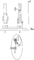
図1は、Rel-15 NRにおけるビーム回復手順の一例を示す図である。ビームの数などは一例であって、これに限られない。図1の初期状態(ステップS101)において、UEは、2つのビームを用いて送信される参照信号(RS(Reference Signal))リソースに基づく測定を実施する。 FIG. 1 shows an example of a beam recovery procedure in Rel-15 NR. The number of beams, etc. is an example, and is not limited to this. In the initial state (step S101) of FIG. 1, the UE performs measurements based on reference signal (RS (Reference Signal)) resources transmitted using two beams.
当該RSは、同期信号ブロック(SSB:Synchronization Signal Block)及びチャネル状態測定用RS(CSI-RS:Channel State Information RS)の少なくとも1つであってもよい。なお、SSBは、SS/PBCH(Physical Broadcast Channel)ブロックなどと呼ばれてもよい。 The RS may be at least one of a Synchronization Signal Block (SSB) and a Channel State Information RS (CSI-RS). The SSB may also be called an SS/PBCH (Physical Broadcast Channel) block.
RSは、プライマリ同期信号(PSS:Primary SS)、セカンダリ同期信号(SSS:Secondary SS)、モビリティ参照信号(MRS:Mobility RS)、SSBに含まれる信号、SSB、CSI-RS、復調用参照信号(DMRS:DeModulation Reference Signal)、ビーム固有信号などの少なくとも1つ、又はこれらを拡張、変更などして構成される信号であってもよい。ステップS101において測定されるRSは、ビーム障害検出のためのRS(BFD-RS:Beam Failure Detection RS)などと呼ばれてもよい。 RS is a primary synchronization signal (PSS: Primary SS), a secondary synchronization signal (SSS: Secondary SS), a mobility reference signal (MRS: Mobility RS), a signal included in SSB, SSB, CSI-RS, a reference signal for demodulation ( DMRS: DeModulation Reference Signal), a beam-specific signal, or at least one of them, or a signal configured by extending or modifying these. The RS measured in step S101 may be called an RS for beam failure detection (BFD-RS: Beam Failure Detection RS).
ステップS102において、基地局からの電波が妨害されたことによって、UEはBFD-RSを検出できない(又はRSの受信品質が劣化する)。このような妨害は、例えばUE及び基地局間の障害物、フェージング、干渉などの影響によって発生し得る。 In step S102, the UE cannot detect the BFD-RS (or the reception quality of the RS deteriorates) due to the jamming of radio waves from the base station. Such disturbances can be caused, for example, by effects such as obstacles, fading, and interference between the UE and the base station.
UEは、所定の条件が満たされると、ビーム障害を検出する。UEは、例えば、設定されたBFD-RS(BFD-RSリソース設定)の全てについて、BLER(Block Error Rate)が閾値未満である場合、ビーム障害の発生を検出してもよい。ビーム障害の発生が検出されると、UEの下位レイヤ(物理(PHY)レイヤ)は、上位レイヤ(MACレイヤ)に対してビーム障害インスタンスを通知(指示)してもよい。 A UE detects a beam failure when certain conditions are met. The UE may detect the occurrence of a beam failure, for example, when BLER (Block Error Rate) is less than a threshold for all configured BFD-RSs (BFD-RS resource configuration). When a beam failure occurrence is detected, the lower layer (physical (PHY) layer) of the UE may notify (indicate) the beam failure instance to the upper layer (MAC layer).
なお、判断の基準(クライテリア)は、BLERに限られず、物理レイヤにおける参照信号受信電力(L1-RSRP:Layer 1 Reference Signal Received Power)であってもよい。また、RS測定の代わりに又はRS測定に加えて、下り制御チャネル(PDCCH:Physical Downlink Control Channel)などに基づいてビーム障害検出が実施されてもよい。BFD-RSは、UEによってモニタされるPDCCHのDMRSと擬似コロケーション(QCL:Quasi-Co-Location)であると期待されてもよい。
Note that the determination criterion (criteria) is not limited to BLER, and may be the reference signal received power (L1-RSRP:
ここで、QCLとは、チャネルの統計的性質を示す指標である。例えば、ある信号/チャネルと他の信号/チャネルがQCLの関係である場合、これらの異なる複数の信号/チャネル間において、ドップラーシフト(doppler shift)、ドップラースプレッド(doppler spread)、平均遅延(average delay)、遅延スプレッド(delay spread)、空間パラメータ(Spatial parameter)(例えば、空間受信パラメータ(Spatial Rx Parameter))の少なくとも1つが同一である(これらの少なくとも1つに関してQCLである)と仮定できることを意味してもよい。 Here, QCL is an index indicating the statistical properties of a channel. For example, if one signal/channel and another signal/channel are in a QCL relationship, between these different signals/channels, doppler shift, doppler spread, average delay ), delay spread, spatial parameters (e.g., spatial reception parameters (Spatial Rx Parameter)) can be assumed to be the same (QCL for at least one of these). You may
なお、空間受信パラメータは、UEの受信ビーム(例えば、受信アナログビーム)に対応してもよく、空間的QCLに基づいてビームが特定されてもよい。本開示におけるQCL(又はQCLの少なくとも1つの要素)は、sQCL(spatial QCL)で読み替えられてもよい。 Note that the spatial reception parameters may correspond to the UE's receive beam (eg, receive analog beam), and the beam may be specified based on the spatial QCL. QCL (or at least one element of QCL) in the present disclosure may be read as sQCL (spatial QCL).
BFD-RSに関する情報(例えば、RSのインデックス、リソース、数、ポート数、プリコーディングなど)、ビーム障害検出(BFD)に関する情報(例えば、上述の閾値)などは、上位レイヤシグナリングなどを用いてUEに設定(通知)されてもよい。BFD-RSに関する情報は、BFR用リソースに関する情報などと呼ばれてもよい。 Information on BFD-RS (eg, RS index, resource, number, number of ports, precoding, etc.), information on beam failure detection (BFD) (eg, the above-mentioned threshold), etc. are sent to the UE using higher layer signaling, etc. may be set (notified) to Information about BFD-RS may be called information about BFR resources.
本開示において、上位レイヤシグナリングは、例えば、RRC(Radio Resource Control)シグナリング、MAC(Medium Access Control)シグナリング、ブロードキャスト情報などのいずれか、又はこれらの組み合わせであってもよい。 In the present disclosure, higher layer signaling may be, for example, RRC (Radio Resource Control) signaling, MAC (Medium Access Control) signaling, broadcast information, etc., or a combination thereof.
MACシグナリングは、例えば、MAC制御要素(MAC CE(Control Element))、MAC PDU(Protocol Data Unit)などを用いてもよい。ブロードキャスト情報は、例えば、マスタ情報ブロック(MIB:Master Information Block)、システム情報ブロック(SIB:System Information Block)、最低限のシステム情報(RMSI:Remaining Minimum System Information)、その他のシステム情報(OSI:Other System Information)などであってもよい。 MAC signaling may use MAC Control Element (MAC CE (Control Element)), MAC PDU (Protocol Data Unit), etc., for example. Broadcast information includes, for example, Master Information Block (MIB), System Information Block (SIB), Remaining Minimum System Information (RMSI), Other System Information (OSI). System Information) or the like.
UEのMACレイヤは、UEのPHYレイヤからビーム障害インスタンス通知を受信した場合に、所定のタイマ(ビーム障害検出タイマと呼ばれてもよい)を開始してもよい。UEのMACレイヤは、当該タイマが満了するまでにビーム障害インスタンス通知を一定回数(例えば、RRCで設定されるbeamFailureInstanceMaxCount)以上受信したら、BFRをトリガ(例えば、後述のランダムアクセス手順のいずれかを開始)してもよい。 The UE's MAC layer may start a predetermined timer (which may be referred to as a beam failure detection timer) upon receiving a beam failure instance notification from the UE's PHY layer. When the MAC layer of the UE receives beam failure instance notifications a certain number of times (for example, beamFailureInstanceMaxCount set by RRC) or more before the timer expires, it triggers BFR (for example, starts one of the random access procedures described later ).
基地局は、UEからの通知がない場合、又はUEから所定の信号(ステップS104におけるビーム回復要求)を受信した場合に、当該UEがビーム障害を検出したと判断してもよい。 The base station may determine that the UE has detected a beam failure when there is no notification from the UE or when a predetermined signal (beam recovery request in step S104) is received from the UE.
ステップS103において、UEはビーム回復のため、新たに通信に用いるための新候補ビーム(new candidate beam)のサーチを開始する。UEは、所定のRSを測定することによって、当該RSに対応する新候補ビームを選択してもよい。ステップS103において測定されるRSは、新候補ビーム識別のためのRS(NCBI-RS:New Candidate Beam Identification RS)、CBI-RS、CB-RS(Candidate Beam RS)などと呼ばれてもよい。NCBI-RSは、BFD-RSと同じであってもよいし、異なってもよい。なお、新候補ビームは、単に候補ビームと呼ばれてもよい。 In step S103, the UE starts searching for a new candidate beam to be newly used for communication for beam recovery. By measuring a given RS, the UE may select a new candidate beam corresponding to that RS. The RS measured in step S103 may be called RS for new candidate beam identification (NCBI-RS: New Candidate Beam Identification RS), CBI-RS, CB-RS (Candidate Beam RS), or the like. NCBI-RS may be the same as BFD-RS or may be different. Note that the new candidate beam may be simply called a candidate beam.
UEは、所定の条件を満たすRSに対応するビームを、新候補ビームとして決定してもよい。UEは、例えば、設定されたNCBI-RSのうち、L1-RSRPが閾値を超えるRSに基づいて、新候補ビームを決定してもよい。なお、判断の基準(クライテリア)は、L1-RSRPに限られない。L1-RSRP、L1-RSRQ、L1-SINR(信号対雑音電力比)のいずれか少なくとも1つを用いて決定しても良い。SSBに関するL1-RSRPは、SS-RSRPと呼ばれてもよい。CSI-RSに関するL1-RSRPは、CSI-RSRPと呼ばれてもよい。同様に、SSBに関するL1-RSRQは、SS-RSRQと呼ばれてもよい。CSI-RSに関するL1-RSRQは、CSI-RSRQと呼ばれてもよい。また、同様に、SSBに関するL1-SINRは、SS-SINRと呼ばれてもよい。CSI-RSに関するL1-SINRは、CSI-SINRと呼ばれてもよい。 The UE may determine beams corresponding to RSs that satisfy a predetermined condition as new candidate beams. The UE may determine new candidate beams based on, for example, the configured NCBI-RSs whose L1-RSRP exceeds the threshold. Note that the criteria for judgment are not limited to L1-RSRP. At least one of L1-RSRP, L1-RSRQ, and L1-SINR (signal-to-noise power ratio) may be used for determination. L1-RSRP for SSB may be referred to as SS-RSRP. L1-RSRP for CSI-RS may be referred to as CSI-RSRP. Similarly, L1-RSRQ for SSB may be referred to as SS-RSRQ. L1-RSRQ for CSI-RS may be referred to as CSI-RSRQ. Similarly, L1-SINR for SSB may also be referred to as SS-SINR. L1-SINR for CSI-RS may be referred to as CSI-SINR.
NCBI-RSに関する情報(例えば、RSのリソース、数、ポート数、プリコーディングなど)、新候補ビーム識別(NCBI)に関する情報(例えば、上述の閾値)などは、上位レイヤシグナリングなどを用いてUEに設定(通知)されてもよい。NCBI-RSに関する情報は、BFD-RSに関する情報に基づいて取得されてもよい。NCBI-RSに関する情報は、NBCI用リソースに関する情報などと呼ばれてもよい。 Information about NCBI-RS (e.g. resources, number of RSs, number of ports, precoding, etc.), information about New Candidate Beam Identification (NCBI) (e.g., thresholds mentioned above), etc. are sent to the UE using higher layer signaling, etc. It may be set (notified). Information on NCBI-RS may be obtained based on information on BFD-RS. Information on NCBI-RS may be called information on resources for NBCI or the like.
なお、BFD-RS、NCBI-RSなどは、無線リンクモニタリング参照信号(RLM-RS:Radio Link Monitoring RS)で読み替えられてもよい。 Note that BFD-RS, NCBI-RS, etc. may be read as radio link monitoring reference signals (RLM-RS: Radio Link Monitoring RS).
ステップS104において、新候補ビームを特定したUEは、ビーム回復要求(BFRQ:Beam Failure Recovery reQuest)を送信する。ビーム回復要求は、ビーム回復要求信号、ビーム障害回復要求信号などと呼ばれてもよい。 In step S104, the UE that has identified the new candidate beam transmits a Beam Failure Recovery reQuest (BFRQ). A beam recovery request may also be referred to as a beam recovery request signal, a beam failure recovery request signal, or the like.
BFRQは、例えば、上り制御チャネル(PUCCH:Physical Uplink Control Channel)、ランダムアクセスチャネル(PRACH:Physical Random Access Channel)、上り共有チャネル(PUSCH:Physical Uplink Shared Channel)、コンフィギュアドグラント(configured grant)PUSCHの少なくとも1つを用いて送信されてもよい。 BFRQ is, for example, an uplink control channel (PUCCH: Physical Uplink Control Channel), a random access channel (PRACH: Physical Random Access Channel), an uplink shared channel (PUSCH: Physical Uplink Shared Channel), a configured grant PUSCH may be transmitted using at least one of
BFRQは、ステップS103において特定された新候補ビームの情報を含んでもよい。BFRQのためのリソースが、当該新候補ビームに関連付けられてもよい。ビームの情報は、ビームインデックス(BI:Beam Index)、所定の参照信号のポートインデックス、リソースインデックス(例えば、CSI-RSリソース指標(CRI:CSI-RS Resource Indicator)、SSBリソース指標(SSBRI))などを用いて通知されてもよい。 The BFRQ may contain information on the new candidate beams identified in step S103. Resources for BFRQ may be associated with the new candidate beam. Beam information includes a beam index (BI), a port index of a predetermined reference signal, a resource index (eg, CSI-RS resource indicator (CRI), SSB resource indicator (SSBRI)), etc. may be notified using
Rel-15 NRでは、衝突型ランダムアクセス(RA:Random Access)手順に基づくBFRであるCB-BFR(Contention-Based BFR)及び非衝突型ランダムアクセス手順に基づくBFRであるCF-BFR(Contention-Free BFR)が検討されている。CB-BFR及びCF-BFRでは、UEは、PRACHリソースを用いてプリアンブル(RAプリアンブル、ランダムアクセスチャネル(PRACH:Physical Random Access Channel)、RACHプリアンブルなどともいう)をBFRQとして送信してもよい。 In Rel-15 NR, CF-BFR (Contention-Free BFR) are being considered. In CB-BFR and CF-BFR, the UE may transmit a preamble (also called RA preamble, Physical Random Access Channel (PRACH), RACH preamble, etc.) as BFRQ using PRACH resources.
また、NRでは、複数のPRACHフォーマット(PRACHプリアンブルフォーマット)が検討されている。各PRACHフォーマットを用いるRA(Random Access)プリアンブルは、RACH OFDMシンボルを含む。更に、RAプリアンブルは、サイクリックプレフィックス(CP)、ガード期間(GP)の少なくとも1つを含んでもよい。例えば、PRACHフォーマット0~3は、RACH OFDMシンボルにおいて、長系列(long sequence)のプリアンブル系列を用いる。PRACHフォーマットA1~A3、B1~B4、C0、C2は、RACH OFDMシンボルにおいて、短系列(short sequence)のプリアンブル系列を用いる。 Also, in NR, a plurality of PRACH formats (PRACH preamble formats) are being considered. An RA (Random Access) preamble using each PRACH format includes a RACH OFDM symbol. Furthermore, the RA preamble may include at least one of a cyclic prefix (CP) and a guard period (GP). For example, PRACH formats 0-3 use long sequence preamble sequences in RACH OFDM symbols. PRACH formats A1-A3, B1-B4, C0, C2 use short sequence preamble sequences in RACH OFDM symbols.
アンライセンスキャリアの周波数は、FR(Frequency Range)1及びFR2のいずれかの周波数範囲内であってもよい。FR1は、所定周波数よりも低い周波数範囲であり、FR2は、所定周波数よりも高い周波数範囲であってもよい。 The frequency of the unlicensed carrier may be within either frequency range of FR (Frequency Range) 1 or FR2. FR1 may be a frequency range lower than a predetermined frequency, and FR2 may be a frequency range higher than the predetermined frequency.
RAプリアンブル系列は、Zadoff-Chu(ZC)系列であってもよい。プリアンブル系列長は、839(長系列)、139のいずれかであってもよい。プリアンブル系列は、PRACHに割り当てられた周波数リソース(例えば、サブキャリア)にマップされてもよい。RAプリアンブルは、複数のニューメロロジーの1つを用いてもよい。NRのFR1の長系列のためのサブキャリア間隔(SubCarrier Spacing:SCS)は、1.25、5kHzのいずれかであってもよい。NRのFR1の短系列のためのSCSは、15、30kHzのいずれかであってもよい。NRのFR2の短系列のためのSCSは、60、120kHzのいずれかであってもよい。LTEの長系列のためのSCSは、1.25kHzであってもよい。LTEの短系列のためのSCSは、7.5kHzであってもよい。 The RA preamble sequence may be a Zadoff-Chu (ZC) sequence. The preamble sequence length may be either 839 (long sequence) or 139. The preamble sequence may be mapped to frequency resources (eg, subcarriers) assigned to the PRACH. The RA preamble may use one of several neumerologies. The SubCarrier Spacing (SCS) for the NR FR1 long sequence may be either 1.25 or 5 kHz. The SCS for NR FR1 short sequences may be either 15 or 30 kHz. The SCS for NR FR2 short sequences may be either 60 or 120 kHz. The SCS for LTE long sequences may be 1.25 kHz. The SCS for LTE short sequences may be 7.5 kHz.
CB-BFRでは、UEは、1つ又は複数のプリアンブルからランダムに選択したプリアンブルを送信してもよい。一方、CF-BFRでは、UEは、基地局からUE固有に割り当てられたプリアンブルを送信してもよい。CB-BFRでは、基地局は、複数UEに対して同一のプリアンブルを割り当ててもよい。CF-BFRでは、基地局は、UE個別にプリアンブルを割り当ててもよい。 In CB-BFR, a UE may transmit a randomly selected preamble from one or more preambles. On the other hand, in CF-BFR, the UE may transmit a UE-specific assigned preamble from the base station. In CB-BFR, the base station may assign the same preamble to multiple UEs. In CF-BFR, the base station may assign preambles for individual UEs.
なお、CB-BFR及びCF-BFRは、それぞれCB PRACHベースBFR(CBRA-BFR:contention-based PRACH-based BFR)及びCF PRACHベースBFR(CFRA-BFR:contention-free PRACH-based BFR)と呼ばれてもよい。CBRA-BFRは、BFR用CBRAと呼ばれてもよい。CFRA-BFRは、BFR用CFRAと呼ばれてもよい。 CB-BFR and CF-BFR are called CB PRACH-based BFR (CBRA-BFR: contention-based PRACH-based BFR) and CF PRACH-based BFR (CFRA-BFR: contention-free PRACH-based BFR), respectively. may CBRA-BFR may be referred to as CBRA for BFR. CFRA-BFR may be referred to as CFRA for BFR.
CB-BFR、CF-BFRのいずれであっても、PRACHリソース(RAプリアンブル)に関する情報は、例えば、上位レイヤシグナリング(RRCシグナリングなど)によって通知されてもよい。例えば、当該情報は、検出したDL-RS(ビーム)とPRACHリソースとの対応関係を示す情報を含んでもよく、DL-RSごとに異なるPRACHリソースが関連付けられてもよい。 Information on PRACH resources (RA preambles) may be reported by higher layer signaling (RRC signaling, etc.), for example, in either CB-BFR or CF-BFR. For example, the information may include information indicating the correspondence between detected DL-RSs (beams) and PRACH resources, and different PRACH resources may be associated with each DL-RS.
ステップS105において、BFRQを検出した基地局は、UEからのBFRQに対する応答信号(gNBレスポンスなどと呼ばれてもよい)を送信する。当該応答信号には、1つ又は複数のビームについての再構成情報(例えば、DL-RSリソースの構成情報)が含まれてもよい。 In step S105, the base station that has detected the BFRQ transmits a response signal (which may be called a gNB response or the like) to the BFRQ from the UE. The response signal may include reconfiguration information (eg, DL-RS resource configuration information) for one or more beams.
当該応答信号は、例えばPDCCHのUE共通サーチスペースにおいて送信されてもよい。当該応答信号は、UEの識別子(例えば、セル-無線RNTI(C-RNTI:Cell-Radio RNTI))によって巡回冗長検査(CRC:Cyclic Redundancy Check)スクランブルされたPDCCH(DCI)を用いて通知されてもよい。UEは、ビーム再構成情報に基づいて、使用する送信ビーム及び受信ビームの少なくとも一方を判断してもよい。 The response signal may be transmitted, for example, in the UE common search space of PDCCH. The response signal is reported using a cyclic redundancy check (CRC) scrambled PDCCH (DCI) by a UE identifier (eg, cell-radio RNTI (C-RNTI: Cell-Radio RNTI)). good too. The UE may determine which transmit beam and/or receive beam to use based on the beam reconstruction information.
UEは、当該応答信号を、BFR用の制御リソースセット(CORESET:COntrol REsource SET)及びBFR用のサーチスペースセットの少なくとも一方に基づいてモニタしてもよい。 The UE may monitor the response signal based on at least one of a control resource set (CORESET: COntrol REsource SET) for BFR and a search space set for BFR.
CB-BFRに関しては、UEが自身に関するC-RNTIに対応するPDCCHを受信した場合に、衝突解決(contention resolution)が成功したと判断されてもよい。 For CB-BFR, contention resolution may be determined to be successful if the UE receives the PDCCH corresponding to its C-RNTI.
ステップS105の処理に関して、BFRQに対する基地局(例えば、gNB)からの応答(レスポンス)をUEがモニタするための期間が設定されてもよい。当該期間は、例えばgNB応答ウィンドウ、gNBウィンドウ、ビーム回復要求応答ウィンドウ、BFRQレスポンスウィンドウなどと呼ばれてもよい。UEは、当該ウィンドウ期間内において検出されるgNB応答がない場合、BFRQの再送を行ってもよい。 Regarding the processing of step S105, a period may be set for the UE to monitor a response (response) from the base station (eg, gNB) to BFRQ. Such time periods may be referred to, for example, as a gNB response window, a gNB window, a beam recovery request response window, a BFRQ response window, and so on. The UE may retransmit the BFRQ if no gNB response is detected within the window period.
ステップS106において、UEは、基地局に対してビーム再構成が完了した旨を示すメッセージを送信してもよい。当該メッセージは、例えば、PUCCHによって送信されてもよいし、PUSCHによって送信されてもよい。 At step S106, the UE may send a message to the base station indicating that the beam reconstruction is complete. The message may be transmitted by PUCCH or PUSCH, for example.
ビーム回復成功(BR success)は、例えばステップS106まで到達した場合を表してもよい。一方で、ビーム回復失敗(BR failure)は、例えばBFRQ送信が所定の回数に達した、又はビーム障害回復タイマ(Beam-failure-recovery-Timer)が満了したことに該当してもよい。 Beam recovery success (BR success) may represent, for example, the case of reaching step S106. On the other hand, a beam recovery failure (BR failure) may correspond, for example, to reaching a predetermined number of BFRQ transmissions or to expiring a beam-failure-recovery-timer.
なお、これらのステップの番号は説明のための番号に過ぎず、複数のステップがまとめられてもよいし、順番が入れ替わってもよい。また、BFRを実施するか否かは、上位レイヤシグナリングを用いてUEに設定されてもよい。 Note that the numbers of these steps are merely numbers for explanation, and a plurality of steps may be grouped together or their order may be changed. Also, whether or not to implement BFR may be configured in the UE using higher layer signaling.
ところで、上述したように、既存のLTEシステムでは、複数のセルを利用して通信を行う場合に所定セル(例えば、プライマリセル)に対してのみBFRを行うことが規定されていたが、NRでは複数のセルに対してBFR手順を適用することが検討されている。 By the way, as described above, in the existing LTE system, when communication is performed using a plurality of cells, it is specified that BFR is performed only for a predetermined cell (eg, primary cell), but in NR Applying the BFR procedure to multiple cells is under consideration.
複数のセルを利用して通信を行う構成としては、例えば、バンド内キャリアアグリゲーション(Intra-band CA)、又はバンド間キャリアアグリゲーション(Inter-band CA)がある。図2は、バンド間CAを適用する場合の一例を示している。 Configurations for performing communication using a plurality of cells include, for example, intra-band carrier aggregation (Intra-band CA) and inter-band carrier aggregation (Inter-band CA). FIG. 2 shows an example of applying inter-band CA.
図2では、複数の周波数バンドとして、第1の周波数帯(FR1:Frequency Range 1)及び第2の周波数帯(FR2:Frequency Range 2)の少なくとも1つの周波数帯(キャリア周波数)を用いる場合を示している。なお、適用する周波数バンドは2つに限られず、周波数バンド(又は、周波数領域)を3つ以上に区分してもよい。 FIG. 2 shows a case where at least one frequency band (carrier frequency) of a first frequency band (FR1: Frequency Range 1) and a second frequency band (FR2: Frequency Range 2) is used as a plurality of frequency bands. ing. Note that the number of applied frequency bands is not limited to two, and the frequency bands (or frequency regions) may be divided into three or more.
例えば、FR1は、6GHz以下の周波数帯(サブ6GHz(sub-6GHz))であってもよいし、FR2は、24GHzよりも高い周波数帯(above-24GHz)であってもよい。FR1は、サブキャリア間隔(SCS:Sub-Carrier Spacing)として15、30及び60kHzのうちから少なくとも1つが用いられる周波数レンジと定義されてもよいし、FR2は、SCSとして60及び120kHzのうちから少なくとも1つが用いられる周波数レンジと定義されてもよい。なお、FR1及びFR2の周波数帯、定義などはこれらに限られず、例えばFR1がFR2よりも高い周波数帯であってもよい。 For example, FR1 may be a frequency band below 6 GHz (sub-6 GHz), and FR2 may be a frequency band above 24 GHz (above-24 GHz). FR1 may be defined as a frequency range in which at least one of 15, 30 and 60 kHz is used as the Sub-Carrier Spacing (SCS), and FR2 is at least one of 60 and 120 kHz as the SCS. One may be defined as the frequency range used. Note that the frequency bands and definitions of FR1 and FR2 are not limited to these, and for example, FR1 may be a higher frequency band than FR2.
FR1を利用するセルと、FR2を利用するセルは、異なるニューメロロジー(例えば、サブキャリア間隔等)を適用する構成としてもよい。図2では、一例として、FR1に含まれるセルが適用するサブキャリア間隔(SCS)が15kHzであり、FR2に含まれるセルが適用するサブキャリア間隔が120kHzである場合を示している。なお、同じ周波数バンドに含まれるセルが異なるニューメロロジーを適用してもよい。 A cell using FR1 and a cell using FR2 may be configured to apply different neumerologies (for example, subcarrier spacing, etc.). FIG. 2 shows, as an example, a case where the subcarrier spacing (SCS) applied by the cells included in FR1 is 15 kHz and the subcarrier spacing applied by the cells included in FR2 is 120 kHz. It should be noted that neumerologies in which cells included in the same frequency band are different may be applied.
図2では、複数の周波数バンド間にわたってCA(例えば、FR1-FR2 CA)を適用する場合を示している。この場合、FR1に含まれる1以上のセルとFR2に含まれる1以上のセル間でCAを適用する。この場合、FR1又はFR2に含まれる特定のセルをプライマリセルとしてもよい。図2では、FR1に含まれるセルをプライマリセル、FR2に含まれるセルをセカンダリセルとする場合を示している。 FIG. 2 shows the case of applying CA (eg, FR1-FR2 CA) across multiple frequency bands. In this case, CA is applied between one or more cells included in FR1 and one or more cells included in FR2. In this case, a specific cell included in FR1 or FR2 may be the primary cell. FIG. 2 shows a case where a cell included in FR1 is a primary cell and a cell included in FR2 is a secondary cell.
UEは、複数のセルを利用する構成(例えば、図2参照)において、いずれかのセルでビーム障害(BF)が発生した場合、ビーム回復(BFR)手順を行う。例えば、UEは、あらかじめ設定された所定セルにおいてPUCCHを利用してビーム回復要求(BFRQとも呼ぶ)の送信を行う。 A UE performs a beam recovery (BFR) procedure when a beam failure (BF) occurs in any cell in a configuration using multiple cells (eg, see FIG. 2). For example, a UE transmits a beam recovery request (also called BFRQ) using PUCCH in a preset cell.
例えば、FR2に含まれるセカンダリセルでBFRが発生した場合、BFRQの報告動作(例えば、送信するセル及びチャネルの選択)又は当該報告に対する基地局からのレスポンス等の動作をどのように制御するかが問題となる。複数のセルに対してBFR手順を行う場合にBFRQの報告又は当該報告に対するレスポンス等が適切に制御されないと通信品質の劣化等が生じるおそれある。 For example, when BFR occurs in a secondary cell included in FR2, how to control the BFRQ reporting operation (for example, selection of the cell and channel to be transmitted) or the response from the base station to the report. It becomes a problem. When the BFR procedure is performed for a plurality of cells, there is a risk that communication quality will deteriorate if BFRQ reports or responses to such reports are not properly controlled.
プライマリセル(例えば、FR1)とセカンダリセル(例えば、FR2)のニューメロロジー等が異なる場合、セカンダリセルに対するBFR動作を当該セカンダリセル(又は、FR2のセル)を利用することも考えられる。また、上り制御チャネルは、PRACHと比較して時間領域においてより柔軟にリソースを設定可能となる。そのため、BFRQの送信に利用するチャネルとして、PRACHの他に上り制御チャネルを利用することも考えられる。 If the primary cell (eg, FR1) and the secondary cell (eg, FR2) have different numerology, etc., it is conceivable to use the secondary cell (or the cell of FR2) for the BFR operation on the secondary cell. Also, in the uplink control channel, resources can be set more flexibly in the time domain than in the PRACH. Therefore, it is conceivable to use an uplink control channel in addition to the PRACH as a channel used for BFRQ transmission.
そこで、本発明者等は、所定条件に基づいてBFRQ送信を行うセル及びチャネルの少なくとも一つを決定することを着想した。具体的に本発明者等は、上り制御チャネルを利用したUL送信が可能となる所定のセカンダリセル(PUCCH-SCellとも呼ぶ)に着目し、当該所定のセカンダリセルの上り制御チャネルを利用してBFRQの送信を行うことを着想した。また、所定のセカンダリセルが設定される場合と設定されない場合がある点に着目し、所定のセカンダリセルの設定有無に基づいてBFRQ送信(又は、BFRQ送信に対するレスポンス)を行うセル及びチャネルの少なくとも一つを決定することを着想した。 Therefore, the inventors of the present invention came up with the idea of determining at least one of cells and channels for BFRQ transmission based on predetermined conditions. Specifically, the present inventors have focused on a predetermined secondary cell (also referred to as PUCCH-SCell) that enables UL transmission using an uplink control channel, and BFRQ using the uplink control channel of the predetermined secondary cell. I came up with the idea of sending In addition, focusing on the fact that a predetermined secondary cell may or may not be set, at least one of a cell and a channel that performs BFRQ transmission (or a response to BFRQ transmission) based on whether or not a predetermined secondary cell is set. I came up with the idea of determining one.
以下、本開示に係る実施形態について、図面を参照して詳細に説明する。以下の各態様は、それぞれ単独で適用されてもよいし、組み合わせて適用されてもよい。なお、以下の説明では、BFRQの送信を上り制御チャネルを利用して送信する場合を示すが、BFRQの送信タイミングで上り共有チャネル(例えば、PUSCH)の送信を行う場合には、PUSCHを利用してBFRQの送信を行ってもよい。また、その他の所定条件(例えば、PUCCHセカンダリセルが非設定等)に応じて上り制御チャネル以外のチャネルを利用してBFRQの送信を行ってもよい。 Hereinafter, embodiments according to the present disclosure will be described in detail with reference to the drawings. Each of the following aspects may be applied independently, or may be applied in combination. In the following description, a case of transmitting BFRQ using an uplink control channel will be described. BFRQ transmission may be performed by Also, BFRQ may be transmitted using a channel other than the uplink control channel according to other predetermined conditions (for example, PUCCH secondary cell is not configured).
また、本実施の形態は、バンド内CA、及びバンド間CA(例えば、F1-F2 CA)のいずれにも適用可能である。あるいは、以下に示す構成の一部をバンド内CAに適用し、他の構成(例えば、PUCCH-SCellを利用したBFR手順)をバンド間CAに適用するように制御してもよい。 In addition, this embodiment can be applied to both intra-band CA and inter-band CA (for example, F1-F2 CA). Alternatively, control may be performed so that part of the configuration shown below is applied to intra-band CA and other configurations (eg, BFR procedures using PUCCH-SCell) are applied to inter-band CA.
(第1の態様)
第1の態様は、所定ルールに基づいてBFRの要求(BFRQ)の送信を行うセルを決定する場合について説明する。(First aspect)
A first mode will describe a case where a cell for transmitting a BFR request (BFRQ) is determined based on a predetermined rule.
まず、PUCCHの送信が可能なセカンダリセル(PUCCH-SCellとも呼ぶ)が設定される場合と設定されない場合のUE動作について説明する。なお、「PUCCH-SCellが設定される」とは、「SCellを利用したPUCCH送信(PUCCH on SCell)が設定される」と読み替えてもよい。 First, UE operations when a secondary cell (also referred to as PUCCH-SCell) capable of transmitting PUCCH is configured and when not configured will be described. Note that “PUCCH-SCell is configured” may be read as “PUCCH transmission using SCell (PUCCH on SCell) is configured”.
<PUCCH on SCell)
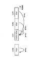
PUCCH-SCellが設定される場合、UEは、当該PUCCH-SCellのPUCCHを利用して上り制御情報(UCI)を送信する(図3A参照)。具体的には、UEは、当該PUCCH-SCellと同じセルグループに含まれるSCellに対応するUCIについて、PUCCH-SCellのPUCCHに多重して送信する。UCIは、HARQ-ACK、及びチャネル状態情報(CSI)の少なくとも一つが含まれていてもよい。また、UEは、ビームレポートについてもPUCCHを利用して送信してもよい。<PUCCH on SCell)
When PUCCH-SCell is configured, the UE uses PUCCH of the PUCCH-SCell to transmit uplink control information (UCI) (see FIG. 3A). Specifically, the UE multiplexes the UCI corresponding to the SCell included in the same cell group as the PUCCH-SCell with the PUCCH of the PUCCH-SCell and transmits the UCI. UCI may include at least one of HARQ-ACK and channel state information (CSI). The UE may also transmit beam reports using the PUCCH.
図3Aでは、CC#1がPUCCH-SCellに相当し、PUCCH-SCellと同じセルグループにCC#2とCC#3が含まれる場合を示している。この場合、UEは、CC#1-CC#3に対応するHARQ-ACK、CSI及びビーム報告の少なくとも一つをCC#1に設定されるPUCCHを利用して送信してもよい。
FIG. 3A shows a case where
PUCCH-SCellが設定されない場合、UEは、当該PCellのPUCCHを利用して上り制御情報(UCI)を送信する(図3B参照)。具体的には、UEは、セカンダリセルに対応するUCIについて、PCellのPUCCHに多重して送信する。また、UEは、ビームレポートについてもPUCCHを利用して送信してもよい。 When PUCCH-SCell is not configured, the UE uses PUCCH of the PCell to transmit uplink control information (UCI) (see FIG. 3B). Specifically, the UE multiplexes the UCI corresponding to the secondary cell on the PUCCH of the PCell and transmits it. The UE may also transmit beam reports using the PUCCH.
図3Bでは、PUCCH送信可能なセカンダリセルが設定されないため、UEは、CC#1-CC#3に対応するHARQ-ACK、CSI及びビーム報告の少なくとも一つをPCell(ここでは、CC#0)に設定されるPUCCHを利用して送信してもよい。
In FIG. 3B, since no secondary cell capable of transmitting PUCCH is set, the UE sends at least one of HARQ-ACK, CSI and beam reports corresponding to
このように、PUCCH-SCellの設定される場合と設定されない場合でHARQ-AC、CSI、ビーム報告等を送信するセルが異なる。そのため、PUCCHを利用したBFRQの送信がサポートされる場合、PUCCH-SCellの設定有無に応じてBFRQを送信するセル及びチャネルが変わることが考えられる。そこで、以下にPUCCH-SCellの設定有無等を含む所定ルールに基づいてBFRQの送信を行うセルを決定する場合を示す。 In this way, the cells that transmit HARQ-AC, CSI, beam reports, etc. differ depending on whether PUCCH-SCell is configured or not. Therefore, when BFRQ transmission using PUCCH is supported, it is conceivable that the cell and channel for transmitting BFRQ will change depending on whether or not PUCCH-SCell is configured. Therefore, a case of determining a cell for transmitting BFRQ based on a predetermined rule including whether PUCCH-SCell is set or not will be described below.
<BFRをPCellで検出した場合>
UEは、PCellにおいてBFRを検出した場合、当該PCellに対してBFRQを送信してもよい。この場合、UEは、PCellのPUCCHを利用してBFRQを送信してもよい。PUCCH-SCellの設定された場合であっても、PCellで発生したBFRに対するBFRQは当該PCellに送信する構成としてもよい。<When BFR is detected by PCell>
When the UE detects BFR in the PCell, the UE may transmit a BFRQ to the PCell. In this case, the UE may transmit the BFRQ using the PCell's PUCCH. Even when PUCCH-SCell is set, BFRQ for BFR generated in PCell may be configured to be transmitted to the PCell.
あるいは、PUCCH-SCellが設定されている場合、PCellで発生したBFRに対するBFRQをPUCCH-SCellに送信する構成としてもよい。例えば、PCellに対する通信環境(例えば、チャネル状態等)が悪い場合には、他のセル(例えば、PUCCH-SCell)にBFRQを送信することが有効となる。特に、PCellとPUCCH-SCellの周波数帯又は位置が異なる場合(例えば、FR1-FR2 CA等)に有効となる。 Alternatively, when PUCCH-SCell is configured, it may be configured to transmit BFRQ for BFR generated in PCell to PUCCH-SCell. For example, when the communication environment (eg, channel state) for PCell is bad, it is effective to transmit BFRQ to another cell (eg, PUCCH-SCell). In particular, it is effective when PCell and PUCCH-SCell have different frequency bands or locations (for example, FR1-FR2 CA, etc.).
<BFRをSCellで検出した場合>
UEは、SCellにおいてBFRを検出した場合、PCell又は所定のSCellに対してBFRQを送信してもよい。<When BFR is detected by SCell>
The UE may send a BFRQ to the PCell or a given SCell when detecting BFR in the SCell.
[オプション1]
例えば、UEは、PUCCH-SCellの設定有無に基づいて、SCellで検出したBFRに対応するBFRQを送信するセルを決定してもよい。[Option 1]
For example, the UE may determine the cell to transmit the BFRQ corresponding to the BFR detected on the SCell based on whether the PUCCH-SCell is configured.
PUCCH-SCellが設定されている場合、UEは、SCell(例えば、PUCCH-SCellが属するPUCCHグループに含まれるSCell)で検出したBFRに対するBFRQを所定のSCellに対して送信してもよい。UEは、所定のSCellとして、PUCCHグループに含まれるPUCCH-SCellを選択してもよい(図4参照)。 When PUCCH-SCell is configured, UE may transmit BFRQ for BFR detected in SCell (eg, SCell included in PUCCH group to which PUCCH-SCell belongs) to predetermined SCell. A UE may select a PUCCH-SCell included in a PUCCH group as a predetermined SCell (see FIG. 4).
例えば、UEは、同じPUCCHグループに含まれるCC#1-CC#3のいずれかでBFRを検出した場合、当該BFRに対するBFRQをPUCCH-SCell(ここでは、CC#1)に対して送信してもよい。この場合、当該PUCCH-SCellのPUCCHを利用してBFRQを送信してもよい。
For example, when the UE detects BFR in any one of
あるいは、UEは、BFRを検出したSCellに対してBFRQを送信するように制御してもよい。例えば、図4において、UEは、CC#2でBFRを検出した場合、当該BFRに対するBFRQをCC#2に送信するように制御してもよい。
Alternatively, the UE may control to transmit BFRQ to the SCell that detected BFR. For example, in FIG. 4, when the UE detects a BFR on
PUCCH-SCellが設定されていない場合、UEは、SCellで検出したBFRに対するBFRQをPCellに対して送信してもよい(図5参照)。例えば、UEは、CC#1-CC#3のいずれかでBFRを検出した場合、当該BFRに対するBFRQをPCell(ここでは、CC#0)に対して送信してもよい。この場合、当該PCellのPUCCHを利用してBFRQを送信してもよい。
If PUCCH-SCell is not configured, the UE may transmit BFRQ for BFR detected in SCell to PCell (see FIG. 5). For example, when the UE detects a BFR in any one of
[オプション2]
UEは、基地局から通知(又は、設定)される情報に基づいて、SCellで検出したBFRに対するBFRQを送信するセルを決定してもよい。[Option 2]
The UE may determine the cell to transmit the BFRQ for the BFR detected in the SCell based on information notified (or configured) from the base station.
基地局から設定される所定セルは、プライマリセル、PSCell、又はPUCCH SCellであってもよい。基地局は、上位レイヤ(例えば、RRCシグナリング)を利用して、BFRQの送信を行うセルをUEに設定してもよい。例えば、基地局は、BFRQの送信に利用するセルに関する情報(例えば、セルインデックス)を所定の上位レイヤパラメータ(例えば、BeamFailureRecoveryConfig)に含めてUEに送信してもよい。また、基地局は、所定の上位レイヤパラメータを用いて、BFRQ送信に利用するPUCCH構成(例えば、BFRQ用のPUCCHリソース)をUEに通知してもよい。 The predetermined cell configured by the base station may be the primary cell, PSCell, or PUCCH SCell. The base station may use higher layers (eg, RRC signaling) to configure the UE with a cell for BFRQ transmission. For example, the base station may include information about cells used for BFRQ transmission (eg, cell index) in a predetermined higher layer parameter (eg, BeamFailureRecoveryConfig) and transmit the information to the UE. Also, the base station may notify the UE of the PUCCH configuration to be used for BFRQ transmission (for example, PUCCH resources for BFRQ) using a predetermined higher layer parameter.
なお、所定の上位レイヤパラメータ(例えば、BeamFailureRecoveryConfig)には、セルに関する情報、PUCCHリソースに関する情報に加えて、回復用の候補ビームを示す参照信号(例えば、CSI-RS及びSSBの少なくとも一つ)候補のリストの情報、BFRQに対するレスポンスに利用されるサーチスペースの情報、及びPUCCHオケージョン毎のSSB数の情報の少なくとも一つが含まれていてもよい。もちろん、他の情報が含まれていてもよい。 It should be noted that predetermined higher layer parameters (eg, BeamFailureRecoveryConfig) include, in addition to cell information and PUCCH resource information, reference signals indicating candidate beams for recovery (eg, at least one of CSI-RS and SSB) candidates list information, information on search spaces used for responses to BFRQ, and information on the number of SSBs for each PUCCH occasion. Of course, other information may be included.
UEは、基地局から通知された所定の上位レイヤパラメータに基づいて、BFRQを送信する所定セルを判断し、当該所定セルにおいてBFR手順(例えば、PUCCHを利用したBFRQ送信等)を制御する。このように、BFRQの送信を基地局から設定されたセルで行う構成とすることにより、BFR手順(例えば、BFRQ送信等)を柔軟に制御することができる。 The UE determines a predetermined cell to transmit BFRQ based on predetermined higher layer parameters notified from the base station, and controls the BFR procedure (for example, BFRQ transmission using PUCCH) in the predetermined cell. In this way, by configuring BFRQ transmission in the cell set by the base station, it is possible to flexibly control the BFR procedure (for example, BFRQ transmission, etc.).
なお、BFR手順は、セル(又は、CC)毎に行う場合を示したが、これに限られない。BFR手順を帯域幅部分(BWP:Bandwidth part)単位で行ってもよい。例えば、BWPは、セル(又は、CC)内に1つ設定されてもよいし、複数設定されてもよい。この場合、所定の上位レイヤパラメータ(例えば、BeamFailureRecoveryConfig)はセルに設定されるBWP毎にUEに通知されてもよい。 Although the BFR procedure is performed for each cell (or CC), it is not limited to this. The BFR procedure may be performed on a bandwidth part (BWP) basis. For example, one BWP may be set in a cell (or CC), or multiple BWPs may be set. In this case, a predetermined higher layer parameter (eg, BeamFailureRecoveryConfig) may be notified to the UE for each BWP configured in the cell.
[オプション3]
UEは、SCellでBFRを検出した場合、当該BFRに対するBFRQを常に所定セル(例えば、PCell)で送信するように制御してもよい。この場合、UEは、PCellに対して、PRACH、又はPUSCHを利用してもよい。PUSCHは、物理レイヤ情報の送信に利用されるPUSCH、DMRS又はベース系列のシーケンス選択の送信に利用されるPUSCH、及びMAC CEの送信に利用されるPUSCHの少なくとも一つであってもよい。[Option 3]
When the UE detects a BFR in the SCell, the UE may control to always transmit the BFRQ for the BFR in a predetermined cell (eg, PCell). In this case, the UE may use PRACH or PUSCH for PCell. The PUSCH may be at least one of PUSCH used for transmitting physical layer information, PUSCH used for transmitting DMRS or base sequence sequence selection, and PUSCH used for transmitting MAC CE.
このように、BFRQの送信をBFが発生したセル(又は、BFRが必要となるセル)とは別のセルを利用して行う構成とすることにより、BFRQ送信の成功確率を向上することができる。 In this way, by configuring BFRQ transmission using a cell other than the cell in which BF occurs (or the cell requiring BFR), the probability of successful BFRQ transmission can be improved. .
(第2の態様)
第2の態様は、所定ルールに基づいてBFRの要求(BFRQ)の送信を行うチャネルを決定する場合について説明する。なお、第2の態様は、第1の態様と適宜組み合わせて適用できる。(Second aspect)
A second example will describe a case where a channel for transmitting a BFR request (BFRQ) is determined based on a predetermined rule. Note that the second aspect can be applied in combination with the first aspect as appropriate.
<PUCCH-SCellの設定有無>
UEは、PUCCH-SCellの設定有無に基づいて、SCellで検出したBFRに対するBFRQの送信に利用するチャネルを決定してもよい。<Whether or not PUCCH-SCell is set>
The UE may determine a channel to be used for transmission of BFRQ for BFR detected in SCell based on whether PUCCH-SCell is configured.
PUCCH-SCellが設定されている場合、UEは、SCell(例えば、PUCCH-SCellが属するPUCCHグループに含まれるSCell)で検出したBFRに対するBFRQをPUCCHを利用して送信してもよい。 When PUCCH-SCell is configured, the UE may transmit BFRQ for BFR detected in SCell (eg, SCell included in the PUCCH group to which PUCCH-SCell belongs) using PUCCH.
UEは、PUCCH-SCellにおいてBFRを検出した場合、当該BFRに対するBFRQをPUCCH-SCellのPUCCHを利用して送信してもよい(図6A参照)。図6Aでは、SCellとなるCC#1-CC#3でPUCCHグループが構成され、CC#1がPUCCH-SCellに相当する。
When the UE detects a BFR in the PUCCH-SCell, the UE may transmit a BFRQ for that BFR using the PUCCH of the PUCCH-SCell (see FIG. 6A). In FIG. 6A, a PUCCH group is configured with
BFRQの送信をPUCCH-SCellのPUCCHで行う場合、UEは、スケジューリングリクエスト(SR)を利用してもよい。この場合、UEは、CC#1-CC#3のいずれかでBFが発生(又は、BFRを検出)した場合、CC#1(PUCCH-SCell)に対してPUCCHを利用してSRを送信してもよい。SRは通知できる情報量が少ないが、BFRQの有無のみ通知する場合には、SRを利用することによりULのオーバヘッドの増加を抑制できる。
If the BFRQ is transmitted on the PUCCH of the PUCCH-SCell, the UE may use a scheduling request (SR). In this case, when BF occurs (or detects BFR) in any of CC#1-
あるいは、UEは、BFRQをビーム報告の一部として送信してもよい。この場合、BFRQを上り制御情報(例えば、UCI)に含めてPUCCH(例えば、所定のPUCCHフォーマット)で送信する。例えば、UEは、BFRQをUCIに含めて所定のPUCCHフォーマット(例えば、PF2、3又は4)で送信する場合、BFR情報(例えば、1ビット)以外の他の情報も送信できる。 Alternatively, the UE may send the BFRQ as part of the beam report. In this case, BFRQ is included in uplink control information (eg, UCI) and transmitted by PUCCH (eg, predetermined PUCCH format). For example, if the UE includes the BFRQ in the UCI and transmits in a given PUCCH format (eg, PF2, 3 or 4), the UE can also transmit other information than the BFR information (eg, 1 bit).
なお、SR又はビーム報告を多重するPUCCHリソースは、複数のPUCCHリソースの中から選択された所定のPUCCHリソースであってもよい。例えば、あらかじめ複数のビーム(例えば、基地局から送信又はビームスイープされるビーム)に対応するPUCCHリソースをそれぞれ設定する。UEは、基地局から受信したビーム(例えば、同期信号ブロック又はCSI-RS)のうち最も好適なビーム(例えば、SSBインデックス)に対応するPUCCHリソースを利用してPUCCHを送信してもよい。 Note that PUCCH resources for multiplexing SRs or beam reports may be predetermined PUCCH resources selected from a plurality of PUCCH resources. For example, PUCCH resources corresponding to multiple beams (for example, beams transmitted or beam-swept from the base station) are configured in advance. The UE may transmit the PUCCH using the PUCCH resource corresponding to the best beam (eg, SSB index) among the beams (eg, synchronization signal blocks or CSI-RS) received from the base station.
これにより、BFが発生したセル(例えば、PUCCH-SCell)に対してBFRQを送信する場合であってもBFRQの送信を適切に行うことができる。 By this means, it is possible to appropriately transmit BFRQ even when transmitting BFRQ to a cell (for example, PUCCH-SCell) in which BF occurs.
なお、PUSCH-SCellのビーム条件が好ましくない場合(新規候補ビームがない場合等)には、他のセル(例えば、PCellのPUCCH)を利用してBFRQを送信してもよい。 If the PUSCH-SCell beam conditions are not favorable (such as when there are no new candidate beams), another cell (for example, the PCell PUCCH) may be used to transmit the BFRQ.
UEは、PUCCH-SCell以外のSCell(例えば、図6BのCC#2)においてBFRを検出した場合、同じPUCCHグループに含まれるPUCCH-SCell(例えば、図6BのCC#1)のPUCCHを利用して送信してもよい(図6B参照)。この場合、BFRを検出したセルと異なるセルで当該BFRに対応するBFRQを送信するため、CC#2のビーム状況が悪い場合であってもBFRQの送信を適切に行うことができる。
UE, when detecting BFR in an SCell other than PUCCH-SCell (eg,
なお、UEは当該BFRを検出したSCell(例えば、図4のCC#2)に対してPUCCHを割当てて送信してもよい。この場合、BFRQ送信時にのみ例外的にPUCCH-SCell以外のSCellにPUCCHを設定する構成としてもよい。あるいは、CC#2のPUSCHを利用してBFRQを送信してもよい。
Note that the UE may allocate and transmit a PUCCH to the SCell (for example,
また、UEは、PCellにおいてBFRを検出した場合、当該BFRに対するBFRQをPCellのPUCCH、及びPUCCH-SCellのPUCCHの少なくとも一方を利用して送信してもよい。これにより、通信環境(例えば、ビーム状況)、PCellとPUCCH-SCellとの位置関係又は周波数帯域等に応じて、BFRQの送信を柔軟に制御することができる。 Also, when the UE detects a BFR in the PCell, the UE may transmit a BFRQ for the BFR using at least one of the PUCCH of the PCell and the PUCCH of the PUCCH-SCell. This makes it possible to flexibly control BFRQ transmission according to the communication environment (for example, beam conditions), the positional relationship between the PCell and PUCCH-SCell, the frequency band, and the like.
PUCCH-SCellが設定されていない場合、UEは、SCell(例えば、PUCCH-SCellが属するPUCCHグループに含まれるSCell)で検出したBFRに対するBFRQをPCellに対して送信してもよい(図6C参照)。 If PUCCH-SCell is not configured, the UE may transmit BFRQ for BFR detected in SCell (eg, SCell included in PUCCH group to which PUCCH-SCell belongs) to PCell (see FIG. 6C) .
BFRQの送信をPCellのPUCCHで行う場合、UEは、スケジューリングリクエスト(SR)を利用してもよい。この場合、UEは、CC#1-CC#3のいずれかでBFが発生(又は、BFRを検出)した場合、CC#0(PCell)に対してBFRQを含むSRをPUCCHに多重して送信してもよい。SRは通知できる情報量が少ないが、BFRQの有無のみ通知する場合には、SRを利用することによりULのオーバヘッドの増加を抑制できる。
If the BFRQ is transmitted on the PCell's PUCCH, the UE may use a scheduling request (SR). In this case, when BF occurs (or detects BFR) in any of
あるいは、UEは、BFRQをビーム報告の一部として送信してもよい。この場合、BFRQを上り制御情報(例えば、UCI)に含めてPUCCH(例えば、所定のPUCCHフォーマット)で送信する。例えば、UEは、BFRQをUCIに含めて所定のPUCCHフォーマット(例えば、PF2、3又は4)で送信する場合、BFR情報(例えば、1ビット)以外の他の情報も送信できる。また、UEは、BFRQをMAC CEに含めてPCellに送信してもよい。 Alternatively, the UE may send the BFRQ as part of the beam report. In this case, BFRQ is included in uplink control information (eg, UCI) and transmitted by PUCCH (eg, predetermined PUCCH format). For example, if the UE includes the BFRQ in the UCI and transmits in a given PUCCH format (eg, PF2, 3 or 4), the UE can also transmit other information than the BFR information (eg, 1 bit). Also, the UE may include the BFRQ in the MAC CE and transmit it to the PCell.
あるいは、PUCCH-SCellが設定されていない場合、UEはSCellで検出したBFRに対するBFRQをPUCCH以外のチャネルを利用して送信してもよい。PUCCH以外のチャネルとしては、PRACH、及びPUSCHの少なくとも一つであってもよい。PUSCHは、物理レイヤ情報の送信に利用されるPUSCH、DMRS又はベース系列のシーケンス選択の送信に利用されるPUSCH、及びMAC CEの送信に利用されるPUSCHの少なくとも一つであってもよい。 Alternatively, when PUCCH-SCell is not configured, the UE may transmit BFRQ for BFR detected in SCell using a channel other than PUCCH. At least one of PRACH and PUSCH may be used as a channel other than PUCCH. The PUSCH may be at least one of PUSCH used for transmitting physical layer information, PUSCH used for transmitting DMRS or base sequence sequence selection, and PUSCH used for transmitting MAC CE.
<SCellのアクティブ化の有無>
UEは、SCellが設定される(又は、セカンダリセルがアクティブ化である)場合、BFRQをPRACH以外のチャネルを利用して送信してもよい。PRACH以外のチャネルとしては、PUCCH、及びPUSCHの少なくとも一つであってもよい。PUSCHは、物理レイヤ情報の送信に利用されるPUSCH、DMRS又はベース系列のシーケンス選択の送信に利用されるPUSCH、及びMAC CEの送信に利用されるPUSCHの少なくとも一つであってもよい。<Whether SCell is activated>
The UE may transmit the BFRQ using channels other than the PRACH when the SCell is configured (or the secondary cell is activated). At least one of PUCCH and PUSCH may be used as a channel other than PRACH. The PUSCH may be at least one of PUSCH used for transmitting physical layer information, PUSCH used for transmitting DMRS or base sequence sequence selection, and PUSCH used for transmitting MAC CE.
UEは、SCellが設定されない(又は、セカンダリセルがディアクティブ状態である)場合、BFRQ(例えば、PCellに対応するBFRQ)をPRACHを利用して送信してもよい。 The UE may transmit BFRQ (eg, BFRQ corresponding to PCell) using PRACH when SCell is not configured (or secondary cell is in inactive state).
<BFR検出セルとBFRQ送信セル>
BFR検出セルとBFRQ送信セルとの関係に基づいて、BFRQ送信に利用するチャネルを決定してもよい。<BFR detection cell and BFRQ transmission cell>
A channel to be used for BFRQ transmission may be determined based on the relationship between the BFR detection cell and the BFRQ transmission cell.
BFが発生(又は、BFRを検出)したセルと、BFRQの送信先のセルが同じである場合、UEは、PUCCH又はPRACHを利用してBFRQの送信を行ってもよい。例えば、UEは、PUCCH-SCellでBFRを検出し、当該BFRに対するBFRQをPUCCH-SCellに対して送信する場合、PUCCHを利用してBFRQを送信する。また、UEは、SCellでBFRを検出し、当該BFRに対するBFRQを当該SCellに対して送信する場合、PRACHを利用してBFRQを送信してもよい。これにより、BFR検出セル及びBFRQ送信セルの種別に応じた送信チャネルを適切に選択できる。 If the cell in which BF occurs (or BFR is detected) and the cell to which BFRQ is sent are the same, the UE may transmit BFRQ using PUCCH or PRACH. For example, when a UE detects a BFR on a PUCCH-SCell and transmits a BFRQ for that BFR to the PUCCH-SCell, the UE transmits the BFRQ using the PUCCH. Also, when the UE detects a BFR in the SCell and transmits a BFRQ for the BFR to the SCell, the UE may transmit the BFRQ using the PRACH. As a result, it is possible to appropriately select transmission channels according to the types of BFR detection cells and BFRQ transmission cells.
BFが発生(又は、BFRを検出)したセルと、BFRQの送信先のセルが異なる場合(例えば、図6B、図6C参照)、UEは、BFRQを送信するセルにUCI又はMAC CEを利用してBFRQを送信してもよい。例えば、UEは、SCellでBFRを検出し、当該BFRに対するBFRQをPUCCH-SCellに対して送信する場合、BFRQを含むUCIをPUCCHで送信する。あるいは、UEは、SCellでBFRを検出し、当該BFRに対するBFRQをPCellに対して送信する場合、BFRQを含むUCIをPUCCHで送信、又はBFRQをMAC CEを利用して送信してもよい。 If the cell in which BF occurs (or detects BFR) and the destination cell of BFRQ are different (for example, see FIG. 6B and FIG. 6C), the UE uses UCI or MAC CE for the cell that transmits BFRQ. may send a BFRQ. For example, when the UE detects a BFR on the SCell and transmits a BFRQ for the BFR on the PUCCH-SCell, the UE transmits UCI including the BFRQ on the PUCCH. Alternatively, when the UE detects a BFR on the SCell and transmits a BFRQ for the BFR to the PCell, the UE may transmit UCI including the BFRQ on the PUCCH or transmit the BFRQ using the MAC CE.
(第3の態様)
第3の態様は、所定ルールに基づいてBFRQに対するレスポンスの受信を行うセル及びチャネルの少なくとも一方を決定する。BFRQに対するレスポンスは、BFRQ応答、BFRQレスポンス、BFRQRと呼んでもよい。なお、第3の態様は、第1の態様及び第2の態様と適宜組み合わせて適用できる。(Third aspect)
A third aspect determines at least one of a cell and a channel for receiving a response to a BFRQ based on a predetermined rule. A response to a BFRQ may also be called a BFRQ response, a BFRQ response, or a BFRQR. Note that the third aspect can be applied in combination with the first aspect and the second aspect as appropriate.
UEは、複数のセルを利用する構成(例えば、図2等)において、いずれかのセルでBFが発生した場合、BFR手順を行う。BFR手順において、UEは、BFRQを送信した後に、当該BFRQに対する応答信号に相当するBFRQレスポンス(BFRQR)を受信する。例えば、UEは、以下の所定ルールの少なくとも一つに基づいてBFRQレスポンスの受信を制御してもよい。 A UE performs a BFR procedure when BF occurs in any cell in a configuration using a plurality of cells (eg, FIG. 2, etc.). In the BFR procedure, after transmitting a BFRQ, the UE receives a BFRQ response (BFRQR) corresponding to a response signal to the BFRQ. For example, the UE may control reception of BFRQ responses based on at least one of the following predefined rules.
<ルール3-1>
UEは、PUCCH-SCellの設定有無に基づいて、BFRQに対するレスポンスの受信を制御してもよい。<Rule 3-1>
The UE may control reception of a response to BFRQ based on whether PUCCH-SCell is configured.
PUCCH-SCellが設定されている場合、UEは、所定のSCellでBFRQレスポンスが送信されると想定してもよい。BFRQレスポンスの受信は、所定のDLチャネル(例えば、所定DCIでスケジュールされるPDSCH等)を利用して行われてもよい。 If the PUCCH-SCell is configured, the UE may assume that the BFRQ response will be sent on the given SCell. Receipt of the BFRQ response may be performed using a given DL channel (eg, PDSCH scheduled with a given DCI, etc.).
所定のSCellは、PUCCH-SCellであってもよい。あるいは、所定のSCellは、PUCCH-SCell以外のSCell(例えば、PUCCH-SCellが含まれるPUCCHグループに含まれるSCell)であってもよい。 A given SCell may be a PUCCH-SCell. Alternatively, the predetermined SCells may be SCells other than PUCCH-SCells (eg, SCells included in a PUCCH group including PUCCH-SCells).
PUCCH-SCellが設定されていない場合、UEは、PCellでBFRQレスポンスが送信されると想定してもよい。PUCCH-SCellが設定されない場合、BFRQレスポンスに対する応答信号(例えば、送達確認信号)の送信を考慮する場合には、PCellを利用することによりUEの処理負荷の増加を低減できる。 If the PUCCH-SCell is not configured, the UE may assume that the BFRQ response will be sent on the PCell. When PUCCH-SCell is not set, when transmission of a response signal (eg, acknowledgment signal) for a BFRQ response is considered, an increase in processing load on the UE can be reduced by using PCell.
<ルール3-2>
BFRQに対するBFRQレスポンスは、UEがBFRを検出したセルで送信されてもよい。例えば、UEは、所定セルにおいてBFRを検出し、当該BFRに対するBFRQを送信した場合、BFRを検出した所定セルでBFRQレスポンスが基地局から送信されると想定して受信処理を行ってもよい。<Rule 3-2>
A BFRQ response to a BFRQ may be sent in the cell in which the UE detected BFR. For example, when a UE detects a BFR in a predetermined cell and transmits a BFRQ for that BFR, the UE may perform reception processing on the assumption that a BFRQ response will be transmitted from the base station in the predetermined cell in which the BFR was detected.
このように、BFRQレスポンスの受信をBFRを検出したセルを利用して行う構成とすることにより、BFRQレスポンスの受信が所定セルに集中することを抑制することができる。 In this way, by adopting a configuration in which the BFRQ response is received using the cell in which the BFR is detected, it is possible to prevent the BFRQ response from being concentrated in a predetermined cell.
<ルール3-3>
BFRQに対するBFRQレスポンスは、UEがBFRQを送信したセルで送信されてもよい。例えば、UEは、所定セルに対してBFRQを送信した場合、BFRを送信した所定セルでBFRQレスポンスが基地局から送信されると想定して受信処理を行ってもよい。これにより、BFRQの送信と、BFRQレスポンスの受信を同じセルで行うことができるため、UE動作を簡略化することができる。<Rule 3-3>
A BFRQ response to a BFRQ may be sent in the cell in which the UE sent the BFRQ. For example, when transmitting a BFRQ to a predetermined cell, the UE may perform reception processing on the assumption that a BFRQ response will be transmitted from the base station in the predetermined cell that transmitted the BFR. This allows the transmission of the BFRQ and the reception of the BFRQ response to be performed in the same cell, thereby simplifying the UE operation.
また、BFRを検出したセルと、BFRQを送信するセルと、BFRQレスポンスを受信するセルが同じとなるように制御してもよい。 Also, control may be performed so that the cell that detects the BFR, the cell that transmits the BFRQ, and the cell that receives the BFRQ response are the same.
<ルール3-4>
BFRQに対するBFRQレスポンスは、ネットワーク(例えば、基地局)から設定された所定セルで送信されてもよい。UEは、基地局から通知(又は、設定)される情報に基づいて、BFRQレスポンスが送信されるセルを決定してもよい。<Rule 3-4>
A BFRQ response to BFRQ may be transmitted in a predetermined cell set by the network (eg, base station). The UE may determine the cell to which the BFRQ response is transmitted based on information notified (or set) by the base station.
基地局から設定される所定セルは、プライマリセル、PSCell、又はSCellであってもよい。基地局は、上位レイヤ(例えば、RRCシグナリング)を利用して、BFRQレスポンスの受信を行うセルをUEに設定してもよい。例えば、基地局は、BFRQレスポンスの受信に利用するセルに関する情報(例えば、セルインデックス)を所定の上位レイヤパラメータ(例えば、BeamFailureRecoveryConfig)に含めてUEに送信してもよい。 The predetermined cell set by the base station may be the primary cell, PSCell, or SCell. The base station may use higher layers (eg, RRC signaling) to configure the UE with a cell in which to receive the BFRQ response. For example, the base station may include information about the cell used to receive the BFRQ response (eg, cell index) in a predetermined upper layer parameter (eg, BeamFailureRecoveryConfig) and transmit it to the UE.
なお、所定の上位レイヤパラメータ(例えば、BeamFailureRecoveryConfig)には、BFRQの送信に利用するセルに関する情報、BFRQの送信に利用するPUCCH構成の情報、回復用の候補ビームを示す参照信号(例えば、CSI-RS及びSSBの少なくとも一つ)候補のリストの情報、BFRに対するレスポンスに利用されるサーチスペースの情報、及びPUCCHオケージョン毎のSSB数の情報の少なくとも一つが含まれていてもよい。もちろん、他の情報が含まれていてもよい。 Note that predetermined higher layer parameters (eg, BeamFailureRecoveryConfig) include information on cells used for BFRQ transmission, information on PUCCH configuration used for BFRQ transmission, reference signals indicating candidate beams for recovery (eg, CSI- At least one of RS and SSB) candidate list information, search space information used for response to BFR, and information on the number of SSBs for each PUCCH occasion may be included. Of course, other information may be included.
UEは、基地局から通知された所定の上位レイヤパラメータに基づいて、BFRQレスポンスを受信する所定セルを判断し、当該所定セルにおいてBFR手順(例えば、BFRQに対する応答信号の受信等)を制御する。このように、BFRQレスポンスの受信を基地局から設定されたセルで行う構成とすることにより、BFR手順を柔軟に制御することができる。 The UE determines a predetermined cell to receive the BFRQ response based on predetermined higher layer parameters notified from the base station, and controls the BFR procedure (for example, reception of a response signal to BFRQ) in the predetermined cell. In this way, the BFR procedure can be flexibly controlled by adopting a configuration in which the BFRQ response is received in the cell set by the base station.
なお、上記第1の態様-第3の態様におけるBFR手順は、セル(又は、CC)毎に行う場合を示したが、これに限られない。BFR手順を帯域幅部分(BWP:Bandwidth part)単位で行ってもよい。例えば、BWPは、セル(又は、CC)内に1つ設定されてもよいし、複数設定されてもよい。この場合、所定の上位レイヤパラメータ(例えば、BeamFailureRecoveryConfig)はセルに設定されるBWP毎にUEに通知されてもよい。 Although the BFR procedure in the above-described first to third aspects shows the case where it is performed for each cell (or CC), it is not limited to this. The BFR procedure may be performed on a bandwidth part (BWP) basis. For example, one BWP may be set in a cell (or CC), or multiple BWPs may be set. In this case, a predetermined higher layer parameter (eg, BeamFailureRecoveryConfig) may be notified to the UE for each BWP configured in the cell.
(無線通信システム)
以下、本開示の一実施形態に係る無線通信システムの構成について説明する。この無線通信システムでは、本開示の上記各実施形態に係る無線通信方法のいずれか又はこれらの組み合わせを用いて通信が行われる。(wireless communication system)
A configuration of a wireless communication system according to an embodiment of the present disclosure will be described below. In this radio communication system, communication is performed using any one of the radio communication methods according to the above embodiments of the present disclosure or a combination thereof.
図7は、一実施形態に係る無線通信システムの概略構成の一例を示す図である。無線通信システム1は、3GPP(Third Generation Partnership Project)によって仕様化されるLTE(Long Term Evolution)、5G NR(5th generation mobile communication system New Radio)などを用いて通信を実現するシステムであってもよい。
FIG. 7 is a diagram illustrating an example of a schematic configuration of a radio communication system according to an embodiment. The
また、無線通信システム1は、複数のRAT(Radio Access Technology)間のデュアルコネクティビティ(マルチRATデュアルコネクティビティ(MR-DC:Multi-RAT Dual Connectivity))をサポートしてもよい。MR-DCは、LTE(E-UTRA:Evolved Universal Terrestrial Radio Access)とNRとのデュアルコネクティビィティ(EN-DC:E-UTRA-NR Dual Connectivity)、NRとLTEとのデュアルコネクティビィティ(NE-DC:NR-E-UTRA Dual Connectivity)などを含んでもよい。
The
EN-DCでは、LTE(E-UTRA)の基地局(eNB)がマスターノード(MN:Master Node)であり、NRの基地局(gNB)がセカンダリーノード(SN:Secondary Node)である。NE-DCでは、NRの基地局(gNB)がMNであり、LTE(E-UTRA)の基地局(eNB)がSNである。 In EN-DC, an LTE (E-UTRA) base station (eNB) is a master node (MN: Master Node), and an NR base station (gNB) is a secondary node (SN: Secondary Node). In NE-DC, the NR base station (gNB) is the MN, and the LTE (E-UTRA) base station (eNB) is the SN.
無線通信システム1は、同一のRAT内の複数の基地局間のデュアルコネクティビティ(例えば、MN及びSNの双方がNRの基地局(gNB)であるデュアルコネクティビティ(NN-DC:NR-NR Dual Connectivity))をサポートしてもよい。
The
無線通信システム1は、比較的カバレッジの広いマクロセルC1を形成する基地局11と、マクロセルC1内に配置され、マクロセルC1よりも狭いスモールセルC2を形成する基地局12(12a-12c)と、を備えてもよい。ユーザ端末20は、少なくとも1つのセル内に位置してもよい。各セル及びユーザ端末20の配置、数などは、図に示す態様に限定されない。以下、基地局11及び12を区別しない場合は、基地局10と総称する。
A
ユーザ端末20は、複数の基地局10のうち、少なくとも1つに接続してもよい。ユーザ端末20は、複数のコンポーネントキャリア(CC:Component Carrier)を用いたキャリアアグリゲーション(Carrier Aggregation)及びデュアルコネクティビティ(DC)の少なくとも一方を利用してもよい。
A
各CCは、第1の周波数帯(FR1:Frequency Range 1)及び第2の周波数帯(FR2:Frequency Range 2)の少なくとも1つに含まれてもよい。マクロセルC1はFR1に含まれてもよいし、スモールセルC2はFR2に含まれてもよい。例えば、FR1は、6GHz以下の周波数帯(サブ6GHz(sub-6GHz))であってもよいし、FR2は、24GHzよりも高い周波数帯(above-24GHz)であってもよい。なお、FR1及びFR2の周波数帯、定義などはこれらに限られず、例えばFR1がFR2よりも高い周波数帯に該当してもよい。 Each CC may be included in at least one of a first frequency band (FR1: Frequency Range 1) and a second frequency band (FR2: Frequency Range 2). Macrocell C1 may be included in FR1, and small cell C2 may be included in FR2. For example, FR1 may be a frequency band below 6 GHz (sub-6 GHz), and FR2 may be a frequency band above 24 GHz (above-24 GHz). Note that the frequency bands and definitions of FR1 and FR2 are not limited to these, and for example, FR1 may correspond to a higher frequency band than FR2.
また、ユーザ端末20は、各CCにおいて、時分割複信(TDD:Time Division Duplex)及び周波数分割複信(FDD:Frequency Division Duplex)の少なくとも1つを用いて通信を行ってもよい。
Also, the
複数の基地局10は、有線(例えば、CPRI(Common Public Radio Interface)に準拠した光ファイバ、X2インターフェースなど)又は無線(例えば、NR通信)によって接続されてもよい。例えば、基地局11及び12間においてNR通信がバックホールとして利用される場合、上位局に該当する基地局11はIAB(Integrated Access Backhaul)ドナー、中継局(リレー)に該当する基地局12はIABノードと呼ばれてもよい。
The plurality of
基地局10は、他の基地局10を介して、又は直接コアネットワーク30に接続されてもよい。コアネットワーク30は、例えば、EPC(Evolved Packet Core)、5GCN(5G Core Network)、NGC(Next Generation Core)などの少なくとも1つを含んでもよい。
A
ユーザ端末20は、LTE、LTE-A、5Gなどの通信方式の少なくとも1つに対応した端末であってもよい。
The
無線通信システム1においては、直交周波数分割多重(OFDM:Orthogonal Frequency Division Multiplexing)ベースの無線アクセス方式が利用されてもよい。例えば、下りリンク(DL:Downlink)及び上りリンク(UL:Uplink)の少なくとも一方において、CP-OFDM(Cyclic Prefix OFDM)、DFT-s-OFDM(Discrete Fourier Transform Spread OFDM)、OFDMA(Orthogonal Frequency Division Multiple Access)、SC-FDMA(Single Carrier Frequency Division Multiple Access)などが利用されてもよい。
In the
無線アクセス方式は、波形(waveform)と呼ばれてもよい。なお、無線通信システム1においては、UL及びDLの無線アクセス方式には、他の無線アクセス方式(例えば、他のシングルキャリア伝送方式、他のマルチキャリア伝送方式)が用いられてもよい。
A radio access scheme may be referred to as a waveform. Note that in the
無線通信システム1では、下りリンクチャネルとして、各ユーザ端末20で共有される下り共有チャネル(PDSCH:Physical Downlink Shared Channel)、ブロードキャストチャネル(PBCH:Physical Broadcast Channel)、下り制御チャネル(PDCCH:Physical Downlink Control Channel)などが用いられてもよい。
In the
また、無線通信システム1では、上りリンクチャネルとして、各ユーザ端末20で共有される上り共有チャネル(PUSCH:Physical Uplink Shared Channel)、上り制御チャネル(PUCCH:Physical Uplink Control Channel)、ランダムアクセスチャネル(PRACH:Physical Random Access Channel)などが用いられてもよい。
In the
PDSCHによって、ユーザデータ、上位レイヤ制御情報、SIB(System Information Block)などが伝送される。PUSCHによって、ユーザデータ、上位レイヤ制御情報などが伝送されてもよい。また、PBCHによって、MIB(Master Information Block)が伝送されてもよい。 User data, higher layer control information, SIB (System Information Block), etc. are transmitted by the PDSCH. User data, higher layer control information, and the like may be transmitted by PUSCH. Moreover, MIB (Master Information Block) may be transmitted by PBCH.
PDCCHによって、下位レイヤ制御情報が伝送されてもよい。下位レイヤ制御情報は、例えば、PDSCH及びPUSCHの少なくとも一方のスケジューリング情報を含む下り制御情報(DCI:Downlink Control Information)を含んでもよい。 Lower layer control information may be transmitted by the PDCCH. The lower layer control information may include, for example, downlink control information (DCI) including scheduling information for at least one of PDSCH and PUSCH.
なお、PDSCHをスケジューリングするDCIは、DLアサインメント、DL DCIなどと呼ばれてもよいし、PUSCHをスケジューリングするDCIは、ULグラント、UL DCIなどと呼ばれてもよい。なお、PDSCHはDLデータで読み替えられてもよいし、PUSCHはULデータで読み替えられてもよい。 Note that DCI for scheduling PDSCH may be called DL assignment, DL DCI, etc., and DCI for scheduling PUSCH may be called UL grant, UL DCI, etc. FIG. PDSCH may be replaced with DL data, and PUSCH may be replaced with UL data.
PDCCHの検出には、制御リソースセット(CORESET:COntrol REsource SET)及びサーチスペース(search space)が利用されてもよい。CORESETは、DCIをサーチするリソースに対応する。サーチスペースは、PDCCH候補(PDCCH candidates)のサーチ領域及びサーチ方法に対応する。1つのCORESETは、1つ又は複数のサーチスペースに関連付けられてもよい。UEは、サーチスペース設定に基づいて、あるサーチスペースに関連するCORESETをモニタしてもよい。 A control resource set (CORESET: COntrol REsource SET) and a search space may be used to detect the PDCCH. CORESET corresponds to a resource searching for DCI. A search space corresponds to a search area and search method for PDCCH candidates. A CORESET may be associated with one or more search spaces. The UE may monitor CORESETs associated with certain search spaces based on the search space settings.
1つのSSは、1つ又は複数のアグリゲーションレベル(aggregation Level)に該当するPDCCH候補に対応してもよい。1つ又は複数のサーチスペースは、サーチスペースセットと呼ばれてもよい。なお、本開示の「サーチスペース」、「サーチスペースセット」、「サーチスペース設定」、「サーチスペースセット設定」、「CORESET」、「CORESET設定」などは、互いに読み替えられてもよい。 One SS may correspond to PDCCH candidates corresponding to one or more aggregation levels. One or more search spaces may be referred to as a search space set. Note that "search space", "search space set", "search space setting", "search space set setting", "CORESET", "CORESET setting", etc. in the present disclosure may be read interchangeably.
PUCCHによって、チャネル状態情報(CSI:Channel State Information)、の送達確認情報(例えば、HARQ-ACK(Hybrid Automatic Repeat reQuest)、ACK/NACKなどと呼ばれてもよい)、スケジューリングリクエスト(SR:Scheduling Request)などが伝送されてもよい。PRACHによって、セルとの接続確立のためのランダムアクセスプリアンブルが伝送されてもよい。 By PUCCH, channel state information (CSI: Channel State Information), acknowledgment information (eg, HARQ-ACK (Hybrid Automatic Repeat reQuest), ACK / NACK, etc.), scheduling request (SR: Scheduling Request ), etc. may be transmitted. A random access preamble for connection establishment with a cell may be transmitted by the PRACH.
なお、本開示において下りリンク、上りリンクなどは「リンク」を付けずに表現されてもよい。また、各種チャネルの先頭に「物理(Physical)」を付けずに表現されてもよい。 Note that, in the present disclosure, downlink, uplink, etc. may be expressed without "link". Also, various channels may be expressed without adding "Physical" to the head.
無線通信システム1では、同期信号(SS:Synchronization Signal)、下りリンク参照信号(DL-RS:Downlink Reference Signal)などが伝送されてもよい。無線通信システム1では、DL-RSとして、セル固有参照信号(CRS:Cell-specific Reference Signal)、チャネル状態情報参照信号(CSI-RS:Channel State Information Reference Signal)、復調用参照信号(DMRS:DeModulation Reference Signal)、位置決定参照信号(PRS:Positioning Reference Signal)、位相トラッキング参照信号(PTRS:Phase Tracking Reference Signal)などが伝送されてもよい。
In the
同期信号は、例えば、プライマリ同期信号(PSS:Primary Synchronization Signal)及びセカンダリ同期信号(SSS:Secondary Synchronization Signal)の少なくとも1つであってもよい。SS(PSS、SSS)及びPBCH(及びPBCH用のDMRS)を含む信号ブロックは、SS/PBCHブロック、SSB(SS Block)などと呼ばれてもよい。なお、SS、SSBなども、参照信号と呼ばれてもよい。 The synchronization signal may be, for example, at least one of a primary synchronization signal (PSS) and a secondary synchronization signal (SSS). A signal block including SS (PSS, SSS) and PBCH (and DMRS for PBCH) may be called SS/PBCH block, SSB (SS Block), and so on. Note that SS, SSB, etc. may also be referred to as reference signals.
また、無線通信システム1では、上りリンク参照信号(UL-RS:Uplink Reference Signal)として、測定用参照信号(SRS:Sounding Reference Signal)、復調用参照信号(DMRS)などが伝送されてもよい。なお、DMRSはユーザ端末固有参照信号(UE-specific Reference Signal)と呼ばれてもよい。
Also, in the
(基地局)
図8は、一実施形態に係る基地局の構成の一例を示す図である。基地局10は、制御部110、送受信部120、送受信アンテナ130及び伝送路インターフェース(transmission line interface)140を備えている。なお、制御部110、送受信部120及び送受信アンテナ130及び伝送路インターフェース140は、それぞれ1つ以上が備えられてもよい。(base station)
FIG. 8 is a diagram illustrating an example of the configuration of a base station according to one embodiment. The
なお、本例では、本実施の形態における特徴部分の機能ブロックを主に示しており、基地局10は、無線通信に必要な他の機能ブロックも有すると想定されてもよい。以下で説明する各部の処理の一部は、省略されてもよい。
It should be noted that this example mainly shows the functional blocks characteristic of the present embodiment, and it may be assumed that the
制御部110は、基地局10全体の制御を実施する。制御部110は、本開示に係る技術分野での共通認識に基づいて説明されるコントローラ、制御回路などから構成することができる。
The
制御部110は、信号の生成、スケジューリング(例えば、リソース割り当て、マッピング)などを制御してもよい。制御部110は、送受信部120、送受信アンテナ130及び伝送路インターフェース140を用いた送受信、測定などを制御してもよい。制御部110は、信号として送信するデータ、制御情報、系列(sequence)などを生成し、送受信部120に転送してもよい。制御部110は、通信チャネルの呼処理(設定、解放など)、基地局10の状態管理、無線リソースの管理などを行ってもよい。
The
送受信部120は、ベースバンド(baseband)部121、RF(Radio Frequency)部122、測定部123を含んでもよい。ベースバンド部121は、送信処理部1211及び受信処理部1212を含んでもよい。送受信部120は、本開示に係る技術分野での共通認識に基づいて説明されるトランスミッター/レシーバー、RF回路、ベースバンド回路、フィルタ、位相シフタ(phase shifter)、測定回路、送受信回路などから構成することができる。
The
送受信部120は、一体の送受信部として構成されてもよいし、送信部及び受信部から構成されてもよい。当該送信部は、送信処理部1211、RF部122から構成されてもよい。当該受信部は、受信処理部1212、RF部122、測定部123から構成されてもよい。
The transmitting/receiving
送受信アンテナ130は、本開示に係る技術分野での共通認識に基づいて説明されるアンテナ、例えばアレイアンテナなどから構成することができる。
The transmitting/receiving
送受信部120は、上述の下りリンクチャネル、同期信号、下りリンク参照信号などを送信してもよい。送受信部120は、上述の上りリンクチャネル、上りリンク参照信号などを受信してもよい。
The transmitting/receiving
送受信部120は、デジタルビームフォーミング(例えば、プリコーディング)、アナログビームフォーミング(例えば、位相回転)などを用いて、送信ビーム及び受信ビームの少なくとも一方を形成してもよい。
The
送受信部120(送信処理部1211)は、例えば制御部110から取得したデータ、制御情報などに対して、PDCP(Packet Data Convergence Protocol)レイヤの処理、RLC(Radio Link Control)レイヤの処理(例えば、RLC再送制御)、MAC(Medium Access Control)レイヤの処理(例えば、HARQ再送制御)などを行い、送信するビット列を生成してもよい。
The transmission/reception unit 120 (transmission processing unit 1211) performs PDCP (Packet Data Convergence Protocol) layer processing and RLC (Radio Link Control) layer processing (for example, for data and control information acquired from the
送受信部120(送信処理部1211)は、送信するビット列に対して、チャネル符号化(誤り訂正符号化を含んでもよい)、変調、マッピング、フィルタ処理、離散フーリエ変換(DFT:Discrete Fourier Transform)処理(必要に応じて)、逆高速フーリエ変換(IFFT:Inverse Fast Fourier Transform)処理、プリコーディング、デジタル-アナログ変換などの送信処理を行い、ベースバンド信号を出力してもよい。 Transmitting/receiving section 120 (transmission processing section 1211) performs channel coding (which may include error correction coding), modulation, mapping, filtering, and discrete Fourier transform (DFT) processing on a bit string to be transmitted. Transmission processing such as (optionally), Inverse Fast Fourier Transform (IFFT) processing, precoding, digital-to-analog conversion, etc. may be performed to output the baseband signal.
送受信部120(RF部122)は、ベースバンド信号に対して、無線周波数帯への変調、フィルタ処理、増幅などを行い、無線周波数帯の信号を、送受信アンテナ130を介して送信してもよい。
The transmitting/receiving unit 120 (RF unit 122) may perform modulation to a radio frequency band, filter processing, amplification, and the like on the baseband signal, and may transmit the radio frequency band signal via the transmitting/receiving
一方、送受信部120(RF部122)は、送受信アンテナ130によって受信された無線周波数帯の信号に対して、増幅、フィルタ処理、ベースバンド信号への復調などを行ってもよい。
On the other hand, the transmitting/receiving unit 120 (RF unit 122) may perform amplification, filtering, demodulation to a baseband signal, and the like on the radio frequency band signal received by the transmitting/receiving
送受信部120(受信処理部1212)は、取得されたベースバンド信号に対して、アナログ-デジタル変換、高速フーリエ変換(FFT:Fast Fourier Transform)処理、逆離散フーリエ変換(IDFT:Inverse Discrete Fourier Transform)処理(必要に応じて)、フィルタ処理、デマッピング、復調、復号(誤り訂正復号を含んでもよい)、MACレイヤ処理、RLCレイヤの処理及びPDCPレイヤの処理などの受信処理を適用し、ユーザデータなどを取得してもよい。 The transmission/reception unit 120 (reception processing unit 1212) performs analog-to-digital conversion, fast Fourier transform (FFT) processing, and inverse discrete Fourier transform (IDFT) on the acquired baseband signal. Applying reception processing such as processing (if necessary), filtering, demapping, demodulation, decoding (which may include error correction decoding), MAC layer processing, RLC layer processing and PDCP layer processing, user data etc., can be obtained.
送受信部120(測定部123)は、受信した信号に関する測定を実施してもよい。例えば、測定部123は、受信した信号に基づいて、RRM(Radio Resource Management)測定、CSI(Channel State Information)測定などを行ってもよい。測定部123は、受信電力(例えば、RSRP(Reference Signal Received Power))、受信品質(例えば、RSRQ(Reference Signal Received Quality)、SINR(Signal to Interference plus Noise Ratio)、SNR(Signal to Noise Ratio))、信号強度(例えば、RSSI(Received Signal Strength Indicator))、伝搬路情報(例えば、CSI)などについて測定してもよい。測定結果は、制御部110に出力されてもよい。
The transmitter/receiver 120 (measuring unit 123) may measure the received signal. For example, the
伝送路インターフェース140は、コアネットワーク30に含まれる装置、他の基地局10などとの間で信号を送受信(バックホールシグナリング)し、ユーザ端末20のためのユーザデータ(ユーザプレーンデータ)、制御プレーンデータなどを取得、伝送などしてもよい。
The transmission path interface 140 transmits and receives signals (backhaul signaling) to and from devices included in the
なお、本開示における基地局10の送信部及び受信部は、送受信部120、送受信アンテナ130及び伝送路インターフェース140の少なくとも1つによって構成されてもよい。
Note that the transmitter and receiver of the
なお、送受信部120は、無線リンク障害が発生したセルに対するビーム回復要求(BFRQ:Beam Failure Recovery reQuest)を受信する。
The transmitting/receiving
制御部110は、上り制御チャネル送信がサポートされる所定のセカンダリセルの設定有無に応じてUEがBFRQの送信に利用するセル及びチャネルの少なくとも一つを判断して、BFRQの受信を制御してもよい。
The
(ユーザ端末)
図9は、一実施形態に係るユーザ端末の構成の一例を示す図である。ユーザ端末20は、制御部210、送受信部220及び送受信アンテナ230を備えている。なお、制御部210、送受信部220及び送受信アンテナ230は、それぞれ1つ以上が備えられてもよい。(user terminal)
FIG. 9 is a diagram illustrating an example of the configuration of a user terminal according to one embodiment. The
なお、本例では、本実施の形態における特徴部分の機能ブロックを主に示しており、ユーザ端末20は、無線通信に必要な他の機能ブロックも有すると想定されてもよい。以下で説明する各部の処理の一部は、省略されてもよい。
It should be noted that this example mainly shows the functional blocks that characterize the present embodiment, and it may be assumed that the
制御部210は、ユーザ端末20全体の制御を実施する。制御部210は、本開示に係る技術分野での共通認識に基づいて説明されるコントローラ、制御回路などから構成することができる。
The
制御部210は、信号の生成、マッピングなどを制御してもよい。制御部210は、送受信部220及び送受信アンテナ230を用いた送受信、測定などを制御してもよい。制御部210は、信号として送信するデータ、制御情報、系列などを生成し、送受信部220に転送してもよい。
The
送受信部220は、ベースバンド部221、RF部222、測定部223を含んでもよい。ベースバンド部221は、送信処理部2211、受信処理部2212を含んでもよい。送受信部220は、本開示に係る技術分野での共通認識に基づいて説明されるトランスミッター/レシーバー、RF回路、ベースバンド回路、フィルタ、位相シフタ、測定回路、送受信回路などから構成することができる。
The transmitting/receiving
送受信部220は、一体の送受信部として構成されてもよいし、送信部及び受信部から構成されてもよい。当該送信部は、送信処理部2211、RF部222から構成されてもよい。当該受信部は、受信処理部2212、RF部222、測定部223から構成されてもよい。
The transmitting/receiving
送受信アンテナ230は、本開示に係る技術分野での共通認識に基づいて説明されるアンテナ、例えばアレイアンテナなどから構成することができる。
The transmitting/receiving
送受信部220は、上述の下りリンクチャネル、同期信号、下りリンク参照信号などを受信してもよい。送受信部220は、上述の上りリンクチャネル、上りリンク参照信号などを送信してもよい。
The
送受信部220は、デジタルビームフォーミング(例えば、プリコーディング)、アナログビームフォーミング(例えば、位相回転)などを用いて、送信ビーム及び受信ビームの少なくとも一方を形成してもよい。
The
送受信部220(送信処理部2211)は、例えば制御部210から取得したデータ、制御情報などに対して、PDCPレイヤの処理、RLCレイヤの処理(例えば、RLC再送制御)、MACレイヤの処理(例えば、HARQ再送制御)などを行い、送信するビット列を生成してもよい。
The transmission/reception unit 220 (transmission processing unit 2211) performs PDCP layer processing, RLC layer processing (for example, RLC retransmission control), MAC layer processing (for example, for data and control information acquired from the
送受信部220(送信処理部2211)は、送信するビット列に対して、チャネル符号化(誤り訂正符号化を含んでもよい)、変調、マッピング、フィルタ処理、DFT処理(必要に応じて)、IFFT処理、プリコーディング、デジタル-アナログ変換などの送信処理を行い、ベースバンド信号を出力してもよい。 The transmitting/receiving unit 220 (transmission processing unit 2211) performs channel coding (which may include error correction coding), modulation, mapping, filtering, DFT processing (if necessary), and IFFT processing on a bit string to be transmitted. , precoding, digital-analog conversion, and other transmission processing may be performed, and the baseband signal may be output.
なお、DFT処理を適用するか否かは、トランスフォームプリコーディングの設定に基づいてもよい。送受信部220(送信処理部2211)は、あるチャネル(例えば、PUSCH)について、トランスフォームプリコーディングが有効(enabled)である場合、当該チャネルをDFT-s-OFDM波形を用いて送信するために上記送信処理としてDFT処理を行ってもよいし、そうでない場合、上記送信処理としてDFT処理を行わなくてもよい。 Note that whether or not to apply the DFT process may be based on transform precoding settings. Transmitting/receiving unit 220 (transmission processing unit 2211), for a certain channel (for example, PUSCH), if transform precoding is enabled, the above to transmit the channel using the DFT-s-OFDM waveform The DFT process may be performed as the transmission process, or otherwise the DFT process may not be performed as the transmission process.
送受信部220(RF部222)は、ベースバンド信号に対して、無線周波数帯への変調、フィルタ処理、増幅などを行い、無線周波数帯の信号を、送受信アンテナ230を介して送信してもよい。
The transmitting/receiving unit 220 (RF unit 222) may perform modulation to a radio frequency band, filter processing, amplification, and the like on the baseband signal, and may transmit the radio frequency band signal via the transmitting/receiving
一方、送受信部220(RF部222)は、送受信アンテナ230によって受信された無線周波数帯の信号に対して、増幅、フィルタ処理、ベースバンド信号への復調などを行ってもよい。
On the other hand, the transmitting/receiving section 220 (RF section 222) may perform amplification, filtering, demodulation to a baseband signal, and the like on the radio frequency band signal received by the transmitting/receiving
送受信部220(受信処理部2212)は、取得されたベースバンド信号に対して、アナログ-デジタル変換、FFT処理、IDFT処理(必要に応じて)、フィルタ処理、デマッピング、復調、復号(誤り訂正復号を含んでもよい)、MACレイヤ処理、RLCレイヤの処理及びPDCPレイヤの処理などの受信処理を適用し、ユーザデータなどを取得してもよい。 The transmission/reception unit 220 (reception processing unit 2212) performs analog-to-digital conversion, FFT processing, IDFT processing (if necessary), filtering, demapping, demodulation, decoding (error correction) on the acquired baseband signal. decoding), MAC layer processing, RLC layer processing, PDCP layer processing, and other reception processing may be applied to acquire user data and the like.
送受信部220(測定部223)は、受信した信号に関する測定を実施してもよい。例えば、測定部223は、受信した信号に基づいて、RRM測定、CSI測定などを行ってもよい。測定部223は、受信電力(例えば、RSRP)、受信品質(例えば、RSRQ、SINR、SNR)、信号強度(例えば、RSSI)、伝搬路情報(例えば、CSI)などについて測定してもよい。測定結果は、制御部210に出力されてもよい。
Transmitter/receiver 220 (measuring unit 223) may measure the received signal. For example, the
なお、本開示におけるユーザ端末20の送信部及び受信部は、送受信部220、送受信アンテナ230及び伝送路インターフェース240の少なくとも1つによって構成されてもよい。
Note that the transmitter and receiver of the
なお、送受信部220は、無線リンク障害が発生したセルに対するビーム回復要求(BFRQ:Beam Failure Recovery reQuest)を送信する。
The transmitting/receiving
制御部210は、上り制御チャネル送信がサポートされる所定のセカンダリセルの設定有無に応じてBFRQを送信するセル及び前記BFRQの送信に利用するチャネルの少なくとも一つを決定する。
The
例えば、制御部210は、所定のセカンダリセルが設定される場合、BFRQを送信するセルとして所定のセカンダリセルを選択してもよい。また、制御部210は、所定のセカンダリセルが設定されない場合、BFRQを送信するセルとしてプライマリセルを選択してもよい。
For example, when a predetermined secondary cell is set, the
また、制御部210は、所定のセカンダリセルが設定される場合、BFRQの送信に利用するチャネルとして所定のセカンダリセルの上り制御チャネルを選択してもよい。また、制御部210は、所定のセカンダリセルが設定されない場合、BFRQの送信に利用するチャネルとしてランダムアクセスチャネル及び上り共有チャネルの少なくとも一方を選択してもよい。
Further, when a predetermined secondary cell is set, the
(ハードウェア構成)
なお、上記実施形態の説明に用いたブロック図は、機能単位のブロックを示している。これらの機能ブロック(構成部)は、ハードウェア及びソフトウェアの少なくとも一方の任意の組み合わせによって実現される。また、各機能ブロックの実現方法は特に限定されない。すなわち、各機能ブロックは、物理的又は論理的に結合した1つの装置を用いて実現されてもよいし、物理的又は論理的に分離した2つ以上の装置を直接的又は間接的に(例えば、有線、無線などを用いて)接続し、これら複数の装置を用いて実現されてもよい。機能ブロックは、上記1つの装置又は上記複数の装置にソフトウェアを組み合わせて実現されてもよい。(Hardware configuration)
It should be noted that the block diagrams used in the description of the above embodiments show blocks in units of functions. These functional blocks (components) are realized by any combination of at least one of hardware and software. Also, the method of implementing each functional block is not particularly limited. That is, each functional block may be implemented using one device that is physically or logically coupled, or directly or indirectly using two or more devices that are physically or logically separated (e.g. , wired, wireless, etc.) and may be implemented using these multiple devices. A functional block may be implemented by combining software in the one device or the plurality of devices.
ここで、機能には、判断、決定、判定、計算、算出、処理、導出、調査、探索、確認、受信、送信、出力、アクセス、解決、選択、選定、確立、比較、想定、期待、みなし、報知(broadcasting)、通知(notifying)、通信(communicating)、転送(forwarding)、構成(configuring)、再構成(reconfiguring)、割り当て(allocating、mapping)、割り振り(assigning)などがあるが、これらに限られない。例えば、送信を機能させる機能ブロック(構成部)は、送信部(transmitting unit)、送信機(transmitter)などと呼称されてもよい。いずれも、上述したとおり、実現方法は特に限定されない。 where function includes judgment, decision, determination, calculation, calculation, processing, derivation, investigation, search, confirmation, reception, transmission, output, access, resolution, selection, selection, establishment, comparison, assumption, expectation, deem , broadcasting, notifying, communicating, forwarding, configuring, reconfiguring, allocating, mapping, assigning, etc. Not limited. For example, a functional block (component) responsible for transmission may be referred to as a transmitting unit, transmitter, or the like. In either case, as described above, the implementation method is not particularly limited.
例えば、本開示の一実施形態における基地局、ユーザ端末などは、本開示の無線通信方法の処理を行うコンピュータとして機能してもよい。図10は、一実施形態に係る基地局及びユーザ端末のハードウェア構成の一例を示す図である。上述の基地局10及びユーザ端末20は、物理的には、プロセッサ1001、メモリ1002、ストレージ1003、通信装置1004、入力装置1005、出力装置1006、バス1007などを含むコンピュータ装置として構成されてもよい。
For example, a base station, a user terminal, or the like in an embodiment of the present disclosure may function as a computer that performs processing of the wireless communication method of the present disclosure. FIG. 10 is a diagram illustrating an example of hardware configurations of a base station and a user terminal according to one embodiment. The
なお、本開示において、装置、回路、デバイス、部(section)、ユニットなどの文言は、互いに読み替えることができる。基地局10及びユーザ端末20のハードウェア構成は、図に示した各装置を1つ又は複数含むように構成されてもよいし、一部の装置を含まずに構成されてもよい。
In the present disclosure, terms such as apparatus, circuit, device, section, and unit can be read interchangeably. The hardware configuration of the
例えば、プロセッサ1001は1つだけ図示されているが、複数のプロセッサがあってもよい。また、処理は、1のプロセッサによって実行されてもよいし、処理が同時に、逐次に、又はその他の手法を用いて、2以上のプロセッサによって実行されてもよい。なお、プロセッサ1001は、1以上のチップによって実装されてもよい。
For example, although only one
基地局10及びユーザ端末20における各機能は、例えば、プロセッサ1001、メモリ1002などのハードウェア上に所定のソフトウェア(プログラム)を読み込ませることによって、プロセッサ1001が演算を行い、通信装置1004を介する通信を制御したり、メモリ1002及びストレージ1003におけるデータの読み出し及び書き込みの少なくとも一方を制御したりすることによって実現される。
Each function in the
プロセッサ1001は、例えば、オペレーティングシステムを動作させてコンピュータ全体を制御する。プロセッサ1001は、周辺装置とのインターフェース、制御装置、演算装置、レジスタなどを含む中央処理装置(CPU:Central Processing Unit)によって構成されてもよい。例えば、上述の制御部110(210)、送受信部120(220)などの少なくとも一部は、プロセッサ1001によって実現されてもよい。
The
また、プロセッサ1001は、プログラム(プログラムコード)、ソフトウェアモジュール、データなどを、ストレージ1003及び通信装置1004の少なくとも一方からメモリ1002に読み出し、これらに従って各種の処理を実行する。プログラムとしては、上述の実施形態において説明した動作の少なくとも一部をコンピュータに実行させるプログラムが用いられる。例えば、制御部110(210)は、メモリ1002に格納され、プロセッサ1001において動作する制御プログラムによって実現されてもよく、他の機能ブロックについても同様に実現されてもよい。
The
メモリ1002は、コンピュータ読み取り可能な記録媒体であり、例えば、ROM(Read Only Memory)、EPROM(Erasable Programmable ROM)、EEPROM(Electrically EPROM)、RAM(Random Access Memory)、その他の適切な記憶媒体の少なくとも1つによって構成されてもよい。メモリ1002は、レジスタ、キャッシュ、メインメモリ(主記憶装置)などと呼ばれてもよい。メモリ1002は、本開示の一実施形態に係る無線通信方法を実施するために実行可能なプログラム(プログラムコード)、ソフトウェアモジュールなどを保存することができる。
The
ストレージ1003は、コンピュータ読み取り可能な記録媒体であり、例えば、フレキシブルディスク、フロッピー(登録商標)ディスク、光磁気ディスク(例えば、コンパクトディスク(CD-ROM(Compact Disc ROM)など)、デジタル多用途ディスク、Blu-ray(登録商標)ディスク)、リムーバブルディスク、ハードディスクドライブ、スマートカード、フラッシュメモリデバイス(例えば、カード、スティック、キードライブ)、磁気ストライプ、データベース、サーバ、その他の適切な記憶媒体の少なくとも1つによって構成されてもよい。ストレージ1003は、補助記憶装置と呼ばれてもよい。
The
通信装置1004は、有線ネットワーク及び無線ネットワークの少なくとも一方を介してコンピュータ間の通信を行うためのハードウェア(送受信デバイス)であり、例えばネットワークデバイス、ネットワークコントローラ、ネットワークカード、通信モジュールなどともいう。通信装置1004は、例えば周波数分割複信(FDD:Frequency Division Duplex)及び時分割複信(TDD:Time Division Duplex)の少なくとも一方を実現するために、高周波スイッチ、デュプレクサ、フィルタ、周波数シンセサイザなどを含んで構成されてもよい。例えば、上述の送受信部120(220)、送受信アンテナ130(230)などは、通信装置1004によって実現されてもよい。送受信部120(220)は、送信部120a(220a)と受信部120b(220b)とで、物理的に又は論理的に分離された実装がなされてもよい。
The
入力装置1005は、外部からの入力を受け付ける入力デバイス(例えば、キーボード、マウス、マイクロフォン、スイッチ、ボタン、センサなど)である。出力装置1006は、外部への出力を実施する出力デバイス(例えば、ディスプレイ、スピーカー、LED(Light Emitting Diode)ランプなど)である。なお、入力装置1005及び出力装置1006は、一体となった構成(例えば、タッチパネル)であってもよい。
The
また、プロセッサ1001、メモリ1002などの各装置は、情報を通信するためのバス1007によって接続される。バス1007は、単一のバスを用いて構成されてもよいし、装置間ごとに異なるバスを用いて構成されてもよい。
Devices such as the
また、基地局10及びユーザ端末20は、マイクロプロセッサ、デジタル信号プロセッサ(DSP:Digital Signal Processor)、ASIC(Application Specific Integrated Circuit)、PLD(Programmable Logic Device)、FPGA(Field Programmable Gate Array)などのハードウェアを含んで構成されてもよく、当該ハードウェアを用いて各機能ブロックの一部又は全てが実現されてもよい。例えば、プロセッサ1001は、これらのハードウェアの少なくとも1つを用いて実装されてもよい。
In addition, the
(変形例)
なお、本開示において説明した用語及び本開示の理解に必要な用語については、同一の又は類似する意味を有する用語と置き換えてもよい。例えば、チャネル、シンボル及び信号(シグナル又はシグナリング)は、互いに読み替えられてもよい。また、信号はメッセージであってもよい。参照信号は、RS(Reference Signal)と略称することもでき、適用される標準によってパイロット(Pilot)、パイロット信号などと呼ばれてもよい。また、コンポーネントキャリア(CC:Component Carrier)は、セル、周波数キャリア、キャリア周波数などと呼ばれてもよい。(Modification)
The terms explained in this disclosure and the terms necessary for understanding the present disclosure may be replaced with terms having the same or similar meanings. For example, channel, symbol and signal (signal or signaling) may be interchanged. A signal may also be a message. The reference signal may be abbreviated as RS (Reference Signal), or may be called a pilot, a pilot signal, etc. according to the applicable standard. A component carrier (CC: Component Carrier) may also be called a cell, a frequency carrier, a carrier frequency, or the like.
無線フレームは、時間領域において1つ又は複数の期間(フレーム)によって構成されてもよい。無線フレームを構成する当該1つ又は複数の各期間(フレーム)は、サブフレームと呼ばれてもよい。さらに、サブフレームは、時間領域において1つ又は複数のスロットによって構成されてもよい。サブフレームは、ニューメロロジー(numerology)に依存しない固定の時間長(例えば、1ms)であってもよい。 A radio frame may consist of one or more periods (frames) in the time domain. Each of the one or more periods (frames) that make up a radio frame may be called a subframe. Furthermore, a subframe may consist of one or more slots in the time domain. A subframe may be a fixed time length (eg, 1 ms) independent of numerology.
ここで、ニューメロロジーは、ある信号又はチャネルの送信及び受信の少なくとも一方に適用される通信パラメータであってもよい。ニューメロロジーは、例えば、サブキャリア間隔(SCS:SubCarrier Spacing)、帯域幅、シンボル長、サイクリックプレフィックス長、送信時間間隔(TTI:Transmission Time Interval)、TTIあたりのシンボル数、無線フレーム構成、送受信機が周波数領域において行う特定のフィルタリング処理、送受信機が時間領域において行う特定のウィンドウイング処理などの少なくとも1つを示してもよい。 Here, a numerology may be a communication parameter that applies to the transmission and/or reception of a signal or channel. Numerology, for example, subcarrier spacing (SCS), bandwidth, symbol length, cyclic prefix length, transmission time interval (TTI), number of symbols per TTI, radio frame structure, transmission and reception specific filtering operations performed by the receiver in the frequency domain, specific windowing operations performed by the transceiver in the time domain, and/or the like.
スロットは、時間領域において1つ又は複数のシンボル(OFDM(Orthogonal Frequency Division Multiplexing)シンボル、SC-FDMA(Single Carrier Frequency Division Multiple Access)シンボルなど)によって構成されてもよい。また、スロットは、ニューメロロジーに基づく時間単位であってもよい。 A slot may consist of one or more symbols (OFDM (Orthogonal Frequency Division Multiplexing) symbol, SC-FDMA (Single Carrier Frequency Division Multiple Access) symbol, etc.) in the time domain. A slot may also be a unit of time based on numerology.
スロットは、複数のミニスロットを含んでもよい。各ミニスロットは、時間領域において1つ又は複数のシンボルによって構成されてもよい。また、ミニスロットは、サブスロットと呼ばれてもよい。ミニスロットは、スロットよりも少ない数のシンボルによって構成されてもよい。ミニスロットより大きい時間単位で送信されるPDSCH(又はPUSCH)は、PDSCH(PUSCH)マッピングタイプAと呼ばれてもよい。ミニスロットを用いて送信されるPDSCH(又はPUSCH)は、PDSCH(PUSCH)マッピングタイプBと呼ばれてもよい。 A slot may include multiple minislots. Each minislot may consist of one or more symbols in the time domain. A minislot may also be referred to as a subslot. A minislot may consist of fewer symbols than a slot. A PDSCH (or PUSCH) transmitted in time units larger than a minislot may be referred to as PDSCH (PUSCH) Mapping Type A. PDSCH (or PUSCH) transmitted using minislots may be referred to as PDSCH (PUSCH) mapping type B.
無線フレーム、サブフレーム、スロット、ミニスロット及びシンボルは、いずれも信号を伝送する際の時間単位を表す。無線フレーム、サブフレーム、スロット、ミニスロット及びシンボルは、それぞれに対応する別の呼称が用いられてもよい。なお、本開示におけるフレーム、サブフレーム、スロット、ミニスロット、シンボルなどの時間単位は、互いに読み替えられてもよい。 Radio frames, subframes, slots, minislots and symbols all represent units of time in which signals are transmitted. Radio frames, subframes, slots, minislots and symbols may be referred to by other corresponding designations. Note that time units such as frames, subframes, slots, minislots, and symbols in the present disclosure may be read interchangeably.
例えば、1サブフレームはTTIと呼ばれてもよいし、複数の連続したサブフレームがTTIと呼ばれてよいし、1スロット又は1ミニスロットがTTIと呼ばれてもよい。つまり、サブフレーム及びTTIの少なくとも一方は、既存のLTEにおけるサブフレーム(1ms)であってもよいし、1msより短い期間(例えば、1-13シンボル)であってもよいし、1msより長い期間であってもよい。なお、TTIを表す単位は、サブフレームではなくスロット、ミニスロットなどと呼ばれてもよい。 For example, one subframe may be called a TTI, multiple consecutive subframes may be called a TTI, and one slot or minislot may be called a TTI. That is, at least one of the subframe and TTI may be a subframe (1 ms) in existing LTE, a period shorter than 1 ms (eg, 1-13 symbols), or a period longer than 1 ms may be Note that the unit representing the TTI may be called a slot, mini-slot, or the like instead of a subframe.
ここで、TTIは、例えば、無線通信におけるスケジューリングの最小時間単位のことをいう。例えば、LTEシステムでは、基地局が各ユーザ端末に対して、無線リソース(各ユーザ端末において使用することが可能な周波数帯域幅、送信電力など)を、TTI単位で割り当てるスケジューリングを行う。なお、TTIの定義はこれに限られない。 Here, TTI refers to, for example, the minimum time unit of scheduling in wireless communication. For example, in the LTE system, a base station performs scheduling to allocate radio resources (frequency bandwidth, transmission power, etc. that can be used by each user terminal) to each user terminal on a TTI basis. Note that the definition of TTI is not limited to this.
TTIは、チャネル符号化されたデータパケット(トランスポートブロック)、コードブロック、コードワードなどの送信時間単位であってもよいし、スケジューリング、リンクアダプテーションなどの処理単位となってもよい。なお、TTIが与えられたとき、実際にトランスポートブロック、コードブロック、コードワードなどがマッピングされる時間区間(例えば、シンボル数)は、当該TTIよりも短くてもよい。 The TTI may be a transmission time unit of channel-encoded data packets (transport blocks), code blocks, codewords, or the like, or may be a processing unit of scheduling, link adaptation, or the like. Note that when a TTI is given, the time interval (for example, the number of symbols) in which transport blocks, code blocks, codewords, etc. are actually mapped may be shorter than the TTI.
なお、1スロット又は1ミニスロットがTTIと呼ばれる場合、1以上のTTI(すなわち、1以上のスロット又は1以上のミニスロット)が、スケジューリングの最小時間単位となってもよい。また、当該スケジューリングの最小時間単位を構成するスロット数(ミニスロット数)は制御されてもよい。 Note that when one slot or one minislot is called a TTI, one or more TTIs (that is, one or more slots or one or more minislots) may be the minimum scheduling time unit. Also, the number of slots (the number of mini-slots) constituting the minimum time unit of the scheduling may be controlled.
1msの時間長を有するTTIは、通常TTI(3GPP Rel.8-12におけるTTI)、ノーマルTTI、ロングTTI、通常サブフレーム、ノーマルサブフレーム、ロングサブフレーム、スロットなどと呼ばれてもよい。通常TTIより短いTTIは、短縮TTI、ショートTTI、部分TTI(partial又はfractional TTI)、短縮サブフレーム、ショートサブフレーム、ミニスロット、サブスロット、スロットなどと呼ばれてもよい。 A TTI having a time length of 1 ms may also be called a normal TTI (TTI in 3GPP Rel. 8-12), normal TTI, long TTI, normal subframe, normal subframe, long subframe, slot, and so on. A TTI that is shorter than a regular TTI may also be called a shortened TTI, a short TTI, a partial or fractional TTI, a shortened subframe, a short subframe, a minislot, a subslot, a slot, and so on.
なお、ロングTTI(例えば、通常TTI、サブフレームなど)は、1msを超える時間長を有するTTIで読み替えてもよいし、ショートTTI(例えば、短縮TTIなど)は、ロングTTIのTTI長未満かつ1ms以上のTTI長を有するTTIで読み替えてもよい。 Note that the long TTI (e.g., normal TTI, subframe, etc.) may be replaced with a TTI having a time length exceeding 1 ms, and the short TTI (e.g., shortened TTI, etc.) is less than the TTI length of the long TTI and 1 ms A TTI having the above TTI length may be read instead.
リソースブロック(RB:Resource Block)は、時間領域及び周波数領域のリソース割当単位であり、周波数領域において、1つ又は複数個の連続した副搬送波(サブキャリア(subcarrier))を含んでもよい。RBに含まれるサブキャリアの数は、ニューメロロジーに関わらず同じであってもよく、例えば12であってもよい。RBに含まれるサブキャリアの数は、ニューメロロジーに基づいて決定されてもよい。 A resource block (RB) is a resource allocation unit in the time domain and the frequency domain, and may include one or more consecutive subcarriers (subcarriers) in the frequency domain. The number of subcarriers included in the RB may be the same regardless of the neumerology, eg twelve. The number of subcarriers included in an RB may be determined based on neumerology.
また、RBは、時間領域において、1つ又は複数個のシンボルを含んでもよく、1スロット、1ミニスロット、1サブフレーム又は1TTIの長さであってもよい。1TTI、1サブフレームなどは、それぞれ1つ又は複数のリソースブロックによって構成されてもよい。 Also, an RB may contain one or more symbols in the time domain and may be 1 slot, 1 minislot, 1 subframe or 1 TTI long. One TTI, one subframe, etc. may each be configured with one or more resource blocks.
なお、1つ又は複数のRBは、物理リソースブロック(PRB:Physical RB)、サブキャリアグループ(SCG:Sub-Carrier Group)、リソースエレメントグループ(REG:Resource Element Group)、PRBペア、RBペアなどと呼ばれてもよい。 Note that one or more RBs are physical resource blocks (PRBs), sub-carrier groups (SCGs), resource element groups (REGs), PRB pairs, RB pairs, and the like. may be called.
また、リソースブロックは、1つ又は複数のリソースエレメント(RE:Resource Element)によって構成されてもよい。例えば、1REは、1サブキャリア及び1シンボルの無線リソース領域であってもよい。 Also, a resource block may be composed of one or more resource elements (RE: Resource Element). For example, 1 RE may be a radio resource region of 1 subcarrier and 1 symbol.
帯域幅部分(BWP:Bandwidth Part)(部分帯域幅などと呼ばれてもよい)は、あるキャリアにおいて、あるニューメロロジー用の連続する共通RB(common resource blocks)のサブセットのことを表してもよい。ここで、共通RBは、当該キャリアの共通参照ポイントを基準としたRBのインデックスによって特定されてもよい。PRBは、あるBWPで定義され、当該BWP内で番号付けされてもよい。 A Bandwidth Part (BWP) (which may also be called a Bandwidth Part) may represent a subset of contiguous common resource blocks (RBs) for a neuron on a carrier. good. Here, the common RB may be identified by an RB index based on the common reference point of the carrier. PRBs may be defined in a BWP and numbered within that BWP.
BWPには、UL用のBWP(UL BWP)と、DL用のBWP(DL BWP)とが含まれてもよい。UEに対して、1キャリア内に1つ又は複数のBWPが設定されてもよい。 The BWP may include a BWP for UL (UL BWP) and a BWP for DL (DL BWP). One or multiple BWPs may be configured for a UE within one carrier.
設定されたBWPの少なくとも1つがアクティブであってもよく、UEは、アクティブなBWPの外で所定の信号/チャネルを送受信することを想定しなくてもよい。なお、本開示における「セル」、「キャリア」などは、「BWP」で読み替えられてもよい。 At least one of the configured BWPs may be active and the UE may not expect to transmit or receive a given signal/channel outside the active BWP. Note that "cell", "carrier", etc. in the present disclosure may be read as "BWP".
なお、上述した無線フレーム、サブフレーム、スロット、ミニスロット及びシンボルなどの構造は例示に過ぎない。例えば、無線フレームに含まれるサブフレームの数、サブフレーム又は無線フレームあたりのスロットの数、スロット内に含まれるミニスロットの数、スロット又はミニスロットに含まれるシンボル及びRBの数、RBに含まれるサブキャリアの数、並びにTTI内のシンボル数、シンボル長、サイクリックプレフィックス(CP:Cyclic Prefix)長などの構成は、様々に変更することができる。 It should be noted that the above structures such as radio frames, subframes, slots, minislots and symbols are only examples. For example, the number of subframes contained in a radio frame, the number of slots per subframe or radio frame, the number of minislots contained within a slot, the number of symbols and RBs contained in a slot or minislot, the number of Configurations such as the number of subcarriers, the number of symbols in a TTI, the symbol length, the Cyclic Prefix (CP) length, etc. can be varied.
また、本開示において説明した情報、パラメータなどは、絶対値を用いて表されてもよいし、所定の値からの相対値を用いて表されてもよいし、対応する別の情報を用いて表されてもよい。例えば、無線リソースは、所定のインデックスによって指示されてもよい。 In addition, the information, parameters, etc. described in the present disclosure may be expressed using absolute values, may be expressed using relative values from a predetermined value, or may be expressed using other corresponding information. may be represented. For example, radio resources may be indicated by a predetermined index.
本開示においてパラメータなどに使用する名称は、いかなる点においても限定的な名称ではない。さらに、これらのパラメータを使用する数式などは、本開示において明示的に開示したものと異なってもよい。様々なチャネル(PUCCH(Physical Uplink Control Channel)、PDCCH(Physical Downlink Control Channel)など)及び情報要素は、あらゆる好適な名称によって識別できるので、これらの様々なチャネル及び情報要素に割り当てている様々な名称は、いかなる点においても限定的な名称ではない。 The names used for parameters and the like in this disclosure are not limiting names in any way. Further, the formulas and the like using these parameters may differ from those expressly disclosed in this disclosure. Since the various channels (PUCCH (Physical Uplink Control Channel), PDCCH (Physical Downlink Control Channel), etc.) and information elements can be identified by any suitable name, the various names assigned to these various channels and information elements is not a definitive designation in any way.
本開示において説明した情報、信号などは、様々な異なる技術のいずれかを使用して表されてもよい。例えば、上記の説明全体に渡って言及され得るデータ、命令、コマンド、情報、信号、ビット、シンボル、チップなどは、電圧、電流、電磁波、磁界若しくは磁性粒子、光場若しくは光子、又はこれらの任意の組み合わせによって表されてもよい。 Information, signals, etc. described in this disclosure may be represented using any of a variety of different technologies. For example, data, instructions, commands, information, signals, bits, symbols, chips, etc. that may be referred to throughout the above description may refer to voltages, currents, electromagnetic waves, magnetic fields or magnetic particles, light fields or photons, or any of these. may be represented by a combination of
また、情報、信号などは、上位レイヤから下位レイヤ及び下位レイヤから上位レイヤの少なくとも一方へ出力され得る。情報、信号などは、複数のネットワークノードを介して入出力されてもよい。 Also, information, signals, etc. may be output from higher layers to lower layers and/or from lower layers to higher layers. Information, signals, etc. may be input and output through multiple network nodes.
入出力された情報、信号などは、特定の場所(例えば、メモリ)に保存されてもよいし、管理テーブルを用いて管理してもよい。入出力される情報、信号などは、上書き、更新又は追記をされ得る。出力された情報、信号などは、削除されてもよい。入力された情報、信号などは、他の装置へ送信されてもよい。 Input/output information, signals, and the like may be stored in a specific location (for example, memory), or may be managed using a management table. Input and output information, signals, etc. may be overwritten, updated or appended. Output information, signals, etc. may be deleted. Input information, signals, etc. may be transmitted to other devices.
情報の通知は、本開示において説明した態様/実施形態に限られず、他の方法を用いて行われてもよい。例えば、本開示における情報の通知は、物理レイヤシグナリング(例えば、下り制御情報(DCI:Downlink Control Information)、上り制御情報(UCI:Uplink Control Information))、上位レイヤシグナリング(例えば、RRC(Radio Resource Control)シグナリング、ブロードキャスト情報(マスタ情報ブロック(MIB:Master Information Block)、システム情報ブロック(SIB:System Information Block)など)、MAC(Medium Access Control)シグナリング)、その他の信号又はこれらの組み合わせによって実施されてもよい。 Notification of information is not limited to the aspects/embodiments described in this disclosure, and may be performed using other methods. For example, the notification of information in the present disclosure includes physical layer signaling (e.g., downlink control information (DCI: Downlink Control Information), uplink control information (UCI: Uplink Control Information)), higher layer signaling (e.g., RRC (Radio Resource Control ) signaling, broadcast information (Master Information Block (MIB), System Information Block (SIB), etc.), MAC (Medium Access Control) signaling), other signals or combinations thereof. good too.
なお、物理レイヤシグナリングは、L1/L2(Layer 1/Layer 2)制御情報(L1/L2制御信号)、L1制御情報(L1制御信号)などと呼ばれてもよい。また、RRCシグナリングは、RRCメッセージと呼ばれてもよく、例えば、RRC接続セットアップ(RRC Connection Setup)メッセージ、RRC接続再構成(RRC Connection Reconfiguration)メッセージなどであってもよい。また、MACシグナリングは、例えば、MAC制御要素(MAC CE(Control Element))を用いて通知されてもよい。
The physical layer signaling may also be called L1/L2 (
また、所定の情報の通知(例えば、「Xであること」の通知)は、明示的な通知に限られず、暗示的に(例えば、当該所定の情報の通知を行わないことによって又は別の情報の通知によって)行われてもよい。 In addition, notification of predetermined information (for example, notification of “being X”) is not limited to explicit notification, but implicit notification (for example, by not notifying the predetermined information or by providing another information by notice of
判定は、1ビットで表される値(0か1か)によって行われてもよいし、真(true)又は偽(false)で表される真偽値(boolean)によって行われてもよいし、数値の比較(例えば、所定の値との比較)によって行われてもよい。 The determination may be made by a value (0 or 1) represented by 1 bit, or by a boolean value represented by true or false. , may be performed by numerical comparison (eg, comparison with a predetermined value).
ソフトウェアは、ソフトウェア、ファームウェア、ミドルウェア、マイクロコード、ハードウェア記述言語と呼ばれるか、他の名称で呼ばれるかを問わず、命令、命令セット、コード、コードセグメント、プログラムコード、プログラム、サブプログラム、ソフトウェアモジュール、アプリケーション、ソフトウェアアプリケーション、ソフトウェアパッケージ、ルーチン、サブルーチン、オブジェクト、実行可能ファイル、実行スレッド、手順、機能などを意味するよう広く解釈されるべきである。 Software, whether referred to as software, firmware, middleware, microcode, hardware description language or otherwise, includes instructions, instruction sets, code, code segments, program code, programs, subprograms, and software modules. , applications, software applications, software packages, routines, subroutines, objects, executables, threads of execution, procedures, functions, and the like.
また、ソフトウェア、命令、情報などは、伝送媒体を介して送受信されてもよい。例えば、ソフトウェアが、有線技術(同軸ケーブル、光ファイバケーブル、ツイストペア、デジタル加入者回線(DSL:Digital Subscriber Line)など)及び無線技術(赤外線、マイクロ波など)の少なくとも一方を使用してウェブサイト、サーバ、又は他のリモートソースから送信される場合、これらの有線技術及び無線技術の少なくとも一方は、伝送媒体の定義内に含まれる。 Software, instructions, information, etc. may also be sent and received over a transmission medium. For example, the software uses wired technology (coaxial cable, fiber optic cable, twisted pair, Digital Subscriber Line (DSL), etc.) and/or wireless technology (infrared, microwave, etc.) to create websites, Wired and/or wireless technologies are included within the definition of transmission medium when sent from a server or other remote source.
本開示において使用する「システム」及び「ネットワーク」という用語は、互換的に使用され得る。「ネットワーク」は、ネットワークに含まれる装置(例えば、基地局)のことを意味してもよい。 As used in this disclosure, the terms "system" and "network" may be used interchangeably. A “network” may refer to devices (eg, base stations) included in a network.
本開示において、「プリコーディング」、「プリコーダ」、「ウェイト(プリコーディングウェイト)」、「擬似コロケーション(QCL:Quasi-Co-Location)」、「TCI状態(Transmission Configuration Indication state)」、「空間関係(spatial relation)」、「空間ドメインフィルタ(spatial domain filter)」、「送信電力」、「位相回転」、「アンテナポート」、「アンテナポートグル-プ」、「レイヤ」、「レイヤ数」、「ランク」、「リソース」、「リソースセット」、「リソースグループ」、「ビーム」、「ビーム幅」、「ビーム角度」、「アンテナ」、「アンテナ素子」、「パネル」などの用語は、互換的に使用され得る。 In the present disclosure, "precoding", "precoder", "weight (precoding weight)", "quasi-co-location (QCL: Quasi-Co-Location)", "TCI state (Transmission Configuration Indication state)", "spatial relationship (spatial relation)", "spatial domain filter", "transmission power", "phase rotation", "antenna port", "antenna port group", "layer", "number of layers", " Terms such as "rank", "resource", "resource set", "resource group", "beam", "beam width", "beam angle", "antenna", "antenna element", "panel" are used interchangeably. can be used for
本開示においては、「基地局(BS:Base Station)」、「無線基地局」、「固定局(fixed station)」、「NodeB」、「eNodeB(eNB)」、「gNodeB(gNB)」、「アクセスポイント(access point)」、「送信ポイント(TP:Transmission Point)」、「受信ポイント(RP:Reception Point)」、「送受信ポイント(TRP:Transmission/Reception Point)」、「パネル」、「セル」、「セクタ」、「セルグループ」、「キャリア」、「コンポーネントキャリア」などの用語は、互換的に使用され得る。基地局は、マクロセル、スモールセル、フェムトセル、ピコセルなどの用語で呼ばれる場合もある。 In the present disclosure, "base station (BS)", "radio base station", "fixed station", "NodeB", "eNodeB (eNB)", "gNodeB (gNB)", " Access point", "Transmission Point (TP)", "Reception Point (RP)", "Transmission/Reception Point (TRP)", "Panel", "Cell" , “sector,” “cell group,” “carrier,” “component carrier,” etc. may be used interchangeably. A base station may also be referred to by terms such as macrocell, small cell, femtocell, picocell, and the like.
基地局は、1つ又は複数(例えば、3つ)のセルを収容することができる。基地局が複数のセルを収容する場合、基地局のカバレッジエリア全体は複数のより小さいエリアに区分でき、各々のより小さいエリアは、基地局サブシステム(例えば、屋内用の小型基地局(RRH:Remote Radio Head))によって通信サービスを提供することもできる。「セル」又は「セクタ」という用語は、このカバレッジにおいて通信サービスを行う基地局及び基地局サブシステムの少なくとも一方のカバレッジエリアの一部又は全体を指す。 A base station may serve one or more (eg, three) cells. When a base station accommodates multiple cells, the overall coverage area of the base station can be partitioned into multiple smaller areas, each smaller area being associated with a base station subsystem (e.g., an indoor small base station (RRH: Communications services may also be provided by a Remote Radio Head). The terms "cell" or "sector" refer to part or all of the coverage area of at least one of the base stations and base station subsystems that serve communication within such coverage.
本開示においては、「移動局(MS:Mobile Station)」、「ユーザ端末(user terminal)」、「ユーザ装置(UE:User Equipment)」、「端末」などの用語は、互換的に使用され得る。 In this disclosure, terms such as “Mobile Station (MS),” “user terminal,” “User Equipment (UE),” “terminal,” etc. may be used interchangeably. .
移動局は、加入者局、モバイルユニット、加入者ユニット、ワイヤレスユニット、リモートユニット、モバイルデバイス、ワイヤレスデバイス、ワイヤレス通信デバイス、リモートデバイス、モバイル加入者局、アクセス端末、モバイル端末、ワイヤレス端末、リモート端末、ハンドセット、ユーザエージェント、モバイルクライアント、クライアント又はいくつかの他の適切な用語で呼ばれる場合もある。 Mobile stations include subscriber stations, mobile units, subscriber units, wireless units, remote units, mobile devices, wireless devices, wireless communication devices, remote devices, mobile subscriber stations, access terminals, mobile terminals, wireless terminals, remote terminals. , a handset, a user agent, a mobile client, a client, or some other suitable term.
基地局及び移動局の少なくとも一方は、送信装置、受信装置、無線通信装置などと呼ばれてもよい。なお、基地局及び移動局の少なくとも一方は、移動体に搭載されたデバイス、移動体自体などであってもよい。当該移動体は、乗り物(例えば、車、飛行機など)であってもよいし、無人で動く移動体(例えば、ドローン、自動運転車など)であってもよいし、ロボット(有人型又は無人型)であってもよい。なお、基地局及び移動局の少なくとも一方は、必ずしも通信動作時に移動しない装置も含む。例えば、基地局及び移動局の少なくとも一方は、センサなどのIoT(Internet of Things)機器であってもよい。 At least one of a base station and a mobile station may also be called a transmitting device, a receiving device, a wireless communication device, and so on. At least one of the base station and the mobile station may be a device mounted on a mobile object, the mobile object itself, or the like. The mobile object may be a vehicle (e.g., car, airplane, etc.), an unmanned mobile object (e.g., drone, self-driving car, etc.), or a robot (manned or unmanned ). Note that at least one of the base station and the mobile station includes devices that do not necessarily move during communication operations. For example, at least one of the base station and the mobile station may be an IoT (Internet of Things) device such as a sensor.
また、本開示における基地局は、ユーザ端末で読み替えてもよい。例えば、基地局及びユーザ端末間の通信を、複数のユーザ端末間の通信(例えば、D2D(Device-to-Device)、V2X(Vehicle-to-Everything)などと呼ばれてもよい)に置き換えた構成について、本開示の各態様/実施形態を適用してもよい。この場合、上述の基地局10が有する機能をユーザ端末20が有する構成としてもよい。また、「上り」、「下り」などの文言は、端末間通信に対応する文言(例えば、「サイド(side)」)で読み替えられてもよい。例えば、上りチャネル、下りチャネルなどは、サイドチャネルで読み替えられてもよい。
Also, the base station in the present disclosure may be read as a user terminal. For example, communication between a base station and a user terminal is replaced with communication between multiple user terminals (for example, D2D (Device-to-Device), V2X (Vehicle-to-Everything), etc.) Regarding the configuration, each aspect/embodiment of the present disclosure may be applied. In this case, the
同様に、本開示におけるユーザ端末は、基地局で読み替えてもよい。この場合、上述のユーザ端末20が有する機能を基地局10が有する構成としてもよい。
Similarly, user terminals in the present disclosure may be read as base stations. In this case, the
本開示において、基地局によって行われるとした動作は、場合によってはその上位ノード(upper node)によって行われることもある。基地局を有する1つ又は複数のネットワークノード(network nodes)を含むネットワークにおいて、端末との通信のために行われる様々な動作は、基地局、基地局以外の1つ以上のネットワークノード(例えば、MME(Mobility Management Entity)、S-GW(Serving-Gateway)などが考えられるが、これらに限られない)又はこれらの組み合わせによって行われ得ることは明らかである。 In this disclosure, operations described as being performed by a base station may also be performed by its upper node in some cases. In a network that includes one or more network nodes with a base station, various operations performed for communication with a terminal may involve the base station, one or more network nodes other than the base station (e.g., Obviously, it can be performed by MME (Mobility Management Entity), S-GW (Serving-Gateway), etc. (but not limited to these) or a combination thereof.
本開示において説明した各態様/実施形態は単独で用いてもよいし、組み合わせて用いてもよいし、実行に伴って切り替えて用いてもよい。また、本開示において説明した各態様/実施形態の処理手順、シーケンス、フローチャートなどは、矛盾の無い限り、順序を入れ替えてもよい。例えば、本開示において説明した方法については、例示的な順序を用いて様々なステップの要素を提示しており、提示した特定の順序に限定されない。 Each aspect/embodiment described in the present disclosure may be used alone, may be used in combination, or may be used by switching according to execution. Also, the processing procedures, sequences, flowcharts, etc. of each aspect/embodiment described in the present disclosure may be rearranged as long as there is no contradiction. For example, the methods described in this disclosure present elements of the various steps using a sample order, and are not limited to the specific order presented.
本開示において説明した各態様/実施形態は、LTE(Long Term Evolution)、LTE-A(LTE-Advanced)、LTE-B(LTE-Beyond)、SUPER 3G、IMT-Advanced、4G(4th generation mobile communication system)、5G(5th generation mobile communication system)、FRA(Future Radio Access)、New-RAT(Radio Access Technology)、NR(New Radio)、NX(New radio access)、FX(Future generation radio access)、GSM(登録商標)(Global System for Mobile communications)、CDMA2000、UMB(Ultra Mobile Broadband)、IEEE 802.11(Wi-Fi(登録商標))、IEEE 802.16(WiMAX(登録商標))、IEEE 802.20、UWB(Ultra-WideBand)、Bluetooth(登録商標)、その他の適切な無線通信方法を利用するシステム、これらに基づいて拡張された次世代システムなどに適用されてもよい。また、複数のシステムが組み合わされて(例えば、LTE又はLTE-Aと、5Gとの組み合わせなど)適用されてもよい。 Each aspect/embodiment described in the present disclosure is LTE (Long Term Evolution), LTE-A (LTE-Advanced), LTE-B (LTE-Beyond), SUPER 3G, IMT-Advanced, 4G (4th generation mobile communication system), 5G (5th generation mobile communication system), FRA (Future Radio Access), New-RAT (Radio Access Technology), NR (New Radio), NX (New radio access), FX (Future generation radio access), GSM (Registered Trademark), CDMA2000, UMB (Ultra Mobile Broadband), IEEE 802.11 (Wi-Fi (Registered Trademark)), IEEE 802.16 (WiMAX (Registered Trademark)), IEEE 802.16 (Registered Trademark). 20, UWB (Ultra-WideBand), Bluetooth (registered trademark), and other appropriate wireless communication methods, and extended next-generation systems based on these. Also, multiple systems may be applied in combination (for example, a combination of LTE or LTE-A and 5G).
本開示において使用する「に基づいて」という記載は、別段に明記されていない限り、「のみに基づいて」を意味しない。言い換えれば、「に基づいて」という記載は、「のみに基づいて」と「に少なくとも基づいて」の両方を意味する。 As used in this disclosure, the phrase "based on" does not mean "based only on," unless expressly specified otherwise. In other words, the phrase "based on" means both "based only on" and "based at least on."
本開示において使用する「第1の」、「第2の」などの呼称を使用した要素へのいかなる参照も、それらの要素の量又は順序を全般的に限定しない。これらの呼称は、2つ以上の要素間を区別する便利な方法として本開示において使用され得る。したがって、第1及び第2の要素の参照は、2つの要素のみが採用され得ること又は何らかの形で第1の要素が第2の要素に先行しなければならないことを意味しない。 Any reference to elements using the "first," "second," etc. designations used in this disclosure does not generally limit the quantity or order of those elements. These designations may be used in this disclosure as a convenient method of distinguishing between two or more elements. Thus, references to first and second elements do not imply that only two elements may be employed or that the first element must precede the second element in any way.
本開示において使用する「判断(決定)(determining)」という用語は、多種多様な動作を包含する場合がある。例えば、「判断(決定)」は、判定(judging)、計算(calculating)、算出(computing)、処理(processing)、導出(deriving)、調査(investigating)、探索(looking up、search、inquiry)(例えば、テーブル、データベース又は別のデータ構造での探索)、確認(ascertaining)などを「判断(決定)」することであるとみなされてもよい。 The term "determining" as used in this disclosure may encompass a wide variety of actions. For example, "determining" includes judging, calculating, computing, processing, deriving, investigating, looking up, searching, inquiring ( For example, looking up in a table, database, or another data structure), ascertaining, etc. may be considered to be "determining."
また、「判断(決定)」は、受信(receiving)(例えば、情報を受信すること)、送信(transmitting)(例えば、情報を送信すること)、入力(input)、出力(output)、アクセス(accessing)(例えば、メモリ中のデータにアクセスすること)などを「判断(決定)」することであるとみなされてもよい。 Also, "determining (deciding)" includes receiving (e.g., receiving information), transmitting (e.g., transmitting information), input, output, access ( accessing (e.g., accessing data in memory), etc.
また、「判断(決定)」は、解決(resolving)、選択(selecting)、選定(choosing)、確立(establishing)、比較(comparing)などを「判断(決定)」することであるとみなされてもよい。つまり、「判断(決定)」は、何らかの動作を「判断(決定)」することであるとみなされてもよい。 Also, "determining" is considered to be "determining" resolving, selecting, choosing, establishing, comparing, etc. good too. That is, "determining (determining)" may be regarded as "determining (determining)" some action.
また、「判断(決定)」は、「想定する(assuming)」、「期待する(expecting)」、「みなす(considering)」などで読み替えられてもよい。 Also, "judgment (decision)" may be read as "assuming", "expecting", "considering", or the like.
本開示において使用する「接続された(connected)」、「結合された(coupled)」という用語、又はこれらのあらゆる変形は、2又はそれ以上の要素間の直接的又は間接的なあらゆる接続又は結合を意味し、互いに「接続」又は「結合」された2つの要素間に1又はそれ以上の中間要素が存在することを含むことができる。要素間の結合又は接続は、物理的であっても、論理的であっても、あるいはこれらの組み合わせであってもよい。例えば、「接続」は「アクセス」で読み替えられてもよい。 The terms “connected”, “coupled”, or any variation thereof, as used in this disclosure, refer to any connection or coupling, direct or indirect, between two or more elements. and can include the presence of one or more intermediate elements between two elements that are "connected" or "coupled" to each other. Couplings or connections between elements may be physical, logical, or a combination thereof. For example, "connection" may be read as "access".
本開示において、2つの要素が接続される場合、1つ以上の電線、ケーブル、プリント電気接続などを用いて、並びにいくつかの非限定的かつ非包括的な例として、無線周波数領域、マイクロ波領域、光(可視及び不可視の両方)領域の波長を有する電磁エネルギーなどを用いて、互いに「接続」又は「結合」されると考えることができる。 In this disclosure, when two elements are connected, using one or more wires, cables, printed electrical connections, etc., and as some non-limiting and non-exhaustive examples, radio frequency domain, microwave They can be considered to be “connected” or “coupled” together using the domain, electromagnetic energy having wavelengths in the optical (both visible and invisible) domain, and the like.
本開示において、「AとBが異なる」という用語は、「AとBが互いに異なる」ことを意味してもよい。なお、当該用語は、「AとBがそれぞれCと異なる」ことを意味してもよい。「離れる」、「結合される」などの用語も、「異なる」と同様に解釈されてもよい。 In the present disclosure, the term "A and B are different" may mean "A and B are different from each other." The term may also mean that "A and B are different from C". Terms such as "separate," "coupled," etc. may also be interpreted in the same manner as "different."
本開示において、「含む(include)」、「含んでいる(including)」及びこれらの変形が使用されている場合、これらの用語は、用語「備える(comprising)」と同様に、包括的であることが意図される。さらに、本開示において使用されている用語「又は(or)」は、排他的論理和ではないことが意図される。 Where "include," "including," and variations thereof are used in this disclosure, these terms are inclusive, as is the term "comprising." is intended. Furthermore, the term "or" as used in this disclosure is not intended to be an exclusive OR.
本開示において、例えば、英語でのa, an及びtheのように、翻訳によって冠詞が追加された場合、本開示は、これらの冠詞の後に続く名詞が複数形であることを含んでもよい。 In this disclosure, where articles have been added by translation, such as a, an, and the in English, the disclosure may include the plural nouns following these articles.
以上、本開示に係る発明について詳細に説明したが、当業者にとっては、本開示に係る発明が本開示中に説明した実施形態に限定されないということは明らかである。本開示に係る発明は、請求の範囲の記載に基づいて定まる発明の趣旨及び範囲を逸脱することなく修正及び変更態様として実施することができる。したがって、本開示の記載は、例示説明を目的とし、本開示に係る発明に対して何ら制限的な意味をもたらさない。 Although the invention according to the present disclosure has been described in detail above, it will be apparent to those skilled in the art that the invention according to the present disclosure is not limited to the embodiments described in this disclosure. The invention according to the present disclosure can be implemented as modifications and changes without departing from the spirit and scope of the invention determined based on the description of the claims. Therefore, the description of the present disclosure is for illustrative purposes and does not impose any limitation on the invention according to the present disclosure.
Claims (5)
上り制御チャネル送信を行うセカンダリセル(PUCCH-SCell)が設定される場合、前記ビーム回復要求を送信するセルとして前記セカンダリセルの選択が可能である制御部と、
前記ビーム回復要求用のPUCCHリソースに関する情報を含む上位レイヤパラメータを受信する受信部と、を有する、端末。 a transmitter that transmits a beam recovery request to a cell in which a beam failure has occurred;
a control unit capable of selecting the secondary cell as a cell for transmitting the beam recovery request when a secondary cell (PUCCH-SCell) that performs uplink control channel transmission is set;
a receiving unit that receives higher layer parameters including information about PUCCH resources for the beam recovery request .
上り制御チャネル送信を行うセカンダリセル(PUCCH-SCell)が設定される場合、前記ビーム回復要求を送信するセルとして前記セカンダリセルの選択するステップと、
前記ビーム回復要求用のPUCCHリソースに関する情報を含む上位レイヤパラメータを受信するステップと、を有する、端末の無線通信方法。 sending a beam recovery request for the beam failed cell;
When a secondary cell (PUCCH-SCell) that performs uplink control channel transmission is set, selecting the secondary cell as the cell that transmits the beam recovery request;
receiving higher layer parameters including information on PUCCH resources for said beam recovery request .
端末が上り制御チャネル送信を行うセカンダリセル(PUCCH-SCell)が設定される場合、前記ビーム回復要求を前記セカンダリセルで受信するように制御する制御部と、
前記ビーム回復要求用のPUCCHリソースに関する情報を含む上位レイヤパラメータを送信する送信部と、を有する、基地局。 a receiver that receives a beam recovery request for a cell in which a beam failure has occurred;
When a secondary cell (PUCCH-SCell) in which the terminal performs uplink control channel transmission is set, a control unit that controls to receive the beam recovery request in the secondary cell;
and a transmitter that transmits higher layer parameters including information on PUCCH resources for the beam recovery request .
前記端末は、
ビーム障害が発生したセルに対するビーム回復要求を送信する送信部と、
上り制御チャネル送信を行うセカンダリセル(PUCCH-SCell)が設定される場合、前記ビーム回復要求を送信するセルとして前記セカンダリセルの選択が可能である制御部と、
前記ビーム回復要求用のPUCCHリソースに関する情報を含む上位レイヤパラメータを受信する受信部と、を有し、
前記基地局は、前記ビーム回復要求を受信する受信部を有する、システム。 A system including a terminal and a base station,
The terminal is
a transmitter that transmits a beam recovery request to a cell in which a beam failure has occurred;
a control unit capable of selecting the secondary cell as a cell for transmitting the beam recovery request when a secondary cell (PUCCH-SCell) that performs uplink control channel transmission is set;
a receiving unit that receives higher layer parameters including information about PUCCH resources for the beam recovery request ;
The system, wherein the base station has a receiver that receives the beam recovery request.
Applications Claiming Priority (1)
| Application Number | Priority Date | Filing Date | Title |
|---|---|---|---|
| PCT/JP2018/036596 WO2020066023A1 (en) | 2018-09-28 | 2018-09-28 | User terminal and wireless communications method |
Publications (2)
| Publication Number | Publication Date |
|---|---|
| JPWO2020066023A1 JPWO2020066023A1 (en) | 2021-08-30 |
| JP7201699B2 true JP7201699B2 (en) | 2023-01-10 |
Family
ID=69951284
Family Applications (1)
| Application Number | Title | Priority Date | Filing Date |
|---|---|---|---|
| JP2020547887A Active JP7201699B2 (en) | 2018-09-28 | 2018-09-28 | Terminal, wireless communication method, base station and system |
Country Status (5)
| Country | Link |
|---|---|
| US (1) | US20220006690A1 (en) |
| EP (1) | EP3860184A4 (en) |
| JP (1) | JP7201699B2 (en) |
| CN (1) | CN113170320A (en) |
| WO (1) | WO2020066023A1 (en) |
Families Citing this family (9)
| Publication number | Priority date | Publication date | Assignee | Title |
|---|---|---|---|---|
| WO2020085808A1 (en) * | 2018-10-25 | 2020-04-30 | 한국전자통신연구원 | Method for managing radio link in multi-carrier environment, and device for same |
| US11778680B2 (en) * | 2019-08-26 | 2023-10-03 | Qualcomm Incorporated | Beam failure recovery for secondary cell |
| US11641649B2 (en) * | 2019-09-19 | 2023-05-02 | Qualcomm Incorporated | Transmission of a beam failure recovery request via a secondary cell used for carrier aggregation |
| US11924837B2 (en) * | 2019-11-15 | 2024-03-05 | Qualcomm Incorporated | Techniques for physical uplink control channel beam failure recovery reselection |
| EP4138436A4 (en) | 2020-04-17 | 2024-01-17 | Ntt Docomo Inc | Terminal, wireless communication method, and base station |
| US11750268B2 (en) * | 2020-08-05 | 2023-09-05 | Samsung Electronics Co., Ltd. | Systems, methods, and apparatus for inactive state beam failure recovery |
| US20230292150A1 (en) * | 2020-08-06 | 2023-09-14 | Ntt Docomo, Inc. | Radio communication node |
| WO2023013028A1 (en) * | 2021-08-06 | 2023-02-09 | 株式会社Nttドコモ | Terminal and wireless communication method |
| US11595105B1 (en) | 2021-10-26 | 2023-02-28 | Qualcomm Incorporated | Beam failure recovery for a primary cell |
Family Cites Families (8)
| Publication number | Priority date | Publication date | Assignee | Title |
|---|---|---|---|---|
| JP2015065621A (en) * | 2013-09-26 | 2015-04-09 | 株式会社Nttドコモ | User terminal, base station and radio communication method |
| WO2017022870A1 (en) * | 2015-08-03 | 2017-02-09 | Samsung Electronics Co., Ltd. | Method and apparatus for initial access in wireless communication system |
| JP2019125821A (en) * | 2016-05-13 | 2019-07-25 | シャープ株式会社 | Terminal device and method |
| WO2018088857A1 (en) * | 2016-11-12 | 2018-05-17 | 엘지전자 주식회사 | Method for transmitting uplink signal in wireless communication system and device therefor |
| EP3689068A4 (en) * | 2017-09-28 | 2021-06-30 | Apple Inc. | Communication network apparatus for uplink scheduling |
| JP7027150B2 (en) * | 2017-12-13 | 2022-03-01 | シャープ株式会社 | Terminal equipment, base station equipment, communication methods, and integrated circuits |
| US10827508B2 (en) * | 2018-02-13 | 2020-11-03 | Ofinno, Llc | Aperiodic indications for beam failure recovery |
| EP4181613A1 (en) * | 2018-03-28 | 2023-05-17 | Beijing Xiaomi Mobile Software Co., Ltd. | Beam failure recovery |
-
2018
- 2018-09-28 EP EP18934630.7A patent/EP3860184A4/en active Pending
- 2018-09-28 WO PCT/JP2018/036596 patent/WO2020066023A1/en unknown
- 2018-09-28 CN CN201880099674.8A patent/CN113170320A/en active Pending
- 2018-09-28 JP JP2020547887A patent/JP7201699B2/en active Active
- 2018-09-28 US US17/280,580 patent/US20220006690A1/en active Pending
Non-Patent Citations (4)
| Title |
|---|
| 3rd Generation Partnership Project; Technical Specification Group Radio Access Network; Evolved Univ,3GPP TS 36.331 V14.0.0,2016年10月04日,p.352 |
| CATT,Summary of email discussion on beam failure recovery on SCell[online],3GPP TSG RAN WG1 #92 R1-1803397,Internet<URL:http://www.3gpp.org/ftp/tsg_ran/WG1_RL1/TSGR1_92/Docs/R1-1803397.zip>,2018年03月01日 |
| Huawei, HiSilicon,Beam failure recovery for SCell[online],3GPP TSG RAN WG2 #101 R2-1801814,Internet<URL:http://www.3gpp.org/ftp/tsg_ran/WG2_RL2/TSGR2_101/Docs/R2-1801814.zip>,2018年02月16日 |
| Huawei, HiSilicon,Discussion on BFR for SCell,3GPP TSG RAN WG1#94 R1-1809120,2018年08月11日,pp.1-6 |
Also Published As
| Publication number | Publication date |
|---|---|
| EP3860184A1 (en) | 2021-08-04 |
| WO2020066023A1 (en) | 2020-04-02 |
| JPWO2020066023A1 (en) | 2021-08-30 |
| EP3860184A4 (en) | 2022-05-18 |
| CN113170320A (en) | 2021-07-23 |
| US20220006690A1 (en) | 2022-01-06 |
Similar Documents
| Publication | Publication Date | Title |
|---|---|---|
| JP7320762B2 (en) | Terminal, wireless communication method and system | |
| JP7323612B2 (en) | Terminal, wireless communication method and system | |
| JP7201699B2 (en) | Terminal, wireless communication method, base station and system | |
| JP7284175B2 (en) | Terminal, wireless communication method and system | |
| JP7284174B2 (en) | Terminal, wireless communication method and system | |
| JP7407726B2 (en) | Terminals, wireless communication methods and systems | |
| JP7252258B2 (en) | Terminal, wireless communication method and system | |
| JP7244637B2 (en) | Terminal, wireless communication method, base station and system | |
| JP7279087B2 (en) | Terminal, wireless communication method, and system | |
| WO2022259543A1 (en) | Terminal, wireless communication method, and base station | |
| WO2021029061A1 (en) | Terminal and wireless communication method | |
| JP7320860B2 (en) | Terminal, wireless communication method, base station and system | |
| JP7320859B2 (en) | Terminal, wireless communication method, base station and system | |
| WO2022024327A1 (en) | Terminal, wireless communication method, and base station | |
| WO2021029060A1 (en) | Terminal and wireless communication method | |
| JP7299324B2 (en) | Terminal, wireless communication method and system | |
| JP7216114B2 (en) | Terminal, wireless communication method and system | |
| WO2022249739A1 (en) | Terminal, wireless communication method, and base station | |
| WO2022259524A1 (en) | Terminal, wireless communication method and base station | |
| WO2021229818A1 (en) | Terminal, radio communication method, and base station | |
| WO2022249741A1 (en) | Terminal, wireless communication method, and base station | |
| WO2023026910A1 (en) | Terminal, wireless communication method, and base station | |
| JP7290741B2 (en) | Terminal, wireless communication method and system | |
| WO2022220107A1 (en) | Terminal, wireless communication method, and base station | |
| WO2022230141A1 (en) | Terminal, wireless communication method, and base station |
Legal Events
| Date | Code | Title | Description |
|---|---|---|---|
| A621 | Written request for application examination |
Free format text: JAPANESE INTERMEDIATE CODE: A621 Effective date: 20210922 |
|
| A131 | Notification of reasons for refusal |
Free format text: JAPANESE INTERMEDIATE CODE: A131 Effective date: 20220614 |
|
| A521 | Request for written amendment filed |
Free format text: JAPANESE INTERMEDIATE CODE: A523 Effective date: 20220812 |
|
| A131 | Notification of reasons for refusal |
Free format text: JAPANESE INTERMEDIATE CODE: A131 Effective date: 20220830 |
|
| A521 | Request for written amendment filed |
Free format text: JAPANESE INTERMEDIATE CODE: A523 Effective date: 20221028 |
|
| TRDD | Decision of grant or rejection written | ||
| A01 | Written decision to grant a patent or to grant a registration (utility model) |
Free format text: JAPANESE INTERMEDIATE CODE: A01 Effective date: 20221122 |
|
| A61 | First payment of annual fees (during grant procedure) |
Free format text: JAPANESE INTERMEDIATE CODE: A61 Effective date: 20221222 |
|
| R150 | Certificate of patent or registration of utility model |
Ref document number: 7201699 Country of ref document: JP Free format text: JAPANESE INTERMEDIATE CODE: R150 |