JP7201412B2 - cold storage - Google Patents
cold storage Download PDFInfo
- Publication number
- JP7201412B2 JP7201412B2 JP2018224868A JP2018224868A JP7201412B2 JP 7201412 B2 JP7201412 B2 JP 7201412B2 JP 2018224868 A JP2018224868 A JP 2018224868A JP 2018224868 A JP2018224868 A JP 2018224868A JP 7201412 B2 JP7201412 B2 JP 7201412B2
- Authority
- JP
- Japan
- Prior art keywords
- temperature
- cooling
- storage
- cooler
- control unit
- Prior art date
- Legal status (The legal status is an assumption and is not a legal conclusion. Google has not performed a legal analysis and makes no representation as to the accuracy of the status listed.)
- Active
Links
Images


Description
本発明は、冷却貯蔵庫に関する。 The present invention relates to cold storage.
従来、冷却貯蔵庫として、扉が開いたことを検知することが可能なセンサを備える構成のものが知られている(下記特許文献1)。特許文献1には、熱線センサによって、扉を開けた人の熱(赤外線)を感知することで扉が開いたことを検知するものが記載されている。 2. Description of the Related Art Conventionally, as a cooling storage, there is known a structure provided with a sensor capable of detecting opening of a door (Patent Document 1 below). Japanese Patent Laid-Open No. 2002-200003 describes a heat sensor that detects the heat (infrared rays) of a person who opens the door to detect that the door has been opened.
冷却貯蔵庫の扉が開くと、湿気を多く含んだ外気が貯蔵室に入り込む。湿気を含んだ外気が貯蔵室から冷却器に向かうと、冷却器への着霜が多くなり、冷却能力が低下してしまう。上記構成のように、扉が開いたことを検知可能な専用のセンサを備える冷却貯蔵庫であれば、扉が開いたことを検知して、冷却貯蔵庫が備える冷却装置の動作を制御することで冷却器への着霜を抑制することが可能となる。しかしながら、扉が開いたことを検知する専用のセンサを備えていない構成の冷却貯蔵庫においても、扉が開いた際の冷却器への着霜を抑制することが求められており、この点において改善の余地がある。 When the door of the cold store is opened, outside air with high humidity enters the store room. When outside air containing humidity goes from the storage compartment to the cooler, frost builds up on the cooler, resulting in a decrease in cooling capacity. As in the above configuration, if the cooling storage is provided with a dedicated sensor capable of detecting that the door is opened, the opening of the door is detected and the operation of the cooling device provided in the cooling storage is controlled to cool the It is possible to suppress frost formation on the vessel. However, even in a refrigerated storage that does not have a dedicated sensor that detects when the door is opened, it is required to suppress frost formation on the cooler when the door is opened. There is room for
本発明は上記のような事情に基づいて完成されたものであって、扉が開いたことを検知するための専用のセンサを用いることなく、貯蔵室内に入り込んだ外気によって冷却器に霜が付く事態を抑制することを目的とする。 The present invention has been completed based on the circumstances as described above, and does not use a dedicated sensor for detecting that the door has been opened, and outside air entering the storage room causes frost to form on the cooler. The purpose is to control the situation.
上記課題を解決するために、本発明の冷却貯蔵庫は、貯蔵室及び冷却器室を有する箱状の貯蔵庫本体と、前記貯蔵庫本体に取り付けられ、前記貯蔵室を開閉可能な扉と、前記貯蔵室を冷却する冷却装置と、前記貯蔵室内の温度を検出する温度センサと、制御部と、を備え、前記冷却装置は、前記冷却器室に収容される冷却器と、前記冷却器と共に冷却サイクルを構成する圧縮機と、前記貯蔵室内の空気を前記冷却器室に吸引すると共に、前記冷却器を通過した空気を前記貯蔵室内に供給する冷却ファンと、を備え、前記制御部は、前記圧縮機及び前記冷却ファンを動作させることで、前記冷却器で冷やされた空気を前記貯蔵室内に供給する冷却運転を行うものとされ、さらに、前記制御部は、前記温度センサから取得した温度情報により、前記冷却運転中に前記貯蔵室内の温度が上昇したと判断した場合に、前記冷却装置の冷却能力を低下させる能力低下処理を実行することに特徴を有する。 In order to solve the above problems, the cooling storage of the present invention includes a box-shaped storage body having a storage room and a cooler room, a door attached to the storage body and capable of opening and closing the storage room, and the storage room. a cooling device that cools the storage chamber, a temperature sensor that detects the temperature in the storage chamber, and a control unit, and the cooling device includes a cooler housed in the cooler chamber and a cooling cycle together with the cooler and a cooling fan that sucks air in the storage chamber into the cooler chamber and supplies air that has passed through the cooler into the storage chamber, wherein the control unit controls the compressor and by operating the cooling fan, a cooling operation is performed to supply the air cooled by the cooler into the storage chamber, and further, the control unit, based on the temperature information obtained from the temperature sensor, It is characterized in that, when it is determined that the temperature in the storage chamber has risen during the cooling operation, capacity reduction processing is executed to reduce the cooling capacity of the cooling device.
扉が開いた場合には、外気が貯蔵室に入り込むことで、貯蔵室内の温度が上昇する。このため、制御部は、冷却運転中に貯蔵室内の温度が上昇したと判断した場合には、扉が開いたと判定し、能力低下処理を実行する。冷却装置の冷却能力を低下させることで、冷却器に霜が付く要因(例えば、貯蔵室内に入り込んだ外気が冷却ファンによって冷却器室に向かう事態や冷却器の温度が低下する事態等)を抑制することができ、冷却器に霜が付く事態を抑制できる。以上のように、上記構成では、温度センサから取得した温度情報により、能力低下処理を実行するため、扉が開いたことを検知するための専用のセンサを用いることなく、扉が開いた場合に冷却器に霜が付く事態を抑制できる。 When the door is opened, outside air enters the storage room, and the temperature inside the storage room rises. Therefore, when the control unit determines that the temperature inside the storage chamber has increased during the cooling operation, it determines that the door has been opened, and executes the capacity reduction process. By lowering the cooling capacity of the cooling device, it is possible to suppress the factors that cause frost on the cooler (for example, outside air entering the storage room is directed to the cooler room by the cooling fan, or the temperature of the cooler drops). It is possible to prevent frost on the cooler. As described above, in the above configuration, the temperature information acquired from the temperature sensor is used to execute the capacity reduction process. It is possible to prevent frost from forming on the cooler.
また、前記制御部は、前記能力低下処理において、前記冷却ファンの運転能力を低下させるものとすることができる。冷却ファンの運転能力を低下させることで、貯蔵室内の空気が冷却器室に吸引されることが抑制されるため、貯蔵室内に入り込んだ外気(比較的湿度の高い空気)が冷却器室に向かう事態を抑制でき、冷却器に霜が付く事態を抑制できる。 Further, the control unit may reduce the operating capacity of the cooling fan in the capacity reduction process. By lowering the operating capacity of the cooling fan, the air inside the storage room is prevented from being sucked into the cooler room, so outside air (air with relatively high humidity) that enters the storage room is directed to the cooler room. The situation can be suppressed, and the situation where the cooler is frosted can be suppressed.
また、前記制御部は、前記冷却運転中に前記温度センサで検出された温度が、基準温度以上になったと判断した場合に前記能力低下処理を実行するものとされ、前記冷却運転中に前記温度センサで検出される温度のうち、最も低い温度を最低温度とした場合において、前記基準温度は、前記最低温度よりも所定温度高く設定された温度であるものとすることができる。 Further, the control unit executes the capacity reduction process when determining that the temperature detected by the temperature sensor during the cooling operation is equal to or higher than a reference temperature. When the lowest temperature among the temperatures detected by the sensor is set as the lowest temperature, the reference temperature may be a temperature set higher than the lowest temperature by a predetermined temperature.
冷却運転中は貯蔵室内の温度が次第に低下し、冷却運転中に扉が開いた場合には外気が貯蔵室に入り込むことで、貯蔵室内の温度が上昇する。このため、最低温度は、扉が開く直前の貯蔵室内の温度と考えることができ、その後、温度センサで検出された温度は最低温度よりも高い値となる。このため、温度センサで検出された温度が、基準温度(最低温度+所定温度)以上になったと判断した場合に、能力低下処理を実行することで、扉が開いた場合に冷却器に霜が付く事態を抑制できる。 During the cooling operation, the temperature in the storage compartment gradually decreases, and when the door is opened during the cooling operation, outside air enters the storage compartment, and the temperature in the storage compartment rises. Therefore, the minimum temperature can be considered as the temperature in the storage compartment just before the door is opened, and the temperature detected by the temperature sensor after that is higher than the minimum temperature. For this reason, when it is determined that the temperature detected by the temperature sensor has reached or exceeded the reference temperature (minimum temperature + predetermined temperature), the capacity reduction process is executed to prevent frost from forming on the cooler when the door is opened. You can suppress the situation that sticks.
また、前記最低温度が記憶される記憶部を備え、前記制御部は、前記圧縮機の動作開始時に、前記記憶部に記憶されている前記最低温度を消去するものとすることができる。冷却運転開始時に自動的に前回の冷却運転時の最低温度を消去することができる。これにより、制御部が前回の冷却運転時の最低温度を参照して能力低下処理を実行してしまう事態を抑制できる。 Further, a storage unit storing the minimum temperature may be provided, and the control unit may delete the minimum temperature stored in the storage unit when the compressor starts to operate. At the start of the cooling operation, the minimum temperature of the previous cooling operation can be automatically deleted. As a result, it is possible to prevent the control unit from executing the capacity reduction process with reference to the lowest temperature during the previous cooling operation.
また、前記制御部は、前記冷却運転中に前記温度センサで検出された前記温度が、基準温度以上になったと判断した場合に前記能力低下処理を実行するものとされ、さらに、前記制御部は、前記冷却運転中に、前記温度センサで検出された温度の所定時間の平均値を前記所定時間毎に算出するものとされ、前記制御部によって算出された複数の前記平均値のうち、最も低い平均値を最低平均値とした場合において、前記基準温度は、前記最低平均値よりも所定温度高く設定された温度であるものとすることができる。 Further, the control unit executes the capacity reduction process when it is determined that the temperature detected by the temperature sensor during the cooling operation is equal to or higher than a reference temperature. , during the cooling operation, an average value of the temperature detected by the temperature sensor over a predetermined time period is calculated for each of the predetermined time periods, and the lowest of the plurality of average values calculated by the control unit When the average value is the lowest average value, the reference temperature may be a temperature set higher than the lowest average value by a predetermined temperature.
冷却運転中は貯蔵室内の温度が次第に低下し、冷却運転中に扉が開いた場合には外気が貯蔵室に入り込むことで、貯蔵室内の温度が上昇する。このため、最低平均値は、扉が開く直前の貯蔵室内の温度に対応した数値と考えることができ、その後、温度センサで検出された温度は最低平均値よりも高い値となる。このため、温度センサで検出された温度が、基準温度(最低平均値+所定温度)以上になったと判断した場合に、能力低下処理を実行することで、扉が開いた場合に冷却器に霜が付く事態を抑制できる。また、上記構成では、温度センサで検出された温度の平均値に基づいて、能力低下処理を実行することから、例えば、温度センサの瞬間的な誤差等の影響を低減することができる。 During the cooling operation, the temperature in the storage compartment gradually decreases, and when the door is opened during the cooling operation, outside air enters the storage compartment, and the temperature in the storage compartment rises. Therefore, the lowest average value can be considered as a numerical value corresponding to the temperature in the storage compartment just before the door is opened, and thereafter the temperature detected by the temperature sensor becomes higher than the lowest average value. For this reason, when it is determined that the temperature detected by the temperature sensor exceeds the reference temperature (minimum average value + predetermined temperature), the capacity reduction process is executed to prevent frost on the cooler when the door is opened. It is possible to suppress the situation where Moreover, in the above configuration, since the capacity reduction process is executed based on the average value of the temperature detected by the temperature sensor, it is possible to reduce the effects of momentary errors of the temperature sensor, for example.
また、前記最低平均値が記憶される記憶部を備え、前記制御部は、前記圧縮機の動作開始時に、前記記憶部に記憶されている前記最低平均値を消去するものとすることができる。冷却運転開始時に自動的に前回の冷却運転時の最低平均値を消去することができる。これにより、制御部が前回の冷却運転時の最低平均値を参照して能力低下処理を実行してしまう事態を抑制できる。 Further, a storage section storing the lowest average value may be provided, and the control section may delete the lowest average value stored in the storage section when the compressor starts to operate. At the start of the cooling operation, the lowest average value of the previous cooling operation can be automatically deleted. As a result, it is possible to prevent the control unit from executing the ability reduction process with reference to the lowest average value of the previous cooling operation.
また、前記冷却器を加熱するヒータを備え、前記制御部は、前記ヒータを動作させることで前記冷却器に付着した霜を除霜するヒータデフロストを実行すると共に、前記ヒータデフロストが終了してから所定の待機時間が経過した後に前記冷却ファンを所定の動作時間だけ動作させるファン動作処理を実行するものとされ、さらに前記制御部は、前記ファン動作処理を実行している間は、前記冷却ファンの運転能力を低下させることがないものとすることができる。ファン動作処理を実行することで、冷却ファンに付着した水滴を飛ばすことができる。ファン動作処理中に冷却ファンの運転能力を低下させることがないから、冷却ファンに付着した水滴を確実に飛ばすことができる。 Further, a heater that heats the cooler is provided, and the control unit executes heater defrost for defrosting frost adhered to the cooler by operating the heater, and after the heater defrost is completed After a predetermined standby time has elapsed, fan operation processing is executed to operate the cooling fan for a predetermined operation time. It can be assumed that it does not reduce the driving ability of Water droplets adhering to the cooling fan can be blown off by executing the fan operation process. Since the operability of the cooling fan is not lowered during the fan operation process, water droplets adhering to the cooling fan can be reliably blown off.
また、前記制御部は、前記圧縮機を停止させると共に前記冷却ファンを動作させることで前記冷却器に付着した霜を除霜するオフサイクルデフロストを実行するものとされ、さらに前記制御部は、前記オフサイクルデフロストを実行している間は、前記冷却ファンの運転能力を低下させることがないものとすることができる。オフサイクルデフロストでは、冷却ファンによって冷却器室に貯蔵室内の空気を送ることで冷却器の除霜を行うことができる。仮に、オフサイクルデフロスト中に冷却ファンの運転能力が低下すると、オフサイクルデフロストの所要時間が長くなってしまう。このため、オフサイクルデフロスト中は、冷却ファンの運転能力を低下させないようにしている。 Further, the control unit is configured to perform off-cycle defrosting, which defrosts frost adhered to the cooler by stopping the compressor and operating the cooling fan. While the off-cycle defrost is being performed, the operability of the cooling fan may not be lowered. In off-cycle defrosting, the cooler can be defrosted by sending the air in the storage compartment to the cooler compartment with a cooling fan. If the operability of the cooling fan deteriorates during the off-cycle defrost, the time required for the off-cycle defrost will become longer. Therefore, during the off-cycle defrosting, the operating performance of the cooling fan is not lowered.
また、前記制御部は、前記温度センサで検出された前記温度が0℃より高いと判断した場合には、前記能力低下処理を実行しないものとすることができる。貯蔵室内の温度が0℃より高い場合には、冷却器に霜が付くことが殆どないため、貯蔵室内の温度が0℃以下である場合に、能力低下処理を実行する。言い換えると、貯蔵室内の温度が0℃より高い場合では、能力低下処理を実行しないため、速やかに貯蔵室内の温度を下げることができる。 Further, when the control unit determines that the temperature detected by the temperature sensor is higher than 0° C., it is possible not to execute the capacity reduction process. When the temperature inside the storage compartment is higher than 0°C, frost rarely forms on the cooler. In other words, when the temperature in the storage chamber is higher than 0° C., the capacity reduction process is not executed, so the temperature in the storage chamber can be quickly lowered.
また、使用者によって操作される操作部を備え、前記制御部は、前記操作部が操作されることで、前記能力低下処理を実行可能とする第1モードから前記能力低下処理を実行不可能とする第2モードに切り替えるモード切替処理を実行するものとすることができる。能力低下処理を実行不可能にする第2モードにすることで、例えば、貯蔵室を常に冷やす必要がある場合に能力低下処理を実行しないようにすることができる。なお、「能力低下処理を実行不可能にする」とは、制御部が貯蔵室内の温度が上昇したと判断した場合であっても能力実行処理を実行しない状態のことである。 Further, an operation unit operated by a user is provided, and the control unit disables execution of the ability reduction processing from a first mode that enables execution of the ability reduction processing by operating the operation unit. A mode switching process for switching to the second mode can be executed. By setting the second mode in which the performance reduction process is disabled, for example, it is possible not to perform the performance reduction process when the storage room needs to be cooled all the time. It should be noted that "disabling performance reduction processing" means a state in which the performance execution processing is not executed even when the control unit determines that the temperature inside the storage chamber has risen.
本発明によれば、扉が開いたことを検知するための専用のセンサを用いることなく、貯蔵室内に入り込んだ外気によって冷却器に霜が付く事態を抑制することができる。 ADVANTAGE OF THE INVENTION According to this invention, the frost on a cooler by the outside air which entered into a storage room can be suppressed, without using the sensor for exclusive use for detecting that the door opened.
<実施形態1>
本発明の実施形態1を図1から図10によって説明する。本実施形態では、冷却貯蔵庫10として横型(テーブル型)の冷蔵庫を例示する。冷却貯蔵庫10は、図1及び図2に示すように、横長の貯蔵庫本体11を備える。貯蔵庫本体11は、箱状をなす断熱箱体であり、ステンレス鋼板等の金属板を主体として構成されており、貯蔵室12及び冷却器室17を有している。より詳しくは、貯蔵庫本体11は、貯蔵室12を主に構成する箱部27と、冷却器室17を主に構成する箱部18によって構成されている。
<Embodiment 1>
Embodiment 1 of the present invention will be described with reference to FIGS. 1 to 10. FIG. In this embodiment, a horizontal (table-type) refrigerator is exemplified as the
貯蔵庫本体11(より詳しくは箱部27)には、観音開き式の一対の扉14,14が回動可能に取り付けられている。貯蔵室12は前面が開口されており、その開口が一対の扉14,14によって開閉可能な構成となっている。これにより、開口を通じて貯蔵室12内に貯蔵物を配置することが可能な構成となっている。また、貯蔵庫本体11は、底面に設けられた4つの脚部15によって支持されている。貯蔵室12の側方(左側)には、機械室13が配されている。冷却貯蔵庫10は、左側の側面を構成するサイドパネル28(図2参照)を備え、機械室13は、貯蔵庫本体11、前面パネル16(図1参照)、サイドパネル28に囲まれた空間となっている。なお、機械室13は、前面パネル16によって開閉可能な構成となっている。
A pair of
図1に示すように、冷却貯蔵庫10は、貯蔵室12を冷却することが可能な冷却装置20(冷却ユニット)を備える。冷却装置20は、基台21と、圧縮機22と、凝縮器ファン23と、凝縮器24と、冷却器30と、冷却ファン25と、を備え、基台21上に各機器が配されることで、ユニット化されている。具体的には、基台21上には、圧縮機22と、凝縮器ファン23と、凝縮器24とが奥側から順番に載置されている。凝縮器24の上面には、箱部18の開口を前方から塞ぐ蓋体19が取り付けられており、蓋体19の裏面側には、冷却器30が片持ち状に取り付けられている。冷却器30は、箱部18の内部(冷却器室17)に対して前方から差し入れることが可能となっている。凝縮器ファン23は、凝縮器24の後面側に設けられており、凝縮器24を空冷する機能を有している。また、蓋体19の前側には、電装箱26が設けられている。電装箱26内部には、後述する制御部70(図3参照)が収容されている。なお、冷却装置20を構成する各機器の配置態様は上述したものに限定されない。
As shown in FIG. 1 , the
冷却装置20においては、圧縮機22、凝縮器24、膨張手段(キャビラリーチューブや膨張弁、図示せず)及び冷却器30が、冷媒が封入された冷媒管によってこの順番で循環接続されることで冷却サイクルを構成する。図2に示すように、冷却器30は、ステンレス鋼板等の金属板からなる一対のカバー37,38によって覆われており、カバー38には、冷却器温度センサ41が取り付けられている。冷却器温度センサ41は、冷却器30の温度を検知する機能を有しており、除霜が完了したことを判別するためのものである。カバー37の上部には、冷却ファン25が取り付けられている。また、カバー37の下端部には、例えばガラス管ヒータ等からなる除霜ヒータ42(ヒータ)が取り付けられている。
In the
貯蔵室12及び冷却器室17は互いに隣り合う形で配されており、仕切板45によって仕切られている。仕切板45の上部には、貯蔵室12と冷却器室17とを連通する吹出口46が設けられ、仕切板45の下部には、貯蔵室12と冷却器室17とを連通する吸引口47が設けられている。また、冷却器室17に収容された冷却器30の下方には、庫内温度(貯蔵室内の温度)を検出する庫内温度センサ43(温度センサ)が取り付けられている。庫内温度センサ43は、冷却器30と吸引口47の間に配されており、吸引口47から冷却器30に向かう空気の温度(貯蔵室12内の温度)を検出することが可能となっている。なお、庫内温度センサ43の設置箇所は上述したものに限定されず、貯蔵室12内の温度を検出可能な位置に設置されていればよい。なお、各温度センサ41,43としては例えばサーミスタを用いることができるが、これに限定されず、サーミスタ以外の温度センサ(例えば熱電対等)を用いてもよい。
The
次に、冷却貯蔵庫10の電気的構成について説明する。図3に示すように、冷却貯蔵庫10は、制御部70を備える。制御部70には、表示部71、操作部72、記憶部73、圧縮機22、凝縮器ファン23、冷却ファン25、庫内温度センサ43、冷却器温度センサ41、除霜ヒータ42、計時可能なタイマ75がそれぞれ電気的に接続されている。
Next, the electrical configuration of the cooling
制御部70は、例えば、CPUを主体に構成されており、記憶部73は、例えば、ROMやRAMなどによって構成されている。制御部70は、記憶部73に記憶されたコンピュータプログラムを実行することで、制御部70に接続された各機器(圧縮機22、凝縮器ファン23、冷却ファン25、除霜ヒータ42)の動作を制御することが可能となっている。
The
また、表示部71及び操作部72は、例えば、電装箱26の前面に設けられたコントロールパネル76(図1参照)に設けられている。表示部71は、例えば、液晶パネル等の表示パネルによって構成され、操作部72は、例えば、押圧操作可能なボタン(又はタッチパネル)によって構成されている。使用者は、前面パネル16を開くことで、操作部72を操作することが可能となっている。作業者は、操作部72を操作することで、冷却貯蔵庫10の運転や各種設定(庫内設定温度の変更など)を行うことができる。
The
次に、制御部70の処理について説明する。制御部70は、圧縮機22、冷却ファン25、凝縮器ファン23を動作させることで、冷却器30で冷やされた空気を貯蔵室12内に供給する冷却運転を行う。冷却ファン25の駆動により、貯蔵室12内の空気が吸引口47から冷却器室17に吸引され、その後、冷却器30を通過した空気(冷却器30を通過する際に熱交換されて生成された冷気)が、吹出口46から貯蔵室12内に供給される。これにより、貯蔵室12内に冷気が循環供給されることで貯蔵室12が冷却される構成となっている。
Next, processing of the
冷却運転では、制御部70は、庫内温度センサ43によって検出された温度が予め設定された上限温度K21以上である場合に、圧縮機22、凝縮器ファン23及び冷却ファン25を動作させ、庫内温度センサ43によって検出された温度が予め設定された下限温度K22となった場合に圧縮機22、凝縮器ファン23及び冷却ファン25を停止させる。具体的には、記憶部73には、予め設定された庫内設定温度が記憶されており、上限温度K21は、庫内設定温度よりも所定温度高い温度であり、下限温度K22は、庫内設定温度よりも所定温度低い温度である。このような冷却運転が実行されることで、貯蔵室12内の温度が庫内設定温度付近で維持される。
In the cooling operation, when the temperature detected by the
そして、制御部70は、庫内温度センサ43から取得した温度情報により、冷却運転中に貯蔵室12内の温度が上昇したと判断した場合に、冷却ファン25の運転能力を低下させる能力低下処理を実行する。つまり、制御部70は、冷却ファン25の運転能力を低下させることで、冷却装置20の冷却能力を低下させる。より具体的には、能力低下処理では、例えば、冷却ファン25を所定時間だけ停止させることで運転能力を低下させる。なお、冷却ファン25の回転数を低下させることで冷却ファン25の運転能力を低下させてもよいし、連続運転していた冷却ファン25を間欠運転させることで冷却ファン25の運転能力を低下させてもよい。
Then, when the
次に、能力低下処理に係る制御について具体的に説明する。記憶部73には、冷却運転中に庫内温度センサ43で検出された温度のうち最も低い温度である最低温度K1が記憶され、制御部70は、最低温度K1に基づいて、能力低下処理を実行する。制御部70は、冷却運転開始時(圧縮機22の動作開始時)に、記憶部73に記憶されている最低温度K1(前回の冷却運転時の最低温度)を消去し、最低温度K1の初期値として、例えば、その時点での庫内温度センサ43で検出された温度の値を記憶部73に記憶する。そして、制御部70は、図5に示すように、冷却運転中に庫内温度センサ43で検出された温度(現在の温度K2)が記憶部73に記憶されている最低温度K1よりも低いと判断した場合(ステップS11で「YES」)に、最低温度更新処理を実行する(ステップS12)。最低温度更新処理では、制御部70は、現在の温度K2を最低温度K1として更新して記憶部73に記憶する。つまり、最低温度K1は、冷却運転中に温度センサで検出される温度のうち、最も低い温度である。
Next, a specific description will be given of the control related to the ability reduction process. The
なお、制御部70による庫内温度センサ43のサンプリング時間T9(庫内温度センサ43で検出された温度を取得する間隔)は、例えば、0.1秒とされ、最低温度更新処理を行うか否かの判定(ステップS11)は、例えばサンプリング時間T9毎に実行されるが、これに限定されない。庫内温度センサ43のサンプリング時間や最低温度更新処理を行うか否かの判定間隔は、適宜変更可能である。
Note that the sampling time T9 of the
そして、制御部70は、図6に示すように、冷却運転中に庫内温度センサ43で検出された温度(現在の温度K2)が、基準温度K4以上になったと判断した場合(ステップS21で「YES」)、及び庫内温度センサ43で検出された温度が0℃以下であると判断した場合(ステップS22で「YES」)に、能力低下処理を実行する(ステップS23)。つまり、制御部70は、庫内温度センサ43で検出された温度が0℃より高いと判断した場合には、能力低下処理を実行しない。
Then, as shown in FIG. 6, when the
上記した基準温度K4は、最低温度K1よりも所定温度K3だけ高く設定された温度である(基準温度K4=最低温度K1+所定温度K3)。つまり、制御部70は、現在の温度K2が基準温度K4以上になることで「冷却運転中に貯蔵室12内の温度が上昇した」と判断し、能力低下処理を実行する。また、所定温度K3は、例えば1K(ケルビン)で設定されているが、これに限定されず、適宜変更可能である。
The above reference temperature K4 is a temperature set higher than the minimum temperature K1 by a predetermined temperature K3 (reference temperature K4=minimum temperature K1+predetermined temperature K3). That is, the
なお、所定温度K3は予め試験等を行うことで決定することができる。例えば、貯蔵室12の容積が小さい場合には、扉14を開けた際の温度上昇がより大きくなり易いため、所定温度K3をより小さい値に設定し、速やかに冷却ファン25を停止させることが好ましい。また、能力低下処理を実行する期間(冷却ファン25を停止させている期間)は適宜設定可能である。
It should be noted that the predetermined temperature K3 can be determined by performing tests or the like in advance. For example, when the volume of the
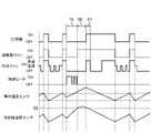
最低温度更新処理(図5のステップS12)及び能力低下処理(図6のステップS23)に係る制御について、図4を例示して説明する。図4に示すように、制御部70は、庫内温度センサ43で検出された温度が上限温度に達すると(時点T1参照)、冷却運転(冷却運転F1参照)を開始する。これにより、庫内温度センサ43で検出された温度が次第に低下していく。このため、制御部70が、所定時間毎に最低温度更新処理を実行することで、最低温度K1は、その都度小さい値に更新されていく。時点T2において扉14が開けられることで、外気が貯蔵室12内に入り込むと、貯蔵室12内の温度が上昇していく。このため、時点T2における庫内温度センサ43で検出された温度が最低温度K1となる。そして、貯蔵室12内の温度が上昇することで、庫内温度センサ43で検出された温度が基準温度K4に達すると(時点T3)、制御部70は、能力低下処理を実行し、冷却ファン25を所定時間T4だけ停止させる。
FIG. 4 will be exemplified to explain the control related to the minimum temperature update process (step S12 in FIG. 5) and the capacity reduction process (step S23 in FIG. 6). As shown in FIG. 4, when the temperature detected by the
また、本実施形態において、制御部70は、冷却器30の除霜を行う除霜運転を実行する。除霜運転としては、ヒータデフロストやオフサイクルデフロストを例示することができる。ヒータデフロストにおいては、制御部70は、図7の期間T5に示すように、圧縮機22、凝縮器ファン23及び冷却ファン25を停止させると共に除霜ヒータ42を動作させることで冷却器30を加熱し、冷却器30に付着した霜を除霜する。制御部70は、冷却器温度センサ41の検出温度が、予め設定された設定温度K5になると、除霜ヒータ42を停止させ、ヒータデフロストを終了させる。
Further, in the present embodiment, the
その後、制御部70は、ヒータデフロストが終了してから所定の待機時間T6(冷却器30の水切り時間)が経過した後に冷却ファン25を所定の動作時間T7だけ動作させるファン動作処理を実行する。これにより、冷却ファン25に付着した水滴を飛ばすことができる。なお、ファン動作処理においては、制御部70は、貯蔵室12内の温度(庫内温度センサ43の検出温度)の変化に関わらず、冷却ファン25の回転数を一定とする。言い換えると、制御部70は、ファン動作処理を実行している間は、冷却ファン25の運転能力を低下させることがない。なお、図7では、ヒータデフロストにおいて除霜ヒータ42を間欠的に動作させているものを例示しているが、除霜ヒータ42を連続的に動作させてもよい。
Thereafter, the
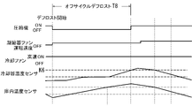
また、オフサイクルデフロストにおいては、図8の期間T8に示すように、制御部70は、圧縮機22を停止させると共に冷却ファン25を動作させることで冷却器30に付着した霜を除霜する。制御部70は、冷却器温度センサ41の検出温度が、予め設定された設定温度K6になると、オフサイクルデフロストを終了させる。なお、オフサイクルデフロストを実行している間は、制御部70は、貯蔵室12内の温度(庫内温度センサ43の検出温度)の変化に関わらず、冷却ファン25の回転数を一定とする。言い換えると、制御部70は、オフサイクルデフロストを実行している間は、冷却ファン25の運転能力を低下させることがない。
In the off-cycle defrost, the
なお、制御部70は所定の除霜開始条件が成立すると除霜運転として、ヒータデフロスト及びオフサイクルデフロストのうちいずれかを実行する。除霜開始条件は「前回の除霜運転が終了してから一定時間が経過したこと」や「予め設定されている時刻に達したこと」などであり、適宜に設定できる。また、制御部70は、例えば、除霜開始条件が成立した際の庫内設定温度が基準値よりも低い場合にはヒータデフロストを実行し、庫内設定温度が基準値よりも高い場合にはオフサイクルデフロストを実行することで消費電力を低減させるようにするが、ヒータデフロスト及びオフサイクルデフロストの切替条件はこれに限定されない。
Note that the
また、制御部70は、図9に示すように、コントロールパネル76の操作部72が使用者によって操作される(ステップS31で「YES」)と、能力低下処理を実行可能とする第1モードから能力低下処理を実行不可能とする第2モードに切り替えるモード切替処理を実行する(ステップS32)。なお、ここで言う「能力低下処理を実行不可能にする」とは、庫内温度センサ43で検出された温度(現在の温度K2)が、基準温度K4以上になったと判断した場合(制御部70が貯蔵室12内の温度が上昇したと判断した場合)であっても能力実行処理を実行しない状態のことである。
Further, as shown in FIG. 9, when the
なお、第2モードの状態で操作部72が操作されることで、制御部70は、第2モードから第1モードに切り替えることが可能となっている。また、本実施形態では、コントロールパネル76に設けられた操作部72を操作されることで、モード切替処理を実行する場合を例示しているが、操作部は、これに限定されず、例えば、操作部として、制御部70を構成する回路基板上に設けられたスイッチを挙げることができる。
By operating the
次に、本実施形態の効果について説明する。本実施形態によれば、扉14が開いた場合には、外気が貯蔵室12に入り込むことで、貯蔵室12内の温度が上昇する。このため、制御部70は、貯蔵室12内の温度が上昇したと判断した場合には、扉14が開いたと判定し、能力低下処理を実行する。能力低下処理において冷却ファン25の運転能力を低下させることで、貯蔵室12内の空気が冷却器室17に吸引されることが抑制されるため、貯蔵室12内に入り込んだ外気(比較的湿度の高い空気)が冷却器室17に向かう事態を抑制でき、冷却器30に霜が付く事態を抑制できる。本実施形態では、庫内温度センサ43から取得した温度情報により、能力低下処理を実行するため、扉14が開いたことを検知するための専用のセンサ(例えば、扉14と貯蔵庫本体11とが近接していることを検知する近接センサや、扉14を開けた人の熱(赤外線)を検知する赤外線センサ等)を用いることなく、扉14が開いた場合に冷却器30に霜が付く事態を抑制できる。
Next, the effects of this embodiment will be described. According to the present embodiment, when the
また、制御部70は、冷却運転中に庫内温度センサ43で検出された温度が、基準温度K4以上になったと判断した場合に能力低下処理を実行するものとされ、冷却運転中に庫内温度センサ43で検出される温度のうち、最も低い温度を最低温度K1とした場合において、基準温度K4は、最低温度K1よりも所定温度K3高く設定された温度である。冷却運転中は貯蔵室12内の温度が次第に低下し、冷却運転中に扉14が開いた場合には外気が貯蔵室12に入り込むことで、貯蔵室12内の温度が上昇する。このため、最低温度K1は、扉14が開く直前の貯蔵室12内の温度と考えることができ、その後、庫内温度センサ43で検出された温度は最低温度K1よりも高い値となる。このため、庫内温度センサ43で検出された温度が、基準温度K4(最低温度K1+所定温度K3)以上になったと判断した場合に、能力低下処理を実行することで、扉14が開いた場合に冷却器30に霜が付く事態を抑制できる。
Further, the
なお、庫内温度センサ43で検出された温度が所定時間(以下の説明では所定時間T50と呼ぶ)内に所定温度(以下の説明では所定温度K50と呼ぶ)だけ上昇した場合に、制御部70が、扉14が開いたと判定して能力低下処理を実行するような制御とすることも可能である。つまり、所定時間T50における庫内温度センサ43の検出温度の変化に基づいて扉14が開いたと判定してもよい。しかしながら、このような制御では、所定時間T50の適切な設定が困難であり判定精度が低くなる。この理由について次に詳しく説明する。
When the temperature detected by the
庫内温度センサ43の検出温度は、扉14が開いたことに起因しない原因(例えば庫内温度センサ43に触れる空気の温度ムラ等)によってわずかに変動することがあり、このような変動は、扉14が開いた際の温度変化と比べて、短期間で起こる変動であると共に小さい変動である。つまり、扉14が開いた際には、庫内温度センサ43の検出温度が、短期的には(扉14が開いたこと以外の原因によって)わずかに変動(上昇及び下降)しつつ、長期的には(扉14が開いたことに起因して)上昇する。
The temperature detected by the
仮に上述した所定時間T50(言い換えると制御部70が庫内温度センサ43の検出温度を参照する間隔)を短く設定すると、制御部70が、庫内温度センサ43の検出温度の短期的な変動のみを参照してしまうことになる。つまり、制御部70が、扉14が開いた際の長期的な温度変化を参照しないことになるため、扉14が開いたことを正しく判定できない事態が懸念される。
If the above-described predetermined time T50 (in other words, the interval at which the
所定時間T50を長く設定すれば、制御部70は、短期的な温度変化(扉14が開いたことによらない温度変化)を参照せず、長期的な温度変化(扉14が開いたことによる比較的大幅な温度上昇)を参照することになるため、扉14が開いたことを正しく判定することができる。しかしながら、扉14が開けられる時間は基本的には短時間であるため、所定時間T50が長過ぎると、扉14が閉じた後の温度変化も参照してしまうことになり、所定時間T50を長く設定することは難しい。つまり、所定時間T50における庫内温度センサ43の検出温度の変化に基づいて扉14が開いたと判定する判定方法は、庫内温度センサ43の検出温度の時間変化による影響を受けることから、判定精度が低くなり易い。
If the predetermined time T50 is set long, the
これに対して、本実施形態では、制御部70は、最低温度K1からの上昇幅(所定温度K3)に基づいて、扉14が開いたか否かを判定している。つまり、本実施形態では、時間を参照せずに扉14が開いたか否かを判定しているため、庫内温度センサ43の検出温度の時間変化による影響を受けることがなく、判定精度をより高くすることができる。なお、所定温度K3は、扉14を開けた際の庫内温度センサ43の検出温度の上昇値を実験によって測定することで、適切に設定することができる。例えば、所定温度K3を庫内温度センサ43の短期的な温度上昇値(扉14が開いたことによらない温度上昇値)よりも大きな値に設定することで、扉14が開いたことをより確実に検知することができる。
On the other hand, in the present embodiment, the
また、最低温度K1が記憶される記憶部73を備え、制御部70は、圧縮機22の動作開始時に、記憶部73に記憶されている最低温度K1を消去する。冷却運転開始時に自動的に前回の冷却運転時の最低温度K1を消去することができる。これにより、前回の冷却運転時の最低温度K1を参照して能力低下処理を実行してしまう事態を抑制できる。
The
また、冷却器30を加熱する除霜ヒータ42を備え、制御部70は、除霜ヒータ42を動作させることで冷却器30に付着した霜を除霜するヒータデフロストを実行すると共に、ヒータデフロストが終了してから所定の待機時間T6が経過した後に冷却ファン25を所定の動作時間T7だけ動作させるファン動作処理を実行するものとされ、さらに制御部70は、ファン動作処理を実行している間は、冷却ファン25の運転能力を低下させることがない。ファン動作処理を実行することで、冷却ファン25に付着した水滴を飛ばすことができる。ファン動作処理中に冷却ファン25の運転能力を低下させることがないから、冷却ファン25に付着した水滴を確実に飛ばすことができる。
The
また、制御部70は、圧縮機22を停止させると共に冷却ファン25を動作させることで冷却器30に付着した霜を除霜するオフサイクルデフロストを実行するものとされ、さらに制御部70は、オフサイクルデフロストを実行している間は、冷却ファン25の運転能力を低下させることがない。オフサイクルデフロストでは、冷却ファン25によって冷却器室17に貯蔵室12内の空気を送ることで冷却器30の除霜を行うことができる。仮に、オフサイクルデフロスト中に冷却ファン25の運転能力が低下すると、オフサイクルデフロストの所要時間が長くなってしまう。このため、オフサイクルデフロスト中は、冷却ファン25の運転能力を低下させないようにしている。
In addition, the
また、制御部70は、庫内温度センサ43で検出された温度が0℃より高いと判断した場合には、能力低下処理を実行しない。貯蔵室12内の温度が0℃より高い場合には、貯蔵室12内の空気が冷却器30に向かった場合であっても、冷却器30に霜が付くことが殆どないため、貯蔵室12内の温度が0℃以下である場合に、能力低下処理を実行する。言い換えると、貯蔵室12内の温度が0℃より高い場合では、能力低下処理を実行しないため、速やかに貯蔵室12内の温度を下げることができる。
Further, when the
また、使用者によって操作される操作部72を備え、制御部70は、操作部72が操作されることで、能力低下処理を実行可能とする第1モードから能力低下処理を実行不可能とする第2モードに切り替えるモード切替処理を実行する。能力低下処理を実行不可能にする第2モードにすることで、例えば、貯蔵室12を常に冷やす必要がある場合に能力低下処理を実行しないようにすることができる。
Further, an
なお、第2モードに切り替えることが可能な構成は、図10に示すような冷却貯蔵庫110に適用すると特に好適である。図10に示す冷却貯蔵庫110においては、貯蔵室12内に設けられた棚111に容器112(例えばホテルパン)が支持され、貯蔵庫本体11の天井壁部113に形成された開口114を通じて、容器112内の冷却対象(例えばアイスクリーム等)を取り出すことが可能となっている。このような構成では、容器112内の冷却対象を常に冷やすことが求められる場合が多い。このため、第2モードにすることで、能力低下処理が実行される事態を防止することが好ましい。
A configuration that allows switching to the second mode is particularly suitable when applied to a
<実施形態2>
次に、本発明の実施形態2を図11から図13によって説明する。上記実施形態と同一部分には、同一符号を付して重複する説明を省略する。本実施形態では、能力低下処理を実行するための判定基準が上記実施形態と相違する。制御部70は、図11に示すように、冷却運転中に、庫内温度センサ43で検出された温度の所定時間T11の平均値K10を算出する(ステップS41、平均値算出処理)。例えば、庫内温度センサ43のサンプリング時間T9が0.1秒で設定され、所定時間T11が5秒で設定されている場合には、平均値K10は、庫内温度センサ43によって取得された複数の温度データD1(図13参照)のうち、平均値算出処理を実行する時点(図13の時点T21,T22,T23,T24)から遡った50個の温度データD1の平均値となる。そして、制御部70は、算出された平均値K10が記憶部73に記憶されている最低平均値K11よりも低いと判断した場合(ステップS42で「YES」)に、最低平均値更新処理を実行する(ステップS43)。最低平均値更新処理では、制御部70は、算出された平均値K10を最低平均値K11として更新して記憶部73に記憶する。
<Embodiment 2>
Next, Embodiment 2 of the present invention will be described with reference to FIGS. 11 to 13. FIG. The same reference numerals are given to the same parts as those of the above-described embodiment, and redundant explanations are omitted. This embodiment differs from the above-described embodiment in terms of criteria for executing the ability reduction process. As shown in FIG. 11, the
なお、冷却運転開始時(圧縮機22の動作開始時)に、制御部70は、記憶部73に記憶されている最低平均値K11(前回の冷却運転時の最低平均値)を消去し、最低平均値K11の初期値として、例えば、その時点での庫内温度センサ43で検出された温度の値を記憶部73に記憶する。つまり、最低平均値K11は、制御部70によって算出された複数の平均値K10のうち、最も低い平均値である。なお、平均値算出処理(ステップS41)、及び最低平均値更新処理を実行するか否かの判定処理(ステップS42)は、所定時間T11毎に実行される。
Note that when the cooling operation is started (when the operation of the
そして、制御部70は、図12に示すように、冷却運転中に庫内温度センサ43で検出された現在の温度K12が、基準温度K14以上になったと判断した場合(ステップS51で「YES」)、及び庫内温度センサ43で検出された温度が0℃以下であると判断した場合(ステップS52で「YES」)に、能力低下処理を実行する(ステップS53)。言い換えると、制御部70は、庫内温度センサ43で検出された温度が0℃より高いと判断した場合には、能力低下処理を実行しない。
Then, as shown in FIG. 12, when the
上記した基準温度K14は、最低平均値K11よりも所定温度K13だけ高く設定された温度である(基準温度K14=最低平均値K11+所定温度K13)。つまり、制御部70は、現在の温度K12が基準温度K14以上になることで「冷却運転中に貯蔵室12内の温度が上昇した」と判断し、能力低下処理を実行する。また、所定温度K13は、例えば1K(ケルビン)で設定されているが、これに限定されず、適宜変更可能である。
The above reference temperature K14 is a temperature set higher than the lowest average value K11 by a predetermined temperature K13 (reference temperature K14=lowest average value K11+predetermined temperature K13). That is, the
所定温度K13は予め試験等を行うことで決定することができる。なお、制御部70による庫内温度センサ43のサンプリング時間T9は、例えば、0.1秒とされ、所定時間T11は、サンプリング時間T9よりも長い時間(例えば5秒)で設定されるが、庫内温度センサ43のサンプリング時間や所定時間T11は、適宜変更可能である。
The predetermined temperature K13 can be determined by performing tests or the like in advance. Note that the sampling time T9 of the
次に、最低平均値更新処理に係る制御について図13を例示して具体的に説明する。図13は、冷却運転中の貯蔵室12内の温度推移の一例を示すグラフである。また、図13においては、各時点T21,T22,T23,T24で平均値算出処理(ステップS41)、及び最低平均値更新処理を実行するか否かの判定処理(ステップS42)が実行するものとする。また、図13の時点T30で扉14が開いたものとする。
Next, FIG. 13 will be exemplified to specifically explain the control related to the minimum average value update process. FIG. 13 is a graph showing an example of temperature transition in the
図13に示すように、冷却運転中は、貯蔵室12内の温度が次第に低下していく。このため、貯蔵室12内の温度が次第に低下していく間は、所定時間T11毎に、最低平均値K11がより低い値に更新されていく。例えば、図13の時点T21から時点T22までの期間の平均値K10よりも時点T22から時点T23までの期間の平均値K10が低くなるため、時点T22においては、時点T21から時点T22までの期間の平均値K10が最低平均値K11として記憶部73に記憶され、時点T23においては、時点T22から時点T23までの期間の平均値K10が最低平均値K11として更新されて記憶部73に記憶される。
As shown in FIG. 13, the temperature in the
そして、時点T30において扉14が開けられると、貯蔵室12内の温度が次第に上昇する。このため、時点T23から時点T24までの期間の平均値K10は、記憶されている最低平均値K11よりも高くなる。つまり、時点T24においては、最低平均値更新処理は実行されない。このため、制御部70は、時点T22から時点T23までの期間の平均値K10に所定温度K13を加算したものを基準温度K14とし、庫内温度センサ43で検出された温度が、基準温度K14以上となった場合に、能力低下処理を実行する。
Then, when the
次に、本実施形態の効果について説明する。本実施形態によれば、冷却運転中は貯蔵室12内の温度が次第に低下し、冷却運転中に扉14が開いた場合には外気が貯蔵室12に入り込むことで、貯蔵室12内の温度が上昇する。このため、最低平均値K11は、扉14が開く直前の貯蔵室12内の温度に対応した数値と考えることができ、扉14が開いた後、庫内温度センサ43で検出された温度は最低平均値K11よりも高い値となる。このため、制御部70が、庫内温度センサ43で検出された温度が基準温度K14(最低平均値K11+所定温度K13)以上になったと判断した場合に、能力低下処理を実行することで、扉14が開いた場合に冷却器30に霜が付く事態を抑制できる。また、上記構成では、庫内温度センサ43で検出された温度の平均値K10に基づいて、能力低下処理を実行することから、庫内温度センサ43の瞬時値に基づいて、基準温度K14が決定される場合と比べて、庫内温度センサ43の瞬間的な誤差等の影響を低減することができる。
Next, the effects of this embodiment will be described. According to the present embodiment, the temperature in the
また、本実施形態では、冷却運転開始時に自動的に前回の冷却運転時の最低平均値K11を消去することができる。これにより、前回の冷却運転時の最低平均値K11を参照して能力低下処理を実行してしまう事態を抑制できる。 Further, in the present embodiment, the lowest average value K11 of the previous cooling operation can be automatically deleted at the start of the cooling operation. As a result, it is possible to prevent the performance reduction process from being performed with reference to the lowest average value K11 during the previous cooling operation.
<他の実施形態>
本発明は上記記述及び図面によって説明した実施形態に限定されるものではなく、例えば次のような実施形態も本発明の技術的範囲に含まれる。
(1)能力低下処理を実行する条件は、上記実施形態で例示したものに限定されない。例えば、貯蔵室12内の温度の上昇速度に基づいて、能力低下処理を実行してもよい。具体的には、冷却運転中において、庫内温度センサ43で検出された温度が所定時間内に所定温度だけ上昇した場合に制御部70が能力低下処理を実行してもよい。
(2)上記実施形態では、能力低下処理において冷却ファン25の運転能力を低下させた場合を例示したが、これに限定されない。例えば、能力低下処理において圧縮機22の運転能力を低下させてもよい。圧縮機22の運転能力を低下させることで、冷却器30の温度低下を抑制することができるため、冷却器30に霜が付く事態を抑制できる。なお、ここで言う「圧縮機22の運転能力を低下させる」とは、圧縮機22の回転数を下げることや圧縮機22を停止させること等を意味する。
<Other embodiments>
The present invention is not limited to the embodiments explained by the above description and drawings, and the following embodiments are also included in the technical scope of the present invention.
(1) The conditions for executing the performance reduction process are not limited to those exemplified in the above embodiments. For example, the capacity reduction process may be executed based on the rate of temperature increase in the
(2) In the above embodiment, the case where the operability of the cooling
10…冷却貯蔵庫、11…貯蔵庫本体、12…貯蔵室、14…扉、17…冷却器室、20…冷却装置、22…圧縮機、25…冷却ファン、30…冷却器、42…除霜ヒータ(ヒータ)、43…庫内温度センサ(温度センサ)、70…制御部、72…操作部、73…記憶部、K1…最低温度、K3,K13…所定温度、K4,K14…基準温度、K10…平均値、K11…最低平均値、T6…待機時間、T7…動作時間、T11…所定時間
DESCRIPTION OF
Claims (9)
前記貯蔵庫本体に取り付けられ、前記貯蔵室を開閉可能な扉と、
前記貯蔵室を冷却する冷却装置と、
前記貯蔵室内の温度を検出する温度センサと、
制御部と、を備え、
前記冷却装置は、
前記冷却器室に収容される冷却器と、
前記冷却器と共に冷却サイクルを構成する圧縮機と、
前記貯蔵室内の空気を前記冷却器室に吸引すると共に、前記冷却器を通過した空気を前記貯蔵室内に供給する冷却ファンと、を備え、
前記制御部は、前記圧縮機及び前記冷却ファンを動作させることで、前記冷却器で冷やされた空気を前記貯蔵室内に供給する冷却運転を行うものとされ、
さらに、前記制御部は、
前記冷却運転における前記圧縮機のオン状態中に前記温度センサで検出される温度のうち、最も低い温度を最低温度とし、
前記冷却運転における前記圧縮機のオン状態中に前記温度センサで検出された温度が前記最低温度よりも所定温度高く設定された基準温度以上になると、前記冷却装置の冷却能力を低下させる能力低下処理を実行する冷却貯蔵庫。 a box-shaped storage body having a storage room and a cooler room;
a door attached to the storage body and capable of opening and closing the storage chamber;
a cooling device for cooling the storage chamber;
a temperature sensor that detects the temperature in the storage chamber;
a control unit;
The cooling device
a cooler housed in the cooler chamber;
a compressor that forms a cooling cycle together with the cooler;
a cooling fan that sucks the air in the storage chamber into the cooler chamber and supplies the air that has passed through the cooler into the storage chamber;
The control unit operates the compressor and the cooling fan to perform a cooling operation to supply the air cooled by the cooler into the storage chamber,
Furthermore, the control unit
The lowest temperature among the temperatures detected by the temperature sensor during the ON state of the compressor in the cooling operation is defined as the lowest temperature,
When the temperature detected by the temperature sensor during the ON state of the compressor in the cooling operation becomes equal to or higher than a reference temperature that is set higher than the minimum temperature by a predetermined temperature, capacity reduction processing for reducing the cooling capacity of the cooling device. Cooling storage that runs.
前記制御部は、前記圧縮機の動作開始時に、前記記憶部に記憶されている前記最低温度を消去する請求項1に記載の冷却貯蔵庫。 A storage unit in which the minimum temperature is stored,
2. The cold storage according to claim 1, wherein the control unit deletes the minimum temperature stored in the storage unit when the compressor starts operating.
前記貯蔵庫本体に取り付けられ、前記貯蔵室を開閉可能な扉と、
前記貯蔵室を冷却する冷却装置と、
前記貯蔵室内の温度を検出する温度センサと、
制御部と、を備え、
前記冷却装置は、
前記冷却器室に収容される冷却器と、
前記冷却器と共に冷却サイクルを構成する圧縮機と、
前記貯蔵室内の空気を前記冷却器室に吸引すると共に、前記冷却器を通過した空気を前記貯蔵室内に供給する冷却ファンと、を備え、
前記制御部は、前記圧縮機及び前記冷却ファンを動作させることで、前記冷却器で冷やされた空気を前記貯蔵室内に供給する冷却運転を行うものとされ、
さらに、前記制御部は、
前記冷却運転における前記圧縮機のオン状態中に前記温度センサで検出された温度の所定時間の平均値を前記所定時間毎に算出し、算出された複数の前記平均値のうち、最も低い平均値を最低平均値とし、
前記冷却運転における前記圧縮機のオン状態中に前記温度センサで検出された温度が前記最低平均値よりも所定温度高く設定された基準温度以上になると、前記冷却装置の冷却能力を低下させる能力低下処理を実行する冷却貯蔵庫。 a box-shaped storage body having a storage room and a cooler room;
a door attached to the storage body and capable of opening and closing the storage chamber;
a cooling device for cooling the storage chamber;
a temperature sensor that detects the temperature in the storage chamber;
a control unit;
The cooling device
a cooler housed in the cooler chamber;
a compressor that forms a cooling cycle together with the cooler;
a cooling fan that sucks the air in the storage chamber into the cooler chamber and supplies the air that has passed through the cooler into the storage chamber;
The control unit operates the compressor and the cooling fan to perform a cooling operation to supply the air cooled by the cooler into the storage chamber,
Furthermore, the control unit
An average value of the temperature detected by the temperature sensor during the ON state of the compressor in the cooling operation is calculated every predetermined time, and the lowest average value among the calculated average values is calculated. is the lowest average value, and
When the temperature detected by the temperature sensor during the ON state of the compressor in the cooling operation becomes equal to or higher than a reference temperature that is set higher than the lowest average value by a predetermined temperature, the ability to reduce the cooling capacity of the cooling device is lowered. Cooling storage that performs processing.
前記制御部は、前記圧縮機の動作開始時に、前記記憶部に記憶されている前記最低平均値を消去する請求項3に記載の冷却貯蔵庫。 A storage unit in which the lowest average value is stored,
4. The cold storage according to claim 3, wherein the control section deletes the lowest average value stored in the storage section when the compressor starts to operate.
前記制御部は、前記ヒータを動作させることで前記冷却器に付着した霜を除霜するヒータデフロストを実行すると共に、前記ヒータデフロストが終了してから所定の待機時間が経過した後に前記冷却ファンを所定の動作時間だけ動作させるファン動作処理を実行するものとされ、
さらに前記制御部は、前記ファン動作処理を実行している間は、前記冷却ファンの運転能力を低下させることがない請求項1から請求項5のいずれか1項に記載の冷却貯蔵庫。 A heater that heats the cooler is provided,
The control unit operates the heater to perform heater defrost for defrosting frost adhered to the cooler, and operates the cooling fan after a predetermined standby time has elapsed after the heater defrost is completed. A fan operation process is executed to operate for a predetermined operation time,
6. The cooling storage according to any one of claims 1 to 5, wherein the control unit does not lower the operability of the cooling fan while the fan operation process is being executed.
さらに前記制御部は、前記オフサイクルデフロストを実行している間は、前記冷却ファンの運転能力を低下させることがない請求項1から請求項6のいずれか1項に記載の冷却貯蔵庫。 The control unit is configured to perform off-cycle defrosting, which defrosts frost adhered to the cooler by stopping the compressor and operating the cooling fan,
7. The cooling storage according to any one of claims 1 to 6, wherein the control unit does not lower the operability of the cooling fan while the off-cycle defrosting is being performed.
前記制御部は、前記操作部が操作されることで、前記能力低下処理を実行可能とする第1モードから前記能力低下処理を実行不可能とする第2モードに切り替えるモード切替処理を実行する請求項1から請求項8のいずれか1項に記載の冷却貯蔵庫。 An operation unit operated by a user is provided,
The control unit executes mode switching processing for switching from a first mode that enables execution of the performance reduction processing to a second mode that disables execution of the performance reduction processing by operating the operation unit. A cold store according to any one of claims 1 to 8.
Priority Applications (1)
| Application Number | Priority Date | Filing Date | Title |
|---|---|---|---|
| JP2018224868A JP7201412B2 (en) | 2018-11-30 | 2018-11-30 | cold storage |
Applications Claiming Priority (1)
| Application Number | Priority Date | Filing Date | Title |
|---|---|---|---|
| JP2018224868A JP7201412B2 (en) | 2018-11-30 | 2018-11-30 | cold storage |
Publications (2)
| Publication Number | Publication Date |
|---|---|
| JP2020085407A JP2020085407A (en) | 2020-06-04 |
| JP7201412B2 true JP7201412B2 (en) | 2023-01-10 |
Family
ID=70907496
Family Applications (1)
| Application Number | Title | Priority Date | Filing Date |
|---|---|---|---|
| JP2018224868A Active JP7201412B2 (en) | 2018-11-30 | 2018-11-30 | cold storage |
Country Status (1)
| Country | Link |
|---|---|
| JP (1) | JP7201412B2 (en) |
Families Citing this family (1)
| Publication number | Priority date | Publication date | Assignee | Title |
|---|---|---|---|---|
| CN112033081B (en) * | 2020-08-31 | 2022-01-11 | 山东冰河制冷技术有限公司 | Device for assisting electric heating defrosting by utilizing external air of refrigerator and operation method thereof |
Citations (6)
| Publication number | Priority date | Publication date | Assignee | Title |
|---|---|---|---|---|
| JP2004069248A (en) | 2002-08-09 | 2004-03-04 | Hitachi Home & Life Solutions Inc | Refrigerator |
| JP2006029772A (en) | 2004-06-17 | 2006-02-02 | Hoshizaki Electric Co Ltd | Cooling storage shed |
| JP2007309530A (en) | 2006-05-16 | 2007-11-29 | Sharp Corp | Refrigerator |
| JP2008045790A (en) | 2006-08-11 | 2008-02-28 | Sanyo Electric Co Ltd | Low-temperature storage |
| JP2009250538A (en) | 2008-04-07 | 2009-10-29 | Hoshizaki Electric Co Ltd | Temperature display method and device for cooling storage cabinet |
| JP2014503835A (en) | 2010-10-28 | 2014-02-13 | サムスン エレクトロニクス カンパニー リミテッド | Display module and display system |
Family Cites Families (3)
| Publication number | Priority date | Publication date | Assignee | Title |
|---|---|---|---|---|
| JP3136632B2 (en) * | 1991-04-08 | 2001-02-19 | ダイキン工業株式会社 | Defrost control device |
| JP3834131B2 (en) * | 1997-07-25 | 2006-10-18 | ホシザキ電機株式会社 | Temperature control device for refrigerator |
| KR20080095200A (en) * | 2008-04-22 | 2008-10-28 | 문영호 | Freezer for meal service sample |
-
2018
- 2018-11-30 JP JP2018224868A patent/JP7201412B2/en active Active
Patent Citations (6)
| Publication number | Priority date | Publication date | Assignee | Title |
|---|---|---|---|---|
| JP2004069248A (en) | 2002-08-09 | 2004-03-04 | Hitachi Home & Life Solutions Inc | Refrigerator |
| JP2006029772A (en) | 2004-06-17 | 2006-02-02 | Hoshizaki Electric Co Ltd | Cooling storage shed |
| JP2007309530A (en) | 2006-05-16 | 2007-11-29 | Sharp Corp | Refrigerator |
| JP2008045790A (en) | 2006-08-11 | 2008-02-28 | Sanyo Electric Co Ltd | Low-temperature storage |
| JP2009250538A (en) | 2008-04-07 | 2009-10-29 | Hoshizaki Electric Co Ltd | Temperature display method and device for cooling storage cabinet |
| JP2014503835A (en) | 2010-10-28 | 2014-02-13 | サムスン エレクトロニクス カンパニー リミテッド | Display module and display system |
Also Published As
| Publication number | Publication date |
|---|---|
| JP2020085407A (en) | 2020-06-04 |
Similar Documents
| Publication | Publication Date | Title |
|---|---|---|
| US11168938B2 (en) | Dual use user interface and door position sensors | |
| JP5709705B2 (en) | Freezer refrigerator | |
| EP3356752B1 (en) | Temperature control of refrigeration cavities in low ambient temperature conditions | |
| JP7201412B2 (en) | cold storage | |
| JP4759406B2 (en) | Cooling storage | |
| KR20160027761A (en) | Frost sensing unit and defrosting apparatus including the same and defrosting methods for refrigerator | |
| JP6657032B2 (en) | Cooling storage | |
| KR100807280B1 (en) | Refrigerator and control method thereof | |
| JP6167430B2 (en) | Cooling storage | |
| JP2006071248A (en) | Cooling storage | |
| JP2019199974A (en) | Refrigerator, refrigerator control method, refrigerator control program | |
| CN109751830B (en) | Refrigeration equipment and method and device for detecting state of refrigeration equipment | |
| JP6657031B2 (en) | Cooling storage | |
| CN109691870B (en) | Cooking apparatus | |
| JP2018009729A (en) | Cooling storage cabinet | |
| JP2003130519A (en) | Ice maker and freezer refrigerator having this ice maker | |
| JP5763469B2 (en) | Refrigerator | |
| JP2020085408A (en) | Cooling storage | |
| JP6310236B2 (en) | Cooling storage | |
| JP7465135B2 (en) | Cooling Storage | |
| JP6782338B2 (en) | refrigerator | |
| JP6559472B2 (en) | refrigerator | |
| JP2023014535A (en) | Cooling storage | |
| JP6667383B2 (en) | Cooling storage | |
| KR20060128529A (en) | Method for defrosting of kimchi storage |
Legal Events
| Date | Code | Title | Description |
|---|---|---|---|
| A621 | Written request for application examination |
Free format text: JAPANESE INTERMEDIATE CODE: A621 Effective date: 20210330 |
|
| A977 | Report on retrieval |
Free format text: JAPANESE INTERMEDIATE CODE: A971007 Effective date: 20220203 |
|
| A131 | Notification of reasons for refusal |
Free format text: JAPANESE INTERMEDIATE CODE: A131 Effective date: 20220222 |
|
| A521 | Request for written amendment filed |
Free format text: JAPANESE INTERMEDIATE CODE: A523 Effective date: 20220415 |
|
| A131 | Notification of reasons for refusal |
Free format text: JAPANESE INTERMEDIATE CODE: A131 Effective date: 20220802 |
|
| A521 | Request for written amendment filed |
Free format text: JAPANESE INTERMEDIATE CODE: A523 Effective date: 20220916 |
|
| TRDD | Decision of grant or rejection written | ||
| A01 | Written decision to grant a patent or to grant a registration (utility model) |
Free format text: JAPANESE INTERMEDIATE CODE: A01 Effective date: 20221213 |
|
| A61 | First payment of annual fees (during grant procedure) |
Free format text: JAPANESE INTERMEDIATE CODE: A61 Effective date: 20221222 |
|
| R150 | Certificate of patent or registration of utility model |
Ref document number: 7201412 Country of ref document: JP Free format text: JAPANESE INTERMEDIATE CODE: R150 |