JP7197896B2 - Tidal power generation system and mooring equipment - Google Patents
Tidal power generation system and mooring equipment Download PDFInfo
- Publication number
- JP7197896B2 JP7197896B2 JP2018218641A JP2018218641A JP7197896B2 JP 7197896 B2 JP7197896 B2 JP 7197896B2 JP 2018218641 A JP2018218641 A JP 2018218641A JP 2018218641 A JP2018218641 A JP 2018218641A JP 7197896 B2 JP7197896 B2 JP 7197896B2
- Authority
- JP
- Japan
- Prior art keywords
- power generation
- tidal current
- mooring
- opening
- generation system
- Prior art date
- Legal status (The legal status is an assumption and is not a legal conclusion. Google has not performed a legal analysis and makes no representation as to the accuracy of the status listed.)
- Active
Links
Images


Classifications
-
- Y—GENERAL TAGGING OF NEW TECHNOLOGICAL DEVELOPMENTS; GENERAL TAGGING OF CROSS-SECTIONAL TECHNOLOGIES SPANNING OVER SEVERAL SECTIONS OF THE IPC; TECHNICAL SUBJECTS COVERED BY FORMER USPC CROSS-REFERENCE ART COLLECTIONS [XRACs] AND DIGESTS
- Y02—TECHNOLOGIES OR APPLICATIONS FOR MITIGATION OR ADAPTATION AGAINST CLIMATE CHANGE
- Y02E—REDUCTION OF GREENHOUSE GAS [GHG] EMISSIONS, RELATED TO ENERGY GENERATION, TRANSMISSION OR DISTRIBUTION
- Y02E10/00—Energy generation through renewable energy sources
- Y02E10/30—Energy from the sea, e.g. using wave energy or salinity gradient
Description
特許法第30条第2項適用 「低コストかつ低流速潮流域へ適用可能な浮沈式潮流発電システムの開発研究」 日本海洋工学会・日本船舶海洋工学会 第27回海洋工学シンポジウム 日本大学理工学部駿河台キャンパス1号館(東京都千代田区神田駿河台1-8-14) 平成30年8月7日Application of
本発明は、潮流によって発電する潮流発電システムおよびその係留装置に関する。 TECHNICAL FIELD The present invention relates to a tidal current power generation system that generates power using a tidal current and a mooring device therefor.
満ち潮時および引き潮時の海水の流れ、すなわち潮流によって発電する潮流発電システムが知られている。潮流発電システムは、海水中にタービンを配置し、潮流によるタービンの回転によって発電機を回転させて発電する。発電機は、たとえば海底から伸びる索によって係留される。 A tidal current power generation system is known that generates electricity by the flow of seawater at high tide and ebb tide, ie, tidal current. A tidal current power generation system has a turbine placed in seawater, and the turbine is rotated by the tidal current to rotate a generator to generate power. The generators are moored, for example, by cables extending from the sea bed.
係留索に繋がれて浮遊する発電装置で発電する潮流発電システムにおいては、潮流の向きの変化に応じて発電装置の向きを変える必要がある。 In a tidal current power generation system that generates power using a floating power generator connected to mooring lines, it is necessary to change the direction of the power generator according to changes in the direction of the tidal current.
特許文献1では、発電機を装着した浮遊体の重心と浮力中心が、浮遊体の中心線上で一致するように為し、この点を通って中心線と直交する水平線上に係留点4を設け、係留点より前後で浮遊体の断面一次モーメントを変えることが示されている。 In Patent Document 1, the center of gravity and the center of buoyancy of a floating body equipped with a generator are made to coincide on the center line of the floating body, and a mooring point 4 is provided on a horizontal line that passes through this point and is perpendicular to the center line. , to change the area moment of inertia of the floating body before and after the mooring point.
また、重心と浮力中心と係留点4が全て一致していると潮流が無くなる憩流時には、浮遊体の姿勢が一意に決まらないため、第8図の説明(段落7、1行目から5行目)においては係留点4を浮遊体の入口側にずらして設けるとしている。 In addition, if the center of gravity, the center of buoyancy, and the mooring point 4 all coincide, the posture of the floating body cannot be uniquely determined at the time of the tidal current when there is no tidal current. 2), the mooring point 4 is shifted to the inlet side of the floating body.
しかしながら、上述のように係留点をずらすと、浮遊体の浮力は重力よりも大きいため、係留点に対して、重力によるモーメントよりも浮力のモーメントの方が大きくなり、潮流が発生したときに浮遊体を水平に保持することができない。 However, when the mooring point is shifted as described above, the buoyant force of the floating body is greater than the gravity force. Inability to keep the body horizontal.
特許文献2では、タービンブレード5を備えたタービン3を旋回可能にするために係留点9を有し、タービンの重心と浮力中心が互いに離間していることが示されている。 WO 2005/010001 shows that the turbine 3 with turbine blades 5 has a mooring point 9 in order to be able to swivel, and that the center of gravity and the center of buoyancy of the turbine are spaced apart from each other.
特許文献2における重心と浮力中心の位置関係は明示されていないが、憩流時に図1の姿勢8になるようにするには、タービン3の浮力中心が重心よりもタービンブレード5側にあるとすることができる。 Although the positional relationship between the center of gravity and the center of buoyancy is not specified in Patent Document 2, in order to achieve posture 8 in FIG. can do.
しかしながら、上述のような位置関係にすると、係留点に対して、重力によるモーメントよりも浮力のモーメントの方が大きくなり、潮流が発生したときにタービンを水平に保持することができない。 However, with the positional relationship as described above, the moment of buoyancy with respect to the mooring point is greater than the moment of gravity, and the turbine cannot be held horizontally when a tidal current occurs.
また、係留索に繋がれて浮遊する発電装置で発電する潮流発電システムにおいて、潮流が大きくなって発電装置が潮流から受ける力が大きくなると、発電装置の沈み込みが大きくなる。発電装置の沈み込みが大きくなると、発電装置が海底に接触し、破損するおそれがある。 Further, in a tidal current power generation system in which a floating power generator connected to a mooring line generates power, as the tidal current increases and the force that the power generator receives from the tidal current increases, the sinking of the power generator increases. If the sinking of the power generation device becomes large, the power generation device may come into contact with the seabed and be damaged.
そのために特許文献3では、発電装置の沈み込みによる係留索7の角度変化を検知する係留角度検知手段9を備えているが、錆や海洋生物の付着を考えると、このような検出器を備えないほうが望ましい。 Therefore, in Patent Document 3, the mooring angle detection means 9 for detecting the angle change of the mooring rope 7 due to the sinking of the power generator is provided. preferably not.
そこで、本発明は、潮流発電システムにおいて潮流が大きくなった場合でも、発電装置が海底に接触する可能性を低減することを目的とする。 SUMMARY OF THE INVENTION Accordingly, it is an object of the present invention to reduce the possibility of a power generation device coming into contact with the seabed even when the tidal current in a tidal current power generation system becomes large.
上述の目的を達成するため、本発明は、潮流発電システムにおいて、潮流によって回転するタービンと、前記タービンの回転で発電する発電機と、前記タービンと前記発電機とを内側に保持し、外側に係留点が形成されたケーシングと、を備えた発電装置と、海底に係止されて前記海底から前記ケーシングに伸びて前記係留点に係止された係留索と、を有する潮流発電システムであって、前記ケーシングは、第1開口および第2開口に向かって貫通する環状であって、前記第2開口が前記第1開口よりも大きな漏斗状に形成されていて、前記係留点が前記第2開口よりも前記第1開口に近く、前記発電装置の浮力中心が前記係留点よりも前記第2開口に近く、前記発電装置の重心が前記浮力中心よりも前記第2開口に近く、前記浮力中心と前記係留点との距離に前記発電装置の浮力を乗じた値が前記重心と前記係留点との距離に前記発電装置の重力を乗じた値以上である、ことを特徴とする。 To achieve the above object, the present invention provides a tidal current power generation system in which a turbine rotated by the tidal current, a generator for generating electricity by the rotation of the turbine, and the turbine and the generator are held inside and held outside. A tidal current power generation system comprising: a power generator including a casing having a mooring point formed thereon; and a mooring line anchored to the seabed, extending from the seabed to the casing and anchored to the mooring point, wherein , the casing has an annular shape penetrating toward a first opening and a second opening, the second opening being formed in a funnel shape larger than the first opening, and the anchor point being the second opening; the center of buoyancy of the power generator is closer to the second opening than the mooring point, the center of gravity of the power generator is closer to the second opening than the center of buoyancy, the center of buoyancy and the mooring point multiplied by the buoyancy of the power generator is greater than or equal to the product of the distance between the center of gravity and the mooring point multiplied by the gravity of the power generator .
本発明によれば、潮流発電システムにおいて潮流が大きくなった場合でも、発電装置が海底に接触する可能性を低減することができる。 ADVANTAGE OF THE INVENTION According to this invention, even when a tidal current becomes large in a tidal current power generation system, a possibility that a power generation apparatus will contact the seabed can be reduced.
本発明に係る潮流発電システムのいくつかの実施の形態を、図面を参照して説明する。なお、これらの実施の形態は単なる例示であり、本発明はこれに限定されない。同一または類似の構成には同一の符号を付し、重複する説明は省略する。 Several embodiments of a tidal power generation system according to the present invention will be described with reference to the drawings. These embodiments are merely examples, and the present invention is not limited to these. The same reference numerals are given to the same or similar configurations, and redundant explanations are omitted.
[第1の実施の形態]
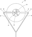
図1は、本発明に係る潮流発電システムの第1の実施の形態の側面図である。図2は、本実施の形態の潮流発電システムの上面図である。図3は、本実施の形態における発電装置の側面図である。図4は、本実施の形態における発電装置の正面図である。図5は、本実施の形態における発電装置の背面図である。
[First embodiment]
FIG. 1 is a side view of a first embodiment of a tidal power generation system according to the present invention. FIG. 2 is a top view of the tidal power generation system of this embodiment. FIG. 3 is a side view of the power generator according to this embodiment. FIG. 4 is a front view of the power generator according to this embodiment. FIG. 5 is a rear view of the power generator according to this embodiment.
本実施の形態の潮流発電システム10は、潮流によって発電する。ここで、潮流とは、海の水(海水)の流れのことであり、潮の満ち干によって周期的に向きが変わる海水の流れを含む。たとえば海水は、満潮に向かう時間帯には概ね矢印91の方向に流れ、干潮に向かう時間帯には矢印92の方向に流れる。図1は、潮流の向きが矢印92の向きのときの状況を示している。
The tidal
潮流発電システム10は、発電装置20と係留索30と中間錘40とを有する。発電装置20は、タービン27と発電機26とケーシング23とを有している。ケーシング23は、第1開口21から第2開口22に向かって貫通する環状に形成されている。ケーシング23の第1開口21および第2開口22は、いずれも円状である。ケーシング23の第2開口22は、第1開口21よりも大きい。ケーシング23は、漏斗状である。ケーシング23の外面には、一対の水平翼24が水平方向両側に突出している。
The tidal current
係留索30は、海底51にアンカー50で係止されている。係留索30は、海底51からケーシング23に伸びている。係留索30の海底51とは反対側の端部は、ケーシング23に取り付けられている。係留索30のケーシング23側の端部は、2本に枝分かれしていて、それぞれケーシング23の水平翼24の係留点25に取り付けられている。係留索30の水平翼24への取り付け部分は、回転自在である方が好ましい。
The
ケーシング23は、たとえば樹脂製である。ケーシング23は、水密の中空部分が内部に形成された鋼板製であってもよい。タービン27は、たとえば樹脂製である。タービンは鋼板あるいは他の金属板で形成されていてもよい。発電機26は、タービン27の回転軸と結合していて、タービン27の回転によって発電する。発電機26には、図示しないケーブルが接続されていて、発電した電気はたとえば陸上の送電線に接続される。発電装置20は、全体として海水中での浮力が重力よりも大きくなるように形成されている。
係留索30は、たとえば金属製のワイヤを束ねたものである。アンカー50は、係留索30をたとえば回転自在に支持している。
The
中間錘40は、たとえば鋼製であって、浮力よりも重力の方が大きい。中間錘40は、係留索30のたとえば中央に固定されている。係留索30と中間錘40と発電装置20とが受ける浮力の合計は、係留索30と中間錘40と発電装置20とが受ける重力よりも大きい。
The
図6は、本実施の形態の潮流発電システムの憩流時の姿勢を示す側面図である。 FIG. 6 is a side view showing the posture of the tidal current power generation system according to the present embodiment when the current is intermittent.
憩流時、すなわち、潮流がない、あるいは潮流の大きさがあるしきい値未満であるとき、係留索30と中間錘40と発電装置20とが受ける浮力の合計が係留索30と中間錘40と発電装置20とが受ける重力よりも大きいため、ケーシング23の第2開口22を上にして静止する。係留索30が十分長い場合には、ケーシング23は海面に浮かぶ。
At the time of rest, that is, when there is no tidal current or the magnitude of the tidal current is less than a certain threshold, the total buoyancy received by the
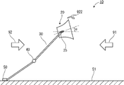
図7は、本実施の形態の潮流発電システムの潮流が発生したときの姿勢の例を示す側面図である。 FIG. 7 is a side view showing an example of the attitude of the tidal power generation system of the present embodiment when a tidal current occurs.
潮流の大きさがあるしきい値以上になると、図7に示すように、発電装置20は、矢印92の方向に流される。発電装置20の軸と潮流との為す角θが正(θ>0度)の場合は、係留点25に対して時計回りのモーメント922が作用する。θ=0度になると、本実施の形態のようにケーシング23を第1開口21から第2開口22に向かう軸を中心とする軸対称に形成しておけば、その対称性ゆえにモーメント922は0(ゼロ)となる。
When the magnitude of the tidal current exceeds a certain threshold, the
図3に示すように、係留点25は第1開口21に比較的近い側に設けられている。発電装置20の浮力中心201は、係留点25よりも第2開口22側に位置している。つまり、発電装置20は、その浮力中心201が係留点25と第2開口22との間に位置するように形成されている。発電装置20の重心202は、浮力中心201よりも更に第2開口22側に位置している。つまり、発電装置20は、その重心202が浮力中心201と第2開口22との間に位置するように形成されている。
As shown in FIG. 3, the
係留点25と浮力中心201の距離をa、係留点25と重心202の距離をbとすると、
a×(発電装置の浮力)=b×(発電装置の重力)
のときに、発電装置20の浮力および重力によって生じるモーメントが釣り合う。その結果、発電装置20の軸心は潮流方向と一致し、水平になって潮流に正対する。なお、このとき発電装置20の軸心が潮流方向と一致しているため、ケーシング23が潮流から受ける力によって生じるモーメントは0(ゼロ)になる。
If the distance between the
a x (buoyancy of power generator) = b x (gravitational force of power generator)
When , the moment caused by the buoyancy of the
a×(発電装置の浮力)>b×(発電装置の重力)
のときは、係留点25に対して第2開口22を上に向ける(図3における反時計回りの方向の)モーメントが作用する。このため、発電装置20の軸と潮流の為す角θが正(θ>0度)となり、発電装置20が潮流から受けるモーメントと、発電装置29の浮力および重力によって発電装置20に生じるモーメントとが釣り合う角度で、発電装置20はほぼ静止する。
a x (buoyancy of power generator) > b x (gravity of power generator)
, a moment acts on the
図1に示すように、発電装置20は、上流側に第1開口21、下流側に第2開口22を向く姿勢で、流れに正対して流される。係留索30の長さは有限であるから、発電装置20が下流側に流されると、発電装置20は海中に沈みこむ。
As shown in FIG. 1, the
発電装置20が潮流がある海中に沈みこむと、タービン27が回転する。タービン27が回転すると、発電機26の軸が回転し、発電機26は回転する。
The
発電装置20は、いわゆる風レンズを用いた風車と同様の構造である。つまり、ケーシング23が集流体として働くことにより、より強い流れがタービン27にあたる。また、ケーシング23の下流側で渦が形成されるため、第2開口22付近の圧力が低下し、海水の流れがより速くなる。このため、発電効率が向上する。
The
図8は、本実施の形態の潮流発電システムの潮流がさらに大きい場合の姿勢を示す側面図である。 FIG. 8 is a side view showing the posture of the tidal current power generation system of the present embodiment when the tidal current is even greater.
潮流が大きくなると、発電装置20を水平方向に押す力が大きくなるため、発電装置20はより深く沈み込む。潮流から受ける力と、係留索30と中間錘40と発電装置20とが受ける浮力とのバランスが取れる位置で、発電装置20は安定する。
As the tidal current increases, the force that pushes the
潮流がさらに大きくなると、まず、中間錘40が海底51に接触する。中間錘40が海底51に接触すると、見かけ上、中間錘40および係留索30のアンカー50から中間錘40までに働く重力がなくなる。このため、見かけ上、発電装置20に働く浮力が大きくなる。その結果、発電装置20の沈み込みが抑制される。
When the tidal current further increases, the
このように、本実施の形態の潮流発電システム10では、潮流が大きくなった場合でも、検出器等を用いずに、発電装置20が海底51に接触する可能性が低減される。その結果、発電装置20が海底に接触することによる破損の可能性が低減される。よって、潮流発電システム10を経済的で信頼性の高いシステムとすることができる。また、潮流は海底51付近よりもある程度上方の方が強いため、本実施の形態の潮流発電システム20は、発電量があまり低下しない。
Thus, in the tidal current
上げ潮から下げ潮に変化して潮流の向きが反転した場合など、潮流の向きが変化した場合であっても、発電装置20は潮流に正対して発電する。その結果、発電装置20の発電効率を向上させることができる。
Even when the direction of the tidal current changes, such as when the direction of the tidal current reverses due to a change from a rising tide to a falling tide, the
また、本実施の形態の潮流発電システムでは、ケーシング23に水平翼24を設けているので、軸を中心とした回転方向の振動が抑制される。係留索30の水平翼24への取り付け部分が回転自在だと、ケーシング23の姿勢の変化に応じて水平翼24の係留点25が回転するため、係留点に過度の応力が生じることがない。
In addition, in the tidal current power generation system of the present embodiment, the
発電装置20の浮力中心201は、係留点25よりも第2開口22側に偏って位置している。このため、潮流が小さくなって発電できなくなった際には、第2開口22が上方を向くように、発電装置20は約90度回転して姿勢を変える。このため、係留索30の取り付け部分が同じ方向に回転して捻じれが蓄積することがない。
The
さらに、発電装置20の浮力中心201が係留点25よりも第2開口22に近いように形成しておくことにより、潮流が小さくなったときには、発電装置20は第2開口22が上に向く姿勢をとる。第2開口22は第1開口21よりも大きいため、第2開口22が上に向く姿勢をとっていると、海上からアクセスしやすく、メンテナンスを行いやすい。また、第1開口21よりも大きい第2開口22が上を向いているため、潮流から発電装置20が受ける力によって生じるモーメントは、発電装置20が第1開口21から第2開口22への向きが潮流に平行になる向きになる。このため、潮流が低速である場合であっても、第1開口21が上流側で第2開口22が下流側となる向きになる。
Furthermore, by forming the center of
本実施の形態において、中間錘40は、係留索30に固定されているが、重力で係留索30を鉛直下方に引っ張るものであれば、どのようなものであってもよい。たとえば、係留索30にロープを固定して、そのロープの下端に錘を取り付けたものでもよい。また、中間錘40は、複数であってもよい。さらに、中間錘40は、係留索30の中央部分の所定の範囲を移動可能な状態で係留索30に取り付けられていてもよい。
In the present embodiment, the
本実施の形態では、ケーシング23は、横断面が外円と内円とで囲まれる環状であるが、円に限定されるわけではなく、多角形であってもよい、たとえば外円および内円のいずれか一方、あるいは両方が多角形であってもよい。また、外円と内円のいずれか一方、あるいは両方が楕円であってもよい。さらに、第1開口21から第2開口に向かって、円から楕円にあるいは楕円から円に変化していても良いし、円から多角形にあるいは多角形から円に変化していても良い。
In the present embodiment, the
[第2の実施の形態]
図9は、本発明に係る潮流発電システムの第2の実施の形態の側面図である。
[Second embodiment]
FIG. 9 is a side view of a second embodiment of a tidal power generation system according to the present invention.
本実施の形態の潮流発電システム10は、第1の実施の形態の潮流発電システム(たとえば図1参照)から中間錐40を削除したものである。
The tidal current
潮流の大きさがあるしきい値以上になると、発電装置20は、矢印92の方向に流される。発電装置20の軸と潮流との為す角θが正(θ>0度)の場合は、係留点25に対して時計回りのモーメント922が作用する。θ=0度になると、本実施の形態のようにケーシング23を第1開口21から第2開口22に向かう軸を中心とする軸対称に形成しておけば、その対称性ゆえにモーメント922は0(ゼロ)となる。
When the magnitude of the tidal current exceeds a certain threshold, the
係留点25と浮力中心201の距離をa、係留点25と重心202の距離をbとすると、
a×(発電装置の浮力)=b×(発電装置の重力)
のときに、発電装置20の浮力および重力によって生じるモーメントが釣り合う。その結果、発電装置20の軸心は潮流方向と一致し、水平になって正対する。なお、このとき発電装置20の軸心が潮流方向と一致しているため、ケーシング23が潮流から受ける力によって生じるモーメントは0(ゼロ)になる。
If the distance between the
a x (buoyancy of power generator) = b x (gravitational force of power generator)
When , the moment caused by the buoyancy of the
a×(発電装置の浮力)>b×(発電装置の重力)
のときは、係留点25に対して第2開口22を上に向ける(図3における反時計回りの方向の)モーメントが作用する。このため、発電装置20の軸と潮流の為す角θが正(θ>0度)となり、発電装置20が潮流から受けるモーメントと、発電装置20の浮力および重力によって発電装置20に生じるモーメントとが釣り合う角度で、発電装置20はほぼ静止する。
a x (buoyancy of power generator) > b x (gravity of power generator)
, a moment acts on the
また、潮流の最大の大きさが予めわかっている場合には、発電装置20の浮力と重力の関係を適切に規定して海底51への接触を防止することができる。
Moreover, when the maximum magnitude of the tidal current is known in advance, the relationship between the buoyancy and gravity of the
発電装置20の浮力中心と重心の位置関係を調整するために、発電機26と略同軸上に付加質量を固定してもよい。その付加質量は、ネジ・ナット機構のナット部であってもよく、また単位重量の質量板を複数枚重ねて固定する形態であってもよい。
In order to adjust the positional relationship between the center of buoyancy and the center of gravity of the
[第3の実施の形態]
図10は、本発明に係る潮流発電システムの第3の実施の形態の側面図である。図11は、本実施の形態の潮流発電システムの上面図である。
[Third embodiment]
FIG. 10 is a side view of a third embodiment of a tidal power generation system according to the present invention. FIG. 11 is a top view of the tidal power generation system of this embodiment.
本実施の形態の潮流発電システム11は、係留索30が4本である。また、中間錘40は、それぞれの係留索30の中央に固定されている。4本の係留索30は、発電装置20に対して潮流の向きの両側にそれぞれ2本ずつ、設けられている。発電装置20に対して潮流の向きの同じ側に位置する係留索30は、潮流の流れを横切る方向に離間した位置で海底に係止されている。発電装置20に対して潮流の向きの同じ側に位置する係留索30の係止位置の幅は、発電装置20への係留索30の取り付け位置の幅よりも広い。
The tidal
このような潮流発電システム11であっても、潮流の向きは、満ち潮時と引き潮時で逆であるものの、概ね一定の方角である。したがって、4本の係留索30で発電装置20をつなぎとめておいても、潮流の向きに概ね正対することができる。
Even in such a tidal current
図12は、本実施の形態の潮流発電システムの憩流時の姿勢を示す側面図である。 FIG. 12 is a side view showing the posture of the tidal current power generation system according to the present embodiment when the current is intermittent.
憩流時、すなわち、潮流がない、あるいは潮流の大きさがあるしきい値未満であるとき、係留索30と中間錘40と発電装置20とが受ける浮力の合計が係留索30と中間錘40と発電装置20とが受ける重力よりも大きいため、ケーシング23の第2開口22を上にして静止する。係留索30が十分長い場合には、ケーシング23は海面に浮かぶ。
At the time of rest, that is, when there is no tidal current or the magnitude of the tidal current is less than a certain threshold, the total buoyancy received by the
潮流が大きくなると、発電装置20を水平方向に押す力が大きくなるため、図9に示すように、発電装置20は深く沈み込む。潮流から受ける力と、係留索30と中間錘40と発電装置20とが受ける浮力とのバランスが取れる位置で、発電装置20は安定する。この際、下流側の係留索30に取り付けられた中間錘40の方が、上流側の中間錘40に比べて深く沈み込む。
As the tidal current increases, the force that pushes the
図13は、本実施の形態の潮流発電システムの潮流がより大きい場合の姿勢を示す側面図である。 FIG. 13 is a side view showing the attitude of the tidal power generation system of the present embodiment when the tidal current is larger.
潮流がより大きくなると、まず、下流側の係留索30に取り付けられた中間錘40が海底51に接触する。中間錘40が海底51に接触すると、見かけ上、中間錘40および係留索30のアンカー50から中間錘40までに働く重力がなくなる。このため、見かけ上、発電装置20に働く浮力が大きくなる。その結果、発電装置20の沈み込みが抑制される。
When the current becomes stronger, the
図14は、本実施の形態の潮流発電システムの潮流がさらに大きい場合の姿勢を示す側面図である。 FIG. 14 is a side view showing the attitude of the tidal power generation system of the present embodiment when the tidal current is even greater.
図14の状態よりも潮流がさらに大きくなると、上流側の係留索30に取り付けられた中間錘40も海底51に接触する。中間錘40が海底51に接触すると、見かけ上、中間錘40および係留索30のアンカー50から中間錘40までに働く重力がなくなる。このため、見かけ上、発電装置20に働く浮力がより大きくなる。その結果、発電装置20の沈み込みがさらに抑制される。
14, the
このように、本実施の形態の潮流発電システム11では、潮流が大きくなった場合でも、発電装置20が海底51に接触する可能性が低減される。その結果、発電装置20が海底に接触することによる破損の可能性が低減される。また、潮流は海底51付近よりもある程度上方の方が強いため、本実施の形態の潮流発電システム11は、発電量があまり低下しない。
Thus, in the tidal current
さらに、本実施の形態では、上流側および下流側に中間錘40が配置されているため、中間錘40の海底51への着底による浮力の変化を2段階とすることができる。このため、より幅広い潮流の大きさに対して、海水中の適正な高さを維持することができる。
Furthermore, in this embodiment, since the
また、本実施の形態では、係留索30を潮流の流れを横切る方向に離間した場所で海底に係止している。このため、潮流の向きが変化した場合であっても、潮流の向きを挟んで一方の係留索30に取り付けられた中間錘40が先に海底51に接触することになるため、発電装置20の水平方向の揺れ(ヨーイング)が抑制される。
Moreover, in this embodiment, the
10…潮流発電システム、11…潮流発電システム、20…発電装置、21…第1開口、22…第2開口、23…ケーシング、24…水平翼、25…係留点、26…発電機、27…タービン、30…係留索、40…中間錘、50…アンカー、51…海底、201…浮力中心、202…重心、922…モーメント
DESCRIPTION OF
Claims (3)
海底に係止されて前記海底から前記ケーシングに伸びて前記係留点に係止された係留索と、
を有する潮流発電システムであって、
前記ケーシングは、第1開口および第2開口に向かって貫通する環状であって、前記第2開口が前記第1開口よりも大きな漏斗状に形成されていて、
前記係留点が前記第2開口よりも前記第1開口に近く、
前記発電装置の浮力中心が前記係留点よりも前記第2開口に近く、
前記発電装置の重心が前記浮力中心よりも前記第2開口に近く、
前記浮力中心と前記係留点との距離に前記発電装置の浮力を乗じた値が前記重心と前記係留点との距離に前記発電装置の重力を乗じた値以上である、
ことを特徴とする潮流発電システム。 A power generation device comprising: a turbine rotated by a tidal current; a generator generating power by the rotation of the turbine; and a casing holding the turbine and the generator inside and having mooring points formed on the outside;
a mooring line anchored to the seabed, extending from the seabed to the casing and anchored to the mooring point;
A tidal power generation system comprising:
The casing has an annular shape penetrating toward a first opening and a second opening, and the second opening is formed in a funnel shape larger than the first opening,
the anchoring point is closer to the first opening than the second opening;
the center of buoyancy of the power generation device is closer to the second opening than the mooring point;
the center of gravity of the power generation device is closer to the second opening than the center of buoyancy;
A value obtained by multiplying the distance between the center of buoyancy and the mooring point by the buoyancy of the power generation device is greater than or equal to the value obtained by multiplying the distance between the center of gravity and the mooring point by the gravity of the power generation device.
A tidal current power generation system characterized by:
Applications Claiming Priority (2)
| Application Number | Priority Date | Filing Date | Title |
|---|---|---|---|
| JP2017224776 | 2017-11-22 | ||
| JP2017224776 | 2017-11-22 |
Publications (2)
| Publication Number | Publication Date |
|---|---|
| JP2019094901A JP2019094901A (en) | 2019-06-20 |
| JP7197896B2 true JP7197896B2 (en) | 2022-12-28 |
Family
ID=66971263
Family Applications (1)
| Application Number | Title | Priority Date | Filing Date |
|---|---|---|---|
| JP2018218641A Active JP7197896B2 (en) | 2017-11-22 | 2018-11-21 | Tidal power generation system and mooring equipment |
Country Status (1)
| Country | Link |
|---|---|
| JP (1) | JP7197896B2 (en) |
Citations (3)
| Publication number | Priority date | Publication date | Assignee | Title |
|---|---|---|---|---|
| WO2009144493A2 (en) | 2008-05-27 | 2009-12-03 | Marine Power Systems Limited | Submersible turbine apparatus |
| JP2012532274A (en) | 2009-06-30 | 2012-12-13 | ターナー ハント | Pitch, roll and drag stabilization technology for tethered hydroelectric generators |
| JP2017013721A (en) | 2015-07-04 | 2017-01-19 | 株式会社Ihi | Buoyancy adjustment device for underwater floating body and ocean current power generation device |
Family Cites Families (1)
| Publication number | Priority date | Publication date | Assignee | Title |
|---|---|---|---|---|
| JPS5716263A (en) * | 1980-06-27 | 1982-01-27 | Mouton William J Jr | Sea current turbine power equipment |
-
2018
- 2018-11-21 JP JP2018218641A patent/JP7197896B2/en active Active
Patent Citations (3)
| Publication number | Priority date | Publication date | Assignee | Title |
|---|---|---|---|---|
| WO2009144493A2 (en) | 2008-05-27 | 2009-12-03 | Marine Power Systems Limited | Submersible turbine apparatus |
| JP2012532274A (en) | 2009-06-30 | 2012-12-13 | ターナー ハント | Pitch, roll and drag stabilization technology for tethered hydroelectric generators |
| JP2017013721A (en) | 2015-07-04 | 2017-01-19 | 株式会社Ihi | Buoyancy adjustment device for underwater floating body and ocean current power generation device |
Also Published As
| Publication number | Publication date |
|---|---|
| JP2019094901A (en) | 2019-06-20 |
Similar Documents
| Publication | Publication Date | Title |
|---|---|---|
| US9624909B2 (en) | Platform for generating electricity from flowing fluid using generally prolate turbine | |
| US7541688B2 (en) | Floating apparatus for deploying in marine current for gaining energy | |
| US8961131B2 (en) | Arrangement for extracting energy from flowing liquid | |
| JP2006521498A (en) | Underwater water flow turbine mounted on deck | |
| US8937395B2 (en) | Ocean floor mounting of wave energy converters | |
| WO2006121337A1 (en) | Anchoring arrangement for floating wind turbine installations | |
| US20120019003A1 (en) | Ocean Current-Based Hydroelectric Power Generation System | |
| JP2014218958A (en) | Floating structure for ocean wind power generation | |
| Kokubun et al. | Model experiment of a SPAR type offshore wind turbine in storm condition | |
| JP7197896B2 (en) | Tidal power generation system and mooring equipment | |
| KR20150031795A (en) | Vibration stabilizing device for lower structure of floating sea-wind generator | |
| JP6150046B2 (en) | Ocean current power generator | |
| KR101850900B1 (en) | Buoyant And Mooring Current Power Generating Device | |
| US9284941B2 (en) | Natural energy extraction apparatus | |
| US20210131397A1 (en) | Water-flow power generating apparatus | |
| JP6063358B2 (en) | Ocean current power generator | |
| JP2018090088A (en) | Lift force body and floating body structure | |
| JP7159888B2 (en) | floating system | |
| KR101717425B1 (en) | Power Generators using currents in the Pending state | |
| KR102192399B1 (en) | Mooring system of float generator | |
| EP2896822B1 (en) | Submersible generator | |
| JP2020084813A (en) | Floating type offshore wind power generation system | |
| KR102093240B1 (en) | Multi-column structured and self weather vaning type offshore wind turbine support ship | |
| US20240034439A1 (en) | Mooring arrangement for a tension leg platform | |
| WO2023285792A1 (en) | Turbine rotor |
Legal Events
| Date | Code | Title | Description |
|---|---|---|---|
| A80 | Written request to apply exceptions to lack of novelty of invention |
Free format text: JAPANESE INTERMEDIATE CODE: A80 Effective date: 20181218 |
|
| A621 | Written request for application examination |
Free format text: JAPANESE INTERMEDIATE CODE: A621 Effective date: 20211010 |
|
| A977 | Report on retrieval |
Free format text: JAPANESE INTERMEDIATE CODE: A971007 Effective date: 20220719 |
|
| A131 | Notification of reasons for refusal |
Free format text: JAPANESE INTERMEDIATE CODE: A131 Effective date: 20220726 |
|
| A521 | Request for written amendment filed |
Free format text: JAPANESE INTERMEDIATE CODE: A523 Effective date: 20220922 |
|
| TRDD | Decision of grant or rejection written | ||
| A01 | Written decision to grant a patent or to grant a registration (utility model) |
Free format text: JAPANESE INTERMEDIATE CODE: A01 Effective date: 20221115 |
|
| A61 | First payment of annual fees (during grant procedure) |
Free format text: JAPANESE INTERMEDIATE CODE: A61 Effective date: 20221209 |
|
| R150 | Certificate of patent or registration of utility model |
Ref document number: 7197896 Country of ref document: JP Free format text: JAPANESE INTERMEDIATE CODE: R150 |