JP7195782B2 - Information processing device, control method and program - Google Patents
Information processing device, control method and program Download PDFInfo
- Publication number
- JP7195782B2 JP7195782B2 JP2018122422A JP2018122422A JP7195782B2 JP 7195782 B2 JP7195782 B2 JP 7195782B2 JP 2018122422 A JP2018122422 A JP 2018122422A JP 2018122422 A JP2018122422 A JP 2018122422A JP 7195782 B2 JP7195782 B2 JP 7195782B2
- Authority
- JP
- Japan
- Prior art keywords
- detection area
- setting
- detection
- image
- captured image
- Prior art date
- Legal status (The legal status is an assumption and is not a legal conclusion. Google has not performed a legal analysis and makes no representation as to the accuracy of the status listed.)
- Active
Links
Images


Classifications
-
- G—PHYSICS
- G06—COMPUTING; CALCULATING OR COUNTING
- G06V—IMAGE OR VIDEO RECOGNITION OR UNDERSTANDING
- G06V20/00—Scenes; Scene-specific elements
- G06V20/50—Context or environment of the image
- G06V20/52—Surveillance or monitoring of activities, e.g. for recognising suspicious objects
- G06V20/53—Recognition of crowd images, e.g. recognition of crowd congestion
-
- G—PHYSICS
- G06—COMPUTING; CALCULATING OR COUNTING
- G06V—IMAGE OR VIDEO RECOGNITION OR UNDERSTANDING
- G06V20/00—Scenes; Scene-specific elements
- G06V20/50—Context or environment of the image
- G06V20/52—Surveillance or monitoring of activities, e.g. for recognising suspicious objects
-
- G—PHYSICS
- G06—COMPUTING; CALCULATING OR COUNTING
- G06T—IMAGE DATA PROCESSING OR GENERATION, IN GENERAL
- G06T7/00—Image analysis
- G06T7/10—Segmentation; Edge detection
- G06T7/11—Region-based segmentation
-
- G—PHYSICS
- G06—COMPUTING; CALCULATING OR COUNTING
- G06T—IMAGE DATA PROCESSING OR GENERATION, IN GENERAL
- G06T7/00—Image analysis
- G06T7/20—Analysis of motion
- G06T7/215—Motion-based segmentation
-
- G—PHYSICS
- G06—COMPUTING; CALCULATING OR COUNTING
- G06T—IMAGE DATA PROCESSING OR GENERATION, IN GENERAL
- G06T7/00—Image analysis
- G06T7/20—Analysis of motion
- G06T7/223—Analysis of motion using block-matching
- G06T7/231—Analysis of motion using block-matching using full search
-
- G—PHYSICS
- G06—COMPUTING; CALCULATING OR COUNTING
- G06T—IMAGE DATA PROCESSING OR GENERATION, IN GENERAL
- G06T7/00—Image analysis
- G06T7/20—Analysis of motion
- G06T7/223—Analysis of motion using block-matching
- G06T7/238—Analysis of motion using block-matching using non-full search, e.g. three-step search
-
- H—ELECTRICITY
- H04—ELECTRIC COMMUNICATION TECHNIQUE
- H04N—PICTORIAL COMMUNICATION, e.g. TELEVISION
- H04N23/00—Cameras or camera modules comprising electronic image sensors; Control thereof
- H04N23/60—Control of cameras or camera modules
- H04N23/63—Control of cameras or camera modules by using electronic viewfinders
- H04N23/633—Control of cameras or camera modules by using electronic viewfinders for displaying additional information relating to control or operation of the camera
- H04N23/635—Region indicators; Field of view indicators
-
- H—ELECTRICITY
- H04—ELECTRIC COMMUNICATION TECHNIQUE
- H04N—PICTORIAL COMMUNICATION, e.g. TELEVISION
- H04N23/00—Cameras or camera modules comprising electronic image sensors; Control thereof
- H04N23/60—Control of cameras or camera modules
- H04N23/695—Control of camera direction for changing a field of view, e.g. pan, tilt or based on tracking of objects
-
- H—ELECTRICITY
- H04—ELECTRIC COMMUNICATION TECHNIQUE
- H04N—PICTORIAL COMMUNICATION, e.g. TELEVISION
- H04N23/00—Cameras or camera modules comprising electronic image sensors; Control thereof
- H04N23/80—Camera processing pipelines; Components thereof
-
- G—PHYSICS
- G06—COMPUTING; CALCULATING OR COUNTING
- G06T—IMAGE DATA PROCESSING OR GENERATION, IN GENERAL
- G06T2207/00—Indexing scheme for image analysis or image enhancement
- G06T2207/10—Image acquisition modality
- G06T2207/10016—Video; Image sequence
-
- G—PHYSICS
- G06—COMPUTING; CALCULATING OR COUNTING
- G06T—IMAGE DATA PROCESSING OR GENERATION, IN GENERAL
- G06T2207/00—Indexing scheme for image analysis or image enhancement
- G06T2207/30—Subject of image; Context of image processing
- G06T2207/30196—Human being; Person
-
- G—PHYSICS
- G06—COMPUTING; CALCULATING OR COUNTING
- G06T—IMAGE DATA PROCESSING OR GENERATION, IN GENERAL
- G06T2207/00—Indexing scheme for image analysis or image enhancement
- G06T2207/30—Subject of image; Context of image processing
- G06T2207/30242—Counting objects in image
Description
本発明は、被写体を検出する情報処理装置、制御方法及びプログラムに関する。 The present invention relates to an information processing apparatus, control method, and program for detecting a subject.
従来、画像の解析を行い、画像内に映る被写体の検出を行う技術が知られている。また、時系列順に連続している複数の画像に対して被写体の検出処理を行う事で、被写体の追尾を行う技術が知られている。さらに、被写体の追尾結果と、画像内に設定したラインの位置から、ライン上を通過した被写体の数をカウントする通過カウント技術が知られている。(以降、このラインを通過カウントラインと呼ぶ。) 2. Description of the Related Art Conventionally, a technique of analyzing an image and detecting a subject appearing in the image is known. Also, there is known a technique of tracking a subject by performing subject detection processing on a plurality of images that are continuous in chronological order. Furthermore, there is known a passing counting technique for counting the number of subjects that have passed through a line from the tracking result of the subject and the position of the line set in the image. (Hereafter, this line is called a passing count line.)
ところで、一般に被写体の検出処理は計算コストが大きい。そのため、被写体の検出を行う領域を狭める事で計算コストを抑制し、検出処理の時間を短縮する技術が知られている。 By the way, in general, subject detection processing requires a large calculation cost. Therefore, there is a known technique for reducing the calculation cost and shortening the detection processing time by narrowing the area in which the subject is detected.
例えば、非特許文献1のような方法がある。非特許文献1では、まず撮像装置から画像を取得し、画像全体に対して被写体の特徴量を用いた検出処理を行う。例えば、人物形状を模したパッチ画像を、画像全体について走査(スキャン)しながらマッチングする(以降、本明細書では全体探索と呼称する。)最初の全体探索が終了時、撮像装置から後続の画像(例えば、次のフレームに対応する画像)を取得し、再度全体探索を実施する。その際、二回目の全体探索の開始と並行して、前述の後続画像に対して、最初の全体探索で検出した被写体の周辺に対して、局所的に被写体の検出を行う。(以降、本明細書では局所探索と呼称する。)例えば、前述のパッチ画像を検出した被写体の近傍だけ走査する。局所探索が終了した時に、撮像装置から後続の画像を取得し、同時に実行している全体探索の処理が終了していれば、全体探索で検出された被写体の周辺に対して更に局所探索を実施する。一方、全体探索の処理が終了していなければ、局所探索で検出された被写体の周辺に対して局所探索を実施する。 For example, there is a method as described in Non-Patent Document 1. In Non-Patent Document 1, first, an image is acquired from an imaging device, and detection processing using the feature amount of the subject is performed on the entire image. For example, a patch image imitating a human shape is matched while scanning the entire image (hereinafter referred to as a global search). (for example, the image corresponding to the next frame) and perform the global search again. At this time, in parallel with the start of the second global search, the subject is locally detected around the subject detected in the first global search in the succeeding image. (Hereinafter referred to as local search in this specification.) For example, only the vicinity of the subject from which the aforementioned patch image is detected is scanned. When the local search is completed, subsequent images are acquired from the imaging device, and if the processing of the global search being executed at the same time is completed, the local search is further performed around the object detected by the global search. do. On the other hand, if the global search process has not ended, the local search is performed around the object detected by the local search.
このように非特許文献1では、計算コストが局所探索と比べて大きな全体探索と、計算コストが全体探索と比べて小さい局所探索を並列に実行し、局所探索の被写体検出結果を出力することで、画像一枚に対する被写体の検出処理時間を短縮しつつ、被写体の追尾を実現している。 As described above, in Non-Patent Document 1, a global search whose calculation cost is higher than the local search and a local search whose calculation cost is lower than the global search are executed in parallel, and the subject detection result of the local search is output. , the tracking of the subject is realized while shortening the subject detection processing time for one image.
しかし、非特許文献1の技術では、全体探索の処理時間(主にパッチ画像を走査しながらマッチングする処理時間)が長くなると、新規被写体の検出の間隔が長くなる。そのため、全体探索を終了する前に被写体が通過カウントラインを通過してしまい、被写体の通過カウントに失敗する可能性が高くなってしまう。 However, in the technique of Non-Patent Document 1, the longer the processing time for the overall search (mainly the processing time for matching while scanning patch images), the longer the interval between new subject detections. As a result, the subject passes the passage count line before the end of the overall search, which increases the possibility that the passage count of the subject will fail.
撮像画像を取得する取得手段と、前記撮像画像に対して、ユーザの指定に基づき第1検出領域を設定する第1設定手段と、前記第1設定手段により設定された第1検出領域の端を含み、新規の被写体の検出を行うための第2領域を設定する第2設定手段と、前記第2設定手段により設定された第2領域から前記撮像画像における新規の被写体を検出する検出手段と、前記第1検出領域において、前記第2検出領域から検出された被写体を追尾する追尾手段と、前記撮像画像に対して、前記第2検出領域から検出された被写体による通過を検知するための検知線を設定する第3設定手段と、前記追尾手段によって得られた追尾結果と、前記検知線とに基づいて、通過カウントを実施する、通過カウント手段と、を備え、前記第2設定手段は、前記撮像画像における前記第1検出領域を複数に分割した小領域のうち、小画像の所定の位置と前記第1検出領域の辺との距離が前記第1閾値以下かつ小画像の所定の位置と前記検知線との距離が第2閾値以上である小領域の集合を前記第2検出領域として設定することを特徴とする。 acquisition means for acquiring a captured image; first setting means for setting a first detection area for the captured image based on a user's designation ; a second setting means for setting a second area for detecting a new subject; a detection means for detecting a new subject in the captured image from the second area set by the second setting means; Tracking means for tracking a subject detected from the second detection area in the first detection area; and a detection line for detecting passage of the subject detected from the second detection area with respect to the captured image. and passage counting means for performing passage counting based on the tracking result obtained by the tracking means and the detection line , wherein the second setting means includes the Among the small areas obtained by dividing the first detection area in the captured image, a distance between a predetermined position of the small image and a side of the first detection area is equal to or less than the first threshold value, and the predetermined position of the small image and the above A set of small regions whose distance from the detection line is equal to or greater than a second threshold is set as the second detection region .
本発明によれば、全体探索の処理時間を短縮させ、全体探索のためスキャン処理を終了する前に、検出すべき被写体がラインを通過してしまうことによる通過カウントのカウント精度の低下を抑制する事ができる。 According to the present invention, the processing time for the global search is shortened, and the drop in counting accuracy of the passing count due to the subject to be detected passing the line before the scanning process for the global search is completed is suppressed. can do things
以下に、本発明の好ましい実施の形態を、図面に基づいて詳細に説明する。なお、本発明においては、非特許文献1と同様に、全体探索処理と局所探索処理を同時に実行する事で追尾処理を行い、通過カウント処理を実現する事とする。 Preferred embodiments of the present invention will be described in detail below with reference to the drawings. In the present invention, as in Non-Patent Document 1, the tracking process is performed by executing the global search process and the local search process at the same time, and the passing count process is realized.
<実施形態1>
本実施形態では、システムは撮像装置から取得した画像に対し、被写体の検出領域を設定し、検出領域の端近傍から一定距離の領域を全体探索領域として設定する。その後、非特許文献1と同様、全体探索処理と局所探索処理を同時に実行する事で追尾処理を行い、通過カウント処理を実現する。以下、本実施形態において、全体探索領域を設定するまでの処理の流れを説明する。
<Embodiment 1>
In this embodiment, the system sets a subject detection area for an image acquired from an imaging device, and sets an area at a constant distance from the vicinity of the edge of the detection area as the entire search area. After that, as in Non-Patent Document 1, the tracking process is performed by executing the global search process and the local search process at the same time, and the passing count process is realized. The flow of processing up to the setting of the entire search area in this embodiment will be described below.
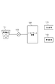
図1は、本実施形態のシステム構成の一例を示す図である。 FIG. 1 is a diagram showing an example of the system configuration of this embodiment.
本実施形態のシステムは、撮像装置110、クライアント装置120を含む。撮像装置110、クライアント装置120は、ネットワーク150を介して、相互に通信可能に接続されている。クライアント装置120は、入力装置130と表示装置140とに接続されている。
The system of this embodiment includes an
撮像装置110は、撮像を行うネットワークカメラ等の撮像装置である。クライアント装置120は、撮像装置110の駆動、撮像画像の取得、取得した画像に対しての動体の検出、マスクの重畳等を行うパーソナルコンピュータ、サーバ装置、タブレット装置等の情報処理装置である。入力装置130は、マウスやキーボード等から構成される入力装置である。表示装置140は、クライアント装置120が出力した画像を表示するモニタ等の表示装置である。本実施形態では、クライアント装置120と入力装置130と表示装置140とは、各々独立した装置とする。しかし、例えば、クライアント装置120と表示装置140とが、一体化されていてもよいし、入力装置130と表示装置140とが一体化されていてもよい。また、クライアント装置120と入力装置130と表示装置140とが、一体化されていてもよい。
The
ネットワーク150は、撮像装置110とクライアント装置120とを接続するネットワークである。ネットワーク150は、例えばEthernet(登録商標)等の通信規格を満足する複数のルータ、スイッチ、ケーブル等から構成される。本実施形態では、ネットワーク150は、撮像装置110とクライアント装置120との間の通信を行うことができるものであればよく、その通信規格、規模、構成を問わない。例えば、ネットワーク150は、インターネットや有線LAN(Local Area Network)、無線LAN(Wireless LAN)、WAN(Wide Area Network)等により構成されてもよい。
A
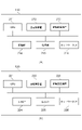
図2(a)は、撮像装置110のハードウェア構成の一例を示す図である。
FIG. 2A is a diagram showing an example of the hardware configuration of the
撮像装置110は、CPU211、主記憶装置212、補助記憶装置213、駆動部214、撮像部215、ネットワークI/F216を含む。各要素は、システムバス217を介して、相互に通信可能に接続されている。
The
CPU211は、撮像装置110の動作を制御する中央演算装置である。主記憶装置212は、CPU211のワークエリア、データの一時的な記憶場所として機能するRandom Access Memory(RAM)等の記憶装置である。補助記憶装置213は、各種プログラム、各種設定データ等を記憶するハードディスクドライブ(HDD)、Read Only Memory(ROM)、ソリッドステートドライブ(SSD)等の記憶装置である。
A
駆動部214は、撮像装置110を駆動し、撮像装置110の姿勢等を変更させ、撮像部215の撮影方向及び画角を変更する駆動部である。撮像部215は、撮像素子と光学系とを有し、光学系の光軸と撮像素子との交点を撮像中心として被写体の像を撮像素子上に結像する撮像部である。撮像素子には、CMOS(ComplementaryMetal-Oxide Semiconductor)、CCD(Charged Coupled Device)等がある。ネットワークI/F216は、クライアント装置120等の外部の装置とのネットワーク150を介した通信に利用されるインターフェースである。
The
CPU211が、補助記憶装置213に記憶されたプログラムに基づき処理を実行することによって、図3で後述する撮像装置110の機能及び撮像装置110の処理が実現される。
The
図2(b)は、クライアント装置120のハードウェア構成の一例を示す図である。
FIG. 2B is a diagram showing an example of the hardware configuration of the
クライアント装置120は、CPU221、主記憶装置222、補助記憶装置223、入力I/F224、出力I/F225、ネットワークI/F226を含む。各要素は、システムバス227を介して、相互に通信可能に接続されている。
The
CPU221は、クライアント装置120の動作を制御する中央演算装置である。主記憶装置222は、CPU221のワークエリア、データの一時的な記憶場所として機能するRAM等の記憶装置である。補助記憶装置223は、各種プログラム、各種設定データ等を記憶するHDD、ROM、SSD等の記憶装置である。
A
入力I/F224は、入力装置130等からの入力を受付ける際に利用されるインターフェースである。出力I/F225は、表示装置140等への情報の出力に利用されるインターフェースである。ネットワークI/F216は、撮像装置110等の外部の装置とのネットワーク150を介した通信に利用されるインターフェースである。
The input I/
CPU221が、補助記憶装置223に記憶されたプログラムに基づき処理を実行することによって、図3で後述するクライアント装置120の機能及び図4で後述するフローチャートの処理等のクライアント装置120の処理が実現される。
The
図3(a)は、撮像装置110の機能構成の一例を示す図である。
FIG. 3A is a diagram showing an example of the functional configuration of the
撮像装置110は、撮像制御部311、信号処理部312、駆動制御部313、通信部314を含む。
The
撮像制御部311は、撮像部215を介して、周囲の環境を撮影する。信号処理部312は、撮像制御部311によって撮影された画像の処理を行う。信号処理部312は、例えば、撮像制御部311によって撮影された画像の符号化を行う。静止画の場合は、信号処理部312は、例えば、JPEG(Joint Photographic Experts Group)等の符号化方式を用いて、画像の符号化を行う。また、動画の場合は、信号処理部312は、H.264/MPEG-4 AVC(以下では、H.264)、HEVC(High Efficiency Video Coding符号化方式)等の符号化方式を用いて、画像の符号化を行う。また、信号処理部312は、予め設定された複数の符号化方式の中から、例えば撮像装置110の操作部を介してユーザーにより選択された符号化方式を用いて、画像の符号化を行うようにしてもよい。
The
駆動制御部313は、駆動部214を介して、撮像制御部311の撮影方向及び画角を変更させる制御を行う。しかし、駆動制御部313は、撮像制御部311による撮影方向と画角とのうちの何れか1つを変更することとしてもよい。また、撮像制御部311の撮影方向及び画角は、固定であってもよい。通信部314は、信号処理部312により処理された撮像制御部311により撮影された画像を、ネットワークI/F216を介して、クライアント装置120に送信する。また、通信部314は、ネットワークI/F216を介して、クライアント装置120から撮像装置110に対する制御命令を受信する。
The driving
図3(b)は、クライアント装置120の機能構成の一例を示す図である。
FIG. 3B is a diagram showing an example of the functional configuration of the
クライアント装置120は、入力情報取得部321、通信制御部322、画像取得部323、設定部324、検出部325、描画部326、表示制御部327を含む。
The
入力情報取得部321は、入力装置130を介したユーザーによる入力を受け付ける。通信制御部322は、撮像装置110から送信された画像を、ネットワーク150を介して受信する。また、通信制御部322は、撮像装置110への制御命令を、ネットワーク150を介して送信する。画像取得部323は、通信制御部322を介して、撮像装置110から、撮像装置110により撮影された画像を、被写体の検出処理の対象である画像として取得する。また、画像取得部323は、補助記憶装置223に記憶されている画像を、被写体の検出処理の対象である画像として取得しても良い。設定部324は、画像取得部323により取得された画像に対して、被写体を検出する領域(第2検出領域)、通過カウントライン(検知線)、および全体探索領域(第1検出領域)を設定する。検出部325は、画像取得部323により取得された画像に対して、全体探索、および局所探索を行い被写体の追尾を行う。さらに、被写体の追尾結果と、前述のラインの位置から被写体の通過カウント処理を行う。描画部326は設定部324で設定された検出領域(第1設定手段により設定された第1検出領域)、全体探索領域(第2設定手段により設定された第2検出領域)、およびラインを撮像画像上に重畳する。また、検出部325で検出された被写体を撮像画像上に重畳する。表示制御部327は、CPU221からの指示に従い、被写体の検出結果が重畳された撮像画像を表示装置140へ出力する。
The input
図10は本実施形態のクライアント装置120による通過カウント処理の概略を示すフローチャートである。S1001において、通信制御部322と画像取得部323は、撮像装置110から撮像画像を取得する。S1002において、入力情報取得部321や設定部324は、ユーザーからの指示(第1検出領域の指示)に基づいて検出領域を設定する。S1003において、検出部325は、新たに画像取得部323が取得した撮像画像について、S1002の設定に基づいて全探索処理と局所探索処理と追尾処理および検知線の通過検出処理を実施する。
FIG. 10 is a flow chart showing an outline of passage count processing by the
ここでは、検出部325は、ユーザーから指定された領域について被写体の特徴量を用いた検出処理を行う。ここでは、人物形状を模したパッチ画像を、第2検出領域について走査(スキャン)しながらマッチングする。第2検出領域の全体探索が終了した際に、撮像装置から次のフレームの画像(次フレーム画像)を取得し、第2検出領域から検出した新規の被写体の近傍について局所探索を実施することで追跡する。検出部325は、追跡により検知線を越えたことにより通過を検出する。
Here, the
次にS1004において、描画部326および表示制御部327は、通過検出したカウント数を表示装置140の画面に表示させる。S1005において、CPU221が通過カウント処理を終了するかどうかを判断し、「NO」であればS1003に遷移し、「YES」であれば終了する。ここでは、ユーザーが通過カウント処理を終了する指示を出しているかどうかや、映像解析のモードを抜けたことを判断するようにすればよい。
Next, in S<b>1004 , the
図4は、本実施形態における、全体探索領域の設定処理を示すフローチャートである。図4を用いて、クライアント装置120が画像を取得し、取得した画像中に全体探索領域を設定するまでの処理を説明する。
FIG. 4 is a flowchart showing processing for setting the entire search area in this embodiment. 4, the processing from the acquisition of an image by the
S400において、設定部324は、通信制御部322を介して、撮像装置110から、撮像装置110により撮影された画像を取得する。以降、S400で取得された撮像装置110により撮影された画像を、撮像画像とする。
In S<b>400 , the
図5は、本実施形態において、撮像装置110により撮影された撮像画像の一例を示す図である。画像500は、撮像装置110により撮影された、撮像画像を示す。被写体501~503は、画像500中の環境において、通過カウント対象である被写体を表す。
FIG. 5 is a diagram showing an example of a captured image captured by the
S401において、設定部324は撮像画像に対して、被写体検出領域と、通過カウントラインを設定する。本実施形態では、システムは撮像画像を、表示装置140を介しユーザーへ表示し、ユーザーの撮像画像上へ入力に基づき、被写体検出領域、および通過カウントラインを設定する。
In S401, the
図6は、本実施形態における、設定部324により設定された被写体検出領域、および通過カウントラインの例である。図6中の領域600は画像500に対して設定部324が設定した被写体検出領域を示す。また、実線601は画像500に対して設定部324が設定した通過カウントラインを示す。
FIG. 6 shows an example of subject detection areas and passing count lines set by the
S402において、設定部324は被写体検出領域を、任意の大きさの小領域へ分割する。本実施形態では、前述の小領域を画像内のピクセル一つとする。しかしながらこの限りではない。例えば、任意のサイズの矩形でも良いし、SUPER PIXELなどの画像領域分割アルゴリズムを用いて小領域を作成しても良い。その後、S403において、設定部324は分割した小領域をリストで管理する。
In S402, the
S404において、設定部324はリストの先頭の小領域に注目する。
In S404, the
S405において、設定部324、注目している小領域を、全体探索領域にするか否かを判断する。本実施形態では、検出領域の端からの距離に基づいて、小領域が全体探索領域か否かの判断を行う。具体的な処理の流れは以下の通りである。
(1)小領域の重心から検出領域の各辺へ垂線を引き、垂線の長さを計算する。
(2)最も長さが短い垂線を選択する
(3)選択した垂線の長さが閾値以下であれば、注目している小領域は全体探索領域と判断し、S406へ進む。一方、閾値よりも大きければ、全体探索領域では無いと判断し、S407へ進む。
In S405, the
(1) A perpendicular line is drawn from the centroid of the small area to each side of the detection area, and the length of the perpendicular line is calculated.
(2) Select the shortest perpendicular line. (3) If the length of the selected perpendicular line is equal to or less than the threshold, the focused small area is determined to be the entire search area, and the process proceeds to S406. On the other hand, if it is larger than the threshold, it is determined that it is not the whole search area, and the process proceeds to S407.
本実施形態では、前述の閾値はクライアント装置120がユーザーからの入力を受け付けるものとして説明するが、この限りではない。例えば、被写体が映る数フレーム分の動画像を撮像装置110からクライアント装置120受信し、各動画像の検出領域に対して全体探索を行い、検出された被写体に対して通過カウント処理を実施する。その後、前述の閾値を変えながら、全体探索および局所探索を並列に実施し、通過カウント処理を実施する。この時、全体探索のみを用いて通過カウントを行った場合と通過カウント結果が等しくなる閾値のうち、最小の値を選択しても良い。
In this embodiment, the
S406において、設定部324は注目している小領域が全体探索領域である事をリストに記す。
In S406, the
S407において、設定部324は注目している小領域が全体探索領域でない事をリストに記す。
In S407, the
S408において、設定部324はリストの最後に注目しているか否かを判断する。リストの最後に注目しているのであれば、S410へ進む。リストの最後に注目していないのであれば、S409へ進む。
In S408, the
S409において、設定部324は次の小領域へ注目し、S405へ進む。
In S409, the
S410において、設定部324は小領域のリストに格納されている、各小領域が全体探索領域か否かの情報に基づき、撮像画像に全体探索領域を設定する。
In S410, the
図7は、本実施形態における、S410により設定された全体探索領域の例である。
図7中の点線と一点鎖線に囲まれた領域700は、画像500に対してS410により設定された全体探索領域である。
FIG. 7 is an example of the entire search area set in S410 in this embodiment.
A
本実施形態では、領域700(第2検出領域)に対して全体探索を実施し、領域600(第1検出領域)に対して局所探索を実行する事で追尾処理を行い、通過カウント処理を実現する。これにより、領域600に対して、一律的に全体探索と局所探索を並行して実施した場合よりも、計算コストを削減する事ができる。
In this embodiment, the tracking process is performed by executing the global search for the area 700 (second detection area) and executing the local search for the area 600 (first detection area) to realize the passage counting process. do. As a result, the calculation cost can be reduced more than when the global search and the local search are uniformly performed on the
<実施形態2>
実施形態1では、検出領域の端近傍から一定距離の領域を全体探索領域として設定することで、通過カウント処理の計算コストを削減していた。しかしながら、通過をカウントする方向に偏りが存在する場合、通過カウントの精度の低下を抑制しつつ、実施形態1で設定した全体探索領域よりも、さらに全体探索領域を削減できる。例えば、撮像画像500では、被写体が上下方向へ移動しており、通過カウントは、上下方向のみカウントしている。この場合、新規被写体は検出領域の上端、下端から現れ、左右端からは現れない。そのため、新規被写体を検出するための全体探索領域は、被写体検出領域の上下端の領域のみでよく、左右端の領域を全体探索の対象から除外する事ができる。
<Embodiment 2>
In the first embodiment, the calculation cost of the passage counting process is reduced by setting the area at a constant distance from the vicinity of the edge of the detection area as the entire search area. However, if there is a bias in the direction in which passages are counted, the overall search area can be further reduced than the overall search area set in the first embodiment while suppressing a decrease in the accuracy of the passage count. For example, in the captured
本実施形態では、ユーザーが設定した通過カウントラインから、被写体の通過の方向を判断し、被写体の通過の方向に基づき、全体探索を行う領域を設定する方法について説明する。 In this embodiment, a method will be described in which the direction of passage of the subject is determined from the passage count line set by the user, and the area for the overall search is set based on the direction of passage of the subject.
本実施形態のシステム構成や、撮像装置110、及びクライアント装置120のハードウェア構成及び機能構成は、実施形態1と同様であるため、説明を省略する。
The system configuration of the present embodiment and the hardware configuration and functional configuration of the
また、図4に示すフローのうち、S400からS404、およびS406~S410は実施形態1と同様であるため、説明を省略する。本実施形態では、図4のS405において注目している小領域が全体探索領域か否かの判定方法が実施形態1と異なる。本実施形態では、通過カウントラインの位置と、検出領域の端からの距離に基づいて、注目している小領域が全体探索領域か否かの判断を行う。具体的な処理の流れは以下の通りである。
(1)注目している小領域の重心から検出領域の各辺へ垂線を引き、垂線の長さを計算する。
(2)最も長さが短い垂線を選択する。
(3)注目している小領域の重心から通過カウントラインへ垂線を引き、垂線の長さを計算する。
(3)検出領域の辺への垂線の長さが閾値以下かつ、通過カウントラインへの垂線の長さが閾値以上であれば、注目している小領域は全体探索領域と判断し、S406へ進む。一方、閾値よりも大きければ、全体探索領域では無いと判断し、S407へ進む。
Also, in the flow shown in FIG. 4, S400 to S404 and S406 to S410 are the same as those in the first embodiment, so description thereof will be omitted. This embodiment differs from the first embodiment in the method of determining whether or not the focused small area is the entire search area in S405 of FIG. In this embodiment, it is determined whether or not the focused small area is the entire search area based on the position of the passing count line and the distance from the edge of the detection area. A specific processing flow is as follows.
(1) A perpendicular line is drawn from the center of gravity of the small area of interest to each side of the detection area, and the length of the perpendicular line is calculated.
(2) Select the perpendicular with the shortest length.
(3) Draw a perpendicular line from the center of gravity of the small area of interest to the passing count line, and calculate the length of the perpendicular line.
(3) If the length of the perpendicular to the side of the detection area is equal to or less than the threshold and the length of the perpendicular to the passing count line is equal to or greater than the threshold, the focused small area is determined to be the entire search area, and the process proceeds to S406. move on. On the other hand, if it is larger than the threshold, it is determined that it is not the whole search area, and the process proceeds to S407.
本実施形態では、前述の二つの閾値はユーザーからの指定を受ける事とするが、この限りではない。例えば、撮像装置から通行する被写体が映る数フレームの動画像を受信し、各動画像の検出領域に対して全体探索を行い、検出された被写体に対して通過カウント処理を実施する。その後、前述の二つの閾値を変えながら、全体探索および局所探索を並列に実施し、通過カウント処理を実施する。この時、全体探索のみを用いて通過カウントを行った場合と通過カウント結果が等しくなる閾値のうち、注目する小領域と被写体検出領域の辺までの垂線に関する閾値は最小の値を、通過カウントラインまでの垂線に関する閾値は最大の値を選択しても良い。 In this embodiment, the above two thresholds are specified by the user, but this is not the only option. For example, several frames of moving images showing passing objects are received from the image pickup device, the entire detection area of each moving image is searched, and passage count processing is performed on the detected objects. After that, while changing the two thresholds described above, the global search and the local search are performed in parallel, and passage count processing is performed. At this time, among the thresholds at which the passage count results are the same as when the passage count is performed using only the entire search, the minimum threshold value for the perpendicular line between the small area of interest and the side of the subject detection area is set as the passage count line. A maximum value may be selected for the threshold for the perpendicular to .
図8は、本実施形態における、S410により設定された全体探索領域の例である。 FIG. 8 is an example of the entire search area set in S410 in this embodiment.
図8中の点線と一点鎖線に囲まれた領域801、および802は、画像500に対してS410により設定された全体探索領域である。
本実施形態では、領域801、802に対して全体探索を実施し、領域600に対して局所探索を実行する事で追尾処理を行い、通過カウント処理を実現する。これにより、領域600に対して、実施形態1を実施した場合よりも、計算コストを削減しつつ、通過カウント処理を実現する事ができる。
In this embodiment, a global search is performed on the
また、本実施形態は上下方向に被写体が通過する環境における、計算コストの削減方法について説明を行ったが、この限りではない。左右方向、もしくは斜め方向でも適用可能である。 Also, in the present embodiment, the calculation cost reduction method in the environment where the subject passes in the vertical direction has been described, but the present invention is not limited to this. It can also be applied in the left-right direction or in the oblique direction.
<実施形態3>
実施形態1では、検出領域の端近傍から一定距離の領域を全体探索領域として設定していた。また、実施形態2では、通過カウントラインから一定以上の距離かつ、検出領域の端近傍から一定以下の距離の領域を全体探索領域として設定していた。しかしながらこの限りでは無く、ユーザーのマニュアル操作に基づいて全体探索領域の設定を行っても良い。本実施形態では、ユーザーのマニュアル操作に基づく被写体検出領域、通過カウントライン、全体探索領域の設定方法について説明する。
<Embodiment 3>
In the first embodiment, an area within a certain distance from the vicinity of the edge of the detection area is set as the entire search area. Further, in the second embodiment, an area having a certain distance or more from the passing count line and a certain distance or less from the vicinity of the edge of the detection area is set as the entire search area. However, this is not the only option, and the entire search area may be set based on the user's manual operation. In this embodiment, a method for setting a subject detection area, a passage count line, and an entire search area based on a user's manual operation will be described.
まずシステムは、表示装置140を介して、撮像装置110により撮影されたライブ映像をユーザーへ表示する。
First, the system displays a live image captured by the
図9は、被写体検出領域、通過カウントライン、全体探索領域を設定するための操作UIの表す。図9中の撮像画像表示領域900は撮像装置110により撮影されたライブ映像を表示する。本実施形態では、撮像画像表示領域には映像を表示するがこの限りではない。静止画でも良い。また、本実施形態では、図9に示す通り、被写体が上下左右の方向へ通過する環境における、全体探索領域の設定方法について説明する事とする。図9中の点線901は、被写体を検出する領域を表す。被写体検出領域の各頂点に重畳している矩形は被写体検出領域の操作子であり、ユーザーがドラッグすることで、被写体検出領域の形状を変形することが可能である。また、本実施形態では、ユーザーは被写体検出領域の辺をドラッグする事で、被写体検出領域の頂点を追加する事が可能とする。また、本実施形態では、ユーザーは被写体検出領域の頂点に対して、右クリックを行う事で、頂点の削除を行うことが可能であるとする。しかしながらこの限りではなく、ダブルクリックなどでも良い。また、例えばタブレット端末で操作を行う際、ダブルタップでも良いし、タップホールドであっても良い。
FIG. 9 shows an operation UI for setting the subject detection area, passing count line, and overall search area. A captured
図9中の実線902~905は、通過カウントラインを表す。各通過カウントラインの端に重畳している丸は、通過カウントラインの始点を表し、二重丸は終点を表す。本実施形態では、始点、終点を表示することにより、通過カウントラインのIN/OUTの違いをユーザーへ提示する。しかしながらこの限りではない。例えば、通過カウントライン上に、通過カウントラインに直交するように矢印を表示し、矢印の矢柄から矢先へ通過する際にIN、逆方向へ通過する際にOUTとカウントする事をユーザーへ定時しても良い。また、前述の丸、二重丸はそれぞれ通過カウントラインの操作子でもあり、ユーザーは丸、および二重丸をドラッグすることにより、通過カウントラインの形状を変形することを可能とする。
図9中の一点鎖線906は、全体探索領域と、局所探索領域の境界を表す。一点鎖線の多角形の内部が局所探索領域である。また、一点鎖線の多角形の外部であり、被写体検出領域の内部に相当する領域が全体探索領域である。多角形の各頂点に重畳されている矩形は操作子であり、ユーザーがドラッグすることで、境界の形状を変形することが可能である。また、被写体検出領域と同様、本実施形態では、頂点の追加や削除が可能である。
A dashed-dotted
<その他の実施形態>
本発明は、上述の実施形態の1以上の機能を実現するプログラムを、ネットワーク又は記憶媒体を介してシステム又は装置に供給し、そのシステム又は装置のコンピュータにおける1つ以上のプロセッサがプログラムを読み出し実行する処理でも実現可能である。また、1以上の機能を実現する回路(例えば、ASIC)によっても実現可能である。
<Other embodiments>
The present invention supplies a program that implements one or more functions of the above-described embodiments to a system or apparatus via a network or a storage medium, and one or more processors in the computer of the system or apparatus reads and executes the program. It can also be realized by processing to It can also be implemented by a circuit (for example, ASIC) that implements one or more functions.
例えば、上述した検出システムの機能構成の一部又は全てをハードウェアとして撮像装置110又はクライアント装置120に実装してもよい。
For example, part or all of the functional configuration of the detection system described above may be implemented in the
以上、本発明の好ましい実施形態について詳述したが、本発明は係る特定の実施形態に限定されるものではない。上述した各実施形態を任意に組み合わせてもよい。 Although preferred embodiments of the invention have been described in detail above, the invention is not limited to such specific embodiments. You may combine each embodiment mentioned above arbitrarily.
110 撮像装置
120 クライアント装置
221 CPU
110
Claims (7)
前記撮像画像に対して、ユーザの指定に基づき第1検出領域を設定する第1設定手段と、
前記第1設定手段により設定された第1検出領域の端を含み、新規の被写体の検出を行うための第2検出領域を設定する第2設定手段と
前記第2設定手段により設定された第2検出領域から前記撮像画像における新規の被写体を検出する検出手段と、
前記第1検出領域において、前記第2検出領域から検出された被写体を追尾する追尾手段と、
前記撮像画像に対して、前記第2検出領域から検出された被写体による通過を検知するための検知線を設定する第3設定手段と、
前記追尾手段によって得られた追尾結果と、前記検知線とに基づいて、通過カウントを実施する、通過カウント手段と、を備え、
前記第2設定手段は、前記撮像画像における前記第1検出領域を複数に分割した小領域のうち、小画像の所定の位置と前記第1検出領域の辺との距離が前記第1閾値以下かつ小画像の所定の位置と前記検知線との距離が第2閾値以上である小領域の集合を前記第2検出領域として設定することを特徴とする情報処理装置。 Acquisition means for acquiring a captured image;
a first setting means for setting a first detection area based on a user's designation for the captured image;
a second setting means for setting a second detection area for detecting a new subject including an end of the first detection area set by the first setting means; and a second setting means for setting the second detection area by the second setting means. detection means for detecting a new subject in the captured image from the detection area;
tracking means for tracking an object detected from the second detection area in the first detection area;
third setting means for setting a detection line for detecting the passage of the subject detected from the second detection area in the captured image;
passage counting means for counting passages based on the tracking result obtained by the tracking means and the detection line ;
The second setting means determines that a distance between a predetermined position of a small image and a side of the first detection area among a plurality of small areas obtained by dividing the first detection area in the captured image is equal to or less than the first threshold and An information processing apparatus , wherein a set of small areas in which a distance between a predetermined position of the small image and the detection line is equal to or greater than a second threshold is set as the second detection area .
撮像画像を取得する取得工程と、
前記撮像画像に対して、ユーザの指定に基づき第1検出領域を設定する第1設定工程と、
前記第1設定工程により設定された第1検出領域の端を含み、新規の被写体の検出を行うための第2検出領域を設定する第2設定工程と、
前記撮像画像における新規の被写体を検出する検出工程と、
前記第1検出領域において、前記第2検出領域から検出された被写体を追尾する追尾工程と、
前記撮像画像に対して、前記第2検出領域から検出された被写体による通過を検知するための検知線を設定する第3設定工程と、
前記追尾工程で得られた追尾結果と、前記検知線とに基づいて、通過カウントを実施する、通過カウント工程と、有し、
前記第2設定工程では、前記撮像画像における前記第1検出領域を複数に分割した小領域のうち、小画像の所定の位置と前記第1検出領域の辺との距離が前記第1閾値以下かつ小画像の所定の位置と前記検知線との距離が第2閾値以上である小領域の集合を前記第2検出領域として設定することを特徴とする制御方法。 A control method for an information processing device,
an acquisition step of acquiring a captured image;
a first setting step of setting a first detection area based on a user's designation for the captured image;
a second setting step of setting a second detection region for detecting a new subject, including the edge of the first detection region set in the first setting step;
a detection step of detecting a new subject in the captured image ;
a tracking step of tracking an object detected from the second detection area in the first detection area;
a third setting step of setting a detection line for detecting passage of the subject detected from the second detection area in the captured image ;
a passage counting step of counting passages based on the tracking result obtained in the tracking step and the detection line ;
In the second setting step, a distance between a predetermined position of a small image and a side of the first detection area among the plurality of small areas obtained by dividing the first detection area in the captured image is equal to or less than the first threshold and A control method, characterized in that a set of small areas in which a distance between a predetermined position of the small image and the detection line is equal to or greater than a second threshold is set as the second detection area .
Priority Applications (4)
| Application Number | Priority Date | Filing Date | Title |
|---|---|---|---|
| JP2018122422A JP7195782B2 (en) | 2018-06-27 | 2018-06-27 | Information processing device, control method and program |
| US16/449,000 US11308342B2 (en) | 2018-06-27 | 2019-06-21 | Information processing apparatus, control method, and storage medium |
| EP19181764.2A EP3588375A1 (en) | 2018-06-27 | 2019-06-21 | Information processing apparatus, control method, and program |
| CN201910554038.6A CN110647792B (en) | 2018-06-27 | 2019-06-25 | Information processing apparatus, control method, and storage medium |
Applications Claiming Priority (1)
| Application Number | Priority Date | Filing Date | Title |
|---|---|---|---|
| JP2018122422A JP7195782B2 (en) | 2018-06-27 | 2018-06-27 | Information processing device, control method and program |
Publications (3)
| Publication Number | Publication Date |
|---|---|
| JP2020005111A JP2020005111A (en) | 2020-01-09 |
| JP2020005111A5 JP2020005111A5 (en) | 2021-07-29 |
| JP7195782B2 true JP7195782B2 (en) | 2022-12-26 |
Family
ID=67262060
Family Applications (1)
| Application Number | Title | Priority Date | Filing Date |
|---|---|---|---|
| JP2018122422A Active JP7195782B2 (en) | 2018-06-27 | 2018-06-27 | Information processing device, control method and program |
Country Status (4)
| Country | Link |
|---|---|
| US (1) | US11308342B2 (en) |
| EP (1) | EP3588375A1 (en) |
| JP (1) | JP7195782B2 (en) |
| CN (1) | CN110647792B (en) |
Families Citing this family (1)
| Publication number | Priority date | Publication date | Assignee | Title |
|---|---|---|---|---|
| JP7428052B2 (en) * | 2020-03-31 | 2024-02-06 | コベルコ建機株式会社 | Surrounding detection device for working machines |
Citations (4)
| Publication number | Priority date | Publication date | Assignee | Title |
|---|---|---|---|---|
| JP2009211311A (en) | 2008-03-03 | 2009-09-17 | Canon Inc | Image processing apparatus and method |
| US20090309966A1 (en) | 2008-06-16 | 2009-12-17 | Chao-Ho Chen | Method of detecting moving objects |
| JP2010140425A (en) | 2008-12-15 | 2010-06-24 | Hitachi Kokusai Electric Inc | Image processing system |
| JP2014116912A (en) | 2012-12-12 | 2014-06-26 | Canon Inc | Image processing apparatus, control method for image processing apparatus, and program |
Family Cites Families (10)
| Publication number | Priority date | Publication date | Assignee | Title |
|---|---|---|---|---|
| JP3757959B2 (en) * | 2003-07-04 | 2006-03-22 | コニカミノルタホールディングス株式会社 | Counting system and counting method |
| JP5578816B2 (en) * | 2009-09-02 | 2014-08-27 | キヤノン株式会社 | Image processing device |
| JP5674857B2 (en) * | 2013-05-10 | 2015-02-25 | 技研トラステム株式会社 | Passenger counting device |
| JP5853141B2 (en) * | 2014-03-26 | 2016-02-09 | パナソニックIpマネジメント株式会社 | People counting device, people counting system, and people counting method |
| KR101558258B1 (en) * | 2015-02-04 | 2015-10-12 | (주)유디피 | People counter using TOF camera and counting method thereof |
| FR3046488B1 (en) * | 2015-12-30 | 2018-02-23 | Fenotek | SYSTEM FOR MEASURING THE FREQUENTATION OF A RECEPTION AREA AND METHOD OF ESTIMATING THE CROSSING OF AN ASSOCIATED THRESHOLD |
| JP6525921B2 (en) * | 2016-05-13 | 2019-06-05 | キヤノン株式会社 | Image processing apparatus, image processing method, search apparatus |
| JP6800628B2 (en) * | 2016-06-22 | 2020-12-16 | キヤノン株式会社 | Tracking device, tracking method, and program |
| JP6765917B2 (en) * | 2016-09-21 | 2020-10-07 | キヤノン株式会社 | Search device, its imaging device, and search method |
| JP6525934B2 (en) * | 2016-10-14 | 2019-06-05 | キヤノン株式会社 | Image processing apparatus and control method |
-
2018
- 2018-06-27 JP JP2018122422A patent/JP7195782B2/en active Active
-
2019
- 2019-06-21 EP EP19181764.2A patent/EP3588375A1/en not_active Withdrawn
- 2019-06-21 US US16/449,000 patent/US11308342B2/en active Active
- 2019-06-25 CN CN201910554038.6A patent/CN110647792B/en active Active
Patent Citations (4)
| Publication number | Priority date | Publication date | Assignee | Title |
|---|---|---|---|---|
| JP2009211311A (en) | 2008-03-03 | 2009-09-17 | Canon Inc | Image processing apparatus and method |
| US20090309966A1 (en) | 2008-06-16 | 2009-12-17 | Chao-Ho Chen | Method of detecting moving objects |
| JP2010140425A (en) | 2008-12-15 | 2010-06-24 | Hitachi Kokusai Electric Inc | Image processing system |
| JP2014116912A (en) | 2012-12-12 | 2014-06-26 | Canon Inc | Image processing apparatus, control method for image processing apparatus, and program |
Also Published As
| Publication number | Publication date |
|---|---|
| CN110647792B (en) | 2023-09-19 |
| JP2020005111A (en) | 2020-01-09 |
| US11308342B2 (en) | 2022-04-19 |
| EP3588375A1 (en) | 2020-01-01 |
| US20200005066A1 (en) | 2020-01-02 |
| CN110647792A (en) | 2020-01-03 |
Similar Documents
| Publication | Publication Date | Title |
|---|---|---|
| JP2019114821A (en) | Monitoring system, device, method, and program | |
| US10713797B2 (en) | Image processing including superimposed first and second mask images | |
| US20190182470A1 (en) | Information processing apparatus, information processing method and storing unit | |
| KR102199094B1 (en) | Method and Apparatus for Learning Region of Interest for Detecting Object of Interest | |
| JP6494418B2 (en) | Image analysis apparatus, image analysis method, and program | |
| US11019251B2 (en) | Information processing apparatus, image capturing apparatus, information processing method, and recording medium storing program | |
| JP7371076B2 (en) | Information processing device, information processing system, information processing method and program | |
| JP7195782B2 (en) | Information processing device, control method and program | |
| WO2021168804A1 (en) | Image processing method, image processing apparatus and image processing system | |
| JP6525934B2 (en) | Image processing apparatus and control method | |
| JP2018092507A (en) | Image processing apparatus, image processing method, and program | |
| US10943103B2 (en) | Human body detection apparatus, human body detection method, information processing apparatus, information processing method, and storage medium | |
| JP7208713B2 (en) | Image analysis device and image analysis method | |
| JP7034690B2 (en) | Information processing equipment, information processing methods and programs | |
| JP6348020B2 (en) | Image processing apparatus, image processing method, and inspection method using the same | |
| JP2015097089A (en) | Object detection device and object detection method | |
| JP6034671B2 (en) | Information display device, control method thereof, and program | |
| JP2019192154A (en) | Image processing apparatus, imaging device, image processing method, and program | |
| JP7140583B2 (en) | Image processing device, image processing method and program | |
| JP6833558B2 (en) | Image processing equipment, image processing methods and programs | |
| JP2019128791A (en) | Image processing device and control method thereof | |
| KR20210116247A (en) | Image processing apparatus, image processing method, and non-transitory computer-readable storage medium | |
| JP6089549B2 (en) | Information processing apparatus, information processing system, and program | |
| JP2023133967A (en) | Image processing apparatus, image processing method, and program | |
| JP2021083117A (en) | Photography support device, photography support method, and photography support program |
Legal Events
| Date | Code | Title | Description |
|---|---|---|---|
| A521 | Request for written amendment filed |
Free format text: JAPANESE INTERMEDIATE CODE: A523 Effective date: 20210611 |
|
| A621 | Written request for application examination |
Free format text: JAPANESE INTERMEDIATE CODE: A621 Effective date: 20210611 |
|
| A977 | Report on retrieval |
Free format text: JAPANESE INTERMEDIATE CODE: A971007 Effective date: 20220613 |
|
| A131 | Notification of reasons for refusal |
Free format text: JAPANESE INTERMEDIATE CODE: A131 Effective date: 20220614 |
|
| A521 | Request for written amendment filed |
Free format text: JAPANESE INTERMEDIATE CODE: A523 Effective date: 20220728 |
|
| TRDD | Decision of grant or rejection written | ||
| A01 | Written decision to grant a patent or to grant a registration (utility model) |
Free format text: JAPANESE INTERMEDIATE CODE: A01 Effective date: 20221115 |
|
| A61 | First payment of annual fees (during grant procedure) |
Free format text: JAPANESE INTERMEDIATE CODE: A61 Effective date: 20221214 |
|
| R151 | Written notification of patent or utility model registration |
Ref document number: 7195782 Country of ref document: JP Free format text: JAPANESE INTERMEDIATE CODE: R151 |