JP7193197B2 - Cylindrical body sliding structure and extendable ladder partly applying it - Google Patents
Cylindrical body sliding structure and extendable ladder partly applying it Download PDFInfo
- Publication number
- JP7193197B2 JP7193197B2 JP2022528881A JP2022528881A JP7193197B2 JP 7193197 B2 JP7193197 B2 JP 7193197B2 JP 2022528881 A JP2022528881 A JP 2022528881A JP 2022528881 A JP2022528881 A JP 2022528881A JP 7193197 B2 JP7193197 B2 JP 7193197B2
- Authority
- JP
- Japan
- Prior art keywords
- diameter
- ladder
- cylindrical body
- tubular
- cylindrical
- Prior art date
- Legal status (The legal status is an assumption and is not a legal conclusion. Google has not performed a legal analysis and makes no representation as to the accuracy of the status listed.)
- Active
Links
Images


Classifications
-
- E—FIXED CONSTRUCTIONS
- E06—DOORS, WINDOWS, SHUTTERS, OR ROLLER BLINDS IN GENERAL; LADDERS
- E06C—LADDERS
- E06C1/00—Ladders in general
- E06C1/02—Ladders in general with rigid longitudinal member or members
- E06C1/04—Ladders for resting against objects, e.g. walls poles, trees
- E06C1/08—Ladders for resting against objects, e.g. walls poles, trees multi-part
- E06C1/12—Ladders for resting against objects, e.g. walls poles, trees multi-part extensible, e.g. telescopic
-
- E—FIXED CONSTRUCTIONS
- E06—DOORS, WINDOWS, SHUTTERS, OR ROLLER BLINDS IN GENERAL; LADDERS
- E06C—LADDERS
- E06C1/00—Ladders in general
- E06C1/02—Ladders in general with rigid longitudinal member or members
- E06C1/14—Ladders capable of standing by themselves
- E06C1/16—Ladders capable of standing by themselves with hinged struts which rest on the ground
- E06C1/20—Ladders capable of standing by themselves with hinged struts which rest on the ground with supporting struts formed as poles
- E06C1/22—Ladders capable of standing by themselves with hinged struts which rest on the ground with supporting struts formed as poles with extensible, e.g. telescopic, ladder parts or struts
-
- E—FIXED CONSTRUCTIONS
- E06—DOORS, WINDOWS, SHUTTERS, OR ROLLER BLINDS IN GENERAL; LADDERS
- E06C—LADDERS
- E06C7/00—Component parts, supporting parts, or accessories
- E06C7/06—Securing devices or hooks for parts of extensible ladders
Description
本発明は、所定状態となるまで摺動可能となる筒状体同士の摺動構造物、および、その筒状体同士の摺動構造物を一部に適用して長さ方向に伸縮自在の梯子に関する。 The present invention provides a sliding structure between cylindrical bodies that can slide until a predetermined state is reached, and a sliding structure that partially applies the sliding structure between cylindrical bodies to extend and contract in the longitudinal direction. Regarding ladders.
一般的に、筒状体の長さを伸縮する構造として筒状体同士を摺動可能とした構造物が知られている。
図15および図16は、筒状体同士を摺動可能としてその長さを伸縮可能とした構造物の例を示した図である(特開2012-072638号公報)。図15および図16の構造例とも、従来技術における伸縮可能な梯子の筒状支柱体として組み込まれた例となっている。
図15および図16には、径の大きな第1の筒状体10と、径の小さな第2の筒状体20が図示されている。
図15は、大きな径の第1の筒状体10が固定され、小さな径の第2の筒状体20が下方にスライドする例を説明する図となっている。Generally, as a structure for expanding and contracting the length of a cylindrical body, a structure in which cylindrical bodies are slidable is known.
FIG. 15 and FIG. 16 are diagrams showing an example of a structure in which cylindrical bodies are made slidable and their lengths can be expanded and contracted (Japanese Patent Application Laid-Open No. 2012-072638). The structural examples of FIGS. 15 and 16 are both examples incorporated as tubular struts of extendable ladders in the prior art.
15 and 16 show a first
FIG. 15 illustrates an example in which the first
第1の筒状体10は、第2の筒状体20より径が大きくなっている。
第2の筒状体20は、第1の筒状体10の内径よりわずかに小さな外径を持ち、第1の筒状体10に内挿される形となっている。
第1の筒状体10の一部には絞り部分が設けられており、内壁面の内側に膨出するように内側膨出部11が設けられている。
第2の筒状体20の一部には膨出部分が設けられており、外壁面の外側に膨出するように外側膨出部21が設けられている。
図15に示すように、第1の筒状体10に対して、第2の筒状体20が上から内挿される形で挿入して摺動してゆくと、図15の右側に示すように、内側膨出部11と外側膨出部21が当接して係止状態となるまで下方に移動可能であるが、両者が係止すると第1の筒状体10に対する第2の筒状体20の相対的な摺動が停止する。第2の筒状体20はそれ以上下方には移動できず、第1の筒状体10の下側に抜け出ることがない。The first
The second
A portion of the first
A portion of the second
As shown in FIG. 15, when the second
次に、図16は、径の小さな第2の筒状体20に対して、径の大きな第1の筒状体10が下方にスライドする例を説明する図となっている。
図16は、小さな径の第2の筒状体20が固定され、大きな径の第1の筒状体10が下方にスライドする例を説明する図となっている。
第1の筒状体10は、第2の筒状体20の外径よりわずかに小さな内径を持ち、第1の筒状体10に対して外挿される形となっている。
図16の構成例でも、図15の場合と同様、第1の筒状体10の一部には絞り部分が設けられており、内壁面の内側に膨出するように内側膨出部11が設けられており、第2の筒状体20の一部には外壁面の外側に膨出するように外側膨出部21が設けられている。
図16に示すように、第2の筒状体20に対して、第1の筒状体10が上から外挿される形で挿入して摺動してゆくと、図16の右側に示すように、内側膨出部11と外側膨出部21が当接して係止状態となるまで下方に移動可能であるが、両者が係止すると第1の筒状体10に対する第2の筒状体20の相対的な摺動が停止する。第1の筒状体10はそれ以上下方には移動できず、第2の筒状体20の下側に抜け出ることがない。Next, FIG. 16 is a diagram for explaining an example in which the first
FIG. 16 illustrates an example in which the second
The first
In the configuration example of FIG. 16, as in the case of FIG. 15, a portion of the first
As shown in FIG. 16, when the first
このように、図15のように、大きな径の第1の筒状体10が固定され、小さな径の第2の筒状体20が下方に摺動してゆく構造例でも、図16のように、小さな径の第2の筒状体20が固定され、大きな径の第1の筒状体10が下方に摺動してゆく構造例でも、内側膨出部11と外側膨出部21が当接して係止し合うまでスライド可能であるが、両者が係止すればスライド移動が停止する仕組みとなっている。
筒状体が摺動して伸縮可能な構造は多様な部材として適用されている。そのごく一例として、伸縮梯子の筒状の支柱体の構造として使用されている。伸縮梯子とは平常時には短縮収納状態となっているが、使用時に動的に伸長して使用状態となり、梯子の使用が終了すれば短縮収納状態に戻される梯子である。例えば、作業において高所から下方の作業現場へ降りてゆく移動手段として作業時に吊下箇所に吊下される作業用吊下梯子や、建物や電車などお客が外部に避難する必要が生じた緊急時に下方へ避難するための避難手段として吊下箇所に吊下される避難用吊下梯子などがある。その他にも用途に応じて様々なバリエーションがあり得る。As shown in FIG. 15, the first
A structure in which a tubular body can slide and expand and contract is applied as a variety of members. As a very small example, it is used as the structure of a tubular strut for a telescopic ladder. A telescopic ladder is a ladder that is normally in a shortened and stored state, but is dynamically extended when in use to enter the use state, and is returned to the shortened and stored state when the use of the ladder is finished. For example, a hanging ladder for work that is hung from a hanging point during work as a means of moving down from a high place to a lower work site, or an emergency ladder that needs to be evacuated outside a building or train. Sometimes, as an evacuation means for evacuating downward, there is a hanging ladder for evacuation that is hung from a hanging point. In addition, there may be various variations depending on the application.
上記したように、筒状体同士を摺動可能にした構造例は知られているが、印加される力が大きくなると、両者の係止構造が崩れて筒状体が抜け出てしまうおそれがある。
図17は、上記図15で示した構造において発生し得る問題を説明する図である。図17は、大きな径の第1の筒状体10が固定され、小さな径の第2の筒状体20が下方にスライドする例である。
内側の小さな径の第2の筒状体20が長く重い場合などには大きな重力が掛かる場合がある。外側膨出部21からの圧力により大きな重量がかかると、第1の筒状体の内側膨出部11の膨らみが潰れて径が拡がるおそれがある。同様に、第2の筒状体の外側膨出部21の膨らみが潰れて径が小さくなるおそれがある。両者いずれかまたは双方の径がある程度変化してくると、第1の筒状体10と第2の筒状体20との係止が働かなくなり、第2の筒状体20の外側膨出部21が通過してしまい、下側へ抜け出てしまうおそれがある。
固定されている第1の筒状体10に対して、第2の筒状体20が係止されずに下方に抜け出ると、第2の筒状体20全体が落下する不具合が発生する。As described above, there is known a structural example in which cylindrical bodies are slidable relative to each other. .
FIG. 17 is a diagram for explaining problems that may occur in the structure shown in FIG. 15 above. FIG. 17 shows an example in which the first
If the inner small-diameter second
If the second
同様の問題は、上記図16で示した構造においても発生し得る。
図18は、上記図16で示した構造において発生し得る問題を説明する図である。図18は、内側の小さな径の第2の筒状体20が固定され、外側の大きな径の第1の筒状体10が下方にスライドする例である。
内側の第2の筒状体20に対して係止している外側の大きな径の第1の筒状体10が長く重い場合などに大きな重力が掛かる場合がある。内側膨出部11に外側膨出部21から受ける圧力により大きな重量がかかると、第1の筒状体10の内側膨出部11の膨らみが潰れ、径が拡がるおそれがある。同様に、第2の筒状体の外側膨出部21の膨らみが潰れて径が小さくなるおそれがある。両者いずれかまたは双方の径がある程度変化してくると第2の筒状体10との係止が働かなくなり、下側へ抜け出てしまうおそれがある。A similar problem may also occur in the structure shown in FIG. 16 above.
FIG. 18 is a diagram for explaining problems that may occur in the structure shown in FIG. 16 above. FIG. 18 shows an example in which the inner small-diameter second
When the outer first
この摺動構造体が梯子に組み込まれたものであれば、筒状体同士の係止が働かなくなると、梯子部材が離脱して一部が落下する危険がある。もっとも伸縮梯子の場合、梯子部材が離脱して落下する事故が発生しないように、二重・三重に安全対策が採られており、落下する事故は発生し得ないようになっているが、筒状体同士の摺動構造が正常に機能することが好ましいことは言うまでもない。
特開2019-015073号公報では内側膨出部11が潰れにくいように外締体で外側から締め上げる工夫がなされている。この技術は内側膨出部11が潰れにくいようにする効果は得られるが、逆に外側膨出部21については手当されていなかった。If this sliding structure is incorporated in a ladder, there is a danger that the ladder member will detach and part of it will fall if the locking between the cylindrical bodies fails. However, in the case of telescoping ladders, double and triple safety measures are taken to prevent accidental falls due to detachment of ladder members. Needless to say, it is preferable that the sliding structure between the shaped bodies functions normally.
In Japanese Patent Application Laid-Open No. 2019-015073, a contrivance is made to tighten the inner bulging
本発明は上記のような実情に鑑みてなされたもので、筒状体同士が摺動して伸縮可能な筒状体摺動構造物において、所定位置にまで伸長した筒状体同士の摺動を制限する構造が大きな構造的強度を持ち、抜け出る不具合が発生しないよう構造的強度を確保せしめることを目的とする。その構造的強度が確保された筒状体同士の摺動構造を組み入れ、伸長使用状態において構造的強度が確保されたものであるとともに、抜け出る不具合が発生しないよう構造的強度を確保せしめた伸縮梯子を提供することを目的とする。 SUMMARY OF THE INVENTION The present invention has been made in view of the actual situation as described above, and provides a cylindrical body sliding structure in which cylindrical bodies can slide and expand and contract. To secure the structural strength so that a structure that restricts a has a large structural strength and does not cause a problem of slipping out. A telescoping ladder that incorporates a sliding structure between cylindrical bodies whose structural strength is ensured to ensure structural strength in extended use, as well as ensuring structural strength to prevent the problem of slipping out. intended to provide
上記目的を達成するため、本発明の筒状体摺動構造物は、第1の筒状体と、前記第1の筒状体の内径よりわずかに小さな外径を持ち、前記第1の筒状体に内挿され得る第2の筒状体と、前記第1の筒状体の内面の一部に設けられ、内壁面の内径を小さくする縮径体と、前記第2の筒状体の一部に設けられ、外壁面の外径を大きくする拡径体を備えた構造において、前記縮径体の径が前記拡径体の径よりも小さいことを特徴とする筒状体摺動構造物である。
なお、第1の筒状体および第2の筒状体の素材、縮径体と拡径体の素材はいずれも限定されないが、例えば、第1の筒状体および第2の筒状体は金属素材で形成され、縮径体と拡径体のいずれかまたは双方が樹脂製素材で形成されたものとすることができる。
上記構成により、第1の筒状体の内空を第2の筒状体が相対的移動により通過する過程において、縮径体と拡径体が当接し合って通過できないこととなり、両者が当接し合うまでは摺動できるが一定の摺動を経た後には係止される構造となる。In order to achieve the above object, the tubular body sliding structure of the present invention has a first tubular body and an outer diameter slightly smaller than the inner diameter of the first tubular body, and a second cylindrical body that can be inserted into the body; a diameter-reducing body that is provided on a part of the inner surface of the first cylindrical body and that reduces the inner diameter of the inner wall surface; and the second cylindrical body. A cylindrical body slide characterized in that the diameter of the diameter-reduced body is smaller than the diameter of the diameter-increased body, in a structure provided with a diameter-expanding body that is provided in a part of the outer wall surface and increases the outer diameter of the outer wall surface It is a structure.
Materials for the first tubular body and second tubular body, and materials for the reduced diameter body and expanded diameter body are not limited, but for example, the first tubular body and the second tubular body are It may be made of a metal material, and either or both of the reduced-diameter body and the enlarged-diameter body may be made of a resin material.
With the above configuration, in the process in which the second cylindrical body passes through the inner space of the first cylindrical body by relative movement, the diameter-reducing body and the diameter-increasing body are in contact with each other and cannot pass through. They can slide until they come into contact with each other, but after a certain amount of sliding, they are locked.
ここで、縮径体が第1の筒状体の内面の一部に付加物として取り付けられ、拡径体が第2の筒状体の外面の一部に付加物として取り付けられたものであり、両者の径が容易には潰れたりしないような構造とすることが好ましい。
例えば、第1の取り付け方法として嵌合がある。
第1の筒状体の内面の内周側と縮径体の外周側に嵌合可能な一又は複数の凹凸嵌合構造が設けられ、両者が凹凸嵌合構造を介して嵌合し合って取り付けられたものとする。
第2の筒状体の外周側と拡径体の内周側に嵌合可能な一又は複数の凹凸嵌合構造が設けられ、両者が凹凸嵌合構造を介して嵌合し合って取り付けられたものとする。
この凹凸嵌合構造により、もともと筒状体である第1の筒状体、第2の筒状体は元のストレートな肉厚のまま、付加構造物として縮径体や拡径体が強固に取り付けられるため、容易には変形しない上部な機械的構造強度を得ることができる。Here, the reduced-diameter body is attached to a part of the inner surface of the first tubular body as an additional article, and the enlarged diameter body is attached to a part of the outer surface of the second tubular body as an additional article. It is preferable to have a structure in which both diameters are not easily crushed.
For example, the first attachment method is fitting.
One or a plurality of concave-convex fitting structures that can be fitted are provided on the inner peripheral side of the inner surface of the first tubular body and the outer peripheral side of the diameter-reduced body, and the two are fitted to each other via the concave-convex fitting structure. shall be installed.
One or a plurality of concave-convex fitting structures that can be fitted are provided on the outer peripheral side of the second cylindrical body and the inner peripheral side of the expanded diameter body, and both are fitted and attached via the concave-convex fitting structure. shall be assumed.
With this concave-convex fitting structure, the first cylindrical body and the second cylindrical body, which are originally cylindrical bodies, retain their original straight thickness, and the diameter-reduced body and diameter-expanded body as additional structures are firmly strengthened. Since it is attached, it can obtain the upper mechanical structural strength which is not easily deformed.
例えば、第2の取り付け方法として螺合がある。
第1の筒状体の内面の内周側の少なくとも一部にメスの螺合ネジ構造が設けられ、縮径体の外周側にオスの螺合ネジ構造が設けられ、縮径体を第1の筒状体の内面にねじ込んでいくことにより、縮径体を第1の筒状体の内面の所定位置において螺合による取り付けた構造とする。
第2の筒状体の外面の外周側の少なくとも一部にオスの螺合ネジ構造が設けられ、拡径体の内周側にメスの螺合ネジ構造が設けられ、拡径体を第2の筒状体の外面にねじ込んでいくことにより、拡径体を第2の筒状体の外面の所定位置において螺合による取り付けた構造とする。
この螺合構造も強固であり、もともと筒状体である第1の筒状体、第2の筒状体は元のストレートな肉厚のまま、付加構造物として縮径体や拡径体が強固に取り付けられるため、容易には変形しない上部な機械的構造強度を得ることができる。また、螺合で縮径体や拡径体を取り付けてゆくので、設定位置を前後に自在に調整することができ、後述する筒状体摺動構造物を一部に適用した伸縮可能な梯子の各段の幅などを任意に調整できる。For example, there is screwing as a second attachment method.
A female screw thread structure is provided on at least a part of the inner peripheral side of the inner surface of the first tubular body, and a male screw thread structure is provided on the outer peripheral side of the reduced diameter body. By screwing it into the inner surface of the first cylindrical body, the diameter-reduced body is attached at a predetermined position on the inner surface of the first cylindrical body by screwing.
A male screw thread structure is provided on at least a part of the outer peripheral side of the outer surface of the second cylindrical body, and a female screw thread structure is provided on the inner peripheral side of the expanded diameter body, and the expanded diameter body is provided with the second cylindrical body. By screwing it into the outer surface of the second cylindrical body, the expanded diameter body is attached at a predetermined position on the outer surface of the second cylindrical body by screwing.
This threaded structure is also strong, and the first cylindrical body and the second cylindrical body, which are originally cylindrical bodies, retain their original straight thickness, and the diameter reducing body and diameter expanding body are added as additional structures. Since it is firmly attached, it can obtain an upper mechanical structural strength that is not easily deformed. In addition, since the diameter-reducing body and the diameter-expanding body are attached by screwing, the set position can be freely adjusted back and forth. The width of each step can be adjusted arbitrarily.
次に、縮径体と拡径体が当接し合う縁における形状の工夫について述べる。縮径体と拡径体が当接し合う縁には当接方向にテーパーを設けておくことができる。テーパー形状として各々のテーパー同士が噛み合うものとすれば、第1の筒状体と第2の筒状体が摺動してゆく中でテーパーが噛み合うように当接するため、一方のテーパーに対して他方のテーパーが下に潜り込むように入り込むため、縁のエッジが潰れてしまうことがなく、両者の当接により係止が確実となる。 Next, the contrivance of the shape of the edge where the diameter-reduced body and the diameter-increased body abut against each other will be described. The edge where the diameter reducing member and the diameter expanding member abut against each other can be provided with a taper in the abutting direction. Assuming that the respective tapers mesh with each other as the tapered shape, the tapers abut against each other while the first cylindrical body and the second cylindrical body slide so that the tapers mesh with each other. Since the other taper is inserted downward, the edge of the edge is not crushed, and the contact between the two ensures secure locking.
なお、工夫として、いわゆるマージンを設けるため、縮径体と拡径体の少なくともいずれか一方において、周回構造の一部において周回構造を切断する隙間を設けたものとすることができる。
機械構造物において、部材の微妙なばらつきによっては、第1の筒状体と第2の筒状体が摺動してゆく中で、本来は通過できるサイズである縮径体の内径と、第2の筒状体の拡径体が設けられていない部分の外径が軋みあって通過しづらいとか、本来は通過できるサイズである拡径体の外径と、第1の筒状体の縮径体が設けられていない部分の内径が軋みあって通過しづらいなどの不具合があり得るが、縮径体と拡径体の少なくともいずれか一方においていわゆるマージンがあれば、そのばらつきに起因する不具合を低減することができる。As an ingenuity, in order to provide a so-called margin, at least one of the diameter-reduced body and diameter-expanded body may be provided with a gap for cutting the winding structure in a part of the winding structure.
In a mechanical structure, the inner diameter of the reduced-diameter body, which is originally a size that allows passage between the first cylindrical body and the second cylindrical body, and the size of the second cylindrical body, may differ depending on the subtle variations in the members. The outer diameter of the portion of the cylindrical body where the expanded diameter body is not provided creaks and it is difficult to pass, or the outer diameter of the expanded diameter body, which is originally a size that can be passed, and the contraction of the first cylindrical body There may be problems such as the inner diameter of the part where the diameter body is not provided creaks and it is difficult to pass, but if there is a so-called margin in at least one of the diameter reducing body and the diameter expanding body, problems caused by the variation can be reduced.
ここで、筒状体のうち固定される側と径の大きさの関係において2パターンある。
第1のパターンは、上記の第1の筒状体および第2の筒状体を基本構造とし、第2の筒状体が支持された状態にあり、第1の筒状体が第2の筒状体に対して上側から外挿され、第1の筒状体の縮径体が、第2の筒状体の拡径体を通過できず、縮径体と拡径体の当接によって第1の筒状体が第2の筒状体に対して係止され得るものとすれば、伸縮梯子の基本部材と捉えることができる。
つまり、この第1のパターンである筒状体摺動構造物を一部に適用した伸縮可能な梯子は、所定の間隔を隔てて互いに平行に配置された一対の筒状体と前記筒状体の間に設けられた横桟を備えた梯子基本部材を基本単位とし、前記梯子基本部材同士が前記筒状体の筒軸線方向に入れ子状態で摺動可能に順次接続したものであり、前記梯子基本部材が摺動収納された短縮収納状態と、前記梯子基本部材が摺動伸長した伸長使用状態を持ち、各段の前記梯子基本部材同士が摺動して下方に伸長して前記伸長使用状態となり、前記伸長使用状態から前記短縮収納状態に変化し得る伸縮可能な梯子において、当段の前記梯子基本部材の前記筒状体の上部付近に前記縮径体を設け、上段側にある前記梯子基本部材の前記筒状体の下部付近に前記拡径体を設け、前記第1の筒状体と前記第2の筒状体の関係とし、上段側にある前記梯子基本部材に対して当段の前記梯子基本部材を上下に摺動可能とし、前記縮径体と前記拡径体が当接し合うまで伸長可能とした伸縮梯子となる。Here, there are two patterns regarding the relationship between the fixed side of the cylindrical body and the size of the diameter.
The first pattern has the basic structure of the first tubular body and the second tubular body, the second tubular body is in a supported state, and the first tubular body is the second tubular body. The reduced-diameter body of the first cylindrical body is inserted over the cylindrical body from above, and the reduced-diameter body of the first cylindrical body cannot pass through the expanded body of the second cylindrical body. If the first tubular body can be locked to the second tubular body, it can be regarded as a basic member of the telescopic ladder.
In other words, an extendable ladder partly applying the tubular body sliding structure of the first pattern comprises a pair of tubular bodies arranged parallel to each other with a predetermined interval therebetween. Ladder basic members having crosspieces provided between them are used as basic units, and the ladder basic members are sequentially connected to each other in a nested state in the cylinder axis direction of the tubular body so as to be slidable, and the ladder It has a shortened storage state in which the basic members are slid and stored, and an extended use state in which the ladder basic members are slid and extended, and the extended use state in which the ladder basic members of each stage slide and extend downward. In the extendable ladder that can be changed from the extended use state to the shortened storage state, the diameter-reduced body is provided near the upper part of the cylindrical body of the ladder base member of the current stage, and the ladder on the upper stage side The expanding body is provided in the vicinity of the lower part of the cylindrical body of the basic member, and the relationship between the first cylindrical body and the second cylindrical body is established. The ladder base member of (1) is slidable up and down, and is extensible until the diameter-reduced body and the diameter-enlarged body come into contact with each other.
次に、第2のパターンは、上記の第1の筒状体および第2の筒状体を基本構造とし、第1の筒状体が支持された状態にあり、第2の筒状体が第1の筒状体に対して上側から内挿され、第1の筒状体の縮径体を、第2の筒状体の拡径体が通過できず、縮径体と拡径体の当接によって第2の筒状体が第1の筒状体に対して係止され得るものとすれば、伸縮梯子の基本部材と捉えることができる。
つまり、この第2のパターンである筒状体摺動構造物を一部に適用した伸縮可能な梯子は、この筒状体摺動構造物を一部に適用した伸縮可能な梯子であって、所定の間隔を隔てて互いに平行に配置された一対の筒状体と前記筒状体の間に設けられた横桟を備えた梯子基本部材を基本単位とし、前記梯子基本部材同士が前記筒状体の筒軸線方向に入れ子状態で摺動可能に順次接続したものであり、前記梯子基本部材が摺動収納された短縮収納状態と、前記梯子基本部材が摺動伸長した伸長使用状態を持ち、各段の前記梯子基本部材同士が摺動して下方に伸長して前記伸長使用状態となり、前記伸長使用状態から前記短縮収納状態に変化し得る伸縮可能な伸縮梯子において、当段の前記梯子基本部材の前記筒状体の下部付近に前記縮径体を設け、上段側にある前記梯子基本部材の前記筒状体の上部付近に前記拡径体を設け、前記第1の筒状体と前記第2の筒状体の関係とし、上段側にある前記梯子基本部材に対して当段の前記梯子基本部材を上下に摺動可能とし、前記縮径体と前記拡径体が当接し合うまで伸長可能とした伸縮梯子となる。
上記の伸縮梯子において、各段の基本部材が伸張状態となった場合に一時的に安定させ、また、短縮状態に変化させる場合に摺動可能とするため、ロック機構を設けることが好ましい。つまり、縮径体と拡径体が係止し合う状態において、梯子基本部材同士を一時的に摺動不能に固定するロック機構と、外部からの操作を契機としてロック機構のロック状態を解除し、当段と下段の前記梯子基本部材同士を摺動可能にするロック解除機構を備えた構造とすることが好ましい。Next, the second pattern has the basic structure of the first tubular body and the second tubular body, the first tubular body is supported, and the second tubular body is It is inserted into the first cylindrical body from above, and the expanding body of the second cylindrical body cannot pass through the reducing body of the first cylindrical body. If the second tubular body can be locked to the first tubular body by abutment, it can be regarded as a basic member of the telescopic ladder.
In other words, the telescopic ladder partially applying the cylindrical body sliding structure of the second pattern is a telescopic ladder partially applying the cylindrical body sliding structure, The basic unit is a ladder basic member comprising a pair of tubular bodies arranged parallel to each other with a predetermined interval and a horizontal beam provided between the tubular bodies, and the ladder basic members are arranged in the tubular form. The ladder base member is slidably connected sequentially in a nested state in the cylinder axis direction of the body, and has a shortened storage state in which the ladder base member is slidably stored and an extended use state in which the ladder base member is slidably extended, In an extensible telescopic ladder in which the ladder base members of each stage are slid to each other and extended downward to be in the extended use state, and which can be changed from the extended use state to the shortened storage state, the ladder base of the current step The diameter-reducing body is provided near the bottom of the tubular body of the member, the diameter-increasing body is provided near the top of the tubular body of the ladder base member on the upper stage side, and the first tubular body and the The ladder base member at the current stage is slidable up and down with respect to the ladder base member at the upper stage until the diameter-reduced body and the diameter-enlarged body come into contact with each other. It becomes an extendable ladder.
In the telescopic ladder described above, it is preferable to provide a lock mechanism in order to temporarily stabilize the base member of each stage when it is in an extended state and to make it slidable when changing to a shortened state. In other words, in the state where the diameter reducing body and the diameter expanding body are engaged with each other, the locking mechanism temporarily fixes the ladder basic members so that they cannot slide, and the locking mechanism is unlocked by an operation from the outside. It is preferable to have a structure provided with a lock release mechanism that makes the ladder basic members of the current stage and the lower stage slidable.
本発明の筒状摺動構造物によれば、第1の筒状体および第2の筒状体に拡径体および縮径体を取り付けることにより、それぞれ潰れることができないよう強固にサポートでき、筒状体同士の摺動を制限する係止構造が大きな構造的強度を持ち、筒状体が抜け出る不具合が発生しない構造的強度を確保せしめることができる。
また本発明の伸縮梯子によれば、梯子本体を展開する際には梯子基本部材同士が摺動し合って展開するとともに、各々の梯子基本部材同士の摺動構造の構造的強度が大きくなり、梯子基本部材が抜け出る不具合が発生しない構造的強度を確保せしめることができる。According to the cylindrical sliding structure of the present invention, by attaching the diameter-expanding body and the diameter-reducing body to the first cylindrical body and the second cylindrical body, they can be firmly supported so as not to be crushed, respectively. The locking structure that restricts the sliding between the cylindrical bodies has a large structural strength, and it is possible to ensure the structural strength that prevents the cylindrical bodies from slipping out.
Further, according to the telescopic ladder of the present invention, when the ladder body is deployed, the ladder basic members slide against each other to deploy, and the structural strength of the sliding structure between the ladder basic members increases, Structural strength can be ensured so that the ladder basic member does not slip out.
以下、図面を参照しつつ、本発明の伸縮可能な伸縮梯子の実施例を説明する。
本発明の範囲は以下の実施例に示した具体的な形状、デザイン、個数、角度などには限定されないことは言うまでもない。
以下、各実施例として以下の順で説明する。
実施例1は、筒状体摺動構造物の基本的構造を説明する。
実施例2は、筒状体摺動構造物を一部に組み込んだ伸縮梯子のうち、下に行くほど筒状体の径が大きくなるパターンの構造を持つ伸縮梯子について説明する。
実施例3は、筒状体摺動構造物を一部に組み込んだ伸縮梯子のうち、下に行くほど筒状体の径が小さくなるパターンの構造を持つ伸縮梯子について説明する。
実施例4は、筒状体摺動構造物を一部に組み込んだ伸縮梯子に対して伸長使用状態にある場合に、筒状体の摺動を一時的に固定するロック機構とロック解除機構を設けた構造について説明する。Hereinafter, embodiments of the extendable ladder of the present invention will be described with reference to the drawings.
Needless to say, the scope of the present invention is not limited to specific shapes, designs, numbers, angles, etc. shown in the following examples.
Hereinafter, each embodiment will be described in the following order.
Example 1 describes the basic structure of the tubular body sliding structure.
In the second embodiment, among the telescopic ladders partly incorporating the cylindrical body sliding structure, the telescopic ladder having a pattern structure in which the diameter of the cylindrical body increases toward the bottom will be described.
In the third embodiment, among the telescopic ladders in which the cylindrical body sliding structure is partially incorporated, a telescopic ladder having a pattern structure in which the diameter of the cylindrical body becomes smaller toward the bottom will be described.
Embodiment 4 has a locking mechanism and an unlocking mechanism for temporarily fixing the sliding of the cylindrical body when the telescoping ladder partially incorporating the cylindrical body sliding structure is in an extended use state. The provided structure will be described.
図1は、実施例1にかかる筒状体摺動構造物100のうち、内径が小さくなる縮径体111を持つ第1の筒状体110-1および外径が大きくなる拡径体112を持つ第2の筒状体110-2の基本的構成例を模式的に示す図である。
FIG. 1 shows, of the tubular
図1(a)は、第1の筒状体110-1の構造の一部をうち縮径体111付近を取り出して示した図である。
図1(a)に示すように、第1の筒状体110-1の構造の一部において縮径体111が設けられており、この構成例では第1の筒状体110-1の内周の一部に縮径体111が取り付けられている。つまり、第1の筒状体110-1の内径と縮径体111の外径が合致しており強固に取り付けられている。その取り付け方法は限定されないが、取り付け例は後述する。
第1の筒状体110-1の内周の一部に縮径体111が取り付けられてため、第1の筒状体110-1の内部を第2の筒状体110-2が通過する際、縮径体111の付近だけ内径が小さくなっていることとなる。第1の筒状体110-1の内径をR1とすると、縮径体111の内径をr1とすると、r1<R1の関係にある。
なお、第1の筒状体110-1の素材は、金属製や剛性のあるプラスチックで良い。また、縮径体111の素材は金属製や剛性のあるプラスチックで良い。FIG. 1(a) is a diagram showing a part of the structure of the first cylindrical body 110-1, with the vicinity of the reduced-
As shown in FIG. 1(a), a reduced-
Since the reduced-
The material of the first cylindrical body 110-1 may be metal or rigid plastic. Also, the material of the reduced-
図1(b)は、第2の筒状体110-2の構造の一部をうち拡径体112付近を取り出して示した図である。
図1(b)に示すように、第2の筒状体110-1の構造の一部において拡径体112が設けられており、この構成例では第2の筒状体110-2の外周の一部に拡径体112が取り付けられている。つまり、第2の筒状体110-2の外径と拡径体112の内径が合致しており強固に取り付けられている。その取り付け方法は限定されないが、取り付け例は後述する。
第2の筒状体110-2の外周の一部に拡径体112が取り付けられてため、第2の筒状体110-2が第1の筒状体110-1の内部を通過する際、拡径体112の付近だけ外径が大きくなっていることとなる。第2の筒状体110-2の外径をR2とすると、拡径体112の外径をr2とすると、R2<r2の関係にある。
なお、第2の筒状体110-2の素材は、金属製や剛性のあるプラスチックで良い。また、拡径体112の素材は金属製や剛性のあるプラスチックで良い。FIG. 1(b) is a diagram showing a portion of the structure of the second tubular body 110-2, with the vicinity of the expanded
As shown in FIG. 1B, a part of the structure of the second cylindrical body 110-1 is provided with a
Since the expanding
The material of the second cylindrical body 110-2 may be metal or rigid plastic. Moreover, the material of the expanding
ここで、第1の筒状体110-1と第2の筒状体110-2との相対的移動および両者に配された縮径体111と拡径体112の当接による相対的移動制限について説明する。この両者の相対的移動には大きく分けて2パターンがある。
第1のパターンは、径の小さな第2の筒状体110-2を固定して、径の大きな第1の筒状体110-1を上から下に被せるように摺動させて係止する組み合わせのパターンである。
第2のパターンは、径の大きな第1の筒状体110-1を固定して、径の小さな第2の筒状体110-2を上から下に摺動させて係止する組み合わせのパターンである。Here, the relative movement is limited by the relative movement between the first cylindrical body 110-1 and the second cylindrical body 110-2 and the contact between the
In the first pattern, the second cylindrical body 110-2 with a small diameter is fixed, and the first cylindrical body 110-1 with a large diameter is slid and locked so as to cover it from top to bottom. combination pattern.
The second pattern is a combination pattern in which the large-diameter first cylindrical body 110-1 is fixed, and the small-diameter second cylindrical body 110-2 is slid from top to bottom and locked. is.
まず、第1のパターンを説明する。
図2は、第1のパターンにより第1の筒状体110-1の内部を第2の筒状体110-2が通過する際に縮径体111と拡径体112が当接する様子を示す図である。
この例では、第2の筒状体110-2の方が支持固定されており、第1の筒状体110-1の方が上から下方向へ移動する例として説明するが、逆の関係であっても当接する関係は同じである。
図2(a)に示すように、第1の筒状体110-1を第2の筒状体110-2に被せてゆき、第1の筒状体110-1の内部に第2の筒状体110-2を通してゆくと、やがて図2(b)に示すように、縮径体111と拡径体112が当接する。
ここで、それぞれの部材の径の関係を整理する。この例では、縮径体111の内径r1、拡径体112の外径r2の関係は、r1<r2となっている。さらにこの構成例では第1の筒状体110-1の内径R1、第2の筒状体110-2の外径R2との関係においても示すと以下のようになっている。
R2≦r1<r2≦R1
ここで、上記式において、実際には物理的に機械的マージンを採らないと大きな摩擦力が生じてしまうため、実際にはR2<r1<r2<R1となる関係が好ましい。First, the first pattern will be explained.
FIG. 2 shows how the reduced-
In this example, the second cylindrical body 110-2 is supported and fixed, and the first cylindrical body 110-1 moves downward, but the relationship is reversed. However, the contact relationship is the same.
As shown in FIG. 2(a), the first tubular body 110-1 is put on the second tubular body 110-2, and the second tubular body is placed inside the first tubular body 110-1. After passing through the shaped body 110-2, the reduced
Here, the relationship between the diameters of the respective members will be organized. In this example, the relationship between the inner diameter r1 of the diameter-reduced
R2≤r1<r2≤R1
Here, in the above formula, a large frictional force will be generated unless a physical mechanical margin is actually taken, so the relationship of R2<r1<r2<R1 is actually preferable.
縮径体111の肉厚とも言える厚みD1は絶対値がついて|r1-R1|である。また、拡径体111の肉厚とも言える厚みD2はr2-R2であるが、図2(b)の構成例では、D1≒D2となっている。つまり、図2(b)において縮径体111の厚みD1と拡径体112の厚みD2の全面に渡って当接し合っており、両者が強固に係止し合うものとなっている。
このように、第1の筒状体110-1が下側に移動しようとしても、内部にある第2の筒状体110-2が上方で支持されており、そこにある拡径体112の外径を縮径体111が通過することができず、両者が係止し合って第1の筒状体110-1は下方に移動できない。その結果、第1の筒状体110-1および第2の筒状体110-2が相対的移動できなくなり両者が固定される。The thickness D1, which can be said to be the thickness of the diameter-reduced
In this way, even if the first cylindrical body 110-1 tries to move downward, the second cylindrical body 110-2 inside is supported upward, and the expanded
次に、第2のパターンを説明する。
図3は、第2のパターンにより径の大きな第1の筒状体110-1を固定して、第1の筒状体110-1の内部を第2の筒状体110-2が通過する際に縮径体111と拡径体112が当接する様子を示す図である。
この例では、第1の筒状体110-1の方が支持固定されており、第2の筒状体110-2の方が上から下方向へ移動する例として説明するが、逆の関係であっても当接する関係は同じである。
図3(a)に示すように、第2の筒状体110-2を第1の筒状体110-1の中に挿入してゆき、第1の筒状体110-1の内部を第2の筒状体110-2が通過すると、やがて図3(b)に示すように、縮径体111と拡径体112が当接する。
ここで、それぞれの部材の径の関係を整理する。この例では、縮径体111の内径r1、拡径体112の外径r2の関係は、r1<r2となっている。さらにこの構成例でも、第1の筒状体110-1の内径R1、第2の筒状体110-2の外径R2との関係についても第1のパターンと同様に以下の関係がある。
R2≦r1<r2≦R1
第1のパターンと同様、上記式において実際には物理的に機械的マージンを採らないと大きな摩擦力が生じてしまうため、実際にはR2<r1<r2<R1となる関係が好ましい。Next, the second pattern will be explained.
In FIG. 3, the first cylindrical body 110-1 having a large diameter is fixed by the second pattern, and the second cylindrical body 110-2 passes through the inside of the first cylindrical body 110-1. FIG. 10 is a diagram showing how a diameter-reducing
In this example, the first cylindrical body 110-1 is supported and fixed, and the second cylindrical body 110-2 moves downward, but the relationship is reversed. However, the contact relationship is the same.
As shown in FIG. 3(a), the second cylindrical body 110-2 is inserted into the first cylindrical body 110-1, and the inside of the first cylindrical body 110-1 is pushed into the first cylindrical body 110-1. After the two cylindrical bodies 110-2 have passed through, the
Here, the relationship between the diameters of the respective members will be organized. In this example, the relationship between the inner diameter r1 of the diameter-reduced
R2≤r1<r2≤R1
Similar to the first pattern, a large frictional force is generated unless a physical mechanical margin is actually taken in the above formula.
縮径体111の肉厚とも言える厚みD1も|r1-R1|であり、また、拡径体111の肉厚とも言える厚みD2もr2-R2であり、図3(b)の構成例では、D1≒D2となっている。つまり、図3(b)においても縮径体111の厚みD1と拡径体112の厚みD2の全面に渡って当接し合っており、両者が強固に係止し合うものとなっている。
このように、第2の筒状体110-2が下側に移動しようとしても、第1の筒状体110-1が支持されており、そこにある縮径体111の内径を拡径体112の外径が通過することができず、両者が係止し合って第2の筒状体110-2は下方に相対的移動ができない。その結果、第1の筒状体110-1および第2の筒状体110-2が相対的移動できなくなり両者が固定される。The thickness D1, which can be said to be the thickness of the
In this way, even if the second tubular body 110-2 tries to move downward, the first tubular body 110-1 is supported, and the inner diameter of the reduced-
上記のように、第1の筒状体110-1に縮径体111を取り付けて、第2の筒状体110-2に拡径体112を取り付けることにより、両者の相対的移動による摺動を制御して所定位置にて当接させて係止を可能とするが、ここで、この第1の筒状体110-1への縮径体111の取り付け方法、第2の筒状体110-2への拡径体112の取り付け方法について述べる。
この取り付け方法としては限定されず幾つかの方法があるが、ここでは下記に2つの方法を説明する。As described above, by attaching the diameter-reduced
The mounting method is not limited and there are several methods, and two methods will be described below.
図4は、嵌合方式による取り付け方法を簡単に示した図である。
図4(a)は、第1の筒状体110-1へ縮径体111を嵌合により取り付けた様子を示す図である。右側に第1の筒状体110-1と縮径体111が嵌合された様子が示されており、左側に嵌合されている部分を拡大した図がある。
図4(a)はごく簡単に4箇所において嵌合させている例となっている。第1の筒状体110-1の壁面に4箇所の凹部を設けている。この例では側壁面に直交する円筒形の穴を設けた例となっている。一方、縮径体111には外周壁に4箇所の凸部を設けている。第1の筒状体110-1の壁面の凹部と縮径体111の凸部の形状は相互に合致する形状となっている。そのため、第1の筒状体110-1の壁面の凹部に縮径体111の凸部を嵌め込むことにより両者が嵌合固定される。
なお、この嵌合し合う凹部と凸部の形状は相互に嵌合すれば良く、円筒形に限定されない。また、個数や位置も限定されず、両者が嵌合し合えば任意に位置に任意の数とすることは可能である。FIG. 4 is a diagram simply showing the fitting method.
FIG. 4(a) is a diagram showing how the reduced
FIG. 4(a) shows an example of very simply fitting at four locations. Four concave portions are provided on the wall surface of the first cylindrical body 110-1. In this example, a cylindrical hole perpendicular to the side wall surface is provided. On the other hand, the reduced-
In addition, the shape of the concave portion and the convex portion that are fitted to each other is not limited to a cylindrical shape as long as they are fitted to each other. Also, the number and positions are not limited, and it is possible to arbitrarily position and arbitrarily number them as long as they are fitted together.
図4(b)は、第2の筒状体110-2へ拡径体112を嵌合により取り付けた様子を示す図である。右側に第2の筒状体110-2と拡径体112が嵌合された様子が示されており、左側に嵌合されている部分を拡大した図がある。
図4(b)はごく簡単に4箇所において嵌合させている例となっている。第2の筒状体110-2の外周壁面に4箇所の凹部を設けている。この例では側壁面に直交する円筒形の穴を設けた例となっている。一方、拡径体112には内周壁に4箇所の凸部を設けている。第2の筒状体110-2の壁面の凹部と拡径体112の凸部の形状は相互に合致する形状となっている。そのため、第2の筒状体110-2の壁面の凹部に拡径体112の凸部を嵌め込むことにより両者が嵌合固定される。
なお、この嵌合し合う凹部と凸部の形状は相互に嵌合すれば良く、円筒形に限定されない。また、個数や位置も限定されず、両者が嵌合し合えば任意に位置に任意の数とすることは可能である。
なお、両者の嵌合による固定に併用して、第1の筒状体110-2の内壁面と縮径体111の外壁面の間、第2の筒状体110-2の外壁面と拡径体112の内壁面の間に接着剤を塗布して接着剤による補強を行っても良い。FIG. 4(b) is a view showing a state in which the expanded
FIG. 4(b) shows an example of very simply fitting at four locations. Four concave portions are provided on the outer peripheral wall surface of the second cylindrical body 110-2. In this example, a cylindrical hole perpendicular to the side wall surface is provided. On the other hand, the expanded
In addition, the shape of the concave portion and the convex portion that are fitted to each other is not limited to a cylindrical shape as long as they are fitted to each other. Also, the number and positions are not limited, and it is possible to arbitrarily position and arbitrarily number them as long as they are fitted together.
In addition, in addition to the fixing by fitting the two together, the inner wall surface of the first tubular body 110-2 and the outer wall surface of the diameter-reduced
次に、螺合による取り付け方法を説明する。
図5は、螺合方式による取り付け方法を簡単に示した図である。
図5(a)は、第1の筒状体110-1へ縮径体111を螺合により取り付けた様子を示す図である。右側に第1の筒状体110-1に縮径体111を螺合する前の様子、左側に螺合した様子を示す図がある。
図5(a)では第1の筒状体110-1の内周にメスネジが設けられている例となっている。一方、縮径体111の外周壁にはオスネジが設けられている。第1の筒状体110-1の内壁面のメスネジと縮径体111の外壁面のオスネジは相互に螺合する径となっている。そのため、第1の筒状体110-1の内壁面のメスネジに沿って縮径体111のオスネジを螺合させてねじ込んでゆくことにより両者が螺合固定される。
なお、第1の筒状体110-1の内壁面のメスネジを設ける範囲は、縮径体111を取り付ける位置まで設けておけば良いが、多少のマージンを取っておけば縮径体111の取り付け位置を調整するマージンともなる。Next, the mounting method by screwing will be described.
FIG. 5 is a diagram simply showing a mounting method by a screwing method.
FIG. 5(a) is a diagram showing how the reduced
FIG. 5A shows an example in which a female screw is provided on the inner circumference of the first cylindrical body 110-1. On the other hand, a male screw is provided on the outer peripheral wall of the reduced-
The female screw on the inner wall surface of the first cylindrical body 110-1 may be provided up to the position where the diameter-reduced
図5(b)は、第2の筒状体110-2へ拡径体112を螺合により取り付けた様子を示す図である。右側に第2の筒状体110-2に拡径体112を螺合する前の様子、左側に螺合した様子を示す図がある。
図5(b)では第2の筒状体110-2の外周にオスネジが設けられている例となっている。一方、拡径体112の内周壁にはメスネジが設けられている。第2の筒状体110-2の外壁面のオスネジと拡径体112の内壁面のメスネジは相互に螺合する径となっている。そのため、第2の筒状体110-2の外壁面のオスネジに沿って拡径体112のメスネジを螺合させてねじ込んでゆくことにより両者が螺合固定される。
なお、第2の筒状体110-2の外壁面のオスネジを設ける範囲は、拡径体112を取り付ける位置まで設けておけば良いが、多少のマージンを取っておけば拡径体112の取り付け位置を調整するマージンともなる。FIG. 5(b) is a view showing a state in which the expanded
FIG. 5B shows an example in which a male screw is provided on the outer circumference of the second cylindrical body 110-2. On the other hand, the inner peripheral wall of the expanded
The male screw on the outer wall surface of the second cylindrical body 110-2 may be provided up to the position where the expanded
なお、図5のように螺合方式で取り付けた場合であっても、上記したように、R2<r1<r2<R1の関係が適度であれば、図2や図3に示した第1の筒状体110-1と第2の筒状体110-2との相対的移動において、ネジ山が邪魔になることはない。 5, if the relationship of R2<r1<r2<R1 is appropriate as described above, the first type shown in FIGS. The threads do not interfere with the relative movement between the cylindrical body 110-1 and the second cylindrical body 110-2.
次に、当接し合う第1の筒状体110-1の縮径体111のエッジ形状と第2の筒状体110-2の拡径体112のエッジ形状の工夫について述べる。
第1の筒状体110-1の縮径体111のエッジと第2の筒状体110-2の拡径体112のエッジは当接し合うため、両者が安定して対向し合って係止できる形状であることが好ましい。Next, the contrivance of the edge shape of the reduced
Since the edge of the reduced
もっともシンプルな形状としては、第1の筒状体110-1の縮径体111のエッジと第2の筒状体110-2の拡径体112のエッジが両者とも当接方向に直交する平面である形状がある。つまり、図1から図3に示したように、両者が角度を付けずに真正面から対向し合うものである。
As the simplest shape, the edge of the reduced
その他としては、第1の筒状体110-1の縮径体111のエッジ形状と第2の筒状体110-2の拡径体112のエッジ形状にテーパーが設けられている例がある。
図6は、縮径体111、拡径体112のテーパー角の付け方の一例を示す図である。図6に示すように、第1の筒状体110-1の縮径体111のエッジ形状の先端が内周側に向けて突出し、第1の筒状体110-1に接している側に向けて落ち込むようにテーパーが付けられている。一方、第2の筒状体110-2の拡径体112のエッジ形状の先端が外周側に向けて突出し、第2の筒状体110-2に接している側に向けて落ち込むようにテーパーが付けられている。As another example, there is an example in which the edge shape of the diameter-reduced
FIG. 6 is a diagram showing an example of how the diameter-reduced
図6(a)はこの状態にある第1の筒状体110-1の縮径体111に対して、第2の筒状体110-2の拡径体112が進行して接近してゆく様子を示している。図6(b)はそのまま両者が当接し合った状態を示す図である。図6(b)に示すように、縮径体111のエッジと拡径体112のエッジが噛み合うように当接し合っており、一度噛み合うと強固に固定されることが理解されよう。
なお、テーパー角の大きさについては限定されず多様な角度が可能である。In FIG. 6A, the diameter-enlarged
Note that the taper angle is not limited and various angles are possible.
以上、第1の筒状体110-1と第2の筒状体110-2について説明してきたが、両者が摺動しあって相対的移動を行う様々な部材として適用することができる。 Although the first cylindrical body 110-1 and the second cylindrical body 110-2 have been described above, they can be applied as various members that slide relative to each other.
次に、実施例2として、実施例1に説明した筒状体摺動構造物を一部に組み込んだ伸縮梯子であって、下側に行くほど梯子基本部材の筒状体の径が大きくなるパターンの構造を持つものについて説明する。
なお、以下、掛止具を介して吊下すれば伸長する伸縮可能な吊下梯子として説明するが、地面から上へ伸ばしてゆく伸縮梯子であっても適用可能であるので、本発明の伸縮梯子は吊下式のものに限定されない。Next, as Example 2, a telescopic ladder in which the cylindrical body sliding structure described in Example 1 is partially incorporated, the diameter of the cylindrical body of the ladder basic member increases as it goes downward. Describe what has a structure of patterns.
In the following description, a retractable suspension ladder that extends when suspended via a hanging tool will be described. Ladder is not limited to hanging type.
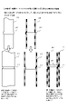
図7は、実施例2にかかる伸長使用状態の伸縮梯子100の背面図(作業個所の壁面側に向く面)を示している。
本発明の伸縮梯子100は、図7の右側に示すように、梯子基本部材101を基本単位とし、上下方向に複数個を連続的に組み合わせたものとなっている。なお、梯子基本部材101同士は上下方向にスライド可能な構造となっており、伸縮梯子100全体として、伸縮式のものとなっている。FIG. 7 shows a rear view (the surface facing the wall surface of the work place) of the
The
この構成例では、基本単位の梯子基本部材101は8段で構成され、横桟の数で言えば最下段のものも含めて10段設けられている例である。この構成例では筒状支柱体110の上部には把持部180が設けられている。
なお、上下方向に組み合わせされている梯子基本部材101の筒状体110は、上段の梯子基本部材101との関係において、当段の梯子基本部材101の筒状体は図2における摺動する第1の筒状体110-1となり、上段の梯子基本部材101の筒状体は図2における支持された第2の筒状体110-2となるが、下段の梯子基本部材101との関係において、当段の梯子基本部材101の筒状体は図2における支持された第2の筒状体110-2となり、上段の梯子基本部材101の筒状体は図2における摺動する第1の筒状体110-1となる。このように、同じ1つの梯子基本部材101の筒状体が、上段との関係で図2に示した摺動する第1の筒状体110-1となり、下段との関係では図2に示した支持された第2の筒状体110-2となる点を理解するように注意する必要がある。In this structural example, the ladder
In addition, the
梯子基本部材101は、図7の右側に示すように、一対の筒状支柱体110と、筒状体110の間に設けられた横桟120を備えた構造となっている。なお、1つの筒状体110において、内周の上方には縮径体111が設けられ、外周の下方には拡径体112が設けられている。縮径体111、拡径体112は、図1および図2に示したものと同様であり、径の関係も実施例1で示したように、R2<r1<r2<R1の関係が満たされたものとなっている。
As shown on the right side of FIG. 7, the
各々の梯子基本部材101にはある程度の剛性・強度が必要である。梯子基本部材101は作業個所において伸縮梯子として作業者の昇降を支える機械的強度が必要となるからである。また、作業員が多少の重量の荷物も担った状態で昇降することもあり得るため、その荷重にも耐える必要がある。
梯子基本部材101ごとの筒状支柱体110の長さは特に限定されないが、人間が一段ずつ昇降する際の歩幅に適切な長さであれば良い。
伸縮梯子100全体としては、図5の左側に示すように、基本構成単位である梯子基本部材101のほか、掛止具170、把持部180を備えている。Each
The length of the
As shown on the left side of FIG. 5, the
以下、各構成要素を説明する。
筒状支柱体110は、図5に示すように、所定の間隔を隔てて互いに平行に配置された一対の支柱体である。素材は、アルミニウムなどの軽金属で構造的強度が強い素材で形成することが好ましい。
なお、縮径体111、拡径体112の素材は、剛性のあるプラスチック樹脂素材やアルミニウムなどの軽金属で良い。Each component will be described below.
As shown in FIG. 5, the cylindrical struts 110 are a pair of struts arranged parallel to each other with a predetermined spacing. The material is preferably a light metal such as aluminum having a high structural strength.
The material of the diameter-reducing
なお、最上段の梯子基本部材101の筒状支柱体110には、掛止具170が設けられている。また、この構成例では、最上段の梯子基本部材101の筒状支柱体110の高さは掛止具170の位置よりも上方に向けて把持部180が延設されている。
A
横桟120は、筒状支柱体110の間に設けられた横架された部材であり、作業者が昇降時に足を載せ置く部分である。横桟120は伸縮梯子100の梯子1段分となっている。この例では、梯子基本部材101の筒状支柱体110の上端付近同士を横桟120が結ぶ形で設けられた例となっている。
横桟120の素材は、アルミニウムなどの軽金属で構造的強度が強い素材で形成することが好ましい。横桟120にはある程度の剛性・強度が必要である。作業者の昇降を支える機械的強度が必要となるからである。また、作業員が多少の重量の荷物も担った状態で昇降することもあり得るため、その荷重にも耐える必要がある。
横桟120の横方向の長さは特に限定されないが、作業員が1人ずつ昇降することを前提としたものであれば、少なくとも人間の腰幅程度の長さは必要である。The
It is preferable that the
The horizontal length of the
掛止具170は、梯子本体110を吊下箇所から吊り下げるために掛け止めする部材である。掛止具170の形状は、掛けやすいものであれば特に限定されないが、この構成例ではコの字型をしており、マンホール等の開口の縁に対して掛け止めしやすい構造をしている。
The hanging
把持部180は、吊下箇所に吊下された梯子を利用して昇降しやすいように設けたものである。最上段の梯子基本部材101の筒状支柱体110を上方に向けて把持部180を延設しておけば、作業者が把持部180を把持すれば安全が確保されやすく、作業効率も向上するというメリットがある。
The
次に、梯子基本部材101同士の摺動による伸縮梯子の伸長と短縮の仕組みについて説明する。
各々の梯子基本部材101は、最上段の梯子基本部材101から最下段の梯子基本部材101にかけてそれらの筒状支柱体110の筒部の径の大きさが順次大きくなるように設けられており、それらが入れ子式になっており筒状支柱体110の筒軸線方向に摺動可能に順次接続されたものとなっている。つまり、当段の梯子基本部材101の筒状支柱体110に対してその直下にある下段の梯子基本部材101の筒状支柱体110は筒部の大きさが一回り大きいものとなっており、入れ子式になっている。
当段の梯子基本部材101の筒状支柱体110の筒部は、下段の梯子基本部材101の筒状支柱体110の筒部に対して摺動して出し入れできるようになっており、下方に引き出すことにより伸長状態となり、上方に押し込むことにより短縮状態となる。各段の梯子基本部材101がすべて短縮状態となった場合、伸縮梯子100全体が短縮収納状態となり、各段の梯子基本部材101がすべて伸長状態となった場合、伸縮梯子100全体も伸長状態となる。Next, a mechanism for extending and shortening the telescopic ladder by sliding the
Each
The tubular portion of the
次に、本発明の伸縮梯子100の利用の手順について図8および図9を参照しつつ説明する。
図8は、短縮収納状態にある伸縮梯子100を短縮収納状態から展開して伸長使用状態とする手順を説明する図である。
作業員等は、短縮収納状態にある本発明の伸縮梯子100を運搬して吊下箇所に搬入し、作業個所となるマンホールの縁など吊下箇所において掛止具170を介して実施例2にかかる伸縮梯子100を吊下する。Next, a procedure for using the
FIG. 8 is a diagram for explaining the procedure for deploying the
A worker or the like carries the
作業員は、図8(a)の状態に示すように、掛止具170を介して伸縮梯子100を吊下する。
各段の梯子基本部材101は、筒状体110同士が摺動し合い、重力により落下を開始して下方に伸長してゆく。A worker suspends the
The
まず、最上段の梯子基本部材101の筒状体110は、掛止具170を介して支持されており、図2における第2の筒状体110-2として機能する。1つ下にある下段(上から2段目)の梯子基本部材101の筒状体110が図2における第1の筒状体110-1として、下方に摺動してゆく。摺動が進んでゆくと、やがて図2(b)および図8の右図に示すように、縮径体111が拡径体112を通過できずに当接して係止され、摺動が制限され吊下支持状態となる。
ここで、上から2段目の梯子基本部材101の筒状体110の上方の縮径体111には上から2段目から8段目までの梯子基本部材101のすべての重量が一時的に掛かって圧力が印加されるので、縮径体111の形状が潰れない構造的強度が必要である。First, the
Here, the weight of all the ladder
次に、上から2段目の梯子基本部材101の筒状体110が吊下支持状態となると、図2および図8(b)右側の図に示すように、第2の筒状体110-2となって、その1つ下にある下段(上から3段目)の梯子基本部材101の筒状体110が図2における第1の筒状体110-1として、下方に摺動してゆく。このような摺動によるスライドと摺動制限による停止が連動してゆき、次々と梯子基本部材101が上から展開されて伸長してゆく。
Next, when the
図8(b)は、伸縮梯子100を伸長してゆく途中段階の様子を示した図である。
各段の梯子基本部材101は重力に従って下方にスライドしてゆくが、その過程において、上段側にある梯子基本部材101の筒状体110から、縮径体111が拡径体112により徐々に係止されて各段の梯子基本部材101の摺動が制限されてゆく。
すべての梯子基本部材101が伸長すれば、伸縮梯子100伸長使用状態となる。FIG. 8(b) is a diagram showing a state in which the
The
When all the
次に、作業個所における伸縮梯子100の使用が終了し、伸長使用状態にある伸縮梯子100を短縮収納状態にする手順を説明する。
図9は、伸長使用状態にある伸縮梯子100を回収して短縮収納状態に変化させる手順を説明する図である。
作業員等は、マンホールなどの作業個所で伸縮梯子100の使用が終了すれば、作業者全員が伸縮梯子100を上って吊下箇所に移動した後、本発明の伸縮梯子100を回収するべく、回収作業を始める。Next, the procedure for putting the
FIG. 9 is a diagram for explaining the procedure for recovering the
After the workers have finished using the
作業員は、図9(a)の状態から下段の梯子基本部材から上方にスライドさせて短縮してゆく。
この例では最下段は固定横桟121であるので、その1つ上の段の梯子基本部材101から上昇させてゆく。その梯子基本部材101の筒状体110は、図2の第1の筒状体110-1に相当し、1つ上段の筒状体が第2の筒状体110-2に対して吊下支持されている。その梯子基本部材101の筒状体110は上方に押し上げると、縮径体111と拡径体112の係止が外れ、そのまま上方にスライドして上昇する。摺動が進んでゆくと、やがて横桟120が1つ上段(下から3段目)の横桟120に当接し、梯子基本部材101ごと押し上げることができる。From the state of FIG. 9(a), the operator slides upward from the lower ladder basic member to shorten it.
In this example, since the lowest stage is the fixed
次に、下から3段目の梯子基本部材101の筒状体110が上方に摺動してスライドしてゆくと、当段の梯子基本部材101の筒状体110は第1の筒状体110-1となり上方に摺動してスライド移動してゆき、その1つ上段の梯子基本部材101の筒状体110は吊下支持されている第2の筒状体110-2となる。
このような摺動によるスライドと、上段の横桟120への当接が連動してゆき、次々と梯子基本部材101が下から短縮して収納されてゆく。
図9(b)は、伸縮梯子100を短縮してゆく途中段階の様子を示した図である。
すべての梯子基本部材101が短縮すれば、伸縮梯子の短縮収納状態となる。Next, when the
The sliding due to such sliding and the contact with the upper
FIG.9(b) is the figure which showed the mode of the intermediate stage which shortens the
When all the
上記したように、梯子基本部材101の筒状体110の摺動において、各段の筒状体110の縮径体111には、それより下段にあるすべての梯子基本部材101の重量が一時的に掛かって圧力が印加されるが、各段の縮径体111の外周には外締体190が取り付けられており、縮径体111の形状が潰れないように外周側からしっかりと挟持され、構造的強度が補強されている。
As described above, when the
実施例3は、実施例1に示した筒状体摺動構造物を一部に組み込んだ伸縮梯子のうち、下に行くほど筒状体の径が小さくなるパターンの構造を持つ伸縮梯子である。なお、実施例2と同様の部分についてはここでの説明は適宜省略する。
図10は、実施例3にかかる伸長使用状態の伸縮梯子100の背面図(作業個所の壁面側に向く面)を示している。
本発明の伸縮梯子100は、図10の右側に示すように、梯子基本部材101を基本単位とし、上下方向に複数個を連続的に組み合わせたものとなっている。横桟120は左右の筒状体110の下端付近同士を接続する形となっている。なお、梯子基本部材101同士は上下方向にスライド可能な構造となっており、伸縮梯子100全体として、伸縮式のものとなっている。
この構成例では、基本単位の梯子基本部材101は8段で構成され、横桟の数で言えば最下段のものも含めて10段設けられている例である。この構成例では筒状支柱体110の上部には把持部180が設けられている。Example 3 is an extensible ladder having a structure in which the diameter of the cylindrical body decreases toward the bottom, among the telescopic ladders partially incorporating the cylindrical body sliding structure shown in Example 1. . Note that the description of the same parts as in the second embodiment will be omitted as appropriate.
FIG. 10 shows a rear view (the surface facing the wall surface of the working place) of the
As shown on the right side of FIG. 10, the
In this structural example, the ladder
なお、上下方向に組み合わせされている梯子基本部材101の筒状体110は、上段の梯子基本部材101との関係において、当段の梯子基本部材101の筒状体は図3における摺動する第1の筒状体110-1となり、上段の梯子基本部材101の筒状体は図3における支持された第2の筒状体110-2となる。また、下段の梯子基本部材101との関係において、当段の梯子基本部材101の筒状体は図3における支持された第2の筒状体110-2となり、上段の梯子基本部材101の筒状体は図3における摺動する第1の筒状体110-1となる。このように、同じ1つの梯子基本部材101の筒状体が、上段との関係では図3に示す摺動する第1の筒状体110-1となり、下段との関係では図3に示す支持された第2の筒状体110-2となる点を理解するように注意する必要がある。
The
梯子基本部材101は、図10の右側に示すように、一対の筒状支柱体110と、筒状体110の間に設けられた横桟120を備えた構造となっている。なお、1つの筒状体110において、内周の下方には縮径体111が設けられ、外周の上方には拡径体112が設けられている。縮径体111、拡径体112は、図1および図2に示したものと同様であり、径の関係も実施例1で示したように、R2<r1<r2<R1の関係が満たされたものとなっている。
横桟120は筒状体110の下端付近同士を接続するように設けられている。As shown on the right side of FIG. 10 , the
The
梯子基本部材101同士の摺動による伸縮梯子の伸長と短縮の仕組みについて説明する。
各々の梯子基本部材101は、最上段の梯子基本部材101から最下段の梯子基本部材101にかけてそれらの筒状支柱体110の筒部の径の大きさが順次小さくなるように設けられており、それらが入れ子式になっており筒状支柱体110の筒軸線方向に摺動可能に順次接続されたものとなっている。つまり、当段の梯子基本部材101の筒状支柱体110に対してその直下にある下段の梯子基本部材101の筒状支柱体110は筒部の大きさが一回り小さいものとなっており、入れ子式になっている。A mechanism for extending and shortening the telescopic ladder by sliding the
Each
当段の梯子基本部材101の筒状支柱体110の筒部は、上段の梯子基本部材101の筒状支柱体110の筒部に対して内挿する形で摺動して出し入れできるようになっており、下方に引き出すことにより伸長状態となり、上方に押し込むことにより短縮状態となる。各段の梯子基本部材101がすべて短縮状態となった場合、伸縮梯子100全体が短縮収納状態となり、各段の梯子基本部材101がすべて伸長状態となった場合、伸縮梯子100全体も伸長状態となる。
The tubular portion of the
次に、本発明の伸縮梯子100の利用の手順について図11および図12を参照しつつ説明する。
図11は、短縮収納状態にある伸縮梯子100を吊下箇所に吊下して短縮収納状態から展開して伸長使用状態とする手順を説明する図である。
作業員等は、短縮収納状態にある本発明の伸縮梯子100を運搬して吊下箇所に搬入し、作業個所となるマンホールの縁など吊下箇所において掛止具170を介して実施例2にかかる伸縮梯子100を吊下する。Next, a procedure for using the
FIG. 11 is a diagram illustrating a procedure for suspending the
A worker or the like carries the
作業員は、図11(a)の状態に示すように、掛止具170を介して伸縮梯子100を吊下する。各段の梯子基本部材101は、筒状体110同士が摺動し合い、重力により落下を開始して下方に伸長してゆく。
A worker suspends the
まず、最上段の梯子基本部材101の筒状体110は、掛止具170を介して吊下支持されており、図3における第1の筒状体110-1として機能する。1つ下にある下段(上から2段目)の梯子基本部材101の筒状体110が図2における第2の筒状体110-2として、下方に摺動してゆく。摺動が進んでゆくと、やがて図3(b)および図9の右図に示すように、拡径体112が縮径体111を通過できずに当接して係止され、摺動が制限され吊下支持状態となる。
First, the
ここで、最上段の梯子基本部材101の筒状体110の下方にある縮径体111には上から2段目から8段目までの梯子基本部材101のすべての重量が一時的に掛かって圧力が印加されるため構造的強度が求められる。
Here, the weight of all the ladder
次に、上から2段目の梯子基本部材101の筒状体110が吊下支持状態となると、図3および図11(b)右側の図に示すように、外側にある第1の筒状体110-1となって、その1つ下にある下段(上から3段目)の梯子基本部材101の筒状体110が図3における内側にある第2の筒状体110-2として、下方に摺動してゆく。このような摺動によるスライドと摺動制限による停止が連動してゆき、次々と梯子基本部材101が上から展開されて伸長してゆく。
Next, when the
図11(b)は、伸縮梯子100を伸長してゆく途中段階の様子を示した図である。
各段の梯子基本部材101は重力に従って下方にスライドしてゆくが、その過程において、上段側にある梯子基本部材101の筒状体110から下段側にある梯子基本部材101の筒状体110が伸長してゆき、内部において拡径体112が縮径体111により係止されて各段の摺動が制限されてゆく。
すべての梯子基本部材101が伸長すれば、伸縮梯子の伸長使用状態となる。FIG. 11(b) is a diagram showing a state in which the
The
When all
次に、作業個所における伸縮梯子100の使用が終了し、伸長使用状態にある伸縮梯子100を短縮収納状態にする手順を説明する。
図12は、伸長使用状態にある伸縮梯子100を回収して短縮収納状態に変化させる手順を説明する図である。
作業員等は、マンホールなどの作業個所で伸縮梯子100の使用が終了すれば、作業者全員が伸縮梯子100を上って吊下箇所に移動した後、本発明の伸縮梯子100を回収するべく、回収作業を始める。Next, the procedure for putting the
12A and 12B are diagrams for explaining the procedure for retrieving the
After the workers have finished using the
作業員は、図12(a)の状態から下段の梯子基本部材から上方にスライドさせて短縮してゆく。
この例では最下段は固定横桟121であるので、その1つ上の段の梯子基本部材101から上昇させてゆく。その梯子基本部材101筒状体110は、図3の第2の筒状体110-2に相当し、1つ上段の筒状体が第1の筒状体110-1に対して吊下支持されている。下から2段目の梯子基本部材101の筒状体110は上方に押し上げると、図3の逆の流れになり、縮径体111と拡径体112の係止が外れ、そのまま上方にスライドして上昇する。
摺動が進んでゆくと、やがて横桟120が1つ上段(下から3段目)の横桟120に当接し、梯子基本部材101ごと押し上げることができる。From the state of FIG. 12(a), the worker slides upward from the lower ladder base member to shorten it.
In this example, since the lowest stage is the fixed
As the sliding progresses, the
次に、下から3段目の梯子基本部材101の筒状体110は第2の筒状体110-2となり上方に摺動してスライド移動してゆき、その1つ上段(下から4段目)の梯子基本部材101の筒状体110は吊下支持されている第1の筒状体110-1となる。
このような摺動によるスライドと、上段の横桟120への当接が連動してゆき、次々と梯子基本部材101が下から短縮して収納されてゆく。Next, the
The sliding due to such sliding and the contact with the upper
図12(b)は、伸縮梯子100を短縮してゆく途中段階の様子を示した図である。すべての梯子基本部材101が短縮すれば、伸縮梯子の短縮収納状態となる。
上記したように、梯子基本部材101の筒状体110の摺動において、各段の筒状体110の縮径体111には、それより下段にあるすべての梯子基本部材101の重量が一時的に掛かって圧力が印加されるが、各段の縮径体111の外周には外締体190が取り付けられており、縮径体111の形状が潰れないように外周側からしっかりと挟持され、構造的強度が補強されている。FIG. 12(b) is a diagram showing an intermediate stage of shortening the
As described above, when the
実施例4として、筒状体摺動構造物を一部に組み込んだ伸縮梯子に対して伸長使用状態にある場合に、筒状体の摺動を一時的に固定するロック機構とロック解除機構を設けた構造について説明する。
梯子本体については、実施例2、実施例3で説明したものと同様で良く、ここでの説明は省略する。
ロック機構130は、各段の梯子基本部材101同士の連結部において、伸長使用状態となったことを契機として梯子基本部材101同士の摺動を一時的にロックするロック機構である。
ロック解除機構140は、外部からの操作を契機としてロック機構130のロック状態を解除し、梯子基本部材同士を摺動可能にする機構である。As a fourth embodiment, a locking mechanism and an unlocking mechanism for temporarily fixing the sliding of the cylindrical body when the extension ladder partly incorporating the cylindrical body sliding structure is in an extended use state are provided. The provided structure will be described.
The ladder main body may be the same as that described in Examples 2 and 3, and description thereof will be omitted here.
The lock mechanism 130 is a lock mechanism that temporarily locks the sliding of the
The unlocking mechanism 140 is a mechanism that releases the locked state of the locking mechanism 130 in response to an operation from the outside and allows the ladder basic members to slide.
図13は、伸縮梯子100の展開時における、梯子基本部材101の接合部分のロック機構130によりロックが掛かる仕組みを簡単に示す図である。
図14は、伸縮梯子100の回収時における、梯子基本部材101の接合部分のロック解除機構140によりロック機構130のロックを解除する仕組みを簡単に示す図である。
なお、図13と図14は、横桟120の左端部と対向する筒状支柱体110の一部が示されており、内部の構造が分かりやすいように一部が断面図で示されている。筒状支柱体110の筒部の径の大きさは下に行くほど大きくなっており、1つ上段の筒状支柱体110が当段の筒状支柱体110の中に入れ子式で入り込むものとなっている。
なお、図示していないが、横桟120の右端部にも図13~図14とは左右対称の同様の構造が設けられている。13A and 13B are diagrams simply showing the mechanism of locking by the lock mechanism 130 of the joint portion of the
FIG. 14 is a diagram simply showing a mechanism for unlocking the locking mechanism 130 by the unlocking mechanism 140 of the joint portion of the ladder
13 and 14 show a portion of the
Although not shown, the right end portion of the
図13に示すように、横桟120の左端部の内部には、突出可能に付勢された嵌入ピン131と付勢バネ132が設けられており、筒状支柱体110の一部には、嵌入孔111が形成されている。このように、嵌入ピン131は左側に付勢が付けられており、嵌入孔111の位置にくると突出して挿通可能に形成されている。
また、嵌入ピン131の一部には、ロック解除機構140が回動接合部143を介して回動可能に接続されている。嵌入ピン131の動作は左右水平方向にスライドする動作であるが、図13に示すように、ロック解除機構140は回動接合部143および回動軸142を介して垂直面内での回転動作に変換され、レバー構造体141が反時計回りに回転することにより下方に突出したり、時計回りに回転することにより上方に収納されたりする動作となる。As shown in FIG. 13, an insertion pin 131 and a biasing spring 132 biased to protrude are provided inside the left end of the
A lock release mechanism 140 is rotatably connected to a part of the insertion pin 131 via a rotation joint portion 143 . The operation of the insertion pin 131 is a horizontal sliding operation, but as shown in FIG. When the lever structure 141 rotates counterclockwise, it protrudes downward, and when it rotates clockwise, it retracts upward.
まず、ロック機構130によりロックが掛かる仕組みを詳しく説明する。
図13(a)に示すように、梯子基本部材101が重力により下方に落下して行く中、嵌入ピン131の先端が嵌入孔111に至ると、図13(b)に示すように、付勢バネ132の付勢力により嵌入ピン131が突出し、嵌入孔111に嵌入するようになっている。そのため、図13(b)に示すように、嵌入孔111がある位置に嵌入ピン131が来れば、付勢バネ132の付勢により嵌入ピン131が突出し、図13(c)に示すように、嵌入ピン131の先端が嵌入孔111内に嵌入し、梯子基本部材101が伸長使用状態において摺動不能に固定されることとなる。First, the mechanism of locking by the locking mechanism 130 will be described in detail.
As shown in FIG. 13(a), while the
この一連の動きの中で、ロック解除機構140は回動接合部143を介して嵌入ピン131と連動しており、回動軸142を支点として垂直方向に回転し、レバー構造体141が下方に突出する動作を行うようになっている。
図13は、横桟1段分の動きのみを示しているが、伸縮梯子100が重力により各段の梯子基本部材101が落下してゆく中、各段の横桟120において図13に示したロック機構130によるロックが次々と掛かって伸長使用状態となる。During this series of movements, the unlocking mechanism 140 is interlocked with the insertion pin 131 via the pivot joint 143, and rotates vertically around the
FIG. 13 shows only the movement of one rung, but while the ladder
次に、伸縮梯子100の回収時の各段におけるロック解除機構140による横桟のロックを外す仕組みについて説明する。
伸縮梯子100の使用の終了時点では、図14(a)に示すように、付勢バネ132により嵌入ピン131が左側の筒状支柱体110の嵌入孔111に押し込まれた状態が維持され、ロックが掛かっている。Next, a mechanism for unlocking the rungs by the unlocking mechanism 140 at each stage when the
At the end of use of the
ここで、図14(b)に示すように、外部からレバー構造体141が上方に押し上げられる操作を契機として、ロック解除機構140が時計回りに回動軸142を中心として回転し、嵌入ピン131と連動している回動接合部143が梃子の作用点として中心側に移動し、嵌入ピン131が連動して中心側にスライド移動し、その結果、ロック機構130のロック状態が解除される。
ここで、図14(b)には図示されていないが、後述するように、下方から下段の横桟120が上昇してレバー構造体141に対して衝突すれば、上記した操作レバー構造体141が上方に押し上げられる操作となる。Here, as shown in FIG. 14(b), when the lever structure 141 is pushed upward from the outside, the unlocking mechanism 140 rotates clockwise about the
Here, although not shown in FIG. 14B, as will be described later, if the lower
ロック解除機構140によりロック機構130のロックが解除されると、図14(c)に示すように、当段の横桟120は筒状支柱体110に対して摺動可能となる。ここでは、下方から下段の横桟120が上昇してレバー構造体141に対して衝突し、下方から上に引き上げる力が働いているので、そのまま当段の梯子基本部材101が上昇してゆく。
図13、図14に示した上記の動作が各段で実行され、伸縮梯子全体が伸長使用状態となったり、短縮収納状態となったりする。When the locking mechanism 130 is unlocked by the unlocking mechanism 140, the
The above operations shown in FIGS. 13 and 14 are executed at each stage, and the entire telescopic ladder is extended and used, or retracted and retracted.
以上、本発明の好ましい実施例を図示して説明してきたが、本発明の技術的範囲を逸脱することなく種々の変更が可能であることは理解されるであろう。従って本発明の技術的範囲は添付された特許請求の範囲の記載によってのみ限定されるものである。 While the preferred embodiment of the invention has been illustrated and described, it will be appreciated that various changes can be made therein without departing from the scope of the invention. Accordingly, the scope of the invention is to be limited only by the terms of the appended claims.
本発明の筒状体摺動構造物は、摺動して伸縮する部材として広く様々な構造物に適用することができる。
本発明の伸縮梯子は、マンホールなどの作業個所で使用する作業用の伸縮梯子として、また、列車の車両の異常事態における車両から脱出する避難用の伸縮梯子や、マンションやホテルなどのベランダから異常時に避難する避難用の伸縮梯子として広く適用することができる。INDUSTRIAL APPLICABILITY The cylindrical body sliding structure of the present invention can be applied to a wide variety of structures as a member that slides and expands and contracts.
The telescopic ladder of the present invention can be used as a telescopic ladder for work to be used at work sites such as manholes, as an telescopic ladder for escaping from a train vehicle in an abnormal situation, or from a veranda such as an apartment or a hotel. It can be widely applied as an extension ladder for evacuation when evacuating.
100 伸縮梯子
110 筒状支柱体
111 縮径体
112 拡径体
120 横桟
130 ロック機構
140 ロック解除機構
170 掛止具
180 把持部
REFERENCE SIGNS
Claims (10)
前記第1の筒状体の内径よりわずかに小さな外径を持ち、前記第1の筒状体に内挿され得る第2の筒状体と、
前記第1の筒状体の内面の一部に設けられ、内壁面の内径を小さくする縮径体と、
前記第2の筒状体の一部に設けられ、外壁面の外径を大きくする拡径体を備え、
前記縮径体の内径が前記拡径体の外径よりも小さく、前記第1の筒状体の内空を前記第2の筒状体が相対的移動により移動すると、前記縮径体と前記拡径体が当接し合って前記第1の筒状体と前記第2の筒状体の相対的移動が制動され得る構造であり、
前記第1の筒状体の内面の内周側と前記縮径体の外周側に嵌合可能な一又は複数の凹凸嵌合構造が設けられ、両者が前記凹凸嵌合構造を介して嵌合し合って取り付けられたものであり、
前記第2の筒状体の外周側と前記拡径体の内周側に嵌合可能な一又は複数の凹凸嵌合構造が設けられ、両者が前記凹凸嵌合構造を介して嵌合し合って取り付けられたものであることを特徴とする筒状体摺動構造物。 a first cylindrical body;
a second tubular body having an outer diameter slightly smaller than the inner diameter of the first tubular body and capable of being inserted into the first tubular body;
a diameter-reducing body provided on a part of the inner surface of the first tubular body for reducing the inner diameter of the inner wall surface;
A diameter expanding body provided in a part of the second cylindrical body and increasing the outer diameter of the outer wall surface,
When the inner diameter of the reduced-diameter body is smaller than the outer diameter of the expanded body, and the second cylindrical body moves in the inner space of the first cylindrical body by relative movement, the reduced-diameter body and the A structure in which the diameter-expanding bodies are in contact with each other so that the relative movement of the first cylindrical body and the second cylindrical body can be braked,
One or a plurality of concave-convex fitting structures capable of being fitted are provided on the inner peripheral side of the inner surface of the first cylindrical body and the outer peripheral side of the diameter-reduced body, and the two are fitted through the concave-convex fitting structure. are fitted together,
One or a plurality of concave-convex fitting structures that can be fitted are provided on the outer peripheral side of the second cylindrical body and the inner peripheral side of the expanded diameter body, and both are fitted to each other through the concave-convex fitting structure. A cylindrical body sliding structure, characterized in that it is attached to the
前記第2の筒状体の外面の外周側の少なくとも一部にオスの螺合ネジ構造が設けられ、前記拡径体の内周側にメスの螺合ネジ構造が設けられ、前記拡径体を前記第2の筒状体の外面にねじ込んでいくことにより、前記拡径体を前記第2の筒状体の外面の所定位置において螺合による取り付けが可能であることを特徴とする請求項1または2に記載の筒状体摺動構造物。 A female screw thread structure is provided on at least a part of the inner peripheral side of the inner surface of the first cylindrical body, a male screw thread structure is provided on the outer peripheral side of the diameter-reduced body, and the diameter-reduced body is screwed into the inner surface of the first cylindrical body, the reduced diameter body can be attached by screwing at a predetermined position on the inner surface of the first cylindrical body,
A male screw thread structure is provided on at least a part of the outer peripheral side of the outer surface of the second cylindrical body, a female screw thread structure is provided on the inner peripheral side of the diameter expanding body, and the diameter expanding body is screwed into the outer surface of the second cylindrical body, so that the diameter expanding body can be attached by screwing at a predetermined position on the outer surface of the second cylindrical body. 3. The cylindrical body sliding structure according to 1 or 2 .
所定の間隔を隔てて互いに平行に配置された一対の筒状体と前記筒状体の間に設けられた横桟を備えた梯子基本部材を基本単位とし、前記梯子基本部材同士が前記筒状体の筒軸線方向に入れ子状態で摺動可能に順次接続したものであり、前記梯子基本部材が摺動収納された短縮収納状態と、前記梯子基本部材が摺動伸長した伸長使用状態を持ち、各段の前記梯子基本部材同士が摺動して下方に伸長して前記伸長使用状態となり、前記伸長使用状態から前記短縮収納状態に変化し得る伸縮可能な梯子において、
当段の前記梯子基本部材の前記筒状体の上部付近に前記縮径体を設け、上段側にある前記梯子基本部材の前記筒状体の下部付近に前記拡径体を設け、前記第1の筒状体と前記第2の筒状体の関係とし、
上段側にある前記梯子基本部材に対して当段の前記梯子基本部材を上下に摺動可能とし、前記縮径体と前記拡径体が当接し合うまで伸長可能としたことを特徴とする伸縮梯子。 An extendable ladder partially applying the cylindrical body sliding structure according to claim 6 ,
The basic unit is a ladder basic member comprising a pair of tubular bodies arranged parallel to each other with a predetermined interval and a horizontal beam provided between the tubular bodies, and the ladder basic members are arranged in the tubular form. The ladder base member is slidably connected sequentially in a nested state in the cylinder axis direction of the body, and has a shortened storage state in which the ladder base member is slidably stored and an extended use state in which the ladder base member is slidably extended, A telescopic ladder capable of changing from the extended use state to the shortened storage state by sliding the ladder base members of each stage to extend downward to the extended use state,
The diameter-reducing body is provided in the vicinity of the upper portion of the cylindrical body of the ladder basic member of the current stage, the diameter-increasing body is provided in the vicinity of the lower portion of the tubular body of the ladder basic member on the upper stage side, and the first and the relationship between the cylindrical body and the second cylindrical body,
The expansion and contraction characterized in that the ladder basic member of the current stage can slide up and down with respect to the ladder basic member of the upper stage, and can be extended until the diameter-reduced body and the diameter-enlarged body abut against each other. ladder.
所定の間隔を隔てて互いに平行に配置された一対の筒状体と前記筒状体の間に設けられた横桟を備えた梯子基本部材を基本単位とし、前記梯子基本部材同士が前記筒状体の筒軸線方向に入れ子状態で摺動可能に順次接続したものであり、前記梯子基本部材が摺動収納された短縮収納状態と、前記梯子基本部材が摺動伸長した伸長使用状態を持ち、各段の前記梯子基本部材同士が摺動して下方に伸長して前記伸長使用状態となり、前記伸長使用状態から前記短縮収納状態に変化し得る伸縮可能な伸縮梯子において、
当段の前記梯子基本部材の前記筒状体の下部付近に前記縮径体を設け、上段側にある前記梯子基本部材の前記筒状体の上部付近に前記拡径体を設け、前記第1の筒状体と前記第2の筒状体の関係とし、
上段側にある前記梯子基本部材に対して当段の前記梯子基本部材を上下に摺動可能とし、前記縮径体と前記拡径体が当接し合うまで伸長可能としたことを特徴とする伸縮梯子。 An extendable ladder partially applying the cylindrical body sliding structure according to claim 7 ,
The basic unit is a ladder basic member comprising a pair of tubular bodies arranged parallel to each other with a predetermined interval and a horizontal beam provided between the tubular bodies, and the ladder basic members are arranged in the tubular form. The ladder base member is slidably connected sequentially in a nested state in the cylinder axis direction of the body, and has a shortened storage state in which the ladder base member is slidably stored and an extended use state in which the ladder base member is slidably extended, An extendable and retractable ladder in which the ladder base members of each stage are slidably extended downward to enter the extended use state, and the extendable use state can be changed to the shortened storage state,
The diameter reducing body is provided in the vicinity of the lower part of the tubular body of the ladder base member of the current stage, the diameter expanding body is provided in the vicinity of the upper part of the tubular body of the ladder basic member on the upper stage side, and the first and the relationship between the cylindrical body and the second cylindrical body,
The expansion and contraction characterized in that the ladder basic member of the current stage can slide up and down with respect to the ladder basic member of the upper stage, and can be extended until the diameter-reduced body and the diameter-enlarged body abut against each other. ladder.
a lock mechanism for temporarily fixing the ladder basic members so that they cannot slide when the diameter-reducing body and the diameter-expanding body are engaged with each other; 9. The telescopic ladder according to claim 8 , further comprising a lock release mechanism that unlocks and allows the ladder basic members of the current stage and the lower stage to slide.
Applications Claiming Priority (3)
| Application Number | Priority Date | Filing Date | Title |
|---|---|---|---|
| JP2020098958 | 2020-06-05 | ||
| JP2020098958 | 2020-06-05 | ||
| PCT/JP2021/021098 WO2021246464A1 (en) | 2020-06-05 | 2021-06-02 | Cylindrical body sliding structure and extendable ladder having same applied to part thereof |
Publications (3)
| Publication Number | Publication Date |
|---|---|
| JPWO2021246464A1 JPWO2021246464A1 (en) | 2021-12-09 |
| JPWO2021246464A5 JPWO2021246464A5 (en) | 2022-09-14 |
| JP7193197B2 true JP7193197B2 (en) | 2022-12-20 |
Family
ID=78831208
Family Applications (1)
| Application Number | Title | Priority Date | Filing Date |
|---|---|---|---|
| JP2022528881A Active JP7193197B2 (en) | 2020-06-05 | 2021-06-02 | Cylindrical body sliding structure and extendable ladder partly applying it |
Country Status (2)
| Country | Link |
|---|---|
| JP (1) | JP7193197B2 (en) |
| WO (1) | WO2021246464A1 (en) |
Citations (2)
| Publication number | Priority date | Publication date | Assignee | Title |
|---|---|---|---|---|
| JP2006077535A (en) | 2004-09-13 | 2006-03-23 | Takashi Teramoto | Ladder with handrail |
| JP2019173466A (en) | 2018-03-29 | 2019-10-10 | 特殊梯子製作所有限会社 | Telescopic ladder |
Family Cites Families (4)
| Publication number | Priority date | Publication date | Assignee | Title |
|---|---|---|---|---|
| JPS5012596U (en) * | 1973-06-04 | 1975-02-08 | ||
| JPS50111999U (en) * | 1974-02-22 | 1975-09-12 | ||
| JPH08128289A (en) * | 1994-10-31 | 1996-05-21 | Haruo Suzuki | Escape ladder |
| JPH08158626A (en) * | 1994-12-09 | 1996-06-18 | Shuji Takase | Connecting structure of safety frame in ladder for installing veranda |
-
2021
- 2021-06-02 JP JP2022528881A patent/JP7193197B2/en active Active
- 2021-06-02 WO PCT/JP2021/021098 patent/WO2021246464A1/en active Application Filing
Patent Citations (2)
| Publication number | Priority date | Publication date | Assignee | Title |
|---|---|---|---|---|
| JP2006077535A (en) | 2004-09-13 | 2006-03-23 | Takashi Teramoto | Ladder with handrail |
| JP2019173466A (en) | 2018-03-29 | 2019-10-10 | 特殊梯子製作所有限会社 | Telescopic ladder |
Also Published As
| Publication number | Publication date |
|---|---|
| JPWO2021246464A1 (en) | 2021-12-09 |
| WO2021246464A1 (en) | 2021-12-09 |
Similar Documents
| Publication | Publication Date | Title |
|---|---|---|
| CA2080135C (en) | Collapsible ladder | |
| US6401861B1 (en) | Adjustable floating ladder for loading a dumpster | |
| EP3904631A1 (en) | Elevated working platform and related methods | |
| JP5488884B2 (en) | Evacuation ladder device | |
| JP7193197B2 (en) | Cylindrical body sliding structure and extendable ladder partly applying it | |
| KR102101779B1 (en) | A Cage lifting system for building construction with slide footrest unit | |
| JP6598092B2 (en) | Telescopic ladder | |
| KR102032305B1 (en) | Folding type system scaffolding | |
| EP2877667B1 (en) | Telescopically collapsible fire escape ladder | |
| JP6600887B2 (en) | Extendable hanging ladder | |
| JP4955456B2 (en) | Multistage ladder | |
| JP6533928B2 (en) | Tubular sliding structure and stretchable forceps to which the same is applied | |
| JP6598085B2 (en) | Extendable hanging ladder | |
| JP4476044B2 (en) | Ladder scaffolding | |
| JPH0516400Y2 (en) | ||
| JP2023034787A (en) | Telescopic ladder with telescopic handrail | |
| JPS5942480Y2 (en) | Telescopic evacuation device | |
| CN220769344U (en) | Semi-rigid folding cat ladder with anti-falling traction rope for underground operation | |
| JPS6236959Y2 (en) | ||
| TW202314098A (en) | Improved prop assemblies | |
| KR200258849Y1 (en) | Multifunctional Falling Safety Net for Construction Worker | |
| JP4668941B2 (en) | Manhole fall curing frame | |
| JP5689280B2 (en) | Workbench | |
| JPS5922880Y2 (en) | evacuation ladder device | |
| KR200233502Y1 (en) | An extension fire ladder |
Legal Events
| Date | Code | Title | Description |
|---|---|---|---|
| A521 | Request for written amendment filed |
Free format text: JAPANESE INTERMEDIATE CODE: A523 Effective date: 20220708 |
|
| A621 | Written request for application examination |
Free format text: JAPANESE INTERMEDIATE CODE: A621 Effective date: 20220708 |
|
| A871 | Explanation of circumstances concerning accelerated examination |
Free format text: JAPANESE INTERMEDIATE CODE: A871 Effective date: 20220708 |
|
| AA64 | Notification of invalidation of claim of internal priority (with term) |
Free format text: JAPANESE INTERMEDIATE CODE: A241764 Effective date: 20220721 |
|
| A521 | Request for written amendment filed |
Free format text: JAPANESE INTERMEDIATE CODE: A523 Effective date: 20220729 |
|
| A131 | Notification of reasons for refusal |
Free format text: JAPANESE INTERMEDIATE CODE: A131 Effective date: 20221020 |
|
| A521 | Request for written amendment filed |
Free format text: JAPANESE INTERMEDIATE CODE: A523 Effective date: 20221025 |
|
| TRDD | Decision of grant or rejection written | ||
| A01 | Written decision to grant a patent or to grant a registration (utility model) |
Free format text: JAPANESE INTERMEDIATE CODE: A01 Effective date: 20221109 |
|
| A61 | First payment of annual fees (during grant procedure) |
Free format text: JAPANESE INTERMEDIATE CODE: A61 Effective date: 20221201 |
|
| R150 | Certificate of patent or registration of utility model |
Ref document number: 7193197 Country of ref document: JP Free format text: JAPANESE INTERMEDIATE CODE: R150 |