JP7192829B2 - Image display transparent member, image display system and image display method - Google Patents
Image display transparent member, image display system and image display method Download PDFInfo
- Publication number
- JP7192829B2 JP7192829B2 JP2020102385A JP2020102385A JP7192829B2 JP 7192829 B2 JP7192829 B2 JP 7192829B2 JP 2020102385 A JP2020102385 A JP 2020102385A JP 2020102385 A JP2020102385 A JP 2020102385A JP 7192829 B2 JP7192829 B2 JP 7192829B2
- Authority
- JP
- Japan
- Prior art keywords
- image display
- transparent
- light
- transparent member
- layer
- Prior art date
- Legal status (The legal status is an assumption and is not a legal conclusion. Google has not performed a legal analysis and makes no representation as to the accuracy of the status listed.)
- Active
Links
Images


Classifications
-
- G—PHYSICS
- G02—OPTICS
- G02B—OPTICAL ELEMENTS, SYSTEMS OR APPARATUS
- G02B5/00—Optical elements other than lenses
-
- G—PHYSICS
- G02—OPTICS
- G02B—OPTICAL ELEMENTS, SYSTEMS OR APPARATUS
- G02B5/00—Optical elements other than lenses
- G02B5/02—Diffusing elements; Afocal elements
-
- G—PHYSICS
- G02—OPTICS
- G02B—OPTICAL ELEMENTS, SYSTEMS OR APPARATUS
- G02B5/00—Optical elements other than lenses
- G02B5/08—Mirrors
-
- G—PHYSICS
- G02—OPTICS
- G02B—OPTICAL ELEMENTS, SYSTEMS OR APPARATUS
- G02B5/00—Optical elements other than lenses
- G02B5/30—Polarising elements
-
- G—PHYSICS
- G03—PHOTOGRAPHY; CINEMATOGRAPHY; ANALOGOUS TECHNIQUES USING WAVES OTHER THAN OPTICAL WAVES; ELECTROGRAPHY; HOLOGRAPHY
- G03B—APPARATUS OR ARRANGEMENTS FOR TAKING PHOTOGRAPHS OR FOR PROJECTING OR VIEWING THEM; APPARATUS OR ARRANGEMENTS EMPLOYING ANALOGOUS TECHNIQUES USING WAVES OTHER THAN OPTICAL WAVES; ACCESSORIES THEREFOR
- G03B21/00—Projectors or projection-type viewers; Accessories therefor
- G03B21/54—Accessories
- G03B21/56—Projection screens
- G03B21/60—Projection screens characterised by the nature of the surface
- G03B21/604—Polarised screens
-
- G—PHYSICS
- G03—PHOTOGRAPHY; CINEMATOGRAPHY; ANALOGOUS TECHNIQUES USING WAVES OTHER THAN OPTICAL WAVES; ELECTROGRAPHY; HOLOGRAPHY
- G03B—APPARATUS OR ARRANGEMENTS FOR TAKING PHOTOGRAPHS OR FOR PROJECTING OR VIEWING THEM; APPARATUS OR ARRANGEMENTS EMPLOYING ANALOGOUS TECHNIQUES USING WAVES OTHER THAN OPTICAL WAVES; ACCESSORIES THEREFOR
- G03B21/00—Projectors or projection-type viewers; Accessories therefor
- G03B21/54—Accessories
- G03B21/56—Projection screens
- G03B21/60—Projection screens characterised by the nature of the surface
- G03B21/62—Translucent screens
Description
本発明は、映像表示透明部材、映像表示システムおよび映像表示方法に関する。 The present invention relates to an image display transparent member, an image display system and an image display method.
商品等のショーケース;美術品等の展示ケース;建物、ショールーム、車両等の窓;ガラス扉;室内の透明パーティション等に用いられる透明部材として、下記のものが提案されている。
観察者側から見て透明部材の向こう側に見える光景を視認でき、かつ観察者に対して商品等の説明、各種機器の状態、行き先案内、伝達事項等の情報を伝達する際、観察者に対して各種機器の操作画面等を表示する際、またはプライバシー保護、セキュリティ等のために観察者に対して透明部材の向こう側の光景を視認できなくする際には、投影機から投射された映像光を観察者に映像として視認可能に表示する映像表示透明部材(いわゆる透明スクリーン)。
Display cases for products, etc.; windows of buildings, showrooms, vehicles, etc.; glass doors;
It is possible to visually recognize the scene that can be seen on the other side of the transparent member when viewed from the observer side, and when communicating information such as product descriptions, various equipment conditions, destination guidance, and communication items to the observer, On the other hand, when displaying the operation screen of various devices, or when making the scene beyond the transparent member invisible to the observer for privacy protection, security, etc., the image projected from the projector An image display transparent member (a so-called transparent screen) that visually displays light as an image to an observer.
映像表示透明部材には、投影機から投射された映像光を投影機と同じ側にいる観察者に映像として視認可能に表示する反射型の映像表示透明部材と;投影機から投射された映像光を投影機と反対側にいる観察者に映像として視認可能に表示する透過型の映像表示透明部材とがある。しかし、従来の映像表示透明部材は、透明性が低く(ヘーズが高く)、光景の視認性が悪かった。 The image display transparent member includes a reflective image display transparent member that displays the image light projected from the projector so that it can be visually recognized as an image by an observer on the same side as the projector; and the image light projected from the projector. There is a transmissive image display transparent member that visually displays the image as an image to an observer on the opposite side of the projector. However, conventional image display transparent members have low transparency (high haze) and poor visibility of scenes.
反射型の映像表示透明部材としては、たとえば、図19に示すような、第1の透明基材110と、第2の透明基材120との間に、表面に規則的な凹凸構造(マイクロレンズアレイ)が形成された第1の透明層132と、第1の透明層132の凹凸構造側の面に沿うように形成された、入射した光の一部を透過する反射膜133と、反射膜133の表面を覆うように設けられた第2の透明層134とを有する映像表示透明部材101が提案されている(特許文献1参照)。
As a reflective image display transparent member, for example, as shown in FIG. array), a
反射型の映像表示透明部材101においては、図19に示すように、投影機200から投射され、第2の透明基材120側の表面(第1の面A)から入射した映像光Lが、反射膜133において散乱することによって結像し、投影機200と同じ側にいる観察者Xに映像として視認可能に表示される。この映像表示透明部材101は、透明性が高く(ヘーズが低く)、光景の視認性が高く、なおかつ映像のスクリーンゲインも高い。
また、投影機200と同じ側にいる観察者Xからも、投影機200と反対側にいる観察者Yからも、観察者側から見て映像表示透明部材101の向こう側の光景が視認できる。
In the reflective image display
Further, both the observer X on the same side as the
しかし、反射型の映像表示透明部材101では、観察者から見て映像表示透明部材101の向こう側の光景の視認性が低下する問題がある。具体的には、向こう側の光景を見ようとした観察者側から映像表示透明部材101に入射した太陽や照明の光が反射膜133で散乱した反射散乱光によって、映像表示透明部材101の向こう側から透過してくる光のコントラストが低下し、映像表示透明部材101の向こう側の光景の視認性が低下する。
たとえば、反射型の映像表示透明部材101を窓に用いた場合、日中は太陽光L1が反射膜133で散乱した反射散乱光によって窓の外にいる観察者Yからは窓が白くぼやけて見え、窓の内側の光景の視認性が低下する。また、この場合、夜は照明の光L2が反射膜133で散乱した反射散乱光によって室内にいる観察者Xからは窓が白くぼやけて見え、窓の外側の光景の視認性が低下する。
However, the reflective transparent
For example, when the reflective image display
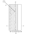
透過型の映像表示透明部材としては、たとえば、図20に示すような、第1の透明基材110と、第2の透明基材120との間に、透明層142と、透明層142の内部に互いに平行に、かつ所定の間隔で配置された、面方向に沿って延びる複数の光散乱部143とを有する映像表示透明部材102が提案されている(特許文献2参照)。
As a transmissive image display transparent member, for example, as shown in FIG. An image display
透過型の映像表示透明部材102においては、図20に示すように、投影機200から投射され、第1の透明基材110側の表面(第1の面A)から入射した映像光Lが、光散乱部143において散乱することによって結像し、投影機200と反対側にいる観察者Yに映像として視認可能に表示される。
また、投影機200と同じ側にいる観察者Xからも、投影機200と反対側にいる観察者Yからも、観察者側から見て映像表示透明部材102の向こう側の光景が視認できる。
In the transmissive image display
Further, both the observer X on the same side as the
しかし、透過型の映像表示透明部材102においては、反射型の映像表示透明部材101の場合と同様に、観察者から見て映像表示透明部材102の向こう側の光景の視認性が低下する問題がある。具体的には、観察者には向こう側の光景を見ようとした際、向こう側の光景から来る直進光は光散乱部143を通過した際に散乱され、観察者は散乱された光を観察してしまうため、光景の解像度が落ちてしまう。例えば文字等の視認性は大きく低下する。また、向こう側の光景を見ようとした観察者側から映像表示透明部材102に入射した太陽や照明の光が光散乱部143で散乱した反射散乱光によって、映像表示透明部材102の向こう側から透過してくる光のコントラストが低下し、映像表示透明部材102の向こう側の光景の視認性が低下する。そのため、たとえば、透過型の映像表示透明部材102を窓に用いた場合、日中は太陽光L1による反射散乱光によって窓の外にいる観察者Yからは窓の内側の光景の視認性が低下し、夜は照明の光L2による反射散乱光によって室内にいる観察者Xからは窓の外側の光景の視認性が低下する。
However, in the transparent
本発明は、観察者から見て透明部材の向こう側の光景の解像度が上がり、視認性に優れた映像表示透明部材、ならびにこれを用いた映像表示システムおよび映像表示方法を提供する。 The present invention provides an image display transparent member that enhances the resolution of the scene on the other side of the transparent member when viewed from an observer and has excellent visibility, and an image display system and an image display method using the same.
本発明は、以下の構成を有する。
[1]第1の面およびこれとは反対側の第2の面を有し、第1の面側の光景を第2の面側の観察者に視認可能に透過し、第2の面側の光景を第1の面側の観察者に視認可能に透過し、かつ第1の面側に設置された投影機から投射された映像光を、第2の面側の観察者に映像として視認可能に表示する透過型の映像表示透明部材であって、
前記第1の面と前記第2の面との間に、
透明層全体に光散乱微粒子が分散された光散乱層を有する映像表示部を備え、
前記映像表示部の前記第1の面側に第1の透明基材が、前記映像表示部の前記第2の面側に第2の透明基材が、それぞれ設けられており、
前記透明基材のうち、少なくとも第2の透明基材が、前記映像表示透明部材を透過する光の一部を減衰させる光減衰層となっている、映像表示透明部材。
[2]前記映像表示透明部材の前方ヘーズが、4~40%である、[1]の映像表示透明部材。
[3]前記光減衰層に偏光依存性を備えた、[1]または[2]の映像表示透明部材。
[4]前記光減衰層の透過率が70%以下である、[1]~[3]のいずれかの映像表示透明部材。
[5]前記光減衰層がグレー(可視光全体に渡って均一(xyY表色系において、0.25≦x≦0.4、0.25≦y≦0.4))である、[1]~[4]のいずれかの映像表示透明部材。
[6]前記光減衰層が青味(xyY表色系において、x≦0.33、y≦0.5)を帯びている、[1]~[4]のいずれかの映像表示透明部材。
[7]前記光減衰層が緑味(xyY表色系において、y>x、0.33≦y)を帯びている、[1]~[4]のいずれかの映像表示透明部材。
[8]光減衰層の面積が、映像表示部の面積と同じか、または映像表示部の面積よりも大きい、[1]~[7]のいずれかの映像表示透明部材。
[9]前記光減衰層が、ガラスまたは透明樹脂に光減衰成分が配合されている、[1]~[8]のいずれかの映像表示透明部材。
[10][1]~[9]のいずれかの映像表示透明部材と、
映像表示透明部材の第1の面側に設置された投影機と、
を備えた、映像表示システム。
[11][1]~[9]のいずれかの映像表示透明部材に、
映像表示透明部材の第1の面側に設置された投影機から映像光を投射し、映像を表示させる、映像表示方法。
The present invention has the following configurations.
[1] It has a first surface and a second surface on the opposite side, and transmits the scene on the first surface side so as to be visible to the observer on the second surface side, and the second surface side The scene is transmitted so as to be visible to the observer on the first surface side, and the image light projected from the projector installed on the first surface side is visually recognized as an image by the observer on the second surface side. A transmissive image display transparent member capable of displaying
Between the first surface and the second surface,
An image display unit having a light scattering layer in which light scattering fine particles are dispersed throughout the transparent layer,
A first transparent base material is provided on the first surface side of the image display part, and a second transparent base material is provided on the second surface side of the image display part,
A transparent image display member, wherein at least a second transparent substrate of the transparent substrates is a light attenuation layer that attenuates part of light transmitted through the transparent image display member.
[2] The image display transparent member of [1], wherein the front haze of the image display transparent member is 4 to 40%.
[3] The image display transparent member of [1] or [2], wherein the light attenuation layer has polarization dependence.
[4] The image display transparent member according to any one of [1] to [3], wherein the light attenuation layer has a transmittance of 70% or less.
[5] The light attenuation layer is gray (uniform over the entire visible light range (0.25≤x≤0.4, 0.25≤y≤0.4 in the xyY color system)) [1 ] to [4].
[6] The image display transparent member according to any one of [1] to [4], wherein the light attenuation layer has a bluish tint (x≤0.33, y≤0.5 in the xyY color system).
[7] The image display transparent member according to any one of [1] to [4], wherein the light attenuation layer is greenish (y>x, 0.33≦y in the xyY color system).
[8] The image display transparent member of any one of [1] to [7], wherein the area of the light attenuation layer is the same as or larger than the area of the image display portion.
[9] The image display transparent member according to any one of [1] to [8], wherein the light-attenuating layer is made of glass or transparent resin containing a light-attenuating component.
[10] an image display transparent member according to any one of [1] to [9];
a projector installed on the first surface side of the image display transparent member;
A video display system with
[11] On the image display transparent member of any one of [1] to [9],
An image display method comprising projecting image light from a projector installed on a first surface side of an image display transparent member to display an image.
本発明の映像表示透明部材、映像表示システムおよび映像表示方法によれば、観察者から見て透明部材の向こう側の光景の解像度が上がり、視認性が優れたものとなる。 According to the image display transparent member, the image display system, and the image display method of the present invention, the resolution of the scene on the other side of the transparent member seen from the observer is improved, and the visibility is excellent.
以下の用語の定義は、本明細書および特許請求の範囲にわたって適用される。
「第1の面」とは、映像表示透明部材の最表面であって、投影機から映像光が投射される側の表面を意味する。
「第2の面」とは、映像表示透明部材の最表面であって、第1の面とは反対側の表面を意味する。
「第1の面側(第2の面側)の光景」とは、映像表示透明部材の第2の面側(第1の面側)にいる観察者から見て、映像表示透明部材の向こう側に見える像(主要対象物(商品、美術品、人物等)およびその背景、ならびに風景等)を意味する。光景には、投影機から投射された映像光が映像表示透明部材において結像して表示される映像は含まれない。
「前方ヘーズ」とは、第1の面側から第2の面側に透過する透過光、または第2の面側から第1の面側に透過する透過光のうち、前方散乱によって、入射光から0.044rad(2.5°)以上それた透過光の百分率を意味する。すなわち、JIS K 7136:2000(ISO 14782:1999)に記載された方法によって測定される、通常のヘーズである。
「後方ヘーズ」とは、第1の面において反射する反射光のうち、散乱によって、正反射光から0.044rad(2.5°)以上それた反射光の百分率を意味する。
「凹凸構造」とは、複数の凸部、複数の凹部、または複数の凸部および凹部からなる凹凸形状を意味する。
「不規則な凹凸構造」とは、凸部または凹部が周期的に出現せず、かつ凸部または凹部の大きさが不揃いである凹凸構造を意味する。
算術平均粗さ(Ra)は、JIS B 0601:2013(ISO 4287:1997,Amd.1:2009)に基づき測定される算術平均粗さである。粗さ曲線用の基準長さlr(カットオフ値λc)は0.8mmとした。
透過率は、入射した光に対し、前方方向へ透過、散乱される光の合計の光量の比を百分率とした値である。
反射率は、入射した光に対し、後方方向へ反射、散乱される光の合計の光量の比を百分率とした値である。
透過率、反射率および屈折率は、ナトリウムランプのd線(波長589nm)を用いて室温で測定したときの値である。
The following term definitions apply throughout the specification and claims.
The “first surface” means the outermost surface of the image display transparent member, which is the surface on which the image light is projected from the projector.
"Second surface" means the outermost surface of the image display transparent member and the surface opposite to the first surface.
"Sight on the first surface side (second surface side)" refers to the view beyond the image display transparent member as seen from the observer on the second surface side (first surface side) of the image display transparent member. It means an image (main object (product, artwork, person, etc.) and its background, scenery, etc.) seen from the side. A scene does not include an image displayed by forming an image of image light projected from a projector on an image display transparent member.
"Forward haze" refers to transmitted light transmitted from the first surface side to the second surface side, or transmitted light transmitted from the second surface side to the first surface side, by forward scattering, incident light means the percentage of transmitted light that deviates from 0.044 rad (2.5°) or more. That is, it is a normal haze measured by the method described in JIS K 7136:2000 (ISO 14782:1999).
"Back haze" means the percentage of reflected light reflected at the first surface that deviates from specularly reflected light by 0.044 rad (2.5°) or more due to scattering.
The “concavo-convex structure” means a concavo-convex shape composed of a plurality of convex portions, a plurality of concave portions, or a plurality of convex portions and concave portions.
The “irregular uneven structure” means an uneven structure in which protrusions or recesses do not appear periodically and the sizes of the protrusions or recesses are irregular.
Arithmetic mean roughness (Ra) is arithmetic mean roughness measured based on JIS B 0601:2013 (ISO 4287:1997, Amd.1:2009). The reference length lr (cutoff value λc) for the roughness curve was 0.8 mm.
The transmittance is the ratio of the total amount of light transmitted and scattered in the forward direction to the incident light, expressed as a percentage.
The reflectance is a ratio of the total amount of light reflected and scattered in the backward direction to the incident light, expressed as a percentage.
The transmittance, reflectance and refractive index are values measured at room temperature using the d-line of a sodium lamp (wavelength 589 nm).
<反射型の映像表示透明部材>
本発明の映像表示透明部材の第1の態様は、第1の面およびこれとは反対側の第2の面を有し、第1の面側の光景を第2の面側の観察者に視認可能に透過し、第2の面側の光景を第1の面側の観察者に視認可能に透過し、かつ第1の面側から投射された映像光を第1の面側の観察者に映像として視認可能に表示する映像表示透明部材であって、前記映像表示透明部材は、当該映像表示透明部材を透過する光の一部を減衰させる光減衰層を有する、反射型の映像表示透明部材である。
<Reflective image display transparent member>
A first aspect of the image display transparent member of the present invention has a first surface and a second surface on the opposite side thereof, and the scene on the first surface side is presented to the observer on the second surface side. visibly transmitted, the scene on the second surface side is visibly transmitted to the observer on the first surface side, and the image light projected from the first surface side is transmitted to the observer on the first surface side An image display transparent member for visually displaying an image as an image on a wall, wherein the image display transparent member is a reflective image display transparent member having a light attenuation layer that attenuates part of the light that passes through the image display transparent member. It is a member.
図1は、本発明の反射型の映像表示透明部材の一例を示す層構成図である。
映像表示透明部材1は、第1の透明基材10と、第2の透明基材20との間に、映像表示部30が配置され、第2の透明基材20に光減衰成分が配合されて着色され、映像表示透明部材1を透過する光の一部を減衰させる光減衰層となっているものである。
第1の透明基材10と映像表示部30とは、接着層12によって接着され、第2の透明基材20と映像表示部30とは、接着層22によって接着されている。
FIG. 1 is a layer configuration diagram showing an example of the reflective image display transparent member of the present invention.
In the image display
The first
(第1の透明基材)
第1の透明基材10の材料としては、ガラス、透明樹脂等が挙げられる。
透明基材を構成するガラスとしては、ソーダライムガラス、無アルカリガラス、ホウケイ酸ガラス、アルミノケイ酸塩ガラス等が挙げられる。ガラスからなる第1の透明基材10には、耐久性を向上させるために、化学強化、物理強化、ハードコーティング等を施してもよい。
(First transparent substrate)
Materials for the first
Glass constituting the transparent substrate includes soda lime glass, alkali-free glass, borosilicate glass, aluminosilicate glass, and the like. The first
第1の透明基材10を構成する透明樹脂としては、ポリカーボネート、ポリエステル(ポリエチレンテレフタレート、ポリエチレンナフタレート等)、トリアセチルセルロース、シクロオレフィンポリマー、ポリメチルメタクリレート等が挙げられ、耐候性および透明性の観点から、ポリカーボネート、ポリエステル、シクロオレフィンポリマーが好ましい。
Examples of the transparent resin that constitutes the first
第1の透明基材10としては、複屈折がないものが好ましい。
第1の透明基材10の厚さは、基材としての耐久性が保たれる厚さであればよい。透明基材の厚さは、たとえば、0.01mm以上であってよく、0.05mm以上であってよく、0.1mm以上であってよい。また、透明基材の厚さは、たとえば、10mm以下であってよく、5mm以下であってよく、0.5mm以下であってよく、0.3mm以下であってよく、0.15mm以下であってよい。
As the first
The thickness of the first
(第2の透明基材(光減衰層))
第2の透明基材20は、光減衰成分が配合されて着色されており、映像表示透明部材1を透過する光の一部を減衰させる光減衰層にもなっている。
映像表示透明部材1では、第2の透明基材20が光減衰層になっていることで、観察者Yが映像表示透明部材1の向こう側の光景を見る際に、その光景の視認性が優れたものとなる。
(Second transparent substrate (light attenuation layer))
The second
In the image display
第2の透明基材20の材料としては、第1の透明基材10の材料として挙げたガラス、透明樹脂等に光減衰成分が配合されたものが挙げられる。
ガラスに含まれる光減衰成分としては、たとえば、Fe2O3、CoO、Ti2O、V2O5、CuO、Cr2O3、NiO、Er2O3、Nd2O3、CeO2、MnO2、SeOx等の金属酸化物が挙げられ、赤外線のカット等の機能付与の点から、Fe、Cuが含まれていることが好ましい。
透明樹脂に含まれる光減衰成分としては、たとえば、カーボンブラック、チタンブラック等の顔料やアジン系化合物等の染料が挙げられ、耐候性の点から、顔料が好ましい。
Materials for the second
Examples of light attenuation components contained in glass include Fe2O3 , CoO , Ti2O , V2O5 , CuO , Cr2O3 , NiO, Er2O3 , Nd2O3 , CeO2 , Metal oxides such as MnO 2 and SeO x can be mentioned, and Fe and Cu are preferably contained from the viewpoint of imparting functions such as infrared cutoff.
Examples of light-attenuating components contained in the transparent resin include pigments such as carbon black and titanium black, and dyes such as azine-based compounds. Pigments are preferred from the viewpoint of weather resistance.
また、第2の透明基材20は偏光依存性を備えていてもよい。たとえば、投影機からの映像光Lに含まれる光量のうち、多くの光が持つ偏光方向と第2の透明基材20がより多く減衰させる側の偏光方向を揃える。これにより、高い透過率を備えながらも効率よく映像光Lを吸収し、観察者Yの光景の視認性を向上させることができる。
偏光依存性を備える光減衰成分としては、二色性色素、金属のナノロッド等が挙げられる。また、偏光依存性を備える第2の透明基材は、ヨウ素や染料、銀等を含んだ透明樹脂を延伸することでも作成できる。また、第2の透明基材20の表面に、ワイヤーグリッド構造を形成して偏光依存性を付与したものを用いてもよい。偏光依存性としては、透過率の比が2以上であれば、偏光依存性の無い光減衰材料との差が光景の明るさとして感じられるようになることから好ましく、5以上であるとさらに好ましく、10以上であると特に好ましい。
Also, the second
Dichroic dyes, metal nanorods, and the like are examples of light attenuation components having polarization dependence. Alternatively, the second transparent substrate having polarization dependence can be produced by stretching a transparent resin containing iodine, dye, silver, or the like. Alternatively, a wire grid structure may be formed on the surface of the second
光減衰層の第2の透明基材20の透過率は、観察者Yから見て映像表示透明部材1の向こう側の光景の視認性がよい点から、3%以上が好ましく、5%以上がより好ましく、10%以上がさらに好ましい。
光減衰層の第2の透明基材20の透過率は、観察者Yから見て映像表示透明部材1の向こう側の光景のコントラストが高くなる点から、70%以下が好ましく、50%以下がより好ましく、30%以下がさらに好ましく、10%以下が特に好ましい。
光減衰層の第2の透明基材20のヘーズは、光減衰層で結像しにくくする点から、10%以下が好ましく、5%以下がより好ましく、2%以下がさらに好ましく、1%以下が特に好ましい。
The transmittance of the second
The transmittance of the second
The haze of the second
光減衰層の第2の透明基材20の色は、均一に光を減光するグレーを用いると光景や投影像のコントラスト向上を図ることができ好ましい。好ましい範囲としては、xyY表色系において、0.25≦x≦0.4、0.25≦y≦0.4であるとよく、0.27≦x≦0.38、0.27≦y≦0.38であると好ましい。
As for the color of the second
光減衰層の第2の透明基材20の色は、青味を帯びていると、光景の視認性が向上するため、好ましい。好ましい範囲としては、xyY表色系において、x≦0.33、y≦0.5であると好ましい。
The color of the second
光減衰層の第2の透明基材20の色は、緑味を帯びていると、透過光量を小さくするようなプライバシーガラスとした際にも、視感度の高い領域の透過率を確保できる。そのため、効率よく可視光、赤外光、紫外光をカットすることによる効能と視界の確保の両立を得ることができる。好ましい範囲としては、xyY表色系において、y>x、0.33≦yであると好ましい。
If the color of the second
本発明では、図1のように光減衰層である第2の透明基材20の面積が映像表示部30の面積と同じか、または光減衰層である第2の透明基材20の面積が映像表示部30の面積よりも大きいことが好ましい。これにより、観察者Y側から入射する光(太陽光等)が後述の反射膜で散乱した反射散乱光の一部が安定して光減衰層に吸収される。そのため、観察者Yから見て映像表示透明部材の向こう側の光景のコントラストの低下が安定して抑制され、映像表示透明部材1の向こう側の光景の優れた視認性が安定して実現されやすくなる。
In the present invention, as shown in FIG. 1, the area of the second
第2の透明基材20としては、複屈折がないものが好ましい。
第2の透明基材20の厚さは、基材としての耐久性が保たれる厚さであればよい。透明基材の厚さは、たとえば、0.01mm以上であってよく、0.05mm以上であってよく、0.1mm以上であってよい。また、透明基材の厚さは、たとえば、10mm以下であってよく、5mm以下であってよく、0.5mm以下であってよく、0.3mm以下であってよく、0.15mm以下であってよい。
The second
The thickness of the second
(接着層)
接着層12および接着層22(以下、まとめて接着層とも記す。)の材料としては、エチレン-酢酸ビニル共重合体、ポリビニルブチラール、粘着剤(アクリル系粘着剤等)、光硬化性樹脂組成物、熱可塑性樹脂組成物等が挙げられる。各接着層の材料は、同じものであってもよく、異なるものであってもよい。
(adhesion layer)
Materials for the
熱可塑性樹脂組成物に含まれる熱可塑性樹脂としては、たとえば、可塑化ポリビニルアセタール、可塑化ポリ塩化ビニル、飽和ポリエステル、可塑化飽和ポリエステル、ポリウレタン、可塑化ポリウレタン、エチレン-酢酸ビニル共重合体、エチレン-エチルアクリレート共重合体等が挙げられる。 The thermoplastic resin contained in the thermoplastic resin composition includes, for example, plasticized polyvinyl acetal, plasticized polyvinyl chloride, saturated polyester, plasticized saturated polyester, polyurethane, plasticized polyurethane, ethylene-vinyl acetate copolymer, ethylene - ethyl acrylate copolymer and the like.
接着層の厚さは、接着層としての機能が保たれる厚さであればよく、たとえば、0.01~1.5mmが好ましく、0.05~1mmがより好ましい。 The thickness of the adhesive layer may be any thickness that maintains the function of the adhesive layer, and is preferably 0.01 to 1.5 mm, more preferably 0.05 to 1 mm.
(映像表示部)
映像表示部30は、第1の透明フィルム31と;第1の透明フィルム31の表面に設けられた、表面に不規則な凹凸構造を有する第1の透明層32と;第1の透明層32の凹凸構造側の面に沿うように形成された、入射した光の一部を透過する反射膜33と;反射膜33の表面を覆うように設けられた第2の透明層34と;第2の透明層34の表面に設けられた第2の透明フィルム35とを有する光散乱シートからなる。
(Image display part)
The
(透明フィルム)
第1の透明フィルム31および第2の透明フィルム35(以下、まとめて透明フィルムとも記す。)は、透明樹脂フィルムであってもよく、薄いガラスフィルムであってもよい。各透明フィルムの材料は、同じものであってもよく、異なるものであってもよい。
(Transparent film)
The first
透明樹脂フィルムを構成する透明樹脂としては、ポリカーボネート、ポリエステル(ポリエチレンテレフタレート、ポリエチレンナフタレート等)、トリアセチルセルロース、シクロオレフィンポリマー、ポリメチルメタクリレート等が挙げられる。 Examples of the transparent resin that constitutes the transparent resin film include polycarbonate, polyester (polyethylene terephthalate, polyethylene naphthalate, etc.), triacetyl cellulose, cycloolefin polymer, polymethyl methacrylate, and the like.
透明フィルムの厚さは、ロールツーロールプロセスを適用できる厚さが好ましく、たとえば、0.01~0.5mmが好ましく、0.05~0.3mmがより好ましく、0.2mm以下がさらに好ましい。 The thickness of the transparent film is preferably a thickness to which a roll-to-roll process can be applied.
(透明層)
第1の透明層32および第2の透明層34(以下、まとめて透明層とも記す。)は、透明樹脂層であることが好ましい。各透明層の材料は、同じものであってもよく、異なるものであってもよく、同じものが好ましい。
(transparent layer)
The first
透明樹脂層を構成する透明樹脂としては、光硬化性樹脂(アクリル樹脂、エポキシ樹脂等)の硬化物、熱硬化性樹脂の硬化物、熱可塑性樹脂が好ましい。透明樹脂層を構成する透明樹脂のイエローインデックスは、映像表示透明部材における窓としての機能が損なわれないように透明感を維持する点から、10以下が好ましく、5以下がより好ましい。 As the transparent resin constituting the transparent resin layer, a cured product of a photocurable resin (acrylic resin, epoxy resin, etc.), a cured product of a thermosetting resin, and a thermoplastic resin are preferable. The yellow index of the transparent resin constituting the transparent resin layer is preferably 10 or less, more preferably 5 or less, from the viewpoint of maintaining transparency so as not to impair the function as a window in the image display transparent member.
透明層の厚さ(凹凸構造が形成された部分を除く)は、ロールツーロールプロセスにて形成しやすい厚さであればよく、たとえば、0.5~50μmが好ましい。
透明層の透過率は、50~100%が好ましく、75~100%がより好ましく、90~100%がさらに好ましい。
The thickness of the transparent layer (excluding the portion where the concave-convex structure is formed) may be any thickness that can be easily formed by a roll-to-roll process, and is preferably 0.5 to 50 μm, for example.
The transmittance of the transparent layer is preferably 50 to 100%, more preferably 75 to 100%, even more preferably 90 to 100%.
第1の透明層32の表面に形成された不規則な凹凸構造の算術平均粗さRaは、0.01~20μmが好ましく、0.05~10μmがより好ましい。算術平均粗さRaが該範囲内であれば、投射された映像の視野角が広く、正反射光を直接見ずに視認でき、凹凸構造による粒状感が抑えられる。算術平均粗さRaが10μm以下であれば、映像表示透明部材1の向こう側の光景を見るときに凹凸構造が邪魔にならず、より好ましい。
The arithmetic mean roughness Ra of the irregular uneven structure formed on the surface of the first
(反射膜)
反射膜33は、反射膜33に入射した光の一部を透過し、他の一部を反射するものであればよい。反射膜33としては、金属膜、半導体膜、誘電体単層膜、誘電体多層膜、これらの組み合わせ等が挙げられる。
(reflective film)
The
金属膜、半導体膜を構成する金属としては、Al、Ag、Ni、Cr、W、Si等が考えられ、特にAlやAg、または、それらが主成分である合金が好ましい。
誘電体膜を構成する誘電体としては、金属酸化物、金属窒化物等が挙げられる。
反射膜33としては、金属薄膜、または、酸化物膜、金属薄膜、酸化物膜の順に積層された膜構成のものが好ましい。
Al, Ag, Ni, Cr, W, Si, and the like can be considered as metals constituting the metal film and the semiconductor film, and particularly, Al, Ag, or alloys containing them as main components are preferable.
Metal oxides, metal nitrides, and the like can be cited as dielectrics constituting the dielectric film.
The
反射膜33の厚さは、第1の透明層32の表面に形成された不規則な凹凸構造の算術平均粗さRaによる機能を妨げずに活かすことができる点から、1~100nmが好ましく、4~25nmがより好ましい。
反射膜33の不規則な凹凸構造の算術平均粗さRaは第1の透明層32と同じ理由で0.01~20μmが好ましく、0.05~10μmがより好ましい。
反射膜33の反射率は、充分なスクリーンのゲインが得られる範囲としては、5%以上が好ましく、15%以上がより好ましく、30%以上がさらに好ましい。
The thickness of the
For the same reason as the first
The reflectance of the
(映像表示部の製造方法)
映像表示部30の製造方法の一例を図2を参照しながら説明する。
(Manufacturing method of video display unit)
An example of a method for manufacturing the
図2(a)に示すように、第1の透明フィルム31の表面に、光硬化性樹脂36を塗布し、不規則な凹凸構造が表面に形成されたモールド61を、凹凸構造が光硬化性樹脂36に接するように、光硬化性樹脂36の上に重ねる。
As shown in FIG. 2A, a photocurable resin 36 is applied to the surface of a first
第1の透明フィルム31の側から光(紫外線等)を照射し、光硬化性樹脂36を硬化させて、モールド61の不規則な凹凸構造が表面に転写された第1の透明層32を形成した後、図2(b)に示すように、モールド61を剥離する。
Light (ultraviolet rays, etc.) is irradiated from the side of the first
図2(c)に示すように、第1の透明層32の表面に金属を物理蒸着し、金属薄膜からなる反射膜33を形成する。
As shown in FIG. 2C, metal is physically vapor-deposited on the surface of the first
図2(d)に示すように、反射膜33の表面に光硬化性樹脂37を塗布し、光硬化性樹脂37の上に第2の透明フィルム35を重ねる。
第1の透明フィルム31の側または第2の透明フィルム35の側から光(紫外線等)を照射し、光硬化性樹脂37を硬化させて、第2の透明層34を形成することによって、映像表示部30を得る。
As shown in FIG. 2(d), a
By irradiating light (such as ultraviolet rays) from the first
モールド61としては、不規則な凹凸構造が表面に形成された樹脂フィルム、金属板等が挙げられる。不規則な凹凸構造が表面に形成された樹脂フィルムとしては、微粒子を含む樹脂フィルム、サンドブラスト処理された樹脂フィルム等が挙げられる。
光硬化性樹脂の塗布方法としては、ダイコート法、ブレードコート法、グラビアコート法、スピンコート法、インクジェット法、スプレーコート法等が挙げられる。
物理蒸着方法としては、真空蒸着法、スパッタリング法等が挙げられる。
Examples of the
Examples of the method of applying the photocurable resin include a die coating method, a blade coating method, a gravure coating method, a spin coating method, an inkjet method, and a spray coating method.
Examples of the physical vapor deposition method include a vacuum deposition method and a sputtering method.
(反射型の映像表示透明部材の光学特性)
映像表示透明部材1の透過率は、観察者側から見て映像表示透明部材1の向こう側に見える光景の視認性がよい点から、3%以上が好ましく、5%以上がより好ましく、10%以上がさらに好ましい。
映像表示透明部材1の透過率は、投影像のコントラストを適切に保つ点から、60%以下が好ましく、40%以下がより好ましく、30%以下がさらに好ましく、20%以下が特に好ましい。
(Optical Characteristics of Reflective Image Display Transparent Member)
The transmittance of the image display
The transmittance of the image display
映像表示透明部材1の前方ヘーズは、観察者側から見て映像表示透明部材1の向こう側に見える光景の視認性がよい点から、50%以下が好ましく、20%以下がより好ましく、10%以下がさらに好ましい。
The front haze of the image display
映像表示透明部材1の後方ヘーズは、スクリーンゲイン確保の点から、正規反射率を上げる平坦なミラーや平坦なハーフミラーの様な構造を映像表示透明部材1が含まない場合、5%以上が好ましく、10%以上がより好ましく、15%以上がさらに好ましい。
映像表示透明部材1の後方ヘーズは、観察者側から見て映像表示透明部材1の向こう側に見える光景の視認性の点から、90%以下が好ましく、80%以下がより好ましい。
From the viewpoint of securing the screen gain, the rear haze of the image display
The rear haze of the image display
前方ヘーズに対する後方ヘーズの比率(後方ヘーズ/前方ヘーズ)は、0.5以上が好ましく、1以上がより好ましい。後方ヘーズ/前方ヘーズが1以上であれば、映像表示透明部材1を見る観察者の視線が届く範囲に100ルクス以上の環境があっても、観察者側から見て映像表示透明部材1の向こう側に見える光景の視認性がよく、投射された映像と映像表示透明部材1の向こう側の光景とを見ることができる。このような映像表示透明部材1は、周囲に外光が存在する環境下で利用されることに適している。
The ratio of rear haze to front haze (rear haze/front haze) is preferably 0.5 or more, more preferably 1 or more. If the rear haze/front haze is 1 or more, even if there is an environment of 100 lux or more in the range where the line of sight of the observer looking at the image display
映像表示透明部材1における隣り合う各層間の屈折率差は、各層界面における反射率が0.5%以内に抑えられる点から、0.2以内が好ましく、各層界面での反射率が0.1%程度となる点から、0.1以内がより好ましい。
The refractive index difference between adjacent layers in the image display
(反射型の映像表示透明部材を備えた映像表示システム)
本発明の映像表示システムの第1の態様は、本発明の反射型の映像表示透明部材と、映像表示透明部材の第1の面側に設置された投影機とを備えた映像表示システムである。
(Image display system provided with reflective image display transparent member)
A first aspect of the image display system of the present invention is an image display system comprising the reflective transparent image display member of the present invention and a projector installed on the first surface side of the transparent image display member. .
図1は、本発明の映像表示システムの一例を示す概略構成図である。
映像表示システムは、反射型の映像表示透明部材1と、映像表示透明部材1の第1の面A側に設置された投影機200とを備える。
FIG. 1 is a schematic configuration diagram showing an example of the image display system of the present invention.
The image display system includes a reflective image display
投影機200は、映像表示透明部材1に映像光Lを投射できるものであればよい。投影機200としては、公知のプロジェクタ等が挙げられる。
The
(反射型の映像表示透明部材を用いた映像表示方法)
本発明の映像表示方法の第1の態様は、本発明の反射型の映像表示透明部材に、映像表示透明部材の第1の面側に設置された投影機から映像光を投射し、映像を表示させる映像表示方法である。
(Image display method using reflective image display transparent member)
In a first aspect of the image display method of the present invention, image light is projected onto the reflective transparent image display member of the present invention from a projector installed on the first surface side of the image display transparent member to display an image. This is a video display method for displaying.
図1に示すように、投影機200から投射され、映像表示透明部材1の第1の透明基材10側の表面(第1の面A)から入射した映像光Lが、反射膜33において散乱することによって結像し、投影機200と同じ側にいる観察者Xに映像として視認可能に表示できる。
また、映像表示透明部材1における反射膜33が入射した光の一部を透過するため、第1の面A側の光景を第2の面B側の観察者Yに視認可能に透過でき、かつ第2の面B側の光景を第1の面A側の観察者Xに視認可能に透過できる。
As shown in FIG. 1, the image light L projected from the
In addition, since the reflecting
(作用機序)
以上説明した反射型の映像表示透明部材1、ならびにこれを用いた映像表示システムおよび映像表示方法にあっては、たとえば映像表示透明部材1を第2の面Bが室外となるように窓として用いる場合、第2の面B側から映像表示透明部材1に入射した太陽光L1が反射膜33で散乱し、その反射散乱光の一部が、光減衰層である第2の透明基材20で吸収されて減少する。その結果、観察者Yが映像表示透明部材1の向こう側の光景を見る際、映像表示透明部材1の向こう側から透過してくる光のコントラストが向上する。そのため、観察者Yから見て映像表示透明部材1の向こう側の光景のコントラストが向上し、日中における該光景の視認性に優れる。
また、光減衰層である第2の透明基材20による前記反射散乱光の吸収によって、第2の面B側から見たときに映像表示透明部材1が白くぼやけて見えることが抑制されるため、意匠性に優れる。そのため、映像表示透明部材1は第2の面Bを室外側とする窓等の用途に有用である。
(Mechanism of action)
In the above-described reflective transparent
In addition, the absorption of the reflected and scattered light by the second
また、この例の反射型の映像表示透明部材1では、映像表示透明部材1の第2の面B側から入射する光の一部が光減衰層である第2の透明基材20で吸収されるため、観察者Xから見て投影機200から投射された映像光による映像のコントラストが向上し、その視認性に優れる。
Further, in the reflective transparent
(他の実施形態)
なお、本発明の反射型の映像表示透明部材は、第1の面およびこれとは反対側の第2の面を有し、第1の面側の光景を第2の面側の観察者に視認可能に透過し、第2の面側の光景を第1の面側の観察者に視認可能に透過し、かつ第1の面側から投射された映像光を第1の面側の観察者に映像として視認可能に表示する映像表示透明部材であって、前記映像表示透明部材は、当該映像表示透明部材を透過する光の一部を減衰させる光減衰層を有するものであればよく、図1の映像表示透明部材1に限定はされない。以下、図1の映像表示透明部材1と同じ構成のものについては同じ符号を付し、説明を省略する。
(Other embodiments)
The reflective image display transparent member of the present invention has a first surface and a second surface on the opposite side, and the scene on the first surface side is presented to the observer on the second surface side. visibly transmitted, the scene on the second surface side is visibly transmitted to the observer on the first surface side, and the image light projected from the first surface side is transmitted to the observer on the first surface side An image display transparent member that can be visually recognized as an image in the image display transparent member, and the image display transparent member may have a light attenuation layer that attenuates part of the light that passes through the image display transparent member. The image display
本発明の反射型の映像表示透明部材は、図3に示すように、第1の透明基材10を省略した映像表示透明部材2であってもよい。映像表示透明部材2の具体例としては、たとえば、第2の透明基材20が既存の窓ガラス等である例、すなわち映像表示部30を、既存の窓ガラス等に貼り付けた例が挙げられる。
また、2枚のガラス板と、ガラス板間に空隙が形成されるようにガラス板の周縁部に介在配置された枠状のスペーサとを有する複層ガラスにおいて、一方のガラス板を着色ガラス板とし、さらに一方のガラス板の内面に映像表示部30を貼り付けたものであってもよい。
The reflective transparent image display member of the present invention may be an image display
Further, in double glazing having two glass plates and a frame-shaped spacer interposed in the peripheral portion of the glass plates so as to form a gap between the glass plates, one of the glass plates is a colored glass plate. Alternatively, the
本発明の反射型の映像表示透明部材は、図4に示すように、第1の透明基材10の代わりに、光減衰成分が配合されて着色され、透明部材を透過する光の一部を減衰させる光減衰層となる第1の透明基材10Aを有し、第2の透明基材20の代わりに、光減衰成分が配合されず着色されていない第2の透明基材20Aを有する映像表示透明部材1Aであってもよい。
光減衰成分が配合されて着色された第1の透明基材10Aとしては、映像表示透明部材1の第2の透明基材20と同じものが挙げられる。光減衰成分が配合されず着色されていない第2の透明基材20Aとしては、映像表示透明部材1の第1の透明基材10と同じものが挙げられる。
As shown in FIG. 4, the reflective image display transparent member of the present invention is colored by blending a light attenuation component instead of the first
As the first transparent base material 10A mixed with the light attenuation component and colored, the same material as the second
映像表示透明部材1Aでは、たとえば映像表示透明部材1Aを第2の面Bが室外となるように窓として用いる場合、第1の面A側から映像表示透明部材1Aに入射した照明の光L2が反射膜33で散乱した反射散乱光の一部が、光減衰層である第1の透明基材10Aで吸収されて減少する。その結果、第1の面A側の観察者が映像表示透明部材1Aの向こう側の光景を見る際、映像表示透明部材1Aの向こう側から透過してくる光のコントラストが向上する。そのため、第1の面A側の観察者から見て映像表示透明部材1Aの向こう側の光景のコントラストが向上し、夜における該光景の視認性に優れる。
また、この例では、第1の面A側の投影機200(図示省略)から投射した映像光が反射膜33で散乱した反射散乱光の一部が光減衰層である第1の透明基材10Aで吸収されることで、光減衰層が無い場合に比べて映像のゲインが低下するが、これは投影機200からの映像光の量を多くすることで対応可能である。
また、偏光依存性のある光減衰材料を用いた場合は、投影光L(図示省略)と透過する偏光方向を揃えることで、ゲインの低下を抑制しながらも、光景の視認性を上げることができ好ましい。
In the image display
Further, in this example, part of the reflected and scattered light obtained by scattering the image light projected from the projector 200 (not shown) on the first surface A side by the reflecting
In addition, when a light-attenuating material having polarization dependence is used, it is possible to improve the visibility of the scene while suppressing the decrease in gain by aligning the polarization direction of the transmitted light with the projection light L (not shown). It is possible and preferable.
本発明の反射型の映像表示透明部材は、図5に示すように、いずれも光減衰成分が配合されず着色されていない第1の透明基材10および第2の透明基材20Aを有し、第2の透明基材20Aの、映像表示部30とは反対側の表面に、光減衰成分が配合されて着色され、透明部材を透過する光の一部を減衰させる光減衰層50が配置された映像表示透明部材3であってもよい。第2の透明基材20Aと光減衰層50とは、接着層52によって接着されている。
As shown in FIG. 5, the reflective image display transparent member of the present invention has a first
光減衰層50としては、たとえば、光減衰成分が配合されて着色された着色透明フィルムが挙げられる。着色透明フィルムは、光減衰成分が配合されて着色された着色透明樹脂フィルムであってもよく、光減衰成分が配合されて着色された薄い着色ガラスフィルムであってもよく、吸光係数が大きい薄膜材料であってもよい。
光減衰層50を構成する着色透明樹脂フィルムの透明樹脂としては、ポリカーボネート、ポリエステル(ポリエチレンテレフタレート、ポリエチレンナフタレート等)、シクロオレフィンポリマー、ポリメチルメタクリレート等が挙げられる。
光減衰層50における光減衰成分としては、たとえば、カーボンブラック、チタンブラック等の顔料やアジン系化合物等の染料が挙げられ、耐候性の点から、顔料が好ましい。
光減衰層50における吸光係数が大きい薄膜材料としては、Cr、Mo、W、Fe、Al、Si等の酸化物、グラフェン、DLC等のカーボン系材料等が挙げられる。
光減衰層50に偏光依存性を付与する場合は、二色性色素、金属等のナノロッド等や、ヨウ素、Ag等を延伸したもの、吸収薄膜を斜方蒸着したもの等が挙げられる。
The light-attenuating
Examples of the transparent resin of the colored transparent resin film forming the
Examples of light-attenuating components in the light-attenuating
Examples of thin film materials having a large absorption coefficient for the
When imparting polarization dependence to the
光減衰層50の透過率は、観察者Yから見て映像表示透明部材1の向こう側の光景の視認性がよい点から、3%以上が好ましく、5%以上がより好ましく、10%以上がさらに好ましい。
光減衰層50の透過率は、観察者Yから見て映像表示透明部材1の向こう側の光景のコントラストが高くなる点から、70%以下が好ましく、50%以下がより好ましく、30%以下がさらに好ましく、10%以下が特に好ましい。
光減衰層50のヘーズは、光減衰層で結像しにくくする点から、10%以下が好ましく、5%以下がより好ましく、2%以下がさらに好ましく、1%以下が特に好ましい。
接着層52としては、接着層12、接着層22と同じものが挙げられる。
The transmittance of the
The transmittance of the
The haze of the
The
映像表示透明部材3では、映像表示透明部材1と同様の理由から、第2の面B側の観察者から見て映像表示透明部材3の向こう側の光景のコントラストが向上し、該光景の視認性に優れる。また、第1の面A側の観察者から見て第1の面A側の投影機200(図示省略)から投射された映像光による映像の視認性に優れる。
In the image display transparent member 3, for the same reason as in the image display
本発明の反射型の映像表示透明部材は、図6に示すように、第1の透明基材10および第2の透明基材20を省略し、映像表示部30の第2の透明フィルム35の表面に光減衰層50を配置した映像表示透明部材4Aであってもよい。映像表示透明部材4Aでは、映像表示透明部材1と同様の理由から、第2の面B側の観察者から見て映像表示透明部材4Aの向こう側の光景のコントラストが向上し、該光景の視認性に優れる。また、第1の面A側の観察者から見て第1の面A側の投影機200(図示省略)から投射された映像光による映像の視認性に優れる。
また、図7に示すように、第1の透明基材10および第2の透明基材20を省略し、映像表示部30の第1の透明フィルム31の表面に光減衰層50を配置した映像表示透明部材4Bであってもよい。映像表示透明部材4Bでは、映像表示透明部材1Aと同様の理由から、第1の面A側の観察者から見て映像表示透明部材4Bの向こう側の光景のコントラストが向上し、該光景の視認性に優れる。
The reflective image display transparent member of the present invention, as shown in FIG. An image display
Further, as shown in FIG. 7, the first
映像表示透明部材4A,4Bは、接着層を用いて既存の窓ガラス等への貼り付けが可能である。また、映像表示透明部材4A,4Bは、変形させることが可能であり、曲面を有する映像表示透明部材を形成するのに向いている。
また、図6、図7の映像表示透明部材4A,4Bにおいて、第1の透明フィルム31および第2の透明フィルム35をそれぞれ透明基材に置き換えた映像表示部を有するものであってもよい。
The image display
Moreover, in the image display
本発明の反射型の映像表示透明部材は、図8に示すように、いずれも光減衰成分が配合されて着色された第1の透明基材10Aおよび第2の透明基材20を有する映像表示透明部材1Bであってもよい。
映像表示透明部材1Bでは、映像表示透明部材1と同様の理由から、第2の面B側の観察者から見て映像表示透明部材1Bの向こう側の光景のコントラストが向上し、該光景の視認性に優れる。また、第1の面A側の観察者から見て第1の面A側の投影機200(図示省略)から投射された映像光による映像の視認性に優れる。また、映像表示透明部材1Aと同様の理由から、第1の面A側の観察者から見て映像表示透明部材1Bの向こう側の光景のコントラストが向上し、該光景の視認性に優れる。
As shown in FIG. 8, the reflective image display transparent member of the present invention has a first transparent base material 10A and a second
In the image display
本発明の反射型の映像表示透明部材は、図9に示すように、いずれも光減衰成分が配合されず着色されていない第1の透明基材10および第2の透明基材20Aを有し、第2の透明フィルム35Aに光減衰成分が配合されて着色され、透明部材を透過する光の一部を減衰させる光減衰層となっている映像表示部30Aを有する映像表示透明部材1Cであってもよい。
映像表示透明部材1Cでは、映像表示透明部材1と同様の理由から、第2の面B側の観察者から見て映像表示透明部材1Cの向こう側の光景のコントラストが向上し、該光景の視認性に優れる。また、第1の面A側の観察者から見て第1の面A側の投影機200(図示省略)から投射された映像光による映像の視認性に優れる。
As shown in FIG. 9, the reflective image display transparent member of the present invention has a first
In the image display
また、映像表示透明部材1Cにおいて、第2の透明フィルム35Aの代わりに、第1の透明フィルム31に光減衰成分が配合されて着色され、透明部材を透過する光の一部を減衰させる光減衰層となっている映像表示透明部材であってもよい。また、第1の透明フィルム31と第2の透明フィルム35の両方に光減衰成分が配合されて着色され、透明部材を透過する光の一部を減衰させる光減衰層となっている映像表示透明部材であってもよい。
また、本発明の反射型の映像表示透明部材は、映像表示透明部材1において、第2の透明基材20の代わりに、光減衰成分が配合されていない第2の透明基材20Aを有し、接着層12および接着層22のいずれか一方もしくは両方に光減衰成分が配合されて着色され、透明部材を透過する光の一部を減衰させる光減衰層となっている映像表示透明部材であってもよい。
映像表示部の透明フィルムや接着層に配合される光減衰成分としては、たとえば、光減衰層50で挙げたものと同じものが挙げられる。
In the image display
Further, the reflective transparent image display member of the present invention has a second
Examples of the light-attenuating component to be blended in the transparent film or the adhesive layer of the image display portion include the same ones as those mentioned for the light-attenuating
光減衰層となっている部材の機能としては、透過率を減少させる機能を持っていればよいため、ハーフミラーを光減衰層として用いてもよい。
ハーフミラーの反射率としては、5%以上であればよく、10%以上であると好ましく、場合によっては、25%以上であってもよい。
ハーフミラーを、映像表示部と投影機との間に配置することにより、上記の効果に加えて、両面への投影を可能とできる。また、映像表示部と投影機との間ではない部分に配置することにより、マジックミラーとしての機能を付与できるため、さらに、後方への映像抜けを観察者へ認識させにくくすることができるようになる。
本発明の反射型の映像表示透明部材における光減衰層の態様としては、上述の通り、図1および図3の第2の透明基材20、図4の第1の透明基材10A、図5~図7の着色透明フィルム、図8における第1の透明基材10Aおよび第2の透明基材20に例示したような透明基材や透明フィルム、およびハーフミラーが挙げられる。
As for the function of the member serving as the light attenuation layer, it is sufficient that it has the function of reducing the transmittance, so a half mirror may be used as the light attenuation layer.
The reflectance of the half mirror may be 5% or more, preferably 10% or more, and may be 25% or more in some cases.
By arranging the half mirror between the image display section and the projector, in addition to the above effects, it is possible to project on both sides. Also, by arranging it in a part that is not between the image display unit and the projector, it is possible to add a function as a magic mirror, so that it is possible to make it difficult for the observer to recognize the lack of images to the rear. Become.
As described above, the embodiment of the light attenuation layer in the reflective image display transparent member of the present invention includes the second
本発明の反射型の映像表示透明部材においては、投影機からの映像光を第2の透明基材側に投射してもよい。この場合、第2の透明基材の表面に反射防止フィルムを設けるか、第2の透明基材の表面に直接、反射防止構造を形成する。
また、映像表示部30の第2の透明フィルム35が、投影機200側となるように、映像表示部30を配置してもよい。
In the reflective image display transparent member of the present invention, the image light from the projector may be projected onto the second transparent substrate side. In this case, an antireflection film is provided on the surface of the second transparent substrate, or an antireflection structure is formed directly on the surface of the second transparent substrate.
Further, the
映像表示部の光散乱シートにおいて、透明フィルムがなくても光散乱シートがその形状を保つことができる場合は、必ずしも光散乱シートに透明フィルムを設ける必要はない。 If the light-scattering sheet of the image display portion can maintain its shape without the transparent film, the light-scattering sheet does not necessarily need to be provided with the transparent film.
本発明の反射型の映像表示透明部材においては、第1の透明層の表面の凹凸構造が規則的な凹凸構造(マイクロレンズアレイ等)であってもよい。ただし、下記の理由から、第1の透明層の表面の凹凸構造は、不規則な凹凸構造であることが好ましい。
規則的な凹凸構造(マイクロレンズアレイ等)の表面に反射膜を形成した場合、光の回折によって観察者側から見て映像表示透明部材の向こう側に見える光景に色むらが生じたり、分光によって観察者側から見て映像表示透明部材の向こう側に見える光景のエッジ部分が虹色に見えたりして、視認性が損なわれる。一方、不規則な凹凸構造の表面に反射膜を形成した場合、光の回折や分光が起こりにくく、これらの問題が生じにくい。そのため、映像表示透明部材を見る方向や場所、入射する光の向きによって色目が変わるような現象が抑えられ、また、映像表示透明部材の向こう側に見える光景の分光が抑えられる。その結果、映像表示透明部材の向こう側に見える光景の視認性に優れ、視線を邪魔しない透明スクリーンとしての性質を備えることができる。
In the reflective image display transparent member of the present invention, the uneven structure on the surface of the first transparent layer may be a regular uneven structure (such as a microlens array). However, for the following reasons, the uneven structure on the surface of the first transparent layer is preferably an irregular uneven structure.
When a reflective film is formed on the surface of a regular concave-convex structure (such as a microlens array), light diffraction causes color unevenness in the scene seen on the other side of the image display transparent member when viewed from the observer side. When viewed from the observer's side, the edge portion of the scene seen on the other side of the image display transparent member appears rainbow-colored, impairing visibility. On the other hand, when a reflective film is formed on a surface having an irregular concave-convex structure, diffraction and dispersion of light are less likely to occur, and these problems are less likely to occur. Therefore, it is possible to suppress the phenomenon that the color changes depending on the viewing direction and place of the image display transparent member and the direction of the incident light, and the spectroscopy of the scene seen on the other side of the image display transparent member is suppressed. As a result, the visibility of the scene seen on the other side of the image display transparent member is excellent, and the property of a transparent screen that does not obstruct the line of sight can be provided.
また、反射膜付の凹凸構造、凹凸を埋め込んだ後のものの他の例としては、ハーフミラーに散乱材料を積層したもの;体積ホログラムによって、反射、偏向、拡散されるもの;キノフォーム型ホログラム、その他凹凸表面やその表面に反射膜を形成した構成によって、偏向、反射、拡散されるもの;コレステリック液晶、高分子コレステリック液晶を利用したもの(凹凸構造の表面に配向、形成したコレステリック液晶、高分子コレステリック液晶の表面にエッチング等で凹凸をつけたもの、水平配向と垂直配向の基材にてコレステリック液晶の液晶層を形成したもの、コレステリック液晶に界面活性剤を添加したものを基材上に塗布して、塗布表面を垂直配光させたもの、または、塗布表面の配向性を落としたもの)等が挙げられる。
また、反射膜がなくても、第1の透明基材10が凹凸構造のみで充分に光を反射、散乱できる場合は、必ずしも反射膜を設ける必要はない。
In addition, other examples of the uneven structure with a reflective film and those after embedding the unevenness include a half mirror laminated with a scattering material; a volume hologram that reflects, deflects, and diffuses; Other items that polarize, reflect, and diffuse due to the uneven surface or the structure of forming a reflective film on the surface; The surface of cholesteric liquid crystal is roughened by etching, etc., the liquid crystal layer of cholesteric liquid crystal is formed on horizontally aligned and vertically aligned substrates, and the substrate is coated with cholesteric liquid crystal added with a surfactant. Then, the coating surface is vertically distributed, or the orientation of the coating surface is reduced).
Further, if the first
<透過型の映像表示透明部材>
本発明の映像表示透明部材の第2の態様は、第1の面およびこれとは反対側の第2の面を有し、第1の面側の光景を第2の面側の観察者に視認可能に透過し、第2の面側の光景を第1の面側の観察者に視認可能に透過し、かつ第1の面側から投射された映像光を第2の面側の観察者に映像として視認可能に表示する映像表示透明部材であって、前記映像表示透明部材は、当該映像表示透明部材を透過する光の一部を減衰させる光減衰層を有する、透過型の映像表示透明部材である。
<Transmissive image display transparent member>
A second aspect of the image display transparent member of the present invention has a first surface and a second surface opposite to the first surface, and presents a scene on the first surface side to an observer on the second surface side. visibly transmitted, the scene on the second surface side is visibly transmitted to the observer on the first surface side, and the image light projected from the first surface side is transmitted to the observer on the second surface side a transmissive image display transparent member for displaying a visible image as an image in the image display transparent member, wherein the image display transparent member has a light attenuation layer that attenuates part of the light transmitted through the image display transparent member It is a member.
図10は、本発明の透過型の映像表示透明部材の一例を示す層構成図である。以下、図1の映像表示透明部材1と同じ構成のものについては同じ符号を付し、説明を省略する。
映像表示透明部材5は、第1の透明基材10と、第2の透明基材20との間に、映像表示部40が配置され、第2の透明基材20に光減衰成分が配合されて着色され、映像表示透明部材1を透過する光の一部を減衰させる光減衰層となっているものである。
第1の透明基材10と映像表示部40とは、接着層12によって接着され、第2の透明基材20と映像表示部40とは、接着層22によって接着されている。
映像表示透明部材5では、第2の透明基材20が光減衰層になっていることで、観察者Yが映像表示透明部材5の向こう側の光景を見る際に、その光景の視認性が優れたものとなる。
FIG. 10 is a layer configuration diagram showing an example of the transmissive image display transparent member of the present invention. In the following description, the same components as those of the image display
In the image display
The first
In the image display
(映像表示部)
映像表示部40は、第1の透明フィルム41と;第1の透明フィルム41の表面に設けられた透明層42と;透明層42の内部に互いに平行に、かつ所定の間隔で配置された、面方向に沿って延びる、長手方向に直交する方向の断面が直角三角形の複数の光散乱部43と;透明層42の表面に設けられた第2の透明フィルム45とを有する光散乱シートからなる。以下、このようにストライプ状に一次元方向に延びる複数の光散乱部43が形成されている構造をルーバー構造と記載する場合がある。
(Image display part)
The
(透明フィルム)
第1の透明フィルム41および第2の透明フィルム45(以下、まとめて透明フィルムとも記す。)は、透明樹脂フィルムであってもよく、薄いガラスフィルムであってもよい。各透明フィルムの材料は、同じものであってもよく、異なるものであってもよい。
透明フィルムとしては、上述した映像表示部30の透明フィルムと同様のものを用いればよい。
(Transparent film)
The first
As the transparent film, the same transparent film as that of the
(透明層)
透明層42は、透明樹脂層であることが好ましい。
透明樹脂層を構成する透明樹脂としては、上述した映像表示部30の透明樹脂層を構成する透明樹脂と同様のものを用いればよい。
(transparent layer)
The
As the transparent resin forming the transparent resin layer, the same transparent resin as that forming the transparent resin layer of the
透明層42の厚さは、10~200μmが好ましい。透明層42の厚さが10μm以上であれば、光散乱部43の間隔も10μm以上となり、ルーバーの構造の効果が充分に発揮される。透明層42の厚さが200μm以下であれば、ロールツーロールプロセスにて透明層42を形成しやすい。
The thickness of the
(光散乱部)
光散乱部43は、たとえば、透明樹脂、光散乱材料、および必要に応じて光減衰材料を含む。
(light scattering part)
The
光散乱部43に含まれる透明樹脂としては、光硬化性樹脂(アクリル樹脂、エポキシ樹脂等)の硬化物、熱硬化性樹脂の硬化物、熱可塑性樹脂が挙げられる。光散乱部43に含まれる透明樹脂は、透明層42を構成する透明樹脂と同一であってもよく、異なってもよい。
Examples of the transparent resin contained in the
光散乱材料としては、酸化チタン(屈折率:2.5~2.7)、酸化ジルコニウム(屈折率:2.4)、酸化アルミニウム(屈折率:1.76)等の高屈折率材料の微粒子;ポーラスシリカ(屈折率:1.3以下)、中空シリカ(屈折率:1.3以下)等の低屈折率材料の微粒子;前記透明樹脂との相溶性の低い屈折率が異なる樹脂材料;結晶化した1μm以下の樹脂材料等が挙げられる。 Fine particles of high refractive index materials such as titanium oxide (refractive index: 2.5 to 2.7), zirconium oxide (refractive index: 2.4), and aluminum oxide (refractive index: 1.76) are used as light scattering materials. fine particles of low refractive index materials such as porous silica (refractive index: 1.3 or less) and hollow silica (refractive index: 1.3 or less); resin materials with low compatibility with the transparent resin and different refractive indexes; crystals and a resin material having a thickness of 1 μm or less.
光散乱材料の濃度は、0.01~5体積%が好ましく、0.05~1体積%がより好ましい。
光散乱材料が微粒子である場合、微粒子の平均粒子径は、0.05~1μmが好ましく、0.15~0.8μmがより好ましい。微粒子の平均粒子径が、散乱する光の波長と同程度かやや小さいと、前方に散乱される確率が大きくなり、入射した光を屈折させずに散乱させる機能が強くなる。その結果、観察者側から見て映像表示透明部材5の向こう側に見える光景の歪みを抑制し、急激に光量を変化させることがないため、光景の視認性が向上する。
The concentration of the light scattering material is preferably 0.01-5% by volume, more preferably 0.05-1% by volume.
When the light scattering material is fine particles, the average particle size of the fine particles is preferably 0.05 to 1 μm, more preferably 0.15 to 0.8 μm. When the average particle diameter of the fine particles is approximately the same as or slightly smaller than the wavelength of the scattered light, the probability of forward scattering increases, and the function of scattering incident light without refracting it becomes stronger. As a result, the distortion of the scene seen on the other side of the image display
光散乱部43が光減衰材料を含む場合、映像表示透明部材5内を不要な迷光として伝搬する光の一部を減衰させることができ、散乱される光が減少する。そのため、映像表示透明部材5において白濁して見える現象を抑え、映像のコントラストが向上し、映像の視認性が向上する。また、観察者側から見て映像表示透明部材5の向こう側に見える光景のコントラストも向上し、光景の視認性も向上する。特に、外光によって100ルクス以上の環境が、観察者の視線の中に存在する場合には、前記効果を得やすい。
光減衰材料としては、カーボンブラック、チタンブラック等が挙げられる。
光減衰材料の濃度は、0.01~10体積%が好ましく、0.1~3体積%がより好ましい。
When the
Light-attenuating materials include carbon black, titanium black, and the like.
The concentration of the light-attenuating material is preferably 0.01-10% by volume, more preferably 0.1-3% by volume.
光散乱部43の間隔(隣り合う光散乱部43の中心間距離)は、10~250μmが好ましく、10~100μmがより好ましい。光散乱部43の間隔が10μm以上であれば、光散乱部43を形成しやすい。光散乱部43の間隔が250μm以下であれば、光散乱部43を視認しにくい。
The interval between the light scattering portions 43 (the center-to-center distance between adjacent light scattering portions 43) is preferably 10 to 250 μm, more preferably 10 to 100 μm. If the distance between the
光散乱部43の幅(映像表示部40の面方向かつ光散乱部43の長手方向に直交する方向)は、光散乱部43の間隔の10~70%が好ましく、25~50%がより好ましい。光散乱部43の幅が光散乱部43の間隔の10%以上であれば、光散乱部43を形成しやすい。光散乱部43の幅が光散乱部43の間隔の70%以下であれば、光散乱部43の透過率、および観察者側から見て映像表示透明部材5の向こう側に見える光景の視認性が向上する。
The width of the light scattering portion 43 (direction perpendicular to the plane direction of the
光散乱部43の幅に対する光散乱部43の高さ(映像表示部40の面方向に直交する方向)の比、すなわちアスペクト比は、光景の直進光の透過率を維持しながら斜入射する投影機からの映像光を高ゲインにて散乱させることから、1以上が好ましく、1.5以上がより好ましく、2以上がさらに好ましい。
The ratio of the height of the
(映像表示部の製造方法)
映像表示部40の製造方法の一例を図11を参照しながら説明する。
(Manufacturing method of video display unit)
An example of a method for manufacturing the
図11(a)に示すように、第1の透明フィルム41の表面に、光硬化性樹脂46を塗布し、光散乱部43に対応した断面直角三角形の複数の凸条が表面に形成されたモールド62を、凸条が光硬化性樹脂46に接するように、光硬化性樹脂46の上に重ねる。
As shown in FIG. 11( a ), a
第1の透明フィルム41の側から光(紫外線等)を照射し、光硬化性樹脂46を硬化させて、モールド62の凸条に対応する溝44が表面に形成された透明層下層42aを形成した後、図11(b)に示すように、モールド62を剥離する。
Light (ultraviolet rays, etc.) is irradiated from the side of the first
図11(c)に示すように、透明層下層42aの表面に、光硬化性樹脂、光散乱材料、および必要に応じて光減衰材料を含むペーストを供給し、余剰分をドクターブレードでかき取ることによって、透明層下層42aの溝44にペースト48を埋め込む。光(紫外線等)を照射し、ペースト48を硬化させて、光散乱部43を形成する。
As shown in FIG. 11(c), a paste containing a photocurable resin, a light-scattering material, and, if necessary, a light-attenuating material is supplied to the surface of the lower
図11(d)に示すように、透明層下層42aの表面および光散乱部43の表面に光硬化性樹脂47を塗布し、光硬化性樹脂47の上に第2の透明フィルム45を重ねる。
第1の透明フィルム41の側または第2の透明フィルム45の側から光(紫外線等)を照射し、光硬化性樹脂47を硬化させて、透明層上層を形成することによって、映像表示部40を得る。
As shown in FIG. 11D, a photocurable resin 47 is applied to the surface of the lower
Light (ultraviolet rays, etc.) is irradiated from the first
モールド62としては、複数の凸部が表面に形成された樹脂フィルム、金属板等が挙げられる。
光硬化性樹脂の塗布方法としては、ダイコート法、ブレードコート法、グラビアコート法、スピンコート法、インクジェット法、スプレーコート法等が挙げられる。
Examples of the
Examples of the method of applying the photocurable resin include a die coating method, a blade coating method, a gravure coating method, a spin coating method, an inkjet method, and a spray coating method.
(透過型の映像表示透明部材の光学特性)
映像表示透明部材5の透過率は、観察者側から見て映像表示透明部材5の向こう側に見える光景の視認性がよい点から、1%以上が好ましく、5%以上がより好ましい。
(Optical characteristics of transmissive image display transparent member)
The transmittance of the image display
映像表示透明部材5の前方ヘーズは、スクリーンゲインの確保および視野角の確保の点から、4%以上が好ましく、5%以上がより好ましく、8%以上がさらに好ましい。
映像表示透明部材5の前方ヘーズは、観察者側から見て映像表示透明部材5の向こう側に見える光景の視認性の点から、40%以下が好ましく、30%以下がより好ましく、20%以下がさらに好ましい。
The front haze of the image display
The front haze of the image display
映像表示透明部材5における透明層42の屈折率と光散乱部43の屈折率との差は、0.01以下が好ましく、0.005以下がより好ましく、0.001以下がさらに好ましい。透明層42の屈折率と光散乱部43の屈折率との差が大きいと、観察者側から見て映像表示透明部材5の向こう側に見える光景が多重に見える。虹ムラや光景の分光を抑える点から、透明層42と光散乱部43は同じ屈折率であることが好ましい。
The difference between the refractive index of the
映像表示透明部材5における透明フィルムの屈折率と透明層42の屈折率との差も、できるだけ小さいことが好ましい。透明フィルムの屈折率と透明層42の屈折率との差は、0.1以下が好ましく、0.05以下がより好ましく、0.01以下がさらに好ましく、0.001以下が特に好ましい。
It is also preferable that the difference between the refractive index of the transparent film in the image display
(透過型の映像表示透明部材を備えた映像表示システム)
本発明の映像表示システムの第2の態様は、本発明の透過型の映像表示透明部材と、映像表示透明部材の第1の面側に設置された投影機とを備えた映像表示システムである。
(Image display system provided with transmissive image display transparent member)
A second aspect of the image display system of the present invention is an image display system comprising the transmissive image display transparent member of the present invention and a projector installed on the first surface side of the image display transparent member. .
図10は、本発明の映像表示システムの他の例を示す概略構成図である。
映像表示システムは、透過型の映像表示透明部材5と、映像表示透明部材5の第1の面A側に設置された投影機200とを備える。
FIG. 10 is a schematic configuration diagram showing another example of the image display system of the present invention.
The image display system includes a transmissive image display
投影機200は、映像表示透明部材5に映像光Lを投射できるものであればよい。投影機200としては、公知のプロジェクタ等が挙げられる。
The
(透過型の映像表示透明部材を用いた映像表示方法)
本発明の映像表示方法の第2の態様は、本発明の透過型の映像表示透明部材に、映像表示透明部材の第1の面側に設置された投影機から映像光を投射し、映像を表示させる映像表示方法である。
(Image display method using transmissive image display transparent member)
In a second aspect of the image display method of the present invention, image light is projected onto the transmissive image display transparent member of the present invention from a projector installed on the first surface side of the image display transparent member to display an image. This is a video display method for displaying.
図10に示すように、投影機200から投射され、映像表示透明部材5の第1の透明基材10側の表面(第1の面A)から入射した映像光Lが、光散乱部43において散乱することによって結像し、投影機200と反対側にいる観察者Yに映像として視認可能に表示される。
また、映像表示透明部材5における光散乱部43間の間隙が光を透過するため、第1の面A側の光景を第2の面B側の観察者Yに視認可能に透過でき、かつ第2の面B側の光景を第1の面A側の観察者Xに視認可能に透過できる。
As shown in FIG. 10, the image light L projected from the
In addition, since the gaps between the
(作用機序)
以上説明した透過型の映像表示透明部材5、ならびにこれを用いた映像表示システムおよび映像表示方法にあっては、たとえば映像表示透明部材5を第2の面Bが室外となるように窓として用いる場合、第1の面A側から映像表示透明部材5に入射した光景(室内)からの直進光が光散乱部43で散乱した散乱光の一部が、光減衰層である第2の透明基材20で吸収されて減少する。その結果、観察者Yが映像表示透明部材5の向こう側の光景を見る際、映像表示透明部材5の向こう側から透過してくる光の解像度が向上する。そのため、該光景の視認性に優れる。また、第2の面B側から映像表示透明部材5に入射した太陽光L1が光散乱部43で散乱し、その反射散乱光の一部が、光減衰層である第2の透明基材20で吸収されて減少する。その結果、第1面のA側の観察者が映像表示透明部材5の向こう側の光景(室外)を見る際、映像表示透明部材5の向こう側から透過してくる光のコントラストが向上する。そのため、観察者Yから見て映像表示透明部材5の向こう側の光景のコントラストが向上し、日中における該光景の視認性に優れる。
また、この例では、投影機200から投射した映像光が光散乱部43で散乱した透過散乱光の一部が光減衰層である第2の透明基材20で減衰されることで、光減衰層が無い場合に比べて映像のゲインが低下するが、これは投影機200からの映像光の量を多くすることで対応可能である。
第2の透明基材20に偏光依存性のある材料を用いる場合は、投影光Lの主たる偏光方向と同じ方向に偏光依存性のある材料の透過率の高い方向を揃えることで、映像光のゲインの低下を抑制しつつ、向こう側の光景の透過率を高くして観察者Yの視認性を高めることができる。
(Mechanism of action)
In the transmission type transparent
Further, in this example, a part of the transmitted and scattered light scattered by the
When a material having polarization dependence is used for the second
(他の実施形態)
なお、本発明の透過型の映像表示透明部材は、第1の面およびこれとは反対側の第2の面を有し、第1の面側の光景を第2の面側の観察者に視認可能に透過し、第2の面側の光景を第1の面側の観察者に視認可能に透過し、かつ第1の面側から投射された映像光を第2の面側の観察者に映像として視認可能に表示する映像表示透明部材であって、前記映像表示透明部材は、当該映像表示透明部材を透過する光の一部を減衰させる光減衰層を有するものであればよく、図10の映像表示透明部材5に限定はされない。以下、図10の映像表示透明部材5と同じ構成のものについては同じ符号を付し、説明を省略する。
(Other embodiments)
The transmissive image display transparent member of the present invention has a first surface and a second surface on the opposite side, and the scene on the first surface side is presented to the observer on the second surface side. visibly transmitted, the scene on the second surface side is visibly transmitted to the observer on the first surface side, and the image light projected from the first surface side is transmitted to the observer on the second surface side An image display transparent member that can be visually recognized as an image in the image display transparent member, and the image display transparent member may have a light attenuation layer that attenuates part of the light that passes through the image display transparent member. The ten image display
本発明の透過型の映像表示透明部材は、図12に示すように、第1の透明基材10を省略した映像表示透明部材6であってもよい。映像表示透明部材6の具体例としては、たとえば、第2の透明基材20が既存の窓ガラス等である例、すなわち映像表示部40を、既存の窓ガラス等に貼り付けた例が挙げられる。
また、2枚のガラス板と、ガラス板間に空隙が形成されるようにガラス板の周縁部に介在配置された枠状のスペーサとを有する複層ガラスにおいて、一方のガラス板を着色ガラス板とし、さらに一方のガラス板の内面に映像表示部40を貼り付けたものであってもよい。
The transmissive image display transparent member of the present invention may be an image display transparent member 6 in which the first
Further, in double glazing having two glass plates and a frame-shaped spacer interposed in the peripheral portion of the glass plates so as to form a gap between the glass plates, one of the glass plates is a colored glass plate. Alternatively, the
本発明の透過型の映像表示透明部材は、図13に示すように、第1の透明基材10の代わりに、光減衰成分が配合されて着色され、透明部材を透過する光の一部を減衰させる光減衰層となる第1の透明基材10Aを有し、第2の透明基材20の代わりに、光減衰成分が配合されず着色されていない第2の透明基材20Aを有する映像表示透明部材5Aであってもよい。
映像表示透明部材5Aでは、たとえば映像表示透明部材5Aを第2の面Bが室外となるように窓として用いる場合、第2の面B側から映像表示透明部材5Aに入射した光景(室外)からの直進光が光散乱部43で散乱した散乱光の一部が、光減衰層である第2の透明基材20で吸収されて減少する。その結果、観察者Yが映像表示透明部材5Aの向こう側の光景を見る際、映像表示透明部材5の向こう側から透過してくる光の解像度が向上する。そのため、該光景の視認性に優れる。また、第1の面A側から映像表示透明部材5Aに入射した照明の光L2が光散乱部43で散乱した反射散乱光の一部が、光減衰層である第1の透明基材10Aで減衰されて減少する。その結果、第1の面A側の観察者が映像表示透明部材5Aの向こう側の光景(室外)を見る際、映像表示透明部材5Aの向こう側から透過してくる光のコントラストが向上する。そのため、第1の面A側の観察者から見て映像表示透明部材5Aの向こう側の光景のコントラストが向上し、夜における該光景の視認性に優れる。
第1の透明基材10Aに偏光依存性のある材料を用いる場合は、投影光Lの主たる偏光方向と同じ方向に偏光依存性のある材料の透過率の高い方向を揃えることで、映像光のゲインの低下を抑制しつつ、向こう側の光景の透過率を高くして観察者Xの視認性を高めることができる。
As shown in FIG. 13, the transmissive image display transparent member of the present invention is colored by blending a light attenuation component instead of the first
In the image display
When a material having polarization dependence is used for the first transparent base material 10A, by aligning the direction of high transmittance of the material having polarization dependence in the same direction as the main polarization direction of the projection light L, the image light can be transmitted. The visibility of the observer X can be improved by increasing the transmittance of the scene on the far side while suppressing the decrease in the gain.
本発明の透過型の映像表示透明部材は、図14に示すように、いずれも光減衰成分が配合されず着色されていない第1の透明基材10および第2の透明基材20Aを有し、第2の透明基材20Aの、映像表示部40とは反対側の表面に、光減衰成分が配合されて着色され、透明部材を透過する光の一部を減衰させる光減衰層50が配置された映像表示透明部材7であってもよい。第2の透明基材20Aと光減衰層50とは、接着層52によって接着されている。
映像表示透明部材7の光減衰層50および接着層52は、映像表示透明部材3の光減衰層50および接着層52と同じである。
映像表示透明部材7では、映像表示透明部材5と同様に、第2の面B側の観察者から見て映像表示透明部材7の向こう側の光景のコントラストが向上し、該光景の視認性に優れる。
As shown in FIG. 14, the transmissive image display transparent member of the present invention has a first
The
In the image display
本発明の透過型の映像表示透明部材は、図15に示すように、第1の透明基材10および第2の透明基材20を省略し、映像表示部40の第2の透明フィルム45の表面に光減衰層50を配置した映像表示透明部材8Aであってもよい。映像表示透明部材8Aでは、映像表示透明部材5と同様に、第2の面B側の観察者から見て映像表示透明部材8Aの向こう側の光景のコントラストが向上し、該光景の視認性に優れる。
また、図16に示すように、第1の透明基材10および第2の透明基材20を省略し、映像表示部40の第1の透明フィルム41の表面に光減衰層50を配置した映像表示透明部材8Bであってもよい。映像表示透明部材8Bでは、映像表示透明部材5Aと同様に、第1の面A側の観察者から見て映像表示透明部材8Bの向こう側の光景のコントラストが向上し、該光景の視認性に優れる。
As shown in FIG. 15, the transmissive image display transparent member of the present invention omits the first
Further, as shown in FIG. 16, the first
映像表示透明部材8A,8Bは、接着層を用いて既存の窓ガラス等への貼り付けが可能である。また、映像表示透明部材8A,8Bは、変形させることが可能であり、曲面を有する映像表示透明部材を形成するのに向いている。
また、図15、図16の映像表示透明部材8A,8Bにおいて、第1の透明フィルム41および第2の透明フィルム45をそれぞれ透明基材に置き換えた映像表示部を有するものであってもよい。
The image display
Moreover, in the image display
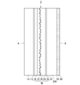
本発明の透過型の映像表示透明部材は、図17に示すように、いずれも光減衰成分が配合されて着色された第1の透明基材10Aおよび第2の透明基材20を有する映像表示透明部材5Bであってもよい。
映像表示透明部材5Bでは、映像表示透明部材5と同様の理由から、第2の面B側の観察者から見て映像表示透明部材5Bの向こう側の光景のコントラストが向上し、該光景の視認性に優れる。
As shown in FIG. 17, the transmissive image display transparent member of the present invention has a first transparent substrate 10A and a second
In the image display
本発明の反射型の映像表示透明部材は、図18に示すように、いずれも光減衰成分が配合されず着色されていない第1の透明基材10および第2の透明基材20Aを有し、第2の透明フィルム45Aに光減衰成分が配合されて着色され、透明部材を透過する光の一部を減衰させる光減衰層となっている映像表示部40Aを有する映像表示透明部材5Cであってもよい。
映像表示透明部材5Cでは、映像表示透明部材5と同様の理由から、第2の面B側の観察者から見て映像表示透明部材5Cの向こう側の光景のコントラストが向上し、該光景の視認性に優れる。
As shown in FIG. 18, the reflective image display transparent member of the present invention has a first
In the image display
また、映像表示透明部材5Cにおいて、第2の透明フィルム45Aの代わりに、第1の透明フィルム41に光減衰成分が配合されて着色され、透明部材を透過する光の一部を減衰させる光減衰層となっている映像表示透明部材であってもよい。また、第1の透明フィルム41と第2の透明フィルム45の両方に光減衰成分が配合されて着色され、透明部材を透過する光の一部を減衰させる光減衰層となっている映像表示透明部材であってもよい。
また、本発明の透過型の映像表示透明部材は、映像表示透明部材5において、第2の透明基材20の代わりに、光減衰成分が配合されていない第2の透明基材20Aを有し、接着層12および接着層22のいずれか一方もしくは両方に光減衰成分が配合されて着色され、透明部材を透過する光の一部を減衰させる光減衰層となっている映像表示透明部材であってもよい。
映像表示部の透明フィルムや接着層に配合される光減衰成分としては、たとえば、光減衰層50で挙げたものと同じものが挙げられる。
Further, in the image display
Further, in the transparent
Examples of the light-attenuating component to be blended in the transparent film or the adhesive layer of the image display portion include the same ones as those mentioned for the light-attenuating
光減衰層となっている部材の機能としては、透過率を減少させる機能を持っていればよいため、ハーフミラーを光減衰層として用いてもよい。
ハーフミラーの反射率としては、5%以上であればよく、10%以上であると好ましく、場合によっては、25%以上であってもよい。
ハーフミラーを、光散乱部43と投影機との間に配置することにより、上記の効果に加えて、マジックミラーとしての機能を付与できるため、前方への映像抜けを観察者へ認識させにくくすることができるようになる。また、光散乱部43と投影機との間ではない部分に配置することにより、両面への投影を可能とする。
本発明の透過型の映像表示透明部材における光減衰層の態様としては、上述の通り、図10および図12の第2の透明基材20、図13の第1の透明基材10A、図14~図16の着色透明フィルム、図17における第1の透明基材10Aおよび第2の透明基材20に例示したような透明基材や透明フィルム、およびハーフミラーが挙げられる。
As for the function of the member serving as the light attenuation layer, it is sufficient that it has the function of reducing the transmittance, so a half mirror may be used as the light attenuation layer.
The reflectance of the half mirror may be 5% or more, preferably 10% or more, and may be 25% or more in some cases.
By arranging the half mirror between the
Embodiments of the light attenuation layer in the transmissive image display transparent member of the present invention include the second
本発明の透過型の映像表示透明部材においては、光散乱部43の長手方向に直交する断面の形状は、図示例のような直角三角形に限定されず、他の三角形、台形、釣鐘形状等であってもよい。
映像表示部の光散乱シートの他の例としては、体積ホログラムによって、透過、偏向、拡散されるもの;キノフォーム型ホログラム、その他凹凸表面を形成した構成によって、偏向、散乱、拡散されるもの等が挙げられる。
In the transmissive image display transparent member of the present invention, the cross-sectional shape of the
Other examples of the light-scattering sheet for the image display part include those that are transmitted, deflected, and diffused by a volume hologram; those that are deflected, scattered, and diffused by a kinoform-type hologram and other structures having an uneven surface. is mentioned.
また、映像表示部の光散乱シートとしては、透明層内に図示例のような複数の光散乱部を設けることなく、透明層全体に光散乱微粒子を分散させて透明層自体を光散乱層としたものであってもよい。
光散乱微粒子としては、上述した酸化チタン、酸化ジルコニウム、酸化アルミニウム等の高屈折率材料の微粒子;ポーラスシリカ、中空シリカ等の低屈折率材料の微粒子等が挙げられる。光散乱微粒子の濃度は、0.01~5体積%が好ましく、0.05~1体積%がより好ましい。光散乱微粒子の平均粒子径は、上述した理由から、50~1000nmが好ましく、100~800nmがより好ましい。
光散乱層は、上述した理由から、光減衰材料を含んでいてもよい。光減衰材料の濃度は、0.01~5体積%が好ましく、0.1~3体積%がより好ましい。
In addition, as a light scattering sheet for the image display portion, light scattering fine particles are dispersed in the entire transparent layer without providing a plurality of light scattering portions in the transparent layer as in the illustrated example, and the transparent layer itself serves as a light scattering layer. It may be
Examples of light scattering fine particles include fine particles of high refractive index materials such as titanium oxide, zirconium oxide and aluminum oxide; fine particles of low refractive index materials such as porous silica and hollow silica. The concentration of the light scattering fine particles is preferably 0.01 to 5% by volume, more preferably 0.05 to 1% by volume. For the reasons described above, the average particle diameter of the light scattering fine particles is preferably 50 to 1000 nm, more preferably 100 to 800 nm.
The light-scattering layer may include light-attenuating materials for the reasons discussed above. The concentration of the light-attenuating material is preferably 0.01-5% by volume, more preferably 0.1-3% by volume.
以下、実施例によって本発明を詳細に説明するが、本発明は以下の記載によっては限定されない。
例2、4は実施例であり、例1、3は比較例である。
EXAMPLES The present invention will be described in detail below with reference to Examples, but the present invention is not limited by the following description.
Examples 2 and 4 are examples, and examples 1 and 3 are comparative examples.
(例1)
透明なポリエチレンテレフタレート(以下、PETと記す。)フィルム(東洋紡社製、コスモシャイン(登録商標)A4300、厚さ:0.1mm)の表面に、紫外線硬化性樹脂(大阪ガスケミカル社製、オグソール(登録商標)EA-F5003)100質量部に対し、光開始剤(BASF社製、イルガキュア(登録商標)907)を3質量部混合した溶液をダイコート法によって10μmの厚みに塗布した。
不規則な凹凸構造が表面に形成された白色PETフィルム(東レ社製E20、算術平均粗さRa:0.23μm)を、凹凸構造が紫外線硬化性樹脂に接するように、紫外線硬化性樹脂の上に重ねた。
(Example 1)
On the surface of a transparent polyethylene terephthalate (hereinafter referred to as PET) film (manufactured by Toyobo Co., Ltd., Cosmoshine (registered trademark) A4300, thickness: 0.1 mm), an ultraviolet curable resin (manufactured by Osaka Gas Chemicals Co., Ltd., Ogusol ( A solution obtained by mixing 100 parts by mass of a photoinitiator (Irgacure (registered trademark) 907, manufactured by BASF) with 100 parts by mass of a registered trademark EA-F5003) was applied to a thickness of 10 μm by a die coating method.
A white PET film (manufactured by Toray Industries, Inc. E20, arithmetic mean roughness Ra: 0.23 μm) with an irregular uneven structure formed on the surface is placed on the UV curable resin so that the uneven structure is in contact with the UV curable resin. overlaid on
透明PETフィルムの側から1000mJの紫外線を照射し、紫外線硬化性樹脂を硬化させて、白色PETフィルムの不規則な凹凸構造が表面に転写された第1の透明層を形成した後、白色PETフィルムを剥離した。
第1の透明層の表面に、アルミニウムを真空蒸着法によって物理蒸着し、アルミニウム薄膜(厚さ:8nm)からなる反射膜を形成した。
UV rays of 1000 mJ are irradiated from the transparent PET film side to cure the UV curable resin to form a first transparent layer with the irregular concave-convex structure of the white PET film transferred to the surface, and then the white PET film. was peeled off.
A reflective film made of an aluminum thin film (thickness: 8 nm) was formed on the surface of the first transparent layer by physical vapor deposition of aluminum by a vacuum vapor deposition method.
反射膜の表面に、紫外線硬化性樹脂(大阪ガスケミカル社製、オグソール(登録商標)EA-F5003)100質量部に対し、光開始剤(BASF社製、イルガキュア(登録商標)907)を3質量部混合した溶液をダイコート法によって10μmの厚みに塗布し、紫外線硬化性樹脂の上に透明PETフィルム(厚さ:0.1mm)を重ねた。
1000mJの紫外線を照射し、紫外線硬化性樹脂を硬化させて、第2の透明層を形成することによって、光散乱シートからなる例1の映像表示部を得た。
On the surface of the reflective film, 100 parts by mass of an ultraviolet curable resin (Ogusol (registered trademark) EA-F5003, manufactured by Osaka Gas Chemicals Co., Ltd.) and a photoinitiator (Irgacure (registered trademark) 907, manufactured by BASF) are added by 3 masses. The mixed solution was applied to a thickness of 10 μm by a die coating method, and a transparent PET film (thickness: 0.1 mm) was layered on the ultraviolet curable resin.
The image display portion of Example 1 made of the light scattering sheet was obtained by irradiating 1000 mJ of ultraviolet rays to cure the ultraviolet curable resin to form a second transparent layer.
ソーダライムガラス板(松浪硝子社製、厚さ:3mm)、ポリビニルブチラール(以下、PVBと記す。)フィルム(Solutia社製 Saflex RK11l、厚さ:375μm)、例1の映像表示部、PVBフィルム(厚さ:375μm)、ソーダライムガラス板(厚さ:3mm)の順に積層し、真空加熱圧着を行い、例1の反射型の映像表示透明部材を得た。例1の映像表示透明部材の評価結果を表1に示す。 Soda lime glass plate (manufactured by Matsunami Glass Co., Ltd., thickness: 3 mm), polyvinyl butyral (hereinafter referred to as PVB) film (Saflex RK11l manufactured by Solutia, thickness: 375 μm), image display part of Example 1, PVB film ( Thickness: 375 μm) and a soda-lime glass plate (thickness: 3 mm) were laminated in this order and subjected to vacuum heating and pressure bonding to obtain a reflective image display transparent member of Example 1. Table 1 shows the evaluation results of the image display transparent member of Example 1.
(例2)
例1の映像表示透明部材において、第2の透明基材として色つきガラス(旭硝子社製、<商品名>マイベール、厚さ:3mm、xyY表色系において、x=0.3069、y=0.3126、Y=28.54)を用いて、例2の反射型の映像表示透明部材を得た。例2の映像表示透明部材の評価結果を表1に示す。
(Example 2)
In the image display transparent member of Example 1, colored glass (manufactured by Asahi Glass Co., Ltd., <trade name> Myveil, thickness: 3 mm, x = 0.3069, y = 0 in the xyY color system) is used as the second transparent base material. .3126, Y=28.54) to obtain a reflective image display transparent member of Example 2. Table 1 shows the evaluation results of the image display transparent member of Example 2.
(例3)
透明PETフィルム(東洋紡社製コスモシャイン(登録商標)A4300、厚さ:50μm)の表面に、紫外線硬化性樹脂(日立化成社製、ヒタロイド(登録商標)7981、比重1.1)をブレードコートによって厚さ80μm塗布した。
光散乱部に対応した断面直角三角形の複数の凸条が表面に形成されたモールドを、凸条が紫外線硬化性樹脂に接するように、温度:25℃、ゲージ圧:0.5MPaの条件で紫外線硬化性樹脂の上に押し付けた。
(Example 3)
The surface of a transparent PET film (Cosmoshine (registered trademark) A4300 manufactured by Toyobo Co., Ltd., thickness: 50 μm) was coated with an ultraviolet curable resin (manufactured by Hitachi Chemical Co., Ltd., Hitaroid (registered trademark) 7981, specific gravity 1.1) by blade coating. It was applied to a thickness of 80 μm.
A mold on the surface of which a plurality of ridges with a right-angled triangular cross section corresponding to the light scattering portion are formed is exposed to ultraviolet rays under the conditions of a temperature of 25°C and a gauge pressure of 0.5 MPa so that the ridges come into contact with the UV-curable resin. It was pressed onto the curable resin.
透明PETフィルムの側から紫外線を照射し、紫外線硬化性樹脂を硬化させて、モールドの凸条に対応する溝が表面に形成された透明層下層(厚さ:10μm)を形成した後、モールドを剥離した。これにより、100mm×100mmの領域の透明層下層の表面に、間隔:80μm、幅:40μm、深さ:80μm、長さ:100mm、断面形状:直角三角形の複数の溝が形成された。 Ultraviolet rays are irradiated from the transparent PET film side to cure the ultraviolet curable resin to form a transparent lower layer (thickness: 10 μm) having grooves corresponding to the ridges of the mold formed on the surface, and then the mold is removed. peeled off. As a result, a plurality of grooves having an interval of 80 μm, a width of 40 μm, a depth of 80 μm, a length of 100 mm, and a cross-sectional shape of a right triangle were formed on the surface of the lower layer of the transparent layer in an area of 100 mm×100 mm.
紫外線硬化性樹脂(日立化成社製、ヒタロイド(登録商標)7981、比重1.1)に、酸化チタン微粒子(平均粒子径:0.2μm、比重4.2)を0.1体積%となるように混合したペーストを用意した。
透明層下層の表面にペーストを供給し、余剰分をドクターブレードでかき取ることによって、透明層下層の溝にペーストを埋め込んだ。紫外線を照射し、ペーストを硬化させることによって、光散乱部を形成した。
Titanium oxide fine particles (average particle diameter: 0.2 μm, specific gravity 4.2) are added to an ultraviolet curable resin (Hitaroid (registered trademark) 7981, specific gravity 1.1, manufactured by Hitachi Chemical Co., Ltd.) so as to be 0.1% by volume. A paste was prepared by mixing
The paste was applied to the surface of the lower layer of the transparent layer, and the surplus was scraped off with a doctor blade to fill the grooves of the lower layer of the transparent layer with the paste. A light scattering portion was formed by curing the paste by irradiating with ultraviolet rays.
透明層下層の表面および光散乱部の表面に紫外線硬化性樹脂(日立化成社製、ヒタロイド(登録商標)7981、比重1.1)をダイコート法により5μm塗布し、紫外線硬化性樹脂の上に透明PETフィルムを重ねた。
紫外線を照射し、紫外線硬化性樹脂を硬化させて、透明層上層を形成することによって、光散乱シートからなる例3の映像表示部を得た。
An ultraviolet curable resin (manufactured by Hitachi Chemical Co., Ltd., Hitaroid (registered trademark) 7981, specific gravity 1.1) was applied to 5 μm on the surface of the lower layer of the transparent layer and the surface of the light scattering part by a die coating method, and a transparent resin was coated on the ultraviolet curable resin. A PET film was overlaid.
An image display portion of Example 3 made of a light scattering sheet was obtained by irradiating ultraviolet rays to cure the ultraviolet curable resin to form a transparent upper layer.
ソーダライムガラス板(松浪硝子社製、厚さ:3mm)、PVBフィルム(Solutia社製 Saflex(登録商標)RK11l、厚さ:375μm)、例3の映像表示部、PVBフィルム(厚さ:375μm)、ソーダライムガラス板(厚さ:3mm)の順に積層し、真空加熱圧着を行い、例3の透過型の映像表示透明部材を得た。例3の映像表示透明部材の評価結果を表1に示す。 Soda lime glass plate (manufactured by Matsunami Glass Co., Ltd., thickness: 3 mm), PVB film (Saflex (registered trademark) RK11l manufactured by Solutia, thickness: 375 μm), image display portion of Example 3, PVB film (thickness: 375 μm) , a soda-lime glass plate (thickness: 3 mm) were laminated in this order and subjected to vacuum heating and pressure bonding to obtain a transmissive image display transparent member of Example 3. Table 1 shows the evaluation results of the image display transparent member of Example 3.
(例4)
例3の映像表示透明部材において、第2の透明基材として色つきガラス(旭硝子社製、<商品名>マイベール、例2と同様のもの)を用いて、例4の透過型の映像表示透明部材を得た。例4の映像表示透明部材の評価結果を表1に示す。
(Example 4)
In the image display transparent member of Example 3, colored glass (manufactured by Asahi Glass Co., Ltd., <trade name> Myveil, similar to Example 2) is used as the second transparent base material, and the transmissive image display transparent member of Example 4 is used. got the parts. Table 1 shows the evaluation results of the image display transparent member of Example 4.

表中の評価基準は、下記のとおりである。
(光景視認性)
日中に屋外で映像表示透明部材を第2の面が太陽に面するように設置し、第2の面側の観察者から見て映像表示透明部材の向こう側に見える光景の視認性を、下記の基準にて評価した。
0:良好である。
1:手前が暗い場合、または外光が小さい場合は良好である。
2:大まかな認識が可能なレベルである。
3:光景を視認できない。
Evaluation criteria in the table are as follows.
(Sight visibility)
The image display transparent member is installed outdoors in the daytime so that the second surface faces the sun, and the visibility of the scene seen on the other side of the image display transparent member seen from the observer on the second surface side is Evaluation was made according to the following criteria.
0: Good.
1: Good when the front is dark or the outside light is small.
2: A level at which rough recognition is possible.
3: The scene cannot be visually recognized.
(映像視認性)
例1、2において、観察者Xから見て映像表示透明部材に表示される映像の視認性を、下記の基準にて評価した。
0:良好である。
1:周囲が暗い場合は良好である。
2:大まかな認識が可能なレベルである。
3:映像を視認できない。
(Image visibility)
In Examples 1 and 2, the visibility of the image displayed on the image display transparent member when viewed from the observer X was evaluated according to the following criteria.
0: Good.
1: Good when the surroundings are dark.
2: A level at which rough recognition is possible.
3: The image cannot be visually recognized.
本願の実施例である例2、および例4は、散乱光が制御され解像度が向上したため、光景の視認性が良好であった。 In Examples 2 and 4, which are examples of the present application, the visibility of the scene was good because the scattered light was controlled and the resolution was improved.
本発明の映像表示透明部材は、商品等のショーケース;美術品、動物等の展示ケース;建物、ショールーム、車両等の窓;ガラス扉;室内の透明パーティション;建物の外壁;時計、テレビ等に用いられる透明部材として有用である。具体的には、観察者側から見て透明部材の向こう側に見える光景を視認でき、かつ観察者に対して商品等の説明、各種機器の状態、行き先案内、伝達事項等の情報を伝達する際、観察者に対して各種機器の操作画面等を表示する際、またはプライバシー保護、セキュリティ等のために観察者に対して透明部材の向こう側の光景を視認できなくする際には、投影機から投射された映像光を観察者に映像として視認可能に表示する、いわゆる透明スクリーンとして有用である。
また、車両や航空機等の移動手段用の窓ガラスに用いると、透明スクリーンとしてもヘッドアップディスプレイとしても使えるため有用である。
なお、2014年6月23日に出願された日本特許出願2014-128552号の明細書、特許請求の範囲、図面及び要約書の全内容をここに引用し、本発明の明細書の開示として、取り入れるものである。
The image display transparent member of the present invention can be used for showcases of commodities, etc.; display cases for works of art, animals, etc.; windows of buildings, showrooms, vehicles, etc.; glass doors; indoor transparent partitions; It is useful as a transparent member used. Specifically, it is possible to visually recognize the scene seen on the other side of the transparent member when viewed from the observer side, and to transmit information such as product explanations, various equipment conditions, destination guidance, and communication items to the observer. When displaying the operation screen of various devices to the observer, or when making the scene beyond the transparent member invisible to the observer for privacy protection, security, etc. It is useful as a so-called transparent screen that visually displays image light projected from an image to an observer as an image.
Further, when used for window glass for transportation means such as vehicles and aircraft, it is useful because it can be used as both a transparent screen and a head-up display.
In addition, the entire contents of the specification, claims, drawings and abstract of Japanese Patent Application No. 2014-128552 filed on June 23, 2014 are cited here, and as a disclosure of the specification of the present invention, It is taken in.
1~3、5~7、1A~1C、4A、4B、5A~5C、8A、8B:映像表示透明部材、10:第1の透明基材、10A:第1の透明基材(光減衰層)、12:接着層、20:第2の透明基材(光減衰層)、20A:第2の透明基材、22:接着層、30、30A:映像表示部、31:第1の透明フィルム、32:第1の透明層、33:反射膜、34:第2の透明層、35:第2の透明フィルム、35A:第2の透明フィルム(光減衰層)、36:光硬化性樹脂、37:光硬化性樹脂、40、40A:映像表示部、41:第1の透明フィルム、42:透明層、42a:透明層下層、43:光散乱部、44:溝、45:第2の透明フィルム、45A:第2の透明フィルム(光減衰層)、46:光硬化性樹脂、47:光硬化性樹脂、48:ペースト、50:光減衰層、52:接着層、61:モールド、62:モールド、101:映像表示透明部材、102:映像表示透明部材、110:第1の透明基材、120:第2の透明基材、132:第1の透明層、133:反射膜、134:第2の透明層、142:透明層、143:光散乱部、200:投影機、A:第1の面、B:第2の面、L:映像光、X:観察者、Y:観察者 1 to 3, 5 to 7, 1A to 1C, 4A, 4B, 5A to 5C, 8A, 8B: image display transparent member, 10: first transparent substrate, 10A: first transparent substrate (light attenuation layer ), 12: Adhesive layer, 20: Second transparent substrate (light attenuation layer), 20A: Second transparent substrate, 22: Adhesive layer, 30, 30A: Image display part, 31: First transparent film , 32: first transparent layer, 33: reflective film, 34: second transparent layer, 35: second transparent film, 35A: second transparent film (light attenuation layer), 36: photocurable resin, 37: photocurable resin, 40, 40A: image display portion, 41: first transparent film, 42: transparent layer, 42a: transparent layer lower layer, 43: light scattering portion, 44: groove, 45: second transparent Film 45A: Second transparent film (light attenuation layer) 46: Photocurable resin 47: Photocurable resin 48: Paste 50: Light attenuation layer 52: Adhesive layer 61: Mold 62: Mold 101: Image display transparent member 102: Image display transparent member 110: First transparent substrate 120: Second transparent substrate 132: First transparent layer 133: Reflective film 134: Second 2 transparent layer, 142: transparent layer, 143: light scattering part, 200: projector, A: first surface, B: second surface, L: image light, X: observer, Y: observer
Claims (11)
前記第1の面と前記第2の面との間に、
透明層全体に光散乱微粒子が分散された光散乱層を有する映像表示部を備え、
前記映像表示部の前記第1の面側に第1の透明基材が、前記映像表示部の前記第2の面側に第2の透明基材が、それぞれ設けられており、
前記第2の透明基材は反射防止層ではなく、前記第2の透明基材の厚さが0.01mm以上であり、
前記透明基材のうち、少なくとも第2の透明基材が、前記映像表示透明部材を透過する光の一部を減衰させる光減衰層となっており、ガラス又は透明樹脂に光減衰成分が配合されて着色されたものである、映像表示透明部材。 It has a first surface and a second surface on the opposite side, transmits the scene on the first surface side so as to be visible to an observer on the second surface side, and transmits the scene on the second surface side. The image light that is visibly transmitted to the observer on the first surface side and projected from the projector installed on the first surface side is visibly displayed to the observer on the second surface side as an image. A transmissive image display transparent member that
Between the first surface and the second surface,
An image display unit having a light scattering layer in which light scattering fine particles are dispersed throughout the transparent layer,
A first transparent base material is provided on the first surface side of the image display part, and a second transparent base material is provided on the second surface side of the image display part,
the second transparent substrate is not an antireflection layer, and the second transparent substrate has a thickness of 0.01 mm or more;
Among the transparent substrates, at least the second transparent substrate serves as a light attenuation layer that attenuates part of the light transmitted through the image display transparent member, and the glass or transparent resin is mixed with a light attenuation component. An image display transparent member which is colored by
映像表示透明部材の第1の面側に設置された投影機と、
を備えた、映像表示システム。 The image display transparent member according to any one of claims 1 to 9;
a projector installed on the first surface side of the image display transparent member;
A video display system with
映像表示透明部材の第1の面側に設置された投影機から映像光を投射し、映像を表示させる、映像表示方法。 The image display transparent member according to any one of claims 1 to 9,
An image display method comprising projecting image light from a projector installed on a first surface side of an image display transparent member to display an image.
Applications Claiming Priority (2)
| Application Number | Priority Date | Filing Date | Title |
|---|---|---|---|
| JP2014128552 | 2014-06-23 | ||
| JP2014128552 | 2014-06-23 |
Related Parent Applications (1)
| Application Number | Title | Priority Date | Filing Date |
|---|---|---|---|
| JP2019070788A Division JP6725029B2 (en) | 2014-06-23 | 2019-04-02 | Image display transparent member, image display system, and image display method |
Publications (2)
| Publication Number | Publication Date |
|---|---|
| JP2020166290A JP2020166290A (en) | 2020-10-08 |
| JP7192829B2 true JP7192829B2 (en) | 2022-12-20 |
Family
ID=54938108
Family Applications (3)
| Application Number | Title | Priority Date | Filing Date |
|---|---|---|---|
| JP2016529569A Active JP6508205B2 (en) | 2014-06-23 | 2015-06-22 | Image display transparent member, image display system and image display method |
| JP2019070788A Active JP6725029B2 (en) | 2014-06-23 | 2019-04-02 | Image display transparent member, image display system, and image display method |
| JP2020102385A Active JP7192829B2 (en) | 2014-06-23 | 2020-06-12 | Image display transparent member, image display system and image display method |
Family Applications Before (2)
| Application Number | Title | Priority Date | Filing Date |
|---|---|---|---|
| JP2016529569A Active JP6508205B2 (en) | 2014-06-23 | 2015-06-22 | Image display transparent member, image display system and image display method |
| JP2019070788A Active JP6725029B2 (en) | 2014-06-23 | 2019-04-02 | Image display transparent member, image display system, and image display method |
Country Status (2)
| Country | Link |
|---|---|
| JP (3) | JP6508205B2 (en) |
| WO (1) | WO2015199026A1 (en) |
Families Citing this family (13)
| Publication number | Priority date | Publication date | Assignee | Title |
|---|---|---|---|---|
| JP7046791B2 (en) | 2016-02-25 | 2022-04-04 | 日華化学株式会社 | Reflective screens and sheets for reflective screens |
| JP6724424B2 (en) * | 2016-03-04 | 2020-07-15 | 大日本印刷株式会社 | Reflective screen, video display |
| JP2017156696A (en) * | 2016-03-04 | 2017-09-07 | 大日本印刷株式会社 | Reflection screen and image display device |
| US10877189B2 (en) * | 2016-03-25 | 2020-12-29 | Panasonic Intellectual Property Management Co., Ltd. | Mirror panel, mirror film and display system |
| JP6790616B2 (en) * | 2016-09-06 | 2020-11-25 | 大日本印刷株式会社 | Reflective screen, video display device |
| JP2018065732A (en) * | 2016-10-17 | 2018-04-26 | セントラル硝子株式会社 | Window glass comprising multiple layer glass with light-scattering coating film |
| CN110023794A (en) * | 2016-12-12 | 2019-07-16 | 日本电气硝子株式会社 | Transparent articles |
| EP3470892A3 (en) | 2017-10-11 | 2019-07-17 | Agc Inc. | Transparent screen |
| CN110928131A (en) * | 2019-12-06 | 2020-03-27 | 广东柯视丽科技有限公司 | Projection screen with positive projection black grid |
| JP7111128B2 (en) * | 2020-06-09 | 2022-08-02 | 大日本印刷株式会社 | Video display device |
| JP7070613B2 (en) * | 2020-07-08 | 2022-05-18 | 大日本印刷株式会社 | Video display device |
| JP7231093B2 (en) * | 2020-07-08 | 2023-03-01 | 大日本印刷株式会社 | Video display device |
| KR102403669B1 (en) * | 2020-07-21 | 2022-05-30 | 이프텍주식회사 | Method of manufacturing security film |
Citations (4)
| Publication number | Priority date | Publication date | Assignee | Title |
|---|---|---|---|---|
| WO2006016556A1 (en) | 2004-08-10 | 2006-02-16 | Kimoto Co., Ltd. | Transmission screen |
| US20060056021A1 (en) | 2004-08-04 | 2006-03-16 | Yeo Terence E | Multi-region light scattering element |
| JP2006227581A (en) | 2005-01-21 | 2006-08-31 | Dainippon Printing Co Ltd | Transmitting-reflecting projection screen, and projection system comprising same |
| JP2011017972A (en) | 2009-07-10 | 2011-01-27 | Lintec Corp | Screen to be stuck on transparent body |
Family Cites Families (19)
| Publication number | Priority date | Publication date | Assignee | Title |
|---|---|---|---|---|
| JPH09133969A (en) * | 1995-11-10 | 1997-05-20 | Toppan Printing Co Ltd | Projection screen |
| JP3993980B2 (en) * | 1999-12-22 | 2007-10-17 | 株式会社きもと | Transparent transmission screen |
| JP2001305660A (en) * | 2000-04-25 | 2001-11-02 | Item 16 Kk | Hologram screen |
| JP2002277962A (en) * | 2001-01-09 | 2002-09-25 | Denso Corp | Hologram screen |
| JP3552709B2 (en) * | 2002-07-17 | 2004-08-11 | 株式会社デンソー | Hologram screen |
| JP2005128343A (en) * | 2003-10-24 | 2005-05-19 | Seiko Epson Corp | Screen |
| JP2005292679A (en) * | 2004-04-05 | 2005-10-20 | Aterio Design Kk | Micromirror screen |
| JP2006003518A (en) * | 2004-06-16 | 2006-01-05 | Kiso Kasei Sangyo Kk | Reflection-cum-transmission projector screen |
| JP4200123B2 (en) * | 2004-06-30 | 2008-12-24 | 大日本印刷株式会社 | Projection screen and projection system including the same |
| JP2006119489A (en) * | 2004-10-25 | 2006-05-11 | Kimoto & Co Ltd | Reflective screen |
| JP2006163165A (en) * | 2004-12-09 | 2006-06-22 | Dainippon Printing Co Ltd | Projection system equipped with reflection type projection screen |
| JP2006317832A (en) * | 2005-05-16 | 2006-11-24 | Sony Corp | Reflection type screen |
| US7715103B2 (en) * | 2007-09-10 | 2010-05-11 | Microvision, Inc. | Buried numerical aperture expander having transparent properties |
| JP2009080208A (en) * | 2007-09-25 | 2009-04-16 | Kimoto & Co Ltd | Liquid crystal screen |
| JP5462443B2 (en) * | 2008-03-27 | 2014-04-02 | 株式会社東芝 | Reflective screen, display device and moving body |
| FR2971060B1 (en) * | 2011-01-31 | 2013-08-09 | Saint Gobain | TRANSPARENT ELEMENT WITH DIFFUSE REFLECTION |
| JP6186760B2 (en) * | 2012-06-06 | 2017-08-30 | 大日本印刷株式会社 | Screen and method for manufacturing screen |
| JP2014197163A (en) * | 2013-01-17 | 2014-10-16 | 株式会社ダイセル | Translucent diffusion type polarizing laminate and application of the same |
| JP2015060193A (en) * | 2013-09-20 | 2015-03-30 | 大日本印刷株式会社 | Reflection type screen, and video display system |
-
2015
- 2015-06-22 WO PCT/JP2015/067881 patent/WO2015199026A1/en active Application Filing
- 2015-06-22 JP JP2016529569A patent/JP6508205B2/en active Active
-
2019
- 2019-04-02 JP JP2019070788A patent/JP6725029B2/en active Active
-
2020
- 2020-06-12 JP JP2020102385A patent/JP7192829B2/en active Active
Patent Citations (4)
| Publication number | Priority date | Publication date | Assignee | Title |
|---|---|---|---|---|
| US20060056021A1 (en) | 2004-08-04 | 2006-03-16 | Yeo Terence E | Multi-region light scattering element |
| WO2006016556A1 (en) | 2004-08-10 | 2006-02-16 | Kimoto Co., Ltd. | Transmission screen |
| JP2006227581A (en) | 2005-01-21 | 2006-08-31 | Dainippon Printing Co Ltd | Transmitting-reflecting projection screen, and projection system comprising same |
| JP2011017972A (en) | 2009-07-10 | 2011-01-27 | Lintec Corp | Screen to be stuck on transparent body |
Also Published As
| Publication number | Publication date |
|---|---|
| JP6508205B2 (en) | 2019-05-08 |
| JP6725029B2 (en) | 2020-07-15 |
| WO2015199026A1 (en) | 2015-12-30 |
| JPWO2015199026A1 (en) | 2017-04-27 |
| JP2020166290A (en) | 2020-10-08 |
| JP2019124956A (en) | 2019-07-25 |
Similar Documents
| Publication | Publication Date | Title |
|---|---|---|
| JP7192829B2 (en) | Image display transparent member, image display system and image display method | |
| US9946147B2 (en) | Transmission-type transparent screen, image display system and image display method | |
| JP6529728B2 (en) | Image display system and image display method | |
| JP6569673B2 (en) | Video display transparent member, video display system, and video display method | |
| JP6756743B2 (en) | Transparent heat shield and heat insulating member with transparent screen function | |
| RU2624334C2 (en) | Method for projecting or reverse projecting on glass, comprising transparent layer element having diffuse reflection properties | |
| JP2017090617A (en) | Screen glass with dimming function and picture display system | |
| EP3151063B1 (en) | Video projection structure, video projection method, and video projection window | |
| JP5101257B2 (en) | Optical film for head-up display, head-up display, and moving body | |
| JP6736958B2 (en) | Transmissive transparent screen, video display system and video display method | |
| US20150212335A1 (en) | Reflective type imaging element and optical system, and method of manufacturing relective type imaging element | |
| WO2019022007A1 (en) | Laminated glass for vehicle | |
| JP2016012117A (en) | Image projection window | |
| JP2016109778A (en) | Light-transmissive transparent screen, and system and method for displaying image | |
| JP2016095456A (en) | Video display transparent member, video display system, and video display method | |
| JP2021534457A (en) | Vehicle projection assembly with side panes | |
| JP2016109894A (en) | Video display transparent member, video display system, and video display method | |
| KR101065725B1 (en) | Projection and/or rear projection screen | |
| JP2005208557A (en) | Reflex-type screen | |
| JP2005208558A (en) | Reflex-type screen | |
| JP2019200392A (en) | Transmissive screen | |
| WO2022188412A1 (en) | Display device | |
| JP6794984B2 (en) | Mirror with display device | |
| JP6565581B2 (en) | Transparent screen including video display transparent member and video display system | |
| JP2016089534A (en) | Partition panel and partition system |
Legal Events
| Date | Code | Title | Description |
|---|---|---|---|
| A621 | Written request for application examination |
Free format text: JAPANESE INTERMEDIATE CODE: A621 Effective date: 20200612 |
|
| A977 | Report on retrieval |
Free format text: JAPANESE INTERMEDIATE CODE: A971007 Effective date: 20210414 |
|
| A131 | Notification of reasons for refusal |
Free format text: JAPANESE INTERMEDIATE CODE: A131 Effective date: 20210629 |
|
| A131 | Notification of reasons for refusal |
Free format text: JAPANESE INTERMEDIATE CODE: A131 Effective date: 20220125 |
|
| A521 | Request for written amendment filed |
Free format text: JAPANESE INTERMEDIATE CODE: A523 Effective date: 20220328 |
|
| A02 | Decision of refusal |
Free format text: JAPANESE INTERMEDIATE CODE: A02 Effective date: 20220705 |
|
| A521 | Request for written amendment filed |
Free format text: JAPANESE INTERMEDIATE CODE: A523 Effective date: 20220906 |
|
| C60 | Trial request (containing other claim documents, opposition documents) |
Free format text: JAPANESE INTERMEDIATE CODE: C60 Effective date: 20220906 |
|
| A911 | Transfer to examiner for re-examination before appeal (zenchi) |
Free format text: JAPANESE INTERMEDIATE CODE: A911 Effective date: 20220913 |
|
| C21 | Notice of transfer of a case for reconsideration by examiners before appeal proceedings |
Free format text: JAPANESE INTERMEDIATE CODE: C21 Effective date: 20220920 |
|
| TRDD | Decision of grant or rejection written | ||
| A01 | Written decision to grant a patent or to grant a registration (utility model) |
Free format text: JAPANESE INTERMEDIATE CODE: A01 Effective date: 20221108 |
|
| A61 | First payment of annual fees (during grant procedure) |
Free format text: JAPANESE INTERMEDIATE CODE: A61 Effective date: 20221121 |
|
| R150 | Certificate of patent or registration of utility model |
Ref document number: 7192829 Country of ref document: JP Free format text: JAPANESE INTERMEDIATE CODE: R150 |