JP7192732B2 - Positional relationship detection system - Google Patents
Positional relationship detection system Download PDFInfo
- Publication number
- JP7192732B2 JP7192732B2 JP2019177157A JP2019177157A JP7192732B2 JP 7192732 B2 JP7192732 B2 JP 7192732B2 JP 2019177157 A JP2019177157 A JP 2019177157A JP 2019177157 A JP2019177157 A JP 2019177157A JP 7192732 B2 JP7192732 B2 JP 7192732B2
- Authority
- JP
- Japan
- Prior art keywords
- article
- unit
- detected
- detection
- positional relationship
- Prior art date
- Legal status (The legal status is an assumption and is not a legal conclusion. Google has not performed a legal analysis and makes no representation as to the accuracy of the status listed.)
- Active
Links
- 238000001514 detection method Methods 0.000 title claims description 139
- 238000012546 transfer Methods 0.000 claims description 125
- 239000000758 substrate Substances 0.000 claims description 35
- 238000003780 insertion Methods 0.000 claims description 17
- 230000037431 insertion Effects 0.000 claims description 17
- 238000000605 extraction Methods 0.000 claims description 16
- 230000032258 transport Effects 0.000 description 73
- 238000012545 processing Methods 0.000 description 10
- 238000000034 method Methods 0.000 description 7
- 239000004065 semiconductor Substances 0.000 description 7
- 238000004891 communication Methods 0.000 description 6
- 238000010586 diagram Methods 0.000 description 6
- 210000000078 claw Anatomy 0.000 description 5
- 238000006073 displacement reaction Methods 0.000 description 5
- 238000007689 inspection Methods 0.000 description 5
- 238000004804 winding Methods 0.000 description 5
- 238000013459 approach Methods 0.000 description 2
- 230000003028 elevating effect Effects 0.000 description 2
- 230000004308 accommodation Effects 0.000 description 1
- 230000032683 aging Effects 0.000 description 1
- 230000015572 biosynthetic process Effects 0.000 description 1
- 230000006866 deterioration Effects 0.000 description 1
- 238000005530 etching Methods 0.000 description 1
- 238000005755 formation reaction Methods 0.000 description 1
- 230000006870 function Effects 0.000 description 1
- 238000012423 maintenance Methods 0.000 description 1
- 230000007246 mechanism Effects 0.000 description 1
- 238000000206 photolithography Methods 0.000 description 1
- 230000008569 process Effects 0.000 description 1
- 239000010409 thin film Substances 0.000 description 1
Images


Classifications
-
- G—PHYSICS
- G01—MEASURING; TESTING
- G01B—MEASURING LENGTH, THICKNESS OR SIMILAR LINEAR DIMENSIONS; MEASURING ANGLES; MEASURING AREAS; MEASURING IRREGULARITIES OF SURFACES OR CONTOURS
- G01B21/00—Measuring arrangements or details thereof, where the measuring technique is not covered by the other groups of this subclass, unspecified or not relevant
-
- H—ELECTRICITY
- H01—ELECTRIC ELEMENTS
- H01L—SEMICONDUCTOR DEVICES NOT COVERED BY CLASS H10
- H01L21/00—Processes or apparatus adapted for the manufacture or treatment of semiconductor or solid state devices or of parts thereof
- H01L21/67—Apparatus specially adapted for handling semiconductor or electric solid state devices during manufacture or treatment thereof; Apparatus specially adapted for handling wafers during manufacture or treatment of semiconductor or electric solid state devices or components ; Apparatus not specifically provided for elsewhere
- H01L21/677—Apparatus specially adapted for handling semiconductor or electric solid state devices during manufacture or treatment thereof; Apparatus specially adapted for handling wafers during manufacture or treatment of semiconductor or electric solid state devices or components ; Apparatus not specifically provided for elsewhere for conveying, e.g. between different workstations
- H01L21/67703—Apparatus specially adapted for handling semiconductor or electric solid state devices during manufacture or treatment thereof; Apparatus specially adapted for handling wafers during manufacture or treatment of semiconductor or electric solid state devices or components ; Apparatus not specifically provided for elsewhere for conveying, e.g. between different workstations between different workstations
- H01L21/67736—Loading to or unloading from a conveyor
-
- B—PERFORMING OPERATIONS; TRANSPORTING
- B65—CONVEYING; PACKING; STORING; HANDLING THIN OR FILAMENTARY MATERIAL
- B65G—TRANSPORT OR STORAGE DEVICES, e.g. CONVEYORS FOR LOADING OR TIPPING, SHOP CONVEYOR SYSTEMS OR PNEUMATIC TUBE CONVEYORS
- B65G1/00—Storing articles, individually or in orderly arrangement, in warehouses or magazines
- B65G1/02—Storage devices
- B65G1/04—Storage devices mechanical
- B65G1/0457—Storage devices mechanical with suspended load carriers
-
- B—PERFORMING OPERATIONS; TRANSPORTING
- B65—CONVEYING; PACKING; STORING; HANDLING THIN OR FILAMENTARY MATERIAL
- B65G—TRANSPORT OR STORAGE DEVICES, e.g. CONVEYORS FOR LOADING OR TIPPING, SHOP CONVEYOR SYSTEMS OR PNEUMATIC TUBE CONVEYORS
- B65G1/00—Storing articles, individually or in orderly arrangement, in warehouses or magazines
- B65G1/02—Storage devices
- B65G1/04—Storage devices mechanical
- B65G1/137—Storage devices mechanical with arrangements or automatic control means for selecting which articles are to be removed
-
- G—PHYSICS
- G01—MEASURING; TESTING
- G01B—MEASURING LENGTH, THICKNESS OR SIMILAR LINEAR DIMENSIONS; MEASURING ANGLES; MEASURING AREAS; MEASURING IRREGULARITIES OF SURFACES OR CONTOURS
- G01B11/00—Measuring arrangements characterised by the use of optical techniques
-
- G—PHYSICS
- G01—MEASURING; TESTING
- G01B—MEASURING LENGTH, THICKNESS OR SIMILAR LINEAR DIMENSIONS; MEASURING ANGLES; MEASURING AREAS; MEASURING IRREGULARITIES OF SURFACES OR CONTOURS
- G01B11/00—Measuring arrangements characterised by the use of optical techniques
- G01B11/02—Measuring arrangements characterised by the use of optical techniques for measuring length, width or thickness
-
- H—ELECTRICITY
- H01—ELECTRIC ELEMENTS
- H01L—SEMICONDUCTOR DEVICES NOT COVERED BY CLASS H10
- H01L21/00—Processes or apparatus adapted for the manufacture or treatment of semiconductor or solid state devices or of parts thereof
- H01L21/67—Apparatus specially adapted for handling semiconductor or electric solid state devices during manufacture or treatment thereof; Apparatus specially adapted for handling wafers during manufacture or treatment of semiconductor or electric solid state devices or components ; Apparatus not specifically provided for elsewhere
- H01L21/67005—Apparatus not specifically provided for elsewhere
- H01L21/67242—Apparatus for monitoring, sorting or marking
- H01L21/67259—Position monitoring, e.g. misposition detection or presence detection
-
- H—ELECTRICITY
- H01—ELECTRIC ELEMENTS
- H01L—SEMICONDUCTOR DEVICES NOT COVERED BY CLASS H10
- H01L21/00—Processes or apparatus adapted for the manufacture or treatment of semiconductor or solid state devices or of parts thereof
- H01L21/67—Apparatus specially adapted for handling semiconductor or electric solid state devices during manufacture or treatment thereof; Apparatus specially adapted for handling wafers during manufacture or treatment of semiconductor or electric solid state devices or components ; Apparatus not specifically provided for elsewhere
- H01L21/673—Apparatus specially adapted for handling semiconductor or electric solid state devices during manufacture or treatment thereof; Apparatus specially adapted for handling wafers during manufacture or treatment of semiconductor or electric solid state devices or components ; Apparatus not specifically provided for elsewhere using specially adapted carriers or holders; Fixing the workpieces on such carriers or holders
- H01L21/6735—Closed carriers
-
- H—ELECTRICITY
- H01—ELECTRIC ELEMENTS
- H01L—SEMICONDUCTOR DEVICES NOT COVERED BY CLASS H10
- H01L21/00—Processes or apparatus adapted for the manufacture or treatment of semiconductor or solid state devices or of parts thereof
- H01L21/67—Apparatus specially adapted for handling semiconductor or electric solid state devices during manufacture or treatment thereof; Apparatus specially adapted for handling wafers during manufacture or treatment of semiconductor or electric solid state devices or components ; Apparatus not specifically provided for elsewhere
- H01L21/677—Apparatus specially adapted for handling semiconductor or electric solid state devices during manufacture or treatment thereof; Apparatus specially adapted for handling wafers during manufacture or treatment of semiconductor or electric solid state devices or components ; Apparatus not specifically provided for elsewhere for conveying, e.g. between different workstations
- H01L21/67703—Apparatus specially adapted for handling semiconductor or electric solid state devices during manufacture or treatment thereof; Apparatus specially adapted for handling wafers during manufacture or treatment of semiconductor or electric solid state devices or components ; Apparatus not specifically provided for elsewhere for conveying, e.g. between different workstations between different workstations
- H01L21/67706—Mechanical details, e.g. roller, belt
-
- H—ELECTRICITY
- H01—ELECTRIC ELEMENTS
- H01L—SEMICONDUCTOR DEVICES NOT COVERED BY CLASS H10
- H01L21/00—Processes or apparatus adapted for the manufacture or treatment of semiconductor or solid state devices or of parts thereof
- H01L21/67—Apparatus specially adapted for handling semiconductor or electric solid state devices during manufacture or treatment thereof; Apparatus specially adapted for handling wafers during manufacture or treatment of semiconductor or electric solid state devices or components ; Apparatus not specifically provided for elsewhere
- H01L21/677—Apparatus specially adapted for handling semiconductor or electric solid state devices during manufacture or treatment thereof; Apparatus specially adapted for handling wafers during manufacture or treatment of semiconductor or electric solid state devices or components ; Apparatus not specifically provided for elsewhere for conveying, e.g. between different workstations
- H01L21/67703—Apparatus specially adapted for handling semiconductor or electric solid state devices during manufacture or treatment thereof; Apparatus specially adapted for handling wafers during manufacture or treatment of semiconductor or electric solid state devices or components ; Apparatus not specifically provided for elsewhere for conveying, e.g. between different workstations between different workstations
- H01L21/67724—Apparatus specially adapted for handling semiconductor or electric solid state devices during manufacture or treatment thereof; Apparatus specially adapted for handling wafers during manufacture or treatment of semiconductor or electric solid state devices or components ; Apparatus not specifically provided for elsewhere for conveying, e.g. between different workstations between different workstations by means of a cart or a vehicule
-
- H—ELECTRICITY
- H01—ELECTRIC ELEMENTS
- H01L—SEMICONDUCTOR DEVICES NOT COVERED BY CLASS H10
- H01L21/00—Processes or apparatus adapted for the manufacture or treatment of semiconductor or solid state devices or of parts thereof
- H01L21/67—Apparatus specially adapted for handling semiconductor or electric solid state devices during manufacture or treatment thereof; Apparatus specially adapted for handling wafers during manufacture or treatment of semiconductor or electric solid state devices or components ; Apparatus not specifically provided for elsewhere
- H01L21/677—Apparatus specially adapted for handling semiconductor or electric solid state devices during manufacture or treatment thereof; Apparatus specially adapted for handling wafers during manufacture or treatment of semiconductor or electric solid state devices or components ; Apparatus not specifically provided for elsewhere for conveying, e.g. between different workstations
- H01L21/67703—Apparatus specially adapted for handling semiconductor or electric solid state devices during manufacture or treatment thereof; Apparatus specially adapted for handling wafers during manufacture or treatment of semiconductor or electric solid state devices or components ; Apparatus not specifically provided for elsewhere for conveying, e.g. between different workstations between different workstations
- H01L21/6773—Conveying cassettes, containers or carriers
-
- H—ELECTRICITY
- H01—ELECTRIC ELEMENTS
- H01L—SEMICONDUCTOR DEVICES NOT COVERED BY CLASS H10
- H01L21/00—Processes or apparatus adapted for the manufacture or treatment of semiconductor or solid state devices or of parts thereof
- H01L21/67—Apparatus specially adapted for handling semiconductor or electric solid state devices during manufacture or treatment thereof; Apparatus specially adapted for handling wafers during manufacture or treatment of semiconductor or electric solid state devices or components ; Apparatus not specifically provided for elsewhere
- H01L21/677—Apparatus specially adapted for handling semiconductor or electric solid state devices during manufacture or treatment thereof; Apparatus specially adapted for handling wafers during manufacture or treatment of semiconductor or electric solid state devices or components ; Apparatus not specifically provided for elsewhere for conveying, e.g. between different workstations
- H01L21/67703—Apparatus specially adapted for handling semiconductor or electric solid state devices during manufacture or treatment thereof; Apparatus specially adapted for handling wafers during manufacture or treatment of semiconductor or electric solid state devices or components ; Apparatus not specifically provided for elsewhere for conveying, e.g. between different workstations between different workstations
- H01L21/67733—Overhead conveying
-
- H—ELECTRICITY
- H01—ELECTRIC ELEMENTS
- H01L—SEMICONDUCTOR DEVICES NOT COVERED BY CLASS H10
- H01L21/00—Processes or apparatus adapted for the manufacture or treatment of semiconductor or solid state devices or of parts thereof
- H01L21/67—Apparatus specially adapted for handling semiconductor or electric solid state devices during manufacture or treatment thereof; Apparatus specially adapted for handling wafers during manufacture or treatment of semiconductor or electric solid state devices or components ; Apparatus not specifically provided for elsewhere
- H01L21/677—Apparatus specially adapted for handling semiconductor or electric solid state devices during manufacture or treatment thereof; Apparatus specially adapted for handling wafers during manufacture or treatment of semiconductor or electric solid state devices or components ; Apparatus not specifically provided for elsewhere for conveying, e.g. between different workstations
- H01L21/67763—Apparatus specially adapted for handling semiconductor or electric solid state devices during manufacture or treatment thereof; Apparatus specially adapted for handling wafers during manufacture or treatment of semiconductor or electric solid state devices or components ; Apparatus not specifically provided for elsewhere for conveying, e.g. between different workstations the wafers being stored in a carrier, involving loading and unloading
- H01L21/67775—Docking arrangements
-
- B—PERFORMING OPERATIONS; TRANSPORTING
- B65—CONVEYING; PACKING; STORING; HANDLING THIN OR FILAMENTARY MATERIAL
- B65G—TRANSPORT OR STORAGE DEVICES, e.g. CONVEYORS FOR LOADING OR TIPPING, SHOP CONVEYOR SYSTEMS OR PNEUMATIC TUBE CONVEYORS
- B65G2201/00—Indexing codes relating to handling devices, e.g. conveyors, characterised by the type of product or load being conveyed or handled
- B65G2201/02—Articles
- B65G2201/0297—Wafer cassette
Description
本発明は、搬送元と搬送先との間で物品を搬送する物品搬送車を備えた物品搬送設備において、搬送元及び搬送先の移載箇所との間で物品を移載する移載装置が備える物品保持部の移載箇所に対する位置関係を検出する位置関係検出システムに関する。 The present invention provides an article transport facility equipped with an article transport vehicle for transporting an article between a transport source and a transport destination, and a transfer device for transferring the article between the transfer locations of the transport source and the transport destination. The present invention relates to a positional relationship detection system for detecting the positional relationship of an article holding unit with respect to a transfer location.
物品を物品搬送車により自動的に搬送する物品搬送設備では、物品搬送車と搬送対象箇所との間で高い精度で物品を移載することが好ましい。具体的には、物品の搬送元において物品を精度良く保持し、搬送して、物品の搬送先の所定の位置に精度良く載置するためには、物品搬送車の停止位置や物品を保持する物品保持部が保持動作をする位置や姿勢が精度良く調整されていることが好ましい。特許第6146537号公報には、このような調整(ティーチング)を行う技術が開示されている。以下、背景技術において括弧内の符号は参照する文献のものである。 2. Description of the Related Art In an article conveying facility that automatically conveys articles by an article conveying vehicle, it is preferable to transfer articles between the article conveying vehicle and a location to be conveyed with high accuracy. Specifically, in order to accurately hold an article at its origin, convey it, and accurately place it at a predetermined position at its destination, it is necessary to determine the stop position of the article conveyance vehicle and hold the article. It is preferable that the position and posture at which the article holding portion performs the holding operation are adjusted with high accuracy. Japanese Patent No. 6146537 discloses a technique for such adjustment (teaching). Reference numerals in parentheses in the background art below refer to references.
物品搬送車にはティーチングユニット(20)が搭載され、搬送対象箇所に対応するロードポートにはターゲットユニット(30)が設置されている。ティーチングユニット(20)には、複数の距離センサ(23X1,23Y1,23Y2,23Z1,23Z2,23Z3)が搭載されている。複数の距離センサは、XYZ軸3次元直交座標系におけるX,Y,Z軸に沿った方向を検出方向としている。ターゲットユニット(30)には、それぞれX,Y,Z軸方向を検出方向とするそれぞれの距離センサの検出対象となるターゲットプレート(32,33,34)が備えられている。ティーチングユニット(20)は、複数の距離センサによるこれらのターゲットプレート(32,33,34)の検出結果に基づいて、物品搬送車の走行方向に平行な第一方向、基準面に平行且つ第一方向に直交する第二方向、基準面に平行な面内での回転方向、基準面の傾きを求める。 A teaching unit (20) is mounted on the article transport vehicle, and a target unit (30) is installed at the load port corresponding to the location to be transported. A plurality of distance sensors (23X 1 , 23Y 1 , 23Y 2 , 23Z 1 , 23Z 2 , 23Z 3 ) are mounted on the teaching unit (20). A plurality of distance sensors have detection directions along the X, Y, and Z axes in the XYZ axis three-dimensional orthogonal coordinate system. The target unit (30) is provided with target plates (32, 33, 34) that are detected by respective distance sensors whose detection directions are in the X-, Y-, and Z-axis directions. Based on the detection results of these target plates (32, 33, 34) by a plurality of distance sensors, the teaching unit (20) moves in the first direction parallel to the traveling direction of the article transport vehicle, parallel to the reference plane and in the first direction. A second direction orthogonal to the direction, a rotational direction in a plane parallel to the reference plane, and the inclination of the reference plane are obtained.
上記によれば、距離センサを備えたティーチングユニットとターゲットユニットとを用いたティーチングにより、物品搬送車の物品保持部の位置を精度良く検出することができる。しかし、検出精度を確保するためには、複数の距離センサの全てを精度よくティーチングユニットに取付ける必要がある。また、複数の異なる方向をそれぞれ検出するために複数の距離センサを用いているため、ティーチングユニットのコストが高くなり易い問題がある。 According to the above, it is possible to accurately detect the position of the article holding section of the article transport vehicle by teaching using the teaching unit having the distance sensor and the target unit. However, in order to ensure detection accuracy, it is necessary to attach all of the plurality of distance sensors to the teaching unit with high accuracy. Moreover, since a plurality of distance sensors are used to detect a plurality of different directions, there is a problem that the cost of the teaching unit tends to increase.
上記背景に鑑みて、より簡単な構成で適切に物品搬送車の物品保持部と移載箇所との位置関係を検出する技術の提供が望まれる。 In view of the above background, it is desired to provide a technique for appropriately detecting the positional relationship between the article holding section of the article transport vehicle and the transfer location with a simpler configuration.
1つの態様として、上記に鑑みた位置関係検出システムは、搬送元及び搬送先の移載箇所との間で物品を移載する移載装置を備えて前記搬送元と前記搬送先との間で物品を搬送する物品搬送車を備えた物品搬送設備において、前記移載装置が備える物品保持部の前記移載箇所に対する位置関係を検出する位置関係検出システムであって、前記物品保持部に保持される第1ユニットと、前記移載箇所に設置される第2ユニットと、を備え、前記第1ユニット及び前記第2ユニットの一方はセンサユニットであり、他方は前記センサユニットによる検出対象を備えた被検出ユニットであり、前記センサユニットは、当該センサユニットにおける検出基準点から前記被検出ユニットに設定された複数の被検出点までの距離を検出し、前記被検出ユニットは、前記移載箇所において前記センサユニットに対向するように設定された基準面に沿った第1方向及び前記基準面に沿うと共に前記第1方向に直交する第2方向における、前記移載箇所に対する前記物品保持部の相対位置を示す平面相対位置、前記基準面に対する前記物品保持部の傾き、前記基準面に直交する基準軸周りの前記物品保持部の回転角度、の内の少なくとも2つを前記検出基準点からの距離に応じた値として検出可能な複数の被検出面を備えて立体的に形成され、前記回転角度を検出する前記被検出面は、前記基準軸周りに一方側に旋回するに従って前記検出基準点からの距離が一定の割合で増加するように配置された螺旋状面である。 As one aspect, a positional relationship detection system in view of the above is provided with a transfer device that transfers an article between a transfer location of a transfer source and a transfer destination, and between the transfer source and the transfer destination In an article transport facility having an article transport vehicle for transporting an article, a positional relationship detection system for detecting a positional relationship of an article holding section provided in the transfer device with respect to the transfer location, wherein the article is held by the article holding section. and a second unit installed at the transfer location, one of the first unit and the second unit being a sensor unit, and the other being an object to be detected by the sensor unit. a detection target unit, wherein the sensor unit detects a distance from a detection reference point in the sensor unit to a plurality of detection points set in the detection target unit; Relative positions of the article holding section with respect to the transfer location in a first direction along a reference plane set to face the sensor unit and in a second direction along the reference plane and orthogonal to the first direction. at least two of the plane relative position indicating the reference plane, the inclination of the article holding section with respect to the reference plane, and the rotation angle of the article holding section around the reference axis perpendicular to the reference plane, at least two of which are the distance from the detection reference point The surface to be detected for detecting the rotation angle is three-dimensionally formed with a plurality of surfaces to be detected that can be detected as corresponding values, and the surface to be detected for detecting the rotation angle is shifted from the detection reference point as it turns to one side around the reference axis. It is a helical plane arranged so that the distance increases at a constant rate .
この構成によれば、1つのセンサユニットによって検出基準点から複数の被検出点までの距離が検出される。複数のセンサを取り付ける必要がないため、複数のセンサ同士の取り付け精度等を考慮する必要もなく、簡単な構成で検出精度を確保することができる。また、立体的に形成された被検出ユニットには、平面相対位置、傾き、回転角度の内の少なくとも2つを検出基準点からの距離に応じた値として検出可能な複数の被検出面を備えている。従って、1つのセンサユニットによって、物品保持部の移載箇所に対する位置関係を示す平面相対位置、傾き、回転角度の内の少なくとも2つを検出することができる。
また、本構成によれば、回転角度を検出する被検出面が、基準軸周りに一方側に旋回するに従って前記検出基準点からの距離が一定の割合で増加するように配置された螺旋状面であるから、基準軸周りに旋回する方向において物品保持部と移載箇所との相対位置が規定された位置からずれていた場合には、検出基準点からの距離が正常な場合と異なる値となる。検出された検出基準点からの距離と規定の距離との差分と、螺旋状面の傾斜角度とに基づけば、旋回方向におけるずれ量を求めることができる。そして、例えば、当該ずれ量と、基準軸周りに1周する場合の旋回距離とに基づけば、物品保持部の回転角度を求めることができる。
このように、本構成によれば、より簡単な構成で適切に物品搬送車の物品保持部と移載箇所との位置関係を検出する技術を提供することができる。
According to this configuration, the distances from the detection reference point to the plurality of detection points are detected by one sensor unit. Since it is not necessary to attach a plurality of sensors, there is no need to consider the attachment accuracy of the plurality of sensors, etc., and detection accuracy can be ensured with a simple configuration. Further, the three-dimensionally formed detection target unit has a plurality of detection target surfaces capable of detecting at least two of the plane relative position, the tilt, and the rotation angle as values according to the distance from the detection reference point. ing. Therefore, one sensor unit can detect at least two of the planar relative position, the tilt, and the rotation angle, which indicate the positional relationship of the article holding section with respect to the transfer location .
Further, according to this configuration, the surface to be detected for detecting the rotation angle is a helical surface arranged so that the distance from the detection reference point increases at a constant rate as it turns in one direction around the reference axis. Therefore, when the relative position between the article holding section and the transfer location deviates from the specified position in the direction of turning around the reference axis, the distance from the detection reference point is a different value than when it is normal. Become. Based on the difference between the detected distance from the detection reference point and the prescribed distance, and the inclination angle of the helical surface, the deviation amount in the turning direction can be obtained. Then, for example, the rotation angle of the article holding portion can be obtained based on the amount of deviation and the turning distance in the case of making one turn around the reference axis.
As described above, according to this configuration, it is possible to provide a technique for appropriately detecting the positional relationship between the article holding section of the article transport vehicle and the transfer location with a simpler configuration.
また、別の態様として、位置関係検出システムは、搬送元及び搬送先の移載箇所との間で物品を移載する移載装置を備えて前記搬送元と前記搬送先との間で物品を搬送する物品搬送車を備えた物品搬送設備において、前記移載装置が備える物品保持部の前記移載箇所に対する位置関係を検出する位置関係検出システムであって、前記物品保持部に保持される第1ユニットと、前記移載箇所に設置される第2ユニットと、を備え、前記第1ユニット及び前記第2ユニットの一方はセンサユニットであり、他方は前記センサユニットによる検出対象を備えた被検出ユニットであり、前記センサユニットは、当該センサユニットにおける検出基準点から前記被検出ユニットに設定された複数の被検出点までの距離を検出し、前記被検出ユニットは、前記移載箇所において前記センサユニットに対向するように設定された基準面に沿った第1方向及び前記基準面に沿うと共に前記第1方向に直交する第2方向における、前記移載箇所に対する前記物品保持部の相対位置を示す平面相対位置、前記基準面に対する前記物品保持部の傾き、前記基準面に直交する基準軸周りの前記物品保持部の回転角度、の内の少なくとも2つを前記検出基準点からの距離に応じた値として検出可能な複数の被検出面を備えて立体的に形成され、前記物品は、複数の基板を収容する収納容器であり、前記収納容器は、複数の前記基板のそれぞれを保持する複数のスリットと、当該スリットに前記基板を出し入れするための挿抜口と、前記挿抜口を閉じる蓋部と、を備え、前記センサユニットは、前記スリットによって支持されると共に、前記蓋部によって前記スリットに沿う方向の位置決めが行われている。 In another aspect, the positional relationship detection system includes a transfer device that transfers an article between a transfer location of a transfer source and a transfer destination, and transfers the article between the transfer source and the transfer destination. A positional relationship detection system for detecting a positional relationship of an article holding unit provided in the transfer device with respect to the transfer location in an article conveying facility having an article conveying vehicle for conveying, the positional relationship detecting system comprising: 1 unit, and a second unit installed at the transfer location, wherein one of the first unit and the second unit is a sensor unit, and the other is a target to be detected by the sensor unit. The sensor unit detects distances from a detection reference point in the sensor unit to a plurality of detection points set in the detection unit, and the detection unit detects the sensor at the transfer location. 4 shows relative positions of the article holding section with respect to the transfer location in a first direction along a reference plane set to face the unit and in a second direction along the reference plane and perpendicular to the first direction; At least two of a plane relative position, an inclination of the article holding portion with respect to the reference plane, and a rotation angle of the article holding portion around a reference axis perpendicular to the reference plane are set according to the distance from the detection reference point. The object is a storage container that is three-dimensionally formed with a plurality of surfaces to be detected that can be detected as values, and that stores a plurality of substrates. A slit, an insertion/extraction opening for inserting/removing the substrate into/from the slit, and a lid portion for closing the insertion/extraction opening, wherein the sensor unit is supported by the slit and along the slit by the lid portion. Orientation is done.
この構成によれば、1つのセンサユニットによって検出基準点から複数の被検出点までの距離が検出される。複数のセンサを取り付ける必要がないため、複数のセンサ同士の取り付け精度等を考慮する必要もなく、簡単な構成で検出精度を確保することができる。また、立体的に形成された被検出ユニットには、平面相対位置、傾き、回転角度の内の少なくとも2つを検出基準点からの距離に応じた値として検出可能な複数の被検出面を備えている。従って、1つのセンサユニットによって、物品保持部の移載箇所に対する位置関係を示す平面相対位置、傾き、回転角度の内の少なくとも2つを検出することができる。 According to this configuration, the distances from the detection reference point to the plurality of detection points are detected by one sensor unit. Since it is not necessary to attach a plurality of sensors, there is no need to consider the attachment accuracy of the plurality of sensors, etc., and detection accuracy can be ensured with a simple configuration. Further, the three-dimensionally formed detection target unit has a plurality of detection target surfaces capable of detecting at least two of the plane relative position, the tilt, and the rotation angle as values according to the distance from the detection reference point. ing. Therefore, one sensor unit can detect at least two of the planar relative position, the tilt, and the rotation angle, which indicate the positional relationship of the article holding section with respect to the transfer location.
物品保持部と移載箇所との位置関係は、実際に物品搬送設備の搬送対象の物品の形状や重量に対応した検査用のユニットを用いることで、より精度良く検出できる可能性が高くなる。従って、搬送対象の物品が収納容器である場合には、当該収納容器を用いて検査用のユニットが構成されると好適である。例えば、物品保持部に保持される第1ユニットがセンサユニットの場合には、本構成のように、基板を保持するスリットを利用してセンサユニットを保持し、収納容器の挿抜口を閉じる蓋部を利用して、センサユニットの位置決めが行われる。従って、搬送対象の収納容器に、適切にセンサユニットを設置して、物品保持部と移載箇所との位置関係を精度良く検出することができる位置関係検出システムを構築することができる。 The positional relationship between the article holding section and the transfer location can be more accurately detected by using an inspection unit that corresponds to the shape and weight of the article to be actually conveyed by the article conveying equipment. Therefore, when the article to be transported is a storage container, it is preferable to construct an inspection unit using the storage container. For example, when the first unit held by the article holding portion is a sensor unit, the slit for holding the substrate is used to hold the sensor unit and the lid portion closes the insertion/extraction opening of the storage container as in this configuration. is used to position the sensor unit. Therefore, it is possible to construct a positional relationship detection system capable of accurately detecting the positional relationship between the article holding section and the transfer location by appropriately installing the sensor unit in the storage container to be transported.
このように、本構成によれば、より簡単な構成で適切に物品搬送車の物品保持部と移載箇所との位置関係を検出する技術を提供することができる。 As described above, according to this configuration, it is possible to provide a technique for appropriately detecting the positional relationship between the article holding section of the article transport vehicle and the transfer location with a simpler configuration.
位置関係検出システムのさらなる特徴と利点は、図面を参照して説明する実施形態についての以下の記載から明確となる。 Further features and advantages of the positional relationship detection system will become clear from the following description of the embodiments described with reference to the drawings.
以下、位置関係検出システムの実施形態を図面に基づいて説明する。図1は、位置関係検出システム100(図5等参照)が用いられる物品搬送設備200の構成例を模式的に示している。本実施形態では、半導体基板に対して、薄膜形成、フォトリソグラフィー、エッチングなどの種々の処理を行う複数の半導体処理装置(処理装置202)の間で、走行経路LTに沿って一方向(走行方向Y)に物品W(図2等参照)を搬送する物品搬送車20を備えた物品搬送設備200を例として説明する。本実施形態では、走行経路LTは、支持ブラケット205(図4参照)によって支持されて天井側に設置された走行レールRL(図2、図4参照)によって形成されており、物品搬送車20は、走行レールRLに吊り下げ支持された天井搬送車である。
An embodiment of the positional relationship detection system will be described below with reference to the drawings. FIG. 1 schematically shows a configuration example of an
図1に示すように、物品搬送設備200には、少なくとも2つの異なる属性の領域(第1エリアE1及び第2エリアE2)が設けられている。第1エリアE1には、相対的に大きな環状の主経路Lpと、相対的に小さな環状の副経路Lsとが形成されている。第1エリアE1は、上述した処理装置202が備えられて、各処理装置202(後述する載置台203)の間を、物品搬送車20によって物品Wが搬送される領域である。第2エリアE2は、第1エリアE1とは別の領域に設けられ、後述する位置関係検出システム100を用いて物品搬送車20の調整が行われる領域である。第2エリアE2には、後述する被検出ユニット4が備えられた調整用載置台204が床面上に設置されている。尚、調整用載置台204と処理装置202に備えられた載置台203とは、床面から載置面までの高さが同一であり、それぞれの載置台203に対する調整が調整用載置台204を用いて実行される。
As shown in FIG. 1, the
本実施形態では、物品Wは、FOUP(Front Opening Unified Pod)と称され、複数枚の半導体基板を収容する容器である。図2は、物品保持部24により物品Wを保持した状態の物品搬送車20の側面図(走行方向Yに直交する方向に見た図)を示している。図2に示すように、物品Wは、フランジ部16と、収容部15とを有しており、収容部15の前面(例えば走行方向Yの側)には、半導体基板を出し入れするための挿抜口12(図9参照)が形成されている。この挿抜口12は着脱可能な蓋部14(図9参照)によって閉じることが可能である。収容部15の内部には、複数の半導体基板(基板)のそれぞれを保持する複数のスリット13が形成されている(図9参照)。
In this embodiment, the article W is called a FOUP (Front Opening Unified Pod), and is a container that accommodates a plurality of semiconductor substrates. FIG. 2 shows a side view (viewed in a direction perpendicular to the running direction Y) of the
処理装置202は、容器(物品W)に収容されている基板(半導体基板)に対して上述したような種々の処理を行う。容器(物品W)を各処理装置202の間で搬送するため、各処理装置202には、それぞれの処理装置202に隣接する状態で、床面上に載置台203が設置されている。これらの載置台203は、物品搬送車20による物品Wの搬送対象箇所(搬送元及び搬送先)である。物品搬送車20は、搬送元及び搬送先における移載箇所と物品搬送車20との間で物品Wを移載する移載装置28を備えている。物品搬送車20は、搬送元の載置台203から移載装置28により物品搬送車20に物品Wを移載し、走行経路LTを走行して、物品搬送車20から移載装置28により搬送先の載置台203に物品Wを移載することにより、搬送元と搬送先との間で物品Wを搬送する。
The
図3のブロック図は、物品搬送設備200及び物品搬送車20のシステム構成を模式的に示している。図4は、物品Wを保持する前の当該物品Wが載置された載置台203と物品搬送車20との関係を示している。図2及び図4に示すように、物品搬送車20は、走行経路LTに沿って走行する走行部22と、走行レールRLの下方に位置するように走行部22に吊り下げ支持され且つ物品Wを保持する物品保持部24を備えた本体部23とを備えている。
The block diagram of FIG. 3 schematically shows the system configuration of the
走行部22には、走行経路LTに沿って設置された走行レールRL上を転がる走行車輪22aと、その走行車輪22aを回転させる走行用モータ22mとが備えられている。本体部23は、物品保持部24と、昇降部25と、スライド部26と、回転部27と、カバー体23cとを備えている。物品保持部24と、昇降部25と、スライド部26と、回転部27とは、移載装置28を構成している。移載装置28は、搬送元及び搬送先の載置台203における移載箇所と物品搬送車20との間で物品Wを移載し、物品保持部24によって物品Wを保持した状態で物品Wを搬送する機構である。図2に示すように、物品Wのフランジ部16は、物品Wの上端部(収容部15よりも上方)に設けられており、物品保持部24によって支持される。物品搬送車20は、物品保持部24によってフランジ部16を吊り下げ支持した状態で物品Wを搬送する。
The running
昇降部25は、物品保持部24を走行部22に対して昇降移動させる駆動部である。スライド部26は、物品保持部24を走行部22に対して横方向X(水平面に沿い、走行方向Yに直交する)にスライド移動させる駆動部である。回転部27は、物品保持部24を走行部22に対して縦軸心Z(垂直方向の軸心)周りに回転させる駆動部である。カバー体23cは、図2に示すように、物品Wを支持した物品保持部24が、上昇基準位置まで上昇している状態で、物品Wの上方側及び経路前後側を覆う部材である。尚、上昇基準位置とは、物品Wを支持した状態で物品搬送車20が走行レールRLに沿って走行する際に、物品保持部24が位置する上下方向(垂直方向)の位置として予め規定された位置である。
The
以下、物品搬送設備200及び物品搬送車20のシステム構成を模式的に示す図3も参照して物品搬送車20の構成について説明する。物品保持部24には、一対の把持爪24aと、把持用モータ24m(図3参照)とが備えられている。図2に示すように、一対の把持爪24aのそれぞれは、各把持爪24aの下端部にて物品Wのフランジ部16を下方から支持するように、側面から見て(X方向に見て)L字状に形成されている。一対の把持爪24aは、把持用モータ24mの駆動力によって、水平方向に沿って、互いに接近及び離間する。物品保持部24は、支持状態と支持解除状態とに切換可能に構成されており、一対の把持爪24aが、接近することで支持状態となり、離間することで支持解除状態となる。
Hereinafter, the configuration of the
図2に示すように、物品Wを吊り下げ支持する物品保持部24は、物品保持部24と同じく移載装置28を構成する昇降部25により走行部22に対して昇降可能に支持されている。昇降部25には、巻回体25aと、巻き取りベルト25bと、昇降用モータ25m(図3参照)とが備えられている。巻回体25aは、後述する回転体27aに支持されている。巻き取りベルト25bは、巻回体25aに巻回されており、先端部には物品保持部24が連結支持されている。昇降用モータ25mは、巻回体25aを回転させるための動力を与える。昇降用モータ25mが巻回体25aを正方向に回転させることによって、巻き取りベルト25bを巻き取り、昇降用モータ25mが巻回体25aを逆方向に回転させることによって、巻き取りベルト25bを繰り出す。これによって、物品保持部24及び物品保持部24に支持された物品Wが昇降移動される。尚、昇降部25には、巻回体25aの繰り出し量をパルス数により計測するエンコーダ(不図示)も備えられている。作動制御部21(図3参照)は、このパルス数に基づいて物品保持部24の昇降高さを制御する。
As shown in FIG. 2, the
同じく本体部23を構成するスライド部26には、中継部26aと、スライド用モータ26m(図3参照)とが備えられている。中継部26aは、走行部22に対して横方向Xに沿ってスライド移動可能なように、走行部22に支持されている。スライド用モータ26mは、中継部26aを横方向Xに沿ってスライド移動させるための動力を与える。スライド部26は、スライド用モータ26mの駆動により中継部26aを横方向Xに沿ってスライド移動させることで、物品保持部24及び昇降部25を横方向Xに沿って移動させる。
A
同じく移載装置28を構成する回転部27には、回転体27aと、回転用モータ27m(図3参照)とが備えられている。回転体27aは、垂直方向(上下方向)に沿った縦軸心Z周りに回転可能に、中継部26aに対して支持されている。回転用モータ27mは、回転体27aを縦軸心周りに回転させるための動力を与える。回転部27は、回転用モータ27mの駆動により回転体27aを回転させることで、物品保持部24及び昇降部25を縦軸心Z周りに沿って回転させる。
The rotating
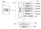
図3に示すように、物品搬送車20は、プロファイル記憶部29を備えている。プロファイル記憶部29は、メモリ等の記憶媒体により構成され、各載置台203において物品Wを移載するための位置や作動量の情報を含むプロファイル情報を記憶する。プロファイル情報には、各載置台203において物品Wを搬送及び移載するために走行経路LTにおいて物品搬送車20を停止させる停止目標位置の情報及び移載基準作動量の情報を含む。移載基準作動量は、例えば、走行部22に対する物品保持部24の縦軸心Z周りの回転量を規定する回転作動量、走行部22に対する物品保持部24の横方向Xでの移動量を規定するスライド作動量、及び、走行部22に対する物品保持部24の上下方向での作動量を規定する下降作動量を含む。移載基準作動量は、走行部22が走行レールRLを走行する際の物品保持部24の姿勢を基準としている。例えば、走行部22が走行レールRLを走行する際の物品保持部24の縦軸心周りの位置を回転基準位置とし、走行部22が走行する際の物品保持部24の横方向Xでの位置をスライド基準位置とし、走行部22が走行する際の物品保持部24の上下方向での位置を上昇設定位置とする。
As shown in FIG. 3 , the
物品搬送車20が物品搬送設備200に導入される際には適切なプロファイル情報が設定される。しかし、物品搬送車20の経年変化や消耗等によって、誤差が大きくなると、物品Wなどの物品が適正に移載できなくなる場合がある。例えば、走行車輪22aの摩耗等により、停止目標位置が、理想的な位置からずれる場合がある。また、昇降部25(昇降用モータ25mや巻き取りベルト25b)の経年劣化や消耗に伴って移載基準作動量と理想的な作動量とのずれが徐々に大きくなる場合もある。このため、例えば期間を定めて定期点検等が行われ、その際に調整が実施される。また、移載エラーが増加した場合などでは、個々の物品搬送車20に応じた適切な時期に調整が行われる場合がある。詳細は後述するが、位置関係検出システム100は、移載基準作動量に基づいて物品保持部24が作動した後の物品保持部24と移載箇所に対する位置関係を検出するシステムである。検出された位置関係に基づいて、移載基準作動量の設定や更新が行われる。
Appropriate profile information is set when the
搬送設備制御装置Hは、物品搬送設備200の中核となるシステムコントローラである。搬送設備制御装置Hは、物品搬送車20に対する上位コントローラであり、第1エリアE1における物品搬送車20の作動を制御して、物品Wを搬送するための搬送制御を実行する。また、搬送設備制御装置Hは、第2エリアE2における物品搬送車20の作動を制御して、物品搬送車20の調整を行う調整制御も実行する。尚、ここでは、搬送制御と調整制御とを共通の搬送設備制御装置Hが中核となって実行する形態を例示したが、それぞれ別の制御装置によって実行される形態であってもよい。
The transport facility control device H is a system controller that is the core of the
図3に示すように、物品搬送車20と搬送設備制御装置Hとは、例えば無線LAN等によってワイヤレス通信を行う。また、物品搬送車20と位置関係検出システム100のセンサユニット3とは、例えば近距離無線通信や無線LANによるワイヤレス通信や、ケーブル等を介した有線通信を行う。作動制御部21は、マイクロコンピュータ等によって構成され、搬送制御では、搬送設備制御装置Hからの指令に基づいて物品搬送車20を自律制御により作動させる。また、調整制御では、位置関係検出システム100と協働して、物品搬送車20の調整(プロファイル情報の設定や更新)を行う。
As shown in FIG. 3, the
以下、図5~図12も参照して説明する。位置関係検出システム100は、物品保持部24に保持される第1ユニット1と、移載箇所に設置される第2ユニット2とを備えている。第1ユニット1及び第2ユニット2の一方はセンサユニット3であり、他方はセンサユニット3による検出対象を備えた被検出ユニット4である。本実施形態では、第1ユニット1がセンサユニット3であり、第2ユニット2が被検出ユニット4である。
Description will be made below with reference to FIGS. 5 to 12 as well. The positional
センサユニット3は、当該センサユニット3における検出基準点Qから被検出体(ここでは被検出ユニット4)の複数箇所までの距離Kを検出することができる。即ち、センサユニット3は、検出基準点Qから被検出ユニット4に設定された複数の被検出点Rまでの距離Kを検出する。ここでは、センサユニット3は、センサユニット3に設定された検出基準面QPに直交する方向における距離Kを検出するものとする。従って、検出基準点Qは、それぞれの被検出点Rに対応して、検出基準面QP上に複数設定されている。当然ながら、1つの検出基準点Qからそれぞれの被検出点Rまでの距離が検出され、三角測量の原理を用いて距離Kが検出される形態であってもよい。
The
被検出ユニット4には、センサユニット3に対向するように基準面P0が設定されている。本実施形態では、被検出ユニット4は、基準面P0が水平面と平行となる状態で調整用載置台204に設置されている。被検出ユニット4は、基準面P0に沿った第1方向D1及び基準面P0に沿うと共に第1方向D1に直交する第2方向D2を基準とした基準位置に設置されている。つまり、被検出ユニット4は、調整用載置台204に対して基準姿勢で基準位置に設置されている。ここで、物品保持部24と調整用載置台204との位置関係が規定の位置関係となるように調整されているとき、センサユニット3と被検出ユニット4との相対位置及び相対姿勢は、基準位置関係にある。
A reference plane P<b>0 is set on the detected
図5に示すように、センサユニット3は、画像センサ31とレーザー32とを備えたセンサ本体部30と、センサ本体部30からの出力信号を増幅するアンプユニット34と、プログラマブルコントローラ36(PLC:Programmable Logic Controller)と、ディスプレイ35とを備えている。センサユニット3は、画像センサ31により検出対象(ここでは被検出ユニット4)を撮影することができる。撮影画像は、ディスプレイ35に表示される。作業者は、物品保持部24と調整用載置台204との位置関係が規定の位置関係(基準位置関係)となるように調整されており、センサユニット3と被検出ユニット4とが基準位置関係にある状態で、ディスプレイ35に表示された撮影画像(被検出ユニット4)上に被検出点Rを設定する。例えば、図7の平面図及び図8の側面図に示すように、撮影画像上の被検出ユニット4に対して被検出点Rが設定される。つまり、レーザー32は、これらの被検出点Rまでの距離Kを測定するように設定される。プログラマブルコントローラ36は、測定された被検出点Rまでの距離Kを、搬送設備制御装置Hへ送信する。
As shown in FIG. 5, the
図6の斜視図に示すように、被検出ユニット4は、移載箇所に対する物品保持部24の相対位置を示す平面相対位置(図11参照)、移載箇所に設定された基準面P0に対する物品保持部24の傾きφ(図12参照)、基準面P0に直交する基準軸Cの周りの物品保持部24の回転角度θ、の内の少なくとも2つを、センサユニット3が検出基準点Qからの距離Kに応じた値として検出可能な複数の被検出面40を備えている。尚、平面相対位置は、移載箇所においてセンサユニット3に対向するように設定された基準面P0に沿った第1方向D1及び基準面P0に沿うと共に第1方向D1に直交する第2方向D2における、移載箇所に対する物品保持部24の相対位置を示している。
As shown in the perspective view of FIG. 6, the unit to be detected 4 has a plane relative position (see FIG. 11) indicating the relative position of the
図6,図8等に示すように、第1方向D1における平面相対位置を検出する被検出面40は、第1方向D1の一方側へ向かうに従って検出基準点Qからの距離Kが一定の割合で増加するように配置された傾斜平面(第1傾斜平面41)である。また、第2方向D2における平面相対位置を検出する被検出面40は、第2方向D2の一方側へ向かうに従って検出基準点Qからの距離が一定の割合で増加するように配置された傾斜平面(第2傾斜平面42)である。
As shown in FIGS. 6, 8, etc., the detected
傾きを検出する被検出面40は、少なくとも3箇所に設けられている。これら3つの被検出面40(51,52,53)は、傾きが無い場合に検出基準点Qからの距離が同じとなるように配置され、基準面P0に平行な面(非傾斜平面50)である。3つの非傾斜平面50のそれぞれを区別する場合には、第1非傾斜平面51、第2非傾斜平面52、第3非傾斜平面53と称する。第1非傾斜平面51と第2非傾斜平面52とは、第2方向D2に沿って配置され、第2非傾斜平面52と第3非傾斜平面53とは第1方向D1に沿って配置されている。
At least three
基準軸C周りの回転角度θを検出する被検出面40は、基準軸C周りに一方側に旋回するに従って検出基準点Qからの距離が一定の割合で増加するように配置された螺旋状面43である。
The detected
尚、基準面P0に沿う各方向における被検出面40の幅は、移載箇所と物品保持部24との理論上のずれの最大値より大きくなるように設定されている。具体的には、第1傾斜平面41は、少なくとも基準面P0に沿うと共に第1方向D1に直交する方向(第2方向D2)の幅が、移載箇所と物品保持部24との第2方向D2における理論上のずれの最大値より大きくなるように設定されている。なお、当然ながら、第1傾斜平面41の第1方向D1の幅(長さ)は、移載箇所と物品保持部24との第1方向D1における理論上のずれの最大値より大きい。同様に、第2傾斜平面42は、少なくとも基準面P0に沿うと共に第2方向D2に直交する方向(第1方向D1)における幅が、移載箇所と物品保持部24との第1方向D1における理論上のずれの最大値より大きくなるように設定されている。なお、当然ながら、第2傾斜平面42の第2方向D2の幅(長さ)は、移載箇所と物品保持部24との第2方向D2における理論上のずれの最大値より大きい。
The width of the surface to be detected 40 in each direction along the reference plane P0 is set to be larger than the theoretical maximum value of deviation between the transfer location and the
また、螺旋状面43は、旋回方向D3に直交する方向における幅が、移載箇所と物品保持部24との基準面P0に沿う方向における理論上のずれの最大値より大きくなるように設定されている。旋回方向D3は、基準軸Cを中心とする円の円周に対応させることができるので、旋回方向D3に直交する方向は、当該円周の接線に直交する方向、即ち基準軸Cを中心とする円の径方向に相当する。従って、螺旋状面43は、基準軸Cを中心とする円の径方向における幅が、移載箇所と物品保持部24との当該径方向における理論上のずれの最大値より大きくなるように設定されている。また、非傾斜平面50は、第1方向D1及び第2方向D2における幅が、第1方向D1及び第2方向D2における理論上のずれの最大値より大きくなるように設定されている。
Further, the
ところで、調整制御に際しては、搬送制御と同様の条件で行われることが好ましい。上述したように、本実施形態では、搬送対象の物品Wは複数の基板(半導体基板)を収容する収納容器(FOUP)であるから、FOUPにセンサユニット3が設置されていると好適である。図9に示すように、収納容器としてのFOUPは、複数の基板のそれぞれを保持する複数のスリット13と、当該スリット13に基板を出し入れするための挿抜口12と、挿抜口12を閉じる蓋部14とを備えている。センサユニット3は、基板と同様の厚みを有する支持基板71に支持され、支持基板71がスリット13により支持されることによってFOUPに設置される。
By the way, it is preferable that the adjustment control is performed under the same conditions as the transport control. As described above, in the present embodiment, the article W to be transported is a storage container (FOUP) containing a plurality of substrates (semiconductor substrates), so it is preferable that the
センサユニット3の中核となるセンサ本体部30は、ブラケット72を介して支持基板71に吊り下げ支持されている。センサ本体部30による検出方向は、下方(FOUPの底に向かう方向)であるから、FOUPの底部には、貫通孔17が形成されている。センサユニット3は、貫通孔17を挟んで被検出ユニット4と対向し、センサユニット3と被検出ユニット4の各被検出点Rとの間の距離Kを検出する。尚、FOUPの底部の一部又は低部の全面が調整用載置台204の上面に接触した状態で、距離Kの検出が行われてもよい。このため、貫通孔17は、物品保持部24と調整用載置台204との位置関係が、理想的な位置関係から最大誤差範囲までずれた場合であっても、貫通孔17の内側にセンサユニット3の全体が収まる大きさに設定されている。
A sensor
図9に示すように、支持基板71には、アンプユニット34も吊り下げ支持されている。また、図示は省略しているが、例えば、バッテリーやDC-DCコンバータなどの電源ユニットや、通信ユニット、プログラマブルコントローラ36等も、支持基板71の上面に載置され、または下面に吊り下げ支持されている。また、FOUPには、挿抜口12の反対側に窓部18が形成されている。ディスプレイ35は、窓部18を介してFOUPの外部から作業者が視認可能に、支持基板71に吊り下げ支持されている。尚、窓部18は取り外し可能に構成されており、窓部18を取り外すことによって、作業者はディスプレイ35のタッチパネルを操作することができ、例えば上述したように基準位置関係において撮影された被検出ユニット4の撮影画像上において被検出点Rを設定することができる。
As shown in FIG. 9, the
図9及び図10に示すように、支持基板71には、挿抜口12の方向、即ち蓋部14の方向に突出した突出部73が形成されている。また、蓋部14には、挿抜口12を閉じた状態で突出部73に対向する位置に凹部14aが形成されている。センサユニット3を支持する支持基板71は、FOUPのスリット13によって支持されると共に、突出部73が凹部14aによって規制されることによって、支持基板71のスリット13に沿う方向の位置決めが行われている。つまり、センサユニット3は、スリット13によって支持されると共に、蓋部14によってスリット13に沿う方向の位置決めが行われている。
As shown in FIGS. 9 and 10, the
以下、図11及び図12を参照して、検出された距離Kと相対位置関係との対応について説明する。下記に説明するように、距離Kに基づいて、相対位置関係を示す平面相対位置、傾きφ、回転角度θを求めることができる。距離Kに基づく演算は、例えばセンサユニット3のアンプユニット34や不図示のコントローラによって実行されても良いし、搬送設備制御装置Hなど、センサユニット3とは別のコントローラによって実行されても良い。
The correspondence between the detected distance K and the relative positional relationship will be described below with reference to FIGS. 11 and 12. FIG. As described below, based on the distance K, it is possible to obtain the plane relative position, the inclination φ, and the rotation angle θ that indicate the relative positional relationship. The calculation based on the distance K may be performed by the
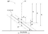
基準面P0に沿う方向に物品保持部24と被検出ユニット4との相対位置が基準位置関係からずれている場合、物品保持部24とセンサユニット3との相対位置も基準位置関係からずれている。図11の傾斜面は、第1傾斜平面41、第2傾斜平面42、螺旋状面43を示している。例えば、相対位置が基準位置関係に対して第1方向D1にずれている場合、検出基準点Qからの第1傾斜平面41における被検出点は、設定された被検出点Rからずれた点R’となる。同様に、相対位置が基準位置関係に対して第2方向D2にずれている場合、検出基準点Qからの第2傾斜平面42における被検出点は、設定された被検出点Rからずれた点R’となる。また、相対位置が基準軸C周りに基準位置関係に対して旋回している場合には、検出基準点Qからの螺旋状面43における被検出点は、設定された被検出点Rからずれた点R’となる。
When the relative positions of the
このようなずれが生じている場合、第1傾斜平面41、第2傾斜平面42、螺旋状面43と検出基準点Qとの間の距離Kは、誤差ΔKを含む値となる。第1方向D1へのずれ量をdとし、第1傾斜平面41の基準面P0に対する傾斜角度をSとすれば、誤差ΔKとずれ量dとの関係は三角関数の正接により“tanS=ΔK/d”と表すことができる。従って、第1方向D1へのずれ量dは、第1傾斜平面41の基準面P0に対する傾斜角度Sに基づいて演算することができる。同様に、第2方向D2へのずれ量dも、第2傾斜平面42の基準面P0に対する傾斜角度Sに基づいて演算することができる。このようにして、第1方向D1及び第2方向D2における相対位置を求めることで、平面相対位置を求めることができる。尚、傾斜角度Sは、第1傾斜平面41と第2傾斜平面42とで同じであっても良いし、異なっていても良い。
When such a deviation occurs, the distance K between the first
また、螺旋状面43におけるずれ量dは、基準面P0に平行な面上において基準軸Cと被検出点Rとを結ぶ線分を半径rとした円の円周に沿った長さに相当する。このずれ量dは、 旋回方向D3における変位量(回転角度θ)を用いて“d=2rπ・(θ/2π)=rθ”と表すことができる(π:円周率)。ずれ量dは、第1方向D1及び第2方向D2と同様に、誤差ΔKと、螺旋状面43の傾斜角度Sとに基づいて求めることができる。そして、半径rと円周上のずれ量dとに基づいて旋回方向D3における変位量(回転角度θ)を演算することができる。
Further, the amount of deviation d on the
上述したように、傾きを検出する3つの非傾斜平面50は、傾きが無い場合に検出基準点Qからの距離Kが同じとなるように配置されている。しかし、図12に示すように、物品保持部24と基準面P0との位置関係に傾きφが生じていると、検出基準点Qから第1非傾斜平面51までの距離Kと検出基準点Qから第2非傾斜平面52までの距離Kとの間、及び、検出基準点Qから第2非傾斜平面52までの距離Kと検出基準点Qから第3非傾斜平面53までの距離Kとの間、の一方または双方に誤差ΔHが生じる。第2方向D2に沿って配置された第1非傾斜平面51及び第2非傾斜平面52における誤差ΔH(ΔH1)は、第1非傾斜平面51における被検出点Rと第2非傾斜平面52における被検出点Rとの基準面P0に沿った方向における距離L(第1距離L1)を半径とする円の円周上における長さに近似することができる。そして、基準面P0に対する傾きφ(φ1)と、誤差ΔH(ΔH1)と、距離L(第1距離L1)との関係は、“tanφ1=L1/ΔH1”と表すことができる。従って、誤差ΔH(ΔH1)に基づいて、第2方向D2における基準面P0に対する傾きφ(φ1)を演算することができる。
As described above, the three non-tilt planes 50 for tilt detection are arranged so that the distances K from the detection reference point Q are the same when there is no tilt. However, as shown in FIG. 12, if there is an inclination φ in the positional relationship between the
同様に、第1方向D1に沿って配置された第2非傾斜平面52及び第3非傾斜平面53における誤差ΔH(ΔH2)は、第2非傾斜平面52における被検出点Rと第3非傾斜平面53における被検出点Rとの基準面P0に沿った方向における距離L(第2距離L2)を半径rとする円の円周上における長さに近似することができる。そして、基準面P0に対する傾きφ(φ2)と、誤差ΔH(ΔH2)と、距離L(第2距離L2)との関係は、“tanφ2=L2/ΔH2”と表すことができる。従って、誤差ΔH(ΔH2)に基づいて、第2方向D2における基準面P0に対する傾きφ(φ2)を演算することができる。そして、第2方向D2における傾きφ1と、第1方向D1における傾きφ2とに基づいて、基準面P0に対する物品保持部24の傾きφを演算することができる。
Similarly, the error ΔH (ΔH2) in the second
ところで、平面相対位置(第1方向D1及び第2方向D2における相対位置)が基準位置関係からずれている場合には、回転角度が基準位置関係に一致していても、螺旋状面43に対する距離Kに誤差ΔKが生じる可能性がある。逆に、回転角度θが基準位置関係からずれている場合には、第1傾斜平面41及び第2傾斜平面42に対する距離Kに誤差ΔKが生じる可能性がある。傾きφとの関係についても同様のことが言える。従って、上述したように、平面相対位置、回転角度θ、傾きφを求める際には、それぞれの被検出面40に対する距離Kの検出結果を考慮することが好ましい。
By the way, when the plane relative position (the relative position in the first direction D1 and the second direction D2) deviates from the reference positional relationship, even if the rotation angle matches the reference positional relationship, the distance to the
〔その他の実施形態〕
以下、その他の実施形態について説明する。尚、以下に説明する各実施形態の構成は、それぞれ単独で適用されるものに限られず、矛盾が生じない限り、他の実施形態の構成と組み合わせて適用することも可能である。
[Other embodiments]
Other embodiments will be described below. The configuration of each embodiment described below is not limited to being applied alone, and can be applied in combination with the configuration of other embodiments as long as there is no contradiction.
(1)上記においては、センサユニット3に撮影画像が表示されるディスプレイ35を備え、作業者が、ディスプレイ35に表示された撮影画像(被検出ユニット4)上に被検出点Rを設定する形態を例示して説明した。しかし、図13に例示するように、ディスプレイ35を備えることなく、パーソナルコンピュータやタブレットなどのコンピュータ37をアンプユニット34に接続しコンピュータ37のモニタ上において被検出点Rが設定される形態であってもよい。また、アンプユニット34とコンピュータ37との接続形態は、ケーブル等による有線接続に限らず、近距離無線通信などを用いたワイヤレス接続であってもよい。
(1) In the above description, the
(2)上記においては、物品保持部24に保持される第1ユニット1がセンサユニット3であり、移載箇所に設置される第2ユニット2が被検出ユニット4である形態を例示した。しかし、物品保持部24に保持される第1ユニット1が被検出ユニット4であり、移載箇所に設置される第2ユニット2がセンサユニット3であってもよい。例えば、調整用載置台204にセンサユニット3が設置され、物品保持部24に保持されるFOUPに被検出ユニット4が設置されていてもよい。
(2) In the above description, the
(3)上記においては、センサユニット3が物品WとしてのFOUPに設置される形態を例示した。しかし、物品WがFOUPではなく、レチクルを収容するレチクルポッドの場合には、当該レチクルポッドを利用して位置関係検出システム100が構成されていてもよい。尚、一般的にレチクルポッドはFOUPよりも薄型であり、上記において例示した形態のように、センサユニット3を収容することが困難な場合がある。従って、物品搬送設備200が搬送する対象の物品Wがレチクルポッドの場合には、物品保持部24に保持される第1ユニット1が被検出ユニット4であり、移載箇所に設置される第2ユニット2がセンサユニット3であると好適である。当然ながら、物品Wがレチクルポッドの場合であっても、第1ユニット1がセンサユニット3であり、第2ユニット2が被検出ユニット4であってもよい。
(3) In the above, the form in which the
(4)上記においては、物品保持部24の移載箇所に対する位置関係として、平面相対位置、傾きφ、及び、回転角度θの3つを求める構成を例として説明したが、これら3つの内のいずれか2つのみを求める構成であっても良い。この場合、被検出ユニット4は、第1傾斜平面41及び第2傾斜平面42と、3つの非傾斜平面50と、螺旋状面43と、のいずれかを備えない構成とされる。
(4) In the above description, as an example of the configuration for determining the three positional relationships of the
(5)上記においては、センサユニット3を支持する支持基板71が、FOUPのスリット13によって支持されると共に、蓋部14の凹部14aによってスリット13に沿う方向の位置決めが行われている構成を例として説明した。しかしこれには限らず、センサユニット3が他の方法によって物品保持部24に対して支持及び位置決めされた構成であっても良い。
(5) In the above example, the
(6)上記においては、物品搬送車20として天井搬送車を例示したが、物品搬送車20は、床面上に敷設されたレール上を走行する地上搬送車やスタッカークレーン等であってもよい。
(6) In the above description, an overhead transport vehicle was exemplified as the
〔実施形態の概要〕
以下、上記において説明した位置関係検出システムの概要について簡単に説明する。
[Outline of embodiment]
An overview of the positional relationship detection system described above will be briefly described below.
1つの態様として、位置関係検出システムは、搬送元及び搬送先の移載箇所との間で物品を移載する移載装置を備えて前記搬送元と前記搬送先との間で物品を搬送する物品搬送車を備えた物品搬送設備において、前記移載装置が備える物品保持部の前記移載箇所に対する位置関係を検出する位置関係検出システムであって、前記物品保持部に保持される第1ユニットと、前記移載箇所に設置される第2ユニットと、を備え、前記第1ユニット及び前記第2ユニットの一方はセンサユニットであり、他方は前記センサユニットによる検出対象を備えた被検出ユニットであり、前記センサユニットは、当該センサユニットにおける検出基準点から前記被検出ユニットに設定された複数の被検出点までの距離を検出し、前記被検出ユニットは、前記移載箇所において前記センサユニットに対向するように設定された基準面に沿った第1方向及び前記基準面に沿うと共に前記第1方向に直交する第2方向における、前記移載箇所に対する前記物品保持部の相対位置を示す平面相対位置、前記基準面に対する前記物品保持部の傾き、前記基準面に直交する基準軸周りの前記物品保持部の回転角度、の内の少なくとも2つを前記検出基準点からの距離に応じた値として検出可能な複数の被検出面を備えて立体的に形成されている。 As one aspect, a positional relationship detection system includes a transfer device that transfers an article between a transfer location of a transfer source and a transfer destination, and transfers the article between the transfer source and the transfer destination. A positional relationship detection system for detecting a positional relationship of an article holding section provided in the transfer device with respect to the transfer location in an article transportation facility having an article conveyance vehicle, the first unit held by the article holding section. and a second unit installed at the transfer location, wherein one of the first unit and the second unit is a sensor unit, and the other is a detection target unit provided with an object to be detected by the sensor unit. the sensor unit detects a distance from a detection reference point in the sensor unit to a plurality of detection points set in the detection unit; A plane relative position indicating the relative position of the article holding unit with respect to the transfer location in a first direction along a reference plane set to face each other and in a second direction along the reference plane and perpendicular to the first direction At least two of a position, an inclination of the article holding section with respect to the reference plane, and a rotation angle of the article holding section around a reference axis perpendicular to the reference plane are set as values according to the distance from the detection reference point. It is three-dimensionally formed with a plurality of detectable surfaces to be detected.
この構成によれば、1つのセンサユニットによって検出基準点から複数の被検出点までの距離が検出される。複数のセンサを取り付ける必要がないため、複数のセンサ同士の取り付け精度等を考慮する必要もなく、簡単な構成で検出精度を確保することができる。また、立体的に形成された被検出ユニットには、平面相対位置、傾き、回転角度の内の少なくとも2つを検出基準点からの距離に応じた値として検出可能な複数の被検出面を備えている。従って、1つのセンサユニットによって、物品保持部の移載箇所に対する位置関係を示す平面相対位置、傾き、回転角度の内の少なくとも2つを検出することができる。このように、本構成によれば、より簡単な構成で適切に物品搬送車の物品保持部と移載箇所との位置関係を検出する技術を提供することができる。 According to this configuration, the distances from the detection reference point to the plurality of detection points are detected by one sensor unit. Since it is not necessary to attach a plurality of sensors, there is no need to consider the attachment accuracy of the plurality of sensors, etc., and detection accuracy can be ensured with a simple configuration. Further, the three-dimensionally formed detection target unit has a plurality of detection target surfaces capable of detecting at least two of the plane relative position, the tilt, and the rotation angle as values according to the distance from the detection reference point. ing. Therefore, one sensor unit can detect at least two of the planar relative position, the tilt, and the rotation angle, which indicate the positional relationship of the article holding section with respect to the transfer location. As described above, according to this configuration, it is possible to provide a technique for appropriately detecting the positional relationship between the article holding section of the article transport vehicle and the transfer location with a simpler configuration.
ここで、前記第1方向における前記平面相対位置を検出する前記被検出面は、前記第1方向の一方側へ向かうに従って前記検出基準点からの距離が一定の割合で増加するように配置された傾斜平面であり、前記第2方向における前記平面相対位置を検出する前記被検出面は、前記第2方向の一方側へ向かうに従って前記検出基準点からの距離が一定の割合で増加するように配置された傾斜平面であると好適である。 Here, the surface to be detected for detecting the planar relative position in the first direction is arranged such that the distance from the detection reference point increases at a constant rate toward one side in the first direction. The surface to be detected, which is an inclined plane and detects the relative position of the plane in the second direction, is arranged so that the distance from the detection reference point increases at a constant rate toward one side in the second direction. preferably a flat inclined plane.
この構成によれば、第1方向において物品保持部と移載箇所との相対位置が規定された位置からずれていた場合には、検出基準点からの距離が正常な場合と異なる値となる。検出された検出基準点からの距離と規定の距離との差分と、傾斜面の傾斜角度とに基づけば、第1方向におけるずれ量を求めることができる。同様に、第2方向においても、検出された検出基準点からの距離と規定の距離との差分と、傾斜面の傾斜角度とに基づけば、第2方向におけるずれ量を求めることができる。 According to this configuration, when the relative position between the article holding section and the transfer location is deviated from the specified position in the first direction, the distance from the detection reference point becomes a different value than when it is normal. Based on the difference between the detected distance from the detection reference point and the prescribed distance, and the inclination angle of the inclined surface, the deviation amount in the first direction can be obtained. Similarly, in the second direction, the amount of deviation in the second direction can be obtained based on the difference between the detected distance from the detection reference point and the prescribed distance, and the inclination angle of the inclined surface.
また、前記傾きを検出する前記被検出面は、少なくとも3箇所に設けられ、前記傾きが無い場合に前記検出基準点からの距離が同じとなるように配置された、前記基準面に平行な面であると好適である。 Further, the detection target surfaces for detecting the tilt are provided in at least three places, and are parallel to the reference plane and arranged so that the distance from the detection reference point is the same when there is no tilt. is preferable.
この構成によれば、傾きが生じている場合には、少なくとも1つの被検出面についての検出基準点からの距離が、他の被検出面についての検出基準点からの距離と異なる値となる。従って、その距離の差分と、差分が生じている2つの被検出面の基準面に沿った方向の距離とに基づいて傾きの程度(角度)を求めることができる。3箇所以上の検出面が設定されることにより、異なる2つの方向における傾きを求めることができるので、物品保持部の基準面に対する傾きをより精度よく求めることができる。 According to this configuration, when there is an inclination, the distance from the detection reference point for at least one surface to be detected is different from the distance from the detection reference point for the other surfaces to be detected. Therefore, the degree of inclination (angle) can be obtained based on the difference in distance and the distance in the direction along the reference plane of the two detection surfaces where the difference occurs. By setting three or more detection planes, inclinations in two different directions can be obtained, so that the inclination of the article holding portion with respect to the reference plane can be obtained with higher accuracy.
また、前記回転角度を検出する前記被検出面は、前記基準軸周りに一方側に旋回するに従って前記検出基準点からの距離が一定の割合で増加するように配置された螺旋状面であると好適である。 Further, the surface to be detected for detecting the rotation angle is a helical surface arranged so that the distance from the detection reference point increases at a constant rate as it turns in one direction around the reference axis. preferred.
この構成によれば、基準軸周りに旋回する方向において物品保持部と移載箇所との相対位置が規定された位置からずれていた場合には、検出基準点からの距離が正常な場合と異なる値となる。検出された検出基準点からの距離と規定の距離との差分と、螺旋状面の傾斜角度とに基づけば、旋回方向におけるずれ量を求めることができる。そして、例えば、当該ずれ量と、基準軸周りに1周する場合の旋回距離とに基づけば、物品保持部の回転角度を求めることができる。 According to this configuration, when the relative position between the article holding section and the transfer location deviates from the specified position in the direction of turning around the reference axis, the distance from the detection reference point is different from the case where it is normal. value. Based on the difference between the detected distance from the detection reference point and the prescribed distance, and the inclination angle of the helical surface, the deviation amount in the turning direction can be obtained. Then, for example, the rotation angle of the article holding portion can be obtained based on the amount of deviation and the turning distance in the case of making one turn around the reference axis.
また、前記基準面に沿う各方向における前記被検出面の幅は、前記移載箇所と前記物品保持部との理論上のずれの最大値より大きいと好適である。 Further, it is preferable that the width of the surface to be detected in each direction along the reference surface is larger than the theoretical maximum value of deviation between the transfer location and the article holding portion.
被検出点が被検出面から外れるほど、移載箇所と物品保持部とのずれが大きくなると、移載箇所と物品保持部との相対位置や姿勢を検出することができなくなる。被検出面の幅が、移載箇所と物品保持部との理論上のずれの最大値より大きいと、被検出点が被検出面から外れる可能性を低減でき、精度良く移載箇所と物品保持部との位置関係を検出することができる。 If the displacement between the transfer location and the article holding portion increases as the detection point deviates from the detection surface, the relative position and orientation between the transfer location and the article holding portion cannot be detected. If the width of the surface to be detected is larger than the theoretical maximum value of the deviation between the transfer location and the article holding portion, the possibility that the detection point will deviate from the detection surface can be reduced, and the transfer location and the article holding portion can be accurately detected. It is possible to detect the positional relationship with the part.
また、前記物品は、複数の基板を収容する収納容器であり、前記収納容器は、複数の前記基板のそれぞれを保持する複数のスリットと、当該スリットに前記基板を出し入れするための挿抜口と、前記挿抜口を閉じる蓋部と、を備え、前記センサユニットは、前記スリットによって支持されると共に、前記蓋部によって前記スリットに沿う方向の位置決めが行われていると好適である。 Further, the article is a storage container that stores a plurality of substrates, and the storage container includes a plurality of slits that hold the plurality of substrates, an insertion/extraction port for inserting and removing the substrates into the slits, a lid portion that closes the insertion/extraction port, and the sensor unit is preferably supported by the slit and positioned in a direction along the slit by the lid portion.
物品保持部と移載箇所との位置関係は、実際に物品搬送設備の搬送対象の物品の形状や重量に対応した検査用のユニットを用いることで、より精度良く検出できる可能性が高くなる。従って、搬送対象の物品が収納容器である場合には、当該収納容器を用いて検査用のユニットが構成されると好適である。例えば、物品保持部に保持される第1ユニットがセンサユニットの場合には、本構成のように、基板を保持するスリットを利用してセンサユニットを保持し、収納容器の挿抜口を閉じる蓋部を利用して、センサユニットの位置決めが行われる。従って、搬送対象の収納容器に、適切にセンサユニットを設置して、物品保持部と移載箇所との位置関係を精度良く検出することができる位置関係検出システムを構築することができる。 The positional relationship between the article holding section and the transfer location can be more accurately detected by using an inspection unit that corresponds to the shape and weight of the article to be actually conveyed by the article conveying equipment. Therefore, when the article to be transported is a storage container, it is preferable to construct an inspection unit using the storage container. For example, when the first unit held by the article holding portion is a sensor unit, the slit for holding the substrate is used to hold the sensor unit and the lid portion closes the insertion/extraction opening of the storage container as in this configuration. is used to position the sensor unit. Therefore, it is possible to construct a positional relationship detection system capable of accurately detecting the positional relationship between the article holding section and the transfer location by appropriately installing the sensor unit in the storage container to be transported.
1 :第1ユニット
2 :第2ユニット
3 :センサユニット
4 :被検出ユニット
12 :挿抜口
13 :スリット
14 :蓋部
20 :物品搬送車
24 :物品保持部
28 :移載装置
40 :被検出面
41 :第1傾斜平面(傾斜平面)
42 :第2傾斜平面(傾斜平面)
43 :螺旋状面
50 :非傾斜平面(傾きを検出するための被検出面で基準面に平行な面)
51 :第1非傾斜平面(被傾斜平面)
52 :第2非傾斜平面(被傾斜平面)
53 :第3非傾斜平面(被傾斜平面)
100 :位置関係検出システム
200 :物品搬送設備
C :基準軸
D1 :第1方向
D2 :第2方向
K :距離
L :距離
P0 :基準面
Q :検出基準点
R :被検出点
W :物品
θ :回転角度
φ :傾き
Reference Signs List 1 : First unit 2 : Second unit 3 : Sensor unit 4 : Unit to be detected 12 : Insertion port 13 : Slit 14 : Lid 20 : Article transport vehicle 24 : Article holder 28 : Transfer device 40 : Surface to be detected 41: first inclined plane (inclined plane)
42: Second inclined plane (inclined plane)
43: Spiral surface 50: Non-inclined plane (a surface to be detected for detecting inclination and parallel to the reference surface)
51: first non-tilted plane (tilted plane)
52: second non-tilted plane (tilted plane)
53: Third non-tilted plane (tilted plane)
100: Positional relationship detection system 200: Article conveying equipment C: Reference axis D1: First direction D2: Second direction K: Distance L: Distance P0: Reference plane Q: Detection reference point R: Point to be detected W: Article θ: Rotation angle φ : Inclination
Claims (6)
前記物品保持部に保持される第1ユニットと、
前記移載箇所に設置される第2ユニットと、を備え、
前記第1ユニット及び前記第2ユニットの一方はセンサユニットであり、他方は前記センサユニットによる検出対象を備えた被検出ユニットであり、
前記センサユニットは、当該センサユニットにおける検出基準点から前記被検出ユニットに設定された複数の被検出点までの距離を検出し、
前記被検出ユニットは、前記移載箇所において前記センサユニットに対向するように設定された基準面に沿った第1方向及び前記基準面に沿うと共に前記第1方向に直交する第2方向における、前記移載箇所に対する前記物品保持部の相対位置を示す平面相対位置、前記基準面に対する前記物品保持部の傾き、前記基準面に直交する基準軸周りの前記物品保持部の回転角度、の内の少なくとも2つを前記検出基準点からの距離に応じた値として検出可能な複数の被検出面を備えて立体的に形成され、
前記回転角度を検出する前記被検出面は、前記基準軸周りに一方側に旋回するに従って前記検出基準点からの距離が一定の割合で増加するように配置された螺旋状面である、位置関係検出システム。 An article transport facility comprising a transfer device for transferring an article between a transfer location of a transfer source and a transfer destination, and an article transport vehicle for transporting an article between the transfer source and the transfer destination, A positional relationship detection system for detecting a positional relationship of an article holding unit provided in the transfer device with respect to the transfer location,
a first unit held by the article holding portion;
and a second unit installed at the transfer location,
One of the first unit and the second unit is a sensor unit, and the other is a detected unit having an object to be detected by the sensor unit,
The sensor unit detects a distance from a detection reference point in the sensor unit to a plurality of detection points set in the detection unit,
The detected unit is arranged in a first direction along a reference plane set to face the sensor unit at the transfer location and in a second direction along the reference plane and perpendicular to the first direction. At least a planar relative position indicating the relative position of the article holding section with respect to the transfer location, an inclination of the article holding section with respect to the reference plane, and a rotation angle of the article holding section around a reference axis orthogonal to the reference plane. three-dimensionally formed with a plurality of surfaces to be detected, two of which can be detected as values corresponding to the distance from the detection reference point ;
Positional relationship , wherein the surface to be detected for detecting the rotation angle is a spiral surface arranged so that the distance from the detection reference point increases at a constant rate as it turns around the reference axis in one direction. detection system.
前記第2方向における前記平面相対位置を検出する前記被検出面は、前記第2方向の一方側へ向かうに従って前記検出基準点からの距離が一定の割合で増加するように配置された傾斜平面である、請求項1に記載の位置関係検出システム。 The surface to be detected for detecting the plane relative position in the first direction is an inclined plane arranged so that the distance from the detection reference point increases at a constant rate toward one side in the first direction. can be,
The surface to be detected for detecting the planar relative position in the second direction is an inclined plane arranged such that the distance from the detection reference point increases at a constant rate toward one side in the second direction. 2. The positional relationship detection system according to claim 1, wherein:
前記収納容器は、複数の前記基板のそれぞれを保持する複数のスリットと、当該スリットに前記基板を出し入れするための挿抜口と、前記挿抜口を閉じる蓋部と、を備え、
前記センサユニットは、前記スリットによって支持されると共に、前記蓋部によって前記スリットに沿う方向の位置決めが行われている、請求項1から4の何れか一項に記載の位置関係検出システム。 The article is a storage container that accommodates a plurality of substrates,
The storage container includes a plurality of slits for holding each of the plurality of substrates, an insertion/extraction opening for inserting/removing the substrate into/from the slits, and a lid portion for closing the insertion/extraction opening,
The positional relationship detection system according to any one of claims 1 to 4 , wherein the sensor unit is supported by the slit and positioned in a direction along the slit by the lid portion.
前記物品保持部に保持される第1ユニットと、
前記移載箇所に設置される第2ユニットと、を備え、
前記第1ユニット及び前記第2ユニットの一方はセンサユニットであり、他方は前記センサユニットによる検出対象を備えた被検出ユニットであり、
前記センサユニットは、当該センサユニットにおける検出基準点から前記被検出ユニットに設定された複数の被検出点までの距離を検出し、
前記被検出ユニットは、前記移載箇所において前記センサユニットに対向するように設定された基準面に沿った第1方向及び前記基準面に沿うと共に前記第1方向に直交する第2方向における、前記移載箇所に対する前記物品保持部の相対位置を示す平面相対位置、前記基準面に対する前記物品保持部の傾き、前記基準面に直交する基準軸周りの前記物品保持部の回転角度、の内の少なくとも2つを前記検出基準点からの距離に応じた値として検出可能な複数の被検出面を備えて立体的に形成され、
前記物品は、複数の基板を収容する収納容器であり、
前記収納容器は、複数の前記基板のそれぞれを保持する複数のスリットと、当該スリットに前記基板を出し入れするための挿抜口と、前記挿抜口を閉じる蓋部と、を備え、
前記センサユニットは、前記スリットによって支持されると共に、前記蓋部によって前記スリットに沿う方向の位置決めが行われている、位置関係検出システム。 An article transport facility comprising a transfer device for transferring an article between a transfer location of a transfer source and a transfer destination, and an article transport vehicle for transporting an article between the transfer source and the transfer destination, A positional relationship detection system for detecting a positional relationship of an article holding unit provided in the transfer device with respect to the transfer location,
a first unit held by the article holding portion;
and a second unit installed at the transfer location,
One of the first unit and the second unit is a sensor unit, and the other is a detected unit having an object to be detected by the sensor unit,
The sensor unit detects a distance from a detection reference point in the sensor unit to a plurality of detection points set in the detection unit,
The detected unit is arranged in a first direction along a reference plane set to face the sensor unit at the transfer location and in a second direction along the reference plane and perpendicular to the first direction. At least a planar relative position indicating the relative position of the article holding section with respect to the transfer location, an inclination of the article holding section with respect to the reference plane, and a rotation angle of the article holding section around a reference axis orthogonal to the reference plane. three-dimensionally formed with a plurality of surfaces to be detected, two of which can be detected as values corresponding to the distance from the detection reference point ;
The article is a storage container that accommodates a plurality of substrates,
The storage container includes a plurality of slits for holding each of the plurality of substrates, an insertion/extraction opening for inserting/removing the substrate into/from the slits, and a lid portion for closing the insertion/extraction opening,
The positional relationship detection system , wherein the sensor unit is supported by the slit and positioned in a direction along the slit by the lid portion .
Priority Applications (4)
| Application Number | Priority Date | Filing Date | Title |
|---|---|---|---|
| JP2019177157A JP7192732B2 (en) | 2019-09-27 | 2019-09-27 | Positional relationship detection system |
| TW109127243A TW202114034A (en) | 2019-09-27 | 2020-08-11 | Positional relationship detection system |
| KR1020200123591A KR20210038338A (en) | 2019-09-27 | 2020-09-24 | Positional relationship detection system |
| CN202011022343.XA CN112577453A (en) | 2019-09-27 | 2020-09-25 | Position relation detecting system |
Applications Claiming Priority (1)
| Application Number | Priority Date | Filing Date | Title |
|---|---|---|---|
| JP2019177157A JP7192732B2 (en) | 2019-09-27 | 2019-09-27 | Positional relationship detection system |
Publications (2)
| Publication Number | Publication Date |
|---|---|
| JP2021054552A JP2021054552A (en) | 2021-04-08 |
| JP7192732B2 true JP7192732B2 (en) | 2022-12-20 |
Family
ID=75119785
Family Applications (1)
| Application Number | Title | Priority Date | Filing Date |
|---|---|---|---|
| JP2019177157A Active JP7192732B2 (en) | 2019-09-27 | 2019-09-27 | Positional relationship detection system |
Country Status (4)
| Country | Link |
|---|---|
| JP (1) | JP7192732B2 (en) |
| KR (1) | KR20210038338A (en) |
| CN (1) | CN112577453A (en) |
| TW (1) | TW202114034A (en) |
Families Citing this family (4)
| Publication number | Priority date | Publication date | Assignee | Title |
|---|---|---|---|---|
| CN113830664B (en) * | 2021-09-18 | 2023-06-20 | 上海应用技术大学 | Double-station intelligent suspension type automatic carrying trolley |
| CN113899328B (en) * | 2021-09-26 | 2022-06-14 | 大连理工大学 | Involute sample plate for connecting shaft assembled large gear |
| FR3128525B1 (en) * | 2021-10-27 | 2023-12-15 | Safran Aircraft Engines | ANGULAR MEASUREMENT ON PROPELLER |
| CN115123775B (en) * | 2022-07-12 | 2023-07-11 | 浙江衣拿智能科技股份有限公司 | Transportation route selection method and device for heavy clothing and electronic equipment |
Citations (2)
| Publication number | Priority date | Publication date | Assignee | Title |
|---|---|---|---|---|
| JP3056346B2 (en) | 1993-03-11 | 2000-06-26 | 三菱電機株式会社 | Optical rotation angle detector |
| JP2016047747A (en) | 2014-08-27 | 2016-04-07 | 村田機械株式会社 | Transporting/loading position determining method |
Family Cites Families (7)
| Publication number | Priority date | Publication date | Assignee | Title |
|---|---|---|---|---|
| JPS6049407B2 (en) * | 1979-04-19 | 1985-11-01 | 三井東圧化学株式会社 | Method for manufacturing polystyrene sheet with wood grain pattern |
| JPS6024336A (en) | 1983-07-20 | 1985-02-07 | Agency Of Ind Science & Technol | Alloy for storing hydrogen |
| JPS6049407A (en) * | 1983-08-29 | 1985-03-18 | Daifuku Co Ltd | Unmanned truck |
| JP5491435B2 (en) * | 2011-02-25 | 2014-05-14 | キヤノン株式会社 | Measuring device |
| JP6531638B2 (en) * | 2015-12-09 | 2019-06-19 | 株式会社ダイフク | Goods transport equipment |
| JP6471702B2 (en) * | 2016-01-12 | 2019-02-20 | 株式会社ダイフク | Article conveying device |
| JP6690497B2 (en) * | 2016-10-28 | 2020-04-28 | 株式会社ダイフク | Goods transport facility |
-
2019
- 2019-09-27 JP JP2019177157A patent/JP7192732B2/en active Active
-
2020
- 2020-08-11 TW TW109127243A patent/TW202114034A/en unknown
- 2020-09-24 KR KR1020200123591A patent/KR20210038338A/en unknown
- 2020-09-25 CN CN202011022343.XA patent/CN112577453A/en active Pending
Patent Citations (2)
| Publication number | Priority date | Publication date | Assignee | Title |
|---|---|---|---|---|
| JP3056346B2 (en) | 1993-03-11 | 2000-06-26 | 三菱電機株式会社 | Optical rotation angle detector |
| JP2016047747A (en) | 2014-08-27 | 2016-04-07 | 村田機械株式会社 | Transporting/loading position determining method |
Also Published As
| Publication number | Publication date |
|---|---|
| CN112577453A (en) | 2021-03-30 |
| KR20210038338A (en) | 2021-04-07 |
| JP2021054552A (en) | 2021-04-08 |
| TW202114034A (en) | 2021-04-01 |
Similar Documents
| Publication | Publication Date | Title |
|---|---|---|
| JP7192732B2 (en) | Positional relationship detection system | |
| US10923370B2 (en) | Transport system and transport method | |
| JP4712388B2 (en) | Container crane | |
| US11476141B2 (en) | Rail-guided trolley system, and rail-guided trolley | |
| US20110245964A1 (en) | Self Aligning Automated Material Handling System | |
| JP4296914B2 (en) | Position teaching device and transport system including the same | |
| JP6531638B2 (en) | Goods transport equipment | |
| JP4378653B2 (en) | Article conveying device | |
| US20170247190A1 (en) | Article Transport Facility | |
| JPH11349280A (en) | Suspended conveying device | |
| JP6119699B2 (en) | Transfer position determination method | |
| WO2014115472A1 (en) | Transferring device and transferring method | |
| US6802413B2 (en) | Hanging conveyance equipment and learning system therefor | |
| JP2003321102A (en) | System for automatic guided vehicle | |
| TW201546588A (en) | Teaching unit and teaching method | |
| JP2003192269A (en) | Hang type carrying equipment and its learning device | |
| JP6760405B2 (en) | Transport system and transport method | |
| WO2019008914A1 (en) | Crane apparatus | |
| WO2022050204A1 (en) | Robot and hand portion posture adjustment method | |
| JP2020193081A (en) | Teaching system, conveyance system, and teaching data generation method | |
| TWI752116B (en) | Support device for teaching | |
| JP3409981B2 (en) | Goods carrier | |
| JP3454338B2 (en) | Goods carrier | |
| KR20210146219A (en) | Transfer position learning method for ceiling transport vehicles, teaching units and ceiling transport vehicles | |
| CN116438133A (en) | Overhead transport vehicle and transport vehicle system |
Legal Events
| Date | Code | Title | Description |
|---|---|---|---|
| A621 | Written request for application examination |
Free format text: JAPANESE INTERMEDIATE CODE: A621 Effective date: 20211111 |
|
| A977 | Report on retrieval |
Free format text: JAPANESE INTERMEDIATE CODE: A971007 Effective date: 20220805 |
|
| A131 | Notification of reasons for refusal |
Free format text: JAPANESE INTERMEDIATE CODE: A131 Effective date: 20220823 |
|
| A521 | Request for written amendment filed |
Free format text: JAPANESE INTERMEDIATE CODE: A523 Effective date: 20221012 |
|
| TRDD | Decision of grant or rejection written | ||
| A01 | Written decision to grant a patent or to grant a registration (utility model) |
Free format text: JAPANESE INTERMEDIATE CODE: A01 Effective date: 20221108 |
|
| A61 | First payment of annual fees (during grant procedure) |
Free format text: JAPANESE INTERMEDIATE CODE: A61 Effective date: 20221121 |
|
| R150 | Certificate of patent or registration of utility model |
Ref document number: 7192732 Country of ref document: JP Free format text: JAPANESE INTERMEDIATE CODE: R150 |