JP7191549B2 - Information processing device, its power control method, and program - Google Patents

Information processing device, its power control method, and program Download PDF

Info

Publication number
JP7191549B2
JP7191549B2 JP2018094637A JP2018094637A JP7191549B2 JP 7191549 B2 JP7191549 B2 JP 7191549B2 JP 2018094637 A JP2018094637 A JP 2018094637A JP 2018094637 A JP2018094637 A JP 2018094637A JP 7191549 B2 JP7191549 B2 JP 7191549B2
Authority
JP
Japan
Prior art keywords
power
unit
state
signal
shutdown
Prior art date
Legal status (The legal status is an assumption and is not a legal conclusion. Google has not performed a legal analysis and makes no representation as to the accuracy of the status listed.)
Active
Application number
JP2018094637A
Other languages
Japanese (ja)
Other versions
JP2019200591A (en
JP2019200591A5 (en
Inventor
靖彦 大熊
貴大 原口
良太郎 奥薗
Current Assignee (The listed assignees may be inaccurate. Google has not performed a legal analysis and makes no representation or warranty as to the accuracy of the list.)
Canon Inc
Original Assignee
Canon Inc
Priority date (The priority date is an assumption and is not a legal conclusion. Google has not performed a legal analysis and makes no representation as to the accuracy of the date listed.)
Filing date
Publication date
Application filed by Canon Inc filed Critical Canon Inc
Priority to JP2018094637A priority Critical patent/JP7191549B2/en
Priority to US16/408,855 priority patent/US10999462B2/en
Publication of JP2019200591A publication Critical patent/JP2019200591A/en
Publication of JP2019200591A5 publication Critical patent/JP2019200591A5/ja
Application granted granted Critical
Publication of JP7191549B2 publication Critical patent/JP7191549B2/en
Active legal-status Critical Current
Anticipated expiration legal-status Critical

Links

Images

Classifications

    • HELECTRICITY
    • H04ELECTRIC COMMUNICATION TECHNIQUE
    • H04NPICTORIAL COMMUNICATION, e.g. TELEVISION
    • H04N1/00Scanning, transmission or reproduction of documents or the like, e.g. facsimile transmission; Details thereof
    • H04N1/0035User-machine interface; Control console
    • H04N1/00352Input means
    • H04N1/00384Key input means, e.g. buttons or keypads
    • HELECTRICITY
    • H04ELECTRIC COMMUNICATION TECHNIQUE
    • H04NPICTORIAL COMMUNICATION, e.g. TELEVISION
    • H04N1/00Scanning, transmission or reproduction of documents or the like, e.g. facsimile transmission; Details thereof
    • H04N1/0035User-machine interface; Control console
    • H04N1/00352Input means
    • H04N1/00392Other manual input means, e.g. digitisers or writing tablets
    • HELECTRICITY
    • H04ELECTRIC COMMUNICATION TECHNIQUE
    • H04NPICTORIAL COMMUNICATION, e.g. TELEVISION
    • H04N1/00Scanning, transmission or reproduction of documents or the like, e.g. facsimile transmission; Details thereof
    • H04N1/0035User-machine interface; Control console
    • H04N1/00405Output means
    • H04N1/00477Indicating status, e.g. of a job
    • HELECTRICITY
    • H04ELECTRIC COMMUNICATION TECHNIQUE
    • H04NPICTORIAL COMMUNICATION, e.g. TELEVISION
    • H04N1/00Scanning, transmission or reproduction of documents or the like, e.g. facsimile transmission; Details thereof
    • H04N1/00885Power supply means, e.g. arrangements for the control of power supply to the apparatus or components thereof
    • H04N1/00888Control thereof
    • H04N1/00891Switching on or off, e.g. for saving power when not in use
    • HELECTRICITY
    • H04ELECTRIC COMMUNICATION TECHNIQUE
    • H04NPICTORIAL COMMUNICATION, e.g. TELEVISION
    • H04N2201/00Indexing scheme relating to scanning, transmission or reproduction of documents or the like, and to details thereof
    • H04N2201/0077Types of the still picture apparatus
    • H04N2201/0094Multifunctional device, i.e. a device capable of all of reading, reproducing, copying, facsimile transception, file transception

Description

本発明は、情報処理装置及びその電源制御方法、並びにプログラム、特に、プッシュスイッチを備える情報処理装置及びその電源制御方法、並びにプログラムに関する。 The present invention relates to an information processing apparatus, its power control method, and program, and more particularly, to an information processing apparatus provided with a push switch, its power control method, and its program.

情報処理装置のオンオフを行うために電源スイッチには、大きく分けて、オルタネイトタイプの電源スイッチと、モーメンタリタイプの電源スイッチとがある。オルタネイトタイプの電源スイッチ(プッシュスイッチ)は、ユーザがスイッチを押下するとオン状態またはオフ状態になり、ユーザがスイッチから手を離しても、オン状態又はオフ状態が保持される。一方で、モーメンタリタイプの電源スイッチは、ユーザがスイッチを押下している間だけオン状態になり、ユーザがスイッチから手を離すと、オフ状態になる。 Power switches for turning on/off the information processing apparatus are broadly classified into alternate type power switches and momentary type power switches. An alternate type power switch (push switch) turns on or off when the user presses the switch, and maintains the on or off state even after the user releases the switch. On the other hand, a momentary type power switch is on only while the user is pressing the switch, and is off when the user releases the switch.

特許文献1には、オルタネイトタイプの電源スイッチを備える情報処理装置が開示されている。特許文献1に開示される情報処理装置は、電源スイッチがユーザによって押下されてオフ状態になると、シャットダウン処理を開始する。そして、この情報処理装置は、シャットダウン処理が開始してから一定時間経過した時点で電源スイッチの状態を確認して、電源スイッチがオン状態になっていれば自動的に起動を行う。 Japanese Unexamined Patent Application Publication No. 2002-100002 discloses an information processing apparatus having an alternate type power switch. The information processing apparatus disclosed in Patent Literature 1 starts shutdown processing when the user presses the power switch to turn it off. Then, the information processing apparatus checks the state of the power switch when a certain period of time elapses after the start of the shutdown processing, and automatically starts up if the power switch is in the ON state.

特開2002-73220号公報JP-A-2002-73220

特許文献1では、情報処理装置をシャットダウンして再起動したい場合、保守作業者は電源スイッチをオフとした後すぐにオンとすることによって、情報処理装置を自動的にシャットダウンして起動することができる。したがって、保守作業員は、電源スイッチをオフした後、シャットダウン処理が完了した頃合いを見て、再度電源スイッチをオンするような作業をする必要がない。しかしながら、特許文献1におけるかかる再起動方法は、情報処理装置の電源スイッチがオルタネイトタイプの電源スイッチであることが前提であり、モーメンタリタイプの電源スイッチである場合には適用できない。 According to Japanese Patent Laid-Open No. 2002-200001, when the information processing apparatus is to be shut down and restarted, the maintenance worker turns off the power switch and then immediately turns it on, so that the information processing apparatus can be automatically shut down and started up. can. Therefore, after turning off the power switch, the maintenance worker does not need to turn on the power switch again when the shutdown processing is completed. However, such a restart method in Patent Document 1 assumes that the power switch of the information processing apparatus is an alternate type power switch, and cannot be applied to a momentary type power switch.

そこで、本発明は、モーメンタリタイプのスイッチを備える情報処理装置において、ユーザによるそのスイッチの押下の仕方によって、シャットダウン処理の完了後における、電源オフと起動の切替を行うことができる情報処理装置及びその電源制御方法、並びにプログラムを提供することを目的とする。 Accordingly, the present invention provides an information processing apparatus having a momentary switch that can switch between power-off and startup after shutdown processing is completed, depending on how the user presses the switch. It aims at providing the power supply control method and program.

本発明の請求項1に係る情報処理装置は、ユーザの操作中はオン状態となり、前記ユーザの非操作中はオフ状態となるモーメンタリタイプのスイッチを備える情報処理装置において、前記スイッチへの前記ユーザの操作に応じて前記情報処理装置のシャットダウン処理を実行する実行手段と、前記情報処理装置を起動する起動手段とを備え、前記起動手段は、シャットダウン処理期間中における前記スイッチがオン状態の期間の回数が偶数の場合、前記シャットダウン処理が完了するのを待って前記情報処理装置を起動することを特徴とする。
本発明の請求項2に係る情報処理装置は、ユーザの操作中はオン状態となり、前記ユーザの非操作中はオフ状態となるモーメンタリタイプのスイッチを備える情報処理装置において、前記スイッチへの前記ユーザの操作に応じて前記情報処理装置のシャットダウン処理を実行する実行手段と、前記シャットダウン処理の実行中に前記スイッチが前記ユーザにより操作されたとき、所定の信号を発行する発行手段と、前記情報処理装置を起動する起動手段とを備え、前記起動手段は、前記シャットダウン処理の完了時に前記所定の信号が発行されている場合、前記シャットダウン処理の完了時に前記所定の信号に基づき前記情報処理装置の起動を行い、前記シャットダウン処理の完了時に前記所定の信号が発行されていない場合、前記シャットダウン処理の完了時に前記情報処理装置の起動を行わないことを特徴とする。
An information processing apparatus according to claim 1 of the present invention is an information processing apparatus comprising a momentary type switch that is in an ON state during user operation and is in an OFF state during non-operation by the user, wherein the switch is operated by the user. execution means for executing shutdown processing of the information processing device in response to the operation of and activation means for activating the information processing device, wherein the activation means is a period during which the switch is in an ON state during the shutdown processing period is an even number, the information processing apparatus is activated after the shutdown processing is completed.
An information processing apparatus according to claim 2 of the present invention is an information processing apparatus comprising a momentary type switch that is in an ON state during a user's operation and is in an OFF state during a non-operation by the user. execution means for executing shutdown processing of the information processing apparatus in response to the operation of; issuing means for issuing a predetermined signal when the switch is operated by the user during execution of the shutdown processing; starting means for starting up the information processing apparatus, wherein the starting means starts the information processing apparatus based on the predetermined signal when the shutdown processing is completed when the predetermined signal is issued when the shutdown processing is completed. and if the predetermined signal is not issued when the shutdown process is completed, the information processing apparatus is not started when the shutdown process is completed.

本発明によれば、モーメンタリタイプのスイッチを備える情報処理装置において、ユーザによるそのスイッチの押下の仕方によって、シャットダウン処理の完了後における、電源オフと起動の切替を行うことができる。 According to the present invention, in an information processing apparatus having a momentary type switch , it is possible to switch between power-off and start -up after completion of shutdown processing, depending on how the user presses the switch.

実施例1に係る本発明の情報処理装置としての画像形成装置の概略図である。1 is a schematic diagram of an image forming apparatus as an information processing apparatus according to Embodiment 1 of the present invention; FIG. 図1におけるコントローラ部の内部構成を示すブロック図である。2 is a block diagram showing an internal configuration of a controller unit in FIG. 1; FIG. 図1における操作部の外観図である。FIG. 2 is an external view of an operation unit in FIG. 1; 図1における電源制御部の実施例1に係る内部構成を示すブロック図である。FIG. 2 is a block diagram showing an internal configuration of a power control unit in FIG. 1 according to the first embodiment; FIG. 図4の電源制御部により実行される実施例1に係る電源制御タイミングチャートである。FIG. 5 is a timing chart of power control according to the first embodiment executed by the power control unit of FIG. 4; FIG. 図1におけるCPU部により実行される実施例1のシャットダウン処理の手順を示すフローチャートである。FIG. 2 is a flow chart showing a procedure of shutdown processing according to the first embodiment executed by a CPU unit in FIG. 1; FIG. 図4の電源制御部により実行される実施例1に係る電源制御処理の手順を示すフローチャートである。FIG. 5 is a flowchart showing the procedure of power control processing according to the first embodiment executed by the power control unit of FIG. 4; FIG. 図1における電源制御部の実施例2に係る内部構成を示すブロック図である。FIG. 3 is a block diagram showing an internal configuration of a power control unit in FIG. 1 according to a second embodiment; 図8の電源制御部により実行される実施例2に係る電源制御タイミングチャートである。FIG. 9 is a timing chart of power control according to the second embodiment executed by the power control unit of FIG. 8; FIG. 図8の電源制御部により実行される実施例2に係る電源制御処理の手順を示すフローチャートである。FIG. 9 is a flow chart showing a procedure of power control processing according to the second embodiment executed by the power control unit of FIG. 8; FIG. 図1における電源制御部の実施例3に係る内部構成を示すブロック図である。FIG. 11 is a block diagram showing an internal configuration of a power control unit in FIG. 1 according to a third embodiment; 図11の電源制御部により実行される実施例3に係る電源制御タイミングチャートである。12 is a power control timing chart according to the third embodiment executed by the power control unit of FIG. 11; 図11の電源制御部により実行される実施例3に係る電源制御処理の手順を示すフローチャートである。FIG. 12 is a flow chart showing a procedure of power control processing according to the third embodiment executed by the power control unit of FIG. 11; FIG. 図1における電源制御部の実施例4に係る内部構成を示すブロック図である。FIG. 11 is a block diagram showing an internal configuration of a power supply controller in FIG. 1 according to a fourth embodiment; 図14の電源制御部により実行される実施例4に係る電源制御タイミングチャートである。FIG. 15 is a power control timing chart according to the fourth embodiment executed by the power control unit of FIG. 14; FIG. 図14の電源制御部により実行される実施例4に係る電源制御処理の手順を示すフローチャートである。FIG. 15 is a flow chart showing a procedure of power control processing according to the fourth embodiment executed by the power control unit of FIG. 14; FIG. 図1における電源制御部の実施例5に係る内部構成を示すブロック図である。FIG. 11 is a block diagram showing an internal configuration of a power control unit in FIG. 1 according to a fifth embodiment; 図17の電源制御部により実行される実施例5に係る電源制御タイミングチャートである。FIG. 18 is a power control timing chart according to the fifth embodiment executed by the power control unit of FIG. 17; FIG. 図17の電源制御部により実行される実施例5に係る電源制御処理の手順を示すフローチャートである。FIG. 18 is a flow chart showing a procedure of power control processing according to the fifth embodiment executed by the power control unit of FIG. 17; FIG. 図1における電源制御部の実施例6に係る内部構成を示すブロック図である。FIG. 11 is a block diagram showing an internal configuration according to a sixth embodiment of the power control unit in FIG. 1; 図20の電源制御部により実行される実施例6に係る電源制御タイミングチャートである。FIG. 21 is a timing chart of power control according to the sixth embodiment executed by the power control unit of FIG. 20; FIG. 図20の電源制御部により実行される実施例6に係る電源制御処理の手順を示すフローチャートである。FIG. 21 is a flow chart showing a procedure of power control processing according to the sixth embodiment executed by the power control unit of FIG. 20; FIG. 図1におけるコントローラ部の実施例7に係る内部構成を示すブロック図である。FIG. 12 is a block diagram showing an internal configuration of a controller unit in FIG. 1 according to Example 7; 図1における電源制御部の実施例7に係る内部構成を示すブロック図である。FIG. 12 is a block diagram showing an internal configuration of a power supply control unit in FIG. 1 according to a seventh embodiment; 図24の電源制御部により実行される実施例7に係る電源制御タイミングチャートである。FIG. 25 is a timing chart of power control according to the seventh embodiment executed by the power control unit of FIG. 24; FIG. 図23のCPU部により実行される実施例7に係る再起動操作検知処理の手順を示すフローチャートである。FIG. 24 is a flowchart showing a procedure of restart operation detection processing according to the seventh embodiment executed by the CPU unit shown in FIG. 23; FIG. 図24の電源制御部により実行される実施例7に係る電源制御処理の手順を示すフローチャートである。FIG. 25 is a flow chart showing a procedure of power control processing according to the seventh embodiment executed by the power control unit of FIG. 24; FIG.

以下、添付の図面を参照して本発明の好適な実施形態について説明する。 Preferred embodiments of the present invention will now be described with reference to the accompanying drawings.

<画像形成装置の全体構成>
図1は、実施例1に係る本発明の情報処理装置としての画像形成装置10の概略図である。画像形成装置10は、電源部101、コントローラ部102、操作部103、プリンタ部104、スキャナ部105、電源スイッチ部106、操作部電源制御部107、プリンタ部電源制御部108、スキャナ部電源制御部109、ACプラグ100を備える。
<Overall Configuration of Image Forming Apparatus>
FIG. 1 is a schematic diagram of an image forming apparatus 10 as an information processing apparatus according to the first embodiment of the present invention. The image forming apparatus 10 includes a power supply unit 101, a controller unit 102, an operation unit 103, a printer unit 104, a scanner unit 105, a power switch unit 106, an operation unit power control unit 107, a printer unit power control unit 108, and a scanner unit power control unit. 109, the AC plug 100 is provided.

図1において、スキャナ部105は、原稿から光学的に画像を読み取りデジタル画像への変換を行う。プリンタ部104は、例えば電子写真方式に従ってシート状の記録媒体(用紙)への画像形成処理を行う。なお、プリンタ部104は、シート状の記録媒体(例えば、記録紙)の両面に画像処理を可能なものであればその記録方式は電子写真方式に限定されるものではなく、他の記録方式、例えば、インクジェット方式や熱転写方式などを用いても良い。コントローラ部102は、画像形成装置10全体を制御し、スキャナ部105で読み取った原稿画像をプリンタ部104で画像形成処理し、コピー動作を行うといった制御を行う。 In FIG. 1, a scanner unit 105 optically reads an image from a document and converts it into a digital image. The printer unit 104 performs image forming processing on a sheet-like recording medium (paper) according to, for example, an electrophotographic method. The printing method of the printer unit 104 is not limited to the electrophotographic method as long as image processing can be performed on both sides of a sheet-like recording medium (for example, recording paper). For example, an inkjet method, a thermal transfer method, or the like may be used. The controller unit 102 controls the entire image forming apparatus 10, performs image forming processing on the original image read by the scanner unit 105 by the printer unit 104, and performs control such as copying operation.

操作部103は、コントローラ部102に接続されている。操作部103は、コントローラ部102からのLED制御信号114、操作部パネル制御信号115、及びサービススイッチ信号119に基づき図3で後述する方法で画像形成装置10の状態等を表示する。また、操作部103は、図3で後述する操作用液晶パネルユニット301やキー部305へのユーザの操作をコントローラ部102や図2で後述する電源制御部200へ通知したりする。 The operation unit 103 is connected to the controller unit 102 . Based on the LED control signal 114, the operation panel control signal 115, and the service switch signal 119 from the controller unit 102, the operation unit 103 displays the state of the image forming apparatus 10 by a method described later with reference to FIG. The operation unit 103 also notifies the controller unit 102 and the power supply control unit 200 (described later with reference to FIG. 2) of user operations on the operation liquid crystal panel unit 301 and the key unit 305 (described later with reference to FIG. 3).

電源スイッチ部106は、ハード的にオン/オフの状態を保持しないプッシュスイッチ等で構成され、電源スイッチ部106の状態を、電源スイッチ信号112を介してコントローラ部102に通知するものである。電源部101は、ACプラグ100が備えられており、画像形成装置10外部の不図示のコンセントにACプラグ100を差し込むことにより、交流商用電源の供給を受けるようになっている。電源部101は、ACプラグ100を介して交流商用電源が供給されると、コントローラ部102、操作部103、プリンタ部104、スキャナ部105、に対して所望の電圧の電源を供給するように構成されている。 The power switch unit 106 is composed of a push switch or the like that does not hold an on/off state in terms of hardware, and notifies the controller unit 102 of the state of the power switch unit 106 via a power switch signal 112 . The power supply unit 101 is provided with an AC plug 100, and by inserting the AC plug 100 into an outlet (not shown) outside the image forming apparatus 10, AC commercial power is supplied. The power supply unit 101 is configured to supply power of a desired voltage to the controller unit 102, the operation unit 103, the printer unit 104, and the scanner unit 105 when AC commercial power is supplied through the AC plug 100. It is

なお、本実施例においては、電源部101で12V電源110と24V電源111を生成するものとするが、とくに出力電圧を限定するものでない。また、電源部101は、コントローラ部102から出力される24V起動信号113に基づいて電源部101内の動作状態を変更する。操作部電源制御部107は、コントローラ部102から出力される操作部電源制御信号116に基づいて操作部103への電源供給/遮断制御を行う。プリンタ部電源制御部108は、コントローラ部102から出力されるプリンタ部電源制御信号117に基づいてプリンタ部104への電源供給/遮断制御を行う。スキャナ部電源制御部109は、コントローラ部102から出力されるスキャナ部電源制御信号118に基づいてスキャナ部105への電源供給/遮断制御を行う。 In this embodiment, the power supply unit 101 generates the 12V power supply 110 and the 24V power supply 111, but the output voltage is not particularly limited. Also, the power supply unit 101 changes the operation state in the power supply unit 101 based on the 24V activation signal 113 output from the controller unit 102 . An operation unit power supply control unit 107 performs power supply/cutoff control to the operation unit 103 based on an operation unit power supply control signal 116 output from the controller unit 102 . A printer unit power control unit 108 controls power supply/cutoff to the printer unit 104 based on a printer unit power control signal 117 output from the controller unit 102 . A scanner unit power control unit 109 performs power supply/cutoff control to the scanner unit 105 based on a scanner unit power control signal 118 output from the controller unit 102 .

<コントローラ部の構成>
図2は、図1におけるコントローラ部102の内部構成を示すブロック図である。
<Configuration of controller>
FIG. 2 is a block diagram showing the internal configuration of the controller section 102 in FIG.

コントローラ部102は、電源制御部200、電源系B電源供給部205、CPU部201、HDD部202、メモリ部203、画像処理部204で構成される。 The controller unit 102 includes a power control unit 200 , a power system B power supply unit 205 , a CPU unit 201 , an HDD unit 202 , a memory unit 203 and an image processing unit 204 .

電源制御部200は、電源スイッチ部106の状態変化を検知し、その検知結果に基づいてCPU部201に送信する電源状態信号210の状態(本体の電源状態のオン/オフ)を切り替える(切替手段)。また電源制御部200は、シャットダウン完了信号209を介してCPU部201が実行するシャットダウン処理の状況を把握する。シャットダウン処理終了後、電源制御部200は、各電源制御信号を用いた電源オフ(第2の処理)もしくはCPU部リセット信号208を用いた再起動処理(第1の処理)のどちらかを行う。 The power control unit 200 detects a change in the state of the power switch unit 106, and switches the state of the power state signal 210 transmitted to the CPU unit 201 based on the detection result (on/off of the power state of the main body) (switching means). ). Also, the power control unit 200 grasps the state of shutdown processing executed by the CPU unit 201 via the shutdown completion signal 209 . After the shutdown processing, the power control unit 200 performs either power off using each power control signal (second processing) or restart processing using the CPU unit reset signal 208 (first processing).

CPU部201は、画像形成装置10全体の制御を行う中央演算装置であり、HDD部202に格納されている制御プログラムに基づいて、コピー機能、プリント機能、FAX機能等の機能を実現する。HDD部202は、CPU部201が実行するプログラムや画像形成装置10に関する各種設定情報等を格納するための記憶装置である。メモリ部203は、DDR SDRAM等の揮発性メモリであり、CPU部201で実行される制御プログラム等によって作成されたユーザデータなどを格納する主メモリである。画像処理部204は、CPU部201の他、図2において不図示だが、プリンタ部104及びスキャナ部105に接続されている。画像処理部204は、スキャナ部105で読み取られた画像データを基に色空間変換などの画像処理を行い、ビットマップデータに変換し、プリンタ部104に出力する。 A CPU unit 201 is a central processing unit that controls the entire image forming apparatus 10 , and implements functions such as a copy function, a print function, and a FAX function based on control programs stored in the HDD unit 202 . The HDD unit 202 is a storage device for storing programs executed by the CPU unit 201 and various setting information related to the image forming apparatus 10 . The memory unit 203 is a volatile memory such as DDR SDRAM, and is a main memory that stores user data and the like created by a control program and the like executed by the CPU unit 201 . The image processing unit 204 is connected to the CPU unit 201 as well as the printer unit 104 and the scanner unit 105 (not shown in FIG. 2). An image processing unit 204 performs image processing such as color space conversion on the image data read by the scanner unit 105 , converts the data into bitmap data, and outputs the data to the printer unit 104 .

次に、図2を用いて画像形成装置10の電源系統に関して説明する。電源系A206は、電源制御部200に電源を供給する電源系統である。電源系A206は、画像形成装置10全体の電源状態の管理を行うためにACプラグ100から交流商用電源が供給されている限り、どの電源状態においても電源が遮断されることはない。電源系B207は、CPU部201、HDD部202、メモリ部203、画像処理部204に電源を供給する電源系統である。電源系B207の電源遮断/供給の制御は、電源制御部200から出力される電源系B電源制御信号211を介して電源系B電源供給部205を制御することで実現する。電源系A206及び電源系B207は、画像形成装置10が通常状態である場合に電源供給を行う。なお、電源系B207は、画像形成装置10が消費電力を低減する状態である省電力モード時に電源供給が停止される。 Next, the power system of the image forming apparatus 10 will be described with reference to FIG. The power system A 206 is a power system that supplies power to the power control unit 200 . The power supply system A 206 is not shut off in any power supply state as long as AC commercial power is supplied from the AC plug 100 in order to manage the power supply state of the entire image forming apparatus 10 . A power supply system B 207 is a power supply system that supplies power to the CPU unit 201 , HDD unit 202 , memory unit 203 , and image processing unit 204 . The control of power shutdown/supply of the power system B 207 is realized by controlling the power system B power supply unit 205 via the power system B power control signal 211 output from the power control unit 200 . The power system A 206 and the power system B 207 supply power when the image forming apparatus 10 is in a normal state. The power supply system B 207 stops supplying power when the image forming apparatus 10 is in a power saving mode in which power consumption is reduced.

<操作部の説明>
図3は、図1における操作部103の外観図である。操作部103(ユーザインタフェース)は、操作用液晶パネルユニット301、処理中通知LED302、エラー通知LED303、主電源LED304、キー部305、及びサービススイッチ306から構成される。
<Description of the operation part>
3 is an external view of the operation unit 103 in FIG. 1. FIG. The operation unit 103 (user interface) is composed of an operation liquid crystal panel unit 301 , a processing notification LED 302 , an error notification LED 303 , a main power supply LED 304 , a key unit 305 and a service switch 306 .

操作用液晶パネルユニット301は、液晶パネルとタッチパネルから構成される。また、キー部305は、テンキー、スタートキーや節電ボタンなどから構成される。処理中通知LED302、エラー通知LED303、主電源LED304は、LED制御信号114を介してコントローラ部102から制御され、画像形成装置10の状態をユーザへ通知する。操作用液晶パネルユニット301、及びキー部305は、操作部パネル制御信号115を介してユーザ操作があったことをコントローラ部102や電源制御部200へ通知する。さらに、操作用液晶パネルユニット301は、コントローラ部102から受け取った画像データを液晶パネルへ表示する。さらに、操作部103(通知手段)は、サービススイッチ信号119を介してサービススイッチ306の押下があったことをコントローラ部102へ通知する。なお、サービススイッチ306は、実施例4にて後述するように、主に画像形成装置のメンテナンス時に使用するメンテナンスモードに移行する際に操作するスイッチである。 The operation liquid crystal panel unit 301 is composed of a liquid crystal panel and a touch panel. A key unit 305 includes a numeric keypad, a start key, a power saving button, and the like. The processing notification LED 302 , the error notification LED 303 , and the main power supply LED 304 are controlled by the controller unit 102 via the LED control signal 114 to notify the user of the state of the image forming apparatus 10 . The operation liquid crystal panel unit 301 and the key unit 305 notify the controller unit 102 and the power supply control unit 200 of the user's operation via the operation panel control signal 115 . Further, the operation liquid crystal panel unit 301 displays the image data received from the controller section 102 on the liquid crystal panel. Further, the operation unit 103 (notifying means) notifies the controller unit 102 via the service switch signal 119 that the service switch 306 has been pressed. Note that the service switch 306 is a switch that is operated when shifting to a maintenance mode that is mainly used during maintenance of the image forming apparatus, as will be described later in the fourth embodiment.

<電源制御部の機能説明>
図4は、図1における電源制御部200の実施例1に係る内部構成を示すブロック図である。電源制御部200は、電源スイッチ状態保持部400、電源状態管理部401で構成される。電源スイッチ状態保持部400は、プッシュスイッチと周辺回路で構成される。プッシュスイッチは、シーソースイッチのようにスイッチ自身がスイッチオンまたはスイッチオフ状態を保持するのとは異なり、押下している間のみスイッチがオン状態になり、離すとスイッチオフ状態になるモーメンタリスイッチである。本実施例においては、プッシュスイッチの一方の端子がGNDに接続され、もう一方の端子は、電源スイッチ信号112をとして電源スイッチ状態保持部400に接続されると共に、さらに抵抗を介して図4において不図示の電源部101に接続される。
<Functional description of the power control unit>
FIG. 4 is a block diagram showing the internal configuration of the power control unit 200 in FIG. 1 according to the first embodiment. The power control unit 200 is composed of a power switch state holding unit 400 and a power state management unit 401 . The power switch state holding unit 400 is composed of a push switch and a peripheral circuit. A push switch is a momentary switch that turns on only while the switch is pressed, and turns off when released, unlike a seesaw switch that maintains the on or off state by itself. . In this embodiment, one terminal of the push switch is connected to GND, and the other terminal is connected to the power switch state holding section 400 as the power switch signal 112, and further through a resistor in FIG. It is connected to the power supply unit 101 (not shown).

電源スイッチ状態保持部400は、D-FFから構成される。論理反転された電源スイッチ信号112が、D-FFのクロック入力端子へ接続される。また、出力Qは入力Dに接続され、出力Qは電源状態信号210として電源状態管理部401及び、CPU部201へ接続される。これにより、電源スイッチ状態保持部400は、電源スイッチ部106の押下を検知すると、出力の論理を反転保持し、電源状態信号210として電源状態管理部401及び、CPU部201へ通知する。その後、電源状態管理部401は、CPU部201よりシャットダウン完了した旨の通知(以下「シャットダウン完了通知」という)がシャットダウン完了信号209を介して受け取ると、電源状態信号210の状態を確認する。確認の結果、電源状態信号210が電源オン状態であった場合、電源状態管理部401は、CPU部201へCPU部リセット信号208を発行する。一方、確認の結果、電源状態信号210が電源オフ状態であった場合、電源状態管理部401は、電源制御信号116,117,118,211を電源オフ状態へ切り替え、画像形成装置10の各部への電源供給を停止する。CPU部201は、電源状態信号210が電源オフ状態になったことを検知すると、画像形成装置10のシャットダウン処理を開始する。CPU部201は、シャットダウン処理が完了した時点で、電源状態管理部401へシャットダウン完了通知をシャットダウン完了信号209を介して行う。また、CPU部201は、CPU部リセット信号208を受け取ると、画像形成装置10の再起動処理を開始する。 The power switch state holding unit 400 is composed of D-FFs. A logically inverted power switch signal 112 is connected to the clock input terminal of the D-FF. Also, the output Q1 is connected to the input D, and the output Q2 is connected to the power state management section 401 and the CPU section 201 as the power state signal 210. FIG. As a result, when the power switch state holding unit 400 detects that the power switch unit 106 is pressed, the power switch state holding unit 400 inverts and holds the logic of the output, and notifies the power state managing unit 401 and the CPU unit 201 as the power state signal 210 . After that, when the power state management unit 401 receives a shutdown completion notification (hereinafter referred to as “shutdown completion notification”) from the CPU unit 201 via the shutdown completion signal 209 , the power state management unit 401 checks the state of the power state signal 210 . As a result of the confirmation, if the power state signal 210 indicates that the power is on, the power state management unit 401 issues the CPU unit reset signal 208 to the CPU unit 201 . On the other hand, if the power state signal 210 indicates the power off state as a result of the confirmation, the power state management unit 401 switches the power control signals 116, 117, 118, and 211 to the power off state, power supply to the When the CPU unit 201 detects that the power state signal 210 indicates the power off state, the CPU unit 201 starts shutdown processing of the image forming apparatus 10 . When the shutdown processing is completed, the CPU unit 201 notifies the power state management unit 401 of the shutdown completion via the shutdown completion signal 209 . Further, when the CPU unit 201 receives the CPU unit reset signal 208 , the CPU unit 201 starts restart processing of the image forming apparatus 10 .

<電源制御部の動作説明>
図5は、図4の電源制御部200により実行される実施例1に係る電源制御タイミングチャートである。
<Explanation of the operation of the power control unit>
FIG. 5 is a power control timing chart according to the first embodiment executed by the power control unit 200 of FIG.

図5(a)は、電源スイッチ部106が一回のみ押下された(第1のユーザ操作があった)場合の実施例1に係る電源制御タイミングチャートである。電源スイッチ部106が押下されると(ステップS500)、電源スイッチ状態保持部400は電源状態信号210を電源オフ状態にする(ステップS501)。電源状態信号210がオフ状態になると、CPU部201は、画像形成装置10のシャットダウン処理を開始する(ステップS502)。画像形成装置10のシャットダウン処理が完了すると、CPU部201はシャットダウン完了通知をシャットダウン完了信号209を介して電源状態管理部401へ行う(ステップS503)。電源状態管理部401は、シャットダウン完了通知を受け取ると、電源状態信号210を確認する。電源状態信号210が電源オフの状態であるため、電源状態管理部401は、各電源制御信号116,117,118,211を電源オフ状態に切り替え、画像形成装置10の各部への電源供給を停止する(ステップS504)。 FIG. 5A is a power control timing chart according to the first embodiment when the power switch unit 106 is pressed only once (first user operation is performed). When the power switch unit 106 is pressed (step S500), the power switch state holding unit 400 sets the power state signal 210 to the power off state (step S501). When the power state signal 210 is turned off, the CPU unit 201 starts shutdown processing of the image forming apparatus 10 (step S502). When the shutdown processing of the image forming apparatus 10 is completed, the CPU unit 201 sends a shutdown completion notification to the power state management unit 401 via the shutdown completion signal 209 (step S503). The power state management unit 401 checks the power state signal 210 upon receiving the shutdown completion notification. Since the power state signal 210 indicates the power off state, the power state management unit 401 switches the power control signals 116, 117, 118, and 211 to the power off state, and stops power supply to each unit of the image forming apparatus 10. (step S504).

次に、電源スイッチ部106が複数回押下された場合について、図5(b)と図5(c)を用いて説明する。 Next, the case where the power switch unit 106 is pressed multiple times will be described with reference to FIGS. 5(b) and 5(c).

図5(b)は、電源スイッチ部106が2回押下された場合の実施例1に係る電源制御タイミングチャートである。電源スイッチ部106が押下される(第2のユーザ操作がある)と(ステップS505)、電源スイッチ状態保持部400は電源状態信号210を電源オフ状態にする(ステップS506)。電源状態信号210がオフ状態になると、CPU部201は、画像形成装置10のシャットダウン処理を開始する(ステップS507)。シャットダウン処理中に、電源スイッチ部106が再度押下されると(ステップS508)、電源スイッチ状態保持部400は、電源状態信号210を電源オン状態にする(ステップS509)。画像形成装置10のシャットダウン処理が完了すると、CPU部201はシャットダウン完了通知をシャットダウン完了信号209を介して電源状態管理部401へ行う(ステップS510)。電源状態管理部401は、シャットダウン完了通知を受け取ると、電源状態信号210を確認する。図5(b)では、電源状態信号210は電源オン状態であるため、電源状態管理部401は、CPU部201に対して、CPU部リセット信号208を発行する(ステップS511)。CPU部201は、CPU部リセット信号208を受け取ると画像形成装置10の再起動処理を実行する。 FIG. 5B is a power control timing chart according to the first embodiment when the power switch unit 106 is pressed twice. When the power switch unit 106 is pressed (there is a second user operation) (step S505), the power switch state holding unit 400 sets the power state signal 210 to the power off state (step S506). When the power state signal 210 is turned off, the CPU unit 201 starts shutdown processing of the image forming apparatus 10 (step S507). When the power switch unit 106 is pressed again during shutdown processing (step S508), the power switch state holding unit 400 sets the power state signal 210 to the power on state (step S509). When the shutdown processing of the image forming apparatus 10 is completed, the CPU unit 201 sends a shutdown completion notification to the power state management unit 401 via the shutdown completion signal 209 (step S510). The power state management unit 401 checks the power state signal 210 upon receiving the shutdown completion notification. In FIG. 5B, the power state signal 210 indicates the power-on state, so the power state management unit 401 issues the CPU unit reset signal 208 to the CPU unit 201 (step S511). When the CPU unit 201 receives the CPU unit reset signal 208 , the CPU unit 201 executes restart processing of the image forming apparatus 10 .

図5(c)は、電源スイッチ部106が3回押下された場合の実施例1に係る電源制御タイミングチャートである。電源スイッチ部106が押下されると(ステップS512)、電源スイッチ状態保持部400は電源状態信号210を電源オフ状態にする(ステップS513)。電源状態信号210がオフ状態になると、CPU部201は、画像形成装置10のシャットダウン処理を開始する(ステップS514)。シャットダウン処理中に、電源スイッチ部106が再度押下されると(ステップS515)、電源スイッチ状態保持部は、電源状態信号210を電源オン状態にする(ステップS516)。さらに電源スイッチ部106が押下されると(ステップS517)、電源スイッチ状態保持部は、電源状態信号210を再度電源オフ状態にする(ステップS518)。画像形成装置10のシャットダウン処理が完了すると、CPU部201はシャットダウン完了通知をシャットダウン完了信号209を介して電源状態管理部401へ行う(ステップS519)。電源状態管理部401は、シャットダウン完了通知を受け取ると、電源状態信号210を確認する。図5(c)では電源状態信号210は電源オフ状態であるため、電源状態管理部401は、各電源制御信号116,117,118,211を電源オフ状態に切り替え、画像形成装置10の各部への電源供給を停止する(ステップS520)。 FIG. 5C is a power control timing chart according to the first embodiment when the power switch unit 106 is pressed three times. When the power switch unit 106 is pressed (step S512), the power switch state holding unit 400 sets the power state signal 210 to the power off state (step S513). When the power state signal 210 is turned off, the CPU unit 201 starts shutdown processing of the image forming apparatus 10 (step S514). When the power switch unit 106 is pressed again during shutdown processing (step S515), the power switch state holding unit sets the power state signal 210 to the power on state (step S516). When the power switch unit 106 is further pressed (step S517), the power switch state holding unit sets the power state signal 210 to the power off state again (step S518). When the shutdown processing of the image forming apparatus 10 is completed, the CPU unit 201 sends a shutdown completion notification to the power state management unit 401 via the shutdown completion signal 209 (step S519). The power state management unit 401 checks the power state signal 210 upon receiving the shutdown completion notification. In FIG. 5C, the power state signal 210 indicates the power off state, so the power state management unit 401 switches the power control signals 116, 117, 118, and 211 to the power off state, and sends the signals to the respective units of the image forming apparatus 10. is stopped (step S520).

電源スイッチ部106がシャットダウン処理期間中において押下されている期間が4回以上あった場合についても同様である。すなわち、電源スイッチ部106がシャットダウン処理期間中において押下されている期間が奇数回あった場合は、1回または3回あった際と同様に、シャットダウン処理が完了すると画像形成装置10の各部への電源供給を停止する。また、電源スイッチ部106がシャットダウン処理期間中において押下されている期間が偶数回あった場合は、2回あった場合と同様に、シャットダウン処理が完了すると画像形成装置10の再起動処理を実行する。 The same applies to the case where the power switch unit 106 is pressed four times or more during the shutdown process . That is, if the power switch unit 106 is pressed down for an odd number of times during the shutdown process, similar to the case where the power switch unit 106 is pressed once or three times , when the shutdown process is completed, each unit of the image forming apparatus 10 is powered on. Stop the power supply. Also, if the power switch unit 106 is pressed down for an even number of times during the shutdown process, the image forming apparatus 10 is restarted after the shutdown process is completed, as in the case of two times . .

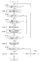
図6は、図1におけるCPU部201により実行される実施例1のシャットダウン処理の手順を示すフローチャートである。本処理は、画像形成装置10が通常状態になると開始する。 FIG. 6 is a flow chart showing the procedure of shutdown processing according to the first embodiment executed by the CPU unit 201 in FIG. This process starts when the image forming apparatus 10 enters a normal state.

まず、電源状態信号210が電源オフ状態か否かを判断する(ステップS601)。電源状態信号210が電源オフ状態でない場合(ステップS601がNo)の場合は、電源状態信号210が電源オフ状態になるのを待つ。電源状態信号210が電源オフ状態の場合(ステップS601がYes)は、画像形成装置10のシャットダウン処理を開始する。シャットダウン処理を開始すると、シャットダウン処理が完了したか否かを判断する(ステップS603)。シャットダウン処理が完了していない場合(ステップS603がNo)は、シャットダウン処理が完了するのを待つ。シャットダウン処理が完了した場合(ステップS603がYes)、シャットダウン完了信号209を設定し、シャットダウン完了通知を電源状態管理部401へ行い(ステップS604)、本処理を終了する。 First, it is determined whether or not the power state signal 210 indicates the power off state (step S601). If the power state signal 210 is not in the power off state (No in step S601), wait until the power state signal 210 indicates the power off state. If the power status signal 210 indicates that the power is off (Yes in step S601), shutdown processing of the image forming apparatus 10 is started. When the shutdown process is started, it is determined whether or not the shutdown process is completed (step S603). If the shutdown process has not been completed (No in step S603), the process waits for the shutdown process to be completed. If the shutdown processing is completed (Yes in step S603), the shutdown completion signal 209 is set, the shutdown completion notification is sent to the power state management unit 401 (step S604), and this processing ends.

図7は、図4の電源制御部200により実行される実施例1に係る電源制御処理の手順を示すフローチャートである。本処理は、画像形成装置10が通常状態になると開始する。 FIG. 7 is a flowchart illustrating the procedure of power control processing according to the first embodiment, which is executed by the power control unit 200 of FIG. This process starts when the image forming apparatus 10 enters a normal state.

まず、ステップS701において電源スイッチ状態保持部400は、電源スイッチ部106が押下されたか否かを判断する。電源スイッチ部106が押下されていないと判断した場合(ステップS701がNo)、電源スイッチ部106が押下されるのを待つ。電源スイッチ部106が押下されたと判断した場合(ステップS701がYes)、電源スイッチ状態保持部400は電源状態信号210をLow(電源オフ状態)に設定する(ステップS702)。その後、ステップS703において電源スイッチ状態保持部400は、電源スイッチ部106が再度押下されたか否かを判断する。電源スイッチ部106が押下されていないと判断した場合(ステップS703がNo)、電源状態信号210を変更せずにステップS705へ移行する。電源スイッチ部106が押下されたと判断した場合(ステップS703がYes)、電源スイッチ状態保持部400は、電源状態信号210を反転(ステップS704)する。その後、ステップS705へ移行する。ステップS705において、電源状態管理部401はシャットダウン完了信号209を介してシャットダウン完了通知がされているか否かを判断する。シャットダウン完了通知がされていないと判断した場合(ステップS705がNo)、ステップS703へ移行し電源スイッチ部106が押下されたか否かを再度判断する。シャットダウン完了通知がされた場合(ステップS705がYes)、ステップS706へ移行する。 First, in step S701, the power switch state holding unit 400 determines whether or not the power switch unit 106 has been pressed. If it is determined that the power switch unit 106 has not been pressed (No in step S701), it waits for the power switch unit 106 to be pressed. When determining that the power switch unit 106 has been pressed (Yes in step S701), the power switch state holding unit 400 sets the power state signal 210 to Low (power off state) (step S702). After that, in step S703, the power switch state holding unit 400 determines whether or not the power switch unit 106 has been pressed again. If it is determined that the power switch unit 106 has not been pressed (No in step S703), the process proceeds to step S705 without changing the power state signal 210. FIG. When determining that the power switch unit 106 has been pressed (Yes in step S703), the power switch state holding unit 400 inverts the power state signal 210 (step S704). After that, the process moves to step S705. In step S<b>705 , the power state management unit 401 determines whether a shutdown completion notification has been received via the shutdown completion signal 209 . If it is determined that the shutdown completion notification has not been received (No in step S705), the process proceeds to step S703 to determine again whether or not the power switch unit 106 has been pressed. If the shutdown completion notification has been received (Yes in step S705), the process proceeds to step S706.

ステップS706において電源状態管理部401は、電源状態信号210がLow(電源オフ状態)か否かを判断する。電源状態信号210がLow(電源オフ状態)と判断した場合(ステップS706がYes)、各電源制御信号116,117,118,211を電源オフ状態に切り替え、画像形成装置10の各部への電源供給を停止し(ステップS707)、本処理を終了する。一方、電源状態信号210がHigh(電源オン状態)と判断した場合(ステップS706がNo)、CPU部リセット信号208を発行し(ステップS708)、本処理を終了する。 In step S706, the power state management unit 401 determines whether the power state signal 210 is Low (power off state). When it is determined that the power state signal 210 is Low (power off state) (Yes in step S706), the power control signals 116, 117, 118, and 211 are switched to the power off state, and power is supplied to each section of the image forming apparatus 10. is stopped (step S707), and the process ends. On the other hand, if it is determined that the power state signal 210 is High (power-on state) (No in step S706), the CPU unit reset signal 208 is issued (step S708), and this processing ends.

本実施例では、シャットダウン処理の期間中において、シャットダウン処理完了後に再起動または電源供給停止するか否かをユーザに通知する。かかる通知を行う際の、操作部103の操作用液晶パネルユニット301、処理中通知LED302、エラー通知LED303、及び主電源LED304(通知手段)の動作について説明する。 In this embodiment, during the shutdown process, the user is notified as to whether or not to restart or stop the power supply after the shutdown process is completed. Operations of the operation liquid crystal panel unit 301, the in-process notification LED 302, the error notification LED 303, and the main power supply LED 304 (notification means) of the operation unit 103 when performing such notification will be described.

シャットダウン処理の期間中において、電源状態信号210がLow(シャットダウン処理完了後に電源供給停止)の場合は、操作部103に備えられた主電源LED304を点滅させ、エラー通知LED303、処理中通知LED302は消灯させる。すなわち、シャットダウン処理完了後に電源供給が停止される旨をユーザに通知する。一方、シャットダウン処理の期間中において、電源状態信号210がHigh(シャットダウン処理完了後に再起動)の場合は、操作部103に備えられた主電源LED304とエラー通知LED303を交互に点滅させ、処理中通知LED302は消灯させる。すなわち、シャットダウン処理完了後に再起動処理がされる旨をユーザに通知する。 During the shutdown process, when the power status signal 210 is Low (the power supply is stopped after the shutdown process is completed), the main power supply LED 304 provided in the operation unit 103 blinks, and the error notification LED 303 and the processing notification LED 302 are turned off. Let That is, the user is notified that the power supply will be stopped after the shutdown processing is completed. On the other hand, if the power status signal 210 is High (restart after completion of shutdown processing) during the shutdown processing, the main power LED 304 and the error notification LED 303 provided in the operation unit 103 blink alternately to notify that processing is in progress. LED 302 is turned off. That is, the user is notified that restart processing will be performed after completion of shutdown processing.

なお、かかる通知方法は例示であって、ユーザが画像形成装置10をシャットダウン処理の期間中に目視したときに、シャットダウン処理完了後に再起動するか電源供給停止するかの2状態を判別可能であればよい。例えば、上記2状態を判別可能とすべく、上記通知方法として、操作用液晶パネルユニット301に備えられた液晶パネルへ「シャットダウン中」という表示や「再起動中」という表示を行うようにしてもよい。 Note that this notification method is merely an example, and if the user can determine two states, that is, whether the image forming apparatus 10 is to be restarted after completion of the shutdown process or the power supply is stopped, when the user visually observes the image forming apparatus 10 during the period of the shutdown process. Just do it. For example, in order to make it possible to distinguish between the two states, as the notification method, a display of "shutting down" or "restarting" may be displayed on the liquid crystal panel provided in the operation liquid crystal panel unit 301. good.

以上、本実施例を用いることにより、プッシュスイッチである電源スイッチ部106を用いた画像形成装置10の本体の電源が完全にオフになるまで待たずに再起動指示を行うことができる。このため、ユーザの待ち時間が不要となり、使い勝手を向上することができる。 As described above, by using the present embodiment, it is possible to issue a restart instruction without waiting until the power of the main body of the image forming apparatus 10 using the power switch unit 106, which is a push switch, is completely turned off. As a result, the user does not have to wait for a long time, and usability can be improved.

本実施例は、画像形成装置10のシャットダウン処理完了時に電源状態信号210の状態が確認され、確認した状態に応じて再起動を行うかを決定するという基本的な動作は実施例1と同様である。以下、実施例1と同一の構成には同一の付番を付し、重複した説明は省略する。 The present embodiment is similar to the first embodiment in that the state of the power supply state signal 210 is checked when the shutdown processing of the image forming apparatus 10 is completed, and whether or not to restart is determined according to the checked state. be. Hereinafter, the same numbers are attached to the same configurations as those of the first embodiment, and redundant explanations are omitted.

図8は、電源制御部200の実施例2に係る内部構成を示すブロック図である。本実施例における電源制御部200は、電源スイッチ状態保持部400の代わりに電源スイッチ状態保持部800、電源状態管理部401の代わりに電源状態管理部801を有し、さらに電源スイッチ状態管理部802を有する点で実施例1と異なる。すなわち、電源スイッチ状態保持部800は、電源スイッチ状態管理部802によって、電源状態を保持するか否かを制御される点が実施例1と異なる。 FIG. 8 is a block diagram showing the internal configuration of the power control unit 200 according to the second embodiment. The power control unit 200 in this embodiment has a power switch state holding unit 800 instead of the power switch state holding unit 400, a power state management unit 801 instead of the power state management unit 401, and a power switch state management unit 802. It differs from Example 1 in that it has That is, the power switch state holding unit 800 is different from the first embodiment in that whether or not to hold the power state is controlled by the power switch state managing unit 802 .

電源スイッチ状態管理部802は、電源スイッチ状態保持部800と接続され、電源スイッチ状態保持マスク信号810を用いて、電源スイッチ状態保持部800が電源状態を保持するか否かを制御する。また、電源スイッチ状態管理部802は、電源状態信号210を基に電源スイッチ状態保持マスク信号810を切り替える。さらに、電源スイッチ状態管理部802は、電源状態管理部801から電源スイッチ状態管理リセット信号811を受け取ると、初期状態に戻される。 The power switch state management unit 802 is connected to the power switch state holding unit 800 and uses a power switch state holding mask signal 810 to control whether the power switch state holding unit 800 holds the power state. Also, the power switch state management unit 802 switches the power switch state holding mask signal 810 based on the power state signal 210 . Further, when the power switch state management unit 802 receives the power switch state management reset signal 811 from the power state management unit 801, the power switch state management unit 802 is returned to the initial state.

図9は、図8の電源制御部200により実行される実施例2に係る電源制御タイミングチャートである。 FIG. 9 is a power control timing chart according to the second embodiment executed by the power control unit 200 of FIG.

図9(a)は、本実施例において、電源スイッチ部106が1回のみ押下された場合の電源制御タイミングチャートである。電源スイッチ部106が1回のみ押下された場合の電源制御は、実施例1と同様である。すなわち、画像形成装置10のシャットダウン処理が完了すると(ステップS903)、電源状態管理部801は、各電源制御信号116,117,118,211を電源オフ状態に切り替える。これにより、画像形成装置10の各部への電源供給を停止する(ステップS904)。 FIG. 9A is a power control timing chart when the power switch unit 106 is pressed only once in this embodiment. Power supply control when the power switch unit 106 is pressed only once is the same as in the first embodiment. That is, when the shutdown processing of the image forming apparatus 10 is completed (step S903), the power state management unit 801 switches the power control signals 116, 117, 118, and 211 to the power off state. As a result, the power supply to each unit of the image forming apparatus 10 is stopped (step S904).

次に図9(b)、図9(c)を用いて、本実施例において電源スイッチ部106が複数回押下された場合について説明する。 Next, a case where the power switch unit 106 is pressed multiple times in this embodiment will be described with reference to FIGS. 9B and 9C.

図9(b)は、本実施例において、電源スイッチ部106が2回押下された場合の電源制御タイミングチャートである。 FIG. 9B is a power control timing chart when the power switch unit 106 is pressed twice in this embodiment.

電源スイッチ部106が押下されると(ステップS905)、電源スイッチ状態保持部800は電源状態信号210を電源オフ状態にする(ステップS906)。電源状態信号210がオフ状態になると、CPU部201は、画像形成装置10のシャットダウン処理を開始する(ステップS907)。シャットダウン処理中に、電源スイッチ部106が再度押下されると(ステップS908)、電源スイッチ状態保持部800は、電源状態信号210を電源オン状態にする(ステップS909)。電源スイッチ状態管理部802は、電源状態信号210が電源オン状態になると電源スイッチ状態保持マスク信号810をHighにする。画像形成装置10のシャットダウン処理が完了すると、CPU部201はシャットダウン完了通知をシャットダウン完了信号209を介して電源状態管理部801へ通知する(ステップS910)。電源状態管理部801は、シャットダウン完了通知を受け取ると、電源状態信号210を確認する。図9(b)では電源状態信号210は電源オン状態であるため、電源状態管理部801は、CPU部201に対して、CPU部リセット信号208を発行する(ステップS911)。CPU部201は、CPU部リセット信号208を受け取ると画像形成装置10の再起動処理を実行する。 When the power switch unit 106 is pressed (step S905), the power switch state holding unit 800 sets the power state signal 210 to the power off state (step S906). When the power state signal 210 is turned off, the CPU unit 201 starts shutdown processing of the image forming apparatus 10 (step S907). When the power switch unit 106 is pressed again during shutdown processing (step S908), the power switch state holding unit 800 sets the power state signal 210 to the power on state (step S909). The power switch state management unit 802 sets the power switch state retention mask signal 810 to High when the power state signal 210 indicates the power-on state. When the shutdown processing of the image forming apparatus 10 is completed, the CPU unit 201 notifies the power state management unit 801 of the shutdown completion notification via the shutdown completion signal 209 (step S910). The power state management unit 801 checks the power state signal 210 upon receiving the shutdown completion notification. In FIG. 9B, the power state signal 210 indicates the power-on state, so the power state management unit 801 issues the CPU unit reset signal 208 to the CPU unit 201 (step S911). When the CPU unit 201 receives the CPU unit reset signal 208 , the CPU unit 201 executes restart processing of the image forming apparatus 10 .

図9(c)は、本実施例において電源スイッチ部106が3回押下された場合の電源制御タイミングチャートである。 FIG. 9C is a power control timing chart when the power switch unit 106 is pressed three times in this embodiment.

電源スイッチ部106が押下されると(ステップS912)、電源スイッチ状態保持部800は電源状態信号210を電源オフ状態にする(ステップS913)。電源状態信号210がオフ状態になると、CPU部201は、画像形成装置10のシャットダウン処理を開始する(ステップS914)。シャットダウン処理中に、電源スイッチ部106が再度押下されると(ステップS915)、電源スイッチ状態保持部800は、電源状態信号210を電源オン状態にする(ステップS916)。電源スイッチ状態管理部802は、電源状態信号210が電源オン状態になると電源スイッチ状態保持マスク信号810をHighにする。さらに電源スイッチ部106が押下(ステップS917)されても、電源スイッチ状態保持マスク信号810がHighのため、電源スイッチ状態保持部800は、電源状態信号210を変更しない。画像形成装置10のシャットダウン処理が完了すると、CPU部201はシャットダウン完了通知をシャットダウン完了信号209を介して電源状態管理部801へ通知する(ステップS918)。電源状態管理部801は、シャットダウン完了通知を受け取ると、電源状態信号210を確認する。図9(c)では電源状態信号210は電源オン状態であるため、電源状態管理部801は、CPU部201に対して、CPU部リセット信号208を発行する(ステップS919)。さらに、電源状態管理部801は電源スイッチ状態管理リセット信号811を電源スイッチ状態管理部802へ発行する。電源スイッチ状態管理部802は、電源スイッチ状態管理リセット信号811を受け取ると、電源スイッチ状態保持マスク信号をLowにする。CPU部201は、CPU部リセット信号208を受け取ると画像形成装置10の再起動処理を実行する。 When the power switch unit 106 is pressed (step S912), the power switch state holding unit 800 sets the power state signal 210 to the power off state (step S913). When the power state signal 210 is turned off, the CPU unit 201 starts shutdown processing of the image forming apparatus 10 (step S914). When the power switch unit 106 is pressed again during shutdown processing (step S915), the power switch state holding unit 800 sets the power state signal 210 to the power on state (step S916). The power switch state management unit 802 sets the power switch state retention mask signal 810 to High when the power state signal 210 indicates the power-on state. Even if the power switch unit 106 is pressed (step S917), the power switch state holding unit 800 does not change the power state signal 210 because the power switch state holding mask signal 810 is High. When the shutdown processing of the image forming apparatus 10 is completed, the CPU unit 201 notifies the power state management unit 801 of the shutdown completion notification via the shutdown completion signal 209 (step S918). The power state management unit 801 checks the power state signal 210 upon receiving the shutdown completion notification. In FIG. 9C, the power state signal 210 indicates the power-on state, so the power state management unit 801 issues the CPU unit reset signal 208 to the CPU unit 201 (step S919). Further, the power state management unit 801 issues a power switch state management reset signal 811 to the power switch state management unit 802 . Upon receiving the power switch state management reset signal 811, the power switch state management unit 802 sets the power switch state retention mask signal to Low. When the CPU unit 201 receives the CPU unit reset signal 208 , the CPU unit 201 executes restart processing of the image forming apparatus 10 .

本実施例において、電源スイッチ部106を4回以上押下された場合は、電源スイッチ部106が2回及び3回押下された場合と同様にシャットダウン処理が完了すると画像形成装置10の再起動処理を実行する。また、本実施例においては、電源スイッチ部106が2回押下された後は、偶数回か奇数回かに関わらずシャットダウン処理完了後は画像形成装置10の再起動処理を実行する点が実施例1と異なる。さらに、本実施例では、電源スイッチ部106が2回押下された後は、電源スイッチ部106に対してどのような操作(例えば長押し等)があってもシャットダウン処理完了後は画像形成装置10の再起動処理を実行する。 In the present embodiment, when the power switch unit 106 is pressed four times or more, the restart processing of the image forming apparatus 10 is performed when the shutdown processing is completed, similarly to the case where the power switch unit 106 is pressed twice and three times. Run. Also, in this embodiment, after the power switch unit 106 is pressed twice, the image forming apparatus 10 is restarted after the shutdown process is completed regardless of whether it is an even number of times or an odd number of times. different from 1. Further, in the present embodiment, after the power switch unit 106 is pressed twice, the image forming apparatus 10 cannot be restarted after the shutdown process is completed regardless of any operation (for example, long press) on the power switch unit 106 . restart processing.

図10は、図8の電源制御部200により実行される実施例2に係る電源制御処理の手順を示すフローチャートである。本処理は、画像形成装置10が通常状態になると開始する。 FIG. 10 is a flow chart showing the procedure of power control processing according to the second embodiment executed by the power control unit 200 of FIG. This process starts when the image forming apparatus 10 enters a normal state.

まず、ステップS1001において電源スイッチ状態保持部800は、電源スイッチ部106が押下されたか否かを判断する。 First, in step S1001, the power switch state holding unit 800 determines whether or not the power switch unit 106 has been pressed.

電源スイッチ部106が押下されていないと判断した場合(ステップS1001がNo)、電源スイッチ部106が押下されるのを待つ。電源スイッチ部106が押下されたと判断した場合(ステップS1001がYes)、電源スイッチ状態保持部800は電源状態信号210をLow(電源オフ状態)に設定する(ステップS1002)。 If it is determined that the power switch unit 106 has not been pressed (No in step S1001), it waits for the power switch unit 106 to be pressed. When determining that the power switch unit 106 has been pressed (Yes in step S1001), the power switch state holding unit 800 sets the power state signal 210 to Low (power off state) (step S1002).

その後、ステップS1003において電源スイッチ状態保持部800は、電源スイッチ部106が再度押下されたか否かを判断する。電源スイッチ部106が押下されていないと判断した場合(ステップS1003がNo)、電源状態信号210をLowのまま変更せずにステップS1007へ移行する。電源スイッチ部106が押下されたと判断した場合(ステップS1003がYes)、ステップS1004へ移行する。 After that, in step S1003, the power switch state holding unit 800 determines whether the power switch unit 106 has been pressed again. If it is determined that the power switch unit 106 is not pressed (No in step S1003), the power state signal 210 remains Low and the process proceeds to step S1007. If it is determined that the power switch unit 106 has been pressed (Yes in step S1003), the process proceeds to step S1004.

ステップS1004において、電源スイッチ状態保持部800は電源スイッチ状態保持マスク信号810がLowか否かを判断する。電源スイッチ状態保持マスク信号810がLowでないと判断した場合(ステップS1004がNo)、ステップS1007へ移行する。電源スイッチ状態保持マスク信号810がLowと判断した場合(ステップS1004がYes)、電源状態信号210を反転する(ステップS1005)。その後、電源スイッチ状態管理部802は、電源スイッチ状態保持マスク信号810をHighにする(ステップS1006)。その後、ステップS1007へ移行する。 In step S1004, the power switch state holding unit 800 determines whether the power switch state holding mask signal 810 is Low. If it is determined that the power switch state retention mask signal 810 is not Low (No in step S1004), the process proceeds to step S1007. If the power switch state retention mask signal 810 is determined to be Low (Yes in step S1004), the power state signal 210 is inverted (step S1005). After that, the power switch state management unit 802 sets the power switch state retention mask signal 810 to High (step S1006). After that, the process moves to step S1007.

ステップS1007において、電源状態管理部801はシャットダウン完了通知がシャットダウン完了信号209を介してされているか否かを判断する。シャットダウン完了信号209を介してシャットダウン完了通知がされていないと判断した場合(ステップS1007がNo)、ステップS1003へ移行し電源スイッチ部106が押下されたか否かを再度判断する。シャットダウン完了信号209を介してシャットダウン完了通知がされた場合(ステップS1007がYes)、電源スイッチ状態管理部802は、電源スイッチ状態保持マスク信号810をLowにする(ステップS1008)。その後、ステップS1009へ移行する。 In step S<b>1007 , the power state management unit 801 determines whether or not a shutdown completion notification has been received via the shutdown completion signal 209 . If it is determined that a shutdown completion notification has not been received via the shutdown completion signal 209 (No in step S1007), the process proceeds to step S1003 to determine again whether or not the power switch unit 106 has been pressed. When a shutdown completion notification is received via the shutdown completion signal 209 (Yes in step S1007), the power switch state management unit 802 sets the power switch state retention mask signal 810 to Low (step S1008). After that, the process moves to step S1009.

ステップS1009において、電源状態管理部801は電源状態信号210がLow(電源オフ状態)か否かを判断する。電源状態信号210がLow(電源オフ状態)と判断した場合(ステップS1009がYes)、各電源制御信号116,117,118,211を電源オフ状態に切り替える。これにより、画像形成装置10の各部への電源供給を停止し(ステップS1010)、本処理を終了する。一方、電源状態信号210がHigh(電源オン状態)と判断した場合(ステップS1009がNo)、CPU部リセット信号208を発行し(ステップS1011)、本処理を終了する。 In step S1009, the power state management unit 801 determines whether the power state signal 210 is Low (power off state). When it is determined that the power state signal 210 is Low (power off state) (Yes in step S1009), the power control signals 116, 117, 118, and 211 are switched to the power off state. As a result, the power supply to each part of the image forming apparatus 10 is stopped (step S1010), and the present process ends. On the other hand, if it is determined that the power status signal 210 is High (power-on state) (No in step S1009), the CPU unit reset signal 208 is issued (step S1011), and this processing ends.

CPU部201の動作は、図6に示す実施例1のシャットダウン処理と同様である。また、シャットダウン処理完了後に再起動または電源供給停止するか否かの表示手段への表示に関しても、実施例1と同様である。 The operation of the CPU unit 201 is the same as the shutdown processing of the first embodiment shown in FIG. Further, the display on the display means as to whether or not to restart or stop the power supply after the completion of the shutdown process is the same as in the first embodiment.

以上、本実施例を用いることにより、プッシュスイッチである電源スイッチ部106を用いた画像形成装置10の本体の電源が完全にオフになるまで待たずに再起動指示を行うことができる。このため、ユーザの待ち時間が不要となり、使い勝手を向上することができる。 As described above, by using the present embodiment, it is possible to issue a restart instruction without waiting until the power of the main body of the image forming apparatus 10 using the power switch unit 106, which is a push switch, is completely turned off. As a result, the user does not have to wait for a long time, and usability can be improved.

本実施例は、画像形成装置10のシャットダウン処理完了時点で電源状態信号210の状態が確認され、確認した状態に応じて、再起動を行うかどうかを決定するという基本的な動作は、実施例1及び実施例2と同様である。 In this embodiment, the basic operation of confirming the state of the power supply state signal 210 at the time of completion of shutdown processing of the image forming apparatus 10 and determining whether or not to restart according to the confirmed state is the same as in the embodiment. 1 and Example 2.

図11は、電源制御部200の実施例3に係る内部構成を示すブロック図である。本実施例における電源制御部200は、以下の点で実施例2と異なる。まず、電源スイッチ状態保持部800の代わりに電源スイッチ状態保持部1100、電源状態管理部801の代わりに電源状態管理部1101、電源スイッチ状態管理部802の代わりに電源スイッチ状態管理部1102を有する。さらにタイマー部1103を有する。すなわち、電源スイッチ状態保持部1100は、電源スイッチ状態管理部1102に加えて、タイマー部1103によって電源状態を保持するか否かを制御される点が実施例2と異なる。 FIG. 11 is a block diagram showing the internal configuration of the power control unit 200 according to the third embodiment. The power control unit 200 in this embodiment differs from that in the second embodiment in the following points. First, it has a power switch state holding unit 1100 instead of the power switch state holding unit 800, a power state management unit 1101 instead of the power state management unit 801, and a power switch state management unit 1102 instead of the power switch state management unit 802. Furthermore, it has a timer section 1103 . In other words, the power switch state holding unit 1100 differs from the second embodiment in that, in addition to the power switch state managing unit 1102, a timer unit 1103 controls whether to hold the power state.

タイマー部1103は、電源スイッチ状態保持部1100、電源スイッチ状態管理部1102と接続され、電源状態信号210が電源オフ状態になったときにタイマーカウントを開始する。また、カウントしたタイマーカウント値1111を電源スイッチ状態管理部1102へ通知する。また、タイマー部1103は、電源状態管理部1101から電源スイッチ状態管理リセット信号811を受け取ると、初期状態に戻される。 The timer unit 1103 is connected to the power switch state holding unit 1100 and the power switch state management unit 1102, and starts timer counting when the power state signal 210 indicates the power off state. Also, the counted timer count value 1111 is notified to the power switch state management unit 1102 . Also, when the timer unit 1103 receives the power switch state management reset signal 811 from the power state management unit 1101, it is returned to the initial state.

電源スイッチ状態管理部1102は、タイマー部1103、電源スイッチ状態保持部1100と接続され、電源スイッチ状態保持マスク信号1110を用いて、電源スイッチ状態保持部1100が電源状態を保持するか否かを制御する。電源スイッチ状態保持マスク信号1110は、電源状態信号210とタイマーカウント値1111を基に制御される。また、電源スイッチ状態管理部1102は、電源状態管理部1101から電源スイッチ状態管理リセット信号811を受け取ると、初期状態に戻される。 The power switch state management unit 1102 is connected to the timer unit 1103 and the power switch state holding unit 1100, and uses the power switch state holding mask signal 1110 to control whether the power switch state holding unit 1100 holds the power state. do. The power switch state holding mask signal 1110 is controlled based on the power state signal 210 and the timer count value 1111 . When the power switch state management unit 1102 receives the power switch state management reset signal 811 from the power state management unit 1101, the power switch state management unit 1102 is returned to the initial state.

図12は、図11の電源制御部200により実行される実施例3に係る電源制御タイミングチャートである。 FIG. 12 is a power control timing chart according to the third embodiment executed by the power control unit 200 of FIG.

図12(a)は、本実施例において、電源スイッチ部106が1回のみ押下された場合の電源制御タイミングチャートである。 FIG. 12A is a power control timing chart when the power switch unit 106 is pressed only once in this embodiment.

電源スイッチ部106が押下されると(ステップS1200)、電源スイッチ状態保持部1100は電源状態信号210を電源オフ状態にする(ステップS1201)。電源状態信号210がオフ状態になると、CPU部201は、画像形成装置10のシャットダウン処理を開始する(ステップS1202)。また、タイマー部1103はタイマーカウントを開始する。その後、タイマーカウント値1111がT1に到達する、すなわち所定値以上となると(ステップS1203)、電源スイッチ状態管理部1102は電源スイッチ状態保持マスク信号1110をHighにする。画像形成装置10のシャットダウン処理が完了すると、CPU部201はシャットダウン完了通知をシャットダウン完了信号209を介して電源状態管理部1101へ通知する(ステップS1204)。電源状態管理部1101は、シャットダウン完了通知を受け取ると、電源スイッチ状態管理リセット信号811を電源スイッチ状態管理部1102とタイマー部1103へ発行する。電源スイッチ状態管理部1102は電源スイッチ状態管理リセット信号811を受け取ると、電源スイッチ状態保持マスク信号1110をLowにする。また、タイマー部1103は電源スイッチ状態管理リセット信号811を受け取ると、タイマーカウント値1111を‘0’(初期値)に戻す。更に電源状態管理部1101は、電源状態信号210を確認する。図12(a)では電源状態信号210は電源オフ状態であるため、電源状態管理部1101は、各電源制御信号116,117,118,211を電源オフ状態に切り替え、画像形成装置10の各部への電源供給を停止する(ステップS1205)。 When the power switch unit 106 is pressed (step S1200), the power switch state holding unit 1100 sets the power state signal 210 to the power off state (step S1201). When the power status signal 210 is turned off, the CPU unit 201 starts shutdown processing of the image forming apparatus 10 (step S1202). Also, the timer unit 1103 starts timer counting. After that, when the timer count value 1111 reaches T1, that is, exceeds a predetermined value (step S1203), the power switch state management unit 1102 sets the power switch state retention mask signal 1110 to High. When the shutdown processing of the image forming apparatus 10 is completed, the CPU unit 201 notifies the power state management unit 1101 of shutdown completion via the shutdown completion signal 209 (step S1204). Upon receiving the shutdown completion notification, the power state management unit 1101 issues a power switch state management reset signal 811 to the power switch state management unit 1102 and the timer unit 1103 . When the power switch state management unit 1102 receives the power switch state management reset signal 811, it changes the power switch state retention mask signal 1110 to Low. Also, when the timer unit 1103 receives the power switch state management reset signal 811, it resets the timer count value 1111 to '0' (initial value). Furthermore, the power state management unit 1101 checks the power state signal 210 . In FIG. 12A, the power state signal 210 indicates the power off state, so the power state management unit 1101 switches the power control signals 116, 117, 118, and 211 to the power off state, and sends the signals to the respective units of the image forming apparatus 10. is stopped (step S1205).

図12(b)は、本実施例において電源スイッチ部106が一定時間内に2回押下された場合の電源制御タイミングチャートである。 FIG. 12B is a power control timing chart when the power switch unit 106 is pressed twice within a certain period of time in this embodiment.

電源スイッチ部106が押下されると(ステップS1206)、電源スイッチ状態保持部1100は電源状態信号210を電源オフ状態にする(ステップS1207)。電源状態信号210がオフ状態になると、CPU部201は、画像形成装置10のシャットダウン処理を開始する(ステップS1208)。また、タイマー部1103はタイマーカウントを開始する。その後、図12(b)では、タイマーカウント値1111がT1に到達する前、すなわち所定値未満の状態で、電源スイッチ部106が再度押下される(ステップS1209)。この場合、電源スイッチ状態保持部1100は、電源状態信号210を電源オン状態にする(ステップS1210)。電源スイッチ状態管理部1102は、電源状態信号210が電源オン状態になると電源スイッチ状態保持マスク信号1110をHighにする。画像形成装置10のシャットダウン処理が完了すると、CPU部201はシャットダウン完了通知をシャットダウン完了信号209を介して電源状態管理部1101へ通知する(ステップS1212)。電源状態管理部1101は、シャットダウン完了通知を受け取ると、電源スイッチ状態管理リセット信号811を電源スイッチ状態管理部1102とタイマー部1103へ発行する。電源スイッチ状態管理部1102は電源スイッチ状態管理リセット信号811を受け取ると、電源スイッチ状態保持マスク信号をLowにする。また、タイマー部1103は電源スイッチ状態管理リセット信号811を受け取ると、タイマーカウント値1111を‘0’(初期値)に戻す。更に電源状態管理部1101は、電源状態信号210を確認する。電源状態信号210が電源オンの状態であるため、電源状態管理部1101は、CPU部201に対してCPU部リセット信号208を発行する(ステップS1213)。CPU部201は、CPU部リセット信号208を受け取ると画像形成装置10の再起動処理を実行する。 When the power switch unit 106 is pressed (step S1206), the power switch state holding unit 1100 sets the power state signal 210 to the power off state (step S1207). When the power state signal 210 is turned off, the CPU unit 201 starts shutdown processing of the image forming apparatus 10 (step S1208). Also, the timer unit 1103 starts timer counting. After that, in FIG. 12B, before the timer count value 1111 reaches T1, that is, before the value is less than the predetermined value, the power switch unit 106 is pressed again (step S1209). In this case, the power switch state holding unit 1100 sets the power state signal 210 to the power on state (step S1210). The power switch state management unit 1102 sets the power switch state retention mask signal 1110 to High when the power state signal 210 indicates the power-on state. When the shutdown processing of the image forming apparatus 10 is completed, the CPU unit 201 notifies the power state management unit 1101 of shutdown completion via the shutdown completion signal 209 (step S1212). Upon receiving the shutdown completion notification, the power state management unit 1101 issues a power switch state management reset signal 811 to the power switch state management unit 1102 and the timer unit 1103 . Upon receiving the power switch state management reset signal 811, the power switch state management unit 1102 sets the power switch state retention mask signal to Low. Also, when the timer unit 1103 receives the power switch state management reset signal 811, it resets the timer count value 1111 to '0' (initial value). Furthermore, the power state management unit 1101 checks the power state signal 210 . Since the power state signal 210 indicates that the power is on, the power state management unit 1101 issues the CPU unit reset signal 208 to the CPU unit 201 (step S1213). When the CPU unit 201 receives the CPU unit reset signal 208 , the CPU unit 201 executes restart processing of the image forming apparatus 10 .

図12(c)は、本実施例において電源スイッチ部106が一定時間経過後に2回目が押下された場合の電源制御タイミングチャートである。 FIG. 12(c) is a power control timing chart when the power switch unit 106 is pressed for the second time after the lapse of a predetermined time in this embodiment.

電源スイッチ部106が押下されると(ステップS1214)、電源スイッチ状態保持部1100は電源状態信号210を電源オフ状態にする(ステップS1215)。電源状態信号210がオフ状態になると、CPU部201は、画像形成装置10のシャットダウン処理を開始する(ステップS1216)。また、タイマー部1103はタイマーカウントを開始する。その後、タイマーカウント値1111がT1に到達(ステップS1217)すると、電源スイッチ状態保持マスク信号1110をHighにする。 When the power switch unit 106 is pressed (step S1214), the power switch state holding unit 1100 sets the power state signal 210 to the power off state (step S1215). When the power state signal 210 is turned off, the CPU unit 201 starts shutdown processing of the image forming apparatus 10 (step S1216). Also, the timer unit 1103 starts timer counting. After that, when the timer count value 1111 reaches T1 (step S1217), the power switch state holding mask signal 1110 is set to High.

その後、図12(c)では所定時間(T1)経過後に電源スイッチ部106が再度押下される(ステップS1218)。しかしながら、電源スイッチ状態保持マスク信号1110がHighのため、かかる押下があっても電源スイッチ状態保持部1100は、電源状態信号210を変更せず電源オフ状態のままとする。画像形成装置10のシャットダウン処理が完了すると、CPU部201はシャットダウン完了通知をシャットダウン完了信号209を介して電源状態管理部1101へ通知する(ステップS1219)。電源状態管理部1101は、シャットダウン完了通知を受け取ると、電源スイッチ状態管理リセット信号811を電源スイッチ状態管理部1102とタイマー部1103へ発行する。電源スイッチ状態管理部1102は電源スイッチ状態管理リセット信号811を受け取ると、電源スイッチ状態保持マスク信号1110をLowにする。また、タイマー部1103は電源スイッチ状態管理リセット信号811を受け取ると、タイマーカウント値1111を‘0’(初期値)に戻す。更に電源状態管理部1101は、電源状態信号210を確認する。電源状態信号210が電源オフの状態であるため、電源状態管理部1101は、各電源制御信号116,117,118,211を電源オフ状態に設定し、画像形成装置10の各部への電源供給を停止する(ステップS1220)。 Thereafter, in FIG. 12C, the power switch unit 106 is pressed again after a predetermined time (T1) has elapsed (step S1218). However, since the power switch state retention mask signal 1110 is High, the power switch state retention unit 1100 does not change the power state signal 210 and keeps the power OFF state even if such a depression occurs. When the shutdown processing of the image forming apparatus 10 is completed, the CPU unit 201 notifies the power state management unit 1101 of the shutdown completion via the shutdown completion signal 209 (step S1219). Upon receiving the shutdown completion notification, the power state management unit 1101 issues a power switch state management reset signal 811 to the power switch state management unit 1102 and the timer unit 1103 . When the power switch state management unit 1102 receives the power switch state management reset signal 811, it changes the power switch state retention mask signal 1110 to Low. Also, when the timer unit 1103 receives the power switch state management reset signal 811, it resets the timer count value 1111 to '0' (initial value). Furthermore, the power state management unit 1101 checks the power state signal 210 . Since the power state signal 210 indicates the power off state, the power state management unit 1101 sets the power control signals 116, 117, 118, and 211 to the power off state to stop power supply to each unit of the image forming apparatus 10. Stop (step S1220).

尚、1回目の押下から所定時間(T1)が経過するまでに電源スイッチ部106を4回以上押下される場合がある。本実施例ではかかる場合も実施例2において電源スイッチ部106が2回及び3回押下された場合と同様に、シャットダウン処理完了後に画像形成装置10の再起動処理を実行する。 Note that there is a case where the power switch unit 106 is pressed four times or more before the predetermined time (T1) elapses after the first pressing. In this embodiment, in such a case as well, similar to the case where the power switch unit 106 is pressed twice and three times in the second embodiment, the restart processing of the image forming apparatus 10 is executed after the shutdown processing is completed.

また、2回目の電源スイッチ部106の押下が一定時間内であった場合のみシャットダウン完了後に画像形成装置10の再起動処理を実行する点が実施例2と異なる。 Further, the second embodiment differs from the second embodiment in that the restart processing of the image forming apparatus 10 is executed after the shutdown is completed only when the power switch unit 106 is pressed for the second time within a predetermined time.

図13は、図11の電源制御部200により実行される実施例3に係る電源制御処理の手順を示すフローチャートである。本処理は、画像形成装置10が通常状態になると開始する。 FIG. 13 is a flow chart showing the procedure of power control processing according to the third embodiment executed by the power control unit 200 of FIG. This process starts when the image forming apparatus 10 enters a normal state.

まず、ステップS1301において電源スイッチ状態保持部1100は、電源スイッチ部106が押下されたか否かを判断する。電源スイッチ部106が押下されていないと判断した場合(ステップS1301がNo)、電源スイッチ部106が押下されるのを待つ。電源スイッチ部106が押下されたと判断した場合(ステップS1301がYes)、電源スイッチ状態保持部1100は電源状態信号210をLow(電源オフ状態)に設定する(ステップS1302)。さらに、タイマー部1103は、タイマーカウントを開始する(ステップS1303)。その後、ステップS1304において電源スイッチ状態保持部1100は、電源スイッチ部106が再度押下されたか否かを判断する。電源スイッチ部106が押下されていないと判断した場合(ステップS1304がNo)、電源状態信号210を変更せずにステップS1309へ移行する。電源スイッチ部106が押下されたと判断した場合(ステップS1304がYes)、ステップS1305へ移行する。ステップS1305において、電源スイッチ状態保持部1100は電源スイッチ状態保持マスク信号1110がLowか否かを判断する。電源スイッチ状態保持マスク信号1110がLowでないと判断した場合(ステップS1305がNo)、ステップS1309へ移行する。電源スイッチ状態保持マスク信号1110がLowと判断した場合(ステップS1305がYes)、ステップS1306へ移行する。 First, in step S1301, the power switch state holding unit 1100 determines whether or not the power switch unit 106 has been pressed. If it is determined that the power switch unit 106 has not been pressed (No in step S1301), it waits for the power switch unit 106 to be pressed. When determining that the power switch unit 106 has been pressed (Yes in step S1301), the power switch state holding unit 1100 sets the power state signal 210 to Low (power off state) (step S1302). Furthermore, the timer unit 1103 starts timer counting (step S1303). After that, in step S1304, the power switch state holding unit 1100 determines whether or not the power switch unit 106 has been pressed again. If it is determined that the power switch unit 106 has not been pressed (No in step S1304), the process proceeds to step S1309 without changing the power status signal 210. FIG. If it is determined that the power switch unit 106 has been pressed (Yes in step S1304), the process proceeds to step S1305. In step S1305, the power switch state holding unit 1100 determines whether the power switch state holding mask signal 1110 is Low. If it is determined that the power switch state retention mask signal 1110 is not Low (No in step S1305), the process proceeds to step S1309. If it is determined that the power switch state retention mask signal 1110 is Low (Yes in step S1305), the process proceeds to step S1306.

ステップS1306において、電源スイッチ状態管理部1102はタイマーカウント値1111がT1未満であるか判断する。タイマーカウント値1111がT1以上と判断した場合(ステップS1306がNo)、ステップS1309へ移行する。タイマーカウント値1111がT1未満と判断した場合(ステップS1306がYes)、電源スイッチ状態保持部1100は、電源状態信号210の論理を反転する(ステップS1307)。さらに、電源スイッチ状態管理部1102は、電源スイッチ状態保持マスク信号1110をHighにする(ステップS1308)。その後、ステップS1309へ移行する。 In step S1306, the power switch state management unit 1102 determines whether the timer count value 1111 is less than T1. If it is determined that the timer count value 1111 is equal to or greater than T1 (No in step S1306), the process proceeds to step S1309. When determining that the timer count value 1111 is less than T1 (Yes in step S1306), the power switch state holding unit 1100 inverts the logic of the power state signal 210 (step S1307). Further, the power switch state management unit 1102 sets the power switch state retention mask signal 1110 to High (step S1308). After that, the process moves to step S1309.

ステップS1309において、電源状態管理部1101はシャットダウン完了信号209を介してシャットダウン完了通知がされているか否かを判断する。シャットダウン完了通知がされていないと判断した場合(ステップS1309がNo)、ステップS1304へ移行し電源スイッチ部106が押下されたか否かを再度判断する。シャットダウン完了通知がされた場合(ステップS1309がYes)、タイマー部1103は、タイマーカウント値1111を‘0’にする(ステップS1310)。さらに電源スイッチ状態管理部1102は、電源スイッチ状態保持マスク信号1110をLowにする(ステップS1311)。その後、ステップS1312へ移行する。 In step S<b>1309 , the power state management unit 1101 determines whether or not a shutdown completion notification has been received via the shutdown completion signal 209 . If it is determined that the shutdown completion notification has not been received (No in step S1309), the process proceeds to step S1304 to determine again whether or not the power switch unit 106 has been pressed. If the shutdown completion notification has been received (Yes in step S1309), the timer unit 1103 sets the timer count value 1111 to '0' (step S1310). Further, the power switch state management unit 1102 sets the power switch state retention mask signal 1110 to Low (step S1311). After that, the process moves to step S1312.

ステップS1312において、電源状態管理部1101は電源状態信号210がLow(電源オフ状態)か否かを判断する。電源状態信号210がLow(電源オフ状態)と判断した場合(ステップS1312がYes)、各電源制御信号116,117,118,211を電源オフ状態に切り替える。これにより、画像形成装置10の各部への電源供給を停止し(ステップS1314)、本処理を終了する。一方、電源状態信号210がHigh(電源オン状態)と判断した場合(ステップS1312がNo)、CPU部リセット信号208を発行し(ステップS1313)、本処理を終了する。 In step S1312, the power state management unit 1101 determines whether the power state signal 210 is Low (power off state). When it is determined that the power state signal 210 is Low (power off state) (Yes in step S1312), the power control signals 116, 117, 118, and 211 are switched to the power off state. As a result, the power supply to each section of the image forming apparatus 10 is stopped (step S1314), and the process ends. On the other hand, if it is determined that the power supply state signal 210 is High (power-on state) (No in step S1312), the CPU unit reset signal 208 is issued (step S1313), and this processing ends.

CPU部201の動作は、図6に示す実施例1のシャットダウン処理と同様である。また、シャットダウン処理完了後に再起動または電源供給停止するか否かの表示手段への表示に関しても、実施例1と同様である。 The operation of the CPU unit 201 is the same as the shutdown processing of the first embodiment shown in FIG. Further, the display on the display means as to whether or not to restart or stop the power supply after the completion of the shutdown process is the same as in the first embodiment.

以上、本実施例を用いることにより、プッシュスイッチである電源スイッチ部106を用いた画像形成装置10の本体の電源が完全にオフになるまで待たずに再起動指示を行うことができる。このため、ユーザの待ち時間が不要となり、使い勝手を向上することができる。 As described above, by using the present embodiment, it is possible to issue a restart instruction without waiting until the power of the main body of the image forming apparatus 10 using the power switch unit 106, which is a push switch, is completely turned off. As a result, the user does not have to wait for a long time, and usability can be improved.

本実施例は、画像形成装置10のシャットダウン処理完了時点で電源状態信号210の状態が確認され、確認した状態に応じて、再起動を行うかどうかを決定するという基本的な動作は、実施例1~3と同様である。 In this embodiment, the basic operation of confirming the state of the power supply state signal 210 at the time of completion of shutdown processing of the image forming apparatus 10 and determining whether or not to restart according to the confirmed state is the same as in the embodiment. Same as 1-3.

本実施例では、画像形成装置10の電源をオフするための電源スイッチ部106の押下をそのまま所定時間継続した場合、画像形成装置10を再起動する。 In this embodiment, if the power switch unit 106 for turning off the power of the image forming apparatus 10 is kept depressed for a predetermined time, the image forming apparatus 10 is restarted.

図14は、電源制御部200の実施例4に係る内部構成を示すブロック図である。本実施例における電源制御部200は、以下の点で実施例3と異なる。まず、電源スイッチ状態保持部1100の代わりに電源スイッチ状態保持部1400、電源状態管理部1101の代わりに電源状態管理部1401を有する。さらに、本実施例の電源制御部200は、電源スイッチ状態管理部1102を有しない。 FIG. 14 is a block diagram showing the internal configuration of the power control unit 200 according to the fourth embodiment. The power control unit 200 in this embodiment differs from that in the third embodiment in the following points. First, a power switch state holding unit 1400 is provided instead of the power switch state holding unit 1100 , and a power state management unit 1401 is provided instead of the power state management unit 1101 . Furthermore, the power control unit 200 of this embodiment does not have the power switch state management unit 1102 .

電源スイッチ状態保持部1400は、電源スイッチ部106と電源スイッチ信号112で接続される。 The power switch state holding unit 1400 is connected to the power switch unit 106 by the power switch signal 112 .

電源スイッチ状態保持部1400は、D-FF、インバータ、ANDロジック、ORロジック、遅延回路で構成される。電源スイッチ部106から出力された電源スイッチ信号112はインバータで論理反転してANDロジックに接続する。加えて、タイマー部1103が出力する電源状態オン信号1402をインバータで反転してANDロジックに接続する。ANDロジックの出力をORロジックへ接続する。タイマー部1103が出力する電源状態オン信号1402を遅延回路に入力し、遅延回路の出力信号をORロジックに接続する。遅延回路は、電源状態オン信号1402のタイミングを遅延させる機能を持つ。ORロジック出力信号1404をD-FFのクロック入力端子へ接続する。また、D-FFの出力Qは、D-FFの入力Dに接続され、D-FFの出力Qは電源状態信号210として電源状態管理部1401及び、CPU部201へ接続される。これにより、電源スイッチ状態保持部1400は、電源スイッチ部106の押下を検知、もしくは、電源状態オン信号1402がHighになると、D-FF出力の論理反転を保持する。そして、電源スイッチ状態保持部1400は、D-FF出力の論理反転の出力を電源状態信号210として電源状態管理部1401及び、CPU部201へ通知する。 The power switch state holding unit 1400 is composed of D-FFs, inverters, AND logic, OR logic, and delay circuits. A power switch signal 112 output from the power switch unit 106 is logically inverted by an inverter and connected to an AND logic. In addition, the power state ON signal 1402 output by the timer unit 1103 is inverted by an inverter and connected to the AND logic. Connect the output of the AND logic to the OR logic. The power state ON signal 1402 output by the timer unit 1103 is input to the delay circuit, and the output signal of the delay circuit is connected to the OR logic. The delay circuit has a function of delaying the timing of the power state ON signal 1402 . The OR logic output signal 1404 is connected to the clock input terminal of the D-FF. Also, the output Q 1 of the D-FF is connected to the input D of the D-FF, and the output Q 2 of the D-FF is connected to the power state management section 1401 and the CPU section 201 as the power state signal 210 . As a result, the power switch state holding unit 1400 holds the logic inversion of the D-FF output when it detects that the power switch unit 106 is pressed or when the power state ON signal 1402 becomes High. Then, the power switch state holding unit 1400 notifies the power state management unit 1401 and the CPU unit 201 of the logically inverted output of the D-FF output as the power state signal 210 .

電源状態管理部1401は、電源状態信号210で電源スイッチ状態保持部1400と接続される。加えて、CPU部リセット信号208、シャットダウン完了信号209、通信信号1405でCPU部201と接続される。更に、電源スイッチ状態管理リセット信号811、カウントイネーブル信号1403でタイマー部1103と接続される。CPU部リセット信号208は、CPU部201をリセットする信号である。シャットダウン完了信号209は、CPU部201がシャットダウン処理を完了したことを電源状態管理部1401に通知する信号である。通信信号1405は、CPU部201が電源状態管理部1401にタイマー部1103へ出力するカウントイネーブル信号1403を有効にする設定を行うための信号である。電源スイッチ状態管理リセット信号811はタイマー部1103の内部のタイマーカウント値を初期化するための信号である。カウントイネーブル信号1403は、タイマー部1103の動作を制御する信号である。カウントイネーブル信号1403がHighの場合、タイマー部1103はタイマー機能が有効となりタイマーカウントを実行する。カウントイネーブル信号1403がLowの場合、タイマー部1103はタイマー機能が無効となりタイマーカウントを実行しない。カウントイネーブル信号1403は、通信信号1405を介してCPU部201によりHighに設定される。カウントイネーブル信号1403は、電源状態信号210がLow、且つ、シャットダウン完了信号209がHighになると、Lowとなる。 The power state management unit 1401 is connected to the power switch state holding unit 1400 by the power state signal 210 . In addition, it is connected to the CPU section 201 by a CPU section reset signal 208 , a shutdown completion signal 209 and a communication signal 1405 . Furthermore, the power switch state management reset signal 811 and the count enable signal 1403 are connected to the timer unit 1103 . A CPU unit reset signal 208 is a signal for resetting the CPU unit 201 . A shutdown completion signal 209 is a signal that notifies the power state management unit 1401 that the CPU unit 201 has completed shutdown processing. The communication signal 1405 is a signal for enabling the count enable signal 1403 that the CPU unit 201 outputs to the power state management unit 1401 to the timer unit 1103 . A power switch state management reset signal 811 is a signal for initializing a timer count value inside the timer section 1103 . A count enable signal 1403 is a signal that controls the operation of the timer section 1103 . When the count enable signal 1403 is High, the timer section 1103 activates the timer function and executes timer counting. When the count enable signal 1403 is Low, the timer section 1103 disables the timer function and does not execute the timer count. The count enable signal 1403 is set to High by the CPU unit 201 via the communication signal 1405 . The count enable signal 1403 becomes Low when the power state signal 210 becomes Low and the shutdown completion signal 209 becomes High.

電源状態管理部1401は、シャットダウン完了信号209によりシャットダウン完了の通知を受信すると、電源状態信号210の状態を確認する。電源状態信号210の確認の結果、電源スイッチ状態がオンの状態であった場合、電源状態管理部1401は、CPU部201へCPU部リセット信号208を発行する。一方、電源状態信号210の確認の結果電源スイッチ状態がオフの状態であった場合、電源状態管理部1401は、電源制御信号116,117,118,211を電源オフ状態へ切り替え、画像形成装置10各部への電源供給を停止する。 The power state management unit 1401 checks the state of the power state signal 210 upon receiving the shutdown completion notification by the shutdown completion signal 209 . As a result of checking the power state signal 210 , if the power switch state is on, the power state management unit 1401 issues the CPU unit reset signal 208 to the CPU unit 201 . On the other hand, if the power switch state is OFF as a result of checking the power state signal 210, the power state management unit 1401 switches the power control signals 116, 117, 118, and 211 to the power OFF state, and the image forming apparatus 10 is turned off. Stop the power supply to each part.

CPU部201は、電源状態信号210が電源オフ状態になったことを検知すると、画像形成装置10のシャットダウン処理を開始する。CPU部201は、シャットダウン処理が完了した時点で、電源状態管理部1401へシャットダウン処理が完了したことを、シャットダウン完了信号209を介して通知する。また、CPU部201は、CPU部リセット信号208を受け取ると、画像形成装置10の再起動処理を開始する。更に、CPU部201は、通信信号1405を介して電源状態管理部1401にカウントイネーブル信号1403を有効にする設定を行う。 When the CPU unit 201 detects that the power state signal 210 indicates the power off state, the CPU unit 201 starts shutdown processing of the image forming apparatus 10 . When the shutdown processing is completed, the CPU unit 201 notifies the power state management unit 1401 of the completion of the shutdown processing via the shutdown completion signal 209 . Further, when the CPU unit 201 receives the CPU unit reset signal 208 , the CPU unit 201 starts restart processing of the image forming apparatus 10 . Further, the CPU unit 201 performs setting to enable the count enable signal 1403 in the power state management unit 1401 via the communication signal 1405 .

タイマー部1103は、時間計測を行う機能を有する。タイマー部1103は、電源スイッチ信号112で電源スイッチ部106と接続される。加えて、カウントイネーブル信号1403、電源スイッチ状態管理リセット信号811で電源状態管理部1401と接続される。更に、電源状態オン信号1402で電源スイッチ状態保持部1400と接続される。タイマー部1103は、カウントイネーブル信号1403がHigh、且つ、電源スイッチ信号がLowの場合、タイマー部1103内部のカウンターをカウントアップする。そして、カウンター値が所定値(本実施例では、T1(所定時間)とする)になると、タイマー部1103は、電源状態オン信号1402をHighにする。タイマー部1103のカウンター値は、電源スイッチ信号がHighになると0(初期値)に戻る。更に、カウンター値がT1の場合、電源スイッチ状態管理リセット信号811がHighになると0(初期値)に戻る。 A timer unit 1103 has a function of measuring time. Timer section 1103 is connected to power switch section 106 by power switch signal 112 . In addition, the count enable signal 1403 and the power switch state management reset signal 811 are connected to the power state management unit 1401 . Furthermore, it is connected to the power switch state holding unit 1400 by the power state ON signal 1402 . The timer unit 1103 counts up the counter inside the timer unit 1103 when the count enable signal 1403 is High and the power switch signal is Low. Then, when the counter value reaches a predetermined value (T1 (predetermined time) in this embodiment), the timer section 1103 sets the power state ON signal 1402 to High. The counter value of the timer unit 1103 returns to 0 (initial value) when the power switch signal becomes High. Furthermore, when the counter value is T1, it returns to 0 (initial value) when the power switch state management reset signal 811 becomes High.

図15は、図14の電源制御部200により実行される実施例4に係る電源制御タイミングチャートである。 FIG. 15 is a power control timing chart according to the fourth embodiment executed by the power control unit 200 of FIG.

図15(a)は、実施例4において、電源スイッチ部106の押下時間が所定時間(T1)未満である場合の電源制御タイミングチャートである。 FIG. 15(a) is a power control timing chart when the power switch unit 106 is pressed for less than the predetermined time (T1) in the fourth embodiment.

電源スイッチ部106が押下されると(ステップS1500)、電源スイッチ状態保持部1400は、ORロジック出力信号1404がHighになるため電源状態信号210を電源オフ状態にする(ステップS1501)。電源状態信号210がオフ状態になると、CPU部201は、画像形成装置10のシャットダウン処理を開始する(ステップS1502)。また、タイマー部1103はタイマーカウントを開始する。その後、タイマー部1103内部のタイマーカウント値は、図15(a)に示すように所定時間(T1)に到達する前に電源スイッチ部106の押下が解除された場合は0になる(ステップS1503)。画像形成装置10のシャットダウン処理が完了すると、CPU部201はシャットダウン完了通知をシャットダウン完了信号209を介して電源状態管理部1401へ通知する(ステップS1504)。電源状態管理部1401は、シャットダウン完了通知を受け取ると、電源スイッチ状態管理リセット信号811をタイマー部1103へ発行する。更に電源状態管理部1401は、電源状態信号210を確認する。電源状態信号210が電源オフの状態であるため、電源状態管理部1401は、各電源制御信号116,117,118,211を電源オフ状態に切り替え、画像形成装置10各部への電源供給を停止する(ステップS1505)。 When the power switch unit 106 is pressed (step S1500), the power switch state holding unit 1400 sets the power state signal 210 to the power off state because the OR logic output signal 1404 becomes High (step S1501). When the power status signal 210 is turned off, the CPU unit 201 starts shutdown processing of the image forming apparatus 10 (step S1502). Also, the timer unit 1103 starts timer counting. After that, the timer count value inside the timer unit 1103 becomes 0 when the power switch unit 106 is released before reaching the predetermined time (T1) as shown in FIG. 15A (step S1503). . When the shutdown processing of the image forming apparatus 10 is completed, the CPU unit 201 notifies the power state management unit 1401 of shutdown completion via the shutdown completion signal 209 (step S1504). Upon receiving the shutdown completion notification, the power state management unit 1401 issues a power switch state management reset signal 811 to the timer unit 1103 . Furthermore, the power status management unit 1401 checks the power status signal 210 . Since the power state signal 210 indicates the power off state, the power state management unit 1401 switches the power control signals 116, 117, 118, and 211 to the power off state to stop power supply to each unit of the image forming apparatus 10. (Step S1505).

図15(b)は、実施例4において、電源スイッチ部106の押下時間が所定時間(T1)以上である場合の電源制御タイミングチャートである。 FIG. 15(b) is a power control timing chart in the case where the power switch unit 106 is pressed for a predetermined time (T1) or more in the fourth embodiment.

電源スイッチ部106が押下されると(ステップS1510)、電源スイッチ状態保持部1400は、ORロジック出力信号1404がHighになるため電源状態信号210を電源オフ状態にする(ステップS1511)。電源状態信号210がオフ状態になると、CPU部201は、画像形成装置10のシャットダウン処理を開始する(ステップS1512)。また、タイマー部1103はタイマーカウントを開始する。その後、図15(b)では電源スイッチ部106の押下が所定時間(T1)以上され、タイマー部1103内部のタイマーカウント値がT1に到達(ステップS1513)する。この場合、タイマー部1103は、タイマーカウントを中止すると共に電源状態オン信号1402をHighにする。電源状態オン信号1402がHighになったことにより、電源スイッチ状態保持部1400のORロジック出力信号1404が一度Lowになり、その後、Highになるため電源状態信号210がオン状態になる(ステップS1514)。画像形成装置10のシャットダウン処理が完了すると、CPU部201はシャットダウン完了通知をシャットダウン完了信号209を介して電源状態管理部1401へ通知する(ステップS1515)。電源状態管理部1401は、シャットダウン完了通知を受け取ると、電源スイッチ状態管理リセット信号811をタイマー部1103へ発行する。タイマー部1103は電源スイッチ状態管理リセット信号811を受け取ると、タイマーカウント値を0(初期値)に戻す。更に電源状態管理部1401は、電源状態信号210を確認する。電源状態信号210が電源オンの状態であるため、電源状態管理部1401は、CPU部201に対してCPU部リセット信号208を発行する(ステップS1516)。CPU部201は、CPU部リセット信号208を受け取ると画像形成装置10の再起動処理を実行する。 When the power switch unit 106 is pressed (step S1510), the power switch state holding unit 1400 sets the power state signal 210 to the power off state because the OR logic output signal 1404 becomes High (step S1511). When the power state signal 210 is turned off, the CPU unit 201 starts shutdown processing of the image forming apparatus 10 (step S1512). Also, the timer unit 1103 starts timer counting. After that, in FIG. 15B, the power switch unit 106 is pressed for a predetermined time (T1) or longer, and the timer count value inside the timer unit 1103 reaches T1 (step S1513). In this case, the timer unit 1103 stops timer counting and sets the power state ON signal 1402 to High. When the power state ON signal 1402 becomes High, the OR logic output signal 1404 of the power switch state holding unit 1400 becomes Low once and then becomes High, so that the power state signal 210 is turned ON (step S1514). . When the shutdown processing of the image forming apparatus 10 is completed, the CPU unit 201 notifies the power state management unit 1401 of shutdown completion via the shutdown completion signal 209 (step S1515). Upon receiving the shutdown completion notification, the power state management unit 1401 issues a power switch state management reset signal 811 to the timer unit 1103 . Upon receiving the power switch state management reset signal 811, the timer unit 1103 resets the timer count value to 0 (initial value). Furthermore, the power status management unit 1401 checks the power status signal 210 . Since the power state signal 210 indicates that the power is on, the power state management unit 1401 issues the CPU unit reset signal 208 to the CPU unit 201 (step S1516). When the CPU unit 201 receives the CPU unit reset signal 208 , the CPU unit 201 executes restart processing of the image forming apparatus 10 .

図16は、図14の電源制御部200により実行される実施例4に係る電源制御処理の手順を示すフローチャートである。本処理は、画像形成装置10が通常状態になると開始する。 FIG. 16 is a flow chart showing the procedure of power control processing according to the fourth embodiment executed by the power control unit 200 of FIG. This process starts when the image forming apparatus 10 enters a normal state.

まず、ステップS1601において電源スイッチ状態保持部1400は、電源スイッチ部106が押下されたか否かを判断する。電源スイッチ部106が押下されていないと判断した場合(ステップS1601がNo)、電源スイッチ部106が押下されるのを待つ。電源スイッチ部106が押下されたと判断した場合(ステップS1601がYes)、タイマー部1103は、内部でタイマーカウントを開始する(ステップS1602)。電源スイッチ状態保持部1400は電源状態信号210をLow(電源オフ状態)に設定する(ステップS1603)。その後、ステップS1604において電源スイッチ状態保持部1400は、電源スイッチ部106の押下が継続中であるか解除されたかを判断する。電源スイッチ部106の押下が解除されたと判断した場合(ステップS1604がNo)、電源状態信号210を変更せずにステップS1608へ移行する。電源スイッチ部106の押下が継続中であると判断した場合(ステップS1604がYes)、ステップS1605へ移行する。ステップS1605において、電源スイッチ状態保持部1400は、タイマーカウント値がT1未満か否かを判断する。タイマーカウント値がT1未満と判断した場合(ステップS1605がYes)、ステップS1604へ移行する。タイマーカウント値がT1以上である場合(ステップS1605がNo)、ステップS1606へ移行する。タイマー部1103は、電源状態オン信号1402をHighにする(ステップS1606)。加えて、電源スイッチ状態保持部1400は、電源状態信号210をHigh(電源オン状態)にする(ステップS1607)。ステップS1608では、タイマー部1103は、タイマーカウントを中止する。 First, in step S1601, the power switch state holding unit 1400 determines whether the power switch unit 106 has been pressed. If it is determined that the power switch unit 106 has not been pressed (No in step S1601), it waits for the power switch unit 106 to be pressed. If it is determined that the power switch unit 106 has been pressed (Yes in step S1601), the timer unit 1103 internally starts timer counting (step S1602). The power switch state holding unit 1400 sets the power state signal 210 to Low (power off state) (step S1603). After that, in step S1604, the power switch state holding unit 1400 determines whether the pressing of the power switch unit 106 continues or has been released. If it is determined that the power switch unit 106 has been released (No in step S1604), the process proceeds to step S1608 without changing the power status signal 210. FIG. If it is determined that the power switch unit 106 is being pressed (Yes in step S1604), the process proceeds to step S1605. In step S1605, the power switch state holding unit 1400 determines whether the timer count value is less than T1. If it is determined that the timer count value is less than T1 (Yes in step S1605), the process proceeds to step S1604. If the timer count value is equal to or greater than T1 (No in step S1605), the process proceeds to step S1606. The timer unit 1103 sets the power state ON signal 1402 to High (step S1606). In addition, the power switch state holding unit 1400 sets the power state signal 210 to High (power on state) (step S1607). In step S1608, the timer unit 1103 stops timer counting.

ステップS1609において、電源状態管理部1401はシャットダウン完了信号209を介してシャットダウン完了通知がされているか否かを判断する。シャットダウン完了通知がされていない場合(ステップS1609がNo)、ステップS1609へ移行し電源状態管理部1401はシャットダウン完了通知を待つ。シャットダウン完了通知がされた場合(ステップS1609がYes)、電源状態管理部1401は、電源状態信号210がLowか否かを判断する(ステップS1610)。電源状態管理部1401が、電源状態信号210がLowであると判断した場合(ステップS1610がYes)、各電源制御信号116,117,118,211を電源オフ状態に切り替える。これにより、画像形成装置10各部への電源供給を停止し(ステップS1611)、本処理を終了する。一方、電源状態管理部1401が、電源状態信号210がLowであると判断しなかった場合(ステップS1610がNo)、ステップS1612へ移行する。ステップS1612では、タイマー部1103は、タイマーカウント値を0(初期化)する。そして、電源状態管理部1401は、CPU部リセット信号208を発行し(ステップS1613)、本処理を終了する。 In step S<b>1609 , the power state management unit 1401 determines whether a shutdown completion notification has been received via the shutdown completion signal 209 . If the shutdown completion notification has not been received (No in step S1609), the process moves to step S1609, and the power state management unit 1401 waits for a shutdown completion notification. When the shutdown completion notification has been received (Yes in step S1609), the power state management unit 1401 determines whether the power state signal 210 is Low (step S1610). When the power state management unit 1401 determines that the power state signal 210 is Low (Yes in step S1610), the power control signals 116, 117, 118, and 211 are switched to the power off state. As a result, the power supply to each section of the image forming apparatus 10 is stopped (step S1611), and the process ends. On the other hand, if the power state management unit 1401 does not determine that the power state signal 210 is Low (No in step S1610), the process proceeds to step S1612. In step S1612, the timer unit 1103 resets the timer count value to 0 (initializes). Then, the power state management unit 1401 issues the CPU unit reset signal 208 (step S1613), and terminates this process.

以上、本実施例を用いることにより、プッシュスイッチである電源スイッチ部106を用いた画像形成装置10の本体の電源が完全にオフになるまで待たずに再起動指示を行うことができる。このため、ユーザの待ち時間が不要となり、使い勝手を向上することができる。更に、プッシュスイッチである電源スイッチ部106を所定時間、押下して電源オフと再起動を切り替えることで、ユーザが意図せず電源スイッチ部106を押下してしまった場合に再起動しないように出来る。 As described above, by using the present embodiment, it is possible to issue a restart instruction without waiting until the power of the main body of the image forming apparatus 10 using the power switch unit 106, which is a push switch, is completely turned off. As a result, the user does not have to wait for a long time, and usability can be improved. Furthermore, by pressing the power switch unit 106, which is a push switch, for a predetermined period of time to switch between power off and restart, it is possible to prevent restarting when the user unintentionally presses the power switch unit 106. .

本実施例は、画像形成装置10のシャットダウン処理完了時点で電源状態信号210の状態が確認され、確認した状態に応じて、再起動を行うかどうかを決定するという基本的な動作は、実施例1~4と同様である。 In this embodiment, the basic operation of confirming the state of the power supply state signal 210 at the time of completion of shutdown processing of the image forming apparatus 10 and determining whether or not to restart according to the confirmed state is the same as in the embodiment. Same as 1-4.

本実施例では、画像形成装置10の電源をオフするために、一度、電源スイッチ部106が押下された後、電源スイッチ部106が再押下された場合に、その再押下時間に応じて画像形成装置10の再起動と電源供給停止を切り替える。 In this embodiment, when the power switch unit 106 is pressed once in order to turn off the power of the image forming apparatus 10, and then the power switch unit 106 is pressed again, image formation is performed according to the re-pressing time. Switches between restarting the device 10 and stopping the power supply.

図17は、電源制御部200の実施例5に係る内部構成を示すブロック図である。実施例5における電源制御部200は、電源スイッチ状態保持部1400の代わりに電源スイッチ状態保持部1700、電源状態管理部1401の代わりに電源状態管理部1701を有する点で実施例4と異なる。 FIG. 17 is a block diagram showing the internal configuration of the power control unit 200 according to the fifth embodiment. The power control unit 200 in the fifth embodiment differs from the fourth embodiment in that it has a power switch state holding unit 1700 instead of the power switch state holding unit 1400 and a power state management unit 1701 instead of the power state management unit 1401 .

電源スイッチ状態保持部1700は、D-FF、インバータ、ANDロジック、ORロジックで構成される。電源スイッチ部106から出力された電源スイッチ信号112はインバータで論理反転してANDロジックに接続する。加えて、電源状態管理部1701が出力する電源スイッチマスク信号1703もANDロジックに接続する。ANDロジックの出力をORロジックへ接続する。更に、タイマー部1103が出力する電源状態オン信号1402もORロジックに接続する。ORロジック出力信号1702をD-FFのクロック入力端子へ接続する。また、D-FFの出力Qは、D-FFの入力Dに接続され、D-FFの出力Qは電源状態信号210として電源状態管理部1701及び、CPU部201へ接続される。 The power switch state holding unit 1700 is composed of D-FFs, inverters, AND logic, and OR logic. A power switch signal 112 output from the power switch unit 106 is logically inverted by an inverter and connected to an AND logic. In addition, the power switch mask signal 1703 output by the power state management unit 1701 is also connected to the AND logic. Connect the output of the AND logic to the OR logic. Furthermore, the power state ON signal 1402 output by the timer unit 1103 is also connected to the OR logic. The OR logic output signal 1702 is connected to the clock input terminal of the D-FF. The output Q 1 of the D-FF is connected to the input D of the D-FF, and the output Q 2 of the D-FF is connected to the power state management section 1701 and the CPU section 201 as the power state signal 210 .

電源スイッチ状態保持部1700は、実施例4から新たに、電源状態管理部1701と電源スイッチマスク信号1703で接続される。電源スイッチマスク信号1703は、電源スイッチ信号112をマスクする信号である。電源スイッチマスク信号1703がHighの場合、電源スイッチ信号112の状態変化は、D-FFの入力に伝達される。電源スイッチマスク信号1703がLowの場合、電源スイッチ信号112の状態変化は、D-FFの入力に伝達されない。 A power switch state holding unit 1700 is newly connected to a power state management unit 1701 by a power switch mask signal 1703 from the fourth embodiment. A power switch mask signal 1703 is a signal that masks the power switch signal 112 . When the power switch mask signal 1703 is high, the state change of the power switch signal 112 is propagated to the input of the D-FF. When power switch mask signal 1703 is low, state changes in power switch signal 112 are not propagated to the inputs of the D-FFs.

電源状態管理部1701に追加した電源スイッチマスク信号1703について説明する。電源状態管理部1701は、給電されると電源スイッチマスク信号1703にHighを出力する。画像形成装置10全体に給電された後は、電源スイッチ状態保持部1700が出力する電源状態信号210の状態により電源状態管理部1701は、電源スイッチマスク信号1703の状態を変化させる。具体的には、電源状態信号210がHighの場合、電源スイッチマスク信号1703はHighとなる。電源状態信号210がLowの場合、電源スイッチマスク信号1703はLowとなる。 The power switch mask signal 1703 added to the power state management unit 1701 will be described. The power state management unit 1701 outputs High to the power switch mask signal 1703 when power is supplied. After power is supplied to the entire image forming apparatus 10 , the power state management unit 1701 changes the state of the power switch mask signal 1703 according to the state of the power state signal 210 output by the power switch state holding unit 1700 . Specifically, when the power state signal 210 is High, the power switch mask signal 1703 is High. When the power state signal 210 is low, the power switch mask signal 1703 is low.

図18は、図17の電源制御部200により実行される実施例5に係る電源制御タイミングチャートである。 FIG. 18 is a power control timing chart according to the fifth embodiment executed by the power control unit 200 of FIG.

図18(a)は、実施例5において、電源スイッチ部106押下後、再度、所定時間未満、電源スイッチ部106が押下された場合の電源制御タイミングチャートである。 FIG. 18A is a power control timing chart when the power switch unit 106 is pressed again for less than a predetermined time after the power switch unit 106 is pressed in the fifth embodiment.

電源スイッチ部106が押下されると(ステップS1815)、電源スイッチ状態保持部1700は、ORロジック出力信号1702がHighになるため電源状態信号210を電源オフ状態にする(ステップS1816)。このとき、電源状態管理部1701は、電源スイッチマスク信号1703をLowにする。電源状態信号210がオフ状態になると、CPU部201は、画像形成装置10のシャットダウン処理を開始する(ステップS1817)。また、タイマー部1103はタイマーカウントを開始する。その後、図18(a)に示すようにタイマーカウント値がT1に到達する前に電源スイッチ部106の押下が解除された場合、タイマー部1103内部のタイマーカウント値は0になる。再度、電源スイッチ部106が押下されると(ステップS1818)、電源スイッチ状態保持部1700は、電源スイッチマスク信号1703によりORロジック出力信号1702がLowのままなので電源状態信号210の電源オフ状態を継続する。また、タイマー部1103は、再度、タイマーカウントを開始する。その後、タイマーカウント値がT1に到達する前に電源スイッチ部106の押下が解除されたためタイマーカウント値は0になる。画像形成装置10のシャットダウン処理が完了すると、CPU部201はシャットダウン完了通知をシャットダウン完了信号209を介して電源状態管理部1701へ通知する(ステップS1819)。電源状態管理部1701は、シャットダウン完了通知を受け取ると、電源スイッチ状態管理リセット信号811をタイマー部1103へ発行する。更に電源状態管理部1701は、電源状態信号210を確認する。電源状態信号210が電源オフの状態であるため、電源状態管理部1701は、各電源制御信号116,117,118,211を電源オフ状態に切り替え、画像形成装置10各部への電源供給を停止する(ステップS1820)。 When the power switch unit 106 is pressed (step S1815), the power switch state holding unit 1700 sets the power state signal 210 to the power off state because the OR logic output signal 1702 becomes High (step S1816). At this time, the power state management unit 1701 sets the power switch mask signal 1703 to Low. When the power state signal 210 is turned off, the CPU unit 201 starts shutdown processing of the image forming apparatus 10 (step S1817). Also, the timer unit 1103 starts timer counting. After that, as shown in FIG. 18A, when the power switch unit 106 is released before the timer count value reaches T1, the timer count value inside the timer unit 1103 becomes zero. When the power switch unit 106 is pressed again (step S1818), the power switch state holding unit 1700 continues the power off state of the power state signal 210 because the power switch mask signal 1703 keeps the OR logic output signal 1702 low. do. Also, the timer unit 1103 starts timer counting again. Thereafter, the timer count value becomes 0 because the power switch unit 106 is released before the timer count value reaches T1. When the shutdown processing of the image forming apparatus 10 is completed, the CPU unit 201 notifies the power state management unit 1701 of shutdown completion via the shutdown completion signal 209 (step S1819). Upon receiving the shutdown completion notification, the power state management unit 1701 issues a power switch state management reset signal 811 to the timer unit 1103 . Further, the power status management unit 1701 checks the power status signal 210 . Since the power state signal 210 indicates the power off state, the power state management unit 1701 switches the power control signals 116, 117, 118, and 211 to the power off state, and stops power supply to each unit of the image forming apparatus 10. (Step S1820).

図18(b)は、実施例5において、電源スイッチ部106押下後、再度、所定時間(T1)以上、電源スイッチ部106が押下された場合の電源制御タイミングチャートである。 FIG. 18B is a power control timing chart when the power switch unit 106 is pressed again for a predetermined time (T1) or longer after the power switch unit 106 is pressed in the fifth embodiment.

電源スイッチ部106が押下されると(ステップS1806)、電源スイッチ状態保持部1700は、ORロジック出力信号1702がHighになるため電源状態信号210を電源オフ状態にする(ステップS1807)。電源状態信号210がオフ状態になると、CPU部201は、画像形成装置10のシャットダウン処理を開始する(ステップS1808)。また、タイマー部1103はタイマーカウントを開始する。その後、図18(b)に示すようにタイマーカウント値がT1に到達する前に電源スイッチ部106の押下が解除された場合、タイマー部1103内部のタイマーカウント値は0になり、またORロジック出力信号1702はLowとなる。また、再度、電源スイッチ部106が押下されると(ステップS1809)、電源スイッチ状態保持部1700は、ORロジック出力信号1702がLowであるので電源状態信号210の電源オフ状態を継続する。また、タイマー部1103は、再度、タイマーカウントを開始する。その後、図18(b)では所定時間(T1)以上、電源スイッチ部106が押下され、タイマーカウント値がT1に到達する(ステップS1810)。この場合、タイマー部1103は、電源状態オン信号1402をHighにする。電源状態オン信号1402がHighになったことにより、電源スイッチ状態保持部1700のORロジック出力信号1702がHighになるため電源状態信号210がオン状態になる(ステップS1811)。画像形成装置10のシャットダウン処理が完了すると、CPU部201はシャットダウン完了通知をシャットダウン完了信号209を介して電源状態管理部1701へ通知する(ステップS1812)。電源状態管理部1701は、シャットダウン完了通知を受け取ると、電源スイッチ状態管理リセット信号811をタイマー部1103へ発行する。タイマー部1103は電源スイッチ状態管理リセット信号811を受け取ると、タイマーカウント値を0(初期値)に戻す。更に電源状態管理部1701は、電源状態信号210を確認する。電源状態信号210が電源オンの状態であるため、電源状態管理部1701は、CPU部201に対してCPU部リセット信号208を発行する(ステップS1813)。CPU部201は、CPU部リセット信号208を受け取ると画像形成装置10の再起動処理を実行する。 When the power switch unit 106 is pressed (step S1806), the power switch state holding unit 1700 sets the power state signal 210 to the power off state because the OR logic output signal 1702 becomes High (step S1807). When the power state signal 210 is turned off, the CPU unit 201 starts shutdown processing of the image forming apparatus 10 (step S1808). Also, the timer unit 1103 starts timer counting. After that, as shown in FIG. 18(b), when the power switch unit 106 is released before the timer count value reaches T1, the timer count value inside the timer unit 1103 becomes 0, and the OR logic output Signal 1702 goes low. When the power switch unit 106 is pressed again (step S1809), the power switch state holding unit 1700 continues the power off state of the power state signal 210 because the OR logic output signal 1702 is Low. Also, the timer unit 1103 starts timer counting again. After that, in FIG. 18B, the power switch unit 106 is pressed for a predetermined time (T1) or more, and the timer count value reaches T1 (step S1810). In this case, timer section 1103 sets power state ON signal 1402 to High. When the power state ON signal 1402 becomes High, the OR logic output signal 1702 of the power switch state holding unit 1700 becomes High, so that the power state signal 210 is turned ON (step S1811). When the shutdown processing of the image forming apparatus 10 is completed, the CPU unit 201 notifies the power state management unit 1701 of shutdown completion via the shutdown completion signal 209 (step S1812). Upon receiving the shutdown completion notification, the power state management unit 1701 issues a power switch state management reset signal 811 to the timer unit 1103 . Upon receiving the power switch state management reset signal 811, the timer unit 1103 resets the timer count value to 0 (initial value). Further, the power status management unit 1701 checks the power status signal 210 . Since the power state signal 210 indicates that the power is on, the power state management unit 1701 issues the CPU unit reset signal 208 to the CPU unit 201 (step S1813). When the CPU unit 201 receives the CPU unit reset signal 208 , the CPU unit 201 executes restart processing of the image forming apparatus 10 .

図19は、図17の電源制御部200により実行される実施例5に係る電源制御処理の手順を示すフローチャートである。本処理は、画像形成装置10が通常状態になると開始する。 FIG. 19 is a flow chart showing the procedure of power control processing according to the fifth embodiment executed by the power control unit 200 of FIG. This process starts when the image forming apparatus 10 enters a normal state.

まず、ステップS1901において、電源スイッチ状態保持部1700は、電源スイッチ部106が押下されたか否かを判断する。電源スイッチ部106が押下されていないと判断した場合(ステップS1901がNo)、電源スイッチ部106が押下されるのを待つ。ステップS1901で、電源スイッチ状態保持部1700は、電源スイッチ部106が押下されたと判断した場合、ステップS1902に処理を移行する。 First, in step S1901, the power switch state holding unit 1700 determines whether the power switch unit 106 has been pressed. If it is determined that the power switch unit 106 has not been pressed (No in step S1901), it waits for the power switch unit 106 to be pressed. If the power switch state holding unit 1700 determines in step S1901 that the power switch unit 106 has been pressed, the process proceeds to step S1902.

ステップS1902では、電源状態管理部1701は、電源スイッチマスク信号1703をLowにする。 In step S1902, the power state management unit 1701 sets the power switch mask signal 1703 to Low.

ステップS1903では、電源スイッチ状態保持部1700は、電源スイッチ部106が再度、押下されたか否かを判断する。ステップS1903で、電源スイッチ状態保持部1700は、電源スイッチ部106が再度、押下されたと判断した場合、ステップS1904に処理を移行する。ステップS1903で、電源スイッチ状態保持部1700は、電源スイッチ部106が再度、押下されていないと判断した場合、ステップS1910に処理を移行する。 In step S1903, the power switch state holding unit 1700 determines whether the power switch unit 106 has been pressed again. If the power switch state holding unit 1700 determines in step S1903 that the power switch unit 106 has been pressed again, the process proceeds to step S1904. If the power switch state holding unit 1700 determines in step S1903 that the power switch unit 106 has not been pressed again, the process proceeds to step S1910.

ステップS1904では、タイマー部1103は、タイマーカウント値がT1か否かを判断する。ステップS1904で、タイマー部1103が、タイマーカウント値がT1であると判断した場合、ステップS1910に処理を移行する。ステップS1904で、タイマー部1103が、タイマーカウント値がT1でないと判断した場合、ステップS1905に処理を移行する。 In step S1904, timer section 1103 determines whether the timer count value is T1. If the timer unit 1103 determines in step S1904 that the timer count value is T1, the process proceeds to step S1910. If the timer unit 1103 determines in step S1904 that the timer count value is not T1, the process proceeds to step S1905.

ステップS1905では、タイマー部1103は、内部でのタイマーカウントを開始する。 In step S1905, the timer unit 1103 starts internal timer counting.

ステップS1906では、電源スイッチ状態保持部1700が、電源スイッチ部106の押下が継続中であるか解除されたか否かを判断する。ステップS1906で、電源スイッチ状態保持部1700が、電源スイッチ部106の押下が継続中であると判断した場合、ステップS1907に処理を移行する。ステップS1906で、電源スイッチ状態保持部1700が、電源スイッチ部106の押下が解除されたと判断した場合、ステップS1911に処理を移行する。 In step S1906, the power switch state holding unit 1700 determines whether the pressing of the power switch unit 106 continues or has been released. If the power switch state holding unit 1700 determines in step S1906 that the power switch unit 106 is being pressed down, the process proceeds to step S1907. If the power switch state holding unit 1700 determines in step S1906 that the power switch unit 106 has been released from being pressed, the process proceeds to step S1911.

ステップS1907では、タイマー部1103は、タイマーカウント値がT1未満か否かを判断する。ステップS1907で、タイマー部1103は、タイマーカウント値がT1未満であると判断した場合、ステップS1906に処理を移行する。ステップS1907で、タイマーカウント値がT1以上であると判断した場合、ステップS1908に処理を移行する。 In step S1907, timer section 1103 determines whether the timer count value is less than T1. If the timer unit 1103 determines in step S1907 that the timer count value is less than T1, the process proceeds to step S1906. If it is determined in step S1907 that the timer count value is equal to or greater than T1, the process proceeds to step S1908.

ステップS1908では、タイマー部1103は、電源状態オン信号1402をHighにする。 In step S1908, the timer unit 1103 makes the power state ON signal 1402 High.

ステップS1909では、電源スイッチ状態保持部1700は、電源状態信号210をHighにする。 In step S1909, the power switch state holding unit 1700 sets the power state signal 210 to High.

ステップS1910では、電源状態管理部1701は、CPU部201からシャットダウン完了信号209を介してシャットダウン完了通知がされている否かの判断をする。ステップS1910で、シャットダウン完了通知がされている判断した場合、ステップS1912に処理を移行する。ステップS1910で、シャットダウン完了通知がされていないと判断した場合、ステップS1903に処理を移行する。 In step S<b>1910 , the power state management unit 1701 determines whether or not a shutdown completion notification has been received from the CPU unit 201 via the shutdown completion signal 209 . If it is determined in step S1910 that a shutdown completion notification has been issued, the process proceeds to step S1912. If it is determined in step S1910 that the shutdown completion notification has not been received, the process proceeds to step S1903.

ステップS1912では、電源状態管理部1701は、電源状態信号210がLowか否かの判断をする。ステップS1912で、電源状態管理部1701が、電源状態信号210がLowであると判断した場合、ステップS1913に処理を移行する。ステップS1912で、電源状態管理部1701が、電源状態信号210がLowでないと判断した場合、ステップS1914に処理を移行する。 In step S1912, the power state management unit 1701 determines whether the power state signal 210 is Low. If the power status management unit 1701 determines in step S1912 that the power status signal 210 is Low, the process proceeds to step S1913. If the power status management unit 1701 determines in step S1912 that the power status signal 210 is not Low, the process proceeds to step S1914.

ステップS1913では、電源状態管理部1701は、各電源制御信号116,117,118,211を電源オフ状態に切り替え、画像形成装置10各部への電源供給を停止する。その後、本処理を終了する。 In step S<b>1913 , the power state management unit 1701 switches the power control signals 116 , 117 , 118 , and 211 to the power off state to stop power supply to each unit of the image forming apparatus 10 . After that, this process is terminated.

ステップS1911では、タイマー部1103は、タイマーカウント値を初期化する処理を行う。その後、ステップS1910に処理を移行する。 In step S1911, the timer unit 1103 performs processing for initializing the timer count value. After that, the process proceeds to step S1910.

ステップS1914では、タイマー部1103は、タイマーカウント値を初期化する処理を行う。 In step S1914, the timer unit 1103 performs processing to initialize the timer count value.

ステップS1915では、電源状態管理部1701は、CPU部201にCPU部リセット信号208を発行する。 In step S<b>1915 , the power state management unit 1701 issues the CPU unit reset signal 208 to the CPU unit 201 .

ステップS1916では、電源状態管理部1701は、電源スイッチマスク信号1703をHighにする。その後、本処理を終了する。 In step S1916, the power state management unit 1701 sets the power switch mask signal 1703 to High. After that, this process is terminated.

以上、本実施例を用いることにより、プッシュスイッチである電源スイッチ部106を用いた画像形成装置10の本体の電源が完全にオフになるまで待たずに再起動指示を行うことができる。このため、ユーザの待ち時間が不要となり、使い勝手を向上することができる。更に、プッシュスイッチである電源スイッチ部106を所定時間、押下して電源オフと再起動を切り替えることで、ユーザが意図せず電源スイッチ部106を押下してしまった場合に再起動しないように出来る。 As described above, by using the present embodiment, it is possible to issue a restart instruction without waiting until the power of the main body of the image forming apparatus 10 using the power switch unit 106, which is a push switch, is completely turned off. As a result, the user does not have to wait for a long time, and usability can be improved. Furthermore, by pressing the power switch unit 106, which is a push switch, for a predetermined period of time to switch between power off and restart, it is possible to prevent restarting when the user unintentionally presses the power switch unit 106. .

本実施例は、画像形成装置10のシャットダウン処理完了時点で電源状態信号210の状態が確認され、確認した状態に応じて、再起動を行うかどうかを決定するという基本的な動作は、実施例1~5と同様である。 In this embodiment, the basic operation of confirming the state of the power supply state signal 210 at the time of completion of shutdown processing of the image forming apparatus 10 and determining whether or not to restart according to the confirmed state is the same as in the embodiment. Same as 1-5.

本実施例では、画像形成装置10が通常状態であるときに、ユーザが操作部103のサービススイッチ306の押下(第3のユーザ操作)と電源スイッチ部106の押下を共に行った場合、ユーザより再起動指示があったと判断する。この場合、シャットダウン処理完了後に再起動処理を実行する。一方、画像形成装置10が通常状態であるときに、ユーザがサービススイッチ306を押下することなく電源スイッチ部106を押下した場合はシャットダウン処理完了後に電源オフ処理を実行する。 In this embodiment, when the user presses both the service switch 306 (third user operation) and the power switch unit 106 of the operation unit 103 when the image forming apparatus 10 is in the normal state, the user It is determined that a restart instruction has been issued. In this case, restart processing is executed after completion of shutdown processing. On the other hand, if the user presses the power switch unit 106 without pressing the service switch 306 when the image forming apparatus 10 is in the normal state, the power off process is executed after the shutdown process is completed.

図20は、電源制御部200の実施例6に係る内部構成を示すブロック図である。本実施例における電源制御部200は、電源スイッチ状態保持部400の代わりに電源スイッチ状態保持部2000、電源状態管理部401の代わりに電源状態管理部2001を有し、さらに再起動指示保持部2002を有する点で実施例1と異なる。すなわち、電源制御部200は、電源スイッチ状態保持部2000、電源状態管理部2001、再起動指示保持部2002で構成される。 FIG. 20 is a block diagram showing the internal configuration of the power control unit 200 according to the sixth embodiment. The power control unit 200 in this embodiment has a power switch state holding unit 2000 instead of the power switch state holding unit 400, a power state management unit 2001 instead of the power state management unit 401, and a restart instruction holding unit 2002. It differs from Example 1 in that it has That is, the power control unit 200 is composed of a power switch state holding unit 2000 , a power state management unit 2001 , and a restart instruction holding unit 2002 .

電源スイッチ状態保持部2000は、電源スイッチ部106と電源スイッチ信号112で接続されている。 The power switch state holding unit 2000 is connected to the power switch unit 106 by the power switch signal 112 .

電源スイッチ状態保持部2000は、D-FFから構成される。論理反転された電源スイッチ信号112が、D-FFのクロック入力端子へ接続される。また、出力Qは入力Dに接続され、出力Qは電源状態信号210として電源状態信号210として電源状態管理部2001及び、CPU部201、再起動指示保持部2002へ接続される。これにより、電源スイッチ状態保持部2000は、電源スイッチ部106の押下を検知すると、出力の論理を反転保持し、電源状態信号210として電源状態管理部2001及び、CPU部201、再起動指示保持部2002へ通知する。再起動指示保持部2002は、電源状態信号210を介して電源オフへの移行が通知されると、サービススイッチ信号119の状態を確認する。サービススイッチ信号119の確認の結果、サービススイッチ306が押下されていた場合、再起動指示保持部2002は、電源スイッチ状態保持部2000、電源状態管理部2001へ再起動信号2003を設定する。一方、サービススイッチ信号119の確認の結果、サービススイッチ306が押下されていなかった場合、再起動指示保持部2002は再起動信号2003を設定しない。電源状態管理部2001は、シャットダウン完了信号209を介してシャットダウン完了が通知されると、再起動信号2003の状態を確認する。再起動信号2003の確認の結果、再起動信号2003が設定されていた場合、電源状態管理部2001は、CPU部201へCPU部リセット信号208を発行する。CPU部リセット信号208発行後、電源状態管理部2001は、電源状態信号210をオン状態及び再起動信号2003をクリアするため、状態クリア信号2004を発行する。一方、再起動信号2003の確認の結果、再起動信号2003が設定されていなかった場合、電源状態管理部2001は、電源制御信号116,117,118,211を電源オフ状態へ切り替え、画像形成装置10各部への電源供給を停止する。電源供給停止後、電源状態管理部2001は、電源状態信号210をオフ状態及び再起動信号2003の状態をクリアするため、状態クリア信号2004を発行する。CPU部201は、電源状態信号210が電源オフ状態になったことを検知すると、画像形成装置10のシャットダウン処理を開始する。CPU部201は、シャットダウン処理が完了した時点で、電源状態管理部2001へシャットダウン処理が完了したことを、シャットダウン完了信号209を介して通知する。また、CPU部201は、CPU部リセット信号208を受け取ると、画像形成装置10の再起動処理を開始する。 The power switch state holding unit 2000 is composed of D-FFs. A logically inverted power switch signal 112 is connected to the clock input terminal of the D-FF. Also, the output Q1 is connected to the input D, and the output Q2 is connected as the power state signal 210 to the power state management unit 2001, the CPU unit 201, and the restart instruction holding unit 2002 as the power state signal 210. FIG. As a result, when the power switch state holding unit 2000 detects that the power switch unit 106 has been pressed, it holds the logic of the output inverted. 2002. The restart instruction holding unit 2002 checks the state of the service switch signal 119 when notified of the transition to power off via the power state signal 210 . When the service switch 306 is pressed as a result of checking the service switch signal 119 , the restart instruction holding unit 2002 sets the restart signal 2003 to the power switch state holding unit 2000 and the power state management unit 2001 . On the other hand, if the service switch 306 has not been pressed as a result of checking the service switch signal 119 , the restart instruction holding unit 2002 does not set the restart signal 2003 . The power status management unit 2001 checks the status of the restart signal 2003 when the shutdown completion is notified via the shutdown completion signal 209 . As a result of confirming the restart signal 2003 , if the restart signal 2003 is set, the power state management unit 2001 issues the CPU unit reset signal 208 to the CPU unit 201 . After issuing the CPU unit reset signal 208 , the power state management unit 2001 issues a state clear signal 2004 to turn on the power state signal 210 and clear the restart signal 2003 . On the other hand, as a result of confirming the restart signal 2003, if the restart signal 2003 is not set, the power state management unit 2001 switches the power control signals 116, 117, 118, and 211 to the power off state, and restarts the image forming apparatus. 10 Stop the power supply to each part. After the power supply is stopped, the power state management unit 2001 issues a state clear signal 2004 in order to clear the power state signal 210 in the OFF state and the state of the restart signal 2003 . When the CPU unit 201 detects that the power state signal 210 indicates the power off state, the CPU unit 201 starts shutdown processing of the image forming apparatus 10 . When the shutdown processing is completed, the CPU unit 201 notifies the power state management unit 2001 of the completion of the shutdown processing via the shutdown completion signal 209 . Further, when the CPU unit 201 receives the CPU unit reset signal 208 , the CPU unit 201 starts restart processing of the image forming apparatus 10 .

図21は、図20の電源制御部200により実行される実施例6に係る電源制御タイミングチャートである。 FIG. 21 is a power control timing chart according to the sixth embodiment executed by the power control unit 200 of FIG.

図21(a)は、本実施例において、電源スイッチ部106押下時にサービススイッチ306が押下されなかった場合の電源制御タイミングチャートである。この場合、再起動処理は実行されず、電源オフ処理が実行される。 FIG. 21A is a power control timing chart when the service switch 306 is not pressed when the power switch unit 106 is pressed in this embodiment. In this case, the restart process is not executed, and the power off process is executed.

電源スイッチ部106が押下されると(ステップS2100)、電源スイッチ状態保持部2000は電源状態信号210を電源オフ状態にする(ステップS2101)。電源状態信号210がオフ状態になると、再起動指示保持部2002は、サービススイッチ信号119の状態を確認する。サービススイッチ信号119の確認の結果、サービススイッチ306が押下されておらずサービススイッチ信号119が変化していないため、再起動指示保持部2002は、再起動信号2003を設定しない。同時にCPU部201は、電源状態信号210のオフ状態を検知すると画像形成装置10のシャットダウン処理を開始する(ステップS2102)。画像形成装置10のシャットダウン処理が完了すると、CPU部201はシャットダウン完了通知をシャットダウン完了信号209を介して電源状態管理部2001へ通知する(ステップS2103)。電源状態管理部2001は、シャットダウン完了通知を受け取ると、再起動信号2003を確認する。再起動信号2003が設定されていないため、電源状態管理部2001は、各電源制御信号116,117,118,211を電源オフ状態に切り替え、画像形成装置10各部への電源供給を停止する(ステップS2104)。電源オフ状態に移行後、電源状態管理部2001は、状態クリア信号2004を介して電源状態信号210をオフ状態とし、再起動信号2003のクリアを実行する(ステップS2105)。 When the power switch unit 106 is pressed (step S2100), the power switch state holding unit 2000 sets the power state signal 210 to the power off state (step S2101). When the power state signal 210 is turned off, the restart instruction holding unit 2002 checks the state of the service switch signal 119 . As a result of checking the service switch signal 119 , the service switch 306 has not been pressed and the service switch signal 119 has not changed. At the same time, when the CPU unit 201 detects that the power supply state signal 210 is turned off, the CPU unit 201 starts shutdown processing of the image forming apparatus 10 (step S2102). When the shutdown processing of the image forming apparatus 10 is completed, the CPU unit 201 notifies the power state management unit 2001 of shutdown completion via the shutdown completion signal 209 (step S2103). The power state management unit 2001 checks the restart signal 2003 upon receiving the shutdown completion notification. Since the restart signal 2003 is not set, the power state management unit 2001 switches the power control signals 116, 117, 118, and 211 to the power off state to stop power supply to each unit of the image forming apparatus 10 (step S2104). After shifting to the power off state, the power state management unit 2001 turns off the power state signal 210 via the state clear signal 2004, and clears the restart signal 2003 (step S2105).

次に、図21(b)は、本実施例において、電源スイッチ部106押下時にサービススイッチ306が押下されていた場合の電源制御タイミングチャートである。この場合はシャットダウン処理終了後、再起動処理が実行される。 Next, FIG. 21B is a power control timing chart when the service switch 306 is pressed when the power switch unit 106 is pressed in this embodiment. In this case, after the shutdown process ends, the restart process is executed.

電源スイッチ部106が押下されると(ステップS2106)、電源スイッチ状態保持部2000は電源状態信号210を電源オフ状態にする(ステップS2107)。電源状態信号210がオフ状態になると、再起動指示保持部2002は、サービススイッチ信号119の状態を確認する。サービススイッチ信号119の確認の結果、サービススイッチ306が押下されサービススイッチ信号119が変化しているため、再起動指示保持部2002は、再起動信号2003を設定する(ステップS2109)。同時にCPU部201は、電源状態信号210のオフ状態を検知すると画像形成装置10のシャットダウン処理を開始する(ステップS2108)。画像形成装置10のシャットダウン処理が完了すると、CPU部201はシャットダウン完了通知をシャットダウン完了信号209を介して電源状態管理部2001へ通知する(ステップS2110)。電源状態管理部2001は、シャットダウン完了通知を受け取ると、再起動信号2003を確認する。再起動信号2003が設定されているため、電源状態管理部2001は、CPU部201に対して、CPU部リセット信号208を発行する(ステップS2111)。CPU部リセット信号208発行後、電源状態管理部2001は、状態クリア信号2004を介して電源状態信号210をオン状態とし、再起動信号2003のクリアを実行する(ステップS2112)。CPU部201は、CPU部リセット信号208を受け取ると画像形成装置10の再起動処理を実行する。 When the power switch unit 106 is pressed (step S2106), the power switch state holding unit 2000 sets the power state signal 210 to the power off state (step S2107). When the power state signal 210 is turned off, the restart instruction holding unit 2002 checks the state of the service switch signal 119 . As a result of checking the service switch signal 119, the service switch 306 is pressed and the service switch signal 119 is changed, so the restart instruction holding unit 2002 sets the restart signal 2003 (step S2109). At the same time, when the CPU unit 201 detects that the power supply state signal 210 is turned off, the CPU unit 201 starts shutdown processing of the image forming apparatus 10 (step S2108). When the shutdown process of the image forming apparatus 10 is completed, the CPU unit 201 notifies the power state management unit 2001 of the shutdown completion via the shutdown completion signal 209 (step S2110). The power state management unit 2001 checks the restart signal 2003 upon receiving the shutdown completion notification. Since the restart signal 2003 is set, the power state management unit 2001 issues the CPU unit reset signal 208 to the CPU unit 201 (step S2111). After issuing the CPU unit reset signal 208, the power state management unit 2001 turns on the power state signal 210 via the state clear signal 2004, and clears the restart signal 2003 (step S2112). When the CPU unit 201 receives the CPU unit reset signal 208 , the CPU unit 201 executes restart processing of the image forming apparatus 10 .

図22は、図20の電源制御部200により実行される実施例6に係る電源制御処理の手順を示すフローチャートである。本処理は、画像形成装置10が通常状態になると開始する。 FIG. 22 is a flow chart showing the procedure of power control processing according to the sixth embodiment executed by the power control unit 200 of FIG. This process starts when the image forming apparatus 10 enters a normal state.

まず、ステップS2201において電源スイッチ状態保持部2000は、電源スイッチ部106が押下されたか否かを判断する。電源スイッチ部106が押下されていないと判断した場合(ステップS2201がNo)、電源スイッチ部106が押下されるのを待つ。電源スイッチ部106が押下されたと判断した場合(ステップS2201がYes)、電源スイッチ状態保持部2000は電源状態信号210をLow(電源オフ状態)に設定する(ステップS2202)。再起動指示保持部2002は、電源状態信号210のLowを検知すると、サービススイッチ信号119を介してサービススイッチ306が押下されているか否かを判断する(ステップS2203)。再起動指示保持部2002は、サービススイッチ306が押下されていないと判断した場合(ステップS2203がNo)、再起動信号2003を変更せずにステップS2205へ移行する。再起動指示保持部2002は、サービススイッチ306が押下されていると判断した場合(ステップS2203がYes)、再起動信号2003をHighに設定する(ステップS2204)。その後、電源状態管理部2001は、シャットダウン完了信号209を介してシャットダウン処理完了通知がされているか否かを判断する(ステップS2205)。電源状態管理部2001は、シャットダウン完了通知がされていないと判断した場合(ステップS2205がNo)、シャットダウン完了通知を待つ。電源状態管理部2001は、シャットダウン完了通知がされていると判断した場合(ステップS2205がYes)、再起動信号2003がHigh(再起動指示あり)か否かを判断する(ステップS2206)。再起動信号2003がHigh(再起動指示あり)と判断した場合(ステップS2206がYes)、電源状態管理部2001は、CPU部リセット信号208を発行する(ステップS2207)。CPU部リセット信号208発行後、電源状態管理部2001は、状態クリア信号2004をHighに設定する。状態クリア信号2004のHighを検知すると、電源状態管理部2001は、電源状態信号210をHigh(電源オン状態)に変更し(ステップS2208)、ステップS2209の処理に移行する。一方、再起動信号2003がLow(再起動指示なし)と判断した場合(ステップS2206がNo)、電源状態管理部2001は、各電源制御信号116,117,118,211を電源オフ状態に切り替える。これにより、画像形成装置10各部への電源供給を停止する(ステップS2210)。電源オフ処理実行後、電源状態管理部2001は、状態クリア信号2004をHighに設定する。状態クリア信号2004のHighを検知すると、電源状態管理部2001は、電源状態信号210をLow(電源オフ状態)とし(ステップS2211)、ステップS2209の処理に移行する。 First, in step S2201, the power switch state holding unit 2000 determines whether or not the power switch unit 106 has been pressed. If it is determined that the power switch unit 106 has not been pressed (No in step S2201), it waits for the power switch unit 106 to be pressed. When determining that the power switch unit 106 has been pressed (Yes in step S2201), the power switch state holding unit 2000 sets the power state signal 210 to Low (power off state) (step S2202). When the restart instruction holding unit 2002 detects that the power state signal 210 is Low, it determines whether the service switch 306 is pressed via the service switch signal 119 (step S2203). If the restart instruction holding unit 2002 determines that the service switch 306 has not been pressed (No in step S2203), the process proceeds to step S2205 without changing the restart signal 2003. FIG. When the restart instruction holding unit 2002 determines that the service switch 306 is pressed (Yes in step S2203), it sets the restart signal 2003 to High (step S2204). After that, the power state management unit 2001 determines whether or not a shutdown process completion notification has been received via the shutdown completion signal 209 (step S2205). If the power state management unit 2001 determines that the shutdown completion notification has not been received (No in step S2205), it waits for the shutdown completion notification. When the power state management unit 2001 determines that the shutdown completion notification has been received (Yes in step S2205), it determines whether the restart signal 2003 is High (restart instruction is present) (step S2206). When it is determined that the restart signal 2003 is High (there is a restart instruction) (Yes in step S2206), the power state management unit 2001 issues the CPU unit reset signal 208 (step S2207). After issuing the CPU unit reset signal 208, the power state management unit 2001 sets the state clear signal 2004 to High. When the state clear signal 2004 is detected as High, the power state management unit 2001 changes the power state signal 210 to High (power-on state) (step S2208), and proceeds to the process of step S2209. On the other hand, when it is determined that the restart signal 2003 is Low (no restart instruction) (No in step S2206), the power state management unit 2001 switches the power control signals 116, 117, 118, and 211 to the power off state. As a result, the power supply to each section of the image forming apparatus 10 is stopped (step S2210). After executing the power-off process, the power state management unit 2001 sets the state clear signal 2004 to High. When the state clear signal 2004 is detected as High, the power state management unit 2001 sets the power state signal 210 to Low (power off state) (step S2211), and proceeds to the process of step S2209.

ステップS2209では、再起動指示保持部2002は、状態クリア信号2004のHighを検知すると、再起動信号2003をLowにクリアし、本処理を終了する。 In step S2209, when the restart instruction holding unit 2002 detects that the state clear signal 2004 is High, it clears the restart signal 2003 to Low, and ends this processing.

以上、実施例6によれば、プッシュスイッチである電源スイッチ部106を用いた画像形成装置10の本体の電源が完全にオフになるまで待たずに再起動指示を行うことができる。このため、ユーザの待ち時間が不要となり、使い勝手を向上することができる。 As described above, according to the sixth embodiment, it is possible to issue a restart instruction without waiting until the power of the main body of the image forming apparatus 10 using the power switch unit 106, which is a push switch, is completely turned off. As a result, the user does not have to wait for a long time, and usability can be improved.

また、プッシュスイッチである電源スイッチ部106を用いた画像形成装置10において、意図的に再起動指示を行うことが可能となり、誤操作による再起動処理を未然に防止することができる。 Further, in the image forming apparatus 10 using the power switch unit 106, which is a push switch, it is possible to intentionally issue a restart instruction, thereby preventing restart processing due to an erroneous operation.

本実施例は、画像形成装置10のシャットダウン処理完了時点で電源状態信号210の状態が確認され、確認した状態に応じて、再起動を行うかどうかを決定するという基本的な動作は、実施例1~6と同様である。 In this embodiment, the basic operation of confirming the state of the power supply state signal 210 at the time of completion of shutdown processing of the image forming apparatus 10 and determining whether or not to restart according to the confirmed state is the same as in the embodiment. Same as 1-6.

本実施例では、サービススイッチ306等の特別なスイッチを使用しない点で実施例6と異なる。すなわち、画像形成装置10が通常状態であるときに、ユーザが操作部103の操作用液晶パネルユニット301とキー部305の双方の押下(第3のユーザ操作があった)状態で電源スイッチ部106を押下した場合、ユーザより再起動指示があったと判断する。この場合、シャットダウン処理完了後に再起動処理を実行する。一方、画像形成装置10が通常状態であるときに、ユーザが電源スイッチ部106のみを押下した場合はシャットダウン処理完了後に電源オフ処理を実行する。 This embodiment differs from the sixth embodiment in that no special switch such as the service switch 306 is used. That is, when the image forming apparatus 10 is in the normal state, the power switch unit 106 is turned on when the user presses both the operation liquid crystal panel unit 301 and the key unit 305 of the operation unit 103 (the third user operation is performed). is pressed, it is determined that the user has issued a restart instruction. In this case, restart processing is executed after completion of shutdown processing. On the other hand, when the user presses only the power switch unit 106 when the image forming apparatus 10 is in the normal state, the power off process is executed after the shutdown process is completed.

図23は、コントローラ部102の実施例7に係る内部構成を示すブロック図である。実施例1と同様にコントローラ部102は、電源制御部200、電源系B電源供給部205、CPU部201、HDD部202、メモリ部203、画像処理部204で構成される。ここでCPU部201と電源制御部200を接続する再起動操作信号212が追加されている点が実施例1と異なる。 FIG. 23 is a block diagram showing the internal configuration of the controller unit 102 according to the seventh embodiment. As in the first embodiment, the controller unit 102 includes a power control unit 200 , a power system B power supply unit 205 , a CPU unit 201 , an HDD unit 202 , a memory unit 203 and an image processing unit 204 . Here, it differs from the first embodiment in that a restart operation signal 212 for connecting the CPU unit 201 and the power supply control unit 200 is added.

CPU部201は、操作部パネル制御信号115を介して、操作部103の操作用液晶パネルユニット301及びキー部305のユーザ操作を検知することができる。CPU部201は、ユーザによる特定操作の実行時に再起動指示を認識し、再起動操作信号212を介して電源制御部200に通知する。なお、本実施例では、上記特定操作は操作用液晶パネルユニット301とキー部305の双方を押下する操作を指すが、サービススイッチ306等の特別なスイッチでなく操作部103に設けられるスイッチ等を押下する操作であればこれに限定されない。 The CPU unit 201 can detect user operations of the operation liquid crystal panel unit 301 and the key unit 305 of the operation unit 103 via the operation unit panel control signal 115 . The CPU unit 201 recognizes the restart instruction when the user executes a specific operation, and notifies the power supply control unit 200 via the restart operation signal 212 . In this embodiment, the specific operation refers to the operation of pressing both the operation liquid crystal panel unit 301 and the key unit 305, but the switch provided in the operation unit 103, not a special switch such as the service switch 306, is used. It is not limited to this as long as it is a pressing operation.

図24は、電源制御部200の実施例7に係る内部構成を示すブロック図である。本実施例における電源制御部200は、以下の点で実施例6と異なる。まず、電源スイッチ状態保持部2000の代わりに電源スイッチ状態保持部2400、電源状態管理部2001の代わりに電源状態管理部2401を有する。さらに再起動指示保持部2002の代わりに再起動指示保持部2402を有する。すなわち、再起動指示保持部2402がCPU部201から出力される再起動操作信号212を再起動指示として保持する点が実施例6と異なる。 FIG. 24 is a block diagram showing the internal configuration of the power control unit 200 according to the seventh embodiment. The power control unit 200 in this embodiment differs from that in the sixth embodiment in the following points. First, a power switch state holding unit 2400 is provided instead of the power switch state holding unit 2000, and a power state management unit 2401 is provided instead of the power state management unit 2001. FIG. Further, a restart instruction holding unit 2402 is provided instead of the restart instruction holding unit 2002 . That is, it differs from the sixth embodiment in that the restart instruction holding unit 2402 holds the restart operation signal 212 output from the CPU unit 201 as a restart instruction.

再起動指示保持部2402は、電源状態信号210を介して電源オフへの移行が通知されると、再起動操作信号212の状態を確認する。再起動操作信号212の確認の結果、操作用液晶パネルユニット301とキー部305が押下されていると判断した場合、再起動指示保持部2402は、電源スイッチ状態保持部2400、電源状態管理部2401へ再起動信号2403を設定する。一方、再起動操作信号212の確認の結果、操作用液晶パネルユニット301とキー部305が押下されていなかった場合、再起動指示保持部2402は再起動信号2403を設定しない。 The restart instruction holding unit 2402 checks the state of the restart operation signal 212 when notified of the transition to power off via the power state signal 210 . As a result of confirming the restart operation signal 212, when it is determined that the operation liquid crystal panel unit 301 and the key portion 305 have been pressed, the restart instruction holding portion 2402 stores the power switch state holding portion 2400 and the power state management portion 2401. The restart signal 2403 is set to . On the other hand, as a result of confirming the restart operation signal 212 , if the operation liquid crystal panel unit 301 and the key portion 305 are not pressed, the restart instruction holding portion 2402 does not set the restart signal 2403 .

図25は、図24の電源制御部200により実行される実施例7に係る電源制御タイミングチャートである。 FIG. 25 is a power control timing chart according to the seventh embodiment executed by the power control unit 200 of FIG.

図25(a)は、本実施例において、電源スイッチ部106押下時に操作用液晶パネルユニット301とキー部305の双方の押下がなかった場合の電源制御タイミングチャートである。この場合は再起動処理は実行されず、電源オフ処理が実行される。 FIG. 25(a) is a power control timing chart when neither the operation liquid crystal panel unit 301 nor the key portion 305 is pressed when the power switch portion 106 is pressed in this embodiment. In this case, the restart process is not executed, and the power off process is executed.

電源スイッチ部106が押下されると(ステップS2500)、電源スイッチ状態保持部2400は電源状態信号210を電源オフ状態にする(ステップS2501)。電源状態信号210がオフ状態になると、再起動指示保持部2402は、再起動操作信号212の状態を確認する。図25(a)では再起動操作信号212が変化していないため、再起動指示保持部2402は、再起動信号2403を設定しない。同時にCPU部201は、電源状態信号210のオフ状態を検知すると画像形成装置10のシャットダウン処理を開始する(ステップS2502)。画像形成装置10のシャットダウン処理が完了すると、CPU部201はシャットダウン完了通知をシャットダウン完了信号209を介して電源状態管理部2401へ通知する(ステップS2503)。電源状態管理部2401は、シャットダウン完了通知を受け取ると、再起動信号2403を確認する。再起動信号2403が設定されていないため、電源状態管理部2401は、各電源制御信号116,117,118,211を電源オフ状態に切り替え、画像形成装置10各部への電源供給を停止する(ステップS2504)。電源オフ状態に移行後、電源状態管理部2401は、状態クリア信号2404を介して電源状態信号210をオフ状態とし、再起動信号2403のクリアを実行する(ステップS2505)。 When the power switch unit 106 is pressed (step S2500), the power switch state holding unit 2400 sets the power state signal 210 to the power off state (step S2501). When the power state signal 210 is turned off, the restart instruction holding unit 2402 checks the state of the restart operation signal 212 . Since the restart operation signal 212 does not change in FIG. 25A, the restart instruction holding unit 2402 does not set the restart signal 2403 . At the same time, when the CPU unit 201 detects that the power supply state signal 210 is turned off, the CPU unit 201 starts shutdown processing of the image forming apparatus 10 (step S2502). When the shutdown processing of the image forming apparatus 10 is completed, the CPU unit 201 notifies the power state management unit 2401 of shutdown completion via the shutdown completion signal 209 (step S2503). The power state management unit 2401 checks the restart signal 2403 upon receiving the shutdown completion notification. Since the restart signal 2403 is not set, the power state management unit 2401 switches the power control signals 116, 117, 118, and 211 to the power off state to stop power supply to each unit of the image forming apparatus 10 (step S2504). After shifting to the power off state, the power state management unit 2401 turns off the power state signal 210 via the state clear signal 2404, and clears the restart signal 2403 (step S2505).

次に、図25(b)は、本実施例において、電源スイッチ部106押下時に操作用液晶パネルユニット301とキー部305の双方が押下されていた場合の電源制御タイミングチャートである。この場合はシャットダウン処理終了後、再起動処理が実行される。 Next, FIG. 25B is a power supply control timing chart when both the operation liquid crystal panel unit 301 and the key section 305 are pressed when the power switch section 106 is pressed in this embodiment. In this case, after the shutdown process ends, the restart process is executed.

電源スイッチ部106が押下されると(ステップS2506)、電源スイッチ状態保持部2400は電源状態信号210を電源オフ状態にする(ステップS2507)。電源状態信号210がオフ状態になると、再起動指示保持部2402は、再起動操作信号212の状態を確認する。なお、CPU部201は、操作用液晶パネルユニット301とキー部305の双方が押下されていると判断した場合、再起動操作信号212を設定する。図25(b)では再起動操作信号212が設定されているため、再起動指示保持部2402は、再起動信号2403を設定する(ステップS2509)。同時にCPU部201は、電源状態信号210のオフ状態を検知すると画像形成装置10のシャットダウン処理を開始する(ステップS2508)。画像形成装置10のシャットダウン処理が完了すると、CPU部201はシャットダウン完了通知をシャットダウン完了信号209を介して電源状態管理部2401へ通知する(ステップS2510)。電源状態管理部2401は、シャットダウン完了通知を受け取ると、再起動信号2403を確認する。再起動信号2403が設定されているため、電源状態管理部2401は、CPU部201に対して、CPU部リセット信号208を発行する(ステップS2511)。CPU部リセット信号208発行後、電源状態管理部2401は、状態クリア信号2404を介して電源状態信号210をオン状態とし、再起動信号2403のクリアを実行する(ステップS2112)。CPU部201は、CPU部リセット信号208を受け取ると画像形成装置10の再起動処理を実行する。 When the power switch unit 106 is pressed (step S2506), the power switch state holding unit 2400 sets the power state signal 210 to the power off state (step S2507). When the power state signal 210 is turned off, the restart instruction holding unit 2402 checks the state of the restart operation signal 212 . Note that the CPU unit 201 sets the restart operation signal 212 when determining that both the operation liquid crystal panel unit 301 and the key unit 305 are pressed. Since the restart operation signal 212 is set in FIG. 25B, the restart instruction holding unit 2402 sets the restart signal 2403 (step S2509). At the same time, when the CPU unit 201 detects that the power state signal 210 is turned off, it starts shutdown processing of the image forming apparatus 10 (step S2508). When the shutdown processing of the image forming apparatus 10 is completed, the CPU unit 201 notifies the power state management unit 2401 of shutdown completion via the shutdown completion signal 209 (step S2510). The power state management unit 2401 checks the restart signal 2403 upon receiving the shutdown completion notification. Since the restart signal 2403 is set, the power state management unit 2401 issues the CPU unit reset signal 208 to the CPU unit 201 (step S2511). After issuing the CPU unit reset signal 208, the power state management unit 2401 turns on the power state signal 210 via the state clear signal 2404, and clears the restart signal 2403 (step S2112). When the CPU unit 201 receives the CPU unit reset signal 208 , the CPU unit 201 executes restart processing of the image forming apparatus 10 .

図26は、図23のCPU部201により実行される実施例7の再起動操作検知処理の手順を示すフローチャートである。本処理は、画像形成装置10が通常状態になると開始する。 FIG. 26 is a flow chart showing the procedure of restart operation detection processing according to the seventh embodiment executed by the CPU unit 201 of FIG. This process starts when the image forming apparatus 10 enters a normal state.

まず、操作部103のキー部305が押下されているか否かを判断する(ステップS2601)。キー部305が押下されていると判断した場合(ステップS2602がYes)、操作部103の操作用液晶パネルユニット301のタッチパネルが押下されているかを判断する(ステップS2602)。操作用液晶パネルユニット301のタッチパネルが押下されていると判断した場合(ステップS2602がYes)、CPU部201は、再起動操作信号212を設定する。これにより、再起動操作が実行されたことを再起動指示保持部2402へ通知し(ステップS2603)、本処理を終了する。一方、キー部305が押下されていない又は操作用液晶パネルユニット301のタッチパネルが押下されていないと判断した場合(ステップS2601又はステップS2602がNo)、ステップS2604の処理に移動する。ステップS2604では、CPU部201は、再起動操作信号212をクリアし、本処理を終了する。なお、CPU部201が実行するシャットダウン処理は、図6に示す実施例6のフローチャートと同様である。 First, it is determined whether or not the key unit 305 of the operation unit 103 is pressed (step S2601). If it is determined that the key unit 305 has been pressed (Yes in step S2602), it is determined whether the touch panel of the operation liquid crystal panel unit 301 of the operation unit 103 has been pressed (step S2602). When determining that the touch panel of the operation liquid crystal panel unit 301 has been pressed (Yes in step S2602), the CPU section 201 sets the restart operation signal 212. FIG. As a result, the restart instruction holding unit 2402 is notified that the restart operation has been executed (step S2603), and this processing ends. On the other hand, if it is determined that the key portion 305 has not been pressed or the touch panel of the operation liquid crystal panel unit 301 has not been pressed (No in step S2601 or step S2602), the process moves to step S2604. In step S2604, the CPU unit 201 clears the restart operation signal 212 and terminates this process. Note that the shutdown process executed by the CPU unit 201 is the same as the flowchart of the sixth embodiment shown in FIG.

図27は、図24の電源制御部200により実行される実施例7に係る電源制御処理の手順を示すフローチャートである。本処理は、画像形成装置10が通常状態になると開始する。 FIG. 27 is a flow chart showing the procedure of power control processing according to the seventh embodiment executed by the power control unit 200 of FIG. This process starts when the image forming apparatus 10 enters a normal state.

まず、ステップS2701において電源スイッチ状態保持部2400は、電源スイッチ部106が押下されたか否かを判断する。電源スイッチ部106が押下されていないと判断した場合(ステップS2701がNo)、電源スイッチ部106が押下されるのを待つ。電源スイッチ部106が押下されたと判断した場合(ステップS2701がYes)、電源スイッチ状態保持部2400は電源状態信号210をLow(電源オフ状態)に設定する(ステップS2702)。再起動指示保持部2402は、電源状態信号210のLowを検知すると、再起動操作信号212が設定されているか否かを判断する(ステップS2703)。再起動指示保持部2402は、再起動操作信号212が設定されていないと判断した場合(ステップS2703がNo)、再起動信号2403を変更せずにステップS2705へ移行する。再起動指示保持部2402は、再起動操作信号212が設定されていると判断した場合(ステップS2703がYes)、再起動信号2403をHighに設定する(ステップS2704)。その後、電源状態管理部2401は、シャットダウン完了信号209を介してシャットダウン完了通知がされているか否かを判断する(ステップS2705)。電源状態管理部2401は、シャットダウン完了通知がされていないと判断した場合(ステップS2705がNo)、シャットダウン完了通知を待つ。電源状態管理部2401は、シャットダウン完了通知がされていると判断した場合(ステップS2705がYes)、再起動信号2403がHigh(再起動指示あり)か否かを判断する(ステップS2706)。再起動信号2403がHigh(再起動指示あり)と判断した場合(ステップS2706がYes)、電源状態管理部2401は、CPU部リセット信号208を発行する(ステップS2707)。CPU部リセット信号208発行後、電源状態管理部2401は、状態クリア信号2404をHighに設定する。状態クリア信号2404のHighを検知すると、電源状態管理部2401は、電源状態信号210をHigh(電源オン状態)に変更し(ステップS2708)、ステップS2709の処理に移動する。一方、再起動信号2403がLow(再起動指示なし)と判断した場合(ステップS2706がNo)、電源状態管理部2401は、各電源制御信号116,117,118,211を電源オフ状態に切り替える。これにより、画像形成装置10各部への電源供給を停止する(ステップS2710)。その後、電源状態管理部2401は、状態クリア信号2404をHighに設定する。状態クリア信号2404のHighを検知すると、電源状態管理部2401は、電源状態信号210をLow(電源オフ状態)に変更し(ステップS2711)、ステップS2709の処理に移動する。 First, in step S2701, the power switch state holding unit 2400 determines whether the power switch unit 106 has been pressed. If it is determined that the power switch unit 106 has not been pressed (No in step S2701), it waits for the power switch unit 106 to be pressed. When determining that the power switch unit 106 has been pressed (Yes in step S2701), the power switch state holding unit 2400 sets the power state signal 210 to Low (power off state) (step S2702). When the restart instruction holding unit 2402 detects that the power state signal 210 is Low, it determines whether the restart operation signal 212 is set (step S2703). When the restart instruction holding unit 2402 determines that the restart operation signal 212 is not set (No in step S2703), the restart signal 2403 is not changed and the process proceeds to step S2705. When the restart instruction holding unit 2402 determines that the restart operation signal 212 is set (Yes in step S2703), it sets the restart signal 2403 to High (step S2704). After that, the power status management unit 2401 determines whether or not a shutdown completion notification has been received via the shutdown completion signal 209 (step S2705). When the power state management unit 2401 determines that the shutdown completion notification has not been received (No in step S2705), it waits for the shutdown completion notification. When the power state management unit 2401 determines that the shutdown completion notification has been received (Yes in step S2705), it determines whether the restart signal 2403 is High (restart instruction is present) (step S2706). When it is determined that the restart signal 2403 is High (there is a restart instruction) (Yes in step S2706), the power state management unit 2401 issues the CPU unit reset signal 208 (step S2707). After issuing the CPU unit reset signal 208, the power state management unit 2401 sets the state clear signal 2404 to High. When the state clear signal 2404 is detected as High, the power state management unit 2401 changes the power state signal 210 to High (power-on state) (step S2708), and proceeds to the processing of step S2709. On the other hand, when it is determined that the restart signal 2403 is Low (no restart instruction) (No in step S2706), the power state management unit 2401 switches the power control signals 116, 117, 118, and 211 to the power off state. As a result, the power supply to each section of the image forming apparatus 10 is stopped (step S2710). After that, the power state management unit 2401 sets the state clear signal 2404 to High. Upon detecting High of the state clear signal 2404, the power state management unit 2401 changes the power state signal 210 to Low (power off state) (step S2711), and proceeds to the processing of step S2709.

ステップS2709では、再起動指示保持部2402は、状態クリア信号2404のHighを検知すると、再起動信号2403をLowにクリアし、本処理を終了する。 In step S2709, when the restart instruction holding unit 2402 detects that the state clear signal 2404 is High, it clears the restart signal 2403 to Low, and ends this processing.

以上、実施例7によれば、プッシュスイッチである電源スイッチ部106を用いた画像形成装置10の本体の電源が完全にオフになるまで待たずに再起動指示を行うことができる。このため、ユーザの待ち時間が不要となり、使い勝手を向上することができる。 As described above, according to the seventh embodiment, it is possible to issue a restart instruction without waiting until the power of the main body of the image forming apparatus 10 using the power switch unit 106, which is a push switch, is completely turned off. As a result, the user does not have to wait for a long time, and usability can be improved.

また、プッシュスイッチである電源スイッチ部106を用いた画像形成装置10において、特別なスイッチを使用せず意図的に再起動指示を行うことが可能となり、誤操作による再起動処理を未然に防止することができる。 In addition, in the image forming apparatus 10 using the power switch unit 106, which is a push switch, it is possible to intentionally issue a restart instruction without using a special switch, thereby preventing restart processing due to an erroneous operation. can be done.

[その他の実施例]
本発明の目的は、前述した実施形態の機能を実現するソフトウェアのプログラムコードを記録した記憶媒体を、装置に供給することによっても、達成されることは言うまでもない。このとき、供給された装置の制御部を含むコンピュータ(またはCPUやMPU)は、記憶媒体に格納されたプログラムコードを読み出し実行する。
[Other Examples]
It goes without saying that the object of the present invention can also be achieved by supplying the device with a storage medium recording software program codes for realizing the functions of the above-described embodiments. At this time, the computer (or CPU or MPU) including the control unit of the supplied device reads and executes the program code stored in the storage medium.

この場合、記憶媒体から読み出されたプログラムコード自体が前述した実施形態の機能を実現することになり、プログラムコード自体及びそのプログラムコードを記憶した記憶媒体は本発明を構成することになる。 In this case, the program code itself read from the storage medium implements the functions of the above-described embodiments, and the program code itself and the storage medium storing the program code constitute the present invention.

プログラムコードを供給するための記憶媒体としては、例えば、フレキシブルディスク、ハードディスク、光ディスク、光磁気ディスク、CD-ROM、CD-R、磁気テープ、不揮発性のメモリカード、ROM等を用いることができる。 As a storage medium for supplying the program code, for example, a flexible disk, hard disk, optical disk, magneto-optical disk, CD-ROM, CD-R, magnetic tape, non-volatile memory card, ROM, etc. can be used.

また、上述のプログラムコードの指示に基づき、装置上で稼動しているOS(基本システムやオペレーティングシステム)などが処理の一部又は全部を行い、その処理によって前述した実施形態の機能が実現される場合も含まれることは言うまでもない。 Also, based on the instructions of the above program code, the OS (basic system or operating system) running on the device performs part or all of the processing, and the processing implements the functions of the above-described embodiments. It goes without saying that the case is also included.

さらに、記憶媒体から読み出されたプログラムコードが、装置に挿入された機能拡張ボードやコンピュータに接続された機能拡張ユニットに備わるメモリに書込まれ、前述した実施形態の機能が実現される場合も含まれることは言うまでもない。このとき、そのプログラムコードの指示に基づき、その機能拡張ボードや機能拡張ユニットに備わるCPU等が実際の処理の一部又は全部を行う。 Furthermore, the program code read from the storage medium may be written to a memory included in a function expansion board inserted into the device or a function expansion unit connected to the computer, and the functions of the above-described embodiments may be realized. It goes without saying that it is included. At this time, based on the instruction of the program code, the CPU or the like provided in the function expansion board or function expansion unit performs part or all of the actual processing.

10 画像形成装置
102 コントローラ部
103 操作部
106 電源スイッチ部
200 電源制御部
201 CPU部
301 操作用液晶パネルユニット
302~304 LED
305 キー部
306 サービススイッチ
400,800,1100,1400,1700,2000,2400 電源スイッチ状態保持部
401,801,1101,1401,1701,2001,2401 電源状態管理部
802,1102 電源スイッチ状態管理部
1103 タイマー部
2002,2402 再起動指示保持部
REFERENCE SIGNS LIST 10 image forming apparatus 102 controller section 103 operation section 106 power switch section 200 power control section 201 CPU section 301 liquid crystal panel unit for operation 302 to 304 LED
305 key section 306 service switch 400, 800, 1100, 1400, 1700, 2000, 2400 power switch state holding section 401, 801, 1101, 1401, 1701, 2001, 2401 power state management section 802, 1102 power switch state management section 1103 timer unit 2002, 2402 restart instruction holding unit

Claims (13)

ユーザの操作中はオン状態となり、前記ユーザの非操作中はオフ状態となるモーメンタリタイプのスイッチを備える情報処理装置において、
前記スイッチへの前記ユーザの操作に応じて前記情報処理装置のシャットダウン処理を実行する実行手段と、
前記情報処理装置を起動する起動手段とを備え、
前記起動手段は、
シャットダウン処理期間中における前記スイッチがオン状態の期間の回数が偶数の場合、前記シャットダウン処理が完了するのを待って前記情報処理装置を起動することを特徴とする情報処理装置。
In an information processing device comprising a momentary switch that is on during user operation and off during non-operation by the user,
execution means for executing shutdown processing of the information processing device according to the user's operation on the switch;
and an activation means for activating the information processing device,
The activation means is
1. An information processing apparatus, wherein when the number of periods during which said switch is on during a shutdown process is an even number, said information processing apparatus is activated after said shutdown process is completed.
ユーザの操作中はオン状態となり、前記ユーザの非操作中はオフ状態となるモーメンタリタイプのスイッチを備える情報処理装置において、
前記スイッチへの前記ユーザの操作に応じて前記情報処理装置のシャットダウン処理を実行する実行手段と、
前記シャットダウン処理の実行中に前記スイッチが前記ユーザにより操作されたとき、所定の信号を発行する発行手段と、
前記情報処理装置を起動する起動手段とを備え、
前記起動手段は、
前記シャットダウン処理の完了時に前記所定の信号が発行されている場合、前記シャットダウン処理の完了時に前記所定の信号に基づき前記情報処理装置の起動を行い、
前記シャットダウン処理の完了時に前記所定の信号が発行されていない場合、前記シャットダウン処理の完了時に前記情報処理装置の起動を行わないことを特徴とする情報処理装置。
In an information processing device comprising a momentary switch that is on during user operation and off during non-operation by the user,
execution means for executing shutdown processing of the information processing device according to the user's operation on the switch;
issuing means for issuing a predetermined signal when the switch is operated by the user during execution of the shutdown process;
and an activation means for activating the information processing device,
The activation means is
if the predetermined signal is issued when the shutdown processing is completed, starting the information processing device based on the predetermined signal when the shutdown processing is completed;
An information processing apparatus, wherein the information processing apparatus is not started when the shutdown process is completed if the predetermined signal is not issued when the shutdown process is completed.
表示手段を更に備え、
前記起動手段は、
前記シャットダウン処理の実行中において、前記所定の信号が発行されている場合、前記シャットダウン処理の完了後に前記情報処理装置が起動される旨を表示するよう前記表示手段を制御し、前記シャットダウン処理の実行中において、前記所定の信号が発行されていない場合、前記シャットダウン処理の完了後に、前記情報処理装置の電源供給が停止される旨を表示するよう前記表示手段を制御することを特徴とする請求項2記載の情報処理装置。
further comprising display means;
The activation means is
If the predetermined signal is issued during execution of the shutdown process, controlling the display means to display that the information processing apparatus will be started after the completion of the shutdown process, and executing the shutdown process. wherein, if the predetermined signal is not issued, the display means is controlled to display that the power supply to the information processing apparatus is stopped after the shutdown processing is completed. 3. The information processing device according to 2 above.
前記所定の信号は、前記情報処理装置の電源状態がオフ状態からオン状態に切り替わったことを示すことを特徴とする請求項2又は3記載の情報処理装置。 4. The information processing apparatus according to claim 2, wherein said predetermined signal indicates that the power state of said information processing apparatus has been switched from an off state to an on state. 前記情報処理装置の電源状態がオフ状態となったときにタイマーカウントを開始するタイマー手段を更に備え、
前記発行手段は、前記シャットダウン処理のうちの少なくとも一部の処理が完了する前に前記タイマー手段のタイマーカウント値が所定値以上となった場合、前記シャットダウン処理の完了時まで前記所定の信号を発行しないことを特徴とする請求項4記載の情報処理装置。
further comprising timer means for starting a timer count when the power supply state of the information processing device is turned off;
The issuing means issues the predetermined signal until the completion of the shutdown process when the timer count value of the timer means reaches a predetermined value or more before at least part of the shutdown process is completed. 5. The information processing apparatus according to claim 4, wherein no.
前記スイッチへの前記ユーザの操作の継続中であって且つタイマーカウント値が所定値未満である間、タイマーカウントを行うタイマー手段を更に備え、
前記スイッチへの前記ユーザの操作の継続中における前記タイマーカウント値が前記所定値以上となった場合、前記情報処理装置の電源状態がオフ状態からオン状態に切り替えられ、前記発行手段は、前記シャットダウン処理の完了時までに前記所定の信号を発行することを特徴とする請求項5記載の情報処理装置。
timer means for performing timer counting while the user's operation of the switch is continuing and the timer count value is less than a predetermined value;
When the timer count value reaches or exceeds the predetermined value while the user continues to operate the switch, the power state of the information processing device is switched from an off state to an on state, and the issuing means performs the shutdown. 6. The information processing apparatus according to claim 5, wherein said predetermined signal is issued by the time processing is completed.
前記タイマー手段は、前記スイッチへの前記ユーザの操作が解除された際の前記タイマーカウント値が前記所定値未満であった場合、前記タイマーカウント値を0とし、前記スイッチへの前記ユーザの操作の次に行われた第2のユーザ操作の継続中であって且つ前記タイマーカウント値が前記所定値未満である間、再度、タイマーカウントを行い、
前記スイッチへの前記のユーザの操作の継続中における前記タイマーカウント値が前記所定値以上となった場合、前記情報処理装置の電源状態がオフ状態からオン状態に切り替えられ、前記発行手段は、前記シャットダウン処理の完了時までに前記所定の信号を発行することを特徴とする請求項6記載の情報処理装置。
The timer means sets the timer count value to 0 when the timer count value when the user's operation of the switch is canceled is less than the predetermined value, and the user's operation of the switch is stopped. while the second user operation performed next is continuing and the timer count value is less than the predetermined value, counting the timer again;
When the timer count value reaches or exceeds the predetermined value while the user continues to operate the switch, the power state of the information processing device is switched from an off state to an on state, and the issuing means 7. The information processing apparatus according to claim 6, wherein said predetermined signal is issued before completion of shutdown processing.
前記スイッチへの前記ユーザの操作がされている時に、第3のユーザ操作がされた場合、前記起動手段は、前記シャットダウン処理の完了後に前記情報処理装置を起動することを特徴とする請求項2乃至7のいずれか1項に記載の情報処理装置。 3. When a third user operation is performed while the switch is being operated by the user, the activation means activates the information processing apparatus after the shutdown processing is completed. 8. The information processing apparatus according to any one of items 1 to 7. サービススイッチを有するユーザインタフェースを更に備え、
前記第3のユーザ操作は、前記サービススイッチの押下であることを特徴とする請求項8記載の情報処理装置。
further comprising a user interface having a service switch;
9. The information processing apparatus according to claim 8, wherein said third user operation is pressing of said service switch.
キー部及びタッチパネルを有するユーザインタフェースを更に備え、
前記第3のユーザ操作は、前記キー部及び前記タッチパネルの双方を押下する操作であることを特徴とする請求項8記載の情報処理装置。
further comprising a user interface having a key unit and a touch panel,
9. The information processing apparatus according to claim 8, wherein the third user operation is an operation of pressing both the key portion and the touch panel.
ユーザの操作中はオン状態となり、前記ユーザの非操作中はオフ状態となるモーメンタリタイプのスイッチを備える情報処理装置の電源制御方法において、
前記スイッチへの前記ユーザの操作に応じて前記情報処理装置のシャットダウン処理を実行する実行ステップと、
前記情報処理装置を起動する起動ステップとを有し、
前記起動ステップは、
シャットダウン処理期間中における前記スイッチがオン状態の期間の回数が偶数の場合、前記シャットダウン処理が完了するのを待って前記情報処理装置を起動することを特徴とする電源制御方法。
In a power control method for an information processing device having a momentary type switch that is on when operated by a user and off when not operated by the user,
an execution step of executing shutdown processing of the information processing device according to the user's operation of the switch;
and a starting step of starting the information processing device,
The start-up step includes:
A power supply control method, comprising: starting up the information processing device after the shutdown processing is completed, if the number of periods during which the switch is on during the shutdown processing is an even number.
ユーザの操作中はオン状態となり、前記ユーザの非操作中はオフ状態となるモーメンタリタイプのスイッチを備える情報処理装置の電源制御方法において、
前記スイッチへの前記ユーザの操作に応じて前記情報処理装置のシャットダウン処理を実行する実行ステップと、
前記シャットダウン処理の実行中に前記スイッチが前記ユーザにより操作されたとき、所定の信号を発行する発行ステップと、
前記情報処理装置を起動する起動ステップとを有し、
前記起動ステップにおいて、
前記シャットダウン処理の完了時に前記所定の信号が発行されている場合、前記シャットダウン処理の完了時に前記所定の信号に基づき前記情報処理装置の起動が行われ、
前記シャットダウン処理の完了時に前記所定の信号が発行されていない場合、前記シャットダウン処理の完了時に前記情報処理装置の起動は行われないことを特徴とする電源制御方法。
In a power control method for an information processing device having a momentary type switch that is on when operated by a user and off when not operated by the user,
an execution step of executing shutdown processing of the information processing device according to the user's operation of the switch;
an issuing step of issuing a predetermined signal when the switch is operated by the user during execution of the shutdown process;
and a starting step of starting the information processing device,
In the activation step,
if the predetermined signal is issued when the shutdown processing is completed, the information processing device is activated based on the predetermined signal when the shutdown processing is completed;
A power supply control method, wherein if the predetermined signal is not issued at the completion of the shutdown processing, the information processing device is not started at the completion of the shutdown processing.
請求項11又は12に係る電源制御方法を実行することを特徴とするプログラム。 A program for executing the power control method according to claim 11 or 12.
JP2018094637A 2018-05-16 2018-05-16 Information processing device, its power control method, and program Active JP7191549B2 (en)

Priority Applications (2)

Application Number Priority Date Filing Date Title
JP2018094637A JP7191549B2 (en) 2018-05-16 2018-05-16 Information processing device, its power control method, and program
US16/408,855 US10999462B2 (en) 2018-05-16 2019-05-10 Information processing apparatus including push switch, power supply control method therefor, and storage medium

Applications Claiming Priority (1)

Application Number Priority Date Filing Date Title
JP2018094637A JP7191549B2 (en) 2018-05-16 2018-05-16 Information processing device, its power control method, and program

Publications (3)

Publication Number Publication Date
JP2019200591A JP2019200591A (en) 2019-11-21
JP2019200591A5 JP2019200591A5 (en) 2021-07-29
JP7191549B2 true JP7191549B2 (en) 2022-12-19

Family

ID=68533275

Family Applications (1)

Application Number Title Priority Date Filing Date
JP2018094637A Active JP7191549B2 (en) 2018-05-16 2018-05-16 Information processing device, its power control method, and program

Country Status (2)

Country Link
US (1) US10999462B2 (en)
JP (1) JP7191549B2 (en)

Families Citing this family (1)

* Cited by examiner, † Cited by third party
Publication number Priority date Publication date Assignee Title
JP2020170468A (en) * 2019-04-05 2020-10-15 キヤノン株式会社 Power source controller and image formation device

Citations (3)

* Cited by examiner, † Cited by third party
Publication number Priority date Publication date Assignee Title
JP2002073220A (en) 2000-08-29 2002-03-12 Matsushita Electric Ind Co Ltd Automatic shut-down control system
JP2011003067A (en) 2009-06-19 2011-01-06 Canon Inc Information processing apparatus, and method and program for controlling the same
JP2017011643A (en) 2015-06-26 2017-01-12 富士ゼロックス株式会社 Image formation apparatus and power supply device

Family Cites Families (4)

* Cited by examiner, † Cited by third party
Publication number Priority date Publication date Assignee Title
JP2997584B2 (en) * 1991-09-30 2000-01-11 株式会社東芝 Power control device
US6438684B1 (en) * 1997-11-03 2002-08-20 3Com Corporation Push button shutdown and reset of embedded systems
US20100283636A1 (en) * 2007-11-14 2010-11-11 The Boeing Company Multi-function switches for a display
US9180368B2 (en) * 2011-06-03 2015-11-10 Nintendo Co., Ltd. Game system, information processing method, game apparatus, and storage medium having information processing program stored therein

Patent Citations (3)

* Cited by examiner, † Cited by third party
Publication number Priority date Publication date Assignee Title
JP2002073220A (en) 2000-08-29 2002-03-12 Matsushita Electric Ind Co Ltd Automatic shut-down control system
JP2011003067A (en) 2009-06-19 2011-01-06 Canon Inc Information processing apparatus, and method and program for controlling the same
JP2017011643A (en) 2015-06-26 2017-01-12 富士ゼロックス株式会社 Image formation apparatus and power supply device

Also Published As

Publication number Publication date
US20190356801A1 (en) 2019-11-21
JP2019200591A (en) 2019-11-21
US10999462B2 (en) 2021-05-04

Similar Documents

Publication Publication Date Title
CN101339416B (en) Power supply control apparatus and power supply control method
JP5586924B2 (en) Image forming apparatus
JP4526499B2 (en) Image processing apparatus, activation control method thereof, and program
JP2008205714A (en) Image forming apparatus, its control method, and program
US20180198939A1 (en) Image forming apparatus, method for controlling image forming apparatus, and storage medium
JP2015152845A (en) Image forming apparatus, control method of image forming apparatus, and program
JP7191549B2 (en) Information processing device, its power control method, and program
JP2013246491A (en) Information processing device, control method of information processing device, program, and recording medium
JP6397223B2 (en) Information processing apparatus, control method therefor, and program
JP6127682B2 (en) Processing control device, image processing device
EP2966564B1 (en) A prinitng control apparatus and printing system including printing apparatus and printing control apparatus
JP2014079956A (en) Information processing apparatus, control method of the same, and program
JP6282320B2 (en) Information processing apparatus, information processing apparatus control method, program, and recording medium
JP2019043029A (en) Image processing system, and control method for image processing system
JP2015066685A (en) Image forming apparatus, control method for said apparatus, and program
JP6142590B2 (en) Start-up operation control device, image processing device, start-up operation control program
JP2008003186A (en) Image forming device
JP6479222B2 (en) Information processing apparatus, information processing apparatus control method, program, and recording medium
JP4951353B2 (en) Image forming apparatus and image forming system
JP2020075386A (en) Printer and control method for the same
JP2008203704A (en) Image forming apparatus
JP2015229334A (en) Image formation device, method of controlling image formation device, system
JP2013010282A (en) Image processing apparatus and image forming apparatus
JP2001274928A (en) System device with energy saving function
JP2018157603A (en) Image forming apparatus, control method for image forming apparatus, and computer program

Legal Events

Date Code Title Description
A521 Request for written amendment filed

Free format text: JAPANESE INTERMEDIATE CODE: A523

Effective date: 20210510

A621 Written request for application examination

Free format text: JAPANESE INTERMEDIATE CODE: A621

Effective date: 20210510

A521 Request for written amendment filed

Free format text: JAPANESE INTERMEDIATE CODE: A523

Effective date: 20210604

A131 Notification of reasons for refusal

Free format text: JAPANESE INTERMEDIATE CODE: A131

Effective date: 20220315

A977 Report on retrieval

Free format text: JAPANESE INTERMEDIATE CODE: A971007

Effective date: 20220316

A521 Request for written amendment filed

Free format text: JAPANESE INTERMEDIATE CODE: A523

Effective date: 20220516

A131 Notification of reasons for refusal

Free format text: JAPANESE INTERMEDIATE CODE: A131

Effective date: 20220906

A521 Request for written amendment filed

Free format text: JAPANESE INTERMEDIATE CODE: A523

Effective date: 20221014

TRDD Decision of grant or rejection written
A01 Written decision to grant a patent or to grant a registration (utility model)

Free format text: JAPANESE INTERMEDIATE CODE: A01

Effective date: 20221108

A61 First payment of annual fees (during grant procedure)

Free format text: JAPANESE INTERMEDIATE CODE: A61

Effective date: 20221207

R151 Written notification of patent or utility model registration

Ref document number: 7191549

Country of ref document: JP

Free format text: JAPANESE INTERMEDIATE CODE: R151