JP7190853B2 - Thickener - Google Patents
Thickener Download PDFInfo
- Publication number
- JP7190853B2 JP7190853B2 JP2018176137A JP2018176137A JP7190853B2 JP 7190853 B2 JP7190853 B2 JP 7190853B2 JP 2018176137 A JP2018176137 A JP 2018176137A JP 2018176137 A JP2018176137 A JP 2018176137A JP 7190853 B2 JP7190853 B2 JP 7190853B2
- Authority
- JP
- Japan
- Prior art keywords
- shaft member
- thickener
- tank
- reiki
- sludge
- Prior art date
- Legal status (The legal status is an assumption and is not a legal conclusion. Google has not performed a legal analysis and makes no representation as to the accuracy of the status listed.)
- Active
Links
Images


Landscapes
- Treatment Of Sludge (AREA)
Description
本発明は、シックナーに関する。 The present invention relates to thickeners.
シックナーは、例えば工場排液等の液体中に混じる不純物を、高分子凝集剤等でフロック状にして槽内に沈降させ、スラッジ(泥漿、汚泥)として回収する装置である。シックナーは、沈降濃縮装置とも呼ばれる。従来、例えば下記特許文献1に記載されるようなシックナーが知られる。
A thickener is a device for flocculating impurities mixed in liquids such as factory effluents with a polymer flocculant or the like, causing them to settle in a tank, and recovering them as sludge. A thickener is also called a sedimentation thickener. Conventionally, there has been known a thickener as described, for example, in
従来のシックナーでは、槽内に溜められるスラッジの内部に、例えば硫化水素等のガスが発生して、スラッジを浮き上がらせてしまうことがある。スラッジが浮き上がると、槽の底部からスラッジを効率よく回収することができない。また、浮き上がったスラッジの上面に液体が流れることで、液体中の不純物が槽内に沈降しにくくなり、不純物が回収しづらくなる。 In a conventional thickener, a gas such as hydrogen sulfide is generated inside the sludge accumulated in the tank, causing the sludge to float. If the sludge floats, it cannot be efficiently collected from the bottom of the tank. In addition, since the liquid flows on the upper surface of the floating sludge, it becomes difficult for the impurities in the liquid to settle in the tank, making it difficult to collect the impurities.
本発明は、上記事情に鑑み、スラッジがガスにより浮き上がることを抑制して、スラッジの回収効率を向上できるシックナーを提供することを目的の一つとする。 SUMMARY OF THE INVENTION In view of the above circumstances, it is an object of the present invention to provide a thickener capable of suppressing floating of sludge by gas and improving sludge collection efficiency.
本発明のシックナーの一つの態様は、液体およびスラッジが溜められる槽と、前記槽の上部に配置され、上下方向に延びる中心軸回りに回転させられる上部レイキと、前記槽の上側から前記槽内に吊り下げられて上下方向に延び、前記上部レイキにより跳ね上げ可能とされて、前記スラッジに抜き差しされる軸部材と、を備え、前記軸部材は、前記上部レイキによって前記中心軸回りの周方向のうちレイキ回転方向に押されて跳ね上げられ、さらに前記上部レイキが前記レイキ回転方向に回転すると、前記上部レイキとの接触が解除されて、自重により吊り下げ姿勢に戻る。 One embodiment of the thickener of the present invention includes a tank in which liquid and sludge are stored, an upper rake arranged in the upper part of the tank and rotated around a central axis extending in the vertical direction, and and a shaft member that is suspended from the upper rake and extends in the vertical direction, can be flipped up by the upper rake, and is inserted into and pulled out of the sludge, and the shaft member is moved by the upper rake in the circumferential direction around the central axis. When the upper Reiki rotates in the rotating direction of Reiki, the contact with the upper Reiki is released and the upper Reiki returns to the hanging posture due to its own weight .
本発明によれば、中心軸回りに回転する上部レイキによって、軸部材が跳ね上げられ、自重でまた元の位置(吊り下げ姿勢)に戻る。これにより、軸部材がスラッジに対して抜き差しされ、スラッジに切り込みが入れられる。切り込みが入れられることにより、スラッジの内部に溜まったガスが抜かれて、スラッジの浮き上がりが抑制される。つまり、スラッジが槽の底部に沈んだ状態が維持されるので、スラッジを槽の底部から回収する効率が向上される。 According to the present invention, the shaft member is flipped up by the upper reiki that rotates around the central axis, and returns to its original position (hanging posture) by its own weight. As a result, the shaft member is inserted into and pulled out of the sludge, and the sludge is cut. By making the cuts, the gas accumulated inside the sludge is removed, and the floating of the sludge is suppressed. In other words, the sludge is kept submerged at the bottom of the tank, so the efficiency of collecting the sludge from the bottom of the tank is improved.
また、スラッジの浮き上がりが抑えられるので、スラッジの上側を流れる排液等の液体中の不純物が、槽内に安定して沈降させられやすくなる。このため、液体中の不純物の回収効率が高められて、シックナーの後工程に不純物が送られることを抑制できる。 In addition, since the floating of the sludge is suppressed, the impurities in the liquid such as the waste liquid flowing above the sludge can be stably settled in the tank. Therefore, the recovery efficiency of the impurities in the liquid is enhanced, and it is possible to suppress the impurities from being sent to the post-thickener process.
上記シックナーにおいて、前記槽の底部に配置され、前記中心軸回りに回転させられる下部レイキを備えることが好ましい。 The thickener preferably includes a lower rake placed at the bottom of the tank and rotated around the central axis.
この場合、下部レイキによってスラッジを集めることができ、槽の底部からスラッジをより回収しやすくできる。 In this case, the bottom rake can collect the sludge, making it easier to collect the sludge from the bottom of the tank.
上記シックナーにおいて、前記軸部材は筒状であり、前記軸部材の内部を通して、前記槽内にエアが供給されることが好ましい。 In the thickener, it is preferable that the shaft member is cylindrical, and air is supplied into the tank through the inside of the shaft member.
この場合、軸部材は例えばパイプであり、軸部材の内部を通して槽内に曝気することができる。これにより、スラッジの内部にガスが発生することを抑えられ、スラッジの浮き上がりがより抑制される。 In this case, the shaft member is, for example, a pipe, and aeration can be conducted into the tank through the interior of the shaft member. This suppresses the generation of gas inside the sludge, and further suppresses the floating of the sludge.
上記シックナーにおいて、前記軸部材が、水平方向に互いに間隔をあけて複数設けられることが好ましい。 In the thickener described above, it is preferable that a plurality of the shaft members are horizontally spaced apart from each other.
この場合、複数の軸部材によって、スラッジに広範囲に切り込みを入れることができ、スラッジ内のガス抜きが効率よく行える。 In this case, the sludge can be cut in a wide range by the plurality of shaft members, and the gas in the sludge can be efficiently vented.
上記シックナーにおいて、複数の前記軸部材が、前記中心軸に直交する径方向に互いに間隔をあけて配置されることが好ましい。 In the thickener described above, it is preferable that a plurality of the shaft members are arranged at intervals in a radial direction orthogonal to the central axis.
この場合、スラッジに、径方向に沿う広範囲にわたって切り込みを入れることができる。スラッジは、径方向の広範囲にわたって浮き上がりが抑制される。したがって、例えば槽の中央部に流入された液体が、径方向に移動して槽の径方向外端部に達するまでの間に、液体中の不純物が槽内により沈降させられやすくなる。 In this case, the sludge can be cut in a wide range along the radial direction. The sludge is suppressed from rising over a wide range in the radial direction. Therefore, for example, impurities in the liquid are more likely to settle in the tank before the liquid that has flowed into the central portion of the tank moves in the radial direction and reaches the radial outer end of the tank.
上記シックナーにおいて、複数の前記軸部材は、複数の前記軸部材のうち、最も径方向内側に配置される最内周軸部材と、複数の前記軸部材のうち、最も径方向外側に配置される最外周軸部材と、前記径方向において、前記最内周軸部材と前記最外周軸部材との間に配置される中間軸部材と、を有し、前記中間軸部材の下端部が、前記最内周軸部材の下端部よりも下側に位置することが好ましい。 In the above-mentioned thickener, the plurality of shaft members includes an innermost circumferential shaft member arranged radially innermost among the plurality of shaft members, and a peripheral shaft member arranged radially outermost among the plurality of shaft members. and an intermediate shaft member arranged between the innermost peripheral shaft member and the outermost peripheral shaft member in the radial direction, the lower end portion of the intermediate shaft member It is preferably positioned below the lower end of the inner peripheral shaft member.
この場合、スラッジの上面のうち、最内周軸部材に切り込まれる部分の上下方向の位置が、中間軸部材に切り込まれる部分の上下方向の位置よりも高くなる。このため、スラッジの上面には、径方向外側へ向かうにしたがい低くなる傾斜面が形成される。槽の中央から槽内に流入した液体が、槽内において径方向外側へ向かうときに、液体中の不純物は、スラッジの傾斜面に沿って下側へと転がりやすくなる。これにより、液体中の不純物の沈降が促されて、回収効率がより高められる。 In this case, the vertical position of the portion of the upper surface of the sludge that is cut into the innermost peripheral shaft member is higher than the vertical position of the portion that is cut into the intermediate shaft member. For this reason, the upper surface of the sludge is formed with an inclined surface that becomes lower as it goes radially outward. When the liquid that has flowed into the tank from the center of the tank moves radially outward in the tank, impurities in the liquid tend to roll downward along the inclined surface of the sludge. As a result, sedimentation of impurities in the liquid is promoted, and recovery efficiency is further enhanced.
上記シックナーにおいて、複数の前記軸部材は、複数の前記軸部材のうち、最も径方向内側に配置される最内周軸部材と、複数の前記軸部材のうち、最も径方向外側に配置される最外周軸部材と、前記径方向において、前記最内周軸部材と前記最外周軸部材との間に配置される中間軸部材と、を有し、前記中間軸部材の下端部が、前記最外周軸部材の下端部よりも下側に位置することが好ましい。 In the above-mentioned thickener, the plurality of shaft members includes an innermost circumferential shaft member arranged radially innermost among the plurality of shaft members, and a peripheral shaft member arranged radially outermost among the plurality of shaft members. and an intermediate shaft member arranged between the innermost peripheral shaft member and the outermost peripheral shaft member in the radial direction, the lower end portion of the intermediate shaft member It is preferably positioned below the lower end of the outer peripheral shaft member.
この場合、スラッジの上面のうち、最外周軸部材に切り込まれる部分の上下方向の位置が、中間軸部材に切り込まれる部分の上下方向の位置よりも高くなる。このため、スラッジの上面には、径方向外側へ向かうにしたがい高くなる傾斜面が形成される。槽内に沈降させられた不純物は、スラッジの傾斜面によって径方向外側へ流れることが抑制されるので、槽内にとどまりやすくなる。これにより、不純物をスラッジとして回収する効率が高められる。 In this case, the vertical position of the portion of the upper surface of the sludge that is cut into the outermost shaft member is higher than the vertical position of the portion that is cut into the intermediate shaft member. For this reason, the upper surface of the sludge is formed with an inclined surface that becomes higher toward the outside in the radial direction. Impurities that have settled in the tank are prevented from flowing outward in the radial direction by the inclined surface of the sludge, so that they tend to remain in the tank. This enhances the efficiency of recovering impurities as sludge.
本発明の一つの態様のシックナーによれば、スラッジがガスにより浮き上がることを抑制して、スラッジの回収効率を向上できる。 According to the thickener of one aspect of the present invention, it is possible to suppress the floating of the sludge by the gas and improve the sludge recovery efficiency.
以下、本発明の一実施形態のシックナー10について、図面を参照して説明する。
本実施形態のシックナー10は、例えば製缶工場の加工処理水等の排液中に混じる不純物を、高分子凝集剤等でフロック状にして槽1内に沈降させ、スラッジ(泥漿、汚泥)Sとして回収する装置である。シックナー10は、沈降濃縮装置と言い換えてもよい。シックナー10に送られる排液は、例えば消石灰等を用いて予めPHが調整されている。なお、シックナー10に送られる不純物を含む液体Lは、工場排液に限定されるものではない。
A
The
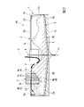
図1~図3に示すように、シックナー10は、槽1と、橋部5と、支持軸6と、駆動手段(図示省略)と、上部レイキ2と、下部レイキ3と、軸部材支持部7と、軸部材4と、エア供給手段(図示省略)と、を備える。
As shown in FIGS. 1 to 3, the
槽1は、有底筒状である。槽1の中心軸Cは、鉛直方向(上下方向)に延びる。槽1には、液体LおよびスラッジSが溜められる。槽1の容量は、例えば数百トンであり、本実施形態の例では400トンである。槽1に溜められる液体Lの液面LSは、水平方向に広がる。
The
本実施形態では、中心軸Cが延びる方向を上下方向と呼ぶ。上下方向のうち、液面LSが向く方向を上側と呼び、液面LSが向く方向とは反対方向を下側と呼ぶ。
中心軸Cに直交する方向を径方向と呼ぶ。径方向のうち、中心軸Cに接近する方向を径方向内側と呼び、中心軸Cから離れる方向を径方向外側と呼ぶ。
中心軸C回りに周回する方向を周方向と呼ぶ。周方向のうち、シックナー10の運転時に上部レイキ2および下部レイキ3が回転させられる方向を、レイキ回転方向Tと呼び、これとは反対の回転方向を、レイキ回転方向Tとは反対方向(反レイキ回転方向)と呼ぶ。本実施形態の例では、図1に示すようにシックナー10を上から下側に向かって見て(つまりシックナー10の上面視で)、レイキ回転方向Tは、周方向のうち時計回りに進む方向である。シックナー10を上から下側に向かって見て、反レイキ回転方向は、周方向のうち反時計回りに進む方向である。
In this embodiment, the direction in which the central axis C extends is called the vertical direction. Among the vertical directions, the direction in which the liquid surface LS faces is called the upper side, and the direction opposite to the direction in which the liquid surface LS faces is called the lower side.
A direction orthogonal to the central axis C is called a radial direction. Of the radial directions, the direction approaching the central axis C is called the radial inner side, and the direction away from the central axis C is called the radial outer side.
The direction of rotation around the central axis C is called the circumferential direction. Among the circumferential directions, the direction in which the
槽1は、周壁1aと、底壁1bと、底排出口1cと、浮き屑排出口1dと、オーバーフロー1eと、液体流入口(図示省略)と、を有する。
周壁1aは、中心軸Cを中心とする円筒状である。底壁1bは、中心軸Cを中心とする円板状または円錐状である。底壁1bが円錐状の場合、底壁1bは、径方向内側へ向かうにしたがい下側へ向けて傾斜するテーパ状である。
The
The
底排出口1cは、槽1の底壁1bの中央部(中心軸C上)に配置される。底排出口1cは、底壁1bを上下方向に貫通する貫通孔により構成される。底排出口1cには、不図示の開閉バルブが設けられる。開閉バルブは、通常の運転時は閉じられており、底排出口1cから液体L等を排出させるときに開けられる。
The
底排出口1cは、例えば2年に一度など、定期的に槽1内のスラッジSを回収して槽1を清掃およびメンテナンスする際に開けられる。具体的には、まず底排出口1cを閉じた状態で、不図示のフィルタープレス装置(加圧ろ過装置)を用いて槽1の底部からスラッジSを汲み取る。槽1内から汲み取ったスラッジSは、フィルタープレス装置により処理される。次いで、槽1内に残された液体L等を、底排出口1cを開けることにより槽1の外部に排出させて、槽1の清掃およびメンテナンス等を行う。
The
浮き屑排出口1dは、槽1の上部に配置され、上側に向けて開口する。浮き屑排出口1dの開口部は、液面LSよりも僅かに上側に位置する。浮き屑排出口1dは、不図示の浮き屑収集部に接続される。浮き屑排出口1dから排出された液面LSの浮き屑は、浮き屑収集部に集められる。
The floating
オーバーフロー1eは、槽1の上部に配置され、上側に向けて開口する。本実施形態の例では、オーバーフロー1eが、中心軸Cを中心として周方向に延びる環状の溝である。オーバーフロー1eは、周壁1aの内周面の上端部に設けられる。オーバーフロー1eは、シックナー10の後工程の処理槽等の設備に接続される。オーバーフロー1eの上下方向の位置に応じて、槽1内の液面LSの上下方向の位置が設定される。
The
特に図示しないが、液体流入口は、槽1の上側に配置される。シックナー10の上面視で、液体流入口は、槽1の略中央部に配置される。不純物を含む液体Lは、シックナー10の前工程の設備から液体流入口を通って、槽1内に供給される。
Although not shown, the liquid inlet is arranged above the
図2に示す矢印Fは、液体流入口から槽1内に供給された液体Lの流れの向きを、模式的に表している。槽1内に流入した液体Lは、槽1の略中央部から径方向外側へ向けて流れていく間に、槽1内において不純物が沈降させられる。槽1内に沈降した不純物は、スラッジSとなる。不純物が沈降させられた後の液体Lは、オーバーフロー1eに流入し、シックナー10の後工程の設備に送られる。
An arrow F shown in FIG. 2 schematically represents the direction of flow of the liquid L supplied into the
橋部5は、槽1の上側に架け渡される。橋部5は、槽1よりも上側に、作業者が通行可能に設けられる足場である。橋部5は、中心軸C上を通り、径方向に延びる。
支持軸6は、橋部5に支持されて、上下方向に延びる。支持軸6は、中心軸Cと同軸に設けられる。支持軸6は、不図示のモータ等の駆動手段により、中心軸C回りのレイキ回転方向Tに回転させられる。
The
The
上部レイキ2は、槽1の上部に配置される。上部レイキ2は、支持軸6に支持され、支持軸6とともに中心軸C回りのレイキ回転方向Tに回転させられる。上部レイキ2の上下方向の位置は、オーバーフロー1eの上下方向の位置と略同じである。上部レイキ2は、槽1の液面LSに浮かぶ浮き屑を回収して、浮き屑排出口1dに排出する。上部レイキ2の中心軸C回りの回転軌跡は、液面LSの略全体を覆う円板状となる。
A
上部レイキ2は、複数の上部レイキアーム2aを有する。上部レイキアーム2aは、径方向内端部が支持軸6に支持され、支持軸6から径方向外側に向けて延びる。本実施形態の例では、上部レイキ2が、2つの上部レイキアーム2aを有する。2つの上部レイキアーム2a同士は、中心軸Cを中心として互いに180°回転対称に設けられる。
The
上部レイキアーム2aは、アーム本体2bと、浮き屑ガイド部2cと、浮き屑捕集部2dと、を有する。
アーム本体2bは、径方向に沿って延びる。アーム本体2bの径方向内端部は、支持軸6に支持される。アーム本体2bの径方向外端部は、コロ部材を介して周壁1aの上端部に支持される。コロ部材は、周壁1aの上端部上を周方向に転動自在である。アーム本体2bは、浮き屑ガイド部2cおよび浮き屑捕集部2dを支持する。
The
The
浮き屑ガイド部2cは、アーム本体2bよりもレイキ回転方向Tに配置される。本実施形態の例では、浮き屑ガイド部2cが板状であり、浮き屑ガイド部2cの一対の板面は、周方向の両側(つまりレイキ回転方向Tおよび反レイキ回転方向)を向く。浮き屑ガイド部2cの下端部は、液面LSよりも下側に位置する。浮き屑ガイド部2cの上端部は、液面LSよりも上側に位置する。
The floating
浮き屑ガイド部2cは、径方向内側に向かうにしたがいレイキ回転方向Tに向けて延びる。このため、液面LSに浮かぶ浮き屑が浮き屑ガイド部2cに接触すると、浮き屑ガイド部2cのレイキ回転方向Tへの移動(中心軸C回りの回転)にともなって、浮き屑は径方向外側へ向けて案内される。具体的に、浮き屑ガイド部2cは、液面LSの浮き屑を浮き屑捕集部2dへ案内する機能を有する。
The
浮き屑捕集部2dは、浮き屑ガイド部2cよりも径方向外側に配置される。浮き屑捕集部2dは、浮き屑ガイド部2cの径方向外側に接続する。シックナー10の上面視で、浮き屑捕集部2dは、反レイキ回転方向に窪む凹状である。本実施形態の例では、浮き屑捕集部2dが板状であり、浮き屑捕集部2dの一対の板面は、周方向の両側(レイキ回転方向Tおよび反レイキ回転方向)を向く部分と、径方向の両側(径方向内側および径方向外側)を向く部分と、を有する。浮き屑捕集部2dの下端部は、液面LSよりも下側に位置する。浮き屑捕集部2dの上端部は、液面LSよりも上側に位置する。
The floating
浮き屑捕集部2dは、浮き屑ガイド部2cよりも反レイキ回転方向に配置される。本実施形態の例では、浮き屑捕集部2dが、アーム本体2bよりも反レイキ回転方向に配置される。浮き屑捕集部2dには、液面LSに浮かぶ浮き屑が一時的に保持される。シックナー10の上面視で、浮き屑捕集部2dの中心軸C回りの回転軌跡は、浮き屑排出口1dと重なる。浮き屑捕集部2dが浮き屑排出口1d上を通過するときに、浮き屑捕集部2dが保持する浮き屑が、浮き屑排出口1dへ排出される。
The
下部レイキ3は、槽1の底部に配置される。下部レイキ3は、槽1の底壁1bの上側に配置され、底壁1bと隙間をあけて対向する。下部レイキ3は、支持軸6に支持され、支持軸6とともに中心軸C回りのレイキ回転方向Tに回転させられる。下部レイキ3は、槽1の底部に溜まるスラッジSを径方向内側へ移動させる機能等を有する。下部レイキ3の中心軸C回りの回転軌跡は、底壁1bの上面の略全体を覆う逆円錐状となる。
A
下部レイキ3は、複数の第1下部レイキアーム3aと、複数の第2下部レイキアーム3bと、を有する。
第1下部レイキアーム3aは、径方向内端部が支持軸6に支持され、支持軸6から径方向外側に向かうにしたがい上側へ向けて傾斜して延びる。第1下部レイキアーム3aの径方向外端部は、周壁1aに径方向内側から隙間をあけて対向する。特に図示しないが、第1下部レイキアーム3aは、径方向内端部以外の部位において、上部レイキアーム2aと連結される部分を有する。つまり第1下部レイキアーム3aは、上部レイキアーム2aにも支持される。
本実施形態の例では、下部レイキ3が、2つの第1下部レイキアーム3aを有する。2つの第1下部レイキアーム3a同士は、中心軸Cを中心として互いに180°回転対称に設けられる。
The
The first
In the example of this embodiment, the
第1下部レイキアーム3aは、複数の第1歯部3cを有する。複数の第1歯部3cは、第1下部レイキアーム3aにおいて、互いに径方向に間隔をあけて配列する。第1歯部3cは、径方向外側へ向かうにしたがいレイキ回転方向Tへ向けて延びる。このため、槽1の底部に溜まるスラッジSが第1歯部3cに接触すると、第1歯部3cのレイキ回転方向Tへの移動(中心軸C回りの回転)にともなって、スラッジSは径方向内側へ向けて案内される。
The first
第2下部レイキアーム3bは、径方向内端部が支持軸6に支持され、支持軸6から径方向外側に向かうにしたがい上側へ向けて傾斜して延びる。第2下部レイキアーム3bの径方向外端部は、第1下部レイキアーム3aの径方向外端部よりも、径方向内側に位置する。つまり第2下部レイキアーム3bは、第1下部レイキアーム3aよりも径方向の長さが短い。
The second
本実施形態の例では、下部レイキ3が、2つの第2下部レイキアーム3bを有する。2つの第2下部レイキアーム3b同士は、中心軸Cを中心として互いに180°回転対称に設けられる。第2下部レイキアーム3bは、第1下部レイキアーム3aと周方向に間隔をあけて配置される。図示の例では、第2下部レイキアーム3bと第1下部レイキアーム3aとが、中心軸C回りに90°ピッチで交互に配置される。
In the example of this embodiment, the
第2下部レイキアーム3bは、複数の第2歯部3dを有する。複数の第2歯部3dは、第2下部レイキアーム3bにおいて、互いに径方向に間隔をあけて配列する。第2歯部3dは、径方向外側へ向かうにしたがいレイキ回転方向Tへ向けて延びる。このため、槽1の底部に溜まるスラッジSが第2歯部3dに接触すると、第2歯部3dのレイキ回転方向Tへの移動(中心軸C回りの回転)にともなって、スラッジSは径方向内側へ向けて案内される。
The second
軸部材支持部7は、橋部5に取り付けられ、槽1の上側に位置する。軸部材支持部7は、橋部5から水平方向に突出して液面LSの上側に配置され、軸部材4を支持する。軸部材支持部7は、支持アーム7aを有する。支持アーム7aは、槽1の上側に配置されて、水平方向に延びる。本実施形態では、支持アーム7aが径方向に延びており、複数の軸部材4を支持する。
The shaft
軸部材4は、槽1の上側から槽1内に吊り下げられて、上下方向に延びる。軸部材4は、水平方向に互いに間隔をあけて複数設けられる。本実施形態では、複数の軸部材4が、支持アーム7aに吊り下げられており、径方向に互いに間隔をあけて配置される。複数の軸部材4は、互いに等間隔をあけて配列する。隣り合う軸部材4同士の軸間距離(配置ピッチ)は、例えば150~250mmであり、本実施形態では200mmである。
The
複数の軸部材4は、上端部が支持アーム7aに接続され、下端部は自由端とされている。軸部材4は、支持アーム7aに支持される上端部を中心に回動自在である。具体的に、軸部材4は、上下方向に延びる吊り下げ姿勢から、軸部材4の上端部回りに、少なくとも周方向(レイキ回転方向Tおよび反レイキ回転方向)に向けて回動自在である。軸部材4は、上端部が液面LSよりも上側に位置し、下端部が液面LSよりも下側に位置する。軸部材4の下端部は、スラッジSの内部に配置される。
The plurality of
軸部材4は、上部レイキ2により跳ね上げ可能とされている。具体的に、軸部材4は、上部レイキ2の中心軸C回りの回転軌跡と重なって配置される。このため、上部レイキ2がレイキ回転方向Tに回転すると、軸部材4は上部レイキ2と接触し、上部レイキ2によってレイキ回転方向Tに押されて、軸部材4の上端部回りに回動させられる(つまり跳ね上げられる)。さらに上部レイキ2がレイキ回転方向Tに回転すると、軸部材4は上部レイキ2から離れて(上部レイキ2との接触が解除されて)、跳ね上げ姿勢が解除され、軸部材4は自重によりまた元の位置(吊り下げ姿勢)に戻る。これにより、軸部材4は、スラッジSに抜き差しされる。具体的には、軸部材4が上端部回りに回動することで、軸部材4の少なくとも下端部が、スラッジSに対して切り込みを入れるように抜き差しされる。軸部材4が、軸部材4の上端部回りに回動可能な角度範囲は、例えば、上下方向(鉛直軸)を基準(0°)として70~90°であり、本実施形態の例では80°である。
The
本実施形態では、軸部材4が筒状である。軸部材4は、例えば金属製のパイプ等である。軸部材4は、軸部材支持部7の内部を通して、不図示のエアコンプレッサ等のエア供給手段と接続される。これにより、軸部材4の内部を通して、槽1内にエアが供給される。
In this embodiment, the
複数の軸部材4は、最内周軸部材4aと、最外周軸部材4bと、中間軸部材4cと、を有する。
最内周軸部材4aは、複数の軸部材4のうち、最も径方向内側に配置される。最内周軸部材4aの径方向位置は、第2下部レイキアーム3bの径方向外端部の径方向位置よりも、径方向内側である。最内周軸部材4aは、第1軸部材4aと言い換えてもよい。
The plurality of
The innermost
最外周軸部材4bは、複数の軸部材4のうち、最も径方向外側に配置される。最外周軸部材4bの径方向位置は、第2下部レイキアーム3bの径方向外端部の径方向位置よりも、径方向外側である。最外周軸部材4bは、第2軸部材4bと言い換えてもよい。
The
中間軸部材4cは、径方向において、最内周軸部材4aと最外周軸部材4bとの間に配置される。中間軸部材4cは、第3軸部材4cと言い換えてもよい。中間軸部材4cは、径方向に互いに間隔をあけて複数設けられる。本実施形態の例では、中間軸部材4cが8つ設けられる。
The
複数の中間軸部材4cのうち、少なくとも1つの中間軸部材4cの下端部は、最内周軸部材4aの下端部よりも下側に位置する。本実施形態の例では、すべての中間軸部材4cの下端部が、最内周軸部材4aの下端部よりも下側に位置する。径方向に配列する8つの中間軸部材4cのうち、径方向内側に配置される6つの中間軸部材4cにおいては、一の中間軸部材4cの下端部よりも、一の中間軸部材4cの径方向外側に隣り合う他の中間軸部材4cの下端部が、下側に位置する。
The lower end of at least one
複数の中間軸部材4cのうち、少なくとも1つの中間軸部材4cの下端部は、最外周軸部材4bの下端部よりも下側に位置する。本実施形態の例では、すべての中間軸部材4cのうち半数以上の中間軸部材4cの下端部が、最外周軸部材4bの下端部よりも下側に位置する。径方向に配列する8つの中間軸部材4cのうち、径方向外側に配置される3つの中間軸部材4cにおいては、一の中間軸部材4cの下端部よりも、一の中間軸部材4cの径方向内側に隣り合う他の中間軸部材4cの下端部が、下側に位置する。
Among the plurality of
本実施形態では、複数の軸部材4の下端部同士を繋ぐ形状が、下側に向けて凸となる略V字状である。
In this embodiment, the shape that connects the lower end portions of the plurality of
以上説明した本実施形態のシックナー10によれば、中心軸C回りに回転する上部レイキ2によって、軸部材4が跳ね上げられ、自重でまた元の位置(吊り下げ姿勢)に戻る。これにより、軸部材4がスラッジSに対して抜き差しされ、スラッジSに切り込みが入れられる。切り込みが入れられることにより、スラッジSの内部に溜まったガスが抜かれて、スラッジSの浮き上がりが抑制される。つまり、スラッジSが槽1の底部に沈んだ状態が維持されるので、スラッジSを槽1の底部から回収する効率が向上される。
According to the
また、スラッジSの浮き上がりが抑えられるので、スラッジSの上側を流れる排液等の液体L中の不純物が、槽1内に安定して沈降させられやすくなる。このため、液体L中の不純物の回収効率が高められて、シックナー10の後工程に不純物が送られることを抑制できる。
In addition, since the floating of the sludge S is suppressed, the impurities in the liquid L such as the waste liquid flowing above the sludge S are easily sedimented in the
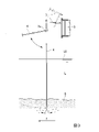
ここで、本実施形態の効果をよりわかりやすくするため、図4に示す参考例を参照する。図4の参考例では、シックナー100に軸部材4が設けられていない。このシックナー100では、スラッジSの内部に例えば硫化水素等のガスGが発生すると、ガスGがスラッジSの内部に溜まったままの状態となり、スラッジSを浮き上がらせてしまう。このため、スラッジSを槽1の底部から効率よく回収することができない。また、浮き上がったスラッジSの上面に、矢印Fで示すように液体Lが流れることで、液体L中の不純物が槽1内に沈降しにくくなり、不純物が回収しづらくなる。このような問題点(課題)を、本実施形態のシックナー10によれば解決できる。
Here, in order to make the effects of the present embodiment easier to understand, reference examples shown in FIG. 4 will be referred to. In the reference example of FIG. 4, the
また本実施形態では、槽1の底部に下部レイキ3が配置されて中心軸C回りに回転するので、下部レイキ3によってスラッジSを集めることができ、槽1の底部からスラッジSをより回収しやすくできる。
In addition, in this embodiment, since the
また本実施形態では、軸部材4が筒状であり、軸部材4の内部を通して、槽1内にエアが供給される。すなわち、軸部材4の内部を通して槽1内に曝気することができる。これにより、スラッジSの内部にガスが発生することを抑えられ、スラッジSの浮き上がりがより抑制される。
Further, in this embodiment, the
また本実施形態では、軸部材4が、水平方向に互いに間隔をあけて複数設けられる。このため、複数の軸部材4によって、スラッジSに広範囲に切り込みを入れることができ、スラッジS内のガス抜きが効率よく行える。
Further, in the present embodiment, a plurality of
また本実施形態では、複数の軸部材4が、中心軸Cに直交する径方向に互いに間隔をあけて配置されるので、スラッジSに、径方向に沿う広範囲にわたって切り込みを入れることができる。スラッジSは、径方向の広範囲にわたって浮き上がりが抑制される。したがって、槽1の中央部に流入された液体Lが、径方向に移動して、槽1の径方向外端部に位置するオーバーフロー1eに達するまでの間に、液体L中の不純物が槽1内により沈降させられやすくなる。
Further, in this embodiment, since the plurality of
また本実施形態では、複数の軸部材4のうち、中間軸部材4cの下端部が、最内周軸部材4aの下端部よりも下側に位置する。この場合、スラッジSの上面のうち、最内周軸部材4aに切り込まれる部分の上下方向の位置が、中間軸部材4cに切り込まれる部分の上下方向の位置よりも高くなる。このため、スラッジSの上面には、径方向外側へ向かうにしたがい低くなる傾斜面I1が形成される。槽1の中央から槽1内に流入した液体Lが、槽1内において径方向外側へ向かうときに、液体L中の不純物は、スラッジSの傾斜面I1に沿って下側へと転がりやすくなる。これにより、液体L中の不純物の沈降が促されて、回収効率がより高められる。
Further, in the present embodiment, among the plurality of
また本実施形態では、複数の軸部材4のうち、中間軸部材4cの下端部が、最外周軸部材4bの下端部よりも下側に位置する。この場合、スラッジSの上面のうち、最外周軸部材4bに切り込まれる部分の上下方向の位置が、中間軸部材4cに切り込まれる部分の上下方向の位置よりも高くなる。このため、スラッジSの上面には、径方向外側へ向かうにしたがい高くなる傾斜面I2が形成される。槽1内に沈降させられた不純物は、スラッジSの傾斜面I2によって径方向外側へ流れることが抑制されるので、槽1内にとどまりやすくなる。これにより、不純物をスラッジSとして回収する効率が高められる。
Further, in the present embodiment, among the plurality of
なお、本発明は前述の実施形態に限定されず、例えば下記に説明するように、本発明の趣旨を逸脱しない範囲において構成の変更等が可能である。 It should be noted that the present invention is not limited to the above-described embodiments, and, for example, as described below, changes in configuration can be made without departing from the gist of the present invention.
前述の実施形態では、シックナー10に軸部材支持部7が1つ設けられる例を挙げたが、軸部材支持部7は、周方向に間隔をあけて複数設けられてもよい。この場合、各軸部材支持部7に支持される軸部材4も、周方向に互いに間隔をあけて複数設けられる。
In the above-described embodiment, an example in which one shaft
前述の実施形態では、軸部材4が筒状であり、例えば金属製のパイプ等であるが、これに限らない。軸部材4は、例えば中実の棒等であってもよい。また、軸部材4は金属製に限らない。
In the above-described embodiment, the
その他、本発明の趣旨から逸脱しない範囲において、前述の実施形態、変形例およびなお書き等で説明した各構成(構成要素)を組み合わせてもよく、また、構成の付加、省略、置換、その他の変更が可能である。また本発明は、前述した実施形態によって限定されず、特許請求の範囲によってのみ限定される。 In addition, within the scope that does not deviate from the spirit of the present invention, each configuration (component) described in the above-described embodiments, modifications, notes, etc. may be combined, and addition, omission, replacement, and other Change is possible. Moreover, the present invention is not limited by the embodiments described above, but only by the claims.
本発明のシックナーによれば、スラッジがガスにより浮き上がることを抑制して、スラッジの回収効率を向上できる。したがって、産業上の利用可能性を有する。 According to the thickener of the present invention, it is possible to suppress the floating of sludge by gas and improve the sludge collection efficiency. Therefore, it has industrial applicability.
1…槽、2…上部レイキ、3…下部レイキ、4…軸部材、4a…最内周軸部材、4b…最外周軸部材、4c…中間軸部材、10…シックナー、C…中心軸、L…液体、S…スラッジ
DESCRIPTION OF
Claims (7)
前記槽の上部に配置され、上下方向に延びる中心軸回りに回転させられる上部レイキと、
前記槽の上側から前記槽内に吊り下げられて上下方向に延び、前記上部レイキにより跳ね上げ可能とされて、前記スラッジに抜き差しされる軸部材と、を備え、
前記軸部材は、前記上部レイキによって前記中心軸回りの周方向のうちレイキ回転方向に押されて跳ね上げられ、さらに前記上部レイキが前記レイキ回転方向に回転すると、前記上部レイキとの接触が解除されて、自重により吊り下げ姿勢に戻る、シックナー。 a tank in which liquid and sludge are collected;
an upper rake placed in the upper part of the tank and rotated around a central axis extending in the vertical direction;
a shaft member that is suspended in the tank from the upper side of the tank and extends in the vertical direction, can be flipped up by the upper rake, and is inserted into and removed from the sludge ;
The shaft member is pushed up by the upper Reiki in the Reiki rotation direction out of the circumferential directions around the central axis, and when the upper Reiki rotates in the Reiki rotation direction, the contact with the upper Reiki is released. The thickener returns to the hanging posture by its own weight .
前記槽の底部に配置され、前記中心軸回りに回転させられる下部レイキを備える、シックナー。 The thickener of claim 1,
A thickener comprising a lower rake placed at the bottom of said tub and rotated about said central axis.
前記軸部材は筒状であり、前記軸部材の内部を通して、前記槽内にエアが供給される、シックナー。 The thickener according to claim 1 or 2,
The thickener, wherein the shaft member is cylindrical, and air is supplied into the tank through the interior of the shaft member.
前記軸部材が、水平方向に互いに間隔をあけて複数設けられる、シックナー。 The thickener according to any one of claims 1 to 3,
A thickener, wherein a plurality of the shaft members are horizontally spaced apart from each other.
複数の前記軸部材が、前記中心軸に直交する径方向に互いに間隔をあけて配置される、シックナー。 The thickener according to claim 4,
A thickener in which a plurality of the shaft members are spaced apart from each other in a radial direction orthogonal to the central axis.
複数の前記軸部材は、
複数の前記軸部材のうち、最も径方向内側に配置される最内周軸部材と、
複数の前記軸部材のうち、最も径方向外側に配置される最外周軸部材と、
前記径方向において、前記最内周軸部材と前記最外周軸部材との間に配置される中間軸部材と、を有し、
前記中間軸部材の下端部が、前記最内周軸部材の下端部よりも下側に位置する、シックナー。 The thickener according to claim 5,
The plurality of shaft members are
an innermost circumferential shaft member arranged radially inward most among the plurality of shaft members;
an outermost peripheral shaft member arranged radially outermost among the plurality of shaft members;
an intermediate shaft member disposed between the innermost peripheral shaft member and the outermost peripheral shaft member in the radial direction;
A thickener in which the lower end of the intermediate shaft member is located below the lower end of the innermost peripheral shaft member.
複数の前記軸部材は、
複数の前記軸部材のうち、最も径方向内側に配置される最内周軸部材と、
複数の前記軸部材のうち、最も径方向外側に配置される最外周軸部材と、
前記径方向において、前記最内周軸部材と前記最外周軸部材との間に配置される中間軸部材と、を有し、
前記中間軸部材の下端部が、前記最外周軸部材の下端部よりも下側に位置する、シックナー。 The thickener according to claim 5 or 6,
The plurality of shaft members are
an innermost circumferential shaft member arranged radially inward most among the plurality of shaft members;
an outermost peripheral shaft member arranged radially outermost among the plurality of shaft members;
an intermediate shaft member disposed between the innermost peripheral shaft member and the outermost peripheral shaft member in the radial direction;
A thickener in which a lower end portion of the intermediate shaft member is positioned below a lower end portion of the outermost peripheral shaft member.
Priority Applications (1)
| Application Number | Priority Date | Filing Date | Title |
|---|---|---|---|
| JP2018176137A JP7190853B2 (en) | 2018-09-20 | 2018-09-20 | Thickener |
Applications Claiming Priority (1)
| Application Number | Priority Date | Filing Date | Title |
|---|---|---|---|
| JP2018176137A JP7190853B2 (en) | 2018-09-20 | 2018-09-20 | Thickener |
Publications (2)
| Publication Number | Publication Date |
|---|---|
| JP2020044510A JP2020044510A (en) | 2020-03-26 |
| JP7190853B2 true JP7190853B2 (en) | 2022-12-16 |
Family
ID=69900414
Family Applications (1)
| Application Number | Title | Priority Date | Filing Date |
|---|---|---|---|
| JP2018176137A Active JP7190853B2 (en) | 2018-09-20 | 2018-09-20 | Thickener |
Country Status (1)
| Country | Link |
|---|---|
| JP (1) | JP7190853B2 (en) |
Citations (6)
| Publication number | Priority date | Publication date | Assignee | Title |
|---|---|---|---|---|
| JP2001500056A (en) | 1996-09-03 | 2001-01-09 | イノベイティブ・バイオシステムズ,インコーポレイテッド | Microbial reforming reactor and process |
| JP2001321800A (en) | 2000-05-18 | 2001-11-20 | Public Works Research Institute | Gravitational concentration method for slurry |
| JP2003200006A (en) | 2002-01-10 | 2003-07-15 | Public Works Research Institute | Slurry gravitationally concentrating apparatus |
| JP2008049321A (en) | 2006-08-28 | 2008-03-06 | Sumitomo Heavy Industries Environment Co Ltd | Gravity concentration tank |
| JP2008119643A (en) | 2006-11-14 | 2008-05-29 | Sumitomo Heavy Industries Environment Co Ltd | Gravity concentration tank |
| JP2011005375A (en) | 2009-06-24 | 2011-01-13 | Nishihara Environment Technology Inc | Solid-liquid separator |
Family Cites Families (1)
| Publication number | Priority date | Publication date | Assignee | Title |
|---|---|---|---|---|
| JPS6262806U (en) * | 1985-10-04 | 1987-04-18 |
-
2018
- 2018-09-20 JP JP2018176137A patent/JP7190853B2/en active Active
Patent Citations (6)
| Publication number | Priority date | Publication date | Assignee | Title |
|---|---|---|---|---|
| JP2001500056A (en) | 1996-09-03 | 2001-01-09 | イノベイティブ・バイオシステムズ,インコーポレイテッド | Microbial reforming reactor and process |
| JP2001321800A (en) | 2000-05-18 | 2001-11-20 | Public Works Research Institute | Gravitational concentration method for slurry |
| JP2003200006A (en) | 2002-01-10 | 2003-07-15 | Public Works Research Institute | Slurry gravitationally concentrating apparatus |
| JP2008049321A (en) | 2006-08-28 | 2008-03-06 | Sumitomo Heavy Industries Environment Co Ltd | Gravity concentration tank |
| JP2008119643A (en) | 2006-11-14 | 2008-05-29 | Sumitomo Heavy Industries Environment Co Ltd | Gravity concentration tank |
| JP2011005375A (en) | 2009-06-24 | 2011-01-13 | Nishihara Environment Technology Inc | Solid-liquid separator |
Also Published As
| Publication number | Publication date |
|---|---|
| JP2020044510A (en) | 2020-03-26 |
Similar Documents
| Publication | Publication Date | Title |
|---|---|---|
| CN202315432U (en) | Skew plate sedimentation basin | |
| KR100860290B1 (en) | Apparatus for removing sludge of round shapesludgegather in settling pond | |
| SI9300268A (en) | Lamellar apparatus and method for clarifying water | |
| JP2009154051A (en) | Simple filtration apparatus | |
| US6358407B1 (en) | High turbidity wastewater purification system | |
| CN115872505A (en) | Seawater desalination impurity pretreatment assembly, system and process | |
| JP2010155322A (en) | Cutting fluid recovery device of machine tool | |
| JP7190853B2 (en) | Thickener | |
| JP2018020289A (en) | Dispersion plate unit and setting tank | |
| JP2010005520A (en) | Floatation separation apparatus | |
| KR20100004577A (en) | A settling tank for a sewage disposal | |
| JP7285717B2 (en) | Thickener | |
| JP3174716U (en) | Cutting fluid recovery device for machine tools | |
| CN209378520U (en) | A kind of settling tank that effect of settling is good | |
| EP2711064A2 (en) | Biofilter for wastewater digestion | |
| JP2009297609A (en) | Rotary separator | |
| CN108946988A (en) | A kind of double helix sedimentation basin suitable for the removing of rural area rainwash suspended matter | |
| JP2011101857A (en) | Overflow trough for sedimentation tank, and sedimentation tank | |
| KR101837575B1 (en) | Scum removal system for circular settling pond | |
| KR101749320B1 (en) | A screen device | |
| JP5478201B2 (en) | Precipitation tank guide plate and scum recovery device | |
| CN2532066Y (en) | Two-purpose settle pound for sewage treatment | |
| JP2021122756A (en) | Sedimentation basin | |
| JP2005238055A (en) | Dust removing apparatus for impurity separation | |
| RU49468U1 (en) | SILT PUMP CLEANER FOR WEIGHTED PARTICLES |
Legal Events
| Date | Code | Title | Description |
|---|---|---|---|
| A621 | Written request for application examination |
Free format text: JAPANESE INTERMEDIATE CODE: A621 Effective date: 20210608 |
|
| A977 | Report on retrieval |
Free format text: JAPANESE INTERMEDIATE CODE: A971007 Effective date: 20220525 |
|
| A131 | Notification of reasons for refusal |
Free format text: JAPANESE INTERMEDIATE CODE: A131 Effective date: 20220614 |
|
| A521 | Request for written amendment filed |
Free format text: JAPANESE INTERMEDIATE CODE: A523 Effective date: 20220805 |
|
| TRDD | Decision of grant or rejection written | ||
| A01 | Written decision to grant a patent or to grant a registration (utility model) |
Free format text: JAPANESE INTERMEDIATE CODE: A01 Effective date: 20221108 |
|
| A61 | First payment of annual fees (during grant procedure) |
Free format text: JAPANESE INTERMEDIATE CODE: A61 Effective date: 20221206 |
|
| R150 | Certificate of patent or registration of utility model |
Ref document number: 7190853 Country of ref document: JP Free format text: JAPANESE INTERMEDIATE CODE: R150 |