JP7187236B2 - Image observation device and imaging device - Google Patents
Image observation device and imaging device Download PDFInfo
- Publication number
- JP7187236B2 JP7187236B2 JP2018188414A JP2018188414A JP7187236B2 JP 7187236 B2 JP7187236 B2 JP 7187236B2 JP 2018188414 A JP2018188414 A JP 2018188414A JP 2018188414 A JP2018188414 A JP 2018188414A JP 7187236 B2 JP7187236 B2 JP 7187236B2
- Authority
- JP
- Japan
- Prior art keywords
- cylindrical member
- axis direction
- optical axis
- display panel
- image
- Prior art date
- Legal status (The legal status is an assumption and is not a legal conclusion. Google has not performed a legal analysis and makes no representation as to the accuracy of the status listed.)
- Active
Links
Images


Classifications
-
- H—ELECTRICITY
- H04—ELECTRIC COMMUNICATION TECHNIQUE
- H04N—PICTORIAL COMMUNICATION, e.g. TELEVISION
- H04N23/00—Cameras or camera modules comprising electronic image sensors; Control thereof
- H04N23/50—Constructional details
- H04N23/53—Constructional details of electronic viewfinders, e.g. rotatable or detachable
- H04N23/531—Constructional details of electronic viewfinders, e.g. rotatable or detachable being rotatable or detachable
-
- H—ELECTRICITY
- H04—ELECTRIC COMMUNICATION TECHNIQUE
- H04N—PICTORIAL COMMUNICATION, e.g. TELEVISION
- H04N23/00—Cameras or camera modules comprising electronic image sensors; Control thereof
- H04N23/50—Constructional details
- H04N23/55—Optical parts specially adapted for electronic image sensors; Mounting thereof
Description
本発明は、撮像装置に設けられる電子ビューファインダ等の画像観察装置に関する。 The present invention relates to an image observation device such as an electronic viewfinder provided in an imaging device.
電子ビューファインダには、撮像装置に対して格納する位置と突出する位置とに移動可能としたものがある。特許文献1にて開示された電子ビューファインダでは、表示ユニットを保持する固定筒に穴部を設け、固定筒に対して移動可能な移動筒により保持されたガイドバーを上記穴部に嵌合させることで、移動筒の移動をガイドする。
Some electronic viewfinders are movable between a retracted position and a projecting position with respect to the imaging device. In the electronic viewfinder disclosed in
しかしながら、特許文献1にて開示された電子ビューファインダでは、ガイドバーと穴部との嵌合長を確保するために、ガイドバーを表示ユニットよりも外側に配置している。このため、電子ビューファインダが大型化する。
However, in the electronic viewfinder disclosed in
本発明は、小型で良好な光学性能を有する画像観察装置およびこれを有する撮像装置を提供する。 SUMMARY OF THE INVENTION The present invention provides a compact image observation device having good optical performance and an imaging device having the same.
本発明の一側面としての画像観察装置は、画像を表示する画像表示パネルユニットと、該画像表示パネルユニットが固定された第1の筒部材と、観察光学系を保持し、該観察光学系の光軸方向において第1の筒部材に対して格納される格納位置と第1の筒部材に対して突出する突出位置とに移動可能な第2の筒部材と、第1の筒部材により保持され、第2の筒部材に設けられたガイド穴部を光軸方向に貫通するガイドバーとを有する。第2の筒部材は、観察光学系を収容する鏡筒部と該鏡筒部よりも光軸方向に直交する方向における外側に張り出した張出部とを有し、該張出部にガイド穴部が設けられている。第2の筒部材が格納位置にあるときに、張出部と画像表示パネルユニットの一部とが光軸方向に直交する方向において重なり合っており、光軸方向から見たときに、ガイドバーが、画像表示パネルユニットの外周よりも光軸方向に直交する方向の内側に配置されていることを特徴とする。
また、本発明の他の側面としての画像観察装置は、画像を表示する画像表示パネルユニットと、該画像表示パネルユニットが固定された第1の筒部材と、観察光学系を保持し、該観察光学系の光軸方向において第1の筒部材に対して格納される格納位置と第1の筒部材に対して突出する突出位置とに移動可能な第2の筒部材と、第1の筒部材により保持され、第2の筒部材に設けられたガイド穴部を光軸方向に貫通するガイドバーとを有する。第2の筒部材は、観察光学系を収容する鏡筒部と該鏡筒部よりも光軸方向に直交する方向における外側に張り出した張出部とを有し、該張出部にガイド穴部が設けられている。第2の筒部材が格納位置にあるときに、張出部と画像表示パネルユニットの一部とが光軸方向に直交する方向において重なり合っており、第2の筒部材は、観察光学系を該第2の筒部材に対して光軸方向に移動させて視度調整を行うカム機構を介して観察光学系を保持していることを特徴とする。
また、本発明の他の側面としての画像観察装置は、画像を表示する画像表示パネルユニットと、該画像表示パネルユニットが固定された第1の筒部材と、観察光学系を保持し、該観察光学系の光軸方向において第1の筒部材に対して格納される格納位置と第1の筒部材に対して突出する突出位置とに移動可能な第2の筒部材と、第1の筒部材により保持され、第2の筒部材に設けられたガイド穴部を光軸方向に貫通するガイドバーとを有する。第2の筒部材は、観察光学系を収容する鏡筒部と該鏡筒部よりも光軸方向に直交する方向における外側に張り出した張出部とを有し、該張出部にガイド穴部が設けられている。第2の筒部材が格納位置にあるときに、張出部と画像表示パネルユニットの一部とが光軸方向に直交する方向において重なり合っており、張出部の外周部に、第1の筒部材の内周面に接触する封止部材が設けられていることを特徴とする。
なお、上記画像観察装置を備えた撮像装置も、本発明の他の一側面を構成する。
An image observation apparatus as one aspect of the present invention holds an image display panel unit that displays an image, a first cylindrical member to which the image display panel unit is fixed, and an observation optical system. held by the first cylindrical member; and a guide bar passing through a guide hole provided in the second cylindrical member in the optical axis direction. The second cylindrical member has a lens barrel portion that accommodates the observation optical system and a protruding portion that protrudes outward from the lens barrel portion in a direction perpendicular to the optical axis direction. department is provided. When the second cylindrical member is in the retracted position, the projecting portion and part of the image display panel unit overlap each other in the direction orthogonal to the optical axis direction, and when viewed from the optical axis direction, the guide The bar is arranged inside the outer periphery of the image display panel unit in a direction orthogonal to the optical axis direction .
Further, according to another aspect of the present invention, there is provided an image observation apparatus holding an image display panel unit for displaying an image, a first cylindrical member to which the image display panel unit is fixed, and an observation optical system, a second cylindrical member movable in the optical axis direction of the optical system between a retracted position with respect to the first cylindrical member and a projecting position with respect to the first cylindrical member; and a guide bar passing through a guide hole provided in the second cylindrical member in the optical axis direction. The second cylindrical member has a lens barrel portion that accommodates the observation optical system and a protruding portion that protrudes outward from the lens barrel portion in a direction perpendicular to the optical axis direction. department is provided. When the second cylindrical member is in the retracted position, the projecting portion and part of the image display panel unit overlap in a direction orthogonal to the optical axis direction, and the second cylindrical member extends the observation optical system. The observation optical system is held via a cam mechanism that moves in the optical axis direction with respect to the second cylindrical member to adjust the dioptric power.
Further, according to another aspect of the present invention, there is provided an image observation apparatus holding an image display panel unit for displaying an image, a first cylindrical member to which the image display panel unit is fixed, and an observation optical system, a second cylindrical member movable in the optical axis direction of the optical system between a retracted position with respect to the first cylindrical member and a projecting position with respect to the first cylindrical member; and a guide bar passing through a guide hole provided in the second cylindrical member in the optical axis direction. The second cylindrical member has a barrel portion that accommodates the observation optical system, and a protruding portion that protrudes outward from the barrel portion in a direction perpendicular to the optical axis direction. department is provided. When the second cylindrical member is in the retracted position, the projecting portion and part of the image display panel unit overlap each other in a direction perpendicular to the optical axis direction, and the first cylindrical member is attached to the outer peripheral portion of the projecting portion. A sealing member is provided in contact with the inner peripheral surface of the member.
Note that an imaging device including the image observation device also constitutes another aspect of the present invention.
本発明によれば、小型で良好な光学性能を有する画像観察装置を実現することができ、これを撮像装置に用いることで、撮像装置の小型化を図ることができる。 According to the present invention, it is possible to realize a small-sized image observation device having good optical performance, and use of this device in an image pickup device makes it possible to reduce the size of the image pickup device.
以下、本発明の実施例について図面を参照しながら説明する。 BEST MODE FOR CARRYING OUT THE INVENTION Hereinafter, embodiments of the present invention will be described with reference to the drawings.
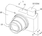
図1、図2および図3は、本発明の実施例である撮像装置としてのデジタルカメラ(以下、単にカメラという)1の外観を示している。カメラ1は、その本体(以下、カメラ本体という)10の前面に撮像光学系を収容したレンズ鏡筒ユニット13を有するとともに、カメラ本体10の内部に撮像光学系により形成された被写体像を撮像する撮像素子50を有する。以下の説明において、撮像光学系の光軸AXが延びる光軸方向をZ方向といい、Z方向のうち被写体側をマイナス側(-Z方向)または前側といい、その反対側をプラス側(+Z方向)または後側という。また、それぞれZ方向に直交する水平方向と上下方向をX方向とY方向という。
1, 2 and 3 show the appearance of a digital camera (hereinafter simply referred to as a camera) 1 as an imaging device according to an embodiment of the present invention. The
またカメラ1は、カメラ本体10に対して格納およびポップアップが可能なフラッシュユニット11を有する。さらにカメラ1は、カメラ本体10に対して格納およびポップアップが可能な電子ビューファインダ(EVF)ポップアップユニット12を有する。図1は、EVFポップアップユニット12がカメラ本体10内に格納された状態を示し、図2はEVFポップアップユニット12がカメラ本体10からポップアップした状態を示している。図2および図3に示すように、EVFポップアップユニット12は、そのポップアップ部12aに対して-Z方向に格納されたり+Z方向に引き出されたりすることが可能な画像観察装置としての電子ビューファインダ(EVF)ユニット14を保持している。
The
以下の説明において、図2および図3に示す状態(位置)をそれぞれ、EVFユニット14の格納状態(格納位置)および使用状態(突出位置)という。
In the following description, the states (positions) shown in FIGS. 2 and 3 are referred to as the stored state (stored position) and the used state (projected position) of the
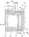
図4はEVFユニット14の格納状態での外観を、図5はEVFユニット14の使用状態での外観をそれぞれ示している。また図6は、EVFユニット14を分解して示している。また図7はEVFユニット14の格納状態での側方(X方向)から見た断面を、図8はEVFユニット14の使用状態での側方から見た断面を示している。また図9はEVFユニット14の格納状態での断面であって後述するガイドバーの位置での上方(Y方向)から見た断面を示し、図10はEVFユニット14の格納状態での断面であって後述するボールの位置での側方から見た断面を示している。
4 shows the appearance of the
EVFユニット14は、第1の筒部材としての固定筒25と、第2の筒部材としての移動筒32と、第3の部材としてのレンズホルダ23とを有する。固定筒25は、図2および図3に示したEVFポップアップユニット12のポップアップ部12a内に固定される。移動筒32は、固定筒25の内側に配置され、該固定筒25に対してZ方向(第1の方向)にて格納位置(図7、図9および図10)と突出位置(図8)とに移動が可能である。レンズホルダ23は、移動筒32とともに固定筒25に対してZ方向に移動可能であり、レンズカバー19と係合して、第1のレンズ22、マスク21および第2のレンズ20により構成される観察光学系としての接眼光学系を保持する。すなわち、移動筒32は、レンズホルダ23および後述する視度調整機構を介して接眼光学系を保持する。
The EVF
固定筒25の後端には、表示素子ホルダとしてのパネルカバー33が取り付けられる(固定される)。固定筒25の前端部における上側左右の部分とパネルカバー33の上側左右の部分とで、Z方向に延びる2本のガイドバー26の前端と後端を保持している。移動筒32は、レンズホルダ23を収容する鏡筒部32aと、該鏡筒部32aよりもZ方向に直交するXおよびY方向(第2の方向)における外側に張り出した張出部32bとを有する。張出部32bの上側左右の2箇所にはガイド穴部32cが設けられており、それぞれのガイド穴部32cには上記ガイドバー26が貫通している。このため、移動筒32は、ガイドバー26によってZ方向に直進ガイドされる。ガイドバー26が一体に固定された固定筒25とパネルカバー33とにより両持ち支持されているため、移動筒32を精度良く(XおよびY方向にがたなく)移動させることができる。
A
移動筒32の前端には第4の部材としての接眼部材16がスナップフィットによって取り付けられる。主として移動筒32、接眼部材16、レンズホルダ23および接眼光学系により接眼ユニットが構成される。接眼ユニットは、固定筒25に対してZ方向における格納位置(図4)と突出位置(図5)との間で移動可能である。
An
ユーザは、接眼ユニットを突出位置に引き出したEVFユニット14の使用状態において、EVFユニット14の内部に設けられた表示パネル(これについては後述する)に表示されるファインダ画像を観察することができる。
The user can observe a finder image displayed on a display panel (described later) provided inside the
固定筒25の左右の内側面部のそれぞれにはボール穴部39が設けられ、移動筒32の鏡筒部32aにおける左右の外側面部にはそれぞれボール溝部40が設けられている。各ボール穴部39は、ボール30を保持する。各ボール溝部40には、移動筒32が格納位置にあるときにボール30が嵌り込む第1の凹部40aと、移動筒32が突出位置にあるときにボール30が嵌り込む第2の凹部40bと、第1および第2の凹部40a,40bの間でZ方向に延びる中間溝部40cとが設けられている。2つのボール穴部39によりそれぞれ保持された2つのボール30は、固定筒25の左右の外側面部にそれぞれ取り付けられた板ばね30によってボール溝部40に向かって付勢される。板ばね30によって付勢されたボール30が第1の凹部40aに嵌り込むことで移動筒32(接眼ユニット)が格納位置にて保持され、第2の凹部40bに嵌り込むことで接眼ユニットが突出位置にて保持される。接眼ユニットが格納位置と突出位置との間でZ方向に移動するときは、ボール30は中間溝部40cの移動に伴ってボール穴部39内で回転する。
Ball holes 39 are provided on the left and right inner side surfaces of the fixed
また、移動筒32の張出部32bの外周部には、リング状のシリコーンゴム(封止部材)38が嵌め込まれている。シリコーンゴム38は、固定筒25の内周面に接触して、張出部32bと固定筒25の内周面との間の隙間を塞ぐ。移動筒32が固定筒25に対してZ方向に移動すると、シリコーンゴム38は固定筒25の内周面に対して摺動し、上記隙間を塞いだ状態を維持する。これにより、外部からの塵埃が上記隙間を通って移動筒32の内部に入り込んだり、後述するカバーガラスに付着したりすることを回避することができる。
A ring-shaped silicone rubber (sealing member) 38 is fitted to the outer peripheral portion of the projecting
移動筒32における鏡筒部32aの内周部には、レンズホルダ23をZ方向に直進ガイドするためのガイド溝部が設けられている。また移動筒32における鏡筒部32aの上部外側には視度調整レバー28が配置され、鏡筒部32aの内側にはカム27が配置されている。視度調整レバー28とカム27とは鏡筒部32aに形成された穴部32dを通して一体回転可能に連結されており、視度調整レバー28を回転させることでカム27も回転する。なお、視度調整レバー28の下面部に回転軸回りに設けられた環状の凹部には、鏡筒部32aの外面に接触して視度調整レバー28の回転とともに該外面に対して摺動するOリング29が嵌め込まれている。
A guide groove portion for guiding the
一方、レンズホルダ23には、カム27に当接するカムフォロア37が設けられている。移動筒32の前端には第4の部材としての接眼部材16がスナップフィットによって取り付けられており、該接眼部材16とレンズホルダ23との間には、カムフォロワ37をカム27に対して付勢するばね18が配置されている。ユーザが視度調整レバー28を回転操作してカム27を回転させると、カムフォロワ37を介してレンズホルダ23がZ方向に移動する。これにより、ユーザの視力に合わせて接眼光学系を移動させて視度調整を行うことができる。視度調整レバー28、カム27およびカムフォロワ37により視度調整機構が構成される。
On the other hand, the
視度調整レバー28は、接眼ユニットが突出位置にあるEVFユニット14の使用状態でのみユーザにより回転操作可能である。これにより、視度がユーザが知らない間に変更されることを避けることができる。
The
固定筒25には、スイッチ24が設けられている。スイッチ24は、接眼ユニットが突出位置にあるか格納位置にあるか(EVFユニット14が格納状態にあるか使用状態にあるか)を検出するために設けられている。
A
パネルカバー33は、表示素子としての表示パネル36を保持する。表示パネル36は、撮像素子50の出力を用いて生成されたファインダ画像を表示する。接眼部材16とパネルカバー33には、ユーザが表示パネル36に表示された画像を観察するための開口部が設けられている。接眼部材16の開口部には、外部から塵埃が入り込んで接眼光学系に付着することを防止するための透明の接眼ガラス15が取り付けられている。パネルカバー33の開口部には、外部からの塵埃が表示パネル36の表示面に付着することを防止するために該表示面を覆う透光性防塵部材としての防塵ガラス35が取り付けられている。パネルカバー33、表示パネル36および防塵ガラス35により、図11に示す表示パネルユニット(画像表示パネルユニット)44が構成される。表示パネル36からはフレキシブル基板36aが延出している。
The panel cover 33 holds a
このようにEVFユニット14を構成することで、表示パネル36から接眼ガラス15までの間の空間を、その外部からの塵埃が入らないように密閉することが可能となる。また、パネルカバー33には、通気用の開口部33aが設けられており、該開口部33aは、通気シート34で覆われている。開口部33aおよび通気シート34は、ユーザが接眼ユニットを引き出したり格納したりして固定筒25に対して移動させる際にシリコーンゴム38により密閉された空間の圧力が急激に変化して微小な隙間から塵埃を含んだ空気が出入りしないようにするために設けられている。
By configuring the
本実施例の接眼ユニットは、固定筒25に対してZ方向に一体移動可能な3つの部材として、移動筒32、接眼部材16およびレンズホルダ23を含む。移動筒32において、シリコーンゴム38が設けられた張出部32bは、移動筒32における後端(最も画像表示ユニット側)に設けられている。このような位置に張出部32bを設けることで、図8に示すように、接眼ユニットを固定筒25に対して引き出してEVFユニット14を使用状態としたときの表示パネル36の表示面から接眼ガラス15までの光学全長を最も長くすることができる。これにより、EVFユニット14の光学性能の向上させることができる。
The eyepiece unit of this embodiment includes a moving
またパネルカバー33は、図7および図11に示すように、表示パネル36を保持する後端部よりも前方(観察光学系側)に突出した凸部33bを有し、該凸部33bの前端に形成された前述した開口部に防塵ガラス35が設けられている。図7に示すEVFユニット14の格納状態では、移動筒32の張出部32bとパネルカバー33の凸部33bとがZ方向における長さαだけY(およびX)方向にて重なり合っている。言い換えれば、移動筒32の張出部32bと表示パネルユニットのうち防塵ガラス35がY(およびX)方向にて重なり合っている。さらに言い換えれば、凸部33bの周囲に移動筒32の一部が配置される。このように構成することで、EVFユニット14を長さαだけZ方向にて小型化することができる。
7 and 11, the
図13は従来の画像表示ユニット44′の外観を示している。従来の画像表示ユニット44′では、パネルカバー33′に本実施例の凸部33bのような部分が設けられておらず、防塵ガラス35′回りの形状がフラットである。このため、パネルカバー33′と移動筒とをY(およびX)方向にて重なり合うように配置することができない。
FIG. 13 shows the appearance of a conventional image display unit 44'. In the conventional image display unit 44', the panel cover 33' is not provided with a portion such as the
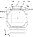
また図12は、本実施例のEVFユニット14のうち+Z方向から見た移動筒32と表示パネル36を示している。この+Z方向視において、移動筒32(鏡筒部32a)の内周部32eは、表示パネル36(画像表示ユニット44)の外周36bよりもXおよびY方向における内側に位置する。これにより、接眼ユニットをXおよびY方向にて小型化することができる。
FIG. 12 shows the
さらに図12に示すように、+Z方向視において、移動筒32の張出部32bに設けられたガイド穴部32c(つまりはガイドバー26)は、表示パネル36(画像表示ユニット44)の外周36bよりもXおよびY方向における内側に位置する。これにより、EVFユニット14をXおよびY方向にて小型化することができる。
Further, as shown in FIG. 12, when viewed in the +Z direction, the
以上説明したように、本実施例によれば、Z方向とXおよびY方向とのそれぞれで小型化され、かつ光学性能が高いEVFユニット14を実現することができ、これを搭載したカメラ1のより小型化に有効である。
As described above, according to this embodiment, it is possible to realize the
以上説明した各実施例は代表的な例にすぎず、本発明の実施に際しては、各実施例に対して種々の変形や変更が可能である。 Each embodiment described above is merely a representative example, and various modifications and changes can be made to each embodiment in carrying out the present invention.
10 デジタルカメラ
14 電子ビューファインダユニット
20 第2のレンズ
21 マスク
22 第1のレンズ
23 レンズホルダ(第3の部材)
24 スイッチ
25 固定筒(第1の部材)
26 ガイドバー
32 移動筒(第2の部材)
32a 鏡筒部
32b 張出部
32c ガイド穴部
33 パネルカバー
33b 凸部
36 表示パネル
44 画像表示ユニット
10
24
26
32a
Claims (8)
該画像表示パネルユニットが固定された第1の筒部材と、
観察光学系を保持し、前記観察光学系の光軸方向において前記第1の筒部材に対して格納される格納位置と前記第1の筒部材に対して突出する突出位置とに移動可能な第2の筒部材と、
前記第1の筒部材により保持され、前記第2の筒部材に設けられたガイド穴部を前記光軸方向に貫通するガイドバーとを有し、
前記第2の筒部材は、前記観察光学系を収容する鏡筒部と該鏡筒部よりも前記光軸方向に直交する方向における外側に張り出した張出部とを有し、該張出部に前記ガイド穴部が設けられており、
前記第2の筒部材が前記格納位置にあるときに、前記張出部と前記画像表示パネルユニットの一部とが前記光軸方向に直交する方向において重なり合っており、
前記光軸方向から見たときに、前記ガイドバーが、前記画像表示パネルユニットの外周よりも前記光軸方向に直交する方向の内側に配置されていることを特徴とする画像観察装置。 an image display panel unit that displays an image;
a first cylindrical member to which the image display panel unit is fixed;
a retracted position in which the observation optical system is held and is movable in the optical axis direction of the observation optical system between a retracted position with respect to the first cylindrical member and a protruding position in which the optical system is projected with respect to the first cylindrical member; 2 cylindrical members;
a guide bar held by the first cylindrical member and passing through a guide hole provided in the second cylindrical member in the optical axis direction;
The second cylindrical member has a barrel portion that accommodates the observation optical system and a projecting portion that projects outward from the lens barrel portion in a direction perpendicular to the optical axis direction, and the projecting portion is provided with the guide hole,
When the second cylindrical member is in the retracted position, the projecting portion and a portion of the image display panel unit overlap in a direction orthogonal to the optical axis direction, and
An image observing apparatus according to claim 1, wherein the guide bar is arranged inside the outer periphery of the image display panel unit in a direction orthogonal to the optical axis direction when viewed from the optical axis direction.
該画像表示パネルユニットが固定された第1の筒部材と、a first cylindrical member to which the image display panel unit is fixed;
観察光学系を保持し、前記観察光学系の光軸方向において前記第1の筒部材に対して格納される格納位置と前記第1の筒部材に対して突出する突出位置とに移動可能な第2の筒部材と、a retracted position in which the observation optical system is held and is movable in the optical axis direction of the observation optical system between a retracted position with respect to the first cylindrical member and a protruding position in which the optical system is projected with respect to the first cylindrical member; 2 cylindrical members;
前記第1の筒部材により保持され、前記第2の筒部材に設けられたガイド穴部を前記光軸方向に貫通するガイドバーとを有し、a guide bar held by the first cylindrical member and passing through a guide hole provided in the second cylindrical member in the optical axis direction;
前記第2の筒部材は、前記観察光学系を収容する鏡筒部と該鏡筒部よりも前記光軸方向に直交する方向における外側に張り出した張出部とを有し、該張出部に前記ガイド穴部が設けられており、The second cylindrical member has a barrel portion that accommodates the observation optical system and a projecting portion that projects outward from the lens barrel portion in a direction perpendicular to the optical axis direction, and the projecting portion is provided with the guide hole,
前記第2の筒部材が前記格納位置にあるときに、前記張出部と前記画像表示パネルユニットの一部とが前記光軸方向に直交する方向において重なり合っており、When the second cylindrical member is in the retracted position, the projecting portion and a portion of the image display panel unit overlap in a direction orthogonal to the optical axis direction, and
前記第2の筒部材は、前記観察光学系を該第2の筒部材に対して前記光軸方向に移動させて視度調整を行うカム機構を介して前記観察光学系を保持していることを特徴とする画像観察装置。The second cylindrical member holds the observation optical system via a cam mechanism that moves the observation optical system relative to the second cylindrical member in the optical axis direction to adjust dioptric power. An image observation device characterized by:
該画像表示パネルユニットが固定された第1の筒部材と、a first cylindrical member to which the image display panel unit is fixed;
観察光学系を保持し、前記観察光学系の光軸方向において前記第1の筒部材に対して格納される格納位置と前記第1の筒部材に対して突出する突出位置とに移動可能な第2の筒部材と、a retracted position in which the observation optical system is held and is movable in the optical axis direction of the observation optical system between a retracted position with respect to the first cylindrical member and a protruding position in which the optical system is projected with respect to the first cylindrical member; 2 cylindrical members;
前記第1の筒部材により保持され、前記第2の筒部材に設けられたガイド穴部を前記光軸方向に貫通するガイドバーとを有し、a guide bar held by the first cylindrical member and passing through a guide hole provided in the second cylindrical member in the optical axis direction;
前記第2の筒部材は、前記観察光学系を収容する鏡筒部と該鏡筒部よりも前記光軸方向に直交する方向における外側に張り出した張出部とを有し、該張出部に前記ガイド穴部が設けられており、The second cylindrical member has a barrel portion that accommodates the observation optical system and a projecting portion that projects outward from the lens barrel portion in a direction perpendicular to the optical axis direction, and the projecting portion is provided with the guide hole,
前記第2の筒部材が前記格納位置にあるときに、前記張出部と前記画像表示パネルユニットの一部とが前記光軸方向に直交する方向において重なり合っており、When the second cylindrical member is in the retracted position, the projecting portion and a portion of the image display panel unit overlap in a direction orthogonal to the optical axis direction, and
前記張出部の外周部に、前記第1の筒部材の内周面に接触する封止部材が設けられていることを特徴とする画像観察装置。An image observing apparatus according to claim 1, wherein a sealing member is provided on an outer peripheral portion of the protruding portion so as to contact an inner peripheral surface of the first cylindrical member.
前記画像表示パネルユニットの前記一部は、前記透光性防塵部材を含むことを特徴とする請求項1から3のいずれか一項に記載の画像観察装置。 The image display panel unit includes a display element and a translucent dust-proof member covering the display surface of the display element,
4. The image observing apparatus according to claim 1, wherein the part of the image display panel unit includes the translucent dust-proof member.
該表示素子ホルダは、前記表示素子を保持する部分よりも前記光軸方向における観察光学系側に突出する凸部を有し、
前記透光性防塵部材は前記凸部に設けられているとともに、
前記一部は、前記凸部を含むことを特徴とする請求項4に記載の画像観察装置。 The image display panel unit has a display element holder that holds the display element,
The display element holder has a convex portion that projects toward the observation optical system in the optical axis direction from a portion that holds the display element,
The translucent dustproof member is provided on the convex portion,
5. The image observing apparatus according to claim 4 , wherein said portion includes said convex portion.
前記撮像素子の出力を用いて生成された画像を表示する画像表示パネルユニットを有する請求項1から7のいずれか一項に記載の画像観察装置とを有することを特徴とする撮像装置。 an imaging device that captures a subject image formed by an imaging optical system;
8. An imaging apparatus, comprising: the image observing apparatus according to claim 1, comprising an image display panel unit for displaying an image generated using the output of said imaging device.
Priority Applications (3)
| Application Number | Priority Date | Filing Date | Title |
|---|---|---|---|
| JP2018188414A JP7187236B2 (en) | 2018-10-03 | 2018-10-03 | Image observation device and imaging device |
| CN201910916768.6A CN110995963B (en) | 2018-10-03 | 2019-09-26 | Image observation device and imaging device |
| US16/590,592 US10965847B2 (en) | 2018-10-03 | 2019-10-02 | Image observation apparatus and imaging apparatus |
Applications Claiming Priority (1)
| Application Number | Priority Date | Filing Date | Title |
|---|---|---|---|
| JP2018188414A JP7187236B2 (en) | 2018-10-03 | 2018-10-03 | Image observation device and imaging device |
Publications (3)
| Publication Number | Publication Date |
|---|---|
| JP2020056941A JP2020056941A (en) | 2020-04-09 |
| JP2020056941A5 JP2020056941A5 (en) | 2021-09-24 |
| JP7187236B2 true JP7187236B2 (en) | 2022-12-12 |
Family
ID=70051376
Family Applications (1)
| Application Number | Title | Priority Date | Filing Date |
|---|---|---|---|
| JP2018188414A Active JP7187236B2 (en) | 2018-10-03 | 2018-10-03 | Image observation device and imaging device |
Country Status (3)
| Country | Link |
|---|---|
| US (1) | US10965847B2 (en) |
| JP (1) | JP7187236B2 (en) |
| CN (1) | CN110995963B (en) |
Families Citing this family (6)
| Publication number | Priority date | Publication date | Assignee | Title |
|---|---|---|---|---|
| JP6852098B2 (en) * | 2019-01-10 | 2021-03-31 | キヤノン株式会社 | Imaging device |
| JP7218189B2 (en) * | 2019-01-29 | 2023-02-06 | キヤノン株式会社 | DISPLAY DEVICE AND IMAGING DEVICE WITH DISPLAY DEVICE |
| JP7292888B2 (en) * | 2019-01-31 | 2023-06-19 | キヤノン株式会社 | Imaging device |
| CN113227894A (en) * | 2020-07-29 | 2021-08-06 | 深圳市大疆创新科技有限公司 | Electronic viewfinder and photographing device |
| JP2022037605A (en) * | 2020-08-25 | 2022-03-09 | ビクター ハッセルブラッド アクチボラーグ | Finder device |
| CN115720285A (en) * | 2021-08-24 | 2023-02-28 | 华为技术有限公司 | Camera module and electronic equipment |
Citations (6)
| Publication number | Priority date | Publication date | Assignee | Title |
|---|---|---|---|---|
| WO2000073837A1 (en) | 1999-05-28 | 2000-12-07 | Nok Corporation | Light shielding structure |
| JP2003274233A (en) | 2002-03-12 | 2003-09-26 | Idt Data System Ltd | Digital camera |
| JP2004257555A (en) | 2003-02-03 | 2004-09-16 | Pentax Corp | Rotation transmission mechanism and zoom lens camera |
| US20050169621A1 (en) | 2004-02-03 | 2005-08-04 | Pentax Corporation | Rotation transfer mechanism and a zoom camera incorporating the rotation transfer mechanism |
| JP2015125313A (en) | 2013-12-26 | 2015-07-06 | キヤノン株式会社 | Dust-proof and drip-proof structure |
| CN104950552A (en) | 2014-03-27 | 2015-09-30 | 松下电器产业株式会社 | Viewfinder and imaging apparatus including the same |
Family Cites Families (25)
| Publication number | Priority date | Publication date | Assignee | Title |
|---|---|---|---|---|
| JP3104560B2 (en) * | 1995-01-13 | 2000-10-30 | 日本ビクター株式会社 | Video camera viewfinder mechanism |
| JP3677991B2 (en) * | 1998-03-19 | 2005-08-03 | 松下電器産業株式会社 | EVF diopter adjustment mechanism |
| US6304728B1 (en) * | 2000-03-14 | 2001-10-16 | Concord Camera Corp. | Camera with flash unit disposed in between viewfinder lenses |
| KR20050087999A (en) * | 2004-02-28 | 2005-09-01 | 삼성전자주식회사 | View finder and image photographing apparatus having the same |
| JP2009015172A (en) * | 2007-07-06 | 2009-01-22 | Ricoh Co Ltd | External finder device and imaging device having it |
| JP5049104B2 (en) * | 2007-11-22 | 2012-10-17 | オリンパスイメージング株式会社 | Digital camera |
| CN101790033B (en) * | 2009-01-28 | 2014-04-16 | 奥林巴斯映像株式会社 | Image pickup apparatus and camera shake correcting apparatus applied to image pickup apparatus |
| KR20150014320A (en) * | 2013-07-29 | 2015-02-06 | 삼성전자주식회사 | Electronic viewfinder apparatus and photographing apparatus |
| WO2015166688A1 (en) * | 2014-05-01 | 2015-11-05 | ソニー株式会社 | Imaging device |
| JP2015227902A (en) * | 2014-05-08 | 2015-12-17 | ソニー株式会社 | Image pickup apparatus |
| EP3142349B1 (en) * | 2014-05-08 | 2020-01-01 | Sony Corporation | Imaging device |
| CN106256121B (en) * | 2014-05-08 | 2019-08-06 | 索尼公司 | Imaging device |
| JP6314645B2 (en) * | 2014-05-08 | 2018-04-25 | ソニー株式会社 | Imaging device |
| JP2015227901A (en) * | 2014-05-08 | 2015-12-17 | ソニー株式会社 | Image pickup apparatus |
| CN106541016A (en) * | 2015-09-16 | 2017-03-29 | 天津市跃峰科技有限公司 | A kind of step-feeding hole punched device |
| JP6561827B2 (en) * | 2015-12-24 | 2019-08-21 | ブラザー工業株式会社 | Image processing apparatus and information processing apparatus program |
| JP6976803B2 (en) * | 2017-10-06 | 2021-12-08 | キヤノン株式会社 | Imaging device |
| JP7016735B2 (en) * | 2018-03-14 | 2022-02-07 | キヤノン株式会社 | Imaging device |
| JP7191617B2 (en) * | 2018-09-26 | 2022-12-19 | キヤノン株式会社 | Imaging device |
| JP7224828B2 (en) * | 2018-09-27 | 2023-02-20 | キヤノン株式会社 | Imaging device |
| JP7207967B2 (en) * | 2018-11-21 | 2023-01-18 | キヤノン株式会社 | electronic device |
| JP6852098B2 (en) * | 2019-01-10 | 2021-03-31 | キヤノン株式会社 | Imaging device |
| JP7218189B2 (en) * | 2019-01-29 | 2023-02-06 | キヤノン株式会社 | DISPLAY DEVICE AND IMAGING DEVICE WITH DISPLAY DEVICE |
| JP7292888B2 (en) * | 2019-01-31 | 2023-06-19 | キヤノン株式会社 | Imaging device |
| JP7237615B2 (en) * | 2019-01-31 | 2023-03-13 | キヤノン株式会社 | Imaging device |
-
2018
- 2018-10-03 JP JP2018188414A patent/JP7187236B2/en active Active
-
2019
- 2019-09-26 CN CN201910916768.6A patent/CN110995963B/en active Active
- 2019-10-02 US US16/590,592 patent/US10965847B2/en active Active
Patent Citations (7)
| Publication number | Priority date | Publication date | Assignee | Title |
|---|---|---|---|---|
| WO2000073837A1 (en) | 1999-05-28 | 2000-12-07 | Nok Corporation | Light shielding structure |
| JP2003274233A (en) | 2002-03-12 | 2003-09-26 | Idt Data System Ltd | Digital camera |
| JP2004257555A (en) | 2003-02-03 | 2004-09-16 | Pentax Corp | Rotation transmission mechanism and zoom lens camera |
| US20050169621A1 (en) | 2004-02-03 | 2005-08-04 | Pentax Corporation | Rotation transfer mechanism and a zoom camera incorporating the rotation transfer mechanism |
| JP2015125313A (en) | 2013-12-26 | 2015-07-06 | キヤノン株式会社 | Dust-proof and drip-proof structure |
| CN104950552A (en) | 2014-03-27 | 2015-09-30 | 松下电器产业株式会社 | Viewfinder and imaging apparatus including the same |
| JP2015195547A (en) | 2014-03-27 | 2015-11-05 | パナソニックIpマネジメント株式会社 | View finder and imaging device having the same |
Also Published As
| Publication number | Publication date |
|---|---|
| US20200112660A1 (en) | 2020-04-09 |
| US10965847B2 (en) | 2021-03-30 |
| CN110995963A (en) | 2020-04-10 |
| CN110995963B (en) | 2021-07-20 |
| JP2020056941A (en) | 2020-04-09 |
Similar Documents
| Publication | Publication Date | Title |
|---|---|---|
| JP7187236B2 (en) | Image observation device and imaging device | |
| JP6852098B2 (en) | Imaging device | |
| JP4274543B2 (en) | Lens moving device | |
| KR20070043660A (en) | Lens barrel | |
| JP2020056941A5 (en) | ||
| JP6500252B2 (en) | Lens barrel | |
| TWI772665B (en) | Accessory and camera system including the same | |
| US9164255B2 (en) | Lens barrel and imaging apparatus | |
| CN113126398B (en) | Projector with a light source | |
| CN110095850A (en) | Lens barrel and optical device | |
| US9348110B2 (en) | Lens barrel and imaging apparatus | |
| JP2006317547A (en) | Catoptric system assembling unit and imaging apparatus using same | |
| JP7016766B2 (en) | Imaging device | |
| JP7218189B2 (en) | DISPLAY DEVICE AND IMAGING DEVICE WITH DISPLAY DEVICE | |
| JP6140982B2 (en) | Lens barrel and optical apparatus equipped with the same | |
| JP2020046630A (en) | Display device and imaging apparatus | |
| JPH09230218A (en) | Camera | |
| US20230093930A1 (en) | Stereo lens apparatus and image pickup apparatus | |
| JP6395637B2 (en) | Optical sight | |
| JP2017015928A (en) | Finder device and imaging device | |
| JP6195360B2 (en) | Imaging device | |
| JPH0772530A (en) | Optical finder | |
| JP2016085383A (en) | Lens barrel and imaging device | |
| JP5681961B2 (en) | Image sensor unit | |
| JP2022189278A (en) | lens device |
Legal Events
| Date | Code | Title | Description |
|---|---|---|---|
| A521 | Request for written amendment filed |
Free format text: JAPANESE INTERMEDIATE CODE: A523 Effective date: 20210813 |
|
| A621 | Written request for application examination |
Free format text: JAPANESE INTERMEDIATE CODE: A621 Effective date: 20210813 |
|
| A977 | Report on retrieval |
Free format text: JAPANESE INTERMEDIATE CODE: A971007 Effective date: 20220621 |
|
| A131 | Notification of reasons for refusal |
Free format text: JAPANESE INTERMEDIATE CODE: A131 Effective date: 20220726 |
|
| A521 | Request for written amendment filed |
Free format text: JAPANESE INTERMEDIATE CODE: A523 Effective date: 20220922 |
|
| TRDD | Decision of grant or rejection written | ||
| A01 | Written decision to grant a patent or to grant a registration (utility model) |
Free format text: JAPANESE INTERMEDIATE CODE: A01 Effective date: 20221101 |
|
| A61 | First payment of annual fees (during grant procedure) |
Free format text: JAPANESE INTERMEDIATE CODE: A61 Effective date: 20221130 |
|
| R151 | Written notification of patent or utility model registration |
Ref document number: 7187236 Country of ref document: JP Free format text: JAPANESE INTERMEDIATE CODE: R151 |