JP7181418B2 - Fluid die memory - Google Patents
Fluid die memory Download PDFInfo
- Publication number
- JP7181418B2 JP7181418B2 JP2021543220A JP2021543220A JP7181418B2 JP 7181418 B2 JP7181418 B2 JP 7181418B2 JP 2021543220 A JP2021543220 A JP 2021543220A JP 2021543220 A JP2021543220 A JP 2021543220A JP 7181418 B2 JP7181418 B2 JP 7181418B2
- Authority
- JP
- Japan
- Prior art keywords
- fluid
- fluidic
- dies
- die
- device component
- Prior art date
- Legal status (The legal status is an assumption and is not a legal conclusion. Google has not performed a legal analysis and makes no representation as to the accuracy of the status listed.)
- Active
Links
- 239000012530 fluid Substances 0.000 title claims description 239
- 230000015654 memory Effects 0.000 title claims description 74
- 238000009826 distribution Methods 0.000 claims description 69
- 238000000034 method Methods 0.000 claims description 10
- 230000003213 activating effect Effects 0.000 claims description 6
- 239000000758 substrate Substances 0.000 claims description 4
- 238000010586 diagram Methods 0.000 description 12
- 238000007639 printing Methods 0.000 description 11
- 238000002347 injection Methods 0.000 description 6
- 239000007924 injection Substances 0.000 description 6
- 239000000463 material Substances 0.000 description 6
- 238000003860 storage Methods 0.000 description 6
- 239000000976 ink Substances 0.000 description 5
- 238000010146 3D printing Methods 0.000 description 4
- 238000001994 activation Methods 0.000 description 4
- 239000003795 chemical substances by application Substances 0.000 description 4
- 230000004913 activation Effects 0.000 description 3
- 238000010304 firing Methods 0.000 description 3
- 238000010438 heat treatment Methods 0.000 description 3
- 238000003491 array Methods 0.000 description 2
- 239000007788 liquid Substances 0.000 description 2
- 238000004519 manufacturing process Methods 0.000 description 2
- 238000012986 modification Methods 0.000 description 2
- 230000004048 modification Effects 0.000 description 2
- 239000000872 buffer Substances 0.000 description 1
- 230000003139 buffering effect Effects 0.000 description 1
- 239000003086 colorant Substances 0.000 description 1
- 238000000151 deposition Methods 0.000 description 1
- 238000001514 detection method Methods 0.000 description 1
- 239000012528 membrane Substances 0.000 description 1
- 239000000843 powder Substances 0.000 description 1
- 238000009834 vaporization Methods 0.000 description 1
- 230000008016 vaporization Effects 0.000 description 1
Images


Classifications
-
- B—PERFORMING OPERATIONS; TRANSPORTING
- B41—PRINTING; LINING MACHINES; TYPEWRITERS; STAMPS
- B41J—TYPEWRITERS; SELECTIVE PRINTING MECHANISMS, i.e. MECHANISMS PRINTING OTHERWISE THAN FROM A FORME; CORRECTION OF TYPOGRAPHICAL ERRORS
- B41J2/00—Typewriters or selective printing mechanisms characterised by the printing or marking process for which they are designed
- B41J2/005—Typewriters or selective printing mechanisms characterised by the printing or marking process for which they are designed characterised by bringing liquid or particles selectively into contact with a printing material
- B41J2/01—Ink jet
- B41J2/015—Ink jet characterised by the jet generation process
- B41J2/04—Ink jet characterised by the jet generation process generating single droplets or particles on demand
- B41J2/045—Ink jet characterised by the jet generation process generating single droplets or particles on demand by pressure, e.g. electromechanical transducers
- B41J2/04501—Control methods or devices therefor, e.g. driver circuits, control circuits
- B41J2/04541—Specific driving circuit
-
- B—PERFORMING OPERATIONS; TRANSPORTING
- B41—PRINTING; LINING MACHINES; TYPEWRITERS; STAMPS
- B41J—TYPEWRITERS; SELECTIVE PRINTING MECHANISMS, i.e. MECHANISMS PRINTING OTHERWISE THAN FROM A FORME; CORRECTION OF TYPOGRAPHICAL ERRORS
- B41J2/00—Typewriters or selective printing mechanisms characterised by the printing or marking process for which they are designed
- B41J2/005—Typewriters or selective printing mechanisms characterised by the printing or marking process for which they are designed characterised by bringing liquid or particles selectively into contact with a printing material
- B41J2/01—Ink jet
- B41J2/015—Ink jet characterised by the jet generation process
- B41J2/04—Ink jet characterised by the jet generation process generating single droplets or particles on demand
- B41J2/045—Ink jet characterised by the jet generation process generating single droplets or particles on demand by pressure, e.g. electromechanical transducers
- B41J2/04501—Control methods or devices therefor, e.g. driver circuits, control circuits
- B41J2/04521—Control methods or devices therefor, e.g. driver circuits, control circuits reducing number of signal lines needed
-
- B—PERFORMING OPERATIONS; TRANSPORTING
- B41—PRINTING; LINING MACHINES; TYPEWRITERS; STAMPS
- B41J—TYPEWRITERS; SELECTIVE PRINTING MECHANISMS, i.e. MECHANISMS PRINTING OTHERWISE THAN FROM A FORME; CORRECTION OF TYPOGRAPHICAL ERRORS
- B41J2/00—Typewriters or selective printing mechanisms characterised by the printing or marking process for which they are designed
- B41J2/005—Typewriters or selective printing mechanisms characterised by the printing or marking process for which they are designed characterised by bringing liquid or particles selectively into contact with a printing material
- B41J2/01—Ink jet
- B41J2/015—Ink jet characterised by the jet generation process
- B41J2/04—Ink jet characterised by the jet generation process generating single droplets or particles on demand
- B41J2/045—Ink jet characterised by the jet generation process generating single droplets or particles on demand by pressure, e.g. electromechanical transducers
- B41J2/04501—Control methods or devices therefor, e.g. driver circuits, control circuits
- B41J2/0458—Control methods or devices therefor, e.g. driver circuits, control circuits controlling heads based on heating elements forming bubbles
-
- B—PERFORMING OPERATIONS; TRANSPORTING
- B41—PRINTING; LINING MACHINES; TYPEWRITERS; STAMPS
- B41J—TYPEWRITERS; SELECTIVE PRINTING MECHANISMS, i.e. MECHANISMS PRINTING OTHERWISE THAN FROM A FORME; CORRECTION OF TYPOGRAPHICAL ERRORS
- B41J2/00—Typewriters or selective printing mechanisms characterised by the printing or marking process for which they are designed
- B41J2/005—Typewriters or selective printing mechanisms characterised by the printing or marking process for which they are designed characterised by bringing liquid or particles selectively into contact with a printing material
- B41J2/01—Ink jet
- B41J2/015—Ink jet characterised by the jet generation process
- B41J2/04—Ink jet characterised by the jet generation process generating single droplets or particles on demand
- B41J2/045—Ink jet characterised by the jet generation process generating single droplets or particles on demand by pressure, e.g. electromechanical transducers
- B41J2/04501—Control methods or devices therefor, e.g. driver circuits, control circuits
- B41J2/04586—Control methods or devices therefor, e.g. driver circuits, control circuits controlling heads of a type not covered by groups B41J2/04575 - B41J2/04585, or of an undefined type
-
- B—PERFORMING OPERATIONS; TRANSPORTING
- B41—PRINTING; LINING MACHINES; TYPEWRITERS; STAMPS
- B41J—TYPEWRITERS; SELECTIVE PRINTING MECHANISMS, i.e. MECHANISMS PRINTING OTHERWISE THAN FROM A FORME; CORRECTION OF TYPOGRAPHICAL ERRORS
- B41J2202/00—Embodiments of or processes related to ink-jet or thermal heads
- B41J2202/01—Embodiments of or processes related to ink-jet heads
- B41J2202/17—Readable information on the head
-
- B—PERFORMING OPERATIONS; TRANSPORTING
- B41—PRINTING; LINING MACHINES; TYPEWRITERS; STAMPS
- B41J—TYPEWRITERS; SELECTIVE PRINTING MECHANISMS, i.e. MECHANISMS PRINTING OTHERWISE THAN FROM A FORME; CORRECTION OF TYPOGRAPHICAL ERRORS
- B41J2202/00—Embodiments of or processes related to ink-jet or thermal heads
- B41J2202/01—Embodiments of or processes related to ink-jet heads
- B41J2202/20—Modules
Landscapes
- Feeding, Discharge, Calcimining, Fusing, And Gas-Generation Devices (AREA)
- Ink Jet (AREA)
- Coating Apparatus (AREA)
- Moulds For Moulding Plastics Or The Like (AREA)
- Particle Formation And Scattering Control In Inkjet Printers (AREA)
- Separation By Low-Temperature Treatments (AREA)
Description
流体分配システムは、目標に向けて流体を分配することができる。幾つかの例では、流体分配システムは、2次元(2D)印刷システムまたは3次元(3D)印刷システムのような印刷システムを含むことができる。印刷システムはプリントヘッドデバイスを含むことができ、プリントヘッドデバイスは印刷流体の分配を生じさせる流体アクチュエータを含む。 A fluid distribution system can dispense fluid toward a target. In some examples, the fluid distribution system can include a printing system, such as a two-dimensional (2D) printing system or a three-dimensional (3D) printing system. The printing system can include a printhead device, which includes fluid actuators that cause dispensing of printing fluid.
本開示の幾つかの実施形態が、以下の図面に関連して記述される。 Some embodiments of the disclosure are described with reference to the following drawings.
図1は、幾つかの例による流体分配システムのブロック図である。 FIG. 1 is a block diagram of a fluid distribution system according to some examples.
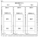
図2は、幾つかの例による、それぞれにメモリを備えた流体ダイの配置のブロック図である。 FIG. 2 is a block diagram of an arrangement of fluidic dies each with a memory, according to some examples.
図3は、さらなる例による、メモリを含む対応する流体ダイを備えた複数の流体分配デバイスの配置のブロック図である。 FIG. 3 is a block diagram of an arrangement of multiple fluid distribution devices with corresponding fluidic dies including memory, according to a further example.
図4は、幾つかの例による流体分配デバイスの部品のブロック図である。 FIG. 4 is a block diagram of components of a fluid distribution device, according to some examples.
図5は、幾つかの例による流体分配システムのブロック図である。 FIG. 5 is a block diagram of a fluid distribution system according to some examples.
図6は、幾つかの例によるプロセスの流れ図である。 FIG. 6 is a process flow diagram according to some examples.
図面全体を通じて、同一の参照番号は、必ずしも同一ではないが類似した要素を指している。図面は必ずしも縮尺通りではなく、幾つかの部品の大きさは、図示された例をより明確に示すために誇張されている場合がある。さらにまた、図面は説明と一貫性のある例および/または実施形態を提示するものである;しかしながら、説明は図面に提示された例および/または実施形態に限定されるものではない。 Throughout the drawings, identical reference numbers designate similar, but not necessarily identical, elements. The drawings are not necessarily to scale and the size of some of the parts may be exaggerated to show the illustrated examples more clearly. Furthermore, the drawings present examples and/or embodiments consistent with the description; however, the description is not limited to the examples and/or embodiments presented in the drawings.
本開示において、「ある」、「あの」、または「その」といった用語の使用は、文脈が明らかに異なるものを指しているのでない限り、複数形をも包含することを意図している。また、「含む」、「含んでいる」、「包含する」、「包含している」、「有する」、「有している」といった用語は、本開示で使用されるとき、言及された要素が存在することを特定するが、他の要素の存在または追加を排除するものではない。 In this disclosure, the use of the terms "a", "that", or "that" is intended to include plural forms as well, unless the context clearly dictates otherwise. Also, when used in this disclosure, the terms "comprise," "comprise," "comprise," "contain," "have," and "have" refer to the elements referred to. does not exclude the presence or addition of other elements.
流体分配デバイスは流体アクチュエータを含むことができ、流体アクチュエータは付勢されると流体の分配(例、吐出または他の流れ)を生じさせる。例えば流体の分配は、付勢された流体アクチュエータによる、流体分配デバイスのノズルのそれぞれからの流体液滴の吐出を含むことができる。他の例においては、付勢された流体アクチュエータ(ポンプのような)は、流体管路または流体チャンバを介しての流体の流れを生じさせることができる。かくして、流体アクチュエータを付勢して流体を分配することは、流体アクチュエータを付勢してノズルから流体を吐出させること、または流体アクチュエータを付勢して流体管路、流体チャンバ、およびその他のような流れ構造を介して流体の流れを生じさせることを指している。 Fluid dispensing devices can include fluid actuators that cause fluid dispensing (eg, ejection or other flow) when energized. For example, dispensing fluid can include ejecting fluid droplets from each of the nozzles of the fluid dispensing device by an energized fluid actuator. In another example, an energized fluid actuator (such as a pump) can cause fluid flow through a fluid conduit or fluid chamber. Thus, activating a fluid actuator to dispense fluid may include activating the fluid actuator to eject fluid from a nozzle, or activating a fluid actuator to actuate fluid lines, fluid chambers, and the like. means to induce fluid flow through a flow structure.
流体アクチュエータを付勢することはまた、流体アクチュエータの噴射として参照されることができる。幾つかの例では、流体アクチュエータは、ヒーター抵抗のような加熱素子を含むサーマル系流体アクチュエータを含んでいる。加熱素子が付勢されると、加熱素子は熱を発生し、この熱は流体の気化を生じさせてサーマル系流体アクチュエータに近接する気泡(例、蒸気気泡)の核生成を行うことができ、これが次いで、ノズルのオリフィスからの吐出、または流体管路または流体チャンバを介しての流れのような、ある量の流体の分配を生じさせる。他の例においては、流体アクチュエータは圧電(ピエゾ)膜系の流体アクチュエータであってよく、これは付勢されると機械力を適用して、ある量の流体を分配する。 Activating a fluid actuator can also be referred to as firing the fluid actuator. In some examples, the fluid actuators include thermal-based fluid actuators that include heating elements such as heater resistors. When the heating element is energized, the heating element generates heat that can cause vaporization of the fluid to nucleate a bubble (e.g., vapor bubble) proximate to the thermal-based fluid actuator; This in turn causes the distribution of an amount of fluid, such as ejection from an orifice of a nozzle or flow through a fluid conduit or fluid chamber. In another example, the fluid actuator may be a piezoelectric (piezo) membrane-based fluid actuator, which, when energized, applies a mechanical force to dispense a volume of fluid.
流体分配デバイスがノズルを含む例においては、各々のノズルは、噴射チャンバとしても参照される流体チャンバを含んでいる。加えて、ノズルは流体が分配時に通過されるオリフィス、流体アクチュエータ、およびセンサーを含むことができる。各々の流体チャンバは、それぞれのノズルによって分配される流体を提供する。 In examples where the fluid dispensing device includes nozzles, each nozzle includes a fluid chamber, also referred to as an ejection chamber. In addition, nozzles can include orifices through which fluid is passed during dispensing, fluid actuators, and sensors. Each fluid chamber provides fluid to be dispensed by a respective nozzle.
一般に、流体アクチュエータは吐出型の流体アクチュエータであって、ノズルのオリフィスを介するなどにより流体の吐出を生じさせることができ、或いは非吐出型の流体アクチュエータであって、流体の流れを生じさせることができる。 In general, the fluid actuator may be an ejecting fluid actuator, which may cause ejection of fluid, such as through an orifice of a nozzle, or may be a non-ejecting fluid actuator, which may cause fluid flow. can.
幾つかの例では、流体分配デバイスはプリントヘッドの形態であることができ、プリントカートリッジ、キャリッジ、およびその他に取り付けることができる。さらなる例においては、流体分配デバイスは流体ダイの形態であることができる。「ダイ」とは、回路、流体チャンバ、および流体管路を作製するために基板上に種々の層が形成されたアセンブリを指している。複数の流体ダイを支持構造体に対して装着または取着することができる。他の例においては、流体分配デバイスは流体ダイスライバーの形態であることができ、これは例えば、長さ対幅の比(L/W)が少なくとも3である、薄い基板(例、650マイクロメートル(μm)またはそれ未満程度の厚さを有している)を含んでいる。他の例においては、ダイスライバーは異なる大きさを有することができる。複数の流体ダイスライバーを、例えば一体型の成形構造体中に成形することができる。 In some examples, the fluid dispensing device can be in the form of a printhead and can be attached to print cartridges, carriages, and the like. In a further example, the fluid distribution device can be in the form of a fluid die. "Die" refers to an assembly in which various layers are formed on a substrate to create circuits, fluid chambers, and fluid conduits. A plurality of fluidic dies can be mounted or attached to the support structure. In other examples, the fluid distribution device can be in the form of a fluidic die sliver, which is, for example, a thin substrate (e.g., 650 micrometers) with a length-to-width ratio (L/W) of at least 3. (μm) or less). In other examples, the die sliver can have different sizes. Multiple fluid die slivers can be molded into, for example, an integral molded structure.
本開示においては、「流体分配デバイスの部品」は、流体分配デバイスそれ自体、或いは流体分配デバイスの一部をなし、または流体分配デバイスに取着され、または流体分配デバイスに結合された部品を指すことができる。 In the present disclosure, "a component of a fluid distribution device" refers to the fluid distribution device itself, or a component forming part of, or attached to, or coupled to the fluid distribution device. be able to.
流体分配デバイスは、データを記憶するための不揮発性メモリを含むことができる。「不揮発性メモリ」とは、メモリから電力が取り除かれた場合でもメモリに記憶されたデータを保持することのできるメモリを指している。不揮発性メモリに記憶することのできるデータの例には、流体分配デバイスについての識別情報(例、シリアル番号または他の識別子)、デバイスの部品の特徴(ブランド名、色の情報、ライセンス情報、その他の如き)、流量の情報のような流体の流れ特性、流体分配デバイスを構成するための構成情報、流体分配デバイスに対するアクセスを安全にするために使用されるセキュリティ情報、およびその他が含まれる。データは任意の仕方で暗号化され、スクランブルされ、またはエンコードされてよい。 The fluid dispensing device can include non-volatile memory for storing data. "Non-volatile memory" refers to memory that can retain data stored in the memory even when power is removed from the memory. Examples of data that can be stored in non-volatile memory include identifying information about the fluid dispensing device (e.g., serial number or other identifier), characteristics of components of the device (brand name, color information, licensing information, etc.). ), fluid flow characteristics such as flow rate information, configuration information for configuring the fluid dispensing device, security information used to secure access to the fluid dispensing device, and others. Data may be encrypted, scrambled, or encoded in any manner.
本開示の幾つかの実施形態によれば、流体分配デバイスは複数の流体ダイを含み、流体ダイの各々はそれぞれメモリ(不揮発性メモリを含む)を含んでいる。複数の流体ダイのメモリの利用効率を改善するために、各々のメモリの第1の部分は対応する流体ダイに特有のデータを記憶するように使用可能であり、そして各々のメモリの第2の部分は複数の流体ダイによって共有される共通データを記憶するように使用可能である。また、流体分配デバイスは複数の制御入力を含み、それらは複数の流体ダイのそれぞれの流体ダイに対して制御情報を提供することができる。流体分配デバイスは、流体ダイのメモリによって共有される共有バスを含み、かくしてメモリからのデータは流体分配デバイスから出力されることができる。 According to some embodiments of the present disclosure, a fluid dispensing device includes a plurality of fluidic dies, each fluidic die each including memory (including non-volatile memory). To improve utilization efficiency of the memory of multiple fluidic dies, a first portion of each memory is operable to store data specific to the corresponding fluidic die, and a second portion of each memory is operable to store data specific to the corresponding fluidic die. Portions can be used to store common data shared by multiple fluidic dies. The fluid distribution device also includes a plurality of control inputs that can provide control information to respective fluid dies of the plurality of fluid dies. The fluid distribution device includes a shared bus shared by the memory of the fluidic dies so that data from the memory can be output from the fluid distribution device.
図1は、幾つかの例による流体分配システム100のブロック図である。流体分配システム100は、2D印刷システムまたは3D印刷システムのような印刷システムであることができる。他の例においては、流体分配システム100は、異なる種類の流体分配システムであることができる。他の種類の流体分配システムの例には、流体検出システム、医用システム、車両、流体流れ制御システム、およびその他で使用されてるシステムが含まれる。
FIG. 1 is a block diagram of a
流体分配システム100は流体分配デバイス102を含み、これは流体分配システム100のキャリッジ103(または他の種類の支持構造体)に装着することができる。幾つかの例では、流体分配デバイス102は、キャリッジ103に対して着脱可能に設けられた流体カートリッジ(例、プリントカートリッジ)に取着することができる。他の例においては、流体分配デバイス102はキャリッジ103に対して固定的に設けることができる。
流体分配デバイス102は、目標106に向けて流体を分配するためのオリフィスを含んでいる。幾つかの例では、キャリッジ103および目標106は互いに対して移動可能(キャリッジ103が移動可能または目標106が移動可能、或いはキャリッジ103および目標106の両方が移動可能)である。
2D印刷システムにおいては、流体分配デバイス102は、紙媒体、プラスチック媒体、およびその他のような印刷媒体上へと印刷流体(例、インク)を吐出するプリントヘッドを含んでいる。
In a 2D printing system, the
3D印刷システムにおいては、流体分配デバイス102は、印刷目標の上へと種々の異なる液体剤の任意のものを吐出可能なプリントヘッドを含んでおり、そこでは液体剤は以下のいずれかまたは幾つかの組み合わせを含むことができる:インク、造形材料の層の粉体を溶融または融合させるのに使用される剤、造形材料の層の細部を仕上げるための剤(例えば造形材料の層の縁部または形状を規定することにより)、およびその他。3D印刷システムにおいては、3D目標は、3D印刷システムの造形プラットフォーム上に造形材料の連続する層を堆積することによって構築される。造形材料の各々の層は、プリントヘッドからの印刷流体を使用することによって処理可能であり、所望の形状、テクスチャ、および/または造形材料の層の他の特徴が形成される。
In a 3D printing system, the
流体分配デバイス102は、複数の流体ダイ108-1-108-N(N≧2)を含んでいる。流体ダイ108-1-108-Nは、流体アクチュエータのアレイ110-1-110-Nのそれぞれ、および不揮発性メモリ112-1-112-Nのそれぞれを含んでいる。例えば、流体ダイ108-1は流体アクチュエータのアレイ110-1および不揮発性メモリ112-1を含んでおり、そして流体ダイ108-Nは流体アクチュエータのアレイ110-Nおよび不揮発性メモリ112-Nを含んでいる。
流体アクチュエータのアレイ108-i(i=1からN)は、流体アクチュエータのカラム、または流体アクチュエータの複数のカラムを含むことができる。幾つかの例では、流体アクチュエータ108-iは複数のプリミティブへと編成可能であり、そこにおいて各々のプリミティブは特定の数の流体アクチュエータを含んでいる。流体アクチュエータ108-iはノズルの一部分であることができ、または流体管路、流体チャンバ、およびその他のような、他の種類の流れ構造に関連していることができる。各々の流体アクチュエータは、流体分配システム100内のコントローラ(例、システムコントローラ110)によって提供される、それぞれに異なるアドレスによって選択される。 The array of fluid actuators 108-i (i=1 to N) can include a column of fluid actuators, or multiple columns of fluid actuators. In some examples, fluid actuators 108-i can be organized into multiple primitives, where each primitive contains a specific number of fluid actuators. Fluid actuator 108-i can be part of a nozzle, or can be associated with other types of flow structures, such as fluid conduits, fluid chambers, and the like. Each fluid actuator is selected by a different address provided by a controller within fluid distribution system 100 (eg, system controller 110).
本願で用いるところでは、「コントローラ」はハードウェア処理回路を指すことができ、これはマイクロプロセッサ、マルチコアマイクロプロセッサのコア、マイクロコントローラ、プログラマブル集積回路(例、アプリケーションプログラマブル集積回路(ASIC)、その他)、プログラマブルゲートアレイ、デジタル信号プロセッサ、幾つもの個別のハードウェア部品(例、タイマー、カウンター、状態マシン、その他)、または別のハードウェア処理回路のいずれか、または幾つかの組み合わせを含むことができる。コントローラはまた、タイマー、カウンター、状態マシン、ラッチ、バッファ、およびその他のような、個別の部品を含むことができる。或いはまた、「コントローラ」は、ハードウェア処理回路と、ハードウェア処理回路上で実行可能な機械可読式の命令(ソフトウェアおよび/またはファームウェア)との組み合わせを指すことができる。 As used herein, a "controller" can refer to a hardware processing circuit, including microprocessors, multi-core microprocessor cores, microcontrollers, programmable integrated circuits (e.g., application programmable integrated circuits (ASICs), etc.). , programmable gate arrays, digital signal processors, any number of discrete hardware components (e.g., timers, counters, state machines, etc.), or other hardware processing circuits, or some combination thereof. . Controllers can also include discrete components such as timers, counters, state machines, latches, buffers, and the like. Alternatively, "controller" can refer to a combination of hardware processing circuitry and machine-readable instructions (software and/or firmware) executable on the hardware processing circuitry.
図1はシステムコントローラ110を1つのブロックとして示しているが、システムコントローラ110は実際には、それぞれにタスクを実行する複数のコントローラを表すことができることが留意される。例えば、システムコントローラ110は複数のASICを使用して実施可能であり、そこでは1つのASICはキャリッジ103上に配置可能であり、そして別のASICは流体分配動作(例、印刷動作)を制御するための主たるASICであることができる。
It is noted that although FIG. 1 shows
流体分配デバイス102は、種々の入力130と、そして検知インタフェース132(例えば、電流および電圧またはデータを入出力するための)とを含んでいる。例においては、検知インタフェース132は入力電流または入力電圧を受信することができ、そして対応する電圧または電流を出力することができる。他の例においては、他の形態の入力/出力を検知インタフェース132において行うことができる。
入力130はプログラミング電圧(「VPP」と称する)入力134を含み、これは入力電圧をメモリ電圧生成器116に提供する。幾つかの例では、メモリ電圧生成器116は入力電圧VPP134をプログラミング電圧に変換するコンバータを含むことができ、プログラミング電圧は、不揮発性メモリ112-iまたは複数の不揮発性メモリ112-iの選択されたメモリセルのプログラミングを行うために印加される
他の例においては、メモリ電圧生成器116は省略することができ、入力電圧VPP134を不揮発性メモリのメモリセルのプログラミングのために使用することができる。
In other examples,
入力130はまた、クロック入力136を含んでおり、これは流体分配デバイス102内の種々の回路に提供されるクロック信号をもたらす。入力130はまた、システムコントローラ110によって提供される制御データ(例、データパケットの形態にある)を受信するためのデータ入力138を含んでいる。データ入力138で受信されるデータパケットは、選択された流体アクチュエータ108の付勢を制御するために使用可能な制御情報を含んでいる。また、以下でさらに説明するように、データパケットは流体分配デバイスの動作モードを設定するための情報を含むことができ、そこでの動作モードは、流体分配デバイスの流体アクチュエータの選択的な付勢のための流体動作モード、または不揮発性メモリにデータを書き込みまたは読み出しするためのメモリアクセスモードを含むことができる。
さらなる例として、システムコントローラ110からのデータ入力138において受信されるデータパケットに含まれる制御情報は、プリミティブデータおよびアドレスデータを含んでいる。プリミティブデータは、流体分配デバイス102内の流体アクチュエータ108がプリミティブに配置されている例において提供される。より一般的には、プリミティブデータはまた、「噴射データ」として称されることができ、これは流体動作モードの間にプリミティブ内での流体アクチュエータ(または流体アクチュエータ)の付勢または非付勢を制御するために使用されるデータである。
As a further example, control information contained in data packets received at
流体アクチュエータ108-iがプリミティブへとグループ化される例においては、プリミティブデータは、プリミティブに対して噴射パルスが伝達された場合に、プリミティブ中のどの流体アクチュエータ(単数または複数)が付勢されるかを表すための、対応したビットを含むことができる。噴射パルスは、付勢されている噴射入力140において受信される噴射信号に対応する。
In the example where the fluid actuators 108-i are grouped into primitives, the primitive data indicates which fluid actuator(s) in the primitive will be energized when the firing pulse is delivered to the primitive. Corresponding bits may be included to indicate whether An injection pulse corresponds to an injection signal received at
アドレスデータはアドレスビットを含み、これは付勢すべき流体アクチュエータ108-iを選択するためのアドレスを規定する。流体アクチュエータ108-iがプリミティブへとグループ化される例においては、各々のプリミティブは流体アクチュエータのセットを含み、そしてプリミティブの流体アクチュエータは、アドレスビットによって表されるところの、それぞれ異なるアドレスによって選択される。 The address data includes address bits, which define addresses for selecting fluid actuators 108-i to be energized. In the example where fluid actuators 108-i are grouped into primitives, each primitive contains a set of fluid actuators, and the primitive's fluid actuators are selected by different addresses, represented by address bits. be.
流体分配デバイス102がメモリアクセスモードに設定された場合(例、メモリ書き込みモードまたはメモリ読み出しモード)、データ入力138において受信されるデータパケットは、書き込みまたは読み出しされる不揮発性メモリのメモリセルを選択することができる。かくして、データ入力138は、流体アクチュエータを付勢するため、または不揮発性メモリにアクセスするための、それぞれの制御情報を受信するために、流体ダイの流体アクチュエータおよび不揮発性メモリの両者によって共有される制御信号である。
When the
制御情報はまた、システムコントローラ110によって流体分配デバイス102に伝達されるデータパケットに含めることができる、他の情報を含むことができる。
Control information can also include other information that can be included in data packets communicated to the
入力130はさらにモード入力142を含んでおり、これはメモリアクセスモードにおいて、流体分配デバイス102を設定するためのシーケンスの一部として使用可能なモード信号を受信する。
Input 130 further includes
他の例においては、流体分配デバイス102の入力130は、付加的な入力または代替的な入力を含むことができる。
In other examples, the
クロック入力136、データ入力138、噴射入力140、およびモード入力142は、流体分配デバイス102に対して制御情報を提供する制御入力の例である。
流体分配デバイス102はまたデータバス160を含んでおり、これに対して不揮発性メモリ112-1-112-Nが結合されている。不揮発性メモリ112-1-112-Nはデータバス160に直接接続されることができ、または代替的には、不揮発性メモリ112-1-112-Nをデータバス160に接続するために、流体ダイ108-1-108-Nのそれぞれに中間回路を設けることができる。
データバス160はさらに、検知インタフェース132に接続される。かくして、不揮発性メモリ112-1-112-Nから読み出されたデータは、データバス160上で検知インタフェース132に通信され、またはシステムコントローラ110へと出力されることができる。
本願で用いるところでは、データバス160上で通信される「データ」という用語は、データバス160上で通信されるアナログ信号(例、電流または電圧の形態)を含むことができる。他の例においては、データはデジタルデータを指すことができる。
As used herein, the term “data” communicated over
図1に示された配置においては、不揮発性メモリ112-1-112-Nは共通のデータバス160を共有し、データバスは流体分配デバイス102の出力(検知インタフェース132の形態)に結合されている。
In the arrangement shown in FIG. 1, non-volatile memories 112-1-112-N share a
データ入力138は、複数のサブセットを含むことができる。例えば、データ入力138は複数のデータ入力部分D1からDNに分割することができ、ここで各々のデータ入力部分Di(i=1からN)は、個々の流体ダイ108-iのそれぞれに対して提供される。例えば、データ入力部分D1は流体ダイ108-1に接続され(しかし流体ダイ108-Nを含む他の流体ダイのどれにも接続されない)、そしてデータ入力部分DNは流体ダイ108-Nに接続される(しかし流体ダイ108-1を含む他の流体ダイのどれにも接続されない)。データ入力部分D1は流体ダイ108-1に対して提供されたデータパケットを受信可能であり、そしてデータ入力部分DNは流体ダイ108-Nに対して提供されたデータパケットを受信可能である。幾つかの例では、各々のデータ入力部分Diは1ビットからなっている。他の例においては、各々のデータ入力部分Diは、複数ビットからなることができる。
幾つかの例では、データバス160は、複数の流体ダイ108-1-108-Nの複数の不揮発性メモリ112-1-112-Nのデータを通信するように共有されることができ、他方で個々の制御入力(D1からDNの形態)は、個々の流体ダイ108-1-108-Nのそれぞれに対して提供される。クロック入力136、噴射入力140、およびモード入力142は、複数の流体ダイ108-1-108-Nによって共有される制御入力である。
In some examples,
流体分配デバイス102はさらに記憶媒体150を含んでおり、これはレジスタまたはラッチの形態であることができ、データ入力138の対応するデータ入力部分D1からDNにおいて受信したデータパケットを記憶する。幾つかの例では、記憶媒体150はシフトレジスタを含むことができる。各々のシフトレジスタは、クロック入力136において受信したクロック信号の連続的な付勢に際して、それぞれのデータ入力部分Diで受信したデータパケットのビットをシフトレジスタ内へとシリアルに入力する。他の例においては、記憶媒体150はレジスタを含むことができ、レジスタの各々は、データパケットの全ビットをレジスタ内へと一度にロードすることができる。
さらなる例においては、記憶媒体150はシフトレジスタおよびラッチを含むことができ、その場合はデータパケットがシフトレジスタ内にシフトインされた後に、シフトレジスタの内容が対応するラッチに提供されて記憶されることができる。「ラッチ」は、データをバッファするための記憶素子を指すことができる。
In a further example,
流体分配デバイス102はさらに、流体分配デバイス102の一部であるデバイスコントローラ152を含んでいる。デバイスコントローラ152は、流体分配デバイス102のモードを設定すること、選択された流体アクチュエータ108の付勢を制御すること、不揮発性メモリ112の書き込みまたは読み出しを制御すること、およびその他といった、流体分配デバイス102の種々の動作を行うことができる。
デバイスコントローラ152は、ASIC、プログラマブルゲートアレイ、マイクロコントローラ、マイクロプロセッサ、およびその他の形態であることができ、或いは、協同して制御タスクを行う個々の部品の形態であることができる。
図1は、流体分配デバイス102の入力130および検知インタフェース132がシステムコントローラ110に結合していることを示している。幾つかの例では、キャリッジ103は電気的相互接続を含んでおり、これは流体分配デバイス102がキャリッジ130に取着された場合に、入力130および検知インタフェース132に接続することができる。システムコントローラ110は次いで、バスまたは別のリンクを介するなどにより、キャリッジ103に対して接続される。
FIG. 1 shows that
図2は、3つの流体ダイ108-1、108-2、および108-3が流体分配デバイス102上に設けられた、例示的な配置のブロック図である。図2においては特定の数の流体ダイが示されているが、他の例においては、異なる数の流体ダイを使用することができる。
FIG. 2 is a block diagram of an exemplary arrangement in which three fluidic dies 108-1, 108-2, and 108-3 are provided on
流体ダイ108-1から108-3は、それぞれに不揮発性メモリ110-1から110-3を含んでいる。各々の不揮発性メモリは、ダイに特有の情報を記憶するための第1の領域と、共有情報(共通情報とも称する)を記憶するための第2の領域へと分割することができる。例えば、不揮発性メモリ110-1は、ダイ特有領域202-1、および共有領域204-1に分割される。同様に、不揮発性メモリ110-2はダイ特有領域202-2および共有領域204-2に分割され、そして不揮発性メモリ110-3はダイ特有領域202-3および共有領域204-3に分割される。さらなる例においては、各々の不揮発性メモリは2つよりも多い別々の領域に分割されることができる。 Fluidic dies 108-1 through 108-3 each include non-volatile memory 110-1 through 110-3. Each non-volatile memory can be divided into a first region for storing die-specific information and a second region for storing shared information (also called common information). For example, non-volatile memory 110-1 is divided into die-specific area 202-1 and shared area 204-1. Similarly, non-volatile memory 110-2 is divided into die-specific area 202-2 and shared area 204-2, and non-volatile memory 110-3 is divided into die-specific area 202-3 and shared area 204-3. . In a further example, each non-volatile memory can be divided into more than two separate regions.
ダイ特有領域202-1、202-2、または202-3の各々は、対応する流体ダイ108-1、108-2、または108-3に特有の情報を記憶する。ダイに特有の情報の例には、流体ダイがその上に形成されたウエーハに関するウエーハロット情報、流体ダイの製造日付、およびその他が含まれ得る。 Each of the die specific regions 202-1, 202-2, or 202-3 stores information specific to the corresponding fluidic die 108-1, 108-2, or 108-3. Examples of die-specific information may include wafer lot information regarding the wafer on which the fluidic die is formed, the manufacturing date of the fluidic die, and the like.
共有領域204-1、204-2、および204-3には、共通情報を記憶することができる。共通情報は、流体分配デバイス102に関している。例えば、共通情報は、流体分配デバイス102が使用される地理的領域の情報、流体分配デバイス102の生成情報、流体分配デバイス102の流体レベル(例、プリントカートリッジのインクレベル)の追跡情報、およびその他を含むことができる。共通情報は、共有領域204-1、204-2、および204-3にわたって分散した仕方で記憶されることができる。
Common information can be stored in shared areas 204-1, 204-2, and 204-3. Common information pertains to
図3は、複数の流体分配デバイス302および304を含む例示的な配置のブロック図である。例えば、流体分配デバイス302および304はそれぞれ、プリントカートリッジのようなプリントヘッドアセンブリを含むことができる。幾つかの例では、流体分配デバイス302は、異なる色のインクを分配するための流体ダイのような、流体ダイ306-1、306-2、および306-3を含むことができる。流体分配デバイス304は、ブラックのような異なる色のインクを分配するための流体ダイのような、流体ダイ308を含むことができる。流体分配デバイス302および304は、それぞれ特定の数の流体ダイを示しているが、他の例においては、対応する流体分配デバイス302および304に、異なる数の流体ダイを含むことができる。さらにまた、2つよりも多い流体分配デバイスを提供することができる。
FIG. 3 is a block diagram of an exemplary arrangement including multiple
流体ダイ306-1、306-2、306-3、および308は、それぞれに不揮発性メモリ307-1、307-2、307-3、および309を含んでいる。 Fluidic dies 306-1, 306-2, 306-3, and 308 include non-volatile memory 307-1, 307-2, 307-3, and 309, respectively.
流体分配デバイス302は検知インタフェース310を含み、そして流体分配デバイス304は検知インタフェース312を含んでいる。検知インタフェース310および312は、グローバルバス314上で検知パッド316に結合されている。検知パッド316はシステムコントローラ110に接続されている。不揮発性メモリ307-1、307-2、307-3、および309から読み出されたデータは、それぞれの検知インタフェース310および312によってグローバルバス314へと出力可能であり、グローバルバスは次いで、データを検知パッド316に提供する。
例えば、グローバル検知インタフェースおよびグローバルバス314は、図1に示されたキャリッジ103上の回路配置318(例、プリント回路配置)の一部であることができる。
For example, global sensing interface and
回路配置318はまた、VPPパッド322、クロックパッド324、データパッド326、噴射パッド328、およびモードパッド330を含む、他の入力320を含むことができる。VPPパッド322は、プログラミング電圧(VPP)を流体分配デバイス302および304のVPP入力に提供することができる。クロックパッド324は、クロック信号を流体分配デバイス302および304のクロック入力に提供することができる。データパッド326は、制御情報(データパケット)を流体分配デバイス302および304のデータ入力に提供することができる。データパッド326は、対応するデータ入力部分(例、図1に示したD1からDN)のそれぞれのデータ部分を、流体分配デバイス302または304の各々に対して提供することができることに留意されたい。かくして、流体ダイ306-1、306-2、306-3、および308がグローバルバス314を共有している間に、流体ダイ306-1、306-2、306-3、および308はデータパッド326のデータ部分から個別の制御情報を受信する。
噴射パッド328は噴射信号を流体分配デバイス302および304の噴射入力に対して提供する。モードパッド330はモード信号を流体分配デバイス302および304のモード入力に対して提供する。
Injection pads 328 provide injection signals to the injection inputs of
図4は、複数の流体ダイ402-1から402-N(N≧2)を含む、流体分配デバイス構成部品400のブロック図である。各々の流体ダイ402-i(i=1からN)は、それぞれのメモリ404-i(図1に示す112-1-112-N)を含んでいる。
FIG. 4 is a block diagram of a fluid
流体分配デバイス構成部品400は複数の制御入力406を含み、流体ダイ402-1から402-Nのそれぞれに対して制御情報をそれぞれ提供する。
Fluid
データバス408が流体ダイ402-1から402-Nに接続されている。データバス408は、流体ダイ402-1から402-Nのメモリ404-1から404-Nのデータを、流体分配デバイス構成部品400の出力410へと提供する。
A
図5は、不揮発性メモリ514を含む複数の流体ダイ512を有する流体分配デバイス510を受容する支持構造体502(例、図1のキャリッジ103)を含む、流体分配システム500のブロック図である。
FIG. 5 is a block diagram of a
流体分配システム500は、種々のタスクを行うためのコントローラ504(例、図1のシステムコントローラ110)を含んでいる。コントローラ504のタスクには、制御情報提供タスク506が含まれており、これは流体分配デバイスの対応する制御入力を使用して、流体分配デバイスのそれぞれの流体ダイに対して制御情報を提供するものである。
コントローラ504のタスクにはさらに、不揮発性メモリデータ受信タスク508が含まれており、これは流体ダイ512の不揮発性メモリ514からのデータを、流体分配デバイス510の共有データバス516上で受信するものである。
The tasks of the
図6は、流体分配デバイス構成部品を形成するためのプロセスの流れ図である。このプロセスは(602において)、基板上に、各々がメモリを含む複数の流体ダイを提供することを含んでいる。このプロセスは(604において)、それぞれの流体ダイについてそれぞれの制御情報を受信するために、流体分配デバイス構成部品の複数の制御入力を提供することを含んでいる。このプロセスは(606において)、複数の流体ダイに接続されたデータバスを介して、流体ダイのメモリのデータを受信するために、流体分配デバイス構成部品の出力を提供することを含んでいる。 FIG. 6 is a flow diagram of a process for forming a fluid distribution device component; The process includes providing (at 602) a plurality of fluidic dies, each containing memory, on a substrate. This process includes (at 604) providing a plurality of control inputs of the fluid distribution device components to receive respective control information for respective fluid dies. This process includes providing (at 606) the output of the fluid distribution device component to receive data in the memory of the fluidic dies via a data bus connected to the plurality of fluidic dies.
以上の記載においては、本願に開示された主題の理解をもたらすために、数多くの詳細事項を説明している。しかしながら、これらの詳細事項の幾つかを欠いても、実施が行われてよい。他の実施形態は、上述した詳細事項からの修正および変更を含んでいてよい。添付の特許請求の範囲は、そうした修正および変更をカバーすることを意図している。
In the foregoing description, numerous details are set forth in order to provide an understanding of the presently disclosed subject matter. However, practice may be practiced without some of these details. Other embodiments may include modifications and variations from the details described above. The appended claims are intended to cover such modifications and changes.
Claims (20)
各々がメモリを含む複数の流体ダイ;
複数の流体ダイのそれぞれの流体ダイに対してそれぞれの制御情報を提供するための複数の制御入力;および
複数の流体ダイに接続されたデータバスを含み、データバスは複数の流体ダイのメモリのデータを流体分配デバイス構成部品の出力に提供し、
複数の流体ダイのそれぞれの流体ダイのそれぞれのメモリの各々は、それぞれの流体ダイに特有のデータを記憶する第1の部分、および複数の流体ダイによって共有される共通データを記憶する第2の部分を含む、流体分配デバイス構成部品。 A fluid distribution device component comprising:
a plurality of fluidic dies each containing a memory;
a plurality of control inputs for providing respective control information to respective fluidic dies of the plurality of fluidic dies; and a data bus coupled to the plurality of fluidic dies, the data bus being a memory of the plurality of fluidic dies. providing data to the output of a fluid dispensing device component;
Each respective memory of each fluid die of the plurality of fluid dies has a first portion storing data specific to the respective fluid die and a second portion storing common data shared by the plurality of fluid dies. A fluid distribution device component , including a portion .
請求項1から14のいずれか1の流体分配デバイス構成部品;
流体分配デバイス構成部品を受容する支持構造体;および
コントローラを含み、コントローラは:
流体分配デバイス構成部品の対応する制御入力を使用して、複数の流体ダイのそれぞれの流体ダイに対して制御情報を提供し、そして
流体分配デバイス構成部品のデータバス上で、複数の流体ダイのメモリからのデータを受信する、流体分配システム。 A fluid distribution system comprising:
A fluid distribution device component according to any one of claims 1 to 14;
a support structure for receiving the fluid distribution device components ; and a controller, the controller comprising:
providing control information for each fluid die of the plurality of fluid dies using corresponding control inputs of the fluid distribution device component ; A fluid distribution system that receives data from memory.
基板上に、各々がメモリを含む複数の流体ダイを提供し;
複数の流体ダイのそれぞれの流体ダイについてそれぞれの制御情報を受信するために、流体分配デバイス構成部品の複数の制御入力を提供し;そして
複数の流体ダイに接続されたデータバスを介して、複数の流体ダイのメモリのデータを受信するために、流体分配デバイス構成部品の出力を提供し、
複数の流体ダイのそれぞれの流体ダイのそれぞれのメモリの各々は、それぞれの流体ダイに特有のデータを記憶する第1の部分、および複数の流体ダイによって共有される共通データを記憶する第2の部分を含む、方法。 A method for forming a fluid distribution device component comprising:
providing a plurality of fluidic dies on a substrate, each containing a memory;
providing a plurality of control inputs of a fluid distribution device component to receive respective control information for respective fluid dies of the plurality of fluid dies; and via a data bus connected to the plurality of fluid dies, a plurality of providing an output of a fluid dispensing device component for receiving data in the memory of the fluidic die of
Each respective memory of each fluid die of the plurality of fluid dies has a first portion storing data specific to the respective fluid die and a second portion storing common data shared by the plurality of fluid dies. A method, including part .
Applications Claiming Priority (1)
| Application Number | Priority Date | Filing Date | Title |
|---|---|---|---|
| PCT/US2019/016780 WO2020162910A1 (en) | 2019-02-06 | 2019-02-06 | Memories of fluidic dies |
Publications (2)
| Publication Number | Publication Date |
|---|---|
| JP2022518784A JP2022518784A (en) | 2022-03-16 |
| JP7181418B2 true JP7181418B2 (en) | 2022-11-30 |
Family
ID=65494600
Family Applications (1)
| Application Number | Title | Priority Date | Filing Date |
|---|---|---|---|
| JP2021543220A Active JP7181418B2 (en) | 2019-02-06 | 2019-02-06 | Fluid die memory |
Country Status (14)
| Country | Link |
|---|---|
| US (2) | US11511539B2 (en) |
| EP (1) | EP3717253B1 (en) |
| JP (1) | JP7181418B2 (en) |
| KR (1) | KR102621218B1 (en) |
| CN (1) | CN113316518B (en) |
| AU (1) | AU2019428636B2 (en) |
| BR (1) | BR112021015518A2 (en) |
| CA (1) | CA3126912C (en) |
| ES (1) | ES2920603T3 (en) |
| IL (1) | IL284653A (en) |
| MX (1) | MX2021009129A (en) |
| PL (1) | PL3717253T3 (en) |
| WO (1) | WO2020162910A1 (en) |
| ZA (1) | ZA202104510B (en) |
Families Citing this family (4)
| Publication number | Priority date | Publication date | Assignee | Title |
|---|---|---|---|---|
| ES2920603T3 (en) * | 2019-02-06 | 2022-08-05 | Hewlett Packard Development Co | Fluid Die Memories |
| US11787173B2 (en) | 2019-02-06 | 2023-10-17 | Hewlett-Packard Development Company, L.P. | Print component with memory circuit |
| KR20210103576A (en) | 2019-02-06 | 2021-08-23 | 휴렛-팩커드 디벨롭먼트 컴퍼니, 엘.피. | Print components that communicate |
| AU2019428241B2 (en) | 2019-02-06 | 2023-03-09 | Hewlett-Packard Development Company, L.P. | Print component with memory circuit |
Citations (6)
| Publication number | Priority date | Publication date | Assignee | Title |
|---|---|---|---|---|
| JP2002014870A (en) | 2000-06-30 | 2002-01-18 | Seiko Epson Corp | Storage device and access method to the same |
| JP2002232113A (en) | 2001-02-05 | 2002-08-16 | Konica Corp | Memory device, printed board, image forming apparatus having them or the like and method of determination processing |
| WO2009064271A1 (en) | 2007-11-14 | 2009-05-22 | Hewlett-Packard Development Company, L.P. | An inkjet print head with shared data lines |
| JP2011230374A (en) | 2010-04-27 | 2011-11-17 | Duplo Corp | Inkjet recording apparatus |
| WO2014133534A1 (en) | 2013-02-28 | 2014-09-04 | Hewlett-Packard Development Company, L.P. | Print head bit information mapping |
| WO2019009902A1 (en) | 2017-07-06 | 2019-01-10 | Hewlett-Packard Development Company, L.P. | Decoders for memories of fluid ejection devices |
Family Cites Families (90)
| Publication number | Priority date | Publication date | Assignee | Title |
|---|---|---|---|---|
| JPS6111845A (en) | 1984-06-27 | 1986-01-20 | Nec Corp | Printing data control device |
| JPH0671875A (en) | 1992-06-30 | 1994-03-15 | Fuji Xerox Co Ltd | Ink-jet recorder |
| US6116714A (en) | 1994-03-04 | 2000-09-12 | Canon Kabushiki Kaisha | Printing head, printing method and apparatus using same, and apparatus and method for correcting said printing head |
| JPH08127162A (en) | 1994-11-02 | 1996-05-21 | Hitachi Ltd | Image printer |
| JP2702426B2 (en) | 1994-12-16 | 1998-01-21 | 日本電気データ機器株式会社 | Thermal head device |
| CA2168994C (en) * | 1995-03-08 | 2000-01-18 | Juan J. Becerra | Method and apparatus for interleaving pulses in a liquid recorder |
| US6022094A (en) | 1995-09-27 | 2000-02-08 | Lexmark International, Inc. | Memory expansion circuit for ink jet print head identification circuit |
| US5745409A (en) | 1995-09-28 | 1998-04-28 | Invox Technology | Non-volatile memory with analog and digital interface and storage |
| WO1997018953A1 (en) | 1995-11-21 | 1997-05-29 | Citizen Watch Co., Ltd. | Drive circuit and drive method for ink jet head |
| US5942900A (en) | 1996-12-17 | 1999-08-24 | Lexmark International, Inc. | Method of fault detection in ink jet printhead heater chips |
| US6672706B2 (en) | 1997-07-15 | 2004-01-06 | Silverbrook Research Pty Ltd | Wide format pagewidth inkjet printer |
| JPH11207948A (en) | 1997-11-14 | 1999-08-03 | Canon Inc | Recording device and recording control method |
| US6038166A (en) | 1998-04-01 | 2000-03-14 | Invox Technology | High resolution multi-bit-per-cell memory |
| JPH11341347A (en) | 1998-05-11 | 1999-12-10 | Newcore Technol Inc | Signal conversion processor |
| US6208542B1 (en) | 1998-06-30 | 2001-03-27 | Sandisk Corporation | Techniques for storing digital data in an analog or multilevel memory |
| US6154157A (en) | 1998-11-25 | 2000-11-28 | Sandisk Corporation | Non-linear mapping of threshold voltages for analog/multi-level memory |
| US6938976B2 (en) | 1999-06-16 | 2005-09-06 | Eastman Kodak Company | Printer and method therefor adapted to sense data uniquely associated with a consumable loaded into the printer |
| WO2002004219A1 (en) | 2000-06-30 | 2002-01-17 | Silverbrook Research Pty Ltd | Controlling the timing of printhead nozzle firing |
| US6866359B2 (en) | 2001-01-09 | 2005-03-15 | Eastman Kodak Company | Ink jet printhead quality management system and method |
| US6616260B2 (en) | 2001-05-25 | 2003-09-09 | Hewlett-Packard Development Company, L.P. | Robust bit scheme for a memory of a replaceable printer component |
| US7510255B2 (en) | 2001-08-30 | 2009-03-31 | Seiko Epson Corporation | Device and method for detecting temperature of head driver IC for ink jet printer |
| JP2004050637A (en) | 2002-07-19 | 2004-02-19 | Canon Inc | Substrate for inkjet head, inkjet head, and inkjet recorder employing inkjet head |
| TW536479B (en) | 2002-09-05 | 2003-06-11 | Benq Corp | Inkjet printer using thermal sensing elements to identify different types of cartridges |
| US7311385B2 (en) | 2003-11-12 | 2007-12-25 | Lexmark International, Inc. | Micro-fluid ejecting device having embedded memory device |
| JP4262070B2 (en) | 2003-12-02 | 2009-05-13 | キヤノン株式会社 | Element base of recording head, recording head, and control method of recording head |
| TWI243990B (en) | 2003-12-26 | 2005-11-21 | Ind Tech Res Inst | Printer, inkjet print head, identification circuit of inkjet print head and identification method thereof |
| MXPA04012681A (en) | 2003-12-26 | 2005-07-01 | Canon Kk | Liquid container and liquid supplying system. |
| US7328956B2 (en) | 2004-05-27 | 2008-02-12 | Silverbrook Research Pty Ltd | Printer comprising a printhead and at least two printer controllers connected to a common input of the printhead |
| CN100548683C (en) | 2004-05-27 | 2009-10-14 | 佳能株式会社 | Head substrate, printhead, a box and PRN device |
| US7267417B2 (en) | 2004-05-27 | 2007-09-11 | Silverbrook Research Pty Ltd | Printer controller for supplying data to one or more printheads via serial links |
| KR100694053B1 (en) | 2004-07-30 | 2007-03-12 | 삼성전자주식회사 | Print head driver of inkjet printer and semiconductor circuit board therefor |
| US7413272B2 (en) | 2004-11-04 | 2008-08-19 | Applied Materials, Inc. | Methods and apparatus for precision control of print head assemblies |
| US7365387B2 (en) | 2006-02-23 | 2008-04-29 | Hewlett-Packard Development Company, L.P. | Gate-coupled EPROM cell for printhead |
| US7613661B2 (en) | 2006-08-02 | 2009-11-03 | Pitney Bowes Inc. | Method and system for detecting duplicate printing of indicia in a metering system |
| US7425047B2 (en) | 2006-10-10 | 2008-09-16 | Silverbrook Research Pty Ltd | Printhead IC compatible with mutally incompatible print engine controllers |
| US7719901B2 (en) | 2007-06-05 | 2010-05-18 | Micron Technology, Inc. | Solid state memory utilizing analog communication of data values |
| US20090040286A1 (en) | 2007-08-08 | 2009-02-12 | Tan Theresa Joy L | Print scheduling in handheld printers |
| EP2263146B3 (en) | 2008-03-14 | 2018-09-05 | Hewlett-Packard Development Company, L.P. | Secure access to fluid cartridge memory |
| US7815273B2 (en) | 2008-04-01 | 2010-10-19 | Hewlett-Packard Development Company, L.P. | Fluid ejection device |
| US7768832B2 (en) | 2008-04-07 | 2010-08-03 | Micron Technology, Inc. | Analog read and write paths in a solid state memory device |
| US20090265596A1 (en) | 2008-04-22 | 2009-10-22 | Mediatek Inc. | Semiconductor devices, integrated circuit packages and testing methods thereof |
| JP5647822B2 (en) | 2009-07-24 | 2015-01-07 | ローム株式会社 | Thermal print head, thermal printer and printer system |
| US8516304B2 (en) | 2009-08-18 | 2013-08-20 | Lexmark International, Inc. | Integrated circuit including a programmable logic analyzer with enhanced analyzing and debugging capabilities and a method therefor |
| US8561910B2 (en) | 2009-10-22 | 2013-10-22 | Intellipaper, Llc | Memory programming methods and memory programming devices |
| BRPI1004997A2 (en) | 2009-11-11 | 2013-02-26 | Seiko Epson Corp | electronic device and control method |
| WO2013006152A1 (en) | 2011-07-01 | 2013-01-10 | Hewlett-Packard Development Company, L.P. | Method and apparatus to regulate temperature of printheads |
| JP5410486B2 (en) | 2011-09-21 | 2014-02-05 | 富士フイルム株式会社 | Liquid discharge head, liquid discharge apparatus, and liquid discharge head abnormality detection method |
| US9592664B2 (en) | 2011-09-27 | 2017-03-14 | Hewlett-Packard Development Company, L.P. | Circuit that selects EPROMs individually and in parallel |
| US10412235B2 (en) | 2011-09-30 | 2019-09-10 | Hewlett-Packard Development Company, L.P. | Identification bit memory cells in data storage chip |
| US8882217B2 (en) | 2011-10-27 | 2014-11-11 | Hewlett-Packard Development Company, L.P. | Printhead assembly including memory elements |
| EP3263340B1 (en) | 2012-08-30 | 2018-12-12 | Hewlett-Packard Development Company, L.P. | Replaceable printing component with factory identity code |
| WO2014084843A1 (en) | 2012-11-30 | 2014-06-05 | Hewlett-Packard Development Company, L.P. | Fluid ejection device with integrated ink level sensor |
| US9224480B2 (en) | 2013-02-27 | 2015-12-29 | Texas Instruments Incorporated | Dual-function read/write cache for programmable non-volatile memory |
| FI124954B (en) | 2013-04-30 | 2015-04-15 | Outotec Oyj | A process for preparing a solution containing gold and a process arrangement for recovering gold and silver |
| US8888226B1 (en) | 2013-06-25 | 2014-11-18 | Hewlett-Packard Development Company, L.P. | Crack detection circuits for printheads |
| US9889664B2 (en) | 2013-09-20 | 2018-02-13 | Hewlett-Packard Development Company, L.P. | Molded printhead structure |
| CN105636789B (en) | 2013-10-15 | 2018-02-02 | 惠普发展公司,有限责任合伙企业 | Fluid ejection apparatus and tube core |
| US9919524B2 (en) | 2013-11-27 | 2018-03-20 | Hewlett-Packard Development Company, L.P. | Printhead with bond pad surrounded by dam |
| CN105873765B (en) | 2014-01-03 | 2017-11-17 | 惠普发展公司,有限责任合伙企业 | Liquid injection device with integrated ink level sensor |
| EP3896696A1 (en) | 2014-01-31 | 2021-10-20 | Hewlett-Packard Development Company, L.P. | Three-dimensional addressing for memory |
| US9196373B2 (en) | 2014-02-26 | 2015-11-24 | Sandisk 3D Llc | Timed multiplex sensing |
| WO2015137960A1 (en) | 2014-03-14 | 2015-09-17 | Hewlett-Packard Development Company, L.P. | Eprom cell with modified floating gate |
| JP6369191B2 (en) | 2014-07-18 | 2018-08-08 | セイコーエプソン株式会社 | CIRCUIT DEVICE, ELECTRONIC DEVICE, MOBILE BODY, AND RADIO COMMUNICATION SYSTEM |
| CN108688326B (en) | 2014-10-29 | 2020-06-16 | 惠普发展公司,有限责任合伙企业 | Wide array printhead module |
| US9472288B2 (en) | 2014-10-29 | 2016-10-18 | Hewlett-Packard Development Company, L.P. | Mitigating parasitic current while programming a floating gate memory array |
| WO2016068927A1 (en) | 2014-10-30 | 2016-05-06 | Hewlett-Packard Development Company, L.P. | Printhead with a number of shared enclosed selectors |
| US10099484B2 (en) | 2014-10-30 | 2018-10-16 | Hewlett-Packard Development Company, L.P. | Print head sensing chamber circulation |
| GB2533967B (en) | 2015-01-12 | 2021-08-25 | Advanced Risc Mach Ltd | Adapting the usage configuration of integrated circuit input-output pads |
| KR102050771B1 (en) | 2015-01-30 | 2019-12-02 | 휴렛-팩커드 디벨롭먼트 컴퍼니, 엘.피. | Crack Detection for Printheads with Multiple Printhead Dies |
| JP6430858B2 (en) | 2015-02-27 | 2018-11-28 | 理想科学工業株式会社 | Substrate connection system and inkjet recording apparatus |
| US9493002B2 (en) | 2015-04-10 | 2016-11-15 | Funai Electric Co., Ltd. | Printhead condition detection system |
| WO2016167763A1 (en) | 2015-04-15 | 2016-10-20 | Hewlett-Packard Development Company, L.P. | Printheads with high dielectric eprom cells |
| CN107206787A (en) | 2015-04-30 | 2017-09-26 | 惠普发展公司,有限责任合伙企业 | Printer fluid impedance sensing in printhead |
| WO2017065743A1 (en) | 2015-10-13 | 2017-04-20 | Hewlett-Packard Development Company, L.P. | Printhead with s-shaped die |
| CN106685425B (en) | 2015-11-11 | 2021-06-29 | 国民技术股份有限公司 | Audio signal processing device and analog front end circuit thereof |
| CA3010329A1 (en) | 2015-12-29 | 2017-07-06 | Oncobiologics, Inc. | Buffered formulations of bevacizumab |
| CN109070617B (en) | 2016-04-29 | 2021-02-09 | 惠普发展公司,有限责任合伙企业 | Printing device and method for detecting liquid level |
| KR101907028B1 (en) | 2016-07-06 | 2018-10-11 | 주식회사 유엑스팩토리 | Analog Digital Interfaced SRAM Structure |
| WO2018017066A1 (en) | 2016-07-19 | 2018-01-25 | Hewlett-Packard Development Company, L.P. | Fluid level sensors |
| US10044360B2 (en) | 2016-08-16 | 2018-08-07 | Microchip Technology Incorporated | ADC controller with temporal separation |
| US10730959B2 (en) | 2016-09-01 | 2020-08-04 | Hs Manufacturing Group, Llc | Methods for biobased derivatization of cellulosic surfaces |
| HUE048918T2 (en) | 2016-10-06 | 2020-08-28 | Hewlett Packard Development Co | Input control signals propagated over signal paths |
| EP3554843B1 (en) | 2017-01-31 | 2022-01-19 | Hewlett-Packard Development Company, L.P. | Disposing memory banks and select register |
| WO2018156617A2 (en) | 2017-02-22 | 2018-08-30 | The Regents Of The University Of Michigan | Compositions and methods for delivery of polymer / biomacromolecule conjugates |
| US10632742B2 (en) | 2017-02-27 | 2020-04-28 | Hewlett-Packard Development Company, L.P. | Nozzle sensor evaluation |
| US11117368B2 (en) | 2017-04-14 | 2021-09-14 | Hewlett-Packard Development Company, L.P. | Fluidic die |
| HRP20231125T1 (en) | 2017-07-06 | 2024-01-05 | Hewlett-Packard Development Company, L.P. | Selectors for nozzles and memory elements |
| CN110650846B (en) | 2017-07-17 | 2021-04-09 | 惠普发展公司,有限责任合伙企业 | Fluidic cartridge and replaceable printhead |
| AU2019428241B2 (en) | 2019-02-06 | 2023-03-09 | Hewlett-Packard Development Company, L.P. | Print component with memory circuit |
| ES2920603T3 (en) * | 2019-02-06 | 2022-08-05 | Hewlett Packard Development Co | Fluid Die Memories |
-
2019
- 2019-02-06 ES ES19706160T patent/ES2920603T3/en active Active
- 2019-02-06 JP JP2021543220A patent/JP7181418B2/en active Active
- 2019-02-06 US US16/771,080 patent/US11511539B2/en active Active
- 2019-02-06 BR BR112021015518-0A patent/BR112021015518A2/en unknown
- 2019-02-06 WO PCT/US2019/016780 patent/WO2020162910A1/en unknown
- 2019-02-06 EP EP19706160.9A patent/EP3717253B1/en active Active
- 2019-02-06 CA CA3126912A patent/CA3126912C/en active Active
- 2019-02-06 MX MX2021009129A patent/MX2021009129A/en unknown
- 2019-02-06 PL PL19706160.9T patent/PL3717253T3/en unknown
- 2019-02-06 KR KR1020217023643A patent/KR102621218B1/en active IP Right Grant
- 2019-02-06 CN CN201980089540.2A patent/CN113316518B/en active Active
- 2019-02-06 AU AU2019428636A patent/AU2019428636B2/en active Active
-
2021
- 2021-06-29 ZA ZA2021/04510A patent/ZA202104510B/en unknown
- 2021-07-06 IL IL284653A patent/IL284653A/en unknown
-
2022
- 2022-10-10 US US18/045,258 patent/US11806999B2/en active Active
Patent Citations (6)
| Publication number | Priority date | Publication date | Assignee | Title |
|---|---|---|---|---|
| JP2002014870A (en) | 2000-06-30 | 2002-01-18 | Seiko Epson Corp | Storage device and access method to the same |
| JP2002232113A (en) | 2001-02-05 | 2002-08-16 | Konica Corp | Memory device, printed board, image forming apparatus having them or the like and method of determination processing |
| WO2009064271A1 (en) | 2007-11-14 | 2009-05-22 | Hewlett-Packard Development Company, L.P. | An inkjet print head with shared data lines |
| JP2011230374A (en) | 2010-04-27 | 2011-11-17 | Duplo Corp | Inkjet recording apparatus |
| WO2014133534A1 (en) | 2013-02-28 | 2014-09-04 | Hewlett-Packard Development Company, L.P. | Print head bit information mapping |
| WO2019009902A1 (en) | 2017-07-06 | 2019-01-10 | Hewlett-Packard Development Company, L.P. | Decoders for memories of fluid ejection devices |
Also Published As
| Publication number | Publication date |
|---|---|
| ES2920603T3 (en) | 2022-08-05 |
| KR20210103567A (en) | 2021-08-23 |
| PL3717253T3 (en) | 2022-08-01 |
| AU2019428636B2 (en) | 2023-11-16 |
| BR112021015518A2 (en) | 2021-10-05 |
| US20210221124A1 (en) | 2021-07-22 |
| US11511539B2 (en) | 2022-11-29 |
| AU2019428636A1 (en) | 2021-09-30 |
| EP3717253B1 (en) | 2022-05-11 |
| US20230057710A1 (en) | 2023-02-23 |
| IL284653A (en) | 2021-08-31 |
| JP2022518784A (en) | 2022-03-16 |
| US11806999B2 (en) | 2023-11-07 |
| MX2021009129A (en) | 2021-09-10 |
| WO2020162910A1 (en) | 2020-08-13 |
| CN113316518B (en) | 2022-10-14 |
| KR102621218B1 (en) | 2024-01-04 |
| CN113316518A (en) | 2021-08-27 |
| CA3126912C (en) | 2023-12-19 |
| ZA202104510B (en) | 2022-09-28 |
| EP3717253A1 (en) | 2020-10-07 |
| CA3126912A1 (en) | 2020-08-13 |
Similar Documents
| Publication | Publication Date | Title |
|---|---|---|
| JP7181418B2 (en) | Fluid die memory | |
| US11216707B2 (en) | Mask registers to store mask data patterns | |
| JP6726805B2 (en) | Input control signal propagated through the signal path | |
| US10875298B2 (en) | Delay elements for activation signals | |
| US20200031119A1 (en) | Microfluidic ejection element and method of operation of a microfluidic ejection element having a simplified interface | |
| US10994531B2 (en) | Drop weights corresponding to drop weight patterns | |
| JP2020510546A (en) | Driving signal delay element | |
| CN113365833B (en) | Writing non-volatile memory to a programmed level | |
| CN113348085B (en) | Fluid dispensing apparatus components, fluid dispensing systems, and methods of fluid dispensing | |
| US9987842B2 (en) | Printhead with a number of memristors and inverters |
Legal Events
| Date | Code | Title | Description |
|---|---|---|---|
| A621 | Written request for application examination |
Free format text: JAPANESE INTERMEDIATE CODE: A621 Effective date: 20210726 |
|
| A131 | Notification of reasons for refusal |
Free format text: JAPANESE INTERMEDIATE CODE: A131 Effective date: 20220614 |
|
| A521 | Request for written amendment filed |
Free format text: JAPANESE INTERMEDIATE CODE: A523 Effective date: 20220913 |
|
| TRDD | Decision of grant or rejection written | ||
| A01 | Written decision to grant a patent or to grant a registration (utility model) |
Free format text: JAPANESE INTERMEDIATE CODE: A01 Effective date: 20221108 |
|
| A61 | First payment of annual fees (during grant procedure) |
Free format text: JAPANESE INTERMEDIATE CODE: A61 Effective date: 20221117 |
|
| R150 | Certificate of patent or registration of utility model |
Ref document number: 7181418 Country of ref document: JP Free format text: JAPANESE INTERMEDIATE CODE: R150 |
|
| RD02 | Notification of acceptance of power of attorney |
Free format text: JAPANESE INTERMEDIATE CODE: R3D02 |