EP3717253B1 - Memories of fluidic dies - Google Patents
Memories of fluidic dies Download PDFInfo
- Publication number
- EP3717253B1 EP3717253B1 EP19706160.9A EP19706160A EP3717253B1 EP 3717253 B1 EP3717253 B1 EP 3717253B1 EP 19706160 A EP19706160 A EP 19706160A EP 3717253 B1 EP3717253 B1 EP 3717253B1
- Authority
- EP
- European Patent Office
- Prior art keywords
- fluidic
- fluid dispensing
- dispensing device
- data
- dies
- Prior art date
- Legal status (The legal status is an assumption and is not a legal conclusion. Google has not performed a legal analysis and makes no representation as to the accuracy of the status listed.)
- Active
Links
- 230000015654 memory Effects 0.000 title claims description 69
- 239000012530 fluid Substances 0.000 claims description 147
- 238000010586 diagram Methods 0.000 description 12
- 238000007639 printing Methods 0.000 description 11
- 230000003213 activating effect Effects 0.000 description 6
- 230000004913 activation Effects 0.000 description 6
- 238000001994 activation Methods 0.000 description 6
- 239000000463 material Substances 0.000 description 6
- 238000003860 storage Methods 0.000 description 6
- 239000000976 ink Substances 0.000 description 5
- 238000000034 method Methods 0.000 description 5
- 238000010146 3D printing Methods 0.000 description 4
- 239000003795 chemical substances by application Substances 0.000 description 4
- 238000010438 heat treatment Methods 0.000 description 3
- 239000000758 substrate Substances 0.000 description 3
- 238000010304 firing Methods 0.000 description 2
- 239000007788 liquid Substances 0.000 description 2
- 238000003491 array Methods 0.000 description 1
- 238000000429 assembly Methods 0.000 description 1
- 230000000712 assembly Effects 0.000 description 1
- 239000000872 buffer Substances 0.000 description 1
- 230000003139 buffering effect Effects 0.000 description 1
- 239000003086 colorant Substances 0.000 description 1
- 238000000151 deposition Methods 0.000 description 1
- 238000004519 manufacturing process Methods 0.000 description 1
- 239000012528 membrane Substances 0.000 description 1
- 238000012986 modification Methods 0.000 description 1
- 230000004048 modification Effects 0.000 description 1
- 238000000465 moulding Methods 0.000 description 1
- 230000006911 nucleation Effects 0.000 description 1
- 238000010899 nucleation Methods 0.000 description 1
- 239000000843 powder Substances 0.000 description 1
- 230000004044 response Effects 0.000 description 1
- 230000008016 vaporization Effects 0.000 description 1
- 238000009834 vaporization Methods 0.000 description 1
Images


Classifications
-
- B—PERFORMING OPERATIONS; TRANSPORTING
- B41—PRINTING; LINING MACHINES; TYPEWRITERS; STAMPS
- B41J—TYPEWRITERS; SELECTIVE PRINTING MECHANISMS, i.e. MECHANISMS PRINTING OTHERWISE THAN FROM A FORME; CORRECTION OF TYPOGRAPHICAL ERRORS
- B41J2/00—Typewriters or selective printing mechanisms characterised by the printing or marking process for which they are designed
- B41J2/005—Typewriters or selective printing mechanisms characterised by the printing or marking process for which they are designed characterised by bringing liquid or particles selectively into contact with a printing material
- B41J2/01—Ink jet
- B41J2/015—Ink jet characterised by the jet generation process
- B41J2/04—Ink jet characterised by the jet generation process generating single droplets or particles on demand
- B41J2/045—Ink jet characterised by the jet generation process generating single droplets or particles on demand by pressure, e.g. electromechanical transducers
- B41J2/04501—Control methods or devices therefor, e.g. driver circuits, control circuits
- B41J2/04521—Control methods or devices therefor, e.g. driver circuits, control circuits reducing number of signal lines needed
-
- B—PERFORMING OPERATIONS; TRANSPORTING
- B41—PRINTING; LINING MACHINES; TYPEWRITERS; STAMPS
- B41J—TYPEWRITERS; SELECTIVE PRINTING MECHANISMS, i.e. MECHANISMS PRINTING OTHERWISE THAN FROM A FORME; CORRECTION OF TYPOGRAPHICAL ERRORS
- B41J2/00—Typewriters or selective printing mechanisms characterised by the printing or marking process for which they are designed
- B41J2/005—Typewriters or selective printing mechanisms characterised by the printing or marking process for which they are designed characterised by bringing liquid or particles selectively into contact with a printing material
- B41J2/01—Ink jet
- B41J2/015—Ink jet characterised by the jet generation process
- B41J2/04—Ink jet characterised by the jet generation process generating single droplets or particles on demand
- B41J2/045—Ink jet characterised by the jet generation process generating single droplets or particles on demand by pressure, e.g. electromechanical transducers
- B41J2/04501—Control methods or devices therefor, e.g. driver circuits, control circuits
- B41J2/04541—Specific driving circuit
-
- B—PERFORMING OPERATIONS; TRANSPORTING
- B41—PRINTING; LINING MACHINES; TYPEWRITERS; STAMPS
- B41J—TYPEWRITERS; SELECTIVE PRINTING MECHANISMS, i.e. MECHANISMS PRINTING OTHERWISE THAN FROM A FORME; CORRECTION OF TYPOGRAPHICAL ERRORS
- B41J2/00—Typewriters or selective printing mechanisms characterised by the printing or marking process for which they are designed
- B41J2/005—Typewriters or selective printing mechanisms characterised by the printing or marking process for which they are designed characterised by bringing liquid or particles selectively into contact with a printing material
- B41J2/01—Ink jet
- B41J2/015—Ink jet characterised by the jet generation process
- B41J2/04—Ink jet characterised by the jet generation process generating single droplets or particles on demand
- B41J2/045—Ink jet characterised by the jet generation process generating single droplets or particles on demand by pressure, e.g. electromechanical transducers
- B41J2/04501—Control methods or devices therefor, e.g. driver circuits, control circuits
- B41J2/0458—Control methods or devices therefor, e.g. driver circuits, control circuits controlling heads based on heating elements forming bubbles
-
- B—PERFORMING OPERATIONS; TRANSPORTING
- B41—PRINTING; LINING MACHINES; TYPEWRITERS; STAMPS
- B41J—TYPEWRITERS; SELECTIVE PRINTING MECHANISMS, i.e. MECHANISMS PRINTING OTHERWISE THAN FROM A FORME; CORRECTION OF TYPOGRAPHICAL ERRORS
- B41J2/00—Typewriters or selective printing mechanisms characterised by the printing or marking process for which they are designed
- B41J2/005—Typewriters or selective printing mechanisms characterised by the printing or marking process for which they are designed characterised by bringing liquid or particles selectively into contact with a printing material
- B41J2/01—Ink jet
- B41J2/015—Ink jet characterised by the jet generation process
- B41J2/04—Ink jet characterised by the jet generation process generating single droplets or particles on demand
- B41J2/045—Ink jet characterised by the jet generation process generating single droplets or particles on demand by pressure, e.g. electromechanical transducers
- B41J2/04501—Control methods or devices therefor, e.g. driver circuits, control circuits
- B41J2/04586—Control methods or devices therefor, e.g. driver circuits, control circuits controlling heads of a type not covered by groups B41J2/04575 - B41J2/04585, or of an undefined type
-
- B—PERFORMING OPERATIONS; TRANSPORTING
- B41—PRINTING; LINING MACHINES; TYPEWRITERS; STAMPS
- B41J—TYPEWRITERS; SELECTIVE PRINTING MECHANISMS, i.e. MECHANISMS PRINTING OTHERWISE THAN FROM A FORME; CORRECTION OF TYPOGRAPHICAL ERRORS
- B41J2202/00—Embodiments of or processes related to ink-jet or thermal heads
- B41J2202/01—Embodiments of or processes related to ink-jet heads
- B41J2202/17—Readable information on the head
-
- B—PERFORMING OPERATIONS; TRANSPORTING
- B41—PRINTING; LINING MACHINES; TYPEWRITERS; STAMPS
- B41J—TYPEWRITERS; SELECTIVE PRINTING MECHANISMS, i.e. MECHANISMS PRINTING OTHERWISE THAN FROM A FORME; CORRECTION OF TYPOGRAPHICAL ERRORS
- B41J2202/00—Embodiments of or processes related to ink-jet or thermal heads
- B41J2202/01—Embodiments of or processes related to ink-jet heads
- B41J2202/20—Modules
Definitions
- a fluid dispensing system can dispense fluid towards a target.
- a fluid dispensing system can include a printing system, such as a twodimensional (2D) printing system or a three-dimensional (3D) printing system.
- a printing system can include printhead devices that include fluidic actuators to cause dispensing of printing fluids.
- WO2019/009902 discloses a circuit for use with a fluid ejection device including a plurality of decoders responsive to a common address to activate respective control signals at different times for selecting respective memories of the fluid ejection device. Each respective decoder of the plurality of decoders comprises a discharge switch to deactivate a control signal of the respective decoder while another decoder of the plurality of decoders is activating a control signal in response to the common address.
- a fluid dispensing device can include fluidic actuators that when activated cause dispensing (e.g., ejection or other flow) of a fluid.
- the dispensing of the fluid can include ejection of fluid droplets by activated fluidic actuators from respective nozzles of the fluid dispensing device.
- an activated fluidic actuator (such as a pump) can cause fluid to flow through a fluid conduit or fluid chamber.
- Activating a fluidic actuator to dispense fluid can thus refer to activating the fluidic actuator to eject fluid from a nozzle or activating the fluidic actuator to cause a flow of fluid through a flow structure, such as a flow conduit, a fluid chamber, and so forth.
- Activating a fluidic actuator can also be referred to as firing the fluidic actuator.
- the fluidic actuators include thermal-based fluidic actuators including heating elements, such as resistive heaters. When a heating element is activated, the heating element produces heat that can cause vaporization of a fluid to cause nucleation of a vapor bubble (e.g., a steam bubble) proximate the thermal-based fluidic actuator that in turn causes dispensing of a quantity of fluid, such as ejection from an orifice of a nozzle or flow through a fluid conduit or fluid chamber.
- a fluidic actuator may be a piezoelectric membrane based fluidic actuator that when activated applies a mechanical force to dispense a quantity of fluid.
- each nozzle includes a fluid chamber, also referred to as a firing chamber.
- a nozzle can include an orifice through which fluid is dispensed, a fluidic actuator, and a sensor.
- Each fluid chamber provides the fluid to be dispensed by the respective nozzle.
- a fluidic actuator can be an ejecting-type fluidic actuator to cause ejection of a fluid, such as through an orifice of a nozzle, or a non-ejecting-type fluidic actuator to cause flow of a fluid.
- a fluid dispensing device can be in the form of a printhead, which can be mounted to a print cartridge, a carriage, and so forth.
- a fluid dispensing device can be in the form of a fluidic die.
- a "die” refers to an assembly where various layers are formed onto a substrate to fabricate circuitry, fluid chambers, and fluid conduits. Multiple fluidic dies can be mounted or attached to a support structure.
- a fluid dispensing device can be in the form of a fluidic die sliver, which includes a thin substrate (e.g., having a thickness on the order of 650 micrometers ( ⁇ m) or less) with a ratio of length to width (L/W) of at least three, for example.
- a die sliver can other dimensions in other examples.
- Multiple fluidic die slivers can be molded into a monolithic molding structure, for example.
- a "fluid dispensing device component” can refer to either a fluid dispensing device, or a component that is part of, or attached to, or coupled to the fluid dispensing device.
- a fluid dispensing device can include a nonvolatile memory to store data.
- a "nonvolatile memory” refers to a memory that is able to retain data stored in the memory even if power is removed from the memory. Examples of data that can be stored in the nonvolatile memory include identification information for the fluid dispensing device (e.g., a serial number or other identifier), device component characteristics (such as a brand name, color information, license information, etc.), fluid flow characteristics such as flow rate information, configuration information to configure the fluid dispensing device, security information used for secure access of the fluid dispensing device, and so forth.
- the data may be encrypted, scrambled, or encoded in any way.
- a fluid dispensing device includes multiple fluidic dies each including a respective memory (including a nonvolatile memory). To improve the efficiency of usage of the memories of the multiple fluidic dies, a first part of each memory can be used to store data specific to the corresponding fluidic die, and a second part of each memory can be used to store common data shared by the multiple fluidic dies. Also, the fluid dispensing device includes multiple control inputs that can provide control information to respective fluidic dies of the multiple fluidic dies. The fluid dispensing device includes a shared bus that is shared by the memories of the fluidic dies, so that data from the memories can be output from the fluid dispensing device.
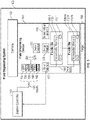
- Fig. 1 is a block diagram of a fluid dispensing system 100, according to some examples.
- the fluid dispending system 100 can be a printing system, such as a 2D printing system or a 3D printing system.
- the fluid dispending system 100 can be a different type of fluid dispensing system. Examples of other types of fluid dispensing systems include those used in fluid sensing systems, medical systems, vehicles, fluid flow control systems, and so forth.
- the fluid dispensing system 100 includes a fluid dispensing device 102, which can be mounted to a carriage 103 (or other type of support structure) of the fluid dispensing system 100.
- the fluid dispensing device 102 can be attached to a fluid cartridge (e.g., a print cartridge) that is removably mounted to the carriage 103.
- the fluid dispensing device 102 can be fixedly mounted to the carriage 103.
- the fluid dispensing device 102 includes orifices for dispensing fluid towards a target 106.
- the carriage 103 and the target 106 are moveable with respect to one another (either the carriage 103 is moveable or the target 106 is moveable or both the carriage 103 and the target 106 are moveable).
- the fluid dispensing device 102 includes a printhead that ejects printing fluid (e.g., ink) onto a print medium, such as a paper medium, a plastic medium, and so forth.
- printing fluid e.g., ink
- the fluid dispensing device 102 includes a printhead that can eject any of various different liquid agents onto a print target, where the liquid agents can include any or some combination of the following: ink, an agent used to fuse or coalesce powders of a layer of build material, an agent to detail a layer of build material (such as by defining edges or shapes of the layer of build material), and so forth.
- a 3D target is built by depositing successive layers of build material onto a build platform of the 3D printing system. Each layer of build material can be processed using the printing fluid from a printhead to form the desired shape, texture, and/or other characteristic of the layer of build material.
- the fluid dispensing device 102 includes multiple fluidic dies 108-1 to 108-N (N ⁇ 2).
- the fluidic dies 108-1 to 108-N include respective arrays of fluidic actuators 110-1 to 110-N, and respective nonvolatile memories 112-1 to 112-N.
- the fluidic die 108-1 includes the array of fluidic actuators 110-1 and the nonvolatile memory 112-1
- the fluidic die 108-N includes the array of fluidic actuators 110-N and the nonvolatile memory 112-N.
- An array of fluidic actuators 108-i 1 to N) can include a column of fluidic actuators, or multiple columns of fluidic actuators.
- the fluidic actuators 108-i can be organized into multiple primitives, where each primitive includes a specified number of fluidic actuators.
- the fluidic actuators 108-i can be part of nozzles or can be associated with other types of flow structures, such as fluid conduits, fluid chambers, and so forth.
- Each fluidic actuator is selected by a respective different address provided by a controller (e.g., a system controller 110) in the fluid dispensing system 100.
- a "controller” can refer to a hardware processing circuit, which can include any or some combination of a microprocessor, a core of a multicore microprocessor, a microcontroller, a programmable integrated circuit (e.g., application programmable integrated circuit (ASIC), etc.), a programmable gate array, a digital signal processor, a number of discrete hardware components (e.g., timers, counters, state machines, etc.), or another hardware processing circuit.
- a controller can also include discrete components such as timers, counters, state machines, latches, buffers, and so forth.
- a “controller” can refer to a combination of a hardware processing circuit and machine-readable instructions (software and/or firmware) executable on the hardware processing circuit.
- Fig. 1 shows the system controller 110 as being one block, it is noted that the system controller 110 can actually represent multiple controllers that perform respective tasks.
- the system controller 110 can be implemented using multiple ASICs, where one ASIC can be deployed on the carriage 103, and another ASIC can be a main ASIC for controlling fluid dispensing operations (e.g., printing operations).
- the fluid dispensing device 102 includes various inputs 130, and a sense interface 132 (for inputting and outputting currents and voltages or data, for example).
- the sense interface 132 can receive an input current or input voltage, and can output a corresponding voltage or current. In other examples, other forms of input/output can be performed at the sense interface 132.
- the inputs 130 include a programming voltage (referred to as "VPP") input 134 that provides an input voltage to the memory voltage generator 116.
- VPP programming voltage
- the memory voltage generator 116 can include a converter to convert the input voltage VPP 134 to a programming voltage applied to perform programming of selected memory cells of a nonvolatile memory 112-i or multiple nonvolatile memories 112-i.
- the memory voltage generator 116 can be omitted, and the input voltage VPP 134 can be used for programming the memory cells of a nonvolatile memory.
- the inputs 130 also include a clock input 136, which provides a clock signal that is provided to various circuitry in the fluid dispensing device 102.
- the inputs 130 also include a data input 138, to receive control data (e.g., in the form of a data packet) provided by the system controller 110.
- the data packet received at the data input 138 includes control information that can be used to control activation of selected fluid actuators 108.
- the data packet can include information to set a mode of operation of the fluid dispensing device, where the mode of operation can include a fluidic operation mode for selective activation of fluidic actuators of the fluid dispensing device, or a memory access mode for writing or reading data of the nonvolatile memory.
- control information included in a data packet received at the data input 138 from the system controller 110 includes primitive data and address data.
- Primitive data is provided in examples where the fluidic actuators 108 in the fluid dispensing device 102 are arranged in primitives. More generally, the primitive data can also be referred to as "fire data," which is data used to control activation or non-activation of a fluidic actuator (or fluidic actuators) within a primitive during the fluidic operation mode.
- the primitive data can include corresponding bits to represent which of the fluidic actuators of a primitive is (are) activated when a fire pulse is delivered to the primitive.
- a fire pulse corresponds to a fire signal received at a fire input 140 being activated.
- the address data includes address bits that define an address for selecting fluidic actuators 108-i to activate.
- each primitive includes a set of fluidic actuators, and the fluidic actuators of the primitive are selected by respective different addresses as represented by the address bits.
- the data packet received at the data input 138 can select memory cells of a nonvolatile memory to be written or read.
- the data input 138 is a control input shared by both the fluidic actuators and nonvolatile memory of a fluidic die for receiving respective control information for activating the fluidic actuators or access the nonvolatile memory, respectively.
- the control information can also include other information that can be included into the data packet delivered by the system controller 110 to the fluid dispensing device 102.
- the inputs 130 further include a mode input 142, which receives a mode signal that can be used as part of a sequence to set the fluid dispensing device 102 in a memory access mode.
- the inputs 130 of the fluid dispensing device 102 can include additional or alternative inputs.
- the clock input 136, data input 138, fire input 140, and mode input 142 are examples of control inputs that provide control information to the fluid dispensing device 102.
- the fluid dispensing device 102 also includes a data bus 160 to which the nonvolatile memories 112-1 to 112-N are coupled.
- the nonvolatile memories 112-1 to 112-N can be connected directly to the data bus 160, or alternatively, intermediate circuitry can be provided in the respective fluidic dies 108-1 to 108-N to connect the nonvolatile memories 112-1 to 112-N to the data bus 160.
- the data bus 160 is further connected to the sense interface 132.
- data read from the nonvolatile memories 112-1 to 112-N can be communicated over the data bus 160 to the sense interface 132, or output to the system controller 110.
- data that is communicated over the data bus 160 can include analog signals (e.g., in the form of electrical currents or voltages) communicated over the data bus 160.
- the data can refer to digital data.
- the nonvolatile memories 112-1 to 112-N share a common data bus (160) that is coupled to an output (in the form of the sense interface 132) of the fluid dispensing device 102.
- the data input 138 can include multiple subsets.
- the data input portion D1 is connected to the fluidic die 108-1 (but not to any other fluidic die including the fluidic die 108-N), and the data input portion DN is connected to the fluidic die 108-N (but not to any other fluidic die including the fluidic die 108-1).
- the data input portion D1 can receive a data packet provided to the fluidic die 108-1, and the data input portion DN can receive a data packet provided to the fluidic die 108-N.
- each data input portion Di is made up of one bit. In other examples, each data input portion Di can be made up of multiple bits.
- the data bus 160 can be shared for communicating data of multiple nonvolatile memories 112-1 to 112-N of multiple fluidic dies 108-1 to 108-N, while individual control inputs (in the form of D1 to DN) are provided to respective individual fluidic dies 108-1 to 108-N.
- the clock input 136, the fire input 140, and the mode input 142 are control inputs that are shared by the multiple fluidic dies 108-1 to 108-N.
- the fluid dispensing device 102 further includes a storage medium 150, which can be in the form of registers or latches, to store data packets received at corresponding data input portions D1 to DN of the data input 138.
- the storage medium 150 can include shift registers. Each shift register serially input bits of a data packet received at respective data input portion Di into the shift register on successive activations of a clock signal received at the clock input 136.
- the storage medium 150 can include registers each being able to load all bits of a data packet at one time into the register.
- the storage medium 150 can include shift registers and latches, where after a data packet is shifted into a shift register, the content of the shift register can be provided to the corresponding latch for storage.
- a “latch” can refer to a storage element for buffering data.
- the fluid dispensing device 102 further includes a device controller 152 that is part of the fluid dispensing device 102.
- the device controller 152 can perform various operations of the fluid dispensing device 102, such as setting a mode of the fluid dispensing device 102, controlling activation of selected fluidic actuators 108, controlling writing or reading of the nonvolatile memory 112, and so forth.
- the device controller 152 can be in the form of an ASIC, a programmable gate array, a microcontroller, a microprocessor, and so forth, or can be in the form of discrete components that cooperate to perform control tasks.
- Fig. 1 shows the inputs 130 and the sense interface 132 of the fluid dispensing device 102 being coupled to the system controller 110.
- the carriage 103 includes an electrical interconnect that can connect to the inputs 130 and the sense interface 132 when the fluid dispensing device 102 is attached to the carriage 130.
- the system controller 110 is in turn connected to the carriage 103, such as over a bus or another link.
- Fig. 2 is a block diagram of an example arrangement in which three fluidic dies 108-1, 108-2, and 108-3 are provided on the fluidic dispensing device 102. Although a specific number of fluidic dies are shown in Fig. 2 , in other examples, a different number of fluidic dies can be used.
- the fluidic dies 108-1 to 108-3 include respective nonvolatile memories 110-1 to 110-3.
- Each nonvolatile memory is divided into a first region for storing die-specific information, and a second region for storing shared information (also referred to as common information).
- the nonvolatile memory 110-1 is divided into a die-specific region 202-1, and a shared 204-1.
- the nonvolatile memory 110-2 is divided into a die-specific region 202-2 and a shared region 204-2
- the nonvolatile memory 110-3 is divided into a die-specific region 202-3 and a shared region 204-3.
- each nonvolatile memory can be divided into more than two separate regions.
- Each die-specific region 202-1, 202-2, or 202-3 stores information that is specific to the corresponding fluidic die 108-1, 108-2, or 108-3.
- Examples of die-specific information can include wafer lot information relating to a wafer on which the fluidic die was formed, a manufacturing date of the fluidic die, and so forth.
- Common information is stored in the shared regions 204-1, 204-2, and 204-3.
- the common information pertains to the fluid dispensing device 102.
- the common information can include information of a geographic region where the fluid dispensing device 102 is to be used, a generation of the fluid dispensing device 102, information tracking a fluid level of the fluid dispensing device 102 (e.g., the ink level of a print cartridge), and so forth.
- the common information can be stored in a distributed manner across the shared regions 204-1, 204-2, and 204-3.
- Fig. 3 is a block diagram of an example arrangement that includes multiple fluid dispensing devices 302 and 304.
- the fluid dispensing devices 302 and 304 can include respective printhead assemblies, such as print cartridges.
- the fluid dispensing device 302 can include fluidic dies 306-1, 306-2, and 306-3, such as fluidic dies for dispensing inks of different colors, in some examples.
- the fluid dispensing device 304 can include a fluidic die 308, such as a fluidic die for dispensing ink of a different color, such as black.
- the fluid dispensing devices 302 and 304 show respective specific numbers of fluidic dies, in other examples, different numbers of fluidic dies can be included in the corresponding fluid dispensing devices 302 and 304.
- more than two fluid dispensing devices can be provided.
- the fluidic dies 306-1, 306-2, 306-3, and 308 include respective nonvolatile memories 307-1, 307-2, 307-3, and 309.
- the fluid dispensing device 302 includes a sense interface 310, and the fluid dispensing device 304 includes a sense interface 312.
- the sense interfaces 310 and 312 are coupled over a global bus 314 to a sense pad 316.
- the sense pad 316 is connected to the system controller 110.
- Data read from the nonvolatile memories 307-1, 307-2, 307-3, and 309 can be output by respective sense interfaces 310 and 312 to the global bus 314, which in turn provides the data to the sense pad 316.
- the global sense interface and the global bus 314 can be part of a circuit arrangement 318 (e.g., a printed circuit arrangement) on the carriage 103 shown in Fig. 1 .
- a circuit arrangement 318 e.g., a printed circuit arrangement
- the circuit arrangement 318 can also include other inputs 320, including a VPP pad 322, a clock pad 324, a data pad 326, a fire pad 328, and a mode pad 330.
- the VPP pad 322 can provide a programming voltage (VPP) to VPP inputs of the fluid dispensing devices 302 and 304.
- the clock pad 324 can provide a clock signal to the clock inputs of the fluid dispensing devices 302 and 304.
- the data pad 326 can provide control information (data packets) to the data inputs of the fluid dispensing devices 302 and 304. Note that the data pad 326 can provide respective data portions to corresponding data input portions (e.g., D1 to DN shown in Fig.
- each fluid dispensing device 302 or 304 each fluid dispensing device 302 or 304.
- the fluidic dies 306-1, 306-2, 306-3, and 308 share the global bus 314, the fluidic dies 306-1, 306-2, 306-3, and 308 receive individual control information from the data portions of the data pad 326.
- the fire pad 328 provides a fire signal to the fire inputs of the fluid dispensing devices 302 and 304.
- the mode pad 330 provides a mode signal to the mode inputs of the fluid dispensing devices 302 and 304.
- the fluid dispensing device component 400 includes multiple control inputs 406 to provide respective control information to respective fluidic dies 402-1 to 402-N.
- a data bus 408 is connected to the fluidic dies 402-1 to 402-N.
- the data bus 408 provides data of the memories 404-1 to 404-N of the fluidic dies 402-1 to 402-N to an output 410 of the fluid dispensing device component 400.
- Fig. 5 is a block diagram of a fluid dispensing system 500 that includes a support structure 502 (e.g., the carriage 103 of Fig. 1 ) to receive a fluid dispensing device 510 having multiple fluidic dies 512 that include nonvolatile memories 514.
- a support structure 502 e.g., the carriage 103 of Fig. 1
- a fluid dispensing device 510 having multiple fluidic dies 512 that include nonvolatile memories 514.
- the fluid dispensing system 500 includes a controller 504 (e.g., the system controller 110 of Fig. 1 ) to perform various tasks.
- the tasks of the controller 504 include a control information provision task 506 to provide control information to respective fluidic dies of the fluid dispensing device using corresponding control inputs of the fluid dispensing device.
- the tasks of the controller 504 further include a nonvolatile memory data reception task 508 to receive data from the nonvolatile memories 514 of the fluidic dies 512 over a shared data bus 516 of the fluid dispensing device 510.
- Fig. 6 is a flow diagram of a process of forming a fluid dispensing device component.
- the process includes providing (at 602), on a substrate, multiple fluidic dies each including a memory.
- the process includes providing (at 604) multiple control inputs of the fluid dispensing device component to receive respective control information for respective fluidic dies.
- the process includes providing (at 606) an output of the fluid dispensing device component to receive, over a data bus connected to the plurality of fluidic dies, data of the memories of the fluidic dies.
Description
- A fluid dispensing system can dispense fluid towards a target. In some examples, a fluid dispensing system can include a printing system, such as a twodimensional (2D) printing system or a three-dimensional (3D) printing system. A printing system can include printhead devices that include fluidic actuators to cause dispensing of printing fluids.
WO2019/009902 discloses a circuit for use with a fluid ejection device including a plurality of decoders responsive to a common address to activate respective control signals at different times for selecting respective memories of the fluid ejection device. Each respective decoder of the plurality of decoders comprises a discharge switch to deactivate a control signal of the respective decoder while another decoder of the plurality of decoders is activating a control signal in response to the common address. - Some implementations of the present disclosure are described with respect to the following figures.
-
Fig. 1 is a block diagram of a fluid dispensing system according to some examples. -
Fig. 2 is a block diagram of an arrangement of fluidic dies with respective memories, according to some examples. -
Fig. 3 is a block diagram of an arrangement that includes multiple fluid dispensing devices with corresponding fluidic dies including memories, according to further examples. -
Fig. 4 is a block diagram of a fluid dispensing device component according to some examples. -
Fig. 5 is a block diagram of a fluid dispensing system according to some examples. -
Fig. 6 is a flow diagram of a process according to some examples. - Throughout the drawings, identical reference numbers designate similar, but not necessarily identical, elements. The figures are not necessarily to scale, and the size of some parts may be exaggerated to more clearly illustrate the example shown. Moreover, the drawings provide examples and/or implementations consistent with the description; however, the description is not limited to the examples and/or implementations provided in the drawings.
- In the present disclosure, use of the term "a," "an", or "the" is intended to include the plural forms as well, unless the context clearly indicates otherwise. Also, the term "includes," "including," "comprises," "comprising," "have," or "having" when used in this disclosure specifies the presence of the stated elements, but do not preclude the presence or addition of other elements.
- A fluid dispensing device can include fluidic actuators that when activated cause dispensing (e.g., ejection or other flow) of a fluid. For example, the dispensing of the fluid can include ejection of fluid droplets by activated fluidic actuators from respective nozzles of the fluid dispensing device. In other examples, an activated fluidic actuator (such as a pump) can cause fluid to flow through a fluid conduit or fluid chamber. Activating a fluidic actuator to dispense fluid can thus refer to activating the fluidic actuator to eject fluid from a nozzle or activating the fluidic actuator to cause a flow of fluid through a flow structure, such as a flow conduit, a fluid chamber, and so forth.
- Activating a fluidic actuator can also be referred to as firing the fluidic actuator. In some examples, the fluidic actuators include thermal-based fluidic actuators including heating elements, such as resistive heaters. When a heating element is activated, the heating element produces heat that can cause vaporization of a fluid to cause nucleation of a vapor bubble (e.g., a steam bubble) proximate the thermal-based fluidic actuator that in turn causes dispensing of a quantity of fluid, such as ejection from an orifice of a nozzle or flow through a fluid conduit or fluid chamber. In other examples, a fluidic actuator may be a piezoelectric membrane based fluidic actuator that when activated applies a mechanical force to dispense a quantity of fluid.
- In examples where a fluid dispensing device includes nozzles, each nozzle includes a fluid chamber, also referred to as a firing chamber. In addition, a nozzle can include an orifice through which fluid is dispensed, a fluidic actuator, and a sensor. Each fluid chamber provides the fluid to be dispensed by the respective nozzle.
- Generally, a fluidic actuator can be an ejecting-type fluidic actuator to cause ejection of a fluid, such as through an orifice of a nozzle, or a non-ejecting-type fluidic actuator to cause flow of a fluid.
- In some examples, a fluid dispensing device can be in the form of a printhead, which can be mounted to a print cartridge, a carriage, and so forth. In further examples, a fluid dispensing device can be in the form of a fluidic die. A "die" refers to an assembly where various layers are formed onto a substrate to fabricate circuitry, fluid chambers, and fluid conduits. Multiple fluidic dies can be mounted or attached to a support structure. In other examples, a fluid dispensing device can be in the form of a fluidic die sliver, which includes a thin substrate (e.g., having a thickness on the order of 650 micrometers (µm) or less) with a ratio of length to width (L/W) of at least three, for example. A die sliver can other dimensions in other examples. Multiple fluidic die slivers can be molded into a monolithic molding structure, for example.
- In the present disclosure, a "fluid dispensing device component" can refer to either a fluid dispensing device, or a component that is part of, or attached to, or coupled to the fluid dispensing device.
- A fluid dispensing device can include a nonvolatile memory to store data. A "nonvolatile memory" refers to a memory that is able to retain data stored in the memory even if power is removed from the memory. Examples of data that can be stored in the nonvolatile memory include identification information for the fluid dispensing device (e.g., a serial number or other identifier), device component characteristics (such as a brand name, color information, license information, etc.), fluid flow characteristics such as flow rate information, configuration information to configure the fluid dispensing device, security information used for secure access of the fluid dispensing device, and so forth. The data may be encrypted, scrambled, or encoded in any way.
- In accordance with some implementations of the present disclosure, a fluid dispensing device includes multiple fluidic dies each including a respective memory (including a nonvolatile memory). To improve the efficiency of usage of the memories of the multiple fluidic dies, a first part of each memory can be used to store data specific to the corresponding fluidic die, and a second part of each memory can be used to store common data shared by the multiple fluidic dies. Also, the fluid dispensing device includes multiple control inputs that can provide control information to respective fluidic dies of the multiple fluidic dies. The fluid dispensing device includes a shared bus that is shared by the memories of the fluidic dies, so that data from the memories can be output from the fluid dispensing device.
-
Fig. 1 is a block diagram of afluid dispensing system 100, according to some examples. The fluid dispendingsystem 100 can be a printing system, such as a 2D printing system or a 3D printing system. In other examples, the fluid dispendingsystem 100 can be a different type of fluid dispensing system. Examples of other types of fluid dispensing systems include those used in fluid sensing systems, medical systems, vehicles, fluid flow control systems, and so forth. - The
fluid dispensing system 100 includes afluid dispensing device 102, which can be mounted to a carriage 103 (or other type of support structure) of thefluid dispensing system 100. In some examples, thefluid dispensing device 102 can be attached to a fluid cartridge (e.g., a print cartridge) that is removably mounted to thecarriage 103. In other examples, thefluid dispensing device 102 can be fixedly mounted to thecarriage 103. - The
fluid dispensing device 102 includes orifices for dispensing fluid towards atarget 106. In some examples, thecarriage 103 and thetarget 106 are moveable with respect to one another (either thecarriage 103 is moveable or thetarget 106 is moveable or both thecarriage 103 and thetarget 106 are moveable). - In a 2D printing system, the
fluid dispensing device 102 includes a printhead that ejects printing fluid (e.g., ink) onto a print medium, such as a paper medium, a plastic medium, and so forth. - In a 3D printing system, the
fluid dispensing device 102 includes a printhead that can eject any of various different liquid agents onto a print target, where the liquid agents can include any or some combination of the following: ink, an agent used to fuse or coalesce powders of a layer of build material, an agent to detail a layer of build material (such as by defining edges or shapes of the layer of build material), and so forth. In a 3D printing system, a 3D target is built by depositing successive layers of build material onto a build platform of the 3D printing system. Each layer of build material can be processed using the printing fluid from a printhead to form the desired shape, texture, and/or other characteristic of the layer of build material. - The
fluid dispensing device 102 includes multiple fluidic dies 108-1 to 108-N (N ≥ 2). The fluidic dies 108-1 to 108-N include respective arrays of fluidic actuators 110-1 to 110-N, and respective nonvolatile memories 112-1 to 112-N. For example, the fluidic die 108-1 includes the array of fluidic actuators 110-1 and the nonvolatile memory 112-1, and the fluidic die 108-N includes the array of fluidic actuators 110-N and the nonvolatile memory 112-N. - An array of fluidic actuators 108-i (i = 1 to N) can include a column of fluidic actuators, or multiple columns of fluidic actuators. In some examples, the fluidic actuators 108-i can be organized into multiple primitives, where each primitive includes a specified number of fluidic actuators. The fluidic actuators 108-i can be part of nozzles or can be associated with other types of flow structures, such as fluid conduits, fluid chambers, and so forth. Each fluidic actuator is selected by a respective different address provided by a controller (e.g., a system controller 110) in the
fluid dispensing system 100. - As used here, a "controller" can refer to a hardware processing circuit, which can include any or some combination of a microprocessor, a core of a multicore microprocessor, a microcontroller, a programmable integrated circuit (e.g., application programmable integrated circuit (ASIC), etc.), a programmable gate array, a digital signal processor, a number of discrete hardware components (e.g., timers, counters, state machines, etc.), or another hardware processing circuit. A controller can also include discrete components such as timers, counters, state machines, latches, buffers, and so forth. Alternatively, a "controller" can refer to a combination of a hardware processing circuit and machine-readable instructions (software and/or firmware) executable on the hardware processing circuit.
- Although
Fig. 1 shows thesystem controller 110 as being one block, it is noted that thesystem controller 110 can actually represent multiple controllers that perform respective tasks. For example, thesystem controller 110 can be implemented using multiple ASICs, where one ASIC can be deployed on thecarriage 103, and another ASIC can be a main ASIC for controlling fluid dispensing operations (e.g., printing operations). - The
fluid dispensing device 102 includesvarious inputs 130, and a sense interface 132 (for inputting and outputting currents and voltages or data, for example). In an example, thesense interface 132 can receive an input current or input voltage, and can output a corresponding voltage or current. In other examples, other forms of input/output can be performed at thesense interface 132. - The
inputs 130 include a programming voltage (referred to as "VPP")input 134 that provides an input voltage to thememory voltage generator 116. In some examples, thememory voltage generator 116 can include a converter to convert theinput voltage VPP 134 to a programming voltage applied to perform programming of selected memory cells of a nonvolatile memory 112-i or multiple nonvolatile memories 112-i. - In other examples, the
memory voltage generator 116 can be omitted, and theinput voltage VPP 134 can be used for programming the memory cells of a nonvolatile memory. - The
inputs 130 also include aclock input 136, which provides a clock signal that is provided to various circuitry in thefluid dispensing device 102. Theinputs 130 also include adata input 138, to receive control data (e.g., in the form of a data packet) provided by thesystem controller 110. The data packet received at thedata input 138 includes control information that can be used to control activation of selectedfluid actuators 108. Also, as explained further below, the data packet can include information to set a mode of operation of the fluid dispensing device, where the mode of operation can include a fluidic operation mode for selective activation of fluidic actuators of the fluid dispensing device, or a memory access mode for writing or reading data of the nonvolatile memory. - As further examples, the control information included in a data packet received at the
data input 138 from thesystem controller 110 includes primitive data and address data. Primitive data is provided in examples where thefluidic actuators 108 in thefluid dispensing device 102 are arranged in primitives. More generally, the primitive data can also be referred to as "fire data," which is data used to control activation or non-activation of a fluidic actuator (or fluidic actuators) within a primitive during the fluidic operation mode. - In examples where fluidic actuators 108-i are grouped into primitives, the primitive data can include corresponding bits to represent which of the fluidic actuators of a primitive is (are) activated when a fire pulse is delivered to the primitive. A fire pulse corresponds to a fire signal received at a
fire input 140 being activated. - The address data includes address bits that define an address for selecting fluidic actuators 108-i to activate. In examples where fluidic actuators 108-i are grouped into primitives, each primitive includes a set of fluidic actuators, and the fluidic actuators of the primitive are selected by respective different addresses as represented by the address bits.
- When the
fluid dispensing device 102 is set in the memory access mode (e.g., memory write mode or memory read mode), the data packet received at thedata input 138 can select memory cells of a nonvolatile memory to be written or read. Thus, thedata input 138 is a control input shared by both the fluidic actuators and nonvolatile memory of a fluidic die for receiving respective control information for activating the fluidic actuators or access the nonvolatile memory, respectively. - The control information can also include other information that can be included into the data packet delivered by the
system controller 110 to thefluid dispensing device 102. - The
inputs 130 further include amode input 142, which receives a mode signal that can be used as part of a sequence to set thefluid dispensing device 102 in a memory access mode. - In other examples, the
inputs 130 of thefluid dispensing device 102 can include additional or alternative inputs. - The
clock input 136,data input 138,fire input 140, andmode input 142 are examples of control inputs that provide control information to thefluid dispensing device 102. - The
fluid dispensing device 102 also includes adata bus 160 to which the nonvolatile memories 112-1 to 112-N are coupled. Note that the nonvolatile memories 112-1 to 112-N can be connected directly to thedata bus 160, or alternatively, intermediate circuitry can be provided in the respective fluidic dies 108-1 to 108-N to connect the nonvolatile memories 112-1 to 112-N to thedata bus 160. - The
data bus 160 is further connected to thesense interface 132. Thus, data read from the nonvolatile memories 112-1 to 112-N can be communicated over thedata bus 160 to thesense interface 132, or output to thesystem controller 110. - As used here, the term "data" that is communicated over the
data bus 160 can include analog signals (e.g., in the form of electrical currents or voltages) communicated over thedata bus 160. In other examples, the data can refer to digital data. - In the arrangement shown in
FIG. 1 , the nonvolatile memories 112-1 to 112-N share a common data bus (160) that is coupled to an output (in the form of the sense interface 132) of thefluid dispensing device 102. - The
data input 138 can include multiple subsets. For example, thedata input 138 can be divided into multiple data input portions D1 to DN, where each data input portion Di (i=1 to N) is provided to a respective individual fluidic die 108-i. For example, the data input portion D1 is connected to the fluidic die 108-1 (but not to any other fluidic die including the fluidic die 108-N), and the data input portion DN is connected to the fluidic die 108-N (but not to any other fluidic die including the fluidic die 108-1). The data input portion D1 can receive a data packet provided to the fluidic die 108-1, and the data input portion DN can receive a data packet provided to the fluidic die 108-N. In some examples, each data input portion Di is made up of one bit. In other examples, each data input portion Di can be made up of multiple bits. - In some examples, the
data bus 160 can be shared for communicating data of multiple nonvolatile memories 112-1 to 112-N of multiple fluidic dies 108-1 to 108-N, while individual control inputs (in the form of D1 to DN) are provided to respective individual fluidic dies 108-1 to 108-N.The clock input 136, thefire input 140, and themode input 142 are control inputs that are shared by the multiple fluidic dies 108-1 to 108-N. - The
fluid dispensing device 102 further includes astorage medium 150, which can be in the form of registers or latches, to store data packets received at corresponding data input portions D1 to DN of thedata input 138. In some examples, thestorage medium 150 can include shift registers. Each shift register serially input bits of a data packet received at respective data input portion Di into the shift register on successive activations of a clock signal received at theclock input 136. In other examples, thestorage medium 150 can include registers each being able to load all bits of a data packet at one time into the register. - In further examples, the
storage medium 150 can include shift registers and latches, where after a data packet is shifted into a shift register, the content of the shift register can be provided to the corresponding latch for storage. A "latch" can refer to a storage element for buffering data. - The
fluid dispensing device 102 further includes adevice controller 152 that is part of thefluid dispensing device 102. Thedevice controller 152 can perform various operations of thefluid dispensing device 102, such as setting a mode of thefluid dispensing device 102, controlling activation of selectedfluidic actuators 108, controlling writing or reading of thenonvolatile memory 112, and so forth. - The
device controller 152 can be in the form of an ASIC, a programmable gate array, a microcontroller, a microprocessor, and so forth, or can be in the form of discrete components that cooperate to perform control tasks. -
Fig. 1 shows theinputs 130 and thesense interface 132 of thefluid dispensing device 102 being coupled to thesystem controller 110. In some examples, thecarriage 103 includes an electrical interconnect that can connect to theinputs 130 and thesense interface 132 when thefluid dispensing device 102 is attached to thecarriage 130. Thesystem controller 110 is in turn connected to thecarriage 103, such as over a bus or another link. -
Fig. 2 is a block diagram of an example arrangement in which three fluidic dies 108-1, 108-2, and 108-3 are provided on thefluidic dispensing device 102. Although a specific number of fluidic dies are shown inFig. 2 , in other examples, a different number of fluidic dies can be used. - The fluidic dies 108-1 to 108-3 include respective nonvolatile memories 110-1 to 110-3. Each nonvolatile memory is divided into a first region for storing die-specific information, and a second region for storing shared information (also referred to as common information). The nonvolatile memory 110-1 is divided into a die-specific region 202-1, and a shared 204-1. Similarly, the nonvolatile memory 110-2 is divided into a die-specific region 202-2 and a shared region 204-2, and the nonvolatile memory 110-3 is divided into a die-specific region 202-3 and a shared region 204-3. In further examples, each nonvolatile memory can be divided into more than two separate regions.
- Each die-specific region 202-1, 202-2, or 202-3 stores information that is specific to the corresponding fluidic die 108-1, 108-2, or 108-3. Examples of die-specific information can include wafer lot information relating to a wafer on which the fluidic die was formed, a manufacturing date of the fluidic die, and so forth.
- Common information is stored in the shared regions 204-1, 204-2, and 204-3. The common information pertains to the
fluid dispensing device 102. For example, the common information can include information of a geographic region where thefluid dispensing device 102 is to be used, a generation of thefluid dispensing device 102, information tracking a fluid level of the fluid dispensing device 102 (e.g., the ink level of a print cartridge), and so forth. The common information can be stored in a distributed manner across the shared regions 204-1, 204-2, and 204-3. -
Fig. 3 is a block diagram of an example arrangement that includes multiplefluid dispensing devices fluid dispensing devices fluid dispensing device 302 can include fluidic dies 306-1, 306-2, and 306-3, such as fluidic dies for dispensing inks of different colors, in some examples. Thefluid dispensing device 304 can include afluidic die 308, such as a fluidic die for dispensing ink of a different color, such as black. Although thefluid dispensing devices fluid dispensing devices - The fluidic dies 306-1, 306-2, 306-3, and 308 include respective nonvolatile memories 307-1, 307-2, 307-3, and 309.
- The
fluid dispensing device 302 includes asense interface 310, and thefluid dispensing device 304 includes asense interface 312. The sense interfaces 310 and 312 are coupled over aglobal bus 314 to asense pad 316. Thesense pad 316 is connected to thesystem controller 110. Data read from the nonvolatile memories 307-1, 307-2, 307-3, and 309 can be output by respective sense interfaces 310 and 312 to theglobal bus 314, which in turn provides the data to thesense pad 316. - For example, the global sense interface and the
global bus 314 can be part of a circuit arrangement 318 (e.g., a printed circuit arrangement) on thecarriage 103 shown inFig. 1 . - The
circuit arrangement 318 can also includeother inputs 320, including aVPP pad 322, aclock pad 324, adata pad 326, afire pad 328, and amode pad 330. TheVPP pad 322 can provide a programming voltage (VPP) to VPP inputs of thefluid dispensing devices clock pad 324 can provide a clock signal to the clock inputs of thefluid dispensing devices data pad 326 can provide control information (data packets) to the data inputs of thefluid dispensing devices data pad 326 can provide respective data portions to corresponding data input portions (e.g., D1 to DN shown inFig. 1 ) to eachfluid dispensing device global bus 314, the fluidic dies 306-1, 306-2, 306-3, and 308 receive individual control information from the data portions of thedata pad 326. - The
fire pad 328 provides a fire signal to the fire inputs of thefluid dispensing devices mode pad 330 provides a mode signal to the mode inputs of thefluid dispensing devices -
Fig. 4 is a block diagram of a fluiddispensing device component 400 that includes multiple fluidic dies 400-1 to 400-N (N ≥ 2). Each fluidic die 400-i (i = 1 to N) incudes a respective memory 404-i (404-1 to 404-N shown inFig. 1 ). - The fluid
dispensing device component 400 includesmultiple control inputs 406 to provide respective control information to respective fluidic dies 402-1 to 402-N. - A
data bus 408 is connected to the fluidic dies 402-1 to 402-N. Thedata bus 408 provides data of the memories 404-1 to 404-N of the fluidic dies 402-1 to 402-N to anoutput 410 of the fluiddispensing device component 400. -
Fig. 5 is a block diagram of afluid dispensing system 500 that includes a support structure 502 (e.g., thecarriage 103 ofFig. 1 ) to receive afluid dispensing device 510 having multiple fluidic dies 512 that includenonvolatile memories 514. - The
fluid dispensing system 500 includes a controller 504 (e.g., thesystem controller 110 ofFig. 1 ) to perform various tasks. The tasks of thecontroller 504 include a controlinformation provision task 506 to provide control information to respective fluidic dies of the fluid dispensing device using corresponding control inputs of the fluid dispensing device. - The tasks of the
controller 504 further include a nonvolatile memorydata reception task 508 to receive data from thenonvolatile memories 514 of the fluidic dies 512 over a shareddata bus 516 of thefluid dispensing device 510. -
Fig. 6 is a flow diagram of a process of forming a fluid dispensing device component. The process includes providing (at 602), on a substrate, multiple fluidic dies each including a memory. The process includes providing (at 604) multiple control inputs of the fluid dispensing device component to receive respective control information for respective fluidic dies. The process includes providing (at 606) an output of the fluid dispensing device component to receive, over a data bus connected to the plurality of fluidic dies, data of the memories of the fluidic dies. - In the foregoing description, numerous details are set forth to provide an understanding of the subject disclosed herein. However, implementations may be practiced without some of these details. Other implementations may include modifications and variations from the details discussed above. The invention is defined by the appended claims.
Claims (10)
- A fluid dispensing device component (102) comprising:a plurality of fluidic dies (108) each comprising a memory (112);a plurality of control inputs (130) to provide respective control information to respective fluidic dies (108) of the plurality of fluidic dies (108); anda data bus (160) connected to the plurality of fluidic dies (108), the data bus (160) to provide data of the memories (112) of the plurality of fluidic dies (108) to an output of the fluid dispensing device component (102),characterized in thateach respective memory (112) of a respective fluidic die (108) of the plurality of fluidic dies (108) includes a first portion (202-1) to store data specific to the respective fluidic die (108), and a second portion (204-1) to store common data shared by the plurality of fluidic dies (108).
- The fluid dispensing device component (102) of claim 1, wherein the common data is distributed across the memories (112) of the plurality of fluidic dies (108).
- The fluid dispensing device component (102) of any of the preceding claims, wherein the fluidic dies (108) comprise fluidic actuators (110), and the control inputs are shared by the fluidic actuators (110) and the memories (112).
- The fluid dispensing device component (102) of any of the preceding claims, wherein the data bus (160) is to provide the data in analog form to the output of the fluid dispensing device component (102).
- The fluid dispensing device component (102) of any of the preceding claims, wherein a first control input of the plurality of control inputs is to individually control a first fluidic die of the plurality of fluidic dies (108), and a second control input of the plurality of control inputs is to individually control a second fluidic die of the plurality of fluidic dies (108).
- The fluid dispensing device component (102) of claim 5, wherein the first control input is to provide a data packet containing control information to activate fluidic actuators (110) of the first fluidic die, and the second control input is to provide a data packet containing control information to activate fluidic actuators (110) of the second fluidic die.
- The fluid dispensing device component (102) of any of the preceding claims, further comprising a control signal input shared by the plurality of fluidic dies (108).
- The fluid dispensing device component (102) of any of the preceding claims, wherein the memory (112) of each of the plurality of fluidic dies (108) comprises a nonvolatile memory.
- A fluid dispensing system (100) comprising:a fluid dispensing device (102) as claimed in any of claims 1 to 8;a support structure (103) to receive the fluid dispensing device (102); anda controller (110) to:provide control information to respective fluidic dies (108) of the plurality of fluidic dies (108) using corresponding control inputs (130) of the fluid dispensing device (102), andreceive data from the nonvolatile memories (112) of the plurality of fluidic dies (108) over the shared data bus (160) of the fluid dispensing device (102).
- The fluid dispensing system (100) of claim 9, wherein the fluid dispensing device (102) is a first fluid dispensing device (310), and wherein the support structure (103) is to receive a second fluid dispensing device (312) comprising a fluidic die (308) that includes a nonvolatile memory (309), and wherein the support structure (103) comprises a global data bus (314) over which data of the fluidic dies of the first (302) and second (304) fluid dispensing devices are to be transmitted.
Applications Claiming Priority (1)
| Application Number | Priority Date | Filing Date | Title |
|---|---|---|---|
| PCT/US2019/016780 WO2020162910A1 (en) | 2019-02-06 | 2019-02-06 | Memories of fluidic dies |
Publications (2)
| Publication Number | Publication Date |
|---|---|
| EP3717253A1 EP3717253A1 (en) | 2020-10-07 |
| EP3717253B1 true EP3717253B1 (en) | 2022-05-11 |
Family
ID=65494600
Family Applications (1)
| Application Number | Title | Priority Date | Filing Date |
|---|---|---|---|
| EP19706160.9A Active EP3717253B1 (en) | 2019-02-06 | 2019-02-06 | Memories of fluidic dies |
Country Status (13)
| Country | Link |
|---|---|
| US (2) | US11511539B2 (en) |
| EP (1) | EP3717253B1 (en) |
| JP (1) | JP7181418B2 (en) |
| KR (1) | KR102621218B1 (en) |
| CN (1) | CN113316518B (en) |
| AU (1) | AU2019428636B2 (en) |
| CA (1) | CA3126912C (en) |
| ES (1) | ES2920603T3 (en) |
| IL (1) | IL284653A (en) |
| MX (1) | MX2021009129A (en) |
| PL (1) | PL3717253T3 (en) |
| WO (1) | WO2020162910A1 (en) |
| ZA (1) | ZA202104510B (en) |
Families Citing this family (4)
| Publication number | Priority date | Publication date | Assignee | Title |
|---|---|---|---|---|
| SG11202107300YA (en) | 2019-02-06 | 2021-08-30 | Hewlett Packard Development Co Lp | Communicating print component |
| US11787173B2 (en) | 2019-02-06 | 2023-10-17 | Hewlett-Packard Development Company, L.P. | Print component with memory circuit |
| US11511539B2 (en) * | 2019-02-06 | 2022-11-29 | Hewlett-Packard Development Company, L.P. | Memories of fluidic dies |
| US11491782B2 (en) | 2019-02-06 | 2022-11-08 | Hewlett-Packard Development Company, L.P. | Print component with memory circuit |
Citations (1)
| Publication number | Priority date | Publication date | Assignee | Title |
|---|---|---|---|---|
| EP1232868B1 (en) * | 2001-02-05 | 2006-08-30 | Konica Corporation | Image forming apparatus having life information |
Family Cites Families (95)
| Publication number | Priority date | Publication date | Assignee | Title |
|---|---|---|---|---|
| JPS6111845A (en) | 1984-06-27 | 1986-01-20 | Nec Corp | Printing data control device |
| JPH0671875A (en) | 1992-06-30 | 1994-03-15 | Fuji Xerox Co Ltd | Ink-jet recorder |
| US6116714A (en) | 1994-03-04 | 2000-09-12 | Canon Kabushiki Kaisha | Printing head, printing method and apparatus using same, and apparatus and method for correcting said printing head |
| JPH08127162A (en) | 1994-11-02 | 1996-05-21 | Hitachi Ltd | Image printer |
| JP2702426B2 (en) | 1994-12-16 | 1998-01-21 | 日本電気データ機器株式会社 | Thermal head device |
| CA2168994C (en) * | 1995-03-08 | 2000-01-18 | Juan J. Becerra | Method and apparatus for interleaving pulses in a liquid recorder |
| US6022094A (en) | 1995-09-27 | 2000-02-08 | Lexmark International, Inc. | Memory expansion circuit for ink jet print head identification circuit |
| US5745409A (en) | 1995-09-28 | 1998-04-28 | Invox Technology | Non-volatile memory with analog and digital interface and storage |
| US5984448A (en) | 1995-11-21 | 1999-11-16 | Citizen Watch Co., Ltd. | Circuit for driving ink-jet head and method of driving the same |
| US5942900A (en) | 1996-12-17 | 1999-08-24 | Lexmark International, Inc. | Method of fault detection in ink jet printhead heater chips |
| US6672706B2 (en) | 1997-07-15 | 2004-01-06 | Silverbrook Research Pty Ltd | Wide format pagewidth inkjet printer |
| JPH11207948A (en) * | 1997-11-14 | 1999-08-03 | Canon Inc | Recording device and recording control method |
| US6038166A (en) | 1998-04-01 | 2000-03-14 | Invox Technology | High resolution multi-bit-per-cell memory |
| JPH11341347A (en) | 1998-05-11 | 1999-12-10 | Newcore Technol Inc | Signal conversion processor |
| US6208542B1 (en) | 1998-06-30 | 2001-03-27 | Sandisk Corporation | Techniques for storing digital data in an analog or multilevel memory |
| US6154157A (en) | 1998-11-25 | 2000-11-28 | Sandisk Corporation | Non-linear mapping of threshold voltages for analog/multi-level memory |
| US6938976B2 (en) | 1999-06-16 | 2005-09-06 | Eastman Kodak Company | Printer and method therefor adapted to sense data uniquely associated with a consumable loaded into the printer |
| JP4081963B2 (en) | 2000-06-30 | 2008-04-30 | セイコーエプソン株式会社 | Storage device and access method for storage device |
| AU5374500A (en) | 2000-06-30 | 2002-01-21 | Silverbrook Res Pty Ltd | Controlling the timing of printhead nozzle firing |
| EP1250233A1 (en) | 2001-01-09 | 2002-10-23 | Encad, Inc. | Ink jet printhead quality management system and method |
| US6616260B2 (en) | 2001-05-25 | 2003-09-09 | Hewlett-Packard Development Company, L.P. | Robust bit scheme for a memory of a replaceable printer component |
| US7510255B2 (en) | 2001-08-30 | 2009-03-31 | Seiko Epson Corporation | Device and method for detecting temperature of head driver IC for ink jet printer |
| JP2004050637A (en) | 2002-07-19 | 2004-02-19 | Canon Inc | Substrate for inkjet head, inkjet head, and inkjet recorder employing inkjet head |
| TW536479B (en) | 2002-09-05 | 2003-06-11 | Benq Corp | Inkjet printer using thermal sensing elements to identify different types of cartridges |
| US7311385B2 (en) | 2003-11-12 | 2007-12-25 | Lexmark International, Inc. | Micro-fluid ejecting device having embedded memory device |
| JP4262070B2 (en) | 2003-12-02 | 2009-05-13 | キヤノン株式会社 | Element base of recording head, recording head, and control method of recording head |
| TWI243990B (en) | 2003-12-26 | 2005-11-21 | Ind Tech Res Inst | Printer, inkjet print head, identification circuit of inkjet print head and identification method thereof |
| MXPA04012681A (en) | 2003-12-26 | 2005-07-01 | Canon Kk | Liquid container and liquid supplying system. |
| US7267417B2 (en) | 2004-05-27 | 2007-09-11 | Silverbrook Research Pty Ltd | Printer controller for supplying data to one or more printheads via serial links |
| US7328956B2 (en) | 2004-05-27 | 2008-02-12 | Silverbrook Research Pty Ltd | Printer comprising a printhead and at least two printer controllers connected to a common input of the printhead |
| CN100548683C (en) | 2004-05-27 | 2009-10-14 | 佳能株式会社 | Head substrate, printhead, a box and PRN device |
| KR100694053B1 (en) | 2004-07-30 | 2007-03-12 | 삼성전자주식회사 | Print head driver of inkjet printer and semiconductor circuit board therefor |
| US7413272B2 (en) | 2004-11-04 | 2008-08-19 | Applied Materials, Inc. | Methods and apparatus for precision control of print head assemblies |
| US7365387B2 (en) | 2006-02-23 | 2008-04-29 | Hewlett-Packard Development Company, L.P. | Gate-coupled EPROM cell for printhead |
| US7613661B2 (en) | 2006-08-02 | 2009-11-03 | Pitney Bowes Inc. | Method and system for detecting duplicate printing of indicia in a metering system |
| US7425047B2 (en) | 2006-10-10 | 2008-09-16 | Silverbrook Research Pty Ltd | Printhead IC compatible with mutally incompatible print engine controllers |
| US7719901B2 (en) | 2007-06-05 | 2010-05-18 | Micron Technology, Inc. | Solid state memory utilizing analog communication of data values |
| US20090040286A1 (en) | 2007-08-08 | 2009-02-12 | Tan Theresa Joy L | Print scheduling in handheld printers |
| US9707752B2 (en) | 2007-11-14 | 2017-07-18 | Hewlett-Packard Development Company, L.P. | Inkjet print head with shared data lines |
| PL2263146T6 (en) | 2008-03-14 | 2019-03-29 | Hewlett-Packard Development Company, L.P. | Secure access to fluid cartridge memory |
| US7815273B2 (en) | 2008-04-01 | 2010-10-19 | Hewlett-Packard Development Company, L.P. | Fluid ejection device |
| US7768832B2 (en) | 2008-04-07 | 2010-08-03 | Micron Technology, Inc. | Analog read and write paths in a solid state memory device |
| US20090265596A1 (en) | 2008-04-22 | 2009-10-22 | Mediatek Inc. | Semiconductor devices, integrated circuit packages and testing methods thereof |
| JP5647822B2 (en) | 2009-07-24 | 2015-01-07 | ローム株式会社 | Thermal print head, thermal printer and printer system |
| US8516304B2 (en) | 2009-08-18 | 2013-08-20 | Lexmark International, Inc. | Integrated circuit including a programmable logic analyzer with enhanced analyzing and debugging capabilities and a method therefor |
| BRPI1004997A2 (en) | 2009-11-11 | 2013-02-26 | Seiko Epson Corp | electronic device and control method |
| WO2011127183A2 (en) | 2010-04-07 | 2011-10-13 | Intellipaper , Llc | Memomy programming methods and memory programming devices |
| JP5678290B2 (en) * | 2010-04-27 | 2015-02-25 | 株式会社デュプロ | Inkjet recording device |
| WO2013006152A1 (en) | 2011-07-01 | 2013-01-10 | Hewlett-Packard Development Company, L.P. | Method and apparatus to regulate temperature of printheads |
| JP5410486B2 (en) | 2011-09-21 | 2014-02-05 | 富士フイルム株式会社 | Liquid discharge head, liquid discharge apparatus, and liquid discharge head abnormality detection method |
| CN103828048B (en) | 2011-09-27 | 2017-03-01 | 惠普发展公司,有限责任合伙企业 | Individually and concurrently select the circuit of EPROM |
| BR112014007538B1 (en) | 2011-09-30 | 2020-06-02 | Hewlett-Packard Development Company, L.P. | AUTHENTICATION SYSTEM AND INK CARTRIDGE |
| US8882217B2 (en) | 2011-10-27 | 2014-11-11 | Hewlett-Packard Development Company, L.P. | Printhead assembly including memory elements |
| PL3263340T3 (en) | 2012-08-30 | 2019-05-31 | Hewlett Packard Development Co | Replaceable printing component with factory identity code |
| KR101964494B1 (en) | 2012-11-30 | 2019-04-01 | 휴렛-팩커드 디벨롭먼트 컴퍼니, 엘.피. | Fluid ejection device with integrated ink level sensor |
| US9224480B2 (en) | 2013-02-27 | 2015-12-29 | Texas Instruments Incorporated | Dual-function read/write cache for programmable non-volatile memory |
| EP2961607B1 (en) | 2013-02-28 | 2020-01-08 | Hewlett-Packard Development Company, L.P. | Print head bit information mapping |
| FI124954B (en) | 2013-04-30 | 2015-04-15 | Outotec Oyj | A process for preparing a solution containing gold and a process arrangement for recovering gold and silver |
| US8888226B1 (en) | 2013-06-25 | 2014-11-18 | Hewlett-Packard Development Company, L.P. | Crack detection circuits for printheads |
| US9889664B2 (en) | 2013-09-20 | 2018-02-13 | Hewlett-Packard Development Company, L.P. | Molded printhead structure |
| CN105636789B (en) | 2013-10-15 | 2018-02-02 | 惠普发展公司,有限责任合伙企业 | Fluid ejection apparatus and tube core |
| DE112013007584T5 (en) | 2013-11-27 | 2016-08-18 | Hewlett-Packard Development Company, L.P. | Printhead with bondpad surrounded by a partition |
| US9707771B2 (en) | 2014-01-03 | 2017-07-18 | Hewlett-Packard Development Company, L.P. | Fluid ejection device with integrated ink level sensors |
| US9773556B2 (en) | 2014-01-31 | 2017-09-26 | Hewlett-Packard Development Company, L.P. | Three-dimensional addressing for erasable programmable read only memory |
| US9196373B2 (en) | 2014-02-26 | 2015-11-24 | Sandisk 3D Llc | Timed multiplex sensing |
| WO2015137960A1 (en) | 2014-03-14 | 2015-09-17 | Hewlett-Packard Development Company, L.P. | Eprom cell with modified floating gate |
| JP6369191B2 (en) | 2014-07-18 | 2018-08-08 | セイコーエプソン株式会社 | CIRCUIT DEVICE, ELECTRONIC DEVICE, MOBILE BODY, AND RADIO COMMUNICATION SYSTEM |
| EP3212415B1 (en) | 2014-10-29 | 2019-07-03 | Hewlett-Packard Development Company, L.P. | Wide array printhead module |
| US9472288B2 (en) | 2014-10-29 | 2016-10-18 | Hewlett-Packard Development Company, L.P. | Mitigating parasitic current while programming a floating gate memory array |
| WO2016068954A1 (en) | 2014-10-30 | 2016-05-06 | Hewlett-Packard Development Company, L.P. | Print head sensing chamber circulation |
| WO2016068927A1 (en) | 2014-10-30 | 2016-05-06 | Hewlett-Packard Development Company, L.P. | Printhead with a number of shared enclosed selectors |
| GB2533967B (en) | 2015-01-12 | 2021-08-25 | Advanced Risc Mach Ltd | Adapting the usage configuration of integrated circuit input-output pads |
| US10124579B2 (en) | 2015-01-30 | 2018-11-13 | Hewlett-Packard Development Company, L.P. | Crack sensing for printhead having multiple printhead die |
| JP6430858B2 (en) | 2015-02-27 | 2018-11-28 | 理想科学工業株式会社 | Substrate connection system and inkjet recording apparatus |
| US9493002B2 (en) | 2015-04-10 | 2016-11-15 | Funai Electric Co., Ltd. | Printhead condition detection system |
| WO2016167763A1 (en) | 2015-04-15 | 2016-10-20 | Hewlett-Packard Development Company, L.P. | Printheads with high dielectric eprom cells |
| CN107206787A (en) | 2015-04-30 | 2017-09-26 | 惠普发展公司,有限责任合伙企业 | Printer fluid impedance sensing in printhead |
| WO2017065743A1 (en) | 2015-10-13 | 2017-04-20 | Hewlett-Packard Development Company, L.P. | Printhead with s-shaped die |
| CN106685425B (en) | 2015-11-11 | 2021-06-29 | 国民技术股份有限公司 | Audio signal processing device and analog front end circuit thereof |
| AU2016382786A1 (en) | 2015-12-29 | 2018-07-19 | Outlook Therapeutics, Inc. | Buffered formulations of bevacizumab |
| EP3448688B1 (en) | 2016-04-29 | 2021-03-24 | Hewlett-Packard Development Company, L.P. | Printing apparatus and methods for detecting fluid levels |
| KR101907028B1 (en) | 2016-07-06 | 2018-10-11 | 주식회사 유엑스팩토리 | Analog Digital Interfaced SRAM Structure |
| US10632756B2 (en) | 2016-07-19 | 2020-04-28 | Hewlett-Packard Development Company, L.P. | Fluid level sensors |
| US10044360B2 (en) | 2016-08-16 | 2018-08-07 | Microchip Technology Incorporated | ADC controller with temporal separation |
| SG11201901751QA (en) | 2016-09-01 | 2019-03-28 | Hs Mfg Group Llc | Methods for biobased derivatization of cellulosic surfaces |
| HUE048918T2 (en) | 2016-10-06 | 2020-08-28 | Hewlett Packard Development Co | Input control signals propagated over signal paths |
| ES2909632T3 (en) | 2017-01-31 | 2022-05-09 | Hewlett Packard Development Co | Memory bank layout and selection register |
| US20190374650A1 (en) | 2017-02-22 | 2019-12-12 | The Regents Of The University Of Michigan | Compositions and methods for delivery of polymer/biomacromolecule conjugates |
| US10632742B2 (en) | 2017-02-27 | 2020-04-28 | Hewlett-Packard Development Company, L.P. | Nozzle sensor evaluation |
| US11117368B2 (en) | 2017-04-14 | 2021-09-14 | Hewlett-Packard Development Company, L.P. | Fluidic die |
| US11090926B2 (en) * | 2017-07-06 | 2021-08-17 | Hewlett-Packard Development Company, L.P. | Decoders for memories of fluid ejection devices |
| KR102284239B1 (en) | 2017-07-06 | 2021-08-02 | 휴렛-팩커드 디벨롭먼트 컴퍼니, 엘.피. | Selector of nozzles and memory elements |
| CN110650846B (en) | 2017-07-17 | 2021-04-09 | 惠普发展公司,有限责任合伙企业 | Fluidic cartridge and replaceable printhead |
| US11511539B2 (en) * | 2019-02-06 | 2022-11-29 | Hewlett-Packard Development Company, L.P. | Memories of fluidic dies |
| US11491782B2 (en) | 2019-02-06 | 2022-11-08 | Hewlett-Packard Development Company, L.P. | Print component with memory circuit |
-
2019
- 2019-02-06 US US16/771,080 patent/US11511539B2/en active Active
- 2019-02-06 ES ES19706160T patent/ES2920603T3/en active Active
- 2019-02-06 CN CN201980089540.2A patent/CN113316518B/en active Active
- 2019-02-06 AU AU2019428636A patent/AU2019428636B2/en active Active
- 2019-02-06 JP JP2021543220A patent/JP7181418B2/en active Active
- 2019-02-06 CA CA3126912A patent/CA3126912C/en active Active
- 2019-02-06 PL PL19706160.9T patent/PL3717253T3/en unknown
- 2019-02-06 WO PCT/US2019/016780 patent/WO2020162910A1/en unknown
- 2019-02-06 MX MX2021009129A patent/MX2021009129A/en unknown
- 2019-02-06 EP EP19706160.9A patent/EP3717253B1/en active Active
- 2019-02-06 KR KR1020217023643A patent/KR102621218B1/en active IP Right Grant
-
2021
- 2021-06-29 ZA ZA2021/04510A patent/ZA202104510B/en unknown
- 2021-07-06 IL IL284653A patent/IL284653A/en unknown
-
2022
- 2022-10-10 US US18/045,258 patent/US11806999B2/en active Active
Patent Citations (1)
| Publication number | Priority date | Publication date | Assignee | Title |
|---|---|---|---|---|
| EP1232868B1 (en) * | 2001-02-05 | 2006-08-30 | Konica Corporation | Image forming apparatus having life information |
Also Published As
| Publication number | Publication date |
|---|---|
| AU2019428636A1 (en) | 2021-09-30 |
| CA3126912A1 (en) | 2020-08-13 |
| JP7181418B2 (en) | 2022-11-30 |
| PL3717253T3 (en) | 2022-08-01 |
| ES2920603T3 (en) | 2022-08-05 |
| KR20210103567A (en) | 2021-08-23 |
| CN113316518A (en) | 2021-08-27 |
| US20230057710A1 (en) | 2023-02-23 |
| ZA202104510B (en) | 2022-09-28 |
| IL284653A (en) | 2021-08-31 |
| US11806999B2 (en) | 2023-11-07 |
| MX2021009129A (en) | 2021-09-10 |
| EP3717253A1 (en) | 2020-10-07 |
| US11511539B2 (en) | 2022-11-29 |
| JP2022518784A (en) | 2022-03-16 |
| KR102621218B1 (en) | 2024-01-04 |
| US20210221124A1 (en) | 2021-07-22 |
| CN113316518B (en) | 2022-10-14 |
| WO2020162910A1 (en) | 2020-08-13 |
| AU2019428636B2 (en) | 2023-11-16 |
| CA3126912C (en) | 2023-12-19 |
Similar Documents
| Publication | Publication Date | Title |
|---|---|---|
| EP3717253B1 (en) | Memories of fluidic dies | |
| EP3915791B1 (en) | Selectors for nozzles and memory elements | |
| US11216707B2 (en) | Mask registers to store mask data patterns | |
| US10994531B2 (en) | Drop weights corresponding to drop weight patterns | |
| EP3826855A1 (en) | Microfluidic ejection element and method of operation of a microfluidic ejection element having a simplified interface | |
| US11433664B2 (en) | Writing a nonvolatile memory to programmed levels | |
| CN113365833B (en) | Writing non-volatile memory to a programmed level | |
| BR112021015518A2 (en) | FLUID ARRAY MEMORIES |
Legal Events
| Date | Code | Title | Description |
|---|---|---|---|
| STAA | Information on the status of an ep patent application or granted ep patent |
Free format text: STATUS: UNKNOWN |
|
| STAA | Information on the status of an ep patent application or granted ep patent |
Free format text: STATUS: THE INTERNATIONAL PUBLICATION HAS BEEN MADE |
|
| PUAI | Public reference made under article 153(3) epc to a published international application that has entered the european phase |
Free format text: ORIGINAL CODE: 0009012 |
|
| STAA | Information on the status of an ep patent application or granted ep patent |
Free format text: STATUS: REQUEST FOR EXAMINATION WAS MADE |
|
| 17P | Request for examination filed |
Effective date: 20200428 |
|
| AK | Designated contracting states |
Kind code of ref document: A1 Designated state(s): AL AT BE BG CH CY CZ DE DK EE ES FI FR GB GR HR HU IE IS IT LI LT LU LV MC MK MT NL NO PL PT RO RS SE SI SK SM TR |
|
| AX | Request for extension of the european patent |
Extension state: BA ME |
|
| GRAP | Despatch of communication of intention to grant a patent |
Free format text: ORIGINAL CODE: EPIDOSNIGR1 |
|
| STAA | Information on the status of an ep patent application or granted ep patent |
Free format text: STATUS: GRANT OF PATENT IS INTENDED |
|
| INTG | Intention to grant announced |
Effective date: 20211122 |
|
| GRAS | Grant fee paid |
Free format text: ORIGINAL CODE: EPIDOSNIGR3 |
|
| GRAA | (expected) grant |
Free format text: ORIGINAL CODE: 0009210 |
|
| STAA | Information on the status of an ep patent application or granted ep patent |
Free format text: STATUS: THE PATENT HAS BEEN GRANTED |
|
| DAV | Request for validation of the european patent (deleted) | ||
| DAX | Request for extension of the european patent (deleted) | ||
| AK | Designated contracting states |
Kind code of ref document: B1 Designated state(s): AL AT BE BG CH CY CZ DE DK EE ES FI FR GB GR HR HU IE IS IT LI LT LU LV MC MK MT NL NO PL PT RO RS SE SI SK SM TR |
|
| REG | Reference to a national code |
Ref country code: GB Ref legal event code: FG4D |
|
| REG | Reference to a national code |
Ref country code: CH Ref legal event code: EP |
|
| REG | Reference to a national code |
Ref country code: AT Ref legal event code: REF Ref document number: 1491067 Country of ref document: AT Kind code of ref document: T Effective date: 20220515 |
|
| REG | Reference to a national code |
Ref country code: DE Ref legal event code: R096 Ref document number: 602019014840 Country of ref document: DE |
|
| REG | Reference to a national code |
Ref country code: IE Ref legal event code: FG4D |
|
| REG | Reference to a national code |
Ref country code: NL Ref legal event code: FP |
|
| REG | Reference to a national code |
Ref country code: ES Ref legal event code: FG2A Ref document number: 2920603 Country of ref document: ES Kind code of ref document: T3 Effective date: 20220805 |
|
| REG | Reference to a national code |
Ref country code: LT Ref legal event code: MG9D |
|
| REG | Reference to a national code |
Ref country code: AT Ref legal event code: MK05 Ref document number: 1491067 Country of ref document: AT Kind code of ref document: T Effective date: 20220511 |
|
| PG25 | Lapsed in a contracting state [announced via postgrant information from national office to epo] |
Ref country code: SE Free format text: LAPSE BECAUSE OF FAILURE TO SUBMIT A TRANSLATION OF THE DESCRIPTION OR TO PAY THE FEE WITHIN THE PRESCRIBED TIME-LIMIT Effective date: 20220511 Ref country code: PT Free format text: LAPSE BECAUSE OF FAILURE TO SUBMIT A TRANSLATION OF THE DESCRIPTION OR TO PAY THE FEE WITHIN THE PRESCRIBED TIME-LIMIT Effective date: 20220912 Ref country code: NO Free format text: LAPSE BECAUSE OF FAILURE TO SUBMIT A TRANSLATION OF THE DESCRIPTION OR TO PAY THE FEE WITHIN THE PRESCRIBED TIME-LIMIT Effective date: 20220811 Ref country code: LT Free format text: LAPSE BECAUSE OF FAILURE TO SUBMIT A TRANSLATION OF THE DESCRIPTION OR TO PAY THE FEE WITHIN THE PRESCRIBED TIME-LIMIT Effective date: 20220511 Ref country code: HR Free format text: LAPSE BECAUSE OF FAILURE TO SUBMIT A TRANSLATION OF THE DESCRIPTION OR TO PAY THE FEE WITHIN THE PRESCRIBED TIME-LIMIT Effective date: 20220511 Ref country code: GR Free format text: LAPSE BECAUSE OF FAILURE TO SUBMIT A TRANSLATION OF THE DESCRIPTION OR TO PAY THE FEE WITHIN THE PRESCRIBED TIME-LIMIT Effective date: 20220812 Ref country code: FI Free format text: LAPSE BECAUSE OF FAILURE TO SUBMIT A TRANSLATION OF THE DESCRIPTION OR TO PAY THE FEE WITHIN THE PRESCRIBED TIME-LIMIT Effective date: 20220511 Ref country code: BG Free format text: LAPSE BECAUSE OF FAILURE TO SUBMIT A TRANSLATION OF THE DESCRIPTION OR TO PAY THE FEE WITHIN THE PRESCRIBED TIME-LIMIT Effective date: 20220811 Ref country code: AT Free format text: LAPSE BECAUSE OF FAILURE TO SUBMIT A TRANSLATION OF THE DESCRIPTION OR TO PAY THE FEE WITHIN THE PRESCRIBED TIME-LIMIT Effective date: 20220511 |
|
| PG25 | Lapsed in a contracting state [announced via postgrant information from national office to epo] |
Ref country code: RS Free format text: LAPSE BECAUSE OF FAILURE TO SUBMIT A TRANSLATION OF THE DESCRIPTION OR TO PAY THE FEE WITHIN THE PRESCRIBED TIME-LIMIT Effective date: 20220511 Ref country code: LV Free format text: LAPSE BECAUSE OF FAILURE TO SUBMIT A TRANSLATION OF THE DESCRIPTION OR TO PAY THE FEE WITHIN THE PRESCRIBED TIME-LIMIT Effective date: 20220511 Ref country code: IS Free format text: LAPSE BECAUSE OF FAILURE TO SUBMIT A TRANSLATION OF THE DESCRIPTION OR TO PAY THE FEE WITHIN THE PRESCRIBED TIME-LIMIT Effective date: 20220911 |
|
| PG25 | Lapsed in a contracting state [announced via postgrant information from national office to epo] |
Ref country code: SM Free format text: LAPSE BECAUSE OF FAILURE TO SUBMIT A TRANSLATION OF THE DESCRIPTION OR TO PAY THE FEE WITHIN THE PRESCRIBED TIME-LIMIT Effective date: 20220511 Ref country code: SK Free format text: LAPSE BECAUSE OF FAILURE TO SUBMIT A TRANSLATION OF THE DESCRIPTION OR TO PAY THE FEE WITHIN THE PRESCRIBED TIME-LIMIT Effective date: 20220511 Ref country code: RO Free format text: LAPSE BECAUSE OF FAILURE TO SUBMIT A TRANSLATION OF THE DESCRIPTION OR TO PAY THE FEE WITHIN THE PRESCRIBED TIME-LIMIT Effective date: 20220511 Ref country code: EE Free format text: LAPSE BECAUSE OF FAILURE TO SUBMIT A TRANSLATION OF THE DESCRIPTION OR TO PAY THE FEE WITHIN THE PRESCRIBED TIME-LIMIT Effective date: 20220511 Ref country code: DK Free format text: LAPSE BECAUSE OF FAILURE TO SUBMIT A TRANSLATION OF THE DESCRIPTION OR TO PAY THE FEE WITHIN THE PRESCRIBED TIME-LIMIT Effective date: 20220511 Ref country code: CZ Free format text: LAPSE BECAUSE OF FAILURE TO SUBMIT A TRANSLATION OF THE DESCRIPTION OR TO PAY THE FEE WITHIN THE PRESCRIBED TIME-LIMIT Effective date: 20220511 |
|
| REG | Reference to a national code |
Ref country code: DE Ref legal event code: R097 Ref document number: 602019014840 Country of ref document: DE |
|
| PLBE | No opposition filed within time limit |
Free format text: ORIGINAL CODE: 0009261 |
|
| STAA | Information on the status of an ep patent application or granted ep patent |
Free format text: STATUS: NO OPPOSITION FILED WITHIN TIME LIMIT |
|
| PG25 | Lapsed in a contracting state [announced via postgrant information from national office to epo] |
Ref country code: AL Free format text: LAPSE BECAUSE OF FAILURE TO SUBMIT A TRANSLATION OF THE DESCRIPTION OR TO PAY THE FEE WITHIN THE PRESCRIBED TIME-LIMIT Effective date: 20220511 |
|
| 26N | No opposition filed |
Effective date: 20230214 |
|
| PGFP | Annual fee paid to national office [announced via postgrant information from national office to epo] |
Ref country code: FR Payment date: 20230119 Year of fee payment: 5 Ref country code: ES Payment date: 20230301 Year of fee payment: 5 |
|
| PG25 | Lapsed in a contracting state [announced via postgrant information from national office to epo] |
Ref country code: SI Free format text: LAPSE BECAUSE OF FAILURE TO SUBMIT A TRANSLATION OF THE DESCRIPTION OR TO PAY THE FEE WITHIN THE PRESCRIBED TIME-LIMIT Effective date: 20220511 |
|
| PGFP | Annual fee paid to national office [announced via postgrant information from national office to epo] |
Ref country code: PL Payment date: 20230119 Year of fee payment: 5 Ref country code: IT Payment date: 20230120 Year of fee payment: 5 Ref country code: GB Payment date: 20230121 Year of fee payment: 5 Ref country code: DE Payment date: 20230119 Year of fee payment: 5 |
|
| PGFP | Annual fee paid to national office [announced via postgrant information from national office to epo] |
Ref country code: NL Payment date: 20230119 Year of fee payment: 5 |
|
| PG25 | Lapsed in a contracting state [announced via postgrant information from national office to epo] |
Ref country code: MC Free format text: LAPSE BECAUSE OF FAILURE TO SUBMIT A TRANSLATION OF THE DESCRIPTION OR TO PAY THE FEE WITHIN THE PRESCRIBED TIME-LIMIT Effective date: 20220511 |
|
| REG | Reference to a national code |
Ref country code: CH Ref legal event code: PL |
|
| REG | Reference to a national code |
Ref country code: BE Ref legal event code: MM Effective date: 20230228 |
|
| PG25 | Lapsed in a contracting state [announced via postgrant information from national office to epo] |
Ref country code: LU Free format text: LAPSE BECAUSE OF NON-PAYMENT OF DUE FEES Effective date: 20230206 Ref country code: LI Free format text: LAPSE BECAUSE OF NON-PAYMENT OF DUE FEES Effective date: 20230228 Ref country code: CH Free format text: LAPSE BECAUSE OF NON-PAYMENT OF DUE FEES Effective date: 20230228 |
|
| REG | Reference to a national code |
Ref country code: IE Ref legal event code: MM4A |
|
| PG25 | Lapsed in a contracting state [announced via postgrant information from national office to epo] |
Ref country code: IE Free format text: LAPSE BECAUSE OF NON-PAYMENT OF DUE FEES Effective date: 20230206 |
|
| PG25 | Lapsed in a contracting state [announced via postgrant information from national office to epo] |
Ref country code: BE Free format text: LAPSE BECAUSE OF NON-PAYMENT OF DUE FEES Effective date: 20230228 |
|
| PGFP | Annual fee paid to national office [announced via postgrant information from national office to epo] |
Ref country code: NL Payment date: 20240123 Year of fee payment: 6 |