JP7181283B2 - Multilayer detector with monolithic scintillator - Google Patents
Multilayer detector with monolithic scintillator Download PDFInfo
- Publication number
- JP7181283B2 JP7181283B2 JP2020511809A JP2020511809A JP7181283B2 JP 7181283 B2 JP7181283 B2 JP 7181283B2 JP 2020511809 A JP2020511809 A JP 2020511809A JP 2020511809 A JP2020511809 A JP 2020511809A JP 7181283 B2 JP7181283 B2 JP 7181283B2
- Authority
- JP
- Japan
- Prior art keywords
- scintillator
- monolithic
- photosensors
- region
- ray radiation
- Prior art date
- Legal status (The legal status is an assumption and is not a legal conclusion. Google has not performed a legal analysis and makes no representation as to the accuracy of the status listed.)
- Active
Links
- 230000005855 radiation Effects 0.000 claims description 80
- 239000000463 material Substances 0.000 claims description 64
- 230000004888 barrier function Effects 0.000 claims description 63
- 230000003287 optical effect Effects 0.000 claims description 43
- 238000002591 computed tomography Methods 0.000 claims description 34
- 238000003491 array Methods 0.000 claims description 15
- 238000000034 method Methods 0.000 claims description 10
- 238000001514 detection method Methods 0.000 claims description 9
- 229910019655 synthetic inorganic crystalline material Inorganic materials 0.000 claims description 6
- 229910019901 yttrium aluminum garnet Inorganic materials 0.000 claims description 6
- PFNQVRZLDWYSCW-UHFFFAOYSA-N (fluoren-9-ylideneamino) n-naphthalen-1-ylcarbamate Chemical compound C12=CC=CC=C2C2=CC=CC=C2C1=NOC(=O)NC1=CC=CC2=CC=CC=C12 PFNQVRZLDWYSCW-UHFFFAOYSA-N 0.000 claims description 5
- BEZBEMZKLAZARX-UHFFFAOYSA-N alumane;gadolinium Chemical compound [AlH3].[Gd] BEZBEMZKLAZARX-UHFFFAOYSA-N 0.000 claims description 5
- 229910052733 gallium Inorganic materials 0.000 claims description 5
- 239000002223 garnet Substances 0.000 claims description 5
- MCVAAHQLXUXWLC-UHFFFAOYSA-N [O-2].[O-2].[S-2].[Gd+3].[Gd+3] Chemical compound [O-2].[O-2].[S-2].[Gd+3].[Gd+3] MCVAAHQLXUXWLC-UHFFFAOYSA-N 0.000 claims description 3
- JNDMLEXHDPKVFC-UHFFFAOYSA-N aluminum;oxygen(2-);yttrium(3+) Chemical compound [O-2].[O-2].[O-2].[Al+3].[Y+3] JNDMLEXHDPKVFC-UHFFFAOYSA-N 0.000 claims description 3
- 229910052793 cadmium Inorganic materials 0.000 claims description 3
- BDOSMKKIYDKNTQ-UHFFFAOYSA-N cadmium atom Chemical compound [Cd] BDOSMKKIYDKNTQ-UHFFFAOYSA-N 0.000 claims description 3
- PBYZMCDFOULPGH-UHFFFAOYSA-N tungstate Chemical compound [O-][W]([O-])(=O)=O PBYZMCDFOULPGH-UHFFFAOYSA-N 0.000 claims description 3
- 238000003384 imaging method Methods 0.000 claims description 2
- 238000004519 manufacturing process Methods 0.000 claims description 2
- 238000003325 tomography Methods 0.000 claims 4
- 229910052684 Cerium Inorganic materials 0.000 claims 2
- GWXLDORMOJMVQZ-UHFFFAOYSA-N cerium Chemical compound [Ce] GWXLDORMOJMVQZ-UHFFFAOYSA-N 0.000 claims 2
- 229910019990 cerium-doped yttrium aluminum garnet Inorganic materials 0.000 claims 2
- 238000007689 inspection Methods 0.000 claims 2
- 238000000151 deposition Methods 0.000 claims 1
- 230000003595 spectral effect Effects 0.000 description 8
- 239000013078 crystal Substances 0.000 description 6
- 239000013590 bulk material Substances 0.000 description 5
- 239000000758 substrate Substances 0.000 description 5
- 239000011248 coating agent Substances 0.000 description 4
- 238000000576 coating method Methods 0.000 description 4
- 230000008859 change Effects 0.000 description 3
- 238000013170 computed tomography imaging Methods 0.000 description 3
- 238000000926 separation method Methods 0.000 description 3
- 238000010586 diagram Methods 0.000 description 2
- 230000035515 penetration Effects 0.000 description 2
- ZCYVEMRRCGMTRW-UHFFFAOYSA-N 7553-56-2 Chemical compound [I] ZCYVEMRRCGMTRW-UHFFFAOYSA-N 0.000 description 1
- OYPRJOBELJOOCE-UHFFFAOYSA-N Calcium Chemical compound [Ca] OYPRJOBELJOOCE-UHFFFAOYSA-N 0.000 description 1
- GWEVSGVZZGPLCZ-UHFFFAOYSA-N Titan oxide Chemical compound O=[Ti]=O GWEVSGVZZGPLCZ-UHFFFAOYSA-N 0.000 description 1
- 230000008901 benefit Effects 0.000 description 1
- 210000000988 bone and bone Anatomy 0.000 description 1
- 229910052791 calcium Inorganic materials 0.000 description 1
- 239000011575 calcium Substances 0.000 description 1
- 230000015556 catabolic process Effects 0.000 description 1
- 238000000701 chemical imaging Methods 0.000 description 1
- 238000006731 degradation reaction Methods 0.000 description 1
- 230000001419 dependent effect Effects 0.000 description 1
- 230000000694 effects Effects 0.000 description 1
- 230000003993 interaction Effects 0.000 description 1
- 229910052740 iodine Inorganic materials 0.000 description 1
- 239000011630 iodine Substances 0.000 description 1
- 238000002955 isolation Methods 0.000 description 1
- 238000005535 overpotential deposition Methods 0.000 description 1
- 239000003973 paint Substances 0.000 description 1
- 230000008569 process Effects 0.000 description 1
- SBIBMFFZSBJNJF-UHFFFAOYSA-N selenium;zinc Chemical compound [Se]=[Zn] SBIBMFFZSBJNJF-UHFFFAOYSA-N 0.000 description 1
- 210000004872 soft tissue Anatomy 0.000 description 1
Images


Classifications
-
- G—PHYSICS
- G01—MEASURING; TESTING
- G01N—INVESTIGATING OR ANALYSING MATERIALS BY DETERMINING THEIR CHEMICAL OR PHYSICAL PROPERTIES
- G01N23/00—Investigating or analysing materials by the use of wave or particle radiation, e.g. X-rays or neutrons, not covered by groups G01N3/00 – G01N17/00, G01N21/00 or G01N22/00
- G01N23/02—Investigating or analysing materials by the use of wave or particle radiation, e.g. X-rays or neutrons, not covered by groups G01N3/00 – G01N17/00, G01N21/00 or G01N22/00 by transmitting the radiation through the material
- G01N23/04—Investigating or analysing materials by the use of wave or particle radiation, e.g. X-rays or neutrons, not covered by groups G01N3/00 – G01N17/00, G01N21/00 or G01N22/00 by transmitting the radiation through the material and forming images of the material
- G01N23/046—Investigating or analysing materials by the use of wave or particle radiation, e.g. X-rays or neutrons, not covered by groups G01N3/00 – G01N17/00, G01N21/00 or G01N22/00 by transmitting the radiation through the material and forming images of the material using tomography, e.g. computed tomography [CT]
-
- G—PHYSICS
- G01—MEASURING; TESTING
- G01T—MEASUREMENT OF NUCLEAR OR X-RADIATION
- G01T1/00—Measuring X-radiation, gamma radiation, corpuscular radiation, or cosmic radiation
- G01T1/16—Measuring radiation intensity
- G01T1/20—Measuring radiation intensity with scintillation detectors
- G01T1/2018—Scintillation-photodiode combinations
- G01T1/20183—Arrangements for preventing or correcting crosstalk, e.g. optical or electrical arrangements for correcting crosstalk
-
- G—PHYSICS
- G01—MEASURING; TESTING
- G01T—MEASUREMENT OF NUCLEAR OR X-RADIATION
- G01T1/00—Measuring X-radiation, gamma radiation, corpuscular radiation, or cosmic radiation
- G01T1/16—Measuring radiation intensity
- G01T1/20—Measuring radiation intensity with scintillation detectors
- G01T1/2018—Scintillation-photodiode combinations
- G01T1/20185—Coupling means between the photodiode and the scintillator, e.g. optical couplings using adhesives with wavelength-shifting fibres
-
- G—PHYSICS
- G01—MEASURING; TESTING
- G01T—MEASUREMENT OF NUCLEAR OR X-RADIATION
- G01T1/00—Measuring X-radiation, gamma radiation, corpuscular radiation, or cosmic radiation
- G01T1/16—Measuring radiation intensity
- G01T1/20—Measuring radiation intensity with scintillation detectors
- G01T1/202—Measuring radiation intensity with scintillation detectors the detector being a crystal
-
- G—PHYSICS
- G01—MEASURING; TESTING
- G01T—MEASUREMENT OF NUCLEAR OR X-RADIATION
- G01T1/00—Measuring X-radiation, gamma radiation, corpuscular radiation, or cosmic radiation
- G01T1/29—Measurement performed on radiation beams, e.g. position or section of the beam; Measurement of spatial distribution of radiation
- G01T1/2914—Measurement of spatial distribution of radiation
- G01T1/2985—In depth localisation, e.g. using positron emitters; Tomographic imaging (longitudinal and transverse section imaging; apparatus for radiation diagnosis sequentially in different planes, steroscopic radiation diagnosis)
-
- H—ELECTRICITY
- H01—ELECTRIC ELEMENTS
- H01L—SEMICONDUCTOR DEVICES NOT COVERED BY CLASS H10
- H01L27/00—Devices consisting of a plurality of semiconductor or other solid-state components formed in or on a common substrate
- H01L27/14—Devices consisting of a plurality of semiconductor or other solid-state components formed in or on a common substrate including semiconductor components sensitive to infrared radiation, light, electromagnetic radiation of shorter wavelength or corpuscular radiation and specially adapted either for the conversion of the energy of such radiation into electrical energy or for the control of electrical energy by such radiation
- H01L27/144—Devices controlled by radiation
- H01L27/146—Imager structures
- H01L27/14643—Photodiode arrays; MOS imagers
- H01L27/14658—X-ray, gamma-ray or corpuscular radiation imagers
- H01L27/14663—Indirect radiation imagers, e.g. using luminescent members
Description
以下は、一般に、イメージング検出器に関し、より詳細には、モノリシックシンチレータを有する多層検出器に関し、マルチエネルギー(スペクトル)コンピュータ断層撮影(CT)への特定用途について記載されている。 The following relates generally to imaging detectors, and more particularly to multilayer detectors with monolithic scintillators, with particular application to multi-energy (spectral) computed tomography (CT).
スペクトルCTイメージングシステムは、X線放射を放出するために単一の広帯域線源、多数の線源、及び/又はkVpスイッチングを含む。放出されたX線放射は、対象物又は対象者が内部に配置された検査領域を横断する。1つの構成は、線源から検査領域を横切って配置された多層検出器アレイを含む。多層検出器アレイは、検査領域を横断し多層検出器アレイに衝突するX線放射を検出する。多層検出器アレイは多数の検出器モジュールを含み、各検出器モジュールは、入射放射を横断する方向に1次元又は2次元で延びる多数の検出器要素を有する。検出器要素のX線放射受取り面は、本明細書ではピクセルとも呼ぶ。 Spectral CT imaging systems include single broadband sources, multiple sources, and/or kVp switching to emit X-ray radiation. The emitted X-ray radiation traverses an examination region within which an object or subject is placed. One configuration includes a multi-layer detector array positioned across the examination region from the source. A multilayer detector array detects X-ray radiation that traverses the examination region and strikes the multilayer detector array. A multilayer detector array includes a number of detector modules, each detector module having a number of detector elements extending in one or two dimensions transverse to the incident radiation. X-ray radiation receiving surfaces of detector elements are also referred to herein as pixels.
2層構成では、各検出器要素は、2層の直方体形状及び/又は正方形直角錐台形状シンチレータ(又はシンチレータボクセル)を含む。層は互いに重ね合わされ、積み重ねは入射放射の方向に延びる。第1の層の第1のシンチレータは、第1の所定のエネルギー範囲のX線放射を受け取って吸収し、それを示す第1の光放射を作り出す。第1の所定のエネルギー範囲よりも大きいX線放射は、第1のシンチレータを横断し、第2の層の第2のシンチレータによって検出され、第2のシンチレータは、このX線放射を受け取って吸収し、それを示す第2の光放射を作り出す。光放射は、X線放射のエネルギーを示す電気信号を作り出すフォトダイオードなどの対応するフォトセンサによって検出される。 In a two-layer configuration, each detector element includes two layers of cuboid-shaped and/or square frustum-shaped scintillators (or scintillator voxels). The layers are superimposed on each other, the stack extending in the direction of the incident radiation. A first scintillator of the first layer receives and absorbs X-ray radiation in a first predetermined energy range and produces a first optical radiation indicative thereof. X-ray radiation greater than the first predetermined energy range traverses the first scintillator and is detected by a second scintillator in the second layer, which receives and absorbs the X-ray radiation. and produce a second optical emission indicative of it. Optical radiation is detected by a corresponding photosensor, such as a photodiode, which produces an electrical signal indicative of the energy of the x-ray radiation.
フォトセンサは、垂直又は水平構成で配列される。垂直構成では、フォトセンサは、シンチレータ間に配列され、X線放射を受け取る検出器の表面の一部分を占める。言い換えれば、アレイとして配列されたフォトセンサは、一般に、入射放射と平行である。水平構成では、フォトセンサは、X線放射を基準としてシンチレータの前後に配置される。言い換えれば、アレイとして配列されたフォトセンサは、入射放射に対して概ね垂直である。X線放射とシンチレータとの前に、又はX線放射とシンチレータとの間に配置される場合、フォトセンサがX線放射に対して透明であり、その結果、X線放射がフォトセンサを通過し、次いで、シンチレータによって吸収されることは有利である。 The photosensors are arranged in a vertical or horizontal configuration. In the vertical configuration, the photosensors are arranged between scintillators and occupy a portion of the surface of the detector that receives X-ray radiation. In other words, the photosensors arranged as an array are generally parallel to the incident radiation. In the horizontal configuration, the photosensors are placed in front of and behind the scintillator with reference to the x-ray radiation. In other words, the photosensors arranged as an array are generally perpendicular to the incident radiation. When placed in front of the X-ray radiation and the scintillator or between the X-ray radiation and the scintillator, the photosensor is transparent to the X-ray radiation so that the X-ray radiation passes through the photosensor. , which is then advantageously absorbed by the scintillator.
各検出器要素の各層の各シンチレータは、一般に、直方体の6つの面のうちの5つでは光学反射材料(例えば、二酸化チタン(TiO2)、白色ペイントなど)で被覆され、6番目の面は対応するフォトセンサに隣接する。層間に機械的に作り出された物理的分離(例えば、間隙)があり、光学反射材料がこの物理的分離に配設される。光学反射材料は、各層のシンチレータ及び/又はボクセル間の光のクロストークを緩和し、検出効率を改善し、及び/又は光を対応するフォトセンサに導き、そこで、光は電気信号に変換される。 Each scintillator in each layer of each detector element is generally coated with an optically reflective material (e.g., titanium dioxide ( TiO2 ), white paint, etc.) on five of the six faces of the cuboid, and the sixth face Adjacent to the corresponding photosensor. There is a mechanically created physical separation (eg, gap) between the layers, and an optically reflective material is disposed in this physical separation. Optically reflective materials mitigate light crosstalk between scintillators and/or voxels in each layer, improve detection efficiency, and/or direct light to corresponding photosensors, where the light is converted to electrical signals. .
各検出器要素の各層の各シンチレータは、機械的に作り出され(例えば、のこぎり、ワイヤなどにより)、光学反射材料で被覆されている。次いで、シンチレータは位置合わされ積み重ねられる。位置合わせ及び積み重ねプロセスは複雑であり、シンチレータを正確に位置合わせし積み重ねることが困難である場合がある。全体的に、第1の層の第1のシンチレータの表面は、同じ検出器要素の第2の層の第2のシンチレータの対応する表面と整列し一致すべきであり、シンチレータは各層の対応するフォトセンサと整列すべきである。残念ながら、不正確な位置合わせ及び/又は積み重ねは、検出の非効率と画質の劣化をもたらす。 Each scintillator in each layer of each detector element is mechanically created (eg, by sawing, wire, etc.) and coated with an optically reflective material. The scintillators are then aligned and stacked. The alignment and stacking process is complicated and it can be difficult to align and stack the scintillators accurately. Generally, the surfaces of the first scintillators of the first layer should align and match the corresponding surfaces of the second scintillators of the second layer of the same detector element, the scintillators of each layer having corresponding It should be aligned with the photosensor. Unfortunately, inaccurate registration and/or stacking result in detection inefficiencies and image quality degradation.
本明細書に記載される態様は、先述の問題などに対処する。 Aspects described herein address the aforementioned problems and others.
以下は、光学バリアをもつモノリシックシンチレータの多層検出器の実施形態を説明する。各検出器要素は、光学反射バリアがモノリシックシンチレータ内及びシンチレータ領域間に配設されたモノリシックシンチレータ又はシンチレータ材料の単一のブロックを含む。シンチレータ領域は、入射放射の方向に沿って順々に配設される。各光学反射バリアは、レーザによって誘起される。いくつかの実施形態では、シンチレータ材料の単一の物理的バルクとレーザによって誘起された光学反射バリアとは、モノリシックシンチレータの1×Nアレイまで及び、ここで、Nは整数である。いくつかの実施形態では、シンチレータ材料の単一の物理的バルクと光学反射バリアとは、モノリシックシンチレータのM×Nアレイまで及び、ここで、M及びNは整数である。いくつかの実施形態では、各光学反射バリアは、レーザによって誘起された、2つの密接配置されたバリアを含む。 The following describes embodiments of monolithic scintillator multilayer detectors with optical barriers. Each detector element comprises a monolithic scintillator or a single block of scintillator material with optical reflective barriers disposed within the monolithic scintillator and between scintillator regions. The scintillator regions are arranged one after the other along the direction of incident radiation. Each optical reflective barrier is induced by a laser. In some embodiments, the single physical bulk of scintillator material and laser-induced optical reflective barrier spans up to a 1×N array of monolithic scintillators, where N is an integer. In some embodiments, a single physical bulk of scintillator material and optical reflective barrier spans up to an M×N array of monolithic scintillators, where M and N are integers. In some embodiments, each optically reflective barrier comprises two closely spaced laser-induced barriers.
1つの態様では、コンピュータ断層撮影(CT)検出器アレイはモノリシックシンチレータを含む。モノリシックシンチレータは、少なくとも第1のシンチレータ領域、第2のシンチレータ領域、及びそれらの間の光学反射バリアを含む。コンピュータ断層撮影(CT)検出器アレイは、検査領域を横断しモノリシックシンチレータに衝突するX線放射を検出し、第1のシンチレータ領域によって吸収されたX線放射のエネルギーを示す第1の投影データと、第1のシンチレータを横断し第2のシンチレータ領域によって吸収されたX線放射のエネルギーを示す第2の投影データとを生成する。 In one aspect, a computed tomography (CT) detector array includes a monolithic scintillator. A monolithic scintillator includes at least a first scintillator region, a second scintillator region, and an optically reflective barrier therebetween. A computed tomography (CT) detector array detects X-ray radiation that traverses the examination region and impinges on the monolithic scintillator, providing first projection data indicative of the energy of the X-ray radiation absorbed by the first scintillator region; and second projection data indicative of the energy of x-ray radiation that traversed the first scintillator and was absorbed by the second scintillator area.
別の態様では、コンピュータ断層撮影システムは、検査領域を横断するX線放射を放出するように構成されたX線放射源と、検査領域を横切ってX線放射源の反対側に配置された検出器アレイとを含む。検出器アレイは、少なくとも第1のシンチレータ領域、第2のシンチレータ領域、及びそれらの間の光学反射バリアを含むモノリシックシンチレータを含む。検出器アレイは、検査領域を横断しモノリシックシンチレータに衝突するX線放射を検出し、第1のシンチレータ領域によって吸収されたX線放射のエネルギーを示す第1の投影データと、第1のシンチレータを横断し第2のシンチレータ領域によって吸収されたX線放射のエネルギーを示す第2の投影データとを生成する。 In another aspect, a computed tomography system includes an x-ray radiation source configured to emit x-ray radiation across an examination region and a detector disposed across the examination region opposite the x-ray radiation source. and a device array. The detector array includes a monolithic scintillator including at least a first scintillator area, a second scintillator area, and an optically reflective barrier therebetween. A detector array detects X-ray radiation that traverses the examination region and impinges on the monolithic scintillator and provides first projection data indicative of the energy of the X-ray radiation absorbed by the first scintillator area and the first scintillator. and generating second projection data indicative of the energy of the x-ray radiation traversed and absorbed by the second scintillator region.
別の態様では、コンピュータ断層撮影(CT)放射検出装置を製造する方法は、物理的に接続された結晶構造として単一の物理的バルクを維持しながらモノリシックシンチレータの複数の領域を画定するために、合焦レーザによってシンチレータ材料の単一の物理的バルクの一部分の結晶構造を変更するステップを有する。変更された一部分は主表面をもつボリューム(volume)を含み、主表面は、X線放射を初めに受け取るように構成されたコンピュータ断層撮影(CT)放射検出装置の表面と平行に配向される。 In another aspect, a method of manufacturing a computed tomography (CT) radiation detection device for defining multiple regions of a monolithic scintillator while maintaining a single physical bulk as a physically connected crystalline structure. , modifying the crystal structure of a portion of a single physical bulk of scintillator material with a focused laser. The modified portion includes a volume having a major surface, the major surface oriented parallel to a surface of a computed tomography (CT) radiation detector configured to initially receive x-ray radiation.
本発明のこれら及び他の態様は、以下に記載した実施形態から明らかであり、それを参照して解明される。 These and other aspects of the invention are apparent from and elucidated with reference to the embodiments described below.
本発明は、様々な構成要素及び構成要素の構成、並びに様々なステップ及びステップの構成の形態をとる。図面は、単に好ましい実施形態を示す目的のものであり、本発明を限定するものと解釈されるべきでない。 The invention may take form in various components and arrangements of components, and in various steps and arrangements of steps. The drawings are for purposes of depicting preferred embodiments only and should not be construed as limiting the invention.
図1を参照すると、コンピュータ断層撮影(CT)システム100の一実施形態が概略的に示される。CTイメージングシステム100は、静止ガントリ114によって支持された回転ガントリ112を含む。CTイメージングシステム100は、回転ガントリ112によって支持されX線放射を放出するように構成されたX線放射源116を含む。放出されたX線放射は検査領域118を横断する。検査領域118を横断するX線放射は、X線放射源116の向かいにある、回転ガントリ112に支持された多層(例えば、2層)放射感応検出器アレイ120によって検出される。寝台などの対象者支持体119は、検査領域118内で対象物又は対象者を支持する。
Referring to FIG. 1, one embodiment of a computed tomography (CT)
多層検出器アレイ120の一部分の拡大図122が示される。図122に示されるように、アレイ120は、モノリシックシンチレータ124を含む。より詳細に以下で説明するように、モノリシックシンチレータ124は、複数のシンチレータ領域(シンチレータボクセル)を含み、それらの領域は、それらの間の光学反射バリアによって分離される。光学反射バリアは、1つ又は複数のレーザなどによって誘起される。誘起された光学反射バリアは、シンチレータ材料の物理的バルクを単一のブロックとして維持し、一方、光学反射バリアの寸法内のシンチレータ材料の結晶構造を変化させることによって領域間に反射バリアを付け加える。
An enlarged
適切に構成されたレーザの一例が、2015年2月27日に出願された「System and method for processing radiation detectors using laser beams」と題するWO2015/131102A1に論じられている。シンチレータ材料には、限定はしないが、ガドリニウムオキシサルファイド(GOS、Gd2O2S)、イットリウムアルミニウムガーネット(YAG、Y3Al5O12)、CeドープYAG(CeYAG、Ce Y3Al5O12)、ジンクセレナイド(ZnSe)、カドミウムタングステート(CdWO4)、ガドリニウムアルミニウムガリウムガーネット(GAGG、Gd3Al2Ga3O12)、セリウムドープGAGG(Ce Gd3Al2Ga3O12)などが含まれる。モノリシックシンチレータ124は、例えば、各検出器要素のシンチレータ材料の層が物理的に分離しており、機械的に一緒に結合される構成では、シンチレータボクセルを正確に位置合わせすることに関連する複雑さを緩和する。
An example of a suitably configured laser is discussed in WO2015/131102A1, filed February 27, 2015, entitled "System and method for processing radiation detectors using laser beams". Scintillator materials include, but are not limited to, gadolinium oxysulfide (GOS, Gd2O2S ), yttrium aluminum garnet ( YAG, Y3Al5O12 ), Ce-doped YAG (CeYAG, CeY3Al5O12 ) . ), zinc selenide ( ZnSe), cadmium tungstate ( CdWO4 ), gadolinium aluminum gallium garnet ( GAGG, Gd3Al2Ga3O12 ), cerium-doped GAGG ( CeGd3Al2Ga3O12 ), etc. included. A
モノリシックシンチレータ124の各シンチレータ領域は、別個の対応するフォトセンサ130に隣接して配設され、光学的に結合される。フォトセンサ130は、フォトセンサ130に対応する多数のシンチレータ領域のうちの1つのシンチレータ領域からの光を感知する。フォトセンサ130は、受け取った光を電気信号(投影データ)に変換するように動作し、電気信号は、読出し電子機器140によってさらに処理及び/又は経路設定される。シンチレータ領域の電気信号は、そのシンチレータ領域で吸収されたX線光子のエネルギーを示す。そのため、2層システムの電気信号は、領域のうちの1つ(例えば、上部の領域及び低いエネルギーの光子)に対応する第1の組の電気信号と、他の領域(例えば、下部領域及び高いエネルギーの光子)に対応する第2の組の電気信号とを含む。
Each scintillator region of
再構成器142は、スペクトル再構成アルゴリズム及び非スペクトル再構成アルゴリズムを含む再構成アルゴリズム144を用いて投影データを再構成する。非スペクトル再構成アルゴリズムは、例えば、スペクトルの投影データを組み合わせ、組み合わされたボリュメトリック画像データを再構成することによって、従来の広帯域(非スペクトル)ボリュメトリック画像データを作り出す。スペクトル再構成アルゴリズムは、スペクトルボリュメトリック画像データ、例えば、高及び低エネルギーボリュメトリック画像データ、光電効果及びコンプトン散乱ボリュメトリック画像データ、骨及び軟組織ボリュメトリック画像データ、カルシウム及びヨウ素ボリュメトリック画像データセットなどを作り出す。
A
オペレータコンソール(コンピューティングデバイス)150は、オペレータがシステム100の動作を制御できるようにする。これには、画像取得プロトコル(例えば、単一エネルギー又はマルチエネルギー)の選択、再構成アルゴリズム(例えば、単一エネルギー又はマルチエネルギー)の選択、スキャニングの起動、可視化ソフトウェアアプリケーションの起動、実行している可視化ソフトウェアアプリケーションとの対話などが含まれる。オペレータコンソール150は、ディスプレイモニタ、フィルマーなどのような出力デバイスと、マウス、キーボードなどのような入力デバイスとを含む。
An operator console (computing device) 150 allows an operator to control the operation of
図2A及び図2Bは、多層放射感応検出器アレイ120の2層垂直検出器構成200を概略的に示す。垂直検出器200は、ボクセル201のスラブ又は列を含む。
2A and 2B schematically illustrate a two-layer
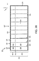
図2Aを参照すると、x方向に沿った検出器ボクセル201の第1列のサブ部分が概略的に示される。この実施形態では、検出器ボクセル201の各列は、第1のシンチレータ層204に対応する第1のシンチレータ領域202、第2のシンチレータ層208に対応する第2のシンチレータ領域206、及びそれらの間の光学反射バリア210をもつモノリシックシンチレータ124を含み、領域202及び206と光学反射バリア210とは同じ物理的シンチレータ材料バルク220内にある。光学反射バリア210は、領域202と領域206を分離するボリュームの主表面を含み、主表面は、入射放射117を受け取る表面250と平行である。いくつかの事例では、バルク220の光学反射バリア210の位置(例えば、深さ)により、入射放射のエネルギー分離が最大化される。
Referring to FIG. 2A, a sub-portion of the first row of
物理的バルク220は、検査領域118を横断した入射放射117を受取り、入射放射117のX線光子のエネルギーに比例したバルク材料220の深さ230においてX線放射を光放射に変換する。言い換えれば、より低いエネルギー(浅い侵入の)X線光子は第1の領域202で吸収され、より高いエネルギー(より深い侵入の)X線光子は第2の領域206で吸収される。
領域202及び206の各々は、支持基材244上の異なる対応する第1及び第2のフォトセンサ240及び242に光学的にそれぞれ結合される。例えば、シンチレータバルク材料220の第1のシンチレータ領域202は、フォトセンサのアレイ246の第1のフォトセンサ240に光学的に結合され、シンチレータバルク材料220の第2のシンチレータ領域204は、フォトセンサのアレイ246の第2のフォトセンサ242に光学的に結合される。フォトセンサのアレイ246は、第1のフォトセンサ240、第2のフォトセンサ242、及び基材244を含む。フォトセンサのアレイ246は、モノリシックシンチレータ124に隣接して配設され、表面250の一部分を占める。入射X線放射の方向に対するフォトセンサ242のアレイと領域202及び206との配置は、2層検出器200を垂直構成と断定する。
Each of
図2Bは、多列構成のz方向に沿った図2Aの検出器ボクセル201の1つの列のシンチレータ側の側面図を概略的に示す。同じ単一の物理的シンチレータ材料バルク220は、検出器ボクセル201の多列構成のN列のすべてに対して2層の両シンチレータ領域を含み、ここで、Nは正の整数である。すなわち、同じ物理的シンチレータ材料バルク220は、各列の各シンチレータボクセルを画定するシンチレータボクセル(又はピクセル)光学バリア260と、各シンチレータボクセル内の2つのシンチレータ領域202及び206を画定する光学反射バリア210とを有するシンチレータ材料のスラブと考えられる。1つのピクセルの検出器表面区域は、複数のボクセル領域の検出器ボリュームに対応する。シンチレータボクセル光学バリア260は、光学反射バリア210と同様の光学反射バリアであり、例えば、それは、レーザによって誘起された同じ物理的バルク材料220の結晶構造の変化を含む。いくつかの実施形態では、ボクセル光学バリア260は、直方体形状ボクセルを画定する。いくつかの実施形態では、ボクセル光学バリア260は、正方形直角錐台形状ボクセルを画定する。
FIG. 2B schematically shows a scintillator side view of one row of
光学反射バリア210の厚さ又は深さ(y方向)は、レーザビームの焦点スポットの直径と、変更されたシンチレータ材料の構造による光学的分離の最小厚さとに依存する。いくつかの実施形態では、光学反射バリア210の厚さは、レーザの焦点スポットによる複数の変更された位置により増加される。すなわち、変更される位置は、さらに、y方向に変更され、光学反射バリアのボリュームの主表面は変更されてxz方向に延びる。
The thickness or depth (y-direction) of the optical
同じ物理的シンチレータ材料220は、レーザによって誘起された光学反射バリアである外側又は外部表面270を含む。いくつかの実施形態では、外側表面はレーザによって変化されず、光学反射被膜が付けられる。光学反射バリアに変更された外側表面270と光学反射被覆との組合せが考えられる。
The same
図2A~図2Bに示された2層検出器アレイ200は、検出器要素のM×Nアレイであり、シンチレータ材料のM個のスラブが、垂直構成のフォトセンサアレイ246の基材244によって分離され、ここで、Mは正の整数である。各スラブは、同じ物理的シンチレータ材料バルク220内にN個のモノリシックシンチレータボクセルを含む。垂直検出器構成の一例が、2009年10月29日に出願された「Spectral Imaging Detector」と題する米国特許第9,000,382号に論じられており、その全体が参照により本明細書に組み込まれる。
The two-
図3を参照すると、多層放射感応検出器アレイ120の2層水平検出器構成300が示される。構成300は、モノリシックシンチレータ124の単一の物理的バルク220を含む。各モノリシックシンチレータ124は、2つの領域202及び206を含む。モノリシックシンチレータ124の単一の物理的バルク220は、フォトセンサの2つのアレイ310及び320の基材間に配設される。フォトセンサの2つのアレイ310、320の各々は、2層検出器300の表面250と平行な面に配設される。
Referring to FIG. 3, a two-layer
シンチレータ材料の同じ物理的バルク220の光学反射バリア210は、2つ以上のサブバリア330及び332などの多数のサブバリアを含み、多数のサブバリアは、2~100ミクロンの距離だけ互いに分離される。バリア330及び332の各々は、バリア330及び332によって画定されたボリュームの主表面を含み、主表面は実質的に平面であり、主表面は、2層検出器300の表面250と平行に配設される。サブバリア330及び332の各々は、例えば、レーザビームによって誘起されたバルク材料220の結晶構造への変化を含む。
The optical
同じ物理的シンチレータ材料バルク220は、ボクセル光学バリア260によって分離され、モノリシックシンチレータ124のボクセルの多次元M×Nアレイを形成する複数の個々のモノリシックシンチレータ124を含む。同じ物理的シンチレータ材料バルク220は、光学反射被覆と、レーザによって光学反射バリアに構造的に変更されたシンチレータ材料の同じ物理的バルク220の外側部分270と、それらの組合せとを含む。
The same physical
フォトセンサのアレイ310及び320は、前面照明フォトダイオード(FIP)、背面照明フォトダイオード(BIP)、有機フォトダイオード(OPD)、及びそれらの組合せを含むことができる。フォトセンサのアレイ310、320のうちの1つ又は複数は、OPD、積極的に薄化されたFIP、積極的に薄化されたBIP、X線透過性フォトセンサなどのようなX線吸収を最小化するフォトダイオードアレイを含むことができる。いくつかの実施形態では、積極的に薄化されたとは、30ミクロン未満に薄化されたことを意味する。いくつかの実施形態では、積極的に薄化されたとは、30~100ミクロンに薄化されたことを意味する。いくつかの実施形態では、積極的に薄化されたとは、100~200ミクロンに薄化されたことを意味する。フォトセンサのアレイ310は、シンチレータ材料の同じ物理的バルク220の第1の層204に光学的に結合され、対応するフォトセンサ240は、各モノリシックシンチレータ124に属する対応する第1の領域202に寸法を合わされ位置合わせされる。第1のフォトセンサアレイ310の反対側のフォトセンサのアレイ320と、シンチレータ材料の同じ物理的バルク220とは、シンチレータ材料の同じ物理的バルク220の第2の層206に光学的に結合される。第2のフォトセンサアレイ320のフォトセンサ244は、各ボクセルモノリシックシンチレータ124に属する対応する第2の領域206に寸法を合わされ位置合わせされる。
Arrays of
図4を参照すると、モノリシックシンチレータ124のボクセルのためのシンチレータ領域202、206を生成する一実施形態が概略的に示される。コントローラ400は、1つ又は複数のレーザ410、420の動作と、ホルダ430によって位置決めされたシンチレータ材料の同じ物理的バルク220に対するレーザ410、420の相対的位置決めとを制御する。いくつかの実施形態では、第1のレーザ410は、レーザビーム412が光学反射バリア210と平行に配向された状態で位置決めされる。いくつかの実施形態では、第2のレーザ420は、レーザビーム422が光学反射バリア210に対して垂直に配向された状態で位置決めされる。いくつかの実施形態では、第1のレーザ410又は第2のレーザ420の一方は省略される。いくつかの実施形態では、いずれかの配向に多数のレーザがある。
Referring to FIG. 4, one embodiment for generating
レーザビーム412、422は、少なくとも1つのレンズ416、426によってポイント414に合焦される。ポイント414、415は、形状が球状であってもよく、又はレーザビーム412、422の方向に沿っても細長くてもよい。ポイント414、415は、レーザ410、420の動作特性に応じてシンチレータ材料の同じ物理的バルク220の結晶構造を変化させる。レーザ410、420の動作特性はシンチレータ材料に関連する。波長、パワー、及びパルスは、例えば、光学反射バリア210の結晶構造の変化を達成するためにシンチレータ材料に応じて変わることができる。
コントローラ400は、ホルダ430を基準としてレーザビーム412、422を移動させる。いくつかの実施形態では、レーザ410、420は固定され、ホルダ430が移動する。いくつかの実施形態では、レーザ410、420が移動し、ホルダ430は固定される。いくつかの実施形態では、レーザ410、420及びホルダ430の両方が移動する。
例えば、第2のレーザ420が省略され、第1のレーザ410が光学反射バリア210及びボクセル光学バリア260の両方を生成する場合、第1のレーザ410は、シンチレータ材料の同じ物理的バルク220の最も離れた面内の位置を横切った所にポイント414を移動させ、次いで、光学反射バリア210及びボクセル光学バリア260の結晶構造の変化が誘起されるまで、次に最も近い面内の位置まで連続的に進むように構成される。すなわち、ポイント414は、既に創り出されたバリアとレーザとの間にとどまる。光学反射バリア210及びボクセル光学バリア260の両方が生成された場合、バリアは、直交面、傾斜面、又は非平行面と関連する。すなわち、光学反射バリア210を画定するボリュームの主表面は、ボクセル光学バリア260を画定するボリュームの主表面に対して非平行である。
For example, if the
図5を参照すると、本明細書の実施形態による流れ図が示される。 Referring to FIG. 5, a flow diagram according to embodiments herein is shown.
500において、シンチレータ材料の物理的バルク220が、1つ又は複数のレーザ410、420に対して位置決めされる。位置決めは、シンチレータ材料の物理的バルク220をホルダ430に受け取ることを含む。位置決めは、次の場所で光学反射バリア210を生成するためのレーザに対する位置の変化を含む。
At 500, a
いくつかの実施形態では、シンチレータ材料の物理的バルク220は、単一のボクセルのモノリシックシンチレータ124用の材料のボリュームを含む。いくつかの実施形態では、シンチレータ材料の物理的バルク220は、モノリシックシンチレータ124の1×Nアレイの材料のボリュームを含む。いくつかの実施形態では、シンチレータ材料の物理的バルク220は、モノリシックシンチレータ124のM×Nアレイ用の材料のボリュームを含む。
In some embodiments, the physical bulk of
いくつかの実施形態では、ホルダは、上述のものの組合せを保持するように構成される。例えば、モノリシックシンチレータ124の1次元アレイのためのシンチレータ材料のスラブ又は個々のモノリシックシンチレータブロック124の材料は、機械的に分離されたスラブにわたって又は個々に機械的に分離されたボクセルにわたって光学反射バリア210を生成するために、ホルダ430に一緒に保持される。
In some embodiments, the holder is configured to hold a combination of the above. For example, a slab of scintillator material for a one-dimensional array of
510において、モノリシックシンチレータブロック124の物理的バルク220の一部分の結晶構造は、物理的接続された構造としてシンチレータ材料を維持しながらボクセルごとにシンチレータ材料に複数の領域を画定するために合焦レーザによって変更される。光学反射バリア210を形成する変更された構造部分は、入射放射117を初めに受け取るように構成されたシンチレータ材料の物理的バルク220の表面250と平行に配向される。モノリシックシンチレータ124の変更された構造部分は、入射放射117を初めに受け取るように構成された表面250と平行な2つ以上のバリア330、332を含む。2つのバリア330、332は平行であり、2ミクロンと100ミクロンとの間の距離だけ分離される。いくつかの実施形態では、距離は、25ミクロンと100ミクロンとの間にある。
At 510, the crystalline structure of a portion of the
いくつかの実施形態では、変更された構造部分は、ボクセル光学バリア260又はその一部分をさらに含む。例えば、ボクセル光学バリア260を形成するために変更されたシンチレータ材料の物理的バルク220の部分に関して、変更された一部分は、さらに、入射放射を初めに受け取るように構成された表面250に対して垂直なバリアを形成する。
In some embodiments, the modified structural portion further includes voxel
いくつかの実施形態では、変更された構造部分は、シンチレータ材料の物理的バルク220の外側表面270又はその一部分を含む。
In some embodiments, the modified structural portion includes the
モノリシックシンチレータ124が形成されるまで、動作500及び510が繰り返され、変更された構造部分が再位置決めされ生成される。コントローラ400は、光学反射バリア210、実施形態によっては追加としてボクセル光学バリア260及び/又は外側表面の反射バリア270を形成するために適切な順序で位置ごとに変更された構造部分を生成するようにレーザの位置決め及び動作を制御するように構成される。
Operations 500 and 510 are repeated to reposition and produce altered structural portions until
520において、モノリシックシンチレータ124は、1つ又は複数のフォトセンサアレイに位置合わせされ付着される。いくつかの実施形態では、モノリシックシンチレータ124は、ボクセルの1×N次元アレイを形成し、各ボクセルのモノリシックシンチレータ124は、光学反射バリア210によって画定された層204、208に対応する複数の領域202、206を含む。例えば、フォトセンサアレイ246は、入射放射を初めに受け取る多層検出器120の表面250に対して垂直に配向され、シンチレータ材料の物理的バルク220に位置合わせされ付着される。各ボクセルの第1の領域202は対応する第1のフォトセンサ240と整列し、各ボクセルの第2の領域206は対応する第2のフォトセンサ242と整列する。ボクセルのM×Nアレイとしての多層検出器アレイ120は、ボクセルのM個の1次元アレイのアセンブリを用いてさらに組み立てられる。アセンブリは、読出し電子機器140の付加をさらに含む。アセンブリは、支持基板の付加をさらに含む。アセンブリは、光学反射被覆の適用をさらに含む。
At 520, the
いくつかの実施形態では、シンチレータ材料の構造的に変更された物理的バルク220から形成されている生成されたモノリシックシンチレータブロック124は、モノリシックシンチレータ124の2次元アレイを含み、各モノリシックシンチレータ124は、複数の領域202、206を含む。位置合わせ及び付着には、生成されたモノリシックシンチレータ124を複数のフォトセンサアレイ310、320に位置合わせし付着させることが含まれる。複数のフォトセンサアレイ310、320の各々は、入射放射117を初めに受け取る多層検出器の表面250と平行に配向される。
In some embodiments, the produced
いくつかの実施形態では、シンチレータ材料の構造的に変更された物理的バルク220から形成されている生成されたモノリシックシンチレータ124は、個々のモノリシックシンチレータ124として機械的に分離され、モノリシックシンチレータ124の1×Nアレイ又はモノリシックシンチレータ124のM×Nアレイのいずれかとして被覆され再組み立てされる。
In some embodiments, the produced
レーザ410、420の位置決め及び動作のためのコントローラ410の動作は、コンピュータプロセッサによって実行されたとき、説明した動作をプロセッサに行わせる、コンピュータ可読記憶媒体にエンコードされたか又は埋め込まれたコンピュータ可読命令を介して実施される。追加として又は代替として、コンピュータ可読命令のうちの少なくとも1つは、信号、搬送波、又は他の一時的媒体によって行われる。いくつかの実施形態では、コントローラ410は、特定用途向け集積回路を含む。
The operation of the
上述のステップは異なる順序で実行されてもよく、及び/又はいくつかのステップは省略されてもよい。 The steps described above may be performed in a different order and/or some steps may be omitted.
本発明が、図面及び前述の記載において詳細に図示され説明されたが、そのような図示及び説明は、説明的又は例示的であり、制限的でないと考えられるべきであり、本発明は、開示された実施形態に限定されない。特許請求される本発明を実践する際に、図面、開示、及び添付の特許請求の範囲の検討から、開示された実施形態に対する他の変形が、当業者によって理解され達成される。 While the invention has been illustrated and described in detail in the drawings and foregoing description, such illustration and description are to be considered illustrative or exemplary and not restrictive; is not limited to the illustrated embodiment. Other variations to the disclosed embodiments can be understood and effected by those skilled in the art, from a study of the drawings, the disclosure, and the appended claims, in practicing the claimed invention.
特許請求の範囲において、「含む、有する」という単語は、他の要素又はステップを排除せず、単数形は複数を排除しない。単一のプロセッサ又は他のユニットは、特許請求の範囲に列挙されているいくつかの項目の機能を果たすことができる。特定の手段が互いに異なる従属請求項に列挙されているという単なる事実は、これらの手段の組合せが有利に使用され得ないことを示していない。 In the claims, the word "comprising" does not exclude other elements or steps, and the singular does not exclude the plural. A single processor or other unit may fulfill the functions of several items recited in the claims. The mere fact that certain measures are recited in mutually different dependent claims does not indicate that a combination of these measures cannot be used to advantage.
Claims (20)
前記モノリシックシンチレータは、第1のシンチレータ領域、第2のシンチレータ領域、及び前記第1のシンチレータ領域と前記第2のシンチレータ領域との間の光学反射バリアを含み、
前記コンピュータ断層撮影検出器アレイが、検査領域を横断し前記モノリシックシンチレータに衝突するX線放射を検出し、前記第1のシンチレータ領域によって吸収されたX線放射のエネルギーを示す第1の投影データと、前記第1のシンチレータ領域を横断し前記第2のシンチレータ領域によって吸収されたX線放射のエネルギーを示す第2の投影データとを生成する、コンピュータ断層撮影検出器アレイ。 A computed tomography detector array comprising a monolithic scintillator,
the monolithic scintillator comprising a first scintillator region, a second scintillator region, and an optical reflective barrier between the first scintillator region and the second scintillator region;
said computed tomography detector array detecting X-ray radiation across an examination region impinging on said monolithic scintillator and first projection data indicative of energy of X-ray radiation absorbed by said first scintillator region; and second projection data indicative of energy of x-ray radiation traversing said first scintillator area and absorbed by said second scintillator area.
ガドリニウムオキシサルファイド(GOS、Gd2O2S)、
イットリウムアルミニウムガーネット(YAG、Y3Al5O12)、
セリウムドープイットリウムアルミニウムガーネット(CE YAG、Ce Y3Al5O12)、
ガドリニウムアルミニウムガリウムガーネット(GAGG、Gd3Al2Ga3O12)、
セリウムドープガドリニウムアルミニウムガリウムガーネット(CE GAGG、Ce Gd3Al2Ga3O12)、
ジンクセレナイド(ZnSe)、及び
カドミウムタングステート(CdWO4)
のうちの少なくとも1つを含む、請求項2に記載のコンピュータ断層撮影検出器アレイ。 The scintillator material is
gadolinium oxysulfide ( GOS , Gd2O2S ),
yttrium aluminum garnet ( YAG, Y3Al5O12 ),
cerium - doped yttrium aluminum garnet (CE YAG, CeY3Al5O12 ),
gadolinium aluminum gallium garnet ( GAGG , Gd3Al2Ga3O12 ),
cerium -doped gadolinium aluminum gallium garnet (CE GAGG, CeGd3Al2Ga3O12 ),
zinc selenide (ZnSe), and cadmium tungstate ( CdWO4 )
3. The computed tomography detector array of claim 2, comprising at least one of:
前記検査領域を横切って前記X線放射源の反対側に配置される検出器アレイであって、
少なくとも第1のシンチレータ領域、第2のシンチレータ領域、及び前記少なくとも第1のシンチレータ領域と前記第2のシンチレータ領域との間の光学反射バリアを含むモノリシックシンチレータ
を含む、検出器アレイとを含む、コンピュータ断層撮影システムであって、
前記検出器アレイが、前記検査領域を横断し前記モノリシックシンチレータに衝突するX線放射を検出し、前記第1のシンチレータ領域によって吸収されたX線放射のエネルギーを示す第1の投影データと、前記第1のシンチレータ領域を横断し前記第2のシンチレータ領域によって吸収されたX線放射のエネルギーを示す第2の投影データとを生成する、コンピュータ断層撮影システム。 an x-ray radiation source that emits x-ray radiation across an examination region;
a detector array positioned across the examination region on the opposite side of the X-ray radiation source,
a detector array comprising: a monolithic scintillator comprising at least a first scintillator region, a second scintillator region, and an optically reflective barrier between the at least first scintillator region and the second scintillator region. A tomography system,
said detector array detecting X-ray radiation traversing said examination region and impinging said monolithic scintillator, said first projection data indicating energy of X-ray radiation absorbed by said first scintillator region; and second projection data indicative of energy of x-ray radiation traversing a first scintillator area and absorbed by said second scintillator area.
ガドリニウムオキシサルファイド(GOS、Gd2O2S)、
イットリウムアルミニウムガーネット(YAG、Y3Al5O12)、
セリウムドープイットリウムアルミニウムガーネット(CE YAG、Ce Y3Al5O12)、
ガドリニウムアルミニウムガリウムガーネット(GAGG、Gd3Al2Ga3O12)、
セリウムドープガドリニウムアルミニウムガリウムガーネット(CE GAGG、Ce Gd3Al2Ga3O12)、
ジンクセレナイド(ZnSe)、及び
カドミウムタングステート(CdWO4)
のうちの少なくとも1つを含む、請求項8に記載のコンピュータ断層撮影システム。 The scintillator material
gadolinium oxysulfide ( GOS , Gd2O2S ),
yttrium aluminum garnet ( YAG, Y3Al5O12 ),
cerium - doped yttrium aluminum garnet (CE YAG, CeY3Al5O12 ),
gadolinium aluminum gallium garnet ( GAGG , Gd3Al2Ga3O12 ),
cerium - doped gadolinium aluminum gallium garnet (CE GAGG, CeGd3Al2Ga3O12 ),
zinc selenide (ZnSe), and cadmium tungstate ( CdWO4 )
9. The computed tomography system of claim 8, comprising at least one of
物理的に接続された結晶構造として単一の物理的バルクを維持しながらモノリシックシンチレータの複数の領域を画定するために、合焦レーザによってシンチレータ材料の前記単一の物理的バルクの一部分の結晶構造を変更するステップであって、前記変更された一部分が、検査領域を横断したX線放射を受け取る前記コンピュータ断層撮影放射検出装置の表面と平行に配向される主表面をもつボリュームを含む、変更するステップ
を有する、方法。 A method of manufacturing a computed tomography radiation detection device, the method comprising:
crystalline structure of a portion of said single physical bulk of scintillator material by a focused laser to define a plurality of regions of the monolithic scintillator while maintaining the single physical bulk as a physically connected crystalline structure; wherein the modified portion includes a volume having a major surface oriented parallel to a surface of the computed tomography radiation detection apparatus that receives X-ray radiation across an examination region. A method having steps.
シンチレータ材料の前記単一の物理的バルクに隣接して配設されるフォトセンサのアレイをさらに含み、
シンチレータ材料の前記単一の物理的バルクを前記フォトセンサのアレイに位置合わせし付着させるステップであって、前記フォトセンサのアレイのフォトセンサが配置されている面が、前記検査領域を横断したX線放射を受け取る前記コンピュータ断層撮影放射検出装置の前記表面に対して垂直に配向される、位置合わせし付着させるステップ
をさらに有する、請求項15に記載の方法。 said single physical bulk of scintillator material comprising a plurality of monolithic scintillators in a one-dimensional array of monolithic scintillators, each monolithic scintillator having a plurality of regions;
further comprising an array of photosensors disposed adjacent to said single physical bulk of scintillator material;
aligning and attaching said single physical bulk of scintillator material to said array of photosensors, wherein the face of said array of photosensors on which the photosensors are located is X across said inspection area; 16. The method of claim 15, further comprising aligning and attaching oriented perpendicular to the surface of the computed tomography radiation detection device that receives line radiation .
シンチレータ材料の前記単一の物理的バルクが間に配設されるフォトセンサの2つのアレイをさらに含み、
前記フォトセンサの2つのアレイ間にシンチレータ材料の前記単一の物理的バルクを位置合わせし付着させるステップであって、前記フォトセンサの2つのアレイのフォトセンサの面の各々が、前記検査領域を横断したX線放射を受け取る前記コンピュータ断層撮影放射検出装置の前記表面と平行に配向される、位置合わせし付着させるステップをさらに有する、請求項15に記載の方法。 said single physical bulk of scintillator material comprising a plurality of monolithic scintillators in a two-dimensional array of scintillators, each monolithic scintillator having a plurality of regions;
further comprising two arrays of photosensors between which said single physical bulk of scintillator material is disposed;
aligning and depositing the single physical bulk of scintillator material between the two arrays of photosensors , each of the faces of the photosensors of the two arrays of photosensors defining the inspection area; 16. The method of claim 15, further comprising aligning and attaching oriented parallel to the surface of the computed tomography radiation detection device that receives transverse X-ray radiation .
Priority Applications (1)
| Application Number | Priority Date | Filing Date | Title |
|---|---|---|---|
| JP2022146094A JP2022174229A (en) | 2017-08-31 | 2022-09-14 | Multi-layer detector with monolithic scintillator |
Applications Claiming Priority (3)
| Application Number | Priority Date | Filing Date | Title |
|---|---|---|---|
| US201762552563P | 2017-08-31 | 2017-08-31 | |
| US62/552,563 | 2017-08-31 | ||
| PCT/EP2018/072383 WO2019042797A1 (en) | 2017-08-31 | 2018-08-20 | Multi-layer detector with a monolithic scintillator |
Related Child Applications (1)
| Application Number | Title | Priority Date | Filing Date |
|---|---|---|---|
| JP2022146094A Division JP2022174229A (en) | 2017-08-31 | 2022-09-14 | Multi-layer detector with monolithic scintillator |
Publications (3)
| Publication Number | Publication Date |
|---|---|
| JP2020531183A JP2020531183A (en) | 2020-11-05 |
| JP2020531183A5 JP2020531183A5 (en) | 2021-09-30 |
| JP7181283B2 true JP7181283B2 (en) | 2022-11-30 |
Family
ID=63294221
Family Applications (2)
| Application Number | Title | Priority Date | Filing Date |
|---|---|---|---|
| JP2020511809A Active JP7181283B2 (en) | 2017-08-31 | 2018-08-20 | Multilayer detector with monolithic scintillator |
| JP2022146094A Pending JP2022174229A (en) | 2017-08-31 | 2022-09-14 | Multi-layer detector with monolithic scintillator |
Family Applications After (1)
| Application Number | Title | Priority Date | Filing Date |
|---|---|---|---|
| JP2022146094A Pending JP2022174229A (en) | 2017-08-31 | 2022-09-14 | Multi-layer detector with monolithic scintillator |
Country Status (5)
| Country | Link |
|---|---|
| US (1) | US11181488B2 (en) |
| EP (1) | EP3676639B1 (en) |
| JP (2) | JP7181283B2 (en) |
| CN (1) | CN111133338A (en) |
| WO (1) | WO2019042797A1 (en) |
Families Citing this family (3)
| Publication number | Priority date | Publication date | Assignee | Title |
|---|---|---|---|---|
| US11802979B2 (en) | 2018-05-23 | 2023-10-31 | The Research Foundation For The State University Of New York | Flat panel x-ray imager with scintillating glass substrate |
| WO2023235270A1 (en) * | 2022-05-31 | 2023-12-07 | University Of Washington | Coded detection for single photon emission computed tomography |
| CN114878604A (en) * | 2022-07-11 | 2022-08-09 | 芯晟捷创光电科技(常州)有限公司 | Ray detector, detection method and detection system |
Citations (4)
| Publication number | Priority date | Publication date | Assignee | Title |
|---|---|---|---|---|
| WO2012127403A2 (en) | 2011-03-24 | 2012-09-27 | Koninklijke Philips Electronics N.V. | Spectral imaging detector |
| JP2013246156A (en) | 2012-05-29 | 2013-12-09 | Natl Inst Of Radiological Sciences | Three-dimensional radiation position detector |
| JP2017072573A (en) | 2015-01-30 | 2017-04-13 | 浜松ホトニクス株式会社 | Radiation detector |
| WO2017067846A1 (en) | 2015-10-21 | 2017-04-27 | Koninklijke Philips N.V. | Radiation detector for combined detection of low-energy radiation quanta and high-energy radiation quanta |
Family Cites Families (14)
| Publication number | Priority date | Publication date | Assignee | Title |
|---|---|---|---|---|
| RU2386981C2 (en) * | 2005-04-26 | 2010-04-20 | Конинклейке Филипс Электроникс Н.В. | Improved detector matrix for spectral computed tomography |
| WO2006114716A2 (en) * | 2005-04-26 | 2006-11-02 | Koninklijke Philips Electronics, N.V. | Double decker detector for spectral ct |
| JP2012509492A (en) | 2008-11-18 | 2012-04-19 | コーニンクレッカ フィリップス エレクトロニクス エヌ ヴィ | Spectral imaging detector |
| CN101937095B (en) * | 2009-06-30 | 2012-05-09 | 同方威视技术股份有限公司 | Dual energy X ray detector and dual energy X ray detector array device |
| CN102655813B (en) | 2009-10-27 | 2015-08-12 | 华盛顿大学商业中心 | Optical interface pattern for radiation detector crystal is formed |
| US9513387B2 (en) | 2010-02-01 | 2016-12-06 | Siemens Aktiengesellschaft | System and method for providing depth of interaction detection using positron emission tomography |
| CN103339527B (en) * | 2011-02-03 | 2016-06-22 | 皇家飞利浦有限公司 | Monoergic or multi-energy vertical radiation sensing detector |
| US9411057B2 (en) * | 2011-04-01 | 2016-08-09 | Medtronic Navigation, Inc. | X-ray imaging system and method |
| CN103620445B (en) * | 2011-04-06 | 2016-08-17 | 皇家飞利浦有限公司 | Imaging detector |
| CN103959097B (en) | 2011-12-02 | 2017-05-10 | 皇家飞利浦有限公司 | Detection apparatus comprising two scintillators for detecting x-ray radiation |
| US9012857B2 (en) * | 2012-05-07 | 2015-04-21 | Koninklijke Philips N.V. | Multi-layer horizontal computed tomography (CT) detector array with at least one thin photosensor array layer disposed between at least two scintillator array layers |
| CN105408940B (en) * | 2013-07-23 | 2019-09-03 | 皇家飞利浦有限公司 | Hybrid (spectrum/non-spectrum) imaging detector arrays and corresponding processing electronic equipment |
| US20170014943A1 (en) | 2014-02-28 | 2017-01-19 | The General Hospital Corporation | System and method for processing radiation detectors using laser beams |
| JP6529858B2 (en) * | 2014-08-20 | 2019-06-12 | キヤノンメディカルシステムズ株式会社 | X-ray CT apparatus and X-ray detector |
-
2018
- 2018-08-20 CN CN201880061019.3A patent/CN111133338A/en active Pending
- 2018-08-20 JP JP2020511809A patent/JP7181283B2/en active Active
- 2018-08-20 EP EP18758583.1A patent/EP3676639B1/en active Active
- 2018-08-20 US US16/642,292 patent/US11181488B2/en active Active
- 2018-08-20 WO PCT/EP2018/072383 patent/WO2019042797A1/en unknown
-
2022
- 2022-09-14 JP JP2022146094A patent/JP2022174229A/en active Pending
Patent Citations (4)
| Publication number | Priority date | Publication date | Assignee | Title |
|---|---|---|---|---|
| WO2012127403A2 (en) | 2011-03-24 | 2012-09-27 | Koninklijke Philips Electronics N.V. | Spectral imaging detector |
| JP2013246156A (en) | 2012-05-29 | 2013-12-09 | Natl Inst Of Radiological Sciences | Three-dimensional radiation position detector |
| JP2017072573A (en) | 2015-01-30 | 2017-04-13 | 浜松ホトニクス株式会社 | Radiation detector |
| WO2017067846A1 (en) | 2015-10-21 | 2017-04-27 | Koninklijke Philips N.V. | Radiation detector for combined detection of low-energy radiation quanta and high-energy radiation quanta |
Non-Patent Citations (1)
| Title |
|---|
| Eiji Yoshida et al.,"Intrinsic spatial resolution evaluation of the X'tal cube PET detector based on a 3D crystal block segmented by laser processing",Radiological Physics and Technology,2013年,6:21-27 |
Also Published As
| Publication number | Publication date |
|---|---|
| EP3676639A1 (en) | 2020-07-08 |
| JP2022174229A (en) | 2022-11-22 |
| CN111133338A (en) | 2020-05-08 |
| US20210072167A1 (en) | 2021-03-11 |
| JP2020531183A (en) | 2020-11-05 |
| EP3676639B1 (en) | 2024-04-24 |
| WO2019042797A1 (en) | 2019-03-07 |
| US11181488B2 (en) | 2021-11-23 |
Similar Documents
| Publication | Publication Date | Title |
|---|---|---|
| JP2022174229A (en) | Multi-layer detector with monolithic scintillator | |
| US7968853B2 (en) | Double decker detector for spectral CT | |
| RU2386981C2 (en) | Improved detector matrix for spectral computed tomography | |
| US7233640B2 (en) | CT detector having an optical mask layer | |
| US9000382B2 (en) | Spectral imaging detector | |
| JP6043474B2 (en) | Volumetric computed tomography system with tileable multi-plane detector | |
| CN110168406A (en) | X-ray detector and x-ray imaging device | |
| US20100116996A1 (en) | Detector with a partially transparent scintillator substrate | |
| JP2009511871A (en) | Multilayer detector for spectral computed tomography | |
| JP2010513908A (en) | Energy decomposition detection system and imaging system | |
| JP2011503535A (en) | Indirect radiation detector | |
| US9638810B2 (en) | Imaging detector | |
| JP2007125086A (en) | X-ray detector and x-ray ct apparatus | |
| US20130235972A1 (en) | Method for manufacturing collimator, collimator and x-ray ct apparatus | |
| JP2024026391A (en) | X-ray detector with focused scintillator structure for uniform imaging | |
| US11226296B2 (en) | Tunnel computerised tomographic scanner and method for acquiring images from a scintillator of a tunnel computerised tomography scanner | |
| WO2018024681A1 (en) | Three-dimensional solid state imaging photodetector | |
| JP2022509219A (en) | Hybrid x-ray and photodetector | |
| JPH11248843A (en) | Two-dimensional array radiation detector |
Legal Events
| Date | Code | Title | Description |
|---|---|---|---|
| A521 | Request for written amendment filed |
Free format text: JAPANESE INTERMEDIATE CODE: A523 Effective date: 20210819 |
|
| A621 | Written request for application examination |
Free format text: JAPANESE INTERMEDIATE CODE: A621 Effective date: 20210819 |
|
| A871 | Explanation of circumstances concerning accelerated examination |
Free format text: JAPANESE INTERMEDIATE CODE: A871 Effective date: 20210819 |
|
| A131 | Notification of reasons for refusal |
Free format text: JAPANESE INTERMEDIATE CODE: A131 Effective date: 20210913 |
|
| A601 | Written request for extension of time |
Free format text: JAPANESE INTERMEDIATE CODE: A601 Effective date: 20211203 |
|
| A521 | Request for written amendment filed |
Free format text: JAPANESE INTERMEDIATE CODE: A523 Effective date: 20220311 |
|
| A02 | Decision of refusal |
Free format text: JAPANESE INTERMEDIATE CODE: A02 Effective date: 20220517 |
|
| A521 | Request for written amendment filed |
Free format text: JAPANESE INTERMEDIATE CODE: A523 Effective date: 20220914 |
|
| C60 | Trial request (containing other claim documents, opposition documents) |
Free format text: JAPANESE INTERMEDIATE CODE: C60 Effective date: 20220914 |
|
| A911 | Transfer to examiner for re-examination before appeal (zenchi) |
Free format text: JAPANESE INTERMEDIATE CODE: A911 Effective date: 20221003 |
|
| C21 | Notice of transfer of a case for reconsideration by examiners before appeal proceedings |
Free format text: JAPANESE INTERMEDIATE CODE: C21 Effective date: 20221007 |
|
| TRDD | Decision of grant or rejection written | ||
| A01 | Written decision to grant a patent or to grant a registration (utility model) |
Free format text: JAPANESE INTERMEDIATE CODE: A01 Effective date: 20221021 |
|
| A61 | First payment of annual fees (during grant procedure) |
Free format text: JAPANESE INTERMEDIATE CODE: A61 Effective date: 20221117 |
|
| R150 | Certificate of patent or registration of utility model |
Ref document number: 7181283 Country of ref document: JP Free format text: JAPANESE INTERMEDIATE CODE: R150 |