JP7180964B2 - Three-dimensional imaging apparatus and method - Google Patents
Three-dimensional imaging apparatus and method Download PDFInfo
- Publication number
- JP7180964B2 JP7180964B2 JP2016546932A JP2016546932A JP7180964B2 JP 7180964 B2 JP7180964 B2 JP 7180964B2 JP 2016546932 A JP2016546932 A JP 2016546932A JP 2016546932 A JP2016546932 A JP 2016546932A JP 7180964 B2 JP7180964 B2 JP 7180964B2
- Authority
- JP
- Japan
- Prior art keywords
- light
- imaging
- scape
- image
- plane
- Prior art date
- Legal status (The legal status is an assumption and is not a legal conclusion. Google has not performed a legal analysis and makes no representation as to the accuracy of the status listed.)
- Active
Links
Images


Classifications
-
- G—PHYSICS
- G02—OPTICS
- G02B—OPTICAL ELEMENTS, SYSTEMS OR APPARATUS
- G02B21/00—Microscopes
- G02B21/0004—Microscopes specially adapted for specific applications
- G02B21/002—Scanning microscopes
- G02B21/0024—Confocal scanning microscopes (CSOMs) or confocal "macroscopes"; Accessories which are not restricted to use with CSOMs, e.g. sample holders
- G02B21/0052—Optical details of the image generation
- G02B21/0064—Optical details of the image generation multi-spectral or wavelength-selective arrangements, e.g. wavelength fan-out, chromatic profiling
-
- G—PHYSICS
- G02—OPTICS
- G02B—OPTICAL ELEMENTS, SYSTEMS OR APPARATUS
- G02B21/00—Microscopes
- G02B21/0004—Microscopes specially adapted for specific applications
- G02B21/002—Scanning microscopes
- G02B21/0024—Confocal scanning microscopes (CSOMs) or confocal "macroscopes"; Accessories which are not restricted to use with CSOMs, e.g. sample holders
- G02B21/0036—Scanning details, e.g. scanning stages
- G02B21/0048—Scanning details, e.g. scanning stages scanning mirrors, e.g. rotating or galvanomirrors, MEMS mirrors
-
- G—PHYSICS
- G02—OPTICS
- G02B—OPTICAL ELEMENTS, SYSTEMS OR APPARATUS
- G02B21/00—Microscopes
- G02B21/0004—Microscopes specially adapted for specific applications
- G02B21/002—Scanning microscopes
- G02B21/0024—Confocal scanning microscopes (CSOMs) or confocal "macroscopes"; Accessories which are not restricted to use with CSOMs, e.g. sample holders
- G02B21/0052—Optical details of the image generation
- G02B21/006—Optical details of the image generation focusing arrangements; selection of the plane to be imaged
Description
本出願は、2014年1月17日に出願された米国特許仮出願番号第61/928,930、2014年3月10日に出願された米国特許仮出願番号第61/950,608、2014年3月19日に出願された米国特許仮出願番号第61/955,482、2014年3月24日に出願された米国特許仮出願番号第61/969,712、および、2014年12月8日に出願された米国特許仮出願番号第62/088,921の優先権を主張する。 No. 61/928,930, filed January 17, 2014; U.S. Provisional Application No. 61/950,608, filed March 10, 2014 U.S. Provisional Application No. 61/955,482 filed March 19, U.S. Provisional Application No. 61/969,712 filed March 24, 2014 and December 8, 2014 No. 62/088,921, filed in US Provisional Application No. 62/088,921.
連邦政府による資金提供を受けた研究の記載
本発明は、認可番号R21NS053684、R01NS076628、R01NS063226の国立衛生研究所(NINDS)、認可番号0954796の全米科学財団(キャリア)、および、アメリカ国防総省の総合的大学研究イニシアチブ(DoD)W911NF-12-1-0594による政府支援を受けてなされた。合衆国政府は本発明に対して権利を有する。
STATEMENT OF FEDERALLY SPONSORED RESEARCH This invention is supported by the National Institutes of Health (NINDS) under Grant Nos. R21NS053684, R01NS076628, R01NS063226, the National Science Foundation (Carrier) under Grant No. 0954796, and the United States Department of Defense General Research. This work was made with government support under the University Research Initiative (DoD) W911NF-12-1-0594. The United States Government has rights in this invention.
遺伝子組み換え技術により、ニューロンの活動などの動的な生体内プロセスの蛍光リポータは日々進化し続けている[1、2]。その結果、従来の光シートイメージング技術や2光子顕微鏡法を超えた、生体内イベントを撮像することができる高速三次元光学顕微鏡法の需要が高まっている。 Genetic engineering continues to evolve fluorescent reporters of dynamic in vivo processes such as neuronal activity [1, 2]. As a result, there is a growing demand for high-speed three-dimensional optical microscopy that can image in vivo events beyond conventional light sheet imaging techniques and two-photon microscopy.
従来の光シートイメージング技術は、薄い光のシートを用いてサンプルを側面から照明し、直交方向に位置決めされた第2の対物レンズを用いて照明された平面の画像を取得するものである[3-5]。その後、サンプルをこの相互位置決めされた平面に対して平行移動させることにより、三次元体積画像を形成する。このように対物レンズを2つ配置すること、側面から照明する必要があること、そしてサンプルを物理的に平行移動させることには多くの制約がある。サンプルをマウントして位置決めするのは非常に難易度が高く、イメージングできるサンプルのタイプが限られ、体積イメージングの達成可能速度も制限される。近年の進歩により、直交検出対物レンズ[6]の圧電動作、または、電気的に調整可能なレンズ[7]を介し、検出焦点面を平行移動させることによる調整走査を用いた高フレームレートの光シートイメージングが実現している。しかしながら、2つの平面の平行移動を調整する必要があることから、このイメージングシステムの速度は制限され、対物レンズを2つ配置することもいまだ制約となっている。他のアプローチとしては、標準的な光シートの配置を45度回転させてマウントされていないサンプルのイメージングをより容易にするものがあるが、体積イメージングでは、やはり対物レンズを2つ配置することが必要であり、サンプルを物理的に平行移動させる必要もある[8、9]。単一の対物レンズによる光シート技術で体積イメージングを行うには、圧電対物レンズの走査を用いる必要があるが、光シートが体積全体を掃引しないので、視野が限られる[10]。いずれの場合も、圧電対物レンズのスキャンには、速度に関しても、撮像できる生体内のサンプルの種類に関しても、本質的に制限がある。 A conventional light sheet imaging technique uses a thin sheet of light to illuminate the sample from the side and acquire an image of the illuminated plane using a second objective lens positioned orthogonally [3]. -5]. A three-dimensional volumetric image is then formed by translating the sample with respect to this co-registered plane. This dual objective arrangement, the need to illuminate from the side, and the physical translation of the sample have many limitations. Mounting and positioning the sample is very difficult, limiting the types of samples that can be imaged and limiting the achievable speed of volumetric imaging. Recent advances have focused on high frame rate light using piezoelectric actuation of the orthogonal detection objective lens [6] or modulated scanning by translating the detection focal plane via an electrically adjustable lens [7]. Sheet imaging has been realized. However, the need to coordinate the translation of the two planes limits the speed of this imaging system and the placement of two objective lenses is still a constraint. Another approach is to rotate the standard light sheet arrangement by 45 degrees to make it easier to image unmounted samples, but volume imaging still requires two objective lens arrangements. It is necessary and also requires physical translation of the sample [8, 9]. Single-objective light-sheet techniques for volumetric imaging require the use of piezoelectric objective scanning, but the field of view is limited because the light-sheet does not sweep the entire volume [10]. In either case, piezoelectric objective scanning is inherently limited, both in terms of speed and the types of in vivo samples that can be imaged.
齧歯類の脳の生体内イメージングでは、遺伝子的に符号化されたカルシウム指示薬を介してニューロンの活動を撮像するための選択方法が行われている[1、2]。しかしながら、2光子顕微鏡法は、通常、体積画像を形成するためには単一の点を順次走査する必要があり、三次元イメージングの速度、解像度、および、視野の間でトレードオフを迫られる[11-14]。広視野、多点、および、時間的集束を実現すれば、より平行化を高めることができるが、コストが増大し、複雑化するとともに、圧電対物レンズのスキャンは依然として必要なので、視野を制限し、得られるレーザ出力も制限してしまうことになる[15]。音響光学デフレクタを用いたランダムアクセススキャンでは、速度を上げるためにサンプル内の数か所をスキャンするが、これは、無傷の脳内の多数のニューロンの活動を迅速に記録する方法として現在好まれている。しかしながら、この方法は、動きに対して非常に敏感であり、特定のニューロン細胞体を事前に選択しなければならず(発火していない状態で細胞が暗くなり得るGCaMPイメージングの場合に限る)、自由な動きを撮像するのに適していない[16、17]。ランダムアクセススキャンは、体積内の測定位置を大幅に減らすことによって速度を上げているが、体積内の選択されていない場所での突発的で予期せぬ変化を検出することができず、正確な意味での画像を形成しない。よって、近年、2光子顕微鏡法が進歩しているといえども、上記のような、ニューロン活動などの生体内プロセスを撮像できる、高速三次元体積光学顕微鏡法の必要性に十分対処できているとは言えない。 In vivo imaging of the rodent brain has been the method of choice for imaging neuronal activity via genetically encoded calcium indicators [1,2]. However, two-photon microscopy typically requires sequential scanning of a single point to form a volumetric image, forcing a trade-off between three-dimensional imaging speed, resolution, and field of view. 11-14]. Wider fields of view, multiple points, and temporal focusing allow for greater collimation, but add cost and complexity, and still require scanning piezoelectric objectives, limiting the field of view. , will also limit the available laser power [15]. Random-access scanning with acousto-optic deflectors scans several locations within the sample for speed, and is currently the preferred method for rapidly recording the activity of large numbers of neurons in the intact brain. ing. However, this method is very sensitive to motion, requires pre-selection of specific neuronal cell bodies (only for GCaMP imaging where cells can darken in the unfiring state), It is not suitable for imaging free motion [16, 17]. Random-access scanning increases speed by greatly reducing the measurement locations within the volume, but cannot detect abrupt and unexpected changes at non-selected locations within the volume, making accurate Does not form an image in meaning. Therefore, even though two-photon microscopy has made progress in recent years, the need for high-speed three-dimensional volumetric optical microscopy that can image in vivo processes such as neuronal activity can be adequately addressed. I can't say
本開示は、顕微鏡を使用した、および、肉眼のイメージングに適用できる新規な三次元イメージングシステムおよび技術に関する。例えば、特定の実施態様では、本開示は、超高速で生きたサンプルの体積イメージングを行う技術に関し、本願明細書中では、掃引共焦点配置平面励起(SCAPE)顕微鏡法として特定している。SCAPEの特定の実施態様は、レーザスキャニング交差平面トモグラフィー(LSITPまたはL-SIPT)、掃引斜光シート(SOLiS)、または、掃引光シート(SLS)顕微鏡と称されている。2光子および共焦点顕微鏡技術は、生物医学研究に大変革をもたらしたが、費用が高く複雑で、高速の三次元体積イメージングに適用するにはその能力に限界がある。直交する2つの対物レンズによって照明および検出を行う光シート顕微鏡技術は、サンプルの配置に非常に制約があり、サンプルを物理的に平行移動させるか、または、照明面と検出面との同期に手間がかかる。それに対し、SCAPEは、光シートの照明によるオプティカルセクショニングと、マウントされていない多様なサンプルを平行移動させる必要なしに高速で体積イメージングできるユニークなスキャン・デスキャン構成とを組み合わせることにより、上記のような制約を克服し、しかも比較的安価に実行できる。 The present disclosure relates to novel three-dimensional imaging systems and techniques applicable to microscopic and macroscopic imaging. For example, in certain embodiments, the present disclosure relates to a technique for ultrafast volumetric imaging of living samples, identified herein as swept confocal plane excitation (SCAPE) microscopy. Particular implementations of SCAPE are referred to as laser scanning cross-plane tomography (LSITP or L-SIPT), swept oblique light sheet (SOLiS), or swept light sheet (SLS) microscopy. Two-photon and confocal microscopy techniques have revolutionized biomedical research, but are costly, complex, and limited in their ability to be applied to fast three-dimensional volumetric imaging. Light-sheet microscopy techniques, which employ two orthogonal objective lenses for illumination and detection, are very limited in sample placement, requiring physical translation of the sample or tedious synchronization of the illumination and detection planes. It takes In contrast, SCAPE combines optical sectioning by illuminating a light sheet with a unique scan-descan configuration that enables rapid volumetric imaging without the need to translate a variety of unmounted samples. It overcomes limitations and is relatively cheap to implement.
特定の実施態様では、SCAPE顕微鏡法は、単一の対物レンズの正面に角度をつけた掃引光シートを配置する(en-face配置)ことにより画像を取得する。特定の実施態様では、デスキャンおよび画像回転光学部品により、動く平面を固定の高速カメラにマッピングし、無傷のサンプルを平行移動させることなく、1秒に20体積を超える速さで三次元イメージングを行うことができる。本願にて実証されるように、SCAPE顕微鏡法は、自由に動いているトランスジェニックキイロショウジョウバエの幼虫だけでなく、覚醒して動いているマウスの無傷の脳における自然発生的なニューロン発火を撮像することができる。 In a particular embodiment, SCAPE microscopy acquires images by placing an angled, sweeping light sheet in front of a single objective lens (en-face configuration). In certain embodiments, descanning and image rotation optics map the moving plane to a fixed high-speed camera for three-dimensional imaging at speeds greater than 20 volumes per second without translating the intact sample. be able to. As demonstrated herein, SCAPE microscopy images spontaneous neuronal firing not only in freely moving transgenic Drosophila melanogaster larvae, but also in the intact brain of awake, moving mice. be able to.
特定の実施態様では、本開示は、サンプルを三次元イメージングするためのシステムおよび方法を提供する。特定の実施態様では、システムおよび方法は、サンプルに光シートを投影することを含み得る。特定の実施態様では、カメラの平面が光の照明シートの平面と位置合わせされることにより、オプティカルセクショニングが得られる。特定の実施態様では、方法は、照明光シートの掃引を含み得る。特定の実施態様では、照明光シートのスキャン動作中でも、検出された光がデスキャンされることにより、照明光シートと位置合わせされたカメラの固定した検出面が維持される。特定の実施態様では、照明光シートは、サンプルの表面に対し、斜めまたは垂直な角度を有することができる。特定の実施態様では、方法は、カメラの平面での放射光の検出精度を向上すべく、照明シートが斜めを向くよう検出光の平面を回転させることをさらに含む。特定の実施態様では、光シートは、スキャンポリゴンミラーを用いて掃引される。特定の実施態様では、光シートは、他の走査反射または回析素子を用いて掃引される。特定の実施態様では、方法は、掃引された光シートから発せられた光を受け、ポリゴンスキャナを用いてこの受けた光をデスキャンすること、あるいは、照明シートのスキャンと、検出された光の固定検出面へのデスキャンとを同期させるスキャンミラーまたは回析素子の他の組合せを含む。特定の実施態様では、多波長、あるいは、平行なまたは連続した光源が用いられることにより、サンプル内で異なる物理的プロセスが生じるようサンプルを照明することができる。特定の実施態様では、方法は、多色検出およびイメージングを可能にすべく、検出光のスペクトル分離を利用することができる。特定の実施態様では、方法は、ラマン散乱、誘導ラマン散乱、2光子励起蛍光、第二高調波発生、後方散乱、フォースター共鳴エネルギー移動、発光、熱放射、および、光学イメージングおよび顕微鏡法を介して通常検出される他の電磁効果を含む物理的効果からコントラストを検出するのに用いられることができる。 In certain embodiments, the present disclosure provides systems and methods for three-dimensional imaging of samples. In certain embodiments, systems and methods may include projecting a light sheet onto a sample. In certain embodiments, optical sectioning is obtained by aligning the plane of the camera with the plane of the illumination sheet of light. In certain implementations, the method may include sweeping an illumination light sheet. In certain embodiments, the detected light is descanned to maintain a fixed detection plane of the camera aligned with the illumination light sheet even during the scanning motion of the illumination light sheet. In certain implementations, the illumination light sheet can have an oblique or perpendicular angle to the surface of the sample. In certain embodiments, the method further includes rotating the plane of detected light such that the illumination sheet is oriented at an angle to improve detection accuracy of the emitted light in the plane of the camera. In certain implementations, the light sheet is swept using a scanning polygon mirror. In certain embodiments, the light sheet is swept using other scanning reflective or diffractive elements. In certain embodiments, the method includes receiving light emitted from a swept light sheet and descanning the received light using a polygon scanner, or scanning an illumination sheet and fixing the detected light. Other combinations of scanning mirrors or diffractive elements are included to synchronize the descanning to the detection surface. In certain embodiments, multiple wavelengths or collimated or continuous light sources can be used to illuminate the sample such that different physical processes occur within the sample. In certain embodiments, methods can take advantage of spectral separation of detected light to enable multicolor detection and imaging. In certain embodiments, the methods are via Raman scattering, stimulated Raman scattering, two-photon excited fluorescence, second harmonic generation, backscattering, Forster resonance energy transfer, luminescence, thermal emission, and optical imaging and microscopy. It can be used to detect contrast from physical effects, including other electromagnetic effects that are commonly detected by lasers.
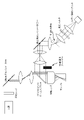
特定の実施態様では、開示される内容は、三次元顕微鏡イメージングのためのシステムに関する。特定の実施態様では、開示される内容は、三次元巨視的イメージングのためのシステムに関する。特定の実施態様では、本開示のシステムは、予め決められた光出力を有するレーザを有し得る。特定の実施態様では、本開示のシステムは、平行な/平行にすることが可能な光源、または、予め決められた光出力を有するパルスまたは連続波の光源の組合せを有し得る。特定の実施態様では、本開示のシステムは、1つ以上のビームアライメントミラー、および、反射または回析素子を有し得る。特定の実施態様では、システムは、1つ以上の望遠鏡を有し得る。各望遠鏡は、スキャン望遠鏡の他に、光シートを形成する前にビームを拡大する1つ以上のレンズからなる。特定の実施態様では、システムは、図1(f)に示されたポリゴンミラーを実装し得る。 In certain embodiments, the disclosed subject matter relates to systems for three-dimensional microscopic imaging. In certain embodiments, the disclosed subject matter relates to systems for three-dimensional macroscopic imaging. In certain implementations, the disclosed system can have a laser with a predetermined optical power. In certain embodiments, the system of the present disclosure may have collimable/collimable light sources or a combination of pulsed or continuous wave light sources with predetermined light outputs. In certain implementations, systems of the present disclosure may have one or more beam alignment mirrors and reflective or diffractive elements. In certain implementations, the system may have one or more telescopes. Each telescope consists of a scanning telescope as well as one or more lenses that expand the beam before forming the light sheet. In certain implementations, the system may implement the polygon mirror shown in FIG. 1(f).
特定の実施態様では、本開示内容にかかるシステムおよび技術は、生きたサンプルの高速生体内三次元体積イメージングを可能にする。さらに、特定の実施態様では、本開示内容は、正面を向いた(en-face)、非接触の、エピ蛍光スタイルのイメージング配置でデータを収集できる。特定の実施態様では、本開示内容は、透過配置でのデータ収集を可能にする。特定の実施態様では、本開示内容は、無傷の器官および組織、例えば、無傷の齧歯類の脳だけでなく、自由に動いている生物体を含む、広視野内で多様なサンプルの三次元動態を撮像することができる。システムは、生きたゼブラフィッシュ(ダニオレリオ)の幼生および成体、シー・エレガンス、および、人間の指先でも実証されてきた。特定の実施態様では、本開示のシステムは、画像固定組織像スライド、免疫組織化学スライド、および、マイクロ流体チャンバ内の流動を撮像することも可能であることが実証されている。ライフサイエンスを含むまたは超えたさらなる用途は、血管内、内視鏡的、体内、あるいは、角膜または網膜の眼球内イメージングの他にも、三次元流動、流体混合、または、粒子追跡、および、三次元プロフィロメトリを含む。 In certain embodiments, systems and techniques according to the present disclosure enable rapid in vivo three-dimensional volumetric imaging of living samples. Further, in certain embodiments, the present disclosure can collect data in an en-face, non-contact, epi-fluorescence style imaging configuration. In certain implementations, the present disclosure allows data collection in a transmissive configuration. In certain embodiments, the present disclosure provides three-dimensional imaging of diverse samples within a wide field of view, including intact organs and tissues, such as intact rodent brains, as well as free-moving organisms. Dynamics can be imaged. The system has also been demonstrated in live zebrafish (Daniorelio) larvae and adults, C. elegans, and human fingertips. In certain embodiments, the system of the present disclosure has also been demonstrated to be capable of imaging image-fixed histology slides, immunohistochemistry slides, and flow within microfluidic chambers. Further applications in and beyond the life sciences include intravascular, endoscopic, in vivo, or intraocular imaging of the cornea or retina, as well as three-dimensional flow, fluid mixing, or particle tracking, and tertiary Includes original profilometry.
3.2.スキャンおよびデスキャンを実現するための追加の光学レイアウト
本開示は、図1(f)に示されたSCAPEの光学レイアウトの多数の代替案を含む。限定ではなく追加の光学配置の例は、図6~10に示すものと同じまたは類似のスキャン・デスキャン構成を実現する。特定の実施態様では、スキャンおよび光を戻すデスキャンの両方に1つのポリゴンスキャナを用いるのではなく、2つの物理的に分離しているスキャンミラーを用いることができる。ポリゴンミラーは、物理的に結合されて正確なスキャンおよびデスキャンを可能にする。その一方で、1秒に50~100体積という高体積速度でも、シートがスキャンされるべき速度が比較的遅ければ(それぞれ1秒につき50~100掃引)、2つの別々のミラーは容易に同期されることができる。2つ(またはそれ以上)の別々のミラーあるいは、以下に述べるような単一のミラーを用いた実施態様は、ポリゴンミラーの実施態様を上回る利点がある。第一に、ポリゴンがその回転軸に関して回転するにつれ、鏡平面が平行移動するとともに回転するので、ポリゴンの回転は、理想的なスキャンパターンで行われず、その結果、スキャン/デスキャンに誤差が生じる。第二に、ポリゴンの使用は、検出光を、対物レンズのバックアパーチャから出る光のたった半分までに制限してしまう。これは、検出光の開口数(NA)を制限することになるため、(図24および25に示されたモデルによって予測されるように)結果として生じた画像の解像度を下げ、その一方で、カメラに達する放射光の量も減少する(信号対雑音比が低下する)。開口数(NA)が大きい検出光を集光することにより、入射光シートと検出光の点拡がり関数との間の有効角は縮小するが、我々のモデルでは、イメージングの点拡がり関数へのこの変化の影響は、放射光すべてを集光することにより、NAが増大し、ポリゴンを用いるよりも解像度を全体的に向上させるというポジティブなものになると予測している。最後に、利用可能なポリゴンの物理的形状がファセットの物理的大きさを制限するので、検出のためにカメラに届く光の量はさらに減少する。ポリゴンの慣性によって高速の両側スキャンにスキューが生じる可能性がある。
3.2. Additional Optical Layouts for Implementing Scanning and Descanning This disclosure includes numerous alternatives to the SCAPE optical layout shown in FIG. 1(f). Additional, non-limiting examples of optical arrangements implement scan-descan configurations the same as or similar to those shown in Figures 6-10. In certain implementations, rather than using one polygon scanner for both scanning and returning light descanning, two physically separate scanning mirrors can be used. Polygon mirrors are physically coupled to allow precise scanning and descanning. On the other hand, even at high volume velocities of 50-100 volumes per second, the two separate mirrors are easily synchronized if the speed at which the sheet is to be scanned is relatively slow (50-100 sweeps per second each). can Implementations using two (or more) separate mirrors, or a single mirror as described below, have advantages over polygon mirror implementations. First, because the mirror planes translate and rotate as the polygon rotates about its axis of rotation, the rotation of the polygon is not done in an ideal scan pattern, resulting in scan/descan errors. Second, the use of polygons limits the detected light to only half of the light exiting the back aperture of the objective lens. This would limit the numerical aperture (NA) of the detected light, thus reducing the resolution of the resulting image (as predicted by the model shown in FIGS. 24 and 25), while The amount of emitted light reaching the camera is also reduced (signal-to-noise ratio is reduced). By collecting the detected light with a large numerical aperture (NA), the effective angle between the incident light sheet and the point spread function of the detected light is reduced, but in our model this contribution to the imaging point spread function The impact of the change is expected to be positive as collecting all the emitted light increases the NA and improves the overall resolution over using polygons. Finally, the physical shape of the available polygons limits the physical size of the facets, further reducing the amount of light reaching the camera for detection. Polygon inertia can skew fast two-sided scans.
図6~10、26、および、その他に示された代替構成は、ポリゴンミラーによるスキャンよりも改善された方法での検出光の集光およびデスキャンを目標としている。図6は、2つのスキャンミラーによる一実施態様を示す(ミラーは反射、屈折、または、回折素子、音響光学変調器、MEMSデバイス等であってもよい)。1つのミラーが光シートをスキャンする一方で、それに同期して他のミラーが戻り光をデスキャンする。特定の実施態様では、これによって、必要に応じて、どれくらいの開口数で検出光がカメラに届くかを選択するために、調整可能なアパーチャを使用することができる。図7は、より少ない画像回転光学部品による実施態様を示す。以下の第3.3章でさらに説明するように、カメラの表面が斜画像面と位置合わせされるような角度にカメラを配置している(第3.3章では、より簡易な実施形態でスループットが向上し、画像回転光学部品に関連する収差も減少する)。図8~10は、ポリゴンに類似した単一の平面スキャンミラーを用いたさらに簡易化されたSCAPEシステムを示す。検出光は、入射するレーザ光と同じ方向に反射される。例えば、ビームスプリッタ(ダイクロイックまたは偏光ビームスプリッタなどの)1つ以上の光学素子を用いることにより、検出光を入射光から分離することができる。特定の実施態様では、ビームスプリッタは、対物レンズとチューブレンズとの間、または、スキャナとスキャンレンズとの間の照明アームの無限空間内に配置され、放射光がデスキャンされる検出アームへと該放射光を導く。特定の実施態様では、調整可能な絞りまたは光空間変調器などの素子がビーム経路に沿って配置されることにより、光を成形しかつスキャンし、および/または、開口数の変化あるいは発生した特定の収差(球面収差、コマ収差など)を補正できる。特定の実施態様では、スキャンミラー(またはそれに相当する素子)は、固定の斜画像面が本来のSCAPE構成におけるものとして形成されるようにスキャンおよびデスキャンのいずれも実施できる。特定の実施態様では、スキャンミラー(またはそれに相当する素子)は、平面である。特定の実施態様では、スキャンミラー(またはそれに相当する素子)は、非平面であり、例えば、限定されないが、屈曲、三角、または、湾曲ミラーであってよい。特定の実施態様では、検出アームまたは他の場所において追加の光学部品が用いられることにより、二次元カメラにマップする固定画像面の位置、および、倍率、角度を調整してよい(あるいは、他の実施態様では、追加のデスキャンが行われることにより、線または点検出器による検出を可能にしてよい)。 The alternative configurations shown in FIGS. 6-10, 26 and others aim at collecting and descanning the detection light in an improved manner over scanning with a polygon mirror. FIG. 6 shows an embodiment with two scanning mirrors (mirrors can be reflective, refractive or diffractive elements, acousto-optic modulators, MEMS devices, etc.). One mirror scans the light sheet while the other synchronously descans the return light. In certain implementations, this allows the use of an adjustable aperture to select at what numerical aperture the detected light reaches the camera, if desired. FIG. 7 shows an embodiment with fewer image rotation optics. As discussed further in Section 3.3 below, the camera is angled such that the surface of the camera is aligned with the oblique image plane (Section 3.3 describes a simpler embodiment Throughput is improved and aberrations associated with image rotation optics are also reduced). Figures 8-10 show a more simplified SCAPE system using a single planar scan mirror similar to a polygon. The detected light is reflected in the same direction as the incident laser light. For example, beamsplitters (such as dichroic or polarizing beamsplitters) can be used to separate the detected light from the incident light by using one or more optical elements. In certain embodiments, the beamsplitter is placed in the infinite space of the illumination arm between the objective lens and the tube lens or between the scanner and the scan lens to the detection arm where the emitted light is descanned. Guide radiant light. In certain embodiments, elements such as adjustable diaphragms or spatial light modulators are placed along the beam path to shape and scan the light and/or to change the numerical aperture or generate specific Aberrations (spherical aberration, coma, etc.) can be corrected. In certain embodiments, the scan mirror (or equivalent element) can both scan and descan such that a fixed oblique image plane is formed as in the original SCAPE configuration. In certain embodiments, the scan mirror (or equivalent element) is planar. In certain embodiments, the scan mirror (or equivalent element) may be non-planar, such as, but not limited to, a bent, triangular, or curved mirror. In certain implementations, additional optics may be used in the detection arm or elsewhere to adjust the position, magnification, angle of the fixed image plane mapped to the two-dimensional camera (or other In embodiments, an additional descan may be performed to allow detection by a line or point detector).
特定の実施態様では、サンプルに入射する光は、円柱レンズ以外の手段によって形成されてよい。サンプルの照明平面は、光源の後ろに配置された走査素子を用い、y’寸法で線形光ビームをスキャンすることによって形成されてよい。結果として照明された平面の検出は、平面を形成するスキャンの間にカメラチップを一括露光するか、あるいは、検出用の固定線画像(z’方向に沿って斜め)を生成すべく、シャッタを回転させるか、または、追加のデスキャンを行うことによりなされ得る。入射光も任意の方法で成形されることにより、例えば、アキシコンレンズ、ベッセルまたはエアリービーム成形、時間的集束、あるいは、特殊な光学素子または光空間変調器による他の成形を用いて、被写界深度を含む性能を強化させることができる。入射ビームの改質により、SCAPEに誘導放出抑制(STED)を取り入れることができる。STEDは、回折が制限されたスポットまたはシートの直径/幅を減少させるために誘導放出抑制を用いる超解像技術である。特定の実施態様では、STEDは、点スキャンのためには焦点付近に位置合わせされたドーナツ形に、ラインスキャンのためには拡大されたドーナツ形に、または、平面スキャンのためには2つの照明光シートのどちらかの側に第2のレーザを位置合わせすることにより達成されてよい。励起シートの幅を狭めるために、STEDをSCAPEに容易に取り入れ得る。特定の実施態様では、STEDの導入は、照明に用いられる光源から赤方偏移した第2の光源を追加することを含み、ビーム経路に沿って配置された円柱レンズ、光空間変調器、または、位相板によってビームをドーナツ形状にするか(例えばラインスキャン用)または2つの光シート(シートによるスキャン用)に成形することによって達成されてよい。図32、33、および、34を参照されたい。 In certain embodiments, the light incident on the sample may be shaped by means other than a cylindrical lens. An illumination plane of the sample may be formed by scanning a linear light beam in the y' dimension using a scanning element positioned behind the light source. Detection of the resulting illuminated plane can be achieved by either blanket exposing the camera chip during the scan to form the plane, or by pressing the shutter to generate a fixed line image (diagonal along the z' direction) for detection. It can be done by rotating or doing an additional descan. The incident light can also be shaped in any way, such as using axicon lenses, Bessel or Airy beam shaping, temporal focusing, or other shaping with special optics or spatial light modulators. Performance, including depth of field, can be enhanced. Stimulated emission suppression (STED) can be incorporated into SCAPE by modifying the incident beam. STED is a super-resolution technique that uses stimulated emission suppression to reduce the diameter/width of a diffraction-limited spot or sheet. In certain implementations, the STED is configured in a donut aligned near focus for point scans, an enlarged donut for line scans, or two illuminations for plane scans. This may be accomplished by aligning a second laser on either side of the light sheet. STED can be easily incorporated into SCAPE to narrow the width of the excitation sheet. In certain implementations, the introduction of STED includes adding a second light source that is red-shifted from the light source used for illumination, with a cylindrical lens, spatial light modulator, or , may be achieved by donuting the beam with a phase plate (eg for line scanning) or shaping it into two light sheets (for scanning by sheet). See Figures 32, 33 and 34.
特定の実施態様では、カメラの前に画像インテンシファイアが配置されてよい。画像インテンシファイアは、解像度は下げるものの、光量が低くても検出効率を著しく高め、イメージング速度を速める。例えば、図36を参照されたい。アバランシェフォトダイオード、または、光電子増倍管アレイを含む、光量が低い場合のためのさらなる技術が用いられてよい。 In certain implementations, an image intensifier may be placed in front of the camera. Image intensifiers significantly increase detection efficiency even in low light and increase imaging speed at the cost of reduced resolution. For example, see FIG. Additional techniques for low light situations may be used including avalanche photodiodes or photomultiplier tube arrays.
特定の実施態様では、面内解像度およびSCAPEのセクショニングを向上させるべく、構造化光が用いられてよい(構造化照明、または、薄層斜光照明法(HiLo microscopy)に類似)。異なる空間周波数で照明をパターン化することにより、画像の高低周波数成分が分離され、解像度は、約2倍以上も向上する。特定の実施態様では、このような構造化照明は、SCAPEのラインスキャン構成(図32)の特定の周波数のレーザビームの強度を変調することによって生じ得る。特定の実施態様では、このような構造化照明は、照明経路内の回折格子を用いて生じ得るか、あるいは、光空間変調器を用いて任意のパターンが形成され得る。特定の実施態様では、平面ごとに繰り返される画像が必要であるが、これは解像度を著しく向上させるための許容範囲内のトレードオフであろう。複数の周波数の並列イメージングは、複数のフルオロフォアを励起させてスペクトルを混合することにより、あるいは、励起と放出波長との間の関係が維持される第二高調波発生などのコントラストを撮像する場合に実現し得る。特定の実施態様では、STED法は、構造化光イメージングと組み合わせてよい。特定の実施態様では、ベッセルビームまたはエアリービームイメージングも、この種のイメージング配置において解像度を高める。 In certain embodiments, structured light may be used (similar to structured illumination or HiLo microscopy) to improve in-plane resolution and SCAPE sectioning. By patterning the illumination at different spatial frequencies, the high and low frequency components of the image are separated and the resolution is improved by about a factor of 2 or more. In certain implementations, such structured illumination can be produced by modulating the intensity of a laser beam at a particular frequency in the line scan configuration of SCAPE (FIG. 32). In certain implementations, such structured illumination can occur using a diffraction grating in the illumination path, or an arbitrary pattern can be formed using a spatial light modulator. In certain implementations, an image that is repeated for each plane is required, but this would be an acceptable trade-off for significantly improved resolution. Parallel imaging of multiple frequencies can be achieved by exciting multiple fluorophores and mixing spectra, or when imaging contrast such as second harmonic generation where the relationship between excitation and emission wavelengths is maintained. can be realized. In certain embodiments, STED methods may be combined with structured light imaging. In certain embodiments, Bessel beam or Airy beam imaging also enhances resolution in this type of imaging arrangement.
特定の実施態様では、SCAPEに多色検出を取り入れてよい。特定の実施態様では、このような多色検出は、固定画像面と画像検出器との間に配置された光学部品に依存する。特定の実施態様では、固定画像面と画像検出器との間で、フィルタホイール、および、ダイクロイック素子を有する複数のカメラが用いられてよい。カメラチップの異なる部分において様々な色チャンネルを分離することができ、様々な色チャンネルの分離のために特注の部品が用いられてよい。このような分離は、カメラの画素密度、フレームレート、および、スペクトル分離を実行するために利用可能な光学部品によって本質的に制限される。特定の実施態様では、色は、同じ波長の照明によって励起される2つ(またはそれ以上)のフルオロフォアの結果生じたものであるか、または、検出アーム内の適切な励起光遮断フィルタと、複数のレーザラインまたは光源とを同時に用いた結果生じたものである。異なるレーザまたは平行にすることが可能な光源を断続的に変調してもよい。図35を参照されたい。 In certain embodiments, SCAPE may incorporate multicolor detection. In certain implementations, such multicolor detection relies on optics placed between a fixed image plane and an image detector. In certain implementations, multiple cameras with filter wheels and dichroic elements may be used between a fixed image plane and an image detector. Various color channels can be separated in different parts of the camera chip, and custom components may be used for the separation of the various color channels. Such separation is inherently limited by the pixel density of the camera, the frame rate, and the optics available to perform the spectral separation. In certain embodiments, the color is the result of two (or more) fluorophores being excited by illumination of the same wavelength, or an appropriate excitation light blocking filter in the detection arm and It is the result of using multiple laser lines or light sources simultaneously. Different lasers or collimable light sources may be intermittently modulated. See FIG.
特定の実施態様では、SCAPEとの関連で電動レンズが用いられてよい。例えば、これに限定されないが、図37および38は、体積のサンプリングまたは位置決めを調整する手段として、励起および検出平面の垂直位置を調整するために電動レンズを用いたSCAPE構成を示している。 In certain embodiments, powered lenses may be used in conjunction with SCAPE. For example, and not by way of limitation, FIGS. 37 and 38 show a SCAPE configuration using motorized lenses to adjust the vertical position of the excitation and detection planes as a means of adjusting volume sampling or positioning.
3.3.フィールド回転
SCAPEの1つの特徴としては、組織を深さに沿って光ビームまたはシートによって照明することにより、異なる深さのところからデータを収集できることである。これは、生成された画像が軸方向の広がりを有しているなら、レンズは軸方向の広がりを有する物体の画像を生成できるということである。極端な例では、画像は完全な軸平面画像であり得るが、実際には、励起平面と検出光との間の角度を大きくすることができるので、光シートの照明にはより傾斜した平面が適しており、より優れたセクショニングをもたらすことができる。しかしながら、これは、斜光シートから形成される画像は、斜めであることを意味する。カメラが斜画像面に位置合わせされているのではなく、入射する検出光に対して垂直に配置されている場合、光シートの軸方向の焦点面の上下からの光により、照明された平面のピントがぼけた画像が形成されることになる。画像全体を保持しつつ、画像回転光学部品を用いてこの斜画像面の向きを変更することにより、斜画像面は、垂直に配置されたカメラチップの正面に向けられる。この画像回転スキームにはいくつかの代替案があり、簡易化と光スループットの向上とを両立できる。これらの代替案は、SCAPEのスキャン/デスキャン光学経路の代替構造を含み、画像の回転は、本願明細書中に記載されるような異なるスキャン/デスキャンのアプローチとさまざまに組み合わせてよい。
3.3. Field Rotation One feature of SCAPE is the ability to collect data from different depths by illuminating the tissue along the depth with a light beam or sheet. This means that the lens can produce an image of an object with axial extent if the produced image has axial extent. In the extreme, the image can be a perfect axial plane image, but in practice the angle between the excitation plane and the detection light can be so large that the illumination of the light sheet requires a more oblique plane. suitable and can result in better sectioning. However, this means that the image formed from the oblique light sheet is oblique. If the camera is oriented perpendicular to the incoming detected light, rather than aligned in the oblique image plane, light from above and below the axial focal plane of the light sheet will cause the illuminated plane An out-of-focus image will be formed. By reorienting this oblique image plane using image rotation optics while retaining the entire image, the oblique image plane is directed in front of the vertically oriented camera chip. There are several alternatives to this image rotation scheme, balancing simplicity with increased light throughput. These alternatives include alternative structures for the SCAPE scan/descan optical path, and image rotation may be variously combined with different scan/descan approaches as described herein.
例えば、特定の実施態様では、カメラは、第1の中間画像面に配置されてよい(例えば図9)。予備テストにおいて、画像の角度と一致する傾きのカメラチップが中間画像面に直接配置されている場合、画像回転光学部品は必要ないことがわかった。この構成は、現実のレンズのための我々の既存のレイアウトで発生し得る著しい光損失を解消することができる。特に、これは、平面の向きを変えるためにミラーを挿入することによっても成し得る。特定の実施態様では、画像の倍率を調整するための追加のレンズによって、画像をカメラチップの大きさと一致させることができる。これらのレンズは、画像の相対的な軸方向の倍率を最小化するよう設計されているので、カメラチップが光学軸に対して配置されるべき角度を最小化する。このようなアプローチは、システム内のレンズの数を減少することができるので、検出光の収差量を減らすことができる。カラーイメージングは、必要に応じて発光/ノッチフィルタと共にバイヤーマスクタイプのカラーカメラを用いても達成できるが、画像スプリッタの導入を可能にする画像リレー光学系を取り入れてもよい。 For example, in certain implementations, the camera may be placed in a first intermediate image plane (eg, FIG. 9). In preliminary tests, it has been found that if the camera chip is placed directly in the intermediate image plane with a tilt that matches the angle of the image, no image rotation optics are required. This configuration can overcome the significant light loss that can occur with our existing layouts for real lenses. In particular, this can also be done by inserting a mirror to change the orientation of the plane. In certain implementations, an additional lens for adjusting the magnification of the image allows the image to match the size of the camera chip. These lenses are designed to minimize the relative axial magnification of the image, thus minimizing the angle at which the camera chip should be placed with respect to the optical axis. Such an approach can reduce the number of lenses in the system and thus reduce the amount of aberration in the detected light. Color imaging can also be achieved using a Bayer mask type color camera with emission/notch filters if desired, but may also incorporate image relay optics to allow the incorporation of an image splitter.
現在の画像回転光学部品は、中間画像を形成する光の指向性が原因で光を損失してしまう。焦点平面を変えずに光の向きを変えるためには、フィールドレンズが用いられてよく、例えば、潜水艦の望遠鏡内の長い距離にわたって画像をリレーする際に達成し得る。特定の実施態様では、フィールドレンズは、リレーレンズセットの焦点平面に配置されてよい。一例として、これに限定されないが、フィールドレンズのレイアウトのための設計が図11に示されている。図11に示されている設計は、画像回転光学部品の集光効率を向上させ得る。しかしながら、これは、特別な設計のレンズの一例に過ぎず、レンズおよびガラス素子の組合せも可能であり、凹凸レンズ(顕微鏡の対物レンズとして)の組み合わせを用いて、標準的な市販の光学部品を用いるよりも収差を抑制し、スループットを向上させてよい。 Current image rotation optics lose light due to the directionality of the light that forms the intermediate image. A field lens may be used to redirect the light without changing the focal plane, which may be achieved, for example, in relaying images over long distances in submarine telescopes. In certain implementations, the field lens may be positioned at the focal plane of the relay lens set. By way of example, and not limitation, a design for a field lens layout is shown in FIG. The design shown in FIG. 11 can improve the collection efficiency of image rotation optics. However, this is only one example of a specially designed lens, and combinations of lenses and glass elements are also possible, using a combination of concave and convex lenses (as microscope objectives) to replace standard commercially available optics. Aberrations may be suppressed and throughput may be improved rather than using them.
特定の実施態様では、画像面の回転中に光の向きを変えるために他の光学素子が用いられてよい。このような素子は、これらに限定されないが、特定の位置および向きで画像を形成するよう光の向きを変えることができるミラー、ミラーの組合せ、プリズム、グレーティング、デフォーマブルミラー、および、光空間変調器を含んでよい。特定の実施態様では、デスキャンされる画像面の相対位置は、例えば図11に示すような三次元スキャン中は補正光学系が静止し得るように、スキャンの間に変化するとは思われていない。図11は、空間光変調器が、例えば、反射光の位相を調整するなどして、どのように光の向きを変えているかを示している。ここでは、異なる位置に入って行く光の向きを変更してその角度および焦点位置を変更することにより、画像の回転を行ってカメラの位置合わせをより正確にする。 In certain implementations, other optical elements may be used to redirect light during rotation of the image plane. Such elements include, but are not limited to, mirrors, combinations of mirrors, prisms, gratings, deformable mirrors, and spatial light modulators that can redirect light to form images at specific positions and orientations. may contain vessels. In certain embodiments, the relative positions of the descanned image planes are not expected to change during scanning, such as the correction optics may be stationary during a three-dimensional scan, such as that shown in FIG. FIG. 11 shows how the spatial light modulator redirects the light, for example by adjusting the phase of the reflected light. Here, the rotation of the image is performed to make the camera alignment more accurate by redirecting the light entering different positions to change its angle and focal position.
特定の実施態様では、高密度ファイバアレイが画像面に配置され、カメラ面に直接マップされ得る平面に光を向け直すよう用いられてよい。特定の実施態様では、アレイの面は、角度を有しているか、あるいは、例えば、図12に示されるように、入射光に対して角度を有して配置されてよい。 In certain implementations, a high density fiber array may be placed in the image plane and used to redirect light to a plane that can be mapped directly to the camera plane. In certain implementations, the faces of the array may be angled or arranged at an angle to the incident light, eg, as shown in FIG.
3.4 ダイナミックレンジ
より深い組織を撮像するためにSCAPEを用いることに関する潜在的な問題の1つに、浅い層から深い層に行くまでに検出光が減衰してしまうということがある。例えば、斜めから照明された平面の画像は、単一のカメラフレームで取得されるので、表面に一番近い部分は、非常に明るいが、深い組織の信号は、かなり暗くなってしまう。特定の実施態様では、表面は、明るい光によってさらにダメージを受け、および/または、カメラ信号は、長い積分時間、強い光力で飽和され、その一方で、深い組織からの信号は、許容範囲内の励起強度に対するノイズレベルを下回る。このダイナミックレンジを拡大すべく、デスキャン光学系とカメラとの間の中間画像面において、またはその近くで、空間的に変化するアッテネータを用いてもよい。例えば、特定の実施態様では、アッテネータ(例えば部分的に反射するかまたは吸収するガラスまたはフィルム)のストリップを配置して表面組織からカメラに達する光の強度を低下させ、その一方で、より深い層からの光のすべてがカメラに届くようにすることにより、入射光の照明をより明るくするか、または、カメラの積分時間/利得を飽和させずに高め得る。特定の実施態様では、段階的なアッテネータを同様の目的で使用してよい。このようなアッテネータは、物理的に移動できる(あるいは、LCD型の調整可能なフィルタまたはSLMなどの反射表面を用いて変更できる)ことにより、サンプルに固有の方法で減衰量を調整できる。組織の特定の深さにおける組織の相対位置がカメラ面の特定の行にマップされ、その物理的関係は、スキャンの間変化しないので、この構成は有効である(ただし、表面が平らでないもの、スキャンの間にそれ自体が動くものは除く)。摺動するアッテネータの位置、または、空間的に変化するアッテネータからの相対的な減衰パターンに関する情報を用いて、この減衰のために収集されるデータを校正してよく、その結果、絶対強度の画像を取り出すことができる。
3.4 Dynamic Range One potential problem with using SCAPE to image deeper tissue is the decay of detected light going from shallow to deeper layers. For example, since an obliquely illuminated planar image is acquired in a single camera frame, the area closest to the surface will be very bright, but the deep tissue signal will be much darker. In certain embodiments, surfaces are more damaged by bright light and/or camera signals are saturated with high light power for long integration times, while signals from deep tissue are within acceptable limits. below the noise level for the excitation intensity of . To extend this dynamic range, a spatially varying attenuator may be used at or near the intermediate image plane between the descan optics and the camera. For example, in certain embodiments, strips of attenuators (e.g., partially reflective or absorbing glass or film) are placed to reduce the intensity of light reaching the camera from surface textures, while deeper layers By allowing all of the light from to reach the camera, the illumination of the incident light can be brighter or the integration time/gain of the camera can be increased without saturating. In certain embodiments, stepped attenuators may be used for similar purposes. Such an attenuator can be physically moved (or changed using a reflective surface such as an LCD-type adjustable filter or SLM) to adjust the attenuation in a sample-specific manner. This configuration is valid because the relative position of the tissue at a particular depth of tissue is mapped to a particular row in the camera plane, and that physical relationship does not change during the scan (except for uneven surfaces, except those that move themselves during the scan). Information about the position of the sliding attenuator, or the relative attenuation pattern from the spatially varying attenuator, may be used to calibrate the data collected for this attenuation, resulting in an image of absolute intensity. can be taken out.
特定の実施態様では、組織の表面でより空間的に強度が分布するように入力面を成形することにより、より深い組織を明るく照明すべく、表面組織を過剰に照明することもあり得る。特定の実施態様では、これは、光シートの軸平面を、表層を通じて出力密度を低下させるサンプルの表面よりもサンプル内のより深い部分に配置することにより達成され得る。これは、表面構造の解像度を低下させてしまうことがあるが、より深いところの解像度および信号対雑音比を高め得る。このことは、例えば、図14に示すような2光子顕微鏡によるSCAPEに特に有益である。これは、開口数がより大きい照明ビームを用いるか、あるいは、ベッセルビームまたはビームレットの組み合わせなどのより高度なビーム設計によって達成し得る。 In certain implementations, shaping the input surface to distribute intensity more spatially at the surface of the tissue may overilluminate superficial tissue in order to brightly illuminate deeper tissue. In certain embodiments, this can be achieved by placing the axial plane of the light sheet deeper into the sample than the surface of the sample which reduces the power density through the surface. This may reduce resolution of surface structures, but may increase resolution and signal-to-noise ratio at deeper depths. This is particularly useful for SCAPE by two-photon microscopy, for example as shown in FIG. This can be achieved by using a higher numerical aperture illumination beam or by a more sophisticated beam design such as a Bessel beam or a combination of beamlets.
3.5 異なる対物レンズに対応するための調整
SCAPEイメージングのための配置を提供すべく、特定の実施態様では、入射する励起ビーム光を、対物レンズのバックアパーチャの中心を外した、サンプル内の光シートの角度を決定する位置に入射するよう位置決めしてよい。いくつかの対物レンズは、バックアパーチャの大きさが異なる。対物レンズを変えたい場合、例えば、対物レンズの異なる特性(倍率など)が互いに代替可能に用いられる対物レンズ用ターレット(または同様なもの)を要する場合、光路を変更する必要がある。特定の実施態様では、これは、スキャンレンズとチューブレンズとの組合せの倍率を変えることで達成し得る。それには、対物レンズのバックアパーチャにおけるビーム位置を変更するとともに、凹レンズと凸レンズとの組合せを移動させるズームレンズタイプの配置を取り入れる(図15を参照)。特定の実施態様では、これは、エンジンまたは手動での移動、あるいは、電動レンズを用いて行われてよい。この調整は、特殊な設計のレンズ、または、システムで用いられるようにそれぞれの対物レンズに取り付けられた複合レンズを導入することによってなされ得る。検出側のレンズにも同様な調整がなされることにより、検出側の光学部品の構成や、デスキャンおよび画像回転の方法によって、異なるレベルの解像度を提供することができる。特定の実施態様では、検出レンズをさらに平行移動させることにより、カメラにおける画像の最適な焦点の調整が可能になる。SCAPEの高速体積イメージングでは、対物レンズを“Z”軸方向に平行移動させる必要がないため、便利なタレット式の対物レンズが実現できる。
3.5 Adjustments to Accommodate Different Objectives To provide an arrangement for SCAPE imaging, in certain embodiments, the incident excitation beam light is directed into the sample, off-center to the back aperture of the objective. It may be positioned to be incident on a position that determines the angle of the light sheet. Some objectives have different back aperture sizes. If it is desired to change the objective lens, for example if different characteristics of the objective lens (such as magnification) require an objective turret (or similar) that can be used interchangeably, the optical path needs to be changed. In certain embodiments, this can be achieved by changing the magnification of the scan lens and tube lens combination. It incorporates a zoom lens type arrangement that changes the beam position at the back aperture of the objective lens and moves the combination of concave and convex lenses (see FIG. 15). In certain embodiments, this may be done using an engine or manual movement, or a powered lens. This adjustment can be done by introducing specially designed lenses or compound lenses attached to each objective lens as used in the system. Similar adjustments can be made to the detector lens to provide different levels of resolution depending on the configuration of the detector optics and the method of descanning and image rotation. In certain implementations, additional translation of the detection lens allows for optimal focus adjustment of the image in the camera. SCAPE's high-speed volumetric imaging eliminates the need to translate the objective along the "Z" axis, allowing a convenient turret-type objective.
3.6 臨床実施
SCAPEは、臨床用途にも実施できる。共焦点内視鏡による検査は、無傷の組織を顕微鏡解像度でイメージングでき、生検およびその場での診断を容易にするため人気のある技術だが、ほとんどの場合、非常に制約のある環境で対物レンズと組織表面との間の距離を物理的に調整する必要があるため、時間がかかる上に三次元データを得るのが難しい。光学的セクショニングの能力があるシステムでも、口腔粘膜および肌などのアクセスしやすい組織でさえ、三次元スキャンを用いたイメージングは困難である。これに対し、SCAPEは、ほとんどビデオ速度のイメージングを可能とし、イメージングの間の動きアーチファクトへの耐性もより高いことから、現在の臨床顕微鏡検査技術を高めるとができる。また、リアルタイムで連続した領域を詳細に検査できる「サーチライト」タイプのイメージングによって、組織のより大きい面積をサンプリングすることができる。さらに、SCAPEは、組織とイメージングレンズとの間の距離を物理的に調整する必要をなくすべく、平行移動なしの対物レンズ構成を導入し得る。例えば、特定の実施態様では、一定の厚さのスペーサによって組織を必要なオフセットで保持し、画像は、スペーサと接触している組織の深さの断面の可視化を提供する。
3.6 CLINICAL IMPLEMENTATION SCAPE can also be implemented for clinical use. Confocal endoscopy is a popular technique because it can image intact tissue at microscopic resolution, facilitating biopsy and in-situ diagnosis, but it is mostly objective in a highly constrained environment. The need to physically adjust the distance between the lens and the tissue surface is time consuming and difficult to obtain three-dimensional data. Even with systems capable of optical sectioning, even easily accessible tissues such as oral mucosa and skin are difficult to image using three-dimensional scanning. In contrast, SCAPE can enhance current clinical microscopy techniques by enabling near-video-rate imaging and being more tolerant of motion artifacts during imaging. Larger areas of tissue can also be sampled with "searchlight" type imaging that allows detailed examination of continuous areas in real time. Additionally, SCAPE may introduce a translation-free objective lens configuration to eliminate the need to physically adjust the distance between the tissue and the imaging lens. For example, in certain embodiments, spacers of constant thickness hold the tissue at the required offset, and the image provides cross-sectional visualization of the depth of the tissue in contact with the spacer.
SCAPEを微小形態で実現する方法は、幾通りもある。主な制約は、照明された平面の画像を記録できる高速撮像素子(例えばカメラ)が必要なことであるが、これに対処する方法は多数ある。特定の実施態様では、例えば、微小なカメラ(あるいは、例えば、口腔粘膜を撮像するために配置できる微小プローブシステム)を内視鏡の先端に配置してよい。現代のスマートフォン様に開発されたカメラの技術は、非常に高性能であり、例えば、図16の設定では高速取得のためのオプションを提供し得る。図16では、内視鏡先端部、または、細長いイメージングヘッドにおいて微小化されるような光学レイアウトが提供されている。 There are several ways to realize SCAPE in microstructure. The main limitation is the need for a high speed imaging device (eg camera) capable of recording images of the illuminated plane, but there are many ways to address this. In certain embodiments, for example, a microcamera (or, for example, a microprobe system that can be positioned to image the oral mucosa) may be placed at the tip of the endoscope. Camera technology developed for modern smartphones is very sophisticated and may offer the option for fast acquisition, for example in the setup of FIG. In FIG. 16, an optical layout is provided as miniaturized in the endoscope tip or elongated imaging head.
特定の微小実施態様では、身体の外側にある高速カメラでイメージングが行われてよい。特定の実施態様では、例えば、図13に示される二次元光ファイバ束または同様の光導管を介して画像をリレーしてよい。 In certain micro-embodiments, imaging may be performed with a high-speed camera outside the body. In certain implementations, the image may be relayed, for example, via a two-dimensional fiber optic bundle or similar light conduit as shown in FIG.
特定の微小実施態様では、画像は、上記の二次元光ファイバ束より安価で密度の高いファイバ束によってリレーできる線状パターンに符号化されるか、あるいは、図17に示すような、ラインスキャンカメラ、アバランシェフォトダイオード、または、光電子増倍管アレイなどの小型線形検出器を用いて、プローブ内での検出を行ってよい。特定の実施態様では、このタイプの構成は、標準的なSCAPE法の延長であり、さまざまなやり方で実現できる(励起側のラインスキャンを有する2光子SCAPEの説明と同様である)。本質的に、励起側に光シートを形成する円柱レンズを用いる代わりに、開口数が小さい(かまたは同様の)(z’方向に延びる)単一のビームをスキャンする別のスキャナを用いることにより、x’方向に沿ってシートを掃引する前に、y’方向に沿ってシートを形成する。なお、ここでは、図1(b)に定義されているSCAPEの座標を参照している。特定の実施態様では、従来のSCAPE構成のように、結果としての照明シートを二次元カメラアレイで撮像することができる。このような実施態様では、ラインがy’軸に沿って掃引するにつれ、カメラが単純に露光することにより、シートが形成されて平面を満たし、1つの二次元y’-z’画像が形成される。特定の実施態様では、この方法は、光学セクショニングおよび解像度を向上させ得る検出スリット(ラインスキャン共焦点だが直交方向のような)を有することと同様である、カメラの「ローリングシャッタ」タイプの撮像と組み合わせて同期させることができる。特定の実施態様では、この検出アームの光は、(x’軸に沿って)通常どおりデスキャンされ、シートを形成する線状ビームの動きを修正するために(y’軸に沿って)再度デスキャンされてよい。この二次元のデスキャンは、所望の時点で、検出側の画像を、(斜めのz’方向における)サンプルを照明する光のラインに対応する単一のラインにしてよい。この入射ビームのスキャン、および/または、さらなるデスキャンは、達成可能な4kHzのスキャン/デスキャン速度であるy’方向の掃引速度(例えば、平面あたり200y’ピクセル)を乗じた体積速度(例えば、毎秒20体積)に等しいラインスキャン速度で行われてよい。y’方向の寸法に沿った光のデスキャンの検出は、従来の臨床レンズまたは同様の形態の全励起光シートと組み合わせるか、あるいは、シート形態とデスキャンとの他の組合せも可能である。特定の実施態様では、ここで用いられる線形検出器は、ラインスキャンカメラまたは線形配列(アバランシェダイオードアレイなど)、あるいは、線形配列を導く線形ファイバ束、または、撮像されているz’軸に沿った複数の異なる深さに対応する数の素子を備えた個別の検出器であってもよい。このような線形検出器は、一般的に、かなり迅速に読み出され得る(y’方向に沿ったラインの数を乗じたカメラの読み出し速度に等しい)。この構成は、内視鏡での実施により適している。なぜなら、線形ファイバ束がより効率的にイメージングデータを外部の線形イメージングアレイにリレーするのに用いられ得るからであり、二次元イメージング用のファイバ束より小型で安価だからである。図17におけるレイアウトは、従来のx’方向およびy’方向のスキャナが両方向のビームのスキャンおよびデスキャンに用いられ得る標準的な光学レイアウトによって達成可能であることに留意されたい。このような実施態様は、励起光が対物レンズ(またはそれに相当するもの)の端部に向けられることにより斜めの照明ラインを形成する点、また、従来の「共焦点面」は、(ピンホールの代わりに)これらに制限されないが、斜めに向けられた線形検出器、画像を直交二次元検出器にマッピングする画像回転および拡大光学系、または、画像を線形二次元検出器に関連付けるための光ファイバ束または光導管を含む上記方法を介してデジタルで撮像され得る対応する斜めの線形画像を有する点で従来の共焦点顕微鏡の設計とは異なる。本願明細書に記載の実施態様は、関心領域を従来のx-yラスタスキャンする間にサンプルの体積のすべての深さから光学的に区分されたデータを獲得するが、共焦点顕微鏡法では、このような検出が入射ビームの焦点に限られ、三次元化像を形成するには、z方向において焦点を連続的に平行移動させる必要がある。 In certain microembodiments, the image is encoded into a linear pattern that can be relayed by a fiber bundle that is cheaper and denser than the two-dimensional fiber optic bundles described above, or by a line scan camera, as shown in FIG. , avalanche photodiodes, or miniature linear detectors such as photomultiplier tube arrays may be used for detection within the probe. In a specific embodiment, this type of configuration is an extension of the standard SCAPE method and can be achieved in various ways (similar to the discussion of two-photon SCAPE with line scan on the excitation side). Essentially, by using another scanner that scans a single beam (extending in the z' direction) with a small (or similar) numerical aperture, instead of using a cylindrical lens that forms a light sheet on the excitation side. , forming a sheet along the y' direction before sweeping the sheet along the x' direction. Here, reference is made to the SCAPE coordinates defined in FIG. 1(b). In certain implementations, the resulting illuminated sheet can be imaged with a two-dimensional camera array, as in conventional SCAPE configurations. In such an embodiment, the sheet is formed to fill the plane by simple exposure of the camera as the line sweeps along the y'-axis to form one two-dimensional y'-z' image. be. In certain embodiments, this method combines optical sectioning and detection slits (such as line-scan confocal but orthogonal) that can improve resolution with camera "rolling shutter" type imaging. They can be combined and synchronized. In a particular embodiment, the light in this detection arm is descanned normally (along the x'-axis) and descanned again (along the y'-axis) to correct for the motion of the linear beam forming the sheet. may be This two-dimensional descanning may reduce the image on the detection side to a single line corresponding to the line of light illuminating the sample (in the oblique z' direction) at a desired time. This incident beam scanning and/or further descanning is performed at a volumetric rate (e.g., 20 y' per second) multiplied by the sweep rate in the y' direction (e.g., 200 y' pixels per plane), which is an achievable 4 kHz scan/descan rate. volume). Descanning detection of light along the y' dimension can be combined with a conventional clinical lens or similar form of full excitation light sheet, or other combinations of sheet form and descanning are possible. In certain embodiments, the linear detectors used herein are line scan cameras or linear arrays (such as avalanche diode arrays), or linear fiber bundles leading to linear arrays, or There may be separate detectors with a number of elements corresponding to different depths. Such linear detectors can generally be read out fairly quickly (equal to the readout speed of the camera multiplied by the number of lines along the y' direction). This configuration is more suitable for endoscopic implementation. This is because linear fiber bundles can be used to more efficiently relay imaging data to an external linear imaging array, and because they are smaller and cheaper than fiber bundles for two-dimensional imaging. Note that the layout in FIG. 17 can be achieved with a standard optical layout in which conventional x' and y' scanners can be used to scan and descan the beam in both directions. Such an embodiment is characterized in that the excitation light is directed at the end of the objective lens (or equivalent) to form an oblique line of illumination, and the conventional "confocal plane" is the pinhole (instead of), but not limited to, obliquely oriented linear detectors, image rotation and magnification optics that map the image to an orthogonal two-dimensional detector, or light to associate the image with a linear two-dimensional detector. It differs from conventional confocal microscope designs in that it has a corresponding oblique linear image that can be digitally imaged via the methods described above, including fiber bundles or light conduits. While the embodiments described herein acquire optically sectioned data from all depths of a sample volume during conventional xy raster scanning of a region of interest, confocal microscopy: Such detection is limited to the focal point of the incident beam, and continuous translation of the focal point in the z-direction is required to form a three-dimensional image.
特定の実施態様では、屈折率分布型レンズ(GRINレンズ)を用いることにより、従来の方式で設計されたSCAPEシステムの物体平面を、組織内の深い面にマッピングできる。特定の実施態様では、このようなGRINレンズは、脳内、または、例えば図18に示すように、胸部内の固形腫瘍に挿入されるニードル内で使用されてよい。 In certain embodiments, a gradient index lens (GRIN lens) can be used to map the object plane of a conventionally designed SCAPE system to a deep plane in tissue. In certain embodiments, such GRIN lenses may be used in the brain, or in needles inserted into solid tumors in the breast, for example, as shown in FIG.
特定の実施態様では、光シート/検出光のスキャンおよびデスキャンは、MEMS、DLP、デフォーマブルミラー、光空間変調器などのマイクロミラー技術、または、内視鏡(またはプローブ)の先端における同様の技術を用いて達成され得る。 In certain embodiments, the scanning and descanning of the light sheet/detected light is performed using micromirror technology such as MEMS, DLP, deformable mirrors, spatial light modulators, or similar technology at the tip of an endoscope (or probe). can be achieved using
3.7 イメージング配置およびスキャンの代替案
ミラースキャナおよび対物レンズを使用せずにSCAPEイメージングの配置を設計するために広範な技術およびアプローチが用いられ得る。特定の実施態様では、図19(a)~(c)に示されるように、単一の反射面が前後に回転してよい。特定の実施態様では、適切に位置合わせされた入力ビームおよび検出平面が相互に位置合わせされ、ミラーの前後移動に合わせ、互いに位置合わせされる。このタイプの設計の特定の実施態様では、スキャナとサンプルとの間にはレンズを配置しない。しかしながら、特定の実施態様では、この測定配置をサンプルにリレーするために中間レンズを追加してもよい。特定の実施態様では、この簡単な構成は、SCAPEの構成が大型でも、また、例えば、MEMSによるマイクロ内視鏡などのように小型でもいずれも有益である。
3.7 Imaging Arrangements and Scanning Alternatives A wide variety of techniques and approaches can be used to design SCAPE imaging arrangements without the use of mirror scanners and objectives. In certain embodiments, a single reflective surface may rotate back and forth, as shown in FIGS. 19(a)-(c). In certain implementations, a properly aligned input beam and detection plane are aligned with each other, aligned with the back and forth movement of the mirror, and aligned with each other. In certain implementations of this type of design, no lens is placed between the scanner and the sample. However, in certain embodiments an intermediate lens may be added to relay this measurement geometry to the sample. In certain embodiments, this simple configuration is beneficial whether the SCAPE configuration is large or small, such as, for example, a MEMS-based micro-endoscope.
3.8.オプトジェネティクス、フォトマニピュレーション、および、マルチモダリティ・イメージング
特定の実施態様では、SCAPE内の対物レンズは、三次元イメージング中は固定されているので、追加で同時に光学的動作を行う際も、あるいは、撮像中に組織を撮像する際も同じレンズを使用することができる(また、サンプルの選択に制約があるものの、他のレンズを用いてサンプルで集束させることも可能である)。従来、2光子および共焦点レーザスキャン顕微鏡法が用いられているが、三次元画像を形成するには、物体を軸方向に上下にスキャンする必要がある。これだとサンプルを物理的に損傷させるだけでなく、同じ対物レンズを介して固定のスポットを同時に照明することは不可能に近い。それに対し、特定の実施態様では、SCAPEのイメージングは、追加のフォトマニピュレーションおよび/またはイメージング技術と共に実行することができる。
3.8. Optogenetics, Photomanipulation, and Multimodality Imaging In certain embodiments, the objective lens within the SCAPE is fixed during three-dimensional imaging, so that additional simultaneous optical motions may be performed, or The same lens can be used to image tissue during imaging (although other lenses can also be used to focus on the sample, subject to sample selection limitations). Conventionally, two-photon and confocal laser scanning microscopy are used, but the object must be scanned axially up and down to form a three-dimensional image. Besides physically damaging the sample, this makes it nearly impossible to simultaneously illuminate a fixed spot through the same objective. In contrast, in certain embodiments, SCAPE imaging can be performed in conjunction with additional photomanipulation and/or imaging techniques.
特定の実施態様では、撮像されている組織のオプトジェネティクスまたは同様のフォトマニピュレーションは、例えば、図20に示すように、同じ対物レンズの下で組織を同時に照明するために、ダイクロイックまたは偏光ビームスプリッタ、あるいは、他のビーム結合方法を用いて達成され得る。特定の実施態様では、SCAPEシステムは、入射光の効果をうまく撮像してSCAPE画像に対するフォトマニピュレーションの部位の三次元共レジストレーションを提供できるが、SCAPEのイメージング光とフォトマニピュレーションに用いられる光とを区別するために波長が用いられてよい。(これは、SCAPEの励起平面が照明されなくても、(デコンボリューション顕微鏡法のように)SCAPEのデスキャン動作によって、サンプルの光学セクショニングを有効に行うことができるためである)。特定の実施態様では、フォトマニピュレーションの光は、いかなるビーム成形光学部品によって生成されてよく、対物レンズの焦点面で単にレーザ光を集束し、ガルバノミラー、音響光学スキャナ、MEMSスキャナ、DLPデバイス、または、光空間変調器(SLM)によってスキャンすることによって生成されてよい。特定の実施態様では、後者は、フォトマニピュレーションの任意の三次元パターンを生成するために用いられてよく、この三次元パターンは、どの領域が励起するかを示すリアルタイムの閉ループガイダンスを用いても、SCAPEイメージングの間に動的に変更することができる。特定の実施態様では、フォトマニピュレーションは、細胞のオプトジェネティクスによる励起または抑制、光学ピンセット、光凝固、例えば、三次元FRAP(光退色後蛍光回復)のための光退色、光誘起の細胞死または障害、微小粒子またはナノ粒子からの光放出のための光キャビテーション、および、フォトアンケージングなどを含んでよい。 In certain embodiments, optogenetics or similar photomanipulation of the tissue being imaged uses a dichroic or polarizing beamsplitter to simultaneously illuminate the tissue under the same objective, for example, as shown in FIG. , or may be achieved using other beam combining methods. In certain embodiments, although the SCAPE system can successfully image the effects of incident light to provide three-dimensional co-registration of the site of photomanipulation to the SCAPE image, the imaging light of SCAPE and the light used for photomanipulation can be Wavelength may be used to distinguish. (This is because the descanning operation of SCAPE (as in deconvolution microscopy) allows effective optical sectioning of the sample even if the excitation plane of SCAPE is not illuminated). In certain embodiments, the light for photomanipulation may be produced by any beam-shaping optics, simply focusing laser light at the focal plane of the objective lens, galvo mirrors, acousto-optic scanners, MEMS scanners, DLP devices, or , may be generated by scanning with a spatial light modulator (SLM). In certain embodiments, the latter can be used to generate arbitrary three-dimensional patterns of photomanipulation, which can also be used with real-time closed-loop guidance to indicate which regions to excite. It can be changed dynamically during SCAPE imaging. In certain embodiments, photomanipulation is optogenetic excitation or suppression of cells, optical tweezers, photocoagulation, photobleaching, e.g., for three-dimensional FRAP (fluorescence recovery after photobleaching), light-induced cell death or Obstacles, optical cavitation for light emission from microparticles or nanoparticles, photouncaging, and the like may be included.
特定の実施態様では、光コヒーレンストモグラフィー(OCT)を含む、他のモダリティを用いたイメージングも同じ対物レンズによって達成され得る。OCTは、深さを解像するためにコヒーレンスゲーティングを用いるので、SCAPEのように、三次元画像を生成するために対物レンズを軸方向に平行移動させる必要がない。OCTは、組織の詳細な構造を数ミリメートルの深さまで高速でイメージングすることができ、蛍光に対して敏感なSCAPEによってより完全なものとなり得る。これは、臨床イメージングにとって有益な組み合わせであり得る。なぜなら、OCTは、角膜、網膜、および、血管内のイメージングのためにすでに実施されているが、例えば、分子または代謝をイメージングする際に、SCAPEの蛍光への感受性が付加されるとよいだろう。紫外線、可視、または、近赤外線イメージングなどの従来の広視野イメージングもSCAPEと同期して高速で組織の表面を撮像するのに有益である。特定の実施態様では、スペックルフローグラフィー、または、レーザドップラーが実施されてよい。特定の実施態様では、従来のレーザスキャン共焦点顕微鏡法、および2光子顕微鏡法も、例えば、補助的なイメージング方法として、または、光励起の位置合わせ方法として、SCAPEシステムに組み込まれてよい。特定の実施態様では、三次元イメージングは、対物レンズの平行移動により、または、電動レンズを用いることにより、あるいは、組み合わされたイメージングシステムの光学部品内で遠隔集束することによりなされ得る。 In certain embodiments, imaging with other modalities, including optical coherence tomography (OCT), can also be accomplished with the same objective. Since OCT uses coherence gating to resolve depth, it does not require axial translation of the objective lens to produce a three-dimensional image, as SCAPE does. OCT can rapidly image detailed structures of tissue to a depth of several millimeters, and can be enhanced by fluorescence-sensitive SCAPE. This may be a useful combination for clinical imaging. Because OCT has already been performed for corneal, retinal, and intravascular imaging, it would be nice to add sensitivity to SCAPE fluorescence, for example, in molecular or metabolic imaging. . Conventional wide-field imaging, such as ultraviolet, visible, or near-infrared imaging, is also useful for imaging tissue surfaces at high speeds in sync with SCAPE. In certain embodiments, speckle flowography or laser Doppler may be performed. In certain embodiments, conventional laser-scanning confocal microscopy and two-photon microscopy may also be incorporated into the SCAPE system, eg, as ancillary imaging methods or as optically-excited alignment methods. In certain embodiments, three-dimensional imaging can be achieved by translation of the objective lens, or by using motorized lenses, or by remote focusing within the optics of the combined imaging system.
3.9.2光子による実施
2光子励起を用いてSCAPEを実施することにより、浸入深さ、コントラスト、および、解像度を向上させることができる。(2光子励起に用いられる)近赤外光は、例えば、散乱した生体組織などの材料のより深いところまで達する。このことは、SCAPEで用いられる入射光シートは、より深いところまで進むにつれより狭くなり、その一方で、より深いところまで行く途中でエネルギーを損失することを意味する。しかしながら、2光子顕微鏡法が必要とするレーザ出力は高く、我々の標準的なSCAPEの配置では、2光子顕微鏡法で通常用いている標準的なレーザによって要求を満たすのは困難である。例えば、ほとんどの2光子顕微鏡は、単一の焦点(約1ミクロンの立方)をスキャンするが、散乱したサンプルをより深いところで撮像するために、チタンサファイヤレーザから得られる限りの出力を用いるものもある(レーザでは約1.5W、サンプルではそれ以下)。この同じ出力が500×500ミクロンの光シート状に広がると、各点で同じ瞬間照明強度を得るには、500×500ミクロンにわたりこの出力が必要である。さらに、2光子励起は、入射電力の二乗(P2)の関数としての放射信号を生成するので、初期ビームが4つに分割されると、同じドウェル時間にこれらのビームの1つからは1/16の信号しか得られないことになる。4つの点のすべてが同時に撮像されると、4倍の長い積分時間が与えられ、よって、同じ期間内に4点すべてを次々に訪れる必要がある顕微鏡の4倍の信号になるが、図21および22に示されるように、検出信号は、1/4になってしまう。
3.9. Two-Photon Implementation Performing SCAPE with two-photon excitation can improve penetration depth, contrast, and resolution. Near-infrared light (used for two-photon excitation) penetrates deeper into materials such as, for example, scattered biological tissue. This means that the incident light sheet used in SCAPE becomes narrower as one goes deeper, while losing energy on the way to deeper depths. However, the laser power required by two-photon microscopy is high and in our standard SCAPE configuration is difficult to meet with standard lasers commonly used in two-photon microscopy. For example, most two-photon microscopes scan a single focal point (about 1 micron cube), but some use all available power from titanium-sapphire lasers to image scattered samples at greater depths. (approximately 1.5 W for the laser, less for the sample). If this same output is spread out over a 500x500 micron light sheet, it would need this output over 500x500 microns to get the same instantaneous illumination intensity at each point. Furthermore, two-photon excitation produces an emission signal as a function of the square of the incident power (P 2 ), so that when the initial beam is split into four, one Only /16 signals are obtained. Imaging all four points at the same time gives a four times longer integration time and thus four times the signal of a microscope that must visit all four points one after the other in the same period of time, FIG. and 22, the detected signal is reduced by a factor of four.
これらの光出力の問題に対処すべく、SCAPEによる照明は、一筋の照明にすることができ、それを横方向にスキャンすることによりシートが形成されるので、利用可能な出力を光シートへと拡張するよりも2光子イメージングの効果を高めることができる(ただし、標準的な点スキャン2光子顕微鏡法と同じパルス繰り返し数および出力などをレーザが有するものと想定した場合)。以下のその例を示す。非常に効率の良い焦点、ライン、または、光シート形成では、1×1×1ミクロンの体積における入射パワーは、Pi,pix≒laser_power、Pi,line≒laser_power/(zFOV)、および、Pi,sheet≒laser_power/(yFOV×zFOV)によって近似できる。ここでは、z/yFOVは、z/yにおける視野のミクロンの寸法を示す。
各事例における所定の体積速度に対する積分時間は以下のとおりである。
tpix≒1/(Vr×xpix×ypix×zpix)
tline≒1/(Vr×xpix×ypix)
tsheet≒1/(Vr×xpix)
ここでは、x/y/zpixは、x/y/zにおけるボクセルの数を表す。2光子励起のスケールはパワーの二乗として示されるので、各事例の発光強度×積分時間の積は、Pi
2×tとなる。(FOVへの除算は二乗されないので)単一点のスキャンモデルが最も高い値Pi,pix
2tpixとなり、50VPSでの400×400×200の体積(x-y-z)では、単一点のスキャンが1,600MHzのピクセルレートを必要とし、これは実現不可能である(80MHzのパルスの2光子顕微鏡法に一般的に用いられるチタンサファイヤレーザの場合)。光のラインは、光シートより高い発光強度×積分時間Pi
2tを示し、カメラのフレームレートがどちらの場合もVr/xpixになるという点でより優れている(この例では、幾分高い20,000fps)。
To address these light output issues, illumination by SCAPE can be a single line of illumination that is laterally scanned to form a sheet, thus directing the available output to the light sheet. Two-photon imaging can be more effective than extended (provided the laser has the same pulse rate and power, etc. as standard point-scanning two-photon microscopy). Examples are given below. For very efficient focus, line, or light sheet formation, the incident power in a 1×1×1 micron volume is P i,pix ≈laser_power, P i,line ≈laser_power/(zFOV), and P It can be approximated by i,sheet≈laser_power /(yFOV×zFOV). Here z/yFOV denotes the dimensions in microns of the field of view in z/y.
The integration time for a given volume velocity in each case is:
tpix ≈ 1/(Vr x xpix x ypix x zpix)
t line ≈1/(Vr×xpix×ypix)
t sheet ≈1/(Vr×xpix)
Here x/y/zpix represents the number of voxels in x/y/z. Since the scale of two-photon excitation is shown as the power squared, the product of emission intensity times integration time for each case is P i 2 ×t. The single-point scan model has the highest value P i,pix 2 t pix (because the division into the FOV is not squared), and for a volume of 400×400×200 (xyz) at 50 VPS, the single-point scan model Scanning requires a pixel rate of 1,600 MHz, which is not feasible (for titanium sapphire lasers commonly used for 80 MHz pulsed two-photon microscopy). The line of light exhibits a higher emission intensity times the integration time P i 2 t than the light sheet, and is superior in that the camera frame rate is V r /xpix in both cases (in this example, somewhat high 20,000 fps).
特定の実施態様では、再生増幅器、または、標準的なチタンサファイヤレーザより低い繰り返し率の同様のパルスレーザを用いて2光子励起の性能を高めてよい。再生増幅器は、ほぼMHzオーダーのレーザパルスをより高いピークエネルギーを有する低周波パルスに圧縮する。(2光子顕微鏡法に通常用いられる)80MHzのチタンサファイヤレーザのパルスは、平均パワー(例えば)7Wの5kHzのパルスに圧縮されてよい。これによって標準的な80MHzのレーザよりもパルス毎のパワーが50,000倍を上回るようになる。この照明がSCAPE平面(例えば500×100ピクセル)に空間的に広がることにより、80MHzのレーザのパルスと等価な瞬間的励起がもたらされる。各平面が再生増幅器からの2パルスだけで照明され得るようにSCAPEイメージングが2,000fps(またはそれと同様)で平面の画像を撮像する場合、パルス繰り返し数が低いのは問題ではない。ラインスキャンタイプの構成を用いて光シートを形成する場合でも同じ効率になることがわかっている。例えば、200のy’ラインに対するy’方向のライン速度と、2,000Hzでの平面取得率とを一致させるようレーザのパルス繰り返し数は、400kHzに調整されてよい。これにより、ピークパワーは1/200になるが、すべての励起光が照明のラインに凝縮され、200倍になってピークパワーの減少が補償される。サンプルの点ごとに1つのパルスと仮定すると、発光される光量には積分またはドウェル時間は考慮されず、パルス繰り返し数を一致させたスキームでは、ラインとシートとでは、励起の形態は、ほとんど同等になる。いずれの場合も、二次元検出器アレイまたはカメラ、あるいは画像検出のための他の構成も実装可能である。さらなる計算およびこれらに関わるトレードオフについては、図21および22に示されている。 In certain embodiments, regenerative amplifiers or similar pulsed lasers with lower repetition rates than standard titanium-sapphire lasers may be used to enhance the performance of two-photon pumping. Regenerative amplifiers compress laser pulses on the order of MHz to low frequency pulses with higher peak energies. An 80 MHz titanium sapphire laser pulse (commonly used for two-photon microscopy) may be compressed into a 5 kHz pulse of 7 W average power (eg). This provides 50,000 times more power per pulse than a standard 80 MHz laser. Spatially spreading this illumination over a SCAPE plane (eg 500×100 pixels) provides instantaneous excitation equivalent to a pulse of an 80 MHz laser. A low pulse repetition rate is not a problem if SCAPE imaging images a plane at 2,000 fps (or similar) so that each plane can be illuminated with only two pulses from the regenerative amplifier. It has been found that the same efficiency is obtained when forming the light sheets using a line scan type configuration. For example, the pulse rate of the laser may be adjusted to 400 kHz to match the line velocity in the y' direction for 200 y' lines and the plane acquisition rate at 2,000 Hz. This reduces the peak power by a factor of 200, but condenses all the pump light into the line of illumination and compensates for the reduction in peak power by a factor of 200. Assuming one pulse per sample point, the amount of light emitted does not take into account integration or dwell times, and in the matched pulse rate scheme, the excitation regimes are nearly identical for line and sheet. become. In either case, a two-dimensional detector array or camera or other configuration for image detection can also be implemented. Further calculations and the trade-offs involved are shown in FIGS.
3.10.アルゴリズム
SCAPEデータに多くの様々な分析および画像補正方法が適用されることにより、画像の解像度、コントラスト、および、空間線形性が向上し得る。特定の実施態様では、中間レンズおよび対物レンズを含むイメージング配置をモデル化してスキャン中に検出されるカメラのピクセルを物体平面におけるデカルト空間にマッピングしてよい。このモデルを用いることにより、結果として生じるデータの完全なデコンボリューションのための予測される空間変化点拡がり関数を生成してよい。特定の実施態様では、(ラミナー光トモグラフィー(LOT)および拡散光トモグラフィーにおいて見られるように)光伝播の放射輸送タイプのモデルにより励起光および放射光のいずれの散乱効果も補正するので、補正画像を「再現」することができる。
3.10. Algorithms Many different analysis and image correction methods can be applied to SCAPE data to improve image resolution, contrast, and spatial linearity. In certain implementations, an imaging arrangement including intermediate and objective lenses may be modeled to map camera pixels detected during scanning to Cartesian space at the object plane. This model may be used to generate a predicted spatial change point spread function for full deconvolution of the resulting data. In certain embodiments, the radiative-transport-type model of light propagation (as seen in laminar optical tomography (LOT) and diffuse optical tomography) corrects for both excitation and emission scattering effects, so that the corrected image is It can be "reproduced".
特定の実施態様では、横方向シフトによる調整がなされてよい。SCAPE独自のイメージング配置の優れた効果としては、斜光照明の効果が挙げられる。得られた平面を積み重ねて単純な立方体にするとそのスキューは補正されないので、それぞれの深度を有する層が、その1つ上の層に対して横にずれる。このずれは、光学軸に対する照明シートの角度に直接依存する。特定の実施態様では、この角度を測定するかまたはモデル化するか、または、データから推定するか、あるいは、例えば、軸方向に直線状の物体を用いて、必要であれば非整数シフトの補間により校正することにより、画像の体積はほぼ補正され得る。特定の実施態様では、シートの位置合わせによってx’方向およびy’方向のいずれにもずれが生じ得る。 In certain implementations, adjustments may be made by lateral shift. An excellent effect of SCAPE's unique imaging arrangement is the effect of oblique illumination. Stacking the resulting planes into a simple cube does not correct the skew, so each depth layer shifts laterally with respect to the layer above it. This deviation is directly dependent on the angle of the illumination sheet with respect to the optical axis. In certain implementations, this angle is measured or modeled, or estimated from data, or interpolated with non-integer shifts if necessary, for example, using axially linear bodies. By calibrating with , the volume of the image can be approximately corrected. In certain implementations, sheet registration can cause misalignment in both the x' and y' directions.
特定の実施態様では、デコンボリューションが用いられ得る。SCAPEの点拡がり関数(PSF)は、空間的に変化するが、小さな視野では、実質的に一定に保たれる。この点拡がり関数は、空間的に変化するか否かに関わらず、データセットまたはファントム測定(例えば、アガロースに懸濁された蛍光ビーズなど)から推定し、デコンボリューションによる点拡がり関数を補正するために用いられてよい。上記のように横方向にずらして調整した後にこのステップを適用することにより、実施がより簡単になり、SCAPEの見かけ上の点拡がり関数は、確立されたコンボリューション技術がすでに展開されている共焦点2光子レーザスキャン顕微鏡法に期待されるものにより近くなる。イメージング中の光学素子の位置を正確に把握することを前提として、このシステムのこれらの特性は、システム全体の構成のために視野全体を通じてモデル化することができる。デコンボリューションは、結果として生じたSCAPE画像の解像度およびセクショニングを、解像できる能力の限度内で向上させるだろう。 Deconvolution may be used in certain embodiments. The point spread function (PSF) of SCAPE varies spatially, but remains substantially constant over small fields of view. This point-spread function, whether spatially varying or not, is estimated from a dataset or phantom measurements (e.g., fluorescent beads suspended in agarose) to correct for the point-spread function due to deconvolution. may be used for Applying this step after adjusting the lateral shift as described above makes it simpler to implement, and the apparent point spread function of SCAPE is similar to that of established convolution techniques already developed. Closer to what is expected for focal two-photon laser scanning microscopy. Given an accurate knowledge of the position of the optical elements during imaging, these properties of the system can be modeled throughout the field of view for the configuration of the overall system. Deconvolution will improve the resolution and sectioning of the resulting SCAPE image, within the limits of resolvability.
特定の実施態様では、拡散バックグラウンド除去法が用いられてよい。例えば、これに限定しないが、散乱した組織を撮像する場合、(特に、単一光子蛍光への)分散バックグラウンド信号は、コントラストに影響を及ぼし、特定の平面上に、他の画像面のゴーストを生じさせ得る。この効果は、励起光および放射光両方の散乱により起き得る。特定の実施態様では、2光子または構造化光のアプローチがこれを改善し得る。しかしながら、特定の実施態様では、体積全体がサンプリングされるので、一定の平面にシャドーイングとなり得るデータに情報が存在することから、数学的補正も実行可能である。特定の実施態様では、スキャン中に横にずれる連続画像のそれぞれの共通パターンがずらされ、スケーリングされ、次の平面から差し引かれることにより、選択的にサンプリングされる平面に対応する各測定値間の差異が特定されてよい。 In certain embodiments, a diffuse background subtraction method may be used. For example, but not by way of limitation, when imaging scattered tissue, the dispersive background signal (especially to single-photon fluorescence) can affect contrast, causing ghosting in other image planes on certain planes. can give rise to This effect can be caused by scattering of both excitation and emission light. In certain embodiments, two-photon or structured light approaches can improve this. However, in certain implementations, since the entire volume is sampled, mathematical corrections can also be performed since there is information in the data that can result in shadowing in certain planes. In certain implementations, the common pattern in each of the consecutive images that is laterally displaced during scanning is displaced, scaled, and subtracted from the next plane such that between each measurement corresponding to a selectively sampled plane. Differences may be identified.
特定の実施態様では、ハイパスフィルタリングが用いられてよい。拡散バックグラウンド信号は、所定の画像面の高解像度構造を反映しないことが知られているが、この拡散バックグラウンド信号を除去する簡単な方法は、空間ハイパスフィルタ、または、他の形状のバックグラウンド除去ツールを用いて高解像度の構造を強調することである。同様に、空間ローパスフィルタによってフィルタリングされたデータも除去されてよい。この方法は、実際にうまく機能するよう見いだされたものであり、2光子顕微鏡法と同様の品質の最大強度投影を提供する。 In certain implementations, high-pass filtering may be used. The diffuse background signal is known not to reflect the high-resolution structure of a given image plane, but a simple way to remove this diffuse background signal is to use a spatial high-pass filter or other shaped background The goal is to highlight high-resolution structures using a removal tool. Similarly, data filtered by a spatial low-pass filter may also be removed. This method has been found to work well in practice and provides maximum intensity projections of similar quality to two-photon microscopy.
特定の実施態様では、時空アンミキシングが用いられてよい。PALMおよびSTORMなどの超解像度技術の原理は、関心構造が点滅またはスイッチオン/オフの原因であり得る場合、システムの空間分解能が第1の物体からレイリー範囲内にある他の物体とその物体とを区別できなくても、その場所が決定され得る。時空アンミキシングは動的データに対してはいくらか利益をもたらすことができ、物体すべてが一緒に照明されている場合、一緒にぼやけ、分解不能である物体は、順番に個別に点滅されれば識別可能になる。我々は、遺伝子符号化された蛍光カルシウムセンサを表わす動物の脳におけるニューロン発火を用いて、この原理が、検出能力に影響を与える光の散乱および拡散バックグラウンドの効果なしに、散乱した組織内において個別のニューロンの樹状突起分岐の枝の解像を可能にすることを示した。このアプローチは、全体積内のボクセルの所定のニューロン発火の経時変化と一致するほどすばやくすべての体積からデータを得ることができるので、SCAPEとうまく機能する。例えば、200のニューロンがそれぞれ自然発火するところで体積の時系列を取得する場合、主成分分析またはブラインド信号源分離などの機械的方法を用いて、データ内の200の一意的なタイミングパターンを識別してよい。体積の各ボクセルの時系列をそれらの分離した経時変化に適合させることにより、それぞれ所定の発火パターンを有する個別のニューロンの三次元の広がりが識別できる。十分な三次元時空分解能を有しないシステムでは、このようなアンミキシングによるアプローチは有効ではないだろう。例えば、必要とされる自発活動のイメージングが1回に1平面行われる一方で、その平面内の同じニューロンの部分は、それらの相関する経時変化に基づき識別され得る場合に、別の平面でイメージングを行うと、所定のニューロンのどの部分がそれぞれの平面に共通するのか決定することができないだろう。したがって、特定の実施態様では、時空アンミキシングは、三次元構造における高度な「超解像」空間描写をも提供し得る。 In certain embodiments, spatio-temporal unmixing may be used. The principle of super-resolution techniques such as PALM and STORM is that if a structure of interest can be the cause of blinking or switching on/off, the spatial resolution of the system is to match other objects within the Rayleigh range from the first object and that object. Its location can be determined even if the . Spatio-temporal unmixing can have some benefit for dynamic data, and if objects are all illuminated together, objects that blur together and cannot be resolved can be identified if blinked individually in sequence. be possible. Using neuronal firing in the brains of animals representing gene-encoded fluorescent calcium sensors, we demonstrate that this principle can be applied in scattered tissue without the effects of light scatter and diffuse background affecting detectability. It has been shown to allow resolution of the branches of dendritic arborization of individual neurons. This approach works well with SCAPE because it can obtain data from all volumes quickly enough to match the time course of a given neuron firing for voxels within the entire volume. For example, if we acquire a volumetric time series where 200 neurons each spontaneously fire, we use mechanical methods such as principal component analysis or blind source separation to identify 200 unique timing patterns in the data. you can By fitting the time series of each voxel of the volume to their separate time course, a three-dimensional spread of individual neurons, each with a given firing pattern, can be identified. Such an unmixing approach may not be effective in systems that do not have sufficient three-dimensional spatio-temporal resolution. For example, imaging in another plane, where the required spontaneous activity imaging is done one plane at a time, while parts of the same neuron in that plane can be identified based on their correlated time course. , it would not be possible to determine which parts of a given neuron are common to each plane. Thus, in certain embodiments, spatio-temporal unmixing can also provide a highly "super-resolution" spatial depiction of three-dimensional structures.
4.実施例
4.1.導入部
トランスジェニック技術により、ニューロンの活動などの動的な生体内プロセスの蛍光リポータは、日々進化している[1、2]。その結果、生体内イベントを撮影する高速の三次元体積測定光学顕微鏡法の必要性が高まっている。なお、本開示で導入するSCAPE顕微鏡法は、既存の顕微鏡技術とは本質的に異なる、体積測定のイメージング速度を実質的に向上させる光シートイメージング技術である。SCAPEは、標準的な落射蛍光顕微鏡の配置における光学的にセクショニングされた三次元データを収集し、対物レンズ(もしあれば)またはサンプルの平行移動を必要とせずに、無傷の齧歯類の脳、および、例えば、キイロショウジョウバエの幼虫などを含む自由に動く生物体を含む多様なサンプルの三次元動態を毎秒20体積を上回る速度で取得することができる。
4. Example 4.1. INTRODUCTION Fluorescent reporters of dynamic in vivo processes such as neuronal activity are evolving daily with transgenic technology [1, 2]. As a result, there is a growing need for fast three-dimensional volumetric optical microscopy to image in vivo events. It should be noted that SCAPE microscopy, introduced in this disclosure, is a light sheet imaging technique that substantially improves volumetric imaging speed, which is fundamentally different from existing microscopy techniques. SCAPE collects optically sectioned three-dimensional data in a standard epifluorescence microscope configuration, without the need for objective lens (if any) or sample translation, to the intact rodent brain. , and three-dimensional kinetics of a variety of samples containing freely moving organisms, including, for example, Drosophila melanogaster larvae, can be acquired at rates greater than 20 volumes per second.
従来の光シートイメージング技術では、薄い光のシートを用いてサンプルを側面から照明し、直角に位置合わせされた第2の対物レンズを用いて、照明された平面の画像を取得する[3-5]。このサンプルを、相互に位置合わせされた平面に関して平行移動させることにより、三次元体積測定画像を形成する。この2つの対物レンズの配置、側面からの照明、サンプルを物理的に平行移動する必要性が主な制約となり、サンプルのマウントおよび配置を非常に困難なものにし、イメージングできるサンプルのタイプを制限し、達成可能な体積測定イメージングの速度も制限している。最近の進歩により、直交検出対物レンズ[6]の圧電移動、または、電気的に調整可能なレンズ[7]を介して、検出平面を平行移動させつつ光シートをスキャンする、フレームレートのさらに高い光シートイメージングが実現している。しかしながら、これらの事例で報告されている最高の体積測定イメージング速度は、SCAPEと等しい体積に対して1Hzを超えることはなく、いずれの構成も2つの直交する対物レンズが必要であるという制約がある。他のアプローチでは、標準的な光シートの配置を45度回転させることにより、マウントされていないサンプルの撮像を容易にするものであるが、これも同様な2つの対物レンズ構成が必要であり、体積測定イメージングのために対物レンズに対してサンプルを物理的に平行移動させる必要がある[8、9]。単一の対物レンズによる他の光シート技術も1つだけ実施されているが、圧電対物レンズを限られた視野で使用する必要がある。上記すべての事例において、圧電対物レンズのスキャンは、撮像速度、および、撮像され得る生体内サンプルのタイプを本質的に制限する。 In conventional light sheet imaging techniques, a thin sheet of light is used to illuminate the sample from the side, and a second orthogonally aligned objective lens is used to acquire an image of the illuminated plane [3-5 ]. A three-dimensional volumetric image is formed by translating the sample with respect to mutually aligned planes. The placement of the two objectives, side illumination, and the need to physically translate the sample are major limitations, making sample mounting and positioning very difficult and limiting the types of samples that can be imaged. , also limits the speed of achievable volumetric imaging. Recent advances have led to higher frame rates by scanning the light sheet while translating the detection plane via piezoelectric movement of the orthogonal detection objective lens [6], or via an electrically adjustable lens [7]. Light sheet imaging has been realized. However, the highest volumetric imaging speed reported in these cases does not exceed 1 Hz for volumes equal to SCAPE, with the limitation that both configurations require two orthogonal objectives. . Another approach, which facilitates imaging of unmounted samples by rotating the standard light sheet arrangement by 45 degrees, also requires a similar two objective lens configuration, Physical translation of the sample with respect to the objective is required for volumetric imaging [8, 9]. Only one other single objective light sheet technique has been implemented, but requires the use of a piezoelectric objective with a limited field of view. In all the above cases, piezoelectric objective scanning inherently limits the imaging speed and the type of in vivo sample that can be imaged.
齧歯類の脳の生体内イメージングでは、2光子顕微鏡法による、遺伝的に符号化されたカルシウム指示薬を介してニューロンの活動を撮像する選択方法が用いられている[1、2]。しかしながら、2光子顕微鏡法は、体積測定画像を生成するために単一の点を連続的にスキャンすることが通常必要とされるので、三次元イメージングの速度、解像度、および、視野の間でトレードオフを迫られる[11-14]。広視野、多点、および、時間的集束を実現すれば、より平行化を高めることができるが、コストが増大し、複雑化するとともに、圧電対物レンズのスキャンは依然として必要なので、視野を制限し、得られるレーザ出力も制限してしまうことになる[15]。音響光学デフレクタを用いたランダムアクセススキャンでは、速度を上げるためにサンプル内の数か所をスキャンするが、これは、無傷の脳内の多数のニューロンの活動を迅速に記録する方法として現在好まれている。[16]。しかしながら、このアプローチは、動きに敏感過ぎ、特定のニューロン細胞体を事前に選択しなければならず、自由に動く生物体に対して実施するのはかなり困難である[17、18]。 In vivo imaging of the rodent brain has used two-photon microscopy as a method of choice to image neuronal activity via genetically encoded calcium indicators [1,2]. However, two-photon microscopy trades between speed, resolution, and field of view for three-dimensional imaging, as it is usually required to continuously scan a single point to generate a volumetric image. Forced to turn off [11-14]. Wider fields of view, multiple points, and temporal focusing allow for greater collimation, but add cost and complexity, and still require scanning piezoelectric objectives, limiting the field of view. , will also limit the available laser power [15]. Random-access scanning with acousto-optic deflectors scans several locations within the sample for speed, and is currently the preferred method for rapidly recording the activity of large numbers of neurons in the intact brain. ing. [16]. However, this approach is too motion sensitive, requires pre-selection of specific neuronal somata, and is rather difficult to implement for freely moving organisms [17, 18].
SCAPEは、上記多数の制約を克服し、特定の実施態様では、光シートの照明による光学セクショニングと、単一の固定した対物レンズを介して、多様な、マウントされていないサンプルの平行移動を必要としない超高速体積測定イメージングを可能にする独自のスキャン/デスキャン構成とを組み合わせている。我々は、覚醒して動いているマウスの脳、および、自由に動いているキイロショウジョウバエの幼虫のいずれの表層も撮像するSCAPEの能力を実証する。これらのサンプルは、従来の光シートイメージングのアプローチでは攻略不可であり、我々の、SCAPEの単一光子による試みでは、2光子顕微鏡法の浸入深さには達し得ないが、体積測定イメージングの速度は、標準的なレーザスキャン顕微鏡法によるものをはるかに超えている。 SCAPE overcomes many of the above limitations and, in certain embodiments, requires optical sectioning by illumination of a light sheet and translation of multiple, unmounted samples through a single fixed objective lens. It is combined with a unique scan/descan configuration that enables ultra-fast volumetric imaging. We demonstrate the ability of SCAPE to image the surface of both awake and moving mouse brains and freely moving Drosophila melanogaster larvae. These samples are invulnerable to conventional light-sheet imaging approaches, and our single-photon approach to SCAPE does not reach the penetration depth of two-photon microscopy, but the speed of volumetric imaging. far exceeds that of standard laser scanning microscopy.
本実施例で用いられる特定のSCAPEの実施態様のイメージング配置を図1(a)および(b)に示している。この実施態様では、サンプルは、対物レンズの端から発せられる斜めのレーザ光シートによって照明され、薄い対角面内で蛍光を励起する。速度の遅いスキャナ(ここではガルバノメータのモータに取り付けられたポリゴンミラー)が対物レンズの背面に入射する光の角度を変え、これによって、照明平面がサンプル内を掃引するようになる。照明平面から発せられた光は、同じ対物レンズによって集光され、単純に集束されることにより、照明平面の斜めの動く画像が形成される。しかしながら、同じスキャンミラーからの放射光の反射によって、共焦点シータ顕微鏡法[19]と同じようにこの光がデスキャンされ、動いている光シートと常に相互に位置合わせされる固定の「斜画像面」が形成される(図23のモデルを参照のこと)。そして、この斜画像面を高速二次元カメラに投影するために画像回転光学部品が用いられる[20](図1(f)、および、完全な光学レイアウトに関しては以下の第4.5章を参照のこと)。このように、SCAPEは、光シートがサンプルを往復して掃引する際に、それぞれの光シート位置(x’)に対する1つの斜めのy’-z’断面と等価である各カメラフレームで画像を高速で取り込むことにより、三次元体積を得る。サンプルの平行移動も対物レンズも必要とせず、スキャンミラーの単一の<+/-4度の掃引の範囲で1つの完全な三次元体積が得られる。 The imaging geometry of the particular SCAPE embodiment used in this example is shown in FIGS. 1(a) and (b). In this embodiment, the sample is illuminated by an oblique sheet of laser light emitted from the edge of the objective, exciting fluorescence in a thin diagonal plane. A slow scanner (here a polygon mirror attached to a galvanometer motor) changes the angle of light incident on the back of the objective lens, causing the illumination plane to sweep through the sample. Light emitted from the illumination plane is collected by the same objective lens and is simply focused to form an oblique moving image of the illumination plane. However, reflection of the emitted light from the same scanning mirror descans this light in the same way as in confocal theta microscopy [19], resulting in a fixed "oblique image plane" that is always co-aligned with the moving light sheet. ' is formed (see model in FIG. 23). Image rotation optics are then used to project this oblique image plane onto a high-speed two-dimensional camera [20] (Fig. 1(f), and see Section 4.5 below for the complete optical layout. ). Thus, SCAPE captures an image at each camera frame that is equivalent to one oblique y'-z' cross-section for each light sheet position (x') as the light sheet sweeps back and forth across the sample. A three-dimensional volume is obtained by fast acquisition. No sample translation or objective lens is required, and a complete three-dimensional volume is obtained within a single <+/-4 degree sweep of the scan mirror.
この独自の配置によって、図1(b)に示すような、デカルト視野とは少し異なる構成がもたらされる。図1(d)は、SCAPE分解能を制御する因子を示し、図1(e)は、SCAPEの点拡がり関数(PSF)をシミュレーションしたものを示す。第4.6章では、SCAPEのイメージング配置の理論上の回折限界の横方向(x-y)の解像度および軸方向(z)の解像度は、広視野において、従来の光シート顕微鏡の0.4~2ミクロンおよび1~3ミクロンにそれぞれ匹敵することをさらに実証する。第4.7章の非散乱ファントム測定では、600×1000×550ミクロンのx-y-z視野が達成可能であることを実証している。組織をまねたファントムおよび生きているマウスの脳において、浸入深さおよび解像度に対する光の散乱の制限効果も特徴づけられる。 This unique arrangement results in a slightly different configuration than the Cartesian field of view, as shown in FIG. 1(b). FIG. 1(d) shows the factors controlling the SCAPE resolution, and FIG. 1(e) shows the simulated point spread function (PSF) of SCAPE. Section 4.6 shows that the theoretical diffraction-limited lateral (xy) and axial (z) resolutions of the SCAPE imaging geometry are 0.4 s of conventional light-sheet microscopy at wide fields. We further demonstrate that it is comparable to ~2 microns and 1-3 microns, respectively. Non-scattering phantom measurements in Section 4.7 demonstrate that an xyz field of view of 600×1000×550 microns is achievable. The limiting effect of light scattering on penetration depth and resolution is also characterized in tissue-mimicking phantoms and in live mouse brains.
イメージング速度の点では、SCAPEは、およそ10~40Hzの体積速度でスキャンミラーを前後に掃引すること以上の動作は必要ないので、イメージング速度は、主にカメラのフレームレート(および信号対雑音比)によって制限される。体積速度は、体積における所望の角度サンプリングステップ数によって序されたカメラのフレームレートに等しい。我々が現在使用しているAndor ZylaのsCMOSカメラは、2、404fpsで横(y’)×深さ(z’)2560×80の画像を読み出すためにビニングされることができ、その結果、50、100、および、200のスキャン角度(x’)での体積がそれぞれ毎秒48、24、および、12体積撮像される。市販のカメラは、第4.8章で説明するように、毎秒300体積を上回る速度でデータを収集できる。我々のsCMOSカメラチップは横幅が大きいので、イメージング速度に影響せずに、1280ボクセル幅までの隣り合った視野で正確に同期した2色イメージングを可能にするスペクトル画像スプリッタを導入することができる。 In terms of imaging speed, SCAPE requires no more motion than sweeping the scan mirror back and forth at a volumetric rate of approximately 10-40 Hz, so imaging speed is primarily a function of camera frame rate (and signal-to-noise ratio). Limited by The volume velocity is equal to the camera frame rate divided by the desired number of angular sampling steps in the volume. The Andor Zyla sCMOS camera we are currently using can be binned to read out 2560×80 horizontal (y′)×depth (z′) images at 2,404 fps, resulting in 50 , 100 and 200 scan angles (x') are imaged 48, 24 and 12 volumes per second, respectively. Commercially available cameras can collect data at rates in excess of 300 volumes per second, as described in Section 4.8. Due to the large lateral width of our sCMOS camera chip, we can introduce a spectral image splitter that enables precisely synchronized two-color imaging in side-by-side fields up to 1280 voxels wide without affecting the imaging speed.
従来のレーザスキャン顕微鏡法では、1MHzのピクセルレートで物理的なz方向スキャンのオーバーヘッドはないものと仮定すると、相当する100×1280×80(x、y、z方向)のボクセル体積が毎秒0.1体積で得られる(10秒につき1体積、または、我々の現在のSCAPEシステムの1秒につき24体積の速度より240倍遅い)。繰り返し率が80MHz(2光子顕微鏡法の基本的なピクセルレートの限界)のチタンサファイヤレーザであってさえも、最高等体積速度は、毎秒7.8体積であろう。 In conventional laser scanning microscopy, the equivalent 100×1280×80 (x, y, z directions) voxel volume is reduced by 0.00 per second, assuming no physical z-direction scanning overhead at a pixel rate of 1 MHz. 1 volume per 10 seconds, or 240 times slower than the rate of 24 volumes per second of our current SCAPE system. Even with a titanium sapphire laser with a repetition rate of 80 MHz (the fundamental pixel rate limit of two-photon microscopy), the maximum isovolumetric velocity would be 7.8 volumes per second.
なお、我々は、現在の神経科学および生物医学研究に大きく関わる、生体内システムにおけるSCAPE顕微鏡の性能を、2つの非常に難易度の高い実例によって証明する。2種類の生体の1つは、覚醒して動いているマウスの無傷の脳であり、他方は、自由に動いているトランスジェニック・キイロショウジョウバエの幼虫である。哺乳類の脳における多数のニューロンの自発活動のイメージングは、神経科学の研究では緊急優先事項であり、現在の2光子技術に適合している必要はない。我々は、(波長488nmの単一光子の照明を用いた)SCAPE顕微鏡法では、覚醒して動いているマウスの脳の皮層I/IIの樹状突起の枝における画像の自発的なGCaMPの過渡状態を十分な時空間分解能で撮像することにより、単一の三次元樹状突起の異なる深度における発現と消失の動態を解像できることを実証する。我々のキイロショウジョウバエのイメージングの例は、最近のトレンドである小さい生物体のイメージングに着目したものである。ここでは、全身、脳、および、神経系を完全な状態で撮像することに成功し[6、21]、自発的に動作および行動する間の動的な細胞機能を撮影することにより、先例を超える結果を得ている。我々は、自由に動いている幼虫の蠕動匍匐、鼓動、ニューロンの追跡、および、筋収縮の動きおよびカルシウムの動態の体積測定イメージングを実証する。 In addition, we demonstrate the performance of SCAPE microscopy in in vivo systems, which are of great relevance to current neuroscience and biomedical research, by two very challenging examples. One of the two organisms is an awake, moving intact mouse brain and the other is a freely moving transgenic Drosophila melanogaster larvae. Imaging the spontaneous activity of large numbers of neurons in the mammalian brain is an urgent priority in neuroscience research and need not be compatible with current two-photon techniques. We used SCAPE microscopy (using single-photon illumination at a wavelength of 488 nm) to image spontaneous GCaMP transients in cortical I/II dendritic branches of awake and moving mouse brains. By imaging the state with sufficient spatiotemporal resolution, we demonstrate that we can resolve the dynamics of expression and loss at different depths of a single three-dimensional dendrite. Our Drosophila melanogaster imaging example focuses on the recent trend of imaging small organisms. Here, we set a precedent by successfully imaging the entire body, brain, and nervous system [6, 21], imaging dynamic cellular function during voluntary movement and behavior. I am getting superior results. We demonstrate volumetric imaging of freely moving larval peristaltic crawling, beating, neuronal tracking, and muscle contraction movements and calcium dynamics.
4.2.結果
ここに示されたすべてのデータは、オリンパスの対物レンズXLUMPLFLN(20倍/0.95Wまたは1.0W;アップライト落射蛍光顕微鏡配置)、および、CWレーザ(30mWまたは50mW、サンプル入射時0.5~5mW、波長488nm)を用いて収集された。ここに示すすべてのデータは、SCAPEの「未処理の」座標系(特に説明がない限り、横方向(y’)×スキャン角度(‘x)×斜めの深さ(z’)、図1(b)を参照のこと)。視野は、実験後のシステムの校正によって決定した(以下の第4.5章を参照のこと)。
4.2. Results All data presented here were obtained using an Olympus objective XLUMPLFLN (20x/0.95 W or 1.0 W; upright epifluorescence microscope configuration) and a CW laser (30 mW or 50 mW, 0.0 mW at sample incidence). 5-5 mW, wavelength 488 nm). All data presented here are in SCAPE's 'raw' coordinate system (transverse (y') x scan angle ('x) x oblique depth (z') unless otherwise stated, Figure 1 ( b)). The field of view was determined by post-experiment calibration of the system (see Section 4.5 below).
4.2.1.齧歯類の脳の生体内イメージング
図2は、マウスの脳の生体内SCAPEイメージングを示す。図2(c)は、SCAPEの体積レンダリングを示し、図2(d)は、頭部を固定されて覚醒して動いているマウスをx’-y’断面の異なる深さで撮像した画像である。マウスの血管内をテキサスレッドデキストランでラベリングして赤くしており、ヒゲのバレル皮質のV層のピラミッド状ニューロンにおいてGCaMP6fを発現している。画像は、定位置の2色画像スプリッタを用いて波長488nmの励起で取得された。(x’-y’-z’空間における100×500×80のボクセルに対応する)350×800×105ミクロンの体積の2色画像が毎秒10体積で撮像された。図2(e)は、血管を蛍光共役デキストランで染色したマウスを撮像した2光子顕微鏡法と高解像度SCAPEとの比較を示す。140ミクロンの深さでは、単一の毛細管(5~10ミクロンの大きさ)が解像でき、下行の血管が2光子顕微鏡法より高いコントラストを示している。図28は、より大きい血管をほぼ300ミクロンの深さまで解像できることを示している。動物の準備、位置合わせ、イメージング、および、パラメータについては、第4.4章および4.5章を参照されたい。
4.2.1. In Vivo Imaging of the Rodent Brain FIG. 2 shows in vivo SCAPE imaging of the mouse brain. Figure 2(c) shows a volumetric rendering of SCAPE, and Figure 2(d) is an image taken at different depths in the x'-y' cross-section of an awake moving mouse with a fixed head. be. The blood vessels of mice are labeled with Texas Red dextran and colored red, and GCaMP6f is expressed in pyramidal neurons of layer V of the barrel cortex of the whisker. Images were acquired with excitation at a wavelength of 488 nm using a fixed position two-color image splitter. Two-color images of a volume of 350 x 800 x 105 microns (corresponding to 100 x 500 x 80 voxels in x'-y'-z' space) were captured at 10 volumes per second. FIG. 2(e) shows a comparison between two-photon microscopy and high-resolution SCAPE imaging mice with fluorescently conjugated dextran-stained blood vessels. At a depth of 140 microns, single capillaries (5-10 microns in size) can be resolved, with descending blood vessels showing higher contrast than two-photon microscopy. Figure 28 shows that larger vessels can be resolved to a depth of approximately 300 microns. See Sections 4.4 and 4.5 for animal preparation, alignment, imaging and parameters.
図3は、GCaMP5gを発現しているマウスの層Vのピラミッド状ニューロンのSCAPEデータを示す。(x’-y’-z’空間における240×200×40ボクセルに対応する)単色の600×650×134ミクロンの体積が毎秒10体積で撮像された(2×2のビニングを用い、画像スプリッタは不使用)。頭部を固定されたマウスがイソフルラン麻酔からちょうど覚醒したときに180秒分のデータが取り込まれた(スキャンが終わるまでにマウスは完全に覚醒した。 FIG. 3 shows SCAPE data of layer V pyramidal neurons in mice expressing GCaMP5g. A monochromatic 600 x 650 x 134 micron volume (corresponding to 240 x 200 x 40 voxels in x'-y'-z' space) was imaged at 10 volumes per second (using 2 x 2 binning, image splitter is not used). 180 seconds of data were acquired when the head-fixed mouse had just awakened from isoflurane anesthesia (by the end of the scan the mouse was fully awake.
図3(b)は、参考のために同じ動物で取得された2光子画像の層を示す。図3(c)は、互いに区別された層I/IIにおける個別の樹状突起と、図3(d)に示すような特有の発火動態に基づく色分けを示すSCAPE体積を示す[22]。図3(d)に示す経時変化は、180秒の獲得期間に観察された多数の個別のニューロンの発火のうちの10個だけを示している(より詳細な分析は図30を参照されたい)。経時変化は、個別の樹状突起における小さな関心領域から抽出したものであり、フィルタリングおよび補間をしていない生データとして示している。個々の発火が明確に区別され、GCaMPの発現と消失の典型的なパターンが示されている。単一の樹状突起内ですら経時変化の微妙な違いが認められる。図3(e)は、単一の発火での発現および消失tの体積測定マップを示す(F(t)=F(t0)e-t/t;t=113.5秒)。これらの枝における異なる深さにおいて2×2×1のボクセル関心領域(ROIs)から抽出された経時変化は、それらのマップを裏付け、樹状突起の2つの枝が同じ発火動態を有する一方で、1つの枝は全く異なる発現および消失の過渡時にある領域を有していることを示している(図3(f))。大きい振幅の8秒前に起きた同じ樹状突起内での発火において同じ挙動が見られ、この挙動はこのニューロンの特性であり、過渡効果ではないことを実証している。 FIG. 3(b) shows layers of two-photon images acquired in the same animal for reference. Figure 3(c) shows individual dendrites in layers I/II that are distinct from each other and the SCAPE volume showing color coding based on unique firing kinetics as shown in Figure 3(d) [22]. The time course shown in FIG. 3(d) shows only 10 of the many individual neuronal firings observed during the 180 s acquisition period (see FIG. 30 for more detailed analysis). . Time courses are extracted from small regions of interest in individual dendrites and shown as raw data without filtering and interpolation. Individual firings are clearly distinguished, showing typical patterns of GCaMP expression and disappearance. Even within a single dendrite, subtle differences in time course are observed. FIG. 3(e) shows a volumetric map of the onset and disappearance t in a single firing (F(t)=F(t 0 )et /t ; t=113.5 s). Time courses extracted from 2 × 2 × 1 voxel regions of interest (ROIs) at different depths in these branches corroborate their maps, with two branches of dendrites having the same firing kinetics, One branch is shown to have a region with completely different expression and loss transitions (Fig. 3(f)). The same behavior was seen in a firing within the same dendrite that occurred 8 seconds before the large amplitude, demonstrating that this behavior is characteristic of this neuron and not a transient effect.
4.2.2.自由に動いている生物全体のイメージング
スライドガラスの上でリン酸緩衝生理食塩水中を自由に動いている1齢~3齢の間の年齢と大きさが異なるキイロショウジョウバエを撮像した。いくつかの事例では、横方向への動きを制限するためにアガロースチャンネルを用いた。図4は、1齢のミオシン重鎖(mhc)-Gal4,UAS-CD8:GFP導入の幼虫のSCAPE画像を示す。体壁、心管、および、内臓の平滑筋を含むすべての筋肉において緑色の蛍光タンパク質(GFP)の発現が見られる[23、24](図31は、同様の幼虫の2光子画像を示す)。動物を自由に動かせつつ、(x’-y’-z’空間における120×800×80のボクセルに対応する)430×1330×134ミクロンの視野を毎秒20体積で撮像した。図4(b)は、全身のSCAPE体積レンダリングを示し、図4(c)は、心管の拍動を撮像した際の、2か所の異なる深さにおける3つの連続したSCAPEx’-y’画像面を示す。図4(e)のキモグラフは、単一の横方向スキャン位置から取られた2つの深度の平面の平均を示す。周辺の筋肉の収縮を示すせん動波と、毎秒2~3拍の心管のリズミカルな拍動とが撮影されている。
4.2.2. Imaging of Freely Moving Whole Organisms Drosophila melanogaster of different ages and sizes between 1st and 3rd instars were imaged freely moving in phosphate buffered saline on glass slides. In some cases, agarose channels were used to limit lateral movement. FIG. 4 shows SCAPE images of first instar myosin heavy chain (mhc)-Gal4,UAS-CD8:GFP-transduced larvae. Expression of green fluorescent protein (GFP) is seen in all muscles, including body wall, heart tube, and visceral smooth muscle [23, 24] (Fig. 31 shows two-photon images of similar larvae). . A field of 430×1330×134 microns (corresponding to 120×800×80 voxels in x′-y′-z′ space) was imaged at 20 volumes per second while the animal was free to move. FIG. 4(b) shows a SCAPE volume rendering of the whole body, and FIG. 4(c) shows three consecutive SCAPEx'-y' at two different depths when imaging the heart tube beat. Indicates the image plane. The kymograph in FIG. 4(e) shows the average of two depth planes taken from a single lateral scan position. Shear waves indicative of contraction of surrounding muscles and rhythmic heart beats of 2-3 beats per second are captured.
図5(a)および5(b)は、筋肉中にmCherryおよびGCaMP6fを共発現させた3齢のmhc-Gal4、UAS-GCaMP6f、UAS-CD8:mCherry導入キイロショウジョウバエの幼虫からのデータを示す。幼虫の腹側の一点をガラス側に固定することにより幼虫の前進運動を制限する。波長488nmで励起したフルオロフォアにより、(x’-y’-z’空間における100×300×100ボクセルに対応する)2色の300×1000×264ミクロンの視野が毎秒10体積で撮像された。大きい幼虫のプロービングヘッドが伸びても縮んでも完全に視野に入る。図に示すSCAPE画像シーケンスには、それぞれの筋肉の収縮にともなうGCaMP蛍光のパルスを表す細胞内カルシウムの動態と並行して、筋肉の動きおよび収縮の複雑な三次元動態が示されている。図5(c)は、動作をより制限された他の幼虫から抽出したGCaMPカルシウムの動態を示す。 Figures 5(a) and 5(b) show data from 3rd instar mhc-Gal4, UAS-GCaMP6f, UAS-CD8:mCherry transduced Drosophila melanogaster larvae co-expressing mCherry and GCaMP6f in muscle. The forward movement of the larvae is restricted by fixing one point on the ventral side of the larvae to the glass side. A bichromatic 300 x 1000 x 264 micron field (corresponding to 100 x 300 x 100 voxels in x'-y'-z' space) was imaged at 10 volumes per second with a fluorophore excited at a wavelength of 488 nm. The probing head of the large larva is fully visible whether it is extended or retracted. The illustrated SCAPE image sequence shows the complex three-dimensional dynamics of muscle movement and contraction alongside intracellular calcium dynamics representing pulses of GCaMP fluorescence associated with each muscle contraction. Figure 5(c) shows the kinetics of GCaMP calcium extracted from other larvae with more restricted movements.
図5(c)および5(d)は、クラスIIIのda感覚ニューロンと、クラスIVのda感覚ニューロンとの2つのサブタイプのニューロンにおいて、TdTomatoおよびGFPを共発現させた1齢のNompC-QF;QUAS-tdTomato×ppk-Gal4;UASmCD8::GFP導入キイロショウジョウバエの幼虫で得られたデータを示す。(x’-y’-z’空間における80×240×100ボクセルに対応する)2色の260×800×265ミクロンの視野が毎秒10体積で得られた。画像シーケンスは、動物が前に向かって這っているときの脳の三次元動作の波を示す選択された(不連続の)フレームである。動物の内臓内に食物の自己蛍光も見られる[25]。MATLAB(登録商標)で記載されている四次元動作追跡アルゴリズムにによって、図5(e)に示すように四次元空間における個別のニューロンの位置を追跡した。これらのニューロンはGCaMPを発現していないが、データは、自由に移動しているすべての生物体の個別のニューロンからの信号を継続的に追跡し、かつ、測定するためにSCAPEを使用する実現可能性を示しており、検出信号の動作に依存する変化を比率計量的に説明するために(図5aのような)2色標識化が用いられ得る。図5(c)は、体外で非常に高いスキャン解像度で得た同じ系統の幼虫のSCAPE体積レンダリングを示す。サンプリングレートのトレードオフによって大きい体積を高速でイメージングできるようになるが、この画像は、個々の細胞体およびプロセスが明確に解像できており、SCAPEの本来有する非常に高い解像度を実証している。 Figures 5(c) and 5(d) show first-instar NompC-QF co-expressed with TdTomato and GFP in two subtypes of neurons, class III and class IV da sensory neurons. ;QUAS-tdTomato x ppk-Gal4; UASmCD8:: GFP-transduced Drosophila melanogaster larvae. A bichromatic 260 x 800 x 265 micron field (corresponding to 80 x 240 x 100 voxels in x'-y'-z' space) was obtained at 10 volumes per second. The image sequences are selected (discrete) frames showing waves of three-dimensional motion of the brain as the animal crawls forward. Food autofluorescence is also seen in animal guts [25]. A four-dimensional motion tracking algorithm described in MATLAB® tracked the position of individual neurons in four-dimensional space, as shown in FIG. 5(e). Although these neurons do not express GCaMP, the data were obtained using SCAPE to continuously track and measure signals from individual neurons in all freely moving organisms. This demonstrates the possibility that two-color labeling (as in FIG. 5a) can be used to ratiometrically account for motion-dependent changes in the detected signal. Figure 5(c) shows a SCAPE volume rendering of larvae of the same strain obtained in vitro at very high scanning resolution. Although the sampling rate trade-off allows large volumes to be imaged at high speed, the images clearly resolve individual cell bodies and processes, demonstrating the inherently very high resolution of SCAPE. .
4.3.考察
SCAPEは、無傷の生きて自由に動く多様な種類のサンプルの三次元構造および機能を撮像することができる、新規で超高速な体積測定顕微鏡法のアプローチの1つである。SCAPEのサンプルは、平行移動させる必要がないので、多目的な光シートの配置に大変有益であり、従来のレーザスキャン顕微鏡技術に比べて体積測定におけるイメージング速度が1桁向上する。スピニングディスク共焦点などの広視野技術と比べて、SCAPEは、物理的なz方向スキャンを必要とせず、選択的な平面照明の利点を活用するので、生体内イメージングでの光損傷を抑制することができる。我々のシミュレーションおよびファントム測定は、従来の共焦点光シート顕微鏡法に比べ、SCAPEは、解像度および浸入深さについてのわずかなトレードオフで、多くの利点を有することを実証している。
4.3. Discussion SCAPE is one of the novel, ultrafast volumetric microscopy approaches that can image the three-dimensional structure and function of a wide variety of intact, living and free-moving samples. The SCAPE sample does not need to be translated, which is very beneficial for versatile light sheet placement and provides an order of magnitude improvement in volumetric imaging speed compared to conventional laser scanning microscopy techniques. Compared to wide-field techniques such as spinning-disk confocal, SCAPE does not require physical z-direction scanning and takes advantage of selective planar illumination, thus reducing photodamage for in vivo imaging. can be done. Our simulations and phantom measurements demonstrate that SCAPE has many advantages over conventional confocal light-sheet microscopy, with small trade-offs in resolution and penetration depth.
実施例に示されているすべてのSCAPE画像は、安易に入手可能な光学部品によって構成した50,000ドルを超えるベンチトッププロトタイプを用いて得られた。すべてのデータは、収集時のものであり、改造またはデコンボリューションはしていない[26、27]。第4.6章に記載された代替案の高開口数構成に加えて、赤方偏移したフルオロフォア[28]、モデルベースのまたは面間デコンボリューション[29]、および、軸外透過に最適化された光学部品を用いることにより、解像度および浸入深さを向上させることができると予測している。SCAPEのさらなる向上のための導入は、2光子励起(例えば、[30]に記載する線形掃引励起、および、向上した浸入深さに対するIRシフト励起波長[31~33]、光シートの厚みを制限するための誘導放出抑制(STED)[34]、および、解像度を向上させるためのベッセルビームまたは構造化された光の導入を含んでよい。我々は、また、SCAPEのen-faceで平行移動なしの構造は、細胞活動への同時オプトジェネティクス操作によって生きた脳にビデオ速度の体積測定マイクロ顕微鏡法を実行できる第2ビーム構造化光励起技術と組み合わせるのに理想的であることに注目している[36、37]。 All SCAPE images shown in the Examples were obtained using >$50,000 benchtop prototypes constructed with off-the-shelf optics. All data are at the time of collection and have not been modified or deconvoluted [26,27]. In addition to the alternative high numerical aperture configurations described in Section 4.6, red-shifted fluorophores [28], model-based or interplanar deconvolution [29], and suitable for off-axis transmission We anticipate that resolution and penetration depth can be improved by using refined optics. Introductions for further improvement of SCAPE include two-photon excitation (e.g., linear sweep excitation as described in [30], and IR-shifted excitation wavelengths [31-33] for improved penetration depth, limiting the thickness of the light sheet. Stimulated Emission Depletion (STED) [34] to improve resolution, and the introduction of Bessel beams or structured light to improve resolution We also found that the SCAPE en-face without translation We note that the structure of is ideal for combining with a second-beam structured photoexcitation technique that can perform video-rate volumetric microscopy on the living brain through simultaneous optogenetic manipulation of cellular activity. [36, 37].
覚醒して動いているマウスの脳におけるSCAPEの結果は、表層においてさえ、完全な体積測定イメージングに多大な利益をもたらすことを実証した。体積におけるすべての点をサンプリングすることは、動作に敏感である必要はなく、関心領域を事前に選択するという時間の無駄をすることもなしにすべての自発活動を撮像し、それらの自発的動態に基づいて樹状突起の三次元体積レンダリングを可能にすることを意味する。マウスの脳内では、我々のSCAPEのベンチトッププロトタイプの空間分解能は、2光子顕微鏡よりは確かに劣るが、ニューロンの動態の複雑な動態の三次元分析を非常に高いサンプリングレートで行うには十分であること示した。キイロショウジョウバエについての我々の結果は、SCAPEイメージングは、大きい三次元視野を毎秒20体積まで撮像し、1齢から3齢の動いている幼虫の自由な挙動および細胞機能を撮像できることを示した。覚醒して動いている完全な生物体における完全な脳および神経系を細胞レベルの解像度でリアルタイムに三次元サンプリングする能力は、生物学および神経科学の研究において最先端である。 The results of SCAPE in the brain of awake and moving mice demonstrated that full volumetric imaging, even in superficial layers, is of great benefit. Sampling all points in the volume does not have to be motion-sensitive, imaging all spontaneous activities without wasting time pre-selecting regions of interest, and their spontaneous dynamics. is meant to enable three-dimensional volumetric rendering of dendrites based on In the mouse brain, the spatial resolution of our benchtop prototype of SCAPE is certainly inferior to that of two-photon microscopy, but sufficient for three-dimensional analysis of the complex dynamics of neuronal dynamics at very high sampling rates. showed that Our results for Drosophila melanogaster showed that SCAPE imaging can image large three-dimensional fields up to 20 volumes per second, imaging the free behavior and cellular function of moving larvae from first to third instars. The ability to perform real-time, three-dimensional sampling of the complete brain and nervous system in awake, moving, whole organisms with cellular resolution is at the cutting edge of biological and neuroscience research.
我々の低価格のSCAPEプロトタイプは、小型であり、扱いが簡単であり、リアルタイムに結果を提供する。したがって、我々は、細胞複製、三次元細胞培養における機能および動作、無傷の人工組織のイメージング[38~40]から、マイクロ流体およびフローサイトメトリシステムにおける三次元動態のイメージング[41~43]までに及ぶSCAPEの多くの追加の用途も想定している。図に示していないデータでは、SCAPEのイメージングがシー・エレガンス、ダニオレリオ(ゼブラフィッシュ)、および、人間の指先にさえ有効であることがわかっている。SCAPEの導入に基づく内視鏡またはグリンレンズは、動物、および、おそらく人間の侵襲的イメージングに実施可能である。ある倍率の範囲では、SCAPEは、動的表面プロフィロメトリ、または、三次元粒子速度測定などのライフサイエンスを超えた環境での用途にも用いられ得る。 Our low-cost SCAPE prototype is compact, easy to handle, and provides real-time results. Thus, we have moved from imaging cell replication, function and behavior in three-dimensional cell culture, intact engineered tissue [38-40] to imaging three-dimensional dynamics in microfluidic and flow cytometric systems [41-43]. A number of additional uses for SCAPE are also envisioned. Data not shown show that SCAPE imaging is effective in C. elegans, Daniorelio (zebrafish), and even the human fingertip. Endoscopes or grin lenses based on the introduction of SCAPE are feasible for invasive imaging of animals and possibly humans. At a range of magnifications, SCAPE can also be used in applications beyond the life sciences, such as dynamic surface profilometry, or three-dimensional particle velocimetry.
4.4.方法
イメージングシステム
我々の現在のSCAPEシステムのプロトタイプは図1(f)に示されている。システムの主な構成要素を以下に示す。
1)オリンパスの対物レンズXLUMPLFLN(20倍/0.95W;アップライト落射蛍光顕微鏡配置)。
2)CWレーザ(30mWまたは50mW、サンプル入射時0.5~5mW、波長488nm)(85-BCD-030-115、メレスグリオ社製)。
3)ガルバノメータのモータ(6240HA、ケンブリッジテクノロジー社製)にカスタム装着したシステムのスキャン素子である軽量の12面ポリゴンスキャンミラー(DT-12-138-043、リンカーンレーザー社製)。
4)Andor ZylaのsCMOSカメラ(Zyla-5.5-CL10)。
5)2色イメージングのための光度計用DV-2画像スプリッタ。
システムの他のすべての部品は、標準的な光学および光学機械構成要素である。我々のプロトタイプの完全な構成、および、光路については、校正手順と共に以下の第4.5章で説明する。
4.4. Methods Imaging System A prototype of our current SCAPE system is shown in Fig. 1(f). The main components of the system are shown below.
1) Olympus objective XLUMPLFLN (20x/0.95 W; upright epifluorescence microscope configuration).
2) CW laser (30 mW or 50 mW, 0.5 to 5 mW at sample incidence, wavelength 488 nm) (85-BCD-030-115, manufactured by Melles Griot).
3) A lightweight 12-sided polygon scan mirror (DT-12-138-043, Lincoln Laser) which is the scanning element of the system custom-fitted to the galvanometer motor (6240HA, Cambridge Technology).
4) Andor Zyla's sCMOS camera (Zyla-5.5-CL10).
5) Photometric DV-2 image splitter for two-color imaging.
All other parts of the system are standard optical and optomechanical components. The complete configuration of our prototype and the optical paths are described below in Section 4.5 along with the calibration procedure.
生きたマウスのイメージング
図2(a)~(d)および図3に示したマウスは、皮質のV層におけるピラミッド状ニューロンにクレリコンビナーゼを発現しているトランジェニックマウス(Rbp4:Cre,GENSAT)であり、Cre誘発性の遺伝的に符号化できるカルシウム指示薬であるGCaMPを担持するアデノ随伴ウィルスの皮質注射を受けている(AAV2:hSyn:FLEX:GCaMP5gまたは6fPENNベクトルコア)。生後6~8週間のオスのマウスにウィルスの皮質注射をした(およそ25g)。機能的に識別される領域をウィルス注射のターゲットとすべく、1回のヒゲ刺激の間に、固有の光学信号でイメージングすることにより、まず各マウスのバレル皮質をマッピングした。注射の後に、マウスは、頭部を慢性的に固定するためにヘッドプレートを埋め込まれた。術後回復してから、2週間で動物を頭部固定に慣れさせ、その後、イソフルラン麻酔をして2mmの頭蓋窓を埋め込み、一晩かけて回復させた。数日後、動物は、行動に関するタスクについての訓練を受けた。図3に示すマウスは、30~60秒の行動セッションの間に、ヒゲ刺激による検出タスクを実行しながら2光子顕微鏡によるイメージングを受けた。
Imaging of Live Mice The mice shown in FIGS. 2(a)-(d) and FIG. 3 are transgenic mice (Rbp4: Cre, GENSAT) expressing clericombinase in pyramidal neurons in layer V of the cortex. and undergoing cortical injections of an adeno-associated virus carrying GCaMP, a Cre-inducible genetically encodable calcium indicator (AAV2:hSyn:FLEX:GCaMP5g or 6fPENN vector core). Male mice aged 6-8 weeks were given cortical injections of virus (approximately 25 g). To target viral injections to functionally identified regions, we first mapped the barrel cortex of each mouse by imaging with unique optical signals during a single whisker stimulation. After injection, mice were implanted with a headplate for chronic head immobilization. After postoperative recovery, animals were acclimatized to head fixation for 2 weeks, followed by isoflurane anesthesia, implanted with a 2 mm cranial window, and allowed to recover overnight. A few days later the animals were trained on behavioral tasks. The mice shown in FIG. 3 were imaged by two-photon microscopy while performing a whisker-stimulated detection task during a 30-60 second behavioral session.
SCAPEイメージングの間、マウスは、SCAPEの対物レンズの下に通常の行動パターンの設定で配置され、30分続くセッションの間にデータが収集された。図2(a)~(d)に示されるマウスは、140μMのテキサスレッドデキストラン(70,000MW)を約0.1ml尾静脈注射して血管系を赤で共標識するため、SCAPEイメージングの前にイソフルレンで短時間麻酔された。その後、動物は、頭部を固定され、環境に順応させられた。図3に示すマウスは、頭部固定の間、イソフルレンで短時間麻酔された。180秒のSCAPEスキャンの終わりにマウスは完全に覚醒した。 During SCAPE imaging, mice were placed under the SCAPE objective in their normal behavioral pattern settings and data were collected during sessions lasting 30 minutes. Mice shown in FIGS. 2(a)-(d) were injected with approximately 0.1 ml tail vein of 140 μM Texas Red dextran (70,000 MW) to co-label the vasculature in red prior to SCAPE imaging. Briefly anesthetized with isoflurane. Animals were then head-fixed and acclimated to the environment. The mice shown in Figure 3 were briefly anesthetized with isoflurane during head fixation. Mice were fully awake at the end of the 180 second SCAPE scan.
鋭形の頭蓋窓が開けられ、ウレタン麻酔され、5%のフルオレセインイソチオシアネートデキストラン(70,000MW,46945-F シグマ社製)を0.1ml尾静脈注射された野生型マウスから図2(e)における血管のイメージングデータを得た。SCAPEイメージングの後に、マウスは、比較イメージングのための特注のアップライト型2光子顕微鏡[44]に移送された(第4.5章を参照されたい)。マウスは、恒温パッドに配置され、手術およびイメージングの間中、パルスオキシメトリによってモニタされた。 Figure 2(e) from a wild-type mouse in which an acute cranial window was opened, urethane anesthetized, and 0.1 ml tail vein injection of 5% fluorescein isothiocyanate dextran (70,000 MW, 46945-F Sigma). We obtained the imaging data of blood vessels in . After SCAPE imaging, mice were transferred to a custom-built upright two-photon microscope [44] for comparative imaging (see Section 4.5). Mice were placed on a thermostatic pad and monitored by pulse oximetry throughout surgery and imaging.
キイロショウジョウバエの幼虫
1齢~3齢の生きた幼虫を標準的な条件下で飼育し、標準的な落射蛍光顕微鏡(オリンパスBX51)で目視検査することにより選択した。その後各幼虫をリン酸緩衝生理食塩水(PBS)で洗浄して表面のゴミを取り除き、スライドガラスの上のPBS滴に配置した。アップライト型SCAPE対物レンズがサンプルを損傷させずにカバースリップの上部の水滴に浸され得るよう、約1mmの厚みのスペーサを用いてサンプルを覆うガラスのカバースリップを緩く支持した。いくつかの事例では、幼虫は、イメージング中に動きを制限されるよう、アガロースチャンネル内に配置された。いくつかの事例では、イメージング中にサンプルを手動で平行移動させることにより、視野内に収まるようにした(例えば図4)。図5(a)~(b)に示す大きい3齢の幼虫を、その端部は自由に動かせるが、視野からはみ出るような前進運動はできないよう、その腹側表面の中心でシアノアクリレートの小滴を用いてカバーガラスに固定した。さらなる幼虫(図示せず)は、逆の構成のSCAPEによって撮像された。図5(c)は、幼虫を10分間100%エタノールに浸して安楽死させた後、死後に撮像したものを示す。
Drosophila melanogaster larvae Live 1st to 3rd instar larvae were reared under standard conditions and selected by visual inspection with a standard epifluorescence microscope (Olympus BX51). Each larva was then washed with phosphate-buffered saline (PBS) to remove surface debris and placed in a PBS drop on a glass slide. A spacer approximately 1 mm thick was used to loosely support the glass cover slip over the sample so that the upright SCAPE objective could be submerged in a drop of water on top of the cover slip without damaging the sample. In some cases, larvae were placed in agarose channels to restrict movement during imaging. In some cases, the sample was manually translated during imaging to fit within the field of view (eg, FIG. 4). A droplet of cyanoacrylate was placed in the center of the ventral surface of the large third instar larvae shown in FIGS. was fixed to the cover glass using Additional larvae (not shown) were imaged by SCAPE in reverse configuration. FIG. 5(c) shows postmortem imaging after larvae were euthanized by soaking in 100% ethanol for 10 minutes.
SCAPEの画像解析および可視化
本願に示される比較的単純な視覚化および分析は、MATLAB(登録商標)およびAmira(登録商標)を用いて実行された。生データとしての平面画像を示し、特に記載のない限り、平滑化、補間、および、レジストレーションはしていない。三次元体積レンダリングは、特注のカラーマップを使用したAmira(登録商標)5.2.1(ヴィサージュイメージング社)のボルレン(Volren)モジュールを用いて生成した。すべてのデータが“SCAPE”(x’-y’-z’)画像空間(図1(b)参照)に示されている。図2(e)および図28に示されるSCAPEデータでは、それぞれの深度での平面を一定の線形係数だけずらすことにより、斜光シートのスキュー効果を補正した。2光子データをx-y平面においてデジタル的に回転させ、SCAPE画像の視野の向きと一致させる。マウスの脳における樹状突起の発火、および、キイロショウジョウバエのニューロンの追跡についてのさらなる詳細および時空間分析に関しては、第4.5章を参照されたい。
Image Analysis and Visualization of SCAPE The relatively simple visualization and analysis presented in this application were performed using MATLAB® and Amira®. Planar images are shown as raw data, without smoothing, interpolation and registration unless otherwise stated. Three-dimensional volumetric renderings were generated with the Volren module of Amira® 5.2.1 (Visage Imaging Inc.) using a custom colormap. All data are presented in “SCAPE” (x′-y′-z′) image space (see FIG. 1(b)). In the SCAPE data shown in FIGS. 2(e) and 28, the skew effect of the oblique light sheet was corrected by shifting the plane at each depth by a constant linear factor. The two-photon data are digitally rotated in the xy plane to match the field orientation of the SCAPE image. For further details and spatiotemporal analysis of dendrite firing in the mouse brain and Drosophila melanogaster neuron tracking, see Section 4.5.
4.5.補助的な方法
SCAPEのプロトタイプ設計および光路
図1(f)に示すように、SCAPEは、ガルバノメータのモータ(6240HA、ケンブリッジテクノロジー社製)にカスタム装着した12面ポリゴンスキャンミラー(DT-12-138-043、リンカーンレーザー社製)を用いて実施することができる。本実施形態では、SCAPEは、ファセットを1回掃引する毎に1つの体積全体を取得するので、ポリゴンは回転せずに、比較的小さい角度範囲を双方向にスキャンする。よって、十分なミラー表面領域を維持しつつ、大きいファセットのデューティサイクルの制限を克服し得る。イメージング速度が高い場合、ポリゴンの動きは連続すると見なされるが、ガルバノメータを用いてこの動きを制御することにより、カメラの動きとカメラによる撮影とを正確に同期できる。ガルバノメータは、カメラのフレームキャプチャ信号によって駆動されるクロックを有するDAQアナログ出力ボードによって駆動される。
4.5. Auxiliary Methods Prototype Design and Optical Path of SCAPE As shown in Fig. 1(f), SCAPE consists of a 12-sided polygon scanning mirror (DT-12-138- 043, manufactured by Lincoln Laser). In the present embodiment, SCAPE acquires an entire volume each time the facet is swept, so the polygon is not rotated and is bi-directionally scanned over a relatively small angular range. Thus, the duty cycle limitation of large facets can be overcome while maintaining sufficient mirror surface area. At high imaging speeds, polygon motion is considered continuous, but by controlling this motion with a galvanometer, camera motion and camera capture can be precisely synchronized. The galvanometer is driven by a DAQ analog output board with a clock driven by the camera's frame capture signal.
ここに示すすべてのデータは、出力30mW、波長488nmであり、サンプルへの光出力が0.5~5.05mWであるレーザ(85-BCD-030-115、メレスグリオ社製)を用いて収集された(サンプルの明るさ、所望のスキャン速度、および、サンプルの感光性に依存する)。ビームアライメントミラーの後に、2つの円柱レンズからなる5倍アナモルフィック顕微鏡を用いてビームを一方向に拡大し、その後、50mmの焦点距離を有するさらなる円柱レンズにより光シートを形成する(それぞれソーラボ社のLJ1695RM-A、LJ1267RM-A、および、LJ1695RM-A)(図1(a))。このビームは、スキャンの掃引の中心部ではオフセットになるが、スキャンレンズの正面に対して垂直になる角度でポリゴンの1つのファセットに入射する(この角度は、ポリゴンのファセット数の関数である)。その後、走査望遠鏡を用いて対物レンズのバックアパーチャの端部で反射ビームを撮像することにより、サンプル内に斜光照明面を形成した。ビームは、対物レンズの真のフロントアパーチャで集束されるはずであり、平面は、ポリゴンのファセットと共役関係にある[45]。走査望遠鏡のレンズは、AC254-050-A1およびAC508-100-A1であり、対物レンズの開口数(NA)の使用を最大限生かすように選択される倍率を有している。よって、倍率は、対物レンズのバックアパーチャの直径と、2つの隣接するポリゴンファセットの中心同士の距離との比率に等しくなるはずである。ここに示されている画像のすべては、オリンパスの対物レンズXLUMPLFLN(20倍/0.95W)を用いて取得された。なお、開口数、作動距離、および、視野の順応性を高めるべく、他の対物レンズ、および、色消しレンズを用いてもよい(上記の条件を満たすにはスキャン望遠鏡を適切に調整することが必要である)。対物レンズの開口数(NA)が変化すると、入射光と検出光との交角の変化、および、個別の励起および発光の点拡がり関数の変化の両方によって解像度が変わることになる(第4.6章を参照)。 All data presented here were collected using a laser (85-BCD-030-115, Melles Griot) with a power of 30 mW, a wavelength of 488 nm, and an optical power to the sample of 0.5-5.05 mW. (depending on sample brightness, desired scan speed, and sample photosensitivity). After the beam alignment mirror, a 5× anamorphic microscope consisting of two cylindrical lenses is used to magnify the beam in one direction, after which a light sheet is formed by a further cylindrical lens with a focal length of 50 mm (each from Thorlabs, Inc.). (Fig. 1(a)). This beam is offset in the center of the scan sweep, but is incident on one facet of the polygon at an angle normal to the front face of the scan lens (this angle is a function of the number of facets in the polygon). . A scanning telescope was then used to form an oblique illumination plane within the sample by imaging the reflected beam at the end of the back aperture of the objective lens. The beam should be focused at the true front aperture of the objective lens, the plane being conjugate with the facet of the polygon [45]. The scanning telescope lenses are AC254-050-A1 and AC508-100-A1, with magnifications selected to optimize the use of the numerical aperture (NA) of the objective lens. The magnification should therefore be equal to the ratio of the diameter of the back aperture of the objective lens and the distance between the centers of two adjacent polygon facets. All of the images shown here were acquired with the Olympus objective XLUMPLFLN (20x/0.95 W). Note that other objectives and achromatic lenses may be used to increase numerical aperture, working distance and field of view adaptability (the scan telescope must be properly adjusted to meet the above conditions). is necessary). A change in the numerical aperture (NA) of the objective lens will result in a change in resolution due to both a change in the angle of intersection of the incident and detected light and a change in the individual excitation and emission point spread functions (Section 4.6 chapter).
波長488nmの励起ビームと反対側の対物レンズのバックアパーチャからの蛍光発光を、スキャン望遠鏡を介してポリゴンミラーの隣接するファセットにマッピングした。ポリゴンは、この光を固定した検出アームにデスキャンした。我々の現在のシステムでは、この検出アームの最初の2つのレンズがスキャンアーム望遠鏡内のそれらと一致する(ポリゴンから順にソーラボ社のAC254-050-A1およびAC508-100-A1)。この望遠鏡からの光は、斜面で集束されてよく、撮像されている物体内の照明面の画像に対応する。ダンズビーの方法[19]に続き、我々は、一対の対物レンズを用いて平面を生成し、回転させた。ここで用いられる対物レンズは、必要な開口数(NA)および短い作動距離を提供することにより、検出光を捕獲しつつ、平面を回転させることができる。現在使用している対の対物レンズは、オリンパスUPlanSApo(20倍/0.75NA)、オリンパスUPlanFL(10倍/0.30NA)、または、オリンパスLCPlanFL(20倍/0.40NA)である(倍率は調整可能)。この最後の対物レンズからの光は、最後のレンズ(AC508-075-A、ソーラボ社製)を用いて高速sCMOSカメラで集束される。 The fluorescence emission from the back aperture of the objective lens opposite the 488 nm wavelength excitation beam was mapped to the adjacent facets of the polygon mirror via a scanning telescope. The polygon descanned this light onto a fixed detection arm. In our current system, the first two lenses of this detector arm coincide with those in the scan arm telescope (Solab AC254-050-A1 and AC508-100-A1 from polygon to polygon). Light from this telescope may be focused at oblique angles and corresponds to an image of the illumination plane within the object being imaged. Following Dansby's method [19], we used a pair of objective lenses to generate and rotate a plane. The objective lens used here provides the necessary numerical aperture (NA) and short working distance to allow plane rotation while capturing detected light. The pairs of objectives currently in use are Olympus UPlanSApo (20x/0.75NA), Olympus UPlanFL (10x/0.30NA), or Olympus LCPlanFL (20x/0.40NA). adjustable). Light from this final objective lens is focused with a high-speed sCMOS camera using a final lens (AC508-075-A, Thorlabs).
蛍光イメージングでは、斜画像面が光学的に回転された後、カメラの正面の平行空間に配置された500nmのロングパスフィルタ(FF01-496/LP-25、セムロック社製)を用いて、励起光が遮断された。2色イメージングでは、2チャンネルの市販の画像スプリッタ(DV2、フォトメトリクス社製)が導入され、回転画像面をスペクトル分離し、隣り合う2つのリレー画像をカメラチップに再配置した。本事例では、クロマ565dcxrダイクロイックフィルタ、525±25nmのバンドパスフィルタ、および、600±25nmのバンドパスフィルタからなる緑/赤のフィルタキューブが用いられた(バンドパスのそれぞれはエドムンドオプティクス社の86984および84785)。 For fluorescence imaging, the excitation light was filtered using a 500 nm long-pass filter (FF01-496/LP-25, Semrock) placed in parallel space in front of the camera after the oblique image plane was optically rotated. blocked. For two-color imaging, a two-channel commercial image splitter (DV2, Photometrics) was introduced to spectrally separate the rotating image plane and relocate two adjacent relay images to the camera chip. In the present case, a green/red filter cube consisting of a Chroma 565dcxr dichroic filter, a 525±25 nm bandpass filter, and a 600±25 nm bandpass filter was used (the bandpasses were the 86984 and 86984 from Edmund Optics, respectively). 84785).
ここに示される画像には、1Tbの固体ハードドライブ(高速データストリーミング用)を有する高性能デスクトップにインストールされたアンドールのプロプライエタリソフトウェアを用いて動作する、Andor ZylaのsCMOSカメラ(Zyla-5.5-CL10)が用いられた。ガルバノメータに装着されたポリゴンミラーの動きは、カメラのフレームグラブ信号と同期したナショナルインスツルメンツ社製のアナログ入力/出力ボードを介して制御された。
MATLAB(登録商標)で記述されている簡単なグラフィカルユーザインターフェース(GUI)を用いてスキャンパターンを生成し、カメラストリーミングおよびガルバノメータ位置信号をトリガしてモニタし、レーザシャッタおよび動物のシミュレーションを制御した(使用先)。
The images shown here include an Andor Zyla sCMOS camera (Zyla-5.5- CL10) was used. The motion of the galvanometer-mounted polygon mirror was controlled via an analog input/output board from National Instruments that was synchronized with the camera's frame grab signal.
A simple graphical user interface (GUI) written in MATLAB was used to generate scan patterns, trigger and monitor camera streaming and galvanometer position signals, control laser shutters and animal simulations ( where it is used).
我々のSCAPEシステムのプロトタイプは、標準的なレンズを介した光の軸外の伝播に起因する収差や、スループットおよび視野に対しては最適とは言えない。我々のシミュレーションによって導かれる多くの改良は、照明の有効領域をより大きくすることができる。特に、我々のモデルは、サンプルから発せられる光の「最大径」をサンプリングすることにより解像度およびスループットをめざましく向上させることができ(図25を参照)、このサンプリングは、ポリゴンスキャナ(戻り光の半分だけをデスキャンする)の代わりに2つの別々のスキャン素子を用いる(第4.6章および図26を参照)ことによって成し得ることを実証した。特定の実施形態では、SCAPEは、さらに、MEMS技術(小型化にも適する)光空間変調器(ビーム成形、構造化された光、STEDパターニング、および、適応制御光学補正を向上させる)および、音響光学偏向器の利用もあり得る。2光子の導入に際して、1つのラインで1つのカメラフレームを満たすよう同期されたさらなるスキャンミラーを用いてポリゴンミラー上のラインをスキャンしてよい(光力が十分であれば、標準的なガルバノメータに対して4,000LPSまで可能であり、2,000FPSのカメラ撮影に適する)。光シート全体を照明することによって2光子が励起できるよう、標準的なチタンサファイヤレーザよりも低い繰り返し数で高エネルギーパルスを生成する再生増幅器を用いてもよい。例えば、2kHzのパルスは、カメラフレーム毎に1つの光シート全体を照明できる。 Our SCAPE system prototype is sub-optimal for throughput and field of view due to aberrations due to off-axis propagation of light through standard lenses. A number of improvements guided by our simulations can make the effective area of illumination larger. In particular, our model can dramatically improve resolution and throughput by sampling the "maximum diameter" of the light emitted from the sample (see Fig. 25), and this sampling is similar to the polygon scanner (half of the returning light). It has been demonstrated that this can be done by using two separate scanning elements (see section 4.6 and FIG. 26) instead of descanning only one. In certain embodiments, the SCAPE further incorporates MEMS technology (also amenable to miniaturization) optical spatial modulators (improving beam shaping, structured light, STED patterning, and adaptive optical correction) and acoustic The use of optical deflectors is also possible. Upon introduction of two photons, the line on the polygon mirror may be scanned using an additional scanning mirror synchronized to fill one camera frame with one line (if the light power is sufficient, a standard galvanometer On the other hand, up to 4,000LPS is possible, which is suitable for camera shooting at 2,000FPS). A regenerative amplifier that produces high energy pulses at a lower repetition rate than a standard titanium sapphire laser may be used so that two photons can be excited by illuminating the entire light sheet. For example, a 2 kHz pulse can illuminate one entire light sheet per camera frame.
生体内2光子顕微鏡との比較方法
SCAPEと比較するための2光子顕微鏡データは、我々の自作の2光子顕微鏡システム[44]を用いて収集された。このシステムは、MaiTai HPレーザ、および、スペクトル的に分解された検出器である浜松光電子増倍管R3896を用いる。図2(e)および28に示された2光子データは、505~560nmの発光フィルタ、800nmの励起を有するFITC-dx、および、オリンパスの対物レンズXLUMPLFLN(20倍/0.95W)によって収集された。図に示された2光子画像は、3ミクロンの深度において、750ミクロンの視野に対応する400×400のx-y平面ピクセルにより取得された。
Comparison method with in vivo two-photon microscopy Two-photon microscopy data for comparison with SCAPE were collected using our home-built two-photon microscopy system [44]. The system uses a MaiTai HP laser and a spectrally resolved detector Hamamatsu photomultiplier R3896. The two-photon data shown in FIGS. 2(e) and 28 were collected with an emission filter of 505-560 nm, FITC-dx with 800 nm excitation, and an Olympus objective lens XLUMPLFLN (20×/0.95 W). rice field. The two-photon image shown in the figure was acquired with a 400×400 xy plane pixel corresponding to a field of view of 750 microns at a depth of 3 microns.
比較するSCAPEデータ(図2(e)および28に示す)は、波長488nmを有する0.4mWのレーザ光を用いて収集された。(924×667×375ミクロンの(x-y-z)体積に対応する)300の角度位置(x’)および1000×500ピクセル(y’-z’)平面の低速スキャンを平面毎に250msの積分時間で実行した結果、信号対雑音比が最大になった(200ミクロンでの同様のコントラストは、毎秒10体積において2.4mWの照明および積分時間2.9msで見られた)。ダイナミックレンジを高めるべく、50%の反射プラスチックフィルムのストリップをポリゴンと検出アームとの間に配置することにより、脳のごく表面から出る信号を減衰させた。カメラにおける浅い位置のv/s深度信号はスキャンの初めから終わりまで一定なので、この種の空間に依存する減衰は、有効である。 The comparative SCAPE data (shown in FIGS. 2(e) and 28) were collected using 0.4 mW laser light with a wavelength of 488 nm. A slow scan of 300 angular position (x′) and 1000×500 pixel (y′-z′) planes (corresponding to an (xyz) volume of 924×667×375 microns) was performed for 250 ms per plane. Running with an integration time resulted in the highest signal-to-noise ratio (similar contrast at 200 microns was seen at 10 volumes per second with 2.4 mW illumination and 2.9 ms integration time). To increase the dynamic range, a strip of 50% reflective plastic film was placed between the polygon and the detection arm to attenuate the signal emanating from the very surface of the brain. This type of spatially dependent attenuation is effective because the v/s depth signal at shallow positions in the camera is constant from the beginning of the scan to the end of the scan.
2光子イメージングとの直接比較を可能にすべく、斜光シートの角度によって生じる深さに依存するスキューに対してSCAPEデータを補正した。これは、(y、x両方向の)スキュー角を選択し、連続する深度におけるフレームを一定の線形係数だけ横にずらすことによってなされた。2光子データをデジタル的に回転させ、両方向のデータセットを得て、それらの関心領域を一致させた。 To allow direct comparison with two-photon imaging, the SCAPE data were corrected for depth-dependent skew caused by the angle of the oblique light sheet. This was done by choosing a skew angle (both y, x) and laterally shifting the frames at successive depths by a constant linear factor. The two-photon data were digitally rotated to obtain data sets in both directions and their regions of interest were matched.
システム校正
それぞれのイメージング実験の後に、以下の方法を用いて、我々の現在のSCAPEシステムの校正係数を測定した。これらの校正によって、SCAPE空間がデカルト空間へと形式的に変換されることはないが、各軸に沿った現実の(ミクロンの)寸法に結果を残している。
System Calibration After each imaging experiment, we measured the calibration factors of our current SCAPE system using the following method. These calibrations do not formally transform SCAPE space into Cartesian space, but leave results in real-world (micron) dimensions along each axis.
深さ軸の校正
蛍光テープ内にコーティングされた平面に斜光シートが集束された。1インチの1/1000の増分のマイクロマニピュレータステージを用いて深さ寸法(z)に沿ってサンプルを平行移動させ、カメラチップに沿った画像のずれ(深さ方向における)をピクセル内で計算した。この校正係数を用いて、z’方向におけるピクセル空間をサンプルz内の現実の深さに変換した。
Depth Axis Calibration An oblique light sheet was focused on a plane coated in fluorescent tape. A micromanipulator stage in 1/1000 increments of 1 inch was used to translate the sample along the depth dimension (z) and the displacement of the image along the camera chip (in the depth direction) was calculated in pixels. . This calibration factor was used to transform the pixel space in the z' direction to the real depth within the sample z.
横軸の校正
システムを用いて、標準的な顕微鏡テストサンプル(本例では、蛍光染色したスズランの茎の切片)を撮像した。1インチの1/1000の増分のマイクロマニピュレータステージを用いて、横方向寸法(y)に沿ってサンプルを平行移動させた。(y方向における)カメラチップに沿った画像のずれをピクセル内で計算した。この校正係数を用いて横方向のピクセルをy方向における実際の距離に変換した。
A standard microscope test sample (in this example, a section of a fluorescently stained lily of the valley stem) was imaged using a horizontal calibration system. A micromanipulator stage in 1/1000 increments of 1 inch was used to translate the sample along the lateral dimension (y). The displacement of the image along the camera chip (in the y-direction) was calculated in pixels. This calibration factor was used to convert horizontal pixels to actual distances in the y direction.
スキャン軸の校正
単一の体積内の連続したフレームの間にも角度間隔があると仮定した場合、標準的な顕微鏡テストサンプル(本例では、蛍光染色したスズランの茎の切片)の2組の測定値からスキャン軸変換係数を計算した。まず、ポリゴンスキャナ(0.01体積/秒)の最大角度範囲でサンプルの高解像度体積スキャンを得た。次に、中心位置に固定した照明平面によって、マイクロマニピュレータステージを用いて同じサンプルをx方向に物理的に平行移動させることにより、1インチの1/1000の増分での画像を得た。スキャン範囲で2つのデータセットを比較し、ポリゴンの1度の角度スキャンと等しいミクロン単位の物理的な平行移動を決定した(係数Kとして定義;単位μm/度)。所定のデータセットでは、変換係数は、以下の式によって表される。この校正係数を用いて、角度ステップをx方向における実際の距離に変換した。

生体内データ分析方法;マウスの樹状突起分析
図3(c)に示されている色分けされた樹状突起は、まず、ニューロンのイベントの四次元データセットを検索することにより得られた。ピークの前の10~20のフレームに関する各イベントのピークのマップを用いて、発火している樹状突起の位置を識別し、これらのピクセルから、同じニューロンにおける他のイベントの表現としての経時変化を抽出した。所定のニューロンの各発火のマップが比較されてソートされることにより、識別されたイベントが同じニューロンと一致することが確かめられた。これらの一致したニューロンをすべてのイベントで平均化することにより、所定の時間的に相関する樹状突起の三次元マップが生成された。平均化された体積のそれぞれは、Amira(登録商標)のボルレン関数を用いてレンダリングされ、独自のカラーマップで表された。各マップにおけるピークピクセルの位置から抽出された経時変化を(生のフィルタリングされていないデータとして)プロットしたものを図3(d)に示している。
In Vivo Data Analysis Methods; Mouse Dendritic Analysis The color-coded dendrites shown in FIG. 3(c) were obtained by first searching a four-dimensional dataset of neuronal events. A map of each event's peak for 10-20 frames before the peak is used to identify the location of the firing dendrites, and from these pixels the time course as a representation of other events in the same neuron. was extracted. The maps of each firing of a given neuron were compared and sorted to ensure that the identified events corresponded to the same neuron. By averaging these matched neurons over all events, a three-dimensional map of pre-determined temporally correlated dendrites was generated. Each averaged volume was rendered using the Amira® Vollen function and represented with a unique colormap. The plot over time (as raw unfiltered data) extracted from the location of the peak pixel in each map is shown in Fig. 3(d).
図3(e)~(f)の樹状突起内の動態の分析は、MATLAB(登録商法)を用いて行われた。生データは、まず1.5Hzのローパスフィルタでフィルタリングされ、その後、特定のニューロンのイベントを囲む時間窓が、イベントのピークの時間と共に識別された。ボクセルの経時変化をこの時間窓の開始に正規化し、(ピークまでの)上昇および(ピークからの)下降スロープを表す各経時変化のログを線形関数に適合させた。この適合の傾きの逆数を各ボクセルの発現または消失の時定数(τ)として記録した。ピーク値が予め決められた閾値を超えないボクセルはゼロに設定した。結果として生じた時定数の体積マップは、「物理学の」カラースケールを用いてAmira(登録商標)で視覚化した。さらなる監視および経時変化を抽出するためのボクセルは、MATLAB(登録商標)の時定数体積の個別の切片を視覚化することによって識別された。 Analysis of intradendritic dynamics in FIGS. 3(e)-(f) was performed using MATLAB. The raw data were first filtered with a 1.5 Hz low-pass filter, after which the time window surrounding a particular neuronal event was identified along with the time of the peak of the event. The voxel time course was normalized to the onset of this time window and the log of each time course representing the rising (to peak) and falling slope (from peak) was fitted to a linear function. The reciprocal of the slope of this fit was recorded as the time constant (τ) of the onset or disappearance of each voxel. Voxels whose peak values did not exceed a predetermined threshold were set to zero. The resulting volumetric maps of time constants were visualized in Amira® using a “physical” color scale. Voxels for extracting further monitoring and time courses were identified by visualizing individual slices of the time constant volume in MATLAB®.
ニューロンの追跡アルゴリズム(キイロショウジョウバエの幼虫
図5(e)に示されたニューロンの追跡は、MATLAB(TM)で実行され、幼虫の内臓の混合発光信号からのGFPニューロンサブセットの澄んだ緑色の信号を、まずスペクトル分離することによってなされた[44]。時系列の開始時におけるニューロンの位置は、深さ(z’)の最大強度投影から手作業で選ばれた。その後、まず、(y’およびz’を見出す)深さの最大強度投影から、連続するフレームを分析して開始点の選択された半径内のピーク強度の点を識別し、このピーク強度の位置を、y’およびz’によって定義される列内のx’の関数として見出した。次のフレームに移動する前に「開始」位置をアップデートした。
プロセスは、誤差のないよう管理されているが、ほぼリアルタイムで進行した。
Neuron Tracking Algorithm (Drosophila melanogaster Larva) The neuron tracking shown in Fig. 5(e) was performed in MATLAB™ to extract the clear green signal of the GFP neuron subset from the mixed luminescence signal of the larval gut. , was done by first spectrally isolating [44].The position of the neuron at the beginning of the time series was manually chosen from the maximum intensity projection at depth (z′), then first (y′ and From the maximum intensity projection of depth (finding z′), consecutive frames are analyzed to identify the point of peak intensity within a selected radius of the starting point, and the location of this peak intensity is determined by y′ and z′. Found as a function of x' in the defined column Update the 'start' position before moving to the next frame.
The process was run in near real-time, although it was controlled to be tight-fitting.
4.6.補足情報S1
4.6.1.スキャン/デスキャン配置
我々の現在のベンチトップシステムは、安易に入手可能な構成要素によって組み立てられており、軸外透過に対しては最適化されていない。よって、原理を実証してはいるものの、我々の測定値は、SCAPEの能力の理論限界を捉えていない。これらの限界値を完全に理解すべく、我々は、SCAPEシステムのいくつかの計算モデルを開発した。第1に、SCAPEのオプタリクス(OpTalix)(登録商標)モデルであり、これは、SCAPEのデスキャンの配置によって、システムを移動中の照明平面が固定カメラにマッピングされる方法を実証するのに用いられる。1つのモデルは、オリンパスの対物レンズXLUMPLFLN(20倍/0.95W)を含む現在の我々のシステムのレンズに基づき生成され、他のモデルは、薄レンズ近似を用いて生成され、30nmの焦点距離を有する直径1インチのレンズがシステムの対物レンズとして含まれている。シミュレーションは、所定のポリゴン回転角度に対する物体空間における光シートの位置を識別し、照明された平面をデスキャンされた中間斜画像面にマッピングする(図1(a)参照)。
4.6. Supplementary information S1
4.6.1. Scan/descan arrangement Our current benchtop system is built with off-the-shelf components and is not optimized for off-axis transmission. Thus, while demonstrating principle, our measurements do not capture the theoretical limits of SCAPE's capabilities. To fully understand these limits, we have developed several computational models of the SCAPE system. First, the OpTalix® model of SCAPE, which is used to demonstrate how the descanning arrangement of SCAPE maps the illumination plane to a fixed camera as it moves through the system. . One model was generated based on the lenses in our current system, including the Olympus objective lens XLUMPLFLN (20x/0.95W), the other model was generated using the thin lens approximation, with a focal length of 30 nm. A 1 inch diameter lens with a is included as the objective of the system. The simulation identifies the position of the light sheet in object space for a given polygon rotation angle and maps the illuminated plane onto the descanned intermediate oblique image plane (see FIG. 1(a)).
図23に示すように、薄レンズの例は、照明シートが、固定した中間斜画像面をほぼ完ぺきにデスキャンできることを示している(非常に広い視野が達成可能なことにも注目されたい)。システムの倍率を1倍とすると、この平面は、(最後のレンズと)共役的な画像空間においてポリゴンが0度回転のときの物体空間における励起シートと同じ斜角を有する。実際のレンズの場合では、実際のアクロマティックレンズの像面湾曲、および、ポリゴンのわずかな平行移動から生じる20ミクロンくらいのエッジのブレはあるものの、オリンパスの対物レンズXLUMPLFLN(20倍/0.95W)を用いたデスキャンパターンでも十分である。実際には、このブレによってデスキャンされた画像のカメラの焦点がぼやけるが、開口数が小さい検出路ではこの影響は少ない。オリンパスの対物レンズXLUMPLFLN(20倍/0.95W)における視野も、90度より大きい入射角度でレンズのエッジに入射する光のレンズ内のアパーチャリングによって制限される(視野の中心から外れる)。 As shown in FIG. 23, the thin lens example shows that the illumination sheet can descan the fixed intermediate oblique image plane almost perfectly (note also that a very wide field of view can be achieved). Given a system magnification of 1, this plane has the same oblique angle as the excitation sheet in object space when the polygon is rotated 0 degrees in conjugate image space (with the last lens). In the case of a real lens, the Olympus objective XLUMPLFLN (20x/0.95W ) is also sufficient. In practice, this blurring defocuses the camera in the descanned image, but in a low numerical aperture detector path this effect is small. The field of view in the Olympus objective XLUMPLFLN (20x/0.95 W) is also limited by the aperture within the lens (off-center of the field of view) for light incident on the edge of the lens at angles of incidence greater than 90 degrees.
これらのシミュレーションは、デカルト空間からの予測される歪みを示す、SCAPEの全体的な角度スキャンパターンも実証する。ここに示されるすべてのデータは、このパターンに対して修正されておらず、目立つスケーリングはほとんどない。しかしながら、絶対的な寸法測定値が要求される場合、このようなシステムに特有のモデルは、三次元デカルト空間にこの歪んだ測定空間をマッピングするのに容易に用いられ得る。 These simulations also demonstrate the global angular scan pattern of SCAPE, showing the expected distortion from Cartesian space. All data presented here are uncorrected for this pattern, with little noticeable scaling. However, if absolute dimensional measurements are required, such system-specific models can readily be used to map this distorted measurement space to the three-dimensional Cartesian space.
4.6.2.システムの解像度
次に、我々は、2つの異なるモデルを利用するためのSCAPEの回折限界解像度について考察した。1つは、光シートによるイメージングの点拡がり関数を計算するためのエンゲルブレットおよびステルザーの方法に従う三次元フーリエ光学分析[46]に基づくものであり、図1(e)に示す点拡がり関数を生成するのに用いた。このモデルは、オリンパスの対物レンズXLUMPLFLN(20倍/0.95W、作動距離(WD)2mm、フロントアパーチャの半径2.3mm)の配置に基づくものであり、瞳孔平面に軸外アパーチャを有することにより、収差のある励起光シート(488nm)、および、図24(a)で定義されるような我々の「半開口」ポリゴン配置pe=a/2に対応する検出点(530nm)を生成することができる。このモデルでは、実際に点拡がり関数(PSF)をさらに小さくし得る、SCAPEの検出側における画像回転光学部品の付加的な影響は考慮していないことに留意されたい。図24(b)は、このシステムの拡がり関数(PSF)がどのように生成されるかを示す。図24(c)は、半開口(pe=a/2)および全開口(pe=a)の検出に対する、点拡がり関数を通じてのx方向およびz方向の断面を示す。
4.6.2. System Resolution Next, we considered the diffraction-limited resolution of SCAPE to make use of two different models. One is based on three-dimensional Fourier optical analysis [46] following the method of Engelbrett and Stelzer for calculating the point spread function for imaging with a light sheet, yielding the point spread function shown in Fig. 1(e). used to This model is based on the placement of the Olympus objective XLUMPLFLN (20x/0.95 W, working distance (WD) 2 mm, front aperture radius 2.3 mm), which has an off-axis aperture at the pupil plane by , an aberrated excitation light sheet (488 nm), and a detection point (530 nm) corresponding to our “half-aperture” polygon arrangement p e =a/2 as defined in FIG. can be done. Note that this model does not take into account the additional effects of image rotation optics on the detection side of SCAPE, which may actually make the point spread function (PSF) even smaller. FIG. 24(b) shows how the spreading function (PSF) for this system is generated. FIG. 24(c) shows x- and z-direction cross-sections through the point spread function for half aperture (p e =a/2) and full aperture (p e =a) detection.
第1のフーリエモデルは、SCAPEスキャンの中心点の「理想的な」解像度を示しているが、SCAPEのスキャンパターンの重要な特徴は、その解像度が視野内の位置の関数として変化するということである。これは、コマ収差などのレンズに基づく収差と、励起シートと有効な「検出円錐」との間の交角とが組み合わさって起きる。大きな視野で高い分解能を有するスキャンビームを生成する必要がある場合、これらの効果を評価すべく、我々は、レンズ収差よりむしろ交角の影響を主に取り入れる回転ガウスビームに基づく単純な点拡がり関数(PSF)モデルを使用した(なお、検証のために個別の点をフーリエモデルと比較した)。簡潔に言うと、初期直径がpiであり、かつ、焦点がz=dの励起ビーム(図25(a)に示すイメージング面を想定)がモデル化されて角度α度回転された。検出(発光)側を表す第2の二次元ガウスビームもシミュレーションされた。開口数はアパーチャpeによって定義され、角度θで回転すると、その焦点は、z=dで励起ビームと交差する。2つのビームの積が計算されて、交差した点拡がり関数(PSF)が形成された[47]。このプロセスは、焦点面z=dの上下の位置znにおいて照明ビームと交差する検出路と、スキャン範囲にわたるαおよびθ値の異なる組とに対して繰り返された。点拡がり関数は、視野の両極の3つの異なるスキャン位置における3つの異なる配置(全開口の20倍の対物レンズ、半開口の20倍の対物レンズ、および、30mmの焦点距離を有する、対物レンズとしての1インチレンズ)に対して生成された。このモデルは、これらの事例のそれぞれに対する広視野の関数としての、x方向およびz方向における点拡がり関数の半値全幅(FWHM)を評価するためにも用いられた。 Although the first Fourier model indicates the "ideal" resolution of the central point of the SCAPE scan, an important feature of the SCAPE scan pattern is that its resolution varies as a function of position within the field of view. be. This is caused by a combination of lens-based aberrations, such as coma, and the intersection angle between the excitation sheet and the effective "detection cone". To evaluate these effects when it is necessary to generate a scanned beam with high resolution over a large field of view, we employ a simple point spread function based on a rotating Gaussian beam ( PSF) model was used (note that individual points were compared with the Fourier model for validation). Briefly, an excitation beam of initial diameter pi and focal point z=d (assuming the imaging plane shown in FIG. 25(a)) was modeled and rotated by an angle α degrees. A second two-dimensional Gaussian beam representing the detection (emission) side was also simulated. The numerical aperture is defined by the aperture pe , rotated through an angle θ, whose focal point intersects the excitation beam at z=d. The product of the two beams was calculated to form the crossed point spread function (PSF) [47]. This process was repeated for detection paths intersecting the illumination beam at positions zn above and below the focal plane z=d, and for different sets of α and θ values across the scan range. The point spread function was calculated for three different configurations at three different scan positions at the extremes of the field of view (a 20x full aperture objective lens, a 20x half aperture objective lens, and an objective lens with a focal length of 30 mm as 1 inch lens). This model was also used to evaluate the full width at half maximum (FWHM) of the point spread function in the x and z directions as a function of wide field for each of these cases.
図25(b)におけるプロットは、開口数(NA)0.95および作動距離(WD)2mmの対物レンズに対する、異なるxスキャン位置および深さznにおける励起シートと「検出円錐」との間の交角を示す。通常の視野内では、従来の光シートによる望遠鏡法に等しい、「半開口」の設定が90度に近い交角を維持する。図25(c)~(e)に示す点拡がり関数は、励起シートと検出円錐との間の交角の変化によって生じた点拡がり関数に対するスキャン位置の予測可能な影響を実証する(このモデルは、収差または画像回転アームにおける点拡がり関数の追加のリマッピングを説明するものではないことに留意されたい)。図25(f)~(h)のマップには、視野にわたるxおよびy方向の解像度の推定パターンが示されている。実際には、我々は、例えば、オリンパスの対物レンズXLUMPLFLN(20倍/0.95W)内の入射光をクリッピングすることにより、このモデルの範囲より小さい視野を用いており、b>0mmであるx方向の位置では信号をほとんど検出しない。しかしながら、視野の拡大は、特殊なレンズ設計により可能である。対物レンズとしての30mmのレンズのシミュレーションは、視野の特定の領域が非常に大きな視野(cmオーダー)で驚くべき良好な解像度を達成し得ることを同様に実証した。キイロショウジョウバエの成虫全体としての鮮明なサンプルを撮像すべく、SCAPEはこの顕微鏡イメージング構成に用いられている。 Plots in Fig. 25(b) show the intersection angle between the excitation sheet and the "detection cone" at different x-scan positions and depths zn for an objective lens with a numerical aperture (NA) of 0.95 and a working distance (WD) of 2 mm. indicates Within the normal field of view, the "half aperture" setting, which is equivalent to conventional light sheet telescopes, maintains an intersection angle close to 90 degrees. The point spread functions shown in FIGS. 25(c)-(e) demonstrate the predictable effect of scan position on the point spread function caused by changes in the intersection angle between the excitation sheet and the detection cone (the model is Note that it does not account for aberrations or additional remapping of the point spread function in the image rotation arm). The maps in FIGS. 25(f)-(h) show estimated patterns of resolution in the x and y directions across the field of view. In practice, we use a smaller field of view than the range of this model, e.g., by clipping the incident light in the Olympus objective XLUMPLFLN (20x/0.95 W), where b > 0 mm x Little signal is detected at the directional position. However, increased field of view is possible with special lens designs. Simulations of a 30 mm lens as the objective lens similarly demonstrated that a specific area of the field of view can achieve surprisingly good resolution with very large fields of view (on the order of cm). SCAPE is used in this microscopy imaging setup to image a sharp sample of whole adult Drosophila melanogaster.
「全開口」と「半開口」とによる検出を比較する場合、開口数が大きい我々のフーリエモデルによって予測されたように、対物レンズに関しては、システムの解像度における重要因子は、励起シートと検出路との間の角度よりも、検出側の開口数である。我々の第1世代の設計におけるポリゴンスキャン素子では、入射光と検出光との間の角度を最大にすべく、検出路の開口数を意図的に制限することを選択した。。しかしながら、2つの交差するビーム経路間の角度(α+θ)を最大化することと、スループット、横方向分解能、および、軸方向分解能を向上させるべく検出光の開口数を最大化すること、との間には明らかなトレードオフがある。我々のシミュレーションは、検出光の開口数を最大化することは、システムの分解能および被写界深度に最も有意な効果を与えており、システムのスループットを著しく向上させるであろうことを示している。我々は、このモデル化から、検出側の開口数を増大させることは非常に有益であるという結論に達した。このモデル化によって導かれる、SCAPE用の他の可能性のあるシステム構成が図26に示されている。この事例では、全角度の放射光がダイクロイックビームスプリッタを用いて分離され、第2のガルバノメトリックミラーを用いてデスキャンされた。この構成により、ポリゴンミラーの回転を伴うわずかな平行移動によるデスキャンの不正確さも改善した(図23)。ミラーは、(100Hzを下回る)体積獲得速度でスキャンするので、ミラーの同期が問題になる可能性は低い。光のラインから光シートを生成するために第3のスキャナを取り入れてもよく、これは2光子SCAPEにも好適である。 When comparing detection with 'full aperture' and 'half aperture', as predicted by our Fourier model with large numerical aperture, for the objective lens, the key factors in system resolution are the excitation sheet and the detection path is the numerical aperture on the detection side rather than the angle between . For the polygon scan element in our first generation design, we deliberately chose to limit the numerical aperture of the detection path to maximize the angle between the incident and detected light. . However, between maximizing the angle (α+θ) between the two intersecting beam paths and maximizing the numerical aperture of the detected light to improve throughput, lateral resolution, and axial resolution. has an obvious trade-off. Our simulations show that maximizing the numerical aperture of the detected light has the most significant effect on system resolution and depth of field, and will significantly improve system throughput. . We conclude from this modeling that increasing the numerical aperture on the detection side is highly beneficial. Another possible system configuration for SCAPE guided by this modeling is shown in FIG. In this case, all angles of emitted light were separated using a dichroic beam splitter and descanned using a second galvanometric mirror. This configuration also improved the descanning inaccuracy due to small translations with rotation of the polygon mirror (FIG. 23). Since the mirrors scan at a volume acquisition rate (below 100Hz), synchronization of the mirrors is unlikely to be a problem. A third scanner may be incorporated to generate light sheets from the lines of light, which is also suitable for two-photon SCAPE.
補足情報S2
第4.6章のシミュレーションでは、SCAPEの分解能の本質的な限界を定義する一方で、ある範囲のファントム測定を実行して我々のSCAPEシステムの現在のプロトタイプのイメージング性能を実証した。本願明細書に示す生体内イメージングの例のほとんどでは、イメージング速度を最大にするには、(カメラの行数に対応するので、測定される最大深度にも対応する)撮像深度の数が選ばれる。これは、カメラでビニングする行数は、カメラの読み出し速度に直接影響するからである(第4.8章を参照のこと)。以下のファントム測定は、非散乱対散乱サンプルにおける我々の現在のシステムのプロタイプの視野を実証するだけでなく、我々の現在の分解能が我々の予測する「最高条件の」モデルにどれだけ近いかを決定する。
Supplementary information S2
In the simulations in section 4.6, we defined the intrinsic limits of the resolution of SCAPE, while performing a range of phantom measurements to demonstrate the imaging performance of the current prototype of our SCAPE system. In most of the in vivo imaging examples presented herein, the number of imaging depths (corresponding to the number of rows of the camera and therefore also the maximum depth measured) is chosen to maximize the imaging speed. . This is because the number of rows binned by the camera directly affects the readout speed of the camera (see Section 4.8). The following phantom measurements demonstrate not only the prototypical field of view of our current system on unscattered vs. scattered samples, but also how close our current resolution is to our predicted 'best-case' model. to decide.
ファントムは、標準的な緑の蛍光ビーズを用いて生成された。ビーズの直径は4ミクロン(ライフテクノロジーズ社製、F-8859)、または、200nm(ライフテクノロジーズ社製、F-8811)である。ビーズを1%の低温アガロース(05073、フルカ社製)に凝集させないように懸濁した。20%のイントラリピッド(I141,シグマ社製)を用いて200nmのビーズファントムの2つをさらに散乱させ、波長488nmにおいて約1mm-1および2mm-1の減少した散乱係数μs’を得た([48、49]に基づく溶液1:36および1:18)。これらの値は、ラットおよびマウスの脳における報告された散乱係数の範囲を網羅するために選ばれた[48、50]。 Phantoms were generated using standard green fluorescent beads. The beads have a diameter of 4 microns (F-8859, Life Technologies) or 200 nm (F-8811, Life Technologies). The beads were suspended in 1% cold agarose (05073, Fluka) to avoid clumping. Two of the 200 nm bead phantoms were further scattered using 20% intralipid (I141, Sigma), yielding a reduced scattering coefficient μ s ′ of about 1 mm −1 and 2 mm −1 at a wavelength of 488 nm ( Solutions 1:36 and 1:18 based on [48, 49]). These values were chosen to cover the range of reported scattering coefficients in rat and mouse brain [48,50].
調製された寒天液を顕微鏡スライドに接着した内径5mmのリザーバに満たし、すぐにガラスのカバースリップで覆うことにより、小さい円盤に成形した。
ガラスのカバーストリップ、および、アガロース(寒天)ファントム(脂質を含むもの)を用いることにより、我々の覚醒マウスの実験における頭蓋窓の配置および屈折率に関して、適正な近似を得ることができる。
The prepared agar solution was shaped into a small disk by filling a 5 mm internal diameter reservoir glued to a microscope slide and immediately covered with a glass coverslip.
By using glass cover strips and agarose (agar) phantoms (containing lipids), a reasonable approximation can be obtained for the placement and refractive index of the cranial window in our conscious mouse experiments.
SCAPEシステムでは、画像回転面でオリンパスの対物レンズLCPlanFL(20倍/0.40NA)を用いることにより(いくつかの研究で用いられているオリンパスの対物レンズUPlanFL N(10倍/0.30)ではなく)、カメラにおける画像の倍率を最大化した(視野は狭くなるが、システムの点拡がり関数のサンプリングを最高にした)。DV-2画像スプリッタは省略し、ファントムからのすべての光を500nmのロングパスフィルタで捕獲した。ファントムは、手書きで示したデータより多いスキャン寸法(x’)ステップで撮像され、システムの点拡がり関数の詳細が再び得られた。画像は、システムの点拡がり関数の深度および散乱への依存性を調べるためだけでなく、システムの三次元視野を調べるために取得された。 In the SCAPE system, by using the Olympus objective LCPlanFL (20x/0.40NA) in the plane of image rotation (in the Olympus objective UPlanFL N (10x/0.30) used in some studies ), maximizing the magnification of the image in the camera (smaller field of view, but maximizing sampling of the system's point spread function). The DV-2 image splitter was omitted and all light from the phantom was captured with a 500 nm longpass filter. The phantom was imaged at more scan dimension (x') steps than the handwritten data, and details of the point spread function of the system were again obtained. Images were acquired to investigate the three-dimensional field of view of the system as well as to examine the dependence of the point spread function of the system on depth and scattering.
4.7.1.視野
図27は、我々の現在のシステムの視野を実証するために取得したSCAPEの測定値を示す。図27(a)は、ナノ散乱アガロースにおける4ミクロンの蛍光ビーズで収集されたデータを示す。それぞれの寸法に対して最大強度投影の画像を示している。データは、挿入画に定義されているような完全なデカルト空間ではないSCAPEのx’,y’,z’空間に示されている。すべての寸法は、第4.5章で説明した校正測定を介してミクロンに変換された。600ミクロンに対応するスキャン(x’)範囲が用いられ、均一に満たされた。横(y’)寸法の視野は、カメラセンサの幅に対応するが、照明光シートの横幅と、検出光学部品による戻り光のアパーチャリングとによって検出信号が制限される。したがって、この構成で使用可能な視野は、約1mmである。深さ(z’)軸がカメラの多数の行によって取得されることにより、可能な浸入深さが明確に示される。
イメージングの深さは、検出ビーム経路における光のアパーチャリングだけでなく、励起光および放射光の減衰および散乱によっても制限される。この構成では、約550ミクロンの有効範囲が明確に示される。
4.7.1. Field of View Figure 27 shows the SCAPE measurements taken to demonstrate the field of view of our current system. Figure 27(a) shows data collected with 4 micron fluorescent beads in nanoscattering agarose. Images of maximum intensity projections are shown for each dimension. The data are shown in SCAPE x', y', z' space, which is not a full Cartesian space as defined in the inset. All dimensions were converted to microns via the calibration measurements described in Section 4.5. A scan (x') range corresponding to 600 microns was used and uniformly filled. The field of view in the lateral (y') dimension corresponds to the width of the camera sensor, but the detected signal is limited by the lateral width of the illumination light sheet and the aperture of the return light by the detection optics. Therefore, the field of view available with this configuration is approximately 1 mm. The depth (z') axis is acquired by multiple rows of cameras to clearly indicate the possible penetration depth.
Imaging depth is limited not only by the aperture of the light in the detection beam path, but also by attenuation and scattering of the excitation and emission light. This configuration clearly exhibits an effective range of approximately 550 microns.
他の重要な効果は、z’-x’方向の投影において見られる。さらに図29を参照すると、我々のモデリング結果と一致して、光シートの厚みによって、光シートの焦点面の上下でイメージングの点拡がり関数が斜めに広がっている(図29のx’-z’平面)。低散乱のサンプルでは、最適解像度がz’方向の視野の中心に来るようにサンプルの表面の下に焦点面を配置することにより、最大浸入深さが実現し得る。なお、最適焦点距離は、点拡がり関数の斜めの広がりが表面およびより深い断面で見られるよう、サンプルの表面下約200~400ミクロンにある。我々は、図23の実際のレンズのモデリングで予測されたデスキャンの不完全性および像面湾曲のからの影響は最小限であることをこれらの画像が示していることに注目している。 Another important effect is seen in projection in the z'-x' direction. Still referring to FIG. 29, the thickness of the light sheet causes the imaging point spread function to spread diagonally above and below the focal plane of the light sheet (x′-z′ in FIG. 29), consistent with our modeling results. Plane). For low scattering samples, maximum penetration depth can be achieved by placing the focal plane below the surface of the sample so that the optimum resolution is centered in the field of view in the z' direction. Note that the optimum focal length is about 200-400 microns below the surface of the sample so that the oblique spread of the point spread function can be seen at the surface and deeper cross-sections. We note that these images show minimal effects from descan imperfections and field curvature predicted in modeling the actual lens of FIG.
図27(b)は、異なるレベルでアガロースに散乱した200nmのビーズファントムから収集されたデータを示している。散乱により、より深い層へ/から移動する検出光が損失するばかりでなく、光シートの広がりに起因する、深度にともなうさらなる信号減衰が生じる。減少した約1mm-1の散乱係数に対して有効な浸入深さは、およそ約250ミクロンであることがわかっており、μs’が約2mm-1では、浸入深さは、150~200ミクロンに低下する。表面下約250ミクロンに光シートの焦点面を配置することによって非散乱ファントムにおけるデータが得られる一方で、散乱ファントムのデータは、サンプルの表面により近い焦点面によって得られる。これによって浸入深さを幾分犠牲にするが、有効な視野内での信号および解像度を最大にする。ここに示される画像は、波長488nmのレーザ光源を用いて得られたことに注目されたい。488nmでの組織の散乱レベルは、非常に高く、標準的な共焦点顕微鏡では、生きた組織での使用に限界がある。組織における散乱は、波長が長いほど指数関数的に低くなるので(μs’=ほぼAλ-b)、散乱した組織へのきわめて高い浸入深さを実現するには長めの励起波長(例えば>600nmまたは近赤外線)でSCAPEを実施することが期待されるだろう。位置合わせ、開口数、およびスループットの最適化により、より深い位置での信号対雑音比も向上し、適切なスケーリングにより有効範囲も拡大する。 Figure 27(b) shows data collected from a 200 nm bead phantom scattered into agarose at different levels. Scattering not only results in the loss of detected light traveling to/from deeper layers, but also results in further signal attenuation with depth due to the spread of the light sheet. The effective penetration depth for a reduced scattering coefficient of about 1 mm −1 has been found to be approximately about 250 microns, and for μ s ′ of about 2 mm −1 the penetration depth is between 150 and 200 microns. to Data in the non-scattering phantom are obtained by placing the focal plane of the light sheet about 250 microns below the surface, while data in the scattering phantom are obtained with the focal plane closer to the surface of the sample. This sacrifices penetration depth somewhat, but maximizes signal and resolution within the useful field of view. Note that the images shown here were obtained using a laser light source with a wavelength of 488 nm. The scattering level of tissue at 488 nm is so high that standard confocal microscopy is of limited use in living tissue. Since scattering in tissue is exponentially lower at longer wavelengths (μ s ′=approximately Aλ −b ), longer excitation wavelengths (eg >600 nm or near-infrared) would be expected to perform SCAPE. Optimizing alignment, numerical aperture, and throughput also improves the signal-to-noise ratio at deeper locations, and proper scaling extends the effective range.
4.7.2.生体内の脳組織における浸入深さの定量化
SCAPEの浸入深さおよび分解能に対する生体内の脳の光学特性の影響をさらに実証するために、我々は、生きたマウスに蛍光共役デキストランを静脈注射した後、SCAPEおよび2光子顕微鏡を用いて比較のためのイメージングを行った。静脈内をラベリングすることにより、皮質の、均一濃度の染料で満たされている直径5~10ミクロンオーダーの深いところにある毛管までの構造が得られる(上記のイメージングされた蛍光ビーズに対しても同じターゲットを提供する)。動物の準備に関しては第4.4章、イメージングのパラメータおよび位置合わせに関しては第4.5章を参照されたい。
4.7.2. Quantification of Penetration Depth in Brain Tissue In Vivo To further demonstrate the effect of in vivo brain optical properties on the penetration depth and resolution of SCAPE, we injected live mice intravenously with fluorescent-conjugated dextran. Afterwards, comparative imaging was performed using SCAPE and two-photon microscopy. Intravenous labeling yields cortical structures down to deep capillaries on the order of 5-10 microns in diameter that are filled with a uniform concentration of dye (also for the fluorescent beads imaged above). serving the same target). See Section 4.4 for animal preparation and Section 4.5 for imaging parameters and registration.
図2(e)は、SCAPEおよび2光子顕微鏡により、4段階の異なる深度で取得したx-y平面の対照比較を示している。図28は、深さの関数としての2つのデータセットをさらに比較したものであり、2光子データとSCAPEデータにおいてそれぞれ略同一なx-yおよびy-z平面での最大強度投影を示している。最大強度投影を向上させるべく、この事例のみ、SCAPEデータ(図2(e)に示す)から拡散背景を取り除くためにハイパスフィルタ(MATLAB(登録商標)「アンシャープ」)が適用された。どちらの技術に対しても、各深度の平面が各々の平均に正規化された。2光子データでは、複数の段階の深度をカバーすることが要求されるレーザパワーを4段階で上げるようにし、SCAPEでは、深さによって信号を漸次減衰するようにした。 FIG. 2(e) shows a side-by-side comparison of xy planes acquired at four different depths by SCAPE and two-photon microscopy. FIG. 28 further compares the two data sets as a function of depth, showing nearly identical maximum intensity projections in the xy and yz planes for the two-photon and SCAPE data, respectively. . To improve the maximum intensity projection, in this case only, a high-pass filter (MATLAB 'Unsharp') was applied to remove the diffuse background from the SCAPE data (shown in Fig. 2(e)). For both techniques, each depth plane was normalized to its respective mean. For two-photon data, the laser power was increased in four steps, which is required to cover multiple depths, and for SCAPE, the signal was gradually attenuated depending on the depth.
この比較により、SCAPEは、2光子顕微鏡法と同様な性能によって、生体内での略等方性解像度を提供し、表皮層のループ状毛管を示し得ることが実証された。より深い深度(>200ミクロン)では、より大きい下行小動脈および上行小静脈が解像され、SCAPEは、実際のところ、2光子顕微鏡法よりもこれらの軸方向に配向した構造に対してより強いコントラストを提供する。これは、1つには、SCAPEによる角度を付けた照明により、表面の血管の真下にある血管からの信号の減衰を防ぐことができるからである(図2(e)の2光子画像でも見られる)。波長488nmの励起を用いることにより、より大きい下行の血管における信号が、生体内のおよそ300ミクロンの深さまで解像できる。6倍を上回る出力および340Hzのフレームレートでは、ほぼ同一のコントラストおよび信号対雑音比が観察され、34の角度ステップによって毎秒10体積が得られた。浸入深さを著しく向上すべく、波長がより長く、潜在的に2光子を実装しているSCAPEが期待される。 This comparison demonstrated that SCAPE can provide near isotropic resolution in vivo and reveal capillary loops in epidermal layers with performance similar to two-photon microscopy. At greater depths (>200 microns), larger descending and ascending arterioles and ascending venules are resolved, and SCAPE is indeed more robust for these axially oriented structures than two-photon microscopy. provide contrast. This is partly because the angled illumination by SCAPE can prevent attenuation of the signal from vessels directly beneath surface vessels (also seen in the two-photon image in Fig. 2(e)). be done). Using 488 nm wavelength excitation, signals in larger descending vessels can be resolved to a depth of approximately 300 microns in vivo. Nearly identical contrast and signal-to-noise ratios were observed at more than 6× power and a frame rate of 340 Hz, with 34 angular steps yielding 10 volumes per second. Longer wavelength and potentially two-photon implementation of SCAPE is expected to significantly improve the penetration depth.
4.7.3.解像度および散乱効果
図29は、我々のシステムの分解能のより詳細な分析を示す。非散乱の200nmのビーズファントムで得られたデータ(図29-1)と、μs’が約1mm-1の散乱ビーズファントムで得られたデータ(図29-2)とを分析した。システムの点拡がり関数は、(シミュレーションで我々が予測したように)空間的に異なるので、平均化するのではなく、図に示すように各ファントムにおける異なる深さでのビーズの範囲で、生の、単一のビーズの点拡がり関数を示している。
各点拡がり関数による断面を半値全幅(FWHM)と共に右側に示す。これまでのように、我々の校正手順に基づいて寸法をミクロンに変換するが、データは、x’-y’-z’空間に固有のサンプル解像度で示されている。
4.7.3. Resolution and Scattering Effects Figure 29 shows a more detailed analysis of the resolution of our system. Data obtained with a non-scattering 200 nm bead phantom (Fig. 29-1) and with a scattering bead phantom with μ s ' of ~1 mm -1 (Fig. 29-2) were analyzed. Since the point spread function of the system is spatially different (as we predicted in the simulations), rather than averaging, the raw , showing the point spread function of a single bead.
Cross-sections by each point spread function are shown on the right along with the full width at half maximum (FWHM). As before, we convert the dimensions to microns based on our calibration procedure, but the data are presented at the inherent sample resolution in the x'-y'-z' space.
興味深いいくつかの特徴が観察された。まず、x’-y’およびy’-z’平面の点拡がり関数はおおむね円形であり、我々の最適化されていない光路におけるコマ収差などによるいくらかの歪みが見られる。x’-z’平面での投影は、我々のシミュレーションで予測したように細長い斜めの形状をしており、これは、光シートの厚み、および、我々のプロトタイプが比較的小さい開口数で検出することによる。予測したように、この点拡がり関数形状の深さの関数としての変化は、光シートがその焦点面に対して狭くなっていくことに対応する。このシミュレーションは、検出における開口数が大きいほど歪みが改善することを予測している。 Several interesting features were observed. First, the point spread functions in the x'-y' and y'-z' planes are roughly circular, showing some distortion due to coma and other aberrations in our non-optimized optical path. The projection in the x'-z' plane has an elongated oblique shape, as predicted by our simulations, due to the thickness of the light sheet and the relatively small numerical aperture that our prototype detects. It depends. As expected, the change in this point spread function shape as a function of depth corresponds to the narrowing of the light sheet relative to its focal plane. This simulation predicts that distortion improves with a larger numerical aperture in detection.
すべての寸法における相対的な解像度は、位置合わせによって異なり得ることに注目されたい。これらの測定に際し、我々は、視野を最大化すべく、コマ収差を抑止するためのアパーチャは用いず、その結果、向上したx’-z’平面の解像度が下がる代わりにy’寸法が広くなった。画像回転光学部品の位置合わせも深さに依存する収差および信号損失の原因となり、図23におけるモデリングで予測したような像面湾曲のせいで我々の現在のシステムは決して完璧とは言えない。 Note that the relative resolution in all dimensions can vary with alignment. In these measurements, we did not use an aperture to suppress coma to maximize the field of view, resulting in a wider y' dimension at the expense of improved x'-z' plane resolution. . Alignment of the image-rotating optics also contributes to depth-dependent aberrations and signal loss, and our current system is far from perfect due to field curvature as predicted by the modeling in FIG.
散乱したサンプルにおけるデータは、予測したように、深さが増すほど信号が減少することを示す。しかしながら、散乱がシステムの分解能に顕著な影響を与えているようには見えないことが興味深い。我々は、このことは、両ファントムの最も深いビーズの点拡がり関数に基づくものであり、光シートの収差、像面湾曲、および、検出用光学部品の不完全性が原因であり得る歪みを呈する、と結論付けた。この最深点拡がり関数は、非散乱ファントムではなく散乱ファントムの浅いところからサンプルが採られるが、この位置は、上記のような散乱サンプルにおける光シートの焦点面のより浅い位置と一致する。この収差が起きる深さは、光の散乱が結果として生じ得ないように、本質的に2つのサンプル間で一致する。この長さのスケールでは、散乱の主な影響は、ぼけを発生させるというよりは、検出可能な信号が減少することであり、波長がより長く、2光子を導入したSCAPEは、散乱したサンプルでの侵入深さの点で著しい利益をもたらすことを再び示している。 The data in the scattered samples show that the signal decreases with increasing depth, as expected. Interestingly, however, scattering does not appear to have a significant effect on the resolution of the system. We conclude that this is based on the point spread function of the deepest bead of both phantoms, exhibiting distortions that may be due to light sheet aberrations, field curvature, and imperfections in the detection optics. , concluded. This deepest point spread function is sampled from the shallower part of the scattering phantom rather than the non-scattering phantom, which coincides with the shallower position of the focal plane of the light sheet in the scattering sample as described above. The depth at which this aberration occurs is essentially matched between the two samples so that light scattering cannot result. At this length scale, the main effect of scattering is the reduction of the detectable signal rather than the blurring, and the longer wavelength, two-photon introduced SCAPE is much more effective in scattered samples. again show significant benefits in terms of penetration depth.
どちらのサンプルでも、我々のシステムの広視野における解像度は、マウスに関してはほとんどの場合2~3ミクロンであることがわかった(y’方向の収差によって解像度は4~7ミクロンになる)。我々は、この解像度は、カスタムメイドの光学部品、位置合わせの最適化、および、より大きい開口数での検出によって劇的に向上することを期待している。しかしながら、生体内イメージングの体積測定フレームレートおよび視野を最適化すべく、本願明細書に示すサンプル密度のデータは、用いられているサンプル密度より低いことに注目されたい。例えば、図3に示されるデータは、x’-y’-z’空間における240×200×40のボクセルを用いて、それぞれのボクセルがx’-y’-z’空間における2.5×3.25×3.6ミクロンに対応するよう、600×650×134ミクロンの視野をサンプリングすることにより、選択されたボクセルのサイズを我々の現在のシステムの光学系の点拡がり関数と同様にしている。 For both samples, the widefield resolution of our system was found to be 2-3 microns in most cases for mice (aberrations in the y' direction lead to a resolution of 4-7 microns). We expect this resolution to improve dramatically with custom-made optics, alignment optimization, and detection at higher numerical apertures. However, it should be noted that the sample density data presented herein is lower than the sample density used to optimize the volumetric frame rate and field of view for in vivo imaging. For example, the data shown in FIG. 3 uses 240×200×40 voxels in x′-y′-z′ space, each voxel being 2.5×3 pixels in x′-y′-z′ space. By sampling a field of view of 600 x 650 x 134 microns to correspond to .25 x 3.6 microns, we make the size of the selected voxels similar to the point spread function of the optics of our current system. .
4.8.補足情報S3
本実施例で用いられているSCAPEにおいて移動する構成要素は、低速スキャンミラーだけなので、システムのイメージング速度は、主にカメラのフレームレート(および、最終的には信号対雑音比)によって制限される。所定の撮像における1秒あたりの体積速度(VPS)は、体積における所望のx’方向の角度ステップの数によって除されるカメラのフレームレートである。
本願明細書に示されたデータに用いられる様々なパラメータを以下に示す。

Since the only moving component in the SCAPE used in this example is the slow scan mirror, the imaging speed of the system is limited primarily by the camera frame rate (and ultimately the signal-to-noise ratio). . The volume velocity per second (VPS) for a given imaging is the frame rate of the camera divided by the number of angular steps in the desired x' direction in the volume.
Various parameters used for the data presented herein are shown below.
体積測定イメージングの速度は、各体積への角度ステップ(x’)をより少なく選択することにより上昇し得るが、それによって、対応する角度範囲によっては、サンプル密度が低下するか、または、x’軸に沿った視野が狭まることになるだろう。行数を減らすためにビニングすることにより、カメラのフレームレートを80行あたり2404fpsまでと著しく向上させることができる(=我々が現在使用している安価なAndor Zyla sCMOSカメラの深度)。
重要なのは、本願明細書で実証された速度を上回るカメラが市販されているということである。例えば、NAC Memrecam HX-3は、75,000fpsで384×288のフレームをサンプリングすることができ、適切な信号対雑音比を仮定すると、横サンプリングのステップが200である視野において毎秒375体積を撮像可能である。
The speed of volumetric imaging can be increased by choosing fewer angular steps (x') into each volume, which, depending on the corresponding angular range, either reduces the sample density or increases x' The field of view along the axis will be narrowed. Binning to reduce the number of rows can significantly improve the camera frame rate to 2404 fps per 80 rows (=depth of the cheap Andor Zyla sCMOS camera we are currently using).
Importantly, there are cameras on the market that exceed the speeds demonstrated here. For example, the NAC Memrecam HX-3 can sample 384×288 frames at 75,000 fps, imaging 375 volumes per second in a field of view with a lateral sampling step of 200, assuming an adequate signal-to-noise ratio. It is possible.
最終的に、SCAPEの特定の実施形態の速度限界は、非常に速いフレームレートを得るために要求される非常に短い積分時間において実現可能な信号対雑音比によって制御されることになろう。したがって、雑音レベル、サンプルにおけるフルオロフォアの効率性、有効なレーザパワー、および、満足な画質を得るのに十分な照明強度に耐え得るサンプルの能力と、カメラの感度との間で性能のトレードオフが生じることになる。したがって、この限界は、サンプルに依存し、かつ、選択されるシステムの用途によって決定されるだろう。このような、サンプルに依存する体積測定スキャンレートの本質的な限界は、すべての光学イメージングシステムに当てはまる。とはいうものの、SCAPEは、共焦点広視野蛍光イメージングと比べて光損傷を最小限にするはずであるという点で、すべての光シートのイメージングアプローチと特徴を共有している。 Ultimately, the speed limit of a particular embodiment of SCAPE will be controlled by the achievable signal-to-noise ratio at the very short integration times required to obtain very fast frame rates. Therefore, there is a performance trade-off between noise level, fluorophore efficiency in the sample, available laser power, and the sample's ability to withstand illumination intensity sufficient to obtain satisfactory image quality, and camera sensitivity. will occur. This limit is therefore sample dependent and will be determined by the chosen system application. This inherent limitation of sample-dependent volumetric scan rates applies to all optical imaging systems. Nevertheless, SCAPE shares features with all light-sheet imaging approaches in that it should minimize photodamage compared to confocal wide-field fluorescence imaging.
我々のSCAPEシステムのプロトタイプは、7×7μmの小さいピクセルを有する比較的安価なsCMOSカメラを用いる例において、ポリゴンスキャナによる検出時のアパーチャリングによりスループットが減少したことを実証している。それでもなお、我々は、生きたサンプルをイメージングした際には、光退色または光毒性が最小限になる証拠を見た。したがって、我々は、ピクセルサイズがより大きい冷却カメラ、および、より高いレーザパワーを用い、ますます明るく安定してきている生体内フルオロフォアを取り入れてスループットを向上させることにより、一般的な生体サンプルにおいて毎秒50体積を上回る実用的なSCAPEの体積測定スキャンレートを直ちに可能にするだろう。 Our prototype of the SCAPE system demonstrates that the throughput is reduced by aperturering during detection by the polygon scanner in an example using a relatively inexpensive sCMOS camera with pixels as small as 7×7 μm. Nonetheless, we saw evidence of minimal photobleaching or phototoxicity when imaging live samples. Therefore, we employ cooled cameras with larger pixel sizes and higher laser powers, incorporating increasingly bright and stable in vivo fluorophores to improve throughput, thereby increasing throughput per second in typical biological samples. It will soon enable practical SCAPE volumetric scan rates in excess of 50 volumes.
5.参考文献
記載された多数の文献は、そのすべての内容が参照により本願明細書に組み込まれる。
5. REFERENCES A number of the documents mentioned are hereby incorporated by reference in their entirety.
Claims (11)
(b)前記サンプル体積内に向けられた光を、前記サンプル体積内における前記異なる深さのところから受けた前記光と分離するよう配置されたビームスプリッタと、
を備え、
前記光再配向器は、前記サンプル体積のスキャンの間に、前記サンプル体積の照明された領域の静止画像を前記光検出器に送るように調整され、前記光再配向器は、単一の平面のスキャンミラーを含み、前記スキャンミラーは、固定の斜画像面が形成されるようにスキャンおよびデスキャンのいずれも実施可能である、イメージング装置。 (a) arranged to redirect light received from a light source to send said light to obliquely illuminated regions comprising at different depths within a sample volume; and detecting discrete measurements of light from different positions along a first direction from the different depths within the sample volume. a light redirector that simultaneously directs to a possible photodetector;
(b) a beam splitter positioned to separate light directed into the sample volume from the light received from the different depths within the sample volume;
with
The light redirector is arranged to send a still image of an illuminated area of the sample volume to the photodetector during scanning of the sample volume, the light redirector being arranged in a single plane. , wherein the scanning mirror is capable of both scanning and descanning such that a fixed oblique image plane is formed.
光源から受けた光の向きを変えて前記光をサンプル体積に送るよう配置され、
前記単一の平面のスキャンミラーは、
前記サンプル体積内の異なる深さのところから光を受け、前記光を、第1の方向に沿った異なる位置からの光の個別の測定を検出することが可能な光検出器に送るよう配置された、請求項1に記載のイメージング装置。 The single plane scan mirror comprises:
arranged to redirect light received from the light source and direct said light to the sample volume;
The single plane scan mirror comprises:
arranged to receive light from different depths within the sample volume and direct the light to a photodetector capable of detecting separate measurements of light from different locations along the first direction; An imaging device according to claim 1.
前記光源は、パルス光源であるか、及び/又は照明されたラインまたは照明された平面を提供する平行光源を含む、請求項1に記載のイメージング装置。 further comprising a light source;
2. The imaging device of claim 1, wherein the light source is a pulsed light source and/or comprises a directional light source providing an illuminated line or illuminated plane.
前記イメージングツールは、光コヒーレンストモグラフィーツール、広視野イメージングツール、スペックルフローグラフィーツール、レーザドップラーツール、レーザスキャン共焦点顕微鏡法ツール、および、2光子顕微鏡法ツールからなるグループから選ばれる、請求項9に記載のイメージング装置。 Said photomanipulation tools are optogenetic excitation, inhibition or modification tools of cells, optical tweezers tools, photocoagulation tools, photobleaching tools, light-induced cell death or damage tools, light emission from microparticles or nanoparticles. and/or the imaging tool is an optical coherence tomography tool, a wide-field imaging tool, a speckle flowgraphy tool, a laser Doppler tool, a laser 10. The imaging device of claim 9 , selected from the group consisting of scanning confocal microscopy tools and two-photon microscopy tools.
Applications Claiming Priority (11)
| Application Number | Priority Date | Filing Date | Title |
|---|---|---|---|
| US201461928930P | 2014-01-17 | 2014-01-17 | |
| US61/928,930 | 2014-01-17 | ||
| US201461950608P | 2014-03-10 | 2014-03-10 | |
| US61/950,608 | 2014-03-10 | ||
| US201461955482P | 2014-03-19 | 2014-03-19 | |
| US61/955,482 | 2014-03-19 | ||
| US201461969712P | 2014-03-24 | 2014-03-24 | |
| US61/969,712 | 2014-03-24 | ||
| US201462088921P | 2014-12-08 | 2014-12-08 | |
| US62/088,921 | 2014-12-08 | ||
| PCT/US2015/012076 WO2015109323A2 (en) | 2014-01-17 | 2015-01-20 | Systems and methods for three-dimensional imaging |
Publications (3)
| Publication Number | Publication Date |
|---|---|
| JP2017504836A JP2017504836A (en) | 2017-02-09 |
| JP2017504836A5 JP2017504836A5 (en) | 2018-03-01 |
| JP7180964B2 true JP7180964B2 (en) | 2022-11-30 |
Family
ID=53543633
Family Applications (1)
| Application Number | Title | Priority Date | Filing Date |
|---|---|---|---|
| JP2016546932A Active JP7180964B2 (en) | 2014-01-17 | 2015-01-20 | Three-dimensional imaging apparatus and method |
Country Status (3)
| Country | Link |
|---|---|
| EP (1) | EP3095001B1 (en) |
| JP (1) | JP7180964B2 (en) |
| WO (1) | WO2015109323A2 (en) |
Families Citing this family (47)
| Publication number | Priority date | Publication date | Assignee | Title |
|---|---|---|---|---|
| US10061111B2 (en) | 2014-01-17 | 2018-08-28 | The Trustees Of Columbia University In The City Of New York | Systems and methods for three dimensional imaging |
| DE102015109645B3 (en) | 2015-06-17 | 2016-09-08 | Carl Zeiss Microscopy Gmbh | Method for multiline detection |
| WO2017015077A1 (en) * | 2015-07-17 | 2017-01-26 | The Trustees Of Columbia University In The City Of New York | Systems and methods for three-dimensional imaging |
| US10564145B2 (en) | 2015-09-29 | 2020-02-18 | Haemonetics Corporation | System and method for imaging a rotating object |
| DE102015116598A1 (en) | 2015-09-30 | 2017-03-30 | Carl Zeiss Microscopy Gmbh | Method and microscope for high-resolution imaging by means of SIM |
| JP6703839B2 (en) * | 2016-01-14 | 2020-06-03 | 株式会社トプコン | Ophthalmic measuring device |
| DE102016103182B4 (en) | 2016-02-23 | 2018-04-12 | Leica Microsystems Cms Gmbh | Light sheet microscope and method for light microscopic imaging of a sample |
| CN109069007A (en) | 2016-03-08 | 2018-12-21 | 泽博拉医疗科技公司 | The Noninvasive testing of skin disease |
| LU93021B1 (en) | 2016-04-08 | 2017-11-08 | Leica Microsystems | Method and microscope for examining a sample |
| CN109477956B (en) * | 2016-05-30 | 2022-01-14 | 纽约市哥伦比亚大学理事会 | Three-dimensional imaging using swept, confocal aligned planar excitation |
| EP3465319A4 (en) * | 2016-05-30 | 2020-02-19 | The Trustees of Columbia University in the City of New York | Scape microscopy with phase modulating element and image reconstruction |
| EP3465316A1 (en) | 2016-06-03 | 2019-04-10 | Leica Microsystems CMS GmbH | Light sheet microscope and microscopic method using a light sheet microscope |
| KR101865624B1 (en) * | 2016-06-10 | 2018-06-11 | 주식회사 토모큐브 | 3D Refractive Index Tomogram and Structured Illumination Microscopy System using Wavefront Shaper and Method thereof |
| WO2018013489A1 (en) | 2016-07-10 | 2018-01-18 | The Trustees Of Columbia University In The City Of New York | Three-dimensional imaging using swept, confocally aligned planar excitation with an image relay |
| FR3054321B1 (en) * | 2016-07-25 | 2018-10-05 | Centre National De La Recherche Scientifique - Cnrs - | SYSTEM AND METHOD FOR MEASURING A PHYSICAL PARAMETER OF A MEDIUM |
| EP3497502B1 (en) * | 2016-08-15 | 2022-10-26 | Leica Microsystems CMS GmbH | Light sheet microscope |
| EP3497501B1 (en) | 2016-08-15 | 2022-01-19 | Leica Microsystems CMS GmbH | Light sheet microscope |
| EP3513235B1 (en) | 2016-09-16 | 2023-06-07 | Leica Microsystems CMS GmbH | Light microscope |
| LU93225B1 (en) | 2016-09-16 | 2018-03-19 | Leica Microsystems | A method for generating preview images with a skew plane microscope and a skew plane microscope and imaging device for a Schiefeebenemikroskop |
| CN109964163B (en) * | 2016-09-16 | 2022-07-26 | 纽约市哥伦比亚大学理事会 | Three-dimensional imaging using swept confocal alignment plane excitation and custom image separator |
| DE102016011227C5 (en) | 2016-09-19 | 2020-04-09 | Leica Microsystems Cms Gmbh | Microscope system and method for imaging a sample using a microscope system |
| US10955652B2 (en) | 2016-09-30 | 2021-03-23 | The Trustees Of Columbia University In The City Of New York | Three-dimensional imaging using swept, confocally aligned planar excitation with a Powell lens and/or deliberate misalignment |
| DE102016119268B3 (en) | 2016-10-10 | 2017-12-21 | Leica Microsystems Cms Gmbh | Wrong plane microscope |
| CN107991766A (en) | 2016-10-26 | 2018-05-04 | 中国科学技术大学 | A kind of microscope and imaging method with three-dimensional imaging ability |
| DE102016120683A1 (en) * | 2016-10-28 | 2018-05-03 | Carl Zeiss Microscopy Gmbh | Light sheet microscope |
| EP3538941A4 (en) | 2016-11-10 | 2020-06-17 | The Trustees of Columbia University in the City of New York | Rapid high-resolution imaging methods for large samples |
| EP3538940A1 (en) | 2016-11-12 | 2019-09-18 | The Trustees of Columbia University in the City of New York | Microscopy devices, methods and systems |
| SG10202104487WA (en) * | 2016-12-01 | 2021-05-28 | Berkeley Lights Inc | Apparatuses, systems and methods for imaging micro-objects |
| WO2018201082A1 (en) | 2017-04-28 | 2018-11-01 | Zebra Medical Technologies, Inc. | Systems and methods for imaging and measurement of sarcomeres |
| CN109214245B (en) * | 2017-07-03 | 2022-02-18 | 株式会社理光 | Target tracking method, device, equipment and computer readable storage medium |
| CN107392948B (en) * | 2017-07-10 | 2020-07-14 | 大连理工大学 | Image registration method of amplitude-division real-time polarization imaging system |
| DE102017116380B3 (en) * | 2017-07-20 | 2018-12-20 | Leica Microsystems Cms Gmbh | Light sheet microscopic method for generating a volume image of a sample and light sheet microscope |
| JP6932036B2 (en) * | 2017-07-31 | 2021-09-08 | シスメックス株式会社 | Cell imaging method, cell imaging device, particle imaging method and particle imaging device |
| JP2019086529A (en) * | 2017-11-01 | 2019-06-06 | 株式会社ニコン | Microscope, illumination device, and observation method |
| US11944270B1 (en) * | 2017-11-17 | 2024-04-02 | PhotonEdge Inc. | Systems and methods of rotation compensation for brain optical imaging and stimulation |
| CN111213049B (en) * | 2017-12-13 | 2023-08-04 | 松下知识产权经营株式会社 | Light sensing device |
| JP7298993B2 (en) | 2018-04-09 | 2023-06-27 | 浜松ホトニクス株式会社 | Specimen observation device and specimen observation method |
| KR102073483B1 (en) * | 2018-07-09 | 2020-02-04 | 한국광기술원 | Apparatus and method for measuring fine particulate matter |
| CN109001180B (en) * | 2018-08-10 | 2021-01-01 | 青岛启明生物科技有限公司 | Raman spectrum combined artificial intelligence high-throughput single cell analysis and identification method |
| DE102019109832B3 (en) | 2019-04-12 | 2020-04-23 | Leica Microsystems Cms Gmbh | Light sheet microscope and method for acquiring a measured variable |
| EP3796065A1 (en) * | 2019-09-20 | 2021-03-24 | Leica Microsystems CMS GmbH | Light sheet microscope with exchangeable optical elements |
| EP3832369A1 (en) * | 2019-12-05 | 2021-06-09 | Leica Microsystems CMS GmbH | Light sheet fluorescence microscope |
| JP2023510785A (en) * | 2020-01-09 | 2023-03-15 | ライカ マイクロシステムズ シーエムエス ゲゼルシャフト ミット ベシュレンクテル ハフツング | Oblique microscopes and methods for correcting aberrations in oblique microscopes |
| EP4127809A1 (en) | 2020-03-31 | 2023-02-08 | Leica Microsystems CMS GmbH | Light sheet microscope and method for manipulating a target area of a sample |
| DE102021100564B4 (en) | 2021-01-13 | 2023-12-28 | Abberior Instruments Gmbh | Method and device for high-resolution location determination of a single dye molecule in several spatial directions |
| KR102347200B1 (en) * | 2020-10-08 | 2022-01-06 | 주식회사 온옵틱스 | Anisotropic material inspection device and inspection method using mono camera and polarized light source |
| CN115202022B (en) * | 2022-08-22 | 2023-03-24 | 浙江荷湖科技有限公司 | Scanning light field imaging system and method with isotropic resolution |
Citations (5)
| Publication number | Priority date | Publication date | Assignee | Title |
|---|---|---|---|---|
| JP2005189290A (en) | 2003-12-24 | 2005-07-14 | Olympus Corp | Scanning laser microscope |
| JP2005536312A (en) | 2002-08-23 | 2005-12-02 | カール ツァイス メディテック アクチエンゲゼルシャフト | Apparatus and method for measuring light transmission in tissue |
| US20090231689A1 (en) | 2007-05-04 | 2009-09-17 | Aperio Technologies, Inc. | Rapid Microscope Scanner for Volume Image Acquisition |
| US20120140240A1 (en) | 2009-12-04 | 2012-06-07 | The Trustees Of Columbia University In The City Of New York | Laser-scanning intersecting plane tomography such as for high speed volumetric optical imaging |
| WO2014009080A1 (en) | 2012-07-09 | 2014-01-16 | Carl Zeiss Microscopy Gmbh | Microscope |
Family Cites Families (9)
| Publication number | Priority date | Publication date | Assignee | Title |
|---|---|---|---|---|
| GB9015793D0 (en) * | 1990-07-18 | 1990-09-05 | Medical Res Council | Confocal scanning optical microscope |
| CA2067400A1 (en) * | 1992-04-28 | 1993-10-29 | Robert E. Bredberg | Laser thickness gauge |
| GB2360162B (en) * | 2000-01-07 | 2004-06-02 | Axon Instr Inc | Scanning microscope |
| MXPA04010282A (en) * | 2002-04-18 | 2005-08-18 | Acuity Pharmaceuticals Inc | Means and methods for the specific inhibition of genes in cells and tissue of the cns and/or eye. |
| CN1764849B (en) * | 2003-03-27 | 2010-05-26 | 皇家飞利浦电子股份有限公司 | Guidance of invasive medical devices by wide view three dimensional ultrasonic imaging |
| DE10344410A1 (en) * | 2003-09-25 | 2005-04-28 | Leica Microsystems | Scanning microscope with evanescent illumination |
| DE102004034956A1 (en) * | 2004-07-16 | 2006-02-02 | Carl Zeiss Jena Gmbh | Method for detecting at least one sample area with a light scanning microscope with linear scanning |
| US8948846B2 (en) * | 2007-09-19 | 2015-02-03 | The Research Foundation Of State University Of New York | Optical coherence tomography systems and methods |
| US8385695B2 (en) * | 2009-11-23 | 2013-02-26 | Corning Incorporated | Optical fiber imaging system and method for generating fluorescence imaging |
-
2015
- 2015-01-20 JP JP2016546932A patent/JP7180964B2/en active Active
- 2015-01-20 WO PCT/US2015/012076 patent/WO2015109323A2/en active Application Filing
- 2015-01-20 EP EP15737758.1A patent/EP3095001B1/en active Active
Patent Citations (5)
| Publication number | Priority date | Publication date | Assignee | Title |
|---|---|---|---|---|
| JP2005536312A (en) | 2002-08-23 | 2005-12-02 | カール ツァイス メディテック アクチエンゲゼルシャフト | Apparatus and method for measuring light transmission in tissue |
| JP2005189290A (en) | 2003-12-24 | 2005-07-14 | Olympus Corp | Scanning laser microscope |
| US20090231689A1 (en) | 2007-05-04 | 2009-09-17 | Aperio Technologies, Inc. | Rapid Microscope Scanner for Volume Image Acquisition |
| US20120140240A1 (en) | 2009-12-04 | 2012-06-07 | The Trustees Of Columbia University In The City Of New York | Laser-scanning intersecting plane tomography such as for high speed volumetric optical imaging |
| WO2014009080A1 (en) | 2012-07-09 | 2014-01-16 | Carl Zeiss Microscopy Gmbh | Microscope |
Also Published As
| Publication number | Publication date |
|---|---|
| EP3095001A4 (en) | 2017-11-08 |
| WO2015109323A2 (en) | 2015-07-23 |
| EP3095001B1 (en) | 2023-04-26 |
| EP3095001A2 (en) | 2016-11-23 |
| JP2017504836A (en) | 2017-02-09 |
| WO2015109323A9 (en) | 2016-01-07 |
| WO2015109323A3 (en) | 2015-11-19 |
Similar Documents
| Publication | Publication Date | Title |
|---|---|---|
| JP7180964B2 (en) | Three-dimensional imaging apparatus and method | |
| US11460685B2 (en) | Systems and methods for three-dimensional imaging | |
| Ji et al. | Technologies for imaging neural activity in large volumes | |
| CN110178069B (en) | Microscope apparatus, method and system | |
| US10394008B2 (en) | Hyperspectral multiphoton microscope for biomedical applications | |
| Bouchard et al. | Swept confocally-aligned planar excitation (SCAPE) microscopy for high-speed volumetric imaging of behaving organisms | |
| Kubby et al. | Wavefront shaping for biomedical imaging | |
| JP2018529125A (en) | System and method for color imaging | |
| JP6889581B2 (en) | Methods for Robust Eye Tracking and Ophthalmic Devices for It | |
| US9517009B2 (en) | Structured illumination ophthalmoscope | |
| Wang et al. | Optics based biomedical imaging: principles and applications | |
| Ota et al. | Breaking trade-offs: Development of fast, high-resolution, wide-field two-photon microscopes to reveal the computational principles of the brain | |
| Zhi et al. | Super-resolution scanning laser microscopy based on virtually structured detection | |
| Ohayon et al. | Deep brain fluorescence imaging with minimally invasive ultra-thin optical fibers | |
| JP7016361B2 (en) | Spatial super-resolution device for fundus fluorescence analysis | |
| Kim et al. | Optical biopsy in high-speed handheld miniaturized multifocal multiphoton microscopy | |
| Zhang et al. | Capturing volumetric dynamics at high speed in the brain by confocal light field microscopy | |
| Yang et al. | Three-dimensional Two-photon Optogenetics and Imaging of Neural Circuits in vivo | |
| Karpf et al. | High speed two-photon lifetime imaging | |
| Taylor et al. | Prospective gating for 3D imaging of the beating zebrafish heart in embryonic development studies | |
| Ozbay et al. | Miniature Multiphoton Microscopes for Recording Neural Activity in Freely Moving Animals | |
| Ching | Techniques for Single-Shot Volumetric Fluorescence Imaging | |
| Streich | Development of adaptive-optics and multi-photon microscopy techniques for high-resolution deep-tissue imaging in the in-vivo mouse | |
| Molins et al. | Adaptive Optics for Microscopy | |
| Voleti | Development of swept, confocally-aligned planar excitation (SCAPE) microscopy for high-speed, volumetric imaging of biological tissue |
Legal Events
| Date | Code | Title | Description |
|---|---|---|---|
| A521 | Request for written amendment filed |
Free format text: JAPANESE INTERMEDIATE CODE: A523 Effective date: 20180118 |
|
| A621 | Written request for application examination |
Free format text: JAPANESE INTERMEDIATE CODE: A621 Effective date: 20180118 |
|
| A977 | Report on retrieval |
Free format text: JAPANESE INTERMEDIATE CODE: A971007 Effective date: 20181221 |
|
| A131 | Notification of reasons for refusal |
Free format text: JAPANESE INTERMEDIATE CODE: A131 Effective date: 20190122 |
|
| A601 | Written request for extension of time |
Free format text: JAPANESE INTERMEDIATE CODE: A601 Effective date: 20190417 |
|
| A521 | Request for written amendment filed |
Free format text: JAPANESE INTERMEDIATE CODE: A523 Effective date: 20190621 |
|
| A131 | Notification of reasons for refusal |
Free format text: JAPANESE INTERMEDIATE CODE: A131 Effective date: 20191105 |
|
| A601 | Written request for extension of time |
Free format text: JAPANESE INTERMEDIATE CODE: A601 Effective date: 20200131 |
|
| A601 | Written request for extension of time |
Free format text: JAPANESE INTERMEDIATE CODE: A601 Effective date: 20200401 |
|
| A521 | Request for written amendment filed |
Free format text: JAPANESE INTERMEDIATE CODE: A523 Effective date: 20200427 |
|
| A131 | Notification of reasons for refusal |
Free format text: JAPANESE INTERMEDIATE CODE: A131 Effective date: 20200929 |
|
| A601 | Written request for extension of time |
Free format text: JAPANESE INTERMEDIATE CODE: A601 Effective date: 20201223 |
|
| A521 | Request for written amendment filed |
Free format text: JAPANESE INTERMEDIATE CODE: A523 Effective date: 20210224 |
|
| A02 | Decision of refusal |
Free format text: JAPANESE INTERMEDIATE CODE: A02 Effective date: 20210302 |
|
| RD03 | Notification of appointment of power of attorney |
Free format text: JAPANESE INTERMEDIATE CODE: A7423 Effective date: 20210526 |
|
| RD04 | Notification of resignation of power of attorney |
Free format text: JAPANESE INTERMEDIATE CODE: A7424 Effective date: 20210527 |
|
| C60 | Trial request (containing other claim documents, opposition documents) |
Free format text: JAPANESE INTERMEDIATE CODE: C60 Effective date: 20210702 |
|
| C22 | Notice of designation (change) of administrative judge |
Free format text: JAPANESE INTERMEDIATE CODE: C22 Effective date: 20220104 |
|
| C13 | Notice of reasons for refusal |
Free format text: JAPANESE INTERMEDIATE CODE: C13 Effective date: 20220307 |
|
| C22 | Notice of designation (change) of administrative judge |
Free format text: JAPANESE INTERMEDIATE CODE: C22 Effective date: 20220418 |
|
| A601 | Written request for extension of time |
Free format text: JAPANESE INTERMEDIATE CODE: A601 Effective date: 20220516 |
|
| A521 | Request for written amendment filed |
Free format text: JAPANESE INTERMEDIATE CODE: A523 Effective date: 20220805 |
|
| C302 | Record of communication |
Free format text: JAPANESE INTERMEDIATE CODE: C302 Effective date: 20220826 |
|
| C13 | Notice of reasons for refusal |
Free format text: JAPANESE INTERMEDIATE CODE: C13 Effective date: 20220829 |
|
| A521 | Request for written amendment filed |
Free format text: JAPANESE INTERMEDIATE CODE: A523 Effective date: 20220902 |
|
| C23 | Notice of termination of proceedings |
Free format text: JAPANESE INTERMEDIATE CODE: C23 Effective date: 20220920 |
|
| C03 | Trial/appeal decision taken |
Free format text: JAPANESE INTERMEDIATE CODE: C03 Effective date: 20221024 |
|
| C30A | Notification sent |
Free format text: JAPANESE INTERMEDIATE CODE: C3012 Effective date: 20221024 |
|
| A61 | First payment of annual fees (during grant procedure) |
Free format text: JAPANESE INTERMEDIATE CODE: A61 Effective date: 20221117 |
|
| R150 | Certificate of patent or registration of utility model |
Ref document number: 7180964 Country of ref document: JP Free format text: JAPANESE INTERMEDIATE CODE: R150 |