JP7179775B2 - Combined ultrasonic surgical and electrosurgical instrument with slip ring electrical contact assembly - Google Patents
Combined ultrasonic surgical and electrosurgical instrument with slip ring electrical contact assembly Download PDFInfo
- Publication number
- JP7179775B2 JP7179775B2 JP2019564528A JP2019564528A JP7179775B2 JP 7179775 B2 JP7179775 B2 JP 7179775B2 JP 2019564528 A JP2019564528 A JP 2019564528A JP 2019564528 A JP2019564528 A JP 2019564528A JP 7179775 B2 JP7179775 B2 JP 7179775B2
- Authority
- JP
- Japan
- Prior art keywords
- contact
- electrical contact
- shaft assembly
- surgical instrument
- electrical
- Prior art date
- Legal status (The legal status is an assumption and is not a legal conclusion. Google has not performed a legal analysis and makes no representation as to the accuracy of the status listed.)
- Active
Links
Images


Classifications
-
- A—HUMAN NECESSITIES
- A61—MEDICAL OR VETERINARY SCIENCE; HYGIENE
- A61B—DIAGNOSIS; SURGERY; IDENTIFICATION
- A61B17/00—Surgical instruments, devices or methods, e.g. tourniquets
- A61B17/32—Surgical cutting instruments
- A61B17/320068—Surgical cutting instruments using mechanical vibrations, e.g. ultrasonic
- A61B17/320092—Surgical cutting instruments using mechanical vibrations, e.g. ultrasonic with additional movable means for clamping or cutting tissue, e.g. with a pivoting jaw
-
- A—HUMAN NECESSITIES
- A61—MEDICAL OR VETERINARY SCIENCE; HYGIENE
- A61B—DIAGNOSIS; SURGERY; IDENTIFICATION
- A61B18/00—Surgical instruments, devices or methods for transferring non-mechanical forms of energy to or from the body
-
- A—HUMAN NECESSITIES
- A61—MEDICAL OR VETERINARY SCIENCE; HYGIENE
- A61B—DIAGNOSIS; SURGERY; IDENTIFICATION
- A61B18/00—Surgical instruments, devices or methods for transferring non-mechanical forms of energy to or from the body
- A61B18/04—Surgical instruments, devices or methods for transferring non-mechanical forms of energy to or from the body by heating
- A61B18/12—Surgical instruments, devices or methods for transferring non-mechanical forms of energy to or from the body by heating by passing a current through the tissue to be heated, e.g. high-frequency current
- A61B18/1206—Generators therefor
-
- A—HUMAN NECESSITIES
- A61—MEDICAL OR VETERINARY SCIENCE; HYGIENE
- A61B—DIAGNOSIS; SURGERY; IDENTIFICATION
- A61B18/00—Surgical instruments, devices or methods for transferring non-mechanical forms of energy to or from the body
- A61B18/04—Surgical instruments, devices or methods for transferring non-mechanical forms of energy to or from the body by heating
- A61B18/12—Surgical instruments, devices or methods for transferring non-mechanical forms of energy to or from the body by heating by passing a current through the tissue to be heated, e.g. high-frequency current
- A61B18/14—Probes or electrodes therefor
- A61B18/1442—Probes having pivoting end effectors, e.g. forceps
- A61B18/1445—Probes having pivoting end effectors, e.g. forceps at the distal end of a shaft, e.g. forceps or scissors at the end of a rigid rod
-
- A—HUMAN NECESSITIES
- A61—MEDICAL OR VETERINARY SCIENCE; HYGIENE
- A61B—DIAGNOSIS; SURGERY; IDENTIFICATION
- A61B17/00—Surgical instruments, devices or methods, e.g. tourniquets
- A61B2017/00017—Electrical control of surgical instruments
-
- A—HUMAN NECESSITIES
- A61—MEDICAL OR VETERINARY SCIENCE; HYGIENE
- A61B—DIAGNOSIS; SURGERY; IDENTIFICATION
- A61B17/00—Surgical instruments, devices or methods, e.g. tourniquets
- A61B2017/00017—Electrical control of surgical instruments
- A61B2017/00137—Details of operation mode
-
- A—HUMAN NECESSITIES
- A61—MEDICAL OR VETERINARY SCIENCE; HYGIENE
- A61B—DIAGNOSIS; SURGERY; IDENTIFICATION
- A61B17/00—Surgical instruments, devices or methods, e.g. tourniquets
- A61B2017/00681—Aspects not otherwise provided for
- A61B2017/00738—Aspects not otherwise provided for part of the tool being offset with respect to a main axis, e.g. for better view for the surgeon
-
- A—HUMAN NECESSITIES
- A61—MEDICAL OR VETERINARY SCIENCE; HYGIENE
- A61B—DIAGNOSIS; SURGERY; IDENTIFICATION
- A61B17/00—Surgical instruments, devices or methods, e.g. tourniquets
- A61B2017/00831—Material properties
- A61B2017/00929—Material properties isolating electrical current
-
- A—HUMAN NECESSITIES
- A61—MEDICAL OR VETERINARY SCIENCE; HYGIENE
- A61B—DIAGNOSIS; SURGERY; IDENTIFICATION
- A61B17/00—Surgical instruments, devices or methods, e.g. tourniquets
- A61B17/28—Surgical forceps
- A61B17/29—Forceps for use in minimally invasive surgery
- A61B2017/2926—Details of heads or jaws
- A61B2017/2927—Details of heads or jaws the angular position of the head being adjustable with respect to the shaft
- A61B2017/2929—Details of heads or jaws the angular position of the head being adjustable with respect to the shaft with a head rotatable about the longitudinal axis of the shaft
-
- A—HUMAN NECESSITIES
- A61—MEDICAL OR VETERINARY SCIENCE; HYGIENE
- A61B—DIAGNOSIS; SURGERY; IDENTIFICATION
- A61B17/00—Surgical instruments, devices or methods, e.g. tourniquets
- A61B17/28—Surgical forceps
- A61B17/29—Forceps for use in minimally invasive surgery
- A61B2017/2926—Details of heads or jaws
- A61B2017/2932—Transmission of forces to jaw members
-
- A—HUMAN NECESSITIES
- A61—MEDICAL OR VETERINARY SCIENCE; HYGIENE
- A61B—DIAGNOSIS; SURGERY; IDENTIFICATION
- A61B17/00—Surgical instruments, devices or methods, e.g. tourniquets
- A61B17/32—Surgical cutting instruments
- A61B17/320068—Surgical cutting instruments using mechanical vibrations, e.g. ultrasonic
- A61B2017/320072—Working tips with special features, e.g. extending parts
- A61B2017/320074—Working tips with special features, e.g. extending parts blade
- A61B2017/320075—Working tips with special features, e.g. extending parts blade single edge blade, e.g. for cutting
-
- A—HUMAN NECESSITIES
- A61—MEDICAL OR VETERINARY SCIENCE; HYGIENE
- A61B—DIAGNOSIS; SURGERY; IDENTIFICATION
- A61B17/00—Surgical instruments, devices or methods, e.g. tourniquets
- A61B17/32—Surgical cutting instruments
- A61B17/320068—Surgical cutting instruments using mechanical vibrations, e.g. ultrasonic
- A61B2017/320072—Working tips with special features, e.g. extending parts
- A61B2017/320078—Tissue manipulating surface
-
- A—HUMAN NECESSITIES
- A61—MEDICAL OR VETERINARY SCIENCE; HYGIENE
- A61B—DIAGNOSIS; SURGERY; IDENTIFICATION
- A61B17/00—Surgical instruments, devices or methods, e.g. tourniquets
- A61B17/32—Surgical cutting instruments
- A61B17/320068—Surgical cutting instruments using mechanical vibrations, e.g. ultrasonic
- A61B2017/320088—Surgical cutting instruments using mechanical vibrations, e.g. ultrasonic with acoustic insulation, e.g. elements for damping vibrations between horn and surrounding sheath
-
- A—HUMAN NECESSITIES
- A61—MEDICAL OR VETERINARY SCIENCE; HYGIENE
- A61B—DIAGNOSIS; SURGERY; IDENTIFICATION
- A61B17/00—Surgical instruments, devices or methods, e.g. tourniquets
- A61B17/32—Surgical cutting instruments
- A61B17/320068—Surgical cutting instruments using mechanical vibrations, e.g. ultrasonic
- A61B2017/320089—Surgical cutting instruments using mechanical vibrations, e.g. ultrasonic node location
-
- A—HUMAN NECESSITIES
- A61—MEDICAL OR VETERINARY SCIENCE; HYGIENE
- A61B—DIAGNOSIS; SURGERY; IDENTIFICATION
- A61B17/00—Surgical instruments, devices or methods, e.g. tourniquets
- A61B17/32—Surgical cutting instruments
- A61B17/320068—Surgical cutting instruments using mechanical vibrations, e.g. ultrasonic
- A61B17/320092—Surgical cutting instruments using mechanical vibrations, e.g. ultrasonic with additional movable means for clamping or cutting tissue, e.g. with a pivoting jaw
- A61B2017/320094—Surgical cutting instruments using mechanical vibrations, e.g. ultrasonic with additional movable means for clamping or cutting tissue, e.g. with a pivoting jaw additional movable means performing clamping operation
-
- A—HUMAN NECESSITIES
- A61—MEDICAL OR VETERINARY SCIENCE; HYGIENE
- A61B—DIAGNOSIS; SURGERY; IDENTIFICATION
- A61B17/00—Surgical instruments, devices or methods, e.g. tourniquets
- A61B17/32—Surgical cutting instruments
- A61B17/320068—Surgical cutting instruments using mechanical vibrations, e.g. ultrasonic
- A61B17/320092—Surgical cutting instruments using mechanical vibrations, e.g. ultrasonic with additional movable means for clamping or cutting tissue, e.g. with a pivoting jaw
- A61B2017/320095—Surgical cutting instruments using mechanical vibrations, e.g. ultrasonic with additional movable means for clamping or cutting tissue, e.g. with a pivoting jaw with sealing or cauterizing means
-
- A—HUMAN NECESSITIES
- A61—MEDICAL OR VETERINARY SCIENCE; HYGIENE
- A61B—DIAGNOSIS; SURGERY; IDENTIFICATION
- A61B18/00—Surgical instruments, devices or methods for transferring non-mechanical forms of energy to or from the body
- A61B2018/00053—Mechanical features of the instrument of device
- A61B2018/00059—Material properties
- A61B2018/00071—Electrical conductivity
- A61B2018/00077—Electrical conductivity high, i.e. electrically conducting
-
- A—HUMAN NECESSITIES
- A61—MEDICAL OR VETERINARY SCIENCE; HYGIENE
- A61B—DIAGNOSIS; SURGERY; IDENTIFICATION
- A61B18/00—Surgical instruments, devices or methods for transferring non-mechanical forms of energy to or from the body
- A61B2018/00053—Mechanical features of the instrument of device
- A61B2018/00059—Material properties
- A61B2018/00071—Electrical conductivity
- A61B2018/00083—Electrical conductivity low, i.e. electrically insulating
-
- A—HUMAN NECESSITIES
- A61—MEDICAL OR VETERINARY SCIENCE; HYGIENE
- A61B—DIAGNOSIS; SURGERY; IDENTIFICATION
- A61B18/00—Surgical instruments, devices or methods for transferring non-mechanical forms of energy to or from the body
- A61B2018/00053—Mechanical features of the instrument of device
- A61B2018/00107—Coatings on the energy applicator
- A61B2018/00136—Coatings on the energy applicator with polymer
-
- A—HUMAN NECESSITIES
- A61—MEDICAL OR VETERINARY SCIENCE; HYGIENE
- A61B—DIAGNOSIS; SURGERY; IDENTIFICATION
- A61B18/00—Surgical instruments, devices or methods for transferring non-mechanical forms of energy to or from the body
- A61B2018/00053—Mechanical features of the instrument of device
- A61B2018/00172—Connectors and adapters therefor
- A61B2018/00178—Electrical connectors
-
- A—HUMAN NECESSITIES
- A61—MEDICAL OR VETERINARY SCIENCE; HYGIENE
- A61B—DIAGNOSIS; SURGERY; IDENTIFICATION
- A61B18/00—Surgical instruments, devices or methods for transferring non-mechanical forms of energy to or from the body
- A61B2018/00571—Surgical instruments, devices or methods for transferring non-mechanical forms of energy to or from the body for achieving a particular surgical effect
- A61B2018/00577—Ablation
-
- A—HUMAN NECESSITIES
- A61—MEDICAL OR VETERINARY SCIENCE; HYGIENE
- A61B—DIAGNOSIS; SURGERY; IDENTIFICATION
- A61B18/00—Surgical instruments, devices or methods for transferring non-mechanical forms of energy to or from the body
- A61B2018/00571—Surgical instruments, devices or methods for transferring non-mechanical forms of energy to or from the body for achieving a particular surgical effect
- A61B2018/00607—Coagulation and cutting with the same instrument
-
- A—HUMAN NECESSITIES
- A61—MEDICAL OR VETERINARY SCIENCE; HYGIENE
- A61B—DIAGNOSIS; SURGERY; IDENTIFICATION
- A61B18/00—Surgical instruments, devices or methods for transferring non-mechanical forms of energy to or from the body
- A61B2018/00571—Surgical instruments, devices or methods for transferring non-mechanical forms of energy to or from the body for achieving a particular surgical effect
- A61B2018/0063—Sealing
-
- A—HUMAN NECESSITIES
- A61—MEDICAL OR VETERINARY SCIENCE; HYGIENE
- A61B—DIAGNOSIS; SURGERY; IDENTIFICATION
- A61B18/00—Surgical instruments, devices or methods for transferring non-mechanical forms of energy to or from the body
- A61B2018/00988—Means for storing information, e.g. calibration constants, or for preventing excessive use, e.g. usage, service life counter
-
- A—HUMAN NECESSITIES
- A61—MEDICAL OR VETERINARY SCIENCE; HYGIENE
- A61B—DIAGNOSIS; SURGERY; IDENTIFICATION
- A61B18/00—Surgical instruments, devices or methods for transferring non-mechanical forms of energy to or from the body
- A61B2018/00994—Surgical instruments, devices or methods for transferring non-mechanical forms of energy to or from the body combining two or more different kinds of non-mechanical energy or combining one or more non-mechanical energies with ultrasound
-
- A—HUMAN NECESSITIES
- A61—MEDICAL OR VETERINARY SCIENCE; HYGIENE
- A61B—DIAGNOSIS; SURGERY; IDENTIFICATION
- A61B18/00—Surgical instruments, devices or methods for transferring non-mechanical forms of energy to or from the body
- A61B18/04—Surgical instruments, devices or methods for transferring non-mechanical forms of energy to or from the body by heating
- A61B18/12—Surgical instruments, devices or methods for transferring non-mechanical forms of energy to or from the body by heating by passing a current through the tissue to be heated, e.g. high-frequency current
- A61B18/1206—Generators therefor
- A61B2018/1246—Generators therefor characterised by the output polarity
- A61B2018/126—Generators therefor characterised by the output polarity bipolar
-
- A—HUMAN NECESSITIES
- A61—MEDICAL OR VETERINARY SCIENCE; HYGIENE
- A61B—DIAGNOSIS; SURGERY; IDENTIFICATION
- A61B18/00—Surgical instruments, devices or methods for transferring non-mechanical forms of energy to or from the body
- A61B18/04—Surgical instruments, devices or methods for transferring non-mechanical forms of energy to or from the body by heating
- A61B18/12—Surgical instruments, devices or methods for transferring non-mechanical forms of energy to or from the body by heating by passing a current through the tissue to be heated, e.g. high-frequency current
- A61B18/14—Probes or electrodes therefor
- A61B2018/1405—Electrodes having a specific shape
- A61B2018/142—Electrodes having a specific shape at least partly surrounding the target, e.g. concave, curved or in the form of a cave
-
- A—HUMAN NECESSITIES
- A61—MEDICAL OR VETERINARY SCIENCE; HYGIENE
- A61B—DIAGNOSIS; SURGERY; IDENTIFICATION
- A61B18/00—Surgical instruments, devices or methods for transferring non-mechanical forms of energy to or from the body
- A61B18/04—Surgical instruments, devices or methods for transferring non-mechanical forms of energy to or from the body by heating
- A61B18/12—Surgical instruments, devices or methods for transferring non-mechanical forms of energy to or from the body by heating by passing a current through the tissue to be heated, e.g. high-frequency current
- A61B18/14—Probes or electrodes therefor
- A61B18/1442—Probes having pivoting end effectors, e.g. forceps
- A61B2018/1452—Probes having pivoting end effectors, e.g. forceps including means for cutting
- A61B2018/1457—Probes having pivoting end effectors, e.g. forceps including means for cutting having opposing blades cutting tissue grasped by the jaws, i.e. combined scissors and pliers
-
- A—HUMAN NECESSITIES
- A61—MEDICAL OR VETERINARY SCIENCE; HYGIENE
- A61B—DIAGNOSIS; SURGERY; IDENTIFICATION
- A61B90/00—Instruments, implements or accessories specially adapted for surgery or diagnosis and not covered by any of the groups A61B1/00 - A61B50/00, e.g. for luxation treatment or for protecting wound edges
- A61B90/08—Accessories or related features not otherwise provided for
- A61B2090/0803—Counting the number of times an instrument is used
Description
(関連出願)
本出願は、その開示が参照により本明細書に組み込まれる、2017年5月22日に出願された米国特許仮出願第62/509,351号、名称「Ultrasonic Instrument With Electrosurgical Features」の利益を主張するものである。
(Related application)
This application claims the benefit of U.S. Provisional Patent Application No. 62/509,351, entitled "Ultrasonic Instrument With Electrosurgical Features," filed May 22, 2017, the disclosure of which is incorporated herein by reference. It is something to do.
超音波外科用器具は、超音波エネルギーを組織の正確な切断及び凝固の制御の両方の目的で利用する。超音波エネルギーは、組織と接触しているブレードを振動させることによって切断かつ凝固させる。超音波ブレードは、例えば、約50キロヘルツ(kHz)の周波数で振動させることによって、組織内のタンパク質を変性させて、粘着性の凝塊を形成する。ブレード表面が組織に及ぼす圧力により血管が崩壊され、凝塊が止血封止を形成することを可能にする。切断及び凝固の精度は、例えば、外科医の技術、並びに電力レベル、ブレードの刃、組織牽引、及びブレード圧力の調節によって制御され得る。 Ultrasonic surgical instruments utilize ultrasonic energy for both precise cutting of tissue and controlled coagulation. The ultrasonic energy cuts and coagulates by vibrating the blade in contact with the tissue. By vibrating at a frequency of, for example, about 50 kilohertz (kHz), an ultrasonic blade denatures proteins in tissue to form sticky clots. The pressure exerted by the blade surface on the tissue causes the vessel to collapse, allowing the clot to form a hemostatic seal. Accuracy of cutting and coagulation can be controlled, for example, by surgeon technique and adjustment of power level, blade edge, tissue traction, and blade pressure.
超音波外科用装置の例としては、HARMONIC ACE(登録商標)Ultrasonic Shears、HARMONIC WAVE(登録商標)Ultrasonic Shears、HARMONIC FOCUS(登録商標)Ultrasonic Shears、及びHARMONIC SYNERGY(登録商標)Ultrasonic Bladesが挙げられ、これらはいずれもEthicon Endo-Surgery,Inc.(Cincinnati,Ohio)製である。かかる装置及び関連する概念の更なる例は、その開示が参照により本明細書に組み込まれる、1994年6月21日に発行された米国特許第5,322,055号、名称「Clamp Coagulator/Cutting System for Ultrasonic Surgical Instruments」、その開示が参照により本明細書に組み込まれる、1999年2月23日に発行された米国特許第5,873,873号、名称「Ultrasonic Clamp Coagulator Apparatus Having Improved Clamp Mechanism」、その開示が参照により本明細書に組み込まれる、1999年11月9日に発行された米国特許第5,980,510号、名称「Ultrasonic Clamp Coagulator Apparatus Having Improved Clamp Arm Pivot Mount」、その開示が参照により本明細書に組み込まれる、2001年9月4日に発行された米国特許第6,283,981号、名称「Method of Balancing Asymmetric Ultrasonic Surgical Blades」、その開示が参照により本明細書に組み込まれる、2001年10月30日に発行された米国特許第6,309,400号、名称「Curved Ultrasonic Blade having a Trapezoidal Cross Section」、その開示が参照により本明細書に組み込まれる、2001年12月4日に発行された米国特許第6,325,811号、名称「Blades with Functional Balance Asymmetries for use with Ultrasonic Surgical Instruments」、その開示が参照により本明細書に組み込まれる、2002年7月23日に発行された米国特許第6,423,082号、名称「Ultrasonic Surgical Blade with Improved Cutting and Coagulation Features」、その開示が参照により本明細書に組み込まれる、2004年8月10日に発行された米国特許第6,773,444号、名称「Blades with Functional Balance Asymmetries for Use with Ultrasonic Surgical Instruments」、その開示が参照により本明細書に組み込まれる、2004年8月31日に発行された米国特許第6,783,524号、名称「Robotic Surgical Tool with Ultrasound Cauterizing and Cutting Instrument」、その開示が参照により本明細書に組み込まれる、2011年11月15日に発行された米国特許第8,057,498号、名称「Ultrasonic Surgical Instrument Blades」、その開示が参照により本明細書に組み込まれる、2013年6月11日に発行された米国特許第8,461,744号、名称「Rotating Transducer Mount for Ultrasonic Surgical Instruments」、その開示が参照により本明細書に組み込まれる、2013年11月26日に発行された米国特許第8,591,536号、名称「Ultrasonic Surgical Instrument Blades」、その開示が参照により本明細書に組み込まれる、2014年1月7日に発行された米国特許第8,623,027号、名称「Ergonomic Surgical Instruments」、その開示が参照により本明細書に組み込まれる、2015年8月4日に発行された米国特許第9,095,367号、名称「Flexible Harmonic Wavegides/Blades for Surgical Instruments」、及びその開示が参照により本明細書に組み込まれる、2016年1月28日に公開された米国特許出願公開第2016/0022305号、名称「Ultrasonic Blade Overmold」に開示されている。 Examples of ultrasonic surgical devices include HARMONIC ACE® Ultrasonic Shears, HARMONIC WAVE® Ultrasonic Shears, HARMONIC FOCUS® Ultrasonic Shears, and HARMONIC SYNERGY® Ultrasonic Blades, Both of these are available from Ethicon Endo-Surgery, Inc. (Cincinnati, Ohio). Further examples of such apparatus and related concepts are found in U.S. Pat. No. 5,322,055, entitled "Clamp Coagulator/Cutting Tool," issued Jun. 21, 1994, the disclosure of which is incorporated herein by reference. System for Ultrasonic Surgical Instruments", U.S. Patent No. 5,873,873, issued Feb. 23, 1999, entitled "Ultrasonic Clamp Coagulator Apparatus Having Improved Clamp Mechanism", the disclosure of which is incorporated herein by reference. , U.S. Pat. No. 5,980,510, issued Nov. 9, 1999, entitled "Ultrasonic Clamp Coagulator Apparatus Having Improved Clamp Arm Pivot Mount," the disclosure of which is incorporated herein by reference, the disclosure of which is incorporated herein by reference. U.S. Pat. No. 6,283,981, issued Sep. 4, 2001, entitled "Method of Balancing Asymmetric Ultrasonic Surgical Blades," which is incorporated herein by reference, the disclosure of which is hereby incorporated by reference. No. 6,309,400, issued Oct. 30, 2001, entitled "Curved Ultrasonic Blade having a Trapezoidal Cross Section," the disclosure of which is incorporated herein by reference, Dec. 2001. U.S. Patent No. 6,325,811, issued July 23, 2002, entitled "Blades with Functional Balance Asymmetries for use with Ultrasonic Surgical Instruments," issued July 23, 2002, the disclosure of which is incorporated herein by reference. U.S. Patent No. 6,423,082, issued Aug. 2004, entitled "Ultrasonic Surgical Blade with Improved Cutting and Coagulation Features," the disclosure of which is incorporated herein by reference; U.S. Patent No. 6,773,444, issued Aug. 31, 2004, entitled "Blades with Functional Balance Asymmetries for Use with Ultrasonic Surgical Instruments," issued Aug. 31, 2004, the disclosure of which is incorporated herein by reference. U.S. Patent No. 6,783,524, issued Nov. 15, 2011, entitled "Robotic Surgical Tool with Ultrasound CauteriZing and Cutting Instrument", the disclosure of which is incorporated herein by reference; 8,057,498, entitled "Ultrasonic Surgical Instrument Blades," U.S. Patent No. 8,461,744, issued Jun. 11, 2013, entitled " U.S. Pat. No. 8,591,536, issued Nov. 26, 2013, entitled "Ultrasonic Surgical Instruments Blades," the disclosure of which is incorporated herein by reference; U.S. Patent No. 8,623,027, issued Jan. 7, 2014, entitled "Ergonomic Surgical Instruments," the disclosure of which is incorporated herein by reference; U.S. Patent No. 9,095,367, entitled "Flexible Harmonic Wavesides/Blades for Surgical Instruments," issued Aug. 4, 2015, Jan. 28, 2016, the disclosure of which is incorporated herein by reference. U.S. Patent Application Publication No. 2016/0022305, entitled "Ultrasonic Blade Overmold," published to date.
電気外科用器具は組織を封止するために電気エネルギーを利用し、両極又は単極動作用に構成可能な遠位に設けられたエンドエフェクタを一般に含む。両極動作中は、電流が、エンドエフェクタの活性電極及び帰還電極によって組織を通して与えられる。単極動作中は、電流が、エンドエフェクタの活性電極及び患者の身体上に別個に位置する帰還電極(例えば、接地パッド)によって組織を通して与えられる。組織を流れる電流によって生成される熱は、組織内及び/又は組織間の止血封止を形成する場合があり、したがって、例えば、血管を封止するために特に有用な場合がある。電気外科用装置のエンドエフェクタはまた、組織に対して可動である切断部材、及び組織を横切するための電極を含んでもよい。 Electrosurgical instruments utilize electrical energy to seal tissue and generally include a distally-mounted end effector that can be configured for bipolar or unipolar operation. During bipolar operation, current is imparted through the tissue by the active and return electrodes of the end effector. During unipolar operation, current is applied through the tissue by an active electrode of the end effector and a return electrode (eg, ground pad) separately located on the patient's body. Heat generated by current flowing through tissue may form hemostatic seals within and/or between tissues, and thus may be particularly useful for sealing blood vessels, for example. An end effector of an electrosurgical device may also include a cutting member movable relative to tissue and an electrode for traversing tissue.
電気外科用装置によって印加される電気エネルギーを、器具と結合する発電機によって器具へと伝達することができる。電気エネルギーは無線周波数(「RF」)エネルギーの形態であってもよい。無線周波数エネルギーは一般に、約300キロヘルツ(kHz)~1メガヘルツ(MHz)の周波数範囲の電気エネルギーの形態である。使用中、電気外科用装置は組織を通して低周波数RFエネルギーを伝送することができ、これによってイオン撹拌又は摩擦、実際には抵抗加熱が生じ、その結果、組織の温度が増加する。罹患組織と周囲組織との間にはっきりとした境界が形成されるため、外科医は、隣接する非標的組織を犠牲にすることなく、高度な正確性及び制御で手術することができる。RFエネルギーの低動作温度は、軟組織を除去、収縮、又は彫刻しつつ同時に血管を封止する上で有用であり得る。RFエネルギーは、主にコラーゲンから構成され、かつ熱に接触した際に収縮する結合組織に対して特に良好に作用する。 Electrical energy applied by the electrosurgical device can be transferred to the instrument by a generator associated with the instrument. The electrical energy may be in the form of radio frequency (“RF”) energy. Radio frequency energy is generally a form of electrical energy in the frequency range of approximately 300 kilohertz (kHz) to 1 megahertz (MHz). In use, electrosurgical devices can transmit low frequency RF energy through tissue, which causes ionic agitation or friction, actually resistive heating, resulting in an increase in tissue temperature. A sharp boundary is formed between diseased and surrounding tissue, allowing the surgeon to operate with a high degree of precision and control without sacrificing adjacent non-target tissue. The low operating temperature of RF energy can be useful in removing, shrinking, or sculpting soft tissue while simultaneously sealing blood vessels. RF energy works particularly well on connective tissue, which is composed primarily of collagen and which contracts when exposed to heat.
RF電気外科用装置の一例は、Ethicon Endo-Surgery,Inc.(Cincinnati,Ohio)によるENSEAL(登録商標)Tissue Sealing Deviceである。電気外科用装置及び関連する概念の更なる実施例は、その開示が参照により本明細書に組み込まれる、2002年12月31日に発行された米国特許第6,500,176号、名称「Electrosurgical Systems and Techniques for Sealing Tissue」、その開示が参照により本明細書に組み込まれる、2006年9月26日に発行された米国特許第7,112,201号、名称「Electrosurgical Instrument and Method of Use」、その開示が参照により本明細書に組み込まれる、2006年10月24日に発行された米国特許第7,125,409号、名称「Electrosurgical Working End for Controlled Energy Delivery」、その開示が参照により本明細書に組み込まれる、2007年1月30日に発行された米国特許第7,169,146号、名称「Electrosurgical Probe and Method of Use」、その開示が参照により本明細書に組み込まれる、2007年3月6日に発行された米国特許第7,186,253号、名称「Electrosurgical Jaw Structure for Controlled Energy Delivery」、その開示が参照により本明細書に組み込まれる、2007年3月13日に発行された米国特許第7,189,233号、名称「Electrosurgical Instrument」、その開示が参照により本明細書に組み込まれる、2007年5月22日に発行された米国特許第7,220,951号、名称「Surgical Sealing Surfaces and Methods of Use」、その開示が参照により本明細書に組み込まれる、2007年12月18日に発行された米国特許第7,309,849号、名称「Polymer Compositions Exhibiting a PTC Property and Methods of Fabrication」、その開示が参照により本明細書に組み込まれる、2007年12月25日に発行された米国特許第7,311,709号、名称「Electrosurgical Instrument and Method of Use」、その開示が参照により本明細書に組み込まれる、2008年4月8日に発行された米国特許第7,354,440号、名称「Electrosurgical Instrument and Method of Use」、その開示が参照により本明細書に組み込まれる、2008年6月3日に発行された米国特許第7,381,209号、名称「Electrosurgical Instrument」に開示されている。 An example of an RF electrosurgical device is manufactured by Ethicon Endo-Surgery, Inc.; (Cincinnati, Ohio). Further examples of electrosurgical devices and related concepts are described in US Pat. Systems and Techniques for Sealing Tissue," U.S. Pat. U.S. Pat. No. 7,125,409, entitled "Electrosurgical Working End for Controlled Energy Delivery," issued Oct. 24, 2006, the disclosure of which is incorporated herein by reference, the disclosure of which is incorporated herein by reference. U.S. Patent No. 7,169,146, issued Jan. 30, 2007, entitled "Electrosurgical Probe and Method of Use," the disclosure of which is incorporated herein by reference, Mar. 2007. U.S. Patent No. 7,186,253, issued Mar. 6, entitled "Electrosurgical Jaw Structure for Controlled Energy Delivery," issued Mar. 13, 2007, the disclosure of which is incorporated herein by reference; U.S. Patent No. 7,189,233, entitled "Electrosurgical Instrument," U.S. Patent No. 7,220,951, issued May 22, 2007, entitled " Surgical Sealing Surfaces and Methods of Use," U.S. Patent No. 7,309,849, issued December 18, 2007, entitled "Polymer Compositions Exhibiting a PTC Property and Methods of Fabrication," U.S. Patent No. 7,311,709, issued Dec. 25, 2007, the disclosure of which is incorporated herein by reference, entitled "Electrosurgical Instrument and Method of Use", U.S. Patent No. 7,354,440, issued Apr. 8, 2008, entitled "Electrosurgical Instrument and Method of Use", the disclosure of which is incorporated herein by reference. , US Pat. No. 7,381,209, entitled "Electrosurgical Instrument," issued Jun. 3, 2008, the disclosure of which is incorporated herein by reference.
電気外科用装置及び関連する概念の追加の例は、その開示が参照により本明細書に組み込まれる、2015年1月27日に発行された米国特許第8,939,974号、名称「Surgical Instrument Comprising First and Second Drive Systems Actuatable by a Common Trigger Mechanism」、その開示が参照により本明細書に組み込まれる、2015年10月20日に発行された米国特許第9,161,803号、名称「Motor Driven Electrosurgical Device with Mechanical and Electrical Feedback」、その開示が参照により本明細書に組み込まれる、2012年3月29日に公開された米国特許出願公開第2012/0078243号、名称「Control Features for Articulating Surgical Device」、その開示が参照により本明細書に組み込まれる、2016年8月2日に発行された米国特許第9,402,682号、名称「Articulation Joint Features for Articulating Surgical Device」、その開示が参照により本明細書に組み込まれる、2015年7月28日に発行された米国特許第9,089,327号、名称「Surgical Instrument with Multi-Phase Trigger Bias」、その開示が参照により本明細書に組み込まれる、2017年1月17日に発行された米国特許第9,545,253号、名称「Surgical Instrument with Contained Dual Helix Actuator Assembly」、及びその開示が参照により本明細書に組み込まれる、2017年2月21日に発行された米国特許第9,572,622号、名称「Bipolar Electrosurgical Features for Targeted Hemostasis」に開示されている。 Additional examples of electrosurgical devices and related concepts are found in U.S. Pat. No. 8,939,974, entitled "Surgical Instrument," issued Jan. 27, 2015, the disclosure of which is incorporated herein by reference. Comprising First and Second Drive Systems Actuatable by a Common Trigger Mechanism," U.S. Patent No. 9,161,803, issued Oct. 20, 2015, entitled "Motor Driven," the disclosure of which is incorporated herein by reference. US Patent Application Publication No. 2012/0078243, published Mar. 29, 2012, entitled "Control Features for Articulating Surgical Devices," the disclosure of which is incorporated herein by reference. , U.S. Patent No. 9,402,682, issued Aug. 2, 2016, entitled "Articulation Joint Features for Articulating Surgical Devices," the disclosure of which is incorporated herein by reference; U.S. Patent No. 9,089,327, issued July 28, 2015, entitled "Surgical Instrument with Multi-Phase Trigger Bias," the disclosure of which is incorporated herein by reference; U.S. Patent No. 9,545,253, entitled "Surgical Instrument with Contained Dual Helix Actuator Assembly," issued Jan. 17, 2017, the disclosure of which is incorporated herein by reference, Feb. 21, 2017; US Pat. No. 9,572,622, issued to Sept. 2000, entitled "Bipolar Electrosurgical Features for Targeted Hemostasis."
いくつかの器具は、単一の外科用装置を介して超音波及びRFエネルギー処理能力を提供し得る。かかる装置並びに関連する方法及び概念の例は、その開示が参照により本願に組み込まれる、2014年3月4日に発行された米国特許第8,663,220号、名称「Ultrasonic Surgical Instruments」、その開示が参照により本明細書に組み込まれる、2015年5月21日に公開された米国特許出願公開第2015/0141981号、名称「Ultrasonic Surgical Instrument with Electrosurgical Feature」、及びその開示が参照により本明細書に組み込まれる、2017年1月5日に公開された米国特許出願公開第2017/0000541号、名称「Surgical Instrument with User Adaptable Techniques」に開示されている。 Some instruments can provide ultrasound and RF energy handling capabilities through a single surgical device. Examples of such devices and related methods and concepts are disclosed in U.S. Pat. U.S. Patent Application Publication No. 2015/0141981, published May 21, 2015, entitled "Ultrasonic Surgical Instrument with Electrosurgical Feature," the disclosure of which is incorporated herein by reference, the disclosure of which is incorporated herein by reference. U.S. Patent Application Publication No. 2017/0000541, entitled "Surgical Instrument with User Adaptable Techniques," published Jan. 5, 2017, which is hereby incorporated by reference.
超音波外科及び電気外科複合器具を含む、様々な種類の超音波外科用器具及び電気外科用器具が作製され、使用されてきたが、本発明者ら以前には、添付の特許請求の範囲に記載されている発明を誰も作製又は使用したことがないものと考えられる。 Although various types of ultrasonic surgical and electrosurgical instruments, including ultrasonic surgical and electrosurgical composite instruments, have been made and used, prior to the present inventors it is not within the scope of the appended claims. It is believed that no one has ever made or used the described invention.
本明細書に組み込まれていると共にその一部をなす添付の図面は、本発明の実施形態を示すものであり、上記の本発明の一般的説明、及び以下の実施形態の詳細な説明と共に、本発明の原理を説明する役割を果たすものである。
図面は、いかなる方式でも限定することを意図しておらず、本発明の様々な実施形態は、図面に必ずしも描写されていないものを含め、他の様々な方式で実施し得ることが企図される。本明細書に組み込まれ、その一部をなす添付図面は、本発明のいくつかの態様を図示したものであり、本説明文と共に本発明の原理を説明する役割を果たすものである。しかしながら、本発明が、示される正確な配置に限定されない点は理解される。 The drawings are not intended to be limiting in any way, and it is contemplated that various embodiments of the invention may be embodied in various other ways, including those not necessarily depicted in the drawings. . The accompanying drawings, which are incorporated in and constitute a part of this specification, illustrate several aspects of the present invention and, together with the description, serve to explain the principles of the invention. However, it is understood that the invention is not limited to the precise arrangements shown.
本発明の特定の実施例の以下の説明文は、本発明の範囲を限定する目的で用いられるべきではない。本発明の他の実施例、特徴、態様、実施形態、及び利点は、本発明を実施するために想到される最良の形態の1つを実例として示す以下の説明文より、当業者には明らかとなろう。理解されるように、本発明は、いずれも本発明から逸脱することなく、他の異なるかつ明白な態様が可能である。したがって、図面及び説明は、限定的な性質のものではなく、例示的な性質のものと見なされるべきである。 The following descriptions of specific embodiments of the invention should not be used to limit the scope of the invention. Other embodiments, features, aspects, embodiments and advantages of the present invention will become apparent to those skilled in the art from the following description which is illustrative of one of the best modes contemplated for carrying out the invention. Let's be As will be realized, the invention is capable of other different and obvious aspects, all without departing from the invention. Accordingly, the drawings and description are to be regarded as illustrative rather than restrictive in nature.
本開示の明瞭さのために、「近位」及び「遠位」という用語は、遠位外科用エンドエフェクタを有する外科用器具を握持する外科医又は他の操作者に対して本明細書で定義される。「近位」という用語は、外科医により近く配置された要素の位置を指し、「遠位」という用語は、外科用器具の外科用エンドエフェクタにより近く、外科医からより遠くに配置された要素の位置を指す。また、図面を参照して「上部」、「下部」、「垂直」、「水平」などの空間的用語が本明細書で使用される限り、このような用語は例示的な記述目的にのみ使用されて、限定も絶対も意図していないと理解されよう。その点において、本明細書に開示されるものなどの外科用器具を、本明細書で図示及び記載するものに限定されない様々な向き及び位置で使用してもよいことが理解される。 For clarity of this disclosure, the terms "proximal" and "distal" are used herein with respect to a surgeon or other operator gripping a surgical instrument having a distal surgical end effector. Defined. The term "proximal" refers to the position of the element placed closer to the surgeon and the term "distal" refers to the position of the element placed closer to the surgical end effector of the surgical instrument and further from the surgeon. point to Also, to the extent spatial terms such as "top", "bottom", "vertical", "horizontal" are used herein with reference to the drawings, such terms are used for exemplary descriptive purposes only. It will be understood that neither limitation nor absolute is intended. In that regard, it is understood that surgical instruments such as those disclosed herein may be used in a variety of orientations and positions, not limited to those shown and described herein.
I.例示的な外科用システム
図1は、発生器(12)及び外科用器具(14)を含む例示的な外科用システム(10)を示す。外科用器具(14)は、電力ケーブル(16)を介して発生器(12)に動作可能に連結されている。以下により詳細に記載されるように、発生器(12)は、組織を切断するための超音波エネルギー、及び組織を封止するための電気外科用双極RFエネルギー(すなわち、治療レベルのRFエネルギー)を送達するため、外科用器具(14)に電力を供給するように動作可能である。例示的な構成では、発生器(12)は、外科用器具(14)に電力を供給して、超音波エネルギー及び電気外科用双極RFエネルギーを同時に送達するように構成されている。
I. Exemplary Surgical System FIG. 1 shows an exemplary surgical system (10) including a generator (12) and a surgical instrument (14). A surgical instrument (14) is operably coupled to the generator (12) via a power cable (16). As described in more detail below, the generator (12) provides ultrasonic energy for cutting tissue and bipolar electrosurgical RF energy (i.e., therapeutic levels of RF energy) for sealing tissue. is operable to power the surgical instrument (14) to deliver the In an exemplary configuration, generator (12) is configured to power surgical instrument (14) to deliver ultrasonic energy and bipolar electrosurgical RF energy simultaneously.
A.超音波及び電気外科用機構を有する例示的な外科用器具の概要
本実施例の外科用器具(14)は、ハンドルアセンブリ(18)、ハンドルアセンブリ(18)から遠位側に延在するシャフトアセンブリ(20)、及びシャフトアセンブリ(20)の遠位端に配置されたエンドエフェクタ(22)を含む。ハンドルアセンブリ(18)は、外科医によって操作されるように構成された、ピストルグリップ(26)及びエネルギー制御ボタン(28、30)を含む、本体(24)を含む。トリガ(32)は、本体(24)の下部に連結され、以下により詳細に記載されるように、エンドエフェクタ(22)を選択的に作動させるように、ピストルグリップ(26)に向かう及びそこから離れる方向に枢動可能である。外科用器具(14)の他の好適な変形例では、ハンドルアセンブリ(18)は、例えば、はさみグリップ構成を含んでもよい。以下により詳細に記載されるように、超音波トランスデューサ(34)は、本体(24)の内部に収容され、本体(24)によって支持される。他の構成では、超音波トランスデューサ(34)は、本体(24)の外部に提供されてもよい。
A. Overview of an Exemplary Surgical Instrument Having Ultrasound and Electrosurgical Mechanisms Surgical instrument (14) of the present example includes a handle assembly (18), a shaft assembly extending distally from handle assembly (18). (20), and an end effector (22) disposed at the distal end of the shaft assembly (20). Handle assembly (18) includes a body (24) including a pistol grip (26) and energy control buttons (28, 30) configured to be operated by a surgeon. A trigger (32) is coupled to the lower portion of body (24) and extends toward and from pistol grip (26) to selectively actuate end effector (22), as described in more detail below. Pivotable away. In other suitable variations of surgical instrument (14), handle assembly (18) may include, for example, a scissor grip configuration. An ultrasonic transducer (34) is housed within and supported by body (24), as described in more detail below. In other configurations, ultrasound transducer (34) may be provided external to body (24).
図2及び図3に示されるように、エンドエフェクタ(22)は、超音波ブレード(36)と、超音波ブレード(36)との間に挟持するために、超音波ブレード(36)に向かう及びそこから離れる方向に選択的に枢動するように構成されたクランプアーム(38)と、を含む。超音波ブレード(36)は、超音波ブレード(36)と接触して位置付けられた組織を切断及び/又は封止するために超音波周波数で超音波ブレード(36)を駆動(すなわち振動)するように構成された、超音波トランスデューサ(34)と音響的に連結されている。クランプアーム(38)はトリガ(32)と動作可能に連結され、それにより、クランプアーム(38)は、ピストルグリップ(26)に向かったトリガ(32)の枢動に応答して、超音波ブレード(36)に向かって閉鎖位置まで枢動するように構成されている。更に、クランプアーム(38)は、ピストルグリップ(26)から離れる方向へのトリガ(32)の枢動に応答して、超音波ブレード(36)から離れる方向に開放位置まで枢動するように構成されている(例えば、図1~図3を参照されたい)。本明細書に記載の教示を考慮すれば、クランプアーム(38)をトリガ(32)と連結させ得る様々な好適な方法が当業者に明らかとなろう。いくつかの変形例では、クランプアーム(38)及び/又はトリガ(32)を開放位置に向かって付勢するために、1つ以上の弾性部材が組み込まれてもよい。 As shown in FIGS. 2 and 3, the end effector (22) is directed toward and between the ultrasonic blade (36) and the ultrasonic blade (36) for sandwiching therebetween. and a clamp arm (38) configured to selectively pivot away therefrom. The ultrasonic blade (36) is adapted to drive (i.e., vibrate) the ultrasonic blade (36) at ultrasonic frequencies to cut and/or seal tissue positioned in contact with the ultrasonic blade (36). is acoustically coupled to an ultrasonic transducer (34) configured to A clamp arm (38) is operatively coupled to the trigger (32) such that the clamp arm (38) actuates the ultrasonic blade in response to pivoting of the trigger (32) toward the pistol grip (26). (36) to a closed position. Additionally, clamp arm (38) is configured to pivot away from ultrasonic blade (36) to an open position in response to pivoting of trigger (32) away from pistol grip (26). (see, eg, FIGS. 1-3). Various suitable ways in which clamp arm (38) may be coupled with trigger (32) will be apparent to those skilled in the art in view of the teachings provided herein. In some variations, one or more resilient members may be incorporated to bias clamp arm (38) and/or trigger (32) toward the open position.
クランプパッド(40)は、超音波ブレード(36)に面するクランプアーム(38)のクランプ側に固定され、クランプ側に沿って遠位側に延在する。クランプパッド(40)は、クランプアーム(38)がその閉鎖位置まで作動されたときに、超音波ブレード(36)の対応する組織治療部分に係合して組織を挟持するように構成されている。クランプアーム(38)の少なくともクランプ側は、本明細書ではクランプアーム電極(42)と称される第1の電極(42)を提供する。加えて、超音波ブレード(36)の少なくともクランプ側は、本明細書ではブレード電極(44)と称される第2の電極(44)を提供する。以下により詳細に記載されるように、電極(42、44)は、発生器(12)によって提供される電気外科用双極RFエネルギーを、電極(42、44)と電気的に連結された組織に印加するように構成されている。クランプアーム電極(42)は、活性電極として機能する一方、ブレード電極(44)は、帰還電極として機能し、又はその逆であってもよい。外科用器具(14)は、超音波周波数で超音波ブレード(36)を振動させる間に、超音波周波数で超音波ブレード(36)を振動させる前に、及び/又は超音波周波数で超音波ブレード(36)を振動させた後に、電極(42、44)を通して電気外科用双極RFエネルギーを印加するように構成されてもよい。 A clamp pad (40) is secured to the clamp side of the clamp arm (38) facing the ultrasonic blade (36) and extends distally along the clamp side. Clamp pads (40) are configured to engage corresponding tissue treatment portions of ultrasonic blade (36) to clamp tissue when clamp arms (38) are actuated to their closed positions. . At least the clamp side of the clamp arm (38) provides a first electrode (42), referred to herein as the clamp arm electrode (42). Additionally, at least the clamp side of the ultrasonic blade (36) provides a second electrode (44), referred to herein as the blade electrode (44). As described in more detail below, electrodes (42, 44) direct electrosurgical bipolar RF energy provided by generator (12) to tissue electrically coupled to electrodes (42, 44). configured to apply The clamp arm electrode (42) may function as the active electrode while the blade electrode (44) may function as the return electrode or vice versa. Surgical instrument (14) vibrates ultrasonic blade (36) at an ultrasonic frequency, prior to vibrating ultrasonic blade (36) at an ultrasonic frequency, and/or vibrates ultrasonic blade (36) at an ultrasonic frequency. Electrosurgical bipolar RF energy may be configured to be applied through electrodes (42, 44) after vibrating (36).
図1~図5に示されるように、シャフトアセンブリ(20)は、長手方向軸に沿って延在し、外管(46)と、外管(46)内に受容されている内管(48)と、内管(48)内に支持されている超音波導波管(50)と、を含む。図2~図5に最もよく見られるように、クランプアーム(38)は、内管及び外管(46、48)の遠位端に連結される。具体的には、クランプアーム(38)は、近位側に延在する一対のクレビスアーム(52)を含み、クレビスアーム(52)は、間に内管(48)の遠位端(54)を受容し、クレビスアーム(52)及び内管(48)の遠位端(54)内に形成された貫通穴内に受容された枢動ピン(56)によって、内管(48)の遠位端(54)に枢動可能に連結している。第1及び第2のクレビスフィンガ(58)は、クレビスアーム(52)から下方に垂下し、外管(46)の遠位端(60)に枢動可能に連結される。具体的には、それぞれのクレビスフィンガ(58)は、外管(46)の遠位端(60)の側壁に形成された対応する開口部(64)内に回転可能に受容される突出部(62)を含む。 As shown in FIGS. 1-5, shaft assembly (20) extends along a longitudinal axis and includes an outer tube (46) and an inner tube (48) received within outer tube (46). ) and an ultrasonic waveguide (50) supported within an inner tube (48). As best seen in Figures 2-5, a clamp arm (38) is coupled to the distal ends of the inner and outer tubes (46, 48). Specifically, clamping arm (38) includes a pair of proximally extending clevis arms (52) that clamp between the distal end (54) of inner tube (48). and the distal end of the inner tube (48) by means of a pivot pin (56) received in a through hole formed in the clevis arm (52) and the distal end (54) of the inner tube (48). (54) is pivotally connected. First and second clevis fingers (58) depend downwardly from clevis arm (52) and are pivotally connected to a distal end (60) of outer tube (46). Specifically, each clevis finger (58) is a protrusion (58) rotatably received within a corresponding opening (64) formed in the side wall of the distal end (60) of the outer tube (46). 62).
本実施例では、内管(48)は、ハンドルアセンブリ(18)に対して長手方向に固定され、外管(46)は、シャフトアセンブリ(20)の長手方向軸に沿って内管(48)及びハンドルアセンブリ(18)に対して並進するように構成されている。外管(46)が遠位側に並進すると、クランプアーム(38)は、その開放位置に向かって枢動ピン(56)の周りを枢動する。外管(46)が近位側に並進すると、クランプアーム(38)は、その閉鎖位置に向かって反対方向に枢動する。図7を参照して以下に記載されるように、外管(46)の近位端は、トリガ(32)と、例えばリンケージアセンブリを介して動作可能に連結され、その結果、トリガ(32)の作動が内管(48)に対する外管(46)の並進を引き起こし、それによってクランプアーム(38)が開閉される。本明細書に示されない他の好適な構成では、外管(46)は、長手方向に固定されてもよく、内管(48)は、クランプアーム(38)をその開放位置と閉鎖位置との間で移動させるために並進するように構成されてもよい。 In the present example, inner tube (48) is longitudinally fixed relative to handle assembly (18) and outer tube (46) extends along inner tube (48) along the longitudinal axis of shaft assembly (20). and the handle assembly (18). As outer tube (46) translates distally, clamp arm (38) pivots about pivot pin (56) toward its open position. As outer tube (46) translates proximally, clamp arm (38) pivots in the opposite direction toward its closed position. As described below with reference to FIG. 7, the proximal end of outer tube (46) is operably coupled to trigger (32), eg, via a linkage assembly, such that trigger (32) actuation causes translation of the outer tube (46) relative to the inner tube (48), thereby opening and closing the clamp arm (38). In other preferred configurations not shown here, the outer tube (46) may be longitudinally fixed and the inner tube (48) moves the clamp arm (38) between its open and closed positions. It may be configured to translate to move between.
シャフトアセンブリ(20)及びエンドエフェクタ(22)は、ハンドルアセンブリ(18)に対して長手方向軸を中心として一緒に回転するように構成されている。図4に示される保持ピン(66)は、外管(46)、内管(48)、及び導波管(50)の近位部分を通って横方向に延在し、それによって、これらの構成要素を互いに対して回転式に連結する。本実施例では、回転ノブ(68)は、シャフトアセンブリ(20)の近位端部分に提供され、ハンドルアセンブリ(18)に対するシャフトアセンブリ(20)及びエンドエフェクタ(22)の回転を容易にする。回転ノブ(68)は、回転ノブ(68)の近位カラーを通って延在する保持ピン(66)によって、シャフトアセンブリ(20)に回転式に固定される。他の好適な構成では、回転ノブ(68)は省略されてもよく、又は代替的な回転作動構造で置換されてもよいことが理解されよう。 Shaft assembly (20) and end effector (22) are configured to rotate together about the longitudinal axis relative to handle assembly (18). A retaining pin (66), shown in FIG. 4, extends laterally through outer tube (46), inner tube (48), and a proximal portion of waveguide (50), thereby The components are rotationally connected to each other. In the present example, a rotation knob (68) is provided at the proximal end portion of shaft assembly (20) to facilitate rotation of shaft assembly (20) and end effector (22) relative to handle assembly (18). Rotation knob (68) is rotationally secured to shaft assembly (20) by a retaining pin (66) extending through a proximal collar of rotation knob (68). It will be appreciated that in other suitable configurations, rotary knob (68) may be omitted or replaced with alternative rotary actuation structures.
超音波導波管(50)は、図5に示すように、例えばねじ式接続部により、その近位端において超音波トランスデューサ(34)と音響的に連結され、その遠位端において超音波ブレード(36)と音響的に連結される。超音波ブレード(36)が示されているが、これは、ブレード(36)が導波管(50)の遠位端から直接遠位側に延在するように、導波管(50)と一体に形成されている。このようにして、導波管(50)は、超音波トランスデューサ(34)を超音波ブレード(36)と音響的に連結し、トランスデューサ(34)からブレード(36)に超音波機械振動を伝達するように機能する。したがって、超音波トランスデューサ(34)、導波管(50)、及び超音波ブレード(36)は、共に音響アセンブリ(100)を画定する。使用中、超音波ブレード(36)は、クランプアーム(38)によって提供される補助的なクランプ力の有無にかかわらず、組織と直接接触して位置付けられて、組織に超音波振動エネルギーを付与し、それによって組織を切断及び/又は封止し得る。例えば、ブレード(36)は、クランプアーム(38)とブレード(36)の第1の治療側との間に挟持された組織を切断し得、又はブレード(36)は、例えば、「逆切断」運動中に、ブレード(36)の反対側に配設された第2の治療側と接触して位置付けられた組織を切断し得る。いくつかの変形例では、導波管(50)は、ブレード(36)に送達される超音波振動を増幅し得る。更に、導波管(50)は、振動の利得を制御するように動作可能な様々な機構、及び/又は導波管(50)を選択された共振周波数に同調するのに好適な機構を含み得る。超音波ブレード(36)及び導波管(50)の更なる例示的な機構は、以下により詳細に記載される。 The ultrasonic waveguide (50) is acoustically coupled at its proximal end to the ultrasonic transducer (34), for example by a threaded connection, and the ultrasonic blade (34) at its distal end, as shown in FIG. (36) are acoustically connected. An ultrasonic blade (36) is shown, which is connected to waveguide (50) such that blade (36) extends directly distally from the distal end of waveguide (50). integrally formed. Thus, the waveguide (50) acoustically couples the ultrasonic transducer (34) with the ultrasonic blade (36) and transmits ultrasonic mechanical vibrations from the transducer (34) to the blade (36). function as Accordingly, the ultrasonic transducer (34), waveguide (50), and ultrasonic blade (36) together define an acoustic assembly (100). In use, the ultrasonic blade (36) is positioned in direct contact with tissue to impart ultrasonic vibrational energy to the tissue, with or without the auxiliary clamping force provided by the clamp arm (38). , thereby cutting and/or sealing tissue. For example, blade (36) may cut tissue sandwiched between clamp arm (38) and the first treatment side of blade (36), or blade (36) may, for example, "reverse cut". During movement, it may cut tissue positioned in contact with a second treatment side disposed on the opposite side of blade (36). In some variations, waveguide (50) may amplify the ultrasonic vibrations delivered to blade (36). Further, waveguide (50) may include various mechanisms operable to control the gain of vibration and/or suitable mechanisms for tuning waveguide (50) to a selected resonant frequency. obtain. Further exemplary features of ultrasonic blade (36) and waveguide (50) are described in greater detail below.
導波管(50)は、図4及び図5に示されるように、導波管(50)の長さに沿って位置付けられた複数のノード支持要素(70)によって内管(48)内に支持される。具体的には、ノード支持要素(70)は、導波管(50)を通って伝達される共振超音波振動によって画定される音響ノードに対応する位置に、導波管(50)に沿って長手方向に位置付けられる。ノード支持要素(70)は、導波管(50)に対する構造的支持、並びに導波管(50)とシャフトアセンブリ(20)の内管及び外管(46、48)との間の音響絶縁を提供し得る。例示的な変形例では、ノード支持要素(70)は、Oリングを含んでもよい。導波管(50)は、図5に示されるオーバーモールド部材(72)の形態のノード支持要素において、その最遠位音響ノードで支持される。導波管(50)は、例えば、最近位音響ノードなど、導波管(50)の近位に配置された音響ノードに形成された横方向貫通穴(74)を通過する保持ピン(66)によって、シャフトアセンブリ(20)内に長手方向に回転式に固定される。 The waveguide (50) is supported within the inner tube (48) by a plurality of nodal support elements (70) positioned along the length of the waveguide (50), as shown in FIGS. Supported. Specifically, node support elements (70) are positioned along waveguide (50) at locations corresponding to acoustic nodes defined by resonant ultrasonic vibrations transmitted through waveguide (50). Positioned longitudinally. The node support element (70) provides structural support for the waveguide (50) and acoustic isolation between the waveguide (50) and the inner and outer tubes (46, 48) of the shaft assembly (20). can provide. In an exemplary variation, node support element (70) may include an O-ring. The waveguide (50) is supported at its distal-most acoustic node in a node support element in the form of an overmolded member (72) shown in FIG. The waveguide (50) has a retaining pin (66) passing through a lateral through hole (74) formed in an acoustic node located proximally of the waveguide (50), e.g., the most proximal acoustic node. is longitudinally and rotationally fixed within the shaft assembly (20) by the .
本実施例では、超音波ブレード(36)の遠位先端(76)は、導波管(50)を通じて伝達される共振超音波振動に関連付けられたアンチノードに対応する位置にある。このような構成により、超音波ブレード(36)に組織の負荷がかかっていないとき、器具(14)の音響アセンブリ(100)を好ましい共振周波数foに合わせることができる。超音波トランスデューサ(34)が発生器(12)によって通電されて、導波管(50)を介してブレード(36)に機械振動を伝送するとき、ブレード(36)の遠位先端(76)は、例えば、約20~120マイクロメートルの最大振幅の範囲内で、場合によっては、約20~50マイクロメートルの範囲内で、例えば、約50kHzの所定の振動周波数foで、長手方向に振動させられる。超音波ブレード(36)が組織と接触して位置付けられているとき、ブレード(36)の超音波振動は、同時に、組織を切断し、隣接する組織細胞内のタンパク質を変性させることによって、最小限の熱拡散を伴う凝固効果を提供し得る。 In the present example, distal tip (76) of ultrasonic blade (36) is at a position corresponding to an antinode associated with resonant ultrasonic vibrations transmitted through waveguide (50). Such a configuration allows the acoustic assembly (100) of the instrument (14) to be tuned to a preferred resonant frequency fo when the ultrasonic blade (36) is not loaded with tissue. When the ultrasonic transducer (34) is energized by the generator (12) to transmit mechanical vibrations to the blade (36) through the waveguide (50), the distal tip (76) of the blade (36) , for example, within a maximum amplitude range of about 20-120 micrometers, optionally within a range of about 20-50 micrometers, at a predetermined vibration frequency f o of, for example, about 50 kHz. be done. When the ultrasonic blade (36) is positioned in contact with tissue, the ultrasonic vibrations of the blade (36) are minimized by simultaneously cutting the tissue and denaturing proteins within adjacent tissue cells. can provide a solidifying effect with thermal diffusion of
図6に示すように、内管(48)の遠位端(54)は、内管(48)の残りの近位部分に対して半径方向外側にオフセットされてもよい。この構成により、クランプアーム枢動ピン(56)を受容する枢動ピン穴(78)は、遠位端(54)が内管(48)の残りの近位部分とぴったり重なって形成されている場合よりも、シャフトアセンブリ(20)の長手方向軸から更に離れた方向に離間配置されることが可能になる。有利には、これは、クランプアーム電極(42)の近位部分とブレード電極(44)の近位部分との間のすきまの増加をもたらし、それにより、例えば、組織によってブレード(36)に及ぼされる垂直力に応答して、超音波ブレード(36)がクランプアーム(38)及び枢動ピン(56)に向かって屈曲したときの逆切断中に、電極(42、44)とそれらの対応する活性電気経路及び帰還電気経路との間での望ましくない「短絡」の危険を軽減する。換言すれば、超音波ブレード(36)が逆切断動作で使用されるとき、超音波ブレード(36)は、シャフトアセンブリ(20)の長手方向軸から離れる方向に、ピン(56)に向かってわずかに偏向する傾向があり得る。本実施例の遠位端(54)によって提供される半径方向のオフセットが普通なら存在しない枢動ピン穴(78)よりも、長手方向軸から更に離れる方向に離間配置された枢動ピン穴(78)を有することにより、遠位端(54)は、枢動ピン(56)と超音波ブレード(36)との間に付加的な横方向のすきまを提供し、それによって、超音波ブレード(36)が後方切断動作中に横方向に偏向するときの、超音波ブレード(36)と枢動ピン(56)との間の接触の危険が低減又は排除される。付加的なすきまは、エンドエフェクタ(22)が起動されて、RF電気外科エネルギーを印加するときに、普通なら超音波ブレード(36)と枢動ピン(56)との間の接触から生じる電気的短絡を防止することに加えて、超音波ブレード(36)が超音波的に振動しているときに、普通なら超音波ブレード(36)と枢動ピン(56)との間の接触から生じ得る機械的損傷を防止する。 As shown in FIG. 6, the distal end (54) of inner tube (48) may be radially outwardly offset relative to the remaining proximal portion of inner tube (48). With this arrangement, the pivot pin hole (78) that receives the clamp arm pivot pin (56) is formed with the distal end (54) flush with the remaining proximal portion of the inner tube (48). It can be spaced further away from the longitudinal axis of the shaft assembly (20) than is possible. Advantageously, this results in an increased clearance between the proximal portion of the clamp arm electrode (42) and the proximal portion of the blade electrode (44), thereby reducing the force exerted on the blade (36) by, for example, tissue. The electrodes (42, 44) and their corresponding Reduce the risk of unwanted "short circuits" between active and return electrical paths. In other words, when ultrasonic blade (36) is used in a reverse cutting motion, ultrasonic blade (36) moves away from the longitudinal axis of shaft assembly (20) and toward pin (56) slightly. may tend to be biased toward A pivot pin hole (78) spaced further away from the longitudinal axis than the pivot pin hole (78) otherwise would not have the radial offset provided by the distal end (54) of the present example. 78), the distal end (54) provides additional lateral clearance between the pivot pin (56) and the ultrasonic blade (36), thereby allowing the ultrasonic blade ( The risk of contact between the ultrasonic blade (36) and the pivot pin (56) is reduced or eliminated as the 36) deflects laterally during the posterior cutting operation. Additional clearance is electrically generated that would otherwise result from contact between the ultrasonic blade (36) and the pivot pin (56) when the end effector (22) is activated to apply RF electrosurgical energy. In addition to preventing short circuits that might otherwise result from contact between the ultrasonic blade (36) and the pivot pin (56) when the ultrasonic blade (36) is ultrasonically vibrating. Prevent mechanical damage.
B.例示的なハンドルアセンブリ及びシャフトアセンブリ
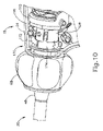
図7は、音響アセンブリ(100)及び作動アセンブリ(102)を含む、外科用器具(14)のハンドルアセンブリ(18)内に収容された機構の更なる詳細を示す。音響アセンブリ(100)について、図9Aを参照してより詳細に以下に説明する。作動アセンブリ(102)は、トリガ(32)と、トリガ(32)を外管(46)、ひいてはクランプアーム(38)と動作可能に連結する一連のリンクと、を含み、それにより、トリガ(32)を本体(24)に対して枢動させることで、クランプアーム(38)を超音波ブレード(36)に対して枢動させることができる。より具体的には、トリガ(32)は、枢動点(106)の周りを枢動する第1のリンク(104)に連結されている。第1のリンク(104)は、その内側曲がり管部分において、第2のリンク(108)の遠位端に枢動可能に連結されている。第2のリンク(108)は、その近位端において、並進部材(110)の近位アーム(112)に対して枢動可能である。アーム(112)は、その遠位端で並進部材(110)のヨーク(114)にしっかりと連結されている。ヨーク(114)は、外管(46)の近位端を少なくとも部分的に取り囲み、それと動作可能に連結している。具体的には、ヨーク(114)は、近位の保持ナット(120)によって円筒形バネ保持具(118)(図8を参照)上に保持されるバネスタック(116)の遠位端に当接する。バネスタック(116)は、この実施例では、隣接する波形バネの直線状に配置されたアレイを含む。バネ保持具は、外管(46)の近位端に固定的に連結している。
B. Exemplary Handle and Shaft Assemblies FIG. 7 shows further details of the mechanisms housed within handle assembly (18) of surgical instrument (14), including acoustic assembly (100) and actuation assembly (102). . Acoustic assembly (100) is described in more detail below with reference to FIG. 9A. Actuation assembly (102) includes a trigger (32) and a series of links that operatively couple trigger (32) with outer tube (46) and thus clamp arm (38), thereby ) relative to the body (24) allows the clamp arm (38) to pivot relative to the ultrasonic blade (36). More specifically, trigger (32) is coupled to a first link (104) that pivots about pivot point (106). The first link (104) is pivotally connected at its inner bend portion to the distal end of the second link (108). Second link (108) is pivotable at its proximal end relative to proximal arm (112) of translation member (110). Arm (112) is rigidly connected at its distal end to yoke (114) of translation member (110). A yoke (114) at least partially surrounds and is operatively connected to the proximal end of outer tube (46). Specifically, the yoke (114) abuts the distal end of a spring stack (116) held on a cylindrical spring retainer (118) (see FIG. 8) by a proximal retaining nut (120). touch. Spring stack (116), in this example, includes a linearly arranged array of adjacent wave springs. A spring retainer is fixedly connected to the proximal end of the outer tube (46).
図7の方向矢印によって示されるように、トリガ(32)をピストルグリップ(26)に向かって引くと、外管(46)が近位側に作動し、それによってクランプアーム(38)が閉鎖される。また、トリガ(32)を解放すると、外管が遠位側に作動し、それによってクランプアーム(38)が開放される。具体的には、トリガ(32)をピストルグリップ(26)に向かって(例えば、引くことによって)移動させることにより、第1及び第2のリンク(104、108)が、それらの対応の枢動軸を中心として枢動し、並進部材(110)をシャフトアセンブリ(20)の長手方向軸に沿って近位側に駆動する。並進部材(110)の近位運動により、ヨーク(114)がバネスタック(116)を保持ナット(120)に対して近位側に圧縮し、バネ保持具(118)及び外管(46)を近位側に駆動する。上述のように、外管(46)の近位側への並進は、クランプアーム(38)をその閉鎖位置に向かって枢動させる。 Pulling the trigger (32) toward the pistol grip (26), as indicated by the directional arrow in FIG. 7, actuates the outer tube (46) proximally, thereby closing the clamp arm (38). be. Releasing the trigger (32) also actuates the outer tube distally, thereby releasing the clamp arm (38). Specifically, moving (e.g., by pulling) the trigger (32) toward the pistol grip (26) causes the first and second links (104, 108) to engage their corresponding pivotal movements. Pivoting about the axis drives the translating member (110) proximally along the longitudinal axis of the shaft assembly (20). Proximal movement of translation member (110) causes yoke (114) to compress spring stack (116) proximally against retention nut (120), pulling spring retainer (118) and outer tube (46). Drive proximally. As noted above, proximal translation of outer tube (46) causes clamp arm (38) to pivot toward its closed position.
本実施例では、作動アセンブリ(102)は、並進部材(110)のアーム(112)の近位端に配置された圧縮バネ(122)を更に含み、並進部材(110)を遠位側に付勢する。トリガ(32)が解放されると、圧縮バネ(122)は、ヨーク(114)がバネ保持具(118)の遠位フランジ(124)に係合するように、並進部材を遠位側に駆動する。バネ保持具(118)が外管(46)に固定されるため、ヨーク(114)は、バネ保持具及び外管(46)を遠位側に一緒に駆動し、クランプアーム(38)をその開放位置に戻す。 In the present example, actuation assembly (102) further includes a compression spring (122) disposed at the proximal end of arm (112) of translation member (110) to distally attach translation member (110). force. When trigger (32) is released, compression spring (122) drives translation member distally such that yoke (114) engages distal flange (124) of spring retainer (118). do. As the spring retainer (118) is secured to the outer tube (46), the yoke (114) drives the spring retainer and the outer tube (46) distally together, clamping the clamp arm (38) against it. Return to open position.
本明細書には示されていないが、作動アセンブリ(102)は、クランプアーム(38)の電動作動をもたらすように構成されたモータアセンブリで補完又は置換され得ることが理解されよう。モータアセンブリを組み込む例示的な外科用装置は、その開示が参照により本明細書に組み込まれる、2014年8月28日に公開された米国特許出願公開第2014/0239037号、名称「Staple Forming Features for Surgical Stapling Instrument」、その開示が参照により本明細書に組み込まれる、2015年12月31日に公開された米国特許出願公開第2015/0374360号、名称「Articulation Drive Features for Surgical Stapler」、参照により上記に組み込まれる2013年12月10日に発行された米国特許第8,602,288号、名称「Robotically-Controlled Motorized Surgical End Effector System with Rotary Actuated Closure Systems Having Variable Actuation Speeds」、及び参照により上記に組み込まれる2015年11月20日に発行された米国特許第9,161,803号、名称「Motor Driven Electrosurgical Device with Mechanical and Electrical Feedback」に開示されている。 Although not shown herein, it will be appreciated that actuation assembly (102) may be supplemented or replaced with a motor assembly configured to provide motorized actuation of clamp arm (38). An exemplary surgical device incorporating a motor assembly is disclosed in U.S. Patent Application Publication No. 2014/0239037, published Aug. 28, 2014, entitled "Staple Forming Features for Surgical Stapling Instrument," U.S. Patent Application Publication No. 2015/0374360, published December 31, 2015, entitled "Articulation Drive Features for Surgical Stapler," the disclosure of which is incorporated herein by reference, by reference above. U.S. Patent No. 8,602,288, issued Dec. 10, 2013, entitled "Robotically-Controlled Motorized Surgical End Effector System with Rotary Actuated Closure Systems Having Variables" and incorporated by supra, in U.S. Pat. No. 9,161,803, entitled "Motor Driven Electrosurgical Device with Mechanical and Electrical Feedback," issued Nov. 20, 2015 to U.S. Pat.
図8は、シャフトアセンブリ(20)の更なる詳細、及び上述の作動アセンブリ(102)の選択的構成要素、並びに超音波導波管(50)の近位端と超音波トランスデューサ(34)の遠位端との連結を示す。上述のように、外管(46)は、内管(48)及び導波管(50)に対して長手方向に並進して、クランプアーム(38)をその開放位置と閉鎖位置との間で移動させるように構成されている。同じ構成では、保持ピン(66)は、回転ノブ(68)の近位カラー(134)を通り、更に外管、内側管、及び導波管(50)を通って横方向に延在し、それによって、上述のように、これらの構成要素のそれぞれを互いに対して回転式に固定する。シャフトアセンブリ(20)の残りの構成要素に対する外管(46)の長手方向の並進に適応するために、図8に示すように、外管(46)は、保持ピン(66)がそこを通って延在する一対の細長いスロット(136)を含む。更に、内管(48)の近位部分は、管支持要素(138)によって外管(46)内で半径方向に支持されてもよい。 FIG. 8 provides further details of the shaft assembly (20) and optional components of the actuation assembly (102) described above, as well as the proximal end of the ultrasonic waveguide (50) and the distal end of the ultrasonic transducer (34). The ligation with the apex is shown. As noted above, outer tube (46) translates longitudinally relative to inner tube (48) and waveguide (50) to move clamp arm (38) between its open and closed positions. configured to move. In the same configuration, retaining pin (66) extends through proximal collar (134) of rotation knob (68) and laterally through outer tube, inner tube, and waveguide (50); Thereby, as described above, each of these components is rotationally fixed relative to each other. To accommodate longitudinal translation of outer tube (46) relative to the remaining components of shaft assembly (20), outer tube (46) is provided with retaining pins (66) passing therethrough, as shown in FIG. It includes a pair of elongated slots (136) that extend through. Additionally, a proximal portion of inner tube (48) may be radially supported within outer tube (46) by tube support element (138).
本実施例では、ヨーク(114)が駆動されて外管(46)を一定の力閾値まで近位側に作動させるときに、バネスタック(116)が圧縮に抵抗し、それによって、ヨーク(114)から保持ナット(120)を介して外管(46)に近位運動を伝送するよう、バネスタック(116)は、力制限機構を提供するように構成されている。クランプアーム(38)が、超音波ブレード(36)に向かった更なる枢動運動に対する実質的な抵抗に遭遇すると、外管(46)は、それに対応して、更なる近位運動に対する実質的な抵抗を提供し、そのような抵抗は、保持ナット(120)を介して更に提供される。この抵抗が所定の力閾値を超え、かつ操作者がトリガ(32)をピストルグリップ(26)に向かって付勢し続けると、バネスタック(116)は、ナット(120)及び外管(46)が静止している間に、ヨーク(114)の更なる近位運動に応答して圧縮し始める。バネスタック(116)は、このように、力閾値を上回る力を吸収する。保持ナット(120)は、ねじ係合によってスリーブ(126)に対して選択的に回転されて、バネスタック(116)をヨーク(114)に対して所望の量の予荷重で圧縮し得る。これにより、保持ナット(120)は、予荷重の調節を可能にすることによって、所定の力閾値を調節可能にする。 In the present example, when yoke (114) is driven to actuate outer tube (46) proximally to a certain force threshold, spring stack (116) resists compression, thereby causing yoke (114) to ) through retention nut (120) to outer tube (46), spring stack (116) is configured to provide a force-limiting mechanism. As clamp arm (38) encounters substantial resistance to further pivotal movement toward ultrasonic blade (36), outer tube (46) correspondingly substantially resists further proximal movement toward ultrasonic blade (36). resistance, and such resistance is further provided via retaining nut (120). When this resistance exceeds a predetermined force threshold, and the operator continues to urge trigger (32) toward pistol grip (26), spring stack (116) forces nut (120) and outer tube (46) into contact. is at rest, it begins to compress in response to further proximal movement of yoke (114). The spring stack (116) thus absorbs forces above the force threshold. Retaining nut (120) may be selectively rotated relative to sleeve (126) by threaded engagement to compress spring stack (116) against yoke (114) with a desired amount of preload. Retaining nut (120) thereby allows adjustment of the predetermined force threshold by allowing adjustment of the preload.
C.例示的な超音波及び双極RF電気回路
図9A及び図9Bは、外科用器具(14)の超音波電気回路(140)及び双極RF電気回路(142)の例示的な構成を示す。図9Aに示すように、外科用システム(10)の発生器(12)は、電気回路(140、142)のそれぞれと電気的に連結され、それぞれに通電するように構成され、それによって、外科用器具(14)が超音波エネルギー及び電気外科用双極RFエネルギーを組織に送達することを可能にする。様々な実施例では、発生器(12)は、超音波電気回路(140)及びRF電気回路(142)を同時に通電してもよく、又は選択的に交互に通電してもよい。超音波電気回路(140)及び双極RF電気回路(142)の構造構成要素は、対応の順序で以下に記載され、その後、回路(140、142)を通る電流の説明が続く。記載されるように、電気回路(140、142)は、共通の電気帰還経路を共有してもよい。
C. Exemplary Ultrasound and Bipolar RF Electrical Circuits FIGS. 9A and 9B show exemplary configurations of ultrasound electrical circuitry (140) and bipolar RF electrical circuitry (142) of surgical instrument (14). As shown in FIG. 9A, the generator (12) of the surgical system (10) is electrically coupled to and configured to energize each of the electrical circuits (140, 142), thereby providing surgical instrument (14) to deliver ultrasonic energy and electrosurgical bipolar RF energy to tissue. In various embodiments, the generator (12) may energize the ultrasound electrical circuitry (140) and the RF electrical circuitry (142) simultaneously or selectively alternately. The structural components of the ultrasound electrical circuit (140) and the bipolar RF electrical circuit (142) are described below in corresponding order, followed by a description of the current flow through the circuits (140, 142). As described, the electrical circuits (140, 142) may share a common electrical return path.
上述のように、外科用器具(14)の音響アセンブリ(100)は、一般に、超音波トランスデューサ(34)、超音波導波管(50)、及び超音波ブレード(36)を含む。図9Aに示すように、本実施例の超音波トランスデューサ(34)は、一般に、第1の共振器(又は「エンドベル」)(144)と、円錐形状の第2の共振器(又は「フォアベル」)(146)と、エンドベル(144)とフォアベル(146)との間に配置され、複数の圧電素子(148)を含む変換部分と、を含む。圧縮ボルト(150)は、エンドベル(144)及び圧電素子(148)を通って遠位側に、同軸状に延在し、フォアベル(146)の近位端内にねじ式で受容される。速度変換器(152)(又は「ホーン」)は、フォアベル(146)から遠位側に延在し、例えば図9Aに示すようにねじ式接続部を介して超音波導波管(50)の近位端と連結する。例示的な変形例では、超音波トランスデューサ(34)は、参照により本明細書に組み込まれる参考文献に開示されるトランスデューサ構成のいずれかに従って更に構成されてもよい。 As mentioned above, the acoustic assembly (100) of the surgical instrument (14) generally includes an ultrasonic transducer (34), an ultrasonic waveguide (50), and an ultrasonic blade (36). As shown in FIG. 9A, the ultrasonic transducer (34) of the present example generally comprises a first resonator (or "endbell") (144) and a conically shaped second resonator (or "forebell"). ) (146) and a transducing portion disposed between the end bell (144) and the fore bell (146) and including a plurality of piezoelectric elements (148). Compression bolt (150) extends coaxially distally through endbell (144) and piezoelectric element (148) and is threadably received within the proximal end of forebell (146). A velocity transducer (152) (or “horn”) extends distally from the forebell (146) and into the ultrasonic waveguide (50) via, for example, a threaded connection as shown in FIG. 9A. Connect with the proximal end. In exemplary variations, the ultrasound transducer (34) may be further configured according to any of the transducer configurations disclosed in the references incorporated herein by reference.
活性トランスデューサ電極(154)が示されているが、これは、内側圧電素子(148)と近位圧電素子(148)との間に配置され、活性トランスデューサリード線(156)を介して発生器(12)と電気的に連結している。帰還トランスデューサ電極(158)が示されているが、これは、エンドベル(144)と近位圧電素子(148)との間に配置され、帰還トランスデューサリード線(160)を介して発生器(12)と電気的に連結している。活性RFリード線(162)が示されているが、これは、発生器(12)と電気的に連結され、外管(46)の近位部分から延在している。シャフトアセンブリ(20)に対する活性RFリード線(162)の位置決めは、例示的なものにすぎず、発生器(12)は、例えば外管(46)に沿った任意の好適な位置で、あるいは、外管(46)をバイパスするように直接クランプアーム(38)で、RF電気回路(142)と電気的に連結してもよいことが理解されよう。更に、他の実施例では、活性RFリード線(162)は、外管(46)の代わりに内管(48)と電気的に連結してもよく、それにより、RF電気回路(142)は、外管(46)の代わりに内管(48)を通過する。 An active transducer electrode (154) is shown, which is positioned between the inner piezoelectric element (148) and the proximal piezoelectric element (148) and is connected to the generator (154) via the active transducer lead (156). 12) are electrically connected. A feedback transducer electrode (158) is shown, which is positioned between the endbell (144) and the proximal piezoelectric element (148) and is connected to the generator (12) via a feedback transducer lead (160). is electrically connected to An active RF lead (162) is shown, electrically coupled to the generator (12) and extending from the proximal portion of the outer tube (46). The positioning of active RF lead (162) relative to shaft assembly (20) is exemplary only, generator (12) may be positioned at any suitable location, such as along outer tube (46), or It will be appreciated that the clamp arm (38) may be electrically coupled directly to the RF electrical circuit (142) to bypass the outer tube (46). Furthermore, in other embodiments, the active RF lead (162) may be electrically coupled to the inner tube (48) instead of the outer tube (46) so that the RF electrical circuit (142) is , passes through the inner tube (48) instead of the outer tube (46).
図9Aに示すように、超音波電気回路(140)は、活性トランスデューサリード線(156)を通って活性トランスデューサ電極(154)まで遠位側に通じ、圧電素子(148)内に入る活性電気経路を含む。超音波電気回路(140)は、圧電素子(148)から帰還トランスデューサ電極(158)を通って帰還トランスデューサリード線(160)まで近位側に通じる帰還電気経路を更に含む。発生器(12)は、活性電気経路を通って帰還電気経路に電流を方向付け、それにより超音波トランスデューサ(34)に通電して超音波機械振動を発生させ、超音波機械振動が超音波導波管(50)を介して超音波ブレード(36)に伝達される。 As shown in FIG. 9A, the ultrasound electrical circuit (140) leads distally through the active transducer lead (156) to the active transducer electrode (154) and into the piezoelectric element (148). including. The ultrasound electrical circuit (140) further includes a return electrical path leading proximally from the piezoelectric element (148) through the return transducer electrode (158) to the return transducer lead (160). The generator (12) directs current through the active electrical path to the return electrical path, thereby energizing the ultrasonic transducer (34) to generate ultrasonic mechanical vibrations, which in turn lead to ultrasonic waves. It is transmitted through the wave tube (50) to the ultrasonic blade (36).
図9A及び図9Bに示されるように、RF電気回路(142)は、活性RFリード線(162)から外管(46)まで、更に外管(46)を通ってクレビスフィンガー(58)を介してクランプアーム(38)まで遠位側に通じる、活性RF経路を含む。本実施例では、RF活性経路を通るRF電気エネルギーの流れは、外管(46)とクランプアーム(38)との電気的連結によって、例えば金属間接触によって可能になる。活性RFエネルギーは、クレビスアーム(52)からクランプアーム電極(42)内に流れ、次いで組織(164)内に流れる。以下により詳細に記載されるように、クランプアーム電極(42)は、クランプアーム(38)のクランプ側表面の形態であってもよく、クランプアーム(38)と一体的に形成され、それによってクランプアーム(38)の残部と電気的に連結されてもよい。様々な実施例において、クランプパッド(40)を含む又は含まないクランプアーム(38)の全体は、クランプアーム(38)全体がクランプアーム電極(42)として機能するように、金属などの導電性材料で形成されてもよい。 As shown in FIGS. 9A and 9B, the RF electrical circuit (142) runs from the active RF lead (162) to the outer tube (46) and through the outer tube (46) through the clevis fingers (58). It contains an active RF path leading distally to the clamp arm (38). In the present example, RF electrical energy flow through the RF active path is enabled by electrical coupling between outer tube (46) and clamp arm (38), for example, by metal-to-metal contact. Active RF energy flows from clevis arm (52) into clamp arm electrode (42) and then into tissue (164). As will be described in more detail below, clamp arm electrode (42) may be in the form of a clamp-side surface of clamp arm (38) and is integrally formed with clamp arm (38), thereby clamping. It may be electrically connected to the rest of arm (38). In various embodiments, the entire clamp arm (38), including or not including the clamp pad (40), is made of a conductive material, such as metal, such that the entire clamp arm (38) functions as the clamp arm electrode (42). may be formed with
RF電気回路(142)は、超音波導波管(50)を介して、エンドエフェクタ(22)からハンドルアセンブリ(18)へとRFエネルギーを近位側に方向付ける帰還電気経路を更に含む。図9Bに示されるように、組織(164)がクランプアーム電極(42)及びブレード電極(44)と同時に、例えば直接接触又は間接接触によって電気的に連結されるとき、RFエネルギーは、活性RF経路から組織(164)を通って帰還RF経路まで、ブレード電極(44)を介して流れる。以下に更に説明するように、RFエネルギーは、ブレード電極(44)から、導波管(50)を通って近位側に帰還し、超音波トランスデューサ(34)に入る。このようにして、組織(164)は、発生器(12)によって提供される双極RFエネルギーを用いて治療される。 The RF electrical circuit (142) further includes a return electrical path that directs RF energy proximally from the end effector (22) to the handle assembly (18) via the ultrasonic waveguide (50). As shown in FIG. 9B, when the tissue (164) is electrically coupled to the clamp arm electrode (42) and blade electrode (44) simultaneously, e.g., by direct or indirect contact, RF energy is directed to the active RF path from through the tissue (164) to the return RF path via the blade electrode (44). From the blade electrode (44), RF energy returns proximally through the waveguide (50) and into the ultrasound transducer (34), as further described below. In this manner, tissue (164) is treated with bipolar RF energy provided by generator (12).
例示的な構成では、ブレード電極(44)は、超音波ブレード(36)の選択されたクランプ側表面によって画定され得る。他の構成では、超音波ブレード(36)の全体は、ブレード電極(44)として機能し得る。様々なそのような構成において、ブレード電極(44)は、超音波ブレード(36)と電気的に連結され、超音波ブレード(36)は、超音波導波管(50)と電気的に連結され、次いで超音波導波管(50)は、超音波トランスデューサ(34)と電気的に連結される。したがって、RF帰還経路内で、RFエネルギーは、ブレード電極(44)から超音波ブレード(36)を通って超音波導波管(50)まで、最終的には超音波トランスデューサ(34)まで近位側に流れる。図9Aに示すように、超音波トランスデューサ(34)に入ると、帰還RFエネルギーは、フォアベル(146)及び圧縮ボルト(150)を通り、圧縮ボルト(150)からエンドベル(144)を通って帰還トランスデューサ電極(158)まで、更に帰還トランスデューサリード線(160)まで近位側に流れる。したがって、RF電気回路(142)及び超音波電気回路(140)は、帰還トランスデューサ電極(158)及び帰還トランスデューサリード線(160)を通る共通の電気帰還経路を共有する。 In an exemplary configuration, blade electrode (44) may be defined by a selected clamping surface of ultrasonic blade (36). In other configurations, the entire ultrasonic blade (36) may function as the blade electrode (44). In various such configurations, blade electrode (44) is electrically coupled with ultrasonic blade (36), and ultrasonic blade (36) is electrically coupled with ultrasonic waveguide (50). The ultrasonic waveguide (50) is then electrically coupled with the ultrasonic transducer (34). Thus, within the RF return path, RF energy travels proximally from the blade electrode (44) through the ultrasonic blade (36) to the ultrasonic waveguide (50) and finally to the ultrasonic transducer (34). flow to the side. As shown in FIG. 9A, upon entering the ultrasonic transducer (34), the return RF energy passes through the forebell (146) and compression bolt (150), from the compression bolt (150) through the endbell (144) to the return transducer. It flows proximally to the electrode (158) and then to the return transducer lead (160). Thus, the RF electronics (142) and the ultrasound electronics (140) share a common electrical return path through the return transducer electrode (158) and the return transducer lead (160).
上述の例示的な構成は、活性電極としてクランプアーム電極(42)を、また帰還電極としてブレード電極(44)を用いているが、逆に指定して、ブレード電極(44)が活性電極となり、クランプアーム電極(42)が帰還電極となってもよいことが理解されよう。そのような構成では、超音波電気回路(140)及びRF電気回路(142)は、トランスデューサリード線(160)及びトランスデューサ電極(158)を通って発生器(12)に戻る共通の活性電気経路を共有する。更に、代替的な配置では、RF電気回路(142)は、外管(46)ではなく内管(48)を通過してもよく、又はRF電気回路(142)は、内管(46)及び外管(48)を全てまとめてバイパスしてもよい。 Although the exemplary configuration described above uses the clamp arm electrode (42) as the active electrode and the blade electrode (44) as the return electrode, specifying the opposite, the blade electrode (44) is the active electrode, It will be appreciated that the clamp arm electrode (42) may be the return electrode. In such a configuration, the ultrasound electronics (140) and RF electronics (142) share a common active electrical path back to the generator (12) through the transducer leads (160) and transducer electrodes (158). share it. Further, in alternative arrangements, RF electrical circuitry (142) may pass through inner tube (48) rather than outer tube (46), or RF electrical circuitry (142) may pass through inner tube (46) and All of the outer tubes (48) may be bypassed together.
上述のように、発生器(12)は、超音波電気回路(140)及びRF電気回路(142)に同時に通電して、外科用器具(14)が超音波エネルギー及び電気外科用双極RFエネルギーを同時に印加して組織を治療することを可能にするように構成されてもよい。加えて、又はあるいは、発生器(12)は、超音波電気回路(140)及びRF電気回路(142)に交互に通電して、所与の時間に超音波エネルギー又は双極RFエネルギーのうちの1つのみを選択的に印加することを可能にするように構成されてもよい。例えば、発生器(12)は、双極RFエネルギーを用いて組織を封止するためにRF電気回路(142)のみに通電し、超音波ブレード(36)を不活性にしてもよい。あるいは、発生器(12)は、超音波エネルギーを用いて組織を切断及び/又は封止するために超音波電気回路(140)のみに通電し、RF電極(42、44)を不活性にしてもよい。 As described above, generator (12) simultaneously energizes ultrasonic electrical circuitry (140) and RF electrical circuitry (142) such that surgical instrument (14) emits ultrasonic energy and electrosurgical bipolar RF energy. It may be configured to allow simultaneous application to treat tissue. Additionally or alternatively, the generator (12) alternately energizes the ultrasonic electrical circuit (140) and the RF electrical circuit (142) to produce one of ultrasonic energy or bipolar RF energy at a given time. It may be configured to allow only one to be selectively applied. For example, generator (12) may energize only RF electrical circuit (142) and deactivate ultrasonic blade (36) to seal tissue using bipolar RF energy. Alternatively, the generator (12) energizes only the ultrasonic electrical circuit (140) and deactivates the RF electrodes (42, 44) to cut and/or seal tissue using ultrasonic energy. good too.
外科用器具(14)は、例えば、クランプアーム電極(42)及びブレード電極(44)の近位の位置において、RF電気回路(142)のRF活性経路及びRF帰還経路の望ましくない電気的短絡を阻止するための様々な機構を含んでもよい。例えば、図9Aに示される保持ピン(66)は、外管(46)と超音波導波管(50)との間での短絡を防止する電気絶縁シース(166)に入れられてもよい。同様に、図9Bに示すクランプアーム旋回ピン(56)は、クランプアーム(38)から、超音波導波管(50)を入れる内管(48)への電気エネルギーの伝送を防止する電気絶縁シース内に入れられてもよい。更に、超音波ブレード(36)、超音波導波管(50)、外管(46)、及び/又は内管(48)の選択部分は、RF電気回路(142)の短絡を防止するように構成された電気絶縁材料の層でコーティングされてもよい。 Surgical instrument (14) prevents unwanted electrical shorting of the RF active and RF return paths of RF electrical circuit (142), for example, at locations proximal to clamp arm electrode (42) and blade electrode (44). Various mechanisms for blocking may be included. For example, the retaining pin (66) shown in FIG. 9A may be encased in an electrically insulating sheath (166) that prevents shorting between the outer tube (46) and the ultrasonic waveguide (50). Similarly, the clamp arm pivot pin (56) shown in FIG. 9B is an electrically insulating sheath that prevents transmission of electrical energy from the clamp arm (38) to the inner tube (48) containing the ultrasonic waveguide (50). may be placed inside. Additionally, selected portions of the ultrasonic blade (36), ultrasonic waveguide (50), outer tube (46), and/or inner tube (48) are configured to prevent shorting of the RF electrical circuit (142). It may be coated with a layer of structured electrically insulating material.
D.例示的なスリップリング電気接触アセンブリ
図10~図12は、RF電気回路(142)の活性経路を通してRFエネルギーを伝送するように構成された、例示的な電気接触アセンブリ(170)を示す。具体的には、電気接触アセンブリ(170)は、RFエネルギーを活性RFリード線(162)から外管(46)の近位端部分に伝送するように構成され、RFエネルギーは次いで、上述のようにクランプアーム電極(42)に向けて方向付けられる。本実施例の電気接触アセンブリ(170)は、外側クリップ接触部(172)と、例えば直接接触によって、外側クリップ接触部(172)に受容され、かつそれと電気的に連結する内側リング接触部(174)と、を有するスリップリング接触アセンブリの形態で示されている。外側クリップ接触部(172)は、装置本体(24)の内側側壁に取り付けられ、内側リング接触部(174)は、外管(46)の近位端部分を取り囲むように、回転ノブ(68)の近位カラー(134)に取り付けられる。以下に記載されるように、外側クリップ接触部(172)は、アクティブなRFリード線(162)と電気的に連結され、内側リング接触部(174)は、外管(46)と電気的に連結される。
D. Exemplary Slip Ring Electrical Contact Assembly FIGS. 10-12 show an exemplary electrical contact assembly (170) configured to transmit RF energy through active paths of RF electrical circuitry (142). Specifically, electrical contact assembly (170) is configured to transmit RF energy from active RF lead (162) to the proximal end portion of outer tube (46), where RF energy is then transmitted as described above. is directed toward the clamp arm electrode (42). Electrical contact assembly (170) of the present example includes an outer clip contact (172) and an inner ring contact (174) received in and in electrical communication with outer clip contact (172), e.g., by direct contact. ) and in the form of a slip ring contact assembly. The outer clip contact (172) is attached to the inner sidewall of the device body (24) and the inner ring contact (174) surrounds the proximal end portion of the outer tube (46) by rotating knob (68). attached to the proximal collar (134) of the . The outer clip contact (172) is in electrical communication with the active RF lead (162) and the inner ring contact (174) is in electrical communication with the outer tube (46), as described below. concatenated.
図13及び図14に示されるように、外側クリップ接触部(172)は、ベースプレート(176)と、ベースプレート(176)から外側に突出する第1及び第2の接触アーム(178)と、を含む。ベースプレート(176)は、図11に示されるように、装置本体(24)に、ないしは別の方法で装置本体(24)内に、例えば熱溶接によって強固に固定されるように構成されている。ベースプレート(176)は、例えば、プレス嵌め係合、スナップ嵌め係合、インサート成形、又は接着剤など、当該技術分野において既知の様々な他の好適な固定方法及び機序を使用して本体(24)に固定されてもよい。接触アーム(178)は、基部プレート(176)の中央部分に向かって、ひいては内側リング接触部(174)に向かって弾性的に付勢されている。したがって、外側クリップ接触部(172)は、リング接触部(174)が回転ノブ(68)及びシャフトアセンブリ(20)と共にハンドルアセンブリ(18)に対して回転する間に、例えば、最大360度又はそれ以上の回転に対して、内側リング接触部(174)と確実に係合し、それとの連続した直接接触を維持するように構成されている。 As shown in FIGS. 13 and 14, the outer clip contact (172) includes a base plate (176) and first and second contact arms (178) projecting outwardly from the base plate (176). . Base plate (176) is configured to be rigidly secured to device body (24) or otherwise within device body (24), such as by heat welding, as shown in FIG. Base plate (176) is secured to body (24) using various other suitable fastening methods and mechanisms known in the art, such as press-fit engagement, snap-fit engagement, insert molding, or adhesives, for example. ) may be fixed. The contact arm (178) is resiliently biased toward the central portion of the base plate (176) and thus toward the inner ring contact portion (174). Thus, outer clip contact (172) may rotate, for example, up to 360 degrees or less while ring contact (174) rotates with rotation knob (68) and shaft assembly (20) relative to handle assembly (18). It is configured to positively engage and maintain continuous direct contact with the inner ring contact (174) for such rotation.
図15及び図16に示されるように、内側リング接触部(174)は、環状本体(180)と、環状本体(180)の側縁部から近位側に突出する、円周方向に離間配置された複数の接触脚部(182)と、を含む。図11及び図12に示されるように、環状本体(180)は、回転ノブ(68)の近位カラー(134)を取り囲むようにサイズ決めされる。それぞれの接触脚部(182)は、外管(46)が回転ノブ(68)及び内側リング接触部(174)に対して並進する間、外管(46)と確実に係合し、それとの連続した直接電気接触を維持するように、環状本体(180)の中心軸に向かって、ひいては外管(46)に向かって弾性的に付勢されている。図11及び図17に示されるように、回転ノブ(68)の近位カラー(134)は、複数の軸方向に延在するスロット(184)を含み、このスロットを通って接触脚部(182)が突出して、外管(46)と接触し、電気的に連結する。 As shown in FIGS. 15 and 16, the inner ring contact portion (174) is circumferentially spaced from the annular body (180) and projects proximally from the side edges of the annular body (180). and a plurality of contact legs (182). As shown in FIGS. 11 and 12, annular body (180) is sized to surround proximal collar (134) of rotation knob (68). Each contact leg (182) positively engages and communicates with outer tube (46) during translation of outer tube (46) relative to rotation knob (68) and inner ring contact (174). It is resiliently biased toward the central axis of the annular body (180) and thus toward the outer tube (46) to maintain continuous direct electrical contact. As shown in FIGS. 11 and 17, proximal collar (134) of rotation knob (68) includes a plurality of axially extending slots (184) through which contact legs (182) extend. ) protrudes to contact and electrically connect with the outer tube (46).
内側リング接触部(174)は、接触脚部(182)の間で交互に離間配置された第1及び第2の保持脚部(186)を更に含む。それぞれの保持脚部(186)は、回転ノブ(68)の近位カラー(134)内に形成された対応する凹部(188)内に受容され、それによって内側リング接触部(174)を回転ノブ(68)と回転可能に連結する。保持脚部(186)はまた、内側リング接触部(174)を近位側に拘束するように機能してもよく、一方、回転ノブ(68)のフランジ(190)は、内側リング接触部(174)を遠位側に拘束する。3つの接触脚部(182)及び2つの保持脚部(186)を有する内側リング接触部(174)が示されているが、任意の好適な量の脚部(182、186)、並びに対応する量のスロット(184)及び凹部(188)が提供され得ることが理解されるであろう。加えて、脚部(182、186)の間隔は、図16に最もよく見られるように、角度が等距離ではない。この間隔は、保持脚部(186)と隣接する接触脚部(182)との間に、上述の保持ピン(66)の収容を提供する。本明細書の教示を考慮することで、他の好適な間隔及び配置が、当業者に明らかになるであろう。 Inner ring contact (174) further includes first and second retaining legs (186) alternately spaced between contact legs (182). Each retaining leg (186) is received within a corresponding recess (188) formed in proximal collar (134) of rotation knob (68), thereby engaging inner ring contact (174) with rotation knob. (68) is rotatably connected. Retaining legs (186) may also serve to constrain inner ring contact (174) proximally, while flange (190) of rotation knob (68) serves to restrain inner ring contact (174). 174) is distally constrained. Inner ring contact (174) is shown having three contact legs (182) and two retaining legs (186), but any suitable amount of legs (182, 186) and corresponding It will be appreciated that any number of slots (184) and recesses (188) may be provided. Additionally, the spacing of the legs (182, 186) is not equidistant in angle, as best seen in FIG. This spacing provides accommodation for the aforementioned retaining pin (66) between the retaining leg (186) and the adjacent contact leg (182). Other suitable spacings and arrangements will be apparent to those of ordinary skill in the art in view of the teachings herein.
当業者であれば、シャフトアセンブリ(20)がハンドルアセンブリ(18)に対して回転している間、外側クリップ接触部(172)の接触アーム(178)が内側リング接触部(174)との摺動接触を維持しながら、内側リング接触部(174)が外管(46)と共に回転し、その結果、接触部(172、174)は、活性RFリード線(162)と外管(46)との間の電気的連続性を維持することを認識するであろう。このように、シャフトアセンブリ(20)がシャフトアセンブリ(20)の長手方向軸を中心にして360度以上の角度運動で回転しているとき、電気接触アセンブリ(170)は、活性RFリード線(162)と外管(46)との間の電気的連続性を維持する。更に、外管(46)が長手方向に並進してクランプアーム(38)を作動させているとき、内側リング接触部(174)の接触脚部(182)は、外管(46)との摺動接触を維持し、その結果、接触部(172、174)は、活性RFリード線(162)と外管(46)との間の電気的連続性を維持する。このように、外管(46)が軸方向に往復運動して、超音波ブレード(36)に対してクランプアーム(38)を作動させているとき、電気接触アセンブリ(170)は、活性RFリード線(162)と外管(46)との間の電気的連続性を維持する。 Those skilled in the art will appreciate that contact arms (178) of outer clip contact (172) slide against inner ring contact (174) while shaft assembly (20) rotates relative to handle assembly (18). Inner ring contact (174) rotates with outer tube (46) while maintaining dynamic contact such that contacts (172, 174) engage active RF lead (162) and outer tube (46). It will be appreciated that maintaining electrical continuity between Thus, when the shaft assembly (20) is rotating about the longitudinal axis of the shaft assembly (20) through an angular motion of 360 degrees or more, the electrical contact assembly (170) is in contact with the active RF lead (162). ) and the outer tube (46). Further, contact legs (182) of inner ring contact (174) slide against outer tube (46) as outer tube (46) translates longitudinally to actuate clamp arms (38). Maintain dynamic contact so that contacts (172, 174) maintain electrical continuity between active RF lead (162) and outer tube (46). In this manner, as outer tube (46) reciprocates axially to actuate clamp arm (38) against ultrasonic blade (36), electrical contact assembly (170) engages the active RF lead. Maintain electrical continuity between line (162) and outer tube (46).
II.例示的な組み合わせ
以下の実施例は、本明細書の教示を組み合わせる、又は適用することができる、種々の非網羅的な方法に関する。以下の実施例は、本出願における又は本出願の後の出願におけるどの時点でも提示され得る、いずれの請求項の適用範囲をも限定することを目的としたものではない、と理解すべきである。一切の棄権を意図するものではない。以下の実施例は、単なる例示の目的で与えられるものにすぎない。本明細書の種々の教示は、その他の多くの方法で配置及び適用が可能であると考えられる。また、いくつかの変形形態では、以下の実施例において言及される特定の特徴を省略してよいことも考えられる。したがって、本発明者ら又は本発明者らの利益の継承者により、後日、そうである旨が明示的に示されない限り、以下に言及される態様又は特徴のいずれも、決定的なものとして見なされるべきではない。以下に言及される特徴以外の更なる特徴を含む請求項が本出願において、又は本出願に関連する後の出願において示される場合、それらの更なる特徴は、特許性に関連するいかなる理由によっても追加されたものとして仮定されるべきではない。
II. Exemplary Combinations The following examples relate to various non-exhaustive ways in which the teachings herein can be combined or applied. It should be understood that the following examples are not intended to limit the scope of any claim, which may be presented at any time in this application or in any subsequent application after this application. . No waiver is intended. The following examples are given for illustrative purposes only. It is believed that the various teachings herein can be arranged and applied in many other ways. It is also contemplated that in some variations certain features referred to in the examples below may be omitted. Accordingly, unless expressly indicated to the contrary at a later date by the inventors, or any assignee of the inventors' interest, any aspect or feature referred to below shall be considered as conclusive. should not be If claims containing further features other than those mentioned below appear in this application, or in a subsequent application related to this application, then those further features are for any reason relevant to patentability. It should not be assumed as added.
外科用器具であって、(a)本体と、(b)長手方向軸に沿って本体から遠位側に延在するシャフトアセンブリであって、シャフトアセンブリは、長手方向軸を中心として本体に対して回転可能である、シャフトアセンブリと、(c)シャフトアセンブリの遠位端に配置されたエンドエフェクタであって、エンドエフェクタは、RFエネルギーを用いて組織を封止するように動作可能なRF電極を含む、エンドエフェクタと、(d)エンドエフェクタの近位側に配置された電気接触アセンブリであって、電気接触アセンブリは、RF電極をRFエネルギー源と電気的に連結するように構成され、電気接触アセンブリは、(i)本体に固定された第1の電気接触部であって、第1の電気接触部は、RFエネルギー源と電気的に連結するように構成されている、第1の電気接触部と、(ii)シャフトアセンブリに固定された第2の電気接触部であって、第2の電気接触部は、RF電極と、また第1の電気接触部と電気的に連結され、第2の電気接触部は、シャフトアセンブリと共に本体及び第1の電気接触部に対して回転するように構成されている、第2の電気接触部と、を含み、第1及び第2の電気接触部は、本体に対するシャフトアセンブリの回転中常に、共に電気的に連結されたままであるように構成されている、電気接触アセンブリと、を備える、外科用器具。 A surgical instrument comprising (a) a body and (b) a shaft assembly extending distally from the body along a longitudinal axis, the shaft assembly being about the longitudinal axis relative to the body. (c) an end effector disposed at a distal end of the shaft assembly, the end effector being operable to seal tissue using RF energy; and (d) an electrical contact assembly disposed proximally of the end effector, the electrical contact assembly configured to electrically couple the RF electrode with an RF energy source; The contact assembly includes: (i) a first electrical contact secured to the body, the first electrical contact configured to electrically couple with the RF energy source; (ii) a second electrical contact secured to the shaft assembly, the second electrical contact electrically coupled to the RF electrode and to the first electrical contact; the two electrical contacts including a second electrical contact configured to rotate with the shaft assembly relative to the body and the first electrical contact; an electrical contact assembly configured to remain electrically coupled together during rotation of the shaft assembly relative to the body.
第1及び第2の電気接触部が互いに直接接触している、実施例1に記載の外科用器具。 2. The surgical instrument of Example 1, wherein the first and second electrical contacts are in direct contact with each other.
第1の電気接触部が外側接触部を含み、第2の電気接触部が内側接触部を含む、実施例1又は2のいずれか1つに記載の外科用器具。 The surgical instrument of any one of Examples 1 or 2, wherein the first electrical contact comprises an outer contact and the second electrical contact comprises an inner contact.
外側接触部が接触アームを含み、内側接触部が、シャフトアセンブリを取り囲む内側リング接触部を含み、接触アームは、本体に対するシャフトアセンブリの回転中常に、内側リング接触部と直接接触し、それとの電気的係合を維持するように構成されている、実施例3に記載の外科用器具。 The outer contact includes a contact arm and the inner contact includes an inner ring contact surrounding the shaft assembly, the contact arm being in direct contact with the inner ring contact at all times during rotation of the shaft assembly with respect to the body for electrical communication therewith. The surgical instrument of example 3, configured to maintain targeted engagement.
接触アームが、内側リング接触部に向かって弾性的に付勢されている、実施例4に記載の外科用器具。 5. The surgical instrument of Example 4, wherein the contact arms are resiliently biased toward the inner ring contact.
内側リング接触部が、シャフトアセンブリと直接接触し、電気的に連結するように構成された少なくとも1つの接触脚部を含む、実施例4~5のいずれか1つに記載の外科用器具。 The surgical instrument of any one of Examples 4-5, wherein the inner ring contact portion includes at least one contact leg configured to directly contact and electrically couple with the shaft assembly.
少なくとも1つの接触脚部が、シャフトアセンブリに向かって弾性的に付勢されている、実施例6に記載の外科用器具。 7. The surgical instrument of Example 6, wherein the at least one contact leg is resiliently biased toward the shaft assembly.
少なくとも1つの接触脚部が、複数の円周方向に離間した接触脚部を含む、実施例6~7のいずれか1つに記載の外科用器具。 The surgical instrument of any one of Examples 6-7, wherein the at least one contact leg comprises a plurality of circumferentially-spaced contact legs.
シャフトアセンブリに連結された回転ノブを更に備え、第2の電気接触部は、回転ノブに連結されている、実施例1~8のいずれか1つに記載の外科用器具。 The surgical instrument of any one of Examples 1-8, further comprising a rotation knob coupled to the shaft assembly, the second electrical contact coupled to the rotation knob.
第2の電気接触部が保持脚部を含み、回転ノブは、保持脚部を受容し、それによって第2の電気接触部を回転ノブに対して軸方向及び回転方向に固定するように構成された凹部を含む、実施例9に記載の外科用器具。 The second electrical contact includes a retention leg, and the rotation knob is configured to receive the retention leg, thereby axially and rotationally securing the second electrical contact relative to the rotation knob. 10. The surgical instrument of Example 9, comprising a recessed portion.
第2の電気接触部が、第1の電気接触部と連続して電気的に連結されたまま、第1の電気接触部に対して360度回転するように構成されている、実施例1~10のいずれか1つに記載の外科用器具。 Embodiments 1- wherein the second electrical contact is configured to rotate 360 degrees with respect to the first electrical contact while remaining in continuous electrical communication with the first electrical contact 11. The surgical instrument according to any one of 10.
エンドエフェクタが、超音波エネルギーを用いて組織を治療するように動作可能な超音波ブレードと、超音波ブレードとの間に組織を挟持するために超音波ブレードに対して移動可能なクランプアームと、を更に含み、クランプアーム又は超音波ブレードのうちの1つは、RF電極を提供する、実施例1~11のいずれか1つに記載の外科用器具。 an end effector having an ultrasonic blade operable to treat tissue with ultrasonic energy; a clamping arm movable relative to the ultrasonic blade to clamp tissue therebetween; and wherein one of the clamp arm or ultrasonic blade provides an RF electrode.
RF電極は、RF活性経路と電気的に連結された第1のRF電極を含み、エンドエフェクタは、RF帰還経路と電気的に連結された第2のRF電極を更に含み、第1及び第2のRF電極は、双極RFエネルギーを用いて組織を封止するように動作可能であり、第1及び第2の電気接触部は、RF活性経路と電気的に連結され、かつRF帰還経路から電気的に絶縁されている、実施例12に記載の外科用器具。 The RF electrode comprises a first RF electrode electrically coupled with the RF active path, the end effector further comprises a second RF electrode electrically coupled with the RF return path, first and second is operable to seal tissue using bipolar RF energy, the first and second electrical contacts are electrically coupled with the RF active path and electrically coupled from the RF return path; 13. The surgical instrument of Example 12, which is thermally insulated.
クランプアームは、第1のRF電極を提供し、超音波ブレードは、第2のRF電極を提供し、シャフトアセンブリは、第1の管及び第2の管を含み、第1の管は、クランプアームと連結され、かつ長手方向軸に沿って本体及び第2の管に対して並進して、クランプアームを超音波ブレードに対して作動させるように動作可能であり、第2の電気接触部は、第1の管を介して第1のRF電極と電気的に連結されている、実施例13に記載の外科用器具。 The clamp arm provides a first RF electrode, the ultrasonic blade provides a second RF electrode, the shaft assembly includes a first tube and a second tube, the first tube clamping a second electrical contact coupled with the arm and operable to translate relative to the body and the second tube along the longitudinal axis to actuate the clamp arm against the ultrasonic blade; 14. The surgical instrument of example 13, electrically coupled to the first RF electrode via the first tube.
第2の電気接触部は、本体及び第1の電気接触部に対して軸方向に固定され、第2の電気接触部は、第1の管との連続した電気接触を維持しながら、第2の電気接触部に対する第1の管の並進を可能にするように構成されている、実施例14に記載の外科用器具。 A second electrical contact is axially fixed with respect to the body and the first electrical contact, the second electrical contact maintaining continuous electrical contact with the first tube while maintaining continuous electrical contact with the second electrical contact. 15. A surgical instrument according to example 14, configured to allow translation of the first tube with respect to the electrical contacts of .
外科用器具であって、(a)本体と、(b)長手方向軸に沿って本体から遠位側に延在するシャフトアセンブリであって、シャフトアセンブリは、長手方向軸を中心として本体に対して回転可能であり、シャフトアセンブリは、(i)第1の管と、(ii)第2の管であって、第1の管は、第2の管及び本体に対して並進可能である、第2の管と、を含む、シャフトアセンブリと、(c)シャフトアセンブリの遠位端に配置されたエンドエフェクタであって、エンドエフェクタは、(i)超音波エネルギーを用いて組織を治療するように動作可能な超音波ブレードと、(ii)超音波ブレードとの間に組織を挟持するために超音波ブレードに対して移動可能なクランプアームであって、第1の管は、クランプアームを作動させるように動作可能である、クランプアームと、(iii)RFエネルギー源によって提供されるRFエネルギーを用いて組織を封止するように動作可能なRF電極と、を含む、エンドエフェクタと、(d)シャフトアセンブリの近位端部分に配置された電気接触アセンブリであって、電気接触アセンブリは、RF電極とRFエネルギー源との間の連続した電気通信を維持しながら、本体に対するシャフトアセンブリの回転、及び第2の管に対する第1の管の並進を可能にするように構成されている、電気接触アセンブリと、を備える、外科用器具。 A surgical instrument comprising (a) a body and (b) a shaft assembly extending distally from the body along a longitudinal axis, the shaft assembly being about the longitudinal axis relative to the body. and the shaft assembly comprises (i) a first tube and (ii) a second tube, the first tube being translatable relative to the second tube and the body; a second tube; and (c) an end effector disposed at a distal end of the shaft assembly, the end effector configured to: (i) treat tissue with ultrasonic energy; and (ii) a clamping arm movable relative to the ultrasonic blade to clamp tissue between the ultrasonic blade, the first tube actuating the clamping arm. and (iii) an RF electrode operable to seal tissue using RF energy provided by the RF energy source; (d ) an electrical contact assembly located at the proximal end portion of the shaft assembly, the electrical contact assembly being adapted to rotate the shaft assembly relative to the body while maintaining continuous electrical communication between the RF electrode and the RF energy source; and an electrical contact assembly configured to allow translation of the first tube relative to the second tube.
電気接触アセンブリが、(i)本体に対して固定された第1の電気接触部であって、第1の電気接触部は、RFエネルギー源と電気的に連結するように構成されている、第1の電気接触部と、(ii)シャフトアセンブリに連結された第2の電気接触部であって、第2の電気接触部は、RF電極と、また第1の電気接触部と電気的に連結され、第2の電気接触部は、シャフトアセンブリと共に本体及び第1の電気接触に対して回転するように構成されている、第2の電気接触部と、を含む、実施例16に記載の外科用器具。 wherein the electrical contact assembly is (i) a first electrical contact fixed with respect to the body, the first electrical contact configured to electrically couple with the RF energy source; and (ii) a second electrical contact coupled to the shaft assembly, the second electrical contact electrically coupling the RF electrode and the first electrical contact. and the second electrical contact configured to rotate with the shaft assembly relative to the body and the first electrical contact. equipment.
第1の電気接触部が、外側接触部を含み、第2の電気接触部が、外側接触部によって受容されるように構成された内側接触部を含む、実施例17に記載の外科用器具。 18. The surgical instrument of Example 17, wherein the first electrical contact includes an outer contact and the second electrical contact includes an inner contact configured to be received by the outer contact.
外科用器具であって、(a)本体と、(b)長手方向軸に沿って本体から遠位側に延在するシャフトアセンブリであって、シャフトアセンブリは、長手方向軸を中心として本体に対して回転可能である、シャフトアセンブリと、(c)シャフトアセンブリの遠位端に配置されたエンドエフェクタであって、エンドエフェクタは、RFエネルギーを用いて組織を封止するように動作可能なRF電極を含む、エンドエフェクタと、(d)シャフトアセンブリの近位端部分に配置された電気接触アセンブリであって、電気接触アセンブリは、RF電極をRFエネルギー源と電気的に連結するように構成され、電気接触アセンブリは、(i)本体に対して固定された外側接触部であって、外側接触部は、RFエネルギー源と電気的に連結するように構成されている、外側接触部と、(ii)シャフトアセンブリに固定された環状内側接触部であって、環状内側接触部は、RF電極と電気的に連結され、環状内側接触部は、外側接触部と直接接触して位置付けられ、かつ外側接触部と電気的に連結されたまま、シャフトアセンブリと共に外側接触部に対して回転するように構成されている、環状内側接触部と、を含む、電気接触アセンブリと、を備える、外科用器具。 A surgical instrument comprising (a) a body and (b) a shaft assembly extending distally from the body along a longitudinal axis, the shaft assembly being about the longitudinal axis relative to the body. (c) an end effector disposed at a distal end of the shaft assembly, the end effector being operable to seal tissue using RF energy; and (d) an electrical contact assembly disposed on the proximal end portion of the shaft assembly, the electrical contact assembly configured to electrically couple the RF electrode with the RF energy source; The electrical contact assembly includes (i) an outer contact fixed relative to the body, the outer contact configured to electrically couple with the RF energy source; ) an annular inner contact secured to the shaft assembly, the annular inner contact electrically coupled to the RF electrode, the annular inner contact positioned in direct contact with the outer contact, and the outer contact; an annular inner contact configured to rotate with the shaft assembly relative to the outer contact while remaining electrically coupled to the portion.
外側接触部が、複数の接触アームを含み、接触アームは、環状内側接触部との間に電気的連結を確立するために、弾性的に付勢されて環状内側接触部と係合している、実施例19に記載の外科用器具。 The outer contact portion includes a plurality of contact arms, the contact arms being resiliently biased into engagement with the annular inner contact portion to establish an electrical connection therebetween. , Example 19.
III.その他
本明細書に記載の教示、表現要素、実施形態、実施例などのうちのいずれか1つ以上を、本明細書に記載の他の教示、表現要素、実施形態、実施例などのうちのいずれか1つ以上と組み合わせることができる点が理解されるべきである。したがって、上述した教示、表現、実施形態、実施例などは、互いに対して独立して考慮されるべきではない。本明細書の教示を考慮して、本明細書の教示を組み合わせることができる種々の好適な方法が、当業者には容易に明らかとなろう。このような修正及び変形形態は、「特許請求の範囲」内に含まれるものとする。
III. Miscellaneous Any one or more of the teachings, elements, embodiments, examples, etc. described herein may be combined with other teachings, elements, embodiments, examples, etc. described herein. It should be understood that any one or more can be combined. Accordingly, the above teachings, expressions, embodiments, examples, etc. should not be considered independently of each other. Various suitable ways in which the teachings herein can be combined will be readily apparent to those skilled in the art in view of the teachings herein. Such modifications and variations are intended to be included within the scope of the claims.
更に、本明細書に記載される教示、表現、実施形態、実施例などのうちの任意の1つ以上のものを、本件と同日に出願された米国特許出願[代理人整理番号END8245USNP]、名称「Combination Ultrasonic and Electrosurgical Instrument Having Electrical Circuits With Shared Return Path」、本件と同日に出願された米国特許出願[代理人整理番号END8245USNP2]、名称「Combination Ultrasonic and Electrosurgical Instrument Having Electrically Insulating Features」、本件と同日に出願された米国特許出願[代理人整理番号END8245USNP3]、名称「Combination Ultrasonic and Electrosurgical Instrument Having Curved Ultrasonic Blade」、本件と同日に出願された米国特許出願[代理人整理番号END8245USNP4]、名称「Combination Ultrasonic and Electrosurgical Instrument Having Clamp Arm Electrode」、本件と同日に出願された米国特許出願[代理人整理番号END8245USNP5]、名称「Combination Ultrasonic and Electrosurgical Instrument Having ving Waveguide With Distal Overmold Member」、本件と同日に出願された米国特許出願[代理人整理番号END8245USNP6]、名称「Combination Ultrasonic and Electrosurgical System Having Generator Filter Circuitry」、及び/又は本件と同日に出願された米国特許出願[代理人整理番号END8245USNP7]、名称「Combination Ultrasonic and Electrosurgical System Having EEPROM and ASIC Components」に記載される教示、表現、実施形態、実施例などのうちの任意の1つ以上のものと組み合わせることができる。これらの出願のそれぞれの開示は、参照により本明細書に組み込まれる。 Further, any one or more of the teachings, expressions, embodiments, examples, etc., described herein may be copied from U.S. Patent Application [Attorney Docket No. END8245USNP], filed on even date herewith, titled 「Combination Ultrasonic and Electrosurgical Instrument Having Electrical Circuits With Shared Return Path」、本件と同日に出願された米国特許出願[代理人整理番号END8245USNP2]、名称「Combination Ultrasonic and Electrosurgical Instrument Having Electrically Insulating Features」、本件と同日にU.S. patent application filed [Attorney Docket No. END8245USNP3] entitled "Combination Ultrasonic and Electrosurgical Instrument Having Curved Ultrasonic Blade"; Electrosurgical Instrument Having Clamp Arm Electrode」、本件と同日に出願された米国特許出願[代理人整理番号END8245USNP5]、名称「Combination Ultrasonic and Electrosurgical Instrument Having ving Waveguide With Distal Overmold Member」、本件と同日に出願された米国Patent application [Attorney Docket No. END8245USNP6] entitled "Combination Ultrasonic and Electrosurgical System Having Filter Generator Filter Circuit"; Any one or more of the teachings, expressions, embodiments, examples, etc. described in "System Having EEPROM and ASIC Components" can be combined. The disclosure of each of these applications is incorporated herein by reference.
更に、本明細書に記載される教示、表現、実施形態、実施例などのうちの任意の1つ以上のものを、本件と同日に出願された米国特許出願[代理人整理番号END8146USNP]、名称「Combination Ultrasonic and Electrosurgical Instrument with Clamp Arm Position Input and Method for Identifying Tissue State」、本件と同日に出願された米国特許出願[代理人整理番号END8146USNP1]、名称「Combination Ultrasonic and Electrosurgical Instrument with Adjustable Energy Modalities and Method for Sealing Tissue and Inhibiting Tissue Resection」、本件と同日に出願された米国特許出願[代理人整理番号END8146USNP2]、名称「Combination Ultrasonic and Electrosurgical Instrument with Adjustable Clamp Force and Related Methods」、本件と同日に出願された米国特許出願[代理人整理番号END8146USNP3]、名称「Combination Ultrasonic and Electrosurgical Instrument with Adjustable Energy Modalities and Method for Limiting Blade Temperature」、本件と同日に出願された米国特許出願[代理人整理番号END8146USNP4]、名称「Combination Ultrasonic and Electrosurgical Instrument and Method for Sealing Tissue with Various Termination Parameters」、及び/又は本件と同日に出願された米国特許出願[代理人整理番号END8146USNP5]、名称「Combination Ultrasonic and Electrosurgical Instrument and Method for Sealing Tissue in Successive Phases」に記載される教示、表現、実施形態、実施例などのうちの任意の1つ以上のものと組み合わせることができる。これらの出願のそれぞれの開示は、参照により本明細書に組み込まれる。 Further, any one or more of the teachings, expressions, embodiments, examples, etc., described herein may be copied from U.S. Patent Application [Attorney Docket No. END8146USNP], filed on even date herewith, titled 「Combination Ultrasonic and Electrosurgical Instrument with Clamp Arm Position Input and Method for Identifying Tissue State」、本件と同日に出願された米国特許出願[代理人整理番号END8146USNP1]、名称「Combination Ultrasonic and Electrosurgical Instrument with Adjustable Energy Modalities and Method for Sealing Tissue and Inhibiting Tissue Resection」、本件と同日に出願された米国特許出願[代理人整理番号END8146USNP2]、名称「Combination Ultrasonic and Electrosurgical Instrument with Adjustable Clamp Force and Related Methods」、本件と同日に出願された米国特許出願[代理人整理番号END8146USNP3]、名称「Combination Ultrasonic and Electrosurgical Instrument with Adjustable Energy Modalities and Method for Limiting Blade Temperature」、本件と同日に出願された米国特許出願[代理人整理番号END8146USNP4]、名称「 Combination Ultrasonic and Electrosurgical Instrument and Method for Sealing Tissue with Various Termination Parameters," and/or U.S. patent application filed on even date herewith [Attorney Docket No. END8146USNP5], named Any one or more of the teachings, expressions, embodiments, examples, etc. described in the "Combination Ultrasonic and Electrosurgical Instrument and Method for Sealing Tissue in Successive Phases" can be combined. The disclosure of each of these applications is incorporated herein by reference.
本明細書に参照により組み込まれると言及されるいかなる特許、公報、又はその他の開示内容も、全体的に又は部分的に、組み込まれる内容が現行の定義、見解、又は本開示に記載されるその他の開示内容とあくまで矛盾しない範囲でのみ本明細書に組み込まれることが理解されるべきである。それ自体、また必要な範囲で、本明細書に明瞭に記載された開示内容は、参考により本明細書に組み込まれるあらゆる矛盾する記載に優先するものとする。現行の定義、見解、又は本明細書に記載されたその他の開示内容と矛盾する任意の内容、又はそれらの部分は本明細書に参考として組み込まれるものとするが、参照内容と現行の開示内容との間に矛盾が生じない範囲においてのみ、参照されるものとする。 Any patents, publications, or other disclosures referred to as being incorporated herein by reference are, in whole or in part, subject to the current definitions, opinions, or other statements set forth in this disclosure. should be understood to be incorporated herein only to the extent not inconsistent with the disclosure of . As such, and to the extent necessary, the disclosure as explicitly set forth herein supersedes any conflicting statements incorporated herein by reference. Any content, or portion thereof, that conflicts with the current definitions, opinions, or other disclosures set forth herein, is hereby incorporated by reference, but the reference content and the current disclosure are hereby incorporated by reference. References shall be made only to the extent that there is no inconsistency between
上記の装置の変形例は、医療専門家により行われる従来の医療処置及び手術における用途のみではなく、ロボット支援された医療処置及び手術における用途をも有することができる。あくまで一例として、本明細書の様々な教示は、ロボット外科用システム、例えばIntuitive Surgical,Inc.(Sunnyvale,California)によるDAVINCI(商標)システムなどに容易に組み込むことができる。同様に、当業者であれば、本明細書における様々な教示を、その開示が参照により本明細書に組み込まれる、1998年8月11日に発行された、米国特許第5,792,135号、名称「Articulated Surgical Instrument For Performing Minimally Invasive Surgery With Enhanced Dexterity and Sensitivity」、その開示が参照により本明細書に組み込まれる、1998年10月6日に発行された、米国特許第5,817,084号、名称「Remote Center Positioning Device with Flexible Drive」、その開示が参照により本明細書に組み込まれる、1999年3月2日に発行された、米国特許第5,878,193号、名称「Automated Endoscope System for Optimal Positioning」、その開示が参照により本明細書に組み込まれる、2001年5月15日に発行された、米国特許第6,231,565号、名称「Robotic Arm DLUS for Performing Surgical Tasks」、その開示が参照により本明細書に組み込まれる、2004年8月31日に発行された米国特許第6,783,524号、名称「Robotic Surgical Tool with Ultrasound Cauterizing and Cutting Instrument」、その開示が参照により本明細書に組み込まれる、2002年4月2日に発行された、米国特許第6,364,888号、名称「Alignment of Master and Slave in a Minimally Invasive Surgical Apparatus」、その開示が参照により本明細書に組み込まれる、2009年4月28日に発行された、米国特許第7,524,320号、名称「Mechanical Actuator Interface System for Robotic Surgical Tools」、その開示が参照により本明細書に組み込まれる、2010年4月6日に発行された、米国特許第7,691,098号、名称「Platform Link Wrist Mechanism」、その開示が参照により本明細書に組み込まれる、2010年10月5日に発行された、米国特許第7,806,891号、名称「Repositioning and Reorientation of Master/Slave Relationship in Minimally Invasive Telesurgery」、その開示が参照により本明細書に組み込まれる、2014年9月30日に発行された、米国特許第8,844,789号、名称「Automated End Effector Component Reloading System for Use with a Robotic System」、その開示が参照により本明細書に組み込まれる、2014年9月2日に発行された、米国特許第8,820,605号、名称「Robotically-Controlled Surgical Instruments」、その開示が参照により本明細書に組み込まれる、2013年12月31日に発行された、米国特許第8,616,431号、名称「Shiftable Drive Interface for Robotically-Controlled Surgical Tool」、その開示が参照により本明細書に組み込まれる、2013年11月5日に公開された、米国特許第8,573,461号、名称「Surgical Stapling Instruments with Cam-Driven Staple Deployment Arrangements」、その開示が参照により本明細書に組み込まれる、2013年12月10日に発行された、米国特許第8,602,288号、名称「Robotically-Controlled Motorized Surgical End Effector System with Rotary Actuated Closure Systems Having Variable Actuation Speeds」、その開示が参照により本明細書に組み込まれる、2016年4月5日に発行された、米国特許第9,301,759号、名称「Robotically-Controlled Surgical Instrument with Selectively Articulatable End Effector」、その開示が参照により本明細書に組み込まれる、2014年7月22日に発行された、米国特許第8,783,541号、名称「Robotically-Controlled Surgical End Effector System」、2013年7月9日に発行された、米国特許第8,479,969号、名称「Drive Interface for Operably Coupling a Manipulatable Surgical Tool to a Robot」、その開示が参照により本明細書に組み込まれる、2014年8月12日に発行された米国特許第8,800,838号、名称「Robotically-Controlled Cable-Based Surgical End Effectors」、及び/又は、その開示が参照により本明細書に組み込まれる、2013年11月5日に発行された、米国特許第8,573,465号、名称「Robotictically Controlled Surgical End Effector System with Rotary Actuated Closure Systems」のうちの任意の様々な教示と容易に組み合わせることができることを認識するであろう。 Variations of the above devices may have application not only in conventional medical procedures and surgeries performed by medical professionals, but also in robot-assisted medical procedures and surgeries. By way of example only, various teachings herein may be used in robotic surgical systems such as Intuitive Surgical, Inc.; (Sunnyvale, Calif.), such as the DAVINCI™ system. Likewise, those skilled in the art will appreciate the various teachings herein in U.S. Pat. , U.S. Patent No. 5,417,08, issued Oct. 6, 1998, entitled "Articulated Surgical Instrument For Performing Minimally Invasive Surgery With Enhanced Dexterity and Sensitivity," the disclosure of which is incorporated herein by reference. , entitled "Remote Center Positioning Device with Flexible Drive", U.S. Pat. for Optimal Positioning," U.S. Pat. No. 6,231,565, issued May 15, 2001, entitled "Robotic Arm DLUS for Performing Surgical Tasks," the disclosure of which is incorporated herein by reference; U.S. Patent No. 6,783,524, issued Aug. 31, 2004, entitled "Robotic Surgical Tool with Ultrasound CauteriZing and Cutting Instrument," the disclosure of which is hereby incorporated by reference, the disclosure of which is hereby incorporated by reference. U.S. Patent No. 6,364,888, entitled "Alignment of Master and Slave in a Minimally Invasive Surgical Apparatus," issued Apr. 2, 2002, the disclosure of which is incorporated herein by reference; U.S. Patent No. 7,524,320, entitled "Mechanical Actuator Interface System for Robotic Surgical Tools," issued April 28, 2009, the disclosure of which is incorporated herein by reference, 2010. Issued on April 6, No. 7,691,098, entitled "Platform Link Wrist Mechanism," issued Oct. 5, 2010, U.S. Patent No. 7,806, the disclosure of which is incorporated herein by reference. , 891, entitled "Repositioning and Reorientation of Master/Slave Relationship in Minimally Invasive Telesurgery," U.S. Patent No. 8,844, issued September 30, 2014, the disclosure of which is incorporated herein by reference. 789, entitled "Automated End Effector Component Reloading System for Use with a Robotic System," U.S. Patent No. 8,820,605, issued September 2, 2014, the disclosure of which is incorporated herein by reference; No., entitled "Robotically-Controlled Surgical Instruments," issued Dec. 31, 2013, entitled "Shiftable Drive Interface for Robotically-Controlled Surgical Tool," US Pat. No. 8,573,461, entitled "Surgical Stapling Instruments with Cam-Driven Staples," published Nov. 5, 2013, the disclosure of which is incorporated herein by reference. Deployment Arrangements," U.S. Patent No. 8,602,288, entitled "Robotically-Controlled Motorized Surgical End Effector System with Rotary Actuated," issued Dec. 10, 2013, the disclosure of which is incorporated herein by reference. Closure Systems Having Variable Actuation Speeds," U.S. Patent No. 9, issued Apr. 5, 2016, the disclosure of which is incorporated herein by reference. , 301,759, entitled "Robotically-Controlled Surgical Instrument with Selectively Articulatable End Effector," U.S. Patent No. 8,783, issued July 22, 2014, the disclosure of which is incorporated herein by reference; 541, entitled "Robotically-Controlled Surgical End Effector System", issued July 9, 2013, U.S. Patent No. 8,479,969, entitled "Drive Interface for Operably Coupling a Manipulatable Surgical Surgic". , U.S. Pat. No. 8,800,838, entitled “Robotically-Controlled Cable-Based Surgical End Effectors,” issued Aug. 12, 2014, the disclosures of which are incorporated herein by reference, and/or U.S. Patent No. 8,573,465, entitled "Robotically Controlled Surgical End Effector System with Rotary Actuated Closure Systems," issued Nov. 5, 2013, the disclosure of which is incorporated herein by reference; It will be recognized that it can be easily combined with any of the various teachings.
上述の装置の変形例は、1回の使用後に処分するように設計することができ、又はそれらは、複数回使用するように設計することができる。変形例は、いずれか又は両方の場合においても、少なくとも1回の使用後に再利用のために再調整され得る。再調整は、装置の分解工程、それに続く特定の部品の洗浄又は交換工程、及びその後の再組み立て工程の、任意の組み合わせを含み得る。特に、装置のいくつかの変形例は分解することができ、また、装置の任意の数の特定の部分若しくは部品を、任意の組み合わせで選択的に交換又は取り外してもよい。特定の部品の洗浄及び/又は交換後、装置のいくつかの変形例を、再調整用の施設において、又は処置の直前に使用者によってのいずれかで、その後の使用のために再組み立てすることができる。当業者であれば、装置の再調整において、分解、洗浄/交換、及び再組み立てのための様々な技術を利用することができることを理解するであろう。こうした技術の使用、及び結果として得られる再調整された装置は、全て本出願の範囲内にある。 Variations of the devices described above can be designed to be disposed of after a single use, or they can be designed to be used multiple times. The variant can be reconditioned for reuse after at least one use in either or both cases. Reconditioning may involve any combination of the steps of disassembly of the device, followed by cleaning or replacement of particular parts, and subsequent reassembly. In particular, several variations of the device may be disassembled, and any number of the particular parts or components of the device may be selectively replaced or removed in any combination. After cleaning and/or replacement of particular parts, reassembling some variation of the device for subsequent use, either at a reconditioning facility or by the user immediately prior to the procedure. can be done. Those skilled in the art will appreciate that reconditioning of the device can utilize a variety of techniques for disassembly, cleaning/replacement, and reassembly. Use of such techniques, and the resulting reconditioned device, are all within the scope of the present application.
単に一例として、本明細書に記載される変形例は、処置の前及び/又は後に滅菌されてもよい。1つの滅菌技術では、装置をプラスチック製又はTYVEK製のバックなど、閉鎖及び封止された容器に入れる。次いで、容器及び装置を、γ線、X線、又は高エネルギー電子線などの、容器を透過し得る放射線場に置いてもよい。放射線は、装置上及び容器内の細菌を死滅させ得る。次に、滅菌された装置を、後の使用のために、滅菌容器内に保管してもよい。β線若しくはγ線、エチレンオキシド、又は水蒸気が挙げられるがこれらに限定されない、当該技術分野で既知の任意の他の技術を用いて、装置を滅菌してもよい。 Merely by way of example, the variations described herein may be sterilized before and/or after treatment. In one sterilization technique, the device is placed in a closed and sealed container, such as a plastic or TYVEK bag. The container and device may then be placed in a radiation field that can penetrate the container, such as gamma rays, X-rays, or high energy electron beams. Radiation can kill bacteria on the device and in the container. The sterilized device may then be stored in the sterile container for later use. Any other technique known in the art may be used to sterilize the device, including but not limited to beta or gamma radiation, ethylene oxide, or steam.
以上、本発明の種々の実施形態を示し、記載したが、当業者による適切な改変により、本発明の範囲から逸脱することなく、本明細書に記載の方法及びシステムの更なる適合化を実現することができる。そのような可能な改変のうちのいくつかについて述べたが、その他の改変も当業者には明らかとなるであろう。例えば、上述の実施例、実施形態、形状、材料、寸法、比率、工程などは例示的なものであり、また必須のものではない。したがって、本発明の範囲は以下の特許請求の範囲の観点から考慮されるべきものであり、本明細書及び図面において図示、説明した構造及び動作の細部に限定されないものとして理解される。 While various embodiments of this invention have been shown and described above, suitable modifications by those skilled in the art will realize further adaptations of the methods and systems described herein without departing from the scope of this invention. can do. While some of such possible modifications have been mentioned, others will become apparent to those skilled in the art. For example, the examples, embodiments, shapes, materials, dimensions, ratios, steps, etc. described above are exemplary and are not required. Accordingly, the scope of the present invention should be considered in light of the following claims and is understood not to be limited to the details of construction and operation shown and described in the specification and drawings.
〔実施の態様〕
(1) 外科用器具であって、
(a)本体と、
(b)長手方向軸に沿って前記本体から遠位側に延在するシャフトアセンブリであって、前記シャフトアセンブリは、前記長手方向軸を中心として前記本体に対して回転可能である、シャフトアセンブリと、
(c)前記シャフトアセンブリの遠位端に配置されたエンドエフェクタであって、前記エンドエフェクタは、RFエネルギーを用いて組織を封止するように動作可能なRF電極を含む、エンドエフェクタと、
(d)前記エンドエフェクタの近位側に配置された電気接触アセンブリであって、前記電気接触アセンブリは、前記RF電極をRFエネルギー源と電気的に連結するように構成され、前記電気接触アセンブリは、
(i)前記本体に固定された第1の電気接触部であって、前記第1の電気接触部は、前記RFエネルギー源と電気的に連結するように構成されている、第1の電気接触部と、
(ii)前記シャフトアセンブリに固定された第2の電気接触部であって、前記第2の電気接触部は、前記RF電極と、また前記第1の電気接触部と電気的に連結され、前記第2の電気接触部は、前記シャフトアセンブリと共に前記本体及び前記第1の電気接触部に対して回転するように構成されている、第2の電気接触部と、を含み、
前記第1及び第2の電気接触部は、前記本体に対する前記シャフトアセンブリの回転中常に、共に電気的に連結されたままであるように構成されている、電気接触アセンブリと、を備える、外科用器具。
(2) 前記第1及び第2の電気接触部が互いに直接接触している、実施態様1に記載の外科用器具。
(3) 前記第1の電気接触部が外側接触部を含み、前記第2の電気接触部が内側接触部を含む、実施態様1に記載の外科用器具。
(4) 前記外側接触部が、接触アームを含み、前記内側接触部が、前記シャフトアセンブリを取り囲む内側リング接触部を含み、前記接触アームは、前記本体に対する前記シャフトアセンブリの回転中常に、前記内側リング接触部と直接接触し、それとの電気的係合を維持するように構成されている、実施態様3に記載の外科用器具。
(5) 前記接触アームが、前記内側リング接触部に向かって弾性的に付勢されている、実施態様4に記載の外科用器具。
[Mode of implementation]
(1) A surgical instrument comprising:
(a) a body;
(b) a shaft assembly extending distally from said body along a longitudinal axis, said shaft assembly being rotatable relative to said body about said longitudinal axis; ,
(c) an end effector disposed at the distal end of the shaft assembly, the end effector including an RF electrode operable to seal tissue using RF energy;
(d) an electrical contact assembly disposed proximally of the end effector, the electrical contact assembly configured to electrically couple the RF electrode with an RF energy source, the electrical contact assembly comprising: ,
(i) a first electrical contact secured to the body, the first electrical contact configured to electrically couple with the RF energy source; Department and
(ii) a second electrical contact secured to the shaft assembly, the second electrical contact electrically coupled to the RF electrode and to the first electrical contact; a second electrical contact configured to rotate with the shaft assembly relative to the body and the first electrical contact;
an electrical contact assembly, wherein the first and second electrical contacts are configured to remain electrically coupled together during rotation of the shaft assembly relative to the body. .
(2) The surgical instrument of claim 1, wherein said first and second electrical contacts are in direct contact with each other.
(3) The surgical instrument of claim 1, wherein the first electrical contact comprises an outer contact and the second electrical contact comprises an inner contact.
(4) said outer contact portion includes a contact arm, and said inner contact portion includes an inner ring contact portion surrounding said shaft assembly, said contact arm constantly moving said inner ring contact portion during rotation of said shaft assembly relative to said body; 4. The surgical instrument of
(5) The surgical instrument of claim 4, wherein said contact arm is resiliently biased toward said inner ring contact portion.
(6) 前記内側リング接触部が、前記シャフトアセンブリと直接接触し、電気的に連結するように構成された少なくとも1つの接触脚部を含む、実施態様4に記載の外科用器具。
(7) 前記少なくとも1つの接触脚部が、前記シャフトアセンブリに向かって弾性的に付勢されている、実施態様6に記載の外科用器具。
(8) 前記少なくとも1つの接触脚部が、複数の円周方向に離間した接触脚部を含む、実施態様6に記載の外科用器具。
(9) 前記シャフトアセンブリに連結された回転ノブを更に備え、前記第2の電気接触部は、前記回転ノブに連結されている、実施態様1に記載の外科用器具。
(10) 前記第2の電気接触部が保持脚部を含み、前記回転ノブは、前記保持脚部を受容し、それによって前記第2の電気接触部を前記回転ノブに対して軸方向及び回転方向に固定するように構成された凹部を含む、実施態様9に記載の外科用器具。
Clause 6. The surgical instrument of clause 4, wherein the inner ring contact portion includes at least one contact leg configured to directly contact and electrically couple with the shaft assembly.
Clause 7. The surgical instrument of Clause 6, wherein the at least one contact leg is resiliently biased toward the shaft assembly.
Clause 8. The surgical instrument of clause 6, wherein the at least one contact leg comprises a plurality of circumferentially spaced contact legs.
Clause 9. The surgical instrument of clause 1, further comprising a rotation knob coupled to the shaft assembly, wherein the second electrical contact is coupled to the rotation knob.
(10) said second electrical contact includes a retention leg, said rotation knob receiving said retention leg thereby axially and rotationally moving said second electrical contact relative to said rotation knob; 10. The surgical instrument of embodiment 9, including a recess configured to fix in orientation.
(11) 前記第2の電気接触部が、前記第1の電気接触部と連続して電気的に連結されたまま、前記第1の電気接触部に対して360度回転するように構成されている、実施態様1に記載の外科用器具。
(12) 前記エンドエフェクタが、超音波エネルギーを用いて組織を治療するように動作可能な超音波ブレードと、前記超音波ブレードとの間に組織を挟持するために前記超音波ブレードに対して移動可能なクランプアームと、を更に含み、前記クランプアーム又は前記超音波ブレードのうちの1つは、前記RF電極を提供する、実施態様1に記載の外科用器具。
(13) 前記RF電極は、RF活性経路と電気的に連結された第1のRF電極を含み、前記エンドエフェクタは、RF帰還経路と電気的に連結された第2のRF電極を更に含み、前記第1及び第2のRF電極は、双極RFエネルギーを用いて組織を封止するように動作可能であり、前記第1及び第2の電気接触部は、前記RF活性経路と電気的に連結され、かつ前記RF帰還経路から電気的に絶縁されている、実施態様12に記載の外科用器具。
(14) 前記クランプアームは、前記第1のRF電極を提供し、前記超音波ブレードは、前記第2のRF電極を提供し、前記シャフトアセンブリは、第1の管及び第2の管を含み、前記第1の管は、前記クランプアームと連結され、かつ前記長手方向軸に沿って前記本体及び前記第2の管に対して並進して、前記クランプアームを前記超音波ブレードに対して作動させるように動作可能であり、前記第2の電気接触部は、前記第1の管を介して前記第1のRF電極と電気的に連結されている、実施態様13に記載の外科用器具。
(15) 前記第2の電気接触部が、前記本体及び前記第1の電気接触部に対して軸方向に固定され、前記第2の電気接触部は、前記第1の管と連続した電気接触を維持しながら、前記第2の電気接触部に対する前記第1の管の並進を可能にするように構成されている、実施態様14に記載の外科用器具。
(11) The second electrical contact is configured to rotate 360 degrees with respect to the first electrical contact while remaining in continuous electrical connection with the first electrical contact. 2. The surgical instrument of embodiment 1, wherein
(12) an ultrasonic blade operable to treat tissue with ultrasonic energy and the end effector moving relative to the ultrasonic blade to sandwich tissue therebetween; and a clamping arm, wherein one of the clamping arm or the ultrasonic blade provides the RF electrode.
(13) the RF electrodes comprise a first RF electrode electrically coupled with an RF active path, and the end effector further comprises a second RF electrode electrically coupled with an RF return path; The first and second RF electrodes are operable to seal tissue using bipolar RF energy, and the first and second electrical contacts are electrically coupled with the RF active path. 13. The surgical instrument of
(14) the clamp arm provides the first RF electrode, the ultrasonic blade provides the second RF electrode, and the shaft assembly includes a first tube and a second tube; , the first tube is coupled with the clamp arm and translates relative to the body and the second tube along the longitudinal axis to actuate the clamp arm relative to the ultrasonic blade; 14. The surgical instrument of embodiment 13, wherein the second electrical contact is electrically coupled to the first RF electrode via the first tube.
(15) the second electrical contact is axially fixed to the body and the first electrical contact, the second electrical contact being in continuous electrical contact with the first tube; 15. The surgical instrument of
(16) 外科用器具であって、
(a)本体と、
(b)長手方向軸に沿って前記本体から遠位側に延在するシャフトアセンブリであって、前記シャフトアセンブリは、前記長手方向軸を中心として前記本体に対して回転可能であり、前記シャフトアセンブリは、
(i)第1の管と、
(ii)第2の管であって、前記第1の管は、前記第2の管及び前記本体に対して並進可能である、第2の管と、を含む、シャフトアセンブリと、
(c)前記シャフトアセンブリの遠位端に配置されたエンドエフェクタであって、前記エンドエフェクタは、
(i)超音波エネルギーを用いて組織を治療するように動作可能な超音波ブレードと、
(ii)前記超音波ブレードとの間に組織を挟持するために前記超音波ブレードに対して移動可能なクランプアームであって、前記第1の管は、前記クランプアームを作動させるように動作可能である、クランプアームと、
(iii)RFエネルギー源によって提供されるRFエネルギーを用いて組織を封止するように動作可能なRF電極と、を含む、エンドエフェクタと、
(d)前記シャフトアセンブリの近位端部分に配置された電気接触アセンブリであって、前記電気接触アセンブリは、前記RF電極と前記RFエネルギー源との間の連続した電気通信を維持しながら、前記本体に対する前記シャフトアセンブリの回転、及び前記第2の管に対する前記第1の管の並進を可能にするように構成されている、電気接触アセンブリと、を備える、外科用器具。
(17) 前記電気接触アセンブリが、
(i)前記本体に対して固定された第1の電気接触部であって、前記第1の電気接触部は、前記RFエネルギー源と電気的に連結するように構成されている、第1の電気接触部と、
(ii)前記シャフトアセンブリに連結された第2の電気接触部であって、前記第2の電気接触部は、前記RF電極と、また前記第1の電気接触部と電気的に連結され、前記第2の電気接触部は、前記シャフトアセンブリと共に前記本体及び前記第1の電気接触部に対して回転するように構成されている、第2の電気接触部と、を含む、実施態様16に記載の外科用器具。
(18) 前記第1の電気接触部が、外側接触部を含み、前記第2の電気接触部が、前記外側接触部によって受容されるように構成された内側接触部を含む、実施態様17に記載の外科用器具。
(19) 外科用器具であって、
(a)本体と、
(b)長手方向軸に沿って前記本体から遠位側に延在するシャフトアセンブリであって、前記シャフトアセンブリは、前記長手方向軸を中心として前記本体に対して回転可能である、シャフトアセンブリと、
(c)前記シャフトアセンブリの遠位端に配置されたエンドエフェクタであって、前記エンドエフェクタは、RFエネルギーを用いて組織を封止するように動作可能なRF電極を含む、エンドエフェクタと、
(d)前記シャフトアセンブリの近位端部分に配置された電気接触アセンブリであって、前記電気接触アセンブリは、前記RF電極をRFエネルギー源と電気的に連結するように構成され、前記電気接触アセンブリは、
(i)前記本体に対して固定された外側接触部であって、前記外側接触部は、前記RFエネルギー源と電気的に連結するように構成されている、外側接触部と、
(ii)前記シャフトアセンブリに固定された環状内側接触部であって、前記環状内側接触部は、前記RF電極と電気的に連結され、前記環状内側接触部は、前記外側接触部と直接接触して位置付けられ、かつ、前記外側接触部と電気的に連結されたまま、前記シャフトアセンブリと共に前記外側接触部に対して回転するように構成されている、環状内側接触部と、を含む、電気接触アセンブリと、を備える、外科用器具。
(20) 前記外側接触部が、複数の接触アームを含み、前記接触アームは、前記環状内側接触部との間に電気的連結を確立するために、弾性的に付勢されて前記環状内側接触部と係合している、実施態様19に記載の外科用器具。
(16) A surgical instrument comprising:
(a) a body;
(b) a shaft assembly extending distally from said body along a longitudinal axis, said shaft assembly being rotatable relative to said body about said longitudinal axis; teeth,
(i) a first tube;
(ii) a shaft assembly comprising a second tube, said first tube being translatable relative to said second tube and said body;
(c) an end effector disposed at the distal end of the shaft assembly, the end effector comprising:
(i) an ultrasonic blade operable to treat tissue with ultrasonic energy;
(ii) a clamping arm movable relative to the ultrasonic blade for clamping tissue therebetween, the first tube being operable to actuate the clamping arm; and a clamp arm that is
(iii) an end effector comprising an RF electrode operable to seal tissue using RF energy provided by an RF energy source;
(d) an electrical contact assembly disposed at a proximal end portion of the shaft assembly, the electrical contact assembly maintaining continuous electrical communication between the RF electrode and the RF energy source while maintaining continuous electrical communication with the RF electrode; an electrical contact assembly configured to allow rotation of the shaft assembly with respect to a body and translation of the first tube with respect to the second tube.
(17) the electrical contact assembly;
(i) a first electrical contact fixed relative to the body, the first electrical contact configured to electrically couple with the RF energy source; an electrical contact;
(ii) a second electrical contact coupled to the shaft assembly, the second electrical contact electrically coupled to the RF electrode and also to the first electrical contact; 17. The method of
18. Aspect 17, wherein the first electrical contact comprises an outer contact and the second electrical contact comprises an inner contact configured to be received by the outer contact. A surgical instrument as described.
(19) A surgical instrument comprising:
(a) a body;
(b) a shaft assembly extending distally from said body along a longitudinal axis, said shaft assembly being rotatable relative to said body about said longitudinal axis; ,
(c) an end effector disposed at the distal end of the shaft assembly, the end effector including an RF electrode operable to seal tissue using RF energy;
(d) an electrical contact assembly disposed on the proximal end portion of the shaft assembly, the electrical contact assembly configured to electrically couple the RF electrode with an RF energy source; teeth,
(i) an outer contact fixed relative to the body, the outer contact configured to electrically couple with the RF energy source;
(ii) an annular inner contact secured to the shaft assembly, wherein the annular inner contact is electrically coupled to the RF electrode and the annular inner contact is in direct contact with the outer contact; and an annular inner contact configured to rotate with the shaft assembly relative to the outer contact while remaining in electrical communication with the outer contact. A surgical instrument comprising an assembly.
(20) the outer contact portion includes a plurality of contact arms, the contact arms being resiliently biased to establish an electrical connection with the annular inner contact portion; 20. A surgical instrument according to embodiment 19, engaged with the portion.
Claims (15)
(a)本体と、
(b)長手方向軸に沿って前記本体から遠位側に延在するシャフトアセンブリであって、前記シャフトアセンブリは、前記長手方向軸を中心として前記本体に対して回転可能であり、前記シャフトアセンブリは、第1の管及び第2の管を含む、シャフトアセンブリと、
(c)前記シャフトアセンブリの遠位端に配置されたエンドエフェクタであって、前記エンドエフェクタは、RFエネルギーを用いて組織を封止するように動作可能なRF電極を含み、前記エンドエフェクタは、超音波エネルギーを用いて組織を治療するように動作可能な超音波ブレードと、前記超音波ブレードとの間に組織を挟持するために前記超音波ブレードに対して移動可能なクランプアームと、を含み、前記クランプアーム又は前記超音波ブレードのうちの1つが、前記RF電極を提供し、前記第1の管が、前記クランプアームと連結され、かつ前記長手方向軸に沿って前記本体及び前記第2の管に対して並進して、前記クランプアームを前記超音波ブレードに対して作動させるように動作可能である、エンドエフェクタと、
(d)前記エンドエフェクタの近位側に配置された電気接触アセンブリであって、前記電気接触アセンブリは、前記RF電極をRFエネルギー源と電気的に連結するように構成され、前記電気接触アセンブリは、
(i)前記本体に固定された第1の電気接触部であって、前記第1の電気接触部は、前記RFエネルギー源と電気的に連結するように構成されている、第1の電気接触部と、
(ii)前記シャフトアセンブリに固定された第2の電気接触部であって、前記第2の電気接触部は、前記RF電極と、また前記第1の電気接触部と電気的に連結され、前記第2の電気接触部は、前記シャフトアセンブリと共に前記本体及び前記第1の電気接触部に対して回転するように構成されている、第2の電気接触部と、を含み、
前記第1及び第2の電気接触部は、前記本体に対する前記シャフトアセンブリの回転中常に、共に電気的に連結されたままであるように構成されており、前記第1の電気接触部は外側接触部を含み、前記第2の電気接触部は内側接触部を含み、前記内側接触部が、前記シャフトアセンブリの前記第1の管を取り囲む内側リング接触部を含む、電気接触アセンブリと、を備える、外科用器具。 A surgical instrument,
(a) a body;
(b) a shaft assembly extending distally from said body along a longitudinal axis , said shaft assembly being rotatable relative to said body about said longitudinal axis; the assembly includes a first tube and a second tube; a shaft assembly;
(c) an end effector disposed at the distal end of the shaft assembly, the end effector including an RF electrode operable to seal tissue using RF energy, the end effector comprising: an ultrasonic blade operable to treat tissue with ultrasonic energy; and a clamping arm movable relative to the ultrasonic blade to clamp tissue therebetween. wherein one of the clamp arm or the ultrasonic blade provides the RF electrode; the first tube is coupled with the clamp arm and extends along the longitudinal axis along the body and the first tube; an end effector operable in translation relative to two tubes to actuate the clamp arm against the ultrasonic blade ;
(d) an electrical contact assembly disposed proximally of the end effector, the electrical contact assembly configured to electrically couple the RF electrode with an RF energy source, the electrical contact assembly comprising: ,
(i) a first electrical contact secured to the body, the first electrical contact configured to electrically couple with the RF energy source; Department and
(ii) a second electrical contact secured to the shaft assembly, the second electrical contact electrically coupled to the RF electrode and to the first electrical contact; a second electrical contact configured to rotate with the shaft assembly relative to the body and the first electrical contact;
The first and second electrical contacts are configured to remain electrically coupled together during rotation of the shaft assembly relative to the body, the first electrical contact being an outer contact. and said second electrical contact includes an inner contact, said inner contact including an inner ring contact surrounding said first tube of said shaft assembly. equipment.
(a)本体と、
(b)長手方向軸に沿って前記本体から遠位側に延在するシャフトアセンブリであって、前記シャフトアセンブリは、前記長手方向軸を中心として前記本体に対して回転可能であり、前記シャフトアセンブリは、第1の管及び第2の管を含む、シャフトアセンブリと、
(c)前記シャフトアセンブリの遠位端に配置されたエンドエフェクタであって、前記エンドエフェクタは、RFエネルギーを用いて組織を封止するように動作可能なRF電極を含み、前記エンドエフェクタは、超音波エネルギーを用いて組織を治療するように動作可能な超音波ブレードと、前記超音波ブレードとの間に組織を挟持するために前記超音波ブレードに対して移動可能なクランプアームと、を含み、前記クランプアーム又は前記超音波ブレードのうちの1つが、前記RF電極を提供し、前記第1の管が、前記クランプアームと連結され、かつ前記長手方向軸に沿って前記本体及び前記第2の管に対して並進して、前記クランプアームを前記超音波ブレードに対して作動させるように動作可能である、エンドエフェクタと、
(d)前記シャフトアセンブリの近位端部分に配置された電気接触アセンブリであって、前記電気接触アセンブリは、前記RF電極をRFエネルギー源と電気的に連結するように構成され、前記電気接触アセンブリは、
(i)前記本体に対して固定された外側接触部であって、前記外側接触部は、前記RFエネルギー源と電気的に連結するように構成されている、外側接触部と、
(ii)前記シャフトアセンブリに固定された環状内側接触部であって、前記環状内側接触部は、前記RF電極と電気的に連結され、前記環状内側接触部は、前記外側接触部と直接接触して位置付けられ、かつ、前記外側接触部と電気的に連結されたまま、前記シャフトアセンブリと共に前記外側接触部に対して回転するように構成され、前記環状内側接触部は、前記シャフトアセンブリの前記第1の管を取り囲む、環状内側接触部と、を含む、電気接触アセンブリと、を備える、外科用器具。 A surgical instrument,
(a) a body;
(b) a shaft assembly extending distally from said body along a longitudinal axis , said shaft assembly being rotatable relative to said body about said longitudinal axis; the assembly includes a first tube and a second tube; a shaft assembly;
(c) an end effector disposed at the distal end of the shaft assembly, the end effector including an RF electrode operable to seal tissue using RF energy, the end effector comprising: an ultrasonic blade operable to treat tissue with ultrasonic energy; and a clamping arm movable relative to the ultrasonic blade to clamp tissue therebetween. wherein one of the clamp arm or the ultrasonic blade provides the RF electrode; the first tube is coupled with the clamp arm and extends along the longitudinal axis along the body and the first tube; an end effector operable in translation relative to two tubes to actuate the clamp arm against the ultrasonic blade ;
(d) an electrical contact assembly disposed on the proximal end portion of the shaft assembly, the electrical contact assembly configured to electrically couple the RF electrode with an RF energy source; teeth,
(i) an outer contact fixed relative to the body, the outer contact configured to electrically couple with the RF energy source;
(ii) an annular inner contact secured to the shaft assembly, wherein the annular inner contact is electrically coupled to the RF electrode and the annular inner contact is in direct contact with the outer contact; and configured to rotate with the shaft assembly relative to the outer contact portion, the annular inner contact portion being positioned on the outer contact portion of the shaft assembly and configured to rotate relative to the outer contact portion. an electrical contact assembly including an annular inner contact portion surrounding a first tube .
Applications Claiming Priority (5)
| Application Number | Priority Date | Filing Date | Title |
|---|---|---|---|
| US201762509351P | 2017-05-22 | 2017-05-22 | |
| US62/509,351 | 2017-05-22 | ||
| US15/967,746 | 2018-05-01 | ||
| US15/967,746 US10945778B2 (en) | 2017-05-22 | 2018-05-01 | Combination ultrasonic and electrosurgical instrument having slip ring electrical contact assembly |
| PCT/US2018/033603 WO2018217596A2 (en) | 2017-05-22 | 2018-05-21 | Combination ultrasonic and electrosurgical instrument having slip ring electrical contact assembly |
Publications (2)
| Publication Number | Publication Date |
|---|---|
| JP2020520736A JP2020520736A (en) | 2020-07-16 |
| JP7179775B2 true JP7179775B2 (en) | 2022-11-29 |
Family
ID=62620977
Family Applications (9)
| Application Number | Title | Priority Date | Filing Date |
|---|---|---|---|
| JP2019564432A Pending JP2020520723A (en) | 2017-05-22 | 2018-05-21 | Combined ultrasound and electrosurgical system having EEPROM and ASIC components |
| JP2019564468A Active JP7301751B2 (en) | 2017-05-22 | 2018-05-21 | Combined ultrasonic surgical and electrosurgical instrument with electrical isolation |
| JP2019564527A Pending JP2020520735A (en) | 2017-05-22 | 2018-05-21 | Combined ultrasound and electrosurgical instrument with electrical circuitry with shared return path |
| JP2019564536A Pending JP2020520739A (en) | 2017-05-22 | 2018-05-21 | Combined ultrasonic and electrosurgical instrument having an ultrasonic waveguide with a distal overmolded member |
| JP2019564478A Active JP7179774B2 (en) | 2017-05-22 | 2018-05-21 | Combined ultrasonic and electrosurgical instrument with curved ultrasonic blade |
| JP2019564528A Active JP7179775B2 (en) | 2017-05-22 | 2018-05-21 | Combined ultrasonic surgical and electrosurgical instrument with slip ring electrical contact assembly |
| JP2019564481A Active JP7150751B2 (en) | 2017-05-22 | 2018-05-21 | Combined ultrasonic and electrosurgical instrument with clamp arm electrodes |
| JP2019564433A Pending JP2020520724A (en) | 2017-05-22 | 2018-05-21 | Combined ultrasonic and electrosurgical system with generator filter circuit |
| JP2023040596A Pending JP2023063489A (en) | 2017-05-22 | 2023-03-15 | Combination ultrasonic and electrosurgical system having eeprom component and asic component |
Family Applications Before (5)
| Application Number | Title | Priority Date | Filing Date |
|---|---|---|---|
| JP2019564432A Pending JP2020520723A (en) | 2017-05-22 | 2018-05-21 | Combined ultrasound and electrosurgical system having EEPROM and ASIC components |
| JP2019564468A Active JP7301751B2 (en) | 2017-05-22 | 2018-05-21 | Combined ultrasonic surgical and electrosurgical instrument with electrical isolation |
| JP2019564527A Pending JP2020520735A (en) | 2017-05-22 | 2018-05-21 | Combined ultrasound and electrosurgical instrument with electrical circuitry with shared return path |
| JP2019564536A Pending JP2020520739A (en) | 2017-05-22 | 2018-05-21 | Combined ultrasonic and electrosurgical instrument having an ultrasonic waveguide with a distal overmolded member |
| JP2019564478A Active JP7179774B2 (en) | 2017-05-22 | 2018-05-21 | Combined ultrasonic and electrosurgical instrument with curved ultrasonic blade |
Family Applications After (3)
| Application Number | Title | Priority Date | Filing Date |
|---|---|---|---|
| JP2019564481A Active JP7150751B2 (en) | 2017-05-22 | 2018-05-21 | Combined ultrasonic and electrosurgical instrument with clamp arm electrodes |
| JP2019564433A Pending JP2020520724A (en) | 2017-05-22 | 2018-05-21 | Combined ultrasonic and electrosurgical system with generator filter circuit |
| JP2023040596A Pending JP2023063489A (en) | 2017-05-22 | 2023-03-15 | Combination ultrasonic and electrosurgical system having eeprom component and asic component |
Country Status (9)
| Country | Link |
|---|---|
| US (10) | US11051866B2 (en) |
| EP (10) | EP3634273A1 (en) |
| JP (9) | JP2020520723A (en) |
| CN (8) | CN110650696A (en) |
| BR (8) | BR112019024307B1 (en) |
| GB (2) | GB2578246B (en) |
| MX (8) | MX2019013879A (en) |
| PL (1) | PL3634274T3 (en) |
| WO (8) | WO2018217601A1 (en) |
Families Citing this family (32)
| Publication number | Priority date | Publication date | Assignee | Title |
|---|---|---|---|---|
| US11090104B2 (en) | 2009-10-09 | 2021-08-17 | Cilag Gmbh International | Surgical generator for ultrasonic and electrosurgical devices |
| US9408622B2 (en) | 2012-06-29 | 2016-08-09 | Ethicon Endo-Surgery, Llc | Surgical instruments with articulating shafts |
| US10687884B2 (en) | 2015-09-30 | 2020-06-23 | Ethicon Llc | Circuits for supplying isolated direct current (DC) voltage to surgical instruments |
| US11229471B2 (en) | 2016-01-15 | 2022-01-25 | Cilag Gmbh International | Modular battery powered handheld surgical instrument with selective application of energy based on tissue characterization |
| US11266455B2 (en) | 2017-05-22 | 2022-03-08 | Cilag Gmbh International | Combination ultrasonic and electrosurgical instrument with a production clamp force based ultrasonic seal process and related methods |
| USD888951S1 (en) * | 2018-11-15 | 2020-06-30 | Ethicon Llc | Pair of bipolar electrosurgical jaws |
| USD966513S1 (en) * | 2019-01-25 | 2022-10-11 | Karl Storz Se & Co. Kg | Shaft attachable medical instrument |
| JP1650795S (en) * | 2019-01-25 | 2020-01-20 | ||
| US11464530B2 (en) | 2019-03-29 | 2022-10-11 | Gyrus Acmi, Inc. | Forceps guide plug |
| CN110123416A (en) * | 2019-05-01 | 2019-08-16 | 杭州康基医疗器械股份有限公司 | The floating support structure of ultrasonic transducer |
| CN110151258A (en) * | 2019-05-01 | 2019-08-23 | 杭州康基医疗器械股份有限公司 | The support system of ultrasound waveguide |
| US11490890B2 (en) | 2019-09-16 | 2022-11-08 | Cilag Gmbh International | Compressible non-fibrous adjuncts |
| GB2594438A (en) * | 2019-12-05 | 2021-11-03 | Creo Medical Ltd | Electrosurgical instrument, generator and apparatus |
| US11937863B2 (en) | 2019-12-30 | 2024-03-26 | Cilag Gmbh International | Deflectable electrode with variable compression bias along the length of the deflectable electrode |
| US20210196344A1 (en) | 2019-12-30 | 2021-07-01 | Ethicon Llc | Surgical system communication pathways |
| CN113116505B (en) * | 2019-12-30 | 2024-03-29 | 北京术锐机器人股份有限公司 | Monopole sealing operation tool head |
| US11944366B2 (en) | 2019-12-30 | 2024-04-02 | Cilag Gmbh International | Asymmetric segmented ultrasonic support pad for cooperative engagement with a movable RF electrode |
| US11779387B2 (en) | 2019-12-30 | 2023-10-10 | Cilag Gmbh International | Clamp arm jaw to minimize tissue sticking and improve tissue control |
| US20210196346A1 (en) * | 2019-12-30 | 2021-07-01 | Ethicon Llc | Variation in electrode parameters and deflectable electrode to modify energy density and tissue interaction |
| US11786291B2 (en) | 2019-12-30 | 2023-10-17 | Cilag Gmbh International | Deflectable support of RF energy electrode with respect to opposing ultrasonic blade |
| US11950797B2 (en) | 2019-12-30 | 2024-04-09 | Cilag Gmbh International | Deflectable electrode with higher distal bias relative to proximal bias |
| CN113116508B (en) * | 2019-12-30 | 2023-10-20 | 北京术锐机器人股份有限公司 | Bipolar sealed surgical tool head |
| US11812957B2 (en) | 2019-12-30 | 2023-11-14 | Cilag Gmbh International | Surgical instrument comprising a signal interference resolution system |
| US11672590B2 (en) | 2020-07-02 | 2023-06-13 | Covidien Lp | Slip-ring contact assembly for electrosurgical instruments |
| US20220079658A1 (en) * | 2020-09-14 | 2022-03-17 | Covidien Lp | Beveled end effector assembly |
| US20220125460A1 (en) * | 2020-10-22 | 2022-04-28 | Auris Health, Inc. | Ultrasonic surgical instrument with a shaft assembly and elongated waveguide support arrangement |
| CN112237465A (en) * | 2020-11-04 | 2021-01-19 | 安速康医疗(苏州)有限公司 | Ultrasonic scalpel handle with ultrasonic generator function, ultrasonic scalpel system and using method of ultrasonic scalpel system |
| CN112690873B (en) * | 2020-12-25 | 2021-10-26 | 中南大学湘雅医院 | Bendable ultrasonic knife |
| EP4114297A1 (en) * | 2021-03-02 | 2023-01-11 | Cilag GmbH International | Adjustment feature for electrosurgical instrument |
| CN113017777A (en) * | 2021-03-08 | 2021-06-25 | 以诺康医疗科技(苏州)有限公司 | Ultrasonic surgical knife head |
| CN114366285A (en) * | 2022-01-25 | 2022-04-19 | 武汉半边天医疗技术发展有限公司 | Conductive tetrafluoro radio frequency ultrasonic knife |
| CN116549094A (en) * | 2022-01-29 | 2023-08-08 | 天津瑞奇外科器械股份有限公司 | Surgical instrument integrating electrosurgical monopolar and ultrasonic functions and surgical system |
Citations (6)
| Publication number | Priority date | Publication date | Assignee | Title |
|---|---|---|---|---|
| JP2009160404A (en) | 2007-12-28 | 2009-07-23 | Olympus Medical Systems Corp | Surgical operation apparatus |
| US20110015627A1 (en) | 2009-07-15 | 2011-01-20 | Ethicon Endo-Surgery, Inc. | Impedance monitoring apparatus, system, and method for ultrasonic surgical instruments |
| US20120078247A1 (en) | 2010-09-24 | 2012-03-29 | Worrell Barry C | Articulation joint features for articulating surgical device |
| US20120136347A1 (en) | 2010-10-01 | 2012-05-31 | Applied Medical Resources Corporation | Electrosurgical instruments and connections thereto |
| JP2012533346A (en) | 2009-07-15 | 2012-12-27 | エシコン・エンド−サージェリィ・インコーポレイテッド | Electrosurgical Electric Generator for Ultrasonic Surgical Instruments |
| WO2014162511A1 (en) | 2013-04-02 | 2014-10-09 | カール シュトルツ ゲゼルシャフト ミット ベシュレンクテル ハフツング ウント コンパニー コマンディートゲゼルシャフト | Medical manipulator |
Family Cites Families (135)
| Publication number | Priority date | Publication date | Assignee | Title |
|---|---|---|---|---|
| US5295484A (en) * | 1992-05-19 | 1994-03-22 | Arizona Board Of Regents For And On Behalf Of The University Of Arizona | Apparatus and method for intra-cardiac ablation of arrhythmias |
| US5657429A (en) | 1992-08-10 | 1997-08-12 | Computer Motion, Inc. | Automated endoscope system optimal positioning |
| US5400267A (en) | 1992-12-08 | 1995-03-21 | Hemostatix Corporation | Local in-device memory feature for electrically powered medical equipment |
| US5322055B1 (en) | 1993-01-27 | 1997-10-14 | Ultracision Inc | Clamp coagulator/cutting system for ultrasonic surgical instruments |
| DE69417229T2 (en) | 1993-05-14 | 1999-07-08 | Stanford Res Inst Int | SURGERY DEVICE |
| US5792135A (en) | 1996-05-20 | 1998-08-11 | Intuitive Surgical, Inc. | Articulated surgical instrument for performing minimally invasive surgery with enhanced dexterity and sensitivity |
| US6364888B1 (en) | 1996-09-09 | 2002-04-02 | Intuitive Surgical, Inc. | Alignment of master and slave in a minimally invasive surgical apparatus |
| US6331181B1 (en) | 1998-12-08 | 2001-12-18 | Intuitive Surgical, Inc. | Surgical robotic tools, data architecture, and use |
| US5944737A (en) * | 1997-10-10 | 1999-08-31 | Ethicon Endo-Surgery, Inc. | Ultrasonic clamp coagulator apparatus having improved waveguide support member |
| US5989275A (en) * | 1997-02-28 | 1999-11-23 | Ethicon Endo-Surgery, Inc. | Damping ultrasonic transmission components |
| US6231565B1 (en) | 1997-06-18 | 2001-05-15 | United States Surgical Corporation | Robotic arm DLUs for performing surgical tasks |
| US5873873A (en) | 1997-10-10 | 1999-02-23 | Ethicon Endo-Surgery, Inc. | Ultrasonic clamp coagulator apparatus having improved clamp mechanism |
| US5980510A (en) | 1997-10-10 | 1999-11-09 | Ethicon Endo-Surgery, Inc. | Ultrasonic clamp coagulator apparatus having improved clamp arm pivot mount |
| JPH11213768A (en) * | 1998-01-22 | 1999-08-06 | Nec Eng Ltd | Cable life predicting apparatus and cable used therefor |
| CA2276316C (en) | 1998-06-29 | 2008-02-12 | Ethicon Endo-Surgery, Inc. | Method of balancing asymmetric ultrasonic surgical blades |
| US6309400B2 (en) | 1998-06-29 | 2001-10-30 | Ethicon Endo-Surgery, Inc. | Curved ultrasonic blade having a trapezoidal cross section |
| US6459926B1 (en) | 1998-11-20 | 2002-10-01 | Intuitive Surgical, Inc. | Repositioning and reorientation of master/slave relationship in minimally invasive telesurgery |
| DE19905804C1 (en) * | 1999-02-12 | 2000-02-24 | Aesculap Ag & Co Kg | Surgical instrument for removal of bone material has tool driven around rotary axis oscillating with rotary directing altering angularly |
| US6454781B1 (en) | 1999-05-26 | 2002-09-24 | Ethicon Endo-Surgery, Inc. | Feedback control in an ultrasonic surgical instrument for improved tissue effects |
| US6325811B1 (en) | 1999-10-05 | 2001-12-04 | Ethicon Endo-Surgery, Inc. | Blades with functional balance asymmetries for use with ultrasonic surgical instruments |
| US6432118B1 (en) | 1999-10-05 | 2002-08-13 | Ethicon Endo-Surgery, Inc. | Multifunctional curved blade for use with an ultrasonic surgical instrument |
| US6423082B1 (en) | 2000-03-31 | 2002-07-23 | Ethicon Endo-Surgery, Inc. | Ultrasonic surgical blade with improved cutting and coagulation features |
| US6500176B1 (en) | 2000-10-23 | 2002-12-31 | Csaba Truckai | Electrosurgical systems and techniques for sealing tissue |
| US6783524B2 (en) | 2001-04-19 | 2004-08-31 | Intuitive Surgical, Inc. | Robotic surgical tool with ultrasound cauterizing and cutting instrument |
| CA2792000C (en) | 2001-06-29 | 2016-08-16 | Intuitive Surgical, Inc. | Platform link wrist mechanism |
| US6929644B2 (en) | 2001-10-22 | 2005-08-16 | Surgrx Inc. | Electrosurgical jaw structure for controlled energy delivery |
| US7125409B2 (en) | 2001-10-22 | 2006-10-24 | Surgrx, Inc. | Electrosurgical working end for controlled energy delivery |
| US7189233B2 (en) | 2001-10-22 | 2007-03-13 | Surgrx, Inc. | Electrosurgical instrument |
| US7311709B2 (en) | 2001-10-22 | 2007-12-25 | Surgrx, Inc. | Electrosurgical instrument and method of use |
| US7354440B2 (en) | 2001-10-22 | 2008-04-08 | Surgrx, Inc. | Electrosurgical instrument and method of use |
| CA2473798C (en) | 2002-01-22 | 2015-11-03 | Sciogen Llc | Electrosurgical instrument and method of use |
| US7169146B2 (en) | 2003-02-14 | 2007-01-30 | Surgrx, Inc. | Electrosurgical probe and method of use |
| US9060770B2 (en) | 2003-05-20 | 2015-06-23 | Ethicon Endo-Surgery, Inc. | Robotically-driven surgical instrument with E-beam driver |
| US7309849B2 (en) | 2003-11-19 | 2007-12-18 | Surgrx, Inc. | Polymer compositions exhibiting a PTC property and methods of fabrication |
| US7220951B2 (en) | 2004-04-19 | 2007-05-22 | Surgrx, Inc. | Surgical sealing surfaces and methods of use |
| US20070016236A1 (en) | 2005-07-18 | 2007-01-18 | Crescendo Technologies, Llc | Balanced ultrasonic curved blade |
| US8800838B2 (en) | 2005-08-31 | 2014-08-12 | Ethicon Endo-Surgery, Inc. | Robotically-controlled cable-based surgical end effectors |
| JP5127139B2 (en) * | 2006-01-24 | 2013-01-23 | キヤノン株式会社 | X-ray imaging apparatus and control method, X-ray imaging system |
| US7845537B2 (en) | 2006-01-31 | 2010-12-07 | Ethicon Endo-Surgery, Inc. | Surgical instrument having recording capabilities |
| US20110295295A1 (en) | 2006-01-31 | 2011-12-01 | Ethicon Endo-Surgery, Inc. | Robotically-controlled surgical instrument having recording capabilities |
| US8025630B2 (en) | 2006-02-22 | 2011-09-27 | Olympus Medical Systems Corp. | Treatment apparatus |
| US8992422B2 (en) | 2006-03-23 | 2015-03-31 | Ethicon Endo-Surgery, Inc. | Robotically-controlled endoscopic accessory channel |
| US8684253B2 (en) | 2007-01-10 | 2014-04-01 | Ethicon Endo-Surgery, Inc. | Surgical instrument with wireless communication between a control unit of a robotic system and remote sensor |
| US8057498B2 (en) | 2007-11-30 | 2011-11-15 | Ethicon Endo-Surgery, Inc. | Ultrasonic surgical instrument blades |
| US8931682B2 (en) | 2007-06-04 | 2015-01-13 | Ethicon Endo-Surgery, Inc. | Robotically-controlled shaft based rotary drive systems for surgical instruments |
| US8430898B2 (en) * | 2007-07-31 | 2013-04-30 | Ethicon Endo-Surgery, Inc. | Ultrasonic surgical instruments |
| JP2010540186A (en) | 2007-10-05 | 2010-12-24 | エシコン・エンド−サージェリィ・インコーポレイテッド | Ergonomic surgical instrument |
| US9107690B2 (en) | 2007-12-03 | 2015-08-18 | Covidien Ag | Battery-powered hand-held ultrasonic surgical cautery cutting device |
| US9179912B2 (en) | 2008-02-14 | 2015-11-10 | Ethicon Endo-Surgery, Inc. | Robotically-controlled motorized surgical cutting and fastening instrument |
| US8573465B2 (en) | 2008-02-14 | 2013-11-05 | Ethicon Endo-Surgery, Inc. | Robotically-controlled surgical end effector system with rotary actuated closure systems |
| US9107625B2 (en) * | 2008-05-05 | 2015-08-18 | Masimo Corporation | Pulse oximetry system with electrical decoupling circuitry |
| US8058771B2 (en) * | 2008-08-06 | 2011-11-15 | Ethicon Endo-Surgery, Inc. | Ultrasonic device for cutting and coagulating with stepped output |
| US9386983B2 (en) | 2008-09-23 | 2016-07-12 | Ethicon Endo-Surgery, Llc | Robotically-controlled motorized surgical instrument |
| JP4755266B2 (en) * | 2009-02-23 | 2011-08-24 | 公益財団法人鉄道総合技術研究所 | Conductive structure |
| US8461744B2 (en) | 2009-07-15 | 2013-06-11 | Ethicon Endo-Surgery, Inc. | Rotating transducer mount for ultrasonic surgical instruments |
| US8663220B2 (en) | 2009-07-15 | 2014-03-04 | Ethicon Endo-Surgery, Inc. | Ultrasonic surgical instruments |
| DE102009041329A1 (en) * | 2009-09-15 | 2011-03-24 | Celon Ag Medical Instruments | Combined Ultrasonic and HF Surgical System |
| US8956349B2 (en) * | 2009-10-09 | 2015-02-17 | Ethicon Endo-Surgery, Inc. | Surgical generator for ultrasonic and electrosurgical devices |
| US8939974B2 (en) | 2009-10-09 | 2015-01-27 | Ethicon Endo-Surgery, Inc. | Surgical instrument comprising first and second drive systems actuatable by a common trigger mechanism |
| US9106038B2 (en) * | 2009-10-15 | 2015-08-11 | Masimo Corporation | Pulse oximetry system with low noise cable hub |
| WO2011082407A2 (en) * | 2009-12-31 | 2011-07-07 | Zetroz Llc | Portable ultrasound system |
| US8951272B2 (en) * | 2010-02-11 | 2015-02-10 | Ethicon Endo-Surgery, Inc. | Seal arrangements for ultrasonically powered surgical instruments |
| US20110238063A1 (en) | 2010-03-29 | 2011-09-29 | Tyco Healthcare Group Lp | Method of Tracking Reposable Instrument Usage |
| US20120078244A1 (en) | 2010-09-24 | 2012-03-29 | Worrell Barry C | Control features for articulating surgical device |
| US9089327B2 (en) | 2010-09-24 | 2015-07-28 | Ethicon Endo-Surgery, Inc. | Surgical instrument with multi-phase trigger bias |
| US9545253B2 (en) | 2010-09-24 | 2017-01-17 | Ethicon Endo-Surgery, Llc | Surgical instrument with contained dual helix actuator assembly |
| EP2635220B1 (en) | 2010-11-05 | 2018-03-14 | Ethicon LLC | Surgical instrument with modular end effector |
| WO2012061646A1 (en) * | 2010-11-05 | 2012-05-10 | Ethicon Endo-Surgery, Inc. | Surgical instrument with modular clamp pad |
| US9161803B2 (en) | 2010-11-05 | 2015-10-20 | Ethicon Endo-Surgery, Inc. | Motor driven electrosurgical device with mechanical and electrical feedback |
| US20120116261A1 (en) * | 2010-11-05 | 2012-05-10 | Mumaw Daniel J | Surgical instrument with slip ring assembly to power ultrasonic transducer |
| US20120191091A1 (en) | 2011-01-24 | 2012-07-26 | Tyco Healthcare Group Lp | Reusable Medical Device with Advanced Counting Capability |
| CA3022252C (en) * | 2011-04-15 | 2020-09-22 | Covidien Ag | Battery powered hand-held ultrasonic surgical cautery cutting device |
| US8734476B2 (en) * | 2011-10-13 | 2014-05-27 | Ethicon Endo-Surgery, Inc. | Coupling for slip ring assembly and ultrasonic transducer in surgical instrument |
| EP2745792B1 (en) | 2011-10-26 | 2019-09-11 | Olympus Corporation | Ultrasound treatment instrument |
| EP2810612B1 (en) | 2012-02-01 | 2016-09-14 | Olympus Corporation | Grasping treatment device |
| US20130253480A1 (en) | 2012-03-22 | 2013-09-26 | Cory G. Kimball | Surgical instrument usage data management |
| US9364249B2 (en) | 2012-03-22 | 2016-06-14 | Ethicon Endo-Surgery, Llc | Method and apparatus for programming modular surgical instrument |
| US9241731B2 (en) * | 2012-04-09 | 2016-01-26 | Ethicon Endo-Surgery, Inc. | Rotatable electrical connection for ultrasonic surgical instruments |
| US9237921B2 (en) * | 2012-04-09 | 2016-01-19 | Ethicon Endo-Surgery, Inc. | Devices and techniques for cutting and coagulating tissue |
| US10238416B2 (en) | 2012-04-30 | 2019-03-26 | Ethicon Llc | Ultrasonic device for cutting and coagulating |
| US20140005705A1 (en) * | 2012-06-29 | 2014-01-02 | Ethicon Endo-Surgery, Inc. | Surgical instruments with articulating shafts |
| US9101385B2 (en) | 2012-06-28 | 2015-08-11 | Ethicon Endo-Surgery, Inc. | Electrode connections for rotary driven surgical tools |
| US20140005702A1 (en) * | 2012-06-29 | 2014-01-02 | Ethicon Endo-Surgery, Inc. | Ultrasonic surgical instruments with distally positioned transducers |
| US9095367B2 (en) | 2012-10-22 | 2015-08-04 | Ethicon Endo-Surgery, Inc. | Flexible harmonic waveguides/blades for surgical instruments |
| US20140135804A1 (en) | 2012-11-15 | 2014-05-15 | Ethicon Endo-Surgery, Inc. | Ultrasonic and electrosurgical devices |
| US9572622B2 (en) | 2012-12-10 | 2017-02-21 | Ethicon Endo-Surgery, Llc | Bipolar electrosurgical features for targeted hemostasis |
| US20140207124A1 (en) * | 2013-01-23 | 2014-07-24 | Ethicon Endo-Surgery, Inc. | Surgical instrument with selectable integral or external power source |
| US10092292B2 (en) | 2013-02-28 | 2018-10-09 | Ethicon Llc | Staple forming features for surgical stapling instrument |
| CN104218420B (en) * | 2013-05-29 | 2017-09-22 | 中航光电科技股份有限公司 | Rotary conduction mechanism and the rotary electric connector using the mechanism |
| JP5866486B2 (en) * | 2013-06-07 | 2016-02-17 | オリンパス株式会社 | Grasping treatment device |
| JP2014236836A (en) * | 2013-06-07 | 2014-12-18 | 株式会社東芝 | Ultrasonic diagnostic equipment and attachment for use in the same |
| CN105451675B (en) | 2013-08-07 | 2018-06-12 | 奥林巴斯株式会社 | Ultrasonic treatment unit |
| CN105246423B (en) | 2013-08-29 | 2017-11-14 | 奥林巴斯株式会社 | Hold processing unit and holding unit |
| US10231747B2 (en) | 2013-09-20 | 2019-03-19 | Ethicon Llc | Transducer features for ultrasonic surgical instrument |
| US9901358B2 (en) * | 2013-11-15 | 2018-02-27 | Ethicon Llc | Ultrasonic surgical instrument with integral blade cleaning feature |
| US9949785B2 (en) | 2013-11-21 | 2018-04-24 | Ethicon Llc | Ultrasonic surgical instrument with electrosurgical feature |
| CN105934210B (en) * | 2013-11-26 | 2019-06-11 | 伊西康内外科有限责任公司 | For applying a fluid to the feature structure of the ultrasound knife of surgical instruments |
| GB2521229A (en) * | 2013-12-16 | 2015-06-17 | Ethicon Endo Surgery Inc | Medical device |
| GB2521228A (en) * | 2013-12-16 | 2015-06-17 | Ethicon Endo Surgery Inc | Medical device |
| US9724120B2 (en) | 2013-12-17 | 2017-08-08 | Ethicon Endo-Surgery, Llc | Clamp arm features for ultrasonic surgical instrument |
| US9539020B2 (en) * | 2013-12-27 | 2017-01-10 | Ethicon Endo-Surgery, Llc | Coupling features for ultrasonic surgical instrument |
| US9795436B2 (en) * | 2014-01-07 | 2017-10-24 | Ethicon Llc | Harvesting energy from a surgical generator |
| CN105873532B (en) | 2014-02-17 | 2019-01-04 | 奥林巴斯株式会社 | Hold disposal plant |
| US10010340B2 (en) | 2014-02-28 | 2018-07-03 | Ethicon Llc | Ultrasonic surgical instrument with removable handle assembly |
| EP3117790A4 (en) | 2014-03-14 | 2017-11-15 | Olympus Corporation | Clamping unit and bipolar treatment tool |
| US9675374B2 (en) * | 2014-03-24 | 2017-06-13 | Ethicon Llc | Ultrasonic forceps |
| US9750499B2 (en) | 2014-03-26 | 2017-09-05 | Ethicon Llc | Surgical stapling instrument system |
| US10092310B2 (en) * | 2014-03-27 | 2018-10-09 | Ethicon Llc | Electrosurgical devices |
| US10667835B2 (en) * | 2014-04-22 | 2020-06-02 | Ethicon Llc | Ultrasonic surgical instrument with end effector having restricted articulation |
| EP3146923A4 (en) | 2014-05-23 | 2018-03-28 | Olympus Corporation | Treatment tool |
| US10292701B2 (en) | 2014-06-25 | 2019-05-21 | Ethicon Llc | Articulation drive features for surgical stapler |
| US9763661B2 (en) * | 2014-06-26 | 2017-09-19 | Covidien Lp | Adapter assembly for interconnecting electromechanical surgical devices and surgical loading units, and surgical systems thereof |
| US9750521B2 (en) | 2014-07-22 | 2017-09-05 | Ethicon Llc | Ultrasonic blade overmold |
| US10285724B2 (en) * | 2014-07-31 | 2019-05-14 | Ethicon Llc | Actuation mechanisms and load adjustment assemblies for surgical instruments |
| DE102014011606A1 (en) | 2014-08-04 | 2016-02-04 | Mtu Friedrichshafen Gmbh | Exhaust system for an internal combustion engine |
| DE102014116065A1 (en) | 2014-11-04 | 2016-05-04 | Aesculap Ag | Bipolar surgical instrument with reusable handle and disposable tool |
| EP3229718B1 (en) | 2014-12-08 | 2019-02-27 | Olympus Corporation | A combined ultrasonic and hf surgical system as well as a control device and a method thereof |
| US10342567B2 (en) | 2015-04-16 | 2019-07-09 | Ethicon Llc | Ultrasonic surgical instrument with opposing thread drive for end effector articulation |
| CN107530105B (en) | 2015-05-07 | 2020-06-12 | 奥林巴斯株式会社 | Energy treatment device and energy control device |
| WO2016190171A1 (en) | 2015-05-27 | 2016-12-01 | オリンパス株式会社 | Surgical device |
| US11020140B2 (en) | 2015-06-17 | 2021-06-01 | Cilag Gmbh International | Ultrasonic surgical blade for use with ultrasonic surgical instruments |
| US11141213B2 (en) | 2015-06-30 | 2021-10-12 | Cilag Gmbh International | Surgical instrument with user adaptable techniques |
| CN107708585B (en) | 2015-06-30 | 2020-08-18 | 奥林巴斯株式会社 | Medical instrument |
| US11129669B2 (en) * | 2015-06-30 | 2021-09-28 | Cilag Gmbh International | Surgical system with user adaptable techniques based on tissue type |
| WO2017027853A1 (en) | 2015-08-12 | 2017-02-16 | Reach Surgical, Inc. | Curved ultrasonic surgical blade |
| EP3355815A2 (en) | 2015-09-30 | 2018-08-08 | Ethicon LLC | Circuit topologies for combined generator |
| US10687884B2 (en) | 2015-09-30 | 2020-06-23 | Ethicon Llc | Circuits for supplying isolated direct current (DC) voltage to surgical instruments |
| US11045275B2 (en) | 2015-10-19 | 2021-06-29 | Cilag Gmbh International | Surgical instrument with dual mode end effector and side-loaded clamp arm assembly |
| US10028765B2 (en) | 2015-10-30 | 2018-07-24 | Ethicon Llc | Ultrasonic surgical instrument clamp arm with proximal nodal pad |
| US10639059B2 (en) | 2015-11-25 | 2020-05-05 | Ethicon Llc | Restricted usage features for surgical instrument |
| US20170164997A1 (en) | 2015-12-10 | 2017-06-15 | Ethicon Endo-Surgery, Llc | Method of treating tissue using end effector with ultrasonic and electrosurgical features |
| US10660692B2 (en) | 2015-12-10 | 2020-05-26 | Ethicon Llc | End effector for instrument with ultrasonic blade and bipolar clamp arm |
| EP3386528A1 (en) | 2015-12-10 | 2018-10-17 | Lubrizol Advanced Materials, Inc. | Compounds useful in the treatment and/or care of the skin, hair, nails, and/or mucous membranes |
| CN106684603A (en) * | 2017-03-03 | 2017-05-17 | 王轶 | Compact jack connector with rotation spring contact piece |
| US11266455B2 (en) | 2017-05-22 | 2022-03-08 | Cilag Gmbh International | Combination ultrasonic and electrosurgical instrument with a production clamp force based ultrasonic seal process and related methods |
-
2018
- 2018-05-01 US US15/967,759 patent/US11051866B2/en active Active
- 2018-05-01 US US15/967,761 patent/US11304741B2/en active Active
- 2018-05-01 US US15/967,747 patent/US10945779B2/en active Active
- 2018-05-01 US US15/967,764 patent/US11129661B2/en active Active
- 2018-05-01 US US15/967,740 patent/US11234750B2/en active Active
- 2018-05-01 US US15/967,751 patent/US11033316B2/en active Active
- 2018-05-01 US US15/967,753 patent/US11058472B2/en active Active
- 2018-05-01 US US15/967,746 patent/US10945778B2/en active Active
- 2018-05-21 JP JP2019564432A patent/JP2020520723A/en active Pending
- 2018-05-21 CN CN201880033501.6A patent/CN110650696A/en active Pending
- 2018-05-21 EP EP18769834.5A patent/EP3634273A1/en active Pending
- 2018-05-21 MX MX2019013879A patent/MX2019013879A/en unknown
- 2018-05-21 EP EP18769835.2A patent/EP3634274B1/en active Active
- 2018-05-21 BR BR112019024307-0A patent/BR112019024307B1/en active IP Right Grant
- 2018-05-21 EP EP18769836.0A patent/EP3634285A1/en active Pending
- 2018-05-21 WO PCT/US2018/033608 patent/WO2018217601A1/en active Application Filing
- 2018-05-21 JP JP2019564468A patent/JP7301751B2/en active Active
- 2018-05-21 WO PCT/US2018/033605 patent/WO2018217598A1/en active Application Filing
- 2018-05-21 MX MX2019013906A patent/MX2019013906A/en unknown
- 2018-05-21 EP EP18769833.7A patent/EP3629955A2/en active Pending
- 2018-05-21 WO PCT/US2018/033607 patent/WO2018217600A2/en active Application Filing
- 2018-05-21 BR BR112019024552A patent/BR112019024552A2/en unknown
- 2018-05-21 GB GB1919176.6A patent/GB2578246B/en active Active
- 2018-05-21 MX MX2019013909A patent/MX2019013909A/en unknown
- 2018-05-21 BR BR112019024335-6A patent/BR112019024335B1/en active IP Right Grant
- 2018-05-21 JP JP2019564527A patent/JP2020520735A/en active Pending
- 2018-05-21 MX MX2019013907A patent/MX2019013907A/en unknown
- 2018-05-21 EP EP18730577.6A patent/EP3629952B8/en active Active
- 2018-05-21 EP EP18730576.8A patent/EP3629951B1/en active Active
- 2018-05-21 JP JP2019564536A patent/JP2020520739A/en active Pending
- 2018-05-21 WO PCT/US2018/033603 patent/WO2018217596A2/en active Application Filing
- 2018-05-21 JP JP2019564478A patent/JP7179774B2/en active Active
- 2018-05-21 CN CN201880033822.6A patent/CN110662497B/en active Active
- 2018-05-21 EP EP18731604.7A patent/EP3634272A1/en active Pending
- 2018-05-21 JP JP2019564528A patent/JP7179775B2/en active Active
- 2018-05-21 BR BR112019024368A patent/BR112019024368A2/en active Search and Examination
- 2018-05-21 CN CN201880033799.0A patent/CN110678130B/en active Active
- 2018-05-21 WO PCT/US2018/033618 patent/WO2018217606A1/en active Application Filing
- 2018-05-21 EP EP21172089.1A patent/EP3881782B1/en active Active
- 2018-05-21 WO PCT/US2018/033615 patent/WO2019013867A1/en unknown
- 2018-05-21 JP JP2019564481A patent/JP7150751B2/en active Active
- 2018-05-21 BR BR112019024342-9A patent/BR112019024342A2/en unknown
- 2018-05-21 PL PL18769835T patent/PL3634274T3/en unknown
- 2018-05-21 MX MX2019013882A patent/MX2019013882A/en unknown
- 2018-05-21 EP EP22151018.3A patent/EP4005511A1/en active Pending
- 2018-05-21 BR BR112019024331-3A patent/BR112019024331A2/en unknown
- 2018-05-21 WO PCT/US2018/033619 patent/WO2018217607A1/en active Application Filing
- 2018-05-21 EP EP18731603.9A patent/EP3634271A1/en active Pending
- 2018-05-21 MX MX2019013898A patent/MX2019013898A/en unknown
- 2018-05-21 MX MX2019013883A patent/MX2019013883A/en unknown
- 2018-05-21 BR BR112019024341-0A patent/BR112019024341A2/en unknown
- 2018-05-21 MX MX2019013908A patent/MX2019013908A/en unknown
- 2018-05-21 CN CN201880034234.4A patent/CN110662502B/en active Active
- 2018-05-21 JP JP2019564433A patent/JP2020520724A/en active Pending
- 2018-05-21 CN CN201880033790.XA patent/CN110650698B/en active Active
- 2018-05-21 GB GB2209985.7A patent/GB2608896B/en active Active
- 2018-05-21 BR BR112019024361A patent/BR112019024361A2/en unknown
- 2018-05-21 CN CN201880033801.4A patent/CN110662496A/en active Pending
- 2018-05-21 CN CN201880033752.4A patent/CN110662505A/en active Pending
- 2018-05-21 WO PCT/US2018/033599 patent/WO2018217595A1/en active Application Filing
- 2018-05-21 CN CN201880033675.2A patent/CN110650697B/en active Active
-
2021
- 2021-05-07 US US17/314,691 patent/US20210346078A1/en active Pending
- 2021-06-03 US US17/337,885 patent/US20210353350A1/en active Pending
-
2023
- 2023-03-15 JP JP2023040596A patent/JP2023063489A/en active Pending
Patent Citations (8)
| Publication number | Priority date | Publication date | Assignee | Title |
|---|---|---|---|---|
| JP2009160404A (en) | 2007-12-28 | 2009-07-23 | Olympus Medical Systems Corp | Surgical operation apparatus |
| US20110015627A1 (en) | 2009-07-15 | 2011-01-20 | Ethicon Endo-Surgery, Inc. | Impedance monitoring apparatus, system, and method for ultrasonic surgical instruments |
| JP2012533346A (en) | 2009-07-15 | 2012-12-27 | エシコン・エンド−サージェリィ・インコーポレイテッド | Electrosurgical Electric Generator for Ultrasonic Surgical Instruments |
| US20120078247A1 (en) | 2010-09-24 | 2012-03-29 | Worrell Barry C | Articulation joint features for articulating surgical device |
| JP2013540004A (en) | 2010-09-24 | 2013-10-31 | エシコン・エンド−サージェリィ・インコーポレイテッド | Articulating features for articulating surgical devices |
| US20120136347A1 (en) | 2010-10-01 | 2012-05-31 | Applied Medical Resources Corporation | Electrosurgical instruments and connections thereto |
| JP2013542765A (en) | 2010-10-01 | 2013-11-28 | アプライド メディカル リソーシーズ コーポレイション | Electrosurgical instrument with jaws and / or electrodes and electrosurgical amplifier |
| WO2014162511A1 (en) | 2013-04-02 | 2014-10-09 | カール シュトルツ ゲゼルシャフト ミット ベシュレンクテル ハフツング ウント コンパニー コマンディートゲゼルシャフト | Medical manipulator |
Also Published As
Similar Documents
| Publication | Publication Date | Title |
|---|---|---|
| JP7179775B2 (en) | Combined ultrasonic surgical and electrosurgical instrument with slip ring electrical contact assembly | |
| JP2022532504A (en) | Blade grounding mechanism and alternative pin design |
Legal Events
| Date | Code | Title | Description |
|---|---|---|---|
| A621 | Written request for application examination |
Free format text: JAPANESE INTERMEDIATE CODE: A621 Effective date: 20210521 |
|
| A977 | Report on retrieval |
Free format text: JAPANESE INTERMEDIATE CODE: A971007 Effective date: 20220311 |
|
| A131 | Notification of reasons for refusal |
Free format text: JAPANESE INTERMEDIATE CODE: A131 Effective date: 20220405 |
|
| A521 | Request for written amendment filed |
Free format text: JAPANESE INTERMEDIATE CODE: A523 Effective date: 20220623 |
|
| TRDD | Decision of grant or rejection written | ||
| A01 | Written decision to grant a patent or to grant a registration (utility model) |
Free format text: JAPANESE INTERMEDIATE CODE: A01 Effective date: 20221018 |
|
| A61 | First payment of annual fees (during grant procedure) |
Free format text: JAPANESE INTERMEDIATE CODE: A61 Effective date: 20221116 |
|
| R150 | Certificate of patent or registration of utility model |
Ref document number: 7179775 Country of ref document: JP Free format text: JAPANESE INTERMEDIATE CODE: R150 |