JP7175509B2 - Method and apparatus for obtaining output blood pressure signal - Google Patents
Method and apparatus for obtaining output blood pressure signal Download PDFInfo
- Publication number
- JP7175509B2 JP7175509B2 JP2019517988A JP2019517988A JP7175509B2 JP 7175509 B2 JP7175509 B2 JP 7175509B2 JP 2019517988 A JP2019517988 A JP 2019517988A JP 2019517988 A JP2019517988 A JP 2019517988A JP 7175509 B2 JP7175509 B2 JP 7175509B2
- Authority
- JP
- Japan
- Prior art keywords
- blood pressure
- pressure sensors
- signal
- sensors
- pressure
- Prior art date
- Legal status (The legal status is an assumption and is not a legal conclusion. Google has not performed a legal analysis and makes no representation as to the accuracy of the status listed.)
- Active
Links
Images


Classifications
-
- A—HUMAN NECESSITIES
- A61—MEDICAL OR VETERINARY SCIENCE; HYGIENE
- A61B—DIAGNOSIS; SURGERY; IDENTIFICATION
- A61B5/00—Measuring for diagnostic purposes; Identification of persons
- A61B5/02—Detecting, measuring or recording pulse, heart rate, blood pressure or blood flow; Combined pulse/heart-rate/blood pressure determination; Evaluating a cardiovascular condition not otherwise provided for, e.g. using combinations of techniques provided for in this group with electrocardiography or electroauscultation; Heart catheters for measuring blood pressure
- A61B5/021—Measuring pressure in heart or blood vessels
- A61B5/02108—Measuring pressure in heart or blood vessels from analysis of pulse wave characteristics
-
- A—HUMAN NECESSITIES
- A61—MEDICAL OR VETERINARY SCIENCE; HYGIENE
- A61B—DIAGNOSIS; SURGERY; IDENTIFICATION
- A61B5/00—Measuring for diagnostic purposes; Identification of persons
- A61B5/02—Detecting, measuring or recording pulse, heart rate, blood pressure or blood flow; Combined pulse/heart-rate/blood pressure determination; Evaluating a cardiovascular condition not otherwise provided for, e.g. using combinations of techniques provided for in this group with electrocardiography or electroauscultation; Heart catheters for measuring blood pressure
- A61B5/0205—Simultaneously evaluating both cardiovascular conditions and different types of body conditions, e.g. heart and respiratory condition
-
- A—HUMAN NECESSITIES
- A61—MEDICAL OR VETERINARY SCIENCE; HYGIENE
- A61B—DIAGNOSIS; SURGERY; IDENTIFICATION
- A61B5/00—Measuring for diagnostic purposes; Identification of persons
- A61B5/68—Arrangements of detecting, measuring or recording means, e.g. sensors, in relation to patient
- A61B5/6801—Arrangements of detecting, measuring or recording means, e.g. sensors, in relation to patient specially adapted to be attached to or worn on the body surface
- A61B5/6802—Sensor mounted on worn items
- A61B5/681—Wristwatch-type devices
-
- A—HUMAN NECESSITIES
- A61—MEDICAL OR VETERINARY SCIENCE; HYGIENE
- A61B—DIAGNOSIS; SURGERY; IDENTIFICATION
- A61B5/00—Measuring for diagnostic purposes; Identification of persons
- A61B5/72—Signal processing specially adapted for physiological signals or for diagnostic purposes
- A61B5/7203—Signal processing specially adapted for physiological signals or for diagnostic purposes for noise prevention, reduction or removal
-
- A—HUMAN NECESSITIES
- A61—MEDICAL OR VETERINARY SCIENCE; HYGIENE
- A61B—DIAGNOSIS; SURGERY; IDENTIFICATION
- A61B5/00—Measuring for diagnostic purposes; Identification of persons
- A61B5/72—Signal processing specially adapted for physiological signals or for diagnostic purposes
- A61B5/7221—Determining signal validity, reliability or quality
-
- A—HUMAN NECESSITIES
- A61—MEDICAL OR VETERINARY SCIENCE; HYGIENE
- A61B—DIAGNOSIS; SURGERY; IDENTIFICATION
- A61B5/00—Measuring for diagnostic purposes; Identification of persons
- A61B5/72—Signal processing specially adapted for physiological signals or for diagnostic purposes
- A61B5/7225—Details of analog processing, e.g. isolation amplifier, gain or sensitivity adjustment, filtering, baseline or drift compensation
-
- A—HUMAN NECESSITIES
- A61—MEDICAL OR VETERINARY SCIENCE; HYGIENE
- A61B—DIAGNOSIS; SURGERY; IDENTIFICATION
- A61B5/00—Measuring for diagnostic purposes; Identification of persons
- A61B5/72—Signal processing specially adapted for physiological signals or for diagnostic purposes
- A61B5/7235—Details of waveform analysis
- A61B5/7264—Classification of physiological signals or data, e.g. using neural networks, statistical classifiers, expert systems or fuzzy systems
- A61B5/7267—Classification of physiological signals or data, e.g. using neural networks, statistical classifiers, expert systems or fuzzy systems involving training the classification device
-
- A—HUMAN NECESSITIES
- A61—MEDICAL OR VETERINARY SCIENCE; HYGIENE
- A61B—DIAGNOSIS; SURGERY; IDENTIFICATION
- A61B2560/00—Constructional details of operational features of apparatus; Accessories for medical measuring apparatus
- A61B2560/02—Operational features
- A61B2560/0204—Operational features of power management
- A61B2560/0209—Operational features of power management adapted for power saving
-
- A—HUMAN NECESSITIES
- A61—MEDICAL OR VETERINARY SCIENCE; HYGIENE
- A61B—DIAGNOSIS; SURGERY; IDENTIFICATION
- A61B2560/00—Constructional details of operational features of apparatus; Accessories for medical measuring apparatus
- A61B2560/02—Operational features
- A61B2560/0223—Operational features of calibration, e.g. protocols for calibrating sensors
- A61B2560/0238—Means for recording calibration data
-
- A—HUMAN NECESSITIES
- A61—MEDICAL OR VETERINARY SCIENCE; HYGIENE
- A61B—DIAGNOSIS; SURGERY; IDENTIFICATION
- A61B2562/00—Details of sensors; Constructional details of sensor housings or probes; Accessories for sensors
- A61B2562/02—Details of sensors specially adapted for in-vivo measurements
- A61B2562/0247—Pressure sensors
-
- A—HUMAN NECESSITIES
- A61—MEDICAL OR VETERINARY SCIENCE; HYGIENE
- A61B—DIAGNOSIS; SURGERY; IDENTIFICATION
- A61B2562/00—Details of sensors; Constructional details of sensor housings or probes; Accessories for sensors
- A61B2562/04—Arrangements of multiple sensors of the same type
-
- A—HUMAN NECESSITIES
- A61—MEDICAL OR VETERINARY SCIENCE; HYGIENE
- A61B—DIAGNOSIS; SURGERY; IDENTIFICATION
- A61B2562/00—Details of sensors; Constructional details of sensor housings or probes; Accessories for sensors
- A61B2562/04—Arrangements of multiple sensors of the same type
- A61B2562/043—Arrangements of multiple sensors of the same type in a linear array
-
- A—HUMAN NECESSITIES
- A61—MEDICAL OR VETERINARY SCIENCE; HYGIENE
- A61B—DIAGNOSIS; SURGERY; IDENTIFICATION
- A61B2562/00—Details of sensors; Constructional details of sensor housings or probes; Accessories for sensors
- A61B2562/06—Arrangements of multiple sensors of different types
Description
本明細書で開示される主題はユーザのバイタルサインを監視する分野に関し、より詳細には、圧力センサアレイを使用して血圧信号を取得するためのシステムおよび方法に関する。 TECHNICAL FIELD The subject matter disclosed herein relates to the field of monitoring user vital signs, and more particularly to systems and methods for obtaining blood pressure signals using pressure sensor arrays.
高血圧はよくある状態であるが、動脈壁に対する血液の長期的な力が最終的に心臓病などの健康上の問題を引き起こし得るほどに高くなる。血圧は、心臓が押し出す血液の量と動脈の血流抵抗量との両方によって決まる。心臓からの血液の押し出し量が多くなればなるほど、また、動脈が狭くなればなるほど、血圧は高くなる。 Hypertension is a common condition, but it becomes so high that the long-term force of blood against arterial walls can eventually lead to health problems such as heart disease. Blood pressure is determined by both the amount of blood pumped by the heart and the amount of blood flow resistance in the arteries. The more blood the heart pumps and the narrower the arteries, the higher the blood pressure.
高血圧であっても何年も症状がないことがある。症状がなくても、血管および心臓への損傷は継続し、検出することができる。コントロールされていない高血圧は、心臓発作および脳卒中を含む重篤な健康問題のリスクを増大させる。高血圧は一般に、長年にわたって発症し、最終的には、ほとんどすべての人に影響を及ぼす。幸いなことに、高血圧の検出は容易である。 High blood pressure can be asymptomatic for years. Even in the absence of symptoms, damage to blood vessels and heart continues and can be detected. Uncontrolled high blood pressure increases the risk of serious health problems, including heart attack and stroke. Hypertension generally develops over many years and eventually affects almost everyone. Fortunately, high blood pressure is easy to detect.
現在、心臓血管疾患は、世界中で報告されている全ての死亡の大部分を占めている。これらの疾患は、重篤で共通のリスクと考えられ、低所得国および中所得国において顕著である。高血圧は、心不全または脳卒中の危険性を増大させ、血管の硬化を加速させ、平均余命を減少させる主な要因である。 Cardiovascular disease currently accounts for the majority of all reported deaths worldwide. These diseases are considered serious and common risks and are prominent in low- and middle-income countries. Hypertension is a major factor in increasing the risk of heart failure or stroke, accelerating hardening of blood vessels and reducing life expectancy.
高血圧は、循環血液が血管壁に及ぼす圧力が上昇する慢性健康状態である。血管内の血液の適切な循環を確保するために、高血圧患者の心臓は、正常よりも激しく働かなければならず、心臓発作、卒中、および心不全のリスクが増大することとなる。しかしながら、健康的な食事をし、運動をすることは、血圧コントロールを有意に改善し、合併症のリスクを減少させることができる。効率的な薬物治療も利用可能である。したがって、血圧が上昇した人を見つけ出し、定期的に血圧情報を監視することが重要である。 Hypertension is a chronic medical condition in which circulating blood exerts increased pressure on the walls of blood vessels. In order to ensure proper circulation of blood in the blood vessels, the heart of hypertensive patients must work harder than normal, increasing the risk of heart attack, stroke, and heart failure. However, eating a healthy diet and exercising can significantly improve blood pressure control and reduce the risk of complications. Efficient drug treatments are also available. Therefore, it is important to find people with elevated blood pressure and monitor blood pressure information regularly.
各心拍の間、血圧は最大(すなわち、収縮期)圧力と最小(すなわち、拡張期)圧力との間で変化する。血圧を測定する従来の非侵襲的な方法は加圧カフを使用し、血流が脈動し始める(すなわち、カフ圧が収縮期圧と拡張期圧との間にある)圧力レベルと、全く流れがない(すなわち、カフ圧が収縮期圧を超える)圧力レベルとを検出することであった。しかしながら、ユーザは特に長期間のモニタリングにおいて、退屈でストレスのかかる加圧カフと同様に、測定状況を考慮する傾向があることが分かっている。さらに、周知の白衣症候群は、測定中に血圧を上昇させる傾向があり、不正確な診断につながる。 During each heartbeat, blood pressure varies between maximum (ie, systolic) and minimum (ie, diastolic) pressures. A conventional non-invasive method of measuring blood pressure uses a pressurized cuff, a pressure level at which blood flow begins to pulse (i.e., the cuff pressure is between systolic and diastolic pressure), and no flow. was to detect pressure levels where there is no (ie, cuff pressure exceeds systolic pressure). However, it has been found that users tend to consider the measurement situation as tedious and stressful as pressure cuffs, especially in long-term monitoring. Furthermore, the well-known white coat syndrome tends to raise blood pressure during measurements, leading to inaccurate diagnoses.
身体生理学的パラメータ(例えば、血圧、心拍数(HR)パルス、体温、血糖値、運動パターンなど)を非侵襲的に、連続的に、および/または断続的に長期間にわたって監視するための装着型デバイスの使用は、健康を監視および改善する方法として一般的になってきている。 Wearables for non-invasive, continuous and/or intermittent long-term monitoring of body physiological parameters (e.g., blood pressure, heart rate (HR) pulses, body temperature, blood glucose levels, exercise patterns, etc.) The use of devices has become a popular way to monitor and improve health.
従来の血圧測定は膨張可能なカフを必要とし、このカフは機械的センサ(例えば、聴診器)を使用して、血管内の血流渦によって生成される音を聴きながら、完全な血管閉塞の状態からより低い圧力まで徐々に収縮される。この方法の利点は、動きに対するその相対的な安定性である。その反面、その大きなフォームファクタと、ユーザによる手動膨張または自動ポンプのいずれかを必要とするため大量のエネルギーを要する点とにおいて、不利である。エネルギー効率および小さいフォームファクタは、着用可能なデバイスにおける主要な要件であるので、膨張可能カフによる血圧感知は、ここでの有用なパラダイムではない。 Conventional blood pressure measurement requires an inflatable cuff that uses a mechanical sensor (e.g., a stethoscope) to listen to the sounds produced by blood flow vortices in the vessel while monitoring the presence of a complete vascular occlusion. The state is gradually contracted to a lower pressure. The advantage of this method is its relative stability to motion. On the other hand, it is disadvantageous in its large form factor and its high energy consumption requiring either manual inflation by the user or an automatic pump. Energy efficiency and small form factor are key requirements in wearable devices, so blood pressure sensing via an inflatable cuff is not a useful paradigm here.
従来技術の血圧測定装置は、重大な欠点を有する。第1に、橈骨動脈上のセンサの位置決めまたは配置は、ユーザにとって困難である。第2に、センサは、通常、正確な読み取り値を得るために較正を必要とする。第3に、センサから得られる信号対雑音比(SNR)は、信頼性のある血圧測定値を得るのに十分ではないかもしれない。 Prior art blood pressure measuring devices have significant drawbacks. First, positioning or placing the sensor on the radial artery is difficult for the user. Second, sensors usually require calibration to get accurate readings. Third, the signal-to-noise ratio (SNR) obtained from the sensor may not be sufficient to obtain reliable blood pressure measurements.
したがって、従来技術の装置および方法の欠点を克服する、血圧を連続的に測定および監視することができる機構が必要とされている。例えば、血圧を測定する機構は、関連する高エネルギー要件を有する膨張可能なカフの使用を必要とすべきではない。さらに、この機構は腕の動脈(すなわち、橈骨動脈および尺骨動脈)のうちの1つまたは複数の動脈上の血圧波形を感知する一方で、波形から運動アーチファクトを有意に低減または排除することができなければならない。 Therefore, there is a need for a mechanism that can continuously measure and monitor blood pressure that overcomes the shortcomings of prior art devices and methods. For example, a mechanism for measuring blood pressure should not require the use of an inflatable cuff with associated high energy requirements. Moreover, the mechanism can sense blood pressure waveforms over one or more of the arteries of the arm (i.e., the radial and ulnar arteries) while significantly reducing or eliminating motion artifacts from the waveforms. There must be.
本発明は、圧力センサアレイを使用して血圧信号を取得するためのシステムおよび方法である。非膨張式、非侵襲的、連続的な血圧波形および血圧取得システムのための解決策が提供される。システムは、様々な検知素子からの信号を結合するように動作可能であり、より正確なセンサ素子を利用して、より正確でないセンサ素子が較正される。 The present invention is a system and method for acquiring blood pressure signals using a pressure sensor array. A solution is provided for a non-inflatable, non-invasive, continuous blood pressure waveform and blood pressure acquisition system. The system is operable to combine signals from various sensing elements, and the more accurate sensor elements are utilized to calibrate the less accurate sensor elements.
血圧を取得するための1つの技術は、感圧センサを使用して実施される非常に感度の高い圧力センサを使用することであり、これは、例えば、マイクロ電気機械システム(MEMS)において、容量性または抵抗性感知手段によって実施され得る。橈骨動脈または尺骨動脈に慎重に配置されたこのようなセンサは、皮膚を通るわずかな圧力変化を検出することができ、これを注意深くサンプリングし処理することで、血圧信号を生成することができる。次いで、血圧信号を処理して、実際の収縮期および拡張期の連続的および/または断続的な血圧読み取り値を生成することができる。 One technique for obtaining blood pressure is the use of highly sensitive pressure sensors implemented using force sensors, which, for example, in micro-electro-mechanical systems (MEMS) have a capacitive It can be implemented by a resistance or resistance sensing means. Carefully placed in the radial or ulnar artery, such a sensor can detect minute pressure changes across the skin, which, when carefully sampled and processed, can produce a blood pressure signal. The blood pressure signal can then be processed to produce actual systolic and diastolic continuous and/or intermittent blood pressure readings.
本発明はこのようなシステムの3つの重要な技術的障壁、すなわち、(1)センサを標的動脈上に正確に配置する方法、(2)センサを較正する方法、および(3)血圧波形の信号対雑音比を改善する方法、を克服する。 The present invention overcomes three key technical barriers to such systems: (1) how to accurately place the sensor over the target artery, (2) how to calibrate the sensor, and (3) the signal of the blood pressure waveform. Overcome, how to improve the noise-to-noise ratio.
センサの配置に関して、典型的な橈骨動脈の直径はわずか数ミリメートルである。とりわけウェアラブルデバイスの場合、センサ圧力センサを、垂直に、橈骨動脈上の皮膚に接触するように位置合わせすることは、困難であり得る。本発明はセンサアレイ、例えば、直線状、二次元等のアレイ、を提供することによってこの困難を克服する。それによって、複数のセンサが手首の十分な領域をカバーすることで、少なくとも1つのセンサが、最適にまたはほぼ最適に、尺骨動脈上に配置され得るようにする。 Regarding sensor placement, a typical radial artery is only a few millimeters in diameter. Especially for wearable devices, it can be difficult to align the sensor pressure sensor vertically and in contact with the skin over the radial artery. The present invention overcomes this difficulty by providing sensor arrays, eg, linear, two-dimensional, etc. arrays. The sensors thereby cover sufficient area of the wrist so that at least one sensor can be optimally or nearly optimally placed over the ulnar artery.
センサ較正に関しては、容量性MEMS圧力センサは、温度、バッチ、および他のパラメータに対して極端に依存するので、較正なしにmmHg精度で絶対圧力を測定するには本質的に適していない。本発明はセンサアレイに容量性(すなわち、より低い精度)センサと抵抗性(すなわち、高い精度)センサとの両方を含めることによって、この問題を克服する。より正確な抵抗型センサは、より正確でない容量型センサを較正するために使用される。 With regard to sensor calibration, capacitive MEMS pressure sensors are extremely dependent on temperature, batch, and other parameters and are inherently unsuitable for measuring absolute pressure with mmHg accuracy without calibration. The present invention overcomes this problem by including both capacitive (ie, lower accuracy) and resistive (ie, higher accuracy) sensors in the sensor array. A more accurate resistive sensor is used to calibrate a less accurate capacitive sensor.
信号対雑音比(SNR)に関しては、血圧測定値は良好な信号対雑音比を有することが必要であり、検知される実際の信号は血管境界および皮膚組織を通る送信圧力波形であるので、信号対雑音比の低減につながる著しい減衰がある。これは、患者内の生理学的変化と相まって、圧力波を一貫して感知することを非常に困難にする。本発明は、センサデータのSNRを改善する技術を提供することによって、この困難を克服する。複合血圧波形は、スケールファクタ(すなわち、重み)を推定し、センサデータに適用することによって、生成される。スケーリングされたデータは加算され、合成波形が出力される。あるいは、すべてのセンサからのデータが読み取られ、1つまたは複数の品質メトリックが計算され、首位のメトリックに対応するセンサデータがさらなる処理のために選択され、選択されなかったセンサからのデータを破棄する。 In terms of signal-to-noise ratio (SNR), blood pressure measurements need to have a good signal-to-noise ratio, and since the actual signal sensed is the transmitted pressure waveform through the vessel boundaries and skin tissue, the signal There is significant attenuation leading to a reduced noise-to-noise ratio. This, combined with physiological changes within the patient, makes it very difficult to consistently sense pressure waves. The present invention overcomes this difficulty by providing techniques to improve the SNR of sensor data. A composite blood pressure waveform is generated by estimating scale factors (ie, weights) and applying them to the sensor data. The scaled data are summed and a composite waveform is output. Alternatively, data from all sensors are read, one or more quality metrics are calculated, sensor data corresponding to the top metric are selected for further processing, and data from sensors not selected are discarded. do.
したがって、本発明のシステムおよび方法は、上記の3つの設計上の問題をすべて軽減する、コンパクトな一群のセンサ素子を提供する。複数のセンサのために、精度の低いセンサ、すなわち容量性圧力MEMSセンサまたは力感知抵抗器(FSR)デバイスを較正することができるいくつかのセンサタイプを使用することができる。 Accordingly, the system and method of the present invention provide a compact family of sensor elements that mitigates all three of the above design issues. For multiple sensors, several sensor types can be used that can calibrate less accurate sensors, ie capacitive pressure MEMS sensors or Force Sensing Resistor (FSR) devices.
さらに、システムはセンサの各々において信号をサンプリングし、検出することができるので、どのセンサが標的動脈上に最も良く配置されているかを検出し、そのセンサからの信号を使用するか、または信号品質に基づいて様々な要素からの信号に重み付けすることができる。 Additionally, since the system can sample and detect the signal at each of the sensors, it can detect which sensor is best placed over the target artery and use the signal from that sensor or improve signal quality. The signals from the various elements can be weighted based on .
さらに、センサアレイはほぼ標的動脈上に配置されるので、複数の要素が動脈からシグナルを獲得する可能性が高い。複数のこのような相関信号を、補正されていない雑音と組み合わせることにより、信号対雑音比が向上し、はるかに正確な血圧測定値が得られる。 Furthermore, since the sensor array is placed approximately over the target artery, it is likely that multiple elements will acquire signal from the artery. Combining multiple such correlated signals with uncorrected noise improves the signal-to-noise ratio and yields a much more accurate blood pressure measurement.
したがって、本発明によれば、出力血圧(BP)信号を取得する方法であって、複数のN個の圧力センサを提供するステップと、複数のN個の血圧波形信号を取得するステップであって、各波形信号が圧力センサの1つから取得され、N個の血圧波形信号を組み合わせて、そこから出力血圧信号を生成するステップとを含む方法が提供される。 Thus, according to the present invention, there is provided a method of obtaining output blood pressure (BP) signals comprising the steps of providing a plurality of N pressure sensors; obtaining a plurality of N blood pressure waveform signals; , each waveform signal obtained from one of the pressure sensors, and combining the N blood pressure waveform signals to generate an output blood pressure signal therefrom.
また、本発明によれば、出力血圧(BP)信号を取得する方法であって、複数のN個の圧力センサを提供することと、複数のN個の血圧波形信号を取得することと、各波形信号が圧力センサのうちの1つから取得されることと、1つ以上の品質メトリックに従ってN個の血圧波形信号のうちの1つを出力血圧信号として選択することとを含む方法が提供される。 Also according to the present invention, there is provided a method of obtaining output blood pressure (BP) signals, comprising: providing a plurality of N pressure sensors; obtaining a plurality of N blood pressure waveform signals; A method is provided that includes obtaining a waveform signal from one of the pressure sensors and selecting one of the N blood pressure waveform signals as an output blood pressure signal according to one or more quality metrics. be.
本発明によれば、出力血圧(BP)信号を取得する方法であって、複数のN個の圧力センサを提供することと、複数のN個の血圧波形信号を取得することと、各波形信号が圧力センサのうちの1つから取得されることと、複数の圧力センサ内の1つまたは複数の比較的正確な圧力センサからの波形信号を利用して、複数の圧力センサ内の1つまたは複数の比較的正確でない圧力センサを較正することと、1つまたは複数の較正された血圧波形信号を含むN個の血圧波形信号を組み合わせて、そこから複合出力血圧信号を生成することとを含む方法、が提供される。 According to the present invention, a method of obtaining an output blood pressure (BP) signal comprises providing a plurality of N pressure sensors; obtaining a plurality of N blood pressure waveform signals; is obtained from one of the pressure sensors, and one or more of the pressure sensors in the plurality of pressure sensors using relatively accurate waveform signals from the one or more pressure sensors in the plurality of pressure sensors. calibrating a plurality of relatively inaccurate pressure sensors; and combining N blood pressure waveform signals including one or more of the calibrated blood pressure waveform signals to generate a composite output blood pressure signal therefrom. A method is provided.
また、本発明によれば、出力血圧(BP)信号を取得する方法であって、複数のN個の圧力センサを提供することと、複数のN個の血圧波形信号(各波形信号は圧力センサのうちの1つから取得される)を取得することと、複数の圧力センサ内の1つまたは複数の比較的正確な圧力センサからの波形信号を利用して複数の圧力センサ内の1つまたは複数のあまり正確でない圧力センサを較正することと、1つまたは複数のメトリックに従ってN個の血圧波形信号のうちの1つを選択することと、選択された信号を出力血圧信号として出力することとを含む方法、が提供される。 The present invention also provides a method of obtaining an output blood pressure (BP) signal, comprising: providing a plurality of N pressure sensors; and a plurality of N blood pressure waveform signals, each waveform signal being a pressure sensor and obtaining one or more of the pressure sensors in the plurality of pressure sensors using relatively accurate waveform signals from the one or more pressure sensors in the plurality of pressure sensors. calibrating a plurality of less accurate pressure sensors; selecting one of the N blood pressure waveform signals according to one or more metrics; and outputting the selected signal as an output blood pressure signal. A method is provided comprising:
本発明によれば、出力血圧(BP)信号を取得するための装置であって、複数のN個の圧力センサと、複数のN個の血圧波形信号を取得するように動作する取得回路であって、各波形信号が圧力センサのうちの1つから導出される取得回路と、プロセッサであって、N個の血圧波形信号を結合して出力血圧信号を生成するようにプログラムされたプロセッサとを備える装置がさらに提供される。 SUMMARY OF THE INVENTION According to the present invention, there is provided an apparatus for acquiring output blood pressure (BP) signals, comprising a plurality of N pressure sensors and an acquisition circuit operable to acquire a plurality of N blood pressure waveform signals. an acquisition circuit in which each waveform signal is derived from one of the pressure sensors; and a processor programmed to combine the N blood pressure waveform signals to produce an output blood pressure signal. Further provided is an apparatus comprising:
また、本発明によれば、出力血圧(BP)信号を得るための装置であって、複数のN個の圧力センサと、複数のN個の血圧波形信号を取得するように動作する取得回路であって、各波形信号を圧力センサの1つから取得するように動作する取得回路と、プロセッサであって、複数の圧力センサ内の1つ以上の比較的正確な圧力センサからの波形信号を利用して、複数の圧力センサ内の1つ以上の比較的正確でない圧力センサを較正し、1つ以上の較正された血圧波形信号を含むN個の血圧波形信号を組み合わせて、そこから複合出力血圧信号を生成する装置、が提供される。 Also in accordance with the present invention is an apparatus for obtaining an output blood pressure (BP) signal, comprising a plurality of N pressure sensors and an acquisition circuit operable to acquire a plurality of N blood pressure waveform signals. an acquisition circuit operative to acquire each waveform signal from one of the pressure sensors; and a processor utilizing waveform signals from one or more relatively accurate pressure sensors in the plurality of pressure sensors. to calibrate one or more relatively inaccurate pressure sensors in a plurality of pressure sensors, combine N blood pressure waveform signals including one or more of the calibrated blood pressure waveform signals, and produce a composite output blood pressure therefrom. An apparatus for generating a signal is provided.
本発明によれば、出力血圧(BP)信号を取得するための装置であって、複数のN個の圧力センサと、複数のN個の血圧波形信号(各波形信号は圧力センサのうちの1つから取得される)を取得するように動作する取得回路と、複数の圧力センサ内の1つまたは複数の比較的正確な圧力センサからの波形信号を利用して複数の圧力センサ内の1つまたは複数の比較的正確でない圧力センサを較正し、1つまたは複数の品質メトリックに従ってN個の血圧波形信号のうちの1つを選択し、選択された信号を出力血圧信号として出力するようにプログラムされたプロセッサとを備える装置、が提供される。 SUMMARY OF THE INVENTION According to the present invention, an apparatus for obtaining an output blood pressure (BP) signal includes a plurality of N pressure sensors and a plurality of N blood pressure waveform signals, each waveform signal being one of the pressure sensors. and one of the plurality of pressure sensors utilizing relatively accurate waveform signals from the one or more pressure sensors in the plurality of pressure sensors. or programmed to calibrate a plurality of relatively inaccurate pressure sensors, select one of the N blood pressure waveform signals according to one or more quality metrics, and output the selected signal as the output blood pressure signal. A processor is provided.
本発明は、添付の図面を参照して、単なる例として本明細書に記載される。
以下の詳細な説明では、本発明の完全な理解を提供するために多くの具体的な詳細について述べる。しかし、当業者であれば、本発明は、これらの特定の詳細なしに実施できることを理解するであろう。他の例では、周知の方法、手順、および構成要素は、本発明を不明瞭にしないように、詳細には説明されていない。 In the following detailed description, numerous specific details are set forth in order to provide a thorough understanding of the invention. However, it will be understood by those skilled in the art that the present invention may be practiced without these specific details. In other instances, well-known methods, procedures and components have not been described in detail so as not to obscure the present invention.
本発明とみなされる主題は、本明細書の結論部分において特に指摘され、明確に請求される。しかし、本発明はその目的、特徴、および利点と共に、動作の構成および方法の両方に関して、添付の図面とともに読まれるときに、以下の詳細な説明を参照することによって最もよく理解され得る。 The subject matter regarded as the invention is particularly pointed out and distinctly claimed in the concluding portion of the specification. The invention, however, both as to organization and method of operation, together with objects, features and advantages thereof, may best be understood by reference to the following detailed description when read in conjunction with the accompanying drawings.
説明を簡単かつ明確にするために、図面に示される要素は必ずしも一定の縮尺で描かれていないことが理解されるであろう。例えば、いくつかの要素の寸法は、明確にするために、他の要素に対して誇張されている場合がある。さらに、適切であると考えられる場合、参照番号は対応するまたは類似の要素を示すために、図面の間で繰り返されている。 It will be appreciated that elements shown in the drawings are not necessarily drawn to scale for simplicity and clarity of description. For example, the dimensions of some of the elements may be exaggerated relative to other elements for clarity. Further, where considered appropriate, reference numerals have been repeated among the figures to indicate corresponding or analogous elements.
本発明の図示された実施形態はほとんどの場合、当業者に知られている電子構成要素および回路を使用して実施され得るので、本発明の基礎となる概念の理解および評価のために、および本発明の教示を不明瞭にしたり、または混乱させたりしないために、必要と考えられる以上の詳細は説明されていない。 For an understanding and appreciation of the underlying concepts of the invention, and because the illustrated embodiments of the invention can be implemented, in most cases, using electronic components and circuits known to those skilled in the art; More detail than is considered necessary has not been described in order not to obscure or obscure the teachings of the invention.
本明細書における方法へのいかなる言及も、方法を実行することができるシステムに準用されるべきである。本明細書におけるシステムへのいかなる言及も、システムによって実行され得る方法に準用されるべきである。 Any reference to a method herein should apply mutatis mutandis to a system capable of performing the method. Any reference herein to a system should apply mutatis mutandis to methods that may be performed by the system.
当業者に理解されるように、本発明は、システム、方法、コンピュータプログラム製品、またはそれらの組合せとして実施することができる。したがって、本発明はハードウェアの実施形態、ソフトウェアの実施形態(ファームウェア、常駐ソフトウェア、マイクロコードなどを含む)、または本明細書ではすべて一般に「回路」、「モジュール」、または「システム」と呼ぶことができるソフトウェアおよびハードウェアの態様を組み合わせた実施形態をとることができる。さらに、本発明の一部は、媒体に具現化されたコンピュータ使用可能プログラムコードを有する任意の有形表現媒体に具現化されたコンピュータプログラム製品の形態をとることができる。 As will be appreciated by those skilled in the art, the present invention can be implemented as a system, method, computer program product, or any combination thereof. Accordingly, the present invention may be implemented as a hardware embodiment, a software embodiment (including firmware, resident software, microcode, etc.), or otherwise generally referred to herein as a "circuit," "module," or "system." Embodiments can take a combination of software and hardware aspects capable of. Moreover, portions of the present invention may take the form of a computer program product embodied in any tangible medium of expression having computer-usable program code embodied in the medium.
本発明は、コンピュータによって実行される、プログラムモジュールなどのコンピュータ実行可能命令の一般的な文脈で説明することができる。一般に、プログラムモジュールは特定のタスクを行ったり、特定の抽象的データ型を有するような、ルーチン、プログラム、オブジェクト、コンポーネント、データ構造等を含む。本発明はまた、タスクが、通信ネットワークを通してリンクされた分散型理装置によって実行される、分散型計算環境において実行されてもよい。分散コンピューティング環境では、プログラムモジュールがメモリ記憶装置を含むローカルおよびリモートコンピュータ記憶媒体の両方に配置することができる。 The invention may be described in the general context of computer-executable instructions, such as program modules, being executed by a computer. Generally, program modules include routines, programs, objects, components, data structures, etc. that perform particular tasks or have particular abstract data types. The invention may also be practiced in distributed computing environments where tasks are performed by distributed processing devices that are linked through a communications network. In a distributed computing environment, program modules may be located in both local and remote computer storage media including memory storage devices.
1つまたは複数のコンピュータ使用可能媒体またはコンピュータ可読媒体の任意の組合せを利用することができる。コンピュータ使用可能またはコンピュータ可読媒体は、例えば、電子、磁気、光学、電磁気、赤外線、または半導体のシステム、装置、デバイス、または伝播媒体であってもよいが、これらに限定されない。コンピュータ可読媒体のより具体的な例(非網羅的なリスト)には、1つまたは複数のワイヤを有する電気接続、ポータブルコンピュータディスケット、ハードディスク、ランダムアクセスメモリ(RAM)、読取り専用メモリ(ROM)、消去可能プログラマブル読取り専用メモリ(EPROMまたはフラッシュメモリ)、光ファイバ、ポータブルコンパクトディスク読取り専用メモリ(CDROM)、光記憶デバイス、インターネットまたはイントラネットをサポートするものなどの伝送媒体、または磁気記憶デバイスが含まれる。プログラムは例えば、紙または他の媒体の光学走査を介して電子的に取り込まれ、次いで、必要であれば、コンパイルされ、解釈され、または他の適切な方法で処理され、次いで、コンピュータメモリに記憶され得るので、コンピュータ使用可能媒体またはコンピュータ可読媒体は、プログラムが印刷される紙または他の適切な媒体でさえあり得ることに留意されたい。本文書の文脈において、コンピュータ使用可能またはコンピュータ読取り可能媒体は、命令実行システム、装置、または装置によって、またはそれに関連して使用するためのプログラムを含むか、または格納することができる任意の媒体であってもよい。 Any combination of one or more computer usable or computer readable media may be utilized. A computer-usable or computer-readable medium may be, for example, but not limited to, an electronic, magnetic, optical, electromagnetic, infrared, or semiconductor system, apparatus, device, or propagation medium. More specific examples of computer readable media (non-exhaustive list) include electrical connections having one or more wires, portable computer diskettes, hard disks, random access memory (RAM), read only memory (ROM), Erasable programmable read-only memory (EPROM or flash memory), optical fiber, portable compact disc read-only memory (CDROM), optical storage devices, transmission media such as those supporting the Internet or an intranet, or magnetic storage devices. Programs can be captured electronically, for example, via optical scanning of paper or other medium, then compiled, interpreted, or otherwise processed as desired, and stored in computer memory. Note that the computer-usable or computer-readable medium can even be paper or other suitable medium upon which the program is printed. In the context of this document, a computer-usable or computer-readable medium is any medium that can contain or store a program for use by or in connection with an instruction execution system, apparatus, or apparatus. There may be.
本発明の動作を実行するためのコンピュータプログラムコードは、Java(登録商標)、Smalltalk(登録商標)、C++、C#などのオブジェクト指向プログラミング言語、「C」プログラミング言語などの従来の手続き型プログラミング言語、およびPrologおよびLispなどの機能プログラミング言語、マシンコード、アセンブラ、または任意の他の適切なプログラミング言語を含む、1つまたは複数のプログラミング言語の任意である。プログラムコードは、ウェアラブルデバイス上、ホストデバイス上、および/またはクラウド内で完全にまたは部分的に実行することができる。後者のシナリオではウェアラブルデバイス、ホスト、および/またはクラウドは例えば、ローカルエリアネットワーク(LAN)またはワイドエリアネットワーク(WAN)を含む任意のタイプのネットワークプロトコルを使用して任意のタイプのネットワークを介して接続されてもよく、または接続が(例えば、インターネットサービスプロバイダを使用するインターネットを介して)外部コンピュータに対して行われてもよい。 Computer program code for carrying out operations of the present invention may be written in conventional procedural programming languages, such as the "C" programming language, object oriented programming languages such as Java, Smalltalk, C++ and C#. , and functional programming languages such as Prolog and Lisp, machine code, assembler, or any other suitable programming language. The program code may execute fully or partially on the wearable device, on the host device, and/or in the cloud. In the latter scenario, the wearable device, host, and/or cloud are connected via any type of network using any type of network protocol including, for example, local area networks (LAN) or wide area networks (WAN). or a connection may be made to an external computer (eg, over the Internet using an Internet service provider).
本発明は、本発明の実施形態による方法、装置(システム)、およびコンピュータプログラム製品のフローチャート図および/またはブロック図を参照して以下に説明される。フローチャート図および/またはブロック図の各ブロック、ならびにフローチャート図および/またはブロック図におけるブロックの組合せは、コンピュータプログラム命令によって実装またはサポートされ得ることが理解されるであろう。これらのコンピュータプログラム命令は、汎用コンピュータ、専用コンピュータ、または他のプログラマブルデータ処理装置のプロセッサに提供されて、コンピュータまたは他のプログラマブルデータ処理装置のプロセッサを介して実行される命令が流れ図および/またはブロック図の1つまたは複数のブロックで指定された機能/動作を実施するための手段を作成するように、マシンを生成することができる。 The present invention is described below with reference to flowchart illustrations and/or block diagrams of methods, apparatus (systems) and computer program products according to embodiments of the invention. It will be understood that each block of the flowchart illustrations and/or block diagrams, and combinations of blocks in the flowchart illustrations and/or block diagrams, can be implemented or supported by computer program instructions. These computer program instructions may be provided to a processor of a general purpose computer, special purpose computer, or other programmable data processing apparatus such that the instructions executed by the processor of the computer or other programmable data processing apparatus appear as flow charts and/or block diagrams. A machine may be created to produce means for performing the functions/acts specified in one or more blocks in the figure.
これらのコンピュータプログラム命令はコンピュータまたは他のプログラマブルデータプロセッシング装置に特定の方法で機能するように指示することができるコンピュータ可読媒体に格納することもでき、その結果、コンピュータ可読媒体に格納された命令は、流れ図および/またはブロック図のブロックまたは複数のブロックに指定された機能/動作を実施する命令手段を含む製品を生成する。 These computer program instructions may also be stored on a computer readable medium capable of directing a computer or other programmable data processing device to function in a particular manner such that the instructions stored on the computer readable medium are , produces an article of manufacture that includes instruction means for performing the functions/acts specified in the block or blocks of the flowchart and/or block diagrams.
コンピュータプログラム命令はまた、コンピュータまたは他のプログラマブルデータ処理装置上にロードされて、一連の動作ステップがコンピュータまたは他のプログラマブル装置上で実行され、コンピュータまたは他のプログラマブル装置上で実行される命令がフローチャートおよび/またはブロック図の1つまたは複数のブロックで指定された機能/動作を実施するためのプロセスを提供するように、コンピュータ実施プロセスを生成することができる。 Computer program instructions may also be loaded onto a computer or other programmable data processing device such that a series of operational steps are executed on the computer or other programmable device and the instructions executed on the computer or other programmable device are represented by flowcharts. And/or a computer-implemented process can be generated to provide a process for performing the functions/acts specified in one or more blocks of the block diagrams.
本発明は、多数の汎用または専用コンピューティングシステム環境または構成で動作可能である。ウェアラブルデバイスプロセッサ、ホストデバイス、およびクラウドを含む、本発明と共に使用するのに適し得る周知のコンピューティングシステム、環境、および/または構成の例には、パーソナルコンピュータ、サーバコンピュータ、クラウドコンピューティング、ハンドヘルドまたはラップトップデバイス、マルチプロセッサシステム、マイクロプロセッサ、マイクロコントローラまたはマイクロコンピュータベースのシステム、セットトップボックス、プログラマブルコンシューマエレクトロニクス、ASICまたはFPGAコア、DSPコア、ネットワークPC、ミニコンピュータ、メインフレームコンピュータ、上記のシステムまたはデバイスのいずれかを含む。 The invention is operational with numerous general purpose or special purpose computing system environments or configurations. Examples of well-known computing systems, environments, and/or configurations, including wearable device processors, host devices, and clouds, that may be suitable for use with the present invention include personal computers, server computers, cloud computing, handheld or Laptop devices, multiprocessor systems, microprocessors, microcontroller or microcomputer based systems, set top boxes, programmable consumer electronics, ASIC or FPGA cores, DSP cores, network PCs, minicomputers, mainframe computers, systems of the above or Including any of the devices.
図面のフローチャートおよびブロック図は、本発明の様々な実施形態によるシステム、方法、およびコンピュータプログラム製品の可能な実装のアーキテクチャ、機能、および動作を示す。この点に関して、フローチャートまたはブロック図の各ブロックは、指定された論理機能(複数可)を実装するための1つまたは複数の実行可能命令を含む、モジュール、セグメント、またはコードの一部を表すことができる。また、いくつかの代替実施形態では、ブロックに記載された機能が図に記載された順序とは異なる順序で行われてもよいことに留意されたい。例えば、連続して示される2つのブロックは実際には実質的に同時に実行されてもよく、またはブロックが含まれる機能に応じて、時々、逆の順序で実行されてもよい。また、ブロック図および/またはフローチャート図の各ブロック、ならびにブロック図および/またはフローチャート図のブロックの組合せは、指定された機能または動作を実行する専用ハードウェアベースのシステムによって、または専用ハードウェアとコンピュータ命令との組合せによって実施できることにも留意されたい。 The flowcharts and block diagrams in the drawings illustrate the architecture, functionality, and operation of possible implementations of systems, methods and computer program products according to various embodiments of the present invention. In this regard, each block of a flowchart or block diagram represents a module, segment, or portion of code containing one or more executable instructions for implementing the specified logical function(s). can be done. It should also be noted that, in some alternative implementations, the functions noted in the block may occur out of the order noted in the figures. For example, two blocks shown in succession may in fact be executed substantially concurrently, or sometimes in the reverse order, depending on the functionality involved. Additionally, each block of the block diagrams and/or flowchart illustrations, and combinations of blocks in the block diagrams and/or flowchart illustrations, may be represented by a dedicated hardware-based system, or by dedicated hardware and a computer, that performs the specified function or operation. Note also that it can be implemented in combination with instructions.
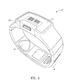
図2には、CPU、メモリ、有線および無線通信などを含むハウジング内に取り付けられたディスプレイ16(例えば、可視OLEDなど)、1つまたは複数のボタン22、圧力センサアレイ12を収容するリストバンド14、1つまたは複数の光学または他の非圧力センサ18、およびストラップ閉鎖、保持またはロック機構20を備える。リストバンドストラップはその上に埋め込まれた圧力センサを有し、センサアレイ12を少なくとも1つの橈骨動脈、尺骨動脈および上腕動脈に適用し、その上に中程度の圧力(すなわち、収縮期圧よりも有意に低いが、圧力波を感知するのに十分である)を加えながら、手首に対して閉じられるように構成される。
FIG. 2 shows a display 16 (e.g., visible OLED, etc.) mounted within a housing that includes a CPU, memory, wired and wireless communications, etc., one or
図3Aには、血管、圧力センサ、および装置ハウジングの向きを示す、ユーザの手首の、全体として30で参照される、手が内側に向いている左手の手首の断面(すなわち、横断面)を示す図が示されている。ウェアラブルの主ハウジング42は、ストラップ14が手首の周りに配置された状態で、手首の頂部に配置される。この断面は、腕の橈骨40および尺骨38、橈骨34および尺骨36の動脈を示す。この例では、圧力センサアレイ12は、橈骨動脈34が位置する手首の領域に配置される。
FIG. 3A shows a cross-section (i.e., transverse cross-section) of a left hand wrist with the hand facing inwards, generally referenced at 30, of a user's wrist showing the orientation of the blood vessels, pressure sensor, and device housing. An illustrative diagram is shown. The wearable's
腕に配置され、ユーザの血圧を測定するように動作するように適合された、本発明の例示的な着用可能なデバイスを示す図が、図3Bに示される。代替の実施形態では、着用可能デバイスが肘の上または下においてユーザの腕に配置されるように構成される。ウェアラブル装置は、アームバンド33と、複数のセンサ素子37を含むセンサアレイ31と、電子機器、ディスプレイ、ボタン等を含むハウジング35とを備える。
A diagram showing an exemplary wearable device of the present invention placed on an arm and adapted to operate to measure a user's blood pressure is shown in FIG. 3B. In alternative embodiments, the wearable device is configured to be placed on the user's arm above or below the elbow. The wearable device comprises an
動作中、センサアレイ31は、アームバンドの底部に配置され、破線で示すように、上腕動脈39が橈骨動脈および尺骨動脈に分岐する前の、上腕動脈39の上に配置される。あるいはセンサアレイおよびアームバンドを、肘の下で腕に取り付けることもでき、橈骨動脈または尺骨動脈からの血圧を感知する。装置は、通信システムを備えてもよい。この場合、血圧データは、信号データを処理して血圧測定値を生成するように動作する外部ホスト装置に中継される。あるいは、装置は、センサ信号データ自体を処理し、連続的な血圧測定値を生成するように適合された、適切にプログラムされたプロセッサを備えてもよい。別の実施形態では装置が上述のような手首装着装置と組み合わせて動作するように構成されてもよく、それによって、アームバンド装置は手首装着装置と無線で通信する。例えば、未加工のセンサ信号データは、アームバンドデバイスから手首装着デバイスに無線で通信されてもよく、そこで、未加工のセンサ信号データは処理され、血圧測定値が手首装着デバイス上でユーザに表示される。
In operation, the
圧力センサアレイは、多数の異なる構成を含むことができることに留意されたい。本発明は、多数の構成が想定され、任意の1つの構成に限定されない。ここで、いくつかの例示的な構成を提示する。 Note that the pressure sensor array can include many different configurations. The invention contemplates numerous configurations and is not limited to any one configuration. Here some exemplary configurations are presented.
本発明の例示的な血圧センサアレイの第1の実施形態を図4Aに示す。この例では、センサアレイ12が3つの圧力センサを含む。3つのセンサは、リストストラップ上に構成され、ユーザの手首に取り付けられると、それらはほぼ橈骨動脈上に配置される。装置は、3つのセンサすべてから同時に信号を受信するように構成される。これらの信号のうちの1つは、さらなる処理のために血圧波形として選択されてもよく、または、すべての信号の重み付けされた和から構成される複合信号が血圧波形を生成するために使用されてもよい。
A first embodiment of an exemplary blood pressure sensor array of the present invention is shown in FIG. 4A. In this example,
複数の圧力センサから複数の信号を取得することは、圧力センサアレイの正確な配置の問題を排除することに留意することが重要である。圧力センサのうちの少なくとも1つが、正しくまたは十分に正しく配置される限り、受信される信号は血圧波形から正しい血圧読み取り値を導出するのに十分であり得る。 It is important to note that obtaining multiple signals from multiple pressure sensors eliminates the problem of precise placement of the pressure sensor array. As long as at least one of the pressure sensors is positioned correctly or sufficiently correctly, the received signal may be sufficient to derive a correct blood pressure reading from the blood pressure waveform.
本発明の例示的な血圧センサアレイの第2の実施形態を図4Bに示す。この例では、リストバンド14上の圧力センサアレイ13が線形アレイに構成された複数のセンサ15を備える。装置は、すべてのセンサから同時に信号を受信するように構成される。これらの信号のうちの1つはさらなる処理のために血圧波形として選択されてもよく、または、すべての信号の重み付けされた和から構成される複合信号が血圧波形を生成するために使用されてもよい。リニアアレイに配置された複数の圧力センサから複数の信号を取得することは、圧力センサアレイの正確な配置の問題を排除する。圧力センサのうちの少なくとも1つが、正しくまたは十分に正しく配置される限り、受信される信号は血圧波形から正しい血圧読み取り値を導出するのに十分であり得る。センサの線形アレイは、図4Bに示されるように、リストストラップに対して垂直に構成されてもよく、またはリストストラップに対して任意の所望の角度で構成されてもよいことが理解される。
A second embodiment of an exemplary blood pressure sensor array of the present invention is shown in FIG. 4B. In this example, the
本発明の例示的な血圧センサアレイの第3の実施形態を図4Cに示す。この例では、リストバンド14上の圧力センサアレイ17が2次元(2D)アレイに構成された複数のセンサ19を備える。装置は、すべてのセンサから同時に信号を受信するように構成される。これらの信号のうちの1つは、さらなる処理のために血圧波形として選択されてもよく、または、すべての信号の重み付けされた和から構成される複合信号が血圧波形を生成するために使用されてもよい。2Dアレイに配置された複数の圧力センサから複数の信号を取得することは、圧力センサアレイの正しい配置の問題を排除する。圧力センサのうちの少なくとも1つが、正しくまたは正しく十分に配置される限り、受信される信号は血圧波形から正しい血圧読み取り値を導出するのに十分であり得る。センサの2Dアレイは、図4Bに示されるように、リストストラップに対して垂直に構成されてもよく、またはリストストラップに対して任意の所望の角度で構成されてもよいことが理解される。
A third embodiment of an exemplary blood pressure sensor array of the present invention is shown in FIG. 4C. In this example,
図5は、複数の圧力センサの出力信号を表す複数の波形を示す図である。各センサは、ユーザの手首上で異なる位置にある。5つの波形、すなわち、波形150、152、154、156、158は、上述したようなセンサアレイに構成され、ユーザの手首上に配置された5つの異なる圧力センサからの出力信号を表す。x軸は時間を表し、y軸は、センサ出力信号の振幅に関連するmmHgを表す。
FIG. 5 is a diagram illustrating multiple waveforms representing output signals of multiple pressure sensors. Each sensor is at a different location on the user's wrist. Five waveforms,
予想されるように、いくつかの信号は、他の信号よりも高品質である。特に、波形152および156内の信号は、いずれの信号もほとんど反応せず、非常に弱く、それらが橈骨動脈からの圧力を感知するために適切でないことを示す。波形150および154内の信号はより強い信号を感知するが、それでもなおかなり弱く、それらがまた、橈骨動脈上の位置にないことを示す。しかしながら、波形158の信号は比較的強く、これが橈骨動脈上に良好に配置されていることを示し、後続の処理のための血圧波形として使用することができる。この例では5つの圧力センサ信号が示されているが、本発明の範囲から逸脱することなく、任意の数の2つ以上のセンサを使用することができることを理解されたい。
As expected, some signals are of higher quality than others. In particular, the signals in
別の実施形態では、アレイを構成する個々の圧力センサが、異なるタイプのセンサを含むことができる。例えば、センサの第1の部分は、典型的には低電力消費及び低精度を有する容量性圧力センサを含むことができる。センサの第2の部分は典型的には高い電力消費を有するが、より良好な精度を有する抵抗圧力センサを含むことができる。一実施形態では、1つまたは複数の抵抗圧力センサ(すなわち、比較的高精度のセンサ)から得られる信号を使用して、1つまたは複数の容量圧力センサ(すなわち、比較的低精度のセンサ)からの読取り値を較正し、それによって、著しく高い精度を有する血圧読取り値を得ることができる。 In another embodiment, the individual pressure sensors that make up the array can include different types of sensors. For example, the first portion of sensors may include capacitive pressure sensors, which typically have low power consumption and low accuracy. The second part of the sensor typically has higher power consumption but can include a resistive pressure sensor with better accuracy. In one embodiment, signals obtained from one or more resistive pressure sensors (i.e., relatively high accuracy sensors) are used to The readings from can be calibrated, thereby obtaining blood pressure readings with significantly higher accuracy.
一実施形態では、アレイ内の圧力センサのうちの1つからの信号が血圧測定値を導出するために使用される血圧波形として選択される。他のすべての選択されていないセンサからの信号は、無視されるか、または破棄される。センサ信号は例えば、SNR、RSSIなどの任意の所望の1つ以上の品質メトリックについて分析されてもよい。 In one embodiment, the signal from one of the pressure sensors in the array is selected as the blood pressure waveform used to derive the blood pressure measurement. Signals from all other non-selected sensors are ignored or discarded. Sensor signals may be analyzed for any desired one or more quality metrics, such as SNR, RSSI, for example.
別の実施形態では、アレイ内の圧力センサのすべてまたは一部からの信号が重み付けスキームを使用して結合され、改善された信号対雑音比(SNR)を有する複合血圧波形を生成する。次いで、複合血圧波形を使用して、より正確な血圧読取り値を生成する。 In another embodiment, signals from all or some of the pressure sensors in the array are combined using a weighting scheme to produce a composite blood pressure waveform with improved signal-to-noise ratio (SNR). The composite blood pressure waveform is then used to generate a more accurate blood pressure reading.
別の実施形態では、上述の2つの技法を組み合わせることができ、1つまたは複数のセンサ信号が任意の所望の品質メトリックに基づいて選択され、これらの信号が重み付けされ、結合されて、複合血圧波形が生成される。 In another embodiment, the two techniques described above can be combined, where one or more sensor signals are selected based on any desired quality metric, these signals are weighted and combined to produce a composite blood pressure A waveform is generated.
本発明に従って構成された着用可能な装置の一例を示すブロック図を、図6に示す。着用可能な装置70は、リストバンドセンサユニット72と、デジタルバス84によって互いに通信する制御ユニット74とを備えている。リストバンドセンサユニット72は、各々がアナログ-デジタル変換器80に結合された複数の圧力センサ1~N(78)を含む。ADCの出力はマルチプレクサ82に入力され、マルチプレクサ82はデジタルバス84に多重化された全ての入力信号を送信するように構成されている。一実施形態では、すべてのセンサ78から出力される信号が制御ユニット74に入力される。
A block diagram illustrating one example of a wearable device constructed in accordance with the present invention is shown in FIG.
制御ユニット74は、プロセッサ86(例えば、CPU、マイクロコントローラ、マイクロプロセッサ等)、ディスプレイサブシステム88、メモリ102(例えば、揮発性、不揮発性、フラッシュ等)、無線および有線通信サブシステム100、および1つ以上の他の非圧力センサ104(例えば、光学、フォトプレチスモグラフ、温度等)を備える。制御ユニット74は、無線LAN、BLE(Bluetooth(登録商標) Low Energy)、USB(Universal Serial Bus)接続などの無線および/または有線通信チャネルを介してホストデバイス76と通信する。プロセッサ86は、デジタルバス84を介してリストバンドセンサユニットとデータを送受信するように構成される。表示サブシステムは、血圧測定値を表示するように構成される。
The control unit 74 includes a processor 86 (eg, CPU, microcontroller, microprocessor, etc.), a
本発明による複合血圧波形を生成するための例示的な回路を示すブロック図を、図7に示す。回路110は、適応重みアルゴリズムブロック118と、乗算器1~N(114)と、加算器116とを備えている。動作中、N個のスケーリングファクタが、N個の圧力センサから受信された血圧波形データサンプル112に適用される。血圧波形データは、乗算器114および適応重みアルゴリズムブロック118に入力される。合成血圧波形119は、適応重みアルゴリズムにも入力される。このアルゴリズムは入力データから、N個のスケールファクタ113(すなわち係数)α1~αNを生成するように動作し、これらのスケールファクタは、N個の乗算器114にそれぞれ適用される。乗算器によって生成された積115は加算器116を介して加算されて、合成血圧波形119を生成し、次いで、この合成血圧波形119は、さらに処理されて、血圧読み取り値を生成する。
A block diagram illustrating exemplary circuitry for generating a composite blood pressure waveform in accordance with the present invention is shown in FIG. The
適応重み付けアルゴリズム118は、N個の血圧波形信号ならびに複合出力波形119を受け取り、複合血圧波形119上のSNRが最大になるように係数α1~αNを推定するように構成される。
例示的な実施形態では、重みは以下の式に従って、最小二乗最大比合成(MRC)法に基づいて、ブロック147を介して計算される。
In an exemplary embodiment, the weights are calculated via

一実施形態では、信号の振幅を、二乗平均平方根(RMS)推定や分散などの任意の適切な周知の技法を使用して推定することができる。 In one embodiment, the amplitude of the signal may be estimated using any suitable known technique such as root mean square (RMS) estimation or variance.
本発明による血圧波形結合(または較正)の例示的な方法を示すフローチャートが図8に示されていることに留意されたい。この例示的な方法では、N個のセンサの一部Pがより高い精度を有し(例えば、抵抗MEMS型圧力センサ)、N個のセンサの一部Rはより低い精度を有し(例えば、容量性MEMS型圧力センサ)、ここで、R+P=Nである。センサ1~センサPはより高い精度のセンサであり、センサP+1~センサNは、より低い精度のセンサである。 Note that a flow chart illustrating an exemplary method of blood pressure waveform combining (or calibration) according to the present invention is shown in FIG. In this exemplary method, some P of the N sensors have higher accuracy (eg, resistive MEMS pressure sensors) and some R of the N sensors have lower accuracy (eg, capacitive MEMS type pressure sensor), where R+P=N. Sensor 1 through sensor P are higher accuracy sensors and sensor P+1 through sensor N are lower accuracy sensors.
図8を参照すると、まず、複数のN個の圧力センサからの信号が取得される(ステップ130)。次に、R個の圧力センサP+1~センサNからの血圧波形に対するスケーリングファクタ較正が推定される(ステップ132)。R個の圧力センサP+1~センサNからの血圧波形は、ステップ132で得られた推定スケーリングファクタによって乗算される(ステップ134)。次に、センサ1~センサNから得られたスケーリングされた血圧波形が組み合わされ(ステップ136)、複合血圧波形がさらなる処理のために出力され、そこから血圧読取り値が導出される(ステップ138)。この方法によれば、より高いSNRを有する合成血圧波形を得られる。 Referring to FIG. 8, first, signals from a plurality of N pressure sensors are acquired (step 130). A scaling factor calibration for the blood pressure waveforms from R pressure sensors P+1 through sensor N is then estimated (step 132). The blood pressure waveforms from R pressure sensors P+1 through sensor N are multiplied by the estimated scaling factor obtained in step 132 (step 134). The scaled blood pressure waveforms obtained from Sensors 1-N are then combined (step 136) and the composite blood pressure waveform is output for further processing from which blood pressure readings are derived (step 138). . This method yields a synthetic blood pressure waveform with a higher SNR.
本発明による複数の圧力センサの1つから血圧波形を選択するための例示的な回路を示すブロック図を、図9に示す。全体を120で示す回路は、複数のN個の圧力センサ入力モジュール122と、マルチプレクサ121と、電力管理ユニット127と、プロセッサブロック129とを備えている。各圧力センサ入力モジュール122は、圧力センサ124と、任意選択のフィルタ回路126と、アナログ-デジタル変換器(ADC)128とを含む。プロセッサ129は、特に、走査シーケンサ143および品質メトリック計算ブロック147を備える。
A block diagram illustrating exemplary circuitry for selecting a blood pressure waveform from one of a plurality of pressure sensors in accordance with the present invention is shown in FIG. A circuit generally designated 120 comprises a plurality of N pressure
上述のように、一実施形態では、着用可能デバイスが単一の圧力センサによって出力される信号を選択し、他のすべてのセンサからの信号を無視することによって、1つまたは複数の品質メトリックを最大化する。これは、プロセッサ86(図6)を介してソフトウェアを使用して達成することができ、それによって、すべてのセンサからの信号波形が受信され、1つを除くすべてが破棄される。 As described above, in one embodiment, the wearable device determines one or more quality metrics by selecting the signal output by a single pressure sensor and ignoring signals from all other sensors. maximize. This can be accomplished using software via processor 86 (FIG. 6), whereby signal waveforms from all sensors are received and all but one are discarded.
この実施形態120では、1つの圧力センサ入力モジュールを除くすべての圧力センサ入力モジュールへの電力を無効にすることによって、電力消費が低減される。動作中、N個のセンサ入力モジュールすべてからの信号がプロセッサに入力され、ブロック147を介して1つまたは複数の品質メトリックが計算される。走査シーケンサは、N個のセンサ入力モジュールからの信号データの収集を制御する。計算されたメトリックに従って、先頭メトリックに基づいてセンサ入力モジュールの1つが選択される。
In this
センサ入力モジュールが選択されると、N-1個の選択されていないセンサ入力モジュールへの電力は、電力管理ブロック127によって生成される電力イネーブル信号145を介して無効化される。プロセッサはまた、選択されたセンサ入力モジュールによって生成された信号を渡すために、マルチプレクサ121への適切な選択コマンド141を生成する。次いで、マルチプレクサから出力された血圧波形125は、血圧読取り値を生成するためにさらに処理される。一実施形態では、N個の圧力センサすべてからのデータを再評価し(すなわち、再スキャンし)、新しいセンサを選択することができる。再評価は定期的に(例えば10秒毎に)、または、センサデータから計算されたいずれかのメトリックが閾値を下回って(例えば、センサ出力が所定のSNRまたはRSSIを下回ったときに)走査が開始される動的ベースで、実行することができる。
When a sensor input module is selected, power to the N−1 unselected sensor input modules is disabled via power enable
プロセッサブロック147によって計算された1つまたは複数の品質メトリックは、任意の所望のメトリックを含むことができることに留意されたい。メトリックの例には、SNRおよびRSSIが含まれる。しかし、本発明はこれらのメトリックに限定されないことが理解される。
Note that the one or more quality metrics calculated by
本発明による血圧波形選択の例示的な方法を示すフローチャートを図10に示す。最初に、複数のN個の圧力センサからの信号が取得され、プロセッサに入力される(ステップ140)。1つ以上の品質メトリック(例えば、SNR、RSSI等)が計算される(ステップ142)。メトリック計算が比較され、首位メトリックが決定される(ステップ144)。次に、首位の品質メトリックに対応するセンサ信号が選択される(ステップ146)。選択された血圧波形は、血圧判定処理に出力される(ステップ148)。任意選択で、電力消費を低減するために、選択されていないセンサに対応するセンサ入力モジュールへの電力は無効にされる。上述したように、N個の圧力センサすべてからのデータを再走査し、新しいセンサを選択することができる。 A flowchart illustrating an exemplary method of blood pressure waveform selection in accordance with the present invention is shown in FIG. First, signals from a plurality of N pressure sensors are acquired and input to the processor (step 140). One or more quality metrics (eg, SNR, RSSI, etc.) are calculated (step 142). The metric calculations are compared to determine the leading metric (step 144). Next, the sensor signal corresponding to the leading quality metric is selected (step 146). The selected blood pressure waveform is output to blood pressure determination processing (step 148). Optionally, power to sensor input modules corresponding to unselected sensors is disabled to reduce power consumption. As described above, the data from all N pressure sensors can be rescanned and new sensors selected.
当業者であれば、論理ブロックと回路ブロックとの間の境界は単に例示的なものであり、代替実施形態は、論理ブロックまたは回路要素を併合するか、または様々な論理ブロックまたは回路要素に機能を分散できることを理解するであろう。したがって、本明細書に示されるアーキテクチャは単に例示的なものであり、実際には、同じ機能を達成する多くの他のアーキテクチャを実装することができることを理解されたい。 Those skilled in the art will appreciate that the boundaries between logic blocks and circuit blocks are merely exemplary and that alternative embodiments may merge logic blocks or circuit elements or function on different logic blocks or circuit elements. can be distributed. Therefore, it should be understood that the architecture shown herein is merely exemplary and that in practice many other architectures can be implemented that achieve the same functionality.
同じ機能性を達成するための構成要素の任意の配置は所望の機能が達成されるように、効果的に「関連付けられる」。したがって、特定の機能を達成するために本明細書で組み合わされる任意の2つのコンポーネントは、アーキテクチャまたは中間コンポーネントにかかわらず、所望の機能が達成されるように、互いに「関連付けられる」と見なされ得る。同様に、そのように関連する任意の2つの構成要素は所望の機能を達成するために、互いに「動作可能に接続される」、または「動作可能に結合される」と見なすこともできる。 Any arrangement of components to achieve the same functionality is effectively "linked" such that the desired function is achieved. Thus, any two components that are combined herein to achieve a particular function, regardless of architecture or intermediate components, can be considered "associated" with each other such that the desired function is achieved. . Similarly, any two components so related may also be considered "operably connected" or "operably coupled" to each other to achieve a desired function.
さらに、当業者は、上述の動作間の境界が単に例示的なものであることを認識するであろう。複数の演算は、単一の演算に組み合わされてもよい。単一のオペレーションは追加のオペレーションに分散されてもよく、オペレーションは少なくとも部分的に時間的に重複して実行されてもよい。さらに、代替の実施形態は特定の動作の複数のインスタンスを含むことができ、動作の順序は、様々な他の実施形態で変更することができる。 Moreover, those skilled in the art will recognize that the boundaries between operations described above are merely exemplary. Multiple operations may be combined into a single operation. A single operation may be distributed in additional operations, and the operations may be performed at least partially overlapping in time. Additionally, alternative embodiments may include multiple instances of a particular operation, and the order of operations may be altered in various other embodiments.
本明細書で使用される用語は特定の実施形態を説明するためだけのものであり、本発明を限定することを意図するものではない。本明細書で使用されるように、単数形「a」、「an」および「the」は文脈が明確にそうでないことを示さない限り、複数形も含むことが意図される。さらに、「comprises」および/または「comprising」という用語は本明細書で使用される場合、述べられた特徴、整数、ステップ、動作、要素、および/または構成要素の存在を指定するが、1つまたは複数の他の特徴、整数、ステップ、動作、要素、構成要素、および/またはそれらのグループの存在または追加を排除しないことが理解されるであろう。 The terminology used herein is for the purpose of describing particular embodiments only and is not intended to be limiting of the invention. As used herein, the singular forms "a," "an," and "the" are intended to include the plural forms as well, unless the context clearly indicates otherwise. Additionally, the terms “comprises” and/or “comprising” as used herein specify the presence of the stated features, integers, steps, acts, elements and/or components, but not one or the presence or addition of multiple other features, integers, steps, acts, elements, components, and/or groups thereof.
特許請求の範囲において、括弧内に置かれたいずれの参照符号も、特許請求の範囲を限定するものとして解釈されるべきではない。特許請求の範囲における「少なくとも1つ」および「1つ以上」などの導入語句の使用は、不定冠詞「a」または「an」による別の請求項要素の導入が同じ請求項が「1つ以上」または「少なくとも1つ」の導入語句および「a」または「an」などの不定冠詞を含む場合であっても、そのような導入された請求項要素を含む任意の特定の請求項を、そのような要素のみを含む発明に限定することを意味するものと理解されるべきでない。定冠詞についても同様である。特に断らない限り、「第1」、「第2」などの用語は、そのような用語が記述する要素を任意に区別するために使用される。従って、これらの語は必ずしも要素間の時間的又は他の優先順位を示すものではない。特定の手段が相互に異なる特許請求の範囲に記載されているという単なる事実は、これらの手段の組み合わせを有利に使用できないことを示すものではない。 In the claims, any reference signs placed between parentheses shall not be construed as limiting the claim. The use of introductory phrases such as "at least one" and "one or more" in a claim means that the introduction of another claim element by the indefinite article "a" or "an" indicates that the same claim refers to "one or more". or "at least one" and an indefinite article such as "a" or "an." It should not be construed as being meant to be limited to the invention containing only such elements. The same is true for the definite article. Unless otherwise stated, terms such as “first,” “second,” etc. are used to arbitrarily distinguish between the elements such terms describe. As such, these terms do not necessarily indicate a temporal or other priority between elements. The mere fact that certain measures are recited in mutually different claims does not indicate that a combination of these measures cannot be used to advantage.
以下の特許請求の範囲におけるすべての機能的手段または工程要素の対応する構造、材料、動作、および均等物は、具体的に記載された他の請求要素と組合せて機能を実行するための任意の構造、材料、または動作を含むことが意図される。本発明の説明は、例示および説明の目的のために提示されたものであり、網羅的であること、または開示された形態の本発明に限定されることを意図するものではない。当業者には多数の修正および変更が容易に想起されるので、本発明は、本明細書に記載される限定された数の実施形態に限定されないことが意図される。したがって、すべての適切な変形、修正、および均等物が、本発明の精神および範囲内に入るように頼ることができることが理解されるであろう。実施形態は本発明の原理および実際の用途を最もよく説明するために、また、他の当業者が企図する特定の用途に適した様々な修正を伴う様々な実施形態について本発明を理解することを可能にするために、選択され、説明された。 Corresponding structure, material, operation and equivalents of all functional means or process elements in the following claims refer to any combination for performing the function in combination with other specifically recited claim elements. It is intended to include structure, material, or action. The description of the present invention has been presented for purposes of illustration and description, and is not intended to be exhaustive or limited to the invention in the form disclosed. It is intended that this invention not be limited to the limited number of embodiments described herein, as numerous modifications and changes will readily occur to those skilled in the art. It will therefore be understood that all suitable variations, modifications and equivalents can be relied upon to come within the spirit and scope of the invention. The embodiments are intended to best explain the principles and practical applications of the invention, and the understanding of the invention in terms of various embodiments with various modifications suitable for particular applications contemplated by others skilled in the art is intended. selected and described to enable
Claims (6)
複数のN個の圧力センサを備えた装置が、前記複数のN個の圧力センサにより、複数のN個の血圧波形信号を同時に取得することと、
前記装置が、前記複数のN個の血圧波形信号のそれぞれの品質として、信号対雑音比(SNR)および受信信号強度表示(RSSI)を含むグループから選択される品質に基づいて、前記複数の圧力センサのうち、1つ以上の相対的に正確な圧力センサと、1つ以上の相対的に正確でない圧力センサとを特定することと、
前記装置が、前記複数の圧力センサのうち、前記1つ以上の相対的に正確な圧力センサからの1つ以上の血圧波形信号を利用して、前記複数の圧力センサのうち、前記1つ以上の相対的に正確でない圧力センサからの1つ以上の血圧波形信号を較正することと、
前記装置が、1つ以上の較正された血圧波形信号を含む前記N個の血圧波形信号を結合して、そこから前記出力血圧信号を生成することと、を含み、
前記血圧波形信号のそれぞれは、前記圧力センサの一つから取得され、
前記1つ以上の相対的に正確でない圧力センサからの1つ以上の血圧波形信号を較正することは、前記1つ以上の相対的に正確な圧力センサから、前記1つ以上の相対的に正確でない圧力センサについてのスケールファクタを推定し、前記1つ以上の較正された血圧波形信号を生成するために、前記1つ以上の相対的に正確でない圧力センサからの1つ以上の血圧波形信号に前記スケールファクタを乗算することを含み、
前記出力血圧信号は、前記N個の血圧波形信号のそれぞれの係数を利用する加重和を含み、
前記係数は、前記出力血圧信号が前記N個の圧力センサ信号のうちの1つまたは複数よりも高い信号対雑音比(SNR)を有するように、適応アルゴリズムを使用して推定される、方法。 A method of obtaining an output blood pressure signal, comprising:
a device comprising a plurality of N pressure sensors simultaneously acquiring a plurality of N blood pressure waveform signals by the plurality of N pressure sensors;
wherein the apparatus selects the quality of each of the plurality of N blood pressure waveform signals from a group including signal-to-noise ratio (SNR) and received signal strength indication (RSSI); identifying one or more relatively accurate pressure sensors and one or more relatively inaccurate pressure sensors among the sensors;
The device utilizes one or more blood pressure waveform signals from the one or more relatively accurate pressure sensors of the plurality of pressure sensors to calibrating one or more blood pressure waveform signals from relatively inaccurate pressure sensors of
said apparatus combining said N blood pressure waveform signals, including one or more calibrated blood pressure waveform signals, to generate said output blood pressure signal therefrom;
each of the blood pressure waveform signals obtained from one of the pressure sensors;
Calibrating one or more blood pressure waveform signals from the one or more relatively inaccurate pressure sensors is performed by calibrating the one or more relatively accurate pressure sensors from the one or more relatively accurate pressure sensors. to one or more blood pressure waveform signals from the one or more relatively inaccurate pressure sensors to estimate a scale factor for the non-accurate pressure sensors and generate the one or more calibrated blood pressure waveform signals . multiplying the scale factor ;
wherein said output blood pressure signal comprises a weighted sum utilizing coefficients of each of said N blood pressure waveform signals;
The method, wherein the coefficients are estimated using an adaptive algorithm such that the output blood pressure signal has a higher signal-to-noise ratio (SNR) than one or more of the N pressure sensor signals .
複数のN個の圧力センサと、
複数のN個の血圧波形信号を同時に取得するように動作する取得回路であって、各波形信号は前記圧力センサのうちの1つから取得される、取得回路と、
プロセッサとを含み、
前記プロセッサは、
前記複数のN個の血圧波形信号のそれぞれの品質として、信号対雑音比(SNR)および受信信号強度表示(RSSI)を含むグループから選択される品質に基づいて、前記複数の圧力センサのうち、1つ以上の相対的に正確な圧力センサと、1つ以上の相対的に正確でない圧力センサとを特定し、
前記複数の圧力センサ内の前記1つ以上の相対的に正確な圧力センサからの1つ以上の血圧波形信号を利用して、前記複数の圧力センサ内の前記1つ以上の相対的に正確でない圧力センサからの1つ以上の血圧波形信号を較正し、
1つ以上の較正された血圧波形信号を含む前記N個の血圧波形信号を結合して、それから前記出力血圧信号を生成する、ようにプログラムされており、
前記1つ以上の相対的に正確でない圧力センサからの1つ以上の血圧波形信号を較正することは、前記1つ以上の相対的に正確な圧力センサから、前記1つ以上の相対的に正確でない圧力センサについてのスケールファクタを推定し、前記1つ以上の較正された血圧波形信号を生成するために、前記1つ以上の相対的に正確でない圧力センサからの1つ以上の血圧波形信号に前記スケールファクタを乗算することを含み、
前記出力血圧信号は、前記N個の血圧波形信号のそれぞれの係数を利用する加重和を含み、
前記係数は、前記出力血圧信号が前記N個の圧力センサ信号のうちの1つまたは複数よりも高い信号対雑音比(SNR)を有するように、適応アルゴリズムを使用して推定される、装置。 An apparatus for obtaining an output blood pressure signal, comprising:
a plurality of N pressure sensors;
acquisition circuitry operable to simultaneously acquire a plurality of N blood pressure waveform signals, each waveform signal acquired from one of said pressure sensors;
a processor;
The processor
Based on the quality of each of the plurality of N blood pressure waveform signals selected from a group including signal-to-noise ratio (SNR) and received signal strength indication (RSSI) , among the plurality of pressure sensors, identifying one or more relatively accurate pressure sensors and one or more relatively inaccurate pressure sensors;
utilizing one or more blood pressure waveform signals from the one or more relatively accurate pressure sensors in the plurality of pressure sensors to determine the one or more relatively inaccurate pressure sensors in the plurality of pressure sensors; calibrate one or more blood pressure waveform signals from the pressure sensor;
programmed to combine the N blood pressure waveform signals, including one or more calibrated blood pressure waveform signals, to produce therefrom the output blood pressure signal;
Calibrating one or more blood pressure waveform signals from the one or more relatively inaccurate pressure sensors is performed by calibrating the one or more relatively accurate pressure sensors from the one or more relatively accurate pressure sensors. to one or more blood pressure waveform signals from the one or more relatively inaccurate pressure sensors to estimate a scale factor for the non-accurate pressure sensors and generate the one or more calibrated blood pressure waveform signals . multiplying the scale factor ;
wherein said output blood pressure signal comprises a weighted sum utilizing coefficients of each of said N blood pressure waveform signals;
The apparatus , wherein the coefficients are estimated using an adaptive algorithm such that the output blood pressure signal has a higher signal-to-noise ratio (SNR) than one or more of the N pressure sensor signals .
複数のN個の圧力センサと、
複数のN個の血圧波形信号を同時に取得するように動作する取得回路であって、各波形信号は前記圧力センサのうちの1つから取得される、取得回路と、
プロセッサとを含み、
前記プロセッサは、
前記N個の血圧波形信号のうちの1つまたは複数を、信号対雑音比(SNR)および受信信号強度表示(RSSI)を含むグループから選択される1つ以上の品質メトリックに従って選択し、
前記選択された1つの信号または前記選択された複数の信号のそれぞれの係数を利用する加重和を含む信号を前記出力血圧信号として出力する、ようにプログラムされ、
前記係数は、前記出力血圧信号が前記N個の圧力センサ信号のうちの1つまたは複数よりも高い信号対雑音比(SNR)を有するように、適応アルゴリズムを使用して推定される、装置。 An apparatus for obtaining an output blood pressure signal, comprising:
a plurality of N pressure sensors;
acquisition circuitry operable to simultaneously acquire a plurality of N blood pressure waveform signals, each waveform signal acquired from one of said pressure sensors;
a processor;
The processor
selecting one or more of the N blood pressure waveform signals according to one or more quality metrics selected from the group comprising signal-to-noise ratio (SNR) and received signal strength indication (RSSI) ;
programmed to output, as the output blood pressure signal, a signal containing a weighted sum using respective coefficients of the selected one signal or the selected plurality of signals ;
The apparatus , wherein the coefficients are estimated using an adaptive algorithm such that the output blood pressure signal has a higher signal-to-noise ratio (SNR) than one or more of the N pressure sensor signals .
Applications Claiming Priority (5)
| Application Number | Priority Date | Filing Date | Title |
|---|---|---|---|
| US201662415003P | 2016-10-31 | 2016-10-31 | |
| US62/415,003 | 2016-10-31 | ||
| US15/401,432 US10722125B2 (en) | 2016-10-31 | 2017-01-09 | Blood pressure signal acquisition using a pressure sensor array |
| US15/401,432 | 2017-01-09 | ||
| PCT/US2017/058197 WO2018081208A1 (en) | 2016-10-31 | 2017-10-25 | Blood pressure signal acquisition using a pressure sensor array |
Publications (3)
| Publication Number | Publication Date |
|---|---|
| JP2019536504A JP2019536504A (en) | 2019-12-19 |
| JP2019536504A5 JP2019536504A5 (en) | 2020-12-03 |
| JP7175509B2 true JP7175509B2 (en) | 2022-11-21 |
Family
ID=62020037
Family Applications (1)
| Application Number | Title | Priority Date | Filing Date |
|---|---|---|---|
| JP2019517988A Active JP7175509B2 (en) | 2016-10-31 | 2017-10-25 | Method and apparatus for obtaining output blood pressure signal |
Country Status (8)
| Country | Link |
|---|---|
| US (1) | US10722125B2 (en) |
| EP (1) | EP3531905A4 (en) |
| JP (1) | JP7175509B2 (en) |
| KR (1) | KR102579840B1 (en) |
| CN (1) | CN109890277B (en) |
| BR (1) | BR112019008681A8 (en) |
| CA (1) | CA3037786A1 (en) |
| WO (1) | WO2018081208A1 (en) |
Families Citing this family (11)
| Publication number | Priority date | Publication date | Assignee | Title |
|---|---|---|---|---|
| US11839453B2 (en) * | 2016-03-31 | 2023-12-12 | The Regents Of The University Of California | Soft capacitive pressure sensors |
| US10722125B2 (en) | 2016-10-31 | 2020-07-28 | Livemetric (Medical) S.A. | Blood pressure signal acquisition using a pressure sensor array |
| US11000193B2 (en) | 2017-01-04 | 2021-05-11 | Livemetric (Medical) S.A. | Blood pressure measurement system using force resistive sensor array |
| EP3430993A1 (en) * | 2017-07-21 | 2019-01-23 | Koninklijke Philips N.V. | An apparatus for measuring a physiological parameter using a wearable sensor |
| US11259712B2 (en) | 2018-11-13 | 2022-03-01 | International Business Machines Corporation | Wearable reflectance-mode PPG sensor network having improved detected signal strength |
| CN109805918A (en) * | 2018-12-28 | 2019-05-28 | 北京津发科技股份有限公司 | A kind of equipment based on annular multipoint pressure measurement pulse wave |
| KR102356200B1 (en) * | 2019-03-06 | 2022-01-27 | (주)참케어 | Blood Pressure Meter And Method For Measuring Blood Pressure Using The Same |
| WO2021176277A1 (en) * | 2020-03-02 | 2021-09-10 | Synapsis Medical Inc. | System and methods for physiological parameter measurement |
| KR20210117693A (en) * | 2020-03-20 | 2021-09-29 | (주)참케어 | Blood Pressure Meter And Method For Measuring Blood Pressure Using The Same |
| CN113397539B (en) * | 2021-07-29 | 2022-06-07 | 宁波康和生物科技有限公司 | Portable noninvasive blood glucose detector |
| CN114145721B (en) * | 2021-11-12 | 2023-12-01 | 北京纳米能源与系统研究所 | Method and device for determining arterial pressure and readable storage medium |
Citations (7)
| Publication number | Priority date | Publication date | Assignee | Title |
|---|---|---|---|---|
| JP2004113368A (en) | 2002-09-25 | 2004-04-15 | Nippon Colin Co Ltd | Indirect continuous blood pressure monitoring device |
| JP2008245943A (en) | 2007-03-30 | 2008-10-16 | Citizen Holdings Co Ltd | Pulse wave measuring instrument |
| JP2010057817A (en) | 2008-09-05 | 2010-03-18 | Omron Healthcare Co Ltd | Electronic sphygmomanometer |
| JP2012500033A (en) | 2008-08-15 | 2012-01-05 | スタブル メディカル リサーチ アクチェンゲゼルシャフト | Apparatus and method for continuously measuring blood pressure for monitoring purposes |
| JP2015123300A (en) | 2013-12-27 | 2015-07-06 | セイコーエプソン株式会社 | Biological information measuring device, processing system, biological information processing method and program |
| JP2015165886A (en) | 2014-02-13 | 2015-09-24 | 日本電気株式会社 | Blood pressure estimation device, blood pressure estimation method, blood pressure estimation program, and blood pressure measuring device |
| US20160262695A1 (en) | 2013-10-31 | 2016-09-15 | Quan Zhang | System for measuring and monitoring blood pressure |
Family Cites Families (60)
| Publication number | Priority date | Publication date | Assignee | Title |
|---|---|---|---|---|
| US4605010A (en) | 1984-05-17 | 1986-08-12 | Western Clinical Engineering Ltd. | Pressurizing cuff |
| US5243992A (en) | 1990-03-30 | 1993-09-14 | Colin Electronics Co., Ltd. | Pulse rate sensor system |
| EP0546098A4 (en) * | 1990-08-31 | 1993-09-01 | The University Of Utah | Method and apparatus for determining blood pressure |
| JPH05176900A (en) * | 1991-12-30 | 1993-07-20 | Shimadzu Corp | Hemomanometer |
| JP3029912B2 (en) * | 1992-01-08 | 2000-04-10 | 日本コーリン株式会社 | Pulse rate measuring device |
| US7192403B2 (en) * | 2001-08-17 | 2007-03-20 | Russell Ted W | Methods, apparatus and articles-of-manufacture for noninvasive measurement and monitoring of peripheral blood flow, perfusion, cardiac output biophysic stress and cardiovascular condition |
| US7395105B2 (en) | 2002-12-10 | 2008-07-01 | Koninklijke Philips Electronics, N.V. | Wearable device for bioelectrical interaction with motion artifact correction means |
| JP3726832B2 (en) * | 2003-03-19 | 2005-12-14 | セイコーエプソン株式会社 | Pulse meter, wristwatch type information device, control program, and recording medium |
| US20080287813A1 (en) | 2004-03-30 | 2008-11-20 | Eidgenossische Technische Hochschule Zurich | Blood Pressure Monitoring Device and Methods for Making and for Using Such a Device |
| US7438687B2 (en) | 2004-08-14 | 2008-10-21 | Nova Technology Corporation | Patient monitoring system with blood pressure measurement capacity |
| WO2006020956A2 (en) | 2004-08-13 | 2006-02-23 | Nova Technology Corporation | Patient monitoring system with blood pressure measurement capability |
| US7761127B2 (en) | 2005-03-01 | 2010-07-20 | Masimo Laboratories, Inc. | Multiple wavelength sensor substrate |
| US7651466B2 (en) * | 2005-04-13 | 2010-01-26 | Edwards Lifesciences Corporation | Pulse contour method and apparatus for continuous assessment of a cardiovascular parameter |
| US7641614B2 (en) | 2005-08-22 | 2010-01-05 | Massachusetts Institute Of Technology | Wearable blood pressure sensor and method of calibration |
| US7539532B2 (en) | 2006-05-12 | 2009-05-26 | Bao Tran | Cuffless blood pressure monitoring appliance |
| CN100560019C (en) * | 2007-01-26 | 2009-11-18 | 香港中文大学 | Pulse wave transmission time method is measured the initial calibration device of arteriotony |
| KR100871230B1 (en) | 2007-03-12 | 2008-11-28 | 삼성전자주식회사 | Method and?apparatus for the cuffless and non-invasive device connected to communication device which measures blood pressure from a wrist |
| KR101261176B1 (en) * | 2007-03-23 | 2013-05-09 | 퀄컴 인코포레이티드 | Multi-sensor data collection and/or processing |
| US8602997B2 (en) * | 2007-06-12 | 2013-12-10 | Sotera Wireless, Inc. | Body-worn system for measuring continuous non-invasive blood pressure (cNIBP) |
| WO2009125349A2 (en) | 2008-04-10 | 2009-10-15 | Cardiosigns Ltd. | Multi-sensor apparatus and method for monitoring of circulatory parameters |
| PL2334227T3 (en) * | 2008-09-11 | 2022-09-12 | Acist Medical Systems, Inc. | Physiological sensor delivery device and fluid injection system |
| US20100113943A1 (en) * | 2008-10-31 | 2010-05-06 | Burnes John E | System and method for simultaneous central and brachial arterial pressure monitoring |
| KR101577342B1 (en) | 2009-05-07 | 2015-12-15 | 삼성전자주식회사 | The Apparatus and Method for measuring blood pressure |
| DE102009039257A1 (en) * | 2009-08-28 | 2011-03-10 | Up Management Gmbh | Blood pressure measuring device and method for measuring the blood pressure of a living being |
| US8986207B2 (en) | 2009-11-12 | 2015-03-24 | Covidien Lp | Systems and methods for providing sensor arrays for detecting physiological characteristics |
| JP5561674B2 (en) | 2010-05-14 | 2014-07-30 | オリンパス株式会社 | Blood pressure measurement system |
| US8672842B2 (en) | 2010-08-24 | 2014-03-18 | Evacusled Inc. | Smart mattress |
| US9524020B2 (en) | 2010-10-12 | 2016-12-20 | New York University | Sensor having a mesh layer with protrusions, and method |
| WO2011137732A2 (en) * | 2011-04-29 | 2011-11-10 | 华为技术有限公司 | Electronic blood pressure meter and error detection method and device thereof |
| US20140243688A1 (en) | 2011-10-28 | 2014-08-28 | Three Rivers Cardiovascular Systems Inc. | Fluid temperature and flow sensor apparatus and system for cardiovascular and other medical applications |
| EP2637007B1 (en) * | 2012-03-08 | 2020-01-22 | ams international AG | MEMS capacitive pressure sensor |
| US20140031646A1 (en) * | 2012-03-29 | 2014-01-30 | Sergey Yakirevich | Blood pressure estimation using a hand-held device |
| US20140081160A1 (en) | 2012-09-20 | 2014-03-20 | Jiannan Xiang | Flexible Multi-point Pulse Sensor |
| US20140243709A1 (en) | 2013-02-28 | 2014-08-28 | Hill-Rom Services, Inc. | Pressure Sensing Pad, Method of Making the Same, Pressure Sensing System, and Pressure Map Display |
| US8812091B1 (en) | 2013-03-15 | 2014-08-19 | Apn Health, Llc | Multi-channel cardiac measurements |
| US9398880B2 (en) | 2013-03-20 | 2016-07-26 | Kelly Annette Vanscoy Barnett | Plurality of lamination for soft tissue compression support, protection and bracing; intelligent textile for equine and equestrian sports or activities |
| FI124971B (en) | 2013-03-22 | 2015-04-15 | Murata Manufacturing Co | Blood pressure measuring device and blood pressure calibration method |
| FI20136306L (en) | 2013-03-22 | 2014-09-23 | Murata Manufacturing Co | Improved blood pressure monitoring method |
| JP6571664B2 (en) * | 2013-12-31 | 2019-09-04 | ライフスキャン・インコーポレイテッドLifescan,Inc. | Method, system and device for optimal positioning of sensors |
| US20160338602A1 (en) * | 2014-01-16 | 2016-11-24 | Nokia Technologies Oy | Device and method for measuring arterial signals |
| CA2941535C (en) * | 2014-03-07 | 2023-03-07 | Lions Eye Institute Limited | Method and system for determining intracranial pressure |
| US20160066894A1 (en) | 2014-03-21 | 2016-03-10 | Razzberry Inc. | Health state monitoring device |
| US10874152B2 (en) | 2014-05-01 | 2020-12-29 | Legionarius, Llc | Wearable device for reducing fluid loss |
| WO2015172897A1 (en) | 2014-05-12 | 2015-11-19 | Koninklijke Philips N.V. | Silicone composite sensor for measurement of heart rate |
| US10478127B2 (en) | 2014-06-23 | 2019-11-19 | Sherlock Solutions, LLC | Apparatuses, methods, processes, and systems related to significant detrimental changes in health parameters and activating lifesaving measures |
| US20150370398A1 (en) | 2014-06-24 | 2015-12-24 | New York University | Mechanical Force Redistribution Sensor Array Embedded in a Single Support Layer |
| US11497406B2 (en) | 2014-07-31 | 2022-11-15 | Samsung Electronics Co., Ltd | Apparatus and method for enhancing accuracy of a contactless body temperature measurement |
| US10702171B2 (en) | 2014-09-08 | 2020-07-07 | Apple Inc. | Systems, devices, and methods for measuring blood pressure of a user |
| CN107106054B (en) | 2014-09-08 | 2021-11-02 | 苹果公司 | Blood pressure monitoring using multifunctional wrist-worn device |
| WO2016041073A1 (en) | 2014-09-17 | 2016-03-24 | 2352409 Ontario Inc. | Device and method for monitoring fat balance |
| US9794653B2 (en) | 2014-09-27 | 2017-10-17 | Valencell, Inc. | Methods and apparatus for improving signal quality in wearable biometric monitoring devices |
| WO2016061668A1 (en) | 2014-10-23 | 2016-04-28 | 2352409 Ontario Inc. | Device and method for identifying subject's activity profile |
| WO2016065463A1 (en) | 2014-10-28 | 2016-05-06 | 2352409 Ontario Inc. | Methods for providing personalized diet and activity recommendations that adapt to the metabolism of each dieter individually using frequent measurements of activity and triglyceride levels |
| WO2016065476A1 (en) | 2014-10-30 | 2016-05-06 | 2352409 Ontario Inc. | A wearable device and method for non-invasive monitoring continuous blood pressure and other physiological parameters with reduced movement artifacts |
| AU2015362697A1 (en) * | 2014-12-15 | 2017-07-06 | i4c Innovations Inc. | Metrics to assess fit quality of a wearable device |
| US10765331B2 (en) | 2015-04-02 | 2020-09-08 | Microsoft Technology Licensing, Llc | Wearable pulse sensing device signal quality estimation |
| CN104873186B (en) * | 2015-04-17 | 2018-05-18 | 中国科学院苏州生物医学工程技术研究所 | A kind of wearable artery detection device and its data processing method |
| US20180325454A1 (en) | 2015-11-18 | 2018-11-15 | University Of Utah Research Foundation | Conformable biomechanical force sensor and method of fabrication |
| CN105877723B (en) * | 2016-06-22 | 2019-11-12 | 中国科学院苏州生物医学工程技术研究所 | Noninvasive continuous blood pressure measurement device |
| US10722125B2 (en) | 2016-10-31 | 2020-07-28 | Livemetric (Medical) S.A. | Blood pressure signal acquisition using a pressure sensor array |
-
2017
- 2017-01-09 US US15/401,432 patent/US10722125B2/en active Active
- 2017-10-25 BR BR112019008681A patent/BR112019008681A8/en not_active Application Discontinuation
- 2017-10-25 JP JP2019517988A patent/JP7175509B2/en active Active
- 2017-10-25 KR KR1020197012633A patent/KR102579840B1/en active IP Right Grant
- 2017-10-25 WO PCT/US2017/058197 patent/WO2018081208A1/en unknown
- 2017-10-25 CN CN201780067062.6A patent/CN109890277B/en active Active
- 2017-10-25 EP EP17865598.1A patent/EP3531905A4/en active Pending
- 2017-10-25 CA CA3037786A patent/CA3037786A1/en active Pending
Patent Citations (7)
| Publication number | Priority date | Publication date | Assignee | Title |
|---|---|---|---|---|
| JP2004113368A (en) | 2002-09-25 | 2004-04-15 | Nippon Colin Co Ltd | Indirect continuous blood pressure monitoring device |
| JP2008245943A (en) | 2007-03-30 | 2008-10-16 | Citizen Holdings Co Ltd | Pulse wave measuring instrument |
| JP2012500033A (en) | 2008-08-15 | 2012-01-05 | スタブル メディカル リサーチ アクチェンゲゼルシャフト | Apparatus and method for continuously measuring blood pressure for monitoring purposes |
| JP2010057817A (en) | 2008-09-05 | 2010-03-18 | Omron Healthcare Co Ltd | Electronic sphygmomanometer |
| US20160262695A1 (en) | 2013-10-31 | 2016-09-15 | Quan Zhang | System for measuring and monitoring blood pressure |
| JP2015123300A (en) | 2013-12-27 | 2015-07-06 | セイコーエプソン株式会社 | Biological information measuring device, processing system, biological information processing method and program |
| JP2015165886A (en) | 2014-02-13 | 2015-09-24 | 日本電気株式会社 | Blood pressure estimation device, blood pressure estimation method, blood pressure estimation program, and blood pressure measuring device |
Also Published As
| Publication number | Publication date |
|---|---|
| WO2018081208A1 (en) | 2018-05-03 |
| EP3531905A1 (en) | 2019-09-04 |
| CN109890277A (en) | 2019-06-14 |
| EP3531905A4 (en) | 2020-06-17 |
| KR102579840B1 (en) | 2023-09-19 |
| BR112019008681A8 (en) | 2023-03-21 |
| BR112019008681A2 (en) | 2019-07-09 |
| US10722125B2 (en) | 2020-07-28 |
| CA3037786A1 (en) | 2018-05-03 |
| CN109890277B (en) | 2022-12-02 |
| US20180116534A1 (en) | 2018-05-03 |
| JP2019536504A (en) | 2019-12-19 |
| KR20190072556A (en) | 2019-06-25 |
Similar Documents
| Publication | Publication Date | Title |
|---|---|---|
| JP7175509B2 (en) | Method and apparatus for obtaining output blood pressure signal | |
| US11517211B2 (en) | Apparatus and method for measuring bioinformation | |
| Zhang et al. | Pulse arrival time is not an adequate surrogate for pulse transit time as a marker of blood pressure | |
| US20200215246A1 (en) | Method and system for ventricular assistive device adjustment using a wearable device | |
| JP2013544576A (en) | Apparatus, system, and method for measuring blood pressure within at least one blood vessel | |
| WO2019144058A1 (en) | Method and apparatus for left ventricular end diastolic pressure measurement | |
| JP2012517291A (en) | Calculation of cardiovascular parameters | |
| EP2967368A1 (en) | Apparatus and methods for computing cardiac output of a living subject via applanation tonometry | |
| US20140316291A1 (en) | Measurement device, evaluating method, and evaluation program | |
| US20230225623A1 (en) | Methods And Systems For Non-Invasive Cuff-Less Blood Pressure Monitoring | |
| JP7462572B2 (en) | Apparatus, system for determining stress and/or pain levels, method of operating said system, and computer readable medium having computer readable code for carrying out the method of operating said system | |
| US20230070912A1 (en) | Method and apparatus for continuous vitals monitoring | |
| US20140243691A1 (en) | Measurement device, index calculating method, and index calculating program | |
| JP2007252767A (en) | Blood oxygen concentration analyzer, and method and apparatus for measuring blood pressure value by electrocardiograph | |
| EP4342387A1 (en) | Fluid responsiveness using ultrasound data | |
| Peter et al. | Determination of Blood Vessels Expandability; Multichannel Photoplethysmography | |
| US20210113097A1 (en) | Heart failure degree-of-exacerbation determination system and heart failure degree-of-exacerbation determination method | |
| Halter et al. | Imaging forearm blood flow with pulse-ox gated electrical impedance tomography | |
| CN114983366A (en) | System and method for non-invasive cuff-less blood pressure measurement of a user |
Legal Events
| Date | Code | Title | Description |
|---|---|---|---|
| A521 | Request for written amendment filed |
Free format text: JAPANESE INTERMEDIATE CODE: A523 Effective date: 20201026 |
|
| A621 | Written request for application examination |
Free format text: JAPANESE INTERMEDIATE CODE: A621 Effective date: 20201026 |
|
| A977 | Report on retrieval |
Free format text: JAPANESE INTERMEDIATE CODE: A971007 Effective date: 20210830 |
|
| A131 | Notification of reasons for refusal |
Free format text: JAPANESE INTERMEDIATE CODE: A131 Effective date: 20211005 |
|
| A601 | Written request for extension of time |
Free format text: JAPANESE INTERMEDIATE CODE: A601 Effective date: 20211216 |
|
| A601 | Written request for extension of time |
Free format text: JAPANESE INTERMEDIATE CODE: A601 Effective date: 20220301 |
|
| A521 | Request for written amendment filed |
Free format text: JAPANESE INTERMEDIATE CODE: A523 Effective date: 20220325 |
|
| A131 | Notification of reasons for refusal |
Free format text: JAPANESE INTERMEDIATE CODE: A131 Effective date: 20220628 |
|
| A521 | Request for written amendment filed |
Free format text: JAPANESE INTERMEDIATE CODE: A523 Effective date: 20220922 |
|
| TRDD | Decision of grant or rejection written | ||
| A01 | Written decision to grant a patent or to grant a registration (utility model) |
Free format text: JAPANESE INTERMEDIATE CODE: A01 Effective date: 20221004 |
|
| A61 | First payment of annual fees (during grant procedure) |
Free format text: JAPANESE INTERMEDIATE CODE: A61 Effective date: 20221101 |
|
| R150 | Certificate of patent or registration of utility model |
Ref document number: 7175509 Country of ref document: JP Free format text: JAPANESE INTERMEDIATE CODE: R150 |