JP7174652B2 - Processing equipment for waste lithium-ion batteries - Google Patents
Processing equipment for waste lithium-ion batteries Download PDFInfo
- Publication number
- JP7174652B2 JP7174652B2 JP2019040341A JP2019040341A JP7174652B2 JP 7174652 B2 JP7174652 B2 JP 7174652B2 JP 2019040341 A JP2019040341 A JP 2019040341A JP 2019040341 A JP2019040341 A JP 2019040341A JP 7174652 B2 JP7174652 B2 JP 7174652B2
- Authority
- JP
- Japan
- Prior art keywords
- heat
- resistant container
- heat treatment
- cooling
- treatment furnace
- Prior art date
- Legal status (The legal status is an assumption and is not a legal conclusion. Google has not performed a legal analysis and makes no representation as to the accuracy of the status listed.)
- Active
Links
Images


Classifications
-
- Y—GENERAL TAGGING OF NEW TECHNOLOGICAL DEVELOPMENTS; GENERAL TAGGING OF CROSS-SECTIONAL TECHNOLOGIES SPANNING OVER SEVERAL SECTIONS OF THE IPC; TECHNICAL SUBJECTS COVERED BY FORMER USPC CROSS-REFERENCE ART COLLECTIONS [XRACs] AND DIGESTS
- Y02—TECHNOLOGIES OR APPLICATIONS FOR MITIGATION OR ADAPTATION AGAINST CLIMATE CHANGE
- Y02P—CLIMATE CHANGE MITIGATION TECHNOLOGIES IN THE PRODUCTION OR PROCESSING OF GOODS
- Y02P10/00—Technologies related to metal processing
- Y02P10/20—Recycling
-
- Y—GENERAL TAGGING OF NEW TECHNOLOGICAL DEVELOPMENTS; GENERAL TAGGING OF CROSS-SECTIONAL TECHNOLOGIES SPANNING OVER SEVERAL SECTIONS OF THE IPC; TECHNICAL SUBJECTS COVERED BY FORMER USPC CROSS-REFERENCE ART COLLECTIONS [XRACs] AND DIGESTS
- Y02—TECHNOLOGIES OR APPLICATIONS FOR MITIGATION OR ADAPTATION AGAINST CLIMATE CHANGE
- Y02W—CLIMATE CHANGE MITIGATION TECHNOLOGIES RELATED TO WASTEWATER TREATMENT OR WASTE MANAGEMENT
- Y02W30/00—Technologies for solid waste management
- Y02W30/50—Reuse, recycling or recovery technologies
- Y02W30/84—Recycling of batteries or fuel cells
Landscapes
- Processing Of Solid Wastes (AREA)
- Manufacture And Refinement Of Metals (AREA)
- Secondary Cells (AREA)
Description
本発明は、電気自動車やハイブリッド自動車等の電源として使用された廃リチウムイオン電池の処理装置に関する。 TECHNICAL FIELD The present invention relates to a processing apparatus for waste lithium ion batteries used as power sources for electric vehicles, hybrid vehicles, and the like.
リチウムイオン電池は、アルミ箔にリチウム、コバルト、ニッケル等を塗布した正極材と、銅箔に黒鉛等を塗布した負極材と、電解液と、セパレーター等で構成される。リチウムイオン電池は、リチウム、コバルト、ニッケル、銅、アルミニウム等の有価物を含むため、廃棄されたリチウム電池からこれらの有価物を回収することは、資源に乏しいわが国にとって極めて有益である。そこで、廃リチウムイオン電池から上記有価物を回収するため、焙焼、破砕又は粉砕、篩分け、選別等による分離回収が行われている。 A lithium-ion battery consists of a positive electrode material in which lithium, cobalt, nickel or the like is applied to an aluminum foil, a negative electrode material in which a copper foil is applied with graphite or the like, an electrolyte, a separator, and the like. Since lithium-ion batteries contain valuables such as lithium, cobalt, nickel, copper, and aluminum, recovering these valuables from discarded lithium batteries is extremely beneficial for our resource-poor country. Therefore, in order to recover the above-mentioned valuables from waste lithium ion batteries, separation and recovery by roasting, crushing or pulverization, sieving, sorting, and the like are performed.
しかし、リチウムイオン電池の電解液には、電解質となるフッ素化合物(LiPF6等)が含まれており、LiPF6は水と反応すると加水分解して有毒なフッ化水素を発生する。そこで、特許文献1には、複数個のリチウムイオン電池セルが配列された電池モジュールが箱型筺体内に複数収納されてなる電池パックを排気口が設けられた耐熱容器に格納した後、耐熱容器を熱処理炉に投入して還元雰囲気下で300℃~650℃で加熱することで、耐熱容器部の電池パックを乾留して炭化混合物を分離すると共に、電池内の電解液を揮発化して耐熱容器の排気口から熱処理炉内に排出させることで、極めて簡易な作業で廃リチウムイオン電池をリサイクル処理する方法が開示されている。
However, the electrolyte of a lithium ion battery contains a fluorine compound (such as LiPF 6 ) as an electrolyte, and when LiPF 6 reacts with water, it hydrolyzes to generate toxic hydrogen fluoride. Therefore, in
一方、特許文献2には、廃リチウムイオン電池を処理する際に、揮発性のフッ素化合物(LiPF6等)等を安全に処理するため、放電処理を行った後、安全弁を開口し、フッ素化合物を含む電解液の揮発成分を減圧下で加熱して気化させる気化工程、気化したガスに含まれるフッ素成分をカルシウムと反応させてフッ化カルシウムとして固定するフッ素固定工程等を備えるフッ素含有電解液の処理方法が記載されている。
On the other hand, in
しかし、特許文献1及び特許文献2に記載の技術で加熱処理を行った後、大気下で自然冷却を行うと、加熱した廃リチウムイオン電池からフッ化水素、塩化水素等を含む有害なガスが発生する可能性があるため安全面で課題が残る。また、自然冷却に長時間を要するため、効率的な処理の妨げになっていた。さらに、廃リチウムイオン電池等に冷却水を噴霧して冷却し、発生した蒸気をセメント製造工程に導入すると、セメント製造工程での熱損失や、セメントクリンカの減産に繋がるおそれがあった。
However, after heat treatment by the techniques described in
そこで、本発明は、上記従来の技術における問題点に鑑みてなされたものであって、安全かつ効率的に廃リチウムイオン電池を処理することができ、セメント製造工程に悪影響を与えることもない廃リチウムイオン電池の処理装置等を提供することを目的とする。 Therefore, the present invention has been made in view of the problems in the conventional technology described above, and is capable of safely and efficiently treating waste lithium ion batteries without adversely affecting the cement manufacturing process. An object of the present invention is to provide a lithium-ion battery processing apparatus and the like.
上記目的を達成するため、本発明は、廃リチウムイオン電池の処理装置であって、廃リチウムイオン電池を収容する耐熱容器と、該耐熱容器を加熱する熱処理炉と、該熱処理炉に前記耐熱容器を投入及び排出する容器搬送装置と、該容器搬送装置によって前記熱処理炉から排出された耐熱容器の下部を冷却水を用いて冷却する冷却装置と、該冷却装置で冷却中の耐熱容器を囲繞する冷却室の内部が負圧になるように制御する圧力制御装置とを備えることを特徴とする。 In order to achieve the above object, the present invention provides an apparatus for treating waste lithium ion batteries, comprising: a heat-resistant container for containing the waste lithium-ion batteries; a heat treatment furnace for heating the heat-resistant container; a container conveying device for charging and discharging the heat-resistant container, a cooling device for cooling the lower part of the heat-resistant container discharged from the heat treatment furnace by the container conveying device using cooling water, and a heat-resistant container being cooled by the cooling device . and a pressure control device for controlling the inside of the cooling chamber to have a negative pressure .
本発明によれば、熱処理炉から排出された耐熱容器の下部を冷却水を用いて冷却するため、熱処理後の廃リチウムイオン電池を短時間で冷却することができ、効率的に廃リチウムイオン電池を処理することができる。また、前記冷却装置で冷却中の耐熱容器を囲繞する冷却室の内部が負圧になるように制御する圧力制御装置を備えることで、フッ化水素、塩化水素等を含む有害ガスが冷却室から放出されるのを防止することができる。 According to the present invention, since the lower part of the heat-resistant container discharged from the heat treatment furnace is cooled using cooling water, the waste lithium ion batteries after the heat treatment can be cooled in a short time, and the waste lithium ion batteries can be efficiently used. can be processed. In addition, by providing a pressure control device for controlling the inside of the cooling chamber surrounding the heat-resistant container being cooled by the cooling device to have a negative pressure, harmful gases including hydrogen fluoride, hydrogen chloride, etc. are released from the cooling chamber. can be prevented from being released.
また、前記冷却室の排ガスをセメントキルンの排ガス処理系統に供給する排ガス処理装置を備えることができ、これによって、フッ化水素、塩化水素等を含む有害ガスをセメント製造工程内のセメント原料に固定化して無害化することができる。 Further, an exhaust gas treatment device for supplying exhaust gas from the cooling chamber to an exhaust gas treatment system of the cement kiln can be provided, thereby fixing harmful gases including hydrogen fluoride, hydrogen chloride, etc. to the cement raw material in the cement manufacturing process. can be rendered harmless.
さらに、前記耐熱容器の下部を冷却水で冷却した際に発生した水蒸気を系外に放出する経路を有することで、発生した蒸気をセメント製造工程に導入する必要がなく、セメント製造工程での熱損失や、セメントクリンカの減産を回避することができる。 Furthermore, by having a path for releasing the steam generated when the lower part of the heat-resistant container is cooled with cooling water to the outside of the system, there is no need to introduce the generated steam into the cement manufacturing process, and the heat in the cement manufacturing process is eliminated. Losses and reduced production of cement clinker can be avoided.
以上のように、本発明によれば、安全かつ効率的に廃リチウムイオン電池を処理することができ、セメント製造工程に悪影響を与えることもない。 As described above, according to the present invention, waste lithium ion batteries can be treated safely and efficiently without adversely affecting the cement manufacturing process.
次に、本発明の一実施の形態について図面を参照しながら詳細に説明する。 An embodiment of the present invention will now be described in detail with reference to the drawings.
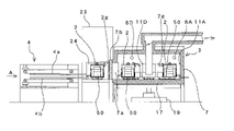
図1~図3に示すように、本発明に係る廃リチウムイオン電池の処理装置1は、複数個のリチウムイオン電池セルが配列された電池モジュールが箱型筐体内に複数収納された電池パック50に加熱処理を施して有用金属を回収するものであって、主に電池パック50を格納する複数の耐熱容器2と、熱処理炉3と、熱処理炉3に耐熱容器2を投入及び排出する容器搬送装置4と、熱処理後の耐熱容器2を冷却する冷却室31等を備える。
As shown in FIGS. 1 to 3, the waste lithium ion
熱処理炉3は円筒状の縦型炉であり、4本のガスバーナー8(8A~8D)によって加熱される。ガスバーナー8の近傍にはノズル11(11A~11D)が設けられ、ファン(不図示)によって燃焼用及び冷却用の空気Aが炉内に供給される。熱処理炉3の炉床17は、電動モータ(不図示)を備えた炉床回転装置19によって鉛直軸回りに回転し、位置決めセンサ(不図示)によって所定の位置に位置決めされる。排気管28の下流側には二次燃焼室、排気用の煙突等が設けられる。
The
熱処理炉3の炉壁7の一部には、上下に開閉式の炉体扉7bで外部と仕切られた開口部7aが形成される。開口部7aに対向する位置に、開口部7aから熱処理炉3内に耐熱容器2を投入すると共に、耐熱容器2を熱処理炉3から排出する容器搬送装置4が設けられる。
A part of the
容器搬送装置4は、図1、図2及び図7に示すように、熱処理炉3の開口部7aと熱処理炉3の中心を結ぶ線上の方向(図1では左右方向)に延びると共に、モーター18の正回転によって耐熱容器2に当接して耐熱容器2を熱処理炉3内に押し入れるプッシャー部4aと、耐熱容器2の容器本体2Aの外周に設けられたハンガー2pを係止する爪4cが先端に設けられ、モーター18の負回転によって耐熱容器2を熱処理炉3内から引っ張り出すプルアウト部4bを備えている。プッシャー部4aはプルアウト部4bの真上に位置する。
As shown in FIGS. 1, 2 and 7, the
開閉式の炉体扉7bに隣接して(図1において左方に)炉前室23が設けられ、炉前室23に隣接して(図3において右方に)冷却室31が設けられる。熱処理炉3の接線方向(図1では上下方向に)搬送装置29によって移動自在のスライドベース21が設置され、スライドベース21は、図3において、炉前室23の左方空間と、開閉式の扉24、25を隔て炉前室23及び冷却室31の間を移動可能に構成される。尚、扉25を設けずに炉前室23及び冷却室31を一つの室としてもよい。
A
冷却室31は、開閉式の扉25を隔てて炉前室23に隣接し、内部には、図4に示すように、熱処理炉3から排出された耐熱容器2を冷却するための冷却装置32が配置される。冷却装置32は、耐熱容器2の冷却空間2cに冷却水を噴霧するための噴霧ノズル33と、先端に噴霧ノズル33を備える給水管34と、給水管34を内部に保持し、先端にパッキン36を備えた排水管35と、排水管35を上下方向に移動させるエアシリンダ37と、冷却水の量を調整するための流調弁38と、給水管34及び排水管35に各々接続されるフレキシブルホース39、40とで構成され、フレキシブルホース39に冷却水が供給され、フレキシブルホース40から耐熱容器2の冷却で生じた蒸気が排出される。
The
また、冷却室31の内部が負圧になるように制御する圧力制御装置(不図示)が設けられ、圧力制御装置は、冷却室31の内部の圧力を測定する圧力計と、冷却室31の排ガスを吸引する吸引装置と、前記圧力計の測定値が負圧になるように吸引装置を制御するコントローラ等を備える。さらに、冷却室31の排ガスをセメントキルンの排ガス処理系統に供給する排ガス処理装置(不図示)が設けられる。
A pressure control device (not shown) is provided to control the inside of the
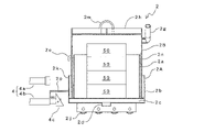
耐熱容器2は、図5~図7に示すように、容器本体2Aと蓋2Bとで構成され、少なくとも650℃の耐熱温度を有する。また、耐熱容器2は、熱伝導の高い一般構造圧延鋼(SS)、ステンレス鋼(SUS304)、銅合金等の金属合金が材料として好ましいが、廃LIBモジュールMを回転炉で加熱する際の熱に耐えるため、ステンレス鋼(SUS304)等の少なくとも650℃の温度に耐えることができる材料からなることがより好ましい。
The heat-
容器本体2Aは、上方に開口して円筒状に形成された内筒2aと、内筒2aよりも大径で内筒2aを囲繞するように配置された外筒2bと、内筒2aの下方に位置する冷却空間2cと、冷却空間2cの底面視で中心部に位置する突出管2dと、外筒2bの底面に配置された複数の車輪2jと、外筒2bの周面2kに固定された2本の取っ手2eと、外筒2bの周面2kから突出するハンガー2pとで構成される。 The container main body 2A includes an inner cylinder 2a formed in a cylindrical shape with an upward opening, an outer cylinder 2b having a larger diameter than the inner cylinder 2a and arranged so as to surround the inner cylinder 2a, and a lower part of the inner cylinder 2a. a cooling space 2c located in the bottom view of the cooling space 2c, a protruding pipe 2d located in the center of the cooling space 2c in a bottom view, a plurality of wheels 2j arranged on the bottom surface of the outer cylinder 2b, and fixed to the peripheral surface 2k of the outer cylinder 2b It is composed of two handles 2e and a hanger 2p projecting from the peripheral surface 2k of the outer cylinder 2b.
一方、蓋2Bは、下方に開口する円筒状に形成された本体2nと、本体2nの周面に開口して斜め上方に突出する排気管2gと、本体2nの天井面2hに設けられた取っ手2mとで構成される。
On the other hand, the lid 2B includes a cylindrical
次に、上記構成を有する廃リチウムイオン電池の処理装置1を用いた廃リチウムイオン電池の処理方法について説明する。尚、以下の説明では、処理装置1によってハイブリッド自動車や電気自動車等から取外されたままの電池パック50を処理する場合を例示する。
Next, a method for processing waste lithium ion batteries using the waste lithium ion
熱処理炉3の内部を650℃に昇温し、クレーン等(不図示)を使用して、図8に示すように、電池パック50を格納した耐熱容器2Nをスライドベース21の右端部に載置する。扉24を開放した後、搬送装置29を介してスライドベース21を右方に移動させ、耐熱容器2Nを炉体扉7bの正面まで移動させた後、扉24を閉じて炉体扉7bを開放し、容器搬送装置4のプッシャー部4a(図7参照)を前進させて耐熱容器2Nを熱処理炉3内に投入する。これにより、耐熱容器2Nは熱処理炉3の炉床17上、図1では9時の位置に載置される。
The inside of the
容器搬送装置4のプッシャー部4aを後退させた後、炉体扉7bを閉鎖し、炉床回転装置19を介して炉床17を45゜左回転させる。この45゜の回転は、特に限定されるものではないが、例えば、37.5分毎に炉床17を45゜ずつ回転させることで、5時間で炉床17が1回転するように設定している。
After retracting the pusher portion 4a of the
上記動作をさらに、7回繰り返すことで、熱処理炉3の炉床17上には、図1に示したように、隣接する耐熱容器2が一定の間隔を開けた状態で8個の耐熱容器2が環状に載置される。 By repeating the above operation seven more times, as shown in FIG. are placed in a ring.
上記動作の間、耐熱容器2は熱処理炉3内で1周する間に外側から加熱されることで、耐熱容器2内は還元雰囲気となり、耐熱容器2に格納された電池パック50の樹脂製の筐体等のプラスチック類は、乾留により炭化混合物としてリチウム、コバルト、ニッケル、マンガン等の有用金属が含まれた材料から分離された状態となっている。尚、耐熱容器2はアルミニウムの融点(660℃)よりも低い温度(650℃)で加熱されるので、電池パック50内で使用されたアルミニウム成分が溶け出すことはない。また、電池内の電解液は揮発し、プラスチック等の可燃性物質が熱分解することによって発生したガスと共に、耐熱容器2の排気管2gから熱処理炉3内に排出される。熱処理炉3内の未燃焼ガスは二次燃焼室に導かれ、熱処理炉3の温度(650℃)よりも高い温度(800℃)で燃焼する。
During the above operation, the heat-
耐熱容器2が熱処理炉3内で1周する前に、図9に示すように、電池パック50を格納した新たな耐熱容器2Nを左端部に載置したスライドベース21の右半分を炉前室23に挿入する。この際、扉24は閉じられている。
Before the heat-
耐熱容器2が熱処理炉3内で1周すると、炉体扉7bを開放して容器搬送装置4のプルアウト部4bを耐熱容器2の位置まで前進させ、図7に示すように、プルアウト部4b先端に設けられた爪4cを、耐熱容器2に設けられたハンガー2pに係止させる。そして、プルアウト部4bを後退させ、図10に示すように、熱処理後の耐熱容器2Tを熱処理炉3から引き出してスライドベース21上に載置し、炉体扉7bを閉鎖する。
When the heat-
次に、扉24、25を開放した後、スライドベース21を右方に移動し、電池パック50を格納した新たな耐熱容器2Nを炉体扉7bの正面まで移動させると共に、熱処理済みの耐熱容器2Tを冷却室31に移動させて扉24、25を閉じる。この状態を図11に示す。
Next, after the
図11の状態から、新たな耐熱容器2Nを上述の要領で熱処理炉3内に投入して加熱すると共に、熱処理済みの耐熱容器2Tを冷却室31で冷却する。冷却室31において、図4に示すように、エアシリンダ37で排水管35を上昇させ、排水管35の先端のパッキン36に耐熱容器2の突出管2dを挿入する。その状態で、フレキシブルホース39に冷却水を供給し、流調弁38で冷却水の量を調整しながら給水管34を経て噴霧ノズル33から冷却水を耐熱容器2の冷却空間2c内に万遍なく噴霧する。これによって、耐熱容器2の内筒2a内の電池パック50が冷却される。電池パック50を冷却することで生じた水蒸気は、耐熱容器2の突出管2dの内部を通過して排水管35、フレキシブルホース40を経て外部に排出される。尚、電池パック重量や加熱温度が変化した場合でも、流調弁38で水の噴霧量を調整することで冷却時間を調整することができる。また、排出した水蒸気を凝縮させて冷却水として循環使用することもできる。
From the state of FIG. 11, a new heat-
次に、扉24、25を開放した後、冷却済みの耐熱容器2Cが載置されたスライドベース21を左方に移動させ(図12参照)、クレーン等で次工程へ搬送する。
Next, after opening the
冷却後の加熱処理済みの耐熱容器2Cは、内部の電池パック50を破砕、分級して炭化混合物を取り除いた後、リチウム、コバルト、ニッケル、マンガン等の有用金属をさらに分離する処理が行われる。また、電池パック50の破砕物を磁選機にかけて、鉄筐体、ねじ等の磁着物と、銅とアルミニウムからなるミックメタルに分離し、ミックメタルを比重選別してアルミ塊及び銅塊と、銅箔及びアルミ箔の積層物とに分けた後、選別機でさらに銅箔とアルミ箔とに分けることができる。
In the heat-treated heat-resistant container 2C after cooling, the
また、冷却室31からのフッ化水素、塩化水素等を含む有害ガスは、排ガス処理装置によってセメントキルンの排ガス処理系統に供給し、セメント製造工程内のセメント原料に固定化して無害化する。
Harmful gases containing hydrogen fluoride, hydrogen chloride, and the like from the cooling
尚、熱処理炉3は、炉床17が回転するものでなくてもよく、バッチ式のものでも適用可能である。また、耐熱容器2は熱処理炉3内で一周するものではなくてもよく、所定の時間を経過したものは熱処理炉3から排出してもよい。また、熱源として電気や重油を使用した各種炉を使用することもでき、既存の製造設備、例えば、セメント焼成装置からの排ガスを熱源として用いてもよい。
The
また、本実施の形態では、電池パック50を電池セルを個々に取外すことなくそのままの状態のものに対して加熱処理したが、電池パック50から分解した電池モジュール単位のものや、電池セルを個々に取外したものを格納した耐熱容器2を熱処理炉3に投入して加熱処理してもよい。
In the present embodiment, the
1 廃リチウムイオン電池の処理装置
2 耐熱容器
3 熱処理炉
4 容器搬送装置
7 炉壁
8(8A~8D) ガスバーナー
11(11A~11D) ノズル
17 炉床
18 モーター
19 炉床回転装置
21 スライドベース
23 炉前室
24、25 扉
28 排気管
29 搬送装置
31 冷却室
32 冷却装置
33 噴霧ノズル
34 給水管
35 排水管
36 パッキン
37 エアシリンダ
38 流調弁
39、40 フレキシブルホース
50 電池パック
1 waste lithium ion
Claims (3)
該耐熱容器を加熱する熱処理炉と、
該熱処理炉に前記耐熱容器を投入及び排出する容器搬送装置と、
該容器搬送装置によって前記熱処理炉から排出された耐熱容器の下部を冷却水を用いて冷却する冷却装置と、
該冷却装置で冷却中の耐熱容器を囲繞する冷却室の内部が負圧になるように制御する圧力制御装置とを備えることを特徴とする廃リチウムイオン電池の処理装置。 a heat-resistant container for housing waste lithium-ion batteries;
a heat treatment furnace for heating the heat-resistant container;
a container conveying device for loading and unloading the heat-resistant container into and from the heat treatment furnace;
a cooling device that uses cooling water to cool the lower portion of the heat-resistant container discharged from the heat treatment furnace by the container conveying device ;
and a pressure control device for controlling the interior of a cooling chamber surrounding a heat-resistant container being cooled by said cooling device to be negative pressure .
Priority Applications (1)
| Application Number | Priority Date | Filing Date | Title |
|---|---|---|---|
| JP2019040341A JP7174652B2 (en) | 2019-03-06 | 2019-03-06 | Processing equipment for waste lithium-ion batteries |
Applications Claiming Priority (1)
| Application Number | Priority Date | Filing Date | Title |
|---|---|---|---|
| JP2019040341A JP7174652B2 (en) | 2019-03-06 | 2019-03-06 | Processing equipment for waste lithium-ion batteries |
Publications (2)
| Publication Number | Publication Date |
|---|---|
| JP2020143329A JP2020143329A (en) | 2020-09-10 |
| JP7174652B2 true JP7174652B2 (en) | 2022-11-17 |
Family
ID=72353370
Family Applications (1)
| Application Number | Title | Priority Date | Filing Date |
|---|---|---|---|
| JP2019040341A Active JP7174652B2 (en) | 2019-03-06 | 2019-03-06 | Processing equipment for waste lithium-ion batteries |
Country Status (1)
| Country | Link |
|---|---|
| JP (1) | JP7174652B2 (en) |
Families Citing this family (3)
| Publication number | Priority date | Publication date | Assignee | Title |
|---|---|---|---|---|
| JP7236524B2 (en) * | 2020-09-16 | 2023-03-09 | Dowaエコシステム株式会社 | Method for collecting valuables from lithium ion secondary battery |
| JP6990753B1 (en) * | 2020-09-16 | 2022-01-12 | Dowaエコシステム株式会社 | How to recover valuables from lithium-ion secondary batteries |
| CN113118178A (en) * | 2021-03-26 | 2021-07-16 | 苏州佰啦多贸易有限公司 | Industrial chip control system for waste battery recovery processing |
Citations (2)
| Publication number | Priority date | Publication date | Assignee | Title |
|---|---|---|---|---|
| JP2013253758A (en) | 2012-06-08 | 2013-12-19 | Toyota Motor Corp | Heat treatment method, and heat treatment furnace |
| JP2018159477A (en) | 2017-03-22 | 2018-10-11 | 太平洋セメント株式会社 | Treatment method of waste lithium-ion battery |
-
2019
- 2019-03-06 JP JP2019040341A patent/JP7174652B2/en active Active
Patent Citations (2)
| Publication number | Priority date | Publication date | Assignee | Title |
|---|---|---|---|---|
| JP2013253758A (en) | 2012-06-08 | 2013-12-19 | Toyota Motor Corp | Heat treatment method, and heat treatment furnace |
| JP2018159477A (en) | 2017-03-22 | 2018-10-11 | 太平洋セメント株式会社 | Treatment method of waste lithium-ion battery |
Also Published As
| Publication number | Publication date |
|---|---|
| JP2020143329A (en) | 2020-09-10 |
Similar Documents
| Publication | Publication Date | Title |
|---|---|---|
| JP7179559B2 (en) | Apparatus and method for treating waste lithium-ion batteries | |
| JP6474207B2 (en) | Waste lithium ion battery treatment method and treatment system | |
| JP7174652B2 (en) | Processing equipment for waste lithium-ion batteries | |
| JP7017860B2 (en) | How to dispose of waste lithium-ion batteries | |
| JP6716389B2 (en) | Method of collecting valuables from waste lithium-ion battery and method of creating database | |
| EP0075978B1 (en) | Process for the recovery of metals from the scrap from nickel-cadmium electric storage batteries | |
| CN103443996B (en) | For recovery method and the processing unit of battery pack | |
| JP6557609B2 (en) | Waste lithium ion battery treatment apparatus and treatment method | |
| JP2019034254A (en) | Apparatus and method for treating waste lithium ion battery | |
| JP2020049460A (en) | Waste lithium ion battery processing equipment and processing method | |
| US11316214B2 (en) | Waste lithium battery recovery system | |
| JP7237732B2 (en) | heat resistant container | |
| JP7174653B2 (en) | Equipment for recovering copper from copper-containing waste | |
| JP2011033333A (en) | Induction heating dry distillation furnace | |
| CA1166593A (en) | Apparatus for pyrolyzing shredded tires | |
| JP6664301B2 (en) | Apparatus and method for processing waste electronic substrate | |
| US11996528B2 (en) | Method to open up electro chemical energy storage devices and thermal treatment system | |
| JP2012125666A (en) | Device for treating metal scrap | |
| KR102618272B1 (en) | Eco-friendly gas processing system | |
| JP2006220328A (en) | Induction heating type dry distillation furnace | |
| JP7352499B2 (en) | Waste lithium ion battery processing equipment and processing method | |
| JPH04128324A (en) | Method for recovering cadmium | |
| JPH07188788A (en) | Plated material treating device | |
| TW202435967A (en) | Battery recycling plant and process | |
| JP2022164399A (en) | Valuable material recovery method and valuable material recovery apparatus |
Legal Events
| Date | Code | Title | Description |
|---|---|---|---|
| A621 | Written request for application examination |
Free format text: JAPANESE INTERMEDIATE CODE: A621 Effective date: 20210816 |
|
| A977 | Report on retrieval |
Free format text: JAPANESE INTERMEDIATE CODE: A971007 Effective date: 20220725 |
|
| A131 | Notification of reasons for refusal |
Free format text: JAPANESE INTERMEDIATE CODE: A131 Effective date: 20220728 |
|
| A521 | Request for written amendment filed |
Free format text: JAPANESE INTERMEDIATE CODE: A523 Effective date: 20220907 |
|
| TRDD | Decision of grant or rejection written | ||
| A01 | Written decision to grant a patent or to grant a registration (utility model) |
Free format text: JAPANESE INTERMEDIATE CODE: A01 Effective date: 20221026 |
|
| A61 | First payment of annual fees (during grant procedure) |
Free format text: JAPANESE INTERMEDIATE CODE: A61 Effective date: 20221107 |
|
| R150 | Certificate of patent or registration of utility model |
Ref document number: 7174652 Country of ref document: JP Free format text: JAPANESE INTERMEDIATE CODE: R150 |