JP7171663B2 - Devices, systems, and methods for in-stent restenosis prediction - Google Patents
Devices, systems, and methods for in-stent restenosis prediction Download PDFInfo
- Publication number
- JP7171663B2 JP7171663B2 JP2020136570A JP2020136570A JP7171663B2 JP 7171663 B2 JP7171663 B2 JP 7171663B2 JP 2020136570 A JP2020136570 A JP 2020136570A JP 2020136570 A JP2020136570 A JP 2020136570A JP 7171663 B2 JP7171663 B2 JP 7171663B2
- Authority
- JP
- Japan
- Prior art keywords
- stent
- vessel
- lesion
- restenosis
- catheter
- Prior art date
- Legal status (The legal status is an assumption and is not a legal conclusion. Google has not performed a legal analysis and makes no representation as to the accuracy of the status listed.)
- Active
Links
Images
Classifications
-
- A—HUMAN NECESSITIES
- A61—MEDICAL OR VETERINARY SCIENCE; HYGIENE
- A61B—DIAGNOSIS; SURGERY; IDENTIFICATION
- A61B8/00—Diagnosis using ultrasonic, sonic or infrasonic waves
- A61B8/12—Diagnosis using ultrasonic, sonic or infrasonic waves in body cavities or body tracts, e.g. by using catheters
-
- A—HUMAN NECESSITIES
- A61—MEDICAL OR VETERINARY SCIENCE; HYGIENE
- A61B—DIAGNOSIS; SURGERY; IDENTIFICATION
- A61B5/00—Measuring for diagnostic purposes; Identification of persons
- A61B5/0059—Measuring for diagnostic purposes; Identification of persons using light, e.g. diagnosis by transillumination, diascopy, fluorescence
- A61B5/0082—Measuring for diagnostic purposes; Identification of persons using light, e.g. diagnosis by transillumination, diascopy, fluorescence adapted for particular medical purposes
- A61B5/0084—Measuring for diagnostic purposes; Identification of persons using light, e.g. diagnosis by transillumination, diascopy, fluorescence adapted for particular medical purposes for introduction into the body, e.g. by catheters
-
- A—HUMAN NECESSITIES
- A61—MEDICAL OR VETERINARY SCIENCE; HYGIENE
- A61B—DIAGNOSIS; SURGERY; IDENTIFICATION
- A61B5/00—Measuring for diagnostic purposes; Identification of persons
- A61B5/02—Detecting, measuring or recording for evaluating the cardiovascular system, e.g. pulse, heart rate, blood pressure or blood flow
- A61B5/02007—Evaluating blood vessel condition, e.g. elasticity, compliance
-
- A—HUMAN NECESSITIES
- A61—MEDICAL OR VETERINARY SCIENCE; HYGIENE
- A61B—DIAGNOSIS; SURGERY; IDENTIFICATION
- A61B5/00—Measuring for diagnostic purposes; Identification of persons
- A61B5/68—Arrangements of detecting, measuring or recording means, e.g. sensors, in relation to patient
- A61B5/6846—Arrangements of detecting, measuring or recording means, e.g. sensors, in relation to patient specially adapted to be brought in contact with an internal body part, i.e. invasive
- A61B5/6847—Arrangements of detecting, measuring or recording means, e.g. sensors, in relation to patient specially adapted to be brought in contact with an internal body part, i.e. invasive mounted on an invasive device
- A61B5/6852—Catheters
- A61B5/6853—Catheters with a balloon
-
- A—HUMAN NECESSITIES
- A61—MEDICAL OR VETERINARY SCIENCE; HYGIENE
- A61B—DIAGNOSIS; SURGERY; IDENTIFICATION
- A61B8/00—Diagnosis using ultrasonic, sonic or infrasonic waves
- A61B8/04—Measuring blood pressure
-
- A—HUMAN NECESSITIES
- A61—MEDICAL OR VETERINARY SCIENCE; HYGIENE
- A61B—DIAGNOSIS; SURGERY; IDENTIFICATION
- A61B8/00—Diagnosis using ultrasonic, sonic or infrasonic waves
- A61B8/06—Measuring blood flow
-
- A—HUMAN NECESSITIES
- A61—MEDICAL OR VETERINARY SCIENCE; HYGIENE
- A61B—DIAGNOSIS; SURGERY; IDENTIFICATION
- A61B8/00—Diagnosis using ultrasonic, sonic or infrasonic waves
- A61B8/06—Measuring blood flow
- A61B8/065—Measuring blood flow to determine blood output from the heart
-
- A—HUMAN NECESSITIES
- A61—MEDICAL OR VETERINARY SCIENCE; HYGIENE
- A61B—DIAGNOSIS; SURGERY; IDENTIFICATION
- A61B8/00—Diagnosis using ultrasonic, sonic or infrasonic waves
- A61B8/08—Clinical applications
- A61B8/0833—Clinical applications involving detecting or locating foreign bodies or organic structures
- A61B8/0841—Clinical applications involving detecting or locating foreign bodies or organic structures for locating instruments
-
- A—HUMAN NECESSITIES
- A61—MEDICAL OR VETERINARY SCIENCE; HYGIENE
- A61B—DIAGNOSIS; SURGERY; IDENTIFICATION
- A61B8/00—Diagnosis using ultrasonic, sonic or infrasonic waves
- A61B8/08—Clinical applications
- A61B8/0833—Clinical applications involving detecting or locating foreign bodies or organic structures
- A61B8/085—Clinical applications involving detecting or locating foreign bodies or organic structures for locating body or organic structures, e.g. tumours, calculi, blood vessels, nodules
-
- A—HUMAN NECESSITIES
- A61—MEDICAL OR VETERINARY SCIENCE; HYGIENE
- A61B—DIAGNOSIS; SURGERY; IDENTIFICATION
- A61B8/00—Diagnosis using ultrasonic, sonic or infrasonic waves
- A61B8/08—Clinical applications
- A61B8/0883—Clinical applications for diagnosis of the heart
-
- A—HUMAN NECESSITIES
- A61—MEDICAL OR VETERINARY SCIENCE; HYGIENE
- A61B—DIAGNOSIS; SURGERY; IDENTIFICATION
- A61B8/00—Diagnosis using ultrasonic, sonic or infrasonic waves
- A61B8/08—Clinical applications
- A61B8/0891—Clinical applications for diagnosis of blood vessels
-
- A—HUMAN NECESSITIES
- A61—MEDICAL OR VETERINARY SCIENCE; HYGIENE
- A61B—DIAGNOSIS; SURGERY; IDENTIFICATION
- A61B8/00—Diagnosis using ultrasonic, sonic or infrasonic waves
- A61B8/46—Ultrasonic, sonic or infrasonic diagnostic devices with special arrangements for interfacing with the operator or the patient
-
- A—HUMAN NECESSITIES
- A61—MEDICAL OR VETERINARY SCIENCE; HYGIENE
- A61B—DIAGNOSIS; SURGERY; IDENTIFICATION
- A61B8/00—Diagnosis using ultrasonic, sonic or infrasonic waves
- A61B8/52—Devices using data or image processing specially adapted for diagnosis using ultrasonic, sonic or infrasonic waves
- A61B8/5215—Devices using data or image processing specially adapted for diagnosis using ultrasonic, sonic or infrasonic waves involving processing of medical diagnostic data
- A61B8/5223—Devices using data or image processing specially adapted for diagnosis using ultrasonic, sonic or infrasonic waves involving processing of medical diagnostic data for extracting a diagnostic or physiological parameter from medical diagnostic data
-
- A—HUMAN NECESSITIES
- A61—MEDICAL OR VETERINARY SCIENCE; HYGIENE
- A61F—FILTERS IMPLANTABLE INTO BLOOD VESSELS; PROSTHESES; DEVICES PROVIDING PATENCY TO, OR PREVENTING COLLAPSING OF, TUBULAR STRUCTURES OF THE BODY, e.g. STENTS; ORTHOPAEDIC, NURSING OR CONTRACEPTIVE DEVICES; FOMENTATION; TREATMENT OR PROTECTION OF EYES OR EARS; BANDAGES, DRESSINGS OR ABSORBENT PADS; FIRST-AID KITS
- A61F2/00—Filters implantable into blood vessels; Prostheses, i.e. artificial substitutes or replacements for parts of the body; Appliances for connecting them with the body; Devices providing patency to, or preventing collapsing of, tubular structures of the body, e.g. stents
- A61F2/82—Devices providing patency to, or preventing collapsing of, tubular structures of the body, e.g. stents
- A61F2/844—Devices providing patency to, or preventing collapsing of, tubular structures of the body, e.g. stents folded prior to deployment
-
- A—HUMAN NECESSITIES
- A61—MEDICAL OR VETERINARY SCIENCE; HYGIENE
- A61F—FILTERS IMPLANTABLE INTO BLOOD VESSELS; PROSTHESES; DEVICES PROVIDING PATENCY TO, OR PREVENTING COLLAPSING OF, TUBULAR STRUCTURES OF THE BODY, e.g. STENTS; ORTHOPAEDIC, NURSING OR CONTRACEPTIVE DEVICES; FOMENTATION; TREATMENT OR PROTECTION OF EYES OR EARS; BANDAGES, DRESSINGS OR ABSORBENT PADS; FIRST-AID KITS
- A61F2/00—Filters implantable into blood vessels; Prostheses, i.e. artificial substitutes or replacements for parts of the body; Appliances for connecting them with the body; Devices providing patency to, or preventing collapsing of, tubular structures of the body, e.g. stents
- A61F2/95—Instruments specially adapted for placement or removal of stents or stent-grafts
-
- G—PHYSICS
- G16—INFORMATION AND COMMUNICATION TECHNOLOGY [ICT] SPECIALLY ADAPTED FOR SPECIFIC APPLICATION FIELDS
- G16H—HEALTHCARE INFORMATICS, i.e. INFORMATION AND COMMUNICATION TECHNOLOGY [ICT] SPECIALLY ADAPTED FOR THE HANDLING OR PROCESSING OF MEDICAL OR HEALTHCARE DATA
- G16H50/00—ICT specially adapted for medical diagnosis, medical simulation or medical data mining; ICT specially adapted for detecting, monitoring or modelling epidemics or pandemics
- G16H50/30—ICT specially adapted for medical diagnosis, medical simulation or medical data mining; ICT specially adapted for detecting, monitoring or modelling epidemics or pandemics for calculating health indices; for individual health risk assessment
-
- A—HUMAN NECESSITIES
- A61—MEDICAL OR VETERINARY SCIENCE; HYGIENE
- A61B—DIAGNOSIS; SURGERY; IDENTIFICATION
- A61B8/00—Diagnosis using ultrasonic, sonic or infrasonic waves
- A61B8/44—Constructional features of the ultrasonic, sonic or infrasonic diagnostic device
- A61B8/4444—Constructional features of the ultrasonic, sonic or infrasonic diagnostic device related to the probe
- A61B8/445—Details of catheter construction
Landscapes
- Health & Medical Sciences (AREA)
- Life Sciences & Earth Sciences (AREA)
- Engineering & Computer Science (AREA)
- Biomedical Technology (AREA)
- Public Health (AREA)
- General Health & Medical Sciences (AREA)
- Veterinary Medicine (AREA)
- Heart & Thoracic Surgery (AREA)
- Animal Behavior & Ethology (AREA)
- Medical Informatics (AREA)
- Pathology (AREA)
- Biophysics (AREA)
- Physics & Mathematics (AREA)
- Molecular Biology (AREA)
- Surgery (AREA)
- Radiology & Medical Imaging (AREA)
- Nuclear Medicine, Radiotherapy & Molecular Imaging (AREA)
- Vascular Medicine (AREA)
- Cardiology (AREA)
- Transplantation (AREA)
- Oral & Maxillofacial Surgery (AREA)
- Physiology (AREA)
- Hematology (AREA)
- Computer Vision & Pattern Recognition (AREA)
- Data Mining & Analysis (AREA)
- Databases & Information Systems (AREA)
- Epidemiology (AREA)
- Primary Health Care (AREA)
- Ultra Sonic Daignosis Equipment (AREA)
- Endoscopes (AREA)
Description
本開示は概して血管の評価に関し、特に、血管を通る流体の流れに対する遮断又はその他の制限の重症度、その治療、並びにその再発の評価に関する。 FIELD OF THE DISCLOSURE The present disclosure relates generally to assessment of blood vessels and, more particularly, to assessment of the severity of blockages or other restrictions to fluid flow through blood vessels, their treatment, and their recurrence.
インターベンション心臓病学では、血管内撮像システム及びその他の血管内生理測定システムが、人体内の、動脈などの罹患血管の診断ツールとして広く用いられている。様々なセンサがカテーテル上に設置され、体内に位置付けられ得る。1つの種類の撮像システムは血管内超音波(intravascular ultrasound、IVUS)システムである。一例では、フェーズドアレイIVUSデバイスは、血管内に通され、撮像対象区域まで案内される多数のトランスデューサを含む。トランスデューサは、関心のある血管の画像を作りだすために、超音波を放射する。超音波は、組織構造(血管壁の様々な層など)、赤血球、及び関心のあるその他の特徴から生じる不連続性によって部分反射される。反射波からのエコーがトランスデューサによって受信され、IVUS撮像システムへ伝えられる。撮像システムは、受信された超音波エコーを処理し、デバイスが配置された血管の断面画像を作成する。 In interventional cardiology, intravascular imaging systems and other intravascular physiological measurement systems are widely used as diagnostic tools for diseased vessels, such as arteries, within the human body. Various sensors may be placed on the catheter and positioned within the body. One type of imaging system is an intravascular ultrasound (IVUS) system. In one example, a phased array IVUS device includes multiple transducers that are passed intravascularly and guided to an area to be imaged. A transducer emits ultrasound waves to produce an image of the vessel of interest. Ultrasound is partially reflected by discontinuities arising from tissue structures (such as the various layers of the vessel wall), red blood cells, and other features of interest. Echoes from the reflected waves are received by the transducer and transmitted to the IVUS imaging system. An imaging system processes the received ultrasound echoes and creates a cross-sectional image of the vessel in which the device is located.
血管内撮像システムは、バルーンカテーテルの使用を通じて緩和することができる動脈閉塞を検出するためにしばしば用いられる。バルーンカテーテルは、先端付近に配置されたバルーンを有するカテーテルの一種である。バルーンカテーテルは、患者の動脈内に挿入され、血管内撮像システムの使用を通じて閉塞が検出された地点へ位置付けられるように設計されている。検出された閉塞に到達すると、バルーンは膨張させられ、閉塞を引き起こしている物体を圧迫する。いくつかの場合には、バルーンカテーテルは、ステントを展開するために利用される。この際、バルーンの膨張はステントを拡張させ、ステントを血管内で展開させる。 Intravascular imaging systems are often used to detect arterial occlusions that can be relieved through the use of balloon catheters. A balloon catheter is a type of catheter that has a balloon positioned near its tip. The balloon catheter is designed to be inserted into the patient's artery and positioned to the point where an occlusion is detected through the use of an intravascular imaging system. Upon reaching a detected occlusion, the balloon is inflated, compressing the object causing the occlusion. In some cases, a balloon catheter is utilized to deploy the stent. Inflation of the balloon then expands the stent and deploys the stent within the vessel.
いくつかの場合には、臨床医の経験に基づいてステントの留置が適切であるかどうかを観察することを目指して、ステントの部位を撮像するために撮像システムが用いられることもある。しかし、このような現在のアプローチは、完全に満足のいくものにはなっていない。したがって、血管のための1つ以上の利用可能な治療の選択肢に伴うリスク及びその成功の可能性を客観的に評定する、改善されたデバイス、システム、及び方法の必要性が残されている。 In some cases, an imaging system may be used to image the site of the stent with the goal of observing whether placement of the stent is appropriate based on the clinician's experience. However, such current approaches have not been entirely satisfactory. Accordingly, there remains a need for improved devices, systems, and methods that objectively assess the risks associated with and the likelihood of success of one or more available vascular treatment options.
本開示は、血管内病変を評価して治療し、且つ治療の有効性を評価するためのデバイス、システム、及び方法を提供する。この結果、後に後続の医療処置において遂行するのではなく、まさにその時点で追加のインターベンションを遂行するために用いられ得る、治療の将来の性能を推定することによって、患者の手術プロセス及び治療が改善される。本開示の諸態様は追跡処置を低減し、転帰の改善を患者にもたらし得る。 The present disclosure provides devices, systems, and methods for evaluating and treating intravascular lesions and evaluating the efficacy of treatments. As a result, the patient's surgical process and treatment can be improved by estimating the future performance of the treatment, which can be used to perform additional interventions at that very moment, rather than later in subsequent medical procedures. be improved. Aspects of the present disclosure may reduce follow-up procedures and provide improved outcomes for patients.
1つの一般的態様は、患者内の血管を治療する方法を含む。本方法は、ステント留置組立体及び血管内超音波撮像デバイスを含むカテーテルを血管の内腔内に挿入することと、カテーテルを血管の内腔内の病変の部位に位置付けることと、ステント留置組立体を作動させ、ステントを血管の内腔内の病変の部位に留置することと、カテーテル上に配置された血管内超音波撮像デバイスを用いて病変の部位におけるステントの留置の血管内超音波撮像データを収集することとを含む。本方法は、病変の部位におけるステントの留置の血管内超音波撮像データに基づいて再狭窄確率値を推定することを更に含む。本方法はまた、推定された再狭窄確率値を臨床医へ伝達することを含む。 One general aspect includes a method of treating a blood vessel within a patient. The method includes inserting a catheter including a stent deployment assembly and an intravascular ultrasound imaging device into a lumen of a blood vessel, positioning the catheter within the lumen of the blood vessel at a site of a lesion, and a stent deployment assembly. to deploy the stent at the site of the lesion within the lumen of the blood vessel, and intravascular ultrasound imaging data of the placement of the stent at the site of the lesion using an intravascular ultrasound imaging device placed on the catheter. and collecting The method further includes estimating a restenosis probability value based on intravascular ultrasound imaging data of placement of the stent at the site of the lesion. The method also includes communicating the estimated restenosis probability value to the clinician.
諸実装形態は以下の特徴のうちの1つ以上を含んでもよい。本方法は、カテーテルが血管内を前進又は後退させられるのに従い、撮像デバイスを用いて血管の内腔を撮像することと、撮像デバイスを用いて血管の内腔内の病変を特定し、撮像することとを更に含む。カテーテルはカテーテルの遠位部分上に血管内撮像デバイスを含む。再狭窄確率値を推定することは、部位における組織の種類、部位におけるプラークの種類、ステントの種類、又は血管内におけるステントの位置のうちの少なくとも1つに基づいて再狭窄確率値を推定することを含む。 Implementations may include one or more of the following features. The method includes imaging a lumen of the blood vessel with an imaging device as the catheter is advanced or retracted through the vessel, and identifying and imaging a lesion within the lumen of the blood vessel with the imaging device. and further including The catheter includes an intravascular imaging device on the distal portion of the catheter. estimating the restenosis probability value based on at least one of a tissue type at the site, a plaque type at the site, a stent type, or a location of the stent within the vessel; including.
1つの一般的態様は、患者内の血管を治療する別の方法を含む。本方法は、カテーテルを血管の内腔内の病変の部位に位置付けることであって、カテーテルはステント留置組立体を含む、位置付けることと、ステント留置組立体を作動させ、ステントを血管の内腔内の病変の部位に留置することと、病変の部位におけるステントの留置に基づいて再狭窄確率値を推定することとを含む。 One general aspect includes another method of treating blood vessels within a patient. The method comprises positioning a catheter at the site of the lesion within the lumen of the vessel, the catheter including a stent deployment assembly; actuating the stent deployment assembly to position the stent within the lumen of the vessel; and estimating a restenosis probability value based on the placement of the stent at the lesion site.
別の一般的態様は医療診断及び治療システムを含む。システムは、命令を記憶するための非一時的コンピュータ可読媒体と、非一時的コンピュータ可読媒体と通信する処理デバイスとを含む。処理デバイスは、患者の血管の内腔内のステントの留置部位にあるカテーテル上の撮像デバイスによって得られた撮像データを受信すること、及び留置部位におけるステントの留置に基づいて再狭窄確率値を推定することであって、留置部位は血管の病変の位置に対応する、推定すること、を含む動作を遂行するための命令を実行する。これらの態様のいくつかの実装形態は、対応するコンピュータシステム、装置、及び方法のアクションを遂行又は実施するように各々構成された、1つ以上の処理デバイスに結合された1つ以上のコンピュータ記憶デバイス上に記録されたコンピュータプログラムを含む。 Another general aspect involves medical diagnostic and therapeutic systems. The system includes a non-transitory computer-readable medium for storing instructions and a processing device in communication with the non-transitory computer-readable medium. A processing device receives imaging data obtained by an imaging device on the catheter at the stent deployment site within the lumen of the patient's vessel and estimates a restenosis probability value based on the stent deployment at the deployment site. The placement site executes instructions to perform operations including estimating corresponding to the location of the vascular lesion. Some implementations of these aspects include one or more computer storage coupled to one or more processing devices, each configured to perform or perform the actions of the corresponding computer systems, apparatus, and methods. Includes computer programs recorded on a device.
本開示の追加の態様、特徴、及び利点が以下の「発明を実施するための形態」から明らかになるであろう。 Additional aspects, features, and advantages of the present disclosure will become apparent from the Detailed Description below.
添付の図面を参照して本開示の例示的な諸実施形態が説明される。 Exemplary embodiments of the present disclosure are described with reference to the accompanying drawings.
これらの添付の図面は、以下の「発明を実施するための形態」を参照することによってより深く理解されるであろう。 These accompanying drawings may be better understood with reference to the Detailed Description below.
本開示の諸原理の理解を促進する目的のために、これより、図面に示される諸実施形態が参照され、それらを説明するために特定の文言が用いられることになる。それにもかかわらず、本開示の範囲に対する限定は意図されていないことが理解される。本記載のデバイス、システム、及び方法に対するあらゆる改変及び更なる変更、並びに本開示の諸原理のあらゆる更なる適用は、本開示が関係する当業者が通常想到するであろうように、完全に企図されており、本開示内に含まれている。特に、一実施形態を参照して説明されている特徴、構成要素、及び/又はステップは、本開示の他の実施形態を参照して説明されている特徴、構成要素、及び/又はステップと組み合わせられてもよいことが完全に企図されている。しかし、簡潔にするために、これらの組み合わせの多数の反復は別個に記載されない。 For the purposes of promoting an understanding of the principles of the disclosure, reference will now be made to the embodiments illustrated in the drawings, and specific language will be used to describe them. It will nevertheless be understood that no limitation on the scope of the disclosure is intended. All modifications and further modifications to the described devices, systems and methods, and all further applications of the principles of this disclosure are fully contemplated, as would normally occur to those skilled in the art to which this disclosure pertains. and are included within this disclosure. In particular, features, components and/or steps described with reference to one embodiment may be combined with features, components and/or steps described with reference to other embodiments of the disclosure. It is fully contemplated that However, for the sake of brevity, the multiple iterations of these combinations are not described separately.
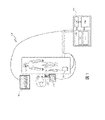
次に、図1を参照すると、同図には、医療システム100を描写する概略図が示されている。概して、医療診断及び治療システム100、又は、単に、医療システム100は、人間の生物学的、生理学的、及び形態学的情報を取得し、解釈するために用いられる種々のモダリティに感受性を有し、様々な条件の治療を調整するように設計された複数の形態の取得及び処理要素の一貫した獲得、集積、及び統合を提供する。一実施形態では、医療システム100は、医療データを取得し、処理し、表示するため、及び血管内デバイスなどの1つ以上の医療デバイスの制御を促進するためのハードウェア及びソフトウェアを有するコンピュータシステムである処理システム101を含む。処理システム101は、マイクロコントローラ又は図示されている中央処理装置(central processing unit、CPU)104などの、少なくとも1つの処理デバイス、並びにハードドライブ、ランダムアクセスメモリ(random-access-memory、RAM)、フラッシュメモリ、及び/又はコンパクトディスクリードオンリーメモリ(compact disk read-only-memory、CD-ROM若しくはDVD-ROM)等などの非一時的コンピュータ可読記憶媒体(メモリ106として示されている)を含むコンピュータワークステーションであってもよい。処理システム101は、複数の医療デバイスモダリティからデータを受信し、及び/又は処理するための取得カード108を更に含んでもよい。取得カード108はまた、コマンド及び要求を、結合された医療デバイスへ伝達するためのインターフェースを提供してもよい。メモリ106は、1つを超えるメモリ又はデータ記憶デバイスを含んでもよく、結合された医療デバイスから取得されたデータ110、及び命令112を記憶してもよい。命令112は、CPU104によって実行されると、ユーザが、結合された医療デバイスから受信されたデータ、及び/又は遠隔に記憶されたデータを見てそれと対話することを可能にするとともに、ユーザが、結合された医療デバイスを制御することを可能にする実行可能コードを含んでもよい。命令112は、処理システム101を、病変の部位において収集された情報に基づいて再狭窄確率値を推定するように仕向けるための実行可能コードを含む。いくつかの実施形態では、命令112は、医療システム100を、以下において更に詳細に説明されるように、方法600、700、及び800を遂行するように仕向けるための実行可能コードを含む。処理システム101はまた、グラフィック処理装置(graphics processing unit、GPU)などのビデオコントローラ、スピーカ、並びにEthernetコントローラ又は無線通信コントローラなどのネットワーク通信デバイスを含んでもよい。
Referring now to FIG. 1, there is shown a schematic diagram depicting a medical system 100. As shown in FIG. In general, the medical diagnostic and treatment system 100, or simply medical system 100, is sensitive to various modalities used to acquire and interpret human biological, physiological, and morphological information. , provides consistent acquisition, integration, and integration of multiple forms of acquisition and processing elements designed to coordinate treatment of various conditions. In one embodiment, medical system 100 is a computer system having hardware and software for acquiring, processing, and displaying medical data and for facilitating control of one or more medical devices, such as intravascular devices. It includes a processing system 101 that is . The processing system 101 includes at least one processing device, such as a microcontroller or central processing unit (CPU) 104 as shown, as well as hard drives, random-access-memory (RAM), flash computer work including memory and/or non-transitory computer-readable storage medium (denoted as memory 106) such as compact disk read-only-memory (CD-ROM or DVD-ROM); It may be a station. Processing system 101 may further include an
いくつかの実施形態では、処理システム101は、本明細書に記載されている、医療データの取得、分析、推定、及び制御に関連付けられたステップを実行するようにプログラムされている。したがって、本開示のデータ取得、データ処理、取得されたデータに基づく推定、機器制御、並びに/或いはその他の処理又は制御態様に関連する任意のステップは、処理システム101によって、処理システムによってアクセス可能な非一時的コンピュータ可読媒体上、又はその内部に記憶された対応する命令を用いて実施され得ることが理解される。 In some embodiments, processing system 101 is programmed to perform steps associated with the acquisition, analysis, estimation, and control of medical data as described herein. Accordingly, any steps associated with data acquisition, data processing, inference based on acquired data, instrument control, and/or other processing or control aspects of the present disclosure can be accessed by the processing system 101. It will be appreciated that it may be implemented with corresponding instructions stored on or within a non-transitory computer-readable medium.
図示の実施形態では、医療システム100は、制御室を有するカテーテル処置室内に展開されており、処理システム101は制御室内に位置している。他の実施形態では、処理システム101は、カテーテル処置室の内部、医療施設内の集中区域内、又は拡大ネットワークによってアクセス可能な現地外の場所などの、他の場所に位置していてもよい。カテーテル処置室及び制御室は、当技術分野において知られている任意の数の医療センシング及び治療処置を患者に対して遂行するために用いられ得る。カテーテル処置室内に示されている患者103は、単独モダリティ又はマルチモダリティ処置を、単独の処置として、又は1つ以上のセンシング処置と組み合わせて受けている最中である可能性がある。例えば、病変を有する患者103の血管系の標的領域内の標的位置内にステントを位置付けるための血管形成処置が遂行されている。患者は、臨床医によって処理システム101を用いて遂行される、経皮冠動脈インターベンションを受けている最中である可能性もある。
In the illustrated embodiment, medical system 100 is deployed in a catheterization room having a control room, and processing system 101 is located within the control room. In other embodiments, the processing system 101 may be located at other locations, such as inside a catheterization lab, within a centralized area within a medical facility, or at an off-site location accessible by an extended network. Catheterization and control rooms may be used to perform any number of medical sensing and therapeutic procedures known in the art on a patient. A
図1の例示されている実施形態では、血管内デバイス114は、臨床医によって、患者103に関する医療撮像データを取得するため、及び/又は患者103に治療を提供するために利用され得る医療撮像デバイスである。例えば、血管内デバイス114は、超音波(例えば、IVUS)、OCT、熱、及び/又はその他の撮像技法を用いることによって撮像データ(静止画像、ビデオなどを含む)を得てもよい。血管内デバイス114は、血管内に位置付けられるサイズ及び形状に作られた任意の形態のデバイス、機器、カテーテル、ガイドワイヤ、又はプローブであり得る。いくつかの実施形態では、血管内デバイス114は、非撮像構成要素とともに、血管内に位置付けられるサイズ及び形状に作られた単一のパッケージに組み合わせられてもよい。図示のように、IVUS血管内デバイス114は、IVUSセンシングデータを収集するためのフェーズドアレイトランスデューサなどの1つ以上のセンサを含むIVUSカテーテルである。いくつかの実施形態では、血管内デバイス114は、IVUS及び血管内光音響(intravascular photoacoustic、IVPA)撮像の両方、OCT撮像、圧力センシング、並びに流量センシング等などのマルチモダリティセンシングの能力を有してもよい。
In the illustrated embodiment of FIG. 1, intravascular device 114 is a medical imaging device that can be utilized by a clinician to obtain medical imaging data about
図示の実施形態では、患者インターフェースモジュール(patient interface module、PIM)116が血管内デバイス114を医療システム100に結合している。PIM116は血管内デバイス114と処理システム101との間の情報の交換を促進し、それらの間の医療デバイスインターフェースの役割を果たす。取得カード108は、PIM116と情報を交換することによってCPU104と血管内デバイス114との間の通信を提供してもよい。この情報は、血管内デバイス114から処理システム101へ伝送された撮像データ、並びに処理システム101からPIM116へ、及び血管内デバイス114そのものへ伝達された、個々のパラメータ指定を含み得る、コマンド及び設定を含む。それゆえ、PIM116は、血管内デバイス114を用いて患者103から収集された医療撮像及び/又はセンシングデータを受信し、受信されたデータを処理システム101などの処理システムへ伝送するように動作可能である。
In the illustrated embodiment, a patient interface module (PIM) 116 couples the intravascular device 114 to the medical system 100 . PIM 116 facilitates the exchange of information between intravascular device 114 and processing system 101 and acts as a medical device interface between them.
ベッドサイドコントローラ118もまた、処理システム101に通信可能に結合されており、患者103を診断及び/又は治療するために用いられている特定の医療モダリティ(又はモダリティ群)のユーザ制御を提供する。現在の実施形態では、ベッドサイドコントローラ118は、操作域の単一の表面上にユーザ制御及び診断画像を提供するタッチスクリーンコントローラである。しかし、代替的な実施形態では、ベッドサイドコントローラ118は、非対話型ディスプレイ、並びに物理的ボタン及び/又はジョイスティック、並びに/或いはキーボード及びマウスなどの別個の制御装置120を含んでもよい。統合された医療システム100では、ベッドサイドコントローラ118は、血管内デバイス114のための制御選択肢、及び血管内デバイス114から収集された患者撮像データをグラフィカルユーザインターフェース(GUI)内に提示するように動作可能である。
医療システム100は医療撮像システムインターフェースを提供する。このインターフェースによって、ステントが、ステントの展開後に、展開の成功を監視するべく観察されることが可能になり、その結果、ステントの展開不足が回避されるとともに、このインターフェースによって、再狭窄の確率の推定又は予測が臨床医へ伝達されることが可能になる。再狭窄確率の推定に関する更なる詳細が本明細書において提供される。 Medical system 100 provides a medical imaging system interface. This interface allows the stent to be monitored after deployment of the stent to monitor deployment success, thereby avoiding under-deployment of the stent, and reduces the probability of restenosis. An estimate or prediction can be communicated to the clinician. Further details regarding restenosis probability estimation are provided herein.
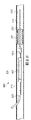
図2A~図2Fは、患者内への治療及び撮像カテーテル(単数又は複数)の挿入及び使用を示す一連の断面図である。いくつかの実施形態では、カテーテル200は、撮像能力と治療能力の両方を含む、統合カテーテルである。他の実施形態では、別個のカテーテル又はデバイスが治療及び撮像のために利用される。このような実施形態では、治療は、図示されている血管内に位置付けられた第1のカテーテルを用いて遂行され、撮像は、撮像能力を有する別個のカテーテルを用いて遂行される。追加的に、いくつかの実施形態では、カテーテル200は複数の治療モードを含んでもよい。例えば、カテーテル200は、ステント展開のためのバルーン組立体を含み、病変切除を提供し、部位の画像を集めるように構成されていてもよく、これら及びその他の特徴を提供するための特殊構造体及びトランスデューサを含んでもよい。
Figures 2A-2F are a series of cross-sectional views showing the insertion and use of the treatment and imaging catheter(s) within a patient. In some embodiments,
図2A~図2Fに示されるように、カテーテル200は、図1の患者103の血管210内で使用するためのサイズ及び形状に作られているバルーン組立体202及び撮像デバイス203を含む。いくつかの実施形態では、血管210は動脈であってもよい。図示のように、カテーテル200は内スリーブ204を含む。いくつかの実施形態では、内スリーブ204は、20ATMよりも大きい高圧能力を有し、これにより、バルーン組立体202は非従順性の後拡張に適するようになっている。例えば、図2A~図2Fは、本開示の一実施形態に係る、血管内病変206に接近し、血管内病変206を評価し、拡張ステント208などの治療デバイスを用いて血管内病変206を治療するためのカテーテル200の使用を示す。カテーテル200はまた、血管210内における拡張ステント208の留置を評価するためにも用いられる。拡張ステント208の留置の評価は、ステント208の留置の前及び後の両方における撮像データ及びその他のデータ(例えば、圧力、流量など)を収集することによって遂行されてもよい。このようなデータは、部位における組織の種類、部位におけるプラークの種類、ステントの種類、並びに/或いは血管内におけるステント及び病変の位置を記述する情報を含んでもよい。例えば、部位における組織の種類(単数又は複数)及びプラークの種類(単数又は複数)は、撮像デバイス203を用いた撮像によって、「VASCULAR PLAQUE CHARACTERIZATION」と題する米国特許第6,200,268号、「INTRAVASCULAR ULTRASONIC ANALYSIS USING ACTIVE CONTOUR METHOD AND SYSTEM」と題する米国特許第6,381,350号、「SYSTEM AND METHOD OF CHARACTERIZING VASCULAR TISSUE」と題する米国特許第7,074,188号、「NON-INVASIVE TISSUE CHARACTERIZATION SYSTEM AND METHOD」と題する米国特許第7,175,597号、「SYSTEM AND METHOD FOR VASCULAR BORDER DETECTION」と題する米国特許第7,215,802号、「SYSTEM AND METHOD FOR IDENTIFYING A VASCULAR BORDER」と題する米国特許第7,359,554号、及び/又は「SYSTEM AND METHOD FOR VASCULAR BORDER DETECTION」と題する米国特許第7,463,759号のうちの1つ以上に記載されているものなどの、仮想組織学的アプローチを用いて収集されてもよい。これらの文献は各々、その全体が本明細書において参照により組み込まれる。
As shown in FIGS. 2A-2F,
図示されている実施形態では、治療デバイスはバルーン組立体202拡張ステント208を備える。他の実施形態では、ステント208は、治療血管内病変のための、バルーン組立体202、又はカテーテルの別の部分上に載せられるように形作られ、構成された種々の拡張可能デバイスのうちの任意のものを備え得る。更に、カテーテル200は、他の治療を展開するように構成されていてもよい。例えば、治療デバイスは、足場デバイス、弁デバイス、濾過デバイス、ステントグラフト、切除デバイス、薬物送達又は溶出デバイスを備えてもよい。いくつかの場合には、治療デバイスは、カテーテル200の取り外し後に血管内に無期限に残るように設計されていてもよい。他の場合には、治療デバイスは、カテーテル200と一緒に取り外されるか、又は後で取り外されるように設計されていてもよい。
In the illustrated embodiment, the treatment device comprises
図2Aは、カテーテル200が患者の血管210内へ前進させられている様子を示す。最初に、ガイドワイヤ212が血管210内へ送り込まれる。一態様では、およそ0.014インチの直径を有するガイドワイヤ212を利用することができる。次に、カテーテル200をガイドワイヤ212に沿って患者の血管210内へより深く移動させることができる。血管210内へのカテーテル200の挿入の間、バルーン組立体202は膨張させられず、拡張されていない状態で扁平を維持する。カテーテル200の遠位端部214は、血管210への進入及びその内部における進行を促進するように設計されることが可能である。例えば、遠位端部214は先細り状になっていてもよい。図2Aに示されるように、カテーテル200は、撮像デバイス203、及びバルーン組立体202の遠位結合部216が血管210に進入するまで血管210内に押し込まれる。次に、カテーテル200は、バルーン組立体202の近位結合部218が血管210に進入するまで血管210内に更に押し込まれる。その後、カテーテル200は、カテーテル200の近位シャフト220が血管210の外部及び患者の外部へ延出した状態で、ガイドワイヤ212に沿って案内され、血管210内に更に押し込まれる。
FIG. 2A shows
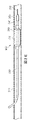
図2Bは、カテーテル200が患者の血管210内の病変206を通り抜ける様子を示す。撮像デバイス203は、ステント208の留置を促進するべく、病変206を検出し、評価するために用いることができる。病変206は近位端部225及び遠位端部230を含み、病変206の近位端部225から遠位端部230に及ぶ長さL1を有する。カテーテル200が血管210を通り抜けていくのに従い、臨床医は、撮像デバイス203によって得られたデータを見て血管の健康を評価することができる。撮像データはまた、非限定例として、血管210の経路及び/又は蛇行、血管210内における病変206の位置に関する情報、血管210内における血管壁の規則性又は不規則性、並びに血管210内における血流についての様々な特徴などの、他の血管特徴を中継してもよい。撮像データは、図1の処理システム101によって、病変206の部位に存在する組織及び/又はプラークの種類を特定するために処理されてもよい。病変206を視覚化すると、カテーテル200は、バルーン組立体202が閉塞206と整列するまで血管210内へ更に前進させられる。カテーテル200の遠位端部214が病変206内を進むのに従い、撮像デバイス203は血管を撮像し続けることができ、これにより、バルーン組立体202の位置の正確な評価を臨床医に提供する。具体的には、撮像デバイス203はバルーン組立体202から既知の距離D1に位置付けられており、これにより、臨床医は、所与の時間において撮像デバイス203が撮像している血管210のどの部分に対しても、カテーテル200をその既知の距離だけ前進及び/又は後退させ、バルーン組立体202を位置付けることが可能である。
FIG. 2B shows
撮像デバイス203はまた、病変206に対するバルーン組立体202の留置を促進するために用いることもできる。図示の実施例では、病変206は、縮小及びステント留置を治療選択肢として必要とし得る血管内閉塞である。図2B及び図2Cに示されるように、撮像デバイス203が病変内を進むのに従い、撮像デバイス203によって中継される撮像データは、非限定例として、病変206の長さL1、内腔の輪郭及び病変206の断面(例えば、病変206の近位、近傍、及び遠位における血管210の腔内直径)、並びに病変206を通過する血流の特徴等などの、血管210内の様々な解剖学的特徴の情報を提供することができる。この撮像データを用いて、臨床医はカテーテル200を適当な距離だけ前方へ前進させ、拡張されていないバルーン組立体202及びそれを覆うステント208を病変206内に正確に位置付けることができる。ステント208は、近位ステント端部235から遠位ステント端部240に及ぶ長さL2を含む。臨床医は、ステントの長さL2が、長さL1を有する病変206を治療するために適切であるかどうかを評価することができる。ステント208が、病変206を適切に治療するには相対的に短すぎるか、又は長すぎる場合には、カテーテル200を取り外して、正しいサイズのステントが提供されてもよく、これにより、不適切なサイズのステントの移植から生じ得る潜在的なステントの故障、崩壊、無効な治療、又は効果の少ない治療を回避する。
図2Cは、患者の血管210内の病変206内におけるバルーン組立体202及びステント208の拡張を示す。臨床医がバルーン組立体202及びステント208を(拡張されていない状態で)病変206内で適切に前進させた後に、臨床医は、病変206を生じさせているプラーク又はその他の物体を圧迫するとともに、病変206の位置における血管210の新しい開通性をも維持するべくステント208を拡張するために、バルーン組立体202内に圧力を導入することによってバルーン組立体202を膨張させてもよい。上述されたように、これは、カテーテル200の近位シャフト220の内腔を通して膨張流体を注入することによって行われてもよい。バルーン組立体202が、通例、15~25ATMの範囲内の圧力を受けて膨張させられると、ステント208は、拡張された状態を呈し、病変206の物体を血管210の内壁に押し付けて圧迫する。
FIG. 2C illustrates expansion of
図2Dは、病変206内におけるステント208の最初の展開後における病変206からのバルーン組立体202の引き抜きを示す。臨床医はバルーン組立体202を収縮させ、カテーテル200を、撮像デバイス203がステント208の近位に位置付けられるまで後退させるか、又は引き戻してもよい。臨床医又は処理システムは、撮像デバイス203が、展開されたステント208を通って引き戻される際に、撮像デバイス203によって受信された撮像データにアクセスし、それを利用することができる。この撮像データは引き戻し撮像データと呼ばれることもある。撮像データは、ステント208の拡張及び展開を評価するために用いられてもよい。具体的には、撮像データは、臨床医が病変206及び動脈壁に対する適切なステント付着を評価することを可能にする。
FIG. 2D shows withdrawal of
引き戻し撮像データ及びその他のデータは、処理システム101によって、再狭窄の確率を推定するために処理されてもよい。処理システム101は、ステント208の展開(病変206の両側における血管の直径に対するステント208の展開量など)、病変206の部位に存在する組織の種類(1つ又は複数)、ステントの種類、及び血管210内におけるステント208の位置に基づいて再狭窄確率を推定してもよい。いくつかの実施形態では、ステント208の展開度は、病変206の部位における血管210の展開前の直径の百分率として、目標若しくは所望の展開直径の百分率として、又は病変206の両側における血管210の直径若しくは平均直径の百分率として、或いはステント208の展開の前及び後における断面積の百分率として決定されてもよい。
Pullback imaging data and other data may be processed by processing system 101 to estimate the probability of restenosis. Processing system 101 determines the deployment of stent 208 (such as the amount of deployment of
例えば、引き戻し撮像データから、ステント208の展開度が閾値未満であると指示されると、処理システム101は、再狭窄の確率が高いと客観的に決定してもよい。この再狭窄確率値は種々の仕方で臨床医へ伝達されてもよい。いくつかの実施形態では、再狭窄確率値の視覚的指示が図1のベッドサイドコントローラ118又はディスプレイ122上に表示されてもよい。閾値は、60%、75%、80%、95%、又は別の百分率であってもよい。本実施例は展開度に基づいて再狭窄確率値を推定するが、多くの実施形態では、再狭窄確率値を推定又は算出するために複数の因子が含まれる。
For example, the processing system 101 may objectively determine that the probability of restenosis is high when the pullback imaging data indicates that the degree of deployment of the
ときとして、図2Dに示されるように、ステント208の拡張は、病変206を適切に治療するために不十分になる。処置によっては、ステント208の拡張は、血管造影撮像又は圧力分析に基づいて、病変206を治療するために十分であるように見えることがあるが、実際には十分でないか、又は将来維持される可能性が低い。例えば、ステント208の展開後にステント208の近位及び遠位で取得された圧力測定値は、現時点では、血管210内の流れの満足なレベルの改善を指示し得る。しかし、ステント208の部位の収集された撮像データは、高い再狭窄の確率を指示し得る。例えば、ステント208の一部分が血管210の壁に接して位置付けられていない場合には、この部分は将来プラーク堆積物にとって好都合の部位になり得る。したがって、たとえ、圧力測定値が、ステント208の性能が満足のいくものであることを指示していても、カテーテル200の引き戻しによって得られた撮像データは、現在及び将来の両方におけるステント208の性能を評価する際に、追加の情報を提供し得る。
Occasionally, expansion of
図2Dでは、ステント208は、病変206を血管210の内腔壁245に押し付けて圧迫するように完全には拡張されていない。その代わりに、病変206は部分的にそのまま残っており、血管210を通る流れを少なくとも部分的に閉塞する能力を有する。撮像デバイス203はこの情報を、撮像データを介して臨床医へ伝えることができ、処理システム101は再狭窄確率値を推定し、それを、視覚的に、及び/又は音声によって臨床医へ伝達してもよい。例えば、処理システム101が、図2Dに示されるように完全に拡張されていないステント208の再狭窄確率値は閾値を上回ると推定すると、処理システムは、処理システム101に結合されたスピーカ上にビープ音又はチャイムを発生させてもよい。追加的に、又は代替的に、処理システム101は告知を臨床医に対して表示させてもよい。推定された再狭窄確率値に関連付けられた、視覚的告知又は音声告知などの告知又は警報は、ステント208が十分に位置付けられていないこと、及び改善措置を検討するべきであることを臨床医に指示し得る。これらの改善措置は、ステント208の展開の修正を遂行すること、又は病変206の部位から物体を除去するための切除処置などの、代替的処置を遂行することを含んでもよい。いくつかの実施形態では、処理システム101は、推奨されるインターベンション(例えば、ステント208のより高圧の展開、切除プロセス、又はそれらの組み合わせなど)を生成し、推奨を、処理システム101によって提供されたユーザインターフェース内で臨床医へ伝達してもよい。
In FIG. 2D,
図2Eは、ステント208の展開を改善するための病変206内におけるバルーン組立体202の再挿入及び再拡張を示す。ステント208の留置が再び評価されてもよく、再狭窄確率値が依然として閾値を上回る場合には、追加のステップが講じられてもよい。再狭窄確率値の推定後に、臨床医が、ステント208の拡張を増大させ、病変206のプロファイルを更に減少させたいと所望する場合には、臨床医はカテーテル200を再び前進させ、バルーン組立体をステント208及び病変206内に再び位置付けてもよい。図2Eに示されるように、バルーン組立体202は、ステント208を更に拡張するために、より高い圧力で再膨張させられてもよく、これにより、血管210の内腔壁245に対するステントの付着及び/又は拡張を改善する。
FIG. 2E shows reinsertion and reexpansion of
図2Fは、病変206内におけるステント208の二次拡張後における病変206からのバルーン組立体202の引き抜きを示す。臨床医はバルーン組立体202を再度収縮させ、カテーテル200を、撮像デバイス203がステント208の近位に位置付けられるまで後退させてもよい。処理システム101は、引き戻しの間に撮像デバイス203によって得られた撮像データを再び用いてステント208の拡張及び展開を評価し、新しい条件に基づいて新たな再狭窄確率値を推定してもよい。推定された再狭窄確率値は、病変206に対する適切なステント付着及び血管210内における拡張が存在しており、ステント208の将来の性能は、再狭窄を生じることなく持続する可能性が高いとの指示を臨床医に提供し得る。推定された再狭窄確率が閾値を下回る場合には、処理システム101はステント208の適切な展開(即ち、適切な位置付け、拡張、及び付着)を臨床医に指示してもよい。次に、臨床医はカテーテル200を血管210(及び患者の体)から引き抜いてもよい。いくつかの実施形態では、処理システム101は、ステント208の展開が十分であることを指示してもよい。同様に、処理システム101は単に、ステント208の展開が不十分であるとの指示を提供しないのでもよい。
FIG. 2F shows withdrawal of
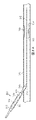
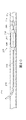
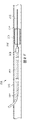
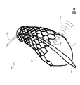
図3は、バルーン302を使用している間に血管内超音波(IVUS)を介して血管を撮像するための撮像カテーテルを含むデバイス300を示す。撮像カテーテルデバイス300は、図2A~図2Fにおけるカテーテル200に関して上述されたように用いられてもよい。撮像カテーテルデバイス300は、バルーン302内で構成された撮像組立体304を含む。好ましくは、撮像組立体304は、音、光、又はその他の媒体に基づく技術などの血管内撮像のために適した任意の技術を含む。カテーテル300は、撮像部分306(例えば、それを通って延在し、膨張内腔、ガイドワイヤ内腔、又はその両方を包囲する導体線を有する、を含んでもよく、遠位先端308まで延在する。
FIG. 3 shows a
上述されたように、いくつかの実施形態では、撮像組立体304はIVUS撮像組立体である。撮像組立体は、フェーズドアレイIVUS撮像組立体又は回転式IVUS撮像組立体であることができる。いくつかの実施形態では、IVUSアレイは、カテーテルの遠位端部を越えて撮像するように構成されており、即ち、前方視IVUSである。他の実施形態では、撮像組立体304は光コヒーレンストモグラフィー(optical coherence tomography、OCT)を用いてもよい。OCTは、小型近赤外光放射プローブを用いる医療撮像手法であり、光散乱媒体(例えば、生物組織)内からマイクロメートル解像度の3次元画像を取得する能力を有する。
As noted above, in some
撮像カテーテルデバイス300は、遠位先端308において終端する長い本体を有するカテーテル310を含む。カテーテル310はその内部に、例えば、デバイス300のカテーテル310が治療部位へ案内されることを可能にするためのガイドワイヤ内腔などの1つ以上の内腔を有してもよい。カテーテル310は、流体312(例えば、空気)がバルーン302へ送達され、それを膨張させることを可能にする別個の膨張内腔を含んでもよい。カテーテル310はまた、撮像デバイス304を含んでもよい。図3では、撮像デバイス304は、バルーン302内に位置するように示されている。カテーテル310の部分306が、導線又は光ファイバなどの撮像組立体304のための必要なハードウェアを保持している。撮像組立体304は、例えば、超音波、光音響撮像、OCT、又はその他のものを含む任意の好適な撮像モダリティを介して動作し得る。撮像カテーテルデバイス300は、上記において図2A~図2Fに関して一般的に説明されたように用いられてもよい。しかし、撮像カテーテルデバイス300は、バルーン302が、ステントを病変の部位に留置するために展開されている間に、少なくともいくらかの撮像データを得るために用いられてもよい。
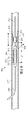
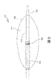
図4は、ステント400がバルーン302の拡張によって展開されている状態の、図3の撮像カテーテルデバイス300を示す。図4に示されるように、撮像データは、バルーン302が、ステント400を留置するために拡張している間に、撮像組立体304から放射された音波402によって発生された反射信号に基づいて収集される。したがって、いくつかの実施形態では、病変の部位から撮像データを収集することは、ステントの展開、又はその他の治療の前、後、及びその最中に遂行されてもよい。この撮像データは、処理システム101によって、部位における組織及びプラークを特定し、部位及び/又は病変を物理的寸法の観点から特徴付けるために処理されてもよい。更に、処理システム101は、ステント400の留置の最中に再狭窄確率を推定してもよい。処理システム101は、ステント400の留置の最中に再狭窄確率値の指示を臨床医に提供してもよい。いくつかの実施形態では、ステント400の展開中に算出された再狭窄確率値は、予備再狭窄値として伝達されてもよい。いくつかの実施形態では、再狭窄確率値はステント400の展開中に繰り返し推定されてもよく、それにより、再狭窄確率値が閾値を下回ると、再狭窄の確率が許容可能なほど小さいことを知らせるための指示がユーザインターフェースを通じて臨床医に提供される。
FIG. 4 shows
図5は、処理システム101によって、図1のベッドサイドコントローラ118及び/又はディスプレイ122による表示のために提供されてもよい、本開示の一実施形態に係るユーザインターフェース500を示す。ユーザインターフェース500はまた、スクリーンディスプレイと呼ばれる場合もある。ユーザインターフェース500は複数のタブを含むか、或いは図1に示される医療システム100の処理システム101及び又は血管内デバイス114に関連付けられたユーザインターフェース全体内のタブとしてアクセス可能であってもよい。ユーザインターフェース500は、ステント留置の部位から得られた撮像データ504の一部分を表示するクローズアップウィンドウ502を含んでもよい。ディスプレイ内のクローズアップウィンドウ502内でレンダリングされた時に、撮像データ504は血管内におけるステント506の描画図を含む。ステント506は少なくとも部分的に展開されている。撮像データ504の表示部分はステント506をほぼ断面図で示し得る。クローズアップウィンドウ502は、臨床医が、それぞれ、図2A~図2F及び図4のステント208又は400などの、ステントの留置を視覚化することを可能にし得る。臨床医はまた、ステント506の部位における血管の断面構成を見ることも可能になり得る。血管は、外部からは観察できないが血管内撮像デバイスを用いて観察できる様々な程度に、概ね円形の断面から逸脱している可能性がある。
FIG. 5 illustrates a
ユーザインターフェース500はまた、レンダリングされた撮像データ504の現在の光景全体を表示してもよい全景ウィンドウ508を含んでもよい。いくつかの実施形態では、ウィンドウ502及び508は「実況」撮像データを含んでもよい。他の実施形態では、ウィンドウ502及び508の一方又は両方は、実況でない、又は記録された撮像データを表示してもよい。いくつかの実施形態では、ウィンドウ502及び508内には、画像の異なるモードが表示されてもよい。例えば、ウィンドウ502内には、プラークの描画を最適化する仕方で得られた撮像データが示されてもよく、一方で、ウィンドウ508内には、組織の描画を最適化する仕方で得られた撮像データが示されてもよい。撮像データは、撮像モードを交互に繰り返すことによって得られてもよい。撮像モードは、撮像データの単一のセットを異なる仕方で処理することによって提供されてよく、或いはモードは、撮像部位における特定の特徴を最もよく捕捉するために、カテーテル内の撮像デバイスによって実装された設定及びパラメータを交互に繰り返すことによって提供されてもよい。例えば、全体が本明細書において参照により組み込まれる、2013年11月13日に出願され、「Visually Optimized Intravascular Imaging and Associated Devices, Systems, and Methods」と題する、米国特許仮出願第61/903,764号に記載されている撮像技法が利用されてもよい。ユーザインターフェース500によって提供される映像を用いて、臨床医は経験に基づいて主観的判断を適用し、ステントの留置の質を評価してもよい。
The
ユーザインターフェース500はステント留置情報ウィンドウ510を更に含む。ステントウィンドウ510は、患者の血管内におけるステントの留置に関する客観的情報を伝達するために用いられてもよい。ステントの留置を記録した情報は、血管内撮像データなどの、血管内のセンサによって取得された生理学的測定値に基づく。臨床医はユーザインターフェース500と対話し、再狭窄の確率の推定を有効又は無効にし得る。図5に示されるように、ウィンドウ510は自動ボタン512Aを含む。自動ボタン512Aによって、ユーザインターフェース500のユーザ、例えば、臨床医は、生理学的データが利用可能になると、推定された再狭窄確率値が処理システム101によって自動的に継続的に算出されるように、積極的に要求することができる。生理学的データは、IVUS撮像カテーテルなどの、カテーテルを用いて収集されることによって、及び/又は、生理学的データが記憶されたネットワーク化された記憶デバイスなどのメモリからアクセスされることによって、入手可能になってもよい。手動ボタン512Bは、推定プロセスを制限するために選択されてもよい。手動ボタン512Bを選択すると、更新ボタン512Cが臨床医によって選択された時に、推定された再狭窄確率値が算出される、手動モードが作動させられる。ボタン512A~Cは、マウスをクリックすること、関連付けられたキーストロークをキーボード上で入力すること、及び/又はタッチスクリーンに触れることによって選択されてもよい。
ステント留置情報ウィンドウ510は、最新の推定された再狭窄確率値516の指示を表示してもよい、推定再狭窄確率エリア514を含む。推定された再狭窄確率値516はユーザインターフェース500を通じて種々の仕方で伝達されてもよい。そのうちの一部のみが本明細書に記載される。例えば、再狭窄確率値516は数値として提供されてもよい。他の実施形態では、複数の値の階層を適用することによって、定量的な推定された再狭窄確率値516の定性的記述が提供されてもよい。例えば、推定された再狭窄確率値が第1の階層定義値と第2の階層定義値との間にある場合には、「不可」、「可」、「良」、又は「優」などの、階層の定性的記述が推定再狭窄確率値エリア514内に提供されてもよい。このように、処理システム101は、実際の推定された再狭窄確率値そのものよりも臨床医によって容易に解釈され得る、推定された再狭窄確率値の定性的記述を伝達してもよい。いくつかの実施形態では、直近の推定された再狭窄確率値が属する階層を指示するための色、例えば、「赤色」、「黄色」、又は「緑色」が表示されてもよい。他の実施形態では、ユーザインターフェース500は、推定された再狭窄確率値を指示するための音声合図を含んでもよい。例えば、ユーザインターフェース500は、直近の推定された再狭窄確率値が閾値を上回るたびに、スピーカを通じて警報又はビープ音を発生させてもよい。推定された再狭窄確率値516がユーザインターフェース500のユーザへ伝達される仕方にかかわらず、推定された再狭窄確率値516は、ステントの現在の留置が病変の適切な補償を提供しない可能性があり、且つ/又は将来において病変の適切な補償を提供しない可能性があることを伝達してもよい。推定された再狭窄確率値516は、ステントを通る流れは最初の留置の後に改善されたが、追加のステップが講じられないかぎりステントの恩恵が存続しない可能性があることを指示してもよい。
The stent placement information window 510 includes an estimated restenosis probability area 514 that may display an indication of the most recent estimated restenosis probability value 516 . Estimated restenosis probability value 516 may be communicated through
ステント留置情報ウィンドウ516はまた、いくつかの実施形態では、推奨インターベンションエリア518を含む。処理システム101によって、特定のインターベンションがステントの性能を最も良く改善すると決定され得る諸実施形態では、その改善を達成する決定された手段が伝達のためにユーザインターフェース500内に表示されてもよい。図5に示されるように、処理システム101は、推定された再狭窄確率値が閾値を上回っており、増大させた圧力を用いてカテーテルの遠位部分においてバルーンを再拡張することによってステントを再展開することが、将来におけるステントの性能を改善し得ると決定した。ユーザインターフェース500に示されるように、処理システム101は、切除治療は推奨されないことを指示している。いくつかの実施形態では、1つを超えるインターベンションが、そのインターベンションは将来におけるステントの性能を改善する可能性が高いかどうかの付随指示とともに、ユーザに表示されてもよい。他の実施形態では、単一の推奨インターベンションが推奨インターベンションエリア518内に表示されてもよい。ユーザインターフェース500は、臨床医が、ステント留置性能の指示をカスタマイズするべく、推定された再狭窄確率値とともに用いられ得る閾値をプログラムできるようにする更なるボタン又はユーザインターフェース要素を含んでもよい。
The stent placement information window 516 also includes a recommended intervention area 518 in some embodiments. In embodiments where it may be determined by the processing system 101 that a particular intervention will best improve stent performance, the determined means of achieving that improvement may be displayed within the
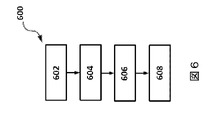
次に、図6を参照すると、同図には、患者内の血管を治療する方法600のフローチャートが示されている。例えば、方法600は、医療システム100を用いて図1の患者103の血管を治療するための方法を示す。方法600は複数の列挙されたステップ又は動作として示されている。方法600の諸実施形態は、列挙されたステップの前、後、間に、又はそれらの一部として、追加のステップ又は動作を含んでもよい。方法600のステップは、血管内デバイス114、CPU104を含む処理システム101、並びにディスプレイ122又はベッドサイドコントローラ118のディスプレイなどのハードウェアを用いて遂行されてもよい。いくつかの実施形態では、方法600の動作のいくつか又は全てを遂行するための命令は、実行可能コードとして図1のメモリ106などの非一時的コンピュータ可読媒体に記憶されてもよい。
Referring now to FIG. 6, there is shown a flowchart of a
図6には、処理システム101のCPU104などの処理デバイスが、病変の部位におけるステントの留置の血管内超音波撮像データに基づいて再狭窄確率値を推定する、方法600の一実施形態が示されている。病変の部位において得られた、収集された撮像データ、及びその他の情報を処理し、再狭窄確率の客観的尺度を生成するための多くのアルゴリズムが用いられ得る。処理デバイスは、部位における組織の種類、部位におけるプラークの種類、及び/又はプラークの存在及び幾何学的形状、ステントの種類、及び/又は血管内におけるステントの位置、ステントと血管の壁との間の間隙の存在、ステントにわたる断面積(区域の形状及び/又はサイズ、並びにステントにわたる断面積の一様性を含む)、病変がステントを越えて延在するかどうかなどに基づいて、再狭窄確率値を推定してもよい。いくつかの実施形態では、処理デバイスは、ステントの近位の区域内における血管の湾曲度に基づいて再狭窄確率値を推定してもよい。追加的に、撮像データ以外のデータがステントの性能に関する情報を提供するために用いられるいくつかの実施形態では、再狭窄確率値の推定は、圧力データ及び/又は流量データなどの生理測定値に基づいてもよい。例えば、圧力情報が、ステントの前及び後の位置において、並びにステント内の様々な地点において得られてもよい。この圧力情報が、ステントの性能を評価するために用いられてもよく、再狭窄確率値の推定において用いられてもよい。いくつかの実施形態では、圧力情報は、推定された再狭窄確率値を生成するために、処理デバイスによって撮像データとともに用いられてもよい。
FIG. 6 shows an embodiment of a
ステップ602において、カテーテルが血管の内腔内に挿入される。これは、本明細書に記載されているとおりの図2A及び図2Bに示されるように行われてもよい。カテーテルは、本明細書に記載されているとおりの図2A~図2Fのバルーン組立体202又は図3及び図4に示されるバルーン302のような、ステント留置組立体、並びに同じく図3及び図4の撮像組立体304などの、血管内超音波撮像デバイスを含んでもよい。方法600のいくつかの実施形態では、カテーテルは、臨床医によるカテーテルの手動制御によって挿入されてもよいか、カテーテルは、臨床医の指示によるロボット制御を用いて挿入されてもよいか、又はカテーテルは、カテーテルが処理システム101によって病変の部位まで操縦される、自動ロボット制御を用いて挿入されてもよい。例えば、カテーテルは、カテーテルの先端を操縦し、カテーテルを血管の内部及び外部へ導くためのコマンドを処理システム101から受信するか、又はベッドサイド制御装置118から直接受信したPIM116に結合された、操縦可能血管内デバイス114であってもよい。カテーテルが血管の内腔内の病変の部位に位置付けられた後に、ステント留置組立体は、図2Cに示されるように、ステントを血管の内腔内の病変の部位に留置するために作動させられてもよい。ステントを留置する際に、ステントは、血管内の流れを改善するために内腔の壁に押し当たって拡張するように展開されてもよい。
At
ステップ604において、カテーテルの血管内超音波撮像デバイスを用いて血管内超音波撮像データが収集される。これは、カテーテルの引き戻しを遂行している間に行われてもよく、それにより、血管に沿ってステント又は病変の遠位側からステント又は病変の近位側まで撮像データが得られる。撮像データは病変の部位におけるステントの留置についての情報を含み、処理システム101によって、組織の種類、プラークの存在及び/又は種類に関する特定の情報、並びに血管内におけるステントの位置に関する情報(例えば、血管が著しい屈曲を含むかどうか、ステントの両側におけるステント直径など)を提供するために処理されてもよい。例えば、情報は、ステントの前及び後、並びにステントの内部における血管の断面積に関する情報を含んでもよい。それゆえ、ステントが展開されず、概ね円形の断面積を有する時には、血管内超音波撮像デバイスは、これを臨床医に指示するための情報を提供してもよい。追加的に、ステントの全長のいくらかの部分においてステントと内腔壁との間に間隙が存在する場合には、撮像データは、処理システム101が間隙を解釈及び分析し、いくつかの実施形態では、ディスプレイ内における間隙の視覚化を提供することを可能にする情報を含んでもよい。
At
ステップ606において、処理システム101のCPU104などの処理デバイスが、病変の部位におけるステントの留置の血管内超音波撮像データに基づいて再狭窄確率値を推定してもよい。病変の部位において得られた、収集された撮像データ、及びその他の情報を処理し、再狭窄確率の客観的尺度を生成するための多くのアルゴリズムが用いられ得る。処理デバイスは、部位における組織の種類、部位におけるプラークの種類、及び/又はプラークの存在及び幾何学的形状、ステントの種類、及び/又は血管内におけるステントの位置、ステントと血管の壁との間の間隙の存在、ステントにわたる断面積(区域の形状及び/又はサイズ、並びにステントにわたる断面積の一様性を含む)、病変がステントを越えて延在するかどうかなどに基づいて、再狭窄確率値を推定してもよい。いくつかの実施形態では、処理デバイスは、ステントの近位の区域内における血管の湾曲度に基づいて再狭窄確率値を推定してもよい。追加的に、いくつかの実施形態では、撮像データ以外のデータが、ステントの性能に関する情報を提供するために用いられてもよい。例えば、圧力情報及び/又は流量情報が、ステントの前及び後の位置において、並びにステント内の様々な地点において得られてもよい。この圧力及び流量情報は、ステントの性能を評価するために用いられてもよく、再狭窄確率値の推定において用いられてもよい。いくつかの実施形態では、圧力情報は、推定された再狭窄確率値を生成するために、処理デバイスによって撮像データとともに用いられてもよい。
At
ステップ608において、推定された再狭窄確率値の指示が臨床医へ伝達される。例えば、処理システム101は、推定された再狭窄確率値の指示を、ディスプレイ122上、又はベッドサイドコントローラ118のタッチスクリーンディスプレイ上に視覚化させてもよい。例えば、処理システム101はユーザインターフェース500などのユーザインターフェースを表示させてもよい。図5に示されるように、ユーザインターフェース500は、本明細書に記載されているとおりのステント留置情報ウィンドウ510を含む。推定された再狭窄確率値516は推定再狭窄確率エリア514内に、数値として、色として、テキストとして、又はそれらの組み合わせとして表示されてもよい。いくつかの実施形態では、推定された再狭窄確率値は臨床医への表示の前に処理システム101によって解釈されてもよい。例えば、推定された再狭窄確率値は、「不可」、「可」、「良」等などの、推定された再狭窄確率の記述に対応する複数の階層と比較されてもよい。いくつかの実施形態では、推定された再狭窄確率値の指示は、ステントの留置後に病変の部位においてカテーテルによって得られた撮像データ及びその他の情報による指示に従い、再狭窄の可能性が高いか又は低いことを指示するための、ビープ音、チャイム、又はアラームなどの、音として臨床医へ伝達されてもよい。推定された再狭窄確率に基づいて、臨床医は、図2E及び図2Fに示されるように、ステント展開組立体をステント内に再挿入し、ステントを展開するために圧力を再び印加してもよい。その後、データが収集されてもよく、再展開を考慮した将来のステント性能を予測するために再狭窄確率が再び算出されてもよい。
At
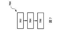
次に、図7を参照すると、同図には、患者内の血管を治療する方法700のフローチャートが示されている。図6の方法600と同様に、方法700は複数のステップ又は動作として示されている。これらの列挙されたステップの前、後、間に、又はそれらの一部として、追加のステップが遂行されてもよい。方法700のステップは図1の医療システム100によって遂行されてもよい。方法700の一実施形態は、カテーテルが血管の内腔内における病変の部位に位置付けられるステップ702から開始してもよい。カテーテルはステント留置組立体を含む。ステップ704において、ステント留置組立体が作動させられ、ステントを血管の内腔内における病変の部位に留置する。例えば、図3に示されるように、カテーテルは、展開可能なバルーン302、及びステントを血管の内腔壁に押し付けて拡張させるための流体圧力を含んでもよい。例えば、ステントは、ステント400によって図4に示されるように展開されてもよい。展開されると、ステントは血管内の流れを回復し得る。
Referring now to FIG. 7, shown is a flowchart of a
ステントが長期にわたる将来の恩恵を提供する可能性が高いかどうかを評価するために、ステップ706において、病変の部位におけるステントの留置に基づいて再狭窄確率値が推定される。再狭窄確率値は図1の処理システム101によって推定されてもよい。例えば、CPU104は、ステントの留置時に血管内で得られた撮像データ及び/又はその他のデータを受信してもよく、データを分析し、組織の種類、プラークの種類、ステント内の複数の地点における血管の断面、及びその血管、若しくはステントの付近の隣接する血管の屈曲度を含む、血管内におけるステントの位置を決定してもよい。追加的に、CPU104は、ステントの留置に先立って得られた撮像データ及び/又はその他のデータを受信してもよい。CPU104は、実行可能コードとしてメモリ106上の命令112内に記憶されたアルゴリズム及び方法を実行してもよい。方法700のいくつかの実施形態では、ステントの長期にわたる将来の恩恵が達成され得るようにインターベンションが遂行されるべきであることを臨床医に知らせるために、推定された再狭窄確率値の指示が臨床医へ伝達されてもよい。例えば、処理システム101は、バルーン302をステント内に再び挿入し、最初に用いた圧力よりも高い圧力を用いてバルーンを再膨張させることによって、推定された再狭窄確率値が増大させられるであろうと決定してもよい。処理システム101は、切除デバイスをステント内に挿入し、病変の部位からプラークの一部を除去するための切除プロセスを遂行することによって、推定された再狭窄確率値が増大させられるであろうと決定してもよい。ステントは、切除プロセス後に、より高い圧力を用いて、又は同じ圧力を用いて再展開されてもよい。各インターベンションが終了すると、推定アルゴリズムによって再狭窄確率を評価及び再評価するために、ステントの留置時におけるデータが得られてもよい。例えば、処理システム101は、撮像データから、ステントは、ステントの少なくともいくらかの部分内では、その最大直径の65%などの割合までしか展開されていないと決定し得る。他のアルゴリズムは異なる閾値を含んでもよく、撮像データから抽出されたより多くの変数を演算対象としてもよい。
To assess whether the stent is likely to provide long-term future benefit, at step 706 a restenosis probability value is estimated based on the placement of the stent at the site of the lesion. A restenosis probability value may be estimated by the processing system 101 of FIG. For example, the CPU 104 may receive imaging data and/or other data obtained intravascularly during placement of the stent and analyze the data to identify tissue types, plaque types, and at multiple points within the stent. The position of the stent within the vessel may be determined, including the cross-section of the vessel and the tortuosity of the vessel or adjacent vessels in the vicinity of the stent. Additionally, CPU 104 may receive imaging data and/or other data obtained prior to stent deployment. CPU 104 may execute the algorithms and methods stored in
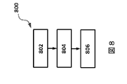
次に、図8を参照すると、同図には、患者の血管を治療する方法800のフローチャートが示されている。図示のように、方法800は、撮像データが受信されるステップ802を含む。撮像データは、患者の血管の内腔内のステントの留置部位にあるカテーテル上の撮像デバイスによって得られ、撮像デバイスから受信される。例えば、図1の処理システム101は、血管内デバイス114によって得られた撮像データを受信してもよい。撮像データは、処理システム101のCPU104による受信に先立ってPIM116及び/又は取得カード108によって何らかの処理を受けていてもよい。ステップ804において、処理システムは、撮像デバイスによって得られた撮像データに基づいて再狭窄確率値を推定する。推定された再狭窄確率値は、病変の部位におけるステントの留置に基づいてもよい。
Referring now to FIG. 8, there is shown a flowchart of a
ステップ806において、推定された再狭窄確率値の指示が臨床医へ伝達されてもよい。指示は、本明細書に記載されているとおりの多くの異なる仕方で伝達されてもよい。処理システム101は、推定された再狭窄確率値を伝達するための情報をディスプレイへ送信してもよい。それゆえ、推定された再狭窄確率値の数値表現が、処理システム101に結合されたディスプレイ上に表示される、音が処理システム101のスピーカから発せられるなどしてもよい。追加的に、方法800のいくつかの実施形態では、撮像デバイスによって得られた撮像データに基づいて、ステントが展開不足であるか、又は他の様態で不満足に機能していると決定されると、インターベンション推奨が決定され、臨床医に提供されてもよい。いくつかの実施形態では、処理システムは、カテーテル内に含まれる別のセンサ又はセンサ群によって得られた、圧力データ又はその他の生理学的データなどの、非撮像データを受信してもよい。推定された再狭窄確率値は、非撮像データ、又は撮像データと非撮像データとの組み合わせに基づいて算出されてもよい。
At
いくつかの実施形態では、方法800の諸実施形態内に含まれる動作を遂行するための命令は、処理システム101のメモリ106などの、非一時的コンピュータ可読媒体内に記憶されていてもよい。したがって、方法600、700、及び800の列挙されているステップのうちの1つ以上に対応する命令が、非一時的コンピュータ可読媒体上に記憶された実行可能コードとして提供される場合には、本開示の諸実施形態は、方法600、700、及び800のうちの1つ以上を遂行する、CPU104、又はより一般的には、処理システム101などの、処理デバイスを有するシステムを含む。
In some embodiments, instructions for performing operations included within embodiments of
本開示の諸実施形態は、血管内における展開後のステントの評価を提供する。ステント自身の内部で得られたデータを含む、血管内で得られたデータを用いることによって、再狭窄の確率が、データから得られた客観的情報に基づいて推定され得る。撮像データなどの客観的情報を用いて、処理システムは現在及び/又は将来のステント性能の客観的指示を提供し得る。追加的に、処理システムは、ステントの現在及び/又は将来の性能を改善するための1つ以上のインターベンションを推奨し得る。留置の時点においてステントの留置を評価し、改善することによって、1つ以上の将来のインターベンションが回避され得る。不必要なインターベンションを回避することは、患者と臨床医の両者に有益である。 Embodiments of the present disclosure provide for post-deployment stent evaluation in a vessel. By using data obtained intravascularly, including data obtained within the stent itself, the probability of restenosis can be estimated based on objective information obtained from the data. Using objective information such as imaging data, the processing system can provide an objective indication of current and/or future stent performance. Additionally, the processing system may recommend one or more interventions to improve current and/or future performance of the stent. By evaluating and improving stent placement at the time of placement, one or more future interventions may be avoided. Avoiding unnecessary intervention benefits both the patient and the clinician.
Claims (16)
前記血管内に位置付けられた血管内超音波(IVUS)撮像トランスデューサと通信する処理デバイスが、再狭窄の可能性があるかどうかを決定するステップであって、
前記処理デバイスが、前記IVUS撮像トランスデューサを制御して、超音波を放射し、前記超音波と関連するエコーを受信することと、
前記処理デバイスが、受信した前記エコーに基づいて、前記病変の前記部位における前記ステントのIVUS撮像データを得ることと、
前記処理デバイスが、前記IVUS撮像データを処理して、前記血管の直径及び前記ステントの展開サイズを計算することと、
前記処理デバイスが、計算された前記ステントの前記展開サイズを、計算された前記血管の前記直径と比較することと、
を含む、再狭窄の可能性があるかどうかを決定するステップと、
再狭窄の可能性があることを決定することに応じて、前記処理デバイスに結合されたディスプレイが、前記再狭窄の可能性があることを示す告知を臨床医に伝えるステップと、
を含む、方法。 by positioning a catheter containing a stent deployment assembly at the site of the lesion within the lumen of the blood vessel and actuating the stent deployment assembly to deploy a stent at the site of the lesion within the lumen of the vessel; , a method of operating a system for treating a vessel in a patient, the method comprising:
A processing device in communication with an intravascular ultrasound (IVUS) imaging transducer positioned within the blood vessel determines whether restenosis is likely;
the processing device controlling the IVUS imaging transducer to emit ultrasound waves and receive echoes associated with the ultrasound waves;
the processing device obtaining IVUS imaging data of the stent at the site of the lesion based on the received echoes;
the processing device processing the IVUS imaging data to calculate the diameter of the vessel and the deployment size of the stent;
the processing device comparing the calculated deployment size of the stent to the calculated diameter of the vessel;
determining whether restenosis is likely, comprising
responsive to determining that restenosis is likely, a display coupled to the processing device communicates to a clinician an announcement indicating that restenosis is likely;
A method, including
前記部位における組織の種類、
前記部位におけるプラークの存在、
前記ステントの種類、
前記血管内における前記ステントの部位、又は
圧力測定値若しくは流量測定値の少なくとも一方に基づく前記ステントの性能
のうちの少なくとも1つを決定することを更に含む、請求項1に記載の方法。 The step of determining whether restenosis is likely,
type of tissue at the site;
the presence of plaque at said site;
the type of stent;
2. The method of claim 1, further comprising determining at least one of: location of the stent within the vessel; or performance of the stent based on at least one of pressure measurements or flow measurements.
Comparing the calculated deployment size of the stent to the calculated diameter of the vessel comprises calculating the deployment size of the stent as a percentage of the calculated diameter of the vessel ; 2. The method of claim 1, wherein determining whether restenosis is likely includes determining whether the calculated deployment size of the percentage of the stent exceeds a threshold.
前記非一時的コンピュータ可読媒体及び血管内超音波(IVUS)撮像カテーテルと通信する処理デバイスとを備える、医療診断及び治療システムであって、前記処理デバイスは、
患者の血管の内腔内のステントの留置部位にある前記IVUS撮像カテーテルによって得られるIVUS撮像データを受信することであって、前記留置部位は前記血管の病変の位置に対応する、受信することと、
受信された前記血管の前記内腔内の前記ステントのIVUS撮像データに基づいて、前記血管の直径及び前記ステントの展開サイズを計算することと、
計算された前記ステントの前記展開サイズを、計算された前記血管の前記直径と比較することと、
前記ステントの前記展開サイズの前記計算された前記血管の直径との比較に基づいて、再狭窄の可能性があるかどうかを決定することと、
前記処理デバイスに結合されたディスプレイに、前記再狭窄の可能性があるかどうかを通信する情報を前記医療診断及び治療システムの操作者に送信することと、
を含む動作を遂行するための前記命令を実行する、医療診断及び治療システム。 a non-transitory computer-readable medium for storing instructions;
A medical diagnostic and treatment system, comprising: a processing device in communication with the non-transitory computer-readable medium and an intravascular ultrasound (IVUS) imaging catheter, the processing device comprising:
receiving IVUS imaging data obtained by said IVUS imaging catheter at a stent deployment site within the lumen of a patient's vessel, said deployment site corresponding to a location of a lesion in said vessel; ,
calculating a diameter of the vessel and a deployed size of the stent based on received IVUS imaging data of the stent within the lumen of the vessel;
comparing the calculated deployment size of the stent to the calculated diameter of the vessel;
determining whether restenosis is likely based on a comparison of the deployed size of the stent to the calculated vessel diameter;
transmitting to a display coupled to the processing device information communicating whether restenosis is likely to occur to an operator of the medical diagnostic and treatment system;
A medical diagnostic and therapeutic system that executes said instructions to perform operations including:
前記ステントが展開不足かどうかを決定することと、
前記ステントが展開不足であると決定されると、前記ディスプレイに、推奨されるインターベンションを表示させることと、
を更に含む、請求項11に記載の医療診断及び治療システム。 the operation is
determining whether the stent is underdeployed;
causing the display to indicate a recommended intervention when the stent is determined to be underdeployed;
12. The medical diagnostic and therapeutic system of claim 11, further comprising:
前記血管の前記直径は、前記病変の近傍の直径、前記病変の近位の直径、又は前記病変の遠位の直径のうちの少なくとも1つを含み、
前記ステントの前記直径は、近位端部直径又は遠位端部直径のうちの少なくとも一方を含む、請求項11に記載の医療診断及び治療システム。 said processing device performing said operations including calculating said deployment size of said stent by calculating a diameter of said stent;
said diameter of said vessel comprises at least one of a diameter proximal to said lesion, a diameter proximal to said lesion, or a diameter distal to said lesion;
12. The medical diagnostic and treatment system of claim 11, wherein the diameter of the stent includes at least one of a proximal end diameter or a distal end diameter.
Applications Claiming Priority (2)
| Application Number | Priority Date | Filing Date | Title |
|---|---|---|---|
| US201462090251P | 2014-12-10 | 2014-12-10 | |
| US62/090,251 | 2014-12-10 |
Related Parent Applications (1)
| Application Number | Title | Priority Date | Filing Date |
|---|---|---|---|
| JP2017530310A Division JP6751092B2 (en) | 2014-12-10 | 2015-11-18 | Device, system and method for predicting in-stent restenosis |
Publications (2)
| Publication Number | Publication Date |
|---|---|
| JP2020195788A JP2020195788A (en) | 2020-12-10 |
| JP7171663B2 true JP7171663B2 (en) | 2022-11-15 |
Family
ID=54780372
Family Applications (2)
| Application Number | Title | Priority Date | Filing Date |
|---|---|---|---|
| JP2017530310A Active JP6751092B2 (en) | 2014-12-10 | 2015-11-18 | Device, system and method for predicting in-stent restenosis |
| JP2020136570A Active JP7171663B2 (en) | 2014-12-10 | 2020-08-13 | Devices, systems, and methods for in-stent restenosis prediction |
Family Applications Before (1)
| Application Number | Title | Priority Date | Filing Date |
|---|---|---|---|
| JP2017530310A Active JP6751092B2 (en) | 2014-12-10 | 2015-11-18 | Device, system and method for predicting in-stent restenosis |
Country Status (5)
| Country | Link |
|---|---|
| US (3) | US10772599B2 (en) |
| EP (2) | EP4230121A3 (en) |
| JP (2) | JP6751092B2 (en) |
| CN (1) | CN106999155A (en) |
| WO (1) | WO2016092389A1 (en) |
Cited By (9)
| Publication number | Priority date | Publication date | Assignee | Title |
|---|---|---|---|---|
| US11648424B2 (en) | 2018-11-28 | 2023-05-16 | Histosonics Inc. | Histotripsy systems and methods |
| US11813485B2 (en) | 2020-01-28 | 2023-11-14 | The Regents Of The University Of Michigan | Systems and methods for histotripsy immunosensitization |
| US12220602B2 (en) | 2015-06-24 | 2025-02-11 | The Regents Of The University Of Michigan | Histotripsy therapy systems and methods for the treatment of brain tissue |
| US12318636B2 (en) | 2022-10-28 | 2025-06-03 | Histosonics, Inc. | Histotripsy systems and methods |
| US12343568B2 (en) | 2020-08-27 | 2025-07-01 | The Regents Of The University Of Michigan | Ultrasound transducer with transmit-receive capability for histotripsy |
| US12446905B2 (en) | 2023-04-20 | 2025-10-21 | Histosonics, Inc. | Histotripsy systems and associated methods including user interfaces and workflows for treatment planning and therapy |
| US12527976B2 (en) | 2020-06-18 | 2026-01-20 | Histosonics, Inc. | Histotripsy acoustic and patient coupling systems and methods |
| US12582848B2 (en) | 2021-06-07 | 2026-03-24 | The Regents Of The University Of Michigan | Minimally invasive histotripsy systems and methods |
| US12599787B2 (en) | 2021-06-07 | 2026-04-14 | The Regents Of The University Of Michigan | All-in-one ultrasound systems and methods including histotripsy |
Families Citing this family (63)
| Publication number | Priority date | Publication date | Assignee | Title |
|---|---|---|---|---|
| US8781555B2 (en) | 2007-11-26 | 2014-07-15 | C. R. Bard, Inc. | System for placement of a catheter including a signal-generating stylet |
| US9521961B2 (en) | 2007-11-26 | 2016-12-20 | C. R. Bard, Inc. | Systems and methods for guiding a medical instrument |
| EP2992825B1 (en) | 2007-11-26 | 2017-11-01 | C.R. Bard Inc. | Integrated system for intravascular placement of a catheter |
| US9532724B2 (en) | 2009-06-12 | 2017-01-03 | Bard Access Systems, Inc. | Apparatus and method for catheter navigation using endovascular energy mapping |
| WO2011150376A1 (en) | 2010-05-28 | 2011-12-01 | C.R. Bard, Inc. | Apparatus for use with needle insertion guidance system |
| AU2016219018B2 (en) | 2015-02-12 | 2020-10-29 | Foundry Innovation & Research 1, Ltd. | Implantable devices and related methods for heart failure monitoring |
| US12465324B2 (en) | 2015-02-12 | 2025-11-11 | Foundry Innovation & Research 1, Ltd. | Patient fluid management systems and methods employing integrated fluid status sensing |
| WO2018031714A1 (en) | 2016-08-11 | 2018-02-15 | Foundry Innovation & Research 1, Ltd. | Systems and methods for patient fluid management |
| US10109058B2 (en) | 2015-05-17 | 2018-10-23 | Lightlab Imaging, Inc. | Intravascular imaging system interfaces and stent detection methods |
| US9996921B2 (en) | 2015-05-17 | 2018-06-12 | LIGHTLAB IMAGING, lNC. | Detection of metal stent struts |
| CN107735828B (en) | 2015-06-25 | 2021-04-09 | 皇家飞利浦有限公司 | Interactive endovascular procedure training and related devices, systems and methods |
| US10338795B2 (en) * | 2015-07-25 | 2019-07-02 | Lightlab Imaging, Inc. | Intravascular data visualization and interface systems and methods |
| WO2017024051A1 (en) | 2015-08-03 | 2017-02-09 | Foundry Innovation & Research 1, Ltd. | Devices and methods for measurement of vena cava dimensions, pressure, and oxygen saturation |
| US11020563B2 (en) | 2016-07-14 | 2021-06-01 | C. R. Bard, Inc. | Automated catheter-to-vessel size comparison tool and related methods |
| US11206992B2 (en) | 2016-08-11 | 2021-12-28 | Foundry Innovation & Research 1, Ltd. | Wireless resonant circuit and variable inductance vascular monitoring implants and anchoring structures therefore |
| US11701018B2 (en) | 2016-08-11 | 2023-07-18 | Foundry Innovation & Research 1, Ltd. | Wireless resonant circuit and variable inductance vascular monitoring implants and anchoring structures therefore |
| US20180235572A1 (en) | 2016-10-28 | 2018-08-23 | Thomas C. Moore | Device and Method for Intravascular Imaging and Sensing |
| EP3705031B1 (en) | 2016-11-29 | 2025-12-10 | Foundry Innovation & Research 1, Ltd. | Wireless resonant circuit and variable inductance vascular implants for monitoring patient vasculature system |
| WO2018220146A1 (en) | 2017-05-31 | 2018-12-06 | Foundry Innovation & Research 1, Ltd. | Implantable sensors for vascular monitoring |
| EP3629937B1 (en) | 2017-05-31 | 2026-01-14 | Foundry Innovation & Research 1, Ltd. | Implantable ultrasonic vascular sensor |
| WO2019175032A1 (en) * | 2018-03-14 | 2019-09-19 | Koninklijke Philips N.V. | Scoring intravascular lesions and stent deployment in medical intraluminal ultrasound imaging |
| KR102287011B1 (en) * | 2018-08-29 | 2021-08-06 | 연세대학교 산학협력단 | Method for providing information of stent insertion and device using the same |
| CN112867443B (en) | 2018-10-16 | 2024-04-26 | 巴德阿克塞斯系统股份有限公司 | Safety equipment connection system and method for establishing electrical connection |
| EP3870057B1 (en) | 2018-10-26 | 2025-02-12 | Koninklijke Philips N.V. | Disease specific and treatment type specific control of intraluminal ultrasound imaging |
| US12440188B2 (en) * | 2018-10-26 | 2025-10-14 | Philips Image Guided Therapy Corporation | Graphical longitudinal display for intraluminal ultrasound imaging and associated devices, systems, and methods |
| US12544101B2 (en) | 2019-01-30 | 2026-02-10 | Bard Access Systems, Inc. | Systems and methods for tracking medical devices |
| EP4014067A2 (en) | 2019-08-13 | 2022-06-22 | Zed Medical, Inc. | Multiple sensor catheter assembly |
| US11759166B2 (en) | 2019-09-20 | 2023-09-19 | Bard Access Systems, Inc. | Automatic vessel detection tools and methods |
| US20230045488A1 (en) * | 2020-01-06 | 2023-02-09 | Philips Image Guided Therapy Corporation | Intraluminal imaging based detection and visualization of intraluminal treatment anomalies |
| CN113952031B (en) | 2020-07-21 | 2025-10-17 | 巴德阿克塞斯系统股份有限公司 | Magnetic tracking ultrasonic probe and system, method and equipment for generating 3D visualization thereof |
| CN114052905A (en) | 2020-08-04 | 2022-02-18 | 巴德阿克塞斯系统股份有限公司 | System and method for optimized medical component insertion monitoring and imaging enhancement |
| CN217907826U (en) | 2020-08-10 | 2022-11-29 | 巴德阿克塞斯系统股份有限公司 | Medical analysis system |
| CN114129181A (en) | 2020-09-03 | 2022-03-04 | 巴德阿克塞斯系统股份有限公司 | Portable ultrasound probe, system and method |
| CN216135922U (en) | 2020-09-08 | 2022-03-29 | 巴德阿克塞斯系统股份有限公司 | Dynamically adjusting an ultrasound imaging system |
| CN114159098B (en) | 2020-09-10 | 2026-01-02 | 巴德阿克塞斯系统股份有限公司 | Ultrasonic detector with pressure measurement capability |
| US12492953B2 (en) | 2020-09-18 | 2025-12-09 | Bard Access Systems, Inc. | Ultrasound probe with pointer remote control capability |
| CN114246614B (en) | 2020-09-25 | 2025-09-23 | 巴德阿克塞斯系统股份有限公司 | Ultrasound imaging system and minimum catheter length tool |
| WO2022072727A2 (en) | 2020-10-02 | 2022-04-07 | Bard Access Systems, Inc. | Ultrasound systems and methods for sustained spatial attention |
| CN121221162A (en) | 2020-10-15 | 2025-12-30 | 巴德阿克塞斯系统股份有限公司 | Ultrasound imaging system and method for creating three-dimensional ultrasound images of a target region using the system |
| EP4247267A1 (en) | 2020-11-24 | 2023-09-27 | Bard Access Systems, Inc. | Ultrasound system with target and medical instrument awareness |
| WO2022119856A1 (en) | 2020-12-01 | 2022-06-09 | Bard Access Systems, Inc. | Ultrasound system with pressure and flow determination capability |
| CN114569155A (en) | 2020-12-01 | 2022-06-03 | 巴德阿克塞斯系统股份有限公司 | Ultrasound imaging system and method for obtaining ultrasound image by the same |
| WO2022117643A1 (en) * | 2020-12-04 | 2022-06-09 | Koninklijke Philips N.V. | Pressure and x-ray image prediction of balloon inflation events |
| WO2022132651A1 (en) | 2020-12-14 | 2022-06-23 | Bard Access Systems, Inc. | Securement of hands-free ultrasound probe |
| JP2024500842A (en) * | 2020-12-18 | 2024-01-10 | バリアン・メディカル・システムズ・インコーポレイテッド | Methods and devices for radioablative treatment |
| CN112914609A (en) * | 2021-01-06 | 2021-06-08 | 苏州中荟医疗科技有限公司 | Blood vessel diagnosis and recanalization system and method for stenotic calcified lesions of blood vessels |
| CN217960146U (en) | 2021-04-15 | 2022-12-06 | 巴德阿克塞斯系统股份有限公司 | Ultrasound imaging system |
| EP4074261A1 (en) * | 2021-04-16 | 2022-10-19 | Koninklijke Philips N.V. | Determining end point locations for a stent |
| US12376817B2 (en) | 2021-11-03 | 2025-08-05 | Bard Access Systems, Inc. | Optimized functionality through interoperation of doppler and image based vessel differentiation |
| CN118435287A (en) | 2021-12-17 | 2024-08-02 | 飞利浦影像引导治疗公司 | Intravascular imaging assessment of stent deployment and associated systems, devices and methods |
| US12514532B2 (en) | 2022-03-01 | 2026-01-06 | Bard Access Systems, Inc. | Ultrasound imaging system |
| US12514533B2 (en) | 2022-03-01 | 2026-01-06 | Bard Access Systems, Inc. | Ultrasound imaging system |
| EP4489661B1 (en) | 2022-03-16 | 2025-10-29 | Bard Access Systems, Inc. | Ultrasound imaging system |
| CN114881935B (en) * | 2022-04-14 | 2025-04-04 | 北京医院 | Method, device, equipment and medium for detecting in-stent restenosis |
| US12102481B2 (en) | 2022-06-03 | 2024-10-01 | Bard Access Systems, Inc. | Ultrasound probe with smart accessory |
| US12137989B2 (en) | 2022-07-08 | 2024-11-12 | Bard Access Systems, Inc. | Systems and methods for intelligent ultrasound probe guidance |
| EP4561673A1 (en) | 2022-07-29 | 2025-06-04 | Foundry Innovation & Research 1, Ltd. | Multistranded conductors adapted to dynamic in vivo environments |
| US12564373B2 (en) | 2022-08-15 | 2026-03-03 | Bard Access Systems, Inc. | Spatially aware medical device configured for performance of insertion pathway approximation |
| JP2024050046A (en) * | 2022-09-29 | 2024-04-10 | テルモ株式会社 | COMPUTER PROGRAM, INFORMATION PROCESSING METHOD, AND INFORMATION PROCESSING APPARATUS |
| WO2024202466A1 (en) * | 2023-03-30 | 2024-10-03 | テルモ株式会社 | Computer program, information processing method, and information processing device |
| WO2024217847A1 (en) * | 2023-04-18 | 2024-10-24 | Biotronik Se & Co. Kg | Method and system for classifying an in-stent re-stenosis |
| WO2025098851A1 (en) * | 2023-11-06 | 2025-05-15 | Koninklijke Philips N.V. | Angioplasty imaging, analysis, and procedure facilitation |
| WO2025252576A1 (en) * | 2024-06-05 | 2025-12-11 | Koninklijke Philips N.V. | Catheter-based intravascular imaging with identification of vessel blockage and/or stent irregularity |
Citations (1)
| Publication number | Priority date | Publication date | Assignee | Title |
|---|---|---|---|---|
| US20140163358A1 (en) | 2012-12-07 | 2014-06-12 | Volcano Corporation | High Pressure Therapeutic and Imaging Catheter |
Family Cites Families (26)
| Publication number | Priority date | Publication date | Assignee | Title |
|---|---|---|---|---|
| US5474074A (en) * | 1994-03-08 | 1995-12-12 | Cardiovascular Imaging Systems, Incorporated | Low profile transducer for intravascular ultrasound imaging and method for mounting |
| EP1007139A4 (en) * | 1997-02-12 | 2000-06-14 | Prolifix Medical Inc | Apparatus for removal of material from stents |
| US20010050087A1 (en) * | 1999-03-24 | 2001-12-13 | Pmd Holdings Corp. | Ultrasonic detection of restenosis in stents |
| US6381350B1 (en) | 1999-07-02 | 2002-04-30 | The Cleveland Clinic Foundation | Intravascular ultrasonic analysis using active contour method and system |
| US6200268B1 (en) | 1999-09-10 | 2001-03-13 | The Cleveland Clinic Foundation | Vascular plaque characterization |
| US20020077568A1 (en) * | 2000-11-22 | 2002-06-20 | Haddock Thomas F. | Biological vessel volume measurement method and apparatus utilizing micro accelerometer |
| US6729336B2 (en) * | 2001-11-27 | 2004-05-04 | Pearl Technology Holdings, Llc | In-stent restenosis detection device |
| US7074188B2 (en) | 2002-08-26 | 2006-07-11 | The Cleveland Clinic Foundation | System and method of characterizing vascular tissue |
| US7359554B2 (en) | 2002-08-26 | 2008-04-15 | Cleveland Clinic Foundation | System and method for identifying a vascular border |
| US7175597B2 (en) | 2003-02-03 | 2007-02-13 | Cleveland Clinic Foundation | Non-invasive tissue characterization system and method |
| US7215802B2 (en) | 2004-03-04 | 2007-05-08 | The Cleveland Clinic Foundation | System and method for vascular border detection |
| US7621874B2 (en) * | 2004-12-14 | 2009-11-24 | Scimed Life Systems, Inc. | Systems and methods for improved three-dimensional imaging of a body lumen |
| JP4891541B2 (en) * | 2004-12-17 | 2012-03-07 | 株式会社東芝 | Vascular stenosis rate analysis system |
| US8778008B2 (en) * | 2006-01-13 | 2014-07-15 | Aga Medical Corporation | Intravascular deliverable stent for reinforcement of vascular abnormalities |
| US8352015B2 (en) * | 2008-05-27 | 2013-01-08 | Kyma Medical Technologies, Ltd. | Location tracking of a metallic object in a living body using a radar detector and guiding an ultrasound probe to direct ultrasound waves at the location |
| US9123614B2 (en) | 2008-10-07 | 2015-09-01 | Mc10, Inc. | Methods and applications of non-planar imaging arrays |
| JP5694947B2 (en) * | 2008-12-11 | 2015-04-01 | エムシー10 インコーポレイテッドMc10,Inc. | Device using extensible electronic components for medical applications |
| EP2445567B1 (en) * | 2009-06-23 | 2018-01-03 | Koninklijke Philips N.V. | Device sizing support during interventions |
| EP2509498B1 (en) * | 2009-12-08 | 2020-09-16 | Avinger, Inc. | Devices for predicting and preventing restenosis |
| AU2011267954B2 (en) * | 2010-06-13 | 2014-07-24 | Angiometrix Corporation | Diagnostic kit and method for measuring balloon dimension in vivo |
| US9737646B2 (en) * | 2011-03-23 | 2017-08-22 | Abbott Cardiovascular Systems Inc. | Small vessel stent and methods of use |
| KR20130104884A (en) * | 2012-03-15 | 2013-09-25 | 삼성전자주식회사 | Apparatus and method for prediction of progression on carotid stenosis |
| US9993628B2 (en) | 2012-08-22 | 2018-06-12 | Volcano Corporation | Balloon catheter junction |
| US20140236011A1 (en) * | 2012-08-31 | 2014-08-21 | General Electric Company | Methods and systems for simultaneous interventional imaging and functional measurements |
| EP4445837A3 (en) * | 2012-12-12 | 2024-12-25 | Lightlab Imaging, Inc. | Apparatus for automated determination of a lumen contour of a blood vessel |
| US9173591B2 (en) * | 2013-03-08 | 2015-11-03 | Lightlab Imaging, Inc. | Stent visualization and malapposition detection systems, devices, and methods |
-
2015
- 2015-11-18 WO PCT/IB2015/058909 patent/WO2016092389A1/en not_active Ceased
- 2015-11-18 EP EP23179835.6A patent/EP4230121A3/en active Pending
- 2015-11-18 CN CN201580067104.7A patent/CN106999155A/en active Pending
- 2015-11-18 JP JP2017530310A patent/JP6751092B2/en active Active
- 2015-11-18 EP EP15804596.3A patent/EP3229695B1/en active Active
- 2015-12-09 US US14/964,287 patent/US10772599B2/en active Active
-
2020
- 2020-08-13 JP JP2020136570A patent/JP7171663B2/en active Active
- 2020-09-14 US US17/020,142 patent/US12089990B2/en active Active
-
2024
- 2024-09-16 US US18/886,078 patent/US20250017563A1/en active Pending
Patent Citations (1)
| Publication number | Priority date | Publication date | Assignee | Title |
|---|---|---|---|---|
| US20140163358A1 (en) | 2012-12-07 | 2014-06-12 | Volcano Corporation | High Pressure Therapeutic and Imaging Catheter |
Non-Patent Citations (2)
| Title |
|---|
| P. J. de Feyter et al.,Reference Chart Derived From Post-Stent-Implantation Intravascular Ultrasound Predictors of 6-Month Expected Restenosis on Quantative Coronary Angiography,Circulation,1999年10月26日,Vol. 100, No. 17,p.1777-1783 |
| R. Hoffman et al.,Tissue Proliferation Within and Surrounding Palmaz-Schatz Stents is Dependent on the Aggressiveness of Stent Implantation Technique,The American Journal of Cardiology,1999年04月15日,Vol. 83, Issue 8,p.1170-1174 |
Cited By (17)
| Publication number | Priority date | Publication date | Assignee | Title |
|---|---|---|---|---|
| US12220602B2 (en) | 2015-06-24 | 2025-02-11 | The Regents Of The University Of Michigan | Histotripsy therapy systems and methods for the treatment of brain tissue |
| US12420118B2 (en) | 2018-11-28 | 2025-09-23 | Histosonics, Inc. | Histotripsy systems and methods |
| US12491382B2 (en) | 2018-11-28 | 2025-12-09 | Histosonics, Inc. | Histotripsy systems and methods |
| US11980778B2 (en) | 2018-11-28 | 2024-05-14 | Histosonics, Inc. | Histotripsy systems and methods |
| US12599784B2 (en) | 2018-11-28 | 2026-04-14 | Histosonics, Inc. | Histotripsy systems and methods |
| US12589261B2 (en) | 2018-11-28 | 2026-03-31 | Histosonics, Inc. | Histotripsy systems and methods |
| US11648424B2 (en) | 2018-11-28 | 2023-05-16 | Histosonics Inc. | Histotripsy systems and methods |
| US11813484B2 (en) | 2018-11-28 | 2023-11-14 | Histosonics, Inc. | Histotripsy systems and methods |
| US12491384B2 (en) | 2018-11-28 | 2025-12-09 | Histosonics, Inc. | Histotripsy systems and methods |
| US11813485B2 (en) | 2020-01-28 | 2023-11-14 | The Regents Of The University Of Michigan | Systems and methods for histotripsy immunosensitization |
| US12527976B2 (en) | 2020-06-18 | 2026-01-20 | Histosonics, Inc. | Histotripsy acoustic and patient coupling systems and methods |
| US12343568B2 (en) | 2020-08-27 | 2025-07-01 | The Regents Of The University Of Michigan | Ultrasound transducer with transmit-receive capability for histotripsy |
| US12582848B2 (en) | 2021-06-07 | 2026-03-24 | The Regents Of The University Of Michigan | Minimally invasive histotripsy systems and methods |
| US12599787B2 (en) | 2021-06-07 | 2026-04-14 | The Regents Of The University Of Michigan | All-in-one ultrasound systems and methods including histotripsy |
| US12390665B1 (en) | 2022-10-28 | 2025-08-19 | Histosonics, Inc. | Histotripsy systems and methods |
| US12318636B2 (en) | 2022-10-28 | 2025-06-03 | Histosonics, Inc. | Histotripsy systems and methods |
| US12446905B2 (en) | 2023-04-20 | 2025-10-21 | Histosonics, Inc. | Histotripsy systems and associated methods including user interfaces and workflows for treatment planning and therapy |
Also Published As
| Publication number | Publication date |
|---|---|
| US20250017563A1 (en) | 2025-01-16 |
| JP6751092B2 (en) | 2020-09-02 |
| EP3229695A1 (en) | 2017-10-18 |
| US20160166232A1 (en) | 2016-06-16 |
| EP3229695B1 (en) | 2023-07-19 |
| EP4230121A2 (en) | 2023-08-23 |
| CN106999155A (en) | 2017-08-01 |
| US10772599B2 (en) | 2020-09-15 |
| WO2016092389A1 (en) | 2016-06-16 |
| US20200405259A1 (en) | 2020-12-31 |
| JP2017536917A (en) | 2017-12-14 |
| EP4230121A3 (en) | 2023-11-08 |
| US12089990B2 (en) | 2024-09-17 |
| JP2020195788A (en) | 2020-12-10 |
Similar Documents
| Publication | Publication Date | Title |
|---|---|---|
| JP7171663B2 (en) | Devices, systems, and methods for in-stent restenosis prediction | |
| US12514542B2 (en) | Speed determination for intraluminal ultrasound imaging and associated devices, systems, and methods | |
| JP7679429B2 (en) | Scoring intravascular lesions and stent deployment in medical intraluminal ultrasound imaging | |
| US12070359B2 (en) | Automated control of intraluminal data acquisition and associated devices, systems, and methods | |
| CN111867481B (en) | Identify and visualize anatomical landmarks for intraluminal injury assessment and treatment planning | |
| US12440188B2 (en) | Graphical longitudinal display for intraluminal ultrasound imaging and associated devices, systems, and methods | |
| JP7493523B2 (en) | Intraluminal ultrasound directional guidance and related devices, systems and methods - Patents.com | |
| US20230045488A1 (en) | Intraluminal imaging based detection and visualization of intraluminal treatment anomalies | |
| CN112512438A (en) | System, device and method for displaying multiple intraluminal images in lumen assessment using medical imaging | |
| JP2022509453A (en) | Intraluminal Ultrasound Vascular Boundary Selection and Related Devices, Systems, and Methods | |
| JP2021531889A (en) | Workflow guide specific to intravascular imaging procedures and related equipment, systems, and methods | |
| US20230190225A1 (en) | Intravascular imaging assessment of stent deployment and associated systems, devices, and methods | |
| US20260123910A1 (en) | Speed determination for intraluminal ultrasound imaging and associated devices, systems, and methods |
Legal Events
| Date | Code | Title | Description |
|---|---|---|---|
| A521 | Request for written amendment filed |
Free format text: JAPANESE INTERMEDIATE CODE: A523 Effective date: 20200831 |
|
| A621 | Written request for application examination |
Free format text: JAPANESE INTERMEDIATE CODE: A621 Effective date: 20200831 |
|
| A977 | Report on retrieval |
Free format text: JAPANESE INTERMEDIATE CODE: A971007 Effective date: 20210630 |
|
| A131 | Notification of reasons for refusal |
Free format text: JAPANESE INTERMEDIATE CODE: A131 Effective date: 20210727 |
|
| A521 | Request for written amendment filed |
Free format text: JAPANESE INTERMEDIATE CODE: A523 Effective date: 20211025 |
|
| A131 | Notification of reasons for refusal |
Free format text: JAPANESE INTERMEDIATE CODE: A131 Effective date: 20220315 |
|
| A521 | Request for written amendment filed |
Free format text: JAPANESE INTERMEDIATE CODE: A523 Effective date: 20220614 |
|
| TRDD | Decision of grant or rejection written | ||
| A01 | Written decision to grant a patent or to grant a registration (utility model) |
Free format text: JAPANESE INTERMEDIATE CODE: A01 Effective date: 20221007 |
|
| A61 | First payment of annual fees (during grant procedure) |
Free format text: JAPANESE INTERMEDIATE CODE: A61 Effective date: 20221102 |
|
| R150 | Certificate of patent or registration of utility model |
Ref document number: 7171663 Country of ref document: JP Free format text: JAPANESE INTERMEDIATE CODE: R150 |
|
| R250 | Receipt of annual fees |
Free format text: JAPANESE INTERMEDIATE CODE: R250 |