JP7168230B2 - Trans-interfacial magnetic separation - Google Patents
Trans-interfacial magnetic separation Download PDFInfo
- Publication number
- JP7168230B2 JP7168230B2 JP2019567253A JP2019567253A JP7168230B2 JP 7168230 B2 JP7168230 B2 JP 7168230B2 JP 2019567253 A JP2019567253 A JP 2019567253A JP 2019567253 A JP2019567253 A JP 2019567253A JP 7168230 B2 JP7168230 B2 JP 7168230B2
- Authority
- JP
- Japan
- Prior art keywords
- chamber
- liquid
- pmp
- chambers
- pmps
- Prior art date
- Legal status (The legal status is an assumption and is not a legal conclusion. Google has not performed a legal analysis and makes no representation as to the accuracy of the status listed.)
- Active
Links
Images


Classifications
-
- B—PERFORMING OPERATIONS; TRANSPORTING
- B01—PHYSICAL OR CHEMICAL PROCESSES OR APPARATUS IN GENERAL
- B01L—CHEMICAL OR PHYSICAL LABORATORY APPARATUS FOR GENERAL USE
- B01L3/00—Containers or dishes for laboratory use, e.g. laboratory glassware; Droppers
- B01L3/50—Containers for the purpose of retaining a material to be analysed, e.g. test tubes
- B01L3/502—Containers for the purpose of retaining a material to be analysed, e.g. test tubes with fluid transport, e.g. in multi-compartment structures
-
- B—PERFORMING OPERATIONS; TRANSPORTING
- B01—PHYSICAL OR CHEMICAL PROCESSES OR APPARATUS IN GENERAL
- B01L—CHEMICAL OR PHYSICAL LABORATORY APPARATUS FOR GENERAL USE
- B01L7/00—Heating or cooling apparatus; Heat insulating devices
- B01L7/52—Heating or cooling apparatus; Heat insulating devices with provision for submitting samples to a predetermined sequence of different temperatures, e.g. for treating nucleic acid samples
- B01L7/525—Heating or cooling apparatus; Heat insulating devices with provision for submitting samples to a predetermined sequence of different temperatures, e.g. for treating nucleic acid samples with physical movement of samples between temperature zones
-
- G—PHYSICS
- G01—MEASURING; TESTING
- G01N—INVESTIGATING OR ANALYSING MATERIALS BY DETERMINING THEIR CHEMICAL OR PHYSICAL PROPERTIES
- G01N35/00—Automatic analysis not limited to methods or materials provided for in any single one of groups G01N1/00 - G01N33/00; Handling materials therefor
- G01N35/0098—Automatic analysis not limited to methods or materials provided for in any single one of groups G01N1/00 - G01N33/00; Handling materials therefor involving analyte bound to insoluble magnetic carrier, e.g. using magnetic separation
-
- B—PERFORMING OPERATIONS; TRANSPORTING
- B01—PHYSICAL OR CHEMICAL PROCESSES OR APPARATUS IN GENERAL
- B01L—CHEMICAL OR PHYSICAL LABORATORY APPARATUS FOR GENERAL USE
- B01L2200/00—Solutions for specific problems relating to chemical or physical laboratory apparatus
- B01L2200/06—Fluid handling related problems
- B01L2200/0647—Handling flowable solids, e.g. microscopic beads, cells, particles
-
- B—PERFORMING OPERATIONS; TRANSPORTING
- B01—PHYSICAL OR CHEMICAL PROCESSES OR APPARATUS IN GENERAL
- B01L—CHEMICAL OR PHYSICAL LABORATORY APPARATUS FOR GENERAL USE
- B01L2200/00—Solutions for specific problems relating to chemical or physical laboratory apparatus
- B01L2200/06—Fluid handling related problems
- B01L2200/0684—Venting, avoiding backpressure, avoid gas bubbles
-
- B—PERFORMING OPERATIONS; TRANSPORTING
- B01—PHYSICAL OR CHEMICAL PROCESSES OR APPARATUS IN GENERAL
- B01L—CHEMICAL OR PHYSICAL LABORATORY APPARATUS FOR GENERAL USE
- B01L2200/00—Solutions for specific problems relating to chemical or physical laboratory apparatus
- B01L2200/10—Integrating sample preparation and analysis in single entity, e.g. lab-on-a-chip concept
-
- B—PERFORMING OPERATIONS; TRANSPORTING
- B01—PHYSICAL OR CHEMICAL PROCESSES OR APPARATUS IN GENERAL
- B01L—CHEMICAL OR PHYSICAL LABORATORY APPARATUS FOR GENERAL USE
- B01L2200/00—Solutions for specific problems relating to chemical or physical laboratory apparatus
- B01L2200/16—Reagents, handling or storing thereof
-
- B—PERFORMING OPERATIONS; TRANSPORTING
- B01—PHYSICAL OR CHEMICAL PROCESSES OR APPARATUS IN GENERAL
- B01L—CHEMICAL OR PHYSICAL LABORATORY APPARATUS FOR GENERAL USE
- B01L2300/00—Additional constructional details
- B01L2300/04—Closures and closing means
- B01L2300/041—Connecting closures to device or container
- B01L2300/042—Caps; Plugs
-
- B—PERFORMING OPERATIONS; TRANSPORTING
- B01—PHYSICAL OR CHEMICAL PROCESSES OR APPARATUS IN GENERAL
- B01L—CHEMICAL OR PHYSICAL LABORATORY APPARATUS FOR GENERAL USE
- B01L2300/00—Additional constructional details
- B01L2300/08—Geometry, shape and general structure
- B01L2300/0809—Geometry, shape and general structure rectangular shaped
- B01L2300/0829—Multi-well plates; Microtitration plates
-
- B—PERFORMING OPERATIONS; TRANSPORTING
- B01—PHYSICAL OR CHEMICAL PROCESSES OR APPARATUS IN GENERAL
- B01L—CHEMICAL OR PHYSICAL LABORATORY APPARATUS FOR GENERAL USE
- B01L2300/00—Additional constructional details
- B01L2300/16—Surface properties and coatings
- B01L2300/161—Control and use of surface tension forces, e.g. hydrophobic, hydrophilic
- B01L2300/165—Specific details about hydrophobic, oleophobic surfaces
- B01L2300/166—Suprahydrophobic; Ultraphobic; Lotus-effect
-
- B—PERFORMING OPERATIONS; TRANSPORTING
- B01—PHYSICAL OR CHEMICAL PROCESSES OR APPARATUS IN GENERAL
- B01L—CHEMICAL OR PHYSICAL LABORATORY APPARATUS FOR GENERAL USE
- B01L2400/00—Moving or stopping fluids
- B01L2400/04—Moving fluids with specific forces or mechanical means
- B01L2400/0403—Moving fluids with specific forces or mechanical means specific forces
- B01L2400/043—Moving fluids with specific forces or mechanical means specific forces magnetic forces
Description
関連出願の相互参照
本発明は、2017年6月6日に出願された米国仮特許出願第62/515,876号の優先権利益を主張し、その仮特許出願は、その全体が参照により組み込まれる。
CROSS-REFERENCE TO RELATED APPLICATIONS This invention claims priority benefit of U.S. Provisional Patent Application No. 62/515,876, filed June 6, 2017, which provisional application is incorporated by reference in its entirety. be
サンプルからの検体の磁気分離を促進する装置、及びその使用方法が本明細書で提供される。特定の実施形態において、サンプルからの検体の界面横断磁気分離(Trans-Interfacial Magnetic Separation、TIMS)のための装置及び方法が提供される。 Provided herein are devices that facilitate magnetic separation of an analyte from a sample, and methods of use thereof. In certain embodiments, devices and methods are provided for Trans-Interfacial Magnetic Separation (TIMS) of analytes from a sample.
当該分野またはポイントオブケア施設における、生体及び環境サンプルからの標的検体の精製及び/または単離のための低コストで効率的な選択肢が利用できないことは、多くの潜在的診断及び環境試験溶液にかなりの制限をもたらす。 The lack of availability of low-cost, efficient options for the purification and/or isolation of target analytes from biological and environmental samples in the field or in point-of-care facilities limits many potential diagnostic and environmental testing solutions. poses considerable limitations.
サンプルからの検体の磁気分離を促進する装置、及びその使用方法が本明細書で提供される。特定の実施形態において、サンプルからの検体の界面横断磁気分離(TIMS)のための装置及び方法が提供される。 Provided herein are devices that facilitate magnetic separation of an analyte from a sample, and methods of use thereof. In certain embodiments, devices and methods are provided for transinterfacial magnetic separation (TIMS) of analytes from a sample.
いくつかの実施形態において、(a)それぞれが閉鎖底部と頂部開口とを備え、ある量の液体を含むことが可能であり、チャンバの頂部開口が平面状表面に沿って存在する、第1及び第2のチャンバと、(b)平面状表面の上方に配設され、平面状表面の方を向く近位側と平面状表面から離れる方を向く遠位側とを有し、平面状表面と移送表面の近位側との間にエアギャップを作成する、移送表面と、(c)第1のチャンバと第2のチャンバとの間に平面状表面に沿って配設され、2つのチャンバの間で平面状表面に沿って経路を遮る、エアロックチャンバとを備え、装置は、第1及び第2のチャンバのいずれかを出る液体がエアロックを横切ることができず、エアロックの縁において平面状表面と移送表面の近位側との間に液体/気体界面を作成するように寸法が決められ、エアロックが、エアロックの両側で第1及び第2のチャンバからの液体によって作成される液体/気体界面との接触を防ぐのに十分な大きさである、検体精製装置が本明細書で提供される。いくつかの実施形態において、第1及び第2のチャンバとエアロックとは、平面状表面に沿って直線的に整列する。いくつかの実施形態において、移送表面の近位側は、薄い疎水性膜またはコーティングを備える。いくつかの実施形態において、装置は、移送表面の遠位側に隣接して位置付けられた磁石をさらに備える。いくつかの実施形態において、磁石は、移送表面の遠位側に沿って横方向に移動可能であり、第1及び第2のチャンバ、ならびに移送表面上のエアロックの上方に個別に位置付けることが可能である。いくつかの実施形態において、磁石によって発生する磁場は、磁石が近接位置にあるとき、第1または第2のチャンバに加えられるが、磁石が離間位置にあるとき、チャンバ内で減少する。 In some embodiments, (a) a first and a first and a top opening, each comprising a closed bottom and a top opening, capable of containing a quantity of liquid, the top opening of the chamber lying along a planar surface; (b) disposed above the planar surface and having a proximal side facing toward the planar surface and a distal side facing away from the planar surface; (c) a transfer surface that creates an air gap with the proximal side of the transfer surface; and an airlock chamber blocking the path along the planar surface therebetween, the device being configured such that liquid exiting either the first and second chambers cannot cross the airlock and at edges of the airlock Dimensioned to create a liquid/gas interface between the planar surface and the proximal side of the transfer surface, an airlock is created by liquid from the first and second chambers on opposite sides of the airlock. Specimen purification devices are provided herein that are large enough to prevent contact with a liquid/gas interface. In some embodiments, the first and second chambers and the airlock are linearly aligned along the planar surface. In some embodiments, the proximal side of the transfer surface comprises a thin hydrophobic membrane or coating. In some embodiments, the device further comprises a magnet positioned adjacent the distal side of the transfer surface. In some embodiments, the magnets are laterally moveable along the distal side of the transfer surface and are individually positionable over the first and second chambers and airlocks on the transfer surface. It is possible. In some embodiments, the magnetic field generated by the magnets is applied to the first or second chamber when the magnets are in the proximate position, but decreases within the chambers when the magnets are in the spaced position.
いくつかの実施形態において、本明細書(たとえば、本明細書の前節及び他の場所)で説明される装置(たとえば、カートリッジ)と、第1及び第2のチャンバ内のバッファ溶液とを備える検体精製システムが本明細書で提供される。いくつかの実施形態において、第1のチャンバ内のバッファ溶液は、常磁性粒子(PMP)を備える。いくつかの実施形態において、PMPは、それらの表面上に捕捉剤を示す。いくつかの実施形態において、捕捉剤は、核酸、抗体もしくは抗体断片、または親和剤である。いくつかの実施形態において、捕捉剤は検体に結合される。いくつかの実施形態において、第1のチャンバのバッファは、捕捉剤への検体の結合を促進するハイブリダイゼーションバッファである。 In some embodiments, a specimen comprising an apparatus (e.g., cartridge) as described herein (e.g., in the preceding section and elsewhere herein) and a buffer solution in first and second chambers Purification systems are provided herein. In some embodiments, the buffer solution in the first chamber comprises paramagnetic particles (PMPs). In some embodiments, PMPs display a scavenger on their surface. In some embodiments, the capture agent is a nucleic acid, antibody or antibody fragment, or affinity agent. In some embodiments, the capture agent is bound to the analyte. In some embodiments, the first chamber buffer is a hybridization buffer that facilitates binding of the analyte to the capture agent.
いくつかの実施形態において、(a)第1のチャンバの上方に本明細書(たとえば、本明細書の前節及び他の場所)で説明されるシステムの磁石を位置付け、それによって、第1のチャンバの上方の移送表面の近位側にPMPを収集することと、(b)移送表面に沿って横方向に磁場を移動させ、それによって、エアギャップを通して移送表面の近位側に沿ってPMPを移動させて、第2のチャンバの上方にPMPを位置付けることと、(c)第2のチャンバに含まれるバッファにPMPを放出することとを含む方法が本明細書で提供される。いくつかの実施形態において、第2のバッファは洗浄バッファである。いくつかの実施形態において、移送表面に沿って横方向に磁場を移動させることは、(i)第1のチャンバの液体とエアロックとの間の気体/液体界面の近くまたはそれに隣接する位置に収集されたPMPを運ぶために、第1のチャンバと第2のチャンバとの間の経路に沿って磁場を移動させることと、(ii)PMPが遭遇した磁場を減少または除去することと、(iii)エアギャップ内で磁場を再生成することと、(iv)液体内でペレット化されたPMPが液体からエアギャップに流れ出ることを可能にすることとを含む。 In some embodiments, (a) positioning the magnets of the systems described herein (e.g., in previous sections and elsewhere herein) above the first chamber, thereby (b) moving a magnetic field laterally along the transfer surface, thereby driving the PMPs along the proximal side of the transfer surface through the air gap; A method is provided herein that includes moving to position the PMP above the second chamber; and (c) releasing the PMP into a buffer contained in the second chamber. In some embodiments, the second buffer is a wash buffer. In some embodiments, moving the magnetic field laterally along the transfer surface causes (i) a position near or adjacent to the gas/liquid interface between the liquid of the first chamber and the airlock (ii) reducing or eliminating the magnetic field encountered by the PMPs; iii) regenerating the magnetic field in the air gap; and (iv) allowing PMP pelleted in the liquid to flow out of the liquid into the air gap.
いくつかの実施形態において、(a)それぞれが閉鎖底部と頂部開口とを備え、ある量の液体を含むことが可能である、第1及び第2のチャンバと、(b)第1及び第2のチャンバを接続するチャネルであって、チャネルが第1のチャンバの底部の近くで第1のチャンバに接続し、チャネルが第2のチャンバの頂部の近くで第2のチャンバに接続し、それにより、装置が平面的な向きにあるとき、液体が第1のチャンバから第2のチャンバに移動するためにチャネルの中を上向きに流れなければならない、チャネルと、(c)第1のチャンバを装置の外部に接続するベントであって、ベントが第1のチャンバの頂部の近くで第1のチャンバに接続する、ベントと、(d)第1のチャンバの頂部開口に嵌合して、第1のチャンバの頂部開口を密封するが、第1のチャンバへのベントを密封せず、第1のチャンバにさらに手動で押し下げると、ベントも密封する、プランジャキャップとを備える検体精製装置が本明細書で提供される。いくつかの実施形態において、装置が非平面的な向きにあるとき、液体は、第1のチャンバから第2のチャンバに移動するために、上に向かって流れることなくチャネルの中を流れることができる。 In some embodiments, (a) first and second chambers each having a closed bottom and a top opening and capable of containing a quantity of liquid; and (b) first and second chambers. wherein the channel connects to the first chamber near the bottom of the first chamber and the channel connects to the second chamber near the top of the second chamber, thereby (c) a channel through which liquid must flow upwardly to move from the first chamber to the second chamber when the device is in a planar orientation; (d) a vent that connects to the exterior of the first chamber, the vent connecting to the first chamber near the top of the first chamber; and a plunger cap that seals the top opening of the chamber of the , but does not seal the vent to the first chamber, and when manually depressed further into the first chamber also seals the vent. provided in In some embodiments, when the device is in a non-planar orientation, liquid can flow through the channels without flowing upward to move from the first chamber to the second chamber. can.
いくつかの実施形態において、本明細書(たとえば、本明細書の前節及び他の場所)で説明される装置(たとえば、カートリッジ)と、第1のチャンバに隣接して位置付けられた第1のヒータとを備える検体精製システムが本明細書で提供される。いくつかの実施形態において、第1のヒータは、第1のチャンバ内の材料を90℃を超える温度まで加熱するように構成されている。いくつかの実施形態において、システムは、第2のチャンバに隣接して位置付けられた第2のヒータをさらに備える。いくつかの実施形態において、第2のヒータは、第2のチャンバ内の材料を50~75℃の温度まで加熱するように構成されている。いくつかの実施形態において、システムは、第1のチャンバ内のサンプルをさらに備える。いくつかの実施形態において、サンプルは、細胞を含む生体サンプルである。いくつかの実施形態において、システムは、第1のチャンバ内の溶解バッファをさらに備える。いくつかの実施形態において、サンプルは、対象の検体を含む。いくつかの実施形態において、システムは、第2のチャンバ内に常磁性粒子(PMP)をさらに備える。いくつかの実施形態において、PMPは、第2のチャンバの壁及び/または底部で乾燥する。いくつかの実施形態において、PMPは、対象の検体に対する親和性を有する捕捉剤を示す。 In some embodiments, an apparatus (e.g., cartridge) as described herein (e.g., in previous sections and elsewhere herein) and a first heater positioned adjacent to the first chamber Provided herein is a specimen purification system comprising: In some embodiments, the first heater is configured to heat the material in the first chamber to a temperature above 90 degrees Celsius. In some embodiments, the system further comprises a second heater positioned adjacent to the second chamber. In some embodiments, the second heater is configured to heat the material in the second chamber to a temperature of 50-75°C. In some embodiments, the system further comprises a sample within the first chamber. In some embodiments, the sample is a biological sample containing cells. In some embodiments, the system further comprises a lysis buffer within the first chamber. In some embodiments, a sample comprises an analyte of interest. In some embodiments, the system further comprises paramagnetic particles (PMPs) in the second chamber. In some embodiments, the PMP dries on the walls and/or bottom of the second chamber. In some embodiments, a PMP represents a capture agent that has an affinity for an analyte of interest.
いくつかの実施形態において、(a)サンプルを本明細書(たとえば、本明細書の前節及び他の場所)で説明されるシステムの第1のチャンバに加えることであって、装置が平面的な向きにある、加えることと、(b)第1のチャンバの開口をプランジャキャップで密封することと、(c)第1のチャンバのサンプルをインキュベートすることと、(d)非平面的な向きに装置の向きを変えることと、(e)第1のチャンバから第2のチャンバにサンプルを移送するためにプランジャキャップを押し下げることと、(f)第2のチャンバのサンプルをインキュベートすることとを含む方法が本明細書で提供される。いくつかの実施形態において、サンプルは、細胞と溶解バッファとを備える。いくつかの実施形態において、方法は、サンプルを加熱することをさらに含む。 In some embodiments, (a) adding the sample to a first chamber of a system described herein (e.g., in previous sections and elsewhere herein), wherein the device is planar (b) sealing the opening of the first chamber with a plunger cap; (c) incubating the sample in the first chamber; and (d) in a non-planar orientation. (e) depressing the plunger cap to transfer the sample from the first chamber to the second chamber; and (f) incubating the sample in the second chamber. A method is provided herein. In some embodiments, the sample comprises cells and lysis buffer. In some embodiments, the method further comprises heating the sample.
いくつかの実施形態において、(a)閉鎖底部と開放頂部とを備え、ある量の液体を含むことが可能である細胞溶解チャンバと、(b)閉鎖底部と開放頂部とを備え、ある量の液体を含むことが可能である検体捕捉チャンバと、(c)細胞溶解チャンバを検体捕捉チャンバに接続する移送チャネルであって、移送チャネルが細胞溶解チャンバの底部の近くで細胞溶解チャンバに接続し、移送チャネルが検体捕捉チャンバの頂部の近くで検体捕捉チャンバに接続し、それにより、装置が平面的な向きにあるとき、液体が細胞溶解チャンバから検体捕捉チャンバに移動するために移送チャネルの中を上向きに流れなければならず、装置が非平面的な向きにあるとき、液体が溶解チャンバから検体捕捉チャンバに移動するために上に向かって流れることなくチャネルの中を流れることができる、移送チャネルと、(d)細胞溶解チャンバを装置の外部に接続するベントであって、ベントが細胞溶解チャンバの頂部の近くで細胞溶解チャンバに接続する、ベントと、(e)第1の位置にあるとき、細胞溶解チャンバの頂部開口を密封するが、細胞溶解チャンバへのベントを密封せず、細胞溶解チャンバにさらに手動で押し下げると、ベントも密封する、プランジャキャップと、(f)閉鎖底部と開放頂部とを備え、ある量の液体を含むことが可能である洗浄チャンバであって、洗浄チャンバの底部が浅部と深部とを備え、装置が平面的な向きにあるとき、ある量の液体が洗浄チャンバの底部の深部に存在し、装置が非平面的な向きにあるとき、ある量の液体が洗浄チャンバの底部の浅部に存在する、洗浄チャンバと、(g)検体捕捉チャンバと洗浄チャンバとの間に平面状表面に沿って配設され、2つのチャンバの間で平面状表面に沿って移送経路を遮る、エアロックチャンバと、(h)平面状表面の上方に置かれ、検体捕捉チャンバ、エアロックチャンバ、及び洗浄チャンバの周辺に近づき、検体捕捉チャンバから洗浄チャンバへの移送経路の側部を画定する切抜きを備える、スペーサ層と、(i)スペーサ層の上方に配設され、平面状表面の方を向く近位側と平面状表面から離れる方を向く遠位側とを有し、平面状表面と移送表面の近位側との間の、検体捕捉チャンバ、エアロックチャンバ、洗浄チャンバ、及び移送経路の上方にエアギャップを作成する、移送表面とを備える検体精製装置が本明細書で提供される。いくつかの実施形態において、平面状表面は、チャンバを備えるカートリッジ上に配置された膜(たとえば、ベース層)を備える。いくつかの実施形態において、装置は、チャンバの頂部開口を通って検体捕捉チャンバを出る液体が移送経路に沿って進むことができるが、エアロックを横切ることはできず、エアロックの縁において平面状表面と移送表面の近位側との間に第1の液体/気体界面を作成するように、寸法が決められ、チャンバの頂部開口を通って洗浄チャンバを出る液体は、移送経路に沿って進むことができるが、エアロックを横切ることはできず、エアロックの縁において平面状表面と移送表面の近位側との間に第2の液体/気体界面を作成する。いくつかの実施形態において、エアロックは、第1の液体/気体界面と第2の液体/気体界面との接触を防ぐのに十分な大きさである。いくつかの実施形態において、検体捕捉チャンバと、洗浄チャンバの浅底と、エアロックとは、移送経路に沿って直線的に整列する。 In some embodiments, (a) a cell lysis chamber with a closed bottom and an open top and capable of containing a volume of liquid; and (b) a volume of liquid with a closed bottom and an open top. an analyte capture chamber capable of containing a liquid; (c) a transfer channel connecting the lysis chamber to the analyte capture chamber, the transfer channel connecting to the lysis chamber near the bottom of the lysis chamber; A transfer channel connects to the analyte capture chamber near the top thereof such that when the device is in a planar orientation, liquid flows through the transfer channel to move from the cell lysis chamber to the analyte capture chamber. A transfer channel that must flow upwards and, when the device is in a non-planar orientation, allows liquid to flow through the channel without flowing upwards to move from the lysis chamber to the analyte capture chamber. (d) a vent connecting the cell lysis chamber to the exterior of the device, the vent connecting to the cell lysis chamber near the top of the cell lysis chamber; and (e) when in the first position. , a plunger cap that seals the top opening of the lysis chamber but does not seal the vent to the lysis chamber and also seals the vent when manually pushed further into the lysis chamber; (f) a closed bottom and an open top; and a wash chamber capable of containing an amount of liquid, wherein the bottom of the wash chamber comprises a shallow portion and a deep portion, and the amount of liquid is washed when the apparatus is in a planar orientation. (g) an analyte capture chamber and a wash chamber, residing deep in the bottom of the chamber such that when the device is in a non-planar orientation, an amount of liquid resides shallow in the bottom of the wash chamber; an airlock chamber disposed along the planar surface between and blocking the transport path along the planar surface between the two chambers; and (h) an analyte capture chamber positioned above the planar surface, (i) a spacer layer disposed above the spacer layer and comprising a cutout approaching the perimeter of the , airlock chamber, and wash chambers and defining the sides of the transfer path from the analyte capture chamber to the wash chamber; a proximal side facing toward the planar surface and a distal side facing away from the planar surface, between the planar surface and the proximal side of the transfer surface; An analyte purification device is provided herein comprising a chamber and a transfer surface that creates an air gap over the transfer path. In some embodiments, the planar surface comprises a membrane (eg, base layer) disposed on a cartridge comprising chambers. In some embodiments, the device allows liquid exiting the analyte capture chamber through the top opening of the chamber to travel along the transport path, but not across the airlock, with a flat surface at the edge of the airlock. is dimensioned to create a first liquid/gas interface between the surface and the proximal side of the transfer surface, and liquid exiting the wash chamber through the top opening of the chamber is directed along the transfer path. It can advance, but not across the airlock, creating a second liquid/gas interface between the planar surface and the proximal side of the transfer surface at the edge of the airlock. In some embodiments, the airlock is large enough to prevent contact between the first liquid/gas interface and the second liquid/gas interface. In some embodiments, the analyte capture chamber, wash chamber shoal, and airlock are linearly aligned along the transport path.
いくつかの実施形態において、本明細書(たとえば、前節及び他の場所)で説明される検体精製装置を備え、(i)溶解チャンバに隣接して位置付けられて、溶解チャンバ内の材料を90℃を超える温度まで加熱するように構成された第1のヒータと、(ii)検体捕捉チャンバに隣接して位置付けられて、検体捕捉チャンバ内の材料を50~75℃の温度まで加熱するように構成された第2のヒータと、(iii)移送表面の遠位側上に位置付けられた磁石であって、磁石が、移送表面の遠位側に沿って横方向に移動可能であり、検体捕捉チャンバ、エアロックチャンバ、及び洗浄チャンバの上方で移送経路に沿って個別に位置付けることが可能であり、磁石によって発生する磁場が、磁石が近接位置にあるとき、検体捕捉チャンバ、エアロックチャンバ、及び洗浄チャンバに加えられるが、磁石が離間位置にあるとき、減少する、磁石とをさらに備えるシステムが本明細書で提供される。 In some embodiments, an analyte purification device as described herein (e.g., in the preceding section and elsewhere) is provided and (i) is positioned adjacent to the lysis chamber to heat the material in the lysis chamber to 90°C. and (ii) positioned adjacent to the analyte capture chamber and configured to heat the material in the analyte capture chamber to a temperature of 50-75°C. and (iii) a magnet positioned on the distal side of the transfer surface, the magnet being laterally moveable along the distal side of the transfer surface to extend the analyte capture chamber. , the airlock chamber, and the wash chamber can be individually positioned along the transfer path above the sample capture chamber, the airlock chamber, and the wash chamber, and the magnetic field generated by the magnets will be applied to the specimen capture chamber, the airlock chamber, and the wash chamber when the magnets are in the proximal position. A magnet is added to the chamber but decreases when the magnet is in the spaced apart position.
いくつかの実施形態において、(a)本明細書(たとえば、前節及び他の場所)で説明されるシステムを提供することであって、システムが、(i)洗浄チャンバ内の洗浄バッファと、(ii)検体捕捉チャンバの壁及び/または底部で乾燥した常磁性粒子(PMP)とをさらに備え、PMPがそれらの表面上に検体捕捉剤を示す、提供することと、(b)システムを平面的な向きに配置することと、(c)サンプルを溶解チャンバに加えることであって、サンプルが検体と溶解バッファとを備える、加えることと、(d)溶解チャンバの開口をプランジャキャップで密封することと、(e)サンプル内の細胞を溶解するために溶解チャンバ内のサンプルを第1の温度でインキュベートすることと、(f)非平面的な向きに装置の向きを変えることであって、それによって、装置の向きを変えることが、洗浄バッファが洗浄チャンバから移送経路に流れて、第2の液体/気体界面を形成することを可能にする、向きを変えることと、(g)溶解チャンバから検体捕捉チャンバにサンプルを移送するためにプランジャキャップを押し下げることであって、装置の非平面的な向きが、液体が細胞溶解チャンバから移送経路に流れて、第1の液体/気体界面を形成することを可能にする、押し下げることと、(h)平面的な向きに装置の向きを変えることと、(i)PMPを再懸濁して、検体捕捉剤によって検体を捕捉するために、検体捕捉チャンバ内のサンプルを第2の温度でインキュベートすることと、(j)検体捕捉チャンバの上方に磁石を位置付けて、それによって、移送表面の近位側にPMPを収集することと、(k)検体溶解チャンバの液体とエアロックとの間の第1の気体/液体界面の近くまたはそれに隣接する位置に収集されたPMPを運ぶために、移送経路に沿って磁場を移動させることと、(l)PMPが遭遇した磁場を減少または除去することと、(m)エアギャップ内で磁場を再生成することと、(n)収集されたPMPが液体からエアギャップに流れ出ることを可能にすることと、(o)磁場を第2の液体/気体界面を横切って移動させ、それによって、PMPを洗浄バッファ液の液体に引きずり込むことと、(p)洗浄チャンバに含まれるバッファにPMPを放出することとを含む方法が本明細書で提供される。他の実施形態において、PMPは、検体捕捉チャンバの壁及び/または底部で乾燥するのではなく、洗浄チャンバの壁/底部で乾燥し、洗浄試薬が洗浄チャンバに放出されるとき、PMPは、洗浄チャンバから検体捕捉チャンバに磁石によって移動することができる(たとえば、サンプルが溶解チャンバから検体捕捉チャンバに移送された後に)。 In some embodiments, (a) providing a system as described herein (e.g., in the preceding section and elsewhere), the system comprises (i) a wash buffer in a wash chamber; ii) further comprising paramagnetic particles (PMPs) dried on the walls and/or bottom of the analyte capture chamber, the PMPs exhibiting an analyte capture agent on their surface; (c) adding the sample to the lysis chamber, the sample comprising the analyte and the lysis buffer; and (d) sealing the opening of the lysis chamber with a plunger cap. (e) incubating the sample in the lysis chamber at a first temperature to lyse cells in the sample; and (f) orienting the device in a non-planar orientation, wherein (g) turning the device around to allow wash buffer to flow from the wash chamber into the transfer path to form a second liquid/gas interface; and (g) from the lysis chamber. Depressing the plunger cap to transfer the sample to the analyte capture chamber, wherein the non-planar orientation of the device causes liquid to flow from the cell lysis chamber to the transfer path to form a first liquid/gas interface. (h) reorienting the device to a planar orientation; and (i) the analyte capture chamber to resuspend the PMPs and capture the analytes with the analyte capture agent. (j) positioning a magnet above the analyte capture chamber to thereby collect the PMPs proximal to the transfer surface; (k) analyte lysis; (l) moving a magnetic field along a transport path to transport the collected PMPs to a location near or adjacent to a first gas/liquid interface between the liquid of the chamber and the airlock; (m) regenerating the magnetic field in the air gap; (n) allowing the collected PMP to flow out of the liquid into the air gap; o) moving a magnetic field across a second liquid/gas interface, thereby entraining the PMPs into the liquid of the wash buffer liquid; and (p) releasing the PMPs into a buffer contained in the wash chamber. A method is provided herein. In other embodiments, rather than drying on the walls and/or bottom of the analyte capture chamber, the PMP dries on the walls/bottom of the wash chamber, and when the wash reagent is released into the wash chamber, the PMP is washed. A magnet can move from the chamber to the analyte capture chamber (eg, after the sample has been transferred from the lysis chamber to the analyte capture chamber).
いくつかの実施形態において、(a)それぞれが(たとえば、恒久的に密封された、または、着脱自在のキャップ、唇部、もしくは他の閉鎖によって密封された)閉鎖底部と頂部開口とを備え、ある量の液体を含むことが可能であり、チャンバの頂部開口が平面状表面に沿って存在する、複数のチャンバ(たとえば、2、3、4、5、6、7、8、9、10個)と、(b)平面状表面上に置かれ、定義された形状及び大きさ(幅と高さ)を有する外縁及び頂面を有し、複数のチャンバのそれぞれの頂部開口の周囲を囲む、隆起したアトールと、(c)平面状表面の上方に配設され、平面状表面及びチャンバの方を向く近位側と、装置の外部の方を向く遠位側とを有し、アトールの頂部の上方に距離Ghのエアギャップを作成する移送表面とを備える装置が本明細書で提供され、装置の反転時、重力は、チャンバ内の液体をチャンバの頂部開口を通して外に引き出すが、表面張力及び毛管力により、液体が隆起したアトールの外縁を越えて流れることが妨げられ、それによって、各チャンバ開口のまわりに固定された液体プールを作成し、隣接するチャンバは、各チャンバ開口のまわりの固定された液体プール間の接触を防ぐだけ十分に間隔があけられており、それによって、固定された液体プール間の距離Agのエアギャップが作成される。 In some embodiments, (a) each comprises a closed bottom and a top opening (e.g., permanently sealed or sealed by a removable cap, lip, or other closure), A plurality of chambers (e.g., 2, 3, 4, 5, 6, 7, 8, 9, 10) that can contain a volume of liquid and whose top opening lies along a planar surface. ) and (b) resting on a planar surface and having an outer edge and a top surface having a defined shape and size (width and height) and surrounding the top opening of each of the plurality of chambers. (c) disposed above the planar surface and having a proximal side facing toward the planar surface and the chamber and a distal side facing toward the exterior of the device, the top of the atole; and a transfer surface that creates an air gap of distance G h above the surface of Tension and capillary forces prevent the liquid from flowing over the outer edge of the raised atole, thereby creating a fixed liquid pool around each chamber opening, with the adjacent chambers flowing around each chamber opening. are sufficiently spaced to prevent contact between the fixed liquid pools, thereby creating an air gap of distance A g between the fixed liquid pools.
いくつかの実施形態において、隆起したアトールは、チャンバ開口の頂部を囲み、同じ形状であるが、より大きな幅または直径を有する。いくつかの実施形態において、チャンバ開口は円形であり、隆起したアトールはリング形状である。いくつかの実施形態において、隆起したアトール及びチャンバ開口は同じ形状ではない。いくつかの実施形態において、チャンバ開口及び/またはアトールは非対称形状である。いくつかの実施形態において、アトールは、長方形、卵形、砂時計形、または他の形状である。いくつかの実施形態において、アトールは、装置の表面に取り付けられている。いくつかの実施形態において、アトールは、装置の表面の一部である。いくつかの実施形態において、隆起したアトールは、丸い内縁を備える。いくつかの実施形態において、複数のチャンバは、平面状表面に沿って直線的に整列する。いくつかの実施形態において、チャンバが0.5~15センチポアズ(たとえば、0.5、1、2、3、4、5、6、7、8、9、10、11、12、13、14、15、またはその間の範囲)の粘性を有する液体を含むとき、装置の反転時に、各チャンバ開口のまわりに固定された液体プールが形成される。いくつかの実施形態において、移送表面の近位側は、(たとえば、疎水性コーティング(たとえば、模様のついた疎水性コーティング)を有する)薄膜を備える。いくつかの実施形態において、知られている粘性を有する特定の液体とともに使用するためのエアギャップを最適化する大きさが選択される。 In some embodiments, a raised atole surrounds the top of the chamber opening and has the same shape but a larger width or diameter. In some embodiments, the chamber opening is circular and the raised atoll is ring-shaped. In some embodiments, the raised atoll and chamber opening are not the same shape. In some embodiments, the chamber opening and/or atol are asymmetrically shaped. In some embodiments, the atole is rectangular, oval, hourglass, or other shape. In some embodiments, the atole is attached to the surface of the device. In some embodiments, the atole is part of the surface of the device. In some embodiments, the raised atole comprises a rounded inner edge. In some embodiments, the multiple chambers are linearly aligned along the planar surface. In some embodiments, the chamber is between 0.5 and 15 centipoise (eg, 0.5, 1, 2, 3, 4, 5, 6, 7, 8, 9, 10, 11, 12, 13, 14, 15, or ranges therebetween), a fixed pool of liquid is formed around each chamber opening upon inversion of the device. In some embodiments, the proximal side of the transfer surface comprises a thin film (eg, having a hydrophobic coating (eg, a patterned hydrophobic coating)). In some embodiments, the size is chosen to optimize the air gap for use with a particular liquid of known viscosity.
いくつかの実施形態において、本明細書の装置、システム、及び方法は、それぞれ、PMPをチャンバから引き出す、または、PMPをチャンバ内に配置するために、チャンバの上方または下方から発生する磁界を備える。いくつかの実施形態において、磁場は、望ましい位置に磁石を配置することによって発生する。 In some embodiments, the devices, systems, and methods herein comprise a magnetic field generated from above or below the chamber to pull the PMP out of the chamber or place the PMP in the chamber, respectively. . In some embodiments, the magnetic field is generated by placing magnets at desired locations.
いくつかの実施形態において、装置は、移送表面の遠位側に隣接して位置付けられた磁石をさらに備える。いくつかの実施形態において、磁石は、移送表面の遠位側に沿って横方向に(または、チャンバの配置に応じて、円弧上を、または、異なって定義された経路に沿って)移動可能であり、移送表面上でチャンバのそれぞれの上方に個別に位置付けることが可能である。いくつかの実施形態において、磁石は、複数のチャンバのうちの1つまたは複数の上方で昇降させることが可能である。いくつかの実施形態において、磁石によって発生する磁場は、磁石が下降位置にあるとき、チャンバに加えられるが、磁石が上昇位置にあるとき、チャンバ内で減少する。 In some embodiments, the device further comprises a magnet positioned adjacent the distal side of the transfer surface. In some embodiments, the magnet can move laterally along the distal side of the transfer surface (or in an arc or along a differently defined path, depending on the arrangement of the chamber). and can be individually positioned above each of the chambers on the transfer surface. In some embodiments, a magnet can be raised and lowered over one or more of the multiple chambers. In some embodiments, the magnetic field generated by the magnet is applied to the chamber when the magnet is in the lowered position, but decreases within the chamber when the magnet is in the raised position.
いくつかの実施形態において、装置は、チャンバのうちの1つまたは複数の下方に位置付けられた磁石をさらに備える。いくつかの実施形態において、チャンバの下方の磁石は、横方向に移動可能であり、チャンバのそれぞれの下方に個別に位置付けることが可能である。いくつかの実施形態において、チャンバの下方の磁石は、複数のチャンバのうちの1つまたは複数の下方で昇降させることが可能である。いくつかの実施形態において、チャンバの下方の磁石によって発生する磁場は、磁石が上昇位置にあるとき、チャンバに加えられるが、磁石が下降位置にあるとき、チャンバ内で減少する。 In some embodiments, the apparatus further comprises magnets positioned below one or more of the chambers. In some embodiments, the magnets below the chambers are laterally moveable and individually positionable below each of the chambers. In some embodiments, magnets below the chambers can be raised and lowered below one or more of the multiple chambers. In some embodiments, the magnetic field generated by the magnet below the chamber is applied to the chamber when the magnet is in the raised position, but decreases within the chamber when the magnet is in the lowered position.
いくつかの実施形態において、装置は、試薬の再懸濁、PMPからの検体の結合/放出などを促進するために、1つまたは複数の温度制御領域(たとえば、ヒータ及び/またはクーラ)をさらに備える。温度制御領域は、チャンバの長さ、移送表面の一部に沿るなどして存在してもよい。いくつかの実施形態において、装置は、1つまたは複数の温度調節要素(たとえば、ヒータ及び/またはクーラ)を備える。いくつかの実施形態において、装置は、サンプル混合チャンバに近接して、チャンバの内容物を加熱するように構成されたヒータを備える。いくつかの実施形態において、混合チャンバの内容物を加熱することは、混合を促進する。いくつかの実施形態において、ヒータは、円筒形である、及び/または、チャンバ(たとえば、混合チャンバ)壁の外側周囲にぴったりと合うように形づくられる。いくつかの実施形態において、装置は、チャンバ(たとえば、サンプル混合チャンバ)に近接してクーラを備え、クーラは、チャンバの内容物を冷却するように構成されている。いくつかの実施形態において、混合チャンバの内容物を冷却することは、検体のPMPへの結合を促進する。いくつかの実施形態において、装置は、(たとえば、溶出チャンバの近くまたは溶出チャンバに隣接する位置の)移送表面の遠位側上に置かれたヒータを備え、ヒータは、移送表面上にプールされた液体を加熱するように構成されている。いくつかの実施形態において、移送表面上にプールされた液体を加熱することは、検体のPMPからの放出を促進する。 In some embodiments, the device further includes one or more temperature control areas (e.g., heaters and/or coolers) to facilitate resuspension of reagents, binding/release of analytes from PMPs, etc. Prepare. A temperature control region may exist along the length of the chamber, along a portion of the transfer surface, and the like. In some embodiments, the device includes one or more temperature regulating elements (eg, heaters and/or coolers). In some embodiments, the apparatus includes a heater proximate to the sample mixing chamber and configured to heat the contents of the chamber. In some embodiments, heating the contents of the mixing chamber facilitates mixing. In some embodiments, the heater is cylindrical and/or shaped to fit around the outside of the chamber (eg, mixing chamber) wall. In some embodiments, the apparatus includes a cooler proximate to the chamber (eg, sample mixing chamber), the cooler configured to cool the contents of the chamber. In some embodiments, cooling the contents of the mixing chamber facilitates binding of the analyte to the PMP. In some embodiments, the device comprises a heater located on the distal side of the transfer surface (e.g., near or adjacent to the elution chamber), the heater being pooled on the transfer surface. configured to heat the liquid. In some embodiments, heating the liquid pooled on the transfer surface facilitates the release of the analyte from the PMP.
いくつかの実施形態において、1つまたは複数の試薬による本明細書に説明される装置を備えるシステムが本明細書で提供される。いくつかの実施形態において、試薬は液体試薬である。いくつかの実施形態において、試薬は、乾燥試薬、固体試薬、または凍結乾燥試薬である。試薬は、チャンバ内に含まれてもよい。いくつかの実施形態において、試薬は、チャンバから隔離されている(たとえば、カプセル内で、または、カプセル内の膜の裏に)。いくつかの実施形態において、試薬は、チャンバの残りの部分から試薬を隔離する材料(たとえば、カプセル、シールド、膜など)の破壊または溶解時に放出される。いくつかの実施形態において、試薬は、コーティングされている、あるいは、チャンバの表面(たとえば、側部もしくは底部)またはチャンバの蓋に取り付けられている。 In some embodiments, provided herein are systems comprising the devices described herein with one or more reagents. In some embodiments, the reagent is a liquid reagent. In some embodiments, reagents are dry reagents, solid reagents, or lyophilized reagents. A reagent may be contained within the chamber. In some embodiments, the reagent is isolated from the chamber (eg, within the capsule or behind a membrane within the capsule). In some embodiments, the reagent is released upon rupture or dissolution of the material (eg, capsule, shield, membrane, etc.) that isolates the reagent from the rest of the chamber. In some embodiments, reagents are coated or otherwise attached to the surface (eg, sides or bottom) of the chamber or lid of the chamber.
いくつかの実施形態において、本明細書で説明される装置と、複数のチャンバのそれぞれの中のバッファ溶液とを備えるシステムが本明細書で提供される。いくつかの実施形態において、バッファ溶液は、検体結合バッファ、1つまたは複数の洗浄バッファ、及び溶出バッファを備える。いくつかの実施形態において、システムは、各チャンバの頂部開口上に、輸送、貯蔵、及び/または操作中に、チャンバに含まれたバッファ溶液がこぼれることを防ぐカバーを備える。いくつかの実施形態において、単一のカバーは、アトールの頂面にわたって延在する。いくつかの実施形態において、カバーは、剥離可能な箔積層体である。 In some embodiments, provided herein is a system comprising an apparatus as described herein and a buffer solution in each of a plurality of chambers. In some embodiments, the buffer solution comprises an analyte binding buffer, one or more wash buffers, and an elution buffer. In some embodiments, the system includes a cover over the top opening of each chamber to prevent the buffer solution contained in the chamber from spilling during transportation, storage, and/or handling. In some embodiments, a single cover extends over the top surface of the atole. In some embodiments, the cover is a peelable foil laminate.
いくつかの実施形態において、システムは、標的検体のために捕捉剤を示す常磁性粒子(PMP)をさらに備える。いくつかの実施形態において、PMPは、標的検体への捕捉剤の結合を促進する検体結合バッファとともに、チャンバの1つに含まれる。 In some embodiments, the system further comprises paramagnetic particles (PMPs) that present a capture agent for target analytes. In some embodiments, a PMP is contained in one of the chambers along with an analyte binding buffer that facilitates binding of the capture agent to the target analyte.
いくつかの実施形態において、システムは、標的検体を含むサンプルをさらに備える。 In some embodiments, the system further comprises a sample containing the target analyte.
いくつかの実施形態において、システムは、チャンバ内に含まれる成分を混合するための装置をさらに備える。 In some embodiments, the system further comprises a device for mixing components contained within the chamber.
いくつかの実施形態において、(a)(i)サンプルと、(ii)検体に対する親和性を有する捕捉剤を示す常磁性粒子(PMP)と、(iii)本明細書で説明される装置の第1のチャンバ内の検体結合バッファとを組み合わせることであって、第2のバッファが第1のチャンバに隣接する第2のチャンバに含まれている、組み合わせることと、(b)第1のチャンバでサンプルと、PMPと、検体結合バッファとを混合し、それによって、検体への捕捉剤の結合を可能にすることと、(c)装置を反転し、それによって、それぞれ、第1のチャンバ及び第2のチャンバの上方に検体結合バッファ及び第2のバッファの固定されたプールを作成することと、(d)第1のチャンバの上方に磁場を加え、それによって、第1のチャンバの上方の移送表面の近位側にPMPを収集することと、(e)移送表面に沿って横方向に磁場を移動させ、それによって、エアギャップを通して、移送表面の近位側に沿ってPMPを移動させ、第2のチャンバの上方にPMPを位置付けることと、(f)隣接するチャンバに含まれる第2のバッファにPMPを放出することとを含む方法が本明細書で提供される。いくつかの実施形態において、第2のバッファは洗浄バッファである。いくつかの実施形態において、第1のチャンバの上方の磁場は、移送表面の遠位側に隣接して位置付けられた磁石によって加えられる。いくつかの実施形態において、PMPは、磁石を上昇させることによって、隣接するチャンバの下方に第2の磁場を加えることによって、または、その両方によって、隣接するチャンバに含まれる第2のバッファに放出される。 In some embodiments, (a) (i) a sample; (ii) a paramagnetic particle (PMP) that exhibits a capture agent that has an affinity for an analyte; (b) combining with an analyte binding buffer in one chamber, wherein a second buffer is contained in a second chamber adjacent to the first chamber; mixing the sample, PMP, and analyte binding buffer, thereby allowing binding of the capture agent to the analyte; creating an immobilized pool of an analyte binding buffer and a second buffer above two chambers; and (d) applying a magnetic field above the first chamber, thereby transporting it above the first chamber. collecting the PMPs proximal to the surface; (e) moving a magnetic field laterally along the transfer surface, thereby moving the PMPs along the proximal side of the transfer surface through the air gap; A method is provided herein comprising positioning a PMP over a second chamber, and (f) releasing the PMP into a second buffer contained in an adjacent chamber. In some embodiments, the second buffer is a wash buffer. In some embodiments, the magnetic field above the first chamber is applied by a magnet positioned adjacent the distal side of the transfer surface. In some embodiments, the PMP is released into a second buffer contained in an adjacent chamber by elevating the magnet, by applying a second magnetic field below the adjacent chamber, or both. be done.
いくつかの実施形態において、装置は、第2のチャンバに隣接して、第3のバッファを備える第3のチャンバを備える。いくつかの実施形態において、方法は、(g)第2のチャンバでPMPと第2のバッファとを混合し、それによって、検体及び/またはPMPから汚染物質を洗い流すことと、(h)第2のチャンバの上方に磁場を加え、それによって、第2のチャンバの上方の移送表面の近位側にPMPを収集することと、(i)移送表面に沿って横方向に磁場を移動させ、それによって、エアギャップを通して、移送表面の近位側に沿ってPMPを移動させ、第3のチャンバの上方にPMPを位置付けることと、(j)第3のチャンバに含まれる第3のバッファにPMPを放出することとを含む。いくつかの実施形態において、第3のバッファは、洗浄バッファまたは溶出バッファである。 In some embodiments, the device comprises a third chamber adjacent to the second chamber, comprising a third buffer. In some embodiments, the method comprises (g) mixing PMP and a second buffer in a second chamber, thereby washing away contaminants from the analyte and/or PMP; applying a magnetic field above the second chamber, thereby collecting PMPs above the second chamber proximal to the transfer surface; and (i) moving the magnetic field laterally along the transfer surface, which (j) moving the PMP along the proximal side of the transfer surface through the air gap and positioning the PMP above the third chamber; and releasing. In some embodiments, the third buffer is a wash buffer or an elution buffer.
いくつかの実施形態において、装置は、第3のチャンバに隣接して、第4のバッファを含む第4のチャンバを備える。いくつかの実施形態において、方法は、(k)第3のチャンバでPMPと第3のバッファとを混合し、それによって、検体及び/またはPMPから汚染物質を洗い流すことと、(l)第3のチャンバの上方に磁場を加え、それによって、第3のチャンバの上方の移送表面の近位側にPMPを収集することと、(m)移送表面に沿って横方向に磁場を移動させ、それによって、エアギャップを通して、移送表面の近位側に沿ってPMPを移動させ、第4のチャンバの上方にPMPを位置付けることと、(n)第4のチャンバに含まれる第4のバッファにPMPを放出することとを含む。いくつかの実施形態において、第4のバッファは溶出バッファである。 In some embodiments, the apparatus includes a fourth chamber adjacent to the third chamber and containing a fourth buffer. In some embodiments, the method comprises (k) mixing PMP and a third buffer in a third chamber, thereby washing away contaminants from the analyte and/or PMP; (m) moving the magnetic field laterally along the transfer surface, which (n) moving the PMP along the proximal side of the transfer surface through the air gap and positioning the PMP above the fourth chamber; and releasing. In some embodiments, the fourth buffer is an elution buffer.
いくつかの実施形態において、サンプルからの検体の抽出、単離、及び/または精製のために、本明細書で説明される装置またはシステムの使用は、本明細書で提供される。 Provided herein, in some embodiments, is the use of the devices or systems described herein for the extraction, isolation, and/or purification of an analyte from a sample.
いくつかの実施形態において、本明細書で説明される装置、1つもしくは複数の緩衝剤、及び/または検体のための捕捉剤を示す常磁性粒子を備えるキットが本明細書で提供される。 In some embodiments, provided herein are kits comprising a device as described herein, one or more buffers, and/or paramagnetic particles representing a capture agent for an analyte.
定義
本明細書に記載の実施形態を実施または試験する際に、本明細書に記載の方法及び材料に類似または同等の任意の方法及び材料を使用してもよいが、本明細書でいくつかの好ましい方法、組成物、装置、及び材料について説明する。ただし、本発明の材料及び方法の説明に入る前に、本明細書に記載の特定の分子、組成物、方法論、またはプロトコルは、通例の実験及び最適化に応じて変動することがあるため、本発明がこれらの記載事項に限定されないということを理解されたい。また、説明で使用する用語は、特定のバージョンまたは実施形態を説明するためのものに過ぎず、こうした用語が本明細書に記載の実施形態の範囲を限定するようには意図されていないことも理解されたい。
DEFINITIONS Although any methods and materials similar or equivalent to those described herein may be used in the practice or testing of the embodiments described herein, some Preferred methods, compositions, apparatus, and materials of are described. However, before proceeding to a description of the materials and methods of the present invention, it is important to note that the specific molecules, compositions, methodologies or protocols described herein may vary depending on routine experimentation and optimization. It should be understood that the invention is not limited to these listings. Also, the terminology used in the description is for the purpose of describing particular versions or embodiments only, and such terms are not intended to limit the scope of the embodiments described herein. be understood.
別途定義されない限り、本明細書で使用されるすべての技術的用語及び科学的用語は、本発明が属する技術分野の当業者によって一般的に理解されている意味と同じ意味を有する。ただし、矛盾が生じる場合は、定義を含めて本明細書が優先される。したがって、本明細書に記載の実施形態の文脈において、以下の定義が適用される。 Unless defined otherwise, all technical and scientific terms used herein have the same meaning as commonly understood by one of ordinary skill in the art to which this invention belongs. In case of conflict, however, the present specification, including definitions, will control. Accordingly, in the context of the embodiments described herein, the following definitions apply.
本明細書及び付属の特許請求の範囲で使用される単数形「a」、「an」、及び「the」は、文脈による別段の明確な定めがない限り、複数の指示対象を含む。よって、たとえば、「磁性粒子」への言及は、1つまたは複数の磁性粒子、及び、当業者に知られているその等価物などへの言及である。 As used in this specification and the appended claims, the singular forms "a," "an," and "the" include plural referents unless the context clearly dictates otherwise. Thus, for example, reference to "magnetic particles" is a reference to one or more magnetic particles and equivalents thereof known to those skilled in the art, and the like.
本明細書で使用される「及び/または」という用語は、個々にリストされた品目のいずれかを含む、リストされた品目のあらゆる組合せを含む。たとえば、「A、B、及び/またはC」は、A、B、C、AB、AC、BC、及びABCを含み、そのそれぞれが、記述「A、B、及び/またはC」によって説明され、個別に考慮されるべきである。 As used herein, the term "and/or" includes any and all combinations of the listed items, including any of the individually listed items. For example, "A, B, and/or C" includes A, B, C, AB, AC, BC, and ABC, each of which is described by the description "A, B, and/or C," should be considered individually.
本明細書で使用される「含む」という用語及びその言語的変形形態は、列挙された特徴(複数可)、要素(複数可)、方法ステップ(複数可)などの存在を示し、追加的な特徴(複数可)、要素(複数可)、方法ステップ(複数可)などの存在は除外されない。これに対し、「~からなる」という用語及びその言語的変形形態は、列挙された特徴(複数可)、要素(複数可)、方法ステップ(複数可)などの存在を示し、列挙されていない任意の特徴(複数可)、要素(複数可)、方法ステップ(複数可)などは、通常付随する不純物を除いて除外される。「本質的に~からなる」という表現は、列挙された特徴(複数可)、要素(複数可)、方法ステップ(複数可)などに加えて、組成物、システム、または方法の基本的性質に実質的に影響を及ぼさない任意の特徴(複数可)、要素(複数可)、方法ステップ(複数可)などを示す。本明細書における多くの実施形態は、オープンな「含む」という語を用いて記載されている。このような実施形態は、このような語を用いて代替的に特許請求または説明することができる、実施形態の複数のクローズドな「~からなる」及び/または「本質的に~からなる」を含む。 As used herein, the term "comprising" and linguistic variations thereof indicate the presence of the recited feature(s), element(s), method step(s), etc. The presence of feature(s), element(s), method step(s), etc. is not excluded. In contrast, the term "consisting of" and linguistic variations thereof indicate the presence of the recited feature(s), element(s), method step(s), etc., not listed. Any feature(s), element(s), method step(s), etc. are excluded except as commonly associated impurities. The phrase "consisting essentially of" includes the essential nature of a composition, system, or method, in addition to the recited feature(s), element(s), method step(s), etc. Any feature(s), element(s), method step(s), etc. that have no material effect are indicated. Many embodiments herein are described using the open term "comprising." Such embodiments may alternatively be claimed or described using such language to describe multiple closed "consisting of" and/or "consisting essentially of" embodiments. include.
本明細書で使用される「略すべての」、「略完全な」という用語及び類似の用語は、99%より大きいことを表し、「実質的にない」、「実質的に含まない」という用語及び類似の用語は、1%未満を表す。 As used herein, the terms “substantially all,” “substantially completely,” and like terms denote greater than 99%, and the terms “substantially free,” “substantially free,” and similar terms denote less than 1%.
「約」という用語は、値または範囲におけるある程度のばらつきを考慮に入れる。本明細書で使用される「約」という用語は、列挙された値または範囲の10%以内の値を表す(たとえば、約50は45~55の等価物である)。 The term "about" allows for some variation in value or range. As used herein, the term "about" denotes a value within 10% of the recited value or range (eg, about 50 is the equivalent of 45-55).
本明細書で使用される「システム」という用語は、望ましい目的のために集合的に集められた装置、組成物などの群を表す。 As used herein, the term "system" refers to a group of devices, compositions, etc., assembled together for a desired purpose.
本明細書で使用される場合、「アトール」という用語は、開口の縁を囲むかつ/またはそれに近い隆起部を表す。アトールは、任意の適切な形状とすることができるが、通常はリング形状であり、井戸またはチャンバの円形開口の縁に近い。 As used herein, the term "atoll" refers to a ridge surrounding and/or near the edge of an aperture. The atole can be of any suitable shape, but is usually ring-shaped, close to the edge of the circular opening of the well or chamber.
本明細書で使用される「バッファ」という用語は、本明細書に記載の装置及び方法で使用するための、望ましい目的(たとえば、細胞溶解、検体への捕捉剤の結合、検体結合PMPからの汚染物質の洗浄、PMPからの検体の溶出など)を実現するための適切な成分及び特性を含む液体または溶液を表す。「バッファ」は、本明細書で使用される場合、pHの安定をもたらす化合物を備えてもよく、または、備えなくてもよい。 The term "buffer" as used herein refers to the desired purpose (e.g., cell lysis, binding of capture agent to analyte, It represents a liquid or solution that contains the appropriate ingredients and properties to accomplish the cleaning of contaminants, elution of analytes from PMPs, etc.). A "buffer", as used herein, may or may not comprise a compound that provides pH stabilization.
本明細書で使用される「抗体」という用語は、抗体分子全体またはその断片(たとえば、Fab、Fab’、及びF(ab’)2などの断片)を表し、それは、ポリクローナルまたはモノクローナル抗体、キメラ抗体、ヒト化抗体、ヒト抗体などであってもよい。 As used herein, the term "antibody" refers to whole antibody molecules or fragments thereof (e.g., fragments such as Fab, Fab', and F(ab')2), which can be polyclonal or monoclonal antibodies, chimeric antibodies, It may be an antibody, a humanized antibody, a human antibody, or the like.
本明細書で使用される「抗体断片」という用語は、全長抗体の一部を表し、抗原結合領域または可変領域の少なくとも一部を含む。抗体断片は、Fab、Fab’、F(ab’)2、Fv、scFv、Fd、ダイアボディ、及び、インタクトな抗体の可変領域の少なくとも一部を保持する他の抗体断片を含むが、これらに限定されるものではない。たとえば、本明細書に全体として参照により組み込まれる、Hudson et al. (2003) Nat. Med. 9:129-134を参照のこと。ある実施形態において、抗体断片は、組み換えDNA技術または化学ポリペプチド合成によって生成されたインタクトな抗体の酵素または化学開裂(たとえば、抗体のパパイン消化及びペプシン消化)によって生成される。 As used herein, the term "antibody fragment" refers to a portion of a full-length antibody and includes at least a portion of the antigen-binding or variable region. Antibody fragments include, but are not limited to, Fab, Fab', F(ab')2, Fv, scFv, Fd, diabodies, and other antibody fragments that retain at least a portion of an intact antibody variable region. It is not limited. For example, Hudson et al. (2003) Nat. Med. 9:129-134. In certain embodiments, antibody fragments are produced by enzymatic or chemical cleavage (eg, papain and pepsin digestion of antibodies) of intact antibodies produced by recombinant DNA techniques or chemical polypeptide synthesis.
サンプルからの検体の磁気分離を促進する装置、及びその使用方法が本明細書で提供される。特定の実施形態において、サンプルからの検体の界面横断磁気分離(TIMS)のための装置及び方法が提供される。 Provided herein are devices that facilitate magnetic separation of an analyte from a sample, and methods of use thereof. In certain embodiments, devices and methods are provided for transinterfacial magnetic separation (TIMS) of analytes from a sample.
いくつかの実施形態において、TIMS装置(たとえば、カートリッジ)は、複数(たとえば、2、3、4、5、6、7、8、9、10、もしくはそれ以上、または、その間の範囲(たとえば、2つ以上))の離散的なチャンバを備え、チャンバはそれぞれ、試薬液体を含むことが可能である。 In some embodiments, the TIMS devices (eg, cartridges) are multiple (eg, 2, 3, 4, 5, 6, 7, 8, 9, 10, or more) or ranges therebetween (eg, Two or more )) discrete chambers, each of which can contain a reagent liquid.
いくつかの実施形態において、装置の反転時、チャンバの液体は、チャンバ開口と移送表面(たとえば、疎水性移送膜)との間に固定されている。移送表面は、チャンバ開口の上方に位置付けられているが、チャンバ開口に接触はしていない。 In some embodiments, upon inversion of the device, the liquid in the chamber is immobilized between the chamber opening and the transfer surface (eg, hydrophobic transfer membrane). The transfer surface is positioned over, but not in contact with, the chamber opening.
いくつかの実施形態において、常磁性粒子(PMP)及びそれに結合された任意の検体は、移送表面の上側に磁石を配置することによって、チャンバの1つから収集され、それによって、移送表面に対してPMPを固定する。いくつかの実施形態において、移送表面に沿った磁石の横方向移動は、結果としてPMPの移動になる。(磁石を引き戻す、または、移送表面を通り過ぎることによって)磁石からPMPを解放することにより、PMP及びそれに結合された任意の検体が第2のチャンバに析出する。他の実施形態において、磁石は、液体/気体界面を越えて配置され、それによって、液体/気体界面を越えて、液体からPMPを引き入れる。次に、PMPは、付加的な処理のために次のチャンバに移送することができる。 In some embodiments, paramagnetic particles (PMPs) and any analytes bound thereto are collected from one of the chambers by placing a magnet above the transfer surface, thereby to fix the PMP. In some embodiments, lateral movement of the magnet along the transfer surface results in movement of the PMP. By releasing the PMP from the magnet (either by pulling the magnet back or past the transfer surface), the PMP and any analyte bound to it are deposited in the second chamber. In other embodiments, a magnet is placed across the liquid/gas interface, thereby drawing the PMP from the liquid across the liquid/gas interface. The PMP can then be transferred to the next chamber for additional processing.
いくつかの実施形態において、PMPならびに液体サンプル及び試薬は、1つのチャンバから次へ移送される。いくつかの実施形態において、2つのチャンバを接続しているチャネルは、移送を促進する。いくつかの実施形態において、チャンバ及びチャネルは、装置が第1の向きで保持されるとき、PMP及び液体サンプル/試薬が最初のチャンバ(たとえば、溶解チャンバ)に保持されるような幾何学的形状である。静水圧重力、及び/または、液体のチャネルとの不整列により、液体の移送が防止される。いくつかの実施形態において、装置を第2の向き(たとえば、10~90°の回転)にすると、液体サンプル/試薬及びPMPは、チャネルを通って後続のチャンバ(たとえば、混合チャンバ)へ流れることができる。 In some embodiments, PMPs and liquid samples and reagents are transferred from one chamber to the next. In some embodiments, a channel connecting the two chambers facilitates transport. In some embodiments, the chambers and channels are geometrically shaped such that the PMP and liquid sample/reagent are retained in the first chamber (e.g., the lysis chamber) when the device is held in the first orientation. is. Hydrostatic gravity and/or misalignment of the liquid with the channel prevents liquid transfer. In some embodiments, when the device is in a second orientation (eg, 10-90° rotation), the liquid sample/reagents and PMPs flow through the channels to subsequent chambers (eg, mixing chambers). can be done.
チャンバの開口のアトール、最適化されたチャンバ/アトールの大きさ、磁石位置、ヒータ/クーラの存在、密封された試薬、密封チャンバ対開けられるチャンバ、エアロック、固定レッジ、親水性及び疎水性コーティング、静水圧、カートリッジの回転、回転混合、独立した溶解及び混合チャンバなどの付加的な特徴が、サンプル処理、及び、液体/気体界面にわたるチャンバ液体または他の汚染物質の最小限の移送(たとえば、移送される材料の10%未満(たとえば、質量%、容積%など)がチャンバ液体である(たとえば、<10%、<9%、8%、7%、6%、5%、4%、3%、2%、1%、0.5%、0.2%、0.1%、またはより少ない))によるチャンバ間の検体結合粒子の効率的な移動、ならびに、本明細書の装置によるサンプルからの検体の精製/単離を促進する。例示的な実施形態は図に示され、本明細書で説明される。 Athole of chamber opening, optimized chamber/athole size, magnet position, presence of heater/cooler, sealed reagents, sealed chamber vs. openable chamber, airlock, fixed ledge, hydrophilic and hydrophobic coatings , hydrostatic pressure, cartridge rotation, rotary mixing, separate lysing and mixing chambers facilitate sample processing and minimal transfer of chamber liquids or other contaminants across the liquid/gas interface (e.g., Less than 10% (e.g., mass %, volume %, etc.) of the material transferred is chamber liquid (e.g., <10%, <9%, 8%, 7%, 6%, 5%, 4%, 3 %, 2%, 1%, 0.5%, 0.2%, 0.1%, or less)) and efficient transfer of analyte-bound particles between chambers and samples by the devices herein Facilitates the purification/isolation of specimens from Exemplary embodiments are shown in the figures and described herein.
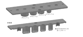
いくつかの実施形態において、TIMSカートリッジは、複数(たとえば、2、3、4、5、6、7、8、9、10、またはそれ以上、またはその間の範囲(たとえば、2つ以上))の離散的なチャンバ(たとえば、同一のチャンバ、または、ある特定の使用(たとえば、試薬追加/混合、溶解、洗浄、溶出など)のために特別に向けられた、覆われた、配置された、寸法決めされた、形づくられるなどしたチャンバ)を備える。 In some embodiments, the TIMS cartridge comprises multiple (eg, 2, 3, 4, 5, 6, 7, 8, 9, 10, or more, or ranges therebetween (eg, 2 or more)) Discrete chambers (e.g., identical chambers or specifically directed, covered, arranged, dimensioned for a particular use (e.g., reagent addition/mixing, lysis, washing, elution, etc.) defined, shaped, etc. chamber).
いくつかの実施形態において、サンプル調製バッファはユーザによって加えられる、または、特定の用途のために(たとえば、特定の検体の精製/抽出/単離/調製のために)予備ロードされる。いくつかの実施形態において、試薬(たとえば、溶解試薬、結合試薬、溶出試薬、洗浄試薬など)は、チャンバに加えられる、または、予備ロードされる。捕捉試薬を示すPMP(たとえば、核酸ハイブリダイゼーションプローブ、抗体または抗体断片、親和剤(たとえば、ストレプトアビジン、二価ニッケルなど)など)が、望ましい検体(たとえば、DNAまたはRNA、エピトープを示す薬剤、親和性標的(たとえば、ビオチンにリンクされる、His6タグを示すなど)など)のために、ユーザによって加えられる、または、チャンバに予備ロードされる。いくつかの実施形態において、試薬及びバッファは、チャンバ内でアクセスできてもよく、または、主チャンバから可逆的に密封されてもよい(たとえば、カプセル、膜、ブリスタ、または他のカバーによって)。いくつかの実施形態において、試薬及びバッファは、チャンバに接続されたチャネルを介して加えられる。いくつかの実施形態において、試薬は、チャネルを介して、1つのチャンバから次へと流れる(たとえば、試薬がチャネルを通ってアクセスまたは進行することを可能とする装置回転またはプランジャ作動時)。いくつかの実施形態において、ベントは、チャネルを介した試薬の追加時の、圧力の放出を可能にする。 In some embodiments, the sample preparation buffer is added by the user or preloaded for a particular application (eg, for purification/extraction/isolation/preparation of a particular analyte). In some embodiments, reagents (eg, lysis reagents, binding reagents, elution reagents, wash reagents, etc.) are added or preloaded into the chamber. A PMP (e.g., nucleic acid hybridization probe, antibody or antibody fragment, affinity agent (e.g., streptavidin, divalent nickel, etc.), etc.) representing a capture reagent (e.g., DNA or RNA, an agent representing an epitope, affinity added by the user or preloaded into the chamber for sexual targets (eg, linked to biotin, presenting a His 6 tag, etc.). In some embodiments, reagents and buffers may be accessible within the chamber or may be reversibly sealed from the main chamber (eg, by a capsule, membrane, blister, or other cover). In some embodiments, reagents and buffers are added through channels connected to the chambers. In some embodiments, reagents flow from one chamber to the next through a channel (eg, upon device rotation or plunger actuation that allows reagents to access or progress through the channel). In some embodiments, the vent allows pressure to be released upon addition of reagents through the channel.
本明細書の装置は、複数のチャンバと、チャンバ間の(i)PMP及び流体(たとえば、サンプル、バッファ(複数可)、試薬など)または(ii)PMP単独の移送のために構成された装置の幾何学構造とを備える。本明細書のいくつかの実施形態は、2つのチャンバ間の(たとえば、1つまたは複数の液体/気体界面を備える)エアギャップを利用して、最初のチャンバから後続のチャンバへのPMP/結合薬剤及びそれに結合された検体の移送を促進し、同時に、液体(たとえば、サンプル、試薬、汚染物質、バッファなど)の移送を最小化する。装置の反転(たとえば、特に、上部にアトールのあるチャンバと結合されたとき)、移送チャネル及び移送(たとえば、ドラッグ)表面の下のエアロックチャンバ(たとえば、固定レッジを有する)などの、さまざまな装置幾何学構造及び移送方法が、エアギャップ及び液体/気体界面(複数可)を確立するのに使用されてもよい。エアギャップの作成、ならびに、PMP及び結合された検体のエアギャップの通過の、例示的な幾何学構造/方法は、本明細書で説明される。他の本明細書の実施形態は、チャンバ間のPMP及び流体(たとえば、サンプル、バッファ(複数可)、試薬など)の移送を可能にする。このような実施形態は、装置が第1の向きに位置付けられたときは、材料(たとえば、PMP及び流体)の移送を妨げるが、装置が装置の軸を中心に(たとえば、10~90°回転された)第2の向きに位置付けられたときは、材料(たとえば、PMP及び流体)の移送が可能になる、チャンバ間のチャネルを備えてもよい。チャンバ間でPMP、液体試薬(たとえば、サンプル、バッファ(複数可)、試薬など)、及び結合された検体を受け渡す例示的な幾何学構造/方法は、本明細書で説明される。本明細書の特定の装置は、チャンバ間で材料を移送するためのさまざまな要素を組み合わせてもよく、かつ/または、チャンバ間での材料の移送のためのさまざまな技術を組み合わせてもよい。 Devices herein are devices configured for multiple chambers and the transfer of (i) PMPs and fluids (e.g., sample, buffer(s), reagents, etc.) between chambers or (ii) PMPs alone. and a geometry of Some embodiments herein utilize an air gap (e.g., with one or more liquid/gas interfaces) between the two chambers to provide PMP/coupling from the first chamber to the subsequent chamber. It facilitates transport of the drug and its bound analyte, while minimizing the transport of liquids (eg, sample, reagents, contaminants, buffers, etc.). A variety of device inversions (e.g., especially when combined with a chamber with an atol on top), transfer channels and airlock chambers (e.g., with fixed ledges) below the transfer (e.g. drag) surface. Device geometries and transfer methods may be used to establish air gaps and liquid/gas interface(s). Exemplary geometries/methods of creating air gaps and passing PMPs and bound analytes through the air gaps are described herein. Other embodiments herein allow transfer of PMPs and fluids (eg, samples, buffer(s), reagents, etc.) between chambers. Such an embodiment prevents transfer of materials (eg, PMP and fluids) when the device is positioned in a first orientation, but allows the device to rotate about the axis of the device (eg, 10-90°). A channel between the chambers may be provided that allows the transfer of materials (eg, PMPs and fluids) when positioned in a second orientation. Exemplary geometries/methods for passing PMPs, liquid reagents (eg, sample, buffer(s), reagents, etc.) and bound analytes between chambers are described herein. Certain devices herein may combine various elements for transferring materials between chambers and/or may combine various techniques for transferring materials between chambers.
いくつかの実施形態において、ユーザは、特定の検体を含有する、または、含有するとみられるサンプル(たとえば、生体または環境サンプル)を第1のチャンバに供給する。いくつかの実施形態において、第1のチャンバのPMP、サンプル、バッファ、試薬などは、PMPを再懸濁するために、かつ/または、PMP上の捕捉試薬への検体の結合を可能とするために、(たとえば、手動で(たとえば、揺動、反転など)、または、機械的手段(たとえば、超音波処理、磁気的流動など)によって)混合される。いくつかの実施形態において、チャンバの温度は、サンプル混合、サンプル溶解、検体結合などを促進するために操作される(たとえば、加熱、冷却、またはその両方)。カートリッジは、チャンバの液体がチャンバ(及び/またはアトールの頂部)の縁と移送膜(たとえば、疎水性移送膜)との間のエアギャップで固定される(図2)ように操作(たとえば、反転)される。カートリッジの適切な大きさ(たとえば、Gh)により、各チャンバの液体よって生成される固定された液体プールの間にエアギャップ(Ag)が存在することが保証される。(たとえば、第1のチャンバに存在する捕捉検体を有する)PMPは、移送表面を通した第1のチャンバへの磁場の適用によって収集される(図3)。いくつかの実施形態において、磁石は、移送表面に対して検体結合PMPのペレットを形成するために、移送表面の遠位側に(たとえば、ユーザによって手動で、自動化された装置によって、など)配置される。移送表面にわたって横方向への磁場の移動により、収集されたPMPは、第1のチャンバの固定された液体を通って、第1のチャンバと第2のチャンバとの間のエアギャップに、そして、第2のチャンバの固定された液体に移動する。磁場を取り外すことにより、検体結合PMPを第2のチャンバのバッファに放出する。あるいは、移送表面にわたって磁石を(たとえば、繰り返し)横切らせることで、移送表面上を走らせることによって、検体結合PMPを放出させてもよい。いくつかの実施形態において、チャンバへのPMPの放出は、チャンバの反対側の端部(たとえば、底部、閉鎖端など)への磁場の一時的な適用によって促進される。(たとえば、PMP及び検体を洗浄するための)バッファの混合、PMPの磁気的な収集、エアギャップを通る次のチャンバの固定された液体(たとえば、洗浄バッファ)へのPMPの移動、ならびに、次のチャンバへのPMPの放出の各プロセスは、その後のチャンバについても繰り返される。いくつかの実施形態において、PMPは、PMPから検体を放出するために、最終チャンバの溶出バッファに移動される。いくつかの実施形態において、検体の放出は、溶出バッファでサンプルを加熱することによって促進される。PMPは、溶出バッファから取り除かれ、溶液中の抽出/単離/精製された検体になる。PMPは、任意の適切な技術(図14F~G参照)によって、溶出バッファから取り除かれてもよい。いくつかの実施形態において、PMPが検体及び/または溶出バッファから分離されると、検体及び/または溶出バッファは、装置から取り除かれる(たとえば、図14H)。いくつかの実施形態において、上記のプロセスは、単一の装置内/上での、数分以内(たとえば、20分、15分、10分、5分、4分、3分、2分、またはそれ以下、または、その間の範囲(たとえば、<10分))の望ましい検体の精製を提供する。いくつかの実施形態において、抽出/単離/精製された検体は、分析及び/またはその後の処理の準備ができている。 In some embodiments, a user provides a sample containing or suspected of containing a particular analyte (eg, biological or environmental sample) to the first chamber. In some embodiments, the PMPs, samples, buffers, reagents, etc. in the first chamber are used to resuspend the PMPs and/or to allow binding of the analyte to the capture reagent on the PMPs. to (eg, manually (eg, rocking, inverting, etc.) or by mechanical means (eg, sonication, magnetic flow, etc.)). In some embodiments, the temperature of the chamber is manipulated (eg, heated, cooled, or both) to facilitate sample mixing, sample lysis, analyte binding, and the like. The cartridge is manipulated (e.g., inverted) so that the liquid in the chamber is fixed (FIG. 2) in the air gap between the rim of the chamber (and/or the top of the atole) and the transfer membrane (e.g., the hydrophobic transfer membrane). ) is done. Appropriate dimensions of the cartridge (eg, G h ) ensure that there is an air gap (A g ) between the fixed pools of liquid produced by the liquid in each chamber. PMPs (eg, with captured analyte present in the first chamber) are collected by application of a magnetic field to the first chamber through the transfer surface (FIG. 3). In some embodiments, a magnet is placed (e.g., manually by a user, by an automated device, etc.) distal to the transfer surface to form a pellet of analyte-bound PMP against the transfer surface. be done. Movement of the magnetic field laterally across the transfer surface forces the collected PMP through the immobilized liquid of the first chamber into the air gap between the first and second chambers, and Move to the fixed liquid in the second chamber. Removal of the magnetic field releases the analyte-bound PMP into the buffer of the second chamber. Alternatively, analyte-bound PMPs may be released by running a magnet (eg, repeatedly) across the transfer surface so that it runs over the transfer surface. In some embodiments, release of PMPs into the chamber is facilitated by temporary application of a magnetic field to the opposite end (eg, bottom, closed end, etc.) of the chamber. Mixing buffer (eg, for washing PMP and analyte), magnetically collecting PMP, moving PMP through an air gap to the immobilized liquid (eg, wash buffer) of the next chamber, and then Each process of PMP release into a chamber is repeated for subsequent chambers. In some embodiments, the PMPs are moved to an elution buffer in the final chamber to release the analytes from the PMPs. In some embodiments, analyte release is facilitated by heating the sample with an elution buffer. The PMP is removed from the elution buffer and becomes the extracted/isolated/purified analyte in solution. PMPs may be removed from the elution buffer by any suitable technique (see Figures 14F-G). In some embodiments, once the PMPs are separated from the analyte and/or elution buffer, the analyte and/or elution buffer are removed from the device (eg, FIG. 14H). In some embodiments, the above process is performed within a few minutes (e.g., 20 minutes, 15 minutes, 10 minutes, 5 minutes, 4 minutes, 3 minutes, 2 minutes, or Less than or a range in between (eg, <10 minutes)) provides desired analyte purification. In some embodiments, the extracted/isolated/purified specimen is ready for analysis and/or subsequent processing.
いくつかの実施形態において、(たとえば、処理された(たとえば、溶解、濾過、遠心分離など)または処理されていない)サンプルの1つまたは複数、PMP、溶解試薬、バッファ、及び他の試薬は、第1のチャンバ(たとえば、混合チャンバ)の中で組み合わされる。いくつかの実施形態において、(たとえば、サンプル内の(たとえば、処理された、または、処理されていない))検体及びPMPは、第1のチャンバ(たとえば、混合チャンバ)に個別に加えられる。いくつかの実施形態において、(たとえば、サンプル内の(たとえば、処理された、または、処理されていない))検体及びPMPは、第1のチャンバ(たとえば、混合チャンバ)の中で組み合わされる。 In some embodiments, one or more of the samples (e.g., processed (e.g., lysed, filtered, centrifuged, etc.) or unprocessed), PMPs, lysis reagents, buffers, and other reagents are Combined in a first chamber (eg, mixing chamber). In some embodiments, analyte (eg, in a sample (eg, treated or untreated)) and PMP are added separately to a first chamber (eg, mixing chamber). In some embodiments, the analyte (eg, in a sample (eg, processed or unprocessed)) and PMP are combined in a first chamber (eg, a mixing chamber).
本明細書の装置の実施形態は、大きさ、形状、または関連する寸法によって限定されないが、いくつかの実施形態において、本明細書で説明される好ましい寸法(たとえば、Aw、Ah、Gh、Fh、Agなど)は、効率的かつ有用な検体精製を提供する。 Although device embodiments herein are not limited by size, shape, or related dimensions, in some embodiments the preferred dimensions described herein (e.g., A w , A h , G h , Fh , Ag , etc.) provide efficient and useful analyte purification.
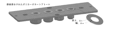
いくつかの実施形態において、チャンバの開口はアトールによって高くなっている。いくつかの実施形態において、アトールはチャンバの開口から上に伸びている。いくつかの実施形態において、隣接するチャンバのアトールは接続せず、隣接するアトール間にギャップを作成する。いくつかの実施形態において、アトールは、チャンバ開口間に不連続な表面を作成する。いくつかの実施形態において、アトールは、チャンバの開口に近く、チャンバ開口に類似の形状(たとえば、円形)を有する。他の実施形態において、アトール及びチャンバ開口は、異なる形状である。たとえば、ある実施形態において、非対称のアトールは、移送表面に対してサンプルを収集する付加的な空間を可能にする(たとえば、溶出に関して(図14H))。いくつかの実施形態において、アトールは、定義された高さ(Ah)及び幅(Aw)を有する。アトール高さ(Ah)は、移送表面とチャンバの頂部との間の距離(Fh)とともに、エアギャップの高さ(Gh)を定義する(図1)。アトール幅(Aw)は、隣接するチャンバ間の距離とともに、エアギャップの幅(Ag)を定義する(図2)。エアギャップの高さ(Gh)は、アトールの外縁の近くに、安定した液体プールを定義して、作成する。適切な寸法は、(たとえば、エアギャップを維持する間)固定された液体間の接触がなく、さらに、第1のチャンバからの液体による、隣接するチャンバの液体の汚染がほとんどなく、第1のチャンバの固定された液体から隣接するチャンバの固定された液体へのPMPの移動を可能にするのに十分な寸法のエアギャップを作成するように選択される。アトールと移送表面との間の約0.025~0.25mm(たとえば、0.025mm、0.03mm、0.04mm、0.05mm、0.06mm、0.07mm、0.08mm、0.09mm、0.10mm、0.11mm、0.12mm、0.13mm、0.14mm、0.15mm、0.16mm、0.17mm、0.18mm、0.19mm、0.20mm、0.21mm、0.22mm、0.23mm、0.24mm、0.25mm、または、その間の範囲(たとえば、0.10~0.15mm))のオーダーの例示的なギャップ高さ(Gh)は、カートリッジが反転されているとき(図2)、各チャンバ内の液体が、流れ出て、各それぞれのアトールの外径(OD)で固定されたようになることを保証する。Ghが小さいので、図から分かるように、表面張力及び毛管力が支配し(結合数、Bo<<1、式1参照)、重力により液体の固定された縁を失うことはない。 In some embodiments, the opening of the chamber is elevated by an atol. In some embodiments, the atole extends up from the opening of the chamber. In some embodiments, the atholes of adjacent chambers are not connected, creating a gap between adjacent atholes. In some embodiments, the atol creates a discontinuous surface between the chamber openings. In some embodiments, the atole is near the opening of the chamber and has a shape similar to the chamber opening (eg, circular). In other embodiments, the atole and chamber opening are of different shapes. For example, in certain embodiments, an asymmetric atole allows additional space to collect sample relative to the transfer surface (eg, for elution (FIG. 14H)). In some embodiments, the atole has a defined height (A h ) and width (A w ). The attoll height (A h ), together with the distance (F h ) between the transfer surface and the top of the chamber, defines the air gap height (G h ) (FIG. 1). The attoll width (A w ), together with the distance between adjacent chambers, defines the width of the air gap (A g ) (FIG. 2). The height of the air gap (G h ) defines and creates a stable liquid pool near the outer edge of the atole. Suitable dimensions are such that there is no fixed liquid-to-liquid contact (e.g., while maintaining an air gap) and there is little contamination of liquid in adjacent chambers by liquid from the first chamber, It is chosen to create an air gap of sufficient dimensions to allow movement of the PMP from one chamber's stationary liquid to the adjacent chamber's stationary liquid. About 0.025-0.25 mm (eg, 0.025 mm, 0.03 mm, 0.04 mm, 0.05 mm, 0.06 mm, 0.07 mm, 0.08 mm, 0.09 mm) between the atole and the transfer surface , 0.10mm, 0.11mm, 0.12mm, 0.13mm, 0.14mm, 0.15mm, 0.16mm, 0.17mm, 0.18mm, 0.19mm, 0.20mm, 0.21mm, 0 Exemplary gap heights (G h ) on the order of 0.22 mm, 0.23 mm, 0.24 mm, 0.25 mm, or ranges therebetween (eg, 0.10-0.15 mm) allow the cartridge to (FIG. 2), ensure that the liquid in each chamber flows out and becomes fixed at the outer diameter (OD) of each respective atole. Since G h is small, surface tension and capillary forces dominate (bond number, Bo<<1, see Eq. 1), as can be seen from the figure, and gravity does not lose the fixed edge of the liquid.
![]()
![]()
ここで、
Δρ=二相の密度差
g=重力加速度
Gh=液体プールが固定される、フレームとアトールとの間の薄いギャップ
σ=表面張力
密封された液体チャンバは、液体が流れ出るとき、負の空気圧を引くことによって静水頭を最小化する。さらに、アトールは、静水圧を比較的大きな領域に広げる、大きな円形界面を提供する(図2)。エアギャップ(Ag)によって分離された離散的な液体プールが各チャンバに作成され、それが液体相互汚染を防止する。これは、多くの他の技術で使用される、コストの高い不混和性のポリメラーゼ連鎖反応(PCR)適合性油の必要性を排除する。いくつかの実施形態において、アトールの内径は、アトール上の液体及びPMPの流れを促進するために、丸み付き縁部またはコーナを有する。
here,
Δρ = density difference between the two phases g = gravitational acceleration G h = thin gap between the frame and the atoll where the liquid pool is fixed σ = a surface tension sealed liquid chamber experiences a negative air pressure when the liquid flows out Minimize hydrostatic head by pulling. In addition, atholl provides a large circular interface that spreads the hydrostatic pressure over a relatively large area (Fig. 2). Discrete liquid pools separated by air gaps (A g ) are created in each chamber, which prevents liquid cross-contamination. This eliminates the need for costly immiscible polymerase chain reaction (PCR) compatible oils used in many other techniques. In some embodiments, the inner diameter of the athole has rounded edges or corners to facilitate the flow of liquid and PMP over the athole.
いくつかの実施形態において、Agは、TIMS(チャンバからチャンバへのPMPペレットの移動)の間、液体架橋がないことを保証するだけ十分に大きい。さらに、固定された液体縁は乱されない。いくつかの実施形態において、Ghは、狭いチャネルに沿った移動の間、硬いPMPペレットの剪断を防ぐだけ十分に大きい(たとえば、ペレット高さ)が、アトール外縁で表面張力及び液体固定に影響を及ぼすだけ十分小さい。高い磁場強度は、薄い移送表面を使用することによって影響を及ぼされる。たとえば、疎水性膜は、移動中のPMP損失を減少させる(PMPは表面に固着しない)。PMPは、液体対空気対液体界面を横切る。1つのチャンバから次のチャンバへの液体のキャリーオーバ(たとえば、望ましくない汚染)は最小化される。 In some embodiments, A g is large enough to ensure no liquid bridging during TIMS (Transfer of PMP pellets from chamber to chamber). Furthermore, the fixed liquid edge is not disturbed. In some embodiments, G h is large enough to prevent shearing of hard PMP pellets during migration along narrow channels (e.g., pellet height), but affects surface tension and liquid anchoring at the outer edge of the atole. small enough to affect High magnetic field strengths are influenced by using thin transfer surfaces. For example, hydrophobic membranes reduce PMP loss during transport (PMPs do not stick to surfaces). PMPs cross the liquid-air-liquid interface. Liquid carryover (eg, unwanted contamination) from one chamber to the next is minimized.
いくつかの実施形態において、本明細書の装置は、複数のチャンバ(たとえば、2、3、4、5、6、7、8、9、10、11、12、16、20、24、32、またはそれ以上、またはその中の範囲)を備える。いくつかの実施形態において、チャンバ開口は、装置の表面と(たとえば、表面にそびえるアトールと)同一平面にある。いくつかの実施形態において、いくつかのチャンバは、装置に沿って直線的に配設される。いくつかの実施形態において、チャンバは、装置の表面上に複数の行及び/または列で配設される。いくつかの実施形態において、装置のすべてのチャンバは、同一の大きさ、形状などである。いくつかの実施形態において、複数の異なるチャンバが(たとえば、異なる機能(たとえば、サンプル混合、サンプル溶解、PMP結合、洗浄、溶出など)のために)装置上に設けられる。いくつかの実施形態において、装置が運転中であるとき、チャンバは開放頂部と閉鎖底部とを備える。いくつかの実施形態において、チャンバの開放頂部は、単一の着脱可能な閉鎖(たとえば、剥離可能な膜または積層)によって密封される(使用前)。いくつかの実施形態において、チャンバの開放頂部は、個別の閉鎖(たとえば、剥離可能な膜または積層、キャップ、ネジ蓋など)によって個々に密封される(使用前)。いくつかの実施形態において、閉鎖底部は、不可逆的に閉じられる(たとえば、底部は側部に結合される)。いくつかの実施形態において、チャンバの底部は、再封可能な蓋またはキャップを備える。 In some embodiments, the devices herein comprise multiple chambers (e.g., 2, 3, 4, 5, 6, 7, 8, 9, 10, 11, 12, 16, 20, 24, 32, or more, or ranges therein). In some embodiments, the chamber opening is flush with the surface of the device (eg, with an atoll rising from the surface). In some embodiments, several chambers are arranged linearly along the device. In some embodiments, the chambers are arranged in multiple rows and/or columns on the surface of the device. In some embodiments, all chambers of the device are the same size, shape, etc. In some embodiments, multiple different chambers (eg, for different functions (eg, sample mixing, sample lysis, PMP binding, washing, elution, etc.) are provided on the device. In some embodiments, the chamber has an open top and a closed bottom when the device is in operation. In some embodiments, the open top of the chamber is sealed (before use) by a single removable closure (eg, peelable membrane or laminate). In some embodiments, the open tops of the chambers are individually sealed (before use) by separate closures (eg, peelable membranes or laminations, caps, screw caps, etc.). In some embodiments, the closed bottom is irreversibly closed (eg, the bottom is joined to the sides). In some embodiments, the bottom of the chamber comprises a resealable lid or cap.
いくつかの実施形態において、チャンバ容積は、25μl~2ml(たとえば、25μl、50μl、100μl、150μl、200μl、300μl、400μl、500μl、600μl、700μl、800μl、900μl、1ml、1.5ml、2ml、または、その間の範囲(たとえば、50μl~1ml))である。いくつかの実施形態において、チャンバ開口は、直径が1~15mm(たとえば、1mm、2mm、3mm、4mm、5mm、6mm、7mm、8mm、9mm、10mm、11mm、12mm、13mm、14mm、15mm、または、その間の範囲(たとえば、2~10mm))である。いくつかの実施形態において、アトール幅(Aw)は、1~20mm(たとえば、1mm、2mm、3mm、4mm、5mm、6mm、7mm、8mm、9mm、10mm、11mm、12mm、13mm、14mm、15mm、16mm、17mm、18mm、19mm、20mm、または、その間の範囲(たとえば、1~10mm))である。いくつかの実施形態において、アトール高さ(Ah)は、0.1~5mm(たとえば、0.1mm、0.2mm、0.3mm、0.4mm、0.5mm、0.6mm、0.7mm、0.8mm、0.9mm、1.0mm、1.1mm、1.2mm、1.3mm、1.4mm、1.5mm、2.0mm、2.5mm、3.0mm、3.5mm、4.0mm、4.5mm、5.0mm、または、その間の範囲(たとえば、0.1~3mm))である。いくつかの実施形態において、フレーム高さ(Fh)は、Ah+0.025mm~Ah+0.5mm(たとえば、Ah+0.025mm、Ah+0.050mm、Ah+0.1mm、Ah+0.125mm、Ah+0.15mm、Ah+0.175mm、Ah+0.2mm、Ah+0.225mm、Ah+0.25mm、Ah+0.275mm、Ah+0.3mm、Ah+0.325mm、Ah+0.35mm、Ah+0.375mm、Ah+0.4mm、Ah+0.425mm、Ah+0.45mm、Ah+0.475mm、Ah+0.5mm、または、その間の範囲(たとえば、Ah+0.025mm及びAh+0.25mm))である。いくつかの実施形態において、狭いギャップ高さ(Gh、Fh-Ahと定義される)は、0.025mm~0.5mm(たとえば、0.025mm、0.050mm、0.15mm、0.175mm、0.2mm、0.225mm、0.25mm、0.275mm、0.3mm、0.325mm、0.35mm、0.375mm、0.4mm、0.425mm、0.45mm、0.475mm、0.5mm、または、その間の範囲(たとえば、0.025mm~0.25mm))である。いくつかの実施形態において、アトール(Ag)間のエアギャップは、0.5~8mm(たとえば、0.5mm、0.6mm、0.7mm、0.8mm、0.9mm、1.0mm、1.5mm、2.0mm、2.5mm、3.0mm、3.5mm、4.0mm、4.5mm、5.0mm、5.5mm、6.0mm、6.5mm、7.0mm、7.5mm、8.0mm、または、その間の範囲(たとえば、1~5mm))である。 In some embodiments, the chamber volume is between 25 μl and 2 ml (eg, 25 μl, 50 μl, 100 μl, 150 μl, 200 μl, 300 μl, 400 μl, 500 μl, 600 μl, 700 μl, 800 μl, 900 μl, 1 ml, 1.5 ml, 2 ml, or , and in between (eg, 50 μl to 1 ml)). In some embodiments, the chamber opening is 1-15 mm in diameter (eg, 1 mm, 2 mm, 3 mm, 4 mm, 5 mm, 6 mm, 7 mm, 8 mm, 9 mm, 10 mm, 11 mm, 12 mm, 13 mm, 14 mm, 15 mm, or , and the range therebetween (eg, 2-10 mm). In some embodiments, the attoll width (A w ) is 1-20 mm (eg, 1 mm, 2 mm, 3 mm, 4 mm, 5 mm, 6 mm, 7 mm, 8 mm, 9 mm, 10 mm, 11 mm, 12 mm, 13 mm, 14 mm, 15 mm , 16 mm, 17 mm, 18 mm, 19 mm, 20 mm, or ranges therebetween (eg, 1-10 mm). In some embodiments, the attoll height (A h ) is 0.1-5 mm (eg, 0.1 mm, 0.2 mm, 0.3 mm, 0.4 mm, 0.5 mm, 0.6 mm, 0.1 mm, 0.2 mm, 0.3 mm, 0.4 mm, 0.5 mm, 0.6 mm, 0.1 mm, 0.2 mm, 0.3 mm, 0.4 mm, 0.5 mm, 0.6 mm, 0.1 mm, 0.2 mm, 0.3 mm, 0.4 mm, 0.5 mm, 0.6 mm, 0.1 mm). 7mm, 0.8mm, 0.9mm, 1.0mm, 1.1mm, 1.2mm, 1.3mm, 1.4mm, 1.5mm, 2.0mm, 2.5mm, 3.0mm, 3.5mm, 4.0 mm, 4.5 mm, 5.0 mm, or ranges therebetween (eg, 0.1-3 mm). In some embodiments, the frame height (F h ) is between A h +0.025 mm and A h +0.5 mm (eg, A h +0.025 mm, A h +0.050 mm, A h +0.1 mm, A h +0.125 mm, A h +0.15 mm, A h +0.175 mm, A h +0.2 mm, A h +0.225 mm, A h +0.25 mm , A h +0.275 mm, A h +0.3 mm, A h +0. 325 mm, A h +0.35 mm, A h +0.375 mm, A h +0.4 mm, A h +0.425 mm, A h +0.45 mm, A h +0.475 mm, A h +0.5 mm, or any range in between ( For example, A h +0.025 mm and A h +0.25 mm)). In some embodiments, the narrow gap height (G h , defined as F h −A h ) is between 0.025 mm and 0.5 mm (eg, 0.025 mm, 0.050 mm, 0.15 mm, 0.15 mm, .175mm, 0.2mm, 0.225mm, 0.25mm, 0.275mm, 0.3mm, 0.325mm, 0.35mm, 0.375mm, 0.4mm, 0.425mm, 0.45mm, 0.475mm , 0.5 mm, or ranges therebetween (eg, 0.025 mm to 0.25 mm). In some embodiments, the air gap between the atholes (A g ) is 0.5-8 mm (eg, 0.5 mm, 0.6 mm, 0.7 mm, 0.8 mm, 0.9 mm, 1.0 mm, 1.5 mm, 2.0 mm, 2.5 mm, 3.0 mm, 3.5 mm, 4.0 mm, 4.5 mm, 5.0 mm, 5.5 mm, 6.0 mm, 6.5 mm, 7.0 mm, 7.0 mm. 5 mm, 8.0 mm, or ranges therebetween (eg, 1-5 mm)).
いくつかの実施形態において、チャンバは、チャンバ全体にわたって平坦な底部及び一定の深さを備える。しかしながら、他の実施形態において、チャンバは、深部と浅部とを備える。異なる深さを備えるチャンバは、装置の向きに応じて、異なる有効容積を有する。たとえば、装置が平面的な向きにあるとき、このようなチャンバの中の液体は、チャンバの深部に存在する。しかしながら、非平面的な向きへ装置が回転すると、液体は、チャンバの浅部に流れ込む。いくつかの実施形態において、液体をチャンバの異なる深さに入れることにより、液体がチャネルに流れ込んでもよく、かつ/または、エアロックに対して固定されたようになってもよい(たとえば、図16参照)。 In some embodiments, the chamber comprises a flat bottom and constant depth throughout the chamber. However, in other embodiments the chamber comprises a deep portion and a shallow portion. Chambers with different depths have different effective volumes depending on the orientation of the device. For example, liquid in such a chamber resides deep within the chamber when the device is in a planar orientation. However, when the device is rotated to a non-planar orientation, the liquid will flow into the shallow part of the chamber. In some embodiments, by placing liquid at different depths of the chamber, the liquid may flow into the channel and/or may become fixed relative to the airlock (e.g., FIG. 16 reference).
いくつかの実施形態において、本明細書で説明される装置は、反転したチャンバからの液体が移送表面に対して固定され、エアギャップが隣接するチャンバの固定された液体の間に形成される限り、チャンバ及びチャンバ開口の形状の寸法によって限定されない。本明細書に示される実施形態は、円形チャンバ及びチャンバ開口(したがって、リング形状のアトール)を示す。いくつかの実施形態において、装置は、円形横断及び/または円形開口横断を有するチャンバを備える。他の実施形態において、他の形状(たとえば、卵形、三角形、正方形、五角形、六角形など)のチャンバ及び/またはチャンバ開口が利用される。いくつかの実施形態において、チャンバは首部を有し、それにより、チャンバの開口は、チャンバ自体より小さい(たとえば、直径が小さい)(図4)。他の実施形態において、チャンバの開口は、チャンバ自体と同じ大きさ(たとえば、同じ直径)である(図4)。いくつかの実施形態において、チャンバの壁は、互いに平行であり、かつ/または、チャンバ開口に垂直である(図12、左)。他の実施形態において、チャンバ壁は、チャンバの平均的な幅(たとえば、直径)より大きいチャンバ開口を作成するために傾斜する。いくつかの実施形態において、チャンバ開口は、チャンバからPMPを取り除くのに使用される磁石と略同じ大きさである(たとえば、+/-20%、+/-15%、+/-10%、+/-50%、+/-2%、+/-1%、または、その間の範囲)。いくつかの実施形態において、チャンバの底部は、任意の適切な形状(たとえば、丸い形状、四角に区切られた形状、平坦な形状など)であってもよい。 In some embodiments, the devices described herein can be used as long as the liquid from the inverted chamber is fixed against the transfer surface and an air gap is formed between the fixed liquid in adjacent chambers. , the dimensions of the shape of the chamber and the chamber opening. The embodiments shown herein show circular chambers and chamber openings (hence the ring-shaped atole). In some embodiments, the device comprises a chamber having a circular cross-section and/or a circular opening cross-section. In other embodiments, other shaped chambers and/or chamber openings (eg, oval, triangular, square, pentagonal, hexagonal, etc.) are utilized. In some embodiments, the chamber has a neck such that the opening of the chamber is smaller (eg, smaller in diameter) than the chamber itself (FIG. 4). In other embodiments, the opening of the chamber is the same size (eg, same diameter) as the chamber itself (FIG. 4). In some embodiments, the chamber walls are parallel to each other and/or perpendicular to the chamber opening (FIG. 12, left). In other embodiments, the chamber walls are sloped to create a chamber opening that is larger than the average width (eg, diameter) of the chamber. In some embodiments, the chamber opening is about the same size as the magnet used to remove the PMP from the chamber (eg, +/-20%, +/-15%, +/-10%, +/-50%, +/-2%, +/-1% or any range therebetween). In some embodiments, the bottom of the chamber may be of any suitable shape (eg, rounded, squared, flat, etc.).
いくつかの実施形態において、チャンバの内部は、単一の制限のない空間である。他の実施形態において、チャンバは、1つまたは複数の密封可能(かつ、開封可能)な区画を備える。いくつかの実施形態において、試薬は、区画内に含まれ、望ましい状況下でチャンバの残りの部分に放出される(たとえば、液体または特定の試薬の追加によって溶解される、シールが壊される、熱の下で溶解されるなど)。 In some embodiments, the interior of the chamber is a single open-ended space. In other embodiments, the chamber comprises one or more sealable (and openable) compartments. In some embodiments, reagents are contained within compartments and released to the rest of the chamber under desired conditions (e.g., dissolved by the addition of liquids or certain reagents, broken seals, heat , etc.).
いくつかの実施形態において、装置は、チャンバ開口の上にアトールを備える。いくつかの実施形態において、アトールは、アトールと移送表面との間でのチャンバ内の液体の固定を容易にする。いくつかの実施形態において、アトールはチャンバ開口を囲む。いくつかの実施形態において、アトールは開口の頂面に近い。いくつかの実施形態において、アトールは、チャンバ開口の外縁と同じ形状(たとえば、円形)である。いくつかの実施形態において、アトールは、チャンバ開口の直径または幅と等しい内側の幅または直径を有する。いくつかの実施形態において、アトールは、チャンバ開口の直径または幅より大きい外側の幅または直径を有する。いくつかの実施形態において、アトール形状は、チャンバ開口の形状に限定されない。アトールは、たとえば、アトール上に固定される液体の容積を変更するために、より広いまたはより狭い領域を備えてもよい。 In some embodiments, the device comprises an atoll over the chamber opening. In some embodiments, the atol facilitates immobilization of liquid within the chamber between the atol and the transfer surface. In some embodiments, the atol surrounds the chamber opening. In some embodiments, the atole is near the top surface of the aperture. In some embodiments, the atole is the same shape (eg, circular) as the outer edge of the chamber opening. In some embodiments, the atole has an inner width or diameter equal to the diameter or width of the chamber opening. In some embodiments, the atole has an outer width or diameter that is greater than the diameter or width of the chamber opening. In some embodiments, the atholl shape is not limited to the shape of the chamber opening. The atol may, for example, comprise wider or narrower regions to alter the volume of liquid immobilized on the atol.
装置が反転されたとき(または、他の実施形態では、回転されたとき)、重力はチャンバから液体を引き出し、各チャンバからの液体の「プール」は、アトールと移送表面との間に固定される。装置の寸法は、プール前面が、アトールの外縁(外径(OD))と同じ(略同じ)だけ進むことを保証する。移送表面は、チャンバからの液体の流れを制限し、チャンバ間の漏出または汚染を防止する。移送表面は、PMPが隣接する固定された液体プールにエアギャップを通して移送されるプラットフォームも提供する。いくつかの実施形態において、移送表面は、平滑な、平坦な、及び/または剛性の材料を備える。いくつかの実施形態において、移送表面は、ポリカーボネートなどの、平滑な硬質プラスチックを備える。移送表面及び他の装置構成要素のための他の例示的な材料は、本明細書で説明されて、いくつかの実施形態で使用される。いくつかの実施形態において、移送表面は、酸化マンガンポリスチレン(MnO2/PS)ナノコンポジット、亜鉛華ポリスチレン(ZnO/PS)ナノコンポジット、沈降炭酸カルシウム、カーボンナノチューブベースのコーティング、シリカナノコーティングなどの疎水性コーティング(たとえば、超疎水性コーティング)を備える、または、それらで完全にもしくは部分的に覆われる。液体と移送表面との間に大きな接触角をもたらす任意のコーティング、膜、薄膜などは、本明細書の実施形態で使用してもよい。いくつかの実施形態において、移送表面(たとえば、ドラッグ膜)またはPMPが接触する他の表面上の疎水性コーティングは、固定された液体空気界面の安定化、及び、特に、液体がペレットの潤滑として使用されないエアロック領域での流動/移動中のPMPの静止摩擦の防止の両方に役立つ。 When the device is inverted (or rotated, in other embodiments), gravity draws liquid from the chambers, and a "pool" of liquid from each chamber is clamped between the atole and the transfer surface. be. The dimensions of the device ensure that the front face of the pool runs the same (approximately the same) as the outer edge (outer diameter (OD)) of the atole. The transfer surface restricts the flow of liquid from the chambers and prevents leakage or contamination between chambers. The transfer surface also provides a platform on which the PMP is transferred through the air gap to an adjacent stationary liquid pool. In some embodiments, the transfer surface comprises a smooth, flat, and/or rigid material. In some embodiments, the transfer surface comprises a smooth hard plastic, such as polycarbonate. Other exemplary materials for the transfer surface and other device components are described herein and used in some embodiments. In some embodiments, the transfer surface is a hydrophobic material such as manganese oxide polystyrene ( MnO2 /PS) nanocomposites, zinc oxide polystyrene (ZnO/PS) nanocomposites, precipitated calcium carbonate, carbon nanotube-based coatings, silica nanocoatings, and the like. provided with or completely or partially covered with a coating (eg, a superhydrophobic coating); Any coating, film, thin film, etc. that provides a large contact angle between the liquid and the transfer surface may be used in the embodiments herein. In some embodiments, a hydrophobic coating on the transfer surface (e.g., drag film) or other surface that the PMP contacts stabilizes the fixed liquid-air interface and, in particular, the liquid as lubrication of the pellets. It helps both prevent stiction of the PMP during flow/movement in unused airlock areas.
いくつかの実施形態において、エアギャップは、チャンバ間に(たとえば、移送チャネルに沿って)作成される。いくつかの実施形態において、2つのチャンバは、エアトラップ(たとえば、2つのチャンバ間の移送チャネルの下に配置される小さいチャンバ)によって分離される。いくつかの実施形態において、エアトラップは、(たとえば、ベース層及び/またはドラッグ(または、移送)層によるエアトラップの両側の液体間の表面張力によって)エアギャップを誘起する。いくつかの実施形態において、エアギャップは、エアロック上を延在するが、エアロックを横切らないベース層に存在する固定レッジ(たとえば、突出部分)の存在によって、さらに誘起される。いくつかの実施形態において、エアロックの一方側の液体は、固定レッジの末端から移送(または、ドラッグ)層まで延在する液体/気体界面を形成する。いくつかの実施形態において、移送層の背後(または、上方)からの磁場の適用により、PMPを、エアギャップを通して、移送層にわたって移送することができ、一方、液体(たとえば、サンプル、バッファ(複数可)、試薬など)は、エアロックを通ることができない。いくつかの実施形態において、移送層の上方(または、背後)から適用される、エアギャップ内の磁場は、液体材料(たとえば、サンプル、バッファ(複数可)、試薬など)の大きな移送なしに、液体/気体界面を通してPMPを引く。このような実施形態において、磁場の移動により、後続の液体層へのPMPの移送が可能になる。 In some embodiments, air gaps are created between chambers (eg, along transfer channels). In some embodiments, the two chambers are separated by an air trap (eg, a small chamber positioned below the transfer channel between the two chambers). In some embodiments, the air trap induces an air gap (eg, due to surface tension between the liquid on either side of the air trap by the base layer and/or the drag (or transfer) layer). In some embodiments, the air gap is further induced by the presence of fixed ledges (eg, protrusions) present in the base layer that extend over the airlock but do not cross the airlock. In some embodiments, the liquid on one side of the airlock forms a liquid/gas interface that extends from the end of the fixed ledge to the transfer (or drag) layer. In some embodiments, application of a magnetic field from behind (or above) the transport layer can transport PMPs through an air gap and across the transport layer, while liquids (e.g., sample, buffer(s) allowed), reagents, etc.) cannot pass through the airlock. In some embodiments, the magnetic field in the air gap, applied from above (or behind) the transfer layer, can be applied without significant transfer of liquid material (e.g., sample, buffer(s), reagents, etc.). Pull the PMP through the liquid/gas interface. In such embodiments, movement of the magnetic field enables transport of the PMPs into the subsequent liquid layer.
いくつかの実施形態において、表面張力能力に影響を及ぼすことに加えて、密封エアロックチャンバは、たとえば、チャンバ2(たとえば、混合チャンバ)とチャンバ3(たとえば、洗浄チャンバ)との間の安定した液体空気界面の作成にさらに役立つ。いくつかの実施形態において、エアロックは、たとえば、チャンバ2とチャンバ3との間にエアギャップを作成し、そのエアギャップを通して、PMPは移送されるが、液体(たとえば、サンプル、バッファ(複数可)、試薬など)及び汚染物質は移送されない。 In some embodiments, in addition to affecting surface tension capabilities, the sealed airlock chamber provides a stable, e.g. It further aids in creating a liquid-air interface. In some embodiments, the airlock creates an air gap, e.g., between chambers 2 and 3, through which air gaps PMPs are transported, but liquids (e.g., sample, buffer(s) ), reagents, etc.) and contaminants are not transferred.
いくつかの実施形態において、エアロックチャンバは、(たとえば、(たとえば、移送チャネルに沿った)長さ、(たとえば、移送チャネルに垂直な)幅、及び、2~15mmの深さ(たとえば、2mm、3mm、4mm、5mm、6mm、7mm、8mm、0.9mm、10mm、11mm、12mm、13mm、14mm、15mm、または、その間の範囲の)寸法を備える。いくつかの実施形態において、固定レッジは、エアギャップ内に、かつ、エアロックチャンバ上に、0.5~2mm(たとえば、0.5mm、0.75mm、1mm、1.25mm、1.5mm、1.75mm、2mm、または、その間の範囲)広がる。いくつかの実施形態において、固定レッジは存在しない(たとえば、エアロックチャンバ上にベース層が延在しない)。いくつかの実施形態において、エアロックチャンバにわたるエアギャップは、3~8mm(たとえば、3mm、4mm、5mm、6mm、7mm、8mm、または、その間の範囲(たとえば、4~6mm))である。いくつかの実施形態において、固定レッジ間の最小距離は、3~8mm(たとえば、3mm、4mm、5mm、6mm、7mm、8mm、または、その間の範囲(たとえば、4~6mm))である。 In some embodiments, the airlock chamber has a length (eg, along the transfer channel), a width (eg, perpendicular to the transfer channel), and a depth of 2-15 mm (eg, 2 mm). , 3 mm, 4 mm, 5 mm, 6 mm, 7 mm, 8 mm, 0.9 mm, 10 mm, 11 mm, 12 mm, 13 mm, 14 mm, 15 mm, or ranges therebetween). , in the air gap and above the airlock chamber, between 0.5 and 2 mm (e.g., 0.5 mm, 0.75 mm, 1 mm, 1.25 mm, 1.5 mm, 1.75 mm, 2 mm, or anything in between). In some embodiments, there is no fixed ledge (e.g., no base layer extends over the airlock chamber) In some embodiments, the air gap across the airlock chamber is 3-8 mm (eg, 3 mm, 4 mm, 5 mm, 6 mm, 7 mm, 8 mm, or ranges therebetween (eg, 4-6 mm). In some embodiments, the minimum distance between fixation ledges is 3-8 mm ( For example, 3 mm, 4 mm, 5 mm, 6 mm, 7 mm, 8 mm, or ranges therebetween (eg, 4-6 mm).
いくつかの実施形態において、PMPを「流す」(たとえば、液体空気界面から離れた距離(たとえば、0.5mm、1mm、1.5mm、2mm、2.5mm、3mm、3.5mm、4mm、4.5mm、5mm、または、その間の範囲)に(たとえば、エアギャップ上に)磁場を位置付け、磁気力を使用して、エアギャップ内にPMPを引き出す)ことにより、PMPペレット内の望ましくない液体のキャリーオーバがほとんどなしに、クリーンな試料移送が提供される。(たとえば、PMPの磁気誘導されたペレット上に連続的に位置付けられた磁石によって)引きずるのではなく、液体/気体界面を横切ってPMPを流れさせることは、液体/気体界面の伸びを減少させ、PMPとのエアギャップへの望ましくない液体のキャリーオーバの量を減少させる。いくつかの実施形態において、流すことは、以下によって実現される。(i)チャンバ内のPMPを移送表面上のペレットに引き入れるために、(たとえば、移送表面(たとえば、ドラッグ膜)の反対側の近く/に対して磁石を配置することによって)チャンバの上方に磁場を作成すること、(ii)気体/液体界面の近くまたはそれに隣接する位置にPMPのペレットを運ぶために、移送チャネルに沿って磁場を移動させること、(iii)(たとえば、移送表面(たとえば、ドラッグ膜)から離れるように磁石を持ち上げることによって)PMPが遭遇した磁場を減少または除去すること、(iv)(たとえば、移送表面の反対側の近く/に対して磁石を配置することによって)エアギャップ内で磁場を再生成すること、及び、(v)液体内でペレット化されたPMPが液体からエアギャップに流れ出ることを可能にすること。ペレット全体を引きずるのではなく、界面を横切ってPMPを流すことによって、液体はPMPとともにほとんどキャリーオーバしない。PMPをエアギャップに流した後、PMPは、第2の液体/気体界面を横切って、次のチャンバに引きずられてもまたは流されてもよい。 In some embodiments, the PMP is "flowed" (e.g., a distance away from the liquid-air interface (e.g., 0.5 mm, 1 mm, 1.5 mm, 2 mm, 2.5 mm, 3 mm, 3.5 mm, 4 mm, 4 By positioning a magnetic field (e.g., over the air gap) at 0.5 mm, 5 mm, or a range in between, and using magnetic forces to draw the PMP into the air gap, the undesirable liquid within the PMP pellet is removed. Clean sample transfer is provided with little carryover. Flowing the PMP across the liquid/gas interface rather than dragging it (e.g., by magnets positioned sequentially over magnetically induced pellets of PMP) reduces the elongation of the liquid/gas interface, Reduces the amount of unwanted liquid carryover into the air gap with the PMP. In some embodiments, shedding is accomplished by: a. (i) a magnetic field above the chamber (e.g., by placing a magnet near/against the opposite side of the transfer surface (e.g., drag film)) to draw the PMPs in the chamber into the pellet on the transfer surface; (ii) moving a magnetic field along the transfer channel to bring the PMP pellets to a location near or adjacent to the gas/liquid interface; (iii) (e.g., a transfer surface (e.g., (iv) reducing or eliminating the magnetic field encountered by the PMP (by lifting the magnet away from the drag membrane); regenerating the magnetic field in the gap; and (v) allowing PMP pelleted in the liquid to flow out of the liquid into the air gap. By flowing the PMP across the interface rather than dragging the entire pellet, little liquid carries over with the PMP. After flowing the PMP into the air gap, the PMP may be dragged or flowed across the second liquid/gas interface to the next chamber.
いくつかの実施形態において、チャンバ、及びそれに接続されるチャネル、ベント、ポートなどは、チャンバ/チャネル間の流れ及び/または静水圧が、装置の位置を新しい方向に向ける(たとえば、軸を中心に装置を回転させる)ことによって誘導可能であるように構成される。たとえば、装置は、サンプルを加熱するとき、平面的な(約0°の回転)向きで存在してもよく、磁気力などによって移送チャネルに沿ってPMPを移送する。いくつかの実施形態において、平面的な向きで存在することは、固定された液体/気体界面に対する応力を減少させる。しかしながら、長手方向軸(図15B参照)を中心とした、たとえば、10~90°(たとえば、10°、20°、30°、40°、50°、60°、70°、80°、90°、または、その間の範囲(たとえば、30~60°など))までの装置の回転により、流体及びチャネルを満たすことが可能であり、PMP収集のためのチャンバ内への液体の圧縮、チャネルを通しての材料の移送などを行う。いくつかの実施形態において、平面的な向きと回転した向きとの間で(たとえば、1回または複数回(たとえば、1、2、3、4、5、6、7、8、またはそれ以上、または、その間の範囲))装置を切り換えることによって、本明細書で説明されるさまざまなステップ(たとえば、流体移送、チャネルプライミング、流体圧縮、PMP圧縮、PMP移送、PMP収集、混合など)が実行される。いくつかの実施形態において、重力が装置の幅方向に加えられるように、カートリッジの向きがほとんど垂直(たとえば、垂直からのずれが<30°、<25°、<20°、<15°、<10°、または<5°)であるとき、静水頭はチャネルを満たすのを助けるように発生する。これは、空気/水界面全体の圧力低下にも影響を与える。カートリッジの平面がほとんど水平(「平面状」とも言う)(たとえば、水平からのずれが<30°、<25°、<20°、<15°、<10°、または<5°)であるとき、圧力低下は減少して、気体/液体界面をより安定させ、粒子がその界面を横切って引かれるとき破壊されることは少ない。装置の回転は、充填のための1つの界面の圧力低下及び粒子流動のための別の界面の圧力低下を有する能力を提供する。 In some embodiments, the chambers and the channels, vents, ports, etc. connected thereto are such that flow and/or hydrostatic pressure between the chambers/channels reorients the device position (e.g., about an axis). rotating the device). For example, the device may reside in a planar (approximately 0° rotation) orientation when heating the sample, transporting the PMPs along the transport channel, such as by magnetic forces. In some embodiments, being in a planar orientation reduces stress on a fixed liquid/gas interface. However, for example 10-90° (eg 10°, 20°, 30°, 40°, 50°, 60°, 70°, 80°, 90°) about the longitudinal axis (see FIG. 15B) , or rotation of the device to a range in between (e.g., 30-60°, etc.) can fill fluid and channels, compress liquid into chambers for PMP collection, through channels. Transfer materials, etc. In some embodiments, between the planar orientation and the rotated orientation (e.g., one or more times (e.g., 1, 2, 3, 4, 5, 6, 7, 8, or more, or ranges in between)) by switching the device, various steps described herein (e.g., fluid transfer, channel priming, fluid compression, PMP compression, PMP transfer, PMP collection, mixing, etc.) are performed. be. In some embodiments, the orientation of the cartridge is nearly vertical (e.g., <30°, <25°, <20°, <15°, < 10°, or <5°), a hydrostatic head is generated to help fill the channel. This also affects the pressure drop across the air/water interface. When the plane of the cartridge is nearly horizontal (also called "planar") (e.g. <30°, <25°, <20°, <15°, <10°, or <5° deviation from horizontal) , the pressure drop is reduced, making the gas/liquid interface more stable and less likely to break when particles are pulled across it. Rotation of the device provides the ability to have one interfacial pressure drop for packing and another interfacial pressure drop for particle flow.
いくつかの実施形態において、2つのチャンバ間のチャネルは、装置が第1の向き(たとえば、平面的な向き)にあるとき、第1のチャンバ(たとえば、溶解チャンバ)の底部に、及び、第2のチャンバ(たとえば、ハイブリダイゼーションチャンバ)の頂部に結合されている。これは、装置が第1の向きにあるとき、チャネルを通る液体の流れを妨げる。しかしながら、装置を第2の向きに配置(たとえば、長手方向軸に沿って回転)することにより、流体は重力下で(たとえば、重量単独で、または、加えられる二次圧力とともに)チャネルを通って流れることができる。 In some embodiments, the channel between the two chambers is at the bottom of the first chamber (eg, the lysing chamber) and at the bottom of the second chamber when the device is in the first orientation (eg, planar orientation). It is attached to the top of two chambers (eg, hybridization chambers). This impedes the flow of liquid through the channel when the device is in the first orientation. However, by placing the device in a second orientation (e.g., rotating along its longitudinal axis), the fluid will flow under gravity (e.g., either by weight alone or with secondary pressure applied) through the channel. can flow.
いくつかの実施形態において、サンプル及び/または試薬は、開放頂部を備えるチャンバに加えられる。いくつかの実施形態において、キャップまたはプラグは、チャンバの頂部開口に固定される。いくつかの実施形態において、キャップ/プラグは、2つ以上の閉構造を採用できるようなプランジャ機能を備える(たとえば、隆起(それでも、閉)構造、押下構造など)。いくつかの実施形態において、プランジャキャップが隆起/閉構造であるとき、チャンバの頂部は密封されるが、チャンバの頂部の近くのベントは大気開放している。いくつかの実施形態において、チャンバの頂部近くにベントを配置することよって(ベントの小型の端部)、装置のかなりの回転及び/または揺動により、液体がベントを通ってチャンバを出ることはない。いくつかの実施形態において、プランジャキャップが押し下げられたとき、ベントは密封され(チャンバの開放頂部に加えて)、したがって、圧力がチャンバの内容物に加えられる。この圧力により、(たとえば、サンプル、試薬、バッファなどを備える)チャンバ内の液体は、プランジャキャップによって密封されたチャンバに接続するチャネルを通って、その後のチャンバに流れる。 In some embodiments, samples and/or reagents are added to a chamber with an open top. In some embodiments, a cap or plug is secured to the top opening of the chamber. In some embodiments, the cap/plug comprises a plunger feature that allows it to adopt more than one closed configuration (eg, raised (but still closed) configuration, depressed configuration, etc.). In some embodiments, when the plunger cap is in the raised/closed configuration, the top of the chamber is sealed, but the vent near the top of the chamber is open to the atmosphere. In some embodiments, by locating the vent near the top of the chamber (the small end of the vent), significant rotation and/or rocking of the device prevents liquid from exiting the chamber through the vent. do not have. In some embodiments, the vent is sealed (in addition to the open top of the chamber) when the plunger cap is depressed, thus applying pressure to the contents of the chamber. This pressure causes liquid in the chamber (eg, comprising sample, reagents, buffers, etc.) to flow through the channel connecting the chamber sealed by the plunger cap to the subsequent chamber.
いくつかの実施形態において、本明細書の装置のチャンバの1つまたは複数(たとえば、溶解チャンバ、ハイブリダイゼーションチャンバ、洗浄チャンバなど)は、液体(たとえば、サンプル、バッファ(複数可)、試薬など)の容積と比較してかなり大きい。いくつかの実施形態において、チャンバの容積は、その中に含まれる液体(たとえば、サンプル、バッファ(複数可)、試薬など)の意図された(または、実際の)容積より大きい(たとえば、1.2X、1.4X、1.6X、1.8X、2.0X、2.2X、2.4X、2.6X、2.8X、3.0X、3.5X、4.0X、またはそれ以上、またはその間の範囲(たとえば、1.6X~2.6X))。いくつかの実施形態において、かなり大きいチャンバは、(たとえば、長手方向軸(図15B参照)を中心とした、別の軸を中心とした)装置の回転、または、揺動による(試薬、サンプル、PMPなどの)混合または再可溶化の促進を可能にする。いくつかの実施形態において、かなり大きいチャンバ容積及び寸法により、チャンバ内の液体の表面積対体積比が大きくなり(たとえば、特に装置が平面的な向きにあるとき)、それによって、チャンバ内の液体の温度変化(たとえば、加熱)の速度を上げる。 In some embodiments, one or more of the chambers of the devices herein (eg, lysis chambers, hybridization chambers, wash chambers, etc.) contain liquids (eg, sample, buffer(s), reagents, etc.). is quite large compared to the volume of In some embodiments, the volume of the chamber is larger than the intended (or actual) volume of liquid (eg, sample, buffer(s), reagents, etc.) contained therein (eg, 1. 2X, 1.4X, 1.6X, 1.8X, 2.0X, 2.2X, 2.4X, 2.6X, 2.8X, 3.0X, 3.5X, 4.0X or more, or a range therebetween (eg, 1.6X to 2.6X)). In some embodiments, sizable chambers can be loaded (reagents, samples, PMP, etc.) to facilitate mixing or re-solubilization. In some embodiments, the sizable chamber volume and dimensions provide a high surface-to-volume ratio of the liquid in the chamber (e.g., especially when the device is in a planar orientation), thereby increasing the volume of the liquid in the chamber. Increase the rate of temperature change (eg heating).
いくつかの実施形態において、本明細書で説明される装置またはその構成要素は使い捨てである。いくつかの実施形態において、本明細書で説明される装置またはその構成要素は、1回限りの消耗品としての使用が意図される。いくつかの実施形態において、装置全体が使い捨てである。いくつかの実施形態において、装置のための材料は、装置の使い捨ての性質のためにコストを低下させるように選択される。いくつかの実施形態において、装置の一部または構成要素は使い捨てである(たとえば、チャンバ及び/またはチャンバを備えるプレート、移送表面など)、一方、装置の他の部分または構成要素は複数可使用される(たとえば、フレーム、磁石組立体など)。いくつかの実施形態において、(たとえば、チャンバ、移送表面、アトールなどを備える)1回限りのカートリッジは、(たとえば、フレーム、磁石、混合装置などを備える)複数回使用の装置に挿入される。いくつかの実施形態において、装置全体について複数回使用が意図される。 In some embodiments, the devices or components thereof described herein are disposable. In some embodiments, the devices or components thereof described herein are intended for use as one-time consumables. In some embodiments, the entire device is disposable. In some embodiments, materials for the device are selected to reduce cost due to the disposable nature of the device. In some embodiments, portions or components of the device are disposable (eg, chambers and/or plates with chambers, transfer surfaces, etc.), while other portions or components of the device are multi-use. (eg, frame, magnet assembly, etc.). In some embodiments, a single-use cartridge (eg, comprising chambers, transfer surfaces, atolls, etc.) is inserted into a multi-use device (eg, comprising frames, magnets, mixing devices, etc.). In some embodiments, multiple uses are intended for the entire device.
特に、装置(または、少なくとも装置のチャンバ部)が消耗品である実施形態において、装置またはその一部には、チャンバに予備ロードされた適切なバッファ及び/または試薬(たとえば、捕捉PMP)が提供されてもよい(たとえば、購入されて、ユーザに提供される、など)。いくつかの実施形態において、試薬は、乾燥(たとえば、凍結乾燥された)形態で提供されてもよい。いくつかの実施形態において、輸送、貯蔵、取扱いなどの間の漏出は、アトールの頂部の間で延在するカバーで防止される。いくつかの実施形態において、このカバーは着脱可能である。いくつかの実施形態において、カバーは、剥離可能な箔積層体である。他の実施形態、特に、装置(または、装置の少なくともチャンバ部)が再使用可能である実施形態において、ユーザは、チャンバを適切なバッファ及び/または試薬(たとえば、捕捉PMP)で満たす。いくつかの実施形態において、ユーザは、1回限りの装置のチャンバ(複数可)に、1つまたは複数のバッファまたは試薬(たとえば、捕捉PMP)を加える。 Particularly in embodiments where the device (or at least the chamber portion of the device) is consumable, the device or portion thereof is provided with appropriate buffers and/or reagents (e.g., capture PMPs) pre-loaded into the chamber. (eg, purchased, provided to users, etc.). In some embodiments, reagents may be provided in dried (eg, lyophilized) form. In some embodiments, leakage during transport, storage, handling, etc. is prevented with a cover extending between the tops of the atole. In some embodiments, this cover is removable. In some embodiments, the cover is a peelable foil laminate. In other embodiments, particularly those in which the device (or at least the chamber portion of the device) is reusable, the user fills the chamber with appropriate buffers and/or reagents (eg, capture PMP). In some embodiments, the user adds one or more buffers or reagents (eg, capture PMPs) to the chamber(s) of the one-time device.
いくつかの実施形態において、1つまたは複数の乾燥試薬がチャンバ内に提供される。いくつかの実施形態において、乾燥試薬は、チャンバの主要なキャビティに提供され、それにより、チャンバへの液体の追加により、可能であれば、液体中で乾燥試薬が懸濁する。他の実施形態において、試薬(液体、または、乾燥)は、主キャビティから密封されたチャンバの二次空間内に含まれる。このような実施形態において、二次空間は、必要に応じて、任意の適切な方法(たとえば、シールの溶解、シールの破壊など)によって、チャンバの主キャビティの材料と試薬との混合を可能とするように開かれてもよい。いくつかの実施形態において、バッファ試薬、溶解試薬、結合試薬、PMPなどは、チャンバの主キャビティに、または、チャンバの開封可能な区画に提供されてもよい。 In some embodiments, one or more dry reagents are provided within the chamber. In some embodiments, dry reagents are provided in the main cavity of the chamber such that addition of liquid to the chamber suspends the dry reagents in the liquid where possible. In other embodiments, reagents (liquid or dry) are contained within a secondary space of a chamber sealed from the main cavity. In such embodiments, the secondary space optionally allows mixing of the material of the main cavity of the chamber with the reagents by any suitable method (e.g., dissolving the seal, breaking the seal, etc.). may be opened to In some embodiments, buffer reagents, lysis reagents, binding reagents, PMPs, etc. may be provided in the main cavity of the chamber or in an openable compartment of the chamber.
いくつかの実施形態において、本明細書の装置/方法による検体の抽出/単離/精製は、(たとえば、チャンバの開口に隣接して配置された、移送表面の遠位側上の、チャンバの底部の下に配置された、などの)磁石と、チャンバのバッファ内のPMPとの間の引力に依存する。いくつかの実施形態において、PMPはナノ粒子または微粒子である。移送表面の遠位側上での磁場の適用によって、移送表面に対してすぐに収集(たとえば、ペレット化)できる任意の適切なPMPは、本明細書の実施形態で使用してもよい。いくつかの実施形態において、PMPは、標的検体への(たとえば、非共有結合的、共有結合的)結合のための適切な捕捉剤を示す。捕捉剤は、検体のためのリガンド(たとえば、小分子またはペプチドリガンドなど)、抗体、抗体断片、抗原(たとえば、検体が抗体であるとき)、核酸(たとえば、NA結合タンパク質の捕捉のため、相補的核酸の捕捉のため)、親和性分子(たとえば、ビオチンまたはストレプトアビジン(たとえば、ストレプトアビジンまたはビオチン標識検体の捕捉のため)、GSTまたはグルタチオン(たとえば、グルタチオンまたはGST標識検体の捕捉のため)など)などであってもよい。本明細書の実施形態は、明示的に指定しない限り、捕捉剤の同一性によって限定されず、当該分野において知られているまたは理解されている任意の検体/捕捉剤対は、本明細書で使用してもよい。 In some embodiments, the extraction/isolation/purification of analytes by the devices/methods herein is performed on the distal side of the transfer surface, e.g. It relies on the attractive force between the magnet (eg, placed under the bottom) and the PMP in the buffer of the chamber. In some embodiments, PMPs are nanoparticles or microparticles. Any suitable PMP that can be readily collected (eg, pelletized) against the transfer surface by application of a magnetic field on the distal side of the transfer surface may be used in embodiments herein. In some embodiments, PMPs represent suitable capture agents for binding (eg, non-covalently, covalently) to target analytes. Capture agents can be ligands for the analyte (such as small molecule or peptide ligands), antibodies, antibody fragments, antigens (eg when the analyte is an antibody), nucleic acids (eg for capture of NA binding proteins, complementary affinity molecules (e.g., biotin or streptavidin (e.g., for capturing streptavidin- or biotin-labeled analytes), GST or glutathione (e.g., for capturing glutathione- or GST-labeled analytes), etc. ) and so on. Embodiments herein are not limited by the identity of the capture agent, unless explicitly specified, and any analyte/capture agent pair known or understood in the art may be used herein. may be used.
いくつかの実施形態において、PMPは、各チャンバで混合及び/または再懸濁される。いくつかの実施形態において、混合は手動で実行される(たとえば、手での揺動)。いくつかの実施形態において、混合は、機械的手段(たとえば、超音波処理、磁気的流動、機械的振盪機など)を介して実行される。いくつかの実施形態において、本明細書で説明される装置の外部の自動化装置が、混合を促進するために利用される。 In some embodiments, PMPs are mixed and/or resuspended in each chamber. In some embodiments, mixing is performed manually (eg, hand rocking). In some embodiments, mixing is performed through mechanical means (eg, sonication, magnetic flux, mechanical shaker, etc.). In some embodiments, automated equipment external to the devices described herein is utilized to facilitate mixing.
いくつかの実施形態において、PMPは、1つまたは複数の磁石の使用によって、チャンバ間を移送される。いくつかの実施形態において、磁石は、チャンバからPMPを引き出して、移送表面に対してそれらを収集するために、移送表面の遠位側に配置される。適切な大きさ、形状、及び強さの任意の磁石が採用されてもよい。いくつかの実施形態において、ユーザは、磁石を装置に手動で加える。いくつかの実施形態において、磁石は装置の一部である。いくつかの実施形態において、本明細書で説明されるカートリッジは、磁石を備える装置内に配置される。いくつかの実施形態において、磁石は、ユーザによって手動で移動される。いくつかの実施形態において、移送表面への磁石の適用、及び、チャンバ間の磁石の移動は、自動化される。いくつかの実施形態において、収集磁石は、PMPが下に整列したチャンバにPMPが入ることができるように、移送表面から引き離される。いくつかの実施形態において、第2の磁石は、PMPを移送表面からチャンバに戻すために使用される。いくつかの実施形態において、第2の磁石はチャンバの底部に配置されて、PMPを移送表面からチャンバに引き入れる。 In some embodiments, PMPs are transferred between chambers through the use of one or more magnets. In some embodiments, a magnet is placed distal to the transfer surface to draw the PMPs from the chamber and collect them against the transfer surface. Any magnet of suitable size, shape and strength may be employed. In some embodiments, the user manually adds magnets to the device. In some embodiments the magnet is part of the device. In some embodiments, the cartridges described herein are placed within a device that includes a magnet. In some embodiments, the magnet is manually moved by the user. In some embodiments, the application of magnets to the transfer surface and the movement of magnets between chambers is automated. In some embodiments, the collection magnet is pulled away from the transfer surface to allow the PMPs to enter the chamber with the PMPs aligned below. In some embodiments, a second magnet is used to drive the PMP from the transfer surface back into the chamber. In some embodiments, a second magnet is placed at the bottom of the chamber to draw the PMP from the transfer surface into the chamber.
いくつかの実施形態において、装置の中で実行されるさまざまな方法ステップは、装置の領域の温度の変化によって促進される。いくつかの実施形態において、チャンバ(もしくは、その一部)またはその中のサンプルは、たとえば、混合、試薬の溶解、検体とPMPとの分離などを促進するために、(たとえば、30℃、35℃、40℃、45℃、50℃、55℃、60℃、65℃、70℃、75℃、80℃、85℃、90℃、95℃、または、その間の範囲まで)加熱されてもよい。いくつかの実施形態において、チャンバ(もしくは、その一部)またはその中のサンプルは、たとえば、PMPへの検体の結合の促進する、検体分解の防止する、などのために、(たとえば、5℃、10℃、15℃、20℃、25℃、30℃、35℃、40℃、45℃、50℃、55℃、60℃、65℃、70℃、または、その間の範囲まで)冷却されてもよい。任意の適切な加熱または冷却機構は、本明細書の範囲内である。いくつかの実施形態において、装置は、加熱機構のみ利用し、冷却機構は利用しない。いくつかの実施形態において、能動的な冷却をなくすことで、装置のハードウェアは簡略化される。いくつかの実施形態において、ヒータは、処理を促進するために予熱される(たとえば、サンプルまたは液体試薬の導入の前の温度に至らせる)。 In some embodiments, various method steps performed within the device are facilitated by temperature changes in regions of the device. In some embodiments, the chamber (or portion thereof) or sample therein is heated (eg, at 30° C., 35 °C, 40°C, 45°C, 50°C, 55°C, 60°C, 65°C, 70°C, 75°C, 80°C, 85°C, 90°C, 95°C, or ranges therebetween). . In some embodiments, the chamber (or portion thereof) or sample therein is heated (eg, at 5° C. , 10°C, 15°C, 20°C, 25°C, 30°C, 35°C, 40°C, 45°C, 50°C, 55°C, 60°C, 65°C, 70°C, or any range in between) good too. Any suitable heating or cooling mechanism is within the scope of this specification. In some embodiments, the device utilizes only a heating mechanism and no cooling mechanism. In some embodiments, the elimination of active cooling simplifies device hardware. In some embodiments, the heater is preheated (eg, brought to temperature prior to sample or liquid reagent introduction) to facilitate processing.
いくつかの実施形態において、異なるチャンバは、異なる温度で維持される。たとえば、溶解チャンバ(たとえば、サンプル内の細胞を溶解するための)は、70℃を上回る温度(たとえば、70℃、75℃、80℃、85℃、90℃、95℃、または、その間の範囲)で維持されてもよく、一方、ハイブリダイゼーションチャンバ(たとえば、PMP上の検体と捕捉剤との間の複合体の形成のための)は、50~70℃の温度(たとえば、50℃、55℃、60℃、65℃、70℃、または、その間の範囲)で維持される。いくつかの実施形態において、異なるチャンバの異なる温度での保守管理、及び、異なるチャンバでの異なるステップの実行により、温度感受性試薬を、それらが高温にさらされる懸念なしに、適切なチャンバに(液体としてまたは乾燥されて)保管できる。たとえば、ハイブリダイゼーションのための温度感受性試薬は、チャンバ1(または、任意の溶解チャンバ)の高い(たとえば、95℃)温度にそれらの試薬がさらされる懸念なしに、チャンバ2(または、任意のハイブリダイゼーションチャンバ)に(たとえば、乾燥されて、または、液体として)保管される。 In some embodiments, different chambers are maintained at different temperatures. For example, a lysis chamber (e.g., for lysing cells within a sample) may be used at temperatures above 70°C (e.g., 70°C, 75°C, 80°C, 85°C, 90°C, 95°C, or any range in between). ), while the hybridization chamber (eg, for complex formation between the analyte and capture agent on the PMP) is maintained at a temperature of 50-70° C. (eg, 50° C., 55 °C, 60°C, 65°C, 70°C, or any range therebetween). In some embodiments, maintenance of different chambers at different temperatures and performing different steps in different chambers allows temperature sensitive reagents to be transferred to the appropriate chambers (liquid can be stored as is or dried). For example, temperature sensitive reagents for hybridization can be used in chamber 2 (or any high Bridization chamber) (eg, dried or as a liquid).
いくつかの実施形態において、サンプルはユーザによって提供され、そこから、検体は抽出/単離/精製される。サンプルは、生体由来、環境由来、またはその他の由来であってもよい。いくつかの実施形態において、未処理のサンプルが装置に加えられる。いくつかの実施形態において、1つまたは複数の前処理ステップ(たとえば、遠心分離、細胞溶解、濾過など)は、装置へのサンプルの適用前に実行される。 In some embodiments, a sample is provided by a user, from which analytes are extracted/isolated/purified. The sample may be of biological, environmental, or other origin. In some embodiments, untreated sample is added to the device. In some embodiments, one or more pretreatment steps (eg, centrifugation, cell lysis, filtration, etc.) are performed prior to sample application to the device.
いくつかの実施形態において、本明細書の装置及び方法は、サンプルからの検体の抽出/単離/精製のために、1つまたは複数のバッファを使用する。本明細書の実施形態で使用されるバッファは、溶解バッファ、検体結合バッファ、ヌクレアーゼバッファ、プロテアーゼバッファ、洗浄バッファ、溶出バッファなどを含んでもよい。これらの目的のためのバッファ及び溶液は理解されている。いくつかの実施形態において、バッファの特定の組は、検体の同一性及びサンプルの種類に応じて提供される。 In some embodiments, the devices and methods herein use one or more buffers for extraction/isolation/purification of analytes from samples. Buffers used in embodiments herein may include lysis buffers, analyte binding buffers, nuclease buffers, protease buffers, wash buffers, elution buffers, and the like. Buffers and solutions for these purposes are understood. In some embodiments, specific sets of buffers are provided depending on analyte identity and sample type.
いくつかの実施形態において、本明細書で説明される装置を、(たとえば、別個の容器に予備ロードされた)適切なバッファ及びPMPとともに備えるキットが提供される。 In some embodiments, kits are provided comprising the devices described herein, along with appropriate buffers and PMPs (eg, pre-loaded in separate containers).
本明細書で説明される装置の構築のための材料は、装置の各構成要素の特定の特徴(たとえば、軽量、安価、剛性、平滑、非反応性、疎水性、薄いなど)を最適化するように選択される。適切な材料は、プラスチック、金属、膜、薄膜などを含む。いくつかの実施形態において、本明細書の装置/システムの構成要素は、Bakelite、COP、COC、ネオプレン、ナイロン、PVC、ポリスチレン、ポリアクリロニトリル、PVB、シリコーン、ゴム、ポリアミド、合成ゴム、加硫ゴム、アクリル、ポリエチレン、ポリプロピレン、ポリエチレンテレフタレート、ポリ四フッ化エチレン、ゴアテックス、ポリカーボネートなどを含むがこれに限定されない1つまたは複数のプラスチック、(たとえば、動物、植物、鉱物、及び/または合成源からの)ガラス、織物などの非プラスチック構成要素、テフロン(登録商標)、HDPE、ナイロン、PEEK、PTFE、及び/もしくはPEBAX、または、他の適切な材料を備える。いくつかの実施形態において、本明細書の装置/システムの構成要素は、アルミニウム、アンチモン、ホウ素、カドミウム、セシウム、クロム、コバルト、銅、金、鉄、鉛、リチウム、マンガン、水銀、モリブデン、ニッケル、プラチナ、パラジウム、ロジウム、銀、スズ、チタン、タングステン、バナジウム、亜鉛、及びそれらの合金を含むがこれらに限定されない1つまたは複数の金属を備える。 Materials for construction of the devices described herein optimize specific characteristics of each component of the device (e.g., lightweight, inexpensive, rigid, smooth, non-reactive, hydrophobic, thin, etc.). is selected as Suitable materials include plastics, metals, films, thin films, and the like. In some embodiments, components of the devices/systems herein are Bakelite, COP, COC, neoprene, nylon, PVC, polystyrene, polyacrylonitrile, PVB, silicone, rubber, polyamide, synthetic rubber, vulcanized rubber , acrylic, polyethylene, polypropylene, polyethylene terephthalate, polytetrafluoroethylene, Goretex, polycarbonate, and the like, one or more plastics (e.g., from animal, plant, mineral, and/or synthetic sources) ) glass, non-plastic components such as fabric, Teflon, HDPE, Nylon, PEEK, PTFE and/or PEBAX, or other suitable materials. In some embodiments, components of devices/systems herein include aluminum, antimony, boron, cadmium, cesium, chromium, cobalt, copper, gold, iron, lead, lithium, manganese, mercury, molybdenum, nickel , platinum, palladium, rhodium, silver, tin, titanium, tungsten, vanadium, zinc, and alloys thereof.
実施例1
例示的な装置の製作及び組立
例示的な装置は、3Dプリントプラスチック(Protolabs、Maple Plain、MN)、レーザ切断プラスチック部品、転写粘着テープ(たとえば、3M 9472LE)、及び、疎水性コーティング(たとえば、Aculon NanoProof 5.0、San Diego、CA)の組合せを使用して製作された。4つのチャンバカートリッジは、プラスチック樹脂から3Dプリントされた。チャンバは一端で密封され、開放端を通してのバッファの追加を可能にする(図4)。
Example 1
Exemplary Device Fabrication and Assembly Exemplary devices include 3D printed plastic (Protolabs, Maple Plain, Minn.), laser cut plastic parts, transfer adhesive tape (e.g., 3M 9472LE), and hydrophobic coatings (e.g., Aculon NanoProof 5.0, San Diego, Calif.) combination. A four chamber cartridge was 3D printed from plastic resin. The chamber is sealed at one end to allow the addition of buffer through the open end (Fig. 4).
ネジ付きインサートは、組立を容易にするために、周囲の穴に熱プレスされた。ポリカーボネート膜(McMaster-Carr 85585K103)は、3M 9472LE接着剤転写テープに片面で接着接合され、円形アトールにレーザ切断された。アトールは、4つのチャンバのそれぞれと同心円状に整列し、カートリッジ表面に接合される。 Threaded inserts were heat pressed into the surrounding holes for ease of assembly. Polycarbonate membranes (McMaster-Carr 85585K103) were adhesively bonded on one side to 3M 9472LE adhesive transfer tape and laser cut into circular atholes. Atoles are aligned concentrically with each of the four chambers and bonded to the cartridge surface.
プラスチックフレームはレーザ切断され、カートリッジ表面の頂部に配置された(図6)。第2の薄いポリカーボネート膜は、スワブを使用してAculonのNanoProof 5.0で一方の面上にコーティングされ、最低30分間乾燥された。厚さ0.125インチの一切れの透明なアクリル(McMaster-Carr 8560K239)が、3M 9472LE接着剤転写テープに片面で接着接合され、レーザ切断された。アクリルは、PMPペレットを移動させる永久円筒磁石(磁石直径よりわずかに大きいスロット幅)の移動を案内する、4つのチャンバの長さに沿った中央スロットを有する。アクリルは、Ghを維持するために、構造的剛性及び支持を提供する(図7)。 A plastic frame was laser cut and placed on top of the cartridge surface (FIG. 6). A second thin polycarbonate membrane was coated on one side with Aculon's NanoProof 5.0 using a swab and allowed to dry for a minimum of 30 minutes. A 0.125 inch thick piece of clear acrylic (McMaster-Carr 8560K239) was adhesively bonded on one side to 3M 9472LE adhesive transfer tape and laser cut. The acrylic has a central slot along the length of the four chambers that guides the movement of a permanent cylindrical magnet (slot width slightly larger than the magnet diameter) that moves the PMP pellets. Acrylic provides structural rigidity and support to maintain G h (Fig. 7).
最終的な組立の前に、チャンバは、正確なピペッタを使用して、適切なバッファ及び再懸濁されたPMP懸濁物で満たされた。アクリル+ポリカーボネート疎水処理PMP移送膜及びアクリルフレームは、機械ネジを使用してカートリッジに組み付けられた(図8)。 Prior to final assembly, the chamber was filled with the appropriate buffer and resuspended PMP suspension using a precision pipettor. The acrylic + polycarbonate hydrophobized PMP transport membrane and acrylic frame were assembled into the cartridge using machine screws (Figure 8).
最終的に組み立てられた消耗品カートリッジが図9に示されている。 The final assembled consumable cartridge is shown in FIG.
実施例2
例示的な装置の操作及びテスト
実施例1で説明された例示的なTIMSカートリッジの機能は、最初の3つのチャンバの3つの液体(溶解バッファ、洗浄1(洗浄剤及びアルコールの混合物)、ならびに、洗浄2(アルコール及び水溶液))でテストされた。これらの流体は、ほとんどの表面上において、非常に低い接触角で非常に濡れる。再懸濁されたPMP懸濁物は、チャンバ1に加えられた。小さい円筒形ネオジム磁石(K&J Magnetics、Pipersville、PA)は、疎水処理されたポリカーボネート膜上にチャンバ1のPMPを収集するのに使用された。PMPペレットは、Ghを通して、チャンバ2にゆっくりと移送された。しばらくした後、PMPは、再収集されて、チャンバ3に移送された(図10)。テストは、液体がそれぞれのアトールの外縁に固定されたままでいることを実証した。さらに、PMPの移動中、液体架橋はない。液体キャリーオーバ(汚染)は、チャンバ間で最小化される。
Example 2
Operation and Testing of an Exemplary Device The function of the exemplary TIMS cartridge described in Example 1 is to extract three fluids in the first three chambers: lysis buffer, wash 1 (a mixture of detergent and alcohol), and Wash 2 (alcohol and aqueous)) was tested. These fluids are highly wetting with very low contact angles on most surfaces. The resuspended PMP suspension was added to
実施例3
付加的なデザイン要素
実施例1で説明された例示的な装置を使用して行われる実験は、本明細書に範囲内の実施形態に組み込まれてもよい代替的なデザイン、次のプロトタイプに統合されてもよい改善を明らかにした。たとえば、アトール高さの増加(たとえば、より高いフレーム)は液体プールがアトールを過ぎて離れることを防ぐ、アトール上の丸いID縁はPMPの移送を容易にする、内部チャンバ首部からの90°コーナ角の除去は収集中のPMP損失を減少させる、などである。PMPは1つの液体チャンバから次のチャンバに移送されているが、液滴がエアバリアを横切って引かれる場合、Ahは、疎水性移送表面上で、液体プール高さ(LPh)より大きくなければならない(最悪のシナリオとして、180°の接触角を有する液体のために)。これは、それは起きた場合に、液体がカートリッジ表面にさらに接触することを防ぐ。
Example 3
ADDITIONAL DESIGN ELEMENTS Experiments conducted using the exemplary apparatus described in Example 1 were integrated into the following prototypes of alternative designs that may be incorporated into embodiments within the scope of this specification. Revealed improvements that may be made. For example, increased atole height (e.g., taller frame) prevents the liquid pool from leaving past the atole, rounded ID edges on the atole facilitate transport of PMPs, 90° corners from the inner chamber neck Corner removal reduces PMP loss during collection, and so on. If the PMP is being transferred from one liquid chamber to the next, and the droplet is drawn across the air barrier, A h must be greater than the liquid pool height (LP h ) above the hydrophobic transfer surface. (worst case scenario, for a liquid with a contact angle of 180°). This prevents liquid from further contacting the cartridge surface should it occur.
![]()
![]()
ここで、
LPh=疎水性移送表面上の液体プール高さ
σ=液体表面張力
g=重力
ρ=液体密度
アトールのID上の鋭い90°の縁は、PMP収集及びGhに沿った横方向移動の間の、抵抗及び/または剪断の増加をもたらすことがある。抵抗を減少させるために、コーナ半径(たとえば、フィレット、面取りなど)が、ある実施形態において、アトールのIDに加えられ、同時に、箔積層体膜を密封するための十分な幅(Aw)を維持する。たとえば、Ghが約0.005インチ(0.125mm)であるとき、抵抗を減少させるために必要なコーナ半径は重要ではない(図11)。
here,
LP h = liquid pool height above the hydrophobic transfer surface σ = liquid surface tension g = gravity ρ = liquid density A sharp 90° edge on the ID of the atoll during PMP collection and lateral migration along G h , resulting in increased resistance and/or shear. To reduce resistance, corner radii (e.g., fillets, chamfers, etc.) are added to the ID of the athole in some embodiments while providing sufficient width (A w ) to seal the foil laminate membrane. maintain. For example, when G h is approximately 0.005 inch (0.125 mm), the corner radius required to reduce drag is not critical (FIG. 11).
いくつかの実施形態において、装置は、以下のうちの1つまたは複数を備える。(1)チャンバのうちの1つまたは複数の上の着脱自在のキャップ、蓋、または他のクロージャ、(2)1つまたは複数のチャンバ内に格納された液体試薬または乾燥試薬(たとえば、溶解試薬、バッファ、結合試薬など)(たとえば、チャンバへの液体の追加が試薬の再懸濁をもたらすような、または、チャンバ内のエンクロージャ内で、試薬を再懸濁するためにエンクロージャを開けなければならない、もしくは、壊されなければならないような)、(3)たとえば、PMPからの検体の結合及び/または放出を促進する、調整された温度帯(たとえば、ヒータ、クーラなど)、(4)たとえば、検体の収集及び/またはPMP収集を促進する、非対称のアトール形状、(5)たとえば、装置からの検体の除去を容易にする、ウィッキングパッド、など。このような特徴を備える装置、及びその使用方法を示す例示的な実施形態は、図13及び14に示されている。しかしながら、これらの特徴はまた、個別に、かつ/または、本明細書で説明された他の要素と組み合わせて、使用してもよい。 In some embodiments, the device comprises one or more of the following. (1) removable caps, lids, or other closures on one or more of the chambers; (2) liquid or dry reagents (e.g., lysing reagents) stored within one or more of the chambers; , buffers, binding reagents, etc.) (e.g., where addition of liquid to the chamber results in resuspension of the reagents, or within an enclosure within the chamber, the enclosure must be opened to resuspend the reagents). (3) a controlled temperature zone (e.g., heater, cooler, etc.) that e.g. promotes binding and/or release of analytes from the PMP; (4) e.g. Asymmetrical atoll geometry to facilitate sample collection and/or PMP collection, (5) e.g. wicking pads to facilitate sample removal from the device. An exemplary embodiment showing a device with such features and its method of use is shown in FIGS. 13 and 14. FIG. However, these features may also be used individually and/or in combination with other elements described herein.
実施例4
例示的なカートリッジ
例示的な界面横断磁気分離(TIMS)装置構築の要素が図15A~Fに示される。代替的な構成ならびに図15に示された要素と本明細書の他の実施形態との組合せが意図されている。例示的なTIMS装置の層及びさまざまな特徴は以下で説明される。
Example 4
Exemplary Cartridge Elements of an exemplary Trans-Interfacial Magnetic Separation (TIMS) device construction are shown in FIGS. 15A-F. Alternative configurations and combinations of the elements shown in FIG. 15 with other embodiments herein are contemplated. The layers and various features of an exemplary TIMS device are described below.
底カバー
チャンバ1及び2で生じる溶解及びハイブリダイゼーションステップの間、数分間の高温(たとえば、120℃)に耐えることができる薄い硬質プラスチック膜(たとえば、ポリカーボネート、厚さ0.010インチ)。膜の種類及び厚さは、チャンバへの高速熱伝達(たとえば、薄いほど熱伝達は速くなる)、及び、その固有の剛性(たとえば、膜とヒータとの間の接触抵抗)の両方に影響を与える。
Bottom Cover A thin rigid plastic membrane (eg polycarbonate, 0.010″ thick) that can withstand high temperatures (eg 120° C.) for several minutes during the lysis and hybridization steps that occur in
感圧接着剤(PSA)底カバー
両面の感圧接着剤(たとえば、3M 9471、AR Care 7876)は、射出成形カートリッジ本体に底カバーを接合するのに使用される。接着剤は、短期間(数分)の間、高温(たとえば、120℃)で使用可能である。接着剤の代わりに、材料が適合する場合、底カバーはカートリッジ本体に溶接されてもよい。
Pressure Sensitive Adhesive (PSA) Bottom Cover A double sided pressure sensitive adhesive (eg 3M 9471, AR Care 7876) is used to bond the bottom cover to the injection molded cartridge body. The adhesive can be used at high temperatures (eg, 120° C.) for short periods of time (minutes). Instead of adhesive, the bottom cover may be welded to the cartridge body if the material is compatible.
カートリッジ
1回限りのプラスチックカートリッジは、ポリプロピレン、ポリカーボネートなどのいくつかのプラスチックから射出成形することができる。それは、数分間の高温(約120℃)への曝露に耐える。それは、たとえば、流体、エアロックチャンバ、及び流体移送チャネルのための3つのチャンバを特徴とする(図15B)。洗浄試薬のバルクは、チャンバ3に予めパッケージされる(いくつかの実施形態において、試薬は、器具の内部のあるときに穴をあけられる箔ブリスタ内に含まれ、試薬は流れ出て、チャンバに流れ込む)。ユーザは、チャンバ1に患者サンプルを導入する(約300uL)。チャンバ1及び2は、以下のいくつかの理由のために、かなり大きい(たとえば、2~4X必要な容積)。(a)カートリッジが比較的平面状に維持されるとき、高速熱伝達のために流体の表面積を最大化する。(b)乾燥試薬の再可溶化及び均一な熱伝達を支援する、示される軸に沿ってカートリッジを回転させることによって混合する能力に影響を及ぼす(参照エラー!参照元なし)。チャンバ2は、300uLの流体が移送チャネルの出口にぎりぎり到達するように設計されている(参照エラー!参照元なし)。(c)平面の外で本体を回転させることによって、コンパクトな流体容積を実現する。
Cartridges Single use plastic cartridges can be injection molded from several plastics such as polypropylene, polycarbonate. It withstands exposure to high temperatures (approximately 120° C.) for several minutes. It features, for example, three chambers for fluid, an airlock chamber, and a fluid transfer channel (Fig. 15B). A bulk of wash reagent is prepackaged in chamber 3 (in some embodiments, the reagent is contained within a foil blister that is punctured while inside the instrument, allowing the reagent to flow out and flow into the chamber). ). The user introduces the patient sample into Chamber 1 (approximately 300 uL).
ベース層
この薄膜(たとえば、プラスチック膜(たとえば、PSA(たとえば、3M 9471)とポリカーボネートなどの硬質プラスチックとの積層(たとえば、厚さ0.010インチ))は、カートリッジ本体に取り付けられ(たとえば、接着接合され)、2つの固定レッジを作成する(図15C参照)。固定レッジ1はチャンバ2に流体に固定し、一方、固定レッジ2はチャンバ3に洗浄試薬を固定する。ベース層は、流体チャネルの底部の表面特性(たとえば、それはカートリッジ本体プラスチックによって限定されない)、及び、チャネルの底部を親水性または疎水性にする界面活性剤コーティングを加える機能を選択する際に、柔軟性を与える。
Base Layer This thin film (e.g., a plastic film (e.g., PSA (e.g., 3M 9471) and a laminate of a hard plastic such as polycarbonate (e.g., 0.010 inch thick)) is attached (e.g., glued) to the cartridge body. ), creating two anchoring ledges (see Figure 15C): anchoring
スペーサ膜
スペーサ膜(たとえば、PSA(たとえば、3M 9471、AR Care 7876)、プラスチック(たとえば、PETプラスチック、厚さ0.0075インチ)、及びPSAの積層)は、流体チャネルの高さ(たとえば、約0.0115インチ)を定義し、ベース層に取り付けられる(たとえば、接着接合される)(図15D参照)。ベントは、溶解(加熱)ステップ中のチャンバ1のために設けられる。常磁性粒子(PMP)移送チャネルは、収集、洗浄、及びチャンバ2からチャンバ3へのPMPの移動に利用可能である。
Spacer Membrane Spacer membranes (e.g., PSA (e.g., 3M 9471, AR Care 7876), plastic (e.g., PET plastic, 0.0075 inch thick), and laminates of PSA) extend the height of the fluid channel (e.g., about 0.0115 inch) and attached (eg, adhesively bonded) to the base layer (see FIG. 15D). A vent is provided for
ドラッグ膜
例示的なドラッグ膜(たとえば、COP/COCプラスチック膜と、PSA(たとえば、3M 9471、AR Care 7876)と、硬質プラスチック支持膜(たとえば、厚さ0.010インチのポリカーボネート)との積層)が、図15Eに示されている。いくつかの実施形態において、COP/COCプラスチック膜は、流体チャネルの内側を向き、チャネルの上面として働く。それは、スペーサ膜の第2の粘着面に接合される。2つの小さいベントは、チャンバ2(ベント2。チャンバ1からチャンバ2への流体の移送中に空気が逃げる)、及び、チャンバ3(ベント3a。洗浄試薬が棚の上に流れ出て、側方チャネルに流れ込むときに空気が入れ替えられる)のためのものである。COP/COC膜は、Aculon NanoProof 5.0xなどの超疎水性コーティングで被覆され、PMPの効率的な磁気的移動を支援する。プラスチック支持膜は剛性でなければならないが、一方側の上の磁石と他方側のPMPの収集との間の距離を最小化するだけ比較的薄くもしなければならない。
Drag Membrane Exemplary Drag Membrane (e.g., laminate of COP/COC plastic film, PSA (e.g., 3M 9471, AR Care 7876), and rigid plastic backing film (e.g., 0.010 inch thick polycarbonate)) is shown in FIG. 15E. In some embodiments, the COP/COC plastic membrane faces the inside of the fluid channel and acts as the top surface of the channel. It is bonded to the second adhesive side of the spacer film. Two small vents are provided in chamber 2 (vent 2, which allows air to escape during fluid transfer from
PSAドラッグプレート
これは、ドラッグ膜をドラッグプレートに接着接合する両面PSA(たとえば、3M 9471、AR Care7876)である。それは、ベント3a及び磁石アクセスチャネルと重なる単一のベント(3b)を有する(図15F参照)。
PSA Drag Plate This is a double sided PSA (eg 3M 9471, AR Care 7876) that adhesively bonds the drag membrane to the drag plate. It has a single vent (3b) overlapping the vent 3a and the magnet access channel (see Figure 15F).
ドラッグプレート
このプレートは、カートリッジ本体と一体化されてもよい。それは、たとえば、3/32インチプラスチックシートから組み立てられ、カートリッジ本体が器具とかみ合うのを支援する。ドラッグプレートは器具のレール上で摺動する。それは、PSAドラッグプレートと同じ特徴を有する(図15F参照)。
Drag Plate This plate may be integral with the cartridge body. It is constructed, for example, from 3/32 inch plastic sheet and assists the cartridge body in engaging the instrument. The drag plate slides on the rails of the instrument. It has the same features as the PSA drag plate (see Figure 15F).
PSA引込穴
これは、引込穴をドラッグプレートに接着接合する両面PSA(たとえば、3M 9471、AR Care7876)である。
PSA Draw-in Hole This is a double-sided PSA (eg, 3M 9471, AR Care 7876) that adhesively bonds the draw-in hole to the drag plate.
引込穴
この機能は、カートリッジ本体と一体化されてもよい。いくつかの実施形態において、それは、3/32インチプラスチックシートから組み立てられ、チャンバ1への開口及びプランジャのための引込部の両方として働き、プランジャは、チャンバ1を閉じ、その後、チャンバ1からチャンバ2に流体を押すのに使用される。
Draw-in Hole This feature may be integrated into the cartridge body. In some embodiments, it is constructed from 3/32 inch plastic sheet and serves as both an opening to
プランジャ
プランジャは、たとえば、チャンバ1の閉鎖及び密封の両方のためのキャップとして働く柔軟なゴム(たとえば、注射器本体のプランジャ)であり、その後、チャンバ1に押し込み、移送チャネルを介してチャンバ1からチャンバ2に患者サンプルを押すことができる。
Plunger A plunger is, for example, a flexible rubber (e.g., the plunger of a syringe body) that acts as a cap for both closing and sealing
独立したヒータを有する2つのチャンバ前部
図15Bに示されるように、カートリッジ本体は、前面に2つのチャンバを有し、それは、(a)たとえば、(たとえば、95℃で)溶解が発生するチャンバ1、及び、(b)たとえば、(たとえば、60℃で)ハイブリダイゼーションが発生するチャンバ2である。2つのチャンバの分離はいくつかの利点を提示する。(a)予熱することができて、固定された設定値で安定させることができる、底カバー(図15A)を介した流体への高速熱伝達に役立つ独立したヒータ。したがって、加熱のみの装置が必要である。エンジニアリングハードウェアを簡略化して、所要時間を早める能動的な冷却は必要とされない。(b)チャンバ1で遭遇する高温に敏感である乾燥試薬は、ハイブリダイゼーションステップで使用するためにチャンバ2に個別に格納されてもよい。
Two Chamber Front with Independent Heaters As shown in FIG. 15B, the cartridge body has two chambers on the front, which are: (a) a chamber where melting occurs (eg, at 95° C.); 1 and (b) a chamber 2 where eg hybridization occurs (eg at 60° C.). Separation of the two chambers presents several advantages. (a) A separate heater that can be preheated and stabilized at a fixed set point, which aids in fast heat transfer to the fluid through the bottom cover (FIG. 15A). Therefore, a heating-only device is required. No active cooling is required which simplifies engineering hardware and speeds turnaround time. (b) Dry reagents that are sensitive to the high temperatures encountered in
エアロック
小さい取り囲まれたチャンバ(エアロック)は、2つの固定レッジ1と2との間に位置付けられる(図15C参照)。使用するとき、最初に、洗浄試薬は深い穴から流れ出て、棚の上に流れる。それは固定レッジ2の方へ流れて、(ベース層と超疎水コーティングされたドラッグ膜との間に作成された)表面張力のためにそこで固定されたままになる。患者サンプルがプランジャを介してチャンバ1からチャンバ2に移送されるとき、ベント1がプランジャによって密封されるので、空気はベント2介してのみ逃れることができる。流体レベルがチャンバ2において上がると、それは、毛管作用のために固定レッジ1にすぐに流れ込む。しかしながら、それは、エアロックチャンバのために固定レッジ1を越えて進まず(たとえば、空気はその方向に出ることができない)、安定した液体空気界面を作成する。流体は、チャンバ2を上向きに充填し続け、移送チャネルに到達することなく停止する。チャンバ2の流体とチャンバ3の洗浄試薬との間にエアギャップができる。PMPは、この液体空気界面を横切って移送される。図16を参照のこと。
Airlock A small enclosed chamber (airlock) is positioned between the two fixed
実施例5
HIV p24 イムノアッセイ
実験は、血漿サンプルを0または50IU/mlでテストするHIV p24 ELISAによるイムノアッセイに関して[National Institute for Biological Standards and Controls (NIBSC)code 90/636,Potters Bar Hertfordshire,UK]、手動アッセイと比較して、(実施例4で説明されて、図15~18に示された)例示的なTIMSカートリッジの使用を実証するために、本明細書の実施形態の開発中に行われた。
Example 5
HIV p24 Immunoassay The experiment was for an immunoassay by HIV p24 ELISA [National Institute for Biological Standards and Controls (NIBSC) code 90/636, Potters Bar Hertfordshire, UK] comparing plasma samples to 0 or 50 IU/ml, manual assay. was performed during the development of embodiments herein to demonstrate the use of an exemplary TIMS cartridge (described in Example 4 and shown in FIGS. 15-18).
試薬
捕捉抗体(115B-151):ChromaLink(商標)Biotin Antibody Labeling Kit(TriLink Biotechnologies B-9007-105,San Diego,CA)を使用した標識
検出抗体(108-394):ThermoFisher FluoroMax 0.328μM粒子(cat#93470720011150)(Waltham,MA)による標識。最初に、N-ヒドロキシスクシンイミドエステル生成を使用するBSA、その後、減少したmAbとBSAとの間のGMBS結合により粒子は被覆された。
Reagents Capture Antibody (115B-151): Labeling using ChromaLink™ Biotin Antibody Labeling Kit (TriLink Biotechnologies B-9007-105, San Diego, Calif.) Detection Antibody (108-394): ThermoFisher FluoroMax 32M FluoroMax 32 μ particles cat#93470720011150) (Waltham, Mass.). Particles were first coated with BSA using N-hydroxysuccinimide ester generation, followed by reduced GMBS conjugation between mAb and BSA.
Dynal M270 Streptavidin被覆常磁性粒子(PMP)(ThermoFisher Scientific 65305)
抗体希釈及びアッセイ&洗浄バッファ
1% BSA
50mM Tris、pH 7.5
0.5% Triton x100
200mM NaCl
0.02% NaN3
溶出バッファ
100mM グリシンHCl、pH 2.74
0.01% Tween 20。
Dynal M270 Streptavidin-coated paramagnetic particles (PMP) (ThermoFisher Scientific 65305)
Antibody Dilution & Assay &
50 mM Tris, pH 7.5
0.5% Triton x 100
200 mM NaCl
0.02% NaN3
Elution buffer 100 mM glycine HCl, pH 2.74
0.01% Tween 20.
反応条件
mAb:反応あたり50ngビオチン化捕捉抗体及び7.0X10⁷Eu複合化検出抗体。0または50IU/ml p24(NIBSC 90/636)を含有する25μl血漿サンプルを190μl結合バッファに添加し、25μl抗体カクテルさらに25μlのプレウォッシュされたDynal M270 Streptavidin被覆PMPを添加し、回転混合しながら30分間インキュベートした。
Reaction conditions mAb: 50 ng biotinylated capture antibody and 7.0×10 7 Eu-conjugated detection antibody per reaction. Add 25 μl plasma sample containing 0 or 50 IU/ml p24 (NIBSC 90/636) to 190 μl binding buffer, add 25 μl antibody cocktail plus 25 μl pre-washed Dynal M270 Streptavidin-coated PMPs, mix for 30 minutes with tumbling. Incubate for 1 minute.
手動洗浄
250μlの洗浄バッファで2回洗浄した。磁気スタンド上で収集し、上澄みを廃棄した。
Manual wash Wash twice with 250 μl wash buffer. Collected on a magnetic stand and discarded the supernatant.
TIMS洗浄
1.サンプルをTIMSカートリッジのチャンバ2に配置。
2.PMPを収集し、チャンバ2からエアロックを通して洗浄チャンバに運搬。 2. Collect PMP and transport from chamber 2 through airlock to wash chamber.
3.磁石を移動させ、PMPが(流動飛行物を)2回捕捉することを可能にすることによる洗浄
4.洗浄でPMPを収集して、洗浄チャンバから移動
5.約10μlの洗浄バッファでPMPを再懸濁して、液体を新規のチューブに移動
6.磁気スタンド上でPMPを磁気的に収集
7.上澄みを除去した。
3. 3. Cleaning by moving the magnet and allowing the PMP to capture (flowing flight) twice. 5. Collect PMPs in wash and move out of wash chamber; 6. Resuspend the PMPs in about 10 μl of wash buffer and transfer the liquid to a new tube. 6. Collect PMP magnetically on a magnetic stand; The supernatant was removed.
TIMS及び手動両方のための溶出
1.125μlの溶出バッファを添加;ピペット混合
2.5分インキュベート
3.磁気スタン上のPMPをペレット化して、溶出タンパク質を含有する上澄みを除去
4.蛍光を読み取る(Biotek Synergy 4 Microplate Reader上での励起@333nm及び発光@613nm)
Elution for both TIMS and

*50 IU/0 IU
TIM洗浄は、かなり多くの非結合ビーズを除去し、TIMSの0IU/ml及び50IU/mlの両方のサンプルで、手動アッセイと比較してより低いシグナルになったが、TIMSのシグナルノイズ比は手動のため2倍近くになった。
* 50IU/0IU
The TIMS wash removed significantly more unbound beads and resulted in lower signals for both 0 IU/ml and 50 IU/ml samples of TIMS compared to the manual assay, although the signal-to-noise ratio of TIMS was lower than that of the manual assay. nearly doubled because of
実施例6
親和性タンパク質精製
実験は、親和性タンパク質精製における、(実施例4で説明されて、図15~18に示された)例示的なTIMSカートリッジの使用を実証するために、本明細書の実施形態の開発中に行われた。HISタグタンパク質は、MagneHis(商標)常磁性粒子に結合された。サンプルは分割され、手動で、または、TIMS機器上で処理する(PMPは3回洗浄された)。
Example 6
Affinity Protein Purification Experiments were performed to demonstrate the use of an exemplary TIMS cartridge (described in Example 4 and shown in FIGS. 15-18) in affinity protein purification, according to embodiments herein. was done during the development of HIS-tagged proteins were bound to MagneHis™ paramagnetic particles. Samples are split and processed manually or on the TIMS instrument (PMPs were washed 3 times).
HSC70は、磁気スタンドを使用するベンチ上で、または、TIMSプロトタイプにおいて、MagneHis(商標)キット(Promega)によるAlexa Fluor(登録商標)633(ThermoFisher Scientific #A20342)Purifyへのマレイミド結合を介して、N末端Hisタグ及びC末端で標識された。 HSC70 was conjugated to N via maleimide conjugation to Alexa Fluor® 633 (ThermoFisher Scientific #A20342) Purify on the bench using a magnetic stand or in a TIMS prototype by MagneHis™ kit (Promega). Labeled with a terminal His-tag and a C-terminus.
1.20μlの標識HSC70を、280μlのMagneHis結合/洗浄バッファへ添加。 1. Add 20 μl labeled HSC70 to 280 μl MagneHis bind/wash buffer.
2.上下にピペットで加えることによる混合。 2. Mix by pipetting up and down.
3.10μlのMagneHis Ni粒子を溶液へ添加。 3. Add 10 μl of MagneHis Ni particles to the solution.
4.結合するために2分インキュベート。 4. Incubate 2 minutes to bind.
5a.手動プロセスの場合:
30秒間、磁気スタンド上でPMPを収集。
5a. For manual process:
Collect PMPs on magnetic stand for 30 seconds.
上澄みを除去して破棄。 Remove and discard supernatant.
30秒のPMP収集による150μlの洗浄バッファで3回洗浄。 Wash 3 times with 150 μl wash buffer with 30 sec PMP collection.
20μlの溶出バッファの添加;ピペット混合。 Add 20 μl elution buffer; pipette mix.
2分間インキュベート。 Incubate for 2 minutes.
磁気スタンド上でPMPをペレット化して、溶出タンパク質を含有する上澄みを除去。 Pellet the PMPs on a magnetic stand and remove the supernatant containing the eluted proteins.
Rotor-Gene Q 5 Plexの赤色チャネルで読み取る(励起@625±、及び、検出@660±10)Gain=5.33。 Read on the red channel of the Rotor-Gene Q 5 Plex (excitation @ 625 ± and detection @ 660 ± 10) Gain = 5.33.
5b.TIMSの場合:
PMPを含有するタンパク質混合物をTIMSカートリッジに添加。
5b. For TIMS:
Add protein mixture containing PMP to TIMS cartridge.
PMPを磁気的に収集。 Collect PMP magnetically.
エアロックを横切って洗浄チャンバに移動。 Move across the airlock to the wash chamber.
磁石を移動させ、PMPが(流動飛行物を)2回捕捉することを可能にすることによる洗浄。 Washing by moving the magnet and allowing the PMP to capture (flowing flight) twice.
洗浄でPMPを収集して、洗浄チャンバから移動。 Collect PMPs in wash and move out of wash chamber.
約10μlの洗浄バッファで再懸濁して、液体を新規のチューブに移動。 Resuspend in approximately 10 μl of wash buffer and transfer liquid to a new tube.
磁気スタンド上でPMPを磁気的に収集。 Collect PMPs magnetically on a magnetic stand.
上澄みを廃棄。 Discard supernatant.
20μlの溶出バッファを添加;ピペット混合。 Add 20 μl elution buffer; pipette mix.
2分インキュベート。 Incubate 2 minutes.
磁気スタンド上でPMPをペレット化して、溶出タンパク質を含有する上澄みを除去。 Pellet the PMPs on a magnetic stand and remove the supernatant containing the eluted proteins.
Rotor-Gene Q 5 Plexの赤色チャネルで5回読み取る(励起@625±、及び、検出@660±10)、平均を読み取る。Gain=5.33 Read 5 times on the red channel of the Rotor-Gene Q 5 Plex (excitation @ 625 ± and detection @ 660 ± 10) and read the average. Gain=5.33

TIMSは、手動プロセスに対して、蛍光標識HSC70をより多く生み出した。 TIMS yielded more fluorescently labeled HSC70 versus the manual process.
下記の及び/または本明細書で提供されたすべての出版物及び特許は、その全体が参照により組み込まれる。本発明の説明された組成物及び方法のさまざまな修正及び変更は、本発明の範囲及び趣旨を逸脱しない範囲で当業者にとって明らかである。本発明が特定の好ましい実施形態に関して説明されたが、請求される本発明が、かかる特定の実施態様に過度に限定されるものではないと解すべきである。実際、当業者にとって明らかである本発明を実行するための説明されたモードのさまざまな修正は、本発明の範囲内であることが意図される。
All publications and patents listed below and/or provided herein are incorporated by reference in their entirety. Various modifications and variations of the described compositions and methods of the invention will be apparent to those skilled in the art without departing from the scope and spirit of the invention. Although the invention has been described in connection with specific preferred embodiments, it should be understood that the invention as claimed should not be unduly limited to such specific embodiments. Indeed, various modifications of the described modes for carrying out the invention which are obvious to those skilled in the art are intended to be within the scope of the invention.
Claims (8)
(a)常磁性粒子(PMP)を含有する液体サンプルを準備することと、
(b)前記PMPのペレットを形成するよう、前記液体サンプル内に磁場を形成することと、
(c)前記液体/気体界面に隣接した当該液体内に前記ペレットを位置させるよう、前記磁場を位置決めすることと、
(d)前記PMPが遭遇した前記磁場を減少または除去することと、
(e)前記液体/気体界面の当該気体側に磁場を形成することと、
(f)前記PMPのペレットを、前記液体/気体界面を横切って当該気体内に流すことと
を含み、前記(a)~(f)の工程はこの順序で実施される、
方法。 A method of moving paramagnetic particles across a liquid/gas interface comprising:
(a) providing a liquid sample containing paramagnetic particles (PMPs);
(b) forming a magnetic field within the liquid sample to form a pellet of the PMP;
(c) positioning the magnetic field to position the pellet within the liquid adjacent to the liquid/gas interface;
(d) reducing or eliminating the magnetic field encountered by the PMP;
(e) forming a magnetic field on the gas side of the liquid/gas interface;
(f) flowing the PMP pellets across the liquid/gas interface into the gas , wherein steps (a)-(f) are performed in that order;
Method.
請求項1に記載の方法。 disposing a moveable magnet adjacent the distal side of the transfer surface to pellet and flow the PMP on the proximal side of the transfer surface;
The method of claim 1.
前記移送表面の遠位側の近傍、あるいは前記移送表面の遠位側に対して、前記磁石を位置させることを含む、
請求項2に記載の方法。 Forming the magnetic field includes:
positioning the magnet near or relative to the distal side of the transfer surface;
3. The method of claim 2.
前記移送表面から前記磁石を離すことを含む、
請求項3に記載の方法。 Reducing or eliminating the magnetic field encountered by the PMP includes:
moving the magnet away from the transfer surface;
4. The method of claim 3.
請求項1に記載の方法。 said PMP presenting a scavenger on its surface;
The method of claim 1.
請求項5に記載の方法。 said capture agent is a nucleic acid probe, an antibody or antibody fragment, or an affinity agent;
6. The method of claim 5.
請求項5に記載の方法。 the capture agent binds to the analyte;
6. The method of claim 5.
(h)前記PMPが遭遇した前記磁場を減少または除去することと、
(i)前記気体/液体界面の当該液体側に磁場を形成することと、
(j)前記気体/液体界面を横切って当該液体内にペレット化したPMPを流すことと
を更に含み、前記(a)~(j)の工程はこの順序で実施される、
請求項1に記載の方法。 (g) positioning the magnetic field to move the pellet within the gas to be adjacent to the gas/liquid interface;
(h) reducing or eliminating the magnetic field encountered by the PMP;
(i) forming a magnetic field on the liquid side of the gas/liquid interface;
(j) flowing the pelletized PMP into the liquid across the gas/liquid interface , wherein steps (a)-(j) are performed in that order;
The method of claim 1.
Applications Claiming Priority (3)
| Application Number | Priority Date | Filing Date | Title |
|---|---|---|---|
| US201762515876P | 2017-06-06 | 2017-06-06 | |
| US62/515,876 | 2017-06-06 | ||
| PCT/US2018/036348 WO2018226891A1 (en) | 2017-06-06 | 2018-06-06 | Trans-interfacial magnetic separation |
Publications (3)
| Publication Number | Publication Date |
|---|---|
| JP2020523570A JP2020523570A (en) | 2020-08-06 |
| JP2020523570A5 JP2020523570A5 (en) | 2021-11-04 |
| JP7168230B2 true JP7168230B2 (en) | 2022-11-09 |
Family
ID=64567202
Family Applications (1)
| Application Number | Title | Priority Date | Filing Date |
|---|---|---|---|
| JP2019567253A Active JP7168230B2 (en) | 2017-06-06 | 2018-06-06 | Trans-interfacial magnetic separation |
Country Status (7)
| Country | Link |
|---|---|
| US (2) | US11673134B2 (en) |
| EP (1) | EP3634634A4 (en) |
| JP (1) | JP7168230B2 (en) |
| CN (2) | CN114011479B (en) |
| AU (2) | AU2018281310B2 (en) |
| CA (1) | CA3065928A1 (en) |
| WO (1) | WO2018226891A1 (en) |
Families Citing this family (5)
| Publication number | Priority date | Publication date | Assignee | Title |
|---|---|---|---|---|
| US11446652B2 (en) * | 2019-07-03 | 2022-09-20 | Siemens Healthcare Diagnostics Inc. | Rotary platform for cell lysing and purification and method of use |
| US20240094099A1 (en) * | 2021-01-29 | 2024-03-21 | Abbott Diagnostics Scarborough, Inc. | Magnetic Particle Air Transfer |
| CN114107035B (en) * | 2021-11-30 | 2022-06-03 | 珠海黑马生物科技有限公司 | Closed full-automatic nucleic acid extraction kit |
| WO2023097922A1 (en) * | 2021-11-30 | 2023-06-08 | 珠海黑马生物科技有限公司 | Fully-enclosed fully-automatic nucleic acid extraction kit |
| CN114657049B (en) * | 2022-05-12 | 2023-06-13 | 广州国家实验室 | Cassette for nucleic acid amplification |
Citations (6)
| Publication number | Priority date | Publication date | Assignee | Title |
|---|---|---|---|---|
| JP2003526523A (en) | 2000-03-16 | 2003-09-09 | エスアールアイ インターナショナル | Micro experimental device and method |
| JP2009505090A (en) | 2005-08-18 | 2009-02-05 | キアゲン ゲゼルシャフト ミット ベシュレンクテル ハフツング | Apparatus and method for separating magnetic particles from a liquid |
| US20120295366A1 (en) | 2009-08-03 | 2012-11-22 | Fraunhofer-Gesellschaft zur Förderung der angewandten Forschung e.V. | Diagnostic system |
| US20130183678A1 (en) | 2010-07-16 | 2013-07-18 | Vanderbilt University | Low resource processor using surface tension valves for extracting, concentrating and detecting molecular species |
| US20130206701A1 (en) | 2010-09-29 | 2013-08-15 | Baden-Wuerttemberg Stiftung Ggmbh | Method of transporting magnetic particles |
| JP2016509475A (en) | 2013-01-09 | 2016-03-31 | ウィスコンシン・アラムナイ・リサーチ・ファウンデーションWisconsin Alumni Research Foundation | Apparatus and method incorporating a slidable lid for extracting a target fraction from a sample |
Family Cites Families (46)
| Publication number | Priority date | Publication date | Assignee | Title |
|---|---|---|---|---|
| US3793445A (en) * | 1970-04-29 | 1974-02-19 | Wisconsin Alumni Res Found | Reagent for radioimmunoassay |
| GB1575805A (en) * | 1976-03-12 | 1980-10-01 | Technicon Instr | Automatic diagnostic apparatus |
| US5110727A (en) * | 1987-04-03 | 1992-05-05 | Cardiovascular Diagnostics, Inc. | Method for performing coagulation assays accurately, rapidly and simply, using dry chemical reagents and paramagnetic particles |
| IL100866A (en) * | 1991-02-06 | 1995-10-31 | Igen Inc | Method and apparatus for magnetic microparticulate based luminescence assay including plurality of magnets |
| FI932866A0 (en) * | 1993-06-21 | 1993-06-21 | Labsystems Oy | Separeringsfoerfarande |
| US5395752A (en) * | 1993-03-19 | 1995-03-07 | Ciba Corning Diagnostics Corp. | Long emission wavelength chemiluminescent compounds and their use in test assays |
| US6586193B2 (en) * | 1996-04-25 | 2003-07-01 | Genicon Sciences Corporation | Analyte assay using particulate labels |
| DE69840334D1 (en) * | 1997-09-22 | 2009-01-22 | Novartis Vaccines & Diagnostic | BUFFERS FOR STABILIZING HCV ANTIGENES |
| EP1071691B1 (en) * | 1998-02-04 | 2005-09-28 | MERCK PATENT GmbH | Method for isolating and purifying nucleic acids |
| EP1104772B1 (en) * | 1998-07-31 | 2004-10-20 | Asahi Kasei Kabushiki Kaisha | Anti-l7/l12 antibody for detecting bacteria |
| CN1185492C (en) * | 1999-03-15 | 2005-01-19 | 清华大学 | Single-point strobed micro electromagnetic units array chip or electromagnetic biologic chip and application thereof |
| CN1128023C (en) * | 1999-05-31 | 2003-11-19 | 中国科学院化工冶金研究所 | Continuous type high-gradient magnetic separation method and device for separating magnetic particles from fluid |
| DE10013990C2 (en) * | 2000-03-22 | 2003-12-04 | Invitek Biotechnik & Biodesign | Polyfunctional carrier material for complex nucleic acid analysis |
| EP1279961A3 (en) * | 2001-07-23 | 2004-02-18 | Norzyme, Inc. | Non-isotopic method and kit for quantifying enzyme inhibitors |
| CN100442052C (en) * | 2002-08-15 | 2008-12-10 | 陕西西大北美基因股份有限公司 | Magnetic fluorescence microsphere and its preparation method and method of proceeding biomolecule detection using said magnetic fluorescence microsphere |
| AU2003302820A1 (en) * | 2002-12-05 | 2004-06-30 | Diadexus, Inc. | Compositions, splice variants and methods relating to breast specific genes and proteins |
| DE10356752A1 (en) * | 2003-12-04 | 2005-06-30 | Roche Diagnostics Gmbh | Coated test elements |
| CN101198707A (en) * | 2004-05-12 | 2008-06-11 | 内诺斯佩尔公司 | Bio-barcode based detection of target analytes |
| EP1621890A1 (en) * | 2004-07-26 | 2006-02-01 | bioMerieux B.V. | Device and method for separating, mixing and concentrating magnetic particles with a fluid and use thereof in purification methods |
| DE102004040785B4 (en) * | 2004-08-23 | 2006-09-21 | Kist-Europe Forschungsgesellschaft Mbh | Microfluidic system for the isolation of biological particles using immunomagnetic separation |
| US8883487B2 (en) | 2004-12-23 | 2014-11-11 | Abbott Point Of Care Inc. | Molecular diagnostics system and methods |
| GB2436616A (en) * | 2006-03-29 | 2007-10-03 | Inverness Medical Switzerland | Assay device and method |
| CN101529250A (en) * | 2006-08-18 | 2009-09-09 | 3M创新有限公司 | Methods of detection using acousto-mechanical detection systems |
| CN1987464B (en) * | 2006-09-29 | 2012-03-14 | 浙江大学 | Method for using magnetic catching technology in NF-kB protein separation and detection |
| AU2009222181B2 (en) | 2008-02-29 | 2014-12-04 | Northwestern University | Barriers for facilitating biological reactions |
| CN101251541A (en) * | 2008-04-11 | 2008-08-27 | 清华大学 | Non-mark phage exhibit protein chip as well as preparation and testing method thereof |
| GB0806771D0 (en) * | 2008-04-12 | 2008-05-14 | Spd Swiss Prec Diagnostics Gmb | Assay devices comprising bubble-forming means |
| WO2010041174A1 (en) | 2008-10-06 | 2010-04-15 | Koninklijke Philips Electronics N.V. | Microfluidic device |
| JP5372167B2 (en) | 2008-12-16 | 2013-12-18 | コーニンクレッカ フィリップス エヌ ヴェ | Hydrophobic valve |
| JP2012529268A (en) * | 2009-06-05 | 2012-11-22 | インテジェンクス,インコーポレイテッド | Use of universal sample preparation system and integrated analysis system |
| WO2011007310A1 (en) | 2009-07-17 | 2011-01-20 | Koninklijke Philips Electronics N.V. | Apparatus for the enrichment of magnetic particles |
| US8697435B2 (en) | 2009-08-31 | 2014-04-15 | Mbio Diagnostics, Inc. | Integrated sample preparation and analyte detection |
| JP5680950B2 (en) * | 2009-12-10 | 2015-03-04 | エフ.ホフマン−ラ ロシュ アーゲーF. Hoffmann−La Roche Aktiengesellschaft | Multiwell plate and lid |
| EP2338595A1 (en) * | 2009-12-23 | 2011-06-29 | Atonomics A/S | Device, method, and system for the quantitative detection of the presence of multiple target analytes. |
| US8728410B2 (en) | 2010-02-26 | 2014-05-20 | Wisconsin Alumni Research Foundation | Device for and method of extracting a fraction from a biological sample |
| US8603416B2 (en) | 2010-02-26 | 2013-12-10 | Wisconsin Alumni Research Foundation | Device for and method of extracting a fraction from a biological sample |
| CN103540518B (en) * | 2010-07-23 | 2015-07-08 | 贝克曼考尔特公司 | Test box |
| US10564077B2 (en) | 2012-09-05 | 2020-02-18 | Wisconsin Alumni Research Foundation | Device for and method of isolating and analyzing a fraction in a biological sample |
| US8728411B2 (en) | 2012-09-05 | 2014-05-20 | Wisconsin Alumni Research Foundation | Device for and method of isolating a fraction in a biological sample |
| US9869675B2 (en) * | 2013-03-13 | 2018-01-16 | Vanderbilt University | Low resource processor using surface tension valves for extracting, concentrating, and detecting whole cells |
| US11029310B2 (en) | 2013-03-14 | 2021-06-08 | Wisconsin Alumni Research Foundation | Device and method for extracting a targeted fraction from a sample |
| US9952209B2 (en) * | 2013-07-01 | 2018-04-24 | The University Of Memphis Research Foundation | Iron oxide-gold core-shell nanoparticles and uses thereof |
| GB201321430D0 (en) * | 2013-12-04 | 2014-01-15 | Spd Swiss Prec Diagnostics Gmbh | Assay device |
| US10040062B2 (en) | 2014-01-14 | 2018-08-07 | Wisconsin Alumni Research Foundation | Device and method for transferring a target between locations |
| WO2015113047A2 (en) * | 2014-01-27 | 2015-07-30 | Brevitest Technologies, Llc | Discontinuous fluidic systems for point-of-care analyte measurement |
| US9518903B2 (en) | 2015-01-13 | 2016-12-13 | Gilson, Inc. | Adapter for sliding magnetic particle separation |
-
2018
- 2018-06-06 WO PCT/US2018/036348 patent/WO2018226891A1/en unknown
- 2018-06-06 CA CA3065928A patent/CA3065928A1/en active Pending
- 2018-06-06 CN CN202111135982.1A patent/CN114011479B/en active Active
- 2018-06-06 EP EP18813844.0A patent/EP3634634A4/en active Pending
- 2018-06-06 JP JP2019567253A patent/JP7168230B2/en active Active
- 2018-06-06 US US16/618,698 patent/US11673134B2/en active Active
- 2018-06-06 CN CN201880048221.2A patent/CN111148572B/en active Active
- 2018-06-06 AU AU2018281310A patent/AU2018281310B2/en active Active
-
2023
- 2023-06-13 US US18/334,135 patent/US20240024865A1/en active Pending
- 2023-09-27 AU AU2023237099A patent/AU2023237099A1/en active Pending
Patent Citations (6)
| Publication number | Priority date | Publication date | Assignee | Title |
|---|---|---|---|---|
| JP2003526523A (en) | 2000-03-16 | 2003-09-09 | エスアールアイ インターナショナル | Micro experimental device and method |
| JP2009505090A (en) | 2005-08-18 | 2009-02-05 | キアゲン ゲゼルシャフト ミット ベシュレンクテル ハフツング | Apparatus and method for separating magnetic particles from a liquid |
| US20120295366A1 (en) | 2009-08-03 | 2012-11-22 | Fraunhofer-Gesellschaft zur Förderung der angewandten Forschung e.V. | Diagnostic system |
| US20130183678A1 (en) | 2010-07-16 | 2013-07-18 | Vanderbilt University | Low resource processor using surface tension valves for extracting, concentrating and detecting molecular species |
| US20130206701A1 (en) | 2010-09-29 | 2013-08-15 | Baden-Wuerttemberg Stiftung Ggmbh | Method of transporting magnetic particles |
| JP2016509475A (en) | 2013-01-09 | 2016-03-31 | ウィスコンシン・アラムナイ・リサーチ・ファウンデーションWisconsin Alumni Research Foundation | Apparatus and method incorporating a slidable lid for extracting a target fraction from a sample |
Also Published As
| Publication number | Publication date |
|---|---|
| EP3634634A1 (en) | 2020-04-15 |
| CN114011479A (en) | 2022-02-08 |
| AU2023237099A1 (en) | 2023-10-12 |
| CN111148572B (en) | 2022-05-06 |
| EP3634634A4 (en) | 2021-03-10 |
| AU2018281310B2 (en) | 2023-06-29 |
| US11673134B2 (en) | 2023-06-13 |
| CA3065928A1 (en) | 2018-12-13 |
| JP2020523570A (en) | 2020-08-06 |
| US20240024865A1 (en) | 2024-01-25 |
| AU2018281310A1 (en) | 2020-01-02 |
| WO2018226891A1 (en) | 2018-12-13 |
| CN111148572A (en) | 2020-05-12 |
| US20210146351A1 (en) | 2021-05-20 |
| CN114011479B (en) | 2023-05-02 |
Similar Documents
| Publication | Publication Date | Title |
|---|---|---|
| JP7168230B2 (en) | Trans-interfacial magnetic separation | |
| JP7252899B2 (en) | Automated point-of-care device and method of use for complex sample processing | |
| US10240186B2 (en) | Devices, systems, and methods for magnetic separation | |
| JP5763652B2 (en) | Purification of magnetic samples | |
| US8501000B2 (en) | Methods and device employing centrifugal force | |
| US20130146461A1 (en) | Droplet Actuator Loading and Target Concentration | |
| JPWO2006132074A1 (en) | Liquid exchange method, component extraction method using the same, composite container and automatic analyzer | |
| JP2008012490A (en) | Method and apparatus for performing microchemical reaction | |
| JP2008209330A (en) | Magnetic separator and analyzing apparatus using the same | |
| US9695414B2 (en) | Suspension container for binding particles for the isolation of biological material | |
| KR101533230B1 (en) | Multistage microfluidic chip and method for selective isolation of sample using the same | |
| US20170176303A1 (en) | Method and device for transferring liquids | |
| US11883831B2 (en) | Magnetic particle operation device | |
| JP6884562B2 (en) | Specimen processing method and sample processing equipment | |
| US20240094099A1 (en) | Magnetic Particle Air Transfer | |
| CN104755169A (en) | A method of manipulating solid carriers and an apparatus of manipulating solid carriers | |
| US20220250061A1 (en) | Multi-fluid density gradient columns | |
| KR20240004234A (en) | Magnetic particle separation device buffer pack and cap design | |
| GB2495536A (en) | Bioanalytical device with mixing device |
Legal Events
| Date | Code | Title | Description |
|---|---|---|---|
| A621 | Written request for application examination |
Free format text: JAPANESE INTERMEDIATE CODE: A621 Effective date: 20210607 |
|
| A521 | Request for written amendment filed |
Free format text: JAPANESE INTERMEDIATE CODE: A523 Effective date: 20210924 |
|
| A977 | Report on retrieval |
Free format text: JAPANESE INTERMEDIATE CODE: A971007 Effective date: 20220415 |
|
| A131 | Notification of reasons for refusal |
Free format text: JAPANESE INTERMEDIATE CODE: A131 Effective date: 20220419 |
|
| A521 | Request for written amendment filed |
Free format text: JAPANESE INTERMEDIATE CODE: A523 Effective date: 20220627 |
|
| TRDD | Decision of grant or rejection written | ||
| A01 | Written decision to grant a patent or to grant a registration (utility model) |
Free format text: JAPANESE INTERMEDIATE CODE: A01 Effective date: 20220920 |
|
| A61 | First payment of annual fees (during grant procedure) |
Free format text: JAPANESE INTERMEDIATE CODE: A61 Effective date: 20221020 |
|
| R150 | Certificate of patent or registration of utility model |
Ref document number: 7168230 Country of ref document: JP Free format text: JAPANESE INTERMEDIATE CODE: R150 |