JP7167008B2 - Protecting Electronics in Negative Pressure Wound Therapy Systems - Google Patents
Protecting Electronics in Negative Pressure Wound Therapy Systems Download PDFInfo
- Publication number
- JP7167008B2 JP7167008B2 JP2019515916A JP2019515916A JP7167008B2 JP 7167008 B2 JP7167008 B2 JP 7167008B2 JP 2019515916 A JP2019515916 A JP 2019515916A JP 2019515916 A JP2019515916 A JP 2019515916A JP 7167008 B2 JP7167008 B2 JP 7167008B2
- Authority
- JP
- Japan
- Prior art keywords
- negative pressure
- circuit board
- pump system
- conductive path
- components
- Prior art date
- Legal status (The legal status is an assumption and is not a legal conclusion. Google has not performed a legal analysis and makes no representation as to the accuracy of the status listed.)
- Active
Links
Images


Classifications
-
- H—ELECTRICITY
- H05—ELECTRIC TECHNIQUES NOT OTHERWISE PROVIDED FOR
- H05K—PRINTED CIRCUITS; CASINGS OR CONSTRUCTIONAL DETAILS OF ELECTRIC APPARATUS; MANUFACTURE OF ASSEMBLAGES OF ELECTRICAL COMPONENTS
- H05K1/00—Printed circuits
- H05K1/02—Details
- H05K1/0213—Electrical arrangements not otherwise provided for
- H05K1/0254—High voltage adaptations; Electrical insulation details; Overvoltage or electrostatic discharge protection ; Arrangements for regulating voltages or for using plural voltages
- H05K1/0257—Overvoltage protection
-
- A—HUMAN NECESSITIES
- A61—MEDICAL OR VETERINARY SCIENCE; HYGIENE
- A61M—DEVICES FOR INTRODUCING MEDIA INTO, OR ONTO, THE BODY; DEVICES FOR TRANSDUCING BODY MEDIA OR FOR TAKING MEDIA FROM THE BODY; DEVICES FOR PRODUCING OR ENDING SLEEP OR STUPOR
- A61M1/00—Suction or pumping devices for medical purposes; Devices for carrying-off, for treatment of, or for carrying-over, body-liquids; Drainage systems
- A61M1/71—Suction drainage systems
- A61M1/74—Suction control
-
- A—HUMAN NECESSITIES
- A61—MEDICAL OR VETERINARY SCIENCE; HYGIENE
- A61M—DEVICES FOR INTRODUCING MEDIA INTO, OR ONTO, THE BODY; DEVICES FOR TRANSDUCING BODY MEDIA OR FOR TAKING MEDIA FROM THE BODY; DEVICES FOR PRODUCING OR ENDING SLEEP OR STUPOR
- A61M1/00—Suction or pumping devices for medical purposes; Devices for carrying-off, for treatment of, or for carrying-over, body-liquids; Drainage systems
- A61M1/80—Suction pumps
-
- A—HUMAN NECESSITIES
- A61—MEDICAL OR VETERINARY SCIENCE; HYGIENE
- A61M—DEVICES FOR INTRODUCING MEDIA INTO, OR ONTO, THE BODY; DEVICES FOR TRANSDUCING BODY MEDIA OR FOR TAKING MEDIA FROM THE BODY; DEVICES FOR PRODUCING OR ENDING SLEEP OR STUPOR
- A61M1/00—Suction or pumping devices for medical purposes; Devices for carrying-off, for treatment of, or for carrying-over, body-liquids; Drainage systems
- A61M1/84—Drainage tubes; Aspiration tips
-
- A—HUMAN NECESSITIES
- A61—MEDICAL OR VETERINARY SCIENCE; HYGIENE
- A61M—DEVICES FOR INTRODUCING MEDIA INTO, OR ONTO, THE BODY; DEVICES FOR TRANSDUCING BODY MEDIA OR FOR TAKING MEDIA FROM THE BODY; DEVICES FOR PRODUCING OR ENDING SLEEP OR STUPOR
- A61M1/00—Suction or pumping devices for medical purposes; Devices for carrying-off, for treatment of, or for carrying-over, body-liquids; Drainage systems
- A61M1/90—Negative pressure wound therapy devices, i.e. devices for applying suction to a wound to promote healing, e.g. including a vacuum dressing
- A61M1/96—Suction control thereof
-
- A—HUMAN NECESSITIES
- A61—MEDICAL OR VETERINARY SCIENCE; HYGIENE
- A61M—DEVICES FOR INTRODUCING MEDIA INTO, OR ONTO, THE BODY; DEVICES FOR TRANSDUCING BODY MEDIA OR FOR TAKING MEDIA FROM THE BODY; DEVICES FOR PRODUCING OR ENDING SLEEP OR STUPOR
- A61M1/00—Suction or pumping devices for medical purposes; Devices for carrying-off, for treatment of, or for carrying-over, body-liquids; Drainage systems
- A61M1/90—Negative pressure wound therapy devices, i.e. devices for applying suction to a wound to promote healing, e.g. including a vacuum dressing
- A61M1/98—Containers specifically adapted for negative pressure wound therapy
- A61M1/984—Containers specifically adapted for negative pressure wound therapy portable on the body
-
- H—ELECTRICITY
- H05—ELECTRIC TECHNIQUES NOT OTHERWISE PROVIDED FOR
- H05K—PRINTED CIRCUITS; CASINGS OR CONSTRUCTIONAL DETAILS OF ELECTRIC APPARATUS; MANUFACTURE OF ASSEMBLAGES OF ELECTRICAL COMPONENTS
- H05K1/00—Printed circuits
- H05K1/02—Details
- H05K1/0213—Electrical arrangements not otherwise provided for
- H05K1/0254—High voltage adaptations; Electrical insulation details; Overvoltage or electrostatic discharge protection ; Arrangements for regulating voltages or for using plural voltages
- H05K1/0257—Overvoltage protection
- H05K1/0259—Electrostatic discharge [ESD] protection
-
- H—ELECTRICITY
- H05—ELECTRIC TECHNIQUES NOT OTHERWISE PROVIDED FOR
- H05K—PRINTED CIRCUITS; CASINGS OR CONSTRUCTIONAL DETAILS OF ELECTRIC APPARATUS; MANUFACTURE OF ASSEMBLAGES OF ELECTRICAL COMPONENTS
- H05K1/00—Printed circuits
- H05K1/02—Details
- H05K1/11—Printed elements for providing electric connections to or between printed circuits
- H05K1/115—Via connections; Lands around holes or via connections
-
- H—ELECTRICITY
- H05—ELECTRIC TECHNIQUES NOT OTHERWISE PROVIDED FOR
- H05K—PRINTED CIRCUITS; CASINGS OR CONSTRUCTIONAL DETAILS OF ELECTRIC APPARATUS; MANUFACTURE OF ASSEMBLAGES OF ELECTRICAL COMPONENTS
- H05K1/00—Printed circuits
- H05K1/18—Printed circuits structurally associated with non-printed electric components
- H05K1/181—Printed circuits structurally associated with non-printed electric components associated with surface mounted components
-
- H—ELECTRICITY
- H05—ELECTRIC TECHNIQUES NOT OTHERWISE PROVIDED FOR
- H05K—PRINTED CIRCUITS; CASINGS OR CONSTRUCTIONAL DETAILS OF ELECTRIC APPARATUS; MANUFACTURE OF ASSEMBLAGES OF ELECTRICAL COMPONENTS
- H05K9/00—Screening of apparatus or components against electric or magnetic fields
- H05K9/0067—Devices for protecting against damage from electrostatic discharge
-
- A—HUMAN NECESSITIES
- A61—MEDICAL OR VETERINARY SCIENCE; HYGIENE
- A61M—DEVICES FOR INTRODUCING MEDIA INTO, OR ONTO, THE BODY; DEVICES FOR TRANSDUCING BODY MEDIA OR FOR TAKING MEDIA FROM THE BODY; DEVICES FOR PRODUCING OR ENDING SLEEP OR STUPOR
- A61M1/00—Suction or pumping devices for medical purposes; Devices for carrying-off, for treatment of, or for carrying-over, body-liquids; Drainage systems
- A61M1/71—Suction drainage systems
- A61M1/78—Means for preventing overflow or contamination of the pumping systems
-
- A—HUMAN NECESSITIES
- A61—MEDICAL OR VETERINARY SCIENCE; HYGIENE
- A61M—DEVICES FOR INTRODUCING MEDIA INTO, OR ONTO, THE BODY; DEVICES FOR TRANSDUCING BODY MEDIA OR FOR TAKING MEDIA FROM THE BODY; DEVICES FOR PRODUCING OR ENDING SLEEP OR STUPOR
- A61M1/00—Suction or pumping devices for medical purposes; Devices for carrying-off, for treatment of, or for carrying-over, body-liquids; Drainage systems
- A61M1/90—Negative pressure wound therapy devices, i.e. devices for applying suction to a wound to promote healing, e.g. including a vacuum dressing
- A61M1/96—Suction control thereof
- A61M1/962—Suction control thereof having pumping means on the suction site, e.g. miniature pump on dressing or dressing capable of exerting suction
-
- A—HUMAN NECESSITIES
- A61—MEDICAL OR VETERINARY SCIENCE; HYGIENE
- A61M—DEVICES FOR INTRODUCING MEDIA INTO, OR ONTO, THE BODY; DEVICES FOR TRANSDUCING BODY MEDIA OR FOR TAKING MEDIA FROM THE BODY; DEVICES FOR PRODUCING OR ENDING SLEEP OR STUPOR
- A61M1/00—Suction or pumping devices for medical purposes; Devices for carrying-off, for treatment of, or for carrying-over, body-liquids; Drainage systems
- A61M1/90—Negative pressure wound therapy devices, i.e. devices for applying suction to a wound to promote healing, e.g. including a vacuum dressing
- A61M1/98—Containers specifically adapted for negative pressure wound therapy
- A61M1/982—Containers specifically adapted for negative pressure wound therapy with means for detecting level of collected exudate
-
- A—HUMAN NECESSITIES
- A61—MEDICAL OR VETERINARY SCIENCE; HYGIENE
- A61M—DEVICES FOR INTRODUCING MEDIA INTO, OR ONTO, THE BODY; DEVICES FOR TRANSDUCING BODY MEDIA OR FOR TAKING MEDIA FROM THE BODY; DEVICES FOR PRODUCING OR ENDING SLEEP OR STUPOR
- A61M1/00—Suction or pumping devices for medical purposes; Devices for carrying-off, for treatment of, or for carrying-over, body-liquids; Drainage systems
- A61M1/90—Negative pressure wound therapy devices, i.e. devices for applying suction to a wound to promote healing, e.g. including a vacuum dressing
- A61M1/98—Containers specifically adapted for negative pressure wound therapy
- A61M1/984—Containers specifically adapted for negative pressure wound therapy portable on the body
- A61M1/985—Containers specifically adapted for negative pressure wound therapy portable on the body the dressing itself forming the collection container
-
- A—HUMAN NECESSITIES
- A61—MEDICAL OR VETERINARY SCIENCE; HYGIENE
- A61M—DEVICES FOR INTRODUCING MEDIA INTO, OR ONTO, THE BODY; DEVICES FOR TRANSDUCING BODY MEDIA OR FOR TAKING MEDIA FROM THE BODY; DEVICES FOR PRODUCING OR ENDING SLEEP OR STUPOR
- A61M2205/00—General characteristics of the apparatus
- A61M2205/02—General characteristics of the apparatus characterised by a particular materials
- A61M2205/0233—Conductive materials, e.g. antistatic coatings for spark prevention
-
- A—HUMAN NECESSITIES
- A61—MEDICAL OR VETERINARY SCIENCE; HYGIENE
- A61M—DEVICES FOR INTRODUCING MEDIA INTO, OR ONTO, THE BODY; DEVICES FOR TRANSDUCING BODY MEDIA OR FOR TAKING MEDIA FROM THE BODY; DEVICES FOR PRODUCING OR ENDING SLEEP OR STUPOR
- A61M2205/00—General characteristics of the apparatus
- A61M2205/15—Detection of leaks
-
- A—HUMAN NECESSITIES
- A61—MEDICAL OR VETERINARY SCIENCE; HYGIENE
- A61M—DEVICES FOR INTRODUCING MEDIA INTO, OR ONTO, THE BODY; DEVICES FOR TRANSDUCING BODY MEDIA OR FOR TAKING MEDIA FROM THE BODY; DEVICES FOR PRODUCING OR ENDING SLEEP OR STUPOR
- A61M2205/00—General characteristics of the apparatus
- A61M2205/18—General characteristics of the apparatus with alarm
-
- A—HUMAN NECESSITIES
- A61—MEDICAL OR VETERINARY SCIENCE; HYGIENE
- A61M—DEVICES FOR INTRODUCING MEDIA INTO, OR ONTO, THE BODY; DEVICES FOR TRANSDUCING BODY MEDIA OR FOR TAKING MEDIA FROM THE BODY; DEVICES FOR PRODUCING OR ENDING SLEEP OR STUPOR
- A61M2205/00—General characteristics of the apparatus
- A61M2205/50—General characteristics of the apparatus with microprocessors or computers
- A61M2205/502—User interfaces, e.g. screens or keyboards
-
- A—HUMAN NECESSITIES
- A61—MEDICAL OR VETERINARY SCIENCE; HYGIENE
- A61M—DEVICES FOR INTRODUCING MEDIA INTO, OR ONTO, THE BODY; DEVICES FOR TRANSDUCING BODY MEDIA OR FOR TAKING MEDIA FROM THE BODY; DEVICES FOR PRODUCING OR ENDING SLEEP OR STUPOR
- A61M2205/00—General characteristics of the apparatus
- A61M2205/82—Internal energy supply devices
- A61M2205/8206—Internal energy supply devices battery-operated
-
- A—HUMAN NECESSITIES
- A61—MEDICAL OR VETERINARY SCIENCE; HYGIENE
- A61M—DEVICES FOR INTRODUCING MEDIA INTO, OR ONTO, THE BODY; DEVICES FOR TRANSDUCING BODY MEDIA OR FOR TAKING MEDIA FROM THE BODY; DEVICES FOR PRODUCING OR ENDING SLEEP OR STUPOR
- A61M2209/00—Ancillary equipment
- A61M2209/08—Supports for equipment
- A61M2209/088—Supports for equipment on the body
-
- H—ELECTRICITY
- H05—ELECTRIC TECHNIQUES NOT OTHERWISE PROVIDED FOR
- H05K—PRINTED CIRCUITS; CASINGS OR CONSTRUCTIONAL DETAILS OF ELECTRIC APPARATUS; MANUFACTURE OF ASSEMBLAGES OF ELECTRICAL COMPONENTS
- H05K2201/00—Indexing scheme relating to printed circuits covered by H05K1/00
- H05K2201/09—Shape and layout
- H05K2201/09209—Shape and layout details of conductors
- H05K2201/0929—Conductive planes
- H05K2201/093—Layout of power planes, ground planes or power supply conductors, e.g. having special clearance holes therein
-
- H—ELECTRICITY
- H05—ELECTRIC TECHNIQUES NOT OTHERWISE PROVIDED FOR
- H05K—PRINTED CIRCUITS; CASINGS OR CONSTRUCTIONAL DETAILS OF ELECTRIC APPARATUS; MANUFACTURE OF ASSEMBLAGES OF ELECTRICAL COMPONENTS
- H05K2201/00—Indexing scheme relating to printed circuits covered by H05K1/00
- H05K2201/09—Shape and layout
- H05K2201/09209—Shape and layout details of conductors
- H05K2201/0929—Conductive planes
- H05K2201/09354—Ground conductor along edge of main surface
-
- H—ELECTRICITY
- H05—ELECTRIC TECHNIQUES NOT OTHERWISE PROVIDED FOR
- H05K—PRINTED CIRCUITS; CASINGS OR CONSTRUCTIONAL DETAILS OF ELECTRIC APPARATUS; MANUFACTURE OF ASSEMBLAGES OF ELECTRICAL COMPONENTS
- H05K2201/00—Indexing scheme relating to printed circuits covered by H05K1/00
- H05K2201/09—Shape and layout
- H05K2201/09209—Shape and layout details of conductors
- H05K2201/095—Conductive through-holes or vias
- H05K2201/09618—Via fence, i.e. one-dimensional array of vias
Description
関連出願の相互参照
本出願は、2016年9月29日に出願された米国仮特許出願第62/401,727号と2017年3月10日に出願された米国仮特許出願第62/469,718号の利益を主張するものであり、これらの開示はその全体が参照によって本明細書に援用される。
CROSS-REFERENCE TO RELATED APPLICATIONS This application is a continuation of U.S. Provisional Patent Application No. 62/401,727, filed September 29, 2016 and U.S. Provisional Patent Application No. 62/469, filed March 10, 2017. 718, the disclosures of which are hereby incorporated by reference in their entireties.
本開示の実施形態は、陰圧療法もしくは減圧療法または局所陰圧(TNP)療法を用いて、創傷を被覆かつ治療するための方法及び装置に関する。具体的には、限定するものではないが、本明細書に開示された実施形態は、陰圧療法デバイス、TNPシステムの動作を制御するための方法、及びTNPシステムの使用方法に関する。 Embodiments of the present disclosure relate to methods and devices for dressing and treating wounds using negative or reduced pressure therapy or topical negative pressure (TNP) therapy. In particular, but not by way of limitation, embodiments disclosed herein relate to negative pressure therapy devices, methods for controlling operation of TNP systems, and methods of using TNP systems.
本開示の特徴及び利点は、添付図面と共に下記の詳細な説明から明らかになるであろう。 Features and advantages of the present disclosure will become apparent from the following detailed description, taken in conjunction with the accompanying drawings.
本開示は、減圧療法または局所陰圧(TNP)療法を用いて、創傷を被覆かつ治療するための方法及び装置に関する。創傷に重ね、パッキングする材料を含む装置および構成要素があれば、本明細書では集合的に創傷被覆材として称される場合がある。 The present disclosure relates to methods and devices for dressing and treating wounds using reduced pressure therapy or topical negative pressure (TNP) therapy. Devices and components that include material that overlays and packs a wound may collectively be referred to herein as a wound dressing.
様々な種類の創傷被覆材が、ヒトまたは動物の治癒過程を補助するものとして知られている。様々な種類の創傷被覆材には、様々な種類の材料及び層、例えば、ガーゼ、パッド、フォームパッド、または多層創傷被覆材が含まれる。TNP療法は、真空補助閉鎖療法、陰圧創傷療法、または減圧創傷療法とも称されることがあり、創傷の治癒率を改善するための有益な機序になり得る。こうした療法は、切開創傷、開放創、及び腹部創などの広範な創傷に適用することができる。 Various types of wound dressings are known to assist the human or animal healing process. Different types of wound dressings include different types of materials and layers, such as gauze, pads, foam pads, or multi-layer wound dressings. TNP therapy, sometimes referred to as vacuum-assisted wound therapy, negative pressure wound therapy, or reduced pressure wound therapy, can be a beneficial mechanism for improving wound healing rates. Such therapy can be applied to a wide variety of wounds, including incisional wounds, open wounds, and abdominal wounds.
TNP療法は、組織浮腫を軽減し、血流を促し、肉芽組織の形成を促進させ、過剰な滲出物を除去し、細菌負荷つまり創傷への感染を低減することによって、創傷の閉鎖及び治癒の助けとなることができる。その上、TNP療法は、創傷の外部障害を減らし、より迅速な治癒を促すことができる。 TNP therapy improves wound closure and healing by reducing tissue edema, increasing blood flow, promoting granulation tissue formation, removing excess exudate, and reducing the bacterial load or infection of the wound. can be of help. Moreover, TNP therapy can reduce wound trauma and promote faster healing.
本明細書で使用される場合、-XmmHgといった減圧または陰圧レベルは、通常、760mmHg(または、1気圧、29.93inHg、101.325kPa、14.696psiなど)に相当する大気圧よりも低い圧力レベルを表す。したがって、-XmmHgの陰圧値は、(760-X)mmHgの圧力といった、大気圧よりもXmmHg低い圧力を表している。さらに、-XmmHgよりも「低い」または「小さい」陰圧は、大気圧により近い圧力に相当する(例えば、-40mmHgは-60mmHgよりも低くなる)。-XmmHgよりも「高い」または「大きい」陰圧は、大気圧からより遠い圧力に相当する(例えば、-80mmHgは-60mmHgよりも高くなる)。 As used herein, a reduced pressure or negative pressure level such as -X mmHg is a subatmospheric pressure typically equivalent to 760 mmHg (or 1 atmosphere, 29.93 inHg, 101.325 kPa, 14.696 psi, etc.) represents a level. Thus, a negative pressure value of -X mmHg represents a pressure of X mmHg below atmospheric pressure, such as a pressure of (760-X) mmHg. Further, negative pressures “lower” or “less” than −X mmHg correspond to pressures closer to atmospheric pressure (eg, −40 mmHg becomes less than −60 mmHg). A negative pressure that is “higher” or “greater” than −X mmHg corresponds to a pressure farther from atmospheric pressure (eg, −80 mmHg is greater than −60 mmHg).
動作陰圧範囲は、およそ-20mmhg~およそ-200mmhgの間、およそ-50mmhg~およそ-150mmhgの間、およそ約-70mmhg~90mmhgの間、これら範囲内の任意の部分範囲、または望ましい任意のその他の範囲とすることができる。一部の実施例では、最大-70mmhg、最大-80mmhg、最大-90mmhg、最大-100mmhg、最大-110mmhgの動作陰圧範囲、または望ましい任意の他の圧力までを使用できる。例えば、ポンプシステムは、創傷被覆材または創傷表面に対して、-80mmhg(公称)+/-20mmhgの陰圧創傷治療を維持することができる。ポンプシステムの動作に関するその他の詳細は、米国特許出願公開第2011/0282309号、2013/0110058号、2013/0331823号、ならびに国際特許公開第2013/171585号に記載されており、これらの出版物の全ての実施形態、構成、詳細、および図面は、参照によりその全体が本明細書に組み込まれる。 The operating negative pressure range can be between about -20 mmhg to about -200 mmhg, between about -50 mmhg to about -150 mmhg, between about about -70 mmhg to 90 mmhg, any subrange within these ranges, or any other desired can be a range. In some embodiments, an operating negative pressure range of up to -70 mmhg, up to -80 mmhg, up to -90 mmhg, up to -100 mmhg, up to -110 mmhg, or up to any other pressure desired may be used. For example, the pump system can maintain a negative pressure wound treatment of −80 mmhg (nominal) +/-20 mmhg against the wound dressing or wound surface. Additional details regarding the operation of the pump system are described in U.S. Patent Application Publication Nos. 2011/0282309, 2013/0110058, 2013/0331823, and International Patent Publication No. WO 2013/171585; All embodiments, configurations, details, and drawings are incorporated herein by reference in their entirety.
本明細書に開示される実施形態のいずれかには、被覆材キットを有するか、または被覆材キットなしでポンプを含むことができる。しかし、本開示のポンプシステムおよび実施形態は、創傷被覆材または創傷療法の使用に限定されない。本明細書に開示されるポンプ実施形態のいずれも、本明細書に開示される創傷被覆材構成要素とは独立して使用されうる。さらに、本明細書に開示される実施形態のいずれかも、陰圧創傷治療を除く他の目的で使用することができ、または陰圧創傷治療を除く他の目的で使用するよう適合することができる。そのため、本明細書に開示される実施形態のいずれかも、流体(気体または液体)を移動させるために使用することができ、または流体を移動させるためのシステムでの使用のために適合することができる。本明細書に開示される実施形態のいずれも、滲出創傷に使用することができる。例えば、ポンプまたはキットは、滲出液レベルが低い創傷(例えば、24時間当たりの創傷領域の液体滲出/cm2が0.6g(公称))、または滲出液のレベルが中程度(例えば、24時間当たりの創傷領域の液体滲出/cm2が1.1g(公称))の創傷で使用されうる。創傷からの滲出液は、創傷被覆材における吸収および創傷被覆材を介した水分の蒸発の組み合わせを介して本明細書に開示される創傷被覆材によって管理されうる。創傷被覆材を介した滲出液の水分の蒸発が意図されうる実施形態では、創傷被覆材領域の上に位置付けられた閉塞性材料は蒸発を損なうことがある。 Any of the embodiments disclosed herein can include a pump with or without a dressing kit. However, the pump system and embodiments of the present disclosure are not limited to use in wound dressings or wound therapy. Any of the pump embodiments disclosed herein can be used independently of the wound dressing components disclosed herein. Additionally, any of the embodiments disclosed herein can be used or adapted for use for purposes other than negative pressure wound treatment. . As such, any of the embodiments disclosed herein can be used to move fluids (gases or liquids) or be adapted for use in systems for moving fluids. can. Any of the embodiments disclosed herein can be used for exuding wounds. For example, the pump or kit can be applied to wounds with low exudate levels (e.g., 0.6 g (nominal) fluid exudate/ cm2 of wound area per 24 hours) or moderate levels of exudate (e.g., 24 hour 1.1 g (nominal) fluid exudate/cm 2 of wound area per wound. Exudate from wounds can be managed by the wound dressings disclosed herein through a combination of absorption in the wound dressing and evaporation of water through the wound dressing. In embodiments where evaporation of exudate water through the wound dressing may be intended, an occlusive material positioned over the wound dressing area may impair evaporation.
概要
TNP療法を実施するためのポンプシステムは、電磁放射または静電気放電(ESD)などの環境条件に対するポンプシステムの許容差を改善する一つまたは複数の特徴を含みうる。TNP装置の許容差の改善により、例えば、非理想的環境条件にも関わらず、またはある一定の環境条件の存在下でより安全に、TNP装置を機能させることが可能になる。
Overview A pump system for delivering TNP therapy may include one or more features that improve the tolerance of the pump system to environmental conditions such as electromagnetic radiation or electrostatic discharge (ESD). Improved tolerances of the TNP device, for example, allow the TNP device to function more safely despite non-ideal environmental conditions or in the presence of certain environmental conditions.
減圧療法システム
本明細書に記載のポンプシステムの実施形態では、コンパクトで小さなサイズを持ちうる。本明細書に開示される一部の実装形態では、ポンプシステムのポンプ組立品は、直径(例えば、直径相当)または横寸法を、15mm~35mmの間、15mm未満、25mm未満、35mm未満、または50mm未満とすることができる。例えば、ポンプシステムの直径または横寸法を、10mm、23mm、または40mmとすることができ、あるいは直径または横寸法をおよそ26mm~およそ27mmの範囲、およそ22mmまたはそれ未満~およそ28mmの間とすることができる。本明細書に開示される実施形態によっては、ポンプ組立品の厚さまたは高さを、およそ8mm、およそ6mm~およそ10mmの間、または20mm未満とすることができる。例えば、ポンプ組立品の厚さまたは高さは、5mm、12mm、または20mmとすることができ、ポンプ組立品の容積は、およそ6.2立方センチメートル、およそ5.0立方センチメートル以下~およそ7.0立方センチメートル、または10.0立方センチメートル未満とすることができる。例えば、ポンプ組立品の容積は4.0立方センチメートル、6.0立方センチメートル、または8.0立方センチメートルとすることができる。実施形態によっては、ハウジングの横寸法は、およそ60.0mm、およそ40.0mm~およそ80.0mm、または90mm未満とすることができ、高さは、およそ約15.0mm、およそ10.0mm~約20.0mmの間、または30mm未満とすることができる。例えば、ハウジングの長さ×幅×高さ寸法を、72mm×66mm×21mm、およそ72mm×66mm×21mm、70~73mm×64-67mm×20~22mm、または長さ×幅×高さ寸法を90mm未満×90mm未満×30mm未満とすることができる。さらに他の実施例において、ハウジングの長さ×幅×高さ寸法を、68mm×62mm×18mm、65mm×78mm×21mm、65mm×79mm×21mm、または80mm×74mm×25mmとすることができる。実施形態によっては、ポンプシステムの質量は、150グラム、およそ150グラム、100~150グラムの間、または200グラム未満、あるいは300グラム未満とすることができる。例えば、ポンプシステムの質量は90グラム、125グラム、150グラム、または220グラムとすることができる。ポンプシステムは任意の小型化されたサイズとすることができ、製造可能な任意の質量および容積とすることができ、かつ全体的な電力出力および効率は、創傷治療の範囲またはそれ以外の所望の用途に対する必要な要件を満たしている。本明細書で使用される場合、効率は(流体出力)/(電力入力)と定義することができる。
Reduced pressure therapy system Embodiments of the pump system described herein can have a compact and small size. In some implementations disclosed herein, the pump assembly of the pump system has a diameter (eg, equivalent diameter) or lateral dimension of between 15 mm and 35 mm, less than 15 mm, less than 25 mm, less than 35 mm, or It can be less than 50 mm. For example, the pump system can have a diameter or transverse dimension of 10 mm, 23 mm, or 40 mm, or a diameter or transverse dimension in the range of approximately 26 mm to approximately 27 mm, between approximately 22 mm or less and approximately 28 mm. can be done. Depending on the embodiments disclosed herein, the thickness or height of the pump assembly can be approximately 8 mm, between approximately 6 mm and approximately 10 mm, or less than 20 mm. For example, the thickness or height of the pump assembly can be 5 mm, 12 mm, or 20 mm, and the volume of the pump assembly is approximately 6.2 cubic centimeters, no more than approximately 5.0 cubic centimeters to approximately 7.0 cubic centimeters. , or less than 10.0 cubic centimeters. For example, the volume of the pump assembly can be 4.0 cubic centimeters, 6.0 cubic centimeters, or 8.0 cubic centimeters. In some embodiments, the lateral dimension of the housing can be approximately 60.0 mm, approximately 40.0 mm to approximately 80.0 mm, or less than 90 mm, and the height is approximately approximately 15.0 mm, approximately 10.0 mm to It can be between about 20.0 mm or less than 30 mm. For example, the housing has length x width x height dimensions of 72 mm x 66 mm x 21 mm, approximately 72 mm x 66 mm x 21 mm, 70-73 mm x 64-67 mm x 20-22 mm, or length x width x height dimensions of 90 mm. It can be less than x less than 90 mm x less than 30 mm. In still other examples, the length x width x height dimensions of the housing can be 68 mm x 62 mm x 18 mm, 65 mm x 78 mm x 21 mm, 65 mm x 79 mm x 21 mm, or 80 mm x 74 mm x 25 mm. In some embodiments, the mass of the pump system can be 150 grams, approximately 150 grams, between 100-150 grams, or less than 200 grams, or less than 300 grams. For example, the mass of the pump system can be 90 grams, 125 grams, 150 grams, or 220 grams. The pump system can be of any miniaturized size, can be of any manufacturable mass and volume, and the overall power output and efficiency can be adjusted to the desired range of wound treatments or otherwise. Meets the necessary requirements for the application. As used herein, efficiency may be defined as (fluid output)/(power input).
ポンプシステムは、低コストで製造でき、高効率で動作でき、携帯型、使い捨て、または単回使用用途に有益である。このポンプは、任意で超軽量型単回使用陰圧治療装置に使用することができる。実施形態によっては、ポンプシステムは、電池交換または再充電を必要とすることなく、小さな一次電池で10日間運転できる。例えば、ポンプシステムは、3V、2000mahの電池(例えば、ポンプの稼働時間が約20%で)で最大10日間動作でき、1.5ボルト、2500~3000MmAhの電池二個の直列接続で給電することができる。実装形態によっては、ポンプシステムは、電池交換または再充電を必要とせず、3Vで3000mAhの合計容量を有する一つ以上の電池などの小さい一次電池で一週間動作できる。さらに、ポンプシステムは、その機能を妨害されることなく、使用中にX線スキャンを受けることができる。実施形態によっては、ポンプシステムは、コンピュータ断層撮影(CT)、コンピュータX線体軸断層撮影(CAT)中などに装着可能である。 The pump system can be manufactured at low cost, operate with high efficiency, and is beneficial for portable, disposable, or single-use applications. This pump can optionally be used in an ultralight single use negative pressure therapy device. In some embodiments, the pump system can run for 10 days on a small primary battery without requiring battery replacement or recharging. For example, the pump system can operate for up to 10 days on a 3V, 2000mah battery (e.g., at about 20% pump run time) and be powered by two 1.5 Volt, 2500-3000MmAh batteries connected in series. can be done. In some implementations, the pump system can run for a week on small primary batteries, such as one or more batteries with a total capacity of 3000 mAh at 3 V, without requiring battery replacement or recharging. Furthermore, the pump system can be subjected to X-ray scanning while in use without disturbing its function. In some embodiments, the pump system can be worn during computed tomography (CT), computed axial tomography (CAT), and the like.
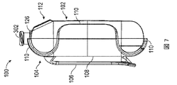
図1~8は、一部の実施形態による外側ハウジング102および取付構成要素104を有するポンプシステム100の複数の図を示す。図1~8に示すように、ポンプシステム100は、ポンプシステム100の構成要素を収容または支持するための外側ハウジング102を含みうる。外側ハウジング102は、図1に示す通り、前方部分102aおよび後方部分102bなどの一つまたは複数の部分から形成することができ、外側ハウジング102を形成するために取り外し可能に取り付けられうる。
1-8 show multiple views of a
ポンプシステム100は随意に、ポンプシステム100がユーザーの使用者に限定されない別の物体上に取り付けられるように設計されうる取付構成要素104を随意に含むことができる。実施形態によっては、取付構成要素104は、ユーザーのポケット、パウチ、ベルト、フラップ、またはその他の方法で使用者の上着に取付構成要素104を保持するよう設計されたクリップ106(図3~8に示す)を含みうる。クリップ106は、クリップ106がクリップ106を形成するために使用される材料の弾性を介して締付力を実現できるように、取付構成要素104の基部108と一体形成されうる。実施形態によっては、クリップ106は、ベース108とは別個の構成要素であってもよく、付勢構成要素(コイルばね、曲げばねなど)を含んで、クランプ力をクリップ106をユーザーの使用者に保持する締付力を実現することができる。実施形態によっては、締付力は、ユーザーがクランプ位置からハウジングを開けることができるほど低いが、ポケット、フラップ、またはその他の材料の周りに留めたままであるほど強くすることができる。
取付構成要素104は、ポンプシステム100が取付構成要素104と併用することができるように、外側ハウジング102に取り外し可能に取り付けられうる。例えば、図1~8は、オプションの取付構成要素104を持つポンプシステム100を図示する。これにより、ユーザーがオプションの取付構成要素104を使用しないと決めた場合、ユーザーがポンプシステム100の全体の形状因子を減らす選択肢を与えるという利点がある。さらに、有利なことに、ユーザーがそのように決定する場合、ユーザーが一つの取付構成要素を別の取付構成要素により簡単に置き換えることができるようになる。図示の実施形態に示されるように、取付構成要素104は、基部108の周辺から延在するクラスプ110などの一つまたは複数の保持機能部を含み、取付構成要素104を外側ハウジング102の部分に保持することができる。図示の実施形態では、取付構成要素104は、クラスプ110の使用によって、スナップフィット式にポンプシステム100上に保持されうる。実施形態によっては、保持機能部は、ねじ、ナット、ボルト、スナップフィットコネクタなどの機械的留め具でありうる。
Mounting
図1~8のポンプシステム100を引き続き参照すると、外側ハウジング102は、ユーザーに情報を提供するように設計されうるディスプレイ112を含みうる(例えば、ポンプシステム100の動作状態に関する情報など)。実施形態によっては、ディスプレイ112は、ユーザーにポンプシステム100の一つまたは複数の操作状態または故障状態を警告できるアイコン114などの一つまたは複数のインジケータを含みうる。例えば、インジケータは、通常または適切な動作状態、ポンプ故障、電源障害、電池の状態または電圧レベル、創傷被覆材の状態または収容力、創傷被覆材の漏れ検知または創傷被覆材とポンプ組立品との間の流体流路、吸引障害、あるいは他の類似もしくは適切な状態またはその組み合わせを含みうる。一組のアイコン114の例は、図1に図示されており、左から右に、ポンプシステム100の通常の動作を示すことができる「OK」インジケータ、ポンプシステム100またはポンプシステム100に取り付けられた構成要素の漏れの存在を示すことができる「漏れ」インジケータ、創傷被覆材が容量一杯またはほぼ容量一杯であることを示すことができる「被覆材フル」インジケータ、電池が無いまたはほぼ無いことを示すことができる「電池限界」インジケータを含むことができる。アイコン114は、緑色または橙色の色であっても、緑色または橙色の光(例えば、色付きのLEDなど)を点灯してもよい。
With continued reference to the
図示の実施形態では、一つまたは複数のアイコン114は、外側ハウジング102のディスプレイ112上に直接印刷されうる。実施形態によっては、アイコン114のうちの一つまたは複数は、外側ハウジング102の一部分に取り付けられたラベル上に設けられうる。アイコン114のうち一つまたは複数は、そのアイコンに対応する状態がシステム内に存在するときに点灯することができる。以下でさらに詳細に論じるように、LEDなどの一つまたは複数の照明構成要素を、外側ハウジング102内に位置付けて、アイコン114を点灯することができる。外側ハウジング102内の照明構成要素を使用するアイコンの点灯を強化するために、アイコン114の一つ以上に近接するまたはその下にある外側ハウジング102の一部の厚さを減少させて、アイコン114に近接するまたはその下にある外側ハウジング102の半透明性を増大させうる。実施形態によっては、アイコン114の一つ以上に近接するまたはその下にある外側ハウジング102の一部は、透明材料から作製されうる。例えば、実施形態によっては、外側ハウジング102のディスプレイ112は、薄いまたは透明もしくは半透明な材料でできている照明パネルを備えてもよい。外側ハウジング102の一部分を薄くする、または外側ハウジング102の一部を透明または半透明材料で作製することで、照明構成要素からの光がハウジング102を貫通し、アイコン114を点灯できる。有利なことに、より薄いまたは透明もしくは半透明ハウジングを有する一つ以上のアイコン114を点灯するため外側ハウジング102に開口部が形成されないので、アイコン114の周りの漏れの可能性を排除する、または少なくとも著しく低減する。
In the illustrated embodiment, one or
図1~8に図示したポンプシステム100を引き続き参照すると、ポンプシステム100は、ポンプシステム100の動作を制御するためにユーザーからの入力を受けるよう設計された、ボタン116などの一つまたは複数のユーザー入力機能を含みうる。図示の実施形態では、ポンプシステム100を作動および停止するため、またはポンプシステム100のその他の動作パラメータを制御するために使用することができる単一のボタンが存在する。例えば、実施形態によっては、ボタン116を使用して、ポンプシステム100を作動させ、ポンプシステム100を停止し、アイコン114などのインジケータを消去する、またはポンプシステム100の動作を制御するための任意の他の適切な目的に使用することができる(例えば、ボタン116を順次押すことによって)。ボタンは、ハウジングの外側、前面上に位置付けられうる押しボタンとすることができる。実施形態によっては、複数の入力機能(例えば、複数のボタン)をポンプシステム100上に備えることができる。
With continued reference to pump
実施形態によっては、ボタン116は、ボタン116の周りの漏れの可能性を排除する、または少なくとも低減するよう設計されうる。実施形態によっては、ボタン116の周辺部分は、外側ハウジング102の周囲リップと締まりばめで配置されうる。実施形態によっては、ボタン116の全体または部分は、ゴム、シリコン、またはその他任意の適切な材料など、表面と当接した時に比較的密封された封止を形成することができる変形可能な材料で形成されうる。
In some embodiments,
実施形態によっては、ポンプシステム100は、管または導管をポンプシステム100に連結するためのコネクタ302を含みうる。例えば、図16Aおよび16Bに示すように、コネクタ302は、ポンプシステム100を被覆材950に連結するために使用されうる。図示の実施形態に示すように、創傷被覆材950は、導管954の端を受けるためのポート952を含みうる。実施形態によっては、ポート952は、導管954を受けるためのコネクタ部953を含みうる。実施形態によっては、導管954は、ポンプシステム100のコネクタ302に直接連結されうる。図16Aに示すように、実施形態によっては、中間導管956を使用して、クイックリリースコネクタ958、960などのコネクタを介して導管954に取り付けることができる。
In some embodiments,
実施形態によっては、ポンプシステムは、創傷被覆材950などの創傷被覆材が創傷から吸引された滲出液を保持するキャニスターレスシステムで動作するように構成されうる。こうした被覆材には、創傷被覆材の下流の液体の通過(ポンプシステムに向かう)を阻止する疎水性フィルタなどのフィルタが含まれうる。実施形態によっては、ポンプシステムは、創傷から吸引される滲出液の少なくとも一部を保存するためのキャニスターを持つシステムで動作するように構成されうる。こうしたキャニスターは、創傷被覆材の下流の液体の通過(ポンプシステムに向かう)を阻止する疎水性フィルタなどのフィルタを含みうる。また実施形態によっては、創傷被覆材およびキャニスターの両方は、創傷被覆材およびキャニスターの下流の液体の通過を阻止するフィルタを含みうる。 In some embodiments, the pump system can be configured to operate in a canisterless system in which a wound dressing, such as the wound dressing 950, retains exudate drawn from the wound. Such dressings may include filters, such as hydrophobic filters, that prevent the passage of liquids downstream of the wound dressing (towards the pump system). In some embodiments, the pump system can be configured to operate with a system having a canister for storing at least a portion of exudate drawn from the wound. Such canisters may include a filter, such as a hydrophobic filter, that prevents the passage of liquid downstream of the wound dressing (towards the pump system). Also, in some embodiments, both the wound dressing and the canister may include a filter that prevents the passage of liquids downstream of the wound dressing and canister.
図9および10は、一部の実施形態による外側ハウジング102に取り付けられたオプションの取付構成要素104を持たないポンプシステム100の背面図を示す。図示の実施形態に示すように、外側ハウジング102の後方部分102bは、空洞120を覆うための取り外し可能カバー118を含みうる。空洞120は、装置に電力供給するための一つまたは複数の電源(電池など)を受けるように設計された一つ以上の窪み122を含みうる。実施形態によっては、空洞120の外周124は、カバー118のそれぞれの特徴と協働して、水分が空洞120に入る可能性を低減しうる特徴を含みうる。例えば、実施形態によっては、外周124は、下部周辺に沿ったリブ、側面周辺、上部周辺部、または一つまたは複数の周辺の組み合わせを含んで、空洞120への湿気の進入の可能性を低減させうる。実施形態によっては、外周124は、底部周辺に沿った窪み、側面周辺、上部周辺部、または一つまたは複数の周辺の組み合わせを含んで、水滴などの水分を空洞120から遠ざけることができる。
9 and 10 show rear views of
図11および12は、一部の実施形態による回路基板200、吸入マニホールド300、およびポンプ組立品400などの陰圧源を露出するため外側ハウジング102の一部が取り外されたポンプシステム100の斜視図を示す。図13は、吸入マニホールド300およびポンプ組立品400を露出するため外側ハウジング102の前方部分ならびに回路基板200が取り外されたポンプシステム100の実施形態の斜視図である。図示の実施形態に示すように、回路基板200、吸気マニホールド300、またはポンプ組立品400は、外側ハウジング102内に位置付けられてもよく、またはそれによって支持されてもよい。
11 and 12 are perspective views of
制御基板200は、ポンプ組立品400などのポンプシステム100の機能を制御するよう設計されうる。制御基板200は、ポンプシステム100の様々な電気/電子部品を機械的に支持かつ電気的に接続するように設計されうる。例えば、実施形態によっては、制御基板200は、一つ以上の電池202をポンプ組立品400に接続して、ポンプ組立品400を動作させる電力を供給できる。実施形態によっては、制御基板200は、圧力モニタ204を含みうる。圧力モニタ204は、制御基板200によって支持することができ、流体流路内の圧力レベルを監視するよう設計できる。制御基板200は、圧力モニタ204と連動して、ポンプ組立品400を所定の閾値圧力の超過から保護するよう設計できる、または創傷における目標圧力を維持するよう設計できる。実装形態によっては、制御基板は、プリント回路基板アセンブリ(PCBA)であってもよく、PCBAは、PCBに電気的に連結された一つまたは複数の電子構成要素を持つPCBであってもよい。
回路基板200は、圧力読み取り値が所定の値に達した場合、ポンプ組立品400への電力を切断するよう設計されてもよく、圧力レベルが所定値または第一の所定値よりも高くても、もしくは低くてもよい第二の所定値を下回ると再開するように設計されてもよい。さらに、制御基板200は、こうした過度な加圧を防止するようプログラムすることができる。
The
制御基板200は、インジケータライト、音声警報、またはこうした特徴の組み合わせを含みうる。例えば、制御基板200は、一つまたは複数のLED206の形態のインジケータライトを含みうる。図1~8に関連して上述したように、一つまたは複数のLED206は、外側ハウジング102上のディスプレイ112の一つまたは複数のアイコン114を点灯するために使用されうる。実施形態によっては、各LED206は、一つまたは複数のアイコン114に対応することができる。制御基板200は、一つまたは複数の機能部208(例えば、感圧スイッチ)を有して、制御ボタン116からの入力を受信することができる。
図13は、吸入マニホールド300およびポンプ組立品400を露出するため外側ハウジング102の前方部分ならびに制御基板200が取り外されたポンプシステム100の正面斜視図を示す。図示の実施形態に示すように、マニホールド300およびポンプ組立品400は、外側ハウジング102の一つまたは複数の部分内に位置付けられてもよく、またはそれによって保持されてもよい。
FIG. 13 shows a front perspective view of
本明細書に開示される実施形態のいずれにおいても、制御基板200は、フレキシブル回路基板であってもよく、または一つまたは複数の柔軟な構成要素を有してもよい。フレキシブル回路基板は、一般に、柔軟なオーバーレイを備えても備えなくてもよい柔軟性のあるベース材料を利用するプリント回路および構成要素のパターン付き配置である。これらの柔軟な電子組立品は、硬質プリント回路基板に使用される同一の構成要素を使用して製造することができるが、その塗布中に基板が所望の形状(フレックス)に適合することを可能にする。最も簡単な形態では、フレックス回路は、端部製品内で非平面の位置決めを可能にする材料で作製されたPCBである。典型的な材料はポリイミドベースであり、カプトン(Dupont)などの商品名で通りうる。さらに、本明細書に開示される制御基板またはコントローラのいずれも、単一のパッケージに積層されたフレキシブル基板および硬質基板の組み合わせを持ちうる。
In any of the embodiments disclosed herein,
図14および15は、一部の実施形態による外側ハウジング102内のポンプシステム100の配線を図示した様々な図である。図示の実施形態に示すように、ポンプシステム100は、回路基板200を電池202などの電源に接続するための端子210を含みうる。回路基板200は、回路基板200のコネクタ212に取り付けられた電気導管604を介して、電源からコイルへ電力を経路指定できる。実施形態によっては、電気導管604は、組立を容易にするフレキシブルプリント回路(FPC)であってもよい。実施形態によっては、電気導管604はコイルに直接接続されうる。例えば、正および負の端子に対応するFPCの端部は、コイルのはんだ付けまたは接着剤を介して、コイルの端部または端子に取り付けることができる。例えば、コイルは、FPCの二つの対応するはんだパッドにはんだ付けできる二つの端子を持ちうる。しかし、コイルを製造するために使用される電線は、手動はんだ付けを困難または信頼できなくしうる絶縁層および自己融着コーティング層によって保護されている場合がある。というのも、手動はんだ付けは、FPCを400度の温度に長時間さらしうるので、FPC基板に損傷を与える可能性があるためである。この問題を軽減するために、実施形態によっては、マイクロ溶接プロセスを使用して、FPCをコイルの二つの端子に電気的に接続することができる。マイクロ溶接では、コイルの端子とFPCパッドの間に数ミリ秒間の高電流スパイクを生成することができる。電流スパイクは、電線の絶縁層および自己接着層を気化することができる局在的な温度スパイクをもたらしうるため、コイルの電線をFPCパッドに接着することができる。例えば、温度スパイクは400℃以上であってもよい。しかし、温度スパイクはマイクロ溶接プロセスを使用する数ミリ秒に制限されるため、FPC基板は損傷しない。
14 and 15 are various views illustrating wiring of
図17は、一部の実施形態によるポンプシステム1000の概略図を示す。実施形態によっては、ポンプシステム1000は、上述のポンプシステム100の実施形態を含む、本明細書に開示または組み込まれる任意の他のポンプシステムの実施形態の同一または類似の構成要素、機能、材料、サイズ、構成、およびその他の詳細を有することができる。実施形態によっては、ポンプシステム1000は小型化および携帯可能でありうるが、より大きい従来型の携帯型または非携帯型(例えば、壁吸込み)ポンプも使用可能である。
FIG. 17 shows a schematic diagram of a
図示の実施形態に示すように、ポンプシステム1000は、スイッチまたはボタン1002、一つまたは複数のインジケータ1004、および制御基板1006を含みうる。ボタン1002または一つまたは複数のインジケータ1004は、制御基板1006と電気的に通信することができる。下記にさらに詳細に説明するように、実施形態によっては、ボタン1002は、ポンプシステム1000の動作を制御するための任意の適切な目的に使用されうる。例えば、ボタン1002を使用して、ポンプシステム1000を作動し、ポンプシステム1000を停止する、システムインジケーター1004を消去する、またはポンプシステム1000の動作を制御するためのその他任意の適切な目的に使用することができる。ボタン1002は、タッチパッド、タッチスクリーン、キーボードなどの任意のタイプのスイッチまたはボタンであってもよい。実施形態によっては、ボタン1002はプレスボタンでありうる。例えば、ボタン1002は、ポンプシステム100のボタン116と同様であってもよい。
As shown in the illustrated embodiment, the
実施形態によっては、一つまたは複数のインジケータ1004は、ポンプシステム1000の一つまたは複数の動作状態または故障状態を示しうる。実施形態によっては、一つまたは複数のインジケータ1004はそれぞれ、異なる動作状態または故障状態に関する表示を提供できる。例えば、アクティブ(例えば、点灯している)インジケータ1004は、正常な動作を表すことができる。別のインジケータ1004(例えば、被覆材インジケータ)は、システム内の漏れの存在について表示できる。例えば、アクティブ(例えば、点灯している)被覆材インジケータは、漏れを表すことができる。別のインジケータ1004(例えば、被覆材容量インジケータ)は、創傷被覆材の残りの流体容量に関して表示できる。例えば、アクティブ(例えば、点灯している)被覆材容量インジケータは、創傷被覆材が容量一杯またはほぼ容量一杯であることを表すことができる。電池インジケータなどの別のインジケータ1004は、電池などの電源の残りの容量または寿命に関して表示できる。例えば、アクティブ(例えば、点灯している)電池インジケータは、低容量を表すことができる。実施形態によっては、インジケータ1004は、ポンプシステム1000またはその他の動作状態または故障状態の上記の動作状態または故障状態の組み合わせを表すことができる。
In some embodiments, one or
図17に図示したポンプシステム1000の実施形態を引き続き参照すると、実施形態によっては、一つ以上のインジケータ1004はアイコンでありうる。例えば、一つまたは複数のインジケータ1004は、ポンプシステム1004のアイコン114と同様であってもよく、ポンプシステム100のLED206などの照明光源を介して作動(例えば、点灯している)可能である。実施形態によっては、一つまたは複数のインジケータ1004は、異なる色、二つの異なる色(例えば、二つのインジケータが同じ色を共有できる)、または同一色であってもよい。ポンプシステム1000は、四つのアイコンおよびプッシュ再生/停止ボタンを含んでもよく、他の構成、他の位置、ならびに他の種類のインジケータ、警報、およびスイッチを代替で使用することができる。実施形態によっては、ポンプシステム1000は、ユーザーにさまざまな動作状態を信号で知らせるように構成される、視覚、聴覚、触覚、およびその他のタイプのインジケータまたは警報を含みうる。こうした状態には、システムオン/オフ、スタンバイ、一時停止、通常動作、被覆材の問題、漏れ、エラーなどが含まれる。インジケータには、スピーカ、ディスプレイ、光源など、またはその組み合わせが含まれてもよい。
With continued reference to the embodiment of
図示の実施形態に示すように、ポンプシステム1000は、電池電源などの電源1008によって給電されうる。ポンプシステム1000は、電動機1014によって給電されたポンプ1012およびポンプシステム100の圧力モニタ204などの圧力センサ1016を有するポンプ組立品などの陰圧源1010も含みうる。実施形態によっては、ポンプシステム1000は、入口1018を含んで、ポンプシステム1000を創傷被覆材に連結することができる。例えば、実施形態によっては、入口1018は、入口1018を創傷被覆材と流体連通する導管に連結するためのコネクタでありうる。コネクタは、ポンプシステム100のコネクタ302と同様であってもよい。ポンプ1012は、出口1020に連結されうる。実施形態によっては、出口1020は、空気を大気に排出することができる。実施形態によっては、フィルタ(図示せず)は、出口と大気との間に介在しうる。フィルタは、大気に通気する前に空気を濾過することができる。実施形態によっては、フィルタは、細菌フィルタ、臭気フィルタなど、またはその任意の組み合わせであってもよい。実施形態によっては、雑音減衰構成要素などの減衰構成要素(図示せず)は、出口と大気との間に介在しうる。減衰構成要素は、動作中にポンプシステム1000によって生成されるノイズを低減することができる。実施形態によっては、減衰構成要素は、ポンプシステム100の減衰構成要素902と同様であってもよい。
As shown in the illustrated embodiment,
実施形態によっては、ポンプシステム1000は、創傷被覆材とポンプ1012の入口との間の流路に一方向弁などの弁(図示せず)を含みうる。バルブは、ポンプ1012が作動していない時に陰圧レベルを維持するのに役立ちうる。実施形態によっては、弁は漏れを回避するのに役立ちうる。弁はまた、創傷から吸引されたまたは除去された流体もしくは滲出液がポンプシステム1000に侵入するのを防止するのに役立ちうる。
In some embodiments,
図18は、一部の実施形態によるポンプシステム1100の電気構成要素概略図を示す。実施形態によっては、ポンプシステム1100は、上述のポンプシステム100、1000の実施形態を含む、本明細書に開示または参照により組み込まれる任意の他のポンプシステムの実施形態の同一または類似の構成要素、機能、材料、サイズ、構成、およびその他の詳細を有することができる。
FIG. 18 shows an electrical component schematic of
ポンプシステム1100は、一つまたは複数のボタン1102、一つまたは複数のインジケータ1104、一つ以上の圧力センサ1106、電源1108、陰圧源1109、またはモジュール1110を含みうる。実施形態によっては、一つまたは複数のボタン1102、一つまたは複数のインジケータ1104、一つまたは複数の圧力センサ1106、電源1108、または陰圧源1109は、ポンプシステム1000のボタン1002、インジケータ1004、圧力センサ1016、電源1008、または陰圧源1010と同様であってもよい。
制御基板(例えば、PCBA)とすることができるモジュール1110は、入力/出力(I/O)モジュール1112、コントローラ1114、およびメモリ1116を含みうる。実施形態によっては、モジュール1110は、追加の電気/電子構成要素、例えば、ヒューズ、または外部メモリ(フラッシュメモリなど)を含みうる。コントローラ1114は、マイクロコントローラ、プロセッサ、マイクロプロセッサなど、またはその任意の組み合わせでありうる。たとえば、コントローラ1114は、STM8L 151G4U6またはSTM8L 151K6U6TRなど、ST MicroelectronicsからのSTM8L MCUファミリタイプ、またはMC9S08QE4CWJなどのFreescaleからのMC9S08QE4/8シリーズのタイプであってもよい。コントローラ1114は、低電力または超低電力装置であることが好ましいが、他の種類の装置を代替で使用可能である。メモリ1116は、リードオンリーメモリ(ROM)、ライトワンスリードメニー(WORM)、ランダムアクセスメモリ(例えば、SRAM、DRAM、SDRAM、DDRなど)、固体メモリ、フラッシュメモリ、磁気抵抗ランダムアクセスメモリ(MRAM)、磁気記憶装置など、またはその任意の組み合わせのうちの一つ以上の揮発性メモリモジュールまたは不揮発性メモリモジュールの一つまたは複数を含みうる。メモリ1116は、プログラムコードまたは命令(コントローラによって実行される)、システムパラメータ、オペレーションデータ、ユーザーデータなど、またはその任意の組み合わせを保存するように構成されうる。実施形態によっては、ポンプシステム1100の一つまたは複数の構成要素は、モノリシックユニットの一部を形成してもよい。実施形態によっては、メモリ1116は、ポンプシステム1100の動作中にログされるように構成されたデータの量に応じる、16メガビット、32メガビット、または別の適切なサイズでありうる。実施形態によっては、ログデータは、有利なことに、臨床試験に関連する情報を収集するために保存することができる。実施形態によっては、ポンプシステム1100の一つまたは複数の構成要素は、他の構成要素から取り外し可能でありうる。例えば、実施形態によっては、メモリ1116は取り外し可能フラッシュメモリでありうる。
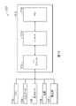
図19は、一部の実施形態によるポンプシステム1200の電気構成要素概略図を示す。実施形態によっては、ポンプシステム1200は、ポンプシステム100、1000、1100の実施形態を含む、本明細書に開示または参照により組み込まれる任意の他のポンプシステム実施形態の同一または類似の構成要素、機能、材料、サイズ、構成、およびその他の詳細を有することができる。電気構成要素は、ユーザー入力を受け入れ、ユーザーに出力を提供し、ポンプシステムおよび陰圧源を操作し、ネットワーク接続を提供するように動作することができる。電気構成要素は、一つまたは複数のPCB(図示せず)上に取り付けることができる。ポンプシステムは、コントローラまたはプロセッサ1202を含みうる。本明細書に開示される任意の実施形態では、コントローラ1202は、低電力プロセッサなどの汎用プロセッサでありうる。実施形態によっては、コントローラ1202は、特定用途向けプロセッサであってもよい。本明細書に開示される任意の実施形態では、コントローラ1202は、ポンプシステムの電子構造における「中心」プロセッサとして構成でき、コントローラ1202は、ユーザーインタフェースコントローラ1204、I/Oインタフェースコントローラ1206、陰圧制御モジュール1208、通信インタフェースコントローラ1210等の活動を調整できる。
FIG. 19 shows an electrical component schematic of
ポンプシステム1200はまた、ボタン、インジケータ(例えば、LED)、ディスプレイなど、ユーザー入力を受け入れ、ユーザーに出力を提供する一つまたは複数の構成要素を操作できる、ユーザーインタフェースコントローラまたはプロセッサ1204を含みうる。ポンプシステム1200への入力およびポンプシステム1200からの出力は、I/Oインタフェースモジュールまたはコントローラ1206によって制御される一つまたは複数の入力/出力(I/O)ポート1212を介して制御されうる。例えば、I/Oモジュール1206は、シリアル、パラレル、ハイブリッドポート、拡張ポートなどの一つまたは複数のI/Oポート1212からデータを受信できる。本明細書に開示される任意の実施形態では、I/Oポート1212は、USBポート、SDポート、コンパクトディスク(CD)ドライブ、DVDドライブ、FireWireポート、Thunderboltポート、PCI Expressポート等のうち一つまたは複数を含む。コントローラ1202は、他のコントローラまたはプロセッサとともに、システム1200の内部または外部でありうる一つ以上のメモリモジュール1214にデータを格納できる。RAM、ROM、WORM、磁気メモリ、固体状態メモリ、MRAM、およびその任意の組み合わせなど、揮発性または不揮発性メモリを含む任意の適切なタイプのメモリを使用できる。ポンプシステム1200は、電源1216によって電力供給可能であり、これは一つ以上の使い捨てまたは再充電可能電池、電力などを備えうる。電源1216は、システム1200の内部または外部とすることができる。
図19に図示したポンプシステム1200の実施形態を引き続き参照すると、実施形態によっては、陰圧またはポンプ制御モジュール1208は、陰圧源1218の動作を制御するように構成されうる。陰圧源1218は、ボイスコイルポンプでありうる。その他の適切なポンプには、ダイアフラムポンプ、蠕動ポンプ、ロータリポンプ、ロータリベーンポンプ、スクロールポンプ、ねじポンプ、液体リングポンプ、圧電変換器によって操作されるポンプなどが含まれる。ポンプ制御モジュール1208は、陰圧源1218の動作を制御するように構成されたドライバモジュール1220を含みうる。例えば、ドライバモジュール1220は、陰圧源1218に電力を供給することができる。電力は電圧または電流信号の形態で提供されうる。本明細書に開示される任意の実施形態では、ドライバモジュール1220は、パルス幅変調(PWM)を使用して陰圧源1218を制御できる。陰圧源1218(またはポンプ駆動信号)を駆動するための制御信号は、0~100%の負荷サイクルPWM信号とすることができる。駆動モジュール1220は、比例積分誘導体(PID)などの任意の他の適切な制御を使用して、陰圧源1218を制御できる。
With continued reference to the embodiment of
コントローラ1202は、ポンプシステム100の吸入マニホールド300内に配置された圧力モニタ204などの流体流路の適切な位置に配置された、圧力センサ1206などの一つまたは複数のセンサからの情報を受信することができる。本明細書に開示される任意の実施形態では、コントローラ1202は、一つ以上の圧力センサ1206から受信したデータを使用して、流体流路内の圧力を測定し、創傷空洞内または創傷被覆材の下で望ましいレベルの陰圧が達成されるように、流体の流れの速度を計算し、陰圧源1218を制御できる。望ましい陰圧のレベルは、圧力セットまたはユーザーによって設定または選択された圧力であってもよい。一つまたは複数のセンサによって測定された圧力は、コントローラ1202に提供されてもよく、それにより、コントローラは、ポンプ駆動信号を決定かつ調整して、望ましい陰圧レベルを達成できる。本明細書に開示される任意の実施形態では、陰圧源1218の制御に関連するタスクは、一つ以上のコントローラまたはプロセッサを含みうるポンプ制御モジュール1208にオフロードされてもよい。
本明細書に開示される任意の実施形態において、様々なタスクを実施するために複数のプロセッサを利用することが有利でありうる。本明細書に開示される任意の実施形態において、第一のプロセッサは、ユーザー活動を担当することができ、第二のプロセッサは、陰圧源の制御を担当することができる。このように、より高いレベルの応答性を必要とする可能性がある陰圧源を制御する活動を専用プロセッサに任せることができ、それによってユーザーとのやりとりのため、完了により時間がかかる場合があるユーザーインタフェースタスクに中断されなくなる。 In any of the embodiments disclosed herein, it may be advantageous to utilize multiple processors to perform various tasks. In any of the embodiments disclosed herein, a first processor can be responsible for user activity and a second processor can be responsible for controlling the negative pressure source. In this way, the activity of controlling the negative pressure source, which may require a higher level of responsiveness, can be offloaded to a dedicated processor, which may take longer to complete due to user interaction. You will not be interrupted by certain user interface tasks.
通信インタフェースコントローラまたはプロセッサ1210は、有線または無線接続を提供するように構成されうる。通信プロセッサ1210は、データを送受信するための一つまたは複数のアンテナ(図示せず)を利用することができる。本明細書に開示される任意の実施形態において、通信プロセッサ1210は、以下の種類の接続のうちの一つまたは複数を提供することができる。すなわち、2G、3G、LTE、4G、Wifi、インターネット接続、ブルートゥース(登録商標)、Zigbee、RFIDなどの全地球測位システム(GPS)技術、携帯電話またはその他の接続。さらに、本明細書に開示される任意の実施形態は、タブレット、スマートフォン、またはその他の類似の装置などからポンプ装置へ、またはポンプ装置からタブレット、スマートフォン、またはその他の類似の装置などへデータを同期、アップロード、またはダウンロードするように構成されうる。
Communication interface controller or
接続は、ポンプシステム位置追跡、アセットトラッキング、コンプライアンス監視、遠隔選択、ログ、警報、その他の操作データのアップロード、セラピー設定の調整、ソフトウェアまたはファームウェアのアップグレードなど、様々なアクティビティに使用できます。本明細書に開示される任意の実施形態では、通信プロセッサ1210は、二重GPS/携帯電話機能を提供することができる。携帯電話機能は、例えば、3Gまたは4G機能でありうる。このような場合、GPSモジュールが大気条件、建物または地形の干渉、衛星ジオメトリなどの様々な要因により衛星接続を確立できない場合、装置の位置は、携帯電話認証、三角測量、フォワードリンクタイミングを使用することなどによる、3Gまたは4Gネットワーク接続を使用して決定できる。本明細書に開示される任意の実施形態では、ポンプシステム1200はSIMカードを含むことができ、SIMベースの位置情報を取得できる。
Connections can be used for a variety of activities including pump system location tracking, asset tracking, compliance monitoring, remote selection, uploading logs, alarms and other operational data, adjusting therapy settings, and software or firmware upgrades. In any of the embodiments disclosed herein,
陰圧閉鎖療法システムの電子機器の保護
ポンプシステム100、1000、1100、または1200などのポンプシステムの電子機器は、環境条件へのポンプシステムの許容差を改善するよう構成かつ位置付けることができる。ポンプシステムは、家庭用医療、機上装置、自動車、ボート、列車、金属探知機、能動埋め込み型装置などの様々な非制御環境で、電気的または機械的に適切かつまたは安全に動作することができる。
Protection of Negative Pressure Wound Therapy System Electronics The electronics of a pump system, such as
ポンプシステムは、高レベルのESDに、以下の複数の工程において耐えるように構成することができる。コンタクト±2kV、±4kV、±6kV、±8kV以上、エアギャップ±2kV、±4kV、±6kV、±8kV±15kV、±30kV以上。ポンプシステムは、追加でまたは代替で、100A/m、150A/m、200A/m、400A/m以上の高レベルの磁性免疫性、ならびに10V/m、20V/m以上の高レベルのRF免疫性を持つよう構成されうる。追加でまたは代替で、ポンプシステムは、高レベルの機械的歪み(例えば、衝撃、振動、低下など)および高度環境(例えば、機上機械)に耐えることができる。 The pump system can be configured to withstand high levels of ESD in the following multiple steps. Contact ±2 kV, ±4 kV, ±6 kV, ±8 kV or more, air gap ±2 kV, ±4 kV, ±6 kV, ±8 kV ±15 kV, ±30 kV or more. The pump system additionally or alternatively has a high level of magnetic immunity of 100 A/m, 150 A/m, 200 A/m, 400 A/m or more and a high level of RF immunity of 10 V/m, 20 V/m or more. can be configured to have Additionally or alternatively, the pump system can withstand high levels of mechanical strain (eg, shock, vibration, drops, etc.) and high-altitude environments (eg, on-board machinery).
ポンプシステムは、実装形態によっては、IEC 60601-1標準、別の標準、またはその他の業界に受け入れられる基準で定義されているように、耐徐細動性(例えば、耐徐細動全装着部)でありうる。ポンプシステムは、例えば、単相または二相の徐細動ショックが加えられた時に、正常な動作を継続することができる。ポンプシステムは、こうした状況でその性能が変化する、または誤報を発することがあってはならない。こうした耐徐細動型構造は、ポンプシステムを使用する患者が心停止になる場合に、ポンプシステムは外部徐細動ショックを切り抜けるため望ましい場合がある。さらに、ポンプシステムは、使いやすさを保持しながら耐徐細動型でありうる(例えば、例えば、装置に過度な重量を加えうる金属ケースを有していない)。 Depending on the implementation, the pump system may be defibrillation resistant (e.g., anti-defibrillation full-mounted) as defined in the IEC 60601-1 standard, another standard, or other industry accepted criteria. ). The pump system can continue to operate normally when, for example, monophasic or biphasic defibrillation shocks are delivered. The pump system should not change its performance or give false alarms in these situations. Such anti-defibrillation structures may be desirable because the pump system will survive external defibrillation shocks if the patient using the pump system goes into cardiac arrest. Further, the pump system can be defibrillation resistant (eg, not having a metal case that can add undue weight to the device) while maintaining ease of use.
本明細書に記載の特徴の一つ以上は、ポンプシステムが高レベルのESD(静電気放電)に耐え、磁気免疫性またはRF免疫性を有し、高高度の機械的歪みに耐え、高高度環境に耐え、または耐徐細動性であることを可能にすることができる。 One or more of the features described herein are that the pump system can withstand high levels of ESD (electrostatic discharge), have magnetic or RF immunity, withstand high altitude mechanical strain, and withstand high altitude environments. tolerant to or to be defibrillation resistant.
ポンプシステムは、一つまたは複数のPCBAを含むことができ、これはそれぞれが電子部品を機械的にサポートし、電気的に接続するPCBを含みうる。コンデンサ、抵抗器、または能動装置などの構成要素は、PCB上にはんだ付けされていてもよく、または基板内に埋め込まれていてもよい。PCBAは片面(一つの銅層)、両面(二つの銅層)または多層(外側層および内側層)でありうる。異なる層上の導体はビアに接続される。多層PCBAは構成要素密度が大幅に高まる。一実装形態では、ポンプシステムは一つまたは二つの層を持つPCBAを含みうる。さらに別の実装形態では、ポンプシステムは、六層などの三つ以上の層を持つPCBAを含みうる。 A pump system may include one or more PCBAs, each of which may include a PCB that mechanically supports and electrically connects electronic components. Components such as capacitors, resistors, or active devices may be soldered onto the PCB or embedded within the substrate. PCBA can be single-sided (one copper layer), double-sided (two copper layers) or multi-layered (outer layer and inner layer). Conductors on different layers are connected to vias. Multilayer PCBA greatly increases component density. In one implementation, the pump system may include a PCBA with one or two layers. In yet another implementation, the pump system can include a PCBA with three or more layers, such as six layers.
ポンプシステムは、特定の内部装置構成要素を電気的に分離し、電磁妨害遮蔽(EMI)遮蔽およびその他の形態の電気絶縁を提供するように構成されうる。 The pump system may be configured to electrically isolate certain internal device components and provide electromagnetic interference shielding (EMI) shielding and other forms of electrical isolation.
図20Aは、ポンプシステム100、1000、1100、または1200のうちの一つと同様に、ポンプシステムの一部として使用可能なPCBA10の前面の例を示す。PCBA10は、例えば、回路基板200の実装形態でありうる。PCBA10は、少なくともPCBA10が導電性経路11、ビア12A、12B、および12C、部分13A、13B、および13C、導電性経路21、およびビア22A、22B、および22Cを含むことができる点で回路基板200と異なることができる。
FIG. 20A shows an example of the front of a
導電性経路11は、PCBA10の少なくとも片側の周囲または縁のすべてあるいは一部の周りに延在することができ(例えば、長さの20%、25%、30%、35%、40%、45%、50%、55%、60%、65%、70%、75%、80%、85%、90%、95%)、ポンプシステムの接地に接続され(例えば、電源の負電圧に)、PCBA10が放電路を備えることでESDにさらされるとき、PCBA10を保護する働きをする。導電性経路11は、ビア12A、12B、および12Cを含む複数のビアを含みうる。導電性経路11のビアは、PCBA10の層を通してPCBA10の反対側の表面に導電性経路11を電気的に連結するPCBA10を通る経路でありうる。導電性経路11のビアは、PCBA10を通した掘削によって製造されてもよく、また導電性材料のカラムでドリル穴の内側を被覆することで製造されてもよい。導電性経路11のビアは、約2.5mmなど、約1mm~10mmの間で互いに離間しうるが、実装形態によってはより少ない間隔またはより大きい間隔で離間してもよい。
The
導電性経路11は、PCBA10を別の構成要素(ポンプ組立品のハウジングなど)に固定するために留め具を挿入ために使用可能なPCBA10の穴の周りの経路に従う部分13Aおよび13Bを含みうる。導電性経路11は、PCBA10上のユーザー入力に応答するボタン(例えば、エラストマーとしうる)など、インタフェース要素の周りの接触経路14に従う部分13Cを含みうる。締め具またはインタフェース要素は名目的に絶縁にできるが、高電圧で導電性になることができる。留め具またはインタフェース要素を通して電気放電が印加される場合、電気放電は部分13A、13B、および13Cに接地されることが望ましい。
導電性経路11は、絶縁部分15および16によってPCBA10または導電性素子に取り付けられた一つ以上の構成要素から分離されうる。導電性経路11は、PCBA10を固定するよりPCBA10を場所に案内するために使用されうる、または比較的高い破壊電圧を持つ留め具を挿入するために使用可能である穴17Aおよび17Bなど、PCBA10の一部の穴の周りに延在できない。図20Aに図示した通り、導電性経路11は、絶縁部分15のエリア18以外のPCBA10の全面の周囲の周りに延在してもよく、これは電源の正電圧がPCBA10に電力を供給する場所の近くであってもよい。実装形態によっては、PCBA10のすべての層は電気的に接地されうる。
図20Bは、ビア22A、22B、および22Cなどの複数のビアを含む導電性経路21を備えるPCBA10の背面の例を示す。導電性経路21の構造およびそのビアは、導電性経路11の構造とそのビアの構造と類似していてもよい。導電性経路21は、さらに導電性経路11および21のバイアスを通して導電性経路11に電気的に接続されうる。導電性経路21は、絶縁部分23によってPCBA10または導電性素子に取り付けられた一つ以上の構成要素から分離されうる。図20Bに図示した通り、導電性経路21は、絶縁部分23の領域24以外のPCBA10の背面の周囲の周りに延在してもよく、これは電源の正電圧がPCBA10に電力を供給する場所の近くであってもよい。実装形態によっては、PCBA10は、PCBA10の一方の側に導電性経路を有してもよいが、反対側には有さない。
FIG. 20B shows an example of the back side of
図21Aは、PCBA10の第一の層30Aの例示的な技術的フィルムを示す。第一の層30Aは、PCBA10の上層とすることができる。図21Bは、PCBA10の第二の層30Bの例示的な技術的フィルムを示す。図21Cは、PCBA10の第三の層30Cの例示的な技術的フィルムを示す。図21Dは、PCBA10の第四の層30Dの技術的な技術的フィルムを示す。第四の層30Dは、PCBA10の底層とすることができる。
FIG. 21A shows an exemplary technical film of the
図22Aは、PCBA10の上側40Aのためのはんだマスクの例を図示したものであり、図22Bは、PCBA10の底側40Bのための例示的なはんだマスクを図示する。第一の層30A、第二の層30B、第三の層30C、第四の層30D、上側40Aおよび底側40Bは、複数のビアを含むPCBA10の特定の特徴をより良く図示しうる。PCBA10の寸法は、例えば、約57mm×32mmであってもよい。第一の層30A、第二の層30B、第三の層30C、および第四の層30Dは、実装形態によっては、少なくとも部分的に銅から構成されうる。図23は、PCBA10の上側組立品50の例示的な技術的フィルムを示す。
22A illustrates an example solder mask for the
図24は、PCBA10の例示的な層構造を示す。例示的な層構造には、以下の特徴が含まれうる。加工後の外側層の最小導体厚さは、約0.0334mmとすることができる。加工後の内側層の最小導体厚さは、約0.0249とすることができる。完成した基板の全体の厚さは約1mmとすることができる。はんだ抵抗の厚さは、約0.01mmとすることができる。絶縁コーティングの破壊電圧は、約500VDCとすることができる。はんだ抵抗タイプは、片側または両側面のLPIとすることができる。表面仕上げは、ENIG(エレクトロレスNi/Au(Ni 2.54um MIN-Au 0.05um MIN))とすることができる。
FIG. 24 shows an exemplary layered structure of
PCBA10の実装形態によっては、エッチング要素、ビアおよび絶縁の寸法は以下の通りでとすることができる。ロジックトラックは、約0.15mmとすることができる。最小絶縁材は約0.15mmとすることができる。ビアは、直径約0.2mmまたは0.6mmとすることができ、メッキされていてもよい。PCBA10は、約245のビアを含みうる。ロジックトラックの許容誤差は、0.0254mmまたは0.04mmとしうる。ビアの許容誤差は約0.076mmとすることができる。メッキされた穴の許容誤差は、約0.076mmとしうる。非メッキ穴の許容誤差は、約0.05mmとしうる。メッキされたスロットの許容誤差は、約0.127mmとしうる。非メッキスロットの許容誤差は、約0.1mとしうる。
Depending on the
ポンプシステムは、PCBAの縁とポンプシステムのプラスチックハウジングなどのハウジングとの間にギャップがあるように位置付けられるPCBA10などのPCBAを含みうる。追加でまたは代替で、ポンプシステムは、PCBに連結された構成要素(一つまたは複数のマイクロコントローラまたはメモリデバイスなど)が、図23に示すように、PCBの周囲からの閾値距離(例えば、約0.5mm、1mm、2mm、3mm、4mm、または5mm)より大きいように構成されたPCBAを含みうる。
The pump system may include a PCBA, such as
ポンプシステムは、ボタンの接点の周囲にトラック(例えば、接地トラック)を有するPCBA10などのPCBAを含みうる。ボタンは、部分的にまたは完全にエラストマーとすることができる。ボタンは部分的な絶縁装置の可能性がある一方、一定の状況下で通電可能な空隙を提示しうる。トラックは、ボタンを介して電気放電をショートするために使用されてもよく、そのためポンプシステムの電気放電に対するイミュニティを増加させる。
The pump system may include a PCBA such as
ポンプシステムは、PCBAがポンプシステムのハウジングに固定されうる場所など、PCBAの一つ以上の穴の周りのトラック(例えば、接地トラック)を持つPCBA10などのPCBAを含みうる。実装形態によっては、PCBAは、四つの穴を含んでもよく、そこでは二つの穴はPCBAを定位置にねじ留めするために使用することができ、他方の穴は取付けではなく案内用としうる。案内に使用される穴に位置付けられた取付構造体は、PCBAにトラックが含まれていない十分に高い破壊電圧を持つことができる。導電性ねじを使用する場合、穴の破壊電圧を低減することができ(例えば、高導電性経路までの距離が短いため)、従ってトラックの恩恵を受けることができる。
The pump system may include a PCBA such as
ポンプシステムは、アナログ入力に対しても含む、認識するよう構成されるソフトウェア入力出力バスを含みうる。ポンプシステムは、マイクロコントローラまたはメモリなどの一つまたは複数の構成要素の上にEMIシールドを含むことができる。 The pump system may include a software input output bus configured to recognize, including for analog inputs. A pump system may include an EMI shield over one or more components such as a microcontroller or memory.
ポンプシステムは、金属遮蔽物ではなく一つ以上のナイロンねじを含んで、ポンプシステムに追加のESD保護を与えることができる。ナイロンねじは、例えば、ポンプシステムのフィルタ下で使用することができる。 The pump system can include one or more nylon screws rather than metal shields to give the pump system additional ESD protection. Nylon threads can be used, for example, under filters in pump systems.
ポンプシステムは、一つまたは複数の内部ガスケットを含んで、ポンプシステムに追加のESD保護を与えることができる。ポンプシステムはまた、金属部品を覆うことによって露出してない金属または露出部が最小量の金属を含むことができ、アークの防止に役立ちうる。例えば、充電ケーブル用のプラグは、ポンプシステムのその他の構成要素から電気的に絶縁することができ、ポンプシステムのクランプを接続する耳は、ポンプシステムの他の構成要素から電気的に絶縁することができる。 The pump system may include one or more internal gaskets to provide additional ESD protection to the pump system. The pump system can also contain no or minimally exposed metal by covering the metal parts, which can help prevent arcing. For example, the plug for the charging cable can be electrically isolated from other components of the pump system, and the ears connecting the clamps of the pump system can be electrically isolated from other components of the pump system. can be done.
ポンプシステムは、一つ以上の個別コネクタ(例えば、USBコネクタまたはアンテナコネクタ)およびESDクランプに電気的に連結されたコンデンサを含みうる。ポンプシステムには、共形コーティング、比較的短いケーブル組立品、比較的短いレイアウトトレース、または平面間の特定のレイアウトトレースを封入することができる。ポンプシステムはまた、PCBA10または接地金属遮蔽などのPCBの周囲からの平面およびトレースを含むことができる。
The pump system may include one or more discrete connectors (eg, USB connector or antenna connector) and a capacitor electrically coupled to the ESD clamp. The pump system can be encapsulated with conformal coatings, relatively short cable assemblies, relatively short layout traces, or specific layout traces between planes. The pump system can also include planes and traces from around the PCB, such as the
ポンプシステムは、PCBA10などのPCBAへの電気チャネルとしうる材料のギャップまたは変化を、徐細動条件下で経験するエネルギーおよび電流レベルで含まないことができる。ポンプシステムの一つ以上の発光ダイオード(LED)は、光パイプ、レンズ、または光を伝送するその他の手段を有よりもむしろ、固体で、未破壊の、半透明な、正面カバーに隠れていてもよい。
The pump system can be free of gaps or changes in material that could be an electrical channel to a PCBA, such as the
本明細書に記載される装置構造を考えると、ポンプシステムは、電気ショートを処理する代替機能を持ちうるため、電気ショートの場合に過真空を防がない可能性がある。 Given the device structure described herein, the pump system may have an alternate function of handling electrical shorts and thus may not prevent over-vacuum in the event of an electrical short.
ポンプシステムは、電気的絶縁を含んで、短絡するポンプシステムから水、尿、または血液の進入を隔離することができる。 The pump system can include electrical isolation to isolate water, urine, or blood ingress from a shorting pump system.
ポンプシステムは、実装形態によっては、連通用の調整された受信機を使用し、短絡を実行して、受信機のコンデンサ保護を実施することができる。関心対象の周波数以外の干渉は、接地に短絡してもよい。ポンプシステムはまだ関心の頻度でいくつかの脆弱性を持つことができるが、周波数が干渉のスペクトルと異なる場合、脆弱性は特に許容可能である。 The pump system may use a regulated receiver for communication, implement a short circuit, and implement receiver capacitor protection in some implementations. Interference outside the frequency of interest may be shorted to ground. Pumping systems can still have some vulnerability at frequencies of interest, but vulnerability is particularly tolerable if the frequencies differ from the interference spectrum.
電気放電から保護するポンプシステムの機能では、ポンプシステムを損傷または誤作動から保護する、または患者または臨床医を衝撃から保護することが望ましい場合がある。 In the ability of the pump system to protect against electrical discharge, it may be desirable to protect the pump system from damage or malfunction, or to protect the patient or clinician from impact.
図25は、一部の実施形態による電気放電からポンプシステムを保護するための方法60を示す。方法60は、PCBA10などの回路基板を含むポンプシステム100、1000、1100、または1200などのポンプシステムによって実施されうる。便宜上、方法60が本明細書に記載されたポンプシステムの関連において説明されるが、代わりに、示されていない他のシステムによって実行される場合もある。方法60は、有利なことに、特定の実施形態では、伝統的にポンプシステムを損傷した電気放電からポンプシステムを保護することを可能にする。
FIG. 25 illustrates a
ブロック61で、方法60は、ポンプシステムの電子機器の動作を制御できる。例えば、コントローラ1114および1202などのポンプシステムの一つ以上のコントローラまたはポンプシステムの他の構成要素は電子機器を制御して、陰圧の供給を作動または停止する、陰圧を供給するとき漏れまたは障害などの動作状態を検出する、動作状態に基づいて警報する、またはその他の電子装置からのデータを送信または受信するなど、さまざまな機能を実行する。一つまたは複数のコントローラまたはその他の構成要素は、回路基板の電気接地に電気的に連結された導電性経路(導電性経路11または21)を有する回路基板(PCBA10)上に取り付けることができる。回路基板は、ポンプシステムのハウジングの内側に位置付けることができる。
At
ブロック62で、方法60は、ポンプシステム外部から電流を受け取ることができる。例えば、ポンプシステムは、ハウジングの構造を安定化するために使用されるユーザーインタフェース(ボタン)または留め具(スクリューなど)を介して、ポンプシステムのハウジングの外部から電気放電を受けることができる。
At
ブロック63で、方法60は、回路基板上の周囲経路を介してポンプシステムの接地に電流を伝えることができる。例えば、周囲経路は、回路基板の側面の周辺または回路基板上の一つ以上の要素の周辺、または回路基板の穴の周辺のすべてまたは一部の周り(例えば、長さの20%、25%、30%、35%、40%、45%、50%、55%、60%、65%、70%、75%、80%、85%、90%、95%)を延在する導電性経路であってもよい。周辺経路の例として、導電性経路11もしくは導電性経路12または部分13A、13B、および13Cが含まれうる。こうして、周囲経路は、電流を消散させるために使用されて、一つまたは複数のコントローラまたはその他の構成要素を損傷させることなく回路基板上に取り付けることができることが望ましい。
At
他の変化形態
本明細書で提供される閾値、限界値、期間などの値は、絶対的なものであることを意図するものではなく、したがっておおよそのものでありうる。さらに、本明細書で提供される任意の閾値、限界値、期間などは、自動的にまたはユーザーによって、固定されるかまたは変えられうる。さらに、本明細書で使用される場合、参照値に関連した、超える、超、未満などの相対的な程度を表す用語は、参照値と等しい場合も包含することが意図される。例えば、正の参照値を超えることは、参照値以上であることを包含することができる。その上、本明細書で使用される場合、参照値に関連した、超える、超、未満などの相対的な程度を表す用語は、参照値に関連した、下にある、未満、超などの開示された関係とは逆のものも包含することが意図される。また、種々のプロセスのブロックは、ある値が特定の閾値に達するかまたは達しないかを判定することに関して説明されうるが、ブロックは、例えば、ある値が(i)閾値未満であるかもしくは閾値を超えているか、または(ii)閾値を満たすかもしくは満たしていないかに関しても同様に解釈されうる。
Other Variations The values for thresholds, limits, time periods, etc. provided herein are not intended to be absolute and may therefore be approximate. Additionally, any thresholds, limits, time periods, etc. provided herein may be fixed or varied, either automatically or by a user. Furthermore, as used herein, terms expressing relative degrees, such as greater than, greater than, less than, relating to a reference value are intended to encompass equality to the reference value. For example, exceeding a positive reference value can include being greater than or equal to the reference value. Moreover, as used herein, terms denoting relative degrees such as above, above, below, etc. in relation to a reference value are defined as below, below, below, above, etc., in relation to a reference value. It is intended to encompass the reverse of the stated relationship as well. Also, although various process blocks may be described in terms of determining whether a value reaches or falls short of a particular threshold, a block may, for example, determine whether a value is (i) below a threshold or or (ii) meeting or not meeting a threshold can be similarly interpreted.
特定の態様、実施形態、または実施例に関連して説明される特性、物質、特徴、または群は、本明細書に記載される他の任意の態様、実施形態、または実施例に、これらと両立できないことがない限り、適用可能であることを理解されたい。本明細書(添付の特許請求の範囲、要約書および図面のいずれをも含む)に開示する特徴のすべて、または同様に開示するいずれの方法もしくは過程のステップのすべては、そのような特徴またはステップの少なくとも一部が、互いに排他的である組み合わせを除き、いかなる組み合わせで組み合わせられてもよい。本発明の保護するものは、前述の任意の実施形態の詳細に限定されない。保護するものは、本明細書(添付の任意の特許請求の範囲、要約書、及び図面を含む)において開示される特徴のうちの任意の新規なもの、もしくは任意の新規な組み合わせに及び、または同様に開示される任意の方法またはプロセスのステップのうちの任意の新規なもの、もしくは任意の新規な組み合わせに及ぶ。 A property, material, feature, or group described in connection with a particular aspect, embodiment, or example may be used in conjunction with any other aspect, embodiment, or example described herein. It should be understood that they are applicable unless they are incompatible. All features disclosed in this specification (including any appended claims, abstract and drawings) or steps of any method or process similarly disclosed may be interpreted as including such features or steps. may be combined in any combination, except combinations that are mutually exclusive. What this invention covers is not limited to the details of any foregoing embodiments. What is covered is any novelty, or any novel combination, of the features disclosed in this specification (including any appended claims, abstract, and drawings), or It extends to any novel one or any novel combination of the steps of any method or process disclosed as well.
一定の実施形態が説明されてきたが、これらの実施形態は、単に例として提示されており、保護範囲を限定することを意図するものではない。実際、本明細書に記載の新規な方法及びシステムは、様々な他の形態で具現化されてもよい。さらに、本明細書に記載の方法及びシステムの形態において、様々な省略、置換、及び変形がなされうる。実施形態によっては、図示または開示されたプロセスにおいて実施される実際のステップは、図に示されたステップとは異なりうることを、当業者は認識するであろう。実施形態によっては、上述したステップのうちの特定のステップが除去される場合があり、別のものが加えられる場合もある。例えば、開示されるプロセスで実施される実際のステップまたはステップの順序は、図で示したものとは異なっていてもよい。実施形態によっては、上述したステップのうちの特定のステップが除去される場合があり、別のものが加えられる場合もある。例えば、図に示した様々な構成要素が、プロセッサ、コントローラ、ASIC、FPGA、または専用ハードウェア上のソフトウェアまたはファームウェアとして実装されてもよい。プロセッサ、ASIC、FPGAなどのハードウェア構成要素には論理回路が含まれうる。さらに、上記に開示された特定の実施形態の特徴及び特性は、様々な方法で組み合わせることができ、さらなる実施形態を形成することができるが、その全てが本開示の範囲内に収まることになる。 Although certain embodiments have been described, these embodiments are presented by way of example only and are not intended to limit the scope of protection. Indeed, the novel methods and systems described herein may be embodied in various other forms. Moreover, various omissions, substitutions, and variations may be made in the form of the methods and systems described herein. Those skilled in the art will recognize that, depending on the embodiment, the actual steps performed in the processes illustrated or disclosed may differ from those depicted in the figures. In some embodiments, certain of the steps described above may be removed and others added. For example, the actual steps or order of steps performed in the disclosed processes may differ from that shown in the figures. In some embodiments, certain of the steps described above may be removed and others added. For example, the various components shown in the figures may be implemented as software or firmware on a processor, controller, ASIC, FPGA, or dedicated hardware. Hardware components such as processors, ASICs, FPGAs, etc. may include logic circuits. Moreover, the features and characteristics of the particular embodiments disclosed above can be combined in various ways to form additional embodiments, all of which will fall within the scope of the present disclosure. .
本明細書で図示され、説明されるユーザーインタフェーススクリーンには、追加の構成要素または代替の構成要素が含まれうる。これらの構成要素には、メニュー、リスト、ボタン、テキストボックス、ラベル、ラジオボタン、スクロールバー、スライダー、チェックボックス、コンボボックス、ステータスバー、ダイアログボックス、ウィンドウなどが含まれうる。ユーザーインタフェーススクリーンには、追加の情報、または代替の情報が含まれうる。構成要素は、任意の好適な順番に配置され、グループ化され、標示されうる。 The user interface screens shown and described herein may include additional or alternative components. These components can include menus, lists, buttons, text boxes, labels, radio buttons, scrollbars, sliders, check boxes, combo boxes, status bars, dialog boxes, windows, and the like. User interface screens may include additional or alternative information. Components may be arranged, grouped, and labeled in any suitable order.
本開示には、特定の実施形態、実施例、及び用途が含まれるが、本開示は、具体的に開示された実施形態の範囲を超えて、他の代替の実施形態または使用ならびにその明らかな変更形及びその等価物にまで及び、これには本明細書に記載された特徴および利点の全てを提供しているとは限らない実施形態が含まれることは、当業者に理解されるであろう。したがって、本開示の範囲は、本明細書における好ましい実施形態の特定の開示によって限定されることを意図するものではなく、本明細書に提示されるまたはこの後に提示される特許請求の範囲によって画定されうる。 Although this disclosure includes specific embodiments, examples, and applications, this disclosure goes beyond the specifically disclosed embodiments and covers other alternative embodiments or uses and the obvious Those skilled in the art will appreciate that this extends to modifications and equivalents, including embodiments that do not provide all of the features and advantages described herein. deaf. Accordingly, the scope of the present disclosure is not intended to be limited by the specific disclosures of preferred embodiments herein, but is defined by the claims presented herein or hereinafter presented. can be
「しうる(can)」、「できる(could)」、「可能性がある(might)」、または「場合がある(may)」などの条件付き言い回しは、別途具体的に記載されない限り、または使用される文脈の範囲内で別途解釈されない限り、一定の実施形態が、特定の特徴、要素、またはステップを含む一方で、他の実施形態は含まないということの伝達を意図するのが通例である。したがって、こうした条件付き言い回しは、特徴、要素、またはステップが一つまたは複数の実施形態に多少なりとも必要とされるという示唆、またはこれらの特徴、要素、もしくはステップが特定の任意の実施形態に含まれているかどうか、もしくは該実施形態で実施されるべきかどうかを、ユーザー入力または命令の有無にかかわらず決定するためのロジックが、一つまたは複数の実施形態に必然的に含まれているという示唆を通常意図しない。「備える(comprising)」、「含む(including)」、および「有する(having)」などの用語は、同義語であり、包含的に非限定様式で用いられ、追加の要素、特徴、行為、および動作などを排除するものではない。また、用語「または(or)」は、包括的な意味で(排他的な意味ではなく)用いられることで、例えば要素の列記をつなぐのに使用される場合、列記の要素のうちの一つ、一部、または全てを意味することになる。さらに、用語「各々」は、本明細書で使用される場合、通常の意味を有するのに加えて、用語「各々」が適用されている一連の要素の任意のサブセットも意味しうる。 Conditional language such as "can," "could," "might," or "may," unless specifically stated otherwise; or Unless otherwise construed within the context of use, it is generally intended to convey that certain embodiments include certain features, elements, or steps, while others do not. be. Thus, such conditional language should not be used to imply that the features, elements or steps are required in some degree in one or more embodiments or that these features, elements or steps may be required in any particular embodiment. One or more embodiments necessarily include logic for determining whether to include or to be implemented in the embodiment, with or without user input or instruction We do not usually intend to suggest that Terms such as "comprising," "including," and "having" are synonymous and are used in an inclusive, non-limiting manner to include additional elements, features, acts, and Actions are not excluded. Also, the term "or" is used in an inclusive (rather than exclusive) sense, e.g., when used to join a list of elements, one of the listed elements , some or all. Further, the term "each" as used herein, in addition to having its ordinary meaning, may also refer to any subset of the series of elements to which the term "each" is applied.
語句「X、Y、およびZのうちの少なくとも一つ」などの連言的言い回しは、別途具体的に記載されない限り、ある項目や用語などが、Xか、Yか、Zのいずれかでありうることを伝えるのに一般的に用いられる文脈と共に、別途解釈されるものである。したがって、こうした連言的言い回しは、一定の実施形態が、少なくともXのうちの一つと、少なくともYのうちの一つと、少なくともZのうちの一つとを含むことを必要とするという示唆を通常意図しない。 Conjunctive phrases such as the phrase "at least one of X, Y, and Z" mean that an item, term, etc. is either X, Y, or Z, unless specifically stated otherwise. It is to be interpreted separately, along with the context in which it is commonly used to convey what is possible. Thus, such conjunctive language is generally intended to imply that certain embodiments require inclusion of at least one of X, at least one of Y, and at least one of Z. do not do.
本明細書で使用される「およそ」、「約」、「概して」、および「実質的に」という用語などの、本明細書で使用される程度を表す言い回しは、所望の機能を依然として果たすかまたは所望の結果をもたらす所定の値、量、または特性に近い値、量、または特性を表すものである。例えば、「およそ」、「約」、「概して」、及び「実質的に」という用語は、所定の量の10%未満以内、5%未満以内、1%未満以内、0.1%未満以内、及び0.01%未満以内の量を意味しうる。別の例として、一定の実施形態において、「概して平行」及び「実質的に平行」という用語は、丁度平行である状態から15度以下、10度以下、5度以下、3度以下、1度以下、または0.1度以下ずれている値、量、または特性を意味する。 The terms used herein, such as the terms "approximately," "about," "generally," and "substantially," as used herein, still perform their desired functions. or represents a value, quantity or property that approximates a given value, quantity or property that produces a desired result. For example, the terms “approximately,” “about,” “generally,” and “substantially” refer to a given amount within 10%, within 5%, within 1%, within 0.1%, and an amount within 0.01%. As another example, in certain embodiments, the terms "generally parallel" and "substantially parallel" refer to 15 degrees or less, 10 degrees or less, 5 degrees or less, 3 degrees or less, 1 degree from being exactly parallel. means a value, quantity, or property that deviates by less than or equal to 0.1 degrees.
本開示の範囲は、本節におけるまたは本明細書の他の箇所における好ましい実施形態の特定の開示によって制限されることを意図するものではなく、本節においてまたは本明細書の他の箇所において提示されているか、またはこの後に提示される特許請求の範囲によって定義されうる。本特許請求の範囲の言い回しは、本特許請求の範囲で用いられている言い回しに基づいて広い意味で解釈されるべきであり、本明細書で説明されている例または本出願の手続きの間に説明される例に限定されるものではなく、それらの例は非排他的なものとして解釈されるべきである。
[付記項1]
創傷に陰圧を加える装置であって、
ハウジングと、
流体流路を介して創傷被覆材によって覆われる創傷に陰圧を与えるように構成された陰圧源と、
前記ハウジングによって支持され、回路基板の第一の側の周囲の少なくとも一部の周りに延在する第一の導電性経路を含む回路基板であって、前記第一の導電性経路が前記回路基板用の電気接地に電気的に連結される、回路基板と、
前記回路基板上に取り付けられた一つまたは複数の構成要素であって、前記一つまたは複数の構成要素が前記陰圧源を作動および停止するように構成される、一つまたは複数の構成要素と、を備え、
前記第一の導電性経路が、前記一つまたは複数の構成要素の少なくとも一部を静電気放電に対して保護するよう構成される、装置。
[付記項2]
前記回路基板が、前記第一の側に対向する前記回路基板の第二の側の周囲の少なくとも一部の周りに延在する第二の導電性経路を備える、付記項1に記載の装置。
[付記項3]
前記第一の導電性経路と前記第二の導電性経路とを前記回路基板を介して電気的に接続する複数のビアをさらに備える、付記項2に記載の装置。
[付記項4]
前記第一の導電性経路が、前記第一の側の前記周囲の少なくとも半分の周りに延在し、前記第二の導電性経路が前記第二の側の前記周囲の少なくとも半分の周りに延在する、付記項3に記載の装置。
[付記項5]
前記第一の導電性経路が、前記第一の側の前記周囲の少なくとも75%の周りに延在し、前記第二の導電性経路が前記第二の側の前記周囲の少なくとも75%の周りに延在する、付記項4に記載の装置。
[付記項6]
前記回路基板が少なくとも四つの層を含む、付記項1に記載の装置。
[付記項7]
前記回路基板がプリント回路基板を備える、付記項1に記載の装置。
[付記項8]
前記回路基板が、前記回路基板の前記第一の側上の要素の少なくとも一部の周りに延在する第三の導電性経路を含み、前記第三の導電性経路が前記電気接地に電気的に連結される、付記項1に記載の装置。
[付記項9]
前記要素がユーザーインタフェース構成要素の接点である、付記項8に記載の装置。
[付記項10]
前記第三の導電性経路が、前記回路基板を通る穴の少なくとも一部の周りに延在する、付記項8に記載の装置。
[付記項11]
前記第三の導電性経路が、前記回路基板と前記ハウジングの外部表面との間に延在する追加の導電性経路と電気的に連結される、付記項8に記載の装置。
[付記項12]
前記一つまたは複数の構成要素が、前記陰圧源が陰圧閾値より低い陰圧を維持する間、前記創傷被覆材が徐細動ショックに晒された後に前記陰圧源を作動および停止し続けるよう構成される、付記項1に記載の装置。
[付記項13]
前記一つまたは複数の構成要素が、前記流体流路内の漏れの存在、または所望の圧力閾値を満たすことができない前記流体流路内の圧力を示す警報を出力するようにさらに構成され、前記陰圧源が陰圧閾値より低い陰圧を維持する間、前記一つまたは複数の構成要素が、前記創傷被覆材が徐細動ショックにさらされた結果としての警報を誤って出力しないようさらに構成される、付記項1に記載の装置。
[付記項14]
前記一つまたは複数の構成要素が、第一のデータを電子装置に送信する、または前記電子装置から第二のデータを受信するようにさらに構成される、付記項1に記載の装置。
[付記項15]
前記陰圧源が、前記創傷被覆材の下の陰圧の大きさが陰圧閾値より低く維持されるとき、陰圧療法を行うように構成される、付記項1に記載の装置。
[付記項16]
陰圧創傷療法装置の動作方法であって、
前記陰圧創傷療法装置の一つまたは複数の構成要素を使用して、創傷被覆材への流体流路を介した陰圧の供給を作動および停止することであって、前記一つまたは複数の構成要素が、前記陰圧創傷治療装置のハウジングによって支持される回路上に取り付けられ、前記回路基板が、前記回路基板の第一の側の周囲の少なくとも一部の周りに延在する第一の導電性経路を備え、前記第一の導電性経路が、前記回路基板用の電気接地に電気的に連結される、作動および停止することと、
静電気放電から前記一つまたは複数の構成要素の少なくとも一部を保護するために、前記陰圧創傷治療装置の外部源から前記第一の導電性経路を介して前記電気接地に前記静電気放電を実施することと、を含む方法。
[付記項17]
前記第一の導電性経路が、前記第一の側の周囲の少なくとも半分の周りに延在する、付記項16に記載の方法。
[付記項18]
前記回路基板が、前記回路基板の前記第一の側上の要素の少なくとも一部の周りに延在する第二の導電性経路を備え、前記第三の導電性経路が前記電気接地に電気的に連結され、
前記一つ以上の構成要素のうちの少なくとも一部を前記別の静電気放電から保護するために、前記第二の導電性経路を介して前記陰圧創傷治療装置の外部源から前記電気接地に別の静電気放電を実施することをさらに含む、付記項16に記載の方法。
[付記項19]
前記要素がユーザーインタフェース構成要素の接点である、付記項18に記載の方法。
[付記項20]
前記一つ以上の構成要素を使用して、第一のデータを電子装置に送信すること、または前記電子装置から第二のデータを電子装置から受信することをさらに含む、付記項16に記載の方法。
The scope of the present disclosure is not intended to be limited by the specific disclosures of preferred embodiments in this section or elsewhere herein, rather than the specific disclosures presented in this section or elsewhere herein. or defined by the claims set forth hereafter. The language of the claims is to be interpreted broadly based on the language used in the claims; The illustrated examples are not intended to be limiting, and those examples should be construed as non-exclusive.
[Appendix 1]
A device for applying negative pressure to a wound, comprising:
a housing;
a negative pressure source configured to apply negative pressure to a wound covered by the wound dressing via the fluid flow path;
A circuit board supported by the housing and including a first conductive path extending around at least a portion of the perimeter of a first side of the circuit board, the first conductive path extending from the circuit board. a circuit board electrically coupled to an electrical ground for
one or more components mounted on the circuit board, wherein the one or more components are configured to activate and deactivate the negative pressure source; and
The device, wherein the first conductive path is configured to protect at least a portion of the one or more components against electrostatic discharge.
[Appendix 2]
2. The apparatus of claim 1, wherein the circuit board comprises a second conductive path extending around at least a portion of the perimeter of a second side of the circuit board opposite the first side.
[Appendix 3]
3. The apparatus of claim 2, further comprising a plurality of vias electrically connecting said first conductive path and said second conductive path through said circuit board.
[Appendix 4]
The first conductive path extends around at least half of the perimeter of the first side and the second conductive path extends around at least half of the perimeter of the second side. 4. The apparatus of claim 3, wherein the apparatus is
[Appendix 5]
the first conductive path extends around at least 75% of the perimeter on the first side and the second conductive path extends around at least 75% of the perimeter on the second side 5. The apparatus of
[Appendix 6]
10. The device of clause 1, wherein the circuit board comprises at least four layers.
[Appendix 7]
10. The apparatus of Claim 1, wherein the circuit board comprises a printed circuit board.
[Appendix 8]
The circuit board includes a third conductive path extending around at least a portion of an element on the first side of the circuit board, the third conductive path being electrically to the electrical ground. 10. The apparatus of claim 1, coupled to a.
[Appendix 9]
9. Apparatus according to
[Appendix 10]
9. The apparatus of
[Appendix 11]
9. The apparatus of
[Appendix 12]
The one or more components activate and deactivate the negative pressure source after the wound dressing is exposed to a defibrillation shock while the negative pressure source maintains a negative pressure below a negative pressure threshold. Apparatus according to clause 1, configured to continue.
[Appendix 13]
The one or more components are further configured to output an alert indicative of the presence of a leak in the fluid flow path or pressure within the fluid flow path that fails to meet a desired pressure threshold; while the negative pressure source maintains a negative pressure below a negative pressure threshold, the one or more components do not falsely output an alarm as a result of exposing the wound dressing to a defibrillation shock; 2. The apparatus of claim 1, wherein the apparatus is configured as:
[Appendix 14]
2. The apparatus of clause 1, wherein the one or more components are further configured to transmit first data to an electronic device or receive second data from the electronic device.
[Appendix 15]
2. The device of clause 1, wherein the negative pressure source is configured to deliver negative pressure therapy when the magnitude of negative pressure under the wound dressing is maintained below a negative pressure threshold.
[Appendix 16]
A method of operating a negative pressure wound therapy device comprising:
activating and deactivating the delivery of negative pressure through a fluid flow path to a wound dressing using one or more components of the negative pressure wound therapy device, wherein the one or more Components are mounted on circuitry supported by a housing of the negative pressure wound therapy device, the circuit board extending around at least a portion of the circumference of the first side of the circuit board. activating and deactivating a conductive path, said first conductive path being electrically coupled to an electrical ground for said circuit board;
Conducting the electrostatic discharge from an external source of the negative pressure wound therapy device to the electrical ground via the first conductive path to protect at least a portion of the one or more components from electrostatic discharge. a method comprising:
[Appendix 17]
17. The method of
[Appendix 18]
The circuit board comprises a second conductive path extending around at least a portion of an element on the first side of the circuit board, the third conductive path being electrically to the electrical ground. connected to
Separately from an external source of the negative pressure wound therapy device to the electrical ground via the second conductive path to protect at least a portion of the one or more components from the separate electrostatic discharge. 17. The method of
[Appendix 19]
19. The method of
[Appendix 20]
17. The method of
Claims (14)
ハウジングと、
流体流路を介して創傷被覆材によって覆われる創傷に陰圧を与えるように構成された陰圧源と、
前記ハウジングによって支持され、回路基板の第一の側の周囲の少なくとも一部の周りに延在する第一の導電性経路を含む回路基板であって、前記第一の導電性経路が前記回路基板用の電気接地に電気的に連結される、回路基板と、
前記回路基板上に取り付けられた一つまたは複数の構成要素であって、前記一つまたは複数の構成要素が前記陰圧源を作動および停止するように構成される、一つまたは複数の構成要素と、を備え、
前記第一の導電性経路が、前記一つまたは複数の構成要素の少なくとも一部を静電気放電に対して保護するよう構成されており、
前記回路基板が、前記第一の側に対向する前記回路基板の第二の側の周囲の少なくとも一部の周りに延在する第二の導電性経路を備えており、
前記第二の導電性経路が前記第一の導電性経路に電気的に接続されている、装置。 A device for applying negative pressure to a wound, comprising:
a housing;
a negative pressure source configured to apply negative pressure to a wound covered by the wound dressing via the fluid flow path;
A circuit board supported by the housing and including a first conductive path extending around at least a portion of the perimeter of a first side of the circuit board, the first conductive path extending from the circuit board. a circuit board electrically coupled to an electrical ground for
one or more components mounted on the circuit board, wherein the one or more components are configured to activate and deactivate the negative pressure source; and
the first conductive path is configured to protect at least a portion of the one or more components against electrostatic discharge ;
the circuit board having a second conductive path extending around at least a portion of a perimeter of a second side of the circuit board opposite the first side;
The device , wherein said second conductive path is electrically connected to said first conductive path .
Applications Claiming Priority (5)
| Application Number | Priority Date | Filing Date | Title |
|---|---|---|---|
| US201662401727P | 2016-09-29 | 2016-09-29 | |
| US62/401,727 | 2016-09-29 | ||
| US201762469718P | 2017-03-10 | 2017-03-10 | |
| US62/469,718 | 2017-03-10 | ||
| PCT/US2017/053562 WO2018064079A1 (en) | 2016-09-29 | 2017-09-26 | Protection of electronics in negative pressure wound therapy systems |
Publications (3)
| Publication Number | Publication Date |
|---|---|
| JP2020501621A JP2020501621A (en) | 2020-01-23 |
| JP2020501621A5 JP2020501621A5 (en) | 2020-10-22 |
| JP7167008B2 true JP7167008B2 (en) | 2022-11-08 |
Family
ID=60043345
Family Applications (1)
| Application Number | Title | Priority Date | Filing Date |
|---|---|---|---|
| JP2019515916A Active JP7167008B2 (en) | 2016-09-29 | 2017-09-26 | Protecting Electronics in Negative Pressure Wound Therapy Systems |
Country Status (8)
| Country | Link |
|---|---|
| US (3) | US11511021B2 (en) |
| EP (1) | EP3519003A1 (en) |
| JP (1) | JP7167008B2 (en) |
| CN (1) | CN109715228A (en) |
| AU (1) | AU2017335637B2 (en) |
| CA (1) | CA3038282A1 (en) |
| WO (1) | WO2018064079A1 (en) |
| ZA (1) | ZA201901594B (en) |
Families Citing this family (26)
| Publication number | Priority date | Publication date | Assignee | Title |
|---|---|---|---|---|
| JP2019527566A (en) | 2016-05-13 | 2019-10-03 | スミス アンド ネフュー ピーエルシーSmith & Nephew Public Limited Company | Wound monitoring and treatment device using sensor |
| AU2017335637B2 (en) * | 2016-09-29 | 2023-01-19 | Smith & Nephew Plc | Protection of electronics in negative pressure wound therapy systems |
| US11324424B2 (en) | 2017-03-09 | 2022-05-10 | Smith & Nephew Plc | Apparatus and method for imaging blood in a target region of tissue |
| WO2018162736A1 (en) | 2017-03-09 | 2018-09-13 | Smith & Nephew Plc | Wound dressing, patch member and method of sensing one or more wound parameters |
| SG11201909449TA (en) | 2017-04-11 | 2019-11-28 | Smith & Nephew | Component positioning and stress relief for sensor enabled wound dressings |
| CN110832598B (en) | 2017-05-15 | 2024-03-15 | 史密夫及内修公开有限公司 | Wound analysis device and method |
| AU2018288530B2 (en) | 2017-06-23 | 2024-03-28 | Smith & Nephew Plc | Positioning of sensors for sensor enabled wound monitoring or therapy |
| GB201809007D0 (en) | 2018-06-01 | 2018-07-18 | Smith & Nephew | Restriction of sensor-monitored region for sensor-enabled wound dressings |
| GB201804502D0 (en) | 2018-03-21 | 2018-05-02 | Smith & Nephew | Biocompatible encapsulation and component stress relief for sensor enabled negative pressure wound therapy dressings |
| US11925735B2 (en) | 2017-08-10 | 2024-03-12 | Smith & Nephew Plc | Positioning of sensors for sensor enabled wound monitoring or therapy |
| GB201718870D0 (en) | 2017-11-15 | 2017-12-27 | Smith & Nephew Inc | Sensor enabled wound therapy dressings and systems |
| JP2020533093A (en) | 2017-09-10 | 2020-11-19 | スミス アンド ネフュー ピーエルシーSmith & Nephew Public Limited Company | Systems and methods for inspecting encapsulation, as well as components within wound dressings equipped with sensors |
| GB201804971D0 (en) | 2018-03-28 | 2018-05-09 | Smith & Nephew | Electrostatic discharge protection for sensors in wound therapy |
| GB201718859D0 (en) | 2017-11-15 | 2017-12-27 | Smith & Nephew | Sensor positioning for sensor enabled wound therapy dressings and systems |
| US11596553B2 (en) | 2017-09-27 | 2023-03-07 | Smith & Nephew Plc | Ph sensing for sensor enabled negative pressure wound monitoring and therapy apparatuses |
| EP3687396A1 (en) | 2017-09-28 | 2020-08-05 | Smith & Nephew plc | Neurostimulation and monitoring using sensor enabled wound monitoring and therapy apparatus |
| JP2021502845A (en) | 2017-11-15 | 2021-02-04 | スミス アンド ネフュー ピーエルシーSmith & Nephew Public Limited Company | Integrated sensor-enabled wound monitoring and / or treatment coverings and systems |
| US10624794B2 (en) | 2018-02-12 | 2020-04-21 | Healyx Labs, Inc. | Negative pressure wound therapy systems, devices, and methods |
| GB2592508B (en) | 2018-09-12 | 2022-08-31 | Smith & Nephew | Device, apparatus and method of determining skin perfusion pressure |
| GB201904686D0 (en) * | 2019-04-03 | 2019-05-15 | Smith & Nephew | Data recorder in wound therapy systems |
| GB201914427D0 (en) | 2019-10-07 | 2019-11-20 | Smith & Nephew | Negative pressure wound therapy systems and methods with multiple negative pressure sources |
| GB201918593D0 (en) | 2019-12-17 | 2020-01-29 | Smith & Nephew | Systems and methods for operating a wound therapy device in stealth mode |
| GB202001212D0 (en) | 2020-01-29 | 2020-03-11 | Smith & Nephew | Systems and methods for measuring and tracking wound volume |
| GB202015790D0 (en) | 2020-10-06 | 2020-11-18 | Smith & Nephew | Control circuitry for negative pressure wound treatment apparatuses |
| WO2023117577A1 (en) | 2021-12-21 | 2023-06-29 | T.J. Smith And Nephew, Limited | Systems and methods for controlling pressure delivery by negative pressure wound therapy devices |
| WO2023135177A1 (en) | 2022-01-14 | 2023-07-20 | T.J.Smith And Nephew, Limited | Self-calibration with dynamic therapy performance for negative pressure wound therapy devices |
Citations (6)
| Publication number | Priority date | Publication date | Assignee | Title |
|---|---|---|---|---|
| US20060139894A1 (en) | 2004-12-24 | 2006-06-29 | Hon Hai Precision Industry Co., Ltd. | Printed circuit board with electrostatic discharge damage prevention |
| JP2008153179A (en) | 2006-12-20 | 2008-07-03 | Pioneer Electronic Corp | Electronic apparatus |
| JP2009502297A (en) | 2005-07-24 | 2009-01-29 | カーメリ・アダハン | Wound cover and drainage system |
| JP2016517290A (en) | 2013-03-14 | 2016-06-16 | スミス アンド ネフュー ピーエルシーSmith & Nephew Public Limited Company | Compressible wound filler and system and method for use in treating wounds with negative pressure |
| US20160242331A1 (en) | 2015-02-17 | 2016-08-18 | Samsung Electronics Co., Ltd. | Electromagnetic shield structure for electronic device |
| WO2016107775A3 (en) | 2014-12-29 | 2016-08-25 | Smith & Nephew Plc | Negative pressure wound therapy apparatus and method of operating the apparatus |
Family Cites Families (21)
| Publication number | Priority date | Publication date | Assignee | Title |
|---|---|---|---|---|
| US4456800A (en) * | 1983-05-25 | 1984-06-26 | Allen-Bradley Company | Planar contact array switch having improved ground path for dissipating electrostatic discharges |
| ATE128570T1 (en) * | 1988-11-14 | 1995-10-15 | Omron Tateisi Electronics Co | DISPLAY DEVICE WITH IMPROVED DISPLAY ELEMENT FRAME. |
| US6493198B1 (en) * | 2000-02-22 | 2002-12-10 | Motorola, Inc. | Electrostatic discharge protection device for a high density printed circuit board |
| JP2004158605A (en) * | 2002-11-06 | 2004-06-03 | Konica Minolta Holdings Inc | Printed wiring board and method of mounting the same to conductive housing |
| TWI220787B (en) * | 2003-10-24 | 2004-09-01 | Asustek Comp Inc | Electric device with electrostatic discharge protection structure thereof |
| CN101801311A (en) | 2007-05-01 | 2010-08-11 | 布赖汉姆妇女医院有限公司 | Wound healing device |
| ES2382595T3 (en) | 2008-01-08 | 2012-06-11 | Bluesky Medical Group Inc. | Wound treatment through variable and sustained negative pressure and method to control it |
| US20100022990A1 (en) | 2008-07-25 | 2010-01-28 | Boehringer Technologies, L.P. | Pump system for negative pressure wound therapy and improvements thereon |
| EP3912551B1 (en) | 2009-02-26 | 2023-08-30 | Abbott Diabetes Care, Inc. | Method of calibrating an analyte sensor |
| US9061095B2 (en) | 2010-04-27 | 2015-06-23 | Smith & Nephew Plc | Wound dressing and method of use |
| EP3973858A1 (en) | 2011-06-17 | 2022-03-30 | Abbott Diabetes Care, Inc. | Connectors for making connections between analyte sensors and other devices |
| CN105963074B (en) | 2011-07-14 | 2020-01-17 | 史密夫及内修公开有限公司 | Wound dressing and method of treatment |
| US9084845B2 (en) | 2011-11-02 | 2015-07-21 | Smith & Nephew Plc | Reduced pressure therapy apparatuses and methods of using same |
| DE102011055782A1 (en) * | 2011-11-28 | 2013-05-29 | Birgit Riesinger | WOUND CARE DEVICE FOR TREATING WOUNDS USING ATMOSPHERIC UNDERPRESSURE |
| US9427505B2 (en) | 2012-05-15 | 2016-08-30 | Smith & Nephew Plc | Negative pressure wound therapy apparatus |
| EP2866851B1 (en) | 2012-06-28 | 2019-09-11 | KCI Licensing, Inc. | Wound connection pad with rfid and integrated strain gauge pressure sensor |
| CN105492035B (en) | 2013-03-14 | 2019-06-14 | 史密夫和内修有限公司 | System and method for application decompression treatment |
| AU2015370582B2 (en) | 2014-12-22 | 2020-07-02 | Smith & Nephew Plc | Negative pressure wound therapy apparatus and methods |
| JP2019527566A (en) | 2016-05-13 | 2019-10-03 | スミス アンド ネフュー ピーエルシーSmith & Nephew Public Limited Company | Wound monitoring and treatment device using sensor |
| AU2017335637B2 (en) | 2016-09-29 | 2023-01-19 | Smith & Nephew Plc | Protection of electronics in negative pressure wound therapy systems |
| EP3519001A1 (en) * | 2016-09-30 | 2019-08-07 | Smith & Nephew PLC | Negative pressure wound treatment apparatuses and methods with integrated electronics |
-
2017
- 2017-09-26 AU AU2017335637A patent/AU2017335637B2/en active Active
- 2017-09-26 EP EP17781296.3A patent/EP3519003A1/en active Pending
- 2017-09-26 CA CA3038282A patent/CA3038282A1/en active Pending
- 2017-09-26 JP JP2019515916A patent/JP7167008B2/en active Active
- 2017-09-26 WO PCT/US2017/053562 patent/WO2018064079A1/en unknown
- 2017-09-26 CN CN201780057829.7A patent/CN109715228A/en active Pending
- 2017-09-26 US US16/334,124 patent/US11511021B2/en active Active
-
2019
- 2019-03-14 ZA ZA2019/01594A patent/ZA201901594B/en unknown
-
2022
- 2022-11-22 US US17/992,161 patent/US11800638B2/en active Active
-
2023
- 2023-10-20 US US18/382,450 patent/US20240080969A1/en active Pending
Patent Citations (6)
| Publication number | Priority date | Publication date | Assignee | Title |
|---|---|---|---|---|
| US20060139894A1 (en) | 2004-12-24 | 2006-06-29 | Hon Hai Precision Industry Co., Ltd. | Printed circuit board with electrostatic discharge damage prevention |
| JP2009502297A (en) | 2005-07-24 | 2009-01-29 | カーメリ・アダハン | Wound cover and drainage system |
| JP2008153179A (en) | 2006-12-20 | 2008-07-03 | Pioneer Electronic Corp | Electronic apparatus |
| JP2016517290A (en) | 2013-03-14 | 2016-06-16 | スミス アンド ネフュー ピーエルシーSmith & Nephew Public Limited Company | Compressible wound filler and system and method for use in treating wounds with negative pressure |
| WO2016107775A3 (en) | 2014-12-29 | 2016-08-25 | Smith & Nephew Plc | Negative pressure wound therapy apparatus and method of operating the apparatus |
| US20160242331A1 (en) | 2015-02-17 | 2016-08-18 | Samsung Electronics Co., Ltd. | Electromagnetic shield structure for electronic device |
Also Published As
| Publication number | Publication date |
|---|---|
| ZA201901594B (en) | 2022-05-25 |
| AU2017335637B2 (en) | 2023-01-19 |
| US11511021B2 (en) | 2022-11-29 |
| WO2018064079A1 (en) | 2018-04-05 |
| AU2017335637A1 (en) | 2019-04-11 |
| US20190231939A1 (en) | 2019-08-01 |
| JP2020501621A (en) | 2020-01-23 |
| US11800638B2 (en) | 2023-10-24 |
| US20230164910A1 (en) | 2023-05-25 |
| CA3038282A1 (en) | 2018-04-05 |
| EP3519003A1 (en) | 2019-08-07 |
| CN109715228A (en) | 2019-05-03 |
| US20240080969A1 (en) | 2024-03-07 |
Similar Documents
| Publication | Publication Date | Title |
|---|---|---|
| JP7167008B2 (en) | Protecting Electronics in Negative Pressure Wound Therapy Systems | |
| JP7361606B2 (en) | Control of negative pressure wound therapy devices in the presence of fault conditions | |
| AU2017336305B2 (en) | Negative pressure wound treatment apparatuses and methods with integrated electronics | |
| EP3240588B1 (en) | Negative pressure wound therapy apparatus and method of operating the apparatus | |
| AU2015370584A1 (en) | Negative pressure wound therapy apparatus and methods | |
| US20220395629A1 (en) | Construction and protection of components in negative pressure wound therapy systems | |
| JP7063912B2 (en) | Decompression therapy system and method including antenna | |
| CN113164662A (en) | Changing a treatment device or wound dressing in reduced pressure wound therapy | |
| CA3222678A1 (en) | Liquid ingress protection and design of electronic circutry for negative pressure wound therapy systems | |
| WO2023094393A1 (en) | Soft-start mechanism for wound monitoring and treatment devices | |
| WO2024068254A1 (en) | Protection and isolation of sensing circuitry for negative pressure wound therapy devices |
Legal Events
| Date | Code | Title | Description |
|---|---|---|---|
| RD03 | Notification of appointment of power of attorney |
Free format text: JAPANESE INTERMEDIATE CODE: A7423 Effective date: 20190408 |
|
| RD04 | Notification of resignation of power of attorney |
Free format text: JAPANESE INTERMEDIATE CODE: A7424 Effective date: 20190416 |
|
| A521 | Request for written amendment filed |
Free format text: JAPANESE INTERMEDIATE CODE: A523 Effective date: 20200907 |
|
| A621 | Written request for application examination |
Free format text: JAPANESE INTERMEDIATE CODE: A621 Effective date: 20200907 |
|
| A977 | Report on retrieval |
Free format text: JAPANESE INTERMEDIATE CODE: A971007 Effective date: 20210728 |
|
| A131 | Notification of reasons for refusal |
Free format text: JAPANESE INTERMEDIATE CODE: A131 Effective date: 20210802 |
|
| A131 | Notification of reasons for refusal |
Free format text: JAPANESE INTERMEDIATE CODE: A131 Effective date: 20220207 |
|
| A521 | Request for written amendment filed |
Free format text: JAPANESE INTERMEDIATE CODE: A523 Effective date: 20220506 |
|
| TRDD | Decision of grant or rejection written | ||
| A01 | Written decision to grant a patent or to grant a registration (utility model) |
Free format text: JAPANESE INTERMEDIATE CODE: A01 Effective date: 20220926 |
|
| A61 | First payment of annual fees (during grant procedure) |
Free format text: JAPANESE INTERMEDIATE CODE: A61 Effective date: 20221026 |
|
| R150 | Certificate of patent or registration of utility model |
Ref document number: 7167008 Country of ref document: JP Free format text: JAPANESE INTERMEDIATE CODE: R150 |