JP7166915B2 - Tangential flow filter system for filtering substances from body fluids - Google Patents
Tangential flow filter system for filtering substances from body fluids Download PDFInfo
- Publication number
- JP7166915B2 JP7166915B2 JP2018505612A JP2018505612A JP7166915B2 JP 7166915 B2 JP7166915 B2 JP 7166915B2 JP 2018505612 A JP2018505612 A JP 2018505612A JP 2018505612 A JP2018505612 A JP 2018505612A JP 7166915 B2 JP7166915 B2 JP 7166915B2
- Authority
- JP
- Japan
- Prior art keywords
- liquid
- filtration system
- flow rate
- filtration
- csf
- Prior art date
- Legal status (The legal status is an assumption and is not a legal conclusion. Google has not performed a legal analysis and makes no representation as to the accuracy of the status listed.)
- Active
Links
Images


Classifications
-
- B—PERFORMING OPERATIONS; TRANSPORTING
- B01—PHYSICAL OR CHEMICAL PROCESSES OR APPARATUS IN GENERAL
- B01D—SEPARATION
- B01D61/00—Processes of separation using semi-permeable membranes, e.g. dialysis, osmosis or ultrafiltration; Apparatus, accessories or auxiliary operations specially adapted therefor
- B01D61/58—Multistep processes
-
- A—HUMAN NECESSITIES
- A61—MEDICAL OR VETERINARY SCIENCE; HYGIENE
- A61M—DEVICES FOR INTRODUCING MEDIA INTO, OR ONTO, THE BODY; DEVICES FOR TRANSDUCING BODY MEDIA OR FOR TAKING MEDIA FROM THE BODY; DEVICES FOR PRODUCING OR ENDING SLEEP OR STUPOR
- A61M1/00—Suction or pumping devices for medical purposes; Devices for carrying-off, for treatment of, or for carrying-over, body-liquids; Drainage systems
- A61M1/88—Draining devices having means for processing the drained fluid, e.g. an absorber
- A61M1/884—Draining devices provided with means for filtering out the harmless water content before discarding the drainage container
-
- A—HUMAN NECESSITIES
- A61—MEDICAL OR VETERINARY SCIENCE; HYGIENE
- A61M—DEVICES FOR INTRODUCING MEDIA INTO, OR ONTO, THE BODY; DEVICES FOR TRANSDUCING BODY MEDIA OR FOR TAKING MEDIA FROM THE BODY; DEVICES FOR PRODUCING OR ENDING SLEEP OR STUPOR
- A61M25/00—Catheters; Hollow probes
-
- B—PERFORMING OPERATIONS; TRANSPORTING
- B01—PHYSICAL OR CHEMICAL PROCESSES OR APPARATUS IN GENERAL
- B01D—SEPARATION
- B01D61/00—Processes of separation using semi-permeable membranes, e.g. dialysis, osmosis or ultrafiltration; Apparatus, accessories or auxiliary operations specially adapted therefor
- B01D61/14—Ultrafiltration; Microfiltration
- B01D61/145—Ultrafiltration
-
- B—PERFORMING OPERATIONS; TRANSPORTING
- B01—PHYSICAL OR CHEMICAL PROCESSES OR APPARATUS IN GENERAL
- B01D—SEPARATION
- B01D61/00—Processes of separation using semi-permeable membranes, e.g. dialysis, osmosis or ultrafiltration; Apparatus, accessories or auxiliary operations specially adapted therefor
- B01D61/14—Ultrafiltration; Microfiltration
- B01D61/147—Microfiltration
-
- B—PERFORMING OPERATIONS; TRANSPORTING
- B01—PHYSICAL OR CHEMICAL PROCESSES OR APPARATUS IN GENERAL
- B01D—SEPARATION
- B01D61/00—Processes of separation using semi-permeable membranes, e.g. dialysis, osmosis or ultrafiltration; Apparatus, accessories or auxiliary operations specially adapted therefor
- B01D61/14—Ultrafiltration; Microfiltration
- B01D61/149—Multistep processes comprising different kinds of membrane processes selected from ultrafiltration or microfiltration
-
- B—PERFORMING OPERATIONS; TRANSPORTING
- B01—PHYSICAL OR CHEMICAL PROCESSES OR APPARATUS IN GENERAL
- B01D—SEPARATION
- B01D61/00—Processes of separation using semi-permeable membranes, e.g. dialysis, osmosis or ultrafiltration; Apparatus, accessories or auxiliary operations specially adapted therefor
- B01D61/14—Ultrafiltration; Microfiltration
- B01D61/22—Controlling or regulating
-
- B—PERFORMING OPERATIONS; TRANSPORTING
- B01—PHYSICAL OR CHEMICAL PROCESSES OR APPARATUS IN GENERAL
- B01D—SEPARATION
- B01D61/00—Processes of separation using semi-permeable membranes, e.g. dialysis, osmosis or ultrafiltration; Apparatus, accessories or auxiliary operations specially adapted therefor
- B01D61/24—Dialysis ; Membrane extraction
- B01D61/32—Controlling or regulating
-
- A—HUMAN NECESSITIES
- A61—MEDICAL OR VETERINARY SCIENCE; HYGIENE
- A61M—DEVICES FOR INTRODUCING MEDIA INTO, OR ONTO, THE BODY; DEVICES FOR TRANSDUCING BODY MEDIA OR FOR TAKING MEDIA FROM THE BODY; DEVICES FOR PRODUCING OR ENDING SLEEP OR STUPOR
- A61M2202/00—Special media to be introduced, removed or treated
- A61M2202/04—Liquids
- A61M2202/0464—Cerebrospinal fluid
-
- A—HUMAN NECESSITIES
- A61—MEDICAL OR VETERINARY SCIENCE; HYGIENE
- A61M—DEVICES FOR INTRODUCING MEDIA INTO, OR ONTO, THE BODY; DEVICES FOR TRANSDUCING BODY MEDIA OR FOR TAKING MEDIA FROM THE BODY; DEVICES FOR PRODUCING OR ENDING SLEEP OR STUPOR
- A61M2205/00—General characteristics of the apparatus
- A61M2205/33—Controlling, regulating or measuring
- A61M2205/3327—Measuring
-
- A—HUMAN NECESSITIES
- A61—MEDICAL OR VETERINARY SCIENCE; HYGIENE
- A61M—DEVICES FOR INTRODUCING MEDIA INTO, OR ONTO, THE BODY; DEVICES FOR TRANSDUCING BODY MEDIA OR FOR TAKING MEDIA FROM THE BODY; DEVICES FOR PRODUCING OR ENDING SLEEP OR STUPOR
- A61M2205/00—General characteristics of the apparatus
- A61M2205/33—Controlling, regulating or measuring
- A61M2205/3331—Pressure; Flow
- A61M2205/3334—Measuring or controlling the flow rate
-
- A—HUMAN NECESSITIES
- A61—MEDICAL OR VETERINARY SCIENCE; HYGIENE
- A61M—DEVICES FOR INTRODUCING MEDIA INTO, OR ONTO, THE BODY; DEVICES FOR TRANSDUCING BODY MEDIA OR FOR TAKING MEDIA FROM THE BODY; DEVICES FOR PRODUCING OR ENDING SLEEP OR STUPOR
- A61M2205/00—General characteristics of the apparatus
- A61M2205/75—General characteristics of the apparatus with filters
-
- A—HUMAN NECESSITIES
- A61—MEDICAL OR VETERINARY SCIENCE; HYGIENE
- A61M—DEVICES FOR INTRODUCING MEDIA INTO, OR ONTO, THE BODY; DEVICES FOR TRANSDUCING BODY MEDIA OR FOR TAKING MEDIA FROM THE BODY; DEVICES FOR PRODUCING OR ENDING SLEEP OR STUPOR
- A61M2206/00—Characteristics of a physical parameter; associated device therefor
- A61M2206/10—Flow characteristics
- A61M2206/11—Laminar flow
-
- A—HUMAN NECESSITIES
- A61—MEDICAL OR VETERINARY SCIENCE; HYGIENE
- A61M—DEVICES FOR INTRODUCING MEDIA INTO, OR ONTO, THE BODY; DEVICES FOR TRANSDUCING BODY MEDIA OR FOR TAKING MEDIA FROM THE BODY; DEVICES FOR PRODUCING OR ENDING SLEEP OR STUPOR
- A61M2230/00—Measuring parameters of the user
- A61M2230/005—Parameter used as control input for the apparatus
-
- A—HUMAN NECESSITIES
- A61—MEDICAL OR VETERINARY SCIENCE; HYGIENE
- A61M—DEVICES FOR INTRODUCING MEDIA INTO, OR ONTO, THE BODY; DEVICES FOR TRANSDUCING BODY MEDIA OR FOR TAKING MEDIA FROM THE BODY; DEVICES FOR PRODUCING OR ENDING SLEEP OR STUPOR
- A61M27/00—Drainage appliance for wounds or the like, i.e. wound drains, implanted drains
- A61M27/002—Implant devices for drainage of body fluids from one part of the body to another
- A61M27/006—Cerebrospinal drainage; Accessories therefor, e.g. valves
-
- B—PERFORMING OPERATIONS; TRANSPORTING
- B01—PHYSICAL OR CHEMICAL PROCESSES OR APPARATUS IN GENERAL
- B01D—SEPARATION
- B01D2311/00—Details relating to membrane separation process operations and control
- B01D2311/06—Specific process operations in the permeate stream
-
- B—PERFORMING OPERATIONS; TRANSPORTING
- B01—PHYSICAL OR CHEMICAL PROCESSES OR APPARATUS IN GENERAL
- B01D—SEPARATION
- B01D2311/00—Details relating to membrane separation process operations and control
- B01D2311/12—Addition of chemical agents
-
- B—PERFORMING OPERATIONS; TRANSPORTING
- B01—PHYSICAL OR CHEMICAL PROCESSES OR APPARATUS IN GENERAL
- B01D—SEPARATION
- B01D2311/00—Details relating to membrane separation process operations and control
- B01D2311/16—Flow or flux control
-
- B—PERFORMING OPERATIONS; TRANSPORTING
- B01—PHYSICAL OR CHEMICAL PROCESSES OR APPARATUS IN GENERAL
- B01D—SEPARATION
- B01D2313/00—Details relating to membrane modules or apparatus
- B01D2313/12—Specific discharge elements
-
- B—PERFORMING OPERATIONS; TRANSPORTING
- B01—PHYSICAL OR CHEMICAL PROCESSES OR APPARATUS IN GENERAL
- B01D—SEPARATION
- B01D2313/00—Details relating to membrane modules or apparatus
- B01D2313/18—Specific valves
-
- B—PERFORMING OPERATIONS; TRANSPORTING
- B01—PHYSICAL OR CHEMICAL PROCESSES OR APPARATUS IN GENERAL
- B01D—SEPARATION
- B01D2315/00—Details relating to the membrane module operation
- B01D2315/08—Fully permeating type; Dead-end filtration
-
- B—PERFORMING OPERATIONS; TRANSPORTING
- B01—PHYSICAL OR CHEMICAL PROCESSES OR APPARATUS IN GENERAL
- B01D—SEPARATION
- B01D2315/00—Details relating to the membrane module operation
- B01D2315/10—Cross-flow filtration
-
- B—PERFORMING OPERATIONS; TRANSPORTING
- B01—PHYSICAL OR CHEMICAL PROCESSES OR APPARATUS IN GENERAL
- B01D—SEPARATION
- B01D2317/00—Membrane module arrangements within a plant or an apparatus
- B01D2317/02—Elements in series
- B01D2317/022—Reject series
-
- B—PERFORMING OPERATIONS; TRANSPORTING
- B01—PHYSICAL OR CHEMICAL PROCESSES OR APPARATUS IN GENERAL
- B01D—SEPARATION
- B01D2317/00—Membrane module arrangements within a plant or an apparatus
- B01D2317/04—Elements in parallel
-
- B—PERFORMING OPERATIONS; TRANSPORTING
- B01—PHYSICAL OR CHEMICAL PROCESSES OR APPARATUS IN GENERAL
- B01D—SEPARATION
- B01D2317/00—Membrane module arrangements within a plant or an apparatus
- B01D2317/08—Use of membrane modules of different kinds
Description
本願発明は、体液から物質を濾過する接線フィルターシステムに関する。より詳細には、ヒトまたは動物被験者の体液から物質を濾過する為のシステムおよび方法に関する。 The present invention relates to a tangential filter system for filtering substances from bodily fluids. More particularly, it relates to systems and methods for filtering substances from bodily fluids of human or animal subjects.
体液から特定の物質を濾過することによって様々な疾患や病気の治療が行われている。体液から物質を除去するための最も一般的なフィルターは、デッド‐エンド(一般的なシリンジフィルター)と、デプスフィルターと、アフィニティフィルターである。デッドエンドフィルターと濾過フィルターは、様々な大きさの孔で使用し、かつ入手することが容易であるが、表面積が小さいため大量用途に使用することや相当量の物質の除去を試みることは困難である。これらのフィルターは、濾過機構がフィルター表面に物質を堆積させることにある為、目詰まりしやすい。加えて、デッドエンドフィルターを通して濾過する際には、血液などの生体物質の濾過は、物質の溶解を引き起こすこともある。従って、本技術分野においては、体液を濾過する為の改良したシステム、および方法が求められている。 Various diseases and ailments are treated by filtering certain substances from body fluids. The most common filters for removing substances from bodily fluids are dead-end (common syringe filters), depth filters and affinity filters. Dead-end filters and filtration filters are easy to use and obtain with various pore sizes, but their small surface area makes them difficult to use in high-volume applications and to attempt to remove significant amounts of material. is. These filters are prone to clogging because the filtering mechanism consists in depositing material on the filter surface. In addition, filtration of biological material such as blood may cause lysis of the material when filtering through dead-end filters. Accordingly, there is a need in the art for improved systems and methods for filtering bodily fluids.
ある実施形態では、ヒトまたは動物の被験者の脳脊髄液(CSF:cerebrospinal fluid)から物質を濾過する方法は、濾過システムを用いて第1流速で、被験者のCSFを含む腔所からCSFからなる液体を抜き取ることと、濾過システムがパラメーターセットにしたがって動作し、濾過システムの接線流フィルターを用いて前記液体を透過液と残留液とに濾過することと、濾過システムの検出器を用いて液体の特性を測定することと、透過液を第2流速で被験者のCSF腔に戻すことと、測定した特性が予め定めた閾値を超えたとの判断に応答して測定した特性に基づいて動作パラメーターセットのパラメーターを更新すること、とからなる。 In one embodiment, a method of filtering a substance from the cerebrospinal fluid (CSF) of a human or animal subject comprises filtering a fluid comprising CSF from a cavity containing CSF of the subject at a first flow rate using a filtration system. a filtration system operating according to a set of parameters to filter said liquid into a permeate and a retentate using a tangential flow filter of the filtration system; and characterizing the liquid using a detector of the filtration system. returning permeate to the subject's CSF cavity at a second flow rate; and determining parameters of the operating parameter set based on the measured characteristic in response to determining that the measured characteristic exceeds the predetermined threshold and updating
ある実施形態では、第1濾過システムは、腔所内に少なくとも部分的に挿入された複数の管腔を有するカテーテルを介して被験者のCSFを含む腔所に対して連通する。パラメーターは、第1流速と第2流速とからなる。動作パラメーターセットのパラメーターを更新することは、第1流速と第2流速とが、ほぼ同一になるようにパラメーターを更新することからなる。特性は、抜き取られた液体の総量から戻された液体の総量を引いたものである。閾値は、脊椎性頭痛を誘導することが予測される除去されたCSFの量である。パラメーターは、流速パラメーターを含み、パラメーターを更新することは、第1流速と第2流速とを低下させる。ヒト被験者において脊椎性頭痛を誘導することが予測される除去されたCSFの量は、1時間あたり約15mL以上であり、1時間当たり約35mLと1時間当たり約45mLの間である。流体量がCSFを含む腔所から抜き取られる速度は、分速約0.04mLと分速約30mLの間である。特性は、残留液に対する透過液の比率であり、閾値は、比率の上昇であり、動作パラメーターセットのパラメーターを更新することは、第1流速と第2流速とが上昇するようにパラメーターを更新することからなる。特性は、残留液の絶対流速であり、閾値は、残留液の許容可能な流速範囲内であり、動作パラメーターセットのパラメーターを更新することには、残留液の絶対流速を残留液の許容可能な流速範囲内に戻すことが含まれる。方法には、透過液を戻す前に透過液に治療薬を添加することがさらに含まれる。方法には、透過液を戻す前に透過液に人工CSFを追加することがさらに含まれる。 In some embodiments, the first filtration system communicates with the subject's CSF-containing cavity via a catheter having multiple lumens at least partially inserted into the cavity. The parameters consist of a first flow rate and a second flow rate. Updating the parameters of the operating parameter set comprises updating the parameters such that the first flow rate and the second flow rate are approximately the same. The characteristic is the total amount of liquid withdrawn minus the total amount of liquid returned. The threshold is the amount of CSF cleared that is predicted to induce spinal headache. The parameters include a flow rate parameter, and updating the parameter reduces the first flow rate and the second flow rate. The amount of cleared CSF predicted to induce spinal headache in human subjects is about 15 mL per hour or more, and between about 35 mL per hour and about 45 mL per hour. The rate at which fluid is drawn from the cavity containing CSF is between about 0.04 mL per minute and about 30 mL per minute. The characteristic is the ratio of permeate to retentate, the threshold is the ratio increase, and updating the parameters of the operating parameter set updates the parameters such that the first flow rate and the second flow rate are increased. It consists of The characteristic is the residual liquid absolute flow rate, the threshold is within the residual liquid acceptable flow rate range, and updating the parameters of the operating parameter set includes setting the residual liquid absolute flow rate to the residual liquid acceptable Returning to within the flow velocity range is included. The method further includes adding a therapeutic agent to the permeate prior to returning the permeate. The method further includes adding artificial CSF to the permeate prior to returning the permeate.
ある実施形態において、CSFを濾過する方法は、第1パラメーターセットに従って動作する第1濾過システムを用いて第1濾過速度で被験者のCSFを含む腔所からCSFからなる液体を抜き取ることと、第1濾過システムの第1接線流フィルターを用いて液体を第1透過液と第1残留液とに濾過することと、第1残留液を第1濾過システムと流体接続状態にあり第2パラメーターセットに従って動作する第2濾過システムに通すことと、第1残留液を第2濾過システムの第2接線流フィルターを用いて第2透過液と第2残留液とに濾過することと、混合透過液を形成する為に、結合器を用いて第1透過液と第2透過液とを混合することと、検出器を用いて液体の特性を測定することと、混合透過液を第2流速で被験者のCSFを含む腔所に戻すことと、測定した特性が、予め定めた閾値を超えたとの判断に応答して測定した特性に基づいて第1動作パラメーターセットと第2動作パラメーターセットのうちの少なくとも1つのパラメーターを更新することとからなる。 In one embodiment, a method of filtering CSF comprises withdrawing fluid comprising CSF from a CSF-containing cavity of a subject at a first filtration rate using a first filtration system operating according to a first set of parameters; filtering the liquid into a first permeate and a first retentate using a first tangential flow filter of the filtration system, the first retentate being in fluid communication with the first filtration system and operating according to a second set of parameters; and filtering the first retentate into a second permeate and a second retentate using a second tangential flow filter of the second filtration system to form a mixed permeate . For this purpose, mixing a first permeate and a second permeate using a coupler, measuring properties of the liquids using a detector, and exposing the mixed permeate to a subject's CSF at a second flow rate. at least one parameter of the first set of operating parameters and the second set of operating parameters based on the measured property in response to returning to the containing cavity and determining that the measured property exceeds the predetermined threshold; and updating
ある実施では、第1残留液が第2濾過システムを通過することは、残留液を流量調節器に通すことから成り、調節器は、第2残留液の流量特性を調節する。結合器は、混合された透過液の被験者のCSFを含む腔所への返送を制御する。第1流速および第2流速とは、ほぼ同じである。 In some implementations, passing the first retentate through the second filtration system comprises passing the retentate through a flow controller, which adjusts the flow characteristics of the second retentate. The coupler controls the return of mixed permeate to the subject's CSF-containing cavity. The first flow rate and the second flow rate are substantially the same.
ある実施形態に基づいて、ヒトまたは動物被験者のCSFを濾過する方法は、被験者のCSFを含む腔所内に、複数の管腔を有し第1ポートと第2ポートとを備えるカテーテルを導入することと、第1ポートを通ってCSFを含む腔所からCSFからなる液体を抜き取ることと、液体をある圧力と流速とで濾過システムの接線流フィルターに通すことによって液体を透過液と残留液とに濾過することと、第2ポートを介して被験者のCSFを含む腔所に透過液を戻すこととからなる。 According to an embodiment, a method of filtering CSF in a human or animal subject includes introducing a multilumen catheter having a first port and a second port into a cavity containing CSF of the subject. and withdrawing liquid comprising CSF from a cavity containing CSF through a first port, and dividing the liquid into permeate and retentate by passing the liquid through a tangential flow filter of a filtration system at a pressure and flow rate. filtering and returning the permeate to the subject's CSF-containing cavity via a second port.
ある実施では、方法は、残留液に対する透過液の比率が上昇したとの判断に応答して圧力と流速のうちの少なくともいずれか一方を上昇させることを含む。圧力と流速の両方は、残留液に対する透過液の比率が上昇したとの判断に応答して上昇される。液体は、抜き取り流速で抜き取られ、残留液は、戻し流速で返送され、抜き取り流速と戻し流速とは、ほぼ同一である。 In some implementations, the method includes increasing the pressure and/or the flow rate in response to determining that the permeate to retentate ratio has increased. Both pressure and flow rate are increased in response to determining that the permeate to retentate ratio has increased. Liquid is withdrawn at the withdrawal flow rate and residual liquid is returned at the return flow rate, the withdrawal flow rate and the return flow rate being approximately the same.
ある実施形態において、脳脊髄液(CSF)を透過液(permeate)と残留液(retentate)とに分離する際に接線流フィルターが使用される。透過液は、被験者に戻される。ある実施形態において、残留液は、例えば、1つ以上の追加的な接線流フィルター、または異なる濾過方法を用いて、再度濾過される。システムの動作中には、流速や圧力などの複数のパラメーターが変更される。ここに説明するシステムおよび方法は、引用によりここに援用する米国特許第8,435,204号明細書に記載されているように、生体物質を調整し、除去し、または処理するその他のシステムや方法と組み合わせることができる。 In one embodiment, a tangential flow filter is used in separating cerebrospinal fluid ( CSF ) into permeate and retentate. The permeate is returned to the subject. In some embodiments, the retentate is filtered again, eg, using one or more additional tangential flow filters or a different filtration method. During operation of the system, multiple parameters such as flow rate and pressure are changed. The systems and methods described herein may be used in conjunction with other systems for conditioning, removing, or processing biological material, as described in US Pat. No. 8,435,204, which is incorporated herein by reference. method can be combined.
図1は、本願発明に係る濾過システム102と、取込口104と、残留液出口106と、透過液出口108と、容器110と、リザーバー112と、チューブ類114と、を含む体液から物質を濾過するシステム100を示した図である。矢印は、システムを通って溶液がとる方向の例である。
FIG. 1 illustrates the removal of substances from body fluids including a
ある実施形態では、濾過システム102は、濾過し、濃縮し、透析し、分離し、またはその他の溶液の内容物を処理、または調整する装置または装置の組み合わせである。濾過システム102は、例えば、図2で示し説明するような接線流濾過システムである。ある実施形態では、濾過システム102は、取込口104を通って溶液を受入れ、溶液を残留液と透過液とに分離する。残留液は、残留液出口106を通って濾過システム102から出て、透過液は、透過液出口108を通って濾過システムから出る。
In some embodiments, the
取込口104は、溶液が濾過システム102に入るポートである。残留液出口106は、残留液が濾過システム102から出る出口である。透過液出口108は、透過液が濾過システム102から出る出口である。
取込口104と、残留液出口106と、透過液出口108とは、物質、または液体が通って流れることができる如何なる種類のポートであってもよい。これらの構成要素は、チューブ類114によって流体接続状態にある。構成要素104,106,108,114は、限定されるものではないが、2つ以上の構成要素の間で流体接続またはその他の接続を可能にするように構成された圧迫接触(compression fittings)、フレアフィッティング(flare fittings)、バイトフィティング(bite fittings)、迅速連結接触(quick connection fittings)、ルアーテーパーフィッティング(Luer-type fittings)、ネジ式フィッティング(threaded fittings)、およびその他の構成要素などの、接続性を高める様々な接触を備える。接触に加えて、構成要素104,106,108,114は、限定されるものではないが、様々な弁、流量調節器、アダプタ、変換機、栓(stopcocks)、抑制機(reducers)、及びその他の要素などの、システム100の利便性を高める様々な要素をさらに備える。
ある実施形態では、1つ以上の透過液出口108と1つ以上の残留液出口106とが存在する。例えば、図1および図3に示したシステム100と300とは、それぞれ2つの透過液出口108を有する濾過システム102を備える。この構成により、濾過システム102,302内部の異なる濾過システムの利用を促進する。例えば、濾過システム102,302は、それぞれが独自の出口を有する複数の濾過構成要素を備える。
In some embodiments, there are one or more
容器110は、保存液体用容器である、例えば、濾過システム102を出た液体は、容器110に廃棄される。容器110に廃棄された溶液は、保管用、廃棄物用、処理用、検査用、その他の用途用に保持される。容器110は、フィルターの同一または異なるセットを通って次の濾過の為のリザーバーでもある。この液体は、前に濾過された溶液と混合されることもあれば、されないこともある。
リザーバー112は、濾過される特定の溶液を含む。ある実施では、リザーバー112は、チャンバー、またはCSFを含む腔所、または血管等のヒトまたは動物被験者の体内の生体構造の部位または場所である。リザーバー112は、体液の源であり、体液の行き先であり、またはその両方である。例えば、システム100は、リザーバー112から液体を抜き取りまたは受け取って、濾過やその他の処理を実施した後、処理や処置を行った液体の一部をリザーバー112に戻す。
システム100の様々な構成要素は、チューブ類114を介して連結されている。例えば、ある実施形態では、チューブ類114の長さは、リザーバー112を取込口104と流体接続状態にする長さである。透過液出口108は、チューブ類114の長さを介してリザーバー112に流体接続状態にある。残留液出口106は、チューブ類114の長さを介して容器110に流体接続状態にある。チューブ類114は、液体を搬送しまたは含むどのような種類のシステムであってもよい。システム100内部の接続は、直接的であるように示されているが、接続は、必ずしも直接的である必要はない。システム100の様々な部分は、複数の接続とチューブ類114の組み合わせを介して接続されうる。ある実施形態では、システム100のチューブ類114とその他の部分とは、生理食塩水等のプライミング溶液(priming fluid)で満たされている。より長い長さのチューブ類114によって、より多くの量のプライミング溶液を含むことができるが、ある実施では、より多くの量のプライミング溶液は、CSFなどの自然の液体の望まない希釈を招く結果となる可能性がある。したがって、ある実施では、チューブ類114は、システム100が被験者のベッドサイドで使用されるのに十分なチューブ類を備えるなど、システムの実質的な利便性を確保しつつ、必要とされるプライミング溶液量を最小限に留めるように選択される。被験者とリザーバー112に依存して液体の抜き取りまたは希釈に対する許容量が異なるため、システム100は、縮小される場合もあれば拡大される場合もある。例えば、システム100のパラメーターは、マウスからヒトまたはより大きな哺乳類にわたる被験者に適合する規模に変更することが可能である。
The various components of
ある実施では、チューブ類114は、チューブ類114の内部を移動する液体にアクセスするためのポート124を有する。図1に示すように、ポート124は、透過液出口108とリザーバー112の間に存在する。このポート124は、治療薬や、人工脳脊髄液等の人工液体やその他の添加物などを導入する為のものである。ポート124は、検査用またはその他の目的で液体を抜き取る為のものでもある。例えば、ある実施形態では、リザーバー112に戻る液体は、抜き取られて、特定の特性またはパラメーターについて検査される。ある実施形態では、リザーバー112を取込口104に連結するチューブ類114は、ポート124を含む。このポート124は、添加物の導入や、液体を抜き取る際にも使用される。ある実施では、チューブ類114に配置されるポート124の代わりにまたは加えて、濾過システム102自体に配置されるポート122も存在する。このポート122は、様々な目的で濾過中に様々な位置において濾過システム102内部の液体にアクセスする為に使用される。例えば、ポート124とポート122とは、システム100に添加物を導入し、またはポートから液体を抜き取る為に使用される。いくつかの実施形態では、ポート122,124は、システム100を他のシステムに連結する際に使用される。
In some implementations,
図2Aは、ある実施に係るリザーバー112から液体202を抜き取ってリザーバー112に液体を戻すためのシステムおよび方法を示した図である。システム100と、リザーバー112などの解剖学的構造体の間の接続は、様々な方法で形成される。例えば、リザーバー112が、図2Aに示すように、被験者の体内の解剖学的部位である場合には、リザーバー112との接続は、特定の解剖学的部位に挿入された1つ以上のカテーテルを介して形成される。例えば、カテーテルは、解剖学上の部位にアクセスする為に、被験者の1つの開口部を通って挿入された複数の管腔を持つカテーテルであるか、または異なる2か所であるが結合した解剖学上の部位に挿入された2本のカテーテルである。ある実施では、接続は、外部の脳室ドレーンシステム(external ventricular drain system)を介して形成される。例えば、カテーテルの先端は、脳の側脳室内部に配置される。
FIG. 2A illustrates a system and method for withdrawing liquid 202 from
具体的な例として、図2Aに示したある実施では、椎骨201を含み、液体202(例えば、CSFからなる液体)を搬送する被験者の脊椎200の一部と、複数の管腔を有するカテーテル204が含まれる。複数の管腔を有するカテーテル204は、リザーバー112をチューブ類114に流体接続状態に配置する第1ポート206と第2ポート208とを備える。図示のように、液体202の第1量は、第1ポート206を通って複数の管腔を有するカテーテル204に入り、チューブの一部(例えば、取込口104に導くチューブ類114の一部)の中を通過する。液体202の第2量は、チューブ類114の一部(例えば、透過液出口108に由来するチューブ類114の一部)から複数の管腔を有するカテーテル204に入り、第2ポート208を通って複数の管腔を有するカテーテル204から出る。
As a specific example, in one implementation shown in FIG. 2A, a portion of a subject's
図2Bは、ある実施に係るリザーバー112から液体の抜き取り、かつリザーバー112へ液体を戻すシステムおよび方法を示した図である。この特定の例では、複数の管腔を有するカテーテル204は、外部の脳室ドレナージと一般的に呼ばれる構成にある被験者の脳210の脳室と流体接続状態に配置されている。
FIG. 2B is a diagram illustrating a system and method for withdrawing liquid from and returning liquid to
図2Aと2Bには、脊椎200の一部と脳210の一部それぞれにおいてCSFにアクセスする様子が示されているが、ここで説明する実施形態は、これらの領域や液体に必ずしも限定されるものではなく、他の部位や液体に使用することができる。例えば、1つ以上の1個の管腔を有するカテーテルが、液体202を搬送するのに使用される。別例では、解剖学上の部位は、血管であり、液体は、血液である。
Although FIGS. 2A and 2B show access to CSF in a portion of the
図2Cは、ある実施形態に係る濾過システム102を示すブロック図であり、実線矢印は、液体と物質の流路の例を示し、破線は、信号と情報の経路を示している。図2Cには、取込口104と、残留液出口106と、透過液出口108と、ポンプ222と、検出器224と、フィルター226と、処理装置228と、インターフェース230とが示されている。
FIG. 2C is a block diagram illustrating a
ポンプ222は、濾過システム102の1つ以上の部分を通って液体の流れを誘導する任意の装置である。ある実施形態では、ポンプ222は、複雑なポンプの構成要素を消毒する必要性を軽減しうる蠕動ポンプであるが、その他のポンプも使用される。ポンプ222の動作は、ポンプ222の動作パラメーターを変更することによって調節される。これにより、流速、圧力、およびポンプ222のその他のパラメーターを変更することが可能である。ポンプ222は、リザーバー112から流体を抜き取る際にも使用される。
検出器224は、限定されるものではないが、濾過前、濾過後、濾過中のうちの少なくとも1つにおいて、リザーバー112から抜き取った液体の1つ以上の特性、例えば、限定されるものではないが、温度、圧力、残留液量に対する透過液量の比率、リザーバー112への流速およびリザーバー112からの流速のうちの少なくともいずれか一方、流体内の混入物質またはその他の物質の量、流体の戻し速度、フィルター効率、フィルターの状態(例えば、フィルターが詰まっているか否か、または非効率的に動作しているか否か)、およびその他のパラメーターまたは特性などの情報を生成することおよび受信することの少なくともいずれか一方を行う装置である。検出器224は、濾過システム102の内部に示されているが、1つ以上の検出器224は、システム100内の他の位置に配置されてもよいし、他の位置と連携してもよい。検出器224は、処理の為に、計算機およびヒトのうちの少なくとも一方が読み取り可能な表現にデータを変換する。
フィルター226は、物質の第1部分、および物質の第2部分から液体、および液体のうちの少なくともいずれか1つを分離する装置である。フィルター226の設計および形式は、液体の形式および所望する濾過結果によって異なる。例えば、フィルター226は、残留液出口106に残留液を流すことと、透過液出口108に透過液を流すことにより液体を透過液と残留液に分離する(例えば、図2D参照)接線流フィルターである。例えば、様々な組み合わせのフィルターが、異なる種類の濾過を行う為に使用される。例えば、フィルターは、様々な孔の大きさと異なる特性を備える。例えば、濾過方式には、限外濾過(ultrafiltration)、精密濾過(microfiltration)、粗濾過(macrofiltration)や、様々な多孔性を有するその他の大きさのフィルターが含まれる。フィルターの組み合わせには、デッドエンド濾過(dead end filtration)、デプス濾過(depth filtration)、接線流濾過(tangential flow filtration)、親和性濾過、遠心濾過(centrifugal filtration)、真空濾過、およびこれらの組み合わせのうちの少なくともいずれか1つが含まれる。複数の濾過システムは、リザーバー112に戻される透過液量をより多くするために、残留液を連続的に再濾過する際に有用である。
処理装置228は、ポンプ222、検出器224、およびフィルター226のうちの少なくともいずれか1つに対して信号を送ることによって濾過システム102の動作を調節する装置である。いくつかの実施形態では、信号は、インターフェース210からの入力の受信に応答して送信される。ある実施形態では、処理装置228は、検出器224およびインターフェース210のうちの少なくともいずれか一方から受信されたデータなどの情報を処理して、その情報に基づいて判断を行う。ある実施形態では、処理装置228自身が、情報に基づいて判断を行う。例えば、処理装置228は、入力を受信し、判断し、出力を与えるように構成された指示を実行する為のプロセッサとメモリとを備える。
インターフェース230は、入力を受信して出力を与えるように構成された装置または複数の装置から成るシステムである。ある実施形態では、インターフェース230は、キーボードと、タッチパッドと、被験者監視装置、および入力を受信するその他の装置のうちの少なくともいずれか1つである。例えば、医療従事者は、インターフェース230を使用して、システム100を開始または停止し、施術にかかる絶対的な時間、ポンプ速度、およびその他のパラメーターなどのシステムのパラメーターを変更する。インターフェース230は、ディスプレイ、スピーカー、または装置使用者が検出できる信号を送信する為のその他の装置を含む。ある実施形態では、インターフェース230は、その他の装置に対して通信を送るネットワークインターフェースからなる。例えば、インターフェース230は、濾過システム102が、他の濾過システム、流量調節装置、サーバー、およびその他の装置のうちの少なくともいずれか1つと通信可能にする。
図2Dは、ある実施形態に係る第1部分256と、膜258と、第2部分260を含むフィルター226の断面を示した図であり、矢印は流れの方向を示している。図2Dに示すように、フィルター226は、接線流フィルターとして構成される。この構成では、液体202は、フィルター206に入り、第1部分256を通過する。液体262は、第1部分256を通過するが、液体262は、膜258に衝突する。第1部分256および第2部分260のうちの少なくともいずれか一方の内部の圧力、流速、またはその他の環境条件によって、膜258に接触するように液体をひき寄せること、または促すことができる。環境条件は、例えば、フィルター226の形状、寸法、または構成によって形成できる。環境は、ポンプ222、またはフィルターシステム102の別の要素、またはシステム100の結果として形成しうる。この結果、流体262のある構成要素(例えば、構成要素252)は、膜258の孔を通って第2部分260に通過する。しかしながら、別の構成要素(例えば、混入物質254)は、膜258を通過するには適さない大きさである為(例えば、ある他の構成要素が大きすぎる)、第1部分256内部に留まる。膜258を通って第2部分260に通過する液体262は、透過液として記載され、透過液出口108を通って通過する。
FIG. 2D illustrates a cross-section of
具体的な例では、液体262は、特定の好ましい構成要素252を含むCSFである。CSFには、血液細胞、血液細胞の断片、溶血成分、好中球、好塩基球、炎症細胞、タンパク質、異常な折畳み構造のタンパク質、サイトカイン、細菌、菌類、ウイルス、大小の分子、オリゴマー(Aβオリゴマー、タウオリゴマー、α‐シヌクレインオリゴマー、ハンチンチンオリゴマーなど)、抗体(抗ミエリン抗体など)、酵素、変異型酵素(SOD1の変異型など)、およびその他の物質のうちの少なくともいずれか1つといった、混入物質254が含まれる。混入物質254には、一般的にCSF内に存在する物質(例えば、一般的に、サイトカインはCSF内に存在するが、上昇またはその他の望まれない程度で存在する)が含まれるが、必ずしも含まれなくともよい。混入物質254の1つ以上は、1つ以上の疾患または病気に関係しているか、または関係していることが疑われる。例えば、物質254は、米国特許出願第13/801,215号明細書に記載されているように、アルツハイマー病、パーキンソン病、多発性硬化症、ハンチントン病、筋委縮性側索硬化症に関係する。フィルター226は、CSFの液体および好ましい構成要素252から混入物質254を分離する際に使用される。例えば、膜258は、CSFは通過することができるが、混入物質254はほぼ通過できないような大きさまたは構成にされる。
In a specific example, liquid 262 is CSF with certain
図3は、ある実施形態に係る体液から物質を濾過するシステム300を示す図である。システム300は、これらに限定されるものではないが、1つ以上の流量(または、圧力)調節器118,318、結合器116、および濾過システム302(例えば、上述した濾過システム102のような)などの追加の構成要素を備える。濾過システム302は、取込口304(例えば、上述した取込口104のような)と、残留液出口306(例えば、上述した残留液出口106のような)と、透過液出口308(例えば、上述した透過液出口108のような)とを備える。矢印は、流れの方向を示している。
FIG. 3 is a diagram illustrating a
ある実施において、システム300は、濾過システム102を備え、残留液出口106は、容器310に対して直接的に接続されるのではなく、流量調整器118に接続されたあと、第2濾過システム302の取込口304に接続されている。透過液出口108と透過液出口308は、流す為に結合器116を介してリザーバー112に対して接続されている。しかしながら、透過液出口108,308とは、必ずしもリザーバー112に対して複数の独立した経路を介して接続されて返送する必要はない。残留液出口306は、流量調節器318を介して容器310に接続される。
In some implementations,
流量調節器118,318は、システム300の1つ以上の液体の流量特性を調節する装置である。これらの特性には、これらに限定されるものではないが、流速と、方向と、圧力とが含まれる。流量調節器118,318は、濾過システム102,302の外側にある構成要素として図示されているが、これらは、必ずしもこうである必要はなく、つまり濾過システム102,302の外側に配置されるか、または図示されたまさにその位置に配置されるだけで十分である。ある実施形態では、流量調節器118,318は、濾過システム102,302の内部に配置される。ある実施では、濾過システム102,302、またはシステム100,300のその他の部分は、追加の流量調節器を備える。流量調節器は、流量特性を調節する為の複数の構成要素、またはサブシステムを含み、かつ圧調節器、背圧調整器、検出器、およびその他の装置のうちの少なくともいずれか1つを備える。流量調節器は、処理装置228等のシステムのその他の構成要素によって制御される。
結合器116は、2つ以上のチューブ112からの液体を1つの液体の流れに結合する装置である。例えば、図3に示すように、結合器116は、透過液出口108と透過液出口308からの液体を取り入れて、リザーバー112の内部に入れるために1つのチューブ類114に液体を合流させる。いくつかの実施形態では、結合器116は、リザーバー112に導くチューブ類114と流体接続状態にある出口108,308からの流れを配置する1つの分岐合流点である。いくつかの実施形態では、結合器116は、液体の混合を促進する。ある実施形態では、結合器116は、流量調節器の機構も備える。例えば、結合装置116は、乱流を抑え、リザーバー112内部に滑らかに入れるために液体を緩衝し、液体から気泡を除去し、その他の流量調節、または液体処理を実施することができる。結合器116は、流れ、方向、リザーバー112内部に入れられる流体の圧力率(pressure rate of the fluid)を制御し得る。
Combiner 116 is a device that combines liquid from two or
濾過システム302は、濾過システム102について上述したような濾過システムである。しかしながら、濾過システム102,302は、異なる。例えば、濾過システム102は、特定の種類の混入物質254を濾過するが、濾過システム302は、異なる種類の混入物質254を濾過する。別の実施形態では、フィルターは、濾過システム102内においては、ある孔寸法のセットを有するが、濾過システム302内においては、より小さな孔寸法のセットを有するなどにより、同じ混入物質254、または異なる混入物質254およびその他の物質のうちの少なくともいずれか一方の濾過を高めるように、選択的、または漸進的濾過を可能にする。濾過システム102,302の一方または両方は、接線流濾過、その他の濾過、またはこれらの組み合わせを使用しうる。
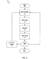
図4は、工程の開始402、液体の抜き取り404、液体の濾過および処理のうちの少なくともいずれか一方406、特性の測定408、液体の返送410、判断412、パラメーターの更新414、工程の終了416を含む体液から物質を濾過する濾過システムの使用方法400を示した図である。方法は、システム100とシステム300など、ある実施形態と共に用いられる。方法は、システム300について説明するが、当業者であれば、限定されるものではないが、システム100または複数のシステムの様々な組み合わせなど他のシステムと共に使用する為に工程を変更することができるであろう。
FIG. 4 illustrates a
本願発明に係る方法は、液体のある量に対して実施されるものとして説明するが、システムが、液体の連続的な流れに対しても動作し得る。つまり、システム300は、必ずしもある液体量を抜き取ってその液体が処理され戻されるのを待ってから次の液体量を抜き取らねばならないことはない。方法は、連続的な工程で進みうる。同様に、図4には、一連の逐次工程を示したが、説明する方法の工程は、同時に実施されてもよい。例えば、システム300は、図4に示した一部の工程または全工程を同時に実施することができる。例えば、システム300は、流体の抜き取ることと戻すことを同時に行うことができる。
Although the method of the present invention is described as being performed on a volume of liquid, the system may also operate on a continuous flow of liquid. That is, the
方法400は、開始402で始まる。この工程402は、システム300の1つ以上の構成要素を活性化することを含む、この工程402は、複数の準備工程を含むか、または複数の準備工程に続く。このような工程は、濾過の構成要素を導入することと、リザーバー112を選択しかつ準備することと、チューブ類114を導入することと、構成要素を較正することと、システム300の構成要素をプライミング(priming)することと、とその他の工程とを含む。
濾過の構成要素を導入する工程には、所望の結果と、特定のリザーバー112と、またはその他の考察とに基づいて特定の濾過の構成要素を選択することとが含まれる。例えば、方法400が、脳血管けいれんを起こした被験者に対して使用される場合には、施術の目的は、被験者のCSFから血球破壊産物を濾過することである。これは、リザーバー112にCSF、つまり液体を搬送する内腔を形成する。このように、特定の濾過の構成要素が、CSFから血液の構成成分を濾過する為に選択される。例えば、血液の構成成分の流れを妨害する大きさの孔であるが、透過液としてCSFがほぼ入れる程度の大きさにされた孔を有する膜258が、使用される。
The step of introducing filtration components may include selecting particular filtration components based on desired results,
リザーバー112を選択しかつ準備する工程には、特定のリザーバー112を選択することが含まれる。例えば、医療従事者は、体液を濾過することによって効果が得られる被験者を選択し、かつ液体を含むリザーバーを選択する。上述したように、これには、脳血管けいれんを起こした被験者が含まれる。リザーバー112を準備することは、リザーバー112にアクセスする手段として解剖学上の部位(例えば、図2Aに示した脊椎部分200など)を特定することと、その部位を消毒することと、施術の為にリザーバー112を準備することが含まれる。リザーバー112を選択すること、および準備することは、この用途についてまたは別の手段を通して説明したシステム、および方法に従って実行される。例えば、リザーバー112の選択と準備は、米国特許出願第62/038,998号明細書に記載の種々のシステムと方法に従って実施される。
The process of selecting and providing
チューブ類114を導入することには、システム300の様々な構成要素を接続することが含まれる。例えば、残留液出口106は、流量調整器118に接続され、流量調節器118は、取込口304に接続される。この工程には、リザーバー112から液体を抜き取り、かつリザーバー112に液体を戻すチューブ類114を導入することも含まれる。この工程には、液体を取込口104の中に引き入れて液体をリザーバー112に戻すことを可能にすべく、解剖学上の部位に複数の管腔を有するカテーテルを挿入して、リザーバー112をシステム300と流体接続状態に配置することが含まれる。
Introducing
構成要素を較正することには、システム300に使用する初期パラメーターを設定することが含まれる。この工程は、初期の流速、初期の圧力、およびその他の初期パラメーター、またはシステムの設定が含まれる。初期パラメーターは、限定されるものではないが、リザーバー112の推定液体量、被験者の健康状態、残留液の透過液に対する予測比率などの観察または予想された臨床測定に基づく。
Calibrating the components involves setting initial parameters for use with the
システム300をプライミング(priming)することには、システム300の構成要素の1つ以上にプライミング溶液を添加することが含まれる。システム300の構成に従って、プライミングは、1つ以上の構成要素を効率的に機能させるのに必要である。リザーバー112、液体、および被験者に基づいて、プライミングは、快適性または良好な健康状態を保証する為に必要である。ある用途では、システム300は、液体を戻す一方で、同時に液体を抜き取ることができる。これは、リザーバー112が比較的少量の液体を含む用途(例えば、CSFを濾過する間)、またはリザーバー112が量の相対変化に敏感である場合に特に有用である。使用される濾過の種類、施術時間の長さ、およびその他の因子によって、プライミング溶液は、施術中に失われた液体を補う為に濾過施術中に追加される。
Priming the
工程404では、液体がリザーバー112から抜き取られる。ある状況において、液体は、システム100内に配置されたポンプ、または装置を用いて抜き取られる。例えば、ポンプは、1つ以上の流量調整器118,318、フィルターシステム102,302(ポンプ222などの)および結合器116のうちの少なくとも1つの構成要素である。ポンプは、リザーバー112から液体を抜き取る際に使用される。
At
いくつかの実施形態では、流体がリザーバー112から抜き取られる速度は、約0.01mL/minと約100mL/minの間である。好ましい実施形態では、流体速度は、約0.1mL/minと約10mL/minの間である。しかしながら、抜き取られる量は、用途によってこれより多い場合もあれば、少ない場合もある。量は、以下に限定されるものではないが、抜き取られる液体の種類、液体の粘性、リザーバー112の中の液体量、およびその他の因子などの様々な因子によって異なる。液体の粘性は、経時的に変化し、かつ個別の被験者に依存する。例えば、CSFの粘性は、一般的なCSFを有する被験者と髄膜炎を発症した被験者では異なる。液体が一旦リザーバー112から抜き取られれば、液体は、チューブ類114を通り取込口104を介して濾過システム102の中に入る。
In some embodiments, the rate at which fluid is withdrawn from
工程406では、液体が濾過される。これには、液体を濾過システム102のフィルターに通す工程が含まれる。本開示では、接線流フィルターについて説明したが、これらが、必ずしも用いられるフィルターでなくてもよいし、または用いられる唯一のフィルターでなくともよい。例えば、濾過システム102には、以下に限定されるものではないが、接線流濾過、精密濾過、限外濾過、ナノ濾過、デッドエンドフィルター、デプスフィルター、およびその他の濾過装置または機構が含まれる。
At
濾過工程により、液体は残留液と透過液とに分離される。透過液は、透過液出口108を通って濾過システム102から出て、残留液は、残留液出口106を通って濾過システム102から出る。フィルターの構成、および方法400の目的により、ある実施では、透過液がリザーバー112に返送される。別の実施では、残留液がリザーバー112に返送される。残留液には、混入物質が含まれるか、またはリザーバー112に返送するにはふさわしくない状態である場合がある。
The filtration process separates the liquid into a retentate and a permeate . Permeate exits
ある実施形態では、例えば、図3に示すように、残留液は、別の濾過工程を通って再度濾過されることによって、または濾過の方向を逆転することにより同じフィルターを通って再度濾過されることによって、連続的に、または段階的に処理される。例えば、ある実施において、残留液は、流量調節器118に通され、追加の濾過の為に濾過システム302に入る。この濾過によって、残留液は、さらに、第2残留液と第2透過液とに分離される。第2透過液は、リザーバー112に返送するために透過液出口308から結合器116まで流れる。第2残留液は、さらに濾過されるか精製されうる。液体が十分に濾過されれば、残った残留液または混入物資は、分析、廃棄、保管、またはその他の用途のために流量調節器318に通されて容器310の中に入れられ、または代替的に又は追加的に、残った残留液は、任意の回数でさらに処理、処置、および濾過のうちの少なくともいずれか1つに付され、このさらに処理された液体は、直接的に、または別の液体と組み合わせてリザーバー112に送られる。
In some embodiments, for example, as shown in FIG. 3, the retentate is filtered again through the same filter by being filtered again through another filtration step or by reversing the direction of filtration. It can be processed continuously or step by step. For example, in one implementation, retentate is passed through
工程408では、液体、およびシステムのうちの少なくとも一方の特性が測定される。特性を測定することには、断続的または連続的にサンプリングすること、および興味ある特性またはパラメーターを監視することのうちの少なくともいずれか一方が含まれる。この工程408は、液体406の濾過後に行われるように示されているが、工程408は、有用なデータが収集される工程400の何れの時点において実行されてもよい。
At
ある実施形態では、特性の測定には、濾過前、濾過中、濾過後に、リザーバー112から抜き取った液体の特性を測定することが含まれる。測定した特性には、特定の混入物質、タンパク質、構成成分、マーカー、および存在するその他の流体成分の存在、または量が含まれる。別例では、残留液量に対する透過液量の比率、リザーバー112からの液体の流速、液体温度、液体の不透明性または透光性または透明性、残留液の絶対流体速度(absolute retentate flow rate)、およびリザーバー112への流体速度も測定される。システム300の性能特性も測定される。例えば、フィルター226の効率、フィルター226の状態(例えば、界面210を介して)、およびシステム300の性能を示すその他のマーカーなどである。
In some embodiments, measuring properties includes measuring properties of liquid withdrawn from
ある実施形態では、測定された特性には、被験者、または医療提供者による入力についての情報が含まれる。例えば、システム300は、血圧、心拍数、負荷、および被験者のその他の情報を監視する。定量的な特性に加えて、定性的な測定も行われる。例えば、被験者の不快感、およびその他の質が測定される。これらのデータ、およびその他のデータは、検出器224によって測定されること、およびシステム300に機能的に接続された入力装置、例えば、キーボード、タッチスクリーン、被験者監視装置、および入力を受け取る為のその他の装置などによってシステム内に入力されること、のうちの少なくともいずれか一方に付される。
In some embodiments, the measured characteristic includes information about input by the subject or healthcare provider. For example,
工程410では、液体がリザーバー112に返送される。ある実施形態では、液体は、濾過の完了後直ちにリザーバー112に返送される。ある実施形態では、液体の流速は、制御することができる。例えば、液体量は、結合器116、またはシステム300の別の領域において、リザーバー112に返送される前に緩衝される。緩衝は、液体の返送速度をなだらかすること、液体がある特定の温度に到達する時間を確保すること、ある特定の添加剤を流体内に混合する時間を確保すること、およびその他の理由の為に使用される。
At
ある実施形態では、液体をリザーバー112に返送する速度および圧力のうちの少なくともいずれか一方は、例えば、結合器116および流量調節器318のうちの少なくともいずれか一方によって調節される。例えば、液体の返送は、液体がリザーバー112の内部の恒常性を維持するような速度、または方法で返送されるように調節される。ある実施形態では、これは、液体が、システムから抜き取られるのと同じ速度で液体を返送することによってなしえる。ある実施形態では、液体は、抜き取られる流速とほぼ同じ速度で返送される。システムから抜き取られてシステムに返送される液体の量が同じでない場合もある。これは、リザーバーから大量の混入物質を除去した際に見られる。ある実施形態では、この違いは、追加的な液体を添加することによって補うことができる。
In some embodiments, the rate and/or pressure of liquid return to
ある実施形態では、ある特定の量の追加的な液体がリザーバー112に返送される。追加的な液体は、リザーバー112から抜き取られなかった液体、以前にリザーバー112から抜き取られた液体、異なるリザーバーから抜き取られた液体、人工的に形成された液体であり、つまり、工程404においてリザーバー112から抜き取られたものとは異なる。追加的な液体の返送は、例えば、濾過された液体を補償する為、特にリザーバー112が開始402時に少量の液体しか有していなかった場合に使用される。
In some embodiments, a certain amount of additional liquid is returned to
ある実施形態では、リザーバー112に返送する前に、1つ以上の治療薬が、液体に添加される。液体は、特定の薬剤で処理、または混合される。例えば、液体がCSFの場合、薬剤は、血管-脳関門を通過するように構成される。薬剤には、必ずしも以下に限定されるものではないが、抗生物質、神経成長因子、抗炎症薬、鎮痛剤、くも膜下腔を介して搬送されるように設計された薬剤、特定の病気(例えば、髄膜炎、アルツハイマー病、鬱病、慢性痛、およびその他の状態)に効果を奏するように設計された薬剤が含まれる。
In some embodiments, one or more therapeutic agents are added to the liquid prior to returning to
具体的な例として、リザーバー112は、あるCSFに対して既知または想定されるくも膜下腔、またはその他の腔所といった、被験者のCSFを含む腔所である。腔所は、CSFについて合計で約125mlを有するのみであり、レベルがある閾値以下、例えば、約85mlなどになれば、被験者は、不快な副作用を発症する。存在するCSFのうちの大部分が、有害な成分を含む場合には、透過液量は、少なくなり、リザーバー112内の流体レベルは閾値以下になる。この結果、システム300は、人工CSFやその他の好適な液体などの追加的な液体を返送して、返送される抜き取られたCSFの量と、リザーバー112の量を閾値以上に保つために返送が必要とされる量との間の乖離を調節する。
As a specific example,
ある実施形態では、液体の抜き取りと返送は、パルス様式で起こる。例えば、システム300は、ある量を抜き取ったあと追加の液体の抜き取りを停止する。抜き取られた液体は、濾過またはその他のシステムによって処理され、例えば、結合器116で緩衝される。緩衝後の濾過液体は、次の液体がリザーバー112から抜き取られる時とほぼ同じ速度およびほぼ同じ総量のうちの少なくともいずれか一方でリザーバー112に返送される。この工程により、システムは、リザーバー112の体積レベルを比較的一定に維持することができ、処理時間、例えば、リザーバー112から液体が抜き取られてからリザーバー112に返送されるまでの時間が長い状況において有用である。
In some embodiments, liquid withdrawal and return occurs in a pulsed fashion. For example, the
工程412では、判断が行われる。判断は、例えば、医療従事者、処理システム、またはこれらの組み合わせによって行われる。例えば、医療従事者が、測定した特性を解析して結果に到達する。別例では、処理装置208が測定した特性をアルゴリズム、またはその他の機構を使用して測定した特性を解析する。判断は、測定したパラメーター、タイマー、スケジュール、またはその他の機構に基づく。判断は、経時変化に対して、および特定の測定された特性に対処する為にシステム300のパラメーターを変更することに用いられる。
At step 412, a decision is made. Determinations are made, for example, by medical personnel, processing systems, or a combination thereof. For example, a medical practitioner analyzes the measured properties to arrive at a result. Alternatively, the
例えば、液体をリザーバー112から抜き取ること、および戻すことのうちの少なくともいずれか一方の流速について、判断がなされる。例えば、液体を抜き取る速度と液体を戻す速度とは、ほぼ同じであることが望ましい。特には、リザーバー112から抜き取られる液体が戻される液体よりも多い場合には、リザーバー112の液体量は、全体として減少する。これは、ある液体とあるリザーバー112にとって好ましくない。なぜなら、リザーバー112の量がある閾値を過ぎた場合、好ましくない副作用が生じるからである。例えば、抜き取られる液体がCSFの場合には、流速は、ヒト被験者から除去されるCSFの量が1時間あたり約5mLと約20mLの間を超えないようにされる。つまり、液体量は、1時間で開始時の元の量から約5mLから約20mL以上減少することがない。ある実施形態では、残留液の許容可能な流速範囲内で残留液の絶対流速を維持することが望ましい。ある実施形態では、閾値は、約0.10mL/minと約0.30mL/minの間である。ある実施形態では、閾値は、0.16mL/minである。ある実施形態では、閾値は、約0.20mL/minと約0.25mL/minの間である。しかしながら、ある状況では、別の量が好ましい場合がある。ある実施形態では、ポンプは、約1.0mL/minで動き、残留液の流速は、約0.25mL/minで、透過液の流速は、約0.75mL/minであり、約3対1の比率をなす。しかし、ポンプスピードが、約2.0mL/minに上げられ、残留液の流速が、0.25mL/minに固定されている場合には、透過液の流速は、1.75mL/minになり、約7対1の比率をなす。閾値範囲内で残留液の流速を維持することによって、比率は変化するものの、システムは、意図したように機能すると考えられる。
For example, a determination is made about the flow rate of liquid withdrawing and/or returning from
測定された特性に基づいて、抜き取り速度と返送速度の乖離を解決する最良の方法は、システムから失われる液体の全体量を減らす為に流速を下げることである。これにより、リザーバー112からの液体の純損失はあるものの、この損失は、よりゆっくりとした速度で生じる。速度が十分にゆっくりであれば、被験者の体は、この損失を補うのに十分な液体を産生することができる。
Based on the measured characteristics, the best way to resolve the withdrawal rate and return rate discrepancies is to reduce the flow rate in order to reduce the overall amount of liquid lost from the system. Although this results in a net loss of liquid from
例えば、濾過工程400の開始時において、液体が、大量の混入物質を含む結果、相対的に大量の物質が濾過して取り除かれて、返送される液体(例えば、透過液)の量が相対的に減少する。濾過または処理工程は連続的に行われる為、処理される液体量は、混入物がすでに濾過して取り除かれている(例えば、残留液)為に減少する。この状況では、比較的遅い流速で工程を開始して、濾過して取り除かれる液体の量が減少するのに従って流速を上昇させるという判断がなされる。加えて、この判断には、特定の濾過効果を達成すべく、フィルター226内部の流速および圧力のうちの少なくともいずれか一方を変更することが含まれる。
For example, at the beginning of the
別例では、測定された特性は、被験者が訴える不快感である。被験者のCSFを含む腔所からCSFを抜き取ることによって、脊椎性頭痛などのオーバードレナージ(overdrainage)の症状を生じうる。オーバードレナージの症状は、CSFの閾値量以上を抜き取らないことによって防止または解決することができる。しかしながら、特定の閾値とは、被験者ごとに異なる。したがって、予測閾値は、実際の閾値と異なっている可能性があり、被験者は、予想以上に早く症状を訴える可能性がある。不快感を訴える被験者に対する対応として、医療従事者は、工程のパラメーターを変更する必要があるかどうかを判断する。 In another example, the characteristic measured is the subject's reported discomfort. Withdrawing CSF from a CSF-containing cavity in a subject can produce symptoms of overdrainage, such as vertebral headaches. Symptoms of overdrainage can be prevented or resolved by not withdrawing more than a threshold amount of CSF. However, the specific threshold will vary from subject to subject. Therefore, the predicted threshold may differ from the actual threshold, and subjects may complain of symptoms sooner than expected. In response to a subject who complains of discomfort, the healthcare professional will determine if process parameters need to be changed.
ある実施形態では、工程412において、処理装置228および医療従事者のうちの少なくともいずれか一方は、工程が完了したかどうかを判断する。この時点では、フロー図は、終了工程416に移動する。ある別の実施形態では、工程412において、処理装置228および医療従事者のうちの少なくともいずれか一方は、工程が、ほぼ変化していないことを判断する。判断された場合には、フロー図は、工程404に戻る。別の実施形態では、工程412において、処理装置228および医療従事者のうちの少なくともいずれか一方は、工程の1つ以上のパラメーターを変更すべきであると判断する。判断された場合には、フロー図は、工程414に移動する。
In some embodiments, at step 412,
工程414では、システム300の1つ以上のパラメーターが工程412でなされた判断に応答して変更される。変更されたパラメーターには、流入速度、流出速度、緩衝サイズ、およびその他のパラメーターが含まれる。このようなパラメーターは、例えば、パラメーターを変更する為に、ポンプ222に信号を送信する処理装置206、またはシステムのその他の構成要素を介して変更される。ある実施形態では、パラメーターは、入力208で受け取った入力を介して手動で変更される。これには、医療従事者によって入力されたパラメーターも含まれる。ある実施形態では、パラメーターは、抜き取る量と返送する量の間の乖離に基づいて更新される。
At
ある実施形態において、パラメーターを更新する工程414には、液体の流れる方向を変更することが含まれる。例えば、システムは、複数の濾過システムを備え、液体は、液体の流れる方向を変更する為に、バルブまたはその他の機構を操作することによって方向づけられる。工程414には、ある濾過システムから、別の濾過システムに液体の流れを変更することが含まれる。これは、第2濾過システム(例えば、濾過システム302)が、第1濾過システム(例えば、濾過システム102)よりもある混入物質に対してより適しているとの判断に対する応答である。 In some embodiments, updating 414 the parameters includes changing the direction of liquid flow. For example, a system may include multiple filtration systems and liquid may be directed by manipulating valves or other mechanisms to change the direction of liquid flow. Step 414 includes diverting liquid flow from one filtration system to another filtration system. This is in response to determining that the second filtration system (eg, filtration system 302) is better suited for certain contaminants than the first filtration system (eg, filtration system 102).
ある実施形態において、パラメーターを更新する工程414には、リザーバー112においてチューブの位置決めを変更することが含まれる。例えば、1つ以上の入力流チューブ、または出力流チューブ114は、詰まるか、または性能が低下した状態で動作していることがある。それに応じて、チューブ類114は、性能が低下した状態を解消すべく、調整、または変更される。医療従事者は、光、アラーム、またはその他の表示によって問題を通知される。
In some embodiments, updating 414 parameters includes changing the positioning of the tube in
ある実施形態では、パラメーターを更新する工程414には、フィルター226などのシステム300の1つ以上の構成要素を洗浄すること、または変更することが含まれる。これは、例えば、背圧やポンプスピードを変更することによって達成される。
In some embodiments, updating 414 parameters includes cleaning or altering one or more components of
ある実施形態において、パラメーターを更新する工程414には、フィルター226、またはシステムのその他の構成要素が目詰まりしているか否かを判断するために、システムの特性を検出することが含まれる。検出された特性は、濾過システムの警告状態を読み取ることと、またはシステムの流速、またはシステムのその他のパラメーターの変更を伴わないフィルター圧力の上昇を検出すること、とが含まれる。システム300内において目詰まりがあると判断された場合には、フィルターの残留液ポートを通る流速が増加される。この流速の増加は、装置使用者またはシステムによって背圧弁が開かれることによる(例えば、流量調節器118,318の背圧弁)。弁が開かれた結果、1つ以上のフィルターの1つ以上の残留液ポートを通って廃棄物収集領域(例えば、容器110、310)に入る液体が急上昇する。液体が急上昇することにより、リザーバー112に戻る液体は、ゼロまたはマイナス速度にまで減少する。このように、流速を調節する装置使用者またはシステムは、このフィルターを浄化する機構の結果として得られる損失液体量、および患者に与えうる影響を考慮に入れることができる。
In some embodiments, updating the
ある実施形態では、パラメーターを更新する工程414には、図5に示した方法500のように、流速を調節する方法を動作させることが含まれる。方法500は、残留液、透過液、廃液、およびその他の液体のうちの少なくともいずれか1つの流れなどのシステムを通る液体の流れを調節する為に用いられる。液体の流量の調節方法は、流体の流れが流量閾値502以外であるか否かを判断することと、流圧が圧力閾値504以上であるか否かを判断することと、ポンプ506を止めることと、背圧弁508を締めることと、背圧弁510を緩めること(例えば、流量調節器118,318またはシステム内のいずれかの場所の背圧弁)とが含まれる。液体は、システム(例えば、システム100,300)を通って流れるが、システムの検出器は、液体の流速(液体が、容器110,310等の廃棄のために移動する際の速度)を検出して、それを閾値と比較する。液体の流速が、閾値と同じであるか、または閾値の範囲内である場合には、実質的な変更は何ら必要ない。液体の流速が閾値範囲以上であれば、方法は、工程504に進む。液体の流れが、閾値範囲以下である場合には、方法は、工程510に進む。流速の検出は、連続的または周期的に行われる。ある実施において、工程504,510への進行は、必ずしも流れの閾値外の流れを検出した際にすぐに生じなくともよい。そのかわり、方法は、流れが特定の回数(例えば、2回以上の廃棄流速のチェック)のチェックを行って閾値外になった後に、工程504,510に進む。ある実施形態では、液体の流速の閾値範囲は、約0.2mL/minと約0.25mL/minの間であるが、特定の実施によって、別の値が用いられてもよい。
In some embodiments, updating the
工程504は、液体の流れが、閾値範囲よりも大きくなった場合に選択される。この工程は、フィルター上またはフィルターの圧力が圧力閾値以上か否かを判断する。圧力が、閾値以上である場合には、方法は、工程506に移動してポンプを停止させる。圧力が閾値以上でない場合には、方法は、工程508に移動して背圧弁を閉めて工程502に戻る。ある実施形態では、圧力閾値は、1100mmHgであるが、別の閾値も考えられる。工程510は、流速が閾値以下の場合に選択される。この工程では、背圧弁は緩められ、方法は、工程502に戻る。 Step 504 is selected if the liquid flow is greater than the threshold range. This step determines whether the pressure on or in the filter is greater than or equal to the pressure threshold. If the pressure is greater than or equal to the threshold, the method moves to step 506 and stops the pump. If the pressure is not above the threshold, the method moves to step 508 to close the back pressure valve and returns to step 502 . In one embodiment, the pressure threshold is 1100 mmHg, although other thresholds are also contemplated. Step 510 is selected if the flow rate is below the threshold. At this step, the back pressure valve is loosened and the method returns to step 502 .
図4では、工程416において、工程は、終了する。工程が完了した後、複数の終末工程が実行される。終末工程は、以下に限定されるものではないが、被験者に包帯を施すこと、システム300の1つ以上の構成要素を分解すること、抜き取られた液体の量を解析すること、残留液を解析すること、およびその他の工程である。
In FIG. 4, at step 416, the process ends. After the process is completed, a number of terminal processes are performed. Terminal steps include, but are not limited to, dressing the subject, disassembling one or more components of the
本願発明の範囲内において、接続参照(例えば、添付され、結合され、付され、または接続された)には、構成要素の集合体間の中間部材、および構成要素間の相対移動が含まれる。上記の参照は、必ずしも2つの構成要素が直接的に接続されていることおよび互いに対して固定された関係にあることを示唆するものではない。例示的な図面は、単に例示することを目的としたものであって、添付の図面に示されている大きさ、位置、順序、及び相対的寸法は、変わる可能性がある。 Within the scope of the present invention, connection references (eg, attached, coupled, attached, or connected) include intermediate members between collections of components and relative movement between components. The above references do not necessarily imply that the two components are directly connected and in a fixed relationship to each other. The exemplary drawings are for illustrative purposes only and the size, position, order and relative dimensions shown in the accompanying drawings may vary.
上述した詳細な説明は、以下に請求項化された例示の実施形態についての構造および使用についての完全な説明を提供する。請求項化された発明についての様々な実施形態が、ある程度の具体性をもってまたは1つ以上の個別の実施形態を参照することによって説明されているが、当業者であれば、本願発明には、本願発明の主旨または範囲を逸脱することなく開示された実施形態に対して多数の変更形態を形成することができるであろう。したがって、別の実施形態も想定しうる。上述した説明に含まれ、かつ添付の図面に示されているすべての事項は、特定の実施形態についての単なる例示であって限定ではないと理解されたい。以下の請求項に定義される本願発明の基本的な要素から逸脱することなく、詳細または構造において変更することが可能である。 The above detailed description provides a complete description of the structure and use of the exemplary embodiments that are claimed below. While various embodiments of the claimed invention have been described with some degree of specificity or by reference to one or more separate embodiments, those skilled in the art will recognize that the present invention includes: Many modifications may be made to the disclosed embodiments without departing from the spirit or scope of the invention. Other embodiments are therefore also conceivable. It is to be understood that all matter contained in the above description and shown in the accompanying drawings is illustrative only and not limiting of particular embodiments. Changes may be made in detail or structure without departing from the essential elements of the invention as defined in the following claims.
Claims (10)
第1流速で被験者のCSFを含む腔所からCSFからなる液体を抜き取り、且つ、動作パラメーターセットに従って動作するように構成され、
前記濾過システムは、前記液体を透過液と残留液とに濾過する為の接線流フィルターと、濾過中に前記液体の特性を測定する為の検出器とを備え、前記特性は、残留液量に対する透過液量の比率からなり、前記透過液量は、前記フィルターの膜を通過する液体の体積であり、前記残留液量は、前記フィルターの膜を通過しない液体の体積であり、前記残留液量に対する透過液量の比率は濾過中に断続的又は連続的に監視され、
前記濾過システムは、前記透過液を第2流速で前記被験者のCSFを含む腔所に戻すように構成され、
前記濾過システムは、測定した前記特性が濾過中に予め定めた閾値を超えたとの判断に応答して、測定した前記特性に基づいて前記動作パラメーターセットのパラメーターを更新するように構成され、
前記パラメーターの更新は、前記第1流速と前記第2流速とを上昇させる、濾過システム。 A filtration system for filtering substances from the cerebrospinal fluid (CSF) of a human or animal subject comprising:
configured to withdraw fluid comprising CSF from a CSF-containing cavity of a subject at a first flow rate and operate according to a set of operating parameters;
The filtration system comprises a tangential flow filter for filtering the liquid into a permeate and a retentate, and a detector for measuring a property of the liquid during filtration, the property being relative to the retentate volume. Permeate volume ratio, wherein the permeate volume is the volume of liquid that passes through the membrane of the filter, the residual volume is the volume of liquid that does not pass through the membrane of the filter, and the residual volume is the ratio of permeate volume to volume is monitored intermittently or continuously during filtration,
the filtration system is configured to return the permeate to a CSF-containing cavity of the subject at a second flow rate;
the filtering system is configured to update parameters of the operating parameter set based on the measured characteristic in response to determining that the measured characteristic exceeds a predetermined threshold during filtering ;
The filtration system, wherein updating the parameter increases the first flow rate and the second flow rate.
前記濾過システムは、前記第2特性が、残留液の許容可能な流速の範囲である第2閾値を超えたか否かを判断するように構成され、且つ、
前記濾過システムは、前記残留液の絶対流速を前記残留液の許容可能な流速の範囲に戻すために前記動作パラメーターセットの第2パラメーターを更新するように構成されている、請求項1に記載の濾過システム。 further comprising a second detector for measuring a second property of the liquid, which is the absolute flow velocity of the residual liquid;
the filtration system is configured to determine whether the second characteristic exceeds a second threshold of a range of acceptable flow rates of retentate; and
2. The filtration system of claim 1, wherein the filtration system is configured to update a second parameter of the operating parameter set to return the absolute flow rate of the retentate to a range of acceptable retentate flow rates. filtration system.
Applications Claiming Priority (3)
| Application Number | Priority Date | Filing Date | Title |
|---|---|---|---|
| US201562201287P | 2015-08-05 | 2015-08-05 | |
| US62/201,287 | 2015-08-05 | ||
| PCT/US2016/036626 WO2017023419A1 (en) | 2015-08-05 | 2016-06-09 | Tangential flow filter system for the filtration of materials from biologic fluids |
Related Child Applications (1)
| Application Number | Title | Priority Date | Filing Date |
|---|---|---|---|
| JP2020061483A Division JP6995916B2 (en) | 2015-08-05 | 2020-03-30 | Tangent flow filter system for filtering substances from body fluids |
Publications (3)
| Publication Number | Publication Date |
|---|---|
| JP2018523524A JP2018523524A (en) | 2018-08-23 |
| JP2018523524A5 JP2018523524A5 (en) | 2021-10-07 |
| JP7166915B2 true JP7166915B2 (en) | 2022-11-08 |
Family
ID=57943990
Family Applications (2)
| Application Number | Title | Priority Date | Filing Date |
|---|---|---|---|
| JP2018505612A Active JP7166915B2 (en) | 2015-08-05 | 2016-06-09 | Tangential flow filter system for filtering substances from body fluids |
| JP2020061483A Active JP6995916B2 (en) | 2015-08-05 | 2020-03-30 | Tangent flow filter system for filtering substances from body fluids |
Family Applications After (1)
| Application Number | Title | Priority Date | Filing Date |
|---|---|---|---|
| JP2020061483A Active JP6995916B2 (en) | 2015-08-05 | 2020-03-30 | Tangent flow filter system for filtering substances from body fluids |
Country Status (8)
| Country | Link |
|---|---|
| US (2) | US20210077951A1 (en) |
| EP (2) | EP3331586B1 (en) |
| JP (2) | JP7166915B2 (en) |
| CN (1) | CN108367102B (en) |
| AU (3) | AU2016304020B2 (en) |
| CA (1) | CA2994669C (en) |
| ES (2) | ES2797223T3 (en) |
| WO (1) | WO2017023419A1 (en) |
Families Citing this family (4)
| Publication number | Priority date | Publication date | Assignee | Title |
|---|---|---|---|---|
| US10632237B2 (en) | 2006-10-09 | 2020-04-28 | Minnetronix, Inc. | Tangential flow filter system for the filtration of materials from biologic fluids |
| CA3078229A1 (en) * | 2017-10-05 | 2019-04-11 | Minnetronix, Inc. | Systems, catheters, and methods for treating along the central nervous system |
| WO2020010074A1 (en) * | 2018-07-02 | 2020-01-09 | Minnetronix Neuro, Inc. | Systems, catheters, and methods for treating along the central nervous system |
| WO2021231311A1 (en) * | 2020-05-11 | 2021-11-18 | Minnetronix Neuro, Inc. | Filtering cassettes and filtering systems |
Citations (4)
| Publication number | Priority date | Publication date | Assignee | Title |
|---|---|---|---|---|
| US4904237A (en) | 1988-05-16 | 1990-02-27 | Janese Woodrow W | Apparatus for the exchange of cerebrospinal fluid and a method of treating brain and spinal cord injuries |
| US20070246406A1 (en) | 2006-03-31 | 2007-10-25 | Dibel Kevin R | Tangential flow filtration apparatuses, systems, and processes for the separation of compounds |
| JP2010505556A (en) | 2006-10-09 | 2010-02-25 | ニューロフルーディクス, インコーポレイテッド | Cerebrospinal fluid purification system |
| WO2010123558A1 (en) | 2009-04-22 | 2010-10-28 | Neurofluidics, Inc. | Programmable system for conditioning of cerebrospinal fluid |
Family Cites Families (17)
| Publication number | Priority date | Publication date | Assignee | Title |
|---|---|---|---|---|
| US5726026A (en) * | 1992-05-01 | 1998-03-10 | Trustees Of The University Of Pennsylvania | Mesoscale sample preparation device and systems for determination and processing of analytes |
| EP0739240B1 (en) * | 1994-11-14 | 2004-06-16 | The Trustees Of The University Of Pennsylvania | Mesoscale sample preparation device and systems for determination and processing of analytes |
| US5980480A (en) * | 1996-07-11 | 1999-11-09 | Cs Fluids, Inc. | Method and apparatus for treating adult-onset dementia of the alzheimer's type |
| US6326044B1 (en) * | 1997-06-19 | 2001-12-04 | Tetra Laval Holdings & Finance S.A. | Filter apparatus and method for the production of sterile skimmed milk |
| US5897528A (en) * | 1998-04-30 | 1999-04-27 | Medtronic, Inc. | Filtered intracerebroventricular or intraspinal access port with direct cerebrospinal fluid access |
| US6875192B1 (en) * | 1998-11-10 | 2005-04-05 | Eunoe, Inc. | Devices and methods for removing cerebrospinal fluids from a patient's CSF space |
| EP1600186A1 (en) * | 1999-03-03 | 2005-11-30 | UAB Research Foundation | Direct central nervous system catheter and temperature control system |
| KR20020077351A (en) * | 1999-12-03 | 2002-10-11 | 뉴런 세러퓨틱스 인코포레이티드 | Method and apparatus for closed recirculation of synthetic cerebrospinal fluid |
| AU2003299890A1 (en) * | 2002-12-23 | 2004-07-22 | Medtronic, Inc. | Implantable drug delivery systems and methods |
| JP2010531142A (en) * | 2007-06-22 | 2010-09-24 | サークル バイオロジクス、 エルエルシー. | Liquid concentrator, autologous concentrated body fluid, and methods of use thereof |
| WO2009155384A1 (en) * | 2008-06-17 | 2009-12-23 | Georgia Tech Research Corporation | Superparamagnetic nanoparticles for removal of cells, pathogens or viruses |
| WO2011114260A1 (en) * | 2010-03-19 | 2011-09-22 | Pfizer Inc. | Cerebrospinal fluid purification system |
| US9827517B2 (en) * | 2011-01-25 | 2017-11-28 | President And Fellows Of Harvard College | Electrochemical carbon nanotube filter and method |
| US9220829B2 (en) * | 2011-03-09 | 2015-12-29 | Zvi Herschman | Implantable systems and methods for removing specific impurities from fluids such as blood |
| EP3052179B1 (en) * | 2013-10-01 | 2020-05-06 | École Polytechnique Fédérale De Lausanne (EPFL) | Systems for moving and circulating fluid to treat alzheimer's disease |
| US10092632B2 (en) * | 2014-05-15 | 2018-10-09 | Washington University | Vaccination against Cryptococcus |
| CN204352261U (en) * | 2014-12-31 | 2015-05-27 | 李思成 | Be mainly used in the modified form suction device used at Cerebral surgery |
-
2016
- 2016-06-09 ES ES16833454T patent/ES2797223T3/en active Active
- 2016-06-09 CA CA2994669A patent/CA2994669C/en active Active
- 2016-06-09 JP JP2018505612A patent/JP7166915B2/en active Active
- 2016-06-09 EP EP16833454.8A patent/EP3331586B1/en active Active
- 2016-06-09 AU AU2016304020A patent/AU2016304020B2/en active Active
- 2016-06-09 WO PCT/US2016/036626 patent/WO2017023419A1/en active Application Filing
- 2016-06-09 EP EP20171087.8A patent/EP3714915B1/en active Active
- 2016-06-09 ES ES20171087T patent/ES2906952T3/en active Active
- 2016-06-09 CN CN201680058286.6A patent/CN108367102B/en active Active
-
2019
- 2019-12-18 AU AU2019283901A patent/AU2019283901B2/en active Active
-
2020
- 2020-03-30 JP JP2020061483A patent/JP6995916B2/en active Active
- 2020-12-01 US US17/108,775 patent/US20210077951A1/en active Pending
-
2021
- 2021-08-18 AU AU2021218067A patent/AU2021218067B2/en active Active
-
2022
- 2022-12-15 US US18/082,152 patent/US20230120296A1/en active Pending
Patent Citations (4)
| Publication number | Priority date | Publication date | Assignee | Title |
|---|---|---|---|---|
| US4904237A (en) | 1988-05-16 | 1990-02-27 | Janese Woodrow W | Apparatus for the exchange of cerebrospinal fluid and a method of treating brain and spinal cord injuries |
| US20070246406A1 (en) | 2006-03-31 | 2007-10-25 | Dibel Kevin R | Tangential flow filtration apparatuses, systems, and processes for the separation of compounds |
| JP2010505556A (en) | 2006-10-09 | 2010-02-25 | ニューロフルーディクス, インコーポレイテッド | Cerebrospinal fluid purification system |
| WO2010123558A1 (en) | 2009-04-22 | 2010-10-28 | Neurofluidics, Inc. | Programmable system for conditioning of cerebrospinal fluid |
Also Published As
| Publication number | Publication date |
|---|---|
| CN108367102B (en) | 2021-04-30 |
| CN108367102A (en) | 2018-08-03 |
| US20210077951A1 (en) | 2021-03-18 |
| AU2021218067A1 (en) | 2021-09-09 |
| WO2017023419A1 (en) | 2017-02-09 |
| AU2019283901A1 (en) | 2020-01-23 |
| AU2016304020B2 (en) | 2019-09-19 |
| CA2994669C (en) | 2020-11-17 |
| EP3331586A1 (en) | 2018-06-13 |
| ES2797223T3 (en) | 2020-12-01 |
| EP3331586A4 (en) | 2019-04-03 |
| CA2994669A1 (en) | 2017-02-09 |
| AU2019283901B2 (en) | 2021-05-20 |
| ES2906952T3 (en) | 2022-04-21 |
| US20230120296A1 (en) | 2023-04-20 |
| JP6995916B2 (en) | 2022-01-17 |
| AU2021218067B2 (en) | 2023-03-16 |
| EP3714915A1 (en) | 2020-09-30 |
| EP3331586B1 (en) | 2020-04-29 |
| JP2020124526A (en) | 2020-08-20 |
| EP3714915B1 (en) | 2021-11-03 |
| JP2018523524A (en) | 2018-08-23 |
| AU2016304020A1 (en) | 2018-02-22 |
Similar Documents
| Publication | Publication Date | Title |
|---|---|---|
| US11529452B2 (en) | Tangential flow filter system for the filtration of materials from biologic fluids | |
| JP6995916B2 (en) | Tangent flow filter system for filtering substances from body fluids | |
| US10850235B2 (en) | Method for filtering cerebrospinal fluid (CSF) including monitoring CSF flow | |
| US11577060B2 (en) | Systems and methods for the conditioning of cerebrospinal fluid | |
| US10695545B2 (en) | Systems and methods for the conditioning of cerebrospinal fluid | |
| JP2004248844A (en) | Filter clogged status detecting method, and filter clogged status monitoring device, and head side system | |
| JP2017176847A5 (en) | ||
| JP2020124526A5 (en) | ||
| JP2017508443A (en) | Device for processing liquid media containing cells | |
| US20180110911A1 (en) | Blood purification apparatus and blood purification system | |
| CN117202946A (en) | Extracorporeal circuit for the carbon dioxide removal of blood of an organic fluid |
Legal Events
| Date | Code | Title | Description |
|---|---|---|---|
| A621 | Written request for application examination |
Free format text: JAPANESE INTERMEDIATE CODE: A621 Effective date: 20180221 |
|
| A977 | Report on retrieval |
Free format text: JAPANESE INTERMEDIATE CODE: A971007 Effective date: 20181218 |
|
| A131 | Notification of reasons for refusal |
Free format text: JAPANESE INTERMEDIATE CODE: A131 Effective date: 20181225 |
|
| A601 | Written request for extension of time |
Free format text: JAPANESE INTERMEDIATE CODE: A601 Effective date: 20190325 |
|
| A521 | Request for written amendment filed |
Free format text: JAPANESE INTERMEDIATE CODE: A523 Effective date: 20190419 |
|
| A131 | Notification of reasons for refusal |
Free format text: JAPANESE INTERMEDIATE CODE: A131 Effective date: 20191001 |
|
| A601 | Written request for extension of time |
Free format text: JAPANESE INTERMEDIATE CODE: A601 Effective date: 20200106 |
|
| A601 | Written request for extension of time |
Free format text: JAPANESE INTERMEDIATE CODE: A601 Effective date: 20200302 |
|
| A521 | Request for written amendment filed |
Free format text: JAPANESE INTERMEDIATE CODE: A523 Effective date: 20200330 |
|
| A131 | Notification of reasons for refusal |
Free format text: JAPANESE INTERMEDIATE CODE: A131 Effective date: 20200825 |
|
| A601 | Written request for extension of time |
Free format text: JAPANESE INTERMEDIATE CODE: A601 Effective date: 20201124 |
|
| A524 | Written submission of copy of amendment under article 19 pct |
Free format text: JAPANESE INTERMEDIATE CODE: A524 Effective date: 20210225 |
|
| A02 | Decision of refusal |
Free format text: JAPANESE INTERMEDIATE CODE: A02 Effective date: 20210316 |
|
| A524 | Written submission of copy of amendment under article 19 pct |
Free format text: JAPANESE INTERMEDIATE CODE: A524 Effective date: 20210716 |
|
| C60 | Trial request (containing other claim documents, opposition documents) |
Free format text: JAPANESE INTERMEDIATE CODE: C60 Effective date: 20210716 |
|
| A521 | Request for written amendment filed |
Free format text: JAPANESE INTERMEDIATE CODE: A821 Effective date: 20210716 |
|
| A911 | Transfer to examiner for re-examination before appeal (zenchi) |
Free format text: JAPANESE INTERMEDIATE CODE: A911 Effective date: 20210827 |
|
| C21 | Notice of transfer of a case for reconsideration by examiners before appeal proceedings |
Free format text: JAPANESE INTERMEDIATE CODE: C21 Effective date: 20210901 |
|
| A912 | Re-examination (zenchi) completed and case transferred to appeal board |
Free format text: JAPANESE INTERMEDIATE CODE: A912 Effective date: 20211001 |
|
| C211 | Notice of termination of reconsideration by examiners before appeal proceedings |
Free format text: JAPANESE INTERMEDIATE CODE: C211 Effective date: 20211005 |
|
| C22 | Notice of designation (change) of administrative judge |
Free format text: JAPANESE INTERMEDIATE CODE: C22 Effective date: 20211221 |
|
| C13 | Notice of reasons for refusal |
Free format text: JAPANESE INTERMEDIATE CODE: C13 Effective date: 20220201 |
|
| C22 | Notice of designation (change) of administrative judge |
Free format text: JAPANESE INTERMEDIATE CODE: C22 Effective date: 20220412 |
|
| A601 | Written request for extension of time |
Free format text: JAPANESE INTERMEDIATE CODE: A601 Effective date: 20220428 |
|
| C22 | Notice of designation (change) of administrative judge |
Free format text: JAPANESE INTERMEDIATE CODE: C22 Effective date: 20220531 |
|
| A521 | Request for written amendment filed |
Free format text: JAPANESE INTERMEDIATE CODE: A523 Effective date: 20220728 |
|
| C23 | Notice of termination of proceedings |
Free format text: JAPANESE INTERMEDIATE CODE: C23 Effective date: 20220906 |
|
| C03 | Trial/appeal decision taken |
Free format text: JAPANESE INTERMEDIATE CODE: C03 Effective date: 20221004 |
|
| C30A | Notification sent |
Free format text: JAPANESE INTERMEDIATE CODE: C3012 Effective date: 20221004 |
|
| A61 | First payment of annual fees (during grant procedure) |
Free format text: JAPANESE INTERMEDIATE CODE: A61 Effective date: 20221026 |
|
| R150 | Certificate of patent or registration of utility model |
Ref document number: 7166915 Country of ref document: JP Free format text: JAPANESE INTERMEDIATE CODE: R150 |