JP7166859B2 - Tripod type constant velocity universal joint - Google Patents
Tripod type constant velocity universal joint Download PDFInfo
- Publication number
- JP7166859B2 JP7166859B2 JP2018177657A JP2018177657A JP7166859B2 JP 7166859 B2 JP7166859 B2 JP 7166859B2 JP 2018177657 A JP2018177657 A JP 2018177657A JP 2018177657 A JP2018177657 A JP 2018177657A JP 7166859 B2 JP7166859 B2 JP 7166859B2
- Authority
- JP
- Japan
- Prior art keywords
- roller
- constant velocity
- velocity universal
- universal joint
- peripheral surface
- Prior art date
- Legal status (The legal status is an assumption and is not a legal conclusion. Google has not performed a legal analysis and makes no representation as to the accuracy of the status listed.)
- Active
Links
Images


Classifications
-
- F—MECHANICAL ENGINEERING; LIGHTING; HEATING; WEAPONS; BLASTING
- F16—ENGINEERING ELEMENTS AND UNITS; GENERAL MEASURES FOR PRODUCING AND MAINTAINING EFFECTIVE FUNCTIONING OF MACHINES OR INSTALLATIONS; THERMAL INSULATION IN GENERAL
- F16D—COUPLINGS FOR TRANSMITTING ROTATION; CLUTCHES; BRAKES
- F16D3/00—Yielding couplings, i.e. with means permitting movement between the connected parts during the drive
- F16D3/16—Universal joints in which flexibility is produced by means of pivots or sliding or rolling connecting parts
- F16D3/20—Universal joints in which flexibility is produced by means of pivots or sliding or rolling connecting parts one coupling part entering a sleeve of the other coupling part and connected thereto by sliding or rolling members
- F16D3/202—Universal joints in which flexibility is produced by means of pivots or sliding or rolling connecting parts one coupling part entering a sleeve of the other coupling part and connected thereto by sliding or rolling members one coupling part having radially projecting pins, e.g. tripod joints
- F16D3/205—Universal joints in which flexibility is produced by means of pivots or sliding or rolling connecting parts one coupling part entering a sleeve of the other coupling part and connected thereto by sliding or rolling members one coupling part having radially projecting pins, e.g. tripod joints the pins extending radially outwardly from the coupling part
- F16D3/2055—Universal joints in which flexibility is produced by means of pivots or sliding or rolling connecting parts one coupling part entering a sleeve of the other coupling part and connected thereto by sliding or rolling members one coupling part having radially projecting pins, e.g. tripod joints the pins extending radially outwardly from the coupling part having three pins, i.e. true tripod joints
-
- F—MECHANICAL ENGINEERING; LIGHTING; HEATING; WEAPONS; BLASTING
- F16—ENGINEERING ELEMENTS AND UNITS; GENERAL MEASURES FOR PRODUCING AND MAINTAINING EFFECTIVE FUNCTIONING OF MACHINES OR INSTALLATIONS; THERMAL INSULATION IN GENERAL
- F16D—COUPLINGS FOR TRANSMITTING ROTATION; CLUTCHES; BRAKES
- F16D3/00—Yielding couplings, i.e. with means permitting movement between the connected parts during the drive
- F16D3/16—Universal joints in which flexibility is produced by means of pivots or sliding or rolling connecting parts
- F16D3/20—Universal joints in which flexibility is produced by means of pivots or sliding or rolling connecting parts one coupling part entering a sleeve of the other coupling part and connected thereto by sliding or rolling members
- F16D3/202—Universal joints in which flexibility is produced by means of pivots or sliding or rolling connecting parts one coupling part entering a sleeve of the other coupling part and connected thereto by sliding or rolling members one coupling part having radially projecting pins, e.g. tripod joints
- F16D2003/2026—Universal joints in which flexibility is produced by means of pivots or sliding or rolling connecting parts one coupling part entering a sleeve of the other coupling part and connected thereto by sliding or rolling members one coupling part having radially projecting pins, e.g. tripod joints with trunnion rings, i.e. with tripod joints having rollers supported by a ring on the trunnion
Description
本発明は、トリポード型等速自在継手に関する。 The present invention relates to a tripod type constant velocity universal joint.
自動車の動力伝達系で使用されるドライブシャフトにおいては、中間軸のインボード側(車幅方向の中央側)に摺動式等速自在継手を結合し、アウトボード側(車幅方向の端部側)に固定式等速自在継手を結合する場合が多い。ここでいう摺動式等速自在継手は、二軸間の角度変位および軸方向相対移動の双方を許容するものであり、固定式等速自在継手は、二軸間での角度変位を許容するが、二軸間の軸方向相対移動は許容しないものである。 In the drive shaft used in the power transmission system of automobiles, a sliding constant velocity universal joint is connected to the inboard side (center side in the vehicle width direction) of the intermediate shaft, and the outboard side (end in the vehicle width direction) side) is often connected to a fixed constant velocity universal joint. The sliding constant velocity universal joint referred to here permits both angular displacement and axial relative movement between two axes, and the fixed constant velocity universal joint permits angular displacement between two axes. However, it does not allow relative axial movement between the two axes.
摺動式等速自在継手としてトリポート型等速自在継手が公知である。このトリポート型等速自在継手としては、シングルローラタイプとダブルローラタイプとが存在する。ダブルローラタイプは、外側継手部材のトラック溝に挿入されるローラと、トリポード部材の脚軸に外嵌して前記ローラを回転自在に支持するインナリングとを備えるものであり、シングルローラタイプに比べ、誘起スラスト(継手内部での部品間の摩擦により誘起される軸力)とスライド抵抗の低減を達成できるという利点を有する。ダブルローラタイプのトリポード型等速自在継手の一例が、例えば特許第3599618号公報に記載されている。 A tripod constant velocity universal joint is known as a sliding constant velocity universal joint. A single roller type and a double roller type exist as this tripod type constant velocity universal joint. The double roller type has a roller inserted into the track groove of the outer joint member, and an inner ring that fits on the leg shaft of the tripod member and supports the roller rotatably. , has the advantage of achieving reduced induced thrust (axial force induced by friction between parts inside the joint) and sliding resistance. An example of a double roller type tripod type constant velocity universal joint is described in Japanese Patent No. 3599618, for example.
従来のダブルローラタイプのトリポード型等速自在継手では、ローラの外周面は円弧を母線とする凸曲面とされ、トラック溝のローラ案内面はゴシックアーチ形状やテーパ形状とされている(特許文献1の段落0020および0021)。また、ローラとトラック溝の接触態様はアンギュラコンタクトとされている。 In a conventional double-roller type tripod type constant velocity universal joint, the outer peripheral surface of the roller is a convex curved surface with a circular arc as a generatrix, and the roller guide surface of the track groove has a Gothic arch shape or a tapered shape (Patent Document 1). paragraphs 0020 and 0021). Further, the contact mode between the roller and the track groove is angular contact.
このようにローラの外周面を、円弧を母線とする凸曲面とすると、トリポード型等速自在継手が作動角をとって回転する際に、図13に示すように、ローラ111とインナリング112とを含むユニット104(ローラユニット)が継手軸方向と直交する断面上で傾く左右傾きや、図14に示すように、ローラユニット104が継手軸方向と平行な断面上で傾く前後傾きを生じることがある。
When the outer peripheral surface of the roller is formed as a convex curved surface having a circular arc as a generatrix in this way, when the tripod type constant velocity universal joint rotates at an operating angle, the
左右傾きや前後傾きが発生すると、ローラ111とトラック溝105のローラ案内面106との転がり接触部で摺動抵抗が増大する。また、ローラ111の外径側の端面111aとトラック溝105の底とが接触し、あるいはローラ111の外周面とトラック溝105の非負荷側のローラ案内面106’とが接触することで(図13に回転方向を矢印で示す)、トルク伝達部以外での接触が生じ、誘起スラストやスライド抵抗が増大する。これらは何れも自動車のNVH特性を悪化させる要因となる。
When a lateral tilt or a longitudinal tilt occurs, the sliding resistance increases at the rolling contact portion between the
また、高速回転中に継手へのトルクが無負荷状態(あるいは無負荷に近い状態)になると、遠心力によりローラ111が外径側に押しつけられた際に、図15に示すように、ローラ111とローラ案内面106の間に生じた楔角で楔効果が発生し、摺動抵抗が大きくなることも懸念される。
Further, when the torque to the joint is in a no-load state (or a state close to no-load) during high-speed rotation, when the
なお、ローラの外周面を円筒面状に形成すれば左右傾きを抑えることができるが、図13や図14に示すように、外周面を非円筒面形状に形成する場合と比べ、前後傾きを生じ易くなるため、転がり摺動抵抗が却って増加する問題がある。 Incidentally, if the outer peripheral surface of the roller is formed in a cylindrical shape, the lateral inclination can be suppressed, but as shown in FIGS. Since it is likely to occur, there is a problem that the rolling and sliding resistance increases.
そこで、本発明は、ダブルローラタイプのトリポート型等速自在継手において、摺動抵抗、スライド抵抗、あるいは誘起スラストを低減することを目的とする。 SUMMARY OF THE INVENTION Accordingly, it is an object of the present invention to reduce sliding resistance, sliding resistance, or induced thrust in a double-roller tripod constant velocity universal joint.
以上の目的を達成するための技術的手段として、本発明は、円周方向の三カ所に軸方向に延びるトラック溝を備え、各トラック溝が円周方向に対向して配置された一対のローラ案内面を有する外側継手部材と、半径方向に突出した三つの脚軸を備えたトリポード部材と、前記トラック溝に挿入されたローラと、前記脚軸に外嵌され、前記ローラを回転自在に支持するインナリングとを備え、前記ローラが前記ローラ案内面に沿って前記外側継手部材の軸方向に移動可能に構成されたトリポード型等速自在継手において、前記ローラの外周面のうち、前記ローラの幅方向中心を挟む両側に円すい面状の円すい面部を設けると共に、前記円すい面部の間に円環部を設け、前記両側の円すい面部を前記円環部の接線上に配置し、前記円環部の曲率半径を前記ローラの最大半径よりも小さくし、前記ローラ案内面のうち、前記ローラの幅方向中心を挟む両側にテーパ面状のテーパ面部を設ける共に、当該テーパ面部の間に部分円筒面状の円筒面部を設け、前記両側のテーパ面部を前記円筒面部の接線上に配置し、前記ローラ外周面の円環部と前記ローラ案内面の円筒面部とが線接触することを特徴とするものである。 As a technical means for achieving the above object, the present invention provides a pair of rollers having track grooves extending axially at three locations in the circumferential direction, the track grooves being arranged to face each other in the circumferential direction. An outer joint member having a guide surface, a tripod member having three radially protruding leg shafts, rollers inserted into the track grooves, and fitted onto the leg shafts to rotatably support the rollers. In a tripod type constant velocity universal joint in which the roller is configured to be movable in the axial direction of the outer joint member along the roller guide surface, the outer peripheral surface of the roller includes Conical surface-shaped conical surface portions are provided on both sides sandwiching the center in the width direction, an annular portion is provided between the conical surface portions, the conical surface portions on both sides are arranged on a tangent line of the annular portion, and the annular portion is smaller than the maximum radius of the roller, tapered surface portions are provided on both sides of the roller guide surface sandwiching the center of the roller in the width direction, and a partial cylindrical surface is provided between the tapered surface portions. and the tapered surface portions on both sides are arranged on a tangential line of the cylindrical surface portion, and the annular portion of the outer peripheral surface of the roller and the cylindrical surface portion of the roller guide surface are in line contact. is.
かかる構成から、作動角をとった場合でも、ローラの円すい面部がローラ案内面のテーパ面部と線接触するため、ローラの左右傾きが抑制される。また、ローラの円環部とローラ案内面の円筒面部とが線接触するため、ローラの前後傾きが抑制される。これにより、ローラの姿勢変化に対する拘束力が高まるため、ローラをトラック溝に対して水平に保つことが可能となり、トルク伝達個所以外でのローラと外側継手部材の不要な接触を防止することができる。 With such a configuration, even when the operating angle is set, the conical surface portion of the roller is in line contact with the tapered surface portion of the roller guide surface, so the lateral inclination of the roller is suppressed. In addition, since the ring portion of the roller and the cylindrical surface portion of the roller guide surface are in line contact, the roller is prevented from tilting forward and backward. As a result, since the restraining force against the change in the posture of the roller is increased, it is possible to keep the roller horizontal to the track groove, and it is possible to prevent unnecessary contact between the roller and the outer joint member at locations other than torque transmission locations. .
ローラの円環部の曲率半径が大きすぎると、ローラの外周面の円すい長さを確保できず、左右傾きに対する抑制効果が不十分となる。その一方で、円環部の曲率半径が小さすぎると、円環部の幅が小さくなり、前後傾きに対する抑制効果が不十分となる。以上の観点から、ローラの外周面の円環部の曲率半径をRとして、0.2≦継手PCD/R≦0.3の範囲に設定するのが好ましい。 If the radius of curvature of the annular portion of the roller is too large, the conical length of the outer peripheral surface of the roller cannot be ensured, and the effect of suppressing lateral tilt becomes insufficient. On the other hand, if the radius of curvature of the annular portion is too small, the width of the annular portion becomes small, and the effect of suppressing the front-rear tilt becomes insufficient. From the above point of view, it is preferable to set the radius of curvature of the annular portion of the outer peripheral surface of the roller to the range of 0.2≦joint PCD/R≦0.3.
ローラ案内面のテーパ面部のテーパ角度と、ローラの外周面の円すい面部の円すい角度とは同じにすることができる。あるいは、ローラ案内面のテーパ面部のテーパ角度θ’を、ローラの外周面の円すい面部の円すい角度θよりも大きくし、ローラ外周面の円環部と前記ローラ案内面の円筒面部とを、トルク伝達中の前記外側継手部材の弾性変形により面接触させることもできる。 The taper angle of the tapered surface portion of the roller guide surface and the conical angle of the conical surface portion of the outer peripheral surface of the roller can be the same. Alternatively, the taper angle θ' of the tapered surface portion of the roller guide surface is made larger than the conical angle θ of the conical surface portion of the outer peripheral surface of the roller, and the annular portion of the roller outer peripheral surface and the cylindrical surface portion of the roller guide surface are adjusted to torque. Surface contact can also be achieved by elastic deformation of the outer joint member during transmission .
後者であれば、ローラの外周面の円環部と、ローラ案内面の円筒面部との間に隙間を形成し、この隙間をグリースの充填部として活用することができる。
この隙間は、等速自在継手に負荷される最大トルクの15%程度のトルクが負荷された際に、ローラ案内面の弾性変形により、この隙間が消失し、ローラの外周面とローラ案内面とが全面的に面接触するように設定することができる。
In the latter case, a gap is formed between the annular portion of the outer peripheral surface of the roller and the cylindrical surface portion of the roller guide surface, and this gap can be utilized as a grease filling portion.
This gap disappears due to elastic deformation of the roller guide surface when a torque of about 15% of the maximum torque applied to the constant velocity universal joint is applied. can be set to make full surface contact.
トリポード型等速自在継手の高速回転中にトルクが無負荷となり、遠心力でローラが外側継手部材の外径側に押し付けられた場合には、ローラの円すい面部とローラ案内面の継手外径側のテーパ面部が接触する。この際、ローラの円すい面部の円すい角度が小さすぎると、楔作用により両者が食い付いて摺動抵抗が増大する。また、円すい角度が大きすぎると、ローラ案内面との接触時のローラの中央寄りと幅面寄りの間で転がり周速差が大きくなり、転がり抵抗が増大する。また、接触荷重の増大による耐久性の低下も懸念される。以上の問題を回避するため、ローラの外周面の円すい面部の円すい角度θは15°以上25°以下にするのが好ましい。 When the torque is no load during high-speed rotation of the tripod type constant velocity universal joint and the roller is pressed against the outer diameter side of the outer joint member by centrifugal force, the conical surface of the roller and the roller guide surface on the outer diameter side of the joint are in contact with each other. At this time, if the conical angle of the conical surface portion of the roller is too small, the rollers bite into each other due to the wedging action, increasing the sliding resistance. Further, if the cone angle is too large, the difference in rolling peripheral speed between the roller near the center and the roller near the width surface at the time of contact with the roller guide surface increases, resulting in increased rolling resistance. In addition, there is concern about a decrease in durability due to an increase in contact load. In order to avoid the above problems, it is preferable that the conical angle .theta.
トリポード型等速自在継手としては、脚軸の外周面が、縦断面においてはストレートで、かつ横断面においては略楕円となる形状をなし、インナリングの内周面が凸曲面で形成されているものを用いることができる。 As a tripod type constant velocity universal joint, the outer peripheral surface of the leg shaft is straight in the longitudinal section and substantially elliptical in the horizontal section, and the inner peripheral surface of the inner ring is formed with a convex curved surface. can use things.
この他、脚軸の外周面が凸曲面で形成され、インナリングの内周面が円筒面で形成されているものや、脚軸の外周面が凸曲面で形成され、インナリングの内周面が凹曲面で形成されているもの、を用いることもできる。 In addition, the outer peripheral surface of the leg shaft is formed with a convex curved surface and the inner peripheral surface of the inner ring is formed with a cylindrical surface, or the outer peripheral surface of the leg shaft is formed with a convex curved surface and the inner peripheral surface of the inner ring. is formed with a concave curved surface.
本発明によれば、ダブルローラタイプのトリポート型等速自在継手において、摺動抵抗、スライド抵抗、あるいは誘起スラストを低減させることが可能となる。 According to the present invention, it is possible to reduce sliding resistance, sliding resistance, or induced thrust in a double-roller tripod constant velocity universal joint.
本発明に係るトリポード型等速自在継手の第一の実施形態を図1~図8に基づいて説明する。 A first embodiment of a tripod type constant velocity universal joint according to the present invention will be described with reference to FIGS. 1 to 8. FIG.
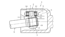
本実施形態のトリポード型等速自在継手1はダブルローラタイプである。なお、図1は、ダブルローラタイプのトリポード型等速自在継手を示す縦断面図であり、図2は図1のK-K線で矢視した部分横断面図である。図3は、図1のL-L線で矢視した横断面図であり、図4は、作動角をとった時のトリポード型等速自在継手を示す縦断面図である。図5~図9は、何れも図2の横断面図において、アウタリングとローラ案内面の接触部を拡大して示す断面図である。
The tripod type constant velocity
図1および図2に示すように、このトリポード型等速自在継手1は、外側継手部材2と、内側継手部材としてのトリポード部材3と、トルク伝達部材としてのローラユニット4とで主要部が構成されている。外側継手部材2は、一端が開口したカップ状をなし、内周面に軸方向に延びる3本の直線状トラック溝5が周方向等間隔に形成される。各トラック溝5には、外側継手部材2の円周方向に対向して配置され、それぞれ外側継手部材2の軸方向に延びるローラ案内面6が形成されている。外側継手部材2の内部には、トリポード部材3とローラユニット4が収容されている。
As shown in FIGS. 1 and 2, this tripod type constant velocity
トリポード部材3は、半径方向に突出した3本の脚軸7を有する。トリポード部材3は、中心孔8に形成された雌スプライン23にシャフト9に形成された雄スプライン24を嵌合させることで、シャフト9とトルク伝達可能に結合される。シャフト9の先端に装着した止め輪10をトリポード部材3の端面と係合させることで、トリポード部材3がシャフト9に対して軸方向に固定される。
The
ローラユニット4は、ローラであるアウタリング11と、このアウタリング11の内側に配置されて脚軸7に外嵌された円環状のインナリング12と、アウタリング11とインナリング12との間に介在された多数の針状ころ13とで主要部が構成されており、外側継手部材2のトラック溝5に収容されている。
The
インナリング12の内周面12aは凸曲面状、具体的にはインナリング12の軸線を含む縦断面において凸円弧状をなす。インナリング12、針状ころ13およびアウタリング11からなるローラユニット4は、ワッシャ14、15により分離しない構造となっている。
The inner
トリポード部材3の各脚軸7の外周面は、脚軸7の軸線O-Oを含んだ縦断面においてストレート形状をなす。また、図3に示すように、脚軸7の外周面は、脚軸7の軸線O-Oに直交する横断面において略楕円形状をなす。脚軸7の外周面は、継手の軸線と直交する方向、すなわち長軸aの方向でインナリング12の内周面12aと接触する。継手の軸線方向、すなわち短軸bの方向では、脚軸7の外周面とインナリング12の内周面12aとの間に隙間mが形成されている。
The outer peripheral surface of each
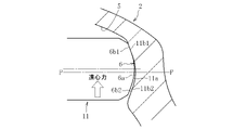
トリポード部材3の脚軸7に装着されたローラユニット4のアウタリング11は、針状ころ13を介してインナリング12によって回転自在に支持される。トリポード型等速自在継手1が作動角をとって回転すると、アウタリング11が外側継手部材2のトラック溝5のローラ案内面6上を転動する。脚軸7の横断面が略楕円形状であるので、図4に示すように、トリポード型等速自在継手1が作動角を取ったとき、外側継手部材2の軸線に対してトリポード部材3の軸線は傾斜するが、ローラユニット4はトリポード部材3の脚軸7の軸線に対して傾斜可能である。従って、ローラユニット4のアウタリング11とローラ案内面6とが斜交した状態になることを回避することができる。これにより、アウタリング11がローラ案内面6に対して正しく転動するので、誘起スラストやスライド抵抗の低減を図ることができ、継手の低振動化を実現することができる。
An
図5に拡大して示すように、アウタリング11の外周面は、断面凸形状に形成される。中央領域11aは、アウタリング11の幅方向(以下、ローラ幅方向と呼ぶ)の中心P-P上に位置する。また、中央領域11aのローラ幅方向両側に、中央領域11aと隣接して領域11b1,11b2が設けられる。
As shown in an enlarged view in FIG. 5, the outer peripheral surface of the
本実施形態において、中央領域11aは円環形状で形成される。中央領域11aの曲率半径R(図8参照)は、アウタリング11の最大半径よりも小さい。また、中央領域11aと隣接して設けられる領域11b1,11b2は、何れも母線形状をテーパ状の直線とした、脚軸7の軸線O-Oを中心とする円すい面状に形成される。以下では、中央領域11aを円環部と呼び、領域11b1,11b2を円すい面部と呼ぶ。
In this embodiment, the
図5の断面において、継手外径側の円すい面部11b1と継手内径側の円すい面部11b2は、ローラ幅方向の中心P-Pに対して線対称の関係にある。円環部11aと各円すい面部11b1,11b2は、各円すい面部11b1,11b2を円環部11aの接線上に配置することで滑らかに連続している。
In the cross section of FIG. 5, the conical surface portion 11b1 on the outer diameter side of the joint and the conical surface portion 11b2 on the inner diameter side of the joint are symmetrical with respect to the center PP in the roller width direction. The
ローラ案内面6は、中央領域6aと領域6b1,6b2とを有する断面凹形状に形成される。中央領域6aは、アウタリング11の幅方向(以下、ローラ幅方向と呼ぶ)の中心P-P上に位置する。また、領域6b1,6b2は、中央領域6aのローラ幅方向両側に、中央領域6aと隣接して設けられる。
The
本実施形態において、中央領域6aは継手軸方向に軸心を有する部分円筒面状に形成される。また、領域6b1,6b2は、何れも中央領域6aに対する接線上にあり、かつ継手軸方向に延びたテーパ面状に形成される。以下では、ローラ案内面6の中央領域6aを円筒面部と呼び、領域6b1,6b2をテーパ面部と呼ぶ。
In this embodiment, the
アウタリング11の外周面と同様に、ローラ案内面6の継手外径側となる円すい面部6b1と継手内径側となる円すい面部6b2は、ローラ幅方向の中心P-Pに対して線対称の関係にある。また、円筒面部6aと各テーパ面部6b1,6b2は滑らかに連続させる。
Similar to the outer peripheral surface of the
本実施形態では、図5に示す断面において、ローラ案内面6の円筒面部6aおよび円すい面部6b1,6b2の輪郭と、アウタリング11の円環部11aおよび円すい面部11b1,11b2の輪郭とを一致させ、ローラ案内面6の外周面を、アウタリング11の外周面の形状に倣った形状にしている。
In this embodiment, in the cross section shown in FIG. 5, the contours of the
以上に述べたアウタリング11の外周面およびローラ案内面6には、何れも高周波焼入れ等により表面硬化層が形成される。
A hardened surface layer is formed on the outer peripheral surface of the
以上の構成を有するトリポード型等速自在継手1の回転中は、負荷側において、アウタリング11の継手外径側の円すい面部11b1がローラ案内面6の継手外径側のテーパ面部6b1と線接触し、アウタリング11の継手内径側の円すい面部11b2がローラ案内面6の継手内径側のテーパ面6b2と線接触する。これにより、それぞれの接触部でトルク伝達が行われる。
During rotation of the tripod type constant velocity
作動角をとった場合でも、アウタリング11の円すい面部11b1,11b2がローラ案内面6のテーパ面部6b1,6b2と線接触するため、アウタリング11の左右傾きが抑制される。また、アウタリング11の円環部11aとローラ案内面6の円筒面部6aとが線接触するため、アウタリング11の前後傾きが抑制される。
Even when the operating angle is set, the conical surface portions 11b1 and 11b2 of the
これにより、アウタリング11の姿勢変化に対する拘束力が高まる。そのため、ローラユニット4をトラック溝5に対して水平に保つことが可能となり、トルク伝達個所以外でのアウタリング11と外側継手部材2の不要な接触を防止することができる。従って、誘起スラストあるいはスライド抵抗等の増大を回避し、自動車のNVH特性を改善することができる。
As a result, the restraining force against the posture change of the
トリポード型等速自在継手の高速回転中にトルクが無負荷となり、図6に示すように、遠心力でアウタリング11が外側継手部材2の外径側に押し付けられた場合には、アウタリング11の継手外径側の円すい面部11b1とローラ案内面6の継手外径側のテーパ面部6b1が接触する。その際の楔作用で両者が食い付くことによる摺動抵抗の増大を回避するため、アウタリング11の継手外径側の円すい面部11b1の円すい角度θ(図7参照)は、15°以上に設定するのが好ましい。円すい角度θは、脚軸7の軸線O-Oに対する円すい面部11b1,11b2の傾斜角度を意味する。
When the torque becomes unloaded during high-speed rotation of the tripod type constant velocity universal joint and the
その一方、円すい角度θが大きすぎると、ローラ案内面6との接触でアウタリング11の中央寄りと幅面寄りの間で転がり周速差が大きくなり、転がり抵抗が増大する。また、接触荷重の増大による耐久性の低下も懸念される。従って、上記円すい角度θは25°以下に設定するのが好ましい。 On the other hand, if the cone angle .theta. In addition, there is concern about a decrease in durability due to an increase in contact load. Therefore, it is preferable to set the cone angle θ to 25° or less.
なお、継手内径側の円すい面部11b2の円すい角度θについても、製作上の都合等から、継手外径側の円すい面部11b1の円すい角度θと同じ値に設定するのが好ましい。 The conical angle θ of the conical surface portion 11b2 on the inner diameter side of the joint is also preferably set to the same value as the conical angle θ of the conical surface portion 11b1 on the outer diameter side of the joint for convenience of manufacturing.
従って、アウタリング11の円すい面部11b1,11b2の円すい角度θは、15°以上25°以下の範囲(20°±5°)に設定するのが好ましい。 Therefore, it is preferable to set the conical angle .theta.
また、図8に示すアウタリング11の円環部11aの曲率半径Rが大きすぎると、アウタリング11の外周面の円すい長さを確保できず、左右傾きに対する抑制効果が不十分となる。その一方で、円環部11aの曲率半径Rが小さすぎると、円環部11aの幅が小さくなり、前後傾きに対する抑制効果が不十分となる。従って、円環部11の曲率半径Rは、継手PCDとの関係において、0.2≦R/継手PCD≦0.3の範囲内に設定するのが好ましい。この範囲であれば、アウタリング11の前後傾きと左右傾きをバランスよく抑制し、NVH特性の優れたトリポード型等速自在継手を提供することができる。
Further, if the curvature radius R of the
次に、本発明に係るトリポード型等速自在継手の第二の実施形態を図9および図10に基づいて説明する。なお、図9および図10は何れもアウタリング11とローラ案内面の接触部を拡大して示す断面図である。
Next, a second embodiment of a tripod type constant velocity universal joint according to the present invention will be described with reference to FIGS. 9 and 10. FIG. 9 and 10 are enlarged sectional views showing the contact portion between the
図9に示すように、第二の実施形態のトリポード型等速自在継手では、第一の実施形態と同様に、アウタリング11の外周面に円環部11aと円環部11aに滑らかにつながった円錐面部11b1,11b2とが形成される。また、ローラ案内面6に円筒面部6aと円筒面部6aに滑らかにつながったテーパ面部6b1,6b2とが形成される。
As shown in FIG. 9, in the tripod type constant velocity universal joint of the second embodiment, as in the first embodiment, the
その一方で、第二の実施形態では、図10に示すように、アウタリング11の円すい面部11b1,11b2の円すい角度θ(図面下側)よりも、ローラ案内面6のテーパ面部6b1,6b2のテーパ角度θ’を大きくしている(θ’>θ)。この際、テーパ角度θ’は、θ’=円すい角度θ+αとし、0<α≦2°程度に設定するのが好ましい。なお、テーパ角度θ’は、脚軸7の軸線O-Oに対するテーパ面部6b1,6b2の傾斜角度を意味する。
On the other hand, in the second embodiment, as shown in FIG. 10, the tapered surface portions 6b1 and 6b2 of the
係る構成から、アウタリング11の円環部11aとローラ案内面6の円筒面部6aとの間に隙間Cを形成し、この隙間Cをグリースの充填部として活用することができる。これによりアウタリング11の外周面とローラ案内面6との間に確実にグリースを介在させることが可能となり、トリポード型等速自在継手の耐久性を高めることができる。
With this configuration, a gap C is formed between the
かかる構成では、車両に装着されたトランスミッションの1速時における最大トルクの15%程度のトルクが負荷された時に、外側継手部材2の弾性変形により、隙間Cが消失し、アウタリング11の外周面とローラ案内面6とが全面的に面接触するように隙間を設定するのが好ましい。
In such a configuration, when a torque of about 15% of the maximum torque in the first speed of the transmission mounted on the vehicle is loaded, elastic deformation of the outer
また、この第二の実施形態においては、図9に示すように、アウタリング11のチャンファに隣接する円すい面部11b1,11b2の外端部に、円弧状のアール部11cが形成されている。このアール部11cの接線上に円すい面部11b1,11b2が位置する。このようなアール部11cを設けることにより、接触面圧を低減して、トリポード型等速自在継手の耐久性をさらに向上させることができる。
Further, in the second embodiment, as shown in FIG. 9, the outer end portions of the conical surface portions 11b1 and 11b2 adjacent to the chamfer of the
以上に説明した事項を除き、第二の実施形態の各部の構成や機能は第一の実施形態と共通するので、重複部分についての説明は省略する。 Except for the items described above, the configuration and function of each part of the second embodiment are the same as those of the first embodiment, so the description of overlapping parts will be omitted.
本発明は以上に述べた実施形態には限定されず、ダブルローラタイプであれば、その他の構成を有するトリポード型等速自在継手に広く適用することができる。 The present invention is not limited to the embodiments described above, and can be widely applied to tripod-type constant velocity universal joints having other configurations as long as they are of the double roller type.
例えば、図11に示す実施形態のように、脚軸7の外周面7aを凸曲面(例えば断面凸円弧状)に形成し、インナリング12の内周面12aを円筒面状に形成することもできる。また、図12に示す実施形態のように、脚軸7の外周面7aを凸曲面(例えば断面凸円弧状)に形成し、インナリング12の内周面12aを脚軸外周面7aと嵌合する凹球面に形成することもできる(アウタリングの内径両端部に鍔を設けることにより、ワッシャ14,15を不要とすることもできる)。何れの実施形態でも、以上に述べた相違点を除き、図1~図10で述べた第一実施形態および第二実施形態と共通する部材および要素には同一の参照番号を付して重複説明を省略する。
For example, as in the embodiment shown in FIG. 11, the outer
以上に述べたトリポード型等速自在継手1は、自動車のドライブシャフトに限って適用されるものではなく、自動車や産業機器等の動力伝達経路に広く用いることができる。
The tripod type constant velocity
1 トリポード型等速自在継手
2 外側継手部材
3 トリポード部材
4 ローラユニット
5 トラック溝
6 ローラ案内面
6a 円筒面部
6b1 テーパ面部
6b2 テーパ面部
7 脚軸
7a 脚軸の外周面
8 中心孔
11 ローラ(アウタリング)
11a 円環部
11b1 円すい面部
11b2 円すい面部
12 インナリング
O 脚軸の軸線
P ローラ幅方向中心
θ 円すい角度
1 tripod type constant velocity
11a Annular portion 11b1 Conical surface portion 11b2
Claims (9)
前記ローラの外周面のうち、前記ローラの幅方向中心を挟む両側に円すい面状の円すい面部を設けると共に、前記円すい面部の間に円環部を設け、前記両側の円すい面部を前記円環部の接線上に配置し、前記円環部の曲率半径を前記ローラの最大半径よりも小さくし、
前記ローラ案内面のうち、前記ローラの幅方向中心を挟む両側にテーパ面状のテーパ面部を設ける共に、当該テーパ面部の間に部分円筒面状の円筒面部を設け、前記両側のテーパ面部を前記円筒面部の接線上に配置し、
前記ローラ外周面の円環部と前記ローラ案内面の円筒面部とが線接触することを特徴とするトリポード型等速自在継手。 An outer joint member provided with axially extending track grooves at three locations in the circumferential direction, each track groove having a pair of roller guide surfaces arranged facing each other in the circumferential direction, and three radially protruding legs. a tripod member having a shaft; a roller inserted into the track groove; In the tripod type constant velocity universal joint configured to be movable in the axial direction of the outer joint member,
Conical surface-shaped conical surface portions are provided on both sides sandwiching the center in the width direction of the roller on the outer peripheral surface of the roller, and an annular portion is provided between the conical surface portions, and the conical surface portions on both sides are provided with the annular portion. and the radius of curvature of the annular portion is smaller than the maximum radius of the roller,
Of the roller guide surface, tapered surface portions are provided on both sides sandwiching the center of the roller in the width direction, and a cylindrical surface portion having a partially cylindrical surface shape is provided between the tapered surface portions. Placed on the tangent line of the cylindrical surface,
A tripod type constant velocity universal joint, wherein an annular portion of the roller outer peripheral surface and a cylindrical surface portion of the roller guide surface are in line contact.
0.2≦R/継手PCD≦0.3にした請求項1に記載のトリポード型等速自在継手。 Assuming that the radius of curvature of the annular portion of the outer peripheral surface of the roller is R,
2. The tripod type constant velocity universal joint according to claim 1, wherein 0.2≤R/joint PCD≤0.3.
前記ローラの外周面のうち、前記ローラの幅方向中心を挟む両側に円すい面状の円すい面部を設けると共に、前記円すい面部の間に円環部を設け、前記両側の円すい面部を前記円環部の接線上に配置し、前記円環部の曲率半径を前記ローラの最大半径よりも小さくし、
前記ローラ案内面のうち、前記ローラの幅方向中心を挟む両側にテーパ面状のテーパ面部を設ける共に、当該テーパ面部の間に部分円筒面状の円筒面部を設け、前記両側のテーパ面部を前記円筒面部の接線上に配置し、
前記ローラ案内面のテーパ面部のテーパ角度θ’を、前記ローラの外周面の円すい面部の円すい角度θよりも大きくし、
前記ローラ外周面の円環部と前記ローラ案内面の円筒面部とが、トルク伝達中の前記外側継手部材の弾性変形により面接触することを特徴とするトリポード型等速自在継手。 An outer joint member provided with axially extending track grooves at three locations in the circumferential direction, each track groove having a pair of roller guide surfaces arranged facing each other in the circumferential direction, and three radially protruding legs. a tripod member having a shaft; a roller inserted into the track groove; In the tripod type constant velocity universal joint configured to be movable in the axial direction of the outer joint member,
Conical surface-shaped conical surface portions are provided on both sides sandwiching the center in the width direction of the roller on the outer peripheral surface of the roller, and an annular portion is provided between the conical surface portions, and the conical surface portions on both sides are provided with the annular portion. and the radius of curvature of the annular portion is smaller than the maximum radius of the roller,
Of the roller guide surface, tapered surface portions are provided on both sides sandwiching the center of the roller in the width direction, and a cylindrical surface portion having a partially cylindrical surface shape is provided between the tapered surface portions. Placed on the tangent line of the cylindrical surface,
making the taper angle θ′ of the tapered surface portion of the roller guide surface larger than the conical angle θ of the conical surface portion of the outer peripheral surface of the roller ;
A tripod type constant velocity universal joint, wherein the annular portion of the roller outer peripheral surface and the cylindrical surface portion of the roller guide surface come into surface contact due to elastic deformation of the outer joint member during torque transmission .
前記インナリングの内周面が凸曲面で形成されている請求項1~6の何れか1項に記載のトリポード型等速自在継手。 The outer peripheral surface of the leg shaft has a shape that is straight in the vertical section and substantially elliptical in the horizontal section,
The tripod type constant velocity universal joint according to any one of claims 1 to 6, wherein the inner peripheral surface of the inner ring is formed with a convex curved surface.
Priority Applications (1)
| Application Number | Priority Date | Filing Date | Title |
|---|---|---|---|
| JP2018177657A JP7166859B2 (en) | 2018-09-21 | 2018-09-21 | Tripod type constant velocity universal joint |
Applications Claiming Priority (1)
| Application Number | Priority Date | Filing Date | Title |
|---|---|---|---|
| JP2018177657A JP7166859B2 (en) | 2018-09-21 | 2018-09-21 | Tripod type constant velocity universal joint |
Publications (2)
| Publication Number | Publication Date |
|---|---|
| JP2020046063A JP2020046063A (en) | 2020-03-26 |
| JP7166859B2 true JP7166859B2 (en) | 2022-11-08 |
Family
ID=69901085
Family Applications (1)
| Application Number | Title | Priority Date | Filing Date |
|---|---|---|---|
| JP2018177657A Active JP7166859B2 (en) | 2018-09-21 | 2018-09-21 | Tripod type constant velocity universal joint |
Country Status (1)
| Country | Link |
|---|---|
| JP (1) | JP7166859B2 (en) |
Families Citing this family (2)
| Publication number | Priority date | Publication date | Assignee | Title |
|---|---|---|---|---|
| CN115698531A (en) * | 2020-06-01 | 2023-02-03 | Ntn株式会社 | Tripod type constant velocity universal joint |
| WO2024017468A1 (en) * | 2022-07-20 | 2024-01-25 | Gkn Driveline International Gmbh | Tripod joint and inner joint part of a tripod joint |
Citations (4)
| Publication number | Priority date | Publication date | Assignee | Title |
|---|---|---|---|---|
| JP2000154832A (en) | 1998-11-17 | 2000-06-06 | Ntn Corp | Constant velocity universal joint |
| JP2002327773A (en) | 2001-05-07 | 2002-11-15 | Ntn Corp | Uniform universal coupling |
| JP3599618B2 (en) | 1999-03-05 | 2004-12-08 | Ntn株式会社 | Constant velocity universal joint |
| JP2006112495A (en) | 2004-10-13 | 2006-04-27 | Toyoda Mach Works Ltd | Uniform joint |
-
2018
- 2018-09-21 JP JP2018177657A patent/JP7166859B2/en active Active
Patent Citations (4)
| Publication number | Priority date | Publication date | Assignee | Title |
|---|---|---|---|---|
| JP2000154832A (en) | 1998-11-17 | 2000-06-06 | Ntn Corp | Constant velocity universal joint |
| JP3599618B2 (en) | 1999-03-05 | 2004-12-08 | Ntn株式会社 | Constant velocity universal joint |
| JP2002327773A (en) | 2001-05-07 | 2002-11-15 | Ntn Corp | Uniform universal coupling |
| JP2006112495A (en) | 2004-10-13 | 2006-04-27 | Toyoda Mach Works Ltd | Uniform joint |
Also Published As
| Publication number | Publication date |
|---|---|
| JP2020046063A (en) | 2020-03-26 |
Similar Documents
| Publication | Publication Date | Title |
|---|---|---|
| JP3599618B2 (en) | Constant velocity universal joint | |
| JP7166859B2 (en) | Tripod type constant velocity universal joint | |
| US5788577A (en) | Homokinetic universal joint having decreased induced thrust | |
| US20090011843A1 (en) | Constant Velocity Joint of Tripod Type | |
| EP1253337B1 (en) | Constant velocity joint | |
| US8608578B2 (en) | Constant velocity joint of tripod type | |
| US7217194B2 (en) | Constant velocity universal joint | |
| US20060105845A1 (en) | Synchronized sliding joint | |
| US7160193B2 (en) | Constant velocity universal joint | |
| JP2018155378A (en) | Tripod type constant velocity universal joint | |
| JP2008261391A (en) | Tripod type constant velocity universal joint | |
| JP5625534B2 (en) | Sliding tripod type constant velocity joint | |
| KR20070025956A (en) | Tripod type constant velocity universal joint | |
| JP2018155379A (en) | Tripod type constant velocity universal joint | |
| JP2008190621A (en) | Tripod type constant velocity universal joint | |
| JP2002081459A (en) | Constant velocity universal joint | |
| WO2021246129A1 (en) | Tripod-type constant-velocity universal joint | |
| WO2023047930A1 (en) | Tripod-type constant-velocity universal joint | |
| WO2023136094A1 (en) | Tripod-type constant-velocity universal joint | |
| JP3889192B2 (en) | Constant velocity universal joint | |
| WO2023189289A1 (en) | Tripod-type constant-velocity universal joint | |
| WO2023032634A1 (en) | Tripod-type constant velocity universal joint | |
| JP4574242B2 (en) | Tripod type constant velocity universal joint | |
| JP6904891B2 (en) | Vehicle constant velocity universal joint | |
| JP2021188742A (en) | Tripod-type constant velocity universal joint |
Legal Events
| Date | Code | Title | Description |
|---|---|---|---|
| A621 | Written request for application examination |
Free format text: JAPANESE INTERMEDIATE CODE: A621 Effective date: 20210311 |
|
| A977 | Report on retrieval |
Free format text: JAPANESE INTERMEDIATE CODE: A971007 Effective date: 20211021 |
|
| A131 | Notification of reasons for refusal |
Free format text: JAPANESE INTERMEDIATE CODE: A131 Effective date: 20211029 |
|
| A521 | Request for written amendment filed |
Free format text: JAPANESE INTERMEDIATE CODE: A523 Effective date: 20211217 |
|
| A131 | Notification of reasons for refusal |
Free format text: JAPANESE INTERMEDIATE CODE: A131 Effective date: 20220408 |
|
| A521 | Request for written amendment filed |
Free format text: JAPANESE INTERMEDIATE CODE: A523 Effective date: 20220603 |
|
| TRDD | Decision of grant or rejection written | ||
| A01 | Written decision to grant a patent or to grant a registration (utility model) |
Free format text: JAPANESE INTERMEDIATE CODE: A01 Effective date: 20221006 |
|
| A61 | First payment of annual fees (during grant procedure) |
Free format text: JAPANESE INTERMEDIATE CODE: A61 Effective date: 20221026 |
|
| R150 | Certificate of patent or registration of utility model |
Ref document number: 7166859 Country of ref document: JP Free format text: JAPANESE INTERMEDIATE CODE: R150 |