JP7166327B2 - Inhalers and methods of using and manufacturing inhalers - Google Patents
Inhalers and methods of using and manufacturing inhalers Download PDFInfo
- Publication number
- JP7166327B2 JP7166327B2 JP2020500019A JP2020500019A JP7166327B2 JP 7166327 B2 JP7166327 B2 JP 7166327B2 JP 2020500019 A JP2020500019 A JP 2020500019A JP 2020500019 A JP2020500019 A JP 2020500019A JP 7166327 B2 JP7166327 B2 JP 7166327B2
- Authority
- JP
- Japan
- Prior art keywords
- flap
- annular member
- inhaler
- compartment
- conduit
- Prior art date
- Legal status (The legal status is an assumption and is not a legal conclusion. Google has not performed a legal analysis and makes no representation as to the accuracy of the status listed.)
- Active
Links
Images

Classifications
-
- A—HUMAN NECESSITIES
- A61—MEDICAL OR VETERINARY SCIENCE; HYGIENE
- A61M—DEVICES FOR INTRODUCING MEDIA INTO, OR ONTO, THE BODY; DEVICES FOR TRANSDUCING BODY MEDIA OR FOR TAKING MEDIA FROM THE BODY; DEVICES FOR PRODUCING OR ENDING SLEEP OR STUPOR
- A61M15/00—Inhalators
- A61M15/0001—Details of inhalators; Constructional features thereof
- A61M15/0013—Details of inhalators; Constructional features thereof with inhalation check valves
- A61M15/0015—Details of inhalators; Constructional features thereof with inhalation check valves located upstream of the dispenser, i.e. not traversed by the product
-
- A—HUMAN NECESSITIES
- A61—MEDICAL OR VETERINARY SCIENCE; HYGIENE
- A61M—DEVICES FOR INTRODUCING MEDIA INTO, OR ONTO, THE BODY; DEVICES FOR TRANSDUCING BODY MEDIA OR FOR TAKING MEDIA FROM THE BODY; DEVICES FOR PRODUCING OR ENDING SLEEP OR STUPOR
- A61M15/00—Inhalators
- A61M15/0001—Details of inhalators; Constructional features thereof
- A61M15/0021—Mouthpieces therefor
-
- A—HUMAN NECESSITIES
- A61—MEDICAL OR VETERINARY SCIENCE; HYGIENE
- A61M—DEVICES FOR INTRODUCING MEDIA INTO, OR ONTO, THE BODY; DEVICES FOR TRANSDUCING BODY MEDIA OR FOR TAKING MEDIA FROM THE BODY; DEVICES FOR PRODUCING OR ENDING SLEEP OR STUPOR
- A61M15/00—Inhalators
- A61M15/0028—Inhalators using prepacked dosages, one for each application, e.g. capsules to be perforated or broken-up
- A61M15/0045—Inhalators using prepacked dosages, one for each application, e.g. capsules to be perforated or broken-up using multiple prepacked dosages on a same carrier, e.g. blisters
- A61M15/0046—Inhalators using prepacked dosages, one for each application, e.g. capsules to be perforated or broken-up using multiple prepacked dosages on a same carrier, e.g. blisters characterized by the type of carrier
- A61M15/0048—Inhalators using prepacked dosages, one for each application, e.g. capsules to be perforated or broken-up using multiple prepacked dosages on a same carrier, e.g. blisters characterized by the type of carrier the dosages being arranged in a plane, e.g. on diskettes
-
- A—HUMAN NECESSITIES
- A61—MEDICAL OR VETERINARY SCIENCE; HYGIENE
- A61M—DEVICES FOR INTRODUCING MEDIA INTO, OR ONTO, THE BODY; DEVICES FOR TRANSDUCING BODY MEDIA OR FOR TAKING MEDIA FROM THE BODY; DEVICES FOR PRODUCING OR ENDING SLEEP OR STUPOR
- A61M15/00—Inhalators
- A61M15/0065—Inhalators with dosage or measuring devices
- A61M15/0068—Indicating or counting the number of dispensed doses or of remaining doses
- A61M15/007—Mechanical counters
- A61M15/0071—Mechanical counters having a display or indicator
- A61M15/0075—Mechanical counters having a display or indicator on a disc
-
- A—HUMAN NECESSITIES
- A61—MEDICAL OR VETERINARY SCIENCE; HYGIENE
- A61M—DEVICES FOR INTRODUCING MEDIA INTO, OR ONTO, THE BODY; DEVICES FOR TRANSDUCING BODY MEDIA OR FOR TAKING MEDIA FROM THE BODY; DEVICES FOR PRODUCING OR ENDING SLEEP OR STUPOR
- A61M15/00—Inhalators
- A61M15/0001—Details of inhalators; Constructional features thereof
- A61M15/0021—Mouthpieces therefor
- A61M15/0025—Mouthpieces therefor with caps
- A61M15/0026—Hinged caps
-
- A—HUMAN NECESSITIES
- A61—MEDICAL OR VETERINARY SCIENCE; HYGIENE
- A61M—DEVICES FOR INTRODUCING MEDIA INTO, OR ONTO, THE BODY; DEVICES FOR TRANSDUCING BODY MEDIA OR FOR TAKING MEDIA FROM THE BODY; DEVICES FOR PRODUCING OR ENDING SLEEP OR STUPOR
- A61M15/00—Inhalators
- A61M15/0028—Inhalators using prepacked dosages, one for each application, e.g. capsules to be perforated or broken-up
- A61M15/003—Inhalators using prepacked dosages, one for each application, e.g. capsules to be perforated or broken-up using capsules, e.g. to be perforated or broken-up
- A61M15/0043—Non-destructive separation of the package, e.g. peeling
-
- A—HUMAN NECESSITIES
- A61—MEDICAL OR VETERINARY SCIENCE; HYGIENE
- A61M—DEVICES FOR INTRODUCING MEDIA INTO, OR ONTO, THE BODY; DEVICES FOR TRANSDUCING BODY MEDIA OR FOR TAKING MEDIA FROM THE BODY; DEVICES FOR PRODUCING OR ENDING SLEEP OR STUPOR
- A61M15/00—Inhalators
- A61M15/0091—Inhalators mechanically breath-triggered
-
- A—HUMAN NECESSITIES
- A61—MEDICAL OR VETERINARY SCIENCE; HYGIENE
- A61M—DEVICES FOR INTRODUCING MEDIA INTO, OR ONTO, THE BODY; DEVICES FOR TRANSDUCING BODY MEDIA OR FOR TAKING MEDIA FROM THE BODY; DEVICES FOR PRODUCING OR ENDING SLEEP OR STUPOR
- A61M2202/00—Special media to be introduced, removed or treated
- A61M2202/06—Solids
- A61M2202/062—Desiccants
-
- A—HUMAN NECESSITIES
- A61—MEDICAL OR VETERINARY SCIENCE; HYGIENE
- A61M—DEVICES FOR INTRODUCING MEDIA INTO, OR ONTO, THE BODY; DEVICES FOR TRANSDUCING BODY MEDIA OR FOR TAKING MEDIA FROM THE BODY; DEVICES FOR PRODUCING OR ENDING SLEEP OR STUPOR
- A61M2202/00—Special media to be introduced, removed or treated
- A61M2202/06—Solids
- A61M2202/064—Powder
Landscapes
- Health & Medical Sciences (AREA)
- Engineering & Computer Science (AREA)
- Life Sciences & Earth Sciences (AREA)
- Anesthesiology (AREA)
- Pulmonology (AREA)
- Biomedical Technology (AREA)
- Heart & Thoracic Surgery (AREA)
- Hematology (AREA)
- Bioinformatics & Cheminformatics (AREA)
- Animal Behavior & Ethology (AREA)
- General Health & Medical Sciences (AREA)
- Public Health (AREA)
- Veterinary Medicine (AREA)
- Biophysics (AREA)
- Medical Preparation Storing Or Oral Administration Devices (AREA)
- Medicinal Preparation (AREA)
Description
関連出願の相互参照
本出願は、「METHODS AND DEVICES FOR FACILITATING DESIRABLE POWDERED DOSE RING POCKET CAVITY AIR FLOW」と題する、2017年3月15日に出願された米国仮特許出願第62/471,661号明細書と、「METHODS AND DEVICES FOR FACILITATING DESIRABLE POWDERED DOSE RING POCKET CAVITY AIR FLOW」と題する、2017年6月2日に出願された米国仮特許出願第62/514,072号明細書に対する優先権を主張し、それらの出願はともに参照により本明細書に援用される。
CROSS-REFERENCE TO RELATED APPLICATIONS This application is filed March 15, 2017, U.S. Provisional Patent Application Serial No. 62/471,661, entitled "METHODS AND DEVICES FOR FACILITATION DESIRAABLE POWDERED DOSE RING POCKET CAVITY AIR FLOW." and claiming priority to U.S. Provisional Patent Application No. 62/514,072, filed June 2, 2017, entitled "METHODS AND DEVICES FOR FACILITATING DESIRAABLE POWDERED DOSE RING POCKET CAVITY AIR FLOW," Both of those applications are incorporated herein by reference.
この本明細書に開示する技術は、概して吸入器に関する。より詳細には、一実施形態では、本明細書に開示する技術は、乾燥粉末薬剤の吸入を容易にする方法及びデバイスに関する。 The technology disclosed herein relates generally to inhalers. More particularly, in one embodiment, the technology disclosed herein relates to methods and devices that facilitate the inhalation of dry powder medicaments.
従来技術の乾燥粉末吸入器(dry powder inhaler)、すなわち「DPI」は、複数回分の粉末状製剤を患者に提供し、患者は呼吸を通して粉末状製剤を自己投与する。参照により本明細書に援用される米国特許出願公開第2014/0007875号明細書は、乾燥粉末を収容するカプセルを有するディスクと、使用者による吸入時に一度に1つのカプセルから1回分の粉末を計量投与するのを容易にする装置とを含む、1つの従来技術によるDPIについて記載している。同様に参照により本明細書に援用される米国特許出願公開第2009/0084379号明細書は、乾燥粉末の投与を容易にするために単一の空気流路を備えたDPIを開示している。 Prior art dry powder inhalers, or "DPIs", provide multiple doses of the powdered formulation to the patient, who self-administers the powdered formulation through their breath. U.S. Patent Application Publication No. 2014/0007875, which is incorporated herein by reference, describes a disc having capsules containing dry powder and measuring a dose of powder from one capsule at a time upon inhalation by the user. One prior art DPI is described, including devices that facilitate administration. US Patent Application Publication No. 2009/0084379, which is also incorporated herein by reference, discloses a DPI with a single air channel to facilitate dry powder administration.
従来技術によるDPIは、有用であり有益であり得るが、従来技術によるDPI、特に複数回分の投与量を収容するDPIの少なくとも1つの問題は、各個々の粉末収容ポケットの容積が小さいことにより、こうしたDPIが不十分な空気流のために機能することが困難になる可能性がある、ということである。少なくともいくつかの従来技術による投与リング形状は、粉末で充填され、その後アルミ箔ディスクに超音波溶接されるとき、粉末を計量投与されるのを可能にするために、レーザでプレカットされたアルミ箔が持ち上がるのを可能にするのに十分なベンチュリ空気流パターンを提供しない可能性がある。少なくともいくつかの従来技術による設計における各ポケットは、単一の開口部(すなわち、箔によって覆われた開口部)のみと、空気のいかなる浸透も可能にしない、開口部以外は連続した内壁形状とを有する。アルミ箔(及び単一開口部)の上方の空気の圧力差が空洞のヘッドスペースの内側の圧力差より大きいことのみにより、粉末は持ち上げられる。 Although prior art DPIs can be useful and beneficial, at least one problem with prior art DPIs, particularly DPIs containing multiple doses, is that the small volume of each individual powder containing pocket results in: That DPI can be difficult to function due to insufficient airflow. At least some prior art dosing ring shapes are laser precut aluminum foil to allow the powder to be dosed when filled with powder and then ultrasonically welded to an aluminum foil disc. may not provide a sufficient venturi airflow pattern to allow the lift. Each pocket in at least some prior art designs has only a single opening (i.e., the opening covered by the foil) and a continuous inner wall geometry other than the opening that does not allow any permeation of air. have The powder is lifted only because the pressure difference in the air above the aluminum foil (and the single opening) is greater than the pressure difference inside the headspace of the cavity.
以前の設計では、多くの場合、アルミ箔フラップが持ち上がり粉末が計量投与されるのを可能にするために、十分な圧力差又は空気流がない。さらに、製品を保存するために必要な封止手段は、空気流が不十分である場合、使用時に適切な機能を妨げるように構成される可能性がある。 In previous designs, there is often not enough pressure differential or airflow to allow the aluminum foil flap to lift and powder to be dispensed. Additionally, the sealing means required to store the product may be configured to prevent proper functioning in use if air flow is insufficient.
当技術分野では、従来技術によるDPIの上記問題及び他の問題に対処することが必要とされている。本明細書に開示する技術は、上記目的及び他の目的を達成する。 There is a need in the art to address the above and other problems of prior art DPI. The technology disclosed herein achieves the above and other objectives.
一実施形態では、従来技術による設計の少なくとも1つの問題は、空気流入口点(たとえば、第2開口部)を介して各ポケット空洞内に追加の空気流路を設けることによって解決される。各ポケット内に又は各ポケットに隣接して空気流入口点を組み込むことにより、使用者が空気ダクト内に吸入すると、プレカットアルミ箔フラップの最上部を横切るベンチュリ空気流パターン速度が、各ポケット内の又は各ポケットに隣接する空気流入口点と組み合わされて、アルミ箔フラップが持ち上がるのを可能にするのに十分な空気流量を提供する。それにより、このアルミ箔フラップの持上げによって、粉末がポケット空洞から空気ダクト内に、最終的に患者の口内に計量投与されるのが可能になり、それにより、計量された投与量の薬剤が投与される。 In one embodiment, at least one problem of prior art designs is solved by providing an additional air flow path within each pocket cavity via an air inlet point (eg, a second opening). By incorporating an air inlet point in or adjacent to each pocket, when a user inhales into the air duct, the venturi airflow pattern velocity across the top of the pre-cut aluminum foil flaps increases to Or in combination with the air inlet points adjacent each pocket to provide sufficient air flow to allow the foil flaps to lift. Lifting of this foil flap thereby allows powder to be dispensed from the pocket cavity into the air duct and ultimately into the patient's mouth, thereby dispensing a metered dose of medication. be done.
本明細書に開示する技術の一態様は、乾燥粉末吸入器のための投与リングを含み、投与リングは、環状部材の第1部分における粒子状薬剤空洞及び貫通孔を覆う環状アルミ箔部材を含み、環状部材の第2部分は、環状部材の第1部分の粒子状薬剤空洞に対応する切取部を有する。箔部材は、1つの半径方向側部が切られておらず、ヒンジを形成するように、C字型切れ目によって形成された、ヒンジ状フラップを含むことができる。各ヒンジ状フラップは、粒子状薬剤のための環状部材の第1部分の1つの空洞と、空洞と環状部材の第2部分の円形内縁との間に位置する1つの貫通孔との両方を覆うことができる。 One aspect of the technology disclosed herein includes a dosing ring for a dry powder inhaler, the dosing ring including an annular aluminum foil member covering a particulate drug cavity and a through hole in a first portion of the annular member. , the second portion of the annular member has a cutout corresponding to the particulate drug cavity of the first portion of the annular member. The foil member may include a hinged flap formed by a C-shaped cut to form a hinge with one radial side left uncut. Each hinged flap covers both one cavity in the first portion of the annular member for particulate medicament and one through hole located between the cavity and the inner circular edge of the second portion of the annular member. be able to.
別の態様では、本明細書に開示する技術は、DPIのためのプラスチック空気ダクトを含む。空気ダクトは、ヒンジ状フラップを開放するために投与リングの孔を通して空気を向けるように構成された空気流チャネルを形成することができ、ヒンジ状フラップは、その孔と粒子状薬剤を収容する空洞との両方を覆うように構成することができる。そして、そのとき覆われていない空洞の上に空気を向けて、粒子状薬剤をベンチュリ効果によりDPIを通して使用者の口内に運ぶことができる。 In another aspect, the technology disclosed herein includes a plastic air duct for a DPI. The air duct can form an airflow channel configured to direct air through a hole in the dosing ring to open the hinged flap, the hinged flap connecting the hole and the cavity containing the particulate medicament. can be configured to cover both Air can then be directed over the uncovered cavities to carry the particulate medicament through the DPI and into the user's mouth by the venturi effect.
さらに別の態様では、本明細書に開示する技術は、乾燥粉末の投与を容易にする吸入器に関する。吸入器は、内部空間を画定する本体を含み、マウスピースを含む。吸入器は、本体の内部空間内に少なくとも1つの部材を含む。少なくとも1つの部材は、少なくとも1つのコンパートメント、少なくとも1つのフラップ及び少なくとも1つの導管を含む。少なくとも1つのコンパートメントは、乾燥粉末を保持するように構成された空洞を画定し、少なくとも1つのフラップが閉鎖位置から開放位置に移動するときに乾燥粉末を放出するように構成された開口部を含む。少なくとも1つのフラップは、閉鎖位置にあるときに少なくとも1つの導管の一端の少なくとも一部を覆う。 In yet another aspect, the technology disclosed herein relates to an inhaler that facilitates dry powder administration. The inhaler includes a body defining an interior space and includes a mouthpiece. The inhaler includes at least one member within the interior space of the body. At least one member includes at least one compartment, at least one flap and at least one conduit. The at least one compartment defines a cavity configured to hold dry powder and includes an opening configured to release the dry powder when the at least one flap is moved from the closed position to the open position. . At least one flap covers at least a portion of one end of the at least one conduit when in the closed position.
さらに別の態様では、本明細書に開示する技術は、マウスピースを通して本体の内部空間内から空気を吸入又は排出し、それにより、空気が少なくとも1つの導管を通って移動しフラップを持ち上げるようにすることに関する。 In yet another aspect, the technology disclosed herein draws or expels air from within the interior space of the body through the mouthpiece such that the air travels through at least one conduit and lifts the flap. about doing
上述した概要は、本明細書に開示する技術の以下の詳細な説明とともに、添付図面と併せて読まれるときによりよく理解されよう。図面を通して、同様の数字は同様の要素を示す。本明細書に開示する技術を例示する目的で、図面にはさまざまな例示的な実施形態が示されている。しかしながら、本明細書に開示する技術は、図示する厳密な配置及び手段に限定されないことが理解されるべきである。 The above summary, together with the following detailed description of the technology disclosed herein, may be better understood when read in conjunction with the accompanying drawings. Like numbers refer to like elements throughout the drawings. For purposes of illustrating the technology disclosed herein, various exemplary embodiments are shown in the drawings. It should be understood, however, that the techniques disclosed herein are not limited to the precise arrangements and instrumentalities shown.
本明細書では、システム、デバイス及び方法について例及び実施形態を用いて説明するが、当業者は、本明細書に開示する技術が記載する実施形態又は図面に限定されないことを理解する。逆に、本明細書に開示する技術は、添付の特許請求の範囲の趣旨及び範囲内にあるすべての変更形態、均等物及び代替形態を包含する。本明細書に開示する任意の一実施形態の特徴を、省略するか、又は別の実施形態に組み込むことができる。 Although systems, devices and methods are described herein using examples and embodiments, those skilled in the art will understand that the technology disclosed herein is not limited to the embodiments or drawings described. On the contrary, the technology disclosed herein covers all modifications, equivalents and alternatives falling within the spirit and scope of the appended claims. Features of any one embodiment disclosed herein may be omitted or incorporated into another embodiment.
本明細書で使用するいかなる見出しも、単に構成のためのものであり、明細書又は請求項の範囲を限定するようには意図されていない。本明細書における「~できる、~得る、場合がある、可能性がある(may)」という用語は、義務的な意味(すなわち、~なければならないを意味する)ではなく、許容的な意味(すなわち、~する可能性を有するを意味する)で使用される。本明細書において具体的に示さない限り、「1つの(a)」、「1つの(an)」及び「その(the)」という用語は、1つの要素に限定されず、むしろ「少なくとも1つ」を意味するものとして読まれるべきである。術語は、上述した用語、その派生語及び同様の意味の用語を含む。 Any headings used herein are for organizational purposes only and are not intended to limit the scope of the specification or the claims. As used herein, the terms “can, obtain, may, may” have a permissive meaning (i.e., must) rather than a mandatory meaning ( That is, it means having the potential to Unless specifically indicated herein, the terms "a," "an," and "the" are not limited to one element, but rather "at least one should be read as meaning The terminology includes the above-mentioned terms, derivatives thereof and terms of similar import.
本明細書に開示する技術の態様によれば、以前の設計の上述した問題は、各ポケット空洞内への又はそれに隣接する空気流入口点を介して追加の空気流路を設けることによって解決される。各ポケット内への又は各ポケットに隣接する空気流入口点を組み込むことにより、使用者が空気ダクト内に吸入するとき、プレカットアルミ箔フラップの最上部を横切るベンチュリ空気流パターン速度が、各ポケット内の又は各ポケットに隣接する空気流入口点と組み合わされて、アルミ箔フラップが持ち上がるのを可能にするのに十分な空気流量を提供する。そして、このようにアルミ箔フラップが持ち上がることにより、医薬品有効成分(active product ingredient)(API)を含む粉末をポケット空洞から空気ダクト内に、最終的に患者の口内に計量投与することができ、それにより、計量された1回分の粉末状APIが投与される。 In accordance with aspects of the technology disclosed herein, the aforementioned problems of previous designs are solved by providing additional air flow paths through air inlet points into or adjacent to each pocket cavity. be. By incorporating an air inlet point into or adjacent to each pocket, when the user inhales into the air duct, the venturi airflow pattern velocity across the top of the pre-cut aluminum foil flaps will increase the velocity within each pocket. In combination with the air inlet points at or adjacent to each pocket, they provide sufficient air flow to allow the foil flaps to lift. This lifting of the foil flap then allows the powder containing the active product ingredient (API) to be dispensed from the pocket cavity into the air duct and ultimately into the patient's mouth, Thereby, a metered dose of powdered API is administered.
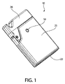
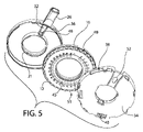
ここでさまざまな図を詳細に参照する。図を通して、同様の参照数字が同様の部分を指す。図1~図9は、乾燥粉末薬剤44又はAPIを含む粉末等(図7~図9を参照)の粉末の吸入を容易にする、全体として10で示すデバイス又は吸入器の一実施形態を示す。吸入器10は、一端にエンドキャップ23を有し反対側の端部にマウスピース26を有する本体25を含むことができる。エンドキャップ23は、詳細に後述するように、活性物質24(たとえば、乾燥剤)を含むことができ、又は活性物質24から形成することができる。本体25は、内部空間を画定し又は包囲し、マウスピース26は、本体25の内部空間に流体的に接続されている経路を画定することができる。マウスピース26により、使用者は、粉末を含有する空気を吸い込むか又は吸入することができる。
Reference is now made in detail to the various figures. Like reference numerals refer to like parts throughout the figures. 1-9 illustrate one embodiment of a device or inhaler, generally designated 10, that facilitates inhalation of powders, such as
本体25に、取外し可能に且つ/又は枢動可能にカバー28を取り付けることができる。一実施形態では、カバー28は、ヒンジを介して本体25に取り付けられる。カバー28は、本体25に対して閉鎖位置(図1を参照)と開放位置との間で移動可能であり得る。カバー28が閉鎖位置にあるとき、マウスピース26は覆われ且つ/又は保護される。カバー28が開放位置にあるとき、マウスピース26は、露出し、使用者がくわえるか又は接触することができる。カバー28は、より詳細に後述するように、枢動可能なトリガ27を含むことができる。
A
本体25、エンドキャップ23及びカバー28のうちの1つ又は複数は、低水蒸気透過率(low moisture vapor transfer rate)(LMVT)プラスチックから形成することができる。LMVT材料は、デバイス10の保管及び使用中に水分侵入を低減させる。閉鎖され且つ/又は完全に取り付けられたとき(図1を参照)、結合された本体25、エンドキャップ23及びカバー28は、密閉DPIを形成する。密閉DPIデバイスを設計し、その中の水分を制御するために乾燥剤プラスチックを使用することにより、従来技術と比較して改善された粉末の分散及び低減した毛管力を期待することができる。
One or more of
一実施形態では、吸入器10は9つの部品のみを含み、それらのうちの8つは射出成形される。この設計により、いくつかの従来技術による設計によって必要とされる、粉末を分散させる前に粉末を固定する材料に穴をあける必要がなくなる。本明細書に開示する技術の設計により、穴あけ機構からの残骸により調剤品を汚染するリスクもなくなる。
In one embodiment,
吸入器10は、本体25の内部空間内に位置決めされた少なくとも1つの部材51を含む。一実施形態では、図4~図6に示すように、少なくとも1つの部材51は、本体25に対して回転可能である環状部材又は投与リングである。別の実施形態では、部材51は、直線状部材又は投与ラインであり得る。部材51は、複数の別個の回数分の薬剤を提供するように構成することができる。さらに別の実施形態では、部材51は、1回分のみの薬剤を提供するように構成することができる。
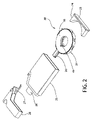
図2~図5に示すように、環状部材51の一実施形態は、第1トレー34及び第2トレー36によって本体25内で支持し又は本体25内に封入することができる。第1トレー34及び第2トレー36の両方が、略円形外周面及び略円形内周面を有することができる。一実施形態では、第2トレー36の少なくとも一部が、第1トレー34内に嵌まることができる。第2トレー36内に空気ダクト32(図5を参照)を配置するか又は形成することができ、空気ダクト32は、第2トレー36の上壁及び/又は側壁を通る開口部46をマウスピース26の通路に接続することができる。一実施形態では、マウスピース26は、第2トレー36の一体化部分又は単体部分である。
As shown in FIGS. 2-5, one embodiment of
図5に示すように、第2トレー36は円形中心ガイド21を含むことができる。環状部材51は、第1トレー34及び第2トレー36内に又はそれらの間に嵌まるか又は位置決めすることができ、環状部材51は、第1トレー34及び第2トレー36の両方に対して回転することができる。より詳細には、一実施形態では、環状部材51は、第2トレー36内に配置されるとき、中心ガイド21の周囲に配置される。環状部材51と第2トレー36の内面との間に、任意選択的にフォームから形成された、スペーサ16を位置決めすることができる。スペーサ16は、開口部又は切取部48を含むことができる。スペーサ16は、空気ダクト32の両側に位置決めされるように、第2トレー36内に配置することができる。
As shown in FIG. 5, the
任意選択的に、第1トレー34(及び/又は第2トレー36)は、付勢又は弛緩状態で第1トレー34の内部に少なくとも部分的に延在する少なくとも1つの止め具又はばね40を含むことができる。別の実施形態では、第1トレー34は、2つ以上の間隔を空けて配置されたばね40を含むことができる。各ばね40は、第1トレー34及び第2トレー36に対する環状部材51の回転を阻止することができる。一実施形態では、各ばね40は、板ばねであり、その一端が第1トレー34の基礎壁と一体的に又は単体であるように形成されている。各ばね40の内面は、突出部又は角度付き面を含むことができる。
Optionally, first tray 34 (and/or second tray 36) includes at least one stop or
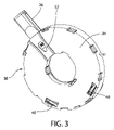
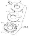
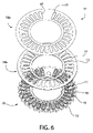
図6を参照すると、一実施形態では、環状部材51は、3つの部品又は構成要素、すなわち、第1環状部材18a、第2環状部材18b及び第3環状部材20から形成されている。一実施形態では、第1環状部材18aはアルミ箔から形成されている。任意選択的に、第1環状部材18aは、複数の間隔を空けて配置され且つ概して同一のヒンジ状フラップ17を形成する切れ目を含む。図6では、参照番号で識別される1つのフラップ17が、部分的に開放位置にあるように示されており、残りのフラップ17は閉鎖して示されている。一実施形態では、切れ目は、「C」字の形状に形成することができ、各フラップ17の切られていない縁によってヒンジ47が生成されている。任意選択的に、第1環状部材18aは、少なくとも30個の別個のフラップ17を含む。フラップ17は、2つの特定のフラップ17の間に空いた又は連続したスペースが形成されることを除き、第1環状部材18aの周囲に等距離で間隔を空けて配置することができる。一実施形態では、空きスペースの幅は、単一のフラップ17の幅の約2倍である。
Referring to FIG. 6, in one embodiment,
任意選択的に、第1環状部材18aは、第2環状部材18bの上面13(又は、デバイス10の向きに応じて下面)に接合される。別の実施形態では、環状部材51が2つの部品又は構成要素のみから形成されるように、第1環状部材18aは第2環状部材18bと一体的に又は単体として形成される。第2環状部材18bは、複数の間隔を空けて配置された孔14を含むことができ、それらの孔14の各々は、フラップ17が開放されたときに第2環状部材18bを通る通路を画定するように、第1環状部材18aの切れ目のうちの1つに位置合せされる。第2環状部材18bの孔14は、概して楕円形状であり得る。
Optionally, the first
第3環状部材20は、複数の間隔を空けて配置されたコンパートメント、カプセル又は投与ポケット空洞19を含むか又は画定することができる。各コンパートメント19は、1日分の投与量の粉末薬剤等、所定量の粉末を保持するようなサイズとし、形状とし、且つ/又はそのように構成することができる。任意選択的に、各コンパートメント19は、10~13mgの粉末44を収容し又は保持するようなサイズとすることができる。各コンパートメント19は、粉末44がコンパートメント19内に挿入され且つ所望の時点でコンパートメント19から除去されるのを可能にするように、少なくとも1つの開口部を含む。各フラップ17は、それぞれのコンパートメント19の開口部を覆い、フラップ17が閉鎖位置にあるときに開口部の外縁を越えて延在する拡張部を含む。各フラップ17の拡張部の下側の少なくとも一部は、固定されておらず、すなわちいかなる構造にも取り付けられていない。
The third
各コンパートメント19の半径方向内向き等に、コンパートメント19に近接して、1つの連続した又は複数の間隔を空けて配置された導管を位置決めすることができる。各フラップ17の下側の少なくとも一部は、関連する又はそれぞれの導管に面している。一実施形態では、複数の間隔を空けて配置された導管の各々は、第3環状部材20を通る孔45である。各孔45は、コンパートメント19のうちの1つに対応し、又は、隣接してただし間隔を空けて位置決めすることができる。一実施形態では、第3環状部材20に孔45を画定する開口部は、それぞれのコンパートメント19の開口部より小さい。任意選択的に、各孔45は、第3環状部材20の内側縁11に向かってそれぞれのコンパートメント19に隣接して配置することができる。一実施形態では、各孔45は、第3環状部材20を通って延在し、一方で、各コンパートメント19は、薬剤を保持するように第3環状部材20を通って延在しない。代替実施形態では、複数の間隔を空けて配置された孔45を、第3環状部材20の周囲に且つそこを通って延在する単一の、連続したチャネル又は導管に置き換えることができる。チャネルは、上述した複数の間隔を空けて配置された孔45と同様に機能することができる。
A continuous or a plurality of spaced-apart conduits may be positioned proximate the
結合されると、第1環状部材18a、第2環状部材18b及び第3環状部材20は、フラップ17が開放されない限り且つ開放されるまで、投与空洞19内で粉末を封止する。一実施形態では、切れ目により各フラップ17をより容易に開放することができるが、切れ目は、結合された第1環状部材18a、第2環状部材18b及び第3環状部材20の封止能力を破壊しない。一実施形態では、第1環状部材18aは、第2環状部材18bにインモールドラベル付けされ、その後第3環状部材18に超音波溶接される、アルミ箔の薄層から形成される。任意選択的に、第2環状部材18b及び第3環状部材20は、医療グレードプラスチック等、成形プラスチックであり得る。
When coupled, first
一代替実施形態では、詳細に上述したように、各フラップ17がコンパートメント19のうちの1つに関連付けられる代わりに、各フラップ17は、2つ以上の別個の間隔を空けて配置されたコンパートメント19を覆い且つ/又はそれらに関連付けることができる。これらのコンパートメント19の各々は、同じタイプ又は種類の粉末44を収容することができる。代替実施形態では、フラップ17のうちの1つに関連付けられた少なくとも2つの隣接するコンパートメント19は、保管中に混合することができないか又は混合されるべきではないが、使用者が吸入するときに同時に又は実質的に同時に送達することができ且つ/又は送達されるべきである、異なるタイプ又は種類の粉末又は薬剤44を収容することができる。
In an alternative embodiment, instead of each
複数の間隔を空けて配置された隆起部又は歯12が、第3環状部材20の外周面にわたって延在することができる。歯12は、第3環状部材20の周囲面全体にわたって均一に又は等距離で間隔を空けて延在することができる。トリガ27の少なくとも一部が、ハウジング36の側壁に形成された開口部38を通って環状部材51の歯12のうちの1つと接触し又はそれと係合することができる。トリガ27はばね式であり得る。別法として、トリガ27は、ばねを省略し、米国特許出願公開第2014/0007875号明細書の図4A~図4Cに示すような、カバー28を開放すると、単に環状部材51を移動させるか又は回転させることができる。環状部材51の歯12とのトリガ27の選択的係合は、環状部材51に対する各ばね40の力を克服して、結合された第1トレー34及び第2トレー36内で環状部材51を回転させ又は「前進させる」ことができる。各ばね40は、各ばね40の付勢力に打ち勝つトリガ27に応答して触覚及び/又は可聴作用を提供することができる。
A plurality of spaced apart ridges or
具体的に図1及び図3~図5を参照すると、ハウジング25は、その壁のうちの1つに窓50を含むことができる。第1トレー34は、その基礎壁を通る開口部52を含むことができる。第1トレー34の開口部52は、第1トレー34がハウジング25内に適切に位置決めされると、窓50と位置合せすることができる。第3環状部材20は、年代順の又は連続的な数字及び/又は文字(たとえば、30、29、28、27等)等、複数の間隔を空けて配置されたしるしを含むことができる。しるしの各々は、コンパートメント19のうちの1つに近接して、ただしコンパートメント19が形成される場所とは反対側に位置することができる。
Referring specifically to FIGS. 1 and 3-5,
一実施形態では、活性物質24は乾燥剤である。これは、水分吸収が望ましい実施形態である。しかしながら、水分吸収が望ましくない場合、活性物質24は代替的な活性剤を含むことができる。たとえば、別の実施形態では、活性物質24は、活性炭、カーボンブラック、ケチャムブラック(ketcham black)及びダイヤモンド粉末からなる群から選択された物質を含む。さらなる実施形態では、活性物質24の1つ又は複数の層を含む活性剤は、吸収性微小球(absorption microsphere)、BaTiO3、SrTiO3、SiO2、Al2O3、ZnO、TiO2、MnO、CuO、Sb2O3、シリカ、酸化カルシウム及びイオン交換樹脂等の物質を含有する。さらに別の実施形態では、活性物質24の層を含む吸収剤は、2つ以上のタイプの吸収剤を含む。好適な吸収剤は、所望の最終用途のために所望の蒸気又はガスの吸収(たとえば、水分、酸素、二酸化炭素、窒素又は他の望ましくないガス若しくは蒸気の吸収)を達成するように選択される。
In one embodiment,
活性物質24(乾燥剤、脱酸素剤、放出材若しくは放出剤等又はそれらの組合せのいずれであっても)は、選択された物質(たとえば、水分又は酸素)に作用し、それと相互作用し、又は反応することができる。こうした作用又は相互作用の例としては、選択された物質の吸収、吸着(一般に、吸着(sorption))又は放出を挙げることができる。 The active substance 24 (whether a desiccant, oxygen scavenger, releaser or releaser, etc., or a combination thereof) acts on and interacts with a selected substance (e.g., moisture or oxygen), or can react. Examples of such actions or interactions may include absorption, adsorption (generally sorption) or release of the selected substance.
活性物質24は、基材に「活性剤」を含むことができる。活性剤は、(i)基材(たとえば、ポリマー)と非混和性とすることができ、ベースポリマー及びチャネリング剤と混合され加熱されたとき、溶融せず、すなわち、ベースポリマー若しくはチャネリング剤のいずれかに対する融点より高い融点を有し、且つ/又は(ii)選択された物質に作用し、選択された物質と相互作用し、若しくは反応する。「活性剤」という用語は、限定されないが、選択された物質を吸収し、吸着し、又は放出する物質を含むことができる。本明細書に開示する技術による活性剤は、鉱物(たとえば、乾燥剤の場合、モレキュラーシーブ又はシリカゲル)等の粒子の形態であり得るが、本明細書に開示する技術は、粒子状活性剤にのみ限定されるものとしてみなされるべきではない。たとえば、いくつかの実施形態では、活性剤として又は活性剤の成分として作用する樹脂から、脱酸素剤を製造することができる。
本明細書における「基材」という用語は、混入活性物質の、その混入物質に対して構造を提供する、活性剤以外の成分(好ましくはポリマー)である。 The term "substrate" herein is a component (preferably a polymer) of a contaminant active agent other than the active agent that provides structure to the contaminant.
本明細書における「ベースポリマー」という用語は、チャネリング剤のガス透過率より実質的に低い、低い、又はそれと実質的に等価である、選択された物質のガス透過率を任意選択的に有するポリマーである。例として、こうした透過率は、選択された物質が水分であり、活性剤が吸水性乾燥剤である実施形態では、水蒸気透過率である。ベースポリマーの主な機能は、混入ポリマーに対して構造を提供することである。好適なベースポリマーとしては、熱可塑性ポリマー、たとえば、ポリプロピレン及びポリウレタン等のポリオレフィン、ポリイソプレン、ポリブタジエン、ポリブテン、ポリシロキサン、ポリカーボネート、ポリアミド、エチレンビニルアセテートコポリマー、エチレンメタクリレートコポリマー、ポリ(塩化ビニル)、ポリスチレン、ポリエステル、ポリ無水物、ポリアクリロニトリル、ポリスルホン、ポリアクリル酸エステル、アクリル酸、ポリウレタン及びポリアセタール、又はそれらのコポリマー若しくは混合物を挙げることができる。 The term "base polymer" herein refers to a polymer optionally having a gas permeability of the selected material that is substantially lower than, lower than, or substantially equivalent to the gas permeability of the channeling agent. is. By way of example, such a permeability is water vapor permeability in embodiments where the selected substance is moisture and the active agent is a water-absorbing desiccant. The primary function of the base polymer is to provide structure to the entrained polymer. Suitable base polymers include thermoplastic polymers such as polyolefins such as polypropylene and polyurethane, polyisoprene, polybutadiene, polybutene, polysiloxanes, polycarbonates, polyamides, ethylene vinyl acetate copolymers, ethylene methacrylate copolymers, poly(vinyl chloride), polystyrene. , polyesters, polyanhydrides, polyacrylonitrile, polysulfones, polyacrylates, acrylics, polyurethanes and polyacetals, or copolymers or mixtures thereof.
ベースポリマー及びチャネリング剤の水蒸気透過率のこうした比較を参照すると、一実施形態では、チャネリング剤は、ベースポリマーの少なくとも2倍の水蒸気透過率を有する。別の実施形態では、チャネリング剤は、ベースポリマーの少なくとも5倍の水蒸気透過率を有する。別の実施形態では、チャネリング剤は、ベースポリマーの少なくとも10倍の水蒸気透過率を有する。さらに別の実施形態では、チャネリング剤は、ベースポリマーの少なくとも20倍の水蒸気透過率を有する。さらに別の実施形態では、チャネリング剤は、ベースポリマーの少なくとも50倍の水蒸気透過率を有する。さらに別の実施形態では、チャネリング剤は、ベースポリマーの少なくとも100倍の水蒸気透過率を有する。 With reference to this comparison of water vapor transmission rates of the base polymer and channeling agent, in one embodiment the channeling agent has a water vapor transmission rate that is at least twice that of the base polymer. In another embodiment, the channeling agent has a water vapor transmission rate of at least 5 times that of the base polymer. In another embodiment, the channeling agent has a water vapor transmission rate of at least 10 times that of the base polymer. In yet another embodiment, the channeling agent has a water vapor transmission rate that is at least 20 times that of the base polymer. In yet another embodiment, the channeling agent has a water vapor transmission rate of at least 50 times that of the base polymer. In yet another embodiment, the channeling agent has a water vapor transmission rate of at least 100 times that of the base polymer.
本明細書における「チャネリング剤」という用語は、ベースポリマーと非混和性であり且つベースポリマーより高速で気相物質を輸送する親和性を有する物質として定義される。任意選択的に、チャネリング剤は、チャネリング剤をベースポリマーと混合することによって形成される場合に、混入ポリマーを通してチャネルを形成することができる。任意選択的に、こうしたチャネルは、ベースポリマーのみの場合より高速で混入ポリマーを通して選択された物質を透過させることができる。 The term "channeling agent" is defined herein as a substance that is immiscible with the base polymer and has an affinity for transporting gas phase substances faster than the base polymer. Optionally, the channeling agent can form channels through the entrained polymer when formed by mixing the channeling agent with the base polymer. Optionally, such channels can allow selected substances to permeate through the entrained polymer at a higher rate than through the base polymer alone.
本明細書における「チャネル」又は「相互接続チャネル」という用語は、ベースポリマーに浸透するチャネリング剤から形成された通路として定義され、互いに相互接続され得る。 The term "channel" or "interconnecting channel" herein is defined as passageways formed from a channeling agent that permeates the base polymer and can be interconnected with each other.
本明細書における「混入ポリマー」という用語は、活性剤を含み任意選択的にチャネリング剤が混入されているか又は分散されている少なくともベースポリマーから形成されたモノリシック物質として定義される。したがって、混入ポリマーは、2相ポリマー及び3相ポリマーを含む。「鉱物添加ポリマー」が一種の混入ポリマーであり、活性剤は、鉱物の一形態、たとえば、モレキュラーシーブ又はシリカゲル等の鉱物粒子の形態である。本明細書では、「混入物質」という用語を用いて、基材に混入された活性剤を含むモノリシック物質を意味し、基材は高分子である場合もあれば又はない場合もある。 The term "embedded polymer" herein is defined as a monolithic material formed from at least a base polymer that contains an active agent and optionally has a channeling agent incorporated or dispersed therein. Thus, entrained polymers include two-phase and three-phase polymers. A "mineral-added polymer" is a type of entrained polymer in which the active agent is in the form of a mineral, eg, mineral particles such as molecular sieves or silica gel. The term "contaminant" is used herein to refer to a monolithic material containing an active agent entrained in a matrix, which may or may not be polymeric.
本明細書における「モノリシック」、「モノリシック構造」又は「モノリシック組成物」という用語は、2つ以上の別個の巨視的な層又は部分から構成されていない組成物又は材料として定義される。したがって、「モノリシック組成物」は多層複合材を含まない。 The terms "monolithic", "monolithic structure" or "monolithic composition" herein are defined as a composition or material that is not composed of two or more separate macroscopic layers or parts. Thus, a "monolithic composition" does not include multilayer composites.
本明細書における「相」という用語は、モノリシック構造又は組成物の、構造又は組成物にそのモノリシック特性を与えるように全体に均一に分散している部分又は成分として定義される。 The term "phase" herein is defined as a portion or component of a monolithic structure or composition that is uniformly dispersed throughout to give the structure or composition its monolithic character.
本明細書における「選択された物質」という用語は、活性剤による作用を受け、又は活性剤と相互作用し若しくは反応し、混入ポリマーのチャネルを通して透過することができる物質として定義される。たとえば、活性剤として乾燥剤が使用される実施形態では、選択された物質は、乾燥剤によって吸収することができる水分又はガスであり得る。活性剤として放出材が使用される実施形態では、選択された物質は、水分、芳香剤又は抗菌剤(たとえば、二酸化塩素)等、放出材によって放出される作用物質であり得る。活性剤として吸着材が使用される実施形態では、選択された物質はいくつかの揮発性有機化合物とすることができ、吸着材は活性炭素であり得る。 The term "selected substance" herein is defined as a substance that can be acted upon by, interact with or react with an active agent and permeate through the channels of the entrained polymer. For example, in embodiments in which a desiccant is used as the active agent, the selected substance can be moisture or gas that can be absorbed by the desiccant. In embodiments in which a releasable material is used as the active agent, the selected substance can be an agent released by the releasable material, such as moisture, fragrance, or antimicrobial agent (eg, chlorine dioxide). In embodiments in which an adsorbent is used as the active agent, the material selected can be some volatile organic compound and the adsorbent can be activated carbon.
本明細書における「3相」という用語は、3つ以上の相を含むモノリシック組成物又は構造として定義される。本明細書に開示する技術による3相組成物の一例は、ベースポリマー、活性剤及びチャネリング剤から形成された混入ポリマーである。任意選択的に、3相組成物又は構造は、追加の相、たとえば着色剤を含むことができる。 The term "three-phase" as used herein is defined as a monolithic composition or structure comprising three or more phases. One example of a three-phase composition according to the technology disclosed herein is an entrained polymer formed from a base polymer, an active agent and a channeling agent. Optionally, the three-phase composition or structure can contain additional phases, such as colorants.
混入ポリマーは、2相配合物(すなわち、チャネリング相なしにベースポリマー及び活性剤を含む)又は3相配合物(すなわち、ベースポリマー、活性剤及びチャネリング剤を含む)であり得る。混入ポリマーは、たとえば、米国特許第5,911,937号明細書、同第6,080,350号明細書、同第6,124,006号明細書、同第6,130,263号明細書、同第6,194,079号明細書、同第6,214,255号明細書、同第6,486,231号明細書、同第7,005,459号明細書及び米国特許出願公開第2016/0039955号明細書に記載されており、それらの各々は、その全体が参照により本明細書に援用される。 The entrained polymer can be a two-phase formulation (ie, containing base polymer and active agent without the channeling phase) or a three-phase formulation (ie, containing base polymer, active agent and channeling agent). Entrained polymers are described, for example, in U.S. Pat. Nos. 5,911,937; 6,080,350; 6,124,006; , 6,194,079, 6,214,255, 6,486,231, 7,005,459 and U.S. Patent Application Publication Nos. 2016/0039955, each of which is incorporated herein by reference in its entirety.
混入物質又はポリマーは、構造を提供する基材(たとえば、ポリマー)と、任意選択的にチャネリング剤と、活性剤とを含む。チャネリング剤は、混入ポリマーを通して微視的な相互接続チャネルを形成する。活性剤の少なくとも一部が、これらのチャネル内に収容され、その結果、チャネルは、混入ポリマーの外面に形成された微視的なチャネル開口部を介して活性剤と混入ポリマーの外部との間を連通する。活性剤は、たとえば、さらに詳細に後述するように、種々の吸収材、吸着材又は放出材のうちの任意の1つであり得る。チャネリング剤が好ましいが、本発明は、広範に、任意選択的にチャネリング剤を含まない混入物質、たとえば2相ポリマーを含む。 Contaminants or polymers include a substrate that provides structure (eg, a polymer), optionally a channeling agent, and an active agent. The channeling agent forms microscopic interconnecting channels through the entrained polymer. At least a portion of the active agent is contained within these channels so that the channels are between the active agent and the exterior of the entrained polymer through microscopic channel openings formed in the outer surface of the entrained polymer. communicate. The active agent can be, for example, any one of a variety of absorbent, adsorbent or release materials, as described in more detail below. Although channeling agents are preferred, the present invention broadly includes contaminants, such as two-phase polymers, optionally free of channeling agents.
任意の実施形態では、好適なチャネリング剤としては、ポリエチレングリコール(PEG)等のポリグリコール、エチレン-ビニルアルコール(EVOH)、ポリビニルアルコール(PVOH)、グリセリンポリアミン、ポリウレタン、及びポリアクリル酸又はポリメタクリル酸を含むポリカルボン酸を挙げることができる。別法として、チャネリング剤は、たとえば、CLARIANT製のPolyglykol B01/240等、酸化プロピレン重合体-モノブチルエーテル等、非水溶性ポリマーであり得る。他の実施形態では、チャネリング剤は、CLARIANT製のPolyglykol B01/20等の酸化プロピレン重合体モノブチルエーテル、CLARIANT製のPolyglykol D01/240等の酸化プロピレン重合体、エチレンビニルアセテート、ナイロン6、ナイロン66又は上述したものの任意の組合せであり得る。 In any embodiment, suitable channeling agents include polyglycols such as polyethylene glycol (PEG), ethylene-vinyl alcohol (EVOH), polyvinyl alcohol (PVOH), glycerol polyamines, polyurethanes, and polyacrylic or polymethacrylic acid. Polycarboxylic acids containing can be mentioned. Alternatively, the channeling agent can be a water insoluble polymer such as, for example, Polyglykol B01/240 from CLARIANT, propylene oxide polymer-monobutyl ether. In other embodiments, the channeling agent is a propylene oxide polymer monobutyl ether such as Polyglykol B01/20 from CLARIANT, a propylene oxide polymer such as Polyglykol D01/240 from CLARIANT, ethylene vinyl acetate, nylon 6, nylon 66 or It can be any combination of the above.
本明細書に開示する技術による好適な活性剤としては、乾燥化合物等、吸収材が挙げられる。活性剤が乾燥剤である場合、所与の用途に好適な乾燥剤を使用することができる。典型的には、多くの用途に対して、物理吸収乾燥剤が好ましい。これらには、モレキュラーシーブ、シリカゲル、粘土及び澱粉を挙げることができる。別法として、乾燥剤は、水と反応して新たな化合物を形成する水又は化合物を含有する結晶を形成する化合物であり得る。 Suitable active agents according to the technology disclosed herein include absorbents, such as dry compounds. If the active agent is a desiccant, any desiccant suitable for a given application can be used. Physically absorbing desiccants are typically preferred for many applications. These can include molecular sieves, silica gels, clays and starches. Alternatively, the desiccant may be a compound that forms crystals containing water or compounds that react with water to form new compounds.
任意選択的に、任意の実施形態では、活性剤は、脱酸素剤、たとえば脱酸素樹脂配合物であり得る。 Optionally, in any embodiment, the active agent may be an oxygen scavenger, such as an oxygen scavenger resin formulation.
以下の表1は、設計された乾燥剤の水分吸着能力の特徴付けと、本明細書に開示する技術の一実施形態のDPIデバイスの製造、保管及び使用のさまざまな段階における計算された水分量にさらされた後のデバイス内への水分侵入に起因する能力の消耗とを示す。 Table 1 below provides a characterization of the moisture adsorption capacity of the designed desiccant and the calculated moisture content at various stages of manufacture, storage and use of the DPI device of one embodiment of the technology disclosed herein. capacity depletion due to moisture ingress into the device after exposure to

以下は、上記表1に記載したデバイスを製造するさまざまな段階中の水分侵入を計算するために使用した仮定である。 The following are the assumptions used to calculate moisture intrusion during the various stages of manufacturing the devices listed in Table 1 above.
吸着:成形された乾燥剤部品において、1時間に3,000μgの水蒸気が吸着される。さらに、デバイスの組立に続き、成形されたプラスチック部品及びPEシールにおいて、.3mgの潜在水分を吸着する必要がある。 Adsorption: 3,000 μg of water vapor per hour is adsorbed on molded desiccant parts. Furthermore, following assembly of the device, . It is necessary to adsorb 3 mg of latent water.
成形:成形された乾燥剤プラスチック部品は、封止されるホイルバッグ内に配置される前に、成形中に少なくとも1時間又は2時間露出される(25℃/60%相対湿度(RH)条件)。 Molding: Molded desiccant plastic parts are exposed during molding for at least 1 or 2 hours (25°C/60% relative humidity (RH) conditions) before being placed in foil bags to be sealed .
成形施設における保管:成形された乾燥剤プラスチック部品は、出荷用段ボールのポリバッグ内に封止されたホイルバッグで保管される(25℃/60%RH条件)。 Storage in Molding Facility: Molded desiccant plastic parts are stored in foil bags sealed within polybags of shipping cardboard (25° C./60% RH conditions).
組立場所における保管:成形された乾燥剤プラスチック部品は、デバイスを製造するために使用される前に、組立場所で1年間保管される(25℃/60%RH条件)。 Storage at Assembly Site: Molded desiccant plastic parts are stored at the assembly site for 1 year (25°C/60% RH conditions) before being used to manufacture devices.
組立:成形された乾燥剤プラスチック部品は、組立場所において完成したデバイスとして製造中に2時間露出され、封止されるホイルポーチ内に個々に配置される。なお、成形されたプラスチック部品及びPEシールにおける潜在水分は、デバイス組立に続いて吸着される(25℃/60%RH条件)。 Assembly: The molded desiccant plastic parts are individually placed in foil pouches that are exposed and sealed during manufacture for 2 hours as finished devices at the assembly site. Note that latent moisture in molded plastic parts and PE seals is adsorbed following device assembly (25° C./60% RH conditions).
保管期間:製造されたデバイスは、封止されたホイルポーチ内に、使用のために開放される前に1年間保管される(30℃/75%RH条件)。 Storage period: Manufactured devices are stored in sealed foil pouches for 1 year before being opened for use (30°C/75% RH conditions).
使用期間:デバイスは、60日間、閉鎖され保管され、使用に利用可能である(30℃/75%RH条件)。 Duration of use: Devices are stored closed and available for use for 60 days (30° C./75% RH conditions).
30回使用:デバイスは、60日の使用期間にわたり、30回開放され且つ再度閉鎖される(30℃/75%RH条件)。 30 Uses: The device is opened and reclosed 30 times (30° C./75% RH conditions) over a period of 60 days of use.
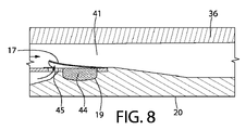
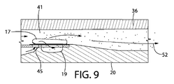
図7~図9は、デバイス10の一実施形態の動作を示す。たとえば、使用者が、トリガ27を操作して環状部材51を所望の位置まで回転させると(たとえば、第1トレー34の開口部52及びハウジング25の窓50を通して正確な1日又は投与期間が可視である場合)、使用者は、マウスピース26を通して吸入することができる。一実施形態では、これにより、空気が、2つの別個の経路を通って、すなわち、(i)第1トレー34の空気ダクト32内に位置決めされている孔45の真下から且つ孔45を通って、且つ、(ii)第2トレー36の開口部46を通り、その後、孔45及び第1トレー34の空気ダクト32内のコンパートメント19の上方に移動する。従来技術による設計とは対照的に、本明細書に開示する技術の一実施形態における空気流は、孔45のうちの1つを通して向けられ、それにより、フラップ17のうちの1つの底面に圧力がかけられてフラップ17のうちの1つが開放する。空気ダクト32のサイズ、形状及び/又は構成は、異なる病状又は集団の異なる部分(たとえば、子供又は高齢者)に対して、変更又は調整することができる。
7-9 illustrate the operation of one embodiment of
上述した空気流の組合せにより、第3トレー34の空気ダクト32と又はその中で位置合せされたフラップ17が、閉鎖位置から開放位置に確実に且つ効果的に移動し、それにより、コンパートメント19内の粉末がベンチュリ効果によって放出されるか又は引き出され、マウスピース36を通して使用者の口に移動することができる。スペーサ16は、第3トレー34の空気ダクト32と又はその中に位置合せされていないフラップ17のすべてを閉鎖位置で維持するように構成されている。したがって、スペーサ16は、開口部48が空気ダクト32に位置合せされる場合を除き、フラップ17を各々閉鎖構成で維持することができる。開口部48の真下又は真上に位置決めされたいかなるフラップ17も、使用者が力をかけると開放することができる。いくつかの実施形態では、スペーサ16は、フラップ17を開放するために必要な力及び/又は使用される薬剤に応じて、約0.062インチ、0.093インチ又は0.125インチの厚さを有することができる。
The combination of air flows described above positively and effectively moves the
図10~図12は、本明細書に開示する技術の別の実施形態を示す。図1~図9の実施形態と図10~図12の実施形態との間の同様の又は同一の構造は、図10~図12では、図1~図9の参照番号より100大きい桁の参照番号によって識別される。単に便宜上及び明確にするために、実施形態の間のいくつかの類似性の説明は省略している場合がある。 10-12 illustrate another embodiment of the technology disclosed herein. Similar or identical structures between the embodiment of FIGS. 1-9 and the embodiment of FIGS. 10-12 are referenced in FIGS. Identified by number. Description of some similarities between embodiments may be omitted merely for convenience and clarity.
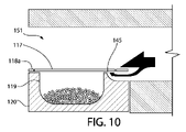
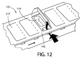
先行する実施形態とは対照的に、各フラップ117は、閉鎖位置にあるとき、孔145を越えて孔145の周縁部全体に延在しない(図10を参照)。代わりに、それぞれの孔145に近接する各フラップ117の端部は、固定されていない、すなわちいかなる構造体にも固定されていない底面を有する。言い換えれば、各フラップ117の縁は、それぞれの孔145の縁の一部とシールを形成することができる。これにより、各フラップ117を開放するために必要な力を低減させ、且つ/又は第1環状部材118aを形成するために必要な材料の量を低減させることができる。先行する実施形態と同様、図12に示すように、各フラップ117は、コンパートメント119を越えてコンパートメント119の周縁部全体に延在する。
In contrast to the previous embodiment, each
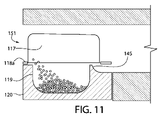
図10及び図11を参照すると、本実施形態は、第2環状部材を省略することができ、その結果、環状部材151は、上述した第1環状部材18a及び第3環状部材20と等価である2つの環状部材118a、120のみを含むことができる。さらに、各フラップ117は、コンパートメント119と孔145との間において、コンパートメント119を形成する構造体(たとえば、第3環状部材120)に取り付けられていないものとすることができる。図10及び図11では、この位置に小さい間隙又は間隔を示す。この配置により、各フラップ117を開放するために必要な力を低減させることができる。
10 and 11, this embodiment can omit the second annular member so that the
図13~図14は、本明細書に開示する技術の別の実施形態を示す。図1~図9の実施形態と図13~図14の実施形態との間のように同様の又は同一の構造は、図13~図14では、図1~図9の参照番号より200大きい桁の参照番号によって識別される。単に便宜上及び明確にするために、先の実施形態と図13~図14の実施形態とのいくつかの類似性の説明は省略している場合がある。 13-14 illustrate another embodiment of the technology disclosed herein. Structures that are similar or identical as between the embodiment of FIGS. 1-9 and the embodiment of FIGS. 13-14 are shown in FIGS. identified by a reference number. A description of some similarities between the previous embodiment and the embodiment of FIGS. 13-14 may be omitted merely for convenience and clarity.
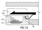
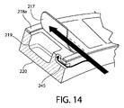
本実施形態では、各孔245は、「L」字形状を有するか又は90度の曲げを含むことができる、より幅の狭い、細長い通路である。各孔245の形状は、空気がそれぞれの孔245を通って流れるように強制される速度を増大させるのに役立つことができ、それにより、それぞれのフラップ217の底面に対する力が増大する。各フラップ217は、それぞれのコンパートメント219及び孔245を形成する構造体(たとえば、第3環状部材220)の一部と接触するか又はそれを越えて半径方向に延在することができる。別法として、図13に示すように、各フラップ217は、それぞれのコンパートメント219を画定する構造体と接触することができるが、固定されておらず、又は、それぞれの孔245を画定する構造体全体から間隔を空けて配置され得る。閉鎖位置では、各フラップ217は、それぞれの孔245によって形成された通路の一端(たとえば、下流端)を覆うことができる。
In this embodiment, each
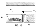
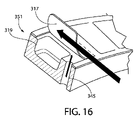
図15~図16は、本明細書に開示する技術の別の実施形態を示す。図1~図9の実施形態と図15~図16の実施形態との間のように同様の又は同一の構造は、図15~図16では、図1~図9の参照番号より300大きい桁の参照番号によって識別される。単に便宜上及び明確にするために、先の実施形態と図15~図16の実施形態とのいくつかの類似性の説明は省略している場合がある。 15-16 illustrate another embodiment of the technology disclosed herein. Structures that are similar or identical as between the embodiment of FIGS. 1-9 and the embodiment of FIGS. 15-16 are shown in FIGS. identified by a reference number. A discussion of some similarities between the previous embodiment and the embodiment of FIGS. 15-16 may be omitted merely for convenience and clarity.
本実施形態では、各孔345は、それぞれのフラップ317の最上面によって画定された平面に対して完全に垂直に延在する通路である。その結果、各孔345を通る空気流は、それぞれのフラップ317の最上部を横切る空気流に対して垂直である。各孔345の位置は、それぞれのコンパートメント319の下流であることに限定されない。たとえば、図15に示す孔345は、コンパートメント319の(右である代わりに)左であり得る。さらに、フラップ317は、単一の第1環状部材から形成されるか又は切り取られることに限定されない。代わりに、各フラップ317は、別個の且つ分離した構成要素とすることができ、接着剤等の種々の方法のうちの任意のもので環状部材351に取り付けることができる。
In this embodiment, each
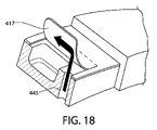
図17~図18は、本明細書に開示する技術の別の実施形態を示す。図1~図9の実施形態と図17~図18の実施形態との間のように同様の又は同一の構造は、図17~図18では、図1~図9の参照番号より400大きい桁の参照番号によって識別される。単に便宜上及び明確にするために、先の実施形態と図17~図18の実施形態とのいくつかの類似性の説明は省略している場合がある。 17-18 illustrate another embodiment of the technology disclosed herein. Structures that are similar or identical as between the embodiment of FIGS. 1-9 and the embodiment of FIGS. 17-18 are shown in FIGS. identified by a reference number. A discussion of some similarities between the previous embodiment and the embodiment of FIGS. 17-18 may be omitted merely for convenience and clarity.
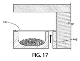
先の実施形態とは対照的に、本実施形態は、(たとえば、各フラップ417の真下の)単一の空気流路のみを利用して、各フラップ417を開放する。特に、本実施形態では、各フラップ417の上方のみを移動する追加の空気流路はない。孔445は、それぞれのフラップ417の最上面に対して垂直であるように示されているが、孔445は、上述したもの等、代替的な形状又は寸法を有することができる。
In contrast to the previous embodiment, this embodiment utilizes only a single air flow path (eg, directly below each flap 417) to open each
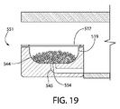
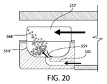
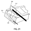
図19~図21は、本明細書に開示する技術の別の実施形態を示す。図1~図9の実施形態と図19~図21の実施形態との間のように同様の又は同一の構造は、図19~図21では、図1~図9の参照番号より500大きい桁の参照番号によって識別される。単に便宜上及び明確にするために、先の実施形態と図19~図21の実施形態とのいくつかの類似性の説明は省略している場合がある。 19-21 illustrate another embodiment of the technology disclosed herein. Structures that are similar or identical as between the embodiment of FIGS. 1-9 and the embodiment of FIGS. 19-21 are shown in FIGS. identified by a reference number. A discussion of some similarities between the previous embodiment and the embodiment of FIGS. 19-21 may be omitted merely for convenience and clarity.
本実施形態の顕著な特徴は、環状部材551が、各コンパートメント519の最上部に第1フラップ517を含み、各コンパートメント519の底部に第2フラップ554を含むことである。第2フラップ554の少なくとも一部を、それぞれのコンパートメント519の内部に(たとえば接着剤を介して)固定するか又は一体的に形成することができ、第2フラップ554の別の部分が、それぞれのコンパートメント519の内部に対して移動可能であり得る。粉末544は、第2フラップ554の内面と第1フラップ517の内面との間に位置する。
A distinctive feature of this embodiment is that the
本実施形態の別の顕著な特徴は、孔545が、先の実施形態に記載したようにそれぞれのコンパートメント519に隣接するのとは対照的に、それぞれのコンパートメント519の内部に至る、ということである。孔545を通って移動する空気は、空気流が第2フラップ554をコンパートメント519内に押し込むまで、第2フラップ554の外面を上向きに押し、それにより、第1フラップ517が開放された後、粉末544を第1フラップ517に向かってコンパートメント519から押し出す。
Another distinguishing feature of this embodiment is that the
一実施形態では、第1フラップ517は、孔545を通って移動する空気流によって生成される力の結果として開放することができる。代替実施形態では、第1フラップ517は、フラップ517の最上部を横切って移動する空気流によって発生する圧力差と、孔545を通って移動する空気流によって生成される力との組合せによって、開放することができる。いずれの場合も、空気流は、第1フラップ517及び第2フラップ554の両方を開放するとき、第1フラップ517及び第2フラップ554を同じ方向に移動させる。
In one embodiment, the
本明細書に開示する技術について、詳細に且つその具体的な例に関して説明したが、当業者であれば、その技術の趣旨及び範囲から逸脱することなく、そうした例においてさまざまな変形、省略及び変更を行うことができることが明らかとなろう。したがって、本明細書に開示する技術は、開示した特定の実施形態に限定されず、添付の特許請求の範囲によって定義されるような本明細書に開示する技術の趣旨及び範囲内にある変更形態を包含するように意図されていることが理解される。 Although the technology disclosed herein has been described in detail and with respect to specific examples thereof, those skilled in the art will appreciate various modifications, omissions and alterations in such examples without departing from the spirit and scope of the technology. It will be clear that it is possible to Accordingly, the technology disclosed herein is not limited to the particular embodiments disclosed, but modifications that fall within the spirit and scope of the technology disclosed herein as defined by the appended claims. It is understood that it is intended to encompass
Claims (6)
内部空間を画定し且つマウスピースを含む本体と、
前記内部空間内の且つ前記マウスピースに対して回転可能な少なくとも1つの環状部材であって、複数のコンパートメント及び複数のフラップを含み、各フラップが、前記コンパートメントのうちの少なくとも1つに関連付けられ、各コンパートメントが、乾燥粉末を保持するように構成された空洞を画定し、且つ、各コンパートメントが、前記フラップが閉鎖位置から開放位置まで移動すると前記乾燥粉末を放出するように構成された前記コンパートメントの開口部を含み、各フラップが、前記コンパートメントのうちの1つについての少なくとも前記コンパートメントの前記開口部を覆い、且つ、各フラップが、前記関連付けられた1つ又は複数のコンパートメントを越えて延在する拡張部を含む、少なくとも1つの環状部材と、
を備え、
各フラップの前記拡張部の少なくとも一部が、少なくとも一つの導管を通って移動し、前記拡張部の下側に作用する空気流に対して露出されるように構成され、前記導管が、それぞれのコンパートメントに隣接して配置され、前記空気流が、前記フラップを前記閉鎖位置から前記開放位置まで移動させるように構成され、
前記吸入器は、前記マウスピースを通して前記本体の前記内部空間内から空気が排出されたとき、空気が前記少なくとも1つの導管を通って移動し、空気が前記フラップを持ち上げるように、構成されている、吸入器。 An inhaler for facilitating inhalation of dry powder, comprising:
a body defining an interior space and including a mouthpiece;
at least one annular member rotatable within the interior space and relative to the mouthpiece, comprising a plurality of compartments and a plurality of flaps, each flap associated with at least one of the compartments; each compartment defining a cavity configured to hold a dry powder, and each compartment configured to release the dry powder when the flap is moved from a closed position to an open position; an opening, each flap covering at least said opening of said compartment for one of said compartments, and each flap extending beyond said associated one or more compartments at least one annular member including an extension;
with
At least a portion of the extension of each flap is configured to travel through at least one conduit and be exposed to airflow acting underneath the extension, the conduit being configured to extend through the respective positioned adjacent to a compartment, wherein the air flow is configured to move the flap from the closed position to the open position ;
The inhaler is configured such that when air is expelled from within the interior space of the body through the mouthpiece, air travels through the at least one conduit and lifts the flap . , inhaler.
Applications Claiming Priority (5)
| Application Number | Priority Date | Filing Date | Title |
|---|---|---|---|
| US201762471661P | 2017-03-15 | 2017-03-15 | |
| US62/471,661 | 2017-03-15 | ||
| US201762514072P | 2017-06-02 | 2017-06-02 | |
| US62/514,072 | 2017-06-02 | ||
| PCT/US2018/022732 WO2018170315A1 (en) | 2017-03-15 | 2018-03-15 | Inhaler and methods of using and making same |
Publications (2)
| Publication Number | Publication Date |
|---|---|
| JP2020512912A JP2020512912A (en) | 2020-04-30 |
| JP7166327B2 true JP7166327B2 (en) | 2022-11-07 |
Family
ID=62025945
Family Applications (1)
| Application Number | Title | Priority Date | Filing Date |
|---|---|---|---|
| JP2020500019A Active JP7166327B2 (en) | 2017-03-15 | 2018-03-15 | Inhalers and methods of using and manufacturing inhalers |
Country Status (11)
| Country | Link |
|---|---|
| US (1) | US11617842B2 (en) |
| EP (1) | EP3595758B1 (en) |
| JP (1) | JP7166327B2 (en) |
| CN (1) | CN110913934B (en) |
| BR (1) | BR112019019107A2 (en) |
| CA (1) | CA3056636A1 (en) |
| CL (1) | CL2019002616A1 (en) |
| CO (1) | CO2019009933A2 (en) |
| MX (1) | MX2019010892A (en) |
| PE (1) | PE20200432A1 (en) |
| WO (1) | WO2018170315A1 (en) |
Citations (4)
| Publication number | Priority date | Publication date | Assignee | Title |
|---|---|---|---|---|
| US20100078022A1 (en) | 2008-09-26 | 2010-04-01 | Rachel Striebig | Inhalers with airway disks having discrete airway channels and related disks and methods |
| US20110259326A1 (en) | 2008-10-08 | 2011-10-27 | John Briant | Inhaler with indexing linked to movement of cover |
| JP2012531961A (en) | 2009-07-01 | 2012-12-13 | アストラゼネカ・アクチエボラーグ | Dispenser and method for drawing powder into an air stream |
| US20140007875A1 (en) | 2011-03-21 | 2014-01-09 | Jan Åberg | Inhalator for substances in powder form |
Family Cites Families (28)
| Publication number | Priority date | Publication date | Assignee | Title |
|---|---|---|---|---|
| US6124006A (en) | 1995-04-19 | 2000-09-26 | Capitol Specialty Plastics, Inc. | Modified polymers having controlled transmission rates |
| US6486231B1 (en) | 1995-04-19 | 2002-11-26 | Csp Technologies, Inc. | Co-continuous interconnecting channel morphology composition |
| US6130263A (en) | 1995-04-19 | 2000-10-10 | Capitol Specialty Plastics, Inc. | Desiccant entrained polymer |
| US6080350A (en) | 1995-04-19 | 2000-06-27 | Capitol Specialty Plastics, Inc. | Dessicant entrained polymer |
| US6194079B1 (en) | 1995-04-19 | 2001-02-27 | Capitol Specialty Plastics, Inc. | Monolithic polymer composition having an absorbing material |
| US6214255B1 (en) | 1995-04-19 | 2001-04-10 | Capitol Specialty Plastics, Inc. | Desiccant entrained polymer |
| US5911937A (en) | 1995-04-19 | 1999-06-15 | Capitol Specialty Plastics, Inc. | Desiccant entrained polymer |
| US5988163A (en) * | 1995-08-02 | 1999-11-23 | Innovative Devices | Dry powder medicament inhalator having an inhalation-activated flow diverting means for triggering delivery of delivery of medicament |
| EP0938907B1 (en) * | 1996-01-03 | 2001-12-05 | Glaxo Group Limited | Inhalation device |
| US6810872B1 (en) | 1999-12-10 | 2004-11-02 | Unisia Jecs Corporation | Inhalant medicator |
| US6722364B2 (en) * | 2001-01-12 | 2004-04-20 | Becton, Dickinson And Company | Medicament inhalation delivery devices and methods for using the same |
| GB0120018D0 (en) | 2001-08-16 | 2001-10-10 | Meridica Ltd | Pack containing medicament and dispensing device |
| JP4261351B2 (en) * | 2001-09-19 | 2009-04-30 | アドヴェント ファーマセウティカルズ プロプライエタリー リミテッド | Inhaler |
| ES2337350T3 (en) * | 2002-05-10 | 2010-04-23 | Oriel Therapeutics, Inc. | DRY POWDER INHALER FOR USE WITH DISPENSING MEDIA ACTIVATED BY PIEZOELECTRIC POLYMERS AND ASSOCIATED BLISTERS CONTAINERS THAT INCLUDES A PIEZOELECTRIC POLYMER MATERIAL. |
| GB0315509D0 (en) * | 2003-07-02 | 2003-08-06 | Meridica Ltd | Dispensing device |
| EP1795221A1 (en) | 2005-12-02 | 2007-06-13 | Boehringer Ingelheim Pharma GmbH & Co. KG | Dispensing device, storage device and method for dispensing a formulation |
| WO2008112661A2 (en) * | 2007-03-09 | 2008-09-18 | Alexza Pharmaceuticals, Inc. | Heating unit for use in a drug delivery device |
| US20090084379A1 (en) | 2007-10-02 | 2009-04-02 | Baxter International Inc. | Dry powder inhaler |
| ES2929343T3 (en) | 2008-06-13 | 2022-11-28 | Mannkind Corp | Suction Actuated Dry Powder Inhaler for Drug Delivery |
| MX2011003233A (en) * | 2008-09-26 | 2011-04-28 | Oriel Therapeutics Inc | Dry powder inhalers with dual piercing members and related devices and methods. |
| CA2738822A1 (en) | 2008-10-08 | 2010-04-15 | Astrazeneca Ab | Inhalation device and method of dispensing medicament |
| US10220164B2 (en) * | 2011-07-13 | 2019-03-05 | Pharmaxis Ltd. | Delivery devices |
| DK2712643T3 (en) | 2012-09-26 | 2018-06-14 | Boehringer Ingelheim Int | INHALER |
| CA2902941C (en) | 2013-03-14 | 2022-05-03 | Csp Technologies, Inc. | Agent for the formation of channels in an entrained polymer, entrained polymer containing such an agent, process for producing such an entrained polymer and product containing the same |
| SE1300485A1 (en) * | 2013-04-23 | 2014-10-24 | Simplified Solutions Sweden Ab | Disposable inhaler for powders |
| SE537715C2 (en) * | 2013-11-26 | 2015-10-06 | Simplified Solutions Sweden Ab | INHALING DEVICE FOR SUBSTANCES IN POWDER FORM |
| WO2017011867A1 (en) * | 2015-07-20 | 2017-01-26 | Medical Developments International Limited | Inhaler device for inhalable liquids |
| CA3067632A1 (en) | 2017-06-02 | 2018-12-06 | Csp Technologies, Inc. | Inhaler and methods of using and making same |
-
2018
- 2018-03-15 PE PE2019001857A patent/PE20200432A1/en unknown
- 2018-03-15 EP EP18718964.2A patent/EP3595758B1/en active Active
- 2018-03-15 CN CN201880031287.0A patent/CN110913934B/en active Active
- 2018-03-15 WO PCT/US2018/022732 patent/WO2018170315A1/en not_active Ceased
- 2018-03-15 BR BR112019019107A patent/BR112019019107A2/en active Search and Examination
- 2018-03-15 JP JP2020500019A patent/JP7166327B2/en active Active
- 2018-03-15 US US16/494,388 patent/US11617842B2/en active Active
- 2018-03-15 CA CA3056636A patent/CA3056636A1/en active Pending
- 2018-03-15 MX MX2019010892A patent/MX2019010892A/en unknown
-
2019
- 2019-09-12 CO CONC2019/0009933A patent/CO2019009933A2/en unknown
- 2019-09-13 CL CL2019002616A patent/CL2019002616A1/en unknown
Patent Citations (4)
| Publication number | Priority date | Publication date | Assignee | Title |
|---|---|---|---|---|
| US20100078022A1 (en) | 2008-09-26 | 2010-04-01 | Rachel Striebig | Inhalers with airway disks having discrete airway channels and related disks and methods |
| US20110259326A1 (en) | 2008-10-08 | 2011-10-27 | John Briant | Inhaler with indexing linked to movement of cover |
| JP2012531961A (en) | 2009-07-01 | 2012-12-13 | アストラゼネカ・アクチエボラーグ | Dispenser and method for drawing powder into an air stream |
| US20140007875A1 (en) | 2011-03-21 | 2014-01-09 | Jan Åberg | Inhalator for substances in powder form |
Also Published As
| Publication number | Publication date |
|---|---|
| WO2018170315A1 (en) | 2018-09-20 |
| JP2020512912A (en) | 2020-04-30 |
| CN110913934A (en) | 2020-03-24 |
| US20200129712A1 (en) | 2020-04-30 |
| CA3056636A1 (en) | 2018-09-20 |
| MX2019010892A (en) | 2020-02-12 |
| EP3595758B1 (en) | 2021-09-29 |
| PE20200432A1 (en) | 2020-02-28 |
| US11617842B2 (en) | 2023-04-04 |
| CO2019009933A2 (en) | 2020-02-07 |
| BR112019019107A2 (en) | 2020-04-22 |
| EP3595758A1 (en) | 2020-01-22 |
| CN110913934B (en) | 2022-06-14 |
| CL2019002616A1 (en) | 2020-06-19 |
Similar Documents
| Publication | Publication Date | Title |
|---|---|---|
| CA2652283C (en) | Dry-powder inhaler for pulmonary or nasal delivery | |
| CN102458543B (en) | Dry powder inhalers | |
| JP5667170B2 (en) | Dry powder inhaler | |
| US20150238723A1 (en) | Inhalator | |
| JP2016539677A (en) | Inhaler | |
| US11590298B2 (en) | Inhaler and methods of using and making same | |
| JP7166327B2 (en) | Inhalers and methods of using and manufacturing inhalers | |
| HK40020015A (en) | Inhaler | |
| HK40020015B (en) | Inhaler | |
| JP7522719B2 (en) | Low or no odor inhalation desiccant polymer | |
| KR20250044315A (en) | Secondary packaging configured to hold at least one device for administering a drug, a method of attaching at least one device for administering a drug to the secondary packaging, and a method of treating a patient | |
| BR112020005425B1 (en) | PACKAGING SET AND CONTAINER THEREOF, METHOD FOR PRODUCING A PACKAGING SET AND ASSOCIATED METHOD FOR ACTIVATING AN ACTIVE AGENT | |
| HK1125871B (en) | A simple inhaler |
Legal Events
| Date | Code | Title | Description |
|---|---|---|---|
| A621 | Written request for application examination |
Free format text: JAPANESE INTERMEDIATE CODE: A621 Effective date: 20210312 |
|
| A131 | Notification of reasons for refusal |
Free format text: JAPANESE INTERMEDIATE CODE: A131 Effective date: 20210907 |
|
| A521 | Request for written amendment filed |
Free format text: JAPANESE INTERMEDIATE CODE: A523 Effective date: 20211207 |
|
| A131 | Notification of reasons for refusal |
Free format text: JAPANESE INTERMEDIATE CODE: A131 Effective date: 20220510 |
|
| A521 | Request for written amendment filed |
Free format text: JAPANESE INTERMEDIATE CODE: A523 Effective date: 20220809 |
|
| TRDD | Decision of grant or rejection written | ||
| A01 | Written decision to grant a patent or to grant a registration (utility model) |
Free format text: JAPANESE INTERMEDIATE CODE: A01 Effective date: 20220927 |
|
| A61 | First payment of annual fees (during grant procedure) |
Free format text: JAPANESE INTERMEDIATE CODE: A61 Effective date: 20221025 |
|
| R150 | Certificate of patent or registration of utility model |
Ref document number: 7166327 Country of ref document: JP Free format text: JAPANESE INTERMEDIATE CODE: R150 |
|
| R250 | Receipt of annual fees |
Free format text: JAPANESE INTERMEDIATE CODE: R250 |