JP7166314B2 - Management system, management device, management method and program - Google Patents
Management system, management device, management method and program Download PDFInfo
- Publication number
- JP7166314B2 JP7166314B2 JP2020131549A JP2020131549A JP7166314B2 JP 7166314 B2 JP7166314 B2 JP 7166314B2 JP 2020131549 A JP2020131549 A JP 2020131549A JP 2020131549 A JP2020131549 A JP 2020131549A JP 7166314 B2 JP7166314 B2 JP 7166314B2
- Authority
- JP
- Japan
- Prior art keywords
- pile
- piles
- distribution image
- unit
- heat distribution
- Prior art date
- Legal status (The legal status is an assumption and is not a legal conclusion. Google has not performed a legal analysis and makes no representation as to the accuracy of the status listed.)
- Active
Links
Images


Classifications
-
- G—PHYSICS
- G01—MEASURING; TESTING
- G01J—MEASUREMENT OF INTENSITY, VELOCITY, SPECTRAL CONTENT, POLARISATION, PHASE OR PULSE CHARACTERISTICS OF INFRARED, VISIBLE OR ULTRAVIOLET LIGHT; COLORIMETRY; RADIATION PYROMETRY
- G01J5/00—Radiation pyrometry, e.g. infrared or optical thermometry
- G01J5/48—Thermography; Techniques using wholly visual means
- G01J5/485—Temperature profile
-
- G—PHYSICS
- G06—COMPUTING OR CALCULATING; COUNTING
- G06Q—INFORMATION AND COMMUNICATION TECHNOLOGY [ICT] SPECIALLY ADAPTED FOR ADMINISTRATIVE, COMMERCIAL, FINANCIAL, MANAGERIAL OR SUPERVISORY PURPOSES; SYSTEMS OR METHODS SPECIALLY ADAPTED FOR ADMINISTRATIVE, COMMERCIAL, FINANCIAL, MANAGERIAL OR SUPERVISORY PURPOSES, NOT OTHERWISE PROVIDED FOR
- G06Q50/00—Information and communication technology [ICT] specially adapted for implementation of business processes of specific business sectors, e.g. utilities or tourism
- G06Q50/04—Manufacturing
-
- B—PERFORMING OPERATIONS; TRANSPORTING
- B65—CONVEYING; PACKING; STORING; HANDLING THIN OR FILAMENTARY MATERIAL
- B65G—TRANSPORT OR STORAGE DEVICES, e.g. CONVEYORS FOR LOADING OR TIPPING, SHOP CONVEYOR SYSTEMS OR PNEUMATIC TUBE CONVEYORS
- B65G3/00—Storing bulk material or loose, i.e. disorderly, articles
- B65G3/02—Storing bulk material or loose, i.e. disorderly, articles in the open air
-
- G—PHYSICS
- G01—MEASURING; TESTING
- G01J—MEASUREMENT OF INTENSITY, VELOCITY, SPECTRAL CONTENT, POLARISATION, PHASE OR PULSE CHARACTERISTICS OF INFRARED, VISIBLE OR ULTRAVIOLET LIGHT; COLORIMETRY; RADIATION PYROMETRY
- G01J5/00—Radiation pyrometry, e.g. infrared or optical thermometry
- G01J5/48—Thermography; Techniques using wholly visual means
-
- G—PHYSICS
- G01—MEASURING; TESTING
- G01N—INVESTIGATING OR ANALYSING MATERIALS BY DETERMINING THEIR CHEMICAL OR PHYSICAL PROPERTIES
- G01N33/00—Investigating or analysing materials by specific methods not covered by groups G01N1/00 - G01N31/00
- G01N33/22—Fuels; Explosives
- G01N33/222—Solid fuels, e.g. coal
-
- G—PHYSICS
- G06—COMPUTING OR CALCULATING; COUNTING
- G06Q—INFORMATION AND COMMUNICATION TECHNOLOGY [ICT] SPECIALLY ADAPTED FOR ADMINISTRATIVE, COMMERCIAL, FINANCIAL, MANAGERIAL OR SUPERVISORY PURPOSES; SYSTEMS OR METHODS SPECIALLY ADAPTED FOR ADMINISTRATIVE, COMMERCIAL, FINANCIAL, MANAGERIAL OR SUPERVISORY PURPOSES, NOT OTHERWISE PROVIDED FOR
- G06Q10/00—Administration; Management
- G06Q10/06—Resources, workflows, human or project management; Enterprise or organisation planning; Enterprise or organisation modelling
-
- G—PHYSICS
- G06—COMPUTING OR CALCULATING; COUNTING
- G06Q—INFORMATION AND COMMUNICATION TECHNOLOGY [ICT] SPECIALLY ADAPTED FOR ADMINISTRATIVE, COMMERCIAL, FINANCIAL, MANAGERIAL OR SUPERVISORY PURPOSES; SYSTEMS OR METHODS SPECIALLY ADAPTED FOR ADMINISTRATIVE, COMMERCIAL, FINANCIAL, MANAGERIAL OR SUPERVISORY PURPOSES, NOT OTHERWISE PROVIDED FOR
- G06Q50/00—Information and communication technology [ICT] specially adapted for implementation of business processes of specific business sectors, e.g. utilities or tourism
- G06Q50/10—Services
-
- A—HUMAN NECESSITIES
- A62—LIFE-SAVING; FIRE-FIGHTING
- A62C—FIRE-FIGHTING
- A62C3/00—Fire prevention, containment or extinguishing specially adapted for particular objects or places
- A62C3/04—Fire prevention, containment or extinguishing specially adapted for particular objects or places for dust or loosely-baled or loosely-piled materials, e.g. in silos, in chimneys
-
- A—HUMAN NECESSITIES
- A62—LIFE-SAVING; FIRE-FIGHTING
- A62C—FIRE-FIGHTING
- A62C3/00—Fire prevention, containment or extinguishing specially adapted for particular objects or places
- A62C3/06—Fire prevention, containment or extinguishing specially adapted for particular objects or places of highly inflammable material, e.g. light metals, petroleum products
-
- B—PERFORMING OPERATIONS; TRANSPORTING
- B64—AIRCRAFT; AVIATION; COSMONAUTICS
- B64U—UNMANNED AERIAL VEHICLES [UAV]; EQUIPMENT THEREFOR
- B64U2101/00—UAVs specially adapted for particular uses or applications
- B64U2101/30—UAVs specially adapted for particular uses or applications for imaging, photography or videography
- B64U2101/31—UAVs specially adapted for particular uses or applications for imaging, photography or videography for surveillance
-
- B—PERFORMING OPERATIONS; TRANSPORTING
- B65—CONVEYING; PACKING; STORING; HANDLING THIN OR FILAMENTARY MATERIAL
- B65G—TRANSPORT OR STORAGE DEVICES, e.g. CONVEYORS FOR LOADING OR TIPPING, SHOP CONVEYOR SYSTEMS OR PNEUMATIC TUBE CONVEYORS
- B65G2201/00—Indexing codes relating to handling devices, e.g. conveyors, characterised by the type of product or load being conveyed or handled
- B65G2201/04—Bulk
- B65G2201/045—Sand, soil and mineral ore
-
- B—PERFORMING OPERATIONS; TRANSPORTING
- B65—CONVEYING; PACKING; STORING; HANDLING THIN OR FILAMENTARY MATERIAL
- B65G—TRANSPORT OR STORAGE DEVICES, e.g. CONVEYORS FOR LOADING OR TIPPING, SHOP CONVEYOR SYSTEMS OR PNEUMATIC TUBE CONVEYORS
- B65G2207/00—Indexing codes relating to constructional details, configuration and additional features of a handling device, e.g. Conveyors
- B65G2207/22—Heat or fire protection
-
- G—PHYSICS
- G01—MEASURING; TESTING
- G01J—MEASUREMENT OF INTENSITY, VELOCITY, SPECTRAL CONTENT, POLARISATION, PHASE OR PULSE CHARACTERISTICS OF INFRARED, VISIBLE OR ULTRAVIOLET LIGHT; COLORIMETRY; RADIATION PYROMETRY
- G01J5/00—Radiation pyrometry, e.g. infrared or optical thermometry
- G01J2005/0077—Imaging
-
- Y—GENERAL TAGGING OF NEW TECHNOLOGICAL DEVELOPMENTS; GENERAL TAGGING OF CROSS-SECTIONAL TECHNOLOGIES SPANNING OVER SEVERAL SECTIONS OF THE IPC; TECHNICAL SUBJECTS COVERED BY FORMER USPC CROSS-REFERENCE ART COLLECTIONS [XRACs] AND DIGESTS
- Y02—TECHNOLOGIES OR APPLICATIONS FOR MITIGATION OR ADAPTATION AGAINST CLIMATE CHANGE
- Y02P—CLIMATE CHANGE MITIGATION TECHNOLOGIES IN THE PRODUCTION OR PROCESSING OF GOODS
- Y02P90/00—Enabling technologies with a potential contribution to greenhouse gas [GHG] emissions mitigation
- Y02P90/30—Computing systems specially adapted for manufacturing
Landscapes
- Engineering & Computer Science (AREA)
- Business, Economics & Management (AREA)
- Physics & Mathematics (AREA)
- General Physics & Mathematics (AREA)
- Health & Medical Sciences (AREA)
- Tourism & Hospitality (AREA)
- Strategic Management (AREA)
- Human Resources & Organizations (AREA)
- Economics (AREA)
- General Health & Medical Sciences (AREA)
- Chemical & Material Sciences (AREA)
- Life Sciences & Earth Sciences (AREA)
- Marketing (AREA)
- General Business, Economics & Management (AREA)
- Theoretical Computer Science (AREA)
- Mechanical Engineering (AREA)
- Spectroscopy & Molecular Physics (AREA)
- Primary Health Care (AREA)
- Entrepreneurship & Innovation (AREA)
- Pathology (AREA)
- Immunology (AREA)
- Biochemistry (AREA)
- Analytical Chemistry (AREA)
- Medicinal Chemistry (AREA)
- Food Science & Technology (AREA)
- Development Economics (AREA)
- Quality & Reliability (AREA)
- Operations Research (AREA)
- Game Theory and Decision Science (AREA)
- Educational Administration (AREA)
- Manufacturing & Machinery (AREA)
- Radiation Pyrometers (AREA)
- Investigating Or Analyzing Materials Using Thermal Means (AREA)
- Management, Administration, Business Operations System, And Electronic Commerce (AREA)
Description
本発明は、管理システム、管理装置、管理方法及びプログラムに関する。 The present invention relates to a management system, a management device, a management method and a program.
製鉄所では製鉄原料として、また発電所では発電燃料として用いられる石炭は、パイルの状態でヤード内に保管される。ここで、石炭は空気中の酸素によって酸化して発熱する。そして、この酸化反応は温度が高いほど促進されて、最終的に発火するおそれがある。 Coal, which is used as a raw material for steelmaking in ironworks and as a fuel for power generation in power plants, is stored in a yard in the form of piles. Here, the coal is oxidized by oxygen in the air and generates heat. The higher the temperature, the more accelerated this oxidation reaction, which may eventually lead to ignition.
このような石炭パイルからの発火を防止するため、従来の石炭パイルの管理においては、パイルに熱電対等を挿入して温度を測定し、温度が高い場合にそのパイルに散水して冷却している。 In order to prevent such ignition from coal piles, in the conventional management of coal piles, thermocouples or the like are inserted into the piles to measure the temperature, and when the temperature is high, the piles are cooled by sprinkling water. .
また、特許文献1には、移動式の散水機に赤外線温度計を設け、石炭パイルの表層の温度を走査しながら測定し、赤外線温度計の値が閾値を超えた箇所に散水機で散水する方法が開示されている。
Further, in
熱電対を用いる方法では、石炭パイルの設置の際に、作業者が石炭パイルを登り、通常、長さが2m程度の熱電対を石炭パイルに挿入する必要があるし、石炭を払い出す際には、この熱電対を回収する必要がある。また、実際に石炭パイルの温度を測定する際には、温度表示盤を現場に持ち出し、熱電対に接続して温度を測定する必要がある。さらに、熱電対では部分的な温度しか評価することができない。石炭パイルの発熱は、偶然、酸素の供給と蓄熱のバランスが取れた箇所が狭い範囲で起こることもある。このようにして発熱が狭い範囲で起こった場合、熱電対がその近傍にない場合、この発熱を感知することができない。熱電対を複数設けることもできるが、漏れなく発熱を感知することは難しいし、上述した挿入と回収の手間が増加する。 In the method using a thermocouple, when installing the coal pile, a worker climbs the coal pile and usually needs to insert a thermocouple with a length of about 2 m into the coal pile. need to retrieve this thermocouple. In addition, when actually measuring the temperature of a coal pile, it is necessary to bring the temperature display panel to the site and connect it to a thermocouple to measure the temperature. Furthermore, thermocouples can only assess partial temperatures. Heat generation in coal piles may happen to occur in small areas where oxygen supply and heat storage are in balance. If the heat generation occurs in such a small area, it cannot be sensed unless the thermocouple is in its vicinity. A plurality of thermocouples can be provided, but it is difficult to detect heat generation without leaks, and the above-described insertion and withdrawal work is increased.
また、特許文献1に示される方法では、石炭パイル全体を走査すれば全体の発熱の像を得ることはできるが、短時間に全体の発熱を把握することはできない。
Further, with the method disclosed in
以上のような発熱は、硫化鉄を含む製鉄ダストでも生じ得る。 Heat generation as described above can also occur in steelmaking dust containing iron sulfide.
本発明では上記事情に鑑み、石炭及び/又は製鉄ダストのパイルの熱分布を簡易に判定することができる管理システム、管理装置、管理方法及びプログラムを提供することとした。 In view of the above circumstances, the present invention provides a management system, a management device, a management method, and a program capable of easily determining the heat distribution of piles of coal and/or steelmaking dust.
本発明の一態様によれば、屋外で管理される、石炭及び/又は製鉄ダストの管理システムが提供される。この管理システムは、撮像部と、閾値情報取得部と、判定部とを備える。撮像部は、石炭及び/又は製鉄ダストのパイルの表層全体を撮像可能な位置から、パイルの表層の熱分布像を示す熱分布像情報を撮像するように構成される。閾値情報取得部は、パイルの表層が有する温度の閾値を示す閾値情報を取得するように構成される。判定部は、熱分布像情報及び閾値情報に基づき、パイルの発熱を判定するように構成される。 According to one aspect of the present invention, there is provided an outdoor managed coal and/or steel dust management system. This management system includes an imaging unit, a threshold information acquisition unit, and a determination unit. The imaging unit is configured to capture heat distribution image information indicating a heat distribution image of the surface layer of the pile from a position where the entire surface layer of the pile of coal and/or steelmaking dust can be imaged. The threshold information acquisition unit is configured to acquire threshold information indicating a temperature threshold of the surface layer of the pile. The determining unit is configured to determine heat generation of the pile based on the heat distribution image information and the threshold information.
具体的には、次に記載の各態様で提供されてもよい。
前記管理システムにおいて、出力部をさらに備え、前記出力部は、前記判定部による前記パイルの発熱の判定結果を、前記パイルごとに表示するように構成される、管理システム。
前記管理システムにおいて、前記撮像部は、熱分布計を有する飛行体である、管理システム。
前記管理システムにおいて、散水部をさらに備え、前記判定部は、前記パイルの発熱の判定結果に基づき、前記パイルごとに散水の必要性を判定するように構成され、前記散水部は、前記判定部による散水の必要性の判定の結果に基づき、散水するように構成される、管理システム。
屋外で管理される、石炭及び/又は製鉄ダストの管理装置であって、熱分布像情報取得部と、閾値情報取得部と、判定部とを備え、前記熱分布像情報取得部は、前記石炭及び/又は製鉄ダストのパイルの表層全体を撮像可能な位置から撮像した、前記パイルの表層の熱分布像を示す熱分布像情報を取得するように構成され、前記閾値情報取得部は、前記パイルの表層が有する温度の閾値を示す閾値情報を取得するように構成され、前記判定部は、前記熱分布像情報及び前記閾値情報に基づき、前記パイルの発熱を判定するように構成される、管理装置。
屋外で管理される、石炭及び/又は製鉄ダストの管理方法であって、撮像工程と、閾値情報取得工程と、判定工程とを備え、前記撮像工程は、前記石炭及び/又は製鉄ダストのパイルの全体を撮像可能な位置から、前記パイルの表層の熱分布像を示す熱分布像情報を撮像し、前記閾値情報取得部は、前記パイルの表層が有する温度の閾値を示す閾値情報を取得し、前記判定部は、前記熱分布像情報及び前記閾値情報に基づき、前記パイルの発熱を判定する、管理方法。
屋外で管理される、石炭及び/又は製鉄ダストの管理プログラムであって、コンピュータを、熱分布像情報取得部、閾値情報取得部及び判定部として機能させ、前記熱分布像情報取得部は、前記石炭及び/又は製鉄ダストのパイルの表層全体を撮像可能な位置から、前記パイルの表層の熱分布像を示す熱分布像情報を取得するように構成され、前記閾値情報取得部は、前記パイルの表層が有する温度の閾値を示す閾値情報を取得するように構成され、前記判定部は、前記熱分布像情報及び前記閾値情報に基づき、前記パイルの発熱を判定するように構成される、管理プログラム。
もちろん、この限りではない。
Specifically, it may be provided in each aspect described below.
The management system further comprises an output unit, wherein the output unit is configured to display the determination result of heat generation of the pile by the determination unit for each pile.
In the management system described above, the imaging unit is an aircraft having a heat distribution meter.
The management system further comprises a water spraying unit, wherein the determination unit is configured to determine the necessity of watering for each pile based on the determination result of heat generation of the pile, and the water spraying unit includes the determination unit a management system configured to apply water based on the results of determining the need for watering by a.
A management apparatus for coal and/or steelmaking dust managed outdoors, comprising a heat distribution image information acquisition unit, a threshold information acquisition unit, and a determination unit, wherein the heat distribution image information acquisition unit is configured to obtain the coal and/or is configured to acquire heat distribution image information indicating a heat distribution image of the surface layer of the pile, which is captured from a position where the entire surface layer of the pile of ironmaking dust can be imaged, and the threshold information acquisition unit is configured to acquire the heat distribution image information of the pile The determination unit is configured to determine heat generation of the pile based on the heat distribution image information and the threshold information. Device.
A method for managing coal and/or steelmaking dust managed outdoors, comprising an imaging step, a threshold information acquisition step, and a determination step, wherein the imaging step includes a pile of coal and/or steelmaking dust. The heat distribution image information indicating the heat distribution image of the surface layer of the pile is imaged from a position where the whole can be imaged, and the threshold information acquisition unit acquires the threshold information indicating the temperature threshold of the surface layer of the pile, The management method, wherein the determination unit determines heat generation of the pile based on the heat distribution image information and the threshold information.
A management program for coal and/or steelmaking dust managed outdoors, wherein a computer functions as a heat distribution image information acquisition unit, a threshold information acquisition unit, and a judgment unit, and the heat distribution image information acquisition unit includes the It is configured to acquire heat distribution image information indicating a heat distribution image of the surface layer of the pile from a position where the entire surface layer of the pile of coal and / or steelmaking dust can be imaged, and the threshold information acquisition unit is configured to acquire the heat distribution image information of the pile. A management program configured to acquire threshold information indicating a temperature threshold of a surface layer, and wherein the determination unit is configured to determine heat generation of the pile based on the heat distribution image information and the threshold information. .
Of course, this is not the only case.
本発明によれば、石炭及び/又は製鉄ダストのパイルの熱分布を簡易に判定することができる。 ADVANTAGE OF THE INVENTION According to this invention, the heat distribution of the pile of coal and/or iron dust can be easily determined.
以下、図面を用いて本発明の実施形態について説明する。以下に示す実施形態中で示した各種特徴事項は、互いに組み合わせ可能である。 Embodiments of the present invention will be described below with reference to the drawings. Various features shown in the embodiments shown below can be combined with each other.
ところで、本実施形態に登場するソフトウェアを実現するためのプログラムは、コンピュータが読み取り可能な非一時的な記録媒体として提供されてもよいし、外部のサーバからダウンロード可能に提供されてもよいし、外部のコンピュータで当該プログラムを起動させてクライアント端末でその機能を実現(いわゆるクラウドコンピューティング)するように提供されてもよい。 By the way, the program for realizing the software appearing in this embodiment may be provided as a computer-readable non-temporary recording medium, or may be provided as downloadable from an external server, It may be provided so that the program is started by an external computer and the function is realized by the client terminal (so-called cloud computing).
また、本実施形態において「部」とは、例えば、広義の回路によって実施されるハードウェア資源と、これらのハードウェア資源によって具体的に実現されうるソフトウェアの情報処理とを合わせたものも含みうる。また、本実施形態においては様々な情報を取り扱うが、これら情報は、例えば電圧・電流を表す信号値の物理的な値、0又は1で構成される2進数のビット集合体としての信号値の高低、又は量子的な重ね合わせ(いわゆる量子ビット)によって表され、広義の回路上で通信・演算が実行されうる。 Further, in the present embodiment, the term “unit” may include, for example, a combination of hardware resources implemented by circuits in a broad sense and software information processing that can be specifically realized by these hardware resources. . In addition, various information is handled in the present embodiment, and these information are, for example, physical values of signal values representing voltage and current, and signal values as binary bit aggregates composed of 0 or 1. It is represented by high and low, or quantum superposition (so-called quantum bit), and communication and operation can be performed on a circuit in a broad sense.
また、広義の回路とは、回路(Circuit)、回路類(Circuitry)、プロセッサ(Processor)、及びメモリ(Memory)等を少なくとも適当に組み合わせることによって実現される回路である。すなわち、特定用途向け集積回路(Application Specific Integrated Circuit:ASIC)、プログラマブル論理デバイス(例えば、単純プログラマブル論理デバイス(Simple Programmable Logic Device:SPLD)、複合プログラマブル論理デバイス(Complex Programmable Logic Device:CPLD)、及びフィールドプログラマブルゲートアレイ(Field Programmable Gate Array:FPGA))等を含むものである。 A circuit in a broad sense is a circuit implemented by appropriately combining at least circuits, circuits, processors, memories, and the like. Application Specific Integrated Circuits (ASICs), programmable logic devices (e.g., Simple Programmable Logic Devices (SPLDs), Complex Programmable Logic Devices (CPLDs), and field It includes a programmable gate array (Field Programmable Gate Array: FPGA).
<管理システム>
本実施形態に係る管理システムは、屋外で管理される、石炭及び/又は製鉄ダストの管理システムである。具体的に、この管理システムは、撮像部と、閾値情報取得部と、判定部とを備える。撮像部は、石炭及び/又は製鉄ダストのパイルの表層全体を撮像可能な位置から、パイルの表層の熱分布像を示す熱分布像情報を撮像するように構成されるものである。また、閾値情報取得部は、パイルの表層が有する温度の閾値を示す閾値情報を取得するように構成されるものである。さらに、判定部は、熱分布像情報及び閾値情報に基づき、パイルの発熱を判定するように構成されるものである。
<Management system>
The management system according to this embodiment is a management system for coal and/or steelmaking dust that is managed outdoors. Specifically, this management system includes an imaging unit, a threshold information acquisition unit, and a determination unit. The imaging unit is configured to capture heat distribution image information indicating a heat distribution image of the surface layer of the pile from a position where the entire surface layer of the pile of coal and/or iron dust can be imaged. The threshold information acquisition unit is configured to acquire threshold information indicating a temperature threshold of the surface layer of the pile. Further, the determination unit is configured to determine heat generation of the pile based on the heat distribution image information and the threshold information.
また、必須の構成ではないが、本実施形態に係る管理システムは、熱分布像情報取得部、気象情報取得部と、水分量情報取得部、出力部、散水部、パイル切崩部及びパイル払出部のうち、1又は2以上を備えてもよい。なお、以下で説明する図1には、これら全てを備える管理システムについて主として説明する。 Although not an essential configuration, the management system according to the present embodiment includes a heat distribution image information acquisition unit, a weather information acquisition unit, a moisture content information acquisition unit, an output unit, a water spray unit, a pile cutting unit, and a pile payout unit. You may provide 1 or 2 or more among parts. In addition, FIG. 1 described below mainly describes a management system including all of these.
〔管理システムの機能的構成〕
図1は、本実施形態に係る管理システムの概略図である。この管理システム1は、管理装置2と、撮像装置3と、出力装置4と、散水装置5とを備える。
[Functional configuration of management system]
FIG. 1 is a schematic diagram of a management system according to this embodiment. This
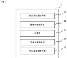
このうち、管理装置2は、管理システム1における石炭及び/又は製鉄ダストの管理のための情報処理を制御するものである。図2は、本実施形態に係る管理装置の機能構成を示す概略模式図である。この図2に示すように、本実施形態に係る管理装置2は、主として、熱分布像情報取得部21と、閾値情報取得部22と、判定部23とを備える。また、管理装置2は、気象情報取得部24と、水分量情報取得部25とを備える。なお、撮像装置3は、撮像部の一例であり、出力装置4は、出力部の一例であり、散水装置5は、散水部の一例であり、以下では特に区別せず説明する。
Among these, the
〔管理システムの機能〕
以下、管理システム1の各部の機能について具体的に説明する。
[Management system functions]
The function of each part of the
[熱分布像情報取得部]
熱分布像情報取得部21は、石炭及び/又は製鉄ダストのパイルPの表層全体を撮像可能な位置から撮像した、パイルPの表層の熱分布像を示す熱分布像情報を取得するように構成されるものである。
[Heat distribution image information acquisition unit]
The heat distribution image
すなわち、この熱分布像情報取得部21が取得する熱分布像情報は、パイルP全体の熱分布情報を見渡すことができる熱分布像である。この熱分布像においては、パイルPのいずれの箇所であっても、測定時に差異がない。すなわち、例えばパイルPのある箇所では14:00に測定したが、パイルPの別の箇所では14:05に測定したという時間的な差異がない。ただし、後述する撮像部が有するセンサ等の仕様によって時間的な幅があってもよい。例えば、14:00~14:02の2分間の間で得られた熱分布像であってもよいが、この場合には、パイルPのいずれの箇所においても、14:00~14:02の2分間の間で得られた熱分布像であるものとする。
That is, the heat distribution image information acquired by the heat distribution image
なお、ヤードY内には複数のパイルPが存在してもよいが、この場合、熱分布像情報は、一つの像でパイル一つのみの熱分布が写った像でもよいし、任意の(例えば、ヤード内の一定範囲の)複数のパイルの熱分布が写った像でもよいし、ヤードYの全てパイルPの熱分布が写った像でもよい。ヤードYの全てパイルPの熱分布が写った像以外の像を用いる場合、パイルPの発熱を比較する観点から、それぞれの像の撮像の時間に大きな時間間隔が開かないようにすることが好ましい。 A plurality of piles P may exist in the yard Y. In this case, the heat distribution image information may be an image showing the heat distribution of only one pile in one image, or any ( For example, an image showing the heat distribution of a plurality of piles within a certain range in the yard, or an image showing the heat distribution of all the piles P in the yard Y may be used. When using an image other than the image showing the heat distribution of the pile P for all of the yard Y, from the viewpoint of comparing the heat generation of the pile P, it is preferable not to open a large time interval between the imaging times of the respective images. .
また、この熱分布像情報は、パイルPを上方から平面視したものであり、パイルの表層の各箇所の温度が含まれるものであれば特に限定されず、例えばサーモグラフィ等が挙げられる。 Further, the heat distribution image information is obtained by planarly viewing the pile P from above, and is not particularly limited as long as it includes the temperature of each location on the surface layer of the pile.
[閾値情報取得部]
閾値情報取得部22は、パイルPの表層が有する温度の閾値を示す閾値情報を取得するように構成されるものである。
[Threshold information acquisition unit]
The threshold information acquisition unit 22 is configured to acquire threshold information indicating the temperature threshold of the surface layer of the pile P. FIG.
温度の閾値は、その温度以上又はその温度を超えた場合に、発熱の度合いを上げるための基準となる閾値である。温度の閾値は、1つでもよいし、複数でもよい。具体的な例は後述する。 The temperature threshold is a threshold that serves as a reference for increasing the degree of heat generation when the temperature is equal to or above that temperature or exceeds that temperature. The number of temperature thresholds may be one or plural. A specific example will be described later.
温度の閾値は、石炭及び/又は製鉄ダストに含まれる水分量や、温度、湿度、設置される箇所等によっても異なる可能性があるため、例えばそれらを考慮して設定してもよい。なお、季節や気象によって閾値を変更しても、変更しなくてもよい。 Since the temperature threshold may vary depending on the amount of water contained in the coal and/or the iron dust, temperature, humidity, installation location, etc., it may be set in consideration of these factors, for example. Note that the threshold may or may not be changed depending on the season or weather.
なお、閾値としては、その値を超えた場合に必ず発熱が起こるものである必要はなく、一定程度の可能性が生じる、高まるものであってもよい。また、閾値としては、安全係数を考慮したものであってもよい。 It should be noted that the threshold value does not necessarily have to generate heat when the value is exceeded, and may be a value that increases the possibility of heat generation to a certain degree. Moreover, the threshold value may be one that considers a safety factor.
[判定部]
判定部23は、熱分布像情報及び閾値情報に基づき、パイルPの発熱を判定するように構成されるものである。
[Determination part]
The
この判定部23は、例えば少なくとも熱分布像情報から、パイルPの表層の温度からパイルPの内部の各箇所の温度を見積って、その見積った温度について、予め設けた温度の閾値を超えるか否か又は閾値以上か否か判定を行うことができる。なお、パイルPの内部の温度の見積りにあたっては、パイルの立体形状(詳細は後述する)等にさらに基づいて見積もることが好ましい。より具体的に、見積りの方法としては、例えばパイルの立体形状と表面温度とからの熱解析等が挙げられる。または、この判定部23は、パイルPの各箇所の表層の温度について、予め設けた閾値を超えるか否か、又は閾値以上か否か判定を行うことができる。例えば、閾値を50℃のみに設定する場合、50℃未満の温度を感知した箇所を「安全」と判定し、50℃以上の温度を感知した箇所を「危険」と判定してもよい。また、閾値を40℃及び50℃に設定する場合、40℃未満の温度を感知した箇所を「安全」と判定し、40℃以上50℃未満の温度を感知した箇所を「注意」と判定し、50℃以上の温度を感知した箇所を「危険」と判定してもよい。
This
判定部23は、パイルPの最も高い温度について温度の閾値を超えるか否か又は閾値以上か否か判定を行ってもよい。例えば、閾値を50℃のみに設定する場合、パイルPの全ての表層が50℃未満であるパイルPを「安全」と判定し、50℃以上の温度の箇所を有するパイルPを「危険」と判定してもよい。また、閾値を40℃及び50℃に設定する場合、パイルPの全ての表層が40℃未満であるパイルPを「安全」と判定し、パイルPが40℃以上の箇所を有するが全ての表層が50℃未満であるパイルPを「注意」と判定し、50℃以上の温度の箇所を有するパイルPを「危険」と判定してもよい。
The
また、ヤードY内に複数のパイルPを設置する場合において、判定部23は、パイルPの最高温度やパイル中の閾値の温度を超える面積等に基づき、パイルPごとに対応の優先度を判定(例えば順位付け等)してもよい。
Further, when a plurality of piles P are installed in the yard Y, the
判定部23は、このようにして優先度の高い順にパイルPをどのように対応するか決定してもよい。対応の方法としては、散水したり、パイルPを切り崩して放熱させたり、払出し(次工程の処理)を行ったりする等してもよい。なお、同じヤードY内のパイルPであっても、あるパイルPは散水するが、別のパイルPは払出しを行う等、複数の対応を組み合わせてもよい。
The
管理システム1が、後述する散水部5を有する場合、判定部23は、パイルの発熱の判定結果に基づき、パイルごとに散水の必要性を判定することが好ましい。
When the
管理システム1が、後述するパイル切崩部(図示せず。)を有する場合、判定部23は、パイルの発熱の判定結果に基づき、パイルPごとにパイルPを切り崩して放熱する必要性を判定することが好ましい。
When the
管理システム1が、後述するパイル払出装置(図示せず。)を有する場合、判定部23は、パイルPの発熱の判定結果に基づき、払い出すパイルPの優先度を判定することが好ましい。
If the
なお、管理システム1が、後述する散水部5、パイル切崩部及びパイル払出装置のうち複数を有する場合(各部が複数存在する場合も含む)、判定部23は、パイルPごとに、それら各部における処理の必要性及びその処理の優先度を判定することが好ましい。
In addition, when the
管理システム1が、後述する気象情報取得部24を有する場合、判定部23は、気象情報取得部24にて取得した気象情報を用いて、パイルPの発熱を判定してもよい。
When the
気象情報として気温を用いる場合、例えば気温が低いときはパイルPが冷却されやすくなり、発熱しにくくなるため、パイルPの発熱の可能性を低下させるような補正をする。一方、例えば気温が高いときは日射による熱も吸収され、発熱しやすくなるため、パイルPの発熱の可能性を高めるような補正をする。 When the air temperature is used as the weather information, for example, when the air temperature is low, the pile P is likely to be cooled and less likely to generate heat. On the other hand, for example, when the air temperature is high, heat due to solar radiation is also absorbed and heat generation is likely to occur.
気象情報として降水量を用いる場合、例えば降水量が多いときは雨によってパイルPが冷却されやすくなり、発熱しにくくなるため、パイルPの発熱の可能性を低下させるような補正をする。一方、例えば降水量が少ないときは雨によって冷却されないため、補正をしない。 When the amount of rainfall is used as the weather information, for example, when the amount of rainfall is large, the pile P is easily cooled by the rain, making it difficult to generate heat. On the other hand, for example, when the amount of rainfall is small, no correction is made because rain does not cool the air.
気象情報として風速を用いる場合、風速が低いときはパイルPの発熱に影響を与えにくいため、補正をしない。また、例えば風速が一定程度高いときにはパイルPへの酸素の供給が高まるため、パイルPの発熱の可能性を高めるような補正をする。さらに、例えば風速が高すぎる場合には風の温度によってパイルPの発熱を冷却するため、パイルPの発熱の可能性を低下させるような補正をする。 When the wind speed is used as the weather information, when the wind speed is low, the heat generation of the pile P is less likely to be affected, so correction is not performed. Further, for example, when the wind speed is high to a certain extent, the supply of oxygen to the pile P increases, so correction is made to increase the possibility of the pile P generating heat. Further, for example, when the wind speed is too high, the heat generation of the pile P is cooled by the temperature of the wind, so correction is made to reduce the possibility of heat generation of the pile P.
また、管理システム1が、後述する水分量情報取得部25を有する場合、判定部23は、水分量情報取得部25にて取得した水分量情報を用いて、パイルPの発熱を判定してもよい。
Further, when the
石炭及び/又は製鉄ダストのパイルPの水分量が多いと発熱しにくくなるため、例えばパイルPの発熱の可能性を低下させるような補正をする。なお、詳細は後述するが、ここで用いる水分量は、特に限定されず、パイルPの表層の水分量、パイルPの水分量の全体平均、パイルPより一部をサンプリングしたものの水分量のいずれであってもよい。 When the moisture content of the pile P of coal and/or steelmaking dust is high, it becomes difficult to generate heat. Although the details will be described later, the moisture content used here is not particularly limited, and may be any of the moisture content of the surface layer of the pile P, the overall average moisture content of the pile P, and the moisture content of a partial sample of the pile P. may be
[気象情報取得部]
気象情報取得部24は、ヤードY内の現在及び未来の予想される気象を示す気象情報を取得するように構成されるものである。
[Weather Information Acquisition Unit]
The weather information acquisition unit 24 is configured to acquire weather information indicating the current and future expected weather within the yard Y. FIG.
なお、「現在」とは判定部23による判定の開始時点をいい、「未来」とは「現在」よりも後の時間をいう。
Note that "current" refers to the time point at which determination by the
気象情報としては、特に限定されないが、降水量、気温、風向、風速、湿度等のうち1又は2以上を用いることができる。気象情報としては、特に、降水量を用いることが好ましい。なお、これらの気象情報は、日本国気象庁をはじめとする各国気象庁や、気象予報会社から得ることができる。 The weather information is not particularly limited, but one or more of precipitation, temperature, wind direction, wind speed, humidity, and the like can be used. As the weather information, it is particularly preferable to use the amount of precipitation. Such weather information can be obtained from the Japan Meteorological Agency and other national meteorological agencies and weather forecasting companies.
なお、パイルPが設置されるヤードYは、通常広大な面積を有することが多く、例えば端部とその反対側の端部とでは、風速等の気象情報が異なることもある。そこで、気象情報取得部24は、気象情報を、パイルPごとに取得してもよい。 The yard Y in which the pile P is installed usually has a vast area, and weather information such as wind speed may differ between the end and the opposite end, for example. Therefore, the weather information acquisition unit 24 may acquire weather information for each pile P. FIG.
[水分量情報取得部]
水分量情報取得部25は、石炭及び/又は製鉄ダストに含まれる水分量を示す水分量情報を取得するように構成されるものである。
[Moisture content information acquisition unit]
The water content
水分量情報としては、特に限定されず、パイルPの表層の水分量、パイルPの水分量の全体平均、パイルPより一部をサンプリングしたものの水分量のいずれであってもよい。ただし、撮像部に、上述したパイルPの表層の熱分布像情報に加えて、水分量情報も測定できるようなセンサを設けることで熱分布像情報と一括して情報を得ることができる。このようなセンサを設ける場合には、パイルPの表層の水分量を用いる。 The moisture content information is not particularly limited, and may be the moisture content of the surface layer of the pile P, the overall average moisture content of the pile P, or the moisture content of a partial sample of the pile P. However, by providing the imaging unit with a sensor capable of measuring moisture content information in addition to the heat distribution image information of the surface layer of the pile P, information can be obtained together with the heat distribution image information. When providing such a sensor, the water content of the surface layer of the pile P is used.
なお、石炭及び/又は製鉄ダストの水分量の測定方法としては、特に限定されず、例えばマイクロ波式、赤外光式等の水分計、熱重量計、乾燥重量方式等によって測定することができる。 The method for measuring the moisture content of coal and/or iron dust is not particularly limited, and can be measured by, for example, a moisture meter such as a microwave type or an infrared light type, a thermogravimetry, a dry weight method, or the like. .
パイルPの水分量情報は、上述したとおりパイルPによって異なることも多い。したがって、水分量情報取得部25は、水分量情報を、パイルPごとに取得することが好ましい。
The moisture content information of the pile P often differs depending on the pile P as described above. Therefore, it is preferable that the moisture content
[撮像部]
撮像部3は、石炭及び/又は製鉄ダストのパイルの表層全体を撮像可能な位置から、パイルの表層の熱分布像を示す熱分布像情報を撮像するように構成されるものである。
[Imaging unit]
The imaging unit 3 is configured to capture heat distribution image information indicating a heat distribution image of the surface layer of the pile from a position where the entire surface layer of the pile of coal and/or steelmaking dust can be imaged.
撮像部3は、具体的には、石炭及び/又は製鉄ダストのパイルの表層全体を撮像可能な位置を飛行することができるドローン等の飛行体や、パイルPの最大高さよりも高い位置まで伸長することができるリクレーマー等のブームに、撮像装置を取り付けて撮像する装置が挙げられる。 Specifically, the imaging unit 3 is a flying object such as a drone that can fly in a position where the entire surface layer of the pile of coal and/or steelmaking dust can be imaged, or an object that extends to a position higher than the maximum height of the pile P. An imaging device is attached to a boom such as a reclaimer that can be used for imaging.
ここで、石炭及び/又は製鉄ダストのパイルPは、高さが10mを超えるものもある。したがって、石炭及び/又は製鉄ダストのパイルPの表層全体を撮像可能な位置は、それよりも十分に高い位置になる。撮像部3の位置としては、特に限定されないが、例えばヤードYから20m以上200m以下高い位置であることが好ましい。具体的に、撮像部3の位置としては、例えば25m以上、30m以上、35m以上、40m以上、45m以上、50m以上、55m以上、60m以上、65m以上、70m以上、75m以上、80m以上、85m以上、90m以上、95m以上、100m以上、105m以上、110m以上、115m以上、120m以上、125m以上、130m以上、135m以上であってよく、また、195m以下、190m以下、185m以下、180m以下、175m以下、170m以下、165m以下、160m以下であってもよい。 Here, some piles P of coal and/or steelmaking dust exceed 10 m in height. Therefore, the position where the entire surface layer of the pile P of coal and/or steelmaking dust can be imaged is a position sufficiently higher than that. Although the position of the imaging unit 3 is not particularly limited, it is preferably a position higher than the yard Y by 20 m or more and 200 m or less. Specifically, the position of the imaging unit 3 is, for example, 25 m or more, 30 m or more, 35 m or more, 40 m or more, 45 m or more, 50 m or more, 55 m or more, 60 m or more, 65 m or more, 70 m or more, 75 m or more, 80 m or more, 85 m or more. 90 m or more, 95 m or more, 100 m or more, 105 m or more, 110 m or more, 115 m or more, 120 m or more, 125 m or more, 130 m or more, 135 m or more, and 195 m or less, 190 m or less, 185 m or less, 180 m or less, It may be 175 m or less, 170 m or less, 165 m or less, or 160 m or less.
なお、撮像部3に、パイルPの表層の水分量を測定するセンサを設け、熱分布像情報とともに、水分量情報を測定し、水分量情報取得部25に取得させてもよい。
Note that the imaging unit 3 may be provided with a sensor for measuring the moisture content of the surface layer of the pile P, and the moisture content information may be measured together with the heat distribution image information, and the moisture content
撮像部3によって測定した熱分布像情報や水分量情報は、熱分布像情報取得部21や水分量情報取得部25とそれぞれ通信して送信してもよいし、撮像部3に記録媒体を付して熱分布像情報をそこに記録し、その記録媒体を介して、熱分布像情報取得部21や水分量情報取得部25に熱分布像情報や水分量情報を取得させてもよい。
The heat distribution image information and moisture content information measured by the imaging unit 3 may be transmitted by communicating with the heat distribution image
[出力部]
出力部4は、判定部によるパイルの発熱の判定結果を、パイルごとに表示するように構成されるものである。
[Output section]
The output unit 4 is configured to display the determination result of pile heat generation by the determination unit for each pile.
この出力部4は、例えば、閾値情報取得部22が取得する閾値を50℃のみに設定する場合、50℃未満の温度を感知した箇所を青色(「安全」を意味する。)に表示し、50℃以上の温度を感知した箇所を赤色(「危険」を意味する。)に表示してもよい。また、閾値を40℃及び50℃に設定する場合、40℃未満の温度を感知した箇所を青色(「安全」を意味する。)に表示し、40℃以上50℃未満の温度を感知した箇所を黄色(「注意」を意味する。)に表示し、50℃以上の温度を感知した箇所を赤色(「危険」を意味する。)に表示してもよい。 For example, when the threshold value acquired by the threshold information acquisition unit 22 is set to only 50° C., the output unit 4 displays locations where a temperature of less than 50° C. is sensed in blue (meaning “safety”), Locations where a temperature of 50° C. or higher is detected may be displayed in red (meaning “danger”). In addition, when the threshold is set to 40°C and 50°C, the locations where the temperature below 40°C is detected are displayed in blue (meaning “safety”), and the locations where the temperature above 40°C and below 50°C are displayed. may be displayed in yellow (meaning "caution"), and locations where a temperature of 50°C or higher is detected in red (meaning "danger").
また、出力部4は、パイルPの最も高い温度について温度の閾値を超えるか否か又は閾値以上か否か判定を行ってもよい。例えば、閾値を50℃のみに設定する場合、パイルPの全ての表層が50℃未満であるパイルPを青色(「安全」を意味する。)に表示し、50℃以上の温度の箇所を有するパイルPを赤色(「危険」を意味する。)に表示してもよい。また、閾値を40℃及び50℃に設定する場合、パイルPの全ての表層が40℃未満であるパイルPを青色(「安全」を意味する。)に表示し、パイルPが40℃以上の箇所を有するが全ての表層が50℃未満であるパイルPを黄色(「注意」を意味する。)に表示し、50℃以上の温度の箇所を有するパイルPを赤色(「危険」を意味する。)に表示してもよい。 The output unit 4 may also determine whether the highest temperature of the pile P exceeds a temperature threshold or is equal to or higher than the threshold. For example, when the threshold is set only to 50°C, the pile P whose surface layer is all less than 50°C is displayed in blue (meaning “safety”) and has a temperature of 50°C or higher. Pile P may be displayed in red (meaning "dangerous"). Further, when the threshold is set to 40 ° C. and 50 ° C., the pile P whose surface layer is all less than 40 ° C. is displayed in blue (meaning “safe”), and the pile P is 40 ° C. or higher. Pile P that has a point but all surface layers are below 50 ° C. is displayed in yellow (meaning "caution"), and pile P that has a point with a temperature of 50 ° C. or higher is displayed in red (meaning "dangerous" ) may be displayed.
以下、本実施形態に係る管理システムによる出力の一例について説明する。図3は、本実施形態に係る出力装置4に出力される画面の一例である。この出力画面は、ヤード全体を上空から平面視した像の温度分布を、2つの閾値を設け、3つの温度帯を設けそれらの温度帯を色分けして示している。具体的に、この出力画面では、40℃未満(安全)、40℃以上50℃未満(注意)及び50℃以上(危険)の3つの温度帯を設けており、後者ほど、すなわち発熱温度が高いほど、濃く着色している。また、この出力画面においては、50℃以上の箇所を有するパイルには、「!!!!」マークを表示している。 An example of output by the management system according to the present embodiment will be described below. FIG. 3 is an example of a screen output to the output device 4 according to this embodiment. This output screen shows the temperature distribution of an image of the entire yard viewed from the sky, with two thresholds provided, three temperature zones provided, and these temperature zones color-coded. Specifically, in this output screen, three temperature zones are provided: less than 40°C (safe), 40°C or more and less than 50°C (caution), and 50°C or more (dangerous). The darker the color. Also, in this output screen, piles having a temperature of 50° C. or higher are marked with “!!!!”.
なお、この出力画面の右側には、本日の天気が示されている。出力画面には、このように本日の天気が示されていてもよいし、示されていなくてもよい。さらに、本日の天気以外の情報が示されていてもよいし、示されていなくてもよい。 Today's weather is displayed on the right side of this output screen. The output screen may or may not show today's weather in this way. Furthermore, information other than today's weather may or may not be displayed.
以上のようにして、パイルP全体、そしてヤードY全体の温度を一つの画面に表示して、発熱の発生を視覚的に認識できるよう表示することで、オペレータ等が素早く対応を検討でき、また、問題の見落としを抑制することもできる。 As described above, the temperatures of the entire pile P and the entire yard Y are displayed on one screen so that the occurrence of heat generation can be visually recognized. , it is also possible to prevent problems from being overlooked.
[散水部]
散水部5は、判定部23による散水の必要性の判定の結果に基づき、散水するように構成されるものである。
[Sprinkler]
The
散水部5としては、パイルPに散水できるものであれば特に限定されないが、例えば移動式の散水車や、パイルPの裾等に設けた散水管等を用いることができる。
The
[パイル切崩部]
図示しないが、パイル切崩部は、判定部23によるパイル切り崩しの必要性の判定の結果に基づき、パイルPごとにパイルPを崩してパイルPの放熱を促進するように構成されるものである。
[Pile cut part]
Although not shown, the pile break-down portion is configured to break the pile P for each pile P based on the determination result of the necessity of pile break-down by the
パイル切崩部は、パイルPを崩して平坦にすることにより、パイルP内部の潜熱を、外気と接触させて放熱する。 The pile cut-out section flattens the pile P by breaking it down, so that the latent heat inside the pile P is brought into contact with the outside air and radiated.
パイル切崩部としては、特に限定されないが、例えばショベルカー、ユンボ等を用いることができる。 The pile cutting part is not particularly limited, but for example, an excavator, a power excavator, or the like can be used.
[パイル払出部]
図示しないが、パイル払出部は、判定部23による払い出すパイルPの優先度の判定の結果に基づき、パイルPの払出しを行うように構成されるものである。
[Pile delivery part]
Although not shown, the pile payout unit is configured to pay out the pile P based on the determination result of the priority of the pile P to be paid out by the
具体的に、このパイル払出部は、例えば判定部23が発熱の可能性が高い順に順位付けしたパイルPについて、その順位付けどおりにパイルPの払出しを行う。
Specifically, the pile dispensing unit dispenses the piles P according to the ranking, for example, the piles P ranked in descending order of the possibility of heat generation by the
なお、このようにして払出しされたパイルP中の石炭及び/又は製鉄ダストは、次の工程に付される。 The coal and/or steelmaking dust in the pile P discharged in this way is subjected to the next step.
本実施形態に係る管理システム1によれば、石炭及び/又は製鉄ダストのパイルPの表層全体を撮像可能な位置から、パイルPの表層の熱分布像を示す熱分布像情報を撮像することにより、簡易にパイルPの表層全体の熱分布を得ることができるし、このような像は視覚的にも発熱の危険性を捉えやすい。しかも、このような熱分布であれば、温度測定の漏れなく、発熱を感知することができる。
According to the
〔管理システムのハードウェア構成〕
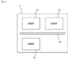
図4は、本実施形態に係る管理装置2のハードウェア構成を示す概略図である。図4に示されるように、管理装置2は、通信部61と、記憶部62と、制御部63とを有し、これらの構成要素が管理装置2の内部において通信バス64を介して電気的に接続されている。以下、これらの構成要素についてさらに説明する。
[Hardware configuration of management system]
FIG. 4 is a schematic diagram showing the hardware configuration of the
通信部61は、USB、IEEE1394、Thunderbolt、有線LANネットワーク通信等といった有線型の通信手段が好ましいが、無線LANネットワーク通信、3G/LTE/5G等のモバイル通信、Bluetooth(登録商標)通信等を必要に応じて含めることができる。すなわち、これら複数の通信手段の集合として実施することがより好ましい。これにより管理装置2と通信可能な他の機器との間で情報や命令のやりとりが実行される。
The
記憶部62は、前述の記載により定義される様々な情報を記憶する。これは、例えばソリッドステートドライブ(Solid State Drive:SSD)等のストレージデバイスとして、または、プログラムの演算に係る一時的に必要な情報(引数、配列等)を記憶するランダムアクセスメモリ(Random Access Memory:RAM)等のメモリとして実施され得る。また、記憶部62は、これらの組合せであってもよい。また、記憶部62は、後述する制御部63が読み出し可能な各種のプログラムを記憶している。
The
制御部63は、管理装置2に関連する全体動作の処理・制御を行う。この制御部63は、例えば中央処理装置(Central Processing Unit:CPU、図示せず。)である。制御部63は、記憶部62に記憶された所定のプログラムを読み出すことによって、管理装置2に係る種々の機能を実現するものである。すなわち、ソフトウェア(記憶部62に記憶されている。)による情報処理がハードウェア(制御部63)によって具体的に実現されることで、図4に示されるように、制御部63における各機能部として実行され得る。なお、図4においては、単一の制御部63として表記されているが、実際はこれに限るものではなく、機能ごとに複数の制御部63を有するように構成してもよく、また、単一の制御部と複数の制御部を組合せてもよい。
The
<管理方法>
本実施形態に係る管理方法は、屋外で管理される、石炭及び/又は製鉄ダストの管理方法であって、撮像工程と、閾値情報取得工程と、判定工程とを備えるものである。撮像工程は、石炭及び/又は製鉄ダストのパイルの全体を撮像可能な位置から、パイルの表層の熱分布像を示す熱分布像情報を撮像する工程である。また、閾値情報取得部は、パイルの表層が有する温度の閾値を示す閾値情報を取得する工程である。さらに、判定部は、熱分布像情報及び閾値情報に基づき、パイルの発熱を判定する工程である。
<Management method>
The management method according to the present embodiment is a management method for coal and/or steelmaking dust that is managed outdoors, and includes an imaging process, a threshold information acquisition process, and a determination process. The imaging step is a step of imaging heat distribution image information indicating a heat distribution image of the surface layer of the pile from a position where the entire pile of coal and/or steelmaking dust can be imaged. The threshold information acquiring unit is a step of acquiring threshold information indicating a temperature threshold of the surface layer of the pile. Furthermore, the determination unit is a step of determining heat generation of the pile based on the heat distribution image information and the threshold information.
図5は、本実施形態に係る管理方法のフローチャート図である。図5に示すとおり、本実施形態に係る管理方法においては、パイルPを撮像する(撮像工程S1)とともに、閾値情報を取得して(閾値情報取得工程S2)、これらを入力情報として、パイルPの発熱を判定する(判定工程S3)。ここで、撮像工程S1及び閾値情報取得工程S2について、順序の先行は問わず、撮像工程S1が先であっても、閾値情報取得工程S2が先であってもよいし、撮像工程S1及び閾値情報取得工程S2を同時に行ってもよい。 FIG. 5 is a flowchart of the management method according to this embodiment. As shown in FIG. 5, in the management method according to the present embodiment, the pile P is imaged (imaging step S1), threshold information is acquired (threshold information acquisition step S2), and the pile P is used as input information. heat generation (judgment step S3). Here, the order of the imaging step S1 and the threshold information obtaining step S2 does not matter. The information acquisition step S2 may be performed at the same time.
なお、本実施形態に係る管理方法においては、気象情報取得工程、水分量情報取得工程、撮像工程、出力工程、散水工程、パイル切崩工程及びパイル払出工程を設けてもよい。これらはそれぞれ、気象情報取得部、水分量情報取得部、撮像部、出力部、散水部、パイル切崩部及びパイル払出部の動作と同様であるので、ここでの説明は省略する。 In addition, in the management method according to the present embodiment, a weather information acquisition process, a moisture content information acquisition process, an imaging process, an output process, a watering process, a pile cutting process, and a pile dispensing process may be provided. These are the same as the operations of the weather information acquisition section, moisture content information acquisition section, imaging section, output section, watering section, pile cutting section, and pile delivery section, respectively, and therefore descriptions thereof are omitted here.
<管理プログラム>
本実施形態に係る管理プログラムは、屋外で管理される、石炭及び/又は製鉄ダストの管理プログラムであって、コンピュータを、熱分布像情報取得部、閾値情報取得部及び判定部として機能させるものである。熱分布像情報取得部、閾値情報取得部及び判定部については上述したので、ここでの説明は省略する。
<Management program>
The management program according to the present embodiment is a management program for coal and/or steelmaking dust that is managed outdoors, and causes a computer to function as a heat distribution image information acquisition unit, a threshold information acquisition unit, and a judgment unit. be. Since the heat distribution image information acquisition unit, the threshold information acquisition unit, and the determination unit have been described above, descriptions thereof will be omitted here.
本発明は、以上の実施形態には何ら制限されず、適宜変更を加えて実施することができる。 The present invention is not limited to the above embodiments, and can be implemented with appropriate modifications.
1 管理システム
2 管理装置
21 熱分布像情報取得部
22 閾値情報取得部
23 判定部
24 気象情報取得部
25 水分量情報取得部
3 撮像装置又は撮像部
4 出力装置又は出力部
5 散水装置又は散水部
61 通信部
62 記憶部
63 制御部
64 通信バス
Y ヤード
P パイル
1
Claims (7)
撮像部と、閾値情報取得部と、判定部とを備え、
前記撮像部は、前記石炭及び/又は製鉄ダストの複数のパイルの表層全体を撮像可能な位置から、前記複数のパイルの表層全体を見渡すことができる熱分布像を示す熱分布像情報を撮像するように構成され、
前記閾値情報取得部は、各前記パイルの表層が有する温度の閾値を示す閾値情報を取得するように構成され、
前記判定部は、前記熱分布像情報及び前記閾値情報に基づき、各前記パイルの発熱を判定した後、前記複数のパイルに対して対応の優先度を判定し、かつ各前記パイルに対する前記対応の方法を決定するように構成され、ここで、前記対応の方法は、前記パイルの切り崩し又は前記パイルの払い出しである、
管理システム。 An outdoor managed coal and/or steel dust management system comprising:
An imaging unit, a threshold information acquisition unit, and a determination unit,
The imaging unit captures heat distribution image information indicating a heat distribution image that allows an overview of the entire surface layer of the plurality of piles from a position where the entire surface layer of the plurality of piles of coal and/or steelmaking dust can be imaged. configured as
The threshold information acquisition unit is configured to acquire threshold information indicating a temperature threshold of the surface layer of each pile,
After determining the heat generation of each of the piles based on the heat distribution image information and the threshold information, the determination unit determines the priority of correspondence to the plurality of piles, and determines the priority of correspondence to each of the piles. configured to determine a method, wherein the corresponding method is cutting the pile or removing the pile;
management system.
出力部をさらに備え、
前記出力部は、前記判定部による各前記パイルの発熱の判定結果を、前記パイルごとに表示するように構成される、
管理システム。 The management system of claim 1, wherein
further equipped with an output section,
The output unit is configured to display the determination result of heat generation of each pile by the determination unit for each pile.
management system.
前記撮像部は、熱分布計を有する飛行体である、
管理システム。 In the management system according to claim 1 or claim 2,
The imaging unit is an aircraft having a heat distribution meter,
management system.
散水部をさらに備え、
前記判定部は、各前記パイルの発熱の判定結果に基づき、前記パイルごとに前記対応の方法としての前記パイルに対する散水の必要性を判定するように構成され、
前記散水部は、前記判定部による散水の必要性の判定の結果に基づき、散水するように構成される、
管理システム。 In the management system according to any one of claims 1 to 3,
Further equipped with a sprinkler part,
The determination unit is configured to determine the necessity of watering the pile as the corresponding method for each pile based on the determination result of heat generation of each pile,
The water spraying unit is configured to spray water based on the determination result of the necessity of watering by the determination unit.
management system.
熱分布像情報取得部と、閾値情報取得部と、判定部とを備え、
前記熱分布像情報取得部は、前記石炭及び/又は製鉄ダストの複数のパイルの表層全体を撮像可能な位置から撮像した、前記複数のパイルの表層全体を見渡すことができる熱分布像情報を取得するように構成され、
前記閾値情報取得部は、各前記パイルの表層が有する温度の閾値を示す閾値情報を取得するように構成され、
前記判定部は、前記熱分布像情報及び前記閾値情報に基づき、各前記パイルの発熱を判定した後、前記複数のパイルに対して対応の優先度を判定し、かつ各前記パイルに対する前記対応の方法を決定するように構成され、ここで、前記対応の方法は、前記パイルの切り崩し又は前記パイルの払い出しである、
管理装置。 A coal and/or steel dust management device managed outdoors,
A heat distribution image information acquisition unit, a threshold information acquisition unit, and a determination unit,
The heat distribution image information acquisition unit acquires heat distribution image information that can overlook the entire surface layer of the plurality of piles, which is imaged from a position where the entire surface layer of the plurality of piles of coal and/or steelmaking dust can be imaged. is configured to
The threshold information acquisition unit is configured to acquire threshold information indicating a temperature threshold of the surface layer of each pile,
After determining the heat generation of each of the piles based on the heat distribution image information and the threshold information, the determination unit determines the priority of correspondence to the plurality of piles, and determines the priority of correspondence to each of the piles. configured to determine a method, wherein the corresponding method is cutting the pile or removing the pile;
management device.
撮像工程と、閾値情報取得工程と、判定工程とを備え、
前記撮像工程は、前記石炭及び/又は製鉄ダストの複数のパイルの全体を撮像可能な位置から、前記複数のパイルの表層全体を見渡すことができる熱分布像を示す熱分布像情報を撮像し、
前記閾値情報取得工程は、各前記パイルの表層が有する温度の閾値を示す閾値情報を取得し、
前記判定工程は、前記熱分布像情報及び前記閾値情報に基づき、各前記パイルの発熱を判定した後、前記複数のパイルに対して対応の優先度を判定し、かつ各前記パイルに対する前記対応の方法を決定し、ここで、前記対応の方法は、前記パイルの切り崩し又は前記パイルの払い出しである、
管理方法。 A method for managing coal and/or steelmaking dust managed outdoors,
An imaging step, a threshold information acquisition step, and a determination step,
In the imaging step, from a position where the entirety of the plurality of piles of coal and/or steelmaking dust can be imaged, thermal distribution image information indicating a thermal distribution image that can overlook the entire surface layer of the plurality of piles is imaged,
The threshold information acquisition step acquires threshold information indicating a temperature threshold of the surface layer of each pile,
In the determination step, after determining the heat generation of each of the piles based on the heat distribution image information and the threshold information, the corresponding priority is determined for the plurality of piles, and the corresponding priority for each of the piles is determined. determining a method , wherein the corresponding method is cutting the pile or removing the pile;
Management method.
コンピュータを、熱分布像情報取得部、閾値情報取得部及び判定部として機能させ、
前記熱分布像情報取得部は、前記石炭及び/又は製鉄ダストの複数のパイルの表層全体を撮像可能な位置から、前記複数のパイルの表層全体を見渡すことができる熱分布像を示す熱分布像情報を取得するように構成され、
前記閾値情報取得部は、各前記パイルの表層が有する温度の閾値を示す閾値情報を取得するように構成され、
前記判定部は、前記熱分布像情報及び前記閾値情報に基づき、各前記パイルの発熱を判定した後、前記複数のパイルに対して対応の優先度を判定し、かつ各前記パイルに対する前記対応の方法を決定するように構成され、ここで、前記対応の方法は、前記パイルの切り崩し又は前記パイルの払い出しである、
管理プログラム。 An outdoor controlled coal and/or steel dust management program comprising:
The computer functions as a heat distribution image information acquisition unit, a threshold information acquisition unit and a determination unit,
The heat distribution image information acquisition unit is configured to obtain a heat distribution image in which the entire surface layer of the plurality of piles of coal and/or steelmaking dust can be imaged from a position where the entire surface layer of the plurality of piles can be imaged. configured to retrieve information,
The threshold information acquisition unit is configured to acquire threshold information indicating a temperature threshold of the surface layer of each pile,
After determining the heat generation of each of the piles based on the heat distribution image information and the threshold information, the determination unit determines the priority of correspondence to the plurality of piles, and determines the priority of correspondence to each of the piles. configured to determine a method, wherein the corresponding method is cutting the pile or removing the pile;
management program.
Priority Applications (10)
| Application Number | Priority Date | Filing Date | Title |
|---|---|---|---|
| JP2020131549A JP7166314B2 (en) | 2020-08-03 | 2020-08-03 | Management system, management device, management method and program |
| EP21852571.5A EP4191506B1 (en) | 2020-08-03 | 2021-07-16 | Management system, management device, management method, and management program |
| AU2021320210A AU2021320210A1 (en) | 2020-08-03 | 2021-07-16 | Management system, management device, management method, and management program |
| BR112023001408A BR112023001408A2 (en) | 2020-08-03 | 2021-07-16 | MANAGEMENT SYSTEM, MANAGEMENT DEVICE, MANAGEMENT METHOD AND MANAGEMENT PROGRAM |
| US18/019,240 US12487127B2 (en) | 2020-08-03 | 2021-07-16 | Management system, management device, management method, and non-transitory computer readable media |
| CN202180058575.7A CN116057561A (en) | 2020-08-03 | 2021-07-16 | Management system, management device, management method and management program |
| PCT/JP2021/026817 WO2022030229A1 (en) | 2020-08-03 | 2021-07-16 | Management system, management device, management method, and management program |
| KR1020237004979A KR20230037638A (en) | 2020-08-03 | 2021-07-16 | Management system, management device, management method and management program |
| TW110128260A TWI883236B (en) | 2020-08-03 | 2021-08-02 | Management system, management apparatus, management method and management program |
| AU2025201399A AU2025201399A1 (en) | 2020-08-03 | 2025-02-27 | Management system, management device, management method, and management program |
Applications Claiming Priority (1)
| Application Number | Priority Date | Filing Date | Title |
|---|---|---|---|
| JP2020131549A JP7166314B2 (en) | 2020-08-03 | 2020-08-03 | Management system, management device, management method and program |
Publications (2)
| Publication Number | Publication Date |
|---|---|
| JP2022028245A JP2022028245A (en) | 2022-02-16 |
| JP7166314B2 true JP7166314B2 (en) | 2022-11-07 |
Family
ID=80119699
Family Applications (1)
| Application Number | Title | Priority Date | Filing Date |
|---|---|---|---|
| JP2020131549A Active JP7166314B2 (en) | 2020-08-03 | 2020-08-03 | Management system, management device, management method and program |
Country Status (9)
| Country | Link |
|---|---|
| US (1) | US12487127B2 (en) |
| EP (1) | EP4191506B1 (en) |
| JP (1) | JP7166314B2 (en) |
| KR (1) | KR20230037638A (en) |
| CN (1) | CN116057561A (en) |
| AU (2) | AU2021320210A1 (en) |
| BR (1) | BR112023001408A2 (en) |
| TW (1) | TWI883236B (en) |
| WO (1) | WO2022030229A1 (en) |
Families Citing this family (1)
| Publication number | Priority date | Publication date | Assignee | Title |
|---|---|---|---|---|
| JP2024099455A (en) * | 2023-01-12 | 2024-07-25 | 栗田工業株式会社 | Management system, management device, management method, and management program |
Citations (8)
| Publication number | Priority date | Publication date | Assignee | Title |
|---|---|---|---|---|
| JP2011007698A (en) | 2009-06-26 | 2011-01-13 | Idemitsu Kosan Co Ltd | Method of measuring temperature distribution of stored coal, method of preventing spontaneous combustion in stored coal, and temperature distribution measuring system of stored coal |
| JP2015132575A (en) | 2014-01-15 | 2015-07-23 | 株式会社神戸製鋼所 | Coal spontaneous combustion prediction method |
| JP2016078999A (en) | 2014-10-20 | 2016-05-16 | Jfeスチール株式会社 | Method for spraying water on deposit of raw material yard |
| JP2016222335A (en) | 2015-06-04 | 2016-12-28 | Ihi運搬機械株式会社 | Method and device for preventing spontaneous ignition of stored coal |
| WO2017038408A1 (en) | 2015-08-28 | 2017-03-09 | 宇部興産株式会社 | Coal storage system and coal storage method |
| JP2018024493A (en) | 2016-08-09 | 2018-02-15 | Ihi運搬機械株式会社 | Method and apparatus for discharging coal from spontaneous combustion in coal storage tank |
| JP2019032165A (en) | 2017-08-04 | 2019-02-28 | 日本アビオニクス株式会社 | Temperature monitoring system and temperature monitoring method |
| JP2021076519A (en) | 2019-11-12 | 2021-05-20 | 千代田化工建設株式会社 | Method and device for detecting heat generation of coal |
Family Cites Families (20)
| Publication number | Priority date | Publication date | Assignee | Title |
|---|---|---|---|---|
| JPH03153829A (en) | 1989-11-09 | 1991-07-01 | Nkk Corp | How to prevent coal ignition |
| JP2761361B2 (en) * | 1995-04-17 | 1998-06-04 | 川崎重工業株式会社 | Method and apparatus for monitoring temperature of coal pile |
| EP1386481A1 (en) * | 2001-05-07 | 2004-02-04 | Flir Systems AB | Infrared camera sensitive for infrared radiation |
| WO2010138987A1 (en) * | 2009-06-02 | 2010-12-09 | Haviland Nominees Pty Ltd | Vehicle mounted unmanned water cannon |
| CN102798470B (en) * | 2012-08-14 | 2015-04-22 | 中国神华能源股份有限公司 | Method and device for monitoring range of heat abnormality in mining area |
| US20150094953A1 (en) * | 2013-10-02 | 2015-04-02 | Deere & Company | System for locating and characterizing a topographic feature from a work vehicle |
| CN103559497A (en) | 2013-10-30 | 2014-02-05 | 中国神华能源股份有限公司 | Coal field fire area information extracting method and device |
| CN103605987A (en) | 2013-11-29 | 2014-02-26 | 中国神华能源股份有限公司 | Coal field fire area determining method and device |
| JP2017096789A (en) | 2015-11-25 | 2017-06-01 | 中国電力株式会社 | Stock coal temperature measurement device and stock coal temperature measurement method |
| KR101653518B1 (en) * | 2016-04-06 | 2016-09-02 | 백정현 | System for predicting spontaneous ignition in coal storehouse and method thereof |
| WO2017199273A1 (en) | 2016-05-19 | 2017-11-23 | 株式会社 スカイロボット | Search system |
| KR101832454B1 (en) | 2017-01-24 | 2018-04-13 | 전주비전대학교산학협력단 | Solar cell exothermic position analysis method using drone based thermal infrared sensor |
| KR101880099B1 (en) | 2017-09-21 | 2018-07-19 | 한국중부발전(주) | Coal depat ignition monitoring system using drone |
| CN107843939B (en) | 2017-10-24 | 2020-03-10 | 防灾科技学院 | Coal fire identification method based on unmanned aerial vehicle thermal infrared image |
| CN108033015B (en) | 2017-12-20 | 2021-05-07 | 西安科技大学 | Unmanned aerial vehicle device and method for monitoring ignition point of coal gangue dump |
| CN108201667A (en) | 2018-01-31 | 2018-06-26 | 成都草寓科技有限公司 | A kind of unmanned plane fire-fighting system based on 3D laser radars |
| CN108536071B (en) | 2018-05-22 | 2021-06-01 | 广州发展集团股份有限公司 | Spontaneous combustion prevention control system for coal yard |
| KR101916375B1 (en) * | 2018-06-07 | 2018-11-07 | (주)수산인더스트리 | System and method for managing volume and fire alarm using drone |
| KR101985019B1 (en) | 2018-12-11 | 2019-05-31 | 전주비전대학교산학협력단 | Method for detecting solar energy module being overheat by using drone and GIS |
| US11170217B2 (en) * | 2019-08-30 | 2021-11-09 | Accenture Global Solutions Limited | Method and system for prediction and mitigation of spontaneous combustion in coal stock piles |
-
2020
- 2020-08-03 JP JP2020131549A patent/JP7166314B2/en active Active
-
2021
- 2021-07-16 CN CN202180058575.7A patent/CN116057561A/en active Pending
- 2021-07-16 WO PCT/JP2021/026817 patent/WO2022030229A1/en not_active Ceased
- 2021-07-16 AU AU2021320210A patent/AU2021320210A1/en not_active Abandoned
- 2021-07-16 BR BR112023001408A patent/BR112023001408A2/en unknown
- 2021-07-16 KR KR1020237004979A patent/KR20230037638A/en active Pending
- 2021-07-16 US US18/019,240 patent/US12487127B2/en active Active
- 2021-07-16 EP EP21852571.5A patent/EP4191506B1/en active Active
- 2021-08-02 TW TW110128260A patent/TWI883236B/en active
-
2025
- 2025-02-27 AU AU2025201399A patent/AU2025201399A1/en active Pending
Patent Citations (8)
| Publication number | Priority date | Publication date | Assignee | Title |
|---|---|---|---|---|
| JP2011007698A (en) | 2009-06-26 | 2011-01-13 | Idemitsu Kosan Co Ltd | Method of measuring temperature distribution of stored coal, method of preventing spontaneous combustion in stored coal, and temperature distribution measuring system of stored coal |
| JP2015132575A (en) | 2014-01-15 | 2015-07-23 | 株式会社神戸製鋼所 | Coal spontaneous combustion prediction method |
| JP2016078999A (en) | 2014-10-20 | 2016-05-16 | Jfeスチール株式会社 | Method for spraying water on deposit of raw material yard |
| JP2016222335A (en) | 2015-06-04 | 2016-12-28 | Ihi運搬機械株式会社 | Method and device for preventing spontaneous ignition of stored coal |
| WO2017038408A1 (en) | 2015-08-28 | 2017-03-09 | 宇部興産株式会社 | Coal storage system and coal storage method |
| JP2018024493A (en) | 2016-08-09 | 2018-02-15 | Ihi運搬機械株式会社 | Method and apparatus for discharging coal from spontaneous combustion in coal storage tank |
| JP2019032165A (en) | 2017-08-04 | 2019-02-28 | 日本アビオニクス株式会社 | Temperature monitoring system and temperature monitoring method |
| JP2021076519A (en) | 2019-11-12 | 2021-05-20 | 千代田化工建設株式会社 | Method and device for detecting heat generation of coal |
Non-Patent Citations (1)
| Title |
|---|
| ドローン水稲モニタリング,[online],2020年02月05日,[令和3年10月5日検索], インターネット<URL:https://web.archive.org/web/20200205165827/https://dronerice.jp/2017/08/07/%E7%86%B1%E8%B5%A4%E5%A4%96%E8%A6%B3%E6%B8%AC/> |
Also Published As
| Publication number | Publication date |
|---|---|
| EP4191506B1 (en) | 2025-11-26 |
| EP4191506C0 (en) | 2025-11-26 |
| AU2025201399A1 (en) | 2025-03-20 |
| EP4191506A1 (en) | 2023-06-07 |
| TW202210979A (en) | 2022-03-16 |
| BR112023001408A2 (en) | 2023-04-04 |
| US12487127B2 (en) | 2025-12-02 |
| WO2022030229A1 (en) | 2022-02-10 |
| CN116057561A (en) | 2023-05-02 |
| AU2021320210A1 (en) | 2023-03-16 |
| TWI883236B (en) | 2025-05-11 |
| EP4191506A4 (en) | 2024-01-17 |
| JP2022028245A (en) | 2022-02-16 |
| KR20230037638A (en) | 2023-03-16 |
| US20240053205A1 (en) | 2024-02-15 |
Similar Documents
| Publication | Publication Date | Title |
|---|---|---|
| CN113847216B (en) | Fan blade state prediction method, device, equipment and storage medium | |
| KR102432286B1 (en) | Road surface condition analysis and salt water spray automatic control system | |
| JP7166314B2 (en) | Management system, management device, management method and program | |
| CN105093047B (en) | Power Line Ampacity Monitoring and Early Warning System | |
| CN208621098U (en) | A kind of temperature and humidity remote supervision system of converter station earthing pole | |
| CN111812457A (en) | Dynamic and static characteristic full-coverage fault assessment model for power transmission line and tower equipment | |
| JP7159251B2 (en) | Management system, management device, management method and management program | |
| JPH0138259B2 (en) | ||
| CN116894584A (en) | Lightning strike risk assessment method, device, storage medium and system for transmission lines | |
| KR100355024B1 (en) | System for measuring snowfall | |
| CN119199350B (en) | A method for monitoring the operating temperature status of electromechanical equipment based on big data | |
| CN113959339A (en) | Method and device for acquiring crack width, crack monitor and crack monitoring system | |
| JP2024099455A (en) | Management system, management device, management method, and management program | |
| US9763397B2 (en) | System and method for monitoring and controlling irrigation delivery in leaching piles | |
| CN118395340A (en) | Abnormality detection method, abnormality detection device, nonvolatile storage medium, and computer device | |
| CN119533673A (en) | A non-contact real-time high-precision road surface temperature acquisition system and method | |
| CN107230217A (en) | A kind of transmission line forest fire method for early warning based on image and gray prediction | |
| CN204480427U (en) | Transmission line forest fire monitoring device | |
| CN117192627A (en) | A low obstacle detection method, device and electronic equipment | |
| CN211402582U (en) | Temperature prediction device for substation equipment | |
| TW202213252A (en) | Management system, management apparatus, management method and management program | |
| CN120601354B (en) | Early warning management system and method for electric energy metering box, computer equipment and storage medium | |
| CN104316219A (en) | Cable trench temperature measuring system and method | |
| US20230403472A1 (en) | Method and system for controlling a guard tour of a thermal camera | |
| CN105444917A (en) | Temperature measuring device and system for switchgear cable joints for switching room |
Legal Events
| Date | Code | Title | Description |
|---|---|---|---|
| A621 | Written request for application examination |
Free format text: JAPANESE INTERMEDIATE CODE: A621 Effective date: 20210716 |
|
| A131 | Notification of reasons for refusal |
Free format text: JAPANESE INTERMEDIATE CODE: A131 Effective date: 20211012 |
|
| A521 | Request for written amendment filed |
Free format text: JAPANESE INTERMEDIATE CODE: A523 Effective date: 20211202 |
|
| A02 | Decision of refusal |
Free format text: JAPANESE INTERMEDIATE CODE: A02 Effective date: 20220419 |
|
| A521 | Request for written amendment filed |
Free format text: JAPANESE INTERMEDIATE CODE: A523 Effective date: 20220627 |
|
| C60 | Trial request (containing other claim documents, opposition documents) |
Free format text: JAPANESE INTERMEDIATE CODE: C60 Effective date: 20220627 |
|
| A521 | Request for written amendment filed |
Free format text: JAPANESE INTERMEDIATE CODE: A821 Effective date: 20220629 |
|
| A911 | Transfer to examiner for re-examination before appeal (zenchi) |
Free format text: JAPANESE INTERMEDIATE CODE: A911 Effective date: 20220719 |
|
| C21 | Notice of transfer of a case for reconsideration by examiners before appeal proceedings |
Free format text: JAPANESE INTERMEDIATE CODE: C21 Effective date: 20220726 |
|
| A131 | Notification of reasons for refusal |
Free format text: JAPANESE INTERMEDIATE CODE: A131 Effective date: 20220913 |
|
| A521 | Request for written amendment filed |
Free format text: JAPANESE INTERMEDIATE CODE: A523 Effective date: 20221006 |
|
| TRDD | Decision of grant or rejection written | ||
| A01 | Written decision to grant a patent or to grant a registration (utility model) |
Free format text: JAPANESE INTERMEDIATE CODE: A01 Effective date: 20221018 |
|
| A61 | First payment of annual fees (during grant procedure) |
Free format text: JAPANESE INTERMEDIATE CODE: A61 Effective date: 20221025 |
|
| R150 | Certificate of patent or registration of utility model |
Ref document number: 7166314 Country of ref document: JP Free format text: JAPANESE INTERMEDIATE CODE: R150 |
|
| S111 | Request for change of ownership or part of ownership |
Free format text: JAPANESE INTERMEDIATE CODE: R313117 |
|
| R350 | Written notification of registration of transfer |
Free format text: JAPANESE INTERMEDIATE CODE: R350 |
|
| R250 | Receipt of annual fees |
Free format text: JAPANESE INTERMEDIATE CODE: R250 |