JP7165466B2 - automatic analyzer - Google Patents

automatic analyzer Download PDF

Info

Publication number
JP7165466B2
JP7165466B2 JP2018176761A JP2018176761A JP7165466B2 JP 7165466 B2 JP7165466 B2 JP 7165466B2 JP 2018176761 A JP2018176761 A JP 2018176761A JP 2018176761 A JP2018176761 A JP 2018176761A JP 7165466 B2 JP7165466 B2 JP 7165466B2
Authority
JP
Japan
Prior art keywords
lid
opening
lid opening
closing
frame
Prior art date
Legal status (The legal status is an assumption and is not a legal conclusion. Google has not performed a legal analysis and makes no representation as to the accuracy of the status listed.)
Active
Application number
JP2018176761A
Other languages
Japanese (ja)
Other versions
JP2020046377A (en
JP2020046377A5 (en
Inventor
太一郎 山下
武徳 大草
進 坂入
Current Assignee (The listed assignees may be inaccurate. Google has not performed a legal analysis and makes no representation or warranty as to the accuracy of the list.)
Hitachi High Tech Corp
Original Assignee
Hitachi High Tech Corp
Priority date (The priority date is an assumption and is not a legal conclusion. Google has not performed a legal analysis and makes no representation as to the accuracy of the date listed.)
Filing date
Publication date
Application filed by Hitachi High Tech Corp filed Critical Hitachi High Tech Corp
Priority to JP2018176761A priority Critical patent/JP7165466B2/en
Priority to US17/265,231 priority patent/US20210349116A1/en
Priority to PCT/JP2019/024692 priority patent/WO2020059231A1/en
Priority to CN201980050156.1A priority patent/CN112513644B/en
Priority to EP19863894.2A priority patent/EP3855188B1/en
Publication of JP2020046377A publication Critical patent/JP2020046377A/en
Publication of JP2020046377A5 publication Critical patent/JP2020046377A5/ja
Application granted granted Critical
Publication of JP7165466B2 publication Critical patent/JP7165466B2/en
Active legal-status Critical Current
Anticipated expiration legal-status Critical

Links

Images

Classifications

    • BPERFORMING OPERATIONS; TRANSPORTING
    • B01PHYSICAL OR CHEMICAL PROCESSES OR APPARATUS IN GENERAL
    • B01LCHEMICAL OR PHYSICAL LABORATORY APPARATUS FOR GENERAL USE
    • B01L3/00Containers or dishes for laboratory use, e.g. laboratory glassware; Droppers
    • B01L3/52Containers specially adapted for storing or dispensing a reagent
    • B01L3/523Containers specially adapted for storing or dispensing a reagent with means for closing or opening
    • GPHYSICS
    • G01MEASURING; TESTING
    • G01NINVESTIGATING OR ANALYSING MATERIALS BY DETERMINING THEIR CHEMICAL OR PHYSICAL PROPERTIES
    • G01N35/00Automatic analysis not limited to methods or materials provided for in any single one of groups G01N1/00 - G01N33/00; Handling materials therefor
    • G01N35/02Automatic analysis not limited to methods or materials provided for in any single one of groups G01N1/00 - G01N33/00; Handling materials therefor using a plurality of sample containers moved by a conveyor system past one or more treatment or analysis stations
    • G01N35/025Automatic analysis not limited to methods or materials provided for in any single one of groups G01N1/00 - G01N33/00; Handling materials therefor using a plurality of sample containers moved by a conveyor system past one or more treatment or analysis stations having a carousel or turntable for reaction cells or cuvettes
    • BPERFORMING OPERATIONS; TRANSPORTING
    • B01PHYSICAL OR CHEMICAL PROCESSES OR APPARATUS IN GENERAL
    • B01LCHEMICAL OR PHYSICAL LABORATORY APPARATUS FOR GENERAL USE
    • B01L3/00Containers or dishes for laboratory use, e.g. laboratory glassware; Droppers
    • B01L3/52Containers specially adapted for storing or dispensing a reagent
    • B01L3/527Containers specially adapted for storing or dispensing a reagent for a plurality of reagents
    • GPHYSICS
    • G01MEASURING; TESTING
    • G01NINVESTIGATING OR ANALYSING MATERIALS BY DETERMINING THEIR CHEMICAL OR PHYSICAL PROPERTIES
    • G01N21/00Investigating or analysing materials by the use of optical means, i.e. using sub-millimetre waves, infrared, visible or ultraviolet light
    • G01N21/01Arrangements or apparatus for facilitating the optical investigation
    • G01N21/13Moving of cuvettes or solid samples to or from the investigating station
    • GPHYSICS
    • G01MEASURING; TESTING
    • G01NINVESTIGATING OR ANALYSING MATERIALS BY DETERMINING THEIR CHEMICAL OR PHYSICAL PROPERTIES
    • G01N35/00Automatic analysis not limited to methods or materials provided for in any single one of groups G01N1/00 - G01N33/00; Handling materials therefor
    • G01N35/10Devices for transferring samples or any liquids to, in, or from, the analysis apparatus, e.g. suction devices, injection devices
    • G01N35/1002Reagent dispensers
    • BPERFORMING OPERATIONS; TRANSPORTING
    • B01PHYSICAL OR CHEMICAL PROCESSES OR APPARATUS IN GENERAL
    • B01LCHEMICAL OR PHYSICAL LABORATORY APPARATUS FOR GENERAL USE
    • B01L2300/00Additional constructional details
    • B01L2300/04Closures and closing means
    • B01L2300/041Connecting closures to device or container
    • GPHYSICS
    • G01MEASURING; TESTING
    • G01NINVESTIGATING OR ANALYSING MATERIALS BY DETERMINING THEIR CHEMICAL OR PHYSICAL PROPERTIES
    • G01N21/00Investigating or analysing materials by the use of optical means, i.e. using sub-millimetre waves, infrared, visible or ultraviolet light
    • G01N21/01Arrangements or apparatus for facilitating the optical investigation
    • G01N2021/0106General arrangement of respective parts
    • G01N2021/0112Apparatus in one mechanical, optical or electronic block
    • GPHYSICS
    • G01MEASURING; TESTING
    • G01NINVESTIGATING OR ANALYSING MATERIALS BY DETERMINING THEIR CHEMICAL OR PHYSICAL PROPERTIES
    • G01N21/00Investigating or analysing materials by the use of optical means, i.e. using sub-millimetre waves, infrared, visible or ultraviolet light
    • G01N21/01Arrangements or apparatus for facilitating the optical investigation
    • G01N2021/0187Mechanical sequence of operations
    • GPHYSICS
    • G01MEASURING; TESTING
    • G01NINVESTIGATING OR ANALYSING MATERIALS BY DETERMINING THEIR CHEMICAL OR PHYSICAL PROPERTIES
    • G01N35/00Automatic analysis not limited to methods or materials provided for in any single one of groups G01N1/00 - G01N33/00; Handling materials therefor
    • G01N2035/00178Special arrangements of analysers
    • G01N2035/00306Housings, cabinets, control panels (details)
    • GPHYSICS
    • G01MEASURING; TESTING
    • G01NINVESTIGATING OR ANALYSING MATERIALS BY DETERMINING THEIR CHEMICAL OR PHYSICAL PROPERTIES
    • G01N35/00Automatic analysis not limited to methods or materials provided for in any single one of groups G01N1/00 - G01N33/00; Handling materials therefor
    • G01N35/02Automatic analysis not limited to methods or materials provided for in any single one of groups G01N1/00 - G01N33/00; Handling materials therefor using a plurality of sample containers moved by a conveyor system past one or more treatment or analysis stations
    • G01N35/04Details of the conveyor system
    • G01N2035/0439Rotary sample carriers, i.e. carousels
    • G01N2035/0441Rotary sample carriers, i.e. carousels for samples
    • GPHYSICS
    • G01MEASURING; TESTING
    • G01NINVESTIGATING OR ANALYSING MATERIALS BY DETERMINING THEIR CHEMICAL OR PHYSICAL PROPERTIES
    • G01N35/00Automatic analysis not limited to methods or materials provided for in any single one of groups G01N1/00 - G01N33/00; Handling materials therefor
    • G01N35/02Automatic analysis not limited to methods or materials provided for in any single one of groups G01N1/00 - G01N33/00; Handling materials therefor using a plurality of sample containers moved by a conveyor system past one or more treatment or analysis stations
    • G01N35/04Details of the conveyor system
    • G01N2035/0439Rotary sample carriers, i.e. carousels
    • G01N2035/0443Rotary sample carriers, i.e. carousels for reagents
    • GPHYSICS
    • G01MEASURING; TESTING
    • G01NINVESTIGATING OR ANALYSING MATERIALS BY DETERMINING THEIR CHEMICAL OR PHYSICAL PROPERTIES
    • G01N35/00Automatic analysis not limited to methods or materials provided for in any single one of groups G01N1/00 - G01N33/00; Handling materials therefor
    • G01N35/02Automatic analysis not limited to methods or materials provided for in any single one of groups G01N1/00 - G01N33/00; Handling materials therefor using a plurality of sample containers moved by a conveyor system past one or more treatment or analysis stations
    • G01N35/04Details of the conveyor system
    • G01N2035/0439Rotary sample carriers, i.e. carousels
    • G01N2035/0444Rotary sample carriers, i.e. carousels for cuvettes or reaction vessels

Description

本開示は、自動分析装置に関する。 The present disclosure relates to automated analyzers.

自動分析装置は、血液や尿などのサンプルを自動的に分析する装置であり、試薬保冷庫内の試薬容器から所定量の試薬を分注してサンプルと混合することにより、測定を実行する。一般に、試薬容器から試薬を吸引するための開口部には、試薬の蒸発や劣化、液もれ等を防止するための蓋が設けられており、自動分析装置には、試薬容器の蓋を開閉する蓋開閉装置が備えられる。 An automatic analyzer is a device that automatically analyzes samples such as blood and urine, and performs measurement by dispensing a predetermined amount of reagent from a reagent container in a reagent cooler and mixing it with the sample. In general, the opening for aspirating the reagent from the reagent container is provided with a lid to prevent the reagent from evaporating, deteriorating, or leaking. A lid opening and closing device is provided.

このような蓋開閉装置を備える自動分析装置として、特許文献1には、「分析に使用する試薬を収容する試薬容器を保管する試薬保冷庫と、前記試薬保冷庫内に設けられ、前記試薬容器の上方に突出して配置された開口部に設けられた蓋を開閉する試薬容器蓋開閉装置と、前記試薬保冷庫への前記試薬容器の搬入及び搬出を行う試薬ローダ機構と、前記試薬容器が前記試薬ローダ機構に挿入される際に前記試薬容器の開口部の蓋を半開状態にする試薬容器制御機構に設けられ、予め定められた向き以外での前記試薬容器の前記試薬容器制御機構への挿入を制限する挿入方向制限機構とを備えたことを特徴とする自動分析装置」が開示されている(請求項1参照)。 As an automatic analyzer equipped with such a lid opening/closing device, Patent Document 1 describes "a reagent cooler for storing a reagent container containing a reagent used for analysis, and a reagent cooler provided in the reagent cooler, wherein the reagent container is a reagent container lid opening/closing device that opens and closes a lid provided in an opening that protrudes upward from the reagent container; a reagent loader mechanism that loads and unloads the reagent container from and to the reagent cooler; provided in a reagent container control mechanism that half-opens the lid of the opening of the reagent container when the reagent container is inserted into the reagent loader mechanism, and inserts the reagent container into the reagent container control mechanism in a direction other than a predetermined orientation and an insertion direction limiting mechanism for limiting the insertion direction” is disclosed (see claim 1).

また、特許文献2には、「試料を化学分析する自動分析装置であって、試料の分析に使用する試薬を収容した複数一組の試薬容器を複数組搭載可能な容器搬送装置と、この容器搬送装置上の分注撹拌位置にある試薬容器の蓋を開閉する試薬容器蓋開閉装置とを備え、当該試薬容器蓋開閉装置は、ユニットベースと、このユニットベースに連結したフック基部と、このフック基部を前記ユニットベースに対して前記試薬容器の蓋の開閉方向に平行移動させる蓋開閉用駆動装置と、前記フック基部に設けた複数のフックと、これらフックを前記フック基部に対して個別に揺動させ、各試薬容器の蓋に対して対応するフックを係脱させる複数のフック用駆動装置とを備えたことを特徴とする自動分析装置」が開示されている(請求項1参照)。 Further, Patent Document 2 describes "an automatic analyzer for chemically analyzing a sample, which is a container transport device capable of mounting a plurality of sets of reagent containers containing reagents used for analyzing the sample, and A reagent container lid opening/closing device for opening and closing the lid of the reagent container at the dispensing and stirring position on the container transporting device is provided, and the reagent container lid opening/closing device includes a unit base, a hook base connected to the unit base, and the a lid opening/closing driving device for moving a hook base parallel to the unit base in the opening/closing direction of the lid of the reagent container; a plurality of hooks provided on the hook base; and a plurality of hook driving devices for rocking and disengaging the corresponding hooks from the lids of the respective reagent containers” (see claim 1).

特開2017-075789号公報JP 2017-075789 A 国際公開第2011/074472号WO2011/074472

しかしながら、特許文献1に開示された試薬容器蓋開閉装置は、試薬ローダ機構に対して試薬容器を挿入又は排出する際に試薬容器全体が水平移動するための空間が必要であり、試薬容器蓋開閉装置の小型化には限界がある。 However, the reagent container lid opening/closing device disclosed in Patent Literature 1 requires a space for horizontal movement of the entire reagent container when the reagent container is inserted into or ejected from the reagent loader mechanism. There is a limit to miniaturization of the device.

また、特許文献2においては、フック基部を蓋の開閉方向に平行移動させる蓋開閉用駆動装置と、複数のフック用駆動装置とを備えるため、各試薬容器の蓋を個別に開閉可能であるものの、構造が複雑であり、小型化が困難である。 Further, in Patent Document 2, since a lid opening/closing driving device for moving a hook base in parallel in the opening/closing direction of the lid and a plurality of hook driving devices are provided, the lid of each reagent container can be opened and closed individually. , the structure is complicated and miniaturization is difficult.

そこで、本開示は、構造が簡単で小型化が可能な自動分析装置を提供する。 Therefore, the present disclosure provides an automatic analyzer that has a simple structure and can be miniaturized.

本開示の自動分析装置は、試薬を収容する試薬容器を保持する試薬庫と、鉛直方向に平行な第1の方向及び前記第1の方向に垂直な第2の方向に移動可能に構成された蓋開閉部材を備える蓋開閉装置と、を備え、前記蓋開閉部材は、前記試薬容器の蓋を開放する第1の部材と、前記蓋を閉じる第2の部材と、を一体で備え、前記試薬容器の上方の位置である第1の位置と、前記第1の位置から前記蓋開閉部材の底面が前記試薬容器に接するまで前記第1の方向に下降した位置である第2の位置とを互いに移動可能に構成され、前記第2の位置と、前記第2の位置から前記第2の方向に移動した位置である第3の位置とを互いに移動可能に構成され、前記第2の位置から前記第3の位置に移動する際に、前記第1の部材により前記蓋を開放し、前記第3の位置から前記第2の位置に移動する際に、前記第2の部材により前記蓋を閉じることを特徴とする。 An automatic analyzer of the present disclosure is configured to be movable in a first direction parallel to a vertical direction and a second direction perpendicular to the first direction, and a reagent storage holding reagent containers containing reagents. a lid opening/closing device comprising a lid opening/closing member, wherein the lid opening/closing member integrally includes a first member for opening the lid of the reagent container and a second member for closing the lid; A first position above the container and a second position lower in the first direction from the first position until the bottom surface of the lid opening/closing member comes into contact with the reagent container. configured to be movable between the second position and a third position that is a position moved in the second direction from the second position; Opening the lid by the first member when moving to the third position, and closing the lid by the second member when moving from the third position to the second position characterized by

本開示に関連する更なる特徴は、本明細書の記述、添付図面から明らかになるものである。また、本開示の態様は、要素及び多様な要素の組み合わせ及び以降の詳細な記述と添付される特許請求の範囲の様態により達成され実現される。
本明細書の記述は典型的な例示に過ぎず、本開示の特許請求の範囲又は適用例を如何なる意味に於いても限定するものではないことを理解する必要がある。
Further features related to the present disclosure will become apparent from the description of the specification and the accompanying drawings. In addition, the aspects of the present disclosure will be achieved and attained by means of the elements and combinations of various elements and aspects of the detailed description that follows and the claims that follow.
It should be understood that the description herein is merely exemplary and is not intended in any way to limit the scope or application of this disclosure.

本開示によれば、構造が簡単で小型化が可能な自動分析装置を提供することができる。
上記した以外の課題、構成及び効果は、以下の実施形態の説明により明らかにされる。
According to the present disclosure, it is possible to provide an automatic analyzer that has a simple structure and can be miniaturized.
Problems, configurations, and effects other than those described above will be clarified by the following description of the embodiments.

第1の実施形態に係る自動分析装置の平面図である。1 is a plan view of an automatic analyzer according to a first embodiment; FIG. 第1の実施形態に係る自動分析装置の斜視図である。1 is a perspective view of an automatic analyzer according to a first embodiment; FIG. 試薬容器の構成を示す斜視図である。4 is a perspective view showing the configuration of a reagent container; FIG. 図3のA-A断面図である。FIG. 4 is a cross-sectional view taken along the line AA of FIG. 3; 蓋開閉装置の正面図であり、蓋開閉カム部材が第1の位置にある。FIG. 4 is a front view of the lid opening/closing device, with the lid opening/closing cam member at the first position; 図5のB-B断面図であり、蓋開閉カム部材が第1の位置にある。FIG. 6 is a cross-sectional view taken along line BB of FIG. 5, in which the lid opening/closing cam member is at the first position; 蓋開閉装置の斜視図であり、蓋開閉カム部材が第1の位置にある。FIG. 4 is a perspective view of the lid opening/closing device, with the lid opening/closing cam member in the first position; 蓋開閉装置及び分注穴カバーの斜視図である。FIG. 3 is a perspective view of a lid opening/closing device and a dispensing hole cover; 蓋開閉装置及び分注穴カバーの平面図である。Fig. 2 is a plan view of the lid opening/closing device and the dispensing hole cover; 蓋開閉装置及び分注穴カバーの分解斜視図である。FIG. 4 is an exploded perspective view of a lid opening/closing device and a dispensing hole cover; 分注穴カバーの構成を示す平面図であり、スライドシャッタが閉じられた状態を示す。FIG. 4 is a plan view showing the configuration of the dispensing hole cover, showing a state in which the slide shutter is closed; 分注穴カバーの構成を示す平面図であり、スライドシャッタが開閉途中の状態を示す。FIG. 4 is a plan view showing the configuration of the dispensing hole cover, showing a state in which the slide shutter is in the middle of opening and closing; 分注穴カバーの構成を示す平面図であり、スライドシャッタが開放された状態を示す。FIG. 4 is a plan view showing the configuration of the dispensing hole cover, showing a state in which the slide shutter is opened; Zスライドフレームの構成を示す斜視図である。FIG. 4 is a perspective view showing the configuration of a Z slide frame; Zスライドフレームの構成を示す背面斜視図である。FIG. 4 is a rear perspective view showing the configuration of a Z slide frame; 図14のC-C断面図である。FIG. 15 is a cross-sectional view taken along line CC of FIG. 14; 蓋開閉カム部材の構成を示す図であり、図17(a)は上面図、図17(b)は図17(a)のA矢視図、図17(c)は図17(a)のD-D断面図、図17(d)は図17(a)のB矢視図、図17(e)は下面図である。17(a) is a top view, FIG. 17(b) is a view in the direction of arrow A in FIG. 17(a), and FIG. 17(c) is a top view of FIG. FIG. 17(d) is a view taken along arrow B in FIG. 17(a), and FIG. 17(e) is a bottom view. 図18(a)は図17(c)のC矢視図であり、図18(b)は図17(c)のD矢視図である。18(a) is a view on arrow C in FIG. 17(c), and FIG. 18(b) is a view on arrow D in FIG. 17(c). 蓋と蓋開閉カム部材の関係を示す正面概略図である。FIG. 4 is a schematic front view showing the relationship between a lid and a lid opening/closing cam member; 図17(a)のD-D断面図であり、蓋開閉カム部材が第1の位置にある状態を示す。FIG. 17B is a cross-sectional view taken along line DD of FIG. 17A, showing a state in which the lid opening/closing cam member is at the first position; 図17(a)のD-D断面図であり、蓋開閉カム部材が第2の位置にある状態を示す。FIG. 17B is a cross-sectional view taken along line DD of FIG. 17A, showing a state in which the cover opening/closing cam member is at the second position; 図17(a)のD-D断面図であり、蓋開閉カム部材が第2の位置から第3の位置に移動する途中にある状態を示す。FIG. 17B is a cross-sectional view taken along line DD of FIG. 17A, showing a state in which the lid opening/closing cam member is in the process of being moved from the second position to the third position. 図17(a)のD-D断面図であり、蓋開閉カム部材が第2の位置から第3の位置に移動する途中にある状態を示す。FIG. 17B is a cross-sectional view taken along line DD of FIG. 17A, showing a state in which the lid opening/closing cam member is in the process of being moved from the second position to the third position. 図17(a)のD-D断面図であり、蓋開閉カム部材が第3の位置にある状態を示す。FIG. 17B is a cross-sectional view taken along line DD of FIG. 17A, showing a state where the lid opening/closing cam member is at the third position; 図17(a)のD-D断面図であり、蓋開閉カム部材が第3の位置から第2の位置に移動する途中にある状態を示す。FIG. 17B is a cross-sectional view taken along line DD of FIG. 17A, showing a state in which the lid opening/closing cam member is in the process of being moved from the third position to the second position. 図17(a)のD-D断面図であり、蓋開閉カム部材が第3の位置から第2の位置に移動する途中にある状態を示す。FIG. 17B is a cross-sectional view taken along line DD of FIG. 17A, showing a state in which the lid opening/closing cam member is in the process of being moved from the third position to the second position. 図17(a)のD-D断面図であり、蓋開閉カム部材が第3の位置から第2の位置に移動する途中にある状態を示す。FIG. 17B is a cross-sectional view taken along line DD of FIG. 17A, showing a state in which the lid opening/closing cam member is in the process of being moved from the third position to the second position. 図17(a)のD-D断面図であり、蓋開閉カム部材が第2の位置にある状態を示す。FIG. 17B is a cross-sectional view taken along line DD of FIG. 17A, showing a state in which the cover opening/closing cam member is at the second position; 蓋開閉装置の斜視図であり、蓋開閉カム部材が第2の位置にある状態を示す。FIG. 11 is a perspective view of the lid opening/closing device, showing a state where the lid opening/closing cam member is at the second position; 蓋開閉装置の斜視図であり、蓋開閉カム部材が第2の位置にある状態を示す。FIG. 11 is a perspective view of the lid opening/closing device, showing a state where the lid opening/closing cam member is at the second position; 蓋開閉装置の正面図であり、蓋開閉カム部材が第2の位置にある状態を示す。FIG. 11 is a front view of the lid opening/closing device, showing a state where the lid opening/closing cam member is at the second position; 蓋開閉装置の斜視図であり、蓋開閉カム部材が第3の位置にある状態を示す。FIG. 11 is a perspective view of the lid opening/closing device, showing a state where the lid opening/closing cam member is at the third position; 蓋開閉装置の斜視図であり、蓋開閉カム部材が第3の位置にある状態を示す。FIG. 11 is a perspective view of the lid opening/closing device, showing a state where the lid opening/closing cam member is at the third position; 蓋開閉装置の正面図であり、蓋開閉カム部材が第3の位置にある状態を示す。FIG. 11 is a front view of the lid opening/closing device, showing a state where the lid opening/closing cam member is at the third position; 図34のB-B断面図であり、開閉カム部材が第3の位置にある状態を示す。FIG. 35 is a cross-sectional view taken along line BB of FIG. 34, showing a state in which the opening/closing cam member is at the third position; 蓋開閉装置の正面図であり、蓋開閉カム部材が第2の位置にある状態を示す。FIG. 11 is a front view of the lid opening/closing device, showing a state where the lid opening/closing cam member is at the second position; 蓋開閉装置の正面図であり、蓋開閉カム部材が第2の位置にある状態から蓋を閉じる方向の力を付与した状態を示す。FIG. 10 is a front view of the lid opening/closing device, showing a state in which the lid opening/closing cam member is applied with a force in the direction of closing the lid from the second position. 蓋開閉装置の正面図であり、試薬容器が逆向きにセットされて、蓋開閉カム部材が下降途中で蓋に当接した状態を示す。FIG. 10 is a front view of the lid opening/closing device, showing a state in which the reagent container is set in the opposite direction and the lid opening/closing cam member comes into contact with the lid in the middle of its descent. 蓋開閉装置の正面図であり、試薬容器が逆向きにセットされて、蓋開閉カム部材が下降途中で蓋に当接した状態を示す。FIG. 10 is a front view of the lid opening/closing device, showing a state in which the reagent container is set in the opposite direction and the lid opening/closing cam member comes into contact with the lid in the middle of its descent. 蓋開閉装置の正面図であり、試薬容器がセットされておらず、蓋開閉カム部材が第4の位置にある状態を示す。FIG. 11 is a front view of the lid opening/closing device, showing a state where the reagent container is not set and the lid opening/closing cam member is at the fourth position; 第1の実施形態に係る自動分析装置の構成を示すブロック図である。1 is a block diagram showing the configuration of an automatic analyzer according to a first embodiment; FIG. 蓋開閉装置による蓋の開き動作を示すフローチャートである。It is a flowchart which shows the opening operation|movement of the lid|cover by a lid|cover opening-and-closing apparatus. 蓋開閉装置による蓋の閉じ動作を示すフローチャートである。It is a flowchart which shows the closing operation|movement of the lid|cover by a lid|cover opening/closing apparatus.

以下、図面を参照して、本開示の実施形態を説明する。 Embodiments of the present disclosure will be described below with reference to the drawings.

[第1の実施形態]
以下において、鉛直方向(第1の方向)にZ軸をとり、Z軸に直交し、自動分析装置1の蓋開閉装置22の長手方向に平行な方向(第2の方向)にX軸をとり、X軸に直交する方向(第3の方向)にY軸をとる。また、X軸の正方向側及び負方向側をそれぞれ「右」及び「左」、Y軸の正方向側及び負方向側をそれぞれ「後」及び「前」、Z軸の正方向側及び負方向側をそれぞれ「上」及び「下」という場合がある。
[First Embodiment]
In the following, the Z-axis is taken in the vertical direction (first direction), and the X-axis is taken in a direction (second direction) perpendicular to the Z-axis and parallel to the longitudinal direction of the lid opening/closing device 22 of the automatic analyzer 1. , the Y-axis in a direction (third direction) orthogonal to the X-axis. In addition, the positive direction side and negative direction side of the X axis are "right" and "left" respectively, the positive direction side and negative direction side of the Y axis are "back" and "front" respectively, the positive direction side and negative direction side of the Z axis are "front" and "back" respectively. The directional sides may be referred to as "up" and "down", respectively.

図1及び2を参照して、第1の実施形態に係る自動分析装置1の全体構成について説明する。図1は、第1の実施形態に係る自動分析装置1の平面図である。図2は、第1の実施形態に係る自動分析装置1の斜視図である。 The overall configuration of the automatic analyzer 1 according to the first embodiment will be described with reference to FIGS. 1 and 2. FIG. FIG. 1 is a plan view of an automatic analyzer 1 according to the first embodiment. FIG. 2 is a perspective view of the automatic analyzer 1 according to the first embodiment.

図1及び2に示すように、自動分析装置1は、試薬ディスク2、安全カバー4、サンプル搬送手段5、サンプル分注手段6、チップラック7、搬送手段8、インキュベータ9、サンプル分注チップバッファ11、廃棄孔12、撹拌手段13、試薬分注プローブ15、撹拌手段16、洗浄手段17、反応溶液分注プローブ18、検出部19、筐体21、蓋開閉装置22、廃棄ボックス23及び試薬保冷庫24(試薬庫)を備える。 As shown in FIGS. 1 and 2, the automatic analyzer 1 includes a reagent disk 2, a safety cover 4, a sample transport means 5, a sample dispensing means 6, a tip rack 7, a transport means 8, an incubator 9, a sample dispensing tip buffer, and a sample dispensing tip buffer. 11, disposal hole 12, stirring means 13, reagent dispensing probe 15, stirring means 16, washing means 17, reaction solution dispensing probe 18, detection unit 19, housing 21, lid opening/closing device 22, disposal box 23, and reagent cooling A storage 24 (reagent storage) is provided.

筐体21は、略直方体の形状を有し、サンプル搬送手段5、洗浄手段17、廃棄ボックス23、試薬保冷庫24、図示しない基板や流路などを内部に収容する。 The housing 21 has a substantially rectangular parallelepiped shape and accommodates therein the sample conveying means 5, the washing means 17, the disposal box 23, the reagent cooler 24, substrates and channels (not shown), and the like.

安全カバー4は、例えばヒンジ等により筐体21の上面の一辺に支持され、ヒンジのまわりに開閉可能に構成される。図1及び2中の一点鎖線は、安全カバー4を閉じた状態を示す。安全カバー4は、例えばソレノイドなどによるインターロックが設けられており、自動分析装置1の動作中はソレノイドに通電することによって閂をかけ、安全カバー4を閉じた状態に維持する。自動分析装置1の停止中は、ソレノイドへの通電が解除され、安全カバー4が開放可能となる。 The safety cover 4 is supported by, for example, a hinge or the like on one side of the upper surface of the housing 21 and configured to be openable and closable around the hinge. 1 and 2 show the state in which the safety cover 4 is closed. The safety cover 4 is provided with an interlock by, for example, a solenoid. During the operation of the automatic analyzer 1, the solenoid is energized to lock and maintain the safety cover 4 in a closed state. While the automatic analyzer 1 is stopped, the solenoid is de-energized and the safety cover 4 can be opened.

サンプル搬送手段5は、例えばベルトコンベヤやラックハンドラ等から構成され、自動分析装置1内においてサンプル5aを移動し、サンプル分注手段6の可動域まで搬送する。 The sample conveying means 5 is composed of, for example, a belt conveyor, a rack handler, etc., moves the sample 5a within the automatic analyzer 1, and conveys it to the movable range of the sample dispensing means 6. FIG.

チップラック7は、自動分析装置1から着脱可能に構成され、複数のサンプル分注チップ10及び複数の反応容器14が載置された状態で操作者により自動分析装置1の上面に配置される。 The tip rack 7 is configured to be detachable from the automatic analyzer 1, and placed on the upper surface of the automatic analyzer 1 by the operator with a plurality of sample dispensing tips 10 and a plurality of reaction containers 14 mounted thereon.

搬送手段8は、平面方向及びZ軸方向に移動可能に構成され、チップラック7、インキュベータ9の一部、サンプル分注チップバッファ11、廃棄孔12及び撹拌手段13の上方を移動可能に構成される。搬送手段8として、例えば三軸ロボット等を用いることができる。搬送手段8は、チップラック7から反応容器14を一つずつ把持し、インキュベータ9へ移動させる。また、搬送手段8は、チップラック7からサンプル分注チップ10を一つずつ把持し、サンプル分注チップバッファ11まで移動させる。 The conveying means 8 is configured to be movable in the planar direction and the Z-axis direction, and is configured to be movable above the tip rack 7, a part of the incubator 9, the sample dispensing tip buffer 11, the disposal hole 12, and the stirring means 13. be. As the transport means 8, for example, a three-axis robot or the like can be used. The transport means 8 grips the reaction containers 14 one by one from the tip rack 7 and moves them to the incubator 9 . Further, the transport means 8 grips the sample dispensing tips 10 one by one from the tip rack 7 and moves them to the sample dispensing tip buffer 11 .

サンプル分注チップバッファ11は、搬送手段8が把持したサンプル分注チップ10を一時的に載置するバッファである。サンプル分注チップバッファ11は、複数のサンプル分注チップ10を載置可能に構成される。 The sample-dispensing tip buffer 11 is a buffer on which the sample-dispensing tip 10 gripped by the conveying means 8 is temporarily placed. The sample-dispensing tip buffer 11 is configured so that a plurality of sample-dispensing tips 10 can be placed thereon.

インキュベータ9は、略円盤形状を有し、回転可能に構成される。インキュベータ9は、周方向に沿って複数の反応容器14を保持し、インキュベータ9の回転によって、各反応容器14を所定の位置まで移動させることができる。 The incubator 9 has a substantially disk shape and is configured to be rotatable. The incubator 9 holds a plurality of reaction vessels 14 along the circumferential direction, and each reaction vessel 14 can be moved to a predetermined position by rotating the incubator 9 .

サンプル分注手段6は、サンプル分注チップバッファ11の上部に移動して、サンプル分注チップ10のいずれか1つを把持し、サンプル5aの上部に移動して、サンプル分注チップ10の内部にサンプル5aを吸引する。その後、インキュベータ9上の反応容器14の上部へ移動し、サンプル5aをサンプル分注チップ10内部から反応容器14内に吐出する。その後、サンプル分注手段6は、廃棄孔12の上部に移動し、サンプル分注チップ10を廃棄孔12の内部に落下させる。 The sample pipetting means 6 moves to the top of the sample pipetting tip buffer 11, grasps any one of the sample pipetting tips 10, moves to the top of the sample 5a, and moves inside the sample pipetting tip 10. aspirate the sample 5a. After that, it moves to the upper part of the reaction container 14 on the incubator 9 and discharges the sample 5a into the reaction container 14 from the inside of the sample pipetting tip 10 . After that, the sample pipetting means 6 moves to the upper part of the disposal hole 12 and drops the sample pipetting tip 10 inside the disposal hole 12 .

廃棄ボックス23は、廃棄孔12の下部に配置され、廃棄されたサンプル分注チップ10及び反応容器14を蓄積する。廃棄ボックス23が満杯となった際には、操作者は、廃棄ボックス23を引き出して中身を廃棄することができる。 The discard box 23 is arranged below the discard hole 12 and accumulates discarded sample pipetting tips 10 and reaction containers 14 . When the disposal box 23 is full, the operator can pull out the disposal box 23 and discard the contents.

試薬保冷庫24は、略円筒形状を有し、試薬ディスク2を収容する。試薬保冷庫24の上面には、試薬ディスク2に対する試薬容器3の着脱を行うための試薬容器装填口20が設けられる。また、試薬容器装填口20には、開閉式の試薬容器装填口蓋(不図示)が設けられ、ソレノイド等を用いたインターロックが設けられる。試薬保冷庫24は、試薬容器3を一定の温度に制御するために、断熱機能を有する。 The reagent cooler 24 has a substantially cylindrical shape and accommodates the reagent discs 2 . A reagent container loading port 20 for loading and unloading the reagent container 3 with respect to the reagent disk 2 is provided on the upper surface of the reagent cooler 24 . Further, the reagent container loading port 20 is provided with an opening/closing type reagent container loading port cover (not shown), and is provided with an interlock using a solenoid or the like. The reagent cooler 24 has a heat insulating function to control the temperature of the reagent container 3 at a constant temperature.

試薬ディスク2は、周方向に沿って複数の試薬容器3を放射状に保持するスロットを形成する。試薬ディスク2は、Z軸方向に延びる中心軸のまわりに回転可能に構成され、試薬ディスク2を回転することで、各試薬容器3を所定の位置へ移動させる。例えば、試薬ディスク2の回転により、目的の試薬を収容する試薬容器3を試薬分注位置15aに移動させることができる。試薬容器3の構成については後述する。なお、試薬容器3は、試薬の撹拌のための磁気粒子を含んでいてもよい。 The reagent disk 2 forms slots for radially holding a plurality of reagent containers 3 along the circumferential direction. The reagent disk 2 is rotatable around a central axis extending in the Z-axis direction, and by rotating the reagent disk 2, each reagent container 3 is moved to a predetermined position. For example, by rotating the reagent disk 2, the reagent container 3 containing the target reagent can be moved to the reagent dispensing position 15a. The configuration of the reagent container 3 will be described later. Note that the reagent container 3 may contain magnetic particles for stirring the reagent.

蓋開閉装置22は、試薬分注位置15aの長手方向に沿って試薬保冷庫24の上部に配置される。蓋開閉装置22は、試薬分注位置15aに位置する試薬容器3の蓋25を開閉可能に構成される。蓋開閉装置22の詳細は後述する。 The lid opening/closing device 22 is arranged above the reagent cooler 24 along the longitudinal direction of the reagent dispensing position 15a. The lid opening/closing device 22 is configured to be able to open and close the lid 25 of the reagent container 3 positioned at the reagent dispensing position 15a. The details of the lid opening/closing device 22 will be described later.

試薬分注プローブ15は、例えばアクチュエータなどによりXY軸方向(水平方向)に移動可能に構成される。試薬分注プローブ15は、試薬分注位置15aに位置する試薬容器3の蓋25が蓋開閉装置22により開放された後、試薬容器3から、所定量の試薬を試薬分注ピペット(不図示)によって吸引し、インキュベータ9に保持された反応容器14に分注する。その後、蓋開閉装置22は、蓋25を閉じる。 The reagent dispensing probe 15 is configured to be movable in the XY axis direction (horizontal direction), for example, by an actuator or the like. After the lid 25 of the reagent container 3 positioned at the reagent dispensing position 15a is opened by the lid opening/closing device 22, the reagent dispensing probe 15 dispenses a predetermined amount of reagent from the reagent container 3 with a reagent dispensing pipette (not shown). and dispensed into the reaction container 14 held in the incubator 9 . After that, the lid opening/closing device 22 closes the lid 25 .

撹拌手段16は、試薬分注位置15aの上部に設けられ、Z軸方向に延びる中心軸のまわりに回転可能な磁気粒子攪拌アームを備える。磁気粒子攪拌アームの下端には、例えばパドル状や螺旋状の磁気粒子攪拌手段が設けられる。磁気粒子攪拌アームは、磁気粒子を含む試薬内に磁気粒子攪拌手段を下降させて回転させることによって試薬を攪拌する。試薬内の磁気粒子の沈殿を防止するために、磁気粒子攪拌アームは、試薬分注プローブ15により試薬が分注される直前に試薬を攪拌する。攪拌後、磁気粒子攪拌アームは、洗浄液が入った洗浄手段17へ移動し、磁気粒子攪拌手段を回転させて洗浄する。 The stirring means 16 is provided above the reagent dispensing position 15a and has a magnetic particle stirring arm rotatable around a central axis extending in the Z-axis direction. At the lower end of the magnetic particle stirring arm, for example, a paddle-shaped or spiral magnetic particle stirring means is provided. The magnetic particle agitating arm agitates the reagent by lowering and rotating the magnetic particle agitating means into the reagent containing the magnetic particles. To prevent sedimentation of the magnetic particles in the reagent, the magnetic particle stirring arm stirs the reagent just before it is dispensed by the reagent dispensing probe 15 . After stirring, the magnetic particle stirring arm moves to the cleaning means 17 containing the cleaning liquid, and rotates the magnetic particle stirring means for cleaning.

所定の試薬とサンプル5aが分注された反応容器14は、インキュベータ9により所定温度に管理され、所定の時間、反応を促進される。試薬とサンプル5aの反応溶液は、反応溶液分注プローブ18によって反応容器14から検出部19へ供給され、検出部19によってその物理特性が検出される。物理特性としては、例えば発光量、散乱光量、透過光量、電流値、電圧値などが挙げられるが、これらに限定されない。なお、検出部19は、反応容器14内に反応溶液を保持したまま分析を行っても良い。 The reaction container 14 into which the predetermined reagent and the sample 5a are dispensed is controlled at a predetermined temperature by the incubator 9, and the reaction is accelerated for a predetermined time. A reaction solution of the reagent and the sample 5a is supplied from the reaction container 14 to the detection section 19 by the reaction solution dispensing probe 18, and the physical properties thereof are detected by the detection section 19. FIG. Examples of physical properties include, but are not limited to, the amount of emitted light, the amount of scattered light, the amount of transmitted light, the value of current, and the value of voltage. Note that the detection unit 19 may perform analysis while the reaction solution is held in the reaction container 14 .

検出部19による分析が終了した反応溶液を収容する反応容器14は、搬送手段8によって廃棄孔12の上部まで移動され、廃棄孔12内に廃棄される。なお、測定の種類によっては、1つの反応容器14を複数回の測定に使用しても良い。その場合は、分析が終了した反応容器14内の反応溶液を廃棄した後で、反応容器14を洗浄する。 The reaction container 14 containing the reaction solution that has been analyzed by the detection unit 19 is moved to the upper part of the disposal hole 12 by the transport means 8 and discarded in the disposal hole 12 . Note that one reaction container 14 may be used for multiple measurements depending on the type of measurement. In that case, the reaction container 14 is washed after the reaction solution in the reaction container 14 that has been analyzed is discarded.

図1に示すように、自動分析装置1には、ホストコンピュータ200が接続され、自動分析装置1の上記構成の一連の動作は、ホストコンピュータ200によって制御される。 As shown in FIG. 1, a host computer 200 is connected to the automatic analyzer 1, and the series of operations of the above configuration of the automatic analyzer 1 are controlled by the host computer 200. FIG.

図3は、試薬容器3の構成を示す斜視図である。図3に示すように、試薬容器3は、蓋25、試薬容器ケース26及び容器28を備える。試薬容器ケース26は、略直方体の外形をなし、Z軸方向の長さが最大、Y軸方向の長さが最小である。試薬容器ケース26のY軸方向の長さをS3とする。 FIG. 3 is a perspective view showing the configuration of the reagent container 3. As shown in FIG. As shown in FIG. 3, the reagent container 3 includes a lid 25, a reagent container case 26 and a container 28. As shown in FIG. The reagent container case 26 has a substantially rectangular parallelepiped outer shape, with a maximum length in the Z-axis direction and a minimum length in the Y-axis direction. Let S3 be the length of the reagent container case 26 in the Y-axis direction.

各容器28の上面には、円筒状の開口部29と、開口部29に対応する蓋25が設けられる。蓋25のY軸方向の長さをS2とする。蓋25のX軸方向の左端(第1の辺)はヒンジ30となっており、蓋25は、ヒンジ30のまわりに開閉可能に構成される。蓋25のX軸方向の右端(第2の辺)には、Y軸方向の長さがS1(S1>S2)である蓋先端突起32(突起部)が設けられる。 The upper surface of each container 28 is provided with a cylindrical opening 29 and a lid 25 corresponding to the opening 29 . Let S2 be the length of the lid 25 in the Y-axis direction. A left end (first side) of the lid 25 in the X-axis direction is a hinge 30 , and the lid 25 is configured to be openable and closable around the hinge 30 . A right end (second side) of the lid 25 in the X-axis direction is provided with a lid tip projection 32 (projection) having a length of S1 (S1>S2) in the Y-axis direction.

図3に示すように、試薬容器3は、例えば試薬の種類を記載したRFIDタグ33などの情報記載手段を備えていてもよく、試薬容器3を試薬ディスク2にセットする際に、RFIDタグリーダ34(図3及び4には不図示)などの情報識別手段によって試薬容器3内の試薬の種類を判別する構成であってもよい。試薬容器3が試薬ディスク2内に正しくセットされると、RFIDタグリーダ34がRFIDタグ33の情報を読み取って、その情報をホストコンピュータ200に送信し、ホストコンピュータ200は、試薬の種類をシステムに登録する。 As shown in FIG. 3, the reagent container 3 may have information recording means such as an RFID tag 33 describing the type of reagent. (Not shown in FIGS. 3 and 4) or the like may be used to discriminate the type of reagent in the reagent container 3 . When the reagent container 3 is correctly set in the reagent disk 2, the RFID tag reader 34 reads the information of the RFID tag 33 and transmits the information to the host computer 200, and the host computer 200 registers the type of reagent in the system. do.

図4は、図3のA-A断面図であり、蓋25の全開状態(a)、半開状態(b)、及び全閉状態(c)を示す。図4に示すように、容器28は、試薬液27を収容し、試薬容器ケース26の内部に3つ、ピッチpで等間隔にX軸方向に沿って収納される。なお、容器28は、試薬容器ケース26から着脱可能であってもよい。3つの容器28は互いに近接して設けられているので、試薬容器3のX軸方向の長さWbは、(3×p)にほぼ等しい。蓋25の下面には、略円盤状の封止部31が設けられ、封止部31は、蓋25を閉じた際に開口部29の内周部と勘合して開口部29を密閉する。 4 is a cross-sectional view taken along line AA of FIG. 3, showing the fully open state (a), the half-open state (b), and the fully closed state (c) of the lid 25. FIG. As shown in FIG. 4, the containers 28 contain the reagent solution 27, and are housed inside the reagent container case 26 at three equal intervals at a pitch p along the X-axis direction. Note that the container 28 may be detachable from the reagent container case 26 . Since the three containers 28 are provided close to each other, the length Wb of the reagent container 3 in the X-axis direction is approximately equal to (3×p). A substantially disk-shaped sealing portion 31 is provided on the lower surface of the lid 25 , and the sealing portion 31 fits into the inner peripheral portion of the opening 29 to seal the opening 29 when the lid 25 is closed.

蓋25の全開状態(a)において、蓋25は、ヒンジ30のまわりに回動して、全開角度、例えば水平より75°以上開いた位置にある。このとき、蓋先端突起32の最大高さは、試薬容器ケース26の上面107からh4である。全開状態においては、開口部29が開放されており、試薬分注プローブ15を容器28内に下降させて、試薬液27を吸引可能な状態である。 In the fully open state (a) of the lid 25, the lid 25 is rotated around the hinge 30 to a fully open angle, for example, 75° or more from the horizontal. At this time, the maximum height of the lid tip protrusion 32 is h4 from the upper surface 107 of the reagent container case 26 . In the fully open state, the opening 29 is open, and the reagent dispensing probe 15 can be lowered into the container 28 to aspirate the reagent liquid 27 .

蓋25の半開状態(b)は、一旦開いた蓋25を開口部29に軽く押し込んだ程度に閉じた状態であり、封止部31の外周が開口部29の内周に接する。このとき、蓋先端突起32の最大高さは、試薬容器ケース26の上面107からh3である。半開状態において、試薬液27の蒸発を防止することができる。蓋25は、半開状態からは弱い力で開放することができる。 The half-open state (b) of the lid 25 is a state in which the once opened lid 25 is lightly pushed into the opening 29 and closed, and the outer periphery of the sealing portion 31 contacts the inner periphery of the opening 29 . At this time, the maximum height of the lid tip protrusion 32 is h3 from the upper surface 107 of the reagent container case 26 . Evaporation of the reagent solution 27 can be prevented in the half-open state. The lid 25 can be opened with a weak force from the half-open state.

蓋25の全閉状態(c)においては、封止部31が開口部29に一杯まで押し込まれており、蓋25が完全に閉じられた状態である。全閉状態において、蓋先端突起32の最大高さは、試薬容器ケース26の上面107からh2であり、蓋先端突起32の下面の高さはh1である(h4>h3>h2>h1)。 In the fully closed state (c) of the lid 25, the sealing portion 31 is fully pushed into the opening 29, and the lid 25 is completely closed. In the fully closed state, the maximum height of the lid tip projection 32 is h2 from the top surface 107 of the reagent container case 26, and the height of the bottom surface of the lid tip projection 32 is h1 (h4>h3>h2>h1).

未使用の試薬容器3においては、蓋25は全て全閉状態にあり、各容器28は密閉されている。全閉状態から蓋25を開放する際には、封止部31が完全に開口部29に嵌合した状態であるため、強い開き力を要し、封止部31が開口部29から離反した後は、蓋25は、ヒンジ30のまわりに弱い力で回動する。 In unused reagent containers 3, all the lids 25 are in a fully closed state, and each container 28 is hermetically sealed. When opening the lid 25 from the fully closed state, since the sealing portion 31 is completely fitted into the opening portion 29, a strong opening force is required, and the sealing portion 31 separates from the opening portion 29. After that, the lid 25 is pivoted about the hinge 30 with a weak force.

次に、図5~10を参照して、蓋開閉装置22の構成について説明する。図5~10は、試薬ディスク2に試薬容器3がセットされた状態を示す。図5は、蓋開閉装置22の正面図であり、図6は、図5のB-B断面図である。図7及び8は、蓋開閉装置22の斜視図である。ここで、図7は、試薬保冷庫24と、試薬保冷庫24の試薬分注位置15aに設けられた分注穴カバー69を省略した図であり、図8は、分注穴カバー69を図示する一方で、試薬容器3及び蓋開閉カム部材36を省略した図である。図9は、蓋開閉装置22の上面図であり、図10は蓋開閉装置22の分解斜視図である。 Next, the configuration of the lid opening/closing device 22 will be described with reference to FIGS. 5 to 10 show the state in which the reagent container 3 is set on the reagent disk 2. FIG. 5 is a front view of the lid opening/closing device 22, and FIG. 6 is a cross-sectional view taken along line BB of FIG. 7 and 8 are perspective views of the lid opening/closing device 22. FIG. Here, FIG. 7 is a diagram omitting the reagent cooler 24 and the dispensing hole cover 69 provided at the reagent dispensing position 15a of the reagent cooler 24, and FIG. 1, while omitting the reagent container 3 and the cover opening/closing cam member 36. FIG. 9 is a top view of the lid opening/closing device 22, and FIG. 10 is an exploded perspective view of the lid opening/closing device 22. FIG.

蓋開閉装置22は、蓋開閉カム部材36(蓋開閉部材)、固定フレーム37、固定レール38a(第1のレール)、スライド部38b、Xスライドフレーム39(第1のフレーム)、固定レール40a(第2のレール)、スライド部40b及びZスライドフレーム41(第2のフレーム)を備える。 The lid opening/closing device 22 includes a lid opening/closing cam member 36 (lid opening/closing member), a fixed frame 37, a fixed rail 38a (first rail), a slide portion 38b, an X slide frame 39 (first frame), a fixed rail 40a ( second rail), slide portion 40b and Z slide frame 41 (second frame).

蓋開閉カム部材36は、蓋25と試薬保冷庫24との間に配置され、蓋開閉カム部材36の底面と、蓋25の上面との間には隙間が設けられる。換言すれば、蓋開閉カム部材36のZ軸方向の高さは、蓋25と試薬保冷庫24との間の隙間より小さい。これにより、試薬容器3の入った試薬ディスク2を回転させることができる。 The lid opening/closing cam member 36 is arranged between the lid 25 and the reagent cooler 24 , and a gap is provided between the bottom surface of the lid opening/closing cam member 36 and the top surface of the lid 25 . In other words, the height of the lid opening/closing cam member 36 in the Z-axis direction is smaller than the gap between the lid 25 and the reagent cooler 24 . Thereby, the reagent disk 2 containing the reagent container 3 can be rotated.

固定フレーム37は、XZ平面に略平行であり、試薬保冷庫24の上面に固定される。固定フレーム37は、上方から見て略U字形状を有し、Y軸方向から見て略L字形状を有する。 The fixed frame 37 is substantially parallel to the XZ plane and fixed to the upper surface of the reagent cooler 24 . The fixed frame 37 has a substantially U shape when viewed from above and a substantially L shape when viewed from the Y-axis direction.

固定レール38aは、X軸方向に延伸し、固定フレーム37の下端部に固定される。スライド部38bは、固定レール38aに沿ってX軸方向に移動可能に構成される。固定レール38a及びスライド部38bは、Xスライドフレーム39のX軸方向への移動を可能とするXレール38を構成する。Xスライドフレーム39は、XZ平面に略平行であり、スライド部38bに固定され、スライド部38bとともに、固定フレーム37に対してX軸方向に移動可能に構成される。 The fixed rail 38 a extends in the X-axis direction and is fixed to the lower end of the fixed frame 37 . The slide portion 38b is configured to be movable in the X-axis direction along the fixed rail 38a. The fixed rail 38a and the slide portion 38b constitute an X rail 38 that allows the X slide frame 39 to move in the X-axis direction. The X slide frame 39 is substantially parallel to the XZ plane, is fixed to the slide portion 38b, and is configured to be movable in the X-axis direction with respect to the fixed frame 37 together with the slide portion 38b.

固定レール40aは、Z軸方向に延伸し、Xスライドフレーム39の中央部に固定される。スライド部40bは、固定レール40aに沿ってZ軸方向に移動可能に構成される。固定レール40a及びスライド部40bは、Zスライドフレーム41のZ軸方向への移動を可能とするZレール40を構成する。 The fixed rail 40 a extends in the Z-axis direction and is fixed to the central portion of the X slide frame 39 . The slide portion 40b is configured to be movable in the Z-axis direction along the fixed rail 40a. The fixed rail 40a and the slide portion 40b constitute a Z rail 40 that allows the Z slide frame 41 to move in the Z-axis direction.

Zスライドフレーム41は、XZ平面に略平行であり、スライド部40bに固定され、Z軸方向に延伸し、下端部が試薬保冷庫24の内部に位置する。Zスライドフレーム41の下端部は蓋開閉カム部材36と接続され、蓋開閉カム部材36と一体としてZ軸方向に移動可能に構成される。以上の構成を有することにより、Xスライドフレーム39がX軸方向に移動し、Zスライドフレーム41がZ軸方向に移動することで、蓋開閉カム部材36は、Zスライドフレーム41とともにX軸方向及びZ軸方向に移動する。 The Z slide frame 41 is substantially parallel to the XZ plane, fixed to the slide portion 40b, extends in the Z-axis direction, and has a lower end positioned inside the reagent cooler 24 . A lower end portion of the Z slide frame 41 is connected to the lid opening/closing cam member 36 and configured to be movable in the Z-axis direction together with the lid opening/closing cam member 36 . With the above configuration, the X slide frame 39 moves in the X axis direction, and the Z slide frame 41 moves in the Z axis direction. Move along the Z axis.

図6に示すように、Zスライドフレーム41は、試薬保冷庫24より上方は常温領域にあり、下方は低温の試薬保冷庫24内にあって、異なる温度領域に跨って設けられる。図6に示すように、蓋開閉装置22は、分注穴カバー69の下面にヒータ85を備える。ヒータ85は、分注穴70a~70cの周囲やスライドシャッタ35を加熱し、これらの結露を防止する。 As shown in FIG. 6, the Z slide frame 41 is located above the reagent cooler 24 in the normal temperature region and below it in the reagent cooler 24 at a low temperature, and is provided across different temperature regions. As shown in FIG. 6 , the lid opening/closing device 22 has a heater 85 on the lower surface of the dispensing hole cover 69 . The heater 85 heats the surroundings of the dispensing holes 70a to 70c and the slide shutter 35 to prevent dew condensation therefrom.

次に、Xスライドフレーム39をX軸方向に駆動する構成について説明する。蓋開閉装置22は、Xスライドフレーム39の駆動源であるXモータ43(第1のモータ)を備える。また、蓋開閉装置22は、Xモータ43の駆動力をXスライドフレーム39に伝達する第1の伝達手段として、モータピニオン44、アイドラギヤ45、アイドラ支軸46、Xピニオン47及びラック48を備える。 Next, a configuration for driving the X slide frame 39 in the X-axis direction will be described. The lid opening/closing device 22 includes an X motor 43 (first motor) that is a drive source for the X slide frame 39 . The lid opening/closing device 22 also includes a motor pinion 44 , an idler gear 45 , an idler support shaft 46 , an X pinion 47 and a rack 48 as first transmission means for transmitting the driving force of the X motor 43 to the X slide frame 39 .

Xモータ43は、固定フレーム37に固定される。Xモータ43は、一例としてステッピングモータであり、ホストコンピュータ200から入力される駆動信号に応じて所定の角度だけ回転駆動するものである。Xスライドフレーム39の移動量は、Xモータ43に入力される駆動信号のパルス数によって制御される。また、Xスライドフレーム39の移動速度は、Xモータ43に入力される駆動信号のパルス周波数によって制御される。Xモータ43は、Y軸方向に延伸する出力軸が固定フレーム37を貫通する。 The X motor 43 is fixed to the fixed frame 37 . The X motor 43 is, for example, a stepping motor, and rotates by a predetermined angle according to a drive signal input from the host computer 200 . The amount of movement of the X slide frame 39 is controlled by the number of pulses of the drive signal input to the X motor 43 . Also, the moving speed of the X slide frame 39 is controlled by the pulse frequency of the drive signal input to the X motor 43 . The X motor 43 has an output shaft extending in the Y-axis direction passing through the fixed frame 37 .

モータピニオン44は、Xモータ43の出力軸に固定される。アイドラ支軸46は、Y軸方向に延伸し、固定フレーム37に固定される。アイドラギヤ45は、アイドラ支軸46に対して回転可能に軸支される。アイドラギヤ45は、モータピニオン44よりも歯数の大きなギヤであり、モータピニオン44と噛み合ってXモータ43の回転を減速する。 A motor pinion 44 is fixed to the output shaft of the X motor 43 . The idler support shaft 46 extends in the Y-axis direction and is fixed to the fixed frame 37 . The idler gear 45 is rotatably supported on the idler support shaft 46 . The idler gear 45 has a larger number of teeth than the motor pinion 44 and meshes with the motor pinion 44 to reduce the rotation speed of the X motor 43 .

Xピニオン47は、アイドラギヤ45よりも歯数が小さく、アイドラ支軸46に軸支され、アイドラギヤ45と同軸に、且つ一体として回転する。 The X pinion 47 has a smaller number of teeth than the idler gear 45, is supported by the idler support shaft 46, and rotates coaxially with the idler gear 45 and integrally.

ラック48は、Xスライドフレーム39の一端部(右端部)に設けられ、X軸方向に延伸し、Xピニオン47と噛み合う。 The rack 48 is provided at one end (right end) of the X slide frame 39 , extends in the X-axis direction, and meshes with the X pinion 47 .

このような構成を有することにより、Xモータ43を回転駆動すると、モータピニオン44、アイドラギヤ45、Xピニオン47及びラック48を介してXスライドフレーム39に駆動力が伝達され、Xスライドフレーム39がラック48とともにX軸方向に移動する。 With such a configuration, when the X motor 43 is rotationally driven, the driving force is transmitted to the X slide frame 39 via the motor pinion 44, the idler gear 45, the X pinion 47 and the rack 48, and the X slide frame 39 is rotated by the rack. 48 moves in the X-axis direction.

次に、Zスライドフレーム41をZ軸方向に駆動する構成について説明する。蓋開閉装置22は、Zスライドフレーム41の駆動源であるZモータ49(第2のモータ)を備える。また、蓋開閉装置22は、Zモータ49の駆動力をZスライドフレーム41に伝達する第2の伝達手段として、モータピニオン50、クランクギヤ51、クランクギヤ支軸52(クランク支軸)、クランクピン53(第1のピン)、第1の凸部54、第2の凸部55、スライダ軸56、スライダ57(移動部材)、スライダスプリング60、スライダピン61(第2のピン)及びコネクティングロッド62を備える。 Next, a configuration for driving the Z slide frame 41 in the Z-axis direction will be described. The lid opening/closing device 22 includes a Z motor 49 (second motor) that is a drive source for the Z slide frame 41 . Further, the lid opening/closing device 22 includes a motor pinion 50, a crank gear 51, a crank gear support shaft 52 (crank support shaft), and a crank pin as second transmission means for transmitting the driving force of the Z motor 49 to the Z slide frame 41. 53 (first pin), first protrusion 54, second protrusion 55, slider shaft 56, slider 57 (moving member), slider spring 60, slider pin 61 (second pin), and connecting rod 62 Prepare.

Zモータ49は、Xスライドフレーム39に固定される。Zモータ49は、一例としてステッピングモータであり、ホストコンピュータ200から入力される駆動信号に応じて所定の角度回転するものである。Zスライドフレーム41の移動量は、Zモータ49に入力される駆動信号のパルス数によって制御される。また、Zスライドフレーム41の移動速度は、Zモータ49に入力される駆動信号のパルス周波数によって制御される。Zモータ49の出力軸は、Y軸方向に延伸し、Xスライドフレーム39を貫通する。 A Z motor 49 is fixed to the X slide frame 39 . The Z motor 49 is, for example, a stepping motor, and rotates by a predetermined angle in response to a drive signal input from the host computer 200 . The amount of movement of the Z slide frame 41 is controlled by the number of pulses of the drive signal input to the Z motor 49 . Also, the moving speed of the Z slide frame 41 is controlled by the pulse frequency of the driving signal input to the Z motor 49 . The output shaft of the Z motor 49 extends in the Y-axis direction and penetrates the X slide frame 39 .

モータピニオン50は、Zモータ49の出力軸に固定される。クランクギヤ支軸52は、Y軸方向に延伸し、Xスライドフレーム39に固定される。クランクギヤ51は、クランクギヤ支軸52に対して回転可能に軸支される。クランクギヤ51は、モータピニオン50よりも歯数の大きなギヤであり、モータピニオン50と噛み合ってZモータ49の回転を減速する。クランクギヤ51の外周近傍には、Y軸方向に延伸するクランクピン53が設けられ、クランクピン53は、クランクギヤ支軸52のまわりに遊星運動する。 A motor pinion 50 is fixed to the output shaft of the Z motor 49 . The crank gear support shaft 52 extends in the Y-axis direction and is fixed to the X slide frame 39 . The crank gear 51 is rotatably supported on the crank gear support shaft 52 . The crank gear 51 has a larger number of teeth than the motor pinion 50 and meshes with the motor pinion 50 to reduce the rotation speed of the Z motor 49 . A crank pin 53 extending in the Y-axis direction is provided in the vicinity of the outer circumference of the crank gear 51 , and the crank pin 53 performs planetary motion around the crank gear support shaft 52 .

第1の凸部54は、XY平面に平行な略板状に形成され、Zスライドフレーム41の上端部に設けられる。また、Zスライドフレーム41には、第1の凸部54の下方に、XY平面に平行な略板状の第2の凸部55が設けられる。 The first convex portion 54 is formed in a substantially plate-like shape parallel to the XY plane and provided at the upper end portion of the Z slide frame 41 . Further, the Z slide frame 41 is provided with a substantially plate-shaped second convex portion 55 parallel to the XY plane below the first convex portion 54 .

第1の凸部54及び第2の凸部55には、スライダ軸56を貫通させるための貫通穴が設けられる。スライダ軸56は、第1の凸部54と第2の凸部55をZ軸方向に貫通するようZ軸方向に延伸する。 Through-holes for allowing the slider shaft 56 to pass through are provided in the first protrusion 54 and the second protrusion 55 . The slider shaft 56 extends in the Z-axis direction so as to pass through the first protrusion 54 and the second protrusion 55 in the Z-axis direction.

スライダ57は、スライダ軸56に沿ってZ軸方向に移動可能に構成される。スライダ57の上端部は、XY平面に平行な略板状の第1のスライダ凸部58となっており、第1の凸部54の下面に接するよう配置される。スライダ57の下端部には、第1のスライダ凸部58と同様に、XY平面に平行な略板状の第2のスライダ凸部59が設けられる。 The slider 57 is configured to be movable in the Z-axis direction along the slider shaft 56 . An upper end portion of the slider 57 is a substantially plate-shaped first slider convex portion 58 parallel to the XY plane, which is arranged so as to be in contact with the lower surface of the first convex portion 54 . At the lower end of the slider 57, a substantially plate-like second slider convex portion 59 parallel to the XY plane is provided, like the first slider convex portion 58. As shown in FIG.

第1のスライダ凸部58及び第2のスライダ凸部59には、スライダ軸56を貫通させるための貫通穴が設けられる。第1のスライダ凸部58の下面と、第2の凸部55との間には、スライダ軸56に沿ってスライダスプリング60が設けられ、第1のスライダ凸部58と第2の凸部55とを互いに離反する方向に付勢する。スライダスプリング60は、例えば圧縮ばねである。 The first slider convex portion 58 and the second slider convex portion 59 are provided with through holes through which the slider shaft 56 is passed. A slider spring 60 is provided along the slider shaft 56 between the lower surface of the first slider projection 58 and the second projection 55 , and the first slider projection 58 and the second projection 55 and are biased away from each other. The slider spring 60 is, for example, a compression spring.

スライダ57の上端部のX軸負方向側には、Y軸方向に延伸するスライダピン61が設けられる。クランクギヤ51に設けられたクランクピン53には、コネクティングロッド62の一端が回転可能に接続され、スライダ57に設けられたスライダピン61には、コネクティングロッド62の他端が回転可能に接続される。このように、クランクギヤ51及びスライダ57は、コネクティングロッド62を介して連結される。 A slider pin 61 extending in the Y-axis direction is provided on the X-axis negative direction side of the upper end of the slider 57 . One end of a connecting rod 62 is rotatably connected to the crank pin 53 provided on the crank gear 51 , and the other end of the connecting rod 62 is rotatably connected to the slider pin 61 provided on the slider 57 . . Thus, the crank gear 51 and slider 57 are connected via the connecting rod 62 .

このような構成を有することにより、Zモータ49が回転駆動すると、モータピニオン50、クランクギヤ51、コネクティングロッド62、スライダ57、スライダスプリング60の順に駆動力がZスライドフレーム41に伝達され、Zスライドフレーム41が固定レール40aに沿ってZ軸方向に移動する。 With such a configuration, when the Z motor 49 rotates, the driving force is transmitted to the Z slide frame 41 in the order of the motor pinion 50, the crank gear 51, the connecting rod 62, the slider 57, and the slider spring 60, thereby causing the Z slide. The frame 41 moves in the Z-axis direction along the fixed rail 40a.

ここで、Zモータ49の駆動力の伝達経路のうち、Zモータ49側を上流側、Zレール40側を下流側とする。Zスライドフレーム41は、スライダ57及びスライダスプリング60よりも下流側に位置し、Zレール40に直接取り付けられるため、スライダ57がスライダスプリング60を圧縮させるよう変位した場合であっても、精度よくZ軸方向に移動することができる。スライダ57及びスライダスプリング60の作用については後述する。 Here, of the driving force transmission path of the Z motor 49, the Z motor 49 side is defined as the upstream side, and the Z rail 40 side is defined as the downstream side. Since the Z slide frame 41 is located downstream of the slider 57 and the slider spring 60 and is directly attached to the Z rail 40, even if the slider 57 is displaced to compress the slider spring 60, the Z slide frame 41 can be accurately moved. Can move axially. Actions of the slider 57 and the slider spring 60 will be described later.

Zモータ49を駆動することでZスライドフレーム41がZ軸方向に移動するのに伴って、蓋開閉カム部材36もZ軸方向に移動する。以下において、蓋開閉カム部材36が上昇する方向にZモータ49を駆動することを「上昇方向に駆動する」という場合がある。また、蓋開閉カム部材36が下降する方向にZモータ49を駆動することを「下降方向に駆動する」という場合がある。 As the Z slide frame 41 moves in the Z-axis direction by driving the Z motor 49, the cover opening/closing cam member 36 also moves in the Z-axis direction. In the following description, driving the Z motor 49 in the upward direction of the lid opening/closing cam member 36 may be referred to as "driving in the upward direction". Driving the Z motor 49 in the direction in which the cover opening/closing cam member 36 descends may be referred to as "driving in the descending direction".

次に、Xスライドフレーム39及びZスライドフレーム41の位置、並びに試薬容器3の向きを判別する構成について説明する。蓋開閉装置22は、Xスライドフレーム39の位置を判別する第1の検知手段63及び第1の検知レバー64、Zスライドフレーム41の位置を判別する第2の検知手段65及び第2の検知レバー66、並びに試薬容器3の向きを判別する第3の検知手段67及び第3の検知レバー68を備える。 Next, a configuration for determining the positions of the X slide frame 39 and the Z slide frame 41 and the orientation of the reagent container 3 will be described. The lid opening/closing device 22 includes a first detection means 63 and a first detection lever 64 for determining the position of the X slide frame 39, and a second detection means 65 and a second detection lever for determining the position of the Z slide frame 41. 66 , and a third detection means 67 and a third detection lever 68 for determining the orientation of the reagent container 3 .

検知手段63、65及び67は、光学的な検知手段であり、それぞれ略U字形状に形成され、凹部が光路を形成する。検知手段63、65及び67は、それぞれ光路に検知レバー64、66及び68が挿入されることにより遮光状態(OFF)となり、光路から検知レバー64、66及び68が退避した場合に透光状態(ON)となる。検知手段63、65及び67は、透光状態(ON)と遮光状態(OFF)とを判別する信号をホストコンピュータ200に出力する。 The detection means 63, 65, and 67 are optical detection means, each of which is formed in a substantially U-shape, and a concave portion forms an optical path. The detectors 63, 65 and 67 are in a light blocking state (OFF) when the detection levers 64, 66 and 68 are inserted into the optical path, respectively, and are in a light transmitting state (OFF) when the detection levers 64, 66 and 68 are retracted from the optical path. ON). The detectors 63, 65 and 67 output to the host computer 200 signals for determining the light transmitting state (ON) and the light shielding state (OFF).

第1の検知手段63は、固定フレーム37の上端部且つ右端部に配置される。図5に示すように、第1の検知レバー64は、Xスライドフレーム39のX軸方向端部(右端部)に設けられ、Xスライドフレーム39のX軸方向の位置が最大となる際に第1の検知手段63の光路(第1の光路)を遮る。このように、第1の検知手段63がOFFとなるXスライドフレーム39の位置を「X原点位置」という。Xモータ43が駆動されて、Xスライドフレーム39がX原点位置からX軸負方向に移動すると、第1の検知手段63がOFFからONになるため、ホストコンピュータ200は、Xスライドフレーム39が移動したと判断できる。 The first detection means 63 is arranged at the upper end and the right end of the fixed frame 37 . As shown in FIG. 5, the first detection lever 64 is provided at the X-axis direction end (right end) of the X-slide frame 39, and detects the first detection lever 64 when the X-axis direction position of the X-slide frame 39 is maximized. The optical path (first optical path) of the detection means 63 of 1 is blocked. Thus, the position of the X slide frame 39 at which the first detection means 63 is turned off is called "X origin position". When the X motor 43 is driven to move the X slide frame 39 from the X origin position in the negative direction of the X axis, the first detection means 63 is turned on. It can be determined that

第2の検知手段65は、Xスライドフレーム39のクランクギヤ51の下方に設けられる。図5に示すように、第2の検知レバー66は、クランクギヤ51の背面において、クランクギヤ支軸52に軸支され、Zモータ49の駆動に従ってクランクギヤ支軸52のまわりに回転する。第2の検知レバー66は、クランクギヤ51の外周よりも外側に延伸する。第2の検知レバー66は、クランクギヤ支軸52、クランクピン53及びスライダピン61が略一直線上に配置され、スライダ57及びZスライドフレーム41のZ軸方向の位置が最大となる際に、第2の検知手段65の光路(第2の光路)を遮る。このように、第2の検知手段65がOFFとなるZスライドフレーム41の位置を「Z原点位置」という。Zモータ49が駆動されて、クランクギヤ51が時計回りに回転すると、第2の検知手段65がOFFからONになるため、ホストコンピュータ200は、Zスライドフレーム41がZ原点位置から下降したと判断できる。 The second detection means 65 is provided below the crank gear 51 of the X slide frame 39 . As shown in FIG. 5 , the second detection lever 66 is pivotally supported on the crank gear support shaft 52 on the back surface of the crank gear 51 and rotates around the crank gear support shaft 52 as the Z motor 49 is driven. The second detection lever 66 extends outside the outer circumference of the crank gear 51 . The second detection lever 66 detects the second detection lever 66 when the crank gear support shaft 52, the crank pin 53 and the slider pin 61 are arranged substantially on a straight line and the positions of the slider 57 and the Z slide frame 41 in the Z-axis direction are maximized. 2, the optical path (second optical path) of the detecting means 65 is blocked. Thus, the position of the Z slide frame 41 at which the second detection means 65 is turned off is called "Z origin position". When the Z motor 49 is driven and the crank gear 51 rotates clockwise, the second detecting means 65 turns ON from OFF, so the host computer 200 determines that the Z slide frame 41 has descended from the Z origin position. can.

Zスライドフレーム41がZ原点位置にある場合、クランクギヤ支軸52、クランクピン53及びスライダピン61が略一直線上に配置され、コネクティングロッド62がつっぱり棒となって、クランクギヤ支軸52に対してスライダピン61を強固に支持する。これにより、Zモータ49への通電を切断してZモータ49が駆動トルクを生じない状態となっても、Zスライドフレーム41が自重で下降せず、Z原点位置を維持できる。 When the Z slide frame 41 is at the Z origin position, the crank gear support shaft 52 , the crank pin 53 and the slider pin 61 are arranged substantially in a straight line, and the connecting rod 62 acts as a tension rod to support the crank gear support shaft 52 . support the slider pin 61 firmly. As a result, even if the Z motor 49 is de-energized and the Z motor 49 does not generate drive torque, the Z slide frame 41 does not descend due to its own weight, and the Z origin position can be maintained.

本明細書において、Xスライドフレーム39がX原点位置に位置し、且つZスライドフレーム41がZ原点位置に位置する際のZスライドフレーム41の位置を「原点位置」という。また、Zスライドフレーム41が原点位置に位置する際の蓋開閉カム部材36の位置を「第1の位置」という。 In this specification, the position of the Z slide frame 41 when the X slide frame 39 is positioned at the X origin position and the Z slide frame 41 is positioned at the Z origin position is referred to as the "origin position". Further, the position of the cover opening/closing cam member 36 when the Z slide frame 41 is positioned at the origin position is referred to as "first position".

第3の検知手段67は、Zスライドフレーム41の上端部、且つスライダ57の上方に設けられる。第3の検知レバー68は、スライダ57の第1のスライダ凸部58からZ軸方向に延伸し、第3の検知手段67の光路(第3の光路)を遮る。第3の検知手段67は、スライダ57がZスライドフレーム41に対して相対的に下降した場合に、第3の検知レバー68が光路から退避し、ONとなる。後述するように、試薬容器3が逆向きにセットされた場合に、スライダ57がZスライドフレーム41に対して相対的に下降し、第3の検知手段67がONとなる。 The third detection means 67 is provided at the upper end of the Z slide frame 41 and above the slider 57 . The third detection lever 68 extends in the Z-axis direction from the first slider protrusion 58 of the slider 57 and blocks the optical path (third optical path) of the third detection means 67 . When the slider 57 descends relative to the Z slide frame 41, the third detection means 67 is turned ON when the third detection lever 68 is retracted from the optical path. As will be described later, when the reagent container 3 is set in the opposite direction, the slider 57 is lowered relative to the Z slide frame 41 and the third detection means 67 is turned on.

次に、分注穴カバー69の構成について説明する。図5~10に示すように、試薬保冷庫24は、蓋開閉装置22の蓋開閉カム部材36の上方に分注穴カバー69を備える。図5及び6に示すように、分注穴カバー69は、例えばスポンジ状ゴム製のシール71を介して試薬保冷庫24の上面に取り付けられ、試薬保冷庫24内への外気の流入を防止する。 Next, the configuration of the dispensing hole cover 69 will be described. As shown in FIGS. 5 to 10, the reagent cooler 24 has a dispensing hole cover 69 above the lid opening/closing cam member 36 of the lid opening/closing device 22 . As shown in FIGS. 5 and 6, the dispensing hole cover 69 is attached to the upper surface of the reagent cooler 24 via a sponge-like rubber seal 71, for example, to prevent outside air from entering the reagent cooler 24. .

分注穴カバー69は、試薬分注プローブ15を容器28内に下降させるための3つの分注穴70a~70cがX軸方向に沿って一列に穿設される。分注穴70a~70cは、試薬ディスク2にセットされた試薬容器3の開口部29に対向する。 The dispensing hole cover 69 is provided with three dispensing holes 70a to 70c for lowering the reagent dispensing probe 15 into the container 28 in a row along the X-axis direction. Dispensing holes 70 a to 70 c face openings 29 of reagent containers 3 set on reagent disk 2 .

試薬保冷庫24の上面及び分注穴カバー69には、Zスライドフレーム41が貫通し、Zスライドフレーム41がX軸方向及びZ軸方向に移動するための支柱移動開口42(開口)が設けられる。支柱移動開口42は、X軸方向を長手方向とする略長方形をなし、Zスライドフレーム41との間に隙間を有する。 The upper surface of the reagent cooler 24 and the dispensing hole cover 69 are provided with support column moving openings 42 (openings) for the Z slide frame 41 to pass through and for the Z slide frame 41 to move in the X-axis direction and the Z-axis direction. . The column moving opening 42 has a substantially rectangular shape with the X-axis direction as the longitudinal direction, and has a gap between it and the Z slide frame 41 .

Zスライドフレーム41の蓋開閉カム部材36との接続部分においては、Zスライドフレーム41の周囲に気密シール72が設けられる。気密シール72は、Zスライドフレーム41が原点位置に位置する際に、支柱移動開口42を下方から塞ぐ位置に配置される。気密シール72の上面側は、例えば薄肉の柔軟なヒレ状パッキンであり、試薬保冷庫24及び分注穴カバー69の下面側から支柱移動開口42の周囲に接した際に変形して、支柱移動開口42を隙間無く塞ぐ。これにより、支柱移動開口42から試薬保冷庫24内に温度差のある外気が侵入したり、外気中の湿気や異物等が侵入したりすることを防止できる。 An airtight seal 72 is provided around the Z slide frame 41 at the connection portion of the Z slide frame 41 with the cover opening/closing cam member 36 . The airtight seal 72 is arranged at a position that closes the support column moving opening 42 from below when the Z slide frame 41 is positioned at the origin position. The top side of the airtight seal 72 is, for example, a thin, flexible fin-like packing, which is deformed when the bottom side of the reagent cooler 24 and the dispensing hole cover 69 comes into contact with the periphery of the support moving opening 42 to move the support. The opening 42 is tightly closed. As a result, it is possible to prevent outside air with a temperature difference from entering the reagent cooler 24 from the support moving opening 42, and moisture and foreign substances in the outside air from entering.

分注穴カバー69は、スライドシャッタ35(分注穴開閉手段)と、スライドシャッタ35を移動させるリンク機構として、アーム支軸73、シャッタ軸74、リンクアーム75、連結リンク軸76、連結リンク77、シャッタ連動アーム79、シャッタ連動ピン受け部80及びアームオサエツメ82を備える。 The dispensing hole cover 69 includes a slide shutter 35 (dispensing hole opening/closing means), and an arm support shaft 73, a shutter shaft 74, a link arm 75, a connecting link shaft 76, and a connecting link 77 as a link mechanism for moving the slide shutter 35. , a shutter interlocking arm 79 , a shutter interlocking pin receiving portion 80 and an arm retainer 82 .

スライドシャッタ35は、分注穴70a~70cを覆うように分注穴70a~70cの上部に配置され、XY平面において摺動可能に構成される。スライドシャッタ35には、Z軸方向に突出し、X軸方向に沿った前方の辺に配置される一対のシャッタ軸74が設けられる。分注穴カバー69には、Z軸方向に突出する一対のアーム支軸73がX軸方向に沿って並置される。一対のシャッタ軸74同士の間隔は、一対のアーム支軸73の間隔と等しい。 The slide shutter 35 is arranged above the dispensing holes 70a to 70c so as to cover the dispensing holes 70a to 70c, and is configured to be slidable in the XY plane. The slide shutter 35 is provided with a pair of shutter shafts 74 that protrude in the Z-axis direction and are arranged on the front sides along the X-axis direction. A pair of arm support shafts 73 projecting in the Z-axis direction are juxtaposed along the X-axis direction on the dispensing hole cover 69 . The interval between the pair of shutter shafts 74 is equal to the interval between the pair of arm support shafts 73 .

一対のアーム支軸73には、それぞれリンクアーム75の一端が回動可能に軸支されており、他端はシャッタ軸74に軸支される。リンクアーム75は、アーム支軸73とシャッタ軸74とを結んだ線に対してX軸正方向に突出する略T字形状を有し、X軸正方向に突出した先端部には、Z軸方向に突出する連結リンク軸76が設けられる。 One end of each link arm 75 is rotatably supported by the pair of arm support shafts 73 , and the other end is supported by the shutter shaft 74 . The link arm 75 has a substantially T-shape protruding in the positive direction of the X-axis with respect to a line connecting the arm support shaft 73 and the shutter shaft 74. A connecting link shaft 76 projecting in the direction is provided.

連結リンク77は、X軸方向に延伸し、一対の連結リンク軸穴78がX軸方向両端部に設けられており、一対の連結リンク軸穴78同士の間隔は、分注穴カバー69に設けられた一対のアーム支軸73の間隔と等しい。連結リンク軸穴78には、連結リンク軸76が回動可能に軸支される。 The connecting link 77 extends in the X-axis direction, and a pair of connecting link shaft holes 78 are provided at both ends in the X-axis direction. is equal to the interval between the pair of arm support shafts 73. A connecting link shaft 76 is rotatably supported in the connecting link shaft hole 78 .

一対のアーム支軸73の間隔と、一対のシャッタ軸74の間隔と、一対の連結リンク軸76の間隔とは互いに等しいので、一対のリンクアーム75は、互いに平行を保ちつつ、それぞれアーム支軸73のまわりに回動する。また、連結リンク77とスライドシャッタ35とは互いに平行を維持しつつ、アーム支軸73のまわりに揺動する。 Since the spacing between the pair of arm support shafts 73, the spacing between the pair of shutter shafts 74, and the spacing between the pair of connecting link shafts 76 are equal to each other, the pair of link arms 75 are arranged parallel to each other and aligned with the respective arm support shafts. Rotate around 73. Further, the connecting link 77 and the slide shutter 35 swing around the arm support shaft 73 while maintaining parallelism with each other.

シャッタ連動アーム79は、全体としてY軸方向に延伸し、スライドシャッタ35の全開時に分注穴70a~70cを塞がないように、屈曲した形状を有する。シャッタ連動アーム79の一端は連結リンク77に接続され、他端はZスライドフレーム41の右方に位置し、開口したシャッタ連動ピン受け部80が設けられる。シャッタ連動ピン受け部80は、Y軸方向の長さがX軸方向の長さよりも大きな略長円形を有する。 The shutter interlocking arm 79 extends in the Y-axis direction as a whole and has a bent shape so as not to block the dispensing holes 70a to 70c when the slide shutter 35 is fully opened. One end of the shutter interlocking arm 79 is connected to the connecting link 77, the other end is positioned on the right side of the Z slide frame 41, and an open shutter interlocking pin receiving portion 80 is provided. The shutter interlocking pin receiving portion 80 has a substantially oval shape whose length in the Y-axis direction is longer than its length in the X-axis direction.

Zスライドフレーム41には、下方に突出する略円筒状のシャッタ連動ピン81が設けられる。シャッタ連動ピン81は、シャッタ連動ピン受け部80の上方に位置し、Zスライドフレーム41を下降した際に、シャッタ連動ピン受け部80と隙間をもって勘合する。シャッタ連動ピン81がシャッタ連動ピン受け部80と嵌合した状態において、Zスライドフレーム41が移動すると、連結リンク77がシャッタ連動ピン81及びシャッタ連動ピン受け部80を介して移動し、リンクアーム75が連結リンク軸76を介してアーム支軸73のまわりに回動して、スライドシャッタ35が移動する。 The Z slide frame 41 is provided with a substantially cylindrical shutter interlocking pin 81 protruding downward. The shutter interlocking pin 81 is positioned above the shutter interlocking pin receiving portion 80 and engages with the shutter interlocking pin receiving portion 80 with a gap when the Z slide frame 41 is lowered. When the Z slide frame 41 moves while the shutter interlocking pin 81 is engaged with the shutter interlocking pin receiving portion 80 , the connecting link 77 moves via the shutter interlocking pin 81 and the shutter interlocking pin receiving portion 80 , and the link arm 75 moves. rotates around the arm support shaft 73 via the connecting link shaft 76, and the slide shutter 35 moves.

アームオサエツメ82は、シャッタ連動アーム79の上方に適度な隙間をもって設けられ、シャッタ連動アーム79が浮き上がることを防止する。 The arm retainer 82 is provided above the shutter interlocking arm 79 with an appropriate gap to prevent the shutter interlocking arm 79 from floating.

図6及び8に示すように、アーム支軸73、シャッタ軸74、リンクアーム75、連結リンク軸76及び連結リンク77は、リンク部カバー120によって覆われる。 As shown in FIGS. 6 and 8 , the arm support shaft 73 , shutter shaft 74 , link arm 75 , connecting link shaft 76 and connecting link 77 are covered with a link section cover 120 .

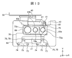
次に、Zスライドフレーム41の動作とスライドシャッタ35の動作の関係について、図11~13を用いて説明する。図11~13は、分注穴カバー69の構成を示す平面図であり、モータやギヤなどの図示を省略している。 Next, the relationship between the operation of the Z slide frame 41 and the operation of the slide shutter 35 will be described with reference to FIGS. 11-13. 11 to 13 are plan views showing the configuration of the dispensing hole cover 69, omitting the illustration of the motor, gears, and the like.

図11は、Zスライドフレーム41を原点位置から下降して、シャッタ連動ピン81がシャッタ連動ピン受け部80と勘合した状態を示している。このとき、蓋開閉カム部材36は、「第2の位置」に位置する。第2の位置の詳細については後述する。 FIG. 11 shows a state in which the Z slide frame 41 is lowered from the origin position and the shutter interlocking pin 81 is engaged with the shutter interlocking pin receiving portion 80 . At this time, the lid opening/closing cam member 36 is positioned at the "second position". Details of the second position will be described later.

図11に示すように、スライドシャッタ35が分注穴70a~70cを被覆した状態を「被覆状態」という。分注穴70a~70cの周囲には、例えば高さ1mm以下の分注穴リブ83a~83cが設けられ、分注穴70a~70cから異物が試薬ディスク2内に落下することを防止する。 As shown in FIG. 11, the state in which the slide shutter 35 covers the dispensing holes 70a to 70c is called a "covered state". Dispensing hole ribs 83a to 83c having a height of, for example, 1 mm or less are provided around the dispensing holes 70a to 70c to prevent foreign matter from falling into the reagent disk 2 from the dispensing holes 70a to 70c.

分注穴リブ83a~83cよりも外側、且つ、被覆状態のスライドシャッタ35の外周よりも内側には、分注穴リブ83a~83cよりもZ軸方向の高さが高い、例えば高さが1mmよりも大きいシャッタリブ84が設けられている。被覆状態のスライドシャッタ35は、シャッタリブ84に当接して支持され、スライドシャッタ35の下面は、分注穴リブ83a~83cとは隙間を有する。 Outside the dispensing hole ribs 83a to 83c and inside the outer periphery of the covered slide shutter 35, the height in the Z-axis direction is higher than the dispensing hole ribs 83a to 83c, for example, 1 mm. A shutter rib 84 is provided which is larger than the The covered slide shutter 35 is supported in contact with the shutter rib 84, and the lower surface of the slide shutter 35 has a gap between the dispensing hole ribs 83a to 83c.

図12は、Xスライドフレーム39及びZスライドフレーム41がX軸負方向に移動する途中の状態を示している。シャッタ連動アーム79は、Zスライドフレーム41とともに、X軸負方向、すなわち分注穴70a~70cに近づく方向に移動する。一対の連結リンク軸76は、互いに平行を維持する一対のリンクアーム75を介してアーム支軸73のまわりに回動し、円弧状の軌跡を描くので、連結リンク77は、被覆状態と平行なまま、連結リンク軸76の円弧状の軌跡に沿って移動する。 FIG. 12 shows a state in which the X slide frame 39 and Z slide frame 41 are moving in the negative direction of the X axis. The shutter interlocking arm 79 moves together with the Z slide frame 41 in the negative direction of the X axis, that is, in the direction of approaching the dispensing holes 70a to 70c. The pair of connecting link shafts 76 rotate around the arm support shaft 73 via the pair of link arms 75 maintained parallel to each other, and draw an arc-shaped trajectory. It moves along the arc-shaped trajectory of the connecting link shaft 76 as it is.

一対のシャッタ軸74は、互いに平行を維持する一対のリンクアーム75を介してアーム支軸73のまわりに回動する円弧状の軌跡を描くので、スライドシャッタ35は、被覆状態と平行なまま、シャッタ軸74の円弧状の軌跡に沿って移動する。 Since the pair of shutter shafts 74 draw an arcuate trajectory rotating around the arm support shaft 73 via the pair of link arms 75 maintained parallel to each other, the slide shutter 35 remains parallel to the covered state. It moves along the arc-shaped trajectory of the shutter shaft 74 .

図12において、スライドシャッタ35は、図11に示した被覆状態と比較すると左前方向に移動しており、分注穴70a~70cは一部が開放しつつある。 In FIG. 12, the slide shutter 35 has moved leftward and forward as compared with the covering state shown in FIG. 11, and the dispensing holes 70a to 70c are partially opening.

図13は、Xスライドフレーム39及びZスライドフレーム41が最もX軸負方向に移動した状態を示している。このとき、蓋開閉カム部材36は、「第3の位置」に位置する。第3の位置の詳細については後述する。 FIG. 13 shows a state in which the X slide frame 39 and Z slide frame 41 have moved most in the negative direction of the X axis. At this time, the lid opening/closing cam member 36 is positioned at the "third position". Details of the third position will be described later.

シャッタ軸74は、アーム支軸73に対して略X軸負方向に並ぶ位置にまで回動し、スライドシャッタ35は、分注穴70a~70cを全て開放した全開位置にある。図13に示すように、シャッタ連動アーム79は、屈曲した形状を有するため、スライドシャッタ35の全開時に分注穴70a~70cは塞がれない。スライドシャッタ35の全開時において、スライドシャッタ35は、シャッタリブ84に載置された状態を維持するとともに、リンク部カバー120に収納される。 The shutter shaft 74 is rotated to a position aligned substantially in the negative direction of the X-axis with respect to the arm support shaft 73, and the slide shutter 35 is at the fully open position where all of the dispensing holes 70a to 70c are opened. As shown in FIG. 13, the shutter interlocking arm 79 has a bent shape, so that the dispensing holes 70a to 70c are not blocked when the slide shutter 35 is fully opened. When the slide shutter 35 is fully opened, the slide shutter 35 remains placed on the shutter ribs 84 and is housed in the link cover 120 .

以上のように、蓋開閉カム部材36が第2の位置にある状態から、Zスライドフレーム41がX軸負方向に向かって移動すると、スライドシャッタ35は、被覆状態から全開位置に移動して、分注穴70a~70cを開放する。 As described above, when the Z slide frame 41 moves in the negative direction of the X axis from the state where the cover opening/closing cam member 36 is at the second position, the slide shutter 35 moves from the covering state to the fully open position. Dispensing holes 70a-70c are opened.

一方、蓋開閉カム部材36が第3の位置にある状態から、Zスライドフレーム41がX軸正方向に向かって移動すると、スライドシャッタ35は、全開位置から被覆状態となる位置にして、分注穴70a~70cを被覆する。 On the other hand, when the Z slide frame 41 moves in the X-axis positive direction from the state where the lid opening/closing cam member 36 is at the third position, the slide shutter 35 is moved from the fully open position to the covering state, and the dispensing liquid is dispensed. It covers the holes 70a-70c.

スライドシャッタ35は、シャッタリブ84に載置された状態で移動するため、スライドシャッタ35の下面は、分注穴リブ83a~83cとは隙間を維持したまま移動する。従って、スライドシャッタ35が閉じる際に、スライドシャッタ35の後側の辺が異物を分注穴70a~70c内に押し込んで落下させる恐れがなく、信頼性の高い自動分析装置を提供することができる。 Since the slide shutter 35 moves while being placed on the shutter ribs 84, the lower surface of the slide shutter 35 moves while maintaining a gap from the dispensing hole ribs 83a to 83c. Therefore, when the slide shutter 35 is closed, there is no fear that the rear side of the slide shutter 35 will push foreign matter into the dispensing holes 70a to 70c and cause the foreign matter to fall, and a highly reliable automatic analyzer can be provided. .

Zスライドフレーム41が原点位置にある際には、スライドシャッタ35は、シャッタリブ84に載置されて分注穴70a~70cを被覆するため、分注穴70a~70cから、温度差のある外気が試薬保冷庫24内に侵入したり、外気中の湿気や異物が試薬保冷庫24内に侵入したりすることを防止できる。 When the Z slide frame 41 is at the origin position, the slide shutter 35 is placed on the shutter rib 84 to cover the dispensing holes 70a to 70c, so that outside air having a temperature difference is released from the dispensing holes 70a to 70c. Intrusion into the reagent cooler 24 and entry of moisture and foreign matter in the outside air into the reagent cooler 24 can be prevented.

次に、Zスライドフレーム41の構成について、図14及び15を用いて説明する。図14は、Zスライドフレーム41を左前上方から見た斜視図である。 Next, the configuration of the Z slide frame 41 will be described with reference to FIGS. 14 and 15. FIG. FIG. 14 is a perspective view of the Z slide frame 41 viewed from the left front upper side.

図14に示すように、Zスライドフレーム41は、支持部86及び支柱部87から構成される。支持部86は、支柱部87の上方に配置され、スライド部40bに取り付けられる。支持部86は、試薬保冷庫24の外部に配置され、周囲温度は例えば20℃程度の常温である。 As shown in FIG. 14, the Z slide frame 41 is composed of a support portion 86 and a strut portion 87. As shown in FIG. The support portion 86 is arranged above the strut portion 87 and attached to the slide portion 40b. The support part 86 is arranged outside the reagent cooler 24, and the ambient temperature is normal temperature, for example, about 20.degree.

支柱部87は、支持部86と蓋開閉カム部材36との間に配置され、下端が気密シール72を介して蓋開閉カム部材36と接続される。蓋開閉カム部材36は、試薬保冷庫24内に配置され、周囲温度は例えば5℃程度の低温である。すなわち、支柱部87は、上部は常温条件下、下部は低温条件下にあり、異なる温度帯を跨いで配置される。 The strut portion 87 is arranged between the support portion 86 and the lid opening/closing cam member 36 , and the lower end thereof is connected to the lid opening/closing cam member 36 via an airtight seal 72 . The lid opening/closing cam member 36 is arranged in the reagent cooler 24, and the ambient temperature is as low as, for example, about 5.degree. That is, the support pillar 87 is placed across different temperature zones, with the upper part under normal temperature conditions and the lower part under low temperature conditions.

ここで、試薬保冷庫24の内部を安定して低温に維持することが望ましいので、支柱部87を経由した試薬保冷庫24外部からの熱伝導を小さくすることが望ましい。そのため、支柱部87の材料は、熱伝導率が小さいことが好適であり、金属材料ではなく樹脂材料であることが好ましい。 Here, since it is desirable to maintain the inside of the reagent cooler 24 at a stable low temperature, it is desirable to reduce the heat conduction from the outside of the reagent cooler 24 via the struts 87 . Therefore, it is preferable that the material of the column portion 87 has a low thermal conductivity, and is preferably a resin material instead of a metal material.

図15は、Zスライドフレーム41を右下後方から見た斜視図である。図15に示すように、支柱部87は、格子状のリブ90で区切った空気層である複数のセル88を備える。支柱部87は、後面が支柱裏蓋89により塞がれ、これによりセル88内と外気との流通を阻止し、セル88を断熱層とすることができる。さらに、リブ90により、セル88内の空気のZ軸方向の対流を防止することができるので、支柱部87を経由して試薬保冷庫24内へ流入する熱量が低減され、試薬保冷庫24内の温度を安定的に維持することができる。 FIG. 15 is a perspective view of the Z slide frame 41 viewed from the lower right rear. As shown in FIG. 15 , the strut portion 87 includes a plurality of cells 88 that are air layers partitioned by grid-like ribs 90 . The rear surface of the column portion 87 is closed by a column back cover 89, thereby blocking communication between the inside of the cell 88 and the outside air, and the cell 88 can be used as a heat insulating layer. Furthermore, since the ribs 90 can prevent convection of the air in the cell 88 in the Z-axis direction, the amount of heat flowing into the reagent cooler 24 via the struts 87 is reduced. temperature can be stably maintained.

さらに、図示しないネジを用いて、支柱裏蓋89の四隅に配置されたネジ穴91及び92において支柱裏蓋89を支柱部87にネジ留めすることで、支柱部87の曲げ剛性やねじり剛性が向上し、外力を受けた際の変形を防止できる。これにより、蓋25の開閉動作が安定して、信頼性の高い自動分析装置を提供できる。 Further, by screwing the column back cover 89 to the column portion 87 using screws (not shown) in the screw holes 91 and 92 arranged at the four corners of the column back cover 89, the bending rigidity and torsional rigidity of the column portion 87 are increased. It is possible to prevent deformation when receiving an external force. As a result, the opening and closing operations of the lid 25 are stabilized, and an automatic analyzer with high reliability can be provided.

上述のように、本実施形態においては、Zスライドフレーム41の支柱部87の下端に蓋開閉カム部材36を一体に設けた構成を図示しているが、蓋開閉カム部材36はZスライドフレーム41と別体とし、ネジやリベットにより支柱部87と締結される構成であってもよい。この場合、異なる温度帯に跨がる支柱部87は樹脂材料で構成され、蓋開閉カム部材36は、例えばステンレスなどの金属材料で構成されてもよい。 As described above, in this embodiment, the configuration in which the cover opening/closing cam member 36 is provided integrally with the lower end of the strut portion 87 of the Z slide frame 41 is illustrated. It may be configured to be separate from and fastened to the strut portion 87 with screws or rivets. In this case, the strut portion 87 spanning different temperature zones may be made of a resin material, and the cover opening/closing cam member 36 may be made of a metal material such as stainless steel.

次に、蓋開閉カム部材36の構成について、図16~19を用いて説明する。図16は、図14のC-C断面図である。図16に示すように、蓋開閉カム部材36(蓋開閉部材)は、蓋開きカム部36a(第1の部材)及び蓋閉じカム部36b(第2の部材)を一体で備える。蓋開きカム部36aは、蓋25を全閉又は半開状態から全開状態まで開放する。蓋閉じカム部36bは、蓋25を全開状態から半開状態まで閉じる。 Next, the configuration of the lid opening/closing cam member 36 will be described with reference to FIGS. 16 to 19. FIG. 16 is a cross-sectional view taken along line CC of FIG. 14. FIG. As shown in FIG. 16, the lid opening/closing cam member 36 (lid opening/closing member) integrally includes a lid opening cam portion 36a (first member) and a lid closing cam portion 36b (second member). The lid opening cam portion 36a opens the lid 25 from the fully closed or half-opened state to the fully opened state. The lid closing cam portion 36b closes the lid 25 from the fully open state to the half open state.

図17は、蓋開閉カム部材36の構成を示す図であって、図17(a)は蓋開閉カム部材36の上面図、図17(b)は図17(a)のA矢視図、図17(c)は図17(a)のD-D断面図、図17(d)は図17(a)のB矢視図、及び図17(e)は下面図である。図18(a)は、図17(c)のC矢視図であり、図18(b)は、図17(c)のD矢視図である。 17A and 17B are diagrams showing the configuration of the lid opening/closing cam member 36. FIG. 17(a) is a top view of the lid opening/closing cam member 36, FIG. 17(c) is a cross-sectional view taken along line DD in FIG. 17(a), FIG. 17(d) is a view in the direction of arrow B in FIG. 17(a), and FIG. 17(e) is a bottom view. 18(a) is a view on arrow C in FIG. 17(c), and FIG. 18(b) is a view on arrow D in FIG. 17(c).

図17(a)及び図18に示すように、蓋開閉カム部材36の上面には、ピッチpの間隔で上面開口93が設けられており、蓋25を開放した際に、上面開口93が試薬容器3の開口部29の直上に位置するよう配置される。 As shown in FIGS. 17A and 18, upper surface openings 93 are provided on the upper surface of the lid opening/closing cam member 36 at intervals of a pitch p. It is arranged to be positioned directly above the opening 29 of the container 3 .

後述するように、蓋開閉カム部材36がX軸方向に移動することで蓋25の開閉動作が行われるため、蓋開閉カム部材36は、第1の位置に移動した際に試薬ディスク2の外周内壁96と近接する角部94と、第3の位置に移動した際に試薬ディスク2の内周外壁97と近接する角部95とを削除した形状とする。これにより、試薬ディスク2と蓋開閉カム部材36との隙間を確保するとともに、試薬ディスク2を小型化しつつ蓋開閉カム部材36のX軸方向の移動を可能にする。 As will be described later, since the lid 25 is opened and closed by moving the lid opening/closing cam member 36 in the X-axis direction, the lid opening/closing cam member 36 moves along the outer circumference of the reagent disk 2 when it moves to the first position. A corner portion 94 adjacent to the inner wall 96 and a corner portion 95 adjacent to the inner peripheral outer wall 97 of the reagent disk 2 when moved to the third position are removed. As a result, the clearance between the reagent disk 2 and the lid opening/closing cam member 36 is ensured, and the lid opening/closing cam member 36 can be moved in the X-axis direction while downsizing the reagent disk 2 .

図17(c)に示すように、蓋開きカム部36a及び蓋閉じカム部36bは、試薬容器3に3つの蓋25がピッチpでX軸方向に沿って配置されることに対応して、それぞれピッチpでX軸方向に沿って3対配置される。1対の蓋開きカム部36a及び1対の蓋閉じカム部36bは、それぞれ上面開口93を挟んでY軸方向に略対称に配置される。蓋開きカム部36a及び蓋閉じカム部36bは、互いに対向する。 As shown in FIG. 17(c), the lid opening cam portion 36a and the lid closing cam portion 36b correspond to the arrangement of the three lids 25 on the reagent container 3 at the pitch p along the X-axis direction. Three pairs are arranged along the X-axis direction at a pitch p, respectively. The pair of lid opening cam portions 36a and the pair of lid closing cam portions 36b are arranged substantially symmetrically in the Y-axis direction with the upper surface opening 93 interposed therebetween. The lid opening cam portion 36a and the lid closing cam portion 36b face each other.

図17(e)に示すように、蓋開閉カム部材36の底面である蓋開閉カム部材底部98は、蓋25のY軸方向の長さS2より大きく、且つ蓋先端突起32のY軸方向の長さS1より小さい間隔V(S2<V<S1)の領域よりも外側に配置される。蓋先端突起32の上方に蓋開閉カム部材底部98が位置する状態から蓋開閉カム部材36を下降させると、蓋開閉カム部材底部98は、蓋先端突起32に当接する。一方、蓋開閉カム部材底部98が蓋先端突起32の上方以外に位置する状態から蓋開閉カム部材36を下降させると、蓋開閉カム部材底部98は、試薬容器ケース26の上面107に当接する。これにより、蓋開閉カム部材底部98が上面107に沿ってX軸方向に摺動することができる。 As shown in FIG. 17(e), the lid opening/closing cam member bottom portion 98, which is the bottom surface of the lid opening/closing cam member 36, is larger than the length S2 of the lid 25 in the Y-axis direction and the length of the lid tip projection 32 in the Y-axis direction. It is arranged outside the region with an interval V (S2<V<S1) smaller than the length S1. When the lid opening/closing cam member bottom 98 is positioned above the lid tip projection 32 and the lid opening/closing cam member 36 is lowered, the lid opening/closing cam member bottom 98 contacts the lid tip projection 32 . On the other hand, when the lid opening/closing cam member bottom 98 is positioned other than above the lid tip projection 32 and the lid opening/closing cam member 36 is lowered, the lid opening/closing cam member bottom 98 contacts the upper surface 107 of the reagent container case 26 . This allows the lid opening/closing cam member bottom portion 98 to slide along the upper surface 107 in the X-axis direction.

蓋開きカム部36aは、蓋25の開き動作時に蓋先端突起32に当接する蓋開きカム曲面99を備える。蓋開きカム曲面99は、Y軸方向の間隔V(S2<V<S1)で設けられたv面と、Y軸方向の間隔U(S1<U)で設けられたu面とを仕切る曲面である。図17(c)、図18又は図19に示すように、蓋開きカム曲面99は、第1領域103及び第2領域104を滑らかに接続した略円弧状の曲面を有し、全体としてZ軸方向に延伸し、X軸方向に湾曲する。 The lid-opening cam portion 36a has a lid-opening cam curved surface 99 that contacts the lid tip projection 32 when the lid 25 is opened. The lid-opening cam curved surface 99 is a curved surface that separates the v-surface provided at the Y-axis direction interval V (S2<V<S1) from the u-surface provided at the Y-axis direction interval U (S1<U). be. As shown in FIG. 17(c), FIG. 18, or FIG. 19, the lid-opening cam curved surface 99 has a substantially arc-shaped curved surface that smoothly connects the first region 103 and the second region 104, and is generally located along the Z axis. direction and curves in the X-axis direction.

図19は、蓋開閉カム部材36と蓋25の概略正面図であり、蓋開きカム部36aと蓋閉じカム部36bの概略構成を示している。図19に示すように、蓋開きカム部36aの先端面101は、蓋開閉カム部材底部98からの高さh5(h5<h1)に配置された開き先端部100から、下方に延伸する。第1領域103は、蓋開閉カム部材底部98に対する角度θ1(0゜<θ1<90゜)で開き先端部100から延伸し、徐々に角度を変えて、高さh7で略90°になる曲面である。第2領域104は、高さh7よりも上方において、90°よりも大きな角度で延伸し、上端点102に至る曲面である。 FIG. 19 is a schematic front view of the lid opening/closing cam member 36 and the lid 25, showing schematic configurations of the lid opening cam portion 36a and the lid closing cam portion 36b. As shown in FIG. 19, the tip surface 101 of the lid opening cam portion 36a extends downward from the opening tip portion 100 which is arranged at a height h5 (h5<h1) from the bottom portion 98 of the lid opening/closing cam member. The first region 103 extends from the opening tip portion 100 at an angle θ1 (0°<θ1<90°) with respect to the lid opening/closing cam member bottom portion 98, gradually changing the angle to a curved surface of approximately 90° at a height h7. is. The second region 104 is a curved surface that extends at an angle greater than 90° above the height h7 and reaches the upper end point 102 .

蓋開きカム曲面99は、上端点102より上方は、高さh8までZ軸方向に延伸しており、蓋25が全開状態となった際に蓋先端突起32が配置される空間105を形成する。高さh8は、蓋25が全開状態の蓋先端突起32の高さh4よりも大きい。 The lid opening cam curved surface 99 extends in the Z-axis direction to a height h8 above the upper end point 102, and forms a space 105 in which the lid tip projection 32 is arranged when the lid 25 is fully opened. . The height h8 is greater than the height h4 of the lid tip projection 32 when the lid 25 is fully opened.

ここで、第1領域103及び第2領域104は、高さh7で滑らかに接続されていることとしたが、第1領域103及び第2領域104の間は、Z軸方向に延伸する直線で接続されていてもよいし、鉛直とは異なる直線で接続されていてもよい。 Here, the first region 103 and the second region 104 are assumed to be smoothly connected at the height h7. It may be connected, or may be connected by a straight line different from the vertical line.

先端面101と、先端面101と対向する開きカム部材背面106との間の領域を領域wとする。蓋開閉カム部材36のY軸方向の長さUが蓋先端突起32の長さS1より大きいので、蓋先端突起32が領域wの下方に位置する位置関係においては、蓋開閉カム部材底部98が試薬容器ケース26の上面107に当接するまで蓋開閉カム部材36を下降することができる。 A region between the tip end surface 101 and the back surface 106 of the opening cam member facing the tip end surface 101 is defined as an area w. Since the length U of the lid opening/closing cam member 36 in the Y-axis direction is greater than the length S1 of the lid tip projection 32, in the positional relationship in which the lid tip projection 32 is positioned below the region w, the lid opening/closing cam member bottom portion 98 is The lid opening/closing cam member 36 can be lowered until it contacts the upper surface 107 of the reagent container case 26 .

蓋開きカム部36aは、以上のような構成を有することにより、蓋25の開き動作時に、蓋開きカム曲面99の第1領域103から第2領域104(下端部から上端部)に向かって蓋先端突起32が当接する。これにより、蓋開きカム部36aは、蓋25を開放することができる。 The lid-opening cam portion 36a has the configuration described above, so that when the lid 25 is opened, the lid-opening cam portion 36a moves from the first area 103 toward the second area 104 (from the lower end to the upper end) of the lid-opening cam curved surface 99. The tip protrusion 32 abuts. Thereby, the lid opening cam portion 36 a can open the lid 25 .

蓋閉じカム部36bは、蓋25の閉じ動作時に蓋先端突起32に当接する第1の段差108と、蓋背面118に当接する第2の段差113とを備える。図17(e)に示すように、第1の段差108は、Y軸方向の間隔V(S2<V<S1)で設けられたk面と、Y軸方向の間隔U(S1<U)で設けられたu面との間を仕切る段差である。第1の段差108は、第2の段差113と比較して、X軸正方向に突出する。 The lid closing cam portion 36b includes a first step 108 that abuts the lid tip projection 32 when the lid 25 is closed, and a second step 113 that abuts the lid back surface 118. As shown in FIG. As shown in FIG. 17( e ), the first step 108 has a k surface provided at an interval V (S2<V<S1) in the Y-axis direction and an interval U (S1<U) in the Y-axis direction. It is a step that separates the provided u surface. The first step 108 protrudes in the positive direction of the X-axis compared to the second step 113 .

第1の段差108は、閉じ先端部109を基点として、X軸方向に略水平に延伸する第3領域110(下端部)と、第3領域110の右端に設けられた屈曲部111と、屈曲部111を境に、角度θ1よりも大きな角度θ2(0゜<θ2<90゜、θ1<θ2)で延伸して空間105と接続する第4領域112とを備える。閉じ先端部109は、蓋開きカム曲面99の先端面101よりもX軸負方向側に設けられ、蓋25が半開状態のときの蓋先端突起32の高さh3とほぼ等しい高さh6に配置される。なお、第3領域110は水平でなくともよく、微小に右上方向に傾斜していてもよい。 The first step 108 includes a third region 110 (lower end) extending substantially horizontally in the X-axis direction with the closed tip portion 109 as a base point, a bent portion 111 provided at the right end of the third region 110, and a bent portion 111 . A fourth region 112 extending at an angle θ2 (0°<θ2<90°, θ1<θ2) greater than the angle θ1 from the portion 111 as a boundary and connecting to the space 105 is provided. The closing tip portion 109 is provided on the X-axis negative direction side of the tip surface 101 of the lid-opening cam curved surface 99, and is arranged at a height h6 substantially equal to the height h3 of the lid tip projection 32 when the lid 25 is in the half-open state. be done. It should be noted that the third region 110 does not have to be horizontal, and may be slightly inclined in the upper right direction.

第2の段差113は、閉じ先端部109から右上方向に延伸する第5領域114と、屈曲部115を境に、第5領域114よりも90°に近い角度で右上方向に延伸する第6領域116とを備える。第2の段差113は、蓋25のY軸方向の長さS2より小さな間隔J(J<S2、J<V<U)で設けられたj面と、k面との間に設けられた段差であって、蓋25の閉じ動作の際に蓋背面118と当接する。 The second step 113 includes a fifth region 114 that extends upward and to the right from the closed tip portion 109, and a sixth region that extends upward and to the right at an angle closer to 90° than the fifth region 114 with the bent portion 115 as a boundary. 116. The second step 113 is a step provided between the j surface and the k surface, which are provided at an interval J (J<S2, J<V<U) smaller than the length S2 of the lid 25 in the Y-axis direction. and contacts the lid back surface 118 when the lid 25 is closed.

蓋閉じカム部36bは、以上のような構成を有することにより、蓋25の閉じ動作時に、第1の段差108の第4領域112(上端部)において、蓋先端突起32が上方から下方に向かって順次当接した後、第2の段差113の第5領域114(下端部)において、蓋背面118が上方から下方に向かって順次当接する。これにより、蓋閉じカム部36bは、蓋25を半開状態まで閉じることができる。 Since the lid closing cam portion 36b has the above-described configuration, the lid tip projection 32 moves downward in the fourth region 112 (upper end portion) of the first step 108 when the lid 25 is closed. , and then the lid back surface 118 sequentially abuts on the fifth region 114 (lower end) of the second step 113 from above downward. As a result, the lid closing cam portion 36b can close the lid 25 to the half-open state.

次に、蓋開閉カム部材36による蓋25の開き動作について、図20~24を用いて説明する。図20~24は、図17(a)のD-D断面図であり、蓋25の開き動作における蓋25と蓋開閉カム部材36との関係を示す。 Next, the operation of opening the lid 25 by the lid opening/closing cam member 36 will be described with reference to FIGS. 20 to 24. FIG. 20 to 24 are cross-sectional views taken along line DD of FIG. 17(a), showing the relationship between the lid 25 and the lid opening/closing cam member 36 during the opening operation of the lid 25. FIG.

図20は、開き動作の開始時における状態を示し、蓋開閉カム部材36がZスライドフレーム41と共に最も上昇した第1の位置にある。分注穴カバー69の支柱移動開口42は、気密シール72により下方から密閉されている。このとき、蓋開閉カム部材底部98は、蓋25の上面よりも上方に位置し、蓋先端突起32は、先端面101と開きカム部材背面106との間の領域wの下方に位置する。 FIG. 20 shows the state at the start of the opening operation, in which the lid opening/closing cam member 36 and the Z slide frame 41 are at the highest raised first position. The post movement opening 42 of the dispensing hole cover 69 is sealed from below by an airtight seal 72 . At this time, the lid opening/closing cam member bottom portion 98 is positioned above the upper surface of the lid 25, and the lid tip protrusion 32 is positioned below the region w between the tip surface 101 and the opening cam member back surface .

蓋開閉カム部材36のX軸方向の長さWcは、試薬容器3のX軸方向の長さWbとほぼ等しい。試薬容器3の右端面に対する蓋開閉カム部材36のX軸正方向への凸量は、容器28のピッチpと領域wとの差(p-w)より小であり、例えば容器28のピッチpの1/2以下である。従って、試薬ディスク2外壁の内面と試薬容器3との間隔を小さくすることができるため、試薬ディスク2の外径を小さくし、小型の自動分析装置を実現できる。 The length Wc of the cover opening/closing cam member 36 in the X-axis direction is substantially equal to the length Wb of the reagent container 3 in the X-axis direction. The amount of protrusion of the cover opening/closing cam member 36 in the positive X-axis direction with respect to the right end surface of the reagent container 3 is smaller than the difference (p−w) between the pitch p of the container 28 and the region w. 1/2 or less. Therefore, since the distance between the inner surface of the outer wall of the reagent disk 2 and the reagent container 3 can be reduced, the outer diameter of the reagent disk 2 can be reduced and a compact automatic analyzer can be realized.

図21は、Zモータ49を駆動して蓋開閉カム部材36を第1の位置から下降させ、蓋開閉カム部材底部98が試薬容器ケース26の上面107に当接した状態を示す。このとき、蓋開閉カム部材36は第2の位置にある。すなわち、第1の位置及び第2の位置は、X軸方向の位置は同一であり、Z軸方向の位置のみが異なる位置関係である。 FIG. 21 shows a state in which the lid opening/closing cam member 36 is lowered from the first position by driving the Z motor 49 and the lid opening/closing cam member bottom portion 98 is in contact with the upper surface 107 of the reagent container case 26 . At this time, the lid opening/closing cam member 36 is at the second position. That is, the first position and the second position have the same positional relationship in the X-axis direction and differ only in the Z-axis direction.

蓋閉じカム部36bを構成する第1の段差108及び第2の段差113は、蓋開閉カム部材36が第2の位置に位置する際は、蓋25よりも上方にある。 The first step 108 and the second step 113 forming the lid closing cam portion 36b are above the lid 25 when the lid opening/closing cam member 36 is positioned at the second position.

図22は、Xモータ43を駆動して蓋開閉カム部材36を第2の位置からX軸負方向に移動させ、蓋開きカム曲面99の第1領域103が蓋先端突起32の下面に当接した状態を示す。蓋開閉カム部材36は、蓋開閉カム部材底部98が試薬容器ケース26の上面107に接しつつX軸負方向に移動する。 22, the X motor 43 is driven to move the lid opening/closing cam member 36 from the second position in the X-axis negative direction, and the first region 103 of the lid opening cam curved surface 99 abuts the lower surface of the lid tip projection 32. In FIG. indicates the state of The lid opening/closing cam member 36 moves in the X-axis negative direction while the lid opening/closing cam member bottom portion 98 is in contact with the upper surface 107 of the reagent container case 26 .

このときの第1領域103の蓋先端突起32に対する接触角度は、角度θ1となる。角度θ1が小さいほど、蓋先端突起32に生じる上方への分力、すなわち蓋開き力が大きくなるので好適である。一方、角度θ1を小さくしすぎると、蓋25を開放するまでに要する蓋開閉カム部材36のX軸負方向への移動量が過大となるので、例えば角度θ1を30°程度とするのが好適である。 At this time, the contact angle of the first region 103 with respect to the lid tip projection 32 is the angle θ1. The smaller the angle θ1, the larger the upward component force generated in the lid tip projection 32, that is, the larger the lid opening force, which is preferable. On the other hand, if the angle θ1 is too small, the amount of movement of the lid opening/closing cam member 36 in the negative direction of the X axis required to open the lid 25 becomes excessive. is.

図23は、Xモータ43を駆動して蓋開閉カム部材36をさらにX軸負方向に移動させ、蓋25が開放される途中の状態を示す。蓋開きカム曲面99と蓋先端突起32との接触点117は、高さh7よりも上方の第2領域104にある。蓋開きカム曲面99の第2領域104は、90°より大きな角度で傾斜するため、蓋開閉カム部材36のX軸負方向への移動量よりも蓋先端突起32のX軸負方向への移動量の方が大きくなる。これにより、蓋開閉カム部材36のX軸負方向へのわずかな移動量で、蓋25を大きく開放することができる。すなわち、蓋開閉カム部材36の移動量を低減できるので、X軸方向の小型化に適している。ここで、蓋先端突起32が接触点117から受ける力は、接触点117の法線方向に働き、蓋25を開放する方向に働く。接触点117の法線及びヒンジ30は距離r1だけ離れている。 FIG. 23 shows a state in the process of opening the lid 25 by driving the X motor 43 to further move the lid opening/closing cam member 36 in the negative direction of the X axis. A contact point 117 between the lid opening cam curved surface 99 and the lid tip protrusion 32 is located in the second region 104 above the height h7. Since the second region 104 of the lid-opening cam curved surface 99 is inclined at an angle larger than 90°, the amount of movement of the lid tip projection 32 in the negative X-axis direction is greater than the amount of movement of the lid-opening/closing cam member 36 in the negative X-axis direction. quantity is greater. As a result, the lid 25 can be largely opened with a small amount of movement of the lid opening/closing cam member 36 in the negative direction of the X axis. That is, since the amount of movement of the cover opening/closing cam member 36 can be reduced, it is suitable for miniaturization in the X-axis direction. Here, the force that the lid tip protrusion 32 receives from the contact point 117 acts in the normal direction of the contact point 117 and acts in the direction of opening the lid 25 . The normal to contact point 117 and hinge 30 are separated by a distance r1.

図24は、Xモータ43を駆動して蓋開閉カム部材36を最もX軸負方向に移動させ、蓋25が全開状態となった状態を示す。図24において、蓋開閉カム部材36は第3の位置にある。すなわち、第2の位置及び第3の位置は、Z軸方向の位置は同一であり、X軸方向の位置のみが異なる位置関係である。第2の位置から第3の位置までの蓋開閉カム部材36のX軸負方向への移動量は、容器28のピッチpにほぼ等しい。 FIG. 24 shows a state in which the X motor 43 is driven to move the cover opening/closing cam member 36 most in the negative direction of the X axis, and the cover 25 is fully opened. In FIG. 24, the lid opening/closing cam member 36 is at the third position. That is, the second position and the third position have the same positional relationship in the Z-axis direction and differ only in the X-axis direction. The amount of movement of the lid opening/closing cam member 36 in the X-axis negative direction from the second position to the third position is substantially equal to the pitch p of the containers 28 .

蓋先端突起32は、蓋開きカム曲面99の上端点102に当接して、上端点102より上方の空間105に配置される。蓋閉じカム部36bを構成する第6領域116は、蓋先端突起32が全開状態からさらに開放することを防止するストッパとしても機能する。 The lid tip protrusion 32 abuts on the upper end point 102 of the lid opening cam curved surface 99 and is arranged in a space 105 above the upper end point 102 . The sixth region 116 that constitutes the lid-closing cam portion 36b also functions as a stopper that prevents the lid tip projection 32 from being further opened from the fully open state.

全開状態においては、X軸方向における容器28の開口部29の位置と、蓋開閉カム部材36の上面開口93の位置と、分注穴70a~70cの位置とは一致するので、試薬分注プローブ15を容器28内に下降させることができる。 In the fully opened state, the position of the opening 29 of the container 28 in the X-axis direction, the position of the upper surface opening 93 of the cover opening/closing cam member 36, and the positions of the dispensing holes 70a to 70c match, so that the reagent dispensing probe 15 can be lowered into container 28 .

蓋開きカム曲面99は、蓋25の開き始めにおいては、角度θ1で蓋先端突起32を下方から開き、第1領域103から鉛直を超えて傾斜した第2領域104を経由して上端点102にて全開状態に至るので、角度θ1を小さくすることで、蓋25を開き始める際の分力を大きくし、蓋開閉カム部材36の開き力を低減できる。さらに、蓋先端突起32が第2領域104に当接する際は、蓋開閉カム部材36のX軸負方向への移動量よりも蓋先端突起32のX軸負方向への移動量の方が大きいので、蓋開閉カム部材36の移動量を低減できる。すなわち、蓋25の開き力を大きくするともに、全開までに要する蓋開閉カム部材36の移動量を小さくすることができるので、小型化に好適である。 When the lid 25 starts to open, the lid opening cam curved surface 99 opens the lid tip projection 32 from below at an angle θ1, and extends from the first region 103 to the upper end point 102 via the second region 104 inclined beyond the vertical. By reducing the angle .theta.1, the component force when the lid 25 starts to open can be increased, and the opening force of the lid opening/closing cam member 36 can be reduced. Furthermore, when the lid tip projection 32 abuts on the second region 104, the amount of movement of the lid tip projection 32 in the negative X-axis direction is greater than the amount of movement of the lid opening/closing cam member 36 in the X-axis negative direction. Therefore, the amount of movement of the lid opening/closing cam member 36 can be reduced. That is, it is possible to increase the opening force of the lid 25 and reduce the amount of movement of the lid opening/closing cam member 36 required for full opening, which is suitable for miniaturization.

ここで、上述のように、試薬容器3のX軸方向の長さWbと蓋開閉カム部材36のX軸方向の長さWcとはほぼ等しく、第2の位置から第3の位置までの蓋開閉カム部材36のX軸負方向への移動量は、容器28のピッチpにほぼ等しいため、蓋25の左端面からの蓋開閉カム部材36の凸量は、ピッチpの1/2程度に過ぎない。従って、試薬ディスク2内壁の外周と試薬容器3との間隔を小さくすることができ、小型の自動分析装置を実現できる。 Here, as described above, the length Wb of the reagent container 3 in the X-axis direction and the length Wc of the lid opening/closing cam member 36 in the X-axis direction are substantially equal, and the lid is positioned from the second position to the third position. Since the amount of movement of the opening/closing cam member 36 in the negative direction of the X-axis is approximately equal to the pitch p of the container 28, the amount of protrusion of the lid opening/closing cam member 36 from the left end surface of the lid 25 is about 1/2 of the pitch p. Not too much. Therefore, the distance between the outer circumference of the inner wall of the reagent disk 2 and the reagent container 3 can be reduced, and a compact automatic analyzer can be realized.

次に、蓋開閉カム部材36による蓋25の閉じ動作について、図25~28を用いて説明する。図25~28は、図17(a)のD-D断面図であり、蓋25の閉じ動作における蓋25と蓋開閉カム部材36との関係を示す。 Next, the operation of closing the lid 25 by the lid opening/closing cam member 36 will be described with reference to FIGS. 25 to 28. FIG. 25 to 28 are sectional views taken along line DD of FIG. 17(a), showing the relationship between the lid 25 and the lid opening/closing cam member 36 during the closing operation of the lid 25. FIG.

図25は、図24に示す状態から、Xモータ43を駆動して蓋開閉カム部材36を第3の位置からX軸正方向に移動させ、蓋閉じカム部36bによって蓋25を閉じ始めた状態を示す。このとき、蓋先端突起32の上面が第1の段差108の第4領域112と当接してX軸正方向に移動する。 25 shows a state in which the X motor 43 is driven to move the lid opening/closing cam member 36 from the third position in the positive direction of the X axis from the state shown in FIG. 24, and the lid closing cam portion 36b begins to close the lid 25. FIG. indicates At this time, the upper surface of the lid tip projection 32 contacts the fourth region 112 of the first step 108 and moves in the positive direction of the X axis.

図26は、図25に示す状態から、さらにXモータ43を駆動して蓋開閉カム部材36をX軸正方向に移動させた状態を示す。このとき、第2の段差113の屈曲部115よりも下方にある第5領域114が蓋背面118に当接し、蓋先端突起32が第4領域112から離反する。 FIG. 26 shows a state in which the X motor 43 is further driven to move the cover opening/closing cam member 36 in the positive direction of the X axis from the state shown in FIG. At this time, the fifth region 114 below the bent portion 115 of the second step 113 contacts the lid back surface 118 , and the lid tip projection 32 separates from the fourth region 112 .

図27は、図26に示す状態から、さらにXモータ43を駆動して蓋開閉カム部材36をX軸正方向に移動させた状態を示す。このとき、蓋閉じカム部36bの閉じ先端部109が蓋背面118に当接する。 FIG. 27 shows a state in which the X motor 43 is further driven to move the cover opening/closing cam member 36 in the positive direction of the X axis from the state shown in FIG. At this time, the closing tip portion 109 of the lid closing cam portion 36b contacts the lid rear surface 118. As shown in FIG.

図28は、図27に示す状態から、さらにXモータ43を駆動して蓋開閉カム部材36をX軸正方向に移動させた状態を示す。図28において、蓋開閉カム部材36は第2の位置にある。このとき、蓋閉じカム部36bの閉じ先端部109が蓋背面118に上方から当接し、且つ第1の段差108の屈曲部111が蓋先端突起32に上方から当接して、蓋25を半開状態まで閉じることができる。 FIG. 28 shows a state in which the X motor 43 is further driven to move the cover opening/closing cam member 36 in the positive direction of the X axis from the state shown in FIG. In FIG. 28, the lid opening/closing cam member 36 is at the second position. At this time, the closing tip portion 109 of the lid closing cam portion 36b abuts the lid back surface 118 from above, and the bent portion 111 of the first step 108 abuts the lid tip projection 32 from above, and the lid 25 is in a half-open state. can be closed up to

上述のように、第2の位置とは、蓋開閉カム部材36を第1の位置から下方に移動させ、試薬容器3の上面107に蓋開閉カム部材底部98が接する位置であるので、その状態からZスライドフレーム41を上昇させても、蓋開閉カム部材36と蓋25とは接触することがなく、蓋25が半開状態のまま、蓋開閉カム部材36を第1の位置まで上昇させることができる。 As described above, the second position is a position where the lid opening/closing cam member 36 is moved downward from the first position and the lid opening/closing cam member bottom portion 98 is in contact with the top surface 107 of the reagent container 3 . Even if the Z slide frame 41 is raised from the upper position, the lid opening/closing cam member 36 and the lid 25 do not come into contact with each other, and the lid opening/closing cam member 36 can be raised to the first position while the lid 25 is in the half-open state. can.

以上説明したように、蓋開閉カム部材36を第1の位置から第2の位置まで下方に移動させ、第2の位置から第3の位置までX軸負方向に移動させることで、蓋25を全閉状態又は半開状態から全開状態に開放させることができる。 As described above, the lid opening/closing cam member 36 is moved downward from the first position to the second position, and moved from the second position to the third position in the negative direction of the X axis, thereby opening the lid 25. It can be opened from a fully closed state or a half open state to a fully open state.

また、蓋開閉カム部材36を第3の位置から第2の位置までX軸正方向に移動させることで、蓋25を全開状態から半開状態にすることができる。その後、蓋開閉カム部材36を第2の位置から上方に移動させることで、第1の位置に復帰させることができる。 Further, by moving the lid opening/closing cam member 36 from the third position to the second position in the positive direction of the X axis, the lid 25 can be changed from the fully open state to the half open state. After that, by moving the lid opening/closing cam member 36 upward from the second position, it can be returned to the first position.

上述のように、蓋開閉カム部材36は、蓋開きカム部36aと蓋閉じカム部36bとを一体で兼ね備えるので、蓋開閉カム部材36を第2の位置から第3の位置にX軸負方向に移動させるだけで複数の蓋25を開き、蓋開閉カム部材36を第3の位置から第2の位置にX軸正方向に移動するだけで複数の蓋25を閉じることができる。これにより、構成が簡単で信頼性の高い自動分析装置を提供できる。 As described above, the lid opening/closing cam member 36 integrally has the lid opening cam portion 36a and the lid closing cam portion 36b. A plurality of lids 25 can be opened simply by moving the cam member 36 from the third position to the second position in the positive direction of the X axis, and the plurality of lids 25 can be closed. This makes it possible to provide an automatic analyzer with a simple configuration and high reliability.

なお、未使用の試薬容器3(蓋25が全閉状態)を試薬ディスク2にセットした後、一度開閉動作を行った蓋25は半開状態となるので、2度目以降の開き動作に要する開き力は小さくて済む。 After an unused reagent container 3 (with the lid 25 fully closed) is set on the reagent disk 2, the lid 25 that has been opened and closed once will be in a half-open state. is small.

次に、蓋25の開閉動作における蓋開閉装置22の一連の動作について、図29~37を用いて説明する。図29及び30は、蓋開閉装置22を示す斜視図である。図29は、試薬保冷庫24及び分注穴カバー69を省略した図であり、図30は、分注穴カバー69を図示する一方で、分注穴カバー69よりも下側の構成を省略した図である。図31は、蓋開閉装置22を示す正面図である。 Next, a series of operations of the lid opening/closing device 22 in the opening/closing operation of the lid 25 will be described with reference to FIGS. 29 and 30 are perspective views showing the lid opening/closing device 22. FIG. 29 is a diagram in which the reagent cooler 24 and the dispensing hole cover 69 are omitted, and FIG. 30 illustrates the dispensing hole cover 69 while omitting the structure below the dispensing hole cover 69. It is a diagram. FIG. 31 is a front view showing the lid opening/closing device 22. FIG.

図29~31は、蓋開閉カム部材36が第2の位置にある状態を示している。蓋開閉カム部材36が第1の位置にある場合、全ての検知手段63、65及び67は遮光状態(OFF)である。蓋開閉カム部材36が第1の位置にある状態から、Zモータ49を所定のステップ数だけ駆動することで、蓋開閉カム部材36を第2の位置まで下降させることができる。このとき、シャッタ連動ピン81は、Zスライドフレーム41とともに下降して、シャッタ連動ピン受け部80に嵌合する。スライドシャッタ35は、分注穴70a~70cを被覆しており、気密シール72は、Zスライドフレーム41とともに下降している。支柱移動開口42は開口しており、試薬保冷庫24内部の低温領域と、試薬保冷庫24外部の常温領域とが連通する。 29 to 31 show the lid opening/closing cam member 36 at the second position. When the lid opening/closing cam member 36 is at the first position, all the detection means 63, 65 and 67 are in the light blocking state (OFF). By driving the Z motor 49 by a predetermined number of steps from the state where the lid opening/closing cam member 36 is at the first position, the lid opening/closing cam member 36 can be lowered to the second position. At this time, the shutter interlocking pin 81 descends together with the Z slide frame 41 and fits into the shutter interlocking pin receiving portion 80 . The slide shutter 35 covers the dispensing holes 70 a - 70 c and the hermetic seal 72 is lowered with the Z slide frame 41 . The pillar movement opening 42 is open, and the low-temperature region inside the reagent cooler 24 and the normal-temperature region outside the reagent cooler 24 communicate with each other.

蓋開閉カム部材36が第2の位置にある場合、第1の検知手段63は遮光状態(OFF)、第2の検知手段65は透光状態(ON)、第3の検知手段67は遮光状態(OFF)となる。 When the cover opening/closing cam member 36 is at the second position, the first detection means 63 is in the light blocking state (OFF), the second detection means 65 is in the light transmitting state (ON), and the third detection means 67 is in the light blocking state. (OFF).

図32及び33は、蓋開閉装置22を示す斜視図である。図32は、試薬保冷庫24及び分注穴カバー69を省略した図であり、図33は、分注穴カバー69を図示する一方で、分注穴カバー69よりも下側の構成を省略した図である。図34は、蓋開閉装置22を示す正面図である。 32 and 33 are perspective views showing the lid opening/closing device 22. FIG. FIG. 32 is a diagram in which the reagent cooler 24 and the dispensing hole cover 69 are omitted, and FIG. 33 illustrates the dispensing hole cover 69 while omitting the structure below the dispensing hole cover 69. It is a diagram. 34 is a front view showing the lid opening/closing device 22. FIG.

図32~34は、蓋開閉カム部材36が第3の位置にある状態を示している。蓋開閉カム部材36が第2の位置にある状態から、Xモータ43を所定のステップ数だけ駆動することで、蓋開閉カム部材36を第3の位置まで移動させることができる。スライドシャッタ35は、シャッタ連動ピン81がシャッタ連動ピン受け部80に嵌合していることにより、Xスライドフレーム39と連動して移動し、これにより分注穴70a~70cが開放されている。このとき蓋25は全開状態にある。 32 to 34 show the state in which the lid opening/closing cam member 36 is in the third position. By driving the X motor 43 by a predetermined number of steps from the state where the lid opening/closing cam member 36 is at the second position, the lid opening/closing cam member 36 can be moved to the third position. The slide shutter 35 moves in conjunction with the X slide frame 39 by fitting the shutter interlocking pin 81 into the shutter interlocking pin receiving portion 80, thereby opening the dispensing holes 70a to 70c. At this time, the lid 25 is in a fully open state.

蓋開閉カム部材36が第3の位置にある場合、第1の検知手段63は透光状態(ON)、第2の検知手段65は透光状態(ON)、第3の検知手段67は遮光状態(OFF)となる。 When the cover opening/closing cam member 36 is at the third position, the first detection means 63 is in the light transmission state (ON), the second detection means 65 is in the light transmission state (ON), and the third detection means 67 is in the light blocking state. state (OFF).

図35は、図34のB-B断面図であって、容器28内部に試薬分注プローブ15を挿入した状態を示している。図35に示すように、分注穴カバー69に設けられた分注穴70a~70cと、蓋開閉カム部材36に設けられた上面開口93と、容器28の開口部29とは、X軸方向の位置が同じである。これにより、試薬分注アーム119を下降して、試薬分注アーム119から下方に向けて延伸された試薬分注プローブ15を容器28内部に挿入して試薬液27を分注することができる。 FIG. 35 is a cross-sectional view taken along line BB of FIG. 34 and shows a state in which the reagent dispensing probe 15 is inserted inside the container 28. As shown in FIG. As shown in FIG. 35, the dispensing holes 70a to 70c provided in the dispensing hole cover 69, the top opening 93 provided in the cover opening/closing cam member 36, and the opening 29 of the container 28 are arranged in the X-axis direction. positions are the same. As a result, the reagent dispensing arm 119 is lowered, and the reagent dispensing probe 15 extended downward from the reagent dispensing arm 119 can be inserted into the container 28 to dispense the reagent solution 27 .

このとき、スライドシャッタ35は、連結リンク77の作用によって、分注穴70a~70cの上方から移動してリンク部カバー120の内部に収納されているので、試薬分注プローブ15の下降の妨げにはならない。 At this time, the slide shutter 35 is moved from above the dispensing holes 70a to 70c by the action of the connecting link 77 and stored inside the link section cover 120. should not.

図36は、蓋開閉装置22を示す正面図であって、蓋開閉カム部材36が第2の位置にある状態を示している。蓋開閉カム部材36が第3の位置にある状態から第2の位置へ移動させることによって、蓋25は半開状態となる。試薬液27の蒸発を防止するために、半開状態において、さらに上方から蓋25を押圧し、封止部31を開口部29に対して押し込んで、全閉状態とすることが望ましい。 FIG. 36 is a front view of the lid opening/closing device 22, showing a state in which the lid opening/closing cam member 36 is at the second position. By moving the lid opening/closing cam member 36 from the third position to the second position, the lid 25 is brought into a half-open state. In order to prevent the reagent solution 27 from evaporating, it is desirable to press the lid 25 from above and push the sealing portion 31 into the opening 29 in the half-open state to achieve a fully closed state.

図37は、蓋開閉装置22の正面図であり、蓋開閉カム部材36が第2の位置にある状態からZモータ49をさらに下降方向に駆動した状態を示している。クランクギヤ51は、クランクピン53とともにさらに時計回りに回動してコネクティングロッド62を下降させ、スライダピン61とともにスライダ57を押し込み量Hだけ下降させる。 FIG. 37 is a front view of the lid opening/closing device 22, showing a state in which the Z motor 49 is further driven downward from the state where the lid opening/closing cam member 36 is at the second position. The crank gear 51 further rotates clockwise together with the crank pin 53 to lower the connecting rod 62 and lowers the slider 57 together with the slider pin 61 by the pushing amount H.

スライダスプリング60の下端は、Zスライドフレーム41の第2の凸部55に当接し、スライダスプリング60の上端はスライダ57の第1のスライダ凸部58に当接するため、スライダスプリング60は、押し込み量Hだけ押し縮められ、ばね反力Fが増加する。 The lower end of the slider spring 60 abuts the second protrusion 55 of the Z slide frame 41, and the upper end of the slider spring 60 abuts the first slider protrusion 58 of the slider 57. It is compressed by H, and the spring reaction force F increases.

ばね反力Fは、第2の凸部55を介してZスライドフレーム41に下向きに加わり、第1の段差108の第3領域110(下端部)を介して蓋25を押圧する。これにより、半開状態の蓋25をさらに閉じて全閉状態に近づけることができる。このように、第2の位置からさらにZ軸方向に下降した蓋開閉カム部材36の位置を「第4の位置」という場合がある。 The spring reaction force F is applied downward to the Z slide frame 41 via the second protrusion 55 and presses the lid 25 via the third region 110 (lower end) of the first step 108 . As a result, the half-opened lid 25 can be further closed to bring it closer to the fully closed state. In this way, the position of the lid opening/closing cam member 36 further lowered in the Z-axis direction from the second position may be referred to as the "fourth position".

次に、試薬ディスク2内に、誤って逆向きに試薬容器3がセットされた場合の動作について、図38及び39を用いて説明する。図38及び39は、蓋開閉装置22の正面図である。 Next, the operation when the reagent container 3 is erroneously set in the reagent disk 2 in the opposite direction will be described with reference to FIGS. 38 and 39. FIG. 38 and 39 are front views of the lid opening/closing device 22. FIG.

図38に示すように、逆向きに試薬容器3がセットされると、ヒンジ30が開口部29のX軸正方向側に配置され、蓋先端突起32が開口部29のX軸負方向側に配置される。このように、試薬容器3が逆向きにセットされた状態で蓋開閉カム部材36を第1の位置から下降させると、蓋開閉カム部材底部98が蓋先端突起32に当接して、蓋開閉カム部材36の下降を妨げる。すなわち、Zスライドフレーム41も下降を妨げられる。 As shown in FIG. 38, when the reagent container 3 is set in the opposite direction, the hinge 30 is arranged on the positive side of the opening 29 in the X-axis direction, and the lid tip projection 32 is positioned on the negative side of the X-axis of the opening 29. placed. In this way, when the lid opening/closing cam member 36 is lowered from the first position with the reagent container 3 set in the opposite direction, the lid opening/closing cam member bottom portion 98 comes into contact with the lid tip projection 32, and the lid opening/closing cam is moved. It prevents the member 36 from descending. That is, the Z slide frame 41 is also prevented from descending.

図39に示すように、図38の状態からさらにZモータ49を下降方向に駆動すると、Zスライドフレーム41が下降しないまま、Zモータ49の回転とともにクランクギヤ51が時計回りに回動し、クランクピン53及びコネクティングロッド62を介して、スライダ57がスライダスプリング60の反力に抗って下降する。すなわち、スライダ57は、Zスライドフレーム41に対して相対的に下降する。 As shown in FIG. 39, when the Z motor 49 is further driven downward from the state shown in FIG. The slider 57 descends against the reaction force of the slider spring 60 via the pin 53 and connecting rod 62 . That is, the slider 57 descends relative to the Z slide frame 41 .

上述のように、第3の検知手段67がZスライドフレーム41に設けられ、第3の検知レバー68がスライダ57に設けられるので、スライダ57がZスライドフレーム41に対して相対的に下降すると、第3の検知レバー68が第3の検知手段67から下降して、第3の検知手段67が遮光状態(OFF)から透光状態(ON)に変化する。このように、蓋開閉カム部材36を第1の位置から第2の位置に下降させる途中で第3の検知手段67が遮光状態(OFF)から透光状態(ON)に変化した場合、ホストコンピュータ200は、試薬容器3が逆向きにセットされたと判断できる。この場合、ホストコンピュータ200は、異常表示をして操作者に報知する。その後、Zモータ49を上昇方向に駆動して蓋開閉カム部材36を第1の位置に復帰させる。 As described above, the third detection means 67 is provided on the Z slide frame 41, and the third detection lever 68 is provided on the slider 57. Therefore, when the slider 57 descends relative to the Z slide frame 41, The third detection lever 68 descends from the third detection means 67, and the third detection means 67 changes from the light shielding state (OFF) to the light transmitting state (ON). As described above, when the third detecting means 67 changes from the light shielding state (OFF) to the light transmitting state (ON) while the lid opening/closing cam member 36 is being lowered from the first position to the second position, the host computer At 200, it can be determined that the reagent container 3 has been set upside down. In this case, the host computer 200 displays an abnormality to inform the operator. After that, the Z motor 49 is driven upward to return the cover opening/closing cam member 36 to the first position.

このように、第3の検知手段67により、試薬容器3が逆向きにセットされたことを検出できるので、信頼性の高い自動分析装置を提供できる。 In this way, the third detection means 67 can detect that the reagent container 3 has been set upside down, so that a highly reliable automatic analyzer can be provided.

次に、試薬容器3がセットされていない場合の動作について、図40を用いて説明する。上述のように、正しく試薬容器3がセットされた状態で、Zモータ49を下降方向に所定量だけ駆動して、蓋開閉カム部材36を第1の位置から第2の位置まで下降させた後、さらに第4の位置まで下降させると、蓋開閉カム部材36は下降しないが、スライダスプリング60の反力に抗ってスライダ57が下降して、第3の検知手段67が遮光状態(OFF)から透光状態(ON)に変化する。 Next, the operation when the reagent container 3 is not set will be described with reference to FIG. As described above, with the reagent container 3 set correctly, the Z motor 49 is driven downward by a predetermined amount to lower the cover opening/closing cam member 36 from the first position to the second position. When it is further lowered to the fourth position, the lid opening/closing cam member 36 does not descend, but the slider 57 descends against the reaction force of the slider spring 60, and the third detecting means 67 is in the light shielding state (OFF). to a translucent state (ON).

一方、試薬容器3がセットされていない場合には、図40に示すように、蓋開閉カム部材36が第2の位置にある状態からさらにZモータ49を下降方向に駆動すると、蓋開閉カム部材36は、スライダ57とともに第4の位置までさらに押し込み量Hだけ下降するので、第3の検知手段67は遮光状態(OFF)のままである。 On the other hand, when the reagent container 3 is not set, as shown in FIG. 40, when the lid opening/closing cam member 36 is at the second position and the Z motor 49 is further driven in the downward direction, the lid opening/closing cam member 36 is further lowered to the fourth position by the pushing amount H together with the slider 57, so the third detection means 67 remains in the light blocking state (OFF).

蓋開閉カム部材36が第2の位置にある状態からさらにZモータ49を下降方向に駆動した際に、第3の検知手段67が遮光状態(OFF)のままである場合、ホストコンピュータ200は、試薬容器3がセットされていないと判断し、遮光状態(OFF)から透光状態(ON)に変化した場合は、試薬容器3が正しくセットされていると判断する。 When the Z motor 49 is further driven downward from the state where the cover opening/closing cam member 36 is at the second position, if the third detection means 67 remains in the light shielding state (OFF), the host computer 200: If it is determined that the reagent container 3 is not set and the state changes from the light shielding state (OFF) to the light transmitting state (ON), it is determined that the reagent container 3 is correctly set.

このように、第3の検知手段67により、試薬容器3の有無を判断することができるため、信頼性の高い自動分析装置を提供できる。 In this manner, the presence or absence of the reagent container 3 can be determined by the third detection means 67, so that a highly reliable automatic analyzer can be provided.

図41を参照して、蓋開閉装置22を制御するハードウェア構成について説明する。図41は、自動分析装置1の構成を示すブロック図である。図41に示すように、自動分析装置1は、ドライバ201及び202、電源203、表示手段204、蓋開閉装置22及びRFIDタグリーダ34を備え、これらの各構成要素はホストコンピュータ200に接続される。 A hardware configuration for controlling the lid opening/closing device 22 will be described with reference to FIG. FIG. 41 is a block diagram showing the configuration of the automatic analyzer 1. As shown in FIG. As shown in FIG. 41, the automatic analyzer 1 includes drivers 201 and 202, a power source 203, a display means 204, a lid opening/closing device 22 and an RFID tag reader 34, each of which is connected to a host computer 200.

ドライバ201は、Xモータ43を駆動し、ドライバ202は、Zモータ49を駆動する。 Driver 201 drives X motor 43 and driver 202 drives Z motor 49 .

電源203は、自動分析装置1、ホストコンピュータ200、ドライバ201及び202に電力を供給する。 A power supply 203 supplies power to the automatic analyzer 1 , host computer 200 , and drivers 201 and 202 .

ホストコンピュータ200は、自動分析装置1全体の動作をプログラムに従って制御する。電源203からドライバ201及び202に電力が供給され、ホストコンピュータ200によりドライバ201及び202に駆動信号が送信されることにより、Xモータ43及びZモータ49は回転駆動する。 The host computer 200 controls the operation of the entire automatic analyzer 1 according to a program. Power is supplied from the power source 203 to the drivers 201 and 202, and the host computer 200 transmits drive signals to the drivers 201 and 202, thereby rotating the X motor 43 and the Z motor 49. FIG.

蓋開閉装置22に設けられた第1の検知手段63、第2の検知手段65及び第3の検知手段67は、ホストコンピュータ200に接続され、それぞれ透光状態(ON)及び遮光状態(OFF)のいずれであるかをホストコンピュータ200に送信する。 The first detection means 63, the second detection means 65, and the third detection means 67 provided in the lid opening/closing device 22 are connected to the host computer 200, and are respectively in a light transmission state (ON) and a light blocking state (OFF). to the host computer 200.

RFIDタグリーダ34は、試薬容器3に設けられたRFIDタグ33の情報を読み取り、ホストコンピュータ200に送信する。ホストコンピュータ200は、RFIDタグリーダ34が読み取ったRFIDタグ33の情報を例えば記憶部に記憶する。 The RFID tag reader 34 reads information from the RFID tag 33 provided on the reagent container 3 and transmits the information to the host computer 200 . The host computer 200 stores the information of the RFID tag 33 read by the RFID tag reader 34 in, for example, a storage unit.

表示手段204は、自動分析装置1の動作状態や、異常を検知した際のアラームを表示する。 The display means 204 displays the operating state of the automatic analyzer 1 and an alarm when an abnormality is detected.

次に、図42及び43を参照して、ホストコンピュータ200による蓋開閉装置22の動作処理について説明する。図42は、蓋25の開き動作を示すフローチャートである。 Next, operation processing of the lid opening/closing device 22 by the host computer 200 will be described with reference to FIGS. FIG. 42 is a flow chart showing the opening operation of the lid 25. As shown in FIG.

ステップS101において、操作者は、電源203から電源を投入して自動分析装置1を起動する。 In step S101, the operator turns on the power source 203 to activate the automatic analyzer 1. FIG.

ステップS102において、ホストコンピュータ200は、自動分析装置1の状態確認及び初期化を行う。このとき、ホストコンピュータ200は、ドライバ201及び202に駆動信号を送信し、Xモータ43及びZモータ49を駆動して、Xスライドフレーム39をX原点位置に移動し、Zスライドフレーム41をZ原点位置に移動する。これにより、蓋開閉カム部材36は、第1の位置に位置する。 In step S102, the host computer 200 confirms the state of the automatic analyzer 1 and initializes it. At this time, the host computer 200 transmits drive signals to the drivers 201 and 202 to drive the X motor 43 and Z motor 49 to move the X slide frame 39 to the X origin position and move the Z slide frame 41 to the Z origin position. Move to position. As a result, the lid opening/closing cam member 36 is positioned at the first position.

ステップS103において、ホストコンピュータ200は、検知手段63、65及び67の状態を確認する。全ての検知手段がOFFである場合(Yes)、ホストコンピュータ200は、蓋開閉カム部材36が第1の位置にあると判断し、ステップS104に移行する。 In step S103, the host computer 200 confirms the states of the detection means 63, 65 and 67. FIG. If all detection means are OFF (Yes), the host computer 200 determines that the lid opening/closing cam member 36 is at the first position, and proceeds to step S104.

ステップS104において、ホストコンピュータ200は、ドライバ202に駆動信号を送信し、Zモータ49を下降方向に駆動して、Zスライドフレーム41を下降させる。 In step S104, the host computer 200 sends a drive signal to the driver 202 to drive the Z motor 49 in the downward direction to lower the Z slide frame 41. As shown in FIG.

ステップS105において、ホストコンピュータ200は、第2の検知手段65がOFFからONへ変化したか否かを判断し、Zスライドフレーム41が下降したことを確認する。第2の検知手段65がOFFからONへ変化した場合(Yes)、ステップS106に移行する。 In step S105, the host computer 200 determines whether the second detection means 65 has changed from OFF to ON, and confirms that the Z slide frame 41 has been lowered. When the second detection means 65 has changed from OFF to ON (Yes), the process proceeds to step S106.

ステップS106において、ホストコンピュータ200は、第3の検知手段67がOFFを維持しているか否かを確認する。第3の検知手段67がOFFを維持している場合(Yes)、ステップS107に移行する。 At step S106, the host computer 200 confirms whether or not the third detecting means 67 remains OFF. If the third detection means 67 remains OFF (Yes), the process proceeds to step S107.

ステップS107において、ホストコンピュータ200は、蓋開閉カム部材36が第4の位置となるまで、Zモータ49が所定のステップ数だけ下降方向に駆動したことを確認する。Zモータ49が所定のステップ数だけ下降方向に駆動した場合(Yes)、ステップS108に移行する。 In step S107, the host computer 200 confirms that the Z motor 49 has been driven downward by a predetermined number of steps until the cover opening/closing cam member 36 reaches the fourth position. When the Z motor 49 is driven in the downward direction by the predetermined number of steps (Yes), the process proceeds to step S108.

ステップS108において、ホストコンピュータ200は、第3の検知手段67がOFFからONに変化したか否かを判断する。第3の検知手段67がOFFからONに変化した場合(Yes)、ステップS109に移行する。 At step S108, the host computer 200 determines whether or not the third detection means 67 has changed from OFF to ON. When the third detection means 67 has changed from OFF to ON (Yes), the process proceeds to step S109.

ステップS109において、ホストコンピュータ200は、ステップS108の結果に基づいて、試薬容器3がセットされていることを確認する。 In step S109, the host computer 200 confirms that the reagent container 3 is set based on the result of step S108.

ステップS110において、ホストコンピュータ200は、ドライバ202に駆動信号を送信し、Zモータ49を所定のステップ数だけ上昇方向に駆動する。 In step S110, the host computer 200 sends a drive signal to the driver 202 to drive the Z motor 49 upward by a predetermined number of steps.

ステップS111において、ホストコンピュータ200は、第3の検知手段67がONからOFFに変化したか否かを判断する。第3の検知手段67がONからOFFに変化した場合(Yes)、ステップS112に移行する。 In step S111, the host computer 200 determines whether or not the third detection means 67 has changed from ON to OFF. When the third detection means 67 has changed from ON to OFF (Yes), the process proceeds to step S112.

ステップS112において、ホストコンピュータ200は、ドライバ202に駆動信号を送信し、Zモータ49を停止する。このとき蓋開閉カム部材36は第2の位置にある。 At step S112, the host computer 200 sends a drive signal to the driver 202 to stop the Z motor 49. FIG. At this time, the lid opening/closing cam member 36 is at the second position.

ステップS113において、ホストコンピュータ200は、ドライバ201に駆動信号を送信し、Xモータ43を所定のステップ数だけX軸負方向に駆動して、Xスライドフレーム39をX軸負方向に駆動する。 In step S113, the host computer 200 sends a drive signal to the driver 201 to drive the X motor 43 in the negative direction of the X axis by a predetermined number of steps, thereby driving the X slide frame 39 in the negative direction of the X axis.

ステップS114において、ホストコンピュータ200は、第1の検知手段63がOFFからONにしたか否かを判断し、Xスライドフレーム39がX軸負方向に移動したことを確認する。第1の検知手段63がOFFからONにした場合(Yes)、ステップS115に移行する。 In step S114, the host computer 200 determines whether or not the first detection means 63 has been turned ON from OFF, and confirms that the X slide frame 39 has moved in the negative direction of the X axis. If the first detection means 63 is turned ON from OFF (Yes), the process proceeds to step S115.

ステップS115において、ホストコンピュータ200は、Xモータ43が所定のステップ数だけ駆動したか否かを判断する。Xモータ43が所定のステップ数だけ駆動した場合(Yes)、ステップS116に移行する。このとき、蓋開閉カム部材36は第3の位置にあり、蓋25は全開状態である。スライドシャッタ35は全開位置にあり、分注穴70a~70cは開放され、容器28内に試薬分注プローブ15を下降可能な状態である。 At step S115, the host computer 200 determines whether the X motor 43 has been driven by a predetermined number of steps. If the X motor 43 has driven the predetermined number of steps (Yes), the process proceeds to step S116. At this time, the lid opening/closing cam member 36 is at the third position, and the lid 25 is fully opened. The slide shutter 35 is at the fully open position, the dispensing holes 70 a to 70 c are open, and the reagent dispensing probe 15 can be lowered into the container 28 .

ステップS116において、蓋25の開放が完了して、蓋25の開き動作を終了する。引き続き、試薬分注プローブ15を容器28内に下降して試薬の分注を行うことができる。 In step S116, the opening of the lid 25 is completed, and the opening operation of the lid 25 is finished. Subsequently, the reagent dispensing probe 15 can be lowered into the container 28 to dispense the reagent.

ステップS106においてNoの場合、ステップS117に移行し、Zモータ49が所定のステップ数だけ下降方向に駆動する以前に、第3の検知手段67は、OFFからONに変化したことを検出する。
ステップS118において、ホストコンピュータ200は、試薬容器3が逆向きにセットされていたと判断する。ホストコンピュータ200は、逆向きにセットされた試薬容器3のシステムへの登録は行わない。
ステップS119において、ホストコンピュータ200は、試薬容器3が逆向きにセットされていたことを表示手段204に表示し、操作者に報知する。
If No in step S106, the process proceeds to step S117, and the third detection means 67 detects that the state has changed from OFF to ON before the Z motor 49 is driven in the downward direction by the predetermined number of steps.
In step S118, the host computer 200 determines that the reagent container 3 has been set upside down. The host computer 200 does not register the reagent container 3 set upside down in the system.
In step S119, the host computer 200 displays on the display means 204 that the reagent container 3 has been set upside down to notify the operator.

ステップS108において、第3の検知手段67がOFFのままであると判断された場合(No)、ステップS120に移行し、ホストコンピュータ200は、蓋開閉カム部材36が第4の位置にあり、試薬容器3がセットされていないと判断する。
ステップS121において、ホストコンピュータ200は、試薬容器3がセットされていないことを表示手段204に表示し、操作者に報知する。
If it is determined in step S108 that the third detection means 67 remains OFF (No), the process proceeds to step S120, and the host computer 200 determines that the lid opening/closing cam member 36 is at the fourth position and the reagent It is determined that the container 3 is not set.
In step S121, the host computer 200 displays on the display means 204 that the reagent container 3 has not been set to notify the operator.

ステップS114においてXモータ43を所定のステップ数だけX軸負方向に駆動したにも関わらず、第1の検知手段63がOFFのままであり、Xスライドフレーム39がX軸負方向に移動していないと判断された場合(No)においても、ステップS121に移行し、ホストコンピュータ200は、表示手段204に異常を表示し、操作者に報知する。 In step S114, although the X motor 43 has been driven in the X-axis negative direction by the predetermined number of steps, the first detection means 63 remains OFF and the X slide frame 39 is moving in the X-axis negative direction. Even when it is determined that there is no abnormality (No), the process proceeds to step S121, and the host computer 200 displays the abnormality on the display means 204 to notify the operator.

図43は、蓋25の閉じ動作を示すフローチャートである。ステップS201において、蓋25の閉じ動作を開始する。このとき蓋開閉カム部材36は第3の位置にあり、蓋25は全開状態である。 FIG. 43 is a flow chart showing the closing operation of the lid 25. As shown in FIG. In step S201, the closing operation of the lid 25 is started. At this time, the lid opening/closing cam member 36 is at the third position, and the lid 25 is fully opened.

ステップS202において、ホストコンピュータ200は、試薬分注プローブ15による分注が完了したか否かを判断する。分注が完了している場合(Yes)、ステップS203に移行する。 At step S202, the host computer 200 determines whether or not dispensing by the reagent dispensing probe 15 has been completed. If the dispensing has been completed (Yes), the process proceeds to step S203.

ステップS203において、ホストコンピュータ200は、ドライバ201に駆動信号を送信し、Xモータ43を所定のステップ数だけX軸正方向に駆動して、第3の位置から蓋開閉カム部材36をX軸正方向に移動させる。 In step S203, the host computer 200 sends a drive signal to the driver 201 to drive the X motor 43 in the X-axis positive direction by a predetermined number of steps, thereby moving the cover opening/closing cam member 36 in the X-axis positive direction from the third position. move in the direction

ステップS204において、ホストコンピュータ200は、第1の検知手段63がONからOFFに変化したか否かを判断する。第1の検知手段63がONからOFFに変化した場合(Yes)、蓋開閉カム部材36が第2の位置にあることが確認できるので、ステップS205に移行する。このとき、蓋25は半開状態である。 At step S204, the host computer 200 determines whether or not the first detection means 63 has changed from ON to OFF. If the first detection means 63 has changed from ON to OFF (Yes), it can be confirmed that the cover opening/closing cam member 36 is at the second position, so the process proceeds to step S205. At this time, the lid 25 is in a half-open state.

ステップS205において、ホストコンピュータ200は、ドライバ201に駆動信号を送信し、Xモータ43を停止する。 In step S205, the host computer 200 sends a drive signal to the driver 201 to stop the X motor 43. FIG.

ステップS206において、ホストコンピュータ200は、ドライバ202に駆動信号を送信し、Zモータ49を下降方向に駆動し、スライダ57を下降してスライダスプリング60の押し力を増加して、蓋25を半開状態から全閉状態にする。 In step S206, the host computer 200 sends a drive signal to the driver 202 to drive the Z motor 49 in the downward direction to lower the slider 57 and increase the pushing force of the slider spring 60 so that the lid 25 is in the half-open state. to the fully closed state.

ステップS207において、ホストコンピュータ200は、ドライバ202に駆動信号を送信し、Zモータ49を所定のステップ数だけ上昇方向に駆動して、蓋開閉カム部材36を上方に移動させる。 In step S207, the host computer 200 sends a drive signal to the driver 202 to drive the Z motor 49 upward by a predetermined number of steps to move the lid opening/closing cam member 36 upward.

ステップS208において、ホストコンピュータ200は、第2の検知手段65がONからOFFに変化したか否かを判断する。第2の検知手段65がONからOFFに変化した場合(Yes)、蓋開閉カム部材36が第1の位置にあることが確認できるので、ステップS209に移行する。 At step S208, the host computer 200 determines whether or not the second detection means 65 has changed from ON to OFF. If the second detection means 65 has changed from ON to OFF (Yes), it can be confirmed that the cover opening/closing cam member 36 is at the first position, so the process proceeds to step S209.

ステップS209において、ホストコンピュータ200は、ドライバ202に駆動信号を送信し、Zモータ49を停止し、蓋25の閉じ動作を終了する。 In step S209, the host computer 200 sends a drive signal to the driver 202, stops the Z motor 49, and ends the operation of closing the lid 25. FIG.

以上のように、本実施形態に係る自動分析装置1は、蓋開閉カム部材36が、蓋開きカム部36aと蓋閉じカム部36bとを一体で備え、蓋開閉カム部材36が第2の位置から第3の位置に移動する際に蓋開きカム部36aにより蓋を開放し、第3の位置から第2の位置に移動する際に蓋閉じカム部36bにより蓋25を閉じるという構成を有する。このように、1つの蓋開閉カム部材36の移動のみによって蓋25の開閉ができるため、本実施形態に係る自動分析装置1は、構造が簡単で小型化が可能である。 As described above, in the automatic analyzer 1 according to the present embodiment, the lid opening/closing cam member 36 integrally includes the lid opening cam portion 36a and the lid closing cam portion 36b, and the lid opening/closing cam member 36 is positioned at the second position. The lid opening cam portion 36a opens the lid when moving from the third position to the third position, and the lid closing cam portion 36b closes the lid 25 when moving from the third position to the second position. Since the lid 25 can be opened and closed only by moving one lid opening/closing cam member 36 in this manner, the automatic analyzer 1 according to the present embodiment has a simple structure and can be miniaturized.

[変形例]
なお、本開示は上記の実施形態に限定されるものではなく、様々な変形例が含まれる。例えば、上記した実施形態は本開示を分かりやすく説明するために詳細に説明したものであり、必ずしも説明した全ての構成を備えるものに限定されるものではない。また、ある実施形態の構成の一部を他の実施形態の構成に置き換えることが可能であり、また、ある実施形態の構成に他の実施形態の構成を加えることも可能である。また、各実施形態の構成の一部について、他の構成の追加・削除・置換をすることが可能である。
[Modification]
Note that the present disclosure is not limited to the above-described embodiments, and includes various modifications. For example, the above-described embodiments have been described in detail in order to explain the present disclosure in an easy-to-understand manner, and are not necessarily limited to those having all the described configurations. Also, part of the configuration of one embodiment can be replaced with the configuration of another embodiment, and the configuration of another embodiment can be added to the configuration of one embodiment. Moreover, it is possible to add, delete, or replace part of the configuration of each embodiment with another configuration.

例えば、上記の実施形態においては、試薬容器3には3つの容器28が直列に配置されるものとしたが、試薬容器3内の容器28は3つに限定されるものではなく、1つのみであってもよいし、4つ以上であってもよい。 For example, in the above embodiment, three containers 28 are arranged in series in the reagent container 3, but the number of containers 28 in the reagent container 3 is not limited to three, and only one or four or more.

蓋開閉カム部材36に蓋開きカム部36a及び蓋閉じカム部36bが一対のみ設けられ、試薬容器3に複数の容器28が配置されてもよい。この場合、複数の蓋25のうちいずれか1つのみを選択して開閉動作を行って、順次ほかの容器28の蓋25の開閉動作を行ってもよい。 Only one pair of the lid opening cam portion 36 a and the lid closing cam portion 36 b may be provided in the lid opening/closing cam member 36 , and a plurality of containers 28 may be arranged in the reagent container 3 . In this case, only one of the plurality of lids 25 may be selected and opened/closed, and the lids 25 of other containers 28 may be opened/closed sequentially.

上記の実施形態においては、蓋開閉カム部材36に設けられた複数の蓋開きカム曲面99は、複数の蓋25に対して同時に作用して、一斉に同期して蓋25の開き動作を行うものとして説明したが、このような構成に限定されるものではない。例えば蓋開きカム曲面99のピッチを容器28のピッチpとは異なるものとし、蓋開きカム曲面99が蓋25に対して一つずつ、タイミングをずらして順次開き動作を行ってもよい。このような構成とすることにより、蓋25を3つ同時に開放する場合と比較して、蓋25を開放する際の開き力の最大値を低減できる。 In the above embodiment, the plurality of lid-opening cam curved surfaces 99 provided on the lid-opening/closing cam member 36 simultaneously act on the plurality of lids 25 to simultaneously and synchronously open the lids 25 . However, it is not limited to such a configuration. For example, the pitch of the lid-opening cam curved surface 99 may be different from the pitch p of the container 28, and the lid-opening cam curved surface 99 may open the lid 25 one by one at different timings. By adopting such a configuration, the maximum value of the opening force when opening the lids 25 can be reduced compared to the case where the three lids 25 are opened at the same time.

さらに、蓋閉じカム部36bのピッチを容器28のピッチpと異なるものとし、蓋閉じカム部36bが蓋25に対して一つずつ、タイミングをずらして順次閉じ動作を行ってもよい。 Further, the pitch of the lid-closing cam portion 36b may be different from the pitch p of the container 28, and the lid-closing cam portion 36b may sequentially close the lids 25 with different timings.

上記の実施形態においては、Xスライドフレーム39の移動とZスライドフレーム41の移動には、ステッピングモータであるXモータ43及びZモータ49をギヤを用いて減速する構成を示したが、そのような構成に限定されるものではない。例えば、ギヤの代わりに、あるいはギヤに加えて、タイミングベルトなどの駆動力伝達手段を用いても良い。また、Xモータ43及びZモータ49としてサーボモータ、あるいは直線動作を行うリニアモータや油圧シリンダを用いても良い。 In the above embodiment, the movement of the X slide frame 39 and the movement of the Z slide frame 41 are performed by using gears to reduce the speed of the X motor 43 and Z motor 49, which are stepping motors. The configuration is not limited. For example, instead of gears or in addition to gears, driving force transmission means such as timing belts may be used. Further, as the X motor 43 and the Z motor 49, servo motors, linear motors or hydraulic cylinders that perform linear motion may be used.

上記の実施形態においては、蓋25の開閉動作の際に試薬容器3は移動せず、蓋開閉カム部材36をZ軸方向及びX軸方向に移動する構成としたが、そのような構成に限定されるものではなく、蓋開閉カム部材36を固定して、試薬容器3をZ軸方向及びX軸方向に移動して蓋25を開閉する構成であっても良い。 In the above embodiment, the reagent container 3 does not move when the lid 25 is opened and closed, and the lid opening/closing cam member 36 is moved in the Z-axis direction and the X-axis direction. Instead, the lid opening/closing cam member 36 may be fixed, and the reagent container 3 may be moved in the Z-axis direction and the X-axis direction to open and close the lid 25 .

上記の実施形態においては、蓋25の閉じ動作の際に、蓋開閉カム部材36を第3の位置から第2の位置に移動して蓋25を半開状態にした後、Zモータ49をさらに下降方向に第4の位置まで駆動することで、スライダスプリング60を押し縮めることによって生じる反力を蓋25に加えて閉じ力を増加する構成とした。しかし、このような動作に限定されるものではなく、蓋開閉カム部材36を第2の位置からさらに下降することなくZモータ49を上昇方向に移動して第1の位置に復帰させてもよい。この場合、図43に示した閉じ動作のフローチャートのうち、ステップS206を省略する。 In the above embodiment, when the lid 25 is to be closed, the lid opening/closing cam member 36 is moved from the third position to the second position to set the lid 25 in the half-open state, and then the Z motor 49 is further lowered. By driving in the direction to the fourth position, the reaction force generated by compressing the slider spring 60 is applied to the lid 25 to increase the closing force. However, the operation is not limited to this, and the Z motor 49 may be moved upward to return to the first position without further lowering the lid opening/closing cam member 36 from the second position. . In this case, step S206 is omitted from the flowchart of the closing operation shown in FIG.

上記の実施形態においては、蓋25を開放するために蓋開閉カム部材36を第1の位置から第2の位置に移動した後、さらに第4の位置まで下降して試薬容器3がセットされているか否かを判別するステップを行う構成としたが、このような動作に限定されるものではない。例えば試薬容器3がセットされているか否かを判別するステップを省略して、蓋開閉カム部材36を第1の位置から第2の位置に移動させた後、第3の位置に移動させてもよい。この場合、図42に示す開き動作のフローチャートにおいて、ステップS107において設定される所定のステップ数とは、蓋開閉カム部材36が第1の位置から第2の位置まで移動するステップ数であり、ステップS108~S111及びS120は省略する。 In the above embodiment, after moving the lid opening/closing cam member 36 from the first position to the second position to open the lid 25, it is further lowered to the fourth position and the reagent container 3 is set. Although the configuration is such that the step of discriminating whether or not there is an object is performed, the operation is not limited to such an operation. For example, even if the step of determining whether or not the reagent container 3 is set is omitted, the cover opening/closing cam member 36 is moved from the first position to the second position and then moved to the third position. good. In this case, in the flowchart of the opening operation shown in FIG. 42, the predetermined number of steps set in step S107 is the number of steps in which the lid opening/closing cam member 36 moves from the first position to the second position. S108 to S111 and S120 are omitted.

1…自動分析装置、2…試薬ディスク、3…試薬容器、4…安全カバー、5…サンプル搬送手段、6…サンプル分注手段、7…チップラック、8…搬送手段、9…インキュベータ、10…サンプル分注チップ、11…サンプル分注チップバッファ、12…廃棄孔、13…撹拌手段、14…反応容器、15…試薬分注プローブ、15a…試薬分注位置、16…撹拌手段、17…洗浄手段、18…反応溶液分注プローブ、19…検出部、20…試薬容器装填口、21…筐体、22…蓋開閉装置、23…廃棄ボックス、24…試薬保冷庫(試薬庫)、25…蓋、26…試薬容器ケース、27…試薬液、28…容器、29…開口部、30…ヒンジ、31…封止部、32…蓋先端突起、33…RFIDタグ、34…RFIDタグリーダ、35…スライドシャッタ、36…蓋開閉カム部材(蓋開閉部材)、36a…蓋開きカム部(第1の部材)、36b…蓋閉じカム部(第2の部材)、37…固定フレーム、38…Xレール、38a…固定レール、38b…スライド部、39…Xスライドフレーム、40…Zレール、40a…固定レール、40b…スライド部、41…Zスライドフレーム、42…支柱移動開口(開口)、43…Xモータ、44…モータピニオン、45…アイドラギヤ、46…アイドラ支軸、47…Xピニオン、48…ラック、49…Zモータ、50…モータピニオン、51…クランクギヤ、52…クランクギヤ支軸、53…クランクピン、54…第1の凸部、55…第2の凸部、56…スライダ軸、57…スライダ(移動部材)、58…第1のスライダ凸部、59…第2のスライダ凸部、60…スライダスプリング、61…スライダピン、62…コネクティングロッド、63…第1の検知手段、64…第1の検知レバー、65…第2の検知手段、66…第2の検知レバー、67…第3の検知手段、68…第3の検知レバー、69…分注穴カバー、70a~70c…分注穴、71…シール、72…気密シール、73…アーム支軸、74…シャッタ軸、75…リンクアーム、76…連結リンク軸、77…連結リンク、78…連結リンク軸穴、79…シャッタ連動アーム、80…シャッタ連動ピン受け部、81…シャッタ連動ピン、82…アームオサエツメ、83…分注穴リブ、83a~83c…分注穴リブ、84…シャッタリブ、85…ヒータ、86…支持部、87…支柱部、88…セル、89…支柱裏蓋、90…リブ、91、92…ネジ穴、93…上面開口、94…角部、95…角部、96…外周内壁、97…内周外壁、98…蓋開閉カム部材底部、99…蓋開きカム曲面(曲面)、100…開き先端部、101…先端面、102…上端点、103…第1領域(曲面の下端部)、104…第2領域(曲面の上端部)、105…空間、106…開きカム部材背面、107…上面、108…第1の段差、109…閉じ先端部、110…第3領域(第1の段差の下端部)、111…屈曲部、112…第4領域(第1の段差の上端部)、113…第2の段差、114…第5領域(第2の段差の下端部)、115…屈曲部、116…第6領域、117…接触点、118…蓋背面、119…試薬分注アーム、120…リンク部カバー、200…ホストコンピュータ、201、202…ドライバ、203…電源、204…表示手段 DESCRIPTION OF SYMBOLS 1... Automatic analyzer, 2... Reagent disk, 3... Reagent container, 4... Safety cover, 5... Sample transport means, 6... Sample dispensing means, 7... Tip rack, 8... Transport means, 9... Incubator, 10... Sample dispensing tip 11 Sample dispensing tip buffer 12 Disposal hole 13 Stirring means 14 Reaction vessel 15 Reagent dispensing probe 15a Reagent dispensing position 16 Stirring means 17 Washing Means 18 Reaction solution dispensing probe 19 Detection unit 20 Reagent container loading port 21 Housing 22 Lid opening/closing device 23 Disposal box 24 Reagent cooler (reagent storage) 25 Lid 26 Reagent container case 27 Reagent liquid 28 Container 29 Opening 30 Hinge 31 Sealing portion 32 Lid tip projection 33 RFID tag 34 RFID tag reader 35 Slide shutter 36 Lid opening/closing cam member (lid opening/closing member) 36a Lid opening cam portion (first member) 36b Lid closing cam portion (second member) 37 Fixed frame 38 X rail , 38a... fixed rail, 38b... slide part, 39... X slide frame, 40... Z rail, 40a... fixed rail, 40b... slide part, 41... Z slide frame, 42... strut movement opening (opening), 43... X Motor 44 Motor pinion 45 Idler gear 46 Idler support shaft 47 X pinion 48 Rack 49 Z motor 50 Motor pinion 51 Crank gear 52 Crank gear support shaft 53 Crankpin 54 First convex portion 55 Second convex portion 56 Slider shaft 57 Slider (moving member) 58 First slider convex portion 59 Second slider convex portion 60 Slider spring 61 Slider pin 62 Connecting rod 63 First detection means 64 First detection lever 65 Second detection means 66 Second detection lever 67 Second 3 detection means 68... third detection lever 69... dispensing hole cover 70a to 70c... dispensing hole 71... seal 72... hermetic seal 73... arm support shaft 74... shutter shaft 75... Link arm 76 Connecting link shaft 77 Connecting link 78 Connecting link shaft hole 79 Shutter interlocking arm 80 Shutter interlocking pin receiving portion 81 Shutter interlocking pin 82 Arm retainer 83 Min Injection hole rib 83a to 83c Dispensing hole rib 84 Shutter rib 85 Heater 86 Support part 87 Support part 88 Cell 89 Back cover of support 90 Rib 9 Reference Signs List 1, 92... Screw hole 93... Top opening 94... Corner 95... Corner 96... Outer peripheral inner wall 97... Inner peripheral outer wall 98... Lid opening/closing cam member bottom 99... Lid opening cam curved surface (curved surface) , 100... Open tip portion 101... Tip surface 102... Upper end point 103... First region (lower end portion of curved surface) 104... Second region (upper end portion of curved surface) 105... Space 106... Opening cam member Back surface 107 Upper surface 108 First step 109 Closed tip 110 Third region (lower end of first step) 111 Bent portion 112 Fourth region (of first step) Upper end), 113 Second step, 114 Fifth region (lower end of second step), 115 Bending portion 116 Sixth region, 117 Contact point, 118 Lid rear surface, 119 Reagent Dispensing arm 120 Link cover 200 Host computer 201, 202 Driver 203 Power supply 204 Display means

Claims (11)

試薬を収容する試薬容器を保持する試薬庫と、
鉛直方向に平行な第1の方向及び前記第1の方向に垂直な第2の方向に移動可能に構成された蓋開閉部材を備える蓋開閉装置と、を備え、
前記蓋開閉部材は、
前記試薬容器の蓋を開放する第1の部材と、前記蓋を閉じる第2の部材と、を一体で備え、
前記試薬容器の上方の位置である第1の位置と、前記第1の位置から前記蓋開閉部材の底面が前記試薬容器に接するまで前記第1の方向に下降した位置である第2の位置とを互いに移動可能に構成され、
前記第2の位置と、前記第2の位置から前記第2の方向に移動した位置である第3の位置とを互いに移動可能に構成され、
前記第2の位置から前記第3の位置に移動する際に、前記第1の部材により前記蓋を開放し、
前記第3の位置から前記第2の位置に移動する際に、前記第2の部材により前記蓋を閉じ、
前記蓋開閉装置は、
前記第2の方向に移動可能な第1のフレームと、
前記第1のフレームを駆動する第1のモータと、
前記第1のモータの駆動力を前記第1のフレームに伝達する第1の伝達手段と、
前記第1の方向に移動可能な第2のフレームと、
前記第1のフレームに設けられ、前記第2のフレームを駆動する第2のモータと、
前記第2のモータの駆動力を前記第2のフレームに伝達する第2の伝達手段と、を備え、
前記蓋開閉部材は、前記第2のフレームの下端部に接続されることにより、前記第1の方向及び前記第2の方向に移動可能である
ことを特徴とする自動分析装置。
a reagent storage holding reagent containers containing reagents;
a lid opening/closing device comprising a lid opening/closing member configured to be movable in a first direction parallel to a vertical direction and a second direction perpendicular to the first direction;
The lid opening/closing member
integrally comprising a first member that opens the lid of the reagent container and a second member that closes the lid;
a first position above the reagent container; and a second position lowered in the first direction from the first position until the bottom surface of the lid opening/closing member contacts the reagent container. are configured to be movable relative to each other,
configured to be movable between the second position and a third position that is a position moved in the second direction from the second position,
opening the lid by the first member when moving from the second position to the third position;
closing the lid by the second member when moving from the third position to the second position;
The lid opening/closing device is
a first frame movable in the second direction;
a first motor that drives the first frame;
a first transmission means for transmitting the driving force of the first motor to the first frame;
a second frame movable in the first direction;
a second motor provided in the first frame for driving the second frame;
a second transmission means for transmitting the driving force of the second motor to the second frame;
The automatic analyzer, wherein the lid opening/closing member is movable in the first direction and the second direction by being connected to the lower end of the second frame.
試薬を収容する試薬容器を保持する試薬庫と、
鉛直方向に平行な第1の方向及び前記第1の方向に垂直な第2の方向に移動可能に構成された蓋開閉部材を備える蓋開閉装置と、を備え、
前記蓋開閉部材は、
前記試薬容器の蓋を開放する第1の部材と、前記蓋を閉じる第2の部材と、を一体で備え、
前記試薬容器の上方の位置である第1の位置と、前記第1の位置から前記蓋開閉部材の底面が前記試薬容器に接するまで前記第1の方向に下降した位置である第2の位置とを互いに移動可能に構成され、
前記第2の位置と、前記第2の位置から前記第2の方向に移動した位置である第3の位置とを互いに移動可能に構成され、
前記第2の位置から前記第3の位置に移動する際に、前記第1の部材により前記蓋を開放し、
前記第3の位置から前記第2の位置に移動する際に、前記第2の部材により前記蓋を閉じ、
前記蓋は、
前記第1の方向及び前記第2の方向に垂直な第3の方向に平行な第1の辺と、
前記第1の辺に対向する第2の辺に設けられ、前記第1の辺よりも前記第2の方向の長さが大きい突起部とを備え、
前記突起部は、前記蓋が有するヒンジに対して前記第2の方向において対向する側に配置されており、
前記第1の部材は、前記蓋を開放するとき前記突起部に対して当接する曲面を有し、
前記蓋開閉部材が前記第2の位置から前記第3の位置に移動する際に、前記突起部が前記曲面の下端部から上端部に向かって当接して前記突起部が前記第1の部材によって押し上げられることにより、前記蓋が開放されることを特徴とする自動分析装置。
a reagent storage holding reagent containers containing reagents;
a lid opening/closing device comprising a lid opening/closing member configured to be movable in a first direction parallel to a vertical direction and a second direction perpendicular to the first direction;
The lid opening/closing member
integrally comprising a first member that opens the lid of the reagent container and a second member that closes the lid;
a first position above the reagent container; and a second position lowered in the first direction from the first position until the bottom surface of the lid opening/closing member contacts the reagent container. are configured to be movable relative to each other,
configured to be movable between the second position and a third position that is a position moved in the second direction from the second position,
opening the lid by the first member when moving from the second position to the third position;
closing the lid by the second member when moving from the third position to the second position;
The lid is
a first side parallel to a third direction perpendicular to the first direction and the second direction;
a protrusion provided on a second side opposite to the first side and having a longer length in the second direction than the first side;
The protrusion is arranged on a side facing the hinge of the lid in the second direction,
the first member has a curved surface that abuts against the protrusion when the lid is opened;
When the lid opening/closing member moves from the second position to the third position, the protrusion contacts the curved surface from the lower end toward the upper end, and the protrusion is moved by the first member. An automatic analyzer, wherein the lid is opened by being pushed up.
前記第2の部材は、
前記第2の方向に突出する第1の段差と、
前記第2の方向に突出し、前記第1の段差よりも突出量が小さい第2の段差と、を備え、
前記蓋開閉部材が前記第3の位置から前記第2の位置に移動する際に、前記第1の段差の上端部に対し、前記突起部が上方から下方に向かって順次当接した後、前記第2の段差の下端部に対し、前記蓋の上面が上方から下方に向かって順次当接することにより、前記蓋を半開状態とすることを特徴とする請求項2に記載の自動分析装置。
The second member is
a first step projecting in the second direction;
a second step that protrudes in the second direction and has a smaller amount of protrusion than the first step;
When the lid opening/closing member moves from the third position to the second position, the protrusions sequentially contact the upper end of the first step downward from above, and then the 3. The automatic analyzer according to claim 2, wherein the lid is brought into a half-open state by sequentially contacting the upper surface of the lid against the lower end of the second step from top to bottom.
前記蓋開閉部材は、前記試薬庫の内部に配置されることを特徴とする請求項1または2記載の自動分析装置。 3. The automatic analyzer according to claim 1, wherein said lid opening/closing member is arranged inside said reagent storage. 前記蓋開閉装置は、
前記蓋開閉部材を前記第3の位置から前記第2の位置に移動して前記蓋を半開状態とした後、前記第2の位置からさらに下方に前記蓋開閉部材を移動させ、前記第1の段差の下端部により前記蓋の上面を押圧することで、前記蓋を半開状態よりもさらに閉じて全閉状態に近づけることを特徴とする請求項3に記載の自動分析装置。
The lid opening/closing device is
After the lid opening/closing member is moved from the third position to the second position to bring the lid into a half-open state, the lid opening/closing member is moved further downward from the second position to move the first position. 4. The automatic analyzer according to claim 3, wherein the upper surface of the lid is pressed by the lower end of the step, so that the lid is closed further from the half-open state and closer to the fully closed state.
前記試薬庫は、
前記試薬容器の開口部に対向する分注穴と、
前記分注穴の開閉を制御する分注穴開閉手段と、をさらに備え、
前記分注穴開閉手段は、前記蓋開閉部材が前記第2の位置から前記第3の位置に移動するのに連動して前記分注穴を開放し、前記蓋開閉部材が前記第3の位置から前記第2の位置に移動するのに連動して前記分注穴を被覆することを特徴とする請求項1または2記載の自動分析装置。
The reagent storage is
a dispensing hole facing the opening of the reagent container;
a dispensing hole opening/closing means for controlling opening/closing of the dispensing hole;
The dispensing hole opening/closing means opens the dispensing hole in conjunction with the movement of the lid opening/closing member from the second position to the third position, and the lid opening/closing member moves to the third position. 3. The automatic analyzer according to claim 1, wherein the dispensing hole is covered in conjunction with the movement from the second position to the second position.
前記試薬庫は、
前記第2のフレームが貫通する開口をさらに備え、
前記蓋開閉装置は、
前記開口を塞ぐ気密シールをさらに備えることを特徴とする請求項1に記載の自動分析装置。
The reagent storage is
further comprising an opening through which the second frame passes;
The lid opening/closing device is
2. The automated analyzer of claim 1, further comprising an airtight seal closing said opening.
前記第2の伝達手段は、
前記第1のフレームに設けられたクランク支軸と、
前記クランク支軸のまわりに遊星運動を行う第1のピンと、
前記第2のフレームに設けられ、前記第1の方向に移動可能なスライダと、
前記第1のピンよりも上方において、前記スライダに設けられた第2のピンと、
前記第1のピンと前記第2のピンとを連結するコネクティングロッドと、を備え、
前記蓋開閉部材は、
前記クランク支軸、前記第1のピン及び前記第2のピンが略一直線上に配置された際に前記第1の位置に位置することを特徴とする請求項1に記載の自動分析装置。
The second transmission means is
a crank spindle provided on the first frame;
a first pin performing planetary motion about the crank spindle;
a slider provided on the second frame and movable in the first direction;
a second pin provided on the slider above the first pin;
a connecting rod that connects the first pin and the second pin;
The lid opening/closing member
2. The automatic analyzer according to claim 1, wherein said crank support shaft, said first pin and said second pin are positioned at said first position when arranged substantially on a straight line.
前記蓋開閉装置は、
前記第1のフレームに設けられた第1の検知レバーと、
前記第1の検知レバーが脱着される第1の光路を有する第1の検知手段と、をさらに備え、
前記第1の検知レバーは、前記第1のフレームが前記第2の方向に最も移動した際に前記第1の光路を遮光状態とし、
前記第1の検知手段は、前記第1の光路が遮光状態であるか否かにより、前記第1のフレームの位置を検出することを特徴とする請求項1に記載の自動分析装置。
The lid opening/closing device is
a first detection lever provided on the first frame;
a first detection means having a first optical path through which the first detection lever is attached and detached,
the first detection lever sets the first optical path to a light blocking state when the first frame moves most in the second direction;
2. The automatic analyzer according to claim 1, wherein said first detection means detects the position of said first frame depending on whether or not said first optical path is in a light blocking state.
前記蓋開閉装置は、
前記第2のモータの駆動に従って回転する第2の検知レバーと、
前記第1のフレームに設けられ、前記第2の検知レバーが脱着される第2の光路を有する第2の検知手段と、をさらに備え、
前記第2の検知レバーは、前記第2のフレームが前記第1の方向の最も上部に位置する際に前記第2の光路を遮光状態とし、
前記第2の検知手段は、前記第2の光路が遮光状態であるか否かにより、前記第2のフレームの位置を検出することを特徴とする請求項1に記載の自動分析装置。
The lid opening/closing device is
a second detection lever that rotates according to the drive of the second motor;
a second detection means provided on the first frame and having a second optical path through which the second detection lever is attached/detached;
the second detection lever places the second optical path in a light blocking state when the second frame is positioned at the top in the first direction;
2. The automatic analyzer according to claim 1, wherein said second detection means detects the position of said second frame depending on whether said second optical path is in a light-blocked state.
前記蓋は、
前記第1の方向及び前記第2の方向に垂直な第3の方向に平行な第1の辺と、
前記第1の辺に対向する第2の辺に設けられ、前記第1の辺よりも前記第2の方向の長さが大きい突起部とを備え、
前記突起部は、前記第1の辺よりも前記第2の方向の前記第2の位置側に配置され、
前記蓋開閉装置は、
前記第2のフレームに対して相対的に前記第1の方向に移動可能な移動部材と、
前記移動部材に設けられた第3の検知レバーと、
前記第2のフレームに設けられ、前記第3の検知レバーが脱着される第3の光路を有する第3の検知手段と、をさらに備え、
前記移動部材は、前記第2のフレームを下降する際に、前記蓋開閉部材の底面が前記蓋に接することにより前記蓋開閉部材が前記第2の位置よりも上方で停止した場合に、前記第2のフレームに対して下方に移動し、
前記第3の検知レバーは、前記移動部材が前記第2のフレームに対して下方に移動した場合に、前記第3の光路を遮光状態から透光状態とし、
前記第3の検知手段は、前記第2のフレームを下降する際に前記第3の光路が遮光状態のままであるか否かにより、前記突起部が前記第1の辺よりも前記第2の方向の前記第2の位置側に配置されているか否かを検出することを特徴とする請求項1に記載の自動分析装置。
The lid is
a first side parallel to a third direction perpendicular to the first direction and the second direction;
a protrusion provided on a second side opposite to the first side and having a longer length in the second direction than the first side;
the protrusion is arranged closer to the second position in the second direction than the first side;
The lid opening/closing device is
a moving member movable in the first direction relative to the second frame;
a third detection lever provided on the moving member;
a third detection means provided on the second frame and having a third optical path through which the third detection lever is attached/detached;
When the second frame is lowered, the moving member moves the second frame when the bottom surface of the lid opening/closing member comes into contact with the lid and the lid opening/closing member stops above the second position. move down for 2 frames,
the third detection lever changes the third optical path from a light blocking state to a light transmitting state when the moving member moves downward with respect to the second frame;
The third detection means determines whether or not the third optical path remains in the light blocking state when the second frame is lowered, and the projection is closer to the second side than the first side. 2. The automatic analyzer according to claim 1, wherein it detects whether or not it is arranged on the second position side of the direction.
JP2018176761A 2018-09-21 2018-09-21 automatic analyzer Active JP7165466B2 (en)

Priority Applications (5)

Application Number Priority Date Filing Date Title
JP2018176761A JP7165466B2 (en) 2018-09-21 2018-09-21 automatic analyzer
US17/265,231 US20210349116A1 (en) 2018-09-21 2019-06-21 Automatic analysis device
PCT/JP2019/024692 WO2020059231A1 (en) 2018-09-21 2019-06-21 Automatic analysis device
CN201980050156.1A CN112513644B (en) 2018-09-21 2019-06-21 Automatic analysis device
EP19863894.2A EP3855188B1 (en) 2018-09-21 2019-06-21 Automatic analysis device

Applications Claiming Priority (1)

Application Number Priority Date Filing Date Title
JP2018176761A JP7165466B2 (en) 2018-09-21 2018-09-21 automatic analyzer

Publications (3)

Publication Number Publication Date
JP2020046377A JP2020046377A (en) 2020-03-26
JP2020046377A5 JP2020046377A5 (en) 2021-03-04
JP7165466B2 true JP7165466B2 (en) 2022-11-04

Family

ID=69886886

Family Applications (1)

Application Number Title Priority Date Filing Date
JP2018176761A Active JP7165466B2 (en) 2018-09-21 2018-09-21 automatic analyzer

Country Status (5)

Country Link
US (1) US20210349116A1 (en)
EP (1) EP3855188B1 (en)
JP (1) JP7165466B2 (en)
CN (1) CN112513644B (en)
WO (1) WO2020059231A1 (en)

Families Citing this family (1)

* Cited by examiner, † Cited by third party
Publication number Priority date Publication date Assignee Title
WO2022014082A1 (en) * 2020-07-15 2022-01-20 株式会社日立ハイテク Automatic analysis device and reagent registration method for automatic analysis device

Citations (11)

* Cited by examiner, † Cited by third party
Publication number Priority date Publication date Assignee Title
JP2001343392A (en) 2000-03-31 2001-12-14 Sysmex Corp Liquid dispensing device and automatic analytical device using it
JP2008096221A (en) 2006-10-10 2008-04-24 Sysmex Corp Analyzer and reagent storing device
JP2012098139A (en) 2010-11-02 2012-05-24 Hitachi High-Technologies Corp Reagent container lid open/close mechanism and automatic analysis device having the same
JP2013502566A (en) 2009-08-19 2013-01-24 エフ.ホフマン−ラ ロシュ アーゲー Reagent kit for analyzer
JP2013524190A (en) 2010-03-31 2013-06-17 エフ.ホフマン−ラ ロシュ アーゲー Reagent kit with fixing means during transportation
JP2014134484A (en) 2013-01-11 2014-07-24 Hitachi High-Technologies Corp Automatic analyzer
WO2015025616A1 (en) 2013-08-20 2015-02-26 株式会社 日立ハイテクノロジーズ Automatic analyzer
WO2015105079A1 (en) 2014-01-07 2015-07-16 株式会社日立ハイテクノロジーズ Automated analyzer
WO2015141599A1 (en) 2014-03-20 2015-09-24 日本電子株式会社 Reagent vessel housing unit and automatic analysis device
WO2017018163A1 (en) 2015-07-27 2017-02-02 株式会社日立ハイテクノロジーズ Automated analyzer
WO2017168993A1 (en) 2016-03-28 2017-10-05 株式会社 日立ハイテクノロジーズ Automated analyzer

Family Cites Families (8)

* Cited by examiner, † Cited by third party
Publication number Priority date Publication date Assignee Title
JP2008020360A (en) * 2006-07-13 2008-01-31 Olympus Corp Autoanalyzer and reagent container
EP1898220A1 (en) * 2006-09-11 2008-03-12 F.Hoffmann-La Roche Ag Analyzer with automatically actuated movable closure of pipetting openings
CN102652262B (en) * 2009-12-14 2014-07-09 株式会社日立高新技术 Automatic analyzing device and device for opening and closing cover of reagent container therein
EP2781921B1 (en) * 2013-03-18 2019-12-11 Siemens Healthcare Diagnostics Products GmbH Closure system for reagent container mounting positions in an automatic analyzer
WO2016136289A1 (en) * 2015-02-26 2016-09-01 株式会社日立ハイテクノロジーズ Automated analysis device, and lid opening/closing mechanism
JP6480299B2 (en) 2015-10-13 2019-03-06 株式会社日立ハイテクノロジーズ Automatic analyzer
WO2017122455A1 (en) * 2016-01-13 2017-07-20 株式会社日立ハイテクノロジーズ Automated analyzer and control method for same
US11215629B2 (en) * 2017-03-24 2022-01-04 Hitachi High-Tech Corporation Automated analyzer

Patent Citations (11)

* Cited by examiner, † Cited by third party
Publication number Priority date Publication date Assignee Title
JP2001343392A (en) 2000-03-31 2001-12-14 Sysmex Corp Liquid dispensing device and automatic analytical device using it
JP2008096221A (en) 2006-10-10 2008-04-24 Sysmex Corp Analyzer and reagent storing device
JP2013502566A (en) 2009-08-19 2013-01-24 エフ.ホフマン−ラ ロシュ アーゲー Reagent kit for analyzer
JP2013524190A (en) 2010-03-31 2013-06-17 エフ.ホフマン−ラ ロシュ アーゲー Reagent kit with fixing means during transportation
JP2012098139A (en) 2010-11-02 2012-05-24 Hitachi High-Technologies Corp Reagent container lid open/close mechanism and automatic analysis device having the same
JP2014134484A (en) 2013-01-11 2014-07-24 Hitachi High-Technologies Corp Automatic analyzer
WO2015025616A1 (en) 2013-08-20 2015-02-26 株式会社 日立ハイテクノロジーズ Automatic analyzer
WO2015105079A1 (en) 2014-01-07 2015-07-16 株式会社日立ハイテクノロジーズ Automated analyzer
WO2015141599A1 (en) 2014-03-20 2015-09-24 日本電子株式会社 Reagent vessel housing unit and automatic analysis device
WO2017018163A1 (en) 2015-07-27 2017-02-02 株式会社日立ハイテクノロジーズ Automated analyzer
WO2017168993A1 (en) 2016-03-28 2017-10-05 株式会社 日立ハイテクノロジーズ Automated analyzer

Also Published As

Publication number Publication date
CN112513644B (en) 2024-03-08
US20210349116A1 (en) 2021-11-11
CN112513644A (en) 2021-03-16
EP3855188B1 (en) 2024-01-24
WO2020059231A1 (en) 2020-03-26
JP2020046377A (en) 2020-03-26
EP3855188A1 (en) 2021-07-28
EP3855188A4 (en) 2022-06-22

Similar Documents

Publication Publication Date Title
US9134332B2 (en) Instrument and process for the automated processing of liquid samples
EP2192411B1 (en) System and method for the processing of liquid samples
EP2356470B1 (en) Reagent container pack
US20080063567A1 (en) Analyzer with automatically actuated movable closure of pipetting openings
JP6032672B2 (en) Automatic analyzer
US11067589B2 (en) Automated analyzer
WO2018168613A1 (en) Automated analysis device
JP2002189033A (en) Method and system for dispensing, and tip stocker device
JP7165466B2 (en) automatic analyzer
JP5860725B2 (en) Automatic analyzer
US9689883B2 (en) Automated analyzer
WO2021095444A1 (en) Automatic analysis device
WO2012014388A1 (en) Dispenser and nucleic acid analyzer
JPH01196570A (en) Container for receiving plural specimen containers each having lid member and automatic chemical analyzer equipped therewith
EP3812774A1 (en) Automatic analysis device
JP5046804B2 (en) Automatic analyzer
WO2022024425A1 (en) Automated analysis device
JP6815801B2 (en) Automatic analyzer
EP3578485A1 (en) Vessel dispensing system
JP2014119424A (en) Automatic analyzer
JP2002168866A (en) Enzyme immunoassay system

Legal Events

Date Code Title Description
A521 Request for written amendment filed

Free format text: JAPANESE INTERMEDIATE CODE: A523

Effective date: 20210118

A621 Written request for application examination

Free format text: JAPANESE INTERMEDIATE CODE: A621

Effective date: 20210118

A131 Notification of reasons for refusal

Free format text: JAPANESE INTERMEDIATE CODE: A131

Effective date: 20220201

A521 Request for written amendment filed

Free format text: JAPANESE INTERMEDIATE CODE: A523

Effective date: 20220304

A131 Notification of reasons for refusal

Free format text: JAPANESE INTERMEDIATE CODE: A131

Effective date: 20220628

A521 Request for written amendment filed

Free format text: JAPANESE INTERMEDIATE CODE: A523

Effective date: 20220711

TRDD Decision of grant or rejection written
A01 Written decision to grant a patent or to grant a registration (utility model)

Free format text: JAPANESE INTERMEDIATE CODE: A01

Effective date: 20221011

A61 First payment of annual fees (during grant procedure)

Free format text: JAPANESE INTERMEDIATE CODE: A61

Effective date: 20221020

R150 Certificate of patent or registration of utility model

Ref document number: 7165466

Country of ref document: JP

Free format text: JAPANESE INTERMEDIATE CODE: R150