JP7162777B1 - Rotating electric machine and aircraft equipped with the rotating electric machine - Google Patents
Rotating electric machine and aircraft equipped with the rotating electric machine Download PDFInfo
- Publication number
- JP7162777B1 JP7162777B1 JP2022517176A JP2022517176A JP7162777B1 JP 7162777 B1 JP7162777 B1 JP 7162777B1 JP 2022517176 A JP2022517176 A JP 2022517176A JP 2022517176 A JP2022517176 A JP 2022517176A JP 7162777 B1 JP7162777 B1 JP 7162777B1
- Authority
- JP
- Japan
- Prior art keywords
- core member
- annular core
- stator
- outer peripheral
- electric machine
- Prior art date
- Legal status (The legal status is an assumption and is not a legal conclusion. Google has not performed a legal analysis and makes no representation as to the accuracy of the status listed.)
- Active
Links
Images


Classifications
-
- H—ELECTRICITY
- H02—GENERATION; CONVERSION OR DISTRIBUTION OF ELECTRIC POWER
- H02K—DYNAMO-ELECTRIC MACHINES
- H02K1/00—Details of the magnetic circuit
- H02K1/06—Details of the magnetic circuit characterised by the shape, form or construction
- H02K1/12—Stationary parts of the magnetic circuit
- H02K1/18—Means for mounting or fastening magnetic stationary parts on to, or to, the stator structures
-
- H—ELECTRICITY
- H02—GENERATION; CONVERSION OR DISTRIBUTION OF ELECTRIC POWER
- H02K—DYNAMO-ELECTRIC MACHINES
- H02K21/00—Synchronous motors having permanent magnets; Synchronous generators having permanent magnets
- H02K21/12—Synchronous motors having permanent magnets; Synchronous generators having permanent magnets with stationary armatures and rotating magnets
-
- Y—GENERAL TAGGING OF NEW TECHNOLOGICAL DEVELOPMENTS; GENERAL TAGGING OF CROSS-SECTIONAL TECHNOLOGIES SPANNING OVER SEVERAL SECTIONS OF THE IPC; TECHNICAL SUBJECTS COVERED BY FORMER USPC CROSS-REFERENCE ART COLLECTIONS [XRACs] AND DIGESTS
- Y02—TECHNOLOGIES OR APPLICATIONS FOR MITIGATION OR ADAPTATION AGAINST CLIMATE CHANGE
- Y02T—CLIMATE CHANGE MITIGATION TECHNOLOGIES RELATED TO TRANSPORTATION
- Y02T50/00—Aeronautics or air transport
- Y02T50/60—Efficient propulsion technologies, e.g. for aircraft
Abstract
二重ロータ構造の回転電機において、ステータにおける漏れ磁束を低減して損失を抑制する。円環状のステータと、内側ロータと、外側ロータとを有する回転電機であって、ステータ(1)は、円環状に離間して配置された複数のティース部材(4)と、複数のコイル(7)と、複数のティース部材の外周側および内周側にそれぞれ締結された外周側円環状鉄心部材(5)および内周側円環状鉄心部材(6)とを有し、外周側円環状鉄心部材はスロット(18)の外周部に径方向の厚さが他の部分よりも小さい外周側肉薄部を有すると共に、内周側円環状鉄心部材はスロットの内周部に径方向の厚さが他の部分よりも小さい内周側肉薄部を有する。In a rotating electric machine having a double rotor structure, leakage magnetic flux in a stator is reduced to suppress loss. A rotating electric machine having an annular stator, an inner rotor, and an outer rotor. ), and an outer annular core member (5) and an inner annular core member (6) respectively fastened to the outer peripheral side and the inner peripheral side of a plurality of tooth members, the outer peripheral annular core member has an outer peripheral side thin portion having a smaller radial thickness than other portions at the outer peripheral portion of the slot (18), and the inner peripheral side annular core member has a radial thickness at the inner peripheral portion of the slot (18). has an inner peripheral thin portion that is smaller than the portion of
Description
本願は、回転電機、およびその回転電機を備えた航空機に関する。 TECHNICAL FIELD The present application relates to a rotating electric machine and an aircraft equipped with the rotating electric machine.
電動航空機への適用を目指して開発が進む二重ロータ構造の回転電機が知られている。従来の二重ロータ構造の回転電機のステータとして、コイルが巻かれた複数のティース部材が円環状に配置されたステータがある。このステータでは、ティース部材の外周側および内周側にそれぞれ配置された2つの円環状の鉄心部材でティース部材が固定されている(例えば、特許文献1参照)。 2. Description of the Related Art There is known a rotary electric machine with a double rotor structure, which is being developed with the aim of being applied to an electric aircraft. 2. Description of the Related Art As a conventional stator for a rotating electric machine having a double rotor structure, there is a stator in which a plurality of tooth members wound with coils are arranged in an annular shape. In this stator, the tooth member is fixed by two annular iron core members arranged respectively on the outer peripheral side and the inner peripheral side of the tooth member (see, for example, Patent Document 1).
しかしながら、従来の二重ロータ構造の回転電機のステータにおいては、スロットの位置における円環状の鉄心部材の径方向の厚みが周方向で一定であるため、漏れ磁束が多く損失が大きいという問題があった。 However, in the conventional stator of a rotary electric machine having a double rotor structure, since the radial thickness of the annular iron core member at the position of the slot is constant in the circumferential direction, there is a problem that leakage flux is large and loss is large. rice field.
本願は、上述のような課題を解決するためになされたもので、二重ロータ構造の回転電機において、ステータにおける漏れ磁束を低減して損失を抑制した回転電機を提供することを目的とする。 SUMMARY OF THE INVENTION The present invention has been made to solve the problems described above, and an object of the present invention is to provide a rotating electric machine having a dual rotor structure in which leakage flux in the stator is reduced to suppress loss.
本願の回転電機は、円環状のステータと、ステータの内周側にギャップを介して配置された内側ロータと、ステータの外周側にギャップを介して配置され、磁石を有し前記内側ロータと一体となって前記ステータに対して回転可能な外側ロータとを有する回転電機である。そして、ステータは、円環状に離間して配置された複数のティース部材と、複数のティース部材にそれぞれ巻かれた複数のコイルと、複数のティース部材の外周側および内周側にそれぞれ締結された外周側円環状鉄心部材および内周側円環状鉄心部材とを有し、円環状に離間して配置された複数のティース部材の間の外周側円環状鉄心部材と内周側円環状鉄心部材とに挟まれた空間はスロットになっており、外周側円環状鉄心部材はスロットの外周壁に径方向の厚さが他の部分よりも小さい外周側肉薄部を有すると共に、内周側円環状鉄心部材は外周壁に外周側肉薄部を有するスロットの内周壁に径方向の厚さが他の部分よりも小さい内周側肉薄部を有し、内周側円環状鉄心部材の内周側肉薄部の厚さは、外周側円環状鉄心部材の外周側肉薄部の厚さよりも大きい。 The rotary electric machine of the present application includes a ring-shaped stator, an inner rotor disposed on the inner peripheral side of the stator with a gap therebetween, and a magnet disposed on the outer peripheral side of the stator with a gap therebetween and integrated with the inner rotor. and an outer rotor rotatable with respect to the stator . The stator includes a plurality of tooth members that are annularly spaced apart, a plurality of coils that are respectively wound around the plurality of tooth members, and a stator that is fastened to the outer peripheral side and the inner peripheral side of the plurality of tooth members, respectively. An outer annular core member and an inner annular core member are provided, and the outer annular core member and the inner annular core member are provided between a plurality of tooth members that are annularly spaced apart from each other. The space sandwiched between the two is a slot, and the outer peripheral side annular core member has an outer peripheral side thin portion whose thickness in the radial direction is smaller than the other portion on the outer peripheral wall of the slot, and the inner peripheral side annular core member The member has an outer thin portion on the outer peripheral wall and an inner thin portion on the inner peripheral wall of the slot whose thickness in the radial direction is smaller than that of other portions, and the inner thin portion on the inner peripheral annular core member. is greater than the thickness of the outer peripheral thin portion of the outer annular core member.
本願の回転電機においては、外周側円環状鉄心部材はスロットの外周壁に径方向の厚さが他の部分よりも小さい外周側肉薄部を有すると共に、内周側円環状鉄心部材は外周壁に外周側肉薄部を有するスロットの内周壁に径方向の厚さが他の部分よりも小さい内周側肉薄部を有し、内周側円環状鉄心部材の内周側肉薄部の厚さは、外周側円環状鉄心部材の外周側肉薄部の厚さよりも大きいので、ステータにおける漏れ磁束を低減して損失を抑制することができる。 In the rotating electric machine of the present application, the outer ring-shaped core member has an outer thin-walled portion on the outer wall of the slot whose thickness in the radial direction is smaller than that of other portions, and the inner ring-shaped core member has a thinner portion on the outer wall of the slot. The inner peripheral wall of the slot having the outer peripheral thin portion has an inner peripheral thin portion whose thickness in the radial direction is smaller than that of other portions, and the thickness of the inner peripheral thin portion of the inner peripheral annular core member is Since the thickness is greater than the thickness of the thin portion on the outer peripheral side of the outer annular core member, it is possible to reduce leakage magnetic flux in the stator and suppress loss.
以下、本願を実施するための実施の形態に係る回転電機および航空機について、図面を参照して詳細に説明する。なお、各図において同一符号は同一もしくは相当部分を示している。 A rotating electric machine and an aircraft according to embodiments for carrying out the present application will be described below in detail with reference to the drawings. In each figure, the same reference numerals denote the same or corresponding parts.
実施の形態1.
図1は、実施の形態1に係る回転電機の断面模式図である。図1は、回転電機の回転軸に平行な方向の断面模式図である。本実施の形態の回転電機は、二重ロータ構造の回転電機である。図1に示すように、本実施の形態の回転電機100は、円環状のステータ1と、ステータ1の内周側にギャップを介して配置された内側ロータ2と、ステータ1の外周側にギャップを介して配置された外側ロータ3と、回転軸14とを有している。ステータ1の軸方向の両端部は、第1ステータ保持部材11と第2ステータ保持部材12とでそれぞれ保持されている。ステータ1は、第2ステータ保持部材12を介して回転電機カバー15に締結されている。内側ロータ2は、回転軸14に締結されている。外側ロータ3は、外側ロータカバー10を介して回転軸14に締結されている。回転軸14は、軸受13を介して回転電機カバー15に回転可能に配置されている。
FIG. 1 is a schematic cross-sectional view of a rotating electric machine according to
図1において、回転軸14の軸方向を矢印Zで示し、回転軸の径方向を矢印Rで示す。本願明細書においては、これ以降、回転軸14の軸方向を単に「軸方向」、回転軸14の径方向を単に「径方向」、回転軸14の回転方向を単に「周方向」と称する。
In FIG. 1, arrow Z indicates the axial direction of the rotating
ステータ1は、円環状に配置された複数のティース部材4と、それぞれのティース部材4に巻かれたコイル7と、ティース部材4の外周側および内周側にそれぞれ配置された外周側円環状鉄心部材5および内周側円環状鉄心部材6とを有する。外周側円環状鉄心部材5および内周側円環状鉄心部材6の軸方向の端部は、コイル7が巻かれたティース部材4の軸方向の端部よりも軸方向の外側まで延伸されている。外周側円環状鉄心部材5および内周側円環状鉄心部材6の軸方向の一方の端部は、第1ステータ保持部材11に締結されている。外周側円環状鉄心部材5および内周側円環状鉄心部材6の軸方向の他方の端部は、第2ステータ保持部材12に締結されている。回転軸14は、軸受13を介して第1ステータ保持部材11に回転可能に配置されている。したがって、本実施の形態の回転電機100においては、内側ロータ2、外側ロータ3および回転軸14が一体となって、ステータ1および回転電機カバー15に対して回転可能となっている。
The
内側ロータ2、外側ロータ3およびティース部材4は、例えば積層された電磁鋼板などの磁性材料で構成されている。外周側円環状鉄心部材5および内周側円環状鉄心部材6は、例えば積層された電磁鋼板、鉄、フェライトなどの磁性材料で構成されている。外側ロータカバー10および回転電機カバー15は、例えばアルミニウム合金、ステンレスなどの非磁性材料で構成されている。
The
外周側円環状鉄心部材5および内周側円環状鉄心部材6と第1ステータ保持部材11および第2ステータ保持部材12との締結方法、第2ステータ保持部材12と回転電機カバー15との締結方法、内側ロータ2と回転軸14との締結方法、外側ロータ3と外側ロータカバー10との締結方法、外側ロータカバー10と回転軸14との締結方法などは、圧入、ボルト締結、接着などの締結方法を用いることができる。
A method of fastening the outer
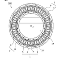
図2は、本実施の形態に係る回転電機の断面模式図である。図2は、図1のA-Aに示す位置での断面模式図である。図2において、外側ロータカバー10および回転電機カバー15は省略されている。ステータ1は、回転軸14を中心として円環状に離間して配置された複数のティース部材4と、それぞれのティース部材4に巻かれたコイル7と、ティース部材4の外周側および内周側にそれぞれ配置された外周側円環状鉄心部材5および内周側円環状鉄心部材6とを有する。本実施の形態の回転電機100は、24個のティース部材4が円環状に離間して配置されている。コイル7は、ティース部材4に集中巻きで同心円状に巻き回されている。離間して配置された複数のティース部材4の間の空間はスロット18になっている。
FIG. 2 is a schematic cross-sectional view of the rotating electric machine according to the present embodiment. FIG. 2 is a schematic cross-sectional view at the position indicated by AA in FIG. In FIG. 2, the
内側ロータ2は、円環状の内側ロータ鉄心8と、内側ロータ鉄心8に埋設された32個の内側ロータ磁石16とを有している。内側ロータ2においては、V字状に配置された2つ一組の内側ロータ磁石16で1つの極を構成しており、その極が周方向に等ピッチに配置されている。2つ一組の内側ロータ磁石16の配置は、外周側に向かって開いたV字状である。
The
外側ロータ3は、円環状の外側ロータ鉄心9と、外側ロータ鉄心9の内周面に固定された16個の外側ロータ磁石17とを有している。外側ロータ磁石17は、ステータ1とギャップを介して対向して設けられている。外側ロータ磁石17は、外側ロータ鉄心9の内周面に例えば接着剤で固定されている。内側ロータ磁石16は、周方向にN極、S極となるように配置されている。また、外側ロータ磁石17は、周方向にS極、N極となるように配置されている。さらに、内側ロータ磁石16と外側ロータ磁石17とは回転軸14の周りに同位相で配置されている。
The
図3は、本実施の形態におけるコイルが巻かれたティース部材の斜視図である。ティース部材4は、軸方向に長い棒状の構造である。ティース部材4には絶縁部材19を介してコイル7が巻かれている。ティース部材4の径方向の両端部には、軸方向に平行な溝状の嵌合凹部4aが形成されている。嵌合凹部4aの断面形状は、外側に向かってテーパー状に開口幅が狭くなっている。
FIG. 3 is a perspective view of a tooth member around which a coil is wound according to the present embodiment. The
図4は、本実施の形態における外周側円環状鉄心部材および内周側円環状鉄心部材の斜視図である。外周側円環状鉄心部材5の内周側には、軸方向に平行な畝状の嵌合凸部5aが形成されている。また、内周側円環状鉄心部材6の外周側には、軸方向に平行な畝状の嵌合凸部6aが形成されている。嵌合凸部5aおよび嵌合凸部6aの断面形状は、外側に向かって幅が広くなっている。嵌合凸部5aおよび嵌合凸部6aは、周方向に等ピッチでそれぞれ24個形成されている。外周側円環状鉄心部材5と内周側円環状鉄心部材6との間に軸方向からコイル7が巻かれたティース部材4が挿入されるときに、ティース部材4の両端の嵌合凹部4aが、外周側円環状鉄心部材5の嵌合凸部5aおよび内周側円環状鉄心部材6の嵌合凸部6aにそれぞれ嵌合される。
FIG. 4 is a perspective view of an outer annular core member and an inner annular core member according to the present embodiment. A ridge-shaped
また、図4に示すように、外周側円環状鉄心部材5の内周側には、スロットの外周壁となる位置に軸方向に平行な溝状の内周側凹部5bが形成されている。さらに、内周側円環状鉄心部材6の外周側には、スロットの内周壁となる位置に軸方向に平行な溝状の外周側凹部6bが形成されている。内周側凹部5bおよび外周側凹部6bの断面形状は、矩形形状である。内周側凹部5bおよび外周側凹部6bは、周方向に等ピッチでそれぞれ24個形成されている。スロット18の外周壁において外周側円環状鉄心部材5の径方向の厚さは、内周側凹部5bが形成された位置が最も小さい。また、スロット18の内周壁において内周側円環状鉄心部材6径方向の厚さは、外周側凹部6bが形成された位置が最も小さい。つまり、内周側凹部5bは、スロット18において外周壁の厚さが他の部分よりも小さい外周側肉薄部である。また、外周側凹部6bは、スロット18において内周壁の厚さが他の部分よりも小さい内周側肉薄部である。
Further, as shown in FIG. 4, on the inner peripheral side of the outer
図5は、本実施の形態におけるステータの組み立て分解図である。図5に示すように、ステータ1は、外周側円環状鉄心部材5と内周側円環状鉄心部材6との間に軸方向からコイル7が巻かれたティース部材4が挿入されて組み立てられる。このとき、ティース部材4の両端の嵌合凹部4aが外周側円環状鉄心部材5の嵌合凸部5aおよび内周側円環状鉄心部材6の嵌合凸部6aにそれぞれ嵌合される。そのため、ティース部材4が周方向に正確に位置決めされると共に、外周側円環状鉄心部材5および内周側円環状鉄心部材6とティース部材4とが強固に締結される。
FIG. 5 is an exploded view of the stator according to this embodiment. As shown in FIG. 5, the
図6は、本実施の形態におけるステータの拡大断面図である。図6に示すように、ティース部材4の両端部の嵌合凹部4aは、外周側円環状鉄心部材5の嵌合凸部5aおよび内周側円環状鉄心部材6の嵌合凸部6aにそれぞれ嵌合されている。スロット18の外周壁には、外周側円環状鉄心部材5の内周側凹部5bが配置されている。スロット18の内周壁には、内周側円環状鉄心部材6の外周側凹部6bが配置されている。
FIG. 6 is an enlarged sectional view of the stator in this embodiment. As shown in FIG. 6, the
図7は、本実施の形態における第2ステータ保持部材の拡大斜視図である。第2ステータ保持部材12は、例えばアルミニウム合金などの非磁性材料で構成されている。図7に示すように、円環状の第2ステータ保持部材12は、軸方向と平行な方向に突出した位置決め凸部12aを備えている。位置決め凸部12aは、第2ステータ保持部材12の径方向に二列になって周方向に並んで配置されている。外周側の位置決め凸部12aは、外周側円環状鉄心部材5が第2ステータ保持部材12に取り付けられたときに、外周側円環状鉄心部材5の嵌合凸部5aの間に位置するように配置されている。また、内周側の位置決め凸部12aは、内周側円環状鉄心部材6が第2ステータ保持部材12に取り付けられたときに、内周側円環状鉄心部材6の嵌合凸部6aの間に位置するように配置されている。なお、第2ステータ保持部材12には、コイル7と電気的に接続された接続コードを引き出すため、またはコイル7の端部を引き出すための引き出し口12bが形成されている。
FIG. 7 is an enlarged perspective view of the second stator holding member in this embodiment. The second
図8は、外周側円環状鉄心部材が第2ステータ保持部材に取り付けられた状態を示す斜視図である。図8に示すように、第2ステータ保持部材12の外周側の位置決め凸部12aに外周側円環状鉄心部材5の嵌合凸部5aが嵌合されて固定される。また、図示はしていないが、第2ステータ保持部材12の内周側の位置決め凸部12aに内周側円環状鉄心部材6の嵌合凸部6aが嵌合されて固定される。このようにして、外周側円環状鉄心部材5および内周側円環状鉄心部材6が周方向に正確に位置決めされて第2ステータ保持部材12に固定される。
FIG. 8 is a perspective view showing a state where the outer peripheral annular core member is attached to the second stator holding member. As shown in FIG. 8, the
図9は、外周側円環状鉄心部材およびティース部材が第2ステータ保持部材に取り付けられた状態を示す斜視図である。図9に示すように、第2ステータ保持部材12に外周側円環状鉄心部材5が固定された後に、コイル7が巻かれたティース部材4が軸方向から挿入される。ティース部材4は、その端部が第2ステータ保持部材12の位置決め凸部12aに接触することで軸方向の位置が決定される。つまり、第2ステータ保持部材12に設けられた位置決め凸部12aは、外周側円環状鉄心部材5および内周側円環状鉄心部材6の周方向の位置を規制すると共に、ティース部材4の軸方向の位置を規制する。
FIG. 9 is a perspective view showing a state in which the outer circumferential annular core member and the tooth member are attached to the second stator holding member. As shown in FIG. 9, after the outer
図10は、ステータに第1ステータ保持部材および第2ステータ保持部材が取り付けられた状態を示す組み立て分解図である。第1ステータ保持部材11は、例えばアルミニウム合金などの非磁性材料で構成されている。図10に示すように、第1ステータ保持部材11には、第2ステータ保持部材12と同様に、軸方向と平行な方向に突出した位置決め凸部11aを備えている。位置決め凸部11aは、第1ステータ保持部材11の径方向に二列になって周方向に並んで配置されている。第1ステータ保持部材11に設けられた位置決め凸部11aも、第2ステータ保持部材12に設けられた位置決め凸部12aと同様に、外周側円環状鉄心部材5および内周側円環状鉄心部材6の周方向の位置を規制すると共に、ティース部材4の軸方向の位置を規制する。図10に示すように、第1ステータ保持部材11と第2ステータ保持部材12とは、軸方向からステータ1に差し込まれる。なお、第1ステータ保持部材11の中心部には、軸受を介して回転軸を回転可能に支持するための軸受挿入孔11bが形成されている。
FIG. 10 is an assembly exploded view showing a state in which the first stator holding member and the second stator holding member are attached to the stator. The first
このように構成された回転電機100においては、内側ロータ磁石16が内側ロータ鉄心8に埋設されているので、ステータ1と内側ロータ2とのギャップの近傍で発生する空間高調波磁束が内側ロータ磁石16に鎖交することを防止できる。そのため、内側ロータ磁石16で発生する渦電流損失を低減することができる。また、内側ロータ磁石16は内側ロータ鉄心8に埋設されているので、遠心力による内側ロータ磁石16の脱落を防止することができる。
In the rotating
また、本実施の形態の回転電機100においては、第1ステータ保持部材11および第2ステータ保持部材12に設けられた位置決め凸部で外周側円環状鉄心部材5および内周側円環状鉄心部材6の周方向の位置決め、およびティース部材4の軸方向の位置決めを行うことができる。さらに、外周側円環状鉄心部材5および内周側円環状鉄心部材6に設けられた嵌合凸部とティース部材に設けられた嵌合凹部とでティース部材4の周方向の位置決めを行うことができる。そのため、ステータ1の組み立て精度が向上すると共に、ステータ1の強度も向上する。
Further, in rotating
さらに、本実施の形態の回転電機100においては、図6に示すように、外周側円環状鉄心部材5はスロット18の外周部に径方向の厚さが他の部分よりも小さい外周側肉薄部を有すると共に、内周側円環状鉄心部材6はスロット18の内周部に径方向の厚さが他の部分よりも小さい内周側肉薄部を有している。円環状鉄心部材の径方向の厚さが小さい部分は少ない磁束量で磁気飽和し、透磁率が低下する。そのため、本実施の形態の回転電機100においては、円環状鉄心部材における漏れ磁束を低減して損失を抑制することができる。
Furthermore, in the rotating
図11は、本実施の形態の回転電機100における外側ロータ磁石17から発生する磁束を示した説明図である。図11から、内周側円環状鉄心部材6が外側ロータ磁石17から発生する磁束の磁束経路として機能していることがわかる。同様に、本実施の形態の回転電機100においては、外周側円環状鉄心部材5が内側ロータ磁石16から発生する磁束の磁束経路として機能する。このように、本実施の形態の回転電機100においては、内周側円環状鉄心部材6が外側ロータ磁石17から発生する磁束の磁束経路として機能し、外周側円環状鉄心部材5が内側ロータ磁石16から発生する磁束の磁束経路として機能するので、コイル7と鎖交する磁束量が多くなり回転電機100の出力が向上する。
FIG. 11 is an explanatory diagram showing the magnetic flux generated from the
内周側円環状鉄心部材6の内周側肉薄部の厚さをT1、外周側円環状鉄心部材5の外周側肉薄部の厚さをT2とし、T1/T2をXとする。図12は、Xに対するステータ1のコイル7に鎖交する鎖交磁束の関係の一例を示す説明図である。図12において、鎖交磁束は、内側ロータ磁石16および外側ロータ磁石17による鎖交磁束である。また、図12の縦軸は、ステータ1が外周側円環状鉄心部材5および内周側円環状鉄心部材6を備えていないときにコイル7に鎖交する鎖交磁束を1としたときの相対値である。図12に示すように、Xが1以上、つまり内周側円環状鉄心部材6の内周側肉薄部の厚さT1が外周側円環状鉄心部材5の外周側肉薄部の厚さT2以上であれば、コイル7に鎖交する鎖交磁束が増加する。その結果、回転電機100の出力をさらに向上させることができる。
Let T1 be the thickness of the inner peripheral side thin portion of the inner peripheral side
実施の形態2.
実施の形態1に係る回転電機においては、外側ロータ磁石が外側ロータ鉄心の内周面に固定されていた。実施の形態2に係る回転電機においては、外側ロータ磁石が外側ロータ鉄心に埋設されている。本実施の形態の回転電機の構成は、外側ロータの構成以外は実施の形態1の回転電機の構成と同様である。
In the rotary electric machine according to
図13は、本実施の形態に係る回転電機の断面模式図である。図13は、回転軸に直角な方向の断面模式図である。図13において、外側ロータカバーおよび回転電機カバーは省略されている。図13に示すように、外側ロータ3は、円環状の外側ロータ鉄心9と、外側ロータ鉄心9に埋設された32個の外側ロータ磁石17とを有している。本実施の形態の回転電機100においては、V字状に配置された2つ一組の外側ロータ磁石17で1つの極を構成しており、その極が周方向に等ピッチに配置されている。2つ一組の外側ロータ磁石17の配置は、内周側に向かって開いたV字状である。
FIG. 13 is a schematic cross-sectional view of the rotary electric machine according to this embodiment. FIG. 13 is a schematic cross-sectional view in a direction perpendicular to the rotation axis. In FIG. 13, the outer rotor cover and rotating electric machine cover are omitted. As shown in FIG. 13 , the
このように構成された回転電機100においては、外側ロータ磁石17が外側ロータ鉄心9に埋設されているので、ステータ1と外側ロータ3とのギャップの近傍で発生する空間高調波磁束が外側ロータ磁石17に鎖交することを防止できる。そのため、外側ロータ磁石17で発生する渦電流損失を低減することができる。また、外側ロータ磁石17は外側ロータ鉄心9に埋設されているので、遠心力による外側ロータ磁石17の脱落を防止することができる。
In the rotating
また、本実施の形態の回転電機100においては、実施の形態1と同様に、外周側円環状鉄心部材5の外周側肉薄部がスロットの外周側に位置すると共に、内周側円環状鉄心部材6の内周側肉薄部がスロットの内周側に位置している。そのため、円環状鉄心部材における漏れ磁束を低減して損失を抑制することができる。
Further, in the rotating
実施の形態3.
実施の形態3に係る回転電機は、実施の形態1に示した回転電機においてティース部材、外周側円環状鉄心部材および内周側円環状鉄心部材の形状を変更したものである。本実施の形態の回転電機の構成は、ティース部材、外周側円環状鉄心部材および内周側円環状鉄心部材の構成以外は実施の形態1の回転電機の構成と同様である。
The rotating electric machine according to the third embodiment is obtained by changing the shapes of the teeth members, the outer circular ring-shaped core member, and the inner ring-shaped core member in the rotating electric machine shown in the first embodiment. The configuration of the rotating electrical machine of the present embodiment is the same as the configuration of the rotating electrical machine of the first embodiment, except for the configuration of the teeth members, the outer circumferential annular core member, and the inner circumferential annular core member.
図14は、本実施の形態におけるティース部材の斜視図である。ティース部材4の径方向の両端部には、軸方向に平行な畝状の嵌合凸部4bが形成されている。嵌合凸部4bの断面形状は、外側に向かって幅が広くなっている。
FIG. 14 is a perspective view of a tooth member according to this embodiment. Ridge-like
図15は、本実施の形態における外周側円環状鉄心部材および内周側円環状鉄心部材の斜視図である。外周側円環状鉄心部材5の内周側には、軸方向に平行な溝状の嵌合凹部5cが形成されている。また、内周側円環状鉄心部材6の外周側には、軸方向に平行な溝状の嵌合凹部6cが形成されている。嵌合凹部5cおよび嵌合凹部6cの断面形状は、外側に向かってテーパー状に開口幅が狭くなっている。嵌合凹部5cおよび嵌合凹部6cは、周方向に等ピッチでそれぞれ24個形成されている。外周側円環状鉄心部材5と内周側円環状鉄心部材6との間に軸方向からコイル7が巻かれたティース部材4が挿入されるときに、ティース部材4の両端の嵌合凸部4bが、外周側円環状鉄心部材5の嵌合凹部5cおよび内周側円環状鉄心部材6の嵌合凹部6cにそれぞれ嵌合される。
FIG. 15 is a perspective view of an outer annular core member and an inner annular core member according to the present embodiment. A groove-shaped
また、図15に示すように、外周側円環状鉄心部材5の内周側には、スロットの外周壁となる位置に軸方向に平行な溝状の内周側凹部5bが形成されている。さらに、内周側円環状鉄心部材6の外周側には、スロットの内周壁となる位置に軸方向に平行な溝状の外周側凹部6bが形成されている。内周側凹部5bおよび外周側凹部6bの断面形状は、矩形形状である。内周側凹部5bおよび外周側凹部6bは、周方向に等ピッチでそれぞれ24個形成されている。すなわち、内周側凹部5bは外周側円環状鉄心部材5の外周側肉薄部であり、外周側凹部6bは内周側円環状鉄心部材6の内周側肉薄部である。
Further, as shown in FIG. 15, on the inner peripheral side of the outer
図16は、本実施の形態におけるステータの組み立て分解図である。図16に示すように、ステータ1は、外周側円環状鉄心部材5と内周側円環状鉄心部材6との間に軸方向からコイル7が巻かれたティース部材4が挿入されて組み立てられる。このとき、ティース部材4の両端の嵌合凸部4bが、外周側円環状鉄心部材5の嵌合凹部5cおよび内周側円環状鉄心部材6の嵌合凹部6cにそれぞれ嵌合される。
FIG. 16 is an exploded view of the stator according to this embodiment. As shown in FIG. 16, the
このように構成されたステータ1においては、実施の形態1のステータと同様に、ティース部材4と外周側円環状鉄心部材5および内周側円環状鉄心部材6とが嵌合凸部と嵌合凹部との嵌合によって強固に締結される。
In the
また、本実施の形態の回転電機100においては、実施の形態1と同様に、外周側円環状鉄心部材5の外側肉薄部がスロットの外周側に位置すると共に、内周側円環状鉄心部材6の内側肉薄部がスロットの内周側に位置している。そのため、円環状鉄心部材における漏れ磁束を低減して損失を抑制することができる。
Further, in the rotating
実施の形態4.
実施の形態4に係る回転電機は、実施の形態1に示した回転電機において外周側円環状鉄心部材および内周側円環状鉄心部材にそれぞれ形成された内周側凹部および外周側凹部の形状を変更したものである。本実施の形態の回転電機の構成は、内周側凹部および外周側凹部の形状以外は実施の形態1の回転電機の構成と同様である。
The rotary electric machine according to the fourth embodiment is different from the rotary electric machine shown in the first embodiment in the shape of the inner peripheral side recess and the outer peripheral side recess formed in the outer peripheral side annular core member and the inner peripheral side annular core member, respectively. It has been changed. The configuration of the rotating electrical machine of the present embodiment is the same as that of the rotating electrical machine of the first embodiment, except for the shapes of the inner peripheral recess and the outer peripheral recess.
図17は、本実施の形態におけるステータの拡大断面図である。図17に示すように、ティース部材4の両端部の嵌合凹部4aは、外周側円環状鉄心部材5の嵌合凸部5aおよび内周側円環状鉄心部材6の嵌合凸部6aにそれぞれ嵌合されている。スロット18の外周壁には、外周側円環状鉄心部材5の内周側凹部5bが配置されている。スロット18の内周壁には、内周側円環状鉄心部材6の外周側凹部6bが配置されている。実施の形態1の回転電機においては、内周側凹部および外周側凹部の断面形状は、矩形形状であった。本実施の形態の回転電機においては、図17に示すように、内周側凹部5bおよび外周側凹部6bの断面形状は、円弧形状である。スロット18の外周壁において外周側円環状鉄心部材5の径方向の厚さは、内周側凹部5bが形成された位置が最も小さい。また、スロット18の内周壁において内周側円環状鉄心部材6径方向の厚さは、外周側凹部6bが形成された位置が最も小さい。すなわち、内周側凹部5bは外周側円環状鉄心部材5の外周側肉薄部であり、外周側凹部6bは内周側円環状鉄心部材6の内周側肉薄部である。
FIG. 17 is an enlarged sectional view of the stator in this embodiment. As shown in FIG. 17, the
このように構成された回転電機においては、実施の形態1と同様に、外周側円環状鉄心部材5の外側肉薄部がスロット18の外周側に位置すると共に、内周側円環状鉄心部材6の内側肉薄部がスロット18の内周側に位置している。そのため、円環状鉄心部材における漏れ磁束を低減して損失を抑制することができる。
In the rotating electric machine configured in this manner, the thin outer wall portion of the outer
実施の形態5.
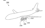
図18は、実施の形態5に係る飛行機の説明図である。本実施の形態の飛行機200は、実施の形態1から4で説明した回転電機100を備えた固定翼航空機である。図18に示すように、本実施の形態の飛行機200は、エンジンケース210の内部に液体燃料で駆動されるエンジン220と、実施の形態1から4で説明した回転電機100とが設置されている。回転電機100は、図示していないが飛行機200に搭載されたバッテリーで駆動される。エンジン220と回転電機100と推進ファン230とは、シャフトで連結されている。推進ファン230は、エンジン220と回転電機100とを駆動力源として回転する。なお、推進ファン230と回転電機100との間、およびエンジン220と回転電機100との間のどちらか一方もしくは両方に回転数を変換するギアが搭載されていてもよい。また、本実施の形態の飛行機200においては、エンジン220と回転電機100と推進ファン230とがシャフトで同軸状に配置されている。別の構成として、エンジン220と回転電機100と推進ファン230とがギアなどを介して別軸状に配置されていてもよい。
18 is an explanatory diagram of an airplane according to
この回転電機は、第1ステータ保持部材および第2ステータ保持部材に設けられた位置決め凸部で外周側円環状鉄心部材および内周側円環状鉄心部材の周方向の位置決め、およびティース部材の軸方向の位置決めを行うことができる。さらに、外周側円環状鉄心部材および内周側円環状鉄心部材とティース部材とにそれぞれ設けられた嵌合凸部と嵌合凹部とでティース部材の周方向の位置決めを行うことができる。そのため、ステータの組み立て精度が向上すると共に、ステータの強度も向上する。この回転電機を飛行機の推進装置の駆動力源に適用することで、信頼性の高い電動飛行機を実現することができる。 In this rotating electric machine, the positioning projections provided on the first stator holding member and the second stator holding member position the outer annular core member and the inner annular core member in the circumferential direction and position the teeth members in the axial direction. can be positioned. Furthermore, the teeth members can be positioned in the circumferential direction by the fitting protrusions and fitting recesses provided on the outer and inner annular core members and the teeth members, respectively. Therefore, the assembling accuracy of the stator is improved, and the strength of the stator is also improved. By applying this rotating electric machine to the driving force source of the propulsion device of an airplane, a highly reliable electric airplane can be realized.
また、この回転電機は、外周側円環状鉄心部材の外側肉薄部がスロットの外周側に位置すると共に、内周側円環状鉄心部材の内側肉薄部がスロットの内周側に位置している。そのため、円環状鉄心部材における漏れ磁束を低減して損失を抑制することができる。さらに、外周側円環状鉄心部材は内側ロータ磁石から発生する磁束の磁束経路として機能し、内周側円環状鉄心部材は外側ロータ磁石から発生する磁束の磁束経路として機能するので、出力に寄与する磁束量を増加させることができる。その結果、この回転電機は高いトルク出力を得ることができるので、この回転電機を搭載した飛行機の単位燃料当たりの航続距離を延ばすことができる。 Further, in this rotating electric machine, the outer thin portion of the outer annular core member is located on the outer peripheral side of the slot, and the inner thin portion of the inner annular core member is located on the inner peripheral side of the slot. Therefore, it is possible to reduce the leakage magnetic flux in the annular core member and suppress the loss. Furthermore, the outer ring-shaped core member functions as a magnetic flux path for the magnetic flux generated from the inner rotor magnet, and the inner ring-shaped core member functions as a magnetic flux path for the magnetic flux generated from the outer rotor magnet, contributing to output. The amount of magnetic flux can be increased. As a result, this rotating electric machine can obtain a high torque output, so that the cruising distance per unit fuel of an airplane equipped with this rotating electric machine can be extended.
なお、本実施の形態の飛行機においては、推進ファンの駆動力源としてエンジンと回転電機との両方を備えているが、駆動力源として回転電機のみでもよい。 In the airplane of the present embodiment, both the engine and the rotating electric machine are provided as driving force sources for the propulsion fan, but only the rotating electric machine may be used as the driving force source.
実施の形態6.
図19は、実施の形態6に係るマルチコプターの説明図である。本実施の形態のマルチコプター300は、実施の形態1から4で説明した回転電機100を備えた回転翼航空機である。図19に示すように、本実施の形態のマルチコプター300は、4つの推進ファン310と、4つの推進ファン310をそれぞれ駆動する4つの回転電機100と、4つの回転電機100をそれぞれ制御する4つのインバータ320と、インバータ320に電力を供給するバッテリー330とを備えている。
FIG. 19 is an explanatory diagram of a multicopter according to
このように構成されたマルチコプターにおいても、実施の形態1から4で説明した回転電機を推進装置の駆動力源に適用しているので、信頼性が高く航続距離の長いマルチコプターを実現することができる。 Even in the multicopter configured in this way, since the rotating electric machine described in the first to fourth embodiments is applied to the driving force source of the propulsion device, it is possible to realize a multicopter with high reliability and a long cruising distance. can be done.
図20は、本実施の形態に係る別のマルチコプターの説明図である。図20に示すマルチコプター300においては、実施の形態1から4で説明した回転電機を発電機340としても用いたものである。この発電機340は、エンジン350で駆動される。発電機340で発電された電力は、バッテリー330に蓄積される。
FIG. 20 is an explanatory diagram of another multicopter according to this embodiment. In the
このように構成されたマルチコプターにおいては、実施の形態1から4で説明した回転電機を発電機に適用し、この発電機を用いてバッテリー330に電力を供給することができるので、さらに航続距離の長いマルチコプターを実現することができる。
In the multicopter configured in this way, the rotating electric machine described in
実施の形態5および6に示したように、固定翼航空機、回転翼航空機などの推進装置の駆動力源に実施の形態1から4で説明した回転電機を適用することで、信頼性が高く、航続距離の長い航空機を実現することができる。
As shown in
本願は、様々な例示的な実施の形態が記載されているが、1つまたは複数の実施の形態に記載された様々な特徴、態様、および機能は特定の実施の形態の適用に限られるのではなく、単独で、または様々な組み合わせで実施の形態に適用可能である。
したがって、例示されていない無数の変形例が、本願に開示される技術の範囲内において想定される。例えば、少なくとも1つの構成要素を変形する場合、追加する場合または省略する場合、さらには、少なくとも1つの構成要素を抽出し、他の実施の形態の構成要素と組み合わせる場合が含まれるものとする。Although this application describes various exemplary embodiments, the various features, aspects, and functions described in one or more embodiments are limited to the application of particular embodiments. can be applied to the embodiments alone or in various combinations.
Therefore, countless modifications not illustrated are envisioned within the scope of the technology disclosed in the present application. For example, modification, addition or omission of at least one component, extraction of at least one component, and combination with components of other embodiments shall be included.
1 ステータ、2 内側ロータ、3 外側ロータ、4 ティース部材、4a 嵌合凹部、4b、5a、6a 嵌合凸部、5 外周側円環状鉄心部材、5b 内周側凹部、5c、6c 嵌合凹部、6 内周側円環状鉄心部材、6b 外周側凹部、7 コイル、8 内側ロータ鉄心、9 外側ロータ鉄心、10 外側ロータカバー、11 第1ステータ保持部材、11a、12a 位置決め凸部、11b 軸受挿入孔、12 第2ステータ保持部材、13 軸受、14 回転軸、15 回転電機カバー、16 内側ロータ磁石、17 外側ロータ磁石、18 スロット、19 絶縁部材、100 回転電機、200 飛行機、210 エンジンケース、220、350 エンジン、230、310 推進ファン、300 マルチコプター、320 インバータ、330 バッテリー、340 発電機。
Claims (7)
前記ステータの内周側にギャップを介して配置された内側ロータと、
前記ステータの外周側にギャップを介して配置され、磁石を有し前記内側ロータと一体となって前記ステータに対して回転可能な外側ロータとを有する回転電機であって、
前記ステータは、円環状に離間して配置された複数のティース部材と、複数の前記ティース部材にそれぞれ巻かれた複数のコイルと、複数の前記ティース部材の外周側および内周側にそれぞれ締結された外周側円環状鉄心部材および内周側円環状鉄心部材とを有し、円環状に離間して配置された複数の前記ティース部材の間の前記外周側円環状鉄心部材と前記内周側円環状鉄心部材とに挟まれた空間はスロットになっており、前記外周側円環状鉄心部材は前記スロットの外周壁に径方向の厚さが他の部分よりも小さい外周側肉薄部を有すると共に、前記内周側円環状鉄心部材は前記外周壁に前記外周側肉薄部を有する前記スロットの内周壁に径方向の厚さが他の部分よりも小さい内周側肉薄部を有し、前記内周側円環状鉄心部材の前記内周側肉薄部の厚さは、前記外周側円環状鉄心部材の前記外周側肉薄部の厚さよりも大きいことを特徴とする回転電機。 an annular stator;
an inner rotor disposed on the inner peripheral side of the stator with a gap therebetween;
A rotating electric machine having an outer rotor disposed on the outer peripheral side of the stator with a gap therebetween and having magnets and capable of rotating integrally with the inner rotor with respect to the stator ,
The stator includes a plurality of tooth members that are annularly spaced apart, a plurality of coils wound around the plurality of tooth members, and fastened to the outer and inner peripheral sides of the plurality of tooth members, respectively. The outer ring-shaped core member and the inner ring-shaped core member are provided between the plurality of tooth members that are annularly spaced apart from each other. The space sandwiched between the annular core members is a slot, and the outer peripheral annular core member has an outer peripheral thin portion having a smaller radial thickness than other portions on the outer peripheral wall of the slot, The inner peripheral annular core member has an inner peripheral thin portion having a smaller radial thickness than other portions on the inner peripheral wall of the slot having the outer peripheral thin portion on the outer peripheral wall, and A rotary electric machine, wherein the thickness of the inner peripheral thin portion of the side annular core member is larger than the thickness of the outer peripheral thin portion of the outer annular core member.
前記ステータの内周側にギャップを介して配置され、磁石を有する内側ロータと、an inner rotor disposed on the inner peripheral side of the stator with a gap therebetween and having a magnet;
前記ステータの外周側にギャップを介して配置され、磁石を有し前記内側ロータと一体となって前記ステータに対して回転可能な外側ロータとを有する回転電機であって、A rotating electric machine having an outer rotor disposed on the outer peripheral side of the stator with a gap therebetween and having magnets and capable of rotating integrally with the inner rotor with respect to the stator,
前記ステータは、円環状に離間して配置された複数のティース部材と、複数の前記ティース部材にそれぞれ巻かれた複数のコイルと、前記ティース部材の径方向端部の外周側および内周側にそれぞれ締結された外周側円環状鉄心部材および内周側円環状鉄心部材とを有し、円環状に離間して配置された複数の前記ティース部材の間の前記外周側円環状鉄心部材と前記内周側円環状鉄心部材とに挟まれた空間はスロットになっており、前記外周側円環状鉄心部材は前記スロットの外周壁に径方向の厚さが他の部分よりも小さい外周側肉薄部を有すると共に、前記内周側円環状鉄心部材は前記外周壁に前記外周側肉薄部を有する前記スロットの内周壁に径方向の厚さが他の部分よりも小さい内周側肉薄部を有することを特徴とする回転電機。The stator includes a plurality of tooth members that are annularly spaced apart, a plurality of coils that are respectively wound around the plurality of tooth members, and coils that are disposed on the outer and inner peripheral sides of the radial ends of the tooth members. An outer ring-shaped core member and an inner ring-shaped core member are fastened to each other, and the outer ring-shaped core member and the inner ring-shaped core member are disposed between the plurality of tooth members that are annularly spaced apart from each other. A space sandwiched between the peripheral annular core member and the peripheral annular core member forms a slot, and the outer peripheral annular core member has an outer peripheral thin portion having a smaller radial thickness than other portions on the outer peripheral wall of the slot. and the inner peripheral annular core member has an inner peripheral thin portion having a radial thickness smaller than that of other portions on the inner peripheral wall of the slot having the outer peripheral thin portion on the outer peripheral wall. Rotating electric machine characterized by:
Applications Claiming Priority (1)
| Application Number | Priority Date | Filing Date | Title |
|---|---|---|---|
| PCT/JP2021/044628 WO2023105551A1 (en) | 2021-12-06 | 2021-12-06 | Rotating electric machine and aircraft provided with said rotating electric machine |
Publications (3)
| Publication Number | Publication Date |
|---|---|
| JP7162777B1 true JP7162777B1 (en) | 2022-10-28 |
| JPWO2023105551A1 JPWO2023105551A1 (en) | 2023-06-15 |
| JPWO2023105551A5 JPWO2023105551A5 (en) | 2023-11-09 |
Family
ID=83806062
Family Applications (1)
| Application Number | Title | Priority Date | Filing Date |
|---|---|---|---|
| JP2022517176A Active JP7162777B1 (en) | 2021-12-06 | 2021-12-06 | Rotating electric machine and aircraft equipped with the rotating electric machine |
Country Status (2)
| Country | Link |
|---|---|
| JP (1) | JP7162777B1 (en) |
| WO (1) | WO2023105551A1 (en) |
Citations (4)
| Publication number | Priority date | Publication date | Assignee | Title |
|---|---|---|---|---|
| JP2003299272A (en) * | 2002-04-01 | 2003-10-17 | Nissan Motor Co Ltd | Stator structure for rotating machine |
| JP2005237191A (en) * | 2004-02-17 | 2005-09-02 | Minebea Co Ltd | Motor |
| US20090140526A1 (en) * | 2007-11-29 | 2009-06-04 | General Electric Company | Stator and stator tooth modules for electrical machines |
| WO2018016497A1 (en) * | 2016-07-22 | 2018-01-25 | 日本精工株式会社 | Dual-axis integrated motor |
-
2021
- 2021-12-06 JP JP2022517176A patent/JP7162777B1/en active Active
- 2021-12-06 WO PCT/JP2021/044628 patent/WO2023105551A1/en active Application Filing
Patent Citations (4)
| Publication number | Priority date | Publication date | Assignee | Title |
|---|---|---|---|---|
| JP2003299272A (en) * | 2002-04-01 | 2003-10-17 | Nissan Motor Co Ltd | Stator structure for rotating machine |
| JP2005237191A (en) * | 2004-02-17 | 2005-09-02 | Minebea Co Ltd | Motor |
| US20090140526A1 (en) * | 2007-11-29 | 2009-06-04 | General Electric Company | Stator and stator tooth modules for electrical machines |
| WO2018016497A1 (en) * | 2016-07-22 | 2018-01-25 | 日本精工株式会社 | Dual-axis integrated motor |
Also Published As
| Publication number | Publication date |
|---|---|
| WO2023105551A1 (en) | 2023-06-15 |
| JPWO2023105551A1 (en) | 2023-06-15 |
Similar Documents
| Publication | Publication Date | Title |
|---|---|---|
| EP2200154B1 (en) | Axial gap motor | |
| US4745312A (en) | Stepping motor | |
| US20160020653A1 (en) | Motor | |
| US20130057102A1 (en) | Rotor and motor | |
| EP1455435B1 (en) | Single phase induction motor further comprising a permanent magnetic unit | |
| JP6584331B2 (en) | Single-phase brushless motor and method for manufacturing single-phase brushless motor | |
| JP2000209825A (en) | Permanent magnet generator | |
| JP3675772B2 (en) | Stepping motor | |
| JP2017050943A (en) | Rotary electric machine | |
| JP2018157612A (en) | motor | |
| JP2000041367A (en) | Hybrid excitation type synchronous machine | |
| JP2013115899A (en) | Rotor of permanent magnet type motor, manufacturing method of the same, and permanent magnet type motor | |
| JP7162777B1 (en) | Rotating electric machine and aircraft equipped with the rotating electric machine | |
| JP2019208360A (en) | Motor, method of manufacturing the same, vacuum cleaner including the same, and method of manufacturing the same | |
| US20030107274A1 (en) | Stepping motor | |
| JP2008017543A (en) | Motor magnetization method | |
| JP2020014368A (en) | Brushless motor and manufacturing method thereof | |
| WO2022118598A1 (en) | Magnetic-geared motor and magnetic gear | |
| WO2021140606A1 (en) | Rotating electric machine | |
| WO2022181035A1 (en) | Motor | |
| US20220181933A1 (en) | Rotor, motor, and electric power steering device | |
| WO2021149753A1 (en) | Magnetic geared dynamo-electric machine, and method for manufacturing stator | |
| KR20100109693A (en) | Inteior permanent magnet type motor | |
| JP2012060709A (en) | Permanent magnet motor | |
| JP2022152554A (en) | motor |
Legal Events
| Date | Code | Title | Description |
|---|---|---|---|
| A521 | Request for written amendment filed |
Free format text: JAPANESE INTERMEDIATE CODE: A523 Effective date: 20220316 |
|
| A621 | Written request for application examination |
Free format text: JAPANESE INTERMEDIATE CODE: A621 Effective date: 20220316 |
|
| A871 | Explanation of circumstances concerning accelerated examination |
Free format text: JAPANESE INTERMEDIATE CODE: A871 Effective date: 20220316 |
|
| A131 | Notification of reasons for refusal |
Free format text: JAPANESE INTERMEDIATE CODE: A131 Effective date: 20220517 |
|
| A521 | Request for written amendment filed |
Free format text: JAPANESE INTERMEDIATE CODE: A523 Effective date: 20220707 |
|
| TRDD | Decision of grant or rejection written | ||
| A01 | Written decision to grant a patent or to grant a registration (utility model) |
Free format text: JAPANESE INTERMEDIATE CODE: A01 Effective date: 20220920 |
|
| A61 | First payment of annual fees (during grant procedure) |
Free format text: JAPANESE INTERMEDIATE CODE: A61 Effective date: 20221018 |
|
| R151 | Written notification of patent or utility model registration |
Ref document number: 7162777 Country of ref document: JP Free format text: JAPANESE INTERMEDIATE CODE: R151 |