JP7160777B2 - Bucket tooth mounting structure and bucket tooth - Google Patents
Bucket tooth mounting structure and bucket tooth Download PDFInfo
- Publication number
- JP7160777B2 JP7160777B2 JP2019167278A JP2019167278A JP7160777B2 JP 7160777 B2 JP7160777 B2 JP 7160777B2 JP 2019167278 A JP2019167278 A JP 2019167278A JP 2019167278 A JP2019167278 A JP 2019167278A JP 7160777 B2 JP7160777 B2 JP 7160777B2
- Authority
- JP
- Japan
- Prior art keywords
- tooth
- nose
- end portion
- adapter
- bucket
- Prior art date
- Legal status (The legal status is an assumption and is not a legal conclusion. Google has not performed a legal analysis and makes no representation as to the accuracy of the status listed.)
- Active
Links
Images


Classifications
-
- E—FIXED CONSTRUCTIONS
- E02—HYDRAULIC ENGINEERING; FOUNDATIONS; SOIL SHIFTING
- E02F—DREDGING; SOIL-SHIFTING
- E02F9/00—Component parts of dredgers or soil-shifting machines, not restricted to one of the kinds covered by groups E02F3/00 - E02F7/00
- E02F9/28—Small metalwork for digging elements, e.g. teeth scraper bits
- E02F9/2808—Teeth
- E02F9/2858—Teeth characterised by shape
-
- E—FIXED CONSTRUCTIONS
- E02—HYDRAULIC ENGINEERING; FOUNDATIONS; SOIL SHIFTING
- E02F—DREDGING; SOIL-SHIFTING
- E02F9/00—Component parts of dredgers or soil-shifting machines, not restricted to one of the kinds covered by groups E02F3/00 - E02F7/00
- E02F9/28—Small metalwork for digging elements, e.g. teeth scraper bits
- E02F9/2808—Teeth
- E02F9/2816—Mountings therefor
- E02F9/2825—Mountings therefor using adapters
-
- E—FIXED CONSTRUCTIONS
- E02—HYDRAULIC ENGINEERING; FOUNDATIONS; SOIL SHIFTING
- E02F—DREDGING; SOIL-SHIFTING
- E02F9/00—Component parts of dredgers or soil-shifting machines, not restricted to one of the kinds covered by groups E02F3/00 - E02F7/00
- E02F9/28—Small metalwork for digging elements, e.g. teeth scraper bits
- E02F9/2808—Teeth
- E02F9/2816—Mountings therefor
- E02F9/2833—Retaining means, e.g. pins
Landscapes
- Engineering & Computer Science (AREA)
- Mining & Mineral Resources (AREA)
- Civil Engineering (AREA)
- General Engineering & Computer Science (AREA)
- Structural Engineering (AREA)
- Component Parts Of Construction Machinery (AREA)
- Dental Prosthetics (AREA)
Description
本発明は、バケット用のツース取付構造、及びバケット用のツースに、関する。 The present invention relates to a bucket tooth mounting structure and a bucket tooth.
従来技術として、特許文献1には、バケット用のツース取付構造が開示されている。従来のバケット用のツース取付構造では、ツースがピン部材を介してツースアダプタに装着される。この場合、リテーナをピン部材に係合させることによって、ピン部材は抜け止めされている。
As a conventional technique,
従来のバケット用のツース取付構造において、ピン部材を介してツースをツースアダプタに装着する場合、掘削を繰り返し行うことによって、ツース及びツースアダプタの間にガタが生じるという問題がある。 In the conventional bucket tooth mounting structure, when the tooth is attached to the tooth adapter via the pin member, there is a problem that looseness is generated between the tooth and the tooth adapter due to repeated excavation.
また、上記のガタの発生によって、ツース及びツースアダプタが摩耗した場合、ツース及びツースアダプタの間に土砂が入り込み、ツース及びツースアダプタの摩耗が促進される。これにより、ツース及びツースアダプタの間のガタがさらに大きくなる可能性がある。 Further, when the tooth and the tooth adapter are worn due to the backlash, earth and sand enter between the tooth and the tooth adapter, accelerating the wear of the tooth and the tooth adapter. This can lead to even greater play between the tooth and tooth adapter.
本発明の目的は、ツース及びツースアダプタの間のガタを抑制できるバケット用のツース取付構造を、提供することにある。また、本発明の目的は、ツースアダプタとの間のガタを抑制できるバケット用のツースを、提供することにある。 SUMMARY OF THE INVENTION An object of the present invention is to provide a tooth mounting structure for a bucket that can suppress backlash between teeth and tooth adapters. Another object of the present invention is to provide a tooth for a bucket that can suppress looseness between itself and the tooth adapter.
第1の態様に係るバケット用のツース取付構造は、ツースアダプタと、ツースとを、備える。ツースアダプタは、バケットに装着される装着部と、装着部から延びるノーズ部とを、有する。ツースは、ノーズ部を挿入するための内部空間を、有する。ノーズ部は、先端部と、装着部に連なる基端部と、先端部及び基端部の間に設けられる連結部とを、有する。ノーズ部の長手方向に延びる軸に直交する平面によって連結部を切断した断面の外周は、8角形に形成される。基端部を上記の平面によって切断した断面の外周は、矩形状に形成される。先端部を上記の平面によって切断した断面の外周は、矩形状に形成される。ツースの内周は、ノーズ部の外周に沿って形成される、
第2の態様に係るバケット用のツースは、ノーズ部を有するツースアダプタに、取り付けられる。ノーズ部では、矩形状の先端部及び矩形状の基端部の間に設けられる連結部が8角形状に形成される。バケット用のツースは、ツース本体を備える。ツース本体は、ノーズ部を挿入するための内部空間を有する。ツース本体において連結部に対向する部分を、ノーズ部の長手方向に延びる軸に直交する平面によって切断した断面の内周は、ノーズ部の連結部の外周に沿って形成される。
A tooth mounting structure for a bucket according to a first aspect includes a tooth adapter and teeth. The tooth adapter has a mounting portion attached to the bucket and a nose portion extending from the mounting portion. The tooth has an interior space for inserting the nose. The nose portion has a distal end portion, a proximal end portion connected to the mounting portion, and a connecting portion provided between the distal end portion and the proximal end portion. The outer periphery of a cross section of the connecting portion cut by a plane perpendicular to the longitudinal axis of the nose portion is formed in an octagon. The outer circumference of the cross section obtained by cutting the base end portion along the above plane is formed in a rectangular shape. The outer periphery of the cross section obtained by cutting the tip portion along the above plane is formed in a rectangular shape. The inner circumference of the tooth is formed along the outer circumference of the nose,
A bucket tooth according to the second aspect is attached to a tooth adapter having a nose portion. In the nose portion, the connecting portion provided between the rectangular distal end portion and the rectangular proximal end portion is formed in an octagonal shape. A bucket tooth has a tooth body. The tooth body has an internal space for inserting the nose. The inner circumference of a cross section obtained by cutting a portion of the tooth body facing the connecting portion along a plane perpendicular to the axis extending in the longitudinal direction of the nose portion is formed along the outer circumference of the connecting portion of the nose portion.
本発明のバケット用のツース取付構造は、ツース及びツースアダプタの間のガタを、抑制することができる。また、本発明のバケット用のツースは、ツースアダプタとの間のガタを抑制することができる。 The bucket tooth mounting structure of the present invention can suppress backlash between the tooth and the tooth adapter. Further, the tooth for the bucket of the present invention can suppress backlash between the tooth adapter and the tooth adapter.
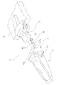
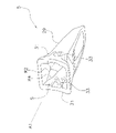
本実施形態に係るバケット用のツース取付構造1の構成について、図面を参照しながら説明する。例えば、図1に示すように、ツース取付構造1は、バケット2に装着される。ツース取付構造1は、ツース5と、ピン部材7と、ロック部材9とを、備える。詳細には、ツース取付構造1は、ツースアダプタ3と、ツース5と、ピン部材7と、ロック部材9とを、備える。
A configuration of a
(ツースアダプタ)
図1に示すように、ツースアダプタ3は、バケット2に設けられる。図2に示すように、ツースアダプタ3は、バケット2の開口部から突出するように、バケット2に装着される。ツースアダプタ3は、一方向に長い部材である。例えば、図2に示すように、ツースアダプタ3の長手方向は、軸A1が延びる方向に対応している。軸A1は、ノーズ部21(後述する)の長手方向にも対応している。
(tooth adapter)
As shown in FIG. 1 , the
図3に示すように、ツースアダプタ3は、アダプタ本体11と、第1ピン孔13(貫通孔の一例)と、凹部15とを、有する。図4Aに示すように、第1ピン孔13は、ツースアダプタ3の軸A1に直交する方向に延びる。第1ピン孔13には、ピン部材7(図2を参照)が配置される。
As shown in FIG. 3 , the
図4Bに示すように、第1ピン孔13の端部13bは、第1ピン孔13の中央部13aより拡径されている。例えば、第1ピン孔13における中央部13aの内周面は、円形状に形成される。第1ピン孔13の中央部13aの直径は、ピン部材7の直径より大きい。第1ピン孔13における端部13bの内周面は、円形状に形成される。
As shown in FIG. 4B, the
図3及び図4Aに示すように、凹部15は、ツースアダプタ3の第1ピン孔13が形成される面に、形成される。凹部15には、ロック部材9が配置される(図7Bを参照)。例えば、凹部15には、ロック部材9の一部が配置される。
As shown in FIGS. 3 and 4A, the
詳細には、ツースアダプタ3は、装着部19と、ノーズ部21とを、有する。装着部19及びノーズ部21は、上述したアダプタ本体11を構成する。装着部19は、バケット2に固定される。装着部19には、上述した凹部15が形成される。
Specifically, the
ノーズ部21は、装着部19から延びる。例えば、ノーズ部21は、装着部19と一体に形成される。ノーズ部21は、バケット2から離れるように、装着部19から突出する。ノーズ部21は、先細り形状に形成される。ノーズ部21は、一方向に長い部材である。ノーズ部21の長手方向は、軸A1が延びる方向に対応している。例えば、ノーズ部21の先端面を外側から見た正面視において、軸A1は、ノーズ部21の先端部23の中心及びノーズ部21の重心を通過する。ノーズ部21には、上述した第1ピン孔13が形成される。
A
図4Aに示すように、ノーズ部21は、先端部23と、基端部25と、連結部27とを、有する。図5Aに示すように、先端部23は、ノーズ部21の軸A1が延びる軸方向においてツース5の内面に当接可能なように、ツース5の内部空間Sに配置される。
As shown in FIG. 4A ,
図5A及び図5B(a)に示すように、ノーズ部21の軸A1に直交する平面(a)によって先端部23を切断した断面の外周は、矩形状に形成される。なお、“外周”は、“外形”と解釈してもよい。以下では、ノーズ部21の軸A1に直交する“平面”は、“切断面”と記載される。
As shown in FIGS. 5A and 5B(a), the outer circumference of the cross section obtained by cutting the
図4Aに示すように、基端部25は、装着部19から連なって設けられる。例えば、基端部25は、装着部19と一体に形成される。図5A及び図5B(e)に示すように、切断面(e)によって基端部25を切断した断面の外周は、矩形状に形成される。
As shown in FIG. 4A , the
図5Aに示すように、連結部27は、先端部23及び基端部25の間に設けられる。例えば、連結部27は、先端部23及び基端部25と一体に形成される。連結部27には、上述した第1ピン孔13が形成される。
As shown in FIG. 5A, the connecting
連結部27の外面は、8角形に形成される。例えば、切断面(b)及び切断面(c)によって連結部27を切断した断面の外周は、8角形に形成される。第1ピン孔13を通過する切断面(d)によって連結部27を切断した断面の外周は、8角形に形成される。このように、断面の外周が8角形に形成される部分が、連結部27として定義される。
The outer surface of the connecting
より詳細には、連結部27において互いに対向する辺L1の両端部それぞれは、基端部25の隅角部及び先端部23の隅角部を連結する第1稜線R1を、形成する。例えば、連結部27では、8角形の辺L1が、ノーズ部21の軸A1及びピン部材7の軸心A2を含む平面P1に平行に形成される。連結部27において平面P1に平行な面は、8角形の辺L1によって形成される。図3、図4A、図5B(b)、図5B(c)、及び図5B(d)に示すように、8角形の辺L1の両端部によって、連結部27の外面には第1稜線部R1が形成される。
More specifically, both end portions of the sides L1 facing each other in the connecting
また、連結部27において辺L1の両端部に隣接する隅角部は、基端部25の隅角部及び先端部23の隅角部を連結する第3稜線R3を、形成する。例えば、図3、図4A、図5B(b)、図5B(c)、及び図5B(d)に示すように、第1稜線部R1を形成する隅角部に隣接する隅角部によって、連結部27の外面には第3稜線部R3が形成される。
Further, the corner portions adjacent to both ends of the side L1 in the connecting
図5B(b)、図5B(c)、及び図5B(d)に示すように、連結部の辺L1に隣接する辺L3は、連結部27の8角形の外周における一辺である。辺L3は、第1稜線部R1及び第3稜線部R3の間の面を、形成する。
As shown in FIGS. 5B(b), 5B(c), and 5B(d), the side L3 adjacent to the side L1 of the connecting portion is one side of the octagonal perimeter of the connecting
ここで、図5B(b)、図5B(c)、及び図5B(d)に示すように、長手方向における連結部27の中央部の辺L1の長さ(図5B(c)の辺L1の長さ)は、連結部27における基端部25側の辺L1の長さ(図5B(d)の辺L1の長さ)より、短い。また、長手方向における連結部27の中央部の辺L1の長さ(図5B(c)の辺L1の長さ)は、連結部27における先端部23側の辺L1の長さ(図5B(b)の辺L1の長さ)より、短い。
Here, as shown in FIGS. 5B(b), 5B(c), and 5B(d), the length of the side L1 of the central portion of the connecting
詳細には、図3に示すように、辺L1は、基端部25から連結部27の中央部に向けて、徐々に短くなる(図5B(d)及び図5B(c)を参照)。また、辺L1は、連結部27の中央部から先端部23に向けて、徐々に長くなる(図5B(c)及び図5B(b)を参照)。
Specifically, as shown in FIG. 3, the side L1 gradually becomes shorter from the
図5B(b)、図5B(c)、及び図5B(d)に示すように、長手方向における連結部27の中央部の辺L3の長さ(図5B(c)の辺L3の長さ)は、連結部27における基端部25側の辺L3の長さ(図5B(d)の辺L3の長さ)より、長い。また、長手方向における連結部27の中央部の辺L3の長さ(図5B(c)の辺L3の長さ)は、連結部27における先端部23側の辺L3の長さ(図5B(b)の辺L3の長さ)より、長い。
As shown in FIGS. 5B(b), 5B(c), and 5B(d), the length of the side L3 of the central portion of the connecting
詳細には、図3に示すように、辺L3は、基端部25から連結部27の中央部に向けて、徐々に長くなる(図5B(d)及び図5B(c)を参照)。また、辺L3は、連結部27の中央部から先端部23に向けて、徐々に短くなる(図5B(c)及び図5B(b)を参照)。
Specifically, as shown in FIG. 3, the side L3 gradually becomes longer from the
(ツース)
図1、図2、及び図5Aに示すように、ツース5は、ツースアダプタ3に取り付けられる。図6に示すように、ツース5は、ツースアダプタ3を挿入するための内部空間Sを、有する。ツース5の内面は、ツースアダプタ3の外面に沿って形成される。例えば、ツース5は、ガイド溝31と、第2ピン孔33(ピン孔の一例)とを、有する。詳細には、ツース5は、ツース本体29と、ガイド溝31と、第2ピン孔33とを、有する。
(tooth)
The
ツース本体29は、有底筒状に形成される。ツース本体29の内面は、ノーズ部21の外面に沿って形成される。例えば、ツース本体29の内面は、先細り形状に形成される。このようにツース本体29を形成することによって、上述した内部空間Sが形成される。内部空間Sには、ツースアダプタ3のノーズ部21が配置される(図5Aを参照)。
The tooth
第2ピン孔33は、ツース本体29を貫通する。例えば、第2ピン孔33は、第1ピン孔13(図4Aを参照)と連通可能なように、ツース本体29に形成される。第2ピン孔33は、ガイド溝31に設けられる。第2ピン孔33は、ガイド溝31の底部を貫通する。第2ピン孔33には、ピン部材7が配置される。
The
ガイド溝31は、ロック部材9をピン部材7に向けて案内するためのものである。ガイド溝31は、ツース5の内面に設けられる。例えば、ガイド溝31は、ツース本体29の内面に設けられる。ガイド溝31は、ツース本体29の開口端からツース本体29の先端部に向かって、延びる。詳細には、ガイド溝31は、ツース本体29の内面に沿って、ツース本体29の開口端からツース本体29の先端部に向かって、延びる。
The
図5A及び図5Bに示すように、ツース5を上記の切断面(a)~(e)によって切断した断面の内周は、次のように形成される。
As shown in FIGS. 5A and 5B, the inner periphery of the cross section obtained by cutting the
図5Bに示すように、ツース本体29においてノーズ部21に対向する部分は、第1部分35と、第2部分37と、第3部分39とを、有する。
As shown in FIG. 5B , the portion of the
図5B(a)に示すように、第1部分35は、ツース本体29がノーズ部21の先端部23に対向する部分である。第1部分35の内面は、ノーズ部21の先端部23の外面に沿って形成される。第1部分35を切断面(a)によって切断した断面の内周は、矩形状に形成される。図5B(e)に示すように、第2部分37は、ツース本体29がノーズ部21の基端部25に対向する部分である。第2部分37の内面は、ノーズ部21の基端部25の外面に沿って形成される。第2部分37を切断面(e)によって切断した断面の内周は、矩形状に形成される。
As shown in FIG. 5B( a ), the
図5(b)、図5(c)、及び図5(d)に示すように、第3部分39は、ツース本体29がノーズ部21の連結部27に対向する部分である。第3部分39の内面は、ノーズ部21の連結部27の外面に沿って形成される。例えば、切断面(b)、切断面(c)、及び切断面(d)によって第3部分39を切断した断面の内周は、8角形に形成される。
As shown in FIGS. 5(b), 5(c), and 5(d), the
第3部分39では、8角形の辺L2が平面P1に平行に形成される。図6、図5B(b)、図5B(c)、及び図5B(d)に示すように、8角形の辺L2の両端部によって、第3部分39の内面には、第2稜線部R2が形成される。第2稜線部R2は、ツースアダプタ3(連結部27)の第1稜線部R1(図3を参照)に対向するように配置される。
In the
また、辺L2の端部に隣接する隅角部によって、第3部分39の内面には、第4稜線部R4が形成される。第4稜線部R4は、ツースアダプタ3の第3稜線部R3(図3を参照)に対向するように配置される。
A fourth ridgeline portion R4 is formed on the inner surface of the
図5B(b)、図5B(c)、及び図5B(d)に示すように、第3部分39の辺L2に隣接する辺L4は、第3部分39の8角形の内周における一辺である。辺L4は、第2稜線部R2及び第4稜線部R4の間の面を、形成する。
As shown in FIGS. 5B(b), 5B(c), and 5B(d), the side L4 adjacent to the side L2 of the
ここで、図5B(b)、図5B(c)、及び図5B(d)に示すように、長手方向における第3部分39の中央部の辺L2の長さ(図5B(c)の辺L2の長さ)は、第3部分39における第2部分37側の辺L2(図5B(d)の辺L2の長さ)より、短い。また、長手方向における第3部分39の中央部の辺L2の長さ(図5B(c)の辺L2の長さ)は、第3部分39における第1部分35側の辺L2の長さ(図5B(b)の辺L2の長さ)より、短い。
Here, as shown in FIGS. 5B(b), 5B(c), and 5B(d), the length of the side L2 of the central portion of the
詳細には、図6に示すように、辺L2は、第2部分37から第3部分の中央部に向けて、徐々に短くなる(図5B(d)及び図5B(c)を参照)。また、辺L2は、第3部分の中央部から第1部分35に向けて、徐々に長くなる(図5B(c)及び図5B(b)を参照)。
Specifically, as shown in FIG. 6, the side L2 gradually becomes shorter from the
図5B(b)、図5B(c)、及び図5B(d)に示すように、長手方向における第3部分39の中央部の辺L4の長さ(図5B(c)の辺L4の長さ)は、第3部分39における第2部分37側の辺L4の長さ(図5B(d)の辺L4の長さ)より、長い。また、長手方向における第3部分39の中央部の辺L4の長さ(図5B(c)の辺L4の長さ)は、第3部分39における第1部分35側の辺L4の長さ(図5B(b)の辺L4の長さ)より、長い。
As shown in FIGS. 5B(b), 5B(c), and 5B(d), the length of the side L4 of the central portion of the
詳細には、図6に示すように、辺L4は、第2部分37から第3部分の中央部に向けて、徐々に長くなる(図5B(d)及び図5B(c)を参照)。また、辺L4は、第3部分の中央部から第1部分35に向けて、徐々に短くなる(図5B(c)及び図5B(b)を参照)。
Specifically, as shown in FIG. 6, the side L4 gradually becomes longer from the
このようにツース5の内面に第2稜線部R2及び第4稜線部R4を形成し、上述したようにツースアダプタ3に第1稜線部R1及び第3稜線部R3を形成することによって、ツース5をツースアダプタ3に対して位置決めすることができる。すなわち、ツースアダプタ3に対するツース5のガタを抑制することができる。
By thus forming the second ridgeline portion R2 and the fourth ridgeline portion R4 on the inner surface of the
(ピン部材)
図2に示すように、ピン部材7は、ツースアダプタ3及びツース5を連結する。ピン部材7は、第1ピン孔13及び第2ピン孔33に配置される。ピン部材7は、円柱状に形成される。なお、ピン部材7は、円筒状に形成されてもよい。ピン部材7は、軸心A2を有する。
(Pin member)
As shown in FIG. 2, the
例えば、図4Cに示すように、ノーズ部21の先端部23がツースアダプタ3の内面に当接した状態で、ピン部材7は、第1ピン孔13及び第2ピン孔33に配置される。この状態において、ピン部材7は、ノーズ部21の先端部23側において第1ピン孔13の内周面に接触する。また、ピン部材7は、ノーズ部21の基端部25側において第2ピン孔33の内周面に接触する。この状態において、軸心A2は、第1ピン孔13における中央部13aの中心C1及び端部13bの中心C2から、ノーズ部21の先端部23側にオフセットしている。
For example, as shown in FIG. 4C , the
ピン部材7は、環状溝7aを有する。環状溝7aは、ピン部材の外周面に形成される。環状溝7aは、ツースアダプタ3及びツース5の間に配置される。環状溝7aには、ロック部材9が係合する。詳細には、環状溝7aには、ロック部材9の係合部41a(後述する)が係合する。
The
この構成によって、ピン部材7がツースアダプタ3の第1ピン孔13及びツース5の第2ピン孔33に配置された状態では、ノーズ部21の基端部25側において、ピン部材7及び第1ピン孔13の間には、隙間が形成される。この隙間によって、バケット2による掘削作業時及び貫入作業時に、ピン部材7が第1ピン孔13の基端部25側に接触しづらくなる。これにより、ピン部材7及び第1ピン孔13の耐久性を向上することができる。
With this configuration, when the
(ロック部材)
ロック部材9は、ピン部材7を抜け止めするためのものである。図7Aに示すように、ロック部材9は、ピン部材7に向けてスライドすることによって、ピン部材7に係合する。詳細には、ロック部材9は、ピン部材7に向かう方向にスライドすることによって、ピン部材7に係合する。より詳細には、ロック部材9は、バケット2からピン部材7に向かう方向にスライドすることによって、ピン部材7に係合する。
(lock member)
The
ロック部材9は、ツースアダプタ3及びツース5の間に配置される。詳細には、ロック部材9は、アダプタ本体11の外面及びツース本体29の内面の間に配置される。ロック部材9は、ガイド溝31に配置される(図8Aを参照)。ロック部材9は、ロック本体41と、爪部43とを、有する。
A locking
ロック本体41は、例えば、矩形板状の部材である。ロック本体41は、係合部41aと、開口部41bとを、有する。係合部41aは、ピン部材7に係合する部分である。係合部41aは、C字形状の内周面を有する。係合部41aは、ピン部材7の環状溝7aに嵌合される。開口部41bは、ピン部材7を係合部41aに案内する部分である。開口部41bにおける開口端の間隔は、ピン部材7の環状溝7aの直径より大きい。
The
図7Aに示すように、爪部43は、ロック本体41から突出する部分である。例えば、爪部43は、ロック本体41と一体に形成される。図7Bに示すように、爪部43は、ツースアダプタ3の凹部15に配置される。
As shown in FIG. 7A , the
上記の構成を有するロック部材9は、次のように取り付けられる。まず、ロック部材9は、ツースアダプタ3に配置される。例えば、ロック本体41は、アダプタ本体11の外面に配置される。詳細には、開口部41bが、アダプタ本体11の第1ピン孔13の位置に配置される。爪部43は、アダプタ本体11の凹部15に配置される。
The
次に、ツース5が、ツースアダプタ3に取り付けられる。その後、ピン部材7が、ツース本体29の第2ピン孔33及びアダプタ本体11の第1ピン孔13に、挿入される。ピン部材7の環状溝7aは、ロック本体41の開口部41bに対向して配置される(図8Aを参照)。この状態は、ロック部材9及びピン部材7の係合が解除された状態(ロック解除状態)である。
A
このロック解除状態において、爪部43がピン部材7に向けて押圧される。これにより、ロック本体41がピン部材7に向けてスライドし、ロック本体41の係合部41aがピン部材7の環状溝7aに嵌合する(図8Bを参照)。この状態は、ロック部材9及びピン部材7が係合した状態(ロック状態)である。
In this unlocked state, the
このように、ロック解除状態においてロック部材9をピン部材7に向けてスライドさせることによって、ピン部材7が抜け止めされる。また、ロック状態においてロック部材9をピン部材7から離れる方向にスライドさせることによって、ピン部材7の抜け止めが解除される。
In this manner, the
(変形例A)
前記実施形態では、ロック部材9が、バケット2からピン部材7に向かう方向にスライドされることによってピン部材7に係合する場合の例が、示された。これに代えて、図9A及び図9Bに示すように、ツース取付構造101が構成されてもよい。なお、ここで説明が省略された構成については、前記実施形態の構成に準ずる。
(Modification A)
In the above-described embodiment, an example in which the
この場合、図9A及び図9Bに示すように、ロック部材109は、ピン部材7から離れる方向にスライドされることによってピン部材7に係合する。例えば、ロック部材109は、ピン部材7からバケット2に向かう方向にスライドすることによって、ピン部材7に係合する。ロック部材109は、ロック本体141と、爪部43とを、有する。爪部43の構成は、前記実施形態の構成と同じである。
In this case, as shown in FIGS. 9A and 9B, the
図9Cに示すように、ロック本体141は、例えば、矩形板状に形成される。ロック本体141は、係合部141aと、開口部141bとを、有する。係合部141aは、ピン部材7に係合する部分である。係合部141aは、C字形状の内周面を有する。係合部141aは、ピン部材7の環状溝7aに嵌合される。
As shown in FIG. 9C, the
開口部141bは、ピン部材7を係合部141aに係合させる前にピン部材7が配置される部分である。開口部141bは、係合部141a及び爪部43の間に設けられる。開口部141bは、C字形状の内周面を有する。開口部141bの直径は、ピン部材7の直径より大きい。
The
上記の構成を有するロック部材109は、次のように取り付けられる。まず、ロック部材109は、ツースアダプタ3に配置される。例えば、ロック本体141は、アダプタ本体11の外面に配置される。開口部141bは、アダプタ本体11の第1ピン孔13の位置に、配置される。
The locking
次に、ツース5が、ツースアダプタ3に取り付けられる。その後、ピン部材7が、ツース本体29の第2ピン孔33、ロック部材109の開口部141b、及びアダプタ本体11の第1ピン孔13に、挿入される。ピン部材7の環状溝7aは、ロック本体41の開口部141bに対向して配置される(図9Aを参照)。この状態は、ロック部材109及びピン部材7の係合が解除された状態(ロック解除状態)である。
A
このロック解除状態において、爪部43がバケット2に向けて押圧される。これにより、ロック本体141が、ピン部材7から離れる方向にスライドする。その結果、ロック本体141の係合部141aがピン部材7の環状溝7aに嵌合する(図9Bを参照)。この状態は、ロック部材109及びピン部材7が係合した状態(ロック状態)である。
In this unlocked state, the
このように、ロック解除状態においてロック部材9をピン部材7から離れる方向にスライドさせることによって、ピン部材7が抜け止めされる。また、ロック状態においてロック部材9をピン部材7に近づく方向にスライドさせることによって、ピン部材7の抜け止めが解除される。
In this manner, the
(変形例B)
前記実施形態では、第1ピン孔13の内周面が拡径される場合の例が、示された(図4B及び図4Cを参照)。これに代えて、図10A及び図10Bに示すように、第1ピン孔113の内周面は、非拡径で形成されてもよい。なお、ここで説明が省略された構成については、前記実施形態の構成に準ずる。
(Modification B)
In the above embodiment, an example in which the inner peripheral surface of the
この場合、例えば、図10A及び図10Bに示すように、第1ピン孔113の内周面は、長孔形状に形成される。図10Bに示すように、ノーズ部21の先端部23側に形成される第1ピン孔113の第1内周面113aは、円弧状に形成される。第1内周面113aを形成する半径は、ピン部材7の半径より大きい。
In this case, for example, as shown in FIGS. 10A and 10B, the inner peripheral surface of the
ノーズ部21の基端部25側に形成される第1ピン孔113の第2内周面113bは、円弧状に形成される。第2内周面113bを形成する半径は、ピン部材7の半径より大きい。第1内周面113a及び第2内周面113bの間隔(長軸)は、ピン部材7の直径より大きい。
A second inner
第1内周面113a及び第2内周面113bの間に形成される1対の第3内周面113cは、平面状に形成される。1対の第3内周面113cの間隔(短軸)は、ピン部材7の直径より大きい。
A pair of third inner
この場合も、図10Aに示すように、前記実施形態と同様に、ノーズ部21の先端部23がツースアダプタ3の内面に当接した状態で、ピン部材7は、第1ピン孔113及び第2ピン孔33に配置される。この状態において、ピン部材7は、ノーズ部21の先端部23側において第1ピン孔113の第1内周面113aに接触する。また、ピン部材7は、ノーズ部21の基端部25側において第2ピン孔33の内周面に接触する。この状態において、軸心A2は、第1ピン孔113の中心C3から、ノーズ部21の先端部23側にオフセットしている。第1ピン孔113の中心C3は、上述した長軸及び短軸の交点である。
In this case also, as shown in FIG. 10A, the
このように構成しても、ピン部材7がツースアダプタ3の第1ピン孔113及びツース5の第2ピン孔33に配置された状態では、ノーズ部21の基端部25側において、ピン部材7及び第1ピン孔113の間には、隙間が形成される。この隙間によって、バケット2による掘削作業時及び貫入作業時に、ピン部材7が第1ピン孔113の基端部25側に接触しづらくなる。これにより、ピン部材7及び第1ピン孔113の耐久性を向上することができる。
Even with this configuration, when the
なお、ここでは、第1ピン孔113の内周面が、第1内周面113a、第2内周面113b、及び第3内周面113cによって形成される場合の例が示されたが、第1ピン孔113の内周面は、長孔形状であれば、どのように形成してもよい。
Here, an example is shown in which the inner peripheral surface of the
(特徴)
上述したバケット用のツース取付構造1では、ノーズ部21の連結部27が、ノーズ部21における先端部23及び基端部25の間に、設けられる。この構成において、切断面(b)(c)(d)によって連結部27を切断した断面の外周は、8角形に形成される。連結部27における辺L1,L3の長さは、上述したように、長手方向に変化する。
(feature)
In the bucket
また、ツース5において連結部27に対向する第3部分39を切断面(b)(c)(d)によって切断した断面の内周は、8角形に形成される。第3部分39における辺L2,L4の長さは、上述したように、長手方向に変化する。
Further, the inner perimeter of a cross section obtained by cutting the
この構成では、8角形の外周面を有する連結部27が、ノーズ部21の中央部(先端部23及び基端部25の間の部分)に形成される。8角形の内周面を有する第3部分39は、連結部27に対向配置される。
In this configuration, a connecting
この状態では、連結部27における辺L1,L3の長さ、及び第3部分39における辺L2,L4の長さが、長手方向に変化するので、ツースアダプタ3の連結部27に対するツース5の第3部分39の移動を、規制することができる。また、ノーズ部21の軸心A1まわりの方向において、ツースアダプタ3の連結部27に対するツース5の第3部分39の移動を、規制することができる。このように、バケット用のツース取付構造1では、ツース5及びツースアダプタ3の間のガタを、抑制することができる。
In this state, the lengths of the sides L1 and L3 of the connecting
(他の実施形態)
以上、本発明の一実施形態について説明したが、本発明は上記実施形態に限定されるものではなく、発明の要旨を逸脱しない範囲で種々の変更が可能である。
(Other embodiments)
Although one embodiment of the present invention has been described above, the present invention is not limited to the above-described embodiment, and various modifications are possible without departing from the gist of the invention.
(A)前記実施形態では、ツース取付構造1がバケット2に適用される場合の例を示したが、ツース取付構造1は、バケット2とは異なる構造に適用してもよい。例えば、ツース取付構造1は、バケット2だけでなく、バケットシュラウド及びリッパーポイント等に適用することができる。
(A) In the above-described embodiment, an example in which the
(B)前記実施形態では、第1ピン孔13が拡径される場合の例が示されたが、第1ピン孔13は、ピン部材7の軸心A2が延びる軸方向において、同径であってもよい。
(B) In the above-described embodiment, an example in which the diameter of the
(C)前記実施形態では、ロック部材9によってピン部材7の抜け止めが行われる場合の例が示されたが、リテーナ等の係止部材を用いてピン部材7を抜け止めしてもよい。
(C) In the above embodiment, the
(D)前記実施形態では、ロック部材9を位置決めするための構成をバケット用のツース取付構造1が有していない場合の例が、示されている。図11A及び図11Bに示すように、バケット用のツース取付構造1は、ロック部材9を位置決めするための構成を有していてもよい。
(D) In the above embodiment, an example in which the
この場合、例えば、ツースアダプタ3は、凸部17,18をさらに有する。凸部17,18は、ツースアダプタ3の外面に設けられる。例えば、凸部17,18は、ノーズ部21の外面に形成される。
In this case, for example, the
図11Aの凸部17は、ロック解除状態において、ロック部材9例えばロック本体41を、支持する。ツース5がツースアダプタ3に配置された状態において、凸部17は、ツース5のガイド溝31に配置される。このようにツースアダプタ3に凸部17を設けることによって、ロック部材9をツースアダプタ3に対して容易に位置決めすることができる。
The
図11Bの凸部18は、ロック状態において、ロック部材9例えばロック本体41に、係合する。ツース5がツースアダプタ3に配置された状態において、凸部18は、ツース5のガイド溝31に配置される。このようにツースアダプタ3に凸部18を設けることによって、ロック部材9をツースアダプタ3に対して容易に位置決めすることができる。なお、バケット用のツース取付構造1は、図11A及び図11Bの両方の構成を有していてもよい。
The
1 ツース取付構造
2 バケット
3 ツースアダプタ
5 ツース
7 ピン部材
7a 環状溝
9 ロック部材
13 第1ピン孔
17,18 凸部
19 装着部
21 ノーズ部
23 先端部
25 基端部
27 連結部
29 ツース本体
31 ガイド溝
35 第1部分
37 第2部分
39 第3部分
A1 軸
A2 軸心
L1,L3 連結部の辺
L2,L4 第3部分の辺
S 内部空間
(a)~(e) 切断面
1
Claims (7)
前記バケットに装着される装着部と、前記装着部から延びるノーズ部とを、有するツースアダプタと、
前記ノーズ部を挿入するための内部空間を有するツースと、
を備え、
前記ノーズ部は、先端部と、前記装着部に連なる基端部と、前記先端部及び前記基端部の間に設けられる連結部とを、有し、
前記ノーズ部の長手方向に延びる軸に直交する平面によって前記連結部を切断した断面の外周は、8角形に形成され、
前記連結部において互いに対向する辺の両端部それぞれは、前記基端部の隅角部及び前記先端部の隅角部を連結する稜線を、形成し、
前記基端部を前記平面によって切断した断面の外周は、矩形状に形成され、
前記先端部を前記平面によって切断した断面の外周は、矩形状に形成され、
前記ツースの内面は、前記ノーズ部の外面に沿って、形成される、
バケット用のツース取付構造。 A tooth mounting structure for a bucket,
a tooth adapter having a mounting portion mounted on the bucket and a nose portion extending from the mounting portion;
a tooth having an internal space for inserting the nose portion;
with
the nose portion has a distal end portion, a proximal end portion connected to the mounting portion, and a connecting portion provided between the distal end portion and the proximal end portion;
The outer periphery of the cross section of the connecting portion cut by a plane perpendicular to the axis extending in the longitudinal direction of the nose portion is formed in an octagon,
Both ends of the sides facing each other in the connecting portion form a ridge line connecting the corner portion of the proximal end portion and the corner portion of the distal end portion,
The outer circumference of the cross section obtained by cutting the base end portion along the plane is formed in a rectangular shape,
The outer periphery of the cross section obtained by cutting the tip by the plane is formed in a rectangular shape,
The inner surface of the tooth is formed along the outer surface of the nose,
Tooth mounting structure for buckets.
をさらに備え、
前記ツースアダプタは、前記軸に直交する方向に延び且つ前記ピン部材が配置される貫通孔を、有し、
前記貫通孔を通過する前記平面によって前記連結部を切断した断面の外周は、8角形に形成される、
請求項1に記載のバケット用のツース取付構造。 further comprising a pin member that connects the tooth adapter and the tooth,
the tooth adapter has a through hole extending in a direction orthogonal to the axis and in which the pin member is arranged;
The outer periphery of the cross section of the connecting portion cut by the plane passing through the through hole is formed in an octagon,
A tooth mounting structure for a bucket according to claim 1 .
請求項2に記載のバケット用のツース取付構造。 An end portion of the through hole is larger in diameter than a central portion of the through hole,
A tooth mounting structure for a bucket according to claim 2 .
請求項2に記載のバケット用のツース取付構造。 The through holes are formed in an elongated shape,
A tooth mounting structure for a bucket according to claim 2 .
請求項2から4のいずれか1項に記載のバケット用のツース取付構造。 A convex portion is provided on the outer surface of the nose portion,
A tooth attachment structure for a bucket according to any one of claims 2 to 4 .
前記ノーズ部を挿入するための内部空間を有するツース本体、
を備え、
前記ツース本体において前記連結部に対向する部分を、前記ノーズ部の長手方向に延びる軸に直交する平面によって切断した断面の内周は、前記ノーズ部の前記連結部の外周に沿って形成される、
バケット用のツース。 A connecting portion provided between the rectangular distal end portion and the rectangular proximal end portion is formed in an octagonal shape, and both end portions of the sides facing each other in the connecting portion are the corner portions of the proximal end portion and the distal end portion, respectively. A tooth for a bucket that is attached to a tooth adapter having a nose portion that forms a ridge connecting the corners of the tooth,
a tooth body having an internal space for inserting the nose portion;
with
The inner circumference of a cross section obtained by cutting the portion of the tooth body facing the connecting portion by a plane orthogonal to the axis extending in the longitudinal direction of the nose portion is formed along the outer circumference of the connecting portion of the nose portion. ,
Bucket tooth.
前記ツース本体の内面に設けられる溝部と、
をさらに備え、
前記貫通孔は、前記溝部の底部を貫通する、
請求項6に記載のバケット用のツース。 a through hole in which a pin member for connecting the tooth body and the tooth adapter is arranged ;
a groove provided on the inner surface of the tooth body;
further comprising
The through-hole penetrates the bottom of the groove,
A tooth for a bucket according to claim 6 .
Priority Applications (7)
| Application Number | Priority Date | Filing Date | Title |
|---|---|---|---|
| JP2019167278A JP7160777B2 (en) | 2019-09-13 | 2019-09-13 | Bucket tooth mounting structure and bucket tooth |
| DE112020004332.0T DE112020004332B4 (en) | 2019-09-13 | 2020-09-09 | TOOTH FIXING STRUCTURE FOR SPOON AND TOOTH FOR SPOON |
| MYPI2022001163A MY196284A (en) | 2019-09-13 | 2020-09-09 | Tooth Mounting Structure for Bucket and Tooth for Bucket |
| CN202080059977.4A CN114341443B (en) | 2019-09-13 | 2020-09-09 | Bucket tooth attachment structure and bucket tooth |
| PCT/JP2020/034169 WO2021049544A1 (en) | 2019-09-13 | 2020-09-09 | Tooth mounting structure for bucket and tooth for bucket |
| AU2020345325A AU2020345325B2 (en) | 2019-09-13 | 2020-09-09 | Tooth mounting structure for bucket and tooth for bucket |
| US17/637,227 US11598074B2 (en) | 2019-09-13 | 2020-09-09 | Tooth mounting structure for bucket and tooth for bucket |
Applications Claiming Priority (1)
| Application Number | Priority Date | Filing Date | Title |
|---|---|---|---|
| JP2019167278A JP7160777B2 (en) | 2019-09-13 | 2019-09-13 | Bucket tooth mounting structure and bucket tooth |
Publications (2)
| Publication Number | Publication Date |
|---|---|
| JP2021042634A JP2021042634A (en) | 2021-03-18 |
| JP7160777B2 true JP7160777B2 (en) | 2022-10-25 |
Family
ID=74862211
Family Applications (1)
| Application Number | Title | Priority Date | Filing Date |
|---|---|---|---|
| JP2019167278A Active JP7160777B2 (en) | 2019-09-13 | 2019-09-13 | Bucket tooth mounting structure and bucket tooth |
Country Status (7)
| Country | Link |
|---|---|
| US (1) | US11598074B2 (en) |
| JP (1) | JP7160777B2 (en) |
| CN (1) | CN114341443B (en) |
| AU (1) | AU2020345325B2 (en) |
| DE (1) | DE112020004332B4 (en) |
| MY (1) | MY196284A (en) |
| WO (1) | WO2021049544A1 (en) |
Families Citing this family (2)
| Publication number | Priority date | Publication date | Assignee | Title |
|---|---|---|---|---|
| JP7197450B2 (en) * | 2019-09-13 | 2022-12-27 | 株式会社小松製作所 | Tooth adapter for bucket, tooth mounting structure for bucket, and bucket |
| WO2022256869A1 (en) * | 2021-06-09 | 2022-12-15 | Bradken Resources Pty Limited | Wear assembly |
Citations (4)
| Publication number | Priority date | Publication date | Assignee | Title |
|---|---|---|---|---|
| JP2002517646A (en) | 1998-06-08 | 2002-06-18 | メタロジェニア,エス.エー. | Equipment for coupling of excavator teeth |
| JP2003511587A (en) | 1999-10-01 | 2003-03-25 | メタロヘニア,エセ.ア. | Improvements in excavator tooth assemblies. |
| JP2012521508A (en) | 2009-03-23 | 2012-09-13 | ブラック、キャット、ブレイズ、リミテッド | Fully stable excavator tooth attachment |
| JP2018518618A (en) | 2015-06-26 | 2018-07-12 | コンビ ウエア パーツ アーベー | Wear part system and wear part locking method |
Family Cites Families (20)
| Publication number | Priority date | Publication date | Assignee | Title |
|---|---|---|---|---|
| US3952433A (en) * | 1974-09-03 | 1976-04-27 | Caterpillar Tractor Co. | Spring clip retaining means for earthworking tips |
| US5709043A (en) | 1995-12-11 | 1998-01-20 | Esco Corporation | Excavating tooth |
| US5937550A (en) * | 1995-12-11 | 1999-08-17 | Esco Corporation | Extensible lock |
| US20030070330A1 (en) * | 2001-10-12 | 2003-04-17 | Olds John R. | Tooth retainer with rotary camlock |
| AU2005269266A1 (en) * | 2004-08-02 | 2006-02-09 | Bradken Operations Pty Ltd | Tooth and adaptor assembly |
| JP2007009631A (en) | 2005-07-04 | 2007-01-18 | Shin Caterpillar Mitsubishi Ltd | Bucket |
| CA2868579C (en) * | 2006-03-30 | 2018-01-30 | Esco Corporation | Wear assembly |
| CA2551312A1 (en) * | 2006-06-28 | 2007-12-28 | Amsco Cast Products (Canada) Inc. | Tooth and adaptor assembly |
| EP2058440B1 (en) | 2006-09-01 | 2021-01-20 | Metalogenia, S.A. | Prong and fitting for a dredging machine |
| JP5242569B2 (en) * | 2007-08-07 | 2013-07-24 | 株式会社小松製作所 | Bucket tooth mounting structure and mounting pin assembly |
| US20090165339A1 (en) * | 2007-12-20 | 2009-07-02 | Kiyoshi Watanabe | Lateral pin and lateral pin type tooth point structure for use with lateral pin type fixture for working machine bucket |
| JP5210415B2 (en) * | 2011-05-09 | 2013-06-12 | 株式会社小松製作所 | Construction machine bucket tooth |
| JP5504205B2 (en) * | 2011-05-09 | 2014-05-28 | 株式会社小松製作所 | Bucket tooth assembly for construction machine and bucket equipped with the same |
| JP5122671B1 (en) * | 2011-07-07 | 2013-01-16 | 株式会社小松製作所 | Construction machine bucket tooth |
| FR2983880B1 (en) * | 2011-12-08 | 2014-11-21 | Afe Metal | MECHANICAL SYSTEM COMPRISING A WEAR PIECE AND A SUPPORT, AND BUCKET COMPRISING AT LEAST ONE SUCH A MECHANICAL SYSTEM |
| JP5885648B2 (en) | 2012-12-18 | 2016-03-15 | 株式会社小松製作所 | Drilling tooth and drilling tool |
| EP2952639A1 (en) * | 2014-06-02 | 2015-12-09 | Metalogenia Research & Technologies S.L. | Locking device for securing a wear member |
| US20170241109A1 (en) * | 2016-02-23 | 2017-08-24 | Minetec S.A. | Lip with exchangeable noses |
| US10508418B2 (en) * | 2016-05-13 | 2019-12-17 | Hensley Industries, Inc. | Stabilizing features in a wear member assembly |
| JP7197450B2 (en) * | 2019-09-13 | 2022-12-27 | 株式会社小松製作所 | Tooth adapter for bucket, tooth mounting structure for bucket, and bucket |
-
2019
- 2019-09-13 JP JP2019167278A patent/JP7160777B2/en active Active
-
2020
- 2020-09-09 MY MYPI2022001163A patent/MY196284A/en unknown
- 2020-09-09 CN CN202080059977.4A patent/CN114341443B/en active Active
- 2020-09-09 US US17/637,227 patent/US11598074B2/en active Active
- 2020-09-09 WO PCT/JP2020/034169 patent/WO2021049544A1/en active Application Filing
- 2020-09-09 DE DE112020004332.0T patent/DE112020004332B4/en active Active
- 2020-09-09 AU AU2020345325A patent/AU2020345325B2/en active Active
Patent Citations (4)
| Publication number | Priority date | Publication date | Assignee | Title |
|---|---|---|---|---|
| JP2002517646A (en) | 1998-06-08 | 2002-06-18 | メタロジェニア,エス.エー. | Equipment for coupling of excavator teeth |
| JP2003511587A (en) | 1999-10-01 | 2003-03-25 | メタロヘニア,エセ.ア. | Improvements in excavator tooth assemblies. |
| JP2012521508A (en) | 2009-03-23 | 2012-09-13 | ブラック、キャット、ブレイズ、リミテッド | Fully stable excavator tooth attachment |
| JP2018518618A (en) | 2015-06-26 | 2018-07-12 | コンビ ウエア パーツ アーベー | Wear part system and wear part locking method |
Also Published As
| Publication number | Publication date |
|---|---|
| MY196284A (en) | 2023-03-24 |
| CN114341443B (en) | 2023-08-15 |
| AU2020345325A1 (en) | 2022-03-17 |
| CN114341443A (en) | 2022-04-12 |
| DE112020004332T5 (en) | 2022-05-19 |
| WO2021049544A1 (en) | 2021-03-18 |
| US11598074B2 (en) | 2023-03-07 |
| JP2021042634A (en) | 2021-03-18 |
| US20220275608A1 (en) | 2022-09-01 |
| DE112020004332B4 (en) | 2023-06-29 |
| AU2020345325B2 (en) | 2022-06-23 |
Similar Documents
| Publication | Publication Date | Title |
|---|---|---|
| JP7160777B2 (en) | Bucket tooth mounting structure and bucket tooth | |
| JP7141376B2 (en) | Bucket tooth mounting structure and bucket tooth | |
| JP5701455B2 (en) | Drilling tooth mounting body and drilling tooth | |
| JP2023001280A (en) | Tooth adapter for bucket, tooth mounting structure for bucket, and bucket | |
| JP2000104293A (en) | Tooth connecting structure of excation backet | |
| JPH10199622A (en) | Double lock for connector | |
| JP2006228558A (en) | Connector | |
| JP7450511B2 (en) | Ripper point mounting structure and ripper point | |
| JP3615422B2 (en) | Hollow metal pipe assembly structure and assembly method | |
| JP2001355258A (en) | Tooth and adapter, and structural body and method for mounting the tooth and adapter | |
| JP5335524B2 (en) | Segment joint structure | |
| JP2006193008A (en) | Fog lamp finisher structure | |
| JP2020114967A (en) | Lock pin, lock structure, attachment, and lock method | |
| JP2019158114A (en) | Fixing structure and clip | |
| WO2022075296A1 (en) | Ripper point attachment structure and ripper point | |
| JP4089496B2 (en) | connector | |
| JP3238298U (en) | Connection structure between scooping body and handle | |
| JP2018026945A (en) | Spiral cable coupling tool | |
| JP6931297B2 (en) | Lever type connector | |
| WO2011155453A1 (en) | Buckle | |
| JP2014145431A (en) | Concatenation mechanism | |
| JP2011254917A (en) | Buckle |
Legal Events
| Date | Code | Title | Description |
|---|---|---|---|
| A621 | Written request for application examination |
Free format text: JAPANESE INTERMEDIATE CODE: A621 Effective date: 20220517 |
|
| A871 | Explanation of circumstances concerning accelerated examination |
Free format text: JAPANESE INTERMEDIATE CODE: A871 Effective date: 20220520 |
|
| A131 | Notification of reasons for refusal |
Free format text: JAPANESE INTERMEDIATE CODE: A131 Effective date: 20220719 |
|
| A521 | Request for written amendment filed |
Free format text: JAPANESE INTERMEDIATE CODE: A523 Effective date: 20220920 |
|
| TRDD | Decision of grant or rejection written | ||
| A01 | Written decision to grant a patent or to grant a registration (utility model) |
Free format text: JAPANESE INTERMEDIATE CODE: A01 Effective date: 20221004 |
|
| A61 | First payment of annual fees (during grant procedure) |
Free format text: JAPANESE INTERMEDIATE CODE: A61 Effective date: 20221013 |
|
| R150 | Certificate of patent or registration of utility model |
Ref document number: 7160777 Country of ref document: JP Free format text: JAPANESE INTERMEDIATE CODE: R150 |