JP7158954B2 - image forming device - Google Patents
image forming device Download PDFInfo
- Publication number
- JP7158954B2 JP7158954B2 JP2018157559A JP2018157559A JP7158954B2 JP 7158954 B2 JP7158954 B2 JP 7158954B2 JP 2018157559 A JP2018157559 A JP 2018157559A JP 2018157559 A JP2018157559 A JP 2018157559A JP 7158954 B2 JP7158954 B2 JP 7158954B2
- Authority
- JP
- Japan
- Prior art keywords
- supply container
- developer supply
- container
- image forming
- developer
- Prior art date
- Legal status (The legal status is an assumption and is not a legal conclusion. Google has not performed a legal analysis and makes no representation as to the accuracy of the status listed.)
- Active
Links
Images


Classifications
-
- G—PHYSICS
- G03—PHOTOGRAPHY; CINEMATOGRAPHY; ANALOGOUS TECHNIQUES USING WAVES OTHER THAN OPTICAL WAVES; ELECTROGRAPHY; HOLOGRAPHY
- G03G—ELECTROGRAPHY; ELECTROPHOTOGRAPHY; MAGNETOGRAPHY
- G03G15/00—Apparatus for electrographic processes using a charge pattern
- G03G15/06—Apparatus for electrographic processes using a charge pattern for developing
- G03G15/08—Apparatus for electrographic processes using a charge pattern for developing using a solid developer, e.g. powder developer
- G03G15/0806—Apparatus for electrographic processes using a charge pattern for developing using a solid developer, e.g. powder developer on a donor element, e.g. belt, roller
- G03G15/0812—Apparatus for electrographic processes using a charge pattern for developing using a solid developer, e.g. powder developer on a donor element, e.g. belt, roller characterised by the developer regulating means, e.g. structure of doctor blade
-
- G—PHYSICS
- G03—PHOTOGRAPHY; CINEMATOGRAPHY; ANALOGOUS TECHNIQUES USING WAVES OTHER THAN OPTICAL WAVES; ELECTROGRAPHY; HOLOGRAPHY
- G03G—ELECTROGRAPHY; ELECTROPHOTOGRAPHY; MAGNETOGRAPHY
- G03G15/00—Apparatus for electrographic processes using a charge pattern
- G03G15/06—Apparatus for electrographic processes using a charge pattern for developing
- G03G15/08—Apparatus for electrographic processes using a charge pattern for developing using a solid developer, e.g. powder developer
- G03G15/0822—Arrangements for preparing, mixing, supplying or dispensing developer
- G03G15/0865—Arrangements for supplying new developer
- G03G15/0867—Arrangements for supplying new developer cylindrical developer cartridges, e.g. toner bottles for the developer replenishing opening
- G03G15/087—Developer cartridges having a longitudinal rotational axis, around which at least one part is rotated when mounting or using the cartridge
- G03G15/0872—Developer cartridges having a longitudinal rotational axis, around which at least one part is rotated when mounting or using the cartridge the developer cartridges being generally horizontally mounted parallel to its longitudinal rotational axis
-
- G—PHYSICS
- G03—PHOTOGRAPHY; CINEMATOGRAPHY; ANALOGOUS TECHNIQUES USING WAVES OTHER THAN OPTICAL WAVES; ELECTROGRAPHY; HOLOGRAPHY
- G03G—ELECTROGRAPHY; ELECTROPHOTOGRAPHY; MAGNETOGRAPHY
- G03G15/00—Apparatus for electrographic processes using a charge pattern
- G03G15/06—Apparatus for electrographic processes using a charge pattern for developing
- G03G15/08—Apparatus for electrographic processes using a charge pattern for developing using a solid developer, e.g. powder developer
- G03G15/0822—Arrangements for preparing, mixing, supplying or dispensing developer
- G03G15/0877—Arrangements for metering and dispensing developer from a developer cartridge into the development unit
-
- G—PHYSICS
- G03—PHOTOGRAPHY; CINEMATOGRAPHY; ANALOGOUS TECHNIQUES USING WAVES OTHER THAN OPTICAL WAVES; ELECTROGRAPHY; HOLOGRAPHY
- G03G—ELECTROGRAPHY; ELECTROPHOTOGRAPHY; MAGNETOGRAPHY
- G03G15/00—Apparatus for electrographic processes using a charge pattern
- G03G15/06—Apparatus for electrographic processes using a charge pattern for developing
- G03G15/08—Apparatus for electrographic processes using a charge pattern for developing using a solid developer, e.g. powder developer
- G03G15/0822—Arrangements for preparing, mixing, supplying or dispensing developer
- G03G15/0865—Arrangements for supplying new developer
- G03G15/0867—Arrangements for supplying new developer cylindrical developer cartridges, e.g. toner bottles for the developer replenishing opening
- G03G15/087—Developer cartridges having a longitudinal rotational axis, around which at least one part is rotated when mounting or using the cartridge
-
- G—PHYSICS
- G03—PHOTOGRAPHY; CINEMATOGRAPHY; ANALOGOUS TECHNIQUES USING WAVES OTHER THAN OPTICAL WAVES; ELECTROGRAPHY; HOLOGRAPHY
- G03G—ELECTROGRAPHY; ELECTROPHOTOGRAPHY; MAGNETOGRAPHY
- G03G15/00—Apparatus for electrographic processes using a charge pattern
- G03G15/06—Apparatus for electrographic processes using a charge pattern for developing
- G03G15/08—Apparatus for electrographic processes using a charge pattern for developing using a solid developer, e.g. powder developer
- G03G15/0822—Arrangements for preparing, mixing, supplying or dispensing developer
- G03G15/0877—Arrangements for metering and dispensing developer from a developer cartridge into the development unit
- G03G15/0881—Sealing of developer cartridges
- G03G15/0886—Sealing of developer cartridges by mechanical means, e.g. shutter, plug
-
- G—PHYSICS
- G03—PHOTOGRAPHY; CINEMATOGRAPHY; ANALOGOUS TECHNIQUES USING WAVES OTHER THAN OPTICAL WAVES; ELECTROGRAPHY; HOLOGRAPHY
- G03G—ELECTROGRAPHY; ELECTROPHOTOGRAPHY; MAGNETOGRAPHY
- G03G15/00—Apparatus for electrographic processes using a charge pattern
- G03G15/14—Apparatus for electrographic processes using a charge pattern for transferring a pattern to a second base
- G03G15/16—Apparatus for electrographic processes using a charge pattern for transferring a pattern to a second base of a toner pattern, e.g. a powder pattern, e.g. magnetic transfer
- G03G15/1605—Apparatus for electrographic processes using a charge pattern for transferring a pattern to a second base of a toner pattern, e.g. a powder pattern, e.g. magnetic transfer using at least one intermediate support
- G03G15/1615—Apparatus for electrographic processes using a charge pattern for transferring a pattern to a second base of a toner pattern, e.g. a powder pattern, e.g. magnetic transfer using at least one intermediate support relating to the driving mechanism for the intermediate support, e.g. gears, couplings, belt tensioning
-
- G—PHYSICS
- G03—PHOTOGRAPHY; CINEMATOGRAPHY; ANALOGOUS TECHNIQUES USING WAVES OTHER THAN OPTICAL WAVES; ELECTROGRAPHY; HOLOGRAPHY
- G03G—ELECTROGRAPHY; ELECTROPHOTOGRAPHY; MAGNETOGRAPHY
- G03G21/00—Arrangements not provided for by groups G03G13/00 - G03G19/00, e.g. cleaning, elimination of residual charge
- G03G21/16—Mechanical means for facilitating the maintenance of the apparatus, e.g. modular arrangements
- G03G21/1642—Mechanical means for facilitating the maintenance of the apparatus, e.g. modular arrangements for connecting the different parts of the apparatus
- G03G21/1647—Mechanical connection means
-
- G—PHYSICS
- G03—PHOTOGRAPHY; CINEMATOGRAPHY; ANALOGOUS TECHNIQUES USING WAVES OTHER THAN OPTICAL WAVES; ELECTROGRAPHY; HOLOGRAPHY
- G03G—ELECTROGRAPHY; ELECTROPHOTOGRAPHY; MAGNETOGRAPHY
- G03G21/00—Arrangements not provided for by groups G03G13/00 - G03G19/00, e.g. cleaning, elimination of residual charge
- G03G21/16—Mechanical means for facilitating the maintenance of the apparatus, e.g. modular arrangements
- G03G21/1661—Mechanical means for facilitating the maintenance of the apparatus, e.g. modular arrangements means for handling parts of the apparatus in the apparatus
- G03G21/1676—Mechanical means for facilitating the maintenance of the apparatus, e.g. modular arrangements means for handling parts of the apparatus in the apparatus for the developer unit
-
- G—PHYSICS
- G03—PHOTOGRAPHY; CINEMATOGRAPHY; ANALOGOUS TECHNIQUES USING WAVES OTHER THAN OPTICAL WAVES; ELECTROGRAPHY; HOLOGRAPHY
- G03G—ELECTROGRAPHY; ELECTROPHOTOGRAPHY; MAGNETOGRAPHY
- G03G2215/00—Apparatus for electrophotographic processes
- G03G2215/06—Developing structures, details
- G03G2215/0634—Developing device
-
- G—PHYSICS
- G03—PHOTOGRAPHY; CINEMATOGRAPHY; ANALOGOUS TECHNIQUES USING WAVES OTHER THAN OPTICAL WAVES; ELECTROGRAPHY; HOLOGRAPHY
- G03G—ELECTROGRAPHY; ELECTROPHOTOGRAPHY; MAGNETOGRAPHY
- G03G2221/00—Processes not provided for by group G03G2215/00, e.g. cleaning or residual charge elimination
- G03G2221/16—Mechanical means for facilitating the maintenance of the apparatus, e.g. modular arrangements and complete machine concepts
- G03G2221/1651—Mechanical means for facilitating the maintenance of the apparatus, e.g. modular arrangements and complete machine concepts for connecting the different parts
- G03G2221/1654—Locks and means for positioning or alignment
-
- G—PHYSICS
- G03—PHOTOGRAPHY; CINEMATOGRAPHY; ANALOGOUS TECHNIQUES USING WAVES OTHER THAN OPTICAL WAVES; ELECTROGRAPHY; HOLOGRAPHY
- G03G—ELECTROGRAPHY; ELECTROPHOTOGRAPHY; MAGNETOGRAPHY
- G03G2221/00—Processes not provided for by group G03G2215/00, e.g. cleaning or residual charge elimination
- G03G2221/16—Mechanical means for facilitating the maintenance of the apparatus, e.g. modular arrangements and complete machine concepts
- G03G2221/18—Cartridge systems
- G03G2221/1807—Transport of supply parts, e.g. process cartridges
Landscapes
- Physics & Mathematics (AREA)
- General Physics & Mathematics (AREA)
- Dry Development In Electrophotography (AREA)
- Electrophotography Configuration And Component (AREA)
Description
本発明は、複写機、プリンタ、ファクシミリ、これらの複数の機能を有する複合機などの画像形成装置に関する。 The present invention relates to an image forming apparatus such as a copier, a printer, a facsimile machine, and a multifunction machine having a plurality of these functions.
画像形成装置として、現像剤を収容した収容容器を装置本体に着脱自在とし、装着状態で収容容器から装置本体内に配置された現像装置に現像剤を補給可能とする構成が知られている。例えば、収容容器を装置本体の所定の装着位置に装着した状態でも収容容器のシャッタが開かず、収容容器への駆動開始に伴いシャッタを開くようにした構成が提案されている(特許文献1)。特許文献1に記載の構成の場合、収容容器を装着していてもシャッタが開いていないため、収容容器を装置本体に装着した状態で画像形成装置を移送(同梱移送)しても、現像剤が漏れることを抑制できる。
2. Description of the Related Art As an image forming apparatus, a configuration is known in which a storage container containing a developer is detachably attached to an apparatus main body, and the developer can be replenished from the storage container to a developing device arranged in the apparatus main body in an attached state. For example, a configuration has been proposed in which the shutter of the container does not open even when the container is mounted at a predetermined mounting position of the apparatus main body, and the shutter opens when the container starts to be driven (Patent Document 1). . In the case of the configuration described in
本発明は、カバーが挿入部を閉じている状態であっても、現像剤補給容器に対する規制部材の取り付けの有無によって、装着部に対する現像剤補給容器の相対位置を、排出部から受け入れ部に現像剤が供給される位置と、排出部から受け入れ部に現像剤が供給されない位置に切り替えることを目的とする。 According to the present invention, even when the cover closes the insertion portion, the relative position of the developer supply container with respect to the mounting portion can be changed from the discharge portion to the reception portion depending on whether or not the regulating member is attached to the developer supply container. To switch between a position where developer is supplied and a position where developer is not supplied from a discharge section to a receiving section .
本発明の画像形成装置は、現像剤を収容し、現像剤を排出するための排出部を有する現像剤補給容器と、前記排出部から排出される現像剤を受け入れる受け入れ部と、現像剤が前記排出部から前記受け入れ部に供給される第1位置に前記現像剤補給容器を装着するための装着部と、前記装着部に前記現像剤補給容器を装着するために前記現像剤補給容器が挿入される挿入部と、前記挿入部を開閉可能なカバーと、前記現像剤補給容器に着脱自在に設けられ、前記現像剤補給容器の前記装着部に対する相対位置を、前記挿入部に挿入された前記現像剤補給容器の挿入方向に関して前記第1位置よりも上流の位置で、前記現像剤補給容器から前記受け入れ部に現像剤が供給されない第2位置に制限するように規制する規制部材と、を備え、前記規制部材が前記現像剤補給容器に取り付けられていない状態、且つ、前記現像剤補給容器が前記第1位置に装着されている状態において、前記カバーは、前記挿入部を閉じることが可能であり、前記規制部材が前記現像剤補給容器に取り付けられた状態、且つ、前記現像剤補給容器が前記第2位置に制限されている状態において、前記カバーは、前記挿入部を閉じることが可能であることを特徴とする。 An image forming apparatus according to the present invention comprises a developer supply container containing developer and having a discharge portion for discharging the developer; a receiving portion for receiving the developer discharged from the discharge portion; a mounting portion for mounting the developer supply container at a first position where the developer supply container is supplied from the discharging portion to the receiving portion; and the developer supply container is inserted into the mounting portion for mounting the developer supply container. an insertion portion that is capable of opening and closing the insertion portion; a regulating member that regulates the developer supply container to a second position where the developer is not supplied from the developer supply container to the receiving portion, and which is located upstream of the first position with respect to the insertion direction of the developer supply container; In a state in which the regulating member is not attached to the developer supply container and in a state in which the developer supply container is attached to the first position, the cover can close the insertion portion. and the cover is capable of closing the insertion portion in a state in which the regulating member is attached to the developer supply container and in a state in which the developer supply container is restricted to the second position. It is characterized by
また、本発明の画像形成装置は、現像剤を収容し、現像剤を排出するための排出部を有する現像剤補給容器と、前記排出部から排出される現像剤を受け入れる受け入れ部と、現像剤が前記排出部から前記受け入れ部に供給される第1位置に前記現像剤補給容器を装着するための装着部と、前記装着部に前記現像剤補給容器を装着するために前記現像剤補給容器が挿入される挿入部と、前記挿入部を開閉可能なカバーと、前記現像剤補給容器に着脱自在に設けられ、前記現像剤補給容器の前記装着部に対する相対位置を、前記挿入部に挿入された前記現像剤補給容器の挿入方向に関して前記第1位置よりも上流の位置で、前記現像剤補給容器から前記受け入れ部に現像剤が供給されない第2位置に制限するように規制する規制部材と、前記規制部材を退避させる退避機構と、を備え、前記規制部材が前記現像剤補給容器に取り付けられていない状態、且つ、前記現像剤補給容器が前記第1位置に装着されている状態において、前記カバーは、前記挿入部を閉じることが可能であり、前記規制部材が前記現像剤補給容器に取り付けられた状態、且つ、前記現像剤補給容器が前記第2位置に制限されている状態において、前記カバーは、前記挿入部を閉じることが可能であることを特徴とする。 Further, the image forming apparatus of the present invention includes a developer supply container containing developer and having a discharge portion for discharging the developer; a receiving portion for receiving the developer discharged from the discharge portion; a mounting portion for mounting the developer supply container at a first position where the developer supply container is supplied from the discharge portion to the receiving portion; and a developer supply container for mounting the developer supply container on the mounting portion. an insertion portion to be inserted; a cover capable of opening and closing the insertion portion; a regulating member that regulates the developer supply container to a second position upstream of the first position with respect to the direction of insertion of the developer supply container, where the developer is not supplied from the developer supply container to the receiving portion; a retracting mechanism for retracting a regulating member, wherein the cover is retracted when the regulating member is not attached to the developer supply container and when the developer supply container is attached to the first position. is capable of closing the insertion portion, and in a state in which the regulating member is attached to the developer supply container and in a state in which the developer supply container is restricted to the second position, the cover is characterized in that the insert can be closed.
本発明によれば、カバーが挿入部を閉じている状態であっても、現像剤補給容器に対する規制部材の取り付けの有無によって、装着部に対する現像剤補給容器の相対位置を、排出部から受け入れ部に現像剤が供給される位置と、排出部から受け入れ部に現像剤が供給されない位置に切り替えることができる。 According to the present invention, even when the cover closes the insertion portion, the relative position of the developer supply container with respect to the mounting portion can be changed from the discharge portion to the reception portion depending on whether or not the regulating member is attached to the developer supply container. It is possible to switch between a position where the developer is supplied to the discharge section and a position where the developer is not supplied from the discharge section to the receiving section.
<第1の実施形態>
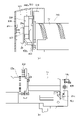
第1の実施形態について、図1ないし図16を用いて説明する。まず、本実施形態の画像形成装置の概略構成について、図1を用いて説明する。
<First embodiment>
A first embodiment will be described with reference to FIGS. 1 to 16. FIG. First, the schematic configuration of the image forming apparatus of this embodiment will be described with reference to FIG.
[画像形成装置]
画像形成装置200は、電子写真方式を用いたカラー画像形成装置であり、4色の画像形成部Pa~Pdを中間転写ベルト7上に並べて配置した、所謂中間転写タンデム方式の画像形成装置である。本実施形態では、画像形成装置200は、イエロー(Y)、マゼンタ(M)、シアン(C)およびブラック(Bk)の4色により画像を形成する。勿論、色数は4色に限定されるものではなく、また色の並び順もこの限りではない。
[Image forming apparatus]
The
画像形成装置200は、装置本体200Aに接続された原稿読取装置(図示せず)又は装置本体200Aに対し通信可能に接続されたパーソナルコンピュータ等のホスト機器からの画像信号に応じてトナー像(画像)を記録材Sに形成する。記録材としては、用紙、プラスチックフィルム、布などのシート材が挙げられる。
The
記録材Sは、収納庫10内に積載されるように収納されており、摩擦分離方式を採用した給送ローラ61により画像形成タイミングに合わせて給送される。給送ローラ61により送り出された記録材Sは、搬送パスを通過し、レジストレーションローラ62へと搬送される。そして、レジストレーションローラ62において記録材Sの斜行補正やタイミング補正を行った後、記録材Sは、2次転写部T2へと送られる。2次転写部T2は、対向する2次転写内ローラ8および2次転写外ローラ9により形成される転写ニップ部であり、所定の加圧力と静電的負荷バイアスを与えることで中間転写ベルト7上のトナー像を記録材S上に2次転写させる。
The recording materials S are stored so as to be stacked in the
次に、以上に説明した2次転写部T2までの記録材Sの搬送プロセスに対して、同様のタイミングで2次転写部T2まで送られて来るトナー像の画像形成プロセスについて説明する。画像形成部Pa~Pdは、主に、像担持体としての円筒状の感光体である感光ドラム1a~1d、帯電装置2a~2d、露光装置3a~3d、現像装置100a~100d、1次転写ローラ5a~5d、およびドラムクリーナ6a~6d等から構成される。
Next, an image forming process of a toner image sent to the secondary transfer portion T2 at the same timing as the above-described process of conveying the recording material S to the secondary transfer portion T2 will be described. The image forming units Pa to Pd mainly include
まず、図示しない駆動装置によって矢印方向に回転駆動される感光ドラム1a~1dは、予め帯電装置2a~2dにより表面を一様に帯電される。そして、原稿読取装置などから送られてきた画像情報の信号(画像信号)に基づいて露光装置3a~3dが駆動され、レーザ光をミラーなどの回折部材を適宜経由して感光ドラム1a~1dに照射する。これにより、感光ドラム1a~1d上にそれぞれの色に応じた静電像が形成される。次に、感光ドラム1a~1d上に形成された静電像は、現像装置100a~100dによるトナー現像を経て、トナー像として顕在化する。
First, the surfaces of the
現像装置100a~100dは、それぞれ、現像剤を収容する現像容器101a~101d、現像剤担持体としての現像スリーブ102a~102dなどを有する。現像スリーブ102a~102dは、現像容器101a~101d内の現像剤を担持して、感光ドラム1a~1dと対向する現像用領域に搬送し、所定の現像バイアスが印加されることで感光ドラム1a~1d上にトナーを供給して、静電像を現像する。本実施形態では、現像剤は、非磁性のトナーと、磁性を有するキャリアを含む2成分現像剤である。但し、現像剤は、トナーを有する1成分現像剤であっても良い。
The developing
感光ドラム1a~1d上にトナー像が形成された後、1次転写部T1a~T1dにて、1次転写ローラ5a~5dにより所定の加圧力および静電的負荷バイアスが与えられ、感光ドラム1a~1d上のトナー像が中間転写ベルト7上に1次転写される。感光ドラム1a~1d上に僅かに残った転写残トナーは、ドラムクリーナ6a~6dにより回収され、再び次の画像形成プロセスに備える。
After the toner images are formed on the
なお、上述のように画像形成を行うことで、現像装置100a~100dの現像容器101a~101d内のトナーが消費される。このため、現像容器101a~101d内のトナー量が低下した際には、対応する収容容器Ta~Td(現像剤補給容器)からトナーが現像容器101a~101dに補給される。このために、収容容器Ta~Tdと現像容器101a~101dとの間には、それぞれトナーを供給するための補給パイプ70が設けられている。このようなトナー補給動作についての詳細については、後述する。
Note that the toner in the developing
中間転写ベルト7は、無端状のベルトで、図示しない中間転写ベルトフレームに設置され、中間転写ベルト7の回転駆動を兼ねる2次転写内ローラ8、テンションローラ17、2次転写上流ローラ18によって張架される。2次転写内ローラ8が矢印R1方向に回転駆動すると、中間転写ベルト7が矢印R2方向へと回転駆動される。
The intermediate transfer belt 7 is an endless belt, which is mounted on an intermediate transfer belt frame (not shown) and is tensioned by a secondary transfer
上述の画像形成プロセスは、Y、M、CおよびBkの画像形成部Pa~Pdにより並列処理され、中間転写ベルト7上に1次転写されたトナー像上に下流側のトナー像が順次重ね合わせるタイミングで行われる。その結果、フルカラーのトナー像が中間転写ベルト7上に形成され、2次転写部T2へと搬送される。なお、2次転写部T2を通過した後に中間転写ベルト7上に残った転写残トナーは、ベルトクリーナ装置11によって回収される。
The image forming process described above is processed in parallel by the Y, M, C, and Bk image forming units Pa to Pd, and the downstream toner image is sequentially superimposed on the toner image primarily transferred onto the intermediate transfer belt 7. done in time. As a result, a full-color toner image is formed on the intermediate transfer belt 7 and conveyed to the secondary transfer portion T2. The transfer residual toner remaining on the intermediate transfer belt 7 after passing through the secondary transfer portion T<b>2 is collected by the belt
以上、それぞれ説明した搬送プロセスおよび画像形成プロセスによって、2次転写部T2において記録材Sとフルカラートナー像の搬送タイミングを一致させて2次転写が行われる。その後、記録材Sは、定着装置13へと搬送される。定着装置13は、内部にヒータを有する定着ローラ14と、定着ローラ14と対向して定着ニップ部を形成する対向ローラ15とを有する。定着装置13に搬送された記録材Sは、定着ニップ部内を通過し、定着ニップ部内で所定の圧力と熱量が加えられる。そして、記録材S上にトナー像が溶融固着(定着)される。トナー像が定着された記録材Sは、排出トレイ63に排出される。
By the conveying process and the image forming process described above, the conveying timings of the recording material S and the full-color toner image are matched at the secondary transfer portion T2 to perform the secondary transfer. After that, the recording material S is conveyed to the fixing
上述のような各プロセスは、制御部50により制御される。制御部50は、CPU(Central Processing Unit)、ROM(Read Only Memory)、RAM(Random Access Memory)を有している。CPUは、ROMに格納された制御手順に対応するプログラム読み出しながら各部の制御を行う。また、RAMには、作業用データや入力データが格納されており、CPUは、前述のプログラム等に基づいてRAMに収納されたデータを参照して制御を行う。また、画像形成装置200は、操作パネルなどの操作部60を有し、ユーザは、操作部60により画像形成装置200の各種設定が可能である。
Each process as described above is controlled by the
[収容容器]
次に、図2及び図3を用いて、トナーを収容した収容容器Ta~Tdについて説明する。なお、収容容器Ta~Tdは各容器とも共通の構成を有するため、以下では、代表して収容容器Taについて説明する。
[Container]
Next, with reference to FIGS. 2 and 3, the storage containers Ta to Td containing toner will be described. Note that, since each container Ta to Td has a common structure, the container Ta will be described below as a representative.
収容容器Taは、図2(a)、(b)に示すように、中空円筒状に形成され内部にトナーを収容する内部空間を備えたトナー収容部20を有する。更に、収容容器Taは、トナー収容部20の長手方向(トナー搬送方向)一端側にフランジ部21を有する。トナー収容部20は、フランジ部21に対して相対回転可能に構成されている。フランジ部21には、トナー収容部20内から搬送されてきたトナーを一時的に貯留するための中空形状を備えた排出部21hが設けられている。排出部21hの底部には、収容容器Taの外部へトナーを排出する、即ち、現像装置100a~100dへトナーを補給するための排出口21aが形成されている。また、フランジ部21の内部には、排出口21aを開閉するためのシャッタ4が設けられている。シャッタ4の動作の詳細に関しては後述する。
As shown in FIGS. 2A and 2B, the storage container Ta has a
トナー収容部20には、ギア部20a、ポンプ部20b、突起部20dなどが形成されている。ギア部20aは、装置本体200A側の駆動部と係合することで、装置本体200A側からの回転駆動力をトナー収容部20に伝達する働きをする。ポンプ部20bは、往復動に伴いその容積が可変な樹脂製の容積可変型ポンプとなっている図2(a)、(b)の矢印ωと矢印γはポンプ部20bの移動方向を示す。
A
具体的には、図2(a)、(b)に示すように、ポンプ部20bは、長手方向に「山折り」部と「谷折り」部が外周部に周期的に交互に複数形成されている蛇腹状のポンプとなっている。ポンプ部20bは、往復動することで伸縮し、排出口21aを介して吸気動作と排気動作を交互に行わせる吸排気機構として機能する。フランジ部21の内周面には、カム形状の溝部21bが形成されており、トナー収容部20に備えられた突起部20dと係合する構成となっている。
Specifically, as shown in FIGS. 2(a) and 2(b), the
突起部20dと溝部21bの関係について、図3を用いて説明する。図3は、溝部21bが形成された部分を展開して示した模式図である。図3において、矢印Aはトナー収容部20の回転方向(突起部20dの移動方向)、矢印B、Cはポンプ部20bの伸縮方向を示している。溝部21bは、図3に示すように、互いに傾斜方向が異なる第1溝21cと第2溝21dとが、交互に連結された構造となっている。トナー収容部20は、回転駆動されることで、突起部20dと溝部21bとの係合によりフランジ部21に対して回転軸線方向に相対移動する。これにより、ポンプ部20bが伸縮動作を行う。即ち、トナー収容部20が回転されると、ポンプ部20bは伸縮動作を行い、これにより吸排気機構を利用して排出口21aからトナーの排出が行われる。
A relationship between the
[トナー補給部の駆動構成]
次に、図4ないし図6を用いて、収容容器Taから現像装置100aに補給用トナーを供給する構成について説明する。装置本体200Aは、収容容器Taを受け入れる受け入れ装置400を有する。受け入れ装置は、収容容器Taから現像装置100aにトナーを補給するトナー補給部を備えている。他の収容容器Tb~Tdから現像装置100b~100dにそれぞれ補給用トナーを供給するトナー補給部、及び、収容容器Tb~Tdを受け入れる受け入れ装置の構成についても、収容容器Taからトナーを供給するトナー補給部、及び、受け入れ装置400と同じであるため、説明を省略する。
[Driving Configuration of Toner Replenishing Portion]
Next, a configuration for supplying replenishing toner from the storage container Ta to the developing
図4に示すように、装置本体200Aの受け入れ装置400には、枠体を形成する前側板201、後側板202、前側板201と後側板202とに保持された容器上保持ガイド401、容器下保持ガイド402が備えられている。収容容器Taは、装置本体200Aの受け入れ装置400に対して着脱自在であり、受け入れ装置400に装着されている時には、容器上保持ガイド401と容器下保持ガイド402に回転可能に収容保持されている。
As shown in FIG. 4, the receiving
本実施形態では、収容容器Taは、装置本体200Aの前側から奥側(後側)に向かって、略水平方向に挿入されることで装置本体200Aの受け入れ装置400内に装着される。また、収容容器Taは、逆方向に引き抜くことで装置本体200Aの受け入れ装置400から抜き出される。このような収容容器Taの挿入方向及び抜き出し方向は、収容容器Taの長手方向及びポンプ部20bの伸縮方向と同じである。また、収容容器Taの回転軸線方向と同じである。なお、装置本体200Aの前側は、ユーザが画像形成装置200を操作する側で、図1の紙面手前側であり、奥側は図1の紙面奥側である。
In this embodiment, the storage container Ta is mounted in the receiving
後側板202には、容器駆動装置300、補給パイプ70が取り付けられている。容器駆動装置300は、図5に示すように、駆動源としての駆動モータ301、駆動伝達部としての容器駆動ギア302、ピニオンギア304、アイドラギア305、アイドラ段ギア308、駆動伝達ギア306、容器駆動軸307で構成される。容器駆動装置300では、駆動モータ301から生じる回転駆動力がピニオンギア304、アイドラギア305、アイドラ段ギア308、駆動伝達ギア306、容器駆動軸307を通して容器駆動ギア302に伝達される。そして、この回転駆動力が容器駆動ギア302から収容容器Taの排出駆動部としてのギア部20aに伝達されることで、収容容器Taが回転駆動し、上述のように収容容器Taからトナーを排出させる。
A
容器駆動装置300には、回動可能に支持された位相検知フラグ309が設けられ、収容容器Taのトナー収容部20、ギア部20aと一体的に回転するカム部24に接触している。カム部24には、図6(a)、(b)に示すように、大径部24aと小径部24bがカム部24の1周で各々2ヶ所ずつ交互に設けられている。
The
図6(a)に示すように、位相検知フラグ309が大径部24aに接触しているとき、位相検知フラグ309は、容器駆動装置300に配置されたフォトセンサ310を遮光する。一方、図6(b)に示すように、位相検知フラグ309が小径部24bに接触しているとき、位相検知フラグ309はフォトセンサ310の透過範囲から外れて、フォトセンサ310は透過される。制御部50(図1)は、フォトセンサ310の変化(遮光→透過→遮光)を検知することで、収容容器Taの半回転を検知することができる。また、駆動モータ301の回転は、フォトセンサ310が遮光→透過→遮光を検知した後、所定時間後に停止されるように制御部50で制御されている。ポンプ部20bは、収容容器Taが半回転する毎に1往復する。
As shown in FIG. 6A, when the
このように制御部50は、収容容器Taを半回転毎に1往復させ、回転停止させることで、収容容器Taからのトナーの排出をコントロールしている。収容容器Taから排出されたトナーは、補給パイプ70の中を通り下流側にある現像装置100a(図1)へと受け渡される。本実施形態では、図1に示すように、補給パイプ70の下流端部にトナーを一旦貯蔵し、画像形成動作などに応じて適宜、現像装置100aに現像剤を補給するホッパー71を設けている。ホッパー71には、補給スクリュー72が設けられており、制御部50は、現像装置100a内のトナー消費量などに応じて補給スクリュー72を回転させることで、現像装置100aにトナーを補給するようにしている。
In this manner, the
[収容容器の着脱について]
次に、図7(a)~(d)及び図8を用いて、収容容器Taの装置本体200Aに対する着脱機構について説明する。上述したように、装置本体200Aの受け入れ装置400(図4)は、収容容器Taの回転軸線方向に沿って挿入された収容容器Taを受け入れるものである。図7(a)~(d)に示すように、収容容器Taの挿入方向(所定方向、矢印D方向)に関し、容器下保持ガイド402の片側端部(下流側端部)には、引き込み部としての容器引き込み装置410が設けられている。容器引き込み装置410は、容器引き込みレバー403、引き込みばね404を有する。容器引き込みレバー403は、容器下保持ガイド402に対して回動可能に保持されている。引き込みばね404は、容器引き込みレバー403と容器下保持ガイド402とに張架されている。
[Detachment of container]
Next, referring to FIGS. 7(a) to (d) and FIG. 8, a mechanism for attaching/detaching the storage container Ta to/from the apparatus
装置本体200Aの受け入れ装置400に収容容器Taを装着する際は、まず、図7(a)に示すように、収容容器Taの先端(挿入方向下流端)と容器引き込みレバー403が接触し、容器引き込みレバー403が押し込まれる形で矢印E方向に回動を始める。このとき、引き込みばね404による力は、容器引き込みレバー403を矢印F1方向に回転させる力として働く。
When the container Ta is attached to the receiving
更に収容容器Taを装置本体200Aの受け入れ装置400に押し込むと、図7(b)に示すように、容器引き込みレバー403が更に回動し、引き込みばね404の位置が死点(ばね掛け部同士を結ぶ直線上に容器引き込みレバー403の回転中心が乗る点)を超える。すると、図7(c)に示すように、引き込みばね404によって容器引き込みレバー403を回転させようとする力の方向がF2方向に切り替わる。そして、容器引き込みレバー403が収容容器Taに設けられたボス21kと係合し、収容容器Tには装置本体200Aの受け入れ装置400の奥側に引き込む力が働く。
When the container Ta is further pushed into the receiving
この結果、図7(d)に示すように、収容容器Taは、引き込みばね404の付勢力により容器引き込みレバー403が更に回動することで、自動で、容器下保持ガイド402に備えられた突き当て部402aまで引き込まれる。収容容器Taの先端が突き当て部402aに突き当たると、収容容器Taの装置本体200Aの受け入れ装置400に対する装着動作が完了し、後述するように収容容器Taからトナーを排出可能とする第1位置に収容容器Taが装着される。即ち、容器引き込みレバー403は、収容容器Taの装置本体200Aの受け入れ装置400への装着動作中(挿入動作中)に収容容器Taの一部であるボス21kと係合し、引き込みばね404の付勢力により収容容器Taを第1位置に引き込む。
As a result, as shown in FIG. 7(d), the container Ta is automatically moved to the thrust position provided in the lower
ここで、収容容器Taの先端には、第1接点としての容器側接点23が、装置本体200Aの受け入れ装置400の収容容器Taの先端と対向する位置には、第2接点としての本体側接点405がそれぞれ設けられている。本体側接点405は、容器側接点23と接触することで収容容器Taと装置本体200Aとの間で通信が可能となる。容器側接点23は、収容容器Taに関する情報が記憶されたメモリに接続されている。収容容器Taが第1位置に装着されると、容器側接点23が本体側接点405と接触して、この情報が装置本体200Aの制御部50に送られる。
Here, a container-
また、図8に示すように、装置本体200Aの受け入れ装置400の収容容器Taの先端と対向する位置には、収容容器Taと接触することで収容容器Taを検知する検知部としてのセンサ406が設けられている。センサ406は、第1位置に収容容器Taが装着されているか否かを検知するセンサである。したがって、収容容器Taが第1位置に装着されると、センサ406が収容容器Taの先端と接触し、制御部50は、収容容器Taが第1位置に装着されたと判断する。一方、収容容器Taの先端がセンサ406に接触していなければ、制御部50は、収容容器Taが第1位置に装着されていないと判断する。
Further, as shown in FIG. 8, a
更に、収容容器Taが装置本体200Aの受け入れ装置400の第1位置に装着された状態で、図5に示したように、装置本体200A側に設けられた容器駆動ギア302が、収容容器Ta側に設けられたギア部20aと係合する。そして、容器駆動ギア302からギア部20aに駆動が伝達可能となる。
Further, in a state where the container Ta is attached to the first position of the receiving
[シャッタの開閉]
次に、図9(a)、(b)及び図10(a)~(c)を用いて、収容容器Taの装置本体200Aの受け入れ装置400に対する着脱と、収容容器Taに備えられたシャッタ4の開閉の関係について説明する。前述の図2(a)、(b)に示したように、シャッタ4は、収容容器Taの内部で、フランジ部21に対して相対的に移動可能に設けられている。上述のように、収容容器Taにはトナーを排出する排出口21aが形成されており、収容容器Taは、この排出口21aを開閉自在なシャッタ4を有する。
[Shutter opening/closing]
Next, referring to FIGS. 9(a), (b), and 10(a) to (c), attachment/detachment of the apparatus
シャッタ4は、図9(a)、(b)に示すように、開口4aが形成されている。そして、シャッタ4の開口4aと排出口21aの位置関係が、図9(a)の場合、シャッタ4が排出口21aを塞いでいるので、収容容器Taからトナーを排出することはできない。一方、シャッタ4が図9(b)の位置にスライド移動した場合、シャッタ4に設けられた開口4aと排出口21aが重なり、開口4aと排出口21aが連通する。このため、収容容器Taから排出口21a及び開口4aを介してトナーを排出することが可能となる。
The
図10(a)~(c)は、容器下保持ガイド402上における収容容器Taとシャッタ4の位置関係を示した図である。また、図10(a)~(c)は、収容容器Taを装置本体200Aに装着している過程を順に示しており、破線の矢印は収容容器Taの移動方向(挿入方向)を示している。
10A to 10C are diagrams showing the positional relationship between the container Ta and the
収容容器Taが装置本体200Aの受け入れ装置400に装着されていない状態の時の収容容器Taとシャッタ4の位置関係は、図9(a)に示したように、シャッタ4で排出口21aを塞いでいる状態である。したがって、収容容器Taは、この状態のまま装置本体200Aの受け入れ装置400に挿入が開始され、図10(a)の状態の時も、排出口21aはシャッタ4で塞がれたままである。
The positional relationship between the container Ta and the
次に、収容容器Taが更に装置本体200Aの受け入れ装置400に挿入されると、図10(b)に示すように、容器下保持ガイド402に形成されたシャッタ係合溝402cとシャッタ4に形成された突起4bがそれぞれ係合する。このとき、容器下保持ガイド402に形成された排出口402bとシャッタ4に形成された開口4aの位置が重なり連通するが、排出口21aとは連通していない。このため、この状態では、まだ収容容器Taからトナーが排出されることはない。
Next, when the receiving container Ta is further inserted into the receiving
この状態から更に収容容器Taが装置本体200Aの受け入れ装置400に挿入されると、シャッタ係合溝402cと突起4bとの係合によりシャッタ4が容器下保持ガイド402に固定されているため、シャッタ4を除く収容容器Taが容器下保持ガイド402に対して移動する。つまり、収容容器Taとシャッタ4が相対移動を行うことになる。そして、図10(c)に示すように、収容容器Taが装置本体200Aの受け入れ装置400の突き当て部402aに突き当たる第1位置まで挿入されると、収容容器Taのシャッタ4に対する移動が、排出口21aと開口4aに連通する位置まで行われる。つまり、排出口21a、開口4a、排出口402bの全てが連通して、収容容器Taからトナーの排出が可能となる。以上により、本実施形態の画像形成装置200は、収容容器Taが装置本体200Aの受け入れ装置400の第1位置に装着されている場合のみ、収容容器Taからトナー排出が可能な構成となっている。
When the receiving container Ta is further inserted into the receiving
[収容容器の同梱移送について]
ここで、収容容器Taを装置本体100Aに装着した状態で移送する同梱移送を、上述のように収容容器Taを装置本体200Aの受け入れ装置400の第1位置に装着した状態で行うと、次のような問題が生じる虞がある。即ち、収容容器Taを第1位置に装着した状態では、上述のように、容器側接点23が本体側接点405と接触し、センサ406が収容容器Taの先端と接触する。また、容器駆動ギア302が、収容容器Ta側に設けられたギア部20aに接続される。このように収容容器Taと装置本体200Aとの間で各種機器が接続又は接触した状態で、画像形成装置の移送を行うと、移送時に収容容器Taが振動し、各種機器に負荷がかかってしまう虞がある。即ち、容器側接点23と本体側接点405との接触部、センサ406、容器駆動ギア302とギア部20aの接続部に負荷がかかってしまう虞がある。
[Regarding the transportation of the container]
Here, if the bundle transfer of transferring the containing container Ta attached to the apparatus main body 100A is performed with the containing container Ta attached to the first position of the receiving
そこで、本実施形態では、装置本体200Aの受け入れ装置400は、上述の第1位置と、この第1位置と異なり、収容容器Taから現像剤が排出されない第2位置に、収容容器Taをそれぞれ装着可能としている。そして、同梱移送する場合には、収容容器Taの位置を、規制手段としての規制部材500により第2位置に規制するようにしている。この第2位置は、第1位置よりも収容容器Taの挿入方向において上流側(所定方向上流側)の位置である。また、第2位置は、センサ406が収容容器Taの先端と接触せず、容器側接点23が本体側接点405に接触せず、更に、容器駆動ギア302がギア部20aに接続されない位置である。
Therefore, in the present embodiment, the receiving
[規制部材]
このように収容容器Taを装置本体200Aの受け入れ装置400の第2位置に規制する規制部材500について、図11ないし図16を用いて説明する。図11は、収容容器Taを装置本体200Aの受け入れ装置400の第2位置に装着して移送する際の、収容容器Taの装着状態を示した斜視図である。詳しくは次述するが、規制部材500は、各色の収容容器Ta~Tdの挿入方向上流端部(挿入方向において収容容器Ta~Tdの上流側の先端)にそれぞれ設けられた取っ手部25に装着される。そして、規制部材500が、取っ手部25と挿入口カバー210との間に挟まれた状態で、収容容器Ta~Tdの位置をそれぞれ第2位置に規制し、この状態で画像形成装置の移送を行うようにしている。即ち、規制部材500は、収容容器Taと挿入口カバー210(装置本体の一部)との間に着脱自在に配置され、非装着状態で第1位置に収容容器Taを装着可能で、装着状態で第2位置に収容容器Taの位置を規制する。各色の収容容器Ta~Tdの位置を第2位置に規制する構成は同じであるため、以下、代表して、収容容器Taの位置を第2位置に規制する構成について、詳しく説明する。
[Regulation member]
The restricting
図12(a)、(b)に示すように、収容容器Taは、挿入方向上流端部(所定方向上流端部)に規制部材500を装着可能な取付部としての取っ手部25を有する。図12(a)に示すように、取っ手部25は、ユーザなどが手で把持し易いように、一部がくびれた形状としている。即ち、取っ手部25は、収容容器Taの挿入方向上流端(後端)から更に上流側に突出するように設けられ、収容容器Ta側の基端部ないし中間部よりも上流側の部分の外径が大きくなるように形成されている。そして、上流側の部分を大径部25a、基端部ないし中間部をくびれ部25bとしている。
As shown in FIGS. 12A and 12B, the container Ta has a
一方、規制部材500は、基部501と、突出部502a、502b、502cと、突き当て突部503とを有する。突出部502a、502b、502cは、基部501の3箇所から収容容器Taへの装着状態で収容容器Taの径方向にそれぞれ突出するように設けられている。突き当て突部503は、突出部502a~502cからそれぞれ挿入方向に突出するように設けられている。基部501には、突出部502b、502cの間から突出部502aに向けて略U字状に凹入した凹入部504が形成されている。規制部材500は、図12(b)に示すように、この凹入部504内にくびれ部25bを進入させることで、収容容器Taに装着される。
On the other hand, the regulating
図13(a)に示すように、装置本体200Aの受け入れ装置400の収容容器Taが挿入される入口側には、当接部としての挿入口カバー210が設けられている。挿入口カバー210は、前側板201(図4)に設けられており、挿入口カバー210及び前側板201には、収容容器Taを挿入可能な挿入口が形成されている。挿入口カバー210は、収容容器Taが第1位置に装着された状態で収容容器Taの挿入方向上流端部(所定方向上流端部)が位置する部分に設けられている(図16参照)。
As shown in FIG. 13(a), an
同梱移送する場合には、規制部材500を取っ手部25に装着した状態で収容容器Taを装置本体200A内に挿入する。この際、収容容器Taを挿入口カバー210及び前側板201に形成された挿入口に挿入しつつ、装置本体200A内に進入させる。そして、図13(a)に示すように、収容容器Taが第2位置に到達した時に、取っ手部25に装着された規制部材500の突き当て突部503が挿入口カバー210に突き当たる。この際、規制部材500の基部501が取っ手部25の大径部25aに突き当たり、収容容器Taがそれ以上の挿入方向下流側に移動しないように保持される。即ち、規制部材500は、取っ手部25に装着された状態で挿入口カバー210と当接して、収容容器Taの位置を第1位置よりも挿入方向上流側の第2位置に規制する。
When transporting together, the container Ta is inserted into the apparatus
このように収容容器Taが第2位置に位置している状態では、容器引き込みレバー403が図7(c)と図7(d)の間の位置にあり、収容容器Taには、装置本体200Aに装着される方向の力が働いている。このため、容器引き込みレバー403により引き込まれている状態の収容容器Taは、規制部材500を介して挿入口カバー210に規制された状態で固定される。言い換えれば、規制部材500は、容器引き込みレバー403により収容容器Taを引き込む力に拘らず、収容容器Taの位置を第2位置で規制する。
When the container Ta is positioned at the second position, the container pull-in
また、装置本体200Aの受け入れ装置400は、収容容器Taが挿入される空間220を開閉自在なカバーとしての前扉230を有する。前扉230は、装置本体200Aの前側に設けられ、ヒンジを中心として回動することで、収容容器Ta~Tdが挿入される挿入部としての空間を開閉する。前扉230は、規制部材500が取っ手部25に装着された状態の収容容器Taが第2位置に位置しても閉じることが可能に形成されている。
Further, the receiving
即ち、本実施形態では、図13(a)に示すように、第2位置では、収容容器Taの挿入方向上流端部よりも取っ手部25が上流側(前側)に突出している。このため、前扉230は、収容容器Taが第2位置に位置する状態で閉めても取っ手部25と干渉しないような空間221が形成されるような形状としている。
That is, in the present embodiment, as shown in FIG. 13A, at the second position, the
また、収容容器Taが第2位置に位置している状態では、図13(b)に示すように、センサ406は収容容器Taの先端と接触せず、容器側接点23と本体側接点405も接触しない。更に、第2位置では、容器駆動ギア302がギア部20aと係合しない。
When the container Ta is located at the second position, the
更に、収容容器Taが第2位置に位置している状態では、収容容器Taのフランジ部21の排出口21aとシャッタ4の開口aの位置関係は、図14に示すようになる。即ち、排出口21aと開口4aが連通しない。このため、第2位置では、収容容器Taからトナーが排出されることはない。
Furthermore, when the container Ta is positioned at the second position, the positional relationship between the
一方、収容容器Taから規制部材500を外すと、収容容器Taの位置の規制が解除され、収容容器Taを第1位置に挿入可能となる。即ち、ユーザなどが前扉230を開き、収容容器Taの取っ手部25から規制部材500を引き抜くと、突き当て突部503と挿入口カバー210との係合及び基部501と大径部25aの係合が外れ、収容容器Taが第2位置から第1位置に移動可能となる。この際、収容容器Taは、容器引き込みレバー403により引き込まれている状態であるため、自動的に第1位置に引き込まれ、第1位置に装着される。即ち、本実施形態では、容器引き込み装置410は、第2位置で規制部材500による規制が解除されると収容容器Taを第1位置に引き込むように構成されている。
On the other hand, when the regulating
収容容器Taが第1位置に引き込まれると、前述の図8に示したように、センサ406は収容容器Taの先端と接触して、センサ406により収容容器Taが検知される。また、容器側接点23が本体側接点405と接触して、収容容器Taと装置本体200Aとの間で通信が可能となる。更に、容器駆動ギア302がギア部20aと係合して、容器駆動ギア302からギア部20aに駆動が伝達可能となる。更に、収容容器Taが第1位置に装着されると、図9(b)に示したように、収容容器Taのフランジ部21の排出口21aとシャッタ4の開口aが連通し、収容容器Taからトナーを排出可能となる。
When the container Ta is pulled into the first position, the
[規制部材の収納]
本実施形態の場合、図15(a)~(c)に示すように、このように取っ手部25から外された規制部材500を収納可能な収納部231が前扉230に設けられている。収納部231は、図16に示すように、収容容器Taが第1位置に装着されている状態で前扉230を閉じても、収納された規制部材500が収容容器Taと干渉しないように形成されている。
[Storage of regulation members]
In this embodiment, as shown in FIGS. 15(a) to 15(c), the
具体的には、収納部231は、図15(a)に示すように、前扉230の前面の板状部230Aに設けられている。このような収納部231は、図15(b)に示すように、一対の上側係合部232a、232b、一対の下側係合部233a、233b、及び、一対の突部234を有する。一対の上側係合部232a、232bは、規制部材500の突出部502aを挟持する。一対の下側係合部233a、233bは、基部501を挟持する。一対の下側係合部233a、233bには、規制部材500の基部501の両側に設けられた一対の係合板部506(図15(c)参照)がそれぞれ係合可能な係合溝が形成されている。一対の突部234は、規制部材500の基部501に形成された一対の係合孔505にそれぞれ侵入可能である。また、規制部材500は、図15(c)の矢印で示す方向に弾性変形可能である。
Specifically, the
規制部材500を収納部231に収納する際には、図15(c)に示すように、下側の一対の突出部502b、502cが互いに近づく方向に基部501を弾性変形させる。この状態で、規制部材500を前扉230の板状部230Aに向けて、一対の突部234が一対の係合孔505に侵入するように移動させる。これと共に、突出部502aを一対の上側係合部232a、232bの間に、基部501を下側係合部233a、233bの間にそれぞれ押し込む。この際、一対の係合板部506は、図15(c)に示すように、一対の下側係合部233a、233bと干渉しない。そして、規制部材500をこのように押し込んでから、下側の一対の突出部502b、502cに付与していた力を解除すると、基部501の形状が弾性的に復元し、一対の係合板部506がそれぞれ下側係合部233a、233bの係合溝に侵入する。
When the regulating
この結果、図15(a)、(b)に示すように、規制部材500が収納部231に前扉230から脱落したりがたついたりしないように装着される。即ち、一対の突部234が一対の係合孔505に侵入することで、規制部材500が前扉230の下方に脱落しないように支持される。また、一対の係合板部506がそれぞれ下側係合部233a、233bの係合溝に侵入することで、規制部材500が図15(a)、(b)の紙面手前側から脱落することが規制される。更に、突出部502aが一対の上側係合部232a、232bに、基部501が一対の下側係合部233a、233bにそれぞれ挟持されることで、規制部材500のがたつきが抑制される。
As a result, as shown in FIGS. 15(a) and 15(b), the restricting
一方、規制部材500を収納部231から取り外す場合には、図15(c)に示すように、下側の一対の突出部502b、502cが互いに近づく方向に基部501を弾性変形させる。そして、一対の係合板部506をそれぞれ下側係合部233a、233bの係合溝から下方に抜き出し、係合溝と係合板部506との係合を外す。この状態で、規制部材500を前扉230の板状部230Aから離れるように移動させることで、一対の係合孔505から一対の突部234を引き抜く。これと共に、突出部502aを一対の上側係合部232a、232bの間から、基部501を下側係合部233a、233bの間からそれぞれ引き抜く。これにより、規制部材500が収納部231から取り外される。
On the other hand, when the regulating
このように本実施形態では、図15(a)に示すように、収容容器Taが使用時の位置である第1位置にあるときに、規制部材500を収納可能な収納部231を前扉230に設けている。なお、規制部材500の収納は、上述のように、規制部材500を撓ませて収納部231に嵌め込む構成以外に、例えば、ビスによる固定など、他の構成であっても良い。
As described above, in this embodiment, as shown in FIG. 15(a), when the container Ta is in the first position, which is the position for use, the
本実施形態では、上述のように規制部材500を前扉230の収納部231に収納しても、図16に示すように、規制部材500が収容容器Taの取っ手部25に干渉しない。即ち、前扉230は、閉めた状態で、前面の板状部230Aと第1位置にある収容容器Taの取っ手部25と間に、規制部材500が取っ手部25に干渉しないように配置できるように形成されている。
In this embodiment, even if the regulating
また、収納部231は、収容容器Taが第1位置よりも挿入方向上流に位置する状態で前扉230を閉じると、収納された規制部材500が収容容器Taを挿入方向下流側(所定方向下流側)に押すように形成されている。ここで、前扉230の収納部231に収納された規制部材500と収容容器Taの取っ手部25とのクリアランス寸法Gは、容器引き込みレバー403が収容容器Taを引き込む引き込み可能範囲よりも小さい。即ち、図7(b)~(d)に示したように、引き込みばね404の位置が死点を超えてから収容容器Taの先端が突き当て部402aに突き当たるまでに収容容器Taが移動する距離よりも、クリアランス寸法Gが小さい。
In addition, when the
したがって、収容容器Taが例えば第2位置に到達していない中途半端な状態で挿入された状態で、規制部材500を収納した前扉230を閉じると、規制部材500が取っ手部25に突き当たって収容容器Taを引き込み可能範囲まで押し込む。この結果、収容容器Taは容器引き込みレバー403により自動的に第1位置に引き込まれる。即ち、本実施形態では、収容容器Taの挿入が不十分な場合でも、前扉230を閉じることで、収容容器Taが自動的に第1位置に引き込まれるようにしている。
Therefore, when the
このような本実施形態の場合、画像形成装置200の移送時に、装着された収容容器Taと装置本体200Aとの間で接続される各種機器に負荷がかかってしまうことを抑制できる。即ち、収容容器Taを装置本体200Aに同梱して移送する場合、収容容器Taの取っ手部25に規制部材500を装着した状態で収容容器Taを装置本体200Aに装着する。これにより、収容容器Taの位置が第2位置に規制された状態となる。上述した様に、第2位置では、排出口21aと開口4aが連通しておらず、収容容器Taからトナーが排出されない。このため、画像形成装置200の移送時に収容容器Taからトナーが漏れることを抑制できる。
In this embodiment, when the
特に、第2位置では、センサ406が収容容器Taの先端と接触せず、容器側接点23が本体側接点405に接触せず、更に、容器駆動ギア302がギア部20aに接続されない。このため、画像形成装置200の移送時の振動で、センサ406、容器側接点23、本体側接点405、容器駆動ギア302、ギア部20aなどの各種機器に負荷がかかってしまうことを抑制できる。
In particular, at the second position, the
また、本実施形態の場合、規制部材500を外して収容容器Taを第1位置に装着し、画像形成装置200を駆動した後でも、再度、同様に、収容容器Taの位置を第2位置に規制して、上述と同様に、同梱移送が可能である。即ち、装置の駆動後に同梱移送する場合には、収容容器Taを第2位置に移動させ、収納部231から取り外した規制部材500を再度、収容容器Taの取っ手部25に装着することで、収容容器Taの位置を、再度、第2位置に規制することが可能である。
Further, in the case of the present embodiment, even after the restricting
なお、上述の実施形態では、容器引き込み装置410を設けた構成について説明したが、画像形成装置は、容器引き込み装置410がない構成であっても良い。この場合、例えば、規制部材500を挿入口カバー210に固定する構成を設けることで、上述と同様の効果を得られる。
In the above-described embodiment, the configuration provided with the container drawing-in
<第2の実施形態>
第2の実施形態について、図17ないし図21を用いて説明する。上述の第1の実施形態では、規制部材500を収容容器Taの取っ手部25に装着することで、収容容器Taの位置を第2位置に規制した。これに対して本実施形態では、規制部及び移動部材としての容器ストッパ601により収容容器Taの位置を第2位置に規制している。その他の構成及び作用は、上述の第1の実施形態と同様であるため、同様の構成については、同じ符号を付して説明及び図示を省略又は簡略にし、以下、第1の実施形態と異なる部分を中心に説明する。
<Second embodiment>
A second embodiment will be described with reference to FIGS. 17 to 21. FIG. In the first embodiment described above, the position of the container Ta is regulated to the second position by attaching the regulating
図17及び図18に示すように、装置本体は、収容容器Taを受け入れる受け入れ装置400Aを有する。また、装置本体の後側板202には、収容容器Taから現像装置100aに補給用トナーを供給する装置本体側のトナー補給部が配置されている。なお、他の収容容器Tb~Tdから現像装置100b~100dにそれぞれ補給用トナーを供給するトナー補給部、及び、収容容器Tb~Tdを受け入れる受け入れ装置の構成については、収容容器Taからトナーを供給するトナー補給部、及び、受け入れ装置400Aと同じであるため、説明を省略する。
As shown in FIGS. 17 and 18, the device main body has a receiving
トナー補給部は、容器駆動装置300及び補給パイプ70を有する。また、後側板202には、メインアセンブリとしてのストッパユニット600が取り付けられている。容器駆動装置300及び補給パイプ70については、第1の実施形態の構成と同様であるため、詳しい説明を省略する。また、ストッパユニット600は、他の収容容器Tb~Tdと同様であるため、代表して、収容容器Taのストッパユニット600について説明する。
The toner supply section has a
ストッパユニット600は、図19(a)~(c)に示すように、容器ストッパ601、スライドギア602、アイドラギア603、604、ピニオンギア605、駆動モータ606、支板607、カバー608などを有する。移動部材としての容器ストッパ601は、装置本体の一部(後側板202)に収容容器Taに対して移動自在に設けられている。そして、後述するように、容器ストッパ601は、第1移動位置(退避位置)で第1位置に収容容器Taを装着可能で、第1移動位置とは異なる第2移動位置(規制位置)で第2位置に収容容器Taの位置を規制する。
The
このような容器ストッパ601は、退避機構としての移動部材駆動部620により第2移動位置から第1移動位置に移動させられる。即ち、移動部材駆動部620は、容器ストッパ601を退避させる。移動部材駆動部620は、駆動モータ606の駆動により回転する回転部材としてのスライドギア602と、スライドギア602の回転を容器ストッパ601の移動に変換する変換部610と、を有する。
Such a
即ち、図19(b)に示すように、駆動モータ606とスライドギア602との間には、ピニオンギア605、アイドラギア603、604が配置されている。スライドギア602は、駆動モータ606の駆動がこれら各ギア605、604、603を介して伝達されることで回転する。そして、スライドギア602の回転は、変換部610により直線方向の移動に変換されて容器ストッパ601に伝達される。なお、各ギア602~605は、図19(a)に示すように、カバー608に覆われている。図19(b)は、このカバー608を省略して示している。
That is, as shown in FIG. 19B, a
図19(c)に示すように、スライドギア602は、容器ストッパ601の周囲に回転可能に支持されており、容器ストッパ601には螺旋溝601aが、スライドギア602には螺旋溝601aと係合する突起602bが備えられている。即ち、容器ストッパ601は、略円柱状に形成され、長手方向中間部に周方向に沿って螺旋状に形成された螺旋溝601aを有する。一方、スライドギア602は、容器ストッパ601が貫通可能な貫通孔602aを有し、貫通孔602aの内周面の一部に径方向内方に突出する突起602bが設けられている。そして、貫通孔602aに容器ストッパ601を挿入し、螺旋溝601aに突起602bを係合させている。これら螺旋溝601a及び突起602bにより変換部610を構成する。
As shown in FIG. 19(c), the
容器ストッパ601は、支板607及びカバー608により回転不能に、且つ、長手方向(スライドギア602の回転軸線方向)に移動可能に保持されている。一方、スライドギア602は、支板607に回転可能に、且つ、回転軸線方向の移動不能に設けられている。これにより、スライドギア602が容器ストッパ601に対して相対回転することで、螺旋溝601aと突起602bとの係合に基づき、容器ストッパ601がスライドギア602に対して長手方向に相対的にスライド移動する。即ち、駆動モータ606の駆動が、ピニオンギア605、アイドラギア603、604を介してスライドギア602に伝達され、スライドギア602が回転する。すると、変換部610によりスライドギア602の回転が変化されて容器ストッパ601に伝達され、容器ストッパ601が長手方向に移動する。
The
本実施形態では、容器ストッパ601は、駆動モータ606の正回転により第2移動位置から第1移動位置に移動し、駆動モータ606の逆回転により第1移動位置から第2移動位置に移動する。駆動モータ606、各ギア602~605、容器ストッパ601は、支板607に支持されており、支板607は、後側板202の奥側に容器ストッパ601が前側に向くように固定されている。また、容器ストッパ601の移動方向は、装置本体に挿入される収容容器Taの挿入方向と略平行としている。そして、図20(a)、(b)に示すように、容器ストッパ601の先端面が収容容器Taの挿入方向先端部と対向するようにしている。
In this embodiment, the
容器ストッパ601は、図20(a)に示すように、収容容器Taに向かって突出する第2移動位置で、収容容器Taの先端部と当接し、収容容器Taの位置を第2位置に規制する。一方、容器ストッパ601は、図20(b)に示すように、第2移動位置よりも収容容器Taから退避した第1移動位置で、収容容器Taの先端部を当接せずに、収容容器Taが第1位置まで挿入されることを許容する。即ち、容器ストッパ601は、装置本体に装着される際の収容容器Taと干渉する位置(第2移動位置)と干渉しない位置(第1移動位置)に移動可能となっている。
As shown in FIG. 20( a ), the
より具体的に説明する。図20(a)に示すように、容器ストッパ601が第2移動位置にある時には、収容容器Taが突き当て部402aに突き当たるより先に容器ストッパ601に突き当たる。この時、容器引き込みレバー403は、前述の図7(c)と図7(d)の間の位置にあり、収容容器Taには、装置本体に装着される方向の力が働いている。このため、容器引き込みレバー403により引き込まれている状態の収容容器Taは、第2移動位置にある容器ストッパ601に突き当たった状態で固定される。言い換えれば、容器ストッパ601は、容器引き込みレバー403により収容容器Taを引き込む力に拘らず、収容容器Taの位置を第2位置で規制する。
More specific description will be given. As shown in FIG. 20(a), when the
また、収容容器Taが第2位置に位置している状態では、容器側接点23と本体側接点405も接触せず、容器駆動ギア302がギア部20aと係合しない。なお、図13(b)に示したように、センサ406も収容容器Taの先端と接触しない。更に、収容容器Taが第2位置に位置している状態では、収容容器Taのフランジ部21の排出口21aとシャッタ4の開口aの位置関係は、図21に示すようになる。即ち、排出口21aと開口4aが連通しない。このため、第2位置では、収容容器Taからトナーが排出されることはない。
Further, when the container Ta is positioned at the second position, the
一方、収容容器Taを第1位置に装着する際には、駆動モータ606を駆動して容器ストッパ601を収容容器Taから退避する方向(奥側)に移動させる。そして、容器ストッパ601を、収容容器Taと干渉しない第1移動位置に移動させる。図20(b)に示すように、容器ストッパ601が第1移動位置にある時には、収容容器Taが突き当て部402aに突き当たり、第1位置に装着される。この際、容器ストッパ601の退避に伴って、収容容器Taが容器引き込みレバー403に引き込まれ、自動的に第1位置に装着される。
On the other hand, when the container Ta is attached to the first position, the
収容容器Taが第1位置に引き込まれると、前述したように、センサ406は収容容器Taの先端と接触して、センサ406により収容容器Taが検知される。また、容器側接点23が本体側接点405と接触して、収容容器Taと装置本体との間で通信が可能となる。更に、容器駆動ギア302がギア部20aと係合して、容器駆動ギア302からギア部20aに駆動が伝達可能となる。更に、収容容器Taが第1位置に装着されると、前述の図9(b)に示したように、収容容器Taのフランジ部21の排出口21aとシャッタ4の開口aが連通し、収容容器Taからトナーを排出可能となる。
When the container Ta is pulled into the first position, the
このような本実施形態の場合、画像形成装置の移送時に、装着された収容容器Taと装置本体との間で接続される各種機器に負荷がかかってしまうことを抑制できる。即ち、収容容器Taを装置本体に同梱して移送する場合、容器ストッパ601を第2移動位置に位置させた状態で収容容器Taを装置本体の受け入れ装置400Aに装着する。これにより、収容容器Taの位置が第2位置に規制された状態となる。第2位置では、センサ406が収容容器Taの先端と接触せず、容器側接点23が本体側接点405に接触せず、更に、容器駆動ギア302がギア部20aに接続されない。このため、画像形成装置の移送時の振動で、センサ406、容器側接点23、本体側接点405、容器駆動ギア302、ギア部20aなどの各種機器に負荷がかかってしまうことを抑制できる。
In the case of the present embodiment as described above, it is possible to suppress load from being applied to various devices connected between the mounted storage container Ta and the apparatus main body when the image forming apparatus is transferred. That is, when the container Ta is transported together with the apparatus main body, the container Ta is attached to the receiving
そして、本体設置後には、容器ストッパ601を第2移動位置から第1移動位置に退避させて、収容容器Taを通常の装着位置である第1位置へと装着可能とする。上述のように、収容容器Taは、容器ストッパ601が退避することで容器引き込みレバー403により第1位置に引き込まれる。なお、仮に容器引き込みレバー403がなくても、容器ストッパ601を第1移動位置に退避させてユーザが収容容器Taを押し込めば、収容容器Taを第1位置に装着可能である。
After the main body is installed, the
また、本実施形態の場合も、収容容器Taを第1位置に装着し、画像形成装置を駆動した後でも、再度、同様に、収容容器Taの位置を第2位置に規制して、上述と同様に、同梱移送が可能である。即ち、駆動モータ606を逆回転させることで容器ストッパ601を第1移動位置に移動させる。これにより、収容容器Taの位置を、再度、第2位置に規制することが可能である。
Also in the case of the present embodiment, even after the storage container Ta is mounted at the first position and the image forming apparatus is driven, the position of the storage container Ta is similarly restricted to the second position, and the above-described operation is performed. Consolidated transfers are likewise possible. That is, by rotating the
なお、本実施形態では、ストッパユニット600を収容容器Taの挿入方向下流端部(先端部)に、収容容器Taに対向する位置に配設し、容器ストッパ601を収容容器Taの挿入方向に伸縮させた構成について説明した。但し、容器ストッパ601は、収容容器Taの位置を第2位置に規制できると共に、収容容器Taが第1位置に移動することが許容できる構成であれば良い。このため、例えば、収容容器Taの挿入方向中間部や上流端部に、収容容器Taの径方向に突出及び退避が可能に容器ストッパを設け、収容容器Taに突出した容器ストッパと当接し、且つ、退避した容器ストッパには当接しない部材を設けても良い。そして、容器ストッパとこの部材が当接した場合には、収容容器Taの位置を第2位置に規制し、当接していない場合には収容容器Taが第1位置に移動可能とする。
In this embodiment, the
<第3の実施形態>
第3の実施形態について、図22ないし図25を用いて説明する。上述の第2の実施形態では、駆動モータ606の駆動により容器ストッパ601を移動させた。これに対して本実施形態では、容器ストッパ601を移動させるための駆動を、収容容器Taの駆動と同一の駆動源で行うようにしている。その他の構成及び作用は、上述の第2の実施形態と同様であるため、同様の構成については、同じ符号を付して説明及び図示を省略又は簡略にし、以下、第2の実施形態と異なる部分を中心に説明する。
<Third Embodiment>
A third embodiment will be described with reference to FIGS. 22 to 25. FIG. In the second embodiment described above, the
図22に示すように、装置本体は、収容容器Taを受け入れる受け入れ装置400Bを有する。また、装置本体の後側板202には、収容容器Taから現像装置100aに補給用トナーを供給する装置本体側のトナー補給部が配置されている。なお、他の収容容器Tb~Tdから現像装置100b~100dにそれぞれ補給用トナーを供給するトナー補給部の構成、及び、収容容器Tb~Tdを受け入れる受け入れ装置については、収容容器Taからトナーを供給するトナー補給部、及び、受け入れ装置400Bと同じであるため、説明を省略する。
As shown in FIG. 22, the device main body has a receiving
トナー補給部は、駆動装置700及び補給パイプ70を有する。収容容器Taから補給パイプ70を介して現像装置100aにトナーを補給する構成については、第1の実施形態の構成と同様であるため、詳しい説明を省略する。また、駆動装置700は、他の収容容器Tb~Tdと同様であるため、代表して、収容容器Taの駆動装置700について説明する。
The toner supply section has a
駆動装置700は、図23(a)、(b)に示すように、駆動源としての駆動モータ701、容器駆動ギア302、排出駆動部としてのギア部20a(図5参照)、移動部材駆動部620、移動部材としての容器ストッパ601などを備える。更に、駆動装置700は、ピニオンギア702、アイドラギア703、ベースギア704、振り子リンク705、振り子ギア706、容器駆動伝達ギア707、支板708、回転軸709などを備える。移動部材駆動部620は、第2の実施形態と同様に、回転部材としてのスライドギア602と、変換部610(図19(c)参照)とを有する。本実施形態では、スライドギア602は、駆動モータ701の駆動により回転する。
As shown in FIGS. 23A and 23B, the
ここで、駆動モータ701は、収容容器Taからトナーを排出させるための駆動を出力可能な駆動源である。即ち、駆動モータ701の駆動は、詳しくは後述するように、ピニオンギア702、アイドラギア703、ベースギア704、振り子ギア706、容器駆動伝達ギア707、容器駆動軸307を介して容器駆動ギア302に伝達される。容器駆動ギア302は、図5に示したように、第1位置にある収容容器Taのギア部20aに接続している。このため、駆動モータ701の駆動により収容容器Taが回転し、前述したように、トナーの排出が行われる。
Here, the
本実施形態の場合、容器ストッパ601は、このようにトナーの排出の駆動に使用する駆動モータ701の駆動により第2移動位置から第1移動位置に移動する。即ち、本実施形態では、容器ストッパ601の移動用の駆動源と、収容容器Taからのトナー排出用の駆動源とを共通にしている。
In this embodiment, the
なお、容器ストッパ601は、第2の実施形態と同様に、装置本体の受け入れ装置400Bの一部(後側板202)に収容容器Taに対して移動自在に設けられている。そして、容器ストッパ601は、第1移動位置で第1位置に収容容器Taを装着可能で、第1移動位置とは異なる第2移動位置で第2位置に収容容器Taの位置を規制する。また、容器ストッパ601は、駆動モータ701の正回転により第2移動位置から第1移動位置に移動し、駆動モータ701の逆回転により第1移動位置から第2移動位置に移動する。
As in the second embodiment, the
このように駆動モータ701の駆動により容器ストッパ601の移動と、トナー排出を行うために、駆動モータ701の駆動を切換部710により切り換えるようにしている。切換部710は、振り子リンク705と、振り子ギア706と、突部705bと、規制部601bとを有する。振り子リンク705は、ベースギア704の回転軸709に対して基端部を回動可能に支持されている。
In order to move the
振り子ギア706は、振り子リンク705の先端部に振り子リンク軸705aを中心に回転可能に支持されている。振り子ギア706は、ベースギア704とギアの歯が噛み合う位置に配置されている。これにより、ベースギア704が回転すると、振り子リンク705と振り子ギア706も回転軸709を回動中心として回動し、さらに振り子ギア706は、振り子リンク軸705a中心に回転動作を行う。
The
突部705bは、振り子リンク705の先端部から容器ストッパ601の端部に向けて突出するように形成されている。規制部601bは、容器ストッパ601の端部に設けられ、突部705bと係合して振り子リンク705の回動を規制する。規制部601bは、容器ストッパ601と共に移動し、容器ストッパ601が第2移動位置に位置する場合に突部705bと係合し、振り子リンク705の回動を規制する。一方、規制部601bは、容器ストッパ601が第1移動位置に位置する場合には、突部705bとの係合が外れ、振り子リンク705の回動を許容する。
The
図24(a)は、容器ストッパ601が収容容器Taと干渉する第2移動位置、即ち、同梱移送時の収容容器Taの装着位置を第2位置に規制するための位置にある状態を示している。このとき、振り子ギア706はスライドギア602と噛み合い、かつ、容器駆動伝達ギア707とは噛み合わない位置関係にある。この状態で、収容容器Taを第1位置に装着すべく、駆動モータ701を駆動する。すると、駆動モータ701によりピニオンギア702、アイドラギア703、ベースギア704に矢印方向の回転駆動力が加えられ、振り子リンク705には矢印H方向に移動しようとする力が加わる。
FIG. 24(a) shows the second movement position where the
但し、図25(a)に示すように、容器ストッパ601が第2移動位置に位置する場合には、規制部601bが振り子リンク705の突部705bと係合して、振り子リンク705の矢印H方向の回動が規制されている。このため、振り子ギア706は、図24(a)の位置のまま振り子リンク軸705aを中心軸に回転する。このとき、振り子ギア706は、スライドギア602と噛み合っているため、振り子ギア706は、スライドギア602と噛み合ってスライドギア602に回転を伝達する。
However, when the
即ち、規制部601bにより振り子リンク705の回動が規制された場合には、駆動モータ701の回転駆動力は、ピニオンギア702、アイドラギア703、ベースギア704、振り子ギア706を介してスライドギア602のみに伝達される。スライドギア602が回転駆動されると、第2の実施形態と同様に、螺旋溝601aと突起602bとの係合により容器ストッパ601がスライド移動し、収容容器Taと干渉する第2移動位置から第1移動位置に退避する。
That is, when the rotation of the
このとき、図25(b)に示すように、規制部601bも振り子リンク705の突部705bと係合しない位置に矢印I方向に移動し、振り子リンク705の回動を許容する。振り子リンク705には矢印H方向に移動しようとする力が加わっているため、振り子リンク705及び振り子ギア706は、回転軸709を中心に回動する。そして、図24(b)に示すように、振り子ギア706が容器駆動伝達ギア707と噛み合う位置へと移動する。
At this time, as shown in FIG. 25(b), the restricting
この位置では、駆動モータ701の回転駆動力は、ピニオンギア702、アイドラギア703、ベースギア704、振り子ギア706を介して容器駆動伝達ギア707のみに伝達される。容器駆動伝達ギア707の回転は、容器駆動軸307を介して容器駆動ギア302に伝達される。容器駆動ギア302は、図5に示したように、第1位置にある収容容器Taのギア部20aに接続しているため、駆動モータ701の駆動により収容容器Taが回転し、前述したように、トナーの排出が行われる。
At this position, the rotational driving force of the
一方、容器ストッパ601を、再度、第2移動位置に移動させる場合には、駆動モータ701を逆回転させる。すると、振り子リンク705は、図24(b)の位置から矢印H方向と逆方向に回動し、図24(a)の状態となる。この際、振り子ギア706がスライドギア602と噛み合って、振り子リンク705の回動が規制される。そして、スライドギア602には、図24(a)の矢印で示す方向と逆方向の回転が伝達され、容器ストッパ601が図25(b)の矢印I方向と逆方向に移動して、図25(a)に示す状態となる。この状態では、容器ストッパ601が第2移動位置に位置し、且つ、規制部601bが振り子リンク705の突部705bと係合した状態となる。
On the other hand, when moving the
このような本実施形態の場合も、容器ストッパ601を第2移動位置に位置させた状態で収容容器Taを装置本体の受け入れ装置400Bに装着する。これにより、収容容器Taの位置が第2位置に規制された状態となり、画像形成装置の移送時に、装着された収容容器Taと装置本体との間で接続される各種機器に負荷がかかってしまうことを抑制できる。
In the case of this embodiment as well, the receiving container Ta is attached to the receiving
そして、本体設置後には、容器ストッパ601を第2移動位置から第1移動位置に退避させて、収容容器Taを通常の装着位置である第1位置へと装着可能とする。即ち、駆動モータ701を正回転させることで、上述のように容器ストッパ601を第1移動位置に移動させる。この際、第2の実施形態と同様に、収容容器Taは、容器ストッパ601が退避することで容器引き込みレバー403(図7(a)~(d)参照)により第1位置に引き込まれる。更に、駆動モータ701を正回転させることで、駆動モータ701の回転駆動力を収容容器Taに伝達して、収容容器Taからトナーの排出を行わせることができる。
After the main body is installed, the
即ち、本実施形態の場合、駆動モータ701の正回転のみを使用して、容器ストッパ601のスライド移動と、容器駆動ギア302の回転駆動を順番に行っている。これにより、収容容器Taが通常の装着位置である第1位置へ移動した後に駆動が行われるので、ギア部20aと容器駆動ギア302とを噛み合わせた後に駆動を開始することが可能となる。また、駆動モータ701を逆回転させることで、容器ストッパ601を再び収容容器Taと干渉する第2移動位置に戻すことも可能である。
That is, in the case of this embodiment, only the forward rotation of the
本実施形態では、このように収容容器Taの回転駆動と同梱移送時の収容容器Taの装着位置を第2位置に規制する容器ストッパ601の駆動を同一駆動源で行うことができる。このため、第2の実施形態と比べて低コスト化を図れる。
In this embodiment, the rotation of the container Ta and the driving of the
<第4の実施形態>
次に、図26ないし図29を用いて、トナーの収容容器Taを装置本体に装着同梱した状態で移送する際の第4の実施形態について説明する。上述の第1の実施形態では、規制部材500を収容容器Taの取っ手部25に装着することで、収容容器Taの位置を第2位置に規制した。これに対して本実施形態では、規制部材500Aを収容容器Taのフランジ部28に装着することで、収容容器Taの位置を第2位置に規制するようにしている。その他の構成及び作用は、上述の第1の実施形態と同様であるため、同様の構成については、同じ符号を付して説明及び図示を省略又は簡略にし、以下、第1の実施形態と異なる部分を中心に説明する。
<Fourth Embodiment>
Next, referring to FIGS. 26 to 29, a description will be given of a fourth embodiment in which the toner storage container Ta is transported while attached to the apparatus main body. In the first embodiment described above, the position of the container Ta is regulated to the second position by attaching the regulating
図26は、装着同梱して移送する際の収容容器Taに規制部材500Aを装着した状態を示した斜視図である。概略としては、各色の収容容器Ta~Tdの排出側に設けられたフランジ部(カバー部材)28に、規制部材500Aを装着し、規制部材500Aが、フランジ部28と突き当て部402aとの間に挟まれた状態で装着同梱して移送を行う。なお、フランジ部28は、第1の実施形態で説明したフランジ部21とほぼ同様の構成を有する。
FIG. 26 is a perspective view showing a state in which the regulating
図26(a)、(b)に示すように、フランジ部28と規制部材500Aは、フランジ部28に設けられた被係合部としての係止穴28bと規制部材500Aに設けられた係合部としての係止爪512とが互いに係合することによって位置決めされる。
As shown in FIGS. 26A and 26B, the
また、図29(a)~(c)に示すように、係止爪512は、規制部材500Aをフランジ部28に係止する過程で撓み、奥まで押し込まれると係止爪512の撓みが元に戻って規制部材500がフランジ部28に固定される。
Further, as shown in FIGS. 29(a) to (c), the locking
図27(a)、(b)を用いて、装着同梱して移送する際のトナーの収容容器Taと関連部品との位置関係について詳細に説明する。図27(a)は、規制部材500Aを収容容器Taに取り付けた状態での排出側の断面図である。図27(b)は、規制部材500Aを収容容器Taに取り付けた際の受け入れ装置の容器下保持ガイド402上における収容容器Taとシャッタ4の位置関係を示した図である。
27(a) and 27(b), the positional relationship between the toner storage container Ta and related parts when the toner is attached and transported together will be described in detail. FIG. 27(a) is a cross-sectional view of the discharge side in a state where the regulating
図27(a)、(b)に示すようにフランジ部28に規制部材500Aを装着すると、規制部材500Aは突き当て部402aに突き当たり、収容容器Taが一定以上奥に行かないように保持される。即ち、収容容器Taは、受け入れ装置の第2位置に装着される。
When the regulating
この状態においては、容器引き込みレバー403は、前述の図7(c)から図7(d)の間にあり、収容容器Taには装置本体に装着される方向の力が働いている。このため、容器引き込みレバー403により収容容器Taは、フランジ部28に装着された規制部材500Aを介して突き当て部402aに規制された状態で固定される。即ち、収容容器Taは、受け入れ装置の第1位置に装着される。
In this state, the container pull-in
さらに図27(b)に示すように、収容容器Taのフランジ部28の排出口21aとシャッタ4の開口4aの位置は、排出口21aと開口4aが連通していないため収容容器Taからトナーが排出することはない。
Further, as shown in FIG. 27(b), the positions of the
本第4の実施形態の構成のように、収容容器Taの挿入方向先端に規制部材500Aを設けると、容器引き込みレバー403の力が、収容容器Taを引き伸ばす力がかからなくなる。このため、長期放置などによって収容容器Taが変形することを防止することができる。また、フランジ部28の排出口21aとシャッタ4の開口4aの位置においても収容容器Taの全長の影響を受けないので、高精度に保証することができる。
If the restricting
図28は、規制部材500Aを取り付けた際の前扉230と収容容器Taの位置関係を示した側面図である。図28に示すように、第1の実施形態と同様に、規制部材500Aを収容容器Taに装着した状態でも前扉230が閉められるようにスペースが設けられている。
FIG. 28 is a side view showing the positional relationship between the
以上の構成において、装置本体を移送する時には、規制部材500Aを収容容器Taのフランジ部28に装着した状態で装置本体の受け入れ装置に装着することで、収容容器Taからトナーが漏れることがなく装着同梱が可能となる。
In the above configuration, when the apparatus main body is transferred, the regulating
一方、トナー補給のために収容容器Taを第1位置に移動させる場合には、収容容器Taを受け入れ装置から取り出し、規制部材500Aの係止爪512を軽く抓めば、規制部材500Aを収容容器Taから容易に外すことが可能である。そして、規制部材500Aを外した収容容器Taを再度、受け入れ装置に装着することで、収容容器Taを第1位置に装着することができる。また、本体動作後であっても、収容容器Taを受け入れ装置から取り出し、再び、規制部材500Aを収容容器Taに装着してから受け入れ装置に装着すれば、装着同梱移送可能な状態に戻すことができる。
On the other hand, when the container Ta is moved to the first position for toner replenishment, the container Ta is removed from the receiving device, and the locking
<第5の実施形態>
次に、図30を用いて、トナーの収容容器Taを装置本体に装着同梱した状態で移送する際の第5の実施形態について説明する。上述の第4の実施形態では、フランジ部28の係止穴28bと規制部材500Aに設けられた係止爪512を係合することで、規制部材500Aをフランジ部28に固定させる構成とした。これに対して、本実施形態では、規制部材500Bの固定方法として、係止爪を用いずに着脱可能な粘着性テープ(シール)510を用いることを特徴とする。その他の構成及び作用は、第4の実施形態と同様である。
<Fifth Embodiment>
Next, with reference to FIG. 30, a fifth embodiment will be described in which the toner storage container Ta is transported while attached to the main body of the apparatus. In the above-described fourth embodiment, the restricting
具体的には、図30(a)、(b)に示すように、規制部材500Bをフランジ部28に固定するために粘着性テープ510を用いる。図30(c)に示すように、フランジ部28には位置決め突部28aが、規制部材500Bには穴部511及び引っ掛け部513がそれぞれ形成されている。規制部材500Bをフランジ部28に取り付ける場合には、引っ掛け部513をフランジ部28の被引っ掛け部28cに引っ掛けつつ、位置決め突部28aを穴部511に挿入することで、フランジ部28に対して規制部材500Bを位置決めする。そして、この状態で粘着性テープ510を図30(a)、(b)に示すように、規制部材500B及びフランジ部28に巻き付けて、規制部材500Bをフランジ部28に固定する。
Specifically, as shown in FIGS. 30(a) and 30(b), an
粘着性テープ510により規制部材500Bがフランジ部28に対して固定された状態で、収容容器Taが装置本体の受け入れ装置に装着される。そして、トナー補給を行う場合には、収容容器Taから粘着性テープ510をはがすことで、規制部材500Bをフランジ部28から取り外す。そして、規制部材500Bを取り外した後に収容容器Taを受け入れ装置に再度取り付ける。
With the restricting
以上の構成において、画像形成装置を移送する時には、規制部材500Bを収容容器Taのフランジ部28に装着した状態で装置本体の受け入れ装置に装着することで、収容容器Taからトナーが漏れることがなく装着同梱が可能となる。
In the above configuration, when the image forming apparatus is transported, the regulating
4・・・シャッタ/4a・・・開口/20a・・・ギア部(排出駆動部)/21a・・・排出口/23・・・容器側接点(第1接点)/25・・・取っ手部(被装着部)/28・・・フランジ部/28b・・・係止穴/200・・・画像形成装置/200A・・・装置本体/210・・・挿入口カバー(当接部)/230・・・前扉(カバー)/231・・・収納部/301、701・・・駆動モータ(駆動源)/302・・・容器駆動ギア(駆動伝達部)/405・・・本体側接点(第2接点)/406・・・センサ(検知部)/410・・・容器引き込み装置(引き込み手段)/500、500A、500B・・・規制部材//510・・・粘着性テープ(シール)512・・・係止爪(係合部)/601・・・容器ストッパ(規制部、移動部材)/610・・・変換部/620・・・移動部材駆動部/710・・・切換部/Ta、Tb、Tc、Td・・・収容容器
4 Shutter/4a Opening/20a Gear portion (ejection driving portion)/21a Ejection port/23 Container side contact (first contact)/25 Handle (Mounting portion)/28 Flange portion/28b Locking hole/200 Image forming apparatus/200A Apparatus body/210 Insertion port cover (contact portion)/230 ... front door (cover) / 231 ... storage section / 301, 701 ... drive motor (drive source) / 302 ... container drive gear (driving transmission section) / 405 ... body side contact ( Second contact) / 406 Sensor (detection unit) / 410 Container drawing device (drawing means) / 500, 500A, 500B Regulating member // 510 Adhesive tape (seal) 512 . , Tb, Tc, Td... container
Claims (24)
前記排出部から排出される現像剤を受け入れる受け入れ部と、
現像剤が前記排出部から前記受け入れ部に供給される第1位置に前記現像剤補給容器を装着するための装着部と、
前記装着部に前記現像剤補給容器を装着するために前記現像剤補給容器が挿入される挿入部と、
前記挿入部を開閉可能なカバーと、
前記現像剤補給容器に着脱自在に設けられ、前記現像剤補給容器の前記装着部に対する相対位置を、前記挿入部に挿入された前記現像剤補給容器の挿入方向に関して前記第1位置よりも上流の位置で、前記現像剤補給容器から前記受け入れ部に現像剤が供給されない第2位置に制限するように規制する規制部材と、を備え、
前記規制部材が前記現像剤補給容器に取り付けられていない状態、且つ、前記現像剤補給容器が前記第1位置に装着されている状態において、前記カバーは、前記挿入部を閉じることが可能であり、
前記規制部材が前記現像剤補給容器に取り付けられた状態、且つ、前記現像剤補給容器が前記第2位置に制限されている状態において、前記カバーは、前記挿入部を閉じることが可能である
ことを特徴とする画像形成装置。 a developer supply container containing the developer and having a discharge portion for discharging the developer;
a receiving portion for receiving the developer discharged from the discharging portion;
a mounting portion for mounting the developer supply container at a first position where the developer is supplied from the discharging portion to the receiving portion;
an insertion portion into which the developer supply container is inserted in order to mount the developer supply container on the mounting portion;
a cover capable of opening and closing the insertion portion;
The developer supply container is detachably attached to the developer supply container, and the relative position of the developer supply container with respect to the mounting portion is upstream of the first position with respect to the insertion direction of the developer supply container inserted into the insertion portion. a regulating member that regulates the developer supply container to a second position where the developer is not supplied from the developer supply container to the receiving portion;
In a state in which the regulating member is not attached to the developer supply container and in a state in which the developer supply container is attached to the first position, the cover can close the insertion portion. ,
The cover is capable of closing the insertion portion in a state in which the regulating member is attached to the developer supply container and the developer supply container is restricted to the second position. An image forming apparatus characterized by:
前記現像剤補給容器が前記第2位置に制限されている状態では、前記排出部が前記受け入れ部と連通しない
ことを特徴とする、請求項1に記載の画像形成装置。 When the developer supply container is attached to the first position, the discharging portion communicates with the receiving portion, and
2. The image forming apparatus according to claim 1, wherein the discharging portion does not communicate with the receiving portion when the developer supply container is restricted to the second position.
前記現像剤補給容器が前記第1位置に装着された状態では、前記シャッタは前記排出部を開放する位置にあり、
前記現像剤補給容器が前記第2位置に制限された状態では、前記シャッタは、前記排出部を塞ぐ位置にある
ことを特徴とする、請求項1又は2に記載の画像形成装置。 The developer supply container has a shutter capable of opening and closing the discharge section,
When the developer supply container is mounted at the first position, the shutter is at a position to open the discharge section,
3. The image forming apparatus according to claim 1, wherein when said developer supply container is restricted to said second position, said shutter is positioned to close said discharge section.
前記検知部は、前記現像剤補給容器が前記第1位置に装着された状態で前記現像剤補給容器と接触し、前記現像剤補給容器が前記第2位置に制限された状態で前記現像剤補給容器と接触しない
ことを特徴とする、請求項1ないし3の何れか1項に記載の画像形成装置。 the mounting portion has a detection portion capable of coming into contact with the developer supply container in order to detect the presence of the developer supply container;
The detection unit contacts the developer supply container when the developer supply container is mounted at the first position, and supplies the developer when the developer supply container is restricted to the second position. 4. The image forming apparatus according to claim 1, wherein the image forming apparatus does not come into contact with the container.
前記装着部は、前記現像剤補給容器が前記第1位置に装着された状態で前記第1接点と接触し、前記現像剤補給容器が前記第2位置に制限された状態で前記第1接点と接触しない第2接点を有する、
ことを特徴とする、請求項1ないし4の何れか1項に記載の画像形成装置。 The developer supply container has a first contact,
The mounting portion contacts the first contact when the developer supply container is mounted at the first position, and contacts the first contact when the developer supply container is restricted to the second position. having a non-contacting second contact,
5. The image forming apparatus according to claim 1, wherein:
前記規制部材は、前記引き込み部により前記現像剤補給容器を引き込む力に拘らず、前記現像剤補給容器を前記第2位置に保持可能であり、
前記引き込み部は、前記第2位置で前記規制部材による規制が解除されると前記現像剤補給容器を前記第1位置に引き込む
ことを特徴とする、請求項1ないし5の何れか1項に記載の画像形成装置。 The mounting portion is a retracting portion that can be engaged with a part of the developer supply container during the operation of inserting the developer supply container into the mounting portion in order to pull the developer supply container into the first position. has
the regulating member is capable of holding the developer supply container at the second position regardless of the force with which the developer supply container is pulled in by the retracting portion;
6. The method according to any one of claims 1 to 5, wherein the retracting portion retracts the developer supply container to the first position when the restriction by the restricting member is released at the second position. image forming device.
前記駆動源から駆動力を受ける排出駆動部と、
前記現像剤補給容器が前記第1位置に装着された状態で前記排出駆動部に前記駆動源からの駆動を伝達し、前記現像剤補給容器が前記第2位置に制限された状態で前記排出駆動部に前記駆動源からの駆動を伝達しない駆動伝達部と、を有する
ことを特徴とする、請求項1ないし6の何れか1項に記載の画像形成装置。 a driving source;
an ejection driving unit that receives a driving force from the driving source;
When the developer supply container is mounted at the first position, the drive from the drive source is transmitted to the discharge drive unit, and when the developer supply container is restricted to the second position, the discharge drive is performed. The image forming apparatus according to any one of claims 1 to 6, further comprising a drive transmission section that does not transmit the drive from the drive source to the section.
ことを特徴とする、請求項1ないし7の何れか1項に記載の画像形成装置。 The image forming apparatus according to any one of claims 1 to 7, characterized by:
ことを特徴とする、請求項1ないし8の何れか1項に記載の画像形成装置。 9. The image forming apparatus according to any one of claims 1 to 8, characterized by:
前記被係合部は、前記現像剤補給容器に設けられた係止穴を有する The engaged portion has an engaging hole provided in the developer supply container.
ことを特徴とする、請求項9に記載の画像形成装置。 10. The image forming apparatus according to claim 9, characterized by:
ことを特徴とする、請求項1ないし10の何れか1項に記載の画像形成装置。 The image forming apparatus according to any one of claims 1 to 10, characterized by:
ことを特徴とする、請求項1ないし7の何れか1項に記載の画像形成装置。 8. The regulation member is provided at an upstream end portion of the developer supply container with respect to the insertion direction in a state in which the regulation member is attached to the developer supply container. 1. The image forming apparatus according to any one of .
前記現像剤補給容器は、前記挿入方向上流端部に前記規制部材を取り付け可能な取付部を有し、
前記規制部材は、前記第2位置の前記現像剤補給容器の位置が前記挿入方向に関して前記第1位置よりも上流側となるように、前記取付部に取り付けられた状態で前記当接部と当接する
ことを特徴とする、請求項1ないし7の何れか1項に記載の画像形成装置。 The mounting portion can mount the developer supply container at the first position by inserting the developer supply container in the insertion direction, and the developer supply container is mounted at the first position. having a contact portion at a portion where an upstream end portion of the developer supply container is positioned with respect to the insertion direction;
The developer supply container has an attachment portion to which the restriction member can be attached at the upstream end portion in the insertion direction,
The regulating member abuts against the contact portion while attached to the attachment portion such that the position of the developer supply container at the second position is upstream of the first position with respect to the insertion direction. The image forming apparatus according to any one of claims 1 to 7, wherein the image forming apparatus is in contact.
前記収納部は、前記カバーが前記挿入部を閉じ、且つ、前記現像剤補給容器が前記第1位置に装着されている状態で、前記収納部に収納された前記規制部材と干渉しない
ことを特徴とする、請求項13に記載の画像形成装置。 The cover is provided with a storage portion capable of storing the regulating member removed from the mounting portion,
The accommodating portion may not interfere with the regulating member accommodated in the accommodating portion in a state where the cover closes the insertion portion and the developer supply container is mounted at the first position. 14. The image forming apparatus according to claim 13 , wherein:
ことを特徴とする、請求項14に記載の画像形成装置。 When the developer supply container is positioned upstream of the first position in the insertion direction and the cover is closed, the regulating member accommodated in the storage portion is arranged to move the developer. 15. The image forming apparatus according to claim 14 , wherein the replenishment container is configured to be pushed downstream with respect to the insertion direction.
前記排出部から排出される現像剤を受け入れる受け入れ部と、
現像剤が前記排出部から前記受け入れ部に供給される第1位置に前記現像剤補給容器を装着するための装着部と、
前記装着部に前記現像剤補給容器を装着するために前記現像剤補給容器が挿入される挿入部と、
前記挿入部を開閉可能なカバーと、
前記現像剤補給容器に着脱自在に設けられ、前記現像剤補給容器の前記装着部に対する相対位置を、前記挿入部に挿入された前記現像剤補給容器の挿入方向に関して前記第1位置よりも上流の位置で、前記現像剤補給容器から前記受け入れ部に現像剤が供給されない第2位置に制限するように規制する規制部材と、
前記規制部材を退避させる退避機構と、を備え、
前記規制部材が前記現像剤補給容器に取り付けられていない状態、且つ、前記現像剤補給容器が前記第1位置に装着されている状態において、前記カバーは、前記挿入部を閉じることが可能であり、
前記規制部材が前記現像剤補給容器に取り付けられた状態、且つ、前記現像剤補給容器が前記第2位置に制限されている状態において、前記カバーは、前記挿入部を閉じることが可能である
ことを特徴とする画像形成装置。 a developer supply container containing the developer and having a discharge portion for discharging the developer;
a receiving portion for receiving the developer discharged from the discharging portion;
a mounting portion for mounting the developer supply container at a first position where the developer is supplied from the discharging portion to the receiving portion;
an insertion portion into which the developer supply container is inserted in order to mount the developer supply container on the mounting portion;
a cover capable of opening and closing the insertion portion;
The developer supply container is detachably attached to the developer supply container, and the relative position of the developer supply container with respect to the mounting portion is upstream of the first position with respect to the insertion direction of the developer supply container inserted into the insertion portion. a regulating member that regulates to a second position where the developer is not supplied from the developer supply container to the receiving portion at a position;
a retraction mechanism for retracting the regulating member,
In a state in which the regulating member is not attached to the developer supply container and in a state in which the developer supply container is attached to the first position, the cover can close the insertion portion. ,
The cover is capable of closing the insertion portion in a state in which the regulating member is attached to the developer supply container and the developer supply container is restricted to the second position. An image forming apparatus characterized by:
前記現像剤補給容器が前記第2位置に制限されている状態では、前記排出部が前記受け入れ部と連通しない
ことを特徴とする、請求項16に記載の画像形成装置。 When the developer supply container is attached to the first position, the discharging portion communicates with the receiving portion, and
17. The image forming apparatus according to claim 16, wherein the discharging portion does not communicate with the receiving portion when the developer supply container is restricted to the second position.
前記現像剤補給容器が前記第1位置に装着された状態では、前記シャッタは前記排出部を開放する位置にあり、
前記現像剤補給容器が前記第2位置に制限された状態では、前記シャッタは、前記排出部を塞ぐ位置にある
ことを特徴とする、請求項16又は17に記載の画像形成装置。 The developer supply container has a shutter capable of opening and closing the discharge section,
When the developer supply container is mounted at the first position, the shutter is at a position to open the discharge section,
18. The image forming apparatus according to claim 16, wherein, when the developer supply container is restricted to the second position, the shutter is positioned to block the discharge section.
前記検知部は、前記現像剤補給容器が前記第1位置に装着された状態で前記現像剤補給容器と接触し、前記現像剤補給容器が前記第2位置に制限された状態で前記現像剤補給容器と接触しない
ことを特徴とする、請求項16ないし18の何れか1項に記載の画像形成装置。 the mounting portion has a detection portion capable of coming into contact with the developer supply container in order to detect the presence of the developer supply container;
The detection unit contacts the developer supply container when the developer supply container is mounted at the first position, and supplies the developer when the developer supply container is restricted to the second position. The image forming apparatus according to any one of claims 16 to 18, wherein the image forming apparatus does not come into contact with the container.
前記装着部は、前記現像剤補給容器が前記第1位置に装着された状態で前記第1接点と接触し、前記現像剤補給容器が前記第2位置に制限された状態で前記第1接点と接触しない第2接点を有する、
ことを特徴とする、請求項16ないし19の何れか1項に記載の画像形成装置。 The developer supply container has a first contact,
The mounting portion contacts the first contact when the developer supply container is mounted at the first position, and contacts the first contact when the developer supply container is restricted to the second position. having a non-contacting second contact,
The image forming apparatus according to any one of claims 16 to 19, characterized by:
前記規制部材は、前記引き込み部により前記現像剤補給容器を引き込む力に拘らず、前記現像剤補給容器を前記第2位置に保持可能であり、
前記引き込み部は、前記第2位置で前記規制部材による規制が解除されると前記現像剤補給容器を前記第1位置に引き込む
ことを特徴とする、請求項16ないし20の何れか1項に記載の画像形成装置。 The mounting portion is a retracting portion that can be engaged with a part of the developer supply container during the operation of inserting the developer supply container into the mounting portion in order to pull the developer supply container into the first position. has
the regulating member is capable of holding the developer supply container at the second position regardless of the force with which the developer supply container is pulled in by the retracting portion;
21. The method according to any one of claims 16 to 20, wherein the retracting portion retracts the developer supply container to the first position when regulation by the regulating member is released at the second position. image forming device.
前記駆動源から駆動力を受ける排出駆動部と、
前記現像剤補給容器が前記第1位置に装着された状態で前記排出駆動部に前記駆動源からの駆動を伝達し、前記現像剤補給容器が前記第2位置に制限された状態で前記排出駆動部に前記駆動源からの駆動を伝達しない駆動伝達部と、を有する
ことを特徴とする、請求項16ないし21の何れか1項に記載の画像形成装置。 a driving source;
an ejection driving unit that receives a driving force from the driving source;
When the developer supply container is mounted at the first position, the drive from the drive source is transmitted to the discharge drive unit, and when the developer supply container is restricted to the second position, the discharge drive is performed. 22. The image forming apparatus according to any one of claims 16 to 21, further comprising a drive transmission section that does not transmit the drive from the drive source to the section.
前記規制部材は、前記モータの正回転により規制位置から退避位置に移動し、前記モータの逆回転により前記退避位置から前記規制位置に移動する、
ことを特徴とする、請求項16ないし22の何れか1項に記載の画像形成装置。 The retraction mechanism has a rotating member driven by a motor, and a conversion unit that converts rotation of the rotating member into movement of the regulating member,
The regulating member moves from the regulated position to the retracted position by forward rotation of the motor, and moves from the retracted position to the regulated position by reverse rotation of the motor.
23. The image forming apparatus according to any one of claims 16 to 22, characterized by:
前記規制部材は、前記現像剤補給容器に対して相対的に移動可能なようにメインアセンブリに設けられた移動部材を有し、
前記現像剤補給容器は、前記規制部材が前記退避位置にある場合に前記第1位置に装着可能であり、
前記現像剤補給容器は、前記規制部材が前記規制位置にある場合に前記第2位置に制限され、
前記移動部材は、前記駆動源の動作により前記規制位置から前記退避位置に移動する
ことを特徴とする、請求項23に記載の画像形成装置。 a drive source capable of outputting a drive for discharging the developer from the developer supply container;
the regulating member has a moving member provided in the main assembly so as to be relatively movable with respect to the developer supply container;
The developer supply container can be mounted at the first position when the regulating member is at the retracted position,
the developer supply container is restricted to the second position when the regulating member is at the regulating position;
24. The image forming apparatus according to claim 23, wherein the moving member is moved from the restricted position to the retracted position by operation of the drive source.
Applications Claiming Priority (2)
| Application Number | Priority Date | Filing Date | Title |
|---|---|---|---|
| JP2017163430 | 2017-08-28 | ||
| JP2017163430 | 2017-08-28 |
Publications (3)
| Publication Number | Publication Date |
|---|---|
| JP2019040189A JP2019040189A (en) | 2019-03-14 |
| JP2019040189A5 JP2019040189A5 (en) | 2021-11-18 |
| JP7158954B2 true JP7158954B2 (en) | 2022-10-24 |
Family
ID=63294138
Family Applications (1)
| Application Number | Title | Priority Date | Filing Date |
|---|---|---|---|
| JP2018157559A Active JP7158954B2 (en) | 2017-08-28 | 2018-08-24 | image forming device |
Country Status (5)
| Country | Link |
|---|---|
| US (1) | US10732539B2 (en) |
| EP (1) | EP3451070A1 (en) |
| JP (1) | JP7158954B2 (en) |
| KR (1) | KR102338717B1 (en) |
| CN (1) | CN109426119B (en) |
Families Citing this family (7)
| Publication number | Priority date | Publication date | Assignee | Title |
|---|---|---|---|---|
| JP6730479B1 (en) | 2019-03-06 | 2020-07-29 | 株式会社ダイセル | Surface modified nanodiamond, nanodiamond dispersion composition, and method for producing surface modified nanodiamond |
| JP7321734B2 (en) * | 2019-03-26 | 2023-08-07 | キヤノン株式会社 | developer container accommodating device |
| US11526097B2 (en) | 2019-06-28 | 2022-12-13 | Canon Kabushiki Kaisha | Image forming apparatus |
| JP7289751B2 (en) * | 2019-07-31 | 2023-06-12 | キヤノン株式会社 | Developer supply container and developer supply system |
| JP7327040B2 (en) * | 2019-09-25 | 2023-08-16 | 富士フイルムビジネスイノベーション株式会社 | Powder container mounting device, image forming apparatus, and powder container |
| JP7395369B2 (en) * | 2020-01-29 | 2023-12-11 | キヤノン株式会社 | Image forming device |
| JP7475889B2 (en) * | 2020-02-19 | 2024-04-30 | キヤノン株式会社 | Image forming device |
Citations (4)
| Publication number | Priority date | Publication date | Assignee | Title |
|---|---|---|---|---|
| JP2007025127A (en) | 2005-07-14 | 2007-02-01 | Ricoh Co Ltd | Process cartridge, conveyance and storage method thereof |
| JP2007272183A (en) | 2006-03-10 | 2007-10-18 | Canon Inc | Process cartridge, developer supply cartridge and electrophotographic image forming apparatus |
| JP2015184567A (en) | 2014-03-25 | 2015-10-22 | キヤノン株式会社 | image forming apparatus |
| JP2017054063A (en) | 2015-09-11 | 2017-03-16 | 京セラドキュメントソリューションズ株式会社 | Image forming apparatus |
Family Cites Families (22)
| Publication number | Priority date | Publication date | Assignee | Title |
|---|---|---|---|---|
| JP3495914B2 (en) * | 1998-06-24 | 2004-02-09 | キヤノン株式会社 | Toner supply container, toner supply device, and toner supply method using the same |
| JP3854893B2 (en) * | 2002-04-25 | 2006-12-06 | キヤノン株式会社 | Developer container |
| JP4275518B2 (en) * | 2003-12-09 | 2009-06-10 | シャープ株式会社 | Developer supply apparatus and image forming apparatus having the same |
| JP2006030574A (en) * | 2004-07-15 | 2006-02-02 | Toshiba Corp | Toner cartridge and its attaching mechanism |
| RU2407049C2 (en) * | 2004-11-24 | 2010-12-20 | Кэнон Кабусики Кайся | Container for supplying developer |
| JP2006309147A (en) * | 2005-03-30 | 2006-11-09 | Kyocera Mita Corp | Toner cartridge and shutter structure thereof |
| CN101395542B (en) * | 2006-03-10 | 2012-01-04 | 佳能株式会社 | Process cartridge, developer supply cartridge and electrophotographic image forming apparatus |
| JP2008129288A (en) * | 2006-11-20 | 2008-06-05 | Sharp Corp | Toner conveying device and image forming apparatus |
| JP2010131755A (en) * | 2008-12-02 | 2010-06-17 | Fuji Xerox Co Ltd | Image forming apparatus |
| US8019252B2 (en) * | 2009-02-26 | 2011-09-13 | Fuji Xerox Co., Ltd. | Removable member-holding device and image forming apparatus |
| JP5183712B2 (en) * | 2010-10-25 | 2013-04-17 | キヤノン株式会社 | Developing device and image forming apparatus |
| JP5561113B2 (en) * | 2010-11-10 | 2014-07-30 | 富士ゼロックス株式会社 | Developer container and image forming apparatus |
| US9405221B2 (en) * | 2012-06-08 | 2016-08-02 | Ricoh Company, Ltd. | Powder container and image forming apparatus incorporating same |
| TWI556070B (en) * | 2013-03-15 | 2016-11-01 | 理光股份有限公司 | Powder container and image forming apparatus |
| JP6218506B2 (en) | 2013-08-30 | 2017-10-25 | キヤノン株式会社 | Image forming apparatus |
| JP6429597B2 (en) * | 2014-11-10 | 2018-11-28 | キヤノン株式会社 | Developer supply container |
| JP2016114848A (en) * | 2014-12-16 | 2016-06-23 | キヤノン株式会社 | Image formation device |
| JP6579753B2 (en) | 2015-01-23 | 2019-09-25 | キヤノン株式会社 | Image forming apparatus |
| JP6562655B2 (en) * | 2015-02-27 | 2019-08-21 | キヤノン株式会社 | Cartridge and image forming apparatus |
| JP6586740B2 (en) * | 2015-03-06 | 2019-10-09 | 富士ゼロックス株式会社 | Image forming apparatus |
| US9360797B1 (en) * | 2015-08-13 | 2016-06-07 | Lexmark International, Inc. | Toner cartridge having a movable projection for providing installation feedback to an image forming device |
| JP2018097200A (en) | 2016-12-14 | 2018-06-21 | キヤノン株式会社 | Development device |
-
2018
- 2018-08-17 EP EP18189467.6A patent/EP3451070A1/en not_active Withdrawn
- 2018-08-24 JP JP2018157559A patent/JP7158954B2/en active Active
- 2018-08-24 US US16/111,537 patent/US10732539B2/en active Active
- 2018-08-28 CN CN201810983837.0A patent/CN109426119B/en active Active
- 2018-08-28 KR KR1020180101662A patent/KR102338717B1/en active IP Right Grant
Patent Citations (4)
| Publication number | Priority date | Publication date | Assignee | Title |
|---|---|---|---|---|
| JP2007025127A (en) | 2005-07-14 | 2007-02-01 | Ricoh Co Ltd | Process cartridge, conveyance and storage method thereof |
| JP2007272183A (en) | 2006-03-10 | 2007-10-18 | Canon Inc | Process cartridge, developer supply cartridge and electrophotographic image forming apparatus |
| JP2015184567A (en) | 2014-03-25 | 2015-10-22 | キヤノン株式会社 | image forming apparatus |
| JP2017054063A (en) | 2015-09-11 | 2017-03-16 | 京セラドキュメントソリューションズ株式会社 | Image forming apparatus |
Also Published As
| Publication number | Publication date |
|---|---|
| JP2019040189A (en) | 2019-03-14 |
| CN109426119A (en) | 2019-03-05 |
| CN109426119B (en) | 2022-07-22 |
| US10732539B2 (en) | 2020-08-04 |
| KR102338717B1 (en) | 2021-12-10 |
| KR20190024795A (en) | 2019-03-08 |
| EP3451070A1 (en) | 2019-03-06 |
| US20190064696A1 (en) | 2019-02-28 |
Similar Documents
| Publication | Publication Date | Title |
|---|---|---|
| JP7158954B2 (en) | image forming device | |
| US9389538B2 (en) | Image forming apparatus having toner supply control | |
| US9927740B2 (en) | Image forming apparatus | |
| JP6137882B2 (en) | Developer supply container | |
| JP5531579B2 (en) | Powder supply device, image forming device, and powder container | |
| US7813671B2 (en) | Process cartridge and electrophotographic image forming apparatus | |
| JP4525782B2 (en) | Developer container and image forming apparatus | |
| JP5825009B2 (en) | Detachable body and image forming apparatus | |
| RU2673441C2 (en) | Developing apparatus, process cartridge and image forming apparatus | |
| JP6066284B2 (en) | Image forming apparatus | |
| KR20210019128A (en) | Toner cartridge and toner supply mechanism | |
| JP6218506B2 (en) | Image forming apparatus | |
| JP5961575B2 (en) | Toner transport mechanism and image forming apparatus | |
| JP6091270B2 (en) | Developer supply device | |
| US20150010313A1 (en) | Image forming apparatus and toner accommodation container | |
| JP2021026015A (en) | Developer supply container and developer supply system | |
| JP2011191403A (en) | Image forming apparatus | |
| US10012930B2 (en) | Image forming apparatus having controlled driving force | |
| JP6319958B2 (en) | Image forming apparatus | |
| US9971280B2 (en) | Developer case and image forming apparatus including the same | |
| JP7395369B2 (en) | Image forming device | |
| JP7475889B2 (en) | Image forming device | |
| JP6583225B2 (en) | Developer container and image forming apparatus provided with the same | |
| JP2017126093A (en) | Developer replenishment container | |
| CN118011748A (en) | Image forming apparatus |
Legal Events
| Date | Code | Title | Description |
|---|---|---|---|
| RD02 | Notification of acceptance of power of attorney |
Free format text: JAPANESE INTERMEDIATE CODE: A7422 Effective date: 20200206 |
|
| RD04 | Notification of resignation of power of attorney |
Free format text: JAPANESE INTERMEDIATE CODE: A7424 Effective date: 20200207 |
|
| A621 | Written request for application examination |
Free format text: JAPANESE INTERMEDIATE CODE: A621 Effective date: 20210819 |
|
| A521 | Request for written amendment filed |
Free format text: JAPANESE INTERMEDIATE CODE: A523 Effective date: 20211004 |
|
| A977 | Report on retrieval |
Free format text: JAPANESE INTERMEDIATE CODE: A971007 Effective date: 20220420 |
|
| A131 | Notification of reasons for refusal |
Free format text: JAPANESE INTERMEDIATE CODE: A131 Effective date: 20220426 |
|
| A521 | Request for written amendment filed |
Free format text: JAPANESE INTERMEDIATE CODE: A523 Effective date: 20220616 |
|
| TRDD | Decision of grant or rejection written | ||
| A01 | Written decision to grant a patent or to grant a registration (utility model) |
Free format text: JAPANESE INTERMEDIATE CODE: A01 Effective date: 20220913 |
|
| A61 | First payment of annual fees (during grant procedure) |
Free format text: JAPANESE INTERMEDIATE CODE: A61 Effective date: 20221012 |
|
| R151 | Written notification of patent or utility model registration |
Ref document number: 7158954 Country of ref document: JP Free format text: JAPANESE INTERMEDIATE CODE: R151 |