JP7158366B2 - Reactor structure - Google Patents
Reactor structure Download PDFInfo
- Publication number
- JP7158366B2 JP7158366B2 JP2019214820A JP2019214820A JP7158366B2 JP 7158366 B2 JP7158366 B2 JP 7158366B2 JP 2019214820 A JP2019214820 A JP 2019214820A JP 2019214820 A JP2019214820 A JP 2019214820A JP 7158366 B2 JP7158366 B2 JP 7158366B2
- Authority
- JP
- Japan
- Prior art keywords
- core
- reactor
- coil
- cooling
- reactor structure
- Prior art date
- Legal status (The legal status is an assumption and is not a legal conclusion. Google has not performed a legal analysis and makes no representation as to the accuracy of the status listed.)
- Active
Links
Images


Classifications
-
- H—ELECTRICITY
- H01—ELECTRIC ELEMENTS
- H01F—MAGNETS; INDUCTANCES; TRANSFORMERS; SELECTION OF MATERIALS FOR THEIR MAGNETIC PROPERTIES
- H01F27/00—Details of transformers or inductances, in general
- H01F27/08—Cooling; Ventilating
-
- H—ELECTRICITY
- H01—ELECTRIC ELEMENTS
- H01F—MAGNETS; INDUCTANCES; TRANSFORMERS; SELECTION OF MATERIALS FOR THEIR MAGNETIC PROPERTIES
- H01F37/00—Fixed inductances not covered by group H01F17/00
-
- H—ELECTRICITY
- H01—ELECTRIC ELEMENTS
- H01F—MAGNETS; INDUCTANCES; TRANSFORMERS; SELECTION OF MATERIALS FOR THEIR MAGNETIC PROPERTIES
- H01F1/00—Magnets or magnetic bodies characterised by the magnetic materials therefor; Selection of materials for their magnetic properties
- H01F1/01—Magnets or magnetic bodies characterised by the magnetic materials therefor; Selection of materials for their magnetic properties of inorganic materials
- H01F1/03—Magnets or magnetic bodies characterised by the magnetic materials therefor; Selection of materials for their magnetic properties of inorganic materials characterised by their coercivity
- H01F1/12—Magnets or magnetic bodies characterised by the magnetic materials therefor; Selection of materials for their magnetic properties of inorganic materials characterised by their coercivity of soft-magnetic materials
- H01F1/14—Magnets or magnetic bodies characterised by the magnetic materials therefor; Selection of materials for their magnetic properties of inorganic materials characterised by their coercivity of soft-magnetic materials metals or alloys
- H01F1/147—Alloys characterised by their composition
- H01F1/14766—Fe-Si based alloys
- H01F1/14791—Fe-Si-Al based alloys, e.g. Sendust
-
- H—ELECTRICITY
- H01—ELECTRIC ELEMENTS
- H01F—MAGNETS; INDUCTANCES; TRANSFORMERS; SELECTION OF MATERIALS FOR THEIR MAGNETIC PROPERTIES
- H01F27/00—Details of transformers or inductances, in general
- H01F27/08—Cooling; Ventilating
- H01F27/22—Cooling by heat conduction through solid or powdered fillings
-
- H—ELECTRICITY
- H01—ELECTRIC ELEMENTS
- H01F—MAGNETS; INDUCTANCES; TRANSFORMERS; SELECTION OF MATERIALS FOR THEIR MAGNETIC PROPERTIES
- H01F27/00—Details of transformers or inductances, in general
- H01F27/24—Magnetic cores
-
- H—ELECTRICITY
- H01—ELECTRIC ELEMENTS
- H01F—MAGNETS; INDUCTANCES; TRANSFORMERS; SELECTION OF MATERIALS FOR THEIR MAGNETIC PROPERTIES
- H01F27/00—Details of transformers or inductances, in general
- H01F27/28—Coils; Windings; Conductive connections
- H01F27/2876—Cooling
-
- H—ELECTRICITY
- H01—ELECTRIC ELEMENTS
- H01F—MAGNETS; INDUCTANCES; TRANSFORMERS; SELECTION OF MATERIALS FOR THEIR MAGNETIC PROPERTIES
- H01F27/00—Details of transformers or inductances, in general
- H01F27/28—Coils; Windings; Conductive connections
- H01F27/30—Fastening or clamping coils, windings, or parts thereof together; Fastening or mounting coils or windings on core, casing, or other support
- H01F27/306—Fastening or mounting coils or windings on core, casing or other support
-
- H—ELECTRICITY
- H01—ELECTRIC ELEMENTS
- H01F—MAGNETS; INDUCTANCES; TRANSFORMERS; SELECTION OF MATERIALS FOR THEIR MAGNETIC PROPERTIES
- H01F27/00—Details of transformers or inductances, in general
- H01F27/28—Coils; Windings; Conductive connections
- H01F27/32—Insulating of coils, windings, or parts thereof
- H01F27/327—Encapsulating or impregnating
Landscapes
- Engineering & Computer Science (AREA)
- Power Engineering (AREA)
- Physics & Mathematics (AREA)
- Electromagnetism (AREA)
- Chemical & Material Sciences (AREA)
- Dispersion Chemistry (AREA)
- Dc-Dc Converters (AREA)
- Housings And Mounting Of Transformers (AREA)
- Inverter Devices (AREA)
Description
本願は、リアクトル構造に関するものである。 The present application relates to a reactor structure.
例えば、電気自動車又はプラグインハイブリッド自動車といった電動車両では、高電圧バッテリーの電力を動力とするモータを駆動するために電力変換装置を有する。電力変換装置には、電力の平滑、昇圧又は降圧等の様々な目的でリアクトルが使用される。 For example, an electric vehicle such as an electric vehicle or a plug-in hybrid vehicle has a power conversion device for driving a motor powered by the power of a high voltage battery. Reactors are used in power converters for various purposes such as power smoothing, step-up or step-down of power.
大きな電力密度が求められる電動車両用の電力変換装置のリアクトルでは、損失密度が大きくポッティング等の充填剤を用いた強制冷却が行われる。ここで損失とはリアクトルの損失であり、リアクトルを構成する巻き線とコアで発生する損失をいう。
従来のリアクトルとして、コアと、コアに装着されるコイルとを備えたリアクトル本体と、リアクトル本体を収容するとともに、リアクトル本体の一部が外部に突出する開口を有するケースと、コイルに電気的に接続された導電性の部材であり、開口から突出したリアクトル本体の側面の一部を覆うバスバーと、バスバーの一部が埋め込まれた樹脂材料により形成され、開口の縁部に沿って設けられた延設部を有するとともに、バスバーと外部との電気的な接続部分を支持する端子台とを有するものがあった(特許文献1参照)。
そして特許文献1においては、充填剤の流れ防止の掘り込みされたケース等に、コアとコイル設置し、充填剤を流し込んで固めた形態を採用することが多い。そしてケースは電力変換装置の冷却器に取り付けられ、発熱体であるコイル及びコアは、充填剤及びケースを介し冷却器によって冷却される。
A reactor of a power converter for an electric vehicle, which requires a large power density, has a large loss density and forced cooling using a filler such as potting is performed. Here, the loss is the loss of the reactor, and refers to the loss that occurs in the windings and core that constitute the reactor.
As a conventional reactor, a reactor body having a core and a coil attached to the core, a case containing the reactor body and having an opening through which a part of the reactor body protrudes to the outside, and a coil are electrically connected A bus bar, which is a connected conductive member and which covers part of the side surface of the reactor body protruding from the opening, and a resin material in which part of the bus bar is embedded, are provided along the edge of the opening. There is one that has an extended portion and a terminal block that supports an electrical connection portion between the bus bar and the outside (see Patent Document 1).
In addition, in
リアクトルのサイズは、放熱性と損失で決まる要素により制約される。リアクトルを小型化するためには放熱性を向上させることと損失を低減させることが必要となる。損失に影響する要素としてリプル電流があり、損失を低減するためにはインダクタンス値を増大させてリプル電流を減らす必要がある。しかし一般にインダクタンス値を増大させるにはリアクトルを大型化しなければならない。また放熱性を向上させるために、ケースを金属製として、発熱体であるコイル及びコアにできるだけケースを接近させて設置することで熱抵抗を低減させることが考えられる。しかし金属部材はリアクトルの漏れ磁束を遮断してしまうため、インダクタンス値が低下し、損失が増大する。 Reactor size is constrained by factors determined by heat dissipation and losses. In order to downsize the reactor, it is necessary to improve heat dissipation and reduce loss. Ripple current is a factor that affects loss, and in order to reduce loss, it is necessary to increase the inductance value to reduce ripple current. However, in general, the size of the reactor must be increased to increase the inductance value. Further, in order to improve heat dissipation, it is conceivable to reduce thermal resistance by making the case metal and placing the case as close as possible to the coil and core, which are heating elements. However, since the metal member blocks the leakage magnetic flux of the reactor, the inductance value decreases and the loss increases.
本願は、上記のような課題を解決するための技術を開示するものであり、漏れ磁束を遮断せずインダクタンス値を増加させるとともに、コイル及びコアを冷却部材を介して冷却器で直接冷却して冷却性能を向上させるリアクトル構造を提供することを目的とする。 The present application discloses a technique for solving the above-described problems. An object of the present invention is to provide a reactor structure that improves cooling performance.
本願に開示されるリアクトル構造は、コイルが巻回されたコアを有するとともに、漏れ磁束をインダクタンスとして利用したものであって、前記コイルを冷却するための巻き線冷却部は非流動材料で構成されるコイル冷却部材を介して冷却器に接するとともに、前記コアを冷却するためのコア冷却部は非流動材料で構成されるコア冷却部材を介して前記冷却器に接し、
前記巻き線冷却部及び前記コア冷却部を除いて前記コイルおよび前記コアを覆う樹脂モールド部材は前記コイルおよび前記コアを保持すると共に、前記コイルおよび前記コアを前記冷却器に固定し、
前記巻き線冷却部及び前記コア冷却部を有する面を除き、前記コイルの端部および前記コアの端部より10mm以内に金属部材を有さない領域を有することにより、少なくとも前記コイルの端部及び前記コアの端部から10mm以内の空間を、漏れ磁束によるインダクタンス値として利用しているものである。
The reactor structure disclosed in the present application has a core around which a coil is wound , and uses leakage magnetic flux as an inductance, and a winding cooling part for cooling the coil is made of a non-flowing material. and a core cooling portion for cooling the core is in contact with the cooler through a core cooling member made of a non-flowing material,
a resin mold member covering the coil and the core except for the winding cooling portion and the core cooling portion holds the coil and the core and fixes the coil and the core to the cooler;
Except for the surface having the winding cooling part and the core cooling part , at least the coil end and A space within 10 mm from the end of the core is used as an inductance value due to leakage magnetic flux .
本願に開示されるリアクトル構造によれば、漏れ磁束を遮断せずインダクタンス値を増加させるとともに、コイル及びコアを冷却部材を介して冷却器で直接冷却して冷却性能を向上させることができる。 According to the reactor structure disclosed in the present application, it is possible to increase the inductance value without interrupting the leakage magnetic flux, and to directly cool the coil and the core with the cooler via the cooling member, thereby improving the cooling performance.
実施の形態1.
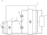
以下、本実施の形態による電力変換装置を図面に基づいて説明する。各図において同一、または相当する部分については、同一符号を付して、重複する説明を省略する。本実施の形態は、電力変換装置に用いられるリアクトルの小型化及び低コスト化を図るものである。図1は、実施の形態1に係る電力変換装置の構成を示す概略図である。図1において、電力変換装置2は直流入力電源1の直流電力を昇圧し、負荷3に供給する一石型昇圧DC/DCコンバータである。
A power converter according to the present embodiment will be described below with reference to the drawings. In each figure, the same or corresponding parts are denoted by the same reference numerals, and overlapping descriptions are omitted. The present embodiment aims to reduce the size and cost of a reactor used in a power converter. FIG. 1 is a schematic diagram showing the configuration of a power converter according to
電力変換装置2は昇圧リアクトル4と半導体スイッチング素子5a、5bと、入力電力平滑コンデンサ6と、出力電力平滑コンデンサ7を備える。半導体スイッチング素子5a、5bは直列に接続されており、その接続点(中点)Nは昇圧リアクトル4の巻き線の一方の端子に接続される。昇圧リアクトル4の巻き線の半導体スイッチング素子5a、5bの接続点Nに接続されない側の端子は、入力電力平滑コンデンサ6の正極側端子とつながる。半導体スイッチング素子5aの中点Nに接続されない側の端子は、出力電力平滑コンデンサ7の正極側端子に接続される。又半導体スイッチング素子5bの中点Nに接続されない側の端子は、出力電力平滑コンデンサ7の陰極端子、および入力電力平滑コンデンサ6の陰極端子に接続される。
The
昇圧リアクトル4は、半導体スイッチング素子5a、5bのスイッチング動作によって、電気エネルギーを磁気エネルギーとして保持、または放出を繰り返すことで昇圧動作を行う。ここで昇圧DC/DCコンバータの動作原理については一般によく知られたものであるため説明を割愛する。
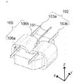
図2は、昇圧リアクトル4の構造を示す分解斜視図である。図2において、昇圧リアクトル4は昇圧リアクトル本体200、冷却器210、コア冷却部材220a、220bとコイル冷却部材230a、230bによって構成される。また昇圧リアクトル本体200は、サーミスタ101、コイル102、樹脂モールド部材201、ねじ202、ねじ穴203を有している。
The step-up reactor 4 performs a step-up operation by repeatedly holding or releasing electric energy as magnetic energy by switching operations of the
FIG. 2 is an exploded perspective view showing the structure of the boost reactor 4. As shown in FIG. 2, the boost reactor 4 is composed of a
図3、図4は昇圧リアクトル本体の構成を示す斜視図であり、図3は下側から見た斜視図、図4は上側から見た斜視図である。尚図2において、Z軸矢印方向を上側とし、その逆を下側とし、X軸、Y軸はZ軸に対して垂直方向に延びる軸である。又図4においては、昇圧リアクトル本体200において樹脂モールド部材201を除いた状態を示す。図において、昇圧リアクトル本体200は、サーミスタ101、コイル102、コア105を樹脂モールド部材201が覆うことにより形成されている。
3 and 4 are perspective views showing the configuration of the boost reactor main body, wherein FIG. 3 is a perspective view from below and FIG. 4 is a perspective view from above. In FIG. 2, the direction of the Z-axis is defined as the upper side, and the opposite direction is defined as the lower side. 4 shows a state in which the
コイル102を構成する2つの巻き線103a、103bは、それぞれ一方の端部が外部で互いに接続されており、それぞれのその他の端部が昇圧リアクトル4の端子となる。また巻き線103a、103bは、コア105に巻かれており、巻き数比率は1:1である。そしてお互いが発生させる磁束がコア105の内部で同じ向き(和動接続)となるように巻かれている。
The two
樹脂モールド部材201はサーミスタ101、コイル102、コア105を保持するとともに、冷却器210へ昇圧リアクトル本体200を固定する機能を有している。図3に示すように、コイル102を冷却するための巻き線冷却部104a、104bとコア105を冷却するためのコア冷却部107a、107bが設けられており、この部分においては、樹脂モールドで覆わない。機能を損なわない範囲で、樹脂モールドで覆わない部分を他に設けてもよい。また、巻き線冷却部104a、104bとコア冷却部107a、107bはリアクトル下部に設置されているがこれに限るものではない。例えば、図5に示すように、リアクトル上部U、又は側面S1、S2に設けることができる。リアクトルと冷却器210の形状に応じて、適切な部位に冷却部を設置することで冷却性能を高めることができる。
Resin molded
巻き線冷却部104a、104bとコア冷却部107a、107bは、それぞれコア冷却部材220a、220bとコイル冷却部材230a、230bを介して冷却器210に接する。コア冷却部材220a、220bおよびコイル冷却部材230a、230bはそれぞれ別の部材として構成しているが、これに限らずたとえば統合して一つの冷却部材としてもよい。又図2に示すように、冷却器210にはコア冷却部材220a、220bを載置するための台211a、211bが設けられている。
The winding
コア冷却部材220a、220bおよびコイル冷却部材230a、230bを構成する冷却部材の材料は半固体または固体のような非流動材料で構成されており、たとえばシリコーン系放熱シート、硬化型シリコーン系ギャップフィラー、更には放熱グリス等がある。このように非流動材料を採用することにより、流動材料(ポッティング)では必要となっていた冷却部材の流れ防止用の掘り込み構造を設ける必要がなくなる。掘り込み構造を排除することによりリアクトル側面を覆う金属部材がなくなり、インダクタンスが大きくなるためリアクトルの小型化を図ることが出来る。
The material of the cooling members constituting the
図6は昇圧リアクトル4のコア105の構成を示す斜視図である。コア105は2つのコア部材106a、106bによって構成され、それぞれの端部がコア部材端部突合せ部108a、108bで接触する。この状態にて樹脂モールド部材201はコア105を固定する。ここでコア105は2つのコア部材で構成した例を示したが、これに限るものではない。
FIG. 6 is a perspective view showing the configuration of the
以下一般的な構成を有する昇圧リアクトルにおける課題について説明する。リアクトルは電流変化に応じた誘導電圧を発生し、電流変化と誘導電圧の比が自己インダクタンスLである。電力変換装置2において、昇圧動作中の昇圧リアクトル4は、発生すべき誘導電圧が動作モードごと入力電圧Vin、Voutによって決まるため、自己インダクタンスLに応じたリプル電流を生じる。
Problems in the boost reactor having a general configuration will be described below. A reactor generates an induced voltage according to a current change, and the ratio of the current change to the induced voltage is the self-inductance L. In the
リプル電流の増大は、昇圧リアクトル4の巻き線損失の増大および、入力電力平滑コンデンサ6、出力電力平滑コンデンサ7、半導体スイッチング素子5a、5bの損失の増大につながる。
即ちリプル電流と巻き線損失の関係については、巻き線に発生する損失は、直流電流成分による直流損と、リプル成分による交流損に分けられる。交流損をWcoil_ac[W]とし、Rcoil[Ω]を巻き線抵抗、Irip[Arms]をリプル電流値とすると、交流損Wcoil_ac[W]は下記(1)式で表される。
Wcoil_ac=Irip2×Rcoil・・・・・・・・(1)
このように交流損はリプル電流値の二乗に比例するためリプル電流の増大が損失の増大につながる。
An increase in ripple current leads to an increase in winding loss of boost reactor 4 and an increase in loss in input power smoothing capacitor 6, output power smoothing capacitor 7, and
That is, regarding the relationship between the ripple current and the winding loss, the loss generated in the winding is divided into a DC loss due to a DC current component and an AC loss due to a ripple component. Assuming that the AC loss is Wcoil_ac[W], Rcoil[Ω] is the winding resistance, and Irip[Arms] is the ripple current value, the AC loss Wcoil_ac[W] is expressed by the following equation (1).
Wcoil_ac= Irip2 ×Rcoil (1)
Since AC loss is thus proportional to the square of the ripple current value, an increase in ripple current leads to an increase in loss.
又入力電力平滑コンデンサ6および出力電力平滑コンデンサ7については、コンデンサに発生する損失をWco[W]とし、ESRco[Ω]をコンデンサの抵抗成分、Ico[Arms]をコンデンサに流れる電流とすると、コンデンサ損失は下記(2)式で表される。
Wco=Ico2×ESRco・・・・・・・・・・(2)
コンデンサに流れる電流Icoは、入力電力平滑コンデンサ6と出力電力平滑コンデンサ7共に、リアクトルのリプル電流の増加に応じて増えるため、リプル電流が増えると、それぞれの損失は増える。
半導体スイッチング素子についても上記と同様であり、リアクトルのリプル電流が増えれば、半導体スイッチング素子に流れる電流のリプルが大きくなり、半導体スイッチング素子を構成する部材の損失が増大する。
以上より損失及び発熱の観点からは自己インダクタンスLを大きくし、リプル電流を小さくした方がよい。
Regarding the input power smoothing capacitor 6 and the output power smoothing capacitor 7, the loss generated in the capacitor is Wco [W], ESRco [Ω] is the resistance component of the capacitor, and Ico [Arms] is the current flowing through the capacitor. Loss is represented by the following formula (2).
Wco=Ico2×ESRco ( 2 )
Since the current Ico flowing through the capacitors increases with an increase in the ripple current of the reactor in both the input power smoothing capacitor 6 and the output power smoothing capacitor 7, the loss of each increases as the ripple current increases.
The same applies to the semiconductor switching elements. As the ripple current of the reactor increases, the ripple of the current flowing through the semiconductor switching elements increases, and the loss of the members constituting the semiconductor switching elements increases.
From the above, from the viewpoint of loss and heat generation, it is better to increase the self-inductance L and decrease the ripple current.
リアクトルのインダクタンス値Lは下記の(3)式により表される。
L=N2×(μr・μ0・S)/lc・・・・・・・(3)
ここで、lcはコア磁路長、μrはコアの比透磁率、μ0は真空透磁率である。
インダクタンスLを大きくするにあたって、一般にはコイル巻き数Nの増大させる、もしくはコア断面積Sを大きくする手法がとられる。
The inductance value L of the reactor is represented by the following equation (3).
L= N2 ×(μr・μ0・S)/lc (3)
Here, lc is the core magnetic path length, μr is the relative permeability of the core, and μ0 is the vacuum permeability.
In order to increase the inductance L, a method of increasing the number of turns N of the coil or increasing the cross-sectional area S of the core is generally adopted.
リアクトルのサイズを制約する主な要素は、放熱性と損失である。リアクトルを小型化するに際しては、インダクタンス値を増やしながら損失量を減らすことが望まれる。しかし前記手法でインダクタンス値を増加させた場合、リアクトルが大型化するという課題があり、小型化に限界がある。 The main factors limiting reactor size are heat dissipation and losses. When downsizing the reactor, it is desirable to reduce the amount of loss while increasing the inductance value. However, when the inductance value is increased by the above method, there is a problem that the reactor becomes large-sized, and there is a limit to miniaturization.
図7は一般的な昇圧リアクトルの構造を示す斜視図である。図7において、昇圧リアクトル本体300のコイル及びコアは、図2に示す昇圧リアクトル本体200と同じものである。図7において、昇圧リアクトル本体300はサーミスタ101、コイル102、ケース301、充填剤302、コアモールド部材303を有する。
コアモールド部材303は、コアを覆っており、コア表面の保護とコイル102の位置決めの機能を有する。充填剤302は、例えばシリコーン系のポッティングで構成されており、コイル102およびコアを冷却し、コアを固定する機能を有する。ケース301は充填剤302が流出することを防止する機能を有する。
FIG. 7 is a perspective view showing the structure of a general boost reactor. 7, the coil and core of the
The
放熱性能を向上させるため、ケース301はアルミ等の金属部材が用いられ、発熱体であるコイル102、コアに近接して設置される。リアクトル近傍に金属部材が存在する場合、リアクトルが生じる漏れ磁束を金属部材が遮断する。ここで漏れ磁束とは、リアクトルのコアもしくはコイルから直接空間中に放出される磁束である。漏れ磁束もインダクタンス値に寄与し、漏れ磁束が減少することによって自己インダクタンス値が低下する。従ってケース301により放熱性能は向上するが、リアクトルの損失量が増大するという課題を有する。
In order to improve the heat dissipation performance, the
本実施の形態はこのような課題を解決するためになされたものであり、本実施の形態に係る電力変換装置2における昇圧リアクトル4では、高い放熱性を維持しつつ、リアクトルの保持機構を樹脂部材とすることで、多くの漏れ磁束を活用することができる。これによりコイル、コアの構造を変更することなくインダクタンス値を増大させることができる。更にリアクトルの損失を低減させるとともに、小型化を実現し、安価に生産することができるようにする。 This embodiment has been made to solve such problems. By using it as a member, many leak magnetic fluxes can be utilized. As a result, the inductance value can be increased without changing the structure of the coil and core. Furthermore, the loss of the reactor can be reduced, the miniaturization can be realized, and the production can be made at low cost.
以下、本実施の形態に係る電力変換装置の昇圧リアクトル4における効果について説明する。図8は本実施の形態に係る昇圧リアクトルのX軸方向に対して垂直な面における断面図である。図9は一般的な昇圧リアクトル構造を示すX軸方向に対して垂直な面における断面図である。
図9において、一般的な昇圧リアクトルは、充填剤302がコイル及びコアの固定の機能を有するため、リアクトルの側面まで金属製のケース301により覆う必要がある。このためコイルおよびコアから発生する漏れ磁束9においては、ケース301によりY軸方向の漏れ磁束が遮断された状態となる。
The effect of the boost reactor 4 of the power converter according to the present embodiment will be described below. FIG. 8 is a cross-sectional view of the boost reactor according to the present embodiment taken along a plane perpendicular to the X-axis direction. FIG. 9 is a cross-sectional view taken along a plane perpendicular to the X-axis direction showing a general boost reactor structure.
In FIG. 9, a general boost reactor needs to be covered with a
これに対し図8において、本実施の形態の昇圧リアクトルは、昇圧リアクトル本体200の固定を樹脂モールド部材201で行うことにより、冷却部材に対する固定の機能を排することができ、冷却面を局所化できる。即ち本実施の形態においては、図8に示すように、冷却面はコア冷却部材220a、220b及びコイル冷却部材230bだけの3面で済むため冷却面を局所化できる。これに対して図9においては、冷却面が充填剤302全体となるので、コイル102及びコア106の底面のみならず、コイル102及びコア106の側面にも及ぶため冷却面を局所化できないこととなる。これにより本実施の形態では、リアクトルの側面を覆う金属製のケースが不要となる。従ってコイルおよびコアから発生する漏れ磁束8はY軸方向にも広がることができ、磁束量として図9に示した漏れ磁束9より多くなるためインダクタンス値が増大する。本実施の形態においては、樹脂モールド部材201が有する固定部によって冷却器210にコア及びコイル等が固定される構成である。
On the other hand, in FIG. 8, in the boost reactor of the present embodiment, the function of fixing the
また一般的な昇圧リアクトルのコイル、コアは充填剤302、ケース301、放熱グリス320を介して冷却器310で冷却されるのに対し、本実施の形態の昇圧リアクトル4のコイル102、コア105はそれぞれコイル冷却部材230a、230b、コア冷却部材220a、220bを介して冷却器210により直接冷却できる。したがって冷却器210までの熱抵抗を小さくすることができ、冷却性能が向上する。
さらに、金属製のケースが不要となるので、リアクトル本体を小型化でき、安価に生産することが出来る。
Further, while the coil and core of a general boost reactor are cooled by cooler 310 via
Furthermore, since a metal case is not required, the reactor body can be downsized and can be produced at low cost.
電力変換装置2において、筐体又はバスバー等のリアクトルの一面を覆う筐体のような大型金属部材が、昇圧リアクトル4の近傍に配置される場合、本実施の形態の効果に影響を与える。本実施の形態の効果を十分に発揮するには、漏れ磁束が発生できる領域を確保する必要がある。冷却部を有する面を除き、磁束の発生源であるコイル、コア端部から、少なくとも10mm以上の空間を確保する、即ち前記大型金属部材をコイル、コア端部から、少なくとも10mm以上離すことが好ましい。ただしネジにより端子台等を締め付けるような小型の金属部材であれば影響を無視できる。
In the
図7に示されるように、一般的な昇圧リアクトルのコアは充填剤302によって固定されるが、充填剤は硬度が小さく、充填剤302だけではコア部材106a、106bのコア部材端部突合せ部108a、108bを接触させた状態で固定できない。そのためコア部材端部突合せ部108a、108bを接着剤で固定する必要がある。これに対し本実施の形態の昇圧リアクトル4では、コア部材106a、106bの端部同士を突き合わせた状態で、樹脂モールド部材201でモールドする。従ってモールド時に発生する熱収縮による応力をかけ続けることができ、コア部材端部突合せ部108a、108bを突き合わせた状態で固定できる。そのため一般的な昇圧リアクトルにおいては、接着剤を使用していたため、温度が高くなると接着剤が機能しなくなりリアクトルが機能しなくなるおそれがあったが、このようなおそれがなくなる。これによりさらに高い温度でもリアクトルを動作させることができ、更にリアクトルの小型化が図れる。
As shown in FIG. 7, the core of a general boost reactor is fixed by a
本実施の形態の昇圧リアクトルにおけるコアとしてダストコア(圧粉磁心)を使用することが考えられる。ダストコアは飽和磁束密度が大きく大電力に向くが、比較的透磁率が小さい。したがってコアが発生させるインダクタンス値に対し、漏れ磁束によるインダクタンス値の割合が大きくなるため、大きなインダクタンスの増大効果を発揮する。特に比透磁率の小さいダストコアであるセンダスト(Sendust)を適応した場合、顕著な効果を発揮できる。しかし本実施の形態の適用対象はこれに限るものでなく、比透磁率の高いフェライト又は電磁鋼板等をコアとして用いてもよい。これにより上記と同様の効果を奏する。 It is conceivable to use a dust core (powder magnetic core) as the core in the step-up reactor of the present embodiment. The dust core has a high saturation magnetic flux density and is suitable for high power, but its magnetic permeability is relatively low. Therefore, the ratio of the inductance value due to the leakage magnetic flux to the inductance value generated by the core becomes large, so that a large effect of increasing the inductance is exhibited. In particular, when Sendust, which is a dust core with a small relative magnetic permeability, is applied, a remarkable effect can be exhibited. However, the object to which the present embodiment is applied is not limited to this, and ferrite having a high relative magnetic permeability, an electromagnetic steel sheet, or the like may be used as the core. This provides the same effect as described above.
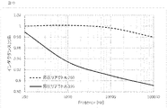
図10はインダクタンス値と周波数との関係を示すグラフであり、本実施の形態の昇圧リアクトルと、一般的な昇圧リアクトルにおけるインダクタンス値の比較を示す。図10において、水平軸は周波数であり、縦軸は本実施の形態の昇圧リアクトルの100Hz時のインダクタンスを基準としたインダクタンスの比率であり、点線は本実施の形態の昇圧リアクトル、実線は一般的な昇圧リアクトルを示している。金属部材による漏れ磁束の遮断は、金属筐体に発生する渦電流によるものであり、周波数(磁束変化量)により大きく変化する。即ち高周波になるほど磁束の遮断効果が大きくなる。図10に示すように、特に電力変換装置2の半導体スイッチング素子5a、5bの駆動周波数が1kHz以上である場合において、本実施の形態ではインダクタンスの減少は少ないが、一般的な昇圧リアクトルでは減少率が大きくなる。従って本実施の形態では電力変換装置の駆動周波数が1kHz以上である場合に特に効果を発揮する。
上記のように本実施の形態によれば、高い放熱性を維持しつつ多くの漏れ磁束を活用できる構造とすることで、コイル並びにコアの材料、構造の変更を伴わずインダクタンス値を増大させ、損失を低減することができる。即ち本実施の形態によるリアクトル構造によれば、リアクトルの保持機構を樹脂部材とした構成とすることで、漏れ磁束を遮断せずインダクタンス値を増加させることができる。またコイル及びコアを、冷却部材を介して冷却器で直接冷却できるため、冷却性能を向上させることができる。更にリアクトル構造の小型化を図ることができ、安価に生産することができる。
FIG. 10 is a graph showing the relationship between the inductance value and the frequency, showing a comparison of the inductance values between the boost reactor of this embodiment and a general boost reactor. In FIG. 10, the horizontal axis is the frequency, the vertical axis is the inductance ratio with reference to the inductance at 100 Hz of the boost reactor of the present embodiment, the dotted line is the boost reactor of the present embodiment, and the solid line is the general A boost reactor is shown. Blocking of leakage magnetic flux by a metal member is caused by an eddy current generated in the metal housing, and varies greatly depending on the frequency (amount of change in magnetic flux). That is, the higher the frequency, the greater the magnetic flux blocking effect. As shown in FIG. 10, especially when the driving frequency of the
As described above, according to the present embodiment, by adopting a structure that can utilize a large amount of leakage magnetic flux while maintaining high heat dissipation, the inductance value can be increased without changing the material and structure of the coil and core, Loss can be reduced. That is, according to the reactor structure according to the present embodiment, the inductance value can be increased without blocking leakage magnetic flux by configuring the reactor holding mechanism with a resin member. Further, since the coil and the core can be directly cooled by the cooler via the cooling member, the cooling performance can be improved. Furthermore, the size of the reactor structure can be reduced, and the production cost can be reduced.
実施の形態2.
上記においては、電力変換装置の昇圧リアクトル本体200は、2つの巻き線103a、103bが和動接続され、1つのコイルを形成する場合について説明した。和動接続はコア内部に磁路を形成することが前提となる。これに対して、コア外部に磁路を形成し、漏れ磁束をインダクタンスとして利用することを前提とした電力変換装置及びリアクトル構成に適用する場合、さらに高い効果を奏する。即ち更にインダクタンス値を大きくすることができる。漏れ磁束をインダクタンスとして利用することを前提としたリアクトルは、漏れ磁束の絶対量が大きく、コアで発生するインダクタンス値に対する割合が大きくなる。そのため相対的に本実施の形態においては、漏れ磁束の増加の効果を大きく得ることができる。
In the above description, the boost reactor
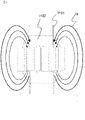
例えば電力変換装置として複数の巻き線を有する昇圧リアクトルによって構成されるマルチフェーズ型昇圧コンバータが例として挙げられる。更には昇圧リアクトルとして、それぞれの巻き線が発生させる磁束が打ち消しあう(差動接続)された磁気結合型リアクトルが例として考えられる。図11は昇圧リアクトルとして、磁気結合型リアクトルを用いた場合を示す側面図である。図11において、コア1102にコイル1101が巻回されており、磁束Mが発生している。なお冷却部材、冷却器及び樹脂モールド部材とコア1102、コイル1101との位置関係については実施の形態1に示したものと同様である。
For example, a multi-phase boost converter configured by a boost reactor having a plurality of windings is given as an example of a power conversion device. Furthermore, as a step-up reactor, a magnetically coupled reactor in which the magnetic fluxes generated by the respective windings cancel each other (differential connection) can be considered as an example. FIG. 11 is a side view showing a case where a magnetically coupled reactor is used as the step-up reactor. In FIG. 11, a
また、本実施の形態に係る電力変換装置の回路構成として昇圧DC/DCコンバータを示したが、これは一例であって、電力変換装置はAC/DCコンバータ回路、絶縁型降圧DC/DCコンバータ回路等の他の回路によって構成されたものであってもよい。この場合も上記と同様の効果を奏する。 Further, although a step-up DC/DC converter is shown as the circuit configuration of the power converter according to the present embodiment, this is just an example, and the power converter includes an AC/DC converter circuit and an isolated step-down DC/DC converter circuit. It may be configured by other circuits such as. In this case as well, the same effect as described above can be obtained.
その他上記した構成部品の数、寸法及び材料等について適宜変更することができる。
更に本願は、様々な例示的な実施の形態及び実施例が記載されているが、1つ、または複数の実施の形態に記載された様々な特徴、態様、及び機能は特定の実施の形態の適用に限られるのではなく、単独で、または様々な組み合わせで実施の形態に適用可能である。
従って、例示されていない無数の変形例が、本願に開示される技術の範囲内において想定される。例えば、少なくとも1つの構成要素を変形する場合、追加する場合または省略する場合、さらには、少なくとも1つの構成要素を抽出し、他の実施の形態の構成要素と組み合わせる場合が含まれるものとする。
In addition, the number, dimensions, materials, etc. of the above-described components can be changed as appropriate.
Further, while this application describes various exemplary embodiments and examples, various features, aspects, and functions described in one or more embodiments may not be consistent with particular embodiments. The embodiments are applicable singly or in various combinations without being limited to the application.
Therefore, countless modifications not illustrated are envisioned within the scope of the technology disclosed in the present application. For example, modification, addition or omission of at least one component, extraction of at least one component, and combination with components of other embodiments shall be included.
2 電力変換装置、4 リアクトル、102 コイル、
104a,104b 巻き線冷却部、105 コア、106a,106b コア部材、
107a,107b コア冷却部、201 樹脂モールド部材、210 冷却器、
220a,220b コア冷却部材、230a,230b コイル冷却部材。
2 power converter, 4 reactor, 102 coil,
104a, 104b winding cooling part, 105 core, 106a, 106b core member,
107a, 107b core cooling part, 201 resin molded member, 210 cooler,
220a, 220b core cooling members, 230a, 230b coil cooling members.
Claims (6)
前記コイルを冷却するための巻き線冷却部は非流動材料で構成されるコイル冷却部材を介して冷却器に接するとともに、
前記コアを冷却するためのコア冷却部は非流動材料で構成されるコア冷却部材を介して前記冷却器に接し、
前記巻き線冷却部及び前記コア冷却部を除いて前記コイルおよび前記コアを覆う樹脂モールド部材は前記コイルおよび前記コアを保持すると共に、前記コイルおよび前記コアを前記冷却器に固定し、
前記巻き線冷却部及び前記コア冷却部を有する面を除き、前記コイルの端部および前記コアの端部より10mm以内に金属部材を有さない領域を有することにより、少なくとも前記コイルの端部及び前記コアの端部から10mm以内の空間を、漏れ磁束によるインダクタンス値として利用しているリアクトル構造。 A reactor structure having a core wound with a coil and using leakage magnetic flux as an inductance ,
The winding cooling part for cooling the coil is in contact with the cooler via a coil cooling member made of a non-flowing material,
a core cooling part for cooling the core is in contact with the cooler via a core cooling member made of a non-flowing material;
a resin mold member covering the coil and the core except for the winding cooling portion and the core cooling portion holds the coil and the core and fixes the coil and the core to the cooler;
Except for the surface having the winding cooling part and the core cooling part , at least the coil end and A reactor structure in which a space within 10 mm from the end of the core is used as an inductance value due to leakage magnetic flux .
複数の前記コア部材の端部同士を突き合わせた状態で前記樹脂モールド部材によって前記コアを保持する請求項1記載のリアクトル構造。 The core is composed of a plurality of core members,
2. The reactor structure according to claim 1, wherein the core is held by the resin molded member with the ends of the plurality of core members butted against each other.
Priority Applications (3)
| Application Number | Priority Date | Filing Date | Title |
|---|---|---|---|
| JP2019214820A JP7158366B2 (en) | 2019-11-28 | 2019-11-28 | Reactor structure |
| US17/072,118 US12106886B2 (en) | 2019-11-28 | 2020-10-16 | Reactor structure |
| CN202011313831.6A CN112863816A (en) | 2019-11-28 | 2020-11-20 | Reactor structure |
Applications Claiming Priority (1)
| Application Number | Priority Date | Filing Date | Title |
|---|---|---|---|
| JP2019214820A JP7158366B2 (en) | 2019-11-28 | 2019-11-28 | Reactor structure |
Publications (2)
| Publication Number | Publication Date |
|---|---|
| JP2021086922A JP2021086922A (en) | 2021-06-03 |
| JP7158366B2 true JP7158366B2 (en) | 2022-10-21 |
Family
ID=75996371
Family Applications (1)
| Application Number | Title | Priority Date | Filing Date |
|---|---|---|---|
| JP2019214820A Active JP7158366B2 (en) | 2019-11-28 | 2019-11-28 | Reactor structure |
Country Status (3)
| Country | Link |
|---|---|
| US (1) | US12106886B2 (en) |
| JP (1) | JP7158366B2 (en) |
| CN (1) | CN112863816A (en) |
Citations (4)
| Publication number | Priority date | Publication date | Assignee | Title |
|---|---|---|---|---|
| JP2016219633A (en) | 2015-05-21 | 2016-12-22 | 株式会社タムラ製作所 | Reactor |
| JP2017174884A (en) | 2016-03-22 | 2017-09-28 | トヨタ自動車株式会社 | Reactor unit |
| JP2018195786A (en) | 2017-05-22 | 2018-12-06 | 株式会社オートネットワーク技術研究所 | Reactor |
| JP2019106515A (en) | 2017-12-14 | 2019-06-27 | 株式会社タムラ製作所 | Reactor |
Family Cites Families (12)
| Publication number | Priority date | Publication date | Assignee | Title |
|---|---|---|---|---|
| JPH061727B2 (en) * | 1984-12-26 | 1994-01-05 | 株式会社東芝 | Iron core |
| US5469124A (en) * | 1994-06-10 | 1995-11-21 | Westinghouse Electric Corp. | Heat dissipating transformer coil |
| JP2004095570A (en) * | 2002-08-29 | 2004-03-25 | Toyota Motor Corp | REACTOR DEVICE AND ITS MANUFACTURING METHOD |
| JP4895171B2 (en) * | 2006-04-06 | 2012-03-14 | 日立金属株式会社 | Composite core and reactor |
| JP4466684B2 (en) * | 2007-06-12 | 2010-05-26 | トヨタ自動車株式会社 | Reactor |
| JP5240246B2 (en) * | 2010-06-23 | 2013-07-17 | トヨタ自動車株式会社 | Reactor |
| WO2013001591A1 (en) * | 2011-06-27 | 2013-01-03 | トヨタ自動車株式会社 | Inductor and manufacturing method therefor |
| JP2014154757A (en) * | 2013-02-12 | 2014-08-25 | Toyota Motor Corp | Reactor |
| JP2015012272A (en) * | 2013-07-02 | 2015-01-19 | トヨタ自動車株式会社 | Reactor |
| JP6744796B2 (en) * | 2016-09-30 | 2020-08-19 | 株式会社タムラ製作所 | Reactor |
| JP2019102632A (en) * | 2017-12-01 | 2019-06-24 | トヨタ自動車株式会社 | Reactor |
| JP7133311B2 (en) | 2017-12-28 | 2022-09-08 | 株式会社タムラ製作所 | Reactor |
-
2019
- 2019-11-28 JP JP2019214820A patent/JP7158366B2/en active Active
-
2020
- 2020-10-16 US US17/072,118 patent/US12106886B2/en active Active
- 2020-11-20 CN CN202011313831.6A patent/CN112863816A/en active Pending
Patent Citations (4)
| Publication number | Priority date | Publication date | Assignee | Title |
|---|---|---|---|---|
| JP2016219633A (en) | 2015-05-21 | 2016-12-22 | 株式会社タムラ製作所 | Reactor |
| JP2017174884A (en) | 2016-03-22 | 2017-09-28 | トヨタ自動車株式会社 | Reactor unit |
| JP2018195786A (en) | 2017-05-22 | 2018-12-06 | 株式会社オートネットワーク技術研究所 | Reactor |
| JP2019106515A (en) | 2017-12-14 | 2019-06-27 | 株式会社タムラ製作所 | Reactor |
Also Published As
| Publication number | Publication date |
|---|---|
| US20210166863A1 (en) | 2021-06-03 |
| CN112863816A (en) | 2021-05-28 |
| US12106886B2 (en) | 2024-10-01 |
| JP2021086922A (en) | 2021-06-03 |
Similar Documents
| Publication | Publication Date | Title |
|---|---|---|
| JP6098870B2 (en) | Reactor, converter, and power converter | |
| JP5743851B2 (en) | Electronic equipment | |
| JP7126210B2 (en) | reactor, power circuit | |
| CN104919549B (en) | It is provided with the reactor of cooler | |
| KR102230546B1 (en) | Motor-driven compressor | |
| JP2017195684A (en) | Multi-phase converter reactor | |
| WO2015133201A1 (en) | Power conversion device | |
| US12266462B2 (en) | Reactor and multi-phase interleave-type DC-DC converter | |
| US20180053596A1 (en) | Coupled inductors for low electromagnetic interference | |
| JP7235794B2 (en) | Power converter controller | |
| KR20180023163A (en) | Trans Inductor and power converter device using the same | |
| JP2019204945A (en) | Coupling inductor and switching circuit | |
| CN104465035A (en) | Reactor and power converter | |
| JP7454952B2 (en) | Noise filters and power converters | |
| JP2015060849A (en) | Inductance component | |
| JP2003142319A (en) | Dust core, coil component, and power converter using them | |
| JP7158366B2 (en) | Reactor structure | |
| WO2023282323A1 (en) | Magnetically coupled reactor and boosting circuit | |
| JP7175807B2 (en) | inductor device | |
| JP2015060850A (en) | Inductance unit | |
| JP7246028B2 (en) | Reactor, core material, and power supply circuit | |
| JP2016063041A (en) | choke coil | |
| JP2015201491A (en) | Reactor with cooler | |
| JP2017135819A (en) | Power converter | |
| WO2025203161A1 (en) | Power conversion device |
Legal Events
| Date | Code | Title | Description |
|---|---|---|---|
| A621 | Written request for application examination |
Free format text: JAPANESE INTERMEDIATE CODE: A621 Effective date: 20191128 |
|
| A131 | Notification of reasons for refusal |
Free format text: JAPANESE INTERMEDIATE CODE: A131 Effective date: 20201222 |
|
| A521 | Request for written amendment filed |
Free format text: JAPANESE INTERMEDIATE CODE: A523 Effective date: 20210212 |
|
| A131 | Notification of reasons for refusal |
Free format text: JAPANESE INTERMEDIATE CODE: A131 Effective date: 20210511 |
|
| A521 | Request for written amendment filed |
Free format text: JAPANESE INTERMEDIATE CODE: A523 Effective date: 20210621 |
|
| A02 | Decision of refusal |
Free format text: JAPANESE INTERMEDIATE CODE: A02 Effective date: 20210914 |
|
| A521 | Request for written amendment filed |
Free format text: JAPANESE INTERMEDIATE CODE: A523 Effective date: 20211112 |
|
| C60 | Trial request (containing other claim documents, opposition documents) |
Free format text: JAPANESE INTERMEDIATE CODE: C60 Effective date: 20211112 |
|
| A911 | Transfer to examiner for re-examination before appeal (zenchi) |
Free format text: JAPANESE INTERMEDIATE CODE: A911 Effective date: 20211122 |
|
| C21 | Notice of transfer of a case for reconsideration by examiners before appeal proceedings |
Free format text: JAPANESE INTERMEDIATE CODE: C21 Effective date: 20211124 |
|
| A912 | Re-examination (zenchi) completed and case transferred to appeal board |
Free format text: JAPANESE INTERMEDIATE CODE: A912 Effective date: 20211217 |
|
| C211 | Notice of termination of reconsideration by examiners before appeal proceedings |
Free format text: JAPANESE INTERMEDIATE CODE: C211 Effective date: 20211221 |
|
| C22 | Notice of designation (change) of administrative judge |
Free format text: JAPANESE INTERMEDIATE CODE: C22 Effective date: 20220726 |
|
| C23 | Notice of termination of proceedings |
Free format text: JAPANESE INTERMEDIATE CODE: C23 Effective date: 20220906 |
|
| C03 | Trial/appeal decision taken |
Free format text: JAPANESE INTERMEDIATE CODE: C03 Effective date: 20221011 |
|
| C30A | Notification sent |
Free format text: JAPANESE INTERMEDIATE CODE: C3012 Effective date: 20221011 |
|
| A61 | First payment of annual fees (during grant procedure) |
Free format text: JAPANESE INTERMEDIATE CODE: A61 Effective date: 20221011 |
|
| R151 | Written notification of patent or utility model registration |
Ref document number: 7158366 Country of ref document: JP Free format text: JAPANESE INTERMEDIATE CODE: R151 |
|
| R250 | Receipt of annual fees |
Free format text: JAPANESE INTERMEDIATE CODE: R250 |
|
| S111 | Request for change of ownership or part of ownership |
Free format text: JAPANESE INTERMEDIATE CODE: R313111 |
|
| R350 | Written notification of registration of transfer |
Free format text: JAPANESE INTERMEDIATE CODE: R350 |