JP7158013B2 - cap - Google Patents

cap Download PDF

Info

Publication number
JP7158013B2
JP7158013B2 JP2018193004A JP2018193004A JP7158013B2 JP 7158013 B2 JP7158013 B2 JP 7158013B2 JP 2018193004 A JP2018193004 A JP 2018193004A JP 2018193004 A JP2018193004 A JP 2018193004A JP 7158013 B2 JP7158013 B2 JP 7158013B2
Authority
JP
Japan
Prior art keywords
fitted
upper lid
overcap
fitting
circumferential direction
Prior art date
Legal status (The legal status is an assumption and is not a legal conclusion. Google has not performed a legal analysis and makes no representation as to the accuracy of the status listed.)
Active
Application number
JP2018193004A
Other languages
Japanese (ja)
Other versions
JP2020059538A (en
JP2020059538A5 (en
Inventor
武尚 橋本
達大 前田
雄嗣 中川
Current Assignee (The listed assignees may be inaccurate. Google has not performed a legal analysis and makes no representation or warranty as to the accuracy of the list.)
Mikasa Sangyo Co Ltd
Original Assignee
Mikasa Sangyo Co Ltd
Priority date (The priority date is an assumption and is not a legal conclusion. Google has not performed a legal analysis and makes no representation as to the accuracy of the date listed.)
Filing date
Publication date
Application filed by Mikasa Sangyo Co Ltd filed Critical Mikasa Sangyo Co Ltd
Priority to JP2018193004A priority Critical patent/JP7158013B2/en
Publication of JP2020059538A publication Critical patent/JP2020059538A/en
Publication of JP2020059538A5 publication Critical patent/JP2020059538A5/ja
Application granted granted Critical
Publication of JP7158013B2 publication Critical patent/JP7158013B2/en
Active legal-status Critical Current
Anticipated expiration legal-status Critical

Links

Images

Description

本発明は容器の口部に取り付けられるキャップに関する。 The present invention relates to a cap that is attached to the mouth of a container.

従来、この種のキャップとして、容器の口部に取り付けられる中栓と、回転することにより中栓に着脱自在な上蓋とを備え、中栓に、周囲が破断可能な薄肉ラインの弱化部で囲まれた除去領域を有しており、上蓋を中栓に装着して回転することにより、弱化部を破断させて、除去領域を上蓋に嵌り込ませ、中栓に注出口を形成するものがある。このキャップによれば、未使用時には、容器の口部に取り付けられる中栓が密閉状態を維持できるので衛生的である。 Conventionally, this type of cap includes an inner stopper attached to the mouth of a container and an upper cover that can be attached to and detached from the inner stopper by rotation. By rotating the upper lid with the inner plug, the weakened portion is broken and the removed area is fitted into the upper lid to form a spout in the inner plug. . According to this cap, when not in use, the inner plug attached to the mouth of the container can maintain a sealed state, which is hygienic.

しかし、上蓋と中栓とが、平面視した場合の大きさがあまり変わらず(例えば両方とも略円形(上蓋は略円筒形状)であり、その直径があまり変わらず)、除去領域を切断する切断寸法が比較的大きい場合には、上蓋を回転させて中栓の除去領域を離脱させる際に、比較的大きな力(大きなトルク)を上蓋に作用させなければならない。 However, the size of the upper lid and the inner plug does not change much when viewed from the top (for example, both are substantially circular (the upper lid is substantially cylindrical) and the diameter does not change much), and the cutting that cuts the removal area If the dimensions are relatively large, a relatively large force (large torque) must be exerted on the top cover when the top cover is rotated to disengage the removal area of the inner plug.

この切断する際の力を軽減する方法としては、例えば、特許文献1に開示されているように、上蓋より大きな直径のオーバーキャップを上蓋に嵌合させて被せることが考えられる。つまり、オーバーキャップと上蓋とに、互いに径方向に一体的に回転できるような嵌合部や被嵌合部を設け、開封時にオーバーキャップを回転して、内側の上蓋も一体的に回転させて、除去領域を切断するようにする。これにより、開封時におけるオーバーキャップを回転する力(トルク)を小さくて済ませることができ、作業性が良好となる。なお、オーバーキャップと上蓋とに設けられている嵌合部や被嵌合部は、平面視して周方向に対して所定の同じ角度毎に凹凸形状に形成されている。 As a method for reducing the cutting force, for example, as disclosed in Patent Document 1, it is conceivable to fit and cover the upper lid with an overcap having a diameter larger than that of the upper lid. In other words, the overcap and the top lid are provided with a fitting portion and a fitted portion that can rotate integrally in the radial direction, and when the overcap is opened, the overcap is rotated, and the inner top lid is also rotated integrally. , so as to cut the removal area. As a result, the force (torque) for rotating the overcap at the time of opening can be reduced, and workability is improved. In addition, the fitting portion and the fitted portion provided on the overcap and the upper lid are formed in an uneven shape at the same predetermined angle with respect to the circumferential direction in a plan view.

特開2012-126402公報Japanese Unexamined Patent Application Publication No. 2012-126402

しかしながら、上記特許文献1に開示されたようなオーバーキャップを上蓋に嵌合させて被せる構成において、オーバーキャップと上蓋との互いに径方向に係止する摩擦力によって、上蓋がオーバーキャップ内に保持されているものの、小さな衝撃などを受けた場合に、オーバーキャップから上蓋が下方に脱落してしまうおそれがある。 However, in the structure in which the overcap is fitted over the top lid as disclosed in Patent Document 1, the top lid is held in the overcap by the frictional force that causes the overcap and the top lid to engage with each other in the radial direction. However, there is a risk that the top lid will drop downward from the overcap if it receives a small impact or the like.

本発明は上記課題を解決するもので、開封時に必要な回転力を比較的小さく済ませることができ、かつ、小さな衝撃などを受けた場合でもオーバーキャップから上蓋が脱落することを防止できるキャップを提供することを目的とするものである。 To solve the above problems, the present invention provides a cap that can be opened with a relatively small rotational force and that can prevent the upper lid from falling off from the overcap even when receiving a small impact. It is intended to

上記課題を解決するために、本発明は、容器の口部に取り付けられる中栓と、回転することにより中栓に着脱自在な上蓋と、この上蓋に嵌合した状態で被せられて一体的に回転可能なオーバーキャップと、を備え、中栓は、中栓本体部と、弱化部を介して中栓本体部から離脱可能に設けられた離脱部とを有し、上蓋に、上蓋が回転された際に中栓の離脱部に係合して離脱部を中栓本体部から離脱させる回転係合部が設けられているキャップであって、上蓋とオーバーキャップとには、互いに嵌合可能な被嵌合部と嵌合部とが設けられ、前記被嵌合部は、上蓋の外周またはオーバーキャップの内周に、周方向に対して所定の角度毎に凹凸形状に形成され、前記嵌合部は、互いに隣り合う周方向の離間角度が、前記被嵌合部が設けられている角度の整数倍の角度で設けられている複数の案内嵌合部と、この案内嵌合部に対する周方向の離間角度が、前記被嵌合部が設けられている角度の整数倍の角度とは異なる角度で設けられて前記被嵌合部に対して周方向に弾性変形しながら嵌合する変形嵌合部と、を有することを特徴とする。 In order to solve the above-mentioned problems, the present invention provides an inner plug attached to the mouth of a container, an upper lid detachably attachable to the inner plug by rotating, and an integrally covered lid that is fitted to the upper lid. a rotatable overcap, wherein the inner plug has an inner plug main body portion and a detachable portion provided to be detachable from the inner plug main body portion via the weakened portion; The cap is provided with a rotary engaging portion that engages with the detachable portion of the inner plug to detach the detached portion from the inner plug main body when the lid is closed, and the upper lid and the overcap can be fitted to each other. A fitting portion and a fitting portion are provided, and the fitting portion is formed on the outer periphery of the upper lid or the inner periphery of the overcap in an uneven shape at predetermined angles with respect to the circumferential direction. The portion includes a plurality of guide fitting portions provided with a spacing angle in the circumferential direction adjacent to each other at an angle that is an integral multiple of the angle at which the fitted portion is provided, and a guide fitting portion with respect to the guide fitting portion. Deformation fitting in which the separation angle of the direction is provided at an angle different from an integral multiple of the angle at which the fitted portion is provided, and the fitted portion is fitted while being elastically deformed in the circumferential direction. and a joint.

上記構成によれば、被嵌合部に嵌合する嵌合部に、互いに隣り合う周方向の離間角度が、前記被嵌合部が設けられている角度の整数倍の角度で設けられている複数の案内嵌合部を設けただけでなく、この案内用嵌合部に対する周方向の離間角度が、前記被嵌合部が設けられている角度の整数倍の角度とは異なる角度で設けられて前記被嵌合部に対して周方向に弾性変形しながら嵌合する変形嵌合部を設けたので、上蓋にオーバーキャップを嵌合させて被せると、変形嵌合部が周方向に弾性変形しながら嵌合する。これにより、比較的小さな衝撃を受けた場合でも、オーバーキャップから上蓋が下方に脱落してしまうことを防止できて、オーバーキャップにより上蓋を脱落しない状態で保持できる。そして、この状態で、オーバーキャップを回転させて上蓋も一体回転させることで、中栓の弱化部を切断させて離脱部を離脱させることができて、中栓に注出口を形成できる。この際、オーバーキャップを回転させるので、弱化部の切断時に必要な回転力を比較的小さく済ませることができる。 According to the above configuration, the fitting portion that fits into the fitted portion is provided with an interval angle in the circumferential direction that is an integral multiple of the angle at which the fitted portion is provided. In addition to providing a plurality of guide fitting portions, the angle of separation in the circumferential direction with respect to the guide fitting portions is provided at an angle different from an integral multiple of the angle at which the fitted portion is provided. Since the deformable fitting portion is provided to be fitted while being elastically deformed in the circumferential direction with respect to the fitted portion, when the overcap is fitted to cover the upper lid, the deformable fitting portion is elastically deformed in the circumferential direction. fit while As a result, even when a relatively small impact is received, the upper lid can be prevented from falling downward from the overcap, and the overcap can hold the upper lid in a state where it does not fall off. In this state, by rotating the overcap and rotating the upper lid integrally, the weakened portion of the inner plug can be cut and the detachable portion can be removed, thereby forming a spout in the inner plug. At this time, since the overcap is rotated, the rotational force required for cutting the weakened portion can be relatively small.

また、本発明は、前記被嵌合部が上蓋に形成され、前記嵌合部はオーバーキャップに形成され、オーバーキャップの天面が上方に向くように配置した状態で、前記案内嵌合部の下端部が、前記変形嵌合部の下端部よりも下方の位置に形成されていると好適である。 Further, according to the present invention, the fitted portion is formed in the upper lid, the fitting portion is formed in the overcap, and the guide fitting portion is positioned so that the top surface of the overcap faces upward. It is preferable that the lower end portion is formed at a lower position than the lower end portion of the deformation fitting portion.

この構成によれば、オーバーキャップの天面部が上方に向くように配置した状態で、前記案内嵌合部の下端部が、前記変形嵌合部の下端部よりも下方の位置に形成されているので、上蓋に対してオーバーキャップを周方向に直交する方向に沿って打栓させるなどして組み付ける場合に、まず、オーバーキャップの案内嵌合部が上蓋の被嵌合部に嵌合し、この後に、オーバーキャップの変形嵌合部が上蓋の被嵌合部に嵌合する。すなわち、上蓋に対してオーバーキャップを打栓させるなどして組み付ける際には、第1段階では、互いに隣り合う案内嵌合部間の周方向の離間角度が、被嵌合部が設けられている角度の整数倍の角度で設けられている案内嵌合部だけが被嵌合部に嵌合するので、比較的小さな力で打栓できる。また、オーバーキャップの変形嵌合部は、案内用嵌合部に対する離間角度が、前記被嵌合部が設けられている角度の整数倍の角度とは異なる角度で設けられているが、この変形嵌合部が上蓋の被嵌合部に嵌合する際には、既に案内嵌合部が被嵌合部に嵌合してオーバーキャップと上蓋とが互いに周方向に移動できない状態に保持されている(位置決めされている)ので、打栓力の増加を最小限に抑えた状態でも、上蓋の被嵌合部に変形嵌合部を変形させながら嵌め込むことができて、打栓時に必要な力を低めに抑えることが可能となる。また、オーバーキャップの変形嵌合部は上蓋の被嵌合部に変形して比較的大きな力で噛み込んだ状態で嵌合しているので、オーバーキャップにより上蓋を脱落しない状態で良好に保持できる。 According to this configuration, the lower end portion of the guide fitting portion is formed at a position lower than the lower end portion of the deformation fitting portion in a state where the top surface portion of the overcap faces upward. Therefore, when the overcap is attached to the top lid by plugging along a direction orthogonal to the circumferential direction, first, the guide fitting portion of the overcap is fitted to the fitting portion of the top lid, and this Later, the deformed fitting portion of the overcap is fitted to the fitted portion of the top lid. That is, when the overcap is attached to the upper lid by plugging, etc., in the first stage, the gap angle in the circumferential direction between the adjacent guide fitting portions is set to the fitted portion. Since only the guide fitting portion provided at an integral multiple of the angle fits into the fitted portion, the plug can be capped with a relatively small force. Further, the deformed fitting portion of the overcap is provided at an angle different from the integral multiple angle of the angle at which the fitted portion is provided with respect to the guiding fitting portion. When the fitting portion is fitted to the fitted portion of the upper lid, the guide fitting portion is already fitted to the fitted portion so that the overcap and the top lid are held in a state in which they cannot move in the circumferential direction relative to each other. Therefore, even when the increase in plugging force is minimized, the deformable fitting portion can be fitted into the fitted portion of the top lid while deforming. It is possible to keep the force low. In addition, since the deformation fitting portion of the overcap is deformed into the fitted portion of the top lid and engaged with a relatively large force, the overcap can hold the top lid well without falling off. .

また、前記嵌合部および前記被嵌合部が、上蓋およびオーバーキャップにおいて周方向に直交する直線方向に沿って延びる形状に形成され、前記変形嵌合部の先端部に、先端ほど周方向寸法が小さくなるように傾斜面が形成されていると好適である。この構成によれば、変形嵌合部が被嵌合部に嵌合し始める際に、前記変形嵌合部の先端部に形成されている傾斜面が被嵌合部に摺接しながら滑らかに嵌合でき、これによっても、オーバーキャップを上蓋に打栓させるなどして組み付ける場合に必要な力を低めに抑えることが可能となる。 Further, the fitting portion and the fitted portion are formed in a shape extending along a straight line direction orthogonal to the circumferential direction in the upper lid and the overcap, and the distal end portion of the deformed fitting portion has a circumferential dimension It is preferable that the inclined surface is formed so that the According to this configuration, when the deformable fitting portion starts to be fitted to the fitted portion, the inclined surface formed at the distal end portion of the deformable fitting portion is smoothly fitted while slidingly contacting the fitted portion. This also makes it possible to reduce the force required when assembling the overcap by plugging it into the upper lid.

また、オーバーキャップに、上蓋に被せる覆い部と、この覆い部から下方に延びて径方向に弾性変形して、上蓋を保持可能な保持用足部が設けられていると好適である。この構成によれば、オーバーキャップに上蓋に被せることで、保持用足部によっても上蓋を保持することができ、より確実にオーバーキャップによって上蓋を保持することができる。 Moreover, it is preferable that the overcap is provided with a covering portion that covers the upper lid, and a holding foot that extends downward from the covering portion and elastically deforms in the radial direction to hold the upper lid. According to this configuration, by covering the top lid with the overcap, the top lid can be held by the holding legs, and the top lid can be held more reliably by the overcap.

また、本発明は、前記キャップの、上蓋に対してオーバーキャップを組み付けるキャップの組付け方法であって、オーバーキャップを上蓋に対して周方向に直交する軸心方向に沿って打栓させることにより組み付け、打栓時に、案内嵌合部が被嵌合部に嵌合した後に、変形嵌合部が被嵌合部に嵌合するように構成されていることを特徴とする。この方法により、変形嵌合部が被嵌合部に嵌合する際には、すでに案内嵌合部が被嵌合部に嵌合しているので、打栓時に必要な力を低めに抑えることが可能となる。 The present invention also provides a method for assembling an overcap to the upper lid of the cap, wherein the overcap is capped along the axial direction orthogonal to the circumferential direction with respect to the upper lid. It is characterized in that the deformable fitting portion is fitted to the fitted portion after the guide fitting portion is fitted to the fitted portion during assembly and plugging. With this method, when the deformation fitting part is fitted to the fitted part, the guide fitting part is already fitted to the fitted part, so the force required for plugging can be kept low. becomes possible.

本発明のキャップによれば、被嵌合部に嵌合する嵌合部に、互いに隣り合う周方向の離間角度が、前記被嵌合部が設けられている角度の整数倍の角度で設けられている複数の案内嵌合部を設けただけでなく、この案内用嵌合部に対する周方向の離間角度が、前記被嵌合部が設けられている角度の整数倍の角度とは異なる角度で設けられて前記被嵌合部に対して周方向に弾性変形しながら嵌合する変形嵌合部を設けることにより、比較的小さな衝撃を受けた場合でも、オーバーキャップから上蓋が下方に脱落してしまうことを防止できて、オーバーキャップにより上蓋を脱落しない状態で保持でき、ひいてはキャップの信頼性を向上させることができる。 According to the cap of the present invention, the fitting portion that fits into the fitted portion is provided with an interval angle in the circumferential direction that is an integral multiple of the angle at which the fitted portion is provided. In addition to providing a plurality of guiding fitting portions, the angle of separation in the circumferential direction with respect to the guiding fitting portion is an angle different from an integral multiple of the angle at which the fitted portion is provided. By providing the deformable fitting portion which is provided and fitted to the fitted portion while being elastically deformed in the circumferential direction, the upper lid is prevented from falling downward from the overcap even when receiving a relatively small impact. It is possible to prevent the overcap from being put away, and the overcap can hold the upper lid in a state in which it does not come off, thereby improving the reliability of the cap.

また、前記被嵌合部を上蓋に形成し、前記嵌合部をオーバーキャップに形成し、オーバーキャップの天面部が上方に向くように配置した状態で、前記案内嵌合部の下端部が、前記変形嵌合部の下端部よりも下方の位置に形成されていることにより、上蓋に対してオーバーキャップを打栓させて組み付ける場合に、打栓時に必要な力を低めに抑えることが可能となる。 Further, in a state in which the fitted portion is formed in the upper lid, the fitting portion is formed in the overcap, and the top surface portion of the overcap is arranged to face upward, the lower end portion of the guide fitting portion is Since it is formed at a position lower than the lower end of the deformable fitting portion, when the overcap is attached to the upper lid by plugging, it is possible to suppress the force required for plugging to a low level. Become.

また、前記嵌合部および前記被嵌合部を、上蓋およびオーバーキャップにおいて周方向に直交する直線方向に沿って延びる形状に形成し、前記変形嵌合部の先端部に、先端ほど周方向寸法が小さくなるように傾斜面を形成することによっても、オーバーキャップを上蓋に打栓させるなどして組み付ける場合に必要な力を低めに抑えることが可能となる。 Further, the fitting portion and the fitted portion are formed in a shape extending along a straight line direction orthogonal to the circumferential direction in the upper lid and the overcap, and the distal end portion of the deformable fitting portion has a circumferential dimension of By forming the inclined surface so as to reduce the .DELTA.

また、前記キャップの、上蓋に対してオーバーキャップを組み付けるキャップの組付け方法として、打栓時に、案内嵌合部が被嵌合部に嵌合した後に、変形嵌合部が被嵌合部に嵌合するよう構成することにより、変形嵌合部が被嵌合部に嵌合する際には、すでに案内嵌合部が被嵌合部に嵌合しているので、打栓時に必要な力を低めに抑えることが可能となる。 In addition, as a cap assembly method for assembling the overcap to the upper lid of the cap, after the guide fitting part is fitted to the fitted part at the time of plugging, the deformed fitting part is fitted to the fitted part. By configuring to fit, when the deformation fitting part is fitted to the fitted part, the guide fitting part is already fitted to the fitted part, so the force required for plugging can be reduced. can be kept low.

本発明の実施の形態に係るキャップの部分切欠正面図である。It is a partially notched front view of the cap which concerns on embodiment of this invention. 同キャップの中栓の平面図である。It is a top view of the inner stopper of the same cap. 同キャップの中栓の部分切欠正面図である。It is a partial notch front view of the inner plug of the same cap. 同キャップの上蓋の平面図である。It is a top view of the upper cover of the same cap. 同キャップの上蓋の部分切欠正面図である。It is a partial notch front view of the upper cover of the same cap. 同キャップの上蓋の底面図である。It is a bottom view of the upper cover of the same cap. 同キャップにおけるオーバーキャップの部分切欠正面図である。It is a partial notch front view of the overcap in the same cap. 同キャップのオーバーキャップの底面図である。It is a bottom view of the overcap of the same cap. 同オーバーキャップの案内用嵌合部およびその近傍箇所の縦断面図である。It is a longitudinal cross-sectional view of the guide fitting portion of the same overcap and its vicinity. 同オーバーキャップの案内用嵌合部をオーバーキャップの軸心位置より矢視した矢視図である。FIG. 4 is a view of the guide fitting portion of the same overcap as viewed from the axial position of the overcap. 同オーバーキャップの変形嵌合部およびその近傍箇所の縦断面図である。It is a longitudinal cross-sectional view of the deformation|transformation fitting part of the same overcap, and its vicinity. 同オーバーキャップの変形嵌合部をオーバーキャップの軸心位置より矢視した矢視図である。FIG. 4 is an arrow view of a deformed fitting portion of the same overcap viewed from the axial center position of the overcap; 同キャップにおける中栓に上蓋を被せる状態を示す部分切欠正面図である。It is a partial notch front view which shows the state which covers the inner plug in the same cap with an upper cover. 同キャップにおける上蓋にオーバーキャップを被せる状態を示す部分切欠正面図である。It is a partial notch front view which shows the state which covers the upper cover in the same cap with an overcap. 同キャップにおける上蓋にオーバーキャップを被せる状態を示す部分切欠斜視図である。It is a partially notched perspective view which shows the state which covers the upper cover in the same cap with an overcap. 同キャップにおける上蓋にオーバーキャップを被せる状態を示す部分切欠斜視図であり、案内用嵌合部が外周凹凸条部に嵌合し始めている状態を示す。It is a partial notched perspective view which shows the state which covers the upper cover in the same cap with an overcap, and shows the state which the fitting part for a guide begins to fit in an outer peripheral uneven|corrugated|grooved line part. 同キャップにおける上蓋にオーバーキャップを被せる状態を示す部分切欠斜視図であり、変形嵌合部が外周凹凸条部に嵌合し始めている状態を示す。It is a partial notch perspective view which shows the state which covers an upper cover in the same cap with an overcap, and shows the state which a deformation|transformation fitting part is starting to fit in an outer peripheral uneven|corrugated|grooved line part. 同キャップにおける上蓋にオーバーキャップを被せた状態を示す断面図であり、案内用嵌合部および変形嵌合部が外周凹凸条部に嵌合した状態を示す。It is sectional drawing which shows the state which covered the upper lid|cover in the same cap with an overcap, and shows the state which the fitting part for guidance and the deformation|transformation fitting part were fitted in the outer periphery uneven|corrugated|grooved line part. 同キャップにおける上蓋およびオーバーキャップにより、中栓の離脱部を取り外した状態を示す断面図である。FIG. 4 is a cross-sectional view showing a state in which the detachable portion of the inner plug is removed by the upper lid and the overcap of the same cap. 同キャップにおけるオーバーキャップの案内嵌合部や変形嵌合部が上蓋の外周凹凸条部(被嵌合部)に嵌り込む状態を概念的に示す平面図である。FIG. 4 is a plan view conceptually showing a state in which a guide fitting portion and a deformable fitting portion of an overcap of the same cap are fitted into an outer peripheral uneven streak portion (to-be-fitted portion) of an upper lid.

以下、本発明に係る実施の形態のキャップを、図面に基づき説明する。
図1などにおいて、1は、内部に内容物(内容液)が収容されている容器2に取付けられるキャップである。キャップ1は、容器2の口部3に取り付けられる中栓4と、回転することにより中栓4に着脱自在な上蓋5と、この上蓋5に嵌合した状態で被せられて、周方向に回転した際に上蓋5に係合して一体的に回転可能なオーバーキャップ6と、を備えている。中栓4と上蓋5とオーバーキャップ6とはそれぞれ、例えば合成樹脂により射出成形されるなどして製造され、弾性変形可能な性質を有する。
BEST MODE FOR CARRYING OUT THE INVENTION Hereinafter, caps according to embodiments of the present invention will be described based on the drawings.
In FIG. 1 and the like, 1 is a cap that is attached to a container 2 containing a content (content liquid). The cap 1 includes an inner plug 4 attached to the mouth portion 3 of the container 2, an upper lid 5 that is detachable from the inner plug 4 by rotating, and a cap 1 that is fitted over the upper lid 5 and rotates in the circumferential direction. and an overcap 6 that engages with the upper lid 5 and rotates integrally with it when it is closed. The inner plug 4, the upper lid 5, and the overcap 6 are each manufactured by, for example, injection molding of a synthetic resin, and have elastically deformable properties.

図2、図3などに示すように、中栓4は、容器2の口部3に取り付けられる中栓本体部10と、弱化部11を介して中栓本体部10から離脱可能に設けられた離脱部12とを有している。中栓本体部10は、中央(弱化部11の外周)から上方に突出するノズル部16と、その下部が容器2の口部3に外側から嵌り込む円筒状の外筒部13と、外筒部13の内周に隙間を有する状態で設けられてその下部が容器2の口部3に内側から嵌り込む円筒状の内筒部14と、外筒部13および内筒部14のそれぞれ上端部箇所で径方向内側に延びて外筒部13と内筒部14などを繋ぐ上面部15と、上面部15の内周端より上方に段付きの筒形状に突出するとともに内周側部分でノズル部16の高さ方向略中央箇所に全周で接続されている段部17などが形成されている。 As shown in FIGS. 2 and 3 , the inner plug 4 is provided so as to be detachable from the inner plug main body 10 via an inner plug main body 10 attached to the mouth portion 3 of the container 2 and a weakened portion 11. and a detachment portion 12 . The inner plug main body 10 includes a nozzle portion 16 protruding upward from the center (outer periphery of the weakened portion 11), a cylindrical outer cylinder portion 13 whose lower part fits into the mouth portion 3 of the container 2 from the outside, and an outer cylinder 13. A cylindrical inner cylindrical portion 14 provided with a gap on the inner circumference of the portion 13 and having a lower portion fitted into the mouth portion 3 of the container 2 from the inside, and upper end portions of the outer cylindrical portion 13 and the inner cylindrical portion 14, respectively. A top surface portion 15 extending radially inward at a point to connect the outer cylinder portion 13 and the inner cylinder portion 14, etc., and a stepped cylindrical shape projecting upward from the inner peripheral end of the top surface portion 15 and having a nozzle at the inner peripheral side portion. A stepped portion 17 or the like connected to the entire circumference is formed at a substantially central portion in the height direction of the portion 16 .

外筒部13の下方には、薄肉部19Aを介して下方に延びるとともに径方向外側および内周側にも突出する鍔状部18が全周に形成され、容器2の使用後などに、鍔状部18の1か所に形成された縦薄肉溝部19Bおよび薄肉部19Aから鍔状部18を切断することで、容器2から中栓4などを外し易くなるよう図られている。また、中栓本体部10の段部17の外周には、上蓋5に形成された後述するねじ部31(図1、図6など参照)に螺合するねじ部20が形成されている。また、中栓本体部10の上面部15には、徐々に盛り上がって、上蓋5に形成された規制リブ44(図6参照)に当接可能とされて上蓋5の回転閉鎖位置を認識させるストッパ部27や、上方に突出して、上蓋5に形成された撥音用突起47(図5、図6参照)に当接可能とされて上蓋5が閉鎖直前状態まで回転した際に手応えと音を発生させる撥音用突部28が複数箇所(この実施の形態では2箇所)に設けられている。 Below the outer cylindrical portion 13, a flange portion 18 extending downward through the thin portion 19A and protruding radially outward and inward is formed around the entire periphery. By cutting the brim portion 18 from the vertical thin groove portion 19B and the thin portion 19A formed at one location of the shape portion 18, the inner plug 4 and the like can be easily removed from the container 2. A threaded portion 20 is formed on the outer periphery of the stepped portion 17 of the inner plug main body 10 so as to be screwed to a threaded portion 31 (see FIGS. 1 and 6) formed on the upper lid 5 and described later. Further, on the upper surface portion 15 of the inner plug main body portion 10, there is provided a stopper which gradually rises and can come into contact with a restricting rib 44 (see FIG. 6) formed on the upper lid 5, thereby recognizing the rotation closing position of the upper lid 5. 5 and 6) formed on the upper lid 5, and generates a response and a sound when the upper lid 5 is rotated to a state immediately before closing. A plurality of (two in this embodiment) sound-repellent projections 28 are provided.

中栓4の離脱部12は弱化部11の内側を少し中央側が若干下方に窪んだ状態で閉鎖する底面壁部21と、底面壁部21の外周寄り箇所(弱化部11よりも少し内周側箇所)から上方に筒状に延びる離脱筒状部22と、を有する。 The detachable portion 12 of the inner plug 4 includes a bottom wall portion 21 that closes the inside of the weakened portion 11 with the central side slightly depressed downward, and a portion near the outer periphery of the bottom wall portion 21 (slightly inner peripheral side of the weakened portion 11). and a detachable cylindrical portion 22 that extends cylindrically upward from the point).

離脱筒状部22には、径方向内側に突出する状態で上下に延びる離脱内側突条リブ25と、径方向外側に突出する状態で上下に延びる離脱外側突条リブ24とが、それぞれ周方向所定角度毎に複数形成されている。なお、この実施の形態では、離脱内側突条リブ25および離脱外側突条リブ24が、それぞれ周方向60度毎に形成されているが、これに限るものではなく、離脱内側突条リブ25と離脱外側突条リブ24とは、それぞれ互いに異なる角度毎に形成されていてもよい。離脱内側突条リブ25は、上蓋5の離脱用内筒部32の外周に周方向所定角度毎(この実施の形態では周方向60度毎)に複数形成された離脱用内筒突条リブ33(図5、図6参照)に、上蓋5が中栓4に対して所定の周方向(例えば、平面視して時計回り)に回転された際に係合可能とされている。また、離脱外側突条リブ24は、上蓋5の離脱用外筒部34の内周に周方向所定角度毎(この実施の形態では周方向60度毎)に複数形成された離脱用外筒突条リブ35(図5、図6参照)に、上蓋5が中栓4に対して所定の周方向(例えば、平面視して時計回り)に回転された際に係合可能とされている。 In the detachable tubular portion 22, a detachable inner rib 25 extending vertically in a state of protruding radially inward and a detachable outer rib 24 extending vertically in a state of protruding radially outward are provided in the circumferential direction. A plurality of them are formed for each predetermined angle. In this embodiment, the detachable inner rib 25 and the detachable outer rib 24 are formed every 60 degrees in the circumferential direction. The detachable outer protrusion ribs 24 may be formed at angles different from each other. The detachable inner cylinder protrusion ribs 25 are formed on the outer periphery of the detachable inner cylinder portion 32 of the upper lid 5 at every predetermined angle in the circumferential direction (every 60 degrees in the circumferential direction in this embodiment). (See FIGS. 5 and 6), when the upper lid 5 is rotated with respect to the inner plug 4 in a predetermined circumferential direction (for example, clockwise when viewed from the top), it can be engaged. In addition, the detachable outer rib 24 is a plurality of detachable outer cylinder protrusions formed on the inner periphery of the detachable outer cylinder portion 34 of the upper lid 5 at every predetermined angle in the circumferential direction (every 60 degrees in the circumferential direction in this embodiment). The ribs 35 (see FIGS. 5 and 6) are engageable when the top cover 5 is rotated in a predetermined circumferential direction (for example, clockwise in plan view) with respect to the inner plug 4 .

また、図3に示すように、中栓4の離脱筒状部22の先端部外周には径方向内側に窪む凹状部26が形成されているとともに、これに対応して、図5に示すように、上蓋5の離脱用外筒部34の基部内周には径方向内側に突出する凸状部36が形成され、中栓4に対して上蓋5が所定位置までねじ込まれると、中栓4の凹状部26が上蓋5の凸状部36が嵌り込むように構成されている。 In addition, as shown in FIG. 3, a recessed portion 26 which is recessed radially inward is formed on the outer circumference of the distal end portion of the detachable cylindrical portion 22 of the inner plug 4, and correspondingly, as shown in FIG. , a convex portion 36 projecting inward in the radial direction is formed on the inner periphery of the base portion of the detachable outer cylinder portion 34 of the upper lid 5, and when the upper lid 5 is screwed into the inner plug 4 to a predetermined position, the inner plug 4 is configured so that the convex portion 36 of the upper lid 5 is fitted.

図4~図6などに示すように、上蓋5は、略円板形状の天板部37と、この天板部37の外周縁から斜め下方に傾斜する第1傾斜面38aを介してこの第1傾斜面部38aの外周縁から垂下する上側壁面部38と、この上側面部38から段状に窪むとともに径方向外側に拡がる段部39と、段部39の外周縁から斜め下方に傾斜する第2傾斜面部40と、第2傾斜面部40の外周縁から垂下する筒状の下側壁面部41と、段部39の窪んだ部分(すなわち、下側壁面部41よりも内側箇所)から下方に垂下する筒状の上蓋円筒部42と、上蓋円筒部42よりもさらに内周側に形成されて天板部37から垂下して中栓4のノズル部16の先端部内周に接触して密閉するノズル密閉用筒部43と、ノズル密閉用筒部43よりもさらに天板部37の内周側箇所から垂下する離脱用外筒部34と、離脱用外筒部34よりもさらに天板部37の内周側箇所から垂下する離脱用内筒部32などを有する。 As shown in FIGS. 4 to 6 and the like, the upper lid 5 includes a substantially disk-shaped top plate portion 37 and a first inclined surface 38a inclined obliquely downward from the outer peripheral edge of the top plate portion 37. 1. An upper wall surface portion 38 that hangs down from the outer peripheral edge of an inclined surface portion 38a, a stepped portion 39 that is recessed stepwise from the upper side surface portion 38 and spreads radially outward, and a second wall portion that is inclined obliquely downward from the outer peripheral edge of the stepped portion 39. 2 inclined surface portion 40, a cylindrical lower wall surface portion 41 hanging down from the outer peripheral edge of the second inclined surface portion 40, and a recessed portion of the step portion 39 (that is, a portion inside the lower wall surface portion 41) hanging downward. A cylindrical upper lid cylindrical portion 42, and a nozzle seal that is formed on the inner peripheral side of the upper lid cylindrical portion 42 and hangs down from the top plate portion 37 to contact and seal the inner periphery of the tip portion of the nozzle portion 16 of the inner plug 4. a nozzle sealing cylinder portion 43, a detachment outer cylinder portion 34 that hangs down from a portion on the inner peripheral side of the top plate portion 37 further than the nozzle sealing cylinder portion 43, and an inner portion of the top plate portion 37 further than the detachment outer cylinder portion 34. It has a detachable inner cylindrical portion 32 and the like that hangs down from the peripheral portion.

上蓋円筒部42の下端は、上蓋5を中栓4に被せた際に中栓4の上面部15に上方から当接可能とされ、上蓋円筒部42の内周には、中栓4のねじ部20に螺合するねじ部31が形成されている。ノズル密閉用筒部43は、上蓋5を中栓4に被せた際に中栓4のノズル部16に内周側から密接して、上蓋5を装着した際に容器5内の内容物が洩れ出さないよう密閉する。 The lower end of the upper lid cylindrical portion 42 can contact the upper surface portion 15 of the inner plug 4 from above when the upper lid 5 is placed on the inner plug 4 . A threaded portion 31 is formed to be screwed onto the portion 20 . The nozzle sealing cylindrical portion 43 is in close contact with the nozzle portion 16 of the inner plug 4 from the inner peripheral side when the upper lid 5 is put on the inner plug 4, so that the contents in the container 5 leak when the upper lid 5 is attached. Seal it up so it doesn't come out.

上蓋5の離脱用外筒部34には、上述したように、内周に周方向所定角度毎(上述したように、この実施の形態では周方向60度毎)に回転係合部としての離脱用外筒突条リブ35が複数形成されているとともに、上蓋5の離脱用外筒突条リブ35の基部に内周側に突出する凸状部36が形成されている。また、上蓋5の離脱用内筒部32には、上述したように、内周に周方向所定角度毎(上述したように、この実施の形態では周方向60度毎)に回転係合部としての離脱用内筒突条リブ33が複数形成されている。そして、上蓋5を中栓4に被せると、中栓4の離脱部12の離脱筒状部22に、上蓋5の離脱用外筒突条リブ35が径方向外側から嵌合し、また、上蓋5の離脱用内筒突条リブ33が径方向内側から嵌合するとともに、中栓4の離脱部12に形成された凹状部26に上蓋5の離脱用外筒突条リブ35の基部に形成された凸状部36が嵌合する。 As described above, the detachable outer cylindrical portion 34 of the upper lid 5 has a detachable portion as a rotational engagement portion at every predetermined angle in the circumferential direction (in this embodiment, every 60 degrees in the circumferential direction as described above) on the inner periphery. A plurality of projection ribs 35 for the outer cylinder are formed, and a convex portion 36 projecting inwardly is formed at the base of the rib 35 for detachment of the outer cylinder of the upper lid 5 . In addition, as described above, the detachable inner cylindrical portion 32 of the upper lid 5 has, as described above, a rotary engaging portion provided at every predetermined angle in the circumferential direction (every 60 degrees in the circumferential direction in this embodiment, as described above). A plurality of detachment inner cylinder ribs 33 are formed. Then, when the upper lid 5 is placed over the inner plug 4, the detachable outer cylinder projection rib 35 of the upper lid 5 is fitted into the detachable cylindrical portion 22 of the detachable portion 12 of the inner plug 4 from the radially outer side, and the upper lid is closed. The detachable inner cylinder rib 33 of 5 is fitted from the radially inner side, and is formed at the base of the detachable outer cylinder rib 35 of the upper lid 5 in the concave portion 26 formed in the detachable portion 12 of the inner plug 4 . The projected portion 36 is fitted.

また、上蓋5における下側壁面部41の内周には、中栓4に対して上蓋5を閉め終わる際に、中栓4のストッパ部27に対して当接可能な規制リブ44が周方向複数箇所(この実施の形態では2箇所)に設けられている。また、上蓋5における上蓋円筒部42の外周には、中栓4に対して上蓋5を閉め終わる際に、中栓4の撥音用突部28に当接して変形するとともに音を発する撥音用突起47が周方向複数箇所(この実施の形態では2箇所)に設けられている。 In addition, on the inner periphery of the lower wall surface portion 41 of the upper lid 5, a plurality of restricting ribs 44 are provided in the circumferential direction, which can come into contact with the stopper portion 27 of the inner plug 4 when the upper lid 5 is closed with respect to the inner plug 4. It is provided at two locations (two locations in this embodiment). Further, on the outer periphery of the upper lid cylindrical portion 42 of the upper lid 5, when the upper lid 5 is completely closed to the inner plug 4, a sound-repellent protrusion is provided that abuts on the sound-repellent protrusion 28 of the inner plug 4 and deforms and emits a sound. 47 are provided at a plurality of locations (two locations in this embodiment) in the circumferential direction.

図4、図5などに示すように、上蓋5の下側壁面部41には、径方向外側に突出する(この実施の形態では、平面視して鋸刃形状となるように径方向外側に突出する)被嵌合部としての外周凹凸条部(いわゆるローレット)45が周方向に対して複数連続して形成されているとともに、下側壁面部41の下端部に、外側に鍔状に広がるフランジ部46が形成されている。また、この実施の形態では、フランジ部46の上部には、下側壁面部41から下方ほど徐々に径方向外側(径方向外側)に広がる傾斜面46aが形成されている。 As shown in FIGS. 4 and 5, the lower wall surface portion 41 of the upper lid 5 protrudes radially outward (in this embodiment, it protrudes radially outward so as to have a sawtooth shape in plan view). ) A plurality of outer peripheral uneven streaks (so-called knurls) 45 as a fitted portion are continuously formed in the circumferential direction, and a flange portion that spreads outward like a flange at the lower end of the lower wall surface portion 41. 46 is formed. Further, in this embodiment, an inclined surface 46a is formed on the upper portion of the flange portion 46 so as to gradually widen radially outward (radially outward) from the lower wall surface portion 41 downward.

ここで、上蓋5の下側壁面部41に形成されている被嵌合部としての外周凹凸条部45は、周方向に一定角度で凹凸となるように形成され、外周凹凸条部45の1つの凹凸部が周方向に所定の角度、例えば8度の角度で凹凸状(谷部と山部)となるように連続して形成されている(いわゆる8度のピッチで形成されている)。また、外周凹凸条部45は、オーバーキャップ6に設けられた後述する嵌合部54に嵌合する(嵌り込む)。 Here, the outer circumferential uneven streak portion 45 as a fitted portion formed on the lower wall surface portion 41 of the upper lid 5 is formed so as to be uneven at a constant angle in the circumferential direction. Concavo-convex portions are continuously formed in a circumferential direction at a predetermined angle, for example, an angle of 8 degrees (troughs and peaks) (formed at a so-called pitch of 8 degrees). In addition, the outer peripheral concave-convex strip portion 45 is fitted (fitted) into a later-described fitting portion 54 provided on the overcap 6 .

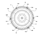
図1および図7、図8などに示すように、オーバーキャップ6は、上蓋5に被せられる覆い部51と、この覆い部51の上部内側から下方に筒状に延びる中筒部52と、この中筒部52からさらに下方に延びて(つまり、中筒部52を介して覆い部51から下方に延びて)弾性変形して上蓋5を保持可能な複数の保持用足部53と、中筒部52から径方向内側に突出して上蓋5の外側凸条部41に嵌合する複数の嵌合部54と、覆い部51の上部内側における中筒部52よりも内周側の箇所から下方に筒状に延びてオーバーキャップ6が上蓋5に被せられた際に、上蓋5の上側壁面部38に外周から嵌合するとともに段部39に上方から当接する内筒部55などが形成されている。なお、この実施の形態では、覆い部51が、平面円板状の天面部51Aと、天面部51Aの外周縁から下方に筒状に延びる外周面部51Bとから構成されており、外周面部51Bの直径が上蓋5や中栓4の直径より大きくなっているが、覆い部51がこのような形状に限られるものではなく、天面部51Aと外周面部51Bとが傾斜面や湾曲面を介してなだらかに接続される形状であってもよい。 As shown in FIGS. 1, 7, and 8, the overcap 6 includes a cover portion 51 that covers the upper lid 5, a middle cylindrical portion 52 that extends cylindrically downward from the upper inner side of the cover portion 51, and a a plurality of holding legs 53 extending further downward from the middle cylinder portion 52 (that is, extending downward from the cover portion 51 via the middle cylinder portion 52) and elastically deforming to hold the upper lid 5; A plurality of fitting portions 54 protruding radially inward from the portion 52 and fitted to the outer protruding streak portion 41 of the upper lid 5 , and downward from a portion on the inner peripheral side of the inner cylinder portion 52 on the inner upper side of the cover portion 51 . An inner cylindrical portion 55 extending in a cylindrical shape is formed so as to be fitted to the upper wall surface portion 38 of the upper lid 5 from the outer periphery and to contact the stepped portion 39 from above when the overcap 6 is put on the upper lid 5 . . In this embodiment, the cover portion 51 is composed of a planar disk-shaped top surface portion 51A and an outer peripheral surface portion 51B that extends cylindrically downward from the outer peripheral edge of the top surface portion 51A. Although the diameter is larger than the diameter of the upper lid 5 and the inner plug 4, the cover portion 51 is not limited to such a shape, and the top surface portion 51A and the outer peripheral surface portion 51B are smoothly formed via an inclined surface and a curved surface. It may be a shape connected to .

また、中筒部52より下方の領域で、周方向の適当角度毎に切欠溝部55が設けられて、これらの切欠溝部55間の部分が保持用足部53とされている。そして、隣り合う保持用足部53同士の間に、切欠溝部55が設けられていることで、保持用足部53は、平面視した状態で径方向に対して弾性変形可能とされている。また、図7、図9、図11などに示すように、保持用足部53の下端部には、径方向内側に突出し、上蓋5に対して下方に移動された際に径方向外側に変形して上蓋5のフランジ部46を乗り越え可能で、フランジ部46を乗り越えるとこのフランジ部46を下方から係止する内側突出部53aが形成されている。 Notch grooves 55 are provided at appropriate angles in the circumferential direction in a region below the middle cylindrical portion 52 , and portions between these notch grooves 55 serve as holding feet 53 . The notch grooves 55 are provided between the adjacent holding leg portions 53, so that the holding leg portions 53 are elastically deformable in the radial direction in plan view. 7, 9, 11, etc., the lower end portion of the holding leg portion 53 protrudes radially inward and deforms radially outward when the upper lid 5 is moved downward. An inner protruding portion 53a is formed so as to be able to climb over the flange portion 46 of the upper lid 5, and to engage the flange portion 46 from below when the flange portion 46 is overcome.

ここで、オーバーキャップ6の嵌合部54は、互いに隣り合う周方向の離間角度が、前記被嵌合部としての外周凹凸条部45が設けられている角度の整数倍の角度で設けられている複数の案内嵌合部54Aと、この案内用嵌合部54Aに対する周方向の離間角度が、外周凹凸条部45が設けられている角度の整数倍の角度とは異なる角度で設けられて外周凹凸条部45に対して周方向に弾性変形しながら嵌合する変形嵌合部54Bと、から構成されている。 Here, the fitting portion 54 of the overcap 6 is provided with an angle of separation in the circumferential direction that is an integral multiple of the angle at which the outer peripheral uneven streak portion 45 as the fitting portion is provided. The plurality of guide fitting portions 54A and the guide fitting portion 54A are separated from each other by an angle different from an integral multiple of the angle at which the outer peripheral uneven streak portion 45 is provided. and a deformation fitting portion 54B that fits into the concave-convex streak portion 45 while being elastically deformed in the circumferential direction.

この実施の形態では、図8に示すように、下方から見て(および上方から平面視して)、案内嵌合部54Aと変形嵌合部54Bとが周方向に60度間隔で交互に設けられている。したがって、互いに隣り合う案内嵌合部54Aの周方向の離間角度(この実施の形態では、120度)が、互いに隣り合う外周凹凸条部45が設けられている角度(この実施の形態では、8度)の整数倍(この実施の形態では、15倍)の角度で設けられている。一方、変形嵌合部54Bは隣り合う案内嵌合部54Aの周方向の離間角度が60度であり、外周凹凸条部45が設けられている角度(この実施の形態では、8度)の整数倍の角度とは異なる角度(この実施の形態では、7.5倍の角度)で設けられている。 In this embodiment, as shown in FIG. 8, when viewed from below (and when viewed from above), guide fitting portions 54A and deformation fitting portions 54B are provided alternately at intervals of 60 degrees in the circumferential direction. It is Therefore, the circumferential separation angle (120 degrees in this embodiment) between the adjacent guide fitting portions 54A is equal to the angle at which the adjacent outer peripheral uneven streaks 45 are provided (8 degrees in this embodiment). degrees) (in this embodiment, 15 times). On the other hand, in the deformed fitting portion 54B, the circumferential separation angle between the adjacent guide fitting portions 54A is 60 degrees, and the angle at which the outer peripheral uneven streak portion 45 is provided (8 degrees in this embodiment) is an integral number. It is provided at an angle different from the double angle (7.5 times the angle in this embodiment).

また、図7、図9、図11、図14~図19などに示すように、オーバーキャップ6の天面部51Aが上方に向くように配置した状態で、案内嵌合部54Aの下端部が、変形嵌合部54Bの下端部よりも下方の位置に形成されている。この実施の形態では、案内嵌合部54Aおよび変形嵌合部54Bの何れもオーバーキャップ6の天面部51Aの下面から中筒部52の内壁面に沿って下方にリブ状に延びるように形成されているが、案内嵌合部54Aは、中筒部52から保持用足部53にかけて上下に延びるように形成されている一方、変形嵌合部54Bは、保持用足部53には形成されず、中筒部52が設けられている上下範囲において上下に延びるように形成されている。なお、案内嵌合部54Aの下端部が、変形嵌合部54Bの下端部よりも下方の位置に形成されていれば、必ずしも、案内嵌合部54Aだけが中筒部52から保持用足部53に形成されていなくてもよい。すなわち、案内嵌合部54Aの下端部が、変形嵌合部54Bの下端部よりも下方の位置に形成されていればよく、案内嵌合部54Aだけでなく変形嵌合部54Bも中筒部52から保持用足部53に形成されていたり、案内嵌合部54Aおよび変形嵌合部54Bの何れも保持用足部53には形成されずに中筒部52のみに形成されていたりしてもよい。また、図12に示すように、変形嵌合部54Bの先端部(下端部)には、先端(下端)ほど周方向に対する厚みが薄くなるように傾斜面56Bが形成されている。また、この実施の形態では、図10に示すように、案内嵌合部54Aの先端部(下端部)にも、先端(下端)ほど周方向に対する厚みが薄くなるように傾斜面56Aが形成されている。なお、傾斜面56A、56Bと先端部との接続部分や、傾斜面56A、56Bと案内嵌合部54Aや変形嵌合部54Bの直線部(傾斜面56A、56Bよりも上方の直線部)との接続部分は、なるべく曲率半径が大きい湾曲形状に形成して滑らかに接続するようにすると好適であるが、これに限るものではない。 7, 9, 11, 14 to 19, etc., in a state in which the top surface portion 51A of the overcap 6 faces upward, the lower end portion of the guide fitting portion 54A is It is formed at a position below the lower end of the deformation fitting portion 54B. In this embodiment, both the guide fitting portion 54A and the deformation fitting portion 54B are formed to extend downward along the inner wall surface of the middle cylindrical portion 52 from the lower surface of the top surface portion 51A of the overcap 6 in a rib shape. However, the guide fitting portion 54A is formed so as to extend vertically from the middle tube portion 52 to the holding leg portion 53, while the deformation fitting portion 54B is not formed in the holding leg portion 53. , is formed so as to extend vertically in the vertical range in which the middle cylindrical portion 52 is provided. Note that if the lower end of the guide fitting portion 54A is formed at a position lower than the lower end of the deformed fitting portion 54B, only the guide fitting portion 54A will necessarily extend from the middle tubular portion 52 to the holding foot portion. 53 may not be formed. That is, it is sufficient that the lower end of the guide fitting portion 54A is formed at a lower position than the lower end of the deformed fitting portion 54B. 52 to the holding foot portion 53, or the guiding fitting portion 54A and the deformation fitting portion 54B are not formed in the holding foot portion 53 but are formed only in the middle tube portion 52. good too. Further, as shown in FIG. 12, an inclined surface 56B is formed at the tip (lower end) of the deformation fitting portion 54B so that the thickness in the circumferential direction decreases toward the tip (lower end). In this embodiment, as shown in FIG. 10, an inclined surface 56A is also formed at the tip (lower end) of the guide fitting portion 54A so that the thickness in the circumferential direction becomes thinner toward the tip (lower end). ing. The connecting portions between the inclined surfaces 56A and 56B and the tip end portions, and the linear portions (the linear portions above the inclined surfaces 56A and 56B) of the inclined surfaces 56A and 56B and the guide fitting portion 54A and the deformation fitting portion 54B are connected with each other. Although it is preferable that the connection portion of is formed in a curved shape having a radius of curvature as large as possible so as to be smoothly connected, it is not limited to this.

また、上蓋5にオーバーキャップ6を組み付ける際には、オーバーキャップ6を上蓋5に対して周方向に直交する軸心方向X(図14参照)に沿って打栓させる(例えば、上蓋5の上方からオーバーキャップ6を移動させて打栓させる)ことにより組み付けるが、この打栓時に、オーバーキャップ6の案内嵌合部54Aが上蓋5の外周凹凸条部(被嵌合部)45に嵌合した(図15参照)後に、変形嵌合部54Bが被嵌合部に嵌合する(図16、図17参照)ように構成されている。 When the overcap 6 is attached to the top lid 5, the overcap 6 is plugged along the axial direction X (see FIG. 14) perpendicular to the circumferential direction of the top lid 5 (for example, above the top lid 5). During this plugging, the guide fitting portion 54A of the overcap 6 was fitted to the outer peripheral uneven streak portion (to-be-fitted portion) 45 of the upper lid 5. (See FIG. 15), the deformation fitting portion 54B is configured to be fitted to the fitted portion (see FIGS. 16 and 17).

次に、上記構成における、キャップ1における中栓4と上蓋5とオーバーキャップ6との組み付け手順などを含む作用を説明する。
まず、キャップ1における中栓4と上蓋5との組み付け手順について説明する。中栓4と上蓋5とを個別に製作した後、離脱部12が中栓本体部10に設けられている未使用状態において、図13に示すように、中栓4に対して上蓋5を下方に移動して(すなわち、キャップ1の軸心方向Xに沿って互いに組み合わせる方向に移動して)、中栓4に上蓋5を取り付ける。なお、この際には、中栓4の内部に治具(図示省略)を嵌め込み、上蓋5を中栓4の上方から下向きに打栓する(打ち込む)。
Next, the operation including the procedure for assembling the inner plug 4, the upper lid 5 and the overcap 6 in the cap 1 in the above configuration will be described.
First, the procedure for assembling the inner plug 4 and the upper lid 5 in the cap 1 will be described. After the inner plug 4 and the upper lid 5 are separately manufactured, the upper lid 5 is downwardly attached to the inner plug 4 as shown in FIG. (that is, move in the direction of combining with each other along the axial direction X of the cap 1) to attach the upper lid 5 to the inner stopper 4. As shown in FIG. At this time, a jig (not shown) is fitted inside the inner plug 4 , and the upper lid 5 is driven downward from above the inner plug 4 .

これにより、図14の下方領域において、中栓4と上蓋5とを組み付けた状態を示すように(但し、図14は、これより後のオーバーキャップ6の組み付け状態を示す)、上蓋5のノズル密閉用筒部43が中栓4のノズル部16における上部内側に挿入されるとともに、上蓋5の天板部37が離脱部12の上端面(離脱筒状部22の上端部)に当接する。また、上蓋5のねじ部31が中栓4のねじ部20を乗り越えるとともに、離脱筒状部22が上蓋5の離脱用内筒部32と離脱用外筒部34との間に入り込んで離脱部12が保持され、離脱筒状部22の先端部に設けられた凹状部26に上蓋5の離脱用外筒部34の基部に設けられた凸状部36が嵌め込まれる。また、上蓋5の離脱用内筒突条リブ33が中栓4の離脱内側突条リブ25間に挿入されるとともに、上蓋5の離脱用外筒突条リブ35が中栓4の離脱外側突条リブ24間に挿入され、このような状態で、上蓋5が中栓4に取り付けられる。 As a result, in the lower region of FIG. 14, the nozzle of the upper lid 5 is opened so as to show the assembled state of the inner plug 4 and the upper lid 5 (however, FIG. 14 shows the assembled state of the overcap 6 after this). The sealing cylinder part 43 is inserted inside the upper part of the nozzle part 16 of the inner plug 4, and the top plate part 37 of the upper lid 5 contacts the upper end surface of the detachable part 12 (the upper end of the detachable cylindrical part 22). In addition, the threaded portion 31 of the upper lid 5 climbs over the threaded portion 20 of the inner plug 4, and the detachable cylindrical portion 22 enters between the detachable inner cylindrical portion 32 and the detachable outer cylindrical portion 34 of the top lid 5, thereby 12 is held, and the convex portion 36 provided at the base portion of the detachable outer cylindrical portion 34 of the upper lid 5 is fitted into the concave portion 26 provided at the distal end portion of the detachable cylindrical portion 22 . In addition, the detachable inner cylinder protrusion rib 33 of the upper lid 5 is inserted between the detachable inner cylinder protrusion ribs 25 of the inner plug 4 , and the detachment outer cylinder protrusion rib 35 of the upper lid 5 is inserted into the detachment outer cylinder protrusion of the inner plug 4 . It is inserted between the row ribs 24, and the upper lid 5 is attached to the inner plug 4 in this state.

なお、この際には、図1や図14の下方領域に示すように、上蓋5の天板部36が離脱部12の上端面に当接し、また、上蓋円筒部42の下端部が中栓4の上面部15に当接するため、上蓋5の離脱用内筒突条リブ33が中栓4の離脱内側突条リブ25間に過剰に挿入されたり、上蓋5の離脱用外筒突条リブ35が中栓4の離脱外側突条リブ24間に過剰に挿入されたりすることはなく、離脱用内筒突条リブ33や離脱用外筒突条リブ35の先端が弱化部11に当接して破断させてしまうことはない。 At this time, as shown in the lower region of FIGS. 1 and 14, the top plate portion 36 of the upper lid 5 abuts against the upper end surface of the detachable portion 12, and the lower end portion of the upper lid cylindrical portion 42 is positioned at the inner plug. 4, the detachable inner cylinder rib 33 of the top lid 5 is excessively inserted between the detachable inner cylinder ribs 25 of the inner plug 4, or the detachable outer cylinder rib 33 of the top lid 5 is inserted excessively. 35 is not excessively inserted between the detachable outer ribs 24 of the inner plug 4, and the tips of the detachable inner cylinder rib 33 and the detachable outer cylinder rib 35 abut on the weakened portion 11. It will not break.

次に、上蓋5が取り付けられた中栓4を打栓して容器2の口部3に取り付けた後、図14に示すように、中栓4が組み付けられている上蓋5に対してオーバーキャップ6を下方に移動して(すなわち、キャップ1の軸心方向Xに沿って上蓋5とオーバーキャップ6とを互いに組み合わせる方向に移動して)、上蓋5にオーバーキャップ6を取り付ける。なお、この際には、オーバーキャップ6を上蓋5の上方から下向きに打栓する(打ち込む)。 Next, after the inner plug 4 to which the upper lid 5 is attached is capped and attached to the mouth portion 3 of the container 2, as shown in FIG. The overcap 6 is attached to the top lid 5 by moving the top lid 5 and the overcap 6 downward (that is, moving along the axial direction X of the cap 1 in the direction in which the top lid 5 and the overcap 6 are combined with each other). At this time, the overcap 6 is plugged (driven) downward from above the upper lid 5 .

これにより、図15に示すように、まず、オーバーキャップ6の案内嵌合部54Aの先端部に形成された傾斜面56Aが上蓋5の外周凹凸条部(被嵌合部)45に接触するなどして、上蓋5とオーバーキャップ6との互いの周方向の相対位置が決められながら(案内されながら)、オーバーキャップ6の案内嵌合部54Aが上蓋5の外周凹凸条部(被嵌合部)45間に挿入されながら嵌合する。また、オーバーキャップ6を上蓋5の上方から下向きにさらに打栓する(打ち込む)と、図16に示すように、オーバーキャップ6の変形嵌合部54Bの先端部に形成された傾斜面56Bが上蓋5の外周凹凸条部(被嵌合部)45に接触するなどしながら、オーバーキャップ6の変形嵌合部54Bが上蓋5の外周凹凸条部(被嵌合部)45間に挿入されながら嵌合する。そして、オーバーキャップ6を上蓋5の上方から下向きにさらに打栓する(打ち込む)と、図17、図18に示すように、オーバーキャップ6の保持用足部53に形成した内側突出部53aが上蓋5のフランジ部46を乗り越え、フランジ部46を下方から係止する。 As a result, as shown in FIG. 15, first, the inclined surface 56A formed at the tip of the guide fitting portion 54A of the overcap 6 comes into contact with the outer peripheral uneven streak (fitted portion) 45 of the upper lid 5, and so on. Then, while the relative positions of the upper lid 5 and the overcap 6 in the circumferential direction are determined (while being guided), the guide fitting portion 54A of the overcap 6 is aligned with the outer peripheral uneven streak portion (fitted portion) of the upper lid 5. ) 45 and fit together. Further, when the overcap 6 is further pushed downward from above the upper lid 5, as shown in FIG. 5, the deformed fitting portion 54B of the overcap 6 is inserted between the outer peripheral uneven streaks (fitted portion) 45 of the upper lid 5 and fitted. match. When the overcap 6 is further pushed downward from above the upper lid 5, as shown in FIGS. 5, and locks the flange portion 46 from below.

すなわち、図14、図15に示すように、上蓋5に対してオーバーキャップ6を打栓させて組み付ける際、第1段階では、互いに隣り合う案内嵌合部54A間の周方向の離間角度(いわゆる周方向ピッチ)が、被嵌合部である外周凹凸条部45が設けられている角度(外周凹凸条部45の周方向ピッチ)の整数倍の角度で設けられている案内嵌合部54Aだけが外周凹凸条部(被嵌合部)45に嵌り込む(図20参照)ので、この際の摩擦力を最小限に抑えることができて比較的小さな力で打栓できる。 That is, as shown in FIGS. 14 and 15, when the overcap 6 is plugged and assembled to the upper lid 5, in the first stage, the circumferential separation angle between the adjacent guide fitting portions 54A (so-called Only the guide fitting portion 54A provided at an angle (circumferential direction pitch of the outer peripheral uneven streak portion 45) provided at an integral multiple of the angle (circumferential direction pitch of the outer peripheral uneven streak portion 45) at which the outer peripheral uneven streak portion 45, which is the fitted portion, is provided. is fitted into the outer peripheral uneven streak portion (to-be-fitted portion) 45 (see FIG. 20), the frictional force at this time can be minimized, and the plug can be plugged with a relatively small force.

また、オーバーキャップ6の変形嵌合部54Bは、案内用嵌合部54Aに対する離間角度が、被嵌合部である外周凹凸条部45が設けられている角度(外周凹凸条部45の周方向ピッチ)の整数倍の角度とは異なる角度で設けられているが、この変形嵌合部54Bが上蓋5の被嵌合部である外周凹凸条部45に嵌合する際には、既に案内嵌合部54Aが外周凹凸条部45に嵌合してオーバーキャップ6と上蓋5とが互いに周方向に移動できない状態に保持されている(位置決めされている)ので、打栓力の増加を最小限に抑えた状態でも、上蓋5の外周凹凸条部(被嵌合部)45に変形嵌合部54Bをキャップ1の周方向に変形させながら嵌め込むことができて(図16、図17、図20参照)、打栓時に必要な力を低めに抑えることが可能となる。また、オーバーキャップ6の変形嵌合部54Bは上蓋5の外周凹凸条部(被嵌合部)45に弾性変形して比較的大きな力で噛み込んだ状態で嵌合しているので、オーバーキャップ6により上蓋5を脱落しない状態で良好に保持できる。 In addition, the deformation fitting portion 54B of the overcap 6 is separated from the guiding fitting portion 54A by an angle at which the outer circumferential uneven streak portion 45, which is the fitted portion, is provided (the circumferential direction of the outer circumferential uneven streak portion 45). However, when the deformed fitting portion 54B is fitted to the outer peripheral uneven streak portion 45, which is the fitted portion of the upper lid 5, the guide fitting is already performed. Since the joining portion 54A is fitted to the outer peripheral uneven streak portion 45 and the overcap 6 and the upper lid 5 are held (positioned) in a state in which they cannot move in the circumferential direction relative to each other, an increase in the plugging force is minimized. 16, 17, and 17, the deformed fitting portion 54B can be fitted into the outer peripheral uneven streak portion (fitted portion) 45 of the upper lid 5 while deforming it in the circumferential direction of the cap 1. 20), it is possible to keep the force required at the time of plugging low. In addition, since the deformed fitting portion 54B of the overcap 6 is fitted to the outer peripheral uneven strip portion (to-be-fitted portion) 45 of the upper lid 5 in a state of being elastically deformed and engaged with a relatively large force, With 6, the upper lid 5 can be well held without falling off.

また、最終的には、オーバーキャップ6の保持用足部53に形成した内側突出部53aが上蓋5のフランジ部46を乗り越え、フランジ部46を下方から係止するので、オーバーキャップ6の保持用足部53によっても上蓋5を脱落しない良好な状態で保持できる。なお、この実施の形態では、上蓋5のフランジ部46に傾斜面46aが形成されているとともに、オーバーキャップ6の内側突出部53aの下部に傾斜面が形成されており、これによっても、オーバーキャップ6の内側突出部53aが上蓋5のフランジ部46を良好に乗り越えることができるよう図られている。 Finally, the inner protruding portion 53a formed on the holding leg portion 53 of the overcap 6 climbs over the flange portion 46 of the upper lid 5 and locks the flange portion 46 from below. The foot part 53 can also hold the upper lid 5 in a good condition so that it does not come off. In this embodiment, an inclined surface 46a is formed on the flange portion 46 of the upper lid 5, and an inclined surface is formed on the lower portion of the inner projecting portion 53a of the overcap 6. 6 is designed so that the inner protruding portion 53a of the upper lid 5 can satisfactorily climb over the flange portion 46 of the upper lid 5. As shown in FIG.

そして、この状態で、オーバーキャップ6を軸心周りに回転させる(この実施の形態では、平面視して上蓋5に対してオーバーキャップ6を反時計回りに回転させる)と、オーバーキャップ6の嵌合部54である案内用嵌合部54Aおよび変形嵌合部54Bが上蓋5の外周凹凸条部(被嵌合部)45に当接して、オーバーキャップ6とともに上蓋5も一体回転され、また、上蓋5の離脱用内筒突条リブ33および離脱用外筒突条リブ35が中栓4の離脱内側突条リブ25および離脱外側突条リブ24に当接して、上蓋5とともに中栓4の離脱部12も一体回転される。これにより、中栓4の弱化部11を切断させて中栓本体部10から離脱部12を離脱させることができて、中栓4に注出口29(図19参照)を形成できる。この際、直径の大きなオーバーキャップ6を回転させるので、開封時に必要な回転力を小さく済ませることができる。すなわち、弱化部11の切断距離、ひいては注出口29(図19参照)の開口面積が比較的大きい場合でも、大きな力を加えなくても切断することができて便利である。 Then, in this state, when the overcap 6 is rotated around the axis (in this embodiment, the overcap 6 is rotated counterclockwise with respect to the upper lid 5 in plan view), the overcap 6 is fitted. The fitting portion 54A for guiding and the deformed fitting portion 54B, which are the joining portions 54, abut against the outer peripheral concave-convex strip portion (to-be-fitted portion) 45 of the upper lid 5, and the upper lid 5 is integrally rotated together with the overcap 6. The detachable inner cylinder rib 33 and the detachable outer cylinder rib 35 of the upper lid 5 come into contact with the detachable inner cylinder rib 25 and the detachable outer cylinder rib 24 of the inner plug 4 , and the inner plug 4 is removed together with the upper lid 5 . The detachment part 12 is also integrally rotated. As a result, the weakened portion 11 of the inner plug 4 can be cut to separate the detachable portion 12 from the inner plug main body 10, thereby forming the spout 29 (see FIG. 19) in the inner plug 4. As shown in FIG. At this time, since the overcap 6 having a large diameter is rotated, the rotational force required for opening can be reduced. That is, even when the cut distance of the weakened portion 11 and thus the opening area of the spout 29 (see FIG. 19) is relatively large, the cut can be conveniently performed without applying a large force.

また、上記構成においては、変形嵌合部54Bの先端部に、先端ほど周方向寸法が小さくなるように傾斜面56Bが形成されているので、これにより、打栓時に変形嵌合部54Bを比較的なめらかに、上蓋5の外周凹凸条部(被嵌合部)45間に周方向に弾性変形させながら挿入させる(嵌り込ませる)ことができ、これによっても、オーバーキャップ6を上蓋5に打栓させるなどして組み付ける場合に必要な力を低めに抑えることが可能となる。 In the above configuration, the inclined surface 56B is formed at the distal end of the deformable fitting portion 54B so that the circumferential dimension decreases toward the distal end. The overcap 6 can be smoothly inserted (fitted) between the outer peripheral uneven streaks (to-be-fitted portion) 45 of the upper lid 5 while being elastically deformed in the circumferential direction. It is possible to reduce the force required when assembling by plugging or the like.

また、上記構成においては、案内用嵌合部54Aの先端部にも、先端ほど周方向寸法が小さくなるように傾斜面56Aが形成されているので、これにより、打栓時に案内用嵌合部54Aをなめらかに上蓋5の外周凹凸条部(被嵌合部)45間に挿入させる(嵌り込ませる)ことができ、これによっても、オーバーキャップ6を上蓋5に打栓させるなどして組み付ける場合に必要な力を低めに抑えることが可能となる。 In addition, in the above configuration, the tip of the guide fitting portion 54A is also formed with the inclined surface 56A so that the circumferential dimension becomes smaller toward the tip. 54A can be smoothly inserted (fitted) between the outer peripheral uneven streaks (fitted portion) 45 of the upper lid 5, and this also allows the overcap 6 to be attached to the upper lid 5 by plugging. It is possible to keep the force required for

このように、打栓する際の力を最小限に抑えても、良好に上蓋5を保持できるので、打栓工程での信頼性を向上させることができる。 In this way, the top lid 5 can be held well even if the force for capping is kept to a minimum, so reliability in the capping process can be improved.

また、上記実施の形態においては、覆い部51から下方に延びて径方向に弾性変形して、上蓋5を保持可能な保持用足部53が設けられている。したがって、オーバーキャップ6を上蓋5に被せることで、保持用足部53によっても上蓋5を保持することができ、より確実にオーバーキャップ6によって上蓋5を保持することができ、キャップ1としての信頼性をさらに向上させることができる。 Further, in the above-described embodiment, the holding leg portion 53 extending downward from the cover portion 51 and elastically deforming in the radial direction to hold the upper lid 5 is provided. Therefore, by covering the top lid 5 with the overcap 6, the top lid 5 can be held by the holding leg portion 53, and the top lid 5 can be held more reliably by the overcap 6, thereby increasing the reliability of the cap 1. It is possible to further improve the performance.

なお、上記実施の形態では、被嵌合部としての外周凹凸条部45が周方向に8度毎に設けられ、案内用嵌合部54Aと変形嵌合部54Bとが互いに周方向に60度毎に設けられている場合を述べたが、これに限るものではなく、被嵌合部としての外周凹凸条部45が周方向に8度よりも小さい角度や大きい角度毎に設けられ、嵌合部54が、互いに隣り合う周方向の離間角度が、前記被嵌合部が設けられている角度の整数倍の角度で設けられている複数の案内嵌合部54Aと、この案内用嵌合部54Aに対する周方向の離間角度が、前記被嵌合部が設けられている角度の整数倍の角度とは異なる角度で設けられて被嵌合部としての外周凹凸条部45に対して周方向に弾性変形しながら嵌合する変形嵌合部54Bと、を有する構成であればよい。 It should be noted that, in the above-described embodiment, the outer circumferential concave-convex strip 45 as a fitted portion is provided at every 8 degrees in the circumferential direction, and the guiding fitting portion 54A and the deformation fitting portion 54B are arranged at 60 degrees in the circumferential direction. Although the case where it is provided at every interval has been described, it is not limited to this. A plurality of guide fitting portions 54A in which the adjacent portions 54 are separated from each other in the circumferential direction at an angle that is an integral multiple of the angle at which the fitted portion is provided, and the guide fitting portion 54A. 54A is provided at an angle different from an integral multiple of the angle at which the fitted portion is provided, and is circumferentially spaced from the outer circumferential uneven streak portion 45 as the fitted portion. A configuration having a deformation fitting portion 54B that fits while being elastically deformed may be used.

また、上記実施の形態では、オーバーキャップ6の覆い部51に上面部分が平坦な天面部51Aが設けられているため、当該キャップ1を開けて上蓋5およびオーバーキャップ6を容器2から取り外した際に、オーバーキャップ6を安定してテーブルなどに置くことができる利点がある。しかしながら、これに限るものではなく、覆い部51の上面部分を半球形状に形成するなどしても差し支えない。 In the above-described embodiment, since the cover portion 51 of the overcap 6 is provided with the top surface portion 51A having a flat upper surface portion, when the cap 1 is opened and the top lid 5 and the overcap 6 are removed from the container 2, Another advantage is that the overcap 6 can be stably placed on a table or the like. However, the shape is not limited to this, and the upper surface portion of the cover portion 51 may be formed in a hemispherical shape.

また、上記実施の形態では、中筒部52および保持用足部53が設けられている箇所に案内用嵌合部54Aや変形嵌合部54Bが設けられている場合を示したが、これに限るものではなく、中筒部52や、保持用足部53や案内用嵌合部54A、変形嵌合部54Bを別個に設けるように構成してもよい。 Further, in the above-described embodiment, the case where the guide fitting portion 54A and the deformation fitting portion 54B are provided at the location where the middle tubular portion 52 and the holding foot portion 53 are provided has been described. The configuration is not limited to this, and the middle tube portion 52, the holding foot portion 53, the guide fitting portion 54A, and the deformation fitting portion 54B may be provided separately.

また、上記実施の形態では、上蓋5に被嵌合部としての外周凹凸条部45を設け、オーバーキャップ6に嵌合部としての案内用嵌合部54Aや変形嵌合部54Bを設けた場合を述べたが、これとは逆に、オーバーキャップ6に被嵌合部としての凹凸条部を設け、上蓋5に嵌合部としての案内用嵌合部や変形嵌合部を設けてもよい。 Further, in the above-described embodiment, the upper cover 5 is provided with the outer circumferential concave-convex strip portion 45 as the fitted portion, and the overcap 6 is provided with the guide fitting portion 54A and the deformation fitting portion 54B as fitting portions. However, on the contrary, the overcap 6 may be provided with an uneven streak portion as a fitted portion, and the upper lid 5 may be provided with a guide fitting portion or a deformed fitting portion as a fitting portion. .

1 キャップ
2 容器
3 口部
4 中栓
5 上蓋
6 オーバーキャップ
10 中栓本体部
11 弱化部
12 離脱部
16 ノズル部
20、31 ねじ部
33 離脱用内筒突条リブ(回転係合部)
35 離脱用外筒突条リブ(回転係合部)
45 外周凹凸条部(被嵌合部)
51 覆い部
53 保持用足部
54 嵌合部
54A 案内嵌合部
54B 変形嵌合部
56A、56B 傾斜面
REFERENCE SIGNS LIST 1 cap 2 container 3 mouth 4 inner stopper 5 upper lid 6 overcap 10 inner stopper main body 11 weakened portion 12 detachment portion 16 nozzle portion 20, 31 screw portion 33 detachment inner cylinder protrusion rib (rotational engagement portion)
35 Detachment outer cylinder ridge rib (rotational engagement portion)
45 Peripheral uneven streak portion (to-be-fitted portion)
51 cover portion 53 holding leg portion 54 fitting portion 54A guide fitting portion 54B deformation fitting portion 56A, 56B inclined surface

Claims (5)

容器の口部に取り付けられる中栓と、回転することにより中栓に着脱自在な上蓋と、この上蓋に嵌合した状態で被せられて一体的に回転可能なオーバーキャップと、を備え、
中栓は、中栓本体部と、弱化部を介して中栓本体部から離脱可能に設けられた離脱部とを有し、
上蓋に、上蓋が回転された際に中栓の離脱部に係合して離脱部を中栓本体部から離脱させる回転係合部が設けられているキャップであって、
上蓋とオーバーキャップとには、互いに嵌合可能な被嵌合部と嵌合部とが設けられ、
前記被嵌合部は、上蓋の外周またはオーバーキャップの内周に、周方向に対して所定の角度毎に凹凸形状に形成され、
前記嵌合部は、互いに隣り合う周方向の離間角度が、前記被嵌合部が設けられている角度の整数倍の角度で設けられている複数の案内嵌合部と、この案内嵌合部に対する周方向の離間角度が、前記被嵌合部が設けられている角度の整数倍の角度とは異なる角度で設けられて前記被嵌合部に対して周方向に弾性変形しながら嵌合する変形嵌合部と、を有する
ことを特徴とするキャップ。
An inner plug attached to the mouth of the container, an upper lid detachably attachable to the inner stopper by rotating, and an overcap that is fitted to and integrally rotatable with the upper lid,
The internal plug has an internal plug main body and a detachable section provided to be detachable from the internal plug main body through the weakened section,
A cap provided with a rotating engaging portion that engages with the detachable portion of the inner plug to detach the detaching portion from the inner plug main body when the top lid is rotated, wherein
The upper lid and the overcap are provided with a to-be-fitted portion and a fitting portion that can be fitted to each other,
The fitted portion is formed on the outer circumference of the upper lid or the inner circumference of the overcap in an uneven shape at every predetermined angle with respect to the circumferential direction,
The fitting portions include a plurality of guide fitting portions each provided with a spacing angle in the circumferential direction that is an integral multiple of the angle at which the to-be-fitted portions are provided; is provided at an angle different from an integral multiple of the angle at which the fitted portion is provided, and the fitted portion is fitted while being elastically deformed in the circumferential direction with respect to the fitted portion. and a deformable fitting portion for fitting.
前記被嵌合部は上蓋に形成され、
前記嵌合部はオーバーキャップに形成され、
オーバーキャップの天面部が上方に向くように配置した状態で、前記案内嵌合部の下端部が、前記変形嵌合部の下端部よりも下方の位置に形成されていることを特徴とする請求項1に記載のキャップ。
The fitted portion is formed on the upper lid,
The fitting portion is formed in the overcap,
A lower end of the guide fitting portion is formed at a position lower than a lower end of the deformation fitting portion in a state in which the top surface of the overcap faces upward. Item 1. The cap according to item 1.
前記嵌合部および前記被嵌合部は、上蓋およびオーバーキャップにおいて周方向に直交する直線方向に沿って延びる形状に形成され、
前記変形嵌合部の先端部に、先端ほど周方向寸法が小さくなるように傾斜面が形成されていることを特徴とする請求項1または2に記載のキャップ。
The fitting portion and the fitted portion are formed in a shape extending along a linear direction orthogonal to the circumferential direction in the upper lid and the overcap,
3. The cap according to claim 1 or 2, wherein an inclined surface is formed at the distal end of said deformable fitting portion so that the dimension in the circumferential direction becomes smaller toward the distal end.
オーバーキャップに、上蓋に被せる覆い部と、この覆い部から下方に延びて径方向に弾性変形して、上蓋を保持可能な保持用足部が設けられていることを特徴とする請求項1~3の何れか1項に記載のキャップ。 The overcap is provided with a covering portion that covers the upper lid, and a holding foot portion that extends downward from the covering portion and elastically deforms in a radial direction to hold the upper lid. 4. The cap according to any one of 3. 前記請求項1~4の何れか1項に記載のキャップの、上蓋に対してオーバーキャップを組み付けるキャップの組付け方法であって、
オーバーキャップを上蓋に対して周方向に直交する軸心方向に沿って打栓させることにより組み付け、
打栓時に、案内嵌合部が被嵌合部に嵌合した後に、変形嵌合部が被嵌合部に嵌合するように構成されていることを特徴とするキャップの組付け方法。
A cap assembly method for assembling an overcap to an upper lid of the cap according to any one of claims 1 to 4,
Assemble by plugging the overcap along the axial direction orthogonal to the circumferential direction with respect to the upper lid,
A method of assembling a cap, characterized in that the deformable fitting portion is fitted to the fitted portion after the guide fitting portion is fitted to the fitted portion during capping.
JP2018193004A 2018-10-12 2018-10-12 cap Active JP7158013B2 (en)

Priority Applications (1)

Application Number Priority Date Filing Date Title
JP2018193004A JP7158013B2 (en) 2018-10-12 2018-10-12 cap

Applications Claiming Priority (1)

Application Number Priority Date Filing Date Title
JP2018193004A JP7158013B2 (en) 2018-10-12 2018-10-12 cap

Publications (3)

Publication Number Publication Date
JP2020059538A JP2020059538A (en) 2020-04-16
JP2020059538A5 JP2020059538A5 (en) 2020-08-06
JP7158013B2 true JP7158013B2 (en) 2022-10-21

Family

ID=70218730

Family Applications (1)

Application Number Title Priority Date Filing Date
JP2018193004A Active JP7158013B2 (en) 2018-10-12 2018-10-12 cap

Country Status (1)

Country Link
JP (1) JP7158013B2 (en)

Families Citing this family (1)

* Cited by examiner, † Cited by third party
Publication number Priority date Publication date Assignee Title
JP7341618B2 (en) 2020-05-28 2023-09-11 株式会社吉野工業所 Uncork cap

Citations (3)

* Cited by examiner, † Cited by third party
Publication number Priority date Publication date Assignee Title
US5863145A (en) 1994-05-10 1999-01-26 Georg Karl Geka-Brush Gmbh Container with a screwed cap for nail varnish, liquid mascara or the like
JP2012126402A (en) 2010-12-13 2012-07-05 Mikasa Sangyo Kk Cap of container
JP2018193088A (en) 2017-05-17 2018-12-06 三笠産業株式会社 cap

Family Cites Families (2)

* Cited by examiner, † Cited by third party
Publication number Priority date Publication date Assignee Title
JP4021461B1 (en) * 2006-09-04 2007-12-12 株式会社ファンケル Cap with opening mechanism and bottle container attached with the cap
JP6444072B2 (en) * 2014-06-24 2018-12-26 三笠産業株式会社 cap

Patent Citations (3)

* Cited by examiner, † Cited by third party
Publication number Priority date Publication date Assignee Title
US5863145A (en) 1994-05-10 1999-01-26 Georg Karl Geka-Brush Gmbh Container with a screwed cap for nail varnish, liquid mascara or the like
JP2012126402A (en) 2010-12-13 2012-07-05 Mikasa Sangyo Kk Cap of container
JP2018193088A (en) 2017-05-17 2018-12-06 三笠産業株式会社 cap

Also Published As

Publication number Publication date
JP2020059538A (en) 2020-04-16

Similar Documents

Publication Publication Date Title
US11718457B2 (en) Closure assembly
US10518948B2 (en) Perforating cap, particularly for a flexible tube
US11827422B2 (en) Cap for a container, and method for producing a cap
US20210171249A1 (en) Safety-cap bottle assembly
JP6410652B2 (en) Hinge cap with inner plug
JP6084113B2 (en) Container with inner stopper
JP7158013B2 (en) cap
JP4902820B1 (en) Container cap structure
JP4588463B2 (en) Capping dental liquid container
JP6986733B2 (en) cap
JP2017190172A (en) Cap and assembly method thereof
JP7116970B2 (en) cap
EP1518525B1 (en) A droplet nozzle for use in eye drop container
JP5823271B2 (en) container
JP6057848B2 (en) Unplug cap
CN110023200B (en) Cap for container
US20070012645A1 (en) Child-resistant closure, package and method of making
JP5411750B2 (en) cap
JP7474467B2 (en) cap
JP2002332056A (en) Synthetic resin composite vessel lid with excellent impact resistance
JP7365666B2 (en) cap
JP7183038B2 (en) container
JP7330861B2 (en) Caps and containers with caps
JP6466052B2 (en) Container with cap
JP5184191B2 (en) Bottle cap

Legal Events

Date Code Title Description
A521 Request for written amendment filed

Free format text: JAPANESE INTERMEDIATE CODE: A523

Effective date: 20200624

A621 Written request for application examination

Free format text: JAPANESE INTERMEDIATE CODE: A621

Effective date: 20211004

A977 Report on retrieval

Free format text: JAPANESE INTERMEDIATE CODE: A971007

Effective date: 20220829

TRDD Decision of grant or rejection written
A01 Written decision to grant a patent or to grant a registration (utility model)

Free format text: JAPANESE INTERMEDIATE CODE: A01

Effective date: 20220906

A61 First payment of annual fees (during grant procedure)

Free format text: JAPANESE INTERMEDIATE CODE: A61

Effective date: 20221003

R150 Certificate of patent or registration of utility model

Ref document number: 7158013

Country of ref document: JP

Free format text: JAPANESE INTERMEDIATE CODE: R150