JP7151663B2 - High-pressure vessel mounting structure - Google Patents
High-pressure vessel mounting structure Download PDFInfo
- Publication number
- JP7151663B2 JP7151663B2 JP2019148012A JP2019148012A JP7151663B2 JP 7151663 B2 JP7151663 B2 JP 7151663B2 JP 2019148012 A JP2019148012 A JP 2019148012A JP 2019148012 A JP2019148012 A JP 2019148012A JP 7151663 B2 JP7151663 B2 JP 7151663B2
- Authority
- JP
- Japan
- Prior art keywords
- vehicle
- width direction
- flow path
- exhaust gas
- fusible plug
- Prior art date
- Legal status (The legal status is an assumption and is not a legal conclusion. Google has not performed a legal analysis and makes no representation as to the accuracy of the status listed.)
- Active
Links
Images

Classifications
-
- F—MECHANICAL ENGINEERING; LIGHTING; HEATING; WEAPONS; BLASTING
- F17—STORING OR DISTRIBUTING GASES OR LIQUIDS
- F17C—VESSELS FOR CONTAINING OR STORING COMPRESSED, LIQUEFIED OR SOLIDIFIED GASES; FIXED-CAPACITY GAS-HOLDERS; FILLING VESSELS WITH, OR DISCHARGING FROM VESSELS, COMPRESSED, LIQUEFIED, OR SOLIDIFIED GASES
- F17C7/00—Methods or apparatus for discharging liquefied, solidified, or compressed gases from pressure vessels, not covered by another subclass
-
- H—ELECTRICITY
- H01—ELECTRIC ELEMENTS
- H01M—PROCESSES OR MEANS, e.g. BATTERIES, FOR THE DIRECT CONVERSION OF CHEMICAL ENERGY INTO ELECTRICAL ENERGY
- H01M8/00—Fuel cells; Manufacture thereof
- H01M8/04—Auxiliary arrangements, e.g. for control of pressure or for circulation of fluids
- H01M8/04082—Arrangements for control of reactant parameters, e.g. pressure or concentration
- H01M8/04201—Reactant storage and supply, e.g. means for feeding, pipes
-
- B—PERFORMING OPERATIONS; TRANSPORTING
- B60—VEHICLES IN GENERAL
- B60K—ARRANGEMENT OR MOUNTING OF PROPULSION UNITS OR OF TRANSMISSIONS IN VEHICLES; ARRANGEMENT OR MOUNTING OF PLURAL DIVERSE PRIME-MOVERS IN VEHICLES; AUXILIARY DRIVES FOR VEHICLES; INSTRUMENTATION OR DASHBOARDS FOR VEHICLES; ARRANGEMENTS IN CONNECTION WITH COOLING, AIR INTAKE, GAS EXHAUST OR FUEL SUPPLY OF PROPULSION UNITS IN VEHICLES
- B60K15/00—Arrangement in connection with fuel supply of combustion engines or other fuel consuming energy converters, e.g. fuel cells; Mounting or construction of fuel tanks
- B60K15/03—Fuel tanks
- B60K15/03006—Gas tanks
-
- B—PERFORMING OPERATIONS; TRANSPORTING
- B60—VEHICLES IN GENERAL
- B60L—PROPULSION OF ELECTRICALLY-PROPELLED VEHICLES; SUPPLYING ELECTRIC POWER FOR AUXILIARY EQUIPMENT OF ELECTRICALLY-PROPELLED VEHICLES; ELECTRODYNAMIC BRAKE SYSTEMS FOR VEHICLES IN GENERAL; MAGNETIC SUSPENSION OR LEVITATION FOR VEHICLES; MONITORING OPERATING VARIABLES OF ELECTRICALLY-PROPELLED VEHICLES; ELECTRIC SAFETY DEVICES FOR ELECTRICALLY-PROPELLED VEHICLES
- B60L3/00—Electric devices on electrically-propelled vehicles for safety purposes; Monitoring operating variables, e.g. speed, deceleration or energy consumption
- B60L3/0007—Measures or means for preventing or attenuating collisions
-
- B—PERFORMING OPERATIONS; TRANSPORTING
- B60—VEHICLES IN GENERAL
- B60L—PROPULSION OF ELECTRICALLY-PROPELLED VEHICLES; SUPPLYING ELECTRIC POWER FOR AUXILIARY EQUIPMENT OF ELECTRICALLY-PROPELLED VEHICLES; ELECTRODYNAMIC BRAKE SYSTEMS FOR VEHICLES IN GENERAL; MAGNETIC SUSPENSION OR LEVITATION FOR VEHICLES; MONITORING OPERATING VARIABLES OF ELECTRICALLY-PROPELLED VEHICLES; ELECTRIC SAFETY DEVICES FOR ELECTRICALLY-PROPELLED VEHICLES
- B60L3/00—Electric devices on electrically-propelled vehicles for safety purposes; Monitoring operating variables, e.g. speed, deceleration or energy consumption
- B60L3/0023—Detecting, eliminating, remedying or compensating for drive train abnormalities, e.g. failures within the drive train
- B60L3/0053—Detecting, eliminating, remedying or compensating for drive train abnormalities, e.g. failures within the drive train relating to fuel cells
-
- B—PERFORMING OPERATIONS; TRANSPORTING
- B60—VEHICLES IN GENERAL
- B60L—PROPULSION OF ELECTRICALLY-PROPELLED VEHICLES; SUPPLYING ELECTRIC POWER FOR AUXILIARY EQUIPMENT OF ELECTRICALLY-PROPELLED VEHICLES; ELECTRODYNAMIC BRAKE SYSTEMS FOR VEHICLES IN GENERAL; MAGNETIC SUSPENSION OR LEVITATION FOR VEHICLES; MONITORING OPERATING VARIABLES OF ELECTRICALLY-PROPELLED VEHICLES; ELECTRIC SAFETY DEVICES FOR ELECTRICALLY-PROPELLED VEHICLES
- B60L50/00—Electric propulsion with power supplied within the vehicle
- B60L50/50—Electric propulsion with power supplied within the vehicle using propulsion power supplied by batteries or fuel cells
- B60L50/70—Electric propulsion with power supplied within the vehicle using propulsion power supplied by batteries or fuel cells using power supplied by fuel cells
- B60L50/71—Arrangement of fuel cells within vehicles specially adapted for electric vehicles
-
- B—PERFORMING OPERATIONS; TRANSPORTING
- B60—VEHICLES IN GENERAL
- B60L—PROPULSION OF ELECTRICALLY-PROPELLED VEHICLES; SUPPLYING ELECTRIC POWER FOR AUXILIARY EQUIPMENT OF ELECTRICALLY-PROPELLED VEHICLES; ELECTRODYNAMIC BRAKE SYSTEMS FOR VEHICLES IN GENERAL; MAGNETIC SUSPENSION OR LEVITATION FOR VEHICLES; MONITORING OPERATING VARIABLES OF ELECTRICALLY-PROPELLED VEHICLES; ELECTRIC SAFETY DEVICES FOR ELECTRICALLY-PROPELLED VEHICLES
- B60L50/00—Electric propulsion with power supplied within the vehicle
- B60L50/50—Electric propulsion with power supplied within the vehicle using propulsion power supplied by batteries or fuel cells
- B60L50/70—Electric propulsion with power supplied within the vehicle using propulsion power supplied by batteries or fuel cells using power supplied by fuel cells
- B60L50/72—Constructional details of fuel cells specially adapted for electric vehicles
-
- F—MECHANICAL ENGINEERING; LIGHTING; HEATING; WEAPONS; BLASTING
- F17—STORING OR DISTRIBUTING GASES OR LIQUIDS
- F17C—VESSELS FOR CONTAINING OR STORING COMPRESSED, LIQUEFIED OR SOLIDIFIED GASES; FIXED-CAPACITY GAS-HOLDERS; FILLING VESSELS WITH, OR DISCHARGING FROM VESSELS, COMPRESSED, LIQUEFIED, OR SOLIDIFIED GASES
- F17C13/00—Details of vessels or of the filling or discharging of vessels
- F17C13/04—Arrangement or mounting of valves
-
- F—MECHANICAL ENGINEERING; LIGHTING; HEATING; WEAPONS; BLASTING
- F17—STORING OR DISTRIBUTING GASES OR LIQUIDS
- F17C—VESSELS FOR CONTAINING OR STORING COMPRESSED, LIQUEFIED OR SOLIDIFIED GASES; FIXED-CAPACITY GAS-HOLDERS; FILLING VESSELS WITH, OR DISCHARGING FROM VESSELS, COMPRESSED, LIQUEFIED, OR SOLIDIFIED GASES
- F17C13/00—Details of vessels or of the filling or discharging of vessels
- F17C13/08—Mounting arrangements for vessels
- F17C13/084—Mounting arrangements for vessels for small-sized storage vessels, e.g. compressed gas cylinders or bottles, disposable gas vessels, vessels adapted for automotive use
-
- F—MECHANICAL ENGINEERING; LIGHTING; HEATING; WEAPONS; BLASTING
- F17—STORING OR DISTRIBUTING GASES OR LIQUIDS
- F17C—VESSELS FOR CONTAINING OR STORING COMPRESSED, LIQUEFIED OR SOLIDIFIED GASES; FIXED-CAPACITY GAS-HOLDERS; FILLING VESSELS WITH, OR DISCHARGING FROM VESSELS, COMPRESSED, LIQUEFIED, OR SOLIDIFIED GASES
- F17C13/00—Details of vessels or of the filling or discharging of vessels
- F17C13/12—Arrangements or mounting of devices for preventing or minimising the effect of explosion ; Other safety measures
-
- B—PERFORMING OPERATIONS; TRANSPORTING
- B60—VEHICLES IN GENERAL
- B60K—ARRANGEMENT OR MOUNTING OF PROPULSION UNITS OR OF TRANSMISSIONS IN VEHICLES; ARRANGEMENT OR MOUNTING OF PLURAL DIVERSE PRIME-MOVERS IN VEHICLES; AUXILIARY DRIVES FOR VEHICLES; INSTRUMENTATION OR DASHBOARDS FOR VEHICLES; ARRANGEMENTS IN CONNECTION WITH COOLING, AIR INTAKE, GAS EXHAUST OR FUEL SUPPLY OF PROPULSION UNITS IN VEHICLES
- B60K15/00—Arrangement in connection with fuel supply of combustion engines or other fuel consuming energy converters, e.g. fuel cells; Mounting or construction of fuel tanks
- B60K15/03—Fuel tanks
- B60K15/03006—Gas tanks
- B60K2015/03026—Gas tanks comprising a valve
-
- B—PERFORMING OPERATIONS; TRANSPORTING
- B60—VEHICLES IN GENERAL
- B60K—ARRANGEMENT OR MOUNTING OF PROPULSION UNITS OR OF TRANSMISSIONS IN VEHICLES; ARRANGEMENT OR MOUNTING OF PLURAL DIVERSE PRIME-MOVERS IN VEHICLES; AUXILIARY DRIVES FOR VEHICLES; INSTRUMENTATION OR DASHBOARDS FOR VEHICLES; ARRANGEMENTS IN CONNECTION WITH COOLING, AIR INTAKE, GAS EXHAUST OR FUEL SUPPLY OF PROPULSION UNITS IN VEHICLES
- B60K15/00—Arrangement in connection with fuel supply of combustion engines or other fuel consuming energy converters, e.g. fuel cells; Mounting or construction of fuel tanks
- B60K15/03—Fuel tanks
- B60K2015/03309—Tanks specially adapted for particular fuels
- B60K2015/03315—Tanks specially adapted for particular fuels for hydrogen
-
- B—PERFORMING OPERATIONS; TRANSPORTING
- B60—VEHICLES IN GENERAL
- B60K—ARRANGEMENT OR MOUNTING OF PROPULSION UNITS OR OF TRANSMISSIONS IN VEHICLES; ARRANGEMENT OR MOUNTING OF PLURAL DIVERSE PRIME-MOVERS IN VEHICLES; AUXILIARY DRIVES FOR VEHICLES; INSTRUMENTATION OR DASHBOARDS FOR VEHICLES; ARRANGEMENTS IN CONNECTION WITH COOLING, AIR INTAKE, GAS EXHAUST OR FUEL SUPPLY OF PROPULSION UNITS IN VEHICLES
- B60K15/00—Arrangement in connection with fuel supply of combustion engines or other fuel consuming energy converters, e.g. fuel cells; Mounting or construction of fuel tanks
- B60K15/03—Fuel tanks
- B60K2015/03328—Arrangements or special measures related to fuel tanks or fuel handling
- B60K2015/03381—Arrangements or special measures related to fuel tanks or fuel handling for preventing explosions
-
- B—PERFORMING OPERATIONS; TRANSPORTING
- B60—VEHICLES IN GENERAL
- B60K—ARRANGEMENT OR MOUNTING OF PROPULSION UNITS OR OF TRANSMISSIONS IN VEHICLES; ARRANGEMENT OR MOUNTING OF PLURAL DIVERSE PRIME-MOVERS IN VEHICLES; AUXILIARY DRIVES FOR VEHICLES; INSTRUMENTATION OR DASHBOARDS FOR VEHICLES; ARRANGEMENTS IN CONNECTION WITH COOLING, AIR INTAKE, GAS EXHAUST OR FUEL SUPPLY OF PROPULSION UNITS IN VEHICLES
- B60K15/00—Arrangement in connection with fuel supply of combustion engines or other fuel consuming energy converters, e.g. fuel cells; Mounting or construction of fuel tanks
- B60K15/03—Fuel tanks
- B60K15/063—Arrangement of tanks
- B60K2015/0634—Arrangement of tanks the fuel tank is arranged below the vehicle floor
-
- F—MECHANICAL ENGINEERING; LIGHTING; HEATING; WEAPONS; BLASTING
- F17—STORING OR DISTRIBUTING GASES OR LIQUIDS
- F17C—VESSELS FOR CONTAINING OR STORING COMPRESSED, LIQUEFIED OR SOLIDIFIED GASES; FIXED-CAPACITY GAS-HOLDERS; FILLING VESSELS WITH, OR DISCHARGING FROM VESSELS, COMPRESSED, LIQUEFIED, OR SOLIDIFIED GASES
- F17C2201/00—Vessel construction, in particular geometry, arrangement or size
- F17C2201/01—Shape
- F17C2201/0104—Shape cylindrical
- F17C2201/0109—Shape cylindrical with exteriorly curved end-piece
-
- F—MECHANICAL ENGINEERING; LIGHTING; HEATING; WEAPONS; BLASTING
- F17—STORING OR DISTRIBUTING GASES OR LIQUIDS
- F17C—VESSELS FOR CONTAINING OR STORING COMPRESSED, LIQUEFIED OR SOLIDIFIED GASES; FIXED-CAPACITY GAS-HOLDERS; FILLING VESSELS WITH, OR DISCHARGING FROM VESSELS, COMPRESSED, LIQUEFIED, OR SOLIDIFIED GASES
- F17C2201/00—Vessel construction, in particular geometry, arrangement or size
- F17C2201/03—Orientation
- F17C2201/035—Orientation with substantially horizontal main axis
-
- F—MECHANICAL ENGINEERING; LIGHTING; HEATING; WEAPONS; BLASTING
- F17—STORING OR DISTRIBUTING GASES OR LIQUIDS
- F17C—VESSELS FOR CONTAINING OR STORING COMPRESSED, LIQUEFIED OR SOLIDIFIED GASES; FIXED-CAPACITY GAS-HOLDERS; FILLING VESSELS WITH, OR DISCHARGING FROM VESSELS, COMPRESSED, LIQUEFIED, OR SOLIDIFIED GASES
- F17C2201/00—Vessel construction, in particular geometry, arrangement or size
- F17C2201/05—Size
- F17C2201/056—Small (<1 m3)
-
- F—MECHANICAL ENGINEERING; LIGHTING; HEATING; WEAPONS; BLASTING
- F17—STORING OR DISTRIBUTING GASES OR LIQUIDS
- F17C—VESSELS FOR CONTAINING OR STORING COMPRESSED, LIQUEFIED OR SOLIDIFIED GASES; FIXED-CAPACITY GAS-HOLDERS; FILLING VESSELS WITH, OR DISCHARGING FROM VESSELS, COMPRESSED, LIQUEFIED, OR SOLIDIFIED GASES
- F17C2205/00—Vessel construction, in particular mounting arrangements, attachments or identifications means
- F17C2205/01—Mounting arrangements
- F17C2205/0103—Exterior arrangements
- F17C2205/0111—Boxes
-
- F—MECHANICAL ENGINEERING; LIGHTING; HEATING; WEAPONS; BLASTING
- F17—STORING OR DISTRIBUTING GASES OR LIQUIDS
- F17C—VESSELS FOR CONTAINING OR STORING COMPRESSED, LIQUEFIED OR SOLIDIFIED GASES; FIXED-CAPACITY GAS-HOLDERS; FILLING VESSELS WITH, OR DISCHARGING FROM VESSELS, COMPRESSED, LIQUEFIED, OR SOLIDIFIED GASES
- F17C2205/00—Vessel construction, in particular mounting arrangements, attachments or identifications means
- F17C2205/01—Mounting arrangements
- F17C2205/0123—Mounting arrangements characterised by number of vessels
- F17C2205/013—Two or more vessels
- F17C2205/0134—Two or more vessels characterised by the presence of fluid connection between vessels
- F17C2205/0142—Two or more vessels characterised by the presence of fluid connection between vessels bundled in parallel
-
- F—MECHANICAL ENGINEERING; LIGHTING; HEATING; WEAPONS; BLASTING
- F17—STORING OR DISTRIBUTING GASES OR LIQUIDS
- F17C—VESSELS FOR CONTAINING OR STORING COMPRESSED, LIQUEFIED OR SOLIDIFIED GASES; FIXED-CAPACITY GAS-HOLDERS; FILLING VESSELS WITH, OR DISCHARGING FROM VESSELS, COMPRESSED, LIQUEFIED, OR SOLIDIFIED GASES
- F17C2205/00—Vessel construction, in particular mounting arrangements, attachments or identifications means
- F17C2205/01—Mounting arrangements
- F17C2205/0123—Mounting arrangements characterised by number of vessels
- F17C2205/013—Two or more vessels
- F17C2205/0134—Two or more vessels characterised by the presence of fluid connection between vessels
- F17C2205/0146—Two or more vessels characterised by the presence of fluid connection between vessels with details of the manifold
-
- F—MECHANICAL ENGINEERING; LIGHTING; HEATING; WEAPONS; BLASTING
- F17—STORING OR DISTRIBUTING GASES OR LIQUIDS
- F17C—VESSELS FOR CONTAINING OR STORING COMPRESSED, LIQUEFIED OR SOLIDIFIED GASES; FIXED-CAPACITY GAS-HOLDERS; FILLING VESSELS WITH, OR DISCHARGING FROM VESSELS, COMPRESSED, LIQUEFIED, OR SOLIDIFIED GASES
- F17C2205/00—Vessel construction, in particular mounting arrangements, attachments or identifications means
- F17C2205/03—Fluid connections, filters, valves, closure means or other attachments
- F17C2205/0302—Fittings, valves, filters, or components in connection with the gas storage device
- F17C2205/0311—Closure means
- F17C2205/0317—Closure means fusing or melting
-
- F—MECHANICAL ENGINEERING; LIGHTING; HEATING; WEAPONS; BLASTING
- F17—STORING OR DISTRIBUTING GASES OR LIQUIDS
- F17C—VESSELS FOR CONTAINING OR STORING COMPRESSED, LIQUEFIED OR SOLIDIFIED GASES; FIXED-CAPACITY GAS-HOLDERS; FILLING VESSELS WITH, OR DISCHARGING FROM VESSELS, COMPRESSED, LIQUEFIED, OR SOLIDIFIED GASES
- F17C2205/00—Vessel construction, in particular mounting arrangements, attachments or identifications means
- F17C2205/03—Fluid connections, filters, valves, closure means or other attachments
- F17C2205/0302—Fittings, valves, filters, or components in connection with the gas storage device
- F17C2205/0323—Valves
- F17C2205/0332—Safety valves or pressure relief valves
-
- F—MECHANICAL ENGINEERING; LIGHTING; HEATING; WEAPONS; BLASTING
- F17—STORING OR DISTRIBUTING GASES OR LIQUIDS
- F17C—VESSELS FOR CONTAINING OR STORING COMPRESSED, LIQUEFIED OR SOLIDIFIED GASES; FIXED-CAPACITY GAS-HOLDERS; FILLING VESSELS WITH, OR DISCHARGING FROM VESSELS, COMPRESSED, LIQUEFIED, OR SOLIDIFIED GASES
- F17C2205/00—Vessel construction, in particular mounting arrangements, attachments or identifications means
- F17C2205/03—Fluid connections, filters, valves, closure means or other attachments
- F17C2205/0302—Fittings, valves, filters, or components in connection with the gas storage device
- F17C2205/0352—Pipes
-
- F—MECHANICAL ENGINEERING; LIGHTING; HEATING; WEAPONS; BLASTING
- F17—STORING OR DISTRIBUTING GASES OR LIQUIDS
- F17C—VESSELS FOR CONTAINING OR STORING COMPRESSED, LIQUEFIED OR SOLIDIFIED GASES; FIXED-CAPACITY GAS-HOLDERS; FILLING VESSELS WITH, OR DISCHARGING FROM VESSELS, COMPRESSED, LIQUEFIED, OR SOLIDIFIED GASES
- F17C2221/00—Handled fluid, in particular type of fluid
- F17C2221/01—Pure fluids
- F17C2221/012—Hydrogen
-
- F—MECHANICAL ENGINEERING; LIGHTING; HEATING; WEAPONS; BLASTING
- F17—STORING OR DISTRIBUTING GASES OR LIQUIDS
- F17C—VESSELS FOR CONTAINING OR STORING COMPRESSED, LIQUEFIED OR SOLIDIFIED GASES; FIXED-CAPACITY GAS-HOLDERS; FILLING VESSELS WITH, OR DISCHARGING FROM VESSELS, COMPRESSED, LIQUEFIED, OR SOLIDIFIED GASES
- F17C2223/00—Handled fluid before transfer, i.e. state of fluid when stored in the vessel or before transfer from the vessel
- F17C2223/01—Handled fluid before transfer, i.e. state of fluid when stored in the vessel or before transfer from the vessel characterised by the phase
- F17C2223/0107—Single phase
- F17C2223/0123—Single phase gaseous, e.g. CNG, GNC
-
- F—MECHANICAL ENGINEERING; LIGHTING; HEATING; WEAPONS; BLASTING
- F17—STORING OR DISTRIBUTING GASES OR LIQUIDS
- F17C—VESSELS FOR CONTAINING OR STORING COMPRESSED, LIQUEFIED OR SOLIDIFIED GASES; FIXED-CAPACITY GAS-HOLDERS; FILLING VESSELS WITH, OR DISCHARGING FROM VESSELS, COMPRESSED, LIQUEFIED, OR SOLIDIFIED GASES
- F17C2223/00—Handled fluid before transfer, i.e. state of fluid when stored in the vessel or before transfer from the vessel
- F17C2223/03—Handled fluid before transfer, i.e. state of fluid when stored in the vessel or before transfer from the vessel characterised by the pressure level
- F17C2223/036—Very high pressure (>80 bar)
-
- F—MECHANICAL ENGINEERING; LIGHTING; HEATING; WEAPONS; BLASTING
- F17—STORING OR DISTRIBUTING GASES OR LIQUIDS
- F17C—VESSELS FOR CONTAINING OR STORING COMPRESSED, LIQUEFIED OR SOLIDIFIED GASES; FIXED-CAPACITY GAS-HOLDERS; FILLING VESSELS WITH, OR DISCHARGING FROM VESSELS, COMPRESSED, LIQUEFIED, OR SOLIDIFIED GASES
- F17C2260/00—Purposes of gas storage and gas handling
- F17C2260/04—Reducing risks and environmental impact
- F17C2260/042—Reducing risk of explosion
-
- F—MECHANICAL ENGINEERING; LIGHTING; HEATING; WEAPONS; BLASTING
- F17—STORING OR DISTRIBUTING GASES OR LIQUIDS
- F17C—VESSELS FOR CONTAINING OR STORING COMPRESSED, LIQUEFIED OR SOLIDIFIED GASES; FIXED-CAPACITY GAS-HOLDERS; FILLING VESSELS WITH, OR DISCHARGING FROM VESSELS, COMPRESSED, LIQUEFIED, OR SOLIDIFIED GASES
- F17C2270/00—Applications
- F17C2270/01—Applications for fluid transport or storage
- F17C2270/0165—Applications for fluid transport or storage on the road
- F17C2270/0168—Applications for fluid transport or storage on the road by vehicles
- F17C2270/0178—Cars
-
- F—MECHANICAL ENGINEERING; LIGHTING; HEATING; WEAPONS; BLASTING
- F17—STORING OR DISTRIBUTING GASES OR LIQUIDS
- F17C—VESSELS FOR CONTAINING OR STORING COMPRESSED, LIQUEFIED OR SOLIDIFIED GASES; FIXED-CAPACITY GAS-HOLDERS; FILLING VESSELS WITH, OR DISCHARGING FROM VESSELS, COMPRESSED, LIQUEFIED, OR SOLIDIFIED GASES
- F17C2270/00—Applications
- F17C2270/01—Applications for fluid transport or storage
- F17C2270/0165—Applications for fluid transport or storage on the road
- F17C2270/0184—Fuel cells
-
- H—ELECTRICITY
- H01—ELECTRIC ELEMENTS
- H01M—PROCESSES OR MEANS, e.g. BATTERIES, FOR THE DIRECT CONVERSION OF CHEMICAL ENERGY INTO ELECTRICAL ENERGY
- H01M2250/00—Fuel cells for particular applications; Specific features of fuel cell system
- H01M2250/20—Fuel cells in motive systems, e.g. vehicle, ship, plane
-
- Y—GENERAL TAGGING OF NEW TECHNOLOGICAL DEVELOPMENTS; GENERAL TAGGING OF CROSS-SECTIONAL TECHNOLOGIES SPANNING OVER SEVERAL SECTIONS OF THE IPC; TECHNICAL SUBJECTS COVERED BY FORMER USPC CROSS-REFERENCE ART COLLECTIONS [XRACs] AND DIGESTS
- Y02—TECHNOLOGIES OR APPLICATIONS FOR MITIGATION OR ADAPTATION AGAINST CLIMATE CHANGE
- Y02E—REDUCTION OF GREENHOUSE GAS [GHG] EMISSIONS, RELATED TO ENERGY GENERATION, TRANSMISSION OR DISTRIBUTION
- Y02E60/00—Enabling technologies; Technologies with a potential or indirect contribution to GHG emissions mitigation
- Y02E60/30—Hydrogen technology
- Y02E60/32—Hydrogen storage
-
- Y—GENERAL TAGGING OF NEW TECHNOLOGICAL DEVELOPMENTS; GENERAL TAGGING OF CROSS-SECTIONAL TECHNOLOGIES SPANNING OVER SEVERAL SECTIONS OF THE IPC; TECHNICAL SUBJECTS COVERED BY FORMER USPC CROSS-REFERENCE ART COLLECTIONS [XRACs] AND DIGESTS
- Y02—TECHNOLOGIES OR APPLICATIONS FOR MITIGATION OR ADAPTATION AGAINST CLIMATE CHANGE
- Y02E—REDUCTION OF GREENHOUSE GAS [GHG] EMISSIONS, RELATED TO ENERGY GENERATION, TRANSMISSION OR DISTRIBUTION
- Y02E60/00—Enabling technologies; Technologies with a potential or indirect contribution to GHG emissions mitigation
- Y02E60/30—Hydrogen technology
- Y02E60/50—Fuel cells
-
- Y—GENERAL TAGGING OF NEW TECHNOLOGICAL DEVELOPMENTS; GENERAL TAGGING OF CROSS-SECTIONAL TECHNOLOGIES SPANNING OVER SEVERAL SECTIONS OF THE IPC; TECHNICAL SUBJECTS COVERED BY FORMER USPC CROSS-REFERENCE ART COLLECTIONS [XRACs] AND DIGESTS
- Y02—TECHNOLOGIES OR APPLICATIONS FOR MITIGATION OR ADAPTATION AGAINST CLIMATE CHANGE
- Y02T—CLIMATE CHANGE MITIGATION TECHNOLOGIES RELATED TO TRANSPORTATION
- Y02T90/00—Enabling technologies or technologies with a potential or indirect contribution to GHG emissions mitigation
- Y02T90/10—Technologies relating to charging of electric vehicles
- Y02T90/16—Information or communication technologies improving the operation of electric vehicles
-
- Y—GENERAL TAGGING OF NEW TECHNOLOGICAL DEVELOPMENTS; GENERAL TAGGING OF CROSS-SECTIONAL TECHNOLOGIES SPANNING OVER SEVERAL SECTIONS OF THE IPC; TECHNICAL SUBJECTS COVERED BY FORMER USPC CROSS-REFERENCE ART COLLECTIONS [XRACs] AND DIGESTS
- Y02—TECHNOLOGIES OR APPLICATIONS FOR MITIGATION OR ADAPTATION AGAINST CLIMATE CHANGE
- Y02T—CLIMATE CHANGE MITIGATION TECHNOLOGIES RELATED TO TRANSPORTATION
- Y02T90/00—Enabling technologies or technologies with a potential or indirect contribution to GHG emissions mitigation
- Y02T90/40—Application of hydrogen technology to transportation, e.g. using fuel cells
Landscapes
- Engineering & Computer Science (AREA)
- Life Sciences & Earth Sciences (AREA)
- Sustainable Energy (AREA)
- Mechanical Engineering (AREA)
- Sustainable Development (AREA)
- General Engineering & Computer Science (AREA)
- Transportation (AREA)
- Power Engineering (AREA)
- Chemical & Material Sciences (AREA)
- Electrochemistry (AREA)
- General Chemical & Material Sciences (AREA)
- Chemical Kinetics & Catalysis (AREA)
- Manufacturing & Machinery (AREA)
- Combustion & Propulsion (AREA)
- Filling Or Discharging Of Gas Storage Vessels (AREA)
- Cooling, Air Intake And Gas Exhaust, And Fuel Tank Arrangements In Propulsion Units (AREA)
- Body Structure For Vehicles (AREA)
- Arrangement Or Mounting Of Propulsion Units For Vehicles (AREA)
Description
本発明は、高圧容器搭載構造に関する。 The present invention relates to a high pressure vessel mounting structure.
特許文献1には、車両の下部にカバー部材が搭載され、その内部に燃料タンクが配置された構造が開示されている。この特許文献1では、燃料タンクの内部と外部が管状の部材で連通されており、この管状の部材が溶栓弁で閉塞されている。そして、火炎暴露試験等の加熱環境下(以下、「加熱環境下」という。)において車両の下部が高温になった場合に、カバー部材及び管状の部材を介して溶栓弁に伝熱され、溶栓弁が溶融することによりタンク内の燃料が排出される構成となっている。
しかしながら、上記特許文献1の構造では、カバー部材及び管状の部材を介して溶栓弁に伝熱されるため、車両下部の熱を効率的に溶栓弁に伝えるという点において改善の余地がある。
However, in the structure of
本発明は上記事実を考慮し、車両下部に高圧容器が搭載された構造において、車両下部が高温になった場合に溶栓弁への伝熱効率を向上させることができる高圧容器搭載構造を得ることを目的とする。 In consideration of the above facts, the present invention provides a high-pressure container mounting structure capable of improving the efficiency of heat transfer to a fusible plug valve when the lower portion of the vehicle is heated to a high temperature, in a structure in which the high-pressure container is mounted in the lower portion of the vehicle. With the goal.
請求項1に係る高圧容器搭載構造は、車両下部に搭載され、高圧ガスを収容する容器本体と、前記容器本体と前記容器本体の開閉を行うバルブとを連通する一般流路と、該一般流路から分岐した排ガス流路とを備える配管と、前記排ガス流路を閉塞させると共に、少なくとも一部が溶融された場合に、前記排ガス流路を開放して前記容器本体に収容された高圧ガスを車両床下の空間へ排出させる溶栓弁と、前記容器本体及び前記配管を車両下方側から覆う下面部を含み、該下面部の一部を車両上方側へ隆起させてなる隆起部を前記溶栓弁に近づけて配置したカバー部材と、前記隆起部における前記溶栓弁と対向する部位に形成され、車両床下の空間と前記溶栓弁とを連通させる連通口と、を有する。
A high-pressure container mounting structure according to
請求項1に係る高圧容器搭載構造では、車両下部に高圧ガスを収容する容器本体が搭載されており、この容器本体には、配管が接続されている。配管は、一般流路と排ガス流路を備えており、一般流路は容器本体と容器本体の開閉を行うバルブとを連通している。一方、排ガス流路は、一般流路から分岐されており、通常は溶栓弁で閉塞されている。これにより、車両下部が高温となった場合には、溶栓弁の少なくとも一部が溶融されて容器本体に収容された高圧ガスを排ガス流路から排出することができる。
In the high-pressure container mounting structure according to
ここで、車両下部にはカバー部材が搭載されており、容器本体及び配管は、カバー部材の下面部によって車両下方側から覆われている。この下面部では、その一部を車両上方側へ隆起させてなる隆起部を溶栓弁に近づけて配置している。さらに、下面部は、隆起部における溶栓弁と対向する部位に連通口を形成しており、連通口は、車両床下の空間と溶栓弁とを連通させている。これにより、隆起部が設けられた部位では溶栓弁と下面部の距離が近づくため、車両下部が高温となった場合に、溶栓弁への伝熱が隆起部の連通口を通して迅速に行われる。その結果、カバー部材を介して車両下部の熱を溶栓弁に伝える構成と比較して、溶栓弁への伝熱効率が高まる。 Here, a cover member is mounted on the lower portion of the vehicle, and the container body and the pipe are covered from the lower side of the vehicle by the lower surface portion of the cover member. In this lower surface portion, a protruding portion formed by protruding a part thereof toward the upper side of the vehicle is arranged close to the fusible plug valve. Further, the lower surface portion has a communication port formed in a portion of the raised portion facing the fusible plug valve, and the communication port communicates the space under the floor of the vehicle with the fusible plug valve. As a result, since the distance between the fusible plug valve and the lower surface is closer in the area where the protuberance is provided, heat is quickly transferred to the fusible plug valve through the communication port of the protuberance when the lower part of the vehicle becomes hot. will be As a result, the efficiency of heat transfer to the fusible plug valve is increased compared to a configuration in which heat from the lower portion of the vehicle is transferred to the fusible plug valve via the cover member.
請求項2に係る高圧容器搭載構造は、請求項1に記載の構成において、前記隆起部は、平面視で長尺状に形成され、長手方向の一端が前記溶栓弁と対向して配置されており、前記連通口は、前記隆起部における前記一端に形成されている。 According to a second aspect of the present invention, there is provided a high-pressure vessel mounting structure according to the first aspect, wherein the raised portion is elongated in plan view, and one end in the longitudinal direction faces the fusible plug valve. and the communication port is formed at the one end of the raised portion.
請求項2に係る高圧容器搭載構造では、平面視で長尺状に形成された隆起部の長手方向の一端が溶栓弁と対向して配置されており、この一端に連通口が形成されている。これにより、例えば、火炎暴露試験等の火炎によって車両の下部が高温となった場合に、車両下で隆起部の長尺な窪みに沿って火炎が誘導される。これにより、車両床下の火炎を早期に連通口まで誘導することができる。
In the high-pressure vessel mounting structure according to
請求項3に係る高圧容器搭載構造は、請求項1又は請求項2に記載の構成において、前記隆起部は、前記カバー部材の前記下面部に複数形成され、前記下面部を補強する補強用のビードとして構成されている。
A high-pressure vessel mounting structure according to claim 3 is the configuration according to
請求項3に係る高圧容器搭載構造では、隆起部が補強用のビードとして構成されている。このため、隆起部を設けることにより溶栓弁への電熱効率的を高めると共に、下面部の剛性を向上させて容器本体の保護性能を向上させることができる。 In the high-pressure vessel mounting structure according to claim 3, the raised portion is configured as a reinforcing bead. Therefore, by providing the raised portion, it is possible to enhance the efficiency of electric heat transfer to the fusible plug valve, and to improve the rigidity of the lower surface portion to improve the protection performance of the container body.
請求項4に係る高圧容器搭載構造は、請求項1~請求項3の何れか1項に記載の構成において、前記連通口は、蓋部材によって閉塞されており、前記蓋部材の融点は、前記カバー部材の前記下面部の融点よりも低く設定されている。
請求項4に係る高圧容器搭載構造では、下面部に蓋部材が配置されており、通常は連通口が蓋部材によって閉塞されている。また、蓋部材の融点が下面部の融点よりも低く設定されているため、車両下部が高温となった場合には、蓋部材が溶けて連通口を開放させることができる。これにより、通常時は、蓋部材によって連通口を塞ぎ、車両床下で飛散する飛び石から容器本体等を保護することができる。
In the high-pressure container mounting structure according to
請求項5に係る高圧容器搭載構造は、請求項1~請求項4の何れか1項に記載の構成において、前記一般流路は、車両幅方向に沿って延在され、前記排ガス流路は、前記一般流路の車両幅方向外側端部から分岐して前記下面部の外部まで延在され、前記排ガス流路が開放された場合に前記高圧ガスを車両下方側かつ車両幅方向外側へ向けて排出させるように構成されている。
A high-pressure vessel mounting structure according to claim 5 is the structure according to any one of
請求項5に係る高圧容器搭載構造では、配管の一般流路が車両幅方向に沿って延在しており、一般流路の車両幅方向外側端部から排ガス流路が分岐している。また、排ガス流路は、一般流路から下面部の外部まで延在され、排ガス流路が開放された場合に容器本体に収容された高圧ガスを車両下方側かつ車両幅方向外側へ向けて排出させる。このように、高圧ガスを両幅方向外側へ向けて排出させることができるため、高圧ガスを単に車両下方側へ向けて排出する構成と比較して、車両床下の空間にガスが滞留することを抑制することができる。 In the high-pressure container mounting structure according to claim 5, the general flow path of the pipe extends along the vehicle width direction, and the exhaust gas flow path branches from the vehicle width direction outer end of the general flow path. In addition, the exhaust gas channel extends from the general channel to the outside of the lower surface portion, and when the exhaust gas channel is opened, the high-pressure gas contained in the container body is discharged toward the vehicle lower side and the vehicle width direction outer side. Let Since the high-pressure gas can be discharged outward in both width directions in this way, it is possible to prevent the gas from accumulating in the space under the floor of the vehicle, compared to a configuration in which the high-pressure gas is simply discharged toward the lower side of the vehicle. can be suppressed.
請求項6に係る高圧容器搭載構造は、請求項5に記載の構成において、前記排ガス流路は、前記一般流路の車両幅方向右側端部及び車両幅方向左側端部から分岐して一対設けられ、前記溶栓弁は、一対の前記排ガス流路のそれぞれを閉塞するように車両下部の車両幅方向右側及び車両幅方向左側に一対設けられている。 A high-pressure vessel mounting structure according to claim 6 is the structure according to claim 5, wherein the exhaust gas flow path is provided as a pair by branching from the vehicle width direction right end and the vehicle width direction left end of the general flow path. A pair of fusible plug valves are provided on the right side in the vehicle width direction and the left side in the vehicle width direction so as to close the pair of exhaust gas passages, respectively.
請求項6に係る高圧容器搭載構造では、溶栓弁が車両下部の車両幅方向右側及び車両幅方向左側にそれぞれ設けられている。このため、例えば、車両下部を高温にする熱源の位置が車両幅方向に偏っている場合でも、一方の溶栓弁に対して迅速に伝熱することにより、排ガス流路を早期に開放させることができる。これにより、車両下部を高温にする熱源の位置に偏りがある場合であっても、溶栓弁への伝熱効率を向上させることができる。 In the high-pressure container mounting structure according to claim 6, the fusible plug valves are provided on the right side in the vehicle width direction and the left side in the vehicle width direction of the lower portion of the vehicle. Therefore, for example, even if the position of the heat source that heats the lower part of the vehicle is biased in the vehicle width direction, the exhaust gas passage can be opened early by quickly transferring heat to one of the fusible plug valves. can be done. As a result, even if the position of the heat source that heats the lower portion of the vehicle is uneven, the efficiency of heat transfer to the fusible plug valve can be improved.
以上説明したように、請求項1に係る高圧容器搭載構造は、車両下部に高圧容器が搭載された構造において、車両下部が高温になった場合に溶栓弁への伝熱効率を向上させることができるという優れた効果を有する。
As described above, the high-pressure container mounting structure according to
請求項2に係る高圧容器搭載構造は、暴露試験等の火炎によって車両の下部が高温となった場合に、車両床下の火炎を早期に連通口まで誘導することができるという優れた効果を有する。
The high-pressure container mounting structure according to
請求項3に係る高圧容器搭載構造は、溶栓弁への電熱効率的を高めると共に、容器本体の保護性能を向上させることができるという優れた効果を有する。 The high-pressure container mounting structure according to claim 3 has the excellent effect of improving the efficiency of electric heat transfer to the fusible plug valve and improving the protection performance of the container body.
請求項4に係る高圧容器搭載構造は、通常時に、車両床下で飛散する飛び石から容器本体等を保護することができるという優れた効果を有する。
The high-pressure container mounting structure according to
請求項5に係る高圧容器搭載構造は、高圧ガスの排出時に、車両床下の空間にガスが滞留することを抑制することができるという優れた効果を有する。 The high-pressure container mounting structure according to claim 5 has the excellent effect of being able to suppress the accumulation of gas in the space under the floor of the vehicle when the high-pressure gas is discharged.
請求項6に係る高圧容器搭載構造は、車両下部を高温にする熱源の位置に偏りがある場合であっても、溶栓弁への伝熱効率を向上させることができるという優れた効果を有する。 The high-pressure container mounting structure according to claim 6 has an excellent effect that the heat transfer efficiency to the fusible plug valve can be improved even when the position of the heat source that heats the lower part of the vehicle is uneven.
以下、図1~図6に基づいて本実施形態に係る高圧容器搭載構造について説明する。なお、各図に適宜記す矢印FR、矢印UP、矢印RHは、高圧容器搭載構造が適用された車両10の車両前方側、車両上方側、車両右側をそれぞれ示している。以下、単に前後、上下、左右の方向を用いて説明する場合は、特に断りのない限り、車両前後方向の前後、車両上下方向の上下、進行方向を向いた場合の車両幅方向の左右を示すものとする。
A high-pressure vessel mounting structure according to the present embodiment will be described below with reference to FIGS. 1 to 6. FIG. An arrow FR, an arrow UP, and an arrow RH shown in each drawing respectively indicate the vehicle front side, the vehicle upper side, and the vehicle right side of the
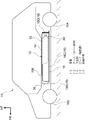
(車両10)
図1に示されるように、本実施形態の高圧容器搭載構造が適用された車両10は、駆動源となる図示しないモータを備えている。モータは、直接又は減速ギヤ列等の変速手段を介して間接的に車両10の駆動輪(前輪102及び後輪104の少なくとも一方)へ機械的に接続されている。これにより、モータから出力された駆動力が駆動輪へ伝わるようになっている。
(Vehicle 10)
As shown in FIG. 1, a
また、車両10は、図示しない燃料電池スタックを備えている。そして、この燃料電池スタックに水素及び空気が供給されることによって発電され、燃料電池スタックから上述したモータへ電力を供給してモータを駆動する。つまり、車両10は、所謂燃料電池車両である。
(ケース12)
車両10の車両下部には、前輪102と後輪104との間にカバー部材としてのケース12が配置されている。より具体的には、ケース12は、車室床部を構成するフロアパネル106の下方側に適用されている。
(Case 12)
A
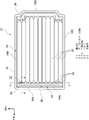
ケース12は、上面部14と、下面部16と周壁部18とを含み、箱状に形成されている。また、ケース12の内部には、容器本体30が設けられている。
The
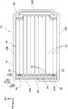
図2に示されるように、ケース12の下面部16は、平面視で略矩形状に形成された板状部材であり、周壁部18よりも外形が大きく形成されている。そして、この下面部16における車両幅方向両端部が、図示しないロッカなどの車両骨格部材に接合されることでケース12が車両10に固定されている。
As shown in FIG. 2 , the
周壁部18は、下面部16上に立設されてケース12の周壁を構成している。また、周壁部18は、車両前方側を車両幅方向に延在された前壁18Aを備えており、この前壁18Aの右側端部及び左側端部からそれぞれ車両後方へ一対の側壁18B、18Cが延在されている。さらに、一対の側壁18B、18Cの後端が車両幅方向に延在された後壁18Dによって連結されている。なお、前壁18A、側壁18B、18C及び後壁18Dは、それぞれ押出成形などによって閉断面状に形成されており、ケース12を補強するリンフォースとしての役割を兼ねている。
The
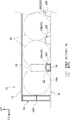
図3に示されるように、ケース12の上面部14は、車両上下方向を厚み方向とする板状部材であり、周壁部18と対応する形状とされている。また、上面部14の周縁部は、周壁部18の上面に重ね合わされて接合されている。
As shown in FIG. 3 , the
(ビード20)
ここで、上述したケース12の下面部16には、隆起部としての複数のビード20(図3において20A、20B、20C)が設けられている。それぞれのビード20は、下面部16を車両上方側に隆起させて形成され、略水平方向に延在する下面部16の一般面16Aよりも上方側へ凸をなしている。また、複数のビード20は、平面視で車両前後方向に延在する長尺状に形成され、車両幅方向に所定の間隔を空けて配置されている。本実施形態では、隣り合って配置された容器本体30の間に一つずつビード20が配置されている。これにより、下面部16全体の断面2次モーメントが大きくなり、剛性が高められている。
(Bead 20)
Here, a plurality of beads 20 (20A, 20B, 20C in FIG. 3) are provided as raised portions on the
なお、図3では、ビード20を車両幅方向に沿って切断した場合の断面形状が車両下方側へ開放された略台形状とされているが、これに限らず、車両下方側へ開放された半球状や三角形状となるように構成してもよい。
In FIG. 3, the cross-sectional shape of the
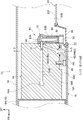
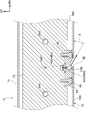
また、図2及び図4に示されるように、下面部16の車両幅方向外側に配置されたビード20は、後述する溶栓弁50に近づけて配置されている。具体的に説明すると、複数のビード20の車両前後方向の前端部(長手方向の一端)20Fが、ケース12の車両前端側に設けられた後述するマニホールド34の車両後方側面に沿って配置されている。そして、ケース12の車両幅方向外側に配置された一のビード20の前端部20Fが、マニホールド34の後方側面に固定された溶栓弁50と対向して配置されている。また、このビード20は、上面20Uが溶栓弁50の感熱部60よりも若干車両上方側に配置されるように構成されている。さらに、ビード20の前端部20Fには、下面部16を貫通する連通口22が形成されている。このようにして、車両床下の空間と溶栓弁50とが連通口22によって連通されている。なお、本実施形態において、連通口22は、溶栓弁50と車両上下方向に対向する下面部16の一般面16Aからビード20の前端部20Fに至る部位に形成されている。
2 and 4, the
(蓋部材24)
ところで、通常は、連通口22に蓋部材24が取り付けられており、路面から飛散した小石等がケース12の内部に侵入することを防止している。この蓋部材24は、連通口22よりも一回り大きな板状に形成され、連通口22の縁を蓋部材24の周縁部に形成された溝に嵌め込むことにより取り付けられている。この蓋部材24は、蓋部材24の融点がケース12の下面部16の融点よりも低くなる材料を用いて形成されている。本実施形態では、蓋部材24が、燃焼性を有する樹脂材料で形成されている。
(Lid member 24)
By the way, normally, a
(容器本体30)
図2に示されるように、ケース12の内部には、複数の容器本体30が配置されている。それぞれの容器本体30は、車両前後方向を軸方向として延在されており、略円筒状に形成されている。そして、これらの容器本体30は、高圧ガスとしての水素ガスを収容できるように構成されている。
(Container body 30)
As shown in FIG. 2 , a plurality of
本実施形態では、ケース12の内部に11本の容器本体30が車両幅方向に一列(一層)に並んで設けられている。また車両幅方向右側端部に配置された2本の容器本体30は、他の容器本体30と比べて軸方向の長さが短く形成されている。なお、本実施形態ではアルミニウム合金を主成分として容器本体30を形成しているが、これに限定されず、樹脂を主成分として容器本体30を形成してもよい。
In this embodiment, eleven
(マニホールド34)
ここで、容器本体30の軸方向の一端側(車両前方側)の端部に口金32が取り付けられており、口金32に配管としてのマニホールド34が接続されている。マニホールド34は、車両幅方向を長手方向として周壁部18の前壁18Aに沿って延在されており、複数の容器本体30の内部空間を連通する一般流路34Aを備えている。また、マニホールド34の長手方向の中央部にはバルブ36が設けられており、容器本体30とケース12の外部に設けられたバルブ36とが一般流路34Aで連通されている。このバルブ36は、容器本体30の開閉を行う機能を備える開閉弁であり、パイプ等の接続手段を介して上述した燃料電池スタック(図示省略)へ接続されている。そして、バルブ36の開閉を調節することにより、容器本体30から燃料電池スタックへ供給される水素ガスの供給量が調節されるように構成されている。
(manifold 34)
Here, a
一方、容器本体30の軸方向他端側(車両後方側)の端部は、ブラケット38を介してケース12の下面部16に固定されている。このようにして、容器本体30がケース内で移動しないようになっている。
On the other hand, the end portion of the
図4及び図5に示されるように、マニホールド34は、車両幅方向の外側端部(図3では右端部)に一般流路34Aから分岐した排ガス流路34Bを備えている。排ガス流路34Bは、一般流路34Aから車両後方側へ延在された横流路34B1と、この横流路34B1から車両下方側へ延出された後、車両幅方向外側へ屈曲されて延在する縦流路34B2とを含んで構成されている。
As shown in FIGS. 4 and 5, the manifold 34 has an exhaust
縦流路34B2の構成を詳細に説明すると、縦流路34B2の上流側は横流路34B1から分岐して車両下方側かつ若干車両前方側に延在する第1流路40とされている(図4参照)。また、図5に示されるように縦流路34B2の下流側は、第1流路40の下端部に接続されて、車両下方側かつ車両幅方向外側に向かって斜めに延在する第2流路42とされている。この第2流路42は、マニホールド34の車両下方側に配置されたブロック状の誘導部材44に形成されている。この誘導部材44は、マニホールド34の下面34Dにボルト46等の締結具を用いて固定されている。なお、本実施形態では、ケース12の下面部16が略水平方向に沿って延在しており、この下面部16に対する第2流路の傾斜角度θが、θ=30°となるように設定されている。
To explain the configuration of the vertical flow path 34B2 in detail, the upstream side of the vertical flow path 34B2 is branched from the horizontal flow path 34B1 to form a
そして、第2流路42の下端部は、下面部16の車両前方側かつ車両幅方向外側に形成された排出口48に接続しており、ケース12の外側に開放されている。これにより、排ガス流路34Bを通って排出される高圧ガスは、車両下方側かつ、車両幅方向外側に向けて排出される(図5の矢印方向参照)。なお、この排出口48は、車両床下の空間に排出ガスが滞留することを抑制するために、下面部16において連通口22よりも車両幅方向外側に形成されている。
A lower end portion of the
図4に示されるように、排ガス流路34Bにおける横流路34B1の後端部は、マニホールド34の車両後方側の面に開口されている。そして、通常は、この開口が溶栓弁50によって閉塞されている。
As shown in FIG. 4 , the rear end portion of the lateral flow path 34B1 in the exhaust
(溶栓弁50)
溶栓弁50は、本体部52と、横栓54と、縦栓56と、コイルバネ58と、感熱部60を主要な構成として備えている。本体部52は、略円柱状に形成されており、内部に筒状の空洞をなす横筒部52A及び縦筒部52Bが形成されている。横筒部52Aは、車両前後方向に延在しており、排ガス流路34Bにおける横流路34B1の後端部に接続されている。一方、縦筒部52Bは、横筒部52Aと直交し、車両上下方向に延在している。
(Fusible plug valve 50)
The
横筒部52Aの内部には、略円柱形状とされ、車両前後方向に延在する横栓54が同軸的に配置されている。この横栓54は、横流路34B1と縦流路34B2における第1流路40との接続部分まで入りこんでおり、通常は第1流路40を閉塞している。これにより、通常は排ガス流路34Bが溶栓弁50で閉塞される構成となっている。
A
一方、縦筒部52Bの内部には、略円柱形状とされ、車両上下方向に延在する縦栓56が同軸的に配置されている。この縦栓56の上端部は、球状のベアリング62を介して横栓54の後端部に当接している。また、縦栓56は、通常時に縦筒部52Bの下端部を閉塞する感熱部60の上に載置されている。この状態において、縦栓56は、軸方向に圧縮された状態で縦筒部52Bに収容されたコイルバネ58により、車両下方側に付勢されている。なお、感熱部60は、円盤状に形成され、一例として鉛、錫等の低融点金属等を材料とする可溶合金とされており、感熱部60の車両下方側に連通口22が配置されている。この感熱部60は、車両下部が高温となった場合に溶融し、縦筒部52Bを車両下方側へ開放する。
On the other hand, a
上記構成の溶栓弁50によれば、車両下部が高温となった場合に、感熱部60が溶融して縦筒部52Bが車両下方側へ開放される。そうすると、コイルバネ58の付勢力に従って、縦栓56が落下する。一方、マニホールド34の一般流路34Aでは、容器本体30の内圧の上昇により横栓54が車両後方側へ移動する。そして、排ガス流路34Bにおける横流路34B1と縦流路34B2とが連通される。これにより、高圧ガスが排出口48から排出される構成となっている(図5及び図6に示す矢印方向参照)。
According to the
次に、火炎により車両10の下部が高温になった場合について説明する。図6に示されるように、車両10の下部では、連通口22に取り付けられた蓋部材24が火炎の熱で溶融し、連通口22が開放される。この際、連通口22から遠い位置の火炎もビード20の窪みに沿って連通口22まで誘導され、ケース12の内部に配置された溶栓弁50に到達する。なお、図6では、連通口22から遠い位置の火炎を符号70で示している。
Next, a case where the lower portion of the
このとき、溶栓弁50の感熱部60が溶融されることで、図5及び図6に示されるように、容器本体30に収容された高圧ガスがマニホールド34の一般流路34Aから排ガス流路34Bに流れて排出口48から排出される。この高圧ガスは、排ガス流路34Bの第2流路42の傾斜方向に従い、車両下方側かつ車両幅方向外側に向けて排出される。
(作用)
次に、本実施形態の作用を説明する。
At this time, the heat-
(action)
Next, the operation of this embodiment will be described.
本実施形態の高圧容器搭載構造では、車両10の下部に高圧ガスを収容する容器本体30が搭載されており、この容器本体30には、マニホールド34が接続されている。マニホールド34は、一般流路34Aと排ガス流路34Bを備えており、一般流路34Aは容器本体30とバルブ36とを連通している。一方、排ガス流路34Bは、一般流路34Aから分岐されており、通常は溶栓弁50で閉塞されている。これにより、加熱環境下で車両10の下部が高温となった場合に、溶栓弁50の少なくとも一部が溶融されて容器本体30に収容された高圧ガスを排ガス流路34Bから排出することができる。
In the high-pressure container mounting structure of this embodiment, a
ここで、車両10の下部にはケース12が搭載されており、容器本体30及びマニホールド34は、ケース12の下面部16によって車両下方側から覆われている。この下面部16には、その一部を車両上方側へ隆起させてなる複数のビード20が形成されており、ビード20の一つは溶栓弁50に近づけて配置されている。さらに、下面部16は、ビード20の前端部20Fにおける溶栓弁50と対向する部位に連通口22を形成しており、連通口22は、車両床下の空間と溶栓弁50とを連通させている。これにより、ビード20の前端部20Fでは下面部16と溶栓弁50との距離が近づくため、車両10の下部が高温となった場合に、溶栓弁50への伝熱が、ビード20の連通口22を通して迅速に行われる。その結果、ケース12を介して溶栓弁50に伝熱される構成と比較して、溶栓弁50への伝熱効率を高めることができる。
Here, the
また、ビード20は下面部16の一般面16Aよりも車両上方側に隆起して形成されている、このため、下面部16を車両下方側へ突出させない構成で溶栓弁50の伝熱効率を向上させることができる。これにより、車両10の下部が路面と干渉することを抑制することができる。
Further, the
また、本実施形態では、長尺状に形成されたビード20の前端部(長手方向の一端)20Fが溶栓弁50と対向して配置されており、この前端部20Fに連通口22が形成されている。これにより、例えば、火炎暴露試験等の火炎によって車両10の下部が高温となった場合に、車両下でビード20の窪みに沿って火炎が誘導される。これにより、車両床下の火炎を連通口22まで早期に誘導することができる。
Further, in this embodiment, the front end portion (one end in the longitudinal direction) 20F of the
さらに、本実施形態では、ビード20を設けることにより下面部16の剛性が高められている。これにより、溶栓弁50への電熱効率的を高めると共に、下面部16の剛性を向上させて容器本体30の保護性能を向上させることができる。
Furthermore, in this embodiment, the rigidity of the
また、本実施形態では、下面部16に蓋部材24が配置されており、通常は連通口22が蓋部材24によって閉塞されている。また、蓋部材24の融点が下面部16の融点よりも低く設定されているため、車両10の下部が高温となった場合には、蓋部材24が溶けて連通口22を開放させる。これにより、通常時は、蓋部材24によって連通口22を塞ぎ、車両床下で飛散する飛び石から容器本体30等を保護することができる。
Further, in this embodiment, a
また、本実施形態では、マニホールド34の一般流路34Aが車両幅方向に沿って延在しており、一般流路34Aの車両幅方向外側端部から排ガス流路34Bが分岐している。また、排ガス流路34Bは、一般流路34Aから下面部16の外部まで延在され、排ガス流路34Bが開放された際に容器本体30に収容された高圧ガスを車両下方側かつ車両幅方向外側へ向けて排出させるように構成されている。このように、高圧ガスを両幅方向外側へ向けて排出させることができるため、高圧ガスを単に車両下方側へ向けて排出する構成と比較して、車両床下の空間にガスが滞留することを抑制することができる。
Further, in this embodiment, the
(変形例)
図7に示されるように、本変形例に係る高圧容器搭載構造では、車両10の下部の車両幅方向の右側端部及び左側端部に溶栓弁50が配置されている。また、溶栓弁50は、マニホールド34における一般流路34Aの車両幅方向の右側端部及び左側端部からそれぞれ分岐した図示しない排ガス流路を閉塞している。なお、当該排ガス流路は、上記した排ガス流路34Bの構成と同様である。
(Modification)
As shown in FIG. 7 , in the high-pressure vessel mounting structure according to this modification,
上記構成によれば、例えば、図7に示されるように車両10の車両幅方向右側に熱源が偏っている場合、車両10の下部の車両幅方向右側の溶栓弁50に対して迅速に伝熱がなされる。このため、溶栓弁50が溶融されることにより、高圧ガスが車両幅方向右側に位置する排ガス流路から車両外側へ向けて排出される。逆に、車両10の車両幅方向左側に熱源が偏っている場合には、車両幅方向左側の溶栓弁50に対して迅速に伝熱がなされる。そして、高圧ガスが車両幅方向左側に位置する排ガス流路から車両外側へ向けて排出される。
According to the above configuration, for example, when the heat source is biased to the vehicle width direction right side of the
以上説明したように、本変形例では、溶栓弁50が車両10の下部の車両幅方向右側及び車両幅方向左側にそれぞれ設けられている。このため、例えば、車両10の下部を高温にする熱源の位置が車両幅方向に偏っている場合でも、一方の溶栓弁50に対して迅速に伝熱することにより、排ガス流路を早期に開放させることができる。これにより、車両10の下部を高温にする熱源の位置に偏りがある場合であっても、溶栓弁50への伝熱効率を向上させることができる。
As described above, in this modified example, the
[補足説明]
上記実施形態及び変形例では、箱状のケース12がカバー部材とされていたが、これに限らない。カバー部材は、少なくとも容器本体30及びマニホールド34を車両下方側から覆う構成であればよく、例えば、周壁部18及び上面部14を備えず、カバー部材を下面部16のみで構成してもよい。
[supplementary explanation]
Although the box-shaped
上記実施形態及び変形例では、長尺状に形成され、車両前後方向に延在するビード20が隆起部とされていたが、これに限らない。ケース12の下面部16を車両上方側に隆起させて下面部を溶栓弁50に近づける構成であればよい。例えば、平面視で多角形状や円形状に形成された隆起部でもよい。
In the above-described embodiment and modified example, the
また、ビード20の数及び延在方向は適宜変更可能とされる。例えば、隣り合った容器本体の間すべてにビード20を設ける構成に限らず、適宜数を減少させることが可能である。また、溶栓弁50と対応する位置のみにビード20を配置する構成でもよい。さらに、平面視で車両前後方向から所定角度傾斜した方向にビードを延在させてもよいし、ビードを車両幅方向に延在させてもよい。
Also, the number and extending direction of the
また、上記実施形態及び変形例では、連通口22が溶栓弁50の車両下方側に位置する一般面16Aからビード20の前端部20Fに至る部位に形成される構成としたが、これに限らない。例えば、連通口22は、下面部16において一般面16Aを含まないビード20だけに重なる位置に形成してもよい。
In addition, in the above-described embodiment and modified example, the
また、上記実施形態及び変形例では、蓋部材24が燃焼性を有する樹脂材料で形成される構成としたがこれに限らない。車両10の下部が高温となった場合に下面部16よりも先に溶融すればよく、融点の低い合金や、難燃性の樹脂材料等、他の材料で形成された蓋部材を適用してもよい。
Further, in the above-described embodiment and modified example, the
また、上記実施形態では、溶栓弁50を車両10の下部の車両幅方向外側に配置したが、これに限らず、適宜変更可能とされる。例えば、溶栓弁を車両幅方向中央に配置してもよい。また、溶栓弁の取付位置に応じて、排ガス流路の配置も適宜変更可能とされる。
Further, in the above-described embodiment, the
また、上記実施形態では、溶栓弁50の車両下方側に配置された連通口22とは別に高圧ガスの排出される排出口48を設けたが、これに限らず、下面部に連通口だけを設けて高圧ガスの排出口を共用化してもよい。
In the above embodiment, the
また、上記変形例では、溶栓弁50が車両10の下部に2つ配置される構成としたが、これに限らず、車両の下部に2つ以上の溶栓弁を配置するように構成してもよい。
In addition, in the above modified example, two
10 車両
12 ケース(カバー部材)
16 下面部
20 ビード(隆起部)
20F 前端部(長手方向の一端)
22 連通口
24 蓋部材
30 容器本体
34 マニホールド(配管)
34A 一般流路
34B 排ガス流路
36 バルブ
50 溶栓弁
10
16
20F front end (one end in the longitudinal direction)
22
34A
Claims (6)
前記容器本体と前記容器本体の開閉を行うバルブとを連通する一般流路と、該一般流路から分岐した排ガス流路とを備える配管と、
前記排ガス流路を閉塞させると共に、少なくとも一部が溶融された場合に、前記排ガス流路を開放して前記容器本体に収容された高圧ガスを車両床下の空間へ排出させる溶栓弁と、
前記容器本体及び前記配管を車両下方側から覆う下面部を含み、該下面部の一部を車両上方側へ隆起させてなる隆起部を前記溶栓弁に近づけて配置したカバー部材と、
前記隆起部における前記溶栓弁と対向する部位に形成され、車両床下の空間と前記溶栓弁とを連通させる連通口と、
を有する高圧容器搭載構造。 A container body mounted on the lower part of the vehicle and containing high-pressure gas;
a pipe comprising a general channel communicating between the container body and a valve for opening and closing the container body, and an exhaust gas channel branched from the general channel;
a fusible plug valve that closes the exhaust gas channel and opens the exhaust gas channel to discharge high-pressure gas contained in the container body to a space under the floor of the vehicle when at least a portion of the exhaust gas channel is melted;
a cover member including a lower surface portion that covers the container body and the pipe from the vehicle lower side, and a protruding portion formed by protruding a part of the lower surface portion toward the vehicle upper side and arranged close to the fusible plug valve;
a communication port formed at a portion of the protuberance facing the fusible plug valve and communicating a space under the floor of the vehicle with the fusible plug valve;
A high-pressure vessel mounting structure with
前記連通口は、前記隆起部における前記一端に形成されている、
請求項1に記載の高圧容器搭載構造。 The raised portion is formed in a long shape in a plan view, and one end in the longitudinal direction is arranged to face the fusible plug valve,
The communication port is formed at the one end of the raised portion,
The high pressure vessel mounting structure according to claim 1.
請求項1又は請求項2に記載の高圧容器搭載構造。 A plurality of the raised portions are formed on the lower surface portion of the cover member, and are configured as reinforcing beads that reinforce the lower surface portion.
The high-pressure vessel mounting structure according to claim 1 or 2.
前記蓋部材の融点は、前記カバー部材の前記下面部の融点よりも低く設定されている、
請求項1~請求項3の何れか1項に記載の高圧容器搭載構造。 The communication port is closed by a lid member,
The melting point of the lid member is set lower than the melting point of the lower surface portion of the cover member,
The high pressure vessel mounting structure according to any one of claims 1 to 3.
前記排ガス流路は、前記一般流路の車両幅方向外側端部から分岐して前記下面部の外部まで延在され、前記排ガス流路が開放された場合に前記高圧ガスを車両下方側かつ車両幅方向外側へ向けて排出させる、
請求項1~請求項4の何れか1項に記載の高圧容器搭載構造。 The general flow path extends along the vehicle width direction,
The exhaust gas flow path branches from the vehicle width direction outer end portion of the general flow path and extends to the outside of the lower surface portion, and when the exhaust gas flow path is opened, the high pressure gas is directed to the vehicle lower side and the vehicle. Discharge outward in the width direction,
The high pressure vessel mounting structure according to any one of claims 1 to 4.
前記溶栓弁は、一対の前記排ガス流路のそれぞれを閉塞するように車両下部の車両幅方向右側及び車両幅方向左側に一対設けられている、
請求項5に記載の高圧容器搭載構造。 A pair of the exhaust gas flow path is provided by branching from a vehicle width direction right end portion and a vehicle width direction left end portion of the general flow channel,
A pair of the fusible plug valves are provided on the right side in the vehicle width direction and the left side in the vehicle width direction of the lower part of the vehicle so as to close the pair of exhaust gas flow paths, respectively.
The high pressure vessel mounting structure according to claim 5.
Priority Applications (3)
| Application Number | Priority Date | Filing Date | Title |
|---|---|---|---|
| JP2019148012A JP7151663B2 (en) | 2019-08-09 | 2019-08-09 | High-pressure vessel mounting structure |
| CN202010558662.6A CN112344206B (en) | 2019-08-09 | 2020-06-18 | High-pressure vessel mounting structure |
| US16/914,481 US11508974B2 (en) | 2019-08-09 | 2020-06-29 | Pressure vessel mounting structure |
Applications Claiming Priority (1)
| Application Number | Priority Date | Filing Date | Title |
|---|---|---|---|
| JP2019148012A JP7151663B2 (en) | 2019-08-09 | 2019-08-09 | High-pressure vessel mounting structure |
Publications (2)
| Publication Number | Publication Date |
|---|---|
| JP2021028519A JP2021028519A (en) | 2021-02-25 |
| JP7151663B2 true JP7151663B2 (en) | 2022-10-12 |
Family
ID=74358209
Family Applications (1)
| Application Number | Title | Priority Date | Filing Date |
|---|---|---|---|
| JP2019148012A Active JP7151663B2 (en) | 2019-08-09 | 2019-08-09 | High-pressure vessel mounting structure |
Country Status (3)
| Country | Link |
|---|---|
| US (1) | US11508974B2 (en) |
| JP (1) | JP7151663B2 (en) |
| CN (1) | CN112344206B (en) |
Families Citing this family (9)
| Publication number | Priority date | Publication date | Assignee | Title |
|---|---|---|---|---|
| DE102021106038A1 (en) * | 2021-03-12 | 2021-05-12 | Bayerische Motoren Werke Aktiengesellschaft | Pressure vessel system with a pressure vessel assembly |
| DE102021111173A1 (en) * | 2021-04-30 | 2022-11-03 | Bayerische Motoren Werke Aktiengesellschaft | Fuel line with insulation and pressure vessel system |
| JP7447875B2 (en) * | 2021-07-02 | 2024-03-12 | トヨタ自動車株式会社 | pressure vessel |
| CN113757551A (en) * | 2021-08-12 | 2021-12-07 | 深圳烯湾科技有限公司 | Power module, carrier and safety management method of power module |
| JP2023054503A (en) * | 2021-10-04 | 2023-04-14 | トヨタ自動車株式会社 | tank unit |
| EP4170763A1 (en) * | 2021-10-20 | 2023-04-26 | Robert Bosch GmbH | Discharge and filling system |
| JP7528920B2 (en) | 2021-12-28 | 2024-08-06 | トヨタ自動車株式会社 | Pressure relief valve |
| KR102908617B1 (en) * | 2022-06-23 | 2026-01-07 | 플라스틱 옴니엄 뉴 에너지스 프랑스 | Operating manifold for pressurized fluid storage and distribution assembly for vehicles |
| DE102022211298A1 (en) * | 2022-10-25 | 2024-04-25 | Robert Bosch Gesellschaft mit beschränkter Haftung | tank system for a hydrogen-powered vehicle, fuel cell assembly, hydrogen internal combustion engine system, fuel cell-powered vehicle, hydrogen-powered vehicle |
Citations (3)
| Publication number | Priority date | Publication date | Assignee | Title |
|---|---|---|---|---|
| US4972965A (en) | 1989-03-14 | 1990-11-27 | Swiss Aluminium Ltd. | Protective device for gas pressure vessels |
| JP2002528321A (en) | 1998-10-27 | 2002-09-03 | ザ ジョンズ ホプキンズ ユニバーシティ | Compressed gas fuel storage system |
| DE102018207494A1 (en) | 2018-05-15 | 2019-11-21 | Bayerische Motoren Werke Aktiengesellschaft | Pressure relief system for pressure relief of at least one pressure vessel and pressure vessel system and motor vehicle |
Family Cites Families (13)
| Publication number | Priority date | Publication date | Assignee | Title |
|---|---|---|---|---|
| JP2004136828A (en) * | 2002-10-18 | 2004-05-13 | Nissan Motor Co Ltd | High pressure gas storage device |
| FR2869573B1 (en) * | 2004-04-30 | 2006-06-16 | Conception Et Dev Michelin Sa | GASEOUS FUEL VEHICLE AND AUTOMATIC PURGE SYSTEM |
| US7270209B2 (en) * | 2004-08-10 | 2007-09-18 | General Motors Corporation | Modular fuel storage system for a vehicle |
| US7624753B2 (en) * | 2004-08-10 | 2009-12-01 | Gm Global Technology Operations, Inc. | Container for gas storage tanks in a vehicle |
| JP4874948B2 (en) * | 2007-12-28 | 2012-02-15 | トヨタ自動車株式会社 | Safety valve device, valve device, high-pressure gas tank, and vehicle |
| FR2933046B1 (en) * | 2008-06-25 | 2010-12-31 | Peugeot Citroen Automobiles Sa | COMPONENT ASSEMBLY FOR VEHICLE AND VEHICLE EQUIPPED WITH SAID ASSEMBLY. |
| JP5386249B2 (en) * | 2009-07-03 | 2014-01-15 | トヨタ自動車株式会社 | Valve device for high-pressure tank for vehicles |
| JP5920980B2 (en) * | 2012-07-12 | 2016-05-24 | 株式会社Fts | Protective structure for automotive gaseous fuel tank |
| JP6048200B2 (en) * | 2013-02-19 | 2016-12-21 | トヨタ自動車株式会社 | Pressure vessel, transportation equipment and mounting structure |
| WO2015195001A2 (en) * | 2014-06-18 | 2015-12-23 | Volvo Truck Corporation | Safety arrangement for a vehicle tank |
| CN206298814U (en) * | 2016-09-13 | 2017-07-04 | 河南路太养路机械股份有限公司 | The heater of control valve and guiding oil groove for road gap-grouting vehicle |
| JP6561974B2 (en) * | 2016-11-28 | 2019-08-21 | トヨタ自動車株式会社 | vehicle |
| JP7069597B2 (en) | 2017-08-10 | 2022-05-18 | トヨタ自動車株式会社 | High pressure container |
-
2019
- 2019-08-09 JP JP2019148012A patent/JP7151663B2/en active Active
-
2020
- 2020-06-18 CN CN202010558662.6A patent/CN112344206B/en not_active Expired - Fee Related
- 2020-06-29 US US16/914,481 patent/US11508974B2/en active Active
Patent Citations (3)
| Publication number | Priority date | Publication date | Assignee | Title |
|---|---|---|---|---|
| US4972965A (en) | 1989-03-14 | 1990-11-27 | Swiss Aluminium Ltd. | Protective device for gas pressure vessels |
| JP2002528321A (en) | 1998-10-27 | 2002-09-03 | ザ ジョンズ ホプキンズ ユニバーシティ | Compressed gas fuel storage system |
| DE102018207494A1 (en) | 2018-05-15 | 2019-11-21 | Bayerische Motoren Werke Aktiengesellschaft | Pressure relief system for pressure relief of at least one pressure vessel and pressure vessel system and motor vehicle |
Also Published As
| Publication number | Publication date |
|---|---|
| US11508974B2 (en) | 2022-11-22 |
| US20210039489A1 (en) | 2021-02-11 |
| CN112344206A (en) | 2021-02-09 |
| JP2021028519A (en) | 2021-02-25 |
| CN112344206B (en) | 2022-07-08 |
Similar Documents
| Publication | Publication Date | Title |
|---|---|---|
| JP7151663B2 (en) | High-pressure vessel mounting structure | |
| EP1167164B1 (en) | Vehicle front structure | |
| JP5067503B2 (en) | Vehicle lower structure | |
| US20230327280A1 (en) | Motor vehicle with an underride protection plate | |
| CN103144534A (en) | Vehicle engine enclosure structure | |
| JP4355312B2 (en) | Arrangement structure of canister in vehicle | |
| JP2014524868A (en) | Hall seal device for automobile front face | |
| EP3127787B1 (en) | Industrial vehicle | |
| JP2535338B2 (en) | Canister layout structure | |
| JP2006188169A (en) | Vehicle and gas fuel tank mounting method | |
| JP7662374B2 (en) | Car battery | |
| US11215324B2 (en) | High pressure container unit | |
| JP4574415B2 (en) | Saddle riding vehicle | |
| JP6687880B2 (en) | Evaporative fuel processor | |
| US12187355B2 (en) | Lower vehicle-body structure of vehicle | |
| JP7119492B2 (en) | Fuel tank protection structure | |
| JP7714917B2 (en) | Automotive fuel cell system | |
| JP5554590B2 (en) | vehicle | |
| JP6811659B2 (en) | Multipurpose vehicle | |
| JP6583386B2 (en) | Car body rear structure | |
| JP7743238B2 (en) | battery support structure | |
| WO2025083950A1 (en) | Vehicle and tank cover | |
| WO2025163723A1 (en) | Battery pack | |
| JP7769147B2 (en) | Intake manifold device | |
| JP2006298312A (en) | Lower body structure |
Legal Events
| Date | Code | Title | Description |
|---|---|---|---|
| A621 | Written request for application examination |
Free format text: JAPANESE INTERMEDIATE CODE: A621 Effective date: 20210921 |
|
| A977 | Report on retrieval |
Free format text: JAPANESE INTERMEDIATE CODE: A971007 Effective date: 20220816 |
|
| TRDD | Decision of grant or rejection written | ||
| A01 | Written decision to grant a patent or to grant a registration (utility model) |
Free format text: JAPANESE INTERMEDIATE CODE: A01 Effective date: 20220830 |
|
| A61 | First payment of annual fees (during grant procedure) |
Free format text: JAPANESE INTERMEDIATE CODE: A61 Effective date: 20220912 |
|
| R151 | Written notification of patent or utility model registration |
Ref document number: 7151663 Country of ref document: JP Free format text: JAPANESE INTERMEDIATE CODE: R151 |