JP7149952B2 - A catch assembly releasably connecting the fluid conduits - Google Patents
A catch assembly releasably connecting the fluid conduits Download PDFInfo
- Publication number
- JP7149952B2 JP7149952B2 JP2019547395A JP2019547395A JP7149952B2 JP 7149952 B2 JP7149952 B2 JP 7149952B2 JP 2019547395 A JP2019547395 A JP 2019547395A JP 2019547395 A JP2019547395 A JP 2019547395A JP 7149952 B2 JP7149952 B2 JP 7149952B2
- Authority
- JP
- Japan
- Prior art keywords
- catch
- female coupler
- coupler
- connector system
- female
- Prior art date
- Legal status (The legal status is an assumption and is not a legal conclusion. Google has not performed a legal analysis and makes no representation as to the accuracy of the status listed.)
- Active
Links
Images


Classifications
-
- A—HUMAN NECESSITIES
- A61—MEDICAL OR VETERINARY SCIENCE; HYGIENE
- A61M—DEVICES FOR INTRODUCING MEDIA INTO, OR ONTO, THE BODY; DEVICES FOR TRANSDUCING BODY MEDIA OR FOR TAKING MEDIA FROM THE BODY; DEVICES FOR PRODUCING OR ENDING SLEEP OR STUPOR
- A61M39/00—Tubes, tube connectors, tube couplings, valves, access sites or the like, specially adapted for medical use
- A61M39/10—Tube connectors; Tube couplings
- A61M39/1011—Locking means for securing connection; Additional tamper safeties
-
- A—HUMAN NECESSITIES
- A61—MEDICAL OR VETERINARY SCIENCE; HYGIENE
- A61M—DEVICES FOR INTRODUCING MEDIA INTO, OR ONTO, THE BODY; DEVICES FOR TRANSDUCING BODY MEDIA OR FOR TAKING MEDIA FROM THE BODY; DEVICES FOR PRODUCING OR ENDING SLEEP OR STUPOR
- A61M39/00—Tubes, tube connectors, tube couplings, valves, access sites or the like, specially adapted for medical use
- A61M39/10—Tube connectors; Tube couplings
-
- F—MECHANICAL ENGINEERING; LIGHTING; HEATING; WEAPONS; BLASTING
- F16—ENGINEERING ELEMENTS AND UNITS; GENERAL MEASURES FOR PRODUCING AND MAINTAINING EFFECTIVE FUNCTIONING OF MACHINES OR INSTALLATIONS; THERMAL INSULATION IN GENERAL
- F16L—PIPES; JOINTS OR FITTINGS FOR PIPES; SUPPORTS FOR PIPES, CABLES OR PROTECTIVE TUBING; MEANS FOR THERMAL INSULATION IN GENERAL
- F16L37/00—Couplings of the quick-acting type
- F16L37/08—Couplings of the quick-acting type in which the connection between abutting or axially overlapping ends is maintained by locking members
-
- F—MECHANICAL ENGINEERING; LIGHTING; HEATING; WEAPONS; BLASTING
- F16—ENGINEERING ELEMENTS AND UNITS; GENERAL MEASURES FOR PRODUCING AND MAINTAINING EFFECTIVE FUNCTIONING OF MACHINES OR INSTALLATIONS; THERMAL INSULATION IN GENERAL
- F16L—PIPES; JOINTS OR FITTINGS FOR PIPES; SUPPORTS FOR PIPES, CABLES OR PROTECTIVE TUBING; MEANS FOR THERMAL INSULATION IN GENERAL
- F16L37/00—Couplings of the quick-acting type
- F16L37/28—Couplings of the quick-acting type with fluid cut-off means
- F16L37/30—Couplings of the quick-acting type with fluid cut-off means with fluid cut-off means in each of two pipe-end fittings
- F16L37/32—Couplings of the quick-acting type with fluid cut-off means with fluid cut-off means in each of two pipe-end fittings at least one of two lift valves being opened automatically when the coupling is applied
- F16L37/36—Couplings of the quick-acting type with fluid cut-off means with fluid cut-off means in each of two pipe-end fittings at least one of two lift valves being opened automatically when the coupling is applied with two lift valves being actuated to initiate the flow through the coupling after the two coupling parts are locked against withdrawal
-
- A—HUMAN NECESSITIES
- A61—MEDICAL OR VETERINARY SCIENCE; HYGIENE
- A61M—DEVICES FOR INTRODUCING MEDIA INTO, OR ONTO, THE BODY; DEVICES FOR TRANSDUCING BODY MEDIA OR FOR TAKING MEDIA FROM THE BODY; DEVICES FOR PRODUCING OR ENDING SLEEP OR STUPOR
- A61M39/00—Tubes, tube connectors, tube couplings, valves, access sites or the like, specially adapted for medical use
- A61M39/10—Tube connectors; Tube couplings
- A61M2039/1016—Unlocking means providing a secure or comfortable disconnection
-
- A—HUMAN NECESSITIES
- A61—MEDICAL OR VETERINARY SCIENCE; HYGIENE
- A61M—DEVICES FOR INTRODUCING MEDIA INTO, OR ONTO, THE BODY; DEVICES FOR TRANSDUCING BODY MEDIA OR FOR TAKING MEDIA FROM THE BODY; DEVICES FOR PRODUCING OR ENDING SLEEP OR STUPOR
- A61M39/00—Tubes, tube connectors, tube couplings, valves, access sites or the like, specially adapted for medical use
- A61M39/10—Tube connectors; Tube couplings
- A61M2039/1027—Quick-acting type connectors
-
- A—HUMAN NECESSITIES
- A61—MEDICAL OR VETERINARY SCIENCE; HYGIENE
- A61M—DEVICES FOR INTRODUCING MEDIA INTO, OR ONTO, THE BODY; DEVICES FOR TRANSDUCING BODY MEDIA OR FOR TAKING MEDIA FROM THE BODY; DEVICES FOR PRODUCING OR ENDING SLEEP OR STUPOR
- A61M39/00—Tubes, tube connectors, tube couplings, valves, access sites or the like, specially adapted for medical use
- A61M39/22—Valves or arrangement of valves
- A61M39/26—Valves closing automatically on disconnecting the line and opening on reconnection thereof
-
- F—MECHANICAL ENGINEERING; LIGHTING; HEATING; WEAPONS; BLASTING
- F17—STORING OR DISTRIBUTING GASES OR LIQUIDS
- F17C—VESSELS FOR CONTAINING OR STORING COMPRESSED, LIQUEFIED OR SOLIDIFIED GASES; FIXED-CAPACITY GAS-HOLDERS; FILLING VESSELS WITH, OR DISCHARGING FROM VESSELS, COMPRESSED, LIQUEFIED, OR SOLIDIFIED GASES
- F17C2205/00—Vessel construction, in particular mounting arrangements, attachments or identifications means
- F17C2205/03—Fluid connections, filters, valves, closure means or other attachments
- F17C2205/0302—Fittings, valves, filters, or components in connection with the gas storage device
- F17C2205/037—Quick connecting means, e.g. couplings
Description
本特許協力条約国際特許出願は、米国非仮特許出願第15/912,280号(2018年3月5日出願)の継続であり、上記出願は、米国仮特許出願第62/468,800号(2017年3月8日出願)の利益を主張し、各々は、参照により本明細書に組み込まれる。 This Patent Cooperation Treaty International Patent Application is a continuation of U.S. Nonprovisional Patent Application No. 15/912,280 (filed March 5, 2018), which is a continuation of U.S. Provisional Patent Application No. 62/468,800. (filed March 8, 2017), each of which is incorporated herein by reference.
本発明の特定の実施形態の広義の目的は、管、例えば、医療用管類を一緒に解放可能に接続するためのコネクタシステムと、そのようなコネクタシステムを作製および使用する方法とを提供することであり得、それによって、コネクタシステムは、第1の通路を有するメス型結合器と、第2の通路を有するオス型結合器と、キャッチアセンブリとを含み、キャッチアセンブリは、メス型結合器に移動可能に結合されたキャッチと、キャッチを付勢するキャッチ付勢部材と、カムに応答するフォロワーとを備え、それによって、キャッチは、フォロワーに応答し、対応して、カムに応答する。 A broad object of certain embodiments of the present invention is to provide connector systems for releasably connecting tubes, e.g., medical tubing, together and methods of making and using such connector systems. , whereby the connector system includes a female coupler having a first passageway, a male coupler having a second passageway, and a catch assembly, the catch assembly being connected to the female coupler. a catch movably coupled to the catch, a catch biasing member for biasing the catch, and a follower responsive to the cam, whereby the catch responds to the follower and correspondingly to the cam.
当然ながら、本発明のさらなる目的は、本明細書の他の部分、図面、および請求項全体を通して開示される。
本発明は、例えば、以下を提供する。
(項目1)
管を解放可能に接続するためのコネクタシステムであって、前記コネクタシステムは、
第1の通路を有するメス型結合器と、
第2の通路を有するオス型結合器と、
キャッチアセンブリと
を備え、
前記キャッチアセンブリは、
前記メス型結合器に移動可能に結合されたキャッチと、
前記キャッチを付勢するキャッチ付勢部材と、
カムに応答するフォロワーと
を備え、
前記キャッチは、前記フォロワーに応答し、対応して、前記カムに応答する、
コネクタシステム。
(項目2)
前記キャッチアセンブリは、一体部品構造を備えている、項目1に記載のコネクタシステム。
(項目3)
前記キャッチ、前記キャッチ付勢部材、および前記フォロワーは、前記一体部品構造として形成されている、項目2に記載のコネクタシステム。
(項目4)
前記キャッチは、前記メス型結合器に移動可能に結合されており、それによって、前記キャッチは、前記メス型結合器のメス型結合器内側表面によって画定されるメス型結合器内側空間に向かう内向き移動と、前記メス型結合器内側空間から離れるような外向き移動とが可能である、項目1に記載のコネクタシステム。
(項目5)
前記キャッチは、前記メス型結合器内側表面に移動可能に結合されている、項目4に記載のコネクタシステム。
(項目6)
前記キャッチは、前記メス型結合器内側表面内にはめ込まれたチャネル内に移動可能に配置され、前記チャネルは、前記メス型結合器内側空間と連通している、項目5に記載のコネクタシステム。
(項目7)
前記オス型結合器に結合されたキャッチ受け取り要素をさらに備え、前記メス型およびオス型結合器の解放可能かつ篏合可能な軸方向結合時、前記キャッチは、前記キャッチ受け取り要素と係合し、前記メス型結合器の軸方向位置を前記オス型結合器に関連して固定し、それによって、前記第1および第2の通路が流体連通して配置され、流体流路を提供する前記コネクタシステムの接続状態を達成する、項目6に記載のコネクタシステム。
(項目8)
前記キャッチ受け取り要素は、前記オス型結合器篏合可能端部に近接してオス型結合器外側表面内に配置された保持溝を備えている、項目7に記載のコネクタシステム。
(項目9)
前記保持溝は、前記オス型結合器篏合可能端部に近接して前記オス型結合器外側表面の周囲に延びている円周保持溝を備えている、項目8に記載のコネクタシステム。
(項目10)
前記メス型およびオス型結合器の解放可能かつ篏合可能な軸方向結合時、前記保持溝は、前記チャネルと整列し、前記キャッチが、前記保持溝との係合のために、前記チャネルから外向きに、かつ前記メス型結合器内側空間に向かって内向きに移動することを可能にし、前記キャッチを係合状態に配置し、前記メス型結合器の前記軸方向位置を前記オス型結合器に関連して固定する、項目8に記載のコネクタシステム。
(項目11)
前記キャッチは、前記キャッチが前記メス型結合器の縦方向軸に略直交する平面内での移動が可能であるように、前記メス型結合器に移動可能に結合されている、項目10に記載のコネクタシステム。
(項目12)
前記キャッチは、前記平面内での垂直移動が可能である、項目11に記載のコネクタシステム。
(項目13)
前記メス型およびオス型結合器の解放可能かつ篏合可能な軸方向結合時、前記保持溝、前記チャネル、および前記キャッチは、前記平面内で整列し、前記キャッチが、前記保持溝との係合のために前記チャネルから外向きに、かつ前記平面内で上向きに移動することを可能にし、前記キャッチを前記係合状態に配置し、前記メス型結合器の前記軸方向位置を前記オス型結合器に関連して固定する、項目12に記載のコネクタシステム。
(項目14)
前記キャッチ付勢部材は、通常、前記キャッチを前記メス型結合器内側空間に向かって内向きに、または前記平面内で上向きに付勢する、項目13に記載のコネクタシステム。
(項目15)
前記キャッチ付勢部材は、通常、前記キャッチを前記係合状態に向かって付勢する、項目14に記載のコネクタシステム。
(項目16)
前記キャッチ付勢部材は、弾力的に可撓な部材を備えている、項目14に記載のコネクタシステム。
(項目17)
前記弾力的に可撓な部材は、前記キャッチから外向きに延びている弾力的に可撓なアームを備え、
前記弾力的に可撓なアームは、前記チャネルを画定する前記メス型結合器内側表面の一部に支えられている、項目16に記載のコネクタシステム。
(項目18)
前記弾力的に可撓な部材は、前記キャッチから反対方向に外向きに延びている前記弾力的に可撓なアームの対を備えている、項目16に記載のコネクタシステム。
(項目19)
前記カムは、前記メス型結合器に移動可能に結合された解放要素によって提供される、項目1に記載のコネクタシステム。
(項目20)
前記メス型結合器のメス型結合器外側表面に沿った前記解放要素の移動は、前記キャッチを前記キャッチ受け取り要素から係合解除し、前記コネクタシステムの接続解除状態を達成する、項目19に記載のコネクタシステム。
(項目21)
前記移動は、前記メス型結合器外側表面に沿った線形運動を含む、項目20に記載のコネクタシステム。
(項目22)
前記線形運動は、前記メス型結合器外側表面に沿ったスライド運動を含む、項目21に記載のコネクタシステム。
(項目23)
前記メス型結合器外側表面に沿った前記解放要素の前記移動は、前記メス型結合器外側表面に関連して0°~約±45°の角度に向けられた加力によって達成される、項目20に記載のコネクタシステム。
(項目24)
前記メス型結合器のメス型結合器外側表面に沿った前記解放要素の縦方向移動は、前記キャッチを前記キャッチ受け取り要素から係合解除し、前記コネクタシステムの接続解除状態を達成する、項目19に記載のコネクタシステム。
(項目25)
前記縦方向移動は、前記メス型結合器外側表面に沿ったスライド移動を含む、項目24に記載のコネクタシステム。
(項目26)
前記メス型結合器外側表面に沿った前記解放要素の前記移動は、前記メス型結合器の第1および第2の端部の間の前記メス型結合器外側表面に沿った縦方向移動のみを含む、項目24に記載のコネクタシステム。
(項目27)
前記解放要素は、前記メス型結合器外側表面に沿った前記線形運動を前記フォロワーの移動に変換するように構成されている、項目21に記載のコネクタシステム。
(項目28)
前記解放要素は、係止表面と、係止解除表面とを有するカム表面を提供する解放要素内側表面を備えている、項目27に記載のコネクタシステム。
(項目29)
キャッチアセンブリは、環状部材を備えている、項目1に記載のコネクタシステム。
(項目30)
前記環状部材は、前記キャッチを提供する第1の部分と、前記フォロワーを提供する対向する第2の部分とを備えている、項目29に記載のコネクタシステム。
(項目31)
前記キャッチ付勢部材は、前記キャッチを提供する前記環状部材の前記第1の部分から外向きに延びている、項目30に記載のコネクタシステム。
(項目32)
前記メス型結合器内に配置された第1の弁であって、前記第1の弁は、前記第1の通路を通した流体流動を中断させるように動作可能である、第1の弁と、
前記オス型結合器内に配置された第2の弁であって、前記第2の弁は、前記第2の通路を通した流体流動を中断させるように動作可能である、第2の弁と
をさらに備えている、項目1に記載のコネクタシステム。
(項目33)
前記コネクタシステムの接続状態において、前記メス型結合器は、前記第2の弁を第2の弁開放位置に向かって押し進め、前記オス型結合器は、前記第1の弁を第1の弁解放位置に向かって押し進め、流体連通している前記第1および第2の通路を配置し、流体流路を提供する、項目32に記載のコネクタシステム。
(項目34)
前記第1の通路の外側に配置された第1の弁付勢部材であって、前記第1の弁付勢部材は、前記第1の弁を第1の弁閉鎖位置に向かって付勢するように動作可能である、第1の弁付勢部材と、
前記第2の通路の外側に配置された第2の弁付勢部材であって、前記第2の弁付勢部材は、前記第2の弁を第2の弁閉鎖位置に向かって付勢するように動作可能である、第2の弁付勢部材と
をさらに備えている、項目33に記載のコネクタシステム。
(項目35)
管を解放可能に接続するためのコネクタシステムを作製する方法であって、前記方法は、
第1の通路を有するメス型結合器を提供することと、
第2の通路を有するオス型結合器を提供することと、
キャッチアセンブリを提供することと
を含み、
前記キャッチアセンブリは、
前記メス型結合器に移動可能に結合されたキャッチと、
前記キャッチを付勢するキャッチ付勢部材と、
カムに応答するフォロワーと
を備え、
前記キャッチは、前記フォロワーに応答し、対応して、前記カムに応答する、方法。
(項目36)
前記キャッチ、前記キャッチ付勢部材、および前記フォロワーを一体部品構造として形成することをさらに含む、項目35に記載の方法。
(項目37)
前記キャッチを前記メス型結合器のメス型結合器内側表面に移動可能に結合することをさらに含む、項目35に記載の方法。
(項目38)
前記キャッチを前記メス型結合器内側表面内にはめ込まれたチャネル内に移動可能に配置することをさらに含む、項目37に記載の方法。
(項目39)
キャッチ受け取り要素を前記オス型結合器に結合することをさらに含む、項目35に記載の方法。
(項目40)
前記キャッチ受け取り要素をオス型結合器篏合可能端部に近接してオス型結合器外側表面内に配置された保持溝として提供することをさらに含む、項目39に記載の方法。
(項目41)
前記キャッチ付勢部材を弾力的に可撓な部材として提供することをさらに含む、項目35に記載の方法。
(項目42)
前記カムを提供する解放要素を提供することをさらに含む、項目35に記載の方法。
(項目43)
前記解放要素を前記メス型結合器に移動可能に結合することをさらに含む、項目42に記載の方法。
(項目44)
環状部材として構成された前記キャッチアセンブリを提供することをさらに含む、項目35に記載の方法。
(項目45)
前記メス型結合器内に第1の弁を配置することであって、前記第1の弁は、前記第1の通路を通した流体流動を中断させるように動作可能である、ことと、
前記オス型結合器内に第2の弁を配置することであって、前記第2の弁は、前記第2の通路を通した流体流動を中断させるように動作可能である、ことと
をさらに含む、項目35に記載の方法。
(項目46)
前記第1の通路の外側に第1の弁付勢部材を配置することであって、前記第1の弁付勢部材は、前記第1の弁を第1の弁閉鎖位置に向かって付勢するように動作可能である、ことと、
前記第2の通路の外側に第2の弁付勢部材を配置することであって、前記第2の弁付勢部材は、前記第2の弁を第2の弁閉鎖位置に向かって付勢するように動作可能である、ことと
をさらに含む、項目45に記載の方法。
(項目47)
管を解放可能に接続するためのコネクタシステムを使用する方法であって、前記方法は、
前記コネクタシステムを取得することであって、
前記コネクタシステムは、
第1の通路を有するメス型結合器と、
第2の通路を有するオス型結合器と、
キャッチアセンブリと
を備え、
前記キャッチアセンブリは、
前記メス型結合器に移動可能に結合されたキャッチと、
前記キャッチを付勢するキャッチ付勢部材と、
カムに応答するフォロワーと
を備え、
前記キャッチは、前記フォロワーに応答し、対応して、前記カムに応答する、ことと、
第1の管を前記メス型結合器に結合することと、
第2の管を前記オス型結合器に結合することと、
前記メス型およびオス型結合器を解放可能に結合し、前記コネクタシステムの接続状態を達成することと
を含み、
前記コネクタシステムの前記接続状態において、前記第1の通路と第2の通路とは、流体連通して配置され、流体流路を提供する、方法。
(項目48)
前記流体流路を通して流体を流動させることをさらに含む、項目47に記載の方法。
(項目49)
前記カムを強制的に押し進め、前記キャッチを前記オス型結合器に結合されたキャッチ受け取り要素から係合解除し、前記コネクタシステムの接続解除状態を達成することをさらに含む、項目48に記載の方法。
(項目50)
解放要素を強制的に押し進めることをさらに含み、前記解放要素を強制的に押し進めることは、前記カムが前記メス型結合器のメス型結合器外側表面に沿って移動し、前記キャッチを前記キャッチ受け取り要素から係合解除し、前記コネクタシステムの前記接続解除状態を達成することを提供する、項目49に記載の方法。
Of course, further objects of the invention are disclosed throughout the rest of the specification, drawings and claims.
The present invention provides, for example, the following.
(Item 1)
A connector system for releasably connecting tubes, said connector system comprising:
a female coupler having a first passage;
a male coupler having a second passage;
catch assembly and
with
The catch assembly includes:
a catch movably coupled to the female coupler;
a catch biasing member biasing the catch;
Followers responding to cams and
with
the catch responds to the follower and correspondingly responds to the cam;
connector system.
(Item 2)
2. The connector system of
(Item 3)
3. The connector system of
(Item 4)
The catch is movably coupled to the female coupler such that the catch faces an inner female coupler space defined by a female coupler inner surface of the female coupler. A connector system according to
(Item 5)
5. The connector system of
(Item 6)
6. The connector system of item 5, wherein the catch is movably disposed within a channel fitted within the female coupler inner surface, the channel communicating with the female coupler inner space.
(Item 7)
further comprising a catch-receiving element coupled to the male coupler, the catch engaging the catch-receiving element upon releasable and matable axial coupling of the female and male couplers; said connector system fixing the axial position of said female coupler in relation to said male coupler such that said first and second passageways are placed in fluid communication to provide a fluid flow path; 7. The connector system according to
(Item 8)
8. The connector system of claim 7, wherein the catch-receiving element comprises a retention groove located in the male coupler outer surface proximate to the male coupler matable end.
(Item 9)
9. The connector system of claim 8, wherein said retention groove comprises a circumferential retention groove extending around said male coupler outer surface proximate said male coupler matable end.
(Item 10)
Upon releasable and matable axial mating of the female and male couplers, the retaining groove is aligned with the channel and the catch extends from the channel for engagement with the retaining groove. allowing it to move outwardly and inwardly toward said female coupler interior space to place said catch in engagement and move said axial position of said female coupler to said male coupling. 9. Connector system according to item 8, for securing in relation to a device.
(Item 11)
11.
(Item 12)
12. The connector system of
(Item 13)
Upon releasable and matable axial mating of the female and male couplers, the retaining groove, the channel and the catch are aligned within the plane and the catch engages the retaining groove. to move outwardly from the channel and upwardly in the plane for mating, placing the catch in the engaged condition and shifting the axial position of the female coupler to the male coupler; 13. Connector system according to
(Item 14)
14. The connector system of
(Item 15)
15. The connector system of
(Item 16)
15. The connector system of
(Item 17)
said resiliently flexible member comprising a resiliently flexible arm extending outwardly from said catch;
17. The connector system of item 16, wherein the resiliently flexible arm rests against a portion of the female coupler inner surface defining the channel.
(Item 18)
17. The connector system of claim 16, wherein said resiliently flexible member comprises a pair of said resiliently flexible arms extending outwardly in opposite directions from said catch.
(Item 19)
The connector system of
(Item 20)
20.
(Item 21)
21. The connector system of
(Item 22)
22. The connector system of
(Item 23)
wherein said movement of said release element along said female coupler outer surface is accomplished by an applied force directed at an angle of 0° to about ±45° relative to said female coupler outer surface; 21. The connector system according to 20.
(Item 24)
(Item 25)
25. The connector system of item 24, wherein the longitudinal movement comprises sliding movement along the female coupler outer surface.
(Item 26)
said movement of said release element along said female coupler outer surface comprises only longitudinal movement along said female coupler outer surface between first and second ends of said female coupler; 25. The connector system of item 24, comprising:
(Item 27)
22. The connector system of
(Item 28)
28. The connector system of Claim 27, wherein the release element comprises a release element inner surface providing a camming surface having a locking surface and an unlocking surface.
(Item 29)
2. The connector system of
(Item 30)
30. The connector system of claim 29, wherein said annular member comprises a first portion providing said catch and an opposing second portion providing said follower.
(Item 31)
31. The connector system of
(Item 32)
a first valve disposed within the female coupler, the first valve being operable to interrupt fluid flow through the first passage; and ,
a second valve disposed within the male coupler, wherein the second valve is operable to interrupt fluid flow through the second passage; and
The connector system of
(Item 33)
In the connected state of the connector system, the female coupler forces the second valve toward a second valve open position and the male coupler pushes the first valve to the first valve open position. 33. The connector system of
(Item 34)
A first valve biasing member disposed outside the first passageway, the first valve biasing member biasing the first valve toward a first valve closed position. a first valve biasing member operable to
a second valve biasing member disposed outside the second passageway, the second valve biasing member biasing the second valve toward a second valve closed position; a second valve biasing member operable to
34. The connector system of
(Item 35)
A method of making a connector system for releasably connecting tubes, the method comprising:
providing a female coupler having a first passage;
providing a male coupler having a second passage;
providing a catch assembly; and
including
The catch assembly includes:
a catch movably coupled to the female coupler;
a catch biasing member biasing the catch;
Followers responding to cams and
with
The method, wherein the catch responds to the follower and correspondingly responds to the cam.
(Item 36)
36. The method of paragraph 35, further comprising forming the catch, the catch biasing member, and the follower as a one-piece construction.
(Item 37)
36. The method of item 35, further comprising movably coupling the catch to a female coupler inner surface of the female coupler.
(Item 38)
38. The method of item 37, further comprising movably disposing the catch within a channel recessed within the female coupler inner surface.
(Item 39)
36. The method of item 35, further comprising coupling a catch receiving element to the male coupler.
(Item 40)
40. The method of
(Item 41)
36. The method of Claim 35, further comprising providing said catch biasing member as a resiliently flexible member.
(Item 42)
36. The method of item 35, further comprising providing a release element that provides said cam.
(Item 43)
43. The method of item 42, further comprising movably coupling the release element to the female coupler.
(Item 44)
36. The method of item 35, further comprising providing the catch assembly configured as an annular member.
(Item 45)
disposing a first valve within the female coupler, the first valve being operable to interrupt fluid flow through the first passageway;
disposing a second valve within the male coupler, wherein the second valve is operable to interrupt fluid flow through the second passageway;
36. The method of item 35, further comprising:
(Item 46)
locating a first valve biasing member outside the first passageway, the first valve biasing member biasing the first valve toward a first valve closed position; and being operable to
locating a second valve biasing member outside the second passageway, the second valve biasing member biasing the second valve toward a second valve closed position; and that it is operable to
46. The method of
(Item 47)
A method of using a connector system for releasably connecting tubes, said method comprising:
obtaining the connector system,
The connector system includes:
a female coupler having a first passage;
a male coupler having a second passage;
catch assembly and
with
The catch assembly includes:
a catch movably coupled to the female coupler;
a catch biasing member biasing the catch;
Followers responding to cams and
with
said catch responds to said follower and correspondingly responds to said cam;
coupling a first tube to the female coupler;
coupling a second tube to the male coupler;
releasably coupling the female and male couplers to achieve a connected state of the connector system;
including
The method, wherein in the connected state of the connector system, the first passageway and the second passageway are arranged in fluid communication to provide a fluid flow path.
(Item 48)
48. The method of
(Item 49)
49. The method of
(Item 50)
further comprising forcing a release element, wherein forcing the release element causes the cam to move along a female coupler outer surface of the female coupler to move the catch into the catch receiving area; 50. A method according to
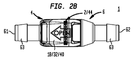
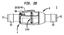
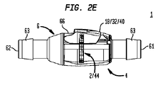
ここで、主として、生体医療用環境において採用される医療用管類等の管(3)を一緒に解放可能に接続するための発明的キャッチアセンブリ(2)を含むコネクタシステム(1)の特定の実施形態を使用する方法を図示する図1を参照する。有利なこととして、コネクタシステム(1)は、比較的に容易かつ確実に接続され、さらに、比較的に容易に意図的に接続解除されることができる。 Here, the particularity of a connector system (1) comprising an inventive catch assembly (2) for releasably connecting tubes (3) together, primarily medical tubing employed in biomedical environments. Reference is made to FIG. 1 which illustrates a method of using embodiments. Advantageously, the connector system (1) can be relatively easily and reliably connected and relatively easily intentionally disconnected.
概して、コネクタシステム(1)は、第1の通路(5)を有するメス型結合器(4)と、第2の通路(7)を有するオス型結合器(6)とを含む。メス型およびオス型結合器(4)(6)の解放可能かつ篏合可能な軸方向(または縦方向)結合時(またはより簡潔に述べると、メス型およびオス型結合器(4)(6)の接続時)、コネクタシステム(1)の接続状態が、達成され、第1および第2の通路(5)(7)を流体連通状態に配置し、流体流路(9)を提供する。 Generally, the connector system (1) includes a female coupler (4) with a first passageway (5) and a male coupler (6) with a second passageway (7). Upon releasable and matable axial (or longitudinal) coupling of the female and male couplers (4)(6) (or more succinctly, the female and male couplers (4)(6) )), a connected state of the connector system (1) is achieved, placing the first and second passages (5) (7) in fluid communication and providing a fluid flow path (9).
本発明の目的のために、縦方向は、第1の通路(5)、第2の通路(7)、および/または流体流路(9)に略平行であると考えられることができる。 For purposes of the present invention, the longitudinal direction can be considered to be substantially parallel to the first passageway (5), the second passageway (7) and/or the fluid flow path (9).
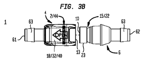
ここでより具体的には、(図3Aの例に示されるように)コネクタシステム(1)の接続状態を達成するために、オス型結合器(6)のオス型結合器篏合可能端部(10)が、メス型結合器(4)のメス型結合器内側空間(11)内に篏合可能に受け取られることができ、それによって、メス型結合器内側空間(11)は、メス型結合器篏合可能端部(13)に近接してメス型結合器内側表面(12)によって画定されることができる。 More specifically here, the male coupler matable end of the male coupler (6) to achieve the connected state of the connector system (1) (as shown in the example of FIG. 3A). (10) can be matably received within the female coupler inner space (11) of the female coupler (4), whereby the female coupler inner space (11) is a female It may be defined by a female coupler inner surface (12) proximate to the coupler matable end (13).
コネクタシステム(1)はさらに、メス型結合器(4)に移動可能に結合されるキャッチ(14)と、オス型結合器(6)に結合されるキャッチ受け取り要素(15)とを備えている、発明的キャッチアセンブリ(2)含む。メス型およびオス型結合器(4)(6)の接続時、キャッチ(14)は、キャッチ受け取り要素(15)と係合し、メス型結合器(4)の軸方向位置をオス型結合器(6)に関連して固定し、それによって、コネクタシステム(1)の接続状態を達成する。 The connector system (1) further comprises a catch (14) movably coupled to the female coupler (4) and a catch receiving element (15) coupled to the male coupler (6). , including the inventive catch assembly (2). Upon connection of the female and male couplers (4)(6), the catch (14) engages the catch receiving element (15) to shift the axial position of the female coupler (4) to that of the male coupler. (6), thereby achieving the connected state of the connector system (1).
本発明の目的のために、用語「キャッチ」は、キャッチ受け取り要素(15)との篏合可能係合時、部分的または完全に、メス型結合器(4)等の関連付けられた構成要素の移動を拘束するように機能し得る拘束部を意味する。 For the purposes of the present invention, the term "catch" is used to partially or fully, when in matable engagement with the catch-receiving element (15), of an associated component such as a female coupler (4). means a restraint that can function to restrain movement.
本発明の目的のために、用語「キャッチ受け取り要素」は、キャッチ(14)との篏合可能係合時、部分的または完全に、オス型結合器(6)等の関連付けられた構成要素の移動を拘束するように機能し得る拘束部を意味する。 For the purposes of the present invention, the term "catch receiving element" means that, upon mating engagement with the catch (14), partially or completely, an associated component, such as the male coupler (6). means a restraint that can function to restrain movement.
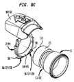
ここで主として、図2H、図3H、図4B、図5A-図5E、図6B、図7A-図7E、および図8A-図9Cを参照すると、キャッチアセンブリ(2)は、キャッチ(14)と、キャッチ(14)を付勢し得るキャッチ付勢部材(16)と、カム(18)に応答し得るフォロワー(17)とを備えていることができる。キャッチ(14)は、フォロワー(17)に応答することができ、対応して、キャッチ(14)は、カム(18)に応答することができる。 2H, 3H, 4B, 5A-5E, 6B, 7A-7E, and 8A-9C, catch assembly (2) comprises catch (14) and , a catch biasing member (16) capable of biasing the catch (14) and a follower (17) responsive to the cam (18). Catch (14) can respond to follower (17) and correspondingly catch (14) can respond to cam (18).
本発明の目的のために、用語「カム」は、機械的連結部内の移動可能な要素を意味し、それによって、カム(18)は、不規則な周辺を有することができ、運動を変換する、例えば、第1の方向における運動を第2の方向における運動に変換することにおいて有用であり得る。 For the purposes of the present invention, the term "cam" means a movable element within the mechanical linkage, whereby the cam (18) can have an irregular perimeter, transforming motion , for example, in converting motion in a first direction into motion in a second direction.
本発明の目的のために、用語「フォロワー」は、機械的連結部内の移動可能な要素を意味し、それによって、フォロワー(17)の移動は、カム(18)の移動からもたらされる。 For the purposes of the present invention, the term "follower" means a movable element within the mechanical linkage, whereby movement of the follower (17) results from movement of the cam (18).
キャッチアセンブリ(2)は、メス型結合器(4)に移動可能に結合されることができ、キャッチ(14)は、図4Bに示される第1の矢印(19)によって図示されるように、メス型結合器内側空間(11)に向かって内向きに、またはその中に移動し得るか、または、キャッチ(14)は、図6Bに示される第2の矢印(20)によって図示されるように、メス型結合器内側空間(11)から離れるように外向きに、またはそれから外に移動し得る。 The catch assembly (2) can be movably coupled to the female coupler (4), and the catch (14), as illustrated by the first arrow (19) shown in Figure 4B, Either the catch (14) can move inward toward or into the female coupler inner space (11), or the catch (14) can move as illustrated by the second arrow (20) shown in FIG. 6B. Additionally, it can move outward away from or out of the female coupler inner space (11).
さらに、キャッチアセンブリ(2)は、メス型結合器内側空間(11)を画定するメス型結合器内側表面(12)に移動可能に結合されることができる。一例証的例としてであるが、キャッチ(14)は、メス型結合器内側表面(12)内にはめ込まれたチャネル(21)内に移動可能に配置されることができ、それによって、チャネル(21)は、メス型結合器内側空間(11)と連通する。キャッチ(14)の大部分またはキャッチ(14)の全体がチャネル(21)内に受け取られると、キャッチ(14)は、メス型結合器内側空間(11)から外側に、かつ離れて配置されることができる。逆に、キャッチ(14)がメス型結合器内側空間(11)に向かって内側に、またはその中に移動すると、キャッチ(14)の大部分またはキャッチ(14)の全体は、チャネル(21)の外側に配置されることができる。 Further, the catch assembly (2) can be movably coupled to the female coupler inner surface (12) defining the female coupler inner space (11). As an illustrative example, the catch (14) may be movably disposed within a channel (21) embedded within the female coupler inner surface (12), thereby allowing the channel ( 21) communicates with the female coupler inner space (11). When most of the catch (14) or all of the catch (14) is received in the channel (21), the catch (14) is positioned outwardly and away from the female coupler inner space (11). be able to. Conversely, when the catch (14) moves inward toward or into the female coupler inner space (11), most of the catch (14) or the entirety of the catch (14) moves into the channel (21). can be placed outside the
ここで主として、図3A-図3E、図3H、および図8A-図9Cを参照すると、キャッチ受け取り要素(15)は、オス型結合器篏合可能端部(10)に結合された保持溝(22)として構成されることができる。例えば、保持溝(22)は、オス型結合器篏合可能端部(10)に近接してオス型結合器外側表面(23)内に配置されることができる。 Referring now primarily to Figures 3A-3E, 3H and 8A-9C, the catch receiving element (15) is a retaining groove ( 22). For example, the retention groove (22) can be located in the male coupler outer surface (23) proximate to the male coupler matable end (10).
特定の実施形態に関して、保持溝(22)は、オス型結合器篏合可能端部(10)に近接してオス型結合器外側表面(23)の周囲に延びている円周保持溝(22)として構成されることができる。 For certain embodiments, the retention groove (22) is a circumferential retention groove (22) extending around the male coupler outer surface (23) proximate to the male coupler matable end (10). ).
したがって、メス型結合器内側空間(11)内でのオス型結合器篏合可能端部(10)の篏合可能受け取り時、保持溝(22)は、チャネル(21)と整列することができ、キャッチ(14)は、保持溝(22)との係合のために、チャネル(21)から外向きに、かつメス型結合器内側空間(11)に向かって内向きに移動し、それによって、キャッチ(14)を係合状態(24)に配置し、メス型結合器(4)の軸方向位置をオス型結合器(6)に関連して固定することができる。 Thus, upon matable reception of the male coupler matable end (10) within the female coupler inner space (11), the retaining groove (22) can be aligned with the channel (21). , the catch (14) moves outwardly from the channel (21) and inwardly toward the female coupler inner space (11) for engagement with the retaining groove (22), thereby , the catch (14) can be placed in engagement (24) to fix the axial position of the female coupler (4) in relation to the male coupler (6).
対照的に、キャッチ(14)は、メス型結合器内側空間(11)から外向きに、かつチャネル(21)の中に移動し、キャッチ(14)を係合解除状態(25)に配置することができ、キャッチ(14)は、保持溝(22)から係合解除され、メス型およびオス型結合器(4)(6)が互いから離れるような軸方向移動によって接続解除することを可能にする。 In contrast, the catch (14) moves outwardly from the female coupler inner space (11) and into the channel (21), placing the catch (14) in a disengaged state (25). The catch (14) is disengaged from the retaining groove (22) allowing the female and male couplers (4) (6) to disconnect by axial movement away from each other. to
ここで主として、図2Aおよび図3Aを参照すると、換言すると、キャッチアセンブリ(2)は、メス型結合器(4)に移動可能に結合されることができ、キャッチ(14)は、(i)該メス型結合器の縦方向軸または(ii)第1の通路(5)に略直交する平面(26)内で移動し得る。例えば、キャッチ(14)は、平面(26)内で垂直に移動することができ、本発明の目的のために、用語「垂直」およびその派生語は、側から側にではなく、上下に位置付けられることを意味し、それによって、「垂直」は、特に、本発明の位置、向き、または使用に関して限定であることを意図しておらず、代わりに、図に示されるコネクタシステム(1)の描写に関する方向基準を提供し、読者の本発明の理解を支援することを意図している。 Referring now primarily to FIGS. 2A and 3A, in other words, catch assembly (2) can be movably coupled to female coupler (4), catch (14) is (i) It may move in a plane (26) substantially perpendicular to the longitudinal axis of the female coupler or (ii) the first passageway (5). For example, the catch (14) can move vertically in the plane (26), and for the purposes of the present invention the term "vertical" and its derivatives are positioned up and down rather than side-to-side. "Vertical" is thereby not intended to be a limitation, particularly as to the position, orientation or use of the present invention, instead of the connector system (1) shown in the figure. It is intended to provide a directional reference for the depiction and to assist the reader in understanding the invention.
続いて、メス型結合器内側空間(11)内でのオス型結合器篏合可能端部(10)の篏合可能受け取り時、保持溝(22)、チャネル(21)、およびキャッチ(14)は、平面(26)内で整列し、保持溝(22)との係合のために、チャネル(21)からの外向き、かつ平面(26)内の上向きのキャッチ(14)の移動を可能にし、それによって、キャッチ(14)を係合状態(24)に配置し、メス型結合器(4)の軸方向位置をオス型結合器(6)に関連して固定することができる。 Subsequently, upon matable reception of the male coupler matable end (10) within the female coupler interior space (11), the retaining groove (22), channel (21) and catch (14) aligns in plane (26) and allows movement of catch (14) outward from channel (21) and upward in plane (26) for engagement with retaining groove (22) , thereby placing the catch (14) in engagement (24) and fixing the axial position of the female coupler (4) in relation to the male coupler (6).
一方、キャッチ(14)は、平面(26)内で下向きに、かつチャネル(21)の中に移動し、キャッチ(14)を係合解除状態(25)に配置することができ、キャッチ(14)は、保持溝(22)から係合解除され、メス型およびオス型結合器(4)(6)が互いから離れるような軸方向移動によって接続解除することを可能にする。 Meanwhile, catch (14) can move downward in plane (26) and into channel (21) to place catch (14) in disengaged condition (25) and catch (14) ) disengage from the retaining groove (22), allowing the female and male couplers (4) (6) to disconnect by axial movement away from each other.
キャッチ(14)は、図4A-図5Eの例に示されるように、通常、キャッチ付勢部材(16)によって係合状態(24)に向かって(またはメス型結合器内側空間(11)に向かって内向きに、もしくは平面(26)内で上向きに)付勢されることができる。対応して、キャッチ(14)は、通常、保持溝(22)との係合に向かって付勢されることができる。 Catch (14) is normally pushed toward engagement (24) (or into female coupler interior space (11) by catch biasing member (16), as shown in the examples of FIGS. 4A-5E. can be biased inward toward or upward in plane (26)). Correspondingly, the catch (14) can be normally biased toward engagement with the retaining groove (22).
一例証的例としてであるが、キャッチ付勢部材(16)は、曲げられた後、その元々の曲げられていない状態(29)に向かって、またはそれに戻り得る弾力的に可撓な部材(28)等の跳ね返る要素(27)として構成されることができる。 As an illustrative example, the catch biasing member (16) is a resiliently flexible member ( 28) can be configured as a rebounding element (27).
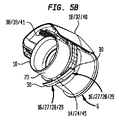
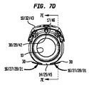
特定の実施形態に関して、弾力的に可撓な部材(28)は、キャッチ(14)から外向きに(例えば、半径方向に外向きに)または下向きに(例えば、半径方向に下向きに)延びており、メス型結合器内側表面(12)に支えられた1つ以上の弾力的に可撓なアーム(30)を備えていることができる。例えば、弾力的に可撓なアーム(30)は、チャネル(21)を画定するメス型結合器内側表面(12)の一部を圧迫し得る。したがって、弾力的に可撓なアーム(30)は、チャネル(21)内に配置されることができ、さらに、キャッチ(14)と同一平面上にあり得、それによって、キャッチ(14)および弾力的に可撓なアーム(30)の両方は、平面(26)内で移動する。 For certain embodiments, the resiliently flexible member (28) extends outward (eg, radially outward) or downward (eg, radially downward) from the catch (14). Cage and may comprise one or more resiliently flexible arms (30) supported on the female coupler inner surface (12). For example, the resiliently flexible arm (30) may compress a portion of the female coupler inner surface (12) that defines the channel (21). Thus, the resiliently flexible arm (30) can be disposed within the channel (21) and can also be coplanar with the catch (14), thereby allowing the catch (14) and the resilient Both of the flexible arms (30) move within the plane (26).
したがって、弾力的に可撓な部材(28)が、通常の付勢状態である曲げられていない状態(29)に配置されているとき、弾力的に可撓な部材(28)は、キャッチ(14)を係合状態(24)に向かって(またはメス型結合器内側空間(11)に向かって内向きに、もしくは平面(26)内で上向きに)付勢する。 Thus, when the resiliently flexible member (28) is placed in its normal biased state, the unbent state (29), the resiliently flexible member (28) is engaged with the catch ( 14) toward engagement (24) (or inward toward female coupler inner space (11) or upward in plane (26)).
強制的な押し進め時、弾力的に可撓な部材(28)は、(図6A-図7Eの例に示されるような)曲げられた状態(31)に向かって曲げられることができ、これは、キャッチ(14)が、メス型結合器内側空間(11)から離れるように外向きに、または平面(26)内で下向きに移動し、キャッチ受け取り要素(15)から係合解除することを可能にし、コネクタシステム(1)の接続解除状態を達成する。 Upon forced pushing, the resiliently flexible member (28) can be bent toward a bent state (31) (as shown in the examples of FIGS. 6A-7E), which , allowing the catch (14) to move outward away from the female coupler inner space (11) or downward in the plane (26) to disengage from the catch receiving element (15). to achieve the disconnected state of the connector system (1).
特定の実施形態に関して、キャッチ付勢部材(16)は、リビングヒンジとして構成されることができる。 For certain embodiments, catch biasing member (16) may be configured as a living hinge.
保持溝(22)との係合のためのキャッチ(14)の内向きまたは上向き移動が、少なくとも部分的に、キャッチ付勢部材(16)によって促進され得るので、保持溝(22)内からキャッチ(14)を係合解除させるためのキャッチ(14)の外向きまたは下向き移動は、少なくとも部分的に、カム(18)として機能し得る解放要素(32)によって促進されることができ、解放要素(32)は、フォロワー(17)を作動させ、対応して、キャッチ(14)を作動させるように構成される。解放要素(32)は、米国特許出願第15/410,636号および米国特許出願第15/447,033号(それらの各々が、本明細書に参照することによってその全体として本明細書に組み込まれる)にさらに詳細に説明されている。 Inward or upward movement of the catch (14) for engagement with the retaining groove (22) may be facilitated, at least in part, by the catch biasing member (16) so that the catch (14) is removed from within the retaining groove (22). Outward or downward movement of catch (14) to disengage (14) may be facilitated, at least in part, by a release element (32), which may function as a cam (18), the release element (32) is arranged to actuate the follower (17) and correspondingly to actuate the catch (14). The release element (32) is disclosed in US patent application Ser. ) for further details.
解放要素(32)は、メス型結合器(4)に移動可能に結合されることができ、それによって、メス型結合器外側表面(66)に沿った、またはそれにわたる解放要素(32)の移動は、キャッチ(14)をキャッチ受け取り要素(15)から係合解除し、コネクタシステム(1)の接続解除状態を達成する。 The release element (32) can be movably coupled to the female coupler (4), thereby allowing the release element (32) to move along or across the female coupler outer surface (66). Movement disengages the catch (14) from the catch receiving element (15) to achieve the disconnected state of the connector system (1).
例えば、メス型結合器外側表面(66)に沿った解放要素(32)の線形またはスライド運動は、フォロワー(17)の移動に変換されることができ、それによって、フォロワー(17)のこの移動は、キャッチ付勢部材(16)を通常の曲げられていない状態(29)から離れるように、かつ曲げられた状態(31)に向かって強制的に押し進め、キャッチ(14)が、メス型結合器内側空間(11)から離れるように外向きに、または平面(26)内で下向きに移動し、保持溝(22)から係合解除することを可能にすることができる。 For example, linear or sliding movement of the release element (32) along the female coupler outer surface (66) can be translated into movement of the follower (17), whereby this movement of the follower (17) forces the catch biasing member (16) away from the normal unbent condition (29) and towards the bent condition (31) so that the catch (14) engages the female coupling It can be allowed to move outwards away from the inner vessel space (11) or downwards in the plane (26) to disengage from the retaining grooves (22).
したがって、フォロワー(17)は、キャッチ付勢部材(16)に動作可能に結合され、対応して、キャッチ(14)に動作可能に結合されることができる。加えて、フォロワー(17)は、メス型結合器外側表面(66)に近接してメス型結合器(4)に移動可能に結合されることができる。例えば、フォロワー(17)は、(図9Aの例に示されるように)メス型結合器外側表面(66)によって画定される開口部(33)内に移動可能に配置されることができ、それによって、開口部(33)は、開口部(33)を通した、メス型結合器内側空間(11)に向かって内向き、もしくは平面(26)内で下向きの、またはメス型結合器内側空間(11)から離れるような外向き、もしくは平面(26)内で上向きのフォロワー(17)の移動を可能にするように十分に構成されることができる。さらに、フォロワー(17)は、解放要素(32)の真下でメス型結合器(4)に移動可能に結合されることができる。 Accordingly, follower (17) may be operably coupled to catch biasing member (16) and correspondingly operably coupled to catch (14). Additionally, the follower (17) can be movably coupled to the female coupler (4) proximate to the female coupler outer surface (66). For example, follower (17) may be movably disposed within opening (33) defined by female coupler outer surface (66) (as shown in the example of FIG. 9A), which The opening (33) is directed inward toward the female coupler inner space (11) through the opening (33), or downward in the plane (26), or the female coupler inner space. It can be well configured to allow movement of the follower (17) outwards away from (11) or upwards in the plane (26). Additionally, the follower (17) can be movably coupled to the female coupler (4) beneath the release element (32).
ここで主として、図4B、図5E、図6B、および図7Eを参照すると、メス型結合器外側表面(66)に近接して(または隣接して)配置された解放要素内側表面(34)が、係止表面(36)と、係止解除表面(37)とを有するカム表面(35)を提供することができ、その両方は、フォロワー(17)と別個に相互作用すること、またはそれに直接接触し、キャッチ(14)の移動をもたらすことができる。 Referring now primarily to Figures 4B, 5E, 6B, and 7E, the release element inner surface (34) located proximate (or adjacent) to the female coupler outer surface (66) is , a locking surface (36) and an unlocking surface (37), both of which interact separately with or directly with the follower (17). contact and can result in movement of the catch (14).
係止解除表面(37)は、係止表面(36)を上回る距離をメス型結合器外側表面(66)に向かって下向きに延び、それによって、係止表面(36)よりもメス型結合器外側表面(66)により近接して係止解除表面(37)を配置する。換言すると、係止表面(36)は、係止解除表面(37)を上回る距離をメス型結合器外側表面(66)から離れるように上向きに延び、それによって、係止解除表面(37)よりもメス型結合器外側表面(66)からより遠くに係止表面(36)を配置する。 The unlocking surface (37) extends downward toward the female coupler outer surface (66) a distance beyond the locking surface (36), thereby allowing the female coupler to face the female coupler more than the locking surface (36). Placing the unlocking surface (37) closer to the outer surface (66). In other words, locking surface (36) extends upwardly away from female coupler outer surface (66) a distance greater than unlocking surface (37), thereby extending more than unlocking surface (37). also places the locking surface (36) farther from the female coupler outer surface (66).
対応して、係止表面(36)をフォロワー(17)と整列(または接触)させるためのフォロワー(17)の上でのカム表面(35)の移動は、キャッチ(14)が、保持溝(22)との係合に向かってキャッチ付勢部材(16)によって内向きまたは上向きに付勢されることを可能にし、コネクタシステム(1)の接続状態を達成する。逆に、係止解除表面(37)をフォロワー(17)と整列(または接触)させるためのフォロワー(17)の上でのカム表面(35)の移動は、キャッチ付勢部材(16)を曲げられた状態(31)に向かって付勢し、それに応じて、キャッチ(14)を外向きまたは下向きに、かつ保持溝(22)から離れるように付勢し、それによって、キャッチ(14)が保持溝(22)から係合解除することを可能にし、係合解除状態(25)を達成する。 Correspondingly, movement of cam surface (35) over follower (17) to align (or contact) locking surface (36) with follower (17) causes catch (14) to engage retaining groove ( 22) to be biased inwardly or upwardly by the catch biasing member (16) toward engagement with the connector system (1) to achieve the connected condition. Conversely, movement of the cam surface (35) over the follower (17) to align (or contact) the unlocking surface (37) with the follower (17) bends the catch biasing member (16). biasing toward the closed state (31), correspondingly biasing the catches (14) outwardly or downwardly and away from the retaining grooves (22), thereby causing the catches (14) to Allowing disengagement from the retaining groove (22) to achieve a disengaged state (25).
ここで主として、図2H、図3H、および図4A-図5Eを参照すると、解放要素付勢部材(38)、例えば、弾力的に圧縮可能な部材(39)は、非圧縮状態(41)にあるとき、解放要素(32)を通常の付勢状態である解放要素の第1の位置(40)に向かって付勢することができる。解放要素の第1の位置(40)にあるとき、係止表面(36)は、フォロワー(17)と整列(または接触)し、対応して、キャッチ(14)を内向きまたは上向きに、かつ保持溝(22)との係合に向かって付勢し、コネクタシステム(1)の接続状態を達成する。 Referring now primarily to Figures 2H, 3H, and 4A-5E, a release element biasing member (38), such as a resiliently compressible member (39), is in an uncompressed state (41). At some point, the release element (32) can be biased toward the first position (40) of the release element, which is the normally biased state. When in the first position (40) of the release element, the locking surface (36) aligns (or contacts) with the follower (17), correspondingly pointing the catch (14) inwardly or upwardly, and It is biased towards engagement with the retaining groove (22) to achieve the connected condition of the connector system (1).
ここで主として、図6A-図7Eを参照すると、強制的な押し進め時、弾力的に圧縮可能な部材(39)は、圧縮状態(42)に向かって圧縮され、係止解除表面(37)がフォロワー(17)と整列(または接触)する解放要素の第2の位置(43)に解放要素(32)を配置し、キャッチ付勢部材(16)を曲げられた状態(31)に向かって付勢し、キャッチ(17)が保持溝(22)から離れるように外向きに移動することを可能にし、コネクタシステム(1)の接続解除状態を達成することができる。 Referring now primarily to Figures 6A-7E, upon forced pushing, the resiliently compressible member (39) is compressed toward the compressed state (42) and the unlocking surface (37) is locating the release element (32) in a release element second position (43) aligned with (or in contact with) the follower (17) and urging the catch biasing member (16) toward the bent state (31); force, allowing the catches (17) to move outwardly away from the retaining grooves (22) to achieve the disconnected state of the connector system (1).
特定の実施形態に関して、キャッチ(14)、キャッチ付勢部材(16)、およびフォロワー(17)は、(i)一体部品構造であり得るか、または、(ii)一体部品構造として形成され得るキャッチアセンブリ(2)を提供するために統合されることができる。換言すると、キャッチ(14)、キャッチ付勢部材(16)、およびフォロワー(17)は、一体的に形成されることができ、それは、単一の完全な部品もしくはユニットを構成するように、または、単一の完全な部品もしくはユニットとして一緒に機能し、かつ部品もしくはユニットの完全性を損なうことなく容易に分解されることが可能でないように、一緒に接続されることを意味する。 For certain embodiments, the catch (14), catch biasing member (16), and follower (17) may be (i) a one-piece construction or (ii) formed as a one-piece construction. It can be integrated to provide an assembly (2). In other words, catch (14), catch biasing member (16) and follower (17) may be integrally formed, such that it constitutes a single complete part or unit, or , means connected together such that they function together as a single complete part or unit and cannot be easily disassembled without compromising the integrity of the part or unit.
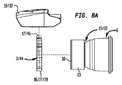
特定の実施形態に関して、キャッチアセンブリ(2)は、環状部材(44)を備えていることができ、それによって、環状部材(44)の第1の部分(45)は、キャッチ(14)を提供することができ、環状部材(44)の対向する第2の部分(46)は、フォロワー(17)を提供することができる。この特定の実施形態に関して、キャッチ付勢部材(16)は、キャッチ(14)を提供する環状部材(44)の第1の部分(45)から外向きに延びていることができる。 For certain embodiments, catch assembly (2) may comprise an annular member (44) whereby a first portion (45) of annular member (44) provides catch (14). and the opposing second portion (46) of the annular member (44) may provide the follower (17). For this particular embodiment, the catch biasing member (16) may extend outwardly from the first portion (45) of the annular member (44) that provides the catch (14).
特定の実施形態に関して、環状部材(44)は、メス型結合器(4)に移動可能に結合されることができ、それによって、キャッチ(14)は、図4Bに示される第1の矢印(19)によって図示されるように、メス型結合器内側空間(11)に向かって内向きに、もしくはその中に移動し得、または、キャッチ(14)は、図6Bに示される第2の矢印(20)によって図示されるように、メス型結合器内側空間(11)から離れるように外向きに、もしくはそれから外に移動し得る。 For certain embodiments, the annular member (44) can be movably coupled to the female coupler (4) such that the catch (14) is aligned with the first arrow ( 19) can move inward toward or into the female coupler inner space (11), or the catch (14) can move inwards towards the second arrow shown in FIG. 6B. As illustrated by (20), it can move outward away from or out of the female coupler inner space (11).
さらに、環状部材(44)は、メス型結合器内側空間(11)を画定するメス型結合器内側表面(12)に移動可能に結合されることができる。一例証的例としてであるが、環状部材(44)は、メス型結合器内側表面(12)内にはめ込まれたチャネル(21)内に移動可能に配置されることができる。 Additionally, the annular member (44) may be movably coupled to the female coupler inner surface (12) defining the female coupler inner space (11). As an illustrative example, the annular member (44) may be movably disposed within a channel (21) that fits within the female coupler inner surface (12).
したがって、メス型結合器内側空間(11)内でのオス型結合器篏合可能端部(10)の篏合可能結合時、オス型結合器篏合可能端部(10)は、環状部材(44)によって画定される環状部材開口部を通過し、コネクタシステム(1)の接続状態を達成することができ、対応して、流体流路(9)は、環状部材開口部を通過することができる。 Therefore, during the matable coupling of the male coupler matable end (10) in the female coupler inner space (11), the male coupler matable end (10) is attached to the annular member ( 44) to achieve a connected state of the connector system (1) and correspondingly the fluid flow path (9) can pass through the annular member opening. can.
(第1の弁)
特定の実施形態に関して、コネクタシステム(1)は、少なくとも1つの導管(47)(48)と、導管(47)(48)を通した流体流動を中断させるように動作可能な少なくとも1つの弁(49)(50)とをさらに含むことができる。
(first valve)
For certain embodiments, the connector system (1) comprises at least one conduit (47) (48) and at least one valve ( 49) (50).
ここで主として、図2Hおよび図3Hを参照すると、メス型結合器(4)は、第1の通路(5)を画定する第1の導管(47)(特定の実施形態に関して、固定または取り外し可能なフィルタを含み得る)と、第1の通路(5)を通した流体流動を中断させるように動作可能な第1の弁(49)とを含むことができる。第1の弁(49)は、第1の弁座(51)内で移動可能であり、第1の通路(5)と流体連通する第1のポート(52)をシール可能に閉塞し、それによって、第1のポート(52)を通した、それに応じて、第1の通路(5)を通した流体流動が中断される第1の通路閉鎖状態(53)を提供することができる。 Referring now primarily to Figures 2H and 3H, the female coupler (4) is connected to a first conduit (47) (fixed or detachable for certain embodiments) that defines the first passageway (5). a filter) and a first valve (49) operable to interrupt fluid flow through the first passageway (5). A first valve (49) is movable within a first valve seat (51) to sealably occlude a first port (52) in fluid communication with the first passageway (5) and can provide a first passageway closed state (53) in which fluid flow through the first port (52) and, accordingly, through the first passageway (5) is interrupted.
第1の弁(49)は、第1の弁(49)を第1の弁閉鎖位置(55)に向かって付勢する第1の弁付勢部材(54)によって付勢されることができ、第1の弁閉鎖位置において、第1の弁(49)は、例えば、第1のポート(52)をシール可能に覆い、第1の通路閉鎖状態(53)を提供することによって、第1のポート(52)をシール可能に閉塞する。 The first valve (49) may be biased by a first valve biasing member (54) biasing the first valve (49) toward the first valve closed position (55). , in the first valve closed position, the first valve (49), for example, sealably covers the first port (52) to provide a first passage closed condition (53), thereby providing a first closed state (53). port (52) of is sealably closed.
第1の弁(49)および第1の弁付勢部材(54)は、米国特許出願第15/410,636号および米国特許出願第15/447,033号(それらの各々が、本明細書に参照することによってその全体として本明細書に組み込まれる)にさらに詳細に説明されている。 The first valve (49) and first valve biasing member (54) are disclosed in U.S. patent application Ser. which is incorporated herein by reference in its entirety).
(第2の弁)
再び、主として、図2Hおよび図3Hを参照すると、オス型結合器(6)は、第2の通路(7)を画定する第2の導管(48)(特定の実施形態に関して、固定または取り外し可能なフィルタを含み得る)と、第2の通路(7)を通した流体流動を中断させるように動作可能な第2の弁(50)とを含むことができる。
(second valve)
Again referring primarily to Figures 2H and 3H, the male coupler (6) connects to a second conduit (48) (fixed or detachable for certain embodiments) that defines the second passageway (7). a filter) and a second valve (50) operable to interrupt fluid flow through the second passageway (7).
第2の弁(50)は、第2の弁座(56)内で移動可能であり、第2の通路(7)と流体連通する第2のポート(57)をシール可能に閉塞し、それによって、第2のポート(57)を通した、それに応じて、第2の通路(7)を通した流体流動が中断される第2の通路閉鎖状態(58)を提供することができる。 A second valve (50) is movable within a second valve seat (56) to sealably occlude a second port (57) in fluid communication with the second passageway (7) and can provide a second passageway closed condition (58) in which fluid flow through the second port (57) and, accordingly, through the second passageway (7) is interrupted.
第2の弁(50)は、第2の弁(50)を第2の弁閉鎖位置(60)に向かって付勢する第2の弁付勢部材(59)によって付勢されることができ、第2の弁閉鎖位置において、第2の弁(50)は、例えば、第2のポート(57)をシール可能に覆い、第2の通路閉鎖状態(58)を提供することによって、第2のポート(57)をシール可能に閉塞する。 The second valve (50) may be biased by a second valve biasing member (59) biasing the second valve (50) toward the second valve closed position (60). , in the second valve closed position, the second valve (50), for example, sealably covers the second port (57) to provide a second passageway closed condition (58), thereby providing a second port (57) of is sealably closed.
第2の弁(50)および第2の弁付勢部材(59)は、米国特許出願第15/410,636号および米国特許出願第15/447,033号(それらの各々が、本明細書に参照することによってその全体として本明細書に組み込まれる)にさらに詳細に説明されている。 The second valve (50) and second valve biasing member (59) are disclosed in U.S. patent application Ser. which is incorporated herein by reference in its entirety).
(管類)
ここで主として、図1を参照すると、特定の実施形態に関して、上で説明されるようなコネクタシステム(1)は、バーブ(63)として構成され得るコネクタシステム端部(61)(62)に結合される少なくとも1つの管(3)をさらに含むことができる。故に、管(3)は、例えば、バーブ(63)の周りでの摩擦係合を介して、バーブ(63)と係合し、管(3)をコネクタシステム(1)に確実に結合することができる。特定の実施形態に関して、第1の管(64)は、コネクタシステムの第1の端部(61)に結合されることができ、第2の管(65)は、コネクタシステムの第2の端部(62)に結合されることができ、コネクタシステム(1)は、第1の管(64)とび第2の管(65)とを流体的に接続するように機能する。
(tubes)
Referring now primarily to FIG. 1, for certain embodiments the connector system (1) as described above couples to connector system ends (61) (62) which may be configured as barbs (63). It can further comprise at least one tube (3) that is Thus, tube (3) engages barb (63), for example via frictional engagement around barb (63), to securely couple tube (3) to connector system (1). can be done. For certain embodiments, the first tube (64) can be coupled to the first end (61) of the connector system and the second tube (65) can be coupled to the second end of the connector system. The connector system (1), which can be coupled to the portion (62), serves to fluidly connect the first tube (64) and the second tube (65).
他の特定の実施形態に関して、コネクタシステムの第1および/または第2の端部(61)(62)は、ルアーロック継手、外部または内部にねじ山を付けられ得るねじ山付き継手、または、管(3)をコネクタシステム端部(61)(62)に結合するために有用であり得る任意の従来の端部継手もしくは従来にない端部継手として構成されることができる。 For certain other embodiments, the first and/or second ends (61) (62) of the connector system may be luer lock fittings, threaded fittings which may be externally or internally threaded, or It can be configured as any conventional or non-conventional end fitting that can be useful for coupling the tube (3) to the connector system ends (61) (62).
他の特定の実施形態に関して、コネクタシステムの第1および/または第2の端部(61)(62)は、管(3)をコネクタシステム端部(61)(62)に結合するために有用であり得るフランジとして構成されることができる。 For other specific embodiments, the first and/or second ends (61) (62) of the connector system are useful for coupling the tube (3) to the connector system ends (61) (62). can be configured as a flange that can be
管(3)を解放可能に接続するためのコネクタシステム(1)の特定の実施形態を作製する方法は、第1の通路(5)を有するメス型結合器(4)を提供することと、第2の通路(7)を有するオス型結合器(6)を提供することと、メス型結合器(4)に移動可能に結合されたキャッチ(14)と、キャッチ(14)を付勢するキャッチ付勢部材(16)と、カム(18)に応答するフォロワー(17)とを含むキャッチアセンブリ(2)を提供することとを含むことができ、それによって、キャッチ(14)は、フォロワー(17)に応答し、対応して、カム(18)に応答する。 A method of making a particular embodiment of a connector system (1) for releasably connecting tubes (3) comprises providing a female coupler (4) having a first passageway (5); providing a male coupler (6) having a second passageway (7), a catch (14) movably coupled to the female coupler (4), and biasing the catch (14). providing a catch assembly (2) including a catch biasing member (16) and a follower (17) responsive to the cam (18) whereby the catch (14) is adapted to the follower ( 17) and correspondingly to cam (18).
コネクタシステム(1)を作製する方法は、上記および請求項に説明されるように、コネクタシステム(1)の追加の構成要素を提供することをさらに含むことができる。 The method of making the connector system (1) may further comprise providing additional components of the connector system (1) as described above and in the claims.
コネクタシステム(1)の構成要素は、機能コネクタシステム(1)を提供することが可能な多数かつ多種多様な材料のいずれかのうちの1つ以上のものから形成されることができる。例証的例として、材料は、ゴム、ゴム様材料、プラスチック、プラスチック様材料、アクリル、ポリアミド、ポリエステル、ポリプロピレン、ポリエチレン、ポリ塩化ビニルベースの材料、シリコーンベースの材料等、もしくはそれらの組み合わせを含むか、またはそれから成ることができる。追加の例証的例は、ポリマー材料または樹脂、例えば、アクリル、ナイロン、ポリベンゾイミダゾール、ポリエチレン、ポリプロピレン、ポリスチレン、ポリ塩化ビニル、ポリテトラフルオロエチレン等、もしくはそれらの組み合わせ等の熱可塑性物質、ポリエステルファイバガラス、ポリウレタン、ゴム、ポリオキシベンジルメチレングリコールアンハイドライド、尿素-ホルムアルデヒド発泡体、メラミン樹脂、エポキシ樹脂、ポリイミド、シアン酸エステル、ポリシアヌレート、ポリエステル樹脂等、もしくはそれらの組み合わせ等の熱硬化性物質、天然ポリイソプレン、合成ポリイソプレン、ポリブタジエン、クロロプレンゴム、ブチルゴム、スチレン-ブタジエンゴム、ニトリルゴム、エチレンプロピレンゴム、エピクロロヒドリンゴム、ポリアクリルゴム、シリコーンゴム、フルオロシリコーンゴム、フルオロエラストマ、パーフルオロエラストマ、ポリエーテルブロックアミド、クロロスルホン化ポリエチレン、エチレン-酢酸ビニル、熱可塑性エラストマ(TPE)等、もしくはそれらの組み合わせ等のエラストマを含むことができる。 Components of the connector system (1) can be formed from one or more of any of the many and wide variety of materials that are capable of providing a functional connector system (1). As illustrative examples, the material may include rubber, rubber-like materials, plastics, plastic-like materials, acrylics, polyamides, polyesters, polypropylene, polyethylene, polyvinyl chloride-based materials, silicone-based materials, etc., or combinations thereof. , or may consist of Additional illustrative examples are polymeric materials or resins, thermoplastics such as acrylic, nylon, polybenzimidazole, polyethylene, polypropylene, polystyrene, polyvinyl chloride, polytetrafluoroethylene, etc., or combinations thereof, polyester fibers. Thermosetting materials such as glass, polyurethane, rubber, polyoxybenzylmethylene glycol anhydride, urea-formaldehyde foam, melamine resin, epoxy resin, polyimide, cyanate ester, polycyanurate, polyester resin, etc., or combinations thereof , natural polyisoprene, synthetic polyisoprene, polybutadiene, chloroprene rubber, butyl rubber, styrene-butadiene rubber, nitrile rubber, ethylene propylene rubber, epichlorohydrin rubber, polyacrylic rubber, silicone rubber, fluorosilicone rubber, fluoroelastomer, perfluoroelastomer , polyether block amides, chlorosulfonated polyethylene, ethylene-vinyl acetate, thermoplastic elastomers (TPE), etc., or combinations thereof.
特定の実施形態に関して、コネクタシステム(1)の1つ以上の構成要素は、抗菌材料から形成されることができる。 For certain embodiments, one or more components of connector system (1) may be formed from antimicrobial materials.
特定の実施形態に関して、コネクタシステム(1)の1つ以上の構成要素は、非金属材料から全体的に形成されることができる。 For certain embodiments, one or more components of connector system (1) may be formed entirely from non-metallic materials.
加えて、コネクタシステム(1)の構成要素は、用途に応じて、1つの部品として、プレス成形、射出成形、製作、機械加工、印刷、付加印刷等、もしくはそれらの組み合わせ等の多種多様なプロセスのいずれかから生産され、または複数の部品からコネクタシステム(1)の構成要素に組み立てられることができる。 In addition, the components of the connector system (1) can be processed as one piece, depending on the application, in a wide variety of processes such as stamping, injection molding, fabrication, machining, printing, additive printing, etc., or combinations thereof. or assembled from multiple parts into components of the connector system (1).
特定の実施形態に関して、コネクタシステム(1)の1つ以上の構成要素は、用途に応じて、使い捨てまたは再使用可能であり得る。 For certain embodiments, one or more components of connector system (1) may be disposable or reusable, depending on the application.
管(3)を解放可能に接続するためのコネクタシステム(1)の特定の実施形態を使用する方法は、上で説明されるようなコネクタシステム(1)を取得することと、第1の管(64)をメス型結合器(4)に結合することと、第2の管(65)をオス型結合器(6)に結合することと、メス型およびオス型結合器(4)(6)を解放可能に結合し、コネクタシステム(1)の接続状態を達成することとを含むことができる。 A method of using a particular embodiment of a connector system (1) for releasably connecting tubes (3) comprises obtaining a connector system (1) as described above; (64) to female coupler (4); coupling a second tube (65) to male coupler (6); ) releasably coupling to achieve a connected state of the connector system (1).
特定の実施形態に関して、方法は、流体流路(9)を通して流体を流動させることをさらに含むことができる。 For certain embodiments, the method may further comprise flowing fluid through the fluid flow path (9).
特定の実施形態に関して、方法は、解放要素(32)を強制的に押し進め、メス型結合器外側表面(66)に沿って移動させ、キャッチ(14)をキャッチ受け取り要素(15)から係合解除し、コネクタシステム(1)の接続解除状態を達成することをさらに含むことができる。 For certain embodiments, the method includes forcing release element (32) to move along female coupler outer surface (66) to disengage catch (14) from catch receiving element (15). and achieving a disconnected state of the connector system (1).
前述から容易に理解されることができるように、本発明の基本的概念は、種々の方法で具現化され得る。本発明は、最良の様態を含む、コネクタシステムならびにそのようなコネクタシステムを作製および使用するための方法の多数の様々な実施形態を伴う。 As can be readily understood from the foregoing, the basic concepts of the invention can be embodied in various ways. The present invention involves many different embodiments of connector systems and methods for making and using such connector systems, including the best mode.
したがって、説明によって開示される、または本願に付随する図もしくは表に示される、本発明の特定の実施形態または要素は、限定であることを意図しておらず、むしろ、本発明によって一般的に包含される多数の様々な実施形態、またはそれらの任意の特定の要素に関して包含される均等物の例示を意図している。加えて、本発明の単一の実施形態または要素の具体的説明は、可能性として考えられる全ての実施形態または要素を明示的に説明しないこともあり、多くの代替が、説明および図によって暗示的に開示される。 Accordingly, the specific embodiments or elements of the invention disclosed by way of description or shown in the figures or tables accompanying this application are not intended to be limiting, but rather generally according to the invention. It is intended to be illustrative of the many different embodiments that are encompassed or equivalents that are encompassed with respect to any particular element thereof. In addition, a specific description of a single embodiment or element of the invention may not explicitly describe all possible embodiments or elements, and many alternatives are implicit in the description and figures. publicly disclosed.
装置の各要素または方法の各ステップは、装置の用語または方法の用語によって説明され得ることを理解されたい。そのような用語は、本発明が享有する、暗示的に広い範囲を明示的にすることが所望される場合に代用されることができる。一例としてであるが、方法の全てのステップは、アクション、そのアクションをとるための手段、またはそのアクションを引き起こす要素として開示され得ることを理解されたい。同様に、装置の各要素は、物理的要素または物理的要素が促進するアクションとして開示され得る。一例としてであるが、「コネクタ」の開示は、明示的に議論されるかどうかにかかわらず、「接続する」行為の開示を包含すると理解されるべきであり、逆に、「接続する」行為の開示が事実上存在した場合、そのような開示は、「コネクタ」およびさらに「接続するための手段」の開示を包含すると理解されるべきである。各要素またはステップのためのそのような代替用語は、説明に明示的に含まれると理解されるものである。 It is to be understood that each element of the apparatus or each step of the method may be described in terms of apparatus or method. Such terms may be substituted where desired to make explicit the implicitly broad scope to which this invention is entitled. By way of example only, it should be understood that all steps of a method may be disclosed as an action, a means for taking that action, or an element that causes that action. Similarly, each element of the device may be disclosed as a physical element or an action that a physical element facilitates. By way of example, disclosure of "connector" should be understood to encompass disclosure of the act of "connecting," whether explicitly discussed or not, and conversely, the act of "connecting." is to be understood to encompass disclosures of "connectors" and further "means for connecting", if any disclosures of are in fact present. Such alternate terminology for each element or step is understood to be expressly included in the description.
加えて、使用される各用語に関して、本願でのその利用が、そのような解釈と矛盾しない限り、Random House Webster’s Unabridged Dictionary第2版に含まれるような一般的な辞書の定義が、各用語について説明に含まれると理解されるべきであり、各定義は、参照することによって本明細書に組み込まれることを理解されたい。 In addition, for each term used, unless its use in this application contradicts such interpretation, a general dictionary definition, such as that contained in Random House Webster's Unbridged Dictionary, 2nd Edition, shall be used. Terms are to be understood to be included in the description, and each definition is to be understood to be incorporated herein by reference.
本明細書の全ての数値は、明示的に示されるかどうかにかかわらず、用語「約」によって修飾されると仮定される。本発明の目的のために、範囲は、「約」1つの特定の値から「約」別の特定の値まで表され得る。そのような範囲が表されるとき、別の実施形態は、一方の特定の値から他方の特定の値まで含む。終点による数値範囲の列挙は、その範囲内に組み込まれる全ての数値を含む。1~5の数値範囲は、例えば、1、1.5、2、2.75、3、3.80、4、5等の数値を含む。範囲のそれぞれの終点は、他の終点に関連して、および他の終点から独立して、両方で有意であることがさらに理解されるであろう。値が先行詞「約」の使用によって近似値として表されるとき、特定の値が別の実施形態を形成することが理解されるであろう。用語「約」は、概して、当業者が列挙された数値と同等である、または同一の機能もしくは結果を有すると見なすであろう数値の範囲を指す。同様に、先行詞「実質的に」は、完全ではなく大部分が同一の形態、様式、または程度を意味し、特定の要素は、当業者が同一の機能または結果を有すると見なすであろうような一連の構成を有するであろう。特定の要素が先行詞「実質的に」の使用によって近似値として表されるとき、特定の要素が別の実施形態を形成することが理解されるであろう。 All numerical values herein are assumed to be modified by the term "about," whether or not explicitly indicated. For the purposes of the present invention, ranges can be expressed as from "about" one particular value to "about" another particular value. When such a range is expressed, another embodiment includes from the one particular value to the other particular value. The recitation of numerical ranges by endpoints includes all numbers subsumed within that range. Numerical ranges from 1 to 5 include, for example, numbers such as 1, 1.5, 2, 2.75, 3, 3.80, 4, 5, and the like. It will be further understood that each endpoint of a range is significant both relative to and independent of the other endpoint. When values are expressed as approximations by the use of the antecedent "about," it will be understood that the particular value forms another embodiment. The term "about" generally refers to a range of numbers that one skilled in the art would consider equivalent to, or have the same function or result as, the recited number. Similarly, the antecedent "substantially" means the same form, manner, or degree for the most part but not the same, and the particular elements would be considered by those skilled in the art to have the same function or result. would have a series of configurations such as When a particular element is approximated by the use of the antecedent "substantially," it will be understood that the particular element forms another embodiment.
さらに、本発明の目的のために、用語「1つの」(「a」または「an」)実体は、別様に限定されない限り、その実体のうちの1つ以上のものを指す。したがって、用語「1つの」(「a」または「an」)、「1つ以上の」、および「少なくとも1つの」は、本明細書で同義的に使用されることができる。 Further, for the purposes of the present invention, the term "a" ("a" or "an") entity refers to one or more of that entity, unless otherwise limited. As such, the terms "a" ("a" or "an"), "one or more," and "at least one" can be used interchangeably herein.
さらに、本発明の目的のために、用語「結合される」またはその派生語は、実施形態に応じて、間接的に結合される、結合される、直接結合される、接続される、直接接続される、または統合されることを意味することができる。 Further, for the purposes of the present invention, the term “coupled” or derivatives thereof means indirectly coupled, coupled, directly coupled, connected, directly connected, depending on the embodiment. It can mean to be combined or integrated.
したがって、本出願者は、少なくとも、i)本明細書で開示および説明されるコネクタシステムの各々、ii)開示および説明される関連方法、iii)これらのデバイスおよび方法のそれぞれの類似、同等、およびさらに暗示的変形例、iv)示される、開示される機能または説明される機能の各々を遂行するそれらの代替実施形態、v)開示および説明されるものを遂行することが暗示的であるように示される機能の各々を達成するそれらの代替設計および方法、vi)別個の独立した発明として示される各特徴、構成要素、およびステップ、vii)開示される種々のシステムまたは構成要素によって強化される用途、viii)そのようなシステムまたは構成要素によって生産される結果として生じる製品、ix)本明細書の上で、および付随の例のうちのいずれかを参照して実質的に説明されるような方法および装置、x)開示される前述の要素のそれぞれの種々の組み合わせおよび順列を請求すると理解されるべきである。 Accordingly, applicant hereby acknowledges, at least, that i) each of the connector systems disclosed and described herein, ii) the associated methods disclosed and described, iii) the similarities, equivalents, and Further implied variations; iv) alternate embodiments thereof that perform each of the functions disclosed or described that are shown; v) as implied to perform that disclosed and described; vi) each feature, component, and step presented as a separate and independent invention; vii) applications enhanced by various disclosed systems or components; , viii) the resulting product produced by such system or component, ix) a method substantially as described hereinabove and with reference to any of the accompanying examples. and apparatus, x) it is to be understood that various combinations and permutations of each of the foregoing elements disclosed are claimed.
本特許願の背景技術の節は、存在する場合、本発明が関連する活動分野の記述を提供する。本節はまた、本発明が取り入れられる技術の状態についての情報、問題、または懸念を関係付けることに有用である、ある米国特許、特許出願、出版物、または請求される発明の主題の言い換えを組み込む、もしくは含み得る。本明細書で引用される、または組み込まれる、任意の米国特許、特許出願、出版物、記述、または他の情報は、本発明に関する従来技術として承認されるものと解釈される、理解される、または考えられることを意図していない。 The Background Art section of this patent application, if any, provides a description of the field of activity to which the invention pertains. This section also incorporates certain United States patents, patent applications, publications, or paraphrases of the subject matter of the claimed invention that are useful in relating information, problems, or concerns about the state of the art in which this invention is incorporated. or may include Any United States patents, patent applications, publications, statements, or other information cited or incorporated herein shall be construed, understood, and admitted as prior art with respect to the present invention, or not intended to be considered.
本明細書に記載される請求項は、存在する場合、本発明の本説明の一部として参照することによって本明細書に組み込まれ、本出願者は、請求項またはそれらの任意の要素もしくは構成要素のうちのいずれかまたは全てを支持するために、追加の説明等の請求項のそのような組み込まれた内容の全てまたは一部を使用する権利を明示的に留保し、本出願者はさらに、本願によって、またはその任意の後続の出願もしくは継続、分割、または部分的継続出願によって、保護が求められる事柄を定義するために、または、任意の国もしくは条約の特許法、規則、または規制に従って、もしくは準拠して、料金の削減の任意の利益を得るために、そのような請求項またはそれらの任意の要素もしくは構成要素の組み込まれる内容の任意の部分または全てを、説明から請求項の中へ、または逆も同様に、必要に応じて移動させる権利を明示的に留保し、参照することによって組み込まれる、そのような内容は、その任意の後続の継続、分割、または部分的継続出願、もしくはそれの任意の再発行または拡張を含む、本願の係属全体の間に存続するものとする。 The claims set forth herein, if any, are hereby incorporated by reference as part of this description of the invention, and Applicant reserves the right to expressly declare that the claim or any element or construction thereof, Applicant expressly reserves the right to use all or part of such incorporated subject matter of the claims, such as additional description, to support any or all of the elements, and applicant further , to define what is sought to be protected by this application, or by any subsequent application or continuation, divisional or continuation-in-part application thereof, or in accordance with the patent laws, rules or regulations of any country or treaty; or, pursuant to, any portion or all of the incorporated subject matter of such claims, or any element or component thereof, to obtain any benefit of reduced fees, from the description to the claims. We expressly reserve the right to transfer to, or vice versa, where necessary, such material incorporated by reference into any subsequent continuation, divisional or continuation-in-part application thereof, or survive the entire pendency of this application, including any reissues or extensions thereof.
加えて、本明細書に記載される請求項は、存在する場合、本発明の限定数の好ましい実施形態の境界を説明することをさらに意図しており、本発明の最も広義の実施形態または請求され得る本発明の実施形態の完全な一覧として解釈されるものではない。本出願者は、任意の継続、分割、または部分的継続、もしくは類似出願の一部として上で記載される説明に基づいて、さらなる請求項を作成するいかなる権利も放棄しない。 In addition, the claims set forth herein are further intended, if any, to delineate the boundaries of a limited number of preferred embodiments of the invention, and not the broadest embodiment or claim of the invention. It is not intended to be an exhaustive list of possible embodiments of the invention. Applicants do not waive any right to formulate further claims based on the description set forth above as part of any continuation, division, or continuation-in-part, or similar application.
Claims (18)
メス型結合器内側表面と、前記メス型結合器内側表面によって画定されるメス型結合器内側空間とを備えるメス型結合器と、
前記メス型結合器に移動可能に結合された解放要素であって、前記解放要素は、カム表面を提供する、解放要素と、
キャッチアセンブリと
を備え、
前記キャッチアセンブリは、
前記メス型結合器の移動を拘束するための前記メス型結合器に移動可能に結合されたキャッチと、
前記キャッチから外向きに延びている弾力的に可撓なアームの対を備えているキャッチ付勢部材であって、前記キャッチ付勢部材は、前記メス型結合器内側空間に向かって内向きに前記キャッチを付勢する、キャッチ付勢部材と、
前記キャッチ付勢部材および前記キャッチに動作可能に結合されたフォロワーであって、前記フォロワーは、前記カム表面に直接接触し、前記カム表面の移動が前記フォロワーの移動をもたらす、フォロワーと
を備え、
前記フォロワーの移動が前記キャッチの移動をもたらし、
前記キャッチアセンブリは、一体部品構造を備えている、コネクタシステム。 A connector system for releasably connecting tubes, said connector system comprising:
a female coupler comprising a female coupler inner surface and a female coupler inner space defined by said female coupler inner surface ;
a release element movably coupled to the female coupler, the release element providing a cam surface;
Equipped with a catch assembly and
The catch assembly includes:
a catch movably coupled to the female coupler for constraining movement of the female coupler;
A catch biasing member comprising a pair of resiliently flexible arms extending outwardly from said catch , said catch biasing member extending inwardly toward said female coupler interior space. a catch biasing member that biases the catch ;
a follower operably coupled to the catch biasing member and the catch, the follower directly contacting the cam surface, movement of the cam surface resulting in movement of the follower ;
movement of the follower results in movement of the catch ;
The connector system, wherein the catch assembly comprises a one-piece construction.
前記オス型結合器に結合されたキャッチ受け取り要素と
をさらに備え、
前記メス型結合器および前記オス型結合器の解放可能かつ篏合可能な軸方向結合時、前記キャッチは、前記キャッチ受け取り要素と係合し、前記メス型結合器の軸方向位置を前記オス型結合器に関連して固定する、請求項1に記載のコネクタシステム。 a male coupler;
a catch-receiving element coupled to the male coupler;
Upon releasable and matable axial mating of the female coupler and the male coupler, the catch engages the catch receiving element to shift the axial position of the female coupler to the male coupler. 2. The connector system of claim 1, fixed in relation to a coupler.
メス型結合器内側表面と、前記メス型結合器内側表面によって画定されるメス型結合器内側空間とを備えるメス型結合器と、
前記メス型結合器に移動可能に結合された解放要素であって、前記解放要素は、カム表面を提供する、解放要素と、
キャッチアセンブリと
を備え、
前記キャッチアセンブリは、
前記メス型結合器の移動を拘束するための前記メス型結合器に移動可能に結合されたキャッチと、
前記キャッチから外向きに延びている弾力的に可撓なアームの対を備えているキャッチ付勢部材であって、前記キャッチ付勢部材は、前記メス型結合器内側空間に向かって内向きに前記キャッチを付勢する、キャッチ付勢部材と、
前記キャッチ付勢部材および前記キャッチに動作可能に結合されたフォロワーであって、前記フォロワーは、前記カム表面に直接接触し、前記カム表面の移動が前記フォロワーの移動をもたらす、フォロワーと
を備え、
前記フォロワーの移動が前記キャッチの移動をもたらし、
前記キャッチは、前記メス型結合器に移動可能に結合されており、それによって、前記キャッチは、
前記メス型結合器内側空間に向かう内向き移動と、
前記メス型結合器内側空間から離れるような外向き移動と
が可能である、コネクタシステム。 A connector system for releasably connecting tubes, said connector system comprising:
a female coupler comprising a female coupler inner surface and a female coupler inner space defined by said female coupler inner surface ;
a release element movably coupled to the female coupler, the release element providing a cam surface;
Equipped with a catch assembly and
The catch assembly includes:
a catch movably coupled to the female coupler for constraining movement of the female coupler;
A catch biasing member comprising a pair of resiliently flexible arms extending outwardly from said catch , said catch biasing member extending inwardly toward said female coupler interior space. a catch biasing member that biases the catch ;
a follower operably coupled to the catch biasing member and the catch, the follower directly contacting the cam surface, movement of the cam surface resulting in movement of the follower ;
movement of the follower results in movement of the catch ;
The catch is movably coupled to the female coupler, whereby the catch:
inward movement toward the female coupler inner space;
outward movement away from said female coupler inner space.
前記チャネルは、前記メス型結合器内側空間と連通している、請求項9に記載のコネクタシステム。 said catch is movably disposed within a channel recessed within said female coupler inner surface;
10. The connector system of claim 9, wherein said channel communicates with said female coupler interior space.
前記オス型結合器に結合されたキャッチ受け取り要素と
をさらに備え、
前記メス型結合器および前記オス型結合器の解放可能かつ篏合可能な軸方向結合時、前記キャッチは、前記キャッチ受け取り要素と係合し、前記メス型結合器の軸方向位置を前記オス型結合器に関連して固定する、請求項10に記載のコネクタシステム。 a male coupler;
a catch-receiving element coupled to the male coupler;
Upon releasable and matable axial mating of the female coupler and the male coupler, the catch engages the catch receiving element to shift the axial position of the female coupler to the male coupler. 11. The connector system of claim 10, fixed in relation to the coupler.
メス型結合器内側表面と、前記メス型結合器内側表面によって画定されるメス型結合器内側空間とを備えるメス型結合器と、
前記メス型結合器に移動可能に結合された解放要素であって、前記解放要素は、カム表面を提供する、解放要素と、
キャッチアセンブリと
を備え、
前記キャッチアセンブリは、
前記メス型結合器の移動を拘束するための前記メス型結合器に移動可能に結合されたキャッチと、
前記キャッチから外向きに延びている弾力的に可撓なアームの対を備えているキャッチ付勢部材であって、前記キャッチ付勢部材は、前記メス型結合器内側空間に向かって内向きに前記キャッチを付勢する、キャッチ付勢部材と、
前記キャッチ付勢部材および前記キャッチに動作可能に結合されたフォロワーであって、前記フォロワーは、前記カム表面に直接接触し、前記カム表面の移動が前記フォロワーの移動をもたらす、フォロワーと
を備え、
前記フォロワーの移動が前記キャッチの移動をもたらす、コネクタシステム。 A connector system for releasably connecting tubes, said connector system comprising:
a female coupler comprising a female coupler inner surface and a female coupler inner space defined by said female coupler inner surface ;
a release element movably coupled to the female coupler, the release element providing a cam surface;
Equipped with a catch assembly and
The catch assembly includes:
a catch movably coupled to the female coupler for constraining movement of the female coupler;
A catch biasing member comprising a pair of resiliently flexible arms extending outwardly from said catch , said catch biasing member extending inwardly toward said female coupler interior space. a catch biasing member that biases the catch ;
a follower operably coupled to the catch biasing member and the catch, the follower directly contacting the cam surface, movement of the cam surface resulting in movement of the follower ;
A connector system wherein movement of the follower results in movement of the catch .
前記オス型結合器に結合されたキャッチ受け取り要素と
をさらに備え、
前記メス型結合器および前記オス型結合器の解放可能かつ篏合可能な軸方向結合時、前記キャッチは、前記キャッチ受け取り要素と係合し、前記メス型結合器の軸方向位置を前記オス型結合器に関連して固定する、請求項17に記載のコネクタシステム。 a male coupler;
a catch-receiving element coupled to the male coupler;
Upon releasable and matable axial mating of the female coupler and the male coupler, the catch engages the catch receiving element to shift the axial position of the female coupler to the male coupler. 18. The connector system of claim 17, fixed in relation to a coupler.
Applications Claiming Priority (5)
| Application Number | Priority Date | Filing Date | Title |
|---|---|---|---|
| US201762468800P | 2017-03-08 | 2017-03-08 | |
| US62/468,800 | 2017-03-08 | ||
| US15/912,280 US10350401B2 (en) | 2017-03-08 | 2018-03-05 | Catch assembly for releasably connecting fluid conduits |
| US15/912,280 | 2018-03-05 | ||
| PCT/US2018/021467 WO2018165375A1 (en) | 2017-03-08 | 2018-03-08 | Catch assembly for releasably connecting fluid conduits |
Publications (3)
| Publication Number | Publication Date |
|---|---|
| JP2020509810A JP2020509810A (en) | 2020-04-02 |
| JP2020509810A5 JP2020509810A5 (en) | 2021-04-15 |
| JP7149952B2 true JP7149952B2 (en) | 2022-10-07 |
Family
ID=63446798
Family Applications (1)
| Application Number | Title | Priority Date | Filing Date |
|---|---|---|---|
| JP2019547395A Active JP7149952B2 (en) | 2017-03-08 | 2018-03-08 | A catch assembly releasably connecting the fluid conduits |
Country Status (7)
| Country | Link |
|---|---|
| US (4) | US10350401B2 (en) |
| EP (1) | EP3593025A4 (en) |
| JP (1) | JP7149952B2 (en) |
| KR (1) | KR102657852B1 (en) |
| AU (1) | AU2018230968B2 (en) |
| CA (1) | CA3055117A1 (en) |
| WO (1) | WO2018165375A1 (en) |
Families Citing this family (9)
| Publication number | Priority date | Publication date | Assignee | Title |
|---|---|---|---|---|
| CA3042633A1 (en) | 2016-01-19 | 2017-07-27 | Wilmarc Holdings, Llc | Connector system for releasably connecting fluid conduits |
| US10350401B2 (en) | 2017-03-08 | 2019-07-16 | Wilmarc Holdings, Llc | Catch assembly for releasably connecting fluid conduits |
| US11199282B2 (en) * | 2017-08-11 | 2021-12-14 | Norma U.S. Holding Llc | Fluid line connector and assembly with securement detection |
| GB2578169A (en) * | 2018-10-19 | 2020-04-22 | Conceptomed As | Fluid transfer devices |
| CA3124263A1 (en) * | 2018-12-20 | 2020-06-25 | Centre For Commercialization Of Regenerative Medicine | Systems and methods for a reusable, aseptic connector |
| US20220243848A1 (en) * | 2019-06-10 | 2022-08-04 | Colder Products Company | Fluid handling couplings |
| US11771819B2 (en) * | 2019-12-27 | 2023-10-03 | Convatec Limited | Low profile filter devices suitable for use in negative pressure wound therapy systems |
| US11555567B2 (en) | 2020-06-30 | 2023-01-17 | Wilmarc Holdings, Llc | Sanitary fitting |
| JP2023070438A (en) * | 2021-11-09 | 2023-05-19 | パナソニックIpマネジメント株式会社 | Tube coupling |
Citations (2)
| Publication number | Priority date | Publication date | Assignee | Title |
|---|---|---|---|---|
| US20100127492A1 (en) | 2007-07-25 | 2010-05-27 | Philippe Poder | Coupling with an indicator |
| JP2015224687A (en) | 2014-05-27 | 2015-12-14 | 株式会社パイオラックス | connector |
Family Cites Families (194)
| Publication number | Priority date | Publication date | Assignee | Title |
|---|---|---|---|---|
| US964310A (en) * | 1910-01-20 | 1910-07-12 | Valentine S Perazio | Pipe-coupling. |
| US2218318A (en) | 1939-05-01 | 1940-10-15 | Blackhawk Mfg Co | Detachable conduit coupling |
| US2263293A (en) * | 1940-07-03 | 1941-11-18 | Romort Mfg Company | Quick action coupling |
| US2456045A (en) | 1945-01-02 | 1948-12-14 | Brock William Hudson James | Pipe coupling |
| US2451218A (en) | 1946-07-13 | 1948-10-12 | Bendix Aviat Corp | Quick disconnect coupling |
| US2545796A (en) | 1947-10-08 | 1951-03-20 | Albert T Scheiwer | Quick-release coupling for highpressure fluid lines |
| US2648548A (en) | 1948-09-02 | 1953-08-11 | Albert T Scheiwer | Valved pipe coupling |
| US2777716A (en) * | 1949-10-11 | 1957-01-15 | Grav Company Inc | Socket type hose coupler with reciprocating detent |
| US2805089A (en) | 1954-12-30 | 1957-09-03 | Hansen Mfg Co | Pipe coupling with wedged spring ring detent means |
| US2854259A (en) | 1955-05-16 | 1958-09-30 | Snap Tite Inc | Self-sealing detachable coupling |
| US3291152A (en) | 1964-01-07 | 1966-12-13 | Thiokol Chemical Corp | Self sealing quick disconnect coupling |
| US3460801A (en) | 1966-07-25 | 1969-08-12 | Hansen Mfg | Valved fluid coupling or conduit |
| US3592231A (en) | 1969-10-17 | 1971-07-13 | Parker Hannifin Corp | Quick connect couplings with selective connection means |
| US3719194A (en) | 1971-09-23 | 1973-03-06 | Wiggens E Inc | Breakaway coupling |
| US3847413A (en) | 1973-10-23 | 1974-11-12 | Dow Chemical Co | Quick release coupling |
| US3916929A (en) | 1974-08-16 | 1975-11-04 | Scovill Manufacturing Co | Self-sealing break-away fitting |
| US4135551A (en) | 1977-05-31 | 1979-01-23 | Fmc Corporation | Modified dry-break coupler |
| US4220174A (en) | 1978-03-29 | 1980-09-02 | Spitz Russell W | Fluid control valves |
| US4436125A (en) | 1982-03-17 | 1984-03-13 | Colder Products Company | Quick connect coupling |
| US4541457A (en) | 1982-03-17 | 1985-09-17 | Colder Products Company | Two-way uncoupling valve assembly |
| US4500118A (en) | 1982-12-30 | 1985-02-19 | Colder Products Company | Fitting apparatus for soft tubing |
| US4543993A (en) | 1983-04-04 | 1985-10-01 | Calvin John H | Positive locking connector |
| US4576359A (en) * | 1984-03-15 | 1986-03-18 | Hans Oetiker | Coupling for pressure gas lines |
| US4703957A (en) | 1984-10-05 | 1987-11-03 | Colder Products Company | Miniature tube fitting having a barbed stem portion surrounded by a protective shroud and method for making same |
| US4630847A (en) | 1984-10-05 | 1986-12-23 | Colder Products Company | Multiple tube connector |
| FR2577300B1 (en) | 1985-02-08 | 1987-08-21 | Fremy Raoul | QUICK CONNECTION WITH RADIAL MOVEMENT LOCK |
| JPH0435670Y2 (en) | 1985-05-30 | 1992-08-24 | ||
| BR8707734A (en) | 1987-04-29 | 1989-10-03 | Bell Helicopter Textron Inc | HYDRAULIC COUPLING AND HYDRAULIC COUPLING FOR FAST CONNECTION AND DISCONNECTION |
| US5033777A (en) | 1987-09-15 | 1991-07-23 | Colder Products Company | Male insert member having integrally molded part line free seal |
| US5165733A (en) | 1988-02-19 | 1992-11-24 | Sampson Richard K | Apparatus for connecting an elastic hose to a system |
| US5076615A (en) | 1988-02-19 | 1991-12-31 | Sampson Richard K | Apparatus for connecting an elastic hose to a system with an anti-hose rotation shaped hollow body |
| US4877145A (en) | 1988-02-29 | 1989-10-31 | Warren R. Manner | Ribbon wrapped intrinsic opening plastic package |
| US4903995A (en) | 1988-09-30 | 1990-02-27 | Colder Products Company | Self-tightening soft tubing fitting and method of use |
| US4946200A (en) | 1988-09-30 | 1990-08-07 | Colder Products Company | Self-tightening soft tubing fitting and method |
| US5052725A (en) | 1989-03-13 | 1991-10-01 | Colder Products Company | Two piece molded female coupling |
| US5104158A (en) | 1989-03-13 | 1992-04-14 | Colder Products Company | Two piece molded female coupling |
| US4934655A (en) | 1989-03-13 | 1990-06-19 | Colder Products Company | Shutoff valve assembly |
| US5259894A (en) | 1990-01-26 | 1993-11-09 | Sampson Richard K | Method for solvent bonding non-porous materials to automatically create variable bond characteristics |
| US5009252A (en) | 1990-05-03 | 1991-04-23 | The United States Of America As Represented By The Secretary Of The Army | Air distribution connector valve |
| USD339417S (en) | 1991-02-14 | 1993-09-14 | Sampson Richard K | Tubing connector |
| US5178303A (en) | 1991-05-17 | 1993-01-12 | Colder Products Company, Inc. | Dispensing valve apparatus |
| JPH07502696A (en) | 1991-12-30 | 1995-03-23 | バリュー プラスチックス,インコーポレイテッド | Modular tube assembly equipment |
| US5295339A (en) | 1992-08-10 | 1994-03-22 | Manner Value Plastic, Inc. | Simulated individual self-venting overlapping plastic shake |
| US5353836A (en) | 1992-08-19 | 1994-10-11 | Colder Products Company | Dispensing valve |
| US5546985A (en) | 1992-09-21 | 1996-08-20 | Proprietary Technology, Inc. | Quick connect fluid coupling |
| USD357307S (en) | 1992-10-27 | 1995-04-11 | Colder Products Company | Quick connection coupling valve assembly |
| US5316041A (en) | 1992-10-27 | 1994-05-31 | Colder Product Company | Quick connection coupling valve assembly |
| USD375160S (en) | 1993-09-10 | 1996-10-29 | Sampson Richard K | Tubing connector handle |
| USD372093S (en) | 1993-09-10 | 1996-07-23 | Sampson Richard K | Circular tubing connector handle |
| US5529951A (en) | 1993-11-02 | 1996-06-25 | Sony Corporation | Method of forming polycrystalline silicon layer on substrate by large area excimer laser irradiation |
| US5390702A (en) | 1994-02-15 | 1995-02-21 | National Coupling Company, Inc. | Undersea hydraulic coupling with pre-sealing guidance |
| US5529085A (en) | 1994-09-13 | 1996-06-25 | Richards Industries | Breakaway hose coupling |
| USD384731S (en) | 1994-10-04 | 1997-10-07 | Colder Products Company | Quick connection coupling valve assembly |
| JPH11500517A (en) | 1995-01-06 | 1999-01-12 | コールダー・プロダクツ・カンパニー | Low outflow high flow quick connect valve assembly |
| US6082401A (en) | 1995-01-06 | 2000-07-04 | Colder Products Company | Low spill high flow quick coupling valve assembly |
| US5799987A (en) | 1995-06-05 | 1998-09-01 | Sampson; Richard K. | Fluid fitting coupling system |
| US5695221A (en) | 1995-10-02 | 1997-12-09 | Dover Corporation | Fuel hose breakaway units |
| USD388876S (en) | 1995-12-04 | 1998-01-06 | Sampson Richard K | Barb connector |
| US5848997A (en) | 1996-03-15 | 1998-12-15 | Becton Dickinson And Company | Disconnect for medical access devices |
| US5911403A (en) | 1996-04-12 | 1999-06-15 | Colder Products Company | Valve and method for assembling the same |
| US5975489A (en) | 1996-04-12 | 1999-11-02 | Colder Products Company | Valve and method for assembling the same |
| US5826610A (en) | 1996-05-06 | 1998-10-27 | Vita International, Inc. | Breakaway coupling device |
| US6161578A (en) | 1996-10-09 | 2000-12-19 | Colder Products Company | Low spill high flow quick coupling valve assembly |
| US5845943A (en) | 1996-12-02 | 1998-12-08 | Colder Products Company | Hybrid insert for fluid couplings |
| US5938244A (en) | 1997-06-20 | 1999-08-17 | Colder Products Company | Apparatus for forming fluid tight seal between coupling body and insert |
| SE510689C2 (en) | 1997-10-23 | 1999-06-14 | Nyberg Bo Erik | Quick coupling, where both torsion and axial displacement are required for disassembly |
| US6493219B2 (en) | 1997-12-22 | 2002-12-10 | Contec Co., Ltd. | Semiconductor memory device |
| FR2786848B1 (en) | 1998-12-02 | 2001-02-09 | Legris Sa | BALL COUPLER |
| US6095191A (en) | 1998-12-03 | 2000-08-01 | National Coupling Company Inc. | Undersea hydraulic coupling with tapered probe |
| JP3442683B2 (en) | 1999-03-01 | 2003-09-02 | 日東工器株式会社 | Pipe fittings |
| US6231089B1 (en) | 1999-03-10 | 2001-05-15 | Colder Products Company | Two piece molded female coupling |
| JP3313675B2 (en) | 1999-10-18 | 2002-08-12 | 日東工器株式会社 | Socket for fittings |
| US6382593B1 (en) | 2000-03-06 | 2002-05-07 | Colder Products Company | Fluid coupling |
| US6206040B1 (en) | 2000-03-28 | 2001-03-27 | National Coupling Company Inc. | Undersea hydraulic coupling |
| US6672565B2 (en) | 2000-04-03 | 2004-01-06 | Larry R. Russell | Dual snap action for valves |
| US20020011730A1 (en) | 2000-05-26 | 2002-01-31 | Stickan Kelley Allen | Apparatus and method for connecting flow conveyances |
| AU2001273430A1 (en) | 2000-07-13 | 2002-01-30 | Colder Products Company | Fluid coupling valve assembly |
| US6557824B1 (en) | 2000-10-20 | 2003-05-06 | Eaton Aeroquip | Releasable coupling assembly |
| DE10059052A1 (en) | 2000-11-28 | 2002-06-06 | Froh House Tech Gmbh & Co Kg | Telescopic vacuum cleaner suction pipe |
| BR0115698A (en) | 2000-12-18 | 2004-02-10 | Colder Prod Co | Coupling and closing apparatus for dispensing valve assembly |
| US6464260B2 (en) | 2001-01-26 | 2002-10-15 | M. M. Buddy Barrier | Latch screw coupling and method of using same |
| WO2002068855A1 (en) | 2001-02-28 | 2002-09-06 | Nitto Kohki Co., Ltd. | Pipe joint |
| US6871669B2 (en) | 2001-03-16 | 2005-03-29 | Colder Products Company | Connector apparatus and method of coupling bioprocessing equipment to a media source |
| KR20040014526A (en) | 2001-05-21 | 2004-02-14 | 콜더 프로덕츠 컴패니 | Connector apparatus and method for connecting the same for controlling fluid dispensing |
| US20020190453A1 (en) | 2001-06-15 | 2002-12-19 | Colder Products Company | Coated spring and method of making the same |
| EP1440262A2 (en) | 2001-09-28 | 2004-07-28 | Colder Products Company | Closure valve apparatus for fluid dispensing |
| US6705591B2 (en) | 2001-10-02 | 2004-03-16 | Colder Products Company | Poppet valve and method of making same |
| AU2003231036A1 (en) | 2002-04-18 | 2003-11-03 | Colder Products Company | Closure device with self-aligning poppet |
| US7352771B2 (en) | 2002-10-08 | 2008-04-01 | Colder Products Company | Data collision detection device and method |
| JP3878903B2 (en) | 2002-10-25 | 2007-02-07 | 日東工器株式会社 | Pipe fitting |
| AT412322B (en) * | 2002-12-20 | 2005-01-25 | W & H Dentalwerk Buermoos Gmbh | QUICK COUPLING FOR CONNECTING DEVICES OF A MEDICAL OR SURGICAL HAND-PARTICLE SYSTEM WITH A SUPPLY TUBE |
| US6902144B2 (en) | 2003-01-10 | 2005-06-07 | Colder Products Company | Connector apparatus with seal protector and method of the same |
| US20040222180A1 (en) | 2003-04-18 | 2004-11-11 | Wicks Jeffrey Clark | Apparatus for dispensing fluid into or drawing fluid from a container using a syringe |
| US6962275B2 (en) | 2003-05-19 | 2005-11-08 | Colder Products Company | Fluid coupling with disposable connector body |
| DE10326181B4 (en) | 2003-06-06 | 2008-04-30 | Cvp Clean Value Plastics Gmbh | Wood-based panel and method for its production |
| US7547047B2 (en) | 2003-07-02 | 2009-06-16 | Colder Products Company | Coupler and method of making molded coupler |
| PL1644170T3 (en) | 2003-07-07 | 2011-08-31 | Cvp Clean Value Plastics Gmbh | Method for producing a fibrous material |
| US7434842B2 (en) | 2003-07-17 | 2008-10-14 | Colder Products Company | Coupling with latch mechanism |
| US7080665B2 (en) | 2003-09-09 | 2006-07-25 | Colder Products Company | Connector apparatus and method of coupling bioprocessor equipment to a media source |
| USD503778S1 (en) | 2003-09-12 | 2005-04-05 | Value Plastics, Inc. | Tube connector |
| US20050057042A1 (en) | 2003-09-12 | 2005-03-17 | Wicks Jeffrey Clark | Push button bayonet tube connector |
| US20050082828A1 (en) | 2003-09-12 | 2005-04-21 | Wicks Jeffrey C. | Releasable connection assembly for joining tubing sections |
| US20050237241A1 (en) | 2004-04-27 | 2005-10-27 | Garber Richard S | Antenna for radio frequency identification reader |
| US7546857B2 (en) | 2004-05-06 | 2009-06-16 | Colder Products Company | Connect/disconnect coupling for a container |
| USD612021S1 (en) | 2004-07-15 | 2010-03-16 | Colder Products Company | Fluid coupling face |
| US20060023113A1 (en) | 2004-07-28 | 2006-02-02 | Acutvista Innovation Co., Ltd. | Ball type camera able of changing lens module |
| WO2006031534A1 (en) | 2004-09-09 | 2006-03-23 | Colder Products Company | Penetrable membrane structure and coupler incorporating the same in a fluid path |
| WO2006036863A1 (en) | 2004-09-24 | 2006-04-06 | Colder Products Company | Coupler with radio frequency identification tag |
| US7828336B2 (en) | 2004-12-09 | 2010-11-09 | Adroit Development, Inc. | Quick disconnect safety connector |
| DE102004062207B3 (en) * | 2004-12-23 | 2005-10-20 | Kirchner Fraenk Rohr | Connecting device for connecting up pipelines has locking element with first spring arm carrying holding sector |
| US7708025B2 (en) | 2005-03-07 | 2010-05-04 | Colder Products Company | Poppet valve member |
| WO2006102028A2 (en) | 2005-03-17 | 2006-09-28 | Colder Products Company | Coupling device |
| DE102005013693A1 (en) | 2005-03-21 | 2006-09-28 | Cvp Clean Value Plastics Gmbh | Process and plant for producing a pulp from agglomerated mixed plastic |
| GB0508275D0 (en) | 2005-04-25 | 2005-06-01 | Visual Edge Ltd | Fastening system |
| US7448653B2 (en) | 2005-06-10 | 2008-11-11 | Value Plastics, Inc. | Female connector for releasable coupling with a male connector defining a fluid conduit |
| DE602006013645D1 (en) | 2005-07-26 | 2010-05-27 | Colder Prod Co | CLUTCH ASSEMBLY WITH OVERFLOW SEALING STRUCTURES AND METHOD FOR THEIR FORMING |
| US7806139B2 (en) | 2006-01-20 | 2010-10-05 | Value Plastics, Inc. | Fluid conduit coupling assembly having male and female couplers with integral valves |
| US7841357B2 (en) | 2006-03-13 | 2010-11-30 | Colder Products Company | Connection state sensing for coupling device |
| KR100717759B1 (en) | 2006-05-04 | 2007-05-11 | 삼성에스디아이 주식회사 | Fuel cartridge coupling apparatus for fuel cell |
| US7631660B2 (en) | 2006-05-15 | 2009-12-15 | Colder Products Company | Aseptic coupling devices |
| JP4787682B2 (en) | 2006-06-02 | 2011-10-05 | 日東工器株式会社 | Joint and socket used for this joint |
| US20080011785A1 (en) | 2006-07-11 | 2008-01-17 | Thomas Anthony Braun | Connect/Disconnect Coupling for a Container |
| USD639398S1 (en) | 2006-07-26 | 2011-06-07 | Colder Products Company | Fluid coupling |
| FR2908494B1 (en) * | 2006-11-15 | 2008-12-26 | Legris Sa | QUICK CONNECTOR |
| DE102006054769A1 (en) | 2006-11-17 | 2008-05-21 | Cvp Clean Value Plastics Gmbh | Recycling process for all waste plastics including mixed plastics involves milling in first stage using toothed disc refiner |
| WO2008071012A1 (en) | 2006-12-13 | 2008-06-19 | Oscar Meier Ag | Quick connect coupling for connecting hydraulic lines, especially in earth moving machines and the interchangeable add-on devices and tools thereof |
| US7976072B2 (en) * | 2007-03-06 | 2011-07-12 | Cooper Technologies Company | Receptacle with rotating release lock |
| FR2919040B1 (en) | 2007-07-18 | 2013-05-10 | Legris Sa | PERFECT BALL COUPLER |
| USD654573S1 (en) | 2007-11-19 | 2012-02-21 | Value Plastics, Inc. | Female quick connect fitting |
| US7757704B2 (en) * | 2007-12-26 | 2010-07-20 | Taiwan Vertex Production Corp. | Coupling assembly with a core unit therein |
| WO2009097327A1 (en) | 2008-01-28 | 2009-08-06 | Colder Products Company | Quick connect/disconnect coupling assemblies |
| WO2009107790A1 (en) | 2008-02-28 | 2009-09-03 | 日東工器株式会社 | Socket for pipe joint and pipe joint |
| USD629894S1 (en) | 2008-07-03 | 2010-12-28 | Value Plastics, Inc. | Male body of connector for fluid tubing |
| USD634840S1 (en) | 2008-07-03 | 2011-03-22 | Value Plastics, Inc. | Female body of connector for fluid tubing |
| USD630320S1 (en) | 2008-07-03 | 2011-01-04 | Value Plastics, Inc. | Connector for fluid tubing |
| US8235426B2 (en) | 2008-07-03 | 2012-08-07 | Nordson Corporation | Latch assembly for joining two conduits |
| EP2321566A1 (en) | 2008-07-25 | 2011-05-18 | Colder Products Company | Coupling with low friction material |
| US7954515B2 (en) | 2008-08-15 | 2011-06-07 | Colder Products Company | Combination cap and plug assembly |
| CH699398A1 (en) | 2008-08-22 | 2010-02-26 | Medmix Systems Ag | Fitting for discharge. |
| USD602128S1 (en) | 2009-01-28 | 2009-10-13 | Colder Products Company | Coupling insert |
| USD612019S1 (en) | 2009-01-28 | 2010-03-16 | Colder Products Company | Coupling body |
| CN102405369B (en) | 2009-03-16 | 2016-04-20 | 考尔得产品公司 | Aseptic coupling devices |
| US9371921B2 (en) | 2009-06-23 | 2016-06-21 | Nordson Corporation | Multi-port valve |
| USD655393S1 (en) | 2009-06-23 | 2012-03-06 | Value Plastics, Inc. | Multi-port valve |
| WO2011034930A1 (en) | 2009-09-15 | 2011-03-24 | Colder Products Company | Hinge coupling assembly |
| USD649240S1 (en) | 2009-12-09 | 2011-11-22 | Value Plastics, Inc. | Male dual lumen bayonet connector |
| US9388929B2 (en) | 2009-12-09 | 2016-07-12 | Nordson Corporation | Male bayonet connector |
| USD650478S1 (en) | 2009-12-23 | 2011-12-13 | Value Plastics, Inc. | Female dual lumen connector |
| EP2516913B1 (en) | 2009-12-23 | 2014-09-17 | Nordson Corporation | Fluid connector latches with profile lead-ins |
| JP5814257B2 (en) | 2009-12-23 | 2015-11-17 | ノードソン コーポレーションNordson Corporation | Button latch with integrally molded cantilever spring |
| US8897756B2 (en) | 2009-12-30 | 2014-11-25 | Telefonaktiebolaget L M Ericsson (Publ) | Call-tracking |
| USD649939S1 (en) | 2010-05-25 | 2011-12-06 | Colder Products Company | Fluid and electrical coupling |
| USD649938S1 (en) | 2010-05-25 | 2011-12-06 | Colder Products Company | Fluid and electrical coupling |
| US20120031515A1 (en) | 2010-08-06 | 2012-02-09 | Value Plastics, Inc. | Shutoff Valves for Fluid Conduit Connectors |
| US20120153615A1 (en) | 2010-12-10 | 2012-06-21 | Rehder Randall J | Coupling assembly |
| WO2012088463A1 (en) | 2010-12-22 | 2012-06-28 | Colder Products Company | Breakaway coupling assembly |
| WO2012096969A1 (en) | 2011-01-10 | 2012-07-19 | Colder Products Company | Biodegradable fluid delivery device |
| USD652510S1 (en) | 2011-02-11 | 2012-01-17 | Value Plastics, Inc. | Connector for fluid tubing |
| USD663022S1 (en) | 2011-02-11 | 2012-07-03 | Nordson Corporation | Male body of connector for fluid tubing |
| USD652511S1 (en) | 2011-02-11 | 2012-01-17 | Value Plastics, Inc. | Female body of connector for fluid tubing |
| WO2012138668A1 (en) | 2011-04-05 | 2012-10-11 | Carticept Medical, Inc. | An injection system comprising a motion transfer cable and a container filling system |
| US8764615B2 (en) | 2011-06-29 | 2014-07-01 | Preventative Medical Health Care Co., Ltd | Modularized electromagnetic resistance apparatus |
| SE535936C2 (en) | 2011-06-30 | 2013-02-26 | Cejn Ab | Coupling with safety lock |
| DE102011108062A1 (en) | 2011-07-21 | 2013-01-24 | Cvp Clean Value Plastics Gmbh | Apparatus and method for removing contaminants on plastic chips |
| DE102011108161A1 (en) | 2011-07-21 | 2013-01-24 | Cvp Clean Value Plastics Gmbh | Method for removing contaminants on plastic chips |
| US8974437B2 (en) | 2011-07-28 | 2015-03-10 | Applied Medical Technology, Inc. | Coupling for medical fluids |
| USD698440S1 (en) | 2011-07-29 | 2014-01-28 | Nordson Corporation | Connector for fluid tubing |
| USD699841S1 (en) | 2011-07-29 | 2014-02-18 | Nordson Corporation | Female body of connector for fluid tubing |
| US20130092271A1 (en) | 2011-10-14 | 2013-04-18 | Colder Products Company | Coupling |
| CN107261318B (en) | 2012-02-15 | 2020-12-08 | 可得制品公司 | Aseptic coupling device |
| US9506590B2 (en) | 2012-02-24 | 2016-11-29 | Colder Products Company | Coupling for fluid bladder |
| US9364653B2 (en) | 2012-04-27 | 2016-06-14 | Colder Products Company | Aseptic coupling devices |
| WO2013188672A1 (en) | 2012-06-15 | 2013-12-19 | Colder Products Company | Quick disconnect coupling |
| USD724703S1 (en) | 2012-08-01 | 2015-03-17 | Colder Products Company | Coupler with a side port |
| US11067210B2 (en) | 2013-03-15 | 2021-07-20 | Colder Products Company | Low-spill coupling assembly |
| WO2014151810A1 (en) | 2013-03-15 | 2014-09-25 | Colder Products Company | Leak detection assembly |
| WO2014143809A1 (en) | 2013-03-15 | 2014-09-18 | Colder Products Company | Low-spill coupling assembly |
| US20150002312A1 (en) | 2013-06-26 | 2015-01-01 | International Business Machines Corporation | Method to mitigate honking of vehicles |
| WO2015013188A1 (en) | 2013-07-23 | 2015-01-29 | Colder Products Company | Aseptic coupling devices |
| US9695966B2 (en) | 2013-09-13 | 2017-07-04 | Nordson Corporation | Quick connect fluid conduit connector having latch with integral spring arms for button release |
| WO2015057574A1 (en) | 2013-10-14 | 2015-04-23 | Colder Products Company | Reagent magazine with motor latch coupler |
| WO2015127205A1 (en) | 2014-02-20 | 2015-08-27 | Boston Scientific Scimed, Inc. | Peelable sheath |
| US20150260325A1 (en) | 2014-03-14 | 2015-09-17 | Colder Products Company | Genderless Coupling Devices |
| US9752714B2 (en) | 2014-03-28 | 2017-09-05 | Eldon James Corp. | Releasable valved coupler |
| US20160018037A1 (en) | 2014-07-15 | 2016-01-21 | Colder Products Company | Fluid Manifold Assembly |
| WO2016018998A1 (en) | 2014-07-29 | 2016-02-04 | Colder Products Company | Axial tube quick coupling assembly with female and male part and perpendicular decoupling pushbutton |
| CA3197460A1 (en) | 2014-08-14 | 2016-02-18 | Flomax International, Inc. | Nozzle and keyed flush face receiver |
| WO2016025875A1 (en) | 2014-08-14 | 2016-02-18 | Colder Products Company | Mechanical lock-out mechanism for motor latch coupler |
| WO2016057794A1 (en) | 2014-10-09 | 2016-04-14 | Colder Products Company | Coupling assembly with retaining clip member |
| USD762826S1 (en) | 2015-03-09 | 2016-08-02 | Colder Products Company | Fluid coupling |
| USD761395S1 (en) | 2015-03-09 | 2016-07-12 | Colder Products Company | Fluid coupling |
| WO2016172229A1 (en) | 2015-04-20 | 2016-10-27 | Colder Products Company | Single-use aseptic fluid couplings |
| CA3042633A1 (en) | 2016-01-19 | 2017-07-27 | Wilmarc Holdings, Llc | Connector system for releasably connecting fluid conduits |
| US10350401B2 (en) * | 2017-03-08 | 2019-07-16 | Wilmarc Holdings, Llc | Catch assembly for releasably connecting fluid conduits |
-
2018
- 2018-03-05 US US15/912,280 patent/US10350401B2/en active Active
- 2018-03-08 KR KR1020197026372A patent/KR102657852B1/en active IP Right Grant
- 2018-03-08 AU AU2018230968A patent/AU2018230968B2/en active Active
- 2018-03-08 WO PCT/US2018/021467 patent/WO2018165375A1/en unknown
- 2018-03-08 JP JP2019547395A patent/JP7149952B2/en active Active
- 2018-03-08 CA CA3055117A patent/CA3055117A1/en active Pending
- 2018-03-08 EP EP18763491.0A patent/EP3593025A4/en active Pending
-
2019
- 2019-07-05 US US16/503,757 patent/US10583281B2/en active Active
-
2020
- 2020-03-06 US US16/811,223 patent/US11191942B2/en active Active
-
2021
- 2021-12-06 US US17/543,417 patent/US20220088364A1/en active Pending
Patent Citations (2)
| Publication number | Priority date | Publication date | Assignee | Title |
|---|---|---|---|---|
| US20100127492A1 (en) | 2007-07-25 | 2010-05-27 | Philippe Poder | Coupling with an indicator |
| JP2015224687A (en) | 2014-05-27 | 2015-12-14 | 株式会社パイオラックス | connector |
Also Published As
| Publication number | Publication date |
|---|---|
| WO2018165375A1 (en) | 2018-09-13 |
| KR20200006033A (en) | 2020-01-17 |
| JP2020509810A (en) | 2020-04-02 |
| AU2018230968B2 (en) | 2024-02-08 |
| CA3055117A1 (en) | 2018-09-13 |
| US20220088364A1 (en) | 2022-03-24 |
| KR102657852B1 (en) | 2024-04-17 |
| US10350401B2 (en) | 2019-07-16 |
| EP3593025A1 (en) | 2020-01-15 |
| US20200206491A1 (en) | 2020-07-02 |
| US11191942B2 (en) | 2021-12-07 |
| US10583281B2 (en) | 2020-03-10 |
| EP3593025A4 (en) | 2021-01-13 |
| US20190329017A1 (en) | 2019-10-31 |
| AU2018230968A1 (en) | 2019-09-12 |
| US20180256878A1 (en) | 2018-09-13 |
Similar Documents
| Publication | Publication Date | Title |
|---|---|---|
| JP7149952B2 (en) | A catch assembly releasably connecting the fluid conduits | |
| US20230134482A1 (en) | Connector System For Releasably Connecting Fluid Conduits | |
| US7562906B2 (en) | Coupling with latch mechanism | |
| US20120031515A1 (en) | Shutoff Valves for Fluid Conduit Connectors | |
| JP7410303B2 (en) | fluid coupling device | |
| US20230003324A1 (en) | Genderless Aseptic Connector |
Legal Events
| Date | Code | Title | Description |
|---|---|---|---|
| A521 | Request for written amendment filed |
Free format text: JAPANESE INTERMEDIATE CODE: A523 Effective date: 20210308 |
|
| A621 | Written request for application examination |
Free format text: JAPANESE INTERMEDIATE CODE: A621 Effective date: 20210308 |
|
| A977 | Report on retrieval |
Free format text: JAPANESE INTERMEDIATE CODE: A971007 Effective date: 20220210 |
|
| A131 | Notification of reasons for refusal |
Free format text: JAPANESE INTERMEDIATE CODE: A131 Effective date: 20220218 |
|
| A601 | Written request for extension of time |
Free format text: JAPANESE INTERMEDIATE CODE: A601 Effective date: 20220517 |
|
| A601 | Written request for extension of time |
Free format text: JAPANESE INTERMEDIATE CODE: A601 Effective date: 20220715 |
|
| A521 | Request for written amendment filed |
Free format text: JAPANESE INTERMEDIATE CODE: A523 Effective date: 20220818 |
|
| TRDD | Decision of grant or rejection written | ||
| A01 | Written decision to grant a patent or to grant a registration (utility model) |
Free format text: JAPANESE INTERMEDIATE CODE: A01 Effective date: 20220829 |
|
| A61 | First payment of annual fees (during grant procedure) |
Free format text: JAPANESE INTERMEDIATE CODE: A61 Effective date: 20220927 |
|
| R150 | Certificate of patent or registration of utility model |
Ref document number: 7149952 Country of ref document: JP Free format text: JAPANESE INTERMEDIATE CODE: R150 |