JP7149215B2 - Printing systems, printers and terminals - Google Patents
Printing systems, printers and terminals Download PDFInfo
- Publication number
- JP7149215B2 JP7149215B2 JP2019060820A JP2019060820A JP7149215B2 JP 7149215 B2 JP7149215 B2 JP 7149215B2 JP 2019060820 A JP2019060820 A JP 2019060820A JP 2019060820 A JP2019060820 A JP 2019060820A JP 7149215 B2 JP7149215 B2 JP 7149215B2
- Authority
- JP
- Japan
- Prior art keywords
- printer
- unit
- image
- screen
- button
- Prior art date
- Legal status (The legal status is an assumption and is not a legal conclusion. Google has not performed a legal analysis and makes no representation as to the accuracy of the status listed.)
- Active
Links
Images


Classifications
-
- G—PHYSICS
- G06—COMPUTING; CALCULATING OR COUNTING
- G06F—ELECTRIC DIGITAL DATA PROCESSING
- G06F3/00—Input arrangements for transferring data to be processed into a form capable of being handled by the computer; Output arrangements for transferring data from processing unit to output unit, e.g. interface arrangements
- G06F3/12—Digital output to print unit, e.g. line printer, chain printer
- G06F3/1201—Dedicated interfaces to print systems
- G06F3/1202—Dedicated interfaces to print systems specifically adapted to achieve a particular effect
- G06F3/1203—Improving or facilitating administration, e.g. print management
- G06F3/1204—Improving or facilitating administration, e.g. print management resulting in reduced user or operator actions, e.g. presetting, automatic actions, using hardware token storing data
-
- B—PERFORMING OPERATIONS; TRANSPORTING
- B41—PRINTING; LINING MACHINES; TYPEWRITERS; STAMPS
- B41J—TYPEWRITERS; SELECTIVE PRINTING MECHANISMS, i.e. MECHANISMS PRINTING OTHERWISE THAN FROM A FORME; CORRECTION OF TYPOGRAPHICAL ERRORS
- B41J3/00—Typewriters or selective printing or marking mechanisms characterised by the purpose for which they are constructed
- B41J3/44—Typewriters or selective printing mechanisms having dual functions or combined with, or coupled to, apparatus performing other functions
- B41J3/445—Printers integrated in other types of apparatus, e.g. printers integrated in cameras
-
- B—PERFORMING OPERATIONS; TRANSPORTING
- B41—PRINTING; LINING MACHINES; TYPEWRITERS; STAMPS
- B41J—TYPEWRITERS; SELECTIVE PRINTING MECHANISMS, i.e. MECHANISMS PRINTING OTHERWISE THAN FROM A FORME; CORRECTION OF TYPOGRAPHICAL ERRORS
- B41J3/00—Typewriters or selective printing or marking mechanisms characterised by the purpose for which they are constructed
- B41J3/36—Typewriters or selective printing or marking mechanisms characterised by the purpose for which they are constructed for portability, i.e. hand-held printers or laptop printers
-
- B—PERFORMING OPERATIONS; TRANSPORTING
- B41—PRINTING; LINING MACHINES; TYPEWRITERS; STAMPS
- B41J—TYPEWRITERS; SELECTIVE PRINTING MECHANISMS, i.e. MECHANISMS PRINTING OTHERWISE THAN FROM A FORME; CORRECTION OF TYPOGRAPHICAL ERRORS
- B41J3/00—Typewriters or selective printing or marking mechanisms characterised by the purpose for which they are constructed
- B41J3/407—Typewriters or selective printing or marking mechanisms characterised by the purpose for which they are constructed for marking on special material
- B41J3/4075—Tape printers; Label printers
-
- G—PHYSICS
- G06—COMPUTING; CALCULATING OR COUNTING
- G06F—ELECTRIC DIGITAL DATA PROCESSING
- G06F1/00—Details not covered by groups G06F3/00 - G06F13/00 and G06F21/00
- G06F1/16—Constructional details or arrangements
- G06F1/1613—Constructional details or arrangements for portable computers
- G06F1/1633—Constructional details or arrangements of portable computers not specific to the type of enclosures covered by groups G06F1/1615 - G06F1/1626
- G06F1/1684—Constructional details or arrangements related to integrated I/O peripherals not covered by groups G06F1/1635 - G06F1/1675
- G06F1/1694—Constructional details or arrangements related to integrated I/O peripherals not covered by groups G06F1/1635 - G06F1/1675 the I/O peripheral being a single or a set of motion sensors for pointer control or gesture input obtained by sensing movements of the portable computer
-
- G—PHYSICS
- G06—COMPUTING; CALCULATING OR COUNTING
- G06F—ELECTRIC DIGITAL DATA PROCESSING
- G06F1/00—Details not covered by groups G06F3/00 - G06F13/00 and G06F21/00
- G06F1/26—Power supply means, e.g. regulation thereof
- G06F1/32—Means for saving power
- G06F1/3203—Power management, i.e. event-based initiation of a power-saving mode
- G06F1/3206—Monitoring of events, devices or parameters that trigger a change in power modality
-
- G—PHYSICS
- G06—COMPUTING; CALCULATING OR COUNTING
- G06F—ELECTRIC DIGITAL DATA PROCESSING
- G06F3/00—Input arrangements for transferring data to be processed into a form capable of being handled by the computer; Output arrangements for transferring data from processing unit to output unit, e.g. interface arrangements
- G06F3/01—Input arrangements or combined input and output arrangements for interaction between user and computer
- G06F3/048—Interaction techniques based on graphical user interfaces [GUI]
- G06F3/0487—Interaction techniques based on graphical user interfaces [GUI] using specific features provided by the input device, e.g. functions controlled by the rotation of a mouse with dual sensing arrangements, or of the nature of the input device, e.g. tap gestures based on pressure sensed by a digitiser
- G06F3/0488—Interaction techniques based on graphical user interfaces [GUI] using specific features provided by the input device, e.g. functions controlled by the rotation of a mouse with dual sensing arrangements, or of the nature of the input device, e.g. tap gestures based on pressure sensed by a digitiser using a touch-screen or digitiser, e.g. input of commands through traced gestures
-
- G—PHYSICS
- G06—COMPUTING; CALCULATING OR COUNTING
- G06F—ELECTRIC DIGITAL DATA PROCESSING
- G06F3/00—Input arrangements for transferring data to be processed into a form capable of being handled by the computer; Output arrangements for transferring data from processing unit to output unit, e.g. interface arrangements
- G06F3/12—Digital output to print unit, e.g. line printer, chain printer
- G06F3/1201—Dedicated interfaces to print systems
- G06F3/1202—Dedicated interfaces to print systems specifically adapted to achieve a particular effect
- G06F3/1203—Improving or facilitating administration, e.g. print management
- G06F3/1205—Improving or facilitating administration, e.g. print management resulting in increased flexibility in print job configuration, e.g. job settings, print requirements, job tickets
-
- G—PHYSICS
- G06—COMPUTING; CALCULATING OR COUNTING
- G06F—ELECTRIC DIGITAL DATA PROCESSING
- G06F3/00—Input arrangements for transferring data to be processed into a form capable of being handled by the computer; Output arrangements for transferring data from processing unit to output unit, e.g. interface arrangements
- G06F3/12—Digital output to print unit, e.g. line printer, chain printer
- G06F3/1201—Dedicated interfaces to print systems
- G06F3/1223—Dedicated interfaces to print systems specifically adapted to use a particular technique
- G06F3/1237—Print job management
- G06F3/1253—Configuration of print job parameters, e.g. using UI at the client
- G06F3/1256—User feedback, e.g. print preview, test print, proofing, pre-flight checks
-
- G—PHYSICS
- G06—COMPUTING; CALCULATING OR COUNTING
- G06F—ELECTRIC DIGITAL DATA PROCESSING
- G06F3/00—Input arrangements for transferring data to be processed into a form capable of being handled by the computer; Output arrangements for transferring data from processing unit to output unit, e.g. interface arrangements
- G06F3/12—Digital output to print unit, e.g. line printer, chain printer
- G06F3/1201—Dedicated interfaces to print systems
- G06F3/1278—Dedicated interfaces to print systems specifically adapted to adopt a particular infrastructure
- G06F3/1285—Remote printer device, e.g. being remote from client or server
-
- G—PHYSICS
- G06—COMPUTING; CALCULATING OR COUNTING
- G06F—ELECTRIC DIGITAL DATA PROCESSING
- G06F3/00—Input arrangements for transferring data to be processed into a form capable of being handled by the computer; Output arrangements for transferring data from processing unit to output unit, e.g. interface arrangements
- G06F3/12—Digital output to print unit, e.g. line printer, chain printer
- G06F3/1201—Dedicated interfaces to print systems
- G06F3/1278—Dedicated interfaces to print systems specifically adapted to adopt a particular infrastructure
- G06F3/1292—Mobile client, e.g. wireless printing
-
- G—PHYSICS
- G06—COMPUTING; CALCULATING OR COUNTING
- G06F—ELECTRIC DIGITAL DATA PROCESSING
- G06F3/00—Input arrangements for transferring data to be processed into a form capable of being handled by the computer; Output arrangements for transferring data from processing unit to output unit, e.g. interface arrangements
- G06F3/12—Digital output to print unit, e.g. line printer, chain printer
- G06F3/1201—Dedicated interfaces to print systems
- G06F3/1223—Dedicated interfaces to print systems specifically adapted to use a particular technique
- G06F3/1229—Printer resources management or printer maintenance, e.g. device status, power levels
Description
本発明は、プリントシステム、プリンタ及び端末に係り、特に、相互に無線で通信が可能なプリンタ及び端末を備えたプリントシステム、プリンタ及び端末に関する。 The present invention relates to a print system , a printer, and a terminal, and more particularly to a print system , a printer, and a terminal having a printer and a terminal that can communicate with each other wirelessly.
特許文献1には、キーボードを搭載したプリンタにおいて、プリンタの設置姿勢を検出し、検出された設置姿勢に応じて、プリンタの動作モードを自動で切り換える技術が記載されている。具体的には、プリンタが横置きされた場合は、キーボードから入力された情報をプリントするモードに設定し、縦置きされた場合は、スマートフォンなどの携帯端末から無線でプリントデータを受信してプリントするモードに設定することが記載されている。 Japanese Patent Application Laid-Open No. 2002-200002 describes a technique for detecting an installation posture of a printer equipped with a keyboard and automatically switching the operation mode of the printer according to the detected installation posture. Specifically, when the printer is placed horizontally, it sets the mode to print the information entered from the keyboard, and when placed vertically, it receives print data wirelessly from a mobile device such as a smartphone and prints it. It is described that the mode should be set to
スマートフォンなどの携帯端末は、年々高性能化しており、実行可能な機能も増えている。プリンタとの関係においても、単に保存されているデータをプリントするだけでなく、プリントするデータを加工したり、生成したりすることも可能になっている。 Mobile terminals such as smartphones are becoming more sophisticated year by year, and their executable functions are also increasing. In relation to printers, it is possible not only to print stored data, but also to process and generate data to be printed.
しかしながら、実行可能な機能が増えると、携帯端末の画面に表示すべき情報も増えるため、操作性が低下するという欠点がある。 However, as the number of executable functions increases, the amount of information to be displayed on the screen of the mobile terminal also increases, resulting in a decrease in operability.
本発明は、このような事情に鑑みてなされたもので、操作性のよいプリントシステム、プリンタ及び端末を提供することを目的とする。 SUMMARY OF THE INVENTION It is an object of the present invention to provide a print system , a printer, and a terminal with good operability.
(1)相互に無線で通信が可能なプリンタ及び端末を備え、端末からプリンタに無線でデータを送信して、プリンタでプリントするプリントシステムであって、プリンタは、携帯可能なプリンタ本体と、プリンタ本体の動きを検出する動き検出部と、動き検出部で第1の動きが検出された場合に、第1の制御信号を端末に送信し、かつ、動き検出部で第2の動きが検出された場合に、第2の制御信号を端末に送信する制御信号送信部と、を備え、端末は、表示部と、表示部の表示を制御する表示制御部と、プリンタから制御信号を受信する制御信号受信部と、を備え、表示制御部は、制御信号受信部が第1の制御信号を受信した場合は、第1の操作画面を表示部に表示させ、制御信号受信部が第2の制御信号を受信した場合は、第2の操作画面を表示部に表示させる、プリントシステム。 (1) A printing system that includes a printer and a terminal that can communicate with each other wirelessly, transmits data wirelessly from the terminal to the printer, and prints the data on the printer. a motion detection unit for detecting motion of the main body; when the motion detection unit detects a first motion, a first control signal is transmitted to the terminal; and when the motion detection unit detects a second motion a control signal transmission unit for transmitting a second control signal to the terminal when the terminal receives the control signal from the printer; a signal receiving unit, wherein the display control unit displays the first operation screen on the display unit when the control signal receiving unit receives the first control signal, and the control signal receiving unit performs the second control A printing system that displays a second operation screen on a display when a signal is received.
(2)プリンタ本体が、横置き及び縦置きが可能な場合において、第1の動きが、プリンタ本体を横置きする動きであり、第2の動きが、プリンタ本体を縦置きする動きである、上記(1)のプリントシステム。 (2) When the printer body can be placed horizontally and vertically, the first motion is to place the printer body horizontally, and the second motion is to place the printer body vertically. The printing system of (1) above.
(3)プリンタは、プリンタのステータス情報を取得するステータス情報取得部と、動き検出部で第3の動きが検出された場合に、ステータス情報取得部で取得されたステータス情報を端末に送信するステータス情報送信部と、を更に備え、端末は、プリンタからステータス情報を受信するステータス情報受信部を更に備え、表示制御部は、ステータス情報受信部がステータス情報を受信した場合は、プリンタのステータス情報を表示部に表示させる、上記(1)又は(2)のプリントシステム。 (3) The printer includes a status information acquisition unit that acquires printer status information, and a status information acquisition unit that transmits the status information acquired by the status information acquisition unit to the terminal when the movement detection unit detects a third motion. an information transmitting unit, the terminal further comprising a status information receiving unit for receiving status information from the printer, and the display control unit transmitting the status information of the printer when the status information receiving unit receives the status information. The print system according to (1) or (2) above, wherein the display is displayed.
(4)プリンタのステータス情報には、プリント可能枚数の情報及びバッテリー残量の情報が含まれる、上記(3)のプリントシステム。 (4) The printing system according to (3) above, wherein the printer status information includes information on the number of prints that can be made and information on the remaining battery level.
(5)第3の動きが、プリンタを持ち上げる動きである、上記(3)のプリントシステム。 (5) The printing system of (3) above, wherein the third movement is a movement to lift the printer.
(6)プリンタは、プリントした画像を記憶するプリント画像記憶部を更に備え、プリンタのプリントを制御するプリント制御部は、動き検出部で第4の動きが検出された場合に、前回プリントした画像をリプリントする、上記(1)から(5)のいずれか一のプリントシステム。 (6) The printer further includes a print image storage unit for storing the printed image, and the print control unit for controlling printing of the printer detects the previously printed image when the fourth motion is detected by the motion detection unit. The printing system according to any one of (1) to (5) above, which reprints the .
(7)プリンタは、プリントした画像を記憶するプリント画像記憶部を更に備え、プリンタのプリントを制御するプリント制御部は、動き検出部で第4の動きが検出され、かつ、プリンタ本体に備えられた操作部材が操作された場合に、前回プリントした画像をリプリントする、上記(1)から(5)のいずれか一のプリントシステム。 (7) The printer further includes a print image storage section for storing the printed image, and the print control section for controlling printing of the printer detects the fourth movement by the motion detection section and is provided in the printer main body. The printing system according to any one of (1) to (5) above, wherein the previously printed image is reprinted when the operating member is operated.
(8)第4の動きが、メディアの排出口を、一定時間以上、下に向ける動き又は下に向けて傾ける動きを含む、上記(6)又は(7)のプリントシステム。 (8) The printing system according to (6) or (7) above, wherein the fourth movement includes a downward movement or a downward tilting movement of the media discharge port for a certain period of time or longer.
(9)プリンタは、動き検出部で第5の動きが検出された場合に、電源をオフする電源制御部を更に備える、上記(1)から(8)のいずれか一のプリントシステム。 (9) The printing system according to any one of (1) to (8) above, wherein the printer further includes a power control section that turns off the power when the motion detection section detects the fifth motion.
(10)第5の動きが、プリンタ本体に備えられた電源ボタンを、一定時間以上、下に向ける動きである、上記(9)のプリントシステム。 (10) The printing system according to (9) above, wherein the fifth movement is to turn the power button provided on the printer body downward for a certain period of time or longer.
(11)プリンタは、発光部と、発光部の発光を制御する発光制御部と、を更に備え、発光制御部は、動き検出部で特定の動きが検出された場合に、検出された動きに応じた発光色、及び/又は、発光パターンで発光部を発光させる、上記(1)から(10)のいずれか一のプリントシステム。 (11) The printer further includes a light emitting unit and a light emission control unit that controls light emission of the light emitting unit. The printing system according to any one of (1) to (10) above, wherein the light-emitting unit emits light in a corresponding light-emitting color and/or light-emitting pattern.
(12)プリンタは、モードを設定するモード設定部と、モード設定部でリモコンモードに設定された場合に、動き検出部で検出される動き、及び/又は、プリンタに備えられた操作部材の操作に応じた操作信号を端末に送信する操作信号送信部と、を更に備え、端末は、プリンタから操作信号を受信する操作信号受信部と、操作信号受信部で受信された操作信号に応じて端末の動作を制御する端末制御部と、を更に備える、上記(1)から(11)のいずれか一のプリントシステム。 (12) The printer has a mode setting unit for setting a mode, and when the mode setting unit is set to the remote control mode, the motion detected by the motion detection unit and/or the operation of the operating member provided in the printer. and an operation signal transmission unit for transmitting an operation signal to the terminal in response to the operation signal received by the operation signal reception unit. The printing system according to any one of (1) to (11) above, further comprising a terminal control unit that controls the operation of the above.
(13)端末は、カメラ部を更に備え、端末制御部は、操作信号に応じてカメラ部の動作を制御する、上記(12)のプリントシステム。 (13) The print system according to (12) above, wherein the terminal further includes a camera section, and the terminal control section controls the operation of the camera section in accordance with the operation signal.
(14)操作信号送信部は、動き検出部で第6の動きが検出された場合、及び/又は、プリンタに備えられた操作部材が操作された場合に、カメラ部のレリーズを動作させる操作信号を送信し、端末制御部は、操作信号に応じてカメラ部のレリーズの動作を制御する、上記(13)のプリントシステム。 (14) The operation signal transmission unit outputs an operation signal for operating the release of the camera unit when the motion detection unit detects the sixth motion and/or when an operation member provided in the printer is operated. is transmitted, and the terminal control unit controls the release operation of the camera unit according to the operation signal.
(15)操作信号送信部は、動き検出部で第7の動きが検出された場合に、及び/又は、プリンタに備えられた操作部材が操作された場合に、端末制御部は、操作信号に応じてカメラ部のズームの動作を制御する、上記(13)又は(14)のプリントシステム。 (15) When the motion detection unit detects the seventh motion and/or when an operation member provided in the printer is operated, the operation signal transmission unit responds to the operation signal by the terminal control unit. The printing system according to (13) or (14) above, wherein the zooming operation of the camera unit is controlled accordingly.
(16)第7の動きが、プリンタ本体を傾ける動きである、上記(15)のプリントシステム。 (16) The printing system of (15) above, wherein the seventh motion is a motion of tilting the printer body.
(17)動き検出部が、加速度センサ及びジャイロセンサを含む複数のセンサを組み合わせて構成される、上記(1)から(16)のいずれか一のプリントシステム。 (17) The printing system according to any one of (1) to (16) above, wherein the motion detection unit is configured by combining a plurality of sensors including an acceleration sensor and a gyro sensor.
(18)カメラ部を備えた端末と、端末と無線で通信が可能な携帯電子機器と、を備え、携帯電子機器は、本体の動きを検出する動き検出部と、動き検出部で検出された動きに応じた操作信号を端末に送信する操作信号送信部と、を備え、端末は、携帯電子機器から操作信号を受信する操作信号受信部と、操作信号受信部で受信された操作信号に応じてカメラ部の動作を制御する端末制御部と、を備えた、操作システム。 (18) A terminal equipped with a camera unit and a mobile electronic device capable of wireless communication with the terminal, wherein the mobile electronic device includes a motion detection unit for detecting motion of the main body and a motion detected by the motion detection unit. an operation signal transmission unit that transmits an operation signal corresponding to movement to the terminal; the terminal includes an operation signal reception unit that receives the operation signal from the portable electronic device; and a terminal control unit for controlling the operation of the camera unit.
(19)動き検出部で検出する動きが、本体を傾ける動きであり、端末制御部は、操作信号受信部で受信された操作信号に応じてカメラ部のズームの動作を制御する、上記(18)の操作システム。 (19) The motion detected by the motion detection unit is a motion of tilting the main body, and the terminal control unit controls the zoom operation of the camera unit according to the operation signal received by the operation signal reception unit. ) operating system.
(20)端末制御部は、更に、操作信号受信部で受信された操作信号に応じてカメラ部のレリーズの動作を制御する、上記(18)又は(19)の操作システム。 (20) The operation system according to (18) or (19) above, wherein the terminal control unit further controls the release operation of the camera unit according to the operation signal received by the operation signal reception unit.
(21)操作信号送信部は、更に、本体に備えられた操作部材の操作に応じた操作信号を端末に送信し、端末制御部は、操作部材の操作に基づく操作信号に応じてカメラ部のレリーズの動作を制御する、上記(18)又は(19)の操作システム。 (21) The operation signal transmission unit further transmits an operation signal corresponding to the operation of the operation member provided on the main body to the terminal, and the terminal control unit controls the operation of the camera unit according to the operation signal based on the operation of the operation member. The operating system according to (18) or (19) above, which controls the operation of the release.
(22)端末から無線で送信されるデータを受信してプリントするプリンタであって、携帯可能なプリンタ本体と、プリンタ本体の動きを検出する動き検出部と、動き検出部で第1の動きが検出された場合に、端末の表示部に第1の操作画面を表示させる第1の制御信号を端末に送信し、かつ、動き検出部で第2の動きが検出された場合に、端末の表示部に第2の操作画面を表示させる第2の制御信号を端末に送信する制御信号送信部と、を備えたプリンタ。 (22) A printer for receiving and printing data wirelessly transmitted from a terminal, comprising: a portable printer main body; a motion detection section for detecting motion of the printer main body; a first control signal for displaying a first operation screen on a display unit of the terminal when the second motion is detected, and displaying the terminal when the second motion is detected by the motion detection unit; a control signal transmission unit configured to transmit a second control signal to the terminal to cause the unit to display a second operation screen.
(23)プリンタに無線でデータを送信して、プリンタにプリントさせる端末であって、表示部と、表示部の表示を制御する表示制御部と、プリンタからプリンタ本体の動きに応じた制御信号を受信する制御信号受信部と、を備え、表示制御部は、制御信号受信部がプリンタ本体の第1の動きに応じた第1の制御信号を受信した場合は、第1の操作画面を表示部に表示させ、制御信号受信部がプリンタ本体の第2の動きに応じた第2の制御信号を受信した場合は、第2の操作画面を表示部に表示させる、端末。 (23) A terminal that transmits data wirelessly to a printer and causes the printer to print, and includes a display unit, a display control unit that controls the display of the display unit, and a control signal from the printer according to the movement of the printer body. a control signal receiving unit for receiving the first operation screen, and the display control unit displays the first operation screen on the display unit when the control signal receiving unit receives the first control signal corresponding to the first movement of the printer body. and displaying the second operation screen on the display unit when the control signal receiving unit receives a second control signal corresponding to the second movement of the printer main body.
本発明によれば、操作性のよいプリントシステム、プリンタ及び端末を提供できる。 According to the present invention, it is possible to provide a print system , a printer, and a terminal with good operability.
以下、添付図面に従って本発明の好ましい実施の形態について詳説する。 Preferred embodiments of the present invention will be described in detail below with reference to the accompanying drawings.
[第1の実施の形態]
[プリントシステム]
図1は、本実施の形態のプリントシステムのシステム構成の一例を示す図である。
[First embodiment]
[Print system]
FIG. 1 is a diagram showing an example of the system configuration of a print system according to this embodiment.
同図に示すように、本実施の形態のプリントシステムは、相互に無線で通信が可能なプリンタ10及びスマートフォン100を備え、スマートフォン100からプリンタ10にプリントデータを送信して、プリンタ10でプリントするシステムとして構成される。スマートフォン100は、端末の一例である。
As shown in the figure, the print system according to the present embodiment includes a
プリンタ10は、持ち運びが可能なモバイルプリンタで構成される。また、プリンタ10は、インスタントフィルム12に画像をプリントするインスタントプリンタで構成される。インスタントフィルム12には、シートフィルム方式(モノシートタイプともいう)が使用される。
The
プリンタ10及びスマートフォン100は、ワイヤレスで接続される。プリンタ10とスマートフォン100との間の通信は、たとえば、Bluetooth(登録商標)、WiFi(Wireless Fidelity)等の近距離無線通信で行われる。
The
[プリンタの外観構成]
図2は、プリンタの外観構成の一例を示す正面斜視図である。図3は、図2に示すプリンタの背面斜視図である。
[External configuration of the printer]
FIG. 2 is a front perspective view showing an example of the external configuration of the printer. 3 is a rear perspective view of the printer shown in FIG. 2; FIG.
上記のように、プリンタ10は、インスタントプリンタ(インスタントフィルムにプリントするプリンタ)で構成される。インスタントフィルム12は、複数枚がケースに収容されたフィルムパック(図5参照)の状態でプリンタ10に装填される。
As described above, the
プリンタ10のボディを構成するプリンタ本体14は、丸みを帯びた平たい矩形の箱型の形状を有し、片手で把持して、持ち運びが可能(携帯可能)に構成される。また、プリンタ本体14は、縦置き(平坦な場所に立てて置くこと)及び横置き(平坦な場所に寝かせて置くこと)が可能に構成される。図1及び図2は、プリンタ10を縦置きした場合を示している。
A printer
プリンタ本体14の正面側には、ほぼ中央の位置に押下式の電源ボタン16が備えられる。プリンタ10は、この電源ボタン16の長押し(一定時間以上押し続ける操作)によって、電源がオン及びオフされる。電源ボタン16は、発光部を兼ね、その内側に備えられた光源部を発光させることにより、発光する。電源ボタン16は、プリンタ本体14に備えられる操作部材の一例である。
On the front side of the printer
プリンタ本体14の上部(縦置きした場合の上部)には、排出口18が備えられる。プリントされたインスタントフィルム12は、この排出口18から排出される。
A
プリンタ本体14の背面側には、フィルムパック装填室(図4参照)を開閉するフィルムパック蓋20が備えられる。また、そのフィルムパック蓋20のロックを解除するロック解除レバー22が備えられる。ロック解除レバー22でロックを解除して、フィルムパック蓋20を開けると、フィルムパック装填室が開放される。インスタントフィルムパックを装填後、フィルムパック蓋20を閉めると、図示しないロック機構によって、フィルムパック蓋20がロックされ、フィルムパックが遮光状態で密閉される。
A
プリンタ本体14の一方の側部には、USB(Universal Serial Bus)ケーブルの接続部(不図示)を開閉するUSBケーブル接続部カバー24が備えられる。プリンタ10は、このUSBケーブル接続部カバー24を開けることで露出するUSBケーブルの接続部を介して内蔵するバッテリーが充電される。
A USB
[プリンタのプリント部の構成]
図4は、プリンタのプリント部の概略構成を示す断面図である。なお、同図は、プリンタを横置きした状態を示している。
[Configuration of the printer's print section]
FIG. 4 is a cross-sectional view showing a schematic configuration of the print section of the printer. It should be noted that the figure shows a state in which the printer is placed horizontally.
同図に示すように、プリンタ10は、その内部にフィルムパック装填室30、フィルムパック装填室30に装填されたフィルムパックからインスタントフィルム12を送り出すフィルム送出機構32、フィルムパックから送り出されたインスタントフィルム12を搬送するフィルム搬送機構34、インスタントフィルム12に画像を記録するプリントヘッド36等を備える。フィルム送出機構32、フィルム搬送機構34及びプリントヘッド36は、プリンタ10のプリント部を構成する。
As shown in the figure, the
フィルムパック装填室30は、フィルムパック40が嵌まる凹部として構成され、フィルムパック蓋20によって開閉される。
The film
図5は、フィルムパックの斜視図である。また、図6は、インスタントフィルムの正面図であり、図7は、インスタントフィルムの背面図である。なお、図5から図7において、矢印Fで示す方向は、インスタントフィルム12の送り方向である。インスタントフィルム12は、矢印Fで示す方向に送られてケース42から排出される。
FIG. 5 is a perspective view of a film pack. 6 is a front view of the instant film, and FIG. 7 is a rear view of the instant film. 5 to 7, the direction indicated by arrow F is the feed direction of the
インスタントフィルム12は、矩形のカード形状を有する。インスタントフィルム12は、一方側の面が露光面(露光により像を記録する面)12a、他方側の面が観察面(記録された像を観察する面)12bとして構成される。
The
図7に示すように、インスタントフィルム12の露光面12aには、露光領域12c、ポッド部12d、及び、トラップ部12fが備えられる。露光領域12cは、露光により画像を記録する領域である。露光領域12cが、インスタントフィルム12のプリント可能領域となる。露光領域12cを挟んで、ポッド部12dとトラップ部12fとが送り方向Fの前後に配置される。ポッド部12dは、露光領域12cに対して送り方向Fの前側に配置される。ポッド部12dには、現像処理液を内包した現像処理液ポッド12eが内蔵される。トラップ部12fは、露光領域12cに対して送り方向Fの後側に配置される。トラップ部12fには、吸収材12gが内蔵される。
As shown in FIG. 7, the
図6に示すように、インスタントフィルム12の観察面12bには、観察領域12hが備えられる。観察領域12hは、画像が表示される領域である。露光領域12cを現像処理することにより、観察領域12hに画像が表示される。観察領域12hは、露光領域12cに対応して配置される。観察領域12hの周囲には、枠12iが備えられる。したがって、画像は枠内に表示される。また、観察領域12hは、露光領域12cよりも若干狭く設定される(一回り小さく設定される。)。したがって、露光領域12cの全域に画像を記録した場合、周囲がトリミングされた画像がプリントされる。
As shown in FIG. 6, the
なお、インスタントフィルム12は、トラップ部12fが上、ポッド部12dが下となる向きで観賞する。したがって、画像は、トラップ部12fが上、ポッド部12dが下となる向きでプリントされる。
The
インスタントフィルム12は、露光後、ポッド部12dの現像処理液を露光領域12cに展開させることにより現像処理される。ポッド部12dの現像処理液は、インスタントフィルム12を展開ローラ対34Bの間に通すことで、ポッド部12dから絞り出され、露光領域12cに展開される。展開処理時に余った現像処理液が、トラップ部12fで捕捉される。
After the exposure, the
ケース42は、矩形の箱形状を有する。ケース42は、正面部分に矩形状の露光用開口42aを有する。また、ケース42は、天面部分にスリット状のフィルム排出口42bを有する。インスタントフィルム12は、露光面12aをケース42の正面側(露光用開口42a側)に向け、かつ、ポッド部12dをケース42の天面側(フィルム排出口42b側)に向けて、ケース内に重ねて収容される。また、ケース42は、底面部分にスリット状のクロー開口部42cを有する。ケース42に収容されたインスタントフィルム12は、このクロー開口部42cからクロー32aを進入させることにより、1枚ずつフィルム排出口42bに向けて送られ、フィルム排出口42bから排出される。
The
1つのフィルムパック40には、複数枚(たとえば10枚)のインスタントフィルム12が積層されて収容される。
A
フィルム送出機構32は、フィルムパック装填室30に装填されたフィルムパック40からインスタントフィルム12を1枚ずつ送り出す。フィルム送出機構32は、インスタントフィルム12の送り方向に沿って前後移動するクロー32aを備える。フィルム送出機構32は、そのクロー32aによってケース内のインスタントフィルム12を1枚ずつ掻き出して、インスタントフィルム12をフィルムパック40から送り出す。
The
フィルム搬送機構34は、フィルム送出機構32によってフィルムパック40から送り出されたインスタントフィルム12を一定速度で搬送する。フィルム搬送機構34は、搬送ローラ対34A及び展開ローラ対34Bを備える。搬送ローラ対34Aは、図示しないモータに駆動されて回転し、インスタントフィルム12の両サイドを挟持して搬送する。展開ローラ対34Bは、図示しないモータに駆動されて回転し、インスタントフィルム12の全体を挟持して搬送する。インスタントフィルム12は、展開ローラ対34Bによって搬送される過程でポッド部12dが押し潰されて、現像処理される。
The
プリントヘッド36は、フィルムパック40から送り出されたインスタントフィルム12に画像を記録する。プリントヘッド36は、ライン型の露光ヘッドで構成される。プリントヘッド36は、フィルム搬送機構34によって搬送されるインスタントフィルム12の露光面12aに1ラインずつプリント光を照射し、シングルパスでインスタントフィルム12に画像を記録する。
A
[プリンタの電気的構成]
図8は、プリンタの電気的構成を示すブロック図である。
[Printer electrical configuration]
FIG. 8 is a block diagram showing the electrical configuration of the printer.
同図に示すように、プリンタ10は、電源ボタン16の操作を検出する操作検出部50、電源ボタン16を発光させる光源部52、アンテナ56Aを介してスマートフォン100と無線で通信する無線通信部56、プリンタ10の各部に電源を供給する電源部58、画像データ等を記憶するプリンタ記憶部62、プリンタ10の動きを検出する動き検出部66、フィルム送出機構32を駆動するフィルム送出機構駆動部68、フィルム搬送機構34を駆動するフィルム搬送機構駆動部70、プリントヘッド36を駆動するプリントヘッド制御部72及びプリンタマイコン80等を備える。
As shown in the figure, the
操作検出部50は、電源ボタン16の操作を検出する。電源ボタン16は、押しボタンで構成され、長押しでプリンタ10の電源がオン及びオフされる。電源がオンされている間、電源ボタン16には、リプリントの指示を入力する機能が割り当てられる。リプリントとは、最後にプリントした画像を再度プリントする機能である。操作検出部50は、プリンタ10の電源がオンされている間、電源ボタン16の短押し(押して直ぐ離す操作)を検出して、その検出信号をプリンタマイコン80に出力する。
The
光源部52は、光源及びその制御回路を含む。光源には、発光色の切り換えが可能なものが使用される。本実施の形態のプリンタ10では、R(red;赤)、G(green;緑)及びB(blue;青)の三色の素子を備えた三色LED(フルカラーLEDともいう)が光源として使用される。三色LEDは、R、G及びBの三色の混合比を選択することによって、その発光色を切り換えられる。光源には、この他、OLED(Organic Light Emitting Diode)等のEL光源(electroluminescent source)を採用できる。
The
光源部52は、電源ボタン16の内側に配置される(図4参照)。電源ボタン16は、全体又は一部が透明又は半透明で構成される。電源ボタン16は、光源部52を発光させると、その透明部分又は半透明部分から光が透過して、発光する。
The
無線通信部56は、プリンタマイコン80による制御の下、アンテナ56Aを介して外部機器(たとえば、スマートフォン100)と無線で通信する。
Under the control of the
電源部58は、電源としてのバッテリー及びその制御回路を含む。電源部58は、プリンタマイコン80による制御の下、プリンタ10の各部に電源を供給する。バッテリーは、充電が可能な二次電池で構成され、外部から電源の供給を受けて充電される。また、電源部58は、バッテリーの残量を検出する機能(バッテリー残量検出部の機能)を有する。
The
プリンタ記憶部62は、メモリ及びその制御回路を含む。プリンタ記憶部62は、プリントした画像の画像データ及びプリンタ10の設定データ等が記憶される。メモリは、たとえば、EEPROM(Electrically Erasable Programmable Read-only Memory)等の不揮発性メモリで構成される。プリンタ記憶部62は、プリント画像記憶部の一例である。
The
プリントした画像の画像データは、あらかじめ設定された枚数分だけ記憶される。記憶可能な枚数の上限に達すると、古い順に消去される。最小の記憶枚数は1である。すなわち、少なくとも最後にプリントされた画像の画像データは記憶される。この場合、プリントするたびにデータが書き換えられる。 The image data of the printed image is stored for the preset number of sheets. When the maximum number of images that can be stored is reached, the oldest images are deleted. The minimum number of images that can be stored is one. That is, at least the image data of the last printed image is stored. In this case, data is rewritten each time printing is performed.
動き検出部66は、プリンタ本体14の動きを検出する。動き検出部66は、たとえば、モーションセンサで構成される。モーションセンサ自体は公知であるので、その詳細についての説明は省略する。一般にモーションセンサは、加速度センサ及びジャイロセンサ等を組み合わせて構成される。動き検出部66によって、プリンタ本体14の姿勢(縦置き、横置き、傾き等)、移動(持ち上げる、下に置く、引っくり返す等)等が検出される。
The
フィルム送出機構駆動部68は、フィルム送出機構32のクロー32aを駆動するモータ、及び、その駆動回路を含み、プリンタマイコン80からの指令に応じて、フィルム送出機構32を駆動する。
The film delivery
フィルム搬送機構駆動部70は、フィルム搬送機構34の搬送ローラ対34Aを駆動するモータ及びその駆動回路、並びに、展開ローラ対34Bを駆動するモータ及びその駆動回路を含み、プリンタマイコン80からの指令に応じて、フィルム搬送機構34を駆動する。
The film transport
プリントヘッド制御部72は、プリントヘッド36の制御回路を含み、プリンタマイコン80からの指令に応じて、プリントヘッド36を動作させる。
The
プリンタマイコン80は、プリンタ10の動作を統括制御する制御部である。プリンタマイコン80は、CPU(Central Processing Unit)、ROM(Read Only Memory)及びRAM(Random Access Memory)を備えたマイクロコンピュータで構成され、所定の制御プログラムを実行することにより、種々の機能を実現する。
The
図9は、プリンタマイコンが実現する主な機能のブロック図である。 FIG. 9 is a block diagram of main functions realized by the printer microcomputer.
プリンタマイコン80は、主として、画像取得部80A、プリントデータ生成部80B、プリント制御部80C、代表色検出部80D、発光制御部80E、電源制御部80F、制御信号送信部80G、ステータス情報取得部80H及びステータス情報送信部80I等として機能する。
The
画像取得部80Aは、無線通信部56を介して、スマートフォン100と無線で通信し、スマートフォン100からプリントする画像の画像データを取得する。リプリントする場合は、最後にプリントした画像の画像データをプリンタ記憶部62から読み出して取得する。
プリントデータ生成部80Bは、画像取得部80Aで取得した画像データをプリント部でプリント可能なデータ形式(プリントヘッド36によってインスタントフィルム12にプリント可能なデータ形式)に変換して、プリント用のデータ(プリントデータ)を生成する。
The print
プリント制御部80Cは、フィルム送出機構駆動部68を介して、フィルム送出機構32によるインスタントフィルム12の送り出しを制御する。また、フィルム搬送機構駆動部70を介して、フィルム搬送機構34によるインスタントフィルム12の搬送を制御する。更に、プリントヘッド制御部72を介して、プリントヘッド36の駆動を制御する。プリントヘッド36は、プリントデータ生成部80Bで生成されたプリントデータに基づいて、インスタントフィルム12の搬送に同期して駆動が制御される。
The
また、プリント制御部80Cは、プリント可能枚数(フィルム残数)を検出する機能(プリント可能枚数検出部の機能)を有する。プリント可能枚数は、フィルムパックを装填した後の総プリント枚数をカウントすることによって検出する。フィルムパックには、規定枚数(たとえば、10枚)のインスタントフィルム12が収容されているので、フィルムパックを装填した後の総プリント枚数をカウントすることによって、プリント可能枚数を検出できる。すなわち、使用開始前のフィルムパックに装填されているインスタントフィルム12の総数からプリントした枚数を差し引いた値がプリント可能枚数(フィルム残数)となる。
The
代表色検出部80Dは、プリントする画像の代表色を検出する。プリントする画像の代表色とは、プリントする画像において中心的に用いられている色のことである。代表色検出部80Dは、たとえば、プリントする画像全体の色分布を求め、最も広い面積を占める色を代表色として検出する。たとえば、画面全体がオレンジ色に染まった夕焼けの画像については、オレンジ色が代表色として検出される。また、たとえば、草原の画像については、グリーンが代表色として検出される。なお、代表色検出部80Dは、光源部52において再現可能な色域の範囲で代表色を検出する。また、代表色については、プリントする画像の一部から求めてもよいし、プリントする画像を複数の領域に分割して求めてもよい。一部の領域から求める場合は、たとえば、画像の中央に検出領域を設定し、当該検出領域から代表色を検出する。また、画像を複数の領域に分割して求める場合は、たとえば、プリントする画像を上下方向に複数の領域に等分割(たとえば、三等分割)し、各領域から代表色を検出する。
The representative
発光制御部80Eは、光源部52の発光を制御し、発光部である電源ボタン16を所定の色及びパターンで発光させる。発光制御部80Eは、あらかじめ定められたタイミングで電源ボタン16を発光させる。たとえば、スマートフォン100からプリントする画像のデータを受信する場合、及び、画像をプリントする場合に電源ボタン16を発光させる。スマートフォン100からプリントする画像を受信する場合は、あらかじめ定められた複数の色を一定の時間間隔で順番に切り換えて発光させる。たとえば、赤色、オレンジ色、黄色、緑色、水色、青色及び紫色の7色(いわゆる虹色)を一定の時間間隔で順番に切り換えて発光させる。発光は、画像を受信している間、継続して行われる。一方、画像をプリントする場合は、代表色検出部80Dで検出された代表色を発光させる。発光は、画像をプリントしている間、継続して行われる。なお、画像を複数の領域に分割して代表色を求めた場合は、求めた代表色を順番に切り換えて発光させる。たとえば、プリントする画像を上下方向に三等分割して各領域から代表色を検出した場合、各領域で検出された代表色を上から順番に一定の時間間隔で発光させる。黒及びグレー等の無彩色が代表色として検出された場合は、特定の色で代替して発光させる。あるいは、特定の発光パターンで発光させる(たとえば、赤色、オレンジ色、黄色、緑色、水色、青色及び紫色の7色(いわゆる虹色)を一定の時間間隔で順番に切り換えて発光させる。あるいは、特定の色を点滅させる(たとえば、白を点滅させる。)。)。あるいは、発光を停止する。
The light
電源制御部80Fは、電源部58を制御し、各部への電源の供給及びバッテリーの充電を制御する。プリンタ10の電源のオン及びオフは、この電源制御部80Fで制御される。電源制御部80Fは、操作検出部50からの出力に基づいて、プリンタ10の電源をオン及びオフする。
The
制御信号送信部80Gは、動き検出部66の検出結果に基づいて、所定の制御信号をスマートフォン100に無線で送信する。すなわち、動き検出部66で所定の動きが検出されると、その動きに応じた制御信号を生成し、無線通信部56を介して、スマートフォン100に無線で送信する。スマートフォン100は、この制御信号を受信することで、所定の動作を実行する。具体的には、動き検出部66によって、プリンタ本体14を横置きする動き(第1の動き)が検出されると、第1の制御信号をスマートフォン100に送信する。また、動き検出部66によって、プリンタ本体14を縦置きする動き(第2の動き)が検出されると、第2の制御信号をスマートフォン100に送信する。スマートフォン100は、第1の制御信号を受信すると、トップ画面として、所定の画面構成の第1のトップ画面(第1の操作画面)をタッチパネル120に表示する。一方、第2の制御信号を受信すると、トップ画面として、所定の画面構成の第2のトップ画面(第2の操作画面)をタッチパネル120に表示する。この点については、後に詳述する。なお、トップ画面(ホーム画面ともいう)とは、アプリケーションプログラムを起動した際に最初に表示される画面である。トップ画面には、実行可能な機能のボタン等が表示される。
Control
ステータス情報取得部80Hは、プリンタ10のステータス情報を取得する。プリンタ10のステータス情報には、プリント可能枚数の情報及びバッテリー残量の情報が含まれる。ステータス情報取得部80Hは、電源部58からバッテリー残量の情報を取得する。また、プリント制御部80Cからプリント可能枚数の情報を取得する。
The status
ステータス情報送信部80Iは、動き検出部66の検出結果に基づいて、ステータス情報取得部80Hで取得されたステータス情報をスマートフォン100に送信する。すなわち、動き検出部66で所定の動きが検出されると、ステータス情報取得部80Hで取得されたステータス情報をスマートフォン100に送信する。具体的には、動き検出部66によって、プリンタ本体14を持ち上げる動き(第3の動き)が検出されると、ステータス情報をスマートフォン100に送信する。この点については、後に詳述する。
The status information transmission unit 80I transmits the status information acquired by the status
[スマートフォン]
図10は、スマートフォンのハードウェア構成の一例を示すブロック図である。
[smartphone]
FIG. 10 is a block diagram showing an example of the hardware configuration of a smartphone.
同図に示すように、スマートフォン100は、全体の動作を制御するCPU101、基本入出力プログラム等を記憶したROM102、CPU101のワークエリアとして使用されるRAM103、内蔵メモリ104、ディスプレイ105、ディスプレイ画面へのタッチ操作(位置入力)を検出するタッチパッド106、GPS(Global Positioning Systems)衛星又は屋内GPSとしてのIMES(Indoor MEssaging System)によってスマートフォン100の位置情報(緯度、経度及び高度)を含んだGPS信号を受信するGPS受信部107、撮影レンズ及びイメージセンサを含み、画像を電子的に撮影するインカメラ部108A(タッチパネル120の画面側に備えられるカメラ部)及びアウトカメラ部108B(タッチパネル120の画面とは反対側の面(背面)に備えられるカメラ部)、マイクロフォンを含み、音声を入力するマイク部109、スピーカを含み、音声を出力するスピーカ部110、アンテナ111Aを利用して最寄りの基地局等と無線で通信する無線通信部111、アンテナ112Aを利用して外部機器(たとえば、プリンタ10等)と近距離無線通信する近距離無線通信部112、地磁気センサ、ジャイロコンパス、加速度センサ等の各種センサを含むセンサ部113、メモリカード115へのデータの読み書きを行うメディアドライブ114等を備える。内蔵メモリ104は、EEPROM等の不揮発性メモリで構成される。内蔵メモリ104には、オペレーティングシステムを含む各種プログラム(たとえば、表示制御プログラム等)の他、インカメラ部108A及びアウトカメラ部108Bで撮影した画像の画像データ及び他の機器から取得した画像データ等の各種データが記憶される。ディスプレイ105及びタッチパッド106は、タッチパネル120を構成する。
As shown in the figure, the
タッチパネル120の画面は長方形状である。スマートフォン100は、タッチパネル120の画面が縦になる向き(画面の長手方向が鉛直方向に沿う向き)を通常の使用形態とする。本実施の形態のスマートフォン100では、タッチパネル120の画面長手方向を縦方向(図中Y方向)とし、縦方向と直交する方向(図中X方向)、すなわち、画面の短辺の方向を幅方向とする。
The screen of the
スマートフォン100は、プリンタ10との関係において、インカメラ部108A又はアウトカメラ部108Bで撮影した画像をプリンタ10にプリントさせる機能、内蔵メモリ104に記録されている画像をプリンタ10にプリントさせる機能、及び、プリンタ10の状態(たとえば、バッテリー残量及びプリント可能枚数等)を確認する機能等を有する。また、画像のプリントに関連して、プリントする画像を加工編集等する機能を有する。
In relation to the
図11は、画像のプリントに関してスマートフォンが有する主な機能のブロック図である。 FIG. 11 is a block diagram of main functions that a smartphone has regarding image printing.
同図に示すように、スマートフォン100は、画像のプリントに関して、タッチパネル120の表示を制御する表示制御部100A、タッチパネル120への入力を制御する入力制御部100B、プリントする画像の撮影を制御する撮影制御部100C、プリントする画像の再生を制御する再生制御部100D、プリントする画像を加工編集する画像処理部100E、及び、プリンタ10との間の通信を制御する通信制御部100F等の機能を有する。これらの機能は、CPU101が、所定のプログラムを実行することによって実現される。
As shown in the figure, the
表示制御部100Aは、タッチパネル120の画面の表示を制御して、画像をプリントする際の操作画面をタッチパネル120に表示させる。表示制御部100Aは、表示部であるディスプレイ105の表示を制御して、タッチパネル120の画面の表示を制御する。後述する操作画面の表示は、この表示制御部100Aによって制御される。
The
入力制御部100Bは、タッチパネル120への操作入力を制御して、画像をプリントする際の操作の入力を制御する。入力制御部100Bは、タッチパネル120の位置入力部であるタッチパッド106の入力を制御して、タッチパネル120への操作入力を制御する。
The
撮影制御部100Cは、タッチパネル120への操作入力に基づいて、インカメラ部108A及びアウトカメラ部108Bを制御し、プリントする画像の撮影を制御する。
The
再生制御部100Dは、タッチパネル120への操作入力に基づいて、内蔵メモリ104へのアクセスを制御し、プリントする画像の再生を制御する。
The
画像処理部100Eは、タッチパネル120への操作入力に基づいて、プリントする画像を加工編集する。たとえば、画像の拡大(トリミング)、画像の回転、フィルター加工、テンプレート合成及びコラージュなどの画像処理を行って、プリントする画像を加工編集する。なお、フィルター加工とは、画像の色調を変化させたり、画像を変形させたりする機能をいう。たとえば、色調補正、ノイズ除去、モザイク処理及びエンボスなどである。テンプレート合成とは、画像にテンプレート画像を合成して合成画像を生成する処理のことである。また、ここでのコラージュとは、内部が複数の領域に分割されたフレーム(分割フレーム)の各領域に画像を当てはめて一枚の合成画像を生成する処理のことである。生成される合成画像をコラージュ画像と呼ぶ。
The
通信制御部100Fは、タッチパネル120への操作入力に基づいて、近距離無線通信部112を制御し、プリンタ10との間の通信を制御する。スマートフォン100からプリンタ10には、プリントする画像のデータ及びそのプリント指令等が送信される。一方、プリンタ10からスマートフォン100には、ステータス情報及び制御信号等が送信される。通信制御部100Fは、プリンタ10から送信されるステータス情報を受信するステータス情報受信部、及び、プリンタ10から送信される制御信号を受信する制御信号受信部として機能する。
The
[画像のプリント方法]
[トップ画面の表示]
スマートフォン100に保存されている画像及びスマートフォン100で撮影した画像等をプリンタ10でプリントする場合は、スマートフォン側で所定のアプリケーションプログラム(以下、プリントアプリと呼ぶ)を起動する。
[Image printing method]
[Top screen display]
When printing an image stored in the
プリントアプリを起動すると、スマートフォン100の画面には、トップ画面が表示される。上記のように、トップ画面は、二種類存在する(第1のトップ画面及び第2のトップ画面)起動時のプリンタ10の姿勢に応じて、いずれか一方のトップ画面が表示される。すなわち、プリンタ本体14が縦置きされている場合は第1のトップ画面が表示され、横置きされている場合は第2のトップ画面が表示される。
When the print application is started, a top screen is displayed on the screen of
図12は、プリントアプリ起動時におけるトップ画面の表示の処理手順を示すフローチャートである。 FIG. 12 is a flow chart showing the processing procedure for displaying the top screen when the print application is activated.
スマートフォン100において、プリントアプリを起動させると(ステップS1)、まず、プリンタ10との間で通信設定が行われる(ステップS2)。すなわち、接続可能なプリンタ10が検出され、検出されたプリンタ10との間で近距離無線通信による接続を確立させる処理が行われる。プリンタ10の側においても、同様にスマートフォン100との間で近距離無線通信による接続を確立させる処理が行われる(ステップS3)。
When the print application is activated in the smartphone 100 (step S1), first, communication settings are made with the printer 10 (step S2). That is, a process of detecting a
近距離無線通信による接続が確立すると、プリンタ10の側において、プリンタ10の動き(設置姿勢)が検出される(ステップS4)。ここでは、プリンタ本体14が縦置き(第1の動き)されているか、横置き(第2の動き)されているかが検出される。そして、その検出結果に基づいて、制御信号が生成され(ステップS5)、スマートフォン100に送信される(ステップS6)。設置姿勢として、縦置き(第1の動き)の状態が検出された場合は、第1の制御信号が送信される。一方、設置姿勢として、横置き(第2の動き)の状態が検出された場合は、第2の制御信号が送信される。
When a connection is established by short-range wireless communication, the
スマートフォン100は、プリンタ10から送信される制御信号を受信する(ステップS7)。そして、受信した制御信号に基づいて、トップ画面として表示させる画面を選択する。この場合、まず、受信した制御信号が、第1の制御信号か否かを判定する(ステップS8)。受信した制御信号が、第1の制御信号の場合、第1のトップ画面200A(図13参照)をタッチパネル120に表示させる(ステップS9)。一方、受信した制御信号が、第2の制御信号の場合、第2のトップ画面200B(図14参照)をタッチパネル120に表示させる(ステップS10)。
The
[第1のトップ画面及び第2のトップ画面の画面構成]
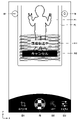
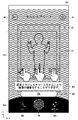
図13は、第1のトップ画面の一例を示す図である。また、図14は、第2のトップ画面の一例を示す図である。
[Screen configuration of first top screen and second top screen]
FIG. 13 is a diagram showing an example of the first top screen. Also, FIG. 14 is a diagram showing an example of the second top screen.
図13及び図14に示すように、第1のトップ画面200A及び第2のトップ画面200Bは、同じ項目が異なるレイアウトで表示される。表示される項目は、プリントアプリで実行可能な機能のボタン、プリントアプリの設定ボタン、プリンタ10のステータス情報、及び、最後にプリントした画像である。
As shown in FIGS. 13 and 14, the first
プリントアプリで実行可能な機能のボタンは、「かんたんプリント」の機能のボタンであるかんたんプリントボタンMB1、「動画プリント」の機能のボタンである動画プリントボタンMB2、「カメラ」の機能のボタンであるカメラボタンMB3、「相性診断」の機能のボタンである相性診断ボタンMB4、「テンプレートプリント」の機能のボタンであるテンプレートプリントボタンMB5、「コラージュプリント」の機能のボタンであるコラージュプリントボタンMB6、「組み写真」の機能のボタンである組み写真ボタンMB7である。 The function buttons that can be executed by the print application are a simple print button MB1 that is a button for the "easy print" function, a movie print button MB2 that is a button for the "movie print" function, and a button for the "camera" function. A camera button MB3, a compatibility diagnosis button MB4 that is a button for the "compatibility diagnosis" function, a template print button MB5 that is a button for the "template print" function, a collage print button MB6 that is a button for the "collage print" function, This is a combined photo button MB7, which is a button for the function of “composite photo”.
「かんたんプリント」の機能とは、スマートフォン100に保存されている画像(静止画)をプリントする機能である。本機能は、画面上でかんたんプリントボタンMB1をタッチすることで起動する。
The “easy print” function is a function of printing an image (still image) saved in the
「動画プリント」の機能とは、動画から1シーンを抽出してプリントする機能である。本機能は、画面上で動画プリントボタンMB2をタッチすることで起動する。 The “moving image print” function is a function of extracting and printing one scene from a moving image. This function is activated by touching the moving image print button MB2 on the screen.
「カメラ」の機能とは、スマートフォン100のカメラ機能を使用して撮影し、撮影した画像をプリンタ10でプリントする機能である。本機能は、画面上でカメラボタンMB3をタッチすることで起動する。
The “camera” function is a function of taking an image using the camera function of the
「相性診断」の機能とは、画像から相性診断を行う機能である。たとえば、学習済みモデルを利用して画像を解析し、画像に写されている人物(二人)の相性を診断する。本機能は、画面上で相性診断ボタンMB4をタッチすることで起動する。 The “compatibility diagnosis” function is a function of performing compatibility diagnosis from an image. For example, an image is analyzed using a trained model to diagnose the compatibility of the person (two people) in the image. This function is activated by touching the compatibility diagnosis button MB4 on the screen.
「テンプレートプリント」の機能とは、画像にテンプレート画像を合成し、プリントする機能である。本機能は、画面上でテンプレートプリントボタンMB5をタッチすることで起動する。 The “template print” function is a function of synthesizing a template image with an image and printing it. This function is activated by touching the template print button MB5 on the screen.
「コラージュプリント」の機能とは、コラージュ画像を生成してプリントする機能である。上記のようにコラージュ画像は、内部が複数の領域に分割されたフレーム(分割フレーム)の各領域に画像を当てはめて生成される。本機能は、画面上でコラージュプリントボタンMB6をタッチすることで起動する。 The "collage print" function is a function of generating and printing a collage image. As described above, a collage image is generated by applying an image to each region of a frame (divided frame) whose interior is divided into a plurality of regions. This function is activated by touching the collage print button MB6 on the screen.
「組み写真」の機能とは、1つの画像を複数に分割してプリントする機能である。本機能は、組み写真ボタンMB7を画面上でタッチすることで起動する。 The “composite photo” function is a function of dividing one image into a plurality of parts and printing them. This function is activated by touching the combined photograph button MB7 on the screen.
各機能のボタンは、アイコンで表示される。すなわち、図、記号又は絵柄を組み合わせて表示される。本実施の形態では、円と絵柄を組み合わせた図形で各機能のボタンが構成されている。円は、ボタンの外形を規定する。 Buttons for each function are displayed as icons. That is, it is displayed by combining figures, symbols or patterns. In the present embodiment, the buttons for each function are composed of figures that are a combination of circles and patterns. A circle defines the outline of the button.
プリンタ10のステータス情報としては、接続されているプリンタ10の名称(たとえば、機種名)、プリント可能枚数(フィルム残数)の情報及びバッテリー残量の情報が表示される。プリント可能枚数は、プリント可能枚数をN、新品のフィルムパックに装填されているインスタントフィルム12の総数をMとすると、「N/M」の形式で表示される。すなわち、フィルムパックを交換してからプリントした枚数も分かる形式で表示される。バッテリー残量の情報は、図形で表示される。
As the status information of the
最後にプリントした画像LIMは、画像表示枠FLOの内側に表示される。画像表示枠FLOは、インスタントフィルム12を模した画像で構成される。すなわち、インスタントフィルム12の観察領域12hの周囲に備えられた枠12iを模した図形で構成される。画像表示枠FLOの内側の領域は、画像表示領域として構成される。最後にプリントした画像LIMは、この画像表示領域に嵌め込まれて表示される。
The last printed image LIM is displayed inside the image display frame FLO. The image display frame FLO is composed of an image imitating the
図13及び図14に示すように、第1のトップ画面200A及び第2のトップ画面200Bにおいて、各機能のボタンは、2つのグループ(第1グループMG1及び第2グループMG2)にグループ分けされて表示される。
As shown in FIGS. 13 and 14, on the first
第1グループMG1は、かんたんプリント、動画プリント及びカメラの各機能のボタンが属するグループである。第1グループMG1は、プリントモードのグループであり、画像を簡単にプリントする機能のグループである。 The first group MG1 is a group to which buttons for easy print, movie print, and camera functions belong. The first group MG1 is a group of print modes and a group of functions for simply printing an image.
第2グループMG2は、相性診断、テンプレートプリント、コラージュプリント及び組み写真の各機能のボタンが属するグループである。第2グループMG2は、プレイモードのグループであり、遊びの要素及び作品造りの要素を含んだ機能のグループである。 The second group MG2 is a group to which buttons for compatibility diagnosis, template print, collage print, and combined photograph functions belong. The second group MG2 is a play mode group, and is a function group including play elements and work creation elements.
第1グループMG1に属するボタン(かんたんプリントボタンMB1、動画プリントボタンMB2及びカメラボタンMB3)は、図13及び図14において、破線で示す第1グループ表示領域MA1に表示される。 Buttons belonging to the first group MG1 (easy print button MB1, movie print button MB2, and camera button MB3) are displayed in the first group display area MA1 indicated by broken lines in FIGS.
一方、第2グループMG2に属するボタン(相性診断ボタンMB4、テンプレートプリントボタンMB5、コラージュプリントボタンMB6及び組み写真ボタンMB7)は、図13及び図14において、破線で示す第2グループ表示領域MA2に表示される。 On the other hand, the buttons belonging to the second group MG2 (compatibility diagnosis button MB4, template print button MB5, collage print button MB6, and combined photo button MB7) are displayed in the second group display area MA2 indicated by broken lines in FIGS. be.
第1グループ表示領域MA1は、画面下部に横方向(X方向)に沿って設定される。一方、第2グループ表示領域MA2は、画面右端に縦方向(Y方向)に沿って設定される。 The first group display area MA1 is set along the horizontal direction (X direction) at the bottom of the screen. On the other hand, the second group display area MA2 is set along the vertical direction (Y direction) at the right end of the screen.
第1グループ表示領域MA1、及び、その第1グループ表示領域MA1に表示されるボタン群(かんたんプリントボタンMB1、動画プリントボタンMB2及びカメラボタンMB3)は、第1のトップ画面200A及び第2のトップ画面200Bでサイズが変化する。すなわち、第1のトップ画面200Aでは、図13に示すように、小さなサイズで表示され、第2のトップ画面200Bでは、図14に示すように、大きなサイズで表示される。より具体的には、図14に示すように、第2のトップ画面200Bでは、画面下部の幅方向(X方向)の全域が第1グループ表示領域MA1とされるのに対して、第1のトップ画面200Aでは、図13に示すように、その幅が縮む(画面左方向に縮む)。これに伴い、各ボタンのサイズも縮小する。
A first group display area MA1 and a group of buttons (easy print button MB1, movie print button MB2, and camera button MB3) displayed in the first group display area MA1 are the first
また、第1グループ表示領域MA1、及び、その第1グループ表示領域MA1に表示されるボタン群は、第1のトップ画面200A及び第2のトップ画面200Bで色が変化する。図13及び図14では、色を反転して表示した場合の例を示している。
Also, the first group display area MA1 and the button group displayed in the first group display area MA1 change colors between the first
同様に、第2グループ表示領域MA2、及び、その第2グループ表示領域MA2に表示されるボタン群(相性診断ボタンMB4、テンプレートプリントボタンMB5、コラージュプリントボタンMB6及び組み写真ボタンMB7)は、第1のトップ画面200A及び第2のトップ画面200Bでサイズが変化する。すなわち、第1のトップ画面200Aでは、図13に示すように、大きなサイズで表示され、第2のトップ画面200Bでは、図14に示すように、小さなサイズで表示される。より具体的には、図13に示すように、第1のトップ画面200Aでは、画面右端の縦方向(Y方向)の全域が第2グループ表示領域MA2とされるのに対して、第2のトップ画面200Bでは、図13に示すように、その長さが縮む(画面上方向に縮む)。これに伴い、各ボタンのサイズも縮小する。
Similarly, the second group display area MA2 and the group of buttons displayed in the second group display area MA2 (compatibility diagnosis button MB4, template print button MB5, collage print button MB6, and combined photograph button MB7) are The size changes between the
また、第1グループ表示領域MA1と同様に、第2グループ表示領域MA2、及び、その第2グループ表示領域MA2に表示されるボタン群は、第1のトップ画面200A及び第2のトップ画面200Bで色が変化する。図13及び図14では、色を反転して表示した場合の例を示している。
Further, similarly to the first group display area MA1, the second group display area MA2 and the button group displayed in the second group display area MA2 are the first
プリントアプリの設定ボタンSEBは、図13に示すように、第1のトップ画面200Aでは、第2グループ表示領域MA2に表示される。一方、第2のトップ画面200Bでは、図14に示すように、第1グループ表示領域MA1に表示される。
The print application setting button SEB is displayed in the second group display area MA2 on the first
プリンタのステータス情報は、ステータス情報表示領域MA3に表示される。ステータス情報表示領域MA3は、第1のトップ画面200A及び第2のトップ画面200Bにおいて、同じ位置に設定される。図13及び図14に示すように、ステータス情報表示領域MA3は、画面上部に設定される。
Printer status information is displayed in the status information display area MA3. The status information display area MA3 is set at the same position on the first
最後にプリントした画像は、画像表示枠FLOの内側に表示される。画像表示枠FLOは、第1グループ表示領域MA1の上側、かつ、第2グループ表示領域MA2の左側の領域に表示される。画像表示枠FLOは、図13に示すように、第1のトップ画面200Aでは、傾けて表示される。一方、第2のトップ画面200Bでは、画面に沿ってまっすぐに表示される。
The last printed image is displayed inside the image display frame FLO. The image display frame FLO is displayed above the first group display area MA1 and on the left side of the second group display area MA2. As shown in FIG. 13, the image display frame FLO is tilted and displayed on the first
なお、未プリントの状態では、画像表示枠FLOの内側が空欄とされる。あるいは、規定の画像が表示される。なお、プリントアプリの設定で、最後にプリントした画像の表示のオン及びオフを設定できる。また、常に規定の画像(たとえば、ユーザーが選択した画像)を表示させることもできる。 It should be noted that the inside of the image display frame FLO is left blank in the unprinted state. Alternatively, a prescribed image is displayed. In addition, you can set the display of the last printed image on or off in the settings of the print application. It is also possible to always display a prescribed image (for example, an image selected by the user).
このように、2つのトップ画面を用意し、必要に応じて表示を切り換えることにより、操作性を向上できる。すなわち、簡単にプリントしたい場合は、これらの機能のボタン(かんたんプリントボタンMB1、動画プリントボタンMB2及びカメラボタンMB3)が、目立つように大きく表示された第2のトップ画面200Bを選択して表示させる。一方、コラージュ等の作品造り等をしたい場合は、これらの機能のボタン(相性診断ボタンMB4、テンプレートプリントボタンMB5、コラージュプリントボタンMB6及び組み写真ボタンMB7)が、目立つように大きく表示された第1のトップ画面200Aを選択して表示させる。これにより、操作性を向上できる。スマートフォンなどの画面の小さな携帯端末においても、ユーザーに分かりやすく、良好な操作性を確保できる。また、トップ画面の切り換えは、プリンタ本体14の設置姿勢を変えるだけで行うことができるため、その操作も簡単に行うことができる。通常、この種の操作は、アプリケーションプログラムの設定で行われる。本実施の形態のシステムによれば、そのような面倒な設定操作を行うことなく、簡単にトップ画面を切り換えることができる。
Thus, by preparing two top screens and switching the display as necessary, the operability can be improved. That is, if you want to print easily, you can select and display the second
(A)[かんたんプリントの機能を使用したプリント]
以下においては、かんたんプリントの機能を使用して、スマートフォン100に保存されている画像をプリントする場合の手順について説明する。
(A) [Print using the Easy Print function]
A procedure for printing an image saved in
大まかな処理手順は、(1)プリントする画像の選択、(2)プリントの指示である。必要に応じて、画像の加工編集が行われる。 The general processing procedure is (1) selection of an image to be printed, and (2) instruction for printing. The image is processed and edited as necessary.
[画像選択画面]
トップ画面(第1のトップ画面200A又は第2のトップ画面200B)において、かんたんプリントボタンMB1がタッチされると、かんたんプリントの機能が起動する。
[Image selection screen]
When the simple print button MB1 is touched on the top screen (first
かんたんプリントの機能が起動すると、タッチパネル120の画面が、画像選択画面201に切り換わる。この画面は、プリントする画像を選択する画面である。
When the easy print function is activated, the screen of the
図15は、画像選択画面の一例を示す図である。 FIG. 15 is a diagram showing an example of an image selection screen.
図15に示すように、画像選択画面201では、スマートフォン100に保存されている画像がサムネイル形式で一覧表示される。すなわち、画像を縮小した形式で一覧表示される。ユーザーは、プリントする画像のサムネイル画像を画面上でタッチして、プリントする画像を選択する。
As shown in FIG. 15, on the image selection screen 201, images saved in the
なお、図15では、スマートフォン100に保存されているすべての画像を一覧表示する場合の例を示している。この他、指定されたフォルダ内の画像のみを表示する形式としてもよい。
Note that FIG. 15 shows an example of displaying a list of all images saved in the
また、画像選択画面201には、図15に示すように、キャンセルボタン201Aが表示される。キャンセルボタン201Aは、画像選択処理のキャンセルを指示するボタンである。キャンセルボタン201Aがタッチされると、かんたんプリントの機能は終了する。この場合、画面の表示が、トップ画面200に切り換わる。 A cancel button 201A is also displayed on the image selection screen 201, as shown in FIG. The cancel button 201A is a button for instructing cancellation of the image selection process. When the cancel button 201A is touched, the simple print function ends. In this case, the screen display switches to the top screen 200 .
[プリント画像確認画面]
プリントする画像が選択されると、タッチパネル120の画面が、プリント画像確認画面202に切り換わる。この画面は、プリントする画像(プリント画像)を確認するための画面である。
[Print image confirmation screen]
When an image to be printed is selected, the screen of
図16は、プリント画像確認画面の一例を示す図である。 FIG. 16 is a diagram showing an example of a print image confirmation screen.
図16に示すように、プリント画像確認画面202には、プリント画像PI、そのプリント画像PIのプリントを指示するプリントボタンPB、及び、画像編集のメニューボタン等が表示される。
As shown in FIG. 16, the print
プリント画像PIは、画面内に設定された画像表示領域EA1に表示される。画像表示領域EA1の周囲には、画像表示領域EA1に表示された画像(プリント画像PI)を囲う枠FLが表示される。この枠FLは、インスタントフィルム12を模した画像で構成される。すなわち、インスタントフィルム12の観察領域12hの周囲に備えられた枠12iを模した図形で構成される(プリントした結果物(プリント物)と同じ余白で構成される。)。これにより、最終的なプリント結果を画面上で確認しやすくできる。
The print image PI is displayed in an image display area EA1 set within the screen. A frame FL surrounding the image (print image PI) displayed in the image display area EA1 is displayed around the image display area EA1. This frame FL is composed of an image imitating the
プリントボタンPB及び画像編集のメニューボタン(拡大&回転ボタンEB1、フィルターボタンEB2、画質補正ボタンEB3)は、ボタン表示領域EA2に表示される。ボタン表示領域EA2は、画面の下部に設定される。プリントボタンPB及び画像編集のメニューボタン(拡大&回転ボタンEB1、フィルターボタンEB2、画質補正ボタンEB3)は、このボタン表示領域EA2において、画面の幅方向(図16においてX方向)に沿って一列に並べて表示される。この際、プリントボタンPBが幅方向(X方向)の中央に配置され、その両側に3つ画像編集のメニューボタン(拡大&回転ボタンEB1、フィルターボタンEB2、画質補正ボタンEB3)が配置されて表示される。 The print button PB and image editing menu buttons (enlargement & rotation button EB1, filter button EB2, image quality correction button EB3) are displayed in the button display area EA2. The button display area EA2 is set at the bottom of the screen. The print button PB and the image editing menu buttons (enlargement & rotation button EB1, filter button EB2, image quality correction button EB3) are arranged in a line along the width direction of the screen (the X direction in FIG. 16) in the button display area EA2. displayed side by side. At this time, the print button PB is arranged in the center in the width direction (X direction), and three image editing menu buttons (enlargement & rotation button EB1, filter button EB2, and image quality correction button EB3) are arranged and displayed on both sides. be done.
プリントボタンPB及び画像編集のメニューボタン(拡大&回転ボタンEB1、フィルターボタンEB2、画質補正ボタンEB3)は、それぞれアイコンで表示される。また、中央のプリントボタンPBについては、他のボタン(拡大&回転ボタンEB1、フィルターボタンEB2、画質補正ボタンEB3)よりも大きなサイズで構成される(ボタンを構成する画像部分のサイズが大きいサイズで構成される。)。更に、本実施の形態では、プリントボタンPBの色を他のボタンと異なる色で構成している。具体的には、他のボタンは白色で構成しているのに対して、プリントボタンPBは赤色で構成している。これにより、プリントの指示操作を分かりやすくできる。なお、他のボタンは、選択(タッチ)されると、色が変化する。これにより、選択された機能を明確にできる。 The print button PB and the image editing menu buttons (enlargement & rotation button EB1, filter button EB2, image quality correction button EB3) are displayed as icons. The print button PB in the center is larger than the other buttons (enlargement & rotation button EB1, filter button EB2, image quality correction button EB3). configured.). Furthermore, in this embodiment, the color of the print button PB is different from that of the other buttons. Specifically, while the other buttons are white, the print button PB is red. This makes the print instruction operation easy to understand. Other buttons change color when selected (touched). This allows the selected function to be clarified.
画像編集のメニューボタン(拡大&回転ボタンEB1、フィルターボタンEB2、画質補正ボタンEB3)については、その下部にメニュータイトルが表示される。なお、図16では、画像編集のメニューとして、拡大及び回転の機能、フィルターの機能、及び、画質補正の機能が用意されている場合の例を示している。 Menu titles are displayed below the image editing menu buttons (enlargement & rotation button EB1, filter button EB2, image quality correction button EB3). Note that FIG. 16 shows an example in which the image editing menu includes enlargement and rotation functions, filter functions, and image quality correction functions.
拡大及び回転の機能とは、画像を拡大及び回転させる機能である。拡大及び回転の機能は、拡大&回転ボタンEB1に割り当てられる。拡大&回転ボタンEB1を画面上でタッチすると、拡大及び回転の機能が起動し、プリント画像PIに対する画像の拡大及び回転が可能になる。 The enlarging and rotating functions are functions for enlarging and rotating images. The enlarging and rotating functions are assigned to the enlarging & rotating button EB1. Touching the enlargement & rotation button EB1 on the screen activates the enlargement and rotation function, enabling enlargement and rotation of the image with respect to the print image PI.
フィルターの機能とは、画像にフィルター加工を施す機能である。フィルターの機能のボタンは、フィルターボタンEB2に割り当てられる。フィルターボタンEB2を画面上でタッチすると、フィルターの機能が起動し、プリント画像PIに対するフィルター加工が可能になる。 The function of the filter is a function of filtering an image. The filter function button is assigned to the filter button EB2. When the filter button EB2 is touched on the screen, the filter function is activated and the print image PI can be filtered.
画質補正の機能とは、画像の明るさ、コントラスト及び彩度を補正する機能である。画質補正の機能は、画質補正ボタンEB3に割り当てられる。画質補正ボタンEB3を画面上でタッチすると、画質補正の機能が起動し、プリント画像PIに対して、画質補正(画像の明るさ、コントラスト及び彩度の補正)が可能になる。 The function of image quality correction is a function of correcting the brightness, contrast and saturation of an image. The image quality correction function is assigned to the image quality correction button EB3. When the image quality correction button EB3 is touched on the screen, the image quality correction function is activated, and image quality correction (correction of image brightness, contrast and saturation) can be performed for the print image PI.
各機能は、対応する各ボタンを画面上でタッチするとオン(起動)され、再度タッチするとオフされる。また、一つの機能が起動中に他の機能のボタンがタッチされると、タッチされた機能に切り換わる。たとえば、フィルターの機能が起動中に画質補正ボタンEB3がタッチされると、フィルターの機能は終了し、画質補正の機能がオンされる。 Each function is turned on (activated) by touching each corresponding button on the screen, and turned off by touching it again. Further, when a button of another function is touched while one function is activated, the function is switched to the touched function. For example, when the image quality correction button EB3 is touched while the filter function is activated, the filter function is terminated and the image quality correction function is turned on.
図16に示すように、プリント画像確認画面202には、バックボタンBB及びトップボタンTBが表示される。バックボタンBBは、一つ前の画面に戻ることを指示するボタンである。トップボタンTBは、トップ画面200に戻ることを指示するボタンである。バックボタンBB及びトップボタンTBが、画面の上部に配置される。
As shown in FIG. 16, the print
トップ画面に戻る場合は、プリンタ本体14の設置姿勢に応じたトップ画面が表示される。すなわち、プリンタ本体14が縦置きされている場合は、第1のトップ画面200A(図13参照)が表示され、横置きされている場合は、第2のトップ画面200B(図14参照)が表示される。この場合、まず、スマートフォン100からプリンタ10に対して、設置姿勢の検出指令が出力される。プリンタ10は、この検出指令を受信することにより、プリンタ本体14の設置姿勢を検出する。そして、検出した設置姿勢に応じた制御信号を生成し、スマートフォン100に送信する。スマートフォン100は、プリンタ10から送信された制御信号を受信し、表示させるトップ画面を決定する。
When returning to the top screen, the top screen corresponding to the installation attitude of the
[拡大及び回転操作画面]
画面上で拡大&回転ボタンEB1がタッチされると、拡大及び回転の機能の操作画面、すなわち、画像の拡大操作及び回転操作を行う操作画面(拡大&回転操作画面)203に切り換わる。
[Enlargement and rotation operation screen]
When the enlargement & rotation button EB1 is touched on the screen, the screen is switched to an operation screen for enlargement and rotation functions, ie, an operation screen (enlargement & rotation operation screen) 203 for performing image enlargement and rotation operations.
図17は、拡大及び回転操作画面の一例を示す図である。 FIG. 17 is a diagram showing an example of an enlargement and rotation operation screen.
拡大及び回転操作画面203では、プリント画像確認画面202での表示内容に加えて、拡大操作用の拡大用スライドバーSB1及び回転操作用の回転用スライドバーSB2が表示される。
On the enlargement and
拡大用スライドバーSB1は、そのノブNB1をスライドさせて操作する(ノブNB1をタッチしてスライドさせる)。拡大用スライドバーSB1を操作すると、その操作量に応じて、画像が拡大する。プリント画像PIは、ノブNB1を画面右方向にスライドさせると拡大し、左方向にスライドさせると縮小する。 The enlargement slide bar SB1 is operated by sliding its knob NB1 (touching and sliding the knob NB1). When the enlargement slide bar SB1 is operated, the image is enlarged according to the amount of operation. The print image PI is enlarged by sliding the knob NB1 rightward on the screen, and is reduced by sliding it leftward.
回転用スライドバーSB2は、そのノブNB2をスライドさせて操作する。回転用スライドバーSB2を操作すると、その操作量に応じて画像が回転する。プリント画像PIは、ノブNB2を画面右方向にスライドさせると時計回りに回転し、左方向にスライドさせると反時計回りに回転する。ノブNB2をバーの左端から右端までスライドさせると、画像が一回転する。 The rotary slide bar SB2 is operated by sliding its knob NB2. When the rotation slide bar SB2 is operated, the image is rotated according to the amount of operation. The print image PI rotates clockwise when the knob NB2 is slid to the right of the screen, and rotates counterclockwise when it is slid to the left. Sliding the knob NB2 from the left end of the bar to the right end rotates the image once.
拡大用スライドバーSB1及び回転用スライドバーSB2は、操作領域EA3に表示される。操作領域EA3は、画面の縦方向(Y方向)において、画像表示領域EA1及びボタン表示領域EA2の間に設定される。図17に示すように、拡大用スライドバーSB1及び回転用スライドバーSB2は、この領域に上下に並べて配置される。また、拡大用スライドバーSB1及び回転用スライドバーSB2は、共に円弧状に湾曲した形状で表示される。より具体的には、画面の幅方向(X方向)の中心を通る直線上に設定された点を中心とする円に沿って表示され、かつ、画面の幅方向の中心を通る直線を基準として左右対称に表示される。このように、円弧状に湾曲させて表示することにより、直線として表示させる場合に比べて、全体の長さを長くできる。これにより、操作の分解能を向上でき、より細かな操作が可能になる。このことは、画面の表示サイズが小さい場合に特に有効に作用する。 The enlargement slide bar SB1 and the rotation slide bar SB2 are displayed in the operation area EA3. The operation area EA3 is set between the image display area EA1 and the button display area EA2 in the vertical direction (Y direction) of the screen. As shown in FIG. 17, the enlargement slide bar SB1 and the rotation slide bar SB2 are arranged vertically in this area. Also, the enlargement slide bar SB1 and the rotation slide bar SB2 are both displayed in an arcuately curved shape. More specifically, it is displayed along a circle whose center is a point set on a straight line passing through the center of the width direction (X direction) of the screen, and is based on a straight line passing through the center of the width direction of the screen. displayed symmetrically. In this manner, by displaying a curved line, the total length can be increased compared to the case where the line is displayed as a straight line. As a result, the resolution of operations can be improved, and finer operations become possible. This is particularly effective when the display size of the screen is small.
[フィルター操作画面]
画面上でフィルターボタンEB2がタッチされると、フィルターの機能の操作画面、すなわち、画像にフィルター加工を施す操作の操作画面(フィルター操作画面)204に切り換わる。
[Filter operation screen]
When the filter button EB2 is touched on the screen, the screen is switched to an operation screen for filter functions, that is, an operation screen (filter operation screen) 204 for performing filter processing on an image.
図18は、フィルター操作画面の一例を示す図である。 FIG. 18 is a diagram showing an example of a filter operation screen.
フィルター操作画面204では、プリント画像確認画面202での表示内容に加えて、適用するフィルターの選択ボタンが表示される。図18は、選択ボタンとして、4つのボタンを表示させた場合の例を示している。具体的には、ノーマルの状態に戻すノーマルボタンFB1、モノクロフィルターを適用するモノクロボタンFB2、セピアフィルターを適用するセピアボタンFB3、及び、オートフィルターを適用するオートボタンFB4を表示した場合の例を示している。
On the
ここで、モノクロフィルターとは、画像を白黒でモノクローム化するフィルターである。画面上でモノクロボタンFB2がタッチされると、画像表示領域EA1に表示されているプリント画像PIが白黒でモノクローム化される。 Here, a monochrome filter is a filter that converts an image into black and white. When the monochrome button FB2 is touched on the screen, the print image PI displayed in the image display area EA1 is monochromeized in black and white.
セピアフィルターとは、画像の色調をセピア調にするフィルターである。画面上でセピアボタンFB3がタッチされると、画像表示領域EA1に表示されているプリント画像PIの色調がセピア調にされる。 A sepia filter is a filter that changes the color tone of an image to sepia. When the sepia button FB3 is touched on the screen, the color tone of the print image PI displayed in the image display area EA1 is changed to sepia tone.
オートフィルターとは、画像の色調を自動で最適化するフィルターである。画面上でオートボタンFB4がタッチされると、画像表示領域EA1に表示されているプリント画像PIの色調が自動で補正される。 An auto filter is a filter that automatically optimizes the color tone of an image. When the auto button FB4 is touched on the screen, the color tone of the print image PI displayed in the image display area EA1 is automatically corrected.
画面でノーマルボタンFB1がタッチされると、適用されたフィルターがキャンセルされ、オリジナルの状態に復帰する。 When the normal button FB1 is touched on the screen, the applied filter is canceled and the original state is restored.
フィルターの選択ボタン(ノーマルボタンFB1、モノクロボタンFB2、セピアボタンFB3、オートボタンFB4)は、画像表示領域EA1に表示されるプリント画像PIの外形に対応した長方形状を有する。より具体的には、プリント画像PIの外形と相似形状を有する(ほぼ相似と認められる形状を含む)。 The filter selection buttons (normal button FB1, monochrome button FB2, sepia button FB3, auto button FB4) have a rectangular shape corresponding to the outline of the print image PI displayed in the image display area EA1. More specifically, it has a shape similar to the outer shape of the print image PI (including a shape recognized as substantially similar).
また、各ボタンには、適用されるフィルターと同じフィルター加工が施された共通の画像が表示される。たとえば、モノクロボタンFB2を構成する画像には、白黒でもクローム化された画像が表示される。 Also, each button displays a common image with the same filter processing as the applied filter. For example, as the image forming the monochrome button FB2, a chrome image is displayed even in black and white.
更に、各ボタンは、操作領域EA3に展開して表示され、画面の幅方向の中心を通る直線上に設定された点を中心として放射状に表示される。このように、放射状に表示することにより、直線状に並べて表示させる場合に比べて、表示できるボタンの数、サイズを大きくできる。これにより、操作性を向上できる。なお、一画面に表示させるボタンの数は、円弧の曲率を調整することで調整できる。すなわち、同じボタンのサイズであれば、曲率を大きくするほど(湾曲を大きくするほど)、一度に表示できるボタンの増やすことができる。 Further, each button is expanded and displayed in the operation area EA3, and displayed radially around a point set on a straight line passing through the center of the screen in the width direction. By displaying the buttons radially in this manner, it is possible to increase the number and size of the buttons that can be displayed compared to the case of displaying the buttons arranged in a straight line. Thereby, operability can be improved. The number of buttons displayed on one screen can be adjusted by adjusting the curvature of the arc. That is, if the button size is the same, the larger the curvature (the larger the curvature), the more buttons that can be displayed at once.
[画質補正操作画面]
画面上で画質補正ボタンEB3がタッチされると、画質補正の機能の操作画面、すなわち、画像の明るさ、コントラスト及び彩度の補正操作を行う操作画面(画質補正操作画面)205に切り換わる。
[Image quality correction operation screen]
When the image quality correction button EB3 is touched on the screen, the screen is switched to an operation screen for the image quality correction function, that is, an operation screen (image quality correction operation screen) 205 for correcting image brightness, contrast and saturation.
図19は、画質補正操作画面の一例を示す図である。 FIG. 19 is a diagram showing an example of an image quality correction operation screen.
画質補正操作画面205では、プリント画像確認画面202での表示内容に加えて、画像の明るさを調整する明るさ調整用スライドバーSB3、画像のコントラストを調整するコントラスト調整用スライドバーSB4、画像の彩度を調整する彩度調整用スライドバーSB5、及び、リセットボタンRSBが表示される。
In the image quality
明るさ調整用スライドバーSB3は、そのノブNB3をスライドさせて操作する。明るさ調整用スライドバーSB3を操作すると、その操作量に応じて、画像の明るさが変化する。ノブNB3は、デフォルトでバーの中央に位置する。プリント画像PIは、ノブNB3を画面右方向にスライドさせると、明るくなり、左方向にスライドさせると、暗くなる。 The brightness adjustment slide bar SB3 is operated by sliding its knob NB3. When the brightness adjustment slide bar SB3 is operated, the brightness of the image changes according to the amount of operation. Knob NB3 is located in the middle of the bar by default. The print image PI becomes brighter when the knob NB3 is slid rightward on the screen, and becomes darker when slid leftward.
コントラスト調整用スライドバーSB4は、そのノブNB4をスライドさせて操作する。コントラスト調整用スライドバーSB4を操作すると、その操作量に応じて、画像のコントラストが変化する。ノブNB4は、デフォルトでバーの中央に位置する。プリント画像PIは、ノブNB4を画面右方向にスライドさせると、コントラストが高くなり、左方向にスライドさせると、コントラストが低くなる。 The contrast adjustment slide bar SB4 is operated by sliding its knob NB4. When the contrast adjustment slide bar SB4 is operated, the contrast of the image changes according to the amount of operation. Knob NB4 is located in the middle of the bar by default. The contrast of the print image PI increases when the knob NB4 is slid to the right of the screen, and decreases when the knob NB4 is slid to the left.
彩度調整用スライドバーSB5は、そのノブNB5をスライドさせて操作する。彩度調整用スライドバーSB5を操作すると、その操作量に応じて、画像の彩度が変化する。ノブNB5は、デフォルトでバーの中央に位置する。プリント画像PIは、ノブNB5を画面右方向にスライドさせると、彩度が高くなり、左方向にスライドさせると、彩度が低くなる。 The saturation adjustment slide bar SB5 is operated by sliding its knob NB5. When the saturation adjustment slide bar SB5 is operated, the saturation of the image changes according to the amount of operation. Knob NB5 is located in the middle of the bar by default. The saturation of the print image PI increases when the knob NB5 is slid to the right of the screen, and decreases when the knob NB5 is slid to the left.
リセットボタンRSBは、各スライドバー(明るさ調整用スライドバーSB3、コントラスト調整用スライドバーSB4及び彩度調整用スライドバーSB5)の操作をリセットするボタンである。リセットボタンRSBが、タッチされると、各スライドバーの操作がリセットされる。すなわち、各スライドバーのノブがデフォルトの位置(中央)に復帰する。 The reset button RSB is a button for resetting the operation of each slide bar (brightness adjustment slide bar SB3, contrast adjustment slide bar SB4, and saturation adjustment slide bar SB5). When the reset button RSB is touched, the operation of each slide bar is reset. That is, each slide bar knob returns to its default position (center).
各スライドバー(明るさ調整用スライドバーSB3、コントラスト調整用スライドバーSB4及び彩度調整用スライドバーSB5)、及び、リセットボタンRSBは、操作領域EA3に表示される。図19に示すように、各スライドバーは、この領域に上下に並べて配置される。また、各スライドバーは、共に円弧状に湾曲した形状で表示される。より具体的には、幅方向の中心を通る直線上に設定された点を中心とする円に沿って表示され、かつ、幅方向の中心を通る直線を基準として左右対称に表示される。これにより、操作の分解能を向上でき、より細かな操作が可能になる。リセットボタンRSBは、操作領域E3の右端に配置される。 Each slide bar (brightness adjustment slide bar SB3, contrast adjustment slide bar SB4, and saturation adjustment slide bar SB5) and a reset button RSB are displayed in the operation area EA3. As shown in FIG. 19, each slide bar is arranged vertically in this area. Also, each slide bar is displayed in an arcuately curved shape. More specifically, it is displayed along a circle centered on a point set on a straight line passing through the center in the width direction, and displayed symmetrically with respect to the straight line passing through the center in the width direction. As a result, the resolution of operations can be improved, and finer operations become possible. The reset button RSB is arranged at the right end of the operation area E3.
[プリントを実行した場合の操作画面]
画面上でプリントボタンPBをタッチすると、画像表示領域EA1に表示されたプリント画像PIのプリントが指示される。プリントが指示されると、プリンタ10にプリント画像PIの画像データが送信される。
[Operation screen when printing is executed]
When the print button PB is touched on the screen, printing of the print image PI displayed in the image display area EA1 is instructed. When printing is instructed, the image data of the print image PI is sent to the
プリント画像PIの送信が実行されると、画像送信のイメージが、アニメーションで表示される。具体的には、プリント画像PIが枠FLと共に移動し、画面の縁から消えてゆくイメージがアニメーションで表示される。 When the transmission of the print image PI is executed, an image of image transmission is displayed in animation. Specifically, an animation is displayed in which the print image PI moves together with the frame FL and disappears from the edge of the screen.
図20は、プリントを指示した場合のアニメーション表示の一例を示す図である。 FIG. 20 is a diagram showing an example of animation display when printing is instructed.
プリントを指示すると、時系列順に画面が、画面206A、画面206B、画面206Cと変化する。同図に示すように、プリント画像PIが、枠FLと共に画面の長手方向に沿って上方に移動し、画面の上縁から消えてゆく(インスタントフィルムが送られる映像を模したもの)。これにより、画像がプリンタに送信されたことを認識しやすくできる。
When printing is instructed, the screen changes to screen 206A,
(B)[テンプレートプリントの機能を使用したプリント]
以下においては、テンプレートプリントの機能を使用して、スマートフォン100に保存された画像をプリントする場合の手順について説明する。上記のように、テンプレートプリントでは、画像にテンプレート画像を合成してプリントする。大まかな処理手順は、(1)テンプレートの選択、(2)プリントする画像の選択、(3)プリントの指示である。必要に応じて、画像の加工編集が行われる。
(B) [Print using the template print function]
A procedure for printing an image saved in
[テンプレート選択画面]
トップ画面(図13及び図14参照)において、テンプレートプリントボタンMB5がタッチされると、テンプレートプリントの機能が起動する。テンプレートプリントの機能が起動すると、タッチパネル120の画面が、テンプレート選択画面210に切り換わる。この画面は、プリントする画像に合成するテンプレート画像を選択する画面である。
[Template selection screen]
When the template print button MB5 is touched on the top screen (see FIGS. 13 and 14), the template print function is activated. When the template print function is activated, the screen of
図21は、テンプレートプリント選択画面の一例を示す図である。 FIG. 21 is a diagram showing an example of the template print selection screen.
同図に示すように、テンプレート選択画面210では、使用可能なテンプレート画像が、サムネイル形式で一覧表示される。ユーザーは、希望する絵柄のテンプレート画像を画面上でタッチして選択する。
As shown in the figure, the
[画像選択画面]
テンプレート選択画面210において、使用するテンプレート画像が選択されると、タッチパネル120の画面が、画像選択画面201に切り換わる(図15参照)。ユーザーは、この画面でプリントする画像を選択する。
[Image selection screen]
When a template image to be used is selected on the
[プリント画像確認画面]
プリントする画像が選択されると、タッチパネル120の画面が、プリント画像確認画面202に切り換わる。この画面は、プリントする画像(プリント画像)を確認するための画面である。
[Print image confirmation screen]
When an image to be printed is selected, the screen of
図22は、テンプレートプリントでのプリント画像確認画面の一例を示す図である。 FIG. 22 is a diagram showing an example of a print image confirmation screen in template printing.
画像編集のメニューボタンとして、テンプレートボタンEB4が追加されている点以外は、かんたんプリントのプリント画像確認画面202の画面構成と同じである。テンプレートボタンEB4は、テンプレート画像を切り換える機能を呼び出すボタンである。
The screen configuration is the same as the print
[テンプレート切り換え操作画面]
拡大及び回転の機能、フィルターの機能及び画質補正の機能は、かんたんプリントの場合と同じなので、ここでは、テンプレート画像の切り換え機能について説明する。
[Template switching operation screen]
Since the enlargement and rotation functions, the filter function, and the image quality correction function are the same as in the simple print, the template image switching function will be explained here.
テンプレートボタンEB4がタッチされると、テンプレート画像の切り換え操作を行う操作画面(テンプレート切り換え操作画面)212に切り換わる。 When the template button EB4 is touched, an operation screen (template switching operation screen) 212 for switching template images is displayed.
図23は、テンプレート切り換え操作画面の一例を示す図である。 FIG. 23 is a diagram showing an example of a template switching operation screen.
テンプレート切り換え操作画面212では、プリント画像確認画面202での表示内容に加えて、切り換え可能なテンプレート画像の選択ボタンTB1、TB2、…が表示される。ユーザーは、切り換えを希望するテンプレート画像の選択ボタンを画面上でタッチして選択する。
On the template switching
各ボタンは、そのボタンによって選択されるテンプレート画像を縮小した画像で構成される。したがって、その外形は、プリント画像PIの外形と相似形状を有する(ほぼ相似と認められる形状を含む)。 Each button consists of a reduced image of the template image selected by that button. Therefore, its outer shape has a shape similar to the outer shape of the print image PI (including shapes recognized as being substantially similar).
テンプレート画像の選択ボタンTB1、TB2、…は、フィルターの選択ボタンと同様に、操作領域EA3に展開表示され、画面の幅方向の中心を通る直線上に設定された点を中心として放射状に表示される。 The template image selection buttons TB1, TB2, . be.
なお、操作領域EA3には、一定数の選択ボタンTB1、TB2、…が表示される。図23は、一度に4つの選択ボタンを表示させる場合(ボタンの全体を表示できる数が4つの場合)の例を示している。その他の選択ボタンについては、スクロールさせて表示する。スクロールは、操作領域EA3に表示された選択ボタン上で画面をスワイプ操作又はフリック操作することによって行われる。ここで、スワイプ操作とは、画面に触れた状態で指を滑らせる操作のことである。フリック操作とは、スワイプをより勢いよく行い、画面を弾くようにして、指を滑らせつつ画面から離す操作のことである。 A certain number of selection buttons TB1, TB2, . . . are displayed in the operation area EA3. FIG. 23 shows an example of displaying four selection buttons at once (when the number of buttons that can be displayed in their entirety is four). Other selection buttons are displayed by scrolling. Scrolling is performed by swiping or flicking the screen on the selection button displayed in the operation area EA3. Here, the swipe operation is an operation of sliding a finger while touching the screen. A flick operation is an operation in which a finger is swiped more vigorously, as if flipping the screen, and the finger is lifted off the screen while sliding.
図24は、操作領域に表示される選択ボタンのスクロールの概念図である。 FIG. 24 is a conceptual diagram of scrolling the selection buttons displayed in the operation area.
同図に示すように、操作領域EA3に表示される選択ボタンTB1、TB2、…は、画面を右方向にスワイプ操作又はフリック操作することにより、円弧に沿って右方向(矢印R+方向)にスクロールする(時計回りにスクロールする。)。また、画面を左方向にスワイプ操作又はフリック操作することにより、円弧に沿って左方向(矢印R-方向)にスクロールする(反時計回りにスクロールする。)。 As shown in the figure, the selection buttons TB1, TB2, . (scroll clockwise). Also, by swiping or flicking the screen leftward, the screen is scrolled leftward (in the direction of arrow R) along an arc (scrolls counterclockwise).
[プリントを実行した場合の操作画面]
プリントの実行は、かんたんプリントの場合と同じである。すなわち、画面上でプリントボタンPBをタッチして、プリントを指示する。プリントが指示されると、プリンタ10にプリント画像PIの画像データが送信される。画像送信のイメージが、アニメーションで表示される点は、かんたんプリントの場合と同様である(図20参照)。
[Operation screen when printing is executed]
Execution of printing is the same as in the case of simple printing. That is, the print button PB is touched on the screen to instruct printing. When printing is instructed, the image data of the print image PI is sent to the
(C)[コラージュプリントの機能を使用したプリント]
以下においては、コラージュプリントの機能を使用して、スマートフォン100に保存されている画像をプリントする場合の手順について説明する。上記のように、コラージュプリントでは、分割フレームの各領域に画像を当てはめてプリントする。その大まかな処理手順は、(1)分割フレームの選択、(2)合成する画像の選択、(3)プリントの指示である。必要に応じて、合成する画像の加工編集が行われる。
(C) [Print using Collage Print function]
A procedure for printing images stored in
[分割フレーム選択画面]
トップ画面(図13及び図14参照)において、コラージュプリントボタンMB6がタッチされると、コラージュプリントの機能が起動する。コラージュプリントの機能が起動すると、タッチパネル120の画面が、分割フレーム選択画面220に切り換わる。この画面は、分割フレームを選択する画面である。
[Split frame selection screen]
When the collage print button MB6 is touched on the top screen (see FIGS. 13 and 14), the collage print function is activated. When the collage print function is activated, the screen of the
図25は、分割フレーム選択画面の一例を示す図である。 FIG. 25 is a diagram showing an example of a division frame selection screen.
同図に示すように、分割フレーム選択画面220では、選択可能な分割フレームの画像(フレーム内の分割の態様を示した画像)が、サムネイル形式で一覧表示される。ユーザーは、希望する分割フレームの画像を画面上でタッチして選択する。
As shown in the figure, on the divided
[コラージュ画像作成画面]
分割フレーム選択画面220において、使用する分割フレームが選択されると、タッチパネル120の画面が、コラージュ画像作成画面221に切り換わる。この画面は、コラージュ画像を作成する画面である。
[Collage image creation screen]
When a divided frame to be used is selected on the divided
図26は、コラージュ画像作成画面の一例を示す図である。 FIG. 26 is a diagram showing an example of a collage image creation screen.
選択した分割フレームに応じて画像表示領域EA1の内部が分割される点、分割の境界線の表示のオン及びオフを切り換える境界線ボタンFBBが表示される点、及び、画像編集のメニューボタンとして、分割フレームボタンEB5が追加されている点以外は、かんたんプリントのプリント画像確認画面202の画面構成と同じである。
The inside of the image display area EA1 is divided according to the selected divided frame, the boundary line button FBB for switching on and off the display of the division boundary line is displayed, and the menu button for image editing, The screen configuration is the same as that of the print
画像表示領域EA1は、その内部の領域が、選択した分割フレームに応じて分割される。境界線ボタンFBBは、その分割の境界線FBLの表示をオン及びオフする。ユーザーが、境界線ボタンFBBを画面上でタッチするたびにオン及びオフが切り換わる。境界線ボタンFBBをオンすると、画像表示領域EA1に境界線FBLが表示される。なお、図26は、境界線FBLの表示をオンした場合を示している。境界線の表示をオンすると、プリントされる画像にも境界線が表示される。 The image display area EA1 is divided according to the selected divided frame. The boundary line button FBB turns on and off the display of the division boundary line FBL. Each time the user touches the border button FBB on the screen, it toggles on and off. When the boundary line button FBB is turned on, a boundary line FBL is displayed in the image display area EA1. Note that FIG. 26 shows a case where the display of the boundary line FBL is turned on. If you turn on display borders, the borders will also appear on the printed image.
画像表示領域EA1において、画像を合成する領域をタッチすると、タッチパネル120の画面が画像選択画面に切り換わる(図15参照)。ユーザーは、この画面で合成する画像を選択する。画像を選択すると、再び、コラージュ画像作成画面221に復帰する。この際、選択した画像が、選択した領域に当てはめられて表示される。
In the image display area EA1, when the area for synthesizing images is touched, the screen of the
図27は、画像選択後のコラージュ画像作成画面の一例を示す図である。 FIG. 27 is a diagram showing an example of a collage image creation screen after image selection.
同図は、フレーム内が上下二等分割された分割フレームにおいて、画面上側の領域を選択して、合成する画像を選択した場合の画面表示の一例を示している。同図に示すように、選択した画像が、選択した領域に当てはめられて表示される。 This figure shows an example of a screen display when an image to be combined is selected by selecting an upper area of the screen in a divided frame in which the frame is vertically divided into two equal parts. As shown in the figure, the selected image is fitted to the selected area and displayed.
選択した領域において、画像をタッチしながら指を移動させると、画像の位置調整が行われる。選択した画像を変更する場合は、画像を変更する領域をタッチして選択し、バックボタンBBをタッチする。本操作により、画面が画像選択画面(図15参照)に切り換わり、画像の選択が可能になる。なお、領域内で画面をフリック操作することによって、順番に画像が切り換わる構成としてもよい。 Moving the finger while touching the image in the selected area adjusts the position of the image. To change the selected image, touch the area to change the image to select it, and touch the back button BB. This operation switches the screen to the image selection screen (see FIG. 15), enabling image selection. Note that the images may be switched in order by flicking the screen within the area.
分割フレームのすべての領域について、画像の選択を行い、コラージュ画像を完成させる。 Image selection is performed for all regions of the split frame to complete the collage image.
選択した各領域の画像については、拡大及び回転の機能、フィルターの機能及び画質補正の機能を使用することで、個別に加工編集できる。拡大及び回転の機能、フィルターの機能及び画質補正の機能は、かんたんプリントの場合と同じである。 The image of each selected area can be processed and edited individually by using the enlargement and rotation functions, the filter function, and the image quality correction function. The enlargement and rotation functions, the filter function, and the image quality correction function are the same as in Easy Print.
[分割フレーム切り換え操作画面]
ボタン表示領域EA2に表示された分割フレームボタンEB5は、分割フレームを切り換える機能を呼び出すボタンである。分割フレームボタンEB5がタッチされると、分割フレームの切り換え操作を行う操作画面(分割フレーム切り換え操作画面)222に切り換わる。
[Division frame switching operation screen]
A split frame button EB5 displayed in the button display area EA2 is a button for calling a function of switching split frames. When the divided frame button EB5 is touched, the screen is switched to an operation screen (divided frame switching operation screen) 222 for performing a division frame switching operation.
図28は、分割フレーム切り換え操作画面の一例を示す図である。 FIG. 28 is a diagram showing an example of a divided frame switching operation screen.
分割フレーム切り換え操作画面222では、コラージュ画像作成画面221での表示内容に加えて、切り換え可能な分割フレームを選択する分割フレーム選択ボタンSFB1、SFB2、…が表示される。ユーザーは、切り換えを希望する分割フレームの選択ボタンを画面上でタッチして選択する。
On the split frame switching
各ボタンは、そのボタンによって選択される分割フレームの画像を縮小した画像で構成される。したがって、その外形は、プリント画像の外形と相似形状を有する(ほぼ相似と認められる形状を含む)。 Each button is composed of an image obtained by reducing the image of the divided frame selected by the button. Therefore, the outer shape has a shape similar to the outer shape of the printed image (including shapes recognized as being substantially similar).
分割フレーム選択ボタンSFB1、SFB2、…は、テンプレート画像の選択ボタンと同様に、操作領域EA3に表示され、画面の幅方向の中心を通る直線上に設定された点を中心として放射状に表示される。また、操作領域EA3には、一定数の分割フレーム選択ボタンSFB1、SFB2、…が表示される。その他の分割フレーム選択ボタンについては、テンプレート画像の選択ボタンと同様に、スクロールさせて表示する(図24参照)。 The split frame selection buttons SFB1, SFB2, . . Also, a certain number of divided frame selection buttons SFB1, SFB2, . . . are displayed in the operation area EA3. Other divided frame selection buttons are scrolled and displayed in the same manner as the template image selection buttons (see FIG. 24).
分割フレームが切り換えられた場合は、再度、各領域の画像が選択される。 When the divided frame is switched, the image of each area is selected again.
[プリントを実行した場合の操作画面]
コラージュ画像が完成すると、プリントが可能になる。プリントの実行は、かんたんプリントの場合と同じである。すなわち、画面上でプリントボタンPBをタッチして、プリントを指示する。プリントが指示されると、プリンタ10にプリント画像(生成されたコラージュ画像)の画像データが送信される。画像送信のイメージが、アニメーションで表示される点は、かんたんプリントの場合と同様である(図20参照)。
[Operation screen when printing is executed]
Once the collage image is completed, it can be printed. Execution of printing is the same as in the case of simple printing. That is, the print button PB is touched on the screen to instruct printing. When printing is instructed, image data of a print image (generated collage image) is transmitted to the
(D)[組み写真の機能を使用したプリント]
以下においては、組み写真の機能を使用して、スマートフォン100に保存されている画像をプリントする場合の手順について説明する。上記のように、組み写真では、1つの画像を複数に分割してプリントする。その大まかな処理手順は、(1)レイアウトの選択、(2)画像の選択、(3)プリントの指示である。必要に応じて、画像の加工編集が行われる。
(D) [Print using combined photo function]
A procedure for printing an image saved in
[レイアウト選択画面]
トップ画面(図13及び図14参照)において、組み写真ボタンMB7がタッチされると、組み写真の機能が起動する。組み写真の機能が起動すると、タッチパネル120の画面が、レイアウト選択画面230に切り換わる。この画面は、分割のレイアウトを選択する画面である。
[Layout selection screen]
When the combined photo button MB7 is touched on the top screen (see FIGS. 13 and 14), the combined photo function is activated. When the combined photograph function is activated, the screen of the
図29は、レイアウト選択画面の一例を示す図である。 FIG. 29 is a diagram showing an example of a layout selection screen.
同図に示すように、レイアウト選択画面230では、選択可能なレイアウトの画像が一覧表示される。選択可能なレイアウトの画像は、インスタントフィルムを模した画像を分割の態様に合わせて並べた画像で構成される。
ユーザーは、希望するレイアウトの画像を画面上でタッチして選択する。
As shown in the figure, on the
The user touches the desired layout image on the screen to select it.
[画像選択画面]
レイアウト選択画面230において、レイアウトが選択されると、タッチパネル120の画面が、画像選択画面201に切り換わる(図15参照)。ユーザーは、この画面でプリントする画像を選択する。
[Image selection screen]
When a layout is selected on the
[プリント画像確認画面]
プリントする画像が選択されると、タッチパネル120の画面が、プリント画像確認画面231に切り換わる。この画面は、プリントする画像(プリント画像)を確認するための画面である。
[Print image confirmation screen]
When an image to be printed is selected, the screen of
図30は、組み写真におけるプリント画像確認画面の一例を示す図である。 FIG. 30 is a diagram showing an example of a print image confirmation screen in combined photographs.
組み写真におけるプリント画像確認画面231では、選択したレイアウトに応じて画像表示領域が設定される。図30には、上下に二分割した組み写真を生成する場合の表示例を示している。この場合、2つの画像表示領域(第1の画像表示領域EA1a及び第2の画像表示領域EA1b)が設定される。各画像表示領域の周囲には枠FL1、FL2が表示される。
In the print
組み写真におけるプリント画像確認画面231では、画像編集のメニューボタンとして、レイアウトボタンEB6が追加して表示される。レイアウトボタンEB6は、レイアウトを変更する機能を呼び出すボタンである。
On the print
[レイアウト操作画面]
レイアウトボタンEB6がタッチされると、レイアウトの変更操作を行う操作画面(レイアウト変更操作画面)232に切り換わる。
[Layout operation screen]
When the layout button EB6 is touched, the screen is switched to an operation screen (layout change operation screen) 232 for performing a layout change operation.
図31は、テンプレート切り換え操作画面の一例を示す図である。 FIG. 31 is a diagram showing an example of a template switching operation screen.
レイアウト変更操作画面232では、プリント画像確認画面231での表示内容に加えて、変更可能なレイアウトの選択ボタンLB1、LB2、…が表示される。ユーザーは、変更を希望するレイアウトの選択ボタンを画面上でタッチして選択する。各ボタンは、そのボタンによって選択されるレイアウトの画像を縮小した画像で構成される。
On the layout
レイアウトの選択ボタンLB1、LB2、…は、フィルターの選択ボタンと同様に、操作領域EA3に展開表示され、画面の幅方向の中心を通る直線上に設定された点を中心として放射状に表示される。また、スワイプ操作によって表示がスクロールされる。 Layout selection buttons LB1, LB2, . . Also, the display is scrolled by a swipe operation.
[プリントを実行した場合の操作画面]
プリントの実行は、かんたんプリントの場合と同じである。すなわち、画面上でプリントボタンPBをタッチして、プリントを指示する。プリントが指示されると、プリンタ10にプリント画像の画像データが送信される。また、画像送信のイメージが、画面上にアニメーション表示される。
[Operation screen when printing is executed]
Execution of printing is the same as in the case of simple printing. That is, the print button PB is touched on the screen to instruct printing. When printing is instructed, the image data of the print image is transmitted to the
なお、組み写真の場合は、選択したレイアウトに応じて複数枚の画像がプリントされる。したがって、アニメーションも、一枚ずつ送信されるイメージのアニメーションが表示される。 In the case of combined photographs, a plurality of images are printed according to the selected layout. Therefore, the animation of the images transmitted one by one is also displayed.
(D)[カメラの機能を使用したプリント]
以下においては、カメラの機能を使用して、画像をプリントする場合の手順について説明する。その大まかな処理手順は、(1)撮影、(2)プリントの指示である。必要に応じて、画像の加工編集が行われる。
(D) [Print using camera function]
The procedure for printing an image using the functions of the camera will be described below. The rough processing procedure is (1) photographing and (2) printing instructions. The image is processed and edited as necessary.
[撮影操作画面]
トップ画面(図13及び図14参照)において、カメラボタンMB3がタッチされると、カメラの機能が起動する。カメラの機能が起動すると、タッチパネル120の画面が、撮影操作画面240に切り換わる。
[Shooting operation screen]
When the camera button MB3 is touched on the top screen (see FIGS. 13 and 14), the camera function is activated. When the camera function is activated, the screen of the
図32は、撮影操作画面の一例を示す図である。 FIG. 32 is a diagram showing an example of a shooting operation screen.
撮影操作画面240では、画像表示領域EA1にライブビューの画像LVIが表示される。ライブビューとは、イメージセンサで捉えた映像をリアルタイムに表示させる機能である。
On the
また、撮影操作画面240では、ボタン表示領域EA2にカメラの操作ボタンが表示される。具体的には、フラッシュボタンCB1、イン/アウト切り換えボタンCB2、シャッターボタンCB3、タイマーボタンCB4及びデートボタンCB5が表示される。フラッシュボタンCB1は、フラッシュのモードを切り換えるボタンである。イン/アウト切り換えボタンCB2は、インカメラとアウトカメラを切り換えるボタンである。シャッターボタンCB3は、レリーズを指示するボタンである。タイマーボタンCB4は、タイマー機能のオン及びオフを切り換えるボタンである。デートボタンCB5は、デート機能のオン及びオフを切り換えるボタンである。デート機能とは、プリント画像の所定位置に日付を写し込む機能である。
Further, in the photographing
ユーザーは、画像表示領域EA1に表示されたライブビューの画像LVIを見ながら、シャッターボタンCB3をタッチして、撮影を実行する。 While viewing the live view image LVI displayed in the image display area EA1, the user touches the shutter button CB3 to execute shooting.
[プリント画像確認画面]
撮影が実行されると、タッチパネル120の画面が、プリント画像確認画面に切り換わる。この画面は、かんたんプリントにおけるプリント画像確認画面202と同じである。ユーザーは、必要に応じて、この画面でプリントする画像の加工編集を行う。加工編集しない場合は、プリントボタンPBをタッチして、プリントを指示する。プリントが指示されると、プリンタ10にプリント画像の画像データが送信される。画像の送信に際して、画像送信のイメージがアニメーションで表示される点は、かんたんプリントの場合と同様である(図20参照)。
[Print image confirmation screen]
When shooting is executed, the screen of
[ステータス情報の表示]
プリンタ10とスマートフォン100との間の接続が確立している状態において、プリンタ本体14が持ち上げられると、スマートフォン100の画面にプリンタ10のステータス情報が表示される。
[Display status information]
When the printer
プリンタ10は、プリンタ本体14が持ち上げられると、その動きが動き検出部66で検出される。プリンタ本体14を持ち上げる動き(第3の動き)が動き検出部66で検出されると、プリンタ10は、自身のステータス情報を収集し取得する。具体的には、プリント可能枚数の情報及びバッテリー残量の情報を取得する。そして、取得した情報をステータス情報として、スマートフォン100に送信する。
When the printer
スマートフォン100は、ステータス情報を受信すると、タッチパネル120にプリンタ10のステータス情報を表示させる。
Upon receiving the status information, the
図33は、ステータス情報の表示の一例を示す図である。 FIG. 33 is a diagram showing an example of display of status information.
同図に示すように、現在の表示に重ねてステータス情報SIが表示される。なお、図33は、かんたんプリントのプリント画像確認画面202の表示中にプリンタ本体14が持ち上げられた場合の例を示している。
As shown in the figure, the status information SI is displayed superimposed on the current display. Note that FIG. 33 shows an example in which the
図33に示す例では、円を表示し、その円内にステータス情報として、プリント可能枚数(フィルム残数)の情報SI1、及び、バッテリー残量の情報SI2を表示する場合の例を示している。また、図32に示す例では、接続されているプリンタ10の名称(たとえば、機種名)も表示する場合の例を示している。 In the example shown in FIG. 33, a circle is displayed, and information SI1 on the number of printable sheets (number of remaining films) and information SI2 on the remaining battery level are displayed in the circle as status information. . Also, the example shown in FIG. 32 shows an example in which the name of the connected printer 10 (for example, the model name) is also displayed.
このように、プリンタ10のステータス情報を表示することにより、たとえば、本実施の形態のプリンタ10のように、ディスプレイ等を持たないプリンタを使用する場合であっても、その状態を把握できる。これにより、システムとしての利便性を向上できる。
By displaying the status information of the
なお、ステータス情報については、トップ画面でも表示されるが(図13及び図14参照)、トップ画面の表示中にプリンタ本体14が持ち上げられた場合も同様に、ステータス情報SIを表示させる。
Although the status information is also displayed on the top screen (see FIGS. 13 and 14), the status information SI is also displayed when the
なお、ステータス情報SIの表示については、ユーザーが任意にオン及びオフを選択できる構成とすることが好ましい。すなわち、プリンタ本体14を持ち上げても、ステータス情報SIが表示されない設定を選択できる構成とすることが好ましい。また、各場面で表示のオン及びオフを個別に設定できる構成とすることがより好ましい。たとえば、トップ画面では常に表示をオフとする設定ができる構成とすることがより好ましい。表示のオン及びオフの設定は、プリントアプリの設定画面で行う。設定画面は、トップ画面において、設定ボタンSEBをタッチすることで呼び出される。
It should be noted that it is preferable that the display of the status information SI be configured so that the user can arbitrarily select ON or OFF. That is, it is preferable to have a configuration in which it is possible to select a setting in which the status information SI is not displayed even when the printer
[プリンタ本体の動きとスマートフォンのタッチパネルの表示との関係]
図34は、プリンタ本体の動きとスマートフォンのタッチパネルの表示の関係を示す表である。
[Relationship between the movement of the printer and the display on the touch panel of the smartphone]
FIG. 34 is a table showing the relationship between the movement of the printer main body and the display on the touch panel of the smartphone.
同図に示すように、スマートフォン100のタッチパネル120にトップ画面を表示する場合において、プリンタ本体14が縦置きされている場合は、トップ画面として、第1のトップ画面200Aが表示される。一方、プリンタ本体14が横置きされている場合は、トップ画面として、第2のトップ画面200Bが表示される。
As shown in the figure, when the top screen is displayed on the
第1のトップ画面200Aは、遊びの要素及び作品造りの要素を含んだ機能のボタン(相性診断ボタンMB4、テンプレートプリントボタンMB5、コラージュプリントボタンMB6及び組み写真ボタンMB7)が、目立つように大きく表示される。したがって、ユーザーは、作品造り等をしたい場合は、トップ画面を表示させる際に、プリンタ本体14を縦置きする。これにより、目的とする機能を簡単に起動させることができる。
On the first
一方、第2のトップ画面200Bは、簡単にプリントできる機能のボタン(かんたんプリントボタンMB1、動画プリントボタンMB2及びカメラボタンMB3)が、目立つように大きく表示される。したがって、ユーザーは、簡単にプリントしたい場合は、トップ画面を表示させる際に、プリンタ本体14を横置きする。これにより、目的とする機能を簡単に起動させることができる。
On the other hand, on the second
また、図34に示すように、プリンタ10とスマートフォン100との接続が確立している状態において、プリンタ本体14が持ち上げられると、スマートフォン100のタッチパネル120の画面にステータス情報SIが表示される。これにより、プリンタ10の状態を瞬時に把握できる。
Also, as shown in FIG. 34 , status information SI is displayed on the screen of the
[変形例]
プリントアプリの起動時にプリンタ10との通信の接続が確立できない場合は、デフォルトのトップ画面として、第1のトップ画面及び第2のトップ画面のいずれか一方を表示させることが好ましい。たとえば、プリントアプリを起動後、一定時間内にプリンタ10との通信の接続が確立できない場合は、デフォルトのトップ画面として、第1のトップ画面を表示させる。なお、プリンタ10との通信の接続が確立できない場合に表示させるトップ画面をユーザーが選択して設定できる構成としてもよい。あるいは、前回表示したトップ画面を表示させる構成としてもよい。
[Modification]
If communication connection with the
また、プリンタ10との関係でトップ画面を切り換えるのは、プリントアプリの起動時だけに限定してもよい。すなわち、プリントアプリの起動後に再度トップ画面を表示させるような場合(たとえば、トップボタンTBをタッチして、トップ画面を表示させる場合など)には、起動時のトップ画面を表示させる。たとえば、起動時に第1のトップ画面を表示させた場合には、プリントアプリを終了させるまで、第1のトップ画面をトップ画面として表示させる。
Also, the switching of the top screen in relation to the
また、トップ画面の表示中にプリンタ本体14の設置姿勢を変えた場合は、設置姿勢の変更に応じて、トップ画面も変更する構成としてもよい。これにより、トップ画面の切り換えを簡単に行うことができる。
Further, when the installation attitude of the
なお、本実施の形態では、トップ画面を2種類用意しているが、トップ画面の種類は、これに限定されるものではない。検出するプリンタ本体14の動きに応じて、複数種類用意できる。横置きする場合において、正面側を上に向けて置く場合と、下に向けておく場合とを区別し、それぞれにトップ画面をよういしてもよい。更に、右側面又は左側面を下にして置く動きを検出し、それぞれについてトップ画面を用意することもできる。
Although two types of top screens are prepared in this embodiment, the types of top screens are not limited to these. A plurality of types can be prepared according to the movement of the
また、トップ画面の構成は、上記実施の形態のものに限定されず、プリントアプリが備える機能等に応じた構成とすることができる。 Also, the configuration of the top screen is not limited to that of the above-described embodiment, and may be configured according to the functions of the print application.
また、上記実施の形態では、各トップ画面に最後にプリントした画像を表示する構成としているが、当該画像を省略することもできる。また、上記実施の形態のように、トップ画面に最後にプリントした画像を表示する場合には、当該画像をリプリントの指示ボタンとして機能させてもよい。すなわち、当該画像の部分をユーザーがタッチした場合には、当該画像をプリント画像に設定して、かんたんプリントの画面を起動させるようにする。これにより、スマートフォン側で簡単にリプリントの操作を行うことができる。また、当該画像をプリント履歴の確認ボタンとして機能させてもよい。すなわち、当該画像の部分をユーザーがタッチした場合には、これまでプリントした画像を再生する画面に切り換える構成とする。プリント履歴の再生画面では、たとえば、ユーザーからのコマ送り指示(たとえば、横方向へのスワイプ操作)に従って、これまでプリントした画像を順番にコマ送り再生する(プリントが新しいものから古いもの順に順番にコマ送り再生する。)。なお、当該機能を作動させるためには、プリント履歴の情報を別途保持する必要がある。 Further, in the above embodiment, the last printed image is displayed on each top screen, but the image may be omitted. Further, when displaying the last printed image on the top screen as in the above embodiment, the image may function as a reprint instruction button. That is, when the user touches the portion of the image, the image is set as the print image and the simple print screen is activated. This makes it possible to easily perform reprint operations on the smartphone side. Also, the image may function as a print history confirmation button. That is, when the user touches the part of the image, the screen is switched to the screen for reproducing the image printed so far. On the print history playback screen, for example, according to the user's frame-advance instruction (for example, swiping in the horizontal direction), the images printed so far are played frame-by-frame in order (newest print to oldest print). frame-by-frame playback). In order to activate this function, it is necessary to separately hold print history information.
また、上記実施の形態では、プリンタ10のステータス情報として、プリント可能枚数の情報及びバッテリー残量の情報を表示させているが、プリンタ10のステータス情報として表示する情報は、これに限定されるものではない。この他、たとえば、プリンタ10に画像の記憶部を備えている場合は、記憶可能枚数の情報、空き容量の情報等を取得して、表示させてもよい。
In the above-described embodiment, information on the number of printable sheets and information on the remaining battery level are displayed as the status information of the
また、上記実施の形態では、プリンタ本体14を持ち上げる動きによって、ステータス情報SIを表示させる構成としているが、ステータス情報SIの表示に割り当てる動きは、これに限定されるものではない。
In the above embodiment, the status information SI is displayed by lifting the
また、プリンタ本体に発光部が備えられている場合には、特定の動きの検出に連動して、発光部を発光させることが好ましい。特に、本実施の形態のプリンタ10のように、カラー発光が可能な発光部(電源ボタン16)が備えられている場合、発光制御部80Eは、動き検出部66で検出された動きに応じた発光色、及び/又は、発光パターンで発光部を発光させることが好ましい。たとえば、プリンタ本体14が縦置きされたことを検出した場合は、発光部である電源ボタン16を赤色で発光させる。一方、横置きされたことを検出した場合は、青色で発光させる。これにより、姿勢が正常に検出されたことを視認できる。
Further, when the printer main body is provided with a light-emitting section, it is preferable to cause the light-emitting section to emit light in conjunction with detection of a specific movement. In particular, when the
[第2の実施の形態]
上記実施の形態のプリントシステムでは、プリンタ本体14の動きに応じて、スマートフォン100の表示を制御する構成とされている。本実施の形態でプリントシステムでは、更に、プリンタ本体14の動きに応じて、プリンタ自身の動作を制御する。具体的には、特定の動きに応じて、画像をリプリントする。また、特定の動くに応じて、プリンタ10の電源をオフする。
[Second embodiment]
The print system of the above embodiment is configured to control the display of the
図35は、本実施の形態のプリンタのプリンタマイコンが実現する主な機能のブロック図である。 FIG. 35 is a block diagram of main functions realized by the printer microcomputer of the printer of this embodiment.
プリント制御部80Cが、動き検出部66の検出結果に基づいて、前回プリントした画像をリプリントする点、及び、電源制御部80Fが、動き検出部66の検出結果に基づいて、プリンタ10の電源をオフする点で上記実施の形態のプリンタ10と相違する。したがって、以下においては、この相違点についてのみ説明する。
The
プリント制御部80Cは、プリンタ本体14を持ち上げて逆さまにした状態が一定時間継続されると、リプリントの処理を実行する。プリンタ本体14を逆さまにする動きとは、プリンタ本体14を持ち上げて、排出口18を下に向ける動き(第4の動き)である。一定時間は、たとえば、5秒である。また、ここでの「下に向ける」には、実質的に鉛直下向きに向けていると認められる範囲が含まれる。すなわち、ほぼ下向きと認められる範囲が含まれる。
When the printer
動き検出部66において、プリンタ本体14を持ち上げて逆さまにする動きが検出され、その状態が一定時間維持されると、前回プリントした画像の画像データが、画像取得部80Aによってプリンタ記憶部62から読み出されて取得される。取得された画像データは、プリントデータ生成部80Bに加えられ、プリント部でプリント可能なデータ形式に変換される。プリント制御部80Cは、プリントデータ生成部80Bからプリントデータを取得して、インスタントフィルム12にプリントする。これにより、前回プリントした画像がリプリントされる。
When the
電源制御部80Fは、プリンタ本体14を水平にして電源ボタン16を下(鉛直方向下向き)に向ける動き(第5の動き)が動き検出部66で検出され、その状態が一定時間維持されると、プリンタ10の電源をオフする。一定時間は、たとえば、10秒である。したがって、たとえば、電源ボタン16を下に向けて横置きした場合などには、横置きしてから一定時間経過後に、自動的に電源がオフされる。
When the
図36は、プリンタ本体の動きとプリンタの動作との関係を示す表である。 FIG. 36 is a table showing the relationship between the movement of the printer body and the operation of the printer.
同図に示すように、プリンタ本体14を持ち上げて逆さまにし、一定時間が経過すると、前回プリントした画像がリプリントされる。これにより、簡単にリプリントできる。
As shown in the figure, the printer
また、同図に示すように、プリンタ本体14を水平にして電源ボタン16を下に向けると、一定時間経過後にプリンタ10の電源がオフされる。たとえば、電源ボタン16を下に向けてプリンタ本体14を横置きすると、一定時間経過後にプリンタ10の電源がオフされる。これにより、簡単に電源をオフにできる。
Also, as shown in the figure, when the printer
なお、本実施の形態のプリンタ10のように、電源ボタン16を下に向けると電源がオフする構成の場合において、プリントアプリのトップ画面を第2のトップ画面にする場合は、電源ボタン16を上に向けて横置きにする。また、ここでの「下に向ける」には、実質的に鉛直下向きに向けていると認められる範囲が含まれる。すなわち、ほぼ下向きと認められる範囲が含まれる。
In the case where the
[変形例]
上記実施の形態では、プリンタ本体14を、一定時間以上、逆さまにすると、前回プリントした画像をリプリントする構成としているが、リプリントの処理に割り当てるプリンタ本体14の動作は、これに限定されるものではない。この他、たとえば、プリンタ本体14を、一定時間以上、逆さまにして傾けると、前回プリントした画像をリプリントする構成とすることができる。好ましくは、あらかじめ定められた角度の範囲内で排出口18を下に向けてプリンタ本体14を傾けると、リプリントする構成とする。たとえば、30°から60°の範囲内で排出口18を下に向けてプリンタ本体14を傾けた場合にリプリントする構成とする。なお、ここでの「逆さまにして傾ける」とは、排出口18を下に向けてプリンタ本体14を傾ける動きをいう。
[Modification]
In the above-described embodiment, when the printer
プリンタ本体14を逆さまにする動き又は逆さまに傾ける動きと他の動きとを組み合わせて、リプリントする構成とすることもできる。たとえば、プリンタ本体14を、一定時間以上、逆さまにした後、上下に振る動作によって、リプリントする構成としてもよい。この場合、振る回数によって、プリント枚数を設定してもよい。たとえば、プリンタ本体14を、一定時間以上、逆さまにした後、上下方向に二回振った場合は、2枚リプリントする構成とすることができる。
Inverting or tilting the
また、動きと操作ボタンとの組み合わせによって、リプリントする構成とすることもできる。たとえば、プリンタ本体14を逆さまにして、あるいは、プリンタ本体14を逆さまにして傾けて、電源ボタン16を押すと、リプリントされる構成とすることもできる。
It is also possible to configure reprinting by combining movement and operation buttons. For example, reprinting can be performed by turning the
プリンタ10の電源をオフする場合も同様であり、電源ボタン16を下に向ける以外の動きを割り当てることができる。たとえば、電源ボタン16を下方向に傾ける動きを割り当てることができる。更に、他の動きと組み合わせて割り当てることもできる。また、動きと操作ボタンとの組み合わせによって、電源をオフする構成とすることもできる。たとえば、電源ボタン16を下向きにして、電源ボタン16を押す(短押し)と、電源がオフされる構成とすることができる(通常は、電源ボタン16の長押しで電源がオフされる。)。
The same is true for powering off the
また、プリンタ本体14の動きによって制御するプリンタ10の動作内容については、上記実施の形態のものに限定されない。プリンタ10が有する機能に応じて、適宜設定できる。
Further, the details of the operation of the
また、本実施の形態のように、プリンタ本体14の動きに応じて、プリンタ自身の動作を制御する場合においても、検出された動きに応じて、発光部(電源ボタン16)を発光させることが好ましい。
Further, even when the operation of the printer itself is controlled according to the movement of the printer
[第3の実施の形態]
本実施の形態でプリントシステムでは、プリンタ10をスマートフォン100のリモートコントローラーとして使用し、スマートフォン100を遠隔制御する。
[Third Embodiment]
In this embodiment, the print system uses the
以下においては、プリンタ10によって、スマートフォン100のカメラ機能を遠隔制御する場合を例に説明する。
In the following, a case where the
図37は、本実施の形態のプリンタのプリンタマイコンが実現する主な機能のブロック図である。 FIG. 37 is a block diagram of main functions realized by the printer microcomputer of the printer of this embodiment.
同図に示すように、本実施の形態のプリンタ10のプリンタマイコン80は、モード設定部80J及び操作信号送信部80Kの機能を更に有する。
As shown in the figure, the
モード設定部80Jは、プリンタ10の動作モードを設定する。本実施の形態のプリンタ10は、その動作モードとして、プリンタモード及びリモコンモードを有する。プリンタモードは、プリンタ10を通常のプリンタとして使用するモードである。リモコンモードは、スマートフォン100との関係でプリンタ10をスマートフォン100のリモートコントローラーとして使用するモードである。
The
モード設定部80Jは、スマートフォン100から送信されるモード切り換え指令に応じて、プリンタ10の動作モードを設定する。なお、プリンタ10は、電源投入時、プリンタモードで起動する。したがって、リモコンモードに設定されるのは、スマートフォン100からリモコンモードへの切り換え指令を受けた場合である。モードの切り換え操作は、プリントアプリの操作画面で行われる。したがって、プリントアプリには、そのメニュー項目の一つに、プリンタのモードの設定機能が用意される。
操作信号送信部80Kは、プリンタ10の動作モードがリモコンモードに設定された場合に、動き検出部66で検出されるプリンタ本体14の動き、及び、電源ボタン16のボタン操作に応じて、スマートフォン100を操作する信号(操作信号)を送信する。具体的には、カメラ部(インカメラ部108A及びアウトカメラ部108B)のズームを操作する操作信号、及び、レリーズを操作する操作信号を送信する。
When the operation mode of the
ズームは、プリンタ本体14の動きで操作する。具体的には、起立姿勢(縦置きの姿勢)から前後に傾ける動作(第7の動き)でズームを操作する。本実施の形態では、前方(正面側)に傾けた場合はテレ側にズームし(ズームアップ)、後方(背面側)に傾けた場合はワイド側ズーム(ズームアウト)する構成とする。ズームは、ステップズームとし、プリンタ本体14を傾けるたびに一定のズーム倍率でズームアップ及びズームアウトする。ズームの操作信号は、プリンタ本体14を一定の角度範囲で傾けた場合に送信する。本実施の形態では、前方に30°から60°の範囲(45°±15°の範囲)で傾けた場合にズームアップ、後方に30°から60°の範囲(45°±15°の範囲)で傾けた場合にズームアップする。ズームの手法については特に限定されない。操作対象とするスマートフォン100に光学ズームの機能が備えられている場合は、光学ズームによってズームアップ及びズームアウトする。また、操作対象とするスマートフォン100は、電子ズームの機能のみ備えている場合は、電子ズームによってズームアップ及びズームダウンする。操作対象とするスマートフォン100が、光学ズーム及び電子ズームの双方の機能を備えている場合は、双方のズーム機能を使用してもよい。たとえば、光学ズームでテレ端までズームアップした後、更にズームアップする場合は、電子ズームに切り換える。また、ユーザーの設定により、いずれか一方のズームのみを機能させる構成としてもよい。
The zoom is operated by the movement of the printer
動き検出部66において、プリンタ本体14の前方への傾きが検出されると、操作信号送信部80Kは、無線通信部56を介して、スマートフォン100にズームアップの操作信号を送信する。また、動き検出部66において、プリンタ本体14の後方への傾きが検出されると、操作信号送信部80Kは、無線通信部56を介して、スマートフォン100にズームアウトの操作信号を送信する。
When the
また、操作信号送信部80Kは、操作検出部50において、電源ボタン16の短押しのボタン操作が検出されると、無線通信部56を介して、スマートフォン100にレリーズの操作信号を送信する。
Further, when the
スマートフォン100は、プリンタ10の動作モードをプリンタモードに設定した場合において、プリンタ10からズームの操作信号を受信すると、撮影制御部100Cを介してカメラ部(インカメラ部108A又はアウトカメラ部108B)のズームを動作させる。また、レリーズの操作信号を受信すると、撮影制御部100Cを介して、記録用の撮影処理を実行する。
When the
なお、スマートフォン100における撮影制御部100Cは、端末制御部の一例である。また、通信制御部100Fは、操作信号受信部の一例である。
Note that the
図38は、リモコンモードにおけるプリンタ本体の動きとスマートフォンのカメラ動作との関係を示す表である。 FIG. 38 is a table showing the relationship between the movement of the printer main body and the camera operation of the smartphone in the remote control mode.
同図に示すように、プリンタ10の動作モードをリモコンモードに設定し、プリンタ本体14を前方に傾けると、プリンタ10からスマートフォン100にズームアップの操作信号が送信される。スマートフォン100は、このズームアップの操作信号を受信して、カメラ部(インカメラ部108A又はアウトカメラ部108B)のズームをテレ側に動作させる。
As shown in the figure, when the operation mode of the
また、プリンタ本体14を後方に傾けると、プリンタ10からスマートフォン100にズームアウトの操作信号が送信される。スマートフォン100は、このズームアウトの操作信号を受信して、カメラ部のズームをワイド側に動作させる。
Further, when the
更に、電源ボタン16をボタン操作(短押し)すると、プリンタ10からスマートフォン100にレリーズの操作信号が送信される。スマートフォン100は、このレリーズの操作信号を受信して、記録用の撮影処理を実行する。
Further, when the
このように、本実施の形態のプリントシステムによれば、プリンタ10をスマートフォン100のリモートコントローラーとして使用できる。これにより、撮影の際の利便性を更に向上できる。
Thus, according to the print system of this embodiment, the
[変形例]
上記実施の形態では、プリンタ本体14を前後に傾ける動作でスマートフォン100のカメラ部のズームを操作する場合を例に説明したが、ズーム動作に割り当てる動作は、これに限定されるものではない。この他、たとえば、プリンタ本体を左右に傾ける動作でズームを操作する構成とすることもできる。また、プリンタ本体に備えられた操作部材の操作でズームを操作する構成とすることもできる。更に、プリンタ本体に備えられた操作部材と動きとの組み合わせでズームを操作する構成とすることもできる。
[Modification]
In the above embodiment, the case where the zoom operation of the camera unit of the
また、上記実施の形態では、プリンタ本体14を傾けるたびに一定のズーム倍率でズームアップ及びズームアウトする構成としているが、ズームの動作形態は、これに限定されるものではない。たとえば、傾斜させている間、連続的にズームする構成とすることもできる。
Further, in the above-described embodiment, each time the printer
また、上記実施の形態では、電源ボタン16のボタン操作によってレリーズを操作する構成としているが、レリーズ動作に割り当てる動作は、これに限定されるものではない。たとえば、プリンタ本体14の特定の動き(第6の動き)にレリーズの動作を割り当ててもよい。たとえば、プリンタ本体14を上下に振る動作でレリーズが操作される構成とすることもできる。また、プリンタ本体14の特定の動きと操作部材の操作との組み合わせでレリーズを動作させる構成としてもよい。
Further, in the above embodiment, the release operation is performed by operating the
また、上記実施の形態では、プリンタ10によってスマートフォン100のカメラ部を遠隔操作する場合を例に説明したが、操作対象は、これに限定されるものではない。たとえば、画像再生において、プリンタ本体14を前後に傾ける動作でコマ送り、及び/又は、コマ戻しを操作することもできる。
Further, in the above-described embodiment, the case where the camera unit of the
また、カメラ部を遠隔操作する場合において、遠隔操作の対象とする動作は、ズーム及びレリーズには限定されない。その他の動作を対象とすることもできる。たとえば、撮影モード(シャッタスピード優先モード、絞り優先モード、オートモード等)の切り換え、シャッタスピードの切り換え、絞り値の切り換え、感度の切り換え等をプリンタ本体14の動き、及び/又は、プリンタ本体14に備えられた操作部材の操作によって遠隔操作してもよい。
In addition, when the camera unit is operated remotely, the operation targeted for remote operation is not limited to zooming and releasing. Other actions can also be targeted. For example, the movement of the printer
また、スマートフォン100の動作と、その動作に割り当てるプリンタ本体14の動きをユーザーが任意に設定できる構成としてもよい(いわゆるカスタマイズ機能)。割り当てる動きは、たとえば、上記のように、プリンタ本体14を傾ける動作の他、上下に振る動作、前後に振る動作、左右に振る動作、斜めに振る動作、上下を反転する動作、表裏を反転する動作等を採用できる。また、これらの動作と、プリンタ本体14に備えられた操作部材の操作とを組み合わせてもよい。また、割り当てを行う際は、割り当てる動きを実際に行って動き検出部66で検出し、検出した動きを特定の操作に割り当てるようにしてもよい。たとえば、プリンタ本体14を前後に傾ける動作をカメラ部のズーム操作に割り当てる場合、実際にプリンタ本体14を前後に傾ける動作を行い、その動きを動き検出部66で検出して、ズーム操作に割り当てる構成とする。これにより、各ユーザーの動かし方の癖等を反映させることができ、より使い勝手を向上できる。
Further, the user may arbitrarily set the operation of the
また、本実施の形態においても、検出されたプリンタ本体14の動きに応じて、発光部(電源ボタン16)を発光させることが好ましい。
Also in the present embodiment, it is preferable to cause the light emitting section (power button 16) to emit light according to the detected movement of the printer
上記実施の形態では、プリンタ10によって端末(スマートフォン100)を遠隔操作する場合について説明したが、本体の動きを検出する機能を備えた機器(動き検出部を備えた機器)を用いることによって、同様の操作システム(端末を遠隔操作するシステム)を構成できる。たとえば、本体の動きを検出する動き検出部を備えた携帯電子機器によって、端末を操作する操作システムを構成できる。特に、カメラ部を備えた端末を携帯電子機器の動きによって、あるいは、携帯電子機器に備えられた操作部材の操作によって操作する操作システムを構成することができる。
In the above embodiment, the case of remotely controlling the terminal (smartphone 100) by the
[その他の実施の形態]
[画面切り換えのアニメーション表示]
トップ画面の表示中にプリンタ本体14の設置姿勢を代えた場合には、画面の切り換わりをアニメーションで表示することが好ましい。たとえば、第1のトップ画面200Aの表示中にプリンタ本体14の設置姿勢を縦置きから横置きに切り換えた場合、トップ画面は、第1のトップ画面200Aから第2のトップ画面200Bに切り換わるが、その切り換わりをアニメーションで表示することが好ましい。同様に、第2のトップ画面200Bの表示中にプリンタ本体14の設置姿勢を横置きから縦置きに切り換えた場合、トップ画面が、第2のトップ画面200Bから第1のトップ画面200Aに切り換わるが、その切り換わりをアニメーションで表示することが好ましい。
[Other embodiments]
[Animation display for screen switching]
When the installation attitude of the printer
図39は、トップ画面の切り換わりのアニメーション表示の一例を示す図である。同図は、アニメーションの切り換わりの様子を時系列順に表示したものである(所定の間隔でコマ送りして表示したもの)。 FIG. 39 is a diagram showing an example of animation display of switching of top screens. The figure shows how the animation changes in chronological order (displayed frame-by-frame at predetermined intervals).
第1のトップ画面200Aから第2のトップ画面200Bに切り換わる場合、画面200a、画面200b、…、画面200r、画面200sの順で画面が変遷して、第2のトップ画面200Bに切り変わる。一方、第2のトップ画面200Bから第1のトップ画面200Aに切り換わる場合は、画面200s、画面200r、…、画面200b、画面200aの順で画面が変遷して、第1のトップ画面200Aに切り換わる。
When switching from the first
このように、画面の切り変わりがアニメーションで表示されることにより、切り変わりを明確に把握でき、より操作性を向上できる。また、プリンタ本体14の設置姿勢によって画面が切り換わることをユーザーが認識しやすくでき、直感的な操作が可能になる。更に、操作する楽しみをユーザーに与えることができる。
In this way, by displaying the switching of the screen by animation, the switching can be clearly grasped, and the operability can be further improved. In addition, the user can easily recognize that the screen is switched depending on the installation posture of the printer
[プリントの指示操作の変形例]
上記実施の形態では、ボタン表示領域EA2に表示されたプリントボタンPBをタッチ操作することにより、画像表示領域EA1に表示された画像のプリントを指示する構成としている。当該方法に代えて、あるいは、当該方法に加えて、次の方法でプリントを指示してもよい。すなわち、画像表示領域EA1に表示されたプリント画像PIの上で又は枠FLの上で画面をスワイプ操作又はフリック操作することにより、プリントを指示する。
[Modified example of print instruction operation]
In the above-described embodiment, the print button PB displayed in the button display area EA2 is touched to instruct printing of the image displayed in the image display area EA1. Instead of or in addition to this method, the following method may be used to instruct printing. That is, the print is instructed by swiping or flicking the screen on the print image PI displayed in the image display area EA1 or on the frame FL.
図40は、フリック操作によりプリントを指示する場合の操作の概念図である。 FIG. 40 is a conceptual diagram of an operation when instructing printing by a flick operation.
同図に示すように、画面に表示された枠FLの上を指でタッチし、上方に弾くように滑らせて、プリントを指示する。 As shown in the figure, a finger is touched on the frame FL displayed on the screen and slid upward as if flipping to instruct printing.
上記のように、プリントが指示されると、画像送信のイメージがアニメーションで表示される。アニメーション表示の際のプリント画像PIの移動方向と、プリント指示の操作方向とが一致する。これにより、直感的な操作を可能にでき、より操作性を向上できる。 As described above, when printing is instructed, an image of image transmission is displayed in animation. The movement direction of the print image PI during animation display matches the operation direction of the print instruction. As a result, intuitive operation can be made possible, and operability can be further improved.
[プリントの中止]
プリントは必要に応じて中止できるようにすることが好ましい。特に、プリントを開始する前においては、プリントを中止できるようにすることにより、プリントシステムの利便性をより向上できる。
[Cancel Printing]
It is preferable to be able to stop printing if necessary. In particular, the convenience of the printing system can be further improved by allowing printing to be stopped before printing is started.
携帯端末側でプリントの中止を指示する方法として、画面上にプリントの中止を指示するボタンを表示する方法を採用できる。 As a method of instructing the cancellation of printing on the portable terminal side, a method of displaying a button for instructing the cancellation of printing on the screen can be adopted.
図41は、プリントのキャンセルの指示入力を受け付ける画面の一例を示す図である。同図は、画像の送信中にプリントのキャンセルを受け付ける場合の画面の一例を示している。 FIG. 41 is a diagram showing an example of a screen for receiving an instruction input to cancel printing. This figure shows an example of a screen for accepting cancellation of printing during transmission of an image.
上記のように、プリントが指示されると、画像送信のイメージがアニメーションで表示される。アニメーション表示の際のプリント画像PIの上に重ねて、画像の送信中であることを示すメッセージMI1(「画像転送中」)、及び、プリントキャンセルボタンPCBを表示する。プリントキャンセルボタンPCBは、プリントの中止を指示するボタンである。プリントキャンセルボタンPCBは、矩形の枠内にキャンセルの文字を付したボタンで構成される。 As described above, when printing is instructed, an image of image transmission is displayed in animation. A message MI1 indicating that the image is being transmitted (“Transferring image”) and a print cancel button PCB are displayed over the print image PI during animation display. The print cancel button PCB is a button for instructing cancellation of printing. The print cancel button PCB is composed of a button with a cancel character in a rectangular frame.
メッセージMI1及びプリントキャンセルボタンPCBは、アニメーション表示の際にプリント画像PIと共に移動する。したがって、最終的には画面の上縁から消える。表示中にプリントキャンセルボタンPCBをタッチすることにより、プリントが中止される。 The message MI1 and print cancel button PCB move with the print image PI during the animation display. Therefore, it eventually disappears from the top edge of the screen. Printing is canceled by touching the print cancel button PCB during display.
プリントを指示した後にプリントキャンセルボタンPCBがタッチされて、プリントが中止された場合は、プリント画像PIが逆方向に移動し、元の位置に復帰する。すなわち、下方向に移動し、移動開始前の位置に復帰する(図20の画面206A参照)。
When the print cancel button PCB is touched after instructing printing to stop printing, the print image PI moves in the opposite direction and returns to its original position. That is, it moves downward and returns to the position before the start of movement (see
このようにプリントキャンセルボタンPCBを表示することにより、プリントを中止できること、及び、そのタイムリミットを把握でき、より操作性を向上できる。 By displaying the print cancel button PCB in this way, it is possible to know that printing can be canceled and its time limit, thereby further improving operability.
[画面上での画像加工の操作方法の変形例]
プリントする画像の拡大及び回転等の操作は、所定のジェスチャーで行ってもよい。たとえば、画像表示領域EA1に表示された画像上でピンチアウト及びピンチインの操作を行うことで、画像を拡大及び縮小させる。また、画像表示領域EA1に表示された画像上でスワイプ操作することにより、操作方向に画像を移動させる。また、画像表示領域EA1に表示された画像を二本の指(たとえば親指と人指し指)でタッチして回転(捻る)することにより、画像を回転させる。なお、ピンチインの操作とは、二本の指(たとえば親指と人指し指)で画面をタッチして摘むように動かす操作をいう。ピンチアウトの操作とは、二本の指(たとえば親指と人指し指)で画面をタッチして広げるように動かす操作をいう。
[Modified example of operation method for image processing on screen]
Operations such as enlargement and rotation of an image to be printed may be performed by predetermined gestures. For example, by performing pinch-out and pinch-in operations on the image displayed in the image display area EA1, the image is enlarged and reduced. Further, by performing a swipe operation on the image displayed in the image display area EA1, the image is moved in the operation direction. Further, the image displayed in the image display area EA1 is rotated (twisted) by touching with two fingers (for example, thumb and forefinger) and rotating (twisting) the image. Note that the pinch-in operation refers to an operation of touching and pinching the screen with two fingers (for example, a thumb and a forefinger). A pinch-out operation refers to an operation of touching the screen with two fingers (for example, thumb and forefinger) and moving the screen so as to widen the screen.
なお、このように画面上のジェスチャーで拡大、移動及び回転等の操作を行う場合、当該機能のオン及びオフを切り換えられる構成にすることが好ましい。たとえば、プリント画像PIを囲う枠FLにタッチすることで、当該機能のオン及びオフを切り換える構成を採用できる。この場合、枠FLをタッチするたびに、当該機能のオン及びオフが交互に切り換わる。 It should be noted that when operations such as enlargement, movement, and rotation are performed by gestures on the screen in this way, it is preferable to have a configuration in which the function can be switched on and off. For example, by touching the frame FL surrounding the print image PI, a configuration can be adopted in which the function is switched on and off. In this case, each time the frame FL is touched, the function is alternately turned on and off.
また、このように画面上のジェスチャーで拡大、移動及び回転等の操作を行う場合は、操作のガイド画面を表示することが好ましい。 In addition, when operations such as enlargement, movement, and rotation are performed using gestures on the screen, it is preferable to display a guide screen for the operation.
図42は、操作のガイド画面の一例を示す図である。 FIG. 42 is a diagram showing an example of an operation guide screen.
同図に示すように、画面上のジェスチャーによって画像を拡大、移動及び回転できることを示すメッセージ(「画像上でジェスチャー入力することで画像の編集をすることができます。」)MI2をプリント画像確認画面202に表示する。このメッセージMI2は、たとえば、プリント画像確認画面202を最初に表示させる際に表示させる。
As shown in the figure, a message indicating that the image can be enlarged, moved, and rotated by gestures on the screen ("You can edit the image by inputting gestures on the image.") is printed. Displayed on the
なお、図42に示す例では、ユーザーに確認を促すためにOKボタンOKBを表示させている。メッセージMI2は、OKボタンOKBがタッチされることで画面から消される。本メッセージMI2は、設定で表示及び非表示を選択できるようにすることが好ましい。 In the example shown in FIG. 42, an OK button OKB is displayed to prompt the user to confirm. The message MI2 is erased from the screen by touching the OK button OKB. It is preferable that this message MI2 can be selected to be displayed or not by setting.
また、本例のように、画面上のジェスチャーによって画像を拡大及び回転等させる場合は、拡大及び回転の機能を呼び出すボタン(拡大&回転ボタンEB1)の表示を省略できる。図42は、拡大&回転ボタンの表示を省略した例を示している。 Also, as in this example, when an image is enlarged and rotated by a gesture on the screen, display of a button (enlargement & rotation button EB1) for calling functions of enlargement and rotation can be omitted. FIG. 42 shows an example in which display of enlargement and rotation buttons is omitted.
[ボタンレイアウトの変形例]
上記実施の形態では、ボタン表示領域EA2において、プリントボタンPBを幅方向の中心を通る直線上に配置する構成としているが、幅方向の中心を通る直線上に配置するボタンの種類は、これに限定されるものではない。その他の機能のボタンを配置してもよい。
[Modified example of button layout]
In the above embodiment, in the button display area EA2, the print buttons PB are arranged on a straight line passing through the center in the width direction. It is not limited. Buttons for other functions may be arranged.
しかし、プリントに係わる操作を行う操作画面において、プリントボタンPBを幅方向の中心を通る直線上に配置し、かつ、他のボタンよりも大きなサイズで表示することにより、プリントの指示操作を明確にできる。 However, by arranging the print button PB on a straight line passing through the center in the width direction and displaying it in a larger size than the other buttons on the operation screen for performing operations related to printing, it is possible to clearly indicate the print instruction operation. can.
また、上記実施の形態では、ボタン表示領域EA2には、プリントボタンPB及び画像編集のメニューボタンのみを表示させているが、ボタン表示領域EA2には、これら以外の機能のボタンを表示してもよい。たとえば、設定ボタンSEBを表示させてもよい。 In the above embodiment, only the print button PB and the image editing menu button are displayed in the button display area EA2. good. For example, a setting button SEB may be displayed.
[画像編集のメニューの変形例]
上記実施の形態では、画像編集のメニューとして、拡大及び回転の機能、フィルターの機能、及び、画質補正の機能が備えられている場合を例に説明したが、画像編集のメニューとして用意する項目は、これに限定されるものではない。上記の項目に代えて、あるいは、上記の項目に加えて、その他の画像編集を行うことができるようにしてもよい。たとえば、ノイズ除去、シャープネスの変更等が行えるようにしてもよい。
[Modified example of image editing menu]
In the above embodiment, the image editing menu includes an enlargement and rotation function, a filter function, and an image quality correction function. , but not limited to. Instead of or in addition to the above items, other image editing may be performed. For example, noise removal, sharpness change, etc. may be performed.
また、タッチパネルを利用して、画像上に文字を書いたり、絵を描いたり、スタンプを押したりできるようにしてもよい(いわゆるお絵描きモード)。更に、画面上にキーボードを表示し、入力した文字を写し込めるようにしてもよい。たとえば、余白領域に文字を写し込めるようにしてもよい。 Also, a touch panel may be used to write characters, draw pictures, or stamp on an image (so-called drawing mode). Furthermore, a keyboard may be displayed on the screen so that input characters can be copied. For example, characters may be printed in the margin area.
[プリンタが接続されていない場合の操作画面]
プリンタ10が接続されていない場合(プリンタ10との間の通信が確立していない場合)、各操作画面において、表示されるプリントボタンに代えて、通信接続ボタンを表示させてもよい。
[Operation screen when no printer is connected]
When the
図43は、通信接続ボタンの表示の一例を示す図である。なお、同図は、シンプルプリントの機能の操作画面において、通信接続ボタンを表示した場合の一例を示している。 FIG. 43 is a diagram showing an example of display of a communication connection button. It should be noted that this figure shows an example of the case where the communication connection button is displayed on the operation screen of the simple print function.
同図に示すように、プリントボタンに代えて通信接続ボタンCCBが表示される。通信接続ボタンCCBは、プリンタ10と通信接続を行うボタンである。通信接続ボタンCCBがタッチされると、通信可能なプリンタ10を検出する処理が行われ、検出されたプリンタ10との間で通信を確立させる処理が行われる。この際、スマートフォン100のタッチパネル120には、通信の設定を行う画面が表示される。たとえば、通信可能なプリンタが一覧表示され、接続するプリンタを選択する画面が表示される。
As shown in the figure, a communication connection button CCB is displayed instead of the print button. The communication connection button CCB is a button for communication connection with the
[プリンタの他の例]
上記実施の形態では、プリンタがインスタントプリンタで構成される場合を例に説明したが、プリンタの構成は、これに限定されるものではない。この他、たとえば、感熱紙にプリントする感熱式プリンタ、インクリボンを使用してプリントする熱転写プリンタ、インクジェット方式でプリントするインクジェットプリンタ等の種々の方式のプリンタに適用できる。また、使用するメディアの種類についても特に限定されず、枚葉紙の他、ロール紙にプリントするプリンタにも適用できる。さらに、ラベル(シールを含む)等にプリントするプリンタにも適用できる。
[Other examples of printers]
In the above embodiment, the case where the printer is an instant printer has been described as an example, but the configuration of the printer is not limited to this. In addition, the present invention can be applied to various types of printers such as a thermal printer that prints on thermal paper, a thermal transfer printer that prints using an ink ribbon, and an inkjet printer that prints by an inkjet method. Also, the type of media to be used is not particularly limited, and the present invention can be applied to printers that print on roll paper as well as sheet paper. Furthermore, it can also be applied to printers that print on labels (including seals) and the like.
また、上記実施の形態では、本発明をモバイルプリンタに適用した場合を例に説明したが、本発明の適用は、これに限定されるものではない。いわゆる据え置きタイプのプリンタにも適用できる。 Further, in the above embodiment, the case where the present invention is applied to a mobile printer has been described as an example, but the application of the present invention is not limited to this. It can also be applied to a so-called stationary type printer.
[端末の他の例]
上記各実施の形態では、端末がスマートフォンで構成される場合を例に説明したが、本発明が適用される端末は、これに限定されるものではない。プリンタと無線で接続され、その操作を行う画面を備えた機器であれば、同様に本発明を適用できる。したがって、たとえば、スマートフォン以外にもタブレット型端末、PDA(PERSONAL DATA ASSISTANCE)、ノートパソコンのモバイルコンピュータを端末として用いることができる。また、これらのモバイルコンピュータ以外にも無線による通信機能を備えたデジタルカメラを端末として用いることができる。この場合、デジタルカメラに備えられたモニタ(背面モニタ等)に操作画面を表示させて、プリンタを操作する。同様に、無線による通信機能を備えた携帯ゲーム機、携帯電話器等を端末として用いることもできる。
[Other terminal examples]
In each of the embodiments described above, a case where the terminal is configured by a smart phone has been described as an example, but the terminal to which the present invention is applied is not limited to this. The present invention can be similarly applied to any device that is wirelessly connected to a printer and has a screen for operating the printer. Therefore, for example, a tablet terminal, a PDA (PERSONAL DATA ASSISTANCE), and a mobile computer such as a notebook computer can be used as a terminal in addition to a smart phone. In addition to these mobile computers, digital cameras equipped with wireless communication functions can also be used as terminals. In this case, an operation screen is displayed on a monitor (rear monitor, etc.) provided in the digital camera to operate the printer. Similarly, portable game machines, mobile phones, etc., having wireless communication functions can also be used as terminals.
[プリンタ及び端末の制御部のハードウェア構成]
プリンタ及び端末の制御部の機能は、各種のプロセッサ(processor)で構成できる。各種プロセッサには、プログラムを実行して各種の処理部として機能する汎用的なプロセッサであるCPU(Central Processing Unit)、FPGA(Field Programmable Gate Array)などの製造後に回路構成を変更可能なプロセッサであるプログラマブルロジックデバイス(Programmable Logic Device;PLD)、ASIC(Application Specific Integrated Circuit)などの特定の処理を実行させるために専用に設計された回路構成を有するプロセッサである専用電気回路などが含まれる。点検支援装置を構成する1つの処理部は、上記各種プロセッサのうちの1つで構成されていてもよいし、同種又は異種の2つ以上のプロセッサで構成されてもよい。たとえば、1つの処理部は、複数のFPGA、あるいは、CPUとFPGAの組み合わせによって構成されてもよい。また、複数の処理部を1つのプロセッサで構成してもよい。複数の処理部を1つのプロセッサで構成する例としては、第1に、クライアントやサーバなどのコンピュータに代表されるように、1つ以上のCPUとソフトウェアの組み合わせで1つのプロセッサを構成し、このプロセッサが複数の処理部として機能する形態がある。第2に、システムオンチップ(System On Chip;SoC)などに代表されるように、複数の処理部を含むシステム全体の機能を1つのIC(Integrated Circuit)チップで実現するプロセッサを使用する形態がある。このように、各種の処理部は、ハードウェア的な構造として、上記各種プロセッサを1つ以上用いて構成される。更に、これらの各種のプロセッサのハードウェア的な構造は、より具体的には、半導体素子などの回路素子を組み合わせた電気回路(circuitry)である。
[Hardware configuration of printer and terminal controller]
The functions of printers and terminal controls can be implemented in a variety of processors. The various processors include CPUs (Central Processing Units), which are general-purpose processors that execute programs and function as various processing units, and FPGAs (Field Programmable Gate Arrays), which are processors whose circuit configuration can be changed after manufacturing. Programmable Logic Devices (PLDs), ASICs (Application Specific Integrated Circuits), and other dedicated electric circuits, which are processors having circuit configurations specially designed to execute specific processing, are included. One processing unit that constitutes the inspection support device may be configured by one of the various processors described above, or may be configured by two or more processors of the same type or different types. For example, one processing unit may be composed of a plurality of FPGAs or a combination of a CPU and an FPGA. Also, a plurality of processing units may be configured by one processor. As an example of configuring a plurality of processing units with a single processor, first, as represented by a computer such as a client or a server, a single processor is configured by combining one or more CPUs and software. There is a form in which a processor functions as multiple processing units. Secondly, as typified by System On Chip (SoC), etc., there is a form of using a processor that implements the functions of the entire system including multiple processing units with a single IC (Integrated Circuit) chip. be. In this way, the various processing units are configured using one or more of the above various processors as a hardware structure. Further, the hardware structure of these various processors is, more specifically, an electrical circuit that combines circuit elements such as semiconductor elements.
[通信形態の変形例]
上記実施の形態では、プリンタと携帯端末とが、近距離無線通信で通信する場合を例に説明したが、通信の方式は、特に限定されるものではない。公知の無線通信の方式を採用できる。
[Modified example of communication mode]
In the above embodiment, the case where the printer and the portable terminal communicate with each other by short-range wireless communication has been described as an example, but the communication method is not particularly limited. A known wireless communication method can be employed.
[動き検出部]
動き検出部66は、少なくとも割り当てられた動きが検出できればよい。したがって、検出する動きによっては、加速度センサのみで構成してもよいし、また、ジャイロセンサのみで構成してもよい。
[Motion detector]
The
[プリンタに備える操作部材]
上記実施の形態のプリンタでは、プリンタ本体に、操作部材として、電源ボタンのみを備える構成としているが、その他の操作部材(いわゆる、メカニカルスイッチ)を備えてもよい。たとえば、リプリントを行うリプリントボタンを別途備えてもよい。
[Operating members for the printer]
In the printer of the above embodiment, the printer main body is provided with only the power button as an operation member, but other operation members (so-called mechanical switches) may be provided. For example, a reprint button for reprinting may be provided separately.
なお、上記実施の形態のように、プリンタ本体に備える操作部材を電源ボタンのみとすることにより、構成を簡素化できる。 It should be noted that the configuration can be simplified by using only the power button as the operation member provided in the printer main body as in the above-described embodiment.
[発光部の変形例]
上記実施の形態のプリンタでは、電源ボタンを発光させる構成としているが、発光部を別途備えてもよい。また、この発光部は、複数箇所に備えてもよい。
[Modified example of light emitting part]
In the printer of the above embodiment, the power button is configured to emit light, but a separate light emitting unit may be provided. Also, the light emitting units may be provided at a plurality of locations.
10 プリンタ
12 インスタントフィルム
12a 露光面
12b 観察面
12c 露光領域
12d ポッド部
12e 現像処理液ポッド
12f トラップ部
12g 吸収材
12h 観察領域
12i 枠
14 プリンタ本体
16 電源ボタン
18 排出口
20 フィルムパック蓋
22 ロック解除レバー
24 USBケーブル接続部カバー
30 フィルムパック装填室
32 フィルム送出機構
32a クロー
34 フィルム搬送機構
34A 搬送ローラ対
34B 展開ローラ対
36 プリントヘッド
40 フィルムパック
42 ケース
42a 露光用開口
42b フィルム排出口
42c クロー開口部
50 操作検出部
52 光源部
56 無線通信部
56A アンテナ
58 電源部
62 プリンタ記憶部
66 動き検出部
68 フィルム送出機構駆動部
70 フィルム搬送機構駆動部
72 プリントヘッド制御部
80 プリンタマイコン
80A 画像取得部
80B プリントデータ生成部
80C プリント制御部
80D 代表色検出部
80E 発光制御部
80F 電源制御部
80G 制御信号送信部
80H ステータス情報取得部
80I ステータス情報送信部
80J モード設定部
80K 操作信号送信部
100 スマートフォン
100A 表示制御部
100B 入力制御部
100C 撮影制御部
100D 再生制御部
100E 画像処理部
100F 通信制御部
101 CPU
102 ROM
103 RAM
104 内蔵メモリ
105 ディスプレイ
106 タッチパッド
107 GPS受信部
108A インカメラ部
108B アウトカメラ部
109 マイク部
110 スピーカ部
111 無線通信部
111A アンテナ
112 近距離無線通信部
112A アンテナ
113 センサ部
114 メディアドライブ
115 メモリカード
120 タッチパネル
200 トップ画面
200A 第1のトップ画面
200B 第2のトップ画面
200a~200s トップ画面の切り換わりのアニメーションの一コマを構成する画面
201 画像選択画面
201A キャンセルボタン
202 プリント画像確認画面
203 回転操作画面
204 フィルター操作画面
205 画質補正操作画面
206A~206C プリントを指示した場合のアニメーションの一コマを構成する画面
210 テンプレート選択画面
212 テンプレート切り換え操作画面
220 分割フレーム選択画面
221 コラージュ画像作成画面
222 分割フレーム切り換え操作画面
230 レイアウト選択画面
231 プリント画像確認画面
232 レイアウト変更操作画面
240 撮影操作画面
BB バックボタン
CB1 フラッシュボタン
CB2 アウト切り換えボタン
CB3 シャッターボタン
CB4 タイマーボタン
CB5 デートボタン
CCB 通信接続ボタン
E3 操作領域
EA1 画像表示領域
EA1a 第1の画像表示領域
EA1b 第2の画像表示領域
EA2 ボタン表示領域
EA3 操作領域
EB1 回転ボタン
EB2 フィルターボタン
EB3 画質補正ボタン
EB4 テンプレートボタン
EB5 分割フレームボタン
EB6 レイアウトボタン
F インスタントフィルムの送り方向
FB1 ノーマルボタン
FB2 モノクロボタン
FB3 セピアボタン
FB4 オートボタン
FBB 境界線ボタン
FBL 境界線
FL プリント画像を囲う枠
FL1 組み写真を構成する画像を囲う枠
FL2 組み写真を構成する画像を囲う枠
FLO 画像表示枠
LB1、LB2、… レイアウトの選択ボタン
LIM 最後にプリントした画像
LVI ライブビューの画像
MA1 第1グループ表示領域
MA2 第2グループ表示領域
MA3 ステータス情報表示領域
MB1 かんたんプリントボタン
MB2 動画プリントボタン
MB3 カメラボタン
MB4 相性診断ボタン
MB5 テンプレートプリントボタン
MB6 コラージュプリントボタン
MB7 組み写真ボタン
MG1 第1グループ
MG2 第2グループ
MI1 メッセージ
MI2 メッセージ
NB1 拡大用スライドバーのノブ
NB2 回転用スライドバーのノブ
NB3 明るさ調整用スライドバーのノブ
NB4 コントラスト調整用スライドバーのノブ
NB5 再度調整用スライドバーのノブ
OKB OKボタン
PB プリントボタン
PI プリント画像
R+ スクロールの方向
R- スクロールの方向
RSB リセットボタン
S1~S10 プリントアプリ起動時におけるトップ画面の表示の処理手順
SB1 拡大用スライドバー
SB2 回転用スライドバー
SB3 明るさ調整用スライドバー
SB4 コントラスト調整用スライドバー
SB5 彩度調整用スライドバー
SEB 設定ボタン
SFB1 分割フレーム選択ボタン
SFB2 分割フレーム選択ボタン
SI ステータス情報
SI1 プリント可能枚数(フィルム残数)の情報
SI2 バッテリー残量の情報
TB トップボタン
TB1、TB2、… テンプレート画像の選択ボタン
10
102 ROMs
103 RAM
104 Built-in memory 105 Display 106 Touch pad 107 GPS receiver 108A In-camera unit 108B Out-camera unit 109 Microphone unit 110 Speaker unit 111 Wireless communication unit 111A Antenna 112 Short-range wireless communication unit 112A Antenna 113 Sensor unit 114 Media drive 115 Memory card 120 Touch panel 200 Top screen 200A First top screen 200B Second top screen 200a to 200s Screen 201 constituting one frame of animation for switching top screens Image selection screen 201A Cancel button 202 Print image confirmation screen 203 Rotation operation screen 204 Filter operation screen 205 Image quality correction operation screens 206A to 206C Screen 210 constituting one frame of animation when printing is instructed Template selection screen 212 Template switching operation screen 220 Division frame selection screen 221 Collage image creation screen 222 Division frame switching operation screen 230 Layout selection screen 231 Print image confirmation screen 232 Layout change operation screen 240 Shooting operation screen BB Back button CB1 Flash button CB2 Out switching button CB3 Shutter button CB4 Timer button CB5 Date button CCB Communication connection button E3 Operation area EA1 Image display area EA1a 1 image display area EA1b second image display area EA2 button display area EA3 operation area EB1 rotate button EB2 filter button EB3 image quality correction button EB4 template button EB5 split frame button EB6 layout button F feed direction of instant film FB1 normal button FB2 monochrome Button FB3 Sepia button FB4 Auto button FBB Boundary line button FBL Boundary line FL Frame for enclosing printed image FL1 Frame for enclosing images that make up the combined photo FL2 Frame for enclosing images that make up the combined photo FLO Image display frame LB1, LB2, ... Layout selection Button LIM Last printed image LVI Live view image MA1 First group display area MA2 Second group display area MA3 Status information display area MB1 Easy print button MB2 Movie print button MB3 Camera button MB4 Compatibility diagnosis button MB5 Template print button MB6 Collage Print button M B7 Group photo button MG1 First group MG2 Second group MI1 Message MI2 Message NB1 Enlargement slide bar knob NB2 Rotation slide bar knob NB3 Brightness adjustment slide bar knob NB4 Contrast adjustment slide bar knob NB5 For readjustment Slide bar knob OKB OK button PB Print button PI Print image R+ Scrolling direction R- Scrolling direction RSB Reset buttons S1 to S10 Processing procedure for displaying the top screen when the print application is started SB1 Slide bar for enlargement SB2 Slide bar for rotation SB3 Brightness adjustment slide bar SB4 Contrast adjustment slide bar SB5 Saturation adjustment slide bar SEB Setting button SFB1 Split frame selection button SFB2 Split frame selection button SI Status information SI1 Information on the number of printable sheets (number of remaining films) SI2 Remaining battery Quantity information TB Top button TB1, TB2, ... Template image selection button
Claims (19)
前記プリンタは、
携帯可能なプリンタ本体と、
前記プリンタ本体の動きを検出する動き検出部と、
前記動き検出部で第1の動きが検出された場合に、第1の制御信号を前記端末に送信し、かつ、前記動き検出部で第2の動きが検出された場合に、第2の制御信号を前記端末に送信する制御信号送信部と、
を備え、
前記端末は、
表示部と、
前記表示部の表示を制御する表示制御部と、
前記プリンタから制御信号を受信する制御信号受信部と、
を備え、
前記表示制御部は、前記制御信号受信部が前記第1の制御信号を受信した場合は、第1の操作画面を前記表示部に表示させ、前記制御信号受信部が前記第2の制御信号を受信した場合は、第2の操作画面を前記表示部に表示させる、
プリントシステム。 A printing system comprising a printer and a terminal that can communicate with each other wirelessly, wherein data is wirelessly transmitted from the terminal to the printer and printed by the printer,
The printer is
a portable printer,
a motion detection unit that detects motion of the printer body;
transmitting a first control signal to the terminal when the motion detection unit detects a first motion; and performing a second control when the motion detection unit detects a second motion a control signal transmission unit that transmits a signal to the terminal;
with
The terminal is
a display unit;
a display control unit that controls display on the display unit;
a control signal receiver that receives a control signal from the printer;
with
The display control unit causes the display unit to display a first operation screen when the control signal reception unit receives the first control signal, and the control signal reception unit receives the second control signal. If received, display a second operation screen on the display unit;
print system.
前記第1の動きが、前記プリンタ本体を横置きする動きであり、
前記第2の動きが、前記プリンタ本体を縦置きする動きである、
請求項1に記載のプリントシステム。 When the printer body can be placed horizontally and vertically,
the first motion is a motion of laying the printer body horizontally;
the second motion is a motion of placing the printer body vertically;
The printing system of Claim 1.
前記プリンタのステータス情報を取得するステータス情報取得部と、
前記動き検出部で第3の動きが検出された場合に、前記ステータス情報取得部で取得された前記ステータス情報を前記端末に送信するステータス情報送信部と、
を更に備え、
前記端末は、
前記プリンタから前記ステータス情報を受信するステータス情報受信部を更に備え、
前記表示制御部は、前記ステータス情報受信部が前記ステータス情報を受信した場合は、前記プリンタのステータス情報を前記表示部に表示させる、
請求項1又は2に記載のプリントシステム。 The printer is
a status information acquisition unit that acquires status information of the printer;
a status information transmission unit configured to transmit the status information acquired by the status information acquisition unit to the terminal when the motion detection unit detects a third motion;
further comprising
The terminal is
further comprising a status information receiving unit that receives the status information from the printer;
When the status information receiving unit receives the status information, the display control unit causes the display unit to display the status information of the printer.
3. The printing system according to claim 1 or 2.
請求項3に記載のプリントシステム。 The status information of the printer includes information on the number of prints that can be made and information on the remaining battery level.
4. The printing system of claim 3.
請求項3に記載のプリントシステム。 the third movement is a movement to lift the printer;
4. The printing system of claim 3.
前記プリンタのプリントを制御するプリント制御部は、前記動き検出部で第4の動きが検出された場合に、前回プリントした画像をリプリントする、
請求項1から5のいずれか1項に記載のプリントシステム。 The printer further includes a print image storage unit that stores the printed image,
a print control unit that controls printing of the printer, when the motion detection unit detects a fourth motion, reprints the previously printed image;
The printing system according to any one of claims 1-5.
前記プリンタのプリントを制御するプリント制御部は、前記動き検出部で第4の動きが検出され、かつ、前記プリンタ本体に備えられた操作部材が操作された場合に、前回プリントした画像をリプリントする、
請求項1から5のいずれか1項に記載のプリントシステム。 The printer further includes a print image storage unit that stores the printed image,
A print control unit for controlling printing of the printer reprints the previously printed image when a fourth movement is detected by the movement detection unit and an operation member provided in the printer main body is operated. ,
The printing system according to any one of claims 1-5.
請求項6又は7に記載のプリントシステム。 wherein the fourth movement includes a downward movement or a downward tilting movement of the media outlet for a certain period of time or longer;
8. The printing system according to claim 6 or 7.
前記動き検出部で第5の動きが検出された場合に、電源をオフする電源制御部を更に備える、
請求項1から8のいずれか1項に記載のプリントシステム。 The printer is
Further comprising a power control unit that turns off the power when the motion detection unit detects a fifth motion,
The printing system according to any one of claims 1-8.
請求項9に記載のプリントシステム。 the fifth movement is a movement of turning a power button provided on the printer body downward for a certain period of time or longer;
10. The printing system of Claim 9.
発光部と、
前記発光部の発光を制御する発光制御部と、
を更に備え、
前記発光制御部は、前記動き検出部で特定の動きが検出された場合に、検出された動きに応じた発光色、及び/又は、発光パターンで前記発光部を発光させる、
請求項1から10のいずれか1項に記載のプリントシステム。 The printer is
a light emitting unit;
a light emission control unit that controls light emission of the light emitting unit;
further comprising
When the movement detection unit detects a specific movement, the light emission control unit causes the light emission unit to emit light in a light emission color and/or light emission pattern according to the detected movement.
The printing system according to any one of claims 1-10.
モードを設定するモード設定部と、
前記モード設定部でリモコンモードに設定された場合に、前記動き検出部で検出される動き、及び/又は、前記プリンタに備えられた操作部材の操作に応じた操作信号を前記端末に送信する操作信号送信部と、
を更に備え、
前記端末は、
前記プリンタから前記操作信号を受信する操作信号受信部と、
前記操作信号受信部で受信された前記操作信号に応じて前記端末の動作を制御する端末制御部と、
を更に備える、
請求項1から11のいずれか1項に記載のプリントシステム。 The printer is
a mode setting unit for setting a mode;
An operation of transmitting an operation signal corresponding to the movement detected by the movement detection unit and/or the operation of an operation member provided in the printer to the terminal when the remote control mode is set by the mode setting unit. a signal transmitter;
further comprising
The terminal is
an operation signal receiver that receives the operation signal from the printer;
a terminal control unit that controls the operation of the terminal according to the operation signal received by the operation signal reception unit;
further comprising
The printing system according to any one of claims 1-11.
カメラ部を更に備え、
前記端末制御部は、前記操作信号に応じて前記カメラ部の動作を制御する、
請求項12に記載のプリントシステム。 The terminal is
Equipped with a camera section,
The terminal control unit controls the operation of the camera unit according to the operation signal.
13. The printing system of claim 12.
前記端末制御部は、前記操作信号に応じて前記カメラ部のレリーズの動作を制御する、
請求項13に記載のプリントシステム。 The operation signal transmission unit operates the release of the camera unit when the motion detection unit detects a sixth motion and/or when an operation member provided in the printer is operated. send a signal,
The terminal control unit controls the release operation of the camera unit according to the operation signal.
14. The printing system of claim 13.
前記端末制御部は、前記操作信号に応じて前記カメラ部のズームの動作を制御する、
請求項13又は14に記載のプリントシステム。 The operation signal transmission unit, when the movement detection unit detects a seventh movement and/or when an operation member provided in the printer is operated,
The terminal control unit controls a zoom operation of the camera unit according to the operation signal.
15. A printing system according to claim 13 or 14.
請求項15に記載のプリントシステム。 the seventh movement is a movement to tilt the printer body;
16. The printing system of claim 15.
請求項1から16のいずれか1項に記載のプリントシステム。 The motion detection unit is configured by combining a plurality of sensors including an acceleration sensor and a gyro sensor,
17. The printing system of any one of claims 1-16.
携帯可能なプリンタ本体と、
前記プリンタ本体の動きを検出する動き検出部と、
前記動き検出部で第1の動きが検出された場合に、前記端末の表示部に第1の操作画面を表示させる第1の制御信号を前記端末に送信し、かつ、前記動き検出部で第2の動きが検出された場合に、前記端末の前記表示部に第2の操作画面を表示させる第2の制御信号を前記端末に送信する制御信号送信部と、
を備えたプリンタ。 A printer that receives and prints data wirelessly transmitted from a terminal,
a portable printer,
a motion detection unit that detects motion of the printer body;
a first control signal for displaying a first operation screen on a display unit of the terminal when the motion detection unit detects a first motion; a control signal transmission unit configured to transmit a second control signal to the terminal to cause the display unit of the terminal to display a second operation screen when the second motion is detected;
printer with
表示部と、
前記表示部の表示を制御する表示制御部と、
前記プリンタからプリンタ本体の動きに応じた制御信号を受信する制御信号受信部と、
を備え、
前記表示制御部は、前記制御信号受信部が前記プリンタ本体の第1の動きに応じた第1の制御信号を受信した場合は、第1の操作画面を前記表示部に表示させ、前記制御信号受信部が前記プリンタ本体の第2の動きに応じた第2の制御信号を受信した場合は、第2の操作画面を前記表示部に表示させる、
端末。 A terminal that wirelessly transmits data to a printer and causes the printer to print,
a display unit;
a display control unit that controls display on the display unit;
a control signal receiving unit that receives a control signal corresponding to the movement of the printer body from the printer;
with
The display control section causes the display section to display a first operation screen when the control signal receiving section receives a first control signal corresponding to the first movement of the printer body, and displays the control signal causing the display unit to display a second operation screen when the receiving unit receives a second control signal corresponding to the second movement of the printer body;
terminal.
Priority Applications (6)
| Application Number | Priority Date | Filing Date | Title |
|---|---|---|---|
| JP2019060820A JP7149215B2 (en) | 2019-03-27 | 2019-03-27 | Printing systems, printers and terminals |
| EP20160508.6A EP3716032B1 (en) | 2019-03-27 | 2020-03-02 | Printing system, operation system, printer, and terminal |
| US16/810,415 US11858283B2 (en) | 2019-03-27 | 2020-03-05 | Printing system, operation system, printer, and terminal |
| CN202010159696.8A CN111752495A (en) | 2019-03-27 | 2020-03-09 | Printing system, operating system, printer and terminal |
| JP2022152168A JP2023002534A (en) | 2019-03-27 | 2022-09-26 | operation system |
| US18/460,301 US20230415495A1 (en) | 2019-03-27 | 2023-09-01 | Printing system, operation system, printer, and terminal |
Applications Claiming Priority (1)
| Application Number | Priority Date | Filing Date | Title |
|---|---|---|---|
| JP2019060820A JP7149215B2 (en) | 2019-03-27 | 2019-03-27 | Printing systems, printers and terminals |
Related Child Applications (1)
| Application Number | Title | Priority Date | Filing Date |
|---|---|---|---|
| JP2022152168A Division JP2023002534A (en) | 2019-03-27 | 2022-09-26 | operation system |
Publications (2)
| Publication Number | Publication Date |
|---|---|
| JP2020160895A JP2020160895A (en) | 2020-10-01 |
| JP7149215B2 true JP7149215B2 (en) | 2022-10-06 |
Family
ID=69743193
Family Applications (2)
| Application Number | Title | Priority Date | Filing Date |
|---|---|---|---|
| JP2019060820A Active JP7149215B2 (en) | 2019-03-27 | 2019-03-27 | Printing systems, printers and terminals |
| JP2022152168A Pending JP2023002534A (en) | 2019-03-27 | 2022-09-26 | operation system |
Family Applications After (1)
| Application Number | Title | Priority Date | Filing Date |
|---|---|---|---|
| JP2022152168A Pending JP2023002534A (en) | 2019-03-27 | 2022-09-26 | operation system |
Country Status (4)
| Country | Link |
|---|---|
| US (2) | US11858283B2 (en) |
| EP (1) | EP3716032B1 (en) |
| JP (2) | JP7149215B2 (en) |
| CN (1) | CN111752495A (en) |
Families Citing this family (3)
| Publication number | Priority date | Publication date | Assignee | Title |
|---|---|---|---|---|
| JP1631659S (en) * | 2019-01-24 | 2019-11-05 | ||
| CN110525023B (en) * | 2019-09-26 | 2021-01-22 | 义乌泰乐机械设备有限公司 | High-frequency suspension thermal transfer printer without pressure |
| CA199338S (en) * | 2020-05-15 | 2022-05-26 | Beijing Bytedance Network Tech Co Ltd | Portable printer |
Citations (10)
| Publication number | Priority date | Publication date | Assignee | Title |
|---|---|---|---|---|
| JP2004112007A (en) | 2002-09-13 | 2004-04-08 | Canon Inc | Terminal, data communication system, data communication control method, data communication method, computer readable storage medium and program |
| JP2008168580A (en) | 2007-01-15 | 2008-07-24 | Seiko Epson Corp | Printer, operational environment setting method of printer and program |
| JP2011253493A (en) | 2010-06-04 | 2011-12-15 | Sony Corp | Operation terminal device, electronic device and electronic device system |
| US20120127319A1 (en) | 2010-11-19 | 2012-05-24 | Symbol Technologies, Inc. | Methods and apparatus for controlling a networked camera |
| JP2013157878A (en) | 2012-01-31 | 2013-08-15 | Jvc Kenwood Corp | Camera control device, camera control method, and program |
| JP2014149860A (en) | 2014-04-14 | 2014-08-21 | Nihon Kokoku Media Kyokyu Kk | Information display method of portable multifunctional terminal, information display system using the same, and portable multifunctional terminal |
| US20160335981A1 (en) | 2015-05-12 | 2016-11-17 | Samsung Electronics Co., Ltd. | Remote control method and device using wearable device |
| JP2017144668A (en) | 2016-02-18 | 2017-08-24 | セイコーエプソン株式会社 | Printer and control method of the same |
| JP2017144669A (en) | 2016-02-18 | 2017-08-24 | セイコーエプソン株式会社 | Printing device and method for controlling printing device |
| JP2017165003A (en) | 2016-03-17 | 2017-09-21 | カシオ計算機株式会社 | Printing device, printing method and program |
Family Cites Families (9)
| Publication number | Priority date | Publication date | Assignee | Title |
|---|---|---|---|---|
| JP2001018491A (en) * | 1999-07-07 | 2001-01-23 | Sony Corp | Remote controller for printer and printer having remote controller |
| JP4850400B2 (en) | 2004-09-17 | 2012-01-11 | キヤノン株式会社 | Imaging device |
| JP2009224918A (en) | 2008-03-14 | 2009-10-01 | Fujifilm Corp | Operation controller |
| JP5909895B2 (en) * | 2011-07-01 | 2016-04-27 | セイコーエプソン株式会社 | Program, portable terminal, portable terminal control method, and printing system |
| JP6383218B2 (en) | 2014-08-21 | 2018-08-29 | 任天堂株式会社 | Information processing apparatus, information processing system, information processing program, and information processing method |
| JP6418123B2 (en) * | 2015-10-07 | 2018-11-07 | セイコーエプソン株式会社 | Information processing apparatus, tape printing apparatus, and display control method for information processing apparatus |
| JP6657929B2 (en) | 2015-12-24 | 2020-03-04 | カシオ計算機株式会社 | Portable device, system, control method, and program |
| KR20170100332A (en) | 2016-02-25 | 2017-09-04 | 삼성전자주식회사 | Video call method and device |
| JP6869656B2 (en) | 2016-07-19 | 2021-05-12 | キヤノン株式会社 | Transmitter, receiver, and communication system |
-
2019
- 2019-03-27 JP JP2019060820A patent/JP7149215B2/en active Active
-
2020
- 2020-03-02 EP EP20160508.6A patent/EP3716032B1/en active Active
- 2020-03-05 US US16/810,415 patent/US11858283B2/en active Active
- 2020-03-09 CN CN202010159696.8A patent/CN111752495A/en active Pending
-
2022
- 2022-09-26 JP JP2022152168A patent/JP2023002534A/en active Pending
-
2023
- 2023-09-01 US US18/460,301 patent/US20230415495A1/en active Pending
Patent Citations (10)
| Publication number | Priority date | Publication date | Assignee | Title |
|---|---|---|---|---|
| JP2004112007A (en) | 2002-09-13 | 2004-04-08 | Canon Inc | Terminal, data communication system, data communication control method, data communication method, computer readable storage medium and program |
| JP2008168580A (en) | 2007-01-15 | 2008-07-24 | Seiko Epson Corp | Printer, operational environment setting method of printer and program |
| JP2011253493A (en) | 2010-06-04 | 2011-12-15 | Sony Corp | Operation terminal device, electronic device and electronic device system |
| US20120127319A1 (en) | 2010-11-19 | 2012-05-24 | Symbol Technologies, Inc. | Methods and apparatus for controlling a networked camera |
| JP2013157878A (en) | 2012-01-31 | 2013-08-15 | Jvc Kenwood Corp | Camera control device, camera control method, and program |
| JP2014149860A (en) | 2014-04-14 | 2014-08-21 | Nihon Kokoku Media Kyokyu Kk | Information display method of portable multifunctional terminal, information display system using the same, and portable multifunctional terminal |
| US20160335981A1 (en) | 2015-05-12 | 2016-11-17 | Samsung Electronics Co., Ltd. | Remote control method and device using wearable device |
| JP2017144668A (en) | 2016-02-18 | 2017-08-24 | セイコーエプソン株式会社 | Printer and control method of the same |
| JP2017144669A (en) | 2016-02-18 | 2017-08-24 | セイコーエプソン株式会社 | Printing device and method for controlling printing device |
| JP2017165003A (en) | 2016-03-17 | 2017-09-21 | カシオ計算機株式会社 | Printing device, printing method and program |
Also Published As
| Publication number | Publication date |
|---|---|
| US11858283B2 (en) | 2024-01-02 |
| JP2020160895A (en) | 2020-10-01 |
| EP3716032B1 (en) | 2023-06-14 |
| US20230415495A1 (en) | 2023-12-28 |
| CN111752495A (en) | 2020-10-09 |
| JP2023002534A (en) | 2023-01-10 |
| EP3716032A1 (en) | 2020-09-30 |
| US20200307255A1 (en) | 2020-10-01 |
Similar Documents
| Publication | Publication Date | Title |
|---|---|---|
| JP2023002534A (en) | operation system | |
| JP6448849B2 (en) | Digital camera and display method of digital camera | |
| US6628333B1 (en) | Digital instant camera having a printer | |
| WO2008044605A1 (en) | Electronic apparatus and electronic camera | |
| JP4453681B2 (en) | Photographic image processing apparatus, photographic image processing apparatus control method, photographic image processing control program, computer-readable recording medium, and composite image communication system | |
| JP7030735B2 (en) | Printer | |
| JP2018094841A (en) | Printer and digital camera with printer and printing method | |
| JP2018094840A (en) | Printer, digital camera with printer, and information display method of printer | |
| JP7381564B2 (en) | Operating device and display control program | |
| JP4742996B2 (en) | Image editing apparatus, image editing method, image editing program, recording medium recording the same, and photo printing apparatus | |
| JP4793107B2 (en) | PHOTOGRAPHIC PRINTING DEVICE, PHOTOGRAPHIC PRINTING DEVICE CONTROL METHOD, IMAGE EDITING PROGRAM, AND RECORDING MEDIUM CONTAINING THE SAME | |
| CN108215536B (en) | Digital camera with printer and printing method | |
| JP2005303800A (en) | Photographing apparatus | |
| JP2001094868A (en) | Digital still camera having strobe default setting allowed to be customized | |
| JP2011199562A (en) | Apparatus and method for recording and processing of image | |
| KR20160069679A (en) | Sticker output device | |
| JP7220318B2 (en) | Printer, printer control method, and printer control program | |
| JP2008210347A (en) | Image editing device, method, and program | |
| EP2634644A2 (en) | Image forming device and method | |
| JP5168388B2 (en) | PHOTOGRAPHIC PRINTING DEVICE, PHOTOGRAPHIC PRINTING DEVICE CONTROL METHOD, IMAGE EDITING PROGRAM, AND RECORDING MEDIUM CONTAINING THE SAME | |
| JP2008283345A (en) | Electronic camera | |
| KR20040046646A (en) | A calendar vending machine and method for control of it | |
| KR20160137048A (en) | Camera with one-click uploading and printing feature | |
| JP2006203759A (en) | Image processor |
Legal Events
| Date | Code | Title | Description |
|---|---|---|---|
| A621 | Written request for application examination |
Free format text: JAPANESE INTERMEDIATE CODE: A621 Effective date: 20210226 |
|
| A977 | Report on retrieval |
Free format text: JAPANESE INTERMEDIATE CODE: A971007 Effective date: 20220125 |
|
| A131 | Notification of reasons for refusal |
Free format text: JAPANESE INTERMEDIATE CODE: A131 Effective date: 20220208 |
|
| A521 | Request for written amendment filed |
Free format text: JAPANESE INTERMEDIATE CODE: A523 Effective date: 20220406 |
|
| TRDD | Decision of grant or rejection written | ||
| A01 | Written decision to grant a patent or to grant a registration (utility model) |
Free format text: JAPANESE INTERMEDIATE CODE: A01 Effective date: 20220826 |
|
| A61 | First payment of annual fees (during grant procedure) |
Free format text: JAPANESE INTERMEDIATE CODE: A61 Effective date: 20220926 |
|
| R150 | Certificate of patent or registration of utility model |
Ref document number: 7149215 Country of ref document: JP Free format text: JAPANESE INTERMEDIATE CODE: R150 |