JP7148511B2 - Method and system for real-time planning and monitoring of ablation needle deployment within an organization - Google Patents
Method and system for real-time planning and monitoring of ablation needle deployment within an organization Download PDFInfo
- Publication number
- JP7148511B2 JP7148511B2 JP2019524870A JP2019524870A JP7148511B2 JP 7148511 B2 JP7148511 B2 JP 7148511B2 JP 2019524870 A JP2019524870 A JP 2019524870A JP 2019524870 A JP2019524870 A JP 2019524870A JP 7148511 B2 JP7148511 B2 JP 7148511B2
- Authority
- JP
- Japan
- Prior art keywords
- treatment
- needle
- probe
- tines
- real
- Prior art date
- Legal status (The legal status is an assumption and is not a legal conclusion. Google has not performed a legal analysis and makes no representation as to the accuracy of the status listed.)
- Active
Links
- 238000000034 method Methods 0.000 title description 76
- 238000002679 ablation Methods 0.000 title description 11
- 238000012544 monitoring process Methods 0.000 title description 3
- 230000008520 organization Effects 0.000 title 1
- 238000011282 treatment Methods 0.000 claims description 280
- 239000000523 sample Substances 0.000 claims description 168
- 238000002560 therapeutic procedure Methods 0.000 claims description 51
- 230000001225 therapeutic effect Effects 0.000 claims description 23
- 230000004044 response Effects 0.000 claims description 15
- 230000007246 mechanism Effects 0.000 claims description 12
- 238000003384 imaging method Methods 0.000 description 55
- 201000010260 leiomyoma Diseases 0.000 description 28
- 206010046798 Uterine leiomyoma Diseases 0.000 description 14
- 210000004291 uterus Anatomy 0.000 description 14
- 210000003484 anatomy Anatomy 0.000 description 12
- 230000000875 corresponding effect Effects 0.000 description 10
- 230000033001 locomotion Effects 0.000 description 8
- 238000002604 ultrasonography Methods 0.000 description 7
- 230000000007 visual effect Effects 0.000 description 6
- 230000001276 controlling effect Effects 0.000 description 5
- 210000000754 myometrium Anatomy 0.000 description 5
- 238000003825 pressing Methods 0.000 description 5
- 239000003814 drug Substances 0.000 description 4
- 239000003550 marker Substances 0.000 description 4
- 230000001105 regulatory effect Effects 0.000 description 4
- 230000008901 benefit Effects 0.000 description 3
- 238000000315 cryotherapy Methods 0.000 description 3
- 238000010586 diagram Methods 0.000 description 3
- 206010011878 Deafness Diseases 0.000 description 2
- 206010028980 Neoplasm Diseases 0.000 description 2
- 230000004913 activation Effects 0.000 description 2
- 238000013473 artificial intelligence Methods 0.000 description 2
- 230000000712 assembly Effects 0.000 description 2
- 238000000429 assembly Methods 0.000 description 2
- 230000009286 beneficial effect Effects 0.000 description 2
- 230000008859 change Effects 0.000 description 2
- 238000011443 conventional therapy Methods 0.000 description 2
- 230000002596 correlated effect Effects 0.000 description 2
- 229940079593 drug Drugs 0.000 description 2
- 238000002595 magnetic resonance imaging Methods 0.000 description 2
- 230000001404 mediated effect Effects 0.000 description 2
- 210000000056 organ Anatomy 0.000 description 2
- 239000000126 substance Substances 0.000 description 2
- 229940124597 therapeutic agent Drugs 0.000 description 2
- 238000012285 ultrasound imaging Methods 0.000 description 2
- FAPWRFPIFSIZLT-UHFFFAOYSA-M Sodium chloride Chemical compound [Na+].[Cl-] FAPWRFPIFSIZLT-UHFFFAOYSA-M 0.000 description 1
- 241001422033 Thestylus Species 0.000 description 1
- 230000009471 action Effects 0.000 description 1
- 238000003491 array Methods 0.000 description 1
- 231100000895 deafness Toxicity 0.000 description 1
- 210000004696 endometrium Anatomy 0.000 description 1
- 239000012530 fluid Substances 0.000 description 1
- 208000016354 hearing loss disease Diseases 0.000 description 1
- 238000002347 injection Methods 0.000 description 1
- 239000007924 injection Substances 0.000 description 1
- 238000000968 medical method and process Methods 0.000 description 1
- 239000000203 mixture Substances 0.000 description 1
- 238000012986 modification Methods 0.000 description 1
- 230000004048 modification Effects 0.000 description 1
- 230000002632 myometrial effect Effects 0.000 description 1
- 230000007935 neutral effect Effects 0.000 description 1
- 230000000149 penetrating effect Effects 0.000 description 1
- 238000004513 sizing Methods 0.000 description 1
- 239000011780 sodium chloride Substances 0.000 description 1
- 238000006467 substitution reaction Methods 0.000 description 1
Images


Classifications
-
- A—HUMAN NECESSITIES
- A61—MEDICAL OR VETERINARY SCIENCE; HYGIENE
- A61B—DIAGNOSIS; SURGERY; IDENTIFICATION
- A61B18/00—Surgical instruments, devices or methods for transferring non-mechanical forms of energy to or from the body
- A61B18/04—Surgical instruments, devices or methods for transferring non-mechanical forms of energy to or from the body by heating
- A61B18/12—Surgical instruments, devices or methods for transferring non-mechanical forms of energy to or from the body by heating by passing a current through the tissue to be heated, e.g. high-frequency current
- A61B18/14—Probes or electrodes therefor
- A61B18/1477—Needle-like probes
-
- A—HUMAN NECESSITIES
- A61—MEDICAL OR VETERINARY SCIENCE; HYGIENE
- A61B—DIAGNOSIS; SURGERY; IDENTIFICATION
- A61B18/00—Surgical instruments, devices or methods for transferring non-mechanical forms of energy to or from the body
- A61B18/18—Surgical instruments, devices or methods for transferring non-mechanical forms of energy to or from the body by applying electromagnetic radiation, e.g. microwaves
- A61B18/1815—Surgical instruments, devices or methods for transferring non-mechanical forms of energy to or from the body by applying electromagnetic radiation, e.g. microwaves using microwaves
-
- A—HUMAN NECESSITIES
- A61—MEDICAL OR VETERINARY SCIENCE; HYGIENE
- A61B—DIAGNOSIS; SURGERY; IDENTIFICATION
- A61B34/00—Computer-aided surgery; Manipulators or robots specially adapted for use in surgery
- A61B34/20—Surgical navigation systems; Devices for tracking or guiding surgical instruments, e.g. for frameless stereotaxis
-
- A—HUMAN NECESSITIES
- A61—MEDICAL OR VETERINARY SCIENCE; HYGIENE
- A61B—DIAGNOSIS; SURGERY; IDENTIFICATION
- A61B34/00—Computer-aided surgery; Manipulators or robots specially adapted for use in surgery
- A61B34/25—User interfaces for surgical systems
-
- A—HUMAN NECESSITIES
- A61—MEDICAL OR VETERINARY SCIENCE; HYGIENE
- A61B—DIAGNOSIS; SURGERY; IDENTIFICATION
- A61B90/00—Instruments, implements or accessories specially adapted for surgery or diagnosis and not covered by any of the groups A61B1/00 - A61B50/00, e.g. for luxation treatment or for protecting wound edges
- A61B90/36—Image-producing devices or illumination devices not otherwise provided for
- A61B90/37—Surgical systems with images on a monitor during operation
-
- A—HUMAN NECESSITIES
- A61—MEDICAL OR VETERINARY SCIENCE; HYGIENE
- A61B—DIAGNOSIS; SURGERY; IDENTIFICATION
- A61B18/00—Surgical instruments, devices or methods for transferring non-mechanical forms of energy to or from the body
- A61B18/02—Surgical instruments, devices or methods for transferring non-mechanical forms of energy to or from the body by cooling, e.g. cryogenic techniques
-
- A—HUMAN NECESSITIES
- A61—MEDICAL OR VETERINARY SCIENCE; HYGIENE
- A61B—DIAGNOSIS; SURGERY; IDENTIFICATION
- A61B18/00—Surgical instruments, devices or methods for transferring non-mechanical forms of energy to or from the body
- A61B18/04—Surgical instruments, devices or methods for transferring non-mechanical forms of energy to or from the body by heating
- A61B18/042—Surgical instruments, devices or methods for transferring non-mechanical forms of energy to or from the body by heating using additional gas becoming plasma
-
- A—HUMAN NECESSITIES
- A61—MEDICAL OR VETERINARY SCIENCE; HYGIENE
- A61B—DIAGNOSIS; SURGERY; IDENTIFICATION
- A61B18/00—Surgical instruments, devices or methods for transferring non-mechanical forms of energy to or from the body
- A61B2018/00053—Mechanical features of the instrument of device
- A61B2018/00184—Moving parts
- A61B2018/00202—Moving parts rotating
- A61B2018/00208—Moving parts rotating actively driven, e.g. by a motor
-
- A—HUMAN NECESSITIES
- A61—MEDICAL OR VETERINARY SCIENCE; HYGIENE
- A61B—DIAGNOSIS; SURGERY; IDENTIFICATION
- A61B18/00—Surgical instruments, devices or methods for transferring non-mechanical forms of energy to or from the body
- A61B2018/00315—Surgical instruments, devices or methods for transferring non-mechanical forms of energy to or from the body for treatment of particular body parts
- A61B2018/00559—Female reproductive organs
-
- A—HUMAN NECESSITIES
- A61—MEDICAL OR VETERINARY SCIENCE; HYGIENE
- A61B—DIAGNOSIS; SURGERY; IDENTIFICATION
- A61B18/00—Surgical instruments, devices or methods for transferring non-mechanical forms of energy to or from the body
- A61B2018/00571—Surgical instruments, devices or methods for transferring non-mechanical forms of energy to or from the body for achieving a particular surgical effect
- A61B2018/00577—Ablation
-
- A—HUMAN NECESSITIES
- A61—MEDICAL OR VETERINARY SCIENCE; HYGIENE
- A61B—DIAGNOSIS; SURGERY; IDENTIFICATION
- A61B18/00—Surgical instruments, devices or methods for transferring non-mechanical forms of energy to or from the body
- A61B2018/00636—Sensing and controlling the application of energy
- A61B2018/00898—Alarms or notifications created in response to an abnormal condition
-
- A—HUMAN NECESSITIES
- A61—MEDICAL OR VETERINARY SCIENCE; HYGIENE
- A61B—DIAGNOSIS; SURGERY; IDENTIFICATION
- A61B18/00—Surgical instruments, devices or methods for transferring non-mechanical forms of energy to or from the body
- A61B2018/00636—Sensing and controlling the application of energy
- A61B2018/00904—Automatic detection of target tissue
-
- A—HUMAN NECESSITIES
- A61—MEDICAL OR VETERINARY SCIENCE; HYGIENE
- A61B—DIAGNOSIS; SURGERY; IDENTIFICATION
- A61B18/00—Surgical instruments, devices or methods for transferring non-mechanical forms of energy to or from the body
- A61B2018/00982—Surgical instruments, devices or methods for transferring non-mechanical forms of energy to or from the body combined with or comprising means for visual or photographic inspections inside the body, e.g. endoscopes
-
- A—HUMAN NECESSITIES
- A61—MEDICAL OR VETERINARY SCIENCE; HYGIENE
- A61B—DIAGNOSIS; SURGERY; IDENTIFICATION
- A61B18/00—Surgical instruments, devices or methods for transferring non-mechanical forms of energy to or from the body
- A61B18/04—Surgical instruments, devices or methods for transferring non-mechanical forms of energy to or from the body by heating
- A61B18/12—Surgical instruments, devices or methods for transferring non-mechanical forms of energy to or from the body by heating by passing a current through the tissue to be heated, e.g. high-frequency current
- A61B18/14—Probes or electrodes therefor
- A61B2018/1405—Electrodes having a specific shape
- A61B2018/1425—Needle
-
- A—HUMAN NECESSITIES
- A61—MEDICAL OR VETERINARY SCIENCE; HYGIENE
- A61B—DIAGNOSIS; SURGERY; IDENTIFICATION
- A61B18/00—Surgical instruments, devices or methods for transferring non-mechanical forms of energy to or from the body
- A61B18/04—Surgical instruments, devices or methods for transferring non-mechanical forms of energy to or from the body by heating
- A61B18/12—Surgical instruments, devices or methods for transferring non-mechanical forms of energy to or from the body by heating by passing a current through the tissue to be heated, e.g. high-frequency current
- A61B18/14—Probes or electrodes therefor
- A61B2018/1475—Electrodes retractable in or deployable from a housing
-
- A—HUMAN NECESSITIES
- A61—MEDICAL OR VETERINARY SCIENCE; HYGIENE
- A61B—DIAGNOSIS; SURGERY; IDENTIFICATION
- A61B34/00—Computer-aided surgery; Manipulators or robots specially adapted for use in surgery
- A61B34/20—Surgical navigation systems; Devices for tracking or guiding surgical instruments, e.g. for frameless stereotaxis
- A61B2034/2046—Tracking techniques
- A61B2034/2065—Tracking using image or pattern recognition
-
- A—HUMAN NECESSITIES
- A61—MEDICAL OR VETERINARY SCIENCE; HYGIENE
- A61B—DIAGNOSIS; SURGERY; IDENTIFICATION
- A61B90/00—Instruments, implements or accessories specially adapted for surgery or diagnosis and not covered by any of the groups A61B1/00 - A61B50/00, e.g. for luxation treatment or for protecting wound edges
- A61B90/08—Accessories or related features not otherwise provided for
- A61B2090/0807—Indication means
- A61B2090/0811—Indication means for the position of a particular part of an instrument with respect to the rest of the instrument, e.g. position of the anvil of a stapling instrument
-
- A—HUMAN NECESSITIES
- A61—MEDICAL OR VETERINARY SCIENCE; HYGIENE
- A61B—DIAGNOSIS; SURGERY; IDENTIFICATION
- A61B90/00—Instruments, implements or accessories specially adapted for surgery or diagnosis and not covered by any of the groups A61B1/00 - A61B50/00, e.g. for luxation treatment or for protecting wound edges
- A61B90/36—Image-producing devices or illumination devices not otherwise provided for
- A61B2090/363—Use of fiducial points
-
- A—HUMAN NECESSITIES
- A61—MEDICAL OR VETERINARY SCIENCE; HYGIENE
- A61B—DIAGNOSIS; SURGERY; IDENTIFICATION
- A61B90/00—Instruments, implements or accessories specially adapted for surgery or diagnosis and not covered by any of the groups A61B1/00 - A61B50/00, e.g. for luxation treatment or for protecting wound edges
- A61B90/36—Image-producing devices or illumination devices not otherwise provided for
- A61B2090/364—Correlation of different images or relation of image positions in respect to the body
- A61B2090/365—Correlation of different images or relation of image positions in respect to the body augmented reality, i.e. correlating a live optical image with another image
-
- A—HUMAN NECESSITIES
- A61—MEDICAL OR VETERINARY SCIENCE; HYGIENE
- A61B—DIAGNOSIS; SURGERY; IDENTIFICATION
- A61B90/00—Instruments, implements or accessories specially adapted for surgery or diagnosis and not covered by any of the groups A61B1/00 - A61B50/00, e.g. for luxation treatment or for protecting wound edges
- A61B90/36—Image-producing devices or illumination devices not otherwise provided for
- A61B90/37—Surgical systems with images on a monitor during operation
- A61B2090/378—Surgical systems with images on a monitor during operation using ultrasound
-
- A—HUMAN NECESSITIES
- A61—MEDICAL OR VETERINARY SCIENCE; HYGIENE
- A61B—DIAGNOSIS; SURGERY; IDENTIFICATION
- A61B34/00—Computer-aided surgery; Manipulators or robots specially adapted for use in surgery
- A61B34/10—Computer-aided planning, simulation or modelling of surgical operations
-
- A—HUMAN NECESSITIES
- A61—MEDICAL OR VETERINARY SCIENCE; HYGIENE
- A61B—DIAGNOSIS; SURGERY; IDENTIFICATION
- A61B8/00—Diagnosis using ultrasonic, sonic or infrasonic waves
- A61B8/08—Detecting organic movements or changes, e.g. tumours, cysts, swellings
- A61B8/0833—Detecting organic movements or changes, e.g. tumours, cysts, swellings involving detecting or locating foreign bodies or organic structures
- A61B8/0841—Detecting organic movements or changes, e.g. tumours, cysts, swellings involving detecting or locating foreign bodies or organic structures for locating instruments
-
- A—HUMAN NECESSITIES
- A61—MEDICAL OR VETERINARY SCIENCE; HYGIENE
- A61B—DIAGNOSIS; SURGERY; IDENTIFICATION
- A61B90/00—Instruments, implements or accessories specially adapted for surgery or diagnosis and not covered by any of the groups A61B1/00 - A61B50/00, e.g. for luxation treatment or for protecting wound edges
- A61B90/36—Image-producing devices or illumination devices not otherwise provided for
Description
(相互参照)
本願は、米国仮出願第62/421,669号(2017年11月14日出願)の利益を主張し、上記出願は、参照により本明細書に組み込まれる。
(cross reference)
This application claims the benefit of U.S. Provisional Application No. 62/421,669 (filed November 14, 2017), which is incorporated herein by reference.
本願の主題は、下記出願の主題に関連する:米国特許出願第12/245,567号(2008年10月3日出願)であり、現在の米国特許第8,088,072号(2012年1月3日発行、代理人事件番号31992-709.201);米国特許出願第13/307,304号(2011年11月30日出願)であり、現在の米国特許第8,262,577号(2012年9月11日発行、代理人事件番号31992-709.301);米国特許出願第13/589,975号(2012年8月20日出願)、代理人事件番号31992-709.302);米国特許出願第12/198,861号(2008年8月26日出願)、代理人事件番号31992-711.201);米国特許出願第13/023,383号(2011年2月8日出願)であり、現在の米国特許第8,206,300号(代理人事件番号31992-711.301);米国特許出願第14/989,732号(2016年1月6日出願)、代理人事件番号31992-711.302);米国特許出願第13/484,076号(2012年5月30日出願)、代理人事件番号31992-711.501);米国特許出願第12/712,969号(2010年2月25日出願)であり、現在の米国特許第8,262,574号(2012年9月11日発行、代理人事件番号31992-712.201);米国特許出願第13/589,956号(2012年8月20日出願)、代理人事件番号31992-712.401);米国特許出願第13/801,782号(2013年3月13日出願)、代理人事件番号31992-714.201);および、米国特許出願第13/801,840号(2013年3月13日出願)であり、現在の米国特許第8,992,427号、代理人事件番号31992-714.202);および、米国仮特許出願第62/421,119号(2016年11月11日出願)、代理人事件番号31992-717.101)。上記出願の内容は、その全体が参照により本明細書に組み込まれる。 The subject matter of this application is related to the subject matter of the following applications: U.S. patent application Ser. issued May 3, Attorney Docket No. 31992-709.201); U.S. patent application Ser. Attorney Docket No. 31992-709.301, issued Sept. 11, 2012; U.S. Patent Application No. 12/198,861 (filed Aug. 26, 2008), Attorney Docket No. 31992-711.201; U.S. Patent Application No. 13/023,383 (filed Feb. 8, 2011); and current U.S. Patent No. 8,206,300 (Attorney Docket No. 31992-711.301); 31992-711.302); U.S. patent application Ser. No. 13/484,076 (filed May 30, 2012), Attorney Docket No. 31992-711.501); filed February 25, 2012) and current U.S. Patent No. 8,262,574 (issued September 11, 2012, Attorney Docket No. 31992-712.201); (filed Aug. 20, 2012), Attorney Docket No. 31992-712.401); 201); and U.S. patent application Ser. No. 13/801,840 (filed March 13, 2013), now U.S. Pat. and US Provisional Patent Application No. 62/421,119 (filed November 11, 2016), Attorney Docket No. 31992-717.101). The contents of the above application are incorporated herein by reference in their entirety.
(政府支援研究に関する声明)
なし
(Statement on government-sponsored research)
none
(発明の分野)
本発明は、概して、医療方法および装置に関する。より具体的には、本発明は、治療される組織の画像上に投影された治療および安全境界を使用して、針の展開を制御する方法およびシステムに関する。
(Field of Invention)
The present invention relates generally to medical methods and devices. More specifically, the present invention relates to methods and systems for controlling needle deployment using treatment and safety boundaries projected onto images of tissue to be treated.
患者の体内の器官および組織の現在の医療処置は、多くの場合、エネルギー、治療薬等の送達のために、針または他の細長い本体を使用する。随意に、方法は、治療標的を観察して識別し、治療標的に対する針の位置を追跡するために、超音波画像診断を使用する。 Current medical procedures for organs and tissues within a patient's body often use needles or other elongated bodies for the delivery of energy, therapeutic agents, and the like. Optionally, the method uses ultrasound imaging to view and identify the treatment target and track the position of the needle relative to the treatment target.
本発明にとって特に興味深いこととして、患者の子宮の中の治療プローブまたはデバイスの経膣または腹腔鏡下位置付けに依存する、子宮筋腫の治療が、近年提案されている。高周波または他のエネルギーあるいは治療送達針が、デバイスから筋腫の中へ展開され、エネルギーおよび/または治療物質が、筋腫を切除または治療するために送達される。筋腫の場所を特定し、筋腫内に針を位置付けることを促進するために、治療デバイスは、針を担持する軸方向シャフトに対して略順方向または横方向に調整可能な視野を伴う超音波画像診断アレイを含む。針を可視化し、組織および標的筋腫の中へ指向することができるように、針は、シャフトから視野を横断して前進させられる。 Of particular interest to the present invention, treatment of uterine fibroids has recently been proposed that relies on transvaginal or laparoscopic positioning of a treatment probe or device within the patient's uterus. A radiofrequency or other energy or therapeutic delivery needle is deployed from the device into the fibroid to deliver energy and/or therapeutic substances to ablate or treat the fibroid. In order to locate the fibroid and facilitate positioning of the needle within the fibroid, the treatment device provides an ultrasound image with a field of view that is adjustable generally anterolaterally or laterally relative to the axial shaft carrying the needle. Contains diagnostic arrays. The needle is advanced from the shaft across the field of view so that the needle can be visualized and directed into the tissue and target fibroids.
患者のために効果的かつ非常に有益であるが、そのような針切除および治療プロトコルは、いくつかの課題に直面する。第1に、針の初期展開は、特に、あまり経験がない医師にとって困難であり得る。医師は、撮像画面上でリアルタイムに組織および標的生体構造を視認することができるが、針が辿るであろう経路を正確に予測し、その最終治療位置を査定することは困難であり得る。針を確かに部分的または完全に後退させ、再展開することができるが、治療が達成される前に必要とされる展開の数を最小限化することが有利であろう。 Although effective and highly beneficial for the patient, such needle ablation and treatment protocols face several challenges. First, initial deployment of the needle can be difficult, especially for less experienced physicians. Although the physician can view the tissue and target anatomy in real time on the imaging screen, it can be difficult to accurately predict the path the needle will follow and assess its final treatment position. Although the needle can certainly be partially or fully retracted and redeployed, it would be advantageous to minimize the number of deployments required before treatment is achieved.
別の課題が、針が展開された後に生じる。針の位置を超音波または他の視覚画像上で観察することができるが、エネルギーまたは他の治療送達に起因する治療容量は、予測することが困難であり得る。初期位置付けと同様に、経験が役立つであろうが、判断および推測を下す必要性を低減させることが望ましいであろう。 Another challenge arises after the needle is deployed. Although needle position can be observed on ultrasound or other visual images, the therapeutic volume resulting from energy or other therapeutic delivery can be difficult to predict. As with initial positioning, experience may be helpful, but it would be desirable to reduce the need for judgment and guesswork.
本願と同一の出願人による、米国特許第8,088,072号は、治療される筋腫または他の組織構造のリアルタイム画像上で安全および治療境界を投影するためのシステムを説明する。単一の針とともに使用されるときに非常に効果的であるが、第‘072号特許のシステムは、共同所有される米国特許第8,206,300号および第8,262,574号で教示されるもの等の複数の針/タインアセンブリとともに使用するために最適化されていない。 Commonly assigned US Pat. No. 8,088,072 describes a system for projecting safety and treatment boundaries on real-time images of fibroids or other tissue structures to be treated. Although highly effective when used with a single needle, the system of the '072 patent is taught in co-owned U.S. Patent Nos. 8,206,300 and 8,262,574. not optimized for use with multiple needle/tine assemblies such as those
本願の譲受人に譲渡された米国特許第8,992,427号は、デバイスハンドル上のノブをスライドおよび/または回転させることによって、アブレーション手技を実装するためのシステムを説明する。治療手技中、制御ノブの動作は、多くの場合、準理想的であり得る。例えば、治療手技中の制御ノブの使用は、経験の少ない医師にとって理想的なものほど直感的ではないこともある。治療を実装することにおいて、ユーザは、多くの場合、その注意を、撮像野、多くの場合、治療および安全領域を示すディスプレイのその観察から、制御ハンドルの動作にシフトさせ得る。 US Pat. No. 8,992,427, assigned to the assignee of the present application, describes a system for implementing ablation procedures by sliding and/or rotating knobs on the device handle. During a therapeutic procedure, the operation of control knobs can often be sub-ideal. For example, use of control knobs during a therapeutic procedure may not be as intuitive as is ideal for less experienced physicians. In implementing therapy, the user can often shift their attention from their observation of the field of view, often a display showing the treatment and safety areas, to the operation of the control handle.
これらの理由により、エネルギー送達および他の治療プロトコルにおいて、超音波または他の撮像視野内のエネルギー送達および他の針の展開のための改良型システムおよび方法を提供することが望ましいであろう。針アセンブリが治療される標的生体構造に対して適切に位置付けられるであろう可能性を向上させるために、複数の針またはタインの初期展開を支援するであろう情報を治療医師に提供することが、特に有用であろう。また、治療容量を正確に予測することに役立つように、フィードバックを医師に提供することも望ましいであろう。そのような情報は、必要であれば、生体構造を完全に治療する可能性を増加させるために、医師がプローブを再配置することを可能にするはずである。さらに、フィードバックを医師に提供して、敏感な組織構造が損傷されないように、医師が安全境界を査定することを可能にすることが望ましいであろう。全てのそのようなフィードバックまたは他の情報は、好ましくは、針の位置を迅速に予測し、査定し、治療を開始することができるように、超音波または他の撮像画面上で仮想的に提供される。これは、システムコントローラまたはディスプレイ上にデータまたはコマンドを入力する必要性を最小限化しながら、プローブの操作に応答して、フィードバック情報がディスプレイ画面上に提示された場合にさらに望ましく、プローブのそのような操作が、後続の針展開の範囲を制御した停止または他の制限を設定することができる場合に、なおもさらに望ましいであろう。フィードバックに応答して、治療プローブを操作するために直感的制御を伴う治療医師を提供することがさらに望ましいであろう、依然としてさらにシステムコントローラおよびディスプレイならびに治療プローブの両方を伴う一体的制御を伴う治療意医師を提供することが望ましいであろう。完全に治療プローブの抜去および再挿入なく、治療医師が手術野に既に置かれた治療プローブを再位置付けすることを可能にすることが、さらに望ましい。これらの目的のうちの少なくともいくつかは、以降で説明される本発明によって満たされるであろう。 For these reasons, it would be desirable in energy delivery and other therapeutic protocols to provide improved systems and methods for energy delivery and other needle deployment within the ultrasound or other imaging field of view. To improve the likelihood that the needle assembly will be properly positioned relative to the target anatomy to be treated, providing the treating physician with information that will aid in the initial deployment of multiple needles or tines. , would be particularly useful. It would also be desirable to provide feedback to physicians to help them accurately predict treatment volumes. Such information should allow the physician to reposition the probe, if necessary, to increase the likelihood of fully treating the anatomy. Additionally, it would be desirable to provide feedback to the physician to allow the physician to assess safety boundaries so that sensitive tissue structures are not damaged. All such feedback or other information is preferably provided virtually on an ultrasound or other imaging screen so that needle position can be rapidly predicted, assessed, and treatment initiated. be done. It would be even more desirable if feedback information was presented on a display screen in response to manipulation of the probe while minimizing the need to enter data or commands on the system controller or display. It would be even more desirable if such manipulation could set controlled stops or other limits on the extent of subsequent needle deployment. It would be further desirable to provide the treating physician with intuitive controls to operate the treatment probe in response to feedback, yet still further treat with integral control with both the system controller and display and the treatment probe. It would be desirable to provide a referral physician. It is further desirable to allow the treating physician to reposition a treatment probe already placed in the surgical field without completely removing and reinserting the treatment probe. At least some of these objectives will be met by the inventions described below.
米国特許第8,992,427号(特許文献1)、第8,088,072号、第8,206,300号、および第8,262,574号が、上で説明されており、参照することにより本明細書に組み込まれる。本願と同一の出願人による、米国特許第7,918,795号(特許文献2)は、子宮筋腫の撮像および治療の両方に有用なプローブを説明し、そのプローブは、本願のシステムおよび方法で使用することができ、参照することにより本明細書に組み込まれる。システムにおいて子宮筋腫を治療するために有用なプローブを説明する、他の同一出願人による特許および公開出願は、米国特許第7,874,986号(特許文献3)および第7,815,571号、ならびに米国特許公開第2007/0179380号および第2008/0033493号を含む。また、米国特許第6,050,992号および米国特許公開第2007/0006215号も参照されたい。 U.S. Pat. Nos. 8,992,427, 8,088,072, 8,206,300, and 8,262,574 are discussed above and referenced incorporated herein by reference. Commonly assigned U.S. Pat. No. 7,918,795 describes a probe useful for both imaging and treating uterine fibroids, which probe can be used in the systems and methods of the present application. can be used and is incorporated herein by reference. Other commonly-owned patents and published applications describing probes useful for treating fibroids in systems are U.S. Pat. Nos. 7,874,986 and 7,815,571 , and U.S. Patent Publication Nos. 2007/0179380 and 2008/0033493. See also US Pat. No. 6,050,992 and US Patent Publication No. 2007/0006215.
本発明は、組織の中で針構造を展開する方法およびシステムを提供する。針構造は、場合によっては、単一の針を備え得るが、殆どの場合、下でさらに詳細に説明されるように、複数の針または針とタイン(tine)のアセンブリを備えているであろう。針構造は、通常、治療を組織に送達することを目的としており、最も典型的には、高周波エネルギー、プラズマエネルギー、治療超音波エネルギー、マイクロ波エネルギー、熱、低温(低温治療)、または他のエネルギーを送達して、標的組織あるいは組織内の標的生体構造を切除するか、または別様に修正するように構成されている。代替として、または組み合わせて、針構造はまた、薬剤または他の物質送達、細切除去術、または針構造を使用して達成することができる他の組織治療を提供することもできる。 The present invention provides methods and systems for deploying needle structures within tissue. The needle structure may in some cases comprise a single needle, but in most cases it will comprise multiple needles or an assembly of needles and tines, as described in more detail below. deaf. Needle structures are generally intended to deliver treatments to tissue, most typically radio frequency energy, plasma energy, therapeutic ultrasonic energy, microwave energy, heat, cryogenic (cryotherapy), or other It is configured to deliver energy to ablate or otherwise modify target tissue or target anatomy within tissue. Alternatively, or in combination, the needle structure can also provide drug or other substance delivery, morcellation, or other tissue treatments that can be accomplished using the needle structure.
本発明の方法およびシステムは、患者の子宮内の筋腫を治療するために特に好適であり得、針構造および撮像変換器、典型的には、超音波撮像変換器を担持する、治療プローブが、経膣的または経頸管的に子宮に導入され、または他の場合においては、子宮または他の器官、もしくは組織標的の外部の中へ、かつそれを通して腹腔鏡下で導入される。治療プローブは、下でさらに詳細に説明されるように、切除エネルギーを筋腫に送達するように子宮内で操作され得る。本発明の殆どの実施形態では、針構造は、実際の組織の中の針の実際の展開に先立って、組織のリアルタイム画像上で「仮想的に」展開される。組織内の治療および/または安全境界もまた、針構造の実際の展開に先立っておよび/またはその間、決定され、随意に調整されるであろう。多くの実施形態では、針構造の実際の位置が、追跡され得、対応する治療および安全境界が、画面上にリアルタイムで投影され得る。多くの実施形態では、針構造の展開と表示される治療および安全境界の調節の両方は、治療プローブのハンドルを用いて制御される。治療が開始される前に治療および安全境界をチェックすることができる。 The methods and systems of the present invention may be particularly suitable for treating fibroids in a patient's uterus, wherein a treatment probe carrying a needle structure and an imaging transducer, typically an ultrasound imaging transducer, It is introduced into the uterus transvaginally or transcervically or, in other cases, laparoscopically into and through the exterior of the uterus or other organ or tissue target. The treatment probe can be manipulated in utero to deliver ablation energy to the fibroid, as described in further detail below. In most embodiments of the present invention, needle structures are deployed "virtually" on real-time images of tissue prior to actual deployment of the needle in the actual tissue. Treatment and/or safety boundaries within the tissue may also be determined and optionally adjusted prior to and/or during actual deployment of the needle structure. In many embodiments, the actual position of the needle structure can be tracked and the corresponding treatment and safety boundaries projected onto the screen in real time. In many embodiments, both deployment of the needle structure and adjustment of the displayed treatment and safety boundaries are controlled using the handle of the treatment probe. Treatment and safety boundaries can be checked before treatment is initiated.
本発明の方法およびシステムはさらに、仮想画像を使用して仮想展開のパラメータが選択されると、針構造が実際に、仮想展開構成に合致する場所および/またはパターンで実際の組織の中に展開され得ることを規定する。システムは、子宮内の治療プローブおよび/または針構造の位置を追跡し得、したがって、治療医師によって治療プローブが移動させられ、針構造が前進させられると、組織のリアルタイム画像上に投影され得る治療および安全境界が計算および/または更新されることを可能にする。治療プローブハンドル上の1つ以上の制御要素は、表示される治療および安全境界を移動させる、平行移動させる、拡大する、縮小する、または別様に調節する、もしくは再位置付けするように操作され得る。多くの実施形態では、1つ以上の制御要素は、典型的には、治療および安全境界内であるであろう、針展開に対するユーザ所望限界および/またはユーザ定義展開パターンに対応する1つ以上の「停止」位置を確立するように操作され得る。治療領域および/または安全境界は、ユーザ定義「停止」位置、ならびにシステムコントローラに供給される、またはそれによって発生され得る、エネルギー送達データに基づいて、システムによって計算され得る。治療領域および/または安全性境界が、治療される生体構造に対してリアルタイム画像上に適切に確立され、位置付けられると、医師は、治療プローブを定位置に保持し、典型的には、初期撮像および治療の設定位相中、治療プローブの中に事前に設定されている、その「停止」位置に到達するまで、制御ハンドルを使用して、針構造を展開し得る。場合によっては、医師が治療プローブ上の制御を使用して画面上で治療および/または安全境界を操作すると、停止部を自動的に設定することができる。代替実施形態では、医師は、仮想投影を予見することなく、リアルタイムで安全および/または治療境界を視認しながら、治療プローブを操作し、針構造を前進させ得る。 The methods and systems of the present invention further provide that once virtual deployment parameters are selected using the virtual image, needle structures are actually deployed in real tissue in locations and/or patterns that match the virtual deployment configuration. It defines what can be done. The system may track the position of the treatment probe and/or needle structure within the uterus and thus may be projected onto a real-time image of the tissue as the treatment probe is moved and the needle structure advanced by the treating physician. and safety boundaries to be calculated and/or updated. One or more control elements on the treatment probe handle can be manipulated to move, translate, expand, reduce or otherwise adjust or reposition the displayed treatment and safety boundaries. . In many embodiments, the one or more control elements typically correspond to user-desired limits for needle deployment and/or user-defined deployment patterns, which will be within therapeutic and safety boundaries. It can be manipulated to establish a "stop" position. The treatment area and/or safety boundary may be calculated by the system based on user-defined "stop" positions and energy delivery data that may be supplied to or generated by the system controller. Once the treatment area and/or safety boundary has been properly established and positioned on the real-time image relative to the anatomy to be treated, the physician holds the treatment probe in place and typically performs the initial imaging. and during the setup phase of treatment, the control handle may be used to deploy the needle structure until it reaches its "stop" position, which is preset in the treatment probe. In some cases, stops can be set automatically when the physician manipulates treatment and/or safety boundaries on-screen using controls on the treatment probe. In an alternative embodiment, the physician may manipulate the treatment probe and advance the needle structure while viewing safety and/or treatment boundaries in real-time without foreseeing the virtual projection.
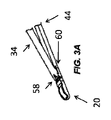
例示的実施形態では、少なくとも1本の主要または中心針が、治療プローブから展開され、複数のタインまたは二次針が、主要または中心針から展開されるであろう。殆どの場合、その中心軸に沿って治療プローブのシャフトから遠位に展開される、単一の主要針があろう。次いで、複数のタインが、遠位に分岐するパターンで単一の針から前進させられるであろう。他の実施形態では、複数の針またはタインが、主要または中心針を使用することなく、治療プローブから前進させられ得る。そのような場合において、針またはタインは、典型的には、遠位に前進させられると3次元アレイに拡張または分岐するであろう。 In an exemplary embodiment, at least one primary or central needle will be deployed from the treatment probe and multiple tines or secondary needles will be deployed from the primary or central needle. In most cases, there will be a single primary needle deployed distally from the shaft of the treatment probe along its central axis. Multiple tines would then be advanced from a single needle in a distally diverging pattern. In other embodiments, multiple needles or tines may be advanced from the treatment probe without using a main or central needle. In such cases, the needles or tines will typically expand or diverge into a three-dimensional array as they are advanced distally.
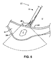
撮像され、後に治療され得る、例示的な解剖学的特徴は、筋腫、腫瘍、被包性組織塊、偽被包性組織塊等を含む。本発明にとって特に興味深いこととして、治療プローブは、子宮の中に位置付けられ得、針構造は、子宮の子宮筋層組織内に位置する筋腫に近接する、または筋腫内の場所に展開され得る。そのような場合において、本明細書で説明されるエネルギー媒介治療によって損傷され得る、子宮筋層および/または他の敏感な解剖学的特徴を包囲する漿膜を撮像することも望ましいであろう。 Exemplary anatomical features that may be imaged and subsequently treated include fibroids, tumors, encapsulated masses, pseudoencapsulated masses, and the like. Of particular interest to the present invention, the treatment probe may be positioned within the uterus and the needle structure may be deployed at a location adjacent to or within the fibroid located within the myometrial tissue of the uterus. In such cases, it would also be desirable to image the serosa surrounding the myometrium and/or other sensitive anatomical features that may be damaged by the energy-mediated treatments described herein.
本明細書で使用されるように、治療領域は、(仮想「停止部」によって設定されるような、または針構造が展開されるとリアルタイムで計算されるようないずれかの)針構造展開構成と、システムコントローラによって設定されるか、またはそれに入力される、エネルギー送達パラメータとに基づいて、システムコントローラによって計算される、またはユーザによって確立される、治療境界によって画定される。選択された場所において選択されたパターンで展開される針構造によって送達される、エネルギーまたは他の治療は、切除または他の治療結果を達成するように、標的組織を効果的に治療するであろう。下で説明されるように、したがって、治療領域が、システムのリアルタイム画像ディスプレイ上で見られるような治療される生体構造を少なくとも部分的に包囲するように、治療プローブならびに針構造停止部および/または実際の針構造を操作することが望ましいであろう。 As used herein, the treatment area is the needle structure deployment configuration (either as set by a virtual “stop” or calculated in real-time as the needle structure is deployed). and energy delivery parameters set by or input to the system controller, defined by a treatment boundary calculated by the system controller or established by the user. Energy or other treatment delivered by needle structures deployed in selected patterns at selected locations will effectively treat target tissue to achieve ablation or other therapeutic results. . As explained below, the treatment probe and needle structure stops and/or therefore such that the treatment region at least partially surrounds the anatomy to be treated as seen on the system's real-time image display. It would be desirable to manipulate the actual needle structure.
本明細書でさらに使用されるように、安全領域は、システムによって計算される、またはユーザによって確立される、安全境界によって画定される。治療領域と同様に、安全境界は、医師によって治療プローブ上で設定または調整された針構造の仮想「停止部」、実際の針構造の位置、および/またはシステムコントローラに入力されるか、またはそれによって設定されるエネルギー送達パラメータに基づいて、ユーザによって計算もしくは確立される。安全境界は、組織を損傷する危険性が低減されるか、または完全に排除される、組織治療領域の境界を超える、最小閾値距離に安全境界が設定されるであろうという点で、治療境界とは異なるであろう。 As used further herein, a safe area is defined by a safe boundary, either calculated by the system or established by a user. Similar to the treatment area, the safety boundary may be input to or from the virtual "stops" of the needle structure set or adjusted on the treatment probe by the physician, the position of the actual needle structure, and/or the system controller. Calculated or established by the user based on the energy delivery parameters set by the . A treatment boundary is defined in that the safety boundary will be set at a minimum threshold distance beyond the boundary of the tissue treatment area at which the risk of damaging tissue is reduced or completely eliminated. would be different from
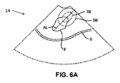
本発明の第1の側面では、組織の中で針構造を展開する方法は、治療される組織の表面近傍に、例えば、子宮の子宮筋層にわたる子宮壁に隣接して、展開可能な針構造を有する治療プローブを位置付けるステップを含む。典型的には、治療プローブによって担持される超音波アレイ等の撮像変換器を使用して、組織のリアルタイム画像が提供され、コントローラに接続されたディスプレイ上に投影され得る。リアルタイム画像は、筋腫等の治療される解剖学的特徴を含む。治療領域および安全領域のうちの少なくとも1つが、針構造の展開に先立って、リアルタイム画像上に投影され得る。次いで、治療領域および/または安全領域の境界のサイズおよび/また配置が、依然として針構造の展開に先立って、リアルタイム画像上で調整され得る。治療領域および/または安全領域の境界が、治療される生体構造に対してリアルタイム画像上で適切に位置付けられた後に、針構造は、境界が調整された後に投影された治療/安全境界内で治療を提供するように、治療プローブから組織の中へ展開され得る。 In a first aspect of the present invention, a method of deploying a needle structure within tissue comprises deploying a deployable needle structure near the surface of the tissue to be treated, e.g., adjacent the uterine wall across the myometrium of the uterus. positioning a treatment probe having a . Real-time images of the tissue are provided, typically using an imaging transducer such as an ultrasound array carried by the treatment probe, and may be projected onto a display connected to the controller. Real-time images include anatomical features to be treated, such as fibroids. At least one of the treatment area and safety area may be projected onto the real-time image prior to deployment of the needle structure. The size and/or placement of the boundaries of the treatment area and/or safety area can then be adjusted on the real-time image, still prior to deployment of the needle structure. After the boundaries of the treatment area and/or safety area are properly positioned on the real-time image relative to the anatomy to be treated, the needle structure is treated within the projected treatment/safety boundary after the boundaries have been adjusted. can be deployed from the treatment probe into tissue to provide a
治療領域および/または安全領域の境界は、いくつかの方法で移動させるか、または調整することができる。第1に、医師による医療プローブの手動移動は、画面上に投影された治療/安全境界に対して、画面上に投影された組織および生体構造のリアルタイム画像を移動させるであろう。画面上に投影された治療および/または安全境界の位置が、針構造の計算された位置に依存し得るため、治療プローブ自体の移動が、リアルタイム画像内で計算された針位置を移動させるであろうことが理解されるであろう。子宮の中の治療プローブのそのような全体移動に加えて、リアルタイム画像上に投影された治療または安全領域の位置は、例えば、治療プローブの制御ハンドル上のジョイスティックまたは指向性パッドを手動で操作することによって、治療プローブ上の制御によって調節されることができる。治療プローブは、1つ以上のセンサを備え、直接、針/タインのためのスライドおよび/または針/タインのためのシャフトの平行移動位置を検出し得る。例えば、針/タインは、加えて、針/タインの位置情報を提供し得る、1つ以上のサーボを使用して、平行移動させられ得る。針およびタインの位置は、それによって、システムコントローラによって決定および追跡され、治療および/または安全境界の位置を計算するために使用されることができる。 The boundaries of the treatment area and/or safety area can be moved or adjusted in several ways. First, manual movement of the medical probe by the physician will move the real-time image of tissue and anatomy projected on the screen relative to the treatment/safety boundary projected on the screen. Since the position of the treatment and/or safety boundary projected on the screen may depend on the calculated position of the needle structure, movement of the treatment probe itself may move the calculated needle position within the real-time image. Deafness will be understood. In addition to such global movement of the treatment probe within the uterus, the position of the treatment or safety region projected onto the real-time image can be determined, for example, by manually manipulating a joystick or directional pad on the control handle of the treatment probe. By doing so, it can be adjusted by controls on the therapy probe. The therapy probe may be equipped with one or more sensors to directly detect the translational position of the slide for the needle/tines and/or the shaft for the needle/tines. For example, the needle/tines may be translated using one or more servos, which may additionally provide needle/tine position information. The positions of the needles and tines can thereby be determined and tracked by the system controller and used to calculate the positions of treatment and/or safety boundaries.
他の実施形態では、治療および/または安全境界の位置およびサイズはまた、キーボード、ジョイスティック、マウス、タッチパネル、タッチスクリーン等の適切なインターフェースを使用して、コントローラ、ディスプレイ画面上、および/または治療プローブ制御ハンドル外で調節され得る。治療および/または安全境界が、画面上に適切に(仮想的に)位置付けられると、コントローラは、治療プローブ上の針構造の展開を制御することができる。例えば、コントローラは、サーボモータを治療プローブ上に位置付け、針/タインを位置付け得る。 In other embodiments, the location and size of the treatment and/or safety boundary can also be determined using a suitable interface such as a keyboard, joystick, mouse, touch panel, touch screen, etc., on a controller, display screen, and/or treatment probe. It can be adjusted outside the control handle. Once the treatment and/or safety boundary is properly (virtually) positioned on the screen, the controller can control the deployment of the needle structure on the treatment probe. For example, the controller may position servo motors on the therapy probe to position needles/tines.
治療および/または安全境界の位置および/またはサイズが調整されている間、仮想針場所情報をリアルタイム画像上に投影することができる。例えば、針場所情報は、針先端の投影された位置または他の針位置情報を示すようにリアルタイム画像上に投影された、複数の基準またはマーカを備えていることができる。他の場合においては、(但し、実際の展開に先立って)組織を通って進行するにつれて、針の長さの完全な画像を投影することが可能であろう。針場所情報は、当然ながら、好ましくは、投影された標的位置が調節されているとき、更新され、針展開後に針があろう場所を医師が認めることを可能にするであろう。さらに、治療および安全境界に基づく針/タインに関する仮想停止部が、ユーザに、針/タインが展開されるべき範囲を示すために表示され得る。 Virtual needle location information can be projected onto the real-time image while the position and/or size of the treatment and/or safety boundary is being adjusted. For example, the needle location information may comprise multiple fiducials or markers projected onto the real-time image to indicate the projected position of the needle tip or other needle position information. In other cases, it would be possible to project a full image of the length of the needle as it progresses through the tissue (but prior to actual deployment). The needle location information will, of course, preferably be updated as the projected target position is adjusted, allowing the physician to see where the needle will be after needle deployment. In addition, virtual stops for the needle/tines based on treatment and safety boundaries can be displayed to indicate to the user the extent to which the needle/tines should be deployed.
本発明の別の側面では、組織中の解剖学的特徴を治療するためのシステムは、リアルタイム画像ディスプレイと、治療プローブと、制御ハンドルとを備えている。治療プローブは、展開可能針構造および撮像変換器を担持し得、変換器は、リアルタイム画像ディスプレイに接続可能である。制御ハンドル上の制御要素は、リアルタイム画像ディスプレイ上に投影された治療および/または安全領域の位置およびサイズのうちの少なくとも1つを制御するように操作され得る。 In another aspect of the invention, a system for treating anatomical features in tissue includes a real-time image display, a treatment probe, and a control handle. The therapy probe may carry a deployable needle structure and an imaging transducer, the transducer connectable to a real-time image display. Control elements on the control handle may be manipulated to control at least one of the position and size of the treatment and/or safety area projected on the real-time image display.
例示的な針構造は、針と、針から前進させられ得る複数のタインとを備え得る。タインは、それらが針から前進させられるにつれて、遠位に発散するパターンをとり得る。 An exemplary needle structure may comprise a needle and multiple tines that may be advanced from the needle. The tines may adopt a pattern that diverges distally as they are advanced from the needle.
治療システムは、随意に、エネルギーを針構造に送達するために治療プローブに接続可能である、コントローラをさらに備え得る。制御ハンドルに加え、コントローラは、ユーザが、コントローラによって送達されるエネルギーレベルに基づいて、投影された治療サイズおよび/または投影された安全領域サイズを制御することを可能にするように構成され得る。 The therapy system may optionally further comprise a controller connectable to the therapy probe for delivering energy to the needle structure. In addition to the control handle, the controller may be configured to allow the user to control the projected treatment size and/or the projected safety zone size based on the energy level delivered by the controller.
本発明のさらなる側面では、撮像および治療送達システムは、近位端と、遠位端を有する撮像シャフトと、遠位端における撮像変換器とを備えている、撮像構成要素を備え得る。遠位端および近位端を有する針シャフトと、シャフト上または内に相互に配置される針構造とを備えている、針構成要素は、撮像シャフトに取り外し可能に付着するように構成され得、シャフトは、それぞれの軸が平行である状態で並んで位置する。 In a further aspect of the invention, an imaging and therapy delivery system may comprise an imaging component comprising a proximal end, an imaging shaft having a distal end, and an imaging transducer at the distal end. a needle component comprising a needle shaft having a distal end and a proximal end and a needle structure interposed on or within the shaft, may be configured to removably attach to the imaging shaft; The shafts are positioned side by side with their respective axes parallel.
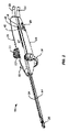
具体的例では、撮像シャフト上の撮像変換器は、撮像シャフトの遠位端において旋回可能に取り付けられ、針シャフトの遠位端は、針シャフトが撮像シャフトに取り付けられるときに、旋回可能に取り付けられた撮像変換器の近位に配置され得る。針シャフト内の針構造は、典型的には、針シャフトの軸に沿って遠位に往復し、撮像変換器は、針シャフトが撮像シャフトに取り付けられるときに、針シャフトの軸から離れて旋回する。撮像構成要素はさらに、撮像シャフトの近位端に取り付けられる撮像ハンドル区分を備え得、針構成要素はさらに、針シャフトの近位端に取り付けられる針ハンドル区分を備え得る。そのような実施形態では、撮像ハンドル区分および針ハンドル区分は、典型的には、針シャフトが撮像シャフトに取り付けられるときに、完全なハンドルを形成し得る。撮像ハンドル区分は、通常、タイン針構造を前進させるための機構を含む、撮像変換器を外部撮像ディスプレイおよび針ハンドル区分と接続するように構成される回路を保持する、内部を有し、撮像ハンドル区分は、通常、撮像シャフトに対して撮像変換器を旋回するための機構をさらに備えている。 In a specific example, the imaging transducer on the imaging shaft is pivotally mounted at the distal end of the imaging shaft and the distal end of the needle shaft is pivotally mounted when the needle shaft is attached to the imaging shaft. can be placed proximal to the imaging transducer. A needle structure within the needle shaft typically reciprocates distally along the axis of the needle shaft, and the imaging transducer pivots away from the axis of the needle shaft when the needle shaft is attached to the imaging shaft. do. The imaging component may further comprise an imaging handle section attached to the proximal end of the imaging shaft, and the needle component may further comprise a needle handle section attached to the proximal end of the needle shaft. In such embodiments, the imaging handle section and the needle handle section may typically form a complete handle when the needle shaft is attached to the imaging shaft. The imaging handle section typically has an interior carrying circuitry configured to connect the imaging transducer with an external imaging display and the needle handle section, including a mechanism for advancing the tine needle structure, and the imaging handle The section typically further comprises a mechanism for pivoting the imaging transducer relative to the imaging shaft.
本発明のなおもさらなる側面では、組織の中で針から複数のタインを展開する方法は、治療される解剖学的特徴を含む、組織のリアルタイム画像をディスプレイ上に提供するステップを含む。針は、典型的には、遠位方向に、解剖学的特徴に近接して組織に貫通させられ、タインは、針からさらに組織の中へ展開され得る。前の実施形態と同様に、タインは、典型的には、治療される組織の量を増加させるように、針から遠位に前進させられると半径方向に分岐する。治療境界および安全境界のうちの少なくとも1つが、タイン展開に応答してディスプレイ上に投影され得る。ディスプレイ上に投影された治療および/または安全境界のサイズおよび/または形状を変化させるように、タイン展開の範囲を調整することができる。治療プローブ内の1つ以上のセンサによって示されるように、実際の針およびタイン展開の位置が、提供され得、実際に展開された針およびタイン構成を使用して、後続の治療が安全かつ効果的の両方であろうことに医師が満足するまで、リアルタイム画像上に安全および/または治療境界を位置付け、かつ再配置するために、依拠することができる。実際の針およびタイン展開に加えて、当然ながら、投影された治療および/または安全境界はまた、以前に議論された仮想境界の投影と類似する様式で、治療の意図された出力および時間の長さに依存するであろう。許容サイズおよび/または安全境界が達成された後、治療がタインを通して送達され得る。特定の実施形態では、タインの展開は、針およびタインを展開するために使用される治療プローブ上の針/タイン展開機構の中のセンサを介して追跡され得る。そのような場合において、針を貫通させることは、組織に貫通させられた治療プローブから針を前進させることを含むであろう。通常、ディスプレイ上で投影された安全および/または治療境界を決定することにおいてに、治療プローブからの針展開の範囲も依拠されるであろう。 In a still further aspect of the invention, a method of deploying multiple tines from a needle in tissue includes providing on a display a real-time image of tissue including anatomical features to be treated. The needle is typically pierced through tissue in a distal direction, proximate an anatomical feature, and tines may be deployed from the needle further into the tissue. As with the previous embodiment, the tines typically diverge radially as they are advanced distally from the needle to increase the amount of tissue treated. At least one of a treatment boundary and a safety boundary may be projected onto the display in response to tine deployment. The extent of tine deployment can be adjusted to change the size and/or shape of the treatment and/or safety boundary projected on the display. Actual needle and tine deployment locations, as indicated by one or more sensors within the treatment probe, can be provided to ensure that subsequent treatments are safe and effective using the actual deployed needle and tine configuration. It can be relied upon to locate and reposition safety and/or treatment boundaries on the real-time images until the physician is satisfied with what will be both targets. In addition to the actual needle and tine deployment, of course, the projected treatment and/or safety boundary also reflects the intended output and duration of treatment, in a manner similar to the projection of the virtual boundary discussed previously. would depend on Treatment may be delivered through the tines after an acceptable size and/or safety boundary is achieved. In certain embodiments, deployment of the tines may be tracked via sensors in the needle/tine deployment mechanism on the needle and treatment probe used to deploy the tines. In such cases, penetrating the needle would include advancing the needle from a treatment probe that has penetrated the tissue. Typically, the extent of needle deployment from the treatment probe will also be relied upon in determining safety and/or treatment boundaries projected on the display.
本発明のなおもさらなる側面では、組織中の解剖学的特徴を治療するためのシステムは、コントローラに接続されるリアルタイムディスプレイを備えている。システムは、治療境界または安全境界のうちの少なくとも1つのサイズをディスプレイ上に投影し、調節し得る。コントローラおよびディスプレイに接続可能である、展開可能な針構造および撮像変換器を有する、治療プローブが、提供され得る。治療プローブは、治療プローブハンドル上のコントローラおよび/または制御要素に接続され、それによって駆動され得る、少なくとも1つのサーボ駆動モータを担持し得る。制御要素および/またはコントローラは、サーボモータを駆動して、治療境界によって画定される領域にわたって効果的であり得、安全境界を有意に超えて拡張し得ない治療を提供するよう針構造を位置付けるように構成され得る。 In still a further aspect of the invention, a system for treating anatomical features in tissue includes a real-time display connected to a controller. The system may project and adjust the size of at least one of the treatment boundary or the safety boundary on the display. A therapy probe can be provided having a deployable needle structure and an imaging transducer connectable to a controller and display. The therapy probe may carry at least one servo drive motor that may be connected to and driven by a controller and/or control elements on the therapy probe handle. A control element and/or controller drives the servomotor to position the needle structure to provide therapy that may be effective over the area defined by the treatment boundary and may not extend significantly beyond the safety boundary. can be configured to
システムの具体的実施形態では、針構造は、針と、遠位に分岐するパターンで針から前進可能な複数のタインとを備え得る。少なくとも1つのサーボモータは、針を駆動する第1のサーボモータと、複数のタインを駆動する第2のサーボモータとを備え得る。システムは、通常、ユーザがディスプレイ上で治療および/または安全境界のサイズおよび/または位置を仮想的に調整することを可能にするように構成される、ユーザインターフェースを備えている。場合によっては、以前に説明されたように、インターフェースは、治療プローブハンドルの制御要素等、治療プローブ自体の上にあり得る。他の場合においては、インターフェースは、針構造を実際に位置付けることに先立って、ユーザが針構造を仮想的に位置付けることを可能にするように、コントローラに接続される、より従来的なキーボード、マウス、ローラボール、タッチスクリーン、音声起動等を備え得る。なおも他の実施形態では、治療プローブは、針構造を位置付けるためのサーボモータおよび/または針構造が展開された範囲を検出するためのセンサを備え得る。そのような場合において、ユーザは、(安全および/または治療境界の仮想投影を生成することなく)サーボを使用して針構造を位置付け、投影された安全および/または治療境界がシステムコントローラによって計算および投影されるにつれて、それらを観察し得る。全ての場合において、システムは、針構造の展開が安全および/または治療境界の要件を満たすことが確認された後のみ、エネルギーまたは他の治療を送達するために使用することができる。 In specific embodiments of the system, the needle structure may comprise a needle and a plurality of tines advanceable from the needle in a distally diverging pattern. The at least one servomotor may comprise a first servomotor that drives the stylus and a second servomotor that drives the plurality of tines. The system typically includes a user interface configured to allow the user to virtually adjust the size and/or position of the treatment and/or safety boundary on the display. In some cases, as previously described, the interface may be on the therapy probe itself, such as control elements of the therapy probe handle. In other cases, the interface is a more conventional keyboard, mouse, connected to a controller to allow the user to virtually position the needle structure prior to actually positioning the needle structure. , roller ball, touch screen, voice activation, and the like. In still other embodiments, the therapy probe may comprise a servomotor for positioning the needle structure and/or a sensor for detecting the extent to which the needle structure has been deployed. In such cases, the user positions the needle structure using servos (without generating a virtual projection of the safety and/or treatment boundaries) and the projected safety and/or treatment boundaries are calculated and calculated by the system controller. You can observe them as they are projected. In all cases, the system can be used to deliver energy or other therapy only after it has been confirmed that the deployment of the needle structure meets the safety and/or therapeutic boundary requirements.
本発明のなおもさらなる側面では、組織を治療する方法が、提供される。例示的組織治療方法は、明確に異なる計画およびリアルタイム監視ステップを含み得る。計画位相では、ユーザは、アブレーションのための安全性および/または治療境界の表示されるグラフィカル表現を制御し得る。これらの境界は、スイッチ、ジェスチャ、音声制御等の任意の数の入力デバイスを用いて制御され得る。針およびタインの標的深度は、計画位相の間に確立され、グラフィカル計画ガイドとしてディスプレイ上に示され得る。例示的実施形態では、安全性および/または治療に関する境界は、プローブのハンドル上のジョイスティックまたは指向性パッドを介して制御される。本明細書に説明されるアブレーションデバイスの多くは、2つの段階、すなわち、針展開のための1つの段階と、タインの展開のための1つの段階とを備えている。多くの場合、アブレーションデバイスの針は、展開されたタインの所望の幾何学形状が、治療中、変更されず、グラフィカルガイドが、無効にされないように、タインが展開される前に、所望の深度まで組織の中に前進させられ、前進させられた針の位置を維持することが望ましくあり得る。計画位相は、ユーザが、浅いがより広い組織アブレーションをより深くかつより狭いアブレーションに対してトレードオフすることを可能にし得る。 In yet a further aspect of the invention, a method of treating tissue is provided. Exemplary tissue treatment methods may include distinct planning and real-time monitoring steps. In the planning phase, the user may control the displayed graphical representation of safety and/or treatment boundaries for ablation. These boundaries can be controlled using any number of input devices such as switches, gestures, voice controls, and the like. Target depths for needles and tines can be established during the planning phase and shown on the display as a graphical planning guide. In an exemplary embodiment, safety and/or therapeutic boundaries are controlled via a joystick or directional pad on the handle of the probe. Many of the ablation devices described herein have two stages, one for needle deployment and one for tine deployment. In many cases, the ablation device needles are placed at the desired depth before the tines are deployed so that the desired geometry of the deployed tines does not change during treatment and the graphical guide is not overridden. , and it may be desirable to maintain the position of the advanced needle. The planning phase may allow the user to trade off shallow but wider tissue ablation for deeper and narrower ablation.
展開位相中、治療プローブ内のセンサは、導入器針、タイン、および/またはその個別の展開シャフトのリアルタイム位置を監視し得、ディスプレイコンソールは、検出された位置および展開の進行度を表示し得る。針および/またはタインの展開が、計画された値に合致すると、システムは、視覚、聴覚、触知、または他のフィードバック等によって、合致をユーザに示すことができる。例示的実施形態では、針および/またはタインに対応するディスプレイマーカは、表示されるグラフィカル計画ガイドと整合および/または重複され得る。ユーザが、針および/またはタインを計画された深度を越えて継続して展開する場合、システムは、エラーを示し、ユーザに、針および/またはタインを後退させるように命令し得る。例えば、システムは、視覚的警告を表示し得る、もしくは安全性境界の外側にあるように、針および/またはタインに対応するディスプレイマーカを示し得る。多くの実施形態では、システムは、グラフィカル計画ガイドと針およびタインの表示されるリアルタイム位置をリンクさせ、針およびタインの検出されたリアルタイム位置に応答して、グラフィカル計画ガイドを表示し得る。いくつかの実施形態では、システムは、ユーザが、システムによって保定され得る位置センサへの調節を入力することを可能にする。 During the deployment phase, sensors within the treatment probe may monitor real-time positions of the introducer needle, tines, and/or their respective deployment shafts, and a display console may display the detected positions and the progress of deployment. . When needle and/or tine deployment meets planned values, the system can indicate the match to the user, such as by visual, auditory, tactile, or other feedback. In an exemplary embodiment, display markers corresponding to the needles and/or tines may be aligned and/or overlapped with the displayed graphical planning guide. If the user continues to deploy the needle and/or tines beyond the planned depth, the system may indicate an error and instruct the user to retract the needle and/or tines. For example, the system may display a visual warning or show display markers corresponding to the needles and/or tines as they are outside the safety perimeter. In many embodiments, the system may link the graphical planning guide with the displayed real-time positions of the needles and tines and display the graphical planning guide in response to the detected real-time positions of the needles and tines. In some embodiments, the system allows the user to input adjustments to position sensors that can be held by the system.
いくつかの実施形態では、計画段階は、随意に、省略され、グラフィカル計画ガイドが、導入器針およびタインのリアルタイム位置を反映することができる。グラフィカル計画ガイドの深度は、導入器針展開の深度を反映させ得、グラフィカル計画ガイドのサイズは、電極展開を反映させ得る。センサ入力への調節は、ユーザによって入力され得る。 In some embodiments, the planning phase is optionally skipped and the graphical planning guide can reflect the real-time position of the introducer needle and tines. The depth of the graphical planning guide may reflect the depth of introducer needle deployment, and the size of the graphical planning guide may reflect electrode deployment. Adjustments to the sensor input can be entered by the user.
いくつかの実施形態では、計画および監視制御スイッチ(例えば、ジョイスティックまたは指向性パッド(すなわち、D-パッド))は、ユーザインターフェース要素として作用し、特徴またはメニュー選択およびカーソル図面等の典型的にはマウスまたはキーボードによって実施される機能を実施する。 In some embodiments, planning and monitoring control switches (e.g., joysticks or directional pads (i.e., D-pads)) act as user interface elements, typically including features or menu selections and cursor drawings. Performs functions performed by a mouse or keyboard.
治療プローブは、1つ以上のセンサを備え、デバイスハンドルに対する針、タイン、および/またはその個別の展開シャフトのうちの1つ以上のものの位置を検出し得る。センサは、いくつか例を挙げると、線形ポテンショメータ、磁気センサ、LVDTセンサ、パルスエンコーダ等の任意のタイプの位置センサであり得る。センサは、導入器針場所に対する、またはデバイスの治療プローブハンドルに対する、運動を感知し得る。同一または異なるタイプのセンサが、針、タイン、および/またはその個別の展開シャフトのために使用され得る。 The therapy probe may include one or more sensors to detect the position of one or more of the needles, tines, and/or their respective deployment shafts relative to the device handle. The sensors can be any type of position sensor such as linear potentiometers, magnetic sensors, LVDT sensors, pulse encoders, to name a few. The sensor may sense motion relative to the introducer needle location or relative to the treatment probe handle of the device. The same or different types of sensors may be used for needles, tines and/or their respective deployment shafts.
本発明のなおもさらなる側面では、針構造を組織内で展開する方法が、提供される。針構造を組織内で展開するための例示的方法は、治療されるべき解剖学的特徴を含む組織のリアルタイム画像をコントローラに接続されたディスプレイ上に提供することを含み得る。展開可能針構造を有する、治療プローブはさらに、治療プローブが解剖学的特徴の近傍に位置付けられるにつれて表示され得る。加えて、治療領域または安全領域のうちの少なくとも1つは、リアルタイム画像上に投影され得る。方法はさらに、リアルタイム画像上の治療領域および/または安全領域の投影された画像の投影された境界のサイズまたは位置のうちの少なくとも1つを調節することを含み得る。投影された境界のサイズおよび/または位置を調節することは、いくつかの事例では、治療プローブのハンドルの第1のユーザインターフェースのユーザ調節を含み得る。さらに、展開可能針構造は、針構造が治療プローブから展開されているとき、リアルタイム画像上に表示され得る。方法を実践することにおいて、針構造は、治療プローブおよび組織に対して位置付けられ、投影された境界が調節された後、投影された境界内で治療を提供し得、治療プローブは、組織内の解剖学的特徴の近傍に位置付けられ得る。加えて、針構造は、治療プローブのハンドルの第2のユーザインターフェースのユーザ調節によって、治療プローブから展開され得る。いくつかの実施形態では、投影された境界のサイズまたは位置のうちの少なくとも1つは、針が治療プローブおよび組織に対して位置付けられ、治療を提供した後、再調節される。 In yet a further aspect of the invention, a method of deploying a needle structure within tissue is provided. An exemplary method for deploying a needle structure within tissue may include providing a real-time image of tissue, including anatomical features to be treated, on a display connected to a controller. A treatment probe having a deployable needle structure may also be displayed as the treatment probe is positioned proximate an anatomical feature. Additionally, at least one of the treatment area or the safety area may be projected onto the real-time image. The method may further include adjusting at least one of the size or position of the projected boundaries of the projected image of the treatment region and/or the safety region on the real-time image. Adjusting the size and/or position of the projected boundary may, in some cases, include user adjustment of the first user interface of the handle of the treatment probe. Additionally, the deployable needle structure can be displayed on the real-time image as the needle structure is being deployed from the treatment probe. In practicing the method, the needle structure may be positioned relative to the treatment probe and tissue to provide treatment within the projected boundary after the projected boundary has been adjusted, the treatment probe being positioned within the tissue. It can be positioned near an anatomical feature. Additionally, the needle structure may be deployed from the therapy probe by user adjustment of the second user interface of the handle of the therapy probe. In some embodiments, at least one of the projected boundary size or position is readjusted after the needle is positioned relative to the treatment probe and tissue and the treatment is delivered.
いくつかの実施形態では、治療プローブのハンドルの第1のユーザインターフェースは、ジョイスティックまたは指向性パッドを備え得る。随意に、投影された境界と関連付けられたパラメータが、ジョイスティックまたは指向性パッドを調節することによって調節され得る。例えば、投影された境界のサイズおよび/または位置を調節することは、投影された境界のサイズを調節することを含み得、投影された境界のサイズは、ジョイスティックまたは指向性パッドが第1の方向に押され、投影された境界を拡大すること、またはジョイスティックまたは指向性パッドが第1の方向と反対の第2の方向に押され、投影された境界を縮小することのうちの1つ以上のものによって調節される。別の例として、投影された境界のサイズおよび/または位置を調節することは、投影された境界の位置を調節することを含み得、投影された境界の位置は、ジョイスティックまたは指向性パッドが第3の方向に押され、投影された境界を前進させること、またはジョイスティックまたは指向性パッドが第3の方向と反対の第4の方向に押され、投影された境界を後退させることのうちの1つ以上のものによって調節される。典型的には、ジョイスティック、指向性パッド、または他のユーザインターフェースは、投影された境界のサイズおよび/または位置が、調節されているとき、治療プローブのハンドルに対して静止したままであろう。代替として、または加えて、投影された境界の位置は、治療プローブを解剖学的特徴に対して手動で再位置付けすることによって調節され得る。 In some embodiments, the first user interface of the treatment probe handle may comprise a joystick or directional pad. Optionally, parameters associated with the projected boundaries can be adjusted by adjusting a joystick or directional pad. For example, adjusting the size and/or position of the projected boundary may include adjusting the size of the projected boundary, the size of the projected boundary being adjusted when the joystick or directional pad is moved in the first direction. one or more of pushing the joystick or directional pad in a second direction opposite the first direction to contract the projected boundary. regulated by things. As another example, adjusting the size and/or position of the projected boundary may include adjusting the position of the projected boundary, the position of the projected boundary being controlled by a joystick or directional pad. One of three directions to advance the projected boundary, or the joystick or directional pad to be pushed in a fourth direction opposite the third direction to retract the projected boundary. regulated by more than one Typically, a joystick, directional pad, or other user interface will remain stationary relative to the handle of the treatment probe as the size and/or position of the projected boundary is adjusted. Alternatively or additionally, the position of the projected boundary may be adjusted by manually repositioning the treatment probe relative to the anatomical feature.
いくつかの実施形態では、治療プローブのハンドルはさらに、針構造および針構造から前進可能な複数のタインのうちの1つ以上のものを展開するための第2のユーザインターフェースを備え得る。第2のユーザインターフェースは、治療プローブのハンドルの1つ以上のスライダ機構を備え得る。例示的治療プローブは、代替として、または加えて、針構造から前進可能な複数のタインを備え得る。そのような事例では、方法はさらに、複数のタインが展開されているとき、複数のタインのリアルタイム位置を検出することと、検出されたリアルタイム位置に応答して、複数のタインをリアルタイム画像上に表示することとを含み得る。本明細書に説明される方法では、治療領域または安全領域のうちの少なくとも1つをリアルタイム画像上に投影することは、複数のタインのための1つ以上のタイン停止インジケータをリアルタイム画像上に投影することを含み得る。複数のタインは、複数のタインの仮想表現がタイン停止インジケータと出会うように前進させられ得る。多くの実施形態では、ハンドルの第1のユーザインターフェースは、複数のタインがそのように前進させられた後、タイン停止インジケータの位置を調節するように調節される。典型的には、複数のタインのための1つ以上のタイン停止インジケータは、治療されるべき解剖学的特徴内に位置付けられる。いくつかの実施形態では、方法はさらに、治療プローブのサーボモータを駆動し、複数のタインを展開することを含み得る。いくつかの実施形態では、複数のタインをリアルタイム画像上に表示することは、複数のタインのリアルタイム位置を検出することと、検出されたリアルタイム位置に応答して、複数のタインの仮想表現を表示することとを含み得る。そのような事例では、複数のタインの仮想表現の位置はさらに、リアルタイムで更新され得る。 In some embodiments, the treatment probe handle may further comprise a second user interface for deploying one or more of the needle structure and a plurality of tines advanceable from the needle structure. The second user interface may comprise one or more slider mechanisms on the handle of the therapy probe. An exemplary treatment probe may alternatively or additionally comprise a plurality of tines advanceable from the needle structure. In such instances, the method further comprises detecting real-time positions of the plurality of tines as they are being deployed; and displaying. In the methods described herein, projecting at least one of the treatment region or the safety region onto the real-time image includes projecting one or more tine stop indicators for the plurality of tines onto the real-time image. can include doing A plurality of tines may be advanced such that a virtual representation of the plurality of tines meets a tine stop indicator. In many embodiments, the first user interface of the handle is adjusted to adjust the position of the tine stop indicator after the tines have been so advanced. Typically, one or more tine stop indicators for multiple tines are positioned within the anatomical feature to be treated. In some embodiments, the method may further include driving a servomotor of the treatment probe to deploy multiple tines. In some embodiments, displaying the plurality of tines on the real-time image includes detecting real-time positions of the plurality of tines and displaying a virtual representation of the plurality of tines in response to the detected real-time positions. and In such cases, the positions of the virtual representations of multiple tines can also be updated in real time.
いくつかの実施形態では、方法はさらに、エネルギーを複数のタインを通して送達し、解剖学的特徴を治療することを含み得る。そのような事例では、方法はさらに、治療電力または治療時間のうちの少なくとも1つを制御し、組織治療の範囲を治療領域および/または安全領域内に限定することを含み得る。いくつかの実施形態では、方法はさらに、エネルギーを針構造を通して送達し、解剖学的特徴を治療することを含む。そのような事例では、方法はさらに、治療電力または治療時間のうちの少なくとも1つを制御し、組織治療の範囲を治療領域および/または安全領域内に限定することを含み得る。いくつかの実施形態では、治療領域または安全領域のうちの少なくとも1つをリアルタイム画像上に投影することは、針構造のための1つ以上の針停止インジケータをリアルタイム画像上に投影することを含み得る。1つ以上の針停止インジケータは、治療されるべき解剖学的特徴の近傍またはその中にあるように構成され得る。針構造は、針構造の仮想表現が1つ以上の針停止インジケータと出会うように前進させられ得る。ハンドルのユーザインターフェースは、針構造がそのように前進させられた後、針停止インジケータの位置を調節するように調節され得る。いくつかの実施形態では、方法はさらに、治療プローブのサーボモータを駆動し、針構造を展開することを含み得る。方法を実践することにおいて、針構造をリアルタイム画像上に表示することは、針構造のリアルタイム位置を検出することと、検出されたリアルタイム位置に応答して、針構造の仮想表現を表示することとを含み得る。いくつかの実施形態では、方法はさらに、針構造の仮想表現の位置をリアルタイムで更新することを含み得る。 In some embodiments, the method may further include delivering energy through multiple tines to treat the anatomical feature. In such instances, the method may further include controlling at least one of treatment power or treatment time to limit the extent of tissue treatment within the treatment and/or safety regions. In some embodiments, the method further includes delivering energy through the needle structure to treat the anatomical feature. In such instances, the method may further include controlling at least one of treatment power or treatment time to limit the extent of tissue treatment within the treatment and/or safety regions. In some embodiments, projecting at least one of the treatment region or the safety region onto the real-time image includes projecting one or more needle stop indicators for the needle structure onto the real-time image. obtain. One or more needle stop indicators may be configured to be near or within the anatomical feature to be treated. The needle structure may be advanced such that a virtual representation of the needle structure meets one or more needle stop indicators. The handle user interface can be adjusted to adjust the position of the needle stop indicator after the needle structure has been so advanced. In some embodiments, the method may further include driving a servomotor of the therapy probe to deploy the needle structure. In practicing the method, displaying the needle structure on the real-time image includes detecting a real-time position of the needle structure and displaying a virtual representation of the needle structure in response to the detected real-time position. can include In some embodiments, the method may further include updating the position of the virtual representation of the needle structure in real time.
本発明のさらに別の側面では、組織内の解剖学的特徴を治療するためのシステムが、提供され得る。システムは、ハンドル、プローブ本体、および解剖学的特徴を治療するためにプローブ本体から展開可能な針構造を備えている、治療プローブと、治療プローブに結合され、リアルタイム画像を表示し、展開された針構造および治療領域または安全領域のうちの少なくとも1つをリアルタイム画像上に投影するように構成される、リアルタイムディスプレイとを備え得、ハンドルは、治療領域または安全領域のうちの少なくとも1つの1つ以上の境界のサイズまたは位置のうちの1つ以上のものを調節するための第1のユーザインターフェースを備えている。多くの実施形態では、第1のユーザインターフェースの位置は、1つ以上の境界のサイズまたは位置のうちの1つ以上のものが調節されているとき、ハンドルに対して静止したままである。 In yet another aspect of the invention, a system for treating anatomical features in tissue can be provided. The system includes a treatment probe comprising a handle, a probe body, and a needle structure deployable from the probe body for treating an anatomical feature, and a treatment probe coupled to the treatment probe for displaying real-time images and deployed. a real-time display configured to project the needle structure and at least one of the treatment area or the safety area onto the real-time image, the handle being positioned in one of the at least one of the treatment area or the safety area. A first user interface is provided for adjusting one or more of the size or position of the boundaries. In many embodiments, the position of the first user interface remains stationary with respect to the handle when one or more of the size or position of one or more boundaries is adjusted.
いくつかの実施形態では、治療プローブは、針構造から展開可能な複数のタインを備え得る。そのような事例では、リアルタイムディスプレイは、複数のタインの検出された位置に応答して、複数のタインの仮想表現を表示するように構成され得る。随意に、治療プローブは、複数のタインの位置を検出するための1つ以上のセンサを備え得る。いくつかの実施形態では、システムのリアルタイムディスプレイは、複数のタインのための1つ以上のタイン停止インジケータを示すように構成され得る。ハンドルの第1のユーザインターフェースは、複数のタインの仮想表現が1つ以上のタイン停止インジケータと出会うように、複数のタインが展開された後、1つ以上のタイン停止インジケータを再位置付けするために調節されるように構成され得る。代替として、または加えて、治療プローブのハンドルはさらに、複数のタインを展開するための第2のユーザインターフェースを備え得る。そのような事例では、第2のユーザインターフェースは、スライド機構を備え得る。 In some embodiments, the treatment probe may comprise multiple tines deployable from the needle structure. In such instances, the real-time display may be configured to display a virtual representation of the multiple tines in response to the detected positions of the multiple tines. Optionally, the therapy probe may include one or more sensors for detecting the positions of multiple tines. In some embodiments, the real-time display of the system may be configured to show one or more tine stop indicators for multiple tines. A first user interface of the handle for repositioning the one or more tine stop indicators after the multiple tines are deployed such that the virtual representation of the multiple tines meets the one or more tine stop indicators. can be configured to be adjusted. Alternatively or additionally, the treatment probe handle may further comprise a second user interface for deploying multiple tines. In such instances, the second user interface may comprise a sliding mechanism.
いくつかの実施形態では、治療プローブのハンドルはさらに、針構造を展開するための第2のユーザインターフェースを備え得る。そのような事例では、第2のユーザインターフェースは、スライド機構を備え得る。いくつかの実施形態では、システムの治療プローブは、複数のタインを駆動するためのサーボを備え得る。代替として、または加えて、治療プローブは、針構造を駆動するためのサーボを備え得る。いくつかの実施形態では、システムのリアルタイムディスプレイは、針構造の検出された位置に応答して、針構造の仮想表現を表示するように構成され得る。そのような事例では、治療プローブは、針構造の位置を検出するための1つ以上のセンサを備え得る。代替として、または加えて、システムのリアルタイムディスプレイは、針構造のための1つ以上の針停止インジケータを示すように構成され得る。いくつかの実施形態では、ハンドルの第1のユーザインターフェースは、針構造の仮想表現が針停止インジケータと出会うように、針構造が展開された後、針停止インジケータを再位置付けするために調節されるように構成される。いくつかの実施形態では、第1のユーザインターフェースは、治療領域または安全領域の境界の位置またはサイズのうちの1つ以上のものを調節するように構成され得る。調節は、種々の手段を通して取り扱われ得る。例えば、第1のユーザインターフェースは、ジョイスティックまたは指向性パッドを治療プローブのハンドル上に備え得る。ジョイスティックまたは指向性パッドは、第1の方向に押され、投影された境界を拡大するように構成され得、第1の方向と反対の第2の方向に押され、投影された境界を縮小するように構成され得る。随意に、ジョイスティックまたは指向性パッドは、第3の方向に押され、投影された境界を前進させるように構成され得、いくつかの事例ではさらに、第3の方向と反対の第4の方向に押され、投影された境界を後退させるように構成され得る。
本発明は、例えば、以下を提供する。
(項目1)
治療構造を組織内で展開する方法であって、前記方法は、
治療されるべき解剖学的特徴を含む前記組織のリアルタイム画像をコントローラに接続されたディスプレイ上に提供することと、
プローブが前記解剖学的特徴の近傍に位置付けられているとき、展開可能治療構造を有する前記プローブを表示することと、
治療領域または安全領域のうちの少なくとも1つを前記リアルタイム画像上に投影することと、
前記リアルタイム画像上の前記治療領域および/または安全領域の前記投影された画像の投影された境界のサイズまたは位置のうちの少なくとも1つを調節することであって、前記投影された境界のサイズおよび/または位置を調節することは、前記プローブのハンドル上の第1のユーザインターフェースのユーザ調節を含む、ことと、
前記治療構造が前記プローブから展開されているとき、前記展開可能治療構造を前記リアルタイム画像上に表示することと
を含み、
前記治療構造は、前記投影された境界が調節された後、前記投影された境界内で治療を提供するために前記プローブおよび前記組織に対して位置付けられ、
前記プローブは、前記組織内の前記解剖学的特徴の近傍に位置付けられ、前記治療構造は、前記プローブのハンドル上の第2のユーザインターフェースのユーザ動作によって、前記プローブから展開され、前記第2のユーザインターフェースを調節することによる前記プローブからの前記治療構造の展開は、前記投影された境界の前記サイズおよび/または位置を調節するための前記第1のユーザインターフェースの前記調節から独立している、方法。
(項目2)
治療を提供するために前記治療構造が前記プローブおよび前記組織に対して位置付けられた後、前記投影された境界のサイズまたは前記位置のうちの少なくとも1つを再調節することをさらに含む、項目1に記載の方法。
(項目3)
前記投影された境界の位置は、前記プローブを前記解剖学的特徴に対して手動で再位置付けすることによって調節される、項目1に記載の方法。
(項目4)
前記プローブの前記ハンドルの前記第1のユーザインターフェースは、ジョイスティックまたは指向性パッドを備えている、項目1に記載の方法。
(項目5)
前記投影された境界の前記サイズおよび/または位置を調節することは、前記投影された境界の前記サイズを調節することを含み、前記投影された境界の前記サイズは、前記ジョイスティックまたは指向性パッドが第1の方向に押され、前記投影された境界を拡大すること、または、前記ジョイスティックまたは指向性パッドが前記第1の方向と反対の第2の方向に押され、前記投影された境界を縮小することのうちの1つ以上によって調節される、項目4に記載の方法。
(項目6)
前記ジョイスティックまたは指向性パッドは、前記投影された境界の前記サイズおよび/または位置が調節されているとき、前記プローブの前記ハンドルに対して静止したままである、項目5に記載の方法。
(項目7)
前記投影された境界の前記サイズおよび/または位置を調節することは、前記投影された境界の前記位置を調節することを含み、前記投影された境界の前記位置は、前記ジョイスティックまたは指向性パッドが第3の方向に押され、前記投影された境界を前進させること、または、前記ジョイスティックまたは指向性パッドが前記第3の方向と反対の第4の方向に押され、前記投影された境界を後退させることのうちの1つ以上によって調節される、項目4に記載の方法。
(項目8)
前記ジョイスティックまたは指向性パッドは、前記投影された境界の前記サイズおよび/または位置が調節されているとき、前記プローブのハンドルに対して静止したままである、項目7に記載の方法。
(項目9)
前記プローブの前記ハンドル上の前記第2のユーザインターフェースは、前記治療構造に結合された1つ以上のスライダ機構を備えている、項目1に記載の方法。
(項目10)
前記治療構造は、針構造を備えている、項目1に記載の方法。
(項目11)
前記治療プローブは、前記針構造から前進可能な複数のタインをさらに備え、前記方法は、前記複数のタインが展開されているとき、前記複数のタインのリアルタイム位置を検出することと、前記検出されたリアルタイム位置に応答して、前記複数のタインの仮想表現を前記リアルタイム画像上に表示することとをさらに含む、項目10に記載の方法。
(項目12)
前記治療領域または前記安全領域のうちの前記少なくとも1つを前記リアルタイム画像上に投影することは、前記複数のタインのための1つ以上のタイン停止インジケータを前記リアルタイム画像上に投影することを含む、項目11に記載の方法。
(項目13)
前記複数のタインの前記仮想表現が前記タイン停止インジケータと出会うように、前記複数のタインを前進させることをさらに含む、項目12に記載の方法。
(項目14)
前記複数のタインが、前記複数のタインの前記仮想表現が前記タイン停止インジケータと出会うように前進させられた後、前記ハンドルの前記第1のユーザインターフェースを調節し、前記タイン停止インジケータの位置を調節することをさらに含む、項目13に記載の方法。
(項目15)
前記複数のタインのための前記1つ以上の停止位置は、治療されるべき解剖学的特徴内にあるように構成されている、項目12に記載の方法。
(項目16)
前記治療プローブのサーボモータを駆動し、前記複数のタインを展開することをさらに含む、項目11に記載の方法。
(項目17)
前記複数のタインを前記リアルタイム画像上に表示することは、前記複数のタインのリアルタイム位置を検出することと、前記検出されたリアルタイム位置に応答して、前記複数のタインの仮想表現を表示することとを含む、項目11に記載の方法。
(項目18)
前記複数のタインの前記仮想表現の位置をリアルタイムで更新することをさらに含む、項目17に記載の方法。
(項目19)
エネルギーを前記複数のタインを通して送達し、前記解剖学的特徴を治療することをさらに含む、項目11に記載の方法。
(項目20)
治療電力または治療時間のうちの少なくとも1つを制御し、前記組織治療の範囲を前記治療領域および/または安全領域内に限定することをさらに含む、項目19に記載の方法。
(項目21)
エネルギーを前記治療構造を通して送達し、前記解剖学的特徴を治療することをさらに含む、項目1に記載の方法。
(項目22)
治療電力または治療時間のうちの少なくとも1つを制御し、前記組織治療の範囲を前記治療領域および/または安全領域内に限定することをさらに含む、項目21に記載の方法。
(項目23)
前記プローブのサーボモータを駆動し、前記治療構造を展開することをさらに含む、項目1に記載の方法。
(項目24)
前記治療領域または前記安全領域のうちの少なくとも1つを前記リアルタイム画像上に投影することは、前記治療構造のための1つ以上の停止位置を前記リアルタイム画像上に投影することを含む、項目1に記載の方法。
(項目25)
前記治療構造のための前記1つ以上の停止位置は、治療されるべき解剖学的特徴の近傍またはその中にあるように構成されている、項目24に記載の方法。
(項目26)
前記治療構造を前記リアルタイム画像上に表示することは、前記治療構造のリアルタイム位置を検出することと、前記検出されたリアルタイム位置に応答して、前記治療構造の仮想表現を表示することとを含む、項目24に記載の方法。
(項目27)
前記治療構造の前記仮想表現の位置をリアルタイムで更新することをさらに含む、項目26に記載の方法。
(項目28)
前記治療構造の前記仮想表現が前記針停止インジケータと出会うように、前記治療構造を前進させることをさらに含む、項目26に記載の方法。
(項目29)
前記針構造の前記仮想表現が前記針停止インジケータと出会うように、前記針構造が前進させられた後、前記ハンドルの前記第1のユーザインターフェースを調節し、前記針停止インジケータの位置を調節することをさらに含む、項目28に記載の方法。
(項目30)
組織内の解剖学的特徴を治療するためのシステムであって、前記システムは、
ハンドル、プローブ本体、および前記解剖学的特徴を治療するために前記プローブ本体から展開可能な治療構造を備えているプローブと、
前記プローブに結合されたリアルタイムディスプレイと
を備え、
前記リアルタイムディスプレイは、リアルタイム画像を表示し、前記展開された治療構造と治療領域または安全領域のうちの少なくとも1つとを前記リアルタイム画像上に投影するように構成され、
前記ハンドルは、前記治療領域または安全領域のうちの少なくとも1つの1つ以上の境界のサイズまたは位置のうちの1つ以上のものを調節するための第1のユーザインターフェースを備え、
前記ハンドルは、前記治療構造を前記プローブから展開するための第2のユーザインターフェースを備え、前記第2のユーザインターフェースを調節することによる前記プローブからの前記治療構造の展開は、前記投影された境界の前記サイズおよび/または位置を調節するための前記第1のユーザインターフェースの前記調節から独立している、
システム。
(項目31)
前記治療構造は、針構造を備えている、項目30に記載のシステム。
(項目32)
前記プローブは、前記針構造から展開可能な複数のタインをさらに備えている、項目31に記載のシステム。
(項目33)
前記リアルタイムディスプレイは、前記複数のタインの検出された位置に応答して、前記複数のタインの仮想表現を表示するように構成されている、項目32に記載のシステム。
(項目34)
前記治療プローブは、前記複数のタインの位置を検出するための1つ以上のセンサを備えている、項目33に記載のシステム。
(項目35)
前記リアルタイムディスプレイは、前記複数のタインのための1つ以上のタイン停止インジケータを示すように構成されている、項目32に記載のシステム。
(項目36)
前記ハンドルの前記第1のユーザインターフェースは、前記複数のタインの前記仮想表現が前記1つ以上のタイン停止インジケータと出会うように、前記複数のタインが展開された後、前記1つ以上のタイン停止インジケータを再位置付けするために調節されるように構成されている、項目35に記載のシステム。
(項目37)
前記治療プローブは、前記複数のタインを駆動するためのサーボを備えている、項目32に記載のシステム。
(項目38)
前記第2のユーザインターフェースは、前記治療構造に結合された1つ以上のスライド機構を備えている、項目30に記載のシステム。
(項目39)
前記治療プローブは、前記治療構造を駆動するためのサーボを備えている、項目30に記載のシステム。
(項目40)
前記リアルタイムディスプレイは、前記治療構造の検出された位置に応答して、前記治療構造の仮想表現を表示するように構成されている、項目30に記載のシステム。
(項目41)
前記治療プローブは、前記治療構造の位置を検出するための1つ以上のセンサを備えている、項目40に記載のシステム。
(項目42)
前記リアルタイムディスプレイは、前記針構造のための停止インジケータを示すように構成されている、項目40に記載のシステム。
(項目43)
前記ハンドルの前記第1のユーザインターフェースは、前記治療構造の前記仮想表現が前記停止インジケータと出会うように、前記治療構造が展開された後、前記停止インジケータを再位置付けするために調節されるように構成されている、項目42に記載のシステム。
(項目44)
前記第1のユーザインターフェースは、前記治療プローブのハンドル上のジョイスティックまたは指向性パッドを備えている、項目30に記載のシステム。
(項目45)
前記ジョイスティックまたは指向性パッドは、第1の方向に押され、前記投影された境界を拡大するように構成され、前記ジョイスティックまたは指向性パッドは、前記第1の方向と反対の第2の方向に押され、前記投影された境界を縮小するように構成されている、項目44に記載のシステム。
(項目46)
前記ジョイスティックまたは指向性パッドは、第3の方向に押され、前記投影された境界を前進させるように構成され、前記ジョイスティックまたは指向性パッドは、前記第3の方向と反対の第4の方向に押され、前記投影された境界を後退させるように構成されている、項目44に記載のシステム。
In some embodiments, the treatment probe handle may further comprise a second user interface for deploying the needle structure. In such instances, the second user interface may comprise a sliding mechanism. In some embodiments, the treatment probe of the system may include servos to drive multiple tines. Alternatively or additionally, the therapy probe may comprise a servo for driving the needle structure. In some embodiments, the system's real-time display may be configured to display a virtual representation of the needle structure in response to the detected position of the needle structure. In such instances, the therapy probe may include one or more sensors for detecting the position of the needle structure. Alternatively or additionally, the system's real-time display may be configured to show one or more needle stop indicators for the needle structure. In some embodiments, the first user interface of the handle is adjusted to reposition the needle stop indicator after the needle structure is deployed such that a virtual representation of the needle structure meets the needle stop indicator. configured as In some embodiments, the first user interface may be configured to adjust one or more of the position or size of the boundaries of the treatment area or safety area. Regulation can be handled through a variety of means. For example, the first user interface may comprise a joystick or directional pad on the handle of the therapy probe. A joystick or directional pad may be configured to be pushed in a first direction to enlarge the projected boundary and pushed in a second direction opposite the first direction to shrink the projected boundary. can be configured as Optionally, the joystick or directional pad can be configured to be pushed in a third direction to advance the projected boundary, and in some cases also in a fourth direction opposite the third direction. It can be configured to push and retract the projected boundary.
The present invention provides, for example, the following.
(Item 1)
A method of deploying a therapeutic structure within tissue, the method comprising:
providing real-time images of the tissue, including anatomical features to be treated, on a display connected to a controller;
displaying the probe with a deployable treatment structure when the probe is positioned near the anatomical feature;
projecting at least one of a treatment region or a safety region onto the real-time image;
adjusting at least one of a size or position of a projected boundary of the projected image of the treatment region and/or safety region on the real-time image, the size of the projected boundary and /or adjusting the position includes user adjustment of a first user interface on a handle of the probe;
displaying the deployable treatment structure on the real-time image as the treatment structure is being deployed from the probe;
including
the treatment structure is positioned relative to the probe and the tissue to provide treatment within the projected boundary after the projected boundary has been adjusted;
The probe is positioned proximate the anatomical feature within the tissue, the treatment structure is deployed from the probe by user action of a second user interface on a handle of the probe, and the second deployment of the treatment structure from the probe by adjusting a user interface is independent of the adjustment of the first user interface to adjust the size and/or position of the projected boundary; Method.
(Item 2)
(Item 3)
2. The method of
(Item 4)
Method according to
(Item 5)
Adjusting the size and/or position of the projected boundary includes adjusting the size of the projected boundary, wherein the size of the projected boundary is controlled by the joystick or directional pad. pushing in a first direction to enlarge the projected boundary; or pushing the joystick or directional pad in a second direction opposite the first direction to shrink the projected boundary. 5. The method of item 4, regulated by one or more of:
(Item 6)
6. The method of item 5, wherein the joystick or directional pad remains stationary relative to the handle of the probe when the size and/or position of the projected boundary is adjusted.
(Item 7)
Adjusting the size and/or position of the projected boundary includes adjusting the position of the projected boundary, wherein the position of the projected boundary is controlled by the joystick or directional pad. pushing in a third direction to advance the projected boundary; or pushing the joystick or directional pad in a fourth direction opposite the third direction to retreat the projected boundary. 5. The method of item 4, wherein the method is regulated by one or more of causing.
(Item 8)
8. The method of item 7, wherein the joystick or directional pad remains stationary relative to the handle of the probe when the size and/or position of the projected boundary is adjusted.
(Item 9)
The method of
(Item 10)
2. The method of
(Item 11)
The treatment probe further comprises a plurality of tines advanceable from the needle structure, the method comprising detecting real-time positions of the plurality of tines as the plurality of tines are deployed; 11. The method of
(Item 12)
Projecting the at least one of the treatment region or the safety region onto the real-time image includes projecting one or more tine stop indicators for the plurality of tines onto the real-time image. , item 11.
(Item 13)
13. The method of item 12, further comprising advancing the plurality of tines such that the virtual representation of the plurality of tines meets the stopped tine indicator.
(Item 14)
After the plurality of tines are advanced such that the virtual representation of the plurality of tines meets the stop tine indicator, adjusting the first user interface of the handle to adjust the position of the stop tine indicator. 14. The method of item 13, further comprising:
(Item 15)
13. The method of item 12, wherein the one or more stop positions for the plurality of tines are configured to be within an anatomical feature to be treated.
(Item 16)
12. The method of item 11, further comprising driving a servo motor of the treatment probe to deploy the plurality of tines.
(Item 17)
Displaying the plurality of tines on the real-time image includes detecting real-time positions of the plurality of tines and displaying a virtual representation of the plurality of tines in response to the detected real-time positions. 12. The method of item 11, comprising
(Item 18)
18. The method of item 17, further comprising updating the positions of the virtual representations of the plurality of tines in real time.
(Item 19)
12. The method of item 11, further comprising delivering energy through the plurality of tines to treat the anatomical feature.
(Item 20)
20. The method of item 19, further comprising controlling at least one of treatment power or treatment time to limit the extent of said tissue treatment within said treatment area and/or safety area.
(Item 21)
2. The method of
(Item 22)
22. The method of item 21, further comprising controlling at least one of treatment power or treatment time to limit the extent of said tissue treatment within said treatment area and/or safety area.
(Item 23)
2. The method of
(Item 24)
(Item 25)
25. The method of
(Item 26)
Displaying the treatment structure on the real-time image includes detecting a real-time position of the treatment structure and displaying a virtual representation of the treatment structure in response to the detected real-time position. ,
(Item 27)
27. The method of
(Item 28)
27. The method of
(Item 29)
Adjusting the first user interface of the handle to adjust the position of the needle stop indicator after the needle structure is advanced such that the virtual representation of the needle structure meets the needle stop indicator. 29. The method of
(Item 30)
A system for treating an anatomical feature in tissue, the system comprising:
a probe comprising a handle, a probe body, and a treatment structure deployable from the probe body for treating the anatomical feature;
a real-time display coupled to said probe;
with
the real-time display is configured to display a real-time image and project the deployed treatment structure and at least one of a treatment region or a safety region onto the real-time image;
the handle comprises a first user interface for adjusting one or more of the size or position of one or more boundaries of at least one of the treatment or safety regions;
The handle includes a second user interface for deploying the therapeutic structure from the probe, wherein deployment of the therapeutic structure from the probe by adjusting the second user interface is controlled by the projected boundary. independent of said adjustment of said first user interface for adjusting said size and/or position of
system.
(Item 31)
31. The system of
(Item 32)
32. The system of item 31, wherein the probe further comprises a plurality of tines deployable from the needle structure.
(Item 33)
33. The system of
(Item 34)
34. The system of
(Item 35)
33. The system of
(Item 36)
The first user interface of the handle is configured to display the one or more tine stops after the plurality of tines are deployed such that the virtual representation of the plurality of tines meets the one or more tine stop indicators. 36. The system of item 35, configured to be adjusted to reposition the indicator.
(Item 37)
33. The system of
(Item 38)
31. The system of
(Item 39)
31. The system of
(Item 40)
31. The system of
(Item 41)
41. The system of
(Item 42)
41. The system of
(Item 43)
The first user interface of the handle is adjusted to reposition the stop indicator after the treatment structure is deployed such that the virtual representation of the treatment structure meets the stop indicator. 43. The system of item 42, wherein the system is configured.
(Item 44)
31. The system of
(Item 45)
The joystick or directional pad is configured to be pushed in a first direction to expand the projected boundary, and the joystick or directional pad is pushed in a second direction opposite the first direction. 45. The system of
(Item 46)
The joystick or directional pad is configured to be pushed in a third direction to advance the projected boundary, and the joystick or directional pad is pushed in a fourth direction opposite the third direction. 45. The system of
(参照による引用)
本明細書で記述される全ての出版物、特許、および特許出願は、各個別出版物、特許、および特許出願が、参照することにより組み込まれるように具体的かつ個別に示された場合と同一の程度に、参照することにより本明細書に組み込まれる。
(quoted by reference)
All publications, patents and patent applications mentioned in this specification are the same as if each individual publication, patent or patent application was specifically and individually indicated to be incorporated by reference. is incorporated herein by reference to the extent of .
本発明の新規特徴は、添付の請求項に詳細に記載される。本発明の特徴および利点のより深い理解は、本発明の原理が利用される例証的実施形態を記載する下記の発明を実施するための形態と、付随の図面とを参照することによって得られるであろう。 The novel features of the invention are set out with particularity in the appended claims. A better understanding of the features and advantages of the present invention may be obtained by reference to the following detailed description, which describes illustrative embodiments in which the principles of the invention are employed, and the accompanying drawings. be.
図1で図示されるように、本発明の原理に従って構築されるシステム10は、システムコントローラ12と、撮像ディスプレイ14と、治療プローブ16とを含み得る。システムコントローラ12は、典型的には、治療パラメータおよび撮像パラメータの両方が従来的な様式で設定されることを可能にする、マイクロプロセッサベースのコントローラであろう。ディスプレイ14は、通常、コントローラ12とともに共通エンクロージャ18に含まれるであろうが、別個のエンクロージャの中で提供することができる。治療プローブ16は、撮像コード24によってコントローラ12に接続され得る、撮像変換器20を含み得る。コントローラ12は、治療コード22を介して、電力を治療プローブ16に供給し得る。治療プローブ16はまた、いくつか挙げると、制御信号、フィードバック信号、位置信号、またはステータス信号のうちの1つ以上のものを提供するため等、治療コード22を介して、コントローラ12と通信し得る。コントローラ12は、典型的には、治療医師が、キーボード、タッチスクリーン、制御パネル、マウス、ジョイスティック、指向性パッド(すなわち、D-パッド)等のコントローラ12に、情報を入力するためのインターフェースをさらに含むであろう。随意に、タッチパネルが、撮像ディスプレイ14の一部であり得る。コントローラ12によって治療プローブ16に送達されるエネルギーは、高周波(RF)エネルギー、マイクロ波エネルギー、治療プラズマ、加熱、低温(低温療法)、または任意の他の従来のエネルギー媒介治療法であり得る。代替として、または加えて、治療プローブ16は、薬剤または他の治療薬を治療される組織生体構造に送達するように適合することができる。いくつかの実施形態では、プローブ16は、超音波システムに、および別個の高周波(RF)発生器に差し込まれる。インターフェースラインが、超音波システムおよびRF発生器を接続する。
As illustrated in FIG. 1, a
ここで図2および3を参照すると、治療プローブ16は、針構成要素26と、撮像構成要素28とを備え得る。針構成要素26および撮像構成要素28は、使用のために相互に取り外し可能に取り付けられ得る、別個のユニットまたはアセンブリとして構築され得る。使用後、針構成要素26が、分離され得、典型的には、廃棄されるであろう一方で、撮像構成要素28は、再利用のために滅菌され得る。治療プローブ16は、図2では、その完全組立構成で示され、図3では、その解体構成で示されている。本発明の他の実施形態では、針構成要素26および撮像構成要素28は、単一の統合ハンドルユニットに組み込むことができる。針構成要素26は、制御要素30をその上側表面上に有する、ハンドル部分27を備え得る。制御要素30は、ジョイスティック、指向性パッド(すなわち、D-パッド)、または他のユーザインターフェースを備え得る。制御要素30は、ハンドル部分27上にあるように図示されるが、治療プローブ16上の任意の場所に位置し得ることを理解されたい。例えば、制御要素30は、ハンドル部分27に沿って任意の場所(例えば、遠位端、近位端の近傍の、またはその間のある場所)に位置し得る。別の例として、制御要素は、治療プローブの側(例えば、タインスライド40の遠位にまたは近位)上に位置し得る。別の例として、制御要素は、撮像構成要素28上に位置し得る。随意に、制御要素は、下向きに面し得る。特定の例が、与えられているが、制御要素は、全体を通して説明されるシステムの任意の構成要素または要素上に位置し得る。例えば、制御要素は、治療プローブ16上に位置しなくてもよく、共通エンクロージャ18、コントローラ12、および/またはディスプレイの一部として提供される、もしくはそこに結合され得る。いくつかの事例では、制御要素は、有線および/または無線接続を介してシステムに結合される、独立型ユニットとして提供され得る。制御要素30は、コントローラ12と通信し、ディスプレイ14を調節する、治療パラメータを調節する、ディスプレイ14上に示される標的領域および/または安全領域のサイズおよび/または位置を調節する、および/または下でより詳細に説明されるように、他の機能を実施し得る。随意に、制御要素30は、ユーザが、マーキングまたはラインを描き、着目領域を識別またはドキュメント化することを可能にし得る(例えば、本明細書で議論される手技の間)。例えば、マーキングまたはラインは、制御要素が操作され、マーキングを描くにつれて、表示される画像上に作成され得る。随意に、制御要素30は、本明細書で議論される手技中、ユーザが、コントローラ12と相互作用し、および/またはそれを制御し、情報源(例えば、MRI画像および/または臨床/人工知能データベース)にアクセスすることを可能にし得、これは、手技品質を改良することに役立ち得る。例えば、情報源のアクセスは、制御要素が操作され、メニューアイテムをナビゲートするにつれて、本開示に説明されるメニューアイテムを用いて行われてもよい。いくつかの事例では、メニューアイテムは、制御要素が操作され、情報源にアクセスする(例えば、メニューアイテムを介して)につれて、表示される画像上でアクセスされ得る。
2 and 3,
針56は、針シャフト34から展開され、針56および随意のタイン57は、例えば、その全開示が参照することにより本明細書に組み込まれる、共同所有米国特許第8,992,427、8,206,300号および第8,262,574号で以前に説明されたように構築され得る、針構造をともに形成し得る。
針構成要素26のハンドル部分27はさらに、生理食塩水または他の流体が、針シャフト34を通して、子宮等の治療されている組織中の標的領域の中へ注入されることを可能にする、流体注入ポート32を含み得る。針ハンドル27はまた、針スライド36と、針解放部38と、針56およびタイン57を展開するために使用されるタインスライド40とを含み得る。針スライド36は、前方にスライドされ、針56を前進させ得、後方にスライドされ、針56を後退させ得る。タインスライド40は、前方にスライドされ、タイン57を前進させ得、後方にスライドされ、タイン57を後退させ得る。いくつかの実施形態では、針56およびタイン57は、針57およびタイン57を作動させるように構成される、ハンドル部分27の本体内の1つ以上のサーボに結合され得、針56およびタイン57は、制御要素30および/またはコントローラ12を動作させることによって作動され得る。多くの実施形態では、針56は、タイン57が展開され得る前に、最初に展開されなければならない。撮像コード24は、以前に説明されたように、コントローラ12への接続のために撮像構成要素28のハンドル部分27の近位端において取り付け可能であり得る。
撮像構成要素28は、ハンドル部分29と、撮像シャフト44とを備え得る。図3の破線で示されるように、撮像変換器20を下向きに偏向させるために、ハンドル部分29上の偏向レバー46を後退させ得る。針構成要素解放レバー48が、針構成要素26のハンドル部分27の底面上のフック52に係合する、一対のラッチ50に連結される。針構成要素26は、最初に、図3Aに示されるように、撮像シャフト44上のフック60の下の針シャフト34上の一対のウィング58(そのうちの1つだけが図3に示されている)を捕捉することによって、撮像構成要素28に解放可能に取り付けられ得る。次いで、フック52がラッチ50に係合して治療プローブ16の完全なアセンブリを形成するように、針ハンドル部分27の底面が、撮像ハンドル部分29の上面を覆って下げられてもよく、ハンドル部分はともに、手技で使用するために完全なハンドルを形成する。使用後、針構成要素解放レバー48は、ラッチ50からフック52を解放するために引かれてもよく、ハンドル部分27および29が分離されることを可能にする。
使用時に、下でさらに詳細に説明されるように、制御要素30は、システム10のディスプレイ14上に投影された仮想治療領域のサイズを位置決めする(平行移動させる)、かつ調節することの両方のために使用され得る。制御要素30は、例えば、画像上の治療/安全領域の位置を平行移動させるために、前方(上)に押圧され、かつ後方(下)に押圧され得る。制御要素30は、左および/または右に押圧され、治療/安全領域の境界のサイズを調節し得る。例えば、制御要素30は、左に押圧され、境界を縮小させ得る一方、制御要素30は、右に押圧され、境界を拡大させ得る。治療/安全領域の仮想境界が、リアルタイム画像上に設定されると、針およびタインは、停止部によって推奨されるように、その移動がユーザによって止められるまで、針スライド36およびタインスライド40を移動させることによって、対応する展開位置に自動的に前進させられ得る。治療/安全領域の位置はまた、医師が標的組織内で治療プローブ16を保持する場所にも依存し得る。したがって、スライド36および40を使用した針56およびタイン57の前進は、針/タインの前進が完了するまで停止部が設定される時間から、治療プローブ位置が安定して保たれる場合のみ、標的組織内の針およびタインの適切な配置をもたらすであろう。
In use,
好ましい実施形態では、制御要素30はまた、治療プロトコル中、送達の長さおよび/または電力を調節するように操作され得る。例えば、制御要素30は、異なる制御メニューを境界の調節のためのものから選択するように押圧され得、選択可能メニューのうちの1つは、上/下に押圧し、電力送達のための時間長を調節し、左/右に押圧し、送達される電力の量を調節すること等によって、電力送達パラメータが調節されることを可能にし得る。別のメニューは、針56およびタイン57が針構成要素26のハンドル構成要素27内の1つ以上のサーボを使用して関節運動される、実施形態におけるように、制御要素30を動作させることによって、針56およびタイン57を展開するためのメニューを備え得る。さらに別のメニューは、制御要素30がディスプレイ14上のカーソルを移動させることを可能にするように選択され得る。したがって、制御要素30は、タインが前進させられた程度だけでなく、標的組織に送達されているエネルギーの量にも基づいて、治療/安全領域を仮想的に定寸するために使用され得る。
In preferred embodiments, the
随意に、制御要素はまた、マーキングを行うように操作され得る(例えば、ディスプレイ上で)。例えば、本明細書に説明される手技または治療中、ユーザは、制御要素30を利用して、着目領域をマーキングし、識別し、および/またはドキュメント化し得る。マーキング、識別、および/またはドキュメント化は、いくつかの事例では、ディスプレイ14を用いて実装され得る。例えば、制御要素30は、(例えば、手技中、リアルタイムで)ディスプレイユニット上に表示される着目領域をマーキングするために利用され得る(例えば、ドット、ライン、形状、円形、多角形等を用いて)。行われたマーキングは、いくつかの事例では、さらなる使用のために、保存または記録され得る。随意に、マーキング、識別、またはドキュメント化は、上で実質的に説明されるように、別のメニューを選択することによって、制御要素によって実装され得る。代替として、マーキングは、下でさらに説明されるように、上で説明される所与のメニューを選択している間、制御ユニットによって実装されるように利用可能であり得る。
Optionally, the control element can also be operated to make markings (eg, on a display). For example, during a procedure or treatment described herein, a user may utilize
随意に、制御要素はまた、情報源にアクセスするように操作され得る。情報源は、いくつかの事例では、本明細書に説明される手技を補助および/または改良するためにアクセスされ得る。情報源は、限定ではないが、磁気共鳴画像診断(MRI)画像、臨床データベース、および/または人工知能データベースを含み得る。例えば、本明細書に説明される手技または治療中、ユーザは、制御要素30を利用して、情報源にアクセスし得る。アクセスは、いくつかの事例では、ディスプレイ14上で実装され得る。例えば、制御要素30は、関連情報をディスプレイ14上に表示するために利用され得る、情報源にアクセスするために利用され得る。随意に、情報源のアクセスは、自動的または半自動的に、ディスプレイ上の情報を分析し、本明細書に説明される手技または治療を改良することに役立つ、アルゴリズムを実装し得る。随意に、情報源のアクセスは、上で実質的に説明されるように、別のメニューを選択することによって、制御要素によって実装され得る。代替として、情報源のアクセスは、下でさらに説明されるように、上で説明される所与のメニューを選択している間、制御ユニットによって実装されるように利用可能であり得る。
Optionally, the control element can also be operated to access the information source. Information sources may, in some cases, be accessed to assist and/or improve the procedures described herein. Information sources may include, but are not limited to, magnetic resonance imaging (MRI) images, clinical databases, and/or artificial intelligence databases. For example, during a procedure or therapy described herein, a user may utilize
いくつかの事例では、所与のメニューは、制御要素30が本明細書に説明される複数の機能性を提供するために提供(または選択)され得る。例えば、制御要素30は、機能性(例えば、仮想治療領域のサイズを位置決めし(平行移動させ)、調節する、治療プロトコルの間の送達の長さおよび/または電力を調節する、針およびタインを展開する、ディスプレイ上のカーソルを移動させる、マーキングを行う、情報源にアクセスする等)のうちの2つ、3つ、4つ、5つ、6つ、7つ、8つ、9つ、10、またはそれを上回るものを単一メニュー内に提供し得る。例えば、制御要素30は、種々の機構(例えば、移動可能、回転可能、押下可能等)を備え得る。第1の機構は、第1の機能性を制御し得る一方、第2の機構は、第2の機能性を制御し得る。例えば、制御要素の移動は、仮想治療領域のサイズを位置決めおよび/または調節し得る一方、制御要素の回転は、治療プロトコルの間の送達の長さおよび/または電力を調節し得る。別の例として、制御要素の移動は、ディスプレイ上のカーソルの移動を可能にし得る一方、制御要素の押下は、制御要素がマーキングまたはラインを描き、着目領域を識別またはドキュメント化することを可能にし得る。
In some instances, a given menu may be provided (or selected) for
図4は、治療プローブ16の針構成要素26の略図を示す。図4に示されるように、針構成要素26は、1つ以上の針位置センサ37と、1つ以上のタイン位置センサ41とを備え得る。針位置センサ37は、針展開シャフト34のハンドル端部部分に結合され得る。スライド36による針56の前進および後退は、それによって、針位置センサ37によって追跡されることができる。針位置センサ37は、針展開シャフト34のための位置信号を発生させ得、これは、治療コード22を通して、コントローラ12に送信され得、そこから、針56の位置が、決定されることができる。同様に、タイン位置センサ41は、針展開シャフト34内に配置されるタイン展開シャフトのハンドル端部部分に結合され得る。スライド40によるタイン57の前進および後退は、それによって、針位置センサ37によって追跡されることができる。タイン位置センサ41は、タイン展開シャフトのための位置信号を発生させ得、これは、治療コード22を通して、コントローラ12に送信され得、そこから、タイン56の位置が、決定されることができる。針位置センサ37およびタイン位置センサ41は、いくつか挙げると、線形エンコーダ、線形ポテンショメータ、磁気センサ、線形可変差動変圧器(LVDT)センサ、加減抵抗器センサ、またはパルスエンコーダ等の任意のタイプの位置センサを備え得る。針56および/またはタイン57の位置は、位置センサ37、41およびコントローラ12によってリアルタイムで追跡され得る。計算された治療および安全境界は、針56およびタイン57の位置が追跡されるにつれて、ディスプレイユニット14上で表示および調節され、随意に、移動させられる場合、更新され得る。代替として、または組み合わせて、針56およびタイン57は、加えて、針56およびタイン57に関する位置情報を提供し得る、1つ以上のサーボモータを使用して平行移動させられ得る。
FIG. 4 shows a schematic representation of the
医師は、制御要素30を調節し、所望に応じて、視覚ディスプレイ14上に示されるべき治療/安全領域の境界を位置特定し得る。
The physician may adjust
方法およびシステムの特定の利点は、制御要素30を操作する(前方/後方、左/右に押圧する)ことにより、リアルタイム画像に対して(またはリアルタイム画像内で)境界を移動させること、または腫瘍にわたって治療境界を得るために治療プローブ16全体を操作し、敏感な生体構造から離して安全境界を保つことにより、標的生体構造に対してリアルタイム画像全体を移動させることのいずれかによって、医師が標的生体構造にわたって治療/安全境界を操作できることである。したがって、医師は、任意の針を患者組織の中へ前進させる前に、仮想標的インターフェースを使用して、切除が効果的かつ安全であろうことを事前に確認することができる。
A particular advantage of the method and system is that manipulating the control element 30 (pressing forward/backward, left/right) can move a boundary with respect to (or within) a real-time image or a tumor. The physician can either manipulate the
ここで図5を参照すると、本発明のシステム10は、子宮壁UW(子宮内膜)の下にあり、漿膜壁SWによって包囲される、子宮U内の子宮筋層Mの中に位置する筋腫Fを治療するために使用することができる。治療プローブ16は、経膣的および経頸管的に(または代替として、腹腔鏡下で)子宮に導入することができ、撮像変換器20は、破線によって示される視野内で筋腫を撮像するために展開することができる。
Referring now to FIG. 5, the
筋腫が図6Aに示されるようにディスプレイ14上に位置すると、ハンドル構成要素27上の制御要素30が、治療境界TBおよび安全境界SBの場所を特定し、定寸するために使用されることができる。最初に、図6Aに示されるように、仮想境界線TBおよびSBは、筋腫を覆って位置付けられても、筋腫を治療するように適切に定寸されてもいないこともあり、制御要素30は、図6Bに示されるように、中立位置に位置し得る。実際の針およびタイン展開に先立って、医師は、適切な治療のために境界TBおよびSBを位置付けるとともに、定寸することを所望するであろう。撮像変換器20がすでに子宮壁UWに対して位置付けられていると、治療および安全境界TBおよびSBを前進させる1つの方法は、図7Bに示されるように、制御要素30を矢印Uの方向に前方に押圧すること等によって、制御要素30を操作することによって、境界を前方に移動させることである。本操作は、治療および安全境界TBおよびSBを軸線ALに沿って前方に移動させ得る。本操作はまた、図7Aに示されるように仮想境界をリアルタイム画像ディスプレイ14上に生じさせ、筋腫の画像にわたって移動させ得る。治療および安全境界TBおよびSBが、後退される必要がある場合、制御要素30は、図7Bに示されるように、制御要素30を矢印Dの方向に後方に押圧すること等によって操作され得る。
Once the fibroid is positioned on
しかしながら、図7Aに示されるように、境界が筋腫の画像にわたって拡張しないため、治療境界TBのサイズは、筋腫を治療するためには不十分である場合がある。したがって、図8Bに示されるように、制御要素30を矢印R+の方向に右に押圧すること等によって、制御要素30を操作することによって、治療境界TBを拡大することが必要であり得る。これは、図8Aに示されるように、治療境界TBおよび安全境界SBの両方を拡大させ得る。ここで、拡大された仮想治療境界TBは、筋腫を治療するために十分であり得る、安全境界SBは、同様に図8Aに示されるように、漿膜壁SWにわたって拡張している。したがって、治療が、子宮を包囲する、より敏感な組織に影響を及ぼすであろう危険性があり、仮想安全境界SBが、図9Bに示されるように、制御要素30を矢印L-の方向に左に押圧すること等によって、再び、制御要素30を反対方向に操作することによって、後退される必要がある。この操作は、図9Aに示されるように、安全および治療境界SBおよびTBの両方のサイズを低減させ得、医師は、治療境界TBがリアルタイム画像ディスプレイ上の筋腫を完全に包囲するため、治療が効果的となり、安全境界SBがリアルタイム画像ディスプレイ上で子宮筋層M内に位置し、漿膜壁SWを横断しないため、治療が安全であろうという確証を有し得る。
However, the size of the treatment border TB may be insufficient to treat fibroids because the border does not extend across the fibroid image, as shown in FIG. 7A. Accordingly, it may be necessary to enlarge the treatment boundary TB by manipulating
治療プローブ16を安定して保ちながら、次いで、医師は、図10Bに示されるように、針スライド36を前進させ、図10Aに示されるように、針56を筋腫Fの中へ拡張させる。図10Aの説明図は、患者の中に存在する物理的プローブに対応し得る、治療プローブ16の表現を含む。図10Aの残りの部分は、標的ディスプレイ14上に存在する画像に対応する。治療および安全境界TB、SBは、針56に関する仮想停止インジケータまたは基準142を決定し得る。標的ディスプレイ14は、針56、多くの場合、針56の先端に関する位置インジケータ140を含み得る。ある場合には、仮想停止インジケータまたは基準142の位置は、治療および安全境界TBおよびSBのサイズおよび位置と相関し得る。他の場合には、仮想停止インジケータまたは基準142の位置は、治療および安全境界TBおよびSBに対して独立して調節され得る。針56は、針位置インジケータ140が停止基準142に重複するまで前進させられ得る。多くの実施形態では、停止基準142は、重複が生じた後、針位置インジケータ140と「ロック」され得る。従来の治療プローブでは、針構造の前進は、機械的停止部を用いて中止され、これは、針構造が完全に前進させられ後、調節されることができない。本発明では、停止基準142は、針構造の停止のための仮想ガイドであって、針56が停止基準142の初期位置まで前進させられた後でも、さらに調節されることができる。
Holding the
標的ディスプレイ14は、図11Aに示されるように、タイン57、多くの場合、タイン56の先端に関する位置インジケータ144を含み得る。治療および安全境界TBおよびSBはまた、図10Aに示されるように、タイン57に関する複数の仮想停止インジケータまたは基準144を決定し得る。多くの実施形態では、タインの位置は、図11Bに示されるように、針位置センサ37から、標的ディスプレイ14上のタイン位置インジケータ143によって示されるために決定され得る。ある場合には、仮想停止インジケータまたは基準144の位置は、治療および安全境界TBおよびSBのサイズおよび位置と相関し得る。他の場合には、仮想停止インジケータまたは基準144の位置は、治療および安全境界TBおよびSBに対して独立して調節され得る。従来の治療プローブでは、複数のタインの前進は、機械的停止部を用いて中止され、これは、複数のタインが完全に前進させられた後、調節されることができない。本発明では、停止基準144は、複数のタインの停止のための仮想ガイドであって、複数のタイン57が停止基準144の初期位置まで前進させられた後でも、さらに調節されることができる。
The
針位置インジケータ140と停止基準142の重複によって示されるように、針56が完全に展開された後、タイン57は、図11Bに示されるように、タイン位置インジケータ143がタインに関する停止基準144と重複するまで、タインスライド40を前進させることによって展開され得る。随意に、治療プローブ16は、中心軸の周囲で回転させられ(典型的には、針56の軸と整合させられ)、治療および安全境界TB、SBが筋腫を中心とする全ての視野の平面にあることを確認し得る。ディスプレイ14は、治療および安全境界TBおよびSBの位置を標的筋腫Fおよび漿膜壁SWに対してリアルタイムで示し得る。タインは、図11Aに示されるように構成され得、電力が、仮想治療境界TBによって描写される境界内で治療を達成するために、タイン57(および随意に針56)に供給されることができる。再度、図11Aは、ディスプレイ14上に存在するであろう仮想画像、ならびに治療プローブ16の物理的存在の両方を混合し得る。
After
ここで図12Aから12Dを参照すると、コントローラ12は、画像ディスプレイ14上に基準およびマーカを表示するようにプログラムすることができ、基準およびマーカは、「仮想」針および/またはタイン上の特定の場所を表す。例えば、図12Aに示されるように、マーカ142は、針56上の所望の位置、例えば、それに対しておよびそこからタインが発散することが意図される、針56の先端が前進することが意図され得る場所を表し得る。追加のマーカ140が、提供され得、これは、針56の実際の先端をリアルタイムで表す。複数の追加のマーカ143が、図11Aに示されるように、タインの先端を表し得る。そのような基準またはマーカの使用は、実際の針56およびタイン57が正しく展開されていることを医師が確認することに役立ち得る。医師は、展開中に実際の針56およびタイン57のリアルタイム画像を観察することができるはずであり、関連先端は、針先端が、マーカ140と142の重複によって示されるように、マーカ142に到達し、タイン先端が、マーカ143と144(または代替として、下で説明されるように、図12B-12Dにおける代替標的146および148)の重複によって示されるように、マーカ144に衝打するまで移動するはずである。
12A through 12D, the controller 12 can be programmed to display fiducials and markers on the
図12Bは、タイン57の先端を表す基準が、各タインの遠位先端の一連の可能性として考えられる位置を表す、弧146として描写されることを除いて、図12Aに類似する。そのような追加の情報は、治療の正確性および安全上の危険性の両方を決定するときに、医師にとって有用であり得る。図12Bに示されるように、各弧は、論理上の電極展開長に等しい半径を有する。図12Cに示されるように、弧148は全て、先端142に位置する起点から測定される、同一の半径を有する。最終的に、図12Dでは、図12Cの弧は、医師による使用のためにより明確な視覚的表現を提示することを意図している、連続弧に接合される。
FIG. 12B is similar to FIG. 12A except that the fiducials representing the tips of
医師または他のユーザは、前の実施形態について説明されるように、制御要素30以外のインターフェースを使用して、ディスプレイ画面14上で治療境界TBおよび/または安全境界SBを仮想的に位置付け得る。例えば、治療および/または安全境界TBおよびSBは、キーボード、マウス、ローラボール、タッチスクリーン、音声起動、またはコンピュータおよび他のディスプレイとともに使用される任意の他の従来のインターフェースを使用して、子宮生体構造のリアルタイム画像を有するディスプレイ画面上に位置付けられ得る。仮想治療および/または安全境界TBおよびSBは、組織中のシャフトの画像を使用してシステムによって追跡することができる、針シャフト34の実際の位置に対して設定されるであろう。医師が仮想治療および/または安全境界TBおよびSBの配置に満足した後、次いで、医師は、システムコントローラ12が針構成要素筐体27内のセンサ37および41を通して前進を監視している間、針56を手動で前進させることができる。視覚、可聴、または他の手段を通して、システムは、針56が適切な距離だけ前進させられたときに医師に警告することができる。針を係止した後、次いで、ユーザは、コントローラ12がセンサ37および41を介してそれらの位置を監視し得る間、タイン57を手動で前進させることができる。システムは、再度、タイン57が仮想治療および/または安全境界TBおよびSBの制限内で適切な量だけ展開されたときに医師に警告し得る。次いで、システム12は、治療が開始し得ることを医師に警告することができる。
A physician or other user may virtually position treatment boundary TB and/or safety boundary SB on
図13は、本発明に従って組織を治療する方法1300を示す。本明細書に説明されるシステムおよびデバイスは、ステップとそのサブステップの任意の組み合わせを含む、方法1300を実装するために使用され得る。
FIG. 13 shows a
ステップ1301では、リアルタイムディスプレイ、例えば、上で説明されるディスプレイ14が、提供され得る。
At step 1301, a real-time display, such as
ステップ1306では、治療領域TRが、本明細書に説明されるように表示され得る。 At step 1306, the treatment region TR may be displayed as described herein.
ステップ1311では、安全領域SRが、本明細書に説明されるように表示され得る。 At step 1311, the safe region SR may be displayed as described herein.
ステップ1316では、治療領域TRおよび安全領域SRが、標的組織と重複し得る。例えば、本重複は、図6Aに示されるように、治療プローブ16を子宮壁UWおよび標的筋腫Fに向かって前進させることによって達成され得る。
At step 1316, the treatment region TR and safety region SR may overlap the target tissue. For example, this overlap can be achieved by advancing the
ステップ1321では、針およびタインに関する標的基準が、ディスプレイ14上等に表示され得る。これらの標的基準は、図10A、11A、および12A-12Dに関して上で説明されるように、治療領域TRまたは安全領域SRのうちの1つ以上のもの内に位置付けられ得る。
At
ステップ1331では、針が、図10Aに関して上で説明されるように、前進させられ、その個別の標的基準に合致し得る。合致されると、ユーザは、ディスプレイ上に示されるように、針のさらなる前進または後退が、それぞれ、標的基準も同様に前進または後退させるように、制御要素30または他のユーザインターフェースを動作させ、基準を示す針位置と針標的基準をロックし得る。このように、療法用標的面積は、針の位置と合致され、適宜、典型的には、リアルタイムで調節され得る。基準を示す針位置が、針標的基準とロックされると、治療領域TRおよび/または安全領域SRのサイズおよび/または位置も同様に、リアルタイムで調節され得る。
At step 1331, the needle may be advanced to meet its individual target criteria, as described above with respect to FIG. 10A. Once matched, the user operates
ステップ1336では、タインが、前進させられ、図11Aに関して上で説明されるように、その個別の標的基準に合致し得る。基準を示す針位置が、針標的基準とロックされても、治療領域TRおよび/または安全領域SRのサイズおよび/または位置は、依然として、同様に調節され得る。 At step 1336, the tines may be advanced to meet their respective target criteria as described above with respect to FIG. 11A. Even if the reference needle position is locked with the needle target reference, the size and/or position of treatment region TR and/or safety region SR may still be similarly adjusted.
ステップ1341では、治療領域TRの位置が、本明細書に説明されるように、制御要素30または他のユーザインターフェースを操作または動作させること等によって調節され得る。
At step 1341, the position of treatment region TR may be adjusted, such as by manipulating or
ステップ1346では、安全領域SRの位置が、本明細書に説明されるように、制御要素30または他のユーザインターフェースを操作または動作させること等によって調節され得る。
At step 1346, the position of safe area SR may be adjusted, such as by manipulating or
ステップ1351では、治療領域TRのサイズが、本明細書に説明されるように、制御要素30または他のユーザインターフェースを操作または動作させること等によって調節され得る。
At step 1351, the size of treatment region TR may be adjusted, such as by manipulating or
ステップ1356では、安全領域SRのサイズが、本明細書に説明されるように、制御要素30または他のユーザインターフェースを操作または動作させること等によって調節され得る。
At step 1356, the size of safe region SR may be adjusted, such as by manipulating or
ステップ1361では、標的組織が、治療領域TRおよび安全領域SRが所望に応じて定寸され、位置付けられ、針およびタインがその所望の位置まで位置付けられると、治療プローブ16を用いて等、アブレートされる。
At step 1361, the target tissue is ablated, such as with
上記ステップは、多くの実施形態による、患者内の組織を治療する方法1300を示すが、当業者は、本明細書に説明される教示に基づいて、多くの変形例を認識するであろう。ステップは、異なる順序で完了され得る。ステップは、追加または削除され得る。ステップのいくつかは、サブステップを備え得る。ステップの多くは、治療に有益である回数だけ繰り返され得る。
Although the above steps illustrate a
ここで図14を参照すると、本発明のシステムおよび方法は、治療プローブの針構成要素のハンドル構成要素内の位置センサの使用等、内部針追跡に依拠し得る。位置センサは、組織内の針およびタインのリアルタイム位置を追跡および/または決定し得る。次いで、安全かつ効果的な治療を達成することができるように、針が境界内に留まっているかどうかを決定するために、システムコントローラによってリアルタイムデータに依拠することができる。 Referring now to Figure 14, the systems and methods of the present invention may rely on internal needle tracking, such as the use of position sensors within the handle component of the needle component of the therapy probe. A position sensor may track and/or determine the real-time position of the needles and tines within the tissue. Real-time data can then be relied upon by the system controller to determine whether the needle remains within boundaries so that safe and effective therapy can be achieved.
本発明の好ましい実施形態が、本明細書で示され、説明されているが、そのような実施形態は、一例のみとして提供されることが当業者に明白となるであろう。ここで、本発明から逸脱することなく、多数の変形例、変更、および置換が、当業者に想起されるであろう。本明細書で説明される本発明の実施形態の種々の代替案が、本発明を実践することにおいてに採用され得ることを理解されたい。下記の請求項が、本発明の範囲を画定し、これらの請求項およびそれらの均等物の範囲内の方法および構造が、それによって対象とされることが意図される。 While preferred embodiments of the present invention have been shown and described herein, it will be apparent to those skilled in the art that such embodiments are provided by way of example only. Numerous variations, modifications, and substitutions will now occur to those skilled in the art without departing from the invention. It is to be understood that various alternatives to the embodiments of the invention described herein may be employed in practicing the invention. It is intended that the following claims define the scope of the invention and that methods and structures within the scope of these claims and their equivalents be covered thereby.
Claims (19)
ハンドル、プローブ本体、および前記解剖学的特徴を治療するために前記プローブ本体から展開可能な治療構造を備えているプローブと、
前記プローブに結合されたリアルタイムディスプレイと
を備え、
前記リアルタイムディスプレイは、リアルタイム画像を表示し、前記展開された治療構造と治療領域または安全領域のうちの少なくとも1つとを前記リアルタイム画像上に投影するように構成され、
前記ハンドルは、前記治療領域または安全領域のうちの前記少なくとも1つの1つ以上の境界のサイズおよび位置の両方を調節するための第1のユーザインターフェースを備え、前記第1のユーザインターフェースは、前記1つ以上の境界の前記サイズおよび位置の両方を同時に調節するように動作可能であり、
前記ハンドルは、前記治療構造を前記プローブから展開するための第2のユーザインターフェースを備え、前記第2のユーザインターフェースを調節することによる前記プローブからの前記治療構造の展開は、前記1つ以上の境界の前記サイズおよび位置を調節するための前記第1のユーザインターフェースの前記調節から独立している、システム。 A system for treating an anatomical feature in tissue, the system comprising:
a probe comprising a handle, a probe body, and a treatment structure deployable from the probe body for treating the anatomical feature;
a real-time display coupled to the probe;
the real-time display is configured to display a real-time image and project the deployed treatment structure and at least one of a treatment region or a safety region onto the real-time image;
The handle comprises a first user interface for adjusting both the size and position of one or more boundaries of the at least one of the treatment regions or safety regions, the first user interface comprising: operable to simultaneously adjust both the size and position of one or more boundaries;
The handle includes a second user interface for deploying the therapeutic structure from the probe, wherein deployment of the therapeutic structure from the probe by adjusting the second user interface is controlled by the one or more A system independent of said adjustment of said first user interface for adjusting said size and position of a boundary.
Priority Applications (1)
| Application Number | Priority Date | Filing Date | Title |
|---|---|---|---|
| JP2022063288A JP2022082707A (en) | 2016-11-14 | 2022-04-06 | Methods and systems for real-time planning and monitoring of ablation needle deployment in tissue |
Applications Claiming Priority (3)
| Application Number | Priority Date | Filing Date | Title |
|---|---|---|---|
| US201662421669P | 2016-11-14 | 2016-11-14 | |
| US62/421,669 | 2016-11-14 | ||
| PCT/US2017/061366 WO2018089923A1 (en) | 2016-11-14 | 2017-11-13 | Methods and systems for real-time planning and monitoring of ablation needle deployment in tissue |
Related Child Applications (1)
| Application Number | Title | Priority Date | Filing Date |
|---|---|---|---|
| JP2022063288A Division JP2022082707A (en) | 2016-11-14 | 2022-04-06 | Methods and systems for real-time planning and monitoring of ablation needle deployment in tissue |
Publications (3)
| Publication Number | Publication Date |
|---|---|
| JP2019534104A JP2019534104A (en) | 2019-11-28 |
| JP2019534104A5 JP2019534104A5 (en) | 2020-12-24 |
| JP7148511B2 true JP7148511B2 (en) | 2022-10-05 |
Family
ID=62106224
Family Applications (2)
| Application Number | Title | Priority Date | Filing Date |
|---|---|---|---|
| JP2019524870A Active JP7148511B2 (en) | 2016-11-14 | 2017-11-13 | Method and system for real-time planning and monitoring of ablation needle deployment within an organization |
| JP2022063288A Withdrawn JP2022082707A (en) | 2016-11-14 | 2022-04-06 | Methods and systems for real-time planning and monitoring of ablation needle deployment in tissue |
Family Applications After (1)
| Application Number | Title | Priority Date | Filing Date |
|---|---|---|---|
| JP2022063288A Withdrawn JP2022082707A (en) | 2016-11-14 | 2022-04-06 | Methods and systems for real-time planning and monitoring of ablation needle deployment in tissue |
Country Status (8)
| Country | Link |
|---|---|
| US (2) | US11219483B2 (en) |
| EP (2) | EP4275636A3 (en) |
| JP (2) | JP7148511B2 (en) |
| KR (1) | KR20190086485A (en) |
| CN (2) | CN110234274B (en) |
| AU (1) | AU2017356228B2 (en) |
| CA (1) | CA3043490A1 (en) |
| WO (1) | WO2018089923A1 (en) |
Families Citing this family (12)
| Publication number | Priority date | Publication date | Assignee | Title |
|---|---|---|---|---|
| US10643371B2 (en) * | 2014-08-11 | 2020-05-05 | Covidien Lp | Treatment procedure planning system and method |
| EP3328308B1 (en) * | 2016-09-27 | 2019-05-29 | Brainlab AG | Efficient positioning of a mechatronic arm |
| CN110290751B (en) | 2016-11-11 | 2022-11-22 | 杰尼索尼克斯公司 | Controlled treatment of tissue and dynamic interaction and comparison with tissue and/or treatment data |
| AU2017356228B2 (en) | 2016-11-14 | 2022-12-01 | Gynesonics, Inc. | Methods and systems for real-time planning and monitoring of ablation needle deployment in tissue |
| EP4285852A3 (en) * | 2017-11-09 | 2024-04-17 | Acessa Health Inc. | System for controlling ablation treatment and visualization |
| US20210000553A1 (en) * | 2018-05-04 | 2021-01-07 | Hologic, Inc. | Introducer and localization wire visualization |
| US11071601B2 (en) * | 2019-11-11 | 2021-07-27 | Procept Biorobotics Corporation | Surgical probes for tissue resection with robotic arms |
| CN110882057B (en) * | 2019-12-11 | 2023-01-20 | 南京亿高微波系统工程有限公司 | Needle withdrawing and distributing system and positioning method thereof |
| US10856841B1 (en) | 2020-01-24 | 2020-12-08 | King Saud University | Ultrasonic imaging probe |
| US11123046B1 (en) * | 2020-05-05 | 2021-09-21 | Techsomed Medical Technologies Ltd. | Monitoring thermal ablation using registration of B-mode ultrasound images |
| KR102405967B1 (en) * | 2020-06-11 | 2022-06-07 | 인하대학교 산학협력단 | System and Method of Electrical Pulses Controlled with Real-Time Imaging Techniques |
| CN117301044A (en) * | 2023-08-31 | 2023-12-29 | 北京纳通医用机器人科技有限公司 | Method, device, equipment and storage medium for controlling movement of end tool |
Citations (4)
| Publication number | Priority date | Publication date | Assignee | Title |
|---|---|---|---|---|
| JP2001340350A (en) | 2000-03-28 | 2001-12-11 | Aloka Co Ltd | Medical system |
| WO2009049082A1 (en) | 2007-10-12 | 2009-04-16 | Gynesonics, Inc. | Methods and systems for controlled deployment of needles in tissue |
| WO2014039795A1 (en) | 2012-09-07 | 2014-03-13 | Gynesonics, Inc. | Methods and systems for controlled deployment of needle structures in tissue |
| JP2015528114A (en) | 2012-07-20 | 2015-09-24 | ラテック イ/エスLattec I/S | Dry stick device and method for determination of analyte in sample |
Family Cites Families (64)
| Publication number | Priority date | Publication date | Assignee | Title |
|---|---|---|---|---|
| US5590658A (en) | 1995-06-29 | 1997-01-07 | Teratech Corporation | Portable ultrasound imaging system |
| US5964709A (en) | 1995-06-29 | 1999-10-12 | Teratech Corporation | Portable ultrasound imaging system |
| JPH11508790A (en) | 1995-06-30 | 1999-08-03 | ボストン・サイエンティフィック・コーポレイション | Ultrasound projection catheter with cutting element |
| US6050992A (en) | 1997-05-19 | 2000-04-18 | Radiotherapeutics Corporation | Apparatus and method for treating tissue with multiple electrodes |
| ITMI991608A1 (en) | 1999-07-21 | 2001-01-21 | Thermo Med 2000 Kft | ELECTROSURGICAL PROBE FOR TREATMENT OF TUMORS BY RADIOFREQUENCY |
| US7387628B1 (en) | 2000-09-15 | 2008-06-17 | Boston Scientific Scimed, Inc. | Methods and systems for focused bipolar tissue ablation |
| US6540677B1 (en) | 2000-11-17 | 2003-04-01 | Bjorn A. J. Angelsen | Ultrasound transceiver system for remote operation through a minimal number of connecting wires |
| US7160296B2 (en) | 2001-05-10 | 2007-01-09 | Rita Medical Systems, Inc. | Tissue ablation apparatus and method |
| US6969354B1 (en) | 2001-09-25 | 2005-11-29 | Acuson Corporation | Adaptable intraoperative or endocavity ultrasound probe |
| EP1314452B1 (en) | 2001-11-23 | 2005-08-10 | Nucletron B.V. | Self controlled image guided device for inserting a needle in an animal body for effecting radiation therapy in said body |
| US8221321B2 (en) | 2002-06-07 | 2012-07-17 | Verathon Inc. | Systems and methods for quantification and classification of fluids in human cavities in ultrasound images |
| US6944490B1 (en) | 2002-09-25 | 2005-09-13 | Advanced Cardiovascular Systems, Inc. | Apparatus and method for positioning and delivering a therapeutic tool to the inside of a heart |
| US6936048B2 (en) | 2003-01-16 | 2005-08-30 | Charlotte-Mecklenburg Hospital Authority | Echogenic needle for transvaginal ultrasound directed reduction of uterine fibroids and an associated method |
| JP4847442B2 (en) | 2004-04-02 | 2011-12-28 | コーニンクレッカ フィリップス エレクトロニクス エヌ ヴィ | Ultrasonic intracavity probe for 3D imaging |
| NL1027678C2 (en) | 2004-12-07 | 2006-06-12 | Benedictus Christiaan Schoot | Device and method for examining a body cavity. |
| US7918795B2 (en) | 2005-02-02 | 2011-04-05 | Gynesonics, Inc. | Method and device for uterine fibroid treatment |
| US7517346B2 (en) | 2005-02-08 | 2009-04-14 | Boston Scientific Scimed, Inc. | Radio frequency ablation system with integrated ultrasound imaging |
| US8377041B2 (en) | 2005-02-28 | 2013-02-19 | Olympus Endo Technology America Inc. | Rotate-to-advance catheterization system |
| US7963941B2 (en) | 2005-04-12 | 2011-06-21 | Wilk Peter J | Intra-abdominal medical method and associated device |
| US20090043295A1 (en) | 2005-06-06 | 2009-02-12 | Ams Research Corporation | Fibroid Treatment Methods and Devices |
| US8512330B2 (en) | 2005-07-01 | 2013-08-20 | Halt Medical Inc. | Ablation method |
| US8512333B2 (en) | 2005-07-01 | 2013-08-20 | Halt Medical Inc. | Anchored RF ablation device for the destruction of tissue masses |
| US8080009B2 (en) | 2005-07-01 | 2011-12-20 | Halt Medical Inc. | Radio frequency ablation device for the destruction of tissue masses |
| US7874986B2 (en) | 2006-04-20 | 2011-01-25 | Gynesonics, Inc. | Methods and devices for visualization and ablation of tissue |
| US9357977B2 (en) | 2006-01-12 | 2016-06-07 | Gynesonics, Inc. | Interventional deployment and imaging system |
| US7815571B2 (en) | 2006-04-20 | 2010-10-19 | Gynesonics, Inc. | Rigid delivery systems having inclined ultrasound and needle |
| JP4812458B2 (en) | 2006-02-15 | 2011-11-09 | 株式会社東芝 | Ultrasonic diagnostic apparatus and treatment support apparatus |
| JP4768494B2 (en) | 2006-03-31 | 2011-09-07 | テルモ株式会社 | Diagnostic imaging apparatus and processing method thereof |
| US20100056926A1 (en) * | 2008-08-26 | 2010-03-04 | Gynesonics, Inc. | Ablation device with articulated imaging transducer |
| US10595819B2 (en) | 2006-04-20 | 2020-03-24 | Gynesonics, Inc. | Ablation device with articulated imaging transducer |
| US8206300B2 (en) | 2008-08-26 | 2012-06-26 | Gynesonics, Inc. | Ablation device with articulated imaging transducer |
| US8298145B2 (en) | 2006-08-01 | 2012-10-30 | Gynesonics, Inc. | Peri-capsular fibroid treatment |
| US20090131790A1 (en) * | 2007-05-15 | 2009-05-21 | Gynesonics, Inc. | Systems and methods for deploying echogenic components in ultrasonic imaging fields |
| CN101801275B (en) | 2007-08-15 | 2013-04-24 | 皇家飞利浦电子股份有限公司 | Method and device for producing images of heating tines near a tissue part |
| US8622911B2 (en) | 2007-10-26 | 2014-01-07 | University Of Virginia Patent Foundation | System for treatment and imaging using ultrasonic energy and microbubbles and related method thereof |
| JP5304986B2 (en) | 2008-03-31 | 2013-10-02 | 株式会社日立メディコ | Ultrasonic diagnostic equipment |
| US20090287081A1 (en) * | 2008-04-29 | 2009-11-19 | Gynesonics , Inc | Submucosal fibroid ablation for the treatment of menorrhagia |
| US8663130B2 (en) | 2008-05-28 | 2014-03-04 | Technion Researh & Development Foundation Ltd. | Ultrasound guided robot for flexible needle steering |
| US8864652B2 (en) | 2008-06-27 | 2014-10-21 | Intuitive Surgical Operations, Inc. | Medical robotic system providing computer generated auxiliary views of a camera instrument for controlling the positioning and orienting of its tip |
| US9089287B2 (en) | 2008-12-30 | 2015-07-28 | St. Jude Medical, Atrial Fibrillation Division, Inc. | Image-guided ablation system and method for monitoring an ablation procedure |
| US8287485B2 (en) | 2009-01-28 | 2012-10-16 | Olympus Medical Systems Corp. | Treatment system for surgery and control method of treatment system for surgery |
| US11284931B2 (en) | 2009-02-03 | 2022-03-29 | Tsunami Medtech, Llc | Medical systems and methods for ablating and absorbing tissue |
| US8690776B2 (en) | 2009-02-17 | 2014-04-08 | Inneroptic Technology, Inc. | Systems, methods, apparatuses, and computer-readable media for image guided surgery |
| US8262574B2 (en) | 2009-02-27 | 2012-09-11 | Gynesonics, Inc. | Needle and tine deployment mechanism |
| US20120209115A1 (en) | 2009-10-30 | 2012-08-16 | Hitachi Medical Corporation | Ultrasonic diagnostic device, method for generating image for evaluating disorder of part to be diagnosed of object, and program for generating image for evaluating disorder of part to be diagnosed of object |
| US20120071794A1 (en) * | 2010-09-20 | 2012-03-22 | Alma Lasers Ltd. | Robotic System for Delivering Energy for Treatment of Skin of a Subject |
| CN103379853B (en) * | 2010-12-23 | 2016-04-20 | 巴德阿克塞斯系统股份有限公司 | For guiding the system of medical apparatus and instruments |
| EP2671512A4 (en) | 2011-02-01 | 2015-07-29 | Konica Minolta Inc | Body cavity ultrasonic probe |
| KR102061899B1 (en) | 2011-04-12 | 2020-01-02 | 써메디컬, 인코포레이티드 | Devices and methods for shaping therapy in fluid enhanced ablation |
| US8814796B2 (en) | 2012-01-10 | 2014-08-26 | Hologic, Inc. | System and method for tissue ablation in a body cavity |
| EP2838426A4 (en) * | 2012-04-17 | 2015-12-23 | Collage Medical Imaging Ltd | Organ mapping system using an optical coherence tomography probe |
| US9439627B2 (en) | 2012-05-22 | 2016-09-13 | Covidien Lp | Planning system and navigation system for an ablation procedure |
| US20150150497A1 (en) | 2012-07-18 | 2015-06-04 | Mor Research Applications Ltd. | Intrauterine device |
| US9615878B2 (en) | 2012-12-21 | 2017-04-11 | Volcano Corporation | Device, system, and method for imaging and tissue characterization of ablated tissue |
| WO2014120923A1 (en) | 2013-01-31 | 2014-08-07 | Muffin Incorporated | 3d catheter-based ultrasound assembly with gimbal-mount transducer and single-coil drive |
| US10555719B2 (en) | 2013-03-12 | 2020-02-11 | St. Jude Medical Puerto Rico Llc | Ultrasound assisted needle puncture mechanism |
| US9198707B2 (en) | 2013-03-15 | 2015-12-01 | Warsaw Orthopedic, Inc. | Nerve and soft tissue ablation device and method |
| US9198719B2 (en) | 2013-09-30 | 2015-12-01 | Gyrus Acmi, Inc. | Electrosurgical fibroid ablation system and method |
| CA2930598C (en) | 2013-11-14 | 2023-10-24 | Clph, Llc | Apparatus, systems, and methods for epicardial imaging and injection |
| WO2015138795A1 (en) | 2014-03-12 | 2015-09-17 | Cibiem, Inc. | Carotid body ablation with a transvenous ultrasound imaging and ablation catheter |
| KR102356719B1 (en) | 2014-12-01 | 2022-01-27 | 삼성메디슨 주식회사 | ULTRASOUND IMAGE APPARATUS AND operating method for the same |
| US20160278740A1 (en) | 2015-03-23 | 2016-09-29 | Hyland Software, Inc. | Ultrasound imaging system and method |
| US10362965B2 (en) | 2015-04-22 | 2019-07-30 | Acclarent, Inc. | System and method to map structures of nasal cavity |
| AU2017356228B2 (en) * | 2016-11-14 | 2022-12-01 | Gynesonics, Inc. | Methods and systems for real-time planning and monitoring of ablation needle deployment in tissue |
-
2017
- 2017-11-13 AU AU2017356228A patent/AU2017356228B2/en active Active
- 2017-11-13 CN CN201780080655.6A patent/CN110234274B/en active Active
- 2017-11-13 EP EP23178101.4A patent/EP4275636A3/en active Pending
- 2017-11-13 CA CA3043490A patent/CA3043490A1/en active Pending
- 2017-11-13 CN CN202311313022.9A patent/CN117481800A/en active Pending
- 2017-11-13 EP EP17870152.0A patent/EP3537968B1/en active Active
- 2017-11-13 JP JP2019524870A patent/JP7148511B2/en active Active
- 2017-11-13 US US15/811,520 patent/US11219483B2/en active Active
- 2017-11-13 WO PCT/US2017/061366 patent/WO2018089923A1/en active Application Filing
- 2017-11-13 KR KR1020197016636A patent/KR20190086485A/en active IP Right Grant
-
2021
- 2021-12-03 US US17/542,176 patent/US20220287763A1/en active Pending
-
2022
- 2022-04-06 JP JP2022063288A patent/JP2022082707A/en not_active Withdrawn
Patent Citations (6)
| Publication number | Priority date | Publication date | Assignee | Title |
|---|---|---|---|---|
| JP2001340350A (en) | 2000-03-28 | 2001-12-11 | Aloka Co Ltd | Medical system |
| WO2009049082A1 (en) | 2007-10-12 | 2009-04-16 | Gynesonics, Inc. | Methods and systems for controlled deployment of needles in tissue |
| JP2011500164A (en) | 2007-10-12 | 2011-01-06 | ガイネソニックス, インコーポレイテッド | Method and system for controlled deployment of a needle in tissue |
| JP2015528114A (en) | 2012-07-20 | 2015-09-24 | ラテック イ/エスLattec I/S | Dry stick device and method for determination of analyte in sample |
| WO2014039795A1 (en) | 2012-09-07 | 2014-03-13 | Gynesonics, Inc. | Methods and systems for controlled deployment of needle structures in tissue |
| JP2015529114A (en) | 2012-09-07 | 2015-10-05 | ガイネソニックス, インコーポレイテッド | Method and system for controlled deployment of needle structures in tissue |
Also Published As
| Publication number | Publication date |
|---|---|
| US11219483B2 (en) | 2022-01-11 |
| CN110234274B (en) | 2023-11-03 |
| EP4275636A3 (en) | 2023-12-20 |
| CN117481800A (en) | 2024-02-02 |
| EP3537968B1 (en) | 2023-07-19 |
| EP4275636A2 (en) | 2023-11-15 |
| AU2017356228A1 (en) | 2019-05-30 |
| WO2018089923A1 (en) | 2018-05-17 |
| AU2017356228B2 (en) | 2022-12-01 |
| CN110234274A (en) | 2019-09-13 |
| US20220287763A1 (en) | 2022-09-15 |
| JP2022082707A (en) | 2022-06-02 |
| KR20190086485A (en) | 2019-07-22 |
| EP3537968A4 (en) | 2019-10-30 |
| US20180132927A1 (en) | 2018-05-17 |
| JP2019534104A (en) | 2019-11-28 |
| CA3043490A1 (en) | 2018-05-17 |
| EP3537968A1 (en) | 2019-09-18 |
Similar Documents
| Publication | Publication Date | Title |
|---|---|---|
| JP7148511B2 (en) | Method and system for real-time planning and monitoring of ablation needle deployment within an organization | |
| US11583243B2 (en) | Methods and systems for controlled deployment of needle structures in tissue | |
| JP2023021242A (en) | Methods for monitoring ablation progression with doppler ultrasound | |
| JP2024061751A (en) | Method and system for real-time planning and monitoring of ablation needle deployment in tissue - Patents.com |
Legal Events
| Date | Code | Title | Description |
|---|---|---|---|
| A521 | Request for written amendment filed |
Free format text: JAPANESE INTERMEDIATE CODE: A523 Effective date: 20201112 |
|
| A621 | Written request for application examination |
Free format text: JAPANESE INTERMEDIATE CODE: A621 Effective date: 20201112 |
|
| A131 | Notification of reasons for refusal |
Free format text: JAPANESE INTERMEDIATE CODE: A131 Effective date: 20211020 |
|
| A977 | Report on retrieval |
Free format text: JAPANESE INTERMEDIATE CODE: A971007 Effective date: 20211020 |
|
| A601 | Written request for extension of time |
Free format text: JAPANESE INTERMEDIATE CODE: A601 Effective date: 20220113 |
|
| A521 | Request for written amendment filed |
Free format text: JAPANESE INTERMEDIATE CODE: A523 Effective date: 20220406 |
|
| A131 | Notification of reasons for refusal |
Free format text: JAPANESE INTERMEDIATE CODE: A131 Effective date: 20220607 |
|
| TRDD | Decision of grant or rejection written | ||
| A01 | Written decision to grant a patent or to grant a registration (utility model) |
Free format text: JAPANESE INTERMEDIATE CODE: A01 Effective date: 20220825 |
|
| A61 | First payment of annual fees (during grant procedure) |
Free format text: JAPANESE INTERMEDIATE CODE: A61 Effective date: 20220922 |
|
| R150 | Certificate of patent or registration of utility model |
Ref document number: 7148511 Country of ref document: JP Free format text: JAPANESE INTERMEDIATE CODE: R150 |