JP7148032B2 - steam supply system - Google Patents
steam supply system Download PDFInfo
- Publication number
- JP7148032B2 JP7148032B2 JP2020524542A JP2020524542A JP7148032B2 JP 7148032 B2 JP7148032 B2 JP 7148032B2 JP 2020524542 A JP2020524542 A JP 2020524542A JP 2020524542 A JP2020524542 A JP 2020524542A JP 7148032 B2 JP7148032 B2 JP 7148032B2
- Authority
- JP
- Japan
- Prior art keywords
- vapor
- seconds
- user
- steam
- input button
- Prior art date
- Legal status (The legal status is an assumption and is not a legal conclusion. Google has not performed a legal analysis and makes no representation as to the accuracy of the status listed.)
- Active
Links
- 239000006200 vaporizer Substances 0.000 claims description 43
- 230000004913 activation Effects 0.000 claims description 33
- 230000011664 signaling Effects 0.000 claims description 30
- 230000004044 response Effects 0.000 claims description 23
- 239000000463 material Substances 0.000 claims description 21
- 239000002243 precursor Substances 0.000 claims description 16
- 238000000034 method Methods 0.000 claims description 14
- 241000208125 Nicotiana Species 0.000 claims description 10
- 235000002637 Nicotiana tabacum Nutrition 0.000 claims description 10
- 239000000796 flavoring agent Substances 0.000 claims description 8
- 235000019634 flavors Nutrition 0.000 claims description 7
- 239000003571 electronic cigarette Substances 0.000 description 53
- 239000007788 liquid Substances 0.000 description 16
- 230000003213 activating effect Effects 0.000 description 10
- 238000004519 manufacturing process Methods 0.000 description 8
- 230000007246 mechanism Effects 0.000 description 7
- 239000000443 aerosol Substances 0.000 description 6
- 230000006870 function Effects 0.000 description 6
- 238000003825 pressing Methods 0.000 description 6
- 230000001960 triggered effect Effects 0.000 description 6
- 238000013459 approach Methods 0.000 description 5
- 238000009834 vaporization Methods 0.000 description 5
- 230000008016 vaporization Effects 0.000 description 5
- 230000008901 benefit Effects 0.000 description 4
- 238000009833 condensation Methods 0.000 description 4
- 230000005494 condensation Effects 0.000 description 4
- 238000007796 conventional method Methods 0.000 description 4
- 238000001514 detection method Methods 0.000 description 4
- 239000002304 perfume Substances 0.000 description 4
- 238000005516 engineering process Methods 0.000 description 3
- 238000010438 heat treatment Methods 0.000 description 3
- 238000012544 monitoring process Methods 0.000 description 3
- 230000000007 visual effect Effects 0.000 description 3
- SNICXCGAKADSCV-JTQLQIEISA-N (-)-Nicotine Chemical compound CN1CCC[C@H]1C1=CC=CN=C1 SNICXCGAKADSCV-JTQLQIEISA-N 0.000 description 2
- 238000004891 communication Methods 0.000 description 2
- 238000010586 diagram Methods 0.000 description 2
- 239000012530 fluid Substances 0.000 description 2
- 229960002715 nicotine Drugs 0.000 description 2
- SNICXCGAKADSCV-UHFFFAOYSA-N nicotine Natural products CN1CCCC1C1=CC=CN=C1 SNICXCGAKADSCV-UHFFFAOYSA-N 0.000 description 2
- 238000012545 processing Methods 0.000 description 2
- 238000005070 sampling Methods 0.000 description 2
- 239000011343 solid material Substances 0.000 description 2
- 238000012546 transfer Methods 0.000 description 2
- 230000007704 transition Effects 0.000 description 2
- 206010011878 Deafness Diseases 0.000 description 1
- 241000196324 Embryophyta Species 0.000 description 1
- 230000009471 action Effects 0.000 description 1
- 238000012387 aerosolization Methods 0.000 description 1
- 230000000903 blocking effect Effects 0.000 description 1
- 235000019504 cigarettes Nutrition 0.000 description 1
- 239000003086 colorant Substances 0.000 description 1
- 238000007906 compression Methods 0.000 description 1
- 230000006835 compression Effects 0.000 description 1
- 238000010276 construction Methods 0.000 description 1
- 230000001934 delay Effects 0.000 description 1
- 230000001419 dependent effect Effects 0.000 description 1
- 230000000994 depressogenic effect Effects 0.000 description 1
- 230000001627 detrimental effect Effects 0.000 description 1
- 230000005674 electromagnetic induction Effects 0.000 description 1
- 239000006260 foam Substances 0.000 description 1
- 235000013355 food flavoring agent Nutrition 0.000 description 1
- 238000009472 formulation Methods 0.000 description 1
- 239000000499 gel Substances 0.000 description 1
- 239000003365 glass fiber Substances 0.000 description 1
- 238000003780 insertion Methods 0.000 description 1
- 230000003993 interaction Effects 0.000 description 1
- 230000013011 mating Effects 0.000 description 1
- 239000007769 metal material Substances 0.000 description 1
- 239000000203 mixture Substances 0.000 description 1
- 238000012986 modification Methods 0.000 description 1
- 230000004048 modification Effects 0.000 description 1
- 229910000623 nickel–chromium alloy Inorganic materials 0.000 description 1
- 230000003287 optical effect Effects 0.000 description 1
- 239000006072 paste Substances 0.000 description 1
- 238000009304 pastoral farming Methods 0.000 description 1
- 230000008569 process Effects 0.000 description 1
- 230000029058 respiratory gaseous exchange Effects 0.000 description 1
- 230000000391 smoking effect Effects 0.000 description 1
- 230000005236 sound signal Effects 0.000 description 1
Images

Classifications
-
- A—HUMAN NECESSITIES
- A24—TOBACCO; CIGARS; CIGARETTES; SIMULATED SMOKING DEVICES; SMOKERS' REQUISITES
- A24F—SMOKERS' REQUISITES; MATCH BOXES; SIMULATED SMOKING DEVICES
- A24F1/00—Tobacco pipes
-
- A—HUMAN NECESSITIES
- A24—TOBACCO; CIGARS; CIGARETTES; SIMULATED SMOKING DEVICES; SMOKERS' REQUISITES
- A24F—SMOKERS' REQUISITES; MATCH BOXES; SIMULATED SMOKING DEVICES
- A24F40/00—Electrically operated smoking devices; Component parts thereof; Manufacture thereof; Maintenance or testing thereof; Charging means specially adapted therefor
- A24F40/50—Control or monitoring
-
- A—HUMAN NECESSITIES
- A24—TOBACCO; CIGARS; CIGARETTES; SIMULATED SMOKING DEVICES; SMOKERS' REQUISITES
- A24F—SMOKERS' REQUISITES; MATCH BOXES; SIMULATED SMOKING DEVICES
- A24F47/00—Smokers' requisites not otherwise provided for
-
- A—HUMAN NECESSITIES
- A24—TOBACCO; CIGARS; CIGARETTES; SIMULATED SMOKING DEVICES; SMOKERS' REQUISITES
- A24F—SMOKERS' REQUISITES; MATCH BOXES; SIMULATED SMOKING DEVICES
- A24F40/00—Electrically operated smoking devices; Component parts thereof; Manufacture thereof; Maintenance or testing thereof; Charging means specially adapted therefor
- A24F40/50—Control or monitoring
- A24F40/51—Arrangement of sensors
-
- A—HUMAN NECESSITIES
- A24—TOBACCO; CIGARS; CIGARETTES; SIMULATED SMOKING DEVICES; SMOKERS' REQUISITES
- A24F—SMOKERS' REQUISITES; MATCH BOXES; SIMULATED SMOKING DEVICES
- A24F40/00—Electrically operated smoking devices; Component parts thereof; Manufacture thereof; Maintenance or testing thereof; Charging means specially adapted therefor
- A24F40/60—Devices with integrated user interfaces
-
- A—HUMAN NECESSITIES
- A61—MEDICAL OR VETERINARY SCIENCE; HYGIENE
- A61M—DEVICES FOR INTRODUCING MEDIA INTO, OR ONTO, THE BODY; DEVICES FOR TRANSDUCING BODY MEDIA OR FOR TAKING MEDIA FROM THE BODY; DEVICES FOR PRODUCING OR ENDING SLEEP OR STUPOR
- A61M11/00—Sprayers or atomisers specially adapted for therapeutic purposes
- A61M11/04—Sprayers or atomisers specially adapted for therapeutic purposes operated by the vapour pressure of the liquid to be sprayed or atomised
- A61M11/041—Sprayers or atomisers specially adapted for therapeutic purposes operated by the vapour pressure of the liquid to be sprayed or atomised using heaters
- A61M11/042—Sprayers or atomisers specially adapted for therapeutic purposes operated by the vapour pressure of the liquid to be sprayed or atomised using heaters electrical
-
- A—HUMAN NECESSITIES
- A61—MEDICAL OR VETERINARY SCIENCE; HYGIENE
- A61M—DEVICES FOR INTRODUCING MEDIA INTO, OR ONTO, THE BODY; DEVICES FOR TRANSDUCING BODY MEDIA OR FOR TAKING MEDIA FROM THE BODY; DEVICES FOR PRODUCING OR ENDING SLEEP OR STUPOR
- A61M15/00—Inhalators
- A61M15/06—Inhaling appliances shaped like cigars, cigarettes or pipes
-
- A—HUMAN NECESSITIES
- A61—MEDICAL OR VETERINARY SCIENCE; HYGIENE
- A61M—DEVICES FOR INTRODUCING MEDIA INTO, OR ONTO, THE BODY; DEVICES FOR TRANSDUCING BODY MEDIA OR FOR TAKING MEDIA FROM THE BODY; DEVICES FOR PRODUCING OR ENDING SLEEP OR STUPOR
- A61M16/00—Devices for influencing the respiratory system of patients by gas treatment, e.g. mouth-to-mouth respiration; Tracheal tubes
- A61M16/0003—Accessories therefor, e.g. sensors, vibrators, negative pressure
- A61M2016/0015—Accessories therefor, e.g. sensors, vibrators, negative pressure inhalation detectors
-
- A—HUMAN NECESSITIES
- A61—MEDICAL OR VETERINARY SCIENCE; HYGIENE
- A61M—DEVICES FOR INTRODUCING MEDIA INTO, OR ONTO, THE BODY; DEVICES FOR TRANSDUCING BODY MEDIA OR FOR TAKING MEDIA FROM THE BODY; DEVICES FOR PRODUCING OR ENDING SLEEP OR STUPOR
- A61M16/00—Devices for influencing the respiratory system of patients by gas treatment, e.g. mouth-to-mouth respiration; Tracheal tubes
- A61M16/0003—Accessories therefor, e.g. sensors, vibrators, negative pressure
- A61M2016/0027—Accessories therefor, e.g. sensors, vibrators, negative pressure pressure meter
-
- A—HUMAN NECESSITIES
- A61—MEDICAL OR VETERINARY SCIENCE; HYGIENE
- A61M—DEVICES FOR INTRODUCING MEDIA INTO, OR ONTO, THE BODY; DEVICES FOR TRANSDUCING BODY MEDIA OR FOR TAKING MEDIA FROM THE BODY; DEVICES FOR PRODUCING OR ENDING SLEEP OR STUPOR
- A61M16/00—Devices for influencing the respiratory system of patients by gas treatment, e.g. mouth-to-mouth respiration; Tracheal tubes
- A61M16/0003—Accessories therefor, e.g. sensors, vibrators, negative pressure
- A61M2016/003—Accessories therefor, e.g. sensors, vibrators, negative pressure with a flowmeter
-
- A—HUMAN NECESSITIES
- A61—MEDICAL OR VETERINARY SCIENCE; HYGIENE
- A61M—DEVICES FOR INTRODUCING MEDIA INTO, OR ONTO, THE BODY; DEVICES FOR TRANSDUCING BODY MEDIA OR FOR TAKING MEDIA FROM THE BODY; DEVICES FOR PRODUCING OR ENDING SLEEP OR STUPOR
- A61M2205/00—General characteristics of the apparatus
- A61M2205/33—Controlling, regulating or measuring
- A61M2205/3379—Masses, volumes, levels of fluids in reservoirs, flow rates
-
- A—HUMAN NECESSITIES
- A61—MEDICAL OR VETERINARY SCIENCE; HYGIENE
- A61M—DEVICES FOR INTRODUCING MEDIA INTO, OR ONTO, THE BODY; DEVICES FOR TRANSDUCING BODY MEDIA OR FOR TAKING MEDIA FROM THE BODY; DEVICES FOR PRODUCING OR ENDING SLEEP OR STUPOR
- A61M2205/00—General characteristics of the apparatus
- A61M2205/82—Internal energy supply devices
- A61M2205/8206—Internal energy supply devices battery-operated
Landscapes
- Health & Medical Sciences (AREA)
- Engineering & Computer Science (AREA)
- General Health & Medical Sciences (AREA)
- Public Health (AREA)
- Heart & Thoracic Surgery (AREA)
- Hematology (AREA)
- Life Sciences & Earth Sciences (AREA)
- Animal Behavior & Ethology (AREA)
- Anesthesiology (AREA)
- Biomedical Technology (AREA)
- Veterinary Medicine (AREA)
- Pulmonology (AREA)
- Bioinformatics & Cheminformatics (AREA)
- Emergency Medicine (AREA)
- Human Computer Interaction (AREA)
- Medicinal Preparation (AREA)
- Investigating Or Analyzing Materials By The Use Of Fluid Adsorption Or Reactions (AREA)
- Control Of Resistance Heating (AREA)
Description
本開示は、ニコチン送達システム(例えば、電子タバコなど)のような蒸気供給システムに関する。 The present disclosure relates to vapor delivery systems, such as nicotine delivery systems (eg, electronic cigarettes, etc.).
電子タバコ(eシガレット)のような電子蒸気供給システムは、一般的に、ニコチンを典型的に含む製剤を含む原料液体のリザーバ、又はタバコベースの製品のような固体材料のような蒸気前駆体材料を含み、そこから、例えば熱気化を介して、ユーザによる吸入のために蒸気が生成される。したがって、蒸気供給システムは、典型的には、蒸気生成チャンバを含み、蒸気生成チャンバは、前駆体材料の一部を気化させて蒸気生成チャンバ内に蒸気を生成させるように配置された気化器、例えば加熱要素を含む。ユーザがデバイスで吸入し、気化器に電力が供給されると、空気が吸気孔を通ってデバイス内に引き込まれ、蒸気生成チャンバに入り、空気が気化した前駆体材料と混合されて凝縮エアロゾルを形成する。蒸気生成チャンバとマウスピースの開口部との間に流路があるので、蒸気生成チャンバを通って引き込まれて入ってくる空気は、流路に沿ってマウスピースの開口部まで続き、蒸気/凝縮エアロゾルの一部を一緒に運び、ユーザによる吸入のためのマウスピースの開口部から排出される。いくつかの電子タバコは、追加の香料を付与するために、デバイスを通る流路に香料要素も含み得る。そのようなデバイスは、ハイブリッドデバイスと呼ばれることがあり、香料要素は、デバイスを通って引き込まれた蒸気/凝縮エアロゾルが、ユーザによる吸入のためにマウスピースを出る前にタバコの一部分を通過するように、例えば、蒸気生成チャンバとマウスピースとの間の空気経路に配置されたタバコの一部分を含み得る。 Electronic vapor delivery systems, such as electronic cigarettes (e-cigarettes), generally include a reservoir of raw liquid containing a formulation typically containing nicotine, or a vapor precursor material such as a solid material such as a tobacco-based product. from which vapor is produced for inhalation by the user, for example via thermal vaporization. Accordingly, the vapor delivery system typically includes a vapor generation chamber, the vaporizer positioned to vaporize a portion of the precursor material to produce vapor within the vapor generation chamber; For example, including a heating element. When a user inhales on the device and the vaporizer is powered, air is drawn into the device through the air inlet and into the vapor generation chamber where it mixes with the vaporized precursor material to form a condensation aerosol. Form. Since there is a flow path between the vapor generation chamber and the mouthpiece opening, the incoming air drawn through the vapor generation chamber continues along the flow path to the mouthpiece opening where vapor/condensation occurs. A portion of the aerosol is carried along and expelled from the mouthpiece opening for inhalation by the user. Some e-cigarettes may also include a flavoring element in the flow path through the device to impart additional flavoring. Such devices are sometimes referred to as hybrid devices, where the flavoring element is such that the vapor/condensation aerosol drawn through the device passes through a portion of the tobacco before exiting the mouthpiece for inhalation by the user. may include, for example, a portion of tobacco positioned in the air path between the vapor generation chamber and the mouthpiece.
いくつかのシステムでは、気化器への電力供給は、例えば、ユーザが吸入のために蒸気を発生させたいときに活性化ボタンを押すことによって、手動で活性化される。このように動作するデバイスは、ボタン活性化/ボタン作動デバイスと呼ばれることがある。他のいくつかのシステムでは、気化器への電力供給は、ユーザがデバイスで吸入しているときに例えば圧力センサ又は気流センサを使用して検出してユーザの吸入に応答して自動的に活性化される。このように動作するデバイスは、パフ活性化/パフ作動デバイスと呼ばれることがある。 In some systems, power to the vaporizer is manually activated, for example, by pressing an activation button when the user wishes to generate vapor for inhalation. Devices that operate in this manner are sometimes referred to as button activation/button actuation devices. In some other systems, the power supply to the vaporizer is automatically activated in response to user inhalation by detecting when the user is inhaling with the device, for example using a pressure sensor or an airflow sensor. become. Devices that operate in this manner are sometimes referred to as puff activation/puff activation devices.
パフ活性化デバイスは、一般的にはユーザにとってより便利であると考えられているが、パフ活性化デバイスにはいくつかの欠点があり得る。例えば、パフ活性化デバイスは、ユーザがデバイスで吸入するまで気化器の加熱を開始せず、これは、パフの最初の部分で気化器が最適な温度で動作していないことを意味し、一部のユーザはこれに不満足な場合があり得る。さらに、パフ活性化デバイスは、(例えば、蒸気生成が周囲の圧力の変化によって容易にトリガされないように)蒸気生成をトリガするために最小レベルの吸入努力を必要とするが、一部のユーザが、例えば通常の呼吸をしている間にデバイスを「かすめる」ように、軽い吸入のみで蒸気を吸入することを望む場合があり得る。さらに、パフ活性化デバイスは、典型的には、デバイスを通る空気経路と流体連通する何らかの形態の圧力センサに依存しており、これらのパフセンサは、例えば、パフセンサへの空気経路を閉塞する結露、又はパフセンサ自体の損傷の可能性のために、ボタン活性化デバイスに使用される単純なボタンよりも故障しやすい。 Although puff-activated devices are generally considered more convenient for users, puff-activated devices can have several drawbacks. For example, a puff activation device does not begin heating the vaporizer until the user inhales with the device, which means the vaporizer is not operating at its optimum temperature during the first part of the puff, and Some users may be dissatisfied with this. Additionally, puff activation devices require a minimal level of inhalation effort to trigger vapor production (e.g., so that vapor production is not easily triggered by changes in ambient pressure), which some users find For example, one may wish to inhale the vapor with only light inhalations, such as "grazing" the device while breathing normally. In addition, puff activation devices typically rely on some form of pressure sensor in fluid communication with the air path through the device, and these puff sensors are subject to, for example, condensation blocking the air path to the puff sensor, Or, due to possible damage to the puff sensor itself, it is more prone to failure than simple buttons used in button activation devices.
上述した問題のいくつかに対処又は緩和するのを助けながら、パフ活性化の利便性を提供しようとする様々なアプローチが本明細書に記載されている。 Various approaches are described herein that seek to provide the convenience of puff activation while helping to address or alleviate some of the problems discussed above.
特定の実施形態の第1の態様によれば、蒸気供給システムのためのコントロールユニットが提供され、コントロールユニットは、吸入センサと、入力ボタンと、ユーザが蒸気供給システムで吸入していると吸入センサから受信したシグナリングから判定したことに応じて蒸気を生成するために蒸気供給システムに電力を供給するように構成されると共に、ユーザが入力ボタンを少なくとも閾値時間だけ活性化させたと入力ボタンから受信したシグナリングから判定したことに応じて蒸気を生成するために蒸気供給システムに電力を供給するように構成された制御回路と、を備える。 According to a first aspect of certain embodiments, there is provided a control unit for a vapor delivery system, the control unit including an inhalation sensor, an input button, and an inhalation sensor when a user is inhaling with the vapor delivery system. configured to power a steam delivery system to produce steam responsive to having determined from signaling received from and received from the input button that the user has activated the input button for at least a threshold amount of time. and a control circuit configured to power the steam supply system to produce steam in response to what is determined from the signaling.
特定の実施形態の別の態様によれば、上記に要約された第1の態様のコントロールユニットを含む蒸気供給システムが提供される。 According to another aspect of certain embodiments, there is provided a steam supply system including the control unit of the first aspect summarized above.
特定の実施形態の別の態様によれば、蒸気供給手段のためのコントロールユニット手段が提供され、コントロールユニット手段は、吸入センサ手段と、入力ボタン手段と、ユーザが蒸気供給手段で吸入していると吸入センサ手段から受信したシグナリング手段から判定したことに応じて蒸気を生成するために蒸気供給手段に電力を供給するように構成されると共に、ユーザが入力ボタン手段を少なくとも閾値時間だけ活性化させたと入力ボタン手段から受信したシグナリング手段から判定したことに応じて蒸気を生成するために蒸気供給手段に電力を供給するように構成された制御回路手段と、を備える。 According to another aspect of certain embodiments, there is provided control unit means for the vapor delivery means, the control unit means comprising inhalation sensor means, input button means, and a user inhaling with the vapor delivery means. and a user activating the input button means for at least a threshold time period. and control circuit means configured to power the vapor supply means for generating vapor responsive to determinations from signaling means received from the input button means.
特定の実施形態の別の態様によれば、蒸気供給システムのためのコントロールユニットを操作する方法が提供され、コントロールユニットは、吸入センサと、入力ボタンと、を備え、方法は、ユーザが蒸気供給システムで吸入しているかどうかを吸入センサから受信したシグナリングから判定し、吸入している場合には、蒸気を生成するために蒸気供給システムに電力を供給するステップと、ユーザが入力ボタンを少なくとも閾値時間だけ活性化させたかどうかを入力ボタンから受信したシグナリングから判定し、活性化させた場合には、蒸気を生成するために蒸気供給システムに電力を供給するステップと、を含む。 According to another aspect of certain embodiments, there is provided a method of operating a control unit for a vapor delivery system, the control unit comprising an inhalation sensor and an input button, the method comprising: enabling a user to determining from signaling received from the inhalation sensor whether the system is inhaling, and if so, powering the vapor delivery system to generate vapor; determining from signaling received from the input button if activated for a period of time, and if activated, powering the steam supply system to generate steam.
本開示の第1の態様及び他の態様に関連して上述した本開示の特徴及び態様は、上述した特定の組み合わせに限らず、本開示の他の態様に従った本開示の実施形態にも同様に適用可能であり、また適宜組み合わせてもよいことが理解されるであろう。 Features and aspects of the disclosure described above in relation to the first and other aspects of the disclosure are not limited to the specific combinations described above, but also to embodiments of the disclosure according to other aspects of the disclosure. It will be appreciated that they are equally applicable and may be combined as appropriate.
本発明の実施形態を、例示のためだけに、添付の図面を参照して説明する。 Embodiments of the present invention will now be described, by way of example only, with reference to the accompanying drawings.
特定の実施例及び実施形態のいくつかの側面及び特徴が、本明細書で議論され/記載される。特定の実施例及び実施形態のいくつかの側面及び特徴は、慣例的に実施されてもよく、これらは簡潔さの観点から詳細には論じられ/記載されていない。したがって、本明細書で議論される装置及び方法の詳細に記載されていない側面及び特徴は、そのような側面及び特徴を実施するための任意の従来技術に従って実施され得ることが理解されるであろう。 Certain aspects and features of particular examples and embodiments are discussed/described herein. Certain aspects and features of certain examples and embodiments may be conventionally practiced and have not been discussed/described in detail for the sake of brevity. It is therefore to be understood that the non-detailed aspects and features of the apparatus and methods discussed herein may be implemented in accordance with any conventional technique for practicing such aspects and features. deaf.
本開示は、ハイブリッドデバイスを含むeシガレットなどのエアロゾル供給システムと呼ばれることもある蒸気供給システムに関する。以下の説明を通して、用語「eシガレット」又は「電子タバコ」が使用されることがあるが、この用語は、蒸気供給システム/デバイス及び電子蒸気供給システム/デバイスと互換的に使用されることがあることが理解されるであろう。さらに、当技術分野において一般的であるように、用語「蒸気」及び「エアロゾル」、並びに「気化」、「揮発化」及び「エアロゾル化」のような関連用語は、一般的に互換的に使用されてもよい。 The present disclosure relates to vapor delivery systems, sometimes referred to as aerosol delivery systems, such as e-cigarettes, including hybrid devices. Throughout the following description, the term "e-cigarette" or "electronic cigarette" may be used, and the terms may be used interchangeably with vapor delivery system/device and electronic vapor delivery system/device. It will be understood. Further, as is common in the art, the terms "vapor" and "aerosol" and related terms such as "vaporization", "volatilization" and "aerosolization" are generally used interchangeably. may be
蒸気供給システム(eシガレット)はしばしば、常にではないが、再使用可能な部分と交換可能な(使い捨ての)カートリッジ部分の両方を含むモジュラー集合体を含む。多くの場合、交換可能なカートリッジ部分は、蒸気前駆体材料と気化器を含み、再利用可能な部分は、電源(例えば、再充電可能なバッテリー)、活性化機構(例えば、ボタン又はパフセンサ)、及び制御回路を含む。しかしながら、これらの異なる部分は、機能性に応じてさらなる要素を含み得ることが理解されるであろう。例えば、ハイブリッドデバイスの場合、カートリッジ部分は、インサート(「ポッド」)として提供される追加の香料要素(例えば、タバコの一部)を含み得る。このような場合、香料要素インサートは、それ自体が使い捨てカートリッジ部分から取り外し可能であり、例えば、香料を変更するために、又は香料要素インサートの使用可能な寿命がカートリッジの蒸気発生構成要素の使用可能な寿命よりも短いために、カートリッジとは別に交換することができる。再利用可能なデバイス部分は、ユーザ入力を受けて動作状態の特性を表示するためのユーザインターフェースなどの追加構成要素を含むことが多い。 Vapor delivery systems (e-cigarettes) often, but not always, include a modular assembly that includes both a reusable portion and a replaceable (disposable) cartridge portion. In many cases, the replaceable cartridge portion includes the vapor precursor material and vaporizer, and the reusable portions include a power supply (e.g., rechargeable battery), activation mechanism (e.g., button or puff sensor), and control circuitry. However, it will be appreciated that these different parts may contain additional elements depending on their functionality. For example, in the case of a hybrid device, the cartridge portion may include additional flavoring elements (eg, pieces of tobacco) provided as inserts (“pods”). In such cases, the flavor element insert may itself be removable from the disposable cartridge portion, e.g. It can be replaced separately from the cartridge because it has a shorter life than normal. The reusable device portion often includes additional components such as a user interface for receiving user input and displaying operating state characteristics.
モジュラーデバイスの場合、カートリッジとコントロールユニットは、例えば、適切に係合する電気接点を有するねじ山、ラッチ又はバヨネット固定を用いて、使用のために電気的及び機械的に結合される。カートリッジ内の蒸気前駆体材料が枯渇した場合、又はユーザが異なる蒸気前駆体材料を有する別のカートリッジへの切り替えを希望する場合、カートリッジをコントロールユニットから取り外し、その場所に交換用のカートリッジを取り付けることができる。このタイプのツーパートモジュール構成に適合するデバイスは、一般的にツーパートデバイス又はマルチパートデバイスと呼ばれる。 In the case of modular devices, the cartridge and control unit are electrically and mechanically coupled for use, for example, using threads, latches or bayonet fixings with appropriately mating electrical contacts. When the vapor precursor material in the cartridge is depleted, or if the user wishes to switch to another cartridge with a different vapor precursor material, the cartridge can be removed from the control unit and a replacement cartridge installed in its place. can be done. Devices that fit this type of two-part modular configuration are commonly referred to as two-part or multi-part devices.
マルチパートデバイスを含む電子タバコは、全体的に細長い形状を有することが比較的一般的であり、具体的な実施例を提供するために、本明細書に記載された開示の特定の実施形態は、タバコポッドインサートを有する使い捨てカートリッジを採用する全体的に細長いマルチパートデバイスを含むものと見なされるであろう。しかしながら、本明細書に記載されている基本的な原理は、異なる電子タバコの構成、例えば、シングルパートデバイス又は3つ以上の部分を含むモジュラーデバイス、詰め替え可能なデバイス及び単回使用の使い捨てデバイス、及び追加の香料要素を持たない非ハイブリッドデバイス、並びに他の全体的な形状に適合するデバイス、例えば、典型的にはより箱状の形状を有する、いわゆるボックスモッド高性能デバイスに基づくデバイスに等しく採用されてもよいことが理解されるであろう。より一般的には、本開示の特定の実施形態は、本明細書に記載された原理に従って活性化機能を提供するように構成された電子タバコに基づくものであり、記載された活性化機能を提供するように構成された電子タバコの特定の構造的側面は、主たる重要性を持たないことが理解されるであろう。 Electronic cigarettes, including multi-part devices, are relatively common to have an overall elongated shape, and to provide a specific example, certain embodiments of the disclosure described herein are , will be considered to include a generally elongated multi-part device that employs a disposable cartridge with a tobacco pod insert. However, the underlying principles described herein apply to different e-cigarette configurations, e.g., single-part devices or modular devices comprising three or more parts, refillable devices and single-use disposable devices. and non-hybrid devices without additional perfume elements, as well as other overall shape conforming devices, e.g. devices based on so-called box-mod high-performance devices, which typically have a more box-like shape. It will be understood that More generally, certain embodiments of the present disclosure are based on electronic cigarettes configured to provide activation functions according to the principles described herein, wherein the described activation functions are It will be appreciated that the particular structural aspects of the electronic cigarette configured to provide are not of primary importance.
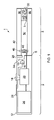
図1は、本開示の特定の実施形態に従った例示的なeシガレット1の全体的な断面図である。eシガレット1は、再使用可能な部分2と交換可能/使い捨てカートリッジ部分4という2つの主要な構成要素を含む。この特定の実施例では、eシガレット1は、細断されたタバコの一部を含むインサートハウジングを含む着脱可能なインサート8を含むカートリッジ部分4を有するハイブリッドデバイスであると仮定される。しかしながら、本実施例がハイブリッドデバイスであるという事実は、それ自体、本明細書でさらに説明されるように、デバイスの活性化機能にとって直接的に重要なものではない。
FIG. 1 is a general cross-sectional view of an exemplary e-cigarette 1 according to certain embodiments of the present disclosure. The e-cigarette 1 includes two main components, a
通常の使用では、再使用可能な部分2とカートリッジ部分4は、インターフェース6で共に解放可能に結合されている。カートリッジ部分が枯渇した場合、又は使用者が単に別のカートリッジ部分に切り替えることを希望する場合、カートリッジ部分が再使用可能な部分から取り外され、交換用のカートリッジ部分が代わりに再使用可能な部分に取り付けられる。インターフェース6は、2つの部分間の構造的、電気的、空気経路の接続を提供し、必要に応じて、2つの部分間の電気的接続及び空気経路を確立するために、例えば、適切に配置された電気接点と開口部を有するねじ山、ラッチ機構、又はバヨネット固定に基づいて、従来の手法に従って確立することができる。カートリッジ部分4を再利用可能な部分2に機械的に取り付ける特定の方法は、本明細書に記載された原理には重要ではないが、具体的な実施例のために、ここでは、例えば、カートリッジの一部が、協動するラッチ係合要素(図1には示されていない)を有する再利用可能な部分の対応するレセプタクル内に受け止められるラッチ機構を含むと仮定される。また、いくつかの実装形態では、インターフェース6は、それぞれの部分間の電気的接続をサポートしていない場合があることが理解されるであろう。例えば、いくつかの実装形態では、気化器がカートリッジ部分ではなく再利用可能な部分に設けられてもよく、又は再利用可能な部分とカートリッジ部分との間の電気的接続が必要とされないように再利用可能な部分からカートリッジ部分への電力の伝達が(例えば電磁誘導に基づく)無線であってもよい。
In normal use,
本開示の特定の実施形態に従うと、カートリッジ部分4は、広く従来のものであってもよい。図1において、カートリッジ部分4は、プラスチック材料で形成されたカートリッジハウジング42を含む。カートリッジハウジング42は、カートリッジ部分の他の構成要素を支持し、再利用可能な部分2との機械的インターフェース6を提供する。カートリッジハウジングは長手方向軸を中心として全体的に円形対称であり、長手方向軸に沿ってカートリッジ部分は再利用可能な部分2に結合する。本実施例では、カートリッジ部分は約4cmの長さ及び約1.5cmの直径を有する。しかしながら、特定の形状、より一般的に使用される全体的な形状及び材料は、異なる実装形態において異なるものであってもよいことが理解されるであろう。
According to certain embodiments of the present disclosure, cartridge portion 4 may be broadly conventional. In FIG. 1, the cartridge portion 4 includes a
カートリッジハウジング42内には、液体蒸気前駆体材料を含むリザーバ44が設けられている。液体蒸気前駆体材料は、従来のものであってもよく、eリキッドと呼ばれてもよい。本実施例の液体リザーバ44は、カートリッジハウジング42によって画定される外壁と、カートリッジ部分4を通る空気通路52を画定する内壁とを有する環状の形状を有する。リザーバ44は、eリキッドを収容するための端壁を有しており、各端部で閉じられている。リザーバ44は、従来の技術に従って形成されてもよく、例えば、プラスチック材料を含んでいてもよく、カートリッジハウジング42と一体的に成形されてもよい。
A
本実施例の香料要素インサート(タバコポッド)8は、コントロールユニット2に結合し、摩擦嵌合によって保持されるカートリッジ4の端部とは反対側の空気通路52の開放端部に挿入される。香料要素インサート8のためのハウジングは、過剰な挿入を防止するために、カートリッジハウジング42の端部に近接するカラーを含む。香料要素インサート8のハウジングはまた、使用中に空気通路52に沿って吸引された空気が香料要素インサート8を通過することを可能にするために、各端部に開口部を含み、ユーザが吸入するためのマウスピース出口50を通ってカートリッジ4を出る前に、内部の香味料(本実施例ではタバコ)から香料を拾い上げることができる。
A flavor element insert (tobacco pod) 8 in this embodiment is inserted into the open end of the
カートリッジ部分は、マウスピース出口50とは反対側のリザーバ44の端部に配置されたウィック46とヒータ(気化器)48をさらに含む。本実施例では、ウィック46は、端部がリザーバ44の内壁の開口部を通ってeリキッドのリザーバ44内に延びるように、カートリッジ空気経路52を横切って延びている。リザーバの内壁の開口部は、液体移送性能に有害であり得るウィックの不当な圧縮を行うことなく、液体リザーバからカートリッジ空気経路への漏れに対して適度なシールを提供するために、ウィック46の寸法に広く一致するように大きさが決められている。
The cartridge portion further includes a
ウィック46及びヒータ48は、ウィック46及びヒータ48の周囲のカートリッジ空気経路52の領域が実質的にカートリッジ部分の気化領域を画定するように、カートリッジ空気経路52に配置されている。リザーバ44内のeリキッドは、リザーバ44内に延びるウィックの端部を通ってウィック46に浸潤し、表面張力/毛細管作用(すなわちウィッキング)によってウィックに沿って引き寄せられる。本実施例のヒータ48は、ウィック46の周りにコイル状に巻かれた電気抵抗性ワイヤを含む。本実施例では、ヒータ48はニッケルクロム合金(Cr20Ni80)ワイヤを含み、ウィック46はガラス繊維束を含むが、特定の気化器の構成は、本明細書に記載された原理には重要ではないことが理解されるであろう。使用時には、電力がヒータ48に供給されて、ウィック46によってヒータ48の近傍に引き寄せられたある量のeリキッド(蒸気前駆体材料)を気化させてもよい。気化されたeリキッドは、気化領域からカートリッジ空気経路に沿って香料要素インサート8を通って引き込まれ、ユーザの吸入のためにマウスピース出口50から出る空気に巻き込まれる。
The
eリキッドが気化器(ヒータ)48によって気化される速度は、使用中にヒータ48に供給される電力の量(レベル)に依存する。したがって、カートリッジ部分4のeリキッドから選択的に蒸気を生成させるために電力をヒータに印加することができ、さらに、例えばパルス幅及び/又は周波数変調技術を用いてヒータ48に供給される電力の量を変化させることによって、蒸気の生成速度を変化させることができる。
The rate at which the e-liquid is vaporized by the vaporizer (heater) 48 depends on the amount (level) of power supplied to the
再利用可能な部分2は、eシガレットのための空気入口28を画定する開口部を有する外側ハウジング12、電子タバコのための動作電力を提供するためのバッテリー26、電子タバコの動作を制御及び監視するための制御回路20、ユーザ入力ボタン14、本実施例では圧力センサチャンバ18内に配置された圧力センサを含む吸入センサ(パフ検出器)16、及び視覚的なディスプレイ24を含む。
The
外側ハウジング12は、例えば、プラスチック又は金属材料から形成されてもよく、本実施例では、インターフェース6において2つの部分の間の滑らかな推移を提供するように、カートリッジ部分4の形状及びサイズに全体的に適合する円形の断面を有する。本実施例では、再利用可能な部分は約8cmの長さを有しているので、カートリッジ部分と再利用可能な部分が結合されたときのeシガレットの全体の長さは約12cmである。しかしながら、既に述べたように、本開示の実施形態を実施する電子タバコの全体的な形状及びスケールは、本明細書に記載された原理に重要ではないことが理解されるであろう。
空気入口28は、再利用可能な部分2を通る空気経路30に接続されている。再利用可能な部分の空気経路30は、再利用可能な部分2とカートリッジ部分4とが一緒に接続されているときに、インターフェース6を横切ってカートリッジ空気経路52に接続される。圧力センサ16を含む圧力センサチャンバ18は、再利用可能な部分2の空気経路30と流体的に連通している(すなわち、圧力センサチャンバ18は、再利用可能な部分2の空気経路30から分岐している)。したがって、ユーザがマウスピース開口部50で吸入すると、圧力センサ16によって検出され得る圧力センサチャンバ18内の圧力の低下があり、空気は、空気入口28を通って吸い込まれ、再利用可能な部分の空気経路30に沿って、インターフェース6を横切って、(気化器が活動しているときに気化したeリキッドが空気の流れに巻き込まれる)アトマイザ48の近傍の蒸気生成領域を通って、カートリッジ空気経路52に沿って、ユーザが吸入するためのマウスピース開口部50を通って外へ出る。
本実施例のバッテリー26は、充電式であり、従来のタイプのものであってもよく、例えば、電子タバコ及び比較的短い期間に比較的大きな電流を供給することを必要とする他の用途で通常使用される種類のものであってもよい。バッテリー26は、再利用可能な部分のハウジング12の充電コネクタ、例えばUSBコネクタを介して充電されてもよい。
The
本実施例のユーザ入力ボタン14は、従来の機械的なボタンであり、例えば、電気的接触を確立するためにユーザによって押圧され得るばね取り付け構成要素を含む。この点で、入力ボタンは、端末装置の手動入力機構を提供するものと考えてもよいが、ボタンが実装される特定の態様は重要ではない。例えば、他の実装形態では、機械的なボタン又は(例えば容量性又は光学的な感知技術に基づく)タッチ感応型ボタンの異なる形態が使用されてもよい。ボタンが実装される特定の態様は、例えば、所望の審美的外観を考慮して選択されてもよい。
ディスプレイ24は、電子タバコに関連する様々な特性、例えば現在の電力設定情報、バッテリー残量などの視覚的表示をユーザに与えるために提供される。ディスプレイは、様々な方法で実装されてもよい。本実施例では、ディスプレイ24は、従来の技術に従って所望の情報を表示するように駆動されてもよい従来のピクシレイテッドLCDスクリーンを含む。他の実装形態では、ディスプレイは、例えば特定の色及び/又はフラッシュシーケンスを介して、所望の情報を表示するように配置された1つ又は複数の離散的なインジケータ、例えばLEDを含んでもよい。より一般的には、ディスプレイが提供され、ディスプレイを使用するユーザに情報が表示される態様は、本明細書に記載された原理に重要ではない。いくつかの実施形態では、視覚的なディスプレイを含まず、例えば音声信号又は触覚フィードバックを使用して、電子タバコの動作特性に関連する情報をユーザに提供するための他の手段を含んでもよく、又は電子タバコの動作特性に関連する情報をユーザに提供するための手段を含んでいなくてもよい。
A
制御回路20は、本明細書にさらに記載されるように、本開示の実施形態に従って機能を提供するために、また、そのようなデバイスを制御するための確立された技術に沿って、電子タバコの従来の動作機能を提供するために、電子タバコの動作を制御するように、好適に構成/プログラムされる。制御回路(プロセッサ回路)20は、本明細書に記載された原理に従って、電子タバコの動作の異なる態様、及びディスプレイ駆動回路及びユーザ入力検出などの電子タバコの他の従来の動作態様に関連する様々なサブユニット/回路要素を論理的に含むと考えられ得る。制御回路20の機能性は、例えば、所望の機能性を提供するように構成された1つ以上の好適にプログラムされたプログラム可能なコンピュータ(複数可)及び/又は1つ以上の好適に構成された特定用途向け集積回路(複数可)/回路/チップ(複数可)/チップセット(複数可)を使用して、様々な異なる方法で提供することができることが理解されるであろう。
このようにして、蒸気供給システム1は、ユーザ入力ボタン14及び吸入センサ16を含む。本開示の特定の実施形態に従って、制御回路20は、吸入センサ16からのシグナリングを受信し、このシグナリングを使用して、ユーザが電子タバコで吸入しているかどうかを判断するように構成され、また、入力ボタン14からのシグナリングを受信し、このシグナリングを使用して、ユーザが入力ボタンを押している(すなわち、活性化している)かどうかを判断するように構成される。電子タバコの動作のこれらの態様(すなわち、パフ検出及びボタン押下検出)は、それ自体は、(例えば、従来の吸入センサ及び吸入センサ信号処理技術を使用して、従来の入力ボタン及び入力ボタン信号処理技術を使用して)確立された技術に従って実行されてもよい。しかしながら、本開示の特定の実施形態に従った制御回路20は、ユーザが電子タバコで吸入したこと、又はユーザが入力ボタンを少なくとも所定の閾値時間、例えば0.3秒押したことのいずれかを判定することに応じて、気化器への電力供給を制御する(すなわち、蒸気生成を活性化する)ように構成されている。したがって、本開示の特定の実施形態によれば、図1の電子タバコは、パフ活性化とボタン活性化の両方を可能にする。これは、ユーザがパフ活性化の利便性を利用することができることを意味するが、ユーザが吸入を開始したときに気化器が最適な温度に達するまでの遅延を避けるために、又はパフ検出をトリガするために十分に深く吸入せずに蒸気を生成するために、例えば、手動活性化のためのボタンを使用することによって、実質的にこれを無効にすることを選択することもできる。さらに、同じデバイスでパフ活性化とボタン活性化の両方の機能を提供することで、一方又は他方の活性化機構が故障した場合の冗長性を提供することができる。例えば、パフセンサが故障しても、デバイスはボタン活性化と共に使用することができ、入力ボタンが故障しても、デバイスはパフ活性化と共に使用することができる。
Thus, vapor delivery system 1 includes
さらに、上述したように、本開示の特定の実施形態に従って、制御回路は、ユーザがボタンを少なくとも最小の閾値期間、例えば0.3秒の間押すことに応じて蒸気生成を活性化させるように構成されていてもよい。このアプローチに従った実施形態は、入力ボタン14が、ユーザが0.3秒未満の間ボタンを活性化したときに、蒸気生成を活性化する以外の手段のためのユーザ入力を受け取るために使用されてもよいことを意味する。したがって、いくつかの実装形態では、制御回路は、例えば、ユーザが電子タバコの態様、例えば電源設定を構成することを可能にするため、又は電子タバコをトリガしてバッテリー残量の表示を提供することを可能にするために、別の方法で蒸気生成をトリガするための閾値持続時間を満たさない入力ボタン14の活性化に応答してもよい。この点において、蒸気生成をトリガするための閾値持続時間未満の間活性化されたときのユーザ入力ボタンの機能性は、蒸気生成を活性化させる以外の目的のためにボタンを使用して電子タバコとユーザとの相互作用のための任意の従来のアプローチに従っていてもよい。この点で、本発明者らは、0.3秒の所定の閾値時間が、場合によっては、ユーザが蒸気生成をトリガする目的のためにボタンを使用したいときに過度に蒸気生成を遅らせることなく、蒸気生成をトリガするためにボタンを活性化する(すなわち、少なくとも0.3秒の間ボタンを活性化する)ユーザと、別の理由のためにボタンを活性化する(すなわち、0.3秒未満の間バンドを活性化する)ユーザとを区別するのに役立つ適切な閾値を提供することができることを発見した。しかしながら、異なる実装形態に従って異なる閾値時間が使用されてもよく、さらに、いくつかの実施例では、これはユーザが設定可能であってもよいことが理解されるであろう。いくつかの実装形態では、閾値時間量は、選択された時間量であってもよく、これは、少なくとも、0.2秒、例えば少なくとも0.25秒、例えば少なくとも0.3秒、例えば少なくとも0.35秒、例えば少なくとも0.4秒、例えば少なくとも0.45秒、例えば少なくとも0.5秒、例えば少なくとも0.55秒、例えば少なくとも0.6秒、例えば少なくとも0.65秒、例えば少なくとも0.7秒、例えば少なくとも0.75秒、例えば少なくとも0.8秒、例えば少なくとも0.85秒、例えば少なくとも0.9秒、例えば少なくとも0.95秒、例えば少なくとも1秒、又はそれ以上である。
Further, as described above, according to certain embodiments of the present disclosure, the control circuit activates vapor generation in response to the user pressing the button for at least a minimum threshold period of time, such as 0.3 seconds. may be configured. Embodiments following this approach are used to receive user input for means other than activating vapor generation when the
図2は、本開示の特定の実施形態に従って、図1の蒸気供給システムのいくつかの動作態様を模式的に表すフロー図である。 2 is a flow diagram that schematically represents some operational aspects of the steam delivery system of FIG. 1, in accordance with certain embodiments of the present disclosure; FIG.
ステップS1において、蒸気供給システム1は待機状態に入る。電子タバコに一般的であるように、蒸気供給システム1は、3つの基本的な動作状態、すなわち「オフ」状態、「オン」状態、及び「待機」状態をサポートする。 At step S1, the steam supply system 1 enters a standby state. As is common with electronic cigarettes, the vapor delivery system 1 supports three basic states of operation: an "off" state, an "on" state, and a "standby" state.
オフ状態では、電子タバコは蒸気を生成させることができない(すなわち、電源供給制御回路は、オフ状態で気化器/ヒータに電力を供給することができないようになっている)。電子タバコは、例えば、電子タバコが脇にセットされるか、又はユーザのポケット又はバッグに置かれるかもしれないときに、使用セッションの間にオフ状態で配置され得る。 In the OFF state, the e-cigarette cannot generate vapor (ie, the power supply control circuit is disabled to power the vaporizer/heater in the OFF state). Electronic cigarettes may be placed in an off state during a session of use, for example, when the electronic cigarette may be set aside or placed in a user's pocket or bag.
オン(又は活性化)状態では、電子タバコは積極的に蒸気を生成している(すなわち、電源供給制御回路が気化器/ヒータに電力を提供している)。したがって、電子タバコは、通常、ユーザが電子タバコから蒸気を吸入しているときにオン状態になる。 In the on (or activated) state, the e-cigarette is actively producing vapor (ie, the power supply control circuit is providing power to the vaporizer/heater). Therefore, electronic cigarettes are typically turned on when the user is inhaling vapor from the electronic cigarette.
待機状態では、電子タバコは、ユーザの活性化に応答して蒸気を生成する準備ができている(すなわち、気化器に電力を適用する準備ができている)が、現在それを行ってはいない。電子タバコは、典型的には、ユーザが使用セッションを開始するために最初にオフ状態を抜けるとき(すなわち、ユーザが最初に電子タバコをオンにしたとき)、又は使用セッション中の使用の間(すなわち、ユーザが電子タバコを使用しているときのパフの間)に待機状態になる。上述したように、本開示の特定の実施形態によれば、電子タバコは、ユーザ活性化の少なくとも2つの異なる形態に応じて、すなわち、ユーザがデバイスで吸入すること(吸入センサ16によって検出される)、及びユーザが入力ボタンを少なくとも閾値の時間だけ押すことに応じて蒸気を生成するように構成されている。具体的な実施例を提供するために、ここでは、ユーザがデバイスをオフ状態から解除して使用セッションを開始することにより、ステップS1で電子タバコが待機状態に入ると仮定する。しかし、図2に示される処理は、本実施例では、電子タバコが使用セッションを開始するために最初にスイッチを入れてからステップS1でスタンバイモードに入るか、進行中の使用セッション中にパフの間にあるかにかかわらず同じである。電子タバコがオフ状態から待機状態に切り替えるために引き起こされる方法は、実装の問題となり、ここでは重要ではない。例えば、オフ状態から待機状態に移行するために、ユーザは、入力ボタン14を特定の順序で、例えば所定時間内に複数回押すように要求されてもよい。
In the standby state, the electronic cigarette is ready to generate vapor in response to user activation (i.e., ready to apply power to the vaporizer), but is not currently doing so. . E-cigarettes typically operate when the user first exits the off state to begin a session of use (i.e., when the user first turns on the e-cigarette), or during use during a session of use ( i.e., during puffs when the user is using the e-cigarette). As noted above, according to certain embodiments of the present disclosure, electronic cigarettes are activated in response to at least two different forms of user activation: the user inhaling with the device (detected by inhalation sensor 16). ), and is configured to generate steam in response to a user pressing the input button for at least a threshold amount of time. To provide a specific example, it is assumed here that the electronic cigarette enters standby state in step S1 by the user releasing the device from the off state to start a usage session. However, the process shown in FIG. 2, in this example, does not allow the e-cigarette to first switch on to initiate a use session and then enter standby mode at step S1, or to release a puff during an ongoing use session. It is the same regardless of whether it is in between. How the e-cigarette is triggered to switch from the off state to the standby state becomes an implementation issue and is not important here. For example, to transition from the off state to the standby state, the user may be required to press the
図2のステップS2に表されるように、待機状態にある間、制御回路は、吸入センサ16からのシグナリングと入力ボタン14からのシグナリングとを監視するように構成されている。特に、制御回路は、ユーザが電子タバコを吸入していることを示す吸入センサ16からのシグナリングを監視すると共に、ユーザが入力ボタンを押していることを示す入力ボタン14からのシグナリングを監視するように構成されている。この監視を行う具体的な方法は、特定の回路の実装に依存する。例えば、いくつかの例示的な実装形態では、制御回路は、定期的なサンプリングスケジュールに従って、例えば10ms毎に、これらの構成要素から受信した出力信号から、吸入センサ及び/又は入力ボタンの状態を決定するように構成されてもよい。しかしながら、他の例示的な実装形態では、制御回路は、サンプリングスケジュールに従って吸入センサ及び/又は入力ボタンからの出力信号を定期的にポーリングしないかもしれないが、代わりに、吸入センサ及び/又は入力ボタンから受信した割り込み信号に依存して、それぞれが活性化されたときにそのことを示すようにしてもよい。この点で、監視が実施される特定の方法は、本明細書に記載されている原理には重要ではないことが理解されるであろう。
While in the standby state, the control circuit is configured to monitor signaling from the
ステップS3に示されるように、制御回路は、(i)吸入センサからのシグナリングが、ユーザがデバイスを吸入していることを示すか、又は(ii)入力ボタンからのシグナリングが、ユーザが予め定義された閾値期間(例えば、本実施例では0.3秒)を上回る間入力ボタンを押したことを示すか、を判定する。これらのトリガ条件のいずれかが満たされていると判定された場合、制御回路は、蒸気を生成するために気化器に電力を供給することによって応答する。この点において、電力を供給する制御回路は、典型的には、コントロールユニットとカートリッジ4との間のインターフェース6の電気接点に電源26を接続するために、スイッチ、例えばMOSFETスイッチを活性化させる制御回路を含むことが理解されるであろう。したがって、カートリッジがコントロールユニット2に接続されているとき、2つのトリガ基準のうちの1つ(又は両方)が満たされていると判定することに応じて制御回路によって提供される電力は、気化器の活性化と、ユーザが吸入するための対応する蒸気の生成をもたらす。
As shown in step S3, the control circuit determines whether (i) signaling from the inhalation sensor indicates that the user is inhaling the device, or (ii) signaling from the input button indicates that the user is pre-defined. indicates that the input button was pressed for more than a specified threshold period of time (eg, 0.3 seconds in this example). If any of these trigger conditions are determined to be met, the control circuit responds by powering the vaporizer to produce vapor. In this regard, the control circuit that supplies the power typically controls activating a switch, for example a MOSFET switch, to connect the
したがって、上述したように、本開示の実施形態に従ったアプローチは、蒸気生成を活性化するための複数の異なる機構をユーザに提供し、さらに、入力ボタンが他の手段のために使用されること(すなわち、予め定義された閾値時間量よりも短い時間押された場合)に加えて、蒸気生成のために使用されることを可能にする方法で行う。 Thus, as noted above, the approach according to embodiments of the present disclosure provides the user with multiple different mechanisms for activating steam generation, and input buttons are used for other means. (ie, pressed for less than a predefined threshold amount of time) in addition to being used for steam generation.
本開示の特定の実施形態によれば、ユーザが電子タバコを吸入しているとの判定に応答してステップS3で蒸気生成がトリガされた場合、制御回路は、吸入センサから受信したシグナリングからユーザが電子タバコの吸引を停止したと判定されたときに、蒸気生成のための気化器への電力供給を停止するように構成されてもよい。同様に、ステップS3において、ユーザが入力ボタンを少なくとも閾値の時間だけ押したと判定することに応じて蒸気生成がトリガされた場合、制御回路は、入力ボタンから受信したシグナリングからユーザが入力ボタンを押すのを止めたと判定されたときに、蒸気生成のための気化器への電力供給を停止するように構成されてもよい。 According to certain embodiments of the present disclosure, when vapor generation is triggered in step S3 in response to determining that the user is inhaling an electronic cigarette, the control circuit determines from signaling received from the inhalation sensor that the user may be configured to stop powering the vaporizer for vapor generation when it is determined that the user has stopped smoking the e-cigarette. Similarly, in step S3, if steam generation is triggered in response to determining that the user has pressed the input button for at least the threshold amount of time, the control circuit determines from the signaling received from the input button that the user has pressed the input button. It may be configured to stop powering the vaporizer for vapor generation when it is determined that the vaporization has stopped.
いくつかの実装形態では、ステップS3において、トリガ条件のうちの1つが満たされていることによって蒸気生成がトリガされると、最初のトリガ条件が満たされていることを停止した後であっても、他のトリガ条件が満たされていると判定された場合には、蒸気生成が継続されてもよい(すなわち、制御回路は、気化器への電力供給を継続するように構成されてもよい)。例えば、そのような実装形態では、ユーザは、入力ボタンを閾値を上回る時間だけ活性化させることによって蒸気生成をトリガしてもよく、その後、パフの途中で入力ボタンを解放してもよいが、吸入センサがパフが継続中であることを検出し続ける限り、制御回路は、気化器への電力供給を継続してもよい。しかしながら、他の実装形態では、トリガ条件の1つが満たされていることによって蒸気生成がトリガされるとき、他のトリガ条件が満たされているかどうかにかかわらず、このトリガ条件がもはや満たされていないときに蒸気生成を停止してもよい。例えば、このような実装形態では、ユーザが入力ボタンを閾値以上の時間だけ活性化させることによって蒸気生成をトリガし、その後入力ボタンを解放してもよく、これによって、ユーザが電子タバコの吸入を続けても、制御回路が気化器への電力供給を停止してもよい。すなわち、特定の実装形態によれば、制御回路は、ユーザが少なくとも閾値量の時間だけ入力ボタンを活性化させたことを入力ボタンから受信したシグナリングから判定することに応じて、気化器に電力を供給する際に、吸入センサから受信したシグナリングを実質的に無視するように、及び/又は吸入センサの動作態様を無効にするように構成されていてもよい。 In some implementations, in step S3, when steam production is triggered by one of the triggering conditions being met, even after the first triggering condition ceases to be met. , if it is determined that other trigger conditions are met, vapor production may continue (i.e., the control circuit may be configured to continue powering the vaporizer). . For example, in such implementations, the user may trigger steam generation by activating the input button for a time above the threshold, and then release the input button mid-puff, As long as the inhalation sensor continues to detect that the puff is ongoing, the control circuit may continue to power the vaporizer. However, in other implementations, when steam production is triggered by one of the triggering conditions being met, this triggering condition is no longer met, regardless of whether other triggering conditions are met. Occasionally steam generation may be stopped. For example, in such implementations, a user may activate an input button for a time equal to or greater than a threshold to trigger vapor generation and then release the input button, thereby allowing the user to inhale the e-cigarette. It may continue or the control circuit may stop supplying power to the vaporizer. That is, according to certain implementations, the control circuit powers the vaporizer in response to determining from signaling received from the input button that the user has activated the input button for at least a threshold amount of time. It may be configured to substantially ignore signaling received from the inhalation sensor and/or override operational aspects of the inhalation sensor when delivering.
いくつかの実装形態では、制御回路は、ユーザが電子タバコを吸入していることを吸入センサが示しているか、ユーザがまだ入力ボタンを押していることを入力ボタンが示しているかにかかわらず、気化器に電力を継続的に供給する所定の期間の後、すなわち最大許容連続活性化時間と呼ばれ得るものの後に、気化器への電力供給を停止するように構成されていてもよい。これは、例えば、吸入センサ又は入力ボタンのいずれかに障害が発生し、その結果、それらのうちの1つが連続的な活性化を示すようになった場合(例えば、入力ボタンが活性化位置で動けなくなったため)に、実質的に安全遮断となるものを提供することができる。最大許容連続活性化時間は、例えば、6秒~10秒の間、例えば、6.5秒~9.5秒の間、例えば、7秒~9秒の間、例えば、7.5秒~8.5秒の間であってもよい。 In some implementations, the control circuit controls whether the inhalation sensor indicates that the user is inhaling the electronic cigarette or whether the input button indicates that the user is still pressing the input button. After a predetermined period of continuous power supply to the vaporizer, which may be referred to as the maximum allowable continuous activation time, the power supply to the vaporizer may be terminated. This may be the case, for example, if either the inhalation sensor or the input button fails so that one of them shows continuous activation (e.g. the input button is in the activated position). can provide what is essentially a safety break-off. The maximum allowable continuous activation time is, for example, between 6 and 10 seconds, such as between 6.5 and 9.5 seconds, such as between 7 and 9 seconds, such as between 7.5 and 8 seconds. It may be between 0.5 seconds.
上述したように、いくつかの例示的な実装形態によれば、コントロールユニットは、本明細書に記載された原理に従って制御回路の制御下で気化器に電力を供給するための再充電可能なバッテリーを含んでいてもよく、いくつかの実施例によれば、制御回路は、コントロールユニットが再充電可能なバッテリーを充電するために外部電源に結合されている場合、及びバッテリーが充電されていない場合も同様に、吸入センサ又はプッシュボタンを使用してユーザの活性化を判定したことに応じて気化器に電力を供給するように構成されてもよい。 As noted above, according to some exemplary implementations, the control unit includes a rechargeable battery for powering the vaporizer under control of the control circuit in accordance with the principles described herein. and, according to some embodiments, the control circuit controls when the control unit is coupled to an external power source to charge the rechargeable battery and when the battery is not being charged. may likewise be configured to power the vaporizer in response to determining user activation using an inhalation sensor or push button.
上述した実施形態は、いくつかの点で、いくつかの特定の例示的な蒸気供給システムに焦点を当ててきたが、他の技術を用いた蒸気供給システムにも同じ原理が適用され得ることが理解されるであろう。すなわち、蒸気供給システムの様々な態様が機能する特定の方法は、本明細書に記載された実施例の基礎となる原理に直接関連しない。 Although the above-described embodiments have, in some respects, focused on certain exemplary steam supply systems, it is understood that the same principles may be applied to steam supply systems using other technologies. will be understood. That is, the specific manner in which various aspects of the steam supply system function are not directly related to the principles underlying the embodiments described herein.
例えば、上述した実施形態では、液体蒸気前駆体材料を加熱するための電気ヒータに基づく気化器を有するデバイスに主に焦点を当てたが、例えば圧電バイブレータに基づく気化器又は光学加熱気化器などの他の技術に基づく気化器、及び植物由来材料、タバコ由来材料などの固体材料のような他のエアロゾル前駆体材料に基づくデバイス、又はゲル、ペースト又は泡に基づく気化器前駆体材料などの他の形態の気化器前駆体材料に基づくデバイスにも、同様の原理を採用することができる。 For example, although the above-described embodiments primarily focused on devices having electric heater-based vaporizers for heating the liquid vapor precursor material, other devices such as piezoelectric vibrator-based vaporizers or optically heated vaporizers may also be used. Vaporizers based on other technologies and devices based on other aerosol precursor materials such as solid materials such as plant-derived materials, tobacco-derived materials, or other vaporizer precursor materials based on gels, pastes or foams. Similar principles can be employed for devices based on morphology vaporizer precursor materials.
さらに、既に述べたように、電子タバコにおける蒸気生成のための複数の独立した活性化機構を提供するための上述のアプローチは、図1で表される異なる全体的な構造を有するタバコで実施されてもよいことが理解されるであろう。例えば、同じ原理は、ツーパートモジュラー構造を含まないが、代わりにシングルパートデバイス、例えば使い捨て(すなわち、非充電式及び非補充式)デバイスを含む電子タバコで採用されてもよい。さらに、モジュラーデバイスのいくつかの実装形態では、構成要素の配置が異なっていてもよい。例えば、いくつかの実装形態では、コントロールユニットはまた、蒸気を生成するのに使用するために気化器に蒸気前駆体材料の供給源を提供する交換可能なカートリッジを有する気化器を含み得る。さらに、上述した実施例では、電子タバコ1が香料インサート8を含むのに対し、他の例示的な実装形態では、そのような追加の香料要素を含まない場合がある。
Furthermore, as already mentioned, the above-described approaches for providing multiple independent activation mechanisms for vapor generation in electronic cigarettes have been implemented with cigarettes having different overall structures represented in FIG. It will be appreciated that For example, the same principles may be employed in electronic cigarettes that do not include a two-part modular construction, but instead include single-part devices, such as disposable (ie, non-rechargeable and non-refillable) devices. Additionally, the arrangement of components may be different in some implementations of modular devices. For example, in some implementations, the control unit may also include a vaporizer with replaceable cartridges that provide a source of vapor precursor material to the vaporizer for use in generating vapor. Further, while in the examples described above, the electronic cigarette 1 includes a
このように、吸入センサ、入力ボタン、制御回路、及び制御回路から電力が供給された場合に蒸気前駆体材料から蒸気を生成するための気化器を含む蒸気供給システムが記載されており、制御回路は、ユーザが蒸気供給システムで吸入していると吸入センサから受信したシグナリングから判定することに応じて、及びユーザが入力ボタンを少なくとも閾値時間だけ活性化させたと入力ボタンから受信したシグナリングから判定することに応じて、蒸気を生成するために気化器に電力を供給するように構成されている。 Thus, a vapor delivery system is described that includes an inhalation sensor, an input button, a control circuit, and a vaporizer for producing vapor from a vapor precursor material when powered by the control circuit, the control circuit comprising: is responsive to determining from signaling received from an inhalation sensor that the user is inhaling with the vapor delivery system and from signaling received from the input button that the user has activated the input button for at least the threshold time. Optionally, it is configured to power the vaporizer to generate vapor.
様々な課題に対処し、技術を進歩させるために、本開示は、請求された発明(複数可)が実施され得る様々な実施形態を図示の方法で示す。本開示の利点及び特徴は、代表的な実施形態のサンプルであり、網羅的及び/又は排他的ではない。本開示の利点及び特徴は、請求された発明(複数可)の理解を助け、教示ために提示されているに過ぎない。本開示の利点、実施形態、実施例、機能、特徴、構造、及び/又は他の態様は、特許請求の範囲によって定義される本開示の制限、又は特許請求の範囲の等価物の制限とは位置付けられず、他の実施形態が利用されてもよく、特許請求の範囲から逸脱することなく修正がなされてもよいことが理解されるべきである。様々な実施形態は、好適には、本明細書に具体的に記載されたもの以外の、開示された要素、構成要素、特徴、部分、ステップ、手段等の様々な組み合わせを含むか、様々な組み合わせからなるか、又は様々な組み合わせから本質的に構成されてもよく、したがって、従属請求項の特徴は、請求項に明示的に記載されたもの以外の組み合わせで、独立請求項の特徴と組み合わせてもよいことが理解されるであろう。本開示は、現在請求されていないが、将来請求される可能性のある他の発明を含み得る。 To address various challenges and advance the art, this disclosure presents, in an illustrative manner, various embodiments in which the claimed invention(s) may be practiced. The advantages and features of this disclosure are of a sample of representative embodiments and are not exhaustive and/or exclusive. The advantages and features of the disclosure are presented merely as an aid to understanding and teaching of the claimed invention(s). Advantages, embodiments, examples, functions, features, structures, and/or other aspects of the present disclosure shall not be construed as limiting the disclosure as defined by the claims or the equivalents of the claims. It is to be understood that other embodiments may be utilized and modifications may be made without departing from the scope of the claims. The various embodiments suitably include various combinations of, or various It may consist of combinations or consist essentially of various combinations, thus the features of the dependent claims may be combined with the features of the independent claims in combinations other than those expressly recited in the claims. It will be appreciated that The disclosure may include other inventions that are not currently claimed but may be claimed in the future.
Claims (15)
吸入センサと、
入力ボタンと、
ユーザが前記蒸気供給システムで吸入していると前記吸入センサから受信したシグナリングから判定したことに応じて蒸気を生成するために前記蒸気供給システムに電力を供給するように構成されると共に、ユーザが前記入力ボタンを少なくとも閾値時間だけ活性化させたと前記入力ボタンから受信したシグナリングから判定したことに応じて蒸気を生成するために前記蒸気供給システムに電力を供給するように構成された制御回路であって、前記制御回路は、ユーザが前記蒸気供給システムで吸入していると判定したこと又はユーザが前記入力ボタンを少なくとも閾値時間だけ活性化させたと判定したことのいずれか一方に応じて蒸気を生成するために前記蒸気供給システムに電力を供給するように構成されている、前記制御回路と、
を備える、コントロールユニット。 A control unit for a steam supply system, said control unit comprising:
an inhalation sensor;
an input button;
configured to power the vapor delivery system to generate vapor in response to determining from signaling received from the inhalation sensor that a user is inhaling through the vapor delivery system ; a control circuit configured to power the steam delivery system to generate steam in response to determining from signaling received from the input button that the user has activated the input button for at least a threshold amount of time; wherein the control circuit is responsive to either determining that a user is inhaling with the vapor delivery system or determining that the user has activated the input button for at least a threshold amount of time. the control circuit configured to power the steam supply system to generate
A control unit with
吸入センサ手段と、
入力ボタン手段と、
ユーザが前記蒸気供給手段で吸入していると前記吸入センサ手段から受信したシグナリングから判定したことに応じて蒸気を生成するために前記蒸気供給手段に電力を供給するように構成されると共に、前記ユーザが前記入力ボタン手段を少なくとも閾値時間だけ活性化させたと前記入力ボタン手段から受信したシグナリングから判定したことに応じて蒸気を生成するために前記蒸気供給手段に電力を供給するように構成された制御回路手段であって、前記制御回路手段は、ユーザが前記蒸気供給手段で吸入していると判定したこと又はユーザが前記入力ボタン手段を少なくとも閾値時間だけ活性化させたと判定したことのいずれか一方に応じて蒸気を生成するために前記蒸気供給手段に電力を供給するように構成されている、前記制御回路手段と、
を備える、コントロールユニット手段。 Control unit means for the vapor supply means, said control unit means comprising:
inhalation sensor means;
an input button means;
configured to power the vapor delivery means to generate vapor in response to determining from signaling received from the inhalation sensor means that a user is inhaling with the vapor delivery means; and powering the vapor supply means for generating vapor in response to determining from signaling received from the input button means that the user has activated the input button means for at least a threshold amount of time. wherein said control circuit means has determined that a user is inhaling with said vapor supply means or that said user has activated said input button means for at least a threshold time. said control circuit means configured to power said steam supply means to produce steam in response to one of :
a control unit means.
ユーザが前記蒸気供給システムで吸入しているかどうかを前記吸入センサから受信したシグナリングから判定し、吸入している場合には、蒸気を生成するために前記蒸気供給システムに電力を供給するステップと、
ユーザが前記入力ボタンを少なくとも閾値時間だけ活性化させたかどうかを前記入力ボタンから受信したシグナリングから判定し、活性化させた場合には、蒸気を生成するために前記蒸気供給システムに電力を供給するステップと、
を含み、
ユーザが前記蒸気供給システムで吸入していると判定したこと又はユーザが前記入力ボタンを少なくとも閾値時間だけ活性化させたと判定したことのいずれか一方に応じて蒸気を生成するために前記蒸気供給システムに電力が供給される、方法。 A method of operating a control unit for a steam supply system, said control unit comprising an inhalation sensor and an input button, said method comprising:
determining from signaling received from the inhalation sensor whether a user is inhaling with the vapor delivery system, and if so, powering the vapor delivery system to generate vapor;
Determining from signaling received from the input button whether a user has activated the input button for at least a threshold amount of time, and if so, powering the steam delivery system to generate steam. a step;
including
The vapor delivery system for generating vapor in response to either determining that a user is inhaling with the vapor delivery system or determining that the user has activated the input button for at least a threshold amount of time. The method by which power is supplied to the
Applications Claiming Priority (3)
| Application Number | Priority Date | Filing Date | Title |
|---|---|---|---|
| GBGB1718462.3A GB201718462D0 (en) | 2017-11-08 | 2017-11-08 | Vapour provision systems |
| GB1718462.3 | 2017-11-08 | ||
| PCT/GB2018/053187 WO2019092405A1 (en) | 2017-11-08 | 2018-11-02 | Vapour provision systems |
Publications (2)
| Publication Number | Publication Date |
|---|---|
| JP2021502073A JP2021502073A (en) | 2021-01-28 |
| JP7148032B2 true JP7148032B2 (en) | 2022-10-05 |
Family
ID=60664650
Family Applications (1)
| Application Number | Title | Priority Date | Filing Date |
|---|---|---|---|
| JP2020524542A Active JP7148032B2 (en) | 2017-11-08 | 2018-11-02 | steam supply system |
Country Status (10)
| Country | Link |
|---|---|
| US (1) | US11944743B2 (en) |
| EP (1) | EP3706589B1 (en) |
| JP (1) | JP7148032B2 (en) |
| KR (1) | KR102509427B1 (en) |
| CA (1) | CA3082062A1 (en) |
| GB (1) | GB201718462D0 (en) |
| LT (1) | LT3706589T (en) |
| PT (1) | PT3706589T (en) |
| RU (1) | RU2741282C1 (en) |
| WO (1) | WO2019092405A1 (en) |
Families Citing this family (2)
| Publication number | Priority date | Publication date | Assignee | Title |
|---|---|---|---|---|
| JP6644157B2 (en) * | 2017-01-24 | 2020-02-12 | 日本たばこ産業株式会社 | Suction device and method and program for operating the same |
| CN213756693U (en) * | 2020-09-10 | 2021-07-23 | 深圳尊一品科技有限公司 | Electronic atomization device |
Citations (2)
| Publication number | Priority date | Publication date | Assignee | Title |
|---|---|---|---|---|
| WO2016194075A1 (en) | 2015-05-29 | 2016-12-08 | 日本たばこ産業株式会社 | Non-combustion flavor inhaler and aerosol delivery method |
| JP2017523785A (en) | 2014-08-05 | 2017-08-24 | ニコベンチャーズ ホールディングス リミテッド | Electronic vapor supply device |
Family Cites Families (57)
| Publication number | Priority date | Publication date | Assignee | Title |
|---|---|---|---|---|
| US4947874A (en) * | 1988-09-08 | 1990-08-14 | R. J. Reynolds Tobacco Company | Smoking articles utilizing electrical energy |
| KR100314138B1 (en) | 1993-06-29 | 2001-12-28 | 마틴 보게스 로버트 | Metering device |
| CN1106812C (en) | 1996-06-17 | 2003-04-30 | 日本烟业产业株式会社 | Flavor producing article |
| US6626133B2 (en) * | 2002-02-19 | 2003-09-30 | Edwards Systems Technology, Inc | Explosion protection sensor for gas appliances |
| CN100381082C (en) | 2003-03-14 | 2008-04-16 | 韩力 | Noncombustible electronic atomized cigarette |
| CN100381083C (en) | 2003-04-29 | 2008-04-16 | 韩力 | Electronic nonflammable spraying cigarette |
| US7726320B2 (en) | 2006-10-18 | 2010-06-01 | R. J. Reynolds Tobacco Company | Tobacco-containing smoking article |
| EP2110034A1 (en) * | 2008-04-17 | 2009-10-21 | Philip Morris Products S.A. | An electrically heated smoking system |
| AT507187B1 (en) | 2008-10-23 | 2010-03-15 | Helmut Dr Buchberger | INHALER |
| WO2010078344A1 (en) | 2008-12-31 | 2010-07-08 | St. Jude Medical, Atrial Fibrillation Division, Inc. | Robotic catheter system input device |
| US8495998B2 (en) | 2009-06-17 | 2013-07-30 | British American Tobacco (Investments) Limited | Inhaler |
| US8897628B2 (en) * | 2009-07-27 | 2014-11-25 | Gregory D. Conley | Electronic vaporizer |
| US8950395B2 (en) | 2010-05-25 | 2015-02-10 | Nicoventures Holdings Limited | Aerosol generator |
| US8689786B2 (en) | 2010-05-25 | 2014-04-08 | British American Tobacco (Investments) Limited | Aerosol generator |
| US20120174914A1 (en) | 2011-01-08 | 2012-07-12 | Nasser Pirshafiey | Electronic vapor inhaling device |
| WO2012114322A1 (en) | 2011-02-24 | 2012-08-30 | Oglesby & Butler Research & Development Limited | A vaporising device |
| US20120260926A1 (en) | 2011-04-13 | 2012-10-18 | Martin Tu | Multi-functional electronic cigarette with function of laser pointer |
| KR102030512B1 (en) | 2011-04-22 | 2019-10-10 | 총 코오퍼레이션 | Medicant delivery system |
| KR101233985B1 (en) | 2011-06-02 | 2013-02-25 | 주식회사 에바코 | Electronic cigarette Liquid vaporizing and inhaling type |
| KR101162688B1 (en) | 2011-06-02 | 2012-07-05 | 주식회사 손엔 | Vaporizing and inhaling apparatus |
| KR101285219B1 (en) | 2011-06-23 | 2013-07-11 | 신종수 | Electronic cigarette |
| KR20240001273A (en) | 2011-08-16 | 2024-01-03 | 쥴 랩스, 인크. | Low temperature electronic vaporization device and methods |
| JP6008971B2 (en) | 2011-09-20 | 2016-10-19 | アール・ジエイ・レイノルズ・タバコ・カンパニー | Segmented smoking product with substrate cavity |
| US20130087160A1 (en) | 2011-10-06 | 2013-04-11 | Alexandru Gherghe | Electronic pipe personal vaporizer with concealed removable atomizer/ cartomizer |
| WO2013138384A2 (en) | 2012-03-12 | 2013-09-19 | Uptoke Llc | Electronic vaporizing device and methods for use |
| US20130255702A1 (en) | 2012-03-28 | 2013-10-03 | R.J. Reynolds Tobacco Company | Smoking article incorporating a conductive substrate |
| PL2840913T3 (en) | 2012-04-26 | 2018-09-28 | Fontem Holdings 1 B.V. | Electronic cigarette with sealed cartridge |
| RU122000U1 (en) | 2012-07-18 | 2012-11-20 | Общество с ограниченной ответственностью "САМАРИН" | VARIABLE TASTE ELECTRONIC CIGARETTE |
| KR101383577B1 (en) | 2012-07-26 | 2014-04-17 | 신종수 | Mobile apparatus for charging electronic cigarette |
| US9854841B2 (en) | 2012-10-08 | 2018-01-02 | Rai Strategic Holdings, Inc. | Electronic smoking article and associated method |
| US10117460B2 (en) | 2012-10-08 | 2018-11-06 | Rai Strategic Holdings, Inc. | Electronic smoking article and associated method |
| GB2507103A (en) | 2012-10-19 | 2014-04-23 | Nicoventures Holdings Ltd | Electronic inhalation device |
| RU138386U1 (en) | 2013-04-26 | 2014-03-10 | Общество с ограниченной ответственностью "Инфилд" | DISPOSABLE ELECTRONIC PERSONAL EVAPORATOR (OPTIONS) |
| US20140338685A1 (en) | 2013-05-20 | 2014-11-20 | Sis Resources, Ltd. | Burning prediction and communications for an electronic cigarette |
| CN103734915B (en) * | 2014-01-13 | 2016-09-14 | 惠州市吉瑞科技有限公司 | A kind of electronic cigarette limiting service life and the method limiting electronic cigarette service life |
| ES2755092T3 (en) | 2014-03-03 | 2020-04-21 | Fontem Holdings 1 Bv | Electronic smoking device |
| CN103948177A (en) | 2014-04-16 | 2014-07-30 | 深圳市合元科技有限公司 | Electronic smoking device with fingerprint identification function and usage |
| WO2016000208A1 (en) * | 2014-07-01 | 2016-01-07 | 惠州市吉瑞科技有限公司 | Electronic cigarette and atomization method |
| PL3171720T3 (en) | 2014-07-24 | 2019-04-30 | Nicoventures Holdings Ltd | Re-charging pack for an e-cigarette |
| KR101698016B1 (en) * | 2014-07-26 | 2017-01-19 | 이상훈 | Evaporating Module Having a Plural of Heaters for Atomizer |
| US10251426B2 (en) | 2014-10-03 | 2019-04-09 | Fertin Pharma A/S | Electronic nicotine delivery system |
| KR20160044712A (en) | 2014-10-15 | 2016-04-26 | 주식회사 시그닛코리아 | Electronic cigarette |
| WO2016075747A1 (en) | 2014-11-10 | 2016-05-19 | 日本たばこ産業株式会社 | Non-combusting flavor inhaler and package |
| RU2681342C2 (en) | 2015-01-22 | 2019-03-06 | Фонтем Холдингс 1 Б.В. | Electronic evaporating devices |
| BR112017019244A2 (en) | 2015-04-07 | 2018-04-24 | Philip Morris Products Sa | aerosol forming substrate sachet, method of manufacture thereof and aerosol generating device for use with the sachet |
| EA036653B1 (en) | 2015-04-22 | 2020-12-04 | Олтриа Клайент Сервисиз Ллк | Pod assembly, dispensing body, and e-vapor apparatus including the same |
| US9763478B2 (en) | 2015-05-15 | 2017-09-19 | Lunatech, Llc | Electronic vapor device in cooperation with wireless communication device |
| GB2540135B (en) * | 2015-07-01 | 2021-03-03 | Nicoventures Holdings Ltd | Electronic aerosol provision system |
| US10918134B2 (en) * | 2015-10-21 | 2021-02-16 | Rai Strategic Holdings, Inc. | Power supply for an aerosol delivery device |
| US20170121911A1 (en) | 2015-11-04 | 2017-05-04 | Georgia-Pacific Consumer Products Lp | Tissue softness by waterless chemistry application and processes thereof |
| US11399571B2 (en) * | 2015-11-17 | 2022-08-02 | Lunatech, Llc | Microprocessor for providing advanced functionality to electronic vapor device |
| US20170135412A1 (en) | 2015-11-17 | 2017-05-18 | Lunatech, Llc | Advanced microprocessor for electronic vapor device |
| US20170150756A1 (en) | 2015-11-30 | 2017-06-01 | National Concessions Group Inc. | Dual-activation for vaporizer devices |
| US10092036B2 (en) | 2015-12-28 | 2018-10-09 | Rai Strategic Holdings, Inc. | Aerosol delivery device including a housing and a coupler |
| CN205358229U (en) | 2016-02-01 | 2016-07-06 | 韩晓勇 | Electron cigarette doublet trigger logic control structure and electron cigarette |
| CA3025407A1 (en) * | 2016-05-25 | 2017-11-30 | Juul Labs, Inc. | Control of an electronic vaporizer |
| GB201610220D0 (en) | 2016-06-13 | 2016-07-27 | Nicoventures Holdings Ltd | Aerosol delivery device |
-
2017
- 2017-11-08 GB GBGB1718462.3A patent/GB201718462D0/en not_active Ceased
-
2018
- 2018-11-02 PT PT188003008T patent/PT3706589T/en unknown
- 2018-11-02 KR KR1020207013165A patent/KR102509427B1/en active IP Right Grant
- 2018-11-02 EP EP18800300.8A patent/EP3706589B1/en active Active
- 2018-11-02 US US16/762,288 patent/US11944743B2/en active Active
- 2018-11-02 WO PCT/GB2018/053187 patent/WO2019092405A1/en unknown
- 2018-11-02 JP JP2020524542A patent/JP7148032B2/en active Active
- 2018-11-02 CA CA3082062A patent/CA3082062A1/en active Pending
- 2018-11-02 LT LTEPPCT/GB2018/053187T patent/LT3706589T/en unknown
- 2018-11-02 RU RU2020114892A patent/RU2741282C1/en active
Patent Citations (2)
| Publication number | Priority date | Publication date | Assignee | Title |
|---|---|---|---|---|
| JP2017523785A (en) | 2014-08-05 | 2017-08-24 | ニコベンチャーズ ホールディングス リミテッド | Electronic vapor supply device |
| WO2016194075A1 (en) | 2015-05-29 | 2016-12-08 | 日本たばこ産業株式会社 | Non-combustion flavor inhaler and aerosol delivery method |
Also Published As
| Publication number | Publication date |
|---|---|
| EP3706589B1 (en) | 2024-06-26 |
| US20200282156A1 (en) | 2020-09-10 |
| LT3706589T (en) | 2024-08-26 |
| US11944743B2 (en) | 2024-04-02 |
| KR102509427B1 (en) | 2023-03-10 |
| EP3706589A1 (en) | 2020-09-16 |
| PT3706589T (en) | 2024-09-02 |
| CA3082062A1 (en) | 2019-05-16 |
| WO2019092405A1 (en) | 2019-05-16 |
| RU2741282C1 (en) | 2021-01-25 |
| GB201718462D0 (en) | 2017-12-20 |
| JP2021502073A (en) | 2021-01-28 |
| KR20200068701A (en) | 2020-06-15 |
Similar Documents
| Publication | Publication Date | Title |
|---|---|---|
| CN110650640B (en) | Steam supply system | |
| EP3579709B1 (en) | Vapour provision system | |
| KR102686728B1 (en) | Aerosol provision device | |
| KR102132466B1 (en) | Electronic inhalation device | |
| US20230157370A1 (en) | Electronic aerosol provision system | |
| JP7148032B2 (en) | steam supply system | |
| US20230354910A1 (en) | Aerosol provision system | |
| JP2024016248A (en) | Vapor provision system and provision method | |
| US20220183381A1 (en) | Vapour provision system and corresponding method | |
| BR122024005903A2 (en) | STEAM SUPPLY SYSTEM, CONTROL CIRCUIT FOR USE IN A STEAM SUPPLY SYSTEM, STEAM SUPPLY DEVICE AND METHOD OF OPERATION OF CONTROL CIRCUITS |
Legal Events
| Date | Code | Title | Description |
|---|---|---|---|
| A621 | Written request for application examination |
Free format text: JAPANESE INTERMEDIATE CODE: A621 Effective date: 20200617 |
|
| A977 | Report on retrieval |
Free format text: JAPANESE INTERMEDIATE CODE: A971007 Effective date: 20210614 |
|
| A131 | Notification of reasons for refusal |
Free format text: JAPANESE INTERMEDIATE CODE: A131 Effective date: 20210622 |
|
| A521 | Request for written amendment filed |
Free format text: JAPANESE INTERMEDIATE CODE: A523 Effective date: 20210914 |
|
| A131 | Notification of reasons for refusal |
Free format text: JAPANESE INTERMEDIATE CODE: A131 Effective date: 20220208 |
|
| TRDD | Decision of grant or rejection written | ||
| A01 | Written decision to grant a patent or to grant a registration (utility model) |
Free format text: JAPANESE INTERMEDIATE CODE: A01 Effective date: 20220823 |
|
| A61 | First payment of annual fees (during grant procedure) |
Free format text: JAPANESE INTERMEDIATE CODE: A61 Effective date: 20220906 |
|
| R150 | Certificate of patent or registration of utility model |
Ref document number: 7148032 Country of ref document: JP Free format text: JAPANESE INTERMEDIATE CODE: R150 |