JP7147591B2 - Submarine structure detection device, submarine structure detection system, and submarine structure detection method - Google Patents
Submarine structure detection device, submarine structure detection system, and submarine structure detection method Download PDFInfo
- Publication number
- JP7147591B2 JP7147591B2 JP2019011424A JP2019011424A JP7147591B2 JP 7147591 B2 JP7147591 B2 JP 7147591B2 JP 2019011424 A JP2019011424 A JP 2019011424A JP 2019011424 A JP2019011424 A JP 2019011424A JP 7147591 B2 JP7147591 B2 JP 7147591B2
- Authority
- JP
- Japan
- Prior art keywords
- detection
- potential difference
- electrode
- moving body
- pipeline
- Prior art date
- Legal status (The legal status is an assumption and is not a legal conclusion. Google has not performed a legal analysis and makes no representation as to the accuracy of the status listed.)
- Active
Links
Images


Classifications
-
- G—PHYSICS
- G01—MEASURING; TESTING
- G01V—GEOPHYSICS; GRAVITATIONAL MEASUREMENTS; DETECTING MASSES OR OBJECTS; TAGS
- G01V3/00—Electric or magnetic prospecting or detecting; Measuring magnetic field characteristics of the earth, e.g. declination, deviation
- G01V3/15—Electric or magnetic prospecting or detecting; Measuring magnetic field characteristics of the earth, e.g. declination, deviation specially adapted for use during transport, e.g. by a person, vehicle or boat
- G01V3/165—Electric or magnetic prospecting or detecting; Measuring magnetic field characteristics of the earth, e.g. declination, deviation specially adapted for use during transport, e.g. by a person, vehicle or boat operating with magnetic or electric fields produced or modified by the object or by the detecting device
Description
本発明は、海底構造物検出装置、海底構造物検出システム、および、海底構造物検出方法に関し、海底に沿って移動しながら海底に設けられた構造物を検出する海底構造物検出装置、海底構造物検出システム、および、海底構造物検出方法に関する。 TECHNICAL FIELD The present invention relates to a seabed structure detection device, a seabed structure detection system, and a seabed structure detection method, and a seabed structure detection device and seabed structure that detect structures provided on the seabed while moving along the seabed. The present invention relates to an object detection system and an undersea structure detection method.
従来、海底に沿って移動しながら海底に設けられた構造物を検出する海底構造物検出装置、海底構造物検出システム、および、海底構造物検出方法が知られている(たとえば、特許文献1参照)。 Conventionally, a seabed structure detection device, a seabed structure detection system, and a seabed structure detection method that detect structures provided on the seabed while moving along the seabed are known (see, for example, Patent Document 1). ).
上記特許文献1には、海底に沿って移動しながら海底に設けられた構造物を、磁気を用いて検出する磁気探査装置(海底構造物検出装置)が開示されている。上記特許文献1に開示されている磁気探査装置は、磁気センサーが上下2段以上に組み合わされた組センサーを備えている。上記特許文献1に開示されている磁気探査装置は、組センサーを少なくとも1対互いに同一平面上で平行に対向するように配置し、調査船によって曳航されることにより、海底に埋設された海底パイプラインから発せられる磁気を検出することにより、海底パイプラインを検出するように構成されている。上記特許文献1には開示されていないが、海底パイプラインは、鋼管(鉄)によって構成されていると考えられ、鋼管の外周面を覆うように錆びを防ぐための防食層が設けられていると考えられる。または、錆びを防ぐため、パイプラインは、ステンレスなどの錆びにくい部材によって構成されていると考えられる。また、上記特許文献1には開示されていないが、上記特許文献1の構成は、海底パイプラインから発せられる磁気を検出するため、カメラなどを用いた目視による海底パイプラインの検出とは異なり、海底パイプラインが砂などに埋まっている場合でも、海底パイプラインを検出することが可能であると考えられる。
The above-mentioned
しかしながら、上記特許文献1に開示されている構成は、海底パイプラインから発せられる磁気を検出する構成のため、海底パイプラインに防食層が設けられている場合や、海底パイプラインがステンレスによって構成されている場合など、海底パイプラインの材質に起因して海底パイプラインから発せられる磁気の大きさが小さい場合、海底パイプラインの位置を検出することが困難であるという問題点がある。
However, the configuration disclosed in
この発明は、上記のような課題を解決するためになされたものであり、海底に設けられた構造物の材質に起因して、海底に設けられた構造物から発せられる磁気の大きさが小さい場合でも、海底に設けられた構造物の位置を検出することが可能な海底構造物検出装置、海底構造物検出システム、および、海底構造物検出方法を提供することである。 The present invention has been made to solve the above problems, and the magnitude of the magnetism emitted from the structure provided on the seabed is small due to the material of the structure provided on the seabed. An object of the present invention is to provide a submarine structure detection device, a submarine structure detection system, and a submarine structure detection method capable of detecting the position of a structure provided on the seabed even in such a case.
上記目的を達成するために、この発明の第1の局面における海底構造物検出装置は、海底に設けられた構造物を検出する海底構造物検出装置であって、各々が正極と負極とを有する複数の供給電極対と、各々の正極と負極との間に配置され、正極と負極との間に供給された電流による正極と負極との間の検出領域の電位差を検出する複数の電位差検出部と、複数の電位差検出部によって検出された検出信号の構造物に起因して生じる変化に基づいて構造物の位置を判定する制御を行う制御部とを備える。 To achieve the above object, a seabed structure detection device in a first aspect of the present invention is a seabed structure detection device for detecting a structure provided on the seabed, each having a positive electrode and a negative electrode. A plurality of supply electrode pairs and a plurality of potential difference detection units disposed between each of the positive and negative electrodes for detecting a potential difference in a detection region between the positive and negative electrodes due to a current supplied between the positive and negative electrodes. and a control unit that performs control for determining the position of the structure based on a change caused by the structure in the detection signals detected by the plurality of potential difference detection units.
この発明の第1の局面における海底構造物検出装置では、上記のように、複数の電位差検出部によって検出された構造物に起因して生じる検出信号の変化に基づいて構造物の位置を判定する制御を行う制御部を備える。これにより、供給電極対に供給された電流の経路が構造物によって変化した際の電位差の変化を検出することが可能となり、検出信号の変化に基づいて構造物の位置を判定することができる。その結果、海底に設けられた構造物から発せられる磁気に基づいて位置を判定する構成とは異なり、海底に設けられた構造物の材質に起因して海底に設けられた構造物から発せられる磁気の大きさが小さい場合でも、海底に設けられた構造物の位置を検出することができる。また、海底の地中には海水が含まれているので、海水が浸透している海底の地中には電流が流れる。したがって、構造物が海底の砂などに埋まっている場合でも、構造物によって検出信号が変化するため、構造物の位置判定を行うことができる。その結果、カメラなどを用いた目視による検出とは異なり、構造物が海底の砂などに埋まっている場合でも、構造物を検出することができる。 In the submarine structure detection apparatus according to the first aspect of the present invention, as described above, the position of the structure is determined based on changes in detection signals caused by the structure detected by the plurality of potential difference detection units. A control section is provided for control. This makes it possible to detect a change in the potential difference when the path of the current supplied to the supply electrode pair changes due to the structure, and to determine the position of the structure based on the change in the detection signal. As a result, unlike the structure that determines the position based on the magnetism emitted from the structure provided on the seabed, the magnetism emitted from the structure provided on the seabed due to the material of the structure provided on the seabed. It is possible to detect the position of a structure provided on the seabed even if the size of the sensor is small. In addition, since seawater is contained in the ground of the seabed, an electric current flows in the ground of the seabed where the seawater permeates. Therefore, even if the structure is buried in sand on the seabed, the position of the structure can be determined because the detection signal varies depending on the structure. As a result, unlike visual detection using a camera or the like, the structure can be detected even when the structure is buried in sand on the seabed.
上記第1の局面における海底構造物検出装置において、好ましくは、少なくとも、供給電極対と、電位差検出部とが設けられ、水中を移動可能な移動体をさらに備え、制御部は、構造物の位置の判定結果および検出信号に基づいて、移動体の移動方向を調整するための信号を出力する制御を行うように構成されている。このように構成すれば、移動方向を調整するための信号に基づいて移動体の移動方向を容易に調整することができる。その結果、検出可能範囲から構造物が外れてしまうことを容易に抑制することができる。なお、「水中を移動可能」とは、移動体が自律走行すること、および、移動体が船舶などに曳航されることにより移動することを含む。 In the submarine structure detection device according to the first aspect, preferably, at least a supply electrode pair and a potential difference detection section are provided, and further comprising a moving body capable of moving in water, wherein the control section controls the position of the structure. Based on the determination result and the detection signal, control is performed to output a signal for adjusting the moving direction of the moving body. With this configuration, it is possible to easily adjust the moving direction of the moving body based on the signal for adjusting the moving direction. As a result, it is possible to easily prevent the structure from being out of the detectable range. It should be noted that the term "movable in water" includes autonomous travel of the mobile body and movement of the mobile body by being towed by a ship or the like.
この場合、好ましくは、電位差検出部は、移動体において、進行方向に沿う方向に互いに離間した位置に配置された検出電極対を含むとともに、検出電極対の間の電位差を検出するように構成されており、制御部は、検出電極対の間の電位差の変化に基づいて、構造物の位置を判定する制御を行うように構成されている。このように構成すれば、検出電極対が進行方向に沿う方向に互いに離間して配置されることにより、1つの電極によって電位差を検出する構成と比較して、検出電極対間の電位差を正確に取得することができる。その結果、検出電極対間の電位差の変化を正確に取得することができる。 In this case, preferably, the potential difference detection unit includes a pair of detection electrodes arranged at positions spaced apart from each other in the moving direction of the moving body, and is configured to detect a potential difference between the pair of detection electrodes. The control unit is configured to perform control to determine the position of the structure based on changes in the potential difference between the pair of detection electrodes. With this configuration, the detection electrode pair is spaced apart from each other in the traveling direction, so that the potential difference between the detection electrode pair can be detected more accurately than in a configuration in which the potential difference is detected by a single electrode. can be obtained. As a result, changes in the potential difference between the detection electrode pair can be accurately obtained.
上記検出電極対の間の電位差の変化に基づいて、構造物の位置を判定する制御を行う構成において、好ましくは、複数の電位差検出部は、少なくとも、進行方向に沿う方向における移動体の左右側部のうち、第1側部に設けられた第1電位差検出部と、第1側部とは異なる第2側部に設けられた第2電位差検出部とを含み、制御部は、第1電位差検出部によって検出された第1検出信号と、第2電位差検出部によって検出された第2検出信号とに基づいて、移動体の進行方向に対する左右方向における構造物の位置を判定する制御を行うように構成されている。このように構成すれば、第1検出信号の大きさと第2検出信号の大きさとを比較することにより、移動体に対する構造物の位置を判定することができる。その結果、移動体の底部に1対の電位差検出部のみが設けられている構成と比較して、移動体の進行方向に対する左右方向における構造物の位置を精度よくできる。 In the configuration for performing control to determine the position of the structure based on the change in the potential difference between the pair of detection electrodes, preferably, the plurality of potential difference detection units are arranged at least on the left and right sides of the moving object in the traveling direction. a first potential difference detection part provided on the first side and a second potential difference detection part provided on a second side different from the first side, the control part comprising: the first potential difference detection part; Based on the first detection signal detected by the detection unit and the second detection signal detected by the second potential difference detection unit, control is performed to determine the position of the structure in the left-right direction with respect to the traveling direction of the moving object. is configured to With this configuration, the position of the structure relative to the moving body can be determined by comparing the magnitude of the first detection signal and the magnitude of the second detection signal. As a result, compared to a configuration in which only one pair of potential difference detection units is provided at the bottom of the moving body, the position of the structure in the left-right direction with respect to the moving direction of the moving body can be accurately determined.
この場合、好ましくは、供給電極対は、第1側部において、進行方向に沿う方向に互いに離間した位置に設けられた第1電極対と、第2側部において、進行方向に沿う方向に互いに離間した位置に設けられた第2電極対とを含み、第1電極対と、第2電極対とは、互いに異なる周波数の電流が供給される。このように構成すれば、各電極対に供給される電流の周波数が異なるため、各電極対に対して同一のタイミングで電流を供給することができる。その結果、各電極対に対して同一の周波数の電流を、タイミングをずらして供給する場合と比較して、検出時間を短縮することができる。 In this case, preferably, the supply electrode pair includes a first electrode pair provided at positions spaced apart from each other in the traveling direction on the first side, and a supply electrode pair provided on the second side at positions spaced apart from each other in the traveling direction. The first electrode pair and the second electrode pair are supplied with currents of different frequencies from each other. With this configuration, the frequency of the current supplied to each electrode pair is different, so that the current can be supplied to each electrode pair at the same timing. As a result, the detection time can be shortened compared to the case where currents of the same frequency are supplied to each electrode pair at different timings.
上記第1電極対と、第2電極対とに、互いに異なる周波数の電流が供給される構成において、好ましくは、制御部は、検出信号をフーリエ変換し、第1電極対および第2電極対にそれぞれ供給された電流の周波数ごとに、フーリエ変換された検出信号を解析することにより、移動体と構造物との位置を判定する制御を行うように構成されている。このように構成すれば、それぞれの電極対に対して、周波数の異なる電流が同一のタイミングで供給された場合でも、フーリエ変換された検出信号をそれぞれの電流の周波数で解析することにより、各検出信号を個別に解析することができる。その結果、各電位差検出部における検出結果を精度よく解析することができる。 In the configuration in which currents of different frequencies are supplied to the first electrode pair and the second electrode pair, preferably, the control unit Fourier-transforms the detection signal, and supplies the first electrode pair and the second electrode pair with By analyzing the Fourier-transformed detection signal for each frequency of the supplied current, control is performed to determine the positions of the moving object and the structure. With this configuration, even if currents with different frequencies are supplied to the respective electrode pairs at the same timing, each detection signal can be detected by analyzing the Fourier-transformed detection signal at the frequency of each current. Signals can be analyzed individually. As a result, it is possible to accurately analyze the detection result of each potential difference detection unit.
上記第1検出信号と第2検出信号とに基づいて、移動体の進行方向に対する左右方向における構造物の位置を判定する制御を行う構成において、好ましくは、電位差検出部は、移動体において、進行方向に対する左右方向に沿って検出電極対が並ぶように設けられた第3電位差検出部をさらに含む。このように構成すれば、第3電位差検出部によって、海底構造物検出装置が構造物の直上にある場合の判定精度を向上させることができる。その結果、構造物の位置の判定精度を向上させることができる。 In the configuration for performing control to determine the position of the structure in the left-right direction with respect to the moving direction of the moving body based on the first detection signal and the second detection signal, preferably, the potential difference detection unit is configured to detect the movement of the moving body. It further includes a third potential difference detection section provided so that the detection electrode pair is arranged along the horizontal direction with respect to the direction. According to this configuration, it is possible to improve the determination accuracy when the submarine structure detection device is directly above the structure by the third potential difference detection section. As a result, it is possible to improve the accuracy of determining the position of the structure.
上記第1検出信号と第2検出信号とに基づいて、移動体の進行方向に対する左右方向における構造物の位置を判定する制御を行う構成において、好ましくは、複数の電位差検出部は、移動体の側部または底部において、移動体の底部からの上下方向の距離がそれぞれ略等しくなる位置に設けられている。このように構成すれば、各電位差検出部から海底に設けられた構造物までの距離を略等しくすることができる。そのため、電位差検出部から構造物までの距離が異なることによって、各検出信号の大きさにばらつきが生じることを抑制することができる。その結果、電位差検出部から構造物までの距離に依存する影響が生じることを抑制することが可能となり、構造物の位置の判定精度をより向上させることができる。 In the configuration for determining the position of the structure in the left-right direction with respect to the traveling direction of the moving body based on the first detection signal and the second detection signal, preferably, the plurality of potential difference detection units are It is provided at a position where the distances in the vertical direction from the bottom of the moving body are substantially the same on the side or bottom. With this configuration, the distances from each potential difference detection unit to the structure provided on the seabed can be made substantially equal. Therefore, it is possible to suppress variation in the magnitude of each detection signal due to a difference in the distance from the potential difference detection unit to the structure. As a result, it is possible to suppress the occurrence of an influence that depends on the distance from the potential difference detection unit to the structure, and it is possible to further improve the accuracy of determining the position of the structure.
上記構造物の位置の判定結果および検出信号に基づいて、移動体の移動方向を調整するための信号を出力する制御を行う構成において、好ましくは、移動体には、供給電極対と、電位差検出部と、供給電極対の間に電流を供給する電流源と、制御部と、移動体に対して推進力を与える推進機構とが設けられ、海中を自律走行可能に構成されている。このように構成すれば、移動体を海中で自律走行させながら構造物の位置の検出を行うことができる。 In the configuration for performing control for outputting a signal for adjusting the moving direction of the moving body based on the determination result of the position of the structure and the detection signal, the moving body preferably includes a supply electrode pair and a potential difference detection. , a current source that supplies current between the pair of supply electrodes, a control unit, and a propulsion mechanism that applies propulsive force to the moving body, and are configured to be able to travel autonomously in the sea. With this configuration, the position of the structure can be detected while the mobile body is autonomously traveling in the sea.
上記第1の局面における海底構造物検出装置において、好ましくは、構造物は、海底に設けられたパイプラインであり、制御部は、パイプラインの位置を判定するように構成されている。このように構成すれば、パイプラインの位置判定に好適な海底構造物検出装置を提供することができる。 In the submarine structure detection device according to the first aspect, the structure is preferably a pipeline provided on the seabed, and the control section is configured to determine the position of the pipeline. With this configuration, it is possible to provide a submarine structure detection device suitable for pipeline position determination.
この発明の第2の局面における海底構造物検出システムは、海底に設けられた構造物を検出する海底構造物検出システムであって、各々が正極と負極とを有する複数の供給電極対と、各々の正極と負極との間に配置され、正極と負極との間に供給された電流による正極と負極との間の検出領域の電位差を検出する複数の電位差検出部とを備える検出装置と、供給電極対の間に電流を供給する電流源と、複数の電位差検出部によって検出された検出信号の構造物に起因して生じる変化に基づいて構造物の位置を判定する制御を行う制御装置とを備える。 A submarine structure detection system according to a second aspect of the present invention is a submarine structure detection system for detecting a structure provided on the seabed, comprising a plurality of supply electrode pairs each having a positive electrode and a negative electrode; a detection device disposed between the positive electrode and the negative electrode of the positive electrode and the negative electrode, and comprising a plurality of potential difference detection units for detecting a potential difference in a detection region between the positive electrode and the negative electrode due to a current supplied between the positive electrode and the negative electrode; a current source that supplies a current between the electrode pairs; and a controller that determines the position of the structure based on changes in the detection signals detected by the plurality of potential difference detectors caused by the structure. Prepare.
この発明の第2の局面における海底構造物検出システムでは、上記のように、複数の電位差検出部によって検出された構造物に起因して生じる検出信号の変化に基づいて構造物の位置を判定する制御を行う制御装置を備える。これにより、上記第1の局面における海底構造物検出装置と同様に、海底に設けられた構造物の材質に起因して、海底に設けられた構造物から発せられる磁気の大きさが小さい場合でも、海底に設けられた構造物の位置を検出することが可能な海底構造物検出システムを提供することができる。 In the submarine structure detection system according to the second aspect of the present invention, as described above, the position of the structure is determined based on changes in detection signals caused by the structure detected by the plurality of potential difference detection units. A control device for controlling is provided. As a result, similar to the seabed structure detection device in the first aspect, even if the magnitude of the magnetism emitted from the structure provided on the seabed is small due to the material of the structure provided on the seabed, , it is possible to provide a seabed structure detection system capable of detecting the position of a structure provided on the seabed.
上記第2の局面における海底構造物検出システムにおいて、好ましくは、制御装置は、海面を航行する船舶に設けられている。このように構成すれば、船舶に設けられた制御装置において、構造物の位置判定を行うことが可能となるので、検出装置の装置構成を簡素化することができる。 In the submarine structure detection system according to the second aspect, preferably, the control device is provided in a vessel that navigates on the sea surface. With this configuration, it is possible to determine the position of the structure in the control device provided on the ship, so that the device configuration of the detection device can be simplified.
この発明の第3の局面における海底構造物検出方法は、海底に設けられた構造物を検出する海底構造物検出方法であって、少なくとも、各々が正極と負極とを有する複数の供給電極対と、各々の正極と負極との間に配置され、正極と負極との間に供給された電流による正極と負極との間の検出領域の電位差を検出する複数の電位差検出部とが設けられた移動体を海底に沿って移動させ、複数の供給電極対の各々の前記正極と前記負極との間に電流を供給し、複数の供給電極対の各々の正極と負極との間の検出領域の各々の電位差を検出し、検出された検出信号の構造物に起因して生じる変化に基づいて構造物の位置を判定する制御を行う。 A submarine structure detection method according to a third aspect of the present invention is a submarine structure detection method for detecting a structure provided on the seabed, comprising at least a plurality of supply electrode pairs each having a positive electrode and a negative electrode; , a plurality of potential difference detection units disposed between each positive electrode and negative electrode for detecting a potential difference in a detection region between the positive electrode and the negative electrode due to a current supplied between the positive electrode and the negative electrode. moving the body along the ocean floor, applying current between the positive and negative electrodes of each of a plurality of feed electrode pairs , and moving each of the detection regions between the positive and negative electrodes of each of the plurality of feed electrode pairs; is detected, and control is performed to determine the position of the structure based on the change in the detected detection signal caused by the structure.
この発明の第3の局面における海底構造物検出方法では、上記のように、検出された構造物に起因して生じる検出信号の変化に基づいて構造物の位置を判定する制御を行う。これにより、上記第1の局面における海底構造物検出装置と同様に、海底に設けられた構造物の材質に起因して、海底に設けられた構造物から発せられる磁気の大きさが小さい場合でも、海底に設けられた構造物の位置を検出することが可能な海底構造物検出方法を提供することができる。 In the submarine structure detection method according to the third aspect of the present invention, as described above, control is performed to determine the position of the structure based on the change in the detection signal caused by the detected structure. As a result, similar to the seabed structure detection device in the first aspect, even if the magnitude of the magnetism emitted from the structure provided on the seabed is small due to the material of the structure provided on the seabed, , it is possible to provide a seabed structure detection method capable of detecting the position of a structure provided on the seabed.
本発明によれば、上記のように、海底に設けられた構造物の材質に起因して、海底に設けられた構造物から発せられる磁気の大きさが小さい場合でも、構造物の位置を検出することが可能な海底構造物検出装置、海底構造物検出システム、および海底構造物検出方法を提供することができる。 According to the present invention, as described above, the position of a structure can be detected even when the magnitude of the magnetism emitted from the structure provided on the seabed is small due to the material of the structure provided on the seabed. It is possible to provide a seafloor structure detection device, a seafloor structure detection system, and a seafloor structure detection method.
以下、本発明を具体化した実施形態を図面に基づいて説明する。 Embodiments embodying the present invention will be described below with reference to the drawings.
[第1実施形態]
図1~図15を参照して、第1実施形態による海底構造物検出装置100の構成について説明する。
[First embodiment]
The configuration of the submarine
(海底構造物検出装置の構成)
まず、図1を参照して、第1実施形態による海底構造物検出装置100の構成について説明する。
(Configuration of seafloor structure detection device)
First, referring to FIG. 1, the configuration of a submarine
海底構造物検出装置100は、海底14(図2参照)に設けられた構造物1(図2参照)を検出する海底構造物検出装置である。具体的には、海底構造物検出装置100は、海底14に設けられたパイプライン1aを検出するように構成されている。パイプライン1aは、たとえば、錆びを防ぐための防食層(図示せず)が外周面を覆うように設けられた鋼管、ステンレス管などを含む。防食層は、たとえば、ゴムやポリ塩化ビニルなどの絶縁体を含む。パイプライン1aに防食層が設けられている場合、パイプライン1aには電流は流れない。また、パイプライン1aがステンレスなどの錆びにくい部材によって構成され、防食層が設けられていない場合でも、海水とパイプライン1aとの電気抵抗の違いにより、パイプライン1aには電流が流れにくい。なお、パイプライン1aは、特許請求の範囲の「構造物」の一例である。
The submarine
図1に示すように、海底構造物検出装置100は、複数の供給電極対2と、複数の電位差検出部3と、制御部4と、電流源5と、推進機構6と、信号処理部7と、記憶部8と、通信部9とを備えている。第1実施形態では、海底構造物検出装置100は、少なくとも、供給電極対2と、電位差検出部3とが設けられ、水中を移動可能な移動体10を備える。なお、本明細書において、海底構造物検出装置100の進行方向をX1方向、その逆向きの方向をX2方向とする。また、進行方向の左右方向をY方向とし、左方向をY1方向、右方向をY2方向とする。また、進行方向の上下方向をZ方向とし、上方向をZ1方向、下方向をZ2方向とする。
As shown in FIG. 1, the submarine
供給電極対2は、各々が正極2aと負極2bとを有する。供給電極対2は、電流源5から供給された電流を、電位差検出部3に供給するように構成されている。
The supply electrode pairs 2 each have a
電位差検出部3は、各々の正極2aと負極2bとの間に配置され、正極2aと負極2bとの間に供給された電流による正極2aと負極2bとの間の検出領域56(図6参照)の電位差を検出するように構成されている。電位差検出部3は、たとえば、銀/塩化銀電極を含む。
The potential
制御部4は、複数の電位差検出部3によって検出された検出信号11のパイプライン1aに起因して生じる変化に基づいてパイプライン1aの位置を判定する制御を行うように構成されている。また、制御部4は、電流源5を制御することにより、供給電極対2に電流を供給するように構成されている。制御部4は、たとえば、CPU(Central Processing Unit)、マイクロプロセッサ、パイプライン1aの位置判定用に構成されたFPGA(Field-Programmable Gate Array)などのプロセッサを含む。また、制御部4は、信号出力部40を含む。
The
信号出力部40は、パイプライン1aの位置の判定結果および検出信号11に基づいて、移動体10の移動方向を調整するための信号を出力する制御を行うように構成されている。なお、第1実施形態では、制御部4が、記憶部8に記憶されたプログラムを実行することにより、信号出力部40として機能する。
The
移動体10は、筐体10aと、推進機構6とを備えている。筐体10aには、供給電極対2と、電位差検出部3と、供給電極対2間に電流を供給する電流源5と、制御部4と、移動体10に対して推進力を与える推進機構6とが設けられている。移動体10は、海中を自律走行可能に構成されている。また、移動体10は、無人で海中を移動可能に構成されている。移動体10は、いわゆるAUV(Autonomous Underwater Vehicle:自律型無人潜水機)である。
The moving
電流源5は、制御部4の制御の下、供給電極対2に電流を供給するように構成されている。第1実施形態では、電流源5は、交流電流を供給電極対2に供給するように構成されている。電流源5は、交流電流として、数十Hz~数百Hzの電流を供給電極対2に供給するように構成されている。また、電流源5は、異なる周波数の電流を、同一のタイミングで供給電極対2に供給可能に構成されている。電流源5は、異なる周波数の電流として、互いに周波数が数十Hz異なる電流を供給するように構成されている。電流源5は、たとえば、交流電流を供給可能な電源装置を含む。
The
推進機構6は、制御部4の制御の下、移動体10に対して推進力を与えるように構成されている。推進機構6は、プロペラ(図示せず)と、プロペラを駆動する駆動源(図示せず)とを含む。推進機構6は、プロペラを回転させることによって水をかき推進力を得る、いわゆるスクリュー構成であってもよいし、後方に高圧の水流を噴出することにより推進力を得る、いわゆるウォータージェット推進機構であってもよい。
The
信号処理部7は、電位差検出部3が検出した検出信号11を、デジタル信号に変換するように構成されている。また、信号処理部7は、デジタル信号に変換した検出信号11を増幅するように構成されている。また、信号処理部7は、検出信号11を制御部4に送信するように構成されている。信号処理部7は、たとえば、A/D(Analog/Digital)変換器、アンプなどを含む。
The
記憶部8は、制御部4が実行するプログラムや、海底構造物検出装置100が検出したパイプライン1aの位置情報などを記憶するように構成されている。記憶部8は、たとえば、HDD(Hard Disk Drive)や不揮発性のメモリなどを含む。
The
通信部9は、制御部4の制御の下、船舶13(図2参照)と通信するように構成されている。具体的には、通信部9は、船舶13からパイプライン1aの分布情報を受信したり、船舶13に対して、パイプライン1aの詳細な位置情報を送信したりするように構成されている。通信部9は、たとえば、無線接続可能な送受信装置を含む。
The
図2に示すように、海底構造物検出装置100(移動体10)は、海底14に沿って航行することにより、パイプライン1aを検出する。なお、図2に示す例は、海底14に設けられたパイプライン1aが、砂などによって埋もれた場合の例である。
As shown in FIG. 2, the submarine structure detection device 100 (moving object 10) navigates along the
(供給電極対および電位差検出部の配置)
次に、図3~図5を参照して、供給電極対2および電位差検出部3の配置について説明する。
(Arrangement of Supply Electrode Pair and Potential Difference Detector)
Next, the arrangement of the
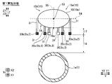
図3に示すように、複数の電位差検出部3は、移動体10において、進行方向(X1方向)に沿う方向(X方向)に互いに離間した位置に配置された検出電極対30を含む。また、電位差検出部3は、少なくとも、進行方向に沿う方向における移動体10の左右側部15のうち、第1側部15aに設けられた第1電位差検出部3aと、第1側部15aとは異なる第2側部15bに設けられた第2電位差検出部3bとを含む。また、電位差検出部3は、移動体10において、進行方向(X1方向)に対する左右方向(Y方向)に沿って検出電極対30が並ぶように設けられた第3電位差検出部3cを含む。なお、図3に示す例では、左右側部15のうち、X方向に沿う方向において、移動体10の中心を通る直線53からY1方向側(左側)を、第1側部15aとする。また、左右側部15のうち、移動体10の中心を通る直線54からY2方向側(右側)を、第2側部15bとする。
As shown in FIG. 3 , the plurality of potential
また、図3に示すように、供給電極対2は、第1側部15aにおいて、X方向に互いに離間した位置に設けられた第1電極対20aと、第2側部15bにおいて、X方向に互いに離間した位置に設けられた第2電極対20bとを含む。なお、第1実施形態では、第1電極対20aと、第2電極対20bとは、互いに異なる周波数の電流が供給される。また、供給電極対2は、底部16(図5参照)において、Y方向に沿う方向に互いに離間した位置に設けられた第3電極対20cを含む。
Further, as shown in FIG. 3, the
また、図4および図5に示すように、複数の電位差検出部3は、移動体10の側部15または底部16において、移動体10の底部16からの上下方向の距離17がそれぞれ略等しくなる位置に設けられている。また、複数の供給電極対2は、移動体10の側部15または底部16において、移動体10の底部16からの上下方向の距離17がそれぞれ略等しくなる位置に設けられている。言い換えると、複数の電位差検出部3および複数の供給電極対2は、移動体10の側部15または底部16において、それぞれ、複数の電位差検出部3および複数の供給電極対2からパイプライン1aまでの上下方向の距離18がそれぞれ略等しくなる位置に設けられている。
Further, as shown in FIGS. 4 and 5 , the plurality of potential
なお、移動体10の底部16からの上下方向の距離17とは、底部16の最下部16aからの上下方向の距離である。また、図4に示す例は、X1方向から見た図であるため、直線53を点で図示している。図4に示す例では、直線53よりもZ2方向側(下側)を、底部16とする。なお、図4では、簡単のため、移動体10の中心を通り、Y方向に沿う破線54および、移動体10の中心を通り、Z方向に沿う破線55を図示している。すなわち、破線54よりもZ2方向側(下側)を、底部16とする。また、破線55のY1方向側を第1側部15aとし、破線55のY2方向側を第2側部15bとする。また、図5に示す例では、直線53よりもZ2方向側(下側)を底部16とする。また、複数の供給電極対2および複数の電位差検出部3は、それぞれ、支持部材31を介して、移動体10に設けられている。支持部材31は、複数の供給電極対2および複数の電位差検出部3を支持することが可能であれば、形状、材質、および構造がどのように構成されていてもよい。
The
(電位差の検出)
電位差検出部3は、検出電極対30の間の電位差を検出するように構成されている。具体的には、電位差検出部3は、検出電極対30のうち、どちらか一方の検出電極による検出値を基準電位とし、基準電位の値と他方の検出電極における検出値との差を取得することにより、検出電極対30の間の検出領域56の電位差を検出するように構成されている。すなわち、第1実施形態では、供給電極対2と、検出電極対30とによって構成される検出ユニットによって、検出電極対30の間の検出領域56の電位差を検出するように構成されている。なお、第1実施形態では、移動体10は、3つの検出ユニットを備えている。
(Detection of potential difference)
The
図3に示すように、第1電極対20aに電流が供給されることにより、矢印50に沿って正極2aから負極2bに電流が流れる。その際、一点鎖線で示した領域60において、電界が生じる。第1電位差検出部3aは、電界が生じた領域60内の電位差を検出する。また、第2電極対20bに電流が供給されることにより、矢印51に沿って正極2aから負極2bに電流が流れる。その際、一点鎖線で示した領域61において、電界が生じる。第2電位差検出部3bは、電界が生じた領域61内の電位差を検出する。また、第3電極対20cに電流が供給されることにより、矢印52に沿って正極2aから負極2bに電流が流れる。その際、一点鎖線で示した領域62において、電界が生じる。第3電位差検出部3cは、電界が生じた領域62内の電位差を検出する。
As shown in FIG. 3, current flows from the
第1実施形態では、制御部4は、検出電極対30の間の電位差の変化に基づいて、パイプライン1aの位置を判定する制御を行うように構成されている。具体的には、制御部4は、第1電位差検出部3aによって検出された第1検出信号11a(図1参照)と、第2電位差検出部3bによって検出された第2検出信号11b(図1参照)とに基づいて、移動体10のY方向におけるパイプライン1aの位置を判定する制御を行うように構成されている。
In the first embodiment, the
(検出信号の変化)
次に、図6~図8を参照して、海底構造物検出装置100が検出する検出信号11の、パイプライン1aによる変化について説明する。なお、図6~図8に示す例は、第1電極対20aおよび第1電位差検出部3aによって検出信号11を検出する場合の例である。第2電極対20bおよび第2電位差検出部3bによる検出信号11の検出、および、第3電極対20cおよび第3電位差検出部3cによる検出信号11の検出も、同様の構成によって行われる。
(Change in detection signal)
Next, changes in the
図6に示すように、移動体10の近傍にパイプライン1aがない場合、供給電極対2の間に流れる電流のうち、最も外側を流れる電流は、破線50aで示すように、正極2aから負極2bに向けて円弧状に流れる。電位差検出部3は、領域60のうち、検出電極対30の間の検出領域56の電位差を検出する。
As shown in FIG. 6, when there is no
図7に示すように、供給電極対2および電位差検出部3が、パイプライン1aと交差する位置にある場合、供給電極対2の間に供給される電流は、パイプライン1aを避けるように流れる。そのため、最も外側を流れる電流の経路は、破線50bで示すように、図6に示す破線50aと比較して変化する。この場合、領域60(図3参照)内の電気力線の密度が大きくなるため、検出電極対30の間の検出領域56の電位差は、図6の配置の場合に検出される検出電極対30の間の検出領域56の電位差よりも大きくなる。すなわち、電位差検出部3で検出される検出信号11の値が大きくなる。
As shown in FIG. 7, when the
図8に示すように、供給電極対2および電位差検出部3が、パイプライン1aに沿う方向に位置する場合、供給電極対2から供給される電流は、パイプライン1aに沿って流れる。そのため、供給電極対2間に流れる電流のうち、最も外側を流れる電流の経路は、破線50cで示すように、図6に示す破線50aと比較して変化する。この場合も、領域60(図3参照)内の電気力線の密度が大きくなるため、検出電極対30の間の検出領域56の電位差は、図6の配置の場合に検出される検出電極対30の間の検出領域56の電位差よりも大きくなる。すなわち、電位差検出部3で検出される検出信号11の値が大きくなる。
As shown in FIG. 8, when the
(検出信号の解析)
次に、図9および図10を参照して、制御部4が検出信号11を解析する構成について説明する。
(Analysis of detected signal)
Next, a configuration for analyzing the
供給電極対2に供給される交流電流の波形の形状が正弦波の形状なので、図9に示すグラフ80のように、電位差検出部3によって検出される検出信号11の波形の形状は、正弦波の波形と同様の形状となる。なお、グラフ80は、縦軸が信号強度であり、横軸が時間のグラフである。グラフ80における信号強度とは、検出信号11の振幅19の大きさのことである。移動体10の近傍にパイプライン1aが存在する場合、検出信号11が大きくなる。すなわち、検出信号11のグラフ80の振幅19が大きくなる。
Since the waveform of the alternating current supplied to the
第1実施形態では、制御部4は、検出信号11をフーリエ変換することにより、検出信号11を解析するように構成されている。具体的には、制御部4は、検出信号11をフーリエ変換することにより、図10のグラフ81に示すフーリエ変換された検出信号12を取得する。グラフ81は、縦軸が信号強度であり、横軸が周波数のグラフである。
In the first embodiment, the
第1実施形態では、制御部4は、第1電極対20aおよび第2電極対20bにそれぞれ供給された電流の周波数ごとに、フーリエ変換された検出信号12を解析することにより、移動体10とパイプライン1aとの位置を判定する制御を行うように構成されている。また、第1実施形態では、第3電極対20cを備えているため、制御部4は、第1電極対20a、第2電極対20b、および、第3電極対20cにそれぞれ供給された電流の周波数ごとに、フーリエ変換された検出信号12を解析する。図10に示すグラフ81において、検出信号12aは、第1電位差検出部3aにおいて検出された検出信号11をフーリエ変換することにより得られた検出信号12である。また、検出信号12bは、第2電位差検出部3bにおいて検出された検出信号11をフーリエ変換することにより得られた検出信号12である。また、検出信号12cは、第3電位差検出部3cにおいて検出された検出信号11をフーリエ変換することにより得られた検出信号12である。
In the first embodiment, the
(パイプラインの位置の判定)
次に、図11~図13を参照して、海底構造物検出装置100によるパイプライン1aの位置を判定する構成について説明する。なお、図11~図13に示す例では、第1電位差検出部3a、第2電位差検出部3b、および、第3電位差検出部3cの検出信号11を、それぞれ、矢印70、矢印71、および、矢印72によって図示するとともに、各矢印の太さを変更することにより、検出信号11の値の大きさの違いを図示している。すなわち、検出信号11の信号強度が大きいほど、太い矢印で図示している。
(Determination of Pipeline Position)
Next, a configuration for determining the position of the
図11に示すように、海底構造物検出装置100がパイプライン1aの左側に位置する場合、第2電位差検出部3bの検出信号11の値が他の電位差検出部3の検出信号11の値よりも大きくなる。すなわち、制御部4は、第2電位差検出部3bの検出信号11の値が、他の電位差検出部3の検出信号11の値よりも大きい場合に、海底構造物検出装置100がパイプライン1aの左側に位置すると判定する。言い換えると、制御部4は、第2電位差検出部3bの検出信号11の値が、他の電位差検出部3の検出信号11の値よりも大きい場合に、パイプライン1aが海底構造物検出装置100の右側に位置すると判定する。
As shown in FIG. 11, when the submarine
図12に示すように、海底構造物検出装置100がパイプライン1aの直上に位置する場合、第3電位差検出部3cの検出信号11の値が他の電位差検出部3の検出信号11の値よりも大きくなる。すなわち、制御部4は、第3電位差検出部3cの検出信号11の値が、他の電位差検出部3の検出信号11の値よりも大きい場合に、海底構造物検出装置100がパイプライン1aの直上に位置すると判定する。言い換えると、制御部4は、第3電位差検出部3cの検出信号11の値が、他の電位差検出部3の検出信号11の値よりも大きい場合に、パイプライン1aが海底構造物検出装置100の直下に位置すると判定する。
As shown in FIG. 12, when the submarine
図13に示すように、海底構造物検出装置100がパイプライン1aの右側に位置する場合、第1電位差検出部3aの検出信号11の値が他の電位差検出部3の検出信号11の値よりも大きくなる。すなわち、制御部4は、第1電位差検出部3aの検出信号11の値が、他の電位差検出部3の検出信号11の値よりも大きい場合に、海底構造物検出装置100がパイプライン1aの右側に位置すると判定する。言い換えると、制御部4は、第1電位差検出部3aの検出信号11の値が、他の電位差検出部3の検出信号11の値よりも大きい場合に、パイプライン1aが海底構造物検出装置100の左側に位置すると判定する。
As shown in FIG. 13, when the submarine
(移動体の移動方向の調整)
次に、図14および図15を参照して、移動体10の移動方向を調整する構成について説明する。
(Adjustment of movement direction of moving body)
Next, a configuration for adjusting the moving direction of the moving
図14に示すグラフ82は、信号出力部40が出力する移動体10の移動方向を調整する信号のグラフである。グラフ82は、縦軸が信号値であり、横軸が時間のグラフである。グラフ82の値が「1」となっている区間90は、移動体10を右方向に移動させる信号が出力されている区間である。また、グラフ82の値が「0」となっている区間91は、移動体10をそのまま移動させる(移動方向を変更しない)信号が出力されている区間である。また、グラフ82の値が「-1」となっている区間92は、移動体10を左方向に移動させる信号が出力されている区間である。
A
信号出力部40は、パイプライン1aが移動体10の右側(図11参照)にある場合、移動体10の移動方向を調整する信号として、「1」を出力する。また、信号出力部40は、パイプライン1aが移動体10の直下(図12参照)にある場合、移動体10の移動方向を調整する信号として、「0」を出力する。信号出力部40は、パイプライン1aが移動体10の左側(図13参照)にある場合、移動体10の移動方向を調整する信号として、「-1」を出力する。
The
制御部4は、信号出力部40が出力する移動体10の移動方向を調整する信号に基づいて、推進機構6を制御することにより、移動体10の移動方向を調整する。具体的には、制御部4は、信号処理部7から「1」の信号を受信した場合、移動体10を右方向に移動させる制御を行う。また、制御部4は、信号処理部7から「0」の信号を受信した場合、移動体10の移動方向を調整する制御は行わない。また、制御部4は、信号処理部7から「-1」の信号を受信した場合、移動体10を左方向に移動させる制御を行う。
The
図14のグラフ82に示すような移動体10の移動方向を調整する信号が出力された場合、制御部4は、図15に示すように移動体10の移動方向を調整する。すなわち、制御部4は、図15に示す矢印57のように、移動体10がパイプライン1aの上方をジグザグ状に移動するように移動方向の調整を行う。
When a signal for adjusting the moving direction of the moving
(移動方向調整信号出力処理)
次に、図16を参照して、第1実施形態の海底構造物検出装置100による移動方向調整信号出力処理をフローチャートに基づいて説明する。なお、移動方向調整信号出力処理は、制御部4(信号出力部40)により行われる。
(Movement direction adjustment signal output processing)
Next, referring to FIG. 16, the movement direction adjustment signal output processing by the submarine
ステップ101において、制御部4は、推進機構6を制御することにより、移動体10を移動させる。具体的には、制御部4は、推進機構6を制御することにより、正極2aと負極2bとを有する供給電極対2と、電位差検出部3とが設けられた移動体10を海底14に沿って移動させる。なお、移動体10を移動させるとは、パイプライン1aの検出を行うために、移動体10を移動させ続けることを意味する。
At
次に、ステップ102において、制御部4は、電流源5を制御することにより、供給電極対2に電流を供給する。具体的には、制御部4は、電流源5を制御することにより、正極2aと負極2bとの間に電流を供給する。
Next, at
次に、ステップ103において、電位差検出部3は、供給電極対2間の電位差を検出する。具体的には、電位差検出部3は、正極2aと負極2bとの間の検出領域56の電位差を検出する。
Next, at
次に、ステップ104において、制御部4は、検出された検出信号11のパイプライン1aに起因して生じる変化に基づいてパイプライン1aの位置を判定する制御を行う。
Next, at
次に、ステップ105において、信号出力部40は、移動体10の移動方向を調整する信号を出力し、処理を終了する。
Next, at
(パイプラインの位置判定)
次に、図17を参照して、第1実施形態の海底構造物検出装置100によるパイプライン位置判定処理をフローチャートに基づいて説明する。なお、パイプライン位置判定処理は、制御部4により行われる。
(Pipeline position determination)
Next, pipeline position determination processing by the submarine
ステップ110において、制御部4は、各電位差検出部3の検出信号11の値に差異があるか否かを判定する。各電位差検出部3の検出信号11の値に差異がない場合、処理は、ステップ111へ進む。各電位差検出部の検出信号11の値に差異がある場合、処理は、ステップ114へ進む。
At
ステップ111において、制御部4は、各電位差検出部3の検出信号11の値が所定の値よりも大きいか否かの判定を行う。各電位差検出部3の検出信号11の値が所定の値よりも大きい場合、処理は、ステップ112へ進む。各電位差検出部3の検出信号11の値が所定の値よりも小さい場合、処理は、ステップ113へ進む。
At
ステップ112において、制御部4は、移動体10の近傍にパイプライン1aがないと判定する。その後、処理は、ステップ105へと進み、パイプライン位置判定処理は終了する。
At
ステップ113において、制御部4は、パイプライン1aが移動体10と直交する方向に位置していると判定する。その後、処理は、ステップ105へと進み、パイプライン位置判定処理は終了する。
At
ステップ114において、制御部4は、第1電位差検出部3aの検出信号11の値が最も大きいか否かの判定を行う。第1電位差検出部3aの検出信号11の値が最も大きい場合、処理は、ステップ115へ進む。第1電位差検出部3aの検出信号11の値よりも大きい値の検出信号11がある場合、処理は、ステップ116へ進む。
At
ステップ115において、制御部4は、パイプライン1aが移動体10の右側に位置していると判定する。その後、処理は、ステップ105へと進み、パイプライン位置判定処理は終了する。
At
ステップ116において、制御部4は、第2電位差検出部3bの検出信号11の値が第3電位差検出部3cの検出信号11の値よりも大きいか否かの判定を行う。第2電位差検出部3bの検出信号11の値が第3電位差検出部3cの検出信号11の値よりも大きい場合、処理は、ステップ117へ進む。第2電位差検出部3bの検出信号11の値が第3電位差検出部3cの検出信号11の値よりも小さい場合、処理は、ステップ118へ進む。
At
ステップ117において、制御部4は、パイプライン1aが移動体10の左側に位置していると判定する。その後、処理は、ステップ105へと進み、パイプライン位置判定処理は終了する。
At
ステップ118において、制御部4は、パイプライン1aが移動体10の直下に位置していると判定する。その後、処理は、ステップ105へと進み、パイプライン位置判定処理は終了する。
At
(第1実施形態の効果)
第1実施形態では、以下のような効果を得ることができる。
(Effect of the first embodiment)
The following effects can be obtained in the first embodiment.
第1実施形態では、上記のように、海底構造物検出装置100は、海底14に設けられたパイプライン1a(構造物1)を検出する海底構造物検出装置であって、各々が正極2aと負極2bとを有する複数の供給電極対2と、各々の正極2aと負極2bとの間に配置され、正極2aと負極2bとの間に供給された電流による正極2aと負極2bとの間の検出領域56の電位差を検出する複数の電位差検出部3と、複数の電位差検出部3によって検出された検出信号11のパイプライン1aに起因して生じる変化に基づいてパイプライン1aの位置を判定する制御を行う制御部4とを備える。これにより、供給電極対2に供給された電流の経路がパイプライン1aによって変化した際の電位差の変化を検出することが可能となり、検出信号11の変化に基づいて海底14に設けられたパイプライン1aの位置を判定することができる。その結果、海底14に設けられたパイプライン1aから発せられる磁気に基づいて位置を判定する構成とは異なり、海底14に設けられたパイプライン1aの材質に起因して、海底14に設けられたパイプライン1aから発せられる磁気の大きさが小さい場合でも、パイプライン1aの位置を検出することができる。また、海底14の地中には海水が含まれているので、海水が浸透している海底14の地中には電流が流れる。したがって、パイプライン1aが海底14の砂などに埋まっている場合でも、パイプライン1aによって検出信号11が変化するため、パイプライン1aの位置判定を行うことができる。その結果、カメラなどを用いた目視による検出とは異なり、パイプライン1aが海底14の砂などに埋まっている場合でも、パイプライン1aを検出することができる。
In the first embodiment, as described above, the submarine
また、第1実施形態では、上記のように、少なくとも、供給電極対2と、電位差検出部3とが設けられ、水中を移動可能な移動体10を備え、制御部4は、パイプライン1aの位置の判定結果および検出信号11に基づいて、移動体10の移動方向を調整するための信号を出力する制御を行うように構成されている。これにより、移動方向を調整するための信号に基づいて移動体10の移動方向を容易に調整することができる。その結果、検出可能範囲からパイプライン1aが外れてしまうことを容易に抑制することができる。
Further, in the first embodiment, as described above, at least the
また、第1実施形態では、上記のように、電位差検出部3は、移動体10において、進行方向(X1方向)に沿う方向(X方向)に互いに離間した位置に配置された検出電極対30を含むとともに、検出電極対30の間の電位差を検出するように構成されており、制御部4は、検出電極対30の間の電位差の変化に基づいて、パイプライン1aの位置を判定する制御を行うように構成されている。これにより、検出電極対30がX方向に互いに離間して配置されることによって、1つの電極によって電位差を検出する構成と比較して、検出電極対30間の電位差を正確に取得することができる。その結果、検出電極対30間の電位差の変化を正確に取得することができる。
Further, in the first embodiment, as described above, the potential
また、第1実施形態では、上記のように、複数の電位差検出部3は、少なくとも、X方向における移動体10の左右側部15のうち、第1側部15aに設けられた第1電位差検出部3aと、第1側部15aとは異なる第2側部15bに設けられた第2電位差検出部3bとを含み、制御部4は、第1電位差検出部3aによって検出された第1検出信号11aと、第2電位差検出部3bによって検出された第2検出信号11bとに基づいて、移動体10の進行方向(X1方向)に対する左右方向(Y方向)におけるパイプライン1aの位置を判定する制御を行うように構成されている。これにより、第1検出信号11aの大きさと第2検出信号11bの大きさとを比較することにより、移動体10に対するパイプライン1aの位置を判定することができる。その結果、移動体10の底部16に1対の電位差検出部3のみが設けられている構成と比較して、移動体10のY方向におけるパイプライン1aの位置を精度よくできる。
Further, in the first embodiment, as described above, the plurality of potential
また、第1実施形態では、上記のように、供給電極対2は、第1側部15aにおいて、X方向に互いに離間した位置に設けられた第1電極対20aと、第2側部15bにおいて、X方向に互いに離間した位置に設けられた第2電極対20bとを含み、第1電極対20aと、第2電極対20bとは、互いに異なる周波数の電流が供給される。これにより、第1電極対20aおよび第2電極対20bに供給される電流の周波数が異なるため、第1電極対20aおよび第2電極対20bに対して同一のタイミングで電流を供給することができる。その結果、第1電極対20aおよび第2電極対20bに対して同一の周波数の電流を、タイミングをずらして供給する場合と比較して、検出時間を短縮することができる。
Further, in the first embodiment, as described above, the
また、第1実施形態では、上記のように、制御部4は、検出信号11をフーリエ変換し、第1電極対20aおよび第2電極対20bにそれぞれ供給された電流の周波数ごとに、フーリエ変換された検出信号12を解析することにより、移動体10とパイプライン1aとの位置を判定する制御を行うように構成されている。これにより、第1電極対20aおよび第2電極対20bに対して、周波数の異なる電流が同一のタイミングで供給された場合でも、フーリエ変換された検出信号12をそれぞれの電流の周波数で解析することにより、各検出信号11を個別に解析することができる。その結果、各電位差検出部3における検出結果を精度よく解析することができる。
Further, in the first embodiment, as described above, the
また、第1実施形態では、上記のように、電位差検出部3は、移動体10において、Y方向に沿って検出電極対30が並ぶように設けられた第3電位差検出部3cをさらに含む。これにより、第3電位差検出部3cによって、海底構造物検出装置100がパイプライン1aの直上にある場合の判定精度を向上させることができる。その結果、パイプライン1aの位置の判定精度を向上させることができる。
Further, in the first embodiment, as described above, the potential
また、第1実施形態では、上記のように、複数の電位差検出部3は、移動体10の側部15または底部16において、移動体10の底部16からの上下方向の距離17がそれぞれ略等しくなる位置に設けられている。これにより、各電位差検出部3から海底14に設けられたパイプライン1aまでの距離18を略等しくすることができる。そのため、電位差検出部3からパイプライン1aまでの距離18が異なることによって、各検出信号11の大きさにばらつきが生じることを抑制することができる。その結果、電位差検出部3からパイプライン1aまでの距離18に依存する影響が生じることを抑制することが可能となり、パイプライン1aの位置の判定精度をより向上させることができる。
Further, in the first embodiment, as described above, the plurality of potential
また、第1実施形態では、上記のように、移動体10は、供給電極対2と、電位差検出部3と、供給電極対2間に電流を供給する電流源5と、制御部4と、移動体10に対して推進力を与える推進機構6とが設けられ、海中を自律走行可能に構成されている。これにより、移動体10を海中で自律走行させながらパイプライン1aの位置の検出を行うことができる。
Further, in the first embodiment, as described above, the moving
また、第1実施形態では、上記のように、構造物1は、海底14に設けられたパイプライン1aであり、制御部4は、パイプライン1aの位置を判定するように構成されている。これにより、パイプライン1aの位置判定に好適な海底構造物検出装置100を提供することができる。
In the first embodiment, as described above, the
また、第1実施形態では、上記のように、海底構造物検出方法は、海底14に設けられたパイプライン1aを検出する海底構造物検出であって、少なくとも、正極2aと負極2bとを有する供給電極対2と、電位差検出部3とが設けられた移動体10を海底14に沿って移動させ、正極2aと負極2bとの間に電流を供給し、正極2aと負極2bとの間の検出領域56の電位差を検出し、検出された検出信号11のパイプライン1aに起因して生じる変化に基づいてパイプライン1aの位置を判定する制御を行う。これにより、上記海底構造物検出装置100と同様に、海底14に設けられたパイプライン1aの材質に起因して、海底14に設けられたパイプライン1aから発せられる磁気の大きさが小さい場合でも、海底14に設けられたパイプライン1aの位置を検出することが可能な海底構造物検出方法を提供することができる。
Further, in the first embodiment, as described above, the submarine structure detection method detects a submarine structure that detects the
[第2実施形態]
次に、図18および図19を参照して、第2実施形態による海底構造物検出装置100(図18参照)を備える海底構造物検出システム200の構成について説明する。海底構造物検出装置100(移動体10)が自律走行可能な第1実施形態とは異なり、第2実施形態による海底構造物検出システム200が備える海底構造物検出装置100(移動体10)は、船舶13によって曳航されることにより、海中を移動可能に構成されている。なお、上記第1実施形態と同様の構成については同様の符号を付し、説明を省略する。
[Second embodiment]
Next, with reference to FIGS. 18 and 19, the configuration of a submarine
海底構造物検出システム200は、海底14に設けられた構造物1(パイプライン1a)を検出する海底構造物検出システムである。図18に示すように、第2実施形態による海底構造物検出システム200は、電流源5と、検出装置300と、制御装置400と、を備えている。また、移動体10と船舶13とは、ケーブル33によって直接接続されている。
The submarine
電流源5は、検出装置300に設けられた供給電極対2に電流を供給するように構成されている。電流源5は、上記第1実施形態による電流源5と同様の構成であるため、詳細な説明は省略する。
The
ケーブル33は、電流源5および制御装置400と、検出装置300とを接続している。ケーブル33は、電流源5からの電流を検出装置300に供給するように構成されている。また、ケーブル33は、検出装置300と制御装置400との間において、検出信号11などを通信可能に構成されている。ケーブル33は、たとえば、移動体10と船舶13とを直接接続する牽引ケーブル、電流源5からの電流を検出装置300に供給するための電力ケーブル、および、検出装置300と制御装置400との間において通信するための通信ケーブルなどを含む。
検出装置300は、各々が正極2aと負極2bとを有する複数の供給電極対2と、各々の正極2aと負極2bとの間に配置され、正極2aと負極2bとの間に供給された電流による正極2aと負極2bとの間の検出領域56の電位差を検出する複数の電位差検出部3とを備える。複数の供給電極対2および複数の電位差検出部3の構成は、上記第1実施形態と同様の構成であるため、詳細な説明は省略する。
The
制御装置400は、制御部4と、信号処理部7と、記憶部8と、接続部32とを備える。制御装置400が備える制御部4、信号処理部7、および、記憶部8は、それぞれ、上記第1実施形態による海底構造物検出装置100が備える制御部4、信号処理部7、および、記憶部8と同様の構成であるため、詳細な説明は省略する。
The
制御装置400は、複数の電位差検出部3によって検出された検出信号11のパイプライン1aに起因して生じる変化に基づいてパイプライン1aの位置を判定する制御を行うように構成されている。制御装置400がパイプライン1aの位置を判定する制御は、上記第1実施形態による制御部4がパイプライン1aの位置を判定する制御と同様であるため、詳細な説明は省略する。
The
接続部32は、ケーブル33が接続されることにより、検出装置300と制御装置400との間において、検出信号11などを通信できるように構成されている。接続部32は、たとえば、通信ケーブルが接続可能なLAN(Local Area Network)ポートなどを含む。
The
電流源5と制御装置400とは、海面を航行する船舶13に設けられている。また、船舶13は、推進機構26を備えている。推進機構26は、船舶13に対して推進力を与えるように構成されている。推進機構26は、プロペラ(図示せず)、プロペラを駆動する駆動源(図示せず)などを含む。また、推進機構26は、制御装置400の制御の下、制御装置400(信号出力部40)から出力される移動体10の移動方向を調整する信号に基づいて、船舶13の移動方向を調整することにより、移動体10の移動方向を調整するように構成されている。
The
図19に示すように、第2実施形態による海底構造物検出システム200は、船舶13によって検出装置300を曳航することにより、海底14に設けられたパイプライン1aを検出するように構成されている。
As shown in FIG. 19, the submarine
検出装置300は、船舶13によって曳航される。そのため、上記第1実施形態による海底構造物検出装置100とは異なり、検出装置300には、推進機構6を設けなくてよい。また、制御装置400がパイプライン1aの位置の判定を行うため、検出装置300は、制御部4を備えなくてよい。すなわち、検出装置300は、複数の供給電極対2および複数の電位差検出部3を備えていればよい。
The
なお、第2実施形態のその他の構成は、上記第1実施形態と同様である。 Other configurations of the second embodiment are the same as those of the first embodiment.
(第2実施形態の効果)
第2実施形態では、以下のような効果を得ることができる。
(Effect of Second Embodiment)
The following effects can be obtained in the second embodiment.
第2実施形態では、上記のように、海底構造物検出システム200は、海底14に設けられた構造物1(パイプライン1a)を検出する海底構造物検出システムであって、各々が正極2aと負極2bとを有する複数の供給電極対2と、各々の正極2aと負極2bとの間に配置され、正極2aと負極2bとの間に供給された電流による正極2aと負極2bとの間の電位差を検出する複数の電位差検出部3とを備える検出装置300と、供給電極対2間に電流を供給する電流源5と、複数の電位差検出部3によって検出された検出信号11のパイプライン1aに起因して生じる変化に基づいてパイプライン1aの位置を判定する制御を行う制御装置400とを備える。これにより、上記第1実施形態における海底構造物検出装置100と同様に、海底14に設けられたパイプライン1aの材質に起因して、海底14に設けられたパイプライン1aから発せられる磁気の大きさが小さい場合でも、海底14に設けられたパイプライン1aの位置を検出することが可能な海底構造物検出システム200を提供することができる。
In the second embodiment, as described above, the submarine
また、第2実施形態では、上記のように、制御装置400は、海面を航行する船舶13に設けられている。これにより、船舶13に設けられた制御装置400において、パイプライン1aの位置判定を行うことが可能となるので、検出装置300の装置構成を簡素化することができる。
Further, in the second embodiment, as described above, the
なお、上記第2実施形態におけるその他の効果は、上記第1実施形態と同様である。 Other effects of the second embodiment are the same as those of the first embodiment.
(変形例)
なお、今回開示された実施形態は、すべての点で例示であって制限的なものではないと考えられるべきである。本発明の範囲は、上記した実施形態の説明ではなく、特許請求の範囲によって示され、さらに特許請求の範囲と均等の意味および範囲内でのすべての変更(変形例)が含まれる。
(Modification)
It should be noted that the embodiments disclosed this time should be considered as examples and not restrictive in all respects. The scope of the present invention is indicated by the scope of the claims rather than the above description of the embodiments, and includes all modifications (modifications) within the meaning and scope equivalent to the scope of the claims.
たとえば、上記第1実施形態では、海底構造物検出装置100が通信部9を備えており、船舶13と無線接続される構成の例を示したが、本発明はこれに限られない。たとえば、図20に示す変形例のように、海底構造物検出装置100は、接続部32を備え、ケーブル33を介して船舶13と有線接続される構成であってもよい。すなわち、図21に示すように、海底構造物検出装置100(移動体10)と船舶13とが、ケーブル33によって接続されており、船舶13と海底構造物検出装置100とが、有線によって通信するように構成されていてもよい。図21に示す変形例では、海底構造物検出装置100が自律走行可能に構成されていてもよいし、ケーブル33を介して船舶13に乗船しているユーザが海底構造物検出装置100を操作してもよい。
For example, in the above-described first embodiment, the submarine
また、上記第1および第2実施形態では、電位差検出部3が、銀/塩化銀電極を含む構成の例を示したが、本発明はこれに限られない。たとえば、電位差検出部3は、パラジウム水素電極などを含んでいてもよい。供給電極対2間の電位差を検出することができれば、電位差検出部3は、どのように構成されていてもよい。
Further, in the above-described first and second embodiments, an example of a configuration in which the potential
また、上記第1および第2実施形態では、電位差検出部3が、第1電位差検出部3a、第2電位差検出部3b、および、第3電位差検出部3cを含む構成の例を示したが、本発明はこれに限られない。たとえば、電位差検出部3は、第1電位差検出部3aおよび第2電位差検出部3bを含んでいれば、第3電位差検出部3cを含んでいなくてもよい。しかしながら、第3電位差検出部3cを含まない場合、海底構造物検出装置100の直下にパイプライン1aが位置する場合のパイプライン1aの位置判定精度が低下するため、第3電位差検出部3cを含む構成の方が好ましい。
Further, in the first and second embodiments, an example of a configuration in which the potential
また、上記第1および第2実施形態では、複数の供給電極対2および複数の電位差検出部3が、それぞれ、移動体10の底部16からの距離17が略等しくなる位置に配置される構成の例を示したが、本発明はこれに限られない。複数の電位差検出部3が、それぞれ、移動体10の底部16からの距離17が略等しくなる位置に配置されていれば、複数の供給電極対2は、上下方向において、異なる位置に設けられていてもよい。
Further, in the first and second embodiments, the plurality of supply electrode pairs 2 and the plurality of potential
また、上記第1および第2実施形態では、各電位差検出部3が検出した検出信号11の大きさを比較することにより、パイプライン1aの位置判定を行う構成の例を示したが、本発明はこれに限られない。たとえば、各電位差検出部3が検出した検出信号11の継時変化を取得し、前回の検出信号11の値よりも今回検出した検出信号11の値が大きくなっているか否かを判定することにより、パイプライン1aの位置判定を行う構成であってもよい。
Further, in the first and second embodiments described above, an example of the configuration for determining the position of the
また、上記第1および第2実施形態では、電流源5が異なる周波数の電流を、同一のタイミングで第1電極対20aおよび第2電極対20bに対して供給する構成の例を示したが、本発明はこれに限られない。たとえば、電流源5は、同一の周波数の電流を、タイミングを異ならせて第1電極対20aおよび第2電極対20bに対して供給するように構成されていてもよい。
In addition, in the above-described first and second embodiments, an example of a configuration in which the
また、上記第1および第2実施形態では、信号出力部40が出力する移動体10の移動方向を調整する信号が、「1」、「0」、および、「-1」である例を示したが、本発明はこれに限られない。たとえば、信号出力部40は、右、左、そのまま(方向を変更しない)の3値信号であって、信号強度によって方向の強さ(パイプライン1aからの近さ)を表す信号を出力するように構成されていてもよい。
Further, in the above-described first and second embodiments, the signals output by the
また、上記第1実施形態では、説明の便宜上、制御部4の制御処理を、処理フローに沿って順番に処理を行うフロー駆動型のフローチャートを用いて説明した例について示したが、本発明はこれに限られない。本発明では、制御部4の制御処理を、イベント単位で処理を実行するイベント駆動型(イベントドリブン型)の処理により行ってもよい。この場合、完全なイベント駆動型で行ってもよいし、イベント駆動およびフロー駆動を組み合わせて行ってもよい。
In addition, in the above-described first embodiment, for convenience of explanation, the control processing of the
1 構造物
1a パイプライン
2 供給電極対
3 電位差検出部
3a 第1電位差検出部
3b 第2電位差検出部
3c 第3電位差検出部
4 制御部
5 電流源
6 推進機構
10 移動体
11 検出信号
11a 第1検出信号
11b 第2検出信号
12 船舶
13 海底
14 側部(左右側部)
14a 第1側部
14b 第2側部
15 底部
16 移動体の底部からの上下方向の距離
20a 第1電極対
20b 第2電極対
30 検出電極対
100 海底構造物検出装置
200 海底構造物検出システム
300 検出装置
400 制御装置
REFERENCE SIGNS
14a first side 14b
Claims (13)
各々が正極と負極とを有する複数の供給電極対と、
各々の前記正極と前記負極との間に配置され、前記正極と前記負極との間に供給された電流による前記正極と前記負極との間の検出領域の電位差を検出する複数の電位差検出部と、
複数の前記電位差検出部によって検出された検出信号の構造物に起因して生じる変化に基づいて構造物の位置を判定する制御を行う制御部とを備える、海底構造物検出装置。 A submarine structure detection device for detecting a structure provided on the seabed,
a plurality of feed electrode pairs each having a positive electrode and a negative electrode;
a plurality of potential difference detection units disposed between each of the positive electrode and the negative electrode for detecting a potential difference in a detection region between the positive electrode and the negative electrode caused by a current supplied between the positive electrode and the negative electrode; ,
A submarine structure detection apparatus, comprising: a control section for determining a position of a structure based on a change caused by the structure in detection signals detected by the plurality of potential difference detection sections.
前記制御部は、構造物の位置の判定結果および前記検出信号に基づいて、前記移動体の移動方向を調整するための信号を出力する制御を行うように構成されている、請求項1に記載の海底構造物検出装置。 At least the supply electrode pair and the potential difference detection unit are provided, and further comprising a moving body capable of moving in water,
2. The control unit according to claim 1, wherein the control unit is configured to output a signal for adjusting the moving direction of the moving body based on the determination result of the position of the structure and the detection signal. of seabed structure detection equipment.
前記制御部は、前記検出電極対の間の電位差の変化に基づいて、前記構造物の位置を判定する制御を行うように構成されている、請求項2に記載の海底構造物検出装置。 The potential difference detection unit includes a pair of detection electrodes arranged at positions spaced apart from each other in a direction along the traveling direction of the moving body, and is configured to detect a potential difference between the pair of detection electrodes,
3. The submarine structure detection apparatus according to claim 2, wherein the control section is configured to perform control to determine the position of the structure based on a change in potential difference between the pair of detection electrodes.
前記制御部は、前記第1電位差検出部によって検出された第1検出信号と、前記第2電位差検出部によって検出された第2検出信号とに基づいて、前記移動体の進行方向に対する左右方向における前記構造物の位置を判定する制御を行うように構成されている、請求項3に記載の海底構造物検出装置。 The plurality of potential difference detection units includes at least a first potential difference detection unit provided on a first side portion of left and right side portions of the moving body in a direction along the traveling direction, and a first potential difference detection portion provided on a first side portion, and a second potential difference detection portion provided on a first side portion. and a second potential difference detection unit provided on two sides,
Based on the first detection signal detected by the first potential difference detection section and the second detection signal detected by the second potential difference detection section, the control section is configured to The submarine structure detection apparatus according to claim 3, configured to perform control for determining the position of the structure.
前記第1電極対と、前記第2電極対とは、互いに異なる周波数の電流が供給される、請求項4に記載の海底構造物検出装置。 The supply electrode pair includes a first electrode pair provided at positions spaced apart from each other in the traveling direction on the first side, and a position spaced from each other in the traveling direction on the second side. a second electrode pair provided in
5. The submarine structure detection apparatus according to claim 4, wherein currents of different frequencies are supplied to said first electrode pair and said second electrode pair.
前記制御部は、パイプラインの位置を判定するように構成されている、請求項1~9のいずれか1項に記載の海底構造物検出装置。 The structure is a pipeline provided on the seabed,
The submarine structure detection device according to any one of claims 1 to 9, wherein the control unit is configured to determine the position of a pipeline.
各々が正極と負極とを有する複数の供給電極対と、各々の前記正極と前記負極との間に配置され、前記正極と前記負極との間に供給された電流による前記正極と前記負極との間の検出領域の電位差を検出する複数の電位差検出部とを備える検出装置と、
前記供給電極対の間に電流を供給する電流源と、
複数の前記電位差検出部によって検出された検出信号の構造物に起因して生じる変化に基づいて構造物の位置を判定する制御を行う制御装置とを備える、海底構造物検出システム。 A submarine structure detection system for detecting structures provided on the seabed,
a plurality of supply electrode pairs, each having a positive electrode and a negative electrode, disposed between each said positive electrode and said negative electrode, and for controlling said positive electrode and said negative electrode by current supplied between said positive electrode and said negative electrode; a detection device comprising a plurality of potential difference detection units that detect a potential difference in a detection region between
a current source that supplies a current between the pair of supply electrodes;
A submarine structure detection system, comprising: a control device for determining a position of a structure based on a change caused by the structure in detection signals detected by the plurality of potential difference detection units.
少なくとも、各々が正極と負極とを有する複数の供給電極対と、各々の前記正極と前記負極との間に配置され、前記正極と前記負極との間に供給された電流による前記正極と前記負極との間の検出領域の電位差を検出する複数の電位差検出部とが設けられた移動体を海底に沿って移動させ、
前記複数の供給電極対の各々の前記正極と前記負極との間に電流を供給し、
前記複数の供給電極対の各々の前記正極と前記負極との間の前記検出領域の各々の電位差を検出し、
検出された検出信号の構造物に起因して生じる変化に基づいて構造物の位置を判定する制御を行う、海底構造物検出方法。 A seabed structure detection method for detecting a structure provided on the seabed,
at least a plurality of supply electrode pairs, each having a positive electrode and a negative electrode, and a plurality of supply electrode pairs, each having a positive electrode and a negative electrode, disposed between each said positive electrode and said negative electrode, said positive electrode and said negative electrode being driven by a current supplied between said positive electrode and said negative electrode. Move along the seabed a moving body provided with a plurality of potential difference detection units that detect the potential difference in the detection area between
supplying a current between the positive electrode and the negative electrode of each of the plurality of supply electrode pairs ;
detecting a potential difference in each of the sensing regions between the positive and negative electrodes of each of the plurality of supply electrode pairs ;
A submarine structure detection method, wherein control is performed to determine the position of a structure based on a change in a detected detection signal caused by the structure.
Priority Applications (2)
| Application Number | Priority Date | Filing Date | Title |
|---|---|---|---|
| JP2019011424A JP7147591B2 (en) | 2019-01-25 | 2019-01-25 | Submarine structure detection device, submarine structure detection system, and submarine structure detection method |
| US16/749,669 US11340376B2 (en) | 2019-01-25 | 2020-01-22 | Subsea structure detection device, subsea structure detection system, and subsea structure detection method |
Applications Claiming Priority (1)
| Application Number | Priority Date | Filing Date | Title |
|---|---|---|---|
| JP2019011424A JP7147591B2 (en) | 2019-01-25 | 2019-01-25 | Submarine structure detection device, submarine structure detection system, and submarine structure detection method |
Publications (2)
| Publication Number | Publication Date |
|---|---|
| JP2020118605A JP2020118605A (en) | 2020-08-06 |
| JP7147591B2 true JP7147591B2 (en) | 2022-10-05 |
Family
ID=71731196
Family Applications (1)
| Application Number | Title | Priority Date | Filing Date |
|---|---|---|---|
| JP2019011424A Active JP7147591B2 (en) | 2019-01-25 | 2019-01-25 | Submarine structure detection device, submarine structure detection system, and submarine structure detection method |
Country Status (2)
| Country | Link |
|---|---|
| US (1) | US11340376B2 (en) |
| JP (1) | JP7147591B2 (en) |
Families Citing this family (2)
| Publication number | Priority date | Publication date | Assignee | Title |
|---|---|---|---|---|
| NO347444B1 (en) * | 2022-01-25 | 2023-11-06 | Argeo Robotics As | A system for detection and delineation of a subsea object |
| WO2023238733A1 (en) * | 2022-06-09 | 2023-12-14 | 川崎重工業株式会社 | Autonomous unmanned underwater vehicle |
Citations (5)
| Publication number | Priority date | Publication date | Assignee | Title |
|---|---|---|---|---|
| JP2001305237A (en) | 2000-04-24 | 2001-10-31 | Kiso Jiban Consultants Kk | Data processing system of electric probe in sea bottom |
| JP2002156460A (en) | 2000-11-20 | 2002-05-31 | Sangaku Renkei Kiko Kyushu:Kk | Electric searching method, electric searching device using the same, and land mine detecting device |
| JP2012117914A (en) | 2010-11-30 | 2012-06-21 | Sewtec:Kk | Substance detector, substance detecting system, and substance detecting method |
| JP2015506475A (en) | 2012-01-09 | 2015-03-02 | ユニベルシテ ド ブルターニュ オキシダンタル(ウ・ベ・オ) | Electromagnetic system for exploring the sea floor |
| WO2018047638A1 (en) | 2016-09-09 | 2018-03-15 | 国立研究開発法人海洋研究開発機構 | Seabed resource exploration system, transmission device, reception device, signal processing device, signal processing method, electrical exploration method, electromagnetic exploration method, and program |
Family Cites Families (12)
| Publication number | Priority date | Publication date | Assignee | Title |
|---|---|---|---|---|
| US2531088A (en) * | 1947-10-16 | 1950-11-21 | Standard Oil Dev Co | Electrical prospecting method |
| US3875497A (en) * | 1973-12-26 | 1975-04-01 | Seatrek Ltd | Waterborne magnetic anomaly detection system and apparatus |
| GB1512161A (en) * | 1976-01-12 | 1978-05-24 | Morgan Berkeley & Co Ltd | Cathodic protection of structures |
| US4617518A (en) * | 1983-11-21 | 1986-10-14 | Exxon Production Research Co. | Method and apparatus for offshore electromagnetic sounding utilizing wavelength effects to determine optimum source and detector positions |
| JPS62148877A (en) | 1985-12-24 | 1987-07-02 | Nippon Butsuri Tanko Kk | Method and device for surveying buried state of submarine pipeline or the like |
| US5126654A (en) * | 1989-02-10 | 1992-06-30 | New York Gas Group | Non-invasive, high resolution detection of electrical currents and electrochemical impedances at spaced localities along a pipeline |
| FI910512A (en) * | 1991-02-01 | 1992-08-02 | Esko Antero Hirvonen | Kontrollsystem. |
| JP4144851B2 (en) | 2002-07-19 | 2008-09-03 | Necネットワーク・センサ株式会社 | Ship position detection method, position detection apparatus and system |
| GB2420855B (en) * | 2004-12-02 | 2009-08-26 | Electromagnetic Geoservices As | Source for electromagnetic surveying |
| US8587316B2 (en) * | 2011-12-08 | 2013-11-19 | Pgs Geophysical As | Noise reduction systems and methods for a geophysical survey cable |
| US8928324B2 (en) * | 2011-12-27 | 2015-01-06 | Pgs Geophysical As | In-line and broadside marine electromagnetic surveying |
| JP2017138254A (en) * | 2016-02-05 | 2017-08-10 | 国立研究開発法人海洋研究開発機構 | System and method for estimating resources |
-
2019
- 2019-01-25 JP JP2019011424A patent/JP7147591B2/en active Active
-
2020
- 2020-01-22 US US16/749,669 patent/US11340376B2/en active Active
Patent Citations (5)
| Publication number | Priority date | Publication date | Assignee | Title |
|---|---|---|---|---|
| JP2001305237A (en) | 2000-04-24 | 2001-10-31 | Kiso Jiban Consultants Kk | Data processing system of electric probe in sea bottom |
| JP2002156460A (en) | 2000-11-20 | 2002-05-31 | Sangaku Renkei Kiko Kyushu:Kk | Electric searching method, electric searching device using the same, and land mine detecting device |
| JP2012117914A (en) | 2010-11-30 | 2012-06-21 | Sewtec:Kk | Substance detector, substance detecting system, and substance detecting method |
| JP2015506475A (en) | 2012-01-09 | 2015-03-02 | ユニベルシテ ド ブルターニュ オキシダンタル(ウ・ベ・オ) | Electromagnetic system for exploring the sea floor |
| WO2018047638A1 (en) | 2016-09-09 | 2018-03-15 | 国立研究開発法人海洋研究開発機構 | Seabed resource exploration system, transmission device, reception device, signal processing device, signal processing method, electrical exploration method, electromagnetic exploration method, and program |
Also Published As
| Publication number | Publication date |
|---|---|
| US11340376B2 (en) | 2022-05-24 |
| US20200241162A1 (en) | 2020-07-30 |
| JP2020118605A (en) | 2020-08-06 |
Similar Documents
| Publication | Publication Date | Title |
|---|---|---|
| US10185047B2 (en) | Controller and method for steering sources | |
| AU2016204267B2 (en) | Motion compensation for relative motion between an object connected to a vessel and an object in the water | |
| JP7147591B2 (en) | Submarine structure detection device, submarine structure detection system, and submarine structure detection method | |
| EP2198355B1 (en) | Method and system for sensor geometry | |
| US8797038B2 (en) | High voltage DC power for electromagnetic survey source | |
| GB2436457A (en) | Deriving the shape of marine seismic cables from measured characteristics of steering devices | |
| US8891331B2 (en) | Steerable source array and method | |
| KR20180094608A (en) | Underwater robot system based surface craft | |
| US20080304358A1 (en) | Method of Assisting The Deployment/Retrieval of Linear Acoustic Antennas Towed By A Vessel, During The Course of Which Distance-Measuring Means Carried By The Antennas Communicate with One Another | |
| EP2635923B1 (en) | Active steering curved and flared seismic streamers | |
| US10328997B2 (en) | Subsurface seismic deployment system and method | |
| MX2012014452A (en) | Method of deployment, method and device for seismic prospecting in an aquatic medium. | |
| AU2011200374A1 (en) | Method for towing marine sensor streamers | |
| JP6609823B2 (en) | Underwater electromagnetic exploration system and exploration method using the same | |
| US9470812B2 (en) | Method and device for measuring source signature | |
| WO2015140526A1 (en) | Underwater platform | |
| US10866333B2 (en) | Controlling the depth of a seismic cable | |
| KR101692471B1 (en) | System and method using rov for detecting damage point submarine power cable | |
| CN108761470A (en) | A kind of object localization method based on the parsing of towing cable shape equation | |
| US10670760B2 (en) | Steerable marine geophysical source | |
| JP2023069835A (en) | Submarine structure body detection system and submarine structure body detection method | |
| EP2770346A2 (en) | Far-Field Detection Device, System and Method | |
| AU2021233526A1 (en) | Steering of marine equipment towed by a vessel by a running block | |
| JPH1185267A (en) | Guide system for underwater equipment |
Legal Events
| Date | Code | Title | Description |
|---|---|---|---|
| A621 | Written request for application examination |
Free format text: JAPANESE INTERMEDIATE CODE: A621 Effective date: 20210617 |
|
| A977 | Report on retrieval |
Free format text: JAPANESE INTERMEDIATE CODE: A971007 Effective date: 20220518 |
|
| A131 | Notification of reasons for refusal |
Free format text: JAPANESE INTERMEDIATE CODE: A131 Effective date: 20220607 |
|
| A521 | Request for written amendment filed |
Free format text: JAPANESE INTERMEDIATE CODE: A523 Effective date: 20220803 |
|
| TRDD | Decision of grant or rejection written | ||
| A01 | Written decision to grant a patent or to grant a registration (utility model) |
Free format text: JAPANESE INTERMEDIATE CODE: A01 Effective date: 20220823 |
|
| A61 | First payment of annual fees (during grant procedure) |
Free format text: JAPANESE INTERMEDIATE CODE: A61 Effective date: 20220905 |
|
| R151 | Written notification of patent or utility model registration |
Ref document number: 7147591 Country of ref document: JP Free format text: JAPANESE INTERMEDIATE CODE: R151 |