JP7147576B2 - BATTERY AND METHOD FOR MANUFACTURING BATTERY - Google Patents
BATTERY AND METHOD FOR MANUFACTURING BATTERY Download PDFInfo
- Publication number
- JP7147576B2 JP7147576B2 JP2019006060A JP2019006060A JP7147576B2 JP 7147576 B2 JP7147576 B2 JP 7147576B2 JP 2019006060 A JP2019006060 A JP 2019006060A JP 2019006060 A JP2019006060 A JP 2019006060A JP 7147576 B2 JP7147576 B2 JP 7147576B2
- Authority
- JP
- Japan
- Prior art keywords
- external terminal
- terminal
- bus bar
- assembled battery
- welded
- Prior art date
- Legal status (The legal status is an assumption and is not a legal conclusion. Google has not performed a legal analysis and makes no representation as to the accuracy of the status listed.)
- Active
Links
Images


Classifications
-
- H—ELECTRICITY
- H01—ELECTRIC ELEMENTS
- H01M—PROCESSES OR MEANS, e.g. BATTERIES, FOR THE DIRECT CONVERSION OF CHEMICAL ENERGY INTO ELECTRICAL ENERGY
- H01M50/00—Constructional details or processes of manufacture of the non-active parts of electrochemical cells other than fuel cells, e.g. hybrid cells
- H01M50/10—Primary casings, jackets or wrappings of a single cell or a single battery
- H01M50/147—Lids or covers
- H01M50/148—Lids or covers characterised by their shape
- H01M50/15—Lids or covers characterised by their shape for prismatic or rectangular cells
-
- H—ELECTRICITY
- H01—ELECTRIC ELEMENTS
- H01M—PROCESSES OR MEANS, e.g. BATTERIES, FOR THE DIRECT CONVERSION OF CHEMICAL ENERGY INTO ELECTRICAL ENERGY
- H01M50/00—Constructional details or processes of manufacture of the non-active parts of electrochemical cells other than fuel cells, e.g. hybrid cells
- H01M50/10—Primary casings, jackets or wrappings of a single cell or a single battery
- H01M50/147—Lids or covers
- H01M50/166—Lids or covers characterised by the methods of assembling casings with lids
- H01M50/169—Lids or covers characterised by the methods of assembling casings with lids by welding, brazing or soldering
-
- H—ELECTRICITY
- H01—ELECTRIC ELEMENTS
- H01M—PROCESSES OR MEANS, e.g. BATTERIES, FOR THE DIRECT CONVERSION OF CHEMICAL ENERGY INTO ELECTRICAL ENERGY
- H01M50/00—Constructional details or processes of manufacture of the non-active parts of electrochemical cells other than fuel cells, e.g. hybrid cells
- H01M50/50—Current conducting connections for cells or batteries
- H01M50/502—Interconnectors for connecting terminals of adjacent batteries; Interconnectors for connecting cells outside a battery casing
- H01M50/507—Interconnectors for connecting terminals of adjacent batteries; Interconnectors for connecting cells outside a battery casing comprising an arrangement of two or more busbars within a container structure, e.g. busbar modules
-
- H—ELECTRICITY
- H01—ELECTRIC ELEMENTS
- H01M—PROCESSES OR MEANS, e.g. BATTERIES, FOR THE DIRECT CONVERSION OF CHEMICAL ENERGY INTO ELECTRICAL ENERGY
- H01M50/00—Constructional details or processes of manufacture of the non-active parts of electrochemical cells other than fuel cells, e.g. hybrid cells
- H01M50/50—Current conducting connections for cells or batteries
- H01M50/502—Interconnectors for connecting terminals of adjacent batteries; Interconnectors for connecting cells outside a battery casing
- H01M50/514—Methods for interconnecting adjacent batteries or cells
- H01M50/516—Methods for interconnecting adjacent batteries or cells by welding, soldering or brazing
-
- H—ELECTRICITY
- H01—ELECTRIC ELEMENTS
- H01M—PROCESSES OR MEANS, e.g. BATTERIES, FOR THE DIRECT CONVERSION OF CHEMICAL ENERGY INTO ELECTRICAL ENERGY
- H01M50/00—Constructional details or processes of manufacture of the non-active parts of electrochemical cells other than fuel cells, e.g. hybrid cells
- H01M50/50—Current conducting connections for cells or batteries
- H01M50/502—Interconnectors for connecting terminals of adjacent batteries; Interconnectors for connecting cells outside a battery casing
- H01M50/521—Interconnectors for connecting terminals of adjacent batteries; Interconnectors for connecting cells outside a battery casing characterised by the material
- H01M50/522—Inorganic material
-
- H—ELECTRICITY
- H01—ELECTRIC ELEMENTS
- H01M—PROCESSES OR MEANS, e.g. BATTERIES, FOR THE DIRECT CONVERSION OF CHEMICAL ENERGY INTO ELECTRICAL ENERGY
- H01M50/00—Constructional details or processes of manufacture of the non-active parts of electrochemical cells other than fuel cells, e.g. hybrid cells
- H01M50/50—Current conducting connections for cells or batteries
- H01M50/543—Terminals
- H01M50/562—Terminals characterised by the material
-
- H—ELECTRICITY
- H01—ELECTRIC ELEMENTS
- H01M—PROCESSES OR MEANS, e.g. BATTERIES, FOR THE DIRECT CONVERSION OF CHEMICAL ENERGY INTO ELECTRICAL ENERGY
- H01M50/00—Constructional details or processes of manufacture of the non-active parts of electrochemical cells other than fuel cells, e.g. hybrid cells
- H01M50/50—Current conducting connections for cells or batteries
- H01M50/543—Terminals
- H01M50/564—Terminals characterised by their manufacturing process
- H01M50/566—Terminals characterised by their manufacturing process by welding, soldering or brazing
-
- H—ELECTRICITY
- H01—ELECTRIC ELEMENTS
- H01M—PROCESSES OR MEANS, e.g. BATTERIES, FOR THE DIRECT CONVERSION OF CHEMICAL ENERGY INTO ELECTRICAL ENERGY
- H01M50/00—Constructional details or processes of manufacture of the non-active parts of electrochemical cells other than fuel cells, e.g. hybrid cells
- H01M50/10—Primary casings, jackets or wrappings of a single cell or a single battery
- H01M50/172—Arrangements of electric connectors penetrating the casing
- H01M50/174—Arrangements of electric connectors penetrating the casing adapted for the shape of the cells
- H01M50/176—Arrangements of electric connectors penetrating the casing adapted for the shape of the cells for prismatic or rectangular cells
-
- H—ELECTRICITY
- H01—ELECTRIC ELEMENTS
- H01M—PROCESSES OR MEANS, e.g. BATTERIES, FOR THE DIRECT CONVERSION OF CHEMICAL ENERGY INTO ELECTRICAL ENERGY
- H01M50/00—Constructional details or processes of manufacture of the non-active parts of electrochemical cells other than fuel cells, e.g. hybrid cells
- H01M50/50—Current conducting connections for cells or batteries
- H01M50/502—Interconnectors for connecting terminals of adjacent batteries; Interconnectors for connecting cells outside a battery casing
- H01M50/509—Interconnectors for connecting terminals of adjacent batteries; Interconnectors for connecting cells outside a battery casing characterised by the type of connection, e.g. mixed connections
- H01M50/51—Connection only in series
-
- H—ELECTRICITY
- H01—ELECTRIC ELEMENTS
- H01M—PROCESSES OR MEANS, e.g. BATTERIES, FOR THE DIRECT CONVERSION OF CHEMICAL ENERGY INTO ELECTRICAL ENERGY
- H01M50/00—Constructional details or processes of manufacture of the non-active parts of electrochemical cells other than fuel cells, e.g. hybrid cells
- H01M50/50—Current conducting connections for cells or batteries
- H01M50/531—Electrode connections inside a battery casing
-
- H—ELECTRICITY
- H01—ELECTRIC ELEMENTS
- H01M—PROCESSES OR MEANS, e.g. BATTERIES, FOR THE DIRECT CONVERSION OF CHEMICAL ENERGY INTO ELECTRICAL ENERGY
- H01M50/00—Constructional details or processes of manufacture of the non-active parts of electrochemical cells other than fuel cells, e.g. hybrid cells
- H01M50/50—Current conducting connections for cells or batteries
- H01M50/543—Terminals
- H01M50/547—Terminals characterised by the disposition of the terminals on the cells
- H01M50/55—Terminals characterised by the disposition of the terminals on the cells on the same side of the cell
-
- H—ELECTRICITY
- H01—ELECTRIC ELEMENTS
- H01M—PROCESSES OR MEANS, e.g. BATTERIES, FOR THE DIRECT CONVERSION OF CHEMICAL ENERGY INTO ELECTRICAL ENERGY
- H01M50/00—Constructional details or processes of manufacture of the non-active parts of electrochemical cells other than fuel cells, e.g. hybrid cells
- H01M50/50—Current conducting connections for cells or batteries
- H01M50/543—Terminals
- H01M50/552—Terminals characterised by their shape
- H01M50/553—Terminals adapted for prismatic, pouch or rectangular cells
-
- Y—GENERAL TAGGING OF NEW TECHNOLOGICAL DEVELOPMENTS; GENERAL TAGGING OF CROSS-SECTIONAL TECHNOLOGIES SPANNING OVER SEVERAL SECTIONS OF THE IPC; TECHNICAL SUBJECTS COVERED BY FORMER USPC CROSS-REFERENCE ART COLLECTIONS [XRACs] AND DIGESTS
- Y02—TECHNOLOGIES OR APPLICATIONS FOR MITIGATION OR ADAPTATION AGAINST CLIMATE CHANGE
- Y02E—REDUCTION OF GREENHOUSE GAS [GHG] EMISSIONS, RELATED TO ENERGY GENERATION, TRANSMISSION OR DISTRIBUTION
- Y02E60/00—Enabling technologies; Technologies with a potential or indirect contribution to GHG emissions mitigation
- Y02E60/10—Energy storage using batteries
Description
本発明は、組電池、及び、組電池の製造方法に関する。 The present invention relates to an assembled battery and an assembled battery manufacturing method.
特許文献1には、外部端子を有する複数のセルと、外部端子の表面上に配置され、外部端子に溶接された金属製で板状のバスバと、を備える組電池が開示されている。このうち、セルは、金属製の電池ケースと、電池ケースの外部に位置する金属製で板状の外部端子と、電池ケースの表面と外部端子の裏面との間に介在して両者を電気的に絶縁する絶縁部(ガスケットの一部)とを有する。なお、絶縁部は、電気絶縁性を有する樹脂により形成される。
特許文献1の組電池は、外部端子とバスバとが溶接された溶接部を有する。この溶接部は、バスバの表面から外部端子の裏面側に向かって、外部端子の厚み方向に延びる形態を有する。なお、溶接部は、バスバの表面から、外部端子の表面と裏面の間の位置まで延びる形態(外部端子を厚み方向に貫通しない形態)とされている。
The assembled battery of
特許文献1では、レーザ溶接により、外部端子とバスバとを溶接している。具体的には、セルの外部端子の表面にバスバを載置した状態で、バスバの表面側(上方)から、外部端子の厚み方向にレーザビームを照射することによって、バスバの一部(溶接部となる部位)と外部端子の一部(溶接部となる部位)を溶融させて、バスバの一部と外部端子の一部とが溶接された溶接部を形成する。
In
ところで、上述のようなレーザ溶接を行ったとき、レーザ溶接によって生じる熱の影響で、樹脂からなる絶縁部の電気絶縁性が低下する虞があった。具体的には、例えば、レーザビームを照射することによって、バスバの一部(溶接部となる部位)と外部端子の一部(溶接部となる部位)を溶融させたとき、溶融金属(バスバまたは外部端子が溶融した溶融金属)などの熱が、外部端子の裏面に接触している絶縁部に伝わることで、絶縁部の電気絶縁性が低下する虞があった。これにより、電池ケースと外部端子との間の電気的絶縁が低下する虞があった。 By the way, when the laser welding as described above is performed, there is a fear that the electrical insulation of the insulating portion made of resin may deteriorate due to the influence of the heat generated by the laser welding. Specifically, for example, by irradiating a laser beam, when part of the busbar (part to be the welded part) and part of the external terminal (part to be the welded part) are melted, the molten metal (busbar or There is a concern that the heat of the molten metal from which the external terminals are melted is transferred to the insulating portions in contact with the back surfaces of the external terminals, thereby degrading the electrical insulation of the insulating portions. As a result, the electrical insulation between the battery case and the external terminals may deteriorate.
本発明は、かかる現状に鑑みてなされたものであって、電池ケースと外部端子との間の電気的絶縁を確保することができる組電池の製造方法、及び、電池ケースと外部端子との間の電気的絶縁が確保された組電池を提供することを目的とする。 The present invention has been made in view of the current situation, and provides a method for manufacturing an assembled battery that can ensure electrical insulation between the battery case and the external terminal, and a method for manufacturing the assembled battery, and An object of the present invention is to provide an assembled battery in which electrical insulation is ensured.
本発明の一態様は、外部端子を有する複数のセルと、前記外部端子の表面上に配置され、前記外部端子に溶接された金属製で板状のバスバと、を備える組電池の製造方法において、前記セルは、金属製の電池ケースと、前記電池ケースの外部に位置する金属製で板状の前記外部端子と、電気絶縁性を有する樹脂からなり、前記電池ケースの表面と前記外部端子の裏面との間に介在して両者を電気的に絶縁する絶縁部と、を有し、前記組電池は、前記外部端子と前記バスバとが溶接された溶接部であって、前記バスバの表面から前記外部端子の前記裏面側に向かって、前記外部端子の厚み方向に延びる形態の溶接部を有し、前記溶接部は、前記外部端子の前記厚み方向について、前記絶縁部との間に空間部を挟んで、前記絶縁部と離間している組電池の製造方法であって、前記外部端子の前記厚み方向について、前記絶縁部との間に前記空間部を挟んで前記絶縁部と離間する部位である離間部を有する前記外部端子、を備える前記セルを複数用意する、セル用意工程と、前記バスバの一部が、前記外部端子の前記厚み方向について、前記外部端子の前記離間部を間に挟んで前記空間部と対向する部位である対向部となるように、用意した前記セルの前記外部端子の前記表面上に前記バスバを載置する載置工程と、前記バスバの前記対向部と前記外部端子の前記離間部をレーザ溶接する、レーザ溶接工程と、を備え、前記レーザ溶接工程は、前記バスバの前記表面側から前記空間部に向かって、前記外部端子の前記厚み方向にレーザビームを照射することによって、前記バスバの前記対向部と前記外部端子の前記離間部を溶融させて、前記離間部と前記対向部とが溶接された前記溶接部を形成する組電池の製造方法であって、前記レーザ溶接工程では、前記レーザビームの照射により溶融した溶融金属部が、前記バスバの前記表面から前記空間部にまで達する態様の貫通レーザ溶接を行って、前記バスバの前記対向部の表面から前記外部端子の前記離間部の裏面にまで延びる形態の前記溶接部を形成する組電池の製造方法である。 According to one aspect of the present invention, there is provided a method for manufacturing an assembled battery including a plurality of cells having external terminals, and a metal plate-shaped bus bar disposed on a surface of the external terminals and welded to the external terminals. The cell is composed of a metal battery case, the plate-shaped metal external terminal positioned outside the battery case, and an electrically insulating resin, and the surface of the battery case and the external terminal are separated from each other. and an insulating portion that is interposed between the back surface and electrically insulates the two, and the assembled battery is a weld portion in which the external terminal and the bus bar are welded together, and the external terminal and the bus bar are welded together. A welded portion extending in the thickness direction of the external terminal toward the rear surface side of the external terminal, wherein the welded portion has a space between the insulating portion and the insulating portion in the thickness direction of the external terminal. A method for manufacturing an assembled battery that is separated from the insulating part with a part interposed therebetween, wherein the part separated from the insulating part with the space part interposed between the external terminal and the insulating part in the thickness direction of the external terminal a cell preparation step of preparing a plurality of the cells each including the external terminal having the spaced portion of . a placing step of placing the bus bar on the surface of the external terminal of the prepared cell so as to form a facing portion that faces the space portion with the bus bar facing the facing portion; and a laser welding step of laser-welding the spaced portion of the external terminal, wherein the laser welding step applies a laser beam in the thickness direction of the external terminal from the surface side of the bus bar toward the space portion. A method for manufacturing an assembled battery, wherein the facing portion of the bus bar and the separated portion of the external terminal are melted by irradiation to form the welded portion in which the separated portion and the facing portion are welded together. In the laser welding step, through laser welding is performed in such a manner that the molten metal portion melted by the irradiation of the laser beam reaches from the surface of the bus bar to the space portion, and is welded from the surface of the facing portion of the bus bar. In the assembled battery manufacturing method, the welded portion extending to the rear surface of the spaced portion of the external terminal is formed.
上述の製造方法では、外部端子を有する複数のセルと、外部端子の表面上に配置されて外部端子に溶接された金属製で板状のバスバとを備える組電池を製造する。このうち、セルは、金属製の電池ケースと、電池ケースの外部に位置する金属製で板状の外部端子と、電気絶縁性を有する樹脂からなる絶縁部とを有する。絶縁部は、電池ケースの表面と外部端子の裏面との間に介在して、電池ケースと外部端子とを電気的に絶縁する。 In the manufacturing method described above, an assembled battery is manufactured that includes a plurality of cells having external terminals, and a metal plate-shaped bus bar that is arranged on the surface of the external terminals and welded to the external terminals. Among them, the cell has a metal battery case, a plate-shaped metal external terminal located outside the battery case, and an insulating portion made of an electrically insulating resin. The insulating portion is interposed between the surface of the battery case and the back surface of the external terminal to electrically insulate the battery case and the external terminal.
さらに、組電池は、外部端子とバスバとが溶接された溶接部を有する。この溶接部は、バスバの表面から外部端子の裏面側に向かって、外部端子の厚み方向に延びる形態を有する。さらに、この溶接部は、外部端子の厚み方向について、絶縁部との間に空間部を挟んで、絶縁部と離間している。換言すれば、外部端子の厚み方向について、溶接部と絶縁部との間に、空間部が介在している。なお、外部端子の厚み方向とは、外部端子の表面から裏面に(または裏面から表面に)真っ直ぐ向かう方向であって、表面または裏面に直交する方向である。 Furthermore, the assembled battery has a welded portion where the external terminal and the bus bar are welded. This welded portion has a shape extending in the thickness direction of the external terminal from the front surface of the bus bar toward the rear surface side of the external terminal. Further, the welded portion is separated from the insulating portion with a space interposed therebetween in the thickness direction of the external terminal. In other words, a space is interposed between the welded portion and the insulating portion in the thickness direction of the external terminal. The thickness direction of the external terminal is a direction straight from the front surface to the rear surface (or from the rear surface to the front surface) of the external terminal, and is perpendicular to the front surface or the rear surface.
上述の製造方法では、以下のようにして、このような組電池を製造する。
まず、セル用意工程において、複数のセル(外部端子にバスバが溶接される前のセル、すなわち、溶接部が形成される前のセル)を用意する。より具体的には、セル用意工程において、外部端子の厚み方向について、絶縁部との間に空間部を挟んで絶縁部と離間する部位である離間部を有する外部端子、を備えるセルを複数用意する。
In the manufacturing method described above, such an assembled battery is manufactured as follows.
First, in a cell preparation step, a plurality of cells (cells before busbars are welded to external terminals, that is, cells before welded portions are formed) are prepared. More specifically, in the cell preparing step, a plurality of cells each having an external terminal having a separation portion which is a portion separated from the insulating portion with a space sandwiched therebetween in the thickness direction of the external terminal is prepared. do.
その後、載置工程において、用意したセルの外部端子の表面上にバスバを載置する。但し、この載置工程では、バスバの一部が、外部端子の厚み方向について、外部端子の離間部を間に挟んで空間部と対向する部位である対向部となるように、セルの外部端子の表面上にバスバを載置する。 After that, in the mounting step, the bus bar is mounted on the surfaces of the external terminals of the prepared cells. However, in this mounting step, the external terminals of the cells are arranged such that a part of the busbars is a portion facing the space with the spaced portion of the external terminals interposed therebetween in the thickness direction of the external terminals. Place the busbar on the surface of
その後、レーザ溶接工程において、バスバの対向部と外部端子の離間部をレーザ溶接する。このレーザ溶接工程では、バスバ(対向部)の表面側から空間部に向かって、外部端子の厚み方向にレーザビームを照射することによって、バスバの対向部と外部端子の離間部を溶融させて、離間部と対向部とが溶接された溶接部を形成する。具体的には、溶接部として、バスバの表面から外部端子の裏面側に向かって、外部端子の厚み方向に延びる形態を有し、外部端子の厚み方向について、絶縁部との間に空間部を挟んで絶縁部と離間する態様(換言すれば、外部端子の厚み方向について、溶接部と絶縁部との間に空間部が介在する態様)の溶接部を形成する。 Thereafter, in a laser welding process, the facing portion of the busbar and the spaced portion of the external terminal are laser-welded. In this laser welding process, a laser beam is irradiated in the thickness direction of the external terminal from the surface side of the bus bar (facing portion) toward the space, thereby melting the spaced portion between the facing portion of the bus bar and the external terminal. A welded portion is formed by welding the separated portion and the opposed portion. Specifically, the welded portion has a shape extending in the thickness direction of the external terminal from the front surface of the bus bar toward the back surface side of the external terminal, and a space portion is formed between the bus bar and the insulating portion in the thickness direction of the external terminal. A welded portion is formed in such a manner that it is sandwiched and separated from the insulating portion (in other words, a space is interposed between the welded portion and the insulating portion in the thickness direction of the external terminal).
このようなレーザ溶接工程を行うことで、レーザ溶接により外部端子等に生じた熱が、樹脂からなる絶縁部に伝わり難くなる。具体的には、レーザ溶接工程において、外部端子の厚み方向について、レーザビームの照射により溶融した溶融金属部(バスバの対向部または外部端子の離間部が溶融した溶融金属部)と絶縁部との間に、空間部が介在しているので、溶融金属部の熱が絶縁部に伝わり難くなる。これにより、レーザ溶接によって生じる熱の影響で絶縁部の電気絶縁性が低下することを低減することができ、電池ケースと外部端子との間の電気的絶縁を確保することができる。 By performing such a laser welding process, the heat generated in the external terminals and the like by laser welding is less likely to be transmitted to the insulating portion made of resin. Specifically, in the laser welding process, in the thickness direction of the external terminal, the molten metal portion melted by laser beam irradiation (the molten metal portion in which the facing portion of the bus bar or the spaced portion of the external terminal is melted) and the insulating portion Since the space part is interposed between them, the heat of the molten metal part is hardly transmitted to the insulating part. As a result, deterioration of the electrical insulation of the insulating portion due to the heat generated by laser welding can be reduced, and electrical insulation between the battery case and the external terminal can be ensured.
なお、レーザ溶接によって生じる熱の影響で絶縁部の電気絶縁性が低下する具体例としては、例えば、レーザ溶接によって生じた熱が絶縁部に伝わることで、絶縁部が変形して絶縁部の一部の厚みが薄くなり(あるいは、絶縁部の一部に孔が空き)、絶縁部の電気絶縁性が低下する場合を挙げることができる。また、レーザ溶接によって生じた熱の影響で、絶縁部の一部が炭化して、炭化した部位の電気抵抗率が低下する(電気伝導率が上昇する)ことによって、絶縁部の電気絶縁性が低下する場合もある。 As a specific example of the deterioration of the electrical insulation of the insulating part due to the heat generated by laser welding, for example, the heat generated by laser welding is transmitted to the insulating part, which deforms the insulating part and causes a part of the insulating part to be deformed. For example, the thickness of the insulating portion is reduced (or a hole is formed in a part of the insulating portion), and the electrical insulation of the insulating portion is lowered. In addition, part of the insulating portion is carbonized due to the heat generated by laser welding, and the electrical resistivity of the carbonized portion decreases (electrical conductivity increases), thereby reducing the electrical insulation of the insulating portion. It may decrease.
さらに、上述の製造方法では、レーザ溶接工程において、レーザビームの照射により溶融した溶融金属部(バスバの対向部を構成する金属または外部端子の離間部を構成する金属が溶融した部位)が、バスバの表面から空間部にまで達する態様の貫通レーザ溶接を行って、バスバの対向部の表面から外部端子の離間部の裏面にまで延びる形態の溶接部を形成する。 Furthermore, in the above-described manufacturing method, in the laser welding process, the molten metal portion melted by the irradiation of the laser beam (the portion where the metal constituting the facing portion of the busbar or the metal constituting the spaced portion of the external terminal is melted) is the busbar. Through laser welding is performed to extend from the surface of the bus bar to the space, thereby forming a welded portion extending from the surface of the facing portion of the bus bar to the back surface of the spaced portion of the external terminal.
このような貫通レーザ溶接を行って、溶融金属部を空間部にまで達するようにすることで、溶融金属部に含まれているガス(気泡)の少なくとも一部を、空間部へ排出することができる。これにより、溶接部内に生じるボイド(気泡によって形成される微小な空隙部)を減少させることができるので、溶接部の強度を高めることができると共に、溶接部の導電性を高める(従って、バスバと外部端子との接続抵抗を小さくする)ことができる。 By performing such penetration laser welding so that the molten metal reaches the space, at least part of the gas (bubbles) contained in the molten metal can be discharged to the space. can. As a result, voids (microscopic voids formed by air bubbles) generated in the welded portion can be reduced, so that the strength of the welded portion can be increased and the conductivity of the welded portion can be increased. connection resistance with external terminals can be reduced).
また、空間部が、後述する閉塞空間部である場合は、溶接により発生したスパッタなどの異物の少なくとも一部を、空間部内に収容(収集)することもできる。これにより、外部に飛散するスパッタ等の異物の量を低減することができ、外部環境の汚染を低減することができる。 Moreover, when the space is a closed space, which will be described later, at least part of foreign matter such as spatter generated by welding can be accommodated (collected) in the space. As a result, the amount of foreign matter such as spatter that scatters to the outside can be reduced, and contamination of the external environment can be reduced.
さらに、前記の組電池の製造方法であって、前記外部端子は、前記外部端子の前記裏面側に開口する凹部であって、前記絶縁部の表面から遠ざかる方向に凹む形態の端子凹部を有し、前記空間部は、前記外部端子の前記端子凹部の開口が前記絶縁部の前記表面によって閉塞された形態の閉塞空間部である組電池の製造方法とすると良い。 Further, in the assembled battery manufacturing method, the external terminal has a terminal recess that is a recess that opens to the back surface of the external terminal and that is recessed in a direction away from the surface of the insulating part. Preferably, the space portion is a closed space portion in which the opening of the terminal recess of the external terminal is closed by the surface of the insulating portion.
上述の製造方法では、セルの外部端子として、外部端子の裏面側に開口する凹部であって、絶縁部の表面から遠ざかる方向に凹む形態の端子凹部を有する外部端子を用いる。さらに、セルとして、空間部が、外部端子の端子凹部の開口が絶縁部の表面によって閉塞された形態の閉塞空間部であるセルを用いる。セル用意工程においてこのようなセルを用意し、前述した載置工程及びレーザ溶接工程を行うことで、レーザ溶接によって生じる熱の影響で絶縁部の電気絶縁性が低下することを低減することができ、電池ケースと外部端子との間の電気的絶縁を確保することができる。 In the manufacturing method described above, as the external terminal of the cell, an external terminal is used which has a terminal recess that opens to the back surface of the external terminal and is recessed in a direction away from the surface of the insulating part. Furthermore, as the cell, a cell is used in which the space portion is a closed space portion in which the opening of the terminal recess of the external terminal is closed by the surface of the insulating portion. By preparing such a cell in the cell preparation step and performing the mounting step and the laser welding step described above, it is possible to reduce the deterioration of the electrical insulation of the insulating portion due to the heat generated by laser welding. , the electrical insulation between the battery case and the external terminal can be ensured.
さらに、前記いずれかの組電池の製造方法であって、前記外部端子は、前記表面側に突出する形態の端子突出部を有し、前記バスバは、前記端子突出部が嵌合する凹形状のバスバ凹部を有し、前記載置工程では、前記端子突出部を前記バスバ凹部に嵌合させつつ、前記外部端子の前記表面上に前記バスバを載置する組電池の製造方法とすると良い。 Further, in any one of the assembled battery manufacturing methods described above, the external terminal has a terminal projecting portion that projects toward the front surface, and the bus bar has a concave shape into which the terminal projecting portion is fitted. It is preferable that the assembled battery has a busbar concave portion, and in the mounting step, the busbar is mounted on the surface of the external terminal while fitting the terminal projecting portion into the busbar concave portion.
上述の製造方法では、セルの外部端子として、その表面側(バスバが配置される側)に突出する形態の端子突出部を有する外部端子を用いる。さらに、バスバとして、外部端子の端子突出部が嵌合する凹形状のバスバ凹部を有するバスバを用いる。 In the manufacturing method described above, an external terminal having a terminal projecting portion projecting to the surface side (the side on which the bus bar is arranged) is used as the external terminal of the cell. Furthermore, as the bus bar, a bus bar having a recessed bus bar concave portion into which the terminal projecting portion of the external terminal is fitted is used.
そして、載置工程において、外部端子の端子突出部をバスバ凹部に嵌合させつつ、外部端子の表面上にバスバを載置する。なお、載置工程では、外部端子の端子突出部をバスバ凹部に嵌合させるようにして、外部端子の表面上にバスバを載置したときに、バスバの一部が前述した対向部(外部端子の厚み方向について外部端子の離間部を間に挟んで空間部と対向する部位)になる。 Then, in the mounting step, the busbar is mounted on the surface of the external terminal while fitting the terminal projecting portion of the external terminal into the busbar concave portion. In the mounting step, when the busbar is mounted on the surface of the external terminal such that the terminal projecting portion of the external terminal is fitted into the busbar recessed portion, a part of the busbar is positioned at the above-described facing portion (external terminal A portion facing the space with the spaced portion of the external terminal interposed therebetween in the thickness direction.
このように、外部端子の端子突出部をバスバ凹部に嵌合させることで、後のレーザ溶接工程において、外部端子に対するバスバの位置ズレを防止することができる。
なお、外部端子の端子突出部を、「離間部」の一部(離間部の表面側の部位)とし、バスバ凹部を、「対向部」の一部(対向部の裏面側の部位)とした場合には、離間部に対する対向部の位置ズレを防止することができるので、レーザ溶接工程において、対向部と離間部を適切に溶接することができる。
By fitting the terminal projecting portion of the external terminal into the busbar concave portion in this way, it is possible to prevent the busbar from being displaced from the external terminal in the subsequent laser welding process.
The terminal projecting portion of the external terminal is part of the "separation part" (part on the surface side of the parting part), and the bus bar concave part is part of the "opposing part" (part on the back side of the opposing part). In this case, it is possible to prevent the opposing portion from being displaced with respect to the separating portion, so that the opposing portion and the separating portion can be properly welded in the laser welding process.
なお、外部端子の端子突出部は、例えば、平板状の外部端子をプレス加工することによって成形することができる。しかも、平板状の外部端子をプレス加工したとき、外部端子の表面側(バスバが配置される側)に突出する形態の端子突出部が成形されると同時に、前述の端子凹部が成形される。なお、端子凹部は、外部端子の裏面側に開口する凹部であって、絶縁部の表面から遠ざかる方向に凹む形態(外部端子の裏面から表面側に凹む形態)の凹部である。従って、この端子凹部によって、前述の「空間部」を構成することができる。 The terminal projecting portion of the external terminal can be formed, for example, by pressing a flat external terminal. Moreover, when the flat external terminals are press-worked, the terminal protrusions are formed so as to protrude toward the surface side of the external terminals (the side on which the bus bar is arranged), and at the same time, the aforementioned terminal recesses are formed. The terminal concave portion is a concave portion that opens to the rear surface side of the external terminal and is concave in a direction away from the surface of the insulating portion (a concave portion that is concave from the rear surface to the front surface side of the external terminal). Therefore, the aforementioned "space portion" can be configured by the terminal recess.
また、バスバ凹部も、平板状のバスバをプレス加工することによって成形することができる。具体的には、バスバ凹部として、バスバの裏面側に開口する凹部であって、外部端子の表面から遠ざかる方向に凹む形態(バスバの裏面から表面側に凹む形態)の凹部を成形することができる。なお、平板状のバスバをプレス加工したとき、上述のバスバ凹部が成形されると同時に、バスバの表面側に突出する形態のバスバ突出部が成形される。この場合は、レーザ溶接工程において、このバスバ突出部にレーザビームを当てるようにすれば良い。 Also, the busbar concave portion can be formed by pressing a flat plate-shaped busbar. Specifically, as the busbar recess, it is possible to form a recess that opens to the back surface of the busbar and is recessed in a direction away from the surface of the external terminal (a recess that is recessed from the back surface to the front surface of the busbar). . When the flat busbar is press-worked, the busbar recesses described above are formed, and at the same time, the busbar protrusions are formed so as to protrude toward the surface of the busbar. In this case, in the laser welding process, a laser beam may be applied to the protruding portion of the busbar.
本発明の他の態様は、外部端子を有する複数のセルと、前記外部端子の表面上に配置され、前記外部端子に溶接された金属製で板状のバスバと、を備える組電池において、前記セルは、金属製の電池ケースと、前記電池ケースの外部に位置する金属製で板状の前記外部端子と、電気絶縁性を有する樹脂からなり、前記電池ケースの表面と前記外部端子の裏面との間に介在して両者を電気的に絶縁する絶縁部と、を有し、前記組電池は、前記外部端子と前記バスバとが溶接された溶接部であって、前記バスバの表面から前記外部端子の前記裏面側に向かって、前記外部端子の厚み方向に延びる形態の溶接部を有し、前記溶接部は、前記外部端子の前記厚み方向について、前記絶縁部との間に空間部を挟んで、前記絶縁部と離間している組電池であって、前記外部端子は、前記厚み方向について、前記絶縁部との間に前記空間部を挟んで前記絶縁部と離間する部位である離間部を有し、前記バスバは、前記外部端子の前記厚み方向について、前記離間部を間に挟んで前記空間部と対向する部位である対向部を有し、前記溶接部は、前記対向部と前記離間部とが溶接された前記溶接部であって、前記対向部の表面から前記離間部の裏面にまで延びる形態を有する組電池である。 Another aspect of the present invention is an assembled battery comprising a plurality of cells having external terminals, and a metal plate-shaped bus bar disposed on the surface of the external terminals and welded to the external terminals, wherein the The cell is composed of a metal battery case, the plate-shaped metal external terminals positioned outside the battery case, and an electrically insulating resin, and the front surface of the battery case and the back surface of the external terminals are connected to each other. and an insulating portion that is interposed therebetween and electrically insulates the two, and the assembled battery is a weld portion in which the external terminal and the busbar are welded together, and the surface of the busbar is connected to the outside. A welding portion extending in the thickness direction of the external terminal toward the back surface side of the terminal is provided, and the welding portion sandwiches a space between the insulating portion and the external terminal in the thickness direction of the external terminal. In the assembled battery that is separated from the insulating portion , the external terminal has a separation portion that is a portion separated from the insulating portion with the space portion sandwiched between the external terminal and the insulating portion in the thickness direction. The bus bar has a facing portion that faces the space with the separation portion interposed therebetween in the thickness direction of the external terminal, and the welding portion includes the facing portion and the In the assembled battery, the welded portion is welded to the spaced portion and extends from the front surface of the facing portion to the rear surface of the spaced portion.
上述の組電池は、外部端子を有する複数のセルと、外部端子の表面上に配置されて外部端子に溶接された金属製で板状のバスバとを備える。このうち、セルは、金属製の電池ケースと、電池ケースの外部に位置する金属製で板状の外部端子と、電気絶縁性を有する樹脂からなる絶縁部とを有する。絶縁部は、電池ケースの表面と外部端子の裏面との間に介在して、電池ケースと外部端子とを電気的に絶縁する。 The assembled battery described above includes a plurality of cells having external terminals, and a plate-shaped metallic bus bar arranged on the surface of the external terminals and welded to the external terminals. Among them, the cell has a metal battery case, a plate-shaped metal external terminal located outside the battery case, and an insulating portion made of an electrically insulating resin. The insulating portion is interposed between the surface of the battery case and the back surface of the external terminal to electrically insulate the battery case and the external terminal.
さらに、組電池は、外部端子とバスバとが溶接された溶接部を有する。この溶接部は、バスバの表面から外部端子の裏面側に向かって、外部端子の厚み方向に延びる形態を有する。さらに、この溶接部は、外部端子の厚み方向について、絶縁部との間に空間部を挟んで、絶縁部と離間している。換言すれば、外部端子の厚み方向について、溶接部と絶縁部との間に、空間部が介在している。 Furthermore, the assembled battery has a welded portion where the external terminal and the bus bar are welded. This welded portion has a shape extending in the thickness direction of the external terminal from the front surface of the bus bar toward the rear surface side of the external terminal. Further, the welded portion is separated from the insulating portion with a space interposed therebetween in the thickness direction of the external terminal. In other words, a space is interposed between the welded portion and the insulating portion in the thickness direction of the external terminal.
このような組電池は、外部端子とバスバの溶接によって生じた熱の影響で絶縁部の電気絶縁性が低下することが低減されており、電池ケースと外部端子との間の電気的絶縁が確保された組電池となっている。具体的には、外部端子とバスバを溶接する溶接工程(例えば、レーザ溶接工程)において、バスバの一部(溶接部となる部位)と外部端子の一部(溶接部となる部位)を溶融させたとき、外部端子の厚み方向について、溶融金属部(バスバまたは外部端子が溶融した溶融金属部)と絶縁部との間に、空間部が介在しているので、溶融金属部の熱が絶縁部に伝わり難くなる。これにより、溶接によって生じる熱の影響で絶縁部の電気絶縁性が低下することを低減することができ、電池ケースと外部端子との間の電気的絶縁を確保することができる。 In such an assembled battery, the deterioration of the electrical insulation of the insulating part due to the heat generated by welding the external terminals and busbars is reduced, and the electrical insulation between the battery case and the external terminals is ensured. It is an assembled battery. Specifically, in a welding process (for example, a laser welding process) for welding the external terminal and the bus bar, a part of the bus bar (the part to be the welded part) and a part of the external terminal (the part to be the welded part) are melted. In the thickness direction of the external terminal, there is a space between the molten metal part (the molten metal part where the bus bar or the external terminal is melted) and the insulating part, so the heat of the molten metal part is transferred to the insulating part. It becomes difficult to convey to As a result, deterioration of the electrical insulation of the insulating portion due to the heat generated by welding can be reduced, and electrical insulation between the battery case and the external terminal can be ensured.
さらに、上述の組電池では、外部端子が、その厚み方向について、絶縁部との間に空間部を挟んで絶縁部と離間する部位である離間部を有する。また、バスバが、外部端子の厚み方向について、離間部を間に挟んで空間部と対向する部位である対向部を有する。さらに、溶接部が、バスバの対向部の表面から外部端子の離間部の裏面にまで延びる形態で、対向部と離間部とが溶接された溶接部となっている。このような組電池は、溶接部内のボイドが低減された組電池となる。従って、溶接部の強度が高く、溶接部の導電性が高い(従って、バスバと外部端子との接続抵抗が小さい)組電池となる。 Furthermore, in the assembled battery described above, the external terminal has a separation portion, which is a portion separated from the insulation portion with a space interposed therebetween, in the thickness direction. In addition, the busbar has a facing portion which is a portion facing the space portion with the spacing portion interposed therebetween in the thickness direction of the external terminal. Further, the welded portion extends from the surface of the facing portion of the bus bar to the back surface of the separated portion of the external terminal, and the welded portion is formed by welding the facing portion and the separated portion. Such an assembled battery becomes an assembled battery in which voids in the welded portion are reduced. Therefore, the assembled battery has a welded portion with high strength and a high electrical conductivity (thus, the connection resistance between the bus bar and the external terminal is small).
具体的には、バスバの対向部の表面から外部端子の離間部の裏面にまで延びる形態を有する溶接部は、例えば、レーザビームの照射により溶融した溶融金属部(バスバの対向部を構成する金属または外部端子の離間部を構成する金属が溶融した部位)が、バスバの表面から空間部にまで達する態様の貫通レーザ溶接を行うことによって形成される。このような貫通レーザ溶接を行って、溶融金属部を空間部にまで達するようにすることで、溶融金属部に含まれているガス(気泡)の少なくとも一部を、空間部へ排出することができる。これにより、溶接部内に生じるボイドを減少させることができるので、溶接部の強度を高めることができると共に、溶接部の導電性を高める(従って、バスバと外部端子との接続抵抗を小さくする)ことができる。 Specifically, the welded portion extending from the surface of the facing portion of the busbar to the rear surface of the spaced portion of the external terminal is, for example, a molten metal portion melted by irradiation with a laser beam (a metal forming the facing portion of the busbar). Alternatively, the portion where the metal forming the spaced portion of the external terminal is melted) is formed by performing penetration laser welding in such a manner as to reach the space from the surface of the bus bar. By performing such penetration laser welding so that the molten metal reaches the space, at least part of the gas (bubbles) contained in the molten metal can be discharged to the space. can. As a result, it is possible to reduce voids generated in the welded portion, so that the strength of the welded portion can be increased, and the electrical conductivity of the welded portion can be increased (thus, the connection resistance between the bus bar and the external terminal can be reduced). can be done.
また、空間部が、後述する閉塞空間部である場合は、溶接により発生したスパッタなどの異物の少なくとも一部を、空間部内に収容(収集)することもできる。これにより、外部に飛散するスパッタ等の異物の量を低減することができ、外部環境の汚染を低減することができる。 Moreover, when the space is a closed space, which will be described later, at least part of foreign matter such as spatter generated by welding can be accommodated (collected) in the space. As a result, the amount of foreign matter such as spatter that scatters to the outside can be reduced, and contamination of the external environment can be reduced.
さらに、前記の組電池であって、前記外部端子は、前記外部端子の前記裏面側に開口する凹部であって、前記絶縁部の表面から遠ざかる方向に凹む形態の端子凹部を有し、前記空間部は、前記外部端子の前記端子凹部の開口が前記絶縁部の前記表面によって閉塞された形態の閉塞空間部である組電池とすると良い。 Further, in the above-described assembled battery, the external terminal has a recess that opens to the back surface side of the external terminal and has a terminal recess that is recessed in a direction away from the surface of the insulating portion, and the space It is preferable that the portion is a closed space portion in which the opening of the terminal concave portion of the external terminal is closed by the surface of the insulating portion.
上述の組電池では、セルの外部端子として、外部端子の裏面側に開口する凹部であって、絶縁部の表面から遠ざかる方向に凹む形態の端子凹部を有する外部端子を用いている。さらに、セルとして、空間部が、外部端子の端子凹部の開口が絶縁部の表面によって閉塞された形態の閉塞空間部であるセルを用いている。このようなセルを用いることで、溶接によって生じる熱の影響で絶縁部の電気絶縁性が低下することを低減することができ、電池ケースと外部端子との間の電気的絶縁を確保することができる。 In the assembled battery described above, as the external terminal of the cell, an external terminal having a terminal recess that opens to the back surface of the external terminal and is recessed in a direction away from the surface of the insulating portion is used. Furthermore, as the cell, a cell is used in which the space portion is a closed space portion in which the opening of the terminal recess of the external terminal is closed by the surface of the insulating portion. By using such a cell, it is possible to reduce the deterioration of the electrical insulation of the insulating part due to the heat generated by welding, and to ensure the electrical insulation between the battery case and the external terminal. can.
さらに、前記いずれかの組電池であって、前記外部端子は、前記表面側に突出する形態の端子突出部を有し、前記バスバは、前記端子突出部が嵌合する凹形状のバスバ凹部を有し、前記端子突出部が前記バスバ凹部に嵌合した状態で、前記外部端子と前記バスバとが溶接されている組電池とすると良い。 Further, in any one of the assembled batteries described above, the external terminal has a terminal projecting portion that projects toward the front surface, and the bus bar has a recessed bus bar recess into which the terminal projecting portion is fitted. and the external terminal and the busbar are welded together with the terminal projecting portion fitted into the busbar recessed portion.
上述の組電池では、セルの外部端子として、その表面側(バスバが配置される側)に突出する形態の端子突出部を有する外部端子を用いる。さらに、バスバとして、外部端子の端子突出部が嵌合する凹形状のバスバ凹部を有するバスバを用いる。そして、上述の組電池では、端子突出部がバスバ凹部に嵌合した状態で、外部端子とバスバとが溶接されている。 In the assembled battery described above, an external terminal having a terminal projecting portion projecting to the surface side (the side on which the bus bar is arranged) is used as the external terminal of the cell. Furthermore, as the bus bar, a bus bar having a recessed bus bar concave portion into which the terminal projecting portion of the external terminal is fitted is used. In the assembled battery described above, the external terminal and the busbar are welded together with the terminal projecting portion fitted into the busbar recessed portion.
端子突出部がバスバ凹部に嵌合した状態で、外部端子とバスバとを溶接することで、外部端子にバスバを溶接するときに、外部端子に対するバスバの位置ズレを防止することができる。従って、上述の組電池は、外部端子に対するバスバの位置が適切な位置に保持された状態で外部端子にバスバが溶接された組電池となる。 By welding the external terminal and the bus bar in a state where the terminal projecting portion is fitted in the bus bar concave portion, it is possible to prevent the bus bar from being displaced with respect to the external terminal when the bus bar is welded to the external terminal. Therefore, the assembled battery described above is an assembled battery in which the busbars are welded to the external terminals while the busbars are held at appropriate positions with respect to the external terminals.
なお、外部端子の端子突出部は、例えば、平板状の外部端子をプレス加工することによって成形することができる。しかも、平板状の外部端子をプレス加工したとき、外部端子の表面側(バスバが配置される側)に突出する形態の端子突出部が成形されると同時に、前述の端子凹部が成形される。従って、この端子凹部によって、前述の「空間部」を構成することができる。 The terminal projecting portion of the external terminal can be formed, for example, by pressing a flat external terminal. Moreover, when the flat external terminals are press-worked, the terminal protrusions are formed so as to protrude toward the surface side of the external terminals (the side on which the bus bar is arranged), and at the same time, the aforementioned terminal recesses are formed. Therefore, the aforementioned "space portion" can be configured by the terminal recess.
(実施例1)
次に、本発明の実施例1について、図面を参照しつつ説明する。
図1は、実施例1にかかる組電池1の平面図(上面図)である。図2は、実施例1にかかるセル100の部分断面図である。図3は、図2のB部拡大図である。図4は、図2のC部拡大図である。図5は、実施例1にかかる端子付蓋部材115の一部を分解した斜視図である。図6は、図1のA-A断面拡大図であって、実施例1の組電池1についてのA-A断面拡大図である。
(Example 1)
Next,
FIG. 1 is a plan view (top view) of an assembled
実施例1にかかる組電池1は、外部端子(正極外部端子137と負極外部端子147)を有する複数のセル100と、外部端子の表面上(正極外部端子137の表面137c上及び負極外部端子147の表面147c上)に配置され、外部端子(正極外部端子137と負極外部端子147)に溶接された金属製で平板状のバスバ30とを備える(図1~図6参照)。
The assembled
なお、本実施例1の組電池1では、複数のセル100によって電池スタック20が構成されている。この電池スタック20は、複数のセル100が列置方向DL(図1において左右方向)に一列に列置されて、収容ケース10の収容部10b内に収容されることで形成される(図1参照)。なお、本実施例1では、列置方向DLに隣り合うセル100の正極外部端子137と負極外部端子147とが列置方向DLに隣り合うように、列置方向DLに隣り合うセル100の向きを交互に代えて、複数のセル100が列置方向DLに一列に列置されることで、電池スタック20が構成されている。また、本実施例1では、収容ケース10に、2つの収容部10bが設けられており、各々の収容部10b内に電池スタック20(列置方向DLに一列に列置された複数のセル100)が収容されている。
In addition, in the assembled
本実施例1の組電池1では、各々のバスバ30が、列置方向DLに隣り合うセル100の外部端子同士(具体的には、正極外部端子137と負極外部端子147)を接続している(図1~図6参照)。より具体的には、各々のバスバ30は、列置方向DLの一方側の部位が、列置方向DLに隣り合う2つのセル100のうち、一方側のセル100の外部端子(例えば、正極外部端子137)に溶接されると共に、列置方向DLの他方側の部位が、他方側のセル100の外部端子(例えば、負極外部端子147)に溶接されている。これにより、電池スタック20を構成する複数のセル100が、電気的に直列に接続されている。
In the assembled
本実施例1にかかるセル100は、図2に示すように、開口111dを有する矩形箱状の電池ケース本体111と、電池ケース本体111の内部に収容された電極体150とを備えるリチウムイオン二次電池である。電極体150は、帯状の正極板155、負極板156、及びセパレータ157を扁平形状に捲回した、扁平型の捲回電極体である。さらに、セル100は、電池ケース本体111の開口111dを閉塞する板状の電池ケース蓋113を備えている。電池ケース本体111と電池ケース蓋113とは、溶接により一体とされ、電池ケース110を構成している。
As shown in FIG. 2, the
電池ケース蓋113は、矩形板状をなし、その長手方向(図2において左右方向)の両端部には、この電池ケース蓋113を貫通する円形状の貫通孔113h,113kが形成されている。また、電池ケース蓋113の長手方向の中央部には、安全弁113jが設けられている。この安全弁113jは、電池ケース蓋113と一体的に形成されて、電池ケース蓋113の一部をなしている。また、電池ケース蓋113の安全弁113jと貫通孔113kとの間には、電解液(図示なし)を電池ケース110内に注入するための注液口113nが形成されている(図2参照)。この注液口113nは、注液栓113mにより封止されている。
The
さらに、セル100は、電池ケース本体111の内部で電極体150に接続すると共に、電池ケース蓋113の貫通孔113h,113kを通じて外部に延出する電極端子部材(正極端子部材130及び負極端子部材140)を備えている(図2参照)。正極端子部材130は、正極接続部材135と正極外部端子137とにより構成されている。このうち、正極接続部材135は、金属からなり、電極体150の正極板155に接続すると共に、電池ケース蓋113の貫通孔113hを通じて外部に延出している。
Furthermore, the
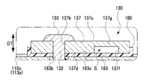
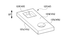
正極外部端子137は、金属からなり、矩形平板状をなしている(図3、図6、及び図7参照)。この正極外部端子137は、その厚み方向DTに貫通する円筒形状の貫通孔137bを有する。さらに、正極外部端子137は、正極外部端子137の裏面137d側(図3及び図6において下方、図7において上方)に開口する端子凹部137fを有する。この端子凹部137fは、平面視矩形状の開口を有し、絶縁部183の表面183cから遠ざかる方向(図3及び図6において上方)に凹む形態を有する。なお、図7は、実施例1にかかる外部端子(正極端子部材130及び負極端子部材140)の斜視図である。
The positive electrode
このような正極外部端子137は、電池ケース蓋113上(電池ケース110の外部)に位置し、電池ケース110の外部において正極接続部材135と電気的に接続している。具体的には、正極接続部材135の加締め部133が、正極外部端子137の表面137cに密着することで、正極外部端子137に電気的に接続している(図3参照)。詳細には、正極外部端子137の貫通孔137bから外部に(上方に)突出した円柱状の加締め部133が、電池ケース110の外部において加締められて円盤状に変形して(拡径するように押し潰されて)、正極外部端子137の表面137cに密着することで、正極外部端子137に電気的に接続している。
Such positive electrode
負極端子部材140は、負極接続部材145と負極外部端子147とにより構成されている。このうち、負極接続部材145は、金属からなり、電極体150の負極板156に接続すると共に、電池ケース蓋113の貫通孔113hを通じて外部に延出している。
The negative
負極外部端子147は、金属からなり、矩形平板状をなしている(図4、図6、及び図7参照)。この負極外部端子147は、その厚み方向DTに貫通する円筒形状の貫通孔147bを有する。さらに、負極外部端子147は、負極外部端子147の裏面147d側(図4及び図6において下方、図7において上方)に開口する端子凹部147fを有する。この端子凹部147fは、平面視矩形状の開口を有し、絶縁部183の表面183cから遠ざかる方向(図4及び図6において上方)に凹む形態を有する。
The negative
この負極外部端子147は、電池ケース蓋113上(電池ケース110の外部)に位置し、電池ケース110の外部において負極接続部材145と電気的に接続している。具体的には、負極接続部材145の加締め部143が、負極外部端子147の表面147cに密着することで、負極外部端子147に電気的に接続している(図4参照)。詳細には、負極外部端子147の貫通孔147bから外部に(上方に)突出した円柱状の加締め部133が、電池ケース110の外部において加締められて円盤状に変形して(拡径するように押し潰されて)、負極外部端子147の表面147cに密着することで、負極外部端子147に電気的に接続している。
The negative electrode
さらに、セル100は、電気絶縁性を有する樹脂からなり、電池ケース蓋113上に配置された第1インシュレータ180を2つ備えている。一方の第1インシュレータ180は、電池ケース110の表面110c(詳細には、電池ケース蓋113の表面113p)と正極外部端子137の裏面137dとの間に介在して、両者を電気的に絶縁する絶縁部183を有する(図3参照)。他方の第1インシュレータ180は、電池ケース110の表面110c(詳細には、電池ケース蓋113の表面113p)と負極外部端子147の裏面147dとの間に介在して、両者を電気的に絶縁する絶縁部183を有する(図4参照)。絶縁部183には、これを貫通する貫通孔183bが形成されており、この貫通孔183b内には、正極端子部材130の挿通部132(負極端子部材140の挿通部142)が挿通している。
Furthermore, the
さらに、セル100は、負極端子部材140の負極接続部材145と電池ケース蓋113の裏面と間に介在して、両者を電気的に絶縁する第2インシュレータ170を備えている(図2及び図5参照)。さらに、セル100では、正極端子部材130の正極接続部材135と電池ケース蓋113の裏面との間にも、第2インシュレータ170が配置されている。
Furthermore, the
さらに、本実施例1の組電池1は、外部端子(正極外部端子137または負極外部端子147)とバスバ30とが溶接された溶接部40を有する(図1及び図6参照)。具体的には、バスバ30のうち列置方向DL(図1及び図6において左右方向)について一方側に位置する部位とセル100の外部端子(例えば、正極外部端子137)とが溶接された溶接部40、及び、バスバ30のうち列置方向DLについて他方側に位置する部位とセル100の外部端子(例えば、負極外部端子147)とが溶接された溶接部40を有する。これらの溶接部40は、バスバ30の表面30cから外部端子(正極外部端子137または負極外部端子147)の裏面137d,147d側に向かって、外部端子(正極外部端子137または負極外部端子147)の厚み方向DT(図6において上下方向)に延びる形態を有する。
Furthermore, the assembled
ところで、本実施例1の組電池1では、前述したように、外部端子(正極外部端子137または負極外部端子147)は、その裏面137d,147d側(図3、図4、及び図6において下方)に開口して、絶縁部183の表面183cから遠ざかる方向(図3、図4、及び図6において上方)に凹む形態の端子凹部137f,147fを有する。さらに、本実施例1の組電池1(セル100)では、端子凹部137f,147fの開口が、絶縁部183の表面183cによって閉塞されることによって、空間部S(閉塞空間部)が形成されている(図3、図4、及び図6参照)。
By the way, in the assembled
そして、本実施例1の組電池1では、前述の溶接部40が、図6に示すように、外部端子(正極外部端子137または負極外部端子147)の厚み方向DT(図6において上下方向)について、絶縁部183との間に空間部Sを挟んで、絶縁部183と離間している。換言すれば、外部端子(正極外部端子137または負極外部端子147)の厚み方向DTについて、溶接部40と絶縁部183との間に、空間部Sが介在している。なお、外部端子(正極外部端子137または負極外部端子147)の厚み方向DTとは、外部端子(正極外部端子137または負極外部端子147)の表面137c,147cから裏面137d,147dに(または裏面137d,147dから表面137c,147cに)真っ直ぐ向かう方向であって、表面137c,147cまたは裏面137d,147dに直交する方向である。
In the assembled
このような組電池1は、「外部端子(正極外部端子137または負極外部端子147)とバスバ30の溶接によって生じた熱の影響で、絶縁部183の電気絶縁性が低下すること」が低減されており、電池ケース110と外部端子(正極外部端子137または負極外部端子147)との間の電気的絶縁が確保された組電池となっている。
In such a
具体的には、外部端子(正極外部端子137または負極外部端子147)とバスバ30を溶接する工程(後述するレーザ溶接工程、ステップS4)において、バスバ30の一部(溶接部40となる部位)と外部端子(正極外部端子137または負極外部端子147)の一部(溶接部40となる部位)を溶融させたとき、外部端子(正極外部端子137または負極外部端子147)の厚み方向DTについて、溶融金属部41(バスバ30または外部端子が溶融した溶融金属部41)と絶縁部183との間に、空間部Sが介在しているので、溶融金属部41の熱が絶縁部183に伝わり難くなる(図11参照)。これにより、「溶接によって生じる熱の影響で、絶縁部183の電気絶縁性が低下すること」を低減することができ、電池ケース110と外部端子(正極外部端子137または負極外部端子147)との間の電気的絶縁を確保することができる。
Specifically, in the step of welding the external terminal (positive electrode
また、本実施例1の組電池1では、外部端子(正極外部端子137または負極外部端子147)が、その厚み方向DT(図3、図4、及び図6において上下方向)について、絶縁部183との間に空間部Sを挟んで絶縁部183と離間する部位(この部位を離間部137gまたは147gとする)を有する(図3、図4、及び図6参照)。また、バスバ30が、外部端子(正極外部端子137または負極外部端子147)の厚み方向DTについて、離間部137gまたは147gを間に挟んで空間部Sと対向する部位(この部位を対向部30gとする)を有する(図6及び図9参照)。
In addition, in the assembled
さらに、溶接部40が、バスバ30の対向部30gの表面(図6及び図11において上面)から外部端子(正極外部端子137または負極外部端子147)の離間部137gまたは147gの裏面(図6及び図11において下面)にまで延びる形態で、対向部30gと離間部137gまたは147gとが溶接された溶接部40となっている。このような組電池1は、溶接部40内のボイドが低減された組電池となる。従って、本実施例1の組電池1は、溶接部40の強度が高く、溶接部40の導電性が高い(従って、バスバ30と正極外部端子137との接続抵抗が小さく、且つ、バスバ30と負極外部端子147との接続抵抗が小さい)組電池となる。
Further, the welded
具体的には、バスバ30の対向部30gの表面(図6及び図11において上面)から外部端子(正極外部端子137または負極外部端子147)の離間部137gまたは147gの裏面(図6及び図11において下面)にまで延びる形態を有する溶接部40は、後述するように、レーザビームLBの照射により溶融した溶融金属部41(バスバ30の対向部30gを構成する金属または外部端子の離間部137g,147gを構成する金属が溶融した部位)が、バスバ30の表面30c(対向部30gの表面)から空間部Sにまで達する態様の貫通レーザ溶接を行うことによって形成することができる(図6及び図11参照)。
Specifically, from the surface (upper surface in FIGS. 6 and 11) of the facing
このような貫通レーザ溶接を行って、溶融金属部41を空間部Sにまで達するようにすることで、溶融金属部41に含まれるガス(気泡)の少なくとも一部を、空間部Sへ排出することができる。これにより、溶接部40内に生じるボイド(気泡によって形成される微小な空隙部)を減少させることができるので、溶接部40の強度を高めることができると共に、溶接部40の導電性を高める(従って、バスバ30と正極外部端子137との接続抵抗を小さくし、且つ、バスバ30と負極外部端子147との接続抵抗を小さくする)ことができる。
By performing such penetration laser welding so that the
しかも、空間部Sは、前述したように閉塞空間部であるため、レーザ溶接により発生したスパッタなどの異物の少なくとも一部を、空間部S内に収容(収集)することもできる。これにより、外部に飛散するスパッタ等の異物の量を低減することができ、外部環境の汚染を低減することができる。 Moreover, since the space S is a closed space as described above, at least a part of foreign matter such as spatter generated by laser welding can be accommodated (collected) in the space S. As a result, the amount of foreign matter such as spatter that scatters to the outside can be reduced, and contamination of the external environment can be reduced.
次に、本実施例1にかかる組電池1の製造方法について説明する。図8は、実施例1にかかる組電池1の製造方法の流れを示すフローチャートである。まず、ステップS1(セル用意工程)において、複数のセル100(正極外部端子137及び負極外部端子147にバスバ30が溶接される前のセル100、図2参照)を用意する。
Next, a method for manufacturing the assembled
より具体的には、ステップS1(セル用意工程)において、外部端子(正極外部端子137及び負極外部端子147)の厚み方向DTについて、絶縁部183との間に空間部Sを挟んで絶縁部183と離間する離間部137g,147gを有する外部端子(正極外部端子137及び負極外部端子147)、を備えるセル100を複数用意する(図3及び図4参照)。なお、本実施例1のセル100では、空間部Sが、「正極外部端子137の端子凹部137fの開口、及び、負極外部端子147の端子凹部147fの開口が、絶縁部183の表面183cによって閉塞されることによって形成された閉塞空間部」とされている。
More specifically, in step S1 (cell preparation step), the insulating
次に、ステップS2(電池スタック作製工程、図8参照)において、用意したセル100を、所定数、列置方向DL(図1において左右方向)に一列に列置して、電池スタック20を作製する。但し、本実施例1では、列置方向DLに隣り合うセル100の正極外部端子137と負極外部端子147とが列置方向DLに隣り合うように、列置方向DLに隣り合うセル100の向きを交互に代えて、複数のセル100を列置方向DLに一列に列置して、電池スタック20を作製している(図1参照)。
Next, in step S2 (battery stack manufacturing step, see FIG. 8), a predetermined number of the
さらに、この電池スタック20を、収容ケース10の収容部10b内に収容する。なお、本実施例1では、列置方向DLに隣り合うセル100の間に、冷却板を介在させている。また、電池スタック20の列置方向DLの両端部に、プレートを配置している。また、収容ケース10には、2つの収容部10bが設けられている。従って、本実施例1では、各々の収容部10b内に、電池スタック20(列置方向DLに一列に列置された複数のセル100)を収容する(図1参照)。
Furthermore, this
その後、ステップS3(載置工程、図8参照)において、図9に示すように、各々の電池スタック20について、列置方向DLに隣り合うセル100の列置方向DLに隣り合う外部端子の表面上(正極外部端子137の表面137c上、及び、負極外部端子147の表面147c上)に、バスバ30を載置する。より具体的には、バスバ30のうち列置方向DLの一方側(図9において左側)に位置する部位を、列置方向DLに隣り合う2つのセル100のうち、一方側のセル100の外部端子の表面上(図9に示す例では、正極外部端子137の表面137c上)に載置すると共に、バスバ30のうち列置方向DLの他方側(図9において右側)に位置する部位を、他方側のセル100の外部端子の表面上(図9に示す例では、負極外部端子147の表面147c上)に載置する。
Thereafter, in step S3 (placing step, see FIG. 8), as shown in FIG. 9, for each
但し、ステップS3(載置工程)では、バスバ30の一部(列置方向DLについて両端側に位置する部位)が、外部端子(正極外部端子137及び負極外部端子147)の厚み方向DT(図9において上下方向)について、外部端子の離間部137g,147gを間に挟んで空間部Sと対向する対向部30gとなるように、正極外部端子137の表面137c上、及び、負極外部端子147の表面147c上に、バスバ30を載置する。なお、図9は、図6に示す2つのセル100(図1のA-Aの位置で切断した2つのセル100)について、ステップS3(載置工程)を行ったときの状態を示す断面図である。
However, in step S3 (placing step), a part of the bus bar 30 (portions located on both end sides with respect to the arrangement direction DL) of the external terminals (positive
その後、ステップS4(レーザ溶接工程)において、バスバ30の対向部30gと外部端子(正極外部端子137及び負極外部端子147)の離間部137g,147gをレーザ溶接する(図10参照)。より具体的には、バスバ30のうち列置方向DLの一方側(図10において左側)に位置する対向部30gを、列置方向DLに隣り合う2つのセル100のうち、一方側のセル100の外部端子の離間部(図10に示す例では、正極外部端子137の離間部137g)に溶接し、バスバ30のうち列置方向DLの他方側(図10において右側)に位置する対向部30gを、他方側のセル100の外部端子の離間部(図10に示す例では、負極外部端子147の離間部147g)に溶接する。
Then, in step S4 (laser welding process), the opposing
このステップS4(レーザ溶接工程)では、バスバ30(対向部30g)の表面30c側(図10においてバスバ30の上方)から空間部Sに向かって、外部端子(正極外部端子137及び負極外部端子147)の厚み方向DT(図10において下方)にレーザビームLBを照射することによって、バスバ30の対向部30gと外部端子(正極外部端子137及び負極外部端子147)の離間部137g,147gを溶融させて、離間部137g,147gと対向部30gとが溶接された溶接部40を形成する(図6、図10、及び図11参照)。
In this step S4 (laser welding process), the external terminals (positive
具体的には、溶接部40として、バスバ30の表面30cから外部端子の裏面側(正極外部端子137の裏面137d側、または、負極外部端子147の裏面147d側)に向かって、外部端子(正極外部端子137及び負極外部端子147)の厚み方向DTに延びる形態を有し、外部端子の厚み方向DTについて、絶縁部183との間に空間部Sを挟んで絶縁部183と離間する態様(換言すれば、外部端子の厚み方向DTについて、溶接部40と絶縁部183との間に空間部Sが介在する態様)の溶接部を形成する(図6及び図11参照)。なお、図10及び図11は、図6に示す2つのセル100(図1のA-Aの位置で切断した2つのセル100)について、ステップS4(レーザ溶接工程)を行っているときの状態を示す断面図である。
Specifically, as the welded
このようなステップS4(レーザ溶接工程)を行うことで、レーザ溶接により外部端子(正極外部端子137及び負極外部端子147)等に生じた熱が、樹脂からなる絶縁部183に伝わり難くなる。具体的には、ステップS4(レーザ溶接工程)において、外部端子(正極外部端子137及び負極外部端子147)の厚み方向DTについて、レーザビームLBの照射により溶融した溶融金属部41(バスバ30の対向部30gまたは外部端子の離間部137g,147gが溶融した溶融金属部41)と絶縁部183との間に、空間部Sが介在しているので、溶融金属部41の熱が絶縁部183に伝わり難くなる(図11参照)。これにより、「レーザ溶接によって生じる熱の影響で、絶縁部183の電気絶縁性が低下すること」を低減することができ、電池ケース110と外部端子(正極外部端子137及び負極外部端子147)との間の電気的絶縁を確保することができる。
By performing such step S4 (laser welding process), the heat generated in the external terminals (the positive electrode
なお、レーザ溶接によって生じる熱の影響で絶縁部183の電気絶縁性が低下する具体例としては、例えば、レーザ溶接によって生じた熱によって絶縁部183が変形することで、絶縁部183の一部の厚みが薄くなり(あるいは、絶縁部183の一部に孔が空き)、絶縁部183の電気絶縁性が低下する場合を挙げることができる。また、レーザ溶接によって生じた熱を絶縁部183が受けることによって、絶縁部183の一部が炭化して、炭化した部位の電気抵抗率が低下する(電気伝導率が上昇する)ことによって、絶縁部183の電気絶縁性が低下する場合もある。
As a specific example of the deterioration of the electrical insulation of the insulating
但し、本実施例1のステップS4(レーザ溶接工程)では、レーザ溶接として、図11に示すように、レーザビームLBの照射により溶融した溶融金属部41(バスバ30の対向部30gを構成する金属または外部端子の離間部137g,147gを構成する金属が溶融した部位)が、バスバ30の表面30c(対向部30gの表面)から空間部Sにまで達する態様の貫通レーザ溶接を行う。これにより、溶接部40として、バスバ30の対向部30gの表面(図6及び図11において上面)から外部端子(正極外部端子137または負極外部端子147)の離間部137gまたは147gの裏面(図6及び図11において下面)にまで延びる形態の溶接部40を形成する(図6及び図11参照)。
However, in step S4 (laser welding process) of the first embodiment, as shown in FIG. Alternatively, through laser welding is performed in such a manner that the melted portion of the metal forming the separated
このような貫通レーザ溶接を行って、溶融金属部41を空間部Sにまで達するようにすることで、溶融金属部41に含まれるガス(気泡)の少なくとも一部を、空間部Sへ排出することができる。これにより、溶接部40内に生じるボイドを減少させることができるので、溶接部40の強度を高めることができると共に、溶接部40の導電性を高める(従って、バスバ30と正極外部端子137との接続抵抗を小さくし、且つ、バスバ30と負極外部端子147との接続抵抗を小さくする)ことができる。
By performing such penetration laser welding so that the
しかも、本実施例1では、前述したように、空間部Sが、「正極外部端子137の端子凹部137fの開口、及び、負極外部端子147の端子凹部147fの開口が、絶縁部183の表面183cによって閉塞されることによって形成された閉塞空間部」となっている(図11参照)。このため、レーザ溶接により発生したスパッタなどの異物の少なくとも一部を、空間部S内に収容(収集)することができる。これにより、ステップS4(レーザ溶接工程)において、外部に飛散するスパッタ等の異物の量を低減することができ、外部環境の汚染を低減することができる。
Moreover, in the
以上のようにして、列置方向DLに隣り合うセル100の外部端子(正極外部端子137と負極外部端子147)に、バスバ30を溶接することで、列置方向DLに隣り合うセル100を、バスバ30を通じて電気的に直列に接続する。これにより、電池スタック20を構成する複数のセル100が電気的に直列に接続されて、本実施例1の組電池1が製造される。
As described above, by welding the
(実施例2)
実施例2の組電池301は、実施例1の組電池1と比較して、セルの外部端子(正極外部端子と負極外部端子)の形状、及び、バスバの形状が異なり、その他については同様である。従って、ここでは、実施例1と異なる点を中心に説明し、同様な点については説明を省略または簡略化する。
(Example 2)
The assembled
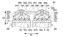
実施例2の組電池301を構成するセル200は、実施例1のセル100と比較して、外部端子(正極外部端子と負極外部端子)のみが異なり、その他は同等である。具体的には、本実施例2の正極外部端子237は、その表面237c側(バスバ330が配置される側、図12及び図13において上側)に突出する形態の端子突出部237hを有する。さらに、端子突出部237hの裏側(図12及び図13において下側)に、正極外部端子237の裏面237d側(図12及び図13において下方)に開口する端子凹部237fを有する。この端子凹部237fは、正極外部端子237の裏面237dから表面237c側に凹む形態を有する。端子突出部237h及び端子凹部237fは、略半球面状をなしている。
The
なお、図12は、図1のA-A断面拡大図であって、実施例2の組電池301についてのA-A断面拡大図である。また、図13は、実施例2にかかるセル200の拡大断面図であって、図2のB部拡大図に相当する図である。図14は、実施例2にかかるセル200の拡大断面図であって、図2のC部拡大図に相当する図である。
FIG. 12 is an enlarged cross-sectional view taken along line AA of FIG. 1, and is an enlarged view of cross section AA of the assembled
本実施例2では、正極外部端子237の端子突出部237hは、矩形平板状の正極外部端子(基材)をプレス加工することによって成形している。しかも、矩形平板状の正極外部端子(基材)をプレス加工したとき、表面237c側に突出する形態の端子突出部237hが成形されると同時に、裏面237d側に開口する(裏面237dから表面237c側に凹む形態の)端子凹部237fが成形される。
In Example 2, the
本実施例2の組電池301(セル200)では、端子凹部237fの開口が、絶縁部183の表面183cによって閉塞されることによって、空間部S(閉塞空間部)が形成されている(図12及び図13参照)。また、正極外部端子237の端子突出部237hは、正極外部端子237の厚み方向DT(図12及び図13において上下方向)について、絶縁部183との間に空間部Sを挟んで絶縁部183と離間する離間部237gの一部(表面部)となる。
In the assembled battery 301 (cell 200) of the second embodiment, the opening of the
本実施例2の負極外部端子247は、上述した正極外部端子237と同等の形状を有している。具体的には、負極外部端子247は、表面247c側(バスバ330が配置される側、図12及び図14において上側)に突出する形態の端子突出部247hと、この端子突出部237hの裏側(図12及び図14において下側)に位置する端子凹部247fとを有する。負極外部端子247の端子突出部247h及び端子凹部247fについても、正極外部端子237と同様に、プレス加工によって成形している。
The negative
本実施例2の組電池301(セル200)では、端子凹部247fの開口が、絶縁部183の表面183cによって閉塞されることによって、空間部S(閉塞空間部)が形成されている(図12及び図14参照)。また、負極外部端子247の端子突出部247hは、負極外部端子247の厚み方向DT(図12及び図14において上下方向)について、絶縁部183との間に空間部Sを挟んで絶縁部183と離間する離間部247gの一部(表面部)となる。
In the assembled battery 301 (cell 200) of the second embodiment, the opening of the
また、本実施例2のバスバ330は、正極外部端子237の端子突出部237hが嵌合する凹形状のバスバ凹部330fと、負極外部端子247の端子突出部247hが嵌合する凹形状のバスバ凹部330fを有する(図12参照)。このバスバ凹部330fは、バスバ330の裏面330d側に開口する凹部であって、バスバ330の裏面330dから表面330c側に凹む形態を有する。さらに、バスバ330は、バスバ凹部330fの表側(図12において上側)に突出する形態のバスバ突出部330hを有する。バスバ凹部330f及びバスバ突出部330hは、略半球面状をなしている。
The
本実施例2では、バスバ凹部330fも、矩形平板状のバスバ330(基材)をプレス加工することによって成形している。なお、矩形平板状のバスバ330(基材)をプレス加工したとき、上述のバスバ凹部330fが成形されると同時に、上述のバスバ突出部330hが成形される。本実施例2では、バスバ330のバスバ凹部330f及びバスバ突出部330hが、対向部330gの一部となる。より具体的には、バスバ凹部330fが、対向部330gの裏面側の部位となり、バスバ突出部330hが、対向部330gの表面側の部位となる(図12及び図15参照)。なお、対向部330gは、バスバ330のうち、外部端子(正極外部端子237または負極外部端子247)の厚み方向DTについて、離間部237gまたは247gを間に挟んで空間部Sと対向する部位である。
In the second embodiment, the busbar
さらに、本実施例2の組電池301では、図12に示すように、正極外部端子237の端子突出部237h及び負極外部端子247の端子突出部247hが、バスバ330のバスバ凹部330fに嵌合した状態で、外部端子(正極外部端子237及び負極外部端子247)とバスバ330とが溶接されている。
Furthermore, in the assembled
外部端子(正極外部端子237及び負極外部端子247)にバスバ330を溶接するときに、正極外部端子237の端子突出部237h及び負極外部端子247の端子突出部247hが、バスバ330のバスバ凹部330fに嵌合した状態にしておくことで、外部端子(正極外部端子237及び負極外部端子247)に対するバスバ330の位置ズレを防止することができる。従って、本実施例2の組電池301は、外部端子(正極外部端子237及び負極外部端子247)に対するバスバ330の位置が適切な位置に保持された状態で、外部端子(正極外部端子237及び負極外部端子247)にバスバ330が溶接された組電池となる。
When the
次に、本実施例2にかかる組電池301の製造方法について説明する。図8は、実施例2にかかる組電池301の製造方法の流れを示すフローチャートである。まず、ステップT1(セル用意工程)において、複数のセル200(正極外部端子237及び負極外部端子247にバスバ330が溶接される前のセル200)を用意する。
Next, a method for manufacturing the assembled
次に、ステップT2(電池スタック作製工程、図8参照)において、用意したセル200を、所定数、列置方向DL(図1において左右方向)に一列に列置して、電池スタック320を作製する。但し、本実施例2でも、本実施例1と同様に、列置方向DLに隣り合うセル200の正極外部端子237と負極外部端子247とが列置方向DLに隣り合うように、列置方向DLに隣り合うセル200の向きを交互に代えて、複数のセル200を列置方向DLに一列に列置して、電池スタック320を作製する(図1参照)。
Next, in step T2 (battery stack manufacturing step, see FIG. 8), a predetermined number of the
さらに、電池スタック320を、収容ケース10の収容部10b内に収容する(図1参照)。なお、本実施例2でも、実施例1と同様に、列置方向DLに隣り合うセル200の間に、冷却板を介在させている。また、電池スタック320の列置方向DLの両端部に、プレートを配置している。
Furthermore, the
その後、ステップT3(載置工程、図8参照)において、図15に示すように、各々の電池スタック320について、列置方向DLに隣り合うセル200の列置方向DLに隣り合う外部端子の表面上(正極外部端子237の表面237c上、及び、負極外部端子247の表面247c上)に、バスバ330を載置する。より具体的には、バスバ330のうち列置方向DLの一方側(図15において左側)に位置する部位を、列置方向DLに隣り合う2つのセル200のうち、一方側のセル200の外部端子の表面上(図15に示す例では、正極外部端子237の表面237c上)に載置すると共に、バスバ330のうち列置方向DLの他方側(図15において右側)に位置する部位を、他方側のセル200の外部端子の表面上(図15に示す例では、負極外部端子247の表面247c上)に載置する。なお、図15は、図12に示す2つのセル200(図1のA-Aの位置で切断した2つのセル200)について、ステップS3(載置工程)を行ったときの状態を示す断面図である。
Thereafter, in step T3 (mounting step, see FIG. 8), as shown in FIG. The
但し、本実施例2では、外部端子の端子突出部(正極外部端子237の端子突出部237h及び負極外部端子247の端子突出部247h)を、バスバ330のバスバ凹部330fに嵌合させつつ、外部端子の表面上(正極外部端子237の表面237c上、及び、負極外部端子247の表面247c上)にバスバ330を載置する。このとき、バスバ330のバスバ凹部330f及びバスバ突出部330hが、前述した対向部330gの一部となる。より具体的には、バスバ凹部330fが、対向部330gの裏面側の部位となり、バスバ突出部330hが、対向部330gの表面側の部位となる(図15参照)。
However, in the second embodiment, the terminal projecting portions of the external terminals (the
このように、外部端子の端子突出部(正極外部端子237の端子突出部237h及び負極外部端子247の端子突出部247h)を、バスバ330のバスバ凹部330fに嵌合させることで、バスバ330のバスバ凹部330f及びバスバ突出部330hを、対向部330gにすることができる。このため、後のステップS4(レーザ溶接工程)において、バスバ突出部330hに向けてレーザビームを照射することで、適切に、バスバ330の対向部330gと外部端子(正極外部端子237及び負極外部端子247)の離間部237g,247gを溶接することができる。
By fitting the terminal projecting portions of the external terminals (the
また、外部端子の端子突出部(正極外部端子237の端子突出部237h及び負極外部端子247の端子突出部247h)を、バスバ330のバスバ凹部330fに嵌合させることで、外部端子(正極外部端子237及び負極外部端子247)に対するバスバ330の位置ズレを防止することができる。本実施例2では、外部端子の端子突出部(正極外部端子237の端子突出部237h及び負極外部端子247の端子突出部247h)を離間部237g,247gの一部とし、バスバ凹部330fが対向部330gの一部としているので、離間部237g,247gに対する対向部330gの位置ズレを防止することができる。
In addition, by fitting the terminal projecting portions of the external terminals (the
その後、ステップT4(レーザ溶接工程)において、バスバ330の対向部330gと外部端子(正極外部端子237及び負極外部端子247)の離間部237g,247gをレーザ溶接する(図16参照)。本実施例2では、バスバ330(対向部330g)の表面330c側(図16においてバスバ330の上方)から外部端子の端子突出部(正極外部端子237の端子突出部237h及び負極外部端子247の端子突出部247h)に向けて、外部端子(正極外部端子237及び負極外部端子247)の厚み方向DT(図16において下方)にレーザビームLBを照射する。これにより、バスバ330の対向部330gと外部端子(正極外部端子237及び負極外部端子247)の離間部237g,247gを溶融させて、離間部237g,247gと対向部330gとが溶接された溶接部340を形成する(図12及び図17参照)。
Then, in step T4 (laser welding process), the opposing
具体的には、溶接部340として、バスバ330の表面330cから外部端子の裏面側(正極外部端子237の裏面237d側、または、負極外部端子247の裏面247d側)に向かって、外部端子(正極外部端子237及び負極外部端子247)の厚み方向DTに延びる形態を有し、外部端子の厚み方向DTについて、絶縁部183との間に空間部Sを挟んで絶縁部183と離間する態様(換言すれば、外部端子の厚み方向DTについて、溶接部340と絶縁部183との間に空間部Sが介在する態様)の溶接部を形成する(図12及び図17参照)。なお、図16及び図17は、図12に示す2つのセル100(図1のA-Aの位置で切断した2つのセル100)について、ステップS4(レーザ溶接工程)を行っているときの状態を示す断面図である。
Specifically, as the welded
このようなステップT4(レーザ溶接工程)を行うことで、レーザ溶接により外部端子(正極外部端子237及び負極外部端子247)等に生じた熱が、樹脂からなる絶縁部183に伝わり難くなる。具体的には、ステップT4(レーザ溶接工程)において、外部端子(正極外部端子237及び負極外部端子247)の厚み方向DTについて、レーザビームLBの照射により溶融した溶融金属部341(バスバ330の対向部330gまたは外部端子の離間部237g,247gが溶融した溶融金属部341)と絶縁部183との間に、空間部Sが介在しているので、溶融金属部341の熱が絶縁部183に伝わり難くなる(図17参照)。これにより、レーザ溶接によって生じる熱の影響で絶縁部183の電気絶縁性が低下することを低減することができ、電池ケース110と外部端子(正極外部端子237及び負極外部端子247)との間の電気的絶縁を確保することができる。
By performing such step T4 (laser welding process), the heat generated in the external terminals (the positive electrode
なお、本実施例2でも、実施例1と同様に、レーザ溶接として、図17に示すように、レーザビームLBの照射により溶融した溶融金属部341(バスバ330の対向部330gを構成する金属または外部端子の離間部237g,247gを構成する金属が溶融した部位)が、バスバ330の表面330c(対向部330gの表面)から空間部Sにまで達する態様の貫通レーザ溶接を行う。これにより、溶接部340として、バスバ330の対向部330gの表面(図12及び図17において上面)から外部端子(正極外部端子237または負極外部端子247)の離間部237gまたは247gの裏面(図12及び図17において下面)にまで延びる形態の溶接部340を形成する(図12及び図17参照)。
In the second embodiment, as in the first embodiment, as shown in FIG. 17, as laser welding, a molten metal portion 341 (a metal or metal forming the facing
このような貫通レーザ溶接を行って、溶融金属部341を空間部Sにまで達するようにすることで、溶融金属部341に含まれるガス(気泡)の少なくとも一部を、空間部Sへ排出することができる。これにより、溶接部340内に生じるボイドを減少させることができるので、溶接部340の強度を高めることができると共に、溶接部340の導電性を高める(従って、バスバ330と正極外部端子237との接続抵抗を小さくし、且つ、バスバ330と負極外部端子247との接続抵抗を小さくする)ことができる。
By performing such penetration laser welding so that the
しかも、本実施例2でも、実施例1と同様に、空間部Sが、「正極外部端子237の端子凹部237fの開口、及び、負極外部端子247の端子凹部247fの開口が、絶縁部183の表面183cによって閉塞されることによって形成された閉塞空間部」とされている(図17参照)。このため、レーザ溶接により発生したスパッタなどの異物の少なくとも一部を、空間部S内に収容(収集)することができる。これにより、ステップT4(レーザ溶接工程)において、外部に飛散するスパッタ等の異物の量を低減することができ、外部環境の汚染を低減することができる。
Moreover, in the second embodiment, as in the first embodiment, the space S is such that the opening of the
以上のようにして、列置方向DLに隣り合うセル200の外部端子(正極外部端子237と負極外部端子247)に、バスバ330を溶接することで、列置方向DLに隣り合うセル200を、バスバ330を通じて電気的に直列に接続する。これにより、電池スタック320を構成する複数のセル200が電気的に直列に接続されて、本実施例2の組電池301(図1参照)が製造される。
As described above, by welding the
なお、本実施例2では、前述したように、ステップT3(載置工程)において、外部端子の端子突出部(正極外部端子237の端子突出部237h及び負極外部端子247の端子突出部247h)を、バスバ330のバスバ凹部330fに嵌合させるようにして、外部端子の表面上(正極外部端子237の表面237c上、及び、負極外部端子247の表面247c上)にバスバ330を載置する。このため、図18に示すように、列置方向DLに隣り合う2つのセル200の外部端子(正極外部端子237と負極外部端子247)の高さが異なっている場合でも、外部端子(正極外部端子237または負極外部端子247)とバスバ330との接触面積を大きく確保することができる。これにより、バスバ30と外部端子(正極外部端子237または負極外部端子247)との接続抵抗を小さくすることができる。
In the second embodiment, as described above, in step T3 (placing step), the terminal projecting portions of the external terminals (the
以上において、本発明を実施例1,2に即して説明したが、本発明は上記実施例に限定されるものではなく、その要旨を逸脱しない範囲で、適宜変更して適用できることはいうまでもない。 In the above, the present invention has been described with reference to Examples 1 and 2, but the present invention is not limited to the above-described examples, and it goes without saying that the present invention can be appropriately modified and applied without departing from the gist of the present invention. Nor.
例えば、実施例1では、空間部Sを、閉塞空間部としたが、開放空間部(例えば、正極外部端子137の端子凹部137fの開口、及び、負極外部端子147の端子凹部147fの開口が、絶縁部183の表面183cによって閉塞されることなく、開放された空間)としても良い。実施例2においても同様である。
For example, in Example 1, the space S was a closed space, but the open space (for example, the opening of the
また、実施例1では、正極外部端子137に端子凹部137fを設けると共に、負極外部端子147に端子凹部147fを設け、平板状の絶縁部183の表面183cによって、端子凹部137fの開口及び端子凹部147fの開口を閉塞することで、空間部Sを形成した。しかしながら、絶縁部に凹部を設け、平板状の正極外部端子の裏面及び平板状の負極外部端子の裏面によって、絶縁部の凹部の開口を閉塞することで、空間部を形成するようにしても良い。
In addition, in Example 1, the positive electrode
1,301 組電池
20,320 電池スタック
30,330 バスバ
30c,330c 表面
30g,330g 対向部
40,340 溶接部
41,341 溶融金属部
100,200 セル
110 電池ケース
110c 表面
130,230 正極端子部材(電極端子部材)
137,237 正極外部端子(外部端子)
137c,237c 表面
137d,237d 裏面
137f,237f 端子凹部
137g,237g 離間部
237h,247h 端子突出部
140,240 負極端子部材(電極端子部材)
147,247 負極外部端子(外部端子)
147c,247c 表面
147d,247d 裏面
147f,247f 端子凹部
147g,247g 離間部
180 第1インシュレータ
183 絶縁部
183c 表面
330f バスバ凹部
DT 厚み方向
DL 列置方向
LB レーザビーム
S 空間部
S1,T1 セル用意工程
S3,T3 載置工程
S4,T4 レーザ溶接工程
1,301 assembled battery 20,320 battery stack 30,330
137, 237 positive external terminal (external terminal)
137c, 237c
147, 247 Negative external terminal (external terminal)
147c, 247c
Claims (6)
前記外部端子の表面上に配置され、前記外部端子に溶接された金属製で板状のバスバと、を備える
組電池の製造方法において、
前記セルは、
金属製の電池ケースと、
前記電池ケースの外部に位置する金属製で板状の前記外部端子と、
電気絶縁性を有する樹脂からなり、前記電池ケースの表面と前記外部端子の裏面との間に介在して両者を電気的に絶縁する絶縁部と、を有し、
前記組電池は、
前記外部端子と前記バスバとが溶接された溶接部であって、前記バスバの表面から前記外部端子の前記裏面側に向かって、前記外部端子の厚み方向に延びる形態の溶接部を有し、
前記溶接部は、前記外部端子の前記厚み方向について、前記絶縁部との間に空間部を挟んで、前記絶縁部と離間している
組電池の製造方法であって、
前記外部端子の前記厚み方向について、前記絶縁部との間に前記空間部を挟んで前記絶縁部と離間する部位である離間部を有する前記外部端子、を備える前記セルを複数用意する、セル用意工程と、
前記バスバの一部が、前記外部端子の前記厚み方向について、前記外部端子の前記離間部を間に挟んで前記空間部と対向する部位である対向部となるように、用意した前記セルの前記外部端子の前記表面上に前記バスバを載置する載置工程と、
前記バスバの前記対向部と前記外部端子の前記離間部をレーザ溶接する、レーザ溶接工程と、を備え、
前記レーザ溶接工程は、
前記バスバの前記表面側から前記空間部に向かって、前記外部端子の前記厚み方向にレーザビームを照射することによって、前記バスバの前記対向部と前記外部端子の前記離間部を溶融させて、前記離間部と前記対向部とが溶接された前記溶接部を形成する
組電池の製造方法であって、
前記レーザ溶接工程では、前記レーザビームの照射により溶融した溶融金属部が、前記バスバの前記表面から前記空間部にまで達する態様の貫通レーザ溶接を行って、前記バスバの前記対向部の表面から前記外部端子の前記離間部の裏面にまで延びる形態の前記溶接部を形成する
組電池の製造方法。 a plurality of cells having external terminals;
A method for manufacturing an assembled battery comprising: a metal plate-shaped bus bar arranged on the surface of the external terminal and welded to the external terminal;
The cell is
metal battery case,
the metal plate-shaped external terminal located outside the battery case;
an insulating part made of an electrically insulating resin and interposed between the surface of the battery case and the back surface of the external terminal to electrically insulate them;
The assembled battery is
a weld portion where the external terminal and the bus bar are welded together, the weld portion extending in the thickness direction of the external terminal from the surface of the bus bar toward the back surface of the external terminal;
A method for manufacturing an assembled battery in which the welded portion is separated from the insulating portion with a space interposed therebetween in the thickness direction of the external terminal,
preparing a plurality of the cells each including the external terminal having a separation portion which is a portion separated from the insulating portion with the space portion interposed therebetween in the thickness direction of the external terminal; process and
A portion of the bus bar of the prepared cell is formed so as to form a facing portion, which is a portion facing the space portion with the spacing portion of the external terminal interposed therebetween, in the thickness direction of the external terminal. a placing step of placing the bus bar on the surface of the external terminal;
a laser welding step of laser welding the facing portion of the bus bar and the spaced portion of the external terminal;
The laser welding process includes
By irradiating a laser beam in the thickness direction of the external terminal from the surface side of the bus bar toward the space, the facing portion of the bus bar and the spaced portion of the external terminal are melted, and the forming the welded portion in which the spaced portion and the facing portion are welded together;
A method for manufacturing an assembled battery,
In the laser welding step, through laser welding is performed in such a manner that the molten metal portion melted by the irradiation of the laser beam reaches the space portion from the surface of the bus bar. The welded portion is formed so as to extend to the rear surface of the spaced portion of the external terminal.
A method for manufacturing an assembled battery.
前記外部端子は、前記外部端子の前記裏面側に開口する凹部であって、前記絶縁部の表面から遠ざかる方向に凹む形態の端子凹部を有し、
前記空間部は、前記外部端子の前記端子凹部の開口が前記絶縁部の前記表面によって閉塞された形態の閉塞空間部である
組電池の製造方法。 A method for manufacturing the assembled battery according to claim 1,
The external terminal has a terminal recess that is a recess that opens to the back surface side of the external terminal and that is recessed in a direction away from the surface of the insulating part,
The method of manufacturing an assembled battery, wherein the space portion is a closed space portion in which an opening of the terminal recess of the external terminal is closed by the surface of the insulating portion.
前記外部端子は、前記表面側に突出する形態の端子突出部を有し、
前記バスバは、前記端子突出部が嵌合する凹形状のバスバ凹部を有し、
前記載置工程では、前記端子突出部を前記バスバ凹部に嵌合させつつ、前記外部端子の前記表面上に前記バスバを載置する
組電池の製造方法。 A method for manufacturing an assembled battery according to claim 1 or 2 ,
the external terminal has a terminal projecting portion that projects toward the front surface;
The bus bar has a recessed bus bar recess into which the terminal projection is fitted,
In the mounting step, the assembled battery manufacturing method includes mounting the busbar on the surface of the external terminal while fitting the terminal projecting portion into the busbar recessed portion.
前記外部端子の表面上に配置され、前記外部端子に溶接された金属製で板状のバスバと、を備える
組電池において、
前記セルは、
金属製の電池ケースと、
前記電池ケースの外部に位置する金属製で板状の前記外部端子と、
電気絶縁性を有する樹脂からなり、前記電池ケースの表面と前記外部端子の裏面との間に介在して両者を電気的に絶縁する絶縁部と、を有し、
前記組電池は、
前記外部端子と前記バスバとが溶接された溶接部であって、前記バスバの表面から前記外部端子の前記裏面側に向かって、前記外部端子の厚み方向に延びる形態の溶接部を有し、
前記溶接部は、前記外部端子の前記厚み方向について、前記絶縁部との間に空間部を挟んで、前記絶縁部と離間している
組電池であって、
前記外部端子は、前記厚み方向について、前記絶縁部との間に前記空間部を挟んで前記絶縁部と離間する部位である離間部を有し、
前記バスバは、前記外部端子の前記厚み方向について、前記離間部を間に挟んで前記空間部と対向する部位である対向部を有し、
前記溶接部は、前記対向部と前記離間部とが溶接された前記溶接部であって、前記対向部の表面から前記離間部の裏面にまで延びる形態を有する
組電池。 a plurality of cells having external terminals;
In an assembled battery comprising: a metal plate-shaped bus bar arranged on the surface of the external terminal and welded to the external terminal,
The cell is
metal battery case,
the metal plate-shaped external terminal located outside the battery case;
an insulating part made of an electrically insulating resin and interposed between the surface of the battery case and the back surface of the external terminal to electrically insulate them;
The assembled battery is
a weld portion where the external terminal and the bus bar are welded together, the weld portion extending in the thickness direction of the external terminal from the surface of the bus bar toward the back surface of the external terminal;
The welded portion is separated from the insulating portion with a space interposed therebetween in the thickness direction of the external terminal.
an assembled battery,
The external terminal has a separation portion, which is a portion separated from the insulating portion with the space interposed therebetween in the thickness direction,
The bus bar has a facing portion that is a portion that faces the space portion with the spacing portion therebetween in the thickness direction of the external terminal,
The welded portion is the welded portion in which the opposed portion and the separated portion are welded together, and has a shape extending from the surface of the opposed portion to the back surface of the separated portion.
assembled battery.
前記外部端子は、前記外部端子の前記裏面側に開口する凹部であって、前記絶縁部の表面から遠ざかる方向に凹む形態の端子凹部を有し、
前記空間部は、前記外部端子の前記端子凹部の開口が前記絶縁部の前記表面によって閉塞された形態の閉塞空間部である
組電池。 The assembled battery according to claim 4 ,
The external terminal has a terminal recess that is a recess that opens to the back surface side of the external terminal and that is recessed in a direction away from the surface of the insulating part,
The space portion is a closed space portion in which the opening of the terminal recess of the external terminal is closed by the surface of the insulating portion.
前記外部端子は、前記表面側に突出する形態の端子突出部を有し、
前記バスバは、前記端子突出部が嵌合する凹形状のバスバ凹部を有し、
前記端子突出部が前記バスバ凹部に嵌合した状態で、前記外部端子と前記バスバとが溶接されている
組電池。 The assembled battery according to claim 4 or 5 ,
the external terminal has a terminal projecting portion that projects toward the front surface;
The bus bar has a recessed bus bar recess into which the terminal projection is fitted,
An assembled battery in which the external terminal and the busbar are welded together with the terminal projecting portion fitted into the busbar recessed portion.
Priority Applications (4)
| Application Number | Priority Date | Filing Date | Title |
|---|---|---|---|
| JP2019006060A JP7147576B2 (en) | 2019-01-17 | 2019-01-17 | BATTERY AND METHOD FOR MANUFACTURING BATTERY |
| DE102019219698.5A DE102019219698A1 (en) | 2019-01-17 | 2019-12-16 | BATTERY PACK AND PRODUCTION METHOD FOR A BATTERY PACK |
| US16/718,512 US11329336B2 (en) | 2019-01-17 | 2019-12-18 | Battery pack and battery pack manufacturing method |
| CN202010048090.7A CN111446406B (en) | 2019-01-17 | 2020-01-16 | Battery pack and method for manufacturing battery pack |
Applications Claiming Priority (1)
| Application Number | Priority Date | Filing Date | Title |
|---|---|---|---|
| JP2019006060A JP7147576B2 (en) | 2019-01-17 | 2019-01-17 | BATTERY AND METHOD FOR MANUFACTURING BATTERY |
Publications (2)
| Publication Number | Publication Date |
|---|---|
| JP2020115418A JP2020115418A (en) | 2020-07-30 |
| JP7147576B2 true JP7147576B2 (en) | 2022-10-05 |
Family
ID=71402992
Family Applications (1)
| Application Number | Title | Priority Date | Filing Date |
|---|---|---|---|
| JP2019006060A Active JP7147576B2 (en) | 2019-01-17 | 2019-01-17 | BATTERY AND METHOD FOR MANUFACTURING BATTERY |
Country Status (4)
| Country | Link |
|---|---|
| US (1) | US11329336B2 (en) |
| JP (1) | JP7147576B2 (en) |
| CN (1) | CN111446406B (en) |
| DE (1) | DE102019219698A1 (en) |
Families Citing this family (3)
| Publication number | Priority date | Publication date | Assignee | Title |
|---|---|---|---|---|
| JP7314187B2 (en) * | 2021-01-28 | 2023-07-25 | プライムプラネットエナジー&ソリューションズ株式会社 | Secondary batteries and assembled batteries |
| EP4303997A1 (en) * | 2021-03-01 | 2024-01-10 | Vehicle Energy Japan Inc. | Assembled battery and method for manufacturing assembled battery |
| WO2024050759A1 (en) * | 2022-09-08 | 2024-03-14 | 宁德时代新能源科技股份有限公司 | Separator assembly, battery cell, battery, and electrical device |
Citations (6)
| Publication number | Priority date | Publication date | Assignee | Title |
|---|---|---|---|---|
| CN202651222U (en) | 2012-05-22 | 2013-01-02 | 比亚迪股份有限公司 | Cover plate assembly, single battery comprising cover plate assembly and battery pack |
| JP2013033661A (en) | 2011-08-02 | 2013-02-14 | Hitachi Vehicle Energy Ltd | Single cell and battery pack |
| US20130078506A1 (en) | 2011-09-22 | 2013-03-28 | Min-Hyung Guen | Rechargeable battery and battery module |
| US20140308568A1 (en) | 2013-04-16 | 2014-10-16 | Samsung Sdi Co., Ltd. | Rechargeable battery and rechargeable battery module including the same |
| JP2015088464A (en) | 2013-09-24 | 2015-05-07 | 株式会社Gsユアサ | Power storage device |
| JP2017130387A (en) | 2016-01-21 | 2017-07-27 | 株式会社Gsユアサ | Power storage element |
Family Cites Families (15)
| Publication number | Priority date | Publication date | Assignee | Title |
|---|---|---|---|---|
| JP3302935B2 (en) * | 1998-11-05 | 2002-07-15 | 株式会社オートネットワーク技術研究所 | Busbar welded structure |
| US8460818B2 (en) * | 2009-10-05 | 2013-06-11 | Samsung Sdi Co., Ltd. | Battery module |
| US9293756B2 (en) * | 2010-09-17 | 2016-03-22 | Samsung Sdi Co., Ltd. | Rechargeable battery |
| JP5628127B2 (en) * | 2011-09-27 | 2014-11-19 | 日立オートモティブシステムズ株式会社 | Secondary battery |
| JP2014063696A (en) | 2012-09-24 | 2014-04-10 | Hitachi Vehicle Energy Ltd | Power storage device and method for manufacturing the same |
| WO2014050329A1 (en) | 2012-09-27 | 2014-04-03 | 株式会社Gsユアサ | Electricity storage device and welding method |
| WO2014157191A1 (en) * | 2013-03-26 | 2014-10-02 | 株式会社Gsユアサ | Electricity storage element, and electricity storage device equipped with electricity storage element |
| EP3062370B1 (en) * | 2013-10-25 | 2019-01-16 | Hitachi Automotive Systems, Ltd. | Rectangular secondary battery |
| KR20150069905A (en) | 2013-12-16 | 2015-06-24 | 삼성에스디아이 주식회사 | Battery Pack |
| KR101689217B1 (en) | 2013-12-23 | 2016-12-23 | 삼성에스디아이 주식회사 | Secondary battery comprising intergral terminal unit and secondary battery module |
| JP6631866B2 (en) | 2015-01-09 | 2020-01-15 | 株式会社Gsユアサ | Power storage device |
| KR102316343B1 (en) * | 2015-02-24 | 2021-10-21 | 삼성에스디아이 주식회사 | Rechargeable battery and module of the same |
| KR102348679B1 (en) * | 2015-02-24 | 2022-01-06 | 삼성에스디아이 주식회사 | Rechargeable battery and module of the same |
| WO2017090706A1 (en) | 2015-11-27 | 2017-06-01 | 株式会社Gsユアサ | Power storage element and power storage module |
| JP2017142929A (en) * | 2016-02-09 | 2017-08-17 | トヨタ自動車株式会社 | battery |
-
2019
- 2019-01-17 JP JP2019006060A patent/JP7147576B2/en active Active
- 2019-12-16 DE DE102019219698.5A patent/DE102019219698A1/en active Pending
- 2019-12-18 US US16/718,512 patent/US11329336B2/en active Active
-
2020
- 2020-01-16 CN CN202010048090.7A patent/CN111446406B/en active Active
Patent Citations (6)
| Publication number | Priority date | Publication date | Assignee | Title |
|---|---|---|---|---|
| JP2013033661A (en) | 2011-08-02 | 2013-02-14 | Hitachi Vehicle Energy Ltd | Single cell and battery pack |
| US20130078506A1 (en) | 2011-09-22 | 2013-03-28 | Min-Hyung Guen | Rechargeable battery and battery module |
| CN202651222U (en) | 2012-05-22 | 2013-01-02 | 比亚迪股份有限公司 | Cover plate assembly, single battery comprising cover plate assembly and battery pack |
| US20140308568A1 (en) | 2013-04-16 | 2014-10-16 | Samsung Sdi Co., Ltd. | Rechargeable battery and rechargeable battery module including the same |
| JP2015088464A (en) | 2013-09-24 | 2015-05-07 | 株式会社Gsユアサ | Power storage device |
| JP2017130387A (en) | 2016-01-21 | 2017-07-27 | 株式会社Gsユアサ | Power storage element |
Also Published As
| Publication number | Publication date |
|---|---|
| DE102019219698A1 (en) | 2020-07-23 |
| CN111446406A (en) | 2020-07-24 |
| US11329336B2 (en) | 2022-05-10 |
| US20200235351A1 (en) | 2020-07-23 |
| JP2020115418A (en) | 2020-07-30 |
| CN111446406B (en) | 2022-12-06 |
Similar Documents
| Publication | Publication Date | Title |
|---|---|---|
| JP7147576B2 (en) | BATTERY AND METHOD FOR MANUFACTURING BATTERY | |
| JP6229903B2 (en) | Battery module | |
| KR101285978B1 (en) | Battery and battery pack using the same | |
| JP6124121B2 (en) | Power storage device manufacturing method, spacer, and power storage device | |
| US9559347B2 (en) | Negative electrode terminal for battery and method for producing negative electrode terminal for battery | |
| KR101895904B1 (en) | Rechargeable battery and a method of manufacturing the same | |
| JP5110842B2 (en) | Battery pack and manufacturing method thereof | |
| CN109690819B (en) | Secondary battery having embossed safety vent | |
| US8790803B2 (en) | Rechargeable battery | |
| CN106560936B (en) | Rechargeable battery | |
| KR20190016691A (en) | Cell module and its manufacturing method | |
| JP2021086814A (en) | Sealed battery | |
| KR20220095139A (en) | Cylindrical secondary battery cell having a structure in which positive and negative terminals are formed in the same direction, and battery pack and vehicle including the same | |
| KR101661869B1 (en) | Electrical storage module | |
| JP2007519189A (en) | Prism battery and manufacturing method thereof | |
| JP7023359B2 (en) | Battery pack | |
| KR20130090771A (en) | Battery assembly production method and battery assembly | |
| JP5258027B2 (en) | Battery pack | |
| CN114976180A (en) | Battery, and battery pack and vehicle including the same | |
| JP6936397B2 (en) | Connection structure and battery module | |
| JP2015011807A (en) | Square secondary battery and battery pack | |
| JP6428077B2 (en) | Power storage device | |
| US11367920B2 (en) | Battery pack | |
| JP5041460B2 (en) | Lead acid battery | |
| JP7443321B2 (en) | Secondary batteries and assembled batteries, and their manufacturing methods |
Legal Events
| Date | Code | Title | Description |
|---|---|---|---|
| A621 | Written request for application examination |
Free format text: JAPANESE INTERMEDIATE CODE: A621 Effective date: 20210426 |
|
| A131 | Notification of reasons for refusal |
Free format text: JAPANESE INTERMEDIATE CODE: A131 Effective date: 20220315 |
|
| A977 | Report on retrieval |
Free format text: JAPANESE INTERMEDIATE CODE: A971007 Effective date: 20220316 |
|
| A521 | Request for written amendment filed |
Free format text: JAPANESE INTERMEDIATE CODE: A523 Effective date: 20220404 |
|
| TRDD | Decision of grant or rejection written | ||
| A01 | Written decision to grant a patent or to grant a registration (utility model) |
Free format text: JAPANESE INTERMEDIATE CODE: A01 Effective date: 20220823 |
|
| A61 | First payment of annual fees (during grant procedure) |
Free format text: JAPANESE INTERMEDIATE CODE: A61 Effective date: 20220905 |
|
| R151 | Written notification of patent or utility model registration |
Ref document number: 7147576 Country of ref document: JP Free format text: JAPANESE INTERMEDIATE CODE: R151 |