JP7146748B2 - Lighting device and display device - Google Patents
Lighting device and display device Download PDFInfo
- Publication number
- JP7146748B2 JP7146748B2 JP2019519090A JP2019519090A JP7146748B2 JP 7146748 B2 JP7146748 B2 JP 7146748B2 JP 2019519090 A JP2019519090 A JP 2019519090A JP 2019519090 A JP2019519090 A JP 2019519090A JP 7146748 B2 JP7146748 B2 JP 7146748B2
- Authority
- JP
- Japan
- Prior art keywords
- light
- light emitting
- blocks
- partial
- block
- Prior art date
- Legal status (The legal status is an assumption and is not a legal conclusion. Google has not performed a legal analysis and makes no representation as to the accuracy of the status listed.)
- Active
Links
Images


Classifications
-
- G—PHYSICS
- G02—OPTICS
- G02F—OPTICAL DEVICES OR ARRANGEMENTS FOR THE CONTROL OF LIGHT BY MODIFICATION OF THE OPTICAL PROPERTIES OF THE MEDIA OF THE ELEMENTS INVOLVED THEREIN; NON-LINEAR OPTICS; FREQUENCY-CHANGING OF LIGHT; OPTICAL LOGIC ELEMENTS; OPTICAL ANALOGUE/DIGITAL CONVERTERS
- G02F1/00—Devices or arrangements for the control of the intensity, colour, phase, polarisation or direction of light arriving from an independent light source, e.g. switching, gating or modulating; Non-linear optics
- G02F1/01—Devices or arrangements for the control of the intensity, colour, phase, polarisation or direction of light arriving from an independent light source, e.g. switching, gating or modulating; Non-linear optics for the control of the intensity, phase, polarisation or colour
- G02F1/13—Devices or arrangements for the control of the intensity, colour, phase, polarisation or direction of light arriving from an independent light source, e.g. switching, gating or modulating; Non-linear optics for the control of the intensity, phase, polarisation or colour based on liquid crystals, e.g. single liquid crystal display cells
- G02F1/133—Constructional arrangements; Operation of liquid crystal cells; Circuit arrangements
- G02F1/1333—Constructional arrangements; Manufacturing methods
- G02F1/1335—Structural association of cells with optical devices, e.g. polarisers or reflectors
- G02F1/1336—Illuminating devices
- G02F1/133602—Direct backlight
- G02F1/133603—Direct backlight with LEDs
-
- G—PHYSICS
- G09—EDUCATION; CRYPTOGRAPHY; DISPLAY; ADVERTISING; SEALS
- G09G—ARRANGEMENTS OR CIRCUITS FOR CONTROL OF INDICATING DEVICES USING STATIC MEANS TO PRESENT VARIABLE INFORMATION
- G09G3/00—Control arrangements or circuits, of interest only in connection with visual indicators other than cathode-ray tubes
- G09G3/20—Control arrangements or circuits, of interest only in connection with visual indicators other than cathode-ray tubes for presentation of an assembly of a number of characters, e.g. a page, by composing the assembly by combination of individual elements arranged in a matrix no fixed position being assigned to or needed to be assigned to the individual characters or partial characters
- G09G3/34—Control arrangements or circuits, of interest only in connection with visual indicators other than cathode-ray tubes for presentation of an assembly of a number of characters, e.g. a page, by composing the assembly by combination of individual elements arranged in a matrix no fixed position being assigned to or needed to be assigned to the individual characters or partial characters by control of light from an independent source
- G09G3/3406—Control of illumination source
- G09G3/342—Control of illumination source using several illumination sources separately controlled corresponding to different display panel areas, e.g. along one dimension such as lines
- G09G3/3426—Control of illumination source using several illumination sources separately controlled corresponding to different display panel areas, e.g. along one dimension such as lines the different display panel areas being distributed in two dimensions, e.g. matrix
-
- F—MECHANICAL ENGINEERING; LIGHTING; HEATING; WEAPONS; BLASTING
- F21—LIGHTING
- F21S—NON-PORTABLE LIGHTING DEVICES; SYSTEMS THEREOF; VEHICLE LIGHTING DEVICES SPECIALLY ADAPTED FOR VEHICLE EXTERIORS
- F21S2/00—Systems of lighting devices, not provided for in main groups F21S4/00 - F21S10/00 or F21S19/00, e.g. of modular construction
-
- G—PHYSICS
- G09—EDUCATION; CRYPTOGRAPHY; DISPLAY; ADVERTISING; SEALS
- G09G—ARRANGEMENTS OR CIRCUITS FOR CONTROL OF INDICATING DEVICES USING STATIC MEANS TO PRESENT VARIABLE INFORMATION
- G09G3/00—Control arrangements or circuits, of interest only in connection with visual indicators other than cathode-ray tubes
- G09G3/20—Control arrangements or circuits, of interest only in connection with visual indicators other than cathode-ray tubes for presentation of an assembly of a number of characters, e.g. a page, by composing the assembly by combination of individual elements arranged in a matrix no fixed position being assigned to or needed to be assigned to the individual characters or partial characters
- G09G3/22—Control arrangements or circuits, of interest only in connection with visual indicators other than cathode-ray tubes for presentation of an assembly of a number of characters, e.g. a page, by composing the assembly by combination of individual elements arranged in a matrix no fixed position being assigned to or needed to be assigned to the individual characters or partial characters using controlled light sources
- G09G3/30—Control arrangements or circuits, of interest only in connection with visual indicators other than cathode-ray tubes for presentation of an assembly of a number of characters, e.g. a page, by composing the assembly by combination of individual elements arranged in a matrix no fixed position being assigned to or needed to be assigned to the individual characters or partial characters using controlled light sources using electroluminescent panels
- G09G3/32—Control arrangements or circuits, of interest only in connection with visual indicators other than cathode-ray tubes for presentation of an assembly of a number of characters, e.g. a page, by composing the assembly by combination of individual elements arranged in a matrix no fixed position being assigned to or needed to be assigned to the individual characters or partial characters using controlled light sources using electroluminescent panels semiconductive, e.g. using light-emitting diodes [LED]
-
- G—PHYSICS
- G09—EDUCATION; CRYPTOGRAPHY; DISPLAY; ADVERTISING; SEALS
- G09G—ARRANGEMENTS OR CIRCUITS FOR CONTROL OF INDICATING DEVICES USING STATIC MEANS TO PRESENT VARIABLE INFORMATION
- G09G3/00—Control arrangements or circuits, of interest only in connection with visual indicators other than cathode-ray tubes
- G09G3/20—Control arrangements or circuits, of interest only in connection with visual indicators other than cathode-ray tubes for presentation of an assembly of a number of characters, e.g. a page, by composing the assembly by combination of individual elements arranged in a matrix no fixed position being assigned to or needed to be assigned to the individual characters or partial characters
- G09G3/34—Control arrangements or circuits, of interest only in connection with visual indicators other than cathode-ray tubes for presentation of an assembly of a number of characters, e.g. a page, by composing the assembly by combination of individual elements arranged in a matrix no fixed position being assigned to or needed to be assigned to the individual characters or partial characters by control of light from an independent source
- G09G3/3406—Control of illumination source
- G09G3/342—Control of illumination source using several illumination sources separately controlled corresponding to different display panel areas, e.g. along one dimension such as lines
-
- G—PHYSICS
- G09—EDUCATION; CRYPTOGRAPHY; DISPLAY; ADVERTISING; SEALS
- G09G—ARRANGEMENTS OR CIRCUITS FOR CONTROL OF INDICATING DEVICES USING STATIC MEANS TO PRESENT VARIABLE INFORMATION
- G09G5/00—Control arrangements or circuits for visual indicators common to cathode-ray tube indicators and other visual indicators
- G09G5/10—Intensity circuits
-
- H—ELECTRICITY
- H01—ELECTRIC ELEMENTS
- H01L—SEMICONDUCTOR DEVICES NOT COVERED BY CLASS H10
- H01L33/00—Semiconductor devices with at least one potential-jump barrier or surface barrier specially adapted for light emission; Processes or apparatus specially adapted for the manufacture or treatment thereof or of parts thereof; Details thereof
- H01L33/48—Semiconductor devices with at least one potential-jump barrier or surface barrier specially adapted for light emission; Processes or apparatus specially adapted for the manufacture or treatment thereof or of parts thereof; Details thereof characterised by the semiconductor body packages
- H01L33/58—Optical field-shaping elements
-
- F—MECHANICAL ENGINEERING; LIGHTING; HEATING; WEAPONS; BLASTING
- F21—LIGHTING
- F21Y—INDEXING SCHEME ASSOCIATED WITH SUBCLASSES F21K, F21L, F21S and F21V, RELATING TO THE FORM OR THE KIND OF THE LIGHT SOURCES OR OF THE COLOUR OF THE LIGHT EMITTED
- F21Y2105/00—Planar light sources
- F21Y2105/10—Planar light sources comprising a two-dimensional array of point-like light-generating elements
- F21Y2105/14—Planar light sources comprising a two-dimensional array of point-like light-generating elements characterised by the overall shape of the two-dimensional array
- F21Y2105/16—Planar light sources comprising a two-dimensional array of point-like light-generating elements characterised by the overall shape of the two-dimensional array square or rectangular, e.g. for light panels
-
- G—PHYSICS
- G02—OPTICS
- G02F—OPTICAL DEVICES OR ARRANGEMENTS FOR THE CONTROL OF LIGHT BY MODIFICATION OF THE OPTICAL PROPERTIES OF THE MEDIA OF THE ELEMENTS INVOLVED THEREIN; NON-LINEAR OPTICS; FREQUENCY-CHANGING OF LIGHT; OPTICAL LOGIC ELEMENTS; OPTICAL ANALOGUE/DIGITAL CONVERTERS
- G02F1/00—Devices or arrangements for the control of the intensity, colour, phase, polarisation or direction of light arriving from an independent light source, e.g. switching, gating or modulating; Non-linear optics
- G02F1/01—Devices or arrangements for the control of the intensity, colour, phase, polarisation or direction of light arriving from an independent light source, e.g. switching, gating or modulating; Non-linear optics for the control of the intensity, phase, polarisation or colour
- G02F1/13—Devices or arrangements for the control of the intensity, colour, phase, polarisation or direction of light arriving from an independent light source, e.g. switching, gating or modulating; Non-linear optics for the control of the intensity, phase, polarisation or colour based on liquid crystals, e.g. single liquid crystal display cells
- G02F1/133—Constructional arrangements; Operation of liquid crystal cells; Circuit arrangements
- G02F1/1333—Constructional arrangements; Manufacturing methods
- G02F1/1335—Structural association of cells with optical devices, e.g. polarisers or reflectors
- G02F1/1336—Illuminating devices
- G02F1/133601—Illuminating devices for spatial active dimming
Description
本開示は、照明装置、および表示装置に関する。 The present disclosure relates to lighting devices and display devices.
バックライトを用いる液晶ディスプレイ等の表示装置において、コントラストを向上させる手法として、バックライトの発光エリアを複数の部分発光ブロックに分割し、各部分発光ブロックごとに発光制御を行う部分駆動(ローカルディミング)制御が知られている。 In a display device such as a liquid crystal display that uses a backlight, as a method of improving the contrast, the light emitting area of the backlight is divided into a plurality of partial light emitting blocks, and the light emission control is performed for each partial light emitting block (local dimming). control is known.
バックライトを部分駆動制御する場合、部分発光ブロックの数に応じた駆動回路が必要とされ得る。 When performing partial drive control of the backlight, drive circuits corresponding to the number of partial light emitting blocks may be required.
部分駆動制御を行うための回路構成を簡略化することができる照明装置、および表示装置を提供することが望ましい。 It is desirable to provide a lighting device and a display device capable of simplifying the circuit configuration for performing partial drive control.
本開示の一実施の形態に係る照明装置は、それぞれが第1の方向に配列された複数の第1の発光素子を含む複数の第1の発光ブロックと、それぞれが第1の方向とは異なる第2の方向に配列された複数の第2の発光素子を含み、それぞれが複数の第1の発光ブロックのそれぞれと部分的に重なり合う複数の第2の発光ブロックと、第1の発光ブロックごとに複数の第1の発光素子を発光制御すると共に、第2の発光ブロックごとに複数の第2の発光素子を発光制御する発光制御部とを備えたものである。 A lighting device according to an embodiment of the present disclosure includes: a plurality of first light emitting blocks each including a plurality of first light emitting elements arranged in a first direction; a plurality of second light emitting blocks each including a plurality of second light emitting elements arranged in a second direction and partially overlapping with each of the plurality of first light emitting blocks; and a light emission control section that controls light emission of the plurality of first light emitting elements and controls light emission of the plurality of second light emitting elements for each second light emission block.
本開示の一実施の形態に係る照明装置は、それぞれが第1の方向に配列された複数の第1の発光素子を含む複数の第1の発光ブロックと、それぞれが第1の方向とは異なる第2の方向に配列された複数の第2の発光素子を含み、それぞれが複数の第1の発光ブロックのそれぞれと部分的に重なり合う複数の第2の発光ブロックと、第1の発光ブロックごとに複数の第1の発光素子を発光制御すると共に、第2の発光ブロックごとに複数の第2の発光素子を発光制御する発光制御部とを備え、複数の第1の発光ブロックのそれぞれと複数の第2の発光ブロックのそれぞれとが重なり合うことによって第1の方向と第2の方向とに複数の部分発光ブロックが形成され、複数の部分発光ブロックにはそれぞれ、少なくとも1つの第1の発光素子と少なくとも1つの第2の発光素子とが配置されているものである。
A lighting device according to an embodiment of the present disclosure includes: a plurality of first light emitting blocks each including a plurality of first light emitting elements arranged in a first direction; a plurality of second light emitting blocks each including a plurality of second light emitting elements arranged in a second direction and partially overlapping with each of the plurality of first light emitting blocks; a light emission control unit that controls light emission of the plurality of first light emitting elements and that controls light emission of the plurality of second light emitting elements for each second light emission block; A plurality of partial light-emitting blocks are formed in the first direction and the second direction by overlapping the second light-emitting blocks, and each of the plurality of partial light-emitting blocks includes at least one first light-emitting element. At least one second light emitting element is arranged .
本開示の一実施の形態に係る表示装置は、照明装置と、照明装置からの照明光に基づいて画像を表示する表示パネルとを含み、照明装置は、それぞれが第1の方向に配列された複数の第1の発光素子を含む複数の第1の発光ブロックと、それぞれが第1の方向とは異なる第2の方向に配列された複数の第2の発光素子を含み、それぞれが複数の第1の発光ブロックのそれぞれと部分的に重なり合う複数の第2の発光ブロックと、第1の発光ブロックごとに複数の第1の発光素子を発光制御すると共に、第2の発光ブロックごとに複数の第2の発光素子を発光制御する発光制御部とを備え、複数の第1の発光ブロックのそれぞれと複数の第2の発光ブロックのそれぞれとが重なり合うことによって第1の方向と第2の方向とに複数の部分発光ブロックが形成され、複数の部分発光ブロックにはそれぞれ、少なくとも1つの第1の発光素子と少なくとも1つの第2の発光素子とが配置されているものである。 A display device according to an embodiment of the present disclosure includes a lighting device and a display panel that displays an image based on illumination light from the lighting device, and the lighting devices are arranged in a first direction. a plurality of first light-emitting blocks each including a plurality of first light-emitting elements; and a plurality of second light-emitting elements arranged in a second direction different from the first direction, each including a plurality of second light-emitting elements. a plurality of second light-emitting blocks partially overlapping with each of the one light-emitting blocks; light emission control of the plurality of first light-emitting elements for each of the first light-emitting blocks; and a light emission control section for controlling light emission of two light emitting elements, wherein each of the plurality of first light emission blocks and each of the plurality of second light emission blocks overlap each other in the first direction and the second direction. A plurality of partial emission blocks are formed, and at least one first light emitting element and at least one second light emitting element are arranged in each of the plurality of partial emission blocks .
本開示の一実施の形態に係る照明装置、または表示装置によれば、複数の第1の発光ブロックと、それぞれが複数の第1の発光ブロックのそれぞれと部分的に重なり合う複数の第2の発光ブロックとを備えるようにしたので、部分駆動制御を行うための回路構成を簡略化し得る。
なお、ここに記載された効果は必ずしも限定されるものではなく、本開示中に記載されたいずれかの効果であってもよい。According to the lighting device or the display device according to an embodiment of the present disclosure, the plurality of first light emitting blocks and the plurality of second light emitting blocks each partially overlapping with each of the plurality of first light emitting blocks block, the circuit configuration for performing partial drive control can be simplified.
Note that the effects described here are not necessarily limited, and may be any of the effects described in the present disclosure.
以下、本開示の実施の形態について図面を参照して詳細に説明する。なお、説明は以下の順序で行う。
0.比較例(図1~図4)
0.1 比較例に係る部分駆動制御の手法の概要
0.2 比較例に係る照明装置の概要
0.3 課題
1.第1の実施の形態(部分駆動制御のための回路構成を簡略化した照明装置)(図5~図10)
1.1 構成、および動作
1.2 効果
2.第2の実施の形態(回路構成をより簡略化した照明装置)(図11~図18)
3.第3の実施の形態(LEDパッケージを用いた照明装置)(図19~図21)
4.第4の実施の形態(2つの列を1発光ブロックとする照明装置)(図22~図25)
5.第5の実施の形態(表示装置への適用例)(図26~図27)
6.その他の実施の形態Hereinafter, embodiments of the present disclosure will be described in detail with reference to the drawings. The description will be made in the following order.
0. Comparative example (Figures 1 to 4)
0.1 Overview of partial drive control method according to comparative example 0.2 Overview of lighting device according to comparative example 0.3
1.1 Configuration and Operation 1.2
3. Third embodiment (lighting device using LED package) (Figs. 19 to 21)
4. Fourth Embodiment (Lighting Device with Two Columns as One Light-Emitting Block) (FIGS. 22 to 25)
5. Fifth embodiment (example of application to display device) (Figs. 26 and 27)
6. Other embodiments
<0.比較例>
[0.1 比較例に係る部分駆動制御の手法の概要]
図1は、比較例に係る表示装置による画像の分割手法の一例を示している。図2は、比較例に係るバックライトによる発光エリアの分割手法の一例を示している。<0. Comparative example>
[0.1 Outline of partial drive control method according to comparative example]
FIG. 1 shows an example of an image dividing method by a display device according to a comparative example. FIG. 2 shows an example of a method of dividing a light emitting area by a backlight according to a comparative example.
バックライトを用いる液晶ディスプレイ等の表示装置において、コントラストを向上させる手法として、図1に示したように、画像全体を複数の部分ブロックに分割し、各部分ブロックごとにバックライトの明るさを制御する部分駆動制御と呼ばれる手法がある。図1では、画像全体を第1の方向(水平方向X)に5つの部分ブロックに分割、第2の方向(垂直方向Y)に4つの部分ブロックに分割し、合計で20分割した例を示している。 In a display device such as a liquid crystal display that uses a backlight, as shown in Fig. 1, as a method of improving the contrast, the entire image is divided into a plurality of partial blocks, and the brightness of the backlight is controlled for each partial block. There is a technique called partial drive control. FIG. 1 shows an example in which the entire image is divided into 5 partial blocks in the first direction (horizontal direction X) and 4 partial blocks in the second direction (vertical direction Y), for a total of 20 divisions. ing.
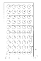
バックライトの部分駆動制御では、例えば図2に示したように、バックライトの発光エリアを複数の部分発光ブロックに分割し、各部分発光ブロックごとに発光制御を行う。部分駆動制御では、相対的に画像の明るい部分に対応する部分発光ブロックでは発光輝度を高くし、相対的に画像の暗い部分に対応する部分発光ブロックでは発光輝度を低くする。図2では、発光エリアを図1の例に対応させて、水平方向Xに5つの部分発光ブロック、垂直方向Yに4つの部分発光ブロックとし、合計で20個の部分発光ブロックに分割した例を示している。なお、図2の右側には、各部分発光ブロックごとの発光輝度の相対値の一例を示しているが、この値はあくまで説明上の参考値である。 In backlight partial drive control, for example, as shown in FIG. 2, the backlight emission area is divided into a plurality of partial emission blocks, and emission control is performed for each partial emission block. In the partial drive control, the emission brightness is increased in the partial emission blocks corresponding to relatively bright portions of the image, and the emission brightness is lowered in the partial emission blocks corresponding to relatively dark portions of the image. FIG. 2 shows an example in which the light-emitting area is divided into 5 partial light-emitting blocks in the horizontal direction X and 4 partial light-emitting blocks in the vertical direction Y, corresponding to the example in FIG. 1, for a total of 20 partial light-emitting blocks. showing. Note that the right side of FIG. 2 shows an example of the relative value of the light emission luminance for each partial light emission block, but this value is only a reference value for explanation.
[0.2 比較例に係る照明装置の概要]
図3は、図2に示した部分駆動制御を実現するための比較例に係る照明装置100の概略構成を示している。図4は、比較例に係る照明装置100の回路構成の一例を示している。[0.2 Outline of Lighting Device According to Comparative Example]
FIG. 3 shows a schematic configuration of a
照明装置100は、複数の部分発光ブロック101を有している。複数の部分発光ブロック101は、図2に示した部分駆動制御を実現するために、水平方向Xに5つ、垂直方向Yに4つ、合計で20個設けられている。
The
複数の部分発光ブロック101のそれぞれには、発光部30と制御素子40とが設けられている。
A light-
発光部30は、図4に示したように、少なくとも1つの発光素子31を有する。発光素子31は例えばLED(Light Emitting Diode)からなる。
The
制御素子40は、図4に示したように、例えば制御用FET(Field Effect Transistor)41と電流制御用抵抗素子42とを有する。
The
複数の部分発光ブロック101のそれぞれにおける発光部30には、昇圧回路60を介して電圧が供給される。
A voltage is supplied to the
昇圧回路60は、入力電圧Vinを発光部30で必要とされる電圧まで昇圧する回路である。昇圧回路60は、インダクタ61と、ダイオード62と、例えばMOS(Metal Oxide Semiconductor)FET等のスイッチング素子63とを有している。
The
複数の部分発光ブロック101のそれぞれにおける制御用FET41は、例えばIC(Integrated Circuit)からなる駆動回路50によって制御される。
The
なお、図4の例では、複数の部分発光ブロック101のそれぞれにおける発光部30に制御素子40を設けているが、制御素子40を駆動回路50に含めることも可能である。
Note that in the example of FIG. 4 , the
[0.3 課題]
比較例に係る照明装置100では、複数の部分発光ブロック101のそれぞれの発光輝度を独立して制御するために、複数の部分発光ブロック101の数に応じた制御素子40と駆動回路50が必要とされる。例えば制御素子40は、複数の部分発光ブロック101の数と同数分、すなわち5(水平方向Xにおける部分発光ブロック101の数)×4(垂直方向Yにおける部分発光ブロック101の数)=20個分、必要とされる。また、例えば1つの駆動回路50が6ch(チャンネル)分の制御機能を有している場合、20個の部分発光ブロック101を駆動するためには、例えば1つの駆動回路50について5ch使用することで、4つの駆動回路50が必要とされる(5ch×4つの駆動回路50=20)。[0.3 Problem]
In the
このため、部分駆動制御を行うための回路構成を簡略化する技術の開発が望まれる。 Therefore, it is desired to develop a technique for simplifying the circuit configuration for performing partial drive control.
<1.第1の実施の形態>
次に、本開示の第1の実施の形態に係る照明装置について説明する。なお、以下では、上記比較例に係る照明装置の構成要素と略同じ部分については、同一符号を付し、適宜説明を省略する。<1. First Embodiment>
Next, a lighting device according to the first embodiment of the present disclosure will be described. In the following description, substantially the same components as those of the lighting device according to the comparative example are denoted by the same reference numerals, and descriptions thereof are omitted as appropriate.
本実施の形態では、回路構成を簡略化しつつ、上記比較例に係る照明装置100と同様に、実質的に20個の部分発光ブロック101による部分駆動制御が可能な照明装置の例を説明する。なお、以下で説明する発光エリアより分割される部分発光ブロック101の数等は一例であり、以下で説明する数に限定されるものではない。以下で説明する例よりも多い、または少ない分割数等にしてもよい。以降の他の実施の形態についても同様である。
In the present embodiment, an example of a lighting device capable of substantially performing partial drive control by 20 partial
[1.1 構成、および動作]
(部分駆動制御の概要)
図5および図6は、本開示の第1の実施の形態に係る表示装置による画像の分割手法の一例を示している。[1.1 Configuration and Operation]
(Overview of partial drive control)
5 and 6 show an example of an image dividing method by the display device according to the first embodiment of the present disclosure.
本実施の形態に係る表示装置では、画像全体を第1の方向(水平方向X)と第2の方向(垂直方向Y)との2つの異なる方向に分割している。すなわち、図5に示したように、画像全体を水平方向Xに区切った4つの水平画像ブロックと、図6に示したように、画像全体を垂直方向Yに区切った5つの垂直画像ブロックとに分割している。 In the display device according to this embodiment, the entire image is divided into two different directions, a first direction (horizontal direction X) and a second direction (vertical direction Y). That is, as shown in FIG. 5, the entire image is divided into four horizontal image blocks in the horizontal direction X, and as shown in FIG. 6, the entire image is divided into five vertical image blocks in the vertical direction Y. split.
図7は、本実施の形態に係る照明装置1による部分駆動制御の概要を示している。図8は、本実施の形態に係る照明装置1の概略構成を示している。
FIG. 7 shows an overview of the partial drive control by the
本実施の形態に係る照明装置1では、図7の上段に示したように、発光エリアを複数の水平ブロック(第1の発光ブロック)10と、複数の垂直ブロック(第2の発光ブロック)20との2種類の発光ブロックに分割し、水平ブロック10ごと、および垂直ブロック20ごとに発光制御を行う。
In the
本実施の形態に係る照明装置1では、実際に発光制御されるのは、図7の上段に示したように、9ブロック(水平ブロック10が4つ+垂直ブロック20が5つ)のみである。しかしながら、図7の下段に示したように、複数の水平ブロック10のそれぞれと複数の垂直ブロック20のそれぞれとが部分的に互いに重なり合うことによって、結果的に、上記比較例と同様に、合計で20個の部分発光ブロック101が形成される。各部分発光ブロック101の輝度は、重なり合っている水平ブロック10の輝度と垂直ブロック20の輝度との和となる。なお、図7には、各ブロックごとの発光輝度の相対値の一例を示しているが、この値はあくまで説明上の参考値である。
In the
(照明装置の概要)
図7の部分駆動制御を実現するために、照明装置1は、図8に示したように、複数の水平ブロック10のそれぞれにおいて、水平方向Xに配列された複数の発光素子(第1の発光素子)31を含んでいる。発光素子31は、例えばLEDチップである。また、複数の水平ブロック10のそれぞれには、水平方向Xに延在する第1の基板33が設けられている。複数の発光素子31は、第1の基板33上に設けられている。第1の基板33上にある隣り合う発光素子31同士が互いに接続されている。(Overview of lighting device)
In order to realize the partial drive control of FIG. 7, the
また、照明装置1は、複数の垂直ブロック20のそれぞれにおいて、垂直方向Yに配列された複数の発光素子(第2の発光素子)32を含んでいる。発光素子32は、例えばLEDチップである。また、複数の垂直ブロック20のそれぞれには、垂直方向Yに延在する第2の基板34が設けられている。複数の発光素子32は、第2の基板34上に設けられている。第2の基板34上にある隣り合う発光素子32同士が互いに接続されている。
The
照明装置1は、複数の水平ブロック10のそれぞれと複数の垂直ブロック20のそれぞれとが部分的に重なり合うことで形成される部分発光ブロック101に、発光素子31と発光素子32とが少なくとも1つずつ配置されるように構成されている。1つの部分発光ブロック101内に配置された発光素子31と発光素子32とによって、1つの発光部30が形成される。従って、各部分発光ブロック101の輝度は、部分発光ブロック101内に配置された発光素子31の輝度と発光素子32の輝度との和となる。
The
(回路構成)
図9は、照明装置1の回路構成の一例を示している。(circuit configuration)
FIG. 9 shows an example of the circuit configuration of the
本実施の形態に係る照明装置1では、上述したように、実際に発光制御される発光ブロックは、4つの水平ブロック10と、5つの垂直ブロック20である。制御素子40と駆動回路50は、本開示における「発光制御部」の一例であってもよい。制御素子40と駆動回路50は、水平ブロック10ごと、垂直ブロック20ごとに発光制御を行う。照明装置1を表示装置に適用した場合、駆動回路50は、発光部30が水平ブロック10と垂直ブロック20とが重なり合うことによって形成された部分発光ブロック101に対応する部分の画像に応じた輝度で発光するように、発光部30の輝度を可変制御する。
In
このため、制御素子40は、水平ブロック10ごと、垂直ブロック20ごとに設ければよい。すなわち、必要とされる制御素子40の数は9個のみでよい(水平方向Xに5つ+垂直方向Yに4つ)。
Therefore, the
同様に、本実施の形態に係る照明装置1では、必要とされる駆動回路50のch数は9つのみでよい(水平ブロック10について4つ+垂直ブロック20について5つ)。例えば1つの駆動回路50が6ch分の制御機能を有している場合、4つの水平ブロック10と5つの垂直ブロック20とを駆動するためには、2つの駆動回路50のみでよい。
Similarly, in the
図10は、照明装置1の回路構成の変形例の一例を示している。
FIG. 10 shows an example of a modification of the circuit configuration of the
図9の回路構成例では、水平ブロック10と垂直ブロック20とで昇圧回路60を共通化しているが、水平ブロック10内の発光素子31の数と垂直ブロック20内の発光素子32の数とが異なる場合、水平ブロック10と垂直ブロック20とで異なる電圧が必要とされ得る。そのような場合、図10に示したように、水平ブロック10用の昇圧回路60Aと、垂直ブロック20用の昇圧回路60Bとを別々に設けるようにしてもよい。
In the circuit configuration example of FIG. 9, the
なお、図9および図10の例では、制御素子40と駆動回路50とを別々に設けているが、制御素子40を駆動回路50に含めることも可能である。
9 and 10, the
その他の構成、および動作は、上記比較例に係る照明装置と略同様であってもよい。 Other configurations and operations may be substantially the same as those of the lighting device according to the comparative example.
[1.2 効果]
以上のように、本実施の形態によれば、複数の水平ブロック10と、それぞれが複数の水平ブロック10のそれぞれと部分的に重なり合う複数の垂直ブロック20とを備えるようにしたので、複数の水平ブロック10のそれぞれと複数の垂直ブロック20のそれぞれとが重なり合うことによって水平方向Xと垂直方向Yとに複数の部分発光ブロック101が形成される。これにより、部分駆動制御を行うための回路構成を簡略化し得る。[1.2 Effect]
As described above, according to the present embodiment, a plurality of
なお、本明細書に記載された効果はあくまでも例示であって限定されるものではなく、また他の効果があってもよい。以降の他の実施の形態の効果についても同様である。 Note that the effects described in this specification are merely examples and are not limited, and other effects may also occur. The same applies to the effects of other embodiments described below.
<2.第2の実施の形態>
次に、本開示の第2の実施の形態に係る照明装置について説明する。なお、以下では、上記第1の実施の形態に係る照明装置の構成要素と略同じ部分については、同一符号を付し、適宜説明を省略する。<2. Second Embodiment>
Next, a lighting device according to a second embodiment of the present disclosure will be described. It should be noted that hereinafter, substantially the same components as those of the lighting device according to the first embodiment are denoted by the same reference numerals, and description thereof will be omitted as appropriate.
上記第1の実施の形態では、複数の水平ブロック10のそれぞれと複数の垂直ブロック20のそれぞれとの各発光ブロックの発光輝度を可変制御するようにしたが、一部の発光ブロックの発光輝度を一定の輝度となるように発光制御してもよい。例えば、駆動回路50は、複数の水平ブロック10のうちの一部の水平ブロック10内の発光素子31の発光輝度と、複数の垂直ブロック20のうちの一部の垂直ブロック20内の発光素子32の発光輝度とを一定の輝度となるように発光制御してもよい。この場合、駆動回路50は、一部の水平ブロック10以外の他の水平ブロック10内の発光素子31の発光輝度と、一部の垂直ブロック20以外の他の垂直ブロック20内の発光素子32の発光輝度とを可変制御する。これにより、駆動回路50の回路構成をより簡略化し得る。
In the above-described first embodiment, the emission brightness of each of the plurality of
(第1の例)
図11は、本開示の第2の実施の形態に係る照明装置による発光エリアの分割手法の第1の例を示している。図12は、本実施の形態に係る照明装置による部分駆動制御の第1の例の概要を示している。(first example)
FIG. 11 illustrates a first example of a method of dividing the light emitting area by the lighting device according to the second embodiment of the present disclosure. FIG. 12 shows an outline of a first example of partial drive control by the lighting device according to this embodiment.
例えば、図11の左側に示したように、上記第1の実施の形態における複数の水平ブロック10のうち、少なくとも垂直方向Yにおける両端に位置する発光ブロックを輝度固定水平ブロック11とし、常時一定の輝度となるように発光制御してもよい。この場合、複数の水平ブロック10のうち、輝度固定水平ブロック11以外の発光ブロックを輝度可変水平ブロック12とし、輝度可変水平ブロック12の発光輝度を可変制御する。
For example, as shown on the left side of FIG. 11, among the plurality of
また、図11の右側に示したように、上記第1の実施の形態における複数の垂直ブロック20のうち、少なくとも水平方向Xにおける両端に位置する発光ブロックを輝度固定垂直ブロック21とする。この場合、複数の垂直ブロック20のうち、輝度固定垂直ブロック21以外の発光ブロックを輝度可変垂直ブロック22とし、輝度可変垂直ブロック22の発光輝度を可変制御する。
Further, as shown on the right side of FIG. 11, among the plurality of
図11に示した各発光ブロックを合成することにより、上記第1の実施の形態と同様に、合計で20個の部分発光ブロックが形成される。部分発光ブロックの合成の輝度は、図12に示した状態となる。合成の輝度は、中央の6ブロック分の部分発光ブロックでは、輝度可変水平ブロック12の輝度と輝度可変垂直ブロック22の輝度との和となる。この中央の部分発光ブロックでは、輝度可変水平ブロック12と輝度可変垂直ブロック22とによる部分駆動制御が行われることとなる。
By synthesizing the respective light emitting blocks shown in FIG. 11, a total of 20 partial light emitting blocks are formed as in the first embodiment. FIG. 12 shows the combined brightness of the partial emission blocks. The combined luminance is the sum of the luminance of the variable luminance
水平方向Xにおける左端略中央の2ブロック分の部分発光ブロックと右端略中央の2ブロック分の部分発光ブロックとでは、合成の輝度は、輝度可変水平ブロック12の輝度と輝度固定垂直ブロック21の輝度との和となる。この左端略中央の部分発光ブロックと右端略中央の部分発光ブロックでは、輝度可変水平ブロック12による部分駆動制御が行われることとなる。
In the horizontal direction X, the two blocks of partial light emission blocks at approximately the center of the left end and the two blocks of partial light emission blocks at approximately the center of the right end in the horizontal direction X have the combined luminance of the luminance of the variable luminance
垂直方向Yにおける上端略中央の3ブロック分の部分発光ブロックと下端略中央の3ブロック分の部分発光ブロックとでは、合成の輝度は、輝度固定水平ブロック11の輝度と輝度可変垂直ブロック22の輝度との和となる。この上端略中央の部分発光ブロックと下端略中央の部分発光ブロックでは、輝度可変垂直ブロック22による部分駆動制御が行われることとなる。
In the vertical direction Y, the luminance of the 3 blocks of the partial luminous blocks at the upper end approximately in the center and the 3 blocks of the partial luminous blocks in the lower end approximately in the center is the luminance of the fixed luminance
四隅の部分発光ブロックでは、合成の輝度は、輝度固定水平ブロック11の輝度と輝度固定垂直ブロック21の輝度との和となる。この四隅の部分発光ブロックでは、部分駆動制御は行われずに、常時一定の輝度となる。なお、図11および図12では、輝度固定水平ブロック11と輝度固定垂直ブロック21とを中間輝度となるように発光制御している例を示しているが、輝度固定水平ブロック11と輝度固定垂直ブロック21とを中間輝度以外の輝度にしてもよい。
In the partial light-emitting blocks at the four corners, the combined luminance is the sum of the luminance of the luminance-fixed
(第2の例)
図13は、本実施の形態に係る照明装置による発光エリアの分割手法の第2の例を示している。図14は、本実施の形態に係る照明装置による部分駆動制御の第2の例の概要を示している。(Second example)
FIG. 13 shows a second example of the method of dividing the light emitting area by the lighting device according to the present embodiment. FIG. 14 shows an overview of a second example of partial drive control by the illumination device according to this embodiment.
この第2の例では、輝度固定水平ブロック11と輝度固定垂直ブロック21とを常時最大輝度となるように発光制御している。それ以外は、上記第1の例と略同様である。
In this second example, the fixed luminance
(第3の例)
図15は、本実施の形態に係る照明装置による発光エリアの分割手法の第3の例を示している。図16は、本実施の形態に係る照明装置による部分駆動制御の第3の例の概要を示している。(Third example)
FIG. 15 shows a third example of the method of dividing the light emitting area by the lighting device according to the present embodiment. FIG. 16 shows an outline of a third example of partial drive control by the illumination device according to this embodiment.
例えば、図15の左側に示したように、上記第1の実施の形態における複数の水平ブロック10のうち、少なくとも垂直方向Yにおける両端に位置する発光ブロックを非発光水平ブロック13としてもよい。非発光水平ブロック13は、発光素子31自体を配置しない構成にし、常時非点灯状態としてもよい。この場合、複数の水平ブロック10のうち、非発光水平ブロック13以外の発光ブロックを輝度可変水平ブロック12とし、輝度可変水平ブロック12の発光輝度を可変制御する。
For example, as shown on the left side of FIG. 15, among the plurality of
また、図15の右側に示したように、上記第1の実施の形態における複数の垂直ブロック20のうち、少なくとも水平方向Xにおける両端に位置する発光ブロックを輝度固定垂直ブロック21とする。この場合、複数の垂直ブロック20のうち、輝度固定垂直ブロック21以外の発光ブロックを輝度可変垂直ブロック22とし、輝度可変垂直ブロック22の発光輝度を可変制御する。
Further, as shown on the right side of FIG. 15, among the plurality of
図15に示した各発光ブロックを合成することにより、上記第1の実施の形態と同様に、合計で20個の部分発光ブロックが形成される。部分発光ブロックの合成の輝度は、図16に示した状態となる。合成の輝度は、中央の6ブロック分の部分発光ブロックでは、輝度可変水平ブロック12の輝度と輝度可変垂直ブロック22の輝度との和となる。この中央の部分発光ブロックでは、輝度可変水平ブロック12と輝度可変垂直ブロック22とによる部分駆動制御が行われることとなる。
By synthesizing the respective light emitting blocks shown in FIG. 15, a total of 20 partial light emitting blocks are formed as in the first embodiment. FIG. 16 shows the combined brightness of the partial emission blocks. The combined luminance is the sum of the luminance of the variable luminance
水平方向Xにおける左端略中央の2ブロック分の部分発光ブロックと右端略中央の2ブロック分の部分発光ブロックとでは、合成の輝度は、輝度可変水平ブロック12の輝度と輝度固定垂直ブロック21の輝度との和となる。この左端略中央の部分発光ブロックと右端略中央の部分発光ブロックでは、輝度可変水平ブロック12による部分駆動制御が行われることとなる。
In the horizontal direction X, the two blocks of partial light emission blocks at approximately the center of the left end and the two blocks of partial light emission blocks at approximately the center of the right end in the horizontal direction X have the combined luminance of the luminance of the variable luminance
垂直方向Yにおける上端略中央の3ブロック分の部分発光ブロックと下端略中央の3ブロック分の部分発光ブロックとでは、合成の輝度は、非発光水平ブロック13の輝度と輝度可変垂直ブロック22の輝度との和となる。このため、合成の輝度は、実質上、輝度可変垂直ブロック22の輝度と同一となる。この上端略中央の部分発光ブロックと下端略中央の部分発光ブロックでは、輝度可変垂直ブロック22による部分駆動制御が行われることとなる。
In the vertical direction Y, the combined luminance of the three blocks of partial light-emitting blocks at approximately the center of the upper end and the three blocks of partial light-emitting blocks at approximately the center of the lower end is the brightness of the non-light-emitting
四隅の部分発光ブロックでは、合成の輝度は、非発光水平ブロック13の輝度と輝度固定垂直ブロック21の輝度との和となる。このため、合成の輝度は、実質上、輝度固定垂直ブロック21の輝度と同一となる。この四隅の部分発光ブロックでは、部分駆動制御は行われずに、常時一定の輝度となる。なお、図15および図16では、輝度固定垂直ブロック21を常時最大輝度となるように発光制御している例を示しているが、輝度固定垂直ブロック21を最大輝度以外の輝度にしてもよい。
In the partially emitting blocks at the four corners, the combined brightness is the sum of the brightness of the non-emitting horizontal blocks 13 and the brightness of the fixed brightness
(第4の例)
図17は、本実施の形態に係る照明装置による発光エリアの分割手法の第4の例を示している。図18は、本実施の形態に係る照明装置による部分駆動制御の第4の例の概要を示している。(Fourth example)
FIG. 17 shows a fourth example of the method of dividing the light emitting area by the lighting device according to the present embodiment. FIG. 18 shows an outline of a fourth example of partial drive control by the illumination device according to this embodiment.
例えば、図17の左側に示したように、上記第1の実施の形態における複数の水平ブロック10のうち、少なくとも垂直方向Yにおける両端に位置する発光ブロックを輝度固定水平ブロック11とし、常時一定の輝度となるように発光制御してもよい。この場合、複数の水平ブロック10のうち、輝度固定水平ブロック11以外の発光ブロックを輝度可変水平ブロック12とし、輝度可変水平ブロック12の発光輝度を可変制御する。
For example, as shown on the left side of FIG. 17, among the plurality of
また、図18の右側に示したように、上記第1の実施の形態における複数の垂直ブロック20のうち、少なくとも水平方向Xにおける両端に位置する発光ブロックを非発光垂直ブロック23としてもよい。非発光垂直ブロック23は、発光素子32自体を配置しない構成にし、常時非点灯状態としてもよい。この場合、複数の垂直ブロック20のうち、非発光垂直ブロック23以外の発光ブロックを輝度可変垂直ブロック22とし、輝度可変垂直ブロック22の発光輝度を可変制御する。
Further, as shown on the right side of FIG. 18, among the plurality of
図17に示した各発光ブロックを合成することにより、上記第1の実施の形態と同様に、合計で20個の部分発光ブロックが形成される。部分発光ブロックの合成の輝度は、図18に示した状態となる。合成の輝度は、中央の6ブロック分の部分発光ブロックでは、輝度可変水平ブロック12の輝度と輝度可変垂直ブロック22の輝度との和となる。この中央の部分発光ブロックでは、輝度可変水平ブロック12と輝度可変垂直ブロック22とによる部分駆動制御が行われることとなる。
By synthesizing the light-emitting blocks shown in FIG. 17, a total of 20 partial light-emitting blocks are formed as in the first embodiment. FIG. 18 shows the combined brightness of the partial emission blocks. The combined luminance is the sum of the luminance of the variable luminance
水平方向Xにおける左端略中央の2ブロック分の部分発光ブロックと右端略中央の2ブロック分の部分発光ブロックとでは、合成の輝度は、輝度可変水平ブロック12の輝度と非発光垂直ブロック23の輝度との和となる。このため、合成の輝度は、実質上、輝度可変水平ブロック12の輝度と同一となる。この左端略中央の部分発光ブロックと右端略中央の部分発光ブロックでは、輝度可変水平ブロック12による部分駆動制御が行われることとなる。
In the horizontal direction X, the two blocks of partial light-emitting blocks at approximately the center of the left end and the two blocks of partial light-emitting blocks at approximately the center of the right end in the horizontal direction X have the luminance of the variable luminance
垂直方向Yにおける上端略中央の3ブロック分の部分発光ブロックと下端略中央の3ブロック分の部分発光ブロックとでは、合成の輝度は、輝度固定水平ブロック11の輝度と輝度可変垂直ブロック22の輝度との和となる。この上端略中央の部分発光ブロックと下端略中央の部分発光ブロックでは、輝度可変垂直ブロック22による部分駆動制御が行われることとなる。
In the vertical direction Y, the luminance of the 3 blocks of the partial luminous blocks at the upper end approximately in the center and the 3 blocks of the partial luminous blocks in the lower end approximately in the center is the luminance of the fixed luminance
四隅の部分発光ブロックでは、合成の輝度は、輝度固定水平ブロック11の輝度と非発光垂直ブロック23の輝度との和となる。このため、合成の輝度は、実質上、輝度固定水平ブロック11の輝度と同一となる。この四隅の部分発光ブロックでは、部分駆動制御は行われずに、常時一定の輝度となる。なお、図17および図18では、輝度固定水平ブロック11を常時最大輝度となるように発光制御している例を示しているが、輝度固定水平ブロック11を最大輝度以外の輝度にしてもよい。
In the partially emitting blocks at the four corners, the combined luminance is the sum of the luminance of the luminance-fixed
その他の構成、動作、ならびに効果は、上記比較例、または上記第1の実施の形態に係る照明装置と略同様であってもよい。 Other configurations, operations, and effects may be substantially the same as those of the lighting device according to the comparative example or the first embodiment.
<3.第3の実施の形態>
次に、本開示の第3の実施の形態に係る照明装置について説明する。なお、以下では、上記第1または第2の実施の形態に係る照明装置の構成要素と略同じ部分については、同一符号を付し、適宜説明を省略する。<3. Third Embodiment>
Next, a lighting device according to a third embodiment of the present disclosure will be described. It should be noted that, hereinafter, substantially the same components as those of the lighting device according to the first or second embodiment are denoted by the same reference numerals, and description thereof will be omitted as appropriate.
図19は、本開示の第3の実施の形態に係る照明装置1Aに用いられるLEDパッケージ70の概略を示している。図20は、図19に示したLEDパッケージ70の等価回路を示している。
FIG. 19 schematically shows an
LEDパッケージ70は、少なくとも1つの第1のLEDチップ71と少なくとも1つの第2のLEDチップ72とが1つにパッケージ化された構成となっている。
The
第1のLEDチップ71と第2のLEDチップ72は、基板73上において封止部材80で封止されている。第1のLEDチップ71と第2のLEDチップ72は、例えば青色LEDチップとなっている。封止部材80は、例えば透明な樹脂材料である。封止部材80には、例えば黄色光を発する黄色蛍光体が分散されている。LEDパッケージ70は、例えば、青色LEDチップからの青色光と黄色蛍光体による黄色光との合成によって白色光を発する。封止部材80には光を拡散させるための拡散剤が分散されていてもよい。
The
第1のLEDチップ71は、アノード81とカソード83とに接続されている。アノード81とカソード83間には、第1の駆動電流IF1が流れる。第2のLEDチップ72は、アノード82とカソード84とに接続されている。アノード82とカソード84間には、第1の駆動電流IF1とは独立した第2の駆動電流IF2が流れる。これにより、第1のLEDチップ71と第2のLEDチップ72は、それぞれ独立して発光制御可能となっている。
A
図21は、図19に示したLEDパッケージ70を用いた本実施の形態に係る照明装置1Aの概略を示している。
FIG. 21 schematically shows a
複数の水平ブロック10のそれぞれと複数の垂直ブロック20のそれぞれとが部分的に重なり合うことで形成される部分発光ブロック101に、少なくとも1つのLEDパッケージ70を配置する。この場合、図8における発光素子31を第1のLEDチップ71とし、発光素子32を第2のLEDチップ72とすることで、1つの部分発光ブロック101に配置される発光部30を少なくとも1つのLEDパッケージ70によって構成することができ、上記第1の実施の形態に係る照明装置1(図8)と同等の照明装置を、例えば図21の照明装置1Aの構成で実現できる。
At least one
図21の照明装置1Aでは、1つの部分発光ブロック101に、1つのLEDパッケージ70を配置した例を示している。照明装置1Aは、水平方向Xに延在する複数のLED基板74を有している。複数のLED基板74のそれぞれに、複数のLEDパッケージ70が設けられている。
The
複数のLED基板74のそれぞれにおいて、水平方向Xに隣り合うLEDパッケージ70内における第1のLEDチップ71同士が互いに接続されている。これにより、1つの水平ブロック10内に複数の第1のLEDチップ71が配列されている。
In each of the plurality of
また、垂直方向Yに隣り合うLEDパッケージ70内における第2のLEDチップ72同士が配線75によって互いに接続されている。これにより、1つの垂直ブロック20内に複数の第2のLEDチップ72が配列されている。
Also, the
その他の構成、動作、ならびに効果は、上記比較例、上記第1または第2の実施の形態に係る照明装置と略同様であってもよい。 Other configurations, operations, and effects may be substantially the same as those of the lighting apparatus according to the comparative example and the first or second embodiment.
<4.第4の実施の形態>
次に、本開示の第4の実施の形態に係る照明装置について説明する。なお、以下では、上記第1ないし第3の実施の形態に係る照明装置の構成要素と略同じ部分については、同一符号を付し、適宜説明を省略する。<4. Fourth Embodiment>
Next, a lighting device according to a fourth embodiment of the present disclosure will be described. In the following description, the same reference numerals are assigned to substantially the same components as those of the lighting devices according to the first to third embodiments, and description thereof will be omitted as appropriate.
図22は、本開示の第4の実施の形態に係る照明装置1Bの概略を示している。図23は、照明装置1Bにおける水平ブロック10の概略を示している。図24は、照明装置1Bにおける垂直ブロック20の概略を示している。図25は、照明装置1Bによって形成される部分発光ブロック101の概略を示している。なお、図22~図25では、隣り合うLEDパッケージ70同士を接続する配線等の図示を省略している。
FIG. 22 shows an outline of a
照明装置1Bは、上記第3の実施の形態に係る照明装置1Aと同様に、複数のLEDパッケージ70を用いた構成とされている。LEDパッケージ70を用いる場合、1つの水平ブロック10内に含まれる第1のLEDチップ71の数と、1つの垂直ブロック20内に含まれる第2のLEDチップ72の数とを同じにすることが好ましい。1つの水平ブロック10内に含まれる第1のLEDチップ71の数と、1つの垂直ブロック20内に含まれる第2のLEDチップ72の数とが異なる場合、図10の回路構成例のように、水平ブロック10用の昇圧回路60Aと、垂直ブロック20用の昇圧回路60Bとを別々に設けることが必要とされ得る。1つの水平ブロック10内に含まれる第1のLEDチップ71の数と、1つの垂直ブロック20内に含まれる第2のLEDチップ72の数とを同じにすることで、図9の回路構成例のように、複数の水平ブロック10と複数の垂直ブロック20とで共通の昇圧回路60を用いることができる。
The
図22の構成例では、水平方向Xに10個のLEDパッケージ70を配置し、垂直方向Yに5個のLEDパッケージ70を配置している。この場合、仮に、水平方向Xの1行分の10個のLEDパッケージ70内の第1のLEDチップ71を1つの水平ブロック10とし、垂直方向Yの1列分の5個のLEDパッケージ70内の第2のLEDチップ72を1つの垂直ブロック20とした場合、1つの水平ブロック10内に含まれる第1のLEDチップ71の数と、1つの垂直ブロック20内に含まれる第2のLEDチップ72の数とが異なることとなる。
In the configuration example of FIG. 22, ten
そこで、垂直方向Yの2列分の10個のLEDパッケージ70内の第2のLEDチップ72を1つの垂直ブロック20とすることが好ましい。これにより、1つの水平ブロック10内に含まれる第1のLEDチップ71の数と、1つの垂直ブロック20内に含まれる第2のLEDチップ72の数とを同じにすることができる。
Therefore, it is preferable that the
これにより、照明装置1Bでは、5個の水平ブロック10(H0~H4)と5個の垂直ブロック20(V0~V4)とが形成される。5個の水平ブロック10(H0~H4)と5個の垂直ブロック20(V0~V4)とが互いに部分的に重なり合うことで、図25に示したように、合計25個の部分発光ブロック101が形成されている。1つの部分発光ブロック101には、2つのLEDパッケージ70が配置されている。1つの部分発光ブロック101には、2つの第1のLEDチップ71と、2つの第2のLEDチップ72とが配置されることとなる。
As a result, in the
本実施の形態に係る照明装置1Bでは、必要とされる制御素子40の数は10個のみでよい(水平方向Xにつき5つ+垂直方向Yにつき5つ)。
In the
同様に、本実施の形態に係る照明装置1Bでは、必要とされる駆動回路50のch数は10個のみでよい(水平ブロック10について5つ+垂直ブロック20について5つ)。このため、例えば1つの駆動回路50が6ch分の制御機能を有している場合、5つの水平ブロック10と5つの垂直ブロック20とを駆動するためには、2つの駆動回路50のみでよい。
Similarly, in the
その他の構成、動作、ならびに効果は、上記比較例、または上記第1ないし第3の実施の形態に係る照明装置と略同様であってもよい。 Other configurations, operations, and effects may be substantially the same as those of the lighting devices according to the comparative example or the first to third embodiments.
<5.第5の実施の形態>
次に、本開示の第5の実施の形態に係る照明装置の適用例について説明する。なお、以下では、上記第1ないし第4の実施の形態に係る照明装置の構成要素と略同じ部分については、同一符号を付し、適宜説明を省略する。<5. Fifth Embodiment>
Next, an application example of the lighting device according to the fifth embodiment of the present disclosure will be described. It should be noted that hereinafter, substantially the same components as those of the lighting devices according to the first to fourth embodiments are denoted by the same reference numerals, and description thereof will be omitted as appropriate.
図26は、本開示の第5の実施の形態に係る表示装置301の概略を示している。図27は、本実施の形態に係る表示装置301の内部構成の一例を示している。
FIG. 26 shows an outline of a
表示装置301は、例えばテレビジョン装置であり、図26に示したように、表示部302と、スタンド303とを備えている。
The
表示部302は、例えば図27に示したように、表示パネル200と、照明装置201と、表示パネル200と照明装置201との間に配置された複数の光学シートとを備えている。複数の光学シートは、例えば、拡散板202と、拡散シート203と、プリズムシート204と、偏光反射シート205とを有してる。
The
表示パネル200は、例えば透過型の液晶表示パネルであり、照明装置201をバックライトとして、照明装置201からの照明光に基づいて画像を表示する。複数の光学シートは、照明光の輝度分布の均一化や照明光の利用効率の向上のために設けられている。
The
照明装置201は、フレーム211と、フレーム211の表面に配置された反射シート212とを有している。
The
また、照明装置201は、反射シート212を介してフレーム211の表面に配置された複数のLED基板213を有している。複数のLED基板213のそれぞれには、複数のLEDパッケージ214と、複数のLEDパッケージ214のそれぞれの上に配置された複数の光源用レンズ215とが設けられている。
The
LEDパッケージ214は、上記第3の実施の形態に係る照明装置におけるLEDパッケージ70(図19)と略同様の構成を適用可能であり、1つのLEDパッケージ214内には、少なくとも2つのLEDチップが設けられている。同一のLED基板213上にある隣り合うLEDパッケージ214内における少なくとも1つのLEDチップ同士は互いに接続されている。複数のLED基板213間の同一方向にある隣り合うLEDパッケージ214内における少なくとも他の1つのLEDチップ同士は、導線216によって互いに接続されている。これにより、照明装置201は、上記第1ないし第4の実施の形態に係る照明装置と略同様の部分駆動制御の手法を適用可能である。
The
なお、本開示の照明装置は、テレビジョン用途以外の表示装置にも適用可能である。例えば、各種モニタ装置や、携帯端末機器の表示部のバックライトとしても適用可能である。また、本開示の照明装置は、表示装置以外の照明用途としても適用可能である。 Note that the lighting device of the present disclosure can also be applied to display devices other than television applications. For example, it can be applied as a backlight for a display unit of various monitor devices and portable terminal devices. In addition, the lighting device of the present disclosure can also be applied to lighting applications other than display devices.
その他の構成、動作、ならびに効果は、上記比較例、または上記第1ないし第4の実施の形態に係る照明装置と略同様であってもよい。 Other configurations, operations, and effects may be substantially the same as those of the lighting devices according to the comparative example or the first to fourth embodiments.
<6.その他の実施の形態>
本開示による技術は、上記各実施の形態の説明に限定されず種々の変形実施が可能である。<6. Other Embodiments>
The technology according to the present disclosure is not limited to the description of the above embodiments, and various modifications are possible.
例えば、上記第3の実施の形態では、発光部30をLEDパッケージ70によって構成する例を説明したが、LEDパッケージ70に代えて、パッケージ化されていないベアチップタイプのLEDを用いてもよい。
For example, in the third embodiment, an example in which the
また例えば、本技術は以下のような構成を取ることもできる。
(1)
それぞれが第1の方向に配列された複数の第1の発光素子を含む複数の第1の発光ブロックと、
それぞれが前記第1の方向とは異なる第2の方向に配列された複数の第2の発光素子を含み、それぞれが前記複数の第1の発光ブロックのそれぞれと部分的に重なり合う複数の第2の発光ブロックと、
前記第1の発光ブロックごとに前記複数の第1の発光素子を発光制御すると共に、前記第2の発光ブロックごとに前記複数の第2の発光素子を発光制御する発光制御部と
を備える
照明装置。
(2)
前記複数の第1の発光ブロックのそれぞれと前記複数の第2の発光ブロックのそれぞれとが重なり合うことによって前記第1の方向と前記第2の方向とに複数の部分発光ブロックが形成されている
上記(1)に記載の照明装置。
(3)
前記複数の部分発光ブロックにはそれぞれ、少なくとも1つの前記第1の発光素子と少なくとも1つの前記第2の発光素子とが配置されている
上記(2)に記載の照明装置。
(4)
前記部分発光ブロックには、前記第1の発光素子と前記第2の発光素子とがそれぞれ独立して発光制御可能な状態で1つにパッケージ化されて配置されている
上記(3)に記載の照明装置。
(5)
前記第1の発光素子は第1のLEDチップからなり、
前記第2の発光素子は前記第1のLEDチップとは独立して発光制御される第2のLEDチップからなり、
前記複数の部分発光ブロックにはそれぞれ、少なくとも1つの前記第1のLEDチップと少なくとも1つの前記第2のLEDチップとが1つにパッケージ化されたLEDパッケージが、少なくとも1つ配置されている
上記(3)または(4)に記載の照明装置。
(6)
前記部分発光ブロックの輝度は、前記部分発光ブロック内に配置された前記第1の発光素子の発光輝度と前記部分発光ブロック内に配置された前記第2の発光素子の発光輝度との和である
上記(3)ないし(5)のいずれか1つに記載の照明装置。
(7)
前記発光制御部は、
前記複数の第1の発光ブロックのうちの一部の第1の発光ブロック内の前記第1の発光素子の発光輝度と、前記複数の第2の発光ブロックのうちの一部の第2の発光ブロック内の前記第2の発光素子の発光輝度とを一定の輝度となるように発光制御し、
前記一部の第1の発光ブロック以外の前記第1の発光ブロック内の前記第1の発光素子の発光輝度と、前記一部の第2の発光ブロック以外の前記第2の発光ブロック内の前記第2の発光素子の発光輝度とを可変制御する
上記(3)ないし(6)のいずれか1つに記載の照明装置。
(8)
前記複数の第1の発光ブロックは前記第2の方向に並列的に設けられ、前記複数の第1の発光ブロックのうち、少なくとも前記第2の方向における両端に位置する発光ブロックが前記一部の第1の発光ブロックとされている
上記(7)に記載の照明装置。
(9)
前記複数の第2の発光ブロックは前記第1の方向に並列的に設けられ、前記複数の第2の発光ブロックのうち、少なくとも前記第1の方向における両端に位置する発光ブロックが前記一部の第2の発光ブロックとされている
上記(7)または(8)に記載の照明装置。
(10)
前記一部の第1の発光ブロックまたは前記一部の第2の発光ブロックに代えて、それぞれが前記複数の第2の発光ブロックまたは前記複数の第1の発光ブロックのそれぞれと部分的に重なり合う複数の非発光ブロックをさらに備え、
前記発光制御部は、
前記一部の第1の発光ブロック内の前記第1の発光素子または前記一部の第2の発光ブロック内の前記第2の発光素子の発光輝度を一定の輝度となるように発光制御する
上記(7)に記載の照明装置。
(11)
照明装置と、
前記照明装置からの照明光に基づいて画像を表示する表示パネルと
を含み、
前記照明装置は、
それぞれが第1の方向に配列された複数の第1の発光素子を含む複数の第1の発光ブロックと、
それぞれが前記第1の方向とは異なる第2の方向に配列された複数の第2の発光素子を含み、それぞれが前記複数の第1の発光ブロックのそれぞれと部分的に重なり合う複数の第2の発光ブロックと、
前記第1の発光ブロックごとに前記複数の第1の発光素子を発光制御すると共に、前記第2の発光ブロックごとに前記複数の第2の発光素子を発光制御する発光制御部と
を備える
表示装置。Further, for example, the present technology can also have the following configuration.
(1)
a plurality of first light emitting blocks each including a plurality of first light emitting elements arranged in a first direction;
A plurality of second light emitting elements each including a plurality of second light emitting elements arranged in a second direction different from the first direction, each partially overlapping with each of the plurality of first light emitting blocks a light emitting block;
a light emission control unit that controls light emission of the plurality of first light emitting elements for each of the first light emitting blocks, and controls light emission of the plurality of second light emitting elements for each of the second light emitting blocks. .
(2)
A plurality of partial light-emitting blocks are formed in the first direction and the second direction by overlapping each of the plurality of first light-emitting blocks and each of the plurality of second light-emitting blocks. (1) The lighting device according to the above.
(3)
The illumination device according to (2), wherein at least one of the first light emitting elements and at least one of the second light emitting elements are arranged in each of the plurality of partial light emitting blocks.
(4)
In the partial light emitting block, the first light emitting element and the second light emitting element are arranged in a packaged state in which light emission can be independently controlled, respectively. lighting device.
(5)
The first light emitting element is composed of a first LED chip,
the second light emitting element comprises a second LED chip whose light emission is controlled independently of the first LED chip;
At least one LED package in which at least one of the first LED chips and at least one of the second LED chips are packaged together is arranged in each of the plurality of partial light-emitting blocks. The lighting device according to (3) or (4).
(6)
The luminance of the partial emission block is the sum of the emission luminance of the first light emitting element arranged in the partial emission block and the emission luminance of the second light emitting element arranged in the partial emission block. The lighting device according to any one of (3) to (5) above.
(7)
The light emission control unit
Light emission luminance of the first light emitting elements in some first light emitting blocks of the plurality of first light emitting blocks and second light emission of some of the plurality of second light emitting blocks controlling the light emission luminance of the second light emitting element in the block so that the light emission luminance is constant;
The light emission luminance of the first light emitting elements in the first light emitting blocks other than the part of the first light emitting blocks and the light emitting elements in the second light emitting blocks other than the part of the second light emitting blocks The lighting device according to any one of (3) to (6) above, wherein the emission luminance of the second light emitting element is variably controlled.
(8)
The plurality of first light-emitting blocks are provided in parallel in the second direction, and among the plurality of first light-emitting blocks, at least light-emitting blocks positioned at both ends in the second direction are part of the plurality of light-emitting blocks. The lighting device according to (7) above, which is the first light emitting block.
(9)
The plurality of second light-emitting blocks are provided in parallel in the first direction, and among the plurality of second light-emitting blocks, at least light-emitting blocks positioned at both ends in the first direction are part of the plurality of light-emitting blocks. The lighting device according to (7) or (8) above, which is a second light emitting block.
(10)
Instead of the part of the first light-emitting blocks or the part of the second light-emitting blocks, a plurality of light-emitting blocks partially overlapping with the plurality of second light-emitting blocks or the plurality of first light-emitting blocks, respectively further comprising a non-emissive block of
The light emission control unit
Light emission control is performed so that light emission luminance of the first light emitting elements in the partial first light emitting blocks or the second light emitting elements in the partial second light emitting blocks is constant. (7) The lighting device according to the above.
(11)
a lighting device;
a display panel that displays an image based on the illumination light from the illumination device;
The lighting device
a plurality of first light emitting blocks each including a plurality of first light emitting elements arranged in a first direction;
A plurality of second light emitting elements each including a plurality of second light emitting elements arranged in a second direction different from the first direction, each partially overlapping with each of the plurality of first light emitting blocks a light emitting block;
a light emission control unit that controls light emission of the plurality of first light emitting elements for each of the first light emitting blocks, and controls light emission of the plurality of second light emitting elements for each of the second light emitting blocks. .
本出願は、日本国特許庁において2017年5月15日に出願された日本特許出願番号第2017-096227号を基礎として優先権を主張するものであり、この出願のすべての内容を参照によって本出願に援用する。 This application claims priority based on Japanese Patent Application No. 2017-096227 filed on May 15, 2017 at the Japan Patent Office, and the entire contents of this application are incorporated herein by reference. incorporated into the application.
当業者であれば、設計上の要件や他の要因に応じて、種々の修正、コンビネーション、サブコンビネーション、および変更を想到し得るが、それらは添付の請求の範囲やその均等物の範囲に含まれるものであることが理解される。 Depending on design requirements and other factors, those skilled in the art may conceive various modifications, combinations, subcombinations, and modifications that fall within the scope of the appended claims and their equivalents. It is understood that
Claims (9)
それぞれが前記第1の方向とは異なる第2の方向に配列された複数の第2の発光素子を含み、それぞれが前記複数の第1の発光ブロックのそれぞれと部分的に重なり合う複数の第2の発光ブロックと、
前記第1の発光ブロックごとに前記複数の第1の発光素子を発光制御すると共に、前記第2の発光ブロックごとに前記複数の第2の発光素子を発光制御する発光制御部と
を備え、
前記複数の第1の発光ブロックのそれぞれと前記複数の第2の発光ブロックのそれぞれとが重なり合うことによって前記第1の方向と前記第2の方向とに複数の部分発光ブロックが形成され、
前記複数の部分発光ブロックにはそれぞれ、少なくとも1つの前記第1の発光素子と少なくとも1つの前記第2の発光素子とが配置されている
照明装置。 a plurality of first light emitting blocks each including a plurality of first light emitting elements arranged in a first direction;
A plurality of second light emitting elements each including a plurality of second light emitting elements arranged in a second direction different from the first direction, each partially overlapping with each of the plurality of first light emitting blocks a light emitting block;
a light emission control unit that controls light emission of the plurality of first light emitting elements for each of the first light emitting blocks and controls light emission of the plurality of second light emitting elements for each of the second light emitting blocks ;
a plurality of partial light-emitting blocks are formed in the first direction and the second direction by overlapping each of the plurality of first light-emitting blocks and each of the plurality of second light-emitting blocks;
At least one of the first light emitting elements and at least one of the second light emitting elements are arranged in each of the plurality of partial light emitting blocks.
lighting device.
請求項1に記載の照明装置。 2. The lighting system according to claim 1 , wherein the first light emitting element and the second light emitting element are arranged in the partial light emitting block in such a manner that they can be independently controlled in light emission and are packaged as one. Device.
前記第2の発光素子は前記第1のLEDチップとは独立して発光制御される第2のLEDチップからなり、
前記複数の部分発光ブロックにはそれぞれ、少なくとも1つの前記第1のLEDチップと少なくとも1つの前記第2のLEDチップとが1つにパッケージ化されたLEDパッケージが、少なくとも1つ配置されている
請求項1に記載の照明装置。 The first light emitting element is composed of a first LED chip,
the second light emitting element comprises a second LED chip whose light emission is controlled independently of the first LED chip;
At least one LED package in which at least one of the first LED chips and at least one of the second LED chips are packaged together is arranged in each of the plurality of partial light-emitting blocks. Item 1. The lighting device according to item 1.
請求項1に記載の照明装置。 The luminance of the partial emission block is the sum of the emission luminance of the first light emitting element arranged in the partial emission block and the emission luminance of the second light emitting element arranged in the partial emission block. The lighting device according to claim 1 .
前記複数の第1の発光ブロックのうちの一部の第1の発光ブロック内の前記第1の発光素子の発光輝度と、前記複数の第2の発光ブロックのうちの一部の第2の発光ブロック内の前記第2の発光素子の発光輝度とを一定の輝度となるように発光制御し、
前記一部の第1の発光ブロック以外の前記第1の発光ブロック内の前記第1の発光素子の発光輝度と、前記一部の第2の発光ブロック以外の前記第2の発光ブロック内の前記第2の発光素子の発光輝度とを可変制御する
請求項1に記載の照明装置。 The light emission control unit
Light emission luminance of the first light emitting elements in some first light emitting blocks of the plurality of first light emitting blocks and second light emission of some of the plurality of second light emitting blocks controlling the light emission luminance of the second light emitting element in the block so that the light emission luminance is constant;
The light emission luminance of the first light emitting elements in the first light emitting blocks other than the part of the first light emitting blocks and the light emitting elements in the second light emitting blocks other than the part of the second light emitting blocks The lighting device according to claim 1 , wherein the light emission luminance of the second light emitting element is variably controlled.
請求項5に記載の照明装置。 The plurality of first light-emitting blocks are provided in parallel in the second direction, and among the plurality of first light-emitting blocks, at least light-emitting blocks positioned at both ends in the second direction are part of the plurality of light-emitting blocks. The lighting device according to claim 5 , wherein the lighting device is a first light emitting block.
請求項5に記載の照明装置。 The plurality of second light-emitting blocks are provided in parallel in the first direction, and among the plurality of second light-emitting blocks, at least light-emitting blocks positioned at both ends in the first direction are part of the plurality of light-emitting blocks. 6. The lighting device according to claim 5 , wherein the lighting device is a second light emitting block.
前記発光制御部は、
前記一部の第1の発光ブロック内の前記第1の発光素子または前記一部の第2の発光ブロック内の前記第2の発光素子の発光輝度を一定の輝度となるように発光制御する
請求項5に記載の照明装置。 Instead of the part of the first light-emitting blocks or the part of the second light-emitting blocks, a plurality of light-emitting blocks partially overlapping with the plurality of second light-emitting blocks or the plurality of first light-emitting blocks, respectively further comprising a non-emissive block of
The light emission control unit
Light emission control is performed so that light emission luminance of the first light emitting elements in the partial first light emitting blocks or the second light emitting elements in the partial second light emitting blocks is constant. Item 6. The lighting device according to item 5 .
前記照明装置からの照明光に基づいて画像を表示する表示パネルと
を含み、
前記照明装置は、
それぞれが第1の方向に配列された複数の第1の発光素子を含む複数の第1の発光ブロックと、
それぞれが前記第1の方向とは異なる第2の方向に配列された複数の第2の発光素子を含み、それぞれが前記複数の第1の発光ブロックのそれぞれと部分的に重なり合う複数の第2の発光ブロックと、
前記第1の発光ブロックごとに前記複数の第1の発光素子を発光制御すると共に、前記第2の発光ブロックごとに前記複数の第2の発光素子を発光制御する発光制御部と
を備え、
前記複数の第1の発光ブロックのそれぞれと前記複数の第2の発光ブロックのそれぞれとが重なり合うことによって前記第1の方向と前記第2の方向とに複数の部分発光ブロックが形成され、
前記複数の部分発光ブロックにはそれぞれ、少なくとも1つの前記第1の発光素子と少なくとも1つの前記第2の発光素子とが配置されている
表示装置。 a lighting device;
a display panel that displays an image based on the illumination light from the illumination device;
The lighting device
a plurality of first light emitting blocks each including a plurality of first light emitting elements arranged in a first direction;
A plurality of second light emitting elements each including a plurality of second light emitting elements arranged in a second direction different from the first direction, each partially overlapping with each of the plurality of first light emitting blocks a light emitting block;
a light emission control unit that controls light emission of the plurality of first light emitting elements for each of the first light emitting blocks and controls light emission of the plurality of second light emitting elements for each of the second light emitting blocks ;
a plurality of partial light-emitting blocks are formed in the first direction and the second direction by overlapping each of the plurality of first light-emitting blocks and each of the plurality of second light-emitting blocks;
At least one of the first light emitting elements and at least one of the second light emitting elements are arranged in each of the plurality of partial light emitting blocks.
display device.
Priority Applications (1)
| Application Number | Priority Date | Filing Date | Title |
|---|---|---|---|
| JP2022150088A JP7459201B2 (en) | 2017-05-15 | 2022-09-21 | Illumination and display devices |
Applications Claiming Priority (3)
| Application Number | Priority Date | Filing Date | Title |
|---|---|---|---|
| JP2017096227 | 2017-05-15 | ||
| JP2017096227 | 2017-05-15 | ||
| PCT/JP2018/010750 WO2018211808A1 (en) | 2017-05-15 | 2018-03-19 | Illuminating device and display device |
Related Child Applications (1)
| Application Number | Title | Priority Date | Filing Date |
|---|---|---|---|
| JP2022150088A Division JP7459201B2 (en) | 2017-05-15 | 2022-09-21 | Illumination and display devices |
Publications (2)
| Publication Number | Publication Date |
|---|---|
| JPWO2018211808A1 JPWO2018211808A1 (en) | 2020-03-19 |
| JP7146748B2 true JP7146748B2 (en) | 2022-10-04 |
Family
ID=64274419
Family Applications (2)
| Application Number | Title | Priority Date | Filing Date |
|---|---|---|---|
| JP2019519090A Active JP7146748B2 (en) | 2017-05-15 | 2018-03-19 | Lighting device and display device |
| JP2022150088A Active JP7459201B2 (en) | 2017-05-15 | 2022-09-21 | Illumination and display devices |
Family Applications After (1)
| Application Number | Title | Priority Date | Filing Date |
|---|---|---|---|
| JP2022150088A Active JP7459201B2 (en) | 2017-05-15 | 2022-09-21 | Illumination and display devices |
Country Status (4)
| Country | Link |
|---|---|
| US (5) | US10871676B2 (en) |
| JP (2) | JP7146748B2 (en) |
| CN (2) | CN117215117A (en) |
| WO (1) | WO2018211808A1 (en) |
Families Citing this family (1)
| Publication number | Priority date | Publication date | Assignee | Title |
|---|---|---|---|---|
| CN114353029A (en) * | 2021-12-27 | 2022-04-15 | 深圳市冠泰实业有限公司 | Multi-mode intelligent control LED banks |
Citations (8)
| Publication number | Priority date | Publication date | Assignee | Title |
|---|---|---|---|---|
| JP2006030309A (en) | 2004-07-12 | 2006-02-02 | Sony Corp | Back light drive device and its drive method |
| JP2008164863A (en) | 2006-12-27 | 2008-07-17 | Toshiba Corp | Display device and display method |
| JP2009139931A (en) | 2007-11-13 | 2009-06-25 | Mitsumi Electric Co Ltd | Backlight device and liquid crystal display device using the same |
| JP2009294436A (en) | 2008-06-05 | 2009-12-17 | Sharp Corp | Backlight device and liquid crystal display device |
| JP2011243330A (en) | 2010-05-14 | 2011-12-01 | Sony Corp | Lighting system and image display device |
| JP2013157225A (en) | 2012-01-31 | 2013-08-15 | Canon Inc | Display device |
| US20150206507A1 (en) | 2014-01-22 | 2015-07-23 | Samsung Display Co., Ltd. | Display device |
| JP2016164853A (en) | 2015-03-06 | 2016-09-08 | 富士フイルム株式会社 | Backlight unit and image display device |
Family Cites Families (16)
| Publication number | Priority date | Publication date | Assignee | Title |
|---|---|---|---|---|
| US6767112B2 (en) * | 2002-05-29 | 2004-07-27 | Jiahn-Chang Wu | Projection lamp with led matrix panel |
| MXPA06003345A (en) | 2003-10-01 | 2006-06-08 | Altana Pharma Ag | Aminopyridine-derivatives as inductible no-synthase inhibitors. |
| KR101090751B1 (en) * | 2004-06-29 | 2011-12-08 | 엘지디스플레이 주식회사 | LCD with a back-light assembly |
| ATE458276T1 (en) * | 2005-04-21 | 2010-03-15 | Fiat Ricerche | CLEAR LED DISPLAY DEVICE |
| JP2007065414A (en) * | 2005-08-31 | 2007-03-15 | Sharp Corp | Method for manufacturing backlight |
| JP2007220855A (en) | 2006-02-16 | 2007-08-30 | Matsushita Electric Ind Co Ltd | Led lighting circuit |
| JP5386211B2 (en) * | 2008-06-23 | 2014-01-15 | 株式会社ジャパンディスプレイ | Image display device and driving method thereof, and image display device assembly and driving method thereof |
| JP2010055998A (en) | 2008-08-29 | 2010-03-11 | Toshiba Corp | Backlight unit and liquid crystal display device including same |
| US8456387B2 (en) * | 2009-02-18 | 2013-06-04 | Global Oled Technology Llc | Display device with chiplet drivers |
| KR101252092B1 (en) | 2009-04-01 | 2013-04-12 | 엘지디스플레이 주식회사 | Back light unit and liquid crystal display using the same |
| KR20120006025A (en) | 2009-04-14 | 2012-01-17 | 샤프 가부시키가이샤 | Planar light source device and display device provided with the planar light source device |
| JP2011242604A (en) | 2010-05-18 | 2011-12-01 | Sony Corp | Liquid crystal display apparatus |
| CN103597283B (en) * | 2011-06-10 | 2016-10-12 | 马田专业公司 | There is the illuminator of multi-layer heat dissipation device |
| JP2013092732A (en) | 2011-10-27 | 2013-05-16 | Hitachi Consumer Electronics Co Ltd | Backlight device, image display device and method for controlling backlight device |
| JP2013157255A (en) | 2012-01-31 | 2013-08-15 | Sharp Corp | Lighting system and display device |
| JP6540098B2 (en) * | 2015-02-27 | 2019-07-10 | 日亜化学工業株式会社 | Light emitting device |
-
2018
- 2018-03-19 CN CN202311169344.0A patent/CN117215117A/en active Pending
- 2018-03-19 WO PCT/JP2018/010750 patent/WO2018211808A1/en active Application Filing
- 2018-03-19 JP JP2019519090A patent/JP7146748B2/en active Active
- 2018-03-19 CN CN201880019946.9A patent/CN110447112B/en active Active
- 2018-03-19 US US16/496,690 patent/US10871676B2/en active Active
-
2020
- 2020-12-01 US US17/108,249 patent/US11194192B2/en active Active
-
2021
- 2021-11-05 US US17/520,110 patent/US11668974B2/en active Active
-
2022
- 2022-09-21 JP JP2022150088A patent/JP7459201B2/en active Active
-
2023
- 2023-04-21 US US18/137,454 patent/US11892727B2/en active Active
- 2023-12-21 US US18/391,741 patent/US20240126119A1/en active Pending
Patent Citations (8)
| Publication number | Priority date | Publication date | Assignee | Title |
|---|---|---|---|---|
| JP2006030309A (en) | 2004-07-12 | 2006-02-02 | Sony Corp | Back light drive device and its drive method |
| JP2008164863A (en) | 2006-12-27 | 2008-07-17 | Toshiba Corp | Display device and display method |
| JP2009139931A (en) | 2007-11-13 | 2009-06-25 | Mitsumi Electric Co Ltd | Backlight device and liquid crystal display device using the same |
| JP2009294436A (en) | 2008-06-05 | 2009-12-17 | Sharp Corp | Backlight device and liquid crystal display device |
| JP2011243330A (en) | 2010-05-14 | 2011-12-01 | Sony Corp | Lighting system and image display device |
| JP2013157225A (en) | 2012-01-31 | 2013-08-15 | Canon Inc | Display device |
| US20150206507A1 (en) | 2014-01-22 | 2015-07-23 | Samsung Display Co., Ltd. | Display device |
| JP2016164853A (en) | 2015-03-06 | 2016-09-08 | 富士フイルム株式会社 | Backlight unit and image display device |
Also Published As
| Publication number | Publication date |
|---|---|
| US20230375875A1 (en) | 2023-11-23 |
| US11892727B2 (en) | 2024-02-06 |
| US11668974B2 (en) | 2023-06-06 |
| CN117215117A (en) | 2023-12-12 |
| JPWO2018211808A1 (en) | 2020-03-19 |
| CN110447112B (en) | 2023-09-26 |
| US20200110306A1 (en) | 2020-04-09 |
| JP2022184981A (en) | 2022-12-13 |
| CN110447112A (en) | 2019-11-12 |
| WO2018211808A1 (en) | 2018-11-22 |
| JP7459201B2 (en) | 2024-04-01 |
| US20240126119A1 (en) | 2024-04-18 |
| US10871676B2 (en) | 2020-12-22 |
| US20210088845A1 (en) | 2021-03-25 |
| US20220057675A1 (en) | 2022-02-24 |
| US11194192B2 (en) | 2021-12-07 |
Similar Documents
| Publication | Publication Date | Title |
|---|---|---|
| JP4172455B2 (en) | Light source unit for backlight, backlight device for liquid crystal display, and transmissive color liquid crystal display device | |
| JP2011100716A (en) | Light source module and electronic equipment having the same | |
| CN111505868A (en) | Backlight module and display panel | |
| JP2006019736A (en) | Backlight equipment for display device, light source for display device, and light-emitting diode for light source | |
| US20130321495A1 (en) | Display device | |
| CN109389947B (en) | Display device | |
| JP2006012819A (en) | Backlight unit of liquid crystal display device utilizing light-emitting diode, and its drive method | |
| KR20100051019A (en) | Backlight module and light-emitting device thereof | |
| KR101706578B1 (en) | backlight unit and liquid crystal display module including the same | |
| US20240126119A1 (en) | Illumination unit and display apparatus | |
| WO2012029360A1 (en) | Illumination device and display device | |
| KR20120036660A (en) | Backlight unit and liquid crystal display including the same | |
| KR20080073950A (en) | Backlight unit and liquid crystal display having the same | |
| WO2010150445A1 (en) | Display device | |
| US11003025B2 (en) | Backlight unit and display device including the same | |
| KR20080061763A (en) | Led back light unit | |
| KR20150014710A (en) | Liquid crystal display apparatus and driving method there of | |
| KR20160077475A (en) | Display device | |
| KR20150092924A (en) | Light emitting diode array and display apparatus | |
| US20240162210A1 (en) | Light source module and led film comprising same | |
| JP5315802B2 (en) | Illumination device and display device | |
| KR20110070555A (en) | Liquid crystal display device | |
| JP2009054913A (en) | Illumination device and liquid crystal display | |
| KR20230147653A (en) | Light source module and LED film containing it | |
| WO2011040089A1 (en) | Lighting device and display device |
Legal Events
| Date | Code | Title | Description |
|---|---|---|---|
| A621 | Written request for application examination |
Free format text: JAPANESE INTERMEDIATE CODE: A621 Effective date: 20210317 |
|
| A131 | Notification of reasons for refusal |
Free format text: JAPANESE INTERMEDIATE CODE: A131 Effective date: 20220405 |
|
| A521 | Request for written amendment filed |
Free format text: JAPANESE INTERMEDIATE CODE: A523 Effective date: 20220602 |
|
| TRDD | Decision of grant or rejection written | ||
| A01 | Written decision to grant a patent or to grant a registration (utility model) |
Free format text: JAPANESE INTERMEDIATE CODE: A01 Effective date: 20220823 |
|
| A61 | First payment of annual fees (during grant procedure) |
Free format text: JAPANESE INTERMEDIATE CODE: A61 Effective date: 20220921 |
|
| R150 | Certificate of patent or registration of utility model |
Ref document number: 7146748 Country of ref document: JP Free format text: JAPANESE INTERMEDIATE CODE: R150 |